apacs+™ advanced control module (acm) … control module (acm) standard function blocks version...
TRANSCRIPT

Siemens Energy & Automation, Inc. Configuration Guide
CG39-22 Rev: 8 August 2002
APACS+™ Advanced Control Module (ACM)
Standard Function Blocks Version 4.40 and Higher

!Notes
CG39-22 Contents
August 2002 i
Table of Contents
Section Title Page
1.0 Introduction....................................................................................................................1-1 1.1 Product Description ......................................................................................................1-1 1.2 Product Support ............................................................................................................1-2 1.3 Related Literature .........................................................................................................1-4
2.0 Standard Function Blocks.............................................................................................2-1
3.0 Dynamic Function Blocks..............................................................................................3-1 3.1 Setpoint Function Block (SETPNT).............................................................................3-2 3.2 PID Function Block (PID)............................................................................................3-6 3.3 Auto/Manual Function Block (AM) .............................................................................3-9 3.4 PD Function Block (PD).............................................................................................3-12 3.5 ID Function Block (ID) ..............................................................................................3-15 3.6 PID Incremental Output Function Blocks ..................................................................3-17 3.6.1 Gain Function Block (GAIN)...............................................................................3-18 3.6.2 Integral Function Block (INTEGRL)...................................................................3-20 3.6.3 Derivative Function Block (DERIV) ...................................................................3-21 3.6.4 Increment-to-Position Function Block (INCRPOS) ............................................3-24 3.7 PID Error Input Function Block (Non-Interacting) (PID_ERR) ................................3-25 3.8 On/Off with Derivative Controller (ON_OFF)...........................................................3-28 3.9 Programmer Function Block (PGRMR).....................................................................3-31 3.10 Lead/Lag Function Block (LEADLAG).....................................................................3-34 3.11 Rate Limiter Function Block (RATELIM).................................................................3-36 3.12 Ramp Generator Function Block (RAMPGEN).........................................................3-37 3.13 Scaler Function Block (SCALER)..............................................................................3-40 3.14 Filter Function Block (FILTER).................................................................................3-41 3.15 Track and Hold Function Block (TRK_HLD)............................................................3-43 3.16 Impulse Function Block (IMPULSE).........................................................................3-44 3.17 Dead Time Table Function Block (DEADTIM).........................................................3-46 3.18 Delayed Error Function Block (DEL_ERR)...............................................................3-48 3.19 Batch Switch Function Block (BAT_SW) .................................................................3-49 3.20 EAM Totalizer Function Block (EAM_TOT)............................................................3-51 3.21 Totalizer Function Block (TOTAL) ...........................................................................3-53 3.22 Accumulator Function Block (ACCUM) ...................................................................3-56 3.23 Loop Status Function Block (LP_STAT) ...................................................................3-57
4.0 Compare and Select Function Blocks ..........................................................................4-1 4.1 Equal Function Block (EQ) ..........................................................................................4-1 4.2 Inequality Function Block (NE) ...................................................................................4-2 4.3 Greater Than Function Block (GT) ..............................................................................4-2 4.4 Greater or Equal Function Block (GE).........................................................................4-3 4.5 Less Than Function Block (LT) ...................................................................................4-3 4.6 Less or Equal Function Block (LE) ..............................................................................4-4 4.7 Binary Selector Switch Function Block (SEL).............................................................4-5 4.8 Low Selector or Function Block (MIN) .......................................................................4-5

Contents CG39-22
ii August 2002
4.9 High Selector Function Block (MAX) .........................................................................4-6 4.10 Middle of Three Selector Function Block (MID_SEL)................................................4-7 4.11 Limiter Function Block (LIMIT)..................................................................................4-7 4.12 Multiplexer Switch Function Block (MUX).................................................................4-8 4.13 State Function Block (STATE) ....................................................................................4-9
5.0 Logic Function Blocks ...................................................................................................5-1 5.1 AND Function Block (AND) .......................................................................................5-1 5.2 OR Function Block (OR)..............................................................................................5-2 5.3 Exclusive OR Function Block (XOR) ..........................................................................5-2 5.4 NOT Function Block (NOT) ........................................................................................5-3 5.5 SR Flip-Flop Function Block (SR)...............................................................................5-3 5.6 RS Flip-Flop Function Block (RS) ...............................................................................5-4 5.7 Rising Edge Detect Trigger Function Block (R_TRIG)...............................................5-5 5.8 Falling Edge Detect Trigger Function Block (F_TRIG) ..............................................5-6
6.0 Shift and Rotate Function Blocks.................................................................................6-1 6.1 Shift Left Function Block (SHL)..................................................................................6-1 6.2 Shift Right Function Block (SHR) ...............................................................................6-2 6.3 Rotate Left Function Block (ROL)...............................................................................6-2 6.4 Rotate Right Function Block (ROR) ............................................................................6-3
7.0 Arithmetic Function Blocks ..........................................................................................7-1 7.1 Addition Function Block (ADD) ..................................................................................7-1 7.2 Subtraction Function Block (SUB)...............................................................................7-2 7.3 Multiplication Function Block (MUL) .........................................................................7-3 7.4 Division Function Block (DIV) ....................................................................................7-3 7.5 Square Root Function Block (SQRT)...........................................................................7-4 7.6 Absolute Value Function Block (ABS) ........................................................................7-4 7.7 Linear Characterizer Function Block (LINCHR) .........................................................7-5 7.8 Weighted Average Function Block (WT_AVG)..........................................................7-6 7.9 Moving Average Function Block (MOV_AVG)..........................................................7-7 7.10 Logarithm Base 10 Function Block (LOG) ..................................................................7-9 7.11 Exponentiation Function Block (EXPT) ......................................................................7-9 7.12 Natural Logarithm Function Block (LN)....................................................................7-10 7.13 Natural Exponentiation Function Block (EXP)..........................................................7-10 7.14 Trigonometric Function Blocks..................................................................................7-11 7.14.1 Sine Function Block (SIN)...................................................................................7-11 7.14.2 Cosine Function Block (COS) .............................................................................7-12 7.14.3 Tangent Function Block (TAN) ...........................................................................7-12 7.15 Inverse Trigonometric Function Blocks .....................................................................7-13 7.15.1 Arcsine Function Block (ASIN)...........................................................................7-13 7.15.2 Arccosine Function Block (ACOS) .....................................................................7-14 7.15.3 Arctangent Function Block (ATAN) ...................................................................7-14 7.16 Conversion Function Block (CONVERT)..................................................................7-15
8.0 Move Function Blocks ...................................................................................................8-1 8.1 Data Move Function Block (MOVE) ...........................................................................8-1 8.2 Set Value Funtion Block (SET_VAL)..........................................................................8-3 8.3 Set Bit Function Block (SET_BIT) ..............................................................................8-4
CG39-22 Contents
August 2002 iii
9.0 Communications Function Blocks................................................................................9-1 9.1 Send and Receive Communication Blocks (SEND, RCV)...........................................9-2 9.2 Un-interlocked Send and Un-interlocked Receive Blocks (USEND, URCV) .............9-4 9.3 Read Function (READ) ................................................................................................9-5 9.4 Write Function Block (WRITE) ...................................................................................9-8 9.5 Broadcast-in and Broadcast-out Function Blocks (BCSTIN, BCSTOUT) ................9-10 9.6 Connect Function Block (CONNECT).......................................................................9-13
10.0 Timing Function Blocks ..............................................................................................10-1 10.1 On-Delay Timer Function Block (TON) ....................................................................10-1 10.2 Off-delay Timer Function Block (TOF) .....................................................................10-2 10.3 Retentive Timer Function Block (ROT).....................................................................10-3 10.4 Timed Pulse Function Block (TP) ..............................................................................10-5 10.5 Repeat Cycle Timer Function Block (RECYCL) .......................................................10-6
11.0 Counting Function Blocks...........................................................................................11-1 11.1 Up Counter Function Block (CTU) ............................................................................11-1 11.2 Down Counter Function Block (CTD) .......................................................................11-2 11.3 Up/Down Counter Function Block (CTUD) ..............................................................11-3
12.0 Alarm Function Blocks................................................................................................12-1 12.1 HLL Analog Alarm Function Block (HLLAALM)....................................................12-1 12.2 HLL Analog Alarm 4 Function Block (HLLAA4).....................................................12-8 12.3 HLL Discrete Alarm Function Block (HLLDALM) ................................................12-14 12.4 HLL Discrete Alarm 1 Function Block (HLLDA1) .................................................12-17
13.0 Array Function Blocks ................................................................................................13-1 13.1 Matrix Dimensions Function Blocks ..........................................................................13-1 13.1.1 Find Matrix Dimension Function Block (MAT_DIM) ........................................13-2 13.1.2 Matrix Bounds Function Block (MAT_BND).....................................................13-2 13.2 Matrix Move Function Blocks....................................................................................13-3 13.2.1 Matrix Load Function Block (MATLOAD) ........................................................13-3 13.2.2 Matrix Unload Function Block (MATUNLD).....................................................13-5 13.2.3 FIFO Function Block (FIFO) ...............................................................................13-6 13.2.4 LIFO Function Block (LIFO)...............................................................................13-9 13.2.5 Matrix Copy Function Block (MATCOPY) ......................................................13-11 13.3 Arithmetic Matrix Blocks.........................................................................................13-13 13.3.1 Matrix Add, Subtract, Multiply , Divide Function Blocks.................................13-13 13.3.2 Matrix Bias Function Block (MATBIAS) .........................................................13-16 13.3.3 Matrix Scaler Function Block (MATSCLR)......................................................13-18 13.3.4 Matrix Square Root Function Block (MATSQRT)............................................13-20 13.4 Logic Matrix Function Blocks..................................................................................13-21 13.4.1 Matrix AND, OR, XOR Function Blocks (MAT_AND, MAT_OR, MAT_XOR)13-22 13.4.2 Matrix NOT Function Block (MAT_NOT) .......................................................13-24 13.5 Fan In/Out Function Blocks .....................................................................................13-26 13.5.1 Boolean Fan-In Function Block (BFAN_IN).....................................................13-26 13.5.2 Array Fan-In Function Block (AFAN_IN) ........................................................13-27 13.5.3 Matrix Fan-Out Function Block (FAN_OUT) ...................................................13-28 13.6 Index Check Function Block (INDXCHK) ..............................................................13-28
Contents CG39-22
iv August 2002
14.0 Data Quality Function Blocks.....................................................................................14-1 14.1 Quality Check Function Block (QUAL_CK) .............................................................14-1 14.2 Basic Quality Function Block (QUALBAS) ..............................................................14-2 14.3 Set Quality Function Block (SETQUAL)...................................................................14-3
15.0 Chart Function Blocks.................................................................................................15-1 15.1 Chart Mode Function Block (CHRTMOD.................................................................15-1 15.2 Chart Data Function Block (CHRTDTA)...................................................................15-4
16.0 Resource Blocks ...........................................................................................................16-1 16.1 Error Log Function Block (ERR_LOG) .....................................................................16-1 16.2 Error Status Function Block (ERRSTAT)..................................................................16-4 16.3 Memory Statistics Function Block (MEMSTAT) ......................................................16-6 16.4 Partial I/O Scan Function Block (PART_IO).............................................................16-8 16.5 Real-time Clock Block (RTC)....................................................................................16-9 16.6 Redundancy Control Block (REDCTRL).................................................................16-10 16.7 Resource Status Block (RSCSTAT).........................................................................16-11 16.8 Security Control Block (SECURTY) .......................................................................16-14 16.9 Time Synchronization Function Block (TIMESYNC).............................................16-16 16.10 Total I/O Scan Function Block (TOT_IO) ...............................................................16-23 16.11 Module Information Function Block (MODINFO)..................................................16-25 16.12 System Information Block (SYSINFO)....................................................................16-28 16.13 Resource Alarm Block (RSCALRM).......................................................................16-30 16.14 Clock Block (CLOCK).............................................................................................16-33
17.0 Hold Function Blocks (HLD****) ..............................................................................17-1
18.0 String Function Blocks ................................................................................................18-1 18.1 String Length Block (LEN) ........................................................................................18-1 18.2 Leftmost Characters of String (LEFT) .......................................................................18-2 18.3 Rightmost Characters of String (RIGHT)...................................................................18-3 18.4 Middle Characters of String (MID) ............................................................................18-3 18.5 Concatenate String Characters (CONCAT)................................................................18-4 18.6 Insert Characters into String Block (INSERT)...........................................................18-5 18.7 Delete Characters in a String (DELETE) ...................................................................18-6 18.8 Replace String Characters Block (REPLACE)...........................................................18-7 18.9 Find String Characters Block (FIND).........................................................................18-8 18.10 Make APACS Path Block (PATHMAK) ...................................................................18-8 18.11 APACS Path Split Block (PATHSPL) .......................................................................18-9
19.0 Diagnostic Function Blocks.........................................................................................19-1 19.1 Get Time Block (GTTIME)........................................................................................19-1 19.2 Memory Read Block (MEM_READ).........................................................................19-1 19.3 Memory Statistic Block (MEM_STAT).....................................................................19-1
CG39-22 Contents
August 2002 v
List of Tables
Table Title Page
Table 1–2 TIC Contact Information..........................................................................................................1-3
Table 3–1 Loop Status Word Logic States .............................................................................................3-59
Table 7–1 Conversion Between Data Types (Part 1)..............................................................................7-15
Table 8–1 Behavior of Elements Directly Connected to a Disabled MOVE Block .................................8-2
Table 12–1 Status and CMD Output Values...........................................................................................12-4 Table 12–2 CMD Values ......................................................................................................................12-12 Table 12–3 CMD Values ......................................................................................................................12-15 Table 12–4 CMD Values ......................................................................................................................12-18
Table 16–1 Status Output Diagnostic Messages...................................................................................16-20 Table 16–2 Track Output Messages......................................................................................................16-22 Table 16–3 Resource Alarms................................................................................................................16-30 Table 16–4 Resource Alarm Block Softlist Parameters........................................................................16-32
List of Illustrations
Figure Title Page
Figure 2–1 Typical Function Block ...................................................................................................2-1 Figure 2–2 Data Type Assignment Example .....................................................................................2-2
Figure 13–1 Matrix Load Operation ..................................................................................................13-3 Figure 13–2 Matrix Unload Operation...............................................................................................13-5 Figure 13–3 First In First Out Operation ...........................................................................................13-7 Figure 13–4 Last In First Out Operation ..........................................................................................13-10
Figure 15–1 CHRTMOD Function Block..........................................................................................15-2
Contents CG39-22
vi August 2002
Significant Changes for Revision 8
Entire document updated for consistency with current Help Files.
Siemens Energy & Automation, Inc., assumes no liability for errors or omissions in this document or for the application and use of information included in this document. The information herein is subject to change without notice.
Procedures included in this document have been reviewed for compliance with applicable approval agency requirements and are considered sound practice. Neither Siemens Energy & Automation, Inc., nor these agencies are responsible for repairs made by the user.
ProcessSuite, QUADLOG, 4-mation, and APACS+ are trademarks of Siemens Energy & Automation, Inc. All other trademarks are the property of their respective owners.
© 2002 Siemens Energy & Automation, Inc. All rights reserved.

CG39-22 Introduction
August 2002 1-1
1.0 Introduction
This Configuration Guide describes the standard function blocks used to configure the APACS+ Advanced Control Module (ACM). These function blocks are configuration elements used by ProcessSuite® 4-mation™ software to configure APACS+ process automation systems.
This guide is intended to be used in conjunction with the configuration procedures located in Using the ProcessSuite 4-mation Configuration Software (document number CG39-20). It contains the following sections:
• Section 1, Introduction • Section 2, Standard Function Blocks • Section 3, Dynamic Function Blocks • Section 4, Compare and Select Function Blocks • Section 5, Logic Function Blocks • Section 6, Shift and Rotate Function Blocks • Section 7, Arithmetic Function Blocks • Section 8, Move Function Blocks • Section 9, Communications Function Blocks • Section 10, Timing Function Blocks • Section 11, Counting Function Blocks • Section 12, Alarm Function Blocks • Section 13, Array Function Blocks • Section 14, Data Quality Function Blocks • Section 15, Chart Function Blocks • Section 16, Resource Function Blocks • Section 17, Hold Function Blocks • Section 18, String Function Blocks • Section 19, Diagnostic Function Blocks
1.1 Product Description
The Function Block language is primarily used to configure function block networks. A function block network consists of a series of function blocks connected to perform a regulatory control application. Each function block within the network processes input variables and provides one or more outputs.
This document provides a graphic symbol, description, and detailed reference information for each of the standard (factory supplied) function blocks included as an integral part of 4-mation.
A function block network is graphically analogous to signal flow. Signal flow is from the output (right) side of a function block to the input (left) side of another function block.
Some function blocks are extensible. This means the standard number of inputs accepted by the block can be extended.
Introduction CG39-22
1-2 August 2002
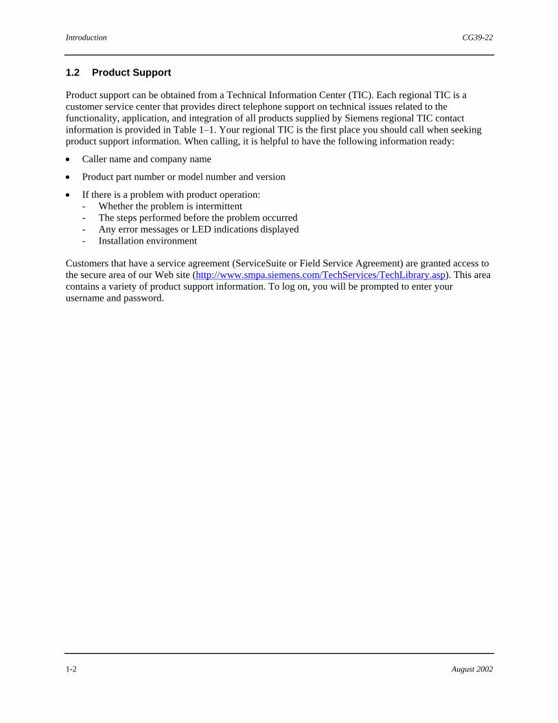
1.2 Product Support
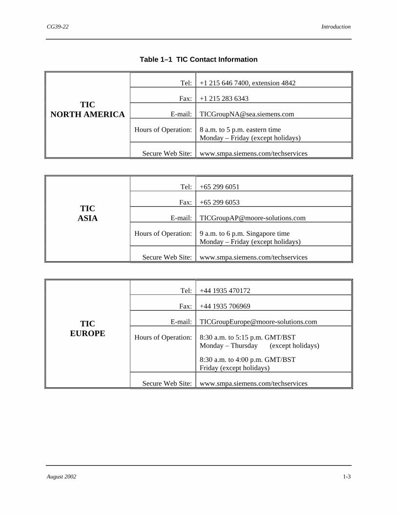
Product support can be obtained from a Technical Information Center (TIC). Each regional TIC is a customer service center that provides direct telephone support on technical issues related to the functionality, application, and integration of all products supplied by Siemens regional TIC contact information is provided in Table 1–1. Your regional TIC is the first place you should call when seeking product support information. When calling, it is helpful to have the following information ready:
• Caller name and company name
• Product part number or model number and version
• If there is a problem with product operation: - Whether the problem is intermittent - The steps performed before the problem occurred - Any error messages or LED indications displayed - Installation environment
Customers that have a service agreement (ServiceSuite or Field Service Agreement) are granted access to the secure area of our Web site (http://www.smpa.siemens.com/TechServices/TechLibrary.asp). This area contains a variety of product support information. To log on, you will be prompted to enter your username and password.
CG39-22 Introduction
August 2002 1-3
Table 1–1 TIC Contact Information
Tel: +1 215 646 7400, extension 4842
Fax: +1 215 283 6343
E-mail: [email protected]
Hours of Operation: 8 a.m. to 5 p.m. eastern time Monday – Friday (except holidays)
TIC NORTH AMERICA
Secure Web Site: www.smpa.siemens.com/techservices
Tel: +65 299 6051
Fax: +65 299 6053
E-mail: [email protected]
Hours of Operation: 9 a.m. to 6 p.m. Singapore time Monday – Friday (except holidays)
TIC ASIA
Secure Web Site: www.smpa.siemens.com/techservices
Tel: +44 1935 470172
Fax: +44 1935 706969
E-mail: [email protected]
Hours of Operation: 8:30 a.m. to 5:15 p.m. GMT/BST Monday – Thursday (except holidays)
8:30 a.m. to 4:00 p.m. GMT/BST Friday (except holidays)
TIC EUROPE
Secure Web Site: www.smpa.siemens.com/techservices

Introduction CG39-22
1-4 August 2002
1.3 Related Literature
The following literature is available from Siemens. Generally, all needed documentation is supplied on a CD-ROM supplied with your system. Refer to it as needed or as directed in text.
• Getting Started with ProcessSuite 4-mation Configuration Software (document number SG39-12)
• Using the ProcessSuite 4-mation Configuration Software (document number CG39-20)
• ProcessSuite 4-mation Configuration Software Messages and Diagnostic Codes (document number CG39-21)
The document files are in the Adobe® Acrobat® portable document format (PDF). You will need the Acrobat Reader to view or print them. This reader is also provided on the CD.
"

CG39-22 Standard Function Blocks
August 2002 2-1
2.0 Standard Function Blocks
Standard function blocks are configuration elements within the Advanced Control Module (ACM) system software supplied with 4-mation. These blocks provide a set of commonly used functions to ease configuration tasks. They were designed to comply with the IEC 61131-3 standard and can be used in any of the available configuration languages according to the rules of that language. For example, in a Sequential Function Chart (SFC), a function block only can be used in the body of action or transition.
Function blocks can have multiple inputs and outputs. Generally, inputs enter on the left of the block and outputs depart from the right of the block.
Each function block has a type name located inside the block at the top. This name describes the function the block performs or what type of block it is. For example: ADD, PID, and XOR are type names and they describe the function of each block. Function blocks can be assigned an instance name to uniquely identify the block. Instance names are located on top of the block, outside the block boundary. However, it is only necessary to assign an instance name to a function block when reading the inputs or writing to either the outputs or softlist parameters externally (from outside the control module). Figure 2–1 shows the basic graphical form of a function block.
INSTANCE_NAME
INPUT1 OUTPUT1
TYPE_NAME
Data Type
Data Type
Data Type
Data TypeINPUT2 OUTPUT2
Figure 2–1 Typical Function Block
Generally, function blocks that accept inputs of ANY or ANY_NUM data type have outputs of ANY or ANY_NUM data type. Each function block assumes that all of the ANY (or ANY_NUM) inputs are the same data type as the first ANY (or ANY_NUM) input assigned. The mixing of data types on the inputs and outputs of a block is not prevented, but it may lead to unpredictable results. Function blocks labeled with the ANY (or ANY_NUM) data type on an output must have a local variable on the output or must be wired to a typed input to assign the data type. A missing data type on an output is indicated in the on-line mode by the TAG NOT FOUND error code on the output.
If an ANY or ANY_NUM type output is wired to an ANY or ANY_NUM type input of another block, a default of REAL is assigned as the data type. To change the default of REAL type to a different data type, the output could be wired to any variable (local or global) of the correct data type (see Figure 2–2). After the network is downloaded, the added variable can be deleted; the function block output will retain the correct data type.

Standard Function Blocks CG39-22
2-2 August 2002
00001125
Integer Local Variable withData Type of Integer
Figure 2–2 Data Type Assignment Example
The standard function blocks are divided into sections according to function. For example, the Dynamic function blocks all perform time-dependent functions, the Selection function blocks all perform selection functions, etc. The entire collection of standard function blocks are described in the remaining sections of this Guide.
"

CG39-22 Dynamic Function Blocks
August 2002 3-1
3.0 Dynamic Function Blocks
The Dynamic function blocks are a subset of the standard function blocks. They execute complex equations that are time dependent. Since time is a variable in these equations, these function blocks have knowledge of the execution time interval (defined as the time period between the input sample and the implementation of the output to the process). This is accomplished by using a fixed execution period for function blocks. If derived coefficients of tuning parameters are used, these coefficients will be updated whenever the execution interval of the function block changes.
The inputs, outputs, and softlist parameters use engineering units. Control inputs use BOOL type data as they represent TRUE/FALSE parameters.
Generally, tuning parameters are available in a softlist and are not hard-wired to the blocks. Softlist parameters can be initialized at configuration time and can be modified on-line using 4-mation’s Softlist dialog box or with a Set Value (SET_VAL) function block.
For memory usage and ACM execution time information on all standard configuration elements see Appendix C in Using the ProcessSuite 4-mation Configuration Software (document number CG39-20).
A listing of Dynamic function blocks is presented here. Individual blocks are detailed in the subsections that follow.
• Setpoint • PID • Auto/manual • PD • ID • PID Incremental Output • PID Error Input • On/Off • Programmer • Lead/Lag • Rate Limiter • Ramp Generator • Scaler • Filter • Track and Hold • Impulse • Dead Time • Delayed Error • Batch Switch • EAM Totalizer • Totalizer • Accumulator • Loop Status

Dynamic Function Blocks CG39-22
3-2 August 2002
3.1 Setpoint Function Block (SETPNT)
REAL
REAL
REAL
BOOL
BOOL
REALREALAUTO
SETPNT
SPISPCSP
LL BOOL
BOOL
ESPEXTRNL
BOOL
PV
TARGET
RAMP
BOOL
TIMERTIME
HOLD
REAL
HL
The symbol of the Setpoint function block is shown above. The setpoint (SP) can be derived from two user-specified sources:
• Internal setpoint (ISP)
• External setpoint (ESP)
The setpoint is limited by both low and high softlist limits (LOLIM and HILIM) which prevent the setpoint from being inadvertently driven beyond a process operating limit. The internal setpoint can be changed via the (ISP) output, the computer setpoint (CSP), or the Setpoint function block itself (in track or ramp mode). A SET_VAL function block can also be used to change the (ISP).
The Setpoint function block may write either the track variable, (PV) (presumably the control loop process variable), or the external setpoint (ESP) to its internal setpoint, depending on the modes and options selected. The computer setpoint is typically written to by an operator command to change the internal setpoint. The (SP) value is assigned to (CSP) as well, thus making the (CSP) the only variable to which an external device needs to interface; however, it is preferred that an external device read the (SP) output and write to the (ISP) output. All values are in engineering units. An additional internal setpoint copy exists in the softlist (SLIST_SP) to retain the (ISP) value for use after a download. During on-line execution, the softlist value is only used when it has been changed by command or via softlist download.
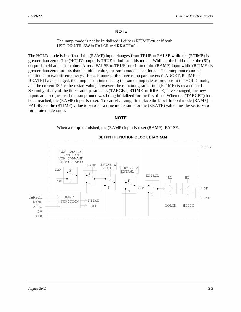
The Setpoint function block has a ramping feature that allows you to create a ramping setpoint. Ramping is allowed only when (AUTO) is TRUE and (EXTRNL) is FALSE. The ramp start point is the ISP. You are to enter a target endpoint (TARGET) and either a ramp time (RTIME) or a ramp rate (RRATE). The USE_RRATE_SW softlist switch determines which parameter is used (RTIME) or (RRATE). If USE_RRATE_SW is FALSE, (RTIME) is used; if USE_RRATE_SW is TRUE, (RRATE) is used. When (RAMP) makes a transition from FALSE to TRUE, the block initializes the ramp mode. As long as (RAMP) is TRUE, (AUTO) is TRUE, and (EXTRNL) is FALSE, ramping is in effect. The SETPNT function block does not ramp while in manual or external modes. If the block goes into external or manual while it previously had been in automatic and ramping, the ramping mode is turned off. To re-enable ramping, the block has to be placed into internal mode (EXTRNL)=FALSE, into automatic mode (AUTO)=TRUE and then placed in the ramp mode (RAMP)=TRUE. The (OUT) output reflects the ramping of the block and the (RTIME) output decrements to show the remaining ramp time. The RRATE must always be entered as positive; ramp direction is based on the relationship of the target and the starting point. RRATE is updated if (RTIME) is used, and (RTIME) is updated if RRATE is used. The (ISP) cannot be changed if ramping is active.
CG39-22 Dynamic Function Blocks
August 2002 3-3
NOTE
The ramp mode is not be initialized if either (RTIME)=0 or if both USE_RRATE_SW is FALSE and RRATE=0.
The HOLD mode is in effect if the (RAMP) input changes from TRUE to FALSE while the (RTIME) is greater than zero. The (HOLD) output is TRUE to indicate this mode. While in the hold mode, the (SP) output is held at its last value. After a FALSE to TRUE transition of the (RAMP) input while (RTIME) is greater than zero but less than its initial value, the ramp mode is continued. The ramp mode can be continued in two different ways. First, if none of the three ramp parameters (TARGET, RTIME or RRATE) have changed, the ramp is continued using the same ramp rate as previous to the HOLD mode, and the current ISP as the restart value; however, the remaining ramp time (RTIME) is recalculated. Secondly, if any of the three ramp parameters (TARGET, RTIME, or RRATE) have changed, the new inputs are used just as if the ramp mode was being initialized for the first time. When the (TARGET) has been reached, the (RAMP) input is reset. To cancel a ramp, first place the block in hold mode (RAMP) = FALSE, set the (RTIME) value to zero for a time mode ramp, or the (RRATE) value must be set to zero for a rate mode ramp.
NOTE
When a ramp is finished, the (RAMP) input is reset (RAMP)=FALSE.
HLLL
SETPNT FUNCTION BLOCK DIAGRAM
LOLIM HILIM
ISP
SP
CSP
F
T
.
. . F
T
.
. . F
T
.
. . F
T
.
. . F
T
.
. .
EXTRNL
ESPTRK &EXTRNL
RAMP PVTRK & -AUTO
CSP CHANGEOCCURRED
VIA COMMAND(MOMENTARY)
RAMPFUNCTION RTIME
HOLD
TARGETRAMPAUTO
CSP
ISP
ISP
PVESP
Dynamic Function Blocks CG39-22
3-4 August 2002
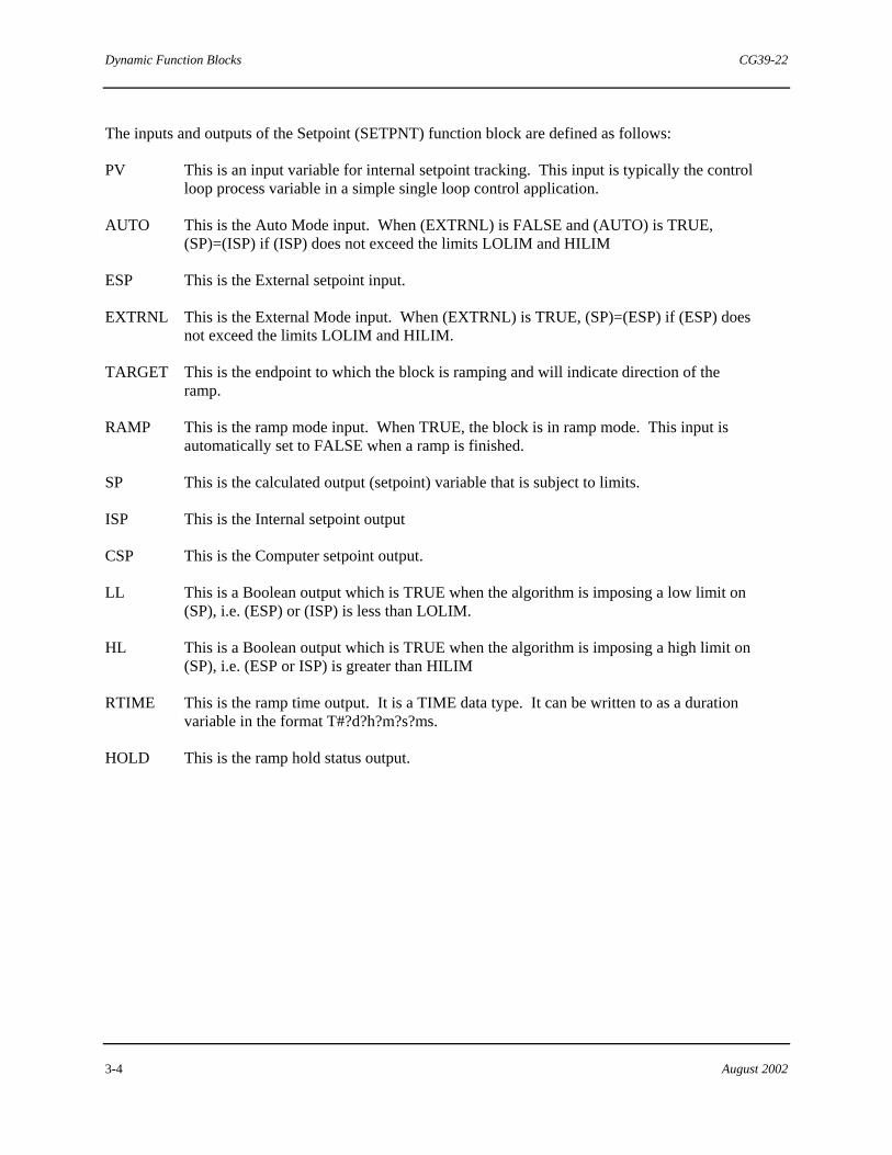
The inputs and outputs of the Setpoint (SETPNT) function block are defined as follows:
PV This is an input variable for internal setpoint tracking. This input is typically the control loop process variable in a simple single loop control application.
AUTO This is the Auto Mode input. When (EXTRNL) is FALSE and (AUTO) is TRUE, (SP)=(ISP) if (ISP) does not exceed the limits LOLIM and HILIM
ESP This is the External setpoint input.
EXTRNL This is the External Mode input. When (EXTRNL) is TRUE, (SP)=(ESP) if (ESP) does not exceed the limits LOLIM and HILIM.
TARGET This is the endpoint to which the block is ramping and will indicate direction of the ramp.
RAMP This is the ramp mode input. When TRUE, the block is in ramp mode. This input is automatically set to FALSE when a ramp is finished.
SP This is the calculated output (setpoint) variable that is subject to limits.
ISP This is the Internal setpoint output
CSP This is the Computer setpoint output.
LL This is a Boolean output which is TRUE when the algorithm is imposing a low limit on (SP), i.e. (ESP) or (ISP) is less than LOLIM.
HL This is a Boolean output which is TRUE when the algorithm is imposing a high limit on (SP), i.e. (ESP or ISP) is greater than HILIM
RTIME This is the ramp time output. It is a TIME data type. It can be written to as a duration variable in the format T#?d?h?m?s?ms.
HOLD This is the ramp hold status output.

CG39-22 Dynamic Function Blocks
August 2002 3-5
Softlist Parameters
The remaining SETPNT inputs are accessed via the softlist. The value of these inputs can be changed via commands from an operator interface or a Set Value (SET_VAL) function block, but they cannot be “wired” to the block. Below is a description and initial value for each softlist parameter.
SLIST_SP This is the Internal setpoint of the softlist array.
LOLIM This is the setpoint low limit softlist input.
HILIM This is the setpoint high limit softlist input.
RRATE This is the ramp rate softlist input. It is a real value entered in engineering units per minute; it must be positive.
USE_RRATE_SW This is the softlist switch which, when FALSE, means use the (RTIME) value to calculate the RRATE and, when TRUE, means use the RRATE value to calculate the (RTIME).
PVTRK This is a boolean softlist parameter. Setting PVTRK=TRUE causes the Internal setpoint to track the (PV) Input when ESPTRK=FALSE or (EXTRNL)=FALSE and (AUTO)=FALSE.
ESPTRK This is a boolean softlist parameter. Setting ESPTRK=TRUE causes the Internal setpoint to track the External setpoint when (EXTRNL)=TRUE.
Parameter Units Initial Value Min Value Max Value
SLIST_SP Engr 0.0 NA NA
LOLIM Engr 0.0 LOLIM must be less than HILIM
HILIM Engr 100.0 HILIM must be greater than LOLIM
RRATE Engr/Min 0.0 NA NA
USE_RRATE_SW BOOL FALSE FALSE TRUE
PVTRK BOOL TRUE FALSE TRUE
ESPTRK BOOL TRUE FALSE TRUE
Where NA indicates not applicable.
Dynamic Function Blocks CG39-22
3-6 August 2002
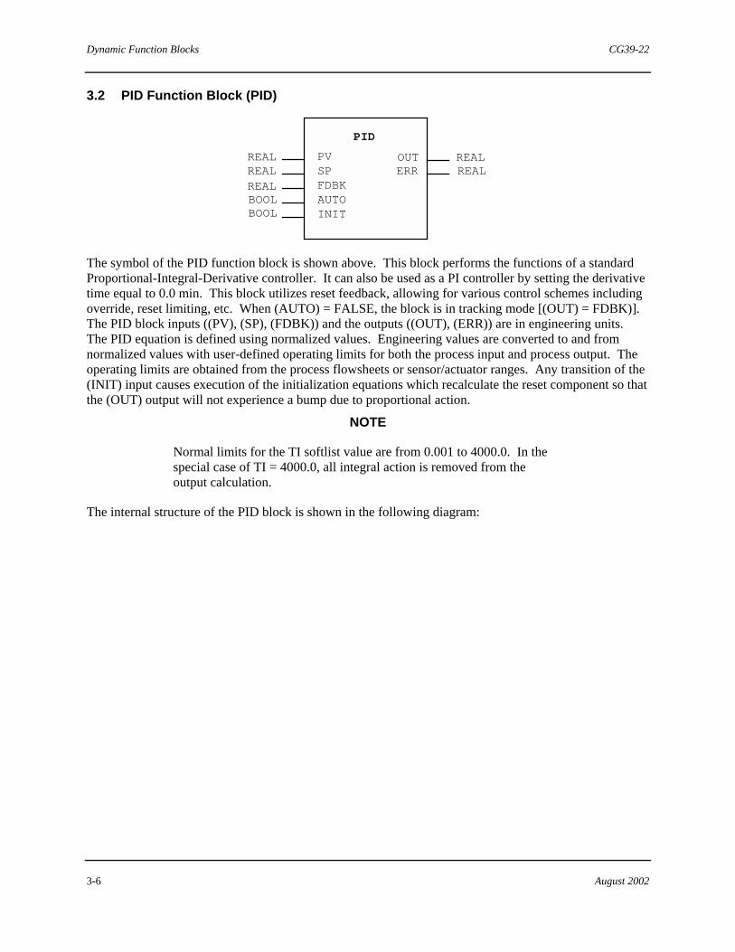
3.2 PID Function Block (PID)
PID
REALREALREALBOOLBOOL
REALREAL
PVSPFDBKAUTOINIT
OUTERR
The symbol of the PID function block is shown above. This block performs the functions of a standard Proportional-Integral-Derivative controller. It can also be used as a PI controller by setting the derivative time equal to 0.0 min. This block utilizes reset feedback, allowing for various control schemes including override, reset limiting, etc. When (AUTO) = FALSE, the block is in tracking mode [(OUT) = FDBK)]. The PID block inputs ((PV), (SP), (FDBK)) and the outputs ((OUT), (ERR)) are in engineering units. The PID equation is defined using normalized values. Engineering values are converted to and from normalized values with user-defined operating limits for both the process input and process output. The operating limits are obtained from the process flowsheets or sensor/actuator ranges. Any transition of the (INIT) input causes execution of the initialization equations which recalculate the reset component so that the (OUT) output will not experience a bump due to proportional action.
NOTE
Normal limits for the TI softlist value are from 0.001 to 4000.0. In the special case of TI = 4000.0, all integral action is removed from the output calculation.
The internal structure of the PID block is shown in the following diagram:

CG39-22 Dynamic Function Blocks
August 2002 3-7
PV
SP
FDBK
Σ
ΣΣ ΣD
DDG S+1
+
+
+
- +- 1
+
+
1
I
A PG>> > > > >
>
>
PV
SP
ERR+
-
R
OUT>
>
PID FUNCTION BLOCK DIAGRAM
τ
τ
τ
S
S+1
AUTO
F
T...
The inputs and outputs of the PID function block are defined as follows:
PV This is the process variable input.
SP This is the setpoint input.
FDBK This is the reset feedback input.
AUTO This is the track command input. When this input is FALSE, the block is in a tracking mode [(OUT)=(FDBK)]. In addition, transitions of this input cause initialization to be performed.
INIT This is a second mode/status input to the block. Transitions of the INIT input cause the initialization equation to be performed but does not cause the mode of the block to change. Initialization causes the reset component to be recalculated so that (OUT) remains the same. This input is typically used to cause initialization upon changes in the source of the setpoint (e.g. internal-to-external or external-to-internal).
OUT This is the calculated output. It is limited from -3.3 to +103.3% of range EOUTL to EOUTH.
ERR This is the error output [(PV) - (SP)].

Dynamic Function Blocks CG39-22
3-8 August 2002
Softlist Parameters
The tuning coefficients (PG, TI, TD, DG) and the remaining PID inputs are accessed via the softlist.
PG This is the Proportional Gain input to the block.
TI This is the Integral Time input (in minutes per repeat) to the block.
TD This is the Derivative Time input to the block.
DG This is the Derivative Gain input to the block.
DIR_ACT This is a boolean input to the block that determines the action of the controller. TRUE signifies direct action (A=1) and FALSE signifies reverse action (A=-1).
EINL This is the (PV) low value in engineering units used for scaling.
EINH This is the (PV) high value in engineering units used for scaling.
EOUTL This is the (OUT) low value in engineering units used for scaling.
EOUTH This is the (OUT) high value in engineering units used for scaling.
ADAPTIVE_PG_INIT This is the Boolean value that when FALSE, suppresses the initialization of the block upon changes of the PG parameter, which is necessary to implement a continuously adaptive gain circuit. When TRUE, normal initialization occurs when the PG softlist parameter value is modified.
Parameter Units Initial Value Min Value Max Value
PG dimensionless 0.001 0.001 100.0
TI Min/repeat 4000.0 (OFF) 0.001 4000.0
TD Min 0.0 (OFF) 0.0 100.0
DG dimensionless 10.00 2.0 20.0
DIR_ACT BOOL FALSE FALSE TRUE
EINL Engr units 0.0 NA NA
EINH Engr units 100.0 NA NA
CG39-22 Dynamic Function Blocks
August 2002 3-9
EOUTL Engr units 0.0 NA NA
EOUTH Engr units 100.0 NA NA
ADAPTIVE_PG_INIT BOOL TRUE FALSE TRUE
Where NA indicates not applicable.
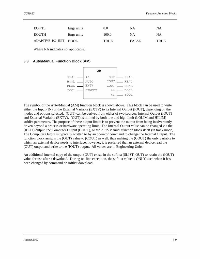
3.3 Auto/Manual Function Block (AM)
REAL
REAL
REAL
REALAUTOCOUTLL BOOL
BOOL
IN
AM
EXTV
STNDBY
OUTIOUTBOOL
BOOLREAL
HL
The symbol of the Auto/Manual (AM) function block is shown above. This block can be used to write either the Input (IN) or the External Variable (EXTV) to its Internal Output (IOUT), depending on the modes and options selected. (OUT) can be derived from either of two sources, Internal Output (IOUT) and External Variable (EXTV). (OUT) is limited by both low and high limit (LOLIM and HILIM) softlist parameters. The purpose of these output limits is to prevent the output from being inadvertently driven beyond a process or hardware operating limit. The Internal Output value can be changed via the (IOUT) output, the Computer Output (COUT), or the Auto/Manual function block itself (in track mode). The Computer Output is typically written to by an operator command to change the Internal Output. The function block assigns the (OUT) value to (COUT) as well, thus making the (COUT) the only variable to which an external device needs to interface; however, it is preferred that an external device read the (OUT) output and write to the (IOUT) output. All values are in Engineering Units.
An additional internal copy of the output (OUT) exists in the softlist (SLIST_OUT) to retain the (IOUT) value for use after a download. During on-line execution, the softlist value is ONLY used when it has been changed by command or softlist download.
Dynamic Function Blocks CG39-22
3-10 August 2002
HLLL
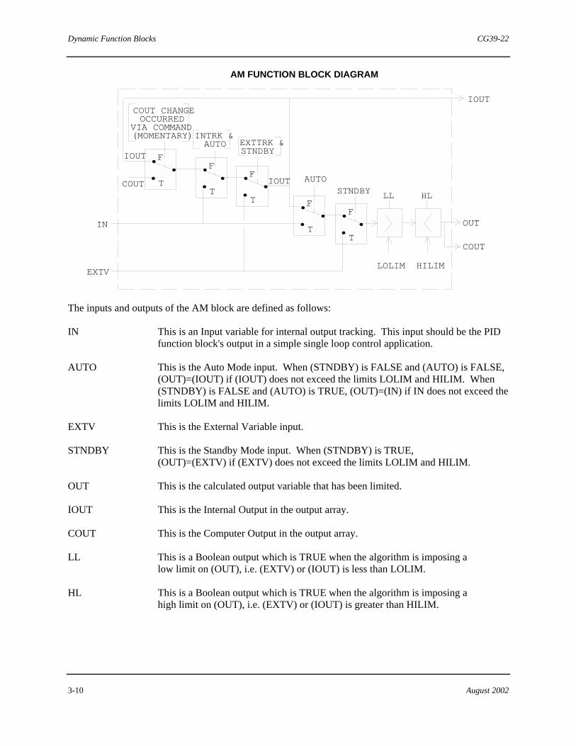
AM FUNCTION BLOCK DIAGRAM
LOLIM HILIM
IOUT
OUT
COUT
F
T
.
. . F
T
.
. . F
T
.
. .F
T
.
. . F
T
.
. .
STNDBYAUTO
EXTTRK & STNDBY
COUT CHANGEOCCURRED
VIA COMMAND(MOMENTARY)
COUT
IOUT
IOUT
IN
EXTV
INTRK & AUTO
The inputs and outputs of the AM block are defined as follows:
IN This is an Input variable for internal output tracking. This input should be the PID function block's output in a simple single loop control application.
AUTO This is the Auto Mode input. When (STNDBY) is FALSE and (AUTO) is FALSE, (OUT)=(IOUT) if (IOUT) does not exceed the limits LOLIM and HILIM. When (STNDBY) is FALSE and (AUTO) is TRUE, (OUT)=(IN) if IN does not exceed the limits LOLIM and HILIM.
EXTV This is the External Variable input.
STNDBY This is the Standby Mode input. When (STNDBY) is TRUE, (OUT)=(EXTV) if (EXTV) does not exceed the limits LOLIM and HILIM.
OUT This is the calculated output variable that has been limited.
IOUT This is the Internal Output in the output array.
COUT This is the Computer Output in the output array.
LL This is a Boolean output which is TRUE when the algorithm is imposing a low limit on (OUT), i.e. (EXTV) or (IOUT) is less than LOLIM.
HL This is a Boolean output which is TRUE when the algorithm is imposing a high limit on (OUT), i.e. (EXTV) or (IOUT) is greater than HILIM.
CG39-22 Dynamic Function Blocks
August 2002 3-11
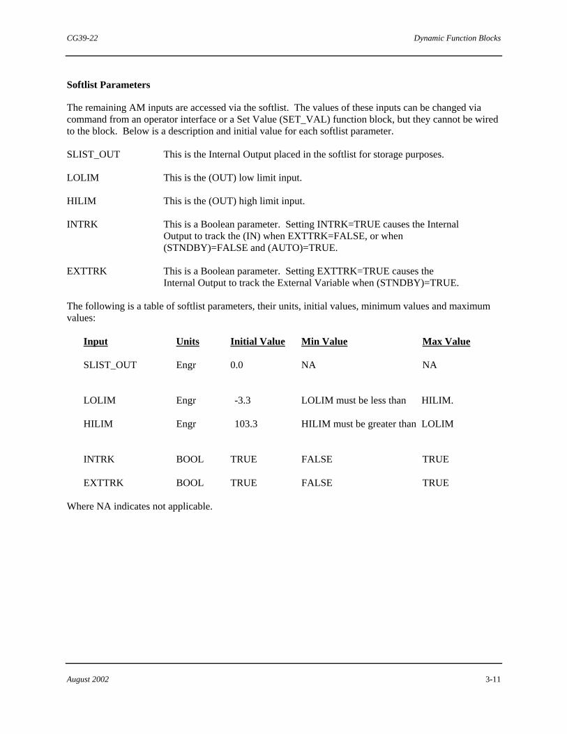
Softlist Parameters
The remaining AM inputs are accessed via the softlist. The values of these inputs can be changed via command from an operator interface or a Set Value (SET_VAL) function block, but they cannot be wired to the block. Below is a description and initial value for each softlist parameter.
SLIST_OUT This is the Internal Output placed in the softlist for storage purposes.
LOLIM This is the (OUT) low limit input.
HILIM This is the (OUT) high limit input.
INTRK This is a Boolean parameter. Setting INTRK=TRUE causes the Internal Output to track the (IN) when EXTTRK=FALSE, or when (STNDBY)=FALSE and (AUTO)=TRUE.
EXTTRK This is a Boolean parameter. Setting EXTTRK=TRUE causes the Internal Output to track the External Variable when (STNDBY)=TRUE.
The following is a table of softlist parameters, their units, initial values, minimum values and maximum values:
Input Units Initial Value Min Value Max Value
SLIST_OUT Engr 0.0 NA NA
LOLIM Engr -3.3 LOLIM must be less than HILIM.
HILIM Engr 103.3 HILIM must be greater than LOLIM
INTRK BOOL TRUE FALSE TRUE
EXTTRK BOOL TRUE FALSE TRUE
Where NA indicates not applicable.

Dynamic Function Blocks CG39-22
3-12 August 2002
3.4 PD Function Block (PD)
PD
REAL
REAL
REAL
BOOL
BOOL
REAL
REAL
PV
SP
FDBK
AUTO
INIT
OUT
ERR
The symbol of the Proportional-Derivative (PD) Controller function block is shown above. This block performs the function of a proportional-derivative (PD) controller with manual reset. It can be set as tracking or non-tracking by the MRTRCK softlist value. Additionally, tt can be used as a proportional-only controller by setting the derivative time equal to 0.0 min. Inputs and outputs use engineering units that are user-selectable. Transitions of the (INIT) input cause execution of the initialization equations which recalculate the reset component so that the (OUT) will not experience a bump due to proportional action.
+ - +
PV
SP
FDBK
Σ
ΣΣ ΣD
DDG S+1
+ +
+- 1
+
1
A PG>> > > > >
>
>
PV
SP
ERR+
-
>
PD FUNCTION BLOCK DIAGRAM
τ
τ
τ
S
S+1MR
R
OUT>
AUTO
F
T. ..
MRTRCK
MR
>
AUTO
F
T. ..F
T. ..
CG39-22 Dynamic Function Blocks
August 2002 3-13
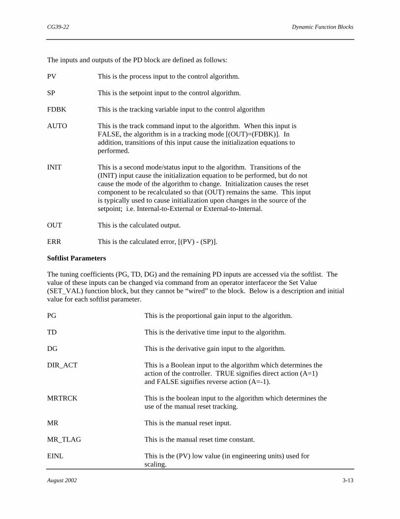
The inputs and outputs of the PD block are defined as follows:
PV This is the process input to the control algorithm.
SP This is the setpoint input to the control algorithm.
FDBK This is the tracking variable input to the control algorithm
AUTO This is the track command input to the algorithm. When this input is FALSE, the algorithm is in a tracking mode [(OUT)=(FDBK)]. In addition, transitions of this input cause the initialization equations to performed.
INIT This is a second mode/status input to the algorithm. Transitions of the (INIT) input cause the initialization equation to be performed, but do not cause the mode of the algorithm to change. Initialization causes the reset component to be recalculated so that (OUT) remains the same. This input is typically used to cause initialization upon changes in the source of the setpoint; i.e. Internal-to-External or External-to-Internal.
OUT This is the calculated output.
ERR This is the calculated error, [(PV) - (SP)].
Softlist Parameters
The tuning coefficients (PG, TD, DG) and the remaining PD inputs are accessed via the softlist. The value of these inputs can be changed via command from an operator interfaceor the Set Value (SET_VAL) function block, but they cannot be “wired” to the block. Below is a description and initial value for each softlist parameter.
PG This is the proportional gain input to the algorithm.
TD This is the derivative time input to the algorithm.
DG This is the derivative gain input to the algorithm.
DIR_ACT This is a Boolean input to the algorithm which determines the action of the controller. TRUE signifies direct action (A=1) and FALSE signifies reverse action (A=-1).
MRTRCK This is the boolean input to the algorithm which determines the use of the manual reset tracking.
MR This is the manual reset input.
MR_TLAG This is the manual reset time constant.
EINL This is the (PV) low value (in engineering units) used for scaling.

Dynamic Function Blocks CG39-22
3-14 August 2002
EINH This is the (PV) high value (in engineering units) used for scaling.
EOUTL This is the output low value (in engineering units) used for scaling.
EOUTH This is the output high value (in engineering units) used for scaling.
ADAPTIVE_PG_INIT This is the Boolean value which, when FALSE, suppresses the initialization of the controller algorithm upon changes of the PG softlist value which is necessary to implement a continuously adaptive gain circuit. When TRUE, normal initialization occurs when the PG softlist value is modified.
Parameter Units Initial Value
Min Value
Max Value
PG dimensionless 0.001 0.001 100.0
TD Min 0.0 (OFF)
0.0 100.0
DG dimensionless 10.0 2.0 20.0
DIR_ACT BOOL FALSE FALSE TRUE
MRTRCK BOOL FALSE FALSE TRUE
MR Engr 0.0 NA NA
MR_TLAG Min 1.0 0.001 4000.0
EINL Engr 0.0 NA NA
EINH Engr 100.0 NA NA
EOUTL Engr 0.0 NA NA
EOUTH Engr 100.0 NA NA
ADAPTIVE_PG_INIT BOOL TRUE FALSE TRUE
Where NA indicates not applicable.

CG39-22 Dynamic Function Blocks
August 2002 3-15
3.5 ID Function Block (ID)
REALREAL
REAL
BOOL
REALREAL
PVSP
FDBK
AUTO
OUTERR
ID
The symbol of the Integral-Derivative (ID) Controller block is shown above. This block performs the function of an Integral-Derivative (ID) controller. It uses external feedback to establish integral action. The AUTO input, when FALSE, forces the output to track the feedback. Controller gain is fixed at a value of 1.00. The block can also be used as an Integral-only (I) controller by setting the Derivative Time (DT) softlist value to 0.00 minutes.
NOTE
Normal limits for the TI softlist value are from 0.001 to 4000.0. In the special case of TI = 4000.0, all integral action is removed from the output calculation.
PV
SP
FDBK
Σ
ΣΣ ΣD
DDG S+1
+
+
+
- +- 1
+
+
1
IA>> > > >
>
>
PV
SP
ERR+
-
>
ID FUNCTION BLOCK DIAGRAM
τ
τ τ
S
S+1
R
OUT>
AUTO
F
T. ..
Dynamic Function Blocks CG39-22
3-16 August 2002
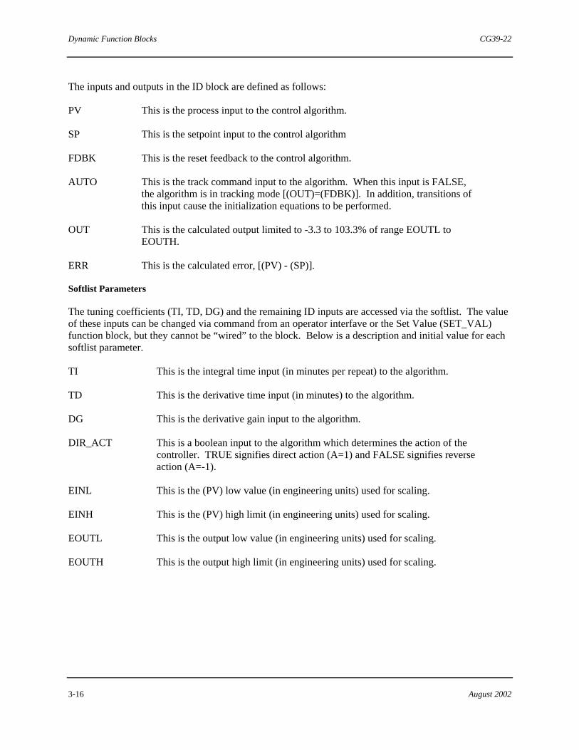
The inputs and outputs in the ID block are defined as follows:
PV This is the process input to the control algorithm.
SP This is the setpoint input to the control algorithm
FDBK This is the reset feedback to the control algorithm.
AUTO This is the track command input to the algorithm. When this input is FALSE, the algorithm is in tracking mode [(OUT)=(FDBK)]. In addition, transitions of this input cause the initialization equations to be performed.
OUT This is the calculated output limited to -3.3 to 103.3% of range EOUTL to EOUTH.
ERR This is the calculated error, [(PV) - (SP)].
Softlist Parameters
The tuning coefficients (TI, TD, DG) and the remaining ID inputs are accessed via the softlist. The value of these inputs can be changed via command from an operator interfave or the Set Value (SET_VAL) function block, but they cannot be “wired” to the block. Below is a description and initial value for each softlist parameter.
TI This is the integral time input (in minutes per repeat) to the algorithm.
TD This is the derivative time input (in minutes) to the algorithm.
DG This is the derivative gain input to the algorithm.
DIR_ACT This is a boolean input to the algorithm which determines the action of the controller. TRUE signifies direct action (A=1) and FALSE signifies reverse action (A=-1).
EINL This is the (PV) low value (in engineering units) used for scaling.
EINH This is the (PV) high limit (in engineering units) used for scaling.
EOUTL This is the output low value (in engineering units) used for scaling.
EOUTH This is the output high limit (in engineering units) used for scaling.

CG39-22 Dynamic Function Blocks
August 2002 3-17
Parameter Units Initial Value Min Value Max Value
TI Min/repeat 4000.0 (OFF) 0.001 4000.0
TD Min 0.0 (OFF) 0.0 100.0
DG dimensionless 10.0 2.0 20.0
DIR_ACT BOOL FALSE FALSE TRUE
EINL Engr 0.0 NA NA
EINH Engr 100.0 NA NA
EOUTL Engr 0.0 NA NA
EOUTH Engr 100.0 NA NA
Where NA indicates not applicable.
3.6 PID Incremental Output Function Blocks
(Non-interacting Modes)
PV - SPREAL
REALREAL
GAIN
INTEGRAL
DERIVATIVE
OUTPUT
REALINCRPOS
The Gain, Integral, Derivative, and Increment-to-Position function blocks can be used to implement a parallel or non-interacting form of the PID controller algorithm. By selecting the appropriate control blocks, additional non-interacting controllers such as PI, P, PD, I, or ID can be implemented.
The controller blocks (Gain, Integral, and Derivative) described in the subsections to follow generate an incremental output as opposed to an absolute position or value. These incremental values can be summed together and/or converted to an absolute value (see Increment-to-Position block).
Dynamic Function Blocks CG39-22
3-18 August 2002
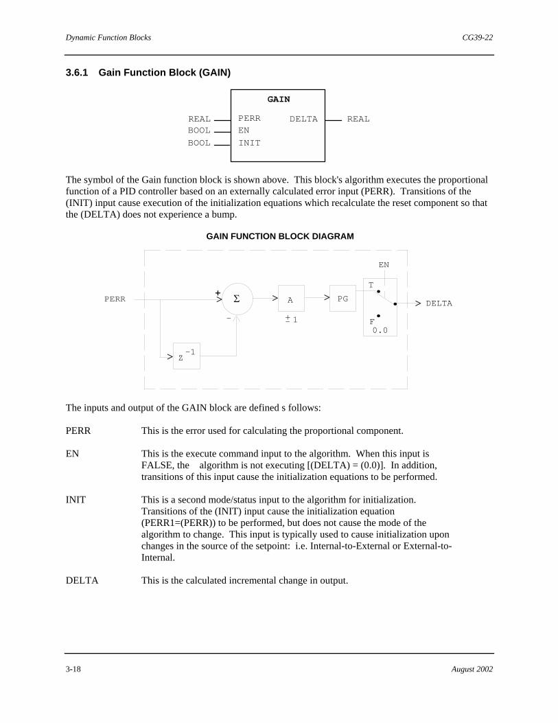
3.6.1 Gain Function Block (GAIN)
REAL REALBOOL
BOOL
EN
INIT
DELTA
GAIN
PERR
The symbol of the Gain function block is shown above. This block's algorithm executes the proportional function of a PID controller based on an externally calculated error input (PERR). Transitions of the (INIT) input cause execution of the initialization equations which recalculate the reset component so that the (DELTA) does not experience a bump.
Σ+>PERR
EN
DELTAA PG
+- 1
Z-1
-
>
>> >
GAIN FUNCTION BLOCK DIAGRAM
T
F0.0
..
.
The inputs and output of the GAIN block are defined s follows:
PERR This is the error used for calculating the proportional component.
EN This is the execute command input to the algorithm. When this input is FALSE, the algorithm is not executing [(DELTA) = (0.0)]. In addition, transitions of this input cause the initialization equations to be performed.
INIT This is a second mode/status input to the algorithm for initialization. Transitions of the (INIT) input cause the initialization equation (PERR1=(PERR)) to be performed, but does not cause the mode of the algorithm to change. This input is typically used to cause initialization upon changes in the source of the setpoint: i.e. Internal-to-External or External-to-Internal.
DELTA This is the calculated incremental change in output.

CG39-22 Dynamic Function Blocks
August 2002 3-19
Softlist Parameters
The remaining GAIN inputs are accessed via the softlist. The value of these inputs can be changed via command from an operator interface or the Set Value (SET_VAL) function block, but they cannot be “wired” to the block. Below is a description and initial value for each softlist parameter.
PG This is the proportional gain input to the algorithm.
DIR_ACT This is a Boolean input to the algorithm which determines the action of the controller. TRUE signifies direct action (A=1) and FALSE signifies reverse action (A=-1).
EINL This is the (PV) low value (in engineering units) used for scaling.
EINH This is the (PV) high value (in engineering units) used for scaling.
EOUTL This is the output low value (in engineering units) used for scaling.
EOUTH This is the output high value (in engineering units) used for scaling.
ADAPTIVE_PG_INIT This is the boolean value which, when FALSE, suppresses the initialization of the controller algorithm upon changes of the PG softlist value, which is necessary to implement a continuously adaptive gain circuit. When TRUE, normal initialization occurs when the PG softlist value is modified.
Parameter Units Initial Value Min Value Max Value
PG dimensionless 0.001 0.001 100.0
DIR_ACT BOOL FALSE FALSE TRUE
EINL Engr 0.0 NA NA
EINH Engr 100.0 NA NA
EOUTL Engr 0.0 NA NA
EOUTH Engr 100.0 NA NA
ADAPTIVE_PG_INIT BOOL TRUE FALSE TRUE
Where NA indicates not applicable.
Dynamic Function Blocks CG39-22
3-20 August 2002
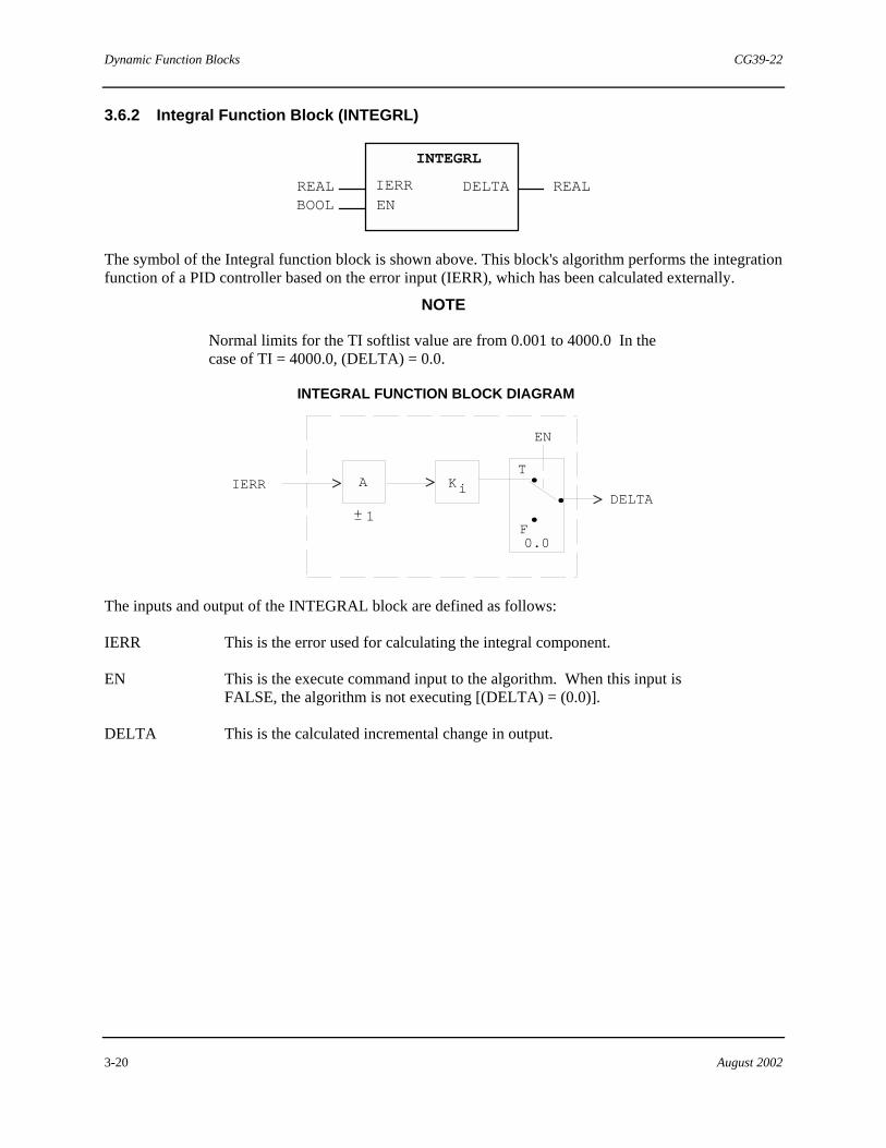
3.6.2 Integral Function Block (INTEGRL)
REAL REALBOOL EN
DELTA
INTEGRL
IERR
The symbol of the Integral function block is shown above. This block's algorithm performs the integration function of a PID controller based on the error input (IERR), which has been calculated externally.
NOTE
Normal limits for the TI softlist value are from 0.001 to 4000.0 In the case of TI = 4000.0, (DELTA) = 0.0.
A
+- 1
> >
INTEGRAL FUNCTION BLOCK DIAGRAM
IERR Ki
EN
DELTA>
T
F0.0
..
.
The inputs and output of the INTEGRAL block are defined as follows:
IERR This is the error used for calculating the integral component.
EN This is the execute command input to the algorithm. When this input is FALSE, the algorithm is not executing [(DELTA) = (0.0)].
DELTA This is the calculated incremental change in output.

CG39-22 Dynamic Function Blocks
August 2002 3-21
Softlist Parameters
The remaining INTEGRAL inputs are accessed via the softlist. The value of these inputs can be changed via command from an operator interface or the Set Value (SET_VAL) function block, but they cannot be “wired” to the block. Below is a description and initial value for each softlist parameter.
TI This is the integral time input (in minutes per repeat) to the algorithm.
DIR_ACT This is a Boolean input to the algorithm which determines the action of the controller. TRUE signifies direct action (A=1) and FALSE signifies reverse action (A=-1).
EINL This is the (PV) low value (in engineering units) used for scaling.
EINH This is the (PV) high value (in engineering units) used for scaling.
EOUTL This is the output low value (in engineering units) used for scaling.
EOUTH This is the output high value (in engineering units) used for scaling.
Parameter Units Initial Value Min Value Max Value
TI Min/repeat 4000.0 (OFF) 0.001 4000.0
DIR_ACT BOOL FALSE FALSE TRUE
EINL Engr 0.0 NA NA
EINH Engr 100.0 NA NA
EOUTL Engr 0.0 NA NA
EOUTH Engr 100.0 NA NA
Where NA indicates not applicable.
3.6.3 Derivative Function Block (DERIV)
REAL REAL BOOL BOOL
EN INIT
DELTA
DERIV
DERR

Dynamic Function Blocks CG39-22
3-22 August 2002
The symbol of the Derivative (DERIV) block is shown above. This block's algorithm performs the derivative function of the PID controller based on an externally calculated error input (DERR). Transitions of the (INIT) input cause execution of the initialization equations which recalculate the reset component so that the (OUT) output remains the same.
DERIVATIVE FUNCTION BLOCK DIAGRAM
Σ+
Σ+
+
Z-1
Kd2
Kd1
Z-1
A
+-1
Σ+
DERR
-
EN
DELTA>
T
F0.0
..
.-
The inputs and output of the DERIVATIVE block are defined as follows:
DERR This is the error used for calculating the derivative component.
EN This is the execute command input to the algorithm. When this input is FALSE, the algorithm is not executing [(DELTA) = (0.0)]. In addition, transitions of this input cause the initialization equations to be performed.
INIT This is a second mode/status input to the algorithm. Transitions of the INIT input cause the initialization equations [D1=0, DERR1=(DERR)] to be performed, but do not cause the mode of the algorithm to change. This input is typically used to cause initialization upon changes in the source of the setpoint (Internal-to-External or External-to-Internal).
DELTA This is the calculated incremental change in output.

CG39-22 Dynamic Function Blocks
August 2002 3-23
Softlist Parameters
The remaining DERIV inputs are accessed via the softlist. The value of these inputs can be changed via command from an operator interface or the Set Value (SET_VAL) function block, but they cannot be “wired” to the block. Below is a description and initial value for each softlist parameter.
TD This is the derivative time input to the algorithm.
DG This is the derivative gain input to the algorithm.
DIR_ACT This is a Boolean input to the algorithm, which determines the action of the controller. TRUE signifies direct action (A=1) and FALSE signifies reverse action (A=-1).
EINL This is the (PV) low value (in engineering units) used for scaling.
EINH This is the (PV) high value (in engineering units) used for scaling.
EOUTL This is the output low value (in engineering units) used for scaling.
EOUTH This is the output high value (in engineering units) used for scaling.
Parameter Units Initial Value Min Value Max Value
TD Min 0.0 (OFF) 0.0 100.0
DG dimensionless 10.0 2.0 20.0
DIR_ACT BOOL FALSE FALSE TRUE
EINL Engr 0.0 NA NA
EINH Engr 100.0 NA NA
EOUTL Engr 0.0 NA NA
EOUTH Engr 100.0 NA NA
Where NA indicates not applicable.

Dynamic Function Blocks CG39-22
3-24 August 2002
3.6.4 Increment-to-Position Function Block (INCRPOS)
REAL REALFDBK
INCRPOS
POSPDELTAIDELTA
DDELTA
AUTOREAL
REALREAL
BOOL
The symbol of the Increment-to-Position (INCRPOS) block is shown above. This block's algorithm converts an incremental value (a change in output from the non-interacting PID or an error signal, PV-SP) into a position. A positive incremental input value increases the position output. A negative incremental input decreases the position output. This block calculates its values based on engineering values.
Σ Σ
+
+Σ
+
+ +
INCREMENT TO POSITION FUNCTION BLOCK DIAGRAM
FDBK
PDELTA
IDELTA
DDELTA
HILIM
LOLIM
POS+
.
. .T
F
AUTO
The inputs and output of the INCRPOS block are defined as follows:
FDBK This is an external variable, such as the output of an AM block or any other external variable. It is a required input since it contains the accumulated value of the sum of the incremental values.
PDELTA This is the incremental input change due to proportional action.
IDELTA This is the incremental input change due to integral action.
DDELTA This is the incremental input change due to derivative action.
AUTO This is the auto/manual input. When FALSE, (POS) = (FDBK).
POS This is the calculated position of the output (in engineering units).

CG39-22 Dynamic Function Blocks
August 2002 3-25
Softlist Parameters
The remaining INCRPOS inputs are accessed via the softlist. The value of these inputs can be changed via command from an operator interface or the Set Value (SET_VAL) function block, but they cannot be “wired” to the block. Below is a description and initial value for each softlist parameter.
LOLIM This is the lower limit of the output (in engineering units).
HILIM This is the upper limit of the output (in engineering units).
Parameter Units Initial Value Min Value / Max Value
LOLIM Engr -3.3 LOLIM must be less than HILIM
HILIM Engr 103.3 HILIM must be greater than LOLIM
3.7 PID Error Input Function Block (Non-Interacting) (PID_ERR)
AUTO
OUT
BOOLBOOL
BOOLBOOL
REALREAL
REALREALREALREAL
DELTA
HLLL
PERRIERRDERRFDBK
INIT
PID_ERR
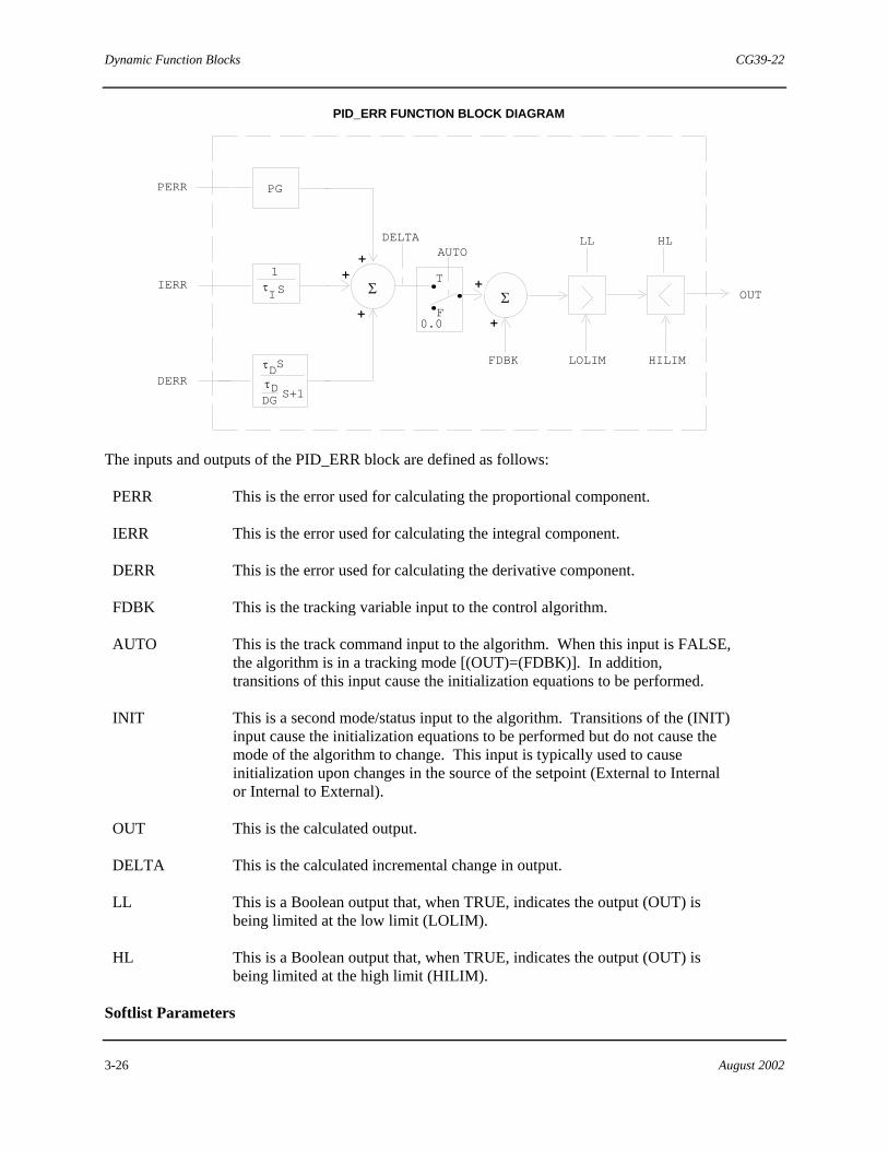
The symbol of the Proportional-Integral-Derivative (PID) Error Input block is shown above. This block's algorithm performs the function of a PID controller using error inputs. A separate error input is provided for the proportional, integral, and derivative components, thus providing a mechanism to implement advanced strategies such as delayed integral action. The velocity equations employed have no interaction between the proportional, integral, and derivative sections. Derivative action occurs on setpoint changes if the derivative error changes due to setpoint modifications. Transitions of the (INIT) input cause execution of the initialization equations, which recalculate the reset component so that the (OUT) output remains the same.
NOTE
Normal limits for integral time (TI) input are from 0.001 to 4000.0 (in minutes per repeat). In the special case of TI = 4000.0, all integral action is removed from the output calculation.
Dynamic Function Blocks CG39-22
3-26 August 2002
Σ+
+
PERR
IERR
DERR
FDBK
AUTO
OUT
HLLLDELTA
+
PID_ERR FUNCTION BLOCK DIAGRAM
T
F
. ..0.0
Σ+
+
LOLIM HILIMD
DDG S+1
τ
τ
S
1
Iτ S
PG
The inputs and outputs of the PID_ERR block are defined as follows:
PERR This is the error used for calculating the proportional component.
IERR This is the error used for calculating the integral component.
DERR This is the error used for calculating the derivative component.
FDBK This is the tracking variable input to the control algorithm.
AUTO This is the track command input to the algorithm. When this input is FALSE, the algorithm is in a tracking mode [(OUT)=(FDBK)]. In addition, transitions of this input cause the initialization equations to be performed.
INIT This is a second mode/status input to the algorithm. Transitions of the (INIT) input cause the initialization equations to be performed but do not cause the mode of the algorithm to change. This input is typically used to cause initialization upon changes in the source of the setpoint (External to Internal or Internal to External).
OUT This is the calculated output.
DELTA This is the calculated incremental change in output.
LL This is a Boolean output that, when TRUE, indicates the output (OUT) is being limited at the low limit (LOLIM).
HL This is a Boolean output that, when TRUE, indicates the output (OUT) is being limited at the high limit (HILIM).
Softlist Parameters
CG39-22 Dynamic Function Blocks
August 2002 3-27
The remaining PID_ERR inputs are accessed via the softlist. The value of these inputs can be changed via command from an operator interface or the Set Value (SET_VAL) function block, but they cannot be “wired” to the block. Below is a description and initial value for each softlist parameter.
PG This is the proportional gain input to the algorithm.
TI This is the integral time input (in minutes per repeat) to the algorithm.
TD This is the derivative time input to the algorithm.
DG This is the derivative gain input to the algorithm.
DIR_ACT This is a boolean input to the algorithm which determines the action of the controller. TRUE signifies direct action (A=1) and FALSE signifies reverse action (A=-1).
LOLIM This is the low limit for the output (OUT).
HILIM This is the high limit for the output (OUT).
EINL This is the (PV) low value (in engineering units) used for scaling.
EINH This is the (PV) high value (in engineering units) used for scaling.
EOUTL This is the output low value (in engineering units) used for scaling.
EOUTH This is the output high value (in engineering units) used for scaling.
ADAPTIVE_PG_INIT This is the Boolean value which, when FALSE, suppresses the initialization of the controller algorithm upon changes of the PG softlist value, which is necessary to implement a continuously adaptive gain circuit. When TRUE, normal initialization occurs when the PG softlist value is modified.

Dynamic Function Blocks CG39-22
3-28 August 2002
The following table lists softlist parameters, their units, initial, minimum and maximum values.
Parameter Units Initial Value Min Value Max Value
PG Dimensionless 0.001 0.001 100.0
TI Min/repeat 4000.0 (OFF) 0.001 4000.0
TD Min 0.0 (OFF) 0.0 100.0
DG Dimensionless 10.0 2.0 20.0
DIR_ACT BOOL FALSE FALSE TRUE
LOLIM Engr units -3.3 NA NA
HILIM Engr units 103.3 NA NA
EINL Engr units 0.0 NA NA
EINH Engr units 100.0 NA NA
EOUTL Engr units 0.0 NA NA
EOUTH Engr units 100.0 NA NA
ADAPTIVE_PG_INIT BOOL TRUE FALSE TRUE
Where NA indicates not applicable.
3.8 On/Off with Derivative Controller (ON_OFF)
OUT BOOL
BOOL
BOOL
BOOL
ON_OFF
OUTH
OUTL
ERR
REAL
REAL
REAL
REAL
PV
SP
LDEV
HDEV
ENREAL
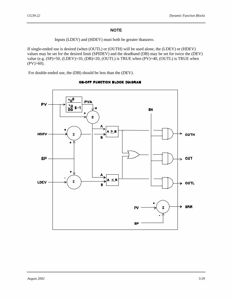
The symbol of the ON/OFF with Derivative Controller (ON_OFF) function block is shown above. This block performs the function of an on/off controller with deviation function. If there is a positive deviation between the process input and setpoint that reaches a preset limit (HDEV), a boolean output is turned on (OUTH). If there is a negative deviation between the process input and setpoint that reaches another preset limit (LDEV), a second boolean output (OUTL) is turned on. Derivative action can be added to the process variable. The boolean output (OUT) is TRUE if either (OUTL) or (OUTH) is TRUE.
CG39-22 Dynamic Function Blocks
August 2002 3-29
NOTE
Inputs (LDEV) and (HDEV) must both be greater thanzero.
If single-ended use is desired (when (OUTL) or (OUTH) will be used alone, the (LDEV) or (HDEV) values may be set for the desired limit (SPIDEV) and the deadband (DB) may be set for twice the (DEV) value (e.g. (SP)=50, (LDEV)=10, (DB)=20, (OUTL) is TRUE when (PV)=40, (OUTL) is TRUE when (PV)>60).
For double-ended use, the (DB) should be less than the (DEV).
Dynamic Function Blocks CG39-22
3-30 August 2002
The inputs and outputs of the ON_OFF Controller are defined as follows:
PV This is the current process input to the control algorithm.
SP This is the current setpoint input to the control algorithm.
LDEV This is the limit for a negative deviation from setpoint (in engineering units). Must be greater than zero.
HDEV This is the limit for a positive deviation from setpoint (in engineering units). Must be greater than zero.
EN This is the enable command input to the algorithm. When this input is FALSE, the algorithm is stopped [(OUT), (OUTH), (OUTL) = FALSE)].
OUT This is a boolean output that is TRUE whenever PVA (PV following a derivative action) exceeds either specified limit (see block diagram).
OUTL This is a Boolean output that is TRUE whenever PVA drops below the specified low limit.
OUTH This is a Boolean output that is TRUE whenever PVA exceeds the specified high limit.
ERR This is the calculated error output [(PV)-(SP)].
Softlist Parameters
The remaining ON_OFF inputs are accessed via the softlist. The value of these inputs can be changed via command from an operator interface or the Set Value (SET_VAL) function block, but they cannot be “wired” to the block. Below is a description and initial value for each softlist parameter.
The following inputs and their initial values make up the softlist for the On/Off function block:
DEADBAND This is a threshold value. An error below this value does not cause a change in output.
TD This is the integral time input.
DG This is the derivative gain input.
EINH This is the (PV) high value (in engineering units) used for scaling.
EINL This is the (PV) low value (in engineering units) used for scaling.

CG39-22 Dynamic Function Blocks
August 2002 3-31
Parameter Units Initial Value Min Value Max Value
TD Min 0.0 (OFF) 0.0 100.0
DG Dimensionless 10.0 2.0 20.0
DEADBAND Engr 0.5 0.0 NA
EINL Engr 0.0 NA NA
EINH Engr 100.0 NA NA
Where NA indicates not applicable.
3.9 Programmer Function Block (PGRMR)
REALOUT
PGRMR
BOOL
BOOL
BOOL INT
DONE
BOOL
BOOL
INT
REAL
EN
HOLD
GOTO
SEGSEGINC
SEGDEC
TRACK
TIMETIMREM
OUTSEG
BOOL
BOOL
IN
The symbol of the Programmer (PGRMR) block is shown above. This block is used to configure a "setpoint profile" or programmed sequence of ramps, steps, and/or soaks, where individual sections are called segments. The setpoint value at any time is available at the OUT output. Each segment is defined by its endpoint and either a rate (units/minute) or duration (time data type), which are specified by softlist parameters. The duration is used only if the configured rate is zero. If both rate and duration are zero, the segment defines a step change to the configured endpoint.
NOTE
The Programmer Function Block Supersedes The Program (Program) Function Block, Which Is Retained In Some Function Block Libraries For Legacy Purposes Only. The Program Block Is Not For General Use.
Once enabled, the PGRMR block moves automatically through the defined segments until it completes the last, when it stops and sets its done (DONE) output. A maximum of 20 segments may be defined in a single block, but a string of blocks may be created by connecting (DONE) of one to the enable (EN) input of the next to create a program of virtually unlimited size.
The enable (EN) input determines whether the block is active. While (EN) is FALSE, the block is reset and its track (TRACK) input determines its output value. If (TRACK) is TRUE, (OUT) = (IN). If (TRACK) is FALSE, (OUT) = DISABLED_OUT softlist value. While (EN) is FALSE, (OUTSEG) is 1,

Dynamic Function Blocks CG39-22
3-32 August 2002
(TIMREM) is 0, and (DONE) is FALSE. When (EN) makes a transition from FALSE to TRUE, the block starts at the first segment. While (EN) is TRUE, (OUTSEG) is the number of the currently executing segment, and (TIMREM) is the number of milliseconds remaining in that segment. When the block finishes its last segment, it sets (DONE) and halts until (EN) becomes FALSE.
The block can be paused and resumed by toggling its hold (HOLD) input. While (HOLD) is TRUE, the (TRACK) input determines the block’s output value. If (TRACK) is TRUE, (OUT) = (IN). If (TRACK) is FALSE, (OUT) retains the value it had when (HOLD) became TRUE.
The current segment can be altered by using the (GOTO), (SEGINC), and (SEGDEC) inputs, which are activated by positive transitions. If the block is held when the current segment is altered, the new segment will start from the current output value when the block is resumed. If the block is running when the segment is altered, (OUT) jumps immediately to the output of the segment preceding the newly-selected segment, and the new segment proceeds from there. Once the block has set (DONE), the hold and segment inputs have no effect.
When (GOTO) makes a transition from FALSE to TRUE, the current segment is set to the value of the segment number (SEG) input. When (SEGINC) makes a transition from FALSE to TRUE, the current segment increments by one unless the block is executing the last segment. When (SEGDEC) makes a transition from FALSE to TRUE, current segment decrements by one, unless the block is executing the first segment. If multiple inputs make their transitions simultaneously, the precedence is that (GOTO) supersedes (SEGINC), which in turn supersedes (SEGDEC).
If there is a need to reconfigure a segment while the block is executing, the recommended course is to first pause the block using (HOLD). While the block is executing, changes to softlist parameter values of the active segment do not affect its operation. However, a change to the endpoint of an active segment affects the starting output for the following segment, causing (OUT) to jump to that value at the beginning of that segment.
When the block is held, any softlist parameter changes made before or during the hold affect operation as soon as the block resumes. If either the rate or the duration is changed, the block uses the new value when it is restarted. Otherwise, the block resumes at the original rate for as long as it takes the output to reach the endpoint. Either way, operation resumes from the current (held) output value.

CG39-22 Dynamic Function Blocks
August 2002 3-33
The inputs and outputs of the PGRMR block are defined as follows:
EN This is the Boolean input that enables the block.
HOLD This is a Boolean input that, when TRUE, pauses the execution of the current segment.
GOTO This is a Boolean input that, upon a transition from FALSE to TRUE, causes the block to jump to the segment indicated by the value of the (SEG) input.
SEG This is the integer input that indicates which segment the block jumps to if (GOTO) transitions to TRUE. If this value is not a defined segment, the (GOTO) input has no effect.
SEGINC This is a Boolean input that, upon a transition from FALSE to TRUE, increments the current segment by one, unless it is the last.
SEGDEC This is a Boolean input that, upon a transition from FALSE to TRUE, decrements the current segment by one, unless it is the first.
IN This is the real input that determines the output value when the block is in tracking mode.
TRACK This is the Boolean input that indicates tracking mode. When TRUE (and a segment is not currently executing), (OUT) = (IN).
OUT This is the calculated output of the block.
TIMREM This is the time remaining in the current segment.
OUTSEG This is the integer output indicating the current segment number.
DONE This is a Boolean output which is TRUE when the block has completed the execution of all configured segments.

Dynamic Function Blocks CG39-22
3-34 August 2002
Softlist Parameters
The remaining PGRMR inputs are accessed via the softlist. The value of these inputs can be changed via an operator interface or the Set Value (SET_VAL) function block, but they cannot be "wired" to the block.
NUM_OF_SEGS This is the number of segments to be programmed. Valid values are from 1 to 20. Numbers entered beyond this range are clipped to these limits.
DISABLED_OUT This value becomes the block output when both (EN) and (TRACK) are FALSE.
ENDPNT_SEG_n This is the endpoint value of the nth segment.
RATE_SEG_n This is the rate value (in engineering units per minute) for the nth segment.
TIME_SEG_n This is the duration value (in milliseconds) for the nth segment. It is only used when RATE_SEG_n is zero.
Initial values of the softlist parameters are listed as follows:
Parameter Initial Value
NUM_OF_SEGS 1 DISABLED_OUT 0.0 ENDPNT_SEG_n 0.0 RATE_SEG_n 0.0 TIME_SEG_n 0
3.10 Lead/Lag Function Block (LEADLAG)
REAL REAL
BOOL
LEADLAG
REAL
IN
EN
TRKVOUT
The symbol of the Lead/Lag (LEADLAG) function block is shown above. This block is used to provide dynamic compensation to a user-specified input. It can be configured as a gain-only, lag-only, or lead/lag function. The block's algorithm has an adjustable gain coefficient, lag coefficient, and lead coefficient. The algorithm is normally used to implement feed-forward control schemes. It can be configured to stand alone or to operate within a feedback controller.
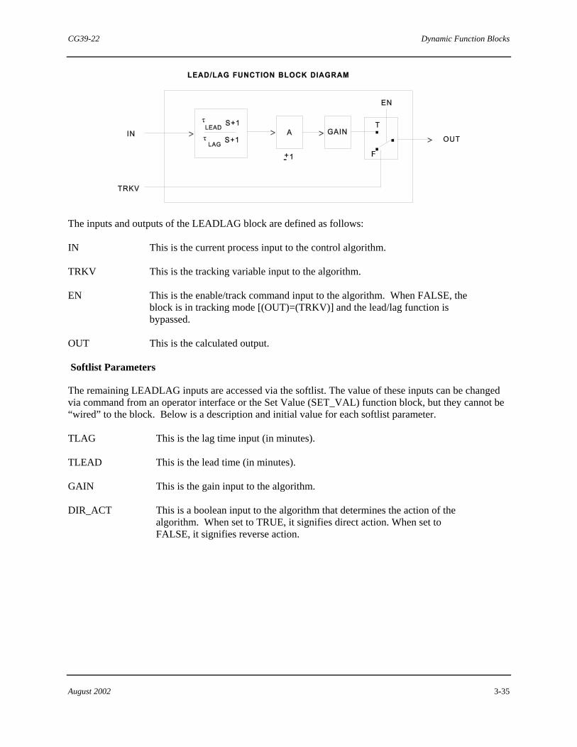
CG39-22 Dynamic Function Blocks
August 2002 3-35
The inputs and outputs of the LEADLAG block are defined as follows:
IN This is the current process input to the control algorithm.
TRKV This is the tracking variable input to the algorithm.
EN This is the enable/track command input to the algorithm. When FALSE, the block is in tracking mode [(OUT)=(TRKV)] and the lead/lag function is bypassed.
OUT This is the calculated output.
Softlist Parameters
The remaining LEADLAG inputs are accessed via the softlist. The value of these inputs can be changed via command from an operator interface or the Set Value (SET_VAL) function block, but they cannot be “wired” to the block. Below is a description and initial value for each softlist parameter.
TLAG This is the lag time input (in minutes).
TLEAD This is the lead time (in minutes).
GAIN This is the gain input to the algorithm.
DIR_ACT This is a boolean input to the algorithm that determines the action of the algorithm. When set to TRUE, it signifies direct action. When set to FALSE, it signifies reverse action.

Dynamic Function Blocks CG39-22
3-36 August 2002
Parameter Units Initial Value Min Value Max Value
TLAG Min 0.01 0.01 NA
TLEAD Min 0.0 0.0 NA
GAIN dimensionless 1.0 NA NA
DIR_ACT BOOL TRUE (Direct Action)
FALSE TRUE
Where NA indicates not applicable.
3.11 Rate Limiter Function Block (RATELIM)
REAL REALBOOL BOOL
RATELIM
BOOL
INEN UP
OUT
DOWN
The symbol of the Rate Limiter (RATELIM) function block is shown above. This block is used to limit the rate of change of its input signal. Separate up and down rates can be specified. These must be REAL numbers specifying the rates (in engineering units per minute). Values for (IN) and (OUT) are expressed in engineering units.
RATE LIMITER FUNCTION BLOCK DIAGRAM
IN
EN
OUT> >T
F
...

CG39-22 Dynamic Function Blocks
August 2002 3-37
The inputs and outputs of the RATELIM block are defined as follows:
IN This is the input variable to be limited by the rate limiter function block.
EN This is the enable command input to the algorithm. When the input is FALSE, the algorithm is in a bypass mode (OUT=IN).
OUT This is the calculated output variable that has been rate-limited.
UP This is a Boolean output which is TRUE when the algorithm is limiting a rising input.
DOWN This is a Boolean output which is TRUE when the algorithm is limiting a falling input.
Softlist Parameters
The remaining RATELIM inputs are accessed via the softlist. The value of these inputs can be changed via command from an operator interface or the Set Value (SET_VAL) function block, but they cannot be “wired” to the block. Below is a description and initial value for each softlist parameter.
UPRATE and DOWNRATE are the rising and falling rate inputs, respectively. They are entered in engineering units per minute.
Parameter Units Initial Value Min Value Max Value
UPRATE Engr/Min 0.0 0.0 NA
DOWNRATE Engr/Min 0.0 0.0 NA
Where NA indicates not applicable.
3.12 Ramp Generator Function Block (RAMPGEN)
REAL
REAL
BOOL BOOL
OUT
RAMPGEN
REAL
REAL
BOOL
TIMETIME
ENHOLD
IN
TARGETRTIMERRATE
DONE
TIMREM
BOOL TRACK
The symbol of the Ramp Generator (RAMPGEN) function block is shown above. This block is used to create a ramp signal using the starting value (IN), a target endpoint value (TARGET), and either a ramp
Dynamic Function Blocks CG39-22
3-38 August 2002
time (RTIME) or a ramp rate (RRATE). The starting value depends on the status of the (TRACK) input. If (TRACK) is TRUE, the starting point is (IN). If (TRACK) is FALSE, the starting point is the last output value. If the (RTIME) input is configured, the block uses the (RTIME) duration input as the length of the ramp time and calculates the ramp rate to use. If the (RRATE) is configured, the block uses the (RRATE) input as the rate of the ramp (engineering units per minute) and calculates the time remaining. If both are configured, the (RTIME) takes priority.
When (EN) makes a transition from FALSE to TRUE, the block initializes the ramp mode. Ramping does not take place if any ramp parameters are invalid. As long as (EN) is TRUE, ramping is in effect. The (OUT) output reflects the ramping of the block. When the ramp is complete, the (OUT) =(TARGET), (DONE) is TRUE, and (TIMREM) is zero.
The (HOLD) input is used to pause the ramp and hold the last (TIMREM) value whenever the ramp is active. In the hold mode or when (EN) is FALSE, (OUT) is either held at its last value or, when (TRACK) is TRUE, it tracks the (IN). After a TRUE to FALSE transition of the (HOLD) input, the ramp mode is continued in one of two ways: if none of the ramping parameters ((TARGET), (RTIME), (RRATE)) have changed, the same ramp rate as previous to the hold mode are used, the current (IN) value is used as the new starting setpoint, and the (TIMREM) is recalculated. If the ramping parameters are altered, the block reinitializes using the new inputs.
When (EN) is FALSE, the block is inactive, (DONE) is set to FALSE, (TIMREM) is set to T#000ms, and (OUT) depends on the value of (TRACK).

CG39-22 Dynamic Function Blocks
August 2002 3-39
The inputs and outputs of the RAMPGEN block are defined as follows:
EN The Boolean input which enables the block.
HOLD The Boolean input that pauses the calculations and holds the outputs in the block.
TARGET The endpoint to which the block is ramping.
RTIME The ramp time input. It is a TIME data type. It is entered as a duration variable in the following format: T#VdWhXmYsZms.
RRATE The ramp rate input. It is a positive REAL value entered in engineering units per minute.
IN The tracking input that can be used as the starting point.
TRACK The track switch input. If TRUE, (OUT) tracks (IN) when in (HOLD) or when (EN) is FALSE. If FALSE, (OUT) = the last output.

Dynamic Function Blocks CG39-22
3-40 August 2002
OUT The calculated output of the block.
DONE This output is TRUE when the target has been reached.
TIMREM The amount of time remaining until the target is reached.
Softlist Parameters
There are no softlist parameters for the RAMPGEN function block.
3.13 Scaler Function Block (SCALER)
REAL REAL
SCALER
EIN EOUT
The symbol of the Scaler (SCALER) function block is shown above. This block provides the scaling and dimensional consistency required in applications such as feed forward control where the output of an Impulse (IMPULSE) function block or a Lead Lag (LEADLAG) function block must be converted from process variable units to valve output units.
The block's input (EIN) and output (EOUT) are in engineering values. Engineering values are converted using the input and output operating limits found on the process flowsheets or sensor/actuator ranges.
The input and output of the SCALER block are defined as follows:
EIN This is the input (in engineering units).
EOUT This is the calculated output (in engineering units).
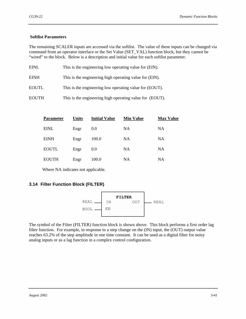
CG39-22 Dynamic Function Blocks
August 2002 3-41
Softlist Parameters
The remaining SCALER inputs are accessed via the softlist. The value of these inputs can be changed via command from an operator interface or the Set Value (SET_VAL) function block, but they cannot be “wired” to the block. Below is a description and initial value for each softlist parameter.
EINL This is the engineering low operating value for (EIN).
EINH This is the engineering high operating value for (EIN).
EOUTL This is the engineering low operating value for (EOUT).
EOUTH This is the engineering high operating value for (EOUT).
Parameter Units Initial Value Min Value Max Value
EINL Engr 0.0 NA NA
EINH Engr 100.0 NA NA
EOUTL Engr 0.0 NA NA
EOUTH Engr 100.0 NA NA
Where NA indicates not applicable.
3.14 Filter Function Block (FILTER)
REALREAL OUTFILTER
BOOL
IN
EN
The symbol of the Filter (FILTER) function block is shown above. This block performs a first order lag filter function. For example, in response to a step change on the (IN) input, the (OUT) output value reaches 63.2% of the step amplitude in one time constant. It can be used as a digital filter for noisy analog inputs or as a lag function in a complex control configuration.

Dynamic Function Blocks CG39-22
3-42 August 2002
This block also includes logic to allow the filter function to be bypassed: (EN) = FALSE.
S+1τLAG
OUT> >
FILTER FUNCTION BLOCK DIAGRAM
1
EN
. .
.T
F
IN
FILTER FUNCTION BLOCK RESPONSE
IN
OUT
63.2%
t
t = the time equal to onetime constant

CG39-22 Dynamic Function Blocks
August 2002 3-43
The inputs and output of the FILTER block are defined as follows:
IN This is the process input to the algorithm.
EN This is the track command input to the algorithm. When this input is FALSE, the algorithm is in tracking mode (OUT=PV) and the filter function is bypassed.
OUT This is the calculated output.
Softlist Parameters
The remaining input ise accessed via the softlist. The value of this input can be changed via command from an operator interface or the Set Value (SET_VAL) function block, but it cannot be “wired” to the block. Below is a description and initial value for this softlist parameter.
TLAG This is the lag time in minutes.
Parameter Units Initial Value Min Value Max Value
TLAG Min 0.001 0.0 NA
Where NA indicates not applicable.
3.15 Track and Hold Function Block (TRK_HLD)
REALBOOLREAL
TRK_HLD
BOOL EN
IN01TRACK
OUT01
REAL IN15 REALOUT15: :: :
The symbol of the Track and Hold (TRK_HLD) function block is shown above. This block is a general purpose track and hold signal processor. It is extensible to handle up to 15 inputs. During each scan, the softlist values for S1 through S15 are loaded into the outputs (OUT01) to (OUT15). For example, the softlist value entered for S3 is used as output (OUT03).
When the (EN) input is TRUE, inputs (IN01) through (IN15) are loaded into softlist parameters S1 through S15, and the (TRACK) output will be TRUE (indicating that the outputs are tracking the inputs). If (EN) is FALSE, the previous values are held in the softlist parameters, and the (TRACK) output is FALSE. Also, an operator interface can write to the softlist parameters and, as a result, change the outputs.
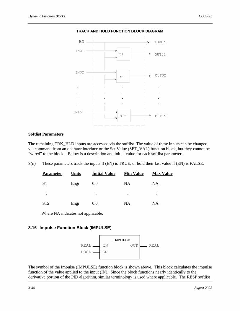
Dynamic Function Blocks CG39-22
3-44 August 2002
S1
S2
S15
IN01
IN02
IN15
OUT01
OUT15
OUT02
.
.
.
.
.
.
.
.
.
.
.
.
.
.
.
.
>
>
>
>
>
>
>
>
>
TRACK AND HOLD FUNCTION BLOCK DIAGRAM
EN TRACK>
Softlist Parameters
The remaining TRK_HLD inputs are accessed via the softlist. The value of these inputs can be changed via command from an operator interface or the Set Value (SET_VAL) function block, but they cannot be “wired” to the block. Below is a description and initial value for each softlist parameter.
S(n) These parameters track the inputs if (EN) is TRUE, or hold their last value if (EN) is FALSE.
Parameter Units Initial Value Min Value Max Value
S1 Engr 0.0 NA NA
: : : :
S15 Engr 0.0 NA NA
Where NA indicates not applicable.
3.16 Impulse Function Block (IMPULSE)
REAL REAL
BOOL
IMPULSEIN
EN
OUT
The symbol of the Impulse (IMPULSE) function block is shown above. This block calculates the impulse function of the value applied to the input (IN). Since the block functions nearly identically to the derivative portion of the PID algorithm, similar terminology is used where applicable. The RESP softlist

CG39-22 Dynamic Function Blocks
August 2002 3-45
value sets the block to respond only to input values that increase (RESP=1), decrease (RESP=-1), or are bi-directional (RESP=0). There are also configuration options for reverse action via the DIR_ACT softlist parameter and absolute value output.
The inputs and output of the IMPULSE block are defined as follows:
IN This is the process input to the algorithm.
EN This is the enable track command input to the algorithm. When this input is FALSE, the algorithm is in a tracking mode [(OUT)=0] and the impulse function is inactive.
OUT This is the calculated output.
Softlist Parameters
The remaining IMPULSE inputs are accessed via the softlist. The value of these inputs can be changed via command from an operator interface or the Set Value (SET_VAL) function block, but they cannot be “wired” to the block. Below is a description and initial value for each softlist parameter.
GAIN This is the gain input to the algorithm.
TD This is the derivative time input (in minutes) to the algorithm.
DG This is the derivative time gain input to the algorithm.
DIR_ACT This is a boolean input to the algorithm which determines the action of the controller. TRUE signifies direct action (A=1) and FALSE signifies reverse action (A=-1).
RESP This is an enumerated input that specifies the responses of the algorithm. The available selections are:
Enumerated Value Selection Description 0 DECREASING Responds only to decreasing input values. 1 BI-DIRECTIONAL Responds to any input change. 2 INCREASING Responds only to increasing input values.
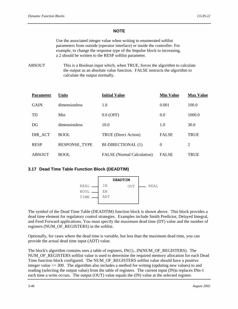
Dynamic Function Blocks CG39-22
3-46 August 2002
NOTE
Use the associated integer value when writing to enumerated softlist parameters from outside (operator interface) or inside the controller. For example, to change the response type of the Impulse block to increasing, a 2 should be written to the RESP softlist parameter.
ABSOUT This is a Boolean input which, when TRUE, forces the algorithm to calculate the output as an absolute value function. FALSE instructs the algorithm to calculate the output normally.
Parameter Units Initial Value Min Value Max Value
GAIN dimensionless 1.0 0.001 100.0
TD Min 0.0 (OFF) 0.0 1000.0
DG dimensionless 10.0 1.0 30.0
DIR_ACT BOOL TRUE (Direct Action) FALSE TRUE
RESP RESPONSE_TYPE BI-DIRECTIONAL (1) 0 2
ABSOUT BOOL FALSE (Normal Calculation) FALSE TRUE
3.17 Dead Time Table Function Block (DEADTIM)
REAL
TIME
BOOL
REAL
DEADTIM
OUTIN
ENADT
The symbol of the Dead Time Table (DEADTIM) function block is shown above. This block provides a dead time element for regulatory control strategies. Examples include Smith Predictor, Delayed Integral, and Feed Forward applications. You must specify the maximum dead time (DT) value and the number of registers (NUM_OF_REGISTERS) in the softlist.
Optionally, for cases where the dead time is variable, but less than the maximum dead time, you can provide the actual dead time input (ADT) value.
The block's algorithm contains uses a table of registers, IN(1)...IN(NUM_OF_REGISTERS). The NUM_OF_REGISTERS softlist value is used to determine the required memory allocation for each Dead Time function block configured. The NUM_OF_REGISTERS softlist value should have a positive integer value <= 300. The algorithm also includes a method for writing (updating new values) to and reading (selecting the output value) from the table of registers. The current input (IN)n replaces INn-1 each time a write occurs. The output (OUT) value equals the (IN) value at the selected register.

CG39-22 Dynamic Function Blocks
August 2002 3-47
The total dead time (DT) is set via a softlist parameter. Data is written to the table at a time interval determined by the ratio DT/NUM_OF_REGISTERS (the sampling time). DT determines how fast the data travels through the table. Normally, the output is the oldest data in the table. If the ADT input value is used, that value determines which table entry to use as the output. The fastest sample time cannot exceed the control module scan time.
Use care in the selection of the DT and NUM_OF_REGISTERS values so that the number of samples (DT/NUM_OF_REGISTERS) are an integer multiple of the execution period. Scan cycles are not interruptable and cannot be split.
The inputs and output are defined as follows:
IN This is the process input to the selected shift register.
EN This is the block's enable input. When FALSE, the dead time function is bypassed [(OUT)=(IN)].
ADT This is the actual dead time input.
OUT This is the blocks’s output. It is equal to the selected shift register.
Softlist Parameters
The remaining DEADTM inputs are accessed via the softlist. The value of these inputs can be changed via command from an operator interface or the Set Value (SET_VAL) function block, but they cannot be “wired” to the block. Below is a description and initial value for each softlist parameter.
DT This is the maximum dead time (in minutes). DT is specified during configuration.
NUM_OF_REGISTERS This is the number of shift registers. It determines the memory allocation for the block.
Parameter Data Type Initial Value Min Value Max Value
DT TIME T#0d0h0m0s0ms T#0d0h0m0s0ms NA
NUM_OF_REGISTERS INT 20 1 300

Dynamic Function Blocks CG39-22
3-48 August 2002
3.18 Delayed Error Function Block (DEL_ERR)
REAL
REAL
REAL
REAL
REAL
REAL
PV
SPPVA
ERREI
D_ERR
DEL_ERR
The symbol of the Delayed Error (DEL_ERR) function block is shown above. This block is typically used with a PID Error Input block and a Dead Time Table block to provide a control strategy implementing delayed integral action.
The second process input to this block (PVA) is often configured as a delayed version of the primary process (PV) via the output of a dead time algorithm.
The Delayed Error algorithm performs a standard error calculation (PV-SP) and a delayed error calculation (PVA-SP). The actual �error to integrate� (EI) is selected by the block based upon the value of the standard and delayed error components; if both errors have the same sign, the smaller absolute error is selected otherwise (EI)=0.0.
This block’s selected error can be very useful in processes dominated by dead time.
DELAYED ERROR FUNCTION BLOCK DIAGRAM
IF,THEN
Σ+>
-
Σ+>
-
PV
SP
PVA
ERR
EI
D_ERR
>
>
>

CG39-22 Dynamic Function Blocks
August 2002 3-49
The inputs and outputs of the DEL_ERR block are defined as follows:
PV This is the current process input to the control algorithm.
P This is the current setpoint input to the control algorithm.
PVA This is the delayed process input (normally from a dead time table).
ERR This is the current error [(PV)-(SP)]output.
EI This is the selected error (normally used as the (IERR) input to the PID Error Input function block).
D_ERR This is the delayed error [(PVA)-(SP)].
Softlist Parameters
There are no softlist parameters for this block.
3.19 Batch Switch Function Block (BAT_SW)
REALREAL IN OUT
BAT_SW
The symbol of the Batch Switch (BAT_SW) function block is shown above. In control loops where a process value takes an extended period of time to reach setpoint, reset windup may cause unacceptable results. This happens most commonly in batch processes, where the process value takes a long time to reach the setpoint value during startup. In a process where overshoot is not tolerable, reset windup can be eliminated with the Batch Switch bloack.
This block is normally used in the feedback path of a controller. When the input (IN) is within the engineering unit range (EINL to EINH), the input value is passed normally to the controller feedback and cause normal reset action.
If (IN), which is normally the controller output, goes beyond the engineering signal range ( < EINL or >EINH), the feedback is modified to keep the controller output within range.
In some cases, as with a large gain error, the feedback can be reduced to zero. While this should eliminate overshoot problems on startup, it could cause the opposite effect of a sluggish startup. To overcome this, the BAT_SW block has a pre-load value (BPL) that limits the amount of change in the feedback signal.

Dynamic Function Blocks CG39-22
3-50 August 2002
Σ
Σ Σ
+
+
+
> > >
> OUT>
BATCH SWITCH FUNCTION BLOCK DIAGRAM
IN
Σ+
+
>
+
-
-G
G
> >>
> >
EINHBPL
EINL
HISEL
LOSEL
LOSEL
HISEL
The input and output of the BAT_SW are defined as follows:
IN This is the input to the block. It is ususally fed from the output from a controller or Auto/Manual block.
OUT This is the calculated output used as the feedback signal to a controller block.

CG39-22 Dynamic Function Blocks
August 2002 3-51
Softlist Parameters
The remaining BAT_SW inputs are accessed via the softlist. The value of these inputs can be changed via command from an operator interface or the Set Value (SET_VAL) function block, but they cannot be “wired” to the block. Below is a description and initial value for each softlist parameter.
EINL This is the engineering low limit for the input.
EINH This is the engineering high limit for the input.
BPL This is the batch pre-load value (in engineering units).
GAIN This is the gain used for the high/low limit controllers (must be greater than zero).
Parameter Units Initial Value Min Value Max Value
EINL Engr 0.0 NA NA
EINH Engr 100.0 NA NA
BPL Engr 50.0 NA NA
GAIN dimensionless 32.0 0.0 NA
Where NA indicates not applicable.
3.20 EAM Totalizer Function Block (EAM_TOT)
UDINT
REAL
BOOL
UDINTREALR
EAM_TOT
TOTALETOT
CYCLES
ALARM1 BOOL
BOOL
HOLDTRIP1
IN
TRIP2
INT
ALARM2
BOOLREAL
The symbol of the EAM (Enhanced Analog Module) Totalizer (EAM_TOT) function block is shown above. It is designed to totalize signals generated by an Enhanced Analog Module's Voltage Pulse In-Total and Current Pulse In-Total channel types.
Totalization is partially accomplished by these channel types. but this block is used to coordinate redundant EAMs and to provide reset, hold, alarming, and scaling features. These channel types provide an integer that corresponds to the total number of pulses received since the EAM powered-up or since the last redundancy switchover.
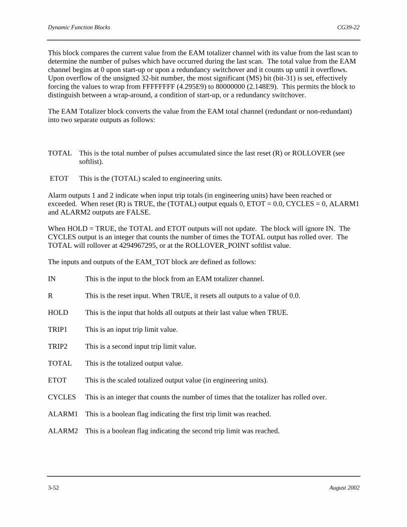
Dynamic Function Blocks CG39-22
3-52 August 2002
This block compares the current value from the EAM totalizer channel with its value from the last scan to determine the number of pulses which have occurred during the last scan. The total value from the EAM channel begins at 0 upon start-up or upon a redundancy switchover and it counts up until it overflows. Upon overflow of the unsigned 32-bit number, the most significant (MS) bit (bit-31) is set, effectively forcing the values to wrap from FFFFFFFF (4.295E9) to 80000000 (2.148E9). This permits the block to distinguish between a wrap-around, a condition of start-up, or a redundancy switchover.
The EAM Totalizer block converts the value from the EAM total channel (redundant or non-redundant) into two separate outputs as follows:
TOTAL This is the total number of pulses accumulated since the last reset (R) or ROLLOVER (see softlist).
ETOT This is the (TOTAL) scaled to engineering units.
Alarm outputs 1 and 2 indicate when input trip totals (in engineering units) have been reached or exceeded. When reset (R) is TRUE, the (TOTAL) output equals 0, ETOT = 0.0, CYCLES = 0, ALARM1 and ALARM2 outputs are FALSE.
When HOLD = TRUE, the TOTAL and ETOT outputs will not update. The block will ignore IN. The CYCLES output is an integer that counts the number of times the TOTAL output has rolled over. The TOTAL will rollover at 4294967295, or at the ROLLOVER_POINT softlist value.
The inputs and outputs of the EAM_TOT block are defined as follows:
IN This is the input to the block from an EAM totalizer channel.
R This is the reset input. When TRUE, it resets all outputs to a value of 0.0.
HOLD This is the input that holds all outputs at their last value when TRUE.
TRIP1 This is an input trip limit value.
TRIP2 This is a second input trip limit value.
TOTAL This is the totalized output value.
ETOT This is the scaled totalized output value (in engineering units).
CYCLES This is an integer that counts the number of times that the totalizer has rolled over.
ALARM1 This is a boolean flag indicating the first trip limit was reached.
ALARM2 This is a boolean flag indicating the second trip limit was reached.

CG39-22 Dynamic Function Blocks
August 2002 3-53
Softlist Parameters
The remaining EAM_TOT inputs are accessed via the softlist. The value of these inputs can be changed via command from an operator interface or the Set Value (SET_VAL) function block, but they cannot be “wired” to the block. Below is a description and initial value for each softlist parameter.
SCALE Value (in pulses per engineering unit) that the TOTAL value is divided by to calculate the ETOT value.
ROLLOVER_POINT When TOTAL equals this UDINT value, TOTAL is set to 0 and CYCLES increments by 1.
Parameter Data Type Initial Value Min Value Max Value
SCALE REAL 1.0 NA NA
ROLLOVER_POINT UDINT 4294967295ud 0ud 4294967295ud
Where NA is not applicable.
3.21 Totalizer Function Block (TOTAL)
REAL
REAL
REAL
BOOL
REAL
BOOL
BOOL
IN
TOTAL
TRIP1
TRIP2
R PULSE
TOTAL
ALARM1
ALARM2
BOOL
The symbol of the Totalizer (TOTAL) function block is shown above. This block is usually used for flow applications where it converts an analog signal into two separate outputs as follows:
TOTAL This is a totaled value (real number) of the number of input units accumulated over time.
PULSE This is a 50% duty cycle pulse whose frequency is proportional to the magnitude of the input. It can be used to drive a counter or accumulator.
A DROPOUT feature causes the block to stop totaling and pulsing if the input falls below the DROPOUT softlist value.
The full scale pulses (per time) is user-selectable. The output is selectable for hours, minutes, or seconds.
The output rate values are dependent on the block's scan rate. Therefore, the PULSE output rate cannot be faster than twice the scan rate.
Alarm outputs 1 and 2 indicate when the input trip totals have been reached (or exceeded).

Dynamic Function Blocks CG39-22
3-54 August 2002
When reset (R) is TRUE, the TOTAL output value equals 0.0 and the PULSE, ALARM1, and ALARM2 outputs are set to FALSE.
NOTE
If the (PULSE) output is not being used, only the OUTPUT_RATE softlist value must be set.
PULSE
IN
TRIP1
TRIP2
PULSEGEN.
COUNTERTOTAL
ALARM1
ALARM2
TOTALIZER FUNCTION BLOCK DIAGRAM
>
>
>>
>
>
>
>
.
..
0.0
>
DROP OUT
R
B
.
.F
T.
A BA
AA
AA
B
B
BB
F
T
>
R
R
R

CG39-22 Dynamic Function Blocks
August 2002 3-55
The inputs and outputs of this block are defined as follows:
IN This is the input to the block.
R This is the reset input. When TRUE, it resets all outputs to 0.0, or FALSE.
TRIP1 This is the first trip limit value.
TRIP2 This is the second trip limit value.
TOTAL This is the totaled output value.
PULSE This is the pulse output.
ALARM1 This is a boolean flag indicating when the first trip limit is reached.
ALARM2 This is a boolean flag indicating when the second trip limit is reached.
Softlist Parameters
The remaining TOTAL inputs are accessed via the softlist. The value of these inputs can be changed via command from an operator interface or the Set Value (SET_VAL) function block, but they cannot be “wired” to the block. Below is a description and initial value for each softlist parameter.
FSCALE This is the full scale number of pulses.
OUTPUT_RATE This is an enumerated value which selects the time base for the TOTAL and PULSE output. The selections are:
Enumerated Value Selection Description
1 PULSES-PER-HOUR The output rate is in pulses per hour.
2 PULSES-PER-MINUTE The output rate is in pulses per min.
3 PULSES-PER-SECOND The output rate is in pulses per sec. NOTE
Use the associated integer value when writing to enumerated softlist parameters from an operator interface or inside the controller. For example, to change the output time base of the TOTAL block to pulses per second, a 3 should be written to the OUTPUT_RATE softlist parameter.
EINL This is the 0% of scale input, used to determine the percent of scale of the input for proper pulse creation.
EINH This is the full-scale (100%) input, used to determine the percent of scale of the input for proper pulse creation.
DROPOUT This is the limit on (IN) below which the block stops pulsing and totalizing.

Dynamic Function Blocks CG39-22
3-56 August 2002
Parameter Units Initial Value Min Value Max Value
FSCALE Pulses 100.0 0.0 NA
OUTPUT_RATE RATE_TYPE PULSES/MIN(2) 1 3
EINL Engr 0.0 NA NA
EINH Engr 100.0 NA NA
DROPOUT Engr 0.0 NA NA
Where NA indicates not applicable.
3.22 Accumulator Function Block (ACCUM)
BOOL
REALBOOL
BOOLR
ACCUM
PLSIN ETOT
PULSE
The symbol of the Accumulator (ACCUM) function block is shown above. This block is used to convert a pulse input (e.g. from a contact on a roller) into engineering units. Upon receiving a pulse, this block increments the Engineering Total (ETOT) value and converts the internal counter to a REAL number that is scaled by the SCALE_FACTOR softlist value.
The PULSE output value is TRUE for one scan when ETOT advances past the next whole integer value. The SCALE_FACTOR softlist value must be 1.0 or less (otherwise, the PULSE output is meaningless).
PULSEGEN. PULSE
>
>
>
ACCUMULATOR FUNCTION BLOCK DIAGRAM
SCALERPLSIN
ETOTCOUNTER>
0.0
F
T
...
R

CG39-22 Dynamic Function Blocks
August 2002 3-57
The inputs and outputs of the ACCUM block are defined as follows:
PLSIN This is the input pulse train.
R This is the reset input. It accepts A BOOL value. When TRUE, all outputs are reset to zero.
ETOT This output provides a REAL value representing total pulses converted to engineering units.
PULSE This is the calculated pulse output. It provides a BOOL value. It is set to TRUE for one scan when the ETOT value advances past the next whole integer value.
NOTE
The fastest output pulse cycle time is twice the scan time.
Softlist Parameters
The remaining ACCUM input is accessed via the softlist. The value of this input can be changed via a command from an operator interface or by the Set Value (SET_VAL) function block, but it cannot be “wired” to the block. Below is a description and initial value for this softlist parameter.
SCALE_FACTOR This is the conversion factor (in engineering units) per pulse.
Parameter Units Initial Value Min Value Max Value
SCALE_FACTOR Engr Unit/Pulse 1.0 0.0 NA
Where NA indicates not applicable.
3.23 Loop Status Function Block (LP_STAT)
BOOLBOOL
AUTO
LP_STAT
BOOLBOOLBOOLBOOLBOOLBOOL
BOOLBOOL
INTINTLOCAL
SSEXTRNLCONSCOMPRAMPOVERRDEMRHOLD
STATUSCMD
The symbol of the Loop Status (LP_STAT) function block is shown above. This block is to be placed on the same sheet as the control loop blocks when communications with the Hi-Level Link (HLL) is desired. When implemented in this manner, it serves three purposes:

Dynamic Function Blocks CG39-22
3-58 August 2002
1. It acts as a grouping mechanism for the loop status parameters. All the status parameters are conveniently located in one block.
2. It is a documentation device. It it used to locate the control source for the loop status parameters on the same sheet as the loop.
3. It aids in the communication between a Link Interface Module (LIM) and a control module.
The loop status (STATUS) output provides an integer value that represents the current state of the inputs when converted to binary form.
The command (CMD) output provides a way for the loop status to be modified from an operator console. The block analyses incoming commands (e.g. AUTO, LOCAL) and attempts to set the input values.
For example, if a command came through to change the auto status from TRUE to FALSE, the block writes to the local variable connected to the AUTO input. If no local variable is wired (no storage is allocated) to a particular input, that command is effectively locked-out.
The STATUS output always reflects the inputs. All unconnected input values default to FALSE, except the console (CONS) input, which defaults to TRUE. The Console and Computer bits in the status word are normally mutually exclusive. In any non-local mode, either the Console or Computer bits should be set in (STATUS), so when one is toggled ON, the other is toggled OFF. In Local mode, the Console and Computer bits may both be set. If the Console and Computer bits are both set when returning to a non-local mode, the mode will default to Console.
The STATUS output provides an INT value and follows the layout below:
Bit Number 1 Automatic Mode (AM) Bit Number 2 Local Mode (Local) Bit Number 3 Standby Sync Mode (S) Bit Number 4 External Setpoint (E) Bit Number 5 Console Mode (CONS) Bit Number 6 Computer Mode (CE) Bit Number 7 Ramping Setpoint Mode (R) Bit Number 8 Override (O) Bit Number 9 Emergency Manual Mode (EM) Bit Number 10 Ramp Hold (H) status is interpreted by MYCRO or other operator consoles.
Table 3–1shows the logic states of status bits. The top row indicates the bit number that represents each item in the status word. The last column indicates the mode the Siemens operator console displays upon receiving the status word.

CG39-22 Dynamic Function Blocks
August 2002 3-59
Table 3–1 Loop Status Word Logic States
10 9 8 7 6 5 4 3 2 1
ConsoleModeH EM O R CE CONS E S Local AM
0 0 0 0 0 0 1 AUTO
X ** 1 0X X X
X X
X *
X X X 1 1
1
1X X X X 0 0 MAN (EM)
1X X X X 0 1 AUTO (EM)
X XX0 0 01 MAN (O)
AUTO (S)
MAN (S)
X X0 01 X AUTO (O)
X X0 0 0 MAN (E)
X X0 0 0 00 MAN
1 0 0 X X 0 1 AUTO (H)
0 0 0 X
01
01 1 AUTO (E)
0 0 0 1 0 0 1 AUTO (R)
Bit Location
Key:
1 = TRUE, 0 = FALSE, X = do not care
* = These bits change the source of control loop commands, but do not affect control loop calculations.
"

Dynamic Function Blocks CG39-22
3-60 August 2002
!Notes

CG39-22 Compare and Select Function Blocks
August 2002 4-1
4.0 Compare and Select Function Blocks
The Compare and Select function blocks are a subset of the standard function blocks. The Compare blocks accept all data types as inputs, compares them, and generate a boolean output. The Select blocks select one of the inputs as the output.
Refer to sections 11 and 12 in Using the ProcessSuite 4-mation Configuration Software (document number CG39-20) for data type descriptions. For memory usage and ACM execution time information on all standard configuration elements, see Appendix C in the same document.
A listing of Compare and Select function blocks is presented here. Individual blocks are detailed in the subsections that follow.
• Equal • Inequality • Greater Than • Greater or Equal • Less Than • Less or Equal • Binary Selector Switch • Low Selector • High Selector • Middle of Three Selector • Limiter • Multiplexer Switch • State
4.1 Equal Function Block (EQ)
OUT
:
IN16
:
BOOLEQ
IN01IN02ANY
ANY
ANY
The symbol of the Equal function block is shown above. This block tests that the configured input values are all equal from (IN01) to (INn).
The Boolean output (OUT) will be TRUE when all configured inputs are equal in value, and the output will be FALSE at all other times.
This block is extensible to a maximum of 16 inputs.
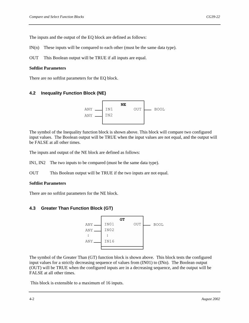
Compare and Select Function Blocks CG39-22
4-2 August 2002
The inputs and the output of the EQ block are defined as follows:
IN(n) These inputs will be compared to each other (must be the same data type).
OUT This Boolean output will be TRUE if all inputs are equal.
Softlist Parameters
There are no softlist parameters for the EQ block.
4.2 Inequality Function Block (NE)
OUTIN1
IN2ANY
ANY BOOLNE
The symbol of the Inequality function block is shown above. This block will compare two configured input values. The Boolean output will be TRUE when the input values are not equal, and the output will be FALSE at all other times.
The inputs and output of the NE block are defined as follows:
IN1, IN2 The two inputs to be compared (must be the same data type).
OUT This Boolean output will be TRUE if the two inputs are not equal.
Softlist Parameters
There are no softlist parameters for the NE block.
4.3 Greater Than Function Block (GT)
OUT
:
IN16
ANY
ANY
:
ANYGT
BOOLIN01
IN02
The symbol of the Greater Than (GT) function block is shown above. This block tests the configured input values for a strictly decreasing sequence of values from (IN01) to (INn). The Boolean output (OUT) will be TRUE when the configured inputs are in a decreasing sequence, and the output will be FALSE at all other times.
This block is extensible to a maximum of 16 inputs.

CG39-22 Compare and Select Function Blocks
August 2002 4-3
The inputs and output of the GT block are defined as follows:
IN(n) The inputs that will be compared to each other (must be the same data type).
OUT This Boolean output will be TRUE if each input is less than the one it follows.
Softlist Parameters
There are no softlist parameters for the GT block.
4.4 Greater or Equal Function Block (GE)
OUT
:
IN16
ANY
ANY
:
ANYGE
BOOLIN01
IN02
The symbol of the Greater or Equal function block is shown above. This block tests the configured input values for a decreasing or equivalent sequence of values from (IN01) to (INn). This means the values can decrease or be equal from one input to the next to cause the (OUT) output to be TRUE. The output will be FALSE at all other times.
This block is extensible to a maximum of 16 inputs.
The inputs and the output of the GE block are defined as follows:
IN(n) These inputs will be compared to each other (must be the same data type).
OUT This output will be TRUE if each input value is equal to, or less than the one it follows.
Softlist Parameters
There are no softlist parameters for the GE block.
4.5 Less Than Function Block (LT)
OUT
:
IN16
ANY
ANY
:
ANY BOOLLT
IN01
IN02
The symbol of the Less Than function block is shown above. This block tests the configured input values for a strictly increasing sequence of values from (IN01) to (INn). The Boolean output (OUT) will be

Compare and Select Function Blocks CG39-22
4-4 August 2002
TRUE when the configured inputs are in an increasing sequence and the output will be FALSE at all other times.
This block is extensible to a maximum of 16 inputs.
The inputs and output of the LT block are defined as follows:
IN(n) The inputs which will be compared to each other (must be the same data type).
OUT This Boolean output will be TRUE if each input is greater than the one it follows.
Softlist Parameters
There are no softlist parameters for the LT block.
4.6 Less or Equal Function Block (LE)
OUT
:
IN16
ANY
ANY
:
ANY BOOLLE
IN01
IN02
The symbol of the Less or Equal function block is shown above. This block tests the configured input values for an increasing or equivalent sequence of values from (IN01) to (INn). This means the values can increase or be equal from one input to the next to make the (OUT) be TRUE. The output will be FALSE at all other times.
This block is extensible to a maximum of 16 inputs.
The inputs and output of the LE block are defined as follows:
IN(n) These inputs will be compared against each other (must be the same data type).
OUT This Boolean output will be TRUE if each input is equal to or greater than the one it follows.
Softlist Parameters
There are no softlist parameters for the LE function block.

CG39-22 Compare and Select Function Blocks
August 2002 4-5
4.7 Binary Selector Switch Function Block (SEL)
IN1
G
IN0
OUTSEL
BOOL
ANY
ANY
ANY
The symbol of the Binary Selector Switch block is shown above. This block acts as a single pole double throw switch.
The output will be equal to the value of (IN0) when the Boolean switch input (G) is FALSE otherwise the output will be equal to the value of (IN1) when the Boolean switch input (G) is TRUE.
Except for the Boolean switch input, this block accepts inputs of ANY data type. However, the input and output must be of the same data type.
The inputs and outputs of the SEL block are defined as follows:
G The Boolean switch input.
IN0 The input of the block which is passed to the output when (G) is FALSE.
IN1 The input to the block which is passed to the output when (G) is TRUE.
OUT The selected value output.
Softlist Parameters
There are no softlist parameters for the SEL function block.
4.8 Low Selector or Function Block (MIN)
OUT
:
IN16
:
*SEE NOTE
IN_NUM
IN1SEL
INT
BOOL
MININ01IN02 *SEE NOTE
*SEE NOTE
*SEE NOTE
The symbol of the Low Selector function block is shown above. This block compares all configured input values in one scan. The output will be equal to the input with the lowest value for that scan cycle.
An additional output (IN_NUM) will indicate which input was selected; another output (IN1SEL) will be set to TRUE when IN01 is selected and will be FALSE at all other times.
This block is extensible up to a maximum of 16 inputs.

Compare and Select Function Blocks CG39-22
4-6 August 2002
NOTE
This Input/Output will accept all data types except BOOL.
The inputs and outputs of the MIN block are defined as follows:
IN(n) The inputs which will be compared to each other (must be the same data type).
OUT The chosen input (lowest) will be passed to this output.
IN_NUM This integer output indicates which number input was chosen. It will be between 1 and 16.
IN1SEL This Boolean output will be TRUE if the first input (IN01) is chosen for the output.
Softlist Parameters
There are no softlist parameters for the MIN function block.
4.9 High Selector Function Block (MAX)
OUT
::
MAX*SEE NOTE
IN_NUM
IN1SEL
INTBOOL
IN01
IN02*SEE NOTE
*SEE NOTE
*SEE NOTE
IN16
The symbol of the High Selector function block is shown above. This block compares all configured input values in one scan. The output will equal the input with the greatest value for that scan cycle.
An additional output (IN_NUM) will indicate which input is selected; another output (IN1SEL) will be set to TRUE when (IN01) is selected and will be FALSE at all other times.
This block is extensible to a maximum of 16 inputs.
NOTE
This Input/Output will accept all data types except BOOL.
The inputs and the outputs of the MAX block are defined as follows:
IN(n) The inputs which will be compared to each other (must be the same data type).
OUT The chosen input (highest) will be passed to this output.
IN_NUM This integer output indicates which input was chosen. It will be from 1 to 16.
IN1SEL This Boolean output will be TRUE if the first input is chosen for the output.

CG39-22 Compare and Select Function Blocks
August 2002 4-7
Softlist Parameters
There are no softlist parameters for the MAX function block.
4.10 Middle of Three Selector Function Block (MID_SEL)
OUT*SEE NOTE
*SEE NOTE
*SEE NOTE*SEE NOTE
MID_SEL
IN1IN2IN3
The symbol of the High Selector function block is shown above. This block compares the three input values in one scan. The output will be the same value as the input with the middle value for that scan cycle.
NOTE
This Input/Output will accept all data types except BOOL and STRING.
The inputs and output of the MID_SEL block are defined as follows:
IN1, IN2 , IN3 The inputs to be compared to each other (must be the same data type).
OUT The chosen input (middle value) will be passed to this output.
Softlist Parameters
There are no softlist parameters for the MID_SEL block.
4.11 Limiter Function Block (LIMIT)
OUT*SEE NOTE*SEE NOTE
*SEE NOTE
LIMIT
*SEE NOTE MNIN
MXLLHL
BOOLBOOL
The symbol of the Limiter (LIMIT) function block is shown above. This block performs limiting action on an input value to maintain the output between two specified limits.
When the IN input value is less than the configured minimum (MN) input value, the OUT value is equal to the MN value and the low limit (LL) value is set to TRUE. When the IN input value is greater than the configured maximum value (MX), the OUT value is equal to the MX value and the high limit (HL) output value is set to TRUE.

Compare and Select Function Blocks CG39-22
4-8 August 2002
MN must be less than or equal to MX for the block to operate meaningfully. If MN exceeds MX, OUT will be set to MX, LL will be set FALSE, and HL will be set TRUE, regardless of the IN value.
NOTE
All data types except BOOL and STRING are supported for this block. The data types of the input, output, and limits must all be the same for the block to operate meaningfully.
The inputs and outputs of the LIMIT block are defined as follows:
MN The lower limit (minimum).
IN The input to be limited.
MX The upper limit (maximum).
OUT The calculated output of the block, which will be one of the input values.
LL This is the Low Limit output flag. It provides a BOOL value that is set to TRUE when the IN value is less than MN value (unless MN exceeds MX).
HL This is the High Limit output flag. It provides a BOOL value that is set to TRUE when the IN value exceeds the MX value (or when MN exceeds MX).
Softlist Parameters
There are no softlist parameters for this block.
4.12 Multiplexer Switch Function Block (MUX)
MUXOUT ANYK
:
IN15
ANY
ANY
ANY
:
INTIN01
IN02
The symbol of the Multiplexer Switch function block is shown above. This block acts as a multi-contact rotary switch. The output value will be determined by the value of the input switch (K).
The input which has the input number (IN01) through (IN15) that corresponds to the (K) input will be passed through as the output. If the input switch (K) is less than 1 or greater than the number of inputs configured, (OUT) will be set to zero.
This block is extensible up to a maximum of 15 inputs.
CG39-22 Compare and Select Function Blocks
August 2002 4-9
The inputs and output to the MUX block are defined as follows:
K The integer input which determines which input is used as the output.
IN(n) The inputs from which the block selects the output (must be the same data type).
OUT The input is passed to this output.
Softlist Parameters
There are no softlist parameters for the MUX block.
4.13 State Function Block (STATE)
The symbol of the State function block is shown above. This block accepts up to 16 BOOL inputs, analyzes them to determine which input or inputs are TRUE, then provides an output identifying the highest numbered TRUE input. For example, if inputs ST01, ST03, ST07, and ST11, are TRUE, the block outputs a value of 11.0.
If none of the inputs are TRUE, the block outputs the value of the STATE0 softlist parameter. Its default value is 0.0.
The block’s output is a REAL value obtained from its softlist. This means that each softlist value used as the block’s output can be edited. For example, if the STATE11 parameter is edited to have a value of 50.0, then it is used as the output whenever ST11 is the highest numbered TRUE input.
This block is extensible up to 16 inputs.
The inputs and outputs of the STATE block are defined as follows:
ST(n) These are the State inputs. Each input accepts a BOOL value. If its value is TRUE, it is analyzed along with all other State inputs that are also TRUE.
STATE This State output is the block’s main output. It provides a REAL data value representing the highest numbered ST(n) input which has a value of TRUE.
Softlist Parameters
STATE(n) These are the State parameters. Each is associated with a corresponding STATE input (except STATE0). The block analyzes all TRUE inputs, then chooses the appropriate STATE(n) softlist value to use as its output.
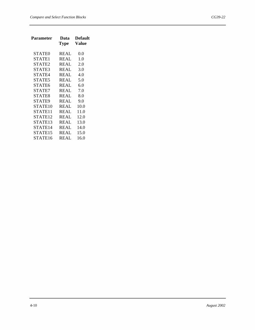
Compare and Select Function Blocks CG39-22
4-10 August 2002
Parameter Data Default Type Value
STATE0 REAL 0.0 STATE1 REAL 1.0 STATE2 REAL 2.0 STATE3 REAL 3.0 STATE4 REAL 4.0 STATE5 REAL 5.0 STATE6 REAL 6.0 STATE7 REAL 7.0 STATE8 REAL 8.0 STATE9 REAL 9.0 STATE10 REAL 10.0 STATE11 REAL 11.0 STATE12 REAL 12.0 STATE13 REAL 13.0 STATE14 REAL 14.0 STATE15 REAL 15.0 STATE16 REAL 16.0
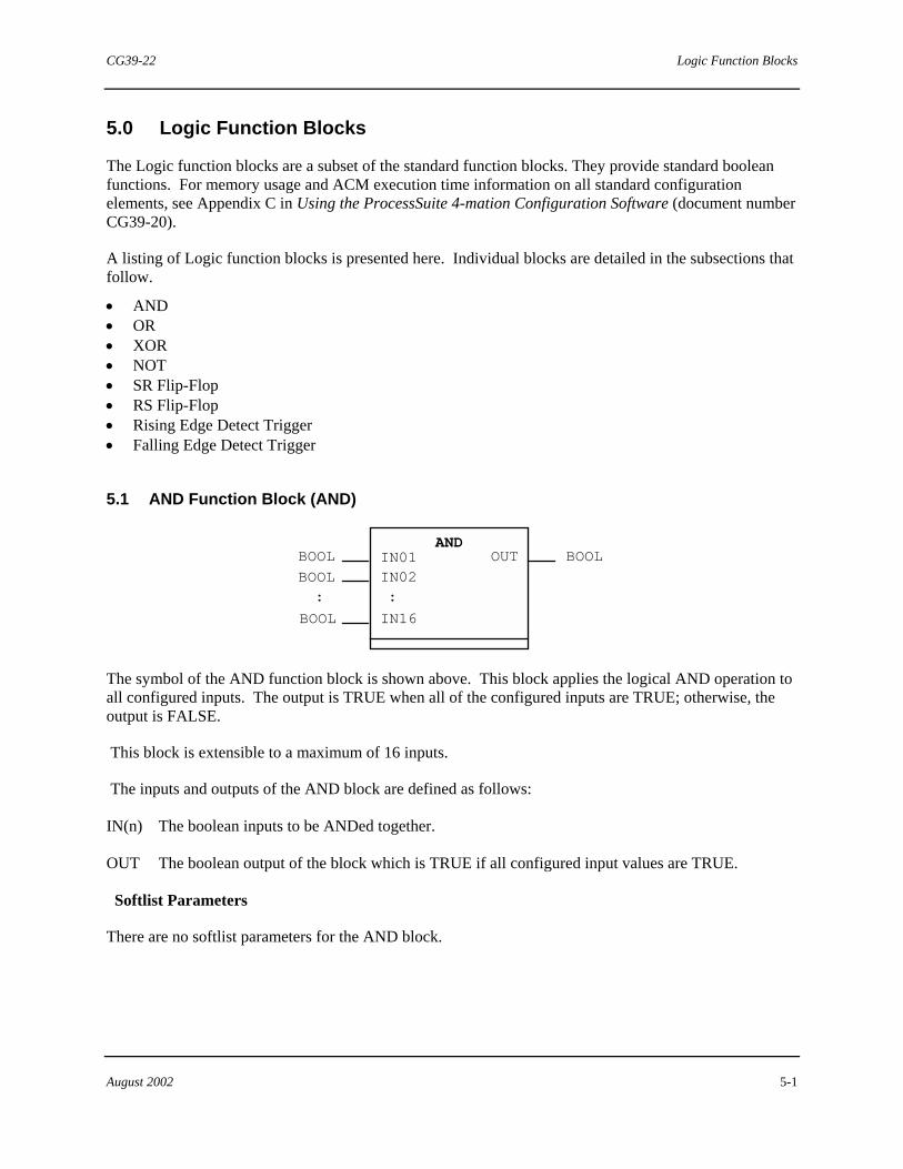
CG39-22 Logic Function Blocks
August 2002 5-1
5.0 Logic Function Blocks
The Logic function blocks are a subset of the standard function blocks. They provide standard boolean functions. For memory usage and ACM execution time information on all standard configuration elements, see Appendix C in Using the ProcessSuite 4-mation Configuration Software (document number CG39-20).
A listing of Logic function blocks is presented here. Individual blocks are detailed in the subsections that follow.
• AND • OR • XOR • NOT • SR Flip-Flop • RS Flip-Flop • Rising Edge Detect Trigger • Falling Edge Detect Trigger
5.1 AND Function Block (AND)
OUT
:
IN16
:
BOOLAND
BOOL
BOOL
BOOL
IN01IN02
The symbol of the AND function block is shown above. This block applies the logical AND operation to all configured inputs. The output is TRUE when all of the configured inputs are TRUE; otherwise, the output is FALSE.
This block is extensible to a maximum of 16 inputs.
The inputs and outputs of the AND block are defined as follows:
IN(n) The boolean inputs to be ANDed together.
OUT The boolean output of the block which is TRUE if all configured input values are TRUE.
Softlist Parameters
There are no softlist parameters for the AND block.

Logic Function Blocks CG39-22
5-2 August 2002
5.2 OR Function Block (OR)
OUT
:
IN16
:
BOOLBOOL
BOOL
BOOL
ORIN01
IN02
The symbol of the OR function block is shown above. This block applies the logical OR operation to all configured inputs. The output is TRUE whenever any of the configured input values are TRUE; otherwise, the output is FALSE when all input values are FALSE.
This block is extensible to a maximum of 16 inputs.
The inputs and output of the OR block are defined as follows:
IN(n) The boolean inputs to be ORed together.
OUT The boolean output of the block. It is TRUE if one or more configured input values are TRUE.
Softlist Parameters
There are no softlist parameters for the OR block.
5.3 Exclusive OR Function Block (XOR)
OUT
:
IN16
:
BOOLBOOL
BOOL
BOOL
XORIN01IN02
The symbol of the Exclusive OR function block is shown above. This block applies the logical Exclusive OR operation to all configured inputs. The output is TRUE whenever any, but not all, of the configured input values are TRUE. The output is FALSE when all input values are TRUE or when all input values are FALSE.
This block is extensible to a maximum of 16 inputs.
The inputs and output of the XOR block are defined as follows:
IN(n) The Boolean inputs to be XORed together.
OUT The Boolean output of the block which will be TRUE if any but not all configured inputs are TRUE.

CG39-22 Logic Function Blocks
August 2002 5-3
Softlist Parameters
There are no softlist parameters for the XOR block.
5.4 NOT Function Block (NOT)
NOT
BOOL IN OUT BOOL
The symbol of the NOT function block is shown above. This block provides the complement, or inversion, of the configured input. The output is TRUE whenever the input value is FALSE. It is FALSE whenever input value is TRUE.
The input and output of the NOT block are defined as follows:
IN The boolean input to be NOTed.
OUT The boolean output of the block is TRUE if the input value is FALSE and vice versa.
Softlist Parameters
There are no softlist parameters for the NOT block.
5.5 SR Flip-Flop Function Block (SR)
BOOL
OUT
SR
BOOL S1
R
BOOL
S1 R Q1 OUT
1 X X 10 1
10
00
00
X1
0 0
Q1 - last outputOUT - output
X - don't care
S1 - set input (dominant)
R - reset input
The symbol of the SR (Set Reset) Flip-Flip function block and its supporting truth table is shown above. This block performs a Set Dominant Flip-Flop function.
This block retains its previous cycle output which determines the output state when (S1) and (R) are both FALSE.
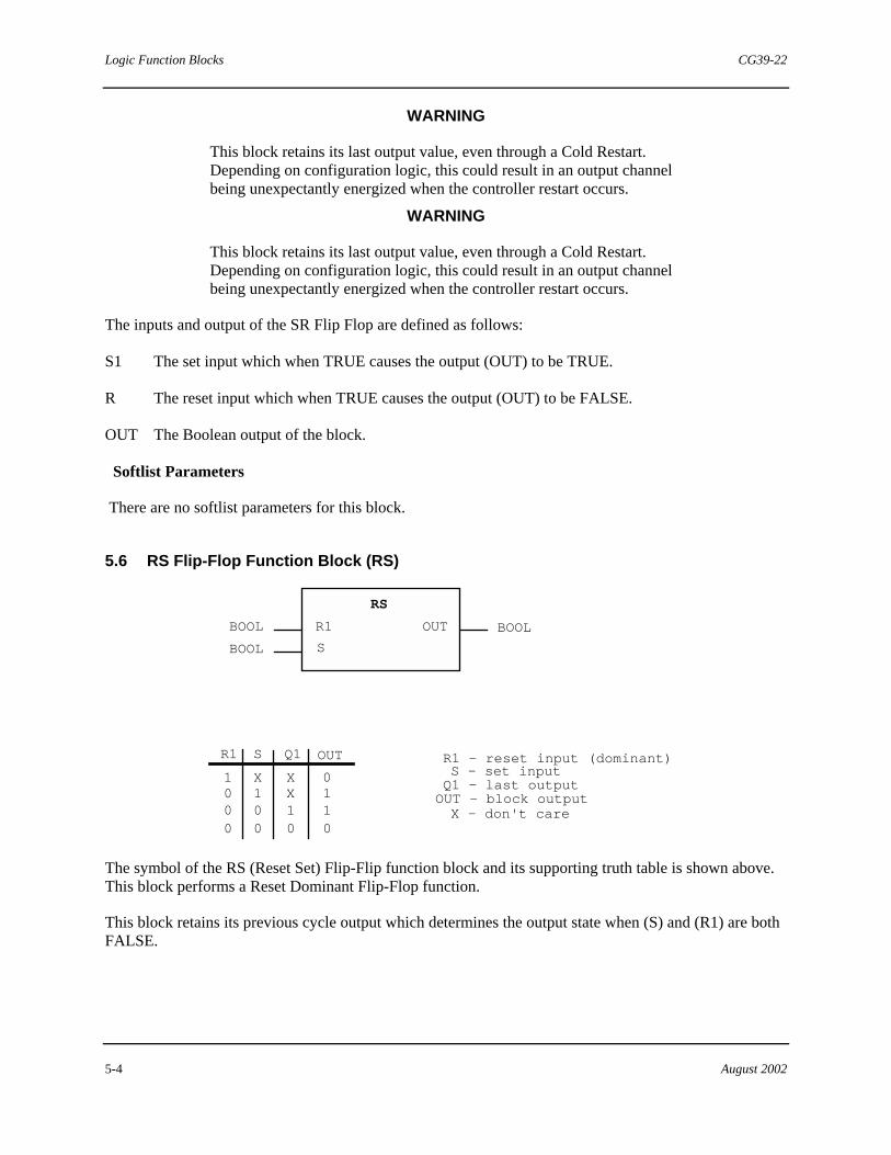
Logic Function Blocks CG39-22
5-4 August 2002
WARNING
This block retains its last output value, even through a Cold Restart. Depending on configuration logic, this could result in an output channel being unexpectantly energized when the controller restart occurs.
WARNING
This block retains its last output value, even through a Cold Restart. Depending on configuration logic, this could result in an output channel being unexpectantly energized when the controller restart occurs.
The inputs and output of the SR Flip Flop are defined as follows:
S1 The set input which when TRUE causes the output (OUT) to be TRUE.
R The reset input which when TRUE causes the output (OUT) to be FALSE.
OUT The Boolean output of the block.
Softlist Parameters
There are no softlist parameters for this block.
5.6 RS Flip-Flop Function Block (RS)
BOOL
OUTBOOL BOOL
Q1 OUT
1 X X10 1 X0
00
00
1 10 0
X - don't care
RS
R1
S
SR1 R1 - reset input (dominant)S - set inputQ1 - last outputOUT - block output
The symbol of the RS (Reset Set) Flip-Flip function block and its supporting truth table is shown above. This block performs a Reset Dominant Flip-Flop function.
This block retains its previous cycle output which determines the output state when (S) and (R1) are both FALSE.
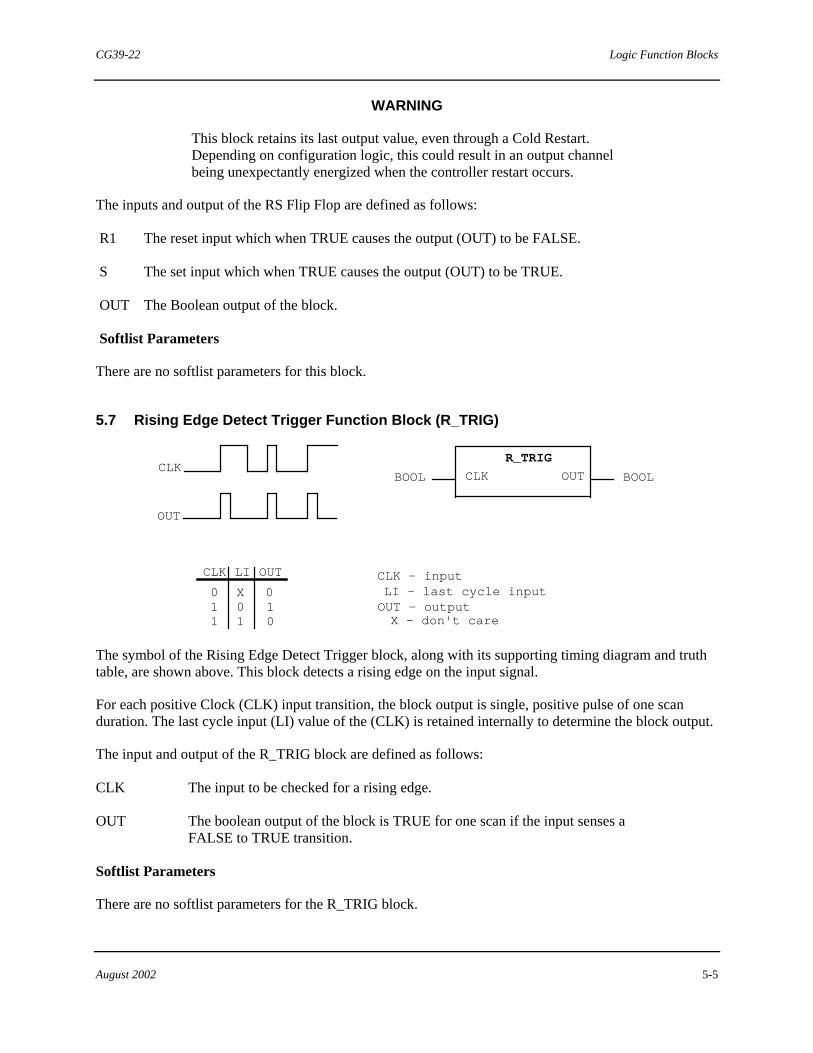
CG39-22 Logic Function Blocks
August 2002 5-5
WARNING
This block retains its last output value, even through a Cold Restart. Depending on configuration logic, this could result in an output channel being unexpectantly energized when the controller restart occurs.
The inputs and output of the RS Flip Flop are defined as follows:
R1 The reset input which when TRUE causes the output (OUT) to be FALSE.
S The set input which when TRUE causes the output (OUT) to be TRUE.
OUT The Boolean output of the block.
Softlist Parameters
There are no softlist parameters for this block.
5.7 Rising Edge Detect Trigger Function Block (R_TRIG)
BOOL OUT BOOLCLK
R_TRIG
CLK LI OUT
011
X01
010
CLK - inputLI - last cycle inputOUT - outputX - don't care
CLK
OUT
The symbol of the Rising Edge Detect Trigger block, along with its supporting timing diagram and truth table, are shown above. This block detects a rising edge on the input signal.
For each positive Clock (CLK) input transition, the block output is single, positive pulse of one scan duration. The last cycle input (LI) value of the (CLK) is retained internally to determine the block output.
The input and output of the R_TRIG block are defined as follows:
CLK The input to be checked for a rising edge.
OUT The boolean output of the block is TRUE for one scan if the input senses a FALSE to TRUE transition.
Softlist Parameters
There are no softlist parameters for the R_TRIG block.

Logic Function Blocks CG39-22
5-6 August 2002
5.8 Falling Edge Detect Trigger Function Block (F_TRIG)
BOOL OUT BOOLCLK
CLK LI OUT
0
1
010
CLK - inputLI - last cycle inputOUT - outputX - don't care
F_TRIG
X
00 1
CLK
OUT
The symbol of the Falling Edge Detect Trigger function block along with its supporting timing diagram and truth table are shown above. This block detects a falling edge on the input signal.
For each negative Clock (CLK) input transition, the block output is a single, positive pulse of one cycle duration. The last cycle input (LI) value of the (CLK) is retained internally to determine the block output.
The input and output of the F_TRIG block are defined as follows:
CLK The input to be checked for a falling edge.
OUT The boolean output of the block which is TRUE for one scan if the input senses a TRUE to FALSE transition.
Softlist Parameters
There are no softlist parameters for the F_TRIG block.
NOTE
The Shift and Rotate function blocks, located in the logic sub menu of the Icon Bar, are defined in section 6.
"

CG39-22 Shift and Rotate Function Blocks
August 2002 6-1
6.0 Shift and Rotate Function Blocks
The Shift and Rotate function blocks are a subset of the standard function blocks. These function blocks provide shifting and rotating functions.
For memory usage and ACM execution time information on all standard configuration elements, refer to Appendix C in Using the ProcessSuite 4-mation Configuration Software (document number CG39-20).
A listing of Shift and Rotate function blocks is presented here. Individual blocks are detailed in the subsections that follow.
• Shift Left • Shift Right • Rotate Left • Rotate Right
6.1 Shift Left Function Block (SHL)
OUT
BOOL...
bn
<<
<
- 0
----
-
b1
ANY_INT
ANY_INT
SHLANY_INT
CARRY
IN
N
A schematic diagram and the graphical symbol and of the Shift Left function block are shown above. Refer to these items when reading the following description.
This block performs a bitwise shift left of the configured input. The input can be shifted a variable number of places based on the value of the (N) input. The maximum value of (N) is limited to the number of bits of the input argument. If left unconfigured or negative, the default value of the (N) input is 0. As the bit positions in the input are shifted left, they will be zero-filled on the right. The last bit shifted out will be saved in the (CARRY) output, but all previously shifted bits will be lost.
The shift variable input, (N), is of type ANY_INT.
The inputs and outputs of the SHL block are defined as follows:
IN The integer input to be shifted.
N The integer input determining the number of places (IN) is shifted.
OUT The shifted input is passed to this output.
CARRY This Boolean saves the last shifted bit.
Softlist Parameters
There are no softlist parameters for the SHL block.

Shift and Rotate Function Blocks CG39-22
6-2 August 2002
6.2 Shift Right Function Block (SHR)
OUT
BOOL...
bn
----
b1
ANY_INT
ANY_INT
ANY INT
CARRY
IN
N
SHR
0 -> ->
>
A schematic diagram and the graphical symbol and of the Shift Right function block are shown above. Refer to these items when reading the following description.
This block performs a bit-wise shift right of the configured input. The input can be shifted a variable number of places based on the (N) input. The maximum value of "N" is limited to the number of bits of the input argument. If left unconfigured or if negative, the default value of the (N) input is 0. As the bit positions in the input are shifted right, they will be zero filled on the left. The last bit shifted out will be saved in the (CARRY) output, but all previously shifted bits will be lost.
The shift variable input, (N), is of type ANY_INT.
The inputs and outputs of the SHR block are defined as follows:
IN The integer input to be shifted.
N The integer input determining the number of places the (IN) is shifted.
OUT The shifted input is passed out this output.
CARRY This Boolean saves the last shifted bit.
Softlist Parameters
There are no softlist parameters for the SHR block.
6.3 Rotate Left Function Block (ROL)
OUT
BOOL...
bn
----
b1
ANY_INT
ANY_INT
ANY_INT
CARRY
IN
N
ROL
<
<
<
A schematic diagram and the graphical symbol and of the Rotate Left function block are shown above. Refer to these items when reading the following description.
This block performs a bit-wise left rotation of the configured input. The input can be rotated a variable number of places based on the (N) input. (N) is limited to the number of bits in the input. If unconfigured or negative, the default value of the (N) input is 0. As the bit positions in the input are rotated left, the last displaced bit on left the fills the vacancy (bit) at the right. No bits will be added or lost. After all shifting is complete, the "b1" bit value will be placed in the (CARRY) output.

CG39-22 Shift and Rotate Function Blocks
August 2002 6-3
The shift variable input, (N), is of type ANY_INT.
The inputs and outputs of the ROL block are defined as follows:
IN The integer input to be rotated.
N The integer input determining the number of places the (IN) is rotated.
OUT The rotated input is passed out this output.
CARRY This Boolean is a copy of the "b1" bit.
Softlist Parameters
There are no softlist parameters for the ROL block.
6.4 Rotate Right Function Block (ROR)
OUT
BOOL...
bn
----
b1
ANY_INT
ANY_INT
ANY_INT
CARRY
IN
N
ROR
> >
>
A schematic diagram and the graphical symbol and of the Rotate Right function block are shown above. Refer to these items when reading the following description.
This block performs a bit-wise right rotation of the configured input. The input can be rotated a variable number of places based on the (N) input. (N) is limited to the number of bits in the input. If unconfigured or negative, the default value of the (N) input will be 0. As the bit positions in the input are rotated right, the last displaced bit on the right fills the vacancy (bit) at the left. No bits will be added or lost. After all shifting is complete, the "bn" bit value will be placed in the (CARRY) output.
The shift variable input, (N), is of type ANY_INT.
The inputs and outputs of the ROR block are defined as follows:
IN The integer input to be rotated.
N The integer input determining the number of places the (IN) is rotated.
OUT The rotated input is passed out this output.
CARRY This Boolean is a copy of the "bn" bit.
Softlist Parameters
There are no softlist parameters for the ROR block. "

Shift and Rotate Function Blocks CG39-22
6-4 August 2002
!Notes

CG39-22 Arithmetic Function Blocks
August 2002 7-1
7.0 Arithmetic Function Blocks
The Arithmetic function blocks are a subset of the standard function blocks. Arithmetic function blocks operate only on numbers, either real or integer. Some of these blocks have outputs of ANY_NUM (meaning any numeric) data type.
Each of these blocks assumes that all of the ANY_NUM inputs and outputs are the same data type as the first ANY_NUM input assigned. Note that the mixing of data types on the ANY_NUM inputs and outputs of a block is not prevented, but it may lead to unpredictable results.
Refer to Using the ProcessSuite 4-mation Configuration Software (document number CG39-20) for information about the ANY_NUM data type. For memory usage and ACM execution time information on all standard configuration elements, see Appendix C in the same document.
A listing of Arithmetic function blocks is presented here. Individual blocks are detailed in the subsections that follow. • Addition • Subtraction • Multiplication • Division • Square Root • Absolute Value • Linear Characterizer • Weighted Average • Moving Average • Logarithm Base 10 • Exponentiation • Natural Logarithm • Natural Exponential • Trigonometric Functions
- Sine - Cosine - Tangent
• Inverse Trigonometric Functions - Arcsine - Arccosine - Arctangent
• Convert
7.1 Addition Function Block (ADD)
OUT = IN01 + IN02 +...IN(n)
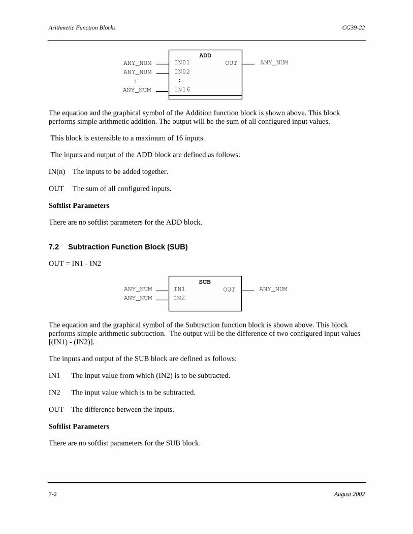
Arithmetic Function Blocks CG39-22
7-2 August 2002
OUT
:
IN16
:
ADDANY_NUMANY_NUM
ANY_NUM
ANY_NUM
IN01
IN02
The equation and the graphical symbol of the Addition function block is shown above. This block performs simple arithmetic addition. The output will be the sum of all configured input values.
This block is extensible to a maximum of 16 inputs.
The inputs and output of the ADD block are defined as follows:
IN(n) The inputs to be added together.
OUT The sum of all configured inputs.
Softlist Parameters
There are no softlist parameters for the ADD block.
7.2 Subtraction Function Block (SUB)
OUT = IN1 - IN2
OUTIN1
IN2
SUBANY_NUMANY_NUM
ANY_NUM
The equation and the graphical symbol of the Subtraction function block is shown above. This block performs simple arithmetic subtraction. The output will be the difference of two configured input values [(IN1) - (IN2)].
The inputs and output of the SUB block are defined as follows:
IN1 The input value from which (IN2) is to be subtracted.
IN2 The input value which is to be subtracted.
OUT The difference between the inputs.
Softlist Parameters
There are no softlist parameters for the SUB block.

CG39-22 Arithmetic Function Blocks
August 2002 7-3
7.3 Multiplication Function Block (MUL)
OUT = IN01 * IN02 *...IN(n)
OUT
:
IN16
:
ANY_NUMANY_NUM
ANY_NUM
ANY_NUM
MULIN01
IN02
The equation and the graphical symbol of the Multiplication function block is shown above. This block performs simple arithmetic multiplication. The output will be the product of all configured input values.
This block is extensible to a maximum of 16 inputs.
The inputs and output of the MUL block are defined as follows:
IN(n) The inputs to be multiplied together.
OUT The product of all configured inputs.
Softlist Parameters
There are no softlist parameters for this block.
7.4 Division Function Block (DIV)
OUT = IN1 / IN2
OUTIN1
IN2
DIVANY_NUM
ANY_NUM
ANY_NUM
The equation and the graphical symbol of the Division (DIV) function block is shown above. The block performs simple arithmetic division. The output value (OUT) is normally the quotient of the two configured input values [(IN1)/(IN2)], and the output data quality value is normally GOOD. However, if (IN2) is unconfigured or equal to zero, (OUT) is zero and its data quality value is BAD.
For the division of two integer data type values, the remainder is truncated, leaving only the quotient as the integer output value.
The inputs and output of the DIV block are defined as follows:
IN1 Dividend value
IN2 Divisor value
OUT Quotient of the two inputs
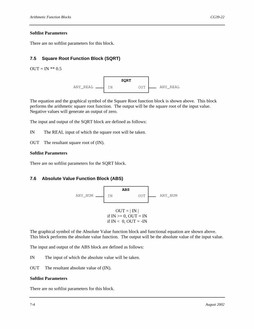
Arithmetic Function Blocks CG39-22
7-4 August 2002
Softlist Parameters
There are no softlist parameters for this block.
7.5 Square Root Function Block (SQRT)
OUT = IN ** 0.5
OUT
SQRT
IN ANY_REALANY_REAL
The equation and the graphical symbol of the Square Root function block is shown above. This block performs the arithmetic square root function. The output will be the square root of the input value. Negative values will generate an output of zero.
The input and output of the SQRT block are defined as follows:
IN The REAL input of which the square root will be taken.
OUT The resultant square root of (IN).
Softlist Parameters
There are no softlist parameters for the SQRT block.
7.6 Absolute Value Function Block (ABS)
OUTIN
ABS
ANY_NUMANY_NUM
OUT = | IN | if IN >= 0, OUT = IN if IN < 0, OUT = -IN
The graphical symbol of the Absolute Value function block and functional equation are shown above. This block performs the absolute value function. The output will be the absolute value of the input value.
The input and output of the ABS block are defined as follows:
IN The input of which the absolute value will be taken.
OUT The resultant absolute value of (IN).
Softlist Parameters
There are no softlist parameters for this block.

CG39-22 Arithmetic Function Blocks
August 2002 7-5
7.7 Linear Characterizer Function Block (LINCHR)
LINCHR
IN_X OUT_YREAL REAL
The graphical symbol of the Linear Characterizer function block is shown above. This block provides X and Y coordinate selections that can be used to form various input/output characterizations, similar to a curve fitting function.
When the input is "X", the output is "Y". The NUM_OF_SEGS Softlist Parameter determines the number of segments (maximum of 20) the algorithm uses. The input is checked to determine which segment it "fits". The output is then determined by the point-slope method (y=mx+b). The slope of the function depends on the "X" and "Y" configuration entries.
For the algorithm to function properly, the "X" and "Y" entries must be continuous with no breaks, and the "X" entries cannot change direction but must be configured from low to high. This block is typed for REAL data. All inputs, outputs and Softlist values are expressed in Engineering Units.
The input and output of the LINCHR block are defined as follows:
IN_X is the input in engineering units.
OUT_Y is the calculated output in engineering units.
Softlist Parameters
The remaining LINCHR inputs are accessed via the softlist. The value of these inputs can be changed via commands from an operator interface (or the Set Value function block) but they cannot be "wired" to the block.
NUM_OF_SEGS is the number of segments (maximum of 20).
YL is the output in engineering units when the input is less than X0
YH is the output in engineering units when the input is greater than the X value at the last configured segment.
X0 is the starting X coordinate.
Xn the X coordinate of a pair of coordinates.
Y0 is the starting Y coordinate.
Yn is the Y coordinate of a pair of coordinates.
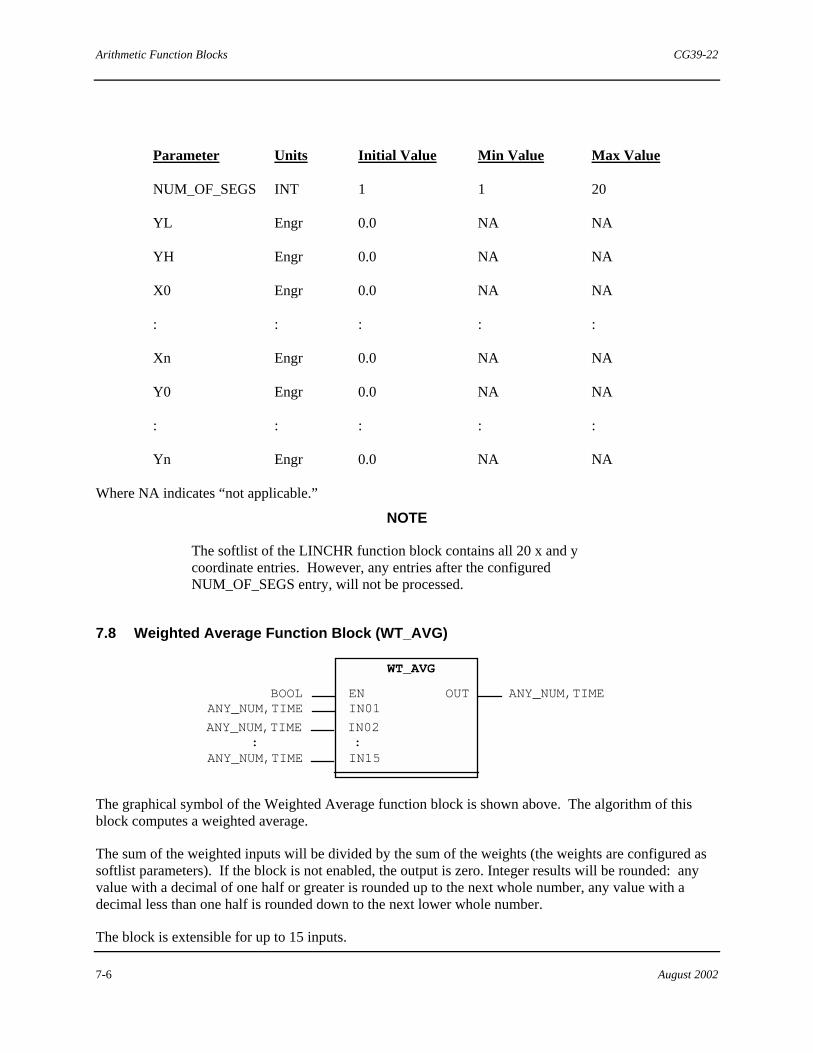
Arithmetic Function Blocks CG39-22
7-6 August 2002
Parameter Units Initial Value Min Value Max Value
NUM_OF_SEGS INT 1 1 20
YL Engr 0.0 NA NA
YH Engr 0.0 NA NA
X0 Engr 0.0 NA NA
: : : : :
Xn Engr 0.0 NA NA
Y0 Engr 0.0 NA NA
: : : : :
Yn Engr 0.0 NA NA
Where NA indicates “not applicable.”
NOTE
The softlist of the LINCHR function block contains all 20 x and y coordinate entries. However, any entries after the configured NUM_OF_SEGS entry, will not be processed.
7.8 Weighted Average Function Block (WT_AVG)
BOOL
WT_AVG
OUTANY_NUM,TIME
:IN15
ENIN01
ANY_NUM,TIME
ANY_NUM,TIME
:ANY_NUM,TIME IN02
The graphical symbol of the Weighted Average function block is shown above. The algorithm of this block computes a weighted average.
The sum of the weighted inputs will be divided by the sum of the weights (the weights are configured as softlist parameters). If the block is not enabled, the output is zero. Integer results will be rounded: any value with a decimal of one half or greater is rounded up to the next whole number, any value with a decimal less than one half is rounded down to the next lower whole number.
The block is extensible for up to 15 inputs.

CG39-22 Arithmetic Function Blocks
August 2002 7-7
The inputs and output of the WT_AVG block are defined as follows:
EN is the block enable. When TRUE the block performs the averaging operation, when FALSE the (OUT) is zero.
IN(n) are the inputs to the block to be averaged.
OUT is the calculated weighted average.
Softlist Parameters
The remaining Weighted Average inputs are accessed via the softlist. The value of these inputs can be changed via commands from an operator interface (or the Set Value function block) but they cannot be "wired" to the block.
WEIGHT(n) are the entered coefficients for each input; these weights should be zero or positive. However, if all weights are zero, the (OUT) output will be nonsensical.
Parameter Units Initial Value Min Value Max Value
WEIGHT1 dimensionless 1.0 0.0 NA
WEIGHT2 dimensionless 1.0 0.0 NA
: : : : :
WEIGHT15 dimensionless 1.0 0.0 NA
Where NA indicates “not applicable.”
7.9 Moving Average Function Block (MOV_AVG)
OUT
MOV_AVG
ANY_NUM, TIME
BOOL
INPREV
EN
IN11
ANY_NUM, TIME
ANY_NUM, TIME
ANY_NUM, TIME
The graphical symbol of the Moving Average function block is shown above. The algorithm of this block contains 10 shift registers.
The (IN) input will be held for a period of time and then each register's value will be transferred to the next register. The output represents the moving average of 10 shift registers. The Sample Period is set via a softlist parameter.

Arithmetic Function Blocks CG39-22
7-8 August 2002
Integer results will be rounded. That is, any value with a decimal of one half or greater will be rounded up to the next whole integer, any value with a decimal less than one half will be rounded down to the lower whole integer.
This block can be chained to another MOV_AVG block to produce a moving average with more shift registers. The OUT output of one block would be wired to the PREV input of the next block, and the IN11 output of the first block would be wired to the IN input of the next block. The period of each chained block would represent the fraction of the overall period that each individual block would contribute so that the total of all of the PERIOD settings would equal the desired overall period. The gain settings of each individual block would also be set to the fraction of the overall period that each block contributes so that the total of all of the GAIN settings equals 1 For example, when chaining two blocks together to achieve improved resolution for a one minute overall period, each block would have PERIOD set to 30 seconds and GAIN set to 0.5 (the WEIGHT settings remain 1).
The inputs and outputs of the MOV_AVG block are defined as follows:
IN This is the process input to the algorithm.
PREV This is the Previous Average input. It is used when chaining MOV_AVG blocks, where this input would be wired to the OUT output of an upstream block.
EN This is the command input to the algorithm. When this input is FALSE, the Averaging function is bypassed [(OUT)=(IN)] and all registers are set equal to (IN).
OUT This the output. It is equal to the average of the 10 samples. If data types other than those specified are used as inputs, the output value will be 0.0.
IN11 This is the output equal to the 11th shift register (sample). This is the oldest sample and is not used by the block's calculation. It is used when chaining MOV_AVG blocks, where this output would be wired to the IN input of a downstream block.
Softlist Parameters
PERIOD This is the Period of the average expressed as a TIME value. When chaining MOV_AVG blocks, this setting represents the fraction of the overall period that this block contributes such that the total of all of the PERIOD settings equals the overall period of the average.
GAIN This is the overall block gain parameter. It allows the output to be scaled for proper "chaining" of several MOV_AVG function blocks, where the total of all of the GAIN settings equals 1.
WEIGHT(n) This is the weighting factor of each sample. Each sample can be individually weighted before the average calculation is performed. These weights should be zero or positive. However, if all weights are zero, the (OUT) output will be nonsensical.
Parameter Units Initial Value Min Value Max Value
PERIOD TIME T#0d0h1m0s0ms T#0d0h0m0s0ms NA
GAIN dimensionless 1.0 0.0 NA

CG39-22 Arithmetic Function Blocks
August 2002 7-9
WEIGHT1 dimensionless 1.0 0.0 NA
WEIGHT2 dimensionless 1.0 0.0 NA
: : : : :
WEIGHT10 dimensionless 1.0 0.0 NA
Where NA indicates not applicable.
7.10 Logarithm Base 10 Function Block (LOG)
OUT = LOG( IN )
OUTIN ANY_REALANY_REAL
LOG
The equation and the graphical symbol of the Logarithm Base 10 function block is shown above. This block performs the common logarithm function, base "10". The output will be the common logarithm of the input value. If (IN) is negative, (OUT) is zero.
The input and output of the LOG block are defined as follows:
IN The input of which the base 10 logarithm is taken.
OUT The resultant base 10 log of (IN).
Softlist Parameters
There are no softlist parameters for this block.
7.11 Exponentiation Function Block (EXPT)
OUT = IN1 ** IN2
OUTIN1
IN2ANY_NUM
EXPT ANY_REAL ANY_REAL
The equation and the graphical symbol of the Exponentiation function block is shown above. This block performs the power function. The output will be the first input value raised to the power of the second input value as shown below.
OUT = IN1IN2

Arithmetic Function Blocks CG39-22
7-10 August 2002
The inputs and output of the EXPT block are defined as follows:
IN1 The input that is to be raised to a power.
IN2 The input which is the power to which the (IN1) will be raised.
OUT The calculated output of the block.
Softlist Parameters
There are no softlist parameters for this block.
NOTE
If the IN1 value is negative and the IN2 value is not an integer value, the output value is zero.
7.12 Natural Logarithm Function Block (LN)
OUT = LN( IN )
OUTIN ANY_REALANY_REAL
LN
The equation and the graphical symbol of the Natural Logarithm function block is shown above. Refer to these items when reading the following description.
This block performs the natural logarithm function, base "e". The output will be the natural logarithm of the input value. If (IN) is negative, (OUT) is zero.
The input and output of the LN block are defined as follows:
IN The REAL input of which the natural log will be taken.
OUT The resultant natural log of (IN).
Softlist Parameters
There are no softlist parameters for this block.
7.13 Natural Exponentiation Function Block (EXP)
OUT = e ** IN
OUTIN ANY_REALANY_REAL
EXP

CG39-22 Arithmetic Function Blocks
August 2002 7-11
The equation and the graphical symbol of the Natural Exponentiation function block is shown above. This block will perform the natural exponentiation function, base "e". The output will be the value "e" raised to the power of the input value. This is the opposite of the Natural Logarithm (LN) function.
The input and output of the EXP block are defined as follows:
IN The input that is the power to which "e" will be raised.
OUT The resultant of the natural Exponentiation of the (IN).
Softlist Parameters
There are no softlist parameters for this block.
7.14 Trigonometric Function Blocks
The blocks described in the following subsections are the trigonometric function blocks. These are: • Sine • Cosine • Tangent
The output is the sine, cosine, or tangent of the input angle value. Note that the input value must be in radians.
7.14.1 Sine Function Block (SIN)
OUT=SIN(IN)
SIN
ANY_REAL ANY_REALIN OUT
1
0
-1
π 2π
The symbol of the Sine function block is shown above. The SIN function block accepts a radian input and outputs the sine of that angle.
The input and output of the SIN block are defined as follows:
IN The input in radians of which the sine will be taken.
OUT The output which is the sine of the (IN) input.
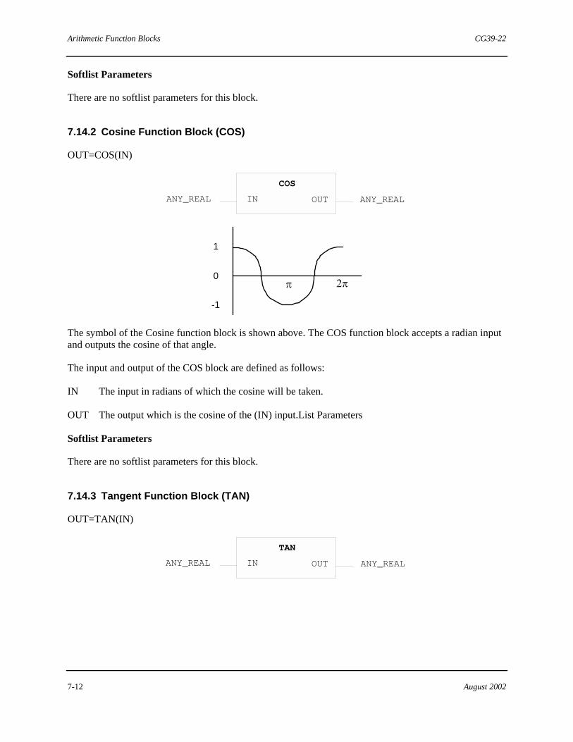
Arithmetic Function Blocks CG39-22
7-12 August 2002
Softlist Parameters
There are no softlist parameters for this block.
7.14.2 Cosine Function Block (COS)
OUT=COS(IN)
COS
ANY_REAL ANY_REALIN OUT
1
0
-1
π 2π
The symbol of the Cosine function block is shown above. The COS function block accepts a radian input and outputs the cosine of that angle.
The input and output of the COS block are defined as follows:
IN The input in radians of which the cosine will be taken.
OUT The output which is the cosine of the (IN) input.List Parameters
Softlist Parameters
There are no softlist parameters for this block.
7.14.3 Tangent Function Block (TAN)
OUT=TAN(IN)
TAN
ANY_REAL ANY_REALIN OUT
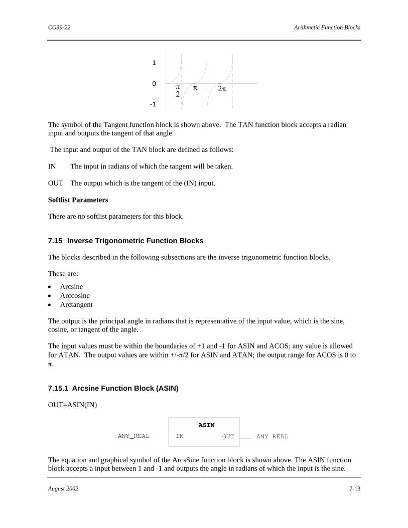
CG39-22 Arithmetic Function Blocks
August 2002 7-13
1
0
-1
π2
π 2π
The symbol of the Tangent function block is shown above. The TAN function block accepts a radian input and outputs the tangent of that angle.
The input and output of the TAN block are defined as follows:
IN The input in radians of which the tangent will be taken.
OUT The output which is the tangent of the (IN) input.
Softlist Parameters
There are no softlist parameters for this block.
7.15 Inverse Trigonometric Function Blocks
The blocks described in the following subsections are the inverse trigonometric function blocks.
These are:
• Arcsine • Arccosine • Arctangent
The output is the principal angle in radians that is representative of the input value, which is the sine, cosine, or tangent of the angle.
The input values must be within the boundaries of +1 and -1 for ASIN and ACOS; any value is allowed for ATAN. The output values are within +/-π/2 for ASIN and ATAN; the output range for ACOS is 0 to π.
7.15.1 Arcsine Function Block (ASIN)
OUT=ASIN(IN)
ASIN
ANY_REAL ANY_REALIN OUT
The equation and graphical symbol of the ArcsSine function block is shown above. The ASIN function block accepts a input between 1 and -1 and outputs the angle in radians of which the input is the sine.
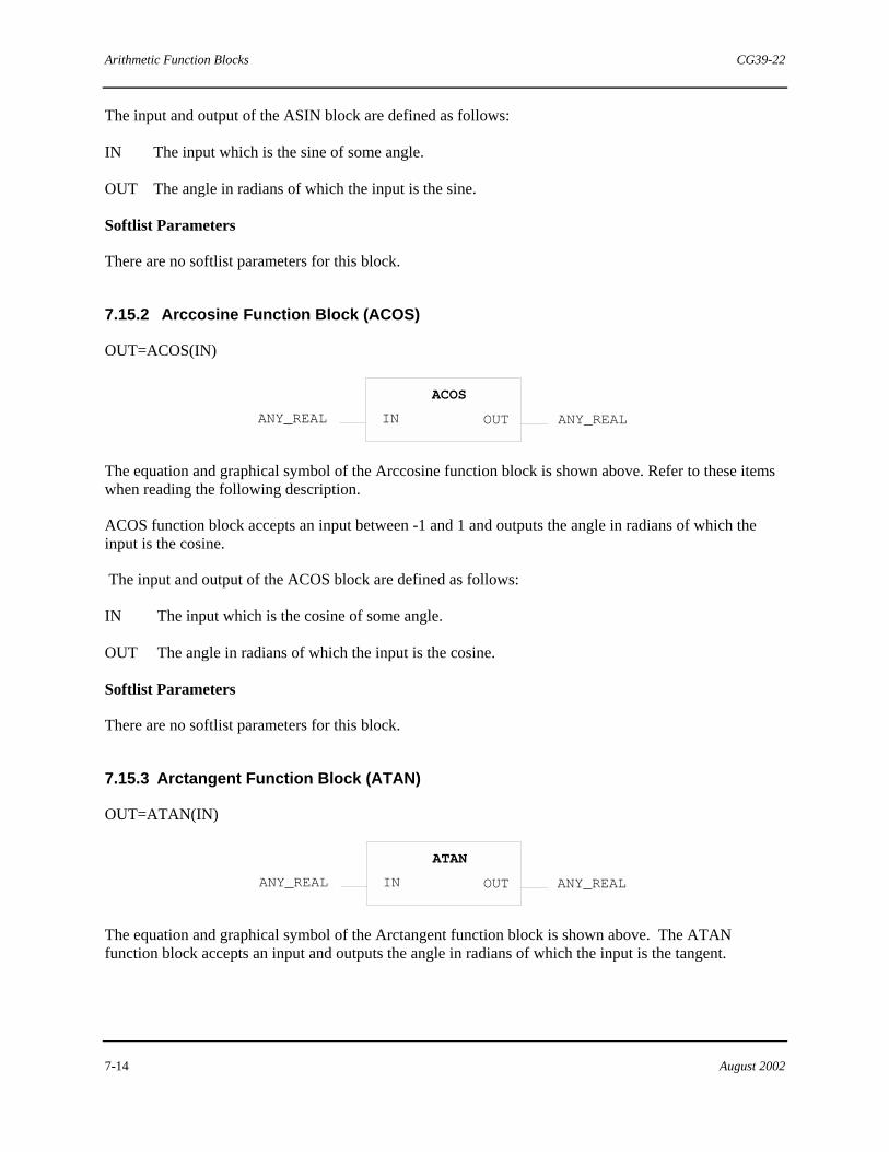
Arithmetic Function Blocks CG39-22
7-14 August 2002
The input and output of the ASIN block are defined as follows:
IN The input which is the sine of some angle.
OUT The angle in radians of which the input is the sine.
Softlist Parameters
There are no softlist parameters for this block.
7.15.2 Arccosine Function Block (ACOS)
OUT=ACOS(IN)
ACOS
ANY_REAL ANY_REALIN OUT
The equation and graphical symbol of the Arccosine function block is shown above. Refer to these items when reading the following description.
ACOS function block accepts an input between -1 and 1 and outputs the angle in radians of which the input is the cosine.
The input and output of the ACOS block are defined as follows:
IN The input which is the cosine of some angle.
OUT The angle in radians of which the input is the cosine.
Softlist Parameters
There are no softlist parameters for this block.
7.15.3 Arctangent Function Block (ATAN)
OUT=ATAN(IN)
ATAN
ANY_REAL ANY_REALIN OUT
The equation and graphical symbol of the Arctangent function block is shown above. The ATAN function block accepts an input and outputs the angle in radians of which the input is the tangent.
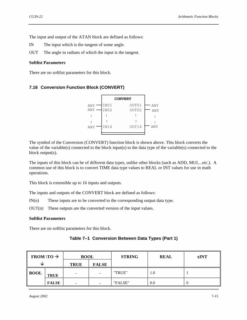
CG39-22 Arithmetic Function Blocks
August 2002 7-15
The input and output of the ATAN block are defined as follows:
IN The input which is the tangent of some angle.
OUT The angle in radians of which the input is the tangent.
Softlist Parameters
There are no softlist parameters for this block.
7.16 Conversion Function Block (CONVERT)
ANY
CONVERT
ANYIN01IN02:
:
IN16
OUT01OUT02:
:
OUT16ANY ANY
:
::
:
ANY ANY
The symbol of the Conversion (CONVERT) function block is shown above. This block converts the value of the variable(s) connected to the block input(s) to the data type of the variable(s) connected to the block output(s).
The inputs of this block can be of different data types, unlike other blocks (such as ADD, MUL...etc.). A common use of this block is to convert TIME data type values to REAL or INT values for use in math operations.
This block is extensible up to 16 inputs and outputs.
The inputs and outputs of the CONVERT block are defined as follows:
IN(n) These inputs are to be converted to the corresponding output data type.
OUT(n) These outputs are the converted version of the input values.
Softlist Parameters
There are no softlist parameters for this block.
Table 7–1 Conversion Between Data Types (Part 1)
BOOL FROM \TO #
$ TRUE FALSE
STRING REAL xINT
TRUE - - "TRUE" 1.0 1 BOOL
FALSE - - "FALSE" 0.0 0
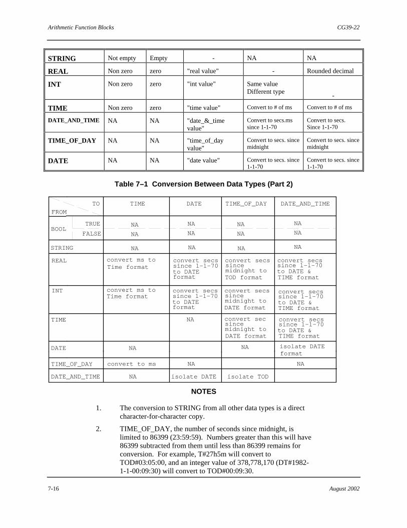
Arithmetic Function Blocks CG39-22
7-16 August 2002
STRING Not empty Empty - NA NA
REAL Non zero zero "real value" - Rounded decimal
INT Non zero zero "int value" Same value Different type
-
TIME Non zero zero "time value" Convert to # of ms Convert to # of ms
DATE_AND_TIME NA NA "date_&_time value"
Convert to secs.ms since 1-1-70
Convert to secs. Since 1-1-70
TIME_OF_DAY NA NA "time_of_day value"
Convert to secs. since midnight
Convert to secs. since midnight
DATE NA NA "date value" Convert to secs. since 1-1-70
Convert to secs. since 1-1-70
Table 7–1 Conversion Between Data Types (Part 2)
TOFROM
TIME DATE TIME_OF_DAY DATE_AND_TIME
BOOLTRUE NA
NAFALSE
NA
NA
NA
NA
NA
NA
STRING NA NA NA NA
REAL
INT
TIME
DATE
DATE_AND_TIME
TIME_OF_DAY
NA
NA
convert to ms NA NA
isolate DATE isolate TOD
NA
convert ms to convert secssince 1-1-70
since midnight to
NA
Time formatto DATEformat
convert secs
DATE format
convert secssince 1-1-70to DATE &TIME format
convert secssince 1-1-70to DATEformat
since midnight to
convert sec
DATE format
convert secssince 1-1-70to DATE &TIME format
isolate DATEformat
convert ms toTime format
since midnight to
convert secs
TOD format
convert secssince 1-1-70to DATE &TIME format
NOTES
1. The conversion to STRING from all other data types is a direct character-for-character copy.
2. TIME_OF_DAY, the number of seconds since midnight, is limited to 86399 (23:59:59). Numbers greater than this will have 86399 subtracted from them until less than 86399 remains for conversion. For example, T#27h5m will convert to TOD#03:05:00, and an integer value of 378,778,170 (DT#1982-1-1-00:09:30) will convert to TOD#00:09:30.

CG39-22 Arithmetic Function Blocks
August 2002 7-17
3. A negative number being converted to any of the time or date based data types (unsigned) will be limited to zero or the lowest value. For example, -127 will be converted to T#0d0h0m0s0ms and -111111111111 will be converted to D#1970-1-1.
4. Conversion from a large xINT to a smaller xINT is limited to the range of the smaller xINT. For example, 500d (DINT) will convert to 127s (SINT), since the SINT has an upper limit of 127. Therefore, the conversion from DINT to INT, DINT to SINT, or INT to SINT might be range limited.
5. Note the difference between TIME and the other time based data types. TIME converts to milliseconds and all other time data types convert to seconds.
6. There is no conversion required for the chart spaces that are empty, (OUTn) = (INn).
7. Conversion does not make sense in the chart spaces that are marked NA, not applicable. For example, DATE to TIME_OF_DAY.
8. REAL values are rounded off when converted.
The following chart shows examples of conversions: INPUT
DATA
TYPE
OUTPUT DATA TYPES
Value
SINT
INT
DINT
TIME
TOD#h:m:s
REAL
22.5
23
23
23
T#23ms
TOD#0:0:23
-131.5 -128 -132 -132 T#0ms TOD#0:0:0
35000.0 127 32767 35000 T#35s TOD#9:43:20
4.14E9 127 32767 2147483647 T#47d22h0m0s0ms TOD#16:0:0
DINT
-132
-128
-132
-132
T#0ms
TOD#0:0:0
132 127 132 132 T#132ms TOD#0:2:12
"

Arithmetic Function Blocks CG39-22
7-18 August 2002
!Notes

CG39-22 Move Function Blocks
August 2002 8-1
8.0 Move Function Blocks
The MOVE function blocks are a subset of the standard function blocks. These blocks accept inputs of ANY data type and have outputs of ANY data type. An ANY output takes on the data type of the variable (or function block input) to which it is connected.
If an ANY type output of one block is connected to an ANY type input of another block, no data type is assigned to the output. The output is defaulted to data type REAL. To change this default to the correct data type, the output could be connected to any variable of the correct data type. After the function block network is downloaded, the added variable can be deleted. The function block output retains the correct data type.
The mixing of data types on the ANY inputs and outputs of a block is not prevented, but may lead to unpredictable results.
For memory consumption and ACM execution time information on all standard configuration elements, see Appendix C in Using the 4-mation Configuration Software (document number CG39-20).
The MOVE function blocks are listed as follows. Each individual block is described in detail in the following subsections:
• Data Move • Set Value • Set Bit
8.1 Data Move Function Block (MOVE)
BOOL BOOL
MOVE
ANY
ANY
ANY
: :
EN
:
IN15
ENO
:OUT15
IN01
IN02OUT01
OUT02
ANYANY
ANY
The symbol of the Data Move (MOVE) function block is shown above. This block assigns input values to output values in pairs: (IN01) to (OUT01), (IN02) to (OUT02), etc. The input data types can be different, but the paired input and output data types must match. This block is extensible, up to a maximun of 15 input/output pairings.
The enable output (ENO) is TRUE whenever the EN input value is TRUE. It is FALSE at all other times.
When the MOVE block is enabled, it transfers each INxx value to its corresponding OUTxx. When the block is not enabled, its outputs retain their previous values.
The MOVE block also has the unique ability to prevent other configuration language elements from accessing its outputs when it is not enabled. This allows multiple MOVE blocks (or MOVE blocks and another data source) to be connected to the same variable without conflict.
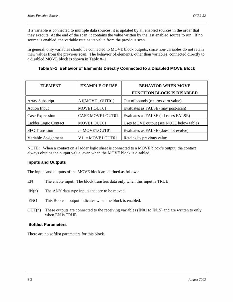
Move Function Blocks CG39-22
8-2 August 2002
If a variable is connected to multiple data sources, it is updated by all enabled sources in the order that they execute. At the end of the scan, it contains the value written by the last enabled source to run. If no source is enabled, the variable retains its value from the previous scan.
In general, only variables should be connected to MOVE block outputs, since non-variables do not retain their values from the previous scan. The behavior of elements, other than variables, connected directly to a disabled MOVE block is shown in Table 8–1.
Table 8–1 Behavior of Elements Directly Connected to a Disabled MOVE Block
ELEMENT EXAMPLE OF USE BEHAVIOR WHEN MOVE
FUNCTION BLOCK IS DISABLED
Array Subscript A1[MOVE1.OUT01] Out of bounds (returns zero value)
Action Input MOVE1.OUT01 Evaluates as FALSE (may post-scan)
Case Expression CASE MOVE1.OUT01 Evaluates as FALSE (all cases FALSE)
Ladder Logic Contact MOVE1.OUT01 Uses MOVE output (see NOTE below table)
SFC Transition := MOVE1.OUT01 Evaluates as FALSE (does not evolve)
Variable Assignment V1: = MOVE1.OUT01 Retains its previous value
NOTE: When a contact on a ladder logic sheet is connected to a MOVE block’s output, the contact always obtains the output value, even when the MOVE block is disabled.
Inputs and Outputs
The inputs and outputs of the MOVE block are defined as follows:
EN The enable input. The block transfers data only when this input is TRUE
IN(n) The ANY data type inputs that are to be moved.
ENO This Boolean output indicates when the block is enabled.
OUT(n) These outputs are connected to the receiving variables (IN01 to IN15) and are written to only when EN is TRUE.
Softlist Parameters
There are no softlist parameters for this block.
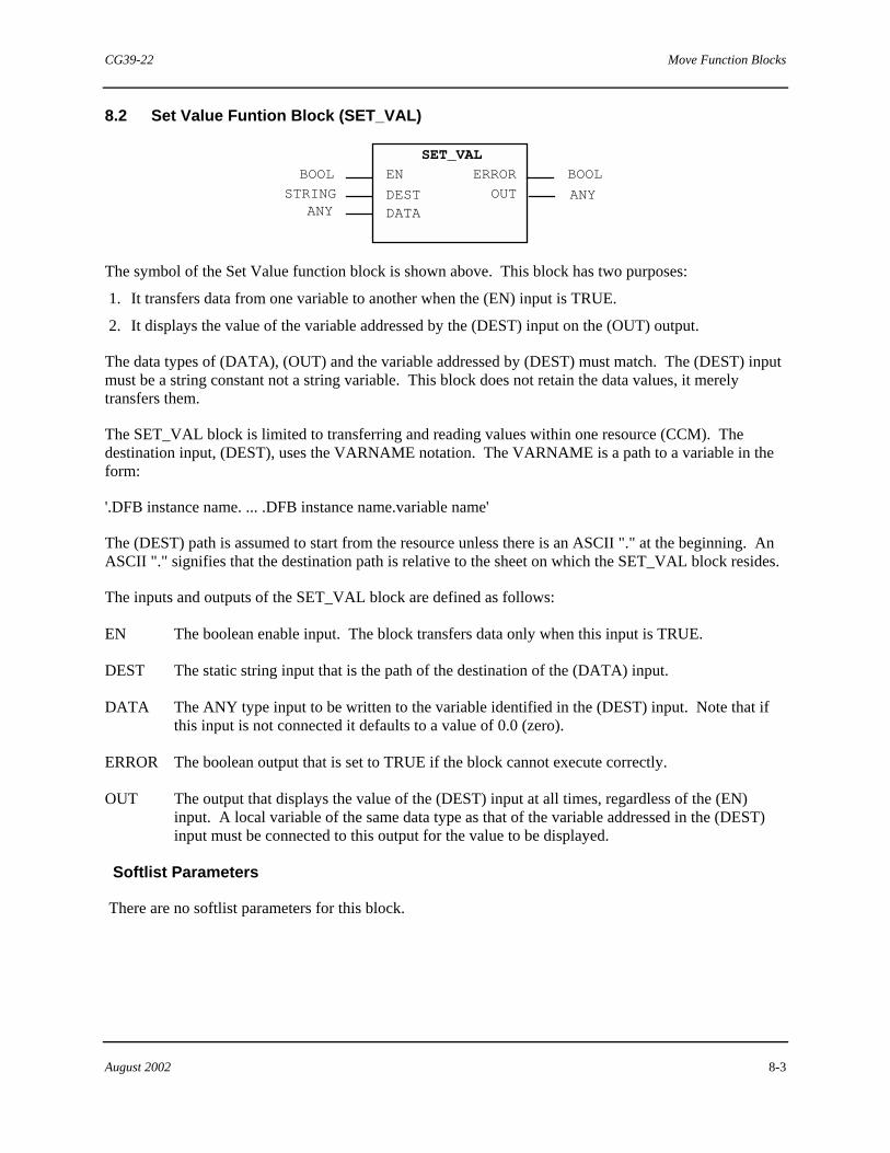
CG39-22 Move Function Blocks
August 2002 8-3
8.2 Set Value Funtion Block (SET_VAL)
ANY
BOOL
STRING
SET_VAL
ERROR BOOLEN
DESTDATA
OUT ANY
The symbol of the Set Value function block is shown above. This block has two purposes:
1. It transfers data from one variable to another when the (EN) input is TRUE.
2. It displays the value of the variable addressed by the (DEST) input on the (OUT) output.
The data types of (DATA), (OUT) and the variable addressed by (DEST) must match. The (DEST) input must be a string constant not a string variable. This block does not retain the data values, it merely transfers them.
The SET_VAL block is limited to transferring and reading values within one resource (CCM). The destination input, (DEST), uses the VARNAME notation. The VARNAME is a path to a variable in the form:
'.DFB instance name. ... .DFB instance name.variable name'
The (DEST) path is assumed to start from the resource unless there is an ASCII "." at the beginning. An ASCII "." signifies that the destination path is relative to the sheet on which the SET_VAL block resides.
The inputs and outputs of the SET_VAL block are defined as follows:
EN The boolean enable input. The block transfers data only when this input is TRUE.
DEST The static string input that is the path of the destination of the (DATA) input.
DATA The ANY type input to be written to the variable identified in the (DEST) input. Note that if this input is not connected it defaults to a value of 0.0 (zero).
ERROR The boolean output that is set to TRUE if the block cannot execute correctly.
OUT The output that displays the value of the (DEST) input at all times, regardless of the (EN) input. A local variable of the same data type as that of the variable addressed in the (DEST) input must be connected to this output for the value to be displayed.
Softlist Parameters
There are no softlist parameters for this block.

Move Function Blocks CG39-22
8-4 August 2002
8.3 Set Bit Function Block (SET_BIT)
BOOL
BOOL
STRING
INT
BOOL WORD DEST
SET_BIT
ERROR W_OUT B_OUT
DATA BIT_n
EN
BOOL
The symbol of the Set Bit (SET_BIT) function block is shown above. This block may be used to write a single bit of a destination variable of type WORD. The SET_BIT block also continuously reads both the specified bit and the value of the specified WORD variable.
The Destination string must point to a WORD data type variable. The DATA input must be a BOOL. The BIT_n input is an integer (INT) that selects which bit of the Destination WORD is to be read/written. The W_OUT output is the current value of the Destination WORD variable. The Data Type is WORD. The B_OUT output is the current value of the bit (determined by the BIT_n input) of the Destination WORD variable. The Data Type is BOOL.
This block is limited to setting or reading bit states within one resource (ACM configuration). The DEST input value uses the VARNAME notation. The VARNAME is a path to a variable in the form:
'.DFB instance name. ... .DFB instance name.variable name'
The path is assumed to start from the resource unless there is a leading period (.) character. The period signifies that the destination path is relative to the sheet on which the SET_BIT block resides.
Inputs and Outputs
The inputs and outputs of the SET_BIT block are defined as follows:
EN The boolean enable input. The block writes the specified bit to the destination variable only when this input is TRUE.
DEST The static string input that specifies the address path of the destination WORD variable. See Address Paths for Remote Access to Variables
DATA The BOOL input specifying the TRUE or FALSE value to be written to the specified bit of the variable identified in the DEST input.
BIT_n The integer (INT) value that selects which bit of the Destination WORD is to be read/written. Use 1 to address the low-order bit and 16 to address the high-order bit.
ERROR The boolean output that will be TRUE if the block cannot execute correctly.
W_OUT The current output value of the Destination WORD variable.
B_OUT The current output value of the bit (determined by the BIT_n input) of the Destination WORD

CG39-22 Move Function Blocks
August 2002 8-5
variable.
Softlist Parameters
There are no softlist parameters for this block. "

Move Function Blocks CG39-22
8-6 August 2002
!Notes

CG39-22 Communications Function Blocks
August 2002 9-1
9.0 Communications Function Blocks
The Communications function blocks are a subset of the standard function blocks. They provide a means of transferring data between resources (ACM, LIM). For memory consumption and ACM execution time information on all standard configuration elements, see Appendix C in Using the ProcessSuite 4-mation Configuration Software (document number CG39-20).
A listing of the Communications function blocks is presented here. Individual blocks are detailed in the subsections that follow.
• Send and Receive • Un-Interlocked Send and Un-Interlocked Receive • Read • Write • Broadcast-In and Broadcast-Out • Connect
The following guidelines are provided as an aid for selecting the appropriate communications blocks during system configuration.
• When one ACM is to be a data source and multiple ACMs are to be data users, use a Broadcast-Out block in the source and a Broadcast-In block in each user.
• For two-way communication, use the Read or Write blocks if possible since they are much simpler to configure. Use these blocks for �tagged� data access, that is, if you know the name and address path of each piece of data that is needed (e.g. �ResourceName.ProgName.FBName.VarName�). Additionally, these blocks provide the only means for an ACM to communicate with a LIM which may not contain any communications function blocks.
• If the tagged names are not appropriate to identify the source and destination of data, use a matched pair of Send and Receive blocks (if data transfer is bi-directional), or Un-Interlocked Send and Un-Interlocked Receive blocks (if the transfer is always in one direction). These blocks establish a data channel of a given data type between the SD_x input of one block and the RD_x output of the corresponding block in the other ACM. The actual variable which is the source or destination of the data may be changing. For example, the values of each element of an array could be sent in succession over one such channel.
• Generally, each ACM must contain one Connect block for each of the other resources to which it is to communicate. Note that the Read and Write blocks and the Broadcast blocks do not require the “partner” resource to have a Connect block.

Communications Function Blocks CG39-22
9-2 August 2002
9.1 Send and Receive Communication Blocks (SEND, RCV)
BOOLSEND
BOOLBOOLBOOL
STRING
ANY:ANY
REQRIDR IDSD 01:
NDRERRORSTATUSRD 01
:
INTANY:
ANYSD 12
RD 12
INT
BOOL BOOLBOOLBOOL
STRINGANY:ANY
IDR IDSD 01:
NDRERROR
STATUSRD 01
:
INTANY:
ANY
RCV
ENRESP
SD 12RD 12
INT
The symbols of both the Send (SEND) and Receive (RCV) communications blocks are shown above. These blocks must be used in pairs as they provide an interlocked exchange of information between resources.
The term “interlocked exchange” means that data is transferred both ways and that the blocks wait for a signal from each other as a trigger to send data.
One resource contains the SEND block and the other resource contains the RCV block.
The remote identification (R_ID) input to each block in the SEND/RCV pair must be identical, as it is this input which links the blocks as a pair. Also, this R_ID input value must be different from the R_ID value used for any other pair.
The SD_(n) inputs of the SEND block are transferred to the RD_(n) outputs of the RCV block, and the SD_(n) inputs of the RCV block are transferred to the RD_(n) outputs of the SEND block.
These blocks are extensible so up to a total of 12 values can be sent in each direction with the SEND/RCV pair. The order and the data types of the input values on the source block must be repeated at the output of the destination block. The ID inputs of these blocks identify the communication channel over which the data will be transferred and is obtained from the ID output of the CONNECT block (see section 9.6 for a description of the CONNECT block).
CG39-22 Communications Function Blocks
August 2002 9-3
The SEND and RCV inputs and outputs are defined as follows:
EN When TRUE, this Boolean input enables the RCV block to perform its function.
REQ This Request input triggers the SEND block to do its function each time it changes from FALSE to TRUE.
R This boolean Reset input resets the SEND block (clears any error codes) and causes a search for the RCV block with the matching R_ID value.
RESP This RESPond input triggers the RCV block to do its function each time it changes from FALSE to TRUE.
ID This integer input identifies the communication channel between two resources (obtained from the CONNECT block ID output value).
R_ID Blocks that work in pairs are connected via this user-defined string input (Remote Identification). This string is identical in each member of the pair, but otherwise unique.
SD_(n) User data to be sent (Send Data).
NDR New Data Ready boolean output is TRUE if at least one message has successfully been received.
ERROR Boolean output that is TRUE if there is a communication error.
STATUS Integer output that shows the last detected error code. See section 3.0 in 4-mation Software Messages and Error Codes (document number CG39-21) for a description of all communication block status codes.
RD_(n) Shows the last received user data value (Receive Data).
Softlist Parameters
The remaining SEND and RCV inputs are accessed via the softlist. The values of these inputs can be changed via commands by the user (or the Set Value function block) but they cannot be �wired� to a block.
NDR_Timeout This parameter uses a TIME data type. The TIME value is used by a watchdog timer function as it monitors the NDR output. If a state change (i.e. from FALSE to TRUE or from TRUE to FALSE) does not occur within the time period set for the NDR_Timeout value, the blocks automatically timeout and reset. A reset means the blocks cancel their attempt of completing the current communications cycle. The default value is 10 seconds.
Version The version number of this function block. It is a read-only STRING value. Note that this value does not represent the version level of the control module software.

Communications Function Blocks CG39-22
9-4 August 2002
9.2 Un-interlocked Send and Un-interlocked Receive Blocks (USEND, URCV)
BOOL
USEND
BOOLBOOL
STRING
ANY:
ANY
REQR
IDR_ID
SD_01:
ERROR
STATUS INT
SD_12
INT
BOOL BOOL
BOOL
STRING R_ID
NDR
ERRORSTATUS
RD_01:
INT
ANY:
ANY
URCV
EN
ID
RD_12
INT
The symbols of the Un-interlocked Send (USEND) and Un-interlocked Receive (URCV) communications blocks are shown above. These blocks are used in pairs to send information unidirectionally from one resource to another.
The USEND and URCV function blocks provide un-interlocked data transfer. That is, there is not the same degree of handshaking between these two blocks as with the SEND/RCV pair and data is transmitted in one direction from the USEND block to the URCV block.
The source resource must contain a USEND block while the other resource must contain a URCV block.
These blocks are extensible so up to a total of 12 values can be transferred with each USEND/URCV pair.
The user-defined Remote Identification input (R_ID) to each block in a USEND/URCV pair must be identical, as this is what links each pair together. Also, the R_ID input value must be different from the R_ID input value used for any other pair. The ID inputs of these blocks identify the communication channel over which the data is transferred and is obtained from the ID output of the CONNECT block (see section 9.6 for a description of the CONNECT block). The order and the data type of each of the RD_(n) outputs of the URCV block must be the same as the SD_(n) inputs of the USEND block. Otherwise, an integer value of 4 (data type mismatch) is placed on the STATUS output.
NOTE
Although the RD_n outputs of the URCV block can extend to 13, only 12 variables can be passed from the USEND block because the USEND block can only extend to 12. The USEND and URCV inputs and outputs are defined as follows:
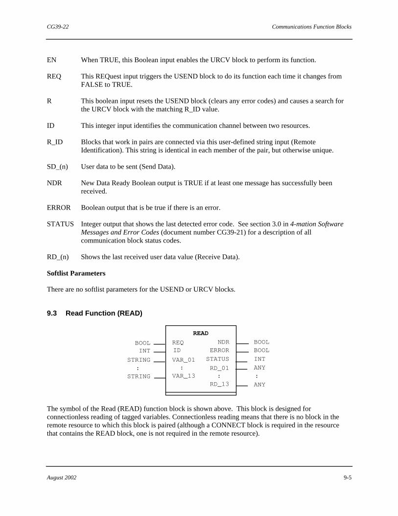
CG39-22 Communications Function Blocks
August 2002 9-5
EN When TRUE, this Boolean input enables the URCV block to perform its function.
REQ This REQuest input triggers the USEND block to do its function each time it changes from FALSE to TRUE.
R This boolean input resets the USEND block (clears any error codes) and causes a search for the URCV block with the matching R_ID value.
ID This integer input identifies the communication channel between two resources.
R_ID Blocks that work in pairs are connected via this user-defined string input (Remote Identification). This string is identical in each member of the pair, but otherwise unique.
SD_(n) User data to be sent (Send Data).
NDR New Data Ready Boolean output is TRUE if at least one message has successfully been received.
ERROR Boolean output that is be true if there is an error.
STATUS Integer output that shows the last detected error code. See section 3.0 in 4-mation Software Messages and Error Codes (document number CG39-21) for a description of all communication block status codes.
RD_(n) Shows the last received user data value (Receive Data).
Softlist Parameters
There are no softlist parameters for the USEND or URCV blocks.
9.3 Read Function (READ)
BOOLBOOLID ERROR
STATUS INT
NDR
RD_01:
BOOL
ANY:
STRING:
STRING
REQ
VAR_01:
ANY
READ
VAR_13RD_13
INT
The symbol of the Read (READ) function block is shown above. This block is designed for connectionless reading of tagged variables. Connectionless reading means that there is no block in the remote resource to which this block is paired (although a CONNECT block is required in the resource that contains the READ block, one is not required in the remote resource).

Communications Function Blocks CG39-22
9-6 August 2002
Tagged variable access indicates that each input is entered as a path name in a STRING data type as described by the VARNAME addressing nomenclature instead of wiring a value directly to the block. See Address Paths for Remote Access to Variables in 4-mation help for addressing details.
The ID input identifies a communication channel which comes from the ID output of the CONNECT block.
This block is extensible so up to 13 variables can be read from a remote resource at the same time.
When the REQ input of the READ block senses a transition from FALSE to TRUE, a tagged read of the configured (VAR_(n) source tags are initiated. The received data values are stored in the corresponding RD_(N) outputs and the NDR output is set to TRUE. If the entire read operation is not completed successfully, the ERROR output is set to TRUE, and the appropriate error code is provided at the STATUS output.
CG39-22 Communications Function Blocks
August 2002 9-7
The READ block's inputs and outputs are defined as follows:
REQ This Request input accepts a BOOL value. When it senses a FALSE to TRUE transition, it triggers the block to perform its function (reading tags)
ID This Identification input accepts an INT value that identifies the communication channel between two resources. It is obtained from the ID output of a CONNECT block.
VAR_(n)
Each of these Variable inputs accepts a STRING value that identifies the variable in the remote device using the VARNAME notation. The variable path always begins at the resource sheet with a program block instance name. The resource name is supplied by the CONNECT block establishing the communication link to the other module (ACM, CCM, or LIM).
NDR This New Data Ready output provides a BOOL value of TRUE if at least one message has successfully been received.
ERROR This Error output provides a BOOL value of TRUE if there is an error.
STATUS This Status output provides an INT value of the last detected error code. Refer to Communication Block Errors in 4-mation help.
RD_(n) Each of these Receive Data outputs provide the last received data value for the variable identified at the corresponding VAR input.
Softlist Parameters
Timeout If the block does not receive a response to a sent message within this timeout value, it provides an error code representing a "Time Out" to its STATUS output. The block will resend the message when its REQ input senses the next FALSE to TRUE (rising edge) transition.
Continuous_REQ If this value is set to TRUE and the REQ input is TRUE, the block continuously performs its communication function (reading tags) each and every scan. The default value is FALSE.
Version The version number of this function block. It is a read-only STRING value. Note that this value does not represent the version level of the control module software.
Use_ Comm_Port 8 This parameter accepts a BOOL value. When set to FALSE (the default value), the block communicates with any other resource (control module or control simulator) using logical communications port 1. Port 1 is shared with other Siemens software products. When this parameter is set to TRUE, the block uses logical communications port 8 which is otherwise idle in most systems. If the data is to be passed between two Advanced Control Modules (ACMs), their module to module communications can be isolated from the data traffic of the operator interface. This may reduce communication latencies in a heavily loaded system.

Communications Function Blocks CG39-22
9-8 August 2002
NOTE
If port 8 is used, both the requesting and responding devices must be ACMs. Do not use port 8 if either device is a Critical Control Module (CCM) or a Control Simulator.
Logical communications ports are used for communications between software components on MODULBUS (M-BUS). The use of this softlist parameter has no effect on the ACM serial communication ports located on the termination strip.
9.4 Write Function Block (WRITE)
BOOL
WRITE
BOOL
ANY
STRING
REQID
VAR_1
DONE
ERROR BOOLINT
INTSTATUSSD_1
VAR_2STRINGANY
ANY
ANY
STRING
STRING
SD_2
SD_3
SD_4
VAR_3
VAR_4
The symbol of the Write (WRITE) function block is shown above. This block is designed for connectionless writing of tagged variables. Connectionless writing means that there is no block in the remote resource to which this block is paired (although a CONNECT block is required in the resource which contains the WRITE block, one is not required in the remote resource).
Tagged variable access indicates that each input is entered as a path name in a STRING data type as described by the VARNAME addressing nomenclature. See Address Paths for Remote Access to Variables in 4-mation help for addressing details.
The ID input identifies the a communication channel which comes from the ID output of the CONNECT block.
Up to four variables can be written to a remote resource using one WRITE block.
When the REQ input of the WRITE block senses a transition from FALSE to TRUE, the block initiates a write operation to a remote resource. The VAR_(n) inputs contain the identifiers (or names), of the variables in the remote device in VARNAME format.
The SD_(n) inputs accept values to which the corresponding variable identifiers are set. If the entire write operation is not completed successfully, the ERROR output is set to TRUE and the appropriate error code is placed on the STATUS output.
CG39-22 Communications Function Blocks
August 2002 9-9
NOTE
A noticable delay (up to several seconds) in data transmission may occur if any of the VAR_(n) inputs change after the WRITE block has initialized. For each changed input, the block requires one scan with no data transmission while it verifies the integrity of the new path, and then it must wait for a valid response from the new destination before data transmission resumes. Other factors that contribute to the delay are the scan times of both the sending and receiving controllers and the amount of background time available for message handling in the receiving controller.
The inputs and outputs of the WRITE block are defined as follows:
REQ This Request input accepts a BOOL value. When it senses a FALSE to TRUE transition, it triggers the block to do its function (writing tags).
ID This Identification input accepts an INT value that identifies the communication channel between two resources and is obtained from the ID output of a CONNECT block.
VAR_(n)
Each of these Variable inputs accepts a STRING value that identifies a variable in the remote device using the VARNAME notation. The variable path always begins at the resource sheet with a program block instance name. The resource name is supplied by the CONNECT block establishing the communication link to the other module (ACM, CCM, or LIM).
SD_(n) Each of these Send Data inputs accepts a data value to be sent.
DONE This output provides a BOOL value of TRUE whenever a FALSE to TRUE transition (rising edge) is sensed at the REQ input and the data has been transmitted.
ERROR This Error output provides a BOOL value of TRUE if there is a communication error.
STATUS This Status output provides an INT value of the last detected error code. Refer to Communication Block Status Codes in 4-mation help.

Communications Function Blocks CG39-22
9-10 August 2002
Softlist Parameters
Timeout If the block does not receive a response to a sent message within this timeout value, it provides an error code representing a "Time Out" to its STATUS output. The block will re-send the message when its REQ input senses the next FALSE to TRUE (rising edge) transition.
Continuous_REQ If this value is set to TRUE and the REQ input is TRUE, the block continuously performs its communication function (writing tags) each and every scan. Continuous_REQ has a default value of FALSE.
Version The version number of this function block. It is a read-only STRING value. Note that this value does not represent the version level of the control module software.
Use_ Comm_Port 8 This parameter accepts a BOOL value. When set to FALSE (the default value), the block communicates with any other resource (control module or control simulator) using logical communications port 1. Port 1 is shared with other Siemens software products. When this parameter is set to TRUE, the block uses logical communications port 8 which is otherwise idle in most systems. If the data is to be passed between two Advanced Control Modules (ACMs), their module to module communications can be isolated from the data traffic of the operator interface. This may reduce communication latencies in a heavily loaded system.
NOTE
If port 8 is used, both the requesting and responding devices must be ACMs. Do not use port 8 if either device is a Critical Control Module (CCM) or a Control Simulator.
Logical communications ports are used for communications between software components on MODULBUS (M-BUS). The use of this softlist parameter has no effect on the ACM serial communication ports located on the termination strip.
9.5 Broadcast-in and Broadcast-out Function Blocks (BCSTIN, BCSTOUT)
BOOL
BCSTIN
BOOLTIME
STRING
:STRING
ENT_LATE
GRP_ID
:
ERROR
STATUS INT
INT
: :
ANY
ANY
:
:RD_13
RD_01
::
VAR_01
VAR_13

CG39-22 Communications Function Blocks
August 2002 9-11
BOOL
STRING
ERRORSTATUS
BOOLINT
EN
BCSTOUT
INTRVL
GRP_ID
VAR_1SD_1VAR_2SD_2
VAR_3
SD_3VAR_4
SD_4
TIME
INT
ANYSTRING
ANY
STRING
ANYSTRING
ANYVAR_5SD_5
VAR_6SD_6
STRINGANY
STRINGANY
The symbols of both the Broadcast In (BCSTIN) and Broadcast Out (BCSTOUT) communications blocks are shown above. These blocks allow the creation of seven unique broadcast groups. The set of names attached to one BCSTOUT block define a broadcast group of globally known identifiers.
These Broadcast names are different from the global variables created within the vertical bar delimiters. The vertical bar globals are resource wide while the BCSTIN/BCSTOUT group variables are system wide. That is, any device on the MODULBUS (M-BUS) or MODULNET (M-NET) can access this data.
The BCSTOUT block places the values and variable names in a particular broadcast group. The data values and names in each broadcast group are kept separate and unique from the data values and names in the other broadcast groups. A particular broadcast group is selected by applying an integer value from 1 to 7 to the Group ID (GRP_ID) input.
Each variable in the broadcast is given a variable name (this name can be different from the name in the source ACM) and a value. The variable name is entered as a STRING value applied to the Var_(n) input and the value to be assigned is wired to the SD_(n) input.
Up to six variables can be transmitted into a broadcast group with one BCSTOUT function block. Each BCSTOUT function block will update its contribution to the broadcast group at the interval specified in the (INTRVL) input.
The BCSTIN block reads from these broadcast groups and brings the data into the ACM requesting the data.
The BCSTIN broadcast group (1-7) is selected via the GRP_ID input value. The variables from the selected broadcast group are entered as strings in the (VAR_n) inputs. At the specified time interval (INTRVL) the variables indicated will be read from the selected broadcast group.
The BCSTIN block is extensible up to 13 data inputs. This so it can be configured to receive data from one or more BCSTOUT blocks.

Communications Function Blocks CG39-22
9-12 August 2002
The BCSTIN and BCSTOUT inputs and outputs are defined as follows:
EN When TRUE, this boolean input enables the block to perform its function.
T_LATE This is the Tolerance Late input of the BCSTIN block. It sets the amount of time that data can be received from a BCSTOUT block and still be accepted. If the time is exceeded, the BCSTIN block�s outputs are displayed in yellow (when viewed on-line).
INTRVL This is the Interval input of the BCSTOUT block. It sets the amount of time that will pass between each update or reading of the specified broadcast group.
GRP_ID This is the Group Identification input. It selects the broadcast group to which the block is interfacing. The value must be between 1 and 7.
VAR_(n) Used in the BSCTOUT block: Each is a STRING variable that assigns the name used in the broadcast group to the value specified in SD_(1-6). For example, the input into VAR_1 is assigned the value applied to the SD_1 input.
Used in the BCSTIN block: Each identifies a variable in a particular broadcast group used to request the value of the variable. It must match one of the names used in the BCSTOUT block having the same Group ID.
SD_(n) Used in the BCSTOUT block: Each input assigns its value to the variable name to which it corresponds. For example, the input into VAR_1 is assigned the value applied to the SD_1 input.
RD_(n) Used in the BCSTIN block: These outputs provide the Receive Data values of the variables requested in the VAR01-13 inputs of the block. For example, the broadcast variable requested in the VAR_02 input has its value displayed at the RD_02 output.
ERROR This output is TRUE if an error occurs while executing the block.
STATUS This output provides an integer value which corresponds to a code which details any error the block is experiencing. See section 3.0 in Software Messages and Error Codes (document number CG39-21) for a description of all communication block status codes.
Softlist Parameters
There are no softlist parameters for these blocks.
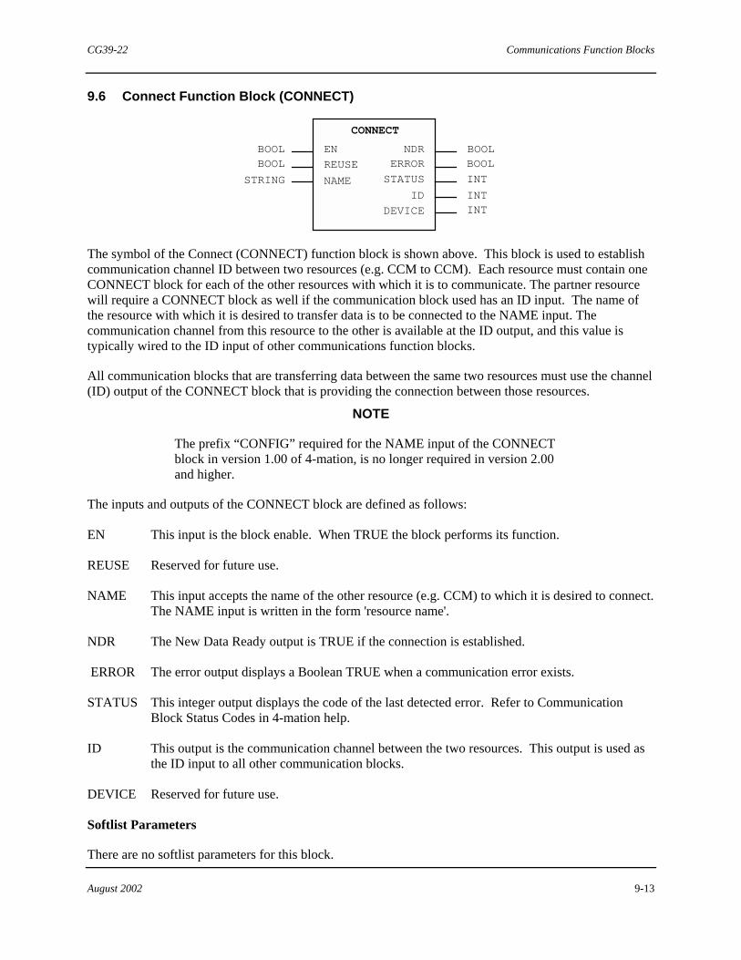
CG39-22 Communications Function Blocks
August 2002 9-13
9.6 Connect Function Block (CONNECT)
BOOL BOOLBOOLBOOL
NDRERROR
STATUS INT
CONNECT
STRING
EN
REUSE
INTID
DEVICE INT
NAME
The symbol of the Connect (CONNECT) function block is shown above. This block is used to establish communication channel ID between two resources (e.g. CCM to CCM). Each resource must contain one CONNECT block for each of the other resources with which it is to communicate. The partner resource will require a CONNECT block as well if the communication block used has an ID input. The name of the resource with which it is desired to transfer data is to be connected to the NAME input. The communication channel from this resource to the other is available at the ID output, and this value is typically wired to the ID input of other communications function blocks.
All communication blocks that are transferring data between the same two resources must use the channel (ID) output of the CONNECT block that is providing the connection between those resources.
NOTE
The prefix “CONFIG” required for the NAME input of the CONNECT block in version 1.00 of 4-mation, is no longer required in version 2.00 and higher.
The inputs and outputs of the CONNECT block are defined as follows:
EN This input is the block enable. When TRUE the block performs its function.
REUSE Reserved for future use.
NAME This input accepts the name of the other resource (e.g. CCM) to which it is desired to connect. The NAME input is written in the form 'resource name'.
NDR The New Data Ready output is TRUE if the connection is established.
ERROR The error output displays a Boolean TRUE when a communication error exists.
STATUS This integer output displays the code of the last detected error. Refer to Communication Block Status Codes in 4-mation help.
ID This output is the communication channel between the two resources. This output is used as the ID input to all other communication blocks.
DEVICE Reserved for future use.
Softlist Parameters
There are no softlist parameters for this block.

Communications Function Blocks CG39-22
9-14 August 2002
!Notes

CG39-22 Timing Function Blocks
August 2002 10-1
10.0 Timing Function Blocks
The Timing function blocks are a subset of the standard function blocks. These blocks perform various timing functions. For memory usage and ACM execution time information on all standard configuration elements, refer to Appendix C in Using the ProcessSuite 4-mation Configuration Software (document number CG39-20).
A listing of Compare and Select function blocks is presented here. Individual blocks are detailed in the subsections that follow.
• ON-Delay Timer • OFF-Delay Timer • Retentive Timer • Timed Pulse • Repeat Cycle Timer
10.1 On-Delay Timer Function Block (TON)
IN
PT
Q
ET
BOOL
TIME
BOOL
TIME
TON
The symbol of the On-Delay Timer (TON) function block is shown above. This block provides an output of TRUE after a preset time period if the input (IN) remains TRUE for a period of time greater than the preset time (PT).
When the TON function block is enabled [(IN) = (TRUE)], the elapsed time (ET) will accumulate until it is equal to the preset time (PT). When the (ET) = (PT), the (Q) output will be set to TRUE. The (Q) output will remain TRUE until the (IN) input is FALSE. When the (IN) input changes to FALSE, the (Q) output changes from TRUE to FALSE, and the (ET) output becomes T#00ms.
WARNING
When timers are activated in a section of configuration that may not be executed every scan (i.e. when used in actions or selective structured text statements), the timers will continue to time internally unless (IN) is turned FALSE upon (Q) becoming TRUE.
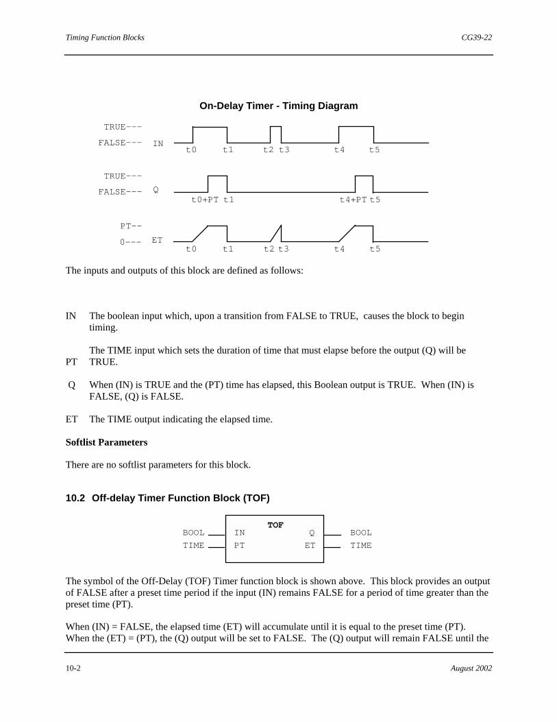
Timing Function Blocks CG39-22
10-2 August 2002
On-Delay Timer - Timing Diagram
TRUE---
FALSE--- IN
TRUE---
FALSE--- Q
PT--
0--- ET
t0 t1 t2 t3 t4 t5
t1 t4+PT t5
t0 t1 t2 t3 t4 t5
t0+PT
The inputs and outputs of this block are defined as follows:
IN The boolean input which, upon a transition from FALSE to TRUE, causes the block to begin timing.
PT
The TIME input which sets the duration of time that must elapse before the output (Q) will be TRUE.
Q When (IN) is TRUE and the (PT) time has elapsed, this Boolean output is TRUE. When (IN) is FALSE, (Q) is FALSE.
ET The TIME output indicating the elapsed time.
Softlist Parameters
There are no softlist parameters for this block.
10.2 Off-delay Timer Function Block (TOF)
IN
PT
Q
ET
BOOL
TIME
BOOL
TIME
TOF
The symbol of the Off-Delay (TOF) Timer function block is shown above. This block provides an output of FALSE after a preset time period if the input (IN) remains FALSE for a period of time greater than the preset time (PT).
When (IN) = FALSE, the elapsed time (ET) will accumulate until it is equal to the preset time (PT). When the (ET) = (PT), the (Q) output will be set to FALSE. The (Q) output will remain FALSE until the
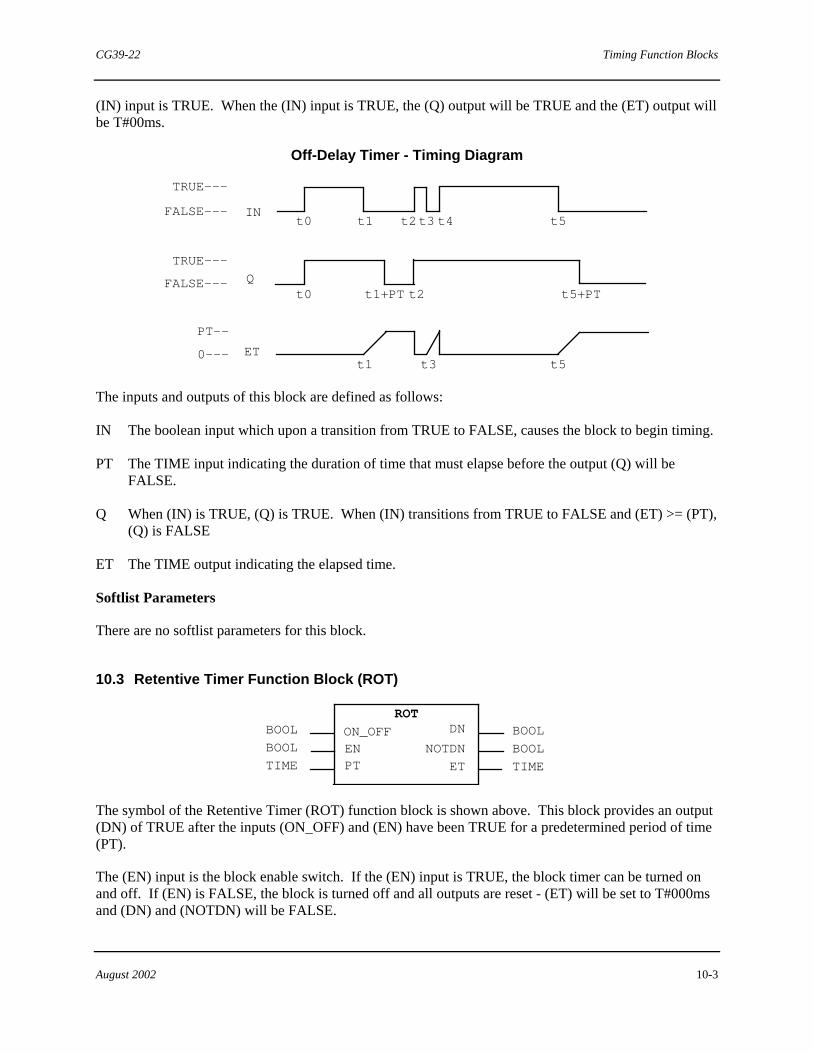
CG39-22 Timing Function Blocks
August 2002 10-3
(IN) input is TRUE. When the (IN) input is TRUE, the (Q) output will be TRUE and the (ET) output will be T#00ms.
Off-Delay Timer - Timing Diagram
TRUE---
FALSE--- IN
TRUE---
FALSE--- Q
PT--
0--- ET
t0 t1 t2t3 t4 t5
t0 t1+PT t2 t5+PT
t1 t3 t5
The inputs and outputs of this block are defined as follows:
IN The boolean input which upon a transition from TRUE to FALSE, causes the block to begin timing.
PT The TIME input indicating the duration of time that must elapse before the output (Q) will be FALSE.
Q When (IN) is TRUE, (Q) is TRUE. When (IN) transitions from TRUE to FALSE and (ET) >= (PT), (Q) is FALSE
ET The TIME output indicating the elapsed time.
Softlist Parameters
There are no softlist parameters for this block.
10.3 Retentive Timer Function Block (ROT)
BOOLBOOL
TIME
BOOL
ROT
BOOL
TIME
ON_OFFENPT
DN
NOTDN
ET
The symbol of the Retentive Timer (ROT) function block is shown above. This block provides an output (DN) of TRUE after the inputs (ON_OFF) and (EN) have been TRUE for a predetermined period of time (PT).
The (EN) input is the block enable switch. If the (EN) input is TRUE, the block timer can be turned on and off. If (EN) is FALSE, the block is turned off and all outputs are reset - (ET) will be set to T#000ms and (DN) and (NOTDN) will be FALSE.

Timing Function Blocks CG39-22
10-4 August 2002
The (ON_OFF) input controls the timing action of the block but has no effect if (EN) is FALSE. While (EN) is TRUE and (ON_OFF) is TRUE, (ET) accumulates. If the (ET) is less than the (PT), then the (NOTDN) output will be TRUE. If the (EN) input is TRUE, the (ON_OFF) input is TRUE, and the (ET) has reached the (PT), then the (DN) output will be TRUE. If (EN) is TRUE and the (ON_OFF) input becomes FALSE, the (ET) will stop accumulating and hold its value (retentive). The (ET) will begin accumulating from where it left off if (ON_OFF) becomes TRUE before (EN) is set to FALSE.
EN
DN
NOTDN
PT
ET 0
RETENTIVE ON TIMER - TIMING DIAGRAM
ON_OFF
The inputs and outputs of this block are defined as follows:
ON_OFF When TRUE, this boolean input tells the block to begin timing. The (EN) input must be TRUE for this input to have an effect.
EN This is the block enable input. When TRUE, the block is capable of performing its function. When FALSE the (ET) is reset.
PT This TIME input indicates the preset time duration that the block must reach for (DN) to go TRUE.
DN This Boolean output indicates when the timing is "done" and will be TRUE when all of the following occur: (EN) is TRUE, (ON_OFF) is TRUE and (ET) >= (PT).
NOTDN This boolean output is TRUE when (EN) is TRUE and (ET) < (PT).
ET This TIME output indicates the elapsed time of the block.
Softlist Parameters
There are no softlist parameters for this block.

CG39-22 Timing Function Blocks
August 2002 10-5
10.4 Timed Pulse Function Block (TP)
TPIN
PT
Q
ET
BOOL
TIME
BOOL
TIME
The symbol of the Timed Pulse (TP) function block is shown above. This block provides a BOOL pulse output for a predetermined time period. The pulse timer starts when block input (IN) changes from FALSE to TRUE. This causes block output (Q) to become TRUE for the duration of the pulse. Pulse duration is set by the TIME value applied to the pulse time (PT) input. The (ET) output value represents the elapsed time of the pulse since starting the timer.
When the pulse times out, the (Q) output changes from TRUE to FALSE. (IN) is already FALSE at this time and (ET) will immediately be set to a value of zero (i.e. T#000ms). Otherwise, (ET) will equal (PT) and will output a value of zero (i.e. T#000ms) when (IN) returns to FALSE.
Based on the above paragraph, the elapsed time value (ET) may not necessarily ever equal pulse time (PT), depending on the (IN) signal at the end of the pulse. The logic that you develop when using this block should use the (Q) output to determine the end of the pulse.
Once the pulse has been triggered, (Q)=TRUE, the block cannot be retriggered until the end of the timed pulse. During power-up, the (Q) and (ET) outputs are initialized to values of FALSE and T#000ms, respectively.
Timed Pulse - Timing Diagram
IN
Q
PT --
0 --- ET
t0 t1 t2 t3 t4 t5
t0 t0+PT t2 t2+PT t4 t4+PT
t0 t1 t2 t4 t5
TRUE ---
FALSE ---
TRUE ---
FALSE ---
The inputs and outputs of the TP block are defined as follows:
IN This is the block input. It accepts a BOOL value; when TRUE, it starts the pulse timer.
PT This is the Pulse Time input. It accepts a TIME data type value, which determines the duration of the pulse.
Q This is the Q output. It outputs a BOOL value. When (IN) turns TRUE, this Q output is TRUE for the duration of the (PT), and then it switches to FALSE.
ET This is the Elapsed Time output. It provides a TIME value indicating the elapsed time.

Timing Function Blocks CG39-22
10-6 August 2002
Softlist Parameters
There are no softlist parameters for this block.
10.5 Repeat Cycle Timer Function Block (RECYCL)
REPCYCL
TIMREM
BOOL BOOLREAL TIME
TIME
OUTENPCTON ET
The symbol of the Repeat Cycle Timer (REPCYCL) function block is shown above. This block performs the function of a repeat cycle timer.
When (EN) is FALSE, the (OUT) output is FALSE, the (ET) output is set to zero, the (TIMREM) output is set to the period time and the internal elapsed timer is also set to zero.
The actual time that the (OUT) output is TRUE equals the Softlist Parameter ONTIME, and can be modified by the input (PCTON).
The START_STATE softlist parameter allows the timer to start in the TRUE or FALSE state.
Elapsed Time (ET) and Time Remaining (TIMREM) are given as outputs. These outputs will always reflect the current period parameters. (ET) will count up from zero and (TIMREM) will count down from the period time. The start of a period will begin on a FALSE-to-TRUE transition of the (EN) input. The start of subsequent periods will be determined by (OUT) output transitions and the (ET). A period will start on the FALSE-to-TRUE output transition, if the START_STATE is TRUE, or on the TRUE-to-FALSE output transition if the START_STATE is FALSE.
Either of two possible timing modes are selected by specifying either a zero or a non-zero value for OFFTIME as follows:
1. When OFFTIME is greater than zero milliseconds, the Repeat Cycle Timer period is a variable equal to [OFFTIME + ((PCTON) * ONTIME)]. (OUT) is FALSE for a fixed length of time (equal to OFFTIME). (PCTON) is internally limited to non-negative values (>= 0%).
2. When OFFTIME is equal to zero milliseconds, the Repeat Cycle Timer period is fixed (equal to ONTIME). (OUT) is FALSE for a variable length of time equal to [ONTIME - ((PCTON) * ONTIME)]. (PCTON) is internally limited to non-negative values <= 100.0%.
The internal timer remains synchronized with real time while the (EN) input is TRUE, even when (PCTON) is greater than or equal to 100.0% ((OUT) is held TRUE) or less than or equal to 0.0% ((OUT) is held FALSE).
The actual (OUT) TRUE or FALSE state lasts at least as long as the configured scan time for the program. On or off times that are not multiples of the scan time will cause the (OUT) state to last up to one scan time longer or shorter than the configured on or off time. (Time will be longer for most cycles until excess elapsed time causes a shorter cycle to re-synchronize with Real-Time.)
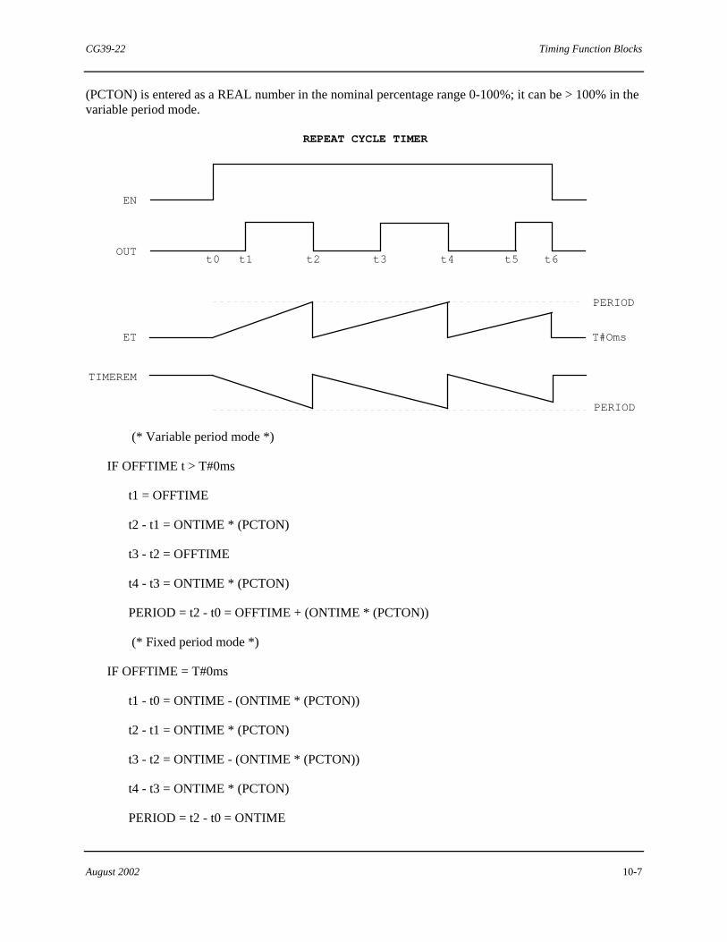
CG39-22 Timing Function Blocks
August 2002 10-7
(PCTON) is entered as a REAL number in the nominal percentage range 0-100%; it can be > 100% in the variable period mode.
EN
OUT
ET
TIMEREM
PERIOD
PERIOD
REPEAT CYCLE TIMER
T#Oms
t1 t2t0 t3 t4 t5 t6
(* Variable period mode *)
IF OFFTIME t > T#0ms
t1 = OFFTIME
t2 - t1 = ONTIME * (PCTON)
t3 - t2 = OFFTIME
t4 - t3 = ONTIME * (PCTON)
PERIOD = t2 - t0 = OFFTIME + (ONTIME * (PCTON))
(* Fixed period mode *)
IF OFFTIME = T#0ms
t1 - t0 = ONTIME - (ONTIME * (PCTON))
t2 - t1 = ONTIME * (PCTON)
t3 - t2 = ONTIME - (ONTIME * (PCTON))
t4 - t3 = ONTIME * (PCTON)
PERIOD = t2 - t0 = ONTIME

Timing Function Blocks CG39-22
10-8 August 2002
The inputs and the outputs of this block are defined as follows:
EN This is the Enable input, when TRUE the timer will begin.
OUT This is the output of the function block.
PCTON This is the input factor which modifies the ONTIME softlist value to provide the actual time on. (PCTON) has percent units in the range of 0.0 to 100.0.
ET This is the Elapsed Time output. It indicates the elapsed time of the period.
TIMREM This is the is the Time Remaining output. It indicates the time remaining of the period.
Softlist Parameters
START_STATE This is the boolean start state of the timer cycle. When TRUE, the period starts on a FALSE to TRUE output transition. When FALSE, the period starts on a TRUE to FALSE output transition.
OFFTIME This is the softlist parameter for specifying the time off.
ONTIME This is the softlist parameter for specifying the time on.
Parameter Data Type Initial Value Min Value Max Value
OFFTIME TIME T#0d0h0m0s0ms T#0d0h0m0s0ms NA
ONTIME TIME T#0d0h1m0s0ms T#0d0h0m0s0ms NA
START_STATE BOOL TRUE FALSE TRUE
NOTE
The REPCYCL block may skip output pulses if the pulse times are less than or equal to the controller scan time. To reduce the chance of missed pulses, the time period used (for either the ONTIME or OFFTIME softlist parameters) would be at least three times the scan time of the controller; for better accuracy, a ratio of five times the scan time is preferred.

CG39-22 Counting Function Blocks
August 2002 11-1
11.0 Counting Function Blocks
The Counting function blocks are a subset of the standard function blocks. These blocks perform counting functions and operate on Boolean inputs.
All process variable (PV) inputs have an INT unit range of +32767 to -32768.
For memory usage and ACM execution time information on all standard configuration elements, see Appendix C in Using the 4-mation Configuration Software (document number CG39-20).
A listing of Counting function blocks is presented here. Individual blocks are detailed in the subsections that follow.
• Up Counter • Down Counter • Up/Down Counter
11.1 Up Counter Function Block (CTU)
Q BOOLBOOLCTU
CV INTBOOLCU
RPVINT
The symbol of the Up Counter (CTU) function block is shown above. This block performs a count-up function.
For each cycle that a FALSE-to-TRUE transition occurs at the (CU) input while (R) is FALSE, the (CV) output will increment once, counting up from zero and stopping at the maximum integer value (+32767). The (Q) output is TRUE when (CV) >= (PV). When reset (R) is TRUE, the counter value (CV) resets to zero and the BOOL output (Q) is set to FALSE.
The inputs and outputs of the CTU block are defined as follows:
CU This boolean count-up input causes the counter's (CV) to increment when a FALSE to TRUE transition is sensed.
R This boolean is the reset input. When toggled from FALSE to TRUE, the (CV) input is set to 0 and (Q) is reset.
PV This integer input is the preset value. The current value (CV) must count up to this value in order for (Q) to be TRUE.
Q This boolean output is TRUE when (CV) >= (PV).
CV This integer output indicates the count amount (The number of times the (CU) has toggled during which (R) has remained FALSE).
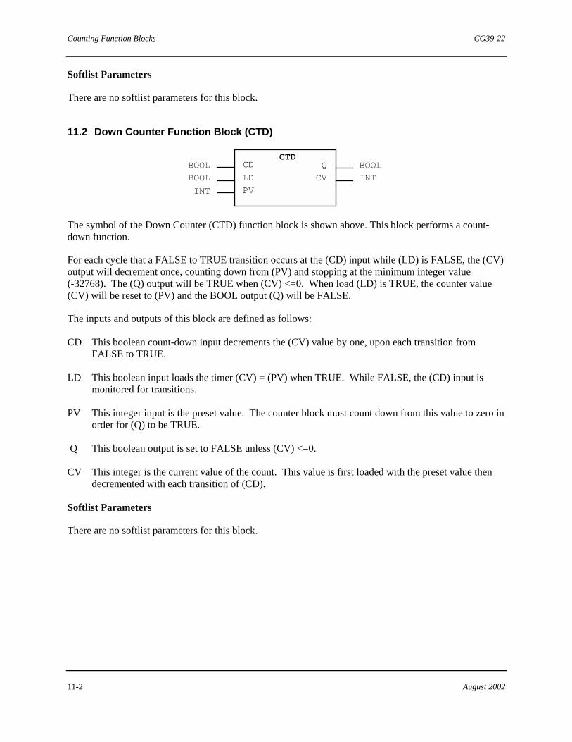
Counting Function Blocks CG39-22
11-2 August 2002
Softlist Parameters
There are no softlist parameters for this block.
11.2 Down Counter Function Block (CTD)
Q BOOLBOOL
CV INTBOOL
CTD
INT
CD
LD
PV
The symbol of the Down Counter (CTD) function block is shown above. This block performs a count-down function.
For each cycle that a FALSE to TRUE transition occurs at the (CD) input while (LD) is FALSE, the (CV) output will decrement once, counting down from (PV) and stopping at the minimum integer value (-32768). The (Q) output will be TRUE when (CV) <=0. When load (LD) is TRUE, the counter value (CV) will be reset to (PV) and the BOOL output (Q) will be FALSE.
The inputs and outputs of this block are defined as follows:
CD This boolean count-down input decrements the (CV) value by one, upon each transition from FALSE to TRUE.
LD This boolean input loads the timer (CV) = (PV) when TRUE. While FALSE, the (CD) input is monitored for transitions.
PV This integer input is the preset value. The counter block must count down from this value to zero in order for (Q) to be TRUE.
Q This boolean output is set to FALSE unless (CV) <=0.
CV This integer is the current value of the count. This value is first loaded with the preset value then decremented with each transition of (CD).
Softlist Parameters
There are no softlist parameters for this block.

CG39-22 Counting Function Blocks
August 2002 11-3
11.3 Up/Down Counter Function Block (CTUD)
BOOL
BOOL
CTUD
BOOL
BOOL
INT
CU
CD
R
LD
PV
BOOL
BOOL
INT
QU
QD
CV
The symbol of the Up/Down Counter (CTUD) function block is shown above. This block performs a count-up/count-down function.
When Reset (R) is TRUE, the Counter value (CV) will be reset to zero. When Load (LD) is TRUE, the (CV) will be loaded with the preset value (PV). Reset (R) has a higher priority than (LD). The Up Output (QU) will be TRUE whenever the (CV) is greater or equal to the (PV). The Down Output (QD) will be TRUE whenever (CV) is less than or equal to zero. These outputs will be FALSE at all other times.
While (R) and (LD) are FALSE, (CV) will increment or decrement once for each cycle that a transition occurs at the (CU) or (CD) inputs, respectively. (CV) uses the following range: -32768 to +32767.
Simultaneous counting is not allowed, and UP counting has priority over DOWN counting.
The inputs and outputs of this block are defined as follows:
CU This boolean input is checked for FALSE to TRUE transitions. If found, the (CV) output increments by one.
CD
This boolean input is checked for FALSE to TRUE transitions. If found, the (CV) output decrements by one.
R When TRUE, this boolean input resets the (CV) output to zero.
LD When this boolean input is TRUE, (CV) is loaded with the (PV) value.
PV This integer value is loaded into the (CV) value when (LD) is TRUE and is used to trip (QU) when (CV) = (PV).
QU This boolean output is TRUE whenever (CV) is greater than (PV).
QD This Boolean output is TRUE whenever (CV) is less than or equal to zero.
CV This is the current value.
Softlist Parameters
There are no softlist parameters for this block. "

Counting Function Blocks CG39-22
11-4 August 2002
!Notes

CG39-22 Alarm Function Blocks
August 2002 12-1
12.0 Alarm Function Blocks
The Alarm function blocks are a subset of the standard function blocks. These blocks provide alarming functions. For memory usage and control module execution time information on all standard configuration elements, see Appendix C in Using the 4-mation Configuration Software (document number CG39-20).
A listing of Alarm function blocks is presented here. Individual blocks are detailed in the subsections that follow.
• HLL Analog Alarm • HLL Analog Alarm 4 • HLL Discrete Alarm • HLL Discrete Alarm 1
12.1 HLL Analog Alarm Function Block (HLLAALM)
BOOL
HLLAALM
ANY_NUM
ANY_NUMPVDEV
BOOL
BOOLBOOL
BOOL
BOOL
EN1
EN2EN3
EN4
OOS
BOOL
BOOL
BOOLBOOL
BOOL
BOOL
BOOL
INT
INT
ALM1
NAK1ALM2
NAK2
ALM3
NAK3
ALM4
NAK4
STATUS
CMD
The symbol of the Hi-Level Link (HLL) Analog Alarm (HLLAALM) function block is shown above. This block detects abnormal data values. It is intended for MYCROÔ users as it maintains an Alarm Status Word output (STATUS) in the MYCRO/MLC/HLL format.
The (STATUS) output reflects the block's enable, alarm, acknowledge, and out of service values.
The (CMD) output allows an HMI to issue commands change the (NAK), (EN) or (OOS) values.
The (OOS) input indicates to monitoring devices that the block's alarms have been put out of service and can be ignored (even though the alarm processing still continues).
There are five different alarm types as follows:
• Absolute • Deviation • Out Of Range • Quality • Rate Of Change

Alarm Function Blocks CG39-22
12-2 August 2002
Absolute The absolute alarm can be configured for high, high_high, low or low_low detection. The second input (DEV) is not used when the alarm is configured for absolute. If the enable input (EN) is TRUE and the (PV) input of an absolute alarm reaches the limit in the direction selected (as high or higher than a high limit, or as low or lower than a low limit) and remains in that state for longer than the configured delay time in, then the [ALM(1 - 4)] output and the [NAK(1-4)] output are set TRUE.
Deviation The deviation alarm checks the difference between the (PV) and the (DEV) inputs. If the enable input (EN) is TRUE and the deviation reaches the deviation limit for the entered delay time in, the [ALM(n)] and the [NAK(n] outputs are set TRUE.
Out of Range The out of range alarm checks if the input value is within the entered range. If (PV) is less than EINL or greater than EINH, the [ALM(n)] and the [NAK(n)] outputs are set TRUE.
Quality The quality alarm can be configured to detect whenever the quality of the PV is not GOOD. If the PV value's quality is BAD, QUESTIONABLE, or UNAVAILABLE the [ALM(n)] and [NAK(n)] outputs are set to TRUE.
Rate of Change The rate of change alarm detects if the PV input value is changing at a rate greater than the (limits per minute in engineering units) value established by the ALARMn_LIMIT softlist parameter. If the condition continues beyond the time period established by the ALARMn_DELAYIN softlist parameter, the [ALM(n)] and [NAK(n)] outputs are set to TRUE. This alarm can be configured to trigger in any one of three ways. The rate of change increase alarm triggers on an increasing PV input; the rate of change decrease alarm triggers on a decreasing PV input, and the rate of change absolute alarm triggers on a PV input changing in either direction.
The annunciation and acknowledgment of the absolute, deviation, out of range, and quality alarms are the same. When an alarm condition occurs, the alarm continues to be annunciated until the alarm has been acknowledged [until the (NAK) bit has been reset]. Once acknowledged, the alarm is not annunciated again until the alarm condition clears and returns. The (ALM) output remains TRUE until the alarm condition is cleared. If ringback is enabled, the (NAK) output is set to TRUE when the alarm condition clears, requiring acknowledgment of the cleared condition.
All (ALM) outputs are FALSE only if the process value (or deviation) is within the alarm limit by at least the amount of the deadband and remains in that state for the required amount of delay time out.
CG39-22 Alarm Function Blocks
August 2002 12-3
The inputs and outputs of the HLLAALM block are defined as follows:
PV This input is the value to be monitored for alarms.
DEV This input is the deviation input. The difference between this input and the (PV) input is monitored when a deviation alarm is selected.
EN(n) These inputs are the enable inputs for alarms one to four. When TRUE, the corresponding alarm is enabled.
OOS This input indicates that the alarm is out of service.
ALM(n) This output is TRUE if the corresponding alarm is detected and enabled.
NAK(n) This output is be TRUE if the corresponding alarm is tripped but has not been acknowledged.
STATUS This integer output is the Alarm Status Word in decimal. It is provided for use by a Human-Machine Interface (HMI).
CMD This output is used by an operator interface to allow access to the input values. That is, a console can modify the outputs [NAK(n)] and the input variables [EN(n)] via this output. See Table 12–1
.
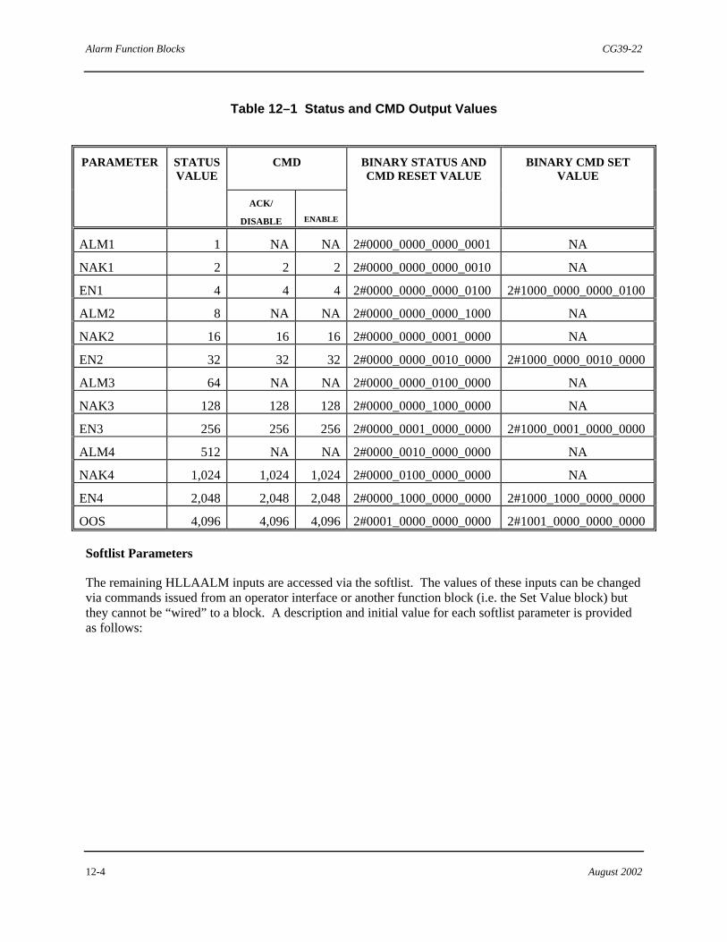
Alarm Function Blocks CG39-22
12-4 August 2002
Table 12–1 Status and CMD Output Values
CMD
PARAMETER STATUS VALUE
ACK/
DISABLE
ENABLE
BINARY STATUS AND CMD RESET VALUE
BINARY CMD SET VALUE
ALM1 1 NA NA 2#0000_0000_0000_0001 NA
NAK1 2 2 2 2#0000_0000_0000_0010 NA
EN1 4 4 4 2#0000_0000_0000_0100 2#1000_0000_0000_0100
ALM2 8 NA NA 2#0000_0000_0000_1000 NA
NAK2 16 16 16 2#0000_0000_0001_0000 NA
EN2 32 32 32 2#0000_0000_0010_0000 2#1000_0000_0010_0000
ALM3 64 NA NA 2#0000_0000_0100_0000 NA
NAK3 128 128 128 2#0000_0000_1000_0000 NA
EN3 256 256 256 2#0000_0001_0000_0000 2#1000_0001_0000_0000
ALM4 512 NA NA 2#0000_0010_0000_0000 NA
NAK4 1,024 1,024 1,024 2#0000_0100_0000_0000 NA
EN4 2,048 2,048 2,048 2#0000_1000_0000_0000 2#1000_1000_0000_0000
OOS 4,096 4,096 4,096 2#0001_0000_0000_0000 2#1001_0000_0000_0000
Softlist Parameters
The remaining HLLAALM inputs are accessed via the softlist. The values of these inputs can be changed via commands issued from an operator interface or another function block (i.e. the Set Value block) but they cannot be “wired” to a block. A description and initial value for each softlist parameter is provided as follows:

CG39-22 Alarm Function Blocks
August 2002 12-5
ALARMn_TYPE The enumerated input that determines the type of alarm configured. The available selections are listed as follows.
Enumerated Value
Selections Description
0 NONE No Alarm
1 HIGH High Absolute Alarm
2 LOW Low Absolute Alarm
3 HIGH_DEV High Deviation Alarm
4 LOW_DEV Low Deviation Alarm
5 ABSOLUTE_DEV Absolute Deviation Alarm
6 OUT_OF_RANGE Out of Range Alarm
7 QUALITY_NOT_GOOD Quality Alarm
8 HIGH_HIGH High high Alarm
9 LOW_LOW Low low Alarm
10 INC_ROC Rate of Change Increase Alarm
11 DEC_ROC Rate of Change Decrease Alarm
12 ABS_ROC Rate of Change Absolute Alarm
NOTE
When using 4-mation to configure this block, select the desired enumerated type by name from the Selections area of the block's Softlist dialog box. When writing to an enumerated softlist parameter from outside the controller (from an operator interface) or from inside the controller (using a Set Value function block), use the associated integer value. For example, to change the alarm type to a high absolute alarm, a "1" should be written to the ALARMn_TYPE softlist parameter.

Alarm Function Blocks CG39-22
12-6 August 2002
ALARMn_LIMIT The value (in engineering units) to which the (PV) input is compared. For rate of change alarm applications, this is the value (in engineering units per minute) to which the (PV) input is compared.
ALARMn_DEADBAND The amount of engineering units by which (PV) must be within the limit for an alarm to clear.
ALARMn_DELAYIN The amount of time the input must reach or exceed the limit to trip an alarm.
ALARMn_DELAYOUT The amount of time the input must be within the limit and deadband to cause the alarm to clear.
ALARMn_RINGBACK The Boolean switch which when TRUE will alarm [set the (NAK) output] when an alarm clears as well as when it trips.
DISABLE_ON_OOS This Disable On Out-of-Service parameter accepts a Boolean value of TRUE or FALSE. When set to TRUE, the block is disabled if the Out-Of-Service (OOS) input is also TRUE. When set to FALSE, this parameter has no affect on block operation.
EINL The PV low value, in engineering units, used for the out of range alarm.
EINH The PV high value, in engineering units, used for the out of range alarm.

CG39-22 Alarm Function Blocks
August 2002 12-7
Parameter Units Initial Value Min Value Max Value
ALARM1_TYPE ALARM_TYPE NONE NA NA
ALARM1_LIMIT Engr 0.0 NA NA
ALARM1_DEADBAND Engr 0.5 0.0 NA
ALARM1_DELAYIN TIME T#0d0h0m0s0ms T#0d0h0m0s0ms NA
ALARM1_DELAYOUT TIME T#0d0h0m0s0ms T#0d0h0m0s0ms NA
ALARM1_RINGBACK BOOL FALSE FALSE TRUE
ALARM2_TYPE ALARM_TYPE NONE NA NA
ALARM2_LIMIT Engr 0.0 NA NA
ALARM2_DEADBAND Engr 0.5 0.0 NA
ALARM2_DELAYIN TIME T#0d0h0m0s0ms T#0d0h0m0s0ms NA
ALARM2_DELAYOUT TIME T#0d0h0m0s0ms T#0d0h0m0s0ms NA
ALARM2_RINGBACK BOOL FALSE FALSE TRUE
ALARM3_TYPE ALARM_TYPE NONE NA NA
ALARM3_LIMIT Engr 0.0 NA NA
ALARM3_DEADBAND Engr 0.5 0.0 NA
ALARM3_DELAYIN TIME T#0d0h0m0s0ms T#0d0h0m0s0ms NA
ALARM3_DELAYOUT TIME T#0d0h0m0s0ms T#0d0h0m0s0ms NA
ALARM3_RINGBACK BOOL FALSE FALSE TRUE
ALARM4_TYPE ALARM_TYPE NONE NA NA
ALARM4_LIMIT Engr 0.0 NA NA
ALARM4_DEADBAND Engr 0.5 0.0 NA

Alarm Function Blocks CG39-22
12-8 August 2002
ALARM4_DELAYIN TIME T#0d0h0m0s0ms T#0d0h0m0s0ms NA
ALARM4_DELAYOUT TIME T#0d0h0m0s0ms T#0d0h0m0s0ms NA
ALARM4_RINGBACK BOOL FALSE FALSE TRUE
EINL Engr 0.0 NA NA
EINH Engr 100.0 NA NA
DISABLE_ON_OOS BOOL FALSE FALSE TRUE
Where NA indicates not applicable
12.2 HLL Analog Alarm 4 Function Block (HLLAA4)
HLLAA4
ANY_NUM INTSTATUSPV
The symbol of the Hi-Level Link (HLL) Analog Alarm 4 (HLLAA4) function block is shown above. This block is used to detect abnormal data values in the control system. This block is a derivation of the HLLAALM block and intended for MYCROä users. This block is used as an analog indicator with alarms in situations where an alarm block must occupy less area on a sheet than the HLLAALM block. To reduce the number of inputs and outputs, the EN(n), ALM(n), NAK(n) and OOS functions are implemented as softlist parameters. In addition, this block does not support deviation alarms.
The HLL Analog Alarm Function Block has two functions. It is used to detect abnormal data values in the control system. It also outputs an Alarm Status Word, STATUS, in the MYCRO/MLC/HLL format. The STATUS output details the block's enable, alarm, acknowledge and out of service values. This allows existing MYCRO consoles to communicate with the HLLAA4 block through the LIM and Presentation block connection and Human-Machine Interface (HMI), to communicate directly to the STATUS Word. The CMD softlist parameter is the command port used to change the NAK or EN values from the HLL.

CG39-22 Alarm Function Blocks
August 2002 12-9
There are four different alarms types:
• Absolute • Out of Range • Quality • Rate of Change
Absolute The absolute alarm can be configured for either high, high-high, low, or low-low detection. If the Enable input (EN) is TRUE and the PV input of an absolute alarm exceeds the limit in the direction selected (i.e. higher than a high limit or lower than a low limit) and remains in that state for longer than the entered delay time in, then the [ALM(n)] and the [NAK(n)] outputs are set to TRUE.
Out of Range
The out of range alarm checks if the input value is within the entered range (EINL - EINH). If PV is less than 0.0% of or greater than 100.0% of the range, the [ALM(n)] and [NAK(n)] outputs are set to TRUE.
Quality The quality alarm can be configured to detect whenever the quality of the PV is not GOOD. If the PV value's quality is BAD, QUESTIONABLE, or UNAVAILABLE, the [ALM(n)] and [NAK(n)] outputs are set to TRUE.
Rate of Change
The rate of change alarm detects if the PV input value is changing at a rate greater than the (limits per minute in engineering units) value established by the ALARMn_LIMIT softlist parameter. If the condition continues beyond the time period established by the ALARMn_DELAYIN softlist parameter, the [ALM(n)] and [NAK(n)] outputs are set to TRUE. This alarm can be configured to trigger in any one of three ways. The rate of change increase alarm triggers on an increasing PV input; the rate of change decrease alarm triggers on a decreasing PV input, and the rate of change absolute alarm triggers on a PV input changing in either direction.
The annunciation and acknowledgement of all four alarm types are the same. When an alarm condition occurs, the alarm continues to be annunciated until it is acknowledged (the NAK bit is reset). Once acknowledged, the alarm is not be annunciated again until the alarm condition clears and returns. The ALM output remains TRUE until the alarm condition is cleared. If the ringback is enabled, the NAK output is TRUE when the alarm condition clears, requiring acknowledgement of the cleared condition.
The ALM output is FALSE only if the process value is within the alarm limits by at least the amount of the deadband and remains in that state for the required amount of delay time out.
The input and output of the HLLAA4 block are as follows:
PV This is the Process Variable input. It is the value to be monitored.
STATUS This is the Status output. It provides the alarm status word in decimal.

Alarm Function Blocks CG39-22
12-10 August 2002
Softlist Parameters
ALARMn_TYPE The enumerated input which determines the type of alarm configured. The available selections are listed below.
Enumerated Value
Selections Description
0 NONE No Alarm
1 HIGH High Absolute Alarm
2 LOW Low Absolute Alarm
6 OUT_OF_RANGE Out of Range Alarm
7 QUALITY_NOT_GOOD Quality Alarm
8 HIGH_HIGH High high Alarm
9 LOW_LOW Low low Alarm
10 INC_ROC Rate of Change Increase Alarm
11 DEC_ROC Rate of Change Decrease Alarm
12 ABS_ROC Rate of Change Absolute Alarm
NOTE
When using 4-mation to configure this block, select the desired enumerated type by name from the Selections area of the block's Softlist dialog box. When writing to an enumerated softlist parameter from outside the controller (from an operator interface) or from inside the controller (using a Set Value function block), use the associated integer value. For example, to change the alarm type to a high absolute alarm, a "1" should be written to the ALARMn_TYPE softlist parameter.

CG39-22 Alarm Function Blocks
August 2002 12-11
ALARMn_LIMIT The value (in engineering units) to which the (PV) input is compared. For rate of change alarm applications, this is the value (in engineering units per minute) to which the (PV) input is compared.
ALARMn_DEADBAND
The amount of engineering units by which (PV) must be within the limit for an alarm to clear.
ALARMn_DELAYIN The amount of time the input must reach or exceed the limit to trip an alarm.
ALARMn_DELAYOUT
The amount of time the input must be within the limit and deadband to cause the alarm to clear.
ALARMn_RINGBACK The Boolean switch which, when TRUE, will alarm [set the (NAK) output] when an alarm clears as well as when it trips.
OOS The Boolean switch which, when TRUE, indicates to monitoring devices that the block's alarms have been put out-of-service (OOS) and can be ignored (even though the alarm processing still continues).
DISABLE_ON_OOS This Disable On Out-of-Service parameter accepts a boolean value of TRUE or FALSE. When set to TRUE, the block is disabled if the Out-Of-Service (OOS) parameter is also TRUE. When set to FALSE, this parameter has no affect on block operation.
EINL The PV low value (in engineering units) used for the out of range alarm.
EINH The PV high value (in engineering units) used for the out of range alarm.
EN(n) These parameters are the Enable inputs for alarms one to four. When TRUE, the corresponding alarm is enabled.
ALM(n) These parameters are the Alarm outputs. An output is TRUE if the corresponding alarm is detected and enabled.
NAK(n) These parameters are the Not Acknowledged outputs. An output is TRUE if the corresponding alarm is tripped but has not been acknowledged.
CMD This parameter is used by an operator interface to allow access to the input values. That is, the operator console can modify the [NAK(n)] outputs, and the input variables [EN(n)]. See
.

Alarm Function Blocks CG39-22
12-12 August 2002
Table 12–2 CMD Values
CMD
PARAMETER STATUS VALUE
ACK/
DISABLE
ENABLE
BINARY STATUS AND CMD RESET VALUE
BINARY CMD SET VALUE
ALM1 1 NA NA 2#0000_0000_0000_0001 NA
MAL1 2 2 2 2#0000_0000_0000_0010 NA
EN1 4 4 4 2#0000_0000_0000_0100 2#1000_0000_0000_0100
ALM2 8 NA NA 2#0000_0000_0000_1000 NA
NAK2 16 16 16 2#0000_0000_0001_0000 NA
EN2 32 32 32 2#0000_0000_0010_0000 2#1000_0000_0010_0000
ALM3 64 NA NA 2#0000_0000_0100_0000 NA
NAK3 128 128 128 2#0000_0000_1000_0000 NA
EN3 256 256 256 2#0000_0001_0000_0000 2#1000_0001_0000_0000
ALM4 512 NA NA 2#0000_0010_0000_0000 NA
NAK4 1,024 1,024 1,024 2#0000_0100_0000_0000 NA
EN4 2,048 2,048 2,048 2#0000_1000_0000_0000 2#1000_1000_0000_0000
OOS 4,096 4,096 4,096 2#0001_0000_0000_0000 2#1001_0000_0000_0000
Parameter Units Initial Value Min Value Max Value
ALARM1_TYPE ALARM_TYPE NONE NA NA
ALARM1_LIMIT Engr 0.0 NA NA
ALARM1_DEADBAND Engr 0.5 0.0 1.0
ALARM1_DELAYIN TIME T#0d0h0m0s0ms T#0d0h0m0s0ms NA
ALARM1_DELAYOUT TIME T#0d0h0m0s0ms T#0d0h0m0s0ms NA
ALARM1_RINGBACK BOOL FALSE FALSE TRUE
EN1 BOOL TRUE FALSE TRUE
ALM1 BOOL FALSE FALSE TRUE
NAK1 BOOL FALSE FALSE TRUE
ALARM2_TYPE ALARM_TYPE NONE NA NA

CG39-22 Alarm Function Blocks
August 2002 12-13
ALARM2_LIMIT Engr 0.0 NA NA
ALARM2_DEADBAND Engr 0.5 0.0 1.0
ALARM2_DELAYIN TIME T#0d0h0m0s0ms T#0d0h0m0s0ms NA
ALARM2_DELAYOUT TIME T#0d0h0m0s0ms T#0d0h0m0s0ms NA
ALARM2_RINGBACK BOOL FALSE FALSE TRUE
EN2 BOOL TRUE FALSE TRUE
ALM2 BOOL FALSE FALSE TRUE
NAK2 BOOL FALSE FALSE TRUE
ALARM3_TYPE ALARM_TYPE NONE NA NA
ALARM3_LIMIT Engr 0.0 NA NA
ALARM3_DEADBAND Engr 0.5 0.0 1.0
ALARM3_DELAYIN TIME T#0d0h0m0s0ms T#0d0h0m0s0ms NA
ALARM3_DELAYOUT TIME T#0d0h0m0s0ms T#0d0h0m0s0ms NA
ALARM3_RINGBACK BOOL FALSE FALSE TRUE
EN3 BOOL TRUE FALSE TRUE
ALM3 BOOL FALSE FALSE TRUE
NAK3 BOOL FALSE FALSE TRUE
ALARM4_TYPE ALARM_TYPE NONE NA NA
ALARM4_LIMIT Engr 0.0 NA NA
ALARM4_DEADBAND Engr 0.5 0.0 1.0
ALARM4_DELAYIN TIME T#0d0h0m0s0ms T#0d0h0m0s0ms NA
ALARM4_DELAYOUT TIME T#0d0h0m0s0ms T#0d0h0m0s0ms NA
ALARM4_RINGBACK BOOL FALSE FALSE TRUE
EN4 BOOL TRUE FALSE TRUE
ALM4 BOOL FALSE FALSE TRUE
NAK4 BOOL FALSE FALSE TRUE
EINL REAL 0.0 NA NA
EINH REAL 100.0 NA NA
CMD INT 0 NA NA

Alarm Function Blocks CG39-22
12-14 August 2002
Parameter Units Initial Value
Min Value
Max Value
DISABLE_ON_OOS BOOL FALSE FALSE TRUE
OOS BOOL FALSE FALSE TRUE
Where NA indicates not applicable.
12.3 HLL Discrete Alarm Function Block (HLLDALM)
BOOL
BOOL
BOOL
BOOL
BOOL
BOOL
OOS
BOOL
BOOL
BOOLBOOL
BOOL
BOOL
BOOL
INT
INT
ALM1
NAK1
ALM2
NAK2
ALM3
NAK3
ALM4
NAK4
STATUS
CMD
HLLDALM
BOOL
BOOL
BOOL
BOOL
IN1
EN1
IN2
EN2
IN3
EN3
IN4
EN4
The symbol of the Hi-Level Link (HLL) Discrete Alarm function block is shown above. This block is used to detect the discrete states of up to four inputs (TRUE or FALSE state detection is selectable for each alarm).
The block outputs the current value of the HLL Alarm Status Word and also allows for Siemens operator station communication.
When the selected alarm state is detected, the (ALM) output and the (NAK) output are set TRUE. Once the alarm has been acknowledged, the (NAK) output is set FALSE. The (ALM) output is the only FALSE value if the alarm state does not equal the input (IN).
The Out of Service output, (OOS), indicates to monitoring devices when the alarm block has been put in the Out of Service state.
The inputs and outputs of the HLLDALM are defined as follows:
IN(n) These inputs are to be checked for the alarm state.
EN(n) These inputs enable alarms one to four.
OOS This input indicates if the alarm block is out of service.
ALM(n) This output is TRUE if the corresponding alarm is tripped.

CG39-22 Alarm Function Blocks
August 2002 12-15
NAK(n) This output is TRUE if the corresponding alarm is active and is not acknowledged.
STATUS This integer output is the HLL Alarm Status Word in decimal. It is used for troubleshooting only.
CMD This output is used by Siemens operator stations to allow access to the block values. That is, the console can modify the outputs (NAK(n)), and the inputs (EN(n)) via this output.
Table 12–3 CMD Values
CMD
PARAMETER STATUS VALUE
ACK/ DISABLE
ENABLE
BINARY STATUS AND CMD RESET VALUE
BINARY CMD SET VALUE
ALM1 1 NA NA 2#0000_0000_0000_0001 NA
MAL1 2 2 2 2#0000_0000_0000_0010 NA
EN1 4 4 4 2#0000_0000_0000_0100 2#1000_0000_0000_0100
ALM2 8 NA NA 2#0000_0000_0000_1000 NA
NAK2 16 16 16 2#0000_0000_0001_0000 NA
EN2 32 32 32 2#0000_0000_0010_0000 2#1000_0000_0010_0000
ALM3 64 NA NA 2#0000_0000_0100_0000 NA
NAK3 128 128 128 2#0000_0000_1000_0000 NA
EN3 256 256 256 2#0000_0001_0000_0000 2#1000_0001_0000_0000
ALM4 512 NA NA 2#0000_0010_0000_0000 NA
NAK4 1,024 1,024 1,024 2#0000_0100_0000_0000 NA
EN4 2,048 2,048 2,048 2#0000_1000_0000_0000 2#1000_1000_0000_0000
OOS 4,096 4,096 4,096 2#0001_0000_0000_0000 2#1001_0000_0000_0000
Softlist Parameters
The remaining HLLDALM inputs are accessed via the softlist. The values of these inputs can be changed via commands from an operator interface or another function block (i.e. the Set Value block) but they cannot be “wired” to a block. Below is a description and initial value for each softlist parameter.
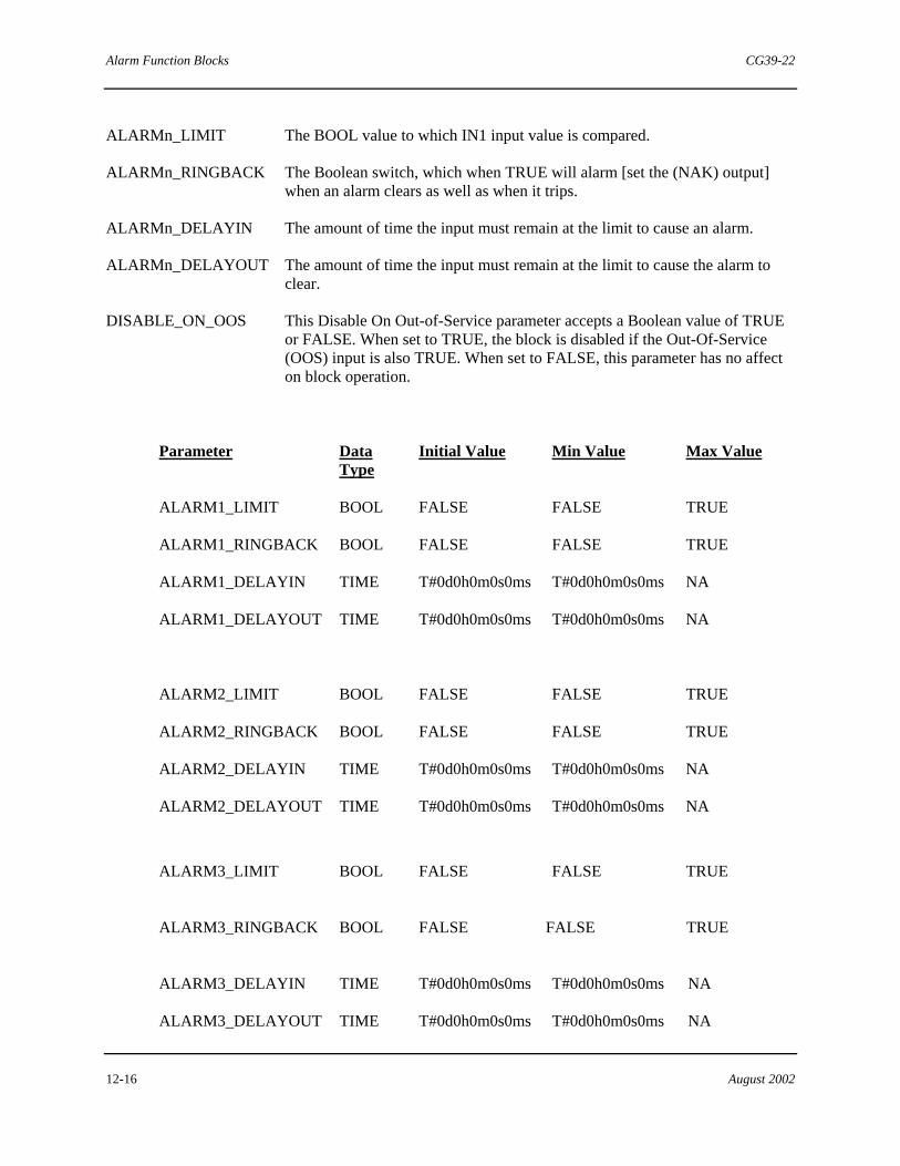
Alarm Function Blocks CG39-22
12-16 August 2002
ALARMn_LIMIT The BOOL value to which IN1 input value is compared.
ALARMn_RINGBACK The Boolean switch, which when TRUE will alarm [set the (NAK) output] when an alarm clears as well as when it trips.
ALARMn_DELAYIN The amount of time the input must remain at the limit to cause an alarm.
ALARMn_DELAYOUT The amount of time the input must remain at the limit to cause the alarm to clear.
DISABLE_ON_OOS This Disable On Out-of-Service parameter accepts a Boolean value of TRUE or FALSE. When set to TRUE, the block is disabled if the Out-Of-Service (OOS) input is also TRUE. When set to FALSE, this parameter has no affect on block operation.
Parameter Data Type
Initial Value Min Value Max Value
ALARM1_LIMIT BOOL FALSE FALSE TRUE
ALARM1_RINGBACK BOOL FALSE FALSE TRUE
ALARM1_DELAYIN TIME T#0d0h0m0s0ms T#0d0h0m0s0ms NA
ALARM1_DELAYOUT TIME T#0d0h0m0s0ms T#0d0h0m0s0ms NA
ALARM2_LIMIT BOOL FALSE FALSE TRUE
ALARM2_RINGBACK BOOL FALSE FALSE TRUE
ALARM2_DELAYIN TIME T#0d0h0m0s0ms T#0d0h0m0s0ms NA
ALARM2_DELAYOUT TIME T#0d0h0m0s0ms T#0d0h0m0s0ms NA
ALARM3_LIMIT BOOL FALSE FALSE TRUE
ALARM3_RINGBACK BOOL FALSE FALSE TRUE
ALARM3_DELAYIN TIME T#0d0h0m0s0ms T#0d0h0m0s0ms NA
ALARM3_DELAYOUT TIME T#0d0h0m0s0ms T#0d0h0m0s0ms NA
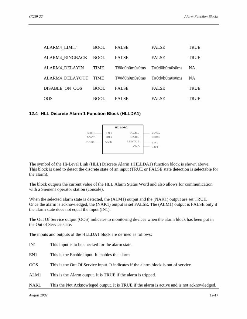
CG39-22 Alarm Function Blocks
August 2002 12-17
ALARM4_LIMIT BOOL FALSE FALSE TRUE
ALARM4_RINGBACK BOOL FALSE FALSE TRUE
ALARM4_DELAYIN TIME T#0d0h0m0s0ms T#0d0h0m0s0ms NA
ALARM4_DELAYOUT TIME T#0d0h0m0s0ms T#0d0h0m0s0ms NA
DISABLE_ON_OOS BOOL FALSE FALSE TRUE
OOS BOOL FALSE FALSE TRUE
12.4 HLL Discrete Alarm 1 Function Block (HLLDA1)
BOOL
OOS
BOOL
INT
INT
ALM1
NAK1
STATUS
CMD
HLLDA1
BOOL
BOOL
BOOL
IN1
EN1
The symbol of the Hi-Level Link (HLL) Discrete Alarm 1(HLLDA1) function block is shown above. This block is used to detect the discrete state of an input (TRUE or FALSE state detection is selectable for the alarm).
The block outputs the current value of the HLL Alarm Status Word and also allows for communication with a Siemens operator station (console).
When the selected alarm state is detected, the (ALM1) output and the (NAK1) output are set TRUE. Once the alarm is acknowledged, the (NAK1) output is set FALSE. The (ALM1) output is FALSE only if the alarm state does not equal the input (IN1).
The Out Of Service output (OOS) indicates to monitoring devices when the alarm block has been put in the Out of Service state.
The inputs and outputs of the HLLDA1 block are defined as follows:
IN1 This input is to be checked for the alarm state.
EN1 This is the Enable input. It enables the alarm.
OOS This is the Out Of Service input. It indicates if the alarm block is out of service.
ALM1 This is the Alarm output. It is TRUE if the alarm is tripped.
NAK1 This the Not Acknowleged output. It is TRUE if the alarm is active and is not acknowledged.
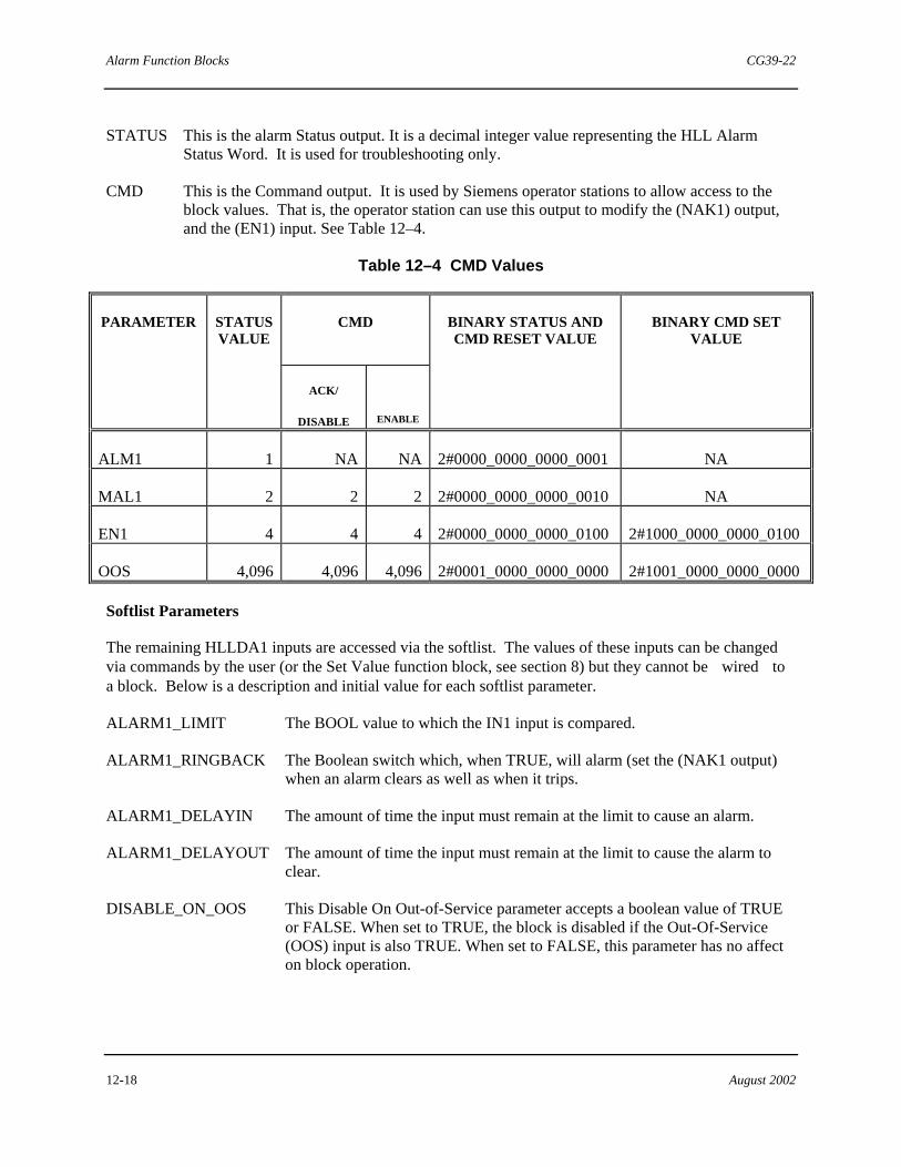
Alarm Function Blocks CG39-22
12-18 August 2002
STATUS This is the alarm Status output. It is a decimal integer value representing the HLL Alarm Status Word. It is used for troubleshooting only.
CMD This is the Command output. It is used by Siemens operator stations to allow access to the block values. That is, the operator station can use this output to modify the (NAK1) output, and the (EN1) input. See Table 12–4.
Table 12–4 CMD Values
CMD
PARAMETER STATUS VALUE
ACK/
DISABLE
ENABLE
BINARY STATUS AND CMD RESET VALUE
BINARY CMD SET VALUE
ALM1 1 NA NA 2#0000_0000_0000_0001 NA
MAL1 2 2 2 2#0000_0000_0000_0010 NA
EN1 4 4 4 2#0000_0000_0000_0100 2#1000_0000_0000_0100
OOS 4,096 4,096 4,096 2#0001_0000_0000_0000 2#1001_0000_0000_0000
Softlist Parameters
The remaining HLLDA1 inputs are accessed via the softlist. The values of these inputs can be changed via commands by the user (or the Set Value function block, see section 8) but they cannot be �wired� to a block. Below is a description and initial value for each softlist parameter.
ALARM1_LIMIT The BOOL value to which the IN1 input is compared.
ALARM1_RINGBACK The Boolean switch which, when TRUE, will alarm (set the (NAK1 output) when an alarm clears as well as when it trips.
ALARM1_DELAYIN The amount of time the input must remain at the limit to cause an alarm.
ALARM1_DELAYOUT The amount of time the input must remain at the limit to cause the alarm to clear.
DISABLE_ON_OOS This Disable On Out-of-Service parameter accepts a boolean value of TRUE or FALSE. When set to TRUE, the block is disabled if the Out-Of-Service (OOS) input is also TRUE. When set to FALSE, this parameter has no affect on block operation.

CG39-22 Alarm Function Blocks
August 2002 12-19
Parameter Data Type
Initial Value Min Value Max Value
ALARM1_LIMIT BOOL FALSE FALSE TRUE
ALARM1_RINGBACK BOOL FALSE FALSE TRUE
ALARM1_DELAYIN TIME T#0d0h0m0s0ms T#0d0h0m0s0ms NA
ALARM1_DELAYOUT TIME T#0d0h0m0s0ms T#0d0h0m0s0ms NA
DISABLE_ON_OOS BOOL FALSE FALSE TRUE
Where NA indicates not applicable. "

Alarm Function Blocks CG39-22
12-20 August 2002
!Notes

CG39-22 Array Function Blocks
August 2002 13-1
13.0 Array Function Blocks
The Array function blocks are a subset of the standard function blocks. These blocks provide array functions. An array is a variable containing a matrix (or array) of values. For memory usage and ACM execution time information on all standard configuration elements, see Appendix C in Using the ProcessSuite 4-mation Configuration Software (document number CG39-20).
The operation of these function blocks is tailored to the use of matrices or tables for batch control strategies. While arrays may be of any valid data type, the Array function blocks are intended for use with particular data types. This is because, for example, there may be little use for operations on arrays of DATE or STRING.
A listing of Array function blocks is presented here. Individual blocks are detailed in the subsections that follow.
Matrix Dimensions Function Blocks
• Find Matrix Dimension Function Block • Matrix Bounds Function Block • Matrix Move Function Blocks • Matrix Load Function Block • Matrix Unload Function Block • FIFO Function Block • LIFO Function Block • Matrix Copy Function Block
Arithmetic Matrix Blocks
• Matrix Add, Subtract, Multiply, Divide Function Blocks • Matrix Bias Function Block • Matrix Scaler Function Block • Matrix Square Root Function Block • Logic Matrix Function Blocks • Matrix AND, OR, XOR Function Blocks • Matrix NOT Function Block
Fan In/Out Function Blocks
• Boolean Fan-In Function Block • Array Fan-In Function Block • Matrix Fan-Out Function Block • Index Check Function Block
13.1 Matrix Dimensions Function Blocks
The Matrix Dimensions function blocks are used to reveal the size definition of an array. These blocks are detailed in the subsections to follow:

Array Function Blocks CG39-22
13-2 August 2002
13.1.1 Find Matrix Dimension Function Block (MAT_DIM)
MAT_DIM
IN OUT UINTARRAY
The symbol of the Find Matrix Dimension function block is shown above. This block is used to find the number of dimensions of the input array.
The inputs and outputs of the MAT_DIM function block are defined below.
IN This is the array input of which the number of dimensions will be found.
OUT This is the number of dimensions of the input array. If (IN) is not configured, (NDIM)=0.
Softlist Parameters
There are no softlist parameters in the MAT_DIM block.
13.1.2 Matrix Bounds Function Block (MAT_BND)
MAT_BND
INDIM
UBNDLBND
INTINT
ARRAYUINT
The symbol of the Matrix Bounds function block is shown above. This block is used to find the upper and lower bounds of a specific dimension of the single or multi dimensional array input.
The inputs and outputs of the MAT_BND function block are defined as follows.
IN This is the array input of which the bounds will be found.
DIM This input is the dimension of the array of which the bound will be found. Assumes the lowest dimension if unconfigured or out of range.
UBND This is the upper index (boundary) of the specified input array dimension.
LBND This is the lower index (boundary) of the specified input array dimension.
Softlist Parameters
There are no softlist parameters in the MAT_BND block.
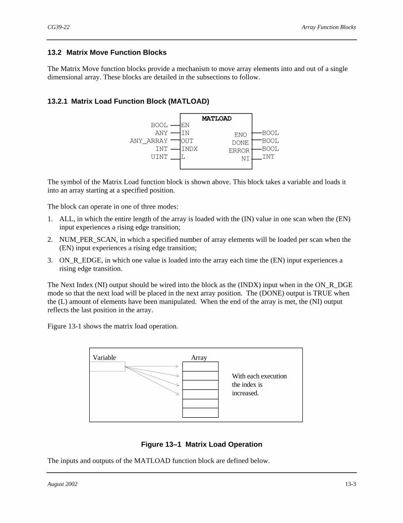
CG39-22 Array Function Blocks
August 2002 13-3
13.2 Matrix Move Function Blocks
The Matrix Move function blocks provide a mechanism to move array elements into and out of a single dimensional array. These blocks are detailed in the subsections to follow.
13.2.1 Matrix Load Function Block (MATLOAD)
MATLOADENINOUTINDXL
ENODONEERROR
NI
BOOLBOOLBOOLINT
BOOLANY
ANY_ARRAYINTUINT
The symbol of the Matrix Load function block is shown above. This block takes a variable and loads it into an array starting at a specified position.
The block can operate in one of three modes:
1. ALL, in which the entire length of the array is loaded with the (IN) value in one scan when the (EN) input experiences a rising edge transition;
2. NUM_PER_SCAN, in which a specified number of array elements will be loaded per scan when the (EN) input experiences a rising edge transition;
3. ON_R_EDGE, in which one value is loaded into the array each time the (EN) input experiences a rising edge transition.
The Next Index (NI) output should be wired into the block as the (INDX) input when in the ON_R_DGE mode so that the next load will be placed in the next array position. The (DONE) output is TRUE when the (L) amount of elements have been manipulated. When the end of the array is met, the (NI) output reflects the last position in the array.
Figure 13-1 shows the matrix load operation.
Array
With each executionthe index isincreased.
Variable
Figure 13–1 Matrix Load Operation
The inputs and outputs of the MATLOAD function block are defined below.

Array Function Blocks CG39-22
13-4 August 2002
EN The rising edge input which enables the block to begin operation (in which ever mode is set). Once triggered, the block will continue the operation for the number of scans it takes until completion (one cycle).
IN This input is the variable which will be loaded.
OUT This is the single dimensional array to which the variable will be loaded.
INDX This is the position of the array where the (INPUT) value will be loaded. The first element in the array is the default when left unconfigured.
L This value indicates the number of elements to be loaded with the (IN) value. When left unconfigured, it defaults to the entire array length.
ENO This Boolean output is TRUE while the block is executing the required function. It turns FALSE when the block is done or when in error.
DONE This Boolean output indicates that the block performed its function on the (L) amount of elements. It is TRUE for one scan if (EN) is FALSE or, if (EN) is TRUE, (DONE) remains TRUE until (EN) becomes FALSE.
ERROR This Boolean output is TRUE when the (L) or (INDX) inputs are invalid (exceeds bounds, wrong data type...).
NI This output indicates the next position of the array pointer. To be wired back to the (INDX) input when in the ON_R_EDGE mode.
Softlist Parameters
Parameter Type Default Min Value
Max Value
MODE enum ON_R_EDGE(2) 2
NUM_ELEMENTS UDINT 1 1 N/A
MODE This enumerated value determines the way in which the block executes. The selections are listed below.
Value Selection Description
0 ALL Entire length is manipulated in one scan
1 NUM_PER_SCAN The NUM_ELEMENTS amount of length will be manipulated in one scan.
2 ON_R_EDGE One array element is manipulated each time the (EN) input sees a rising edge.

CG39-22 Array Function Blocks
August 2002 13-5
NUM_ELEMENTS Specifies the number of elements per scan to be manipulated when in the NUM_PER_SCAN mode. It is ignored otherwise.
13.2.2 Matrix Unload Function Block (MATUNLD)
MATUNLDEN INPUT OUT INDX L
ENO DONE ERROR
NI
BOOL BOOL BOOL INT
BOOL ANY_ARRAY
ANY INT UINT
The symbol of the Matrix Unload function block is shown above. This block takes an array and unloads it into a variable.
Upon the (EN) input experiencing a rising edge transition the Matrix Unload Function Block removes the (INDX) indexed element from the array, places it into the variable indicated in the (OUT) input and increments the Next Index (NI) output. When a value is removed, zero is put in its place.
Figure 13–2 shows the matrix unload operation.
Array
With each execution,the index isincreased.
Variable
Figure 13–2 Matrix Unload Operation

Array Function Blocks CG39-22
13-6 August 2002
The inputs and outputs of the MATUNLD function block are defined below.
EN The input which enables the block to perform its function upon experiencing a rising edge transition.
IN This is the array from which an element will be unloaded.
OUT This is the variable to which the array element will be unloaded. The array must have one dimension.
INDX This is the position of the array from where the value will be unloaded. The first element in the array is the default when left unconfigured.
L This value indicates the number of (IN) array values to be unloaded to the (OUT) variable. When left unconfigured, it defaults to the entire array length.
ENO This Boolean output is TRUE while the block is executing the required function. It turns FALSE when the block is done.
DONE This Boolean output indicates that the block performed its function on the (L) amount of elements. It is TRUE for one scan if (EN) is FALSE or, if (EN) is TRUE, (DONE) remains TRUE until (EN) becomes FALSE.
ERROR This Boolean output is TRUE when the (L) or (INDX) inputs are invalid (exceeds bounds, wrong data type...)
NI This output indicates the next position of the array pointer. It should be wired into the (INDX) input.
Softlist Parameters
There are no softlist parameters in the MATUNLD block.
13.2.3 FIFO Function Block (FIFO)
FIFOPUSH PULL MATRIX IN CLEAR
OUT FULL EMPTY ERROR SIZE
ANY BOOLBOOLBOOLUINT
BOOL BOOL
ANY_ARRAY ANY
BOOL
The symbol of the First-In, First-Out (FIFO) block is shown above. This block pushes values into a user-supplied array and pulls them out on a first-in, first-out basis.

CG39-22 Array Function Blocks
August 2002 13-7
The block requires a one-dimensional array to be connected to the MATRIX input. The block uses the array as a circular buffer, over-writing earlier pushed values when the last array element has been pushed into. Internally, the block tracks push and pull operations, which initially point to the first array element.
When the PUSH input senses a rising edge transition, the block places the value at the IN input into the next available MATRIX array element. The SIZE output is incremented, unless it was already at the array size limit.
When the PULL input senses a rising edge transition, the block reads the oldest available value in the MATRIX array and copies it to the OUT output, then decrements the SIZE output unless it has reached 0. In that case, the block sets the OUT value to the default value for its data type. The array contents are unchanged.
The FULL value becomes TRUE when the SIZE value equals the size of the array attached to the MATRIX input. When the FULL value is TRUE, the block will not prevent another value from being pushed into the array and overwriting the oldest array element. Separate logic must be configured to prevent this occurrence.
The EMPTY value becomes TRUE when the SIZE value is 0 (zero). When the EMPTY value is TRUE, the block will not prevent another pull operation. Separate logic must be configured to prevent this occurrence. If the EMPTY value is TRUE and a pull operation is performed, the block sets the OUT value to the default value for its data type.
When the CLEAR input senses a rising edge transition, it forces the SIZE value to 0 and sets the OUT value to the default value for its data type. The array contents are unchanged.
The following figure shows the state of the MATRIX array after pushing values 1, 2, 3, 4, and pulling once.
Array
Pushed into the firstposition.
Push
Pull
Existing elements arepushed down into thearray.
Pulled from the bottomposition.
Figure 13–3 First In First Out Operation

Array Function Blocks CG39-22
13-8 August 2002
The inputs and outputs of the FIFO function block are defined below.
PUSH This rising edge sensitive input causes the IN value to be pushed into the array connected to the MATRIX input.
PULL This rising edge sensitive input causes the oldest element pushed into the MATRIX array to be placed in the OUT output, and makes the next oldest element ready for the next pull.
MATRIX This is the array input. It accepts a single dimensional array that the block uses to store pushed values and establish the maximum number of elements to be managed by the FIFO function.
IN This input holds the value that will be pushed next.
CLEAR This rising edge sensitive input sets the SIZE value to 0, sets the EMPTY value to TRUE, and sets OUT value to the default value for its data type.
OUT This is the block output. It provides the value from the last pull operation. If no pull operation has occurred or EMPTY was TRUE at the last pull operation, this output will provide the default value for the its data type.
FULL This output is TRUE when the SIZE output equals the number of elements in the MATRIX array. It is FALSE otherwise.
EMPTY This output is TRUE when SIZE is zero. It is FALSE otherwise.
ERROR This output is TRUE whenever there is a data type mismatch between the MATRIX input, the OUT output, or the IN input. It is FALSE otherwise.
SIZE This output value indicates the number of pushes minus the number of pulls, limited by zero and the array size.
Softlist Parameters
There are no softlist parameters in the FIFO block.

CG39-22 Array Function Blocks
August 2002 13-9
13.2.4 LIFO Function Block (LIFO)
LIFOPUSH PULL MATRIX IN CLEAR
OUT FULL EMPTY ERROR SIZE
ANY BOOLBOOLBOOLUINT
BOOL BOOL
ANY_ARRAY ANY
BOOL
The symbol of the Last-In First-Out (LIFO) function block is shown above. This block pushes values into a user-supplied array and pulls them out on a last-in, first-out basis.
The block requires a one-dimensional array to be connected to the MATRIX input. The block uses the array as a circular buffer, over-writing earlier pushed values when the last array element has been pushed into. Internally, the block tracks push and pull operations, which initially point to the first array element.
When the PUSH input senses a rising edge transition, the block places the value at the IN input into the next available MATRIX array element. The SIZE output is incremented, unless it was already at the array size limit.
When the PULL input senses a rising edge transition, the block reads the most recent value in the MATRIX array and places it in the OUT output, then decrements the SIZE output unless it has reached 0. In that case, the block sets the OUT output to the default value for its data type. The array contents are unchanged.
The FULL value becomes TRUE when the SIZE value equals the size of the array attached to the MATRIX input. When the FULL value is TRUE, the block will not prevent another value from being pushed into the array and overwriting the oldest array element. Separate logic must be configured to prevent this occurrence.
The EMPTY value becomes TRUE when the SIZE value is 0 (zero). When the EMPTY value is TRUE, the block will not prevent another pull operation. Separate logic must be configured to prevent this occurrence. If the EMPTY value is TRUE and a pull operation is performed, the block sets the OUT value to the default value for its data type.
When the CLEAR input senses a rising edge transition, it forces the SIZE value to 0 and sets the OUT value to the default value for its data type. The array contents are unchanged.
Figure 13–4 shows the state of the MATRIX array after pushing values 1, 2, 3, 4, and pulling once.

Array Function Blocks CG39-22
13-10 August 2002
Array IN OUT 1 2 3
Next Push
4
Next Pull
(Wraps to top)
MATRIX
00001155.DS4
4
LIFO
Figure 13–4 Last In First Out Operation
The inputs and outputs of the LIFO function block are defined below.
PUSH This rising edge sensitive input causes the IN value to be pushed into the array connected to the MATRIX input.
PULL This rising edge sensitive input causes the newest element pushed into the MATRIX array to be placed in the OUT output, and makes the next newest element ready for the next pull.
MATRIX This is the array input. It accepts a single dimensional array that the block uses to store pushed values and establish the maximum number of elements to be managed by the LIFO function.
IN This input is the variable which will be pushed.
CLEAR This rising edge sensitive input sets the SIZE value to 0, sets the EMPTY value to TRUE, and sets OUT value to the default value for its data type.
OUT This is the block output. It provides the value from the last pull operation. If no pull operation has occurred or EMPTY was TRUE at the last pull operation, this output will provide the default value for its data type.
FULL This output is TRUE when the (SIZE) output equals the size of the input array. It is FALSE at all other times.
EMPTY This output is TRUE when SIZE is zero. It is FALSE otherwise.
ERROR This output is TRUE whenever there is a data type mismatch between the MATRIX input, the OUT output, or the IN input. It is FALSE otherwise.
SIZE This output value indicates the number of pushes minus the number of pulls, limited by zero and the array size.

CG39-22 Array Function Blocks
August 2002 13-11
Softlist Parameters
There are no softlist parameters in the LIFO block.
13.2.5 Matrix Copy Function Block (MATCOPY)
MATCOPYEN IN INDX_I L OUT INDX_O
ENO DONE ERROR NI_I NI_O
BOOLBOOLBOOLINT INT
BOOL ANY_ARRAY
INT UINT
ANY_ARRAY INT
The symbol of the Matrix Copy function Block is shown above. This block copies the identified contents of one array into another array (the values in the input array are maintained).
The block can operate in one of three modes:
1. ALL, in which the entire length of the (IN) array is copied to the (OUT) array in one scan when the (EN) input experiences a rising edge transition.
2. NUM_PER_SCAN, in which a specified number of array elements are copied per scan starting when the (EN) input experiences a rising edge transition.
3. ON_R_EDGE, in which one value is copied into the array and the (NI) output is incremented each time the (EN) input experiences a rising edge transition.
When in the ON_R_EDGE mode, the Next Index of the input (NI_I) output should be wired into the block as the (INDX_I) input, and the Result Next Index (NI_O) should be wired into the (INDX_O) so that the next copy will be placed in the next array position.

Array Function Blocks CG39-22
13-12 August 2002
The inputs and outputs of the MATCOPY function block are defined below.
EN This Boolean input enables the block to perform its function upon experiencing a rising edge transition.
IN This is the input array to be copied. The array must have one dimension.
INDX_I This is the position of the (IN) array from where the elements will be copied. The first element in the array is the default when left unconfigured.
L This value indicates the number of elements in the (IN) array to be copied. When left unconfigured, it defaults to the entire (IN) array length.
OUT This is the array to which the values will be copied. The array must have one dimension.
INDX_O This is the position of the array where the (IN) array values will be copied. The first element in the array is the default when left unconfigured.
ENO This Boolean output is TRUE while the block is executing the required function. It turns FALSE when the block is done.
DONE This Boolean output indicates that the block performed its function on the (L) amount of elements. It is TRUE for one scan if (EN) is FALSE or, if (EN) is TRUE, (DONE) remains TRUE until (EN) becomes FALSE.
ERROR This Boolean output is TRUE when the (L) or (INDX) inputs are invalid (exceeds bounds, wrong data type...).
NI_I This output indicates the next position of the (IN) array pointer. When in the ON_R_EDGE mode, it should be wired to the (INDX_I) input. This output does not indicate the next position when the end of the array is reached; it reflects the last array position.
NI_O This output indicates the next position of the (OUT) array pointer. When in the ON_R_EDGE mode, it should be wired to the (INDX_O) input. This output does not indicate the next position when the end of the array is reached; it reflects the last array position.
Softlist Parameters
Parameter Type Default Min Value
Max Value
MODE enum ALL(0) 0 2
NUM_ELEMENTS UDINT 1 1 N/A

CG39-22 Array Function Blocks
August 2002 13-13
MODE This enumerated value determines the way in which the block executes. The selections are listed below.
Value Selection Description
0 ALL Entire length operated on in one scan
1 NUM_PER_SCAN The NUM_ELEMENTS amount of length (L) that is manipulated in one scan.
2 ON_R_EDGE One array element is manipulated each time the (EN) input sees a rising edge.
NUM_ELEMENTS Specifies the number of elements per scan that should be manipulated when in the NUM_PER_SCAN mode. It is ignored otherwise.
13.3 Arithmetic Matrix Blocks
The Arithmetic Function Blocks allow the user to perform arithmetic operations on arrays of numeric (ANY_NUM) data types. These blocks are detailed in the subsections to follow. Each array must have one dimension.
13.3.1 Matrix Add, Subtract, Multiply , Divide Function Blocks
(MAT_ADD, MAT_SUB, MAT_MUL, MAT_DIV)
MAT_***ENIN01INDX_1IN02INDX_2LOUTINDX_O
ENODONEERRORNI_1NI_2NI_O
BOOLBOOLBOOLINTINTINT
BOOLANY_ARRAY
INTANY_ARRAY
INTUINT
ANY_ARRAYINT
The symbol for the Matrix Arithmetic function blocks is shown above. These blocks perform mathematical functions on two array inputs. The arithmetic functions include:
• Addition • Subtraction • Multiplication • Division.
Array Function Blocks CG39-22
13-14 August 2002
For example:
If the MAT_ADD block is chosen, the two matrices are added together. The (L) input determines how many values in the (IN01) array and (IN02) arrays are to be involved in the operation. One of the input arrays can be the (OUT) array.
These blocks can operate in one of three modes:
1. ALL, in which the entire (L) of the (IN01) array is operated on the (IN02) array in one scan when the (EN) input experiences a rising edge transition
2. NUM_PER_SCAN, in which a specified number of array elements will be operated on per scan starting when the (EN) input experiences a rising edge transition
3. ON_R_EDGE, in which one array element value is operated on the other array element value and the next index outputs are incremented each time the (EN) input experiences a rising edge transition.
When in the ON_R_EDGE mode, the first Next Index (NI_1) output should be wired into the block as the (INDX_1) input, the second Next index (NI_2) should be wired into the (INDX_2) and (NI_O) should be wired back into (INDX_O) so that the next calculation will be at the next array position.
The inputs and outputs of the MAT_*** function blocks are defined below.
EN The input that enables the block to perform its function upon experiencing a rising edge transition.
IN01 This is the first array to be involved in the calculation. The array must have one dimension.
INDX_1 This is the starting position of the first input array from where the elements will be added, subtracted, divided or multiplied. The first element in the array is the default when left unconfigured. The array must have one dimension.
IN02 This is the second array involved in the calculation. The array must have one dimension.
INDX_2 This is the starting position of the (IN02) array to which the (IN01) array values will be added, subtracted, divided or multiplied. The first element in the array is the default when left unconfigured. The array must have one dimension.
L This value indicates the number of elements in the (IN) array to be mathematically altered. When left unconfigured it defaults to the entire (IN) array length. If this value is longer than the (OUT) or either input array size the operation will stop at the shortest length. This array must have one dimension.
OUT This is the array where the resultant array is stored. The array must have one dimension.
INDX_O This is the starting position of the array where the result is stored. The first element in the array is the default when left unconfigured.
ENO This Boolean output is TRUE while the block is executing the required function. It turns FALSE when the block is done.
CG39-22 Array Function Blocks
August 2002 13-15
DONE This Boolean output indicates that the block performed its function on the (L) amount of elements. It is TRUE for one scan if (EN) is FALSE or, if (EN) is TRUE, (DONE) remains TRUE until (EN) becomes FALSE.
ERROR This Boolean output is TRUE when the (L) or (INDX) inputs are invalid (exceeds bounds, wrong data type...).
NI_1 This output indicates the next position of the (IN01) array pointer. When in the ON_R_EDGE mode, it should be wired to the (INDX_1) input. This output does not indicate the next position when the end of the array is reached; it reflects the last array position.
NI_2 This output indicates the next position of the (IN02) array pointer. When in the ON_R_EDGE mode, it should be wired to the (INDX_2) input. This output does not indicate the next position when the end of the array is reached; it reflects the last array position.
NI_O This output indicates the next position of the (OUT) array pointer. When in the ON_R_EDGE mode, it should be wired into the (INDX_O) input. This output does not indicate the next position when the end of the array is reached; it reflects the last array position.
Softlist Parameters
Parameter Type Default Min Value
Max Value
MODE enum NUM_PER_SCAN(1) 0 2
NUM_ELEMENTS UDINT 1 1 N/A
MODE This enumerated value determines the way in which the block executes. The selections are listed below.
Value Selection Description
0 ALL Entire length operated on in one scan.
1 NUM_PER_SCAN The NUM_ELEMENTS amount of length (L) that is manipulated in one scan.
2 ON_R_EDGE One array element is manipulated each time the (EN) input sees a rising edge.
NUM_ELEMENTS Specifies the number of elements per scan to be manipulated when in the NUM_PER_SCAN mode. It is ignored otherwise.

Array Function Blocks CG39-22
13-16 August 2002
13.3.2 Matrix Bias Function Block (MATBIAS)
MATBIASEN IN INDX_I L BIAS OUT INDX_O
ENO DONE
ERROR NI_I NI_O
BOOLBOOLBOOLINT INT
BOOL ANY_ARRAY
INT UINT
ANY_NUM ANY_ARRAY
INT
The symbol for the Matrix Bias function block is shown above. This block is used to add a single value to the identified members of the input matrix.
The block can operate in one of three modes:
1. ALL, in which the entire length (L) of the array is biased when the (EN) input experiences a rising edge transition.
2. NUM_PER_SCAN, in which a specified number of array elements will be biased per scan starting when the (EN) experiences a rising edge transition
3. ON_R_EDGE, in which one value is biased and the next index outputs are incremented each time the (EN) input experiences a rising edge transition.
When in the ON_R_EDGE mode, the Next Index (NI_I) output should be wired into the block as the (INDX_I) input and the Result index (NI_O) output should be wired into the block as the (INDX_O) so that the next array value will be biased on the next scan.
The inputs and outputs of the MATBIAS function block are defined below.
EN The input that enables the block to perform its function upon experiencing a rising edge transition.
IN This is the input array to be biased. The array must have one dimension.
INDX_I This is the position of the input array where the operation will begin. The first element in the array is the default when left unconfigured. The array must have one dimension.
L This value indicates the number of elements in the input array to be biased. When left unconfigured, it defaults to the entire input array length. The array must have one dimension.
OUT This is the array where the biased resultant array is stored. The array must have one dimension.
BIAS This is the value by which the identified array elements are to be biased.
INDX_O This is the beginning position in the (OUT) array where the biased values will be stored. The first element in the array is the default when left unconfigured.

CG39-22 Array Function Blocks
August 2002 13-17
ENO This Boolean output is TRUE while the block is executing the required function. It turns FALSE when the block is done.
DONE This Boolean output indicates that the block performed its function on the (L) amount of elements. It is TRUE for one scan if (EN) is FALSE or, if (EN) is TRUE, (DONE) remains TRUE until (EN) becomes FALSE.
ERROR This Boolean output is TRUE when the (L) or (INDX) inputs are invalid (exceeds bounds, wrong data type, etc.).
NI_I This output indicates the next position of the (IN) array pointer. When in the ON_R_EDGE mode, it should be wired to the (INDX_I) input. This output does not indicate the next position when the end of the array is reached; it reflects the last array position.
NI_O This output indicates the next position of the (RESULT) array pointer. When in the ON_R_EDGE mode, it will be wired into the (INDX_O) input. This output does not indicate the next position when the end of the array is reached; it reflects the last array position.
Softlist Parameters
Parameter Type Default Min Value
Max Value
MODE enum NUM_PER_SCAN(1) 0 2
NUM_ELEMENTS UDINT 1 1 N/A
MODE This enumerated value determines the way in which the block executes. The selections are listed below.
Value Selection Description
0 ALL Entire length operated on in one scan
1 NUM_PER_SCAN The NUM_ELEMENTS amount of length (L) that is manipulated in one scan.
2 ON_R_EDGE One array element is manipulated each time the (EN) input sees a rising edge.
NUM_ELEMENTS Specifies the number of elements per scan to be manipulated when in the NUM_PER_SCAN mode. It is ignored otherwise.
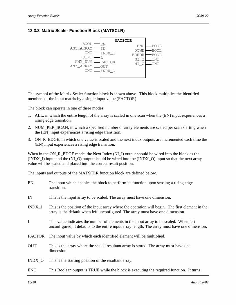
Array Function Blocks CG39-22
13-18 August 2002
13.3.3 Matrix Scaler Function Block (MATSCLR)
MATSCLRENININDX_ILFACTOROUTINDX_O
ENODONEERRORNI_INI_O
BOOLBOOLBOOLINTINT
BOOLANY_ARRAY
INTUINT
ANY_NUMANY_ARRAY
INT
The symbol of the Matrix Scaler function block is shown above. This block multiplies the identified members of the input matrix by a single input value (FACTOR).
The block can operate in one of three modes:
1. ALL, in which the entire length of the array is scaled in one scan when the (EN) input experiences a rising edge transition.
2. NUM_PER_SCAN, in which a specified number of array elements are scaled per scan starting when the (EN) input experiences a rising edge transition.
3. ON_R_EDGE, in which one value is scaled and the next index outputs are incremented each time the (EN) input experiences a rising edge transition.
When in the ON_R_EDGE mode, the Next Index (NI_I) output should be wired into the block as the (INDX_I) input and the (NI_O) output should be wired into the (INDX_O) input so that the next array value will be scaled and placed into the correct result position.
The inputs and outputs of the MATSCLR function block are defined below.
EN The input which enables the block to perform its function upon sensing a rising edge transition.
IN This is the input array to be scaled. The array must have one dimension.
INDX_I This is the position of the input array where the operation will begin. The first element in the array is the default when left unconfigured. The array must have one dimension.
L This value indicates the number of elements in the input array to be scaled. When left unconfigured, it defaults to the entire input array length. The array must have one dimension.
FACTOR The input value by which each identified element will be multiplied.
OUT This is the array where the scaled resultant array is stored. The array must have one dimension.
INDX_O This is the starting position of the resultant array.
ENO This Boolean output is TRUE while the block is executing the required function. It turns

CG39-22 Array Function Blocks
August 2002 13-19
FALSE when the block is done.
DONE This Boolean output indicates that the block performed its function on the (L) amount of elements. It is TRUE for one scan if (EN) is FALSE or, if (EN) is TRUE, (DONE) remains TRUE until (EN) becomes FALSE.
ERROR This Boolean output is TRUE when the (L) or (INDX) inputs are invalid (exceeds bounds, wrong data type...).
NI_I This output indicates the next position of the (IN) array pointer. When in the ON_R_EDGE mode, should be wired to the (INDX_I) input. This output does not indicate the next position when the end of the array is reached; it reflects the last array position.
NI_O This output indicates the next position of the (OUT) array pointer. When in the ON_R_EDGE mode, it should be wired into the (INDX_O) input. This output does not indicate the next position when the end of the array is reached; it reflects the last array position.
Softlist Parameters Parameter Type Default Min
Value Max Value
MODE enum NUM_PER_SCAN(1) 0 2 NUM_ELEMENTS UDINT 1 1 N/A
MODE This enumerated value determines the way in which the block executes. The selections are listed below.
Value Selection Description
0 ALL Entire (LENGTH) manipulated in one scan.
1 NUM_PER_SCAN The NUM_ELEMENTS amount of length (L) that is manipulated in one scan.
2 ON_R_EDGE One array element is manipulated each time the (EN) input sees a rising edge.
NUM_ELEMENTS Specifies the number of elements per scan to be manipulated when in the NUM_PER_SCAN mode. It is ignored otherwise.

Array Function Blocks CG39-22
13-20 August 2002
13.3.4 Matrix Square Root Function Block (MATSQRT)
MATSQRTENININDX_ILOUTINDX_O
ENODONEERRORNI_INI_O
BOOLBOOLBOOLINTINT
BOOLANY_ARRAY
INTUINT
ANY_ARRAYINT
The symbol of the Matrix Square Root function block is shown above. This block takes the square root of each element of the array input.
The block can operate in one of three modes:
1. ALL, in which the entire length of the array is square rooted in one scan when the (EN) input experiences a rising edge transition.
2. NUM_PER_SCAN, in which a specified number of array elements are square rooted per scan starting when the (EN) input experiences a rising edge transition.
3. ON_R_EDGE, in which one value is square rooted and the next index outputs are incremented each time the (EN) input experiences a rising edge transition.
When in the ON_R_EDGE mode, the Next Index (NI_I) output should be wired into the block as the (INDX_I) and (NI_O) should be wired into the (INDX_O) input so that the next array value will be square rooted.
The inputs and outputs of the MATSQRT function block are defined below.
EN The input which enables the block to perform its function upon the (EN) input experiencing a rising edge transition.
IN This is the input array to be square rooted. The array must have one dimension.
INDX_I This is the position of the input array where the operation will begin. The first element in the array is the default when left unconfigured. The array must have one dimension.
L This value indicates the number of elements in the input array to be square rooted. When left unconfigured, it defaults to the entire input array length. The array must have one dimension.
OUT This is the array where the square rooted resultant array is stored. The array must have one dimension.
INDX_O This is the starting position of the resultant array.
ENO This Boolean output is TRUE while the block is executing the required function. It turns FALSE when the block is done.
CG39-22 Array Function Blocks
August 2002 13-21
DONE This Boolean output indicates that the block performed its function on the (L) amount of elements. It is TRUE for one scan if (EN) is FALSE or, if (EN) is TRUE, (DONE) remains TRUE until (EN) becomes FALSE.
ERROR This Boolean output is TRUE when the (L) or (INDX) inputs are invalid (exceeds bounds, wrong data type, etc.).
NI_I This output indicates the next position of the (IN) array pointer. When in the ON_R_EDGE mode, it should be wired to the (INDX_I) input. This output does not indicate the next position when the end of the array is reached; it reflects the last array position.
NI_O This output indicates the next position of the (OUT) array pointer. When in the ON_R_EDGE mode, it should be wired into the (INDX_O) input. This output does not indicate the next position when the end of the array is reached; it reflects the last array position.
Softlist Parameters
Parameter Type Default Min Value
Max Value
MODE enum NUM_PER_SCAN(1) 0 2
NUM_ELEMENTS UDINT 11 N/A
MODE This enumerated value determines the way in which the block executes. The selections are listed below.
Value Selection Description
0 ALL Entire length (L) manipulated in one scan.
1 NUM_PER_SCAN The NUM_ELEMENTS amount of length (L) that is manipulated in one scan.
2 ON_R_EDGE One array element is manipulated each time the (EN) input sees a rising edge.
NUM_ELEMENTS Specifies the number of elements per scan to be manipulated when in the NUM_PER_SCAN mode. It is ignored otherwise.
13.4 Logic Matrix Function Blocks
The Logic Matrix function blocks are used to perform logical operations on arrays of Boolean (BOOL) or 16-bit unsigned integer data types (WORD, or UINT). Each array must have one dimension. These blocks are detailed in the subsections to follow.

Array Function Blocks CG39-22
13-22 August 2002
13.4.1 Matrix AND, OR, XOR Function Blocks (MAT_AND, MAT_OR, MAT_XOR)
MAT_***EN IN01 INDX_1 IN02 INDX_2 L OUT INDX_O
ENO DONE ERROR NI_1 NI_2 NI_O
BOOL BOOL BOOL INT INT INT
BOOL ANY_ARRAY
INT ANY_ARRAY
INT UINT
ANY_ARRAY INT
The symbol of the Matrix Logic function blocks is shown above. These blocks logically manipulate the bits or BOOLs in the input arrays. This block is used for arrays of unsigned integers, Booleans, and Bit Strings (see ANY_BIT and WORD data types) only.
The Logic Blocks include:
• Matrix AND
• Matrix OR
• Matrix XOR
Note that Matrix NOT is a separate block
For example:
If the MAT_AND is selected the elements of the two input arrays will be ANDed and the result placed in the (OUT) array.
One of the input arrays may be the (OUT) array.
The block can operate in one of three modes:
1. ALL, in which the (L) of the array is manipulated in one scan when the (EN) input experiences a rising edge transition.
2. NUM_PER_SCAN, in which a specified number of array elements are manipulated per scan when the (EN) input experiences a rising edge transition.
3. ON_R_EDGE in which one value is manipulated and the next index outputs are incremented each time the (EN) input experiences a rising edge transition.
The inputs and outputs of the MAT_*** function blocks are defined below.
EN The input which enables the block to perform its function upon the (EN) input experiencing a rising edge transition.
IN01 This is one array input to be logically manipulated. This array must have one dimension.
INDX_1 This is the starting position of the first input array. The first element in the array is the default

CG39-22 Array Function Blocks
August 2002 13-23
when left unconfigured. This array must have one dimension.
IN02 This is the array with which the (IN01) array values will be ANDed. This array must have one dimension.
INDX_2 This is the starting position of the second input array. The first element in the array is the default when left unconfigured. This array must have one dimension.
L This value indicates the number of elements in the (IN01) array to be manipulated. When left unconfigured it defaults to the entire (IN01) array length. If this value is longer than the (IN02) or (OUT) length the operation will stop at the shorter length. This array must have one dimension.
OUT This is the array where the resultant array is stored. This array must have one dimension.
INDX_O This is the starting position of the (OUT) array to which the manipulated values will be stored. The first element in the array is the default when left unconfigured.
ENO This boolean output is TRUE while the block is executing the required function. It turns FALSE when the block is done.
DONE This boolean output indicates that the block performed its function on the (L) amount of elements. It is TRUE for one scan if (EN) is FALSE or, if (EN) is TRUE, (DONE) remains TRUE until (EN) becomes FALSE.
ERROR This boolean output is TRUE when the (L) or (INDX) inputs are invalid (exceeds bounds, wrong data type, ...).
NI_1 This output indicates the next position of the (IN01) array pointer. When in the ON_R_EDGE mode, should be wired to the (INDX_1) input. This output does not indicate the next position when the end of the array is reached; it reflects the last array position.
NI_2 This output indicates the next position of the (IN02) array pointer. When in the ON_R_EDGE mode, should be wired to the (INDX_2) input. This output does not indicate the next position when the end of the array is reached; it reflects the last array position.
NI_O This output indicated the next position of the (OUT) array pointer. When in the ON_R_EDGE mode, should be wired into the (INDX_R) input. This output does not indicate the next position when the end of the array is reached; it reflects the last array position.
Softlist Parameters
Parameter Type Default Min Value
Max Value
MODE enum ALL (0) 0 2
NUM_ELEMENTS UDINT 1 1 N/A
MODE This enumerated value determines the way in which the block executes. The

Array Function Blocks CG39-22
13-24 August 2002
selections are listed below.
Value Selection Description
0 ALL Entire length (L) manipulated in one scan.
1 NUM_PER_SCAN The NUM_ELEMENTS amount of length (L) that is manipulated in one scan.
2 ON_R_EDGE One array element is manipulated each time the (EN) input sees a rising edge.
NUM_ELEMENTS Specifies the number of elements per scan to be manipulated when in the NUM_PER_SCAN mode. It is ignored otherwise.
13.4.2 Matrix NOT Function Block (MAT_NOT)
MAT_NOTENININDX_ILOUTINDX_O
ENODONEERRORNI_INI_O
BOOLBOOLBOOLINTINT
BOOLANY_ARRAY
INTUINT
ANY_ARRAYINT
The symbol of the Matrix NOT function block is shown above. This block logically NOTs (inverts) the bits or BOOLs in the input arrays. It is useful for an array of unsigned integers, booleans and bit strings (see the ANY_BIT and WORD data types).
One of the input arrays may be the (OUT) array.
The block can operate in one of three modes:
1. ALL, in which the length of the array is NOTed in one scan when the (EN) input experiences a rising edge transition.
2. NUM_PER_SCAN, in which a specified number of array elements are NOTed per scan starting when the (EN) input experiences a rising edge transition.
3. ON_R_EDGE, in which one value is NOTed and the next index outputs are incremented each time the (EN) input experiences a rising edge transition.
The inputs and outputs of the MAT_NOT function block are defined below.
EN The input which enables the block to perform its function upon experiencing a rising edge transition.
IN This is the array to be NOTed. The array must have one dimension.

CG39-22 Array Function Blocks
August 2002 13-25
INDX_I This is the starting position of the first input array. The first element in the array is the default when left unconfigured. The array must have one dimension.
L This value indicates the number of elements in the (IN01) array to be manipulated. When left unconfigured, it defaults to the entire (IN01) array length. The array must have one dimension.
OUT This is the array where the resultant array is stored. The array must have one dimension.
INDX_O This is the starting position of the (OUT) array to which the manipulated values will be stored. The first element in the array is the default when left unconfigured.
ENO This Boolean output is TRUE while the block is executing the required function. It turns FALSE when the block is done.
DONE This Boolean output indicates that the block performed its function on the (L) amount of elements. It is TRUE for one scan if (EN) is FALSE or, if (EN) is TRUE, (DONE) remains TRUE until (EN) becomes FALSE.
ERROR This Boolean output is TRUE when the (L) or (INDX) inputs are invalid (exceeds bounds, wrong data type, etc.).
NI_I This output indicates the next position of the (IN) array pointer. When in the ON_R_EDGE mode, it should be wired to the (INDX_I) input. This output does not indicate the next position when the end of the array is reached; it reflects the last array position.
NI_O This output indicated the next position of the (OUT) array pointer. When in the ON_R_EDGE mode, it should be wired into the (INDX_O) input. This output does not indicate the next position when the end of the array is reached; it reflects the last array position.

Array Function Blocks CG39-22
13-26 August 2002
Softlist Parameters
Parameter Type Default Min Value
Max Value
MODE enum ALL(0) 0 2
NUM_ELEMENTS UDINT 1 1 N/A
MODE This enumerated value determines the way in which the block executes. The selections are listed below.
Value Selection Description
0 ALL Entire length (L) manipulated in one scan.
1 NUM_PER_SCAN The NUM_ELEMENTS amount of length (L) that is manipulated in one scan.
2 ON_R_EDGE One array element is manipulated each time the (EN) input sees a rising edge.
NUM_ELEMENTS Specifies the number of elements per scan to be manipulated when in the NUM_PER_SCAN mode. It is ignored otherwise.
13.5 Fan In/Out Function Blocks
The Fan-In and Fan-Out function blocks are used to connect between BOOL and WORD data types, and between arrays of BOOL and WORD data types. These blocks are detailed in the subsections to follow.
13.5.1 Boolean Fan-In Function Block (BFAN_IN)
BFAN_ININ01IN02 :IN16
OUT UINT or WORDBOOLBOOL
:BOOL
The symbol of the Boolean Fan-In function block is shown above. This block inputs Boolean values and packs them into one unsigned integer. It is extensible up to 16 inputs.
The BFAN_IN inputs and output are defined below.

CG39-22 Array Function Blocks
August 2002 13-27
IN(n) The Boolean inputs to be packed.
OUT The fanned-in inputs in the form of a 16-bit unsigned integer.
Softlist Parameters
There are no softlist parameters for the BFAN_IN block.
13.5.2 Array Fan-In Function Block (AFAN_IN)
AFAN_IN
ININDXL
ERRORERROR
UINT or WORDBOOL
BOOL_ARRAYINTUINT
The symbol of the Array Fan-In function block is shown above. This block inputs a single dimensional array of Booleans and packs them into an unsigned integer.
The length (L) input can be between 1 and 16.
Element=(INDX) is placed in bit 0, element=(INDX)+1 is placed in bit 1, etc.
The Array fan-in inputs and outputs are defined below.
IN The Boolean array input to be fanned-in to an unsigned integer or bit string. The array must have one dimension.
INDX The starting point of the input array.
L The length of the array to be fanned-in. Limited from 1 to 16.
OUT The packed UINT or BIT_STRING.
ERROR This Boolean output is TRUE when the (L) or (INDX) inputs are invalid (exceeds bounds, wrong data type, etc).
Softlist Parameters
There are no softlist parameters in the AFAN_IN block.

Array Function Blocks CG39-22
13-28 August 2002
13.5.3 Matrix Fan-Out Function Block (FAN_OUT)
FAN_OUT IN INDX OUT
OUT01 OUT02 : OUT16
BOOL BOOL BOOL
WORD OR UNIT INT
BOOL_ARRAY
The symbol of the Fan-Out function block is shown above. This block inputs an unsigned integer or WORD and unpacks it into both an array of BOOLs and 16 Boolean outputs.
NOTE
To accommodate 16 outputs, this block does not have an ERROR output.
The inputs and outputs of the FAN_OUT block are defined below.
IN The Word or Unsigned integer input to be unpacked. The array must have one dimension.
INDX The starting position in the (OUT) array where the fanned-out BOOLs are to be placed.
OUT The resulting unpacked array of 16 Booleans.
OUTn The 16 fanned-out Boolean outputs.
Softlist Parameters
There are no softlist parameters in the FAN_OUT function block.
13.6 Index Check Function Block (INDXCHK)
ARRAY
INDXCHK
OUTANY NUM
:INDX08
ININDX01
ANY NUM
ANY
: : :
OUTCLIPHOLD
ERROR
BOOLBOOL
BOOL
The symbol of the Index Check function block is shown above. This block provides two different choices for dealing with out of bounds array indices.
In normal operation, when an array index exceeds the boundary of the array definition the array value returned will be zero.
For example:
If an array A is defined as having dimensions [1..2, 1..2] and an index reference A[i,j] exists with the following values:

CG39-22 Array Function Blocks
August 2002 13-29
j1 j2
i1 11 12
i2 21 22
Where:
I or j are less than 1 or greater than 2, the value of the array for that scan will be zero.
If this behavior is not desired, the INDXCHK function block provides two alternatives selectable by a softlist parameter.
The first alternative is to use the previous valid value of the index which was exceeded. This means that the value of the array output would remain the same (see note below).
For example:
If last scan I=1 and j=1, and this scan I=2 and j=4, then the previous scan's (or whichever was the last valid) set of indices (I and j) will be used to determine the value of the array. In this case value of the array would remain at 11.
The second alternative is to clip the array index which exceeded the boundary at the maximum or minimum value allowed.
For example:
If last scan array A's indices I=2 and j=2, and this scan I=2 and j=0, then the j index would be clipped at 1 (the minimum) and the array value would be 11.
The inputs and outputs of the INDXCHK function block are defined below.
IN The multi- or single-dimensional input array whose indices are the be checked.
INDXn The variable indices of the array. Maximum number of dimensions in any one array is limited to 8.
OUT The calculated value of the array.
CLIP This Boolean output is TRUE whenever any array index is clipped and the CLIP_INDEX softlist parameter is TRUE.
HOLD This Boolean output is TRUE for one scan whenever the last valid array indices are used.
ERROR This Boolean output is TRUE whenever there is an error in the configuration of the block. Errors include:
Number of (INDXn) inputs does not match the number of dimensions in the array input • Datatype of (OUT) does not match the datatype of the array input • The (IN) input is not an array

Array Function Blocks CG39-22
13-30 August 2002
NOTE
Use of the previous valid indices implies using the same indices again, which MAY NOT coincide with the same array value if the array value changed during the scan.
Softlist Parameters
Parameter Type Default Min/Max
CLIP_INDEX BOOL TRUE NA
CLIP_INDEX When TRUE, this Boolean parameter will cause the index of the array to be clipped the minimum or maximum when the boundary of the index is exceed. When FALSE, the last valid set of indices will be held.
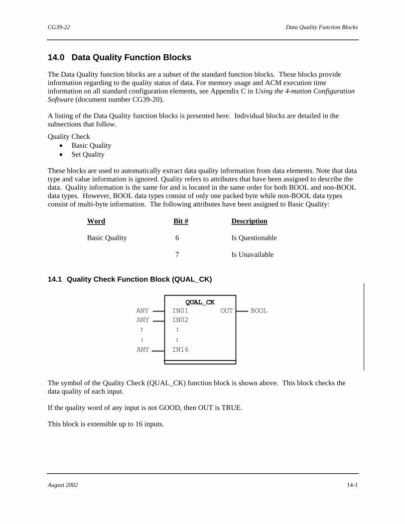
CG39-22 Data Quality Function Blocks
August 2002 14-1
14.0 Data Quality Function Blocks
The Data Quality function blocks are a subset of the standard function blocks. These blocks provide information regarding to the quality status of data. For memory usage and ACM execution time information on all standard configuration elements, see Appendix C in Using the 4-mation Configuration Software (document number CG39-20).
A listing of the Data Quality function blocks is presented here. Individual blocks are detailed in the subsections that follow.
Quality Check • Basic Quality • Set Quality
These blocks are used to automatically extract data quality information from data elements. Note that data type and value information is ignored. Quality refers to attributes that have been assigned to describe the data. Quality information is the same for and is located in the same order for both BOOL and non-BOOL data types. However, BOOL data types consist of only one packed byte while non-BOOL data types consist of multi-byte information. The following attributes have been assigned to Basic Quality:
Word Bit # Description
Basic Quality 6 Is Questionable
7 Is Unavailable
14.1 Quality Check Function Block (QUAL_CK)
OUT
: : IN16
ANY
: ANY
:
ANY BOOL QUAL_CK
IN01 IN02
The symbol of the Quality Check (QUAL_CK) function block is shown above. This block checks the data quality of each input.
If the quality word of any input is not GOOD, then OUT is TRUE.
This block is extensible up to 16 inputs.
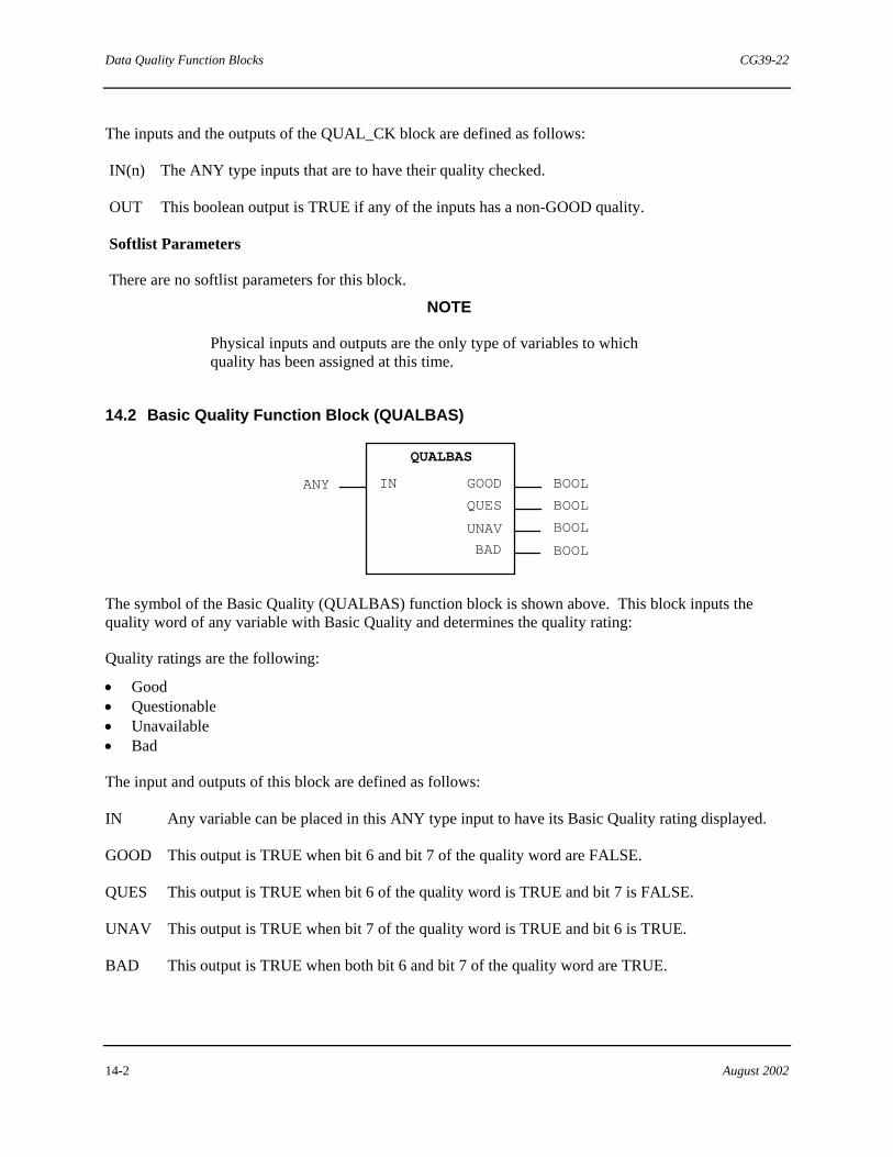
Data Quality Function Blocks CG39-22
14-2 August 2002
The inputs and the outputs of the QUAL_CK block are defined as follows:
IN(n) The ANY type inputs that are to have their quality checked.
OUT This boolean output is TRUE if any of the inputs has a non-GOOD quality.
Softlist Parameters
There are no softlist parameters for this block.
NOTE
Physical inputs and outputs are the only type of variables to which quality has been assigned at this time.
14.2 Basic Quality Function Block (QUALBAS)
BOOL
BOOL
BOOL
BOOL
ANY IN
UNAV
QUES
GOOD
BAD
QUALBAS
The symbol of the Basic Quality (QUALBAS) function block is shown above. This block inputs the quality word of any variable with Basic Quality and determines the quality rating:
Quality ratings are the following:
• Good • Questionable • Unavailable • Bad
The input and outputs of this block are defined as follows:
IN Any variable can be placed in this ANY type input to have its Basic Quality rating displayed.
GOOD This output is TRUE when bit 6 and bit 7 of the quality word are FALSE.
QUES This output is TRUE when bit 6 of the quality word is TRUE and bit 7 is FALSE.
UNAV This output is TRUE when bit 7 of the quality word is TRUE and bit 6 is TRUE.
BAD This output is TRUE when both bit 6 and bit 7 of the quality word are TRUE.
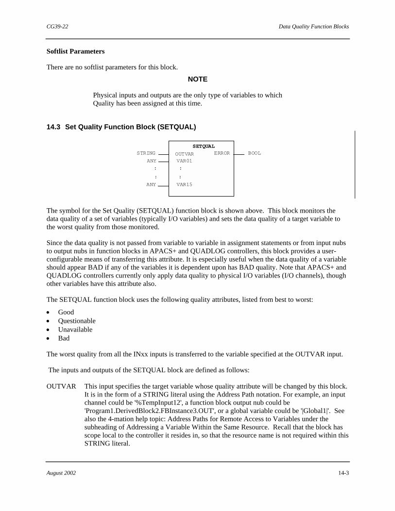
CG39-22 Data Quality Function Blocks
August 2002 14-3
Softlist Parameters
There are no softlist parameters for this block.
NOTE
Physical inputs and outputs are the only type of variables to which Quality has been assigned at this time.
14.3 Set Quality Function Block (SETQUAL)
ERROR
: : VAR15
ANY
: ANY
:
STRING BOOL SETQUAL
OUTVAR VAR01
The symbol for the Set Quality (SETQUAL) function block is shown above. This block monitors the data quality of a set of variables (typically I/O variables) and sets the data quality of a target variable to the worst quality from those monitored.
Since the data quality is not passed from variable to variable in assignment statements or from input nubs to output nubs in function blocks in APACS+ and QUADLOG controllers, this block provides a user-configurable means of transferring this attribute. It is especially useful when the data quality of a variable should appear BAD if any of the variables it is dependent upon has BAD quality. Note that APACS+ and QUADLOG controllers currently only apply data quality to physical I/O variables (I/O channels), though other variables have this attribute also.
The SETQUAL function block uses the following quality attributes, listed from best to worst:
• Good • Questionable • Unavailable • Bad
The worst quality from all the INxx inputs is transferred to the variable specified at the OUTVAR input.
The inputs and outputs of the SETQUAL block are defined as follows:
OUTVAR This input specifies the target variable whose quality attribute will be changed by this block. It is in the form of a STRING literal using the Address Path notation. For example, an input channel could be '%TempInput12', a function block output nub could be 'Program1.DerivedBlock2.FBInstance3.OUT', or a global variable could be '|Global1|'. See also the 4-mation help topic: Address Paths for Remote Access to Variables under the subheading of Addressing a Variable Within the Same Resource. Recall that the block has scope local to the controller it resides in, so that the resource name is not required within this STRING literal.

Data Quality Function Blocks CG39-22
14-4 August 2002
IN01 to IN15
These inputs are the variables (typically input channels) whose data quality is being monitored. The one with the worst quality in the sequence: Good, Questionable, Unavailable, and Bad, will be selected as the one whose quality is applied to the target variable specified in OUTVAR.
ERROR This is the Error output. It provides a BOOL data value which is FALSE if the specified string at the OUTVAR input is valid. When TRUE, it indicates that the string at OUTVAR specifies a variable that does not exist or is otherwise invalid.
Softlist Parameters
There are no softlist parameters for this block. "

CG39-22 Chart Function Blocks
August 2002 15-1
15.0 Chart Function Blocks
The Chart blocks are a subset of the standard function blocks. These function blocks provide
control capabilities and diagnostic information about sequential function charts (SFC). SFCs configure a sequential process with a series of steps to which actions can be attached. The chart function blocks control selected charts by changing their configuration mode or resetting them. The blocks can also provide information about a particular chart, such as the sequence of chart steps and amount of time a step has been running.
This section provides a detailed description of the following blocks:
• Chart Mode Function Block • Chart Data Function Block
15.1 Chart Mode Function Block (CHRTMOD
The symbol of the Chart Mode function block is shown above. This block is used to change the mode or reset all of the charts that are connected to the block's inputs.
The CHRT(n) inputs are assumed to begin from the resource sheet unless the string begins with a period (.) character which signifies that the path is relative to the sheet on which the CHRTMOD block resides. For example, if chart A_BATCH exists in a derived function block (DFB) with an instance name of SFC_1, and SFC_1 is located on another DFB called FBD_1 and the CHRTMOD block was also placed on FBD_1, the CHRT(n) input for the A_BATCH chart is ‘.SFC_1.A_BATCH’. If the CHRMOD block is not located on FBD_1, the string input would not begin with a period (.) character but the first common DFB's or Program's instance name (common to the CHRTMOD block and the chart) as shown in Figure 15–1.
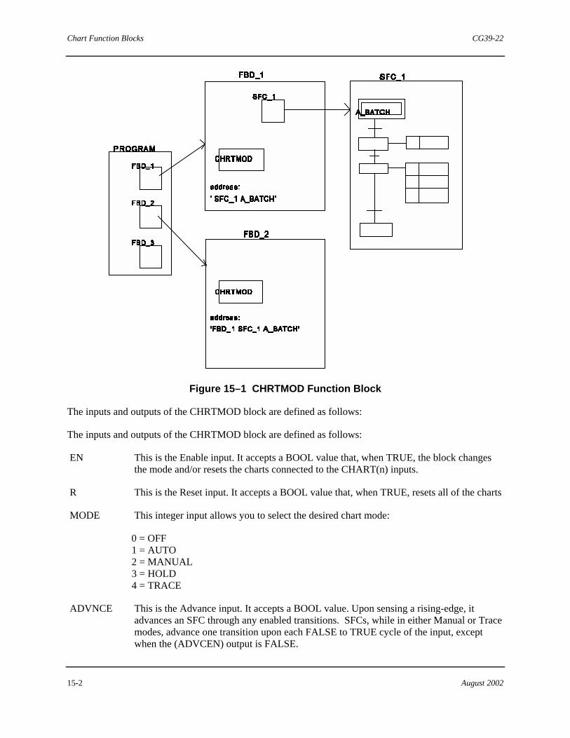
Chart Function Blocks CG39-22
15-2 August 2002
Figure 15–1 CHRTMOD Function Block
The inputs and outputs of the CHRTMOD block are defined as follows:
The inputs and outputs of the CHRTMOD block are defined as follows:
EN This is the Enable input. It accepts a BOOL value that, when TRUE, the block changes the mode and/or resets the charts connected to the CHART(n) inputs.
R This is the Reset input. It accepts a BOOL value that, when TRUE, resets all of the charts
MODE This integer input allows you to select the desired chart mode:
0 = OFF 1 = AUTO 2 = MANUAL 3 = HOLD 4 = TRACE
ADVNCE This is the Advance input. It accepts a BOOL value. Upon sensing a rising-edge, it advances an SFC through any enabled transitions. SFCs, while in either Manual or Trace modes, advance one transition upon each FALSE to TRUE cycle of the input, except when the (ADVCEN) output is FALSE.

CG39-22 Chart Function Blocks
August 2002 15-3
CHRT(n) These are the CHART inputs, which specify the chart(s) to be controlled. These should be entered as string literals in the address path format described in Address Path for Remote Access to Variables in 4-mation help.
Example strings are:
'.SFC_BLK1.CHART000' (Where the SFC chart named CHART000 is contained within the DFB instance 'SFC_BLK1', which is placed on the same sheet as the CHRTMOD block itself)
'DFB1.DFB2.CHART001' (Where DFB1 is the first DFB common to both the chart and to the CHRTMOD block)
NOTE
Be sure to use string literals (actual strings enclosed in single quotes) and not string variables for these inputs. No error is reported by 4-mation if string variables are used, but the string value used at any one time may not be correct.
ENO This is the Enable Output. It is TRUE whenever (EN) is TRUE.
ROUT This is the Reset output. It provides a BOOL value that is TRUE whenever the (R) input is TRUE.
ERROR This is the Error output. It is an integer that outputs a value of 99 if the mode input is invalid; or the number corresponding to the first input (01 to 12) whose tag is unresolved. The value is zero (0) if there are no errors.
ADVCEN This is the Advance Enable output. It indicates when the Advance input is usable. In cases where the CHRTMOD block is extended (that is, where more than one chart is input to the block), the ADVNCE input is not supported, and the ADVCEN output is FALSE. In the case where only one chart is input to the block, the ADVCEN output is TRUE.
MODE(n)
These are the Chart Mode outputs. Each output is of data type integer and constantly provides the mode of the chart listed at the corresponding input regardless of the (EN) input. For example, MODE(04) will display the mode of the chart connected to input CHRT(04).
Softlist Parameter
RESET_S_ACTIONS When TRUE, this parameter causes all the stored actions in the charts that are input to the block to be reset when R is TRUE.
Parameter Type Default Min Value
Max Value
RESET_S_ACTIONS BOOL FALSE FALSE TRUE

Chart Function Blocks CG39-22
15-4 August 2002
15.2 Chart Data Function Block (CHRTDTA)
The symbol of the Chart Data (CHRTDTA) function block is shown above. The block provides information about the current state of the sequential function chart (SFC) that is attached as the block's input. This information includes step names and how long the step has run. A query is initiated by typing the full path name of the chart at the input. The PARA_STEP(n) softlist parameters indicate additional active steps if any are running simultaneously with a selected step.
The inputs and outputs of the CHRTDTA block are defined as follows:
CHART The CHART input is the full path to an SFC. It accepts a STRING data value up to 254 characters.
ERROR The Error output indicates whether or not an error has occurred when the block attempts to obtain output information. It provides an INT value as follows:
0 = No error 1 = The input CHART cannot be found 99 or higher = An internal error has occurred while the block was trying to obtain information (database corrupted).
LSTEPN The Last Step Name output indicates the name of the step previously executed. It provides STRING data value up to 16 characters.
CSTEPN The Current Step Name output indicates the name of the step that is currently active. It provides STRING data value up to 16 characters.
CSTEPT The Current Step Time output indicates the amount of time that CSTEPN and been active.
ACTION The Action output indicates the name of the first action that is attached to the currently active step. It provides STRING data value up to 16 characters.
NSTEPN The Next Step Name output indicates the name of the step that will be executed next. It provides STRING data value up to 16 characters.
STRING
CHRTDTA
ERRORLSTEPN
ACTIONTIME
CHART INT
NSTEPN
STRINGSTRINGCSTEPN
CSTEPTSTRINGSTRING

CG39-22 Chart Function Blocks
August 2002 15-5
Softlist Parameters
ACTION_NAME1 to
ACTION_NAME8
These 16-character STRING values are the names of additional actions that are attached to the currently active step. The first action attached to the current step is the ACTION output of the block.
PARA_STEP1 to
PARA_STEP4
These 16-character STRING values are the names of additional active steps (if any are running simultaneously with the selected step). The CSTEPN output also displays an active step name.
PARA_STEP1T to
PARA_STEP4T
These parameters provide a TIME value that indicates the amount of time that the steps identified by the PARA_STEP1 to PARA_STEP4 softlist values have been active.
"

Chart Function Blocks CG39-22
15-6 August 2002
!Notes

CG39-22 Resource Blocks
August 2002 16-1
16.0 Resource Blocks
The Resource function blocks are a subset of the standard function blocks. These blocks control parameters that affect an entire resource (Advanced Control Module). The portion of these blocks that are required for a non-redundant system are configured automatically. A program is created with the instance name of RESOURCE_BLOCKS and the individual blocks are configured in the body of that program. To view the body of the RESOURCE_BLOCKS program, see Appendix A in Using the ProcessSuite 4-mation Configuration Software (document number CG39-20). For memory usage and ACM execution time information on all standard configuration elements, see Appendix C in the same document.
A listing of Resource function blocks is presented here. Individual blocks are detailed in the subsections that follow.
• Error Log • Error Status • Memory Statistics • Partial I/O Scan • Real Time Clock • Redundancy Control • Resource Status • Security Control • Time Synchronization • Total I/O Scan • Module Information Block • System Information Block • Resource Alarm Block • Clock Block
16.1 Error Log Function Block (ERR_LOG)
BOOL STRINGPURGE
ERR_LOG
NEW_ERADDRTIME
E_TYPE STRING
BOOLBOOL NEXT_E
UINT
UINTSS_CD
ERR_CD
STRING
CLASS
STRINGSTRING
USER_ASCOPECHAN
GROUP STRING
UINT
UINTERR_ID
UINT
NUM_ER
UINT

Resource Blocks CG39-22
16-2 August 2002
The symbol for the Error Log (ERR_LOG) function block is shown above. This block provides access to the information in the Error History List. Use this block to step through the Error History List either in time mode (based on UPDATE_TIME softlist parameter) or in manual mode (based on a FALSE to TRUE transition of the NEXT_E (next event) input.
If the PURGE input senses a FALSE to TRUE transition, the system's Error History List is emptied of all past events and the block outputs are either cleared or set to default values.
The outputs are only be updated when a new error is being displayed. Only the NEW_ER and NUM_ER outputs are updated every scan.
No attempt to write to the outputs via external methods (data services or variable control box) should be made.
As long as the history list is not empty, and the timed mode or the manual mode has not passed the last listed event, the block outputs display information of some event in the list. If there is no new error after the "next" one is requested, the outputs will be set to the initial default values (zero or blanks). This means when there are no newer events remaining [(NUM_ER)=0)], the last event in the list will continue to be displayed only if automatic update is inactive and NEXT_E is not tripped.
The block continues to poll the error history list to detect any new entries. If the default output values are being displayed, a new entry to the list will cause an immediate update of all block outputs. The block will usually display some event information on its first scan unless the history list is empty.
Redundancy and the ERR_LOG block
In 4-mation, the ERR-LOG block is used to display the Error History List of the calculate (primary) control module. Although the Error History List of the verify (backup) control module is not available in 4-mation, it is available via a human-machine interface (HMI).
The data is accessed by appending an “#A” and a “#B” to the resource name when referring to the ERR_LOG block variables. The “#A” and “#B” notation represents physical location, therefore, both the A and B tags must be configured to ensure access to both the primary and backup date.
For example:
If the primary and backup values of the ERR_LOG variable ERR_CD were desired the HMI tag names would be:
“ResourceName #A.RESOURCEBLOCKS.ERROR_LOG.ERR_CD” “ResourceName #B.RESOURCEBLOCKS.ERROR_LOG.ERR_CD”
where:
ResourceName is the name assigned to the control module when a New resource configuration was opened
RESOURCEBLOCKS is the default instance name given to the program containing the ERR_LOG and other resource effecting blocks
ERROR_LOG is the default instance name given to the ERR_LOG block

CG39-22 Resource Blocks
August 2002 16-3
ERR_CD is the output nub name.
The inputs and outputs of the ERR_LOG block are defined as follows:
CLASS This INT output indicates the error class of the reported event. It is valid between 0 and 4 where 0 indicates no error and class 1 to class 4 increase in severity.
SS_CD This INT output is the System Service Code. Since error codes are duplicated throughout the system, each hardware and software module has a unique System Service Code used to differentiate the error codes for each module.
For example:
An event reporting SS_CD 6 and ERR_CD 4 is an open circuit on an SAM module (the ADDR output would indicate which SAM module) but SS_CD 7 ERR_CD 4 is the channel failed off on a SDM module.
ERR_CD The INT output indicating the error code of the reported event.
USER_A The STRING output (up to 64 characters) provides a User Action message for a given error code. For example, '16- Replace Module Immediately' is a user action string.
SCOPE This up to 8 character string output identifies the scope of the reported error. The four current scopes are:
System - An error is one that effects multiple modules such as a redundancy error.
Module - An error that effects more than one channel or group of channels on a module.
Group- An error that effects one or more channels in a group (some I/O modules have channels collected in groups for isolation purposes).
Channel - An error that effects one channel.
CHAN The INT output which indicates the channel number of the error if the (SCOPE) is channel.
GROUP The STRING output which indicates the group (A to G) if the SCOPE is group.
NUM_ER The INT output that indicates the number of errors in the log which have not been displayed.
ERR_ID The INT output which assigns a unique identifier to each reported error event.
Remaining ERR_LOG inputs are accessed via the softlist. The values of these inputs can be changed via command by the user (or the Set Value function block) but they cannot be "wired" to the block.
UPDATE_TIME The duration softlist parameter that determines how long the block outputs are held before being overwritten by the information of the next error event. If parameter is zero, you must manually toggle the NEXT_E input to view the next logged event.
X_INFO This 16 character string allows you to place additional information in the block.
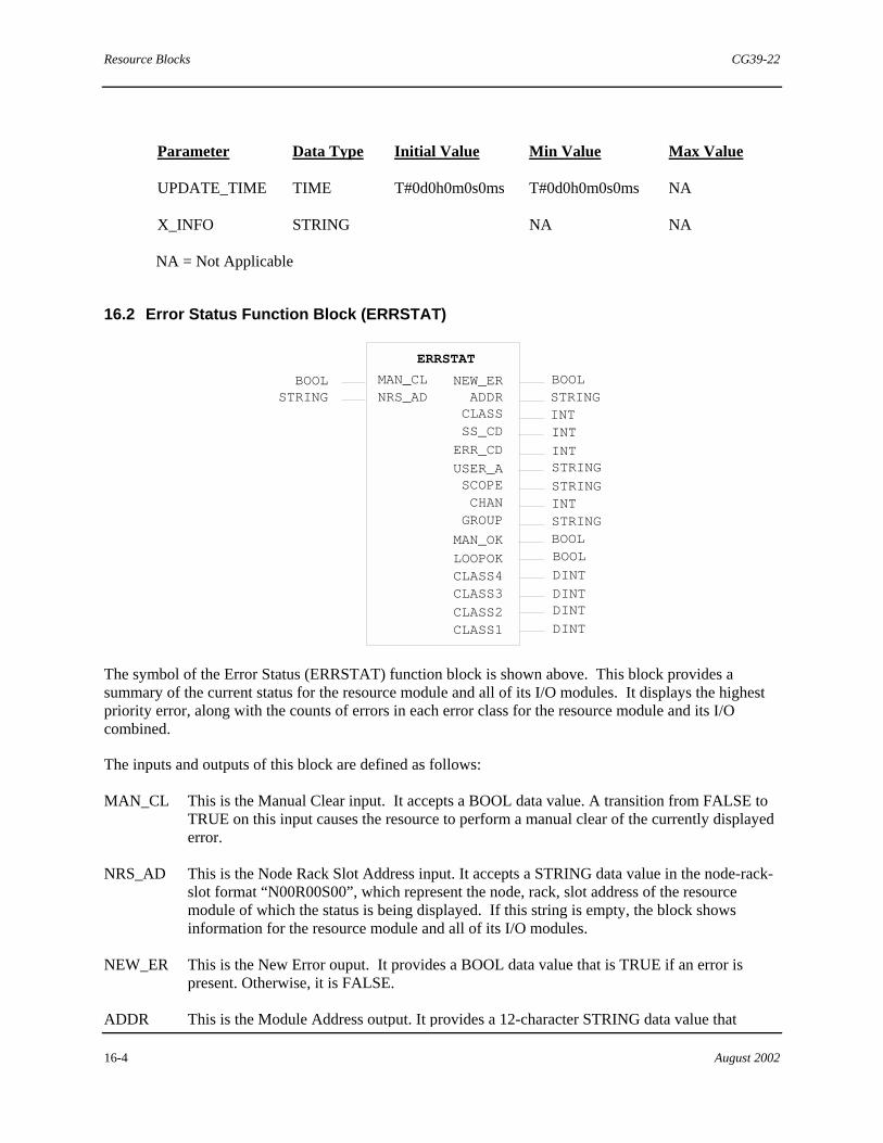
Resource Blocks CG39-22
16-4 August 2002
Parameter Data Type Initial Value Min Value Max Value
UPDATE_TIME TIME T#0d0h0m0s0ms T#0d0h0m0s0ms NA
X_INFO STRING � � NA NA
NA = Not Applicable
16.2 Error Status Function Block (ERRSTAT)
STRING STRINGNRS_AD
ERRSTAT
NEW_ERADDRCLASSSS_CD INT
BOOLBOOL MAN_CL
STRING
STRING
LOOPOK
ERR_CD
INT
CLASS4
INTSTRING
USER_ASCOPECHANGROUP
BOOL
DINT
DINTCLASS3
BOOLMAN_OK
INT
CLASS2CLASS1
DINT
DINT
The symbol of the Error Status (ERRSTAT) function block is shown above. This block provides a summary of the current status for the resource module and all of its I/O modules. It displays the highest priority error, along with the counts of errors in each error class for the resource module and its I/O combined.
The inputs and outputs of this block are defined as follows:
MAN_CL This is the Manual Clear input. It accepts a BOOL data value. A transition from FALSE to TRUE on this input causes the resource to perform a manual clear of the currently displayed error.
NRS_AD This is the Node Rack Slot Address input. It accepts a STRING data value in the node-rack-slot format “N00R00S00”, which represent the node, rack, slot address of the resource module of which the status is being displayed. If this string is empty, the block shows information for the resource module and all of its I/O modules.
NEW_ER This is the New Error ouput. It provides a BOOL data value that is TRUE if an error is present. Otherwise, it is FALSE.
ADDR This is the Module Address output. It provides a 12-character STRING data value that
CG39-22 Resource Blocks
August 2002 16-5
identifies the node, rack, slot, and module type name of the module that reported the error. The 12 characters are in the following format:
‘NnnRrrSssSDM’
where: nn is the node number rr is the rack number ss is the slot number SDM is a three character module identifier (e.g. SDM=Standard Discrete Module Plus)
CLASS This is the Error Class output. It provides an INT value from 0 to 4 that indicates the error class of the reported event. A value of 0 indicates no error. Remaining values indicate error severity from 1 (lowest) to 4 (highest).
SS_CD This is the System Service Code Output. It provides an INT value that represents the module where the error occured. Since error codes are duplicated throughout the system, each hardware and software module has a unique system service code. This output is to be used in conjunction with the Error Code (ERR_CD) output.
For example, an event reporting SS_CD 6 and ERR_CD 4 is an open circuit on an SAM (Standard Analog Module). The ADDR output indicates which SAM. SS_CD 7 and ERR_CD 4 means the channel failed off within an SDM+ (Standard Discrete Module Plus).
ERR_CD This is the Error Code output. It provides an INT data value that indicates the specific error code of the reported event. This output is to be used in conjunction with the System Service Code (SS_CD) output.
USER_A This is the User Action output. It provides a STRING data value (up to 64 characters) that describes what you should do to resolve the error identified by the SS_CD and ERR_CD outputs. For example, ‘16- Replace Module’ is a user action string.
SCOPE This is the Error Scope output. It provides a STRING data value (up to eight characters) that identifies the scope of the reported error. The four current scopes are:
System - An error that affects multiple modules such as a redundancy error.
Module - An error that affects more than one channel or group on a module.
Group - An error that affects one or more channels in a group (some I/O modules have channels collected in groups for isolation purposes).
Channel - An error that affects one channel.
CHAN This is the Error Channel Identification output. It provides an UINT data value that identifies the channel number of the error if the SCOPE output string is ‘channel’.
GROUP This is the Channel Group Identification output. It provides a STRING data value that identifies the channel group containing the error (‘A’ to ‘G’) if the SCOPE output string is ‘Group’.
MAN_OK This the Manual Clear OK output. It provides a BOOL value that is TRUE if it is permissible to clear errors manually via the MAN_CL input.
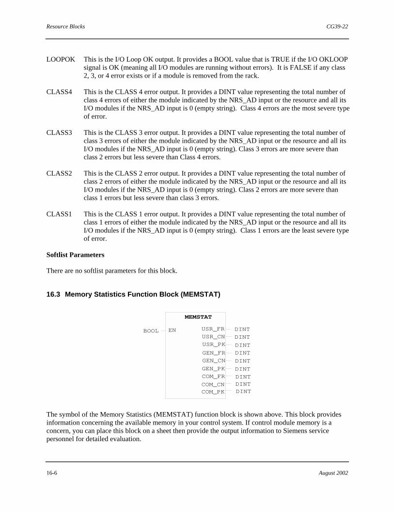
Resource Blocks CG39-22
16-6 August 2002
LOOPOK This is the I/O Loop OK output. It provides a BOOL value that is TRUE if the I/O OKLOOP signal is OK (meaning all I/O modules are running without errors). It is FALSE if any class 2, 3, or 4 error exists or if a module is removed from the rack.
CLASS4 This is the CLASS 4 error output. It provides a DINT value representing the total number of class 4 errors of either the module indicated by the NRS_AD input or the resource and all its I/O modules if the NRS_AD input is 0 (empty string). Class 4 errors are the most severe type of error.
CLASS3 This is the CLASS 3 error output. It provides a DINT value representing the total number of class 3 errors of either the module indicated by the NRS_AD input or the resource and all its I/O modules if the NRS_AD input is 0 (empty string). Class 3 errors are more severe than class 2 errors but less severe than Class 4 errors.
CLASS2 This is the CLASS 2 error output. It provides a DINT value representing the total number of class 2 errors of either the module indicated by the NRS_AD input or the resource and all its I/O modules if the NRS_AD input is 0 (empty string). Class 2 errors are more severe than class 1 errors but less severe than class 3 errors.
CLASS1 This is the CLASS 1 error output. It provides a DINT value representing the total number of class 1 errors of either the module indicated by the NRS_AD input or the resource and all its I/O modules if the NRS_AD input is 0 (empty string). Class 1 errors are the least severe type of error.
Softlist Parameters
There are no softlist parameters for this block.
16.3 Memory Statistics Function Block (MEMSTAT)
MEMSTAT
DINT
BOOL USR_FREN
COM_PK DINT
USR_CN
GEN_FR
USR_PK
COM_FR
DINTDINT
DINT
DINTGEN_CNGEN_PK
COM_CN
DINT
DINT
DINT
The symbol of the Memory Statistics (MEMSTAT) function block is shown above. This block provides information concerning the available memory in your control system. If control module memory is a concern, you can place this block on a sheet then provide the output information to Siemens service personnel for detailed evaluation.

CG39-22 Resource Blocks
August 2002 16-7
This block gathers information from the control module (CCM) concerning the free (FR), contiguous (CN), and peak (PK) memory usage for each of the following areas:
• User configuration memory (SAT) • General purpose heap memory (HEAP) • Communications heap memory (LLHEAP)
All outputs are updated whenever the (EN) input is TRUE. All outputs are in bytes.
The input and outputs of the MEMSTAT block are defined as follows:
EN This is the Enable input. It accepts a BOOL data type value. When TRUE, all block outputs are updated with current memory statistics.
USR_FR This is the User Free memory output. It provides a DINT data value, in bytes, that represents the amount of free user configuration memory (SAT).
USR_CN This is the User Contiguous memory output. It provides a DINT data value, in bytes, that represents the amount of free contiguous user configuration memory (SAT).
USR_PK This is the User Peak memory output. It provides a DINT data value, in bytes, that represents the peak usage of user configuration memory (SAT).
GEN_FR This is the General Free memory output. It provides a DINT data value, in bytes, that represents the amount of free general purpose heap memory (HEAP).
GEN_CN This is the General Contiguous memory output. It provides a DINT data value, in bytes, that represents the amount of free contiguous general purpose heap memory (HEAP).
GEN_PK This is the General Peak memory output. It provides a DINT data value, in bytes, that represents the peak usage of general purpose memory (HEAP).
COM_FR This is the Communications Free memory output. It provides a DINT data value, in bytes, that represents the amount of free communications heap memory (LLHEAP).
COM_CN This is the Communications Contiguous memory output. It provides a DINT data value, in bytes, that represents the amount of free contiguous communications heap memory (LLHEAP).
COM_PK This is the Communications Peak memory output. It provides a DINT data value, in bytes, that represents the peak usage of communications heap memory (LLHEAP).
Softlist Parameters
There are no softlist parameters for this block.

Resource Blocks CG39-22
16-8 August 2002
16.4 Partial I/O Scan Function Block (PART_IO)
BOOL
BOOL
PART_IO
SCANTM TIME
INT
SCANEN
OUTPEN ERRCOD
The symbol for the Partial I/O Scan (PART_IO) block is shown above. This block is used to define a partial list of I/O modules which will be scanned upon each execution. When executed, this block causes all the specified I/O modules to be read/updated. This includes updating specified inputs and outputs whether they be on-board, local, distributed, or remote. However, upon the first execution of this block, no output modules or channels are updated.
One I/O Scan block (i.e. Total I/O Scan block, Total I/O Hold Scan block, or the Partial I/O Scan block) must be present in the configuration, otherwise no I/O updating will occur.
NOTE
An I/O scan block must be located on the resource sheet before any program blocks.
The inputs and outputs of the Partial I/O Scan block are defined as follows:
SCANEN This is the Scan Enable input. It accepts a BOOL value. When TRUE, the block causes the inputs to be scanned.
OUTPEN This is the Outputs Enable input. It accepts a BOOL value. When TRUE, the block causes the outputs to be updated.
SCANTM This is the Scan Time output. It provides a TIME value that indicates the execution time duration of the I/O scan.
ERRCOD This is the Error Code output. It provides an INT value that indicates the code of any detected error. The possible error codes are as follows:
0 = No error. 1 =One or more modules are not responding to the scan commands. 2 =One or more I/O module addresses in the softlist are invalid. 3 =Not used 4 =One or more modules are configured incorrectly.
Note: Error 1 takes precedence over error 2, etc. so that if more than one error is present, only one error is displayed.
Softlist Parameters
The remaining PART_IO input is accessed via the softlist.

CG39-22 Resource Blocks
August 2002 16-9
IO_ADDRESS_n The value is the address of the I/O module in the following string format:
‘%RrrSss’
Where:
rr = rack number ss = slot number for the module
Parameter Data Type Initial Value Privilege
IO_ADDRESS_n String “ ” (Blank) R/W
Where: n = 1 to 39 in the parameter list R/W = Read/Write
16.5 Real-time Clock Block (RTC)
BOOLDATE_AND_TIME PDT
RTC
QCDT
EN BOOLDATE_AND_TIME
The symbol of the Real-Time Clock (RTC) function block is shown above. This block is used to set and/or read the real-time clock (chip) of the control module (e.g., CCM). There are two ways to use this block to set the time. The first way is to enter a DATE_AND_TIME value into the SetTime softlist parameter. The second way is to use the block's inputs by connecting a DATE_AND_TIME value to the PDT (Present Date/Time) input then enabling the block.
The allowable range of setting is Jan 1, 1970 thru Jan 19, 2038. Values outside this range are ignored, but cause an error to be posted by the Time Synchronization (TIMESYNC) block within the same resource.
The inputs and outputs of the RTC block are defined as follows:
EN This is the Enable input. It accepts a BOOL data value. When a FALSE to TRUE transition is detected on this input, the Present Date/Time (PDT) input value is used to set the time in the control module.
PDT This is the Present Date/Time input. It accepts a DATE_AND_TIME data value. The control module time gets set to the DATE_AND_TIME value when the EN input is toggled from FALSE to TRUE.
Q This is the Q output. It outputs a BOOL value that is a copy of the EN input value.
CDT This is the Current Date/Time output. It outputs a DATE_AND_TIME value that is the current date and time of the control module.

Resource Blocks CG39-22
16-10 August 2002
Softlist Parameter
SetTime This parameter uses the DATE_AND_TIME data type. Its value is used to set the date and time in the control module (e.g. CCM).
16.6 Redundancy Control Block (REDCTRL)
REDCTRL
BOOL REQ REDUNACTIVELCABLE
A_BA_ADDRA_STATA_LOOPB_ADDRB_STATB_LOOP
BOOL
BOOLBOOL
BOOLBOOL
BOOLBOOL
STRING
BOOL DIS_SW
STRING
STRING
The symbol for the Redundancy Control (REDCTRL) function block is shown above. This block is used to indicate that the control module (ACM) is part of a redundant pair, and provides redundancy status information.
The inputs and outputs of the REDCTRL block are defined as follows:
REQ This is the Switch Over Request input. It accepts a BOOL data value. When a FALSE to TRUE transition is detected, the block forces a control switchover between the redundant control modules.
DIS_SW This is the Disable Switch input. It accepts a BOOL value that, when TRUE, disables the block so no switchovers can occur, unless otherwise forced to do so via the REQ input.
REDUN This is the Redundancy output. It provides a BOOL value that is TRUE if redundancy exists. Otherwise, it is FALSE to indicate no redundancy.
ACTIVE This is the Active Module output. It provides a BOOL value that is TRUE if the module is the primary control module in the redundant pair. This mirrors the LED indication on the front of the module. Note that the value displayed on a sheet will always be TRUE since 4-mation sheets display the contents of the active (primary) resource. But the actual value may be obtained through an operator interface or the Variable control dialog box by addressing the specific resource in the redundant pair (preceding the resource name with A: or B:). For Example, to query this nub value in the B: resource, use the address path: B:ResourceName:RESOURCE_BLOCKS.RedCtl1.[ACTIVE]
LCABLE This is the Redundancy Link Cable output. It provides a BOOL value that is TRUE when the redundancy cable is OK.
A_B This is the A/B Identification output. It provides a STRING value of “A” if the block is located in the A resource module or “B” if the block is located in the B resource module.
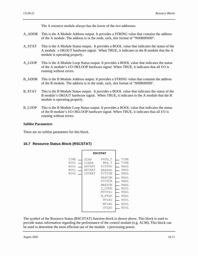
CG39-22 Resource Blocks
August 2002 16-11
The A resource module always has the lower of the two addresses.
A_ADDR This is the A Module Address output. It provides a STRING value that contains the address of the A module. The address is in the node, rack, slot format of “N00R00S00”.
A_STAT This is the A Module Status output. It provides a BOOL value that indicates the status of the A module�s OKOUT hardware signal. When TRUE, it indicates to the B module that the A module is operating properly.
A_LOOP This is the A Module Loop Status output. It provides a BOOL value that indicates the status of the A module’s I/O OKLOOP hardware signal. When TRUE, it indicates that all I/O is running without errors.
B_ADDR This is the B Module Address output. It provides a STRING value that contains the address of the B module. The address is in the node, rack, slot format of ‘N00R00S00’.
B_STAT This is the B Module Status output. It provides a BOOL value that indicates the status of the B module’s OKOUT hardware signal. When TRUE, it indicates to the A module that the B module is operating properly.
B_LOOP This is the B Module Loop Status output. It provides a BOOL value that indicates the status of the B module’s I/O OKLOOP hardware signal. When TRUE, it indicates that all I/O is running without errors.
Softlist Parameters
There are no softlist parameters for this block.
16.7 Resource Status Block (RSCSTAT)
RSCSTAT
TIMEBOOL
SCANCLEAR
PCTPRGMAXPRGPCTCOM
MAXCOMPCTSCNMAXSCNS_OVERMTOTALM_FREE
CSTART
HSTART
PROG_TMAX_T
BOOL
BOOL
BOOL
REALREAL
REALREALREAL
REAL
REALREAL
WSTART
HFLAG
WFLAGCFLAG BOOL
BOOLBOOLBOOL
TIMETIME
The symbol of the Resource Status (RSCSTAT) function block is shown above. This block is used to provide status information regarding the performance of the control module (e.g. ACM). This block can be used to determine the most efficient use of the module�s processing power.

Resource Blocks CG39-22
16-12 August 2002
A resource configuration is defined as the database resident in a resource module that was transferred there using 4-mation. System and communication tasks are defined as the overhead in the control module plus the communication block and presentation block messages.
The inputs and outputs of the RSCSTAT block are defined as follows:
SCAN This is the Scan Time input. It accepts a TIME data value for setting the periodic scan times allocated to execute the resource configuration and other system tasks. For further information regarding scan rates, refer to Section 24 �Optimizing a Configuration� of Using the 4-mation Configuration Software (document CG39-20).
CLEAR This is the Clear input. It accepts a BOOL data value. When a FALSE to TRUE transition is detected, all MAX values are cleared.
HSTART This is the Hot Restart input. It accepts a BOOL data value. When a FALSE to TRUE transition is detected, it forces a hot restart.
WSTART This is the Warm Restart input. It accepts a BOOL data value. When a FALSE to TRUE transition is detected, it forces a warm restart.
CSTART This is the Cold Restart input. It accepts a BOOL data value. When a FALSE to TRUE transition is detected, it forces a cold restart.
PROG_T This is the Program Time output. It provides a TIME data value that indicates the amount of time it takes to execute the resource configuration.
MAX_T This is the Maximum Time output. It provides a TIME data value that indicates the maximum amount of time it takes to execute the resource configuration.
PCTPRG This is the Percentage of Program output. It provides a REAL data value that indicates the percentage of the SCAN input value used for processing the resource configuration.
MAXPRG This is the Maximum Percentage of Program output. It provides a REAL data value that indicates the maximum percentage of the SCAN input value used for processing the resource configuration.
PCTCOM This is the Percentage of Communication output. It provides a REAL data value that indicates the percentage of the SCAN input value used for processing system and communications tasks.
MAXCOM This is the Maximum Percentage of Communication output. It provides a REAL data value that indicates the maximum percentage of the SCAN input value used for processing system and communications tasks.
PCTSCN This is the Percentage of Scan output. It provides a REAL data value that indicates the percentage of the SCAN input value the processor is working (not idle).
MAXSCN This is the Maximum Percentage of Scan output. It provides a REAL data value that indicates the maximum percentage of the SCAN input value the processor is working (not idle).

CG39-22 Resource Blocks
August 2002 16-13
S_OVER This the Scan Over output. It provides a BOOL data value that is pulsed TRUE if the total scan time exceeds the SCAN input value. If this output is pulsing TRUE, the SCAN input value should be increased, communications between resources should be compacted or minimized, or logic should be moved to another resource.
MTOTAL This is the Total Memory output. It provides a REAL data value that indicates the total memory (in bytes) available for the resource configuration.
M_FREE This is the Memory Free output. It provides a REAL data value that indicates the total amount of free memory (in bytes). To find the percentage of available memory remaining in a control module, open the control module on-line and divide the M_FREE output by the MTOTAL output.
HFLAG This is the Hot Restart Flag output. It provides a BOOL value that is TRUE for the FLAG_TIME amount of time if the system is powered down for less than the WARM_TIME value or if the HSTART input experiences a FALSE to TRUE transition.
WFLAG This is the Warm Restart Flag output. It provides a BOOL value that is TRUE for the FLAG_TIME amount of time if the system is powered down for longer than the WARM_TIME value but less than the COLD_TIME value, or if the WSTART input experiences a FALSE to TRUE transition.
CFLAG This is the Cold Restart Flag. It provides a BOOL data value that is TRUE for the FLAG_TIME amount of time when the system is powered down for longer than the COLD_TIME length of time.
Softlist Parameters
The remaining RSCSTAT inputs to the Resource Status function block are accessed via the softlist. The value of these inputs can be changed via commands from an operator interface or by using a Set Value (SET_VAL) function block. Below is a description and initial value for each softlist parameter.
SCAN_COUNT This is the Scan Counting Parameter. It is a DINT data value that increments every scan.
FLAG_TIME This is the Flag Time parameter. It accepts a TIME value that sets the amount of time the HFLAG, WFLAG, and CFLAG outputs stay TRUE.
WARM_TIME This is the Warm Time parameter. It accepts a TIME value that sets the amount of time a control module can be powered down before a hot start becomes a warm start.
COLD_TIME This is the Cold Time parameter. It accepts a TIME value that sets the amount of time a control module can be powered down before a warm start becomes a cold start.
POWER_UP_STOP_W This is the Warm Restart Power Up After Stop parameter. It accepts a BOOL value that determines the power up state of the control module in a warm restart. When TRUE, it will power up in the Stopped mode. When FALSE, it

Resource Blocks CG39-22
16-14 August 2002
will power up in the last state.
POWER_UP_STOP_C This is the Cold Restart Power Up After Stop parameter. It accepts a BOOL value that determines the power up state of the control module in a cold restart. When TRUE, it will power up in the Stopped mode. When FALSE, it will power up in the last state.
Parameter Data Type Initial Value Min Value Max Value
SCAN_COUNT DINT 0 0 NA
FLAG_TIME TIME T#0d0h0m1s0ms
T#0d0h0m0s0ms NA
WARM_TIME TIME T#0d0h0m1s0ms
T#0d0h0m0s0ms NA
COLD_TIME TIME T#0d0h1m0s0ms
T#0d0h0m0s0ms NA
POWER_UP_STOP_W BOOL FALSE FALSE TRUE
POWER_UP_STOP_C BOOL FALSE FALSE TRUE
16.8 Security Control Block (SECURTY)
BOOL BOOL
SECURTY
EN ENOCWEDWE
SECBOOLBOOL
BOOL
The symbol of the Security Control (SECURTY) function block is shown above. This block is used to control access to both on-line data and the resource configuration. This block operates in conjunction with the SECURITY ENABLE (hardware) switch located behind the front panel of the control module (ACM).
For security to be enabled in a resource configuration database, the hardware switch must be in the ENABLED position and the EN input on the Security Control function block must be TRUE. If security is enabled, the LED on the front of the module is illuminated and the CWE and DWE block inputs determine the permitted action as follows:
If the Configuration Write Enable (CWE) input is TRUE, configuration writes are permitted. If the Data Write Enable (DWE) input is TRUE, on-line writes to data values are permitted.
If neither CWE or DWE are TRUE and security is enabled, the only way to gain access (including initializing a resource and transferring a new resource configuration) is to toggle the SECURITY ENABLE switch to the disabled position.

CG39-22 Resource Blocks
August 2002 16-15
NOTE
The 4-mation program also has built-in password protection that disallows the opening of a protected resource configuration database. Refer to the “Password Protection for Resource Configuration” section of Using the 4-mation Configuration Software (document CG39-20) for more information.
The inputs and outputs of the Security Control block are defined as follows:
EN This is the Security Enable input. It accepts a BOOL data value. When it is TRUE and the hardware switch is in the ENABLED position, the block limits access to a control module’s database as defined by the state of the CWE and DWE inputs. When EN is FALSE, any device on the MODULBUS can alter any portion of the control module’s database regardless of the state of the hardware switch. Essentially, EN overrides the hardware switch.
CWE This is the Configuration Write Enable input. It accepts a BOOL data value. When it is TRUE, the EN input is TRUE, and the hardware switch is in the ENABLED position, read/write access to the control module�s database is permitted. If CWE is FALSE, the EN input is TRUE, and hardware switch is in the ENABLED position, read-only access to the control module�s database is permitted. If EN is FALSE, the configuration can be modified regardless of the state of CWE.
DWE This is the Data Write Enable input. It accepts a BOOL value. When it is TRUE and EN is TRUE and the hardware switch is in the ENABLED position, Read/Write access to data elements within the control module is granted. When it is FALSE, EN is TRUE, and the hardware switch is in the ENABLED position, then read-only access to the variables in the control module is granted. If EN is FALSE, the data can be modified regardless of the state of CWE.
ENO This is the Security Enabled Output. It provides a BOOL data value. It is TRUE when EN is TRUE and the hardware switch is in the ENABLED position. Otherwise, it is FALSE.
SEC This is the Security Enable (hardware) switch position output. It provides a BOOL data value that is TRUE when the switch is in the ENABLED position and FALSE when the switch is in the DISABLED position.
The following chart details the switch settings and resultant user accessibility. Security Enable Switch
EN DWE CWE Data Configuration Edits
ENO SEC
ENABLED FALSE x x YES YES FALSE TRUE
ENABLED TRUE FALSE FALSE NO NO TRUE TRUE
ENABLED TRUE TRUE FALSE YES NO TRUE TRUE
ENABLED TRUE FALSE TRUE NO YES TRUE TRUE
ENABLED TRUE TRUE TRUE YES YES TRUE TRUE
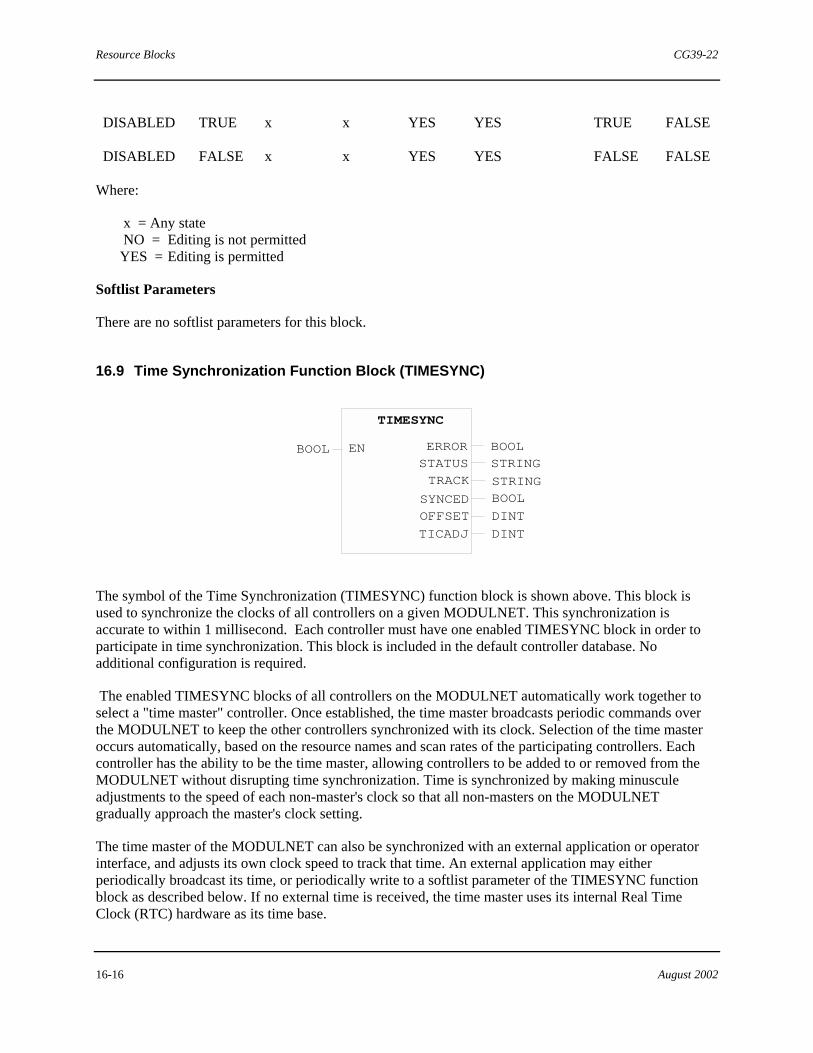
Resource Blocks CG39-22
16-16 August 2002
DISABLED TRUE x x YES YES TRUE FALSE
DISABLED FALSE x x YES YES FALSE FALSE
Where:
x = Any state NO = Editing is not permitted
YES = Editing is permitted
Softlist Parameters
There are no softlist parameters for this block.
16.9 Time Synchronization Function Block (TIMESYNC)
TIMESYNC
DINT
ERRORENSTATUS
SYNCED
TRACKSTRINGSTRING
DINTOFFSETTICADJ
BOOL
BOOL
BOOL
The symbol of the Time Synchronization (TIMESYNC) function block is shown above. This block is used to synchronize the clocks of all controllers on a given MODULNET. This synchronization is accurate to within 1 millisecond. Each controller must have one enabled TIMESYNC block in order to participate in time synchronization. This block is included in the default controller database. No additional configuration is required.
The enabled TIMESYNC blocks of all controllers on the MODULNET automatically work together to select a "time master" controller. Once established, the time master broadcasts periodic commands over the MODULNET to keep the other controllers synchronized with its clock. Selection of the time master occurs automatically, based on the resource names and scan rates of the participating controllers. Each controller has the ability to be the time master, allowing controllers to be added to or removed from the MODULNET without disrupting time synchronization. Time is synchronized by making minuscule adjustments to the speed of each non-master's clock so that all non-masters on the MODULNET gradually approach the master's clock setting.
The time master of the MODULNET can also be synchronized with an external application or operator interface, and adjusts its own clock speed to track that time. An external application may either periodically broadcast its time, or periodically write to a softlist parameter of the TIMESYNC function block as described below. If no external time is received, the time master uses its internal Real Time Clock (RTC) hardware as its time base.

CG39-22 Resource Blocks
August 2002 16-17
After startup, at least one controller's time must be set before any will participate in time synchronization. Once any controller has been set, all others on the MODULNET with enabled TIMESYNC blocks will obtain that time automatically. Time may be set by an external application, or may be set manually using the Real Time Clock (RTC) function block. Time should be set only on startup, or on large changes in system time, such as a change from Standard Time to Daylight Savings Time.
The input and outputs of the TIMESYNC block are defined as follows:
EN This is the Enable input. It accepts a BOOL data type. When EN is TRUE, the block participates in system time synchronization. The time setting of its controller is shared with all controllers on the same MODULNET that have an enabled TIMESYNC block. When EN is FALSE, the block does not perform its function, and the time setting of its controller does not track the others.
ERROR This is the Error output. It provides a BOOL data value that is TRUE whenever a problem is detected with the time synchronization function. The STATUS output (described below) simultaneously provides information describing the problem. The ERROR output is FALSE when no problem is detected.
STATUS This is the Status output. It provides a STRING data value containing a diagnostic message. The messages are listed below. This output is intended to be used as a troubleshooting aid. During normal operation, a ‘NoError’ message is output.
Status Messages and Descriptions:
NoError There are no errors being reported by the TIMESYNC block. This is the normal value. No user action is required.
TimeSyncIsOutOfTolerance This controller's time differs from system time by more than the configured limit. The limit value used depends upon whether the controller is the time master of its group or is tracking another controller's time (see descriptions of the EXTERN_TOLERANCE and GROUP_TOLERANCE softlist parameters below). This condition normally occurs only after startup or a change in system configuration, and usually clears on its own.
TimeSetThroughEvolution This controller changed its time abruptly to match another controller's time, after detecting that the other controller's time had been set more recently. This condition normally occurs after startup, and usually persists for only one scan.
TimeSetBelowSysTime An attempt to set time and date was unsuccessful because the specified date was prior to the earliest date the controller can represent (e.g., before January 1, 1970).

Resource Blocks CG39-22
16-18 August 2002
TimeSyncServicesError An internal error occurred during initialization. This condition should never occur. If it does, please notify the Technical Information Center as soon as possible.
OldTimeSampleRemoved An incomplete set of time synchronization messages was received. This condition may occur following a communication error, and usually persists for only one scan.
TimeSampleNotFound This controller did not receive an expected periodic synchronization update. This condition occurs if the time master is reset, and persists only until a new master is established automatically. It may also occur after a prolonged sequence of communication errors.
RTCChipFailed This controller's Real Time Clock (RTC) hardware has failed. Although the controller is still capable of control, it should be repaired or replaced at the next convenient opportunity.
TRACK The Track output provides a STRING data value describing this controller's time tracking status. When this controller is tracking another module's time, the output string contains that module's resource name. When this controller is not tracking another module's time, the output string contains one of the messages listed below.
Tracking Messages and Descriptions:
ResourceName This controller is tracking periodic synchronization messages from the named resource, which may be another controller, a workstation, or a PC.
TrackingTIMESYNCTagWrite This controller is tracking periodic time updates being received via writes to the EXTERNAL_SYNC softlist parameter of its TIMESYNC block. The resource name of the writer is not displayed since it is not available to the controller.
TrackingRTCChip This controller is using its own Real Time Clock (RTC) hardware as its time reference. This occurs when the controller is not receiving synchronization messages from an external source.
TimeIsDrifting This controller is not tracking any time reference. This occurs at startup before the time has been set or received from another controller, or whenever the TIMESYNC block

CG39-22 Resource Blocks
August 2002 16-19
is disabled. It also occurs during a transition when the controller is no longer receiving expected synchronization messages, until a new time master is established.
SYNCED The Synchronized output provides a BOOL data value that is TRUE when this controller is successfully tracking time within the expected tolerance. It is FALSE if tracking is outside of this value, as described above for the TimeSyncIsOutOfTolerance status message.
OFFSET The Offset output provides a DINT data value that represents the difference in microseconds between this controller's time and the time that it is tracking. A positive value means this controller is running ahead (fast); a negative value means it is running behind (slow). During normal operation this value varies slightly from scan to scan.
TICADJ The Timer Tic Adjustment output provides a DINT value that represents the signed hundredths of a percent by which this controller's clock is being slowed down (positive) or sped up (negative) in order to approach the time it is tracking. During normal operation this value varies slightly from scan to scan; its sign matches the sign of the OFFSET output.

Resource Blocks CG39-22
16-20 August 2002
Table 16–1 Status Output Diagnostic Messages
Diagnostic Message Description
Arbitrating ACM modules are contending for time master status. This is initiated when a TIMESYNC block is enabled. Generally, this message only lasts for about two ACM scans (of the largest scan rate). Time master status is granted to the module having the shortest scan period and, as a second criteria, having the lexicographically greatest resource name. No user action is required.
NoError There are no errors being reported by the TIMESYNC block. This is the normal value. No user action is required.
TimeSyncIsOutOfTolerance This ACM�s time differs from the greater system time by more than the value of the TOLERANCE softlist parameter. This may occur immediately after an initial time setting but should not persist.
TimeSetThroughEvolution If this ACM undergoes a warm start or a TIMESYNC block is initially enabled at a time when arbitration has settled among existing ACMs on the same MODULNET, this ACM first sets its time to the current MODULNET time prior to participating in system time synchronization tasks. No user action is required.
BadTimeSample A communications error has occurred. This is a tolerable condition, providing that it does not persist. No user action is required.
OldTimeSampleRemoved As a result of a communications error, the current time sample shall be discarded. No user action is required.
MultipleTimeMasters The names of two resource modules (i.e. ACMs) are identical and are lexicographically the greatest in the system. In addition, they both have the same scan rate. You must rename one of them.

CG39-22 Resource Blocks
August 2002 16-21
Table 16–1 Status Output Diagnostic Messages (Continued)
Diagnostic Message Description
TimeSampleNotFound Previously, time synchronization samples have been arriving on time; now they are not. This may be due to the loss of the current time master. The ACMs will now arbitrate and a new time master shall be decided. You should investigate the operational status of the ACM that has lost its time master status.
RTCChipFailed The Real Time Clock chip has failed on the ACM acting as the time master. That ACM is operating as a time slave. No immediate action is required; however, at the earliest possible convenience, this module should be replaced.
MessageCreationFailure The ACM is out of memory or there is a problem with lower level communications support. If this error persists, contact the Siemens Technical Information Center (TIC). Refer to the “Product Support” section of Using the 4-mation Configuration Software (document CG39-20).
MessageSendFailure
CommandNotRecognized
CommLinkLayerError
TimeSyncServicesError
OutOfBoundsAccess
InvalidStateCode
There is a problem with lower level communications support. If any of these errors persist, contact the SiemensTechnical Information Center (TIC). Refer to the “Product Support” section of Using the 4-mation Configuration Software (document CG39-20).
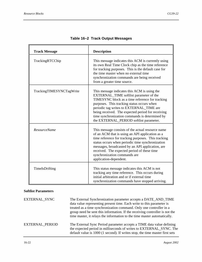
Resource Blocks CG39-22
16-22 August 2002
Table 16–2 Track Output Messages
Track Message Description
TrackingRTCChip This message indicates this ACM is currently using its own Real Time Clock chip as the time reference for tracking purposes. This is the default case for the time master when no external time synchronization commands are being received from a greater time source.
TrackingTIMESYNCTagWrite This message indicates this ACM is using the EXTERNAL_TIME softlist parameter of the TIMESYNC block as a time reference for tracking purposes. This tracking status occurs when periodic tag writes to EXTERNAL_TIME are being received. The expected period for receiving time synchronization commands is determined by the EXTERNAL_PERIOD softlist parameter.
ResourceName This message consists of the actual resource name of an ACM that is using an API application as a time reference for tracking purposes. This tracking status occurs when periodic time synchronization messages, broadcasted by an API application, are received. The expected period of these time synchronization commands are application-dependent.
TimeIsDrifting This status message indicates this ACM is not tracking any time reference. This occurs during initial arbitration and or if external time synchronization commands have stopped arriving.
Softlist Parameters
EXTERNAL_SYNC The External Synchronization parameter accepts a DATE_AND_TIME data value representing present time. Each write to this parameter is treated as a time synchronization command. Only one controller in a group need be sent this information. If the receiving controller is not the time master, it relays the information to the time master automatically.
EXTERNAL_PERIOD The External Sync Period parameter accepts a TIME data value defining the expected period in milliseconds of writes to EXTERNAL_SYNC. The default value is 1000 (1 second). If writes stop, the time master first sets
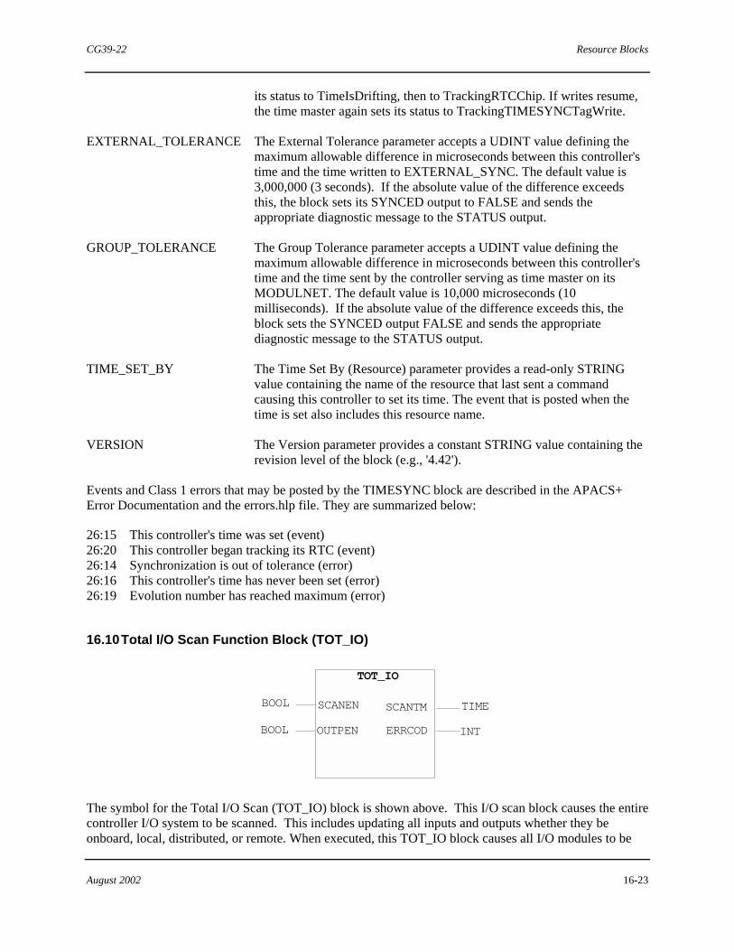
CG39-22 Resource Blocks
August 2002 16-23
its status to TimeIsDrifting, then to TrackingRTCChip. If writes resume, the time master again sets its status to TrackingTIMESYNCTagWrite.
EXTERNAL_TOLERANCE The External Tolerance parameter accepts a UDINT value defining the maximum allowable difference in microseconds between this controller's time and the time written to EXTERNAL_SYNC. The default value is 3,000,000 (3 seconds). If the absolute value of the difference exceeds this, the block sets its SYNCED output to FALSE and sends the appropriate diagnostic message to the STATUS output.
GROUP_TOLERANCE The Group Tolerance parameter accepts a UDINT value defining the maximum allowable difference in microseconds between this controller's time and the time sent by the controller serving as time master on its MODULNET. The default value is 10,000 microseconds (10 milliseconds). If the absolute value of the difference exceeds this, the block sets the SYNCED output FALSE and sends the appropriate diagnostic message to the STATUS output.
TIME_SET_BY The Time Set By (Resource) parameter provides a read-only STRING value containing the name of the resource that last sent a command causing this controller to set its time. The event that is posted when the time is set also includes this resource name.
VERSION The Version parameter provides a constant STRING value containing the revision level of the block (e.g., '4.42').
Events and Class 1 errors that may be posted by the TIMESYNC block are described in the APACS+ Error Documentation and the errors.hlp file. They are summarized below:
26:15 This controller's time was set (event) 26:20 This controller began tracking its RTC (event) 26:14 Synchronization is out of tolerance (error) 26:16 This controller's time has never been set (error) 26:19 Evolution number has reached maximum (error)
16.10 Total I/O Scan Function Block (TOT_IO)
BOOL
BOOL
TOT_IO
SCANTM TIME
INT
SCANEN
OUTPEN ERRCOD
The symbol for the Total I/O Scan (TOT_IO) block is shown above. This I/O scan block causes the entire controller I/O system to be scanned. This includes updating all inputs and outputs whether they be onboard, local, distributed, or remote. When executed, this TOT_IO block causes all I/O modules to be
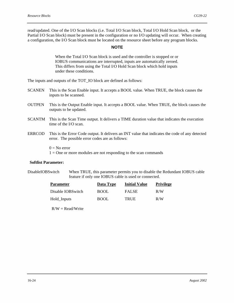
Resource Blocks CG39-22
16-24 August 2002
read/updated. One of the I/O Scan blocks (i.e. Total I/O Scan block, Total I/O Hold Scan block, or the Partial I/O Scan block) must be present in the configuration or no I/O updating will occur. When creating a configuration, the I/O Scan block must be located on the resource sheet before any program blocks.
NOTE
When the Total I/O Scan block is used and the controller is stopped or or IOBUS communications are interrupted, inputs are automatically zeroed. This differs from using the Total I/O Hold Scan block which hold inputs under these conditions.
The inputs and outputs of the TOT_IO block are defined as follows:
SCANEN This is the Scan Enable input. It accepts a BOOL value. When TRUE, the block causes the inputs to be scanned.
OUTPEN This is the Output Enable input. It accepts a BOOL value. When TRUE, the block causes the outputs to be updated.
SCANTM This is the Scan Time output. It delivers a TIME duration value that indicates the execution time of the I/O scan.
ERRCOD This is the Error Code output. It delivers an INT value that indicates the code of any detected error. The possible error codes are as follows:
0 = No error 1 = One or more modules are not responding to the scan commands
Softlist Parameter:
DisableIOBSwitch When TRUE, this parameter permits you to disable the Redundant IOBUS cable feature if only one IOBUS cable is used or connected.
Parameter Data Type Initial Value Privilege
Disable IOBSwitch BOOL FALSE R/W
Hold_Inputs BOOL TRUE R/W
R/W = Read/Write

CG39-22 Resource Blocks
August 2002 16-25
16.11 Module Information Function Block (MODINFO)
BOOLBOOL STRING
INTMAN_CL
MODINFONEW_ERADDR
SS_CD
NEXT_E
INTCLASS
BOOL
STRINGERR_CD
MAN_OK
INTE_MASKIOBRD
USER_ASCOPECHAN
NUMACTERRNUMMASKEDCLASS4CLASS3CLASS2CLASS1
STRINGINTBOOLINTINT
DINTDINTDINTDINT
BOOL
STRINGINT
The symbol for the Module Information (MODINFO) block is shown above. This block allows you to monitor the five highest priority errors for a module one at a time. It also allows you to optionally mask (i.e. suppress) unwanted errors of a designated error class and lower in I/O modules only.
The address of the desired I/O module is to be applied as a STRING variable to the IOBRD (I/O Board) input. If no address is applied, the control module’s errors are monitored.
Errors are reported by pulsing the NEXT_E (Next Error) input. This causes the ERRNUM (Error Number) output to output the specific number of the error being reported.
A reported error can be manually cleared by applying a TRUE value to the MAN_CL (Manual Clear) input whenever the MAN_OK (Manual Clear OK) output is also TRUE.
The inputs and outputs of the Module Information block are defined as follows:
NEXT_E This is the Next Error input. It accepts a BOOL value. When a FALSE to TRUE transition is sensed the block reports the next highest priority error. Up to five of the highest priority errors can be observed. The block rotates through the errors by priority level. Each time the input is pulsed the block shifts one priority level starting from priority 5 (lowest) towards a priority 1 (highest).
MAN_CL This is the Manual Clear input. It accepts a BOOL value. When a FALSE to TRUE transition is sensed, the block attempts to clear the currently referenced error.
NOTE
If multiple MODINFO blocks are used, make sure each input is connected to a unique variable. Also, do not clear errors on all of them at once (within the same scan). To assure all errors are cleared, design configuration logic to stagger clear operations.
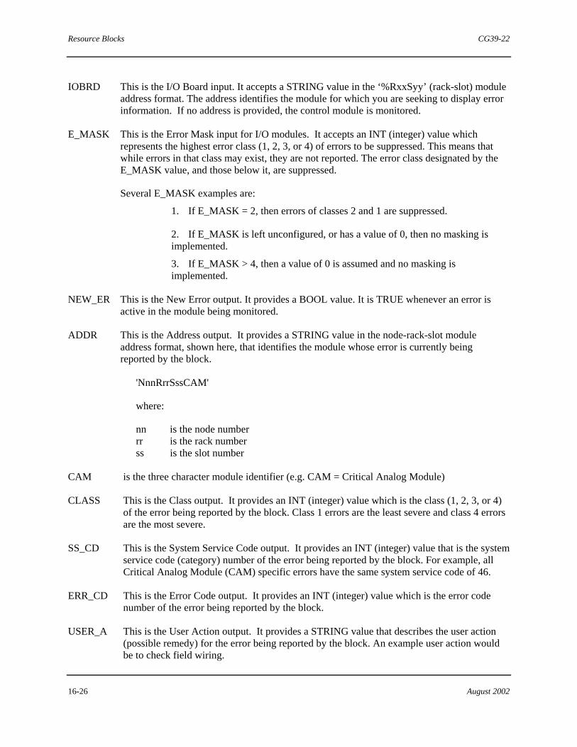
Resource Blocks CG39-22
16-26 August 2002
IOBRD This is the I/O Board input. It accepts a STRING value in the ‘%RxxSyy’ (rack-slot) module address format. The address identifies the module for which you are seeking to display error information. If no address is provided, the control module is monitored.
E_MASK This is the Error Mask input for I/O modules. It accepts an INT (integer) value which represents the highest error class (1, 2, 3, or 4) of errors to be suppressed. This means that while errors in that class may exist, they are not reported. The error class designated by the E_MASK value, and those below it, are suppressed.
Several E_MASK examples are:
1. If E_MASK = 2, then errors of classes 2 and 1 are suppressed.
2. If E_MASK is left unconfigured, or has a value of 0, then no masking is implemented.
3. If E_MASK > 4, then a value of 0 is assumed and no masking is implemented.
NEW_ER This is the New Error output. It provides a BOOL value. It is TRUE whenever an error is active in the module being monitored.
ADDR This is the Address output. It provides a STRING value in the node-rack-slot module address format, shown here, that identifies the module whose error is currently being reported by the block.
'NnnRrrSssCAM'
where:
nn is the node number rr is the rack number ss is the slot number
CAM is the three character module identifier (e.g. CAM = Critical Analog Module)
CLASS This is the Class output. It provides an INT (integer) value which is the class (1, 2, 3, or 4) of the error being reported by the block. Class 1 errors are the least severe and class 4 errors are the most severe.
SS_CD This is the System Service Code output. It provides an INT (integer) value that is the system service code (category) number of the error being reported by the block. For example, all Critical Analog Module (CAM) specific errors have the same system service code of 46.
ERR_CD This is the Error Code output. It provides an INT (integer) value which is the error code number of the error being reported by the block.
USER_A This is the User Action output. It provides a STRING value that describes the user action (possible remedy) for the error being reported by the block. An example user action would be to check field wiring.
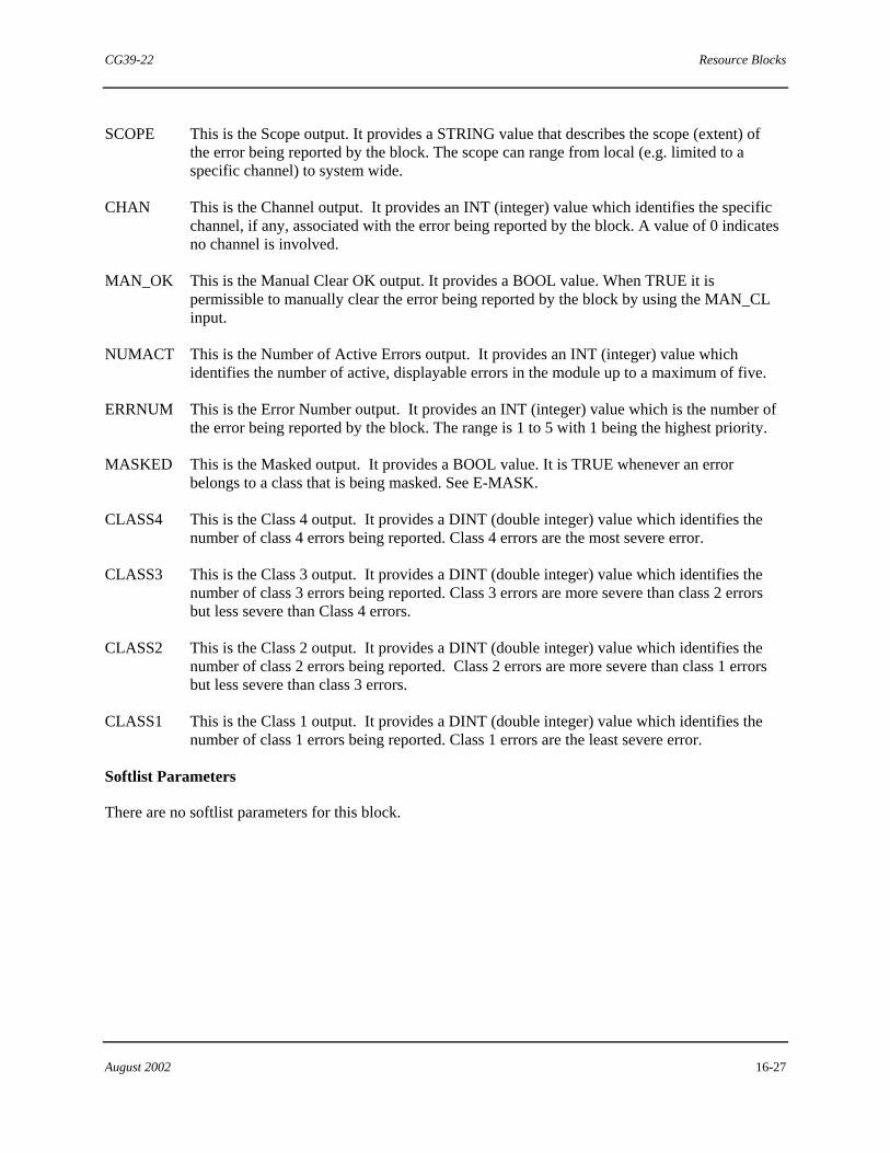
CG39-22 Resource Blocks
August 2002 16-27
SCOPE This is the Scope output. It provides a STRING value that describes the scope (extent) of the error being reported by the block. The scope can range from local (e.g. limited to a specific channel) to system wide.
CHAN This is the Channel output. It provides an INT (integer) value which identifies the specific channel, if any, associated with the error being reported by the block. A value of 0 indicates no channel is involved.
MAN_OK This is the Manual Clear OK output. It provides a BOOL value. When TRUE it is permissible to manually clear the error being reported by the block by using the MAN_CL input.
NUMACT This is the Number of Active Errors output. It provides an INT (integer) value which identifies the number of active, displayable errors in the module up to a maximum of five.
ERRNUM This is the Error Number output. It provides an INT (integer) value which is the number of the error being reported by the block. The range is 1 to 5 with 1 being the highest priority.
MASKED This is the Masked output. It provides a BOOL value. It is TRUE whenever an error belongs to a class that is being masked. See E-MASK.
CLASS4 This is the Class 4 output. It provides a DINT (double integer) value which identifies the number of class 4 errors being reported. Class 4 errors are the most severe error.
CLASS3 This is the Class 3 output. It provides a DINT (double integer) value which identifies the number of class 3 errors being reported. Class 3 errors are more severe than class 2 errors but less severe than Class 4 errors.
CLASS2 This is the Class 2 output. It provides a DINT (double integer) value which identifies the number of class 2 errors being reported. Class 2 errors are more severe than class 1 errors but less severe than class 3 errors.
CLASS1 This is the Class 1 output. It provides a DINT (double integer) value which identifies the number of class 1 errors being reported. Class 1 errors are the least severe error.
Softlist Parameters
There are no softlist parameters for this block.

Resource Blocks CG39-22
16-28 August 2002
16.12 System Information Block (SYSINFO)
SYSINFO
BOOL BOOL
BOOL
BOOL
MAN_CL REDUN
ACTIVE
ADDR
NEW_ERNRS_AD
STRING A_B
INTCLASSINTSS_CD
STRING
STRING
USER_A
INTERR_CD
SCOPE
BOOLCHAN
DINT
DINT
DINT
STRING
STRINGINT
MAN_OK
DINTCLASS4
CLASS3CLASS2
CLASS1
The Symbol for the System Information (SYSINFO) block is shown above. This block is used to monitor the highest priority error message of a control module (e.g. ACM or CCM) and all of its associated I/O modules.
For redundant systems, either of the control modules can be selected via the block's A-B input for monitoring errors. This way, the highest priority error message for the calculate control module and the verify control module can be observed.
The Manual Clear (MAN_CL) input is used to manually clear a displayed error if the Manual Clear OK (MAN_OK) output is TRUE.
The inputs and outputs of the SYSINFO block are as follows:
MAN_CL This is the Manual Clear Input. It accepts a BOOL data type. When TRUE, it clears the currently displayed error.
A_B This is the A/B Selector input. It accepts a STRING data type. The string value is to specify which control module (A side or B side) in a redundant system is to be monitored for errors.
REDUN This is the Redundant output. It delivers a BOOL variable. It is TRUE whenever the system is redundant.
ACTIVE This is the control module Activity output. It delivers a BOOL variable. It is TRUE whenever the control module is active.

CG39-22 Resource Blocks
August 2002 16-29
NRS_AD This is the Resource Address output. It delivers a STRING variable that is the address of the control module. The address is in the node-rack-slot format.
NEW_ER
This is the New Error output. It delivers a BOOL value that is TRUE whenever an error is active in the control module or any of its I/O modules.
ADDR This is the Address output . It delivers a STRING value that is the address of the module (in node-rack-slot format) with the error being reported in the block.
CLASS This is the Class input. It delivers an INT value that represent the class of the error being reported in the block.
SS_CD This is the System Service Code output. It delivers an INT value which is the System Service Code of the error being reported in the block.
ERR_CD This is the Error Code output. It delivers an INT value which is the Error Code of the error being reported in the block.
USER_A This is the User Action message output. It delivers a STRING value that describes the user action prescribed for the error being reported in the block.
SCOPE This is the Scope output. It delivers a STRING value representing the scope of the error being reported in the block.
CHAN This is the Channel Output. It delivers an INT value representing the channel number, if any, associated with the error being reported in the block. The value is 0 if no channel number is reported.
MAN_OK
This the Manual Clear Ok output. It delivers a BOOL value that is TRUE whenever it is permissible to manually clear the error being reported.
CLASS4 This is the Class 4 Error output. It delivers an DINT value representing the number of class 4 errors in the control module and any of its I/O modules.
CLASS3 This is the Class 3 Error output. It delivers an DINT value representing the number of class 3 errors in the control module and any of its I/O modules.
CLASS2 This is the Class 2 Error output. It delivers an DINT value representing the number of class 2 errors in the control module and any of its I/O modules.
CLASS1 This is the Class 1 Error output. It delivers an DINT value representing the number of class 1 errors in the control module and any of its I/O modules.
Softlist Parameters
There are no softlist parameters for this block.

Resource Blocks CG39-22
16-30 August 2002
16.13 Resource Alarm Block (RSCALRM)
The symbol of the Resource Alarm (RSCALRM) function block is shown above. This block is used to configure resource alarm processing in the Advanced Control Module (ACM). There are presently 20 alarms defined, as shown in Table 16-3. Alarms may be individually enabled or disabled using the softlist parameters of this block. Various other parameters (e.g. limits) may also be configured. Resource alarming continues even if no RSCALRM block is configured, using the softlist parameter defaults.
Resource alarm states may be accessed via the embedded global variable #AlarmState, which is a 32-bit (DINT) word containing one bit per state. The least-significant bit corresponds to the first alarm, the next to the second, etc. These states are also available on the two 16-bit outputs of the RSCALRM function block, with the least-significant bits (1 to 16) on the STATE1 output, and the remaining bits (17 to 20) on STATE2. If an alarm is not enabled, its output bit is always zero.
Table 16–3 Resource Alarms
#ALARMSTATE BIT NUMBER*
NAME MEANING
1 Informational Diagnostic Class 1 error occurred in system.
2 Channel Fault Class 2 error occurred in system.
3 Module Fault Class 3 error occurred in system.
4 System Fault Class 4 error occurred in system.
5 Percent Scan High % scan consistently exceeding limit as defined by ScanHiLimit softlist parameter (default 70%)
6 Scan Rate Exceeded Scan rate consistently overrunning
7 Free Memory Low Available memory in the controller less than limit as defined by MemoryLoLimit softlist parameter (default 25%)
8 Security Disabled System security is disabled.
9 Time Out of Synch System time out of synchronization with time master
10 Redundancy Degraded Redundancy is not functioning.
11 MBUS Redundancy Disabled
Maintenance override to lock M-BUS to a side
12 IOBUS Redundancy Disabled
Maintenance override to lock IOBUS to a side
13 MBUS Comm Faults M-BUS fault anywhere in system
14 IOBUS Comm Faults IOBUS fault anywhere in system
15 Forced Data Present Forced variables or I/O tags exist in the system.

CG39-22 Resource Blocks
August 2002 16-31
16 Diagnostic Masking Active
Module error masking is enabled.
17 (future) (future)
18 Outputs Disabled Active controller instructed an I/O module to disable outputs.
19 Battery Fault Battery low/failed on either side of the system
20 Power Supply Fault One or more of the power supplies identified by the PowerXRequired softlist parameters has failed.
* Bit numbers are 1-based.
The MASK1 (1-16) and MASK2 (17-20) inputs provide a way to suppress individual alarms without modifying the softlist parameters. The mask values affect both the #AlarmState embedded global variable and the function block outputs. The input bit positions correspond to the bit positions on the alarm state outputs. A “1” input bit causes the corresponding output bit to be set to zero, regardless of the actual alarm state. A “0” (zero) allows the output to reflect the actual alarm state if the alarm is enabled.
The purpose of the function block inputs and outputs is to allow the user to configure alarm recurrence logic if it is needed. For example, an output going TRUE could start a delay timer that would later pulse the corresponding input, causing the alarm to disappear briefly and then be re-posted.
The inputs and outputs of the RSCALRM block are defined as follows:
MASK1 This input masks alarms 1-16, as described previously. The MASK1 input accepts a 16-bit UINT data value. The least-significant bit corresponds to the alarm 1, the next to alarm 2, etc.
MASK2 This input masks alarms 17-20, as described previously. The MASK2 input accepts a 16-bit UINT data value. The least-significant bit corresponds to the alarm 17, the next to alarm 18, etc.
STATE1 This output reflects the states of alarms 1-16. The STATE1 output provides a 16-bit UINT data value. The least-significant bit corresponds to the alarm 1, the next to alarm 2, etc.
STATE2 This output reflects the states of alarms 17-20. The STATE2 output provides a 16-bit UINT data value. The least-significant bit corresponds to the alarm 17, the next to alarm 18, etc.
MASK1 and STATE1:
16 15 14 13 12 11 10 9 8 7 6 5 4 3 2 1
MASK2 and STATE2:
- - - - - - - - - - - - 20 19 18 17

Resource Blocks CG39-22
16-32 August 2002
Softlist Parameters
The softlist parameters are used to individually enable the resource alarms. Each accepts a BOOL data value. The corresponding alarm numbers and default values are as shown in Table 16–4 .
Table 16–4 Resource Alarm Block Softlist Parameters
ALARM NUMBER PARAMETER NAME DEFAULT VALUE
1 EnInfoDiag FALSE
2 EnIOChannelFault TRUE
3 EnModuleFault TRUE
4 EnCriticalFault TRUE
5 EnPctScanHigh TRUE
6 EnScanOverrun TRUE
7 EnMemoryLow TRUE
8 EnSecurityDsbl FALSE
9 EnTimeOutOfSync TRUE
10 EnRedunDegrade TRUE
11 EnMBusRedunDsbl TRUE
12 EnIOBusRedunDsbl TRUE
13 EnMBusFault TRUE
14 EnIOBusFault TRUE
15 EnForcdDataPrsnt TRUE
16 EnDiagMaskPrsnt TRUE
17 EnIOChanDecomm FALSE
18 EnOutputsDisabld TRUE
19 EnBatteryFault TRUE
20 EnPwrSupplyFault TRUE
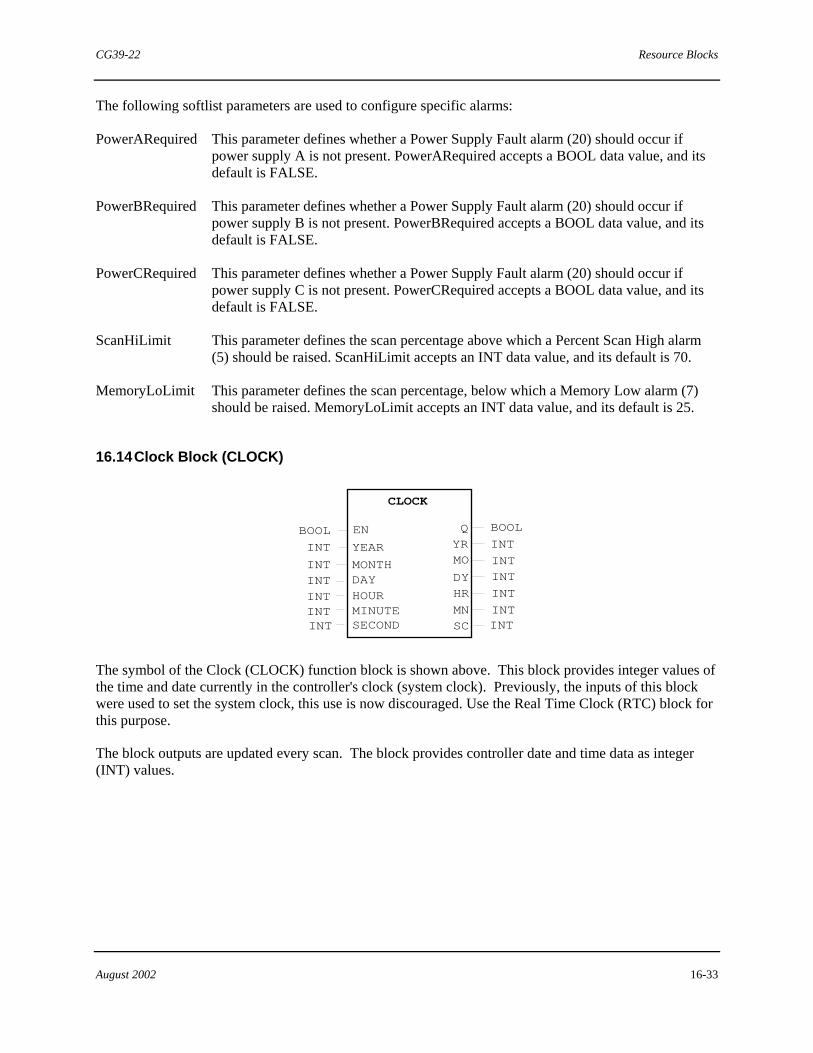
CG39-22 Resource Blocks
August 2002 16-33
The following softlist parameters are used to configure specific alarms:
PowerARequired This parameter defines whether a Power Supply Fault alarm (20) should occur if power supply A is not present. PowerARequired accepts a BOOL data value, and its default is FALSE.
PowerBRequired This parameter defines whether a Power Supply Fault alarm (20) should occur if power supply B is not present. PowerBRequired accepts a BOOL data value, and its default is FALSE.
PowerCRequired This parameter defines whether a Power Supply Fault alarm (20) should occur if power supply C is not present. PowerCRequired accepts a BOOL data value, and its default is FALSE.
ScanHiLimit This parameter defines the scan percentage above which a Percent Scan High alarm (5) should be raised. ScanHiLimit accepts an INT data value, and its default is 70.
MemoryLoLimit This parameter defines the scan percentage, below which a Memory Low alarm (7) should be raised. MemoryLoLimit accepts an INT data value, and its default is 25.
16.14 Clock Block (CLOCK)
CLOCK
INT
QEN YR
DY
MOINTINT
INT HR MN
BOOL
INT
BOOL
SC INT
YEAR
MONTHDAYHOURMINUTESECOND
INT
INTINTINTINTINT
The symbol of the Clock (CLOCK) function block is shown above. This block provides integer values of the time and date currently in the controller's clock (system clock). Previously, the inputs of this block were used to set the system clock, this use is now discouraged. Use the Real Time Clock (RTC) block for this purpose.
The block outputs are updated every scan. The block provides controller date and time data as integer (INT) values.

Resource Blocks CG39-22
16-34 August 2002
The inputs and outputs of the CLOCK block are defined as follows:
EN This is the Enable input. It accepts a BOOL value. Upon sensing a FALSE-to-TRUE transition, the block reads its inputs and sets the controller date and time using the inputs' values. Note: Do not set this input to TRUE, or connect anything to it to avoid mistakenly setting the controller's clock, which should only be done via the RTC block.
YEAR This is the Year input. It accepts an INT value representing the current year.
MONTH This is the Month input. It accepts an INT value representing the current month.
DAY This is the Day input. It accepts an INT value representing the current day.
HOUR This is the Hour input. It accepts an INT value representing the current hour.
MINUTE This is the Minute input. It accepts an INT value representing the current minute.
SECOND This is the Second input. It accepts an INT value representing the current second.
Q This is the Q output. It provides a BOOL value that mirrors the EN input.
YR This is the Year output. It provides an INT value used as the current year.
MO This is the Month output. It provides an INT value used as the current month.
DY This is the Day output. It provides an INT value used as the current day.
MN This is the Month output. It provides an INT value used as the current month.
SC This is the Second output. It provides an INT value used as the current second.
Softlist Parameters
RTCTimeSource This parameter accepts a BOOL value that determines the source of the time data provided by the outputs. When set to FALSE (default), the block outputs are sourced from the system time counter. When set to TRUE, the output are sourced from the the RTC chip. This parameter is useful for determining the amount of drift between two time sources.
There is no softlist parameter for this block when used with APACS+ controllers. "

CG39-22 Hold Function Blocks (HLD****)
August 2002 17-1
17.0 Hold Function Blocks (HLD****)
HLD****
DATA TYPEOUT
HLD****
The two basic symbols of the Hold blocks are shown above. The top symbol is used for Hold blocks that have an output (OUT) while the bottom symbol is for those that do not. Hold blocks are used to store instance specific information in a User-Defined Function Block (UDFB). Prior to the introduction of Hold blocks, all variables and function block I/O could not be unique for a specific instance of a UDFB. These items had to be the same for each instance. Softlists provided the only unique storage in a UDFB. Each of the Hold blocks provides a softlist parameter of a certain data type allowing storage in a UDFB.
The Hold blocks can also be used to store tuning-type information when backing up an on-line database (i.e. transferring a database from on-line to off-line). Previously, only softlist parameters and initial values of variables were stored within a database. Present variable values were not stored. Now, these important values can be stored in Hold blocks’ softlists so they can be saved with the database.
There is a Hold block for each data type available within 4-mation. For example, the HLDBOOL block is used to hold a BOOL value; the HLDREAL block is used to hold a REAL value.
The listing of Hold blocks is as follows:
HLDBOOL HLDINT HLDUINT HLDDINT
HLDUSIN HLDUDIN HLDSINT HLDREAL
HLDWORD HLDTIME HLDDATE HLDDT
HLDTOD HLDSTR HLDST28 HLDST92
HLDST16 HLDST32 HLDST96

Hold Function Blocks (HLD****) CG39-22
17-2 August 2002
Hold blocks do not have inputs, however, each block’s softlist parameter can be edited using any of the following tools:
• A Set Value (SET_VAL) function block • An HMI • The Variable Control dialog box • The blocks’s Softlist dialog box
Most Hold blocks have an output. The output (OUT) delivers the value stored in the block’s VALUE softlist parameter.
A subset of the Hold blocks is used specifically for storing STRING type data. These are the Hold String blocks as listed here:
HLDSTR HLDST16 HLDST28 HLDST32 HLDST92 HLDST96
The first listed Hold String block is the HLDSTR block. Its VALUE softlist parameter holds a STRING data type value from 0 up to 254 characters. Similarly, the number specified within the name of the remaining Hold String blocks (i.e. HLDSTxx) represents the maximum string length that can be accommodated by each block’s VALUE softlist parameter. For example, The HLDST96 block can accommodate a string length of 96 characters.
The following Hold String blocks do not have outputs.
HLDST16 HLDST32 HLDST96
When several Hold String blocks are needed for storing string data, use these blocks to conserve control module memory.
The output and softlist parameter of the various Hold Blocks are defined as follows:
OUT For Hold blocks that have an output, OUT is the block’s output. It delivers the same value as that being held in the VALUE softlist parameter.
Softlist Parameter:
VALUE This softlist parameter is applicable to all Hold blocks. It contains one value of the data type specified by the block name. For example, the VALUE parameter of the HLDBOOL block holds a BOOL value. The default initial value is that of the data type designated by the block’s name.
"

CG39-22 String Function Blocks
August 2002 18-1
18.0 String Function Blocks
The String function blocks are used to control parameters that effect string data. These blocks are not oriented toward control strategy, but are very useful in manipulating strings in structured text and other applications.
For detailed information about the STRING data type, see Using the ProcessSuite 4-mation Configuration Software (document number CG39-20). Refer to the section on “Basic Configuration Elements” and the subsection on “Data Types.”
A listing of string blocks is presented here. Reference information pertaining to individual blocks is detailed in the subsections that follow.
• String Length • Leftmost Characters • Rightmost Characters • Middle Characters • Concatenate String Characters • Insert String Characters • Delete String Characters • Replace String Characters • Find String Characters • Make APACS Path • Split APACS Path
18.1 String Length Block (LEN)
LEN
IN INT STRING OUT IN
The symbol of the String Length (LEN) block is shown above. This block is used to find the length of an input character string. The output will be the exact number of characters in the string, excluding the null terminator.
For example: If IN = ‘ASTR’, then OUT = 4
The input and output of the LEN block are defined as follows:
IN This input accepts the string of which the length is to be found.
OUT This output provides an integer value that represents the length of the input string.

String Function Blocks CG39-22
18-2 August 2002
Softlist Parameters
There are no softlist parameters for this block.
18.2 Leftmost Characters of String (LEFT)
The symbol of the Leftmost Characters (LEFT) block is shown above. This block is used to find the left-most characters of an input string. The output will be a string of length (L), beginning with the left-most character of the input string.
For example: If IN = ‘ASTR’, and L = 3, OUT = ‘AST’
If (L) is greater than the length of the input string, the output will be limited to the entire input string. If (L) is less than or equal to zero, the result is a null string being output.
The inputs and output of the LEFT block are defined as follows:
IN This input accepts the character string from which the left most characters are to be found.
L This is the length input. The value can be any integer. This value determines the length of the left most portion of the input character string that the block is to find.
OUT This output delivers the output string. The output string consists of the (L) number of the left most characters from the input string.
Softlist Parameters
There are no softlist parameters for this block.

CG39-22 String Function Blocks
August 2002 18-3
18.3 Rightmost Characters of String (RIGHT)
RIGHT
IN STRINGSTRING OUT L ANY_INT
The symbol of the Rightmost Characters (RIGHT) block is shown above. This block will find the right-most characters of an input string. The output will be a string of length (L), beginning with the ‘length - L’ character of the input string.
For example: If IN = ‘ASTR’, and L = 3, OUT = ‘STR’
If (L) is greater than the length of the input string, the output will be limited to the entire input string. If (L) is less than or equal to zero, the result is a null string being output.
The inputs and output of the RIGHT block are defined as follows:
IN
This input accepts the character string from which the right most characters are to be found.
L
This is the length input. The value can be any integer. This value determines the length of the left most portion of the input character string that the block is to find.
OUT
This output delivers the output string. The output string consists of (L) number of the right most characters from the input string.
Softlist Parameters
There are no softlist parameters for this block.
18.4 Middle Characters of String (MID)
MID
IN STRING STRING OUT L ANY_INT P ANY_INT
The symbol for the Middle Characters (MID) block is shown above. This block will find the middle characters of an input character string. The output will be a string of length (L), beginning with the (P) character position of the input string.
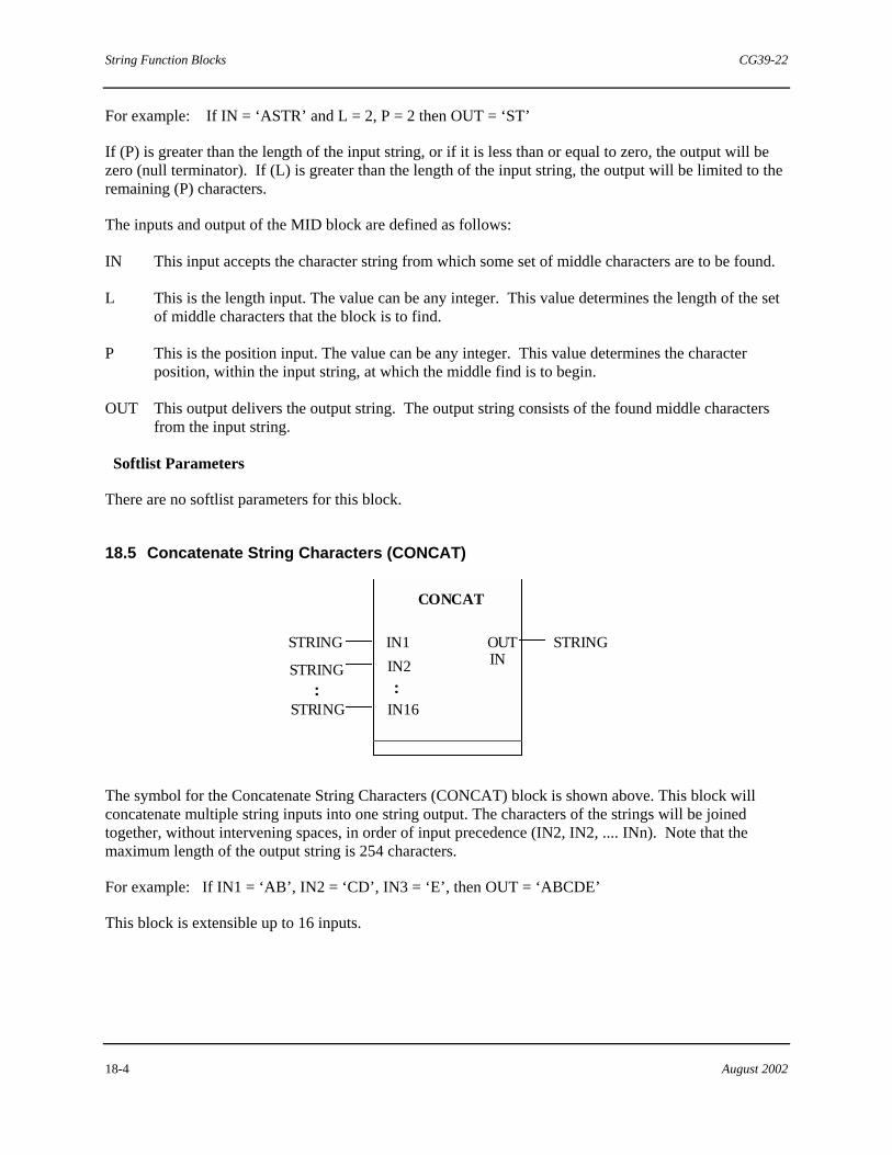
String Function Blocks CG39-22
18-4 August 2002
For example: If IN = ‘ASTR’ and L = 2, P = 2 then OUT = ‘ST’
If (P) is greater than the length of the input string, or if it is less than or equal to zero, the output will be zero (null terminator). If (L) is greater than the length of the input string, the output will be limited to the remaining (P) characters.
The inputs and output of the MID block are defined as follows:
IN This input accepts the character string from which some set of middle characters are to be found.
L This is the length input. The value can be any integer. This value determines the length of the set of middle characters that the block is to find.
P This is the position input. The value can be any integer. This value determines the character position, within the input string, at which the middle find is to begin.
OUT This output delivers the output string. The output string consists of the found middle characters from the input string.
Softlist Parameters
There are no softlist parameters for this block.
18.5 Concatenate String Characters (CONCAT)
CONCAT
IN1 STRING STRING OUT IN IN2 STRING
IN16 STRING : :
The symbol for the Concatenate String Characters (CONCAT) block is shown above. This block will concatenate multiple string inputs into one string output. The characters of the strings will be joined together, without intervening spaces, in order of input precedence (IN2, IN2, .... INn). Note that the maximum length of the output string is 254 characters.
For example: If IN1 = ‘AB’, IN2 = ‘CD’, IN3 = ‘E’, then OUT = ‘ABCDE’
This block is extensible up to 16 inputs.
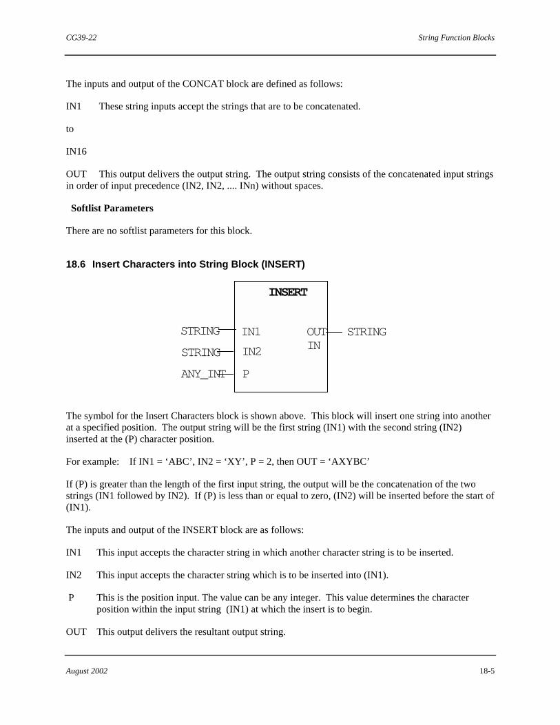
CG39-22 String Function Blocks
August 2002 18-5
The inputs and output of the CONCAT block are defined as follows:
IN1 These string inputs accept the strings that are to be concatenated.
to
IN16
OUT This output delivers the output string. The output string consists of the concatenated input strings in order of input precedence (IN2, IN2, .... INn) without spaces.
Softlist Parameters
There are no softlist parameters for this block.
18.6 Insert Characters into String Block (INSERT)
INSERT
IN1 STRINGSTRING OUT IN IN2 STRING
P ANY_INT
The symbol for the Insert Characters block is shown above. This block will insert one string into another at a specified position. The output string will be the first string (IN1) with the second string (IN2) inserted at the (P) character position.
For example: If IN1 = ‘ABC’, IN2 = ‘XY’, P = 2, then OUT = ‘AXYBC’
If (P) is greater than the length of the first input string, the output will be the concatenation of the two strings (IN1 followed by IN2). If (P) is less than or equal to zero, (IN2) will be inserted before the start of (IN1).
The inputs and output of the INSERT block are as follows:
IN1 This input accepts the character string in which another character string is to be inserted.
IN2 This input accepts the character string which is to be inserted into (IN1).
P This is the position input. The value can be any integer. This value determines the character position within the input string (IN1) at which the insert is to begin.
OUT This output delivers the resultant output string.

String Function Blocks CG39-22
18-6 August 2002
Softlist Parameters
There are no softlist parameters for this block.
18.7 Delete Characters in a String (DELETE)
DELETE
IN STRINGSTRING OUT IN L ANY_INT
P ANY_INT
The symbol for the Delete Characters (DELETE) block is shown above. This block will delete characters from the input string. The output string of this block will be the input string with (L) characters deleted after the (P) character position.
For example: If IN = ‘ABXYC’, L = 2, P = 3, then OUT = ‘ABC’
If (P) is greater than the length of the input string, or if it is less than or equal to zero, the output string will be the unchanged input string. If (L) is greater than the length of the input string, the remaining characters of the string from (P) will be deleted. If (L) is less than or equal to zero, the input string is unchanged.
The inputs and output of the DELETE block are defined as follows:
IN This input accepts the character string from which characters are to be deleted.
L This is the length input. The value can be any integer. This value determines the length of the set of characters to be deleted.
P This is the position input. The value can be any integer. This value determines the character position within the input string (IN) at which the delete is to begin.
OUT This output delivers the resultant output string.
Softlist Parameters
There are no softlist parameters for this block.
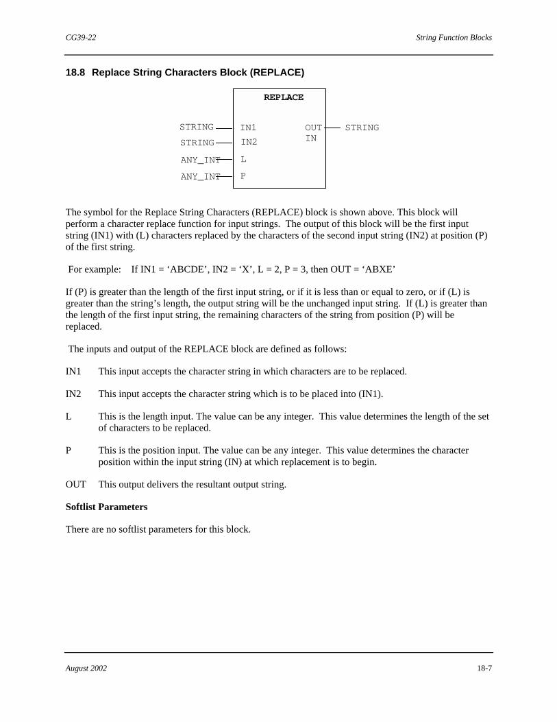
CG39-22 String Function Blocks
August 2002 18-7
18.8 Replace String Characters Block (REPLACE)
REPLACE
IN1 STRING STRING OUT IN IN2 STRING
L ANY_INT P ANY_INT
The symbol for the Replace String Characters (REPLACE) block is shown above. This block will perform a character replace function for input strings. The output of this block will be the first input string (IN1) with (L) characters replaced by the characters of the second input string (IN2) at position (P) of the first string.
For example: If IN1 = ‘ABCDE’, IN2 = ‘X’, L = 2, P = 3, then OUT = ‘ABXE’
If (P) is greater than the length of the first input string, or if it is less than or equal to zero, or if (L) is greater than the string’s length, the output string will be the unchanged input string. If (L) is greater than the length of the first input string, the remaining characters of the string from position (P) will be replaced.
The inputs and output of the REPLACE block are defined as follows:
IN1 This input accepts the character string in which characters are to be replaced.
IN2 This input accepts the character string which is to be placed into (IN1).
L This is the length input. The value can be any integer. This value determines the length of the set of characters to be replaced.
P This is the position input. The value can be any integer. This value determines the character position within the input string (IN) at which replacement is to begin.
OUT This output delivers the resultant output string.
Softlist Parameters
There are no softlist parameters for this block.

String Function Blocks CG39-22
18-8 August 2002
18.9 Find String Characters Block (FIND)
FIND
IN1 INT STRING OUT IN IN2
L STRING
The symbol for the Find String Characters (FIND) block is shown above. This block will find the position of the beginning of the first occurrence of one string in another. The output of this block will be a number representing the position of the first occurrence of the second string (IN2) inside the first string (IN1).
For example: If IN1 = ‘ABCBC’, IN2 = ‘BC’, then OUT = 2
If the string is not found, then OUT will be zero. If either input string is null, the output string will be null.
The inputs and output of the FIND block are defined as follows:
IN1 This input accepts the character string in which characters are to be found.
IN2 This input accepts the character string which is to be found in (IN1).
OUT This output is an integer value. It represents the starting character position within string (IN1), of the first occurrence of the character string (IN2).
Softlist Parameters
There are no softlist parameters for this block.
18.10 Make APACS Path Block (PATHMAK)
PATHMAK
EN STRING BOOL FPATH DREV STRING[] ERR BOOL
The symbol for the Make APACS Path (PATHMAK) block is shown above. This block is used to create an APACS path name from the contents of the (DREV) input array. When the block is enabled, (EN) = TRUE, FPATH will be the concatenation of each element of (DREV) separated by periods.
For example: If DREV[1] = ‘ABC’, DREV[2] = ‘DEF’, DREV[3] = ‘GHI’, then FPATH = ‘ABC.DEF.GHI’

CG39-22 String Function Blocks
August 2002 18-9
The error output (ERR) will be TRUE in the following cases:
• DREV is not a single dimension string array
• An element of DREV is longer than 18 characters
• The total size of FPATH exceeds 254 characters
The inputs and outputs of the PATHMAK block are defined as follows:
EN This enable input accepts BOOL values. When TRUE, the block is enabled.
DREV This input accepts a single dimension string array from which the output path name is built.
FPATH This output provides the resultant string which is to be used as an APACS path name.
ERR This is the error output which outputs BOOL values. This output is TRUE whenever any of the conditions listed above occur.
Softlist Parameters
There are no softlist parameters for this block.
18.11 APACS Path Split Block (PATHSPL)
PATHSPL
EN INT BOOL N FPATH ERR BOOL DREV
STRING STRING
The symbol for the APACS Path Split (PATHSPL) block is shown above. This block is used to split an APACS path name into its component parts. When the block is enabled, (EN) = TRUE, each section of (FPATH) will be placed into an element of (DREV).
For example: If FPATH= ‘AB.C.DEF’, then DREV[n] = ‘AB’, DREV[n+1] = ‘C’, DREV[n+2] = ‘DEF’
Where: n is the lower bound of DREV[]
The value of output (N) is the number of levels in the path name. The error output (ERR) will be TRUE in the following situations:
• There is nothing connected to (FPATH) or (DREV) • (DREV) is not a single dimension string array • (DREV) does not contain enough elements for the current (FPATH) • The string length of (DREV) is too small for one of the level names in the current (FPATH) • One of the levels of (FPATH) is greater than 18 characters

String Function Blocks CG39-22
18-10 August 2002
Whenever (ERR) is TRUE, N will indicate the number of levels which were successfully stored prior to encountering the error.
The inputs and outputs of the PATHSPL block are defined as follows:
EN This enable input accepts BOOL values. When TRUE, the block is enabled.
FPATH This input accepts the APACS path name string. The string must be arranged in a delimited form as this example: ABC.DEF.GHI
DREV[ ] This output places the component levels of FPATH into a single dimension string array.
N The integer value of this output represents the number of levels successfully stored from FPATH to DREV[ ].
ERR This is the error output which outputs BOOL values. This output is TRUE whenever any of the conditions listed above occur.
Softlist Parameters
There are no softlist parameters for this block. "

CG39-22 Diagnostic Function Blocks
August 2002 19-1
19.0 Diagnostic Function Blocks
The Diagnostic function blocks are used for troubleshooting and testing configurations.
The Diagnostic blocks are listed as follows. Detailed specific information pertaining to each individual block is provided in the following subsections.
• Get Time (GTTIME) Block
• Memory Read (MEM_READ) Block
• Memory Statistic (MEM_STAT) Block
19.1 Get Time Block (GTTIME)
GTTIME
DINT
CTIME
The symbol of the Get Time (GTTIME) block is shown above. This block gives a current timestamp in microseconds. Two of these blocks can be used in conjunction with a Subtraction (SUB) block to determine the execution time of a section of logic (configuration). Place one block before the logic being tested and one block after the logic being tested. Then take the outputs and subtract the CTIME after the logic from the CTIME that is before the logic. The output of the SUB block gives the execution time of the logic in between in microseconds.
The output of the GTTIME block is defined as follows:
CTIME This DINT output holds the current timestamp in microseconds. This output is used to calculate the execution time of logic.
Softlist Parameters
There are no softlist parameters for this block.
19.2 Memory Read Block (MEM_READ)
The Memory Read (MEM_READ) block is used for advanced troubleshooting under the direction of a Siemens field service or technical support engineer. This function block is not for general use.
19.3 Memory Statistic Block (MEM_STAT)
The Memory Statistic (MEM_STAT) block is used for advanced troubleshooting under the direction of a Siemens field service or technical support engineer. This function block is not for general use.
