api 2028 : 2002
TRANSCRIPT

Flame Arresters in Piping Systems
API RECOMMENDED PRACTICE 2028 THIRD EDITION, FEBRUARY 2002
American Petroleum Institute
Helping You Get The Job Done Right.""
Copyright American Petroleum Institute Reproduced by IHS under license with API
Document provided by IHS Licensee=PETROGAL/9989365001, User=NUNO, 04/01/200408:36:44 MST Questions or comments about this message: please call the DocumentPolicy Group at 303-397-2295.
--`,,``````,`,,``,,,,`,,`,``,,,-`-`,,`,,`,`,,`---

Flame Arresters in Piping Systems
Safety & Fire Protection
API RECOMMENDED PRACTICE 2028 THIRD EDITION, FEBRUARY 2002
American Petroleum Institute
Helping You Get The Job Done Right?
Copyright American Petroleum Institute Reproduced by IHS under license with API
Document provided by IHS Licensee=PETROGAL/9989365001, User=NUNO, 04/01/200408:36:44 MST Questions or comments about this message: please call the DocumentPolicy Group at 303-397-2295.
--`,,``````,`,,``,,,,`,,`,``,,,-`-`,,`,,`,`,,`---

SPECIAL NOTES
API publications necessarily address problems of a general nature. With respect to partic- ular circumstances, local, state, and federal laws and regulations should be reviewed.
API is not undertaking to meet the duties of employers, manufacturers, or suppliers to warn and properly train and equip their employees, and others exposed, concerning health and safety risks and precautions, nor undertaking their obligations under local, state, or fed- eral laws.
Information concerning safety and health risks and proper precautions with respect to par- ticular materials and conditions should be obtained from the employer, the manufacturer or supplier of that material, or the material safety data sheet.
Nothing contained in any API publication is to be construed as granting any right, by implication or otherwise, for the manufacture, sale, or use of any method, apparatus, or prod- uct covered by letters patent. Neither should anything contained in the publication be con- strued as insuring anyone against liability for infringement of letters patent.
Generally, API standards are reviewed and revised, reafhed, or withdrawn at least every five years. Sometimes a one-time extension of up to two years will be added to this review cycle. This publication will no longer be in effect five years after its publication date as an operative API standard or, where an extension has been granted, upon republication. Status of the publication can be ascertained from the API Standards Department [telephone (202) 682-8000]. A catalog of API publications and materials is published annudy and updated quarterly by API, 1220 L Street, N.W., Washington, D.C. 20005.
This document was produced under API standardization procedures that ensure appropri- ate notification and participation in the developmental process and is designated as an API standard. Questions concerning the interpretation of the content of this standard or com- ments and questions concerning the procedures under which this standard was developed should be directed in writing to the API Standards Department, American Petroleum Insti- tute, 1220 L Street, N.W., Washington, D.C. 20005. Requests for permission to reproduce or translate d or any part of the material published herein should also be addressed to the gen- eral manager.
API standards are published to facilitate the broad availability of proven, sound engineer- ing and operating practices. These standards are not intended to obviate the need for apply- ing sound engineering judgment regarding when and where these standards should be utilized. The formulation and publication of API standards is not intended in any way to inhibit anyone from using any other practices.
Any manufacturer marking equipment or materials in conformance with the marking requirements of an API standard is solely responsible for complying with all the applicable requirements of that standard. API does not represent, warrant, or guarantee that such prod- ucts do in fact conform to the applicable API standard.
All rights resewed. No part of this work may be reproduced, stored in a retrieval system, or transmitted by any means, electronic, mechanical, photocopying, recording, or otherwise,
without prior written permission fiom the publisher. Contact the Publisher, API Publishing Services, 1220 L Street, N.W, Washington, D.C. 20005.
Copyright O 2002 American Petroleum Institute
Copyright American Petroleum Institute Reproduced by IHS under license with API
Document provided by IHS Licensee=PETROGAL/9989365001, User=NUNO, 04/01/200408:36:44 MST Questions or comments about this message: please call the DocumentPolicy Group at 303-397-2295.
--`,,``````,`,,``,,,,`,,`,``,,,-`-`,,`,,`,`,,`---

FOREWORD
This recommended practice was prepared under the direction of the API Safety and Fire Protection Subcommittee. This third edition of API 2028 Flame Arresters in Piping Systems has been extensively rewritten and updated from the previous edition. Appendices to the doc- ument are intended to provide additional supplementary information.
This guide was prepared to help provide a basic understanding of flame arresters used in piping systems. The information presented is based primarily upon experience in the petro- leum industry. It is not intended to exclude or limit the use of other approaches of compara- ble merit. Because of the special nature of flame arresters, especially those used for detonation protection, this recommended practice strongly encourages dialogue with the equipment supplier and the use of sound engineering judgement in flame arrester selection and application.
... 111
Copyright American Petroleum Institute Reproduced by IHS under license with API
Document provided by IHS Licensee=PETROGAL/9989365001, User=NUNO, 04/01/200408:36:44 MST Questions or comments about this message: please call the DocumentPolicy Group at 303-397-2295.
--`,,``````,`,,``,,,,`,,`,``,,,-`-`,,`,,`,`,,`---
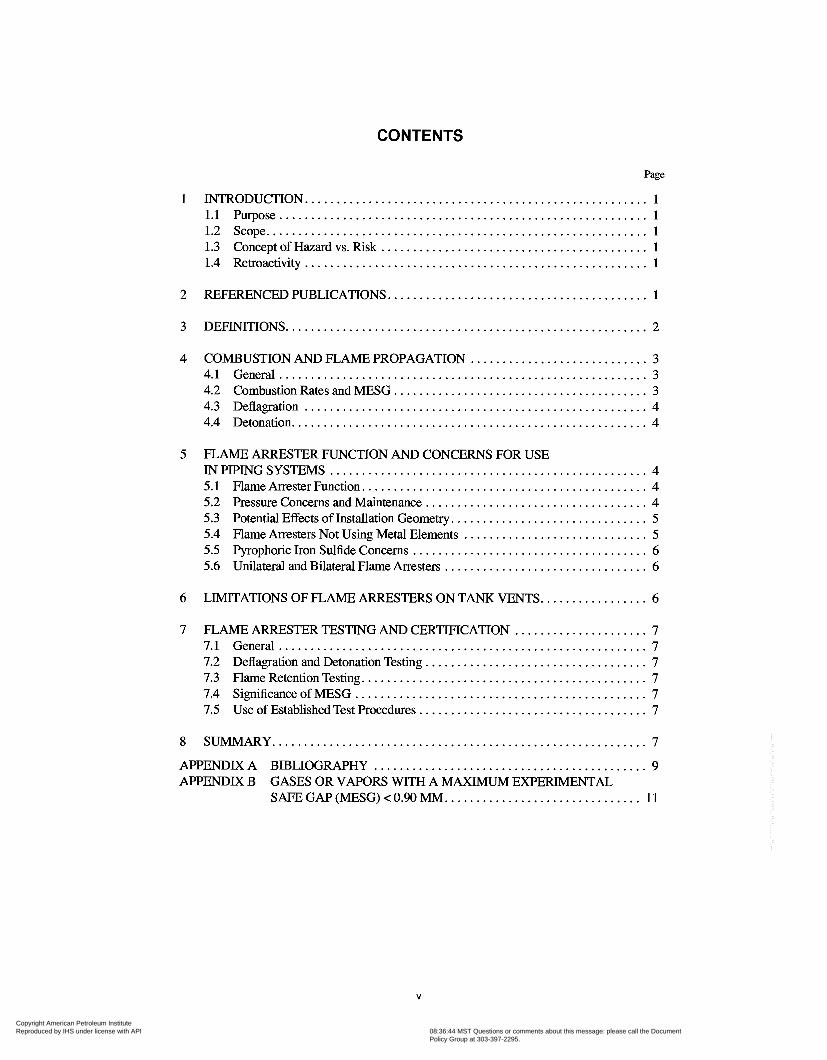
CONTENTS
Page
1 INTRODUCTION ...................................................... 1 1.1 mirpose .......................................................... 1 1.2 Scope ............................................................ 1
Concept of Hazard vs . Risk .......................................... 1 1.4 Retroactivity ...................................................... 1 1.3
2 REFERENCED PUBLICATIONS ......................................... 1
3 DEFINITIONS ......................................................... 2
4 COMBUSTION AND FLAME PROPAGATION ............................ 3 4.1 General .......................................................... 3 4.2 Combustion Rates and MESG ........................................ 3 4.3 Deflagration ...................................................... 4 4.4 Detonation ........................................................ 4
5 FLAME ARRESTER FUNCTION AND CONCERNS FOR USE IN PIPING SYSTEMS .................................................. 4 5.1 FlameArresterFunction ............................................. 4 5.2 Pressure Concerns and Maintenance ................................... 4 5.3 Potential Effects of Installation Geometry ............................... 5 5.4 Flame Arresters Not Using Metal Elements ............................. 5 5.5 Pyrophoric Iron Sulfide Concerns ..................................... 6 5.6 Unilateral and Bilateral Flame Arresters ................................ 6
6 LIMITATIONS OF FLAME ARRESTERS ON TANK VENTS ................. 6
7 FLAME ARRESTER TESTING AND CERTIFICATION ..................... 7 7.1 General .......................................................... 7 7.2 Deflagration and Detonation Testing ................................... 7 7.3 Flame Retention Testing ............................................. 7 7.4 SignificanceofMESG .............................................. 7 7.5 Use of Established Test Procedures .................................... 7
8 SUMMARY ........................................................... 7
APPENDIXA BIBLIOGRAPHY ........................................... 9 APPENDIX B
SAFEGAP(MESG)<O.WMM ............................... 11 GASES OR VAPORS WITJ3 A MAXIMUM EXPElUMENTAL
V
Copyright American Petroleum Institute Reproduced by IHS under license with API
Document provided by IHS Licensee=PETROGAL/9989365001, User=NUNO, 04/01/200408:36:44 MST Questions or comments about this message: please call the DocumentPolicy Group at 303-397-2295.
--`,,``````,`,,``,,,,`,,`,``,,,-`-`,,`,,`,`,,`---

Flame Arresters in Piping Systems
SECTION I-INTRODUCTION
1.1 PURPOSE
This recommended practice is intended to inform industry about limitations of flame arresters installed in piping systems. Concerns about potential environmentd effects of hydrocar- bon and chemical vapor emissions have led to regulations requiring the installation of vapor control systems. In the United States, for marine transfer of oil or hazardous materi- als, United States Coast Guard regulations require installation of flame arresters (suitable to interrupt a detonation) in vapor control piping. These USCG regulations specifically direct (in detail) where to install these flame detonation arresters in the vapor control systems. An independent laboratory must test detonation arresters installed to meet these regulations.
The diversity of commercial flame arresters can lead to the installation of these arresters in piping systems where the con- ditions within the piping may be significantly Merent from the conditions for which they were designed, or tested and listed by testing laboratories. Under certain conditions, flames propagating through piping systems can reach velocities and pressures at which detonation can OCCUT. Unless a flame arrester has been designed and tested for a detonation, it may not stop the progression of a combustion wave in the piping. Guidance is provided concerning the important factors involved in the selection, installation and maintenance of appropriate flame arresters. The intent is to assist the user of this recommended practice in developing the awareness of review needs, and to encourage discussions with flame arrester manufacturers regarding specific applications and test results.
1.2 SCOPE
The scope of this recommended practice is the use and lim- itations of flame arresters installed in piping systems in the petroleum and petrochemical industries. It provides a general
overview of flame arresters currently in use and some poten- tial concerns or limitations. Applicable combustion and flame propagation parameters are discussed including the distinc- tion between arresting flames versus arresting detonations.
This recommended practice is neither a design manual nor a regulatory compliance document. It does provide reference to more detailed technical discussions of flame arresters and combustion. Various standards, codes, and regulations are noted in the Section 2 references and in the Appendix A Bib- liography.
1.3 CONCEPT OF HAZARD VS. RISK
Hazards are properties of materials with the inherent ability to cause harm. Fiammability, toxicity, corrosivity, stored chem- i d or mechanid energy all are hazards associated with vari- ous industrial materials. Risk requires exposure. The flammability of a material transported in piping is an inherent hazard, but becomes a risk only when having access to an oxi- dizer and being exposed to an ignition mechanism There is no risk of ignition when there is no potential for those exposures. Determining the level of risk involves estimating the probabil- ity and severity of exposure conditions that could lead to harm.
1.4 RETROACTIVITY
Any provisions in this recommended practice related to design are intended for reference when designing new facili- ties or when considering major revisions or expansions. It is not intended that any recommendations in this recommended practice be applied retroactively to existing facilities unless deemed appropriate based on facility review. Each facility must make their own determination regarding how to comply with any applicable regulations.
SECTION 2-REFERENCED PUBLICATIONS
The most recent edition or revision of each of the following standards, codes, and regulations are cited in this recom- mended practice. Additional references not specifically cited in this document are listed in the Bibliography, Appendix A.
API' Flame Arresters
Rp 2210 Flame Arresters for Vents of Tanks Storing Petroleum Products
ASTM2 F 1273 Standard SpeciJcation for Tank Vent
Std 2000 Venting Atmospheric and Low-Pressure
2American Society for Testing and Materials, 100 Barr Harbor Drive, West Conshohocken, Pennsylvania, USA 19428.
Storage Tanks
1www.api.org www.astsn.org 1
Copyright American Petroleum Institute Reproduced by IHS under license with API
Document provided by IHS Licensee=PETROGAL/9989365001, User=NUNO, 04/01/200408:36:44 MST Questions or comments about this message: please call the DocumentPolicy Group at 303-397-2295.
--`,,``````,`,,``,,,,`,,`,``,,,-`-`,,`,,`,`,,`---

2 API RECOMMENDED PRACTICE 2028
CEN3 EN 12814 Flame Arresters, PeijGomnce Require-
ments, Test Methods and Limits for Use
CGA4 G-1.2 Acetylene Metering and Pipeline
Transmission
F M 5 Approval Guide, A Guide to Equipment, Materials & Services Approved by Factory Mutual Research for Property Conservation *“Fiame Arresters for Gas Piping Systems” *“Fiame Arresters, Dry Type” *“Fiame Arresters, Hydraulic Type” *“Detonation Fiame Arresters for Fiamma-
*“Fiame Arresters for Storage Tank Vent ble Vapor Piping Systems”
Pipe,”
IEC6 IEC 19-1A First Supplement to Publication 79-1, Elec-
trical apparatus for explosive gas atmospheres, Part 1: Construction and test of @meproof enclosures of electrical apparatus
3European Committee for Standardization, rue de Stassart 36, B- 1050 Brussels, Belgium. www.cenorm.be 4Compressed Gas Association, Inc., Fifth Floor, 4221 Walney Road, Chantilly, Viiginia 20151-2923. www.cganet.com 5Fact0ry Mutual Insurance Company, 22055 Network Place, Chi- cago, Illinois 60673- 1220. www.fmglobal.com %ternational Electrotechnical Commission, 3 rue de Varembé, Case postale 131,121 1 Geneva 20, Switzerland. www.iec.ch
“A7 30 69
OSHA*
UL9
19 10.106
UL 525
USCG’O 33 CFR 154
Appendix D: Method of test for ascertain- ment of maximum experimental safe gap
Flammable & Combustible Liquids Code Standard on Explosion Prevention Systems
Subpart H- Hazardous Materials
Standard for Safety for Flame Arresters UL Gas and Oil Equipment Directory
Facilities Transferring Oil or Hazardous Material in Bulk *Subpart E, Vapor Control Systems *Appendix A to Part 154-Guidelines for Detonation Flame Arresters
*Appendix B to Part 154-Standard Speci- $cation for Tank Vent Flame Arresters
7Nati0nal Fire Protection Association, Batterymarch Park, Quincy, Massachusetts 02269. www.nfpa.org *U.S. Department of Labor, Occupational Safety and Health Admin- istration, 200 Constitution Avenue, N.W., Washington, D.C. 20210. OSHA regulations are posted on, and can be downloaded from, the OSHA web site. www.osha.gov gUnderwriters Laboratories, Inc., 333 Pfingsten Road, Northbrook, Illinois 60062. www.ul.com l%ited States Coast Guard, U.S. Department of Transportation. www.uscg.mil. The Code of Federal Regulations is available from the U.S. Government Printing Office, Washington, D.C. 20402.
SECTION 3-DEFINITIONS
3.1 autoignition temperature: The minimum tempera- ture at which a material will ignite with self-sustained combus- tion without an external source of ignition (such as a spark or flame).
3.2 deflagration: A combustion wave that propagates subsonically (as measured at the pressure and temperature of the flame front) by the transfer of heat and active chemical species to the unburned gas ahead of the flame front.
3.3 detonation: A reaction in a combustion wave propa- gating at sonic or supersonic velocity (as measured at the pres- sure and temperature of the flame front). A detonation is stable when it has a velocity equal to the speed of sound in the burnt gas or may be unstable (overdriven) with a higher velocity and pressure.
3.4 explosion: A rapid release of energy (such as burn- ing) which produces a pressure wave.
3.5 hazard: An inherent chemical or physical property with the potential to do harm (flammability, toxicity, corrosiv- ity, stored chemical or mechanical energy).
3.6 inerted: (For vessels under U.S. Coast Guard regula- tions.) Means the oxygen content of the vapor space in a tank vessel’s cargo tank is reduced to 8% by volume or less, in accordance with the inert gas requirements of 46 CFR 32.53 or 46 CFR 153.500.
3.7 maximum experimental safe gap (MESG): The MESG is the maximum clearance between two parallel metal surfaces that has been found, under specified test conditions, to prevent an explosion in a test chamber from being propa- gated to a secondary chamber containing the same gas or
Copyright American Petroleum Institute Reproduced by IHS under license with API
Document provided by IHS Licensee=PETROGAL/9989365001, User=NUNO, 04/01/200408:36:44 MST Questions or comments about this message: please call the DocumentPolicy Group at 303-397-2295.
--`,,``````,`,,``,,,,`,,`,``,,,-`-`,,`,,`,`,,`---
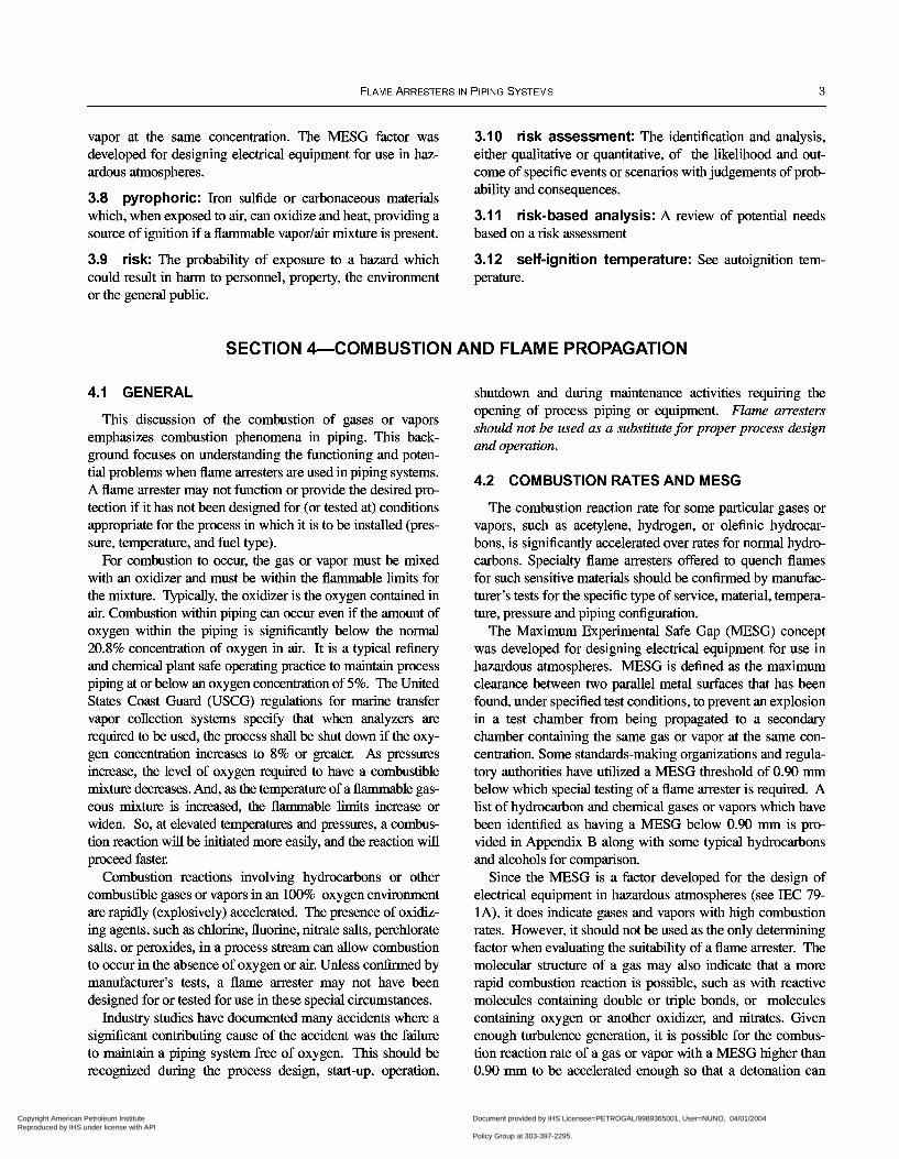
FLAME ARRESTERS IN PIPING SYSTEMS 3
vapor at the same concentration. The MESG factor was developed for designing electrical equipment for use in haz- ardous atmospheres.
3.8 pyrophoric: Iron sulfide or carbonaceous materials which, when exposed to air, can oxidize and heat, providing a source of ignition if a flammable vapor/air mixture is present.
3.9 risk: The probability of exposure to a hazard which could result in harm to personnel, property, the environment or the general public.
3.10 risk assessment: The identification and analysis, either qualitative or quantitative, of the likelihood and out- come of specific events or scenarios with judgements of prob- ability and consequences.
3.1 1 risk-based analysis: A review of potential needs based on a risk assessment
3.12 self-ignition temperature: See autoignition tem- perature.
SECTION 4-COMBUSTION AND FLAME PROPAGATION
4.1 GENERAL
This discussion of the combustion of gases or vapors emphasizes combustion phenomena in piping. This back- ground focuses on understanding the functioning and poten- tial problems when flame arresters are used in piping systems. A flame arrester may not function or provide the desired pro- tection if it has not been designed for (or tested at) conditions appropriate for the process in which it is to be installed (pres- sure, temperature, and fuel type).
For combustion to occur, the gas or vapor must be mixed with an oxidizer and must be within the flammable limits for the mixture. Typically, the oxidizer is the oxygen contained in air. Combustion within piping can occur even if the amount of oxygen within the piping is significantly below the n o d 20.8% concentration of oxygen in air. It is a typid refìnery and chemid plant safe operating practice to maintain process piping at or below an oxygen concentration of 5%. The United States Coast Guard (USCG) regulations for marine transfer vapor collection systems speafj that when analyzers are required to be used, the process shall be shut down if the oxy- gen concentration increases to 8% or greater. As pressures increase, the level of oxygen required to have a combustible mixture decreases. And, as the temperature of a flammable gas- eous mixture is increased, the flammable limits increase or widen. So, at elevated temperatures and pressures, a combus- tion reaction will be initiated more easily, and the reaction will proceed faster.
Combustion reactions involving hydrocarbons or other combustible gases or vapors in an 100% oxygen environment are rapidly (explosively) accelerated. The presence of oxidiz- ing agents, such as chlorine, fluorine, nitrate salts, perchlorate salts, or peroxides, in a process stream can allow combustion to occur in the absence of oxygen or air. Unless conñrmed by manufacturer’s tests, a flame arrester may not have been designed for or tested for use in these special circumstances.
Industry studies have documented many accidents where a significant contributing cause of the accident was the failure to maintain a piping system free of oxygen. This should be recognized during the process design, start-up, operation,
shutdown and during maintenance activities requiring the opening of process piping or equipment. Flame arresters should not be used as a substitute for proper process design and operation.
4.2 COMBUSTION RATES AND MESG
The combustion reaction rate for some particular gases or vapors, such as acetylene, hydrogen, or olefìnic hydrocar- bons, is significantly accelerated over rates for normal hydro- carbons. Specialty flame arresters offered to quench flames for such sensitive materials should be conñrmed by manufac- turer’s tests for the specific type of service, material, tempera- ture, pressure and piping conñguration.
The Maximum Experimental Safe Gap (MESG) concept was developed for designing electrical equipment for use in hazardous atmospheres. MESG is defined as the maximum clearance between two parallel metal surfaces that has been found, under specified test conditions, to prevent an explosion in a test chamber from being propagated to a secondary chamber containing the same gas or vapor at the same con- centration. Some standards-making organizations and regula- tory authorities have utilized a MESG threshold of 0.90 mm below which special testing of a flame arrester is required. A list of hydrocarbon and chemical gases or vapors which have been identified as having a MESG below 0.90 mm is pro- vided in Appendix B along with some typical hydrocarbons and alcohols for comparison.
Since the MESG is a factor developed for the design of electrical equipment in hazardous atmospheres (see IEC 79- lA), it does indicate gases and vapors with high combustion rates. However, it should not be used as the only determining factor when evaluating the suitability of a flame arrester. The molecular structure of a gas may also indicate that a more rapid combustion reaction is possible, such as with reactive molecules containing double or triple bonds, or molecules containing oxygen or another oxidizer, and nitrates. Given enough turbulence generation, it is possible for the combus- tion reaction rate of a gas or vapor with a MESG higher than 0.90 mm to be accelerated enough so that a detonation can
Copyright American Petroleum Institute Reproduced by IHS under license with API
Document provided by IHS Licensee=PETROGAL/9989365001, User=NUNO, 04/01/200408:36:44 MST Questions or comments about this message: please call the DocumentPolicy Group at 303-397-2295.
--`,,``````,`,,``,,,,`,,`,``,,,-`-`,,`,,`,`,,`---

4 API RECOMMENDED PRACTICE 2028
occur. Research organizations have documented that it is not possible to characterize the potential for the occurrence of a rapid combustion reaction with a single physical parameter.
4.3 DEFLAGRATION
Flames propagating through piping systems are capable of reaching extremely high speeds. Initially, flames travel at a burning velocity of a few feet per second. This is the laminar flame speed typically tabulated in handbooks. The flame front can be accelerated by turbulence induced in the unburned mixture ahead of the flame, by the combustion wave itself, or can result from factors such as pipe wall roughness or turbu- lence-producing fittings and bends. A particularly strong igni- tion source can “immediately” initiate a combustion reaction with greater than normal initial turbulence. Increased turbu- lence also can be generated as the pressure of a process increases. It is possible for the flame front to accelerate both upstream and downstream of the original direction of flow. Flame fronts in piping can readily reach a velocity of several hundred feet per second. As long as the flame front propa- gates in the unburned mixture at a velocity less than the speed of sound, it is characterized as a deflagration. All flame arresters should be designed to interrupt a deflagration.
4.4 DETONATION
If a pipe is long enough, or if enough turbulence is gener- ated, a flame front many accelerate to the point where a deto- nation occurs. Detonations travel at or above the speed of sound (which is a function of the density of the mixture within the piping), and typically reach speeds of several thou- sand feet per second. Pressure pulses accompanying the flame front may exceed 20 times the initial pressure. Even higher pressures can be generated at:
a. Closed ends and elbows, where reflection occurs, b. The point where a deflagration transforms into a detonation, which is known as an overdriven or unstable detonation, or c. At the termination of a closed system as the mixture of unburned gases is compressed before the transition to detona- tion, which is known as pressure piling.
Not all flame arresters are designed to quench andor with- stand the elevated pressure and impulse of a detonation. USCG regulations require use of detonation-type flame arresters when those regulations require flame arresters in vapor collection systems. The potential for a detonation to occur is diffìcult to predict except in controlled laboratory settings. Transforma- tion of a flame front from a deflagrating to a detonating com- bustion wave is more probable if the combustion reaction is occurring within a piping system than if in open air.
SECTION 5-FLAME ARRESTER FUNCTION AND CONCERNS FOR USE IN PIPING SYSTEMS
5.1 FLAME ARRESTER FUNCTION
Flame arresters function by interrupting the combustion wave as it progresses through the flame arrester. Typical flame arresters accomplish this by quenching the flame front using a heat sink with high surface-to-volume ratio and nar- row passageways, such as a wire screen, woven wire gauze, metal honeycomb, parallel metal plates, or a porous metal plate. The metal absorbs heat from the flame and quenches it, thus preventing it from passing through the flame arrester. Various types of flame arresters and potential problems associated with their use in piping systems are discussed in the following sections.
5.2 PRESSURE CONCERNS AND MAINTENANCE
High pressures developed in piping, especially during a det- onation, may damage the element in a flame arrester or even rupture the housing. Flame arresters should be included in periodic maintenance checks. After interrupting a flame front, flame arrester elements should always be inspected for possible damage. A flame arrester should be designed and installed in piping so that maintenance can be done without the need to completely remove the flame arrester. Some high risk systems
use parallel flame arresters to enable one at a time to be taken out of service for maintenance. For these systems, the effects of piping conñguration should be evaluated to determine if there has been an inñuence on flame speed.
5.2.1 Typical flame arresters with elements will cause a pressure drop. Because of this pressure drop and the high sur- face area of the elements, condensation can readily occur. Gases that have a high carbon content or that can polymerize can plug the elements. Or, if the gas mixture contains sulfur or hydrogen sulfide, deposition of sulfur compounds may occur. It may be necessary to heat or heat trace the flame arrester to reduce the potential for condensation, deposition and plugging of the element. Some facilities install pressure gauges upstream and downstream of a flame arrester to moni- tor changes in pressure drop and facilitate determining if ele- ments have become plugged. Where condensation is a concern, it may be appropriate to install normally closed, valved drains on the housing of the flame arrester to enable draining of accumulated condensed liquids.
The manufacturer should be consulted if it is necessary to heat or heat trace a flame arrester for the service conditions it will experience. The test results for the flame arrester should
Copyright American Petroleum Institute Reproduced by IHS under license with API
Document provided by IHS Licensee=PETROGAL/9989365001, User=NUNO, 04/01/200408:36:44 MST Questions or comments about this message: please call the DocumentPolicy Group at 303-397-2295.
--`,,``````,`,,``,,,,`,,`,``,,,-`-`,,`,,`,`,,`---

FLAME ARRESTERS IN PIPING SYSTEMS 5
be reviewed to ensure that the specific heating conditions envi- sioned for operation of the flame arrester will not cause it to be incapable of quenching a flame front. This review should take place before the changed conditions are implemented. For installations under Coast Guard jurisdiction the vapor control system must be separated or insulated from external heat sources to limit vapor control system piping surface tempera- ture to not more than 350°F (177°C) during normal operation.
5.3 POTENTIAL EFFECTS OF INSTALLATION GEOMETRY
The geometry, size, and length of piping and piping systems are important to consider when selecting a flame arrester. It is possible that the level of turbulence generated by combinations of these factors may render a flame arrester incapable of quenching a flame front. Studies have noted that a correlation of the performance of a flame arrester and piping size is not always possible. It may be necessary to have tests performed for the particular size of flame arrester proposed for use. This is particularly relevant as piping diameter increases. For piping systems, it is advisable to install only flame arresters that have been designed and tested for detonations. In some situations, this is required for regulatory compliance.
Placing two or more flame arresters in series is not advis- able. It has not been demonstrated that additional protection would be provided. If the flame front propagates through the fìrst flame arrester, it can be expected to propagate through the second flame arrester.
Pipe diameter going into and out of a flame arrester should be kept constant. Proprietary testing indicates that changes in diameter can cause flame fronts to accelerate through an arrester.
5.4 FLAME ARRESTERS NOT USING METAL ELEMENTS
Some standards and testing laboratories have provided for flame arresters that have a design that does not use metal elements. Examples are hydraulic (water) type flame arrest- ers in CEN-EN 12874 and in the FM Approval Guide. The performance of these flame arresters must be demonstrated by testing.
In certain situations, the USCG regulations d o w the instdation of “water seals” and quick closing valves for mechanical interruption of the flame path. These devices must meet USCG certification requirements. Demonstration of the suitability of these devices may require performance testing of the design. By contrast, emergency shutdown valves required by the USCG regulations for oil or hazardous material transfer lines and cargo vapor shutoff valves are not intended to act as flame arresters and are not required to func- tion as quickly.
Flame arresters using devices and techniques other than metal elements are available and in use within the hydrocarbon
industry. Some of these flame arresters have been in service for years without incident; however, without proof of performance of the design by testing, it should not be assumed that the flame arrester will be capable of performing properly. Examples of flame arresters with designs that do not use metal elements are discussed in the following sections.
5.4.1 Water Seals
Water (hydraulic) seals are often installed to prevent reverse gas flow. Their design is capable of interrupting a flame front. The gas mixture is bubbled through a reservoir of water (or sometimes another liquid). Passage of the flame front is prevented because each gas bubble is isolated by the liquid water. There is no standard design for water seals. Each installation presents a specific design problem involving the rate of gas flow, the depth of the seal, and the size and configuration of the vessel containing the water. If composi- tion of the process gas is such that a flame arrester using a metal element could become frequently plugged, using a water seal may be appropriate. If a water seal is used as a flame arrester, some important design considerations are:
a. The water seal must be capable of withstanding the pres- sures developed. Water seals are typicdy used immediately adjacent to ignition sources such as flare stacks. In such a case, the water seal would most likely have to withstand only a deflagration. If a water seal is installed within a closed pip- ing system, it should be designed to withstand a detonation. b. The water must remain in the seal for it to function as a flame arrester. Automatic water level control and low level alarms are desirable. It is doubtful that it is possible to design for the water to be retained within the seal in the event of a detonation and its accompanying pressure. c. In cold climates, the water seal must be protected against freezing which may require being heated or heat traced. In some instances, anti-freeze has been added to water, or lower freezing point materials (such as glycerine) have been used as the fluid for hydraulic seals.
5.4.2 Packed Beds
Vessels with gravel, raschig rings, s m d pebbles, and other bulk materials have been used as flame arresters. CGA G-1.2 provides guidelines for acetylene operating within specific low velocity and pressure regimes; liquid wetted packing is preferred. However, there are no established general design criteria for using packed beds as in-line flame arresters. Peri- odic inspection and maintenance of packed beds used as flame arresters would be required.
5.4.3 Velocity-type Seals
Where the flow of a gas is only in a single direction, it is pos- sible to ensure, by design, that the flow velocity will never be less than the velocity corresponding to the maximum rate that a
Copyright American Petroleum Institute Reproduced by IHS under license with API
Document provided by IHS Licensee=PETROGAL/9989365001, User=NUNO, 04/01/200408:36:44 MST Questions or comments about this message: please call the DocumentPolicy Group at 303-397-2295.
--`,,``````,`,,``,,,,`,,`,``,,,-`-`,,`,,`,`,,`---

6 API RECOMMENDED PRACTICE 2028
flame front will propagate in the gas. Velocity type seals are typically used in flare stacks, where the ignition source is at the open end of the pipe. If a velocity type s e d is used as a flame arrester, some important design considerations are:
a. It will only be effective where the ignition source is at the open end of a pipe. b. The appropriate velocity must be determined for each gas and pipe diameter. c. Some means must be provided either to maintain a mini- mum velocity under all conditions or to interrupt the gas supply if the flow velocity becomes too low. d. To prevent flames from heating the arrester, which could permit flames to pass through the arrester, the design must provide for some means either to interrupt the gas supply or to extinguish burning within the velocity section of the arrester.
5.4.4 Mechanical Interruption of the Flame Path
Closing a valve in the pipe can prevent flame passage; however, the valve must be a fast-operating valve. In order to utilize a fast-closing valve as a flame arrester, sensing devices must be installed within the piping system. For this scheme to function as a flame arrester, the combination of the response time of the sensing devices and the valve closure time must be very fast, on the order of hundreds of millisec- onds. A propagating flame front would not be stopped if such
sensing devices malfunction or are not properly maintained, including periodic testing.
5.5 PYROPHORIC IRON SULFIDE CONCERNS
If the gas mixture contains sulfur or hydrogen sulfide, the potential for formation of pyrophoric iron sulfide within the piping should be considered in the design. This formation occurs only in oxygen deficient conditions such as inert atmo- spheres. When exposed to oxygen, pyrophoric iron sulfide oxidation can heat gases in piping or act as an ignition source. Also, as was noted in 5.2, sulfur compounds can deposit on flame arrester elements causing restrictions.
5.6 UNILATERAL AND BILATERAL FLAME ARRESTERS
Not all flame arrester designs will interrupt a flame front traveling in either direction through the flame arrester. Those that can function with gas flow only in one direction are known as “unilateral” type flame arresters. USCG regula- tions require that “bilateral” type flame arresters be used in the cargo vapor piping of marine transfer facilities. Potential ignition sources along with the process design and piping sys- tem configuration should be reviewed in order to determine if a unilateral type flame arrester installation is appropriate and protective. At certain locations, such as at a flare stack or at a combustion unit, installing a unilateral type flame arrester may be sufficient.
SECTION 6-LIMITATIONS OF FLAME ARRESTERS ON TANKVENTS
API RP 2210 discusses benefits and concerns related to installation of flame arresters on tank vents. The characteris- tics of flame propagation in piping systems makes the instal- lation of flame arresters in piping systems fundamentally different from the installation of flame arresters on tank vents. API RP 2210 establishes that the risk of ignition is very low on tank vents with a pressure-vacuum (PN) valve, and that when tank vent systems are equipped with a P N valve the use of a flame arrester is not considered necessary.
API Std 2000 and NFPA 30 both state that a flame arrester is not considered necessary for use in conjunction with a P N valve where the tank is normally closed except when venting. This is consistent with OSHA requirements in 1910.106(b)(2)(iv)(f). Coast Guard regulations provide a simi- lar exemption for tanks equipped with P N valves. 33 CFR 154.820(h) states “Except for a discharge vent from a vapor destruction unit, each outlet of a vapor control system that vents to atmosphere and is not isolated with a pressure-vacuum relief valve must have a flame arrester located at the outlet.”
If tanks equipped with vents without P N valves are part of a vapor control system falling under U.S. Coast Guard juris- diction, then the vent may be subject to the requirements of 33 CFR Part 154 Subpart E, Appendix B Standard Spec$ca- tion for Tank Vent Flame Arresters.
Most companies accept the premise that a tight steel roof and a P N valve provide appropriate protection. Any poten- tial additional protection afforded by flame arresters must be balanced against practical safety concerns for the necessary maintenance required to ensure that the required venting capacity is maintained to avoid tank damage through the introduction of a new potential failure mode.
API RP 2210 states that flame arresters designed for tank vents should not normally be installed within piping systems or with significant downstream open piping. In order to ensure that a flame arrester is not being used in conditions outside of its design and testing parameters, the manufacturer should always be consulted before installing a tank-vent flame arrester within a piping system.
Copyright American Petroleum Institute Reproduced by IHS under license with API
Document provided by IHS Licensee=PETROGAL/9989365001, User=NUNO, 04/01/200408:36:44 MST Questions or comments about this message: please call the DocumentPolicy Group at 303-397-2295.
--`,,``````,`,,``,,,,`,,`,``,,,-`-`,,`,,`,`,,`---

FLAME ARRESTERS IN PIPING SYSTEMS 7
SECTION 7-FLAME ARRESTERTESTING AND CERTIFICATION
7.1 GENERAL
Flame arresters installed in piping systems should always be tested to verify that the design would quench a flame front propagating within a closed piping system. If the test condi- tions are not equivalent to, or representative of, the actual ser- vice conditions of the particular piping system and gas (including the system temperature and pressure), further test- ing is warranted before installing a particular flame arrester.
7.2 DEFLAGRATION AND DETONATION TESTING
Deflagration tests as well as detonation tests should be per- formed for flame arresters used in closed piping systems. Experience has shown that some flame arrester designs will pass a detonation test but will fail a deflagration test. Defla- gration, detonation, and explosion tests for flame arresters are typically performed using propane. However, if the process gas of concern has an accelerated combustion reaction rate, such as acetylene, hydrogen (or hydrogen-containing mix- ture), or olefìnic hydrocarbons, additional tests using the spe- cific process gas are warranted.
7.3 FLAME RETENTION TESTING
If a flame is retained on the element of a flame arrester, the flame arrester may become incapable of preventing passage of the flame through the arrester as a result of the arrester housing and element becoming heated by the flame. Continuous burn and endurance burn tests typically are performed using gaso- line vapor or n-hexane to determine how the flame arrester will perform during flame retention. Arresters tested using these fuels are probably suitable for use with most common paraffìn or aromatic hydrocarbons. However, if the gas to be trans- ported in the piping supports accelerated rate combustion reac- tions, such as acetylene, hydrogen, or olefìnic hydrocarbons, additional tests using the specific process gas are warranted.
7.4 SIGNIFICANCE OF MESG
Background for MESG is discussed in Section 4. If the MESG of the gas is less than 0.90 mm., additional tests using the specific process gas are warranted. A list of hydrocarbon and chemical gases or vapors which have a MESG less than 0.90 mm. is contained in Appendix B. If the process gas con- tains some portion of a gas or vapor which has a MESG less
than 0.90 mm (like hydrogen), it is advisable to conduct addi- tional tests at least to establish the specific MESG for the pro- cess gas mixture. It is advisable not to rely totally upon the MESG value as a determining factor as to the nature of a potential combustion wave within a piping system. The molecular structure of the gas or vapor can be an important factor, particularly if double or triple bonds exist. Turbulence generation can cause a combustion reaction to accelerate such that a flame arrester design is challenged beyond its capability to interrupt a flame front andor a detonation occurs.
7.5 USE OF ESTABLISHED TEST PROCEDURES
The test results for a flame arrester listed or approved by a testing laboratory should be reviewed to ensure suitability for the intended use. The distinction between arresting flames versus protecting against detonations should be recognized. If detonation tests have not been performed, additional testing may be warranted prior to utilizing a flame arrester in a pip- ing system. It is important to understand the tests used.
Flame arresters tested in accordance with USCG require- ments in 33 CFR Part 154, Appendix A, have been tested for detonations. However, Appendix B of the same regulation addresses testing for flame arresting capability of both in-line and end-of-line devices, but not detonation. The standard USCG tests address fuels with an MESG of 0.90 mm or greater; if the MESG for the fuel of concern is lower than 0.90 mm then tests on an equivalent fuel must be run.
Test procedures generally considered suitable for detona- tion flame arresters installed in piping systems are enumer- ated in 33 CFR Part 154 Appendix A, and included in UL 525 and CEN EN 12874. However, standards such as UL 525 may cover tank vent deflagration flame arresters as well as in- line detonation flame arresters. So, flame arresters tested in accordance with UL 525 or CEN EN 12874 or approved by FM may not have been tested for detonation performance and the listing and test results for the specific flame arrester should be consulted. Flame arresters tested only in accor- dance with ASTM F 1273 or 33 CFR Part 154, Appendix B have not been required to be tested for detonations.
only tested flame arrester designs should be used. It is not advisable to rely upon, or use, untested flame arrester designs irrespective of regulatory requirements.
SECTION 8CUMMARY
8.1 Only flame arresters, the design of which has been tested, should be installed in piping systems. Flame arresters must be installed and maintained in the exact mechanical
form in which they were tested. This includes proper mainte- nance of the flame arrester element, housing, and gaskets.
Copyright American Petroleum Institute Reproduced by IHS under license with API
Document provided by IHS Licensee=PETROGAL/9989365001, User=NUNO, 04/01/200408:36:44 MST Questions or comments about this message: please call the DocumentPolicy Group at 303-397-2295.
--`,,``````,`,,``,,,,`,,`,``,,,-`-`,,`,,`,`,,`---

8 API RECOMMENDED PRACTICE 2028
8.2 Unless the flame arrester is installed at the end of a pipe open to atmosphere, flame arresters used in piping systems should be capable of withstanding and interrupting a propa- gating, detonating flame front.
8.3 A hazard and risk analysis should be performed before utilizing a unilateral type flame arrester. If enough turbulence is generated, it is possible for a flame front within piping to propagate opposite the normal process flow direction. Instal- lations regulated by the Coast Guard in 33 CFR Section 154, for cargo vapor piping of marine transfer facilities, require bilateral flame arresters capable of withstanding a detonation. Other installations, such as at a flare stack, may not need bilateral performance.
8.4 Listings of flame arresters provided by testing laborato- ries should be reviewed to determine that the flame arrester has been tested for conditions (deflagration or detonation) in which it is expected to perform as installed. Actual service conditions include:
a. Gas mixture composition. b. Temperature. c. Pressure. d. Flow rate.
e. Configuration (in-line or at end of pipe). f. Potential ignition location relative to the flame arrester.
8.5 A flame arrester capable of withstanding a flame burn- ing on the face of its element should be used where such a condition would be expected to occur. If such a condition may occur with a flame arrester which is not capable of with- standing the flame, provision must be made to prevent, or detect and suppress, the burning.
8.6 When comparing gases or vapors based on MESG, a value of e 0.90 mm is used by some standards as the thresh- old for requiring special flame arrester testing. While no sin- gle parameter can characterize a fuel, one can use as a working hypothesis that the flame arrester challenge becomes greater as the MESG becomes smaller.
8.7 Flame arresters should not be considered the sole means of protection but should be used as a supplement to proper pro- cess design, other systems, and operational controls.
8.8 Where tank vent systems are equipped with a P N valve the use of a flame arrester is not considered necessary. If flame arresters are used on tank vents, they should be at the end of the vent piping open to the atmosphere.
Copyright American Petroleum Institute Reproduced by IHS under license with API
Document provided by IHS Licensee=PETROGAL/9989365001, User=NUNO, 04/01/200408:36:44 MST Questions or comments about this message: please call the DocumentPolicy Group at 303-397-2295.
--`,,``````,`,,``,,,,`,,`,``,,,-`-`,,`,,`,`,,`---

APPENDIX A-BIBLIOG RAPHY
API" Std 620
Std 650 RP 12N
fib1758 Section 1
fib1758 Section 2
fib1758 Section 3
fib1758 Section 4
K19900
Design and Construction of Large, Welded Low-Pressure Storage Tanks Welded Steel Tanks for Oil Storage Recommended Practice for the Operation, Maintenance and Testing of Firebox Flame Arresters
Safety Digest of Lessons Learned, General Safety Precautions in ReJning
Safety Digest of Lessons Learned, Safety in Unit Operations
Safety Digest of Lessons Learned, Safe Operation of Auxiliaries
Safety Digest of Lessons Learned, Safety in Maintenance Special Report on Detonation Arrester Safety: "Mitigation of Explosion Hazards of Marine Vapor Control Systems", R.E. White and C.J. Oswald, Southwest Research Institute, October 1992
AIchE, CCPS'2 Guidelines for Engineering Design for Process Safety
Gas Explosion Handbook CMR Research Report No. CMR-9345034
Christian Michelsen Research (CMR)13
1 1www.api.org 12American Institute of Chemical Engineers, Center for Chemical Process Safety, 345 East 47th Street, New York, New York 10017. www.aiche.orgldocslccps 13Christian Michelsen Research, P.O. Box 603 1 Postterminalen, N-5892 Bergen, Norway.
FM'4 Approval Guide-A Guide to Equipment, Materials & Services Approved by Factory Mutual Research Corporation for Property Conservation *Flame Arresters for Vent Pipes of Storage Tanks
*Detonation Flame Arresters for Flamma- ble Vapor Piping Systems
*Flame Arresters for Gas Piping Systems *Flame Arresters, Dry Type *Flame Arresters, Hydraulic Type
IEc'5 IEC 79-20 Electrical apparatus for explosive gas
atmospheres Part 20: Data for JEammable gases and vapours, relating to the use of electrical apparatus
Fire Protection Handbook, 18th edition Principles of Fire Protection Chemistry and Physics, Raymond Friedman, 1998
Gas and Oil Equipment Directory
NFPA'6
uL'7
14Factory Mutual Insurance Company, 1151 Boston Providence Turnpike, P.O. Box 9102, Norwood, Massachusetts 02062. www. factorymutual.com 151nternati0nal Electrotechnical Commission, 3 rue de Varembé, Case postale 131,1211 Geneva 20, Switzerland. www.iec.ch 16National Fire Protection Association, 1 Batterymarch Park, Quincy, Massachusetts 02269. www.nfpa.org 17Underwriters Laboratories, Inc., 333 Pfingsten Road, Northbrook, Illinois 60062. www.ul.com
9
Copyright American Petroleum Institute Reproduced by IHS under license with API
Document provided by IHS Licensee=PETROGAL/9989365001, User=NUNO, 04/01/200408:36:44 MST Questions or comments about this message: please call the DocumentPolicy Group at 303-397-2295.
--`,,``````,`,,``,,,,`,,`,``,,,-`-`,,`,,`,`,,`---

APPENDIX B-GASES ORVAPORS WITH A MAXIMUM EXPERIMENTAL SAFE GAP (MESG) 0.90 MM
(From IEC Publications 79-IA and 79-20 & 33 CFR Part 154, Appendix A) lowest value reported shown along with some > 0.90 mm typical hydrocarbons and alcohols for comparison
(Reported values above 0.90 are in parentheses)
Gas or Vapor MESG (mm) Hydrogen o. 102
HYDROCARBONS Acetylene Ethylene 1,3-Butadiene 2-Butene (isomer not stated) Ethylene Methane Propane Hexane Benzene Cyclohexane Isooctane
< 0.025 0.7 1 0.79 0.89 0.65
(1.170) (0.965) (0.965) (0.99) (0.94) (1 M O )
CHEMICALS PROCESSED IN SOME PETROLEUM FACILSTIES Hydrogen Sulfide Ethyl Alcohol (Ethanol) Carbon Monoxide Carbon Disuiphide Ethyl Alcohol Methyl Alcohol
mHER CHEMICALS Acrolein (Acryl Aldehyde) Acrylic Acid Acrylonitrile Allyl Alcohol Allyl 2,3-Epoxypropyl Ether Blue Water Gas (52% H2,47% CO) Butanone 3-Buten-3-olide Butyl Acrylate Butyl 2,3- Epoxypropyl Ether Butyl Glycolate 1-Butyne Carbon Disuiphide l-Choloro-2,3-Epoxypropane
Crotonaldehyde Dibutyl Ether Di-tert-Butyl Peroxide Dichlorodiethy lsilane 1,2-Diethoxyethane (Diethyl Glycol) Diethyl Carbonate Diethyl Ether (Ethyl Ether)
Coal Gas (57% H2)
0.89 0.89 0.84 0.20
(1 .O 16) (0.915)
0.72 0.86 0.87 0.84 0.70 0.203 0.84 0.84 0.88 0.78 0.88 0.71 0.20 0.74 0.482 0.8 1 0.88 0.84 0.45 0.8 1 0.83 0.864
11
Copyright American Petroleum Institute Reproduced by IHS under license with API
Document provided by IHS Licensee=PETROGAL/9989365001, User=NUNO, 04/01/200408:36:44 MST Questions or comments about this message: please call the DocumentPolicy Group at 303-397-2295.
--`,,``````,`,,``,,,,`,,`,``,,,-`-`,,`,,`,`,,`---

12 API RECOMMENDED PRACTICE 2028
Gas or Vapor MESG (mm) 1,2-Dimethoxyethane 0.72 (Ethylene Glycol Dimethyl Ether)
Dimethyoxymethane (Methylal) Dimethyl Ether (Methyl Ether) 1,l -Dimethylhydazine p-Dioxane (Diethylene Dioxide) 1,2-Epoxypropene 2-Ethoxyethanol
Ethyl Acrylate Ethyl Nitrate Ethylene Oxide 2-Ethylhexyl Acetate Ethyl Propylacrolein (isomer not stated) Formaldehyde 2-Furaldehyde (Furfural) Furan Furfuryl Alcohol Hydrogen Cyanide 2-Methoxyethanol Methyl Acetoacetate Methyl Acrylate Methylene Cyclobutane 4-Methylene Tetrahydropyran 2-Methyl- 1-buten-3-yne 2-Methylpent-2-enal A-Methylstyrene Nitroethane 1 -Nitropropane Paraformaldehyde Phenylacety lene
Propionicaldehyde Propylene Oxide
Tetra fluoroethylene Tetrahydrofuran Tetrahydrofurfyryl Alcohol
1,3,5-Trioxane 2-Vinyl Oxyethanol
(Ethylene Glycol Monoethyl Ether)
l-Pr0pan01 (Propyl Alcohol)
Prop-29- 1-01
TOW Gas (57% H2,16% CO)
0.86 0.84 0.85 0.70 0.70 0.84
0.86 < 0.025
0.59 0.88 0.86 0.57 0.88 0.68 0.80 0.80 0.85 0.85 0.85 0.76 0.89 0.78 0.84 0.88 0.87 0.84 0.57 0.86 0.89 0.86 0.70 0.58 0.60 0.87 0.85 0.53 0.75 0.86
Copyright American Petroleum Institute Reproduced by IHS under license with API
Document provided by IHS Licensee=PETROGAL/9989365001, User=NUNO, 04/01/200408:36:44 MST Questions or comments about this message: please call the DocumentPolicy Group at 303-397-2295.
--`,,``````,`,,``,,,,`,,`,``,,,-`-`,,`,,`,`,,`---

Available through Global Engineering Documents.
Quantity
Effective January 1, 2002.
Product Number Title SO* Unit Price Total
K22103 RP 2210, Flame Arresters k r Vents of Tanks Storing Petroleum Products $ 46.00
K20214 Pub1 2021, Management of Atmospheric Storage Tank Fires $ 98.00
$ 86.00 Pub1 2218, fireproofing Practices in Petroleum and Petrochemical
Processing plants K22182
Phone Orders: 1-800-854-7179 (Toll-free in the US. and Canada) 303-397-7956 (Local and International)
Fax Orders: 303-397-2740 Online Orders: www.global.ihs.com
Date: m API Member (&&if%)
Invoice To (U Check here if same as “Ship To”)
Name: Name:
Ship To (UPS will not deliver to a P.O. Box)
Title: Title:
Company: Company:
Department: Department:
Address: Address:
city: State/Province: city: State/Province:
ZiD/Postal Code: Countrv: ZiD/Postal Code: Countrv:
TeleDhone: TeleDhone:
Fax: Fax:
E-Mail: E-Mail:
Subtotal
Applicable Sales Tax (see below)
Rush Shipping Fee (see below)
m Payment Enclosed
m Charge My Global Account No.
m P.O. No. (Enclose Copy)
m VISA m MasterCard m American Express m Diners Club m Discover Shipping and Handling (see below)
Total (in U.S. Dollars) 1- - * To be placed on Standlng Order for future edltlons of thls publlcatlon, place a check mark In the SO column and sign here:
P n n t k ( k 1 t P m W :
EkptlmDttE
SipLne Pricing and avaiiabiiity subJect to change without notice.
Mail Orders - Payment by check or money order in U.S. dollars is required except for established accounts. State and local taxes, $10 processing fee*, and 5% shipping must be added. Send mail orders to: APi Publications, Global Engineering Documents, 15 Inverness Way East, M/S C303B, Engiewood, CO 80112-5776, USA. Purchase Orders - Purchase orders are accepted from established accounts. Invoice will include actual freight cost, a $10 processingfee*, plus state and local taxes. Telephone Orders - If ordering by telephone, a $10 processingfee* and actual freight costs will be added to the order. Sales lax - All U.S. purchases must include applicable state and local sales tax. Customers claiming tax-exempt status must provide Global with a copy of their exemption ceitificate. Shipping (U.S. Orders) - Orders shipped within the U.S. are sent via traceable means. Most orders are shipped the same day. Subscription updates are sent by First-class Mail. Other options, including next-day sewice, air sewice, and fax transmission are available at additional cost. Call 1-80@854-7179 for more information. Shipping (International Orders) - Standard international shipping is by air express courier sewice. Subscription updates are sent by World Mail. Normal delivery is 3-4 days from shipping date. Rush Shipping Fee - Next Day Delivery orders charge is $20 in addition to the carrier charges. Next Day Delivery orders must be placed by 2:OO p.m. MST to ensure overnight delivery. Returns - All returns must be pre-approved by calling Global’s Customer Sewice Depaitment at 1-800-624-3974 for information and assistance. There may be a 15% restocking fee. Special order items, electronic documents, and age-dated materials are non-returnable. *Minimum Order - There is a $50 minimum for all orders containing hardcopy documents. The $50 minimum applies to the order subtotal including the $10 processing fee, excluding any applicable taxes and freight charges. If the total cost of the documents on the order plus the $10 processing fee is less than $50, the processing fee will be increased to bring the order amount up to the $50 minimum. This processing fee will be applied before any applicable deposit account, quantity or member discounts have been applied. There is no minimum for orders containing only electronically delivered documents.
Copyright American Petroleum Institute Reproduced by IHS under license with API
Document provided by IHS Licensee=PETROGAL/9989365001, User=NUNO, 04/01/200408:36:44 MST Questions or comments about this message: please call the DocumentPolicy Group at 303-397-2295.
--`,,``````,`,,``,,,,`,,`,``,,,-`-`,,`,,`,`,,`---

There's more where this came from.
The American Petroleum Institute provides additional resources and programs to the oil and natural gas industry which are based on API Standards. For more information, contact:
Monogram Licensing Program Phone: 202-962-4791 Fax: 202-682-80 7 O
American Petroleum Institute Quality Registrar Phone: 202-962-4791 (A PI Q R) Fax: 202-682-80 7 O
API Spec Q 1 Registration
Perforator System Registration
Inspector Certification Programs
Phone: 202-962-4791 Fax: 202-682-80 7 O
Phone: 202-962-4791 Fax: 202-682-80 7 O
Phon e: 2 02-682-8161 Fax: 202-962-4739
Engine Oil Licensing and Certification System Phone: 202-682-8233 (EOLCS) Fax: 202-962-4739
Tra i n i ng/Wor ks h ops Phon e: 202-682-8490 Fax: 202-962-4797
Check out the API Publications, Programs, and Services Catalog online at www.api.org.
m Institute Helping You Get The Job Done Rights" o1 o1 o2
Copyright American Petroleum Institute Reproduced by IHS under license with API
Document provided by IHS Licensee=PETROGAL/9989365001, User=NUNO, 04/01/200408:36:44 MST Questions or comments about this message: please call the DocumentPolicy Group at 303-397-2295.
--`,,``````,`,,``,,,,`,,`,``,,,-`-`,,`,,`,`,,`---

02/02
Copyright American Petroleum Institute Reproduced by IHS under license with API
Document provided by IHS Licensee=PETROGAL/9989365001, User=NUNO, 04/01/200408:36:44 MST Questions or comments about this message: please call the DocumentPolicy Group at 303-397-2295.
--`,,``````,`,,``,,,,`,,`,``,,,-`-`,,`,,`,`,,`---

Additional copies are available through Global Engineering Documents at (800) 854-7179 or (303) 397-7956
Information about API Publications, Programs and Services is available on the World Wide Web at: http://www.api.org
American 1220 L Street, Northwest Petroleum Washington, D.C. 20005-4070 Institute 202-682-8000 Product No. K20283
Copyright American Petroleum Institute Reproduced by IHS under license with API
Document provided by IHS Licensee=PETROGAL/9989365001, User=NUNO, 04/01/200408:36:44 MST Questions or comments about this message: please call the DocumentPolicy Group at 303-397-2295.
--`,,``````,`,,``,,,,`,,`,``,,,-`-`,,`,,`,`,,`---