api 570 course material
TRANSCRIPT

INTRODUCTION 3
API 570 Course Introduction ……………………………….…………………….……….….……… 4 - 10
API RP 574 11
Review of API RP 574 ……………………….……….…..………………………………….……… 12 - 43
API RP 574 Practice Questions ……………………….……….…………………………………… 44 - 61
API RP 577 62
Review of API RP 577 ………………………………………………………..…….…….………… 63 - 71
API RP 577 Practice Questions ………………………………………………………...…………… 72 - 81
ASME IX 82
Review of ASME Section IX ……………………………………………………….....…………….. 83 - 99
ASME Section IX Practice Questions ………………………………………….…...……………... 100 - 115
ASME Section IX Welding Errors ……………………………………………….…...…………….. 116 - 147
ASME B31.3 & B16.5 148
Review of ASME B31.3 ……………………………………………………….……….……………. 149 - 187
ASME B31.3 Practice Questions …………………………………………...……….…………….. 188 - 208
Review of ASME B16.5 ……………………………………………………….……….……………. 209 - 212
ASME B16.5 Practice Questions ……………………………………………...…….…………….. 213 - 218
API 570 219
Review of API 570 …………….…..……………..………………………………………………….. 220 - 265
API 570 Practice Questions …………….…..…………………………………………..………….. 266 - 300
ASME V 301
ASME Section V Introduction ……………………………………….……....………….………….. 302 - 303
ASME Section V RT ……………………………………………………..…..………….…………... 304 - 313
ASME Section V PT ………………………………………………………....………….…………... 314 - 319
ASME Section V MT ……………………………………………………….…………….………….. 320 - 326
ASME Section V VT ………………………………………………………….………….………….. 327 - 328
ASME Section V BLT ………………………………………………………...………….………….. 329 - 330
ASME Section V UT ……………………………………………………….…………….………….. 331 - 339
ASME Section V Practice Questions ………………………………………………….…………... 340 - 356
API RP 578 357
Review of API RP 578 ………………………..………………………………….………….……… 358 - 365
API RP 578 Practice Questions ………………………..……………………...………….……….. 366 - 370
API RP 571 371
Review of API RP 571 ……………………………………………………….…….…..…………… 372 - 397
PRACTICE EXAM 398
API 570 Final Exam ( Last Updated on MAY 2006 ) ……………………………..……………. 399 - 427
2
TABLE OF CONTENTS

3
INTRODUCTION

4
TRAINING COURSE FOR
API 570 INSPECTOR’S EXAMINATION
P R E S S U R E P I P I N G I N S P E C T O R
PREPARATION COURSE FOR CERTIFICATION EXAMINATION
DISCLAIMER: THE TRAINING MATERIAL HEREIN IS THE PROPERTY OF itcSkills ANY UNAUTHORIZED REPRODUCTION, COPYING, OR DISTRIBUTION WITHOUT THE EXPRESS WRITTEN CONSENT OF SCHINDLER & ASSOCIATES (LLC.) OR CODEWEST IS PROHIBITED AND WILL BE PROSECUTED TO THE FULLEST EXTENT ALLOWED BY THE LAW.
All figures, sketches, and tables reproduced from ASME Code books and shown in this book are provided courtesy of the American Society of Mechanical Engineers in New York, New York.
NOTE: The opinions and material presented here are solely those of itcSkills, and do not, in any way, constitute an official interpretation or guidance to the user. As in all codes and standards, any official interpretation or guidance must be provided by the applicable committee of individual responsible for that code or standard.

5
5 DAY TRAINING COURSE
TENTATIVE COURSE OUTLINE FOR API 570 TRAINING SEMINAR (All times/dates are approximate)
Day 1
Instructor Introduction Introduction to Training Course and what will be covered Review of ASME B31.3 Piping Design
Day 2
Complete Review of ASME B31.3 Piping Design Review of API 570 In-service Inspection Of Piping
Day 3
Complete Review of API 570 In-service Inspection Of Piping Review of ASME B16.5 Flanges
Day 4
Review of API RP 578 PMT Review of API RP 577
Review of ASME Section IX
Day 5
Review of ASME V NDE Review of API RP 571 Damage Mechanisms
6
SUBJECT: API AUTHORIZED PRESSURE PIPING INSPECTOR CERTIFICATION EXAM LESSON: INTRODUCTION TO US CODES AND STANDARDS FOR
PRESSURE PIPING IN SERVICE INSPECTION OBJECTIVE: FAMILIARIZE CANDIDATES WITH THE API INSPECTOR
APPROACH AND RELATIONSHIPS BETWEEN US CODES. REFERENCE: API 570 BODY OF KNOWLEDGE We are not here to make you inspectors. We expect that you come to this course with essential knowledge in this field of expertise. We are here to add, redefine and extend the knowledge you already possess. Overview To many outside the US the API approach can seem strange so you need to adopt the position from which the code approaches the subject matter. We place the API Inspector at the very heart of everything to do with mechanical integrity of piping systems. He acts as a gatekeeper to ensure all that needs to be done is done. The Pressure Piping exam assumes that an inspector may be totally alone in some situations therefore we need to test his ability to be competent in all aspects of piping mechanical integrity starting with materials, design, fabrication, assembly, testing, inspection and then on into in-service deterioration, repairs and fitness for service. The American Petroleum Institute (API Standard 570) Inspection, Repair, Alteration and Rerating of Pressure Piping is designed to accommodate the issues that arise during the in-service inspection, assessment and repair of pressure piping. It was developed to overcome the gap that existed between design codes which deal only with structural issues based on pressure and loading and which do not address deterioration. API 570 discusses and references the American Society Of Mechanical Engineers (ASME) pressure piping design code ASME B 31.3. However it is clearly embodied within 570 that the principles can be applied to pressure piping designed to any code. API 570 references other codes and standards where appropriate instead of developing or re-stating existing guidance. Figure 1 details the relationship between the various referenced documents. The Figure describes the relationship between the documents and at what time during the lifecycle of pressure piping they are applicable. A number of the documents provide guidance that can be applied during both construction of new as well as inspection, re-assessment of in-service piping. This course text is designed to provide participants with an overview of each of the documents and the essential elements that are applicable during the in-service inspection and assessment of pressure vessels in the Hydrocarbon Process Industry.

7
Legal Or Regulatory Requirements These rules will govern what you are allowed to or have to do to comply with safe operation and assessment of pressure piping. They change from country to country and state to state. It is essential that operators apprise themselves of their legal compliance obligations. In the USA the base regulation emanates from the Federal Government and is then supplemented by state regulations. Some jurisdictions simply reference compliance with an industry-recognized standard such as API 570. The base US Government compliance regulation 19.10 stipulates that process operators must have a mechanical integrity program to assess the in-service condition of their pressure piping. It was in order to comply with this regulation that API member companies supported and contributed to the development of 570. It was necessary for two reasons:
A) The construction codes made no allowance for assessment of in-service deterioration. B) The industry needed to adopt a set of rules that were Recognized And Generally Accepted Good
Engineering Practices commonly known as RAGAGEPS. The adoption of a common set of rules and practices therefore provides the industry with a benchmark by which it can demonstrate legal compliance. Since its first publication the standard has now been adopted and referenced by many jurisdictions making. Even where specific jurisdictional reference or rules apply it has also been recognized as the pre-eminent document of its type. The topic of each document referenced and its relationship needs to be clearly understood. Design – The most widely used document for piping design in the hydrocarbon process industry is ASME/ANSI B31.3. Welding – ASME Section IX contains most of the standard rules and instructions for the qualification and testing of welding procedures and welders. Section IX is referenced both by ASME VIII and API 570 for guidance on welding and we shall review this in detail. Non Destructive Examination - ASME Section V outlines standard rules for controlling the performance and quality of NDE. This is an essential element in the construction assessment of vessels and is also applicable during the in-service inspection. Both the construction codes and API 570 reference ASME V for basic guidelines on the application and performance criteria of NDE. Some in-service specialized NDE methods are not covered but the inherent underlying physical principles still apply. ASME V is one of the essential documents that will be reviewed in detail. The certification of personnel who perform NDE is a critical component in the control of performance standards. In the ASME codes mandatory certification is not always required and personnel under performance demonstration may perform some disciplines. Where certification is required the guidelines set out in SNT-TC-1A are referenced. This document establishes the basic requirements for the training and certification of personnel performing NDE. Whilst it is important to understand this we do not intend to review its requirements in detail.

8
A recent exception to this is that API 570 now details that in the assessment of complex defects utilizing shear wave ultrasonics – for example in determining information for a Fitness For Service (FFS) calculations personnel shall be qualified to an industry approved scheme by the owner/user. Examples of these schemes are the API UT Shear Wave Qualification or any Owner/Operator PDI test. A move towards non-standard flaw acceptance criteria demands improved flaw detection and particularly sizing accuracy hence this demand for an enhanced demonstration of operator ability. I ITEM II CONSTRUCTION CODE III INSPECTION, TEPAIR, ALTERATION AND RERATING CODE IV SUPPORTING OR REFERENCING CODES Figure 1 – Relationship Of Applicable & Referenced Documents
Pressure Piping
ASME B31.3
API 570
ASME II ASME V ASME IX
ASME B16.5 API RP 574 API RP 578 API RP 577 API RP 571
API 580 API 579
SNT-TC-1A
Legal Requirements - In USA OSHA 19.10

9
API 5 Series Support Documents In support of many of the rules outlined in API 570 a demand was envisaged for a series of support or reference documents to either provide good practice or expand on essential principles such as RBI and FFS. This series of documents is still under development as new documents such as RP 571, which will replace the old Refinery Guide To Inspection, are in progress and will eventually become an essential part of the in-service inspection series. The core in-service inspection document is API 570 and that will form much of the basis of discussion relating to deteriorating piping. It will be reviewed in substantial detail throughout this course. It does call out or reference a range of other documents. Currently we have the following referenced documents:
RP 574 Inspection of Piping System Components. This document provides inspection personnel with good practice and reference material regarding the in-service inspection of pressure piping. The document discusses why we inspect and causes of deterioration. This material is very important to inspection personnel as it dictates how often and what methods of detection we can apply based on what we expect in terms of damage mechanisms. The document then expands on how we inspect and the associated limitations in inspection methods related to different types of equipment. A lot of guidance information is contained within this document that is not readily available in other standards, which tell you what you have to do but not explain fully how you do it.
RP 578 Material verification Program For New And Existing Piping Systems. The industry has had a lot of problems with mixed materials. RP 578 outlines how to establish and run a good material verification program for new and existing piping installations.
RP 580 Risk Based Inspection This is a relatively new document first published in 2002 but referenced in the main inspection standard such as 510 for some time. This topic is dealt with in detail in a separate module. It has gained significance over recent years as the industry within the main inspection codes has permitted a choice in the important process of inspection planning. The topic of Risk can be emotive and there must be a clear understanding that RBI methodologies are not about increasing risk but about identifying and managing it properly. API 570 still includes time based interval planning as the industry followed for many years. However we have recognized that pure time based planning is not always effective either in terms of protection or economic operation. The 580 document outlines as we shall review guidelines and recommendations to standardize and effectively monitor the RBI process.
10
RP 579 Fitness For Service When we discover a flaw how do we assess its impact on the integrity of our vessel? In construction terms we have always deferred to the acceptance criteria in the codes, which have often been derived from what we term ‘workmanship standards’. Whilst these have served us well and continue to do so they often are conservative and are also not suited to in-service deterioration mechanisms. As with 580 we will review the document as an overview in a separate module. 579 outlines ways to go beyond the simple thickness averaging type life assessments contained in API 570. The document deals on three levels of analysis requiring increasing amounts of engineering assessment. This allows piping to be correctly assessed and decisions made on continued operation, repair or replacement bearing in mind that we have on many occasions caused more problems by incorrect repairs than if we had done nothing.
RP 571 Damage Mechanisms To conduct RBI or FFS properly you need to understand damage mechanisms properly and that is what RP 571 sets out to explain and demonstrate.
RP 577 Welding & Metallurgy Seeks to fill in gaps not explained in ASME IX and required to perform satisfactory weld inspections if you are not a certified welding inspector, This introduction sets out how the various published documents are utilized to support the in-service inspection process. Subsequent modules will build the knowledge base that is expected of the API Certified 570 Inspector as outlined in the API 570 document. This is the critical component in application of the documents. API 570 defines the ‘Authorized Pressure Vessel Inspector’ as an employee of an authorized inspection agency who is qualified and certified under the API 570 code. In order to become a certified inspector you need to have and be examined upon the typical information contained in all of the above referenced documents. This is the base reason for this training and the subsequent modules we will explore.

11
REVIEW OF API RP 574

12
SUBJECT: API AUTHORIZED PIPING INSPECTOR CERTIFICATION
EXAMINATION. OBJECTIVE: FAMILIARIZE CANDIDATES FOR PIPING EXAM WITH
GENERAL PIPING INSPECTION INFORMATION FROM RP 574 IN WHICH THEY MUST BE KNOWLEDGEABLE.
REFERENCES: API RP 574, INSPECTION PRACTICES FOR PIPING
SYSTEM COMPONENTS. Module Objective The aim of this module is to prepare candidates for a general basic appreciation of piping components and inspection practices as outlined in the API Recommended Practice 574. This document is a great source of Closed Book Questions so repetitive study and memory retention plays a significant role. I. INTRODUCTION In this module the initial page is a summary of all the calculation formulae that you may encounter in the API 570 examination. The inspection of piping systems is a combination of many efforts. Piping systems are custom designed, with particular emphasis on the pressure, temperature and applications in the presence of corrosive and erosive products. This training module will discuss piping systems, components, materials, use of drawings, codes and specifications and inspection and testing activities. This information, in conjunction with knowledge and training such as welding inspection and NDE will assist in preparing personnel for the API 570 examination and, hopefully for the actual inspection of piping systems, either new or after placing in service. The inspection of piping systems requires Inspectors who have experience and training. These Inspectors must read and interpret drawings; be able to distinguish various components contained in a pipe system and have knowledge of procedures, codes and standards. They must be able to perform nondestructive testing and document these tests when applicable to their duties. API 574 is provided to give guidance to Inspectors on these and other subjects. The duties of the Piping Inspector will vary depending on the requirements of the plant or installation. All Inspectors must be trained, tested, and certified in the appropriate methods prior to performing such inspections.

13
CALCULATIONS SUMMARY SHEET
CODE SEC. MIN THK PIPE B31.3 304.1.2
O.D. t m = PDSE Py2( )+
+C I.D. t m =
P d cSE P y
( )[ ( )]
+− −
22 1
+C
MIN THK PIPE 574 11.2 t m = PD
SEC
2+ - Alternative Barlow Formula from API RP 574
PRESSURE OF PIPE (MAWP)
B31.3 570
304.1 7.2
NEW P = 2SE t c
D( )− (This is “Design” Pressure per B31.3)
c = Corr Allowance or other additional thickness
OLD P = 2 2SE t xCRxYRS cD
[ ( ) ]− − (This is “MAWP” per 570)
BLANKS B31.3 304.5.3 t m = dg 3
16PSE
+C
FILLET WELDS B31.3 328.5.2 328.5.4
LEG = 1.414 x THROAT THROAT = .707 x LEG Xmin (REQUIRED LEG) for Socket/Slip on Flanges t c = .5 t R or .7 t min. (Required throat) for Branch Connections/repads
FLANGES B16.5 Allowable Press - Table 1A and Table 2 Min Thickness - Table 1A and Tables 7 thru 27 Max Hydro Press - Par 2.5 – 1.5 x system design pressure-rounded to 25 psi (whole) Types 150, 300, 400, 600, 900, 1500, 2500 NPS 1/2 thru NPS 24
FLANGED FITTINGS
B16.5 ANNEX D
Tables 1A and 7 thru 27 - New/Cold, if info. to calculate is unknown from the problem
FLANGED FITTINGS
B31.3 574
304.1.2 11.2
Old/corroded:
t m = 152. PDSE
+C If unknown materials, use 7000 for
S(Calculated) FLANGED FITTINGS
B16.5 ANNEX D New/Cold t = 15
2 12.
( . )Pcd
S Pc−
Use 7000 for Stress if unknown (Calculated) VALVES MIN THK
B31.3 574
304.1.2 11.2 t m = 15
2. PDSE
+C If unknown materials, use 7000 for
S(Calculated) HYDRO PRESS PIPE
B31.3 345.4.2 Min Press P T = 15. PST
S ST = Stress Value/Test
Temp S = Stress Value/Design Temp

14
HYDRO PRESS FITTINGS
B16.5 Max Press = 1.5 x 100° Flange Rating (Round to next 25 PSI) 1 min for NPS 2 and ↓ and 2 min for NPS 2 1/2 - 8 3 min 10↑
AIR PRESS PIPE
B31.3 345 Pneumatic 1.1xP
JOINT EFF/ QUALITY FACTOR
B31.3 Castings Table 302.3.3C Piping Table A-1A through A-1B (Add NDE See Table 302.3.4)
FLANGED FITTINGS AREAS BELOW MINt
B16.5 6.1.1 Diameter = .35 dtm d = ID Meas Thk = .75tm Area = πR 2 Dist Appart = 1.75 dtm t = Min Wall From Charts Tables 13 - 28
CORROSION RATES
570 7.1.1 RL =
t tC
actual required
R
− (LT)CR = t t
yearsinitial actual− or (ST)CR =
t tyears
previous actual−
TENSION TESTS
SEC.IX
QW.152
Turn Spec. Area = πR 2 or .7854 D 2 Reduce Spec. Area = Width x Thickness Tensile Strength = Load/Area Load = Area x Tensile Strength
PWHT (BRANCH CONNECTIONS)
B31.3 331.1.3 MUST BE 2X THICKNESS FOR GIVEN MATERIAL IN Table 331.1.1 Sketch 1 - branch thickness + fillet throat Sketch 2 - header thickness + fillet throat Sketch 3 - greater of branch + fillet throat or repad + fillet throat Sketch 4 - Header thickness + repad thickness + fillet throat Sketch 5 - same as Sketch 1
1. SCOPE The Scope of API RP 574 covers recommended inspection practices for piping, tubing, valves, (not control valves) and fittings. Specialty items can also be inspected to RP 574. 2. REFERENCED CODES Explanation (Not in RP 574): In the design and planning stages of a system or assembly, engineering assigns a code/class designation to components based on the medium, pressure, temperature and intended service, e.g. safety, primary cooling or heat removal, etc. A code consists of a set of rules of procedure and standards of materials designed to secure uniformity and to protect the public interest in matters such as building construction, established usually by a public agency. A standard is something that is established by a recognized authority, custom, or general consent as a model or example to be followed. These two terms have become almost interchangeable.

15
Both codes and standards are documents that have been established and are published methods for designing, manufacturing, installing, and testing. Each may refer to or incorporate portions of the other in order to present a concise, clear understanding of what is to be accomplished. With the great amount of research and testing that is currently underway in the chemical industry, many advances are being made to insure safe plant operations. These advances will sometimes necessitate a revision or addition to a published code or standard. These changes are reviewed and approved by committees who have members from the industry, professional societies, government, trade associations, and universities. Therefore, it will be necessary for you to know which codes or standards apply to the work in which you are involved. The issuance of codes and standards have evolved from proven engineering practices over many years of experience. On this basis, these codes and standards have been written to include minimum requirements for selection of materials, dimensions, design, erection, testing, and inspection to assure the safety of the plant, of its employees, and the general public. Some of the wording contained in these codes and standards is explained as follows: shall denotes a requirement of obligation; a recommendation implies an advisable practice and should implies a recommendation. Some of the standards and codes commonly encountered are issued by the American Petroleum Institute (API), American Standards Institute(ANSI), the American Society of Mechanical Engineers (ASME), the Instrument Society of America (ISA), the American Society for Testing and Materials (ASTM), and the American Welding Society (AWS). These are all nationally recognized standards and codes that may apply to any piping project. This list does not include all the different organizations issuing standards and codes, only the major ones you are likely to see. There are three main reasons why we accept and follow codes and standards. These are as follows: 1. Items of hardware that are made according to a standard or code are interchangeable and are of known
dimensions and characteristics. 2. Compliance with a relevant code or standard often assures performance, reliability, quality, and provides a
basis for obtaining insurance. 3. Codes are often the basis for federal, state, and municipal safety regulations. Sometimes the federal
government may at its own discretion publish its own regulations in the form of a code. The use of codes and standards persists from the planning and design stage into the purchasing (procurement) of materials. 3. DEFINITIONS: The API 570 candidate should review and be familiar with all terms and definitions shown. Some of these are redundantly identified in API 570.

16
4. PIPE MATERIALS AND COMPONENTS: 4.1.1 Piping - General Carbon steel pipe is specified for in many applications because it is strong, ductile, easily welded and machined. Also; the production costs are low. Most grades of steel pipe for code construction are produced in accordance with ASTM or ASME specifications. The most common grade of carbon steel plate produced is ASTM A36. The grade of carbon pipe most common are ASTM A53 Grade B or ASTM A106 Grade B due to its tensile strength, temperature factors, and lower cost. The pipe used in plant piping systems is normally produced in accordance with the American Society for Testing and Materials (ASTM) standards and the American Society of Mechanical Engineers (ASME) Boiler and Pressure Vessel Code. The American Society for Testing and Materials has established specifications for both ferrous and non-ferrous materials used by industry. These specifications delineate the mechanical and chemical characteristics of various grades of metal. The ASTM/ASME specifications for some grades of carbon steel and stainless steel pipe are shown on the following pages and are shown in RP 574. As you can see, the specifications give a description and application, the minimum tensile strength properties, and chemical compositions of each grade listed. The ASME Code has incorporated portions of ASTM specifications within the scope of its jurisdiction. In the United States, carbon steel piping is made to ASME B36.10M standards and stainless steel piping is made to ASME B36.19M standards. Of course, custom piping can be produced that does not follow these rules, exactly. Piping under 16” is normally extruded (or hot formed), reamed (or “pierced”) or drilled. Piping larger than 16” is usually made by rolling plate (“skelp”) to size and welding the seams. Piping thicknesses are designated as “schedules” up to 36 NPS. For NPS 12 and smaller, the size is the nominal i.d. of the pipe for standard wall. For NPS 14 and over, size is the actual o.d. of the pipe. Tolerances for piping depend on the type of material, and size, and method of manufacture. For example: Seamless carbon steel piping - 12.5% undertolerance on published thickness. Seamless/welded stainless steel piping - 12.5% undertolerance on published thickness. Welded carbon steel piping - .01” undertolerance on published thickness. Cast piping - + 1/16”, -0” undertolerance on published thickness. Other tolerances for weight, length, etc. are given in the pipe charts provided on the following pages: 4.1.2 Small bore pipe (# 2 NPS) can be used for nearly any use. Nipples are normally 6” long or less. Secondary pipe is normally isolated from primary process piping by valves. A nipple is a short length of
pipe, normally under 6 inches. It is used as a drain line on valves, equipment, or strainers.

17
4.2 Tubing. A. With the exception of heater, boiler, and exchanger tubes, tubing is similar to piping, but it is
manufactured in many outside diameters and wall thicknesses. B. Tubing is generally seamless drawn, but it may be welded.
C. Its stated size is its outside diameter (see ASTM B88 tubing is an exception--often used as steam tracing--its size designation is 1/8 inch less than the actual outside diameter).
D. Tubing is usually made in small diameters and is mainly used for instrument piping, lubrication oil
services, steam tracing, and similar services.
4.3 Valves. A valve provides a means of controlling the flow of fluids such as air, water, oil, steam, or gas used in piping systems. Valves can be operated either manually or automatically, depending on such factors as function, location, or line flow requirements. There are many types of valves manufactured from many different materials. Some of the major valves you may see include the following: butterfly, gate, globe, check, control, stop, relief, diaphragm, and ball. 4.3.1. General B. Valves are made in standard pipe sizes, materials and pressure ratings that permit them to be
used in any pressure-temperature service in accordance with ASME or API Standards. C. Valve bodies can be cast, forged, machined from bar stock or built up by welding a combination of two or
more materials. D. Seating surfaces in the body can be integral with the body or they can be made as inserts. 1. The insert material can be the same as or different from the body material. 2. When special nonmetallic material that could fail in the event of a fire is used to prevent seat
leakage, metal-to-metal backup seating surfaces can be provided. E. Other parts of the valve trim may be made of any suitable material and can be cast, formed, forged, or
machined from commercial rolled shapes. F. Valve ends can be flanged, threaded, recessed (socket welding), or beveled. G. Valves may be manually operated, equipped with electric motors and gear operators, or other power
operators to accommodate large sizes or inaccessible locations.

18
4.3.2 A gate valve, receives its name from the gate-like disc used to turn on or shut off the flow in a
system. The valve stem does not impede flow when open, since the valve opening is approximately the same size as the pipe it is welded to. This valve is used on systems where the flow is constant or not flowing at all.
A. Consists of a body that contains a gate which interrupts flow. 1. Normally used in full open or full closed position. 2. Gate valves larger than 2 inches usually have port openings that are approximately the same size as the valve end openings. B. Venturi-type gate valves have body and port openings that are smaller than the end openings. 1. Should not be used as block valves associated with pressure relief devices/ 2. Should not be used in erosive applications. 3. Should not be used in lines that are to be “pigged”. 4. If venturi-type gate valves are used the following measures should be taken: a. The pressure drop in the design of the piping should be increased, and the section modulus and
flexibility of the piping should be reduced. b. Drains should be installed at low points to drain pockets caused by the use of venturi-type gate valve. 4.3.3 A globe valve receives its name from the globe or disc component that is used to apply pressure
against the valve seat, thus stopping the flow of the fluid. This type of valve is preferred where system application requires frequent opening and closing, or when the valve is used to regulate the flow.
A. Commonly used to regulate fluid flow. 1. Consists of a valve body that contains a disk which moves axially to the disk centerline against a seat. 2. The stream flows upward through the seat against the disk and then changes direction to flow through the body to the outlet. 3. The seating surface may be flat or tapered. 4. If a steep tapered seat is used, it is referred to as a needle valve.

19
4.3.4. Plug Valve A. Functions normally as a block valve. 1. Consists of a tapered or cylindrical plug fitted snugly into a correspondingly shaped seat in the valve body. 2. When the valve is open, an opening in the plug is in line with the flow openings in the valve body. 3. May be operated by a gear-operated device or by turning a wrench on the extended stem. 4. Plug valves are either lubricated or non-lubricated. 4.3.5 A ball valve uses a ball instead of a disc to block the flow of fluid. The position of the ball regulates the
fluid flowing through the system. A. Functions well for conditions that require quick on/off or bubbletight service and usually used as a block valve. 1. Similar to plug valve except that the plug in a ball valve is spherical instead of tapered or cylindrical. 2. A ball valve is typically equipped with an elastomeric seating material that provides good shutoff characteristics; however, all metal, high pressure ball valves are available. 4.3.6. Diaphragm Valves. A packless valve that contains a diaphragm made of a flexible material that functions as both a closure and a seal. When the valve spindle is screwed down, it forces the flexible diaphragm against a seat, or dam, in the valve body and blocks the flow of fluid. Not used extensively in petro chemical industry, but they may be used in corrosive service under 250°F. The diaphragm valve is normally found in systems where abrasive or corrosive conditions are present.
In this type of valve, a flexible diaphragm is attached to a screw stem, and flow is stopped by forcing the diaphragm against a rounded ridge in the base of the valve body. The valve diaphragm can be made of rubber, Teflon, or some other flexible material. Diaphragm valves are not usually damaged by high-velocity fluids, but accurate flow regulation is difficult. Diaphragm valves are often damaged by being closed too tightly. This valve is used to open, throttle, or shut off the flow.
4.3.7 A butterfly valve provides a tight seal when in the closed portion. Most butterfly valves require
mechanical or electrical motors to aid in opening or closing the valve disc. You see these valves used on high pressure systems such as on main steam systems. A butterfly valve will not allow the flow to reverse.
A. Most often used in low pressure service for coarse flow control. 1. Consists of disk mounted on a stem in the flow path within the valve body. 2. Body can be flanged or of the lug or wafer type.

20
3. A 90 degree turn of the stem changes the valve from closed to completely open. 4. They are available in a variety of seating materials and configurations for tight shut off in low and high pressure service. 5. Large butterfly valves are generally mechanically operated. This is intended to prevent them from slamming shut in service. BUTTERFLY VALVE 4.3.8 A check valve is designed to control the direction of flow of the liquid or gas. It is used when the flow must
be in one direction only. If the flow reverses, the valve will close automatically from the fluid pressure. A. Used to automatically prevent backflow. 1. Types: a. Swing. b. Lift-piston. c. Ball. d. Spring-loaded wafer. 4.3.9. Slide Valves. A. Specialized gate valve generally used in erosive or high temperature service. 1. Consists of a flat plate that slides against a seat. 2. Utilizes a fixed orifice and one or two solid slides that move in guides. This creates a variable orifice that makes the valve suitable for throttling or blocking. 4.4 Fittings. A. Used to connect pipe sections and change the direction of flow or allow the flow in a piping run to be diverted or added to. 1. Flanged fittings are made of various materials that meet primary ANSI pressure class ratings. a. Cast. b. Forged. c. Seamless drawn, or formed. d. Welded.

21
2. Ends of fittings may be: a. Flanged. b. Recessed for socket welding. c. Beveled for butt welding. d. Threaded. 3. Fittings are made in many shapes: a. Wyes. b. Tees are used to make 90-degree branches from the main run of pipe. A straight tee is one which has branch connections the same size as the main run of pipe. A reducing tee has branch connections smaller than the main run of pipe. (See Figure below). c. Elbows are fittings that make a 45-degree or 90-degree change in the direction of a run or spool of pipe. There are two types of elbows, a long radius and a short radius. The Figure below illustrates both sizes and types of elbows. d. A cross provides 90-degree outlets opposite each other. All four outlets are equal in dimension. (See Figure below) e. Laterals, shown below, are used to permit odd-angle entry into a pipe run where low resistance to flow is important. f. Reducers are used to connect a large pipe run to a smaller pipe run. Concentric and eccentric reducers are often used in piping systems. (See Figure below). g. Caps as shown below are used to close or seal off the ends of pipe. This may be permanent or only temporary to enable Inspectors to perform hydrostatic or pneumatic tests on certain parts of sections in a system. 4.5 Pipe-Joining Methods. 4.5.1 General -- The common joining methods used to assemble piping components are welding,
threading, and flanging. In addition to flanged connections, several special connections are available for cast iron piping. Because small sized tubing has a thin wall, special joining methods are used.

22
4.5.2. Threaded Joints. A. Joints 24 inches and smaller are standardized (see ASME B1.20.1). 1. Generally limited to piping in non-critical service and has a nominal size of 2 inches or smaller. B. Lengths of pipe may be joined by any of several types of threaded fittings.
1. Couplings or unions have the function of connecting two lengths of pipe together. This type of fitting does not change the direction of flow or provide for a branch connection. (See Figure below).
COUPLING 2. Unions. 3. Threaded flanges. 4.5.3. Welded Joints. 4.5.3.1 General -- Welded joints have for the most part replaced threaded and flanged joints except in cases
were piping connected to equipment will require disconnection. Joints are either butt-welded or socket welded (socket welded is usually in nominal pipe sizes of 2 inches and smaller).
.5.3.2 Butt-Welded Joints -- are joints most commonly found in the petroleum/chemical industry. Made by fusion
welding the ends together. 4.5.3.3. Socket-Welded Joints -- are joints made by inserting the end of a pipe into a recess in a fitting or valve
and then fillet welding the joint. Space must be provided between the end of the pipe and the bottom of the socket to allow for pipe expansion and weld shrinkage. Two lengths of pipe or tubing can be connected by this method using a socket-weld coupling. (See Figure below).

23
Sockolets are used to make 90-degree branch socket weld connections to a main run of pipe. They can be either full size or reducing.
4.5.3.4. Welded Branch Joints -- Many piping failures occur at pipe-to-pipe welded branch joints. The reason for
the failures is that the branch connections are often subject to higher-than-normal stress caused by valve weights, vibration, and thermal loading. The configuration concentrates the stresses, resulting in cracks and other failures while they are in service. Welded branch joints should be installed according to ASME B31.3. Weldolets, are used to make 90-degree branch butt weld connections to a system. They may be full size or reducing weldolets.
4.5.4 Flanged joints - made by bolting two flanges together with a gasket. ASME B16.5 covers standard rules for steel flanges. A weld-neck flange is primarily used to connect vessel and equipment nozzles with the piping system. These meet the requirements where extreme temperatures, shear, impact, and vibratory stresses occur. This flange is shown below.
A slip-on flange, as shown below, is mainly used to connect pipe. This flange will not resist shock and vibration as well as a weld-neck flange. It is cheaper than a weld-neck flange but may cost more to assemble. It is easier to align than a weld-neck flange.
There are raised face and full face flanges available. Routinely, the raised face flange is used for joining piping to piping. In conjunction with proper gasket material, they are instrumental in obtaining optimum sealing properties. Flat faced or full faced flanges are normally specified when connecting to vessels, equipment or machinery.
4.5.5. Cast Iron Pipe Joints -- can be flanged, packed sleeve, hub-and spigot-end, or hub-and-plain-end, or bell-and-spigot, or bell-and-plain-end type. Push-on joints with rubber or synthetic ring gaskets are available. Clamped joints are also used. Threaded joints are seldom used for cast iron.

24
4.5.6. Tubing Joints -- can be joined by welding, soldering, brazing, or by using flared or compression fittings. 4.5.7. Special Joints -- Proprietary joints are available that incorporate unique gaskets, clamps, and bolting
arrangements. These designs offer advantages over conventional joints in certain services but usually have lower pressure and temperature limits than the other joints described. They also cannot tolerate significant axial or lateral movements.
Section 5 -- Reasons for Inspection. 5.1 General. A. The primary purpose of inspection: 1. Ensure safety. 2. Achieve the desired quality assurance. 3. Ensure reliability. B. Achieving the above requires information about the physical condition of equipment and the rate and causes of its deterioration. 1. With the above information, the user may: a. Recommend necessary repairs. b. Predict future repairs and replacements. c. Act to prevent or retard further deterioration. 2. This will result in reduced maintenance costs and more reliable and efficient operations. 5.2 Safety. A. Leaks or failures in a piping system may be minor or major. 1. Leaks and minor inconvenience. 2. Source of fire or explosion. 3. Materials carried in piping systems -- acids, alkali’s, hydrocarbons, chemicals, toxic by-products. 4. Adequate inspection is a prerequisite for maintaining piping in a safe, operable condition.

25
B. In general leakage normally occurs at flanged joints in a piping system. 1. Controlled bolt-up procedures. a. Bolt-tensioning devices. b. Ultrasonic tightening methods. 2. Use of hardened washers or Bellville washers. 5.3 Reliability and Efficient Operation. A. Thorough inspection, analysis, and use of detailed historical records. B. Attain reliability, efficient operation, and optimum on-stream service. 5.4 Regulatory Requirements. A. Check requirements of Federal, State, and Local statutes and regulations. B. Regulatory requirements usually cover only those conditions that affect safety. Section 6 -- Inspecting for Deterioration in Piping 6.1 General: Piping can deteriorate by several means:
• internal or external corrosion • internal erosion.
6.2 Most frequent reason for replacing piping is thinning due to corrosion. This necessitates that an effective corrosion monitoring program be developed and implemented.
• piping must be risk prioritized per API 570
• TML’s (Thickness Measurement Locations) designated and recorded
• factors to consider for a corrosion monitoring program:
1. risk classification 2. categorize pipe into circuits for similar corrosion 3. identify susceptible locations for corrosion 4. accessibility to monitor TML’s
6.2.1 When determining what (or how far) a piping circuit should extend, the following should be considered:
• metallurgy • temperature • mixing of steams • contents • pressure • external conditions • velocity • injection points • areas of no/low flow
Dividing piping into circuits is primarily done to allow management of the enormous amounts of data that are generated.

26
6.2.2 Additional TML’s should be assigned at areas of accelerated corrosion such as mixing tees, elbow reducers, control valves, and restrictor orifices or metering orifices.
6.2.3 Piping risk classifications are based on:
• toxicity • combustibility • experience and history • volatility • location in the plant
All piping within the scope of 570 must be risk-classified. 6.2.4 The Inspector should always taken into account accessibility when selecting areas for TML’s. 6.3 This entire section is, essentially a verbatim repeat of what is currently located in Section 3 of API 570.
Eventually, it is thought that Section 3 in API 570 will be deleted, and this is the reason why they put this in RP 574 at this time. This section will be thoroughly reviewed in the API 570 module.
EDITORS NOTE: This section has really never belonged in API 570, and as such, this will be a good “clean-up” of 570 when, and if, this change occurs. Section 7 -- Frequency and Time of Inspection. 7.1 General. A. Frequency and thoroughness. 1. Often and complete where deterioration is extreme. 2. Seldom and cursory in non-corrosive service. B. Frequency determined by: 1. The consequence of failure. (piping classifications) 2. The degree of risk. (likelihood and consequence of failure - RBI) 3. The amount of corrosion allowance remaining. 4. The historical data available. 5. Regulatory requirements. C. Some inspections can and should be made while the equipment is operating. D. Other inspections must be made while the equipment is not operating. 7.2 Inspection While Equipment is Operating. A. On-stream UT inspections and Radiographs to monitor wall thickness. B. Review historical records -- determine pipe sections that may be approaching minimum and may have to be replaced at a scheduled shutdown.

27
C. Reduce downtime by: 1. Extending process runs and preventing some unscheduled shutdowns. 2. Permitting fabrication of replacement piping before a shutdown. 3. Eliminating unnecessary work and reducing personnel requirements. 4. Aiding maintenance planning to reduce surges in work load. D. Look for leaks -- determine seriousness and take corrective action. E. Inspect pipe supports and pipe anchors. F. Inspect for external corrosion -- Piping, supports, and spring hangers. 7.3 Inspection While Equipment is Shut Down. Section 8 -- Safety Precautions and Preparatory Work. 8.1 Safety Precautions. A. Procedures for: 1. Segregation of piping. 2. Installation of blinds. 3. Leak testing. B. Precautions before opening piping. 1. Isolate. 2. Purge. C. Precautions before hammer testing or drilling telltale or test holes. 8.2 Preparatory Work. A. Erect scaffolds. B. Excavate buried piping. C. Gather tools. D. Equipment required for personnel safety. E. Necessary warning signs and barricades erected.

28
Section 9 -- Inspection Tools. Table 2 -- Tools for Inspection of Piping Ultrasonic equipment Borescope Radiographic equipment Magnet Portable lights, including flashlight Wire brush Thin-bladed knife Small mirror Scraper Magnetic-particle equipment Inspector’s hammer Liquid-penetrant equipment ID and OD transfer calipers Paint or crayon Direct-reading calipers with specially shaped legs Notebook or sketches Steel rule Portable hardness tester Thickness or hook gage Material identification kit Pit-depth gauge Leak detector (sonic, gas test, Magnifying glass or soap solution) Eddy-current equipment Infrared pyrometer and camera Remote television camera Nuclear alloy analyzer Abrasive blasting or high pressure water equipment may be required to remove paint or other coatings, dirt, or products of corrosion. Also, chemical cleaning may be required. Section 10 -- Inspection Procedures. 10.1 Inspection While Equipment is Operating. 10.1.1 Visual Inspection. 10.1.1.1 Leaks. A. Safety or fire hazards. 1. Cause premature shutdowns. 2. Result in economic losses. B. Utility piping leaks are seldom hazardous or cause shutdown, but they result in loss. C. Leaks in hot or volatile oil, gas, and chemical piping. 1. Fire. 2. Explosion. 3. Toxicity of surrounding atmosphere. 4. Serious pollution problem.

29
D. Frequent visual inspections should be made for leaks. 1. Flanged joints. 2. Packing glands. 3. Bonnets of valves. 4. Expansion joints. E. Stop leaks. 1. Tighten flange bolts. 2. Tighten packing glands. 3. Temporary repairs while in service. a. Box in. b. Stop leak (pump in material that acts as a gasket, etc.) c. Lap patch (temporary) d. Full circumference wrap. 10.1.1.2 Misalignment. A. Pipe off its support. B. Deformation of a vessel wall at a pipe attachment. C. Pipe supports out of plumb. D. Excessive replacement or repair of pump and compressor bearings. E. Shifting of baseplates or foundation breaking. F. Cracks in connecting flanges or the cases of pumps or turbines where pipe attached. G. Expansion joints that are not performing properly. 10.1.1.3 Supports. A. Shoes, Hangers (Chains or springs), and braces. Inspect visually: 1. Deterioration of protective coatings or fireproofing. 2. Evidence of corrosion.

30
3. Distortion. 4. General physical damage. 5. Movement or deterioration of concrete footings. 6. Failure or loosening of foundation bolts. 7. Insecure attachment of brackets and beams to the support. 8. Restricted operation of pipe rollers or slide plates. 9. Insecure attachment or improper adjustment of pipe hangers. 10. Broken or defective pipe anchors. 11. Restricted operation of pulleys or pivot points in counter balanced piping systems. B. Defective fireproofing -- strip as necessary to determine if corrosion present and extent. C. Determine cause of deteriorated concrete footings and support pads. D. Loose foundation bolts or corroded and broken foundation bolts. E. Search for small branch connections that are against pipe supports as a result of thermal movement. Also, check for damage due to hydraulic shock A DUMMY LEG is a line support welded to an elbow. The dummy leg could be a piece of pipe or structural beam. In some cases a dummy leg is used on tees. The end of the tee used for the dummy leg will be capped or plugged to prevent the loss of the system’s fluid. A dummy leg welded to an elbow is illustrated below: HANGERS Typically, hangers consist of a rod attached to a component by a welded ear or bolted clamp. Hangers are usually simple in design with just a few parts and connections. The hanger may include a constant-weight or variable-spring attachment, which will be set to a certain load setting, usually measured in pounds. Hangers may also be made from cables, struts or frames, and will usually be of a typical component standard support design. HANGERS are usually attached to embedded structural steel beams or plates, or by the use of hanger accessories embedded in concrete. The majority of hangers used are adjustable for the correct height or elevation. The use of turnbuckles or “all threaded” rod allow for height variations without hardware modification. Principal hanger characteristics: -Typically installed vertically. -Usually carry component weight from above. -Support member usually in tension.

31
10.1.1.4 Vibration. A. Inspect for cracks where vibration or swaying has been observed. 1. Problems at small connections with heavy valves attached. 2. Problems at small lines that are tied down to a larger line and forced to move with the larger line. 10.1.1.5 External Corrosion. A. Moisture getting through at defects in protective coatings. 1. Check small connections, such as bleed lines and gauge connections--difficult to obtain a good seal in the insulation. 2. Remove enough insulation to get a good check. B. Sweating lines. C. Losses in thickness can be determined by comparing the pipe diameter at the corroded area with the original pipe diameter. Pits can be checked with a pit gage. D. Check bolting. 10.1.1.6 Accumulations of Corrosive Liquids -- Spilled liquid onto the ground may involve chemical analysis. 10.1.1.7 Hot Spots - May cause bulging and may be caused by failed internal insulation, which should be
reported. Can be detected by a red glow, or measured using thermography, pyrometer, or temp stik may be temporarily cooled by water or steam, or air until the hot spot can be repaired, if reviewed by a qualified Piping Engineer.
10.1.2 Thickness Measurements. 10.1.2.1 Ultrasonic Inspection. A. Used widely for thickness measurements and is “standard equipment”. Advantages: a. portability b. low cost c. minimum training Disadvantages: a. Not explosion proof. b. Temperatures affect transducers (approx. 1,000°F max.).

32
c. Isolated pits are difficult to find - Dual transducers can detect pits as small as 1/8”. “A” scan meters should be used on highly corroded surfaces.
d. Above 200°F readings are normally higher. Usually 1% at 300°F to 5% at 700°F. Thickness corrections should be tabulated and established for heated and unheated samples. EXAMPLE: 1” thick at 70°F will be approximately 1.05” thick at 700°F. B. Good for flaw detection in welds (cracks, weld porosity, LP, etc.) -- special training of operators required. 10.1.2.2 Radiographic Inspection. A. Advantages. 1. Pipe insulation can remain intact. 2. The metal temperature of the line has little bearing on the quality of the radiograph -- moving liquid in a line can prevent quality pictures. 3. Radiographs of small pipe connections, such as nipples and couplings, can be examined for thread contact, corrosion and weld quality. 4. Film negatives provide a permanent visual record of the condition of the piping at the time of the radiograph. 5. The position of internal parts of valves can be observed. 6. Radiographic equipment is easily maneuverable in a plant. 7. Isotope radiography is not an ignition source in the presence of hydrocarbons. B. Disadvantages. 1. Special precautions must be taken because of radioactivity. 2. Higher cost. 3. Jurisdictions involved because of radioactivity. 4. Must guard against interference with existing process-unit control systems. 10.1.3 Other on-stream Inspections.
• Halogen Leak Detectors • Magnetic Induction • Neutron RT • Thermography • VT for CUI • Real Time RT • Neutron Backscatter
NOTE: Visual inspection of TML’s will usually not provide a good evaluation of CUI.

33
10.2 Inspection While Equipment is Shut Down. 10.2.1 Visual Inspection. 10.2.1.1 Corrosion, Erosion, and Fouling. A. Open pipe at various places by removing a valve, or fitting or by springing the pipe apart at flanges -- check internally with: 1. Flashlight. 2. Extension light. 3. Borescope or flexiscope. 4. Mirror. 5. TV camera. 6. Supplement with radiographs. B. Note fouling observed to determine if cleaning required. 10.2.1.2 Cracks. A. Welds are most susceptible. 1. Tack welds. 2. Heat affected zones. 3. Arc strikes (especially true in Amine equipment). B. Areas of restraint or excessive strain. C. Clean surfaces to be inspected. D. Use MT, PT, UT, VT 10.2.1.3 Gasket Faces of Flanges. A. Visually inspect for corrosion and defects such as scratches, cuts, and gouges. B. Use straight edge for check for warping. C. Check grooves of ring joint flanges for defects and cracks.

34
10.2.1.4 Valves. A. Dismantle at intervals and check internals and body thickness. B. Check gate valves for thickness between the seats -- turbulence. Check wedge guides for corrosion and erosions. C. Stem and threads on the stem and in the bonnet of all valves should be examined for corrosion that might cause failure. D. Check shaft and hinges and all other parts of check valves. E. Quarter turn valves should be inspected for ease of operation and the ability to open and close completely. Check seating surfaces. F. Hydrotest or pneumatically test valves for tightness after re-assembly. 10.2.1.5 Joints. 10.2.1.5.1 Flanged Joints. A. When opened, they should be visually inspected for cracks and metal loss caused by corrosion and erosion. B. Check flange bolts. 1. Stretching and corrosion. 2. Check for cracks in thread area. 3. Check for bent bolts. 4. Check for proper specifications of bolt. 5. Check for proper specifications of gasket material. 6. Replace deformed flanges. 10.2.1.5.2 Welded Joints. A. Cracks and corrosion/erosion. 1. Check for hardness where environment cracking service may occur. B. Pitting corrosion. C. Welded joints in carbon steel and carbon-Moly steel operating at temperatures of 800 degrees F. or over may be subject to graphitization. A sample should be taken from a welded joint, and examined metallurgically for evidence of graphitization.

35
10.2.1.5.3 Threaded Joints. A. Leaks may be caused by: 1. Improper assembly. 2. Loose threads. 3. Corrosion. 4. Poor fabrication. 5. Cross threading. 6. Dirty threads. 7. Lack of thread lubricant or the use of the wrong lubricant. CAUTION: A leaking threaded joint should not be tightened while the system is in service under pressure. An
undetected crack in a thread root might fail and cause a release of product with serious consequences.
10.2.1.5.4 Clamped Joints. A. Depends on machined surface for tightness (Grayloc flanges). 1. May leak because of dirt, corrosion of the mating faces, mechanical damage, or failure of the clamp to provide sufficient force on the mating faces for proper contact.
B. If leak occurs, tighten clamp. If leak cannot be stopped by tightening clamp, shut system down and dismantle the joint to determine cause of leak. 10.2.1.6 Misalignment. A. Causes of misalignment. 1. Inadequate provision for expansion. 2. Broken or defective anchors or guides. 3. Excessive friction on sliding saddles, indicating a lack of lubrication or a need for rollers. 4. Broken rollers or rollers that cannot turn because of corrosion or lack of lubrication. 5. Broken or improperly adjusted hangers. 6. Hangers that are too short and thus limit movement or cause lifting of the piping. 7. Excessive operating temperature.

36
B. Consequences of misalignment can be serious. 1. Pumps thrown out of alignment. 2. Compressors thrown out of alignment. 10.2.1.7 Vibration. A. Check points of abrasion. B. Check for external wear. C. Check for cracks. D. Supplement visual inspection with: RT, UT, MT, PT E. Correct excess vibration. 10.2.1.8 Hot Spots. A. Inspect internal insulation. B. Correct cause of hot spot. C. Check metal in area of hot spot. 1. Oxidation. 2. Scaling. 3. Check for creep by measuring pipe OD for increase. 10.2.2 Thickness Measurements. A. Measurement methods. 1. Caliper at open flanges. 2. UT. 3. RT. B. Measure piping that was not available during on-stream. C. Check small connections (such as nipples). 1. Radiograph. 2. Hammer test.

37
10.2.3 Pressure Tests. A. Can function as a leakage or tightness test before a unit is place back on stream. 1. A pressure test in most cases is a leak test. 2. Reveal gross errors in design or fabrication. 3. Test should be in accordance with API 570, which references B31.3. B. Piping systems subject to pressure testing include the following: 1. Underground lines and other inaccessible piping. 2. Water and other non-hazardous utility lines. 3. Long oil-transfer lines in areas where a leak or spill would not be hazardous to personnel or harmful to the environment. 4. Complicated manifold systems. 5. Small piping and tubing systems. 6. All systems, after a chemical cleaning operation. C. The rules for pressure testing equipment are generally the same as those for piping. When vessels of process units are pressure tested, the main lines connected to the vessels are often tested at the same time. D. Completely isolate any system being tested -- Use blinds rated same as flanges. 1. Be sure to isolate or remove or make sure the test will not damage: Gauge glasses, pressure gauges, control valves, pressure relief valves, instrument lines, and similar connecting lines. 2. Expansion joints must be protected against excessive pressure or isolated during testing. E. Follow jurisdictional rules. F. During liquid testing, air must be expelled from the piping through vents provided at high points -- remove compressible medium.
G. Do not over pressure system. Use calibrated pressure gages properly located. Avoid sudden rises in pressure. H. Pressure supply: 1. Pump. 2. Bottled inert gas -- keep quantity small.

38
I. Always use a relief valve when testing. J. Mediums used for testing. 1. Water with or without an inhibitor, freezing- point depressant, or wetting agent. 2. Liquid products normally carried in the system, if they of not toxic or likely to cause a fire in the event of a leak or failure. 3. Steam. 4. Air, carbon dioxide, nitrogen, helium, or another inert gas. K. Water. 1. Considered best because it is inert and will not harm environment unless it is contaminated by product present in the lines. (If this occurs, the system must be drained to an environmentally safe system for treatment.) 2. Corrosion caused by salt in water. 3. Stress corrosion cracking because of high chloride content. 4. Problems because of freezing. 5. Requires warming in cold weather -- may be done with steam. L. Steam. 1. Should not exceed operating pressure 2. Follow pneumatic testing precautions noted in B31.3. M. Pneumatic tests. 1. Preferred medium is inert gas. 2. Follow pneumatic testing precautions noted in B31.3. N. Use “drop test” on underground systems -- use pressure recorders. 10.2.4 Hammer Testing. A. Do not use: 1. On lines under pressure. 2. Cast iron. 3. Stress relieved lines in caustic and corrosive service.

39
4. On copper tubing, brass piping, or other piping made from soft materials. 5. On glass lined piping. 6. On cement, refractory, or other internally coated piping. 7. Alloy piping where stress corrosion cracking can occur. B. Used to extend the scope of inspection to detect the presence of unexpected thin sections. 10.2.5 Inspection of Piping Welds -- Inspect for weld quality according to the recommendations given in ASME B31.3. 10.3 Inspection of Buried Piping. 10.3.1 Types and Methods of Inspection and Testing. 10.3.1.1 Above Ground Surveillance - for softening, discoloration, puddles, etc. 10.3.1.2 Close-Internal Potential Survey - used to locate corrosion cells, anodes, stray currents, coating problems. Typically performed at 2.5, 5, 10, or 20 feet. 10.3.1.3 Holiday Pipe Coating Survey - locates defects in coating or exposed pipe. 10.3.1.4 Soil Resistivity Testing - Classifies soil corrosivity. Lower resistivity equals more corrosion. higher
resistivity, usually means less corrosion. 3 methods normally used, which measures voltage drop across a known amount of soil.
1. Wenner 4-pin method (resistivity = 191.5 x d x R) Where 191.5 is a constant. d = distance in feet between pins, and R = resistance factor of the voltage drop across the two inner pins, divided by the current flow between the two outer pins. 2. Soil bar (a - c bridge) 3. Soil box
• Wenner 4 Pin Resistivity Test should consider:
• exclusive of underground structures • pins in straight line and equally spaced • depth of pin should be less than 4% of spacing • meter must preclude AC or DC stray currents
• Soil Bar Method Test should consider:
• using a standard prod bar • avoiding addition of water • apply pressure on soil bar after insertion
40
• Soil Box Method Test should consider:
• avoid contamination • avoid adding or deleting water • compacting to same density as it was in the ground
10.3.1.5 Cathodic Protection Monitoring - done to NACE RP 0169 and Section II or API RP 651. 10.3.2 Inspection Methods - Intelligent pigging, video camera, excavation. 10.3.3 Leak testing (used when visual inspection cannot be done): A. Pressure Decay Method B. Volume Measurement Method C. Single Point Volumetric Method D. Tracer - Gas Method E. Acoustic Emission Method 10.4 Inspection of New Construction. 10.4.1 General. A. Must meet Requirements of B31.3 as a minimum. B. Procedures used to inspect piping systems while equipment is shut down are adaptable to the inspection of new construction. 1. Thickness measurements. 2. Inspection for cracks. 3. Inspection of gasket faces. 4. Inspection of valves, and joints. 5. Inspection for misalignment of piping. 6. Inspection of welds. 7. Pressure testing. B. Extent of inspection during fabrication and installation depends largely on the severity of the service & the quality of the workmanship, and it should be part of the design. 10.4.2 Inspection of Materials. A. Check for conformance with codes and specifications. B. Radiograph of welds is especially important during new construction.. C. PT and MT may also be required on welds.

41
10.4.3 Deviations. A. Special reviews may be required to determine whether piping deviates enough from standards or specifications to cause rejection. B. Any deviations accepted should be thoroughly and properly documented for future reference. Section 11 -- Determination of Retirement Thickness. 11.1 Piping. A. Refer to B31.3 B. Take into account: 1. Corrosion. 2. Threads -- crevice corrosion. 3. Stresses caused by mechanical loading, hydraulic surges, thermal expansion, and other conditions. C. Additional thickness is usually required when the items in “B” is taken into account. D. Calculate thickness according to ASME B31.3. E. Manufacturing tolerance must also be taken into account. F. May use Barlow Equation if thickness is less than D/6 and P/SE is not greater than 0.385. PD t = pressure design thickness for internal pressure in inches. t = ------- P = internal design gage pressure of the pipe in psi. 2SE D = outside diameter of pipe in inches. S = allowable unit stress at the design temperature in psi. E = longitudinal joint efficiency. The manufacturing tolerance and any applicable thread or groove depth plus corrosion or
erosion must be considered. Additional thickness must be added as necessary when taking into account the previous.
G. The Barlow Equation gives results that are practically equivalent to those obtained by the more elaborate formula except in cases involving high pressures where thick-walled tubing is required. Metallic pipe for which t>D/6 or P/SE>0.385. H. ASME B31.3 contains the allowable unit stresses to be used in the formulas. I. At low pressures and temperatures, the thicknesses determined by the Barlow Equation may be so small that the pipe would have insufficient structural strength. For this reason, an absolute minimum thickness to prevent sag, buckling, and collapse at supports should be determined for each size of pipe. The pipe wall should not be permitted to deteriorate below this minimum thickness regardless of the results obtained by the formula.

42
11.2 Valves and Flanged Fittings. A. ASME B16.34 establishes the minimum valve wall thickness at 1.5 times the thickness (1.35 times for Class 4500) of a simple cylinder designed for 7000 psi and subject to an internal pressure equal to the pressure rating class for valve Classes 150 to 2500. The actual valve wall thickness requirements given in Table 3 of ASME B16.34 are approximately 0.1 inch thicker than the calculated values. Valves furnished in accordance with API Standard 600 have thickness requirements for corrosion and erosion in addition to those given in ASME B16.34. B. If corrosion or erosion is expected, reference thicknesses should be taken when the valves are installed so that the corrosion rate and metal loss can be determined. C. The formula for calculating the retirement thickness of pipe can be adapted for valves and flanged fittings by using the factor of 1.5 and the allowable stress for material specified in ASME B31.3. In some cases, the calculated thickness will be impractical from a structural standpoint; therefore minimum thicknesses should be established. 1.5 PD t = ----------- + Corrosion Allowance. 2SE D. Above calculations do not apply to welded fittings. The calculations for pipe can be applied to welded fittings using appropriate corrections for shape. Section 12 -- Records. 12.1 General. A. Accurate records make possible an evaluation of service life on any piping, valve, or fitting. B. When properly organized, records form a permanent record form which corrosion rates and probable replacement or repair intervals can be determined. C. A computer program can be used for complete evaluation. 1. Determine next inspection date. 2. Determine piping replacement date. D. Records should contain: 1. Original date of installation. 2. The specifications and strength levels of the materials used. 3. Original thickness measurements. 4. Locations and dates of all subsequent thickness measurements. 5. The calculated retirement thickness. E. Suitable forms must be developed and used that will furnish a chronological picture of the piping.

43
12.2 Sketches. A. Isometric or oblique drawings provide a means of recording the size of piping lines and locations at
which thickness measurements are taken. They may be original construction drawings or separate sketches made by Inspectors.
B. Sketches have the following important functions: 1. Identify particular piping systems in terms of location , size, material specification, general process flow, and service condition. 2. Inform the mechanical department of points to be opened for visual inspection and parts that require replacement or repair. 3. Serve as field data sheets on which can be recorded the locations of thickness measurements, serious corrosion, and sections requiring immediate replacement. These data can be transferred to continuous records at a later date. 4. Assist at future inspections in determining locations that urgently require examination. 12.3 Numbering Systems -- The use of a coding system that identifies the process unit, the piping system, and
the individual items composing the system may be advisable. 12.4 Thickness Data -- A record of thickness readings obtained during inspections provides a means of arriving
at corrosion or erosion rates and expected material life. Some use computerized record systems for this purpose. Data may be shown on isometric sketches or presented in tabulated form.
12.5 Review of Records -- Records should be reviewed after inspections to schedule the next Inspection. High
corrosion rate areas, retirement thickness areas, and suspect areas should be considered. Predicting repairs/replacements at the next down should be documented and submitted to maintenance for planning purposes.

44
Practice Questions BASIC PIPING INSPECTION TERMINOLOGY AND RP 574
CLOSED BOOK QUESTIONS ( 1 ~ 95 ) 1. API Recommended Practice 574, Inspection of Piping, Tubing Valves, and Fittings, does not cover: a. control valves. b. piping smaller than 2” NPS. c. tubing smaller than 1.5” diameter. d. fittings smaller than 2” NPS 2. The refining industry generally uses what type piping for severe service? a. brass b. cast c. seamless d. longitudinal seam welded 3. Piping made by rolling plates to size and welding the seams is larger than ______ inches outside diameter. a. 10 b. 16 c. 14 d. 12 4. Steel and alloy piping are manufactured to standard dimensions in nominal pipe sizes up to ______ inches. a. 24 b. 36 c. 48 d. 50 5. Steel and alloy piping are also manufactured to standard thicknesses designated as schedules in nominal
pipe sizes up to _______ inches. a. 24 b. 36 c. 48 d. 50 6. The actual thickness of wrought piping may vary from its nominal thickness by a manufacturing under
tolerance of as much as _________ percent. a. 12.5 b. 12.0 c. 10.0 d. 10.5

45
7. Cast piping has thickness tolerance of + ______ inch and - _______ inch. a. 1/16, 0 b. 1/16, 1/16 c. 1/32, 1/32 d. 3/64, 0 8. For all nominal pipe sizes of ______ inches and smaller, the size refers to the nominal inside diameter. a. 10 b. 12 c. 14 d. 16 9. Under tolerance of welded pipe often used in refinery service is ________ inch. a. 0.125 b. 0.050 c. 0.010 d. 0.005 10. For what service is cast iron piping normally used. a. Nonhazardous service, such as lube oils b. Nonhazardous service, such as water. c. Corrosive service, such as acids. d. Noncorrosive service, such as low temperature caustic. 11. Tubing is generally seamlessly drawn, but it may be welded. Its stated size is its actual: a. outside radius. b. inside diameter. c. outside diameter. d. inside radius. 12. There are many type valves. Which is the incorrect valve type listed below? a. style valve b. gate valve c. check valve d. globe valve 13. What type valve is normally used in a fully open or fully closed position? a. gate b. globe c. slide d. plug 14. What type gate valves have body and port openings that are smaller than the valves’ end opening. a. Borda tube gate valves b. Reduced-port gate valves c. Weir gate valves d. Sluice gate valves

46
15. What type of gate valve should not be used as block valves associated with pressure relief devices? a. Sluice gate valves b. Weir gate valves c. Borda tube gate valves d. Reduced-port gate valves 16. What is a globe valve used for? a. It is normally used as block valve. b. It is commonly used to regulate fluid flow. c. It is ordinarily used to measure pressure drop. d. It is frequently used in place of a slide valve. 17. A plug valve consists: a. of a slide or slides that operate perpendicularly to the flow and move on rail guides to interrupt flow. b. of a ball with a hole in it that fits into the valve body and interrupts the flow of material. c. of a circular gate that operates in and out in the body to interrupt flow. d. of a tapered or cylindrical truncated cone with a slot that is fitted into a correspondingly shaped seat. 18. What type of valve depends upon a spherical type gate has a hole in it and is rotated to open or close it? a. diaphragm valve b. plug valve c. globe valve d. ball valve 19. What are check valves normally used for? a. They are generally used in erosive or high-temperature service. b. They are used to automatically prevent backflow. c. They are commonly used to regulate fluid flow. d. They are used for conditions that require quick on/off or bubbletight service. 20. What are slide valves generally used for? a. They are used to automatically prevent backflow. b. They are used for conditions that require quick on/off or bubbletight service. c. They are generally used in erosive or high-temperature service. d. They are commonly used to regulate fluid flow. 21. What type of joint listed below would you NOT use in a 300 psi pipe system? a. lap-joint flanged b. welded c. bell-and-spigot d. weld-neck flanged

47
22. What type of pipe joint is generally limited to piping in non-critical service and has a nominal size of 2 inches or smaller.
a. flanged joint b. threaded joint c. socket-weld joint d. butt-welded joint 23. Socket-welded joints are usually used in nominal pipe sizes of _____ or smaller. a. 4” b. 3” c. 2.5” d. 2” 24. Which of the joints listed is the most common found in the petroleum industry? a. compression joints b. butt-welded joints c. bell-and-spigot joints d. sleeve joints 25. The primary purpose of piping inspection is to: a. satisfy the requirements of jurisdictional regulations. b. achieve at the lowest cost, piping that is reliable and has the desired quality. c. ensure plant safety and reliability; also achieve desired quality assurance. d. produce a piping system that meets minimum design and serviceability requirements. 26. Adequate inspection is a prerequisite for maintaining piping: a. in a leak free condition. b. satisfactory to the owner-user. c. in a satisfactory operating condition. d. in a safe, operable condition. 27. OSHA 1910.119 mandates that: a. piping be inspected to a code or standard such as API 570. b. owner/users adopt API 570. c. water piping be inspected the same as chemical piping. d. the owner/user immediately shut down corroded piping systems. 28. Regulatory requirements usually cover only those conditions that affect: a. pollution. b. operations. c. safety. d. maintenance.

48
29. The single most frequent reason for replacing piping is: a. an over-zealous Inspector. b. in-service cracking. c. H2S deterioration and erosion. d. thinning due to corrosion. 30. On piping that is operating, the key to effective monitoring of piping corrosion is identifying and establishing __________________. a. L.O.L.’s b. J.L.G.’s c. T.M.L.’s d. C.U.I.’s 31. You are asked to recommend a method for determining the thickness of a pipe that has 1.5” of insulation,
with a vapor barrier, and aluminum jacketing on it. What is one of the best ways to get the wall thickness without stripping the jacketing and insulation?
a. UT b. RT c. ET d. AE 32. Leaks in piping systems are most easily detected: a. by the inspector when the system is down for inspection and test. b. by acoustic instruments that can pick up high frequency sounds produced by leaks. c. while the piping is being tested. d. while the equipment is operating and should be looked for continuously. 33. Three problems can occur when tightening bolts to correct leaking flanges in-service. Which of the below is not one of these problems? a. bolt interactions b. yielding due to overload c. flange deflection d. none of the above 34. Which one of the following is not a factor for consideration when establishing corrosion monitoring
programs? a. accessibility b. circuitization c. transducer diameter d. risk classification 35. A greater loss in metal thickness will usually be observed near a restriction or change in direction in a pipe
line. What usually causes this? a. The effects of turbulence or velocity. b. The effects of stagnation or fretting. c. The effects of corrosion or declination. d. The effects of oxidation or waning.

49
36. What type of problem would you expect to find in catalyst, flue-gas, and slurry piping on a Fluid Catalytic Cracking Unit.
a. embrittlement b. cracking c. corrosion d. erosion 37. Stainless steel such as type 304 18 Chr.-8 Ni in the presence of temperature above 100 degrees F. may
crack because of the presence of: a. nitrates b. sulfides c. chlorides d. dissolved oxygen 38. A 2” diameter line is injecting a product into an eight inch diameter pipe. What type of deterioration would
you expect to take place? a. accelerated corrosion or erosion. b. long term corrosion. c. chloride cracking. d. dissolved oxygen pitting. 39. An inspector is checking a piping system that has had problems with isolated corrosion at or near the welds
of piping shoes. Without knowing what product is in the line, what would be the best answer below for the problem?
a. The shoes are at high stress points and thus leaks occur. b. The welds of the shoes to the pipe were too large. c. The welds of the shoes to the pipe burned nearly through the pipe. d. The shoes are acting as cooling fins and causing localized temperature differences. 40. What type of problem would you expect in piping containing Amine? a. dissolved oxygen cracking. b. stress corrosion cracking. c. galvanic corrosion. d. crevice corrosion. 41. What area do you consider to be of most concern when inspecting a piping system? a. Underneath insulation on lines operating at temperatures above 200 degrees F. b. In a straight run pipe containing motor oil. c. At and/or downstream of a chemical injection point. d. Underneath insulation on lines operating below 25 degrees F. 42. Leaks in utility piping (water, steam, etc.) are: a. only of minor concern and may be disregarded. b. always dangerous but losses are negligible. c. seldom hazardous but they do result in losses. d. usually hazardous and losses result.

50
43. Where do many (maybe the majority) of leaks occur in pipelines? a. straight runs of piping. b. flanges or packing glands. c. changes of direction of piping. d. downstream of injection points. 44. The prompt repair of _________ will often prevent serious corrosion or erosion of gasket surfaces or
packing glands. a. supports b. leaks c. guides d. welds 45. The deformation of a vessel wall in the vicinity of a pipe attachment; expansion joints that are not performing
properly; a pipe dislodged from its support; etc. are evidence of: a. misalignment b. leaks c. weld problems d. drips 46. Spring hanger loadings should be checked under: a. elevated temperature conditions. b. both cold and hot conditions. c. sub-zero temperature conditions. d. ambient temperature conditions. 47. An inspector finds concrete fireproofing around a structural steel column with openings (cracks). The
inspector suspects that water may be entering. What should the inspector do? a. The inspector should ask his supervisor what he should do. b. All the fireproofing should be stripped from the column. c. Enough fireproofing should be removed to determine the extent of the problem. d. No action should be taken. 48. If a steel column in a pipe support rack is corroded. What should the inspector do? a. Have the corrosion products cleaned off and have the column painted. b. No action is required. c. Thickness measurements should be taken to determine whether enough metal is left to safely support
the load. d. Call a piping engineer. 49. How do you inspect non-destructively for loose or broken foundation bolts ? a. Break out the concrete around the foundation bolt. b. Hammer the bolts vertically with a hammer. c. Lightly rap the bolts sideways with a hammer while holding a finger against the opposite side. d. Radiograph the foundation.

51
50. If you find a slotted hole in a baseplate, what would this indicate to you? a. It indicates that the craftsman making the hole was not sure of it exact location. b. It indicates that the baseplate may have been designed to accommodate expansion. c. It indicates that the baseplate was possibly made to be used in multiple locations. d. It indicates that the baseplate had two holes side by side punched in it by mistake. 51. As an inspector, you find a 6” diameter pipe line that is vibrating and swaying. What is one of the most
important things you would you check for and where would you check? a. Fireproofing on the supports should be checked for spalling and breaking. b. Welds should be inspected for cracks, particularly at points of restraint. c. Baseplates of the pipe supports should be checked to see if the bolts are tight. d. Valves in the system should be checked to insure they are not vibrating open/closed. 52. A insulated pipe shows evidence of defects in the jacketing covering the insulation. You suspect that water
may be getting in through the defects. What would you do? a. Strip the pipe line complete to allow 100% inspection and renewal of the insulation. b. If no discoloration is present to indicate corrosion (rust), no action is required. c. Strip enough insulation to determine the extent and severity of possible corrosion. d. Strip at least 50% of the insulation from the pipe to allow examination. 53. While inspecting an underground pipe line right-of-way, you find a discolored spot on the ground near a road
that crosses the right-of-way. Which of the items below would be the course you would follow? a. The inspector should make a note for the records and have the area checked at some future time for
possible leakage. b. It is not unusual to have discoloration on pipe line right-of-ways. If the discoloration is not wet and there is
no evidence of leakage, no action is required. c. The inspector pick up material from the discolored area. If it smells okay and no there is no reaction on the
skin, the area should pose no problem. d. The discoloration should be investigated as a possible spill. Soil or liquid samples should be checked to see
if it is corrosive to the underground 54. An increase in pump pressure at the pump accompanied by a decrease in flow in a pipe line downstream is
an indication of __________. a. leakage b. a broken line c. effluence d. fouling 55. Ultrasonic instruments are widely used for thickness measurements and are used extensively by inspection
organizations. If a transducer is not equipped with “high temperature” delay-line material, it can be damaged by temperatures over ______ degrees F.
a. 150 b. 1000 c. 250 d. 300

52
56. What would you expect to happen if you were taking UT readings on piping that was operating higher than 200 degrees F.?
a. The thickness readings could be at least 10% higher or lower. b. The thickness readings would not be influenced. c. The thickness readings could be about 1% to 5% higher depending on the temperature. d. The thickness readings would be 15% higher or lower. 57. An insulated piping system needs to have its pipe wall thicknesses checked. The owner-user does not want
holes cut in the insulation for UT measurements and they do not want to shut down. What would you do to obtain thickness readings.
a. AE b. MT c. ET d. RT 58. Reduction of strength of the metal in a pipe, scaling, bulging, metal deterioration or complete failure are all
symptoms of: a. excessive pressure. b. low temperature. c. excessive temperature. d. blocked effluent. 59. Points of probable external corrosion of underground piping can be located by a series of measurements of the: a. electrical resistance of surrounding soil or by measurement of pipe-to-soil electrical potential. b. wattage of the surrounding piping or by measurement of pipe-to-conduit electrical resistance. c. potential of the cathodic protection or by wattage of the pipe-to-soil electrical resistance. d. volt-amps readings of the surrounding soil or by measurement of pipe-to-pipe electrical potential. 60. One of the most important things that an inspector must do before he actually goes out to make an
inspection is: a. make sure all electrical potentials have been checked and shut off where necessary to prevent contact. b. check all lines to just before the point they enter the unit limits to make sure only the unit lines are
inspected. c. review the condition of transportation (cars, trucks, scooters, bicycles, etc.) to make sure transportation is
not interrupted. d. review the records of previous inspections and of inspections conducted during the current operating
period. 61. When making a visual internal inspection of a pipe and fouling is found, what should the inspector do? a. Make a note to include in the records; another inspector at the next period may want to investigate further. b. Check with the operators to see if it is causing problems, if no problems no further action is necessary. c. Cleaning should be considered, also, the deposits should be checked to find their origin. d. Have the line cleaned completely immediately; make a complete write up for records.

53
62. The locations on piping most susceptible to cracking are: a. changes of directions b. welds. c. straight runs. d. flange bolts. 63. When checking austenitic materials for cracks using PT methods only liquid penetrants: a. with low or no nitrides should be used. b. with low or no carbides should be used. c. with high or medium chlorides should be used. d. with low or no chlorides should be used. 64. What type of defect would you expect to find at the bottom of a groove of a ring joint flange made from
ASTM A-347 Stainless Steel? a. pits b. cracks c. hydrogen blisters d. fouling 65. Valves should be dismantled at specified intervals to permit examination of all internal parts. Body thickness
should be measured at locations that were inaccessible before dismantling, particularly at: a. the disk seating surfaces b. flange where the bonnet is attached. c. locations that show evidence of corrosion or erosion. d. random locations throughout the valve. 66. Bodies of valves that operate in severe cyclic temperature service should be checked internally for: a. erosion. b. fouling. c. cracks. d. pitting. 67. Gate valves should be measured for thickness between the seats, since serious deterioration may have occurred because of: a. cracks. b. turbulence. c. fouling. d. corrosion. 68. Why is the area between the seats of a gate valve a weak location? a. Pitting can occur at this location while the valve is operating open. b. Fouling can occur at this location where there is a possibility of high velocity. c. The body of the valve is thinner in this location. d. The wedging action of the disk when is seats causes strain in this area.

54
69. After a valve has been inspected, repaired as necessary, and reassembled, what should be done next? a. It should be plasited inside to prevent corrosion and returned for reinstallation. b. It should be returned to the job for reinstallation. c. It should be painted and the inlet and outlet capped. d. It should be tested to API 598 requirements. 70. In addition to checking the gasket surfaces of flanges for defects, and checking for corrosion and erosion,
which of the following additional checks: a. The rating of the flanges must be checked to make sure that they are both class 150 and they both have
the same number of bolt holes. b. The bolts should be checked for proper specification, stretching, and corrosion. The gasket must be of the
proper type and material. c. The flange bolt holes must match and at least one flange must be a class 15 or 30. d. The bolts should be machine grade and brand new. The gasket must be a minimum of a spiral wound
grafoil filled. 71. A weld is being made in carbon steel piping carrying Amine (MEA). What should the inspector check in
addition to insuring that the weld is proper and meets specifications. a. The class of the piping, i.e., 150, 300, 600, etc. should be verified. b. Amine can cause environmental cracking; the weld should be checked for hardness. c. Welds on the weld hangers should be made checked and the results recorded. d. Check the seating surface and tightness of the joint by WFMT. 72. Welded joints in carbon steel and carbon-molybdenum steel exposed to elevated temperatures of 800
degrees F or over may be subject to: a. hydrogen attack. b. graphitization. c. environmental cracking. d. graphitic corrosion. 73. Which one of the listed is NOT a cause for a threaded joint leak? a. use of the proper lubricant. b. improper assembly or loose threads. c. corrosion or poor fabrication. d. cross threading or dirty threads at assembly. 74. Why should a leaking threaded joint NOT be tightened while the system is in service under pressure? a. An undetected crack in a thread root might fail and cause a release of product. b. Tightening may exacerbate the hardness of the threads and cause leaks. c. The pressure on the gasket may be so great that it causes a failure and thus leaks. d. Supports may fail if the threaded joint is tightened--tension on the supports. 75. What type of pipe joint must not be used without adequate axial restraint on the piping? a. threaded joints. b. flanged joints. c. clamped joints. d. welded joints.

55
76. Which of the following is NOT a cause of misalignment? a. Inadequate provision for expansion or broken and/or defective anchors or guides. b. Too many bolts in the flanges or bolts with the wrong material. c. Excessive friction on sliding saddles or broken or corroded rollers. d. Excessive operating temperatures or broken or improperly adjusted hangers. 77. Where excessive vibration or swaying was noted in a piping system during operation, an inspection should
be made for points of _________ and _________ ________ and for cracks in welds at locations that could not be inspected during operation.
a. graphitization, graphitic corrosion b. scaling, internal oxidation c. abrasion, external wear d. rusting, hydrogen blisters 78. Piping that has been in service or had hot spots of 800 degrees F and above should be checked for creep or
deformation with time under stress by: a. using a transit to establish correct alignment and elevation or plumbness. b. measuring the outside diameter of the pipe and comparing established data for life. c. pressure testing the piping to ensure it is serviceable. d. examining the piping with acoustic emission equipment. 79. Special attention should be given to small connections such as vents, bleeders, any type of small nipple.
One method for successfully checking the condition and the thickness of nipples is the use of: a. RT b. AE c. MT d. PT 80. A pressure test of piping, in most cases is a: a. leak test. b. stress test. c. ebullition test. d. strength test. 81. Any system being tested needs to be completely isolated to: a. prevent the testing medium from entering connecting lines. b. insure only the system in question is tested. c. minimize the amount of work by limiting the lines in the test. d. stop the testing medium from being contaminated with material from other lines.

56
82. If a pressure test is conducted with air or if excess air is trapped in a system that is being hydrostatically tested, a failure of the system will be:
a. less violent than in a totally liquid filled system because it does not expand as rapidly as a hydraulic
medium. b. easy to manage because the air will prevent liquid from being spread of the area and possibly causing an
environmental incident. c. more violent than in a totally liquid filled system because of the expansion of the compressible medium. d. of little consequence since it the failure will be similar to air leaking from a nail hole in a motor car tire inner
tube. 83. Which of the following materials would NOT be commonly used for a pressure test? a. Water, with or without an inhibitor, freezing-point depressant, or wetting agent. b. hydrogen, hydrogen sulfide, gasoline, liquid propane, or weak hydrogen chloride. c. liquid products normally carried in the system, if they are not toxic or likely to cause a fire in the event of a
leak or failure. d. steam, air, carbon dioxide, nitrogen, helium, or another inert gas. 84. In which of the following systems would water be a questionable test medium? a. gasoline reflux lines, propane piping, and butane systems. b. diesel fuel systems, gas oil systems, and kerosene systems. c. acid lines, cryogenic systems, and air-drier systems. d. reboiler oil systems, boiler piping, and steam turbine lines. 85. What should be considered when testing carbon steel piping during cold weather or if cold fluids are used in
the testing? a. The transition temperature of the steel should be considered to prevent brittle failure. b. The test medium may freeze if it escapes during the test. c. The transition temperature of the medium should be considered for brittle cracking. d. The translation temperature of the test medium may freeze the test gages. 86. What is the preferred medium for a pneumatic test? a. a flammable gas b. an inert gas. c. hydrogen gas. d. propane gas. 87. What type of piping usually has a pressure recorder attached in which a permanent record of the test is
made. a. boiler piping. b. underground piping. c. light hydrocarbon unit piping. d. operating unit piping.

57
88. Which of the following piping should NOT be hammer tested? a. pipe made from steel on a Fluid Catalytic Cracking Unit. b. steel pipe and lines off a crude tower on a crude still. c. cast iron and stress-relieved lines in caustic and corrosive service. d. ASTM A-106 Grade A pipe on a Catalytic Reforming Unit. 89. New construction piping should meet the requirements of _________ as a minimum. a. API 571 b. ASTM A-53 c. ASME B-31.3 d. ASME Std 607 90. When ASME B31.3 cannot be followed because of its new construction orientation, which document should guide the Engineer/Inspector? a. API 574 b. API 575 c. ASME VIII d. none of the above 91. A Piping Engineer must be: a. a degreed Mechanical Engineer b. acceptable to the owner/user c. qualified as an API 570 Inspector d. a single entity (i.e., cannot be more than one person) 92. Which of the following is not a re-rating? a. a “scab” patch causing a decrease in design pressure. b. a de-rating for corrosion. c. a change in materials to a lower stress value. d. an increase in the MAWP of the system. 93. A “piping system” does not include which of the following items? a. piping supports b. fittings c. bents d. valves 94. The boundary of a piping circuit should be sized: a. by the Inspector b. to provide for accurate record-keeping and field inspection c. to minimize TML’s d. to remove the threat of CUI 95. When using statistical methods to assess corrosion in piping, it is very important to ___________. a. properly select components to b. hydrotest all piping. c. ensure an adequate number of TML’s are placed. d. both a & c, above.

58
OPEN BOOK QUESTIONS ( 96 ~ 112 )
96. In the Barlow formula for determining pipe thickness, the term S stands for: a. internal design gage pressure of the pipe in psi. b. pressure design strength for internal pressure, in inches. c. allowable unit stress at the design temperature, in psi. d. maximum strain at the average operating temperature, in psi. 97. At low pressures and temperatures, the thicknesses determined by the Barlow formula may be so small that
the pipe would have ___________ structural strength. a. adequate b. insufficient c. ample d. good 98. A seamless NPS 12, A-106 Grade A pipe operates at 300 degrees F and 941 psi. The allowable stress is
16000 psi. Using the Barlow Equation, determine the thickness required for these conditions. a. 0.375” b. 0.750” c. 0.353” d. 0.706” 99. A seamless NPS 6, A-106 Grade A pipe operates at 300 degrees F and 941 psi. The allowable stress is
16000 psi. The owner-user specified that the pipe must have 0.1” allowed for corrosion allowance. Using the Barlow Equation, determine the thickness required for these conditions.
a. 0.295” b. 0.195” c. 0.277” d. 0.352” 100. A seamless NPS 8, A-53 Grade B pipe operates at 700 degrees F and 700 psi. The allowable stress is
16500 psi. The pipe has been in service for 6 years. The measured wall thickness of the pipe was 0.375” prior to being placed in service. The pipe wall now measures 0.30”. Using the Barlow formula, and considering no structural requirements, estimate how long the piping can continue to operate and not be below the minimum thickness.
a. 4.68 yrs b. 9.8 yrs c. 0 yrs, pipe below minimum now. d. 10.42 yrs

59
101. An Inspector finds a thin area in the body of a NPS 8 (8.625” O.D.), 600# gate valve. The valve’s body is made from ASTM A216 WCB material. The system operates at 700 psi and 750 degrees F. Using a corrosion allowance of 0.125”, what thickness must be present in order to continue to safely operate? Round your answer to the nearest hundredth, and use the Barlow equation with the1.5 intensification factor as discussed in RP 574.
a. 0.48” b. 0.38” c. 0.51” d. 0.43” 102. If corrosion or erosion is anticipated for a valve, what should be done prior to installing the valve? a. Severance thickness determinations should be made when the valves are installed so that the fretting rate
and metal ruination can be determined. b. Retirement thickness measurements should be made after installation so that the fatigue rate and metal
loss can be determined. c. Reference thickness measurements should be made when the valves are installed so that the corrosion
rate and metal loss can be determined. d. Retina measurements of the macula should be made when the iris’ are installed so the optical rate and
the losses of perception can be determined. 103. Which of the items listed below would NOT normally be contained in inspection records or piping? a. original date of installation, the specifications and strength levels of the materials used. b. original vessel hydrotest pressures and conditions that the tests were performed under. c. original thickness measurements and the locations and dates of all subsequent readings. d. calculated retirement thicknesses. 104. Accurate records of a piping system make possible an evaluation of __________ on any piping, valve, or
fitting. a. computerization b. security and continuity c. cost and competency d. service life 105. You are working as an inspector. While reviewing a tabulation of thickness data on a section of piping in non-corrosive or very low corrosive service, you find the initial thickness reading of an inspection point to be 0.432” and marked nominal on a NPS 6 pipe. At the next inspection 12 months later you find a reading by ultrasonics of 0.378” at the same point. Twelve months later UT readings were taken and the thickness at the point was still 0.378”. What would this mean to you? a. No measurement was taken originally, the nominal thickness was listed and the piping probably had an
under-tolerance of 12.5%. b. There was an error made by the inspector at the installation or the inspector who UT’d the piping at the
next inspection made an error. c. The UT machine that the inspector used during the 12 month inspection after installation was defective and
not reading correctly. d. The pipe contractor or the installer put the wrong schedule piping in service.

60
106. You are working as an inspector. While reviewing a tabulation of thickness data on a section of piping, you find the letter “C” marked under a column headed by the word METHOD. What does the “C” indicate?
a. The inspection temperature of the pipe was COLD. b. The thickness measurement was made by an inspector with the I.D. of “C”. c. The thickness measurement was taken with calipers. d. The thickness measurement was CONFIRMED by a second party. 107. Which of the following is not an important function of an accurate sketch? a. assist in determining future locations that urgently require examination. b. identifying systems and circuits in terms of location, size, materials, etc. c. serve as field data sheets. d. none of the above. 108. As soon as possible after completing an inspection, the Inspector should: a. review the inspection records and schedule the next inspection. b. always require a hydrotest. c. sign all RT records. d. notify the Piping Engineer, so he can wake up and go home. 109. The Wenner 4-Pin method, the soil bar, and the soil box do not represent methods of determining: a. holidays b. pipe-to-soil potentials c. cathodic protection acceptability d. all of the above. 110. The total resistivity for a Wenner 4-Pin test that utilizes pins spaced 2 feet apart and a 6 “R” factor is: a. 2298 ohm/cm b. 3500 ohm/cm c. 6000 ohm/cm d. 8000 ohm/cm 111. Which of the following is not a consideration when using a soil bar? a. using a standard prod bar b. avoiding the addition of water c. applying pressure on the soil bar after injection d. none of the above 112. Which of the following is a consideration when using a soil box: a. depth of Pins less than 4% of spacing b. ensuring the soil has dried out before testing c. avoiding contamination of the sample during handling and storage d. all of the above

61
ANSWER SHEET
CLOSED BOOK QUESTIONS ANSWER SHEET ( 1 ~ 95 )
1. a, API 574, 1.1 2. c, API 574, 4.1 3. b, API 574, 4.1 4. c, API 574, 4.1 5. b, API 574, 4.1 6. a, API 574, 4.1 7. a, API 574, 4.1 8. b, API 574, 4.1 9. c, API 574, 4.1 10. b, API 574, 4.1 11. c, API 574, 4.2 12. a, API 574, 4.3 13. a, API 574, 4.3.2 14. b, API 574, 4.3.2 15. d, API 574, 4.3.2 16. b, API 574, 4.3.3 17. d, API 574, 4.3.4 18. d, API 574, 4.3.5 19. b, API 574, 4.3.8 20. c, API 574, 4.3.9 21. c, API 574, 4.5 22. b, API 574, 4.5.2 23. d, API 574, 4.5.3.1 24. b, API 574, 4.5.3.2 25. c, API 574, 5.1 26. d, API 574, 5.2 27. a, API 574, 5.2 28. c, API 574, 5.4 29. d, API 574, 6.2 30. c, API 574, 6.2 31. b, API 574, 10.1.2.2 32. d, API 574, 10.1.1.1 33. d, API 574, 10.1.1.1 34. c, API 574, 6.2 35. a, API 574, 6.2.2
36. d, API 574, 6.3.6 37. c, API 574, 6.3.7 38. a, API 574, 6.3.1 39. d, API 574, 6.3.5 40. b, API 574, 6.3.7 41. c, API 574, 6.3.1 42. c, API 574, 10.1.1.1 43. b, API 574, 10.1.1.1 44. b, API 574, 10.1.1.1 45. a, API 574, 10.1.1.2 46. b, API 574, 10.1.1.3 47. c, API 574, 10.1.1.3 48. c, API 574, 10.1.1.3 49. c, API 574, 10.1.1.3 50. b, API 574, 10.1.1.3 51. b, API 574, 10.1.1.4 52. c, API 574, 10.1.1.5 53. d, API 574, 10.3.1.1 54. d, API 574, 10.2.1.1 55. b, API 574, 10.1.2.1 56. c, API 574, 10.1.2.1 57. d, API 574, 10.1.2.2 58. c, API 574 10.1.1.7 59. a, API 574, 10.3.1.4 60. d, API 574, 12.5 61. c, API 574, 10.2.1.1 62. b, API 574, 10.2.1.2 63. d, API 574, 10.2.1.2 64. b, API 574, 10.2.1.3 65. c, API 574, 10.2.1.4 66. c, API 574, 10.2.1.4 67. b, API 574, 10.2.1.4 68. d, API 574, 10.2.1.4 69. d, API 574, 10.2.1.4 70. b, API 574, 10.2.1.5.1
71. b, API 574, 10.2.1.5.2 72. b, API 574, 10.2.1.5.2 73. a, API 574, 10.2.1.5.3 74. a, API 574, 10.2.1.5.3 75. c, API 574, 10.2.1.5.4 76. b, API 574, 10.2.1.6 77. c, API 574, 10.2.1.7 78. b, API 574, 10.2.1.8 79. a, API 574, 10.2.2 80. a, API 574, 10.2.3 81. a, API 574, 10.2.3 82. c, API 574, 10.2.3 83. b, API 574, 10.2.3 84. c, API 574, 10.2.3 85. a, API 574, 10.2.3 86. b, API 574, 10.2.3 87. b, API 574, 10.2.3 88. c, API 574, 10.2.4 89. c, API 574, 10.4.1 90. d, API 574, 3.1 91. b, API 574, 3.19 92. c, API 574, 3.23 93. c, API 574, 3.20 94. b, API 574, 6.2.1 95. d, API 574 , 6.2.1
OPEN BOOK QUESTIONS ANSWER SHEET ( 96 ~ 112 )
96. c, API 574, 11.1 97. b, API 574, 11.1 98. a, API 574, 11.1 99. a, API 574, 11.1 100. b, API 574, 11.1 101. c, API 574, 11.2
102. c, API 574, 11.2 103. b, API 574, 12.1 104. d, API 574, 12.1 105. a, API 574, 4.1.1 106. c, API 574, Figure 34 107. d, API 574, 12.2
108. a, API 574, 12.5 109. d, API 574, 10.3.1 110. a, API 574, 10.3.1.4 111. d, API 574, 10.3.1.4 112. c, API 574, 10.3.1.9

62
REVIEW OF API RP 577

63
SUBJECT: API 570 AUTHORIZED PRESSURE PIPING INSPECTOR CERTIFICATION EXAM LESSON: REVIEW OF RP 577 WELDING INSPECTION &
METALLURGY OBJECTIVE: FAMILIARIZE CANDIDATES FOR THE API-570
CERTIFICATION WITH RELEVANT REQUIREMENTS OF RP 577 WELDING INSPECTION
REFERENCE: API RP 577 Module Objective:- The API ICP Committee has deemed that inspectors shall demonstrate their knowledge and understanding of the information listed in API Recommended Practice 577.
The aim of this module is to review the text in such a way as to prepare candidates to correctly answer questions posed about topics within the document. This module is not an exhaustive review and great emphasis is placed on students studying and re-studying the document to commit essential information to memory.
Unlike other modules this material is new to the examination so experience on the type of question and answer sets is not available.
Document Status: Last Updated 11 August 2005 – Verified To API RP 577 First Edition
64
1.0 SCOPE Provides guidance on welding inspection as encountered with fabrication and repair of refinery and chemical plant equipment and piping.
This is not a replacement for training and experience required for a CWI. Does not require all welds to be inspected. Welds selected for inspection, and the appropriate inspection techniques should be determined by the welding inspectors and engineers. 2.0 REFERENCES Refer to the listed referenced publications in Section 2. 3.0 DEFINITIONS Refer to Section 3 for definitions related to this section. 4.0 WELDING INSPECTION 4.1 General Welding inspection is a critical part of an overall weld quality assurance program, including: -Review of specifications -Joint design -Cleaning procedures -Welding procedures -Welder qualifications Welding inspection activities can be separated into three stages. Inspectors should perform specific tasks: 1. Prior to welding 2. during welding 3. upon completion of welding Although it is not usually necessary to inspect every weld. 4.2 Tasks Prior to Welding Many welding problems can be avoided during this stage when it is easier to make changes and corrections. Such tasks may include review of:
4.2.1 Drawings, Codes and Standards
4.2.2 Welding Requirements
4.2.3 Procedures and Qualification Records

65
4.2.4 NDE Information
4.2.5 Welding Equipment and Instruments
4.2.6 Heat Treatment and Pressure Testing
4.2.7 Materials
4.2.8 Weld Preparation
4.2.9 Preheat
4.2.10 Welding Consumables 4.3 Tasks During Welding Operations Should include audit parameters to verify the welding is performed to the procedure. Such tasks may include the following:
4.3.1 Quality Assurance
4.3.2 Welding Parameters and Techniques
4.3.3 Weldment Examination 4.4 Tasks Upon Completion of Welding Final tasks upon completion of the weldment and work should include those that assure final weld quality before placing the weldment in service, these include:
4.4.1 Appearance and Finish
4.4.2 NDE Review
4.4.3 Post-weld Heat Treatment
4.4.4 Pressure Testing
4.4.5 Documentation Audit 4.5 Non-Conformances and Defects If defects or non-conformances are identified, they should be brought to the attention of those responsible, or corrected. Defects should be completely removed and re-inspected.

66
4.6 NDE Examiner Certification The referencing codes or standards may require the examiner be qualified in accordance with a specific code and certified as meeting the requirements. ASME Section V, Article 1, when specified by the referencing code, requires NDE personnel be qualified with one of the following:
• ASNT SNT-TC-1A • ANSI/ASNT CP-189
These references (SNT-TC-1A or CP-189) provide guidelines for the certification of NDE inspection personnel. They also require the employer to develop and establish a written practice or procedure detailing employer’s requirements for certification of inspection personnel. 4.7 Safety Precautions 5.0 WELDING PROCESSES 5.2 Shielded Metal Arc Welding (SMW) 5.3 Gas Tungsten Arc Welding (GTAW) 5.4 Gas Metal Arc Welding (GMAW) 5.5 Flux Cored Arc Welding (FCAW) 5.6 Submerged Arc Welding (SAW) 5.7 Stud Arc Welding (SW) 6.0 WELDING PROCEDURE Are required for welding fabrication and repair of pressure vessels, piping and tanks. They detail the steps necessary to make a specific weld and generally consists of a written description, details of the weld joint and welding process variables, and test data to demonstrate the procedure produces weldments that meet design requirements. This section reflects criteria described in ASME Section IX. Welding procedures required by ASME Section IX include:
• A written welding procedure specification (WPS) • A procedure qualification record (PQR)
The purpose of the PQR is to establish the properties of the weldment. The purpose of the WPQ (welder performance qualification – detailed in Section 7) is to establish the welder is capable of making a quality weld using the welding procedure. 6.2 Welding Procedure Specification (WPS) 6.3 Procedure Qualification Record (PQR) 6.4 Reviewing a WPS and PQR
67
7.0 WELDING MATERIALS 7.1 General Welding materials refers to the many material involved in welding including the base metal, filler, metal, fluxes, and gases, if any. Each of these materials has an impact on the WPS and the weldment properties. 7.2 P-Number Assignment to Base Metals 7.3 F-Number Assignment to Filler Metals 7.4 AWS Classification of Filler Metals 7.5 A-Number 7.6 Filler Metal Selection 7.7 Consumable Storage and handling Welding consumable storage and handling guidelines should be in accordance with the consumable manufacturer’s instructions and guidelines and as given in the AWS A 5.XX series of filler metal specifications. Coatings on low-hydrogen electrodes and stainless steel electrodes are particularly susceptible to moisture pickup. Moisture can be a source of hydrogen. 8.0 WELDER QUALIFICATION 8.1 General Welder performance qualification is to establish the welder’s ability to deposit sound weld metal. 8.2 Welder Performance Qualification (WPQ) 8.3 Reviewing a WPQ 9.0 NON-DESTRUCTIVE EXAMINATION 9.2 Materials Identification 9.3 Visual Examination (VT) 9.3.2 Visual Inspection Tools 9.3.2.1 Optical Aids 9.3.2.2 Mechanical Aids 9.3.2.3 Weld Examination Devices 9.4 Magnetic Particle Examination (MT)

68
9.5 Alternating Current Field Measurement (ACFM) The ACFM technique is an electromagnetic non-contacting technique that is able to detect and size surface breaking defects in a range of different materials and through coatings of varying thicknesses. Requires minimal surface preparation. Can be used at elevated temperatures up to 900°F (482°C). Uses a probe similar to an eddy current probe and introduces an alternating current in a think skin near to the surface of any conductor. When a uniform current is introduced into the area that is defect free, the current flows undisturbed. If the areas has a crack, the current flows around the ends and the faces of the crack. A magnetic field is present above the surface associated with this uniform alternating current and will be disturbed if a surface-breaking crack is present. Two components of the magnetic field are measured: BX along the length of the defect, which responds to changes in surface current density and gives an indication of depth when the reduction is the greatest; and BZ, which gives a negative and positive response at either end of the defect. During the application of the ACFM technique actual values of the magnetic field are being measured in real time. These are used with mathematical model look-up tables to eliminate the need for calibration of the ACFM instrument using a calibration piece with artificial defects such as slots. 9.6 Liquid Penetrant Examination (PT) 9.7 Eddy Current Inspection (ET) 9.8 Radiographic Inspection (RT) 9.8.2 Image Quality Indicators (Penetrameters) 9.8.3 Radiographic Film 9.8.4 Radioactive Source Selection 9.8.5 Film Processing 9.8.6 Surface Preparation 9.8.7 Radiographic Identification 9.8.8 Radiographic Techniques 9.8.8.1 Single-wall Technique 9.8.8.2 Single-wall Viewing
69
9.8.8.3 Double-wall Technique 9.8.9 Evaluation of Radiographs 9.8.9.1 Facilities for Viewing Radiographs 9.8.9.2 Quality of Radiographs 9.8.9.3 Radiographic Density
Exposed film that allows 10% of the incident light to pass through has a 1.0 film density. A film density of 2.0, 3.0, and 4.0 allows 1%, 0.1% and 0.01% of the incident light to pass through respectively.
9.8.9.4 Excessive Backscatter 9.8.9.5 Interpretation 9.8.10 Radiographic Examination Records 9.9 Ultrasonic Inspection (UT) 9.9.1 Ultrasonic Inspection System Calibration 9.9.1.1 Echo Evaluation with DAC 9.9.2 Surface Preparation 9.9.3 Examination Coverage 9.9.4 Straight Beam Examination 9.9.5 Angle Beam Examination 9.9.6 Automated Ultrasonic Testing ((AUT) a. Pulse Echo Raster Scanning b. Pulse Echo Zone Inspection c. Time of Flight Diffraction (TOFD) 9.9.7 Discontinuity Evaluation and Sizing 9.9.7.1 The ID Creeping Wave Method 9.9.7.2 The Tip Diffraction Method 9.9.7.3 The High Angle Longitudinal Method 9.9.7.4 The Bimodal Method 9.10 Hardness Testing

70
9.11 Pressure and Leak Testing (LT) 9.12 Weld Inspection Data Recording 9.12.1 Reporting Details 9.12.1.1 General Information 9.12.1.2 Inspection Information 9.12.1.3 Inspection Results 9.12.2 Terminology 10.0 METALLURGY 10.2 The Structure of Metals and Alloys 10.2.1 The Structure of Castings 10.2.2 The Structure of Wrought Materials The vast majority of metallic materials used for the fabrication of refinery and chemical plant equipment are used in the wrought form rather than cast. 10.2.3 Welding Metallurgy 10.3 Physical Properties 10.3.1 Melting Temperature 10.3.2 Thermal Conductivity 10.3.3 Electrical Conductivity 10.3.4 Coefficient of Thermal Expansion 10.3.5 Density 10.4 Mechanical Properties 10.4.1 Tensile and Yield Strength 10.4.2 Ductility 10.4.3 Hardness 10.4.4 Toughness 10.5 Preheating 10.6 Post-Weld Heat Treatment 10.7 Hardening 10.8 Material Test Reports

71
10.9 Weldability of Steels 10.9.1 Metallurgy and Weldability 10.9.2 Weldability Testing 10.10 Weldability of High-Alloys 10.10.1 Austenitic Stainless Steels 10.10.2 Nickel Alloys 11.0 REFINERY AND PETROCHEMICAL PLANT WELDING ISSUES 11.1 General 11.2 Hot Tapping and In-Service Welding 11.2.1 Electrode Considerations
Hot tap and in-service welding operations should be carried out only with low-hydrogen consumables and electrodes (e.g., E7016, E7018 and E7048). Extra-low-hydrogen consumables such as Exxx-H4 should be used for welding carbon steels with CE greater than 0.43% or where there is potential for hydrogen assisted cracking (HAC) such as cold worked pieces, high strength, and highly constrained areas.
Cellulosic type electrodes (e.g., E6010, E6011 or E7010) may be used for root and hot passes.
11.2.2 Flow Rates 11.2.3 Other Considerations 11.2.4 Inspection 11.3 Lack of Fusion with GMAW-S Welding Process
72
Closed Book Practice Questions API RP 577 PRACTICE QUESTIONS
1. The level of learning and training offered by RP 577 is __________________. a. consistent with an AWS CWI b. the same as required for an AWS CWI c. not a replacement for AWS CWI training d. automatically makes one a welding inspector 2. “DCEN” means. a. direct current, electrode none b. direct current, electrode negative c. don’t come easy, Norman d. direct current, electrode normal 3. Another name or abbreviation for a penetrameter is: a. O.C.T. b. D.E.Q. c. B.E.P. d. I.Q.I. 4. A theoretical throat dimension is based on the assumption that the root opening is equal to: a. zero b. 1/16” c. 1/8” d. 1/32” – 1/16” 5. Welding inspection is a critical part of any ____________ program. a. Quality Assurance b. Quality Process c. ISO 9000 d. ISO 11000 6. Welding inspection can be separated into 3 distinct stages: a. welding, NDE, hardness testing b. pre-welding, NDE, heat treatment c. visual, NDE, RT d. before welding, during welding, after welding

73
7. One of the items that should be checked prior to welding is: a. confirm NDE examiners qualifications b. confirm acceptability of heat treatment procedures c. review WPS, PQR, and WPQ’s d. All of the above should be checked prior to welding 8. When discovered, welding defects should be: a. radiographed to determine extent b. removed and re-inspected c. shearwave tested d. evaluated to API 580 acceptance criteria 9. NDE examiners should be qualified to ______ when specified by the referencing code. a. ASME XII b. API 570 c. SNT-TC-1A d. API 510 10. As a minimum, each Inspector should review the ______________ prior to starting each job. a. OSHA regulations b. EPA regulations c. site safety rules d. HAZWOPER Guidelines 11. An advantage of SMAW is: a. equipment is very expensive b. slag must be removed from weld passes c. can be used on almost all commonly-used metal or alloy d. deposition rates are much higher than for other processes 12. GTAW and SMAW can be distinguished from other processes as they are both used with _______. a. cc power supplies b. cv power supplies c. external gas shielding d. flux cored electrodes 13. When welding aluminum, and magnesium with GTAW, ______ is normally used. a. DCEN b. CCPO c. DCEP d. AC

74
14. GMAW can be used in 3 distinct modes of transfer. The coolest or fastest freezing of these transfers is: a. spray b. short circuiting c. pulse-spray d. globular 15. A limitation of the FCAW process is: a. slag removal b. slower than GTAW or SMAW c. lower deposition than GTAW d. lack of fusion problems because of short arcing 16. One of the unusual aspects of SAW is that: a. it is not an arc welding process b. it can be automated c. the arc is not visible during welding d. a gas is used for shielding 17. The three welding documents required to make a production weld (as required by ASME IX) are: a. WPS, PQR, WPL b. PSW, QPR, WPQ c. WPQ, PQR, WPS d. POR, PQR, WOR 18. F numbers are assigned to electrodes based on their ______________. a. alloy b. chemistry c. usability characteristics d. flux coating 19. What type of electrodes should be stored in a heated oven after initial removal from the package? a. low hydrogen b. cellulose coated c. GMAW rod d. high nickel 20. Slightly damp low hydrogen electrodes should be: a. discarded b. rebaked in special ovens c. used “as is” d. rebaked in the storage oven

75
21. A welder continuity log should be maintained to allow verification that each welder has utilized each welding process within a _______ period.
a. one yea b. 3 month c. 2 year d. six month 22. Undercut is normally found_______________. a. in the weld metal b. in the base metal c. at the weld interface d. at the root of the weld, only 23. Weld underbead cracking is normally found _______________________. a. in the HAZ b. in the throat of the weld c. in the weld root d. in the weld face 24. The best NDE method used to inspect butt joints volumetrically (through the entire weld) would be: a. PT b. VT c. RT d. LT 25. Hydrogen cracking may occur in all of the following welding processes, except: a. SMAW b. FCAW c. SAW d. GMAW 26. In austenitic stainless steel, incomplete penetration is normally corrected by: a. reducing travel speed b. proper heat input c. controlling ferrite content d. all of the above 27. “Optical aids” include which of the following: a. levels b. thickness gauge c. mirrors d. fillet weld gauge
76
28. A typical fillet weld gauge would include which of the following: a. skew-T b. Bridge Cam c. Hi-Lo d. Vernier Caliper 29. ACFM is an NDE technique that is applied to detect: a. sub-surface indications, in carbon steel b. surface and sub-surface indications in stainless steel c. surface indications in carbon, alloy and stainless steel d. surface indications in carbon steel only 30. One of the best features of ACFM is that it: a. requires not calibration standards b. does not require a skilled operator c. requires no electricity d. is a low temperature technique 31. Eddy Current (ET) has limited use in welding inspection, but is often used in____________. a. heavy wall volumetric testing b. coating thickness measurement c. measuring cladding thickness d. both b and c, above 32. The NDE Examiner that performs the radiographic film interpretation should be qualified, as a minimum, to
a _____. a. ASNT Level I b. ASNT Level II c. ASNT Level III d. ASNT Level IV 33. Cobalt is normally used for radiographing thicknesses of _________. a. 0.25” – 3.0” b. 1.5” – 7.0” c. 8.0” – 10.0” d. 0.50” – 2.0” 34. A film density of 1.0 will allow _______% of light through to the film. a. 1% b. 10% c. 0.01% d. 0.001%

77
35. Ultrasonic examination that shows a plan view of the test object would be _____________. a. A-scan b. B-scan c. C-scan d. D-scan 36. Each pass of the UT transducer should overlap the previous pass by _____% of the transducer dimension. a. 1% b. 5% c. 10% d. 15% 37. Because of the similarities in the shape of the grains and cooling characteristics, a weld can be considered
to be a small_______________. a. casting b. forging c. extrusion d. ingot 38. A defect is also considered to be a (an): a. imperfection b. rejectable flaw c. acceptable flaw d. non-relevant indication 39. The vast majority of metallic materials used in refineries or chemical plants are ___________. a. cast materials b. killed materials c. stainless steel materials d. wrought materials 40. Hydrogen in welding may come from various sources, such as: a. lubricants b. moisture c. net electrodes d. all of the above 41. Materials with high thermal conductivity will require ___________________. a. higher heat input to weld b. lower heat input to weld c. preheating d. post-weld heating

78
42. Metals with a high coefficient of thermal expansion are more susceptible to: a. transverse cracking b. lack of fusion
c. warpage and distortion d. linear porosity
43. The three hardness tests normally used are the: a. Schindler, Johnson, Williams b. Rockwell, Vickes, Brinell c. Rockwell, UT, Shearwave d. Brinell, Vicky, Rockdale 44. In Rockwell hardness testing, the minor load is always____________________ a. 10 psi b. 150 psi c. 150 kg d. 10 kg 45. One of the most common types of fracture toughness tests is the _________ test. a. Rockwell b. Tensile c. Charpy d. Stress-strain 46. How does preheating carbon steel tend to reduce hydrogen-induced delayed cracking? a. eliminates SCC b. prevents carbon migration c. slows the cooling rate – prevents martensite formation d. makes the grains grow so they won’t crack 47. Preheat is usually monitored by________________ a. thermocouples b. crayons c. contact pyrometer d. any or all of the above 48. The primary reason for PWHT is: a. relieve residual stresses b. complete phase transformations c. de-sensitize steel d. drive off excess moisture

79
49. Hardness and hardenability are two terms that: a. mean the same thing b. indicate the carbon content of a material c. mean two different properties d. indicate the alloying content of a material 50. A typical test for hardenability is the ___________. a. bend test b. Rockwell test c. Jominy Bar test d. Charpy V-notch test 51. The general Brinell Hardness limit for 5CR-Mo steels is: a. 200 b. 225 c. 241 d. 250 52. Which of the following elements influences the mechanical properties of weldments more than any other? a. carbon b. silicon c. nitrogen d. nickel 53. OPEN BOOK QUESTION: A material Test Report shows the following chemistries: carbon – 0.15% chrome – 1.25% vanadium – 0.02% manganese – 0.20% molybdenum – 1.00% silicon – 0.53% nickel – 0.35% copper – 0.01% What is the approximate CE of this material using the formula supplied in RP 577? a. 0.35 b. 0.7 c. 0.9 d. 0.55 54. From the above CE number, what should typically be done after welding this steel? a. no PWHT b. preheating c. PWHT d. preheat and PWHT

80
55. A very specialized external loading weld test is the _________ test. a. bend b. Schindlerini c. gleeble d. rrc 56. Austenitic stainless steels typically contain chrome and nickel, and are used for: a. corrosion resistance b. resistance to high temperature degradation c. sulfur resistance d. both a and b, above 57. The most common measure of weldability and hot cracking of stainless steel is the _________. a. bend test b. ferrite number c. Charpy V-notch number d. hydrogen number 58. An extra-low hydrogen electrode (H4) should be used when hot tapping carbon steels with a CE greater
than _____________(%) a. 0.50 b. 0.43 c. 0.25 d. 0.35 59. To reduce burn-through potential, liquid flow rates should be between _________ and _________ when hot-tapping. a. 0.4 – 1.3 m/sec b. 1.5 – 4.0 ft/sec c. 0.4 – 1.2 m/sec d. 40 – 70 ft/sec 60. A common weld defect encountered with the GMAW-S welding process is: a. LOP b. slag c. LOF d. cracking

81
ANSWER SHEET FOR API RP 577 PRACTICE QUESTIONS
1. c, Para. 1
2. b, 3.17
3. d, 3.33
4. a, 3.58
5. a, 4.1
6. d, 4.1
7. d, 4.2
8. b, 4.5
9. c, 4.6
10. c, 4.7
11. c, 5.2.2
12. a, 5.2 and 5.3
13. d, 5.3
14. b, 5.4.1
15. a, 5.5.2
16. c, 5.6.2
17. c, 6.1
18. c, 7.3
19. a, 7.7
20. b, 7.7
21. d, 8.2
22. c, Table 2
23. a, Table 2
24. c, Table 4 – 5
25. d, Table 6
26. b, Table 6
27. c, 9.3.2.1
28. a, 9.3.2.3
29. c, 9.5
30. a, 9.5
31. d, 9.7
32. b, 9.8.1
33. b, 9.8.4
34. b, 9.8.9.3
35. c, 9.9
36. c, 9.9.3
37. a, 10.2
38. b, Table 10
39. d, 10.2.2
40. d, 10.2.3
41. a, 10.3.2
42. c, 10.3.4
43. b, 10.4.3
44. d, 10.4.3
45. c, 10.4.4
46. c, 10.5
47. d, 10.5
48. a, 10.6
49. c, 10.7
50. c, 10.7
51. c, 10.7
52. a, 10.9.1
53. b, Calculated 0.68 10.9.1
54. d, 10.9.1
55. a, Table 12
56. d, 10.10.1
57. b, 10.10.1
58. b, 11.2.1
59. c, 11.2.2 Last paragraph
60. c, 11.3

82
ASME SECTION IX

83
SUBJECT: API AUTHORIZED PRESSURE PIPING INSPECTOR CERTIFICATION EXAMINATION LESSON: INTRODUCTION OBJECTIVE: FAMILIARIZE CANDIDATES FOR THE CERTIFICATION
TEST WITH TYPES AND FORMS OF INFORMATION IN WHICH THEY MUST BE KNOWLEDGEABLE
REFERENCES: ASME SECTION IX 2003 WELDING QUALIFICATION CODE Module Objective:- Currently most Pressure Piping Systems are made from a welded construction. The relevant design code ASME B31.3 whilst having specific welding requirements in general defers all welding, welder and welding operator qualification rules to the ASME Section IX document. The API Body Of Knowledge recognizes this and ASME IX is certain to appear on your exam and the open book part has always had a WPS & PQR with questions for candidates to review. This module is intended to provide you with a clear understanding of how to utilize the ASME Section IX document. Foreword A section no one ever reads but does contain important information. Most significantly is when an edition of the codes becomes applicable. In general applicability occurs 6 months after date of issue except for Material Specifications where additional guidance may apply due to the interrelationship with ASTM.

84
INTRODUCTION Section IX relates to the qualification of:
• Welders
• Welding Operators
• Brazers
• Brazing Operators
• Welding/Brazing Procedures who are employed in welding or brazing in accordance with the:
• ASME Boiler and Pressure Vessel Code and
• ASME Piping Codes PURPOSE The Welding Procedure Specification (WPS) and the Procedure Qualification Record (PQR) are used to determine that the weldment proposed for construction is capable of having the required properties. The procedure qualification test is to establish the properties of the weldment/brazement, NOT the skill of the welder/brazer. ORGANIZATION Section IX is divided into two parts:
• Welding, Identified as QW
• Brazing, identified as QB These two parts are further divided into four Articles:
• General Requirements
• Procedure Qualification
• Performance Qualification
• Data

85
PROCEDURE QUALIFICATION Each process is listed separately with the applicable essential and non-essential variables
• Change in an ESSENTIAL variable requires requalification
• Change in a NON-ESSENTIAL variable requires a revision to WPS/BPS
• Change in a SUPPLEMENTARY ESSENTIAL variable requires requalification ADDITIONAL RULES In addition to covering various joining processes, rules also exist for special processes:
• Corrosion Resistance Weld Metal Overlay
• Hard-Facing Weld Metal Overlay PERFORMANCE QUALIFICATION Each process is listed separately with the applicable essential variables
• Welder/Welding Operator can be qualified by:
• Mechanical Tests • Radiography of the Test Plate/pipe • Radiography of Initial Production Weld
• Brazer/Brazing Operators CANNOT be qualified by radiography

86
ARTICLE I WELDING GENERAL REQUIREMENTS QW-100.1 A WPS is a written document that provides direction to the welder or operator for making
production welds. The WPS must be qualified by the manufacturer or it shall be a Standard Welding Procedure Specification (SWPS) listed in Appendix E.
QW-100.2 The purpose of the performance test for a welder is to determine her ability to deposit sound
weld metal. The purpose of the operator’s test is to determine her ability to operate the equipment.
QW-100.3 WPS, PQR, and Records of Performance Qualification can be used for construction built according to either the
• ASME Boiler and Pressure Vessel Code -- or the --
• B31 Code for Pressure Piping Providing it meets the requirements of either the
• 1962, or later, editions of Section IX • Pre-1962 Edition of Section IX meeting ALL requirements of 1962, or later, editions
Qualification/requalification of WPS MUST conform with the current Edition and Addenda of Section IX Scope Rules in this section apply to QW-101
• preparation of WPS
• qualification of welding procedures, welders, and welding operator for ALL manual/machine welding processes permitted in other sections
Responsibility Manufacturer/contractor is responsible for welding QW-103
• MUST conduct tests to qualify Welding Procedure and Welders/Welders Operators Test results MUST be kept by manufacturer/contractor
• MUST be certified by Manufacturer/contractor Types and Purpose of Tests and Examinations QW-140 Mechanical Tests QW-141

87
Tension Tests Determine the ultimate strength of groove-weld joints QW-141.1 Guided-Bend Tests Determine the degree of soundness and ductility of groove-weld QW-141.2 joints Fillet-Weld Tests Determine the size, contour, and degree of soundness of fillet welds QW-141.3 Notch-Toughness Determine the notch toughness of the weldment Tests QW-141.4 Stud-Weld Tests Determine the acceptability of stud welds QW-141.5 Tension Test To determine the ultimate strength of a joint, expose sample to stress QW-150 levels exceeding stated limitations Tension Test Sample shall be ruptured under tensile load Procedure QW-152
• Calculation: Maximum Load Tensile Strength = Minimum Cross - Sectional Area
- Measurements MUST be taken before load is applied

88
5” SCHEDULE 80 3/8” SA-106 GR B
W t A LOAD PSI loc. 5 0.695 0.249 0.173 11,000 63,583 WM Acceptable
Ref. QW-153.1(d) 6 0.785 0.220 0.173 9,878 57,098 BM Acceptable
Ref. QW-153.1(d) Acceptance Criteria-

89
Tension Tests QW-153 Tensile Strength Minimum tensile strength requirements: QW-153.1
• Stated base metal limitation, or
• Stated base metal limitation of WEAKEST specimen when two different strength levels are present, or
• Stated weld metal limitation when the applicable Section requires use of weld metal
with a lower room temperature strength than the base metal
• Strength is NOT MORE than 5% below the stated base metal limitation IF the specimen breaks outside the Fusion Zone and weld in the base material
Exercise Caution about notes at the bottom of 451.1. They relate to when you can use multiple specimens in lieu of a single specimen. They love to pose questions to see if you understand these rules. It can only be applied once the base metal is over 1.0” thick. Over being the critical word. These two specimens represent one specimen. Another set of two is needed to meet Procedure Qualifications Requirements.

90
2” SA-537 CLASS 2 (MIN. SPECIFIED TENSILE = 80,000) W t A 1b PSI loc. 1a 1.500 0.984 1.446 116,000 80,220 WM Acceptable
Ref. QW-153.1(a)
1b 1.490 0.997 1.486 114,000 76,720 PM Acceptable Ref. QW-153.1(a)
2a 1.197 0.950 1.137 91,200 80,000 WM Acceptable Ref. QW-153.1(a)
2b 1.250 0.981 1.226 98,000 79,934 WM Unacceptable Ref. QW-153.1(a)
NOTE: Full set unacceptable because of 2b. Reference QW-151.1(c) SPECIAL NOTE: The math is incorrect on 1a. The area is 1.476 which makes the PSI 78,590 which is unacceptable. Reference QW-153.1 The alternative to a standard reduced section tensile is:
TENSILE TEST “TURNED SPECIMENS”
“0.505”

91
EXAMPLE: Base Metal Tensile Strength = 75,000 NOTE: EACH PROCESS OR PROCEDURE SHALL BE INCLUDED IN THE TENSION, BEND OR IMPACT TEST SPECIMEN. REF. QW-200.4(a) W t A LOAD PSI Loc. Results 1 0.511D 0.205 15,570 75,950 BM Fail* 2 0.501D 0.197 14,520 73,750 WM Fail** NOTE: Turned Specimens(QW-151.3) *REF. QW-462.1(d) **Ref. QW-153.1(a) D = 0.500 + 0.010 In. Guided Bend Tests Using a test jig, bend the sample into a "U" shape QW-160 Types of Guided Bend Tests QW-161 Transverse Side Bend Weld is transverse to the longitudinal axis of the specimen QW-161.1 Side surface of the weld becomes the convex surface of the specimen Transverse Face Weld is transverse to the longitudinal axis of the specimen Bend QW 161.2 Face surface of the weld becomes the convex surface of the specimen Transverse Root Weld is transverse to the longitudinal axis of the specimen Bend QW-161.3 Root surface of the weld becomes the convex surface of the specimen Longitudinal Face Bend Weld is parallel to the longitudinal axis of the Specimen

92
QW-462.2 SIDE BEND SIDE BENDS EXPOSE THE FULL CROSS SECTION OF THE WELD TO THE 180° BEND VERSUS THE FACE OR ROOT BENDS. QW-161.6 Face surface of the weld becomes the convex surface of the specimen Longitudinal Root Weld is parallel to the longitudinal axis of the specimen Bend QW-161.7 Root surface of the weld becomes the convex surface of the specimen Acceptance Criteria Weld and heat affected zone SHALL BE ENTIRELY within the bent QW-163 area of the specimen Specimen MUST NOT have any defects greater than 1/8 inch
• Measurements taken anywhere on rounded surface
• Corner cracks discounted unless evidence of internal defects are present Corrosion Resistant Weld Overlay Cladding requirements:
• No defects greater than 1/16 inch (cladding)
• No defects greater than 1/8 inch (approximate weld interface)

93
Notch Toughness When required by the Code, one of the following tests MUST be conducted: Tests QW-170
• Charpy V-notch • Drop Weight Impact
Other Tests and Examinations QW-190 Visual examination of welder/operator qualification test is required Radiographic May be substituted for mechanical testing for welders/welding operators Examination QW-191
MUST meet requirements of Article 2, Section V – Except that a written RT procedure is not required.
MUST meet acceptance criteria of QW-191.2 QW191.2.3 Acceptance standards for operators that qualify on production welds shall be
the referencing code section. The acceptance standard for welders on production welds shall be QW 191.2.2.
ARTICLE II WELDING PROCEDURE QUALIFICATIONS General QW-200 Welding Procedure Written directions for the welder/welding operator making production welds Specification (WPS) describing all variables involved QW-200.1
• ESSENTIAL VARIABLE Welding specification change affecting mechanical properties of the weldment Requires specification requalification
• SUPPLEMENTARY ESSENTIAL VARIABLE Welding specification change affecting notch toughness properties of the weldment Requires specification requalification
• NON-ESSENTIAL VARIABLE Welding specification change NOT affecting the mechanical or notch toughness properties of the weldment. Requalification NOT required providing WPS is amended Essential variable for one process may be non-essential for another or may not be required at all for a third process

94
Non-essential variables can be changed without requalification
• Change MUST be documented by variable on either a new, or amended original, WPS
Procedure Tests to determine that the weld can provide the required (PQR) properties for Qualification the intended application QW-200.2 All variables of the WPS MUST be followed Base metal of the specimen can be in any form
• Procedure qualification transferable between plate and pipe welding PQR components:
• All essential and supplementary essential variables used during test coupon welding MUST be recorded
• Any non-essential or other variables can be recorded at a later date
• Any variables recorded MUST be the actual variable
• Variables not monitored MUST NOT be recorded
• If more than one process/filler metal is employed, RECORD the approximate
deposit weld thickness of each Changes;
• NOT allowed except as an editorial or addenda
• REQUIRES recertification Multiple WPS's with Several WPS's may be prepared from data on one PQR One PQR/Multiple PQR's with one One WPS may cover numerous essential variable changes providing a PQR WPS exists for all essential and supplementary essential variables QW-200.4 Combination welding procedures (more than one process) are allowed; However ALL variables and ranges for each process shall be applied and identified. Note restriction on GMAW -SC arc. QW-201 Manufacturers/Contractors responsibility to conduct tests, document results, and maintain records. NOT permissible to sub-contract welding of coupons, but all other work in preparing coupons and testing can be subcontracted. QW-202.1 This sends you to QW-451 for type and number of tests required. This is one of the most important pages to mark or tab for the examination. We assure You that you will turn to this page on numerous occasions,

95
QW 252 - Variable Tables Per Process These tables are very important and should be treated as your ‘road map’ to the use of ASME IX. Understand these and use them as your starting point and the document becomes relatively easy. Fail to understand these and you will be lost. We will be undertaking a separate and detailed exercise on these tables ARTICLE III WELDING PERFORMANCE QUALIFICATIONS General QW-300 QW-300.1 Welder qualification is limited by the essential variables given for each process Welder/welding operator can be qualified by:
• Radiography of test coupon
• Radiography of initial production welding
• Bend tests taken from test coupon Visual examination of all tests is required QW-300.2 Manufacturer/contractor MUST conduct tests to qualify welders/welding operators in accordance with a qualified WPS
• This is to ensure that welders/welding operators can develop the minimum requirements specified for an acceptable weldment
QW-301.1 Intent of Tests. Determine the ability of the welders/welding operators to make sound welds QW-301.2 Qualification of Tests Performance qualification tests MUST be welded in accordance with qualified WPS Welder/Welding operator who prepares the WPS qualification test coupon Is also qualified within the performance qualification range of the performance variables.

96
QW-301.3 Must be assigned an individual identifying: Welders/Welding • number, Operators -- or -- • symbol ALL work must be identified in this manner Record of Tests WPQ record MUST include: QW-301.4 • Essential variables • Type of test • Test results • Qualified range of welder/welding operator Use form QW-484 or equivalent Welders Welders MUST pass the mechanical test prescribed in QW-302.1 QW-304
• Exception: special requirements Welder making groove-welds using
• SMAW
• SAW
• GTAW
• PAW
• GMAW (except short-circuiting mode)
• Or a combination of these Can be qualified by radiographic examination - - Exception: P-21 - 25, P-51 - 53 and P-61 - 62 metals
Welders making groove-welds in P-21 - 25 and P-51 - 53 metals using GTAW process may be qualified by radiographic examination
Welders qualified with one WPS are likewise qualified with another WPS providing the same welding process is used within the applicable range of essential variables Examination Shall be examined by either: QW-304.1
• Mechanical Tests (QW-302.1) - - or - -
• Radiography (QW-302.2)

97
Failure to Meet If the production weld selected for welder performance qualification Radiographic DOES NOT meet the radiographic standards the welder has FAILED Standards QW-304.2
If the entire production weld had been made by this welder, it MUST be radiographed and repaired by a qualified welder/welding operator
Welding Operators Same as QW-304 QW-305 Examination Same as QW-304.1 QW-305.1 • Exception: for the production weld being radiographed, a three foot length MUST be examined Failure to Meet Same as QW-304.2 Radiographic Standards QW-305.2 Combination of Welder MUST be qualified for the welding process(es) used in production Welding Processes QW-306 Welder can be qualified by making tests with the
• Individual welding process - - or - -
• combination of welding processes in one test coupon(s) Thickness limits of which the welder will be qualified depend upon the Thickness of the deposited weld metal of each welding process Failure of ANY portion of a combination test in a test coupon fails the entire combination Retests and Renewal of Qualifications QW-320 Retests Welder/welding operator can be retested per the conditions of QW-321 • QW-321.1 • QW-321.2 Immediate Retest MUST make two consecutive test coupons for each Mechanical Testing position QW-321.1 failed-All coupons must pass the required tests

98
Immediate Retest Retest must be two 6 inch plate coupons or Using Radiography QW-321.2 Pipe:
• Two pipes, totaling 12 inches of welds, that MUST include the entire weld circumference
Small Diameter Pipe:
• Perform no more than eight consecutively made test coupons Production Welds:
• Can be retested by an additional 12 inch length of the SAME weld - - If length PASSES, the welder is qualified - - If length FAILS, all production welds must be completely radiographed and repaired A welding operator who has failed can retest by submitting an additional six Foot length of the same production weld - - If length PASSES, the welding operator is qualified - - If length FAILS, all production welds must be completely radiographed and repaired Renewal of Welder/welding operator performance qualifications will be affected by these Qualification conditions QW-322
• Not welding with a specific process during six month or greater period of time: - - Qualifications for that process have expired
• Specific reason to doubt that the welds meet required specifications: - - Qualifications for those processes MUST be revoked When qualifications have expired it can be renewed by welding one test coupon and testing it as specified in QW-301 and QW-302 for each process qualified.
• Test coupon can be of either plate or pipe, of any material, thickness, or diameter, and in any position
• This process renews the welder/welding operator's previous qualifications
When qualifications have been revoked a welder/welding operator can be requalified by welding and testing a test coupon representative of the work that person will be doing
• Test MUST be in accordance with QW-301 and QW-302. • Test MUST be completed prior to performing any work
Table QW-352-357 Variable tables for WELDERS - all essential variables QW-360 Variables for machine/automatic OPERATORS -all essential variables QW-380 Special process requirements for welders/operators - includes corrosion-resistant weld
metal overlay and hard facing weld metal overlay

99
ARTICLE IV WELDING DATA This Article contains many - Tables, Graphs, and other mandatory information that is referenced throughout Articles I, II, and III. Many of the Tables (such as QW 451.1, QW 452.1(a) and 452.1(b)) will be used to determine the allowable ranges for the WPS or WPQ, such as: • Allowable Base Metal Ranges for WPS (QW 451.1) • Allowable Deposited Weld Metal Ranges for WPS (QW 451.1) • Allowable Deposited Weld Metal Ranges for Welders (QW 452.1(b)) • Allowable Pipe Diameter Qualification Ranges for Welders (QW 452.3) • Allowable Position Qualifications for Welders (QW 461.7) • Allowable P# Qualification ranges for Welders and WPS (QW 423 and 424, respectively) • The candidate must become familiar with the Tables, and know where to go to obtain the correct
information. After several practice sessions these Tables become quite easy to master, and can be accessed rather quickly.
ARTICLE V STANDARD WELDING PROCEDURE SPECIFICATIONS (SWPS) QW-510 The SWP’s listed in Appendix E (approximately 17) are only allowed. Prior to use a laundry list
of items must be completed by the user of the SWPs, including the following: a. Enter the name of the user (manufacturer); b. The SWPs must be certified; c. The applicable referencing code sections must be met; d. The user (manufacturer) must weld and test one groove weld using the SWPS and
record 15 items. Then the coupon must be visually examined and bend tested or RT’d.
QW-520 Once the above coupon passes all similar SWP’s may be used without the demonstration in (d), above. The list of changes that will require additional discreet demonstrations are listed in this paragraph.
QW-540 All production welding must be done in strict accordance to the SWP’s, other rules for utilizing
SWP’s are provided in the paragraph.

100
Closed Book Practice Questions ASME SECTION IX PRACTICE QUESTIONS
1. The purpose of the WPS and PQR is to determine that:
A. the welder is qualified B. the base metals are strong enough C. the weldment has the desired properties D. the skill of the welder
2. The WPS lists:
A. nonessential variables B. essential variables C. ranges for 1 & 2 above D. all of the above
3. The PQR must list:
A. essential variables B. qualification test & examination results C. supplementary essential variables (when notch toughness is required) D. all of the above
4. What is the earliest Edition of Section IX recognized by the current edition?
A. 1958 B. 1992 C. 1987 D. 1962
5. New Welding Procedure Specifications must meet the ______________ Edition and Addenda of Section IX.
A.1962 B. current C. 1986 D. 1995

101
6. Each _________________ shall conduct the tests required by Section IX to qualify the WPS's used during the construction, alteration, or repair.
A. Welder or welding operator B. Manufacturer or contractor C. Inspector D. All of the above
7. The records of procedure, welder and welding operator qualification must be available to the _______________ .
A. Manufacturer B. Welder C. Authorized Inspector D. Foreman
8. A welder qualifying with a groove weld in plate in the 4G position is qualified to weld groove welds in plate
and pipe over 24"O.D. in at least the _________ positions.
A. Vertical B. Flat & horizontal C. Flat & overhead D. Horizontal
9. A welder qualifying with plate fillet welds in the 3F and 4F positions is qualified to weld groove welds in plate
in the _______________ positions.
A. Flat only B. Flat and horizontal C. Flat and vertical D. None of the above
10. A welder qualifying by making a groove weld on pipe with an O.D. of 3/4" in the 5G position is qualified to
weld groove welds in:
A. 1/2" O.D. Pipe in the overhead position B. 6" O.D. Pipe in the vertical position C. 3/4" O.D. pipe in the horizontal position D. None of the above
11. In general, qualification on groove welds also qualifies a welder to make:
A. Stud welds B. Overhand welds C. Fillet welds D. All of the above
12. Charpy V-notch tests are performed to determine a weldment's
A. Tensile strength B. Ductility C. Notch toughness D. All of above

102
13. A welder making a groove weld using the SAW process on P1 materials may be qualified using radiography.
A. True B. False
14. When a tensile specimen breaks in the base metal outside of the weld or fusion line, the strength recorded may be at most ___ below the specified tensile and be accepted.
A. 3.5% B. .5% C. 5% D. All of the above
15. Guided-bend specimens shall have no open defects in the weld or heat effected zone exceeding
________________ measured in any direction on the convex surface of the specimen after bending.
A. 1/16" B. 3/32" C. 1/8" D. None of the above
16. When using radiographs to qualify welders, the acceptance standards used are found in
A. ASME Section V B. ASME Section IX C. ASME Section VIII D. The referencing code
17. A WPS must describe:
A. Essential variables B. Nonessential variables C. Supplementary essential variables when required for notch toughness D. All of the above
18. A PQR must describe
A. Nonessential variables B. Essential variables C. Results of Welder Qualification tests D. Project description & NDE methods
19. The ______ must certify the PQR as accurate.
A. Inspector B. Manufacturer or contractor C. Welder D. All of the above

103
20. For the SMAW process ______________ is an essential variable for the WPS.
A. Groove design B. Post Weld Heat Treatment C. Root spacing D. Method of cleaning
21. For the SAW process _____________ is an essential variable for the WPS.
A. Supplemental powdered filler metal (if used) B. Filler metal diameter C. Preheat maintenance D. Addition or deletion of peening
22. The basic purpose of testing a welder is to establish the welder's ______________.
A. Knowledge of welding requirements B. Ability to deposit sound weld metal C. mechanical ability to operate equipment D. General attitude toward welding inspectors
23. The record of a welder's performance test is called a ______________.
A. PQR B. WQR C. WPS D. WPQ
24. If a welder qualified with the SMAW process on Jan. 1, 1994 and last welded with SMAW on March 15,
1994, would he still be qualified on October 7, 1994?
A. Yes B. No
25. A welder qualifying with a groove weld welded from both sides is qualified to weld ________.
A. Without backing B. With all base metals C. With backing only D. With P1 backing only
26. Immediate retests of welders qualifications coupons
A. Must use the same method B. May use any method C. Are not allowed D. Require Inspector approval

104
27. Welder performance qualification records must describe all the _____________ variables specified.
A. Essential & nonessential B. Nonessential C. Essential D. Brazing
28. A welder depositing 1/2" of weld metal in a groove weld using 3 layers of weld metal with the SMAW
process is qualified to deposit _________ of weld metal.
A. 8" maximum B. an unlimited amount C. 1" maximum D. 1/2" maximum
29. "P" numbers are used to designate groups of
A. Electrodes B. Flux C. Base metals D. Joints
30. A welder qualifying by welding P-No. 21 to P-No. 21 is qualified to weld
A. P-1 - P-11 to P-1 - P-11 B. P-8 - P8 C. P-21 - P-25 to P-21 - P-25 D. P21 to P21 only
31. Welding electrodes are grouped in Section IX by
A. AWS class B. ASME specification C. SFA D. "F" number
32. Ferrous weld metal chemical composition may be designated using
A. "P" number B. Welder I.D. C. "A" number D. page number
33. For welder qualification with the SMAW process ________________ is an essential variable.
A. Base metal thickness B. Peening C. P-number D. Electrode diameter

105
34. Each welder must be assigned a(n)
A. P number B. Unique identifier C. Hood & gloves D. Inspector
35. May a welder who qualified in the 2G position on 1/4 inch thick plate, weld a 1 inch outside diameter groove
weld in pipe, 1/4 inch thick in the horizontal position without requalification? A. Yes B. No C. Not enough information provided D. Yes, provided pipe is carbon steel, P#1 36. What is the basic difference between gas metal arc welding and gas tungsten arc welding processes? A. GMAW uses a continuously fed filler metal and GTAW a tungsten electrode B. The SFA specification of the filler metal C. The F# of the filler metal D. GTAW is run with gas; gas is optional with GMAW 37. A welder has been tested in the 6-G position, using an E-7018 F-4 electrode, on 6” sch 160 (.718” nom) SA
106B pipe. Is this welder qualified to weld a 2” 300# ANSI schedule 80 bore flange to a 2” schedule 80 SA 106 B nozzle neck?
A. Yes B. No C. Not enough information provided D. Yes, provided a backing strip is provided in the 2” weld. 38. May a welder who is qualified using a double-groove weld, make a single V-groove weld without backing? A. Yes B. No C. Not enough information provided D. Yes, because backing is not an essential variable for a welder 39. May a GTAW welder be qualified by radiography, in lieu of bend tests? The test coupon will be P-22
material and the production welds will be P-22 also. A. Yes B. No C. Not enough information provided D. Yes, provided the P-22 is welded with F-22 fillers 40. Who is responsible for qualification of welding procedures, welders and welding operators? A. The Inspector B. The A.I. C. The Shop Foreman D. The Manufacturer of Contractor

106
41. A welding electrode has the marking E-6010. The “1” marking indicates: A. Flat position only B. Horizontal position only C. All positions D. Only good for heat treated welds 42. May a FCAW welder, qualified using UT, be used to weld in production? A. Yes, welder can be used B. No welder cannot be used C. Yes, if welder is using GMAW (Short Arc) D. Yes, if welder is qualified with backing 43. A welder may deviate from the parameters specified in a WPS if they are a nonessential variable. (True or False) A. True B. False 44. A repair organization has a WPS which states it is qualified for P-8 to P-8 material welded with either E308,
E308L, E309, E316, electrodes (SMAW process). The PQR, supporting this WPS, states the weld test coupons were SA-240 Type 304L material, welded with E308 electrodes. Is the WPS properly qualified for the base material listed?
A. Yes B. No C. Not enough information given D. Yes, if properly heat treated 45. What positions are necessary to qualify a welder for all position pipe welding? A. 3G and 4G B. 2G and 5G C. 3G and 1G D. 4G and 5G 46. What ASME Code Section has welding electrode storage requirements? A. ASME IX B. ASME VIII C. ASME B31.1 D. ASME II Part C 47. What are the number of transverse guided bend tests required for Performance Qualification in a 6G
position? A. 2 B. 4 C. 6 D. 3

107
48. May a GMAW, short circuit transfer, welding procedure be qualified using real-time ultrasonics? A. Yes B. No C. Not enough information given D. Yes, provided bend tests are done 49. Three arc welding processes are: A. BMAW, SMAW, EFGAW B. FCAW, SAW, ESW C. SMAW, GTAW, PAW D. PTAW, SLAW, PEAW 50. You are reviewing a WPQ (QW-484) for a welder testing in the 2-G position; on SA-53 grade B pipe
(TS-60,000 psi). The test results indicate the following: #1 Tensile developed 51,000 psi, broke in the weld #2 Tensile developed 56,900 psi, broke in base metal #1 Transverse root bend satisfactory #2 Transverse face bend satisfactory Will these test qualify the welder? A. Yes B. No C. Not enough information given D. Tension test is acceptable but #1 is unacceptable 51. Is a welding procedure qualified under the 1965 ASME Code Section IX still applicable? A. Yes B. No, must be requalified C. Is only applicable for 1965 pressure vessels D. Cannot be used for new construction - repairs only 52. A nonessential variable must be documented on: A. The WPQ B. The PQR C. The WPS D. All of the above 53. What are the various positions in which a welder may qualify for plate groove welds? A. 1G B. 3G C. 4G D. All of the above

108
54. A welder was qualified with a P-1 test coupon using SMAW E7018 electrodes. May the welder weld P-4 material using E8028 electrodes in production? (Assume the P-4 procedure using E8028 electrodes has been qualified.)
A. Yes B. No C. Not enough information provided D. None of the above 55. What are the primary classifications of guided-bend tests permitted by the Code? A. Side and Transverse B. Face and Root C. Transverse and Longitudinal D. Side and Face 56. A welder qualified by welding in the 5G position is qualified for what position on plate? A. F, H, OH B. F, V, OH C. V, OH, SP D. H, V, OH 57. Which of the following is a covered electrode? A. E6010 B. E 7018 C. E 9028 D. All of the above 58. Applicable essential variables must be documented on which of the following? A. The WPS B. The PQR C. The WPQ D. All of the above 59. In performance qualification of pipe welds to ASME Section IX, which positions require more than two
guided bend specimens for qualification? A. 5G and 6G B. 2G and 4F C. 4G and 5G D. None of the above 60. Name two defects that would cause visual rejection of a welder’s test pipe or plate? A. Porosity, underfill B. Lack of penetration/fusion C. Slag, overlap D. Any of the above
109
61. A variable that,when changed will cause a change in the mechanical properties of the weldment is called a:
A. Essential variable B. Non-essential variable C. Supplementary essential variable D. All of the above 62. The test that determines the ultimate strength of groove-weld joints is a: A. Notch Toughness Test B. Tension Test C. Fillet Weld Test D. Guided-Bend Test 63. The procedure qualification test is used to determine: A. The skill of the welder B. That the proposed production weldment is capable of having the required properties C. The corrosion -resistance of the proposed weldment D. None of the above 64. A change in a supplementary essential variable requires requalification, when notch- toughness is a consideration. True or False (circle one) 65. When using Macro-examination of fillet weld tests, the weld and the HAZ must not reveal cracks when magnified at: A. 5X B. 2X C. 10X D. No magnification is required - visual examination is required, only. 66. A non-essential variable may be changed without re-qualification because: A. Nobody cares about non-essential variables B. The welder is allowed to change variables at his discretion C. Non-essential variables do not affect the mechanical or notch-toughness properties D. Non-essential variables cannot be changed without re-qualification 67. The data recorded on a PQR (non-editorial) may be changed provided: A. The AI approves B. The test data on a PQR is a record of what occurred and should never be changed. Only editorial information can be changed on a PQR. C. The API 510 Inspector approves D. The date of the WPS is changed

110
68. A WPS must only address essential and, if applicable, supplementary essential variables. True or False (circle one) 69. Tension tests may be used in lieu of bend tests to qualify welders or welding operators. True or False (circle one) 70. A groove weld bend test reveals a linear indication on the face of the bend surface that measures exactly
1/8" long. No other indications are seen. Does this coupon pass or fail?
A. Pass B. Fail 71. Unless notch-toughness is a consideration, a qualification in any position qualifies a welding procedure for
all positions. True or False (circle one) 72. The purpose of a WPS and PQR is to determine if a welder has the skill necessary to make sound
production welds. True or False (circle one) 73. Welders can be qualified by radiograph when using P 6X materials? True or False (circle one) 74. It is permissible to sub-contract welding of coupons as well as other work to prepare coupons. True Or False (circle one) 75. Variable QW 402.4 for SMAW procedure qualification is a _____________variable A. Essential B. Non-essential C. Supplemental essential D. None of the above 76. Variable QW 404.24 for SAW procedure qualification is an ___________ variable A. Essential B. Non-essential C. Supplemental essential D. None of the above 77. Each manufacturer must certify the PQR (by signature) indicating that the information given is true and
correct. True Or False (circle one)

111
78. Welder variable QW- 405.1 (for welders qualifying with the SMAW process) is a _________ variable. A. Essential B. Non-essential C. Supplemental essential D. None of the above 79. The purpose of a WPS and PQR is to determine if a proposed weldment to be used in construction is
capable of providing the required properties for the intended application. True or False (circle one) 80. A qualification in a 4G position qualifies a welder for all groove weld positions. True or False (circle one) 81. A WPS must address all applicable non-essential variables. True or False (circle one) 82. Groove weld coupons shall be tested by macro-examination when qualifying a welding procedure. True or False (circle one) 83. A welding procedure must be qualified with impact tests only when required by the applicable construction
code, such as ASME VIII Div. 1. True or False (circle one) 84. A welder qualified to weld in the 2G position on pipe would have to be qualified in which of the additional
positions to qualify for all position groove welding on pipe? A. 1G B. 2G C. 5G D. 6G E All of the above 85. The maximum preheat temperature decrease allowed without requalification of a GMAW groove weld
procedure is: A. 50°F B. 100°F C. 125°F D. 150°F E. None of the above

112
86. A welder is qualified to weld all thicknesses of material when: A. The test is any thickness above 3/8 inch B. The test thickness was ½ inch or over and a minimum of three passes are run. C. The test thickness was 3/4 inch or over D. The test pipe wall thickness was 5/8 inch and nominal pipe size was over ½ inches E. None of the above 87. What is the maximum defect permitted on the convex surface of a welder qualification bend test after
bending , except for corner cracks and corrosion resistant weld overlay? A. 1/4 inch B. 1/8 inch C. 1/16 inch D. 3/16 inch E. No defects are allowed 88. What period of inactivity from a given welding process requires the welder to requalify in that process? A. 3 months B. 6 months C 9 months D. 12 months E. As stated by the AI 89. Notch-toughness requirements are mandatory A. For heat treated metals B. For quenched and tempered metals C. For hardened and tempered metals D. For annealed and tempered metals E. When specified as required by the referencing Code section 90. A welder qualified for SMAW using an E7018 electrode is also qualified to weld with: A. E7015 B. E6011 C. E6010 D. E7024 E. All of the above 91. Macro examination of an etched fillet weld section for performance qualification is acceptable if the examination shows: A. Complete fusion and freedom from cracks, excepting linear indications not exceeding 1/32 inch at the root. B. Concavity or convexity no greater than 1/16 inch C. Not more than 1/8 inch difference in leg lengths D. All of the above E. Both B and C above

113
92. Each manufacturer or contractor is responsible for the welding or brazing done by his organization. Whenever these words are used in Section IX, they shall include: A. Designer or architect B. Designer or installer C. Architect or installer D. Installer or assembler E. Assembler or designer 93. For P-11 materials, weld grooves for thicknesses_____________shall be prepared by thermal processes,
when such processes are to be employed during fabrication. A. Less than 5/8 inch B. 5/8 inch C. 1 inch D. 1-1/4 inches E. None of the above 94. A SWP’s may be used in lieu of a manufacturer-qualified WPS when_______________________. A. approved by the Inspector’s Supervisor B. allowed by ASME V C. one test coupon is tension tested per Article V D. compliance to Article V and Appendix E of ASME IX is shown 95. A change in a non-essential variable requires re-certification of the PQR. True or False (circle one) 96. Reduced-section tensile test specimens conforming to QW-462.1 (b) may be used on all thicknesses of
pipe having an outside diameter greater than: A. 2 inches B. 2-1/2 inches C. 3 inches D. 3-1/2 inches E. 4 inches 97. Groove weld tests may be used for qualification of welders. Which of the following shall be used for
evaluation? A. Only bend tests B. Only radiography C. Both radiography and bend tests D. Either bend tests or radiography E. None of the above 98. Under which of the following conditions can a welder be qualified during production work? A. A 6" length of the first production groove weld may be qualified by radiography B. A bend test coupon may be cut from the first 12" length of weld C. A macro examination may be taken from the first 3" of weld length D. None of the above

114
99. Two plate tensile test specimens have been tested and found to be acceptable. The characteristics of
each specimen are as follows: Specimen #1 has a width of .752”, thickness of .875” and an ultimate tensile value of 78,524 psi. Specimen #2 has a width of .702”, thickness of .852” and an ultimate tensile value of 77,654 psi. What is the ultimate load for each specimen that was reported on the laboratory report? A. 51,668 & 46,445 B. 67,453 & 56,443 C. 78,524 & 77,654 D. None of the above 100. Which of the following welding processes are currently not permitted to be used with SWP’s as referenced in Appendix E of ASME IX? A. GMAW B. SAW C. PAW D. All of the above

115
ANSWER SHEET ASME SECTION IX PRACTICE QUESTIONS
1. C QW-100.1
2. D QW-100.1
3. D QW-100.1, QW-200.2
4. D QW-100.3
5. B QW-100.3
6. B QW-103
7. C QW-103
8. C QW-461.9
9. D QW-461.9
10. B QW-461.9, QW-452.3
11. C QW-303
12. C QW-171
13. A QW-304
14. C QW-153
15. C QW-163
16. B QW-191
17. D QW-200.1
18. B QW-200.2
19. B QW-200.2
20. B QW-253
21. A QW-254
22. B QW-100.2, QW-301.1
23. D QW-301.4
24. B QW-322.1
25. C QW-310.2
26. A QW-321
27. C QW-301.4
28. B QW-452.1(b)
29. C QW-421
30. C QW-423.1
31. D QW-431
32. C QW-442
33. C QW-353
34. B QW-301.3
35. B
36. A
37. B
38. B
39. A
40. D
41. C
42. B
43. B
44. A
45. B
46. D
47. B
48. B
49. C
50. A
51. A
52. C
53. D
54. A
55. C
56. B
57. D
58. D
59. A
60. B
61. A
62. B
63. B
64. True
65. D
66. C
67. B
68. False
69. False
70. Pass
71. True
72. False
73. False
74. False
75. B
76. A
77. True
78. A
79. True
80. False
81. True
82. False
83. True
84. C
85. B
86. B
87. B
88. B
89. E
90. E
91. D
92. D
93. A
94. D
95. False
96. C
97. D
98. A
99. A
100. D

116
ASME Section IX Practice Reviews Module Objective. The only way to grasp how to use the Tables Of variables of ‘road map’ concept explained in the previous module is to apply the technique. Reviewing welding documents is about method and accuracy. Remember:
the WPS must list all variables the PQR must list all essential variables.
The ranges shown on a WPS must be supported by the actual value on the PQR plus within the rules allowed by ASME IX. As such the WPS values must be supported by both PQR and Code.

117
PQR & WPS # SMAW-1-8, REV. 0 - PRACTICE QUESTIONS
1. Do the mechanical tests support qualification of this PQR?
A. Yes B. No, one tensile test failed. C. Face Bends and root Bends should have been performed instead of side bends. D. The 3/32” defect in the heat effected zone on the side bend tests is over the acceptable limit.
Note: .758 x ,752 = .570 sq. in. 37850/57 x 100 = 66403.5 70000 x .95 = 66500 66403.5 , 66500 so the tensile failed & the report is incorrect
See QW-153.1 (d) (5% rule)
2. Is joint design fully addressed on the WPS?
A. No, the sketch of the joint must also show weld layers & specify uphill or downhill. B. Yes C. No, root spacing is not addressed. D. No, spacing between backing strip & base metal must also be addressed.
Note: If a sketch of the joint is not supplied and a note such as; “See drawings.” is entered in place of a sketch it is not acceptable unless the sketch is supplied with the WPS. The WPS is used to provide direction to the welder. It is not acceptable to allow the welder to choose the joint design or type he desires.
3. The full range qualified for the base metal thickness that may be welded with this WPS is:
A. 1/16” to 1 1/2” B. 3/16” to 1 1/8” C. As shown on the WPS D. None of the above
Note: See Table QW-451.1
4. The actual maximum throat dimension allowed for the weld metal thickness “t” for fillet welds:
A. has been restricted by the WPS to 1” maximum throat. B. should be 0” to 8” C. is 1/16” to 3/4” D. is 3/16” to 1 1/2”
118
5. If a joint was made using this WPS and the welder put in a single pass with a deposited weld metal thickness, “t”, of 9/16” :
A. It would not make any difference. B. The welder would need to use a different electrode. C. The WPS would need to be requalified with a new PQR. D. Charpy production toughness tests would need to run.
Note: 1/2” “t” rule
6. The minimum preheat temperature that this WPS could specify without requalification is:
A. 200O F B. 300O F C. 50O F D. 100O F
7. To increase the full range qualified for “T” on the WPS to 3/16” to 2”: A. The original coupon used for the PQR would have to have been 1” thick.
B. The WPS only needs editorial revision to allow the welding the thicker material. C. The preheat temperature needs to be increased to 300O F. D. The method of back gouging must be restricted to grinding only.
8. The full range of A Number qualification which may be shown on the WPS is:
A. A-1 through A-11, P-34 and P-4X B. As shown on the WPS C. A-1, Groups 1, 2 & 3 only D. Not covered by ASME Section IX.

119

120

121

122

123
WPS # GTAW - 1 REV. 0 and PQR # GTAW-2
1. The proper base metal thickness range shown on the WPS is: a. Correct as shown b. 1/16” - 1” c. 3/16” - 1/2” d. 3/16” - 1/4” 2. The shielding gas shown on the WPS is: a. Correct as shown b. Should be 75% AR 25% CO2 c. Should be shown as 20-30 CFH d. Both B & C above 3. The proper preheat temperature range that should be shown on the WPS is: a. Correct as shown b. 100°F minimum c. 250° maximum d. 150° minimum 4. The PQR supporting this WPS: a. is properly identified and traceable to the WPS b. is not properly identified and is not traceable to the WPS c. is not traceable to the WPS d. must be PWHT’d per ASME requirements 5. A drawing or sketch of the weld joint: a. must be shown on the PQR b. must be shown on the WPS and PQR c. must be shown on the WPS but not the PQR d. none of the above 6. The tension tests shown on the PQR: a. are acceptable as shown b. are unacceptable because of mathematical error c. are unacceptable due to the size of the specimen shown d. are unacceptable due to the strength of the specimens; shown

124
7. The tension tests shown on the PQR: a. are full size pipe specimens b. are full size reduced section specimens c. are reduced section turned specimens d. are not required for this PQR 8. The bend tests shown on the PQR: a. are acceptable as shown b. are insufficient in number c. are incorrect as to the type of bend test performed (i.e., side, face, root) d. Both B and C above 9. The bend tests shown on the PQR: a. are acceptable as shown b. do not meet the acceptance criteria of ASME IX c. should be listed with the length of each specimen d. need to be PWHT’d after bending 10. PQR #GTAW-2 is: a. unacceptable because it was run in the 1G position and the WPS states all positions are acceptable. b. unacceptable because it is not certified. c. unacceptable because it was run with backing gas and the WPS does not require backing gas. d. none of the above 11. The filler metal shown on the WPS: a. has been properly qualified by the PQR b. has not been properly qualified by the PQR c. is not necessary because GTAW can be run without filler metal d. will need to be peened after deposition, per the WPS 12. The amperage and voltage ranges shown on the WPS: a. are acceptable as shown b. are unacceptable as qualified on the PQR c. must be higher to properly run this size of electrode d. none of the above 13. The best explanation for the problems observed on the PQR is: a. Mr. Blow was insane at the time of preparation b. Mrs. Blow was distracting Mr. Blow at the time of preparation (New swimsuit) c. The test laboratory personnel just checked out of Betty Ford Clinic d. The front and back pages of the PQR have been copied from separate documents

125

126

127

128

129
WPS # GMAW-1, REV. 0 AND PQR #GMAW-1 1. The base material thickness range shown on the WPS: a. should be 3/16” - 4” maximum b. should be 3/16” - 2” maximum c. is proper as shown d. should be 3/16” - 8” maximum 2. The deposited weld metal thickness range shown on the WPS: a. is acceptable as shown b. is beyond the range allowed by the Code c. is acceptable if impact tests are performed d. none of the above 3. The filler metal shown on the WPS: a. is acceptable as shown b. is unacceptable because ER 70S-2 was qualified, and ER 70S-7 is shown on the WPS c. is incorrect for the SFA # correlating to the F # d. cannot be used with the GMAW process 4. The mode of transfer shown on the WPS: a. is unacceptable for that qualified on the PQR b. is acceptable as shown c. should be “pulsed” on the WPS d. none of the above 5. The gas shielding shown on the WPS is: a. acceptable as shown b. unacceptable, because the composition has changed c. not required because GMAW can be run without gas d. none of the above 6. The 3G position of the test coupon indicates that the plate: a. was tested in the horizontal position b. was tested in the overhead position c. was tested in the 45° fixed position d. none of the above

130
7. The tension test results shown on the PQR are: a. acceptable as shown b. unacceptable because of insufficient strength c. unacceptable because an insufficient number of tests were taken for the thickness welded d. unacceptable because of errors in mathematical calculations 8. The bend test results shown on the PQR are: a. acceptable as shown b. unacceptable because of incorrect type of specimens tested c. unacceptable because results do not meet the Code d. unacceptable because not enough bend tests were taken 9. The PQR is acceptable because: a. It is properly certified b. it does not list toughness tests c. it has the welder’s name and lab # listed d. the PQR is unacceptable because it has not been properly certified 10. A non-essential variable that has not been addressed on the PQR is: a. peening b. electrode spacing c. gas cup size d. not applicable - non-essential variables do not have to be addressed on the PQR 11. An essential variable (or variables) that has not been addressed on the PQR is: a. QW 403.9 b. QW 404.24 - QW 404.27 c. QW-402.1 d. both a & b above

131

132

133

134

135
WPS #SAW-1, REV. O, PQR #SAW-1
1. The deposited weld metal thickness range listed on the WPS: a. is correct as shown b. is incorrect - should be 3/16” - 2” max. c. should be 4” max. d. none of the above 2. The joint design shown on the WPS: a. must be qualified by the PQR b. is acceptable as shown c. must be re-qualified if an open root joint will be used d. should be qualified with a backing strip instead of weld metal 3. An essential variable that has not been addressed on both the WPS and PQR is: a. QW-404.36 b. QW-403.9 c. QW-403.13 d. all of the above 4. The pipe diameter range listed on the WPS: a. is acceptable as shown b. is incorrect - plate does not qualify for pipe c. should be >24” o.d. d. should be shown as > 2 7/8” o.d. 5. Post-weld heat treatment as shown on the WPS/PQR is: a. incorrect, as all codes require PWHT in this thickness b. incorrect, as the PQR should be PWHT’d c. incorrect as the WPS should specify required PWHT of production welds d. none of the above 6. The tension test results shown on the PQR are: a. acceptable as shown b. unacceptable due to insufficient width of specimens c. unacceptable due to insufficient number of specimens d. unacceptable because multiple specimens cannot be used in this thickness of plate coupon

136
7. The bend test results shown on the PQR are: a. acceptable as shown b. unacceptable due to insufficient number of specimens c. unacceptable due to wrong type of bend test specimen d. unacceptable due to wrong size of specimen 8. The tension test results shown on the PQR are: a. sufficiently strong to meet the Code b. too weak to meet the Code c. 1.5% over the rated base metal tensile strength, and therefore, do not meet the Code d. unacceptable because the results look “bogus” 9. The PQR: a. does not need to be signed b. must be signed to be “Code legal” c. must be signed by the President of the Company d. none of the above 10. An essential variable that is addressed on the WPS but not addressed on the PQR is: a. QW 404.25 b. QW 406.1 c. QW 407 d. QW 404.34

137

138

139
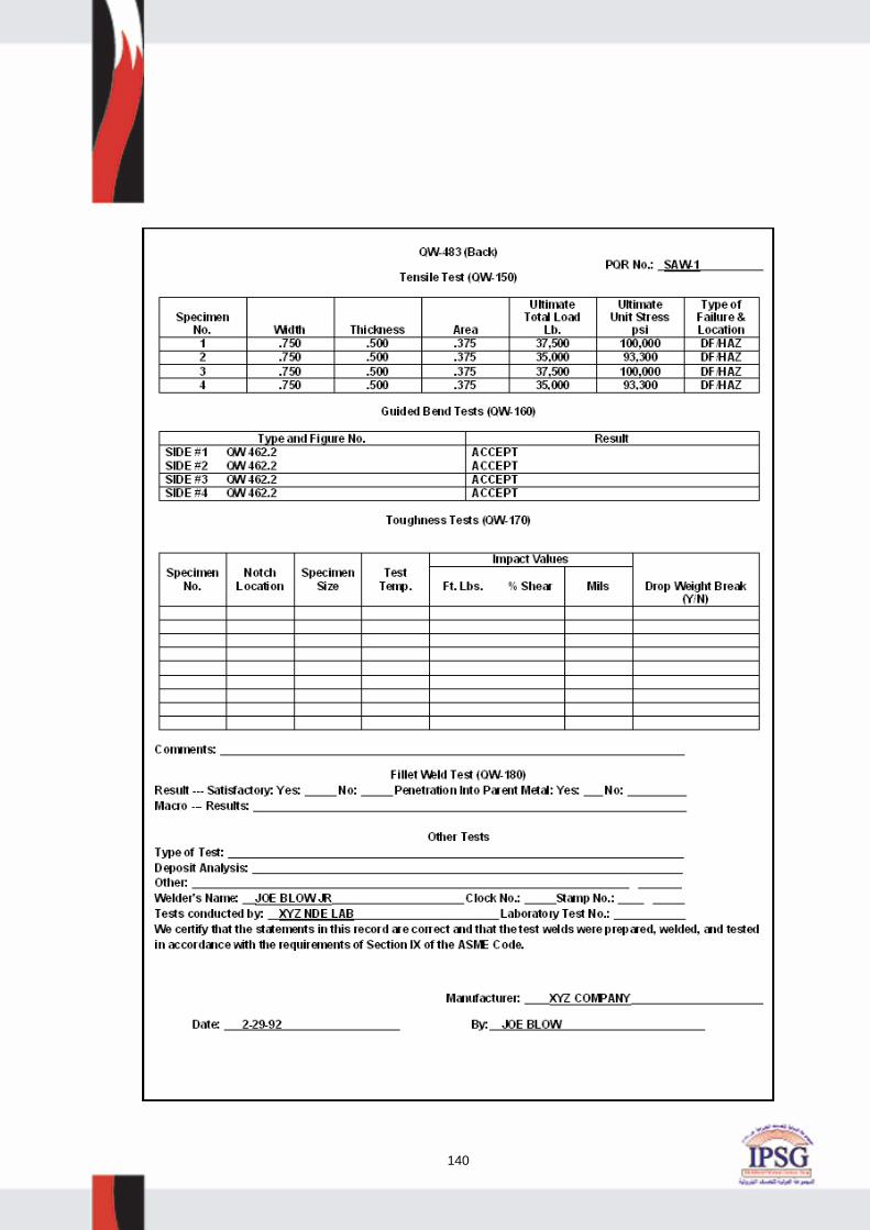
140

141
WPS #SMAW-1, REV. 0 AND PQR # SMAW-1A
1. The base metal thickness range shown on the WPS is: a. correct as shown b. incorrect - should be - 1/16” - 1 1/2” c. incorrect - should be - 3/16” - 2” d. incorrect - should be 3/8” - 1” 2. The deposited weld metal thickness range shown on the WPS is: a. correct as shown b. incorrect - should be “unlimited” c. incorrect - should be 8” maximum d. incorrect - should be 2” maximum 3. The welding rod change (from 7018 on the PQR to 7016 on the WPS) is: a. acceptable as shown b. unacceptable - can only be 7018 on the WPS c. acceptable - provided the rod is 7016 A1 d. unacceptable - the rod on the WPS must be 6010 only 4. The preheat temperature shown on the WPS should be: a. 60° F minimum b. 100° F minimum c. 250° F minimum d. 300° F minimum 5. The tension test specimen results shown on the PQR are: a. acceptable as shown b. unacceptable - not enough specimens c. unacceptable - ultimate stress does not meet ASME IX d. unacceptable - width of specimens are incorrect 6. The bend test results shown on the PQR are: a. acceptable as shown b. unacceptable - defect greater than allowed c. unacceptable - wrong type and insufficient number of specimens d. unacceptable - incorrect Figure # - should be QW-463.2

142
7. The PQR must be _________ to be “Code legal”. a. certified b. notarized c. authorized d. witnessed 8. Essential variable # QW 403.9 has been: a. correctly addressed on the WPS b. incorrectly addressed on the WPS c. not addressed on the PQR d. both B & C above 9. The position of the groove on the PQR is: a. acceptable as shown b. unacceptable - essential variable not addressed c. unacceptable - position shown does not correlate to plate d. both B & C above 10. The PQR shows “string” beads. The WPS shows “both” string and weave beads. This condition is: a. unacceptable - doesn’t meet Code b. acceptable - meets Code c. acceptable if “string” beads are in the root only d. acceptable if “weave” beads are in the cap pass only

143
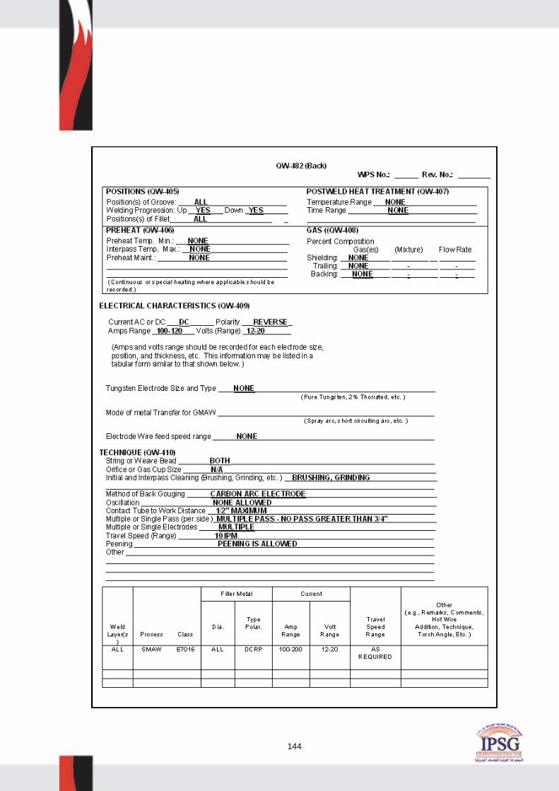
144

145

146

147
ANSWER SHEET WELDING PROCEDURE REVIEW QUESTIONS

148
ASME B31.3 & B16.5

149
SUBJECT: API AUTHORIZED PIPING INSPECTOR CERTIFICATION EXAMINATION.
OBJECTIVE: FAMILIARIZE CANDIDATES FOR THE PIPING EXAM WITH
TYPES AND FORMS OF PIPING DESIGN INFORMATION IN WHICH THEY MUST BE KNOWLEDGEABLE.
REFERENCES: ASME CODE FOR PROCESS PIPING, B31.3 2002 EDITION. Module Objective:- This module is designed to provide you with a thorough understanding of the basic design elements for piping systems as identified in the ASME B31.3 Code. It is essential that inspectors understand basic design computations related to temperature, pressure and thickness as they form an integral part of examination material for design and their use in remaining life calculations in API 570. For many inspectors they never look beyond the inspection acceptance criteria page so this may be a new experience. Review Of B31.3 2002 Edition. This is the primary section dealing with designs issues of process piping. The B31.3 Code is based primarily on design for Pressure, temperature and Flexibility (support). I. Foreword.
A. Project B31 was initiated in March 1926 by ASME and American Standards Association (ASA).
B. Initial publication of B31 was in 1935 and it was called the American Tentative Standard Code for Pressure Piping. Revisions from 1942 through 1955 were published as American Standard Code for Pressure Piping, ASA B31.1. Industry Sections were published as separate documents beginning with ASA B31.8- 1955, Gas Transmission and Distribution Piping Systems.
C. The first Petroleum Refinery Piping Code Section was designated ASA B31.3-1959. Revisions were
published in 1962 and 1966. D. In 1967 through 1969, ASA became the United States of America Standards Institute, then the American
Standards Institute, then the American National Standards Institute. The Sectional Committee became the American National Standards Committee B31 and the Code was renamed the American National Standard Code for Pressure Piping. The next B31.3 revision was designated ANSI B31.3-1973. Addenda were published through 1975.
E. A draft Code Section for Chemical Plant Piping, prepared by Section Committee B31.6, was ready for
approval in 1974. It was decided, rather than have 2 closely related Code Sections, to merge the Section Committees and develop a joint Code Section, titled Chemical Plant and Petroleum Refinery Piping,
published as ANSI B31.3-1976.

150
F. The Standards Committee was reorganized in 1978 as a Committee operating under ASME procedures
with ANSI accreditation. It is now the ASME Code for Pressure Piping, B31 Committee. Section committee structure remains essentially unchanged.
G. Nonmetal requirements were added in ASME B31.3-1980. H. Cryogenic Piping was added in ASME B31.3-1984. I. High Pressure piping plus stress changes (stress no longer presented as SE) were added in ASME
B31.3-1987. K. Changes on bellows expansion joint design, updated requirements, and a procedure for submitting
Inquiries were added in the ASME B31.3-1990. L. The 1993 Edition of ASME B31.3-1993 was issued with an automatic update service that included Addenda, Interpretations, and cases.
II. INTRODUCTION
A. ASME B31.3 sets forth engineering requirements deemed necessary for safe design and construction of
pressure piping. While safety is the basic consideration, this factor alone will not necessarily govern the final specifications for any piping installation. The designer is cautioned that this Code is not a design “cookbook”. It does not do away with the need for the designer or for competent engineering judgment.
B. The Code and subsequent Addenda (also other B31.3 editions) are not retroactive. Unless agreement is
specifically made between contracting parties to use another issue, or the regulatory body having jurisdiction imposes the use of another issue, the latest Edition and Addenda issued at least 6 months prior to the original contract date for the first phase of activity covering a piping installation shall be the governing document for all design, materials, fabrication, erection, examination, and testing for the piping until the completion of the work and initial operation.
C. Users should not make use of the Code revisions without assurance that they are acceptable to the proper
authorities in the jurisdiction where the piping is to be installed. D. Clauses in the Code are not necessarily numbered consecutively. This is because a common outline is
followed for all Code Sections. Corresponding material is thus consecutively numbered in most Code Sections and this facilitates referencing.
E. The Code is under the direction of ASME Committee B31 and is accredited by ANSI. The Committee is a
continuing one, and keeps all Code Sections current with new developments in materials, construction, and industrial practice. Addenda are issued periodically. New editions are published at intervals of 3 to 5 years.
F. It is the owner’s responsibility to determine which Code Section is applicable to the piping installation. The
owner, at his discretion, may select any section in the Code determined to be generally applicable. Some of the factors to be considered by the owner are: jurisdictional requirements, limitations of the Code Section, and the applicability of other Codes and Standards. Requirements supplementing the Code Section may be necessary to provide safe piping for the intended application.

151
G. Inquiries. H. Code cases. I. Request for revision. J. Materials.
CHAPTER I
SCOPE AND DEFINITIONS 300 General Statements. (a) Identification. B31.3 is a Section of The American Society of Mechanical Engineers Code for Pressure
Piping, ASME B31. It is published as a separate document for convenience of Code users. (b) Responsibilities.
(1) Owner. (i) Has overall responsibility for compliance with Code. (ii) Responsible for establishing the requirements for design, construction, examination, inspection, and testing which will govern the entire fluid handling or process installation of which the piping is a part. (iii) Also responsible to determine if a Quality System is to be employed. (2) Designer. Responsible to the owner for assurance that engineering design of piping complies with the
requirements of B31.3.
(3) Manufacturer, Fabricator, and Erector. Responsible for providing materials, components, and workmanship in compliance with the requirements of B31.3 and engineering design.
(4) Owner’s Inspector. Responsible to the owner for ensuring that the requirements of B31.3 for inspection, examination and testing are met. If a Quality System is to be employed, the Inspector is responsible for verifying that it is properly implemented.
(c) Intent of Code.
(1) Sets the engineering requirements deemed necessary for safe design and construction of piping installations.
(2) Engineering requirements of B31.3 while considered necessary and adequate for safe design, generally
employ a simplified approach to the subject. A designer capable of applying a more rigorous analysis shall have the latitude to do so, but must be able to demonstrate the validity of that approach.
(3) Piping elements should, insofar as practicable, conform to the specs and stds. listed in B31.3. Piping
elements neither specifically approved nor specifically prohibited by B31.3 may be used provided they are qualified for use as set for the in applicable parts of B31.3.

152
(4) Engineering design shall specify and unusual requirements for a particular service. Where service requirements necessitate measures beyond those required by B31.3, such measures shall be specified by the engineering design. Where so specified, B31.3 requires that they be accomplished.
(5) Compatibility of materials with the service and hazards from instability of contained fluids are not with the
scope of B31.3.
(d) Determining Code Requirements. (1) Code requirements for design and construction include fluid service requirements, which affect select and application of materials, components, and joints. Fluid service requirements include prohibitions, limitations, and conditions, such as temperature limits or a requirement for safeguarding. Code requirements for a piping system are the most restrictive of those which apply to any of its elements.
(2) For metallic piping not in Category M or high pressure fluid service, Code requirements are found in Chapters I through VI and fluid service requirements are found in
(i) Chapter III for materials (ii) Chapter II, Part 3, for components; (iii) Chapter II, Part 4, for joints.
(3) Nonmetallic piping--see Chapter VII (Paragraph designations begin with “A”) (4) Category M fluid service--see Chapter VIII, Para 300.2, and Appendix M. Paragraph designations begin with “M”. (5) Category D fluid service--see para 300.2 and Appendix M. (6) Severe cyclic conditions--Metallic piping elements suitable for Normal Fluid Service in Chapters 1 through VI may be uses unless a specific requirement for severe cyclic condition is stated.
(e) High Pressure Piping. Chapter IX provides alternative rules for design and construction of piping designated by the owner as being in High Pressure Fluid Service.
(1) Rules apply only when specified by the owner, and only as a whole, not in part. (2) Chapter IX rules do not provide for Category M Fluid Service. See paragraph K300.1.4. (3) Paragraph designations begin with “K”.
(f) Appendices. Appendices of B31.3 contain Code requirements, supplementary guidance, or other information. See paragraph 300.4 for a description of the status of each Appendix.

153
300.1 Scope 300.1.1 Content and Coverage. (a) Prescribes requirements for the materials, design, fabrication assembly, erection, examination, inspection, and testing of piping. (b) B31.3 applies to piping for all fluids including:
(1) raw, intermediate, and finished chemicals; (2) petroleum products; (3) gas, steam, air, and water; (4) fluidized solids; and (5) refrigerants;
(6) cryogenic fluids except as provided in paragraph 300.1.2 or 300.1.3. See Fig. 300.1.1 diagram. You will see a modified version of the above when we come to API 570.
300.1.2 Packaged Equipment Piping. Piping which interconnects individual pieces or stages of equipment within a packaged equipment assembly shall be in accordance with B31.3.
300.1.3 Exclusions. (a) Piping systems designed for internal gage pressures at or above zero but less than 15 psi provided the fluid
handled is nonflammable, nontoxic and not damaging to human tissue as defined in 300.2 and its design temperatures is from -20 degrees F through 366 degrees F.
(b) Power boilers in accordance with BPV Code Section I and boiler external piping which is required to conform to B31.1.
(c) Tubes, tube headers, crossovers, and manifolds of fired heaters, which are internal to the heater enclosure; (d) Pressure vessels, heat exchangers, pumps, compressors, and other fluid handling or processing equipment,
including internal piping and connections for external piping; 300.2 Definitions. There are approximately 121 definitions listed in this section. Some of the definitions have several sub-definitions listed under them. The definitions included on the test will be covered in class, and sample questions are provided at the back of this chapter. 300.3 Nomenclature. Dimensional and mathematical symbols used in B31.3 are listed in Appendix J, with definitions and location references to each. 300.4 Status of Appendices.

154
CHAPTER II DESIGN 301 DESIGN CONDITIONS--Selection of pressures, temperatures, and various forces that may apply to the
design of piping can be influenced by unusual requirements which should be considered when they occur. These include but are not limited to conditions listed in B31.3, Paragraph F301 of Appendix F.
301.1 Designer Qualifications – The designer (in charge of the design) must be qualified and experienced in
using B31.3. Degree in engineering plus 5 years design experience; PE registration and experience in design or piping; AS Degree plus 10 years experience in design of piping; 15 years experience in design of piping.
301.2 Design Pressure. 301.2.1 General. (a) Design pressure of each component in a piping system shall be not less than the pressure at the most
severe condition of coincident internal or external pressure and temperature (minimum or maximum) expected during service, except as provided in paragraph 302.2.4.
(b) The most severe condition is that which results in the greatest required component thickness and the highest
component rating. (c) When more than one set of pressure-temperature conditions exist for a piping system, the conditions
governing the rating of components conforming to listed standards may differ from the conditions governing the rating of components designed in accordance with paragraph 304 of B31.3.
301.2.2 Required Pressure Containment or Relief. (a) Safely contain or relieve any pressure piping is subject to. (1) Protect by Pressure Relieving Device. (2) Design for highest pressure that can be developed. (b) Sources of pressure. (1) Ambient influences. (2) Pressure oscillations and surges. (3) Improper operation. (4) Decomposition of unstable fluids.
(5) Failure of control devices. (c) See Paragraph 302.2.4 for PRV allowances.

155
301.3 Design Temperatures.
(a) Temperature at which, under the coincident pressure, the greatest thickness or highest component rating is required. (b) Establish design temperature by considering: (1) Fluid temperature. (2) Ambient temperatures. (3) Solar radiation. (4) Heating or cooling medium temperatures. (5) Material qualification requirements. 301.3.1 Design Minimum Temperature: Lowest component temperature expected in service. 301. 3.2 Uninsulated Components. (a) Fluid temperatures below 150 degrees F.--the component temperature shall be taken as the fluid
temperature unless solar radiation or other effects result in a higher temperature. (b) Fluid temperature 150 degrees F. and above--temperature for uninsulated components shall be no less than
the following values: (1) Valves, pipe, lapped ends, welding fittings, and other components having wall thickness comparable to that of the pipe--95% of the fluid temperature. (2) Flanges (except lap joint) including those on fittings and valves--90% of the fluid temperature. (3) Lap joint flanges--85% of the fluid temperature. (4) Bolting--80% of the fluid temperature. Note: a lower temperature may be determined by test of heat transfer calculations. 301.3.3 Externally Insulated Piping--Component design temperature shall be fluid temperature unless tests,
calculations, or service experience based on measurements support the use of another temperature. Tracing of jacketing influence shall be considered.
301.3.4 Internally Insulated Piping--Component design temperature shall be based on heat transfer calculations
or tests. 301.4 Ambient Effects. 301.4.1 Cooling: Effects on Pressure. 301.4.2 Fluid Expansion Effects. 301.4.3 Atmospheric Icing. 301.4.4 Low Ambient Temperature.

156
301.5 Dynamic Effects. 301.5.1 Impact. 301.5.2 Wind. 301.5.3 Earthquake. 301.5.4 Vibration. 301.5.5 Discharge Reactions. 301.6 Weight Effects. 301.6.1 Live Loads. 301.6.2 Dead Loads. 301.7 Thermal Expansion and Contraction Effects. 301.7.1 Thermal Loads Due to Restraints. 301.7.2 Loads Due to Temperature Gradients. 301.7.3 Loads Due to Differences in Expansion Characteristics. 301.8 Effects of Support, Anchor, and Terminal Movements. 301.9 Reduced Ductility Effects. 301.10 Cyclic Effects. 301.11 Air Condensation Effects. 302 DESIGN CRITERIA. 302.1 General. 302.3.3(C) - Casting Quality factors (should not be on the test, because it is outside the Body of Knowledge, but questions have historically come from this table. See notes below table for applicable NDE and assigned quality factors. 302.3.4 Weld Joint Quality Factor Ej. (a) See Table A-1B of B31.3. (b) Weld factor increased by additional examination. This factor will be used in calculating the thickness/MAWP
of piping.

157
TABLE 302.3.3C and 302.3.4 LONGITUDINAL WELD JOINT QUALITY FACTOR E C and EJ
PART 2--PRESSURE DESIGN OF PIPING COMPONENTS 303 GENERAL Components manufactured in accordance with standards listed in Table 326.1 of B31.3 shall be considered suitable for use at pressure-temperature ratings in with paragraph 302.2.1 of B31.3. Paragraph 304 of B31.3 covers pressure design of components not covered in Table 326.1. 304 PRESSURE DESIGN OF COMPONENTS. 304.1 Straight Pipe. 304.1.1 General. (a) tm = t + c tm = minimum required thickness including mechanical, corrosion, and erosion allowances.
t = pressure design thickness, as calculated per B31.3. c = the sum of the mechanical allowances (thread or groove depth) plus corrosion and erosion allowances.
d = inside diameter of pipe. D = outside diameter of pipe. Y = coefficient from Table 304.1.1 of B31.3, valid for t < D/6 and for materials shown. The value of Y may be interpolated for intermediate temperatures. d + 2c (b) For t ≥ D/6: Y = -------------------- D + d + 2c
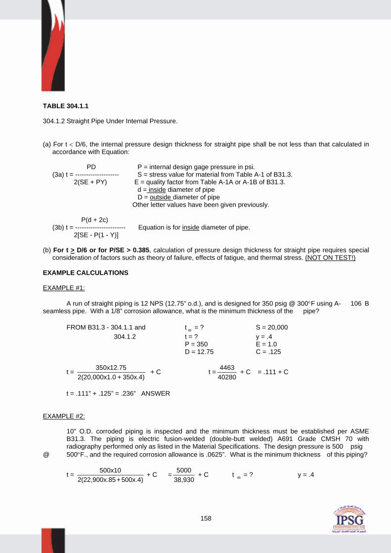
158
TABLE 304.1.1 304.1.2 Straight Pipe Under Internal Pressure. (a) For t < D/6, the internal pressure design thickness for straight pipe shall be not less than that calculated in
accordance with Equation: PD P = internal design gage pressure in psi. (3a) t = -------------------- S = stress value for material from Table A-1 of B31.3. 2(SE + PY) E = quality factor from Table A-1A or A-1B of B31.3. d = inside diameter of pipe D = outside diameter of pipe Other letter values have been given previously. P(d + 2c) (3b) t = ----------------------- Equation is for inside diameter of pipe. 2[SE - P(1 - Y)] (b) For t > D/6 or for P/SE > 0.385, calculation of pressure design thickness for straight pipe requires special
consideration of factors such as theory of failure, effects of fatigue, and thermal stress. (NOT ON TEST!) EXAMPLE CALCULATIONS EXAMPLE #1: A run of straight piping is 12 NPS (12.75” o.d.), and is designed for 350 psig @ 300°F using A- 106 B seamless pipe. With a 1/8” corrosion allowance, what is the minimum thickness of the pipe? FROM B31.3 - 304.1.1 and t m = ? S = 20,000 304.1.2 t = ? y = .4 P = 350 E = 1.0 D = 12.75 C = .125
t = 350x12.752(20,000x1.0 + 350x.4)
+ C t = 446340280
+ C = .111 + C
t = .111” + .125” = .236” ANSWER EXAMPLE #2: 10” O.D. corroded piping is inspected and the minimum thickness must be established per ASME B31.3. The piping is electric fusion-welded (double-butt welded) A691 Grade CMSH 70 with radiography performed only as listed in the Material Specifications. The design pressure is 500 psig @ 500°F., and the required corrosion allowance is .0625”. What is the minimum thickness of this piping?
t = 500x102(22,900x.85+500x.4)
+ C = 500038,930
+ C t m = ? y = .4

159
t = ? t = .127 + .0625 = .189” C = .0625 S = 22,900 t m = .189” - ANSWER E = .85 EXAMPLE #3: What is the maximum design pressure on piping that is 14” O.D., ASTM A335 Grade P5 seamless 3/8” thick (with 1/8” corrosion allowance) and operating at 600°F? (Transposed Barlow Formula from API 510/570 will normally be provided)
P = 2SEtD
P = ?
D = 14 S = 16,800 E = 1.0 t = .375 - .125 = .250
P = 2x16,800x.25014
= 600 psig ← ANSWER
EXAMPLE #4 What is the minimum thickness of a 5.75” i.d. pipe that is A-106-B (seamless) and is installed in a system operating at 3650 PSI @ 400°F? A 1/16” corrosion allowance will be maintained. t m = ? P = 3650 d = 5.75
S = 20,000 t m = P d cSE P Y
C( )[ ( )]
+− −
+2
2 1 Equation is for inside diameter of pipe.
C = .0625 E = 1.0 Y = .4
t m = m
+ .0625
t m = 214437535620
. + .0625
t m = .602 + .0625 = .664” ← ANSWER

160
EXAMPLE #5: What is the allowed casting quality factor for cast piping that has been fully radiographed and all surfaces have been MT tested per B31.3? ANSWER: 1.00 (Table 302.3.3C) EXAMPLE #6:
What is the longitudinal weld quality factor of an A691 Class 13 pipe that has received additional spot
radiography as allowed by B31.3?
ANSWER: .90 (Table 302.3.4)
304.5 Pressure Design of Flanges and Blanks. 304.5.1 Flanges--General 304.5.2 Blind Flanges – Blind flanges will be computed directly from ASME B16.5 for dimensions, pressures,
temperatures, etc. 304.5.3 Blanks (plate blinds). The minimum required thickness of a permanent blank shall be calculated in accordance with Equation (15).
Tm = dg3P
16SE + c (15)
tm = Minimum thickness of blank. Dg = Inside diameter of gasket for raised or flat face flanges or the gasket pitch diameter for ring joint and fully retained gasketed flanges. E = Quality factor from Table A-1A or A-1B of B31.3. S = Stress value for material from Table A-1 of B31.3.
c = Sum of mechanical allowances (thread) plus corrosion and erosion allowances.

161
EXAMPLE #7 What is the minimum thickness of a permanent blank that will be installed in a piping system that has a
16” i.d. gasket face on the flanges, with a design pressure of 750 psig @ 800°F. The corrosion allowance is 1/8” and the material is SA-516-70 plate with no butt welds.
FROM 304.5.3 t = ? S = 12,000 E = 1.0 d g = 16 P = 750 C = .125
t m = 16 3x75016x12,000x1
+ .125
t m = 16 2250192,000
+ .125
t m = 1.857” ← ANSWER
NOTE: Depending on how the question is worded, the corrosion allowance factor (c) may have to be added twice to compensate for corrosion from both sides of the blank.
PART 3 FLUID SERVICE REQUIREMENTS FOR PIPING COMPONENTS 305 PIPE--Pipe includes components designated as “tube” or “tubing” in the material specification, when
intended for pressure service. 305.1 General. 305.2 Specific Requirements. 305.2.3 Pipe for Severe Cyclic Conditions. 306 FITTINGS, BENDS, MITERS, LAPS, AND BRANCH CONNECTIONS. 306.1.1 Listed fittings. 306.1.2 Unlisted Fittings. 306.1.3 Specific Fittings. 306.1.4 Fittings for Severe Cyclic Conditions.

162
306.2 Pipe Bends. 306.2.1 General. 306.2.2 Corrugated and Other Bends. 306.2.3 Bends for Severe Cyclic Conditions. 306.3 Miter Bends. 306.4 Fabricated or Flared Laps. 306.5 Fabricated Branch Connections. 307 VALVES AND SPECIALTY COMPONENTS. 308 FLANGES, BLANKS, FLANGE FACINGS, AND GASKETS. 309 BOLTING. PART 4 FLUID SERVICE REQUIREMENTS FOR PIPING JOINTS 310 GENERAL. 311 WELDED JOINTS. 311.1 General. 311.2 Specific Requirements. 311.2.1 Welds for Category D Fluid Service. 311.2.2 Welds for Severe Cyclic Conditions. 311.2.3 Backing Rings and Consumable Inserts. 311.2.4 Socket Welds - Limited to NPS 2 on Severe Cycle Service. 311.2.5 Fillet Welds - Socket Welds, slip on flanges, only. Drains/By passes acceptable. 311.2.6 Seal Welds - No strength contribution to joint.

163
312 FLANGED JOINTS. 312.1 Joints Using Flanges of Different Ratings. 312.2 Metal to Nonmetal Flanged Joints. 313 EXPANDED JOINTS. 314 THREADED JOINTS. 314.1 General. Threaded joints are suitable for Normal Fluid Service except as stated elsewhere in this section. They may be used under severe cyclic conditions only as provided by B31.3. (a) Threaded joints should be avoided in any service where crevice corrosion, severe erosion, or cyclic loading
may occur. (b) When threaded joints are intended to be seal welded, thread sealing compound shall not be used. (c) Layout of piping employing threaded joints should, insofar as possible, minimize stress on joints, giving
special consideration to stresses due to thermal expansion and operation of valves (particularly a valve at a free end). Provision should be made to counteract forces that would tend to unscrew the joints.
314.2 Specific Requirements. 314.2.1 Taper-Threaded Joints. 314.2.2 Straight-Threaded Joints. 318 SPECIAL JOINTS. PART 5 FLEXIBILITY AND SUPPORT 319 PIPING FLEXIBILITY. 319.1 Requirements. 319.1.1 Basic Requirements--Piping systems shall have sufficient flexibility to prevent thermal expansion or
contraction or movements of piping supports and terminals from causing: (a) failure of piping or supports from overstress or fatigue; (b) leakage at joints; or (c) detrimental stresses or distortion in piping and valves or in connected equipment (pumps and turbines, for
example), resulting from excessive thrusts and moments in the piping. 319.1.2 Specific Requirements.

164
319.2 Concepts. 319.2.1 Displacement Strains. 319.2.2 Displacement Stresses. 319.2.3 Displacement Stress Range. 319.2.4 Cold Spring. 319.3 Properties for Flexibility Analysis. 319.3.1 Thermal Expansion Data. 319.3.2 Modulus of Elasticity. 319.3.3 Poisson’s Ratio. 319.3.4 Allowable Stresses. 319.3.5 Dimensions. 319.3.6 Flexibility and Stress Intensification Factors. 321 PIPING SUPPORT. 321.1 General. (a) Base loading on all concurrently acting loads transmitted into supports. These loads include weight effects,
loads introduced by service pressures and temperatures, vibration, wind, earthquake, shock, and displacement strain.
(b) For piping containing gas or vapor, weight calculations need not include the weight of liquid if the designer
has taken specific precautions against entrance of liquid into the piping, and if the piping is not to be subjected to hydrostatic testing at initial construction or subsequent inspections.
321.1.1 Objectives--The layout and design of piping and its supporting elements shall be directed toward
preventing the following: (1) piping stresses in excess of those permitted in B31.3; (2) leakage at joints; (3) excessive thrusts and moments on connected equipment (such as pumps and turbines); (4) excessive stresses in the supporting (or restraining) elements; (5) resonance with imposed or fluid-induced vibrations; (6) excessive interference with thermal expansion and contraction in piping which is otherwise adequately
flexible; (7) unintentional disengagement of piping from its supports; (8) excessive piping sag in piping requiring drainage slope; (9) excessive distortion or sag of piping (e.g., thermoplastics) subject to creep under conditions of repeated
thermal cycling; (10) excessive heat flow, exposing supporting elements to temperature extremes outside their design limits.

165
321.1.2 Analysis. 321.1.3 Stresses for Pipe Supporting Elements. 321.1.4 Materials. 321.4 Structural Connections. PART 6 SYSTEMS 322 SPECIFIC PIPING SYSTEMS. 322.6 Pressure Relieving Systems. 322.6.1 Stop Valves in Pressure Relief Piping--No stop valves allowed except for: (a) Stop valves may be used in PRV piping if they are so constructed or positively controlled that the closing of
the maximum number of block valves possible at one time will not reduce the pressure relieving capacity provided by the unaffected relieving devices below the required relieving capacity.
(b) A full-area stop valve may be installed on the inlet side of a pressure relieving device. A full area stop valve
may be placed on the discharge side of a PR device when its discharge is connected to a common header with other discharge lines from other PR devices. Stop valves of less than full area may be used on both the inlet side and discharge side of PR devices as outlined in the foregoing, if the stop valves are of such type and size the increase in pressure drop will not reduce the relieving capacity below that required, no adversely affect the proper operation of the PR device.
(c) Stop valves shall be so arranged that they can be locked or sealed in both the open and the closed
positions. See Appendix F, paragraph F322.6 of B31.3. 322.6.2 Pressure Relief Discharge Piping--Discharge lines from PRS devices shall be designed to facilitate
drainage. When discharging directly to the atmosphere, discharge shall not impinge on other piping or equipment and shall be directed away from platforms and other areas used by personnel. Reactions on the piping system due to actuation of PRS devices shall be considered, and adequate strength shall be provided to withstand these reactions.
322.6.3 Pressure Relieving Devices--See ASME BPV Code.

166
CHAPTER III MATERIALS 323 GENERAL REQUIREMENTS. 323.1 Materials and Specifications. 323.1.2 Unlisted Materials. 323.1.3 Unknown Materials. 323.1.4 Reclaimed Materials. 323.2 Temperature Limitations. 323.2.1 Upper Temperature Limits, Listed Materials. 323.2.2 Lower Temperature Limits, Listed Materials. 323.2.3 Temperature Limits, Unlisted Materials. 323.2.4 Verification of Serviceability. 323.2.2, 323.2.2A, and FIGURES 323.2.2A, 323.2.2B FROM B31.3 323.3 Impact testing Methods and Acceptance Criteria - These charts and graphs will be explained in detail in class, with examples provided. 323.3.1 General. 323.3.2 Procedure. 323.3.3 Test Specimens. 323.3.4 Test Temperatures. 323.3.5 Acceptance Criteria. TABLE 323.3.1 FROM B31.3 TABLE 323.3.4 FROM B31.3

167
TABLE 323.3.5 323.4 Fluid Service Requirements for Materials. 323.4.1 General--apply to pressure containing parts. 323.4.2 Specific Requirements. (a) Ductile Iron. (b) Other Cast Irons. (c) Other Materials. 323.4.3 Cladding and Lining Materials. 323.5 Deterioration of Materials in Service. 325 MATERIALS--MISCELLANEOUS. 325.1 Joining and Auxiliary Materials. CHAPTER IV STANDARDS FOR PIPING COMPONENTS TABLE 326.1 FROM B31.3 CHAPTER V FABRICATION, ASSEMBLY, AND ERECTION 327 GENERAL--Metallic piping materials and components are prepared for assembly and erection by one or
more of the fabrication processes covered in paragraphs 328, 330, 331, 332, and 333 of B31.3. When any of these processes is used in assembly or erection, requirements are the same as for fabrication.
328 WELDING--Welding shall conform to the following in accordance with applicable requirements. 328.1 Welding Responsibility--Employer is responsible and shall conduct tests required.

168
328.2 Welding Qualifications. 328.2.1 Qualification Requirements. (a) Shall be per BPV Code Section IX except as modified by B31.3. (b) Where base metal will not withstand the 180 degree guided bend required by Section IX of the BPV Code, a
qualifying welded specimen is required to undergo the same degree of bending as the base metal, within 5 degrees.
(c) The requirements for preheating shall apply in qualifying welding procedures. (d) Impact requirements shall be met in qualifying welding procedures. (e) If consumable inserts (or equivalents) are used, their suitability shall be demonstrated by procedure
qualification, except that a procedure qualified without use of a backing ring is also qualified for use with a backing ring in a single-welded butt joint.
(f) To reduce the number of welding procedure qualifications required, P-Numbers and Group Numbers are
assigned to groupings of metals generally based on composition, weldability, and mechanical properties, insofar as practicable. The P-Numbers for most metals appear in a separate column in Table A-1 of B31.3.
328.2.2 Procedure Qualification by Others--Each employer is responsible for qualifying any welding procedure
that personnel of the organization will use. Subject to the specific approval of the Inspector, welding procedures qualified by others may be used, provided that the following conditions are met:
(a) the Inspector shall be satisfied that: (1) the proposed welding procedure specification (WPS) has been prepared, qualified, and executed by a responsible, recognized organization with expertise in the field of welding; and (2) the employer has not made any change in the welding procedure. (b) The base metals to be joined are of the same P-Number, except that P-Nos. 1, 3, 4 Gr. No.1 (1.25 Cr Max.),
or 8; and impact testing is not required. (c) The base metals to be joined are of the same P-Number, except that P-Nos. 1, 3, and 4 Gr. No. 1 may be
welded to each other as permitted by Section IX, BPV. (d) The material to be welded is not more than 3/4” thickness. Postweld heat treatment shall not be required. (e) the design pressure does not exceed the ASME B16.5 Class 300 rating for the material at design
temperature; and the design temperature is in the range -20 degrees F to 750 degrees F inclusive. (f) the welding process is SMAW or GTAW or a combination thereof.

169
(g) Welding electrodes for the SMAW process are selected from the following classifications: AWS A5.1 AWS A5.4 AWS A5.5 E6010 E308-15,-16 E7010-A1 E6011 E308L-15,-16 E7018-A1 E7015 E309-15,-16 E8016-B1 E7016 E310-15,-16 E8018-B1 E7018 E-16-8-2-15,-16 E8015-B2L E316-15, 16 E8016-B2 E316L-15,-16 E8018-B2 E347-15,-16 E8018-B2L (h) By signature, the employer accepts responsibility for both the WPS and the procedure qualification record
(PQR). (i) The employer has at least one currently employed welder or welding operator who, while in his employ, has
satisfactorily passed a performance qualification test using the procedure and the P-Number material specified in the WPS. The performance bend test required by Section IX, QW-302, BPV Code, shall be used for this purpose. Qualification by radiography is not acceptable.
328.2.3 Performance Qualification by Others--To avoid duplication of effort, an employer may accept a
performance qualification made for another employer, provided that the Inspector specifically approves. 328.2.4 Qualification Records--The employer shall maintain a self-certified record, available to the owner (and
the owner’s agent) and the Inspector, of the procedures used and the welders and welding operators employed, showing the date and results of procedure and performance qualifications, and the identification symbol assigned to each welder and welding operator.
328.3 Welding Materials. 328.3.1 Filler Metal--Section IX, BPV Code. 328.3.2 Weld Backing Material. 328.3.3 Consumable Inserts. 328.4 Preparation for Welding. 328.4.1 Cleaning. 328.4.2 End Preparation. 328.4.3 Alignment. 328.4.4 FIGS. 328.3.2, 328.4.2, 328.4.3, & 328.4.4

170
328.5 Welding Requirements. 328.5.1 General. 328.5.2 Fillet and Socket Welds. 328.5.3 Seal Welds. 328.5.4 Welded Branch Connections. 328.5.5 Fabricated Laps. 328.5.2A, 328.5.2B, 328.5.2C, 328.5.4A,B,C, 328.5.4.D, 328.5.4E, and 328.5.5. 328.5.6 Welding for Severe Cyclic Conditions. 328.6 Weld Repair. 330 PREHEATING. 330.1 General. 330.1.1 Requirements and Recommendations. 330.1.2 Unlisted Materials. 330.1.3 Temperature Verification. 330.1.4 Preheat Zone--extends at least 1” beyond each edge of the weld. 330.2 Specific Requirements. TABLE 330.1.1 330.2.1 Interrupted Welding. 331 HEAT TREATMENT-- is used to avert or relieve the detrimental effects of high temperature and severe
temperature gradients inherent in welding, and to relieve residual stresses created by bending and forming. 331.1 GENERAL. 331.1.1 Heat Treatment Requirements.

171
TABLE 331.1.1 331.1.3 Governing Thickness--When components are joined by welding, the thickness to be used in applying
the heat treatment provisions shall be that of the thicker component measured at the joint, except as follows: (a) Branch connections (other than weld metal) added as reinforcement, shall not be considered in determining
heat treatment requirements. Heat treatment is required when the thickness through the weld in any plane through the branch is greater than twice the minimum material thickness requiring heat treatment, even though the thickness of the components at the joint is less than the minimum thickness. Thickness through the weld for the details shown in Figure 328.5.4D of B31.3 shall be computed using the following formulas:
sketch (1) = T b+tc sketch (2) = T h+tc
sketch (3) = greater of T b+tc or T r+tc sketch (4) = T h+tc T r+tc sketch (5) = T b+tc tc = lesser of 0.7 T b or 1/4 inch. T b= nominal thickness of branch. T h= nominal thickness of header. T r = nominal thickness of reinforcing pad or saddle. tmin= lesser of T b or T r (b) In the case of fillet welds at slip-on and socket welding flanges and piping connections NPS 2” and smaller,
for seal welding of threaded joints in piping NPS 2” and smaller, and for attachment of external nonpressure parts such as lugs or other pipe supporting elements in all pipe sized, heat treatment is required when the thickness through the weld in any plane is more than twice the minimum material thickness requiring heat treatment (even though the thickness of the components at the joint is less than that minimum thickness) except:
(1) not required for P-No. 1 materials when weld throat thickness is 5/8” or less, regardless of base metal
thickness. (2) not required for P-No. 3,4,5, or 10A materials when weld throat thickness is 1/2” or less, regardless of
base metal thickness, provided that not less than the recommended preheat is applied, and the specified minimum tensile strength of the base metal is less than 71 ksi.
(3) not required for ferritic materials when welds are made with filler metal which does not air harden. Austenitic welding materials may be used for welds to ferritic materials when the effects of service conditions, such as differential thermal expansion due to elevated temperature, or corrosion, will not adversely affect the weldment.

172
331.1.4 Heating and Cooling. 331.1.6 Temperature Verification. 331.1.7 Hardness Tests--applies to weld and the heat affected zone tested as close as practicable to the edge
of the weld. (a) 10% of welds, hot bends, and hot formed components in each furnace heat treated batch and 100% of those
locally heat treated shall be tested. (b) When dissimilar metals are joined by welding, the hardness limits specified for the base and welding
materials shall be met for each material. 331.2 Specific Requirements--Where warranted by experience or knowledge of service conditions, alternative
methods of heat treatment or exceptions to basic heat treatment may be adopted as provided below: 331.2.1 Alternative Heat Treatment--Normalizing, or normalizing and tempering, or annealing may be applied in
lieu of the required heat treatment provided that the mechanical properties of any affected weld and base metal meet specification requirements after such treatment and that the substitution is approved by the designer.
331.2.2 Exceptions to Basic Requirements. (a) More stringent requirements specified by designer. (b) When provisions less stringent than those required by B31.3 are specified, the designer must demonstrate to
the owner’s satisfaction the adequacy of those provisions. Appropriate tests shall be conducted, including WPS qualification tests.
331.2.3 Dissimilar Materials. (a) Higher temperature range shall govern. (b) Heat treatment of welded joints including both ferritic and austenitic components and filler metals shall be as
required for the ferritic material or materials unless otherwise specified in the engineering design. 331.2.4 Delayed Heat Treatment--rate of cooling shall be controlled. 331.2.5 Partial Heat Treatment--large pieces may be heat treated in more than one heat provided there is at
least 1 ft. overlap between successive heats and parts outside furnace are protected from harmful temperature gradients.
331.2.6 Local Heat Treatment--apply over circumferential band and shall be heated until the specified
temperature range exists over the entire pipe section, gradually diminishing beyond the ends of a band which includes the weldment or the bent or formed section and at least 1 inch beyond the edges thereof.
332 BENDING AND FORMING. 332.1 General--may be done hot or cold. No cracks or buckles permitted. Thickness after bending or forming
shall be not less than that required by design.

173
332.2 Bending 332.2.1 Bend Flattening. 332.2.2 Bending Temperature. 332.2.3 Corrugated and Other Bends. 332.3 Forming. 332.4 required Heat Treatment. 332.4.1 Hot Bending and Forming. 332.4.2 Cold Bending and Forming. 333 BRAZING AND SOLDERING. 333.1 Qualification. 333.1.1 Brazing Qualification--qualified per BPV Code Section IX. 333.2 Brazing and Soldering Materials. 333.2.1 Filler Metal. 333.2.2 Flux. 333.3 Preparation. 333.3.1 Surface Preparation. 333.3.2 Joint Clearance. 333.4 Requirements. 333.4.1 Soldering Procedure. 333.4.2 Heating. 333.4.3 Flux Removal. 335 ASSEMBLY AND ERECTION. 335.1 General. 335.1.1 Alignment. (a) Piping Distortions--may not cause detrimental strain. (b) Cold Spring--heating shall not be used to help close gap; must be per designer. (c) Flanged Joints--faces must be aligned within 1/16 in./ft. (0.05%) measured across and diameter. Bolt holes
shall be aligned with 1/8” maximum offset.

174
335.2 Flanged Joints. 335.2.1 Preparation for Assembly--check gasket surface. 335.2.2 Bolting Torque. (a) Uniformly compress gasket to proper loading. (b) Take care in assembling joint with different properties. 335.2.3 Bolt Length--should extend completely through nuts. Acceptable if lack of complete engagement is not
more than one thread. 335.2.4--only one gasket may be used. 335.3 Threaded Joints. 335.3.1 Thread Compound or Lubricant. 335.3.2 Joints for Seal Welding--make up without thread compound. May seal wed a threaded joint with
compound if it leaks on test, provided compound is cleaned from welding area. 335.3.3 Straight Threaded Joints--see Figure 335.3.3, B31.3, sketches (a), (b) & (c). 335.4 Tubing Joints. 335.4.1 Flared Tubing Joints. 335.4.2 flareless and Compression Tubing Joints. 335.5 Caulked Joints. 335.6 Expanded Joints and Special Joints. 335.6.1 General 335.6.2 Packed Joints. 335.9 Cleaning of Piping--see Appendix F, paragraph F335.9 of B31.3.

175
CHAPTER VI INSPECTION, EXAMINATION, AND TESTING 340 INSPECTION. 340.1 General--Inspection applies to functions performed for the owner by the owner’s Inspector or the
Inspector’s delegates. References in B31.3 to the “Inspector” are to the owner’s Inspector or the Inspector’s delegates.
340.2 Responsibility for Inspection--owner’s responsibility, exercised through the owner’s Inspector, to verify
that all required examinations and testing have been completed and to inspect the piping to the extent necessary to be satisfied that it conforms to all applicable examination requirements of the Code and of the engineering design.
340.3 Rights of the Owner’s Inspector--shall have access to any place where work concerned with the piping
installation is being performed. Shall have the right to audit any examination, to inspect the piping using any examination method specified by the engineering design, and to review all certifications and records necessary to satisfy the owner’s responsibility (see above).
340.4 Qualifications of the Owner’s Inspector. (a) Designated by owner and shall be the owner, an employee of the owner, an employee of an engineering or
scientific organization, or of a recognized insurance or inspection company acting as the owner’s agent. Shall not represent nor be an employee of the manufacturer, fabricator, or erector unless the owner is also the manufacturer, fabricator, or erector.
(b) Inspector shall have not less than 10 years experience in the design, fabrication, or inspection of industrial pressure piping. Each 20% of satisfactorily completed work toward an engineering degree recognized by the Accreditation Board for Engineering and Technology shall be considered equivalent to 1 year experience up to 5 years total.
(c) Inspector is responsible for delegation performance of inspection and for determining that a person to whom an inspection function is delegated is qualified to perform that function.
341 EXAMINATION. 341.1 General--examination applies to quality control functions performed by the manufacturer (for components
only), fabricator, or erector. “Examiner” refers to a person who performs quality control examinations. 341.2 Responsibility for Examination--inspection does not relieve the manufacturer, the fabricator, or the
erector of the responsibility for: (a) providing materials, components, and workmanship in accordance with the requirements of B31.3 and of
the engineering design. (b) performing all required examination; and (c) preparing suitable records of examinations and tests for the Inspector’s use.

176
341.3 Examination Requirements. 341.3.1 General--Prior to initial operation each piping installation, including components and workmanship shall
be examined in accordance with the applicable requirements of paragraph 341 of B31.3. The type and extent of any additional examination required by the engineering design, and the acceptance criteria to be applied, shall be specified. Joints not included in examinations required by paragraph 341.4 of B31.3 or by the engineering design are accepted if they pass the leak test required.
(a) For P-Nos. 3,4, and 5 materials, examination shall be performed after completion of any heat treatment. (b) For a welded branch connection, the examination of and any necessary repairs to the pressure containing
weld shall be completed before any reinforcing pad or saddle is added. 341.3.2 acceptance Criteria--shall be as stated in the engineering design and shall at least meet the applicable
requirements of paragraph 344.6.2 of B31.3 for ultrasonic examination of welds. (a) Limits on imperfections for welds-- TABLE 341.3.2 and FIGURE 341.3.2. (b) Acceptance criteria for castings are specified in paragraph 302.3.3 of B31.3. 341.3.3 Defective Components and Workmanship--repair or replace and reexamine. 341.3.4 Progressive Examination--when a defect is found. (a) two additional items of the same kind (if welded or bonded joints, by the same welder, bonder, or operator)
shall be given the same type of examination; and (b) if the items examined as required by (a) above are acceptable, the defective item shall be repaired or
replaced and reexamined as specified in paragraph 341.3.3 of B31.3, and all items represented by this additional examination shall be accepted; but
(c) if any of the items examined as required by (a) above reveals a defect, two further items of the same kind shall be examined for each defective item found by that examination; and
(d) if all the items examined as required by (c) above are acceptable, the defective item(s) shall be repaired or replaced and reexamined as specified in paragraph 341.3.3 of B31.3, and all items represented by this additional examination shall be accepted; but
(e) if any of the items examined as required by (c) above reveals a defect, all items represented by the progressive examinations shall be either:
(1) repaired or replaced and reexamined as required; or (2) fully examined and repaired or replaced as necessary, and reexamined as necessary to meet the
requirements of B31.3. 341.4 Extent of Required Examination. 341.4.1 Examination Normally Required--piping in Normal Fluid Service shall be examined to the extent
specified or to any greater extent specified in engineering design. (a) Visual Examination--at least the following shall be examined: (1) sufficient materials and components, selected at random, to satisfy the examiner that they conform to
specifications and are free from defects; (2) at least 5% of fabrication. For welds, each welder’s and welding operator’s work shall be represented. (3) 100% of fabrication for longitudinal welds, except those in components made in accordance with a listed
specification. see paragraph 341.5.1(a) for B31.3 for examination of longitudinal welds required to have a joint factor Ej of 0.90.

177
(4) random examination of the assembly of threaded, bolted, and other joints to satisfy the examiner that they conform to the applicable requirements of paragraph 335 of B31.3. When pneumatic testing is to be performed, all threaded, bolted, and other mechanical joints shall be examined.
(5) random examination during erection of piping, including checking of alignment, supports, and cold spring; (6) examination of erected piping for evidence of defects that would require repair or replacement, and for
other evident deviations from the intent of the design. (b) Other Examination. (1) Not less than 5% of circumferential butt and miter groove welds shall be examined fully by random
radiography in accordance with paragraph 344.5 of B31.3 or by random ultrasonic examination in accordance with paragraph 344.6 of B31.3 . The welds to be examined shall be selected to ensure that the work product of each welder or welding operator doing the production welding is included. They shall also be selected to maximize coverage of intersections with longitudinal joints. At least 1.5” of the longitudinal welds shall be examined. In-process examination may be substituted for all or part of the radiographic or ultrasonic examination on a weld for weld basis if specified in the engineering design.
(2) Not less than 5% of all brazed joints shall be examined by in-process examination in accordance with
B31.3 , the joints to be examined being selected to ensure that the work of each brazer making the production joints is included.
(3) Certifications and Records. The examiner shall be assured, by examination of certifications, records, and
other evidence, that the materials and components are of the specified grades and that they have received required heat treatment, examination, and testing. The examiner shall provide the inspector with a certification that all the quality control requirements of B31.3 and of the engineering design have been carried out.
341.4.2 Examination--Category D Fluid Service. 341.4.3 Examination--Sever Cyclic Conditions. (a) Visual examination. (b) Other Examinations. (c) In-process examination. (d) Certification and Records. 341.5 Supplementary Examination. 341.5.1 Spot Radiography (a) Longitudinal Welds. Ej=0.90 Examine at least 1 ft. in each 100 ft. for each welder. (b) Circumferential Butt Welds and Other Welds. Not less than one shot on one in each 20 welds for each
welder. (c) Progressive Examination. (d) Welds to Be Examined. The locations of welds and the points at which they are to be examined by spot
radiography shall be selected or approved by the Inspector. 341.5.2 Hardness Tests.

178
341.5.3 Examinations to Resolve Uncertainty--Any method may be used to resolve doubtful indications. Acceptance criteria shall be those for the required examination.
342. EXAMINATION PERSONNEL. 342.1 Personnel Qualification and Certification. 342.2 Specific Requirement. 343 EXAMINATION PROCEDURES. 344 TYPES OF EXAMINATION. 344.1 General. 344.1.1 Methods. 344.1.2 special Methods. 344.1.3 Definitions. (a) 100% examination--complete examination of all of a specified kind of item in a designated lot of piping. (b) random examination--complete examination of a percentage of a specified kind of item in a designated lot of
piping. (c) spot examination--a specified partial examination of each of a specified kind of item in a designated lot of
piping, e.g., of part of the length of shop-fabricated welds in a lot of jacketed piping. (d) random spot examination--a specified partial examination of a percentage of a specified kind of item in a
designated lot of piping. 344.2 Visual Examination. 344.2.1 Definition--visual examination is observation of the portion of components, joints, and other piping
elements that are or can be exposed to view before, during, or after manufacture, fabrication, assembly, erection, examination, or testing.
344.2.2 Method--per BPV Code, Section V, Article 9. 344.3 Magnetic Particle Examination--per BPV Code, Section V, Article 7. 344.4 Liquid Penetrant Examination--per BPV Code, Section V, Article 6. 344.5 Radiographic Examination. 344.5.1 Do per BPV Code, Section V, Article 2. 344.5.2 Extent of Radiography. (a) 100% Radiography. Applies only to girth and miter groove welds and to fabricated branch connection welds
comparable to Figure 328.5.4E of B31.3, unless other wise specified in the engineering design. (b) Random Radiography. Applies only to girth and miter groove welds.

179
(c) Spot Radiography. Requires a single exposure radiograph in accordance with paragraph 344.5.1 of B31.3. at a point within a specified extent of welding. For girth, miter, and branch groove welds, the minimum requirement is:
(1) for NPS ≤ 2.5, a single elliptical exposure encompassing the entire weld circumference; (2) for NPS > 2.5”, the lesser of 25% of the inside circumference or 6 inches. For longitudinal welds, the minimum requirement is 6 inches of the weld length. 344.6 Ultrasonic Examination. 344.6.1 Method--per BPV Code, Section V, Article 5, except that the alternative specified in (a) and (b) below is
permitted for T-543.1.3 and T-542.2.1.1. (a) Calibration blocks have not received heat treatment. (b) Reference reflector. (c) When transfer method is used it shall be used, at the minimum: (1) for NPS ≤ 2.5” , once in each 10 welded joints examined; (2) for sizes 2”<NPS ≤ 18”, once in each 5 ft. of welding examined; (3) for NPS>18”, once for each welded joint examined. (d) Each type of material and each size and wall thickness shall be considered separately in applying the
transfer method. In addition, the transfer method shall be used at least twice on each type of weld joint. (e) the reference level for monitoring discontinuities shall be modified to reflect the transfer correction when the
transfer method is used. 344.6.2 Acceptance Criteria--a linear-type discontinuity is unacceptable if the amplitude of the indication
exceeds the reference level and its length exceeds; (a) 1/4” in for T w ≤ 3/4” (b) T w/3 for 3/4” < T w ≤ 2.25”. (c) 3/4” for T w > 2.25”. 344.7 In-Process Examination. 344.7.1 Definition--comprises examination of the following, as applicable; (a) joint preparation and cleanliness; (b) preheating; (c) fit-up, joint clearance, and internal alignment prior to joining; (d) variables specified by the joining procedure, including filler material; and (1) (for welding) position and electrode; (2) (for brazing) position, flux, brazing temperature, proper wetting, and capillary action; (e) (for welding) condition of the root pass after cleaning--external and, where accessible, internal--aided by
liquid penetrant or magnetic particle examination when specified in the engineering design; (f) (for welding) slag removal and weld condition between passes; and (g) appearance of the finished joint.

180
344.7.2 Method. 345 TESTING. 345.1 Required Leak Test--prior to initial operation, each piping system shall be tested to ensure tightness.
The test shall be a hydrostatic leak test in accordance except as below: (a) At the owner’s option, a piping system in Category D fluid service may be subjected to an initial service leak
test in lieu of the hydrostatic leak test. (b) Where the owner considers a hydrostatic leak test impracticable, either a pneumatic test or a combined
hydrostatic-pneumatic test may be substituted. (c) Where the owner considers both hydrostatic and pneumatic leak testing impracticable, the alternative
specified in paragraph 345.9 of B31.3 may be used if both of the following apply: (1) a hydrostatic test would damage linings of internal insulation, or contaminate a process which would be
hazardous, corrosive, or inoperative in the presence of moisture, or would present the danger of brittle fracture due to low metal temperature during the test; and
(2) a pneumatic test would present an undue hazard of possible release of energy stored in the system, or would present the danger of brittle fracture due to low metal temperature during the test.
345.2 General Requirements for Leak Tests. 345.2.1 Limitations on Pressure. (a) Stress Exceeding Yield Strength--may reduce test pressure. (b) Test Fluid Expansion--take precautions. (c) Preliminary Pneumatic Test--no more than 25 psi to locate leaks prior to hydrotest. 345.2.2 Other Test Requirements. (a) Examination for Leaks--maintain test for at least 10 minutes to check for leaks. (b) Heat Treatment--Leak tests conducted after any heat treatment has been completed. (c) Low Test Temperature--consider brittle fracture. 345.2.3 Special Provisions for Testing. (a) Piping Subassemblies--test separately or as assembly. (b) Flanged Joints--test not required upon removing test blinds. (c) Closure welds on tested piping or components need not be re-pressure tested, but must pass 100% RT or
UT. 345.2.4 Externally Pressured Piping--piping subject to external pressure shall be tested at an internal gage
pressure 1.5 times the external differential pressure, but not less than 15 psi. 345.2.5 Jacketed Piping. (a) Test internal line on the basis of the internal or external design pressure, whichever is critical. Perform test
before the jacket is completed if it is necessary to provide visual access to joints of the internal line. (b) The jacket shall be leak tested on the basis of jacket design pressure unless otherwise specified in the
engineering design.

181
345.2.6 Repairs of Additions After Leak Testing--affected piping shall be retested, except that for minor repairs
or additions the owner may waive retest requirements when precautionary measures are taken to assure sound construction.
345.2.7 Test Records--records shall be made of each system during testing showing: (a) date of test. (b) identification of piping system tested. (c) test fluid. (d) test pressure. (e) certification of results by examiner. The records need not be retained after completion of the test if a certification by the Inspector that the piping has satisfactorily passed pressure testing are required by B31.3 is retained. 345.3 Preparation for Leak Test. 345.3.1 Joints Exposed--All joints, including welds and bonds, are to be left uninsulated and exposed for
examination during leak testing, except that joints previously tested may be insulated or covered. If a sensitive leak test is required, all joints shall also be left unprimed and unpainted.
345.3.2 Temporary Supports. 345.3.3 Expansion Joints--shall be tested without temporary restraint at the lesser of the required test pressure
or 150% of design pressure. Previously shop-tested expansion joints may be excluded from the system test, except when a sensitive leak test will be required. For this test, expansion joints which depend on external main anchors to restrain pressure end load shall be system tested in place. Self-restrained expansion joints may be tested in place or remotely. For test continuation above 150% of design pressure, the expansion joints may be provided with temporary restraint and tested in place or remotely. A metallic bellows expansion joint shall not be subjected to any pressure in excess of its shop test pressure.
345.3.4 Limits of Tested Piping--Equipment which is not to be tested shall be either disconnected from the
piping or isolated by blinds or other means during the test. A valve may be used provided the valve is suitable for the test pressure.
345.4 Hydrostatic Leak Test. 345.4.1 Test Fluid. (a) Shall be water unless there is a possibility of freezing. Substitute another nontoxic liquid. (b) If the substituted liquid is flammable, its flash point shall be at least 120 degrees F., and consideration shall
be given to the test environment.

182
345.4.2 Test Pressure. (a) not less than 1.5 times the design pressure; (b) for design temperature above the test temperature, the minimum test pressure shall be calculated by
Equation (24) below, except that the value of ST/S shall not exceed 6.5: 1.5PST (24) PT = ------------- where ST/S ≤ 6.5 S PT=minimum test gage pressure. P =internal design gage pressure. ST=stress value at test temperature. S =stress value at design temperature (see Table A-1 of B31.3). (c) if the test pressure as defined above would produce a stress in excess of the yield strength at test
temperature, the test pressure may be reduced to the maximum pressure that will not exceed the yield strength at test temperature.
345.4.3 Hydrostatic Test of Piping With Vessels as a System. (a) where the test pressure of piping attached to a vessel is the same as or less than the test pressure for the
vessel, the piping may be tested with the vessel at the piping test pressure. (b) Where the test pressure of the piping exceeds the vessel test pressure, and it is not considered practicable
to isolate the piping from the vessel, the piping and the vessel may be tested together at the vessel test pressure, provided the owner approves and the vessel test pressure is not less than 77% of the piping test pressure.
345.5 Pneumatic Leak Test. 345.5.1 Precautions--Pneumatic testing involves the hazard of released energy stored in compressed gas.
Particular care must be taken to minimize the chance of brittle failure during a pneumatic leak test. Test temperature is important in this regard and must be considered when the designer chooses the material of construction.
345.5.2 Pressure Relief Device--A PR device shall be provided, having a set pressure not higher than the test
pressure plus the lesser of 50 psi or 10% of the test pressure. 345.5.3 Test Fluid. The gas used, if not air, shall be nonflammable and nontoxic. 345.5.4 Test Pressure--110% of design pressure. 345.5.5 Procedure--pressure shall be gradually increased until a gage pressure which is the lesser of 1/2 the
test pressure or 25 psi is attained, at which time a preliminary check shall be made, including examination of joints. Thereafter, the pressure shall be gradually increased in steps until the test pressure is reached, holding the pressure at each step long enough to equalize the piping strains. The pressure shall then be reduced to the design pressure before examining for leakage.

183
345.6 Hydrostatic-Pneumatic Leak Test--If a combination leak test is used, the requirements of previous paragraph shall be met, and the pressure in the liquid filled part of the piping shall not exceed the limits stated in paragraph 345.4.2 of B31.3.
345.7 Initial Service Leak Test--only applicable to Category D Fluid Service. 345.7.1 Test Fluid--service fluid. 345.7.2 Procedure--during or prior to initial operation, the pressure shall be gradually increased in steps until the
operating pressure is reached, holding the pressure at each step long enough to equalize piping strains. Check system based on whether it is liquid of gas.
345.7.3 Examination for Leaks. 345.8 Sensitive Leak Test--shall be in accordance with the Gas and Bubble Test method specified in the BPV
Code, Section V, Article 10, or by another method demonstrated to have equal sensitivity. Sensitivity of the test shall be not less than 10-3 atm-ml/sec under test conditions.
(a) the test pressure shall be at least the lesser of 15 psi gage, or 25% of the design pressure. (b) the pressure shall be gradually increased until a gage pressure the lesser of 1/2 the test pressure or 25 psi is
attained, at which time a preliminary check shall be made. The pressure shall be gradually increased in steps until the test pressure is reached, the pressure being held long enough at each step to equalize piping strains.
345.9 Alternative Leak Test. 345.9.1 Examination of Welds--welds and fittings not subjected to a hydrostatic or pneumatic leak test shall be
examined as follows: (a) Circumferential, longitudinal, and spiral groove welds shall be 100% radiographed or ultrasonically
examined. (b) All welds, including structural attachment welds, not covered in (a) above, shall be examined using the liquid
penetrant method or, for magnetic materials, the magnetic particle method. 345.9.2 Flexibility Analysis. 345.9.3 Test Method--the system shall be subjected to a sensitive leak test. 346 RECORDS. 346.2 Responsibility--of the piping designer, the manufacturer, the fabricator, and the erector, as applicable, to
prepare the records required by this Code and by the engineering design. 346.3 Retention of Records--the following records shall be retained for at least 5 years after the record is
generated for the project (unless otherwise specified by engineering design): (a) examination procedures; and
(b) examination personnel qualifications.
184
APPENDIX A ALLOWABLE STRESSES AND QUALITY FACTORS FOR METALLIC PIPING AND BOLTING MATERIALS Review tables. Know how to find stress values, joint efficiencies, and minimum temperature of materials. ********************************************************************* APPENDIX C PHYSICAL PROPERTIES OF PIPING MATERIALS ********************************************************************* APPENDIX E REFERENCE STANDARDS ********************************************************************* APPENDIX F PRECAUTIONARY CONSIDERATIONS F300 GENERAL. Provides guidance in the form of precautionary considerations relating to particular fluid services and piping applications. These are not Code requirements but should be considered. F301 DESIGN CONDITIONS. F301.4 Ambient Effects. F301.5 Dynamic Effects. F301.7 Thermal Expansion and Contraction Effects. F304 PRESSURE DESIGN. F304.7 Pressure Design of Other Metallic Components. F304.7.4 Expansion Joints. (a) Susceptibility to stress corrosion cracking. (b) Properties of flowing medium and external environment. (c) Minimum bellows or ply thickness. (d) Accessibility of expansion joint for maintenance and inspections. (e) Need for leak tightness for mechanical seals on slip type joints. (f) Specification of installation procedures and shipping.

185
(g) Need to request data from expansion joint manufacturer such as: (1) effective thrust area; (2) lateral, axial, and rotational stiffness (spring constant); (3) calculated design cycle life under specified design conditions. (4) friction force in hinges, tie rods, etc.; (5) installed length and weight; (6) requirements for additional support or restraint in the piping; (7) expansion joint elements that are designed to be uninsulated during operation; (8) certification of pressure containing and/or restraining materials of construction; (9) maximum test pressure. (10) design calculations. F307 VALVES. F308 FLANGES AND GASKETS. F308.2 Specific Flanges. (a) Slip-on Flanges--need for venting space between welds. F308.4 Gaskets. (a) Gasket materials. (b) Use of full face gaskets with flat faced flanges. (c) Effect of flange facing finish with gasket material. F309 BOLTING F309.1 General (a) Use of controlled bolting procedures--high, low, and cycling temperature. (1) potential for joint leakage due to differential thermal expansion. (2) possibility of stress relaxation and loss of bolt tension. F312 FLANGED JOINTS. F312.1 General. Three distinct elements of a flanged joint must act together to provide a leak-free joint: the flanges, the gasket, and the bolting. (a) Selection and Design. (1) consideration of service conditions (also external loads, and thermal insulation); (2) flange rating, type, facing, and facing finish. (3) gasket type, material, thickness, and design; (4) bolt strength, cold and at temperatures plus specs for tightening. (5) design for access to the joint. (b) Installation. (1) condition of flange mating surfaces; (2) joint alignment and gasket placement before boltup; (3) implementation of specified bolting procedures.
186
F322 DESIGN CONSIDERATION FOR SPECIFIC SYSTEMS. F322.6 Pressure Relief Piping. (a) Stop Valves in Pressure Relief Piping. F323 MATERIALS. (a) Selection of materials to resist deterioration. (b) Information on material performance in corrosive environments--see NACE. F323.1 General Considerations. (a) Exposure to fire and melting point of materials. (b) Brittle fracture or failure. (c) Ability of thermal insulation to protect piping when exposed to a fire. (d) Crevice corrosion. (e) Electrolytic effects. (f) Compatibility of lubricants or sealants used on threads. (g) Compatibility of packing, seals, and O-rings. (h) Compatibility of materials such as: cements, solvent, solders, & brazing materials with the fluid service. (i) Chilling effect of sudden loss of pressure. (j) Possibility of pipe support failure from exposure to low or high temperatures. (k) Compatibility of materials, including sealants, gaskets, lubricants, and insulation, used in strong oxidizer fluid
service (e.g., oxygen or fluorine).. F323.4 Specific Material Considerations--Metals. (a) Irons--cast, Malleable, High Silicon. (b) Carbon Steel, and Low and Intermediate Alloy Steels. (1) possibility of embrittlement with alkaline or caustic. (2) possibility of conversion of carbides to graphite when exposed long term to temperatures above 800
degrees F.--carbon steels, plain nickel steel, carbon-manganese steel, and carbon-silicon steel. (3) possibility of conversion of carbides to graphite when exposed to temperatures above 875 degrees F--
carbon-molybdenum steel, manganese-molybdenum-vanadium steel, and chromium-vanadium steel. (4) advantages of silicon-killed carbon steel for temperatures above 900 degrees F. (5) possibility of damage due to hydrogen exposure at elevated temperature (API RP 941). (6) possibility of stress corrosion cracking when exposed to cyanides, acids, acid salts, or wet hydrogen
sulfide--maximum hardness limit is usually specified (NACE MR 0175 and RP 0472). (7) possibility of sulfidation in the presence of hydrogen sulfide at elevated temperatures. (c) High Alloy (Stainless) Steels. (1) possibility of stress corrosion cracking. (2) susceptibility to intergranular corrosion. (3) susceptibility to intercrystalline attack on contact with liquid metals. (4) brittleness of ferritic stainless steels at room temperature after service at temperatures above 700
degrees F (885 embrittlement). (d) Nickel and Nickel Base Alloys. (1) susceptibility to grain boundary attack by sulfur at temperatures above 600 degrees F. (2) susceptibility to grain boundary attack at temperatures above 1100 degrees F under reducing conditions
and above 1400 degrees F under oxidizing conditions. (3) possibility of stress corrosion cracking of nickel-copper Alloy 400 in HF vapor in the presence of air, also,
if the alloy is highly stressed.

187
(e) Aluminum and Aluminum Alloys. (1) compatibility with aluminum of thread compounds used in aluminum threaded joints. (2) possibility of corrosion from concrete, mortar, lime, plaster, or other alkaline materials. (3) susceptibility of alloys to intergranular attack or exfoliation (scaling). (f) Copper and Copper Alloys. (1) possibility of dezincification. (2) susceptibility to stress-corrosion cracking when exposed to ammonia. (3) possibility of unstable acetylide formation when exposed to acetylene. (g) Titanium and Titanium Alloys. (1) possibility of deterioration above 600 degrees F. (h) Zirconium and Zirconium Alloys. (1) possibility of deterioration above 600 degrees F. (i) Tantalum. (1) possibility of reactivity with all gases except the inert gases above 570 degrees F. (j) Metals With Enhance Properties. (1) possible loss of strength, in a material whose properties have been enhanced by heat treatment, during
long-continued exposure to temperatures above its tempering temperature. (k) Desirability of specifying some degree of production impact testing, in addition to the weld procedure
qualification tests, when using materials with limited low temperature service experience below the minimum temperature stated in Table A-1 of B31.3.
F335 ASSEMBLY AND ERECTION. F335.9 Cleaning of Piping. (a) requirements of the service, including possible contaminants and corrosion products during fabrication,
assembly, storage, erection, and testing. (b) for low temperature service, removal of moisture, oil, grease, and other contaminants to prevent sticking of
valves or blockage of piping and small cavities. (c) for strong oxidizer fluid service (e.g., oxygen or fluorine), special cleaning and inspection. FA323.4 Material Considerations--Nonmetals. (a) Static Charges. (b) Thermoplastics. (c) Borosilicate Glass. ******************************************************************

188
Practice Questions ASME B31.3
CLOSED BOOK QUESTIONS ( 1 ~ 62 )
1. The requirements of the latest edition of ASME Code Section B31.3 and any subsequent Addenda: a. must be followed explicitly as soon as the latest edition is issued. b. are retroactive and all piping installed per earlier additions must be upgraded. c. are not retroactive & all piping installed per earlier additions need not be upgraded. d. may be used without regard to the acceptability of Code revisions to the jurisdiction. 2. Clauses in the B31 code are not necessarily numbered consecutively. Such discontinuities result from: a. the age of the code and the number of changes that have been made. b. following a common outline, insofar as practical for all Code Sections. c. no particular logic was followed in the original versions of the Code. d. practices followed by all Codes to make them difficult to reproduce. 3. Who has the responsibility of determining which Code Section is applicable to piping installations, i.e., B31.1, B31.3, etc.? a. owner b. inspector c. jurisdiction d. engineer 4. Who has the overall responsibility for compliance with ASME B31.3? a. inspector b. owner c. engineer d. jurisdiction 5. The intent of ASME B31.3 is to set forth engineering requirements deemed necessary for ________ __________ and ______________ of piping installations. a. structural design, fabrication b. safe design, construction c. adequate fabrication, execution d. permanent existence, longevity 6. ASME Code is not intended to apply to piping: a. in the chemical industry. b. that has been placed in service. c. in the agronomy industry. d. in the space industry.

189
7. Compatibility of materials with the service and hazards from instability of contained fluids: a. is covered extensively by ASME B31.3. b. are not within the scope of ASME B31.3. c. is addressed on a limited basis by ASME B31.3. d. is the main scope of ASME B31.3. 8. ASME B31.3 applies to piping for all fluids except for which of the below? a. tubes of fired heaters, plumbing, and storm sewers b. raw, intermediate, and finished chemicals c. petroleum products, fluidized solids and refrigerants d. gas, steam, air, and water 9. A preplaced filler metal which is completely fused into the root of a welded joint and becomes part of the weld
is called: a. a depleted appendage. b. a preplaced ligament. c. a consumable insert. d. a caulked joint. 10. Define “face of weld”. a. It is the longitudinal view of a weld that has been split down the middle for inspection. b. It is the elevation view of a weld that has been cut out to show its cross section. c. It is the concealed weld surface on the side opposite from which the welding was done. d. It is the exposed surface of a weld on the side from which the welding was done. 11. A fluid service that is nonflammable, nontoxic, and not damaging to human tissue and its gage pressure
does not exceed 150 psi and the design temperature is from -20 degrees through 366 degrees F is known as a category ______ fluid.
a. D b. C c. M d. N 12. A fluid service in which the potential for personnel exposure is judged to be significant and in which a single
exposure to a very small quantity of a toxic fluid, caused by leakage, can produce serious irreversible harm to persons on breathing or bodily contact, even when prompt restorative measures are taken is known as a category _____ fluid.
a. D b. M c. H d. N 13. A fillet weld whose size is equal to the thickness of the thinner member joined is called: a. a butt fillet weld. b. a longitudinal fillet weld. c. a full fillet weld. d. a fillet weld with out backing.

190
14. The heating of metal to and holding at a suitable temperature and then cooling at a suitable rate for such purposes as: reducing hardness, improving machinability, facilitating cold working, producing a desired microstructure, or obtaining desired mechanical, physical, or other properties is known as:
a. annealing. b. normalizing. c. quenching. d. stress-relieving. 15. A piping joint that for the purpose of mechanical strength or leak resistance, or both, in which the
mechanical strength is developed by threaded, grooved, rolled, flared, or flanged pipe ends; or by bolts, pins, toggles, or rings; and the leak resistance is developed by threads and compounds, gaskets, rolled ends, caulking, or machined and mated surfaces is known as a:
a. bonded joint. b. mechanical joint. c. fused joint. d. juke joint. 16. The term NPS 6 refers to: a. a pipe whose outside diameter is 6.625”. b. a pipe whose outside diameter is 6”. c. a pipe whose radius is 6” d. a tube whose inside diameter is 6” 17. A pipe produced by piercing a billet followed by rolling or drawing, or both is a: a. electric-fusion welded pipe. b. spiral welded pipe. c. seamless pipe. d. ERW pipe. 18. What is a “root opening”? a. It is the gaps between flanges left to facilitate the installation of gaskets. b. It is the division between different rods accounting for different metallurgy. c. It is the separation between members to be joined by welding, at the root of the joint. d. It is the conjunction of members joined by bonding at the face of the joint. 19. A weld intended primarily to provide joint tightness against leakage in metallic piping is known as a: a. fillet weld. b. fissure weld. c. seal weld. d. caulking weld. 20. A weld made to hold parts of weldment in proper alignment until the final welds are made is known as a: a. face weld. b. fissure weld. c. seal weld d. tack weld.

191
21. The junction between the face of a weld and the base metal is known as: a. root of the weld. b. face of the weld. c. toe of the weld. d. throat of the weld. 22. The pressure in a piping system that is the pressure at the most severe condition of coincident internal or
external pressure and temperature (minimum or maximum) expected during service (except for allowances for occasional variations of pressure or temperature, or both, above operating levels which are characteristics of certain services) is known as:
a. excursion pressure. b. test pressure. c. design pressure. d. absolute pressure. 23. Piping not protected by a pressure relieving device, or that can be isolated from a pressure relieving device,
shall be designed for at least the: a. usual pressure that is developed. b. median pressure that is developed. c. average pressure that can be developed. d. highest pressure that can be developed. 24. What might happen to a piping system that has a gas or vapor in it (like steam) and it is allowed to cool
significantly? a. Nothing will happen. b. The gas or vapor will form a liquid, which will not affect the piping system. c. The pressure in the piping system may reduce sufficiently to create a internal vacuum. d. The pressure in the piping system may increase and create an over pressure. 25. What happens to a piping system that has fluids in it and the fluids are heated with the system blocked? a. The internal pressure will decrease. b. The internal pressure will increase. c. There will be no change in the system. d. The external pressure will increase. 26. _______ ________ caused by external or internal conditions (including changes in flow rate, hydraulic shock, liquid or solid slugging, flashing, and geysering) shall be taken into account in the design of piping. a. Virtual kinetics b. Abnormal potential c. Normal dynamism d. Impact forces 27. Loads on a piping system that include the weight of the medium transported or the medium used for test and snow loads or ice loads are examples of ________ loads. a. dead b. live c. normal d. vortex

192
28. What can be caused by low operating temperatures, including the chilling effect of sudden loss of pressure on highly volatile fluids, or in alloy piping the failure to properly post weld heat treat after welding?
a. Thermal restraint effect. b. Loss of ductility or reduced ductility. c. Increase in plasticity or deformation. d. Increase in toughness strength. 29. Fillet welds may vary from convex to concave. The size of a fillet weld is based on the theoretical throat,
which is _______ x the leg length. a. .707 b. .770 c. 1.414 d. .500 30. In spot radiography of circumferential butt welds, it is recommended that not less than one shot for
each _____ welds for each welder/operator be completed. a. 5 b. 10 c. 20 d. 30 31. If a requirement is specified in the engineer design, but is not a Code requirement, ASME B31.3 states that
the requirement ___________________. a. may be ignored. b. may be optionally applied c. shall be implemented only if the Inspector requires it. d. shall be considered a Code requirement. 32. In the equation, tm=t+c, pick the correct definition of the value “t”. a. minimum required thickness, including mechanical, corrosion, & erosion allowances. b. pressure design thickness, as calculated for internal pressure. c. pipe wall thickness (measured or minimum per purchase specification. d. minimum design temperature of the pipe. 33. When the service is erosive, if there is crevice corrosion present, or if cyclic loadings occur, slip-on flanges
shall: a. be bolted together with double nutted machine bolts. b. be bolted together with machine bolts. c. not be used. d. be double welded. 34. The use of slip-on flanges should be _________ where many large temperature cycles are expected
particularly if the flanges are not insulated. a. called for b. encouraged c. avoided d. the first choice

193
35. Severe cyclic service conditions require the use of: a. slip-on flanges. b. welding neck flanges. c. socket weld flanges. d. lap joint flanges. 36. Bolting having not more than _________ ksi specified minimum yield strength shall not be used for flanged
joints rated ASME B16.5 Class 400 and higher. a. 35 b. 30 c. 45 d. 40 37. Tapped holes for pressure retaining bolting in metallic piping components shall be of sufficient depth that the
thread engagement will be al least _____ times the nominal thread diameter. a. 7/8 b. 3/4 c. 5/8 d. 1/2 38. What type backing rings shall not be used under severe cyclic conditions? a. continuous backing rings. b. split backing rings c. slip-on backing rings d. consumable backing rings 39. Socket welded joints should be avoided in any service where _____________ or _________ occur. a. crevice corrosion, severe erosion b. graphitic corrosion, continual fretting c. plug type dezincification, severe carburization. d. hydrogen attack, sensitization 40. Socket welds larger than NPS _____ shall not be used under severe cyclic conditions. a. 3/4 b. 1 c. 1.5 d. 2 41. Which of the listed items is NOT a location where fillet welds are permissible? a. weld of socket weld flange. b. attach a weld neck flange. c. weld of a slip-on flange. d. attach a nozzle reinforcement pad.

194
42. What type weld is considered to furnish no strength and is only used to prevent leakage of threaded joints? a. tack weld b. seal weld c. fillet weld d. butt weld 43. Where flanges of different ratings are bolted together,: a. the rating of the joint shall not exceed that of the higher rated flange. b. they are not acceptable and one flange shall be changed where they both match. c. the rating of the joint shall not exceed that of the lower rated flange. d. the bolt diameter must be 1/8” less than that required for the lower rated flange. 44. Where a metallic flange is bolted to a nonmetallic flange,: a. a ring joint type gasket is preferred. b. a spiral wound grafoil filled gasket is preferred. c. a full-faced gasket is preferred. d. a Grayloc type gasket is preferred. 45. What type of joint should not be used under severe cyclic conditions? a. welded joints b. expanded joints c. flanged joints d. lap joints 46. Threaded joints should be avoided in any service where: a. crevice corrosion, severe erosion, or cyclic loadings may occur. b. graphitic corrosion, biological corrosion or static loadings may occur. c. graphitization, sensitization, or longitudinal loadings may occur. d. dezincification, hydrolysis, or hoop stress loadings may occur. 47. An inspector is checking threaded joints prior to seal welding them. What is an important item to check? a. Check and make sure all gasket surfaces are covered. b. Make sure that thread sealing compound has not been used. c. Check the longitudinal loading of the joint. d. Make sure that the consumable insert to be used is made from the correct material 48. The intentional deformation of piping during assembly to produce a desired initial displacement and stress is
known as: a. hot spring. b. cold spring. c. post stress. d. displacement
195
49. When fitting up a socket weld joint, the male end is welded in the female socket with: a. an approximate 1/32” gap at the base of the joint. b. no gap left at the base of the joint. c. an approximate 1/16” gap at the base of the joint. d. an approximate 1/8” gap at the base of the joint. 50. A weld defect to be repaired shall be removed: a. to the satisfaction of the pipe fitter. b. to apparently good material. c. until the defect can no longer be seen. d. to sound metal. 51. What is acceptable as an alternate heat treatment for B31.3 piping? a. Synthesizing, forging, or standardizing b. Pre-heating, peening, or case hardening c. Stress relieving, tempering, or peening d. Normalizing, normalizing and tempering, or annealing 52. When an entire piping assembly to be heat treated cannot be fitted into the furnace, it is permissible to heat
treat in more than one heat, provided there is at least ______ overlap between successive heats, and that parts of the assembly outside the furnace are protected from harmful temperature gradients.
a. 6 inches b. 1 foot c. 2 feet d. 3 feet 53. According to B31.3, Inspection applies to functions performed: a. by a third party Inspector or their delegates. b. by the owner’s Inspector or the Inspector’s delegates. c. by a jurisdictional Inspector or their delegates. d. by an ASME Inspector or their delegates. 54. Who is responsible for verifying that all required examinations and testing have been completed and to
inspect the piping to the extent necessary to be satisfied that it conforms to all applicable examination requirements of the ASME B31.3 Code and of the engineering design?
a. It is the owner’s responsibility, exercised through his Inspector. b. It is the API Examiner’s responsibility. c. It is the Jurisdiction’s Inspector’s responsibility. d. It is the ASME Inspector’s responsibility. 55. According to ASME B31.3, how much experience in the design, fabrication, or inspection of industrial
pressure piping must an Piping Inspector have? a. 10 years b. 8 years c. 6 years d. 5 years
196
56. Prior to initial operation each piping installation, including components and workmanship shall be examined in accordance with ASME B31.3, paragraph 341. When should examination of P-Numbers 3, 4, and 5 materials be carried out?
a. Examination shall be performed prior to any heat treatment. b. Examination shall be performed before heat treatment and after heat treatment. c. Examination shall be performed after completion of any heat treatment. d. Examination shall be performed on at least 5% of the fabrication after heat treatment. 57. For normal fluid service, how much of the piping welds (circumferential and miter groove welds) shall be
examined by random radiography? a. 3% b. 10% c. 5% d. 33% 58. VT, MT, PT, UT and RT shall be performed as specified in the: a. ASME BPV Code, Section V b. ASME BPV Code, Section IX c. ASME BPV Code, Section VIII d. ASME BPV Code, Section I 59. The extent of radiography when considering longitudinal welds, the minimum requirement is ______ inches of weld length. a. 12 b. 9 c. 6 d. 4 60. Which of the following examinations is NOT considered an in-process examination? a. examination of joint preparation and cleanliness. b. examination of fit-up, joint clearance, and internal alignment prior to joining. c. examination of appearance of the finished joint. d. examination of material for toughness. 61. What method of in-process examination is used unless additional methods are specified in the engineering
design? a. MT b. RT c. UT d. VT 62. What is the only category fluid service that may be subject to an initial in-service leak test? a. Category M b. Category D c. Category N d. Category H

197
OPEN BOOK QUESTIONS ( 63 ~ 130 )
63. What is the minimum wall schedule that can be used in a male threaded joint in normal fluid service, carbon
steel (notch-sensitive) and NPS 1.5 and smaller? a. Sch 10 b. Sch 40 c. Sch 80 d. Sch 160 64. What is an example of a straight-threaded joint? a. threads (male) of threaded piping b. threads (female) on a threaded valve c. an union comprising male and female ends joined with a threaded union nut d. a joint used in instrument tubing. 65. Determine the linear expansion (in/100ft) of a carbon steel pipe between 70 degrees F. and 450 degrees F. a. 3.04” per 100 ft. b. 3.39” per 100 ft. c. 2.93” per 100 ft. d. 3.16” per 100 ft. 66. A 20’ long carbon steel pipe is heated uniformly to 450 degrees F. from 70 degrees F. Determine its length
after heating. a. 20.052’ b. 20.263’ c. 20.210’ d. 20.250’ 67. If 4 materials, carbon steel, 18Chr-8Ni, Monel, Aluminum are heated from 70 degrees F. to 550 degrees F.,
which one will expand more? a. 18Chr-8Ni b. Monel c. Aluminum d. Carbon steel 68. What is the modulus of elasticity of carbon steel material (carbon content < 0.3) at 700 degrees F. a. 25,500,000 psi b. 25,300,000 psi c. 26,700,000 psi d. 29,500,000 psi

198
69. Poisson’s ratio may be taken as ____ at all temperatures for all metals. a. 0.30 b. 0.31 c. 0.32 d. 0.33 70. Stop valves are allowed on the inlet and outlet side of a pressure relieving device, provided: a. the valves are approved by the jurisdiction. b. they are approved by the inspector. c. they can be locked or sealed in both the open and closed position. d. the valves are non-rising stem valves. 71. For a liquid thermal expansion relief device which protects only a blocked-in portion of a piping system, the
set pressure shall not exceed the lesser of the system test pressure or _______ % of design pressure. a. 105 b. 110 c. 115 d. 120 72. An ASTM A53 Grade B pipe with a maximum wall thickness of 0.75” is being considered for use in a cold
service. What minimum temperature can it be used and not have an impact test? a.+20 degrees F. b.+15 degrees F. c.-10 degrees F. d. 0 degrees F. 73. Each set of impact test specimens shall consist of ______ specimen bars. a. 2 b. 3 c. 4 d. 5 74. A carbon steel ASTM A 106 Grade C material is being impact tested. What is the minimum energy
requirement for this material (average for 3 specimens--fully deoxidized steel)? a. 7 ft-lbs b. 10 ft-lbs c. 13 ft-lbs d. 15 ft-lbs 75. A thicker wall pipe is joined to a thinner wall pipe. The thicker pipe is taper bored to facilitate the fit up. What
is the maximum slope of the taper bore? a. 15 degrees b. 20 degrees c. 25 degrees d. 30 degrees

199
76. A NPS 2 Schedule 80 (0.218” wall) is welded into a NPS 6 Schedule 40 (0.0.280” wall) header. What size cover fillet weld (tc) is required around the fully penetrated groove weld of the branch into the header? (Express answer to nearest hundredth.)
a. 0.15” b. 0.20” c. 0.22” d. 0.25” 77. A NPS 8 Schedule 40 (0.322” wall), ASTM A106 Grade B, is to be welded. The weather is clear. The sun is
shining. The temperature is 30 degrees F. What preheat temperature, if any, is required. a. None b. 250 F c. 500 F d. 1750 F 78. The zone for preheat shall extend: a. at least 1/2” beyond each edge of the weld. b. at least 1” beyond each edge of the weld. c. over only the weld itself. d. at a minimum 2” each side of the weld. 79. An ASME A106 Grade B, NPS 8, Schedule 40 (0.322” wall) pipe is to be welded to an ASME A335 Grade
P9, NPS 8, Schedule 40 (0.322” wall) pipe. What preheat temperature is required? a. 500 F b. 1750 F c. 3000 F d. 3500F 80. When components of a piping system are joined by welding, the thickness to be used in applying the heat
treatment provisions of ASME B31.3, Table 331.1.1 shall be: a. that of the thinner component measured at the joint, except for certain exclusions. b. that of the thicker component measured at the joint, except for certain exclusions. c. that of the average thickness of the two components, except for certain exclusions. d. that of the thinner component measured in the thinner pipe except exclusions. 81. A NPS 4 Schedule 40 (0.237” wall) branch connection is welded into a NPS 6 Schedule 40 (0.0.280” wall)
header. A 1/4” reinforcing pad is used around the branch connection. The branch connection is inserted into the header. The material of the branch and the header is ASTM A106 Grade B. What thickness would be used to determine whether heat treatment of this connection is required. (Express answer to nearest hundredth.)
a. 0.80” b. 0.77” c. 0.70” d. 0.60”

200
82. An ASME A335 Grade P9, NPS 8, Schedule 40 (0.322” wall) pipe is to be welded to an ASME A335 Grade P9, NPS 8, Schedule 40 (0.322” wall) pipe. What Brinnell Hardness is required after post weld heat treatment?
a. 200 b. 225 c. 241 d. 250 83. Where a hardness limit is specified in Table 331.1.1, at least _____ % of welds, hot bends, and hot formed
components in each furnace heat treated batch and 100% of those locally heat treated shall be tested. a. 5 b. 10 c. 15 d. 20 84. An ASME A335 Grade P11, NPS 8, Schedule 120 (0.718” wall) pipe is to be welded to an ASME A335
Grade P9, NPS 8, Schedule 80 (0.500” wall) pipe. What Brinnell Hardness number is required after post weld heat treatment?
a. The Grade P11 material is the controls; thus, the Bhn number must be < 225. b. The average of both materials must give a Bhn number of < 233. c. The Grade P9 material only requires checking; its Bhn number must be < 241. d. The Grade P11 material must be < 225 and the Grade P9 material must be < 241. 85. Flattening of a bend, the difference between maximum and minimum diameters at any cross section, shall
not exceed _____ % on nominal outside diameter for internal pressure. a. 5 b. 8 c. 10 d. 12 86. Flattening of a bend, the difference between maximum and minimum diameters at any cross section, shall
not exceed _____ % on nominal outside diameter for external pressure. a. 2 b. 3 c. 5 d. 8 87. While assembling a piping system it is required to pull two pieces into alignment. This distorts one of the
pieces (puts a bend into one of the pipe sections. The assembly is in a strain that the inspector feels is detrimental to the equipment. What action should the Inspector take?
a. Since any distortion that introduces a strain is prohibited, the detail(s) should be removed and the problem
corrected. b. Since the pipe details fit up and there appears to be no problem, the system may be tested and if no leaks
the Inspector can accept it. c. As long as the system will fit together and the flanges and other connections will make connection, the
Inspector may accept it. d. If the system will not make connection the Inspector should require the problem to be corrected; however, if
it connects without leaks, the Inspector may accept it.

201
88. Before bolting up flanged joints, the Inspector should check alignment to the design plane. It should be within _____ in/ft or _____ % measured across any diameter.
a. 1/16, 0.5% b. 1/8, 0.05% c. 1/32, 0.05% d. 1/64, 0.5% 89. Before bolting up flanged joints, the Inspector should check alignment of the flange bolt holes. They shall be
aligned within ____ inch maximum offset. a. 1/32 b. 1/16 c. 1/8 d. 9/64 90. An Inspector, checking bolts on flanges, finds 3 bolts in a NPS 6, 300# class flange that will not meet ASME
B31.3 bolt length specification. What did he find? a. The bolt only extended from the nut by 1/4” b. The lack of engagement was 2 threads. c. The lack of engagement was 1 thread. d. The bolt only extended from the nut by 3/8” 91. You find a flanged joint with two fiber gaskets used to make up the joint. What is the correct course of action
for an Inspector? a. Remove the gaskets and replace them with two spiral wound grafoil filled gaskets. b. The joint is acceptable as is because the gaskets are fiber. c. Two gaskets are unacceptable, have the joint repaired to take only one gasket. d. Remove the gaskets and replace them with two wrapped with grafoil tape. 92. An Inspector finds incomplete penetration in a radiograph of a girth weld of normal fluid service piping. What
can he accept or can he accept any incomplete penetration?
a. If the incomplete penetration is 1/16” or less (or ≤ 0 2. Tw ) deep, he may accept. b. If the incomplete penetration is 1/32” or less (and ≤ 0 2. Tw ) deep, he may accept. c. He may not accept the incomplete penetration. d. If the incomplete penetration is 1/32” or less (or ≤ Tw ) deep, he may accept. 93. When spot or random examination reveals a defect, what should the Inspector do? a. Take one additional sample of the same kind used for the first examination. If it is acceptable, repair or
replace the original defect and accept the job. b. Take two additional samples of the same kind used for the first examination. If they are acceptable, repair
or replace the original defect and accept the job. c. Take two additional samples using a different inspection technique. If this is acceptable, repair or replace
the original defect and accept the job. d. Take 4 additional samples of the same kind used for the first examination. If they are acceptable, repair or
replace the original defect and accept the job.

202
94. Prior to a hydrostatic test, a piping system may be subject to a preliminary test using air at no more than ______ psi gage to locate major leaks. a. 45 b. 35 c. 25 d. 15 95. What is the minimum time that a leak test must be maintained (all joints and connections shall be examined
for leaks).? a. 60 minutes b. 45 minutes c. 30 minutes d. 10 minutes 96. A NPS 10 ASTM A335 Grade P9 pipe was installed. It had to be changed by adding an NPS 6 ASTM A335
Grade P9 branch connection. The weld(s) were post weld heat treated. When should this section of piping be leak tested or should it be leak tested?
a. before and after the heat treatment b. before the heat treatment c. after the heat treatment d. no test is required. 97. If a non-toxic flammable liquid is used as a leak testing medium, it must have: a. at least a flash point of 1200 F. b. a boiling point of 1500 F. c. a vapor point of 1000 F. d. a Staybolt viscosity of 120 at 1220 F. 98. Where the design temperature of the system is the same as the hydrostatic test temperature, the hydrostatic
test pressure shall be not less than: a. that calculated according to B31.3. b. 1.1 times the design pressure. c. 1.25 times the operating pressure. d. 1.5 times the design pressure. 99. Calculate the hydrostatic leak test at 700 F. required for a piping system with NPS 6 ASTM A106 Grade B
pipe that operates at a maximum of 6000 F and 400 psi. Round to the nearest psi. a. 500 psi b. 600 psi c. 694 psi d. 440 psi 100. Where the test pressure of piping exceeds the a vessels test pressure, and it is not considered practicable
to isolate the piping from a vessel, the piping and the vessel may be tested together at the vessel test pressure, provided the owner approves and the vessel test pressure is not less than _____ % of the piping test pressure calculated by ASME B31.3, paragraph 345.4.2(b).
a. 67 b. 77 c. 85 d. 110

203
101. If a pneumatic leak test is used, the test pressure shall be _______ % of design pressure. a. 50 b. 150 c. 125 d. 110 102. If it becomes necessary to use a “Sensitive Leak Test” method, the test pressure shall be at least the
lesser of ______ psi or _______ % of the design pressure. a. 10, 33 b. 15, 25 c. 17, 23 d. 20, 20 103. Unless otherwise specified by the engineering design, the following records shall be retained for at least
_______ years after the record is generated for the project: examination procedures, and examination personnel qualifications.
a. 10 b. 8 c. 5 d. 2 104. What is the longitudinal weld joint factor, Ej, for API 5L ERW (Electric Resistance Welded) pipe? a. 1.00 b. 0.95 c. 0.85 d. 0.60 105. What is the casting quality factor, Ec, of a A216 carbon steel casting that is not upgraded per B31.3
paragraph 302.3.3(c) and Table 302.3.3C? a. 0.85 b. 0.80 c. 0.75 d. 0.60 106. You have carbon steel pipe that has < 0.3% carbon in it. What is its Modulus of Elasticity at 4000 F.? a. 30,000,000 psi b. 31,900,000 psi c. 29,000,000 psi d. 27,700,000 psi 107. Double welded slip-on flanges should be _________ between the welds for fluid services that require leak
testing of the inner fillet weld, or when fluid handled can diffuse into the enclosed space, resulting in possible failure.
a. sanded b. machined c. scored d. vented

204
108. If a relief valve has a stop valve at the inlet or outlet. Is it permissible to close either or both these valves while the equipment the relief valve is protecting is in service.
a. It is not permissible to block off a relief valve while the equipment it is protecting is in operations. b. It is permissible if an authorized person is present and this person can relieve the pressure by another
means. c. It is permissible to block off a relief valve while the equipment it is protecting is in a reduced operating
mode, i.e. the operating pressure and/or temperature is reduced. d. It is permissible to block off a relief valve only when the equipment it is protecting is not in operations. 109. Why would you not use cast iron material in the majority of cases in oil refinery or chemical plant
applications? a. The possibility of embrittlement when handling strong caustic solutions. b. Its lack of ductility and its sensitivity to thermal and mechanical shock restricts its use. c. The possibility of stress corrosion cracking when exposed to acids or wet H2S. d. The possibility of stress corrosion cracking if exposed to chlorides in H2O > 50 ppm. 110. If you expose copper and copper alloys to ammonia, what would this possibly cause? a. embrittlement b. stress corrosion cracking c. hydrogen attack d. sulfidation 111. You have a fluid that does not operate at high pressure. The fluid is not toxic. The fluid is not flammable.
Exposure to the fluid will not cause damage to human tissue. The design gage pressure is 120 psi and the operating temperature is 1000 F. The owner requires metal piping to be used and he does not designate the category. No cyclic problems will occur. What category fluid service would you design?
a. Normal fluid service. b. Category D fluid service. c. Category M fluid service. d. High pressure fluid service. 112. In elevated temperature service any condition of pressure and temperature under which the design
conditions are not exceeded is known as the: a. operating condition. b. design condition. c. extent of the excursions. d. service life. 113. In elevated temperature service a condition under which pressure or temperature or both, exceed the
design conditions is known as: a. a design condition. b. an operating condition. c. an excursion. d. a duration.

205
114. In elevated temperature service, the life assigned to a piping system for design purposes, in hours is known as the:
a. estimated life. b. service life. c. equivalent life. d. excursion life. 115. The Inspector finds that ERW (electric resistance weld) pipe is used in a piping system. What longitudinal
joint factor (Ej ) would be used to calculate the required thickness for pressure? a. 0.85 b. 0.60 c. 0.80 d. 0.90 116. The joint factor can not be increased by additional examination on which of the following longitudinal pipe
joint: a. Electric fusion weld, single butt weld, straight or spiral, without filler metal. b. Electric fusion weld, double butt weld, straight or spiral. c. Electric fusing weld, single butt weld, straight or spiral with filler metal. d. Electric resistance weld, straight or spiral, 117. A NPS 10 pipe made from ASTM A106 Grade B carbon steel is to be checked for minimum thickness (tm).
The pipe operates at 900 degrees F. The existing thickness is 0.29”. Determine the coefficient Y. a. 0.4 b. 0.5 c. 0.6 d. 0.7 118. A NPS 10 pipe made from ASTM A53 Grade B carbon steel is to be checked for thickness (t). The pipe
operates at 975 degrees F. The existing thickness is .29”. Determine the coefficient Y. a. 0.4 b. 0.5 c. 0.6 d. 0.7 119. “S” is defined as the stress value for material from Table A-1 of ASME B31.3. Pick the value of “S” when
the material is ASTM A335 Grade P9 and the temperature is 950 degrees F. a. 11400 psi b. 10600 psi c. 7400 psi d. 20000 psi 120. An NPS 12 seamless pipe made from ASTM A-53 Grade B material operates at 600 psi and 600 degrees
F. Calculate the pressure design thickness for these conditions. a. 0.218” b. 0.442” c. 0.205” d. 0.191”

206
121. An NPS 12 (12.75” o.d.) seamless pipe made from ASTM A-53 Grade B material operates at 600 psi and 600 degrees F. The conditions require that a corrosion allowance of 0.125” be maintained. Calculate the minimum required thickness for these conditions.
a. 0.218” b. 0.343” c. 0.330” d. 0.436” 122. An NPS 4(4.5” o.d.) seamless pipe made from ASTM A-106 Grade A material operates at 300 psi and 400
degrees F. The pipe must cross a small ditch and it must be capable of supporting itself without any visible sag. A piping Engineer states that the pipe must be at least 0.25” thick just to support itself and the liquid product. He also states that a 0.10” corrosion allowance must be included. Calculate the thickness required for the pipe.
a. 0.292” b. 0.391” c. 0.350” d. 0.142” 123. A blank is required between two NPS 8, 150 pound class flanges. The maximum pressure in the system is
285 psi at 100 degrees F. A corrosion allowance of 0.10” is required. The inside diameter of the gasket surface is 8.25”. The blank is ASTM A-285 Grade C material. Calculate the thickness required for the blank.
a. 0.545” b. 0.584” c. 0.530” d. 0.552” 124. Which of the below may only be used for category D fluid service? a. ASTM A-333 Grade 6 b. API 5L Grade X46 c. ASTM A-106 Grade B d. ASTM A-53 Grade F 125. What is the minimum thickness of a blank that is made from A516-60 material (seamless) and is 17.375”
I.D.? The pressure is 630 psi @ 600°F. Corrosive product will be on both sides of the blank, and the specified corrosion allowance is 1/8”.
a. 1.5” b. 1.627” c. 1.752” d. 2.067” 126. Per B31.3, a piping designer must have _____ years of experience if she has a bachelor’s degree in
engineering? a. 5 b. 10 c. 15 d. not specified

207
127. Using the given formula, calculate the design pressure of a .397” replacement pipe (measured thickness) with the following information:
material: A672 B70 Class 13 pressure/temperature: 753 psi @ 300°F diameter: NPS 16 corrosion allowance: 1/16”
P = 2SE t cD( )−
a. 1000 psi b. 949 psi c. 942 psi d. 800 psi 128. What is the design pressure allowed on a replacement A-135-A ERW pipe that is NPS 6 (6.625”), and is
installed in a system operating at 700°F? The pipe is sch. 80, and the engineering specifications require a 1/16” erosion allowance to be maintained.
P = 2SE t cD( )−
a. 1596 psi b. 1167 psi c. 1367 psi d. 1800 psi 129. What schedule of seamless pipe will be required if a seamless replacement piece is ordered for a piping
circuit with the following conditions: A-106 Grade B, 770 psi @ 800°F, NPS 18, with a 1/8” corrosion allowance required? a. Sch 40 b. Sch 60 c. Sch 80 d. Sch 140 130. An A 381 Y 35 pipe is 1.0” thick and is installed in a system operating at 150 psi. A replacement pipe will
be ordered, and will be the same material (not normalized or quenched/tempered). If the design minimum temperature is 400° and the nominal pressure stress is 10,000 psi, what temperature can this material be operated at without impact testing?
a. +8°F b. -8° F c. 68° F d. 20° C

208
ANSWER SHEET CLOSED BOOK QUESTIONS ANSWER SHEET ( 1 ~ 62 )
1. c, ASME B31.3, INTRODUCTION 2. b, ASME B31.3, INTRODUCTION 3. a, ASME B31.3, INTRODUCTION 4. b, ASME B31.3, 300(b)(1) 5. b, ASME B31.3, 300(c)(1) 6. b, ASME B31.3, 300(c)(2) 7. b, ASME B31.3, 300(c)(6) 8. a, ASME B31.3, 300.1.1(b) 9. c, ASME B31.3, 300.2 10. d, ASME B31.3, 300.2 11. a, ASME B31.3, 300.2 12. b, ASME B31.3, 300.2 13. c, ASME B31.3, 300.2 14. a, ASME B31.3, 300.2 15. b, ASME B31.3, 300.2 16. a, ASME B31.3, 300.2 17. c, ASME B31.3, 300.2 18. c, ASME B31.3, 300.2 19. c, ASME B31.3, 300.2 20. d, ASME B31.3, 300.2 21. c, ASME B31.3, 300.2 22. c, ASME B31.3,301.2.1(a)
&302.2.4
23. d, ASME B31.3, 301.2.2(a) 24. c, ASME B31.3, 301.4.1 25. b, ASME B31.3, 301.4.2 26. d, ASME B31.3, 301.5.1 27. b, ASME B31.3, 301.6.1 28. b, ASME B31.3, 301.9 29. a, ASME B31.3, Fig. 328.5.2A 30. c, ASME B31.3, 341.5.1 31. d, ASME B31.3, 300(c)(5) 32. b, ASME B31.3, 304.1.1(b) 33. d, ASME B31.3, 308.2.1(a) 34. c, ASME B31.3, 308.2.1(b) 35. b, ASME B31.3, 308.2.4 36. b, ASME B31.3, 309.2.1 37. a, ASME B31.3, 309.3 38. b, ASME B31.3, 311.2.3(b) 39. a, ASME B31.3, 311.2.4(a) 40. d, ASME B31.3, 311.2.4 41. b, ASME B31.3,311.2.5(a)& (b) 42. b, ASME B31.3, 311.2.6 43. c, ASME B31.3, 312.1 44. c, ASME B31.3, 312.2 45. b, ASME B31.3, 313
46. a, ASME B31.3, 314.1(a) 47. b, ASME B31.3, 314.1(b) 48. b, ASME B31.3, 319.2.4 49. c, ASME B31.3, 328.5.2(A) &
Fig. 328.5.2 B&C 50. d, ASME B31.3, 328.6 51. d, ASME B31.3, 331.2.1 52. b, ASME B31.3, 331.2.5 53. b, ASME B31.3, 340.1 54. a, ASME B31.3, 340.2 55. a, ASME B31.3, 340.4(b) 56. c, ASME B31.3, 341.3.1(a) 57. c, ASME B31.3, 341.3.1(b)(1) 58. a, ASME B31.3, 344.2, 344.3,
344.4, 344.5, 344.6 59. c, ASME B31.3, 344.5.2 60. d, ASME B31.3, 344.7.1 61. d, ASME B31.3, 344.7.2 62. b, ASME B31.3,345.1(a), 345.7
OPEN BOOK QUESTIONS ANSWER SHEET ( 63 ~ 130 ) 63. c, ASME B31.3,Table 314.2.1, 314.2.1(a) 64. c, ASME B31.3, 314.2.2 65. d, ASME B31.3,319.3.1(a)& Appendix C 66. a, ASME B31.3,319.3.1(a)& Appendix C 67. c, ASME B31.3,319.3.1(a)& Appendix C 68. a, ASME B31.3, 319.3.2 & Appendix C 69. a, ASME B31.3, 319.3.3 70. c, ASME B31.3, 322.6.1(c)& Appendix F 71. d, ASME B31.3, 322.6.3(b)(2) 72. b, ASME B31.3,Table A-1& Fig. 323.2.2 73. b, ASME B31.3, 323.3.3 74. d, ASME B31.3, 323.3.5, Table 323.3.5 75. d, ASME B31.3, Fig. 328.4.3 76. a, ASME B31.3,328.5.4(c)&Fig. 328.5.4D 77. c, ASME B31.3, 330.1.1 &Table 330.1.1 78. b, ASME B31.3, 330.1.4 79. d, ASME B31.3, 330.2.3& Table 330.1.1 80. b, ASME B31.3, 331.1.3 81. c, ASME B31.3, 331.1.3& Fig. 328.5.4D 82. c, ASME B31.3, Table 331.1.1 83. b, ASME B31.3, 331.1.7(a) 84. d, ASME B31.3, 331.1.7(b) 85. b, ASME B31.3, 332.2.1
86. b, ASME B31.3, 332.2.1 87. a, ASME B31.3, 335.1.1(a) 88. a, ASME B31.3, 335.1.1(c) 89. c, ASME B31.3, 335.1.1(c) 90. b, ASME B31.3, 335.2.3 91. c, ASME B31.3, 335.2.4 92. b, ASME B31.3, Table 341.3.2A 93. b, ASME B31.3, 341.3.4 94. c, ASME B31.3, 345.2.1(c) 95. d, ASME B31.3, 345.2.2(a) 96. c, ASME B31.3, 345.2.2(b) 97. a, ASME B31.3, 345.4.1 98. d, ASME B31.3, 345.4.2(a) 99. c, ASME B31.3, 345.4.2(b) 100. b, ASME B31.3, 345.4.3(b) 101. d, ASME B31.3, 345.5.4 102. b, ASME B31.3, 345.8(a) 103. c, ASME B31.3, 346.3 104. c, ASME B31.3, Table A-1B 105. b, ASME B31.3, Table A-1A 106. d,ASME B31.3, Table C-6 107. d, ASME B31.3, F308.2 108. b, ASME B31.3, F322.6 109. b, ASME B31.3, F323.4(a) 110. b, ASME B31.3, F323.4(f)(2)
111. a, ASME B31.3, Figure M-300 112. a, ASME B31.3, V300.1 113. c, ASME B31.3, V300.1 114. b, ASME B31.3, V300.1 115. a, ASME B31.3, 302.3.4 116. d, ASME B31.34, 302.2.4,
Table 302.3.4 117. a, ASME B31.3, 304.1.1(b),
Table 304.1.1 118. c, ASME B31.3, 304.1.1(b),
Table 304.1.1 119. b, ASME B31.3, 304.1(b) 120. a, ASME B31.3, 304.1.2(a) 121. b, ASME B31.3, 304.1.2(a) 122. b, ASME B31.3, 304.1.2(a) 123. a, ASME B31.3, 304.5.3 124. d, ASME B31.3, 305.2.1 125. c, ASME B31.3, 304.5.3 126. a, ASME B31.3, 301.1 127. d,ASME B31.3/API 570Table 7-1 128. b,ASME B31.3/API 570Table 7-1 129. c, ASME B31.3, 304.1.2/API
574 Table 1 & Table 3 130. a, ASME B31.3 Appendix A,
Figure 323.2.2A & 323.2.2B

209
SUBJECT: API AUTHORIZED PIPING INSPECTOR CERTIFICATION
EXAMINATION. OBJECTIVE: FAMILIARIZE CANDIDATES FOR THE CERTIFICATION
TEST WITH TYPES AND FORMS OF INFORMATION IN WHICH THEY MUST BE KNOWLEDGEABLE.
REFERENCES: BODY OF KNOWLEDGE, API PIPING INSPECTOR
CERTIFICATION EXAMINATION, ASME B16.5 2003 Module Objective. Flanges and flanged fitting are an important integral part of piping systems. This module is designed to introduce candidates to the ASME B16.5 Code for these components and the design issues contained therein.
1.0 Scope B16.5 applies to pipe flanges and flanged fittings NPS 1/2 - 24, Classes 150 - 2500 (cast or forged) and includes requirements for: • Pressure/Temperature Ratings • Markings • Materials • Testing • Dimensions • Designating openings • Tolerances 2.0 Pressure Temperature Ratings P/T ratings are based on maximum “non-shock” working gage pressures at the temperatures shown in the Tables. Interpolation between shown sizes and ranges area permitted 2.2 Flanged Joints comprised of 3 components:
• Flanges • Gaskets • Bolting
Highlights that the assembler is a key component and references controlled bolting procedures as per ASME PCC-1 2.3.2 Where two different flange ratings are joined then it is the lower rated that governs.

210
2.5 Temperature Considerations 2.5.2 Periodic tightening of bolts needed in extremely high temperatures. Above 400°F - Class 150 may leak unless precautions are taken. Above 750°F - others may leak unless precautions are taken. 2.6 System Hydrostatic Tests Normal limit is 1.5 x the 100°F pressure rating of the flange rounded off to next highest 25 psi. Testing at higher pressure is responsibility of the user. 2.7 Weld Neck Flanges Ratings for WN Flanges are based on the hubs at the weld end, which is calculated as pipe with a wall thickness having 40 KSI yield strength. 3.0 Size 3.1 -”Nominal” size is always used - actual dimensions will vary with tolerances shown. 4.0 Markings 4.1 All flanges and fittings shall be marked with:
• Manufacturers name or trademark • Material Specification (ASTM) • Rating Class • “B16” or “B16.5” • Size • “R” - (Ring Joint Flanges only) • Temperature (optional)
5.0 Materials Materials that flanges/flanged fittings are produced from must conform to the material specifications listed in Table 1A. Bolts are given in Table 1B. 5.3 Three kinds of bolting are given: 1. High Strength - A193 B7 or above in strength (Table 1B) 2. Intermediate Strength - A193 B5 or above in strength (Table 1B) 3. Low Strength - <30 KSI yield strength (Table 1B) Used only in Class 150/300 joints, -20°F to 400°F. 5.3.5 Gray Cast iron flanges should employ low strength bolts with Group IA gaskets extending to the bolt holes, or high/intermediate strength bolts with gaskets extended to the full o.d. of the flange. 5.4 Gaskets Ring joints must conform to ANSI B16.20. All other gasket materials to come from Annex C of 16.5.

211
6.0 Dimensions 6.1 Wall Thicknesses - All wall thicknesses are shown in applicable tables, including tolerances. Annex D can
be used for calculating this minimum thickness. 6.1.2 Local areas less than minimum thickness are acceptable where: The area of sub minimum thickness can be enclosed within a circle with a diameter no greater than 0.35 dtm Where d and tm are taken from the appropriate table. Example #1 - An NPS 12 ASME B16.5 flanged fitting has a locally corroded area that measured to be below the
minimum wall thickness by 1/8”. The minimum wall thickness of the fitting is .380”. If the area of corrosion can be enclosed by a 3”-diameter circle, does this fitting continue to meet Code requirements?
Answer: From ASME B16.5 Para 6.1.1 = D = 0.35 dtm
.35 12 380x. 3” actual diameter > .747 allowed diameter Does not meet Code ← Answer Measured thickness is not less than 0.75 tm Adjacent minimum areas and the enclosure circles must be separated by an edge to edge distance of more than 1.75 dtm Example #2 - If the above 3” diameter circle is approximately 1.5” away from another 3” circle of reduced
thickness, would this condition meet the Code? Answer: From Para 6.1.1 - E D = 1.75 dtm
1.75 12 380x. = 3.73” No - must be at least 3.73” away from each other - doesn’t meet Code ← Answer 6.2 - 6.4 Various dimensional requirements/tolerances are stated or referenced in the applicable tables.
212
6.4.5 Flange Facing Finishes
• Finishes are judged by visual comparators per ASME B46.1 - stylus tracers and electronic amplification not allowed.
• Raised Face - 24 - 40 grooves/in, with surface finish of 125-250 μ/inch
• Tongue/Groove - 125 μ/inch
• Ring Joint - 63 μ/inch
6.10 Flange Bolting Dimensions 7.0 Tolerances Various tolerances are given for various dimensions. 8.0 Testing 8.1 Flanged fittings must be hydrotested at 1.5 x the 100°F rating rounded off to next higher 25 psi increment. No leakage through the wall is permitted. 8.2 Flanges are not required to be hydrotested 8.3 Test to be made with water, (corrosion inhibitor optional) at a temperature not above 125°F. Test
duration minimum: 1 min - < NPS 2 2 min - NPS 2 1/2 through NPS 8 3 min - NPS 10 and above Table 1A Applicable Materials used for Corresponding Material Groupings. Table 1B List of Bolting Specifications Table 1C Flange Bolting Dimensional Recommendations Table 2 Pressure Temperature Ratings Table 3 Permissible Imperfections in Flange Facings
Document Status: Last Review November 19 2005

213
Practice Questions ASME B16.5
CLOSED BOOK QUESTIONS ( 1 ~ 15 )
1. ASME B16.5 does not cover: a. Class 150 flanges b. Class 300 flanged fittings c. Butt welded pipe caps d. All of the above e. A & B above 2. The maximum hydrostatic test pressure permitted for a flange in a system hydrostatic test is: a. Not required b. Conducted at 1.5 x class rating @ 100°F c. Conducted at 25 psi above class rating d. Required only for welded flanges 3. “High strength” bolting is described as equivalent to: a. ASTM A 193 B5 b. ASTM A 193 B7 c. ASTM A 320 GR 8 d. Any high carbon steel bolt 4. The pressure class ratings covered by ASME B16.5 are: a. 150, 300, 400, 600, 900, 1500, 2500 b. 150, 300, 400, 450, 600, 900, 1500 c. 125, 150, 300, 400, 600, 900, 1500, 2500 d. 150, 300, 400, 600, 700, 900, 1000, 1500 5. The standard finish for raised face flanges per ASME B16.5 is: a. 250 μ to 500 μ/inch b. 125 μ to 250 μ/inch c. 260 mm to 500 mm/inch d. 250 μ/mm to 500 μ/mm

214
6. Socket weld and threaded flanges are not recommended for service beyond the following temperatures if thermal cycles are involved:
a. -20 - 650°F b. -30 - 600°F c. -50 - 500°F d. -50 - 500°C 7. “Low strength” bolting is: a. ≤ 30 KSI yield strength b. ≥ 30 KSI yield strength c. ≥30 KSI tensile strength d. ≥100 KSI yield strength 8. Ring Joint side wall surfaces (gasket groove) must not exceed ___________ roughness. a. 50 μ/in b. 63 μ/in c. 100 μ/in d. 63 mm/in 9. Which of the following items must be marked on all flanges or flanged fittings? a. Temperature b. Actual working pressure c. ASTM material specification d. Hydrotest pressure 10. When used above _______°F, Class 150 flanges may develop leakage unless special precautions are
taken regarding loads or thermal gradients. a. 150 b. 300 c. 600 d. 400 11. The three basic parts to a flanged joint are: a. Flanges, welds, gaskets b. Flanges, bolts, nuts c. Flanges, bolts, gaskets d. Flanges, gaskets, threads 12. Class 600 flanged joints may develop leakage, unless special considerations for thermal gradients are applied at temperatures above _________°F. a. 600 b. 800 c. 950 d. 750

215
13. A Class 400 flanged fitting must be hydrotested at what pressure, if the 100°F rating is 800 psig? a. 1020 psig b. 1200 psig c. 1225 psig d. Not required per ASME B16.5 14. The maximum temperature for hydrotesting a fitting is: a. 125°F b. 125°C c. Per Construction Code requirements d. Per Owner/User system requirements 15. The minimum duration for hydrotesting on NPS 12 fitting shall be: a. 2 min. b. 1 min. c. 3 min. d. No requirements to test fittings
OPEN BOOK QUESTIONS ( 16 ~ 32 ) 16. The maximum depth and radial projection of an imperfection (deeper than the bottom of the serration) on a
NPS 14 raised face flange is: a. .31” b. .018” c. 0.18” d. 0.25” 17. On an NPS 24, 600 Class flange, the thickness of the flange (minimum) is: a. 4 1/2” b. 3.00” c. 6.0” d. 4.0” 18. The allowable pressure (in psig) on a 100°F, Class 150 8” flange made from A-182 Grade F2 material is: a. 170 b. 290 c. 300 d. 400

216
19. If a Class 1500 flange is to be made from A-182 F347 stainless steel and will be used at 280 psig with a carbon content of .09%, at what maximum temperature can this flange be used?
a. 1000°F b. 1300°F c. 1180°F d. 2000°F 20. What is the minimum wall thickness of a Class 900 fitting that is NPS 16? a. 1.56” b. 2.6” c. 3.2” d. 4.1” 21. What is the rated working pressure of a flanged fitting that is a 400 Class with a material stress value of 16,200 psi? a. 1000 psig b. 1500 psig c. 800 psig d. 740 psig 22. What is the minimum wall thickness of a NPS 5 Class 1500 fitting? a. .091” b. .91” c. 1.00” d. 1.15” 23. What is the maximum system hydrostatic test pressure required for a Class 300 flange that is made from Group 1.10 material? a. 1125 psig b. 450 psig c. 1000 psig d. None of the above 24. A local area has been thinned on the wall thickness of a flanged fitting. The fitting is NPS 8 Class 400, and
the local area has been thinned to .400”. Is this corrosion acceptable per ASME B16.5? a. Yes b. No c. Cannot be calculated from information given. d. Wall thicknesses may not be less than that shown in B16.5. 25. In question #24, what is the maximum circular area of subminimum thickness allowed, in square inches? a. 2.75 b. .74 c. 1.85 d. .431

217
26. From problem #24 and #25 above, if two areas of subminimum thickness are observed on the fitting, what is the minimum distance between the edges of these circles?
a. 3.0” b. 2.70” c. 8.0” d. 3.70” 27. What is the maximum system hydrostatic test pressure required for a Class 600 flange in a flanged joint
made from Group 3.5 material? a. 2250 psi b. 1500 psi c. 1000 psi d. None of the above 28. A local area has been thinned on the wall of a flanged fitting. The fitting is NPS 12 Class 900, and the local
area has been thinned to 0.945”. What is the minimum acceptable thickness for this thinned area per ASME B16.5?
a. 0.9375” b. 1.250” c. 1.750” d. Cannot be calculated from information given. 29. From the information in Question #28, what is the maximum circular area of subminimum thickness allowed
in square inches? a. 2.75” b. 1.33” c. 1.85” d. 0.431” 30. Using the information in questions #28 and #29, if two areas of subminimum thickness are observed on the
fitting, what is the minimum distance between the edges of these circles? a. 3.0” b. 2.70” c. 6.52” d. 4.70” 31. What would be the calculated thickness of a new NPS 14 flanged fitting with a 900 psi class designation? a. 0.830” b. 1.28” c. 1.112” d. None of the above 32. A NPS flanged fitting is operating at a temperature of 650°F and has a pressure class rating of 600 psi.
Using a stress value of 17,400 psi, what would be the maximum permitted rated working pressure? a. 2000 psi b. 1193 psi c. 1175 psi d. 1500 psi

218
ANSWER SHEET
CLOSED BOOK QUESTIONS ANSWER SHEET ( 1 ~ 15 )
1. c 2. b 3. b 4. a 5. b
6. c 7. a 8. b 9. c 10. d
11. c 12. d 13. b 14. a 15. c
OPEN BOOK QUESTIONS ANSWER SHEET ( 16 ~ 32 )
16. c 17. d 18. b 19. a 20. a 21. d
22. b 23. a 24. b 25. d 26. d 27. a
28. a 29. b 30. c 31. b 32. c

219
REVIEW OF API 570
220
SUBJECT: API AUTHORIZED PIPING INSPECTOR CERTIFICATION
EXAMINATION. OBJECTIVE: AMILIARIZE CANDIDATES FOR THE CERTIFICATION
TEST WITH TYPES AND FORMS OF INFORMATION IN, WHICH THEY MUST BE KNOWLEDGEABLE.
REFERENCES: BODY OF KNOWLEDGE, API PIPING INSPECTOR
CERTIFICATION EXAMINATION.API 570, 2nd EDITION ADDENDUM 1, 2 & 3.
Module Objective:- This module is designed to prepare candidates for the specific knowledge areas outlined in the 570 Standard and how this then refers to the other specified documents.
Forward A. This edition supercedes all previous editions. Each edition, revision, or addenda may be used beginning with the date of issuance. Effective 6 months after publication. B. During the six month lag time between issuance and effectivity, the user must specify which edition/addenda is mandatory. C. Use of API publications 1. May be used by anyone desiring to do so. 2. No warranties given. 3. Disclaims liability or responsibility for loss or damage. D. Submit revisions, reports, comments and requests for interpretations to API. *********************************************************************************************************

221
SECTION 1- SCOPE 1.1.General Application. 1.1.1. Coverage. Covers inspection, repair, alteration, and rerating procedures for metallic piping systems that have been in service. 1.1.2 Intent. A. Developed for: a. Petroleum refining industry. b. Chemical process industries. B. May be used: a. Where practical, for any piping system. C. Intended for use: a. By organizations that maintain or have access to an authorized: 1. Inspection agency. 2. Repair organization. 3. Technically qualified piping engineers, inspectors, and examiners (refer to Appendix A). 1.1.3 Limitations. A. SHALL NOT be used as a substitute for the original construction requirements governing a piping system before it is placed in-service. B. SHALL NOT be used in conflict with any prevailing regulatory requirements. 1.2 SPECIFIC APPLICATIONS. 1.2.1 Included Fluid Services. A. Raw, intermediate, and finished petroleum products. B. Raw, intermediate, and finished chemical products. C. Catalyst lines. D. Hydrogen, natural gas, fuel gas, and flare systems. E. Sour water and hazardous waste streams above threshold limits, as defined in jurisdictional regulations. F. Hazardous chemicals above threshold limits, as defined by jurisdictional regulations. 1.2.2 Excluded and Optional Piping Systems. A. Fluid services that are excluded or optional include the following: 1. Hazardous fluid services below threshold limits, as defined by jurisdictional regulations. 2. Water (including fire protection systems), steam, steam condensate, boiler feed water, and Category D fluid services, as defined in ASME B31.3.

222
B. Classes of piping systems that are excluded or optional are as follows: 1. Piping systems on movable structures covered by jurisdictional regulations, including piping systems on trucks, ships, barges, and other mobile equipment. 2. Piping systems that are an integral part or component of rotating or reciprocating mechanical devices, such as pumps, compressors, turbines, generators, engines, and hydraulic or pneumatic cylinders where the primary design considerations and/or stresses are derived from the functional requirements of the device. 3. Internal piping or tubing of fired heaters and boilers, including tubes, tube headers, return bends, external crossovers, and manifolds. 4. Pressure vessels, heaters, furnaces, heat exchangers, and other fluid handling or processing equipment, including internal piping and connections for external piping. 5. Plumbing, sanitary sewers, process waste sewers, and storm sewers. 6. Piping or tubing with an outside diameter not exceeding that of NPS 1/2". 7. Nonmetallic piping and polymeric or glass-lined piping. 1.3 FITNESS-FOR-SERVICE API 570 recognizes FFS concepts for evaluating degradation and references RP 579 for guidance when assessing various forms of degradation. SECTION 2 Referenced Publications – Be familiar with these publications. Don’t try to memorize. SECTION 3 – Definitions The API 570 candidate must know all terms and definitions. Some of the terms that have been on the test, include: 3.1 Alterations 3.4 Authorized Inspection Agency 3.6 Auxiliary Piping 3.9 Deadlegs 3.12 Examiner 3.13 Imperfections 3.16 Injection Point 3.31 Piping Circuit 3.33 Piping System 3.34 Primary Process Piping 3.37 Repair 3.38 Repair Organization 3.41 SBP 3.46 Test Point 3.47 TML New terms that have recently been added are: material verification program, pre testing, fitness-for-service assessment, Industry-Qualified UT Shearwave Examiner.

223
4. Owner-User Inspection Organization 4.1 General. Owner-user of piping systems. 1. Exercise control of: a. Piping system inspection program. b. Inspection frequencies. c. Maintenance. 2. Responsible for the function of an authorized inspection agency in accordance with API 570. The owner/user inspection organization shall control activities relating to: a. Rerating of piping. b. Repair of piping. c. Alteration of piping. 4.2 Authorized Piping Inspector Qualification and Certification (see Appendix A) A. Education and Experience.
1. A BS in engineering or technology plus one year of experience in the design, construction, repair, operation, or inspection of piping systems or supervision of piping inspection. 2. A 2-year certificate or degree in engineering or technology plus 2 years of experience in the design, construction, repair, operation, or inspection of piping systems or supervision of inspection of piping systems.
3. The equivalent of a high school education plus 3 years of experience in the design, construction, repair, operation, or inspection of piping systems or supervision of inspection of piping systems. 4. A minimum of five years of experience in the design, construction, repair, inspection or operation of piping systems, or supervision of inspection. Note: Whenever the term inspector is used in API 570, it refers to an Authorized Piping Inspector. 4.3 Responsibilities 4.3.1 Owner/User Responsible for developing, documenting, implementing executing and assessing piping inspection systems and procedures to meet this code. A mandatory QA program is required which shall include items a – o. 4.3.2 Piping Engineer. A. Responsible to owner-user B. For activities involving design, engineering review, analysis, or evaluation of piping systems covered by API 570.

224
4.3.3 Repair Organization. A. Responsible to owner-user. B. Provides materials, equipment, quality control, and workmanship necessary to maintain and repair the piping systems in accordance with the requirements of API 570. 4.3.4 Inspector. A. Responsible to owner-user for inspections, repairs, alterations. Must be directly involved with inspection activities. B. Determines that the requirements of API 570 for inspection, examination, and testing are met. C. May be assisted by other non-certified personnel. All examination results must be evaluated and accepted by the API 570 Inspector. 4.3.5 Other Personnel. A. Operating, maintenance, or other personnel who have special knowledge or expertise related to particular piping systems. B. Responsible for promptly making the inspector or piping engineer aware of any unusual conditions that may develop. C. Responsible for providing other assistance, where appropriate. *************************************************************************************************************** SECTION 5-INSPECTION AND TESTING PRACTICES 5.1 Risk Based Inspection (RBI) Paragraph added in 1997 to specifically address RBI. Highlights to remember from this paragraph: *RBI - Assessments include both likelihood and consequence of failure. *Likelihood - based on all forms of degradation and should be repeated if process changes are made. Material selection and piping design are important factors. History of piping very important! *Each assessment should be tailored to the specific degradation that will occur, and should be modified (i.e. higher/lower risk factors) based on the consequence of a failure of the piping system. 5.2 Preparation. A. Safety precautions. 1. Because of products carried. 2. Particularly dangerous when opened.
225
B. Safety procedures should be an integral part of: 1. Segregating piping systems. 2. Installing blanks (blinds). 3. Testing tightness. C. Safety precautions shall be taken before any piping system is opened and before some types of external inspection are performed. D. In general, the section of piping to be opened should be isolated from all sources of harmful liquids, gases, or vapors and purged to remove all oil and toxic or flammable gases and vapors. E. Before starting inspection: 1. Obtain permission to work from operating personnel. F. Wear protective equipment required by regulations or by owner-user. G. NDT equipment is subject to safety requirements for electrical equipment. H. General. 1. Inspectors familiarize themselves with prior inspection results and repairs in the piping system being inspected.
2. Inspectors should review history of individual piping systems before making any of the inspections required by API 570 (see Section 8 of RP 574, and RP 579 for overview of deterioration and failure modes).
5.3 Inspection for Specific Types of Corrosion and Cracking. A. Areas where owner-user should provide specific attention because they are susceptible to specific types and areas of deterioration: 1. Injection points. 2. Deadlegs. 3. Corrosion under insulation (CUI). 4. Soil-to-air (S/A) interfaces. 5. Service specific and localized corrosion. 6. Erosion and corrosion/erosion. 7. Environmental cracking. 8. Corrosion beneath linings and deposits. 9. Fatigue cracking. 10. Creep cracking. 11. Brittle fracture. 12. Freeze damage. B. Also see RP 571 and 574 for further guidance.

226
5.3.1 Injection Points A. Injection points sometimes experience accelerate or localized corrosion from normal or abnormal operating conditions. 1. May be treated as separate inspection circuits. 2. Inspect thoroughly and on a regular schedule. B. Recommended upstream limit of the injection point circuit: 1. Minimum of 12" (305 mm) or 3 pipe diameters upstream of the injection point. C. Recommended downstream limit of the injection point circuit: 1. Second change in flow direction past the injection point, or 25 feet (7.6 meters) beyond the first change in flow direction, whichever is less. 2. In some cases, it may be appropriate to extend this circuit to the next piece of pressure equipment (see Figure 1). D. Selection of thickness measurement locations (TML's) in injection point circuits should be in accordance with the following: 1. Establish TML's on appropriate fittings within the injection point circuit. 2. Establish TML's on the pipe wall at the location of expected pipe wall impingement of injected fluid. 3. TML's may be required at intermediate locations along the longer straight piping within the injection point circuit. 4. Establish TML's at both the upstream and downstream limits of the injection point circuit. E. Preferred methods of inspecting injection points are: 1. Radiography. and/or 2. Ultrasonics. 3. Establish minimum thickness at each TML. 4. Close grid ultrasonic measurements or scanning my be used, as long as temperatures are appropriate. F. For some applications, piping spools may be removed to facilitate a visual inspection of the inside surface. Thickness measurements will still be required to determine the remaining thickness. G. During periodic scheduled inspections, more extensive inspection should be applied to an area beginning 12" (305 mm) upstream of the injection nozzle and continuing for at least ten pipe diameters downstream of the injection point. Additionally, measure and record the thickness at all TML's within the injection point circuit.

227
5.3.2 Deadlegs. A. Corrosion rate in deadlegs can vary from adjacent active piping. 1. Monitor wall thickness on selected deadlegs in a system. a. Stagnant end. b. Connection to an active line.
2. In hot piping. a. High-point may corrode due to convective currents set up in deadleg. 3. Deadlegs should be removed if they serve no process purpose. 5.3.3 Corrosion under insulation. A. External inspection. 1. Review integrity of the insulation system for conditions that could lead to CUI. 2. Check for signs of ongoing CUI. 3. Sources of moisture. a. Rain. b. Water leaks. c. Condensation. d. Deluge systems. 4. Most common for of CUI is localized corrosion of carbon steel and chloride stress corrosion cracking of austenitic stainless steels.
B. CUI inspection programs may vary depending on the local climate. 1. Warmer, marine locations may require a very active program. 2. Cooler, drier, midcontinent locations may not need as extensive a program. 5.3.3.1 Insulated Piping Systems Susceptible to CUI. A. Areas and types of piping systems more susceptible to CUI. 1. Areas exposed to mist overspray from cooling water towers. 2. Areas exposed to steam vents. 3. Areas exposed to deluge systems. 4. Areas subject to process spills, ingress of moisture, or acid vapors. 5. Carbon steel piping systems, including those insulate for personnel protection, operating between 25 degrees F and 250 degrees F. CUI is particularly aggressive where operating temperatures cause frequent or continuous condensation and re-evaporation. 6. Carbon steel piping systems that normally operate in-service above 250 degrees F, but are in intermittent service. 7. Deadlegs and attachments that protrude from insulated piping and operate at a different temperature than the operating temperature of the active line. 8. Austenitic stainless steel piping systems operating between 150 and 400 degrees F (subject to chloride stress corrosion cracking). 9. Vibrating piping systems that have a tendency to inflict damage to insulation jacketing -- provides a path for water ingress. 10. Steam traced piping systems that may experience tracing leaks, especially a tubing fittings beneath insulation. 11. Piping systems with deteriorated coatings and/or wrappings.

228
5.3.3.2 Common Locations on Piping Systems Susceptible to CUI. A. Specific locations for CUI. 1. All penetrations or breaches in the insulation jacketing systems, such as: a. Deadlegs (vents, drains, and other similar items). b. Pipe hangers and other supports. c. Valves and fittings (irregular insulation surfaces). d. Bolted-on pipe shoes. e. Steam tracer tubing penetrations. 2. Termination of insulation at flanges and other piping components. 3. Damaged or missing insulation jacketing. 4. Insulation jacketing seams located on the top of horizontal piping or improperly lapped or sealed insulation jacketing. 5. Termination of insulation in a vertical pipe. 6. Caulking that has hardened, has separated, or is missing. 7. Bulges or staining of the insulation or jacketing system or missing bands. (Bulges may indicate corrosion product buildup.) 8. Low points in piping systems that have a known breach in the insulation system, including low points in long unsupported piping runs. 9. Carbon or low-alloy steel flanges, bolting, and other components under insulation in high-alloy piping systems. B. Other location susceptible to CUI. 1. Locations where insulation plugs have been removed to permit piping thickness measurements. Plugs should be replaced and sealed. Many types of plugs are available. 5.3.4 Soil-to-Air Interface A. Soil-to-air (S/A) for buried piping without adequate cathodic protection. 1. Include in scheduled external piping inspections. 2. Inspect at grade for: a. Coating damage. b. Bare pipe. c. Pitting (include pit depth measurements. 3. Significant corrosion found. a. Check further to determine: 1. Thickness. 2. Whether further excavation required (is corrosion confined to the only the S/A interface). 3. Make sure the area exposed by inspection is properly repaired--prevent future deterioration. 4. If the buried piping has satisfactory cathodic protection, as determined by monitoring in Section 7 of API 570, excavation is required only if there is evidence of coating or wrapping damage. 5. If piping is uncoated at grade, consideration should be given to excavating 6 to 12 inches deep to assess the potential for hidden damage.

229
B. Concrete-to-air and Asphalt-to-air interfaces. 1. Look for evidence that the caulking or seal at the interface has deteriorated and allowed moisture ingress. 2. If evidence exists that moisture has penetrated the interface seal, and the system is over 10 years old, inspection may be required beneath the surface before sealing the joint (Recommend if ANY doubt exists, INSPECT). 5.3.5 Service-Specific and Localized Corrosion. A. An effective inspection program includes the following three elements, which help identify the potential for service-specific and localized corrosion facilitate the selection of TML's. 1. An inspector with knowledge of the service and where corrosion is likely to occur. 2. Extensive use of nondestructive examination (NDE). 3. Communication from operating personnel when process upsets occur that may affect corrosion rates. B. Examples of where service-specific and localized corrosion may occur. 1. Downstream of injection points and upstream of product separators, such as in hydroprocess reactor effluent lines. 2. Dew-point corrosion in condensing streams, such as over-head fractionation. 3. Unanticipated acid or caustic carryover from processes into non-alloyed piping systems that are not postweld heat treated. 4. Ammonium salt condensation locations in hydroprocess streams. 5. Mixed-phase flow and turbulent areas in acidic systems. 6. Mixed grades of carbon steel piping in hot corrosive oil service (450 degrees F or higher) and sulfur content in the oil is greater than 0.5 percent by weight. Note that nonsilicon killed steel pipe (ASTM A-53 and API 5L) may corrode at higher rates than silicon killed steel pipe (ASTM A-106)-- especially in high temperature sulfidic environments. 7. Underdeposit corrosion in slurries, crystallizing solutions, or coke producing fluids. 8. Chloride carryover in catalytic reformer regeneration systems. 9. Hot-spot corrosion on piping with external heat tracing. In services that become much more corrosive to piping with increased temperature, such as caustic in carbon steel, corrosion or stress corrosion cracking (SCC) can occur at hot spots that develop under low-flow conditions. 5.3.6 Erosion and Corrosion/Erosion. A. Erosion. 1. Defined as the removal of surface material by the action of numerous individual impacts of solid or liquid particles. 2. Characterized by: a. Grooves. b. Rounded holes. c. Waves and valleys in a directional pattern. 3. Erosion damage occurs: a. in areas of turbulent flow: 1. Such as at changes of direction in a piping system. 2. Downstream of control valves where vaporization may take place.

230
B. Corrosion/Erosion. 1. Significantly greater metal loss can be expected where combination of Corrosion and Erosion exist. 2. Corrosion/Erosion occurs at high-velocity and high-turbulence areas. C. Locations to inspect for Corrosion, Erosion, and Corrosion/Erosion. 1. Downstream of control valves, especially when flashing occurs. 2. Downstream of orifices. 3. Downstream of pump discharges. 4. At any point of flow direction change, such as the inside and outside radius of elbows. 5. Downstream of piping configurations (such as welds, thermowells, and flanges) that produce turbulence, particularly in velocity sensitive systems such as ammonium hydrosulfide and sulfuric acid systems. D. Areas suspected of having localized corrosion/erosion should be inspected using appropriate NDE methods that will yield thickness data over a wide area, such as ultrasonic scanning, radiographic profile, or eddy current. 5.3.7 Environmental Cracking. A. Construction materials. 1. Selected to resist various forms of SCC. 2. Some systems susceptible to environmental cracking due to: a. Upset process conditions. b. CUI (corrosion under insulation). c. Unanticipated condensation. d. Exposure to wet hydrogen sulfide or carbonates. B. Examples of environmental cracking: 1. Chloride SCC of austenitic stainless steels due to moisture and chlorides under insulation, under deposits, under gaskets, or in crevices. 2. Polythionic acid SCC of sensitized austenitic alloy steels due to exposure to sulfide, moisture condensation or oxygen. 3. Caustic SCC (sometimes known as caustic embrittlement). 4. Amine SCC in piping systems that are not stress relieved. 5. Carbonate SCC. 6. SCC in environments where wet hydrogen sulfide exists, such as systems containing sour water. 7. Hydrogen blistering and hydrogen induced cracking (HIC) damage. C. What to do if a piping circuit is suspected to have environmental cracking. 1. Schedule supplemental inspections. a. Surface NDE (PT, WFMT, or UT. 2. When possible, suspect pipe spools may be removed and examined internally. D. When environmental cracking is detected during internal inspection of pressure vessels and the piping is considered equally susceptible, the inspector should: 1. Designate appropriate piping spools upstream and downstream of the pressure vessel for environmental cracking inspection.

231
E. When the potential for environmental cracking is suspected in piping circuits: 1. The inspector should schedule selected spools for inspection prior to an upcoming turnaround. 2. Inspection should provide information useful in forecast of turnaround maintenance. 5.3.8 Corrosion Beneath Linings and Deposits. A. Condition of external or internal coatings, refractory linings, and corrosion resistant linings. 1. If in good condition, no reason to suspect deterioration of metal behind the lining. 2. No need to remove lining or parts of lining if the lining is in good condition and no evidence of penetration or deterioration exists. B. Reduction of corrosion resistant liner effectiveness. 1. Effectiveness is reduced when the liner has: a. Breaks (cracks). b. Separation (disbonding). c. Holes. d. Blisters (disbonding). 2. If above conditions are noted, it may be necessary to remove portions of the to investigate the conditions behind the liner. 3. Ultrasonic inspection from the external surface can be used to measure wall thickness and detect separation, holes, and blisters. C. Reduction of refractory lining effectiveness. 1. Effectiveness reduced when: a. Linings spall. b. Linings crack. c. Separation (disbonding). d. Bulging (also disbonding). 2. If problems are noted, portions of the refractory may be removed to inspect the metal surface beneath the liner. 3. UT inspection from the external metal surface can also reveal metal loss. D. Operating deposits. 1. Examples: Coke. 2. Particularly important to determine whether there is active corrosion beneath the deposit. 3. May require a thorough inspection in selected areas. a. Larger lines should have the deposits removed in selected critical areas for spot examinations. b. Smaller lines may require that selected spools be removed or that NDE methods, such as radiography, be performed in selected areas.

232
5.3.9 Fatigue Cracking. A. Results from excessive cyclic stresses that are often well below the static yield strength of the material. B. Cyclic Stress causes: 1. Pressure. 2. Mechanical. 3. Thermal. C. Cyclic Stress may be from low-cycle or high-cycle fatigue. 1. Low-cycle fatigue cracking. a. Often related to the number of heat-up and cool-down cycles. 2. High-cycle fatigue cracking. a. Usually related to excessive piping system vibration. 1. Machines (pumps, compressors, etc.). 2. Flow-induced vibrations. Note: Refer to Paragraph 5.5.4 of API 570 for vibrating pipe surveillance requirement and to paragraph 7.5 of API 570 for design requirements associated with vibrating piping. D. Detection of fatigue cracking. 1. Typically detected at points of high-stress concentrations. a. Branch connections. 2. Locations where metals having different coefficients of thermal expansion are joined by welding (thermal fatigue). E. Preferred NDE methods of detecting fatigue cracking. 1. PT, liquid-penetrant testing. 2. MT, magnetic-particle testing. 3. AE, acoustic emission also may be used to detect the presence of cracks that are activated by test pressures or stresses generated during the test. F. Failure. 1. Fatigue cracking is likely to cause piping failure before it is detected with any NDE method. 2. Of the total number of fatigue cycles required to produce a failure, the vast majority are required to initiate a crack and relatively fewer cycles are required to propagate the crack to failure. Proper design and installation are necessary in order to prevent the initiation of fatigue cracking.

233
5.3.10 Creep Cracking. A. Creep is dependent on time, temperature and stress. 1. May eventually occur at design conditions since some piping code allowable stresses are in the creep range. 2. Cracking is accelerated by creep and fatigue interaction when operating conditions in the creep range are cyclic. 3. High stress areas should be checked. 4. Excessive temperatures also cause mechanical property and microstructural changes in metal. These changes may permanently weaken the metal. 5. Actual or estimated levels of operating time, temperature and stress shall be used in evaluations. As an example of where creep cracking has been experienced in industry is in 1.25% CR - 0.5 Moly Steels operating above 900 degrees F. B. NDE methods for determining creep. 1. PT, liquid-penetrant testing. 2. MT, magnetic-particle testing. 3. UT, ultrasonic testing. 4. RT, radiographic testing. 5. In-situ metallography. 6. AE, acoustic emission testing, may also be used to detect the presence of cracks that are activated by test pressures or stresses generated during a test. 5.3.11 Brittle Fracture. A. Brittle fracture can occur in carbon, low-alloy, and other ferritic steels at temperatures at or below
ambient temperatures. (Each metal has a transition temperature or a point where it ceases to be ductile and becomes brittle. The transition temperature varies markedly with differences in chemical composition, hardness or strength level, heat-treatment, microstructure, and steel-making practices. Steel with the proper combination of the above factor may have a transition temperature that is satisfactorily low. Most commonly used pressure vessel steel probably have transition temperatures between 0 degrees F and 100 degree F. However, special steels may have transition temperatures as high as 300 to 400 degrees F.)
B. Most brittle fractures have occurred on the first application of a particular stress level, i.e., the first hydrotest of overload. This is true unless a critical defect has been introduced during service. 1. The potential for brittle failure shall be considered when rehydrotesting. 2. Careful evaluation is necessary when pneumatically testing of equipment. 3. Evaluate also, when additional loads are added. 4. Evaluate low-alloy steels (2.25 CR - 1 Mo) because they may be prone to brittle failure at much higher temperatures than ambient, i.e. 300+ degrees F. C. API RP 579 contains procedures for assessing brittle fracture in piping.

234
5.3.12 Freeze Damage. A. Water and aqueous solutions in piping may freeze and cause failure because the expansion of the solutions. 1. Check piping that has frozen solutions in them before they thaw (usually occurs after an
unexpectedly severe freeze). Checking for breaks before the thaw may provide a window to temporarily prevent excess lose of fluid.
2. Low points, driplegs, and deadlegs of piping containing water should be carefully examined for damage. 3. It is obvious that draining of piping before a freeze takes place is a preventative measure. Steam or electric tracing of system subject to freeze damage is also an obvious precaution. 5.4 Types of Inspection and Surveillance. A. Inspection and surveillance methods include: 1. Internal visual inspection. 2. Thickness measurement inspection. 3. External visual inspection. 4. Vibrating piping inspection. 5. Supplemental inspection. Note: See Section 6 of API 570 for frequency and extent of inspection. 5.4.1 Internal Visual Inspection. A. Not normally performed on the majority of piping. B. Internal visual inspections may be done on the following: 1. Large-diameter transfer lines (lines large enough for human entry). 2. Ducts (large enough for human entry). 3. Catalyst lines (large enough for human entry). 4. Other large-diameter lines that permit human entry. 5. Inspection of the above lines are similar to pressure vessel inspections and should be conducted with methods and procedures similar to those listed in API 510. C. Remote visual inspection techniques can be helpful when inspecting piping too small to enter. D. Pipe also may be inspected internally when piping flanges are disconnected. Visual and NDE may be used. E. Destructive testing such as removing a section of pipe and splitting it along its centerline may also be used. 5.4.2 Thickness Measurement Inspection. A. Performed to determine the internal condition and remaining thickness of piping components. B. Obtain when piping is in or out of operation. C. Thickness measurements made by the inspector or examiner.
235
5.4.3 External Visual Inspection. A. Performed to: 1. Determine the condition of the outside of the piping, insulation, painting or coating system. 2. Check for signs of misalignment, vibration and leakage. B. Corrosion product buildup at pipe support contact areas indicate the need to lift the supports to inspect the pipe. Care should exercised if piping is in service. C. In-service external piping inspection. 1. Refer to API RP 574. 2. See Appendix E in API 570 for a checklist to assist in the inspection. D. What to include in external visual inspections. 1. Check condition of piping hangers and supports. a. Cracked or broken hangers. b. Bottoming out of spring supports. c. Support shoes displaced. d. Improper restraint conditions. e. Check vertical support dummy legs to confirm that they have not filled with water. f. Check horizontal support dummy legs to insure that they have not become moisture traps. E. Inspect bellows expansion joints. 1. Deformation. 2. Misalignment. 3. Displacements exceeding design. F. Field modifications. 1. Inspector should check for: a. Field changes to piping. b. Temporary repairs. c. Anything not recorded on piping drawings and/or inspection records. 2. Inspector should be alert to the presence of any components in the service that may be unsuitable for long term operation: a. Improper flanges. b. Temporary repairs such as clamps. c. Modifications (flexible hoses). d. Valves of improper specification. e. Threaded components that may be more easily removed and installed deserve particular attention because of their higher potential for installation of improper components.

236
G. Periodic inspections should be performed by the inspector (see Paragraph 4.3 of API 570). 1. Inspector also responsible for record keeping and repair inspection. 2. Qualified operating or maintenance personnel also may conduct external inspections when acceptable to the inspector. a. In such cases, the persons conducting external piping inspections in accordance with API 570 shall be qualified through an appropriate amount of training. H. External inspections in addition to scheduled external inspections. 1. Any person who frequents the area should report deterioration of changes to the inspector. 2. See Appendix E of API 570 and Paragraph 8.2 of API RP 574 for examples. 5.4.4 Vibrating Piping and Line Movement Surveillance. A. Vibrating or swaying piping should be reported by operating personnel to engineering or to inspection personnel. B. Other significant line movements should be reported. Movements as a result of: 1. Liquid hammer. 2. Liquid slugging in vapor lines. 3. Abnormal thermal expansion. C. Inspect at junctions where vibrating piping systems are restrained. Periodic magnetic-particle testing or
liquid-penetrant testing should be considered to check for the onset of fatigue cracking. Branch connections should receive special attention.
5.4.5 Supplemental Inspection. A. Other inspections may be scheduled as appropriate or necessary. Examples of : 1. Radiography. a. Check fouling or internal plugging. b. Detect localized corrosion. 2. Thermography. a. Check for hot spots in refractory lined systems. b. Check for remote leak detection. 3. Acoustic emission. a. Leak detection. 4. Ultrasonics. a. Check for localized corrosion.

237
5.5 Thickness Measurement Locations. 5.5.1 General. A. TML's, thickness measurement locations are specific areas along the piping circuit where inspections are to be made. 1. Nature varies according to TML location in the piping system. a. Are they associated with injection points, etc. 2. Selection of TML's shall consider the potential for localized corrosion and service-specific corrosion as described in Paragraph 3.2 of API 570. a. Type of deterioration. b. Number readings to be taken at the TML. 5.5.2 TML Monitoring. A. Monitor each piping system by taking TMLs. 1. Requirement for number of TMLs. a. Circuits subject to higher corrosion rates. b. Circuits subject to localized corrosion. 2. Distribute TMLs appropriately throughout each piping circuit. 3. Reduce or eliminate TMLs on piping not subject to high or selective corrosion. a. Olefin plant cold side piping. b. Anhydrous ammonia piping. c. clean noncorrosive hydrocarbon products. d. High-alloy piping for product purity. 4. Where TMLs are reduced or eliminated, persons knowledgeable in corrosion should be consulted. B. Located Minimum thickness at TMLs. 1. UT scanning. a. Scan with UT to find minimum thickness. This consists of taking several "searching" thickness measurements at the TML. b. The thinnest reading or an average of several measurement readings taken within the area of a test point shall be recorded and used to calculate: a. Corrosion Rates. b. Remaining Life. c. Next Inspection Date. 2. Radiography. 3. Electromagnetic techniques also can be used to locate thinning areas, then use UT and/or RT.

238
C. Thickness measurements should include, where appropriate: 1. Measurements at each of 4 quadrants on pipe and fittings. 2. Special attention should be given: a. Inside radius of elbows. b. Out radius of elbows. c. Tees. 3. As a minimum, the thinnest reading and its location shall be recorded.
D. TMLs should also be established: 1. For areas with continuing CUI. 2. For areas with corrosion at S/A interfaces. 3. For areas with general, uniform corrosion. 4. Other locations of potential localized corrosion. E. Mark TMLs on inspection drawings and on the piping system to allow repetitive measurements at the same TMLs. This recording procedure provides data for more accurate corrosion rate determination. 5.5.3 TML Selection. A. Selection or Adjust of TMLs. 1. Inspector should take into account: a. Patterns of corrosion expected. b. Patters of corrosion experienced. 2. Uniform corrosion processes common to refining and petrochemical units. a. Result in fairly constant rate of pipe wall reduction independent of location within the piping circuit, either axially or circumstantially. Examples: 1. High temperature sulfur corrosion. 2. Sour water corrosion. 3. Both of the above must have velocities not so excessive as to cause local corrosion/erosion to ells, tees, etc. 4. In the above situations, the number of TMLs will be fewer than those required to monitor circuits subject to more localized metal loss. b. In theory, a circuit subject of perfectly uniform corrosion could be adequately monitored with a single TML. In reality, corrosion is never truly uniform, so additional TMLs may be required. c. Inspectors must use their knowledge (and that of others) of the process units to optimize TML selection for each circuit. d. The effort of collecting data must be balanced with the benefits provided by the data.

239
Selection of TMLs for non-uniform corrosion systems: A. More TMLs should be selected for the piping systems with the following characteristics: 1. Higher potential for creating a safety or environmental emergency in the event of a leak. 2. Higher expected or experienced corrosion rates. 3. Higher potential for localized corrosion. 4. More complexity in terms of fittings, branches, deadlegs, injection points, and other similar items. 5. Higher potential for CUI.
Selection of fewer TMLs. A. Fewer TMLs can be selected for piping systems with following characteristics: 1. Low potential for creating a safety or environmental emergency in the event of a leak. 2. Relatively noncorrosive system. 3. Long, straight run piping system.
Eliminate TMLs. A. TMLs can be eliminate for piping systems with the following characteristics: 1. Extremely low potential for creating a safety or environmental emergency in the event of a leak. 2. Noncorrosive systems, as demonstrated by history or similar service. 3. Systems not subject to changes that could cause corrosion. 5.6 Thickness Measurement Methods. A. UT measuring instruments. 1. Usually most accurate means for installed pipe larger than NPS 1". B. Radiographic profile techniques. 1. Preferred for pipe of NPS 1" and smaller. 2. Also used for locating areas to be measured. a. Insulated systems. b. Where nonuniform or localized corrosion is suspected. c. UT can be used for further inspection. C. After thickness readings are obtained on insulated piping, the insulation must be properly repaired. 1. Reduce potential for CUI. D. When corrosion in a piping system is nonuniform or the remaining thickness is approaching the minimum required thickness, additional thickness measuring may be required. 1. RT or UT is preferred. 2. Eddy current devices may be useful.

240
E. Temperature effect on UT measurements. 1. Measurements above 150 degrees F. a. Instruments, couplants, and procedures should be used that will result in accurate measurements at the higher temperatures. b. Adjust by the appropriate correction factors. F. Possible sources of measurement inaccuracies and eliminate their occurrence. As a general rule, each
of the NDE techniques will have practical limits with respect to accuracy. The following are factors that can contribute to reduced accuracy of UT measurements.
1. Improper instrument calibration. 2. External coatings or scale. 3. Excessive surface roughness. 4. Excessive "rocking" of the probe (on curved surfaces). 5. Subsurface material flaws, such as laminations. 6. Temperature effects (at temperatures above 150 degrees F.). 7. Small flaw detector screens. 8. Thicknesses of less than 1/8" (for typical thickness gages). G. Nonuniform corrosion. 1. To determine the corrosion rate of nonuniform corrosion, measurements on the thinnest point must
be repeated as closely as possible to the same location. 2. Alternatively, the minimum reading or an average of several readings at a test point may be considered. H, Out of service piping systems. 1. Thickness measurements may be taken through openings using calipers. 2. Calipers are useful in determining approximate thicknesses of castings, forgings, and valve bodies. 3. Pit depth may also be determined through openings using calipers (internal and external) -- also pit depth approximation from CUI. I. Pit depth gages may also be used to determine the depth of localized metal loss (Pit depth). 5.7 Pressure Testing of Piping Systems. A. Pressure tests are not normally conducted as part of a routine inspection. (See 6.2.6 for pressure testing requirements.) 1. Exceptions. a. Requirements of USCG for overwater piping. b. Requirements of Local Jurisdictions. c. After welded alterations. d. When specified by the inspector or piping engineer.

241
2. When conducted, pressure tests shall be performed in accordance with the requirements of ASTM B31.3. a. Additional considerations are found in API RP 574 and API RP 579. 3. Lower pressure test, which are used only for tightness of piping systems, may be conducted at pressures designated by the owner-user. B. Test medium. 1. Should be water. a. Unless there is the possibility of damage due to freezing. b. Unless there are other adverse effects of water on the piping system. 2. A suitable nontoxic liquid may be used. a. If the liquid is flammable, its flash point shall be at least 120 degrees F. or greater. b. Consideration shall be given to the effect of the test environment of the test fluid. C. Piping fabricated of or having components of 300 series stainless steels. 1. Hydrotest with a solution made up of potable water (Potable water in this context follows U.S. practice, with 250 ppm maximum chloride, sanitized with chlorine or ozone). 2. After completing testing: a. Drain thoroughly. Make sure high point vents are open. b. Blow dry with air (Nitrogen or another inert gas may be used if proper safety precautions are observed.) 3. If potable water is not used, or if immediate draining and drying is not possible, water having a very low chloride level, higher pH (>10), and having inhibitor added, may be considered to reduce the risk of pitting and microbiologically induced corrosion. D. Sensitized austenitic stainless steel piping subject to polythionic stress corrosion cracking-- consideration should be given to using an alkaline-water solution for testing. Refer to NACE RP0170. E. If a pressure tests to be maintained for a period of time and the test fluid in the system is subject to thermal expansion, precautions shall be taken to avoid excessive pressures. F. When a pressure test is required, it shall be conducted after an heat treatment. G. Before applying a hydrostatic test to piping systems, consideration should be given to the supporting structure design. H. Pneumatic pressure test. 1. May be used when it is impractical to hydrostatically test due to: a. Temperature. b. Structural. c. Process Limitations. 2. Risks due to personnel and property shall be considered. As a minimum, the inspection precautions contained in ASME B31.3 shall be applied to any pneumatic testing.

242
I. Test pressure exceeding the pressure relief valve on a piping system. 1. Remove the pressure relief valve. 2. Blind or blank the pressure relief valve. 3. An alternate is to use a test clamp to hold down the valve disk. a. Do not turn down the adjusting nut on the valve spring. 4. Other appurtenances that are incapable of withstanding the test pressure should be removed or blanked. a. Gage glasses. b. Pressure gages. c. Expansion joints. d. Rupture disks. 5. Lines containing expansion joints that cannot be removed or isolated, may be tested at a reduced pressure in accordance with the principles of ASME B31.3. 6. If block valves are used to isolate a piping system, caution should be used to not exceed the permissible seat pressure as described in ASME B16.34 or applicable valve manufacturer data. J. Upon completion of the pressure test, pressure relief devices of the proper setting and other appurtenances removed or made inoperable during the pressure test, shall be reinstalled or reactivated. 5.8 Material Verification and Traceability.
A. Inspector must verify correct new alloy materials used for repairs or alterations, when the alloy material is required to maintain pressure containment. The alloy verification program should be consistent with API RP 578.
B. Using risk-assessment procedures, this verification can be: 1. 100% of all materials, or; 2. Sampling a percentage of the materials, or; 3. PMI testing in accordance with RP 578. C. Owner/user shall assess whether inadvertent materials have been substituted in existing piping
systems. Retroactive PMI testing may be required; discrepant conditions should be targeted for replacement, and a schedule for replacement shall be established by the owner/user and inspector, in consultation with a corrosion specialist.
5.9 Inspection of Valves. A. Normally, thickness measurements are not routinely taken on valves in piping circuits. a. Body of valve normally thicker than other piping. B. When valves are dismantled for servicing and repair, the shop should be attentive to any unusual
corrosion patterns or thinning. If noted, this information should be reported to the inspector.

243
C. Valves exposed to steep temperature cycling (FCCU, CRU, Steam Cleaning) should be examined periodically for thermal fatigue cracking.
D. Gate valves known to be or suspected of being exposed to corrosion/erosion. 1. Thickness readings should be taken between the sets--area of high turbulence and high stress. E. Control Valves and other throttling valves, particularly in high pressure drop and slurry services, can be
susceptible to localized corrosion/erosion of the body down stream of the orifice. If such metal loss is suspected, the valve should be removed from the line for internal inspection.The inside of the downstream mating flange and piping also should be inspected for local metal loss.
F. When valve body and/or closure pressure tests are performed after servicing, they should be
conducted in accordance with API Standard 598. 5.10 Inspection of Welds In-service. A. Inspection for piping weld quality is normally accomplished as a part of the requirements for new
construction, repairs, or alterations. However, welds are often inspected for corrosion as part of a radiographic profile inspection or as part of internal inspection. When preferential weld corrosion is noted, additional welds in the same circuit or system should be examined for corrosion.
B. When radiographic profile exams of in service piping welds reveal imperfections. 1. Crack-like imperfections. a. Inspect further with weld quality radiography and/or UT to assess the magnitude of the imperfection. 2. Make an effort to determine whether crack-like imperfections are from original weld fabrication or may be from an environmental cracking mechanism. C. Environmental cracking shall be assessed by the piping engineer. D. If imperfections are from the original weld fabrication, inspection and/or engineering analysis is
required to assess the impact of the weld quality on piping integrity. This analysis may consist of one or more of the following:
1. Inspector judgment. 2. Certified welding inspector judgment. 3. Piping engineer judgment. 4. Engineering fitness-for-service analysis. E. Issues to consider when assessing the quality of existing welds include the following: 1. Original fabrication inspection acceptance criteria. 2. Extent, magnitude, and orientation of imperfections. 3. Length of time in-service. 4. Operating versus design conditions. 5. Presence of secondary piping stresses (residual and thermal). 6. Potential for fatigue loads (mechanical and thermal). 7. Primary or secondary piping system. 8. Potential for impact or transient loads. 9. Potential for environmental cracking. 10. Weld hardness.

244
F. In many cases for in-service welds, it is not appropriate to use the random or radiography acceptance
criteria for weld quality in ASME B31.3. These acceptance criteria are intended to apply to new construction on a sampling of welds, not just the welds examined, in order to assess the probable quality of all welds (or welders) in the system. Some welds may exist that will not meet these criteria but will still perform satisfactorily in-service after being hydrotested. This is especially true on small branch connections that are normally not examined during new construction.
G. The owner/user shall specify the use of industry-qualified UT shearwave operators for specific sizing of
defects,fitness-for-service evaluations and monitoring of known flaws.This requirement becomes effective 2 years after publication of the 2001 Addendum (2003).
5.11 Inspection of Flanged Joints. A. Markings on a representative sample of newly installed fasteners and gaskets should be examined to
determine whether they meet the material specification. The markings are identified in the applicable ASME and ASTM standards. Questionable fasteners should be verified or renewed.
B. Fasteners should extend completely through their nuts. Any fastener failing to do so is considered
acceptably engaged if the lack of complete engagement is not more than one thread. C. If installed flanges are excessively bent, their markings and thicknesses should be checked against
engineering requirements before taking corrective action. D. Flange and valve fasteners should be examined visually for corrosion. E. Flanged and valve bonnet joints should be examined for evidence of leakage, such as stains, deposits,
or drips. Process leaks onto flange and bonnet fasteners may result in corrosion or environmental cracking. This examination should include those flanges enclosed with flange or splash-and-spray guards.
F. Flanged joints that have been clamped and pumped with sealant should be checked for leakage at the
bolts. Fasteners subjected to such leakage may corrode or crack (caustic cracking, for example). If repumping is contemplated, affected fasteners should be renewed first.
G. fasteners on instrumentation that are subject to process pressure and/or temperature should be
included in the scope of these examinations. H. See API RP 574 for guidance when flanged joints are opened.

245
SECTION 6 - FREQUENCY AND EXTENT OF INSPECTION. 6.1 General A. Two ways of establishing inspection intervals of piping - Consequence of failure with time/condition based criteria in Para 6.2 or Risk Based Assessment, as stated in 5.1. B. The owner/user may modify the classification system to provide a more elaborate means of assessing consequence (i.e. sub-classifications, additional classes, etc.). C. RBI assessment can be used to better define: a. Most appropriate inspections based on expected forms of degradation. b. Optimal inspection frequency. c. Extent of inspection d. Prevention or lowering the likelihood or consequence of a failure. D. Important Paragraph to Learn!
RBI can be used to increase or decrease maximum recommended inspection intervals in Table 6-1 or Table 6-2. However the RBI assessment must be conducted at intervals not exceeding Table 6-1 limits or more often if required by process changes, equipment, or consequence changes. RBI assessments shall be reviewed and approved by a Piping Engineer and API Inspector at intervals not to exceed Table 6-1 or sooner.
6.2 Piping Service Classes A. Process piping systems. 1. Categorize into different classes. a. Allows extra inspection on piping systems with higher potential consequences if failure or loss of containment occurs. 2. Higher classified systems require more extensive inspection. a. Inspection also required on shorter intervals. b. Shorter intervals and more extensive inspections affirm integrity of system for continued safe operation. 3. Classifications based on potential safety and environmental effects should a occur. B. Responsibility. 1. Owner/User shall maintain a record or process piping fluids handled, including their classifications. a. API RP 750 and NFPA 704 provide information on classifying piping systems according to the potential hazards of the process fluids they contain.

246
6.2.1 Class 1 A. Service with highest potential of resulting in an immediate emergency if a leak occurs. B. Emergency may be: 1. Safety. 2. Environmental. C. Examples are as follows: 1. Flammable services that may auto-refrigerate and lead to brittle fracture. 2. Pressurized services that may rapidly vaporize during release, creating vapors that may collect and form an explosive mixture, such as C2, C3, and C4 streams. 3. Hydrogen sulfide (greater than 3% weight) in a gaseous stream. 4. Anhydrous hydrogen chloride. 5. Hydrofluoric acid. 6. Piping over or adjacent to water and piping over public throughways. (Refer to DOT and USCG regulations for inspection of underwater piping.) 6.2.2 Class 2. A. Service not included in other classes are in Class 2. This classification includes the majority of unit process piping and selected off-site piping. B. Examples are as follows: 1. On-site hydrocarbons that will slowly vaporize during release. 2. Hydrogen, fuel gas and natural gas. 3. On-site strong acids and caustics. 6.2.3 Class 3. A. Services that are flammable. 1. Do not significantly vaporize when the leak. 2. Not located in high-activity areas. B. Services that are potentially harmful to human tissue but are located in remote areas may be included in this class. C. Examples. 1. On-site hydrocarbons that will not significantly vaporize during release. 2. Distillate and product lines to and from storage and loading. 3. Off-site acids and caustics.

247
6.3 Inspection intervals. A. Establish and maintain inspection interval using the following criteria. 1. Corrosion rate and remaining life calculations. 2. Piping service classification. 3. Applicable jurisdictional requirements. 4. Judgment of the inspector, piping engineer, piping engineer supervisor, or a corrosion specialist. Base on: a. Operating condition. b. Previous inspection history. c. Current inspection results. d. Conditions that may warrant supplemental inspections covered in Paragraph 5.4.5.
B. Responsibility. 1. Owner/User or the Inspector SHALL establish inspection intervals for thickness measurements and external visual inspections. Also, where applicable, for internal and supplemental inspections. C. Thickness measurements should be scheduled based on the calculation of not more than half the
remaining life determined from corrosion rates indicated in API 570, paragraph 7.1.1 or at the maximum intervals given in Table 6-1 of API 570. Corrosion rates should be calculated according to API 570, paragraph 7.1.3.
TABLE 6.1 Recommended Maximum Inspection Intervals
(MAX. YEARS BETWEEN INSPECTION) CIRCUIT THICKNESS VISUAL Class 1 5 5 Class 2 10 5 Class 3 10 10 Ins. Points 3 By Class S/A Interfaces None By Class D. Table 6-1 of API 570 recommends maximum inspection intervals for the 3 categories of piping services described in 6-2 of API 570. Also, it recommends intervals for injection point and S/A interfaces. E. Inspection intervals must be reviewed and adjusted as necessary after each inspection or significant change in operating conditions. 1. Consider the following when establishing various inspection intervals. a. General corrosion. b. Localized corrosion. c. Pitting. d. Environmental cracking. e. Other forms of deterioration.

248
6.4 Extent of External and CUI Inspections.
A. External inspections should be conducted at the maximum intervals listed in Table 6-1 of API 570 using the checklist in Appendix D of API 570. Bare pipe must be checked for the condition of coatings and possible corrosion or other deterioration.
B. Inspection for CUI. 1. Conduct on all piping systems susceptible to CUI listed in API 570, paragraph 5.3.3.1. After the required external is done, additional CUI inspection is required on susceptible systems as follows: 2. TABLE 6-2 Amount of CUI Inspection at Amount of CUI Inspection Areas of Damaged Insulation at Subject areas by NDE (within (NDE or Insulation Removal) temperature ranges of 5.3.3.1, e,f,h) Class 1 75% 50% Class 2 50% 33% Class 3 25% 10% 3. RT Profile or insulation removal/Visual is normally required. Other NDE may be used. 4. Table 2 is a target for plants with no CUI history. Several factors affect likelihood, including:
• local climate • insulation quality • coating quality • service
5. If the plant has CUI experience, the targets in Table 2 may be increased or decreased. NOTE: An exact documentation system of CUI is not required ( What a relief ! ) D. Piping systems that are known to have a remaining life of over 10 years or that are protected against
external corrosion, need not have insulation removed for the periodic external inspection. However, the condition of the insulating system or the outer jacketing, such as the cold-box shell, should be observed periodically by operating or other personnel. If deterioration is noted, it should be reported to the inspector.
1. Examples: a. Piping systems insulated effectively to preclude the entrance of moisture. b. Jacketed cryogenic piping systems. c. Piping systems installed in a cold box in which the atmosphere is purged with an inert gas. d. Piping systems in which the temperature being maintained is sufficiently low or sufficiently high to
preclude the presence of water.

249
6.5 Extent of Thickness Measurement Inspection. A. To satisfy inspection interval requirements, each thickness measurement inspection should obtain
thickness readings on a representative sampling of TMLs on each circuit (refer to API 570, paragraph 3.4).
1. Representative sample should include: a. Data for all the various types of components and orientations (horizontal and vertical) found in each circuit. b. TMLs with the earliest renewal date as of the previous inspection. c. The more TMLs measured for each circuit, the more accurately the next inspection date will be projected. Therefore, scheduled inspection of circuits should obtain as many measurements as necessary. B. Extent of inspection for injection points is covered in paragraph 3.2.1 of API 570. 6.6 Extent of Small-Bore, Auxiliary Piping, and Threaded-Connections Inspections. 6.6.1 Small-Bore Piping Inspection. A. Small-Bore Piping (SBP) that is primary process piping should be inspected in accordance with all the requirements of API 570. B. SBP that is secondary process piping has different minimum requirements depending upon service classification. 1. Class 1 secondary SBP shall be inspected to the same requirements as primary process piping. 2. Class 2 and Class 3 secondary SBP inspection is optional. 3. SBP deadlegs (such as level bridles) in Class 2 and Class 3 systems should be inspected where corrosion has been experienced or is anticipated. 6.6.2 Auxiliary Piping Inspection. A. Inspection of secondary auxiliary SBP associated with instruments and machinery is optional. B. Criteria to consider in determining whether auxiliary SBP will need inspection includes the following: 1. Classification. 2. Potential for environmental or fatigue cracking. 3. Potential for corrosion based on experience with adjacent primary systems. 4. Potential for CUI. 6.6.3 Threaded-Connections Inspection. A. Inspection of threaded connections will be according to the requirements listed above for auxiliary SBP. B. When selecting TMLs on threaded connections, include only those that can be radiographed during scheduled inspections.

250
C. Threaded connections associated with machinery and subject to fatigue damage be periodically assessed and considered for possible renewal with a thicker wall or upgrading to welded components. 1. The schedule for such renewal will depend on issues such as the following: a. Classification of piping. b. Magnitude and frequency of vibration. c. Amount of unsupported weight. d. Current piping wall thickness. e. Whether or not the system can be maintained on-stream. f. Corrosion rate. g. Intermittent service. SECTION 7 - INSPECTION DATA EVALUATION, ANALYSIS, AND RECORDING 7.1 Corrosion Rate Determination. 7.1.1 Remaining Life Calculations. A. Calculate the remaining life of piping systems using this formula. tactual - trequired Remaining Life (years) = ------------------------------------ Corrosion Rate (inches/mm per year) t actual = the actual minimum thickness in inches/mm, measured at the time of inspection as specified in API 570, paragraph 5.6. t required = the required thickness, in inches or mm, at the same location as the tactual measurement. Computed by design formulas before corrosion allowance, and manufacturer’s tolerance are added. B. Long Term (LT) corrosion rate shall be calculated as the following: tinitial - tactual Corrosion rate (LT) = ------------------------------------------------------ Time (years) between the initial and actual inspections t initial = the thickness, in inches/mm, obtained during the initial installation of piping, or the commencement of a new corrosion rate environment. t actual = same as above. C. Short Term (ST) corrosion rate shall be calculated as follows: tprevious - tactual Corrosion rate (ST) = --------------------------------------------------------- Time (years) between the last and previous inspections t previous = the thickness, in inches/mm, obtained during one or more previous inspections at the same location. t actual = same as above.

251
D. A statistical approach to assess corrosion may be used with the formulas above. Statistical analysis using “point” measurements should not be used on piping systems susceptible to unpredictable localized corrosion.
E. LT and ST corrosion rates should be compared to see which results in the shortest remaining life. (See
paragraph 6.3 of API 570 for inspection interval determination.) The Inspector, consulting with a corrosion specialist, shall select the most appropriate corrosion rate.
7.1.2 Newly Installed Piping Systems or Changes in Service. A. One of the following methods shall be used to determine the probable rate of corrosion from which the
remaining wall thickness ate the time of the next inspection can be estimated. 1. A corrosion rate for a piping circuit may be calculated from data collected by the owner-user on
piping systems in comparable service. 2. If data for the same or similar service are not available, a corrosion rate for a piping circuit may be
estimated from the owner-user's experience or from published data on piping systems in comparable service.
3. If the probable corrosion rate cannot be determined by either method listed above (items 1&2), the
initial thickness measurement determinations shall be made after no more that 3 months of service by using NDT. Corrosion monitoring devices, such as corrosion coupons or corrosion probes, may be useful in establishing the timing of these thickness measurements. Subsequent measurements shall be made after appropriate intervals until the corrosion rate is established.
7.1.3 Existing Piping Systems. A. Corrosion rates shall be calculated on either a ST or LT basis. B. If calculations indicate that an inaccurate rate of corrosion has been assumed, the rate to be used for the next period shall be adjusted to agree with the actual rate found. 7.2 Maximum Allowable Working Pressure Determination. A. MAWP for the continued use of piping systems shall be established using the applicable code.
Computations may be made for known materials if all the following essential details are known to comply with the principles of the applicable code:
1. Upper and/or lower temperature limits for specific materials. 2. Quality of materials and workmanship. 3. Inspection requirements. 4. Reinforcement of openings. 5. Any cyclical service requirements. B Unknown Materials. 1. Assume the lowest grade material and joint efficiency in the applicable code and make calculations. 2. Use the actual thickness of the pipe wall as determined by inspection minus twice the estimated corrosion loss before the date of the next inspection for recalculating the MAWP. 3. Allowance shall be made for the other loadings in accordance with the applicable code. 4. The applicable code allowances for pressure and temperature variations from the MAWP are permitted provided all of the associated code criteria are satisfied.

252
C. Table 7-1 contains two examples of calculation of MAWP illustrating the use of the corrosion half-life concept.
Table 7-1 Calculations Para. 7.2 states that the MAWP of existing pipe must be calculated using a wall thickness determined by inspection (ultrasonics) minus twice the estimated corrosion loss before the next inspection. Table 7-1 provides examples of these computations. Example #1: An 18 NPS pipe is rated for 600 psig @ 500°F. The pipe is SA-106 (stress is 20,000 psi) and the
thickness is .380”. If the pipe was checked 10 years before and was found to be .500”, what is the MAWP if the next inspection will be 5 years from now (assuming the observed corrosion rate will continue)?
P = 2 20 000 1 380 2 06018
x x x x, (. . )−
S = 20,000 E = 1 P = 577 psig t = .380 D = 18
CR = . .500 38010−
CR = .012”/year 5 yrs x 0.012 “/yr = 0.060” metal loss at next inspection = .060” Example #2: If the above pipe will not be inspected for 15 years, what will the MAWP be?
P = 2 20 000 1 380 2 1818
x x x x, (. . )− 15 yrs x 0.012 “/yr = 0.18”
P = 44 psig NOTE: API 570 Second Edition has included examples “using the SI units”. Since ASME B31.3 (nor any of the documents we are given) do not list stress values or pipe dimensions in SI units, you should not overly concern yourself with this SI formula. Be aware that you could get a test question, but they will (more than likely) provide you with all the units.

253
7.3 Retirement Thickness Determination. A. The minimum required pipe wall retirement thickness, shall be equal to or greater than the minimum
required thickness or retirement thickness: B. Consideration of general and localized corrosion shall be used. C. For services with high potential consequences if failure were to occur, the piping engineer should
consider increasing the required minimum thickness above the calculated minimum thickness to provide for unanticipated or unknown loadings, undiscovered metal loss, or resistance to normal abuse. In this case, this retirement thickness shall be used in lieu of “minimum required thickness” for remaining life calculations.
7.4 Assessment of Inspection Findings.
A. RP 579 may be used to evaluate degradation that can affect the load-carrying capacities of the piping. The rest of this paragraph is basically a Table of Contents for RP-579: 1. General Metal Loss – Chapter 4 2. Local Metal Loss – Chapter 5 3. Pitting Corrosion – Chapter 6 4. Blisters/Laminations – Chapter 7 5. Weld Misalignment/Distortion – Chapter 8 6. Cracks – Chapter 9 7. Fire Damage – Chapter 10
7.5 Piping Stress Analysis. A. Piping must be supported and guided so that: 1. Its weight is carried safely. 2. It has sufficient flexibility for thermal expansion or contraction. 3. It does not vibrate excessively. Piping flexibility is of increasing concern the larger the diameter of the piping and the greater the difference between ambient and operating temperature conditions. B. Piping stress analysis to assess system flexibility and support adequacy is not normally performed as part of a piping inspection. However, many existing piping systems were analyzed as part of their original design or as part of a rerating or modification, and the results of these analyses can be useful in developing inspection plans. When unexpected movement of a piping system is observed, such as during an external visual inspection (see paragraph 5.3.3 of API 570), the inspector should discuss these observations with the piping engineer and evaluate the need for conducting a piping stress analysis. C. Piping stress analysis: 1. Identify the most highly stressed components in a piping system. 2. Predict the thermal movement of the system when it is placed in operation.
254
3. Information useful: a. Concentrate inspection efforts at locations prone to fatigue damage from: 1. Thermal expansion (heat-up and cool-down) cycles. 2. Creep damage in high-temperature piping. b. Comparing predicted thermal movements with observed movements: 1. Help ID the occurrence of unexpected operating conditions and deterioration of guides and supports. c. Consultation with the piping engineer may be necessary to explain observed deviations from the
analysis predictions, particularly for complicated systems involving multiple supports and guides between end points.
D. Piping stress analysis also can be employed to help solve observed piping vibration problems. 1. Natural frequencies in which a piping system will vibrate can be predicted by analysis. 2. Effects of additional guiding can be evaluated to assess its ability to control vibration by increasing
the system's natural frequencies beyond the frequency of exciting forces such as machine rotational speed.
3. It is important to determine that guides added to control vibration do not adversely restrict thermal expansion.
7.6 Reporting and Records for Piping System Inspection. A. Any significant increase in corrosion rates shall be reported to the owner-user for appropriate action. B. Owner-user shall maintain appropriate permanent and progressive records of each piping system
covered by API 570. These records shall contain: 1. Piping system service. 2. Classification. 3. Identification numbers. 4. Inspection intervals. 5. Documents necessary to record: a. The name of the individual performing the testing, b. The date of the testing. c. The types of testing. d. The results of thickness measurements and other tests, inspections, repairs (temporary and permanent), alterations, or reratings. 6. Design information and piping drawings may be included. 7. Information on maintenance activities and events affecting piping system integrity also should be
included. 8. The date and results of required external inspections. 9. See API RP 574 for guidance on piping inspection records.

255
C. The use of a computer based system for storing, calculating, and analyzing data should be considered in view of the volume of data that will be generated as part of a piping test-point program. Computer programs are particularly useful for:
1. Storing the actual thickness readings. 2. Calculating short and long term corrosion rates, retirement dates, MAWP, and reinspection intervals on a test-point by test-point basis. 3. Highlighting areas of high corrosion rates, circuits overdue for inspection, circuits close to retirement thickness, and other information. 4. Fitness-For-Service assessment documentation. D. Algorithms for the analysis of data from entire circuits also may be included in the program.Care
should be taken to ensure that the statistical treatment of circuit data results in predictions that accurately reflect the actual condition of the piping circuit.
SECTION 8 - REPAIRS, ALTERATIONS, AND RERATING OF PIPING SYSTEMS 8.1 Repairs and Alterations. A. The principles of ASME B31.3 or the code to which the piping system was built shall be followed. 8.1.1 Authorization.
A. All repair and alteration work must be done by a repair organization as defined in the Glossary of API 570 and must be authorized by the inspector prior to its commencement.
B. Authorization for alteration work to a piping system may not be given without prior consultation with, and approval by, the piping engineer. C. The inspector will designate any inspection hold points required during the repair or alteration sequence. 1. Inspector may give prior general authorization for limited or routine repairs and procedures, provided the inspector is satisfied with the competency of the repair organization. 8.1.2 Approval. A. All proposed methods of design, execution, materials, welding procedures, examinations, and testing must be approved by the inspector or by the piping engineer, as appropriate. B. Owner-User approval of on-stream welding is required. C. Welding repairs of cracks that occurred in-service should not be attempted without prior consultation
with the piping engineer in order to identify and correct the cause of the cracking. Examples are cracks suspected of being caused by vibration, thermal cycling, thermal expansion problems, and environmental cracking.
D. The inspector shall approve all repair and alteration work at designated hold points and after the
repairs and alterations have been satisfactorily completed in accordance with the requirements of API 570.

256
8.1.3 Welding Repairs (Including On-stream). 8.1.3.1 Temporary Repairs. A. For temporary repairs, including on-stream, a full encirclement welded split sleeve or box-type enclosure designed by the piping engineer may be applied over the damaged or corroded area. 1. Longitudinal cracks SHALL NOT be repaired in this manner unless the piping engineer has
determined that cracks would not be expected to propagate from under the sleeve. In some cases, the piping engineer will need to consult with a fracture analyst.
B. If the repair area is localized, e.g., pitting or pinholes, and the specified minimum yield strength (SMYS)
of the pipe is not more than 40,000 psi, a temporary repair may be made by fillet welding a properly designed split coupling or plate patch over the pitted area. (See paragraph 8.2.3 of API 570 for design considerations and Appendix C of API 570 for an example.) The material for the repair shall match the base metal unless approved by the piping engineer.
C. For minor leaks, properly designed enclosures may be welded over the leak while the piping system is
in service, provided the inspector is satisfied that adequate thickness remains in the vicinity of the weld and the piping component can withstand welding without the likelihood of further material damage, such as from caustic service.
D. Temporary repairs should be removed and replaced with a suitable permanent repair at the next
available maintenance opportunity. Temporary repairs may remain in place for a longer period of time only if approved and documented by the piping engineer.
8.1.3.2 Permanent Repairs. A. Repairs to defects found in piping components may be made by preparing a welding groove that
completely removes the defect and then filling the groove with weld metal deposited in accordance with paragraph 8.2 of API 570.
B. Corroded areas may be restored with weld metal deposited in accordance with paragraph 8.2 of API
570. Surface irregularities and contamination shall be removed before welding. Appropriate NDE methods shall be applied after completion of the weld.
C. If it is feasible to take the piping system out of service, the defective area may be removed by cutting
out a cylindrical section and replacing it with a piping component that meets the applicable code. D. Insert patches (flush patches) may be used to repair damaged or corroded areas if the following requirements are met: 1. Full-penetration groove welds are provided. 2. For Class 1 & 2 piping systems, the welds shall be 100% radiographed or UT'd using NDE procedures that are approved by the engineer. 3. Patches may be any shape but shall have rounded corners (1" minimum radii).

257
8.1.4 Nonwelding Repairs (On-stream) A. Temporary repairs of locally thinned sections or circumferential linear defects may be made on-stream
by installing a properly designed and fabricated bolted leak clamp. The design shall include control of axial thrust loads if the piping component being clamped is (or may become) insufficient to control pressure thrust. The effect of clamping (crushing) forces on the component also shall be considered.
B. During turnarounds or other appropriate opportunities, temporary leak sealing and leak dissipating
devices, including valves, shall be removed and appropriate actions taken to restore the original integrity of the piping system. The inspector and/or piping engineer shall be involved in determining repair methods and procedures.
C. Procedures that include leak sealing fluids ("pumping") for process piping should be reviewed for
acceptance by the inspector or piping engineer. The review should take into consideration: 1. The compatibility of the sealant with the leaking material. 2. The pumping pressure on the clamp (especially when repumping). 3. The risk of sealant affecting downstream flow meter, relief valves, or machinery. 4. The risk of subsequent leakage at bolt threads causing corrosion or stress corrosion cracking of
bolts. 5. The number of times the seal area is repumped. 8.2 Welding and Hot Tapping. A. All repair and alteration welding shall be done in accordance with the principles of ASME B31.3 or the
code to which the piping system was built. B. Any welding conducted on piping components in operation must be done in accordance with API Publ.
2201. The inspector shall use as a minimum the "Suggested Hot Tap Checklist" contained in API Publ. 2201 for hot tapping performed on piping components.
8.2.1 Procedures, Qualifications and Records. A. The repair organization shall use welders and welding procedures qualified in accordance with ASME
B31.3 or the code to which the piping was built. B. The repair organization shall maintain records of welding procedures and welder performance qualifications. These records shall be available to the inspector prior to the start of welding. 8.2.2 Preheating and Postweld Heat Treatment. 8.2.2.1 Preheat A. Preheat temperature used in making welding repairs shall be in accordance with the applicable code
and qualified welding procedure. Exceptions for temporary repairs must be approved by the piping engineer.
258
B. Preheating to not less that 300 degrees F may be considered as an alternative to postweld heat treatment (PWHT) for alterations or repairs of piping systems initially PWHT as a code requirement (Preheating may not be considered as an alternative to environmental cracking prevention.). This applies to piping constructed of P-1 steels listed in ASME B31.3. P-3 steels, with the exception of Mn-Mo steels, also may receive the 300 degree minimum preheat alternative when the piping system operating temperature is high enough to provide reasonable toughness and when there is no identifiable hazard associated with pressure testing, shutdown and startup. The inspector should determine that the minimum preheat temperature is measured and maintained. After welding, the joint should immediately be covered with insulation to slow the cooling rate.
C. Piping systems constructed of other steels initially requiring PWHT normally are PWHT if alterations or repairs involving pressure retaining welding are performed. The use of the preheat alternative requires consultation with the piping engineer who should consider the potential for environmental cracking and whether the welding procedure will provide adequate toughness. Examples of situations where this alternative could be considered include seal welds, weld metal buildup of thin areas, and welding support clips. 8.2.2.2 Postweld Heat Treatment. A. PWHT of piping system repairs or alterations should be made using the applicable requirements of
ASME B31.3 or the code to which the piping was built. See paragraph 8.2.2.1 of API 570 for an alternative preheat procedure for some PWHT requirements. Exceptions for temporary repairs must be approved by the piping engineer.
B. Local PWHT may be substituted for 360-degree banding on local repairs on all materials, provided the
following precautions and requirements are applied. 1. The application is reviewed, and a procedure is developed by the piping engineer. 2. In evaluating the suitability of a procedure, consideration shall be given to applicable factors, such as
base metal thickness, thermal gradients, material properties, changes resulting from PWHT, the need for full-penetration welds, and surface and volumetric examinations after PWHT. Additionally, the overall and local strains and distortions resulting from the heating of a local restrained area of the piping wall shall be considered in developing and evaluating PWHT procedures.
3. A preheat of 300 degrees F or higher as specified by specific welding procedures, is maintained while welding. 4. The required PWHT temperature shall be maintained for a distance of not less than two times the
base metal thickness measured from the weld. The PWHT temperature shall be monitored by a suitable number of thermocouples (a minimum of two) based on the size and shape of the area being heat treated.
5. Controlled heat also shall be applied to any branch connection or other attachment within the PWHT area. 6. The PWHT is performed for code compliance and not for environmental cracking resistance. 8.2.3 Design. A. Butt joints shall be full-penetration groove welds. B. Piping components shall be replaced when repair is likely to be inadequate. New connections and
replacements shall be designed and fabricated according to the principles of the applicable code. The design of temporary enclosures and repairs shall be approved by the piping engineer.

259
C. New connections may be installed on piping systems provided the design, location, and method of attachment conform to the principles of the applicable code. D. Fillet welded patches require special design considerations, especially relating to weld-joint efficiency
and crevice corrosion. Fillet welded patches shall be designed by the piping engineer. A patch may be applied to the external surfaces of piping, provided it is in accordance with paragraph
8.1.3 of API 570 and meets either of the following requirements: 1. The proposed patch provides design strength equivalent to a reinforced opening designed according
to the applicable code. 2. The proposed patch is designed to absorb the membrane strain of the part in a manner that is in accordance with the principles of the applicable code, if the following criteria are met: a. The allowable membrane stress is not exceeded in the piping part or the patch. b. The strain in the patch does not result in fillet weld stresses exceeding allowable stresses for such welds. c. An overlay patch shall have rounded corners (see Appendix C of API 570). 8.2.4 Materials. A. The materials used in making repairs or alterations shall be of known weldable quality, shall conform to
the applicable code, and shall be compatible with the original material. For material verification requirements, see paragraph 5.8 of API 570.
8.2.5 Nondestructive Examination. A. Acceptance of a welded repair or alteration shall include NDE in accordance with the applicable code
and the owner-user specification, unless otherwise specified in API 570. 8.2.6 Pressure Testing. A. After welding is completed, a pressure test in accordance with paragraph 5.7 of API 570 shall be
performed if practical and deemed necessary by the inspector. Pressure tests are normally required after alterations and major repairs.
1. When a pressure test is not necessary or practical, NDE shall be utilized in lieu of a pressure test. 2. Substituting special procedures for a pressure test after an alteration or repair may be done only
after consultation with the inspector and the piping engineer. B. When it is not practical to perform a pressure test of a final closure weld that joins a new or
replacement section of piping to an existing system, all of the following requirements shall be satisfied: 1. The new or replacement piping is pressure tested. 2. The closure weld is a full-penetration butt weld between a weld neck flange and standard piping component or straight sections of pipe of equal diameter and thickness, axially aligned (not miter cut), and of equivalent materials. Alternatives are: a. SOF’s for flange class 150 up to 500°F. b. Socket weld flanges or unions, NPS 2 or less and class 150 up to 500°F (Spacers must be used to ensure 1/16” gap). Socket welds must meet 31.3 and be two weld passes, minimum.
260
c. Any final closure butt weld shall be of 100% radiographic quality; or angle-beam ultrasonics flaw detection may be used, provided the appropriate acceptance criteria have been established. d. MT or PT shall be performed on the root pass and the completed weld on butt welds. Fillet welds
must have PT/MT on final welds.
C. The owner/user must use industry-qualified shearwave examiners for closure welds that have not been pressure tested and weld repairs. This becomes a requirement in 2003 (2 years after 2001 Addendum).
8.3 Rerating. A. Rerating piping systems by changing the temperature rating or the MAWP may be done only after all of the following requirements have been met. 1. Calculations are performed by the piping engineer or the inspector. 2. All reratings shall be established in accordance with the requirements of the code to which the piping system was built or by computation using the appropriate methods in the latest edition of the applicable code. 3. Current inspection records verify that the piping system is satisfactory for the proposed service conditions and that the appropriate corrosion allowance is provided. 4. Rerated piping systems shall be leak tested in accordance with the code to which the piping system
was built or the latest edition of the applicable code for the new service conditions, unless documented records indicate a previous leak test was performed at greater than or equal to the test pressure for the new condition. An increase in the rating temperature that does not affect allowable stress does not require a leak test.
5. The piping system is checked to affirm that the required pressure relieving devices are present, are
set at the appropriate pressure, and have the appropriate capacity at set pressure. 6. The piping system rerating is acceptable to the inspector or piping engineer. 7. All piping components in the system (such as valves, flanges, bolts, gaskets, packing, and
expansion joints) are adequate for the new combination of pressure and temperature. 8. Piping flexibility is adequate for design temperature changes. 9. Appropriate engineering records are updated. 10. A decrease in minimum operating temperature is justified by impact test results, if required by the
applicable code.

261
SECTION 9 - INSPECTION OF BURIED PIPING Inspection of buried process piping (not regulated by DOT) is different from other process piping inspection because significant external deterioration can be caused by corrosive soil conditions. Since the inspection is hindered by the inaccessibility of the affected areas of the piping, the inspection of buried piping is treated in a separate section of API 570. Important, nonmandatory references for underground piping inspection are the following NACE documents: RP0169, RP0274, and RP0275; and Section 9 of API RP 651. 9.1 Types and methods of Inspection. 9.1.1 Above-Grade Visual Surveillance. A. Following are indicators of leaks in buried piping: 1. Change in surface contour of the ground. 2. Discoloration of the soil. 3. Softening of paving asphalt. 4. Pool formation. 5. Bubbling water puddles. 6. Noticeable odor. 7. Freezing of the ground. 9.1.2 Close-Interval Potential Survey. A. Close-interval survey at ground level over buried pipe can be used to locate active corrosion points on the pipe's surface. B. Corrosion cells can form on both bare and coated pipe where the bare steel contacts the soil. 1. Potential at areas of corrosion is measurably different from adjacent areas. 2. Location of active corrosion can be determined by this survey technique. 9.1.3 Pipe Coating Holiday Survey. A. Survey to locate coating defects on buried coated pipes. 1. Use on newly constructed pipe to ensure coating is intact and holiday free. 2. Use on buried pipe that has been in service for a long period. B. Survey data gives information on effectiveness of coating and rate of coating deterioration. 1. Information used for: a. Predicting corrosion activity in a specific area. b. Forecasting replacement of the coating.

262
9.1.4 Soil Resistivity. A. Corrosion of bare or poorly coated piping is often caused by a mixture of different soils in contact with the pipe surface. 1. Corrosiveness of soil determined by measurement of soil resistivity. a. Lower levels of resistivity are relatively more corrosive than higher levels (especially in areas where pipe is exposed to significant changes in soil resistivity). B. Measurements of soil resistivity should be performed using the Wenner Four-pin Method in accordance
with ASTM G57. In cases of parallel pipes or in areas of intersecting pipelines, it may be necessary to use the Single-Pin Method to accurately measure the soil resistivity. For measuring resistivity of soil samples from auger holes or excavations, a soil box serves as a convenient means for obtaining accurate results.
C. The depth of the piping shall be considered in selecting the method to be used and the location of
samples. 1. Trained person used to evaluate the results. 9.1.5 Cathodic Protection Monitoring. A. Monitor cathodically protected pipe. 1. Insure adequate levels of protection. 2. Periodic measurements and analysis of potentials should be made by experienced personnel. 3. More frequent monitoring of critical cathodic protection components, such as impressed current
rectifiers is required to ensure reliability. B. Use NACE RP0169 and Section 9 of API RP 651 for guidance to inspecting and maintaining cathodic
protection systems of buried pipe. 9.1.6 Inspection Methods. A. Inspection methods available. 1. Intelligent pigging. Involves the movement of a device through the pipe while in or out of service.
Several types of devices are available. a. Line must be free of restrictions. b. Five diameter bends are usually required. c. Line must have facilities to launch and retrieve the pig. 2. Video cameras. a. Insert camera into pipe. b. Provides visual view of interior of pipe.

263
3. Excavation. a. Unearth the pipe. b. Visually inspect the external condition of the piping. c. Take UT measurements like you would for above ground pipe. d. Radiographs also can be used. e. Do not damage coating of pipe when it is unearthed--remove last few inches of soil manually. f. Follow OSHA regulations for shoring of trenches. 9.2 Frequency and Extent of Inspection. 9.2.1 Above-Grade Visual Surveillance. A. Owner-user, at approximately 6 month intervals, survey the surface conditions on and adjacent to each pipe line path. 9.2.2 Pipe-To-Soil Potential Survey. A. Cathodically protected pipe--Conduct survey at 5-year intervals. B. No cathodic protection. 1. Pipe-to-soil potential survey should be made. 2. Excavate at sites where active corrosion cells are indicated or located. 3. Check areas where leaks have occurred before. 9.2.3 Pipe Coating Holiday Survey. A. Frequency of pipe coating holiday surveys is usually based on indications that other forms of corrosion control are ineffective. 1. Example: A coated pipe where there is gradual loss of cathodic protection potentials or an external
corrosion leak occurs at a coating defect, a pipe coating holiday survey may be used to evaluate the coating.
9.2.4 Soil Corrosivity. A. Buried pipe in lengths greater than 100 feet and not cathodically protected. 1. Evaluate soil corrosivity every 5 years. 2. Soil resistivity measurements may be used for relative classification of the soil corrosivity. 3. Additional factors that warrant consideration: a. Change in soil chemistry. b. Analyses of the polarization resistance of the soil and piping interface. 9.2.5 Cathodic Protection. A. Monitor asp per Section 10 of NACE RP0169 or Section 9 or API RP 651.

264
9.2.6 External and Internal inspection Intervals. A. Internal corrosion of buried pipe suspected. 1. Adjust inspection accordingly. 2. Inspector should be aware of accelerated corrosion, e.g., deadlegs. B. Determine external condition of buried pipe. 1. Pig. 2. Excavate. C. Pipe inspected by excavation. 1. Inspect lengths of 6 to 8 feet. 2. Inspect one or more locations at points susceptible to corrosion. 3. Inspect full circumference. D. Damaged coating. 1. If excavation reveals damaged coating, continue excavation until good coating is reached. 2. Check wall thickness of pipe. If the average wall thickness is at or below retirement thickness, repair or replace pipe. E. Pipe contained inside a pipe casing. 1. Check condition of the casing. a. Check to see if water or soil is present in the casing. 2. Inspector should verify the following: a. Both ends of the casing extend beyond the ground line. b. The ends of the casing are sealed if the casing is not self-draining. c. The pressure carrying pipe is properly coated and wrapped. 9.2.7 Leak Testing Intervals. A. An alternate or supplement to inspection of buried pipe is leak testing with liquid at a pressure at least
10% greater than maximum operating pressure at intervals 1/2 the length of those shown in Table 9-1 of API 570. The leak test should be maintained for a period of 8 hours. 4 hours after the initial pressurization of the piping system, the pressure should be noted and if necessary, the line repressured to original test pressure and isolated from the pressure source. If during the remainder of the test period, the pressure decreases more than 5% the piping should be visually inspected externally and/or inspected internally to find the leak and assess the extent of corrosion. Sonic measurements may be helpful in locating leaks.
B. Survey buried pipe for integrity by performing a leak test using temperature-corrected volume or
pressure test methods. Another method typically involves acoustic emission or pressurizing the line with a tracer gas (such as helium or sulfur hexafluoride), and checking the area above the buried pipe with a detector. If a gas tracer is used, suitability for mixing with the product must be assured.
9.3 Repairs to Buried Piping Systems. 9.3.1 Repairs to Coatings. A. Any coating removed for inspection shall be inspected appropriately and renewed or repaired as necessary.

265
B. For coating repairs, the inspector should be assured that the coating meets the following criteria: 1. It has sufficient adhesion to the pipe to prevent underfilm migration of moisture. 2. It is sufficiently ductile to resist cracking. 3. It is free of voids and gaps in the coating (holidays). 4. It has sufficient strength to resist damage due to handling and soil stress. 5. It can support any supplemental cathodic protection. C. Coating repairs may be tested using a high voltage holiday detector. The detector voltage shall be
adjusted to the appropriate value for the coating material and thickness. Any holidays found shall be repaired and retested.
9.3.2 Clamp Repairs. A. Pipe leaks clamped and reburied. 1. Log location of clamp on inspection records. 2. Surface mark if possible. 3. Marker and record shall note date of installation and information on its location. 4. ALL clamps shall be considered temporary. The piping should be permanently repaired at the first opportunity. 9.3.3 Welded Repairs--Make in accordance with paragraph 8.2 of API 570. 9.4 Records. A. Record systems for buried piping should be maintained in accordance with paragraph 7.6 of API 570. B. A record of the location and date of installation of temporary clamps shall be maintained. REVIEW APPENDICES Appendix A – See review of 4.1 and: • API is the Certifying Agent • Recertification every 3 years • “actively engaged” means at least 20% of time is spent performing or supervising inspection activities. Appendix B – Review procedure for submittal of interpretation. Appendix C – Examples of repairs (a poorly written section in our opinion) C-1 – • GMAW or SMAW only • Below 50ºF – L.H. welding rod only on C.S. materials • Below 32ºF – L.H. welding rod on all materials • When L.H. rod is used on circ. welds – uphill only • Diameter of rods on circ. welds – 5/32” max • Diameter of rods on long. welds – 3/16” max. • longitudinal weld – backing tape used, unless checked with UT to confirm acceptable thickness. C-2 – Small patches (see Figure C-2) • Diameter rods – 5/32” max. L.H. below 32ºF • Weaving of L.H. rods should be avoided • Patches greater than 1/2 D should be full encirclement sleeve.
266
Practice Questions
API 570
CLOSED BOOK QUESTIONS ( 1 ~ 181 )
1. API 570 covers inspection, repair, alteration, and rerating procedures for metallic piping systems that
_______________________. a. are being fabricated. b. does not fall under ASTM B31.3. c. have been in-service. d. has not been tested. 2. API 570 was developed for the petroleum refining and chemical process industries. a. It shall be used for all piping systems. b. It may be used, where practical, for any piping system. c. It can be used, where necessary, for steam piping. d. It may not be used unless agreed to by all parties. 3. API 570 ________ be used as a substitute for the original construction requirements governing a piping
system before it is placed in-service. a. shall not b. should c. may d. can 4. API 570 applies to piping systems for process fluids, hydrocarbons, and similar flammable or toxic fluid
services. Which of the following services is not specifically applicable? a. Raw, intermediate, and finished petroleum products. b. Water, steam condensate, boiler feed water. c. Raw, intermediate, and finished chemical products. d. Hydrogen, natural gas, fuel gas, and flare systems. 5. Some of the classes of piping systems that are excluded or optional for coverage under API 570 are listed
below. Which one is a mandatory included class? a. Water. b. Catalyst lines. c. Steam. d. Boiler feed water.

267
6. The _________ shall be responsible to the owner-user for determining that the requirements of API 570 for inspection, examination, and testing are met.
a. Piping Engineer. b. Inspector. c. Repair Organization. d. Operating Personnel. 7. Who is responsible for the control of piping system inspection programs, inspection frequencies, and
maintenance of piping? a. Authorized Piping Inspector. b. Owner-User. c. Jurisdiction. d. Contractor. 8. An Authorized Piping Inspector shall have the following qualifications. Pick the one that does not belong in
this list. a. Four years of experience inspecting in-service piping systems. b. High school education plus 3 years of experience in the design, construction, repair, operation, or
inspection of piping systems. c. Two year certificate in engineering or technology plus 2 years of experience in the design, construction,
repair, operation, or inspection of piping systems. d. Degree in engineering plus one year experience in the design, construction, repair, operation, or inspection
of piping systems. 9. Risk Based Inspections include which of the following:
a. Likelihood assessment. b. Consequence analysis. c. Operating and Inspection histories. d. All of the above. 10. An RBI assessment can be used to alter the inspection strategy provided: a. The degradation methods are identified. b. The RBI is fully documented. c. A third party conducts the RBI. d. Both A & B above. 11. Which one of the following is not a specific type or an area of deterioration? a. Rectifier performance. b. Injection points. c. Deadlegs. d. Environmental cracking. 12. Injection points subject to accelerated or localized corrosion may be treated as ________. a. the focal point of an inspection circuit. b. separate inspection circuits. c. piping that must be renewed on a regular schedule. d. locations where corrosion inhibitors must be used.

268
13. The recommended upstream limit of inspection of an injection point is a minimum of: a. 12 feet or 3 pipe lengths whichever is smaller. b. 12 inches or 3 pipe diameters whichever is smaller. c. 12 inches or 3 pipe diameters whichever is greater. d. 12 feet or 3 pipe lengths whichever is greater. 14. The recommended downstream limit of inspection of an injection point is a minimum of: a. second change in flow direction past the injection point, or 25 feet beyond the first change in flow direction
whichever is less. b. second change in flow direction past the injection point, or 25 feet beyond the first change in flow direction
whichever is greater. c. second change in flow direction past the injection point, or 25 inches beyond the first change in flow
direction whichever is less. d. second change in flow direction past the injection point, or 25 inches beyond the first change in flow
direction whichever is greater. 15. Select thickness measurement locations (TMLs) within injection point circuits subject to localized corrosion
according to the following guidelines. Select the one that does not belong. a. Establish TMLs on appropriate fittings within the injection point circuit. b. Establish at least one TML at a location at least 25 feet beyond the downstream limit of the injection point. c. Establish TMLs on the pipe wall at the location of expected pipe wall impingement or injected fluid. d. Establish TMLs at both the upstream and downstream limits of the injection point circuit. 16. What are the preferred methods of inspecting injection points? a. Radiography and/or ultrasonics. b. Hammer test and/or radiograph. c. Ultrasonics and/or liquid penetrant. d. Liquid penetrant and/or eddy current. 17. During periodic scheduled inspections, more extensive inspection should be applied to an area beginning
__________ upstream of the injection nozzle and continuing for at least __________ pipe diameters downstream of the injection point.
a. 10 inches, 20 b. 12 feet, 10 c. 12 inches, 10 d. 10 feet, 10 18. Why should deadlegs in piping be inspected? a. API 510 mandates the inspection of deadlegs. b. Acid products and debris build up in deadlegs. c. The corrosion rate in deadlegs can vary significantly from adjacent active piping. d. Caustic products and debris build up in deadlegs.

269
19. Both the stagnant end and the connection to an active line of a deadleg should be monitored. In a hot piping system, why does the high point of a deadleg corrode and need to be inspected?
a. corrosion occurs due to directed currents set up in the deadleg. b. erosion occurs due to convective currents set up in the deadleg. c. corrosion occurs due to convective currents set up in the deadleg. d. erosion occurs due to directed currents set up in the deadleg. 20. What is the best thing to do with deadlegs that are no longer in service? a. Ultrasonically inspect often. b. Radiograph often. c. Inspect often. d. Remove them. 21. What are the most common forms of corrosion under insulation (CUI). a. localized corrosion of nonferrous metals and chloride stress corrosion cracking of carbon steel. b. localized corrosion of chrome-moly steel and chloride stress corrosion cracking of ferritic stainless steel. c. localized corrosion of carbon steel and chloride stress corrosion cracking of austenitic stainless steel. d. localized corrosion of nickel-silicon alloy and caustic stress corrosion of austenitic stainless steel. 22. What climatic area may require a very active program for corrosion under insulation? a. Cooler northern continent locations. b. Cooler drier, midcontinent locations. c. Warmer, marine locations. d. Warmer drier, desert locations. 23. Certain areas and types of piping systems are potentially more susceptible to corrosion under insulation.
Which of the items listed is not susceptible to CUI? a. Areas exposed to mist overspray from cooling water towers. b. Carbon steel piping systems that normally operate in-service above 250 degrees but are in intermittent
service. c. Deadlegs and attachments that protrude from insulated piping and operate at a different temperature than
the temperature of the active line. d. Carbon steel piping systems, operating between 250 degrees F and 600 degrees F. 24. What location is subject to corrosion under insulation and inspection contributes to it. a. Locations where pipe hangers and other supports exist. b. Locations where insulation has been stripped to permit inspection of the piping. c. Locations where insulation plugs have been removed to permit piping thickness measurements. d. Locations where there is damaged or missing insulation jacketing. 25. Soil-to-air (S/A) interfaces for buried piping are a location where localized corrosion may take place. If the
buried part is excavated for inspection, how deep should the excavation be to determine if there is hidden damage?
a. 12 to 18 inches. b. 6 to 12 inches. c. 12 to 24 inches. d. 6 to 18 inches.

270
26. At concrete-to-air and asphalt-to-air interfaces of buried piping without cathodic protection, the inspector should look for evidence that the caulking or seal at the interface has deteriorated and allowed moisture ingress. If such a condition exists on piping systems over ______ years old, it may be necessary to inspect for corrosion beneath the surface before resealing the joint.
a. 8 b. 5 c. 15 d. 10 27. An example of service-specific and localized corrosion is: a. Corrosion under insulation in areas exposed to steam vents. b. Unanticipated acid or caustic carryover from processes into non-alloyed piping. c. Corrosion in deadlegs. d. Corrosion of underground piping at soil-to-air interface where it ingresses or egresses. 28. Erosion can be defined as: a. galvanic corrosion of a material where uniform losses occur. b. removal of surface material by action of numerous impacts of solid or liquid particles. c. gradual loss of material by a corrosive medium acting uniformly on the material surface. d. pitting on the surface of a material to the extent that a rough uniform loss occurs. 29. A combination of corrosion and erosion results in significantly greater metal loss than can be expected from
corrosion or erosion alone. This type of loss occurs at: a. high-velocity and high-turbulence areas. b. areas where condensation or exposure to wet hydrogen sulfide or carbonates occur. c. surface-to-air interfaces of buried piping. d. areas where gradual loss of material occurs because of a corrosive medium. 30. Environmental cracking of austenitic stainless steels is caused many times by: a. exposing areas to high-velocity and high-turbulence streams. b. excessive cyclic stresses that are often very low. c. exposure to chlorides from salt water, wash-up water, etc. d. creep of the material by long time exposure to high temperature and stress. 31. When the inspector suspects or is advised that specific piping circuits may be susceptible to environmental
cracking the inspector should: a. call in a Piping Engineer for consultation. b. investigate the history of the piping circuit. c. obtain advise from a Metallurgical Engineer. d. schedule supplemental inspections. 32. If environmental cracking is detected during internal inspection of pressure vessels, what should the
Inspector do? a. The Inspector should designate appropriate piping spools upstream and downstream of the vessel to be
inspected if piping is susceptible to environmental cracking. b. The Inspector should consult with a Metallurgical Engineer to determine the extent of the problems. c. The Inspector should review the history of adjacent piping to determine if it has ever been affected. d. The Inspector should consult with a Piping Engineer to determine the extent of the problems.

271
33. If external or internal coatings or refractory liners on a piping circuit are in good condition, what should an inspector do?
a. After inspection, select a portion of the liner for removal. b. The entire liner should be removed for inspection. c. Selected portions of the liner should be removed for inspection. d. After inspection, if any separation, breaks, holes or blisters are found, it may be necessary to remove
portions of the lining to determine the condition under it.
34. What course of action should be followed if a coating of coke is found on the interior of a large pipe off a reactor on a Fluid Catalytic Cracking Unit.
a. Determine whether such deposits have active corrosion beneath them. If corrosion is present, thorough
inspection in selected areas may be required. b. The coke deposits should be removed from the area for inspection. c. The coke deposits may be ignored -- the deposits will probably protect the line from corrosion. d. Consult with a Process Engineer and a Metallurgist on the necessity of removing the coke deposits. 35. Fatigue cracking of piping systems may result from: a. embrittlement of the metal due to it operating below its transition temperature. b. erosion or corrosion/erosion that thin the piping where it cracks. c. excessive cyclic stresses that are often well below the static yield strength of the material. d. environmental cracking caused by stress corrosion due to the presence of caustic, amine, or other
substance. 36. Where can fatigue cracking typically be first detected? a. At points of low-stress intensification such as reinforced nozzles. b. At points of high-stress intensification such as branch connections. c. At points where cyclic stress are very low. d. At points where there are only bending or compressive stresses. 37. What are the preferred NDE methods for detecting fatigue cracking. a. Eddy current testing, ultrasonic A-scan testing, and/or possibly hammer testing. b. Liquid penetrant testing, magnetic particle testing and/or possibly acoustic emission testing. c. Visual testing, eddy current testing and/or possibly ultrasonic testing. d. Acoustic emission testing, hydro-testing, and/or possibly ultrasonic testing.
38. Creep is dependent on: a. time, temperature, and stress. b. material, product contained, and stress. c. temperature, corrosive medium, and load. d. time, product contained, and load. 39. An example of where creep cracking has been experienced in the industry is in the problems experienced
with cracking of 1.25% Chrome steels operating at temperatures above _________ degrees F. a. 500 b. 900 c. 1000 d. 1200

272
40. Brittle fracture can occur in carbon, low-alloy, and other ferritic steels at or below _______ temperatures. a. 140 degree b. ambient c. 100 degree d. 30 degree 41. Water and aqueous solutions in piping systems may freeze and cause failure because of the: a. expansion of these materials. b. contraction of these materials. c. constriction of these materials. d. decrease of these materials. 42. Different types of inspection and surveillance are appropriate depending on the circumstances and the
piping system. Pick the one that does not belong in the following list. a. Internal and external visual inspection. b. Thickness measurement inspection. c. Vibrating piping inspection. d. Chemical analysis inspection. 43. Internal visual inspections are __________ on piping unless it is a large diameter transfer line, duct, catalyst
line or other large diameter piping system. a. the most effective inspection b. the most useful means of inspection c. not normally performed d. the major means of inspection 44. Name an additional opportunity for a normal non-destructive internal inspection of piping. a. When the piping fails and the interior is revealed. b. When maintenance asks for an internal inspection. c. When piping flanges are disconnected. d. When a fire occurs and the pipe is in the fire. 45. Why is thickness measurement inspection performed? a. To satisfy jurisdictional requirements. b. To determine the internal condition and remaining thickness of the piping components. c. To determine the external condition and amount of deposits inside the piping. d. To satisfy heat transfer requirements of the piping. 46. Who performs a thickness measurement inspection? a. The operator or control man. b. The Inspector or examiner. c. The maintenance workers or supervisor. d. The Jurisdiction or OSHA.

273
47. When corrosion product buildup is noted during an external visual inspection at a pipe support contact area lifting off such supports may be required for inspection. When doing this, care should be:
a. exercised if the piping is in-service. b. used when determining the course of action. c. practiced so as not to disturb the supports. d. taken that a complete record of the problem is made. 48. Qualified operating or maintenance personnel also may conduct external visual inspections, when: a. satisfactory to the owner-user. b. acceptable to the inspector. c. agreeable to the maintenance supervisor. d. permissible to the operation supervisor. 49. Who would normally report vibrating or swaying piping to engineering or inspection personnel? a. Operating personnel. b. Maintenance personnel. c. Jurisdictional personnel. d. OSHA personnel. 50. Thermography is used to check for: a. vibrating sections of the piping system. b. detecting localized corrosion in the piping system. c. abnormal thermal expansion of piping systems. d. hot spots in refractory lined piping systems. 51. Thickness measurement locations (TMLs) are specific ________ along the piping circuit where inspections
are to be made. a. points b. areas c. items d. junctures 52. The minimum thickness at each TML can be located by: a. electromagnetic techniques. b. ultrasonic scanning or radiography. c. hammer testing. d. MT and/or PT. 53. Where appropriate, thickness measurements should include measurements at each of _________ on pipe
and fittings. a. two quadrants b. three locations c. four quadrants d. six points

274
54. Where should special attention be placed when taking thickness measurements of an elbow? a. The outlet end. b. The inlet end. c. The inside and outside radius. d. The sides. 55. TMLs should be marked on inspection drawings and __________________ to allow repetitive
measurements. a. on the inspectors notes b. on a computer system c. on the piping system d. on maintenance department charts 56. What is taken into account by an experienced inspector when selecting TML’s? a. The amount of corrosion expected. b. The patterns of corrosion that would be expected. c. The number and the cost of reading the TMLs. d. Whether the TML’s are easily accessed. 57. In theory, a piping circuit subject to perfectly uniform corrosion could be adequately monitored with ______
TML/s. a. 1 b. 2 c. 3 d. 4 58. More TML’s should be selected for piping systems with any of the following characteristics: a. Low potential for creating a safety or environmental emergency in the event of a leak. b. More complexity in terms of fittings, branches, deadlegs, injection points, etc. c. Relatively non-corrosive piping systems. d. Long, straight-run piping systems. 59. Fewer TML’s can be selected for piping systems with any of the following characteristics:
a. More complexity in terms of fittings, branches, deadlegs, injection points, etc. b. Higher expected or experienced corrosion rates. c. Long, straight-run piping systems. d. Higher potential for localized corrosion. 60. TML’s can be eliminated for piping systems with the following characteristics:
a. Higher potential for creating a safety or environmental emergency in the event of a leak. b. Low potential for creating a safety or environmental emergency in the event of a leak. c. Extremely low potential for creating a safety or environmental emergency in the event of a leak. d. More complexity in terms of fittings, branches, deadlegs, injection points, etc.

275
61. What is usually the most accurate means for obtaining thickness measurements on installed pipe larger than NPS 1?
a. MT b. UT c. PT d. ET 62. What thickness measuring technique does not require the removal of some external piping insulation? a. AE b. UT c. ET d. RT 63. When ultrasonic thickness measurements are taken above ________ degrees F., instruments couplants,
and procedures should be used that will result in accurate measurements at the higher temperature. a. 150 b. 175 c. 200 d. 250 64. Typical digital thickness gages may have trouble measuring thicknesses less than ____ inches. a. 0.2188 b. 0.1875 c. 0.1562 d. 0.1250 65. When pressure testing of piping systems are conducted they shall be performed in accordance with the
requirements of: a. ASME B31.3. b. ASME B&PV Code, Section VIII. c. ASA B16.5 d. API 510 66. If a lower pressure test (lower than prescribed by code) is used only for tightness of piping systems, the
_______ may designate the pressure. a. owner-user b. inspector c. jurisdiction d. contractor 67. The preferred medium for a pressure test is ______. a. steam b. air c. water d. hydrocarbon

276
68. If a non-toxic hydrocarbon (flammable) is used as the test medium, the liquid flash point shall be at least ______ degrees F. or greater.
a. 95 b. 100 c. 110 d. 120 69. Piping fabricated of or having components of 300 series stainless steel should be tested with _________. a. water with a pH of 4 b. water with a pH of 6. c. water with a chloride content of less than 400 ppm chlorides. d. steam condensate. 70. For sensitized austenitic stainless steel piping subject to polythionic stress corrosion cracking, consideration
should be given to using _________ for pressure testing. a. an acidic-water solution b. an alkaline-water solution c. a water with a pH of 5 d. a water with a pH of 4 71. When a pipe requires post weld heat treatment, when should the pressure test be performed. a. During heat treatment. b. Before any heat treatment. c. After any heat treatment. d. No test is required. 72. During a pressure test, where the test pressure will exceed the set pressure of the safety relief valve or
valves on a piping system the safety relief valve or valves should be ______________ when carrying out the test.
a. altered by screwing down on the adjusting screw b. reset to exceed the test pressure c. checked or tested d. removed or blanked 73. If block valves are used to isolate a piping system for a pressure test, what precaution should be taken? a. Do not use a globe valve during a test. b. Make sure the packing gland of the valve is tight. c. Do not exceed the permissible seat pressure of the valve. d. Check the bonnet bolts to make sure they are tight. 74. Several methods may be used to verify that the correct alloy piping is in a system. Which of the following
methods may be used: a. 100% verification b. PMI testing c. sampling a percentage of materials d. any of the above may be used

277
75. Name a part of a piping system that thickness measurements are not normally routinely taken. a. elbows b. expansion loops c. tees d. valves 76. If environmental cracking is found during in-service inspection of welds, who should conduct the untrasonic
shear wave examination, if required? a. Owner-user. b. Inspector. c. Industry-qualified UT Examiner (after 2003). d. Industry-qualified inspection-engineers. 77. If an Inspector finds an imperfection in an original fabrication weld and analysis is required to assess the
impact of the weld quality on piping integrity, which of the following may perform the analysis? a. An API 510 Inspector, a WPS Inspector, a Pressure Vessel Engineer. b. An API 570 Inspector, a CWI Inspector, a Piping Engineer. c. An Owner-User, a B31.3 Inspector, an Industrial Engineer. d. A Jurisdictional Representative, a API 574 Inspector, an Chemical Engineer. 78. According to API 570, some welds in a piping system that has been subjected to radiography according to
ASME B31.3: a. will meet random radiograph requirements, and will perform satisfactorily in-service without a hydrotest. b. will not meet random radiograph requirements, and will not perform satisfactorily in-service even though
hydrotested. c. will meet random radiograph requirements, and will not perform satisfactorily in-service after a hydrotest. d. will not meet random radiograph requirements, but will still perform satisfactorily in-service after being
hydrotested. 79. How should fasteners and gaskets be examined to determine whether they meet the material specifications. a. All fasteners and gaskets should be checked to see if their markings are correct according to ASME and
ASTM standards. b. A representative sample of the fasteners and gaskets should be checked to see if their markings are
correct according to ASME and ASTM standards. c. Purchase records of all fasteners and gaskets should be checked to see if the fasteners and gaskets meet
ASME and ASTM standards. d. A representative sample of the purchase records of fasteners and gaskets should be checked to see if the
fasteners and gaskets meet ASME and ASTM standards. 80. When checking flange and valve bonnet bolts for corrosion, what type of NDT is usually used? a. RT b. UT c. VT d. AE
278
81. What course of action is called for when an inspector finds a flange joint that has been clamped and pumped with sealant?
a. Disassemble the flange joint; Renew the fasteners and gaskets. The flanges may also require renewal or
repair. b. Renew all the fasteners and renew the gasket if leakage is still apparent. c. Check for leakage at the bolts; if repumping is contemplated, affected fasteners should be renewed. d. No action is required since the joint has been pumped with a sealant. 82. All process piping systems must be categorized into different classes. On what are the classifications
selection based? a. Requirements of jurisdiction and the proximity of population areas. b. Potential safety and environmental effects should a leak occur. c. Liability to the owner-user and the requirements of the jurisdiction. d. Access to the systems for inspection and closeness to population areas. 82. (1). Inspection strategy based on likelihood and consequence of failure is called: a. RBI b. FFS c. BIR d. MSOS 82. (2). An RBI assessment can be used to _______________ the inspection interval limits in Table 1 of API 570 or the extent of the inspection conducted. a. increase b. decrease c. either a or b, above d. none of the above 82. (3). When an RBI assessment is used to increase or decrease inspection intervals, the assessment shall be conducted on Class 1 systems at a maximum interval of _________ years. a. 5 b. 10 c. 15 d. 3 83. Listed below are several examples of a CLASS 1 piping system. Which one does not belong? a. Anhydrous hydrogen chloride. b. Hydrofluoric acid. c. Piping over or adjacent to water and piping over public throughways. d. Distillate and product lines to and from storage and loading. 84. Of the three classification of piping systems, which includes the majority of unit process and selected off-site
piping? a. Class 3 b. Combination of classes 1 and 2 c. Class 1 d. Class 2

279
85. Class 3 piping is described as being in services: a. with the highest potential of resulting in an immediate emergency if a leak occurs. b. that are flammable but do not significantly vaporize when they leak and are not located in high-activity
areas. c. that are not flammable and pose no significant risk to populated areas. d. that are not in classes 1 and 2. 86. Who establishes inspection interval for thickness measurements, external visual inspections and for internal
and supplemental inspections? a. Piping Engineer. b. Owner-user or the Inspector. c. Chemical Engineer. d. Piping Engineer and the Jurisdiction. 87. Thickness measurement inspection should be scheduled based on the calculation of not more than: a. one half the remaining life determined from corrosion rates or the maximum interval of 5 years whichever is
shorter. b. one half the remaining life determined from corrosion rates or the maximum interval allowed by API 570 in
Table 1, whichever is shorter. c. one fourth the remaining life determined from corrosion rates or the maximum interval of 10 years
whichever is shorter. d. one quarter the remaining life determined from corrosion rates or the maximum interval allowed by API 570
in Table 1, whichever is shorter. 88. For External inspections for potential corrosion under insulation (CUI) on Class 1 systems, the examination
should include at least _____ percent of all suspect areas and _____ percent of all areas of damaged insulation.
a. 50, 75 b. 50, 33 c. 75, 50 d. 25, 10 89. Piping systems that are known to have a remaining life of over ______ years or that are protected against
external corrosion need not have insulation removed for the periodic external inspection. a. 10 b. 15 c. 5 d. 20 90. For Class 3 piping systems, the examination for corrosion under insulation (CUI) should include at least
_____ percent of all suspect areas. a. 50 b. 30 c. 10 d. 0

280
91. For Class 2 piping, the extent of CUI inspections on a system operating at -45°F will be: a.75% of damaged areas, 50% of suspect areas. b. 50% of suspect areas, 33% of damaged areas. c. 33% of damaged areas, 50% of suspect areas. d. none of the above. 92. Small bore piping (SBP) that is Class 1 shall be inspected: a. where corrosion has been experienced. b. at the option of the inspector. c. to the same requirements as primary process piping. d. only if it has dead legs. 93. Inspection of small bore piping (SBP) that is secondary and auxiliary (associated with instruments and
machinery) is: a. only required where corrosion has been experienced. b. optional. c. only if it has dead legs. d. only if it is threaded. 94. If an inspector finds threaded small bore piping (SBP) associated with machinery and subject to fatigue
damage, he should: a. plan periodically to assess it and consider it for possible renewal with a thicker wall or upgrade it to welded
components. b. inspect it only if it is corroded and the class of service requires an inspection. c. call for dismantling the threaded joints for close inspection to determine if any cracks are in the roots of the
threads. d. have all the threaded piping renewed at each inspection period. 95. An eight inch diameter piping system is installed December, 1979. The installed thickness is measured as
0.34”. The required thickness of the pipe is 0.20”. It is inspected on12/83 and the thickness is found to be 0.32”. An inspection 12/87 reveals a loss of 0.01” from the 12/85 inspection. During 12/89 the thickness was found to be 0.29”. The last inspection was during 12/95 and the thickness was found to be 0.26”. What is the long term corrosion rate of this system?
a. 0.005”/year b. 0.0075”/year c. 0.00375”/year d. 0.0025”/year 96. Using the information in question 95, calculate the short term corrosion rate. a. 0.005”/year b. 0.0075”/year c. 0.00375”/year d. 0.0025”/year

281
97. Using the information in questions 95 and 96, determine the remaining life of the system. a. 18 years b. 15 years c. 12 years d. 6 years 98. You have a new piping system that has just been installed. It is completely new an no information exists to
establish a corrosion rate. Also, information is not available on a similar system. You decide to put the system in service and NDT it later to determine the corrosion rate. How long do you allow the system to stay in service before you take your first thickness readings?
a. 1 month b. 3 months c. 6 months d. 12 months 99. After an inspection interval is completed and if calculations indicate that an inaccurate rate of corrosion has
been assumed in a piping system, how do you determine the corrosion rate for the next inspection period? a. Check the original calculations to find out what the error is in the original assumption.
b. Unless the corrosion rate is higher, the initial rates shall be used. c. The corrosion rate shall be adjusted to agree with the actual rate found.
d. If the corrosion rate is higher than originally assumed, call in a corrosion specialist.
100. If a piping system is made up of unknown materials and computations must be made to determine the minimum thickness of the pipe, what can the inspector or the piping engineer do to establish the minimum thickness?
a. The lowest grade material and joint efficiency in the applicable code may be assumed for calculations. b. Samples must be taken from the piping and testing for maximum tensile stress and yield strength will
determine the allowable stress to be used. c. The piping made of the unknown material must be removed from service and current piping of known
material must be installed. d. The piping of unknown material may be subjected to a hydrostatic stress tests while having strain gages on
it to determine its yield strength and thus allowable stress. 101. A piping engineer is designing a piping service with high potential consequences if a failure occurs, i.e., a
350 psi natural gas line adjacent to a high density population area. What should he consider doing to provide for unanticipated situations?
a. Have all his calculations checked twice. b. Increase the required minimum thickness. c. Notify the owner-user and the jurisdiction. d. Set up an emergency evacuation procedure. 102. When evaluating locally thinned areas, the provisions of RP 579 Section ______ should be followed. a. 4 b. 5 c. 6 d. 7

282
103. An Inspector finds a thin area in a fabricated 24” diameter pipe. The thin area includes a longitudinal weld in the pipe and is 10 feet long and 2 foot circumferentially. Calculations show that with 0.85 joint factor, the pipe must be repaired, renewed, etc. or the pressure in the pipe must be lowered. The owner does not want do any hot work on the pipe and he does not wish to lower the pressure. What other course could be followed, per API 570?
a. Write the results of the inspection up and leave it with the owner. b. Conduct an FFS per RP 579. c. Insist that the weld be repaired or renewed or that the pressure be lowered. d. Call in a regulatory agency to force the owner to repair, renew, etc. the line. 104. Piping stress analysis is done during the system’s original design. How can the inspector make use of
stress analysis information? a. An inspector can not use this information. It is only meaningful to a piping engineer. b. It can be used to make sure the piping system was originally evaluated and designed correctly. c. It can be used to concentrate inspection efforts at locations most prone to fatigue or creep damage, and to solve vibration problems d. The inspector should use this information to evaluate the need for conducting additional piping stress analysis. 105. You are inspecting a piping system. You find a significant loss of material (a major increase of corrosion
rate) in gas oil piping (used as reboiler oil, temperature 500 degrees F.) on an Fluid Catalytic Cracking Unit. What is the best course of action for you to take?
a. The losses may be reported to your supervisor for corrective response. b. The losses should be recorded & reported in your final report after the unit has started. c. It shall be reported to the owner-user for appropriate action. d. Replace excessively thin piping & note replacement in the final report after unit start-up. 106. The ___________ shall maintain appropriate permanent and progressive records of each piping system
covered by API 570. a. inspector b. owner-user c. jurisdiction d. examiner 107. When making repairs and alterations to piping systems the principles of ________ or the code to which the
piping system was built shall be followed. a. ASME B31.3 b. API 570 c. API 574 d. ASME B&PV Code 108. Repair and alteration work must be done by a repair organization as defined in API 570 and must be
authorized by the _________ prior to its commencement. a. jurisdiction b. inspector c. owner-user d. examiner

283
109. Authorization for alteration work to a piping system may be given by the inspector after: a. notifying the jurisdiction and getting their approval. b. consulting API 570 and getting the approval of the owner-user. c. consultation with, and approval by a piping engineer. d. discussing with, and consent by an examiner. 110. A repair procedure involving welding requires that the root pass of the weld be inspected before continuing
the weld. A “hold” on the repair is required at this point. Who designates this “hold”? a. A metallurgist. b. The owner-user. c. An API 570 inspector. d. The welder Supervisor. 111. What type of repairs and procedures may the inspector give prior general authorization to continue
(provided the inspector is satisfied with the competency or the repair organization? a. major repairs and minor procedures. b. limited or routine repairs and procedures. c. alterations and reratings. d. minor reratings and alterations. 112. Who approves all proposed methods of design, execution, materials, welding procedures, examination,
and testing of in-service piping? a. The jurisdiction or the piping engineer as appropriate. b. The analyst and the operator as appropriate. c. The examiner and the piping programmer as appropriate. d. The inspector or the piping engineer, as appropriate. 113. Who must give approval for any on-stream welding? a. owner-user. b. jurisdiction. c. examiner. d. analyst. 114. An inspector finds a crack in the parent metal of a pipe adjacent to a support lug. The pipe was being
inspected after a 5 year run. Before repairing the he should: a. Notify the jurisdiction prior to the start of any repairs. b. Write a detailed procedure for the repair organizations use in repairing the crack. c. Consult with the piping engineer to identify and correct the cause of the crack. d. Consult with a metallurgist prior to writing a procedure to repair the crack. 115. A full encirclement welded split sleeve designed by a piping engineer may be applied over a damaged or
corroded area of a pipe. This is considered a temporary repair. When should a permanent repair be made? a. If the owner-user designates the welded split sleeve as permanent, it may remain. b. A full encirclement welded split sleeve is permanent if okayed by the inspector. c. A full encirclement welded split sleeve is considered a permanent repair. d. A permanent repair must be made at the next available maintenance opportunity.

284
116. What type of defect, corrosion, pitting and/or discontinuity should not be repaired by a full encirclement
welded split sleeve? a. A longitudinal crack. b. A circumferential crack. c. Pits that are one half through wall. d. General corrosion in the longitudinal direction. 117. If a repair area is localized (for example, pitting or pin-holes) and the specified minimum yield strength
(SMYS) of the pipe is not more than ___________ psi, a temporary repair may be made by fillet welding a properly designed plate patch over the pitted area.
a. 30,000 psi b. 55,000 psi c. 40,000 psi d. 36,000 psi 118. Insert patches (flush patches may be used to repair damaged or corroded areas of pipe if several
requirements are met. One of these is that an insert patch (flush patch) may be of any shape but it shall have rounded corners with ______ minimum radii.
a. 0.375” b. 0.50” c. 0.75” d. 1” 119. An inspector finds a pin-hole leak in a weld during an on-stream inspection of a piping system. A
permissible temporary repair is: a. the use of plastic steel to seal off the leak. b. driving a wooden plug into the hole. c. screwing a self tapping screw into the hole. d. the installation of a properly designed and fabricated bolted leak clamp. 120. Temporary leak sealing and leak dissipating devices shall be removed and the pipe restored to original
integrity: a. as soon as the piping system can be safely removed from service. b. at a turnaround or other appropriate time. c. when the leak seal and leak dissipating device ceases to work. d. as soon as possible--must be done on a safe, emergency shut-down basis. 121. Which of the following is NOT an item for consideration by an inspector when a leak sealing fluid
(“pumping”) is used for a temporary leak seal repair. a. Consider the compatibility of the sealant with the leaking material. b. Consider the pumping pressure on the clamp (especially when repumping). c. Consider the pressure testing of the piping in question. d. Consider the number of times the seal area is repumped.

285
122. Any welding conducted on piping components in operation must be done in accordance with: a. NFPA 704 b. API Standard 510. c. ASME B31.3. d. API Publication 2201. 123. All repair and alteration welding to piping systems shall be done in accordance with the: a. exact procedures of ASME B31.3 or to the code to which it was built. b. standards of ASME B31.1 or the code to which it was built. c. principles of ASME B31.3 or the code to which it was built. d. ideals of ASME, NBIC, or API standards. 124. Welders and welding procedures used in making piping repairs, etc. shall be qualified in accordance with: a. ASME B31.3 or the code to which the piping was built. b. NBIC or the system to which the piping was built. c. NACE or the method to which the piping was built. d. ASTM or the law to which the piping was built. 125. The repair organization responsible for welding shall maintain records of welding procedures and welder
performance qualifications. These records shall be available to the inspector: a. at the end of the job. b. after the start of welding. c. following the start of welding. d. before the start of welding. 126. Preheating to not less than ________ degrees F. may be considered as an alternative to post weld heat
treatment for alterations or repairs of P-1 piping initially post weld heat treated as a code requirement (may not be used if the piping was post weld heat treated due to environmental cracking prevention).
a. 150 b. 200 c. 300 d. 350 127. When using local PWHT as a substitute for 360-degree banding on local repairs of PWHT’d piping, which
of the following items is NOT considered? a. The application is reviewed, and a procedure is developed by the piping engineer. b. The locally PWHT’d area of the pipe must be RT’d or UT’d c. A preheat of 3000 F., or higher is maintained while welding. d. The PWHT is performed for code compliance and not for environmental cracking. 128. Piping butt joints shall be: a. double spiral fillet welds b. single fillet lap welds. c. double fillet lap welds. d. full-penetration groove welds.

286
129. When should piping components that need repair be replaced? a. When enough time remains on a turnaround to allow replacement. b. When repair is likely to be inadequate. c. When the cost of repair is as high as renewal. d. When replacement is preferred by maintenance personnel. 130. Fillet welded patches (lap patches) shall be designed by: a. an engineer. b. the inspector. c. the piping engineer. d. the repair organization. 131. Fillet welded lap patches (overlay patches) shall have: a. no membrane stresses. b. right-angled corners. c. rounded corners. d. burnished corners. 132. Materials used in making welding repairs or alterations _______ be of known weldable quality. a. may b. shall c. should d. can 133. Acceptance of a welded repair or alteration shall include _______ in accordance with the applicable code
and the owner-user’s specification, unless other wise specified in API 570. a. Nominal pragmatic sizing (NPS) b. NBE c. safeguards d. Nondestructive examination 134. After welding is completed on a repair or alteration, __________________ in accordance with API 570
shall be performed if practical and deemed necessary by the inspector a. NPS b. safety sanctions c. NBE d. a pressure test 135. When are pressure tests normally required? a. Pressure tests are normally required after alterations and any repair. b. Pressure tests are normally required after alterations and major repairs. c. Pressure tests are normally required after major and minor repairs. d. Pressure tests are normally required only as specified by the owner-user.
287
136. When a pressure test is not necessary or practical, what shall be utilized in lieu of a pressure test? a. NPS b. Nondestructive examination. c. Vacuum visual examination. d. NBE 137. Substituting special procedures in place of a pressure test after an alteration or repair may be done only
after consultation with: a. the operators and the repair organization. b. the inspector and the piping engineer. c. the jurisdiction. d. the examiner and the inspector. 138. When it is not practical to perform a pressure test of a final closure weld that joins a new or replacement
section of piping to an existing system, several requirements shall be satisfied. Which of the following is NOT one of the requirements.
a. The closure weld is a full-penetration fillet weld between a weld neck flange and standard piping component
or straight sections of pipe of equal diameter and thickness, axially aligned, and of equivalent materials. For design cases up to Class 150 and 5000 F., slip-on flanges are acceptable alternates.
b. MT or PT shall be performed on the root pass and the completed butt weld. Fillet welds must have PT/MT on the completed weld.
c. The new or replacement piping is pressure tested. d. Any final closure butt weld shall be of 100 % radiographic quality; or angle-beam UT may be used, provide
the appropriate acceptance criteria is established. 139. Which of the following is NOT a requirement for rerating a piping system by changing the temperature or
the MAWP. a. The existing pressure relieving devices are still in place & set as they were originally. b. Calculations are performed by the piping engineer or the inspector. c. Piping flexibility is adequate for design temperature changes. d. A decrease in minimum operating temperature is justified by impact test results, if required by the
applicable code. 140. Why is inspection of buried process piping (not regulated by DOT)different from other process piping
inspection? a. The insulating effect of the soil increases the possibility of more internal corrosion. b. Internal corrosion has to be controlled by cathodic protection. c. Significant external deterioration can be caused by corrosive soil conditions. d. Internal corrosion must be controlled by internal coatings. 141. Indications of leaks in buried piping may include several indications. Which of the ones listed below is NOT
one of the indications. a. A change in the surface contour of the ground. b. Water standing on the pipeline right-of-way. c. Discoloration of the soil. d. Notice odor.

288
142. Corrosion cells can form on both bare and coated pipe where bare steel contacts the soil. How can these cells be detected?
a. Run an acoustic emission test on the piping. b. Visually survey the route of buried piping. c. The potential at the area of corrosion will be measurable different than other areas and a close-interval
potential survey can detect the location of corrosion. d. Run a internal survey of the piping using a video camera. 143. A pipe coating holiday survey is used to locate coating defects on coated pipes. It can be used on newly
constructed pipe systems to ensure that the coating is intact and holiday-free. More often it is used on buried pipe to:
a. show the measurable differences in electrical potential in corroded areas. b. evaluate coating serviceability for buried piping that has been in-service for a long time. c. determine the depth of the piping for resistivity testing. d. evaluate the cathodic protection components of the under-ground pipe. 144. Cathodically protected buried piping should be monitored __________ to assure adequate levels of
protection. a. regularly b. intermittently c. erratically d. frequently 145. If an “intelligent pigging” system is used to inspect buried piping, what type of bends are usually required in
the piping system? a. Five diameter bends. b. 90 degree pipe ells. c. Ten diameter bends. d. Three diameter bends. 146. How often should above-grade visual surveillance of a buried pipeline right-of-way be made? a. Once a month. b. Approximately 6 month intervals. c. Once a year. d. Once every 3 months. 147. How often should poorly coated pipes with inconsistent cathodic protection potentials have a pipe-to-soil
potential survey made? a. Yearly. b. Every 2 years. c. Every 5 years. d. Every 7 years.

289
148. On buried piping, what is the frequency of pipe coating holiday surveys? a. The frequency is governed by the leak test interval of the pipe. b. It is usually based on indications that other forms of corrosion control are ineffective. c. Surveys are normally made every 5 years. d. Pipe coating holiday surveys are made when the pipe is excavated. 149. For piping buried in lengths greater than ________ feet and not cathodically protected, evaluation of soil
corrosivity should be performed at 5-year intervals. a. 50 b. 75 c. 100 d. 150 150. If buried piping is cathodically protected, the system should be monitored at intervals in accordance with
Section 10 of NACE RP0169 or Section 9 of API RP 651. API RP 651 specifies _________ interval. a. annual b. biannual c. biennial d. triennial 151. Buried piping inspected periodically by excavation shall be inspected in lengths of ________ feet at one or
more locations judged to be most susceptible to corrosion. a. 2 to 4 b. 4 to 6 c. 6 to 8 d. 8 to 10 152. After excavation of buried piping, if inspection reveals damaged coating or corroded piping: a. the condition should be noted in the records and the inspection interval shortened. b. the complete piping system must be daylighted (excavated) for repair or replacement. c. the damaged coating or corroded piping must be repaired or replaced. d. additional piping shall be excavated until the extent of the condition is identified. 153. If buried piping is contained inside a casing pipe, the casing should be: a. capable of caring the same pressure as the product pipe. b. checked to see if its protective coating is intact and serviceable. c. pressure tested to make sure it is serviceable. d. inspected to determine if water and/or soil has entered the casing.
154. An alternative or supplement to inspection of buried piping is leak testing with liquid at a pressure at least ____ % greater than the maximum operating pressure at intervals 1/2 the length of those shown in Table 9-1 of API 570 for piping not cathodically protected and at the same intervals as shown in Table 9-1 for cathodically protected piping.
a. 5 b. 10 c. 25 d. 50

290
155. The leak test for buried piping should be for a period of ______ hours. a. 4 b. 8 c. 12 d. 24 156. The leak test for a 8” diameter buried piping system is 300 psi. After 7 hours, the pressure reads 273 psi.
What should the inspector do? a. Nothing is required. The loss of pressure is negligible and will not affect the test. The loss can be
disregarded. b. The system should be repressured to the original leak test pressure and the test should begin again. c. The test charts and the temperature should be reviewed to determine if any change in temperature caused
the pressure drop. d. The piping should be visually inspected externally and/or inspected internally to find the leak and assess
the extent of corrosion. 157. A buried piping system that is not cathodically protected has to have an inspection interval set. The soil
resistivity is checked and found to be 3400 ohm-cm. As the inspector, what interval of would you set? a. 2.5 years b. 7.5 years c. 5 years d. 10 years 158. Buried piping also may be surveyed for integrity by removing the line from service and performing a leak
test. This inspection method typically involves pressurizing the line with a __________ , allowing time for the ___________ to diffuse to the surface, and surveying the buried line with a gas-specific detector to detect the __________.
a. tracer gas (such as helium or sulfur hexafluoride) b. light hydrocarbon (such as butane) c. smoke type material (such as chemical smoke) d. water vapor (such as steam) 159. Repairs to coatings on buried piping may be tested using: a. a low-voltage holiday detector. b. light taps with a inspection hammer. c. an flaw indicator fluid. d. a high-voltage holiday detector. 160. If buried piping leaks are clamped and reburied,: a. no further action is required unless the piping leaks again. b. the date of installation shall be marked on the clamp for future identification. c. a record of the location and the date of installation shall be maintained. d. the clamped line shall be leak tested.

291
161. A 10” diameter piping system with 4” diameter and 6” diameter reinforced branch connections is to have changes made to it. Which of the following is considered an alteration?
a. A new 1” diameter unreinforced nipple is installed. b. A new 8” diameter reinforced branch connection is installed. c. A new 4” diameter reinforced branch connection is installed. d. A new 3” diameter reinforced branch connection is installed. 162. Which of the following would not be classified as an applicable code to which a piping system was built? a. ASME B31.3 b. ASME B31.1 c. ASA B31.1-1955, Section 3 d. ASTM A-20 163. Which of the inspection agencies listed below is NOT an authorized inspection agency as defined in API
570? a. Jurisdictional inspection organization. b. Owner-user inspection organization. c. ASTM inspection organization d. Independent inspection organization. 164. An authorized piping inspector is an employee of an authorized inspection agency who is qualified to
perform the functions specified in API 570. Which individual listed below is not usually an authorized piping inspector.
a. An owner-user inspector. b. A jurisdictional inspector c. An NDE examiner. d. An insurance inspector. 165. Which of the following qualifies as auxiliary piping? a. control valve manifolds b. bypass lines around exchangers c. pump seal oil lines d. orifice runs. 166. CUI stands for: a. control unit inspector b. corrosion under insulation c. corrected unobtrusive inserts d. corroded underground installation 167. Deadlegs legs of a piping system are: a. the upstream piping of control valve manifolds. b. supports attached to a pipeline that has no product in them. c. the upstream part of an orifice runs. d. sections that normally have no significant flow.

292
168. A defect is an imperfection of a type or magnitude exceeding the ______ criteria. a. nonspecific b. imprecise c. general d. acceptable 169. The design temperature of a piping system component is the temperature at which, under the coincident
pressure, the ______________________________________ is required. a. smallest thickness or highest component rating b. greatest thickness or highest component rating c. maximum thickness or lowest component rating d. minimum thickness or minimum component rating 170. An examiner is a person who _________ the inspector. a. supplants b. assists c. supervises d. directs 171. Hold point is a point in the repair or alteration process beyond which work may not proceed until the
_______ _________ has been performed and documented. a. PWHT required b. required inspection c. RT required d. ultrasonic testing 172. What is an imperfection? a. It is a flaw or discontinuity noted during inspection that may be subject to acceptance. b. It is a defect noted during inspection that is unacceptable. c. It is a weld flaw noted during an inspection that may be subject to repair. d. It is a blemish that is only cosmetic and acceptable under all conditions. 173. _____________ : is a response or evidence resulting from the application of a nondestructive evaluation
technique. a. indication b. imperfection c. breach d. division 174. What are points where chlorine is introduced in reformers, water is added in overhead systems, etc. called. a. primary process points b. level bridle points c. injection points d. test points
293
175. What is the loss of ductility and notch toughness in susceptible low-alloy steels such as 1.25 and 2.5 Cr., due to prolonged exposure to high-temperature service called?
a. creep b. temper embrittlement c. incipient melting d. graphitization 176. Secondary process piping is small-bore (less than or equal to _______) process piping downstream of
normally closed block valves. a. NPS 3/4 b. NPS 1 c. NPS 2 d. NPS 3 177. A test point is an area defined by a circle having a diameter not greater than _____ inches for a line
diameter not exceeding 10 inches or not greater than ______ inches for larger lines. a. 3, 4 b. 2, 3 c. 1, 2 d. 3/4, 1 178. When making a repair utilizing a welded full encirclement repair sleeve and the sleeve material is different from the pipe material, you should: a. consult the piping engineer. b. use a weld rod matching the higher strength material. c. use a weld rod matching the lower strength material. d. use a alloy weld rod such as Inco-A. 179. What type of electrode should be used when welding a full encirclement repair sleeve? a. low-hydrogen electrode b. low-phosphorus electrode c. low-chrome electrode d. low-nitrogen electrode 180. Which of the following welding electrodes is low-hydrogen? a. E6010 b. E7016 c. E7011 d. E7014 181. When welding a small repair patch, the diameter of electrodes used should not exceed: a. 1/8” b. 3/16” c. 5/32” d. 1/4”

294
OPEN BOOK QUESTIONS ( 182 ~ 205 )
182. An industry-qualified UT examiner may be qualified by: a. API b. ASNT c. An equivalent qualification approved by the owner/user d. Either a or b, above 183. An FFS assessment for general metal loss must be conducted to ________________. a. RP 578, Section 4 b. RP 579, Section 4 c. RP 579, Section 5 d. RP 579, Section 6 184. The difference between ‘retirement” thickness and “required” thickness is: a. Retirement thickness includes corrosion/loading allowances. b. Required thickness includes corrosion/loading allowances c. One is actual thickness – the other is measured thickness. d. Retirement thickness is when the pipe must be removed from service. 185. PMI testing is defined as: a. Alloy analysis using an alloy tester b. spark testing c. any physical evaluation that confirms the alloy d. a qualitative test to confirm carbon content. 186. A 14” O.D. pipe has a corroded area on it. What is the maximum size of a small repair patch that may be
used to cover the corroded area? a. 3.5” b. 7” c. 6” d. 6.5” 187. A NPS 4 Schedule 80 (0.337” wall) branch is welded into a NPS 12 Schedule 40 (0.406” wall) header. What size cover fillet weld (tc) is required over the full penetration groove weld? (Express answer to nearest hundredth) a. 0.578” b. 0.286” c. 0.334” d. 0.236”

295
188. A NPS 6 (6.625” od) seamless pipe made from ASTM A335 Grade P2 material operates at 800psi and 600 degrees F. The conditions require that a corrosion allowance of 0.125” be maintained.
Calculate the minimum required thickness for these conditions. a. 0.290” b. 0.343” c. 0.631” d. 0.524” 189. A NPS 14 (14.00” od) seamless pipe made from ASTM A106 Grade A material operates at 300 psi and
600 degrees F. The pipe must cross a small ditch and it must be capable of supporting itself without a visible sag. A piping engineer states that the pipe must be at least 0.375” to support itself and the liquid product. He also states that a 0.125” corrosion allowance must be included. Calculate the minimum required thickness for the pipe.
a. 0.778” b. 0.567” c. 0.642” d. 0.600” 190. A 10’ long carbon steel pipe is welded to a 10’ 18-8 stainless pipe and is heated uniformly to 475 degrees F. from 70 degrees F. Determine its total length after heating. a. 20.067’ b. 20.156’ c. 20.234’ d. 20.095’ 191. A blank is required between two NPS 10, 300 lb. class flanges. The maximum pressure in the system is
385 psi at 200 degrees F. A corrosion allowance of 0.175” is required. The inside diameter of the gasket surface is 9.25”. The blank is ASTM A516 Grade 70 material with no weld joint. Calculate the pressure design thickness required for the blank.
a. 0.789” b. 0.692” c. 0.556” d. 0.768” 192. A NPS 14 (14.00” od) seamless pipe made from ASTM A53 Grade B material operates at 600 psi 600
degrees F. Calculate the pressure design thickness for these conditions, using the formula:
t = PDSE2
a. 0.243” b. 0.442” c. 0.205” d. 0.191”

296
193. A NPS 6 piping system is installed in December 1989. The installed thickness is measured at 0.719”. The required thickness of the pipe is 0.456” It is inspected December 1994 and the measured thickness is 0.608”. An inspection in December 1995 reveals a 0.025” loss from the December 1994 inspection. During December 1996 the thickness was measured to be 0.571”.
What is the long term corrosion rate of this system? a. 0.01996”/year b. 0.02567”/year c. 0.02114”/year d. 0.03546” year 194. Using the data in question #193, calculate the short term corrosion rate in mils per year (M/P year) a. .0012 M/P year b. .012 M/P year c. .12 M/P year d. 12 M/P year 195. Using the information in questions #193 and #194, determine the remaining life of the system. a. 18 years b. 5.44 years c. 1.2 years d. 6 years 196. Using the information in question #193 - #195 and assuming an injection point in a Class 2 system with 7
years estimated until the next inspection, what would the next UT interval be? a. 10 years b. 5 years c. 3 years d. 2.72 years 197. A seamless NPS 10 pipe, ASTM A106 Grade B material , operates at 750 psi and 700 degrees F. maximum. Considering only pressure design thickness, what minimum thickness is required? a. 0.24” b. 0.20” c. 0.28” d. 0.17” 198. A seamless NPS 16 pipe, ASTM A135 Grade A material operates at 550 psi and 600 degrees F.
maximum. The thickness of the pipe as determined by the last inspection is 0.40”. The pipe has been in service for 8 years. The original thickness at installation was measured to be 0.844” Two years previous to the 0.40” measurement the thickness of the pipe was found to be 0.54”.
Determine the greatest corrosion rate, i.e. short or long term in mils per year (M/P year) a. 55 M/P year b. 70 M/P year c. .70 M/P year d. 700 M/P year

297
199. A seamless NPS 12 pipe, ASTM A106 Grade B material operates at 750 psi and 700 degrees F.
maximum. The thickness of the pipe as determined by the last inspection is 0.305”. The pipe has been in service for 13 years. The original thickness at installation was measured to be 0.405” . Two years previous to the 0.305” measurement the thickness of the pipe found to be 0.316”. The next planned inspection is scheduled for 8 years. Using the appropriate corrosion rate determine what MAWP the pipe will withstand at the end of the next inspection period.
a. 720 psi b. 499 psi c. 611 psi d. 550 psi 200. A seamless NPS 6, ASTM A106 Grade A pipe operates at 300 degrees F. and 765 psi. The allowable
stress is 16,000 psi. Using the Barlow equation, determine the required thickness for these conditions. a. 0.446” b. 0.332” c. 0.231” d. 0.155” 201. A seamless NPS 8, ASTM A106 Grade A pipe operates at 300 degrees F. and 741 psi. The allowable
stress is 16,000 psi. The owner-user specified that the pipe must have 0.125” for corrosion allowance. Using the B31.3 equation, determine the required thickness for these conditions.
a. 0.295” b. 0.195” c. 0.321” d. 0.392” 202. A NPS 4 Schedule 80 (0.337” wall) branch connection is welded into a NPS 6 Schedule 40 (0.280” wall).
A .375” reinforcing pad is used around the branch connection. The fillet weld sizes are as required by the Code. The branch connection is inserted into the header. The material of the branch and header is ASTM A672 Grade B70. What thickness would be used to determine whether heat treatment of the this connection is required? (Express answer to nearest hundredth)
a. 0.768” b. 0.891” c. 0.998” d. 0.567”

298
203. An Inspector finds a thin area in the body of a NPS 8, 600 lb. gate valve body. The body is made from
ASTM A216 WCB material The system operates at 900 psi and 750 degrees F. Using a corrosion allowance of 0.125”, what minimum required thickness must the valve body have to continue to safely operate? (Round to the nearest 3 decimals)
a. 0.492” b. 0.617” c. 0.510” d. 0.345” 204. A seamless NPS 10 pipe, ASTM A106 Gr. B material, operates at 750 psi and 700 degrees F. (maximum).
The thickness of the pipe as determined by the last inspection is 0.30”. The pipe has been in service for 10 years. The original thickness (measured when installed) was 0.365”. Two years previous to the 0.30” measurement the thickness of the pipe was measured to be 0.31”.
Determine the greatest corrosion rate, i.e., short or long term. a. 0.0050 inches per year b. 0.0065 inches per year c. 0.0100 inches per year d. 0.0130 inches per year 205. A seamless NPS 10 pipe, ASTM A106 Gr. B material, operates at 750 psi and 700 degrees F. (maximum).
The thickness of the pipe as determined by the last inspection is 0.30”. The pipe has been in service for 10 years. The original thickness (measured when installed) was 0.365”. Two years previous to the 0.30” measurement the thickness of the pipe was measured to be 0.31”. The next planned inspection is scheduled for 7 years. Using the worst corrosion rate (short or long term) determine what pressure the pipe will withstand at the end of its next inspection period?
a. 920 psi b. 663 psi c. 811 psi d. 750 psi

299
ANSWER SHEET
CLOSED BOOK QUESTIONS ANSWER SHEET ( 1 ~ 181 ) 1. c, API 570, 1.1.1 2. b, API 570, 1.1.2 3. a, API 570, 1.1.3 4. b, API 570, 1.2.1 5. b, API 570, 1.2.1 6. b, API 570, 4.3.4 7. b, API 570, 4.1 8. a, API 570, A.2.1 9. d, API 570, 5.1 10. d, API 570 5.1 11. a, API 570, 5.3 12. b, API 570, 5.3.1 13. c, API 570, 5.3.1 14. a, API 570 5.3.1 15. b, API 570 5.3.1 16. a, API 570 5.3.1 17. c, API 570 5.3.1 18. c, API 570 5.3.2 19. c, API 570 5.3.2 20. d, API 570 5.3.2 21. c, API 570 5.3.3 22. c, API 570 5.3.3 23. d, API 570 5.3.3.1 24. c, API 570 5.3.3.2 25. b, API 570, 5.3.4 26. d, API 570, 5.3.4 27. b, API 570 5.3.5 28. b, API 570 5.3.6 29. a, API 570 5.3.6 30. c, API 570 5.3.7 31. d, API 570 5.3.7 32. a, API 570 5.3 33. d, API 570 5.3.8 34. a, API 570 5.3.8 35. c, API 570 5.3.9 36. b, API 570 5.3.9 37. b, API 570 5.3.9 38. a, API 570 5.3.10 39. b, API 570 5.3.10 40. b, API 570 5.3.11 41. a, API 570 5.3.12 42. d, API 570 5.4 43. c, API 570 5.4.1 44. c, API 570 5.4.1 45. b, API 570 5.4.2 46. b, API 570 5.4.2 47. a, API 570 5.4.3 48. b, API 570 5.4.3
49. a, API 570 5.4.3 50. d, API 570 5.4.5 51. b, API 570, 5.5.1 52. b, API 570, 5.5.2 53. c, API 570, 5.5.2 54. c, API 570, 5.5.2 55. c, API 570, 5.5.2 56. b, API 570, 5.5.3 57. a, API 570, 5.5.3 58. b, API 570, 5.5.3 59. c, API 570, 5.5.3 60. c, API 570, 5.5.3 61. b, API 570, 5.6. 62. d, API 570, 5.6. 63. a, API 570, 5.6. 64. d, API 570, 5.6. 65. a, API 570, 5.7 66. a, API 570, 5.7 67. c, API 570, 5.7 68. d, API 570, 5.7 69. d, API 570, 5.7 70. b, API 570, 5.7 71. c, API 570, 5.7 72. d, API 570, 5.7 73. c, API 570, 5.7 74. d, API 570, 5.8 75. d, API 570, 5.9 76. c, API 570, 5.10 77. b, API 570, 5.10 78. d, API 570, 5.10 79. b, API 570, 5.11 80. c, API 570, 5.11 81. c, API 570, 5.11 82. b, API 570, 6.2
(1) a, API 570 6.1 (2) c, API 570 6.1 (3) a, API 570 6.1
83. d, API 570, 6.1.1 84. d, API 570 6.1.2 85. b, API 570, 6.2.3 86. b, API 570 6.2 87. b, API 570, 6.2 88. a, API 570 6.4 89. a, API 570, 6.4 90. c, API 570, 6.3 91. d, API 570, 6.4 92. c, API 570 6.5.1 93. b, API 570 6.6.2
94. a, API 570 6.6.3 95. a, API 570 7.1.1 96. a, API 570 7.1.1 97. c, API 570, 7.1.1 98. b, API 570, 7.1.2 99. c, API 570, 7.1.3 100. a, API 570, 7.2 101. b, API 570, 7.3 102. b, API 570, 7.4 103. b, API 570, 7.4 104. c, API 570, 7.5 105. c, API 570, 7.6 106. b, API 570, 7.6 107. a, API 570, 8.1 108. b, API 570, 8.1.1 109. c, API 570, 8.1.1 110. c, API 570, 8.1.1 111. b, API 570, 8.1.1 112. d, API 570, 8.1.2 113. a, API 570, 8.1.2 114. c, API 570, 8.1.2 115. d, API 570, 8.1.3.1 116. a, API 570, 8.1.3.1 117. c, API 570, 8.1.3.1 118. d, API 570, 8.1.3.2 119. d, API 570, 8.1.4 120. b, API 570, 8.1.4 121. c, API 570, 8.1.4 122. d, API 570, 8.2 123. c, API 570, 8.2 124. a, API 570, 8.2.1 125. d, API 570, 8.2.1 126. c, API 570, 8.2.2.1 127. b, API 570, 8.2.2.1 128. d, API 570, 8.2.3 129. b, API 570, 8.2.3 130. c, API 570, 8.2.3 131. c, API 570, 8.2.3 132. b, API 570, 8.2.4 133. d, API 570, 8.2.5 134. d, API 570, 8.2.6 135. b, API 570, 8.2.6 136. b, API 570, 8.2.6 137. b, API 570, 8.2.6
138. a, API 570, 8.2.6 139. a, API 570, 8.3 140. c, API 570, SEC. 9 141. b, API 570, 9.1.1 142. c, API 570, 9.1.2 143. b, API 570, 9.1.3 144. a, API 570, 9.1.5 145. a, API 570, 9.1.6 146. b, API 570, 9.2.1 147. c, API 570, 9.2.2 148. b, API 570, 9.2.3 149. c, API 570, 9.2.4 150. a, API 570, 9.2.5 151. c, API 570, 9.2.6 152. d, API 570, 9.2.6 153. d, API 570, 9.2.6 154. b, API 570, 9.2.7 155. b, API 570, 9.2.7 156. d, API 570, 9.2.7 157. d, API 570, 9.2.7 158. a, API 570, 9.2.7 159. d, API 570, 9.3.1 160. c, API 570, 9.3.2 & 9.4 161. b, API 570, 3.1 162. d, API 570, 3.3 163. c, API 570, 3.4 164. c, API 570, 3.5 165. c, API 570, 3. 6 166. b, API 570, 3.8 167. d, API 570, 3.9 168. d, API 570, 3.10 169. b, API 570, 3.11 170. b, API 570, 3.12 171. b, API 570, 3.13 172. a, API 570, 3.14 173. a, API 570, 3.15 174. c, API 570, 3.16 175. b, API 570, 3.44 176. c, API 570, 3.40 177. b, API 570, 3.46 178. a, API 570, APP C 179. a, API 570, APP. C 180. b, API 570, APP. C 181. c, API 570, APP.C

300
OPEN BOOK QUESTIONS ANSWER SHEET ( 182 ~ 205 )
182. d, API 570, 3.53 183. b, API 570, 7.4 184. a, API 570, 7.1 and 7.3 185. c, API 570, 3.51 186. b, API 570, APP. C-2 187. d, B31.3, 328.5.4(c) 188. a, B31.3, 304.1.1 189. c, B31.3, 304.1.1 190. a, B31.3, Table C-1 191. b, B31.3, 304.5.3 192. a, B31.3, 304.1.1 193. c, API 570, 7.1.1
194. d, API 570, 7.1.1 195. b, API 570, 7.1.1 196. d, API 570, 6.3 197. a, B31.3, 304.1.1 198. b, API 570, 7.1.1 199. b, API 570, 7.2 200. d, B31.3, 304.1.1 201. c, B31.3, 304.1.1 202. b, B31.3, 331.1 203. b, API 574, 11.2 204. b, API 570, 7.1 AND 7.2 205. b, API 570, 7.1 AND 7.2
301
ASME SECTION V

302
SUBJECT: API AUTHORIZED PRESSURE PIPING INSPECTOR CERTIFICATION EXAM
LESSON: REVIEW GENERAL REQUIREMENTS FOR NDE OBJECTIVE: FAMILIARIZE CANDIDATES FOR THE API-570
CERTIFICATION WITH RELEVANT GENERAL REQUIREMENTS FOR NDE.
REFERENCE: ASME SECTION V 2001, ARTICLE 1 T-110 SCOPE A) General requirements for NDE when referenced by other Codes B) General NDE terms are defined in the Mandatory Appendix I. We will cover these in the review of Article 2. T-120 GENERAL A) Subsection A describes methods of NDE to be used B) Subsection B lists NDE Standards - Standards are Mandatory when referenced by Subsection A C) Reference to a paragraph in Subsection A or referencing Code includes all applicable rules in the paragraph D) Standards in Subsection B are mandatory only to the extent specified when referenced E) When qualification is required per this Article then it must be in accordance with the employers written practice as per:
SNT-TC-1A (2001) ANSI CP-189 ACCP or International Equivalent. Basically ISO 9712 – be careful although Article 1 has changed some of the referencing codes have not look out for conflicts.
G) Performance demonstration permitted when allowed by referencing code – this is common for MT and PT in ASME Codes. I) Limited certification is permitted Big Note: The term Code User is now adopted meaning anyone who uses the code. This changes emphasis in many subsequent paragraphs. T-130 EQUIPMENT The CODE USER is responsible for equipment compliance. This is a change in 2003.

303
T-150 PROCEDURE A) Special conditions such as part geometry or materials may require special procedures - If required they shall: - be equivalent or superior to the methods and techniques described in Section V - produce interpretable examination results - be capable of detecting discontinuities - be submitted to the Inspector for approval B) The manufacturer, fabricator or installer is responsible for establishing: - examination procedures - personnel certification procedures C) All NDE required by referencing code shall be done in accordance with a written procedure:
Demonstrated to the satisfaction of the Inspector In compliance with the applicable Article of Section V Made available to the Inspector on request At least one copy available to the NDE personnel performing the examinations
T-160 CALIBRATION A) The manufacturer, installer or fabricator shall assure that all required calibrations are performed B) The manufacturer, installed or fabricator shall specify what calibrations are needed when using special
procedures; if required T-170 EXAMINATIONS AND INSPECTIONS A) The Inspector is responsible for: - verifying that all examinations meet all requirements of Section V and referencing Code - witness any examinations to the extent stated in the referencing Code - Inspector means the Authorized Inspector as defined in the referencing Code B) Inspection: - Refers to the functions of the Authorized Inspector - Examination: - Refers to the functions of the NDE personnel - There are some minor conflicts in these definitions in the ASTM documents T-180 EVALUATION Acceptance standards are as stated in the referencing Code T-190 RECORDS/DOCUMENTATION - Records shall be in compliance with:
The referencing Code and Section V The CODE USER shall be responsible for all records and documentation
Document Status: Last Updated March 15 2005 – Verified To ASME V Article 1 2003 Addenda

304
SUBJECT: API AUTHORIZED PRESSURE PIPING INSPECTOR
CERTIFICATION EXAM LESSON: REVIEW OF RADIOGRAPHIC EXAMINATION METHOD OBJECTIVE: FAMILIARIZE CANDIDATES FOR THE API-570
CERTIFICATION WITH THE REQUIREMENTS FOR RADIOGRAPHY.
REFERENCE: ASME SECTION V 2003, ARTICLE 2 - RADIOGRAPHIC
EXAMINATION Module Objective:- This module is not designed to qualify you to produce or interpret radiographic images. The intent is to provide those becoming API Inspectors with the required knowledge to identify that radiography has been performed in accordance with the requirements of the ASME Code and that all the quality requirements have been met. Remember it is the Inspectors responsibility to accept radiographic examinations so you must be in a position to verify they are correct. T-210-SCOPE When the referencing Code Section specifies this Article, the radiographic method described in this Article shall be used together with Article 1, General Requirements. Definitions Definitions of terms used in Article 2 are found in Mandatory Appendix V, Standard Definition of Terms and SE-1316. Some important definitions are: -Defect -- a flaw (imperfection or unintentional discontinuity) of such size, shape, orientation, location, or
properties as to be rejectable. -Discontinuity -- a lack of continuity or cohesion; an interruption in the normal physical structure of material or a
product. -Evaluation of indications -- The process of deciding the severity of the condition after the indication has been
interpreted. Evaluation leads to the decision as to whether the part must be rejected, salvaged, or may be accepted for use.

305
-Flaw -- an imperfection or unintentional discontinuity which is detectable by NDE. imperfection -- a condition of being imperfect; a departure of a quality characteristic from its intended
condition. -Indication -- the response or evidence from the application of a NDE. limited certification -- Limited certification within a given method or technique is defined as accreditation of
an individual's qualification to perform a limited scope of work. -IQI -- Image Quality Indicator (used to be known as a Penetrameter) – a device used to indicate whether the
required sensitivity of the radiographic technique is satisfactory. Two types of IQI’s are permitted in ASME V – Hole type or wire type.
-Method -- A method is the utilization of a physical principle in non-destructive examination (NDE). -Procedure -- In NDE a procedure is an orderly sequence of rules that describes how a specific technique will
be applied. -Source side -- that surface of an area of interest being radiographed for evaluation nearest the source of
radiation. -Technique -- A technique is a specific way of utilizing a particular NDE method. Each technique is identified
by at least one important variable from another technique within the method ( Example: RT -- method -- X-Ray/Gamma Ray Techniques).
T-220 GENERAL REQUIREMENTS T-221 Procedure Requirements T-221.1 A written procedure is required for radiography. The variables that must be addressed are listed as
follows: (a) material & thickness range (b) isotope used or maximum X-ray voltage used (c) minimum source-to-object distance (d) distance from source side of object to the film (e) maximum source size (f) film brand and designation (g) screens used T-221.2 Demonstration of the density and IQI image requirements of the written procedure on production or
technique radiographs shall be considered satisfactory evidence of compliance with that procedure T-222 Surface Preparation T-222.1 Materials Surfaces shall satisfy the requirements of the applicable materials specification. Additional conditioning may be
required (grinding, etc.), if necessary, by any suitable process to a degree that surface irregularities cannot mask or be confused with surface discontinuities.

306
T-222.2 Welds Weld ripples or weld surface irregularities on both the inside and outside shall be removed by any suitable process to such a degree that the resulting radiographic image due to any irregularities cannot mask or be confused with the image of any discontinuity. T-222.3 Surface Finish The finished surface of all butt-welded joints may be flush with the base material or may be reasonably uniform crowns, with reinforcement not to exceed that specified in the referenced Code Section. (API 650 and/or API 653 in the case of Tanks) T-223 Backscatter Radiation A lead symbol "B" with minimum dimensions of 1/2" in height and 1/16" in thickness, shall be attached to the
back of each film holder during each exposure to determine if backscatter radiation is exposing the film. T-224 System of Identification Permanent identification system shall be established to trace radiograph to the contract, component, weld or
weld seam, or part numbers, as appropriate. In addition: - Manufacturer's symbol or name and the date of the radiograph shall be plainly and permanently included on
the radiograph - I. D. system does not require that the information appear as radiographic image - the information shall not obscure the area of interest. T-225 Monitoring Density Limitations of Radiographs Either a Densitometer or step wedge comparison film shall be used for judging film density. T-230 EQUIPMENT AND MATERIALS T-231 Film T-231.1 Radiographs shall be made using industrial radiographic film. T-231.2 SE-999 or paragraphs 23 through 26 of Standard Guide for Radiographic Examination SE-94 shall be used as a
guide for processing film. T-232 Intensifying Screens May be used when performing radiographic examination in accordance with this Article. T-233 Image Quality Indicator (IQI) Design T-233.1 - IQIs shall be either hole type or wire type - Manufactured and identified in accordance with: SE-1025 (for hole type) SE-747 (for wire type)
307
- ASME standard IQIs shall consist of those in: Table T-233.1 for hole type (See table in Section V) Table 233.2 for wire type (See table in Section V) T-233.2 Alternative IQI Design IQI’s designed in accordance with other national or internal standards may be used provided: a.) Hole Type IQI’s – The calculated equivalent IQI sensitivity (EPS), per SE 1025, Appendix XI, is equal or
better than the required standard hole type. b.) Wire type IQI’s – The alternative wire IQI essential wire diameter is equal to or less than the required
standard IQI essential wire. T-234 Facilities for Viewing Radiographs - Viewing Facilities shall provide subdued background of an intensity that will not cause troublesome reflections,
shadows, or glow on the radiograph. - Equipment used for viewing shall provide a variable light source sufficient for essential IQI hole or designated
wire to be visible for the specified density range. - Viewing conditions shall be such that light from around the outer edge of the radiograph or coming through
low-density portions of the radiograph does not interfere with interpretation. T-260 CALIBRATION T-261 Source Size T-261.1 Verification of Source Size - follow manufacturer's or supplier's publications, technical manuals, or written statements documenting
the actual or maximum source size or focal spots. - T-261.2 Determination of Source Size - X-ray 320 kV or less, use pinhole method - For IR-192, determine by ASTM E 1114-86 T- 262 Densitometer and Step Wedge Comparison Film T-262.1 Densitometers – calibrated at least every 90 days during use:
National Standard Step Tablet or step wedge film strip – 5 steps minimum (1.0 – 4.0), step wedge verified within last year.
Densitometer Mfg. instructions followed Density steps closest to 1.0, 2.0, 3.0, and 4.0 are to be read Densitometer is acceptable if densities are within + .05 from tablet/wedge
T-262.2 Step wedge comparison films verified prior to first use by calibrated densitometer, unless performed by manufacturer. Acceptable if density readings are within + .01. T-262.3 Periodic accuracy verifications of densitometers shall be performed each shift, after 8 hours of use, or after change of apertures, whichever comes first. Step wedge comparison films checked annually.

308
T-262.4 Documentation - densitometer calibration (not periodic verification) must be recorded in a calibration log. - step wedge/tablet calibrations/verifications do not have to be documented.
T-270 EXAMINATION T-271 Radiographic Technique T-271.1 Single-Wall Technique -Use whenever practical -Radiation passes through only one wall of the weld (material) -Adequate number of exposures shall be made to demonstrate required coverage T-271.2 Double-Wall Technique -Use when a single-wall technique is not practical -Radiation passes through two walls of the weld (material) -Adequate number of exposures shall be made to demonstrate required coverage A) Single-Wall Viewing via Double-Wall Technique -for materials and for welds in components -weld (material) on the film side is viewed for acceptance on the radiograph. -when complete coverage is required for circumferential welds, a minimum of 3 exposures taken 120
degrees to each other shall be made. b) Double-Wall Viewing via Double-Wall Technique for materials and for welds in components 3.5-inches or less in nominal OD the radiation passes through
two walls/weld in both walls is viewed for acceptance only a source side IQI shall be used
- If the geometric unsharpness requirement cannot be met use single-wall viewing T-272 Selection of Radiation Energy The radiation energy employed for any radiographic technique shall achieve the density and IQI image requirements of this Article. T-273 Direction of Radiation - centered on the area of interest whenever practical. T-274 Geometric Unsharpness Geometric unsharpness of the radiograph shall be determined in accordance with: Ug = Fd/D where: Ug = geometric unsharpness. F = source size; the maximum projected dimension of the radiating source (or effective focal spot) in the plane
perpendicular to the distance D from the weld or object being radiographed, inches. D = distance from source of radiation to weld or object being radiographed, inches. d = distance from source side of weld or object being radiographed, inches.

309
T- 275 Location Markers (See Fig. T-275) - to appear as radiographic images on the film - shall be placed on the part, not on the exposure holder / cassette. - Their locations are to be permanently marked on surface of part being radiographed - or on a map in a manner permitting the area of interest to be accurately traceable - Locations shall be available for the required retention period of the radiograph - Evidence provided on the radiograph that the required coverage has been obtained T-275.1 Single-Wall Viewing A) Source Side Markers: Location markers shall be placed on the source side when radiographing the following: -flat components or longitudinal joints in cylindrical or conical components -curved or spherical components whose concave side is toward the source and the "source-to-material" distance is less than the inside radius of the component -curved or spherical components whose convex side is toward the source B) Film Side Markers: Location markers shall be placed on the film side when: -radiographing either curved or spherical components/concave side toward the source and the "source-to-material" distance is greater than the inside radius As an alternative to source side placement, location markers may be placed on the film side when the
radiograph shows coverage beyond the location markers to the extent demonstrated in Fig. T-275 (e) and is documented in the radiographic report.
C) Either Side Markers: Location markers may be placed on either the source side or film side when:
radiographing either curved or spherical components/concave side is toward the source and the "source-to-material" distance equals the inside radius of the component.
T-275.2 Double-Wall Viewing: - For double wall viewing, at least one location marker shall be placed on the source side surface adjacent to
the weld for each radiograph. T-275.3 Mapping the Placement of Location Markers: When inaccessibility or other limitations prevent the placement of markers as stipulated in "Single-Wall
Viewing" and "Double-Wall Viewing", a dimensioned map of the actual marker placement shall accompany the radiographs to show that full coverage has been obtained.
T-276 IQI Selection T-276.1 IQI’s shall be of the same alloy groups as shown in SE-1025, or SE-747, or an alloy of lower radiation
absorption than the material being radiographed

310
T-276.2 The designated hole IQI designated wire shall be as specified in ASME Code, Section V, Article 2, Table 276 (See table in Section V)
- a smaller hole in a thicker IQI - or a larger hole in a thinner IQI may be substituted for any section thickness listed in Table 276 provided equivalent IQI sensitivity is
maintained as shown in Table T-283.
A) Welds With Reinforcements Selection of IQI based on: - nominal single wall thickness + the estimated weld reinforcement - Backing rings or strips are not considered as part of the thickness - Actual measurement of the weld reinforcement is not required.
B) Welds Without Reinforcement
Thickness of IQI based on: - nominal single wall thickness - Backing rings or strips are not considered as part of the thickness
T-277 Use of IQI to Monitor Radiographic Examination T-277.1 PLACEMENT OF IQIS A) Source Side IQIs - Place on the source side except for the condition described under T-277.1(b). - Place on a separate block when size or configuration prevents placing on the part or weld: - Blocks shall be made of the same or radiographically similar materials.
- No restriction on the separate block thickness provided the IQI/area-of-interest density tolerance requirements of Paragraph T-282.2 are met.
B) Film Side IQIs Where inaccessibility prevents hand placing the IQI(s) on the source side, the IQI(s) shall be placed: - on the film side in contact with the part - separate block or “shim” placed as close to part as possible - block shall be larger than the IQI/3 sides of IQI must be visible on film - lead letter “F” placed next to or on the IQI - “F” may not mask the essential hole in the IQI C) IQI Location for Welds -- Hole IQIs - Place IQI(s) adjacent to or on the weld. - ID numbers, lead letter "F", shall not be in the area of interest except when geometric configuration makes it impractical. D) IQI Location for Welds -- Wire IQIs - on the weld so that the length of wires is perpendicular to the length of the weld ID numbers, lead letter "F", shall not be in the area of interest except as in (1) and (2). 1) configuration makes it impractical to place the IQIs as outlined above 2) when weld metal is not radiographically similar to the base material ( See SE-142) E) IQI Location for Materials other than Welds -The IQI(s) with the IQI ID number(s), and, lead letter "F", may be placed in the area of interest

311
T-277.2 Number Of IQIs - For components where one or more film holders are used, at least one IQI image shall appear on each
radiograph except as outlined in "Special Cases". A) Multiple IQIs - One shall be representative of the lightest area of interest and the other the darkest area of interest;
intervening densities on the radiograph shall be considered as having acceptable density. B) Special Cases 1) Cylindrical vessels where source is placed on axis of the object and one or more film holders used for single
exposure of a complete circumference Three IQIs shall be spaced approximately 120 degrees apart. Where sections of longitudinal welds adjoin circumferential welds and are radiographed simultaneously with
circumferential weld, an additional IQI shall be placed on each longitudinal weld at the end of each section most remote from the junction with the circumferential weld being radiographed.
2) Cylindrical vessels where source is placed on the axis of the object and four or more film holders are used for
single exposure of a section of the circumference: - At least three IQIs shall be used - One shall be in the approximate center of the section exposed and one at each end - if the section exceeds 240 degrees, the rule for cylindrical vessels applies and additional film locations may be required to obtain necessary IQI spacing; otherwise at least one IQI shall appear on each film 3) Spherical vessels where source is located at the center of the vessel and one or more film holders used for
single exposure of a complete circumference: - Three IQIs shall be spaced approximately 120 degrees apart - One additional IQI shall be placed on each other weld 4) Segments of spherical vessels where source is located at the center of the vessel and four or more film
holders are used for single exposure of a section of the circumference: - At least three IQIs shall be used - One IQI shall be in the approximate center and one at each end - When the portion exceeds 240 degrees, the rule for spherical vessels applies and additional film locations may be required to obtain necessary IQI spacing; otherwise at least one IQI shall appear on each film 5) When an array of objects in a circle is radiographed, at least one IQI shall show on each object image. 6) In order to maintain the continuity of records involving subsequent exposures, all radiographs exhibiting IQIs which qualify the techniques permitted above must be retained. T-277.3 Shims Under Hole IQIs - material radiographically similar to the weld metal shall be placed between the part and the IQI if needed - the radiographic density throughout the area of interest shall be no more than minus 15% from (lighter than)
the radiographic density through the IQI. - the shim dimensions shall exceed the IQI dimensions such that the outline of at least three sides of the IQI
image shall be visible in the radiograph. Note- the term ‘SHIM’ is also used in Magnetic Particle Examination know how to discriminate they love to try and confuse you in examinations.

312
T-280 EVALUATION T-281 Quality of Radiographs
All radiographs must be free from mechanical, chemical, or other blemishes to the extent that they do not mask and are not confused with the image of any discontinuity in the area of interest of the object being radiographed. Such blemishes include, but are not limited to:
fogging processing defects such as streaks, watermarks, or chemical stains scratches, finger marks, crimps, dirtiness, static marks, smudges, or tears false indications due to defective screens
T-282 Radiographic Density "T-282.1 Density Limitations. The transmitted film density through the radiographic image of the body of the
appropriate hole IQI or adjacent to the designated wire of a wire IQI and the area of interest shall be:
- 1.8 minimum for single film viewing for radiographs made with an X-ray source - 2.0 minimum for radiographs made with a gamma ray source - For composite viewing of multiple film exposures, each film of the composite set shall have a minimum density of 1.3 - The maximum density shall be 4.0 for either single or composite viewing - A tolerance of 0.05 in density is allowed for variations between Densitometer readings
T-282.2 Density Variation A) If the density of the radiograph anywhere through the area of interest varies by more than minus 15% or plus
30% from the density through the body of the hole IQI or adjacent to the designated wire of the wire IQI, within the minimum / maximum allowable density ranges specified in T-282.1:
- an additional IQI shall be used for each exceptional area and the radiograph retaken - when calculating the allowable variation in density, the calculation may be rounded to the nearest 0.1
within the range specified in T-282.1. B) when shims are used the plus 30% density restriction of (a) above may be exceeded: - provided the required IQI sensitivity is displayed and the density limitations of T-282.1 are not exceeded." T-283 IQI Sensitivity Radiography shall be performed with a technique of sufficient sensitivity to display - the designated hole IQI image and the 2T hole - or the designated wire of a wire IQI - the radiographs shall display the ID numbers and letters. - If the required hole IQI image and specified hole, or designated wire, do not show on any film in multiple film
technique, but do show in composite film viewing, interpretation shall be permitted only by composite film viewing
T-284 Excessive Backscatter - If a light image of the "B" appears on a darker background of the radiograph, protection from backscatter is
insufficient and the radiograph shall be considered unacceptable - A dark image of the "B" on a lighter background is not cause for rejection.

313
T-285 Geometric Unsharpness Limitations Shall not exceed:
Material Ug Thickness in inches Maximum in inches Under 2” 0.020” 2” through 3” 0.030” Over 3” through 4” 0.040 Greater than 4” 0.070
NOTE: Material thickness is the thickness on which the IQI is based. T-286 EVALUATION BY MANUFACTURER This paragraph was added in the 1998 Addenda to clearly reflect that film review consists of two separate and distinct elements -- 1.) A Technique Review 2.) Evaluation and Interpretations of the indications present on the film. The review form documenting the acceptability of the technique must be completed prior to the evaluation on the film. Both sheets must be completed and accepted prior to submittal to the Inspector. T-290 DOCUMENTATION T-291 Radiographic Technique Details Details of the radiographic examination technique used shall be documented. As a minimum the information shall include:
identification, e. g., job or heat number data specified in T-275.3 when applicable (dimensioned or ID marker map) number of exposures or radiographs isotope or maximum X-ray voltage used effective focal spot size or physical source size material type and thickness, weld thickness, weld reinforcement thickness minimum source-to-object distance distance from source side of object to the film at the minimum source to object distance film designation and manufacturer number of films per cassette single- or double-wall exposure -single- or double-wall viewing
T-292 Radiographic Review Form Manufacturer shall prepare a radiographic review form. This form must contain at least: a.) A listing of each film location. b.) The information in T-291 or by reference. c.) Evaluation and disposition of each weld or material. d.) Name of the Mfg.’s representative that accepted the film. e.) Date
Document Status: Last Updated March 15 2005 – Verified To ASME V Article 2 2003 Addenda

314
SUBJECT: API AUTHORIZED PRESSURE PIPING INSPECTOR CERTIFICATION EXAM
LESSON: REVIEW REQUIREMENTS FOR LIQUID PENETRANT
EXAMINATION OBJECTIVE: FAMILIARIZE CANDIDATES FOR THE API-570
CERTIFICATION WITH RELEVANT REQUIREMENTS FOR LIQUID PENETRANT EXAMINATION.
REFERENCE: ASME SECTION V 2003, ARTICLE 6 T-610 SCOPE Liquid penetrant examination techniques describe in Article 6 shall be used when specified by the referencing Code Section Listed SE Standards (ASTM) Provide details which may be considered in specific procedures - SE-165, Standard Practice for Liquid Penetrant Inspection Method - Use PT method as described in Article 6 together with Article 1, General Requirements Definition of terms - Found in Mandatory Appendix I of this Article, which will send you to SE-1316. T-620 GENERAL - PT is effective method for detecting discontinuities open to the surface of nonporous metals - Typical detectable discontinuities:
cracks seams laps cold shuts laminations porosity
Principles - penetrant applied to surface and allowed to enter discontinuity - excess penetrant removed - part is dried - developer applied - developer acts as blotter to absorb penetrant and as contrasting background

315
T-621 Written Procedure T-621.1 Requirements
A written procedure shall be developed and include items listed as essential and non-essential in Table T-621. Lets Review Those Items Now As They Are ideal For Closed Book Questions.
T-621.2 Procedure Qualification Revision of procedure shall be required when: A change in an essential variable is made; changing a non-essential variable only means correcting the document.
T-630 EQUIPMENT Penetrant Materials - Include all penetrants, solvents, cleaning agents, developers, etc. used in the process T-640 MISCELLANEOUS REQUIREMENTS T-641 Control of Contaminants
- required for penetrant materials when used on: - nickel based alloys, low sulphur, 1% residue by weight - austenitic stainless steel and titanium – low chlorine/fluorine, 1% residue by weight
Certification is required – what constitutes certification? Documentation stated on the cans is not enough.
T-642 SURFACE PREPARATION A) When as welded, as cast, or as rolled condition is not satisfactory preparation by grinding, matching or other
methods may be required B) Prior to examination the area to be examined and all adjacent areas within at least 1 inch shall be free of
matter that can interfere with the examination C) Cleaning agents may be used to remove matter that will interfere with the examination D) Cleaning agents must meet the requirements of T641 if applicable T-643 DRYING AFTER PREPARATION - after cleaning drying may be accomplished by evaporation or forced hot or cold air - minimum time must be established to assure cleaning agents dry prior to applying penetrant T-650 TECHNIQUES T-651 Techniques
Six liquid penetrant techniques: - color contrast (visible) penetrant
water washable post-emulsifying solvent removable
- fluorescent penetrant: water washable post-emulsifying solvent removable
316
T-652 TECHNIQUES FOR STANDARD TEMPERATURES - standard temperature range: 500 F to 1250 F - local heating and cooling is permitted Outside these ranges procedure must be qualified. Be careful 1250F is not very high. T-653 TECHNIQUES FOR NON STANDARD TEMPERATURES Outside temperature ranges in T-652 require qualification per Mandatory Appendix III. This is the Liquid Penetrant Comparator requirement. T-654 TECHNIQUE RESTRICTIONS
fluorescent penetrant shall not follow a color contrast examination Intermixing of penetrant materials from different families or manufacturers not permitted retest with water washable penetrants may cause loss of marginal indications
T-660 CALIBRATION Lights meters both visible and black light must be calibrated:
Annually After repair
T-670 EXAMINATION T-671 PENETRANT APPLICATION
by any suitable means dipping, Spraying, or Brushing compressed-air-type spray requires air be filtered to keep out contaminants
T-672 PENETRATION TIME
Critical. minimum time as shown in Table T-672 or as qualified by demonstration
T-673 EXCESS PENETRANT REMOVAL T-673.1 Water Washable Penetrants
remove with water spray pressure 50 PSI or less temperature 1100F or less
T-673.2 Post-Emulsifying Penetrants Lipophilic Emulsification After dwell time emulsify excess by immersing or flooding component with emulsifier Time shall be determined experimentally. Following emulsification remove by rinsing with water at a temperature and pressure recommended by manufacturer.

317
Hydrophilic Emulsification After dwell time and prior to emulsification pre-rinse with water spray using the same procedure as for water washable for a time not to exceed 1 minute. Emulsify by spraying or immersion in hydrophilic emulsion. Following emulsification remove mixture by immersing or rinsing with water at a pressure and temperature recommended by manufacturer. T-673.3 Solvent Removable Penetrants
remove by wiping with cloth or absorbent paper traces removed by cloth or absorbent paper moistened with solvent FLUSHING SURFACE WITH SOLVENT IS PROHIBITED
T-674 DRYING AFTER EXCESS PENETRANT REMOVAL A) Water washable or post-emulsifying technique:
- Blot with clean materials or by circulating air - Air to not raise surface temperature above 125F
B) Solvent Removable Technique: - Dry by normal evaporation, blotting, wiping, or forced air
T-675 DEVELOPING - apply as soon as possible after penetrant removed - time interval to not exceed time per procedure - insufficient coating thickness may not draw out penetrant - excess coating thickness may mask indications - use only wet developer with color contrast penetrants - wet or dry may be used with fluorescent penetrants. T-675.1 Dry Developer Application
- powder dusted evenly over entire surface to be examined. - apply to dry surface only. - apply by soft brush, hand powder bulb, powder gun, or other means.
T-675.2 Wet Developer Application
Must agitate suspension type prior to application. Ensure adequate dispersion of suspended particles. A) Aqueous Developer Application - apply to either wet or dry surface - apply by dipping, brushing, spraying, or other means - thin coating needed over entire surface - dry time may be reduced using warm air so long as surface does not exceed 125F - blotting not permitted B) Nonaqueous Developer Application - apply only to dry surface - apply by spraying - can apply by brushing where safety or access preclude spraying - dry by normal evaporation
T-675.3 Developing Time for Final Interpretation
- begins immediately after application of dry developer - begins as soon as wet developer coating is dry

318
T-676 INTERPRETATION T-676.1 Final Interpretation
- make within 10 to 60 minutes after developing time - longer periods permitted if bleed-out does not alter examination results - examine in increments if entire surface (large area) can not be done within prescribed time
T-676.2 Characterizing Indication(s)
If penetrant diffuses excessively into developer and discontinuities difficult to evaluate, close observation of formation of indications should be done.
T-676.3 Color Contrast Penetrants
Developer forms uniform white coating Bleed-out indicate discontinuities - usually deep red color Light pink color indicates excessive cleaning Inadequate cleaning may leave excess background Adequate illumination is required to insure adequate sensitivity ( 100 ft. candles/ 1000 Lux minimum)
T-676.4 Fluorescent Penetrants Essentially same as Color Contrast process above except examination is by using Ultraviolet Light (black light). Perform examination as follows:
In darkened area Examiner in darkened area 5 minute prior to performing examination Glasses or lenses worn by examiner shall not be photosensitive Black-light shall be warmed up minimum of 5 minutes before use or measurement of the intensity of the
UV light emitted Measure black-light with black light meter Minimum of 1000 µW/sq. cm on surface of part required Measure intensity at least once every 8 hours
T-677 POST EXAMINATION CLEANING When required by procedure should be conducted as soon as possible after evaluation and documentation. T-680 EVALUATION A) All indications shall be evaluated in terms of acceptance standards B) Discontinuities at surface will be indicated by bleed-out of penetrant
- Surface irregularities may produce false indications C) Broad areas of fluorescence or pigmentation can mask indications
- Such areas must be cleaned and reexamined.

319
T-690 DOCUMENTATION T-691.1 Nonrejectable Indications
- Shall be recorded in accordance with Referencing Code Section T-691.2 Rejectable Indications
- Shall be recorded in accordance with Referencing Code Section as a minimum type rounded or linear and extent shall be recorded.
T-692 Examination Records
For each examination you shall record
Procedure Identification and revision Visible or Fluorescent Type of materials Examination personnel and if required qualification level Map or record of indications Material and thickness Lighting equipment Date and time of examinations.
Note this list calls up a number of items on light intensity – it is important. T-693 PERFORMANCE DEMONSTRATION When required by Referencing Code Section shall be documented.
Document Status: Last Updated 14 March 2005 – Verified To ASME V Article 6 2003 Addenda

320
SUBJECT: API AUTHORIZED PRESSURE PIPING INSPECTOR CERTIFICATION EXAM
LESSON: REVIEW REQUIREMENTS FOR MAGNETIC PARTICLE
EXAMINATION OBJECTIVE: FAMILIARIZE CANDIDATES FOR THE API-570
CERTIFICATION WITH RELEVANT REQUIREMENTS FOR MAGNETIC PARTICLE EXAMINATION.
REFERENCE: ASME SECTION V 2003, ARTICLE 7 Module Objective:- There is no intent to produce personnel qualified to perform Magnetic Particle Examinations. This module is designed to familiarize candidates with the Quality requirements outlined in ASME Section V Article 7 in order that Inspectors can assure themselves that MT examinations have been correctly conducted and that the results will therefore be valid. Upon completion of this module and in-depth review of the Code document candidates should be able to identify and utilize the correct sections of the Code related to MT examination and to successfully answer examination questions on the subject matter. T-710 SCOPE - When specified by referencing Code Section, the MT techniques of this Article shall be used - This Article generally in conformance with ASTM SE-709, Standard Recommended Practice for Magnetic
Particle Examination. - SE-709 provides additional details to be considered in the procedures used - Article 7 shall be used together with Article 1, General Requirements - Definition of terms used found in Mandatory Appendix II, which will send you to SE-1316. T-72O GENERAL The magnetic particle method is applied to detect cracks and other discontinuities on or near the surfaces of ferromagnetic materials.
Sensitivity greatest for surface discontinuities Sensitivity decreases rapidly with increasing depth of discontinuity Discontinuities detected typically are: cracks laps seams cold shuts laminations

321
Principle:
- Magnetizing an area to be examined - Applying ferromagnetic particles to the surface - Particles form patterns on surface/ discontinuities cause distortions in normal magnetic field - Patterns are usually characteristic of type of discontinuity detected - Maximum sensitivity is to linear discontinuities oriented perpendicular to the lines of flux - Examine each area twice for optimum effectiveness in detecting all types of discontinuities - Lines of flux during one examination to be perpendicular to lines of flux during the other
T-721 WRITTEN PROCEDURE REQUIREMENTS. T-721.1 Requirements MT shall be performed in accordance with a written procedure, which shall as a minimum contain the variables listed as essential and non-essential in Table T-721. Lets review, as these are ideal for closed book exam questions. T-721.2 Procedure Qualification When required a change in an essential variable requires requalification. A change in a non-essential variable requires documentation updates only. T-730 EQUIPMENT - Suitable and appropriate means used to produce the necessary magnetic flux - Use techniques listed in and described in T-750 T-731 EXAMINATION MEDIUM Ferromagnetic particles shall meet the following requirements:
Treated with coloring agents to ensure adequate contrast with surface specific requirements given in SE-709 particles shall be used within temperature ranges set by the manufacturer
T-741.1 PREPARATION A) Results usually satisfactory when surfaces are in the as-welded, as-rolled, as-cast, or as-forged condition - Grinding or machining may be necessary where surface irregularities could mask indications due to
discontinuities B) Prior to examination: examine surface and all adjacent areas within 1 inch shall be dry, free of dirt, grease,
lint, scale, welding flux, weld spatter, paint, oil, and other extraneous matter that could interfere with the examination
C) Typical cleaning agents: detergents, organic solvents, descaling operations, and paint removers, degreasing, sand or grit blasting, or ultrasonic cleaning methods also may used
D) If coatings left on part, it must be demonstrated that indications can be detected through the maximum coating thickness
-- When temporary coatings are used to enhance particle contrast it must be demonstrated that indications can be detected through the enhancement coating

322
T-741.2 SURFACE CONTRAST ENHANCEMENT Where temporary non-magnetic coatings are utilized to provide particle contrast it shall be demonstrated that indications can be detected through the coating. T-750 TECHNIQUE - One or more of five magnetization techniques shall be used:
prod technique longitudinal magnetization technique circular magnetization technique yoke technique multidirectional magnetization technique
T-752 PROD TECHNIQUE T-752.1 Magnetizing Procedure - Magnetize by portable prod type electrical contacts pressed against area to be examined - Avoid arcing via remote switch that is operated only after prods have been properly positioned T-752.2 Magnetizing Current
Direct or rectified magnetizing current shall be used Current shall be 100 (min) amp/in. to 125 (max) amp/in. of prod spacing for sections > 3/4” Current shall be 90 amp/in. to 110 amp/in. of prod spacing for sections < 3/4”.
For Example: When testing a 1.0” thick section using prods 6” apart the current range shall be: 1.0” is greater than ¾” so range is 100-125 amps per inch 6 x 100 = 600 6 x 125 = 750 Range Is Therefore: 600-750 amps T-752.3 Prod Spacing
Space shall not exceed 8 in Shorter space to accommodate geometric limitations or to increase sensitivity Prod spacing less than 3 in. usually not practical. Particles band around prods Keep prod tips clean and dressed If open circuit voltage is greater than 25 volts, lead, steel, or aluminium (rather than copper) tipped
prods are recommended to avoid copper deposits on parts being examined. T-753 LONGITUDNAL MAGNETIZATION TECHNIQUE Not part of current Body Of Knowledge

323
T-754 CIRCULAR MAGNETIZATION TECHNIQUE Not part of current Body Of Knowledge T-755 YOKE TECHNIQUE T-755.1 Application - Shall only be applied to detect discontinuities that are open to the surface of the part T-755.2 Magnetizing Procedure - Alternating or direct current electromagnetic yokes, or permanent magnet yokes, shall be used There is a note that states for material ¼” (6mm) or less AC Yokes are superior for detection of surface discontinuities for equivalent lifting power DC Yokes or Permanent magnets. T-756 MULTIDIRECTIONAL MAGNETIZATION TECHNIQUE Not currently part of the Body Of Knowledge. T-760 CALIBRATION T-761 Frequency of Calibration T-761.1 Magnetizing Equipment A) Frequency: Equipment equipped with an ammeter
Calibrate each piece of equipment at least once per year Calibrate prior to first use after major electrical repair, periodic overhaul, or damage
B) Procedure:
accuracy of meter verified annually by equipment traceable to a national standard Take readings at 3 different current out put levels encompassing the usable range
C) Tolerance:
- Unit's meter reading shall not deviate more than ±10% full scale, relative to the actual current value shown by the test meter.
T-761.2 Light Meters Both visible and black light meters shall be calibrated
Annually Following repair

324
T-762 LIFTING POWER OF YOKES A) - Check magnetizing force prior to use, at least once per year - whenever a yoke has been damaged - DC yokes checked daily prior to use B) - Alternating current yoke shall have a lifting power of at least 10 LB at the maximum pole spacing to be used C) - Direct current yoke or permanent magnet yoke shall have a lifting power of at least 40 LB at the maximum pole spacing to be used D) - Test weights to be weighed with a scale from a reputable manufacturer and stencilled With the applicable nominal weight prior to its first use.
- Verify weight only if damaged in a manner that could have caused potential weight loss T-763 GAUSSMETERS Gaussmeters shall be calibrated
Annually Following repair
T-764 MAGNETIC FIELD ADEQUECY T-764.1.1 Pie –Shaped Gauges
- Place gage on part surface - Clearly defined line across copper face of indicator indicates suitable flux or field strength - When clearly defined line not present, the magnetizing technique shall be changed or adjusted - best used with dry particles
T-764.1.2 Artificial Flaw Shims Understand what these are they are similar to ‘CASTROL Indicators or Strips’. Be cautious about the word ‘SHIM’ it is also use din Radiography and is often used in examination questions to determine if you know the difference. T-764.1.3 Hall Effect Tangential Probes
Not current part of Body Of Knowledge T-753.3 Magnetic Field Direction Adequacy and Direction of the field shall be verified using indicators or shims. A clear line of direction shall be identified. T-765 WET PARTICLE CONCENTRATION AND CONTAMINATION. Not currently part of Body Of Knowledge T-766 SYSTEM PERFORMANCE OF HORIZONTAL UNITS. Not currently part of Body Of Knowledge T-770 EXAMINATION T-771 PRELIMINARY EXAMINATION Visual examination prior to MT examination is required to identify and flaws that are obvious.

325
T-772 DIRECTION OF EXAMINATION - Perform 2 separate examinations on each area - During 2nd examination, lines of magnetic flux shall be approximately perpendicular to those used during 1st examination - A different technique may be used for 2nd examination
T-773 METHOD OF EXAMINATION Examination shall be done by the continuous method.
a) Dry Particles - the magnetizing current remaining on while the examination medium is being applied and while the excess of the examination medium is being removed.
b) Wet Particles – the magnetizing current shall be turned on after particle applied. Wet particles applied by aerosol cans may be applied at any time. Wet particles applied while current is on should be applied adjacent to area of interest and allowed to flow over the examined area.
T-774 EXAMINATION COVERAGE - Conduct with sufficient overlap to assure 100% coverage at required sensitivity (SEE T-764) T-775 RECTIFIED CURRENT A) When direct current is required rectified current may be used. Rectified current shall be either 3-phase or
single-phase B) Amperage required with 3-phase, full rectified current / verified by measuring average current. C) Amperage required with single-phase current / verified by measuring the average current during the
conducting half cycle only. T-776 EXCESS PARTICLE REMOVAL Excess of dry particles remove by light air stream or low pressure dry air. Current or power shall remain on during removal of excess particles. T-777 INTERPRETATION Indications shall be classed as False, Nonrelevant or Relevant. T-777.1 Non-fluorescent examinations must have a minimum of 100 fc (1000 lx) light intensity at the surface. This must be demonstrated one time, documented, and retained on file. T-778.2 Fluorescent Particles:
Examination performed using ultraviolet or “black light” as follows: in a darkened area examiner shall be in darkened area for 5 minutes prior to exam examiners glasses or lenses shall not be photosensitive “black light” warmed up for min of 5 minutes or intensity measured “black light” intensity shall be a minimum of 1000 μ W / cm2 on the part surface intensity measured every 8 hours or when work station changed
T-778 DEMAGNETIZATION - Do any time after completion of examination if residual magnetism in the part could interfere with subsequent
processing.

326
T-780 EVALUATION A) - Evaluate all indications in terms of acceptance standards of the referencing Code Section B) - Discontinuities on or near surface indicated by retention of the examination medium - False indications may exist because of localized surface irregularities due to machining marks or other surface conditions C) - Particle accumulations in broad areas might mask indications and are prohibited - Such areas must be cleaned and re-examined T-790 DOCUMENTATION T-791 Multidirectional Magnetization Technique Sketch - Technique sketch shall be prepared for each different geometry examined - Sketch to show the part geometry, cable arrangement and connections, magnetizing current for each circuit,
and the areas of examination where adequate field strengths are obtained - Parts with repetitive geometry's but different sizes can be examined using one sketch, provided the magnetic
field strength is adequate when demonstrated using the magnetic particle field strength indicator. (SEE T-755.2)
T-792 RECORDING OF INDICATIONS T-792.1 Nonrejectable Indications. Shall be recorded as per referencing code. T-792.2 Rejectable Indications. Shall be recorded and identified as linear or rounded with their extent and alignment. T-793 EXAMINATION RECORDS. Each examination shall record the following as a minimum:
Procedure identification and revision. MT equipment and type of current. Particle type. Examination personnel identity and if required qualifications. Map of indications per T-792. Material and thickness. Lighting equipment. Date and time examinations performed.
T-794 PERFORMANCE DEMONSTRATION. When required by referencing code will be performed and documented.
Document Status: Last Updated 15 March 2005 – Verified To ASME V Article 7 2003 Addenda

327
SUBJECT: API AUTHORIZED PRESSURE PIPING INSPECTOR CERTIFICATION EXAM LESSON: REVIEW GENERAL REQUIREMENTS FOR NDE OBJECTIVE: FAMILIARIZE CANDIDATES FOR THE API-570
CERTIFICATION WITH REQUIREMENTS FOR VISUAL EXAMINATION.
REFERENCE: ASME SECTION V 2003, ARTICLE 9 T-910 SCOPE This Article only applies when specified by the referencing code section (in this case, ASME B31.3). T-920 GENERAL T-921 WRITTEN PROCEDURE REQUIREMENTS T-921.1 Requirements All VE must be performed to a written procedure. (Reference Table T-921) T-921.2 Procedure Qualification ( Refer to Table T-921) T-922 PERSONNEL REQUIREMENTS The user of Article 9 is responsible to ensure proper qualification of personnel. Limited certifications are acceptable, but all qualifications must meet the referencing Code. T-930 EQUIPMENT Equipment used in VE shall be as specified in the procedure. T-940 MISCELLANEOUS REQUIREMENTS T-941 PROCEDURE REQUIREMENTS The procedure must describe what was used in qualification. A fine line 1/32” or less in width on a test specimen (or equivalent flaw) can be used for this purpose. The line should be in the least discernable location. T-942 PHYSICAL REQUIREMENTS Personnel must have an annual vision test to a Jaeger 1 standard or equivalent.

328
T-950 PROCEDURE/TECHNIQUE T-951 APPLICATIONS T-952 DIRECT VISUAL EXAMINATION Direct visual examination can usually be made when the following is followed:
a.) eye should be within 24 inches of surface b.) angle not less than 30º to surface c.) minimum light level of 100 foot-candles or 1000 Lx (must be demonstrated one time, documented, and retained on file.) d.) personnel must have annual J-1 eye exams, or equivalent
T-953 REMOTE VISUAL EXAMINATION Remote visual examinations can be substituted for direct examinations on a case-by-case basis. Mirrors, telescopes, borescopes, fiber optics, cameras, etc. may be used. T-980 EVALUATION T-980.1 - All indications must be evaluated to the referencing code section. T-980.2 - A checklist shall be used to plan visual examinations and verify that adequate observations were performed. T-990 DOCUMENTATION/RECORDS T-991 REPORT OF EXAMINATION T- 991.1 A written report shall be provided which must contain the following:
a. date b. procedure/revision # c. technique d. results e. personnel identity and qualification level, if required f. part or component identification
T-991.2 Documentation of each viewing or each dimensional check is not necessary, unless specified by the referencing code. T-992 PERFORMANCE DOCUMENTATION
Performance documentation completed when required by the referencing Code. T-993 RECORD MAINTENANCE Records maintained as required by the referencing Code.
Document Status: Last Updated May 4 2005 – Verified To ASME V Article 1 2003 Addenda

329
SUBJECT: API AUTHORIZED PRESSURE PIPING INSPECTOR CERTIFICATION EXAM
LESSON: REVIEW REQUIREMENTS FOR NDE OBJECTIVE: FAMILIARIZE CANDIDATES FOR THE API-570
CERTIFICATION WITH REQUIREMENTS FOR BUBBLE LEAK TESTING
REFERENCE: ASME SECTION V 2003, ARTICLE 10 T-1010 SCOPE When a leak testing method or technique is specified by the referencing code section, the method or technique shall be done to this Article and Article 1 of ASME V. T-1020 GENERAL When a written procedure is required by the referencing code section, it must address the following as a minimum:
a.) extent of examination b.) type of equipment used to detect leaks c.) surface cleanliness and preparation d.) method or technique that will be used e.) temperature, pressure gas
The referencing code shall then be consulted for the remainder of the information in T-1022. T-1030 EQUIPMENT a.) Gage Range – graduated over approximately double the maximum test pressure – but not less than 1.5 – 4.0 x Test Pressure. EXAMPLE: Test Pressure – 100 PSI – gage range should be 0 – 200 PSI, but no case less than 0 – 150 PSI or greater than 0 – 400 PSI. Does not apply to recording gages or dial gages. b.) Gage location – readily visible to pressure/vacuum operator. Large vessels or items, a recording gage is recommended, and may be substituted for one of the required gages. T-1040 REQUIREMENTS All surfaces must be clean and free from contaminants. All openings shall be sealed or plugged. Temperature must be maintained per the applicable appendix or the referencing code section. T-1050 PROCEDURE/TECHNIQUE A preliminary leak test can be done to find gross leaks. It is recommended that leak testing be conducted before hydro or pneumatic testing. T-1060 CALIBRATION a.) All dial and recording gages shall be calibrated against a standard dead weight tester, master gage or mercury column at least once a year or when error is suspected.

330
T-1080 EVALUATION The referencing code governs all acceptance criteria applied. T-1090 DOCUMENTATION The test report shall contain, as a minimum:
a.) date b.) certification level/name of operator c.) Procedure # and Revision # d.) method or technique e.) results f.) instruments used g.) conditions, pressure, gas h.) gages – manufacturer, model, range, ID # i.) temperature measuring devices and ID #’s j.) sketch showing technique or method used
LEAK TESTING MANDATORY APPENDIX APPENDIX I – BUBBLE TEST – DIRECT PRESSURE TECHNIQUE I-1000 INTRODUCTION
The objective is to locate leaks by applying pressure to the component and then applying a bubble forming solution to form bubbles than can be readily seen.
I-1030 EQUIPMENT
The bubble solution must be able to produce a thin film that will not break when a bubble is formed. Household soap or detergents are not acceptable.
Immersion baths may be used.
I-1070 TEST
Prior to the examination, pressure must be held for at least 15 min.
Temperature shall not be below 40ºF nor above 125ºF. Solution may be applied by any means. The presence of bubble growth indicates a leak.
I-1080 EVALUATION
All tests shall be evaluated to the referencing code section. The area under test is acceptable when no continuous bubble formation is observed. If repairs are required, the leak shall be marked, the component depressurized, the leak repaired, and then re-tested as per above.
Document Status: Last Updated May 4 2005 – Verified To ASME V Article 10 2003 Addenda

331
SUBJECT: API AUTHORIZED PRESSURE PIPING INSPECTOR CERTIFICATION EXAM LESSON: REVIEW REQUIREMENTS FOR ULTRASONIC
EXAMINATION OBJECTIVE: FAMILIARIZE CANDIDATES FOR THE API-570
CERTIFICATION WITH RELEVANT REQUIREMENTS FOR ULTRASONIC EXAMINATION.
REFERENCE: ASME SECTION V 2003, ARTICLE 23 Module Objective:- The current Body Of Knowledge limits the examination on ultrasonic techniques. The Body Of Knowledge refers to Section 23 of ASME Section V, which is a collection of 10 referenced ASTM Standards dealing with the application of Ultrasonics in a variety of situations. You will however only be examined upon SE-797 Standard Practice For Measuring Thickness By Manual Ultrasonic Pulse-Echo Contact Method. This is an important knowledge area as ultrasonic thickness measurement is a common technique for detecting and recording material loss due to corrosion/erosion. Since the API Inspector will go on to make calculations based on this data it is critical that the data is valid. This module is not designed to qualify you to make UT measurements but to provide you the skills to ensure the quality control requirements are met in collecting data and therefore ensuring the numbers you work with are valid.
1. Scope The scope of the document is very straightforward. The most significant issue is that it does specify an upper temperature limit of 2000F (93 0C). Why is this? 2. Referenced Documents. Simple listing there is nothing of great significance here. 3. Terminology. It is important that candidates understand the terminology commonly applied to ultrasonic examinations. There have been a lot of examination questions in this area.

332
- Definitions of terms used are in: a) Mandatory Appendix III that will send you to: b) SE-1316 (now a general section on definitions as of the 1994 addenda) - The SA, SB & SE documents referenced are in Article 23. Some common definitions from SE-1316 are given below: A-scan -- a method of data presentation utilizing a horizontal base line that indicates distance, or time, and a vertical deflection from the base line which indicates amplitude.
back reflection --- indication of the echo from the far boundary of the material under test. contact inspection --- the method in which the search unit makes direct contact with the material, with a minimum couplant film. couplant --- a substance used between the search unit and test surface to permit or improve transmission of ultrasonic energy. crystal --- a piezoelectric element in a probe or search unit. dual search unit (twin probes) --- a probe or search unit containing two elements, one a transmitter, the other a receiver (T-R, S-E) echo --- indication of reflected energy initial pulse --- the response of the ultrasonic system display to the transmitter pulse (sometimes called the "main bang" ). interface --- the boundary between two materials

333
loss of back reflection --- an absence or significant reduction in the amplitude of the indication from the back surface of the part under examination. multiple back reflections --- successive reflections from the back surface of the material under examination. normal incidence (straight beam)--- a condition in which the axis of the ultrasonic beam is perpendicular to the entry surface of the part under examination. pulse echo method --- an inspection method in which the presence and the position of a reflector are indicated by the echo amplitude and time. reference block --- a block used to establish a measurement scale, and a means of producing a reflection of known characteristics. scanning --- the relative movement of the search unit over a test piece. search unit --- a device incorporating one or more transducers. straight beam --- a vibrating pulse wave train traveling normal to the test surface. transducer -- an electro-acoustical device for converting electrical energy into acoustical energy and vice versa. ultrasonic --- pertaining to mechanical vibrations having frequency greater than approximately 20,000 Hz. 4. Summary Of Practice.
1. We shall understand the relationship between the thicknesses measured by ultrasound is a transit time out and back so the product is the velocity of sound in the material divided by two for the return time of the signal.
2. This goes on to explain that the pulse-echo approach measures the total transit time, even though the
instrument may automatically do the division for you.
3. This expands on 4.1 that since the thickness is dependent upon velocity then the material characteristics are important as velocity changes with material. In many common applications a standard velocity is accepted for a given group of material i.e. Carbon Steels.
4. Reference blocks are therefore required having a known velocity, or of the same material to be tested
and having a thickness in the range of that to be examined. This is a common deviation or error in practical filed testing. Lack of availability, cost cutting, laziness means that operators often ignore this rule. A reference block should have different reference thickness close to the minimum and maximum thickness to be examined.
5. Instrument displays must present a convenient presentation of thickness over the range of interest.
Adjustments are commonly termed, range, sweep, material calibrate of velocity. The term used is not important it is the understanding behind it that matters.
6. This discusses the relationship between Transit Time and Thickness. There is no great significance in
this. 5 Significance And Use. 5.1 This reinforces that the practice is designed for indirect measurement of thickness in material not exceeding
the scope of the practice. It goes on to explain that these are single sided measurements without access to the far side of the component.
5.2 Discusses simple applications for the practice including precision machined parts, corrosion and erosion
detection. These latter phenomena are discussed in the API Inspection Documents.

334
6 Apparatus. 6.1 Instruments covered include Flaw Detectors with CRT A-Scan readouts Flaw Detectors with both A-Scan & digital readouts Digital Thickness read out. The last is not well liked in the oil and gas industry as discussed in some of the API documents. The section then goes on to discuss the various modes of screen presentation. 6.2 Search Units For thickness measurement less than 0.6 mm (0.025 in) high frequency 10 MHz or greater are usually required. Special search units with delay lines, dual element etc. can all be used but in some cases need to be matched to the instrument for optimum performance. 6.3 Calibration Blocks. General requirements discussed previously and application is discussed in section 7. Step wedge examples are found in the Appendix to SE-797. 7 Procedure – Calibration and Adjustment of Apparatus. Four basic case conditions are reviewed in detail:
Direct Contact Single Element. Delay Line Single Element. Dual Search Units Thick Sections.
The paragraphs through to 7.4.6 describe the set up and calibration approaches and will be reviewed in class in detail.
A. Case I - Direct Contact, Single-Element Search Unit:
1. Conditions a. display start is synchronized to the initial pulse b. all display elements are linear c. full thickness is displayed on CRT
Note: Under these conditions, we can assume that the velocity conversion line effectively pivots about the origin (Fig. 1). It may be necessary to subtract the wear-plate time, requiring minor use of delay control. It is recommended that test blocks providing a minimum of two thicknesses that span the thickness range be used to check the full-range accuracy.
2. Calibration & Adjustment
a. place the search unit on a test block of known thickness with suitable couplant b. adjust the instrument controls (material calibrate, range, sweep, or velocity) until the display
presents the appropriate thickness reading c. readings should then be checked and adjusted on test blocks with thickness of lesser value to
improve the overall accuracy of the system.

335
B. Case II - Delay Line Single-Element Search Unit:
1. Conditions
a. the equipment must be capable of correcting for the time during which the sound passes through
the delay line so that the end of the delay can be made to coincide with zero thickness b. this requires a "delay" control in the instrument, or automatic electronic sensing of zero thickness
Note: In most instruments, if the material calibrate circuit was previously adjusted for a given material velocity, the delay control should be adjusted until a correct thickness reading is obtained on the instrument. However, if the instrument must be completely calibrated with the delay line search unit. the following technique is recommended:
2. Calibration & Adjustment
a. use at least two test blocks
1. one should have a thickness near the maximum of the range to be measured 2. one should have a thickness near the minimum thickness to be measured 3. it is desirable that the thickness should be "round numbers" so that the difference between
them also has a "round number" value
b. place the search unit sequentially on one and then the other block, and obtain both readings and calculate the difference between the readings
1. if the reading thickness difference is less than the actual thickness difference
a. place the search unit on the thicker specimen b. adjust the material calibrate control to expand the thickness range
2. If the reading thickness difference is greater than the actual thickness difference
a. place the search unit on the thicker specimen, and adjust the material calibrate control
to decrease the thickness range (a certain amount of over correction is usually recommended)
b. reposition the search unit sequentially on both blocks c. note the reading differences while making additional appropriate corrections d. when the reading thickness differential equals the actual thickness differential, the
material thickness range is correctly adjusted e. a single adjustment of the delay control should then permit correct readings at both the
high and low end of the thickness range.
Note: An alternative technique for delay line search units is a variation of that described in 7.2.2. A series of sequential adjustments are made. using the "delay" control to provide correct readings on the thinner test block and the "range" control to correct the readings on the thicker block. Moderate over-correction is sometimes useful. When both readings are "correct" the instrument is adjusted properly.

336
C. Case III - Dual Search Units:
1. Conditions, Calibration & Adjustment a. the method described in Case II is also suitable for dual search units in the thicker ranges,
above 3 mm (0.125 in.) b. below those values there is an inherent error due to the Vee path that the sound beam travels
and: 1. transit time is no Ionger linearly proportional to thickness 2. the condition deteriorates toward the low thickness end of the range 3. the variation is also shown schematically in Fig. 2(a). Typical error values are shown in
Fig. 2(b). c. Measuring thin materials:
1. if measurements are to be made over a very limited range near the thin end of the scale 2. it is possible to calibrate the instrument with the technique in Case II using appropriate thin
test blocks 3. this will produce a correction curve that is approximately correct over that limited range 4. Note that it will be substantially in error at thicker measurements.
d. Measuring a wide range of thickness: 1. if a wide range of thicknesses is to be measured, it may be more suitable to calibrate as in
Case II 2. using test blocks
a. at the high end of the range b. and perhaps halfway toward the low end
3. Following this, empirical corrections can be established for the very thin end of the range. e. for a direct-reading panel-type meter display, it is convenient to build these corrections into tile
display as a nonlinear function.
D. Case IV - Thick Sections:
1. Conditions a. for use when a high degree of accuracy is required for thick sections b. direct contact search unit and initial pulse synchronization are used c. the display start is delayed as described in h below d. all display elements should be linear e. incremental thickness is displayed on the CRT f. Basic calibration of the sweep will be made as described in Case 1 g. the test block chosen for this calibration should have a thickness that will permit calibrating the
full-sweep distance to adequate accuracy that is, about 10 mm (0.4 in.) or 25 mm (1.0 in.) full scale h. after basic calibration. the sweep must be delayed. For instance:
1. if the nominal part thickness is expected to be from 50 to 60 mm (2.0 to 2.4 in.) and a the basic calibration block is 10 mm (0.4 in.) b the incremental thickness displayed will also be from 50 to 60 min (2.0 to 2.4 in.)
g. the following steps are required. 1. adjust the delay control so that 2. the fifth back echo of the basic calibration block. equivalent to 50 min (2.0 in.). is aligned with
the 0 reference on the CRT. 3. the sixth back echo should then occur at the right edge of the calibrated sweep 4. this calibration can be checked on a known block of the approximate total thickness
Note: The reading obtained on the unknown specimen must be added to the value delayed off screen. For example, if the reading is 4 min (0.16 in.), the total thickness will be 54 mm (2.16 in.).

337
8. Technical Hazards
Not really hazards more limitations of techniques.
1. Dual search units: a. may be used effectively with rough surface conditions b. only the first returned echo, such as from the bottom of a pit, is used in the measurement c. generally, a localized scanning search is made to detect the minimum remaining wall.
2. Material Properties:
a. the instrument should be calibrated on a material having the same acoustic velocity and attenuation as the material to be measured
b. where possible, calibration should be confirmed by direct dimensional measurement of the material to be examined.
3. Scanning:
a. the maximum speed of scanning should be stated in the procedure b. the following may require slower scanning:
- material conditions - type of equipment - operator capabilities
4. Geometry:
a. Highest accuracy can be obtained from materials with parallel or concentric surfaces b. it is possible to obtain measurements from materials with nonparallel surfaces. However: the
accuracy of the reading may be limited as follows: - the reading obtained is generally that of the thinnest portion of the section being
interrogated by the sound beam at a given instant - relatively small diameter curves often require special techniques and equipment - when small diameters are to be measured, special procedures including additional
specimens may be required to ensure accuracy of setup and readout.
5. High-temperature materials: a. high-temperature materials, up to about 540*C ( 1000 F ) can be measured with specially
designed Instruments with high temperature compensation, search unit assemblies, and couplants
b. normalization of apparent thickness reading for elevated temperatures is required c. a rule of thumb often used is as follows:
- the apparent thickness reading obtained from steel walls having elevated temperatures is high (too thick) by a factor of about 1% per 55*C (100*F)
- if the instrument was calibrated on a piece of similar material at 20'C (68*F), and if the reading was obtained with a surface temperature of 460*C (860*F), the apparent reading should be reduced by 8%
- this correction is an average one for many types of steel - other corrections would have to be determined empirically for other materials.
6. Instrument:
a. time base linearity is required so that a change in the thickness of material will produce a corresponding change of indicated thickness
b. if a CRT is used as a readout. its horizontal linearity can be checked by using Practice E 317.

338
7. Back Reflection Wavetrain: a. direct-thickness readout instruments read the thickness at the first half cycle of the wavetrain that
exceeds a set amplitude a fixed time. b. If the amplitude of the back reflection from the measured material is different from the amplitude of
the back reflection from the calibration blocks, the thickness readout may read to a different half cycle in the wavetrain, thereby producing an error
c. this may be reduced by:
- using, calibration blocks having attenuation characteristics equal to those in the measured material
- or adjusting back reflection amplitude to be equal for both the calibrating blocks and measured material.
d. using an instrument with automatic gain control to produce a constant amplitude back reflection.
8. Readouts: a. CRT displays are recommended where reflecting surfaces are rough, pitted, or corroded b. direct-thickness readout, without CRT, presents hazards of misadjustment and misreading under
certain test conditions such as: - especially thin sections - rough corroded surfaces - and rapidly changing thickness ranges
9. Calibration Standards:
a. Greater accuracy can be obtained when the equipment is calibrated on areas of known thickness of the material to be measured
10. Variations in echo signal strength
a. may produce an error equivalent to one or more half-cycles of the RF frequency, dependent on instrumentation characteristics.
9. Procedure Requirements
A. In developing the detailed procedure. the following items should be considered 1. Instrument manufacturer's operating instructions 2. Scope of materials/objects to be measured 3. Applicability, accuracy requirements 4. Definitions 5. Requirements 6. Personnel 7. Equipment 8. Procedure qualification 9. Procedure 10. Measurement conditions 11. Surface preparation and couplant 12. Calibration and allowable tolerances 13. Scanning parameters 14. Report 15. Procedure used 16. Calibration record 17. Measurement record

339
10. Report
A. Record the following information at the time of the measurements and include it in the report: 18. Inspection procedure. 19. Type of instrument. 20. Calibration blocks, size and material type 21. Size, frequency, and type of search unit 22. Scanning method 23. Results 24. Maximum and minimum thickness measurements 25. Location of measurements 26. Personnel data, certification level
11. Keywords
27. contact testing 28. nondestructive testing 29. pulse echo 30. thickness measurement 31. ultrasonics
Document Status: Last Updated 15 March 2005 – Verified To ASME V Article 23 2003 Addenda

340
Closed Book Practice Questions
ASME SECTION V
1. A filmside IQI can be used for: A. inaccessible welds ( unable to hand place a source IQI) B. all welds C. all castings at any time D. an alternative to a source-side wire IQI 2. A dark image of the “B” on a lighter background is ___________________. A. Acceptable B. Rejectable C. Sometimes rejectable D. None of the above 3. One of the procedural requirements for conducting PT is to address the processing details for _________________. A. Post-examination cleaning B. Pre-examination cleaning C. Apply the penetrant D. All of the above 4. Non-aqueous developer shall be applied to a _____________. A. wet surface B. dry surface C. wet or dry surface D. Slightly wet surface 5. The accuracy of a piece of magnetizing equipment that is equipped with an ammeter shall be verified______________________. A. Each year B. Each two years C. When possible D. Every 6 months 6. When using fluorescent penetrant, the examiner shall be in a darkened area for at least ______ minutes prior to performing the examination. A. 7 B. 10 C. 9 D. 5

341
7. A wire IQI shall be placed ___________ the weld, with the wires _________ to the weld. A. Adjacent to, perpendicular B. Adjacent to, parallel C. only perpendicular D. none of the above 8. A field indicator is composed of ________ low carbon steel pie sections, furnace brazed together. A. 2 B. 6 C. 10 D. 8 9. The magnetizing current must be identified on the written MT procedure. A. type B. amperage C. voltage D. A and B, above 10. Certification of contaminants shall be obtained for all PT materials used on ___________. A. carbon steels B. Ferritic stainless steels C. Austenitic stainless steels D. None of the above 11. Black light intensity shall be measured with a ______________when conducting fluorescent PT. A. Dark room meter B. Phot-meter C. Black light meter D. None of the above 12. When should a densitometer be calibrated as a minimum? A. Annually B. Every 90 days C. Whenever it is turned on D. As required by the Examiner 13. The location markers required by ASME V are required __________________. A. be written with a sharpie pen B. be vibra-etched C. appear as radiographic images D. both A & B, above
342
14. D.C. yokes may be used for detecting _________________discontinuities, per ASME V? A. Surface B. Subsurface C. Surface and subsurface
D. None of the above 15. When coatings are applied to enhance contrast, the procedure must be demonstrated that indications ______________________. A. Cannot be detected through the coating B. Can be detected in 20°F weather C. Can be detected through the coating D. None of the above 16. How many total liquid penetrant techniques are listed in ASME V? A. 4 B. 6 C. 2 D. 1 17. Prior to examination, each adjacent surface shall be cleaned within at least ______” of the area to be examined. A. 1 B. 1.5 C. 2 D. 3 18. Water washable penetrant shall be removed with a water spray not exceeding _____ and _____. A. 150 psi, 200°F B. 60 psi, 110°F C. 50 psi, 110°F D. 50 KSI, 110°C 19. The maximum emulsification time shall be: A. 5 min. B. 10 min/ C. 15 min. D. none of the above 20. Densitometers shall be calibrated by verification with a calibrated______________. A. Densitometer B. Step Wedge Film C. Light Meter D. Transmission monitor

343
21. When using a hydrophilic emulsifier versus a lipophilic emulsifier and intermediate step that must be taken is: A. pre-flooding with emulsifier B. pre-cleaning with solvent C. pre-rinsing with water
D. pre-washing with detergent
22. A welded part is to be radiographed and is 1” thick, with 1/8” reinforcement. What ASTM wire set IQI should be used on these radiographs if a source side technique is used:
A. Set A B. Set B C. Set C D. Set D 23. When a PT test cannot be conducted between 50° - 125°F, what must be done, per ASME V? A. The procedure must be qualified. B. The surface must be re-cleaned. C. The test cannot be conducted. D. None of the above. 24. The double wall viewing technique is limited to what sizes?
A. 3.5” OD or less. B. 3 ½” OD or greater. C. 4” OD or less. D. There are no size limitations if the RT technician will sign off acceptance.
25. All PT indications are to be evaluated in accordance with_____________________. A. ASME VIII B. ASME V C. The referencing Code section D. The written procedure 26. The scope of the ASME Boiler and Pressure Vessel Code, Section V includes: A. NDE acceptance criteria B. How to perform NDE to achieve a desired result C. Where to do NDE (i.e., what welds to examine) D. Who can be the AI 27. SE 797 is applicable to _____________________.
A. ferrous materials. B. any material in which ultrasonic waves will propagate at a constant velocity. C. any material in which ultrasonic waves will not propagate at a constant velocity. D. none of the above

344
28. What finished surface is required of butt welds for PT examination? A. Smooth surface prepared by grinding B. Cosmetically clean acid etched surface C. A near white blast surface D. None of the above 29. An IQI is used on a DWE/DWV. The IQI selection is based on___________. A. The single wall thickness and weld reinforcement B. Both wall thicknesses C. The single wall thickness for Sch 80 pipe
D. None of the above 30. A suitable means for applying penetrant is: A. Dipping B. Brushing C. Spraying D. Any or all of the above 31. What materials require the use of tested and certified liquid penetrants as to the contaminants in the penetrant? A. Nickel alloys B. Austenitic stainless steel alloys C. Ferritic/martensitic stainless steel D. Both A & B, above 32. How shall indications be evaluated, i.e., acceptance standards for RT A. To ASME V B. To ASME VIII C. To B31.3 D. To the referencing Code section 33. In penetrant testing, the developer acts as a:
A. Blotter to absorb penetrant. B. Contrasting background. C. Wetting agent. D. Both A and B.
34. How many copies of a procedure must be available to the Manufacturers Nondestructive Examination Personnel? A. 1 B. 2 C. 3 D. 4

345
35. How shall Nondestructive Examination Personnel be qualified? A. To SNT-TC-1A B. To CP-189 C. To referencing code requirements D. To ACCP rules 36. Which NDE methods are considered “surface” methods? A. PT B. RT C. MT D. Both A & C above 37. What designation is used to indicate the IQI is on the film side? A. an “F” B. an “E” C. a “D” D. an “FS” 38. What is a shim used for? A. UT field adequacy B. RT field direction C. MT field strength and direction D. MT field current applications 39. Why must the surface be closely observed during the application of the PT developer? A. To ensure proper coating application B. To ensure excess penetrant removal C. To allow proper characterization of discontinuities D. To see the “groovy” lines form 40. One of the five magnetization techniques is? A. Round B. Circular C. Shearwave D. Hall-effect Tangential-field 41. At least _______ calibration blocks should be used for delay line single element search unit calibration.
A. four B. one C. three D. two

346
42. Name one typical discontinuity detectable by the magnetic particle method. A. Lack of penetration B. Interpass lack of fusion C. Slag inclusions D. Toe cracks 43. For a DWE/SWV RT Technique, a minimum of ______________exposures shall be made.
A. 1 B. 2 C. 3 D. 4
44. When are location markers placed on the film-side in SWV for curved surfaces? A. Concave side is toward the source B. Source-to-material distance greater than IR C. A cobalt source is used D. Both A & B, above 45. What is the difference between an inspection and an examination per Section V of the ASME Code. A. Inspection performed by AI B. Examination performed by manufacturer’s personnel C. There is no difference between the two D. Both A & B, above 46. Geometric unsharpness is determined by: A. UG = Fd/D B. UG = PD/d C. UG = fd/d D. UG = ft/d 47. Certifications of contaminant content for all liquid penetrant materials used on all nickel base alloys,
austenitic stainless steel and titanium shall include which of the following?
A. Penetrant Manufacturers. B. Batch Numbers and test results. C. Technicians using the product. D. Both A and B.
48. Name one typical discontinuity detectable by the liquid penetrant method. A. I.P. on an NPS 2 girth weld B. I.F. at the root of an NPS 2 girth weld C. HAZ surface cracks on a NPS 2 girth weld D. Slag inclusions on a NPS 8 longitudinal weld

347
49. What is to be done to excess penetrant remaining on the surface after the specified penetration time has elapsed? A. It must be removed B. It can remain on the part C. It must be developed D. It must be removed with water only 50. What must be done to ensure 100% coverage on any NDE method?
A. Overlap by 20% during examination. B. All examination must overlap by 10% to ensure 100% coverage of the part. C. All examination must overlap to ensure 100% coverage of the part. D. All examination must overlap between 10-20% to ensure 100% coverage of the part.
51. When surface irregularities may mask indications of unacceptable discontinuities, what is required.
A. Grinding B. Machining C. Other methods D. All of the above
52. What types of discontinuities is magnetic particle examinations effective in detecting.
A. Surface indications only. B. Surface and slight subsurface indications. C. Surface and subsurface indications. D. Subsurface only
53. Which one is not one the six penetrant techniques used.
A. Color contrast or fluorescent B. post-emulsifying C. pre-emulsifying D. solvent removable E.
54. You calibrated your UT instrument on a calibration block similar to the A106 B piping you are inspecting.
Calibration was conducted at 100°F and the piping is operating at 400°F. Approximately how much higher will your reading vary because of this temperature difference?
A. 1% B. 8% C. 3 % D. none of the above

348
55. The ability to see the prescribed hole or wire on the designated IQI and compliance with the density requirements is how:
A. The quality of the radiograph is determined B. How cracks are identified C. How the thickness of the material radiographed is determined. D. None of the above
56. Where are RT location markers placed?
A. On the exposure holder/cassette B. On the part C. Location markers are optional unless required by the referencing code D. They can be drawn in with a Sharpe on the film after developing
57. IQIs may be of what two types?
A. Only the wire type is allowed B. Only the hole type is allowed C. The Wire and Hole type. D. None of the above
58. Using calibration bocks having attenuation characteristics equal to those in the measured material or adjusting back reflection amplitude to be equal for both the calibrating blocks and measured material may reduce_____________________.
A. Back reflection wavetrain. B. Backscatter wavetrain. C. Battery life. D. Forward reflection wavetrain.
59. Once the part to be tested by the Magnetic Particle examination is initially magnetized, the current ____________________magnetic particles applied.
A. can then be shut off and B. must remain on C. must be monitored closely D. none of the above
60. The IQI is normally placed on which side of the part?
A. Source side B. Film side C. They are not required D. Both A and B
61. A 4T hole on a 20 IQI has a diameter of: (Note: This is an Open Book Question)
A. .80” B. .043” C. .080” D. .070”

349
62. Which is not one the four types of blemishes not permitted on film.
A. Processing B. Scratches, Finger marks C. Light letter “B” on a darker background D. Fogging
63. A written procedure is required by ASME SEC V for _____________.
A. UT and MT only B. RT, UT, MT, and PT C. RT and PT only D. MT and UT only
64. When should developer be applied?
A. As the job schedule permits B. No longer than 4 hours. C. As soon as possible after penetrant removal. Not to exceed time in the written procedure D. 7 minutes
65. What type of discontinuity is the magnetic particle method most sensitive to?
A. Surface discontinuities aligned perpendicular to the magnetic field. B. Subsurface discontinuities aligned perpendicular to the magnetic field. C. Surface discontinuities aligned parallel to the magnetic field. D. Subsurface discontinuities in any direction.
66. What is the examination and probing medium when using MT?
A. Austenitic particles, non-magnetic fields B. Ferro Magnetic particles, magnetic fields C. None of the above D. A and B.
67. When writing a Visual Examination procedure, which is not an Essential Variable?
A. Surface preparation/cleaning B. Surface condition C. Personnel Qualifications D. All are essential variables
68. With the exception for panoramic techniques, how many IQIs should appear on each radiograph.
A. At least two B. At least one C. One on each side of the weld. D. No more than three
69. Intensifying screens are _________per ASME SEC V.
A. not permitted B. permitted C. an Essential Variable D. none of the above

350
70. What radiographic technique is noted as available for examination?
A. Single wall technique B. Any technique as long as it specified in the written procedure C. Double wall technique D. Both A and C
71. CRT displays are recommended where reflecting surfaces_______________.
A. thick walled. B. dirty. C. smooth, pitted, or corroded. D. none of the above
72. What type of discontinuity is the liquid penetrant method effective in detecting?
A. Cracks B. Subsurface C. Surface and subsurface discontinuities D. Surface discontinuities
73. Penetrant is to be applied to a part. What temperature should this be?
A. 125°F Max B. 125°C Max C. 130°F is acceptable D. 30° maximum
74. When must the lifting power of yokes be tested?
A. Daily or if the yoke has been damaged. Permanent magnetic yokes must be checked annually. B. Prior to use within the last year or if the yoke has been damaged. Permanent magnetic yokes must be checked daily. C. Prior to use within the last quarter or it the yoke has been repaired. Permanent magnetic yokes must be checked daily. D. Only if required by Tim Schindler.
75. When developing a detailed procedure which of the following should not be considered?
A. Instrument manufacture B. personnel C. calibration records D. objects to be measured
76. What is the minimum light intensity when conducting a visible MT test?
A. 100 Lx B. 1000 μ W/cm2 C. 1000 Lx D. 10000 Lx
351
77. A ½” thick material is to be magnetic particle tested with a yoke, the preferred method is __________
A. Alternating current. B. Direct Current. C. Shear wave. D. Both A & B.
78. The thickness range of a typical five step calibration block is___________________
A. .25,.50,.75,.1.00. B. .15, .25,.35,.45,.55. C. .10,.20,.30,.40,.50. D. .10,.20,.30,.40,.50
79. Which is not one of the three different methods of conducting “Visual Examinations” (VT)?
A. Direct B. Indirect C. Transparent D. Remote visual examination
80. A shim shall be fabricated of _________________to the object to be inspected.
A. radiographically similar material B. radiographically dissimilar material C. carbon steel D. stainless steel
81. A _________________________________ is a device used to determine the image quality of radiograph. a. A step wedge comparison film. b. A densitometer. c. An IQI. d. All of the above. e. None of the above? 82. In accordance with Section V, wire-type IQIs: a. Can always be used. b. Can be used unless restricted by the referencing Code. c. Can never be used. d. Can be used only with Type 1 film. 83. Which is one method of non-destructive examination?
A. Ultrasonic examination B. PMI C. Charpy V-Notch D. None of the above

352
84. Film sensitivity or quality is measured or judged by_____________ A. Pie gage B. Densitometer C. IQI D. Both B and C
85. Film Density is measured or judged by ____________________
A. Pie gage B. Densitometer C. IQI D. Both B and C
86. Using A 2000kv x-ray tube, what is the minimum and maximum density through the image of the IQI for radiographs?
A. 2.15- 4.30 B. 1.0-2.0 C. 2.0-4.0 D. 1.8-4.0
87. A single film technique was used to make a radiograph using a Cobalt-60 source. The minimum permitted
density in the area of interest is: A. 4.0 B. 1.8 C. 2.0 D. 1.3 E. None of the above 88. Under ASME Code Section V, what upper and low-density limits are acceptable for viewing if the density
through the body of the IQI is 2.7? Assume single film viewing.
A. 2.0-4.0 B. 2.29-3.51 C. 2.29-4.0 D. 2.0-3.51
89. As a radiographer is removing cassettes (film holders) from a weld seam that has just been radiographed,
you notice that there is nothing attached to the back of the cassettes. These radiographs would be unacceptable because:
A. a lead “B” is not attached B. a lead “F” is not attached C. a lead “M” is not attached D. the welders stamp is not attached

353
90. The girth seam for a 48” OD pipe was shot with a single exposure (30 radiographs), how many IQIs are required?
A. 3 IQIs B. 30 IQIs C. 48 IQIs D. 1 IQI
91. A radiograph is made using an X-ray source, and two films in each film holder. If the film is to be viewed
separately the minimum permitted density would be: A. 4.0 B. 1.8 C. 2.0 D. 1.3 E. None of the above? 92. A weld with a nominal thickness of 1.5 inch is to be radiographed using a film side hole IQI. The IQI designation should be: (NOTE: This is an open book question) A. 25 B. 30 C. 35 D. Both a and b are acceptable? 93. An IQI is a small strip of material, fabricated of radiographically similar material to the object being inspected, and having a thickness of approximately ____ of the object being radiographed.
A. 2%-4% B. 10% C. 5% D. 2%
94. The IQI is normally placed on the _____________side.
A. film side B. Source side C. at the discretion of the radiographer D. film side with a letter “F”
95. __________________can be detected by the Liquid Penetrant method.
A. Surface Discontinuities B. Surface and slight sub-surface discontinuities C. Surface and sub-surface discontinuities D. Sub-surface Discontinuities
96. __________________can be detected by the Ultrasonic examination method.
A. Surface Discontinuities B. Surface and slight sub-surface discontinuities C. sub-surface Discontinuities D. Surface and sub-surface discontinuities
354
97. __________________can be detected by the Magnetic particle testing method.
A. Surface Discontinuities B. Surface and slight sub-surface discontinuities C. Sub-surface Discontinuities D. Surface and sub-surface discontinuities
98. __________________can be detected by the Radiographic examination method.
A. Surface Discontinuities B. Surface and slight subsurface discontinuities C. Surface and sub-surface discontinuities D. Subsurface Discontinuities
99. A 1.25” thick weld was radiographed using an IQI hole type designation of 40. This is acceptable provided:
A. Matt New approves it. B. Substituting IQI’s is not acceptable in ASME SEC V C. The 1T hole is visible on the film. D. The 2T holes is still visible.
100. A 1/8” reinforced weld on a .25” plate is to be radiographed on the film side and the radiographer is out of 15 Hole type IQIs. What other hole size IQI can be substituted in its place?
A. 20 B. 10 C. 17 D. Both A & B
101. When reviewing a radiograph, a dark image of the letter B can be seen on the film. This film is ___________. A. unacceptable B. acceptable C. can be determined acceptable by the Inspector D. none of the above 102. Inaccessibility prevents the placement of the IQI on the sources side, the IQI can be place on the film side provided:
A. A light image of the “B” does not appear on a darker background of the radiograph. B. A letter E at least as high as the identification number is placed adjacent to the IQI. C. The Plant Manager approves it. D. A letter F at least as high as the identification number is placed adjacent to the IQI.
103. For materials other than welds, the IQI should be placed_________
A. by the authorized inspector. B. in the area of interest. C. in any location. D. None of the above, IQIs are not required when not radiographing welds.

355
104. If the density through the IQI is 2.50, what would the maximum allowable density and minimum allowable density through the weld represented by this unshimmed IQI be?
A. 1.8-4.0 B. 2.0-4.0 C. 2.0-3.25 D. 2.125-3.25
105. Pulse echo ultrasonic instruments are designed to take measurements from_____________.
A. both sides of the part requiring access to the rear surface. B. one side of the part, and not requiring access to the rear surface. C. are not designed with measurement capabilities. D. none of the above
106. What length of indication is required to demonstrate that a visual examination procedure is adequate per ASME V? A. 1/32” B. 1/16” C. 3/32” D. none of the above 107. Personnel performing visual examinations to ASME V must have acuity to which of the following standards, if any? A. Jaeger Type 2 B. Jaeger Type 1
C. equivalent to Jaeger Type 1 D. either b or c, above
108. Visual examination must be conducted when the eye is within ________ “ of the piece to be examined. A. 36 B. 30 C. 24 D. 12 109. An item is designed for 675 psig. The item will be tested at 1.5 x Design pressure. What should the
absolute minimum gage range be on a test of this pressure, per ASME V Art. 10? A. 0 – 1012 psig B. 0 – 1518 psig C. 0 – 2025 psig D. 0 – 4050 psig 110. The standard test temperature of a part to be bubble tested shall be between: A. 40ºC - 125ºC B. 4ºC - 52ºC C. 40ºF - 125ºC D. 4ºC - 125ºF

356
ANSWER SHEET
1. A, T 277.1 2. A, T 284 3. D, T 621.1 4. B, T 675.2 5. A, T 761 6. D, T 778.2 7. C, T 277.1 8. D, FIG T 753.1 9. D, T 750 10. C, T 641 11. C, T 676.4 12. B, T 262.1 13. C, T 275 14. A, T 776.1 15. C, T-741.2 16. B, T 651 17. A, T 642 18. FALSE, T 673.1 19. D, T 673.2 20. B, T 262.1 21. C, T 673.2 22. B, T 276/T 233 23. A, T 652 24. A, T 271.2 25. C, T 680 26. B, T 110 27. B, SE-797, 1.2 28. D, T 642 29. A, T 276.2 30. D, T 671 31. D, T 641 32. D, T 286 33. D, T 600 34. A, T 150 35. C, T 140 36. D, T 600, T 720 37. A, T 277.1
38. C, 753.2 39. C, T 676.2 40. B, T 752 41. D, SE-797, 7.2.2.1 42. D, T 720 43. C, T 271.2 44. D, T 275.1 45. D, T 170 46. A, T 274 47. D, T 641 48. C, T 600 49. A, T 673 50. C, App A 51. D, T-222.2 52. B, T 720 53. C, T 651 54. C, SE-797, 8.5 55. A, T 221.2 56. B, T 277.1 57. C, T 233.1 58. A, SE-797, 8.7 59. B, T 751 60. A, T 277.1 61. C, TABLE T 233.1 62. C, T 281 63. A, T 221, T 150-B 64. C, T 675 65. A, T 720 66. B, T 720 67. A, TABLE T 921 68. B, T 277.2 69. B, T 232 70. D, T 271 71. D, SE-797, 8.8 72. D, T 600 73. A, T653.1 74. B, T 762
75. A, SE-797, 9.1 76. C, T 778.1 77. A, T 776.2 (notes) 78. C, SE-797, Fig X1.2 79. C, T-954 80. A, T 277.3 81. C, no reference, previous
test question 82. A, T 233.1 83. A, Table of Contents 84. C, T 221.2 85. B, T 225 86. D, T 282.1 87. C, T 277.3,T 282.1 88. B, T 277.3,T 282.1 89. A, T 223 90. A, T 277.2 (b) (1) 91. B, T 282.1 92. A, Table T-276 93. D, no reference, previous
test question 94. B, T 277.1 95. A, T 600 96. D, Table A-110 97. B, T 720 98. C, Table A-110 99. C, T 276.1, T 283.2 100. D, TABLE T283,T 276.1 101. B, T 284 102. D, T 277.1 (B) 103. B, T 277.1 (e) 104. D, T 277.3, T 282.1 105. B, SE-797, 5.1 106. D, T 941 107. D, T 942 108. C, T 952 109. B, T 1031 110. B, I 1072

357
REVIEW OF API RP 578
358
SUBJECT: API AUTHORIZED PIPING INSPECTOR CERTIFICATION EXAMINATION. OBJECTIVE: FAMILIARIZE CANDIDATES FOR THE 570
CERTIFICATION EXAM WITH INFORMATION FROM RP 578 IN WHICH THEY MUST BE KNOWLEDGEABLE.
REFERENCES: BODY OF KNOWLEDGE, API PIPING INSPECTOR
CERTIFICATION EXAMINATION. API RP-578, MATERIAL VERIFICATION PROGRAM FOR NEW AND EXISTING ALLOY PIPING SYSTEMS.
1.0 Scope 1.1 General The purpose of RP 578 is to provide guidelines for a material and QA system to verify the composition and alloy components within the piping system are consistent with the specified construction materials to minimize the potential for release of toxic or hazardous liquids or vapors. RP 578 also provides guidelines for material control and material verification programs on ferrous and non-ferrous alloys of new and existing systems specifically covered by B 31.3 (New Process Piping) and API 570 (In Service inspection) during: - Construction - Installation - Maintenance - Inspection RP 578 applies to metallic alloy materials purchased for use: -Directly by the owner. -Indirectly through vendors, fabricators, or contractors. Includes the supply, fabrication and erection of these materials. Carbon steel components specified in new or existing piping systems are not covered by this document. 1.2 Alloy Substitutions in Carbon Steel Systems When determining if carbon steel systems require material verification, the owner/user should consider what effect the process stream could have on a substituted alloy material. Substitutions of hardenable alloy materials in carbon steel systems have resulted in failure and loss of containment.

359
Examples:
-Wet H2S -Hydrofluoric acid -And sulfuric acid
1.3 Roles and Responsibilities Consideration should be given to the roles and responsibilities that each group involved in the material verification program has. Groups within the operating plant or shops of contractors, vendors or fabricators should have roles and responsibilities clearly defined and documented. Groups can include:
-Purchasing -Engineering -Warehousing/receiving -Operations -Reliability -Maintenance -Inspection
2.0 References Refer to the listed referenced publications in Section 2. 3.0 Definitions Refer to section 3 for definitions related to Material Verification Programs. 4.0 Extent of Verification 4.1 General The owner/user should establish a written material verification program indicating the extent and type of PMI testing to be conducted during construction of: -New piping systems -Retroactively on existing piping systems -Maintenance and repair -Alterations A. The owner/user should consider performing a high percentage of examinations for higher-risk systems. B. Lower risk-systems could have random sampling performed. C. Material substitution problems tend to be random and small sampling may not locate all substitutions.

360
4.2 New Construction Q/A Material Verification Program Covers shop and field fabrication of alloy pipe.
-Prior to being put into service. -Is restricted to pressure containing boundaries.
4.2.1 Responsibilities The owner/user or designee is responsible for:
A. Determining the extent of examination needed. B. Verify implementation and conduct of the program is performed in accordance with RP 578. C. Verify that alloy materials placed into service are as specified. D. Documentation of the material program is in accordance with this recommended practice.
4.2.2 Material Verification Test Procedure Review When PMI testing is performed by the material supplier or third-party agency; the owner/user should review and approve the adequacy of the material verification program and testing procedure of the fabricator or material supplier prior to testing. 4.2.3 Scheduling of Material Verification Testing PMI testing should be conducted at a time that ensures that proper alloy materials have been used in the fabrication of an identifiable assembly. 4.2.4 Mill Test Report Although this is an important part of a material QA program, MTRs should not be considered a substitute for PMI testing. 4.2.5 Components Covered in a Material Verification Program Examples:
a. pipe lengths b. pipe fittings c. flanges d. special forgings e. processes valves and RVs f. instruments g. instruments h. weld overlays or cladding i. bolting j. expansion joints and bellows
4.2.6 PMI Testing of Welding Consumables
- Should PMI one electrode or wire sample form each lot or package of alloy weld rods. - Should compare remainder of the lot to sample to verify markings are correct.
Because of alloying elements in flux, PMI testing of weld metal is an acceptable alternative provided it is conducted immediately after welding or during the welding process.

361
4.2.6.1 Longitudinal Pipe and Fitting Welds
- Should receive random PMI of the base metal and weld metal. 4.2.6.2 Autogenous welds
If required, it only necessary to test the base metals. 4.2.7 PMI testing of Components Supplied by a Distributor
A higher degree of PMI testing should be performed due to the potential for material mix-ups. 4.3 Material Verification Program For Existing Piping Systems
Section covers alloy piping in service where material verification programs were not in accordance with 4.2 - Material verification is limited to pressure containing components and attachments welds.
4.3.1 Responsibilities The owner/user is responsible for: - Determining if a retroactive material verification program is required for existing piping systems. - Prioritizing the piping systems to receive retroactive PMI testing. - Determining the extent of PMI testing required. 4.3.2 Prioritizing piping systems for retroactive PMI Testing When determining if retroactive PMI testing is necessary, the owner/user should consider the following:
a. likelihood of material mix up b. consequence of a failure c. reason for alloy specification d. related historical data- non-conformance report
Owner/user should establish a methodology for prioritizing PMI testing. Methodology may be based on a qualitative or quantitative risk analysis. 4.3.2.1 Carbon Steel Substitutions in Low Alloy Steel Systems. Historically, low alloy steel has the greatest number of material non-conformances with serious consequences. 4.3.2.2 Other Factors to Consider When Prioritizing Piping Systems Site specific or experienced-based factors should be considered when prioritizing piping systems. Factor to consider: A. Constructions and maintenance practices. B. Reasons for the alloy specification

362
4.3.3 Component Prioritization Factors Piping components may have a higher likelihood or inadvertent substitutions of a non-specific material. Examples are:
a. warm up and bypass lines on pumps or check valves. b. small diameter piping systems. c. valves and other removable devices d. thermowells e. bolting f. piping as apart of a packaged system g. components without an ASTM stamp
4.3.4 Factors to Consider when Determining the Extent of PMI testing
a. Historical inspection material verification records. b. Number of plant modifications. c. Material control during original fabrication. d. Material verification program during construction and fabrication. e. Consequence of release. f. Likelihood of corrosion/degradation.
4.4 Material Verification Program as Element of Maintenance Systems
Concepts in 4.2 and API 570 should be reviewed and applied as applicable. 4.4.1 Responsibilities
- It is the owner/user’s responsibility to verify programs are designed and implemented to support the MI of alloy piping.
- A material verification procedure should also be written to address the repair of piping systems during maintenance outages. 4.4.2 Control of Incoming Materials and Warehousing PMI testing can be as part of receiving function or performed at the supplier’s location (as a condition of release for shipment). Material verification in the warehouse should be regarded as a QA practice to minimize potential discrepancies during subsequent PMI testing but should not be regarded as an alternative to PMI testing of fabricated systems when required. 4.4.3 Maintenance Repairs of Piping Systems
- Important to consider PMI testing of the repair materials. 5.0 Material Verification Program Test Methods 5.1 Material Verification Program Test Method Objectives
- Methods of RP 578 are intended to ID alloy materials and not intended to establish the exact conformance of material to a particular spec.
- Depending on the test method used, PMI testing may identify the nominal composition of the material. - ID of materials by visual stamps/markings alone should not be considered a substitute for PMI testing.

363
5.2 PMI Test Methods
- Portable x- ray fluorescence - portable optical emission spectroscopy - laboratory chemical analysis
There are also alloy-sorting techniques may be appropriate. These techniques can include magnetic testing to differentiate between ferritic and austenitic. 5.2.1 Portable X-ray Fluorescence 5.22 Portable Optical Emission Spectrometry 5.2.3 Chemical Laboratory Chemical Analysis 5.2.4 Other Qualitative Tests 5.2.4.1 Chemical Spot Testing 5.2.4.2 Resistivity Testing 5.2.4.3 Other Techniques 5.3 Equipment Calibration
- Calibrate or verify the test equipment as specified by the equipment manufacturer - PMI test procedure should provide frequency interval. - If the manufacturer does not provide calibration procedures, the owner/user should establish them. - Procedures should include calibration verification using certified standards.
5.4 Equipment Precision
- Should be consistent with established test objectives (see 5.1). - When composition is required, the owner/user should establish the acceptable precision and repeatability.
5.6 Safety Issues
- Should consider electrical arching and hot spots. - Consider appropriate electrical and hot work permits. - Take safety precautions when handling chemicals used in chemical spot testing.
6.0 Evaluation of PMI Test Results 6.1 Material Acceptance Methods
- Confirmation of materials by the use of relevant material specifications (e.g. ASME Sec II or ASTM). - Materials can be classified through qualitative sorting techniques. - When PMI testing indicates alloying elements are outside the material specification ranges, the owner/ user
can choose to allow the use of the materials provide a knowledgeable person confirms that the material will perform satisfactorily in the service.
- If portable or qualitative PMI testing leads to a potential rejection, a more accurate analysis may be used to determine component acceptance.

364
6.2 Dissimilar Metal Welds And Weld Overlays
When testing dissimilar welds, consider the effects of dilution, which occurs during, weld deposition. 6.3 Follow-Up PMI Testing After Discovery Of A Nonconformity
If a representative sample is rejected, all of that lot should be considered suspect and more extensive inspection should be conducted of the remaining lot.
7 Marking and Record-keeping 7.1 Materials Identification Process
Acceptable examples: a. Color coding by alloy b. Stamp marking c. Documentation of PMI results and test locations
7.1.1 Color Coding/Marker
If visual identification (color coding or marking) is required by the material verification program, records of the alloy material/ color-code combinations should be maintained by the owner/user. Examples:
- PFI (pipe fabrication institute) STD ES22. Color-coding is not a substitute for permanent manufacturers markings required by ASTM or other material specs.
7.1.2 Marking or Components
Documentation process should specify one of the following: - If the marking system is to remain for the expected life of the component. - If the marking system is only to be temporary.
7.2 Material Certifications.
Should not be considered a substitute for PMI testing.
7.3 Shop And Field PMI Test Documentation 7.4 New And Existing Piping System Documentation
- Records of results for PMI testing should be kept as long as the piping system exists in its original location. - Should consider PMI testing prior to placing relocated components into service for piping that has no records of material verification

365
7.5 PMI Test Records Test records should contain:
a. Reference to the PMI test procedure(s) used. b. Date of testing. c. Test instruments identification number or serial number (where appropriate) d. Name of each person and company performing the test. e. Results of the test. f. Basis and action for resolving and documenting PMI test including those that have been left in service. g. Documentation of the criteria used for prioritization of piping systems and the extent of PMI testing
performed. 7.6 PMI Test Procedures Should include:
- Techniques used - Equipment calibration - Qualification requirements for PMI test performed - The testing methodology - Documentation requirements
7.7 Traceability To Field Components The information in 7.5 should be reported in such a manner that they are traceable to the point of installation.
Last Update: November 31 2005 – Corrections To Answer Key

366
Closed Book Practice Questions
API RP 578
1. RP 578 applies to _______________________________process piping systems covered by ASME B 31.3
and API 570 piping codes.
A. New B. Existing C. New and Existing D. None of the Above
2. RP 578 applies to ____________________________materials purchased directly or indirectly by the owner/user.
A. all materials B. metallic and non metallic C. metallic alloy D. all grades of monel
3. Carbon steel components__________________________ under the Scope of RP 578.
A. are specifically covered. B. are not specifically covered C. are optional D. none of the above
4. Any metallic material (including welding filler metals) that contains alloying elements such as chromium,
nickel, or molybdenum, which are intentionally added to enhance mechanical or physical properties and/or corrosion resistance is called___________
A. A 53B pipe. B. Austenitic material. C. alloy material. D. none of the above
5. _____________________ is an organization that performs or services and directly controls one or more of
the operations that affect the chemical composition or mechanical properties of a metallic material.
A. A material manufacturer B. A distributor C. A fabricator D. A owner/user

367
6. An organization that supplies materials furnished and certified by a material manufacturer, but does not perform any operation intended to alter the material properties required by the applicable material specification is a _______________.
A. distributor. B. fabricator. C. material supplier. D. material manufacture.
7. Who has the responsibility to determine the extent of examination required and to verify the material verification program is performed in accordance with RP 578?
A. engineer B. owner/user or designee C. Tim Schindler D. material supplier
8. Review and approval of the material verification program and testing procedure of the fabricator or material supplier should be done:
A. Prior to PMI testing. B. After PMI testing. C. Any time prior to hydrotesting. D. Both A and B.
9. Mill Test Reports _____________________considered a substitute for PMI testing.
A. and X-rays are B. should be C. should not be D. can be
10. Which of the following is an example of a pressure-containing component that makes up a fabricated piping system covered in the Material Verification Program?
A. Instruments B. dummy legs C. spring cans D. none of the above
11. Verification of the alloy materials subsequently placed into service are as specified is a responsibility of:
A. Authorized inspector B. Engineer C. Owner/User or designee D. None of the above
12. You have received a shipment of alloy electrodes and wire from your supplier. How much PMI testing should you perform?
A. Positively identify two electrodes or wire samples from each lot or package. B. Positively identify one electrode or wire sample from each lot or package. C. As determined by the owner/user D. No testing is required.

368
13. A new section of seamed (longitudinal) alloy pipe is to be used for repairs and requires PMI testing, where should PMI testing be performed?
A. PMI the weld metal only. B. PMI the base metal only. C. PMI the base metal and weld metal D. No testing is required. You only need to verify the correct ASTM markings are on the pipe.
14. The lead inspector (owner/user) has decided to prioritize existing piping systems in the crude unit for PMI testing. Which is a consideration for prioritization?
A. How lucky he feels. B. Likelihood of Failure C. Consequence of failure D. Both A and B
15. The greatest Number of material non conformities with serious consequence have involved carbon steel components in ____________________________
A. non ferrous systems. B. stainless steel systems. C. low alloy systems. D. non metallic systems.
16. ___________________ should be considered when determining the extent of PMI testing for existing units.
A. The plant manufacturer B. The type of PMI equipment available C. The number of plant modifications D. The number of previous plant turnarounds
17. Which is not an example of a component prioritization factor?
A. Warm-up and bypass lines on pumps or check valves. B. Small diameter piping systems. C. Components with and ASTM stamp. D. Components without and ASTM stamp.
18. Calibration and/or verification of the PMI test equipment should be performed:
A. Before and after every use. B. Once every quarter. C. As determined by the AI. D. As specified the equipment manufacturer.
19. If PMI equipment calibration/verification procedures are not provided by the equipment manufacturer,_____________________
A. they should be established by the owner/user. B. they should be established by the authorized inspector. C. then equipment calibration is not required. D. then a complete refund of the equipment should be obtained.

369
20. Personnel performing PMI testing should be: A. Trained by Tim Schindler. B. Knowledgeable about all aspects of B31.3 and API 570. C. Certified to ASME Sec V. D. Knowledgeable about all aspects of operation of PMI test equipment.
21. What safety considerations are there when performing PMI testing?
A. All PMI testing requires a hot work permit and a fire watch. B. Appropriate electrical permits, and hot work permits. C. Consider electrical arching and “hot spots”, appropriate electrical and hot work permits. D. Always test the Ground Fault interrupter.
22. What is an acceptable method of material acceptance?
A. Materials can be classified through a qualitative sorting technique to establish the conformance with the intended material. B. Materials can be confirmed to contain nominal amounts of alloying elements specified in relevant
materials specifications. C. Materials can be confirmed to contain nominal amounts of alloying elements specified in the written
procedure. D. Both A and B
23. You are the QA inspector of a new construction project and have been informed that some 5 Chrome
fittings were PMI tested and the alloying elements are outside the ranges that allowed in the ASTM material specification, could these fittings still be used for your project?
A. No, these fittings should be rejected and sent back to the supplier. B. Yes, provided they are higher than the specified ranges allowed by ASTM and a person
knowledgeable of the appropriate damage mechanisms confirms that the materials will perform satisfactory in the service.
C. Yes, provided a person knowledgeable of the appropriate damage mechanisms confirms that the materials will perform satisfactory in the service.
D. Yes, proved the supplier signs off that the materials in question are acceptable. 24. You are testing one representative fitting from a lot and find it rejectable, you should________.
A. consider the entire lot suspect and send it back to the supplier. B. consider the entire lot suspect and conduct a more extensive inspection. C. reject the bad fitting and assume the remainder of the lot is acceptable. D. inform the manufacturer of his poor quality materials.
25. Material test reports should ___________________
A. be considered a substitute for PMI testing as long as the project engineer signs off they are acceptable.
B. be considered a substitute for PMI testing as long as metallurgists signs off they are acceptable. C. be considered a substitute for PMI testing when it is near the end of the project. D. not be considered a substitute for PMI testing.
26. How long should records of PMI testing for new and existing piping systems be kept?
A. Records should be kept as long as the piping system remains in the original location. B. Records should be kept until the next PMI survey is performed C. Records should be kept as long as the plant is not sold. D. None of the above.

370
ANSWER SHEET
1. C, 1.1 2. C, 1.1 3. B, 1.1 4. C, 3 5. A, 3 6. C, 3 7. B, 4.2.1 8. A, 4.2.2 9. C, 4.2.4 10. A, 4.2.5 11. C, 4.2.1 12. B, 4.2.6 13. C, 4.2.6.1
14. C, 4.3.2 15. C, 4.3.2.1 16. C, 4.3.4 17. D, 4.3.3 18. D, 5.3 19. A, 5.3 20. D, 5.5 21. C, 5.6 22. D, 6.1 23. C, 6.1 24. B, 6.3 25. D, 7.2 26. A, 7.4

371
REVIEW OF API RP 571

372
SUBJECT: API AUTHORIZED PRESSURE PIPING INSPECTOR
CERTIFICATION EXAM LESSON: REVIEW OF SELECTED RP 571 DAMAGE MECHANISMS OBJECTIVE: FAMILIARIZE CANDIDATES FOR THE API-570
CERTIFICATION WITH RELEVANT REQUIREMENTS OF RP 571 DAMAGE MECHANISMS
REFERENCE: API RP 571 Module Objective:- The API ICP Committee has deemed that inspectors shall demonstrate their knowledge and understanding of a selected list of common damage mechanism that occur in the refining industry and are listed in API Recommended Practice 571.
The current list of damage mechanisms given in the published body of knowledge are:
4.2.7 – Brittle Fracture 4.2.9 – Thermal Fatigue 4.2.14 – Erosion/Erosion-Corrosion 4.2.16 – Mechanical Failure 4.2.17 – Vibration Induced Fatigue 4.3.2 – Atmospheric Corrosion 4.3.3 – Corrosion Under Insulation (CUI) 4.3.4 – Cooling Water Corrosion 4.3.5 – Boiler Water Condensate Corrosion 4.3.7 – Flue Gas Dew Point Corrosion 4.3.8 – Microbiologically Inducede Corrosion (MIC) 4.3.9 – Soil Corrosion 4.4.2 – Sulfidation 4.5.1 – Chloride Stress Corrosion Cracking (Cl-SCC) 4.5.3 – Caustic Stress Corrosion Cracking (Caustic Embrittlement) 5.1.3.1 – High Temperature Hydrogen Attack (HTHA) the aim of this module is to review the selected mechanisms in such a way as to prepare candidates to correctly answer questions posed about each mechanism. This module is not an exhaustive review and great emphasis is placed on students studying and re-studying the document to commit essential information to memory.
Unlike other modules this material is new to the examination so experience on the type of question and answer sets is not available.
373
1.3 Organization and Use The information for each damage mechanism is provided in a set format as shown below. This recommended practice format facilitates use of the information in the development of inspection programs, FFS assessment and RBI applications.
a) Description of Damage – a basic description of the damage mechanism. b) Affected Materials – a list of the materials prone to the damage mechanism. c) Critical Factors – a list of factors that affect the damage mechanism (i.e. rate of damage). d) Affected Units or Equipment–a list of the affected equipment and/or units where the damage mechanism commonly occurs is provided.This information is also shown on process flow diagrams for typical process units. e) Appearance or Morphology of Damage – a description of the damage mechanism, with pictures in some cases, to assist with recognition of the damage. f) Prevention / Mitigation – methods to prevent and/or mitigate damage. g) Inspection and Monitoring – recommendations for NDE for detecting and sizing the flaw types associated with the damage mechanism. h) Related Mechanisms – a discussion of related damage mechanisms. i) References – a list of references that provide background and other pertinent information. Damage mechanisms that are common to a variety of industries including refining and petrochemical, pulp and paper, and fossil utility are covered in Section 4.0. Damage mechanisms that are specific to the refining and petrochemical industries are covered in Section 5. In addition, process flow diagrams are provided in 5.2 to assist the user in determining primary locations where some of the significant damage mechanisms are commonly found. 4.2.7 Brittle Fracture 4.2.7.1 Description of Damage Brittle fracture is the sudden rapid fracture under stress (residual or applied) where the material exhibits little or no evidence of ductility or plastic deformation. 4.2.7.2 Affected Materials Carbon steels and low alloy steels are of prime concern, particularly older steels. 400 Series SS are also susceptible.
4.2.7.3 Critical Factors a) When the critical combination of three factors is reached, brittle fracture can occur: i) The materials’ fracture toughness (resistance to crack like flaws) as measured in a Charpy impact test; ii) The size, shape and stress concentration effect of a flaw; iii) The amount of residual and applied stresses on the flaw. b) Susceptibility to brittle fracture may be increased by the presence of embrittling phases. c) Steel cleanliness and grain size have a significant influence on toughness and resistance to brittle fracture. d) Thicker material sections also have a lower resistance to brittle fracture due to higher constraint which increases triaxial stresses at the crack tip. e) In most cases, brittle fracture occurs only at temperatures below the Charpy impact transition temperature (or ductile-to-brittle transition temperature), the point at which the toughness of the material drops off sharply.

374
4.2.7.4 Affected Units or Equipment a) Equipment manufactured to the ASME Boiler and Pressure Vessel Code, Section VIII, Division 1, prior to
the December 1987 Addenda, were made with limited restrictions on notch toughness for vessels operating at cold temperatures. However, this does not mean that all vessels fabricated prior to this date will be subject to brittle fracture. Many designers specified supplemental impact tests on equipment that was intended to be in cold service.
b) Equipment made to the same code after this date were subject to the requirements of UCS 66 (impact exemption curves). c) Most processes run at elevated temperature so the main concern is for brittle fracture during startup, shutdown, or hydrotest/tightness testing. Thick wall equipment on any unit should be considered. d) Brittle fracture can also occur during an autorefrigeration event in units processing light hydrocarbons such
as methane, ethane/ethylene, propane/propylene, or butane. This includes alkylation units, olefin units and polymer plants (polyethylene and polypropylene). Storage bullets/spheres for light hydrocarbons may also be susceptible.
e) Brittle fracture can occur during ambient temperature hydrotesting due to high stresses and low toughness at the testing temperature. 4.2.7.5 Appearance or Morphology of Damage a) Cracks will typically be straight, non-branching, and largely devoid of any associated plastic deformation (no shear lip or localized necking around the crack)
b) Microscopically, the fracture surface will be composed largely of cleveage, with limited Intergranular cracking and very little microvoid coalescence. 4.2.7.6 Prevention / Mitigation a) For new equipment, brittle fracture is best prevented by using materials specifically designed for low
temperature operation including upset and autorefrigeration events. Materials with controlled chemical composition, special heat treatment and impact test verification may be required. Refer to UCS 66 in Section VIII of the ASME BPV Code.
b) Brittle fracture is an “event” driven damage mechanism. For existing materials, where the right combination of stress, material toughness and flaw size govern the probability of the event, an engineering study can be performed in accordance with API RP 579, Section 3, Level 1 or 2.
c) Preventative measures to minimize the potential for brittle fracture in existing equipment are limited to controlling the operating conditions (pressure, temperature), minimizing pressure at ambient temperatures during startup and shutdown, and periodic inspection at high stress locations.
d) Some reduction in the likelihood of a brittle fracture may be achieved by: i) Performing a post weld heat treatment (PWHT) on the vessel if it was not originally done during
manufacturing; or if the vessel has been weld repaired/modified while in service without the subsequent PWHT.
ii) Perform a “warm” pre-stress hydrotest followed by a lower temperature hydrotest to extend the Minimum Safe Operating Temperature (MSOT) envelope.
4.2.7.7 Inspection and Monitoring a) Inspection is not normally used to mitigate brittle fracture. b) Susceptible vessels should be inspected for pre-existing flaws/defects.

375
4.2.7.8 Related Mechanisms Temper embrittlement (see 4.2.3), strain age embrittlement (see 4.2.4), 885oF (475oC) embrittlement (see 4.2.5), titanium hydriding (see 5.1.3.2) and sigma embrittlement (see 4.2.6). 4.2.9 Thermal Fatigue 4.2.9.1 Description of Damage Thermal fatigue is the result of cyclic stresses caused by variations in temperature. Damage is in the form of cracking that may occur anywhere in a metallic component where relative movement or differential expansion is constrained, particularly under repeated thermal cycling. 4.2.9.2 Affected Materials All materials of construction. 4.2.9.3 Critical Factors a) Key factors affecting thermal fatigue are the magnitude of the temperature swing and the frequency (number of cycles). b) Time to failure is a function of the magnitude of the stress and the number of cycles and decreases with increasing stress and increasing cycles. c) Startup and shutdown of equipment increase the susceptibility to thermal fatigue. There is no set limit on
temperature swings; however, as a practical rule, cracking may be suspected if the temperature swing exceeds about 200°F (93oC).
d) Damage is also promoted by rapid changes in surface temperature that result in a thermal gradient through the thickness or along the length of a component. For example: cold water on a hot tube (thermal shock); rigid attachments and a smaller temperature differential; inflexibility to accommodate differential expansion. e) Notches (such as the toe of a weld) and sharp corners (such as the intersection of a nozzle with a vessel shell) and other stress concentrations may serve as initiation sites. 4.2.9.4 Affected Units or Equipment a) Examples include the mix points of hot and cold streams such as locations where condensate comes in
contact with steam systems, such as de-superheating or attemporating equipment . b) Thermal fatigue cracking has been a major problem in coke drum shells. Thermal fatigue can also occur on
coke drum skirts where stresses are promoted by a variation in temperature between the drum and skirt . c) In steam generating equipment, the most common locations are at rigid attachments between neighboring
tubes in the superheater and reheater. Slip spacers designed to accommodate relative movement may become frozen and act as a rigid attachment when plugged with fly ash.
d) Tubes in the high temperature superheater or reheater that penetrate through the cooler waterwall tubes may crack at the header connection if the tube is not sufficiently flexible. These cracks are most common at the end where the expansion of the header relative to the waterwall will be greatest.
e) Steam actuated soot blowers may cause thermal fatigue damage if the first steam exiting the soot blower nozzle contains condensate. Rapid cooling of the tube by the liquid water will promote this form of damage. Similarly, water lancing or water cannon use on waterwall tubes may have the same effect.

376
4.2.9.5 Appearance or Morphology of Damage a) Thermal fatigue cracks usually initiate on the surface of the component. They are generally wide and often
filled with oxides due to elevated temperature exposure. Cracks may occur as single or multiple cracks. b) Thermal fatigue cracks propagate transverse to the stress and they are usually dagger-shaped,
transgranular, and oxide filled. However, cracking may be axial or circumferential, or both, at the same location.
c) In steam generating equipment, cracks usually follow the toe of the fillet weld, as the change in section thickness creates a stress raiser. Cracks often start at the end of an attachment lug and if there is a bending moment as a result of the constraint, they will develop into circumferential cracks into the tube.
d) Water in soot blowers may lead to a crazing pattern. The predominant cracks will be circumferential and the minor cracks will be axial.
4.2.9.6 Prevention / Mitigation a) Thermal fatigue is best prevented through design and operation to minimize thermal stresses and thermal
cycling. Several methods of prevention apply depending on the application. i) Designs that incorporate reduction of stress concentrators, blend grinding of weld profiles, and smooth
transitions should be used.
ii) Controlled rates of heating and cooling during startup and shutdown of equipment can lower stresses. iii) Differential thermal expansion between adjoining components of dissimilar materials should be considered. b) Designs should incorporate sufficient flexibility to accommodate differential expansion. i) In steam generating equipment, slip spacers should slip and rigid attachments should be avoided. ii) Drain lines should be provided on soot-blowers to prevent condensate in the first portion of the soot blowing
cycle. c) In some cases, a liner or sleeve may be installed to prevent a colder liquid from contacting the hotter
pressure boundary wall 4.2.9.7 Inspection and Monitoring a) Since cracking is usually surface connected, visual examination, MT and PT are effective methods of
inspection. b) External SWUT inspection can be used for non-intrusive inspection for internal cracking and where
reinforcing pads prevent nozzle examination. c) Heavy wall reactor internal attachment welds can be inspected using specialized ultrasonic techniques. 4.2.9.8 Related Mechanisms Corrosion fatigue (see 4.5.2) and dissimilar metal weld cracking (see 4.2.12).
4.2.14 Erosion/Erosion – Corrosion 4.2.14.1 Description of Damage a) Erosion is the accelerated mechanical removal of surface material as a result of relative movement between,
or impact from solids, liquids, vapor or any combination thereof. b) Erosion-corrosion is a description for the damage that occurs when corrosion contributes to erosion by
removing protective films or scales, or by exposing the metal surface to further corrosion under the combined action of erosion and corrosion.

377
4.2.14.2 Affected Materials All metals, alloys and refractories.
4.2.14.3 Critical Factors a) In most cases, corrosion plays some role so that pure erosion (sometimes referred to as abrasive wear) is
rare. It is critical to consider the role that corrosion contributes. b) Metal loss rates depend on the velocity and concentration of impacting medium (i.e., particles, liquids,
droplets, slurries, two-phase flow), the size and hardness of impacting particles, the hardness and corrosion resistance of material subject to erosion, and the angle of impact.
c) Softer alloys such as copper and aluminum alloys that are easily worn from mechanical damage may be subject to severe metal loss under high velocity conditions.
d) Increasing hardness of the metal substrate is not always a good indicator of improved resistance to erosion, particularly where corrosion plays a significant role.
e) For each environment-material combination, there is often a threshold velocity above which impacting objects may produce metal loss. Increasing velocities above this threshold result in an increase in metal loss rates as shown in Table 4-3. This table illustrates the relative susceptibility of a variety of metals and alloys to erosion/corrosion by seawater at different velocities.
f) The size, shape, density and hardness of the impacting medium affects the metal loss rate. g) Increasing the corrosivity of the environment may reduce the stability of protective surface films and increase
the susceptibility to metal loss. Metal may be removed from the surface as dissolved ions, or as solid corrosion products which are mechanically swept from the metal surface.
h) Factors which contribute to an increase in corrosivity of the environment, such as temperature, pH, etc., can increase susceptibility to metal loss.
4.2.14.4 Affected Units or Equipment a) All types of equipment exposed to moving fluids and/or catalyst are subject to erosion and erosion
corrosion. This includes piping systems, particularly the bends, elbows, tees and reducers; piping systems downstream of letdown valves and block valves; pumps; blowers; propellers; impellers; agitators; agitated vessels; heat exchanger tubing; measuring device orifices; turbine blades; nozzles; ducts and vapor lines; scrapers; cutters; and wear plates.
b) Erosion can be caused by gas borne catalyst particles or by particles carried by a liquid such as a slurry. In refineries, this form of damage occurs as a result of catalyst movement in FCC reactor/regenerator systems in catalyst handling equipment (valves, cyclones, piping, reactors) and slurry piping; coke handling equipment in both delayed and fluidized bed cokers; and as wear on pumps compressors and other rotating equipment.
c) Hydroprocessing reactor effluent piping may be subject to erosion-corrosion by ammonium bisulfide. The metal loss is dependent on the ammonium bisulfide concentration, velocity and alloy corrosion resistance.
d) Crude and vacuum unit piping and vessels exposed to naphthenic acids in some crude oils may suffer severe erosion-corrosion metal loss depending on the temperature, velocity, sulfur content and TAN level.
4.2.14.5 Appearance or Morphology of Damage a) Erosion and erosion-corrosion are characterized by a localized loss in thickness in the form of pits, grooves,
gullies, waves, rounded holes and valleys. These losses often exhibit a directional pattern. b) Failures can occur in a relatively short time.

378
4.2.14.6 Prevention / Mitigation a) Improvements in design involve changes in shape, geometry and materials selection. Some examples are:
increasing the pipe diameter to decrease velocity; streamlining bends to reduce impingement; increasing the wall thickness; and using replaceable impingement baffles.
b) Improved resistance to erosion is usually achieved through increasing substrate hardness using harder
alloys, hardfacing or surface-hardening treatments. Erosion resistant refractories in cyclones and slide valves have been very successful.
c) Erosion-corrosion is best mitigated by using more corrosion-resistant alloys and/or altering the process
environment to reduce corrosivity, for example, deaeration, condensate injection or the addition of inhibitors. Resistance is generally not improved through increasing substrate hardness alone.
d) Heat exchangers utilize impingement plates and occasionally tube ferrules to minimize erosion problems. e) Higher molybdenum containing alloys are used for improved resistance to naphthenic acid corrosion. 4.2.14.7 Inspection and Monitoring a) Visual examination of suspected or troublesome areas, as well as UT checks or RT can be used to detect the extent of metal loss. b) Specialized corrosion coupons and on-line corrosion monitoring electrical resistance probes have been used in some applications. c) IR scans are used to detect refractory loss on stream. 4.2.14.8 Related Mechanisms Specialized terminology has been developed for various forms of erosion and erosion-corrosion in specific environments and/or services. This terminology includes cavitation, liquid impingement erosion, fretting and other similar terms. 4.2.16 Mechanical Fatigue 4.2.16.1 Description of Damage a) Fatigue cracking is a mechanical form of degradation that occurs when a component is exposed to cyclical
stresses for an extended period, often resulting in sudden, unexpected failure. b) These stresses can arise from either mechanical loading or thermal cycling and are typically well below the yield strength of the material. 4.2.16.2 Affected Materials All engineering alloys are subject to fatigue cracking although the stress levels and number of cycles necessary to cause failure vary by material.

379
4.2.16.3 Critical Factors Geometry, stress level, number of cycles, and material properties (strength, hardness, microstructure) are the predominant factors in determining the fatigue resistance of a component. a) Design: Fatigue cracks usually initiate on the surface at notches or stress raisers under cyclic loading. For
this reason, design of a component is the most important factor in determining a component’s resistance to fatigue cracking. Several common surface features can lead to the initiation of fatigue cracks as they can act as stress concentrations. Some of these common features are:
i) Mechanical notches (sharp corners or groves); ii) Key holes on drive shafts of rotating equipment; iii) Weld joint, flaws and/or mismatches; iv) Quench nozzle areas; v) Tool markings; vi) Grinding marks; vii) Lips on drilled holes; viii) Thread root notches; ix) Corrosion.
b) Metallurgical Issues and Microstructure
i) For some materials such as titanium, carbon steel and low alloy steel, the number of cycles to fatigue fracture decreases with stress amplitude until an endurance limit reached. Below this stress endurance limit, fatigue cracking will not occur, regardless of the number of cycles.
ii) For alloys with endurance limits, there is a correlation between Ultimate Tensile Strength (UTS) and the minimum stress amplitude necessary to initiate fatigue cracking. The ratio of endurance limit over UTS is typically between 0.4 and 0.5. Materials like austenitic stainless steels and aluminum that do not have an endurance limit will have a fatigue limit defined by the number of cycles at a given stress amptitude.
iii) Inclusions found in metal can have an accelerating effect on fatigue cracking. This is of importance when dealing with older, “dirty” steels or weldments, as these often have inclusions and discontinuities that can degrade fatigue resistance.
iv) Heat treatment can have a significant effect on the toughness and hence fatigue resistance of a metal. In general, finer grained microstructures tend to perform better than coarse grained. Heat treatments such as quenching and tempering, can improve fatigue resistance of carbon and low alloy steels.
c) Carbon Steel and Titanium: These materials exhibit an endurance limit below which fatigue cracking will not occur, regardless of the number of cycles.
d) 300 Series SS, 400 Series SS, aluminum, and most other non-ferrous alloys: i) These alloys have a fatigue characteristic that does not exhibit an endurance limit. This means that
fatigue fracture can be achieved under cyclical loading eventually, regardless of stress amplitude. ii) Maximum cyclical stress amplitude is determined by relating the stress necessary to cause fracture to
the desired number of cycles necessary in a component’s lifetime. This is typically 106 to 107 cycles. 4.2.16.4 Affected Units or Equipment a) Thermal Cycling
i) Equipment that cycles daily in operation such as coke drums. ii) Equipment that may be auxiliary or on continuous standby but sees intermittent service such as
auxiliary boiler. iii) Quench nozzle connections that see significant temperature deltas during operations such as water
washing systems.

380
b) Mechanical Loading i) Rotating shafts on centrifugal pumps and compressors that have stress concentrations due to changes
in radii and key ways. ii) Components such as small diameter piping that may see vibration from adjacent equipment and/or
wind. For small components, resonance can also produce a cyclical load and should be taken into consideration during design and reviewed for potential problems after installation.
iii) High pressure drop control valves or steam reducing stations can cause serious vibration problems in connected piping.
4.2.16.5 Appearance or Morphology of Damage a) The signature mark of a fatigue failure is a “clam shell” type fingerprint that has concentric rings called “beach
marks” emanating from the crack initiation site (Figure 4-29 and Figure 4-30). This signature pattern results from the “waves” of crack propagation that occur during every cycle above the threshold loading. These concentric cracks continue to propagate until the cross-sectional area is reduced to the point where failure due to overload occurs.
b) Cracks nucleating from a surface stress concentration or defect will typically result in a single “clam shell” fingerprint
c) Cracks resulting from cyclical overstress of a component without significant stress concentration will typically result in a fatigue failure with multiple points of nucleation and hence multiple “clam shell” fingerprints. These multiple nucleation sites are the result of microscopic yielding that occurs when the component is momentarily cycled above its yield strength.
4.2.16.6 Prevention / Mitigation a) The best defense against fatigue cracking is good design that helps minimize stress concentration of
components that are in cyclic service. b) Select a metal with a design fatigue life sufficient for its intended cyclic service. c) Allow for a generous radius along edges and corners. d) Minimize grinding marks, nicks and gouges on the surface of components.
e) Insure good fit up and smooth transitions for welds. Minimize weld defects as these can accelerate fatigue cracking.
f) Remove any burrs or lips caused by machining. g) Use low stress stamps and marking tools. 4.2.16.7 Inspection and Monitoring a) NDE techniques such as PT, MT and SWUT can be used to detect fatigue cracks at known areas of stress
concentration. b) VT of small diameter piping to detect oscillation or other cyclical movement that could lead to cracking. c) Vibration monitoring of rotating equipment to help detect shafts that may be out of balance. d) In high cycle fatigue, crack initiation can be a majority of the fatigue life making detection difficult. 4.2.16.8 Related Mechanisms Vibration induced fatigue (see 4.2.17).

381
4.2.17 Vibration-Induced Fatigue 4.2.17.1 Description of Damage A form of mechanical fatigue in which cracks are produced as the result of dynamic loading due to vibration, water hammer, or unstable fluid flow. 4.2.17.2 Affected Materials All engineering materials. 4.2.17.3 Critical Factors a) The amplitude and frequency of vibration as well as the fatigue resistance of the components are critical
factors. b) There is a high likelihood of cracking when the input load is synchronous or nearly synchronizes with the
natural frequency of the component. c) A lack of or excessive support or stiffening allows vibration and possible cracking problems that usually
initiate at stress raisers or notches. 4.2.17.4 Affected Units or Equipment a) Socket welds and small bore piping at or near pumps and compressors that are not sufficiently gusseted. b) Small bore bypass lines and flow loops around rotating and reciprocating equipment. c) Small branch connections with unsupported valves or controllers. d) Safety relief valves are subject to chatter, premature pop-off, fretting and failure to operate properly. e) High pressure drop control valves and steam reducing stations. f) Heat exchanger tubes may be susceptible to vortex shedding. 4.2.17.5 Appearance or Morphology of Damage a) Damage is usually in the form of a crack initiating at a point of high stress or discontinuity such as a thread or
weld joint (Figure 4-34 and Figure 4-35). b) A potential warning sign of vibration damage to refractories is the visible damage resulting from the failure of
the refractory and/or the anchoring system. High skin temperatures may result from refractory damage. 4.2.17.6 Prevention / Mitigation a) Vibration-induced fatigue can be eliminated or reduced through design and the use of supports and vibration
dampening equipment. Material upgrades are not usually a solution. b) Install gussets or stiffeners on small bore connections. Eliminate unnecessary connections and inspect field
installations. c) Vortex shedding can be minimized at the outlet of control valves and safety valves through proper side
branch sizing and flow stabilization techniques. d) Vibration effects may be shifted when a vibrating section is anchored. Special studies may be necessary
before anchors or dampeners are provided, unless the vibration is eliminated by removing the source.

382
4.2.17.7 Inspection and Monitoring a) Look for visible signs of vibration, pipe movement or water hammer. b) Check for the audible sounds of vibration emanating from piping components such as control valves and
fittings. c) Conduct visual inspection during transient conditions (such as startups, shutdowns, upsets, etc.) for
intermittent vibrating conditions. d) Measure pipe vibrations using special monitoring equipment. e) The use of surface inspection methods (such as PT, MT) can be effective in a focused plan. f) Check pipe supports and spring hangers on a regular schedule. g) Damage to insulation jacketing may indicate excessive vibration. This can result in wetting the insulation
which will cause corrosion. 4.2.17.8 Related Mechanisms Mechanical fatigue (see 4.2.16) and refractory degradation (see 4.2.18). 4.3.2 Atmospheric Corrosion 4.3.2.1 Description of Damage A form of corrosion that occurs from moisture associated with atmospheric conditions. Marine environments and moist polluted industrial environments with airborne contaminants are most severe. Dry rural environments cause very little corrosion.
4.3.2.2 Affected Materials Carbon steel, low alloy steels and copper alloyed aluminum.
4.3.2.3 Critical Factors a) Critical factors include the physical location (industrial, marine, rural); moisture (humidity), particularly designs
that trap moisture or when present in a cooling tower mist; temperature; presence of salts, sulfur compounds and dirt.
b) Marine environments can be very corrosive (20 mpy) as are industrial environments that contain acids or sulfur compounds that can form acids (5-10 mpy).
c) Inland locations exposed to a moderate amount of precipitation or humidity are considered moderately corrosive environments (~1-3 mpy).
d) Dry rural environments usually have very low corrosion rates (<1 mpy). e) Designs that trap water or moisture in crevices are more prone to attack. f) Corrosion rates increase with temperature up to about 250oF (121oC). Above 250oF (121oC), surfaces are
usually too dry for corrosion to occur except under insulation (see 4.3.3). g) Chlorides, H2S, fly ash and other airborne contaminates from cooling tower drift, furnace stacks and other
equipment accelerate corrosion. h) Bird turds can also cause accelerated corrosion and unsightly stains.( For those unfamiliar the word ‘turds’
means excrement from birds suach as guano etc)

383
4.3.2.4 Affected Units or Equipment a) Piping and equipment with operating temperatures sufficiently low to allow moisture to be present. b) A paint or coating system in poor condition. c) Equipment may be susceptible if cycled between ambient and higher or lower operating temperatures. d) Equipment shut down or idled for prolonged periods unless properly mothballed. e) Tanks and piping are particularly susceptible. Piping that rests on pipe supports is very prone to attack due to
water entrapment between the pipe and the support.
f) Orientation to the prevailing wind and rain can also be a factor. g) Piers and docks are very prone to attack. h) Bimetallic connections such as copper to aluminum electrical connections 4.3.2.5 Appearance a) The attack will be general or localized, depending upon whether or not the moisture is trapped. b) If there is no coating or if there is a coating failure, corrosion or loss in thickness can be general. c) Localized coating failures will tend to promote corrosion. d) Metal loss may not be visually evident, although normally a distinctive iron oxide (red rust) scale forms.
4.3.2.6 Prevention / Mitigation Surface preparation and proper coating application are critical for long-term protection in corrosive environments.
4.3.2.7 Inspection and Monitoring VT and UT are techniques that can be used. 4.3.2.8 Related Mechanisms Corrosion under insulation (see 4.3.3). 4.3.3 Corrosion Under Insulation (CUI)
4.3.3.1 Description of Damage Corrosion of piping, pressure vessels and structural components resulting from water trapped under insulation or fireproofing.
4.3.3.2 Affected Materials Carbon steel, low alloy steels, 300 Series SS and duplex stainless steels. 4.3.3.3 Critical Factors a) Design of insulation system, insulation type, temperature, environment (humidity, rainfall and chlorides from
marine environment, industrial environments containing high SO2) are critical factors. b) Poor design and/or installations that allow water to become trapped will increase CUI. c) Corrosion rates increase with increasing metal temperature up to the point where the water evaporates
quickly.

384
d) Corrosion becomes more severe at metal temperatures between the boiling point 2120F (1000C) and 2500F (1210C), where water is less likely to vaporize and insulation stays wet longer.
e) In marine environments or areas where significant amounts of moisture may be present, the upper
temperature range where CUI may occur can be extended significantly above 250oF (121oC). f) Insulating materials that hold moisture (wick) can be more of a problem. g) Cyclic thermal operation or intermittent service can increase corrosion. h) Equipment that operates below the water dew point tends to condense water on the metal surface thus
providing a wet environment and increasing the risk of corrosion. i) Damage is aggravated by contaminants that may be leached out of the insulation, such as chlorides. j) Plants located in areas with high annual rainfall or warmer, marine locations are more prone to CUI than
plants located in cooler, drier, mid-continent locations. k) Environments that provide airborne contaminants such as chlorides (marine environments, cooling tower drift)
or SO2 (stack emissions) can accelerate corrosion. 4.3.3.4 Affected Materials a) Carbon and low alloy steels are subject to pitting and loss in thickness. b) 300 Series SS, 400 Series SS and duplex SS are subject to pitting and localized corrosion. c) 300 Series SS are also subject to Stress Corrosion Cracking (SCC) if chlorides are present, while the duplex
SS are less susceptible. 4.3.3.5 Affected Units or Equipment a) Location Issues Common areas of concern in process units are higher moisture areas such as those areas down-wind from
cooling towers, near steam vents, deluge systems, acid vapors, or near supplemental cooling with water spray.
b) Design Issues
i) CUI can be found on equipment with damaged insulation, vapor barriers, weatherproofing or mastic, or protrusions through the insulation or at insulation termination points such as flanges.
ii) Equipment designed with insulation support rings welded directly to the vessel wall (no standoff); particularly around ladder and platform clips, and lifting lugs, nozzles and stiffener rings.
iii) Piping or equipment with damaged/leaking steam tracing. iv) Localized damage at paint and/or coating systems. v) Locations where moisture/water will naturally collect (gravity drainage) before evaporating (insulation
support rings on vertical equipment) and improperly terminated fireproofing.
vi) The first few feet of a horizontal pipe run adjacent to the bottom of a vertical run is a typical a CUI location.

385
4.3.3.6 Appearance or Morphology of Damage a) After insulation is removed from carbon and low alloy steels, CUI damage often appears as loose, flaky scale
covering the corroded component. Damage may be highly localized . b) In some localized cases, the corrosion can appear to be carbuncle type pitting (usually found under a failed
paint/coating system). c) For 300 Series SS, specifically in older calcium silicate insulation (known to contain chlorides), localized
pitting and chloride stress corrosion cracking can occur. d) Tell tale signs of insulation and paint/coating damage often accompany CUI. 4.3.3.7 Prevention / Mitigation a) Since the majority of construction materials used in plants are susceptible to CUI degradation, mitigation is
best achieved by using appropriate paints/coatings and maintaining the insulation/sealing/vapor barriers to prevent moisture ingress.
b) High quality coatings, properly applied, can provide long term protection. c) Careful selection of insulating materials is important. Closed-cell foam glass materials will hold less water
against the vessel/pipe wall than mineral wool and potentially be less corrosive. d) Low chloride insulation should be used on 300 Series SS to minimize the potential for pitting and chloride
SCC. e) It is not usually possible to modify operating conditions. However, consideration should be given to removing
the insulation on equipment where heat conservation is not as important. f) An inspection plan for corrosion under insulation should be a structured and systematic approach starting
with prediction/analysis, then looking at the more invasive procedures. The inspection plan should consider operating temperature; type and age/condition of coating; and type and age/condition of insulation material. Additional prioritization can be added from a physical inspection of the equipment,
looking for evidence of insulation, mastic and/or sealant damage, signs of water penetration and rust in gravity drain areas around the equipment.
g) Utilize multiple inspection techniques to produce the most cost effective approach, including: i) Partial and/or full stripping of insulation for visual examination. ii) UT for thickness verification. iii) Real-time profile x-ray (for small bore piping). iv) Neutron backscatter techniques for identifying wet insulation. v) Deep penetrating eddy-current inspection (can be automated with a robotic crawler). vi) IR thermography looking for wet insulation and/or damaged and missing insulation under the jacket. vii) Guided Wave UT. 4.3.3.8 Related Mechanisms Atmospheric corrosion (see 4.3.2), oxidation (see 4.4.1) and chloride SCC (see 4.5.1). 4.3.5 Boiler Water Condensate Corrosion 4.3.5.1 Description of Damage General corrosion and pitting in the boiler system and condensate return piping. 4.3.5.2 Affected Materials Primarily carbon steel, some low alloy steel, some 300 Series SS and copper based alloys.

386
4.3.5.3 Critical Factors a) Corrosion in boiler feedwater and condensate return systems is usually the result of dissolved gases, oxygen
and carbon dioxide. b) Critical factors are the concentration of dissolved gas (oxygen and carbon dioxide), pH, temperature, quality
of the feedwater and the specific feedwater treating system. c) Corrosion protection in the boiler is accomplished by laying down and continuously maintaining a layer of
protective Fe3O4 (magnetite). d) The chemical treatment for scale and deposit control must be adjusted to coordinate with the oxygen
scavenger for the specific water service and boiler feedwater treating system. e) Ammonia SCC of Cu-Zn alloys can occur due to hydrazine, neutralizing amines or ammoniacal compounds.
4.3.5.4 Affected Units or Equipment Corrosion can occur in the external treatment system, deaerating equipment, feedwater lines, pumps, stage heaters and economizers as well as the steam generation system on both the water and fire sides and the condensate return system. 4.3.5.5 Appearance or Morphology of Damage a) Corrosion from oxygen tends to be a pitting type damage and can show up anywhere in the system even if
only very small quantities break through the scavenging treatment. Oxygen is particularly aggressive in equipment such as closed heaters and economizers where there is a rapid water temperature rise.
b) Corrosion in the condensate return system tends to be due to carbon dioxide although some oxygen pitting
problems can occur if the oxygen scavenging treatment is not working correctly. Carbon dioxide corrosion tends to be a smooth grooving of the pipe wall.
4.3.5.6 Prevention/Mitigation a) Oxygen scavenging treatments typically include catalyzed sodium sulfite or hydrazine depending on the
system pressure level along with proper mechanical deareator operation. A residual of the oxygen scavenger is carried into the steam generation system to handle any oxygen ingress past the deaerator.
b) If the scale/deposit control/magnetite maintenance treatment scheme does not minimize carbon dioxide in the
condensate return system, an amine inhibitor treatment might be required. 4.3.5.7 Inspection and Monitoring a) Water analysis is the common monitoring tool used to assure that the various treatment systems are
performing in a satisfactory manner. Parameters which can be monitored for signs of upset include the pH, conductivity, chlorine or residual biocide, and total dissolved solids to check for leaks in the form of organic compounds.
b) There are no proactive inspection methods other than developing an appropriate program when problems
such as a ruptured boiler tube or condensate leaks are recognized in the various parts of complex boiler water and condensate systems.
c) Deaerator cracking problems can be evaluated off-line at shutdowns by utilizing properly applied wet
fluorescence magnetic particle inspection.

387
4.3.5.8 Related Mechanisms CO2 corrosion (see 4.3.6), corrosion fatigue (see 4.5.2), and erosion/erosion-corrosion (see 4.2.14). 4.3.7 Flue-Gas Dew-Point Corrosion 4.3.7.1 Description of Damage a) Sulfur and chlorine species in fuel will form sulfur dioxide, sulfur trioxide and hydrogen chloride within the
combustion products. b) At low enough temperatures, these gases and the water vapor in the flue gas will condense to form sulfurous
acid, sulfuric acid and hydrochloric acid which can lead to severe corrosion. 4.3.7.2 Affected Materials Carbon steel, low alloy steels and 300 Series SS. 4.3.7.3 Critical Factors a) The concentration of contaminants (sulfur and chlorides) in the fuel and the operating temperature of flue gas
metal surfaces determine the likelihood and severity of corrosion. b) Since all fuels contain some amount of sulfur, sulfuric and sulfurous acid dewpoint corrosion can occur if the
metal temperatures are below the dewpoint. c) The dewpoint of sulfuric acid depends on the concentration of sulfur trioxide in the flue gas, but is typically
about 2800F (1380C). d) Similarly, the dewpoint of hydrochloric acid depends on the concentration of hydrogen chloride. It is typically
about 1300F (540C). 4.3.7.4 Affected Units or Equipment a) All fired process heaters and boilers that burn fuels containing sulfur have the potential for sulfuric acid
dewpoint corrosion in the economizer sections and in the stacks. b) Heat-Recovery Steam Generators (HRSG’s) that have 300 Series SS feedwater heaters may suffer chloride-
induced stress corrosion cracking from the gas side (OD) when the temperature of the inlet water is below the dewpoint of hydrochloric acid.
c) 300 Series SS feedwater heaters in HRSG’s are potentially at risk if the atmosphere of the combustion
turbine includes chlorine. Cooling tower drift from cooling towers that use chlorine-based biocides may blow into the combustion turbine and lead to potential damage in the feedwater heaters.
4.3.7.5 Appearance or Morphology of Damage a) Sulfuric acid corrosion on economizers or other carbon steel or low alloy steel components will have general
wastage often with broad, shallow pits, depending on the way the sulfuric acid condenses. b) For the 300 Series SS feedwater heaters in HRSG’s, stress corrosion cracking will have surface breaking
cracks and the general appearance will be somewhat crazed.

388
4.3.7.6 Prevention / Mitigation a) Maintain the metallic surfaces at the back end of the boilers and fired heaters above the temperature of
sulfuric acid dewpoint corrosion. b) For HRSG’s, avoid the use of 300 Series SS in the feedwater heaters if the environment is likely to contain
chlorides. c) Similar damage occurs in oil-fired boilers when the units are water-washed to remove ash if the final rinse
does not neutralize the acid salts. Sodium carbonate should be added to the final rinse as a basic solution to neutralize the acidic ash constituents.
4.3.7.7 Inspection and Monitoring a) Wall-thickness measurements by UT methods will monitor the wastage in economizer tubes. b) Stress corrosion cracking of 300 Series SS can be found using VT and PT inspection. 4.3.7.8 Related Mechanisms At lower temperatures, hydrochloric acid may condense and promote HCL corrosion of carbon steels (see 5.1.1.4) and chloride stress corrosion cracking of 300 Series SS (see 4.5.1). 4.3.8 Microbiologically Induced Corrosion (MIC)
4.3.8.1 Description of Damage A form of corrosion caused by living organisms such as bacteria, algae or fungi. It is often associated with the presence of tubercles or slimy organic substances. 4.3.8.2 Affected Materials Most common materials of construction including carbon and low alloy steels, 300 Series SS and 400 Series SS, aluminum, copper and some nickel base alloys. 4.3.8.3 Critical Factors a) MIC is usually found in aqueous environments or services where water is always or sometimes present,
especially where stagnant or low-flow conditions allow and/or promote the growth of microorganisms. This can occur in crude oil storage tank floors and is very difficult to identify.
b) Because there are several types, organisms can survive and grow under severe conditions including lack of
oxygen, light or dark, high salinity, pH range of 0 to 12, and temperatures from 00F to 2350F (–17 0C to 1130C).
c) Systems may become “inoculated” by the introduction of organisms that multiply and spread unless
controlled. d) Different organisms thrive on different nutrients including inorganic substances (e.g., sulfur, ammonia, H2S)
and inorganic substances (e.g., hydrocarbons, organic acids). In addition, all organisms require a source of carbon, nitrogen and phosphorous for growth.
e) In-leakage of process contaminants such as hydrocarbons or H2S may lead to a massive increase in
biofouling and corrosion.
389
4.3.8.4 Affected Units or Equipment a) MIC is most often found in heat exchangers, bottom water of storage tanks, piping with stagnant or low flow,
and piping in contact with some soils. b) MIC is also found in equipment where the hydrotest water has not been removed or equipment has been left
outside and unprotected. c) Product storage tanks and water cooled heat exchangers in any unit where cooling water is not properly
treated can be affected. d) Fire water systems can be affected. 4.3.8.5 Appearance or Morphology of Damage a) MIC corrosion is usually observed as localized pitting under deposits or tubercles that shield the organisms. b) Damage is often characterized by cup-shaped pits within pits in carbon steel or subsurface cavities in
stainless steel (Figure 4-45 through Figure 4-50). In some cases these are very small circa 1 mm in diameter and difficult to identify.
4.3.8.6 Prevention / Mitigation a) Microbes require water to thrive. Systems that contain water (cooling water, storage tanks, etc.) should be
treated with biocides such as chlorine, bromine, ozone, ultraviolet light or proprietary compounds. b) Proper application of biocides will control but not eliminate microbes so that continued treatment is
necessary. c) Maintain flow velocities above minimum levels. Minimize low flow or stagnant zones. d) Systems that are not designed or intended for water containment should be kept clean and dry. e) Empty hydrotest water as soon as possible. Blow dry and prevent moisture intrusion. f) Wrapping and cathodically protecting underground structures have been effective in preventing MIC. g) Effective mitigation of established organisms requires complete removal of deposits and organisms using a
combination of pigging, blasting, chemical cleaning and biocide treatment. h) Add biocides to water phase in storage tanks. i) Maintain coatings on the interior of storage tanks. 4.3.8.7 Inspection and Monitoring a) In cooling water systems, effectiveness of treatment is monitored by measuring biocide residual, microbe counts and visual appearance. b) Special probes have been designed to monitor for evidence of fouling which may precede or coincide with MIC damage. c) An increase in the loss of duty of a heat exchanger may be indicative of fouling and potential MIC damage. d) Foul smelling water may be a sign of trouble. 4.3.8.8 Related Mechanisms Cooling water corrosion (see 4.3.4). 4.3.9 Soil Corrosion 4.3.9.1 Description of Damage The deterioration of metals exposed to soils is referred to as soil corrosion.
390
4.3.9.2 Affected Materials Carbon steel, cast iron and ductile iron. 4.3.9.3 Critical Factors a) The severity of soil corrosion is determined by many factors including operating temperature, moisture and
oxygen availability, soil resistivity (soil condition and characteristics), soil type (water drainage), and homogeneity (variation in soil type), cathodic protection, stray current drainage, coating type, age, and condition.
b) There is no single parameter that can be used to determine soil corrosivity. Instead, a number of
characteristics must be combined to estimate the corrosion in particular soil as outlined in ASTM STP 741 as well as API RP 580 and Publ 581.
c) Soil resistivity is frequently used to estimate soil corrosivity, mainly because it is easy to measure. Soil
resistivity is related to soil moisture content and dissolved electrolytes in the soil water. d) Soils having high moisture content, high dissolved salt concentrations, and high acidity are usually the most
corrosive. e) Soil-to-air interface areas are often much more susceptible to corrosion than the rest of the structure because
of moisture and oxygen availability (Figure 4-51). f) Corrosion rates increase with increasing metal temperature. g) Other factors that affect soil corrosion include galvanic corrosion, dissimilar soils, stray currents, differential
aeration corrosion cells, and microbiologically induced corrosion. 4.3.9.4 Affected Units or Equipment a) Underground piping and equipment as well as buried tanks and the bottoms of above ground storage tanks. b) Ground supported metal structures. 4.3.9.5 Appearance or Morphology of Damage a) Soil corrosion appears as external thinning with localized losses due to pitting. The severity of corrosion
depends on the local soil conditions and changes in the immediate environment along the equipment metal surface.
b) Poor condition of a protective coating is a tell tale sign of potential corrosion damage. 4.3.9.6 Prevention / Mitigation Soil corrosion of carbon steel can be minimized through the use of special backfill, coatings and Cathodic protection. The most effective protection is a combination of a corrosion resistant coating and a Cathodic protection system.

391
4.3.9.7 Inspection and Monitoring a) The most common method used for monitoring underground structures is measuring the structure to soil
potential using dedicated reference electrodes near the structure (corrected for IR drop error). Cathodic protection should be performed and monitored in accordance with NACE RP 0169.
b) There are many techniques for inspecting buried or on-grade metallic omponents. Piping may be inspected
by inline inspection devices, guided ultrasonic thickness tools, indirectly by pressure testing, or visually by evaluation. The same or similar techniques may be used on other structures.
4.3.9.8 Related Mechanisms Galvanic corrosion (see 4.3.1). 4.4.2 Sulfidation 4.4.2.1 Description of Damage Corrosion of carbon steel and other alloys resulting from their reaction with sulfur compounds in high temperature environments. The presence of hydrogen accelerates corrosion. 4.4.2.2 Affected Materials a) All iron based materials including carbon steel and low alloy steels, 300 Series SS and 400 Series SS. b) Nickel base alloys are also affected to varying degrees depending on composition, especially chromium
content. c) Copper base alloys form sulfide at lower temperatures than carbon steel. 4.4.2.3 Critical Factors a) Major factors affecting sulfidation are alloy composition, temperature and concentration of corrosive sulfur
compounds. b) Susceptibility of an alloy to sulfidation is determined by its ability to form protective sulfide scales. c) Sulfidation of iron-based alloys usually begins at metal temperatures above 500oF (260oC). d) In general, the resistance of iron and nickel base alloys is determined by the chromium content of the
material. Increasing the chromium content significantly increases resistance to sulfidation. 300 Series SS, such as Types 304, 316, 321 and 347, are highly resistant in most refining process environments. Nickel base alloys are similar to stainless steels in that similar levels of chromium provide similar
resistance to sulfidation. e) Crude oils, coal and other hydrocarbon streams contain sulfur at various concentrations. Total sulfur content
is made up of many different sulfur-containing compounds. f) Sulfidation is primarily caused by H2S and other reactive sulfur species as a result of the thermal
decomposition of sulfur compounds at high temperatures. Some sulfur compounds react more readily to form H2S. Therefore, it can be misleading to predict corrosion rates based on weight percent sulfur alone.
g) A sulfide scale on the surface of the component offers varying degrees of protection depending on the alloy and the severity of the process stream.

392
4.4.2.4 Affected Units or Equipment a) Sulfidation occurs in piping and equipment in high temperature environments where sulfur-containing streams
are processed. b) Common areas of concern are the crude, FCC, coker, vacuum, visbreaker and hydroprocessing units. c) Heaters fired with oil, gas, coke and most other sources of fuel may be affected depending on sulfur levels in
the fuel. d) Boilers and high temperature equipment exposed to sulfur-containing gases can be affected. 4.4.2.5 Appearance or Morphology of Damage a) Depending on service conditions, corrosion is most often in the form of uniform thinning but can also occur as
localized corrosion or high velocity erosion-corrosion damage. b) A sulfide scale will usually cover the surface of components. Deposits may be thick or thin depending on the
alloy, corrosiveness of the stream, fluid velocities and presence of contaminants. 4.4.2.6 Prevention / Mitigation a) Resistance to sulfidation is generally achieved by upgrading to a higher chromium alloy. b) Piping and equipment constructed from solid or clad 300 Series SS or 400 Series SS can provide significant
resistance to corrosion. c) Aluminum diffusion treatment of low alloy steel components is sometimes used to reduce sulfidation rates
and minimize scale formation, however, it may not offer complete protection. 300 Series SS catalyst support screens in hydroprocessing reactors can also be treated to prolong life.
4.4.2.7 Inspection and Monitoring a) Process conditions should be monitored for increasing temperatures and/or changing sulfur levels. b) Temperatures can be monitored through the use of tubeskin thermocouples and/or infrared thermography. c) Evidence of thinning can be detected using external ultrasonic thickness measurements and profile
radiography. d) Proactive and retroactive PMI programs are used for alloy verification and to check for alloy mix-ups in
services where sulfidation is anticipated. 4.4.2.8 Related Mechanisms Sulfidation is also known as sulfidic corrosion. High temperature sulfidation in the presence of hydrogen is covered in 5.1.1.5. 4.5.1 Chloride Stress Corrosion Cracking (Cl-SCC) 4.5.1.1 Description of Damage Surface initiated cracks caused by environmental cracking of 300 Series SS and some nickel base alloys under the combined action of tensile stress, temperature and an aqueous chloride environment. The presence of dissolved oxygen increases propensity for cracking. 4.5.1.2 Affected Materials a) All 300 Series SS are highly susceptible. b) Duplex stainless steels are more resistant. c) Nickel base alloys are highly resistant.

393
4.5.1.3 Critical Factors a) Chloride content, pH, temperature, stress, presence of oxygen and alloy composition are critical factors. b) Increasing temperatures increase the susceptibility to cracking. c) Increasing levels of chloride increase the likelihood of cracking. d) No practical lower limit for chlorides exists because there is always a potential for chlorides to concentrate. e) Heat transfer conditions significantly increase cracking susceptibility because they allow chlorides to
concentrate. Alternate exposures to wet-dry conditions or steam and water are also conducive to cracking. f) SCC usually occurs at pH values above 2. At lower pH values, uniform corrosion generally predominates.
SCC tendency decreases toward the alkaline pH region. g) Cracking usually occurs at metal temperatures above about 140oF (60oC), although exceptions can be found
at lower temperatures. h) Stress may be applied or residual. Highly stressed or cold worked components, such as expansion bellows,
are highly susceptible to cracking. i) Oxygen dissolved in the water normally accelerates SCC but it is not clear whether there is an oxygen
concentration threshold below which chloride SCC is impossible. j) Nickel content of the alloy has a major affect on resistance. The greatest susceptibility is at a nickel content of
8% to 12%. Alloys with nickel contents above 35% are highly resistant and alloys above 45% are nearly immune.
k) Low-nickel stainless steels, such as the duplex (ferrite-austenite) stainless steels, have improved resistance over the 300 Series SS but are not immune.
l) Carbon steels, low alloy steels and 400 Series SS are not susceptible to Cl-SCC. 4.5.1.4 Affected Units or Equipment a) All 300 Series SS piping and pressure vessel components in any process units are susceptible to Cl-SCC. b) Cracking has occurred in water-cooled condensers and in the process side of crude tower overhead
condensers. c) Drains in hydroprocessing units are susceptible to cracking during startup/shutdown if not properly purged. d) Bellows and instrument tubing, particularly those associated with hydrogen recycle streams contaminated
with chlorides, can be affected. e) External Cl–SCC has also been a problem on insulated surfaces when insulation gets wet. f) Cracking has occurred in boiler drain lines. 4.5.1.5 Appearance or Morphology of Damage a) Surface breaking cracks can occur from the process side or externally under insulation.
b) The material usually shows no visible signs of corrosion. c) Characteristic stress corrosion cracks have many branches and may be visually detectable by a
crazecracked appearance of the surface. d) Metallography of cracked samples typically shows branched transgranular cracks . Sometimes intergranular
cracking of sensitized 300 Series SS may also be seen. e) Welds in 300 Series SS usually contain some ferrite, producing a duplex structure that is usually more
resistant to Cl–SCC. f) Fracture surfaces often have a brittle appearance.

394
4.5.1.6 Prevention / Mitigation a) Use resistant materials of construction. b) When hydrotesting, use low chloride content water and dry out thoroughly and quickly. c) Properly applied coatings under insulation. d) Avoid designs that allow stagnant regions where chlorides can concentrate or deposit. e) A high temperature stress relief of 300 Series SS after fabrication may reduce residual stresses. However,
consideration should be given to the possible effects of sensitization that may occur, increasing susceptibility to polythionic SCC, possible distortion problems and potential reheat cracking.
4.5.1.7 Inspection and Monitoring a) Cracking is surface connected and may be detected visually in some cases. b) PT or phase analysis EC techniques are the preferred methods. c) Eddy current inspection methods have also been used on condenser tubes as well as piping and pressure
vessels. d) Extremely fine cracks may be difficult to find with PT. Special surface preparation methods, including
polishing or high-pressure water blast, may be required in some cases, especially in high pressure services. e) UT. f) Often, RT is not sufficiently sensitive to detect cracks except in advanced stages where a significant network
of cracks has developed. 4.5.1.8 Related Mechanisms Caustic SCC (see 4.5.3) and polythionic acid SCC.
4.5.3 Caustic Stress Corrosion Cracking (Caustic Embrittlement)
4.5.3.1 Description of Damage Caustic embrittlement is a form of stress corrosion cracking characterized by surface-initiated cracks that occur in piping and equipment exposed to caustic, primarily adjacent to non-PWHT’d welds.
4.5.3.2 Affected Materials Carbon steel, low alloy steels and 300 Series SS are susceptible. Nickel base alloys are more resistant. 4.5.3.3 Critical Factors a) Susceptibility to caustic embrittlement in caustic soda (NaOH) and caustic potash (KOH) solutions is a
function of caustic strength, metal temperature and stress levels. b) Increasing caustic concentration and increasing temperatures increase the likelihood and severity of
cracking. Conditions likely to result in cracking have been established through plant experience and are presented in Figure 4-85.
c) Cracking can occur at low caustic levels if a concentrating mechanism is present. In such cases, caustic concentrations of 50 to 100 ppm are sufficient to cause cracking.
d) Stresses that promote cracking can be residual that result from welding or from cold working (such as bending and forming) as well as applied stresses (Figure 4-86 and Figure 4-87).

395
e) It is generally accepted that stresses approaching yield are required for SCC so that thermal stress relief (PWHT) is effective in preventing caustic SCC. Although failures have occurred at stresses that are low relative to yield, they are considered more rare (Figure 4-88 through Figure 4-91).
f) Crack propagation rates increase dramatically with temperature and can sometimes grow through wall in a matter of hours or days during temperature excursions, especially if conditions promote caustic concentration. Concentration can occur as a result of alternating wet and dry conditions, localized hot spots or high temperature steamout.
g) Special care must be taken with steam tracing design and steamout of non-PWHT’d carbon steel piping and equipment.
4.5.3.4 Affected Units or Equipment a) Caustic embrittlement is often found in piping and equipment that handles caustic, including H2S and
mercaptan removal units, as well as equipment that uses caustic for neutralization in sulfuric acid alkylation units and HF alkylation units. Caustic is sometimes injected into the feed to the crude tower for chloride control.
b) Failures have occurred in improperly heat-traced piping or equipment as well as heating coils and other heat transfer equipment.
c) Caustic embrittlement may occur in equipment as a result of steam cleaning after being in caustic service. d) Traces of caustic can become concentrated in BFW and can result in caustic embrittlement of boiler tubes
that alternate between wet and dry conditions due to overfiring. 4.5.3.5 Appearance or Morphology of Damage a) Caustic stress corrosion cracking typically propagates parallel to the weld in adjacent base metal but can also
occur in the weld deposit or heat-affected zones. b) The pattern of cracking observed on the steel surface is sometimes described as a spider web of small
cracks which often initiate at or interconnect with weld-related flaws that serve as local stress raisers. c) Cracks can be confirmed through metallographic examination as surface breaking flaws that are
predominantly intergranular. The cracking typically occurs in as-welded carbon steel fabrications as a network of very fine, oxide-filled cracks.
d) Cracking in 300 Series SS is typically transgranular and is very difficult to distinguish from chloride stress corrosion cracking (Figure 4-92).
4.5.3.6 Prevention / Mitigation a) Cracking can be effectively prevented by means of a stress-relieving heat treatment (e.g. PWHT). A heat
treatment at 1150°F (621°C) is considered an effective stress relieving heat treatment for carbon steel. The same requirement applies to repair welds and to internal and external attachment welds.
b) 300 Series SS offer little advantage in resistance to cracking over CS. c) Nickel base alloys are more resistant to cracking and may be required at higher temperatures and/or caustic
concentrations. d) Steamout of non-PWHT’d carbon steel piping and equipment should be avoided. Equipment should be water
washed before steamout. Where steamout is required, only low-pressure steam should be used for short periods of time to minimize exposure.
e) Proper design and operation of the injection system is required to ensure that caustic is properly dispersed before entering the high-temperature crude preheat system.

396
4.5.3.7 Inspection and Monitoring a) Although cracks may be seen visually, crack detection is best performed with WFMT, EC, RT or ACFM
techniques. Surface preparation by grit blasting, high pressure water blasting or other methods is usually required.
b) PT is not effective for finding tight, scale-filled cracks and should not be used for detection. c) Crack depths can be measured with a suitable UT technique including external SWUT. d) AET can be used for monitoring crack growth and locating growing cracks. 4.5.3.8 Related Mechanisms Amine cracking (see 5.1.2.2) and carbonate cracking (see 5.1.2.5) are two other similar forms of alkaline SCC. 5.1.3.1 High Temperature Hydrogen Attack (HTHA) 5.1.3.1.1 Description of Damage a) High temperature hydrogen attack results from exposure to hydrogen at elevated temperatures and
pressures. The hydrogen reacts with carbides in steel to form methane (CH4) which cannot diffuse through the steel. The loss of carbide causes an overall loss in strength.
b) Methane pressure builds up, forming bubbles or cavities, microfissures and fissures that may combine to form cracks.
c) Failure can occur when the cracks reduce the load carrying ability of the pressure containing part. 5.1.3.1.2 Affected Materials In order of increasing resistance: carbon steel, C-0.5Mo, Mn-0.5Mo, 1Cr-0.5Mo, 1.25Cr-0.5Mo, 2.25Cr-1Mo, 2.25Cr-1Mo-V, 3Cr-1Mo, 5Cr-0.5Mo and similar steels with variations in chemistry.
5.1.3.1.3 Critical Factors a) For a specific material, HTHA is dependent on temperature, hydrogen partial pressure, time and stress.
Service exposure time is cumulative. b) HTHA is preceded by a period of time when no noticeable change in properties is detectable by normal
inspection techniques. c) The incubation period is the time period during which enough damage has occurred to be measured with
available inspection techniques and may vary from hours at very severe conditions to many years. d) Figure 5-35 of 571 contains curves that show a temperature/hydrogen partial pressure safe operating
envelope for carbon and low alloy steels. Additional information on HTHA can be found in API RP 941. e) The curves are reasonably conservative for carbon steel up to about 10,000 psi hydrogen partial pressure. f) 300 Series SS, as well as 5Cr, 9Cr and 12 Cr alloys, are not susceptible to HTHA at conditions normally seen
in refinery units. 5.1.3.1.4 Affected Units a) Hydroprocessing units, such as hydrotreaters (desulfurizers) and hydrocrackers, catalytic reformers,
hydrogen producing units and hydrogen cleanup units, such as pressure swing absorption units, are all susceptible to HTHA.
b) Boiler tubes in very high pressure steam service. 5.1.3.1.5 Appearance or Morphology of Damage a) HTHA can be confirmed through the use of specialized techniques including metallographic analysis of
damaged areas as described.. b) The hydrogen/carbon reaction can cause surface decarburization of steel. If the diffusion of carbon to the
surface is limiting, the reaction can result in internal decarburization, methane formation and cracking.

397
c) In the early stages of HTHA, bubbles/cavities can be detected in samples by a scanning microscope, although it may be difficult to tell the difference between HTHA cavities and creep cavities. Some refinery services expose low alloy steels to both HTHA and creep conditions. Early stages of HTHA can only be confirmed through advanced metallographic analysis of damaged areas.
d) In later stages of damage, decarburization and/or fissures can be seen by examining samples under a microscope and may sometimes be seen by in-situ metallography.
e) Cracking and fissuring are intergranular and occur adjacent to pearlite (iron carbide) areas in carbon steels. f) Some blistering may be visible to the naked eye, due to either molecular hydrogen or methane accumulating
in laminations in the steel.
5.1.3.1.6 Prevention/Mitigation a) Use alloy steels with chromium and molybdenum to increase carbide stability thereby minimizing methane
formation. Other carbide stabilizing elements include tungsten and vanadium. b) Normal design practice is to use a 25oF to 50oF (14oC to 28oC) safety factor approach when using the API RP
941 curves. c) While the curves have served the industry well, there have been several failures of C-0.5Mo steels in refinery
service under conditions that were previously considered safe. C-0.5Mo carbide stability under HTHA conditions may be due at least in part to the different carbides formed during the various heat treatments applied to the fabricated equipment.
d) As a result of the problems with the 0.5 Mo alloy steels, its curve has been removed from the main set of curves and the material is not recommended for new construction in hot hydrogen services. For existing equipment, this concern has prompted an economic review of inspection cost versus replacement with a more suitable alloy. Inspection is very difficult because problems have occurred in weld heat affected zones as well as base metal away from welds.
e) 300 Series SS overlay and/or roll bond clad material is used in hydrogen service where the base metal does not have adequate sulfidation resistance. Although it is recognized that properly metallurgically bonded austenitic overlay/clad will decrease the hydrogen partial pressure seen by the underlying metal, most refiners make sure the base metal has adequate resistance to HTHA under service conditions. In some cases, refiners take the decrease in partial pressure into account when evaluating the need for hydrogen outgassing while shutting down heavy wall equipment.
5.1.3.1.7 Inspection and Monitoring a) Damage may occur randomly in welds or weld heat affected zones as well as the base metal, making
monitoring and detection of HTHA in susceptible materials extremely difficult.
b) Ultrasonic techniques using a combination of velocity ratio and backscatter have been the most successful in finding fissuring and/or serious cracking.
c) In-situ metallography can only detect microfissuring, fissuring and decarburization near the surface. However, most equipment has decarburized surfaces due to the various heat treatments used during fabrication.
d) Visual inspection for blisters on the inside surface may indicate methane formation and potential HTHA. However, HTHA may frequently occur without the formation of surface blisters.
e) Other conventional forms of inspection, including WFMT and RT, are severely limited in their ability to detect anything except the advanced stages of damage where cracking has already developed.
f) AET is not a proven method for the detection of damage. 5.1.3.1.8 Related Mechanisms A form of HTHA can occur in boiler tubes and is referred to by the fossil utility industry as hydrogen damage.
Last Updated 1 February 2006 – Verified To API RP 571 First Edition & API 570 BOK For June 2006 Exam.

398
API AUTHORIZED PIPING INSPECTOR
PREPARATION COURSE FOR CERTIFICATION EXAMINATION
FINAL EXAMINATION #1 NAME ______________________________________________________________________ DATE________________________________________________________________________ COMPANY____________________________________________________________________
AUTHORED BY:
J O’Brien & T. Schindler

399
Final Examination #1
API 570
OPEN BOOK QUESTIONS ( 1 ~ 50 ) 1. A weld will be radiographed using a source-side wire IQI. The weld is 3/8” thick with 1/16”
reinforcement on both sides. What ASTM IQI set will be required? A. Set A B. Set B C. Set C D. Set D 2. A pipe is NPS 16, and is made from A 335 Grade P1 material. The design pressure is 1200 psig, and
the temperature is 750°F. What is the minimum thickness of this pipe, if a 1/16” corrosion allowance will be maintained?
A. .734” B. .675” C. .480” D. .970” 3. From the information in #2 above, what will the required PWHT be (if any), if this piping will be girth
welded in place, and the actual thickness used will be 1/16” over the required thickness (including the corrosion allowance)?
A. 1100 - 1325°F B. 1100 - 1200°F C. 200° preheat in lieu of PWHT is allowable per API 570 D. No PWHT is required on this thickness 4. If a WPS is qualified using a base material that is 9” thick, the correct base metal thickness range
shown in the WPS should be: A. 3/16” - 12” thick B. 1/16” - 14” thick C. 3/16” - 18” thick D. 3/16” - 9.9” thick

400
5. A valve will be replaced in a line that has seen significant external corrosion. The new valve is heavier than the old valve, and will be placed in a location 10’ away from the nearest supports. What would a primary concern be to you, the Inspector, regarding this situation?
A. Incorrect material on the valve flanges B. Moving the supports in to properly support the valve C. Reordering a valve with lesser body thickness and less weight D. Recommending an evaluation of the structural bending moment at the corroded area for the amount of weight installed 6. An NPS 1/2 Category M pipe will be replaced. Baseline UT thickness readings to API 570 were waived by the owner/user. The most likely reason for this is: A. Category M does not require baseline readings B. It was probably secondary Class B piping - no UT’s required C. NPS 1/2 pipe is beyond the scope of API 570 D. There is no such thing as NPS 1/2 Category M piping 7. The total linear thermal expansion of a 30’ long, A426 Grade CP5 pipe operating between 70° and
350°F is: A. .63” B. 2.10” C. 3.4’ D. 47” 8. An A-135 Gr. B Category D service pipe is to be replaced. The pipe is NPS 8, and will be .875” thick.
The pressure on the system is 120 psi @ 300°F, and the minimum temperature is -20°F. T his piping: A. Must be impact tested B. Is exempt from impact testing C. Must be RT’d to NFS D. Must be received with MTR’s 9. Re-ratings must be acceptable to the: A. owner/user B. Engineer or Inspector C. Only the Engineer D. Both A & B above 10. The primary difference between pipe and tube is the: A. Sizes B. Materials C. Welding D. Hydro requirements

401
11. During impact testing of an A182 F321 base metal, a 3/4 size bar was used instead of a full size bar. The design temperature is 30° below the allowable minimum temperature listed in B31.3. At what temperature must the impact test be performed?
A. -325°F B. -355°F C. -360°F D. -430°F 12. A Class 600 flange, NPS 14, has a bolt hole diameter of ______________. A. 1.50” B. 20.75” C. 1.375” D. Not given in any available literature 13. When conducting ultrasonic shear wave examination of metal pipe and tubing to a DAC, it is required that: A. The examination be conducted using a 45° transducer B. Calibration reflectors shall be axial notches or grooves on both sides of the cal block C. Only longitudinal waves be used D. Couplant should only be “Vaseline” or equivalent 14. Two types of impact testing are permitted in ASME IX. One of these is: A. Charpy V-notch B. Etch-notch C. Drop weight D. Either A or C, above 15. A NPS 16 pipe has externally corroded 1/8” uniformly around the circumference. The pipe was originally
1.031” thick, and the material is SA-106 B, seamless with a temperature of 650°F. The current operating pressure is 875 psi. Per API 570 rules, can this piping continue to run at this pressure without inspection for 10 years, assuming a continued external corrosion rate of .031” per year?
A. Yes, can continue to operate for 10 years at this pressure B. No, cannot continue to operate at this pressure C. Not enough information given to calculate the problem D. Only if Tim personally sprinkles “holy” water on it. 16. The gasket contact surface from a 600# flange (NPS 8) has a radial “ding” in the 125 RMS face surface
that is not deeper than the bottom of the serrations but is greater than 1/2 the depth of the serrations. The length of the “ding” is 3/8”. This imperfection should be judged _________.
A. Acceptable B. Rejectable C. Not enough information given D. Flange “dings” are not a concern to a piping inspector

402
17. The allowable unsharpness for a material that is 2” thick is: A. .030 B. .020 C. .040 D. Unsharpness is not allowed in any ASME Code 18. A locally thin area is 1/2” away from a girth weld on an NPS 18 pipe. The thin area is found to be .725”
thick, and the original base metal is 1.23” thick. The pipe is A 369 Gr. FP9, and the temperature is 600°F. If the girth weld has not been radiographed, what is the current design pressure (or MAWP) of this piping using the formula provided in API 570. (Not considering future corrosion or inspections.)
A. 812 psi B. 947 psi C. 1150 psi D. 1350 psi 19. A 12 NPS pipe is repaired by butt welding a replacement piece into the line using machine GMAW. The welding operator is qualified by radiography on the first butt weld. What criteria should be used to determine the acceptability of this radiograph? A. ASME IX B. ASME V C. ASME B31.3 D. API 570 20. A hole-type IQI is observed on a RT film for an aluminum weld. The IQI body is placed across the weld,
but the lead letter “F” and the I.D. markers are not in the area of interest. Per ASME V, this condition is: A. Acceptable as shown B. Unacceptable - wrong placement for aluminum welds C. Unacceptable - hole IQI’s cannot be used on this material
D. Unacceptable – hole type IQI’s cannot be used across the weld when a film-side set-up is used. 21. A globe valve will normally: A. Allow flow in only one direction B. Allow flow in three directions C. Be installed with the flow coming from above the disc D. Be installed with the flow coming from below the disc 22. A B564 GR NO 6600 Class 2500 flange is installed in a piping system that will be hydrotested at 9500
psi. This condition will be: A. Acceptable B. Unacceptable - exceeds flange hydro-rating C. Acceptable, provided the test medium is water, and not air D. Unacceptable if the system will operate above 10,000 psi

403
23. A piping system will be hydrotested after a re-rating. The new design is for 600 psi @ 800°F, and material is A376 TP 304H. The test will be run with condensate at 400°F. What is the required test pressure on this system?
A. 900 psi B. 1184 psi C. 1107 psi D. 1200 psi 24. If a carbon steel piping system is A-106B and is .125” thick with a minimum design temperature of -
55°F, the piping must be: A. Normalized B. Annealed C. Impact tested D. Radiographed 25. One of the items that must be marked on every B16.5 flange is: A. Material heat number B. Mill marking C. Size D. Temperature marking 26. Piping stress analysis can be employed to: A. Take the place of inspections B. Solve any questionable conditions discovered by inspection C. Allow the owner/user to waive thickness inspections D. Help solve piping vibration and flexibility problems 27. The difference between a “cross” and a “tee” is: A. 3 inlets/outlets instead of 4 B. 2 inlets and 2 outlets instead of 6 C. Flow is allowed to go only one way in a cross D. A “cross” can be used as a reducer - a “tee” cannot 28. During a pneumatic leak test of a 160 psi design pressure system, the pressure shall be gradually
increased until ________ psi is reached, and then a preliminary check of the system shall be made: A. 25 B. 88 C. 176 D. 80 29. The maximum miter bend angle permitted in severe cyclic conditions is: A. > 22.5 degrees B. > 30.5 degrees C. < 25 degrees D. < 22.5 degrees

404
30. A 600# flanged fitting is NPS 6 (6.625” O.D.) and is made from A-48 Grade 55 gray cast iron. The fitting is installed in a system operating at 200 psig @ 300°F. The fitting is seamless, and is currently in use in an underground piping system. What is the minimum thickness of this fitting?
A. .250 B. .120 C. .350 D. .180 31. Clamped joints cannot be used: A. On Category D piping systems B. Without adequate axial restraints on the piping C. To stop leaks D. On underground piping 32. SCC of Austenitic stainless steels is classified as ___________ per API 570, when it does not occur
under insulation. A. Environmental cracking B. Creep C. CUI D. Erosion 33. A welding procedure is qualified on P5A to P5A steel. This WPS is then qualified to weld on: A. P5A - P4 steels B. P5A - P5B steels C. P4 - P4 steels D. All of the above 34. A hot spot on a run of piping can best be detected by: A. Contact pyrometers B. Infrared thermography C. Temper sticks D. Feeling with your hand 35. A pipe is thickness checked in 1997 and found to be .380” thick. The pipe was previously checked in
1991 and was found to be .466” thick. The pipe is 16 NPS and is made from API 5L Grade X-42 ERW pipe. Assuming the same corrosion rate continues, can the piping MAWP rating of 150 psi @ 400°F be continued if the next inspection is set for 10 years?
A. Yes. MAWP is acceptable B. No. MAWP must be reduced C. Not enough information given D. MAWP should be increased to 250 psig

405
36. When inaccessibility prevents placing of RT location markers on the source or film side, a ___________ shall accompany the radiographs to show full coverage has been obtained. A. Narrative report B. Inspector’s certification C. Dimensioned map D. Photograph 37. A girth weld is UT inspected to Normal Fluid Service and is found to have an indication that is
characterized as a slag inclusion. The inclusion is 3/8” long and the piping is 1/2” thick. The width is 3/8”. This indication is characterized as a ______________ per B31.3.
A. Imperfection - acceptable B. Discontinuity - acceptable C. Defect - unacceptable D. Indication - acceptable 38. When will the next UT thickness inspection be required on a Class 2 piping system with the following
information:
• NPS 3.5, standard wall pipe • Design pressure 775 psi @ 500°F • A53 Grade A, ERW with supplemental 100% RT performed on the longitudinal weld • Initial UT inspection - installed new in 1974 and was .226” thick • Last UT inspections done - 1990 - .175” thick
A. 1995 B. 1998 C. 2000 D. 2013 39. An NPS 4 branch connection is made from A-106 Gr B, and is installed in an NPS 16 header that is
A671-CC70. The installation is similar to Fig. 328.5.4D, Sketch 4. The branch is .281” thick. The header is .535” thick, and the repad is .200” thick. The fillet weld leg is .500”. This connection _____________________ per B31.3.
A. Will require post weld heat treatment. B. Will not require post weld heat treatment. C. Will require full RT. D. Is not allowed in “lethal” service. 40. When conducting a bubble leak test, the temperature at the surface of the part should be within _____°F to _____°F. A. 60 - 125 B. 40 - 125 C. 30 - 100 D Above 70°F

406
QUESTIONS ( 41 ~ 50 ) are based on WPS/PQR GMAW-2, attached: 41. The upper base metal thickness allowed on the WPS: A. Is acceptable as shown B. Should be .495” C. Should be .900” D. Should be .450” 42. The preheat temperature range shown on the WPS is: A. Acceptable to B31.3 B. Should be 100°F min C. Should be 160°F min D. Not to B31.3 requirements - must be at least 175°F 43. The gas backing range shown on the WPS, as qualified on the PQR is: A. Acceptable as shown B. Unacceptable - should not be shown on the WPS C. Unacceptable - should not be shown on the PQR D. Unacceptable - material shown does not require a backing gas 44. The bend tests shown on the PQR should be: A. Rejected due to the 1/4” corner crack B. Rejected due to the 1/8” crack C. Changed to side bends D. Accepted 45. The tension tests results shown on the PQR: A. Are acceptable B. Are rejectable - T-1 fails C. Are rejectable - T-2 fails D. Are rejectable - not enough specimens were taken 46. The impact test results shown on the PQR for the weld: A. Are acceptable as shown B. Are unacceptable per ASME IX C. Are unacceptable per ASME B31.3
D. Should be changed to drop-weight tests

407
47. If this procedure will be used for pipe inservice at -30°F design temperature, the impact tests shown on the PQR for the HAZ are: A. Unacceptable due to insufficient absorbed energy B. Unacceptable due to insufficient temperature for size of specimen C. Unacceptable due to wrong type of test D. Both A & B above 48. The shielding gas shown on the WPS: A. Is proper for the gas qualified B. Is unacceptable due to flow rate C. Is unacceptable due to change in gas composition D. Both B & C above 49. The PQR is unacceptable because: A. It was done after the WPS was written B. It is not certified C. It was done without PWHT D. It cannot be traced to the WPS 50. The DWM range shown on the WPS is: A. Acceptable as shown B. Should be restricted to .495” C. Should be restricted to .550” D. Should be 1/8” only, as shown on the PQR for filler metal size

408

409

410

411

412
CLOSED BOOK QUESTIONS ( 51 ~ 150 )
51. The radiographic density through an IQI is measured at 2.6 with a densitometer using gamma RT. The
allowable density through the weld will be _______, if no shim is used. A. 2.0 - 4.0 B. 1.8 - 4.0 C. 2.21 - 3.38 D. 2.0 - 2.99 52. A pipe support that is adjustable and is spring loaded is a _______________. A. Hydraulic snubber B. Shoe C. “Can” spring hanger D. Sway brace 53. RBI utilizes two assessments of failures. These are: A. Consequence and probability B. Likelihood and outcome C. Consequence and likelihood D. Truth or consequences 54. A Class 3 pipe is UT thickness checked in 1990 and found to be .385” thick. The pipe is then checked
in 1994 and found to be .300” thick. Original thickness was .432” in 1981. If the required thickness is .182”, how many years can pass before the next thickness inspection?
A. 5.6 B. 5 C. 10 D. 2.8 55. Mill Test Reports _____________ considered a substitute for PMI Testing. A. can be B. & X-Rays are C. should not be D. are 56. A hole type IQI may be placed: A. Only on the weld B. Only beside the weld C. Either on or beside the weld D. Wire type IQIs must always be used

413
57. Austenitic stainless steel piping (for example A312 Type 304) is NPS 6 (.432” nominal wall thickness). This piping will have a minimum wall thickness (new and cold) of: A. .432” B. .378” C. .300” D. SS piping is not supplied in “NPS”. It only comes in “min. wall” 58. Which of the following is an essential variable for the GMAW process? A. Wire diameter B. Travel speed C. Interpass temperature D. Electrical characteristics (short arc to spray or vice-versa) 59. A P-1 (carbon steel) piping system has originally been PWHT’d because of H2S Service. A flush patch
repair weld is required to one section of the pipe due to corrosion. This repair weld: A. Must be PWHT’d B. May be preheated to 300°F per API 570, and no PWHT applied C. May be “Temper-bead” repaired per API 570 D. Can be stress relieved by peening and interpass heat control 60. A 4T hole on a 40 IQI has an area of: A. .0400 B. .160 C. .020 D. .40 61. The scope of API 570 does not include: A. Pressure vessels B. HF Alky piping C. Bulk transfer lines at a dock D. Both A & C above 62. Per ASME V, personnel performing PT examinations must be qualified to: A. SNT-TC-1A B. CP-189 C. An in-house manufacturer’s program D. No specific personnel qualifications are mandated by ASME V – per referencing code 63. Inspection of Category D piping is: A. Not required per B31.3 B. Optional per B31.3 C. Mandatory per B31.3 D. Left up to the discretion of the Erector
414
64. A “TML” is utilized to provide thickness information on piping systems. This information must then be used to establish:
A. Corrosion rates B. Inspection Intervals C. Metal loss D. All of the above 65. An API 570 Inspector with a high school education must have _____ years experience to qualify as an
API 570 Inspector. A. 3 B. 5 C. 8 D. 10 66. An API 570 Inspector with a high school education must have _________ years experience to qualify as an ASME 31.3 Inspector A. 3 B. 5 C. 8 D. 10 67. The scope of API 570 does not include: A. Hydrogen service B. Catalyst lines C. Sour water piping NPS 3/8” D. Raw chemicals 68. Per API 570, CUI inspections on Class 2 systems _________ include _______ % of suspect areas
and _______% of damaged insulation areas for plants with no CUI experience or history. A. Should, 50%, 10% B. Shall, 33%, 50% C. Should, 50%, 33% D. Should, 25%, 10% 69. A welder cannot be qualified by radiography when using: A. P4X metals B. P5A metals C. P3X metals with GMAW-Spray Arc D. P-1 metals with GMAW short-circuiting arc 70. Dry MT shall not be performed above what temperature? A. 60 - 125°F B. 135°F C. Manufacturer’s recommendation D. 600°F
415
71. Class 3 secondary SBP shall be UT inspected at which maximum intervals? A. 10 years B. 5 years C. 3 years D. None of the above 72. An example of a place to check for erosion includes: A. Downstream of control valves B. Downstream of orifices C. Downstream of pump discharges D. All of the above 73. Fatigue cracking will normally be prevalent at: A. Areas of high stress reversals B. Insulated stainless steel areas C. Pipe supports on “sleeper” racks D. Junctions of flow restrictions 74. Underground piping may alternatively be pressure tested instead of inspected. If used, this pressure
test must be conducted at ___________ intervals on piping not cathodically protected in soil that has a resistivity of 2,000 - 10,000 OHM/CM.
A. 5 year B. 10 year C. 15 year D. 20 year 75. One of the procedural requirements for MT examination that must be addressed is: A. Magnetizing time B. Developer application C. Type of particles, wet or dry D. A and B above 76. The primary difference between a repair and an alteration is: A. Material considerations B. Welding considerations C. Design considerations D. Inspector opinion 77. An internal inspection of piping is: A. Required for large bore piping B. Not required for underground large bore piping C. Is normally not done unless the piping is opened D. Must always be done for H2S service

416
78. Cathodic protection systems shall be monitored at intervals in accordance with: A. NACE RP 0169 B. API RP 651 C. Both A & B above D. None of the above 79. Records of PMI Testing for new & existing piping systems should be kept? A. As long as the piping system remains in the original location. B. Until next PMI survey. C. Owner/User discretion D. None of the above. 80. Per B31.3, personnel performing VT examinations shall be qualified to _______________. A. SNT-TC-1A B. AWS CWI C. Manufacturer’s/contractor’s program D. ACCP 81. Class 3 piping should be visually inspected at a maximum interval of _________ years. A. 5 B. 10 C. 15 D. 1/2 RCL or 10 years 82. Supplementary Essential Variables (if applicable) must be addressed on the: A. WPS only B. PQR only C. WPQ only D. WPS and PQR only 83. After major repairs are completed on a piping system a pressure test shall be performed if: A. The repair is an alteration B. The API 570 Inspector deems a test practical and necessary C. The Engineer deems one necessary D. The repair firm conducts a pressure test in lieu of NDE 84. If RBI is used to plan the frequency of detailed inspections on a Class 1 system, the RBI assessment
must be done at least every ____________. A. 3 years B. 10 years C. 5 years D. year

417
85. A piping system is Class 3 and is 1/2” thick carbon steel. The decision is made to replace a corroded section of the piping by welding in an insert (flush) butt-welded patch. This patch will: A. Require full RT on the weld B. Require full UT on the weld C. Not require RT or UT on the weld D. Either A or B above 86. The required mill undertolerance on pipe is normally -12.5%, but some piping is made from plate which
has an undertolerance of ______________. A. 12.5% B. +16”, -0” C. - .01” D. + 9% 87. If environmental cracking is suspected on attached piping during internal inspection of pressure vessels, the Inspector should: A. Designate pipe spools upstream and down for inspection B. Not assume automatically that the piping is also cracked C. Require all piping in the unit to be inspected D. Replace all cracked piping nozzles in the vessel 88. A visual examination procedure must be qualified to prove the procedure is adequate. An artificial flaw
may be used for this demonstration that is __________. A. 1/8” or less in width B. 1/32” or less in length C. 0.8 mm or less in width D. .8 mm or less in length 89. Which of the following is not a tool for measuring corrosion of piping: A. Acoustic emission transducers B. Ultrasonic instruments C. Radiography profile D. Corrosion coupons 90. If the WPS shows a single “Vee” groove is to be used and the PQR was qualified with a double “Vee”
groove: A. The WPS can be used without re-qualification B. The WPS must be requalified C. The PQR must be retested D. The WPS must be modified to show the correct joint 91. Welded repair of cracks occurring in-service should not be attempted without consulting the: A. API Inspector B. Contractor C. Piping Engineer D. Maintenance Foreman

418
92. If carbon steel piping is to be welded and the temperature is less than 32°F, the piping must be preheated to a minimum temperature of ___________ °F per B31.3 A. 100°F B. 75°F C. 150°F D. 50°F 93. Many problems found during in-service inspection of piping systems can be directly attributable to: A. Hydrostatic testing B. Lack of proper new-construction inspection C. Cold winters D. Lack of internal inspections 94. Of the types of stresses that are placed on a thin walled cylinder, the most severe is: A. Longitudinal B. Circumferential C. Compressive D. Radial 95. The ultimate load on a .510” diameter tensile specimen is 15,000 lbs. The ultimate strength of this
specimen is approximately: A. 73,529 psi B. 90,200 psi C. 85,100 psi D. 18,359 psi 96. At what temperatures does SE-797 provide guidelines for measuring the thickness of materials using
the contact pulse-echo method?
A. Not to exceed 93° F B. Not to exceed 200° C C. Not to exceed 200° F D. Not to exceed 1000°
97. A common root pass welding defect is: A. Porosity B. Lack of penetration C. Tungsten inclusion D. Overlap

419
98. If a probable corrosion rate cannot be determined from the same or similar service, estimated data, or other methods, an initial thickness measurement shall be conducted after no more than _______ of service using NDE thickness measurements.
A. 1000 hours B. 3 months C. 2 years D. 5 years 99. A pressure test of a final closure weld is not required when a slip-on flange construction in service
piping is used, provided the new piping is pressure tested, a miter joint is not used, and ____________. A. PT/RT is performed on the welds B. UT/VT is performed on the welds C. ET/UT is performed on the welds D. MT/PT is performed on the welds 100. A welding electrode is marked E8018. The first two digits mean that the electrode has: A. 80 KSI weld strength B. 80 PSI stress C. 80,000 KSI tensile strength D. 80,000 psi tensile strength 101. A standard hydrostatic test is to be run after an alteration on a piping system. The piping has a stress
value of 20 ksi at the test temperature and 17 ksi at design temperature. The design pressure is 720 psi. What is the calculated test pressure?
A. 1080 psi B. 918 psi C. 1270 psi D. 792 psi 102. Before breaking a flanged connection to conduct an inspection, necessary precautions should include: A. Purging of the system before disconnection B. Proper PPE or blinding C. Gas freeing of all connections to the system D. All of the above 103. After radiography of a piping girth weld, a dark image of a “B” is noticed on the radiograph. This is
probably caused by: A. Backscatter B. A welders I.D. stamp indented in the metal C. A lead reference mark D. An artifact of the film

420
104. A piping “scab” patch will be applied to correct a leak in an NPS 14 pipe. The pipe material is rated for 41 KSI SMYS. This “scab” patch is ____________.
A. Allowed per API 570 B. Disallowed per API 570 C. Radiographed per API 570 D. Approved by the Piping Engineer, only 105. Per ASME IX, a longitudinal bend test is only allowed when: A. The base and filler metal is the same B. The base and filler metal is non-ferrous C. The base and filler metals are of different bending compositions D. The weld is a fillet weld 106. The scope of API 570 begins where a vessel terminates, specifically: A. At the face of first flange B. At the vessel-to-nozzle connection C. At the pipe hanger D. At the weld attaching a LWN nozzle to the vessel 107. Creep is affected by: A. Time, temperature, stress B. Time, stress, materials C. Time, upsets, coatings D. Temperature, stress, service 108. The two primary NDE methods referenced by API 570 for thickness examinations are: A. RT, AET B. ET, UT C. MT, UT D. UT, RT 109. The primary difference between GMAW and FCAW is: A. The wire feeder used B. The gas used C. The wire used
D. The power source used 110. A leak test of a buried piping system should be maintained for a minimum of _______ hours. After
________ hours the system pressure should be noted, and the system should be re-pressurized if required.
A. 4, 4 B. 8, 8 C.` 8, 4 D. 4, 8

421
111. An API Piping Inspector’s duties may include: A. Authorize repairs and alterations B. Performing flexibility calculations C. Perform RT D. Install nameplates 112 A pipe is UT inspected in 1978 and found to be .370” thick. The pipe is next inspected in 1982 and
found to be .300” thick. The pipe is next inspected in 1990 and found to be .200” thick. The pipe is then inspected in 1997 and found to be .180” thick. If the piping required thickness is .135”, when should the next UT thickness inspection be conducted?
A. 4.5 B. 2.25 C. 5 D. 10 113. A ferritic stainless steel piping system will be hydrotested. The water used for this test must be: A. Low in chlorine B. Low in fluorine C. Low in sulphur D. None of the above 114. Per ASME IX a welding operator may be qualified by: A. Test plates (bend tests) B. Production weld radiograph C. Radiography of a test pipe D. Any of the above 115. An ASME magnetic particle field indicator is made up of how many “PIE” sections furnace brazed together? A. 2 B. 8 C. 6 D. 4 116. Per ASME V Article 9, personnel performing VT shall: A. Be qualified to SNT-TC-1A B. Have 10 years experience C. Have an annual vision test to J-1 standards
D. Have an annual vision test to J-2 standards 117. RP 578 applies to ________________ process piping systems covered by ASME B31.3 & API 570. A. new B. existing C. covered D. both A & B, above

422
118. CUI must be investigated for piping systems operating between _________ which may have had moisture ingress. A. 20 - 250°F B. 250 - 600°F C. -4 to 120°C D. 65 to 204°C 119. Remaining Life is calculated using the formula: A. RL = CA/ pressure B. RL = t actual – t required/ corrosion rate C. RL - t minimum/ corrosion allowance D. RL = t actual - t min/ temperature 120. Which of the following should not be considered an alteration per API 570. A. Replacement of a 6” nozzle with a 6” nozzle (both reinforced) B. Replacement of an un-reinforced 6” nozzle with a 12” reinforced nozzle C. Replacement of a 12” reinforced nozzle with an 18” reinforced nozzle D. All of the above should be considered alterations 121. The allowable internal misalignment on a circumferential butt weld is ______ per ASME B31.3 requirements. A. 1/16” B. 1/8” C. Per the Inspector’s judgment D. Per the WPS allowances 122. A quench cracked aluminum block is used in: A. PT examinations B. RT examinations C. MT examinations D. AE examinations 123. A 1/4” leg fillet weld will have a throat dimension of: A. .250” B. .176” C. .190” D. .35” 124. Per API 570, the absolute minimum number of TML’s that any given piping circuit must be assigned is _____________. A. One B. Two C. 12 D. As required by the API 570 Inspector

423
125. The pressure classes given in ASME B16.5 include which of the following: A. 100 B. 700 C. 900 D. 1200 126. If seal welds are employed on a threaded joint, the Code requires that: A. Seal welds be at least .250” leg B. The seal welds must cover all threads C. The seal welds can only be used in Cat. D and NFS D. Both B & C, above 127. The difference between a concentric and eccentric reducer is: A. Size B. Diameter at the reduced end C. Diameter at the large end D. The geometry of the reduction 128. If welding procedures are to be “shared” between companies as allowed by ASME B31.3, a number of conditions must be met. One of these conditions is: A. P # limited to 1, 3, 4, 5, 6, 7, or 8 B. Material to be welded is not more than 3/4” thick C. Lethal service is not permitted D. The employer has at least two welders qualified with the new procedure. 129. A Class 1 piping system has been thickness checked in 1972, and was found to be .760” thick. The
required thickness is .428” (by calculation), and the piping was re-checked visually and for thickness in 1984 and 1995. The 1984 inspection showed .688” and the 1995 inspection shows .540”. Per API 570, when should the next UT and visual inspection be conducted?
A. 2.3 years UT, 5 years visual B. 4.3 years UT, 5 years visual C. 2.3 years UT, 10 years visual D. 5 years UT, 5 years visual 130. When weld hardness tests are required by ASME B31.3, at least __________% of the welds must be
tested when local PWHT is employed. A. 5% B. 10% C. 25%
D. 100%

424
131. ___________ or ____________ may be used with UT instruments when checking pipe with operating temperatures above 200°F. A. Delay line transducers, pulse echo equipment B. Water cooled transducers, delay line transducers C. Special air cooled equipment, water “bubble” transducers D. Lucite shoes, delay line “sweep” a scan machines 132. The IQI image must be visible on _______ sides when using a shim, per ASME V. A. 1 B. 2 C. 3 D. 4 133. A flared tubing joint has (essentially) 4 critical components, one of these components, by name could be
the: A. Body B. Nut C. Sleeve D. Both A & B above 134. Socket weld and threaded flanges are not recommended for service above ______°F or below _____
°F, per B16.5. A. 500, -50 B. 300, -20 C. 200, -10 D. 100, -5 135. Which of the following welding documents must be certified by the test laboratory, per ASME IX? A. WPS B. PQR C. PQR and WPQ D. None of the above 136. Some common internal corrodents found in a refinery are: A. Sulfur and chlorine compounds B. Caustics and organic salts C. Water deposits and marine growth D. Atmospheric contaminants and rain 137. The difference between an “examination” and an “inspection” per B31.3 is: A. One is QC, the other is NDE
B. One is QA, the other is hydrotesting C. One is QC- done by the examiner, one is QA-done by the Inspector D. One is required, the other is optional

425
138. Shims may be placed under a hole IQI to simulate weld reinforcement to assure the density in the area of interest is not more than ______ lighter than the density through the IQI.
A. -30% B. +30% C. -15% D. +15% 139. The intensity of the black light at the surface shall not be less than ___________ when conducting a
fluorescent PT examination. A. 100 μW/cm 2 B. 1000 μW/cm 2 C. 800 μW/cm 2 D. 400 μW/cm 2 140. By definition, a piping circuit is a section of piping that has all points exposed to an environment of
similar corrosivity and of similar ________ and _________. A. Design conditions and operations B. Design conditions and construction materials C. Materials and flow characteristics D. Operating parameters and piping specifications 141. When selecting TML’s for threaded connections, only those that can be _________ should be selected. A. UT’d B. VT’d C. RT’d D. PT’d 142. A welder qualifies on a 3 NPS pipe in a 6G position. The piping is titanium, and the weld is made with
SMAW. How many bend tests are required for this test weld? A. 2 B. 4 C. At least 3 D. RT is required for this weld in lieu of bend tests 143. How many individual examinations must be conducted on each area of interest when conducting MT
examination, per ASME V? A. 1 B. 2 C. 3 D. 4

426
144. The recommended upstream limit of an injection point on an NPS 10 pipe in a Class 1 system is? A. 12” B. 20” C. 18” D. 30” 145. Rerating by changing temperature or pressure of a system can be done only if which of the following is met? A. Accepted by the Engineer B. Leak test is performed C. All piping components are checked for the new service conditions D. All of the above 146. An example of an essential variable using the SMAW process for procedure qualification is: A. Change in PWHT B. Change in backing C. Change in pipe diameter D. Change in amps/volts 147. If pipe leaks are clamped and re-buried, the location of the clamp ______ be logged in the inspection record and ______ be surface marked. A. Shall, shall B. Shall, must C. Shall, may D. May, shall 148. TML’s can be reduced or eliminated on piping systems that _______. A. Are guaranteed not to leak by the Engineer B. Are non-corrosive, as demonstrated by history or similar service C. Are classified as Category K piping systems D. Have a higher complexity in terms of fittings, branches, etc. 149. Per ASME V, an examiner must be in a darkened room for at least _____ minutes prior to performing a fluorescent PT examination. A. 2 B. 1 C. 10 D. 15 150. Per ASME B16.5, bolt holes in flanges are all required to be placed in multiples of _______. A. 2 B. 3 C. 6 D. 4

427
1. B, ASME V, Art 2, T-276 2. A, B31.3 3. A, B31.3, 331.1.3 4. A, ASME IX, QW 403.7 5. D, 570, 7.5 6. C, 570, 1.2.2 7. A, B31.3, App C 8. B, B31.3 9. D, 570, 4.1 10. A, 574, 4.2 11. B, B31.3, 323.3.4 12. A, B16.5, Table 17 13. B, V, Art 5, T-534.1 14. D, IX, QW-170 15. B, B31.3 16. B, 16.5, Table 3 17. A, ASME V, Art 2, T-285 18. D, B31.3/570 19. C, ASME IX, QW191.2.3 20. A, ASME V, Art. 2, T-277 21. D, 574, Fig 2 22. B, B16.5, 2.5 23. C, B31.3, 345.4.2 24. C, B31.3. Fig 323.2.2A + tables 25. C, B16.5, 4.16 26. D, 570, 7.5 27. A, 574. Fig 10 28. A, B31.3, 345.5 29. D, B31.3, 306.3.3 30. D, 574/B31.3 31. B, 574. 2.1.5.4 32. A, 570, 5.3.7 33. A, ASME IX, QW 424 34. B, 570, 5.3.5/ 5.4.5 35. A, 570 36. C, ASME V. T275.3 37. C, B31.3, 344.6.2 38. C, B31.3/570 39. B, B31.3, 331.1.3 40. B, V, Article 10, I-1071 41. B, ASME IX, QW-403.10 42. A, B31.3, 406.1 43. A, ASME IX, 408.9 408.10 44. D, ASME IX, QW 163 45. C, ASME IX, QW152 46. C, B31.3, Table 323.3.5 47. D, B31.3, 323.3.4 – 323.3.5 48. C, ASME IX, QW 408.2 49. B, ASME IX, QW 200.2 50. B, ASME IX, QW404.30
51. C, ASME V, T-282.2 52. C, 574 53. C, 570, 5.1 54. D, 570, 7.1.1 55. C, RP 578, 7.2 56. C, ASME V, T-277.1(c) 57. B, 574,Table 3 58. D, ASME IX, QW-255 59. A, 570, 8.22.1 60. B, ASME V,Table T-233.1 61. A, 570, 1.2.2 62. D, ASME V, T-610 63. C, B31.3,341.4.2 64. D, 570, 5.5 65. A, 570, A-1 66. D, B31.3, 340.4 67. C, 570, 1.2.2 68. B, 570, T-6.2 69. D, ASME IX, QW-304 70. C, ASME V, T-731 71. D, 570, 6.6.1 72. D, 570, 5.3.6 73. A, 570, 5.3.9 74. A, 570, 9.2.7 75. C, ASME V, T-731 76. C, 570, 3.1 77. C, 570, 5.4.1 78. D, 570, 9.1.5 79. A, RP 578, 7.4 80. C, ASME B31.3, 342 81. B, API 570, Table 6.1 82. D, ASME IX, QW-100 83. B, API 570, 8.2.6 84. C, 570, 6.1 85. C, 570, 8.1.32 86. C, 574, 4.1.1 87. A, 570, 5.3.7 88. C, ASME V 89. A, 570, 5.6 90. A, ASME IX,QW-200.1(c) 91. C, 570, 8.1.3.1 92. D, B31.3, T330.1 93. B, 574, 10.4.1 94. B, B31.3, 302.3.5 95. A, ASME IX, QW 152 96. C, ASME V 97. B, B31.3 98. B, 570, 7.1.2 99. D, 570, 8.2.6(D) 100. D, ASME IX Gen Know
101. C, B31.3, 345.4.2 102. D, 570, 5.2 103. B, ASME V, T-284 104. B, 570, 8.1.3.1 105. C, ASME IX,QW-161.5 106. A, 570, Fig 300.1.1 107. A, 570, 5.3.10 108. D, 570, 5.5.2 109. C, ASME IX, QW 492 110. C, 570, 9.2 111. A, 570, 8.1.1 112. B, 570, 6.6 113. D, 570, 5.7 114. D, ASME IX, QW 301 115. B, ASME V,T-753.1.2 116. C, ASME V, T-942 117. D, RP 578, 1.1 118. C, 570, 5.3.3.1 119. B, 570, 7.1.1 120. A, 570, 3.1 121. D, B31.3, 328.4.3 122. A, ASME V, T-653.1 123. B, B31.3, Fig 328.5.2A 124. D, 570, 5.5.3 125. C, B16.5, 1.1 126. B, B31.3, 328.5.3 127. D, 574, fig 10 128. B, B31.3 129. B, 570, Table G-1 130. D, B31.3, 331.1.7 131. B, 574, 10.1.2.1 132. C, ASME V, T-277.3 133. D, 574, Fig 16 134. A, B16.5, 2.4.1 135. D, ASME IX, QW-200.1 136. A, 574, 6.3.5 137. C, B31.3, 340.1 138. C, ASME V, T-277.3 139. B, ASME V, T676.4 140. B, 570, 3.31 141. C, 570, 6.6.3 142. B, ASME IX, QW 452 143. B, ASME V, T-771 144. D, 570, 5.3.1 145. D, 570, 8.1.1 146. A, ASME IX, QW 253 147. C, 570, 9.3.2 148. B, 570, 5.5.5 149. B, ASME V, T-690.1(B) 150. D, B16.5, 6.5
API 570 ANSWER SHEET