api rp 05c7 coiled tubing 1996.pdf
TRANSCRIPT
STD.API/PETRO RP 5C7-ENGL L97b 0732290 05b2075 742 m
Recommended Practice for Coiled Tubing Operations in Oil and Gas Well Services
API RECOMMENDED PRACTICE 5C7 FIRST EDITION, DECEMBER 1996
American Petroleum Institute
COPYRIGHT American Petroleum InstituteLicensed by Information Handling ServicesCOPYRIGHT American Petroleum InstituteLicensed by Information Handling Services
STD-API/PETRO RP 5C7-ENGL 1 9 9 b m 0732290 05b207b b87 W ~
Recommended Practice for Coiled Tubing Operations in Oil and Gas Well Services
Exploration and Production Department
API RECOMMENDED PRACTICE 5C7 FIRST EDITION, DECEMBER 1996
American Petroleum Institute
COPYRIGHT American Petroleum InstituteLicensed by Information Handling ServicesCOPYRIGHT American Petroleum InstituteLicensed by Information Handling Services
~~
STD-APIIPETRO RP 5C7-ENGL 177b 0732270 05b2077 515 m K-
SPECIAL NOTES
API publications necessarily address problems of a general nature. With respect to partic- ular circumstances, local, state, and federal laws and regulations should be reviewed.
API is not undertaking to meet the duties of employers, manufacturers, or suppliers to warn and properly train and equip their employees, and others exposed, concerning health and safety risks and precautions, nor undertaking their obligations under local, state, or federal laws.
Information concerning safety and health risks and proper precautions with respect to par- ticular materials and conditions should be obtained from the employer, the manufacturer or supplier of that material, or the material safety data sheet.
Nothing contained in any API publication is to be construed as granting any right, by implication or otherwise, for the manufacture, sale, or use of any method, apparatus, or prod- uct covered by letters patent. Neither should anything contained in the publication be con- strued as insuring anyone against liability for infringement of letters patent.
Generally, API standards are reviewed and revised, reaffirmed, or withdrawn at least every five years. Sometimes a one-time extension of up to two years will be added to this review cycle. This publication will no longer be in effect five years after its publication date as an operative API standard or, where an extension has been granted, upon republication. Status of the publication can be ascertained from the API Authoring Department [telephone (202) 682-8000]. A catalog of API publications and materials is published annually and updated quarterly by API, 1220 L Street, N.W., Washington, D.C. 20005.
This document was produced under API standardization procedures that ensure appropri- ate notification and participation in the developmental process and is designated as an API standard. Questions concerning the interpretation of the content of this standard or com- ments and questions concerning the procedures under which this standard was developed should be directed in writing to the director of the Authoring Department (shown on the title page of this document), American Petroleum Institute, 1220 L Street, N.W., Washington, D.C. 20005.
API standards are published to facilitate the broad availability of proven, sound engineer- ing and operating practices. These standards are not intended to obviate the need for apply- ing sound engineering judgment regarding when and where these standards should be utilized. The formulation and publication of API standards is not intended in any way to inhibit anyone from using any other practices.
Any manufacturer marking equipment or materials in conformance with the marking requirements of an API standard is solely responsible for complying with all the applicable requirements of that standard. API does not represent, warrant, or guarantee that such prod- ucts do in fact conform to the applicable API standard.
All rights reserved. No part of this work may be reproduced, stored in a retrieval system, or transmitted by any means, electronic, mechanical, photocopying, recording, or otherwise,
without prior written permission fiam the publisher Contact the Publisher; API Publishing Services, 1220 L Street, N.W, Washington, D.C. 20005.
Copyright O 1996 American Petroleum Institute
COPYRIGHT American Petroleum InstituteLicensed by Information Handling ServicesCOPYRIGHT American Petroleum InstituteLicensed by Information Handling Services
STD.API/PETRO RP 5Cï”ENGL L79b m 0732290 05b2078 451 m
FOREWORD
API publications may be used by anyone desiring to do so. Every effort has been made by the Institute to assure the accuracy and reliability of the data contained in them; however, the Institute makes no representation, warranty, or guarantee in connection with this publication and hereby expressly disclaims any liability or responsibility for loss or damage resulting from its use or for the violation of any federal, state, or municipal regulation with which this publication may conflict.
Suggested revisions are invited and should be submitted to the director of the Exploration and Production Department, American Petroleum Institute, 1220 L Street, N.W., Washing- ton, D.C. 20005.
iii
COPYRIGHT American Petroleum InstituteLicensed by Information Handling ServicesCOPYRIGHT American Petroleum InstituteLicensed by Information Handling Services
STD-API/PETRO RP 5C7-ENGL 177b m 0732270 05b2079 378 m
CONTENTS
Page
O INTRODUCTION . . . . . . . . . . . . . . . . . . . . . . . . . . . . . . . . . . . . . . . . . . . . . . . . . . . . . 1
1 SCOPE . . . . . . . . . . . . . . . . . . . . . . . . . . . . . . . . . . . . . . . . . . . . . . . . . . . . . . . . . . . . . 1 1.1 Material Covered. . . . . . . . . . . . . . . . . . . . . . . . . . . . . . . . . . . . . . . . . . . . . . . . . . 1 1.2 Material Not Covered . . . . . . . . . . . . . . . . . . . . . . . . . . . . . . . . . . . . . . . . . . . . . . 1
1.4 Applications Not Covered . . . . . . . . . . . . . . . . . . . . . . . . . . . . . . . . . . . . . . . . . . . 1 1.5 Document Organization . . . . . . . . . . . . . . . . . . . . . . . . . . . . . . . . . . . . . . . . . . . . . 1
1.3 Applications Covered . . . . . . . . . . . . . . . . . . . . . . . . . . . . . . . . . . . . . . . . . . . . . . 1
2 REFERENCES . . . . . . . . . . . . . . . . . . . . . . . . . . . . . . . . . . . . . . . . . . . . . . . . . . . . . . . 1 2.1 Standards . . . . . . . . . . . . . . . . . . . . . . . . . . . . . . . . . . . . . . . . . . . . . . . . . . . . . . . 1 2.2 Other References . . . . . . . . . . . . . . . . . . . . . . . . . . . . . . . . . . . . . . . . . . . . . . . . . 2
3 COILED TUBING ADVANTAGES AND LIMITATIONS . . . . . . . . . . . . . . . . . . . . 2 3.1 Advantages . . . . . . . . . . . . . . . . . . . . . . . . . . . . . . . . . . . . . . . . . . . . . . . . . . . . . . 2 3.2 Limitations . . . . . . . . . . . . . . . . . . . . . . . . . . . . . . . . . . . . . . . . . . . . . . . . . . . . . . . 2
4 AS-MANUFACTURED COILED TUBING . . . . . . . . . . . . . . . . . . . . . . . . . . . . . . . . 3 4.1 Introduction . . . . . . . . . . . . . . . . . . . . . . . . . . . . . . . . . . . . . . . . . . . . . . . . . . . . . . 3 4.2 Process of Manufacture . . . . . . . . . . . . . . . . . . . . . . . . . . . . . . . . . . . . . . . . . . . . . 3
4.4 Mechanical Properties . . . . . . . . . . . . . . . . . . . . . . . . . . . . . . . . . . . . . . . . . . . . . 4 4.5 Mechanical Testing Procedures . . . . . . . . . . . . . . . . . . . . . . . . . . . . . . . . . . . . . . - 4
4.7 Properties of New Coiled Tubing . . . . . . . . . . . . . . . . . . . . . . . . . . . . . . . . . . . . . 6 4.8 Tapered Coiled Tubing Strings . . . . . . . . . . . . . . . . . . . . . . . . . . . . . . . . . . . . . . 11 4.9 Nondestructive Inspection (NDI) of Coiled Tubing . . . . . . . . . . . . . . . . . . . . . . 11 4.10 Certification and Documentation . . . . . . . . . . . . . . . . . . . . . . . . . . . . . . . . . . . . 15
4.3 Coiled Tubing Material . . . . . . . . . . . . . . . . . . . . . . . . . . . . . . . . . . . . . . . . . . . . . 4
4.6 Dimensions, Weights. and Tolerances . . . . . . . . . . . . . . . . . . . . . . . . . . . . . . . . . . 5
5 COILED TUBING STRING DESIGN AND WORKING LIFE . . . . . . . . . . . . . . . . 15 5.1 Introduction . . . . . . . . . . . . . . . . . . . . . . . . . . . . . . . . . . . . . . . . . . . . . . . . . . . . . 15 5.2 Design Considerations of Coiled Tubing String . . . . . . . . . . . . . . . . . . . . . . . . . 15 5.3 Description of Fatigue . . . . . . . . . . . . . . . . . . . . . . . . . . . . . . . . . . . . . . . . . . . . . 16 5.4 Fatigue Cracking . . . . . . . . . . . . . . . . . . . . . . . . . . . . . . . . . . . . . . . . . . . . . . . . . 17 5.5 Typical Fatigue Derating Methods . . . . . . . . . . . . . . . . . . . . . . . . . . . . . . . . . . . 17 5.6 Diameter Changes . . . . . . . . . . . . . . . . . . . . . . . . . . . . . . . . . . . . . . . . . . . . . . . . 19 5.7 Collapse Derating . . . . . . . . . . . . . . . . . . . . . . . . . . . . . . . . . . . . . . . . . . . . . . . . 20 5.8 Corrosion and Environmental Cracking of Coiled Tubing . . . . . . . . . . . . . . . . . 21 5.9 Welds . . . . . . . . . . . . . . . . . . . . . . . . . . . . . . . . . . . . . . . . . . . . . . . . . . . . . . . . . . 26
6 GENERAL DESCRIPTION OF COILED TUBING SURFACE EQUIPMENT . . . . 27 6.1 Introduction . . . . . . . . . . . . . . . . . . . . . . . . . . . . . . . . . . . . . . . . . . . . . . . . . . . . . 27 6.2 Injector . . . . . . . . . . . . . . . . . . . . . . . . . . . . . . . . . . . . . . . . . . . . . . . . . . . . . . . . . 27 6.3 Tubing-GuideArch . . . . . . . . . . . . . . . . . . . . . . . . . . . . . . . . . . . . . . . . . . . . . . . 29 6.4 Reel . . . . . . . . . . . . . . . . . . . . . . . . . . . . . . . . . . . . . . . . . . . . . . . . . . . . . . . . . . . 32 6.5 Power SupplyPrime Mover . . . . . . . . . . . . . . . . . . . . . . . . . . . . . . . . . . . . . . . . 34 6.6 Control and Monitoring Equipment . . . . . . . . . . . . . . . . . . . . . . . . . . . . . . . . . . 34 6.7 Downhole Coiled Tubing Tool Connections ............................ 36
V
COPYRIGHT American Petroleum InstituteLicensed by Information Handling ServicesCOPYRIGHT American Petroleum InstituteLicensed by Information Handling Services
STD.API/PETRO RP 5C7-ENGL L79b 0732290 05b2080 OUT m
Page
6.8 Well Control Equipment . . . . . . . . . . . . . . . . . . . . . . . . . . . . . . . . . . . . . . . . . . . 37
6.10 Well Control Tests and Drills . . . . . . . . . . . . . . . . . . . . . . . . . . . . . . . . . . . . . . . 46 6.1 1 Accumulators . . . . . . . . . . . . . . . . . . . . . . . . . . . . . . . . . . . . . . . . . . . . . . . . . . . 47 6.12 Surface Piping Systems. . . . . . . . . . . . . . . . . . . . . . . . . . . . . . . . . . . . . . . . . . . . 49
6.9 Well Control Equipment for Hydrogen Sulfide Service . . . . . . . . . . . . . . . . . . . 45
7 OPERATIONAL GUIDELINES AND CONTINGENCIES . . . . . . . . . . . . . . . . . . . 53
7.2 Coiled Tubing Applications ......................................... 53 7.3 Pre-Job Planning and Preparation . . . . . . . . . . . . . . . . . . . . . . . . . . . . . . . . . . . . 53 7.4 Equipment Checks and Maintenance . . . . . . . . . . . . . . . . . . . . . . . . . . . . . . . . . 55 7.5 Job Review . . . . . . . . . . . . . . . . . . . . . . . . . . . . . . . . . . . . . . . . . . . . . . . . . . . . . . 55 7.6 Equipment Rig-up Considerations . . . . . . . . . . . . . . . . . . . . . . . . . . . . . . . . . . . 56 7.7 Equipment Testing . . . . . . . . . . . . . . . . . . . . . . . . . . . . . . . . . . . . . . . . . . . . . . . . 56 7.8 Coiled Tubing Service Considerations . . . . . . . . . . . . . . . . . . . . . . . . . . . . . . . . 56 7.9 Coiled Tubing Service String Management . . . . . . . . . . . . . . . . . . . . . . . . . . . . 56
7.1 Scope . . . . . . . . . . . . . . . . . . . . . . . . . . . . . . . . . . . . . . . . . . . . . . . . . . . . . . . . . . 53
APPENDIX A-GLOSSARY . . . . . . . . . . . . . . . . . . . . . . . . . . . . . . . . . . . . . . . . . . . . . 59
APPENDIX C-EMERGENCY RESPONSES AND CONTINGENCY APPENDIX B-METRIC CONVERSION PROCEDURE . . . . . . . . . . . . . . . . . . . . . . . 63
PLANNING . . . . . . . . . . . . . . . . . . . . . . . . . . . . . . . . . . . . . . . . . . . . . . 65
Figures 1-Typical Coiled Tubing Unit Modular Components . . . . . . . . . . . . . . . . . . . . . . . . . 3 2-Calculated Collapse Pressure Ratings for Various D/[.¡ . Ratios of
As-Manufactured Coiled Tubing . . . . . . . . . . . . . . . . . . . . . . . . . . . . . . . . . . . . . . 12 3-Opposed Counter-Rotating Chain Injector-Cut-Away View . . . . . . . . . . . . . . . . 28 4-Typical Injector Chain System . . . . . . . . . . . . . . . . . . . . . . . . . . . . . . . . . . . . . . . . 30 5-Typical Tension Bar Configurations . . . . . . . . . . . . . . . . . . . . . . . . . . . . . . . . . . . . 31 W p p o s e d Counter-Rotating Chain Injector-Side View ..................... 33 7"Typical Coiled Tubing Reel-Side View . . . . . . . . . . . . . . . . . . . . . . . . . . . . . . . . 35 S-Typical Coiled Tubing Reel-Front View . . . . . . . . . . . . . . . . . . . . . . . . . . . . . . . 36 9-Reelcapacity . . . . . . . . . . . . . . . . . . . . . . . . . . . . . . . . . . . . . . . . . . . . . . . . . . . . . 37 I0" in imum Recommended Well Control Stack . . . . . . . . . . . . . . . . . . . . . . . . . . . 38 11-BlindRam . . . . . . . . . . . . . . . . . . . . . . . . . . . . . . . . . . . . . . . . . . . . . . . . . . . . . . . 39 12"ShearRam . . . . . . . . . . . . . . . . . . . . . . . . . . . . . . . . . . . . . . . . . . . . . . . . . . . . . . 39 13-SlipRam . . . . . . . . . . . . . . . . . . . . . . . . . . . . . . . . . . . . . . . . . . . . . . . . . . . . . . . . 40 14-PipeRam . . . . . . . . . . . . . . . . . . . . . . . . . . . . . . . . . . . . . . . . . . . . . . . . . . . . . . . 40 15-Typical Coiled Tubing Riser Equipment . . . . . . . . . . . . . . . . . . . . . . . . . . . . . . . 41 16-Alternate Coiled Tubing Riser Equipment .............................. 42
18-Surface Piping Recommendations for Pump Line ........................ 50 19-Surface Piping Recommendations for Kill Line (When Required) . . . . . . . . . . . 51
17-Additional Well Control Components . . . . . . . . . . . . . . . . . . . . . . . . . . . . . . . . . 44
20"Surface Piping Recommendations for Choke/Returns Line . . . . . . . . . . . . . . . . . 52
Tables I-Common Ladle Chemistry for Coiled Tubing (by Weight Percent) . . . . . . . . . . . . . 5 2-Tensile and Hardness Requirements for As-Manufactured Coiled Tubing . . . . . . . 5 3"Coiled Tubing Specification Requirements and Performance Properties . . . . . . . . . 7 4-Comparison of the Yield Radius of Curvature (Ry). Shipping Spool Core (Rs).
Tubing Reel Core Radii (RREEL). and Tubing-Guide Arch Radii (RTGA) for Various Specified Sizes of Coiled Tubing . . . . . . . . . . . . . . . . . . . . . . . . . . . . 17
Vi
COPYRIGHT American Petroleum InstituteLicensed by Information Handling ServicesCOPYRIGHT American Petroleum InstituteLicensed by Information Handling Services
STD.API/PETRO RP 5C7-ENGL 1796 m 0732290 05b208L Tllb
Page Tables
5-Predictions of Coiled Tubing Collapse for CT55 Grade With Ovality and Tensile Loads Applied . . . . . . . . . . . . . . . . . . . . . . . . . . . . . . . . . . . . . . . . . . .21
&Predictions of Coiled Tubing Collapse for CT70, CT80, and CT90 Grades With Ovality and Tensile Loads Applied . . . . . . . . . . . . . . . . . . . . . . . . . . . . . . .23
7-Collapse Pressure Correction Factor ( K ) for Given Load Factors . . . . . . . . . . . . ,25 8-Comparison of the Yield Radius of Curvature (RY). Tubing Reel Core
Radii (RREEL), and Tubing-Guide Arch Radii (RTGA) for Various Specified Sizes of Coiled Tubing . . . . . . . . . . . . . . . . . . . . . . . . . . . . . . . . . . . . . . . . . . . . . . 3 2
COPYRIGHT American Petroleum InstituteLicensed by Information Handling ServicesCOPYRIGHT American Petroleum InstituteLicensed by Information Handling Services
STD-API/PETRO RP 5C7-ENGL L77b 0732290 05b2082 782 m
Recommended Practice for Coiled Tubing Operations in Oil and Gas Well Services
O Introduction This recommended practice is provided to meet the need
for design and operating recommendations covering the coiled tubing industry.
Coiled tubing operations and limitations are different in several ways from those for jointed tubing. The primary dif- ferences between coiled tubing and jointed tubing are that coiled tubing bends and lacks connections. As with all tubing operations, coiled tubing's effectiveness depends on good job planning and equipment design along with proper pipe han- dling, maintenance, and storage procedures.
1 Scope 1.1 MATERIAL COVERED
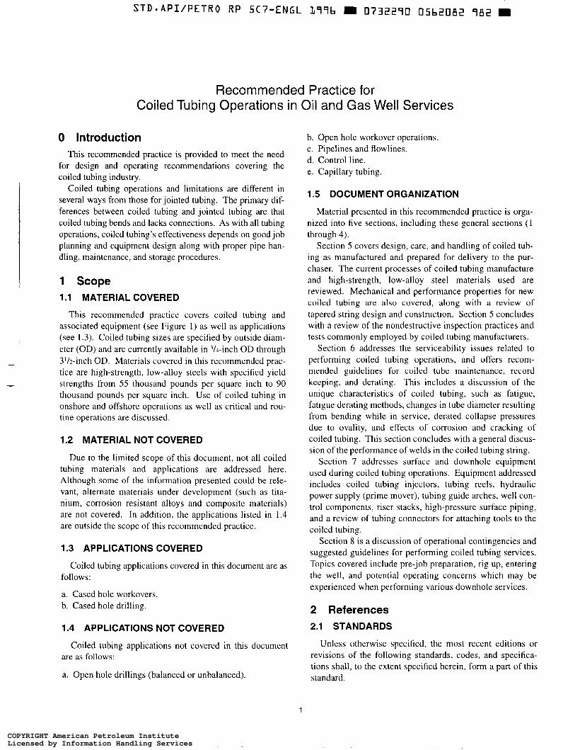
This recommended practice covers coiled tubing and associated equipment (see Figure 1) as well as applications (see 1.3). Coiled tubing sizes are specified by outside diam- eter (OD) and are currently available in 3/1-inch OD through 3'h-inch OD. Materials covered in this recommended prac- tice are high-strength, low-alloy steels with specified yield strengths from 55 thousand pounds per square inch to 90 thousand pounds per square inch. Use of coiled tubing in onshore and offshore operations as well as critical and rou- tine operations are discussed.
1.2 MATERIAL NOT COVERED
Due to the limited scope of this document, not all coiled tubing materials and applications are addressed here. Although some of the information presented could be rele- vant, alternate materials under development (such as tita- nium, corrosion resistant alloys and composite materials) are not covered. In addition, the applications listed in 1.4 are outside the scope of this recommended practice.
1.3 APPLICATIONS COVERED
Coiled tubing applications covered in this document are as follows:
a. Cased hole workovers. b. Cased hole drilling.
1.4 APPLICATIONS NOT COVERED
Coiled tubing applications not covered in this document are as follows:
a. Open hole drillings (balanced or unbalanced).
h. Open hole workover operations. c. Pipelines and flowlines. d. Control line. e. Capillary tubing.
1.5 DOCUMENT ORGANIZATION
Material presented in this recommended practice is orga- nized into five sections, including these general sections (1 through 4).
Section 5 covers design, care, and handling of coiled tub- ing as manufactured and prepared for delivery to the pur- chaser. The current processes of coiled tubing manufacture and high-strength, low-alloy steel materials used are reviewed. Mechanical and performance properties for new coiled tubing are also covered, along with a review of tapered string design and construction. Section 5 concludes with a review of the nondestructive inspection practices and tests commonly employed by coiled tubing manufacturers.
Section 6 addresses the serviceability issues related to performing coiled tubing operations, and offers recom- mended guidelines for coiled tube maintenance, record keeping, and derating. This includes a discussion of the unique characteristics of coiled tubing, such as fatigue, fatigue derating methods, changes in tube diameter resulting from bending while in service, derated collapse pressures due to ovality, and effects of corrosion and cracking of coiled tubing. This section concludes with a general discus- sion of the performance of welds in the coiled tubing string.
Section 7 addresses surface and downhole equipment used during coiled tubing operations. Equipment addressed includes coiled tubing injectors, tubing reels, hydraulic power supply (prime mover), tubing guide arches, well con- trol components, riser stacks, high-pressure surface piping, and a review of tubing connectors for attaching tools to the coiled tubing.
Section 8 is a discussion of operational contingencies and suggested guidelines for performing coiled tubing services. Topics covered include pre-job preparation, rig up, entering the well, and potential operating concerns which may be experienced when performing various downhole services.
2 References 2.1 STANDARDS
Unless otherwise specified, the most recent editions or revisions of the following standards, codes, and specifica- tions shall, to the extent specified herein, form a part of this standard.
1
COPYRIGHT American Petroleum InstituteLicensed by Information Handling ServicesCOPYRIGHT American Petroleum InstituteLicensed by Information Handling Services
-~
STD*API/PETRO RP SC7-ENGL L77b W 0732270 05b2083 817 W
2 API RECOMMENDED PRACTICE 5C7
API Spec 5CT
Spec 5L Spec 6A
Spec 6H
Spec 16A Spec 16C
RP 16E
RP 53
Bu1 5C3
ANSI’ B 1.20.1 B3.1.3
ASME2
ASTM3 A370
A450
El 8
E384
E144 E-94
E-140-88
NACE4 MR-01-75
Specifcation for Casing and Tubing (U.S. Customary Units) Specification for Line Pipe Specification for Valves and Wellhead Equip- ment Specification for End Closures, Connectors, and Swivels Specification for Drill Through Equipment Specification for Choke and Kill Systems Recommended Practice fo r Design of Con- trol Systems for Drilling Well Control Equip- ment Recommended Practice f o r Blowout Pre- vention Equipment Systems f o r Drilling Wells, 2nd Edition, May 1984 Bulletin on Formulas and Calculations for Casing, Tubing, and Drill Pipe
Pipe Threads, General Purpose Chemical Plant and Petroleum Rejînery Piping
Boiler and Pressure Vessel Code
Mechanical Testing of Steel, Steel Products, Annex II-Steel Tubular Products Standard Specification for General Require- ments for Carbon, Ferritic Alloy, andAusten- ìtic Alloy Steel Tubes Standard Methods of Tests for Rockwell Hardness and Rockwell Superjìcial Hard- ness of Metallic Materials Standard Test Method for Microhardness Testing of Materials Hardness Conversion for Metals Guide for Radiographic Testing Standard Hardness Conversion Table for Metals
Suljïde Stress Cracking Resistant Metallic Materials for Oil Field Equipment
2.2 OTHER REFERENCES
1. S.M. Wilhelm, “Galvanic Corrosion in Oil and Gas Pro- duction, Part l-Laboratory Studies,” Corrosion, 1992, Vol- ume 48, Number 8, p. 69 l.
‘American National Standards Institute, I 1 West 42nd Street, New York, NY 10036. 2American Society for Mechanical Engineers, 345 East 47th Street, New York, NY 10017 ’American Society for Testing and Materials, 1 0 0 Bar Harbor Drive, West Conshohocken, PA 19428. *National Association of Corrosion Engineers International, P.O. Box 218340, Houston, TX 77218-8340.
2. M. Bonis and J.L. Crolet, “Practical Aspects of In Situ pH on H2S Induced Cracking.” Corrosion Science, 1987, Volume 27, Number 10.1 1 , p. 1059. 3. A. Ikeda, et al, “Corrosion Behavior of Low and High Alloy Tubular Products in Completion Fluids for High Tem- perature Deep Well”, Corrosion, 1992, Paper No. 46, NACE4, Houston, Texas, April 1992. 4. M.L. Walker and K.R. Lancaster, Coiled Tubing Acid Related Corrosion Proceedings, 3rd International H2S Mate- rials and Corrosion Conference, Corrosion Laboratories, Inc., Houston, Texas, May 1993. 5. T. Taira, et al, “Resistance of Pipeline Steels to Wet Sour j Gas,” Current Solutions to Hydrogen Problems in Steels, 1982, American Society for Metals, Metals Park, Ohio, p. 173. 6. T. Kushida and T. Kudo, “Hydrogen Induced Cracking Observed by the In Situ HIC Measurement Method,” Corro- sion Engineering, Volume 40, 199 1, p. 7 1 l . 7. J.F. Bates, “Sulfide Cracking of High Yield Strength Steels in Sour Crude Oils,” Materials Protection, 1969, Volume 8, Number 1, p. 33.
3 Coiled Tubing Advantages and Limitations
~
I
3.1 ADVANTAGES 1 -
The ability to deploy coiled tubing provides several advan- - tages including the following:
a. Work on live wells (pressure at surface). b. Efficient well entry. c. Quick rig up. d. Small surface footprint as compared to workover rig. e. Efficient offshore mobilization (modular components). f. Fast entry and withdrawal from wells. g. Continuous circulation of fluids throughout the well service. h. Performing work while the well is producing. i. No threaded connections to complicate pressure seals and well control during operation. j. Flush outside diameters. k. Ability to deploy many tools adapted from workover, drilling, and wireline operations. 1. Adaptation to permanent completions.
3.2 LIMITATIONS
Growth in the coiled tubing industry has been facilitated by a better understanding of coiled tubing limitations and inno- vative adaptation of the technology. The bending radii and surface equipment used stress the coiled tubing beyond its yield strength, causing plastic deformation. This planned yielding of pipe is unique in oil-field operations. Limita- tions of current coiled tubing service operations include the following:
COPYRIGHT American Petroleum InstituteLicensed by Information Handling ServicesCOPYRIGHT American Petroleum InstituteLicensed by Information Handling Services

STD.API/PETRO RP 5C7-ENGL L79b D 0732270 05b208LI 755 m
RECOMMENDED PRACTICE FOR COILED TU6lNG OPERATIONS IN OIL AND GAS WELL SERVICES 3
Stripper assembly
Well control stack
Wellhead valve
Figure 1-Typical Coiled Tubing Unit Modular Components
a. Ultralow cycle fatigue cracking. b. Diametral growth (ballooning). c. Mechanical damage from handling and use. d. Environmental damage from acid, oxygen, or other substances. e. New pipe operational limits due to pipe strength in burst, collapse, tension, or buckling. f. Uncertainties in derating used coiled tubing. g. Difficulties in tube-to-tube butt welding. h. Operational limits of surface equipment for well control working pressure, push or pull loads, allowable pipe defor- mation, and tool lubricators. i. Downhole operational limits for pushing or pulling loads, frictional pressure losses through the tubing string, and collapse resistance due to ovality of the coiled tubing.
Failure modes and reasons for some past failures are as follows:
a. b. C.
d. e. f. g. h.
Tensile yielding. Burst and collapse (wall loss or cracking). Fatigue cracking. Leaks (corrosion). Buckling. Ballooning (work hardening or softening). Plugging. Using tubing not fit for the service (improper working
pressure ratings or excessive fatigue cracking due to bend- ing/pressure cycles). i. Mechanical damage to the tubing (improper injection head procedures or downhole conditions).
j . Inadequate welding practices or quality control. k. Lack of derating for field welds.
4 As-Manufactured Coiled Tubing 4.1 INTRODUCTION
Factors affecting coiled tubing performance are presented in this section. Particular topics include manufacturing, steel composition, properties and testing, and inspection. The information presented here is considered proven technology.
4.2 PROCESS OF MANUFACTURE
4.2.1 Description
Coiled tubing is electric-welded pipe manufactured in a tube mill with one longitudinal seam formed by high-fre- quency induction welding without the addition of filler metal. A flat strip is formed into a round shape in preparation for welding. The edges to be welded are mechanically pressed together, and the heat for welding is generated by the resis- tance to flow of electric current. Sizing to the final diameter is accomplished in the tube-forming line by slightly reducing the diameter after welding.
4.2.2 Length
The length of the flat strip material may be in excess of 3,000 feet and a spool of coiled tubing may be in excess of 20,000 feet. Long coiled tubing spools can be manufactured by welding the lengths of flat strip together prior to forming
COPYRIGHT American Petroleum InstituteLicensed by Information Handling ServicesCOPYRIGHT American Petroleum InstituteLicensed by Information Handling Services
STD-APIIPETRO RP SC7-ENGL L77b 0732290 05b2085 b7L m
4 API RECOMMENDED PRACTICE 5C7
the tube. Coiled tubing can also be tube-to-tube butt-welded to desired lengths.
4.2.3 Heat Treatment
Subsequent to welding, the coiled tubing should be heat treated by one or more of the following methods to achieve the final mechanical properties:
a. The coiled tubing weld seam is annealed (minimum tem- perature of 1600°F) and stress relieved, typically in the tube mill line immediately after welding. b. The coiled tubing is full body stress relieved. c. The coiled tubing is quenched and tempered.
4.2.4 Tapered Strings
Tapered strings of coiled tubing can be manufactured by changing the wall thickness of the tubing within the length of a spool while maintaining a constant outside diameter. This is done to increase the performance properties of the coiled tubing in selected sections while minimizing the total weight of the string. Tapered coiled tubing strings are dis- cussed in 4.8.
4.2.5 Spool Documentation
Spools of coiled tubing should be identified by a unique identification number which is assigned at the time of man- ufacture. Documentation for each spool of coiled tubing should include the number, outside diameter, grade, wall thickness(es), length, and weld positions. A spool of coiled tubing may be manufactured from one heat or a combina- tion of heats that are selected according to a documented procedure.
4.2.6 Traceability
Traceability of coiled tubing should be maintained by the manufacturer throughout the manufacturing and testing pro- cess. Purchaser requirements often include traceability to the heat of steel.
4.3 COILED TUBING MATERIAL
4.3.1 Characteristics
High-strength, low-alloy steels are commonly used to achieve the desired weldability, corrosion resistance, fatigue resistance, and mechanical properties. The hot-rolled steels are manufactured using fine grain practices.
4.3.2 Ladle Chemistry
Commonly used ladle chemistries are modified ASTM A606 Type 4 and modified ASTM A607, as shown in Table l . The ranges shown in Table 1 are a composite of the values offered by the manufacturers surveyed.
4.4 MECHANICAL PROPERTIES
Mechanical properties of coiled tubing should be provided for each spool of coiled tubing by the manufacturer. The mechanical properties reported are for the tubing prior to spooling or any service-induced cold work. Spooling and service conditions can alter the degree of cold work and hence the actual mechanical properties of a coiled tubing string. The minimum tensile properties for commonly used grades are shown in Table 2.
4.4.1 Yield Strength
The yield strength of new coiled tubing is determined by either the tensile stress at which the strain in the gauge length exhibits a 0.2 percent offset, or the tensile stress required to produce an extension under load of 0.5 percent.
4.4.2 Tensile Strength
The tensile strength is the tensile stress corresponding to the maximum load in a tensile test of the gauge section, and shall meet the manufacturer’s written specification or the requirements of Table 2, whichever is greater.
4.4.3 Ductility
Ductility of coiled tubing is the percent elongation of a 2-inch gauge length in a tensile test. The minimum elonga- tion required for each grade, weight, size (outside diameter), and wall thickness shall be in accordance with the manufac- turer’s written specification.
4.4.4 Hardness
The maximum hardness of coiled tubing is specified to reduce the susceptibility to sulfide stress cracking per NACE MR-01-75. The maximum allowable hardness is HRC 22 for standard coiled tubing grades as shown in Table 2.
4.4.5 Impact Toughness
Standard Charpy V-notch testing is not applicable to coiled tubing, due to the low thickness of the tubing. Toughness of the coiled tubing is enhanced by the steel manufacturing process. Typically, the steel is fully killed, made to fine grain practice, and the sulfur content is limited to 0.005 percent. These steps provide the steel with inherent toughness to resist brittle failure.
Other inspection procedures, (such as electromagnetic, radiographic, flaring, hydrostatic pressure testing, and coil- ing) are used to detect flaws in the product which could affect performance.
4.5 MECHANICALTESTING PROCEDURES Note: The mechanical properties do not necessarily remain the same after spooling.
COPYRIGHT American Petroleum InstituteLicensed by Information Handling ServicesCOPYRIGHT American Petroleum InstituteLicensed by Information Handling Services
STD.API/PETRO RP 5C7-ENGL L 7 9 b m 0732290 05b208b 528 m
RECOMMENDED PRACTICE FOR COILED TUBING OPERATIONS IN OIL AND GAS WELL SERVICES 5
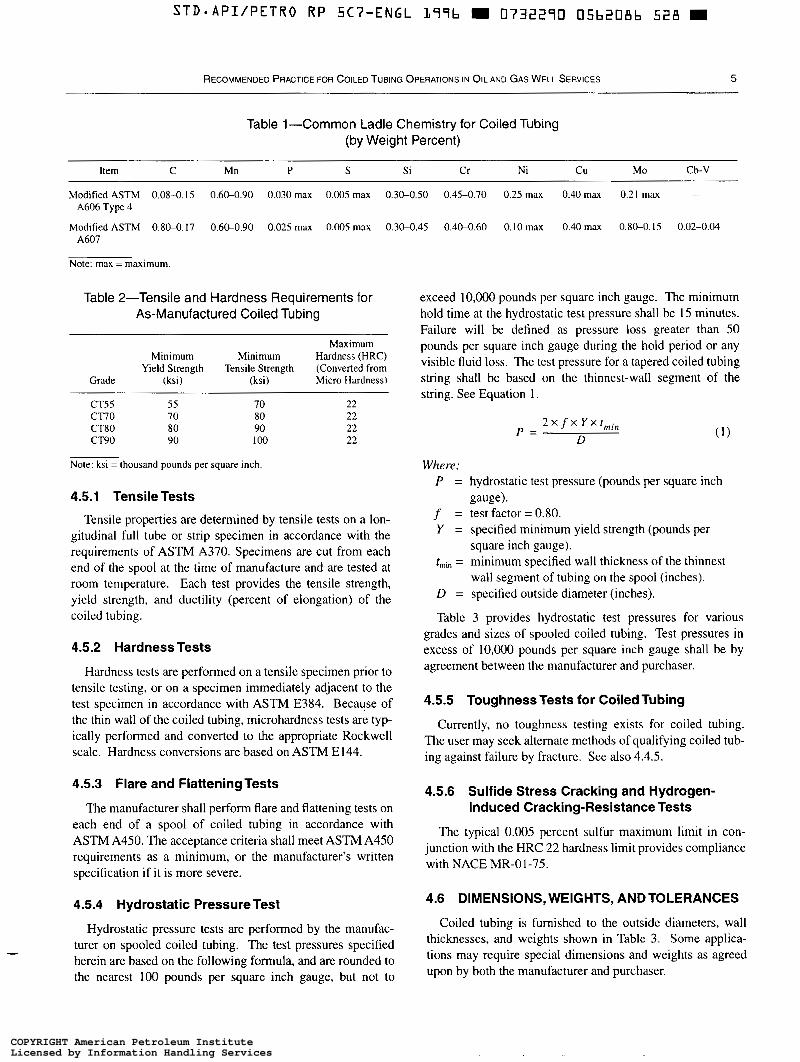
Table 1-Common Ladle Chemistry for Coiled Tubing (by Weight Percent)
Item C Mn P S Si Cr Ni Cu Mo Cb-V
Modified ASTM 0.08-0.15 0.60-0.90 0.030 rnax 0.005 max 0.30-0.50 0.45-0.70 0.25 rnax 0.40 rnax 0.21 rnax A606 Type 4
-
Modified ASTM 0.80-0.17 0.6M.90 0.025 rnax 0.005 rnax 0.3M.45 0.40-0.60 0.10 max 0.40 rnax 0.80-0.15 0.02-0.04 A607
Note: rnax = maximum.
Table 2-Tensile and Hardness Requirements for As-Manufactured Coiled Tubing
Maximum Minimum Minimum Hardness (HRC)
Grade Yield Strength Tensile Strength (Converted from
(ksi) (ksi) Micro Hardness)
CTSS 55 70 22 CT70 70 80 22 CT80 80 90 22 CT90 90 1 0 0 22
Note: ksi = thousand pounds per square inch
4.5.1 Tensile Tests
Tensile properties are determined by tensile tests on a lon- gitudinal full tube or strip specimen in accordance with the requirements of ASTM A370. Specimens are cut from each end of the spool at the time of manufacture and are tested at room temperature. Each test provides the tensile strength, yield strength, and ductility (percent of elongation) of the coiled tubing.
4.5.2 Hardness Tests
Hardness tests are performed on a tensile specimen prior to tensile testing, or on a specimen immediately adjacent to the test specimen in accordance with ASTM E384. Because of the thin wall of the coiled tubing, microhardness tests are typ- ically performed and converted to the appropriate Rockwell scale. Hardness conversions are based on ASTM E144.
4.5.3 Flare and Flattening Tests
The manufacturer shall perform flare and flattening tests on each end of a spool of coiled tubing in accordance with ASTM A450. The acceptance criteria shall meet ASTM A450 requirements as a minimum, or the manufacturer's written specification if it is more severe.
4.5.4 Hydrostatic PressureTest
exceed 10,OOO pounds per square inch gauge. The minimum hold time at the hydrostatic test pressure shall be 15 minutes. Failure will be defined as pressure loss greater than 50 pounds per square inch gauge during the hold period or any visible fluid loss. The test pressure for a tapered coiled tubing string shall be based on the thinnest-wall segment of the string. See Equation l .
P = 2 x f X Y X t r n i , ,
D
Where: P = hydrostatic test pressure (pounds per square inch
f = test factor = 0.80. Y = specified minimum yield strength (pounds per
t,,, = minimum specified wall thickness of the thinnest
D = specified outside diameter (inches).
Table 3 provides hydrostatic test pressures for various grades and sizes of spooled coiled tubing. Test pressures in excess of 10,OOO pounds per square inch gauge shall be by agreement between the manufacturer and purchaser.
gauge).
square inch gauge).
wall segment of tubing on the spool (inches).
4.5.5 Toughness Tests for Coiled Tubing
Currently, no toughness testing exists for coiled tubing. The user may seek alternate methods of qualifying coiled tub- ing against failure by fracture. See also 4.4.5.
4.5.6 Sulfide Stress Cracking and Hydrogen- Induced Cracking-ResistanceTests
The typical 0.005 percent sulfur maximum limit in con- junction with the HRC 22 hardness limit provides compliance with NACE MR-01-75,
4.6 DIMENSIONS, WEIGHTS, AND TOLERANCES
Hydrostatic pressure tests are performed by the manufac- Coiled tubing is furnished to the outside diameters, wall
turer on spooled coiled tubing, The test pressures specified weights shown in Table 3. 'Orne applica-
herein are based on the following formula, and are rounded to tions may require 'Pecia1 dimensions and weights as agreed
the nearest 100 pounds per square inch gauge, but not to 'pon by both the manufacturer and purchaser.
COPYRIGHT American Petroleum InstituteLicensed by Information Handling ServicesCOPYRIGHT American Petroleum InstituteLicensed by Information Handling Services
6 API RECOMMENDED PRACTICE 5C7
4.6.1 Diameter
Outside diameter is determined by a caliper-type measure- ment. Tolerances typically specified before spooling are f 0.010 inch. Coiled tubing is spooled during manufacturing, which distorts the tube and may affect the outside diameter and ovality. The user should take such factors into account in the design and use of coiled tubing.
4.6.2 Wall Thickness
Each length of coiled tubing shall be measured for con- formance to wall-thickness requirements. The wall thickness at any place shall not vary from the specified thickness, t , by more than the permissible tolerance specified below:
Wall thicknesses below -0.005 inch +0.010 inch O. 1 10 inch
0.1 10 inch or greater Wall thicknesses of -0.008 inch +0.012 inch
4.6.3 Weight
Weights shall be calculated using the theoretical density of the steel, the specified wall thickness, and specified outside diameter of the tube. See Equation 2.
W = 1 0 . 6 8 x ( D - t ) x t (2)
Where:
W = plain end weight (pound/foot). D = specified outside diameter (inches). t = specified wall thickness (inches).
4.6.4 Length
Lengths shall be measured during manufacturing. Measur- ing instruments used in manufacturing should be accurate to f 1 percent.
4.6.5 Weld Flash
The external weld flash on the coiled tubing is removed. Coiled tubing may be supplied with the internal weld flash removed, depending upon the manufacturer’s capability and the purchase order. When the internal weld flash is not removed, the maximum height of the weld flash shall not exceed the value of the minimum wall thickness of the tube.
4.6.6 Capacity
Capacity (V,) is the unit volume of fluid contained inside the coiled tubing. See Equation 3.
V , = 0.0009714 X d 2 (3)
Where:
V, = internal capacity per foot (barrelslfoot).
d = D- 2t (inches). D = specified outside diameter (inches). t = specified wall thickness (inches).
4.6.7 Displacement
Displacement (V,) is the equivalent unit volume of fluid that will be displaced by the cross-sectional area of the coiled tubing body upon insertion into a filled well. See Equation 4.
V, = 0.0009714 X (DL - dL) (4)
Where:
V , = body displacement per foot (barrelslfoot). D = specified outside diameter (inches). d = D - 2t (inches). t = specified wall thickness (inches).
External displacement (V,) is the equivalent unit volume of fluid that will be displaced by insertion of a closed-end string of coiled tubing into a filled well. See Equation 5.
V , = O.OO09714 X LI2 ( 5 )
Where:
V, = tube displacement per foot (barrelslfoot). D = specified outside diameter (inches).
4.6.8 Drift Ball
When specified on the purchase order by the purchaser, the manufacturer should drift the coiled tubing to a specification agreed upon by the manufacturer and purchaser.
4.7 PROPERTIES OF NEW COILEDTUBING
4.7.1 Collapse Pressure (Round Tube Without Axial Stress)
The collapse pressure (in the absence of axial stress and internal pressure), P,, for as-manufactured coiled tubing is calculated using the appropriate formula of API Bulletin 5C3 for yield strength, plastic or transition collapse pressure. If the coiled tubing Dl?,,,¡, ratio is less than the Dlt,,, ratio as shown in API Bulletin 5C3, Table 4, Column 2, then the col- lapse pressure can be estimated using Figure 2 as a function of Olt,,,,, and minimum yield strength, Y Cases where axial load is combined with external pressure, P, are discussed in 5.7.
4.7.2 Pipe Body Yield Load
The pipe body yield loud is defined as the axial tension load (in the absence of pressures or torque) which produces a stress in the tube equal to the specified minimum yield strength (Y) in tension. See Equation 6.
COPYRIGHT American Petroleum InstituteLicensed by Information Handling ServicesCOPYRIGHT American Petroleum InstituteLicensed by Information Handling Services

STD.API/PETRO RP 5C7-ENGL L79b m 0732290 05b2088 3 T O
RECOMMENDED PRACTICE FOR COILED TUBING OPERATIONS IN OIL AND GAS WELL SERVICES 7
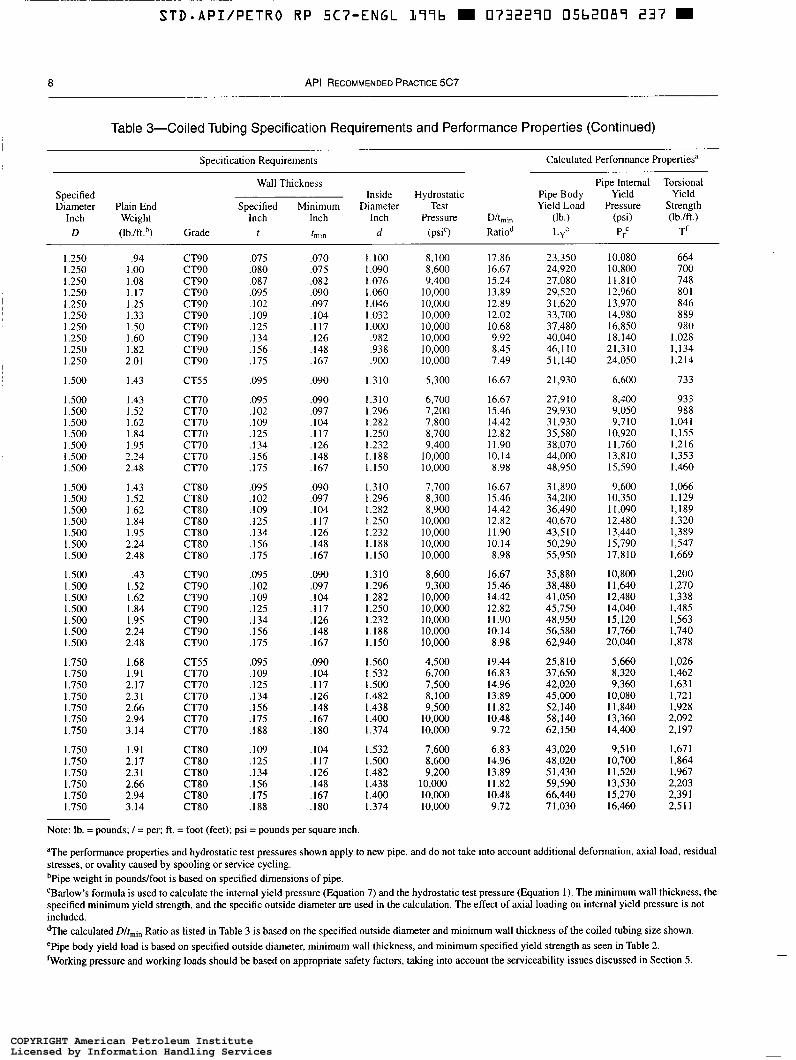
Table 3-Coiled Tubing Specification Requirements and Performance Properties
Specification Requirements Calculated Performance Propertiesa
Wall Thickness Specified Diameter Plain End
Pipe Internal Torsional Pipe Body Yield Yield
Inch Weight Inch Inch Inch Pressure D/tmi, (lb.) (psi) Yield Load Pressure Strength
(Ib./ft.)
Inside Hydrostatic Specified Minimum Diameter Test
D (Ib./ft.h) Grade r hm d (psi') Ratiod L,' Pr' T1
,750
1.000
1.000 I.000 I .o00 1.000 1.000 1.000 I .o00 I .o00 1.000 I .o00 I .o00 I .o00 1.000 I .o00 I.000 1.000 I .o00 I .O00 1.000 1 ,000 1 .o00
1.250
1.250 1.250 I .250 1.250 1.250 I .250 1.250 1.250 1.250 1.250
1.250 1.250 1.250 1.250 1.250 1.250 1.250 1.250 1.250 1.250
.S9
.8 I
.74
.79
.85
.92
.98 1 .o4 1.17
.74
.79
.85
.92
.98 1 .O4 1.17
.74
.79
.85
.92
.98 1 .O4 1.17
1 .O3
.94 I .00 I .O8 1.17 I .25 1.33 I .50 I .60
2.01 I .82
.94 1 .00 1 .O8 1.17 1.25 1.33 1 .so 1.60 I .82 2.01
CT55
CTSS
CT70 CT70 CT70 CT70 CT70 CT70 CT70
CT80 CT80 CT80 CT80 CT80 CT80 CT80
CT90 CT90 CT90 CT90 CT90 CT90 CT90
CT55
CT70 CT70 CT70 CT70 CT70 CT70 CT70 CT70 CT70 CT70
CT80 CT8O CT8O CT8O CT80 CT80 CT80 CT80 CT80 CT80
.O83
.O83
.O75
.O80
.O87
.O95 ,102 ,109 .I25
.O75
.O80
.O87
.O95
. I02
. I09 ,125
,075 .O80 .O87 .O95 . I02 . I09 . I25
.O83
.O75
.O80
.O87 ,095 . IO2 .IO9 .I25 ,134 . I 56 .I75
.O75
.O80
.O87
.O95
. I02 ,109 . I25 . I34 . I 56 .I75
.O78
.O78
.O70
.O75
.O82
.o90
.O97 ,104 . I17
,070 .O75 .O82 .O90 .O97 ,104 . I 17
.O70
.O75
.O82
.o90
.o97
.I04
. I 17
.O78
.O70
.O75
.O82 ,090 .O97 . l o 4 . I 17 . I26 . I48 ,167
.O70
.O75
.O82
.o90
.O97
.IO4
. I 17
. I26 ,148 . I67
S84
,834
,850 .840 .S26 .S10 ,796 ,782 ,750
350 ,840 326 .S 10 .796 ,782 ,750
,850 ,840 ,826 ,810 .796 .782 ,750
I .O84
1.100 I .O90 1 .O76 1 .O60 1.046 1.032 1 .o00 ,982 ,938 ,900
1 . 1 0 0 I .O90 I .O76 1.060 I .O46 I .O32 I .o00 .982 .938 .900
9,200
6,900
7,800 8,400 9,200
I O , 0 0 0 I O , 0 0 0 10,000 10,000
9,000 9,600
10,000 10,000 10,000 10,000 10.000
10.000 I0,000 10,000 I O , 0 0 0 I O , 0 0 0 I O , 0 0 0 10,000
5,500
6,300 6,700 7,300 8,100 8,700 9,300
10,000 I0,ooO I0,OOo IO,000
7,200 7,700 8,400 9,200 9,900
10,000 10,000 10,000 10,000 10,000
9.62
12.82
14.29 13.33 12.20 1 1 . 1 1 10.31 9.62 8.55
14.29 13.33 12.20 1 1 . 1 1 10.3 I 9.62 8.55
14.29 13.33 12.20 1 1 . 1 1 10.31 9.62 8.55
16.03
17.86 16.67 15.24 13.89 12.89 12.02 10.68 9.92 8.45 7.49
17.86 16.67 15.24 13.89 12.89 12.02 10.68 9.92 8.45 7.49
9,060
12,430
14,320 15,260 16,550 18,010 19,260 20.490 22.720
16,360 I 7,440 18,920 20,580 22,010 23,420 25,960
8,410 19,620 2 1.280 23,160 24,770 26,350 29,210
15,800
18,160 19,380 2 1,060 22,960 24.600 26.2 I 0 29.150 31.140 35,870 39,770
20,760 22,150 24,070 26,240 28,110 29,950 33,320 35,590 40,990 45,460
1 1.440
8,580
9,800 10.500 I 1,480 12.600 13.580 14,560 16,380
I 1,200 12,000 13,120 14,400 I5.520 16,640 18,720
12.600 13.500 14,760 16,200 17,460 18,720 2 1,060
6,860
7,840 8.400 9, I80
10,080 10,860 11,650 13,100 14,l I O 16,580 18,700
8,960 9,600
10,500 1 1.520 12.420 13,310 14,980 16,130 18,940 21,380
138
268
316 332 353 376 395 414 452
36 I 379 403 430 452 473 516
406 426 454 484 508 532 58 I
440
517 544 582 623 658 69 I 762 799 882 944
622 590
665 712 752 790 87 1 913
1,008 1,079
'The performance properties and hydrostatic test pressures shown apply to new pipe, and do not take into account additional deformation, axial load, residual stresses, or ovality caused by spooling or service cycling. bPipe weight in pounds/foot is based on specified dimensions of pipe. 'Barlow's formula is used to calculate the internal yield pressure (Equation 7) and the hydrostatic test pressure (Equation I ) . The minimum wall thickness, the specified minimum yield strength, and the specific outside diameter are used in the calculation. The effect of axial loading on internal yield pressure is not included. dThe calculated D/t,,,in Ratio as listed in Table 3 is based on the specified outside diameter and minimum wall thickness of the coiled tubing size shown. 'Pipe body yield load is based on specified outside diameter, minimum wall thickness, and minimum specified yield strength as seen in Table 2. 'Working pressure and working loads should be based on appropriate safety factors, taking into account the serviceability issues discussed in Section 5 .
COPYRIGHT American Petroleum InstituteLicensed by Information Handling ServicesCOPYRIGHT American Petroleum InstituteLicensed by Information Handling Services
8 API RECOMMENDED PRACTICE 5C7
Table 3-Coiled Tubing Specification Requirements and Performance Properties (Continued) I
Specification Requirements Calculated Performance Properties”
Wall Thickness Pipe Internal Torsional Specified Inside Hydrostatic Pipe Body Yield Yield Diameter Plain End Specified Minimum Diameter Test Yield Load Pressure Strength
Inch Weight Inch Inch D (Ib./ft.h) Grade t t m n
1.250 1.250 I .250 I .250
1.250 I .250 I .250 I .250 I .250
I S00
I S00 I S00 I S00 I S00 I S00 I S00 I S00
1.500 I S00 1.500 1.500 1 S00 1.500 1.500
1.500 1.500 1.500 1.500 1.500 1 SOO 1.500
1.750 1.750 1.750 1.750 1.750 1.750 1.750
1.750 1.750 1.750 1.750 1.750 1.750
~ I .250
~
.94 1 .o0 1 .O8 1.17 I .25 1.33 1 S O I .60 1 .82 2.01
1.43
1.43 I .52 1.62 1 .84 1.95 2.24 2.48
1.43 I .52 I .62 1.84 I .95 2.24 2.48
.43 1.52 I .62 I .84 I .95 2.24 2.48
1.68 1.91 2.17
2.66 2.3 I
2.94 3.14
1.91 2.17 2.3 I 2.66 2.94 3.14
CT90 CT90 CT90 CT90 CT90 CT90 CT90 CT90 CT90 CT90
CT55
CT70 CT70 CT70 CT70 CT70 CT70 CT70
CT80 CT80 CT80 CT80 CT80 CT80 CT80
CT90 CT90 CT90 CT90 CT90 CT90 CT90
CT55 CT70 CT70 CT70 CT70 CT70 CT70
CT80 CT80 CT80 CT80 CT80 CT80
.O75
.O80
.O87
.O95
. IO2
.I09 ,125 .I34 ,156 ,175
.O95
.O95 ,102 ,109 ,125 . I34 .I56 .I75
.O95
. I02
.I09
.I25 ,134 ,156 ,175
.O95
.IO2
. I 09
.I25 ,134 .I56 .I75
.O95 ,109 .I25 ,134 . I56 .I75 . I88
, 1 0 9 .I25 .I34 . I56 . I75 . I88
.O70
.O75
.O82 ,090 .O97 . I04 ,117 . I26 ,148 . I67
,090
,090 .O97 . I04 ,117 . I26 ,148 . I67
.O90
.O97
. I 04 ,117 . I26 ,148 . I67
.O90 ,097 . I04 ,117 ,126 . I48 . I67
,090 ,104 ,117 . I26 ,148 . I67 ,180
,104 ,117 .I26 ,148 ,167 ,180
1.100 I .o90 1 .O76 1.060 I .O46 I .O32 I ,000 .982 ,938 .900
1.310
1.310 1.296 I .282 1.250 I .232 1.188 1.150
1.310 I .296 I .282 I .250 I .232 1.188 1.150
1.310 I .296 1.282 I .250 1.232 1.188 1.150
1.560
I S O O 1.532
1.482 I .438 I .400 1.374
I S32 I S O O 1.482 I .438 1.400 1.374
8,100 8,600 9,400
10,000 IO,O00 10,000 10,000 10,000 10,000 I0,ODO
5,300
6,700 7,200 7,800 8,700 9,400
10,000 10,000
7,700 8,300 8,900
10.000 10,000 10.000 10,000
8,600 9,300
10,000 10,000 10,000 10,ooo 10,ooo
4,500 6,700 7,500 8,100 9,500
10,000 10,000
7,600 8,600 9,200
I0,Ooo 10,000 10,000
17.86 16.67 15.24 13.89 12.89 12.02 10.68 9.92 8.45 7.49
16.67
16.67 15.46 14.42 12.82 11.90 10.14 8.98
16.67 15.46 14.42 12.82 11.90 10.14 8.98
16.67 15.46 14.42 12.82 11.90 10.14 8.98
19.44 16.83 14.96 13.89 1 I .82 10.48 9.72
6.83 14.96 13.89 1 I .82 10.48 9.72
23,350 24,920 27,080 29,520 3 1,620 33,700 37,480 40,040 46.1 I O 51,140
2 1,930
27,9 I O 29,930 3 1.930 35,580 38,070 44,000 48,950
3 1,890 34,200 36,490 40,670 4 3 5 10 50,290 55,950
35,880 38,480 4 1,050 45,750 48,950 56,580 62,940
25,810 37,650 42,020 45,000 52,140 58,140 62, I50
43,020 48,020 5 1,430 59,590 66,440 7 1,030
10,080 10,800 11,810 12,960 13,970 14,980 16,850 18,140 21,310 24,050
6,600
8,400 9,050 9.7 I O
10,920 1 1,760 13,810 15,590
9,600 10,350 11,090 12,480 13,440 15,790 17,810
10,800 I 1,640 12,480 14,040 15,120 17,760 20,040
5,660 8,320 9,360
10,080 1 1,840 13,360 14,400
9,510 10,700 I 1,520 13,530 15,270 16,460
664 700 748 80 1 846 889 980
1,028 1,134 1,214
733
933 988
1,041 1,155 1,216 1,353 1.460
1,066 1,129 1,189 1,320 1,389 1,547 1,669
1,200 1,270 1,338 1,485 1,563 1.740 1,878
1,026 1,462 1,631 I ,72 1 1,928 2,092 2,197
1,864 1,671
1,967 2,203 2,39 1 2.51 1
Note: lb. = pounds; / = per; ft. = foot (feet); psi = pounds per square inch
aThe performance properties and hydrostatic test pressures shown apply to new pipe, and do not take into account additional deformation, axial load, residual stresses, or ovality caused by spooling or service cycling. bPipe weight in pounds/foot is based on specified dimensions of pipe. CBarlow’s formula is used to calculate the internal yield pressure (Equation 7) and the hydrostatic test pressure (Equation 1). The minimum wall thickness, the specified minimum yield strength, and the specific outside diameter are used in the calculation. The effect of axial loading on internal yield pressure is not included. dThe calculated D/rmin Ratio as listed in Table 3 is based on the specified outside diameter and minimum wall thickness of the coiled tubing size shown.
body yield load is based on specified outside diameter, minimum wall thickness, and minimum specified yield strength as seen in Table 2. ‘Working pressure and working loads should be based on appropriate safety factors, taking into account the serviceability issues discussed in Section 5.
COPYRIGHT American Petroleum InstituteLicensed by Information Handling ServicesCOPYRIGHT American Petroleum InstituteLicensed by Information Handling Services
STD-APIIPETRO RP 5C7-ENGL L79b m 0732270 05bZ.070 T 5 7 m
RECOMMENDED PRACTICE FOR COILED TUBING OPERATIONS IN OIL AND GAS WELL SERVICES 9
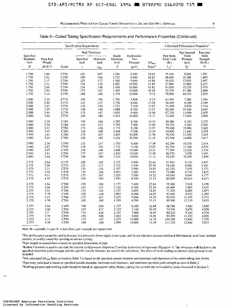
Table 3-Coiled Tubing Specification Requirements and Performance Properties (Continued)
Specification Requirements Calculated Performance Propertiesa
Wall Thickness Specified
Pipe Internal Torsional Inside Hydrostatic Pipe Body Yield Yield
Diameter Plain End Specified Minimum Diameter Test Yield Load Pressure Strength Inch Weight Inch Inch Inch Pressure D/t,,, (lb.) (psi) (Ib./ft.) D (Ib./ft.’) Grade t tmm d (psi‘) Ratiod LYC P: T’
1.750 1.750 1.750 1.750 1.750 1.750 1.750
2.000 2.000 2.000 2.000 2.000 2.000
2.000 2.000 2.000 2.000 2.0(x) 2.000
2.000 2.000 2.Ooo 2.000 2 . m
2.375 2.375 2.375 2.375 2.375 2.375
2.375 2.375 2.375 2.375 2.375 2.375
2.375 2.375 2.375 2.375 2.375 2.375
1 .S0 1.91 2.17 2.3 1 2.66 2.94 3.14
2.20 2.50 2.67 3 .O7 3.41 3.64
2.20 2.50 2.67 3 .O7 3.41 3.64
2.67 2.50
3.07 3.4 I 3.64
2.64 3.00 3.2 I 3.70 4.1 I 4.39
2.64
3.2 I 3.00
3.70 4.1 I 4.39
2.64 3.00 3.2 3.70 4.1 I 4.39
CT90 CT9O CT90 CT90 CT90 CT90 CT90
CT70 CT70 CT70 CT70 CT70 CT70
CT80 CT80 CT80 CT80 CT80 CT80
CT90 CT90 CT90 CT90 CT90
CT70 CT70 CT70 CT70 CT70 CT70
CT80 CT80 CT80 CT80 CT80 CT80
CT90 CT90 CT90 CT90 CT90 CT90
,102 ,109 .I25 . I 34 ,156 .I75 ,188
.I09
.I25 - 1 34 . I 56 .I75 ,188
,109 ,125 . I 34 ,156 .I75 .I88
. I25
.I34
. I 56 ,175 . I88
. I09
.I25
. I34
. I 56
.I75
.I88
. I09
. I25
. I34
. I 56
. I75
. I 88
. I09
. I25
. I34 ,156 .I75 . I88
,097 ,104 . I 17 . I26 . I48 ,167 . I80
. I04 ,117 . I26 . I48 ,167 ,180
. I 04
. I 17
. I26 ,148 ,167 ,180
,117 . I26 ,148 . 167 . I80
. I04 ,117 ,126 ,148 . I67 ,180
. I 04
. I 17
. I26 ,148 ,167 . I80
. I04
.I 17 ,126 ,148 ,167 . I80
I .546 I .532 I S00 I .482 1.438 I .400 I .374
1.782 1.750 1.732 1.688 1.650 1.624
1.782 1.750 1.732 1.688 1.650 1.624
1.750 1.732 1.688 1.650 1.624
2.157 2.125 2. I07 2.063 2.025 1.999
2.157 2.125 2.107 2.063 2.025 1.999
2.157 2.125 2. I07 2.063 2.025 1.999
8,000 8,600 9,600 10,000 10.000 10,000 10,000
5,800 6,600 7,l 00 8,300 9,400 10,m
6.700 7,500 8,100 9,500
10,000 10.000
8,400 9,100
l0.000 1 o.Oo0 10.000
4,900 5,500 5,900 7,000 7,900 8,500
5,600 6,300 6,800 8,000 9,000 9,700
6,300 7,100 7,600 9,000
I0,000 I 0 , m
18.04 16.83 14.96 13.89 1 I .82 10.48 9.72
9.23 17.09 15.87 13.5 I I I .98 1 1 . 1 I
19.23 17.09
13.5 I 1 1.98 1 1 . 1 1
I7 .O9 15.87 13.51 I 1.98 1 1 . 1 1
22.84 20.30 18.85
14.22 16.05
13.19
22.84 20.30 18.85 16.05 14.22 13.19
22.84 20.30 18.85 16.05 14.22 13.19
15.87
45,340 48,400 54,020 57,860 67,040 74,750 79,900
43,360 48,450 5 1,930 60,280 67,320 72,040
49,560 55,370
68,890 59,340
76,930 82,340
62,290 66,760 77,500 86,550 92,630
5 1.940 58.100 62.320 72,480 X 1,090 86,890
59,360 66,400 7 1,220 82,840 92,670 99,300
66,780 74,700 80,120 93,190 104,260 1 11,710
9,980 10,700 12,030 12,960 15,220 17,180 18.5 10
7,280 8,190 8.820 10,360 1 1.690 12,600
8,320
10.080 9.360
I 1,840 13,360 14,400
10,530 I 1,340 13,320 5,030 16,200
6,130 6,900 7,430 8,720 9.840 10,610
7,010 7,880 8,490 9,970
1 1,250 12,130
7,880 8.870
I 1.220 9,550
12,660 13,640
1,78 I 1,880 2.097 2.2 13 2.479 2,690 2,825
1,956 2,189 2.3 14 2,605 2,839 2,990
2,235 2,502 2,645 2,978 3,245 3,417
2,814 2,976 3,350 3.65 1 3,844
2.83 1 3,181 3,371
4,177 3,815
4,413
3,236 3,635 3,853 4,360 4,773 5,043
3,640 4,090 4,334 4,905 5,370 5.673
Note: lb. = pounds; / = per; ft. = foot (feet); psi = pounds per square inch
aThe performance properties and hydrostatic test pressures shown apply to new pipe, and do not take into account additional deformation, axial load, residual stresses, or ovality caused by spooling or service cycling. bPipe weight in pounds/foot is based on specified dimensions of pipe CBarlow’s formula is used to calculate the internal yield pressure (Equation 7) and the hydrostatic test pressure (Equation I ) . The minimum wall thickness, the specified minimum yield strength, and the specific outside diameter are used in the calculation. The effect of axial loading on internal yield pressure is not included. dThe calculated Dlt,,, Ratio as listed in Table 3 is based on the specified outside diameter and minimum wall thickness of the coiled tubing size shown. ePipe body yield load is based on specified outside diameter, minimum wall thickness, and minimum specified yield strength as seen in Table 2. ‘Working pressure and working loads should be based on appropriate safety factors, taking into account the serviceability issues discussed in Section 5.
COPYRIGHT American Petroleum InstituteLicensed by Information Handling ServicesCOPYRIGHT American Petroleum InstituteLicensed by Information Handling Services
10 API RECOMMENDED PRACTICE 5C7
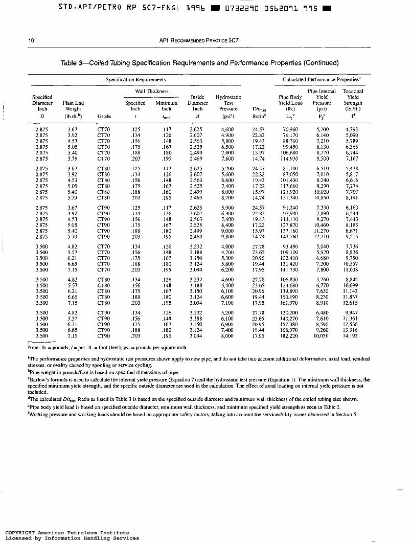
Table 3-Coiled Tubing Specification Requirements and Performance Properties (Continued)
Specification Requirements Calculated Performance Propertiesa
Wall Thickness Pipe lnternal Torsional Specified Inside Hydrostatic Pipe Body Yield Yield Diameter Plain End Specified Minimum Diameter Test Yield Load Pressure Strength
Inch Weight Inch Inch Inch Pressure D/tmin (lb.) (psi) (Ib./ft.) D (Ib./ft.b) Grade f fmm d (psiC) Ratiod Lye P: T'
2.875 2.875 2.875 2.875 2.875 2.875
2.875 2.875 2.875 2.875 2.875 2.875
2.875 2.875 2.875 2.875 2.875 2.875
3.500 3.500 3.500 3.500 3.500
3.500 3.500 3.500 3.500 3.500
3.500 3.500 3.500 3.500 3.500
3.67 3.92 4.53 5.05 5.40 5.79
3.67 3.92 4.53 5.05 5.40 5.79
3.67 3.92 4.53 5.05 5.40 5.79
4.82 5.57 6.2 I 6.65 7.15
4.82 5.57 6.2 I 6.65 7.15
4.82 5.57 6.2 I 6.65 7.15
CT70 CT70 CT70 c 7 0 c l 7 0 CT70
CT80 CT80 CT80 CT80 CT80 CT80
CT90 CT90 CT90 CT90 CT90 CT90
cno CT70 cno CT70 CT70
CT80 CT8O CT80 CT80 CT80
CT90 CT90 CT90 CT90 CT90
,125 ,134 ,156 ,175 ,188 ,203
. I25
. I34
. I56
. I75 ,188 .203
,125 . I34 . I56 ,175 ,188 ,203
,134 . I 56 ,175 ,188 ,203
. I34 ,156 . I75 . I88 ,203
.134
.I56 ,175 ,188 ,203
,117 . I26 .I48 . I67 . I80 ,195
.I17
.I26
.I48
.I67
.I80
.I95
. I 17 ,126 .I48 ,167 ,180 ,195
. I26
.I48
. I67 ,180 .I95
.I26 ,148 ,167 .I80 .I95
,126 ,148 ,167 ,180 ,195
2.625 2.607 2.563 2.525 2.499 2.469
2.625 2.607 2.563 2.525 2.499 2.469
2.625 2.607 2.563 2.525 2.499 2.469
3.232 3.188 3.150 3.124 3.094
3.232 3.188 3.150 3.124 3.094
3.232 3.188 3.150 3.124 3.094
4,600 4,900 5,800 6,500 7,000 7,600
5,200 5,600 6,600 7,400 8,000 8,700
5,900 6,300 7,400 8,400 9,000 9,800
4,000 4,700 5,300
6,200 5,800
4,600 5,400 6,100 6,600 7.100
5.200 6,100 6,900 7,400 8,000
24.57 22.82 19.43 17.22 15.97 14.74
24.57 22.82 19.43 17.22 15.97 14.74
24.57 22.82 19.43 17.22 15.97 14.74
27.78 23.65 20.96 19.44 17.95
27.78 23.65 20.96 19.44 17.95
27.78 23.65 20.96 19.44 17.95
70.960 76,170 88,760 99,450
106,680 1 14,930
81,100 87,050
101,430 113,660 121,920 131,340
9 1.240 97,940
114.1 10 127,870 137.160 147,760
93,490 109,100 122,410 13 1,420 14 1,730
106,850 124,680 139,890 150,190 161,970
120,200 140,270 157,380 168,970 182,220
5,700 6,140 7,210 8,130 8,770 9,500
6.5 1 O 7,010 8,240 9,290
10,020 10,850
7,330 7,890 9,270
10,460 1 1,270 12,210
5,040 5,920 6,680 7,200 7.800
5,760 6,770 7,630 8,230 8,910
6,480 7.61 O
9,260 8,590
I0.030
4,793 5,090 5,789 6.365 6,744 7,167
5,478 5,817 6,616 7,274 7,707 8,191
6,163 6,544 7,443 8,183 8.67 I 9,215
7,736 8.836 9.750
10,357 1 1,038
8,842 10,099 11,143 1 1,837 12,615
9,947 1 1,361 12,536 13,316 14.192
Note: lb. =pounds; / =per; ft. = foot (feet); psi =pounds per square inch.
aThe performance properties and hydrostatic test pressures shown apply to new pipe, and do not take into account additional deformation. axial load, residual stresses, or ovality caused by spooling or service cycling. bPipe weight in pounds/foot is based on specified dimensions of pipe. 'Barlow's formula is used to calculate the internal yield pressure (Equation 7) and the hydrostatic test pressure (Equation I). The minimum wall thickness, the specified minimum yield strength, and the specific outside diameter are used in the calculation. The effect of axial loading on internal yield pressure is not included. dThe calculated D/t,i, Ratio as listed in Table 3 is based on the specified outside diameter and minimum wall thickness of the coiled tubing size shown. ePipe body yield load is based on specified outside diameter, minimum wall thickness, and minimum specified yield strength as seen in Table 2. 'Working pressure and working loads should be based on appropriate safety factors, taking into account the serviceability issues discussed in Section 5.
COPYRIGHT American Petroleum InstituteLicensed by Information Handling ServicesCOPYRIGHT American Petroleum InstituteLicensed by Information Handling Services
STD-API/PETRO RP SC7-ENGL 1 9 9 b m 0 7 3 2 2 9 0 05b20’72 821
RECOMMENDED PRACTICE FOR COILED TUBING OPERATIONS I N OIL AND GAS WELL SERVICES 11
Wh e re:
L, = pipe body yield load (pounds). Y = specified minimum yield strength (pounds per
square inch). D = specified outside diameter (inches).
tmi, = minimum wall thickness (inches).
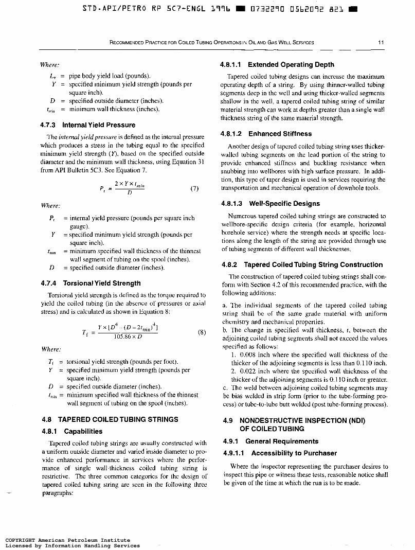
4.7.3 Internal Yield Pressure
The intemal yield pressure is defined as the internal pressure which produces a stress in the tubing equal to the specified minimum yield strength (r) , based on the specified outside diameter and the minimum wall thickness, using Equation 31 from API Bulletin 5C3. See Equation 7.
P , = 2 x Y x
D
Where:
P , = internal yield pressure (pounds per square inch
Y = specified minimum yield strength (pounds per
r,,,,, = minimum specified wall thickness of the thinnest
D = specified outside diameter (inches).
gauge).
square inch).
wall segment of tubing on the spool (inches).
4.7.4 Torsional Yield Strength
Torsional yield strength is defined as the torque required to yield the coiled tubing (in the absence of pressures or axial stress) and is calculated as shown in Equation 8:
Y x [ D -(D-2t,in)4] 4
105.86 x D T , =
Where:
Ti = torsional yield strength (pounds per foot). Y = specified minimum yield strength (pounds per
D = specified outside diameter (inches). r,,, = minimum specified wall thickness of the thinnest
square inch).
wall segment of tubing on the spool (inches).
4.8 TAPERED COILEDTUBING STRINGS
4.8.1 Capabilities
Tapered coiled tubing strings are usually constructed with a uniform outside diameter and varied inside diameter to pro- vide enhanced performance in services where the perfor- mance of single wall-thickness coiled tubing string is restrictive. The three common categories for the design of tapered coiled tubing string are seen in the following three paragraphs:
4.8.1.1 Extended Operating Depth
Tapered coiled tubing designs can increase the maximum operating depth of a string. By using thinner-walled tubing segments deep in the well and using thicker-walled segments shallow in the well, a tapered coiled tubing string of similar material strength can work at depths greater than a single wall thickness string of the same material strength.
4.8.1.2 Enhanced Stiffness
Another design of tapered coiled tubing string uses thicker- walled tubing segments on the lead portion of the string to provide enhanced stiffness and buckling resistance when snubbing into wellbores with high surface pressure. In addi- tion, this type of taper design is used in services requiring the transportation and mechanical operation of downhole tools.
4.8.1.3 Well-Specific Designs
Numerous tapered coiled tubing strings are constructed to wellbore-specific design criteria (for example, horizontal borehole service) where the strength needs at specific loca- tions along the length of the string are provided through use of tubing segments of different wall thicknesses.
4.8.2 Tapered Coiled Tubing String Construction
The construction of tapered coiled tubing strings shall con- form with Section 4.2 of this recommended practice, with the following additions:
a. The individual segments of the tapered coiled tubing string shall be of the same grade material with uniform chemistry and mechanical properties. b. The change in specified wall thickness, t , between the adjoining coiled tubing segments shall not exceed the values specified as follows:
1. 0.008 inch where the specified wall thickness of the thicker of the adjoining segments is less than 0. 1 10 inch. 2. 0.022 inch where the specified wall thickness of the thicker of the adjoining segments is O. 1 I O inch or greater.
c. The weld between adjoining coiled tubing segments may be bias welded in strip form (prior to the tube-forming pro- cess) or tube-to-tube butt welded (post tube-forming process).
4.9 NONDESTRUCTIVE INSPECTION (NDI) OF COILEDTUBING
4.9.1 General Requirements
4.9.1.1 Accessibility to Purchaser
Where the inspector representing the purchaser desires to inspect this pipe or witness these tests, reasonable notice shall be given of the time at which the run is to be made.
COPYRIGHT American Petroleum InstituteLicensed by Information Handling ServicesCOPYRIGHT American Petroleum InstituteLicensed by Information Handling Services

~~
STD*API/PETRO RP 5Cï"ENGL 177b I 0732270 05b2073 7bA I
12 API RECOMMENDED PRACTICE 5C7
O O 0 O o m O
O m N - r
Jeq ,j'aJnssaJd asdello3
COPYRIGHT American Petroleum InstituteLicensed by Information Handling ServicesCOPYRIGHT American Petroleum InstituteLicensed by Information Handling Services
S T D . A P I / P E T R O R P S C 7 - E N G L L 9 9 b m 0732290 05b2099 bTY m
RECOMMENDED PRACTICE FOR COILED TUBING OPERATIONS I N OIL AND GAS WELL SERVICES 13
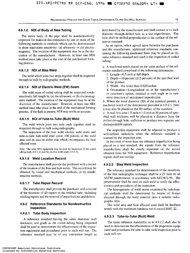
4.9.1.2 ND1 of Body of New Tubing determined by the manufacturer and shall contain a Va-inch
The entire body of the pipe shall be nondestructively inspected for material discontinuities by one or more of the following methods or methods which can be demonstrated to show equivalent sensitivity: (a) ultrasonic or (h) electro- magnetic. The location of the equipment may be at the dis- cretion of the manufacturer. However, at least one ND1 method must take place at the end of the mechanical form- ing piocess.
4.9.1.3 ND1 of Bias Weld
The weld which joins two strips together shall be inspected through its bulk by radiographic methods.
4.9.1.4 ND1 of Electric Weld (EW) Seam
The weld seam of coiled tubing shall be inspected nonde- structively full length by (a) the ultrasonic or (h) electromag- netic method. The location of the equipment may be at the discretion of the manufacturer. However, at least one ND1 method must take place at the end of the mechanical forming process. If the flash is present, N D 1 may not be as accurate.
4.9.1.5 ND1 of Tube-to-Tube (Butt) Weld
The weld which joins two tube ends together shall be inspected through its bulk using radiography.
The inspection of the bias weld, electric weld seam, and tube-to-tube butt-weld shall cover 100 percent of the weld area, and an area on either side which encompasses the heat affected zone.
Note: The same ND1 equipment may be used for inspection of the coiled tubing body (4.9.1.2) and the electric weld seam (4.9.1.4).
4.9.1.6 Weid Location Record
The manufacturer shall provide the purchaser with a record of the location of the bias and butt-welds. This record may be obtained by visual and mechanical methods, or by nonde- structive methods.
4.9.1.7 Tube Repair Record
The manufacturer shall provide the purchaser with a record of the locations of all repairs in the finished tube, including welding repairs and the removal of imperfections and defects.
4.9.2 Reference Standards for Nondestructive Inspection
4.9.2.1 Tube Body inspection
A reference standard having the same diameter, wall thickness, and grade as the coiled tubing being inspected shall be used to demonstrate the effectiveness of the inspec- tion equipment and procedures prior to each mill run. The reference standard may be of any convenient length as
diameter through-drilled hole as a test imperfection. The hole shall be drilled perpendicular to the surface of the ref- erence standard.
As an option, when agreed upon between the purchaser and the manufacturer, additional reference standards con- taining the following machined flaws may be placed on the same reference standard and used in the inspection of coiled tubine: c
a. A machined notch placed on the outer surface of the ref- erence standard comprised of the following dimensions:
1. Length-0.5 inch at full depth. 2. Depth-10 percent (+I 5 percent) of the specified wall of the product. 3. Width-No wider than 0.020 inches. 4. Orientation-Longitudinal or, at the manufacturer’s or customer’s option, oriented at such angle as to opti- mize detection of anticipated imperfection.
b. Where the inner diameter (ID) of the standard permits, a machined notch of the dimensions provided in 4.9.2.1, Item a may also be placed on the ID surface of the standard. c. A wall loss area 1 .O inch X 1 .O inch at 10 percent of spec- ified wall thickness will be placed at a distance from the drilled-through hole, sufficient to produce two separate and distinguishable signals.
The inspection equipment shall be adjusted to produce a well-defined indication when the reference standard is scanned by the inspection unit.
In the event of more than one reference imperfection being placed in a test standard, the signals from the reference imperfections shall be clearly separated on the record obtained from the ND1 equipment. Reference imperfection signals shall not overlap.
4.9.2.2 Bias Weld inspection
The reference standard for determination of the sensitivity of the film radiographic technique shall be a 2T hole on an ASTM penetrometer, in accordance with ASTM E-94. The penetrometer shall be used on each weld to verify the effec- tiveness and procedures of the inspection.
The homogeneity of weld seams examined by radiologi- cal methods shall be determined by means of X-rays directed through the weld material onto a suitable radio- graphic film.
The weld area and heat affected zone shall be hardness tested, with the maximum hardness not to exceed HRC 22.
4.9.2.3 Tube-to-Tube (Butt) Weld
The same reference standard(s) as in 4.9.2.2 shall also be used to demonstrate the effectiveness of the inspection equip- ment and procedures for tube-to-tube weld inspection prior to each mill run.
COPYRIGHT American Petroleum InstituteLicensed by Information Handling ServicesCOPYRIGHT American Petroleum InstituteLicensed by Information Handling Services
4.9.2.4 Tube Electric Weld (EW)
The same reference standard(s) as in 4.9.2.a shall also be used to demonstrate the effectiveness of the inspection equipment and procedures for EW inspection prior to each mill run. If the flash is present, ND1 may not be as accurate.
Note: The reference standards defined in the preceding are convenient standards for the calibration (standardization) of ND1 equipment. The dimensions of the drilled hole or machined notches in these standards should not be construed as a minimum size imperfection detectable by the ND1 equipment.
4.9.3 Nondestructive Evaluation of Body
4.9.3.1 Inspection
The body of coiled tubing shall be 100 percent inspected for defects to a written procedure after standardization of the inspection unit with the reference standard. The equipment used shall be capable of continuous and uninterrupted inspec- tion of the tube body. The equipment shall be adjusted to pro- duce well defined indications when the reference standard is scanned by the inspection unit in a manner simulating inspec- tion of the product.
Regions from which defect indications originate shall be marked with an automatic paint-spraying device or other marking methods for further evaluation.
4.9.3.2 Drift
By agreement between the purchaser and manufacturer, a drift ball may be pumped through the entire spool of coiled tubing prior to shipment of the coiled tubing to verify drift. This process shall be performed to the manu- facturer’s written procedure with documentation provided to the purchaser.
4.9.4 Nondestructive Evaluation of EW Seam
The EW seam of coiled tubing shall be inspected for 100 percent of its length to a written procedure after standardiza- tion of the inspection unit with the reference standard. The equipment used shall be capable of continuous and uninter- rupted inspection of the tube body, and shall be capable of inspecting an area of ‘ h inch on either side of the weld. The equipment shall be adjusted to produce well-defined indications when the reference standard is scanned by the inspection unit in a manner simulating inspection of the product.
Regions from which defect indications originate shall be marked with paint or other marking method for further evaluation.
4.9.5 Imperfections and Defects in Finished Tubing
4.9.5.1 Imperfection
An imperfection is a material discontinuity or irregularity in the product detected by the methods outlined in this recom- mended practice or visual inspection.
4.9.5.2 Defect
A defect is an imperfection of sufficient magnitude to war- rant rejection of the product.
4.9.5.3 Disposition of Imperfections and Defects
Any imperfection that produces a signal as great or greater than that of the reference standard shall be consid- ered a defect. Coiled tubing imperfections and defects are categorized as follows, along with the recommended disposition:
4.9.5.3.1 An external imperfection may be removed by grinding or machining, provided the remaining wall thickness is not less than the minimum wall thickness, t,,,. When the depths of the grind exceeds 10 percent of the specified wall thickness, t, the remaining wall thickness shall be verified with a calibrated compression wave ultrasonic wall thickness gauge. Where grinding is performed, generous radii shall be employed to prevent abrupt changes in wall thickness; the grind shall exhibit a high degree of workmanship; and the surface texture of the grind shall exhibit no transverse scratches.
The area from which the defect is removed shall be rein- spected by one of the nondestructive testing methods speci- fied in 4.9.6 to verify complete removal of the defect.
4.9.5.3.2 Any imperfection on the inner or outer surface of the coiled tubing which reduces the thickness remaining at the root of the imperfection to less than minimum wall, tmin, but greater than 87.5 percent of the specified wall thick- ness, t , shall be identified by the manufacturer. The location of all imperfections on the inner or outer surface of the coiled tubing which reduce the thickness remaining at the root of the imperfection to less than minimum wall, tmin, but greater than 87.5 percent of the specified wall thickness, t, shall be clearly marked by the manufacturer, and the posi- tion of the imperfection on the spool will be recorded and supplied to the purchaser.
4.9.5.3.3 Any imperfection on the inner or outer surface of the coiled tubing which reduces the thickness remaining at the root of the imperfection to less than 87.5 percent of the specified wall thickness, r, shall be considered a defect and given one of the following dispositions:
a. The section of the pipe containing the defect may be cut off within the limits of the requirements of the length and weld provisions of the purchase order. b. Repair of defects by welding shall be permitted only upon agreement between the manufacturer and the purchaser c. Rejected.
COPYRIGHT American Petroleum InstituteLicensed by Information Handling ServicesCOPYRIGHT American Petroleum InstituteLicensed by Information Handling Services

STD-APIIPETRO RP SC7-ENGL 177b m 0732270 05b207b q77 m
RECOMMENDED PRACTICE FOR COILED TUBING OPERATIONS IN OIL AND GAS WELL SERVICES 15
4.9.6 ND1 Methods for Verifying Defect or Imperfection Removal
The area from which a defect or imperfection is removed shall be reinspected with any of the following techniques: (a) liquid penetrant inspection or (b) magnetic particle inspection.
4.9.7 ND1 Indications Not Generated From the OD
Occasionally, ND1 indications may be generated from mid- wall and internal surface imperfections and from weld bead droplets. These may be proved to written procedures using x- radiography, ultrasonic compression wave testing, or ultra- sonic shear-wave testing.
4.10 CERTIFICATION AND DOCUMENTATION
The manufacturer shall provide certification and documen- tation for each spool of coiled tubing which includes, as a minimum, the following:
a. Chemical composition. b. Heat number(s). c. Mechanical properties: hardness, tensile strength(s) and yield strength(s). d. Identification and position of various segments of coiled tube on the spool of different specified wall thicknesses (tapered string). e. Weld log including bias-weld and butt-weld locations f. Tube grade and serial number(s). g. Hydrostatic-test pressure including test duration, maxi- mum pressure, minimum pressure, temperature, and test fluid. h. Drying procedure used if applicable (removing liquids from ID of coiled tubing using nitrogen). i. Nondestructive test methods performed on the spooled coiled tubing and welds and subsequent results obtained. j. Tube repair record. k. Details of drift ball pumping program if applicable. 1. Record of the number of times the coiled tubing has been spooled and unspooled during the manufacturing and test- ing program.
5 CoiledTubing String Design and Working Life
5.1 INTRODUCTION
This section includes topics on coiled tubing string design considerations, ultra-low cycle fatigue prediction methods, diametral growth, other OD anomalies, collapse derating, dis- cussion on corrosion effects, and common weld survivability.
The useful working life of coiled tubing is limited by sev- eral factors, including the following:
a. Fatigue. b. Diameter growth and ovality. c. Mechanical damage (kinks, surface anomalies). d. Corrosion. e. Welds.
All of the preceding factors, acting either singly or in com- bination, will contribute to eventual mechanical failure of the coiled tubing. Every effort must be made to avoid failure due to these factors during well site operations. A decision when to retire the workstring must be made based on its current condition and known service history. Except for severe mechanical damage, none of these factors can be precisely quantified or predicted. When derating coiled tubing for one or more of these effects, a compromise is required between the need to minimize well site failures and the need to obtain an economic working life from the string.
5.2 DESIGN CONSIDERATIONS OF COILED TUBING STRING
The design of coiled tubing strings shall be based upon the specified minimum yield strength, wall thickness(es) and out- side diameters of the coiled tubing. Design criteria relating to the tubing weight, overpull, wellbore condition, and hydrauli- cally applied loads, as defined in the following paragraphs shall be considered.
5.2.1 Weight
The weight of the coiled tubing string shall be calculated relative to a specific reference fluid(s) and shall be consistent throughout the string design calculations.
One of the two following conditions shall be used to define the weight of a coiled tubing string and reference fluid(s) in the design procedure for a specific coiled tubing string.
a. Air weight: The weight of an empty (air filled) coiled tubing string in air. b. Buoyed weight: The weight of the coiled tubing string immersed in a fluid. The tubing may be gas filled (maxi- mum buoyancy), filled with a reference liquid (conventional buoyancy), or filled with a heavier fluid.
5.2.2 Overpull
The tension load applied in excess of the buoyed load of the coiled tubing and tools hanging below the injector. Over- pull loads are the combined loads resulting from tubing-to- pipe friction and anticipated downhole service pulling loads.
5.2.3 Wellbore Condition
The wellbore condition includes the following design concerns:
COPYRIGHT American Petroleum InstituteLicensed by Information Handling ServicesCOPYRIGHT American Petroleum InstituteLicensed by Information Handling Services
16 API RECOMMENDED PRACTICE 5C7
a. Maximum anticipated wellhead pressure used to evaluate collapse potential, snubbing force, and minimum pump pressures required. b. Wellbore orientation and geometry needed to evaluate coiled tubing string design to ensure that the tubing can reach the designated depth and perform the prescribed service.
5.2.4 Hydraulically Applied Loads
The additional tensile loads applied to the coiled tubing string as follows:
coiled tubing and operational limits are a component of proper job design.
5.3 DESCRIPTION OF FATIGUE
Coiled tubing will always be plastically deformed both when it is bent over the reel and tubing-guide arch and when it is straightened again. Such plastic deformation results in cumulative and regressive changes to the material, a phenomenon known as fatigue.
Fatigue is a critical factor in the life of coiled tubing
a. Frictional: The result of friction generated by pumping viscous fluids through the coiled tubing at specific pump rates. Note that high-viscosity liquids will generate larger applied tensile loads onto the coiled tubing string than low- viscosity liquids at equivalent pump rates. b. End effect: The force resulting from fluid pressure acting on the cross-sectional area of end connections or restrictions in the ID of the tubing string.
because it is unavoidable (for all practical purposes), cannot currently be measured nondestructively, and yet can have a major impact on the working life. The most significant fatigue occurs in coiled tubing where it is bent beyond the elastic limit. Hence, most fatigue in coiled tubing operations occurs at the reel and tubing-guide arch, and very little in the well. Understanding and predicting the fatigue condition of the string and derating it accordingly is critical to a successful and safe operation.
5.2.5 Transition Point
The transition point shall be defined as the point where coiled tubing segments of different specified wall thicknesses are mechanically joined together. The minimum criteria for selecting the transition point shall include overpull, tubing weight, wellbore condition, and hydraulically applied loads, as discussed in 5.2.
5.2.6 Maximum Length
The maximum length of each coiled tubing segment in the tapered string shall be limited to such a length where the weight of the coiled tubing string below any point on the seg- ment, when combined with the anticipated overpull and hydraulically applied loads, does not exceed 80 percent of the pipe body yield load at that point, as shown in Table 3.
5.2.7 Buckling
A compressive load on the coiled tubing can be seen in many operations, such as snubbing, to overcome the com- bined effects of wellhead pressure, friction in the sealing ele- ment (stripper), and other forces. With increasing compressive load, buckling can occur in the coiled tubing. It is generally accepted that this will occur in the area of the greatest unsupported length. There is no constraining feature in the area between the bottom of typical coiled tubing injector chains and the top of a conventional sealing element (stripper).
The force required to buckle the coiled tubing is dependent upon material characteristics and coiled tubing geometry (that is, outside diameter, wall thickness, and ovality). A
Fatigue is often identified within the following classes:
a. High-cycle fatigue (HCF): Loading is primarily elastic, and failure occurs after in excess of 10,000 stress cycles. Common examples include failures of sucker rods, shafts and bearings, and many items subject to vibration. b. Low-cycle fatigue (LCF): Loading is mostly elastic, and failure occurs in 1,000-10,000 stress cycles. Examples are those where loading is normally low but where occasional peaks can be seen, such as a car suspension absorbing shocks due to potholes. c. Ultra-low cycle fatigue (ULCF): Loading is plastic, and failure occurs in less than 1,000 stress cycles. A well-known example is bending a paper clip, which fails after just a few cycles. There are very few instances of ULCF in industry. Coiled tubing, which falls in this category, is one example.
As coiled tubing is bent, a radius is reached where the material begins to yield plastically. The yield radius of curva- ture, Ry, is given by Equation 9:
R E D y - Y 2
Wh e re:
Ry = yield radius of curvature to the centerline axis of
D = specified outside diameter (inches). E = Young’s modulus (pounds per square inch). Y = specified minimum yield strength (pounds per
the coiled tubing (inches).
square inch).
buckling guide that constrains the coiled tubing between the Assuming a specified yield strength of 70,000 pounds per injector chains and the top of a conventional stripper can help square inch gauge, the value of Ry for standard sizes of coiled increase the snubbing limits by applying constraints to the tubing, the typical size for the reel core, and the size ranges unsupported section. Analysis of compressive loads on the for the tubing guide arch are given in Table 4.
COPYRIGHT American Petroleum InstituteLicensed by Information Handling ServicesCOPYRIGHT American Petroleum InstituteLicensed by Information Handling Services
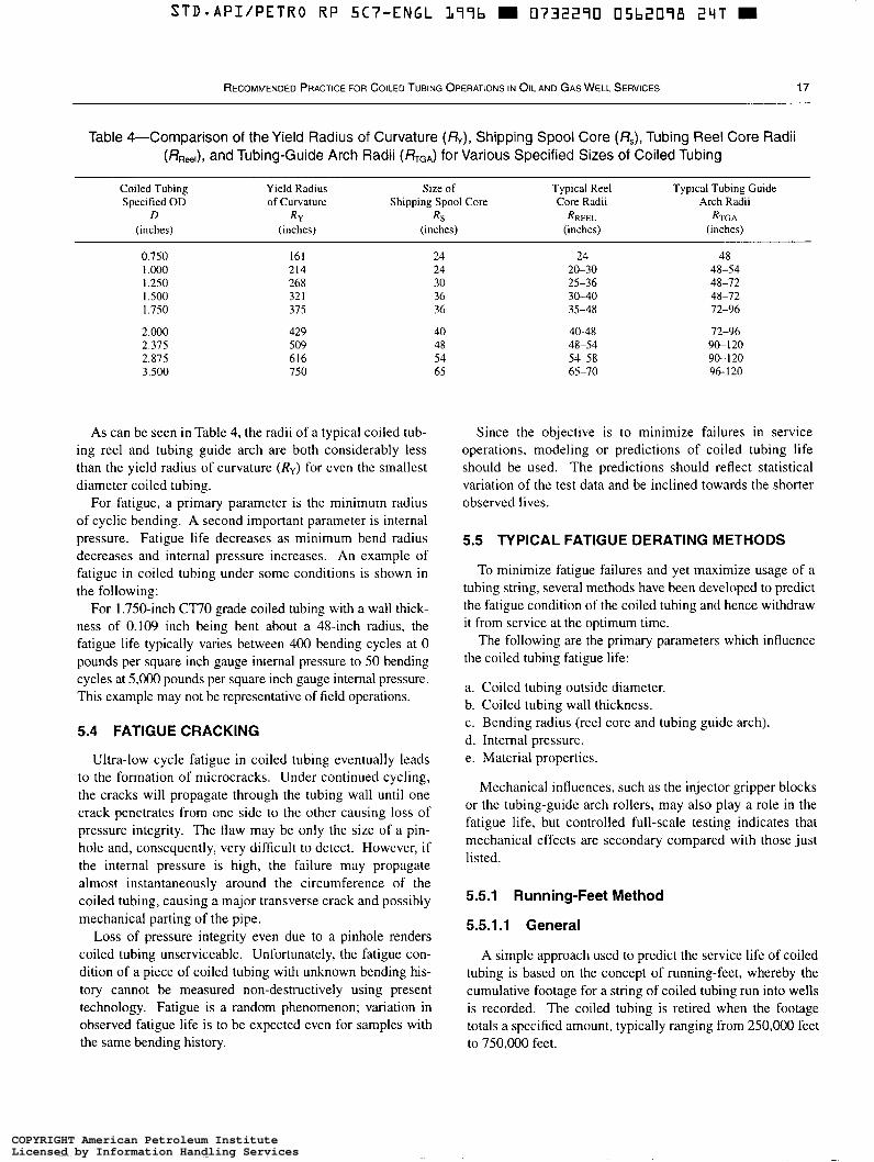
STD*API/PETRO RP SC7-ENGL L77b m 0732270 05b2078 2qT
RECOMMENDED PRACTICE FOR COILED TUBING OPERATIONS IN O I L AND GAS WELL SERVICES 17
Table 4-Comparison of the Yield Radius of Curvature (h), Shipping Spool Core (Rs), Tubing Reel Core Radii (ßReel), and Tubing-Guide Arch Radii (&GA) for Various Specified Sizes of Coiled Tubing
Coiled Tubing Specified OD of Curvature Shipping Spool Core Core Radii Arch Radii
(inches) (inches) (inches) (inches) (inches)
~ ~~~~~~~~~
Yield Radius Size of Typical Reel Typical Tubing Guide
D R-i R , RREEL RTG A
0.750 1.000 1.250 1.500 1.750
2.000 2.375 2.875 3.500
161 214 268 32 1 375
429 509 616 750
24 24 30 36 36
40 48 54 65
24 20-30 25-36 30-40 35-48
40-48 48-54 54-58 65-70
48 48-54 48-72 48-72 72-96
72-96 90- I20 90- I20 96- 120
As can be seen i n Table 4, the radii of a typical coiled tub- ing reel and tubing guide arch are both considerably less than the yield radius of curvature (Ry) for even the smallest diameter coiled tubing.
For fatigue, a primary parameter is the minimum radius of cyclic bending. A second important parameter is internal pressure. Fatigue life decreases as minimum bend radius decreases and internal pressure increases. An example of fatigue in coiled tubing under some conditions is shown in the following:
For 1.750-inch Cl70 grade coiled tubing with a wall thick- ness of 0.109 inch being bent about a 48-inch radius, the fatigue life typically varies between 400 bending cycles at O pounds per square inch gauge internal pressure to 50 bending cycles at 5,000 pounds per square inch gauge internal pressure. This example may not be representative of field operations.
5.4 FATIGUE CRACKING
Ultra-low cycle fatigue in coiled tubing eventually leads to the formation of microcracks. Under continued cycling, the cracks will propagate through the tubing wall until one crack penetrates from one side to the other causing loss of pressure integrity. The flaw may be only the size of a pin- hole and, consequently, very difficult to detect. However, if the internal pressure is high, the failure may propagate almost instantaneously around the circumference of the coiled tubing, causing a major transverse crack and possibly mechanical parting of the pipe.
Loss of pressure integrity even due to a pinhole renders coiled tubing unserviceable. Unfortunately, the fatigue con- dition of a piece of coiled tubing with unknown bending his- tory cannot be measured non-destructively using present technology. Fatigue is a random phenomenon; variation in observed fatiguc life is to be expected even for samples with the same bending history.
Since the objective is to minimize failures in service operations, modeling or predictions of coiled tubing life should be used. The predictions should reflect statistical variation of the test data and be inclined towards the shorter observed lives.
5.5 TYPICAL FATIGUE DERATING METHODS
To minimize fatigue failures and yet maximize usage of a tubing string, several methods have been developed to predict the fatigue condition of the coiled tubing and hence withdraw it from service at the optimum time.
The following are the primary parameters which influence the coiled tubing fatigue life:
a. Coiled tubing outside diameter. b. Coiled tubing wall thickness. c. Bending radius (reel core and tubing guide arch). d. Internal pressure. e. Material properties.
Mechanical influences, such as the injector gripper blocks or the tubing-guide arch rollers, may also play a role in the fatigue life, but controlled full-scale testing indicates that mechanical effects are secondary compared with those just listed.
5.5.1 Running-Feet Method
5.5.1.1 General
A simple approach used to predict the service life of coiled tubing is based on the concept of running-feet, whereby the cumulative footage for a string of coiled tubing run into wells is recorded. The coiled tubing is retired when the footage totals a specified amount, typically ranging from 250,000 feet to 750,000 feet.
COPYRIGHT American Petroleum InstituteLicensed by Information Handling ServicesCOPYRIGHT American Petroleum InstituteLicensed by Information Handling Services
STD-API/PETRO RP 5C7-ENGL L77b m 0732270 05b2077 L8 b
18 API RECOMMENDED PRACTICE 5C7
5.5.1.2 Advantages
Major advantages to the running-feet method are these:
a. Requires only a depth measurement. b. It is simple to implement.
5.5.1.3 Disadvantages
Major disadvantages to this method are the following:
a. The specified maximum footage is based on previous experience with the same type of tubing performing essen- tially similar well-site operations. b. Limited consideration is given to coiled tubing dimen- sions, bending radius, material type, internal pressure, or where the cycles are applied. c. Predictive techniques based on precedent cannot be readily extended to different tubing sizes or operating condi- tions because the fatigue life may be significantly different.
5.5.2 Trip Method and Empirical Modeling
5.5.2.1 General
Several improvements can be made to the running-feet method. First, the service string can be considered in dis- crete sections, typically 500 feet long or less. This accounts for the fact that some parts of the coiled tubing are subjected to more bending than others during a given job, depending on depth and the nature of the application being performed. The number of trips across the reel and tubing-guide arch for each section can then be tracked, instead of for the ser- vice string as a whole. The smaller the length increment, the more accurate the overall record of bending history and the better the prospects of identifying the most fatigued sec- tion of tubing.
Second, the effect of pressure can be accounted for using this method. Tests and field experience show that the coiled tubing fatigue life decreases significantly with increasing pressure when cycled during service. A series of empirical coefficients can be derived from full-scale fatigue experi- ments to weight the number of trips over the reel and tub- ing-guide arch according to the prevailing pressure. Once a particularly fatigued section of tubing has been identified, the option exists to remove that section from service.
Several fatigue test machines have been developed that simulate well-site conditions sufficiently to enable statisti- cally significant quantities of fatigue data to be obtained. By performing enough tests for a wide range of conditions, an estimate can be made, even for untested conditions, by interpolation.
5.5.2.2 Advantages
Primary advantages to the trip method and empirical mod- eling are the following:
a. More accurately identifies which sections of tubing are subject to bending at the reel and tubing-guide arch during the course of a job. h. Accounts for the conditions prevailing at the time of bending.
5.5.2.3 Disadvantages
The following are major disadvantages to this method:
a. The fatigue coefficients can be expected to be different for every combination of coiled tubing outside diameter, wall thickness, bending radius, and tubing material. h. Full-scale testing is needed to determine the fatigue coef- ficients experimentally, which is time-consuming and expensive. c. Fatigue machine test data will usually be acquired for constant pressure; whereas, in actual service, coiled tubing will be subject to varying pressure over its working life. Hence, the effect of bending cycles at one pressure must be combined with the effect of bending cycles at another pres- sure to obtain a total life prediction. However, experiments show that bending cycles applied later in the tubing life cause greater fatigue than bending cycles applied earlier. Simply adding estimates of fatigue linearly when conditions are varying may not produce a reliable prediction.
5.5.3 Theoretical Modeling
5.5.3.1 General
Another solution to coiled tubing fatigue prediction is the development of a model based on fundamental principles of fatigue and appropriate consideration of geometry and mate- rial properties.
Theoretical modeling of fatigue typically involves the fol- lowing:
a. Plasticity algorithm: To estimate the instantaneous stress and strain condition of the tubing material for a given load- ing (bending radius and pressure). b. Damage algorithm: To quantify the reduction in tubing life (“damage”) caused by the given stress/strain condition, and then sum the damage for every bending cycle to obtain the overall fatigue life, usually expressed as a percentage.
The plasticity algorithm requires material data as input. Several of these parameters-Young’s Modulus and Pois- son’s Ratio-are well known. However, material properties under cyclic loading are different from those under a single monotonic load (such as a pull-test).
These cyclic material properties are determined by con- trolled laboratory testing on specimens from coiled tubing strings. Such methods are established; however, most labora- tory testing is uniaxial (the sample is loaded along a single axis), whereas coiled tubing loading is multiaxial (three- dimensional).
COPYRIGHT American Petroleum InstituteLicensed by Information Handling ServicesCOPYRIGHT American Petroleum InstituteLicensed by Information Handling Services
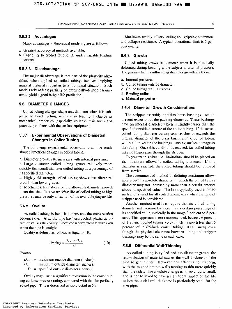
STD-API/PETRO RP 5C7-ENGL 1996 m 0732290 05b2100 7 2 8 W
RECOMMENDED PRACTICE FOR COILED TUBING OPERATIONS IN OIL AND GAS WELL SERVICES 19
5.5.3.2 Advantages
Major advantages to theoretical modeling are as follows:
a. Greatest accuracy of methods available. b. Capability to predict fatigue life under variable loading situations.
5.5.3.3 Disadvantage
The major disadvantage is that part of the plasticity algo- rithm, when applied to coiled tubing, involves applying uniaxial material properties to a multiaxial situation. Such models rely at least partially on empirically-derived parame- ters to yield a good fatigue life prediction.
5.6 DIAMETER CHANGES
Coiled tubing changes shape and diameter when it is sub- jected to bend cycling, which may lead to a change in mechanical properties (especially collapse resistance) and potential problems with the surface equipment.
5.6.1 Experimental Observations of Diametral Changes in Coiled Tubing
The following experimental observations can be made about diametrical changes in coiled tubing:
a. Diameter growth rate increases with internal pressure. b. Large diameter coiled tubing grows relatively more quickly than small diameter coiled tubing as a percentage of its specified diameter. c. High yield-strength coiled tubing shows less diametral growth than lower grades. d. Mechanical limitations on the allowable diameter growth mean that the effective working life of coiled tubing at high pressures may be only a fraction of the availablefatigue life.
5.6.2 Ovality
As coiled tubing is bent, it flattens and the cross-section becomes oval. After the pipe has been cycled, plastic defor- mation causes the ovality to become a permanent feature even when the pipe is straight.
Ovality is defined as follows in Equation 10:
Ova l i t y = Dm, - D,, D
Where:
D,,, = maximum outside diameter (inches). D,,, = minimum outside diameter (inches).
D = specified outside diameter (inches).
Ovality may cause a significant reduction in the coiled tub- ing collapse pressure rating, compared with that for perfectly round pipe. This is described in more detail in 5.7.
Maximum ovality affects sealing and gripping equipment and collapse resistance. A typical operational limit is 5 per- cent ovality.
5.6.3 Growth
Coiled tubing grows in diameter when it is plastically deformed during bending while subject to internal pressure. The primary factors influencing diameter growth are these:
a. Internal pressure. b. Coiled tubing outside diameter. c. Coiled tubing wall thickness. d. Bending radius. e. Material properties.
5.6.4 Diametral Growth Considerations
The stripper assembly contains brass bushings used to prevent extrusion of the packing elements. These bushings have an internal diameter which is slightly larger than the specified outside diameter of the coiled tubing. If the actual coiled tubing diameter on any axis reaches or exceeds the internal diameter of the brass bushings, the coiled tubing will bind up within the bushings, causing surface damage to the tubing. Once this condition is reached, the coiled tubing may no longer pass through the stripper.
To prevent this situation, limitations should be placed on the maximum allowable coiled tubing diameter. If this diameter is reached, the coiled tubing should be removed from service.
The recommended method of defining maximum allow- able growth is absolute diameter, in which the coiled tubing diameter may not increase by more than a certain amount above its specified value. The limit typically used is 0.050 inch and is valid for all coiled tubing sizes when the type of stripper used is considered.
Another method used is to require that the coiled tubing diameter not increase by more than a certain percentage of its specified value, typically in the range 3 percent to 6 per- cent. This approach is not recommended, because 6 percent of 1.25-inch coiled tubing (0.075 inch) is much less than 6 percent of 2.375-inch coiled tubing (0.143 inch) even though the physical clearance between tubing and stripper bushings may be the same in each case.
5.6.5 Differential Wall-Thinning
As coiled tubing is cycled and the diameter grows, the redistribution of material causes the wall thickness of the tube to get thinner. However, the effect is not uniform, with the top and bottom walls tending to thin more quickly than the sides. The absolute change is however quite small, and is not believed to have a significant impact on the life unless the initial wall thickness is particularly small for the size pipe.
COPYRIGHT American Petroleum InstituteLicensed by Information Handling ServicesCOPYRIGHT American Petroleum InstituteLicensed by Information Handling Services

STD-API/PETRO RP 5 C ï " E N G L L77b m 0732270 05bZLUL bb4 W
20 API RECOMMENDED PRACTICE 5C7
The industry does not currently derate coiled tubing for differential wall-thinning.
5.6.6 Mechanical Constraints
The action of the injector gripper blocks on the coiled tub- ing usually has an impact on the geometry. The effect will vary according to the gripper block load, block geometry and wear, the coiled tubing internal pressure, geometry, and mate- rial type. However, the net diametral growth is constrained to some extent.
The industry does not currently derate coiled tubing for these effects.
5.6.7 Surface Rippling
It is common to find that coiled tubing that has been sub- ject to bending cycles at pressure develops ripples in the top surface, with a typical period of twice the tube diameter. This has been observed both in the field and in using fatigue machines, but seems to be confined to the minor axis. This phenomenon occurs because coiled tubing does not yield continuously along its length as it is deformed, but instead hinges locally at regular intervals.
Rippling typically occurs quite late in the fatigue life of the tubing. Therefore, it is recommended that the coiled tubing be regularly inspected and consideration be given to with- drawing it from service if rippling is detected.
5.7 COLLAPSE DERATING
The collapse pressure (in the absence of axial stress and internal pressure), PC for as-manufactured coiled tubing is calculated using the appropriate formula of API Bulletin 5C3 for yield strength, plastic, or transition collapse pressure using the specified outside diameter and the minimum wall thickness to determine the Dlt ratio in the formula.
For coiled tubing in service, the condition of the tube can- not be considered perfectly round. Therefore, coiled tubing should always be considered as oval, with a minimum ovality of 0.02 (2 percent). For standard coiled tubing sizes and material grades, collapse pressures at ovalities of 0.02 and 0.05 are calculated and listed in Table 5 and Table 6. When actual ovality is other than 0.02 or 0.05, Equation 11, Equa- tion 12, and Equation 13 should be used to predict the col- lapse rating of the tube.
P,, = g - Ff (1 1)
Wh e re:
2 Y P , = Dit,,- 1 (13)
Y = specified minimum yield strength (pounds per square inch).
round tubing determined using the procedure defined in the first paragraph of this subsection.
PC, = collapse pressure for oval tubing (pounds per square inch).
D,,, = section maximum outside diameter (inches). D,¡, = section minimum outside diameter (inches).
PC = collapse pressure (pounds per square inch) for
D = specified outside diameter (inches). t,,, = minimum wall thickness (inches).
When tensile load (L) or torque ( r ) is combined with exter- nal pressure (P) , the full safety factors (S.F.) may be defined using Equation 14 and Equation 15.
Where:
Po =
PC0 =
L = Ly = T =
Ty = S.F. =
operating external pressure (pounds per square inch). collapse pressure for oval tubing (pounds per square inch). operating tensile load (pounds). pipe body yield load (pounds). operating torque (pound-feet). torsional yield strength (pound-feet). safety factor (S.F. 2 1).
Using minimal allowable safety factors, Equation 14 and Equation 15 can be resolved for allowable external pressure (Po), allowable tensile load (L), required collapse capacity (Pco), or required load capacity (&), as needed.
As a result, allowable external pressure may be found with Equation 16.
P, = PC, K (16)
Where:
PC,, = collapse pressure for oval tubing (pounds per square inch).
Equation 17 and Equation 18. K = collapse pressure correction factor obtained from
3/4
(]/S. F.) 4t3 - (LiL,)"'} (17)
COPYRIGHT American Petroleum InstituteLicensed by Information Handling ServicesCOPYRIGHT American Petroleum InstituteLicensed by Information Handling Services
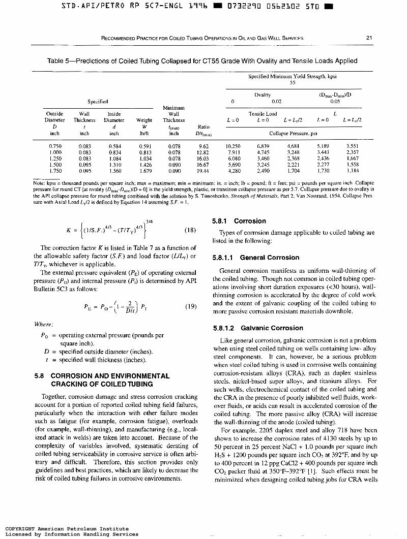
STD.API/PETRO RP 5C7-ENGL L77b m 0732270 05b2102 5 T 0 m
RECOMMENDED PRACTICE FOR COILED TUBING OPERATIONS I N OIL A N D GAS WELL SERVICES 21
Table 5-Predictions of Coiled Tubing Collapsed for CT55 Grade With Ovality and Tensile Loads Applied
Specified Minimum Yield Strength, kpsi 55
Ovality (Drnax-DrnidfD Specified O 0.02 0.05
Outside Wall Inside Wall Tensile Load L Diameter Thickness Diameter Weight Thickness L = O
D
Minimum
L=O L=Lyf2 L=O L=Ly/2 f d W t(min) Ratio
inch inch inch IbJft inch Dff(rnm) Collapse Pressure, psi
0.750 0.083 0.584 0.591 0.078 9.62 10.250 6,839 I.000
4,68 I 0.083 0.834
5, I89 3.55 1 0.813 0.078 12.82 7,91 I 4,745 3,248 3,443 2.357
1.250 0.083 1.084 I .O34 0.078 16.03 6,080 3,460 2,368 2,436 1,667 I ,500 0.095 1.310 I .426 0.090 16.67 5,690 1.750 0.095 1.560
3,245 1.679
2.22 I 2,277 1.558 0.090 19.44 4,280 2,490 1,704 1,730 1,184
Note: kpsi = thousand pounds per square inch; max = maximum; min = minimum; in. = inch; lb = pound; ft = feet; psi = pounds per square inch. Collapse pressure for round CT [at ovality (Dmax-Drnin)JD = O] is the yield strength, plastic, or transition collapse pressure as per 5.7. Collapse pressure due to ovality is the API collapse pressure for round tubing combined with the solution by S. Timoshenko, Sfrengfh ofhfuten'uls. Part 2, Van Nostrand, 1954. Collapse Pres- sure with Axial Load Ly/2 is defined by Equation 14 assuming S.F. = I .
i 3 14
K = (1/S.F.)4'3 - ( T / T y ) l I 3 } (18)
The correction factor K is listed in Table 7 as a function of the allowable safety factor ( X E ) and load factor (LILY) or TIT,, whichever is applicable.
The external pressure equivalent (PE) of operating external pressure (P,) and internal pressure (P,) is determined by API Bulletin SC3 as follows:
Where:
P, = operating external pressure (pounds per square inch).
D = specified outside diameter (inches). t = specified wall thickness (inches).
5.8 CORROSION AND ENVIRONMENTAL CRACKING OF COILED TUBING
Together, corrosion damage and stress corrosion cracking account for a portion of reported coiled tubing field failures, particularly when the interaction with other failure modes such as fatigue (for example, corrosion fatigue), overloads (for example, wall-thinning), and manufacturing (e.g., local- ized attack in welds) are taken into account. Because of the complexity of variables involved, systematic derating of coiled tubing serviceability in corrosive service is often arbi- trary and difficult. Therefore, this section provides only guidelines and best practices, which are likely to decrease the risk of coiled tubing failures in corrosive environments.
5.8.1 Corrosion
Types of corrosion damage applicable to coiled tubing are listed in the following:
5.8.1.1 General Corrosion
General corrosion manifests as uniform wall-thinning of the coiled tubing. Though not common in coiled tubing oper- ations involving short duration exposures (<30 hours), wall- thinning corrosion is accelerated by the degree of cold work and the extent of galvanic coupling of the coiled tubing to more passive corrosion resistant materials downhole.
5.8.1.2 Galvanic Corrosion
Like general corrosion, galvanic corrosion is not a problem when using steel coiled tubing on wells containing low- alloy steel components. It can, however, be a serious problem when steel coiled tubing is used in corrosive wells containing corrosion-resistant alloys ( C M ) , such as duplex stainless steels, nickel-based super alloys, and titanium alloys. For such wells, electrochemical contact of the coiled tubing and the C M in the presence of poorly inhibited well fluids, work- over fluids, or acids can result in accelerated corrosion of the coiled tubing. The more passive alloy ( C M ) will increase the wall-thinning of the anode (coiled tubing).
For example, 2205 duplex steel and alloy 71 8 have been shown to increase the corrosion rates of 4130 steels by up to 50 percent in 25 percent NaCl + 1.0 pounds per square inch H2S + 1200 pounds per square inch COz at 392"F, and by up to 400 percent in 12 ppg CaC12 + 400 pounds per square inch CO2 packer fluid at 35OoF-392"F [ 11. Such effects must be minimized when designing coiled tubing jobs for CRA wells
COPYRIGHT American Petroleum InstituteLicensed by Information Handling ServicesCOPYRIGHT American Petroleum InstituteLicensed by Information Handling Services
~
STD*API/PETRO RP 5C7-ENGL L 7 7 b m 0732270 05b2103 LI37 W
22 API RECOMMENDED PRACTICE 5C7
by use of inhibition, by limiting the duration of the exposure (<30 hours), or by using thicker-wall coiled tubing.
5.8.1.3 Atmospheric and Filiform Corrosion Coiled tubing stored with remnant fluids in the ID,
splashed fluid on the OD, or in areas of high humidity and warm climate with aerated conditions can suffer accelerated corrosion on OD (rust) and localized corrosion streak on ID (filiform). The ID corrosion manifests as sharp and narrow pits which grow deep within a short time during storage or transit and could result in pinhole leaks. To minimize dam- age due to internal corrosion during storage or transit, coiled tubing strings should be displaced with an inhibitor and blown dry with inert gas and seal capped. Various vapor cor- rosion inhibitors (VCI) are commercially available for provid- ing protection during storage and transoceanic shipments.
5.8.1.4 Pitting and Crevice Corrosion
Pitting and crevice corrosion of coiled tubing occurs pri- marily in hot acidic environments (low pH) and gets worse with increasing temperature. It has also been observed to occur in aerated brines under atmospheric conditions. These are more common forms of coiled-tubing corrosion damage than general corrosion and result in pinhole leaks or prema- ture fatigue life.
Effective inhibition is a necessary control for such damage, even for short duration jobs, as pit depths are not reliably monitored during service. Also, crevices formed by poor contact at seals, downhole connectors, or other downhole tools should be avoided. High-flow rates, such as in velocity strings or in coiled tubing completions, increase pitting rates.
5.8.2 Effects of Corrosion on Coiled Tubing Serviceability
Material loss due to the various forms of corrosion described in 5.8.1 has several specific detrimental effects such as the following:
a. Reduced usable strength of coiled tubing due to wall thinning and pits. b. Reduced pressure integrity-collapse, burst, and yield. c. Reduced service cycles due to corrosion fatigue. d. Increased susceptibility to premature fracture due to cor- rosion and pits acting as initiators for HIS and/or COz related stress-corrosion cracks. e. Reduced service life in deviated wells due to increased erosion-corrosion.
Corrosion and rust on the OD surface have the following undesirable effects:
a. Poor seal exists at the stripper and BOPS. b. Deterioration of the tubing surface weakens the mechan- ical integrity and provides sites for subsequent corrosion following exposure to wellbore or treatment fluids. c. Elastomers used in well pressure control equipment may be damaged or rendered less effective by a rough tubing sur- face. d. Accumulated rust or scale can affect the depth measure- ment and tubing monitoring equipment. e. The snubbing force required to run the tubing through the stripper on a high-pressure well may be significantly increased by a rough tubing surface.
5.8.3 Corrosive Fluids in Coiled Tubing Service
Specific considerations for various fluids are as follows:
a. Production fluids: In production fluids with acid gases (H2S + COz), the pH of the aqueous phase can be very low. For temperatures of 68°F to 212"F, pH = 3.4 at PHzS + PC02 = 0.147 thousand pounds per square inch; pH = 3.0 at PH2S + PC02 = 1.47 thousand pounds per square inch, and pH = 5.0 at PH$ + PC02 = 0.147 pounds per square inch [2]. Production water containing brines increases the corro- sivity of production fluids. Multiphase fluids and fluid velocity are also critical considerations, particularly in the use of coiled tubing for production or velocity strings. b. Workover and completion fluids: Brines used in work- overs and completions increase in corrosivity as tempera- ture increases from 120°F to 400°F. The effect increases with the specific gravity (SC) of the brine and the degree of aeration. For example, at 216"F, NaCl brine with SC = 1.05 corrodes low-alloy steel at the rate of 4 mills per year after 8 hours exposure when de-aerated, but under aerated condi- tions, the corrosion rate can be up to 40 mills per year [3].
Similarly, a high-density brine such as CaBr2 - ZnBrz, SC = 2.3, can produce a corrosion rate of = 25 mills per year at 300"F, while CaCI2 - CaBrz, SC = 1.45, produces a corrosion rate of <10 mills per year at 300°F [3]. c. Acidizing fluids: Stimulation and well cleanout acids used in coiled tubing jobs require special care to avoid aera- tion. Corrosion rates can increase by up to 5-7 times due to aeration [4]. The largest danger of aeration occurs from exposure of coiled tubing to air between coiled tubing runs and between job locations, even though the acids used are deaerated. Spent acids are also more corrosive than fresh acids because of oxygen pickup as well as deterioration of the inhibitor. When acid cleanouts are enhanced with gas, such as during nitrified acid descaling, increased corrosion rates and loss of inhibitor effectiveness can result from more turbulence and slug behavior of the acid inside the tubing.
COPYRIGHT American Petroleum InstituteLicensed by Information Handling ServicesCOPYRIGHT American Petroleum InstituteLicensed by Information Handling Services

STD.API/PETRO RP 5Cï"ENGL L79b m 0732270 0 5 b 2 L O ~ 3 7 3 m
RECOMMENDED PRACTICE FOR COILED TUBING OPERATIONS I N OIL AND GAS WELL SERVICES 23
r! J
O Il 4
c! J
O II 4
O II 4
$1 $
O II
4 4 U- ?r! M C .o - 0
II 4
O II 4 -
c! J
O II cl
$1 2
O
4 Il
O II 4
O F , N O r - - t r - r - r - m m m z = 99999 o 0 0 0 0 0 0
s r - w m r - o
6 0 0 0 0 0 "Nb'D\Doo ""
m - m N m o w m m m r - m b m b - r - m w r - r - m m m o -
l r . o w 0 w D N o m b N - m m w 0 0 0 0 0 0 0 90909-????
0000000 000000
8888888 9994999 ""-" """""
. . "I""
. . . . . . .
COPYRIGHT American Petroleum InstituteLicensed by Information Handling ServicesCOPYRIGHT American Petroleum InstituteLicensed by Information Handling Services
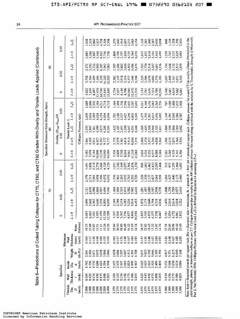
S T D - A P I i P E T R O RP 5C7-ENGL L99b m 0732290 05b2105 20T m
24 API RECOMMENDED PRACTICE 5C7
- m - ~ m w w o o t - r - c " . m m P l m w o w D O o m
m m i b w m m m oclmzrma 0000000
8 8 8 8 8 8 8 9949499 N N N N N N N
COPYRIGHT American Petroleum InstituteLicensed by Information Handling ServicesCOPYRIGHT American Petroleum InstituteLicensed by Information Handling Services
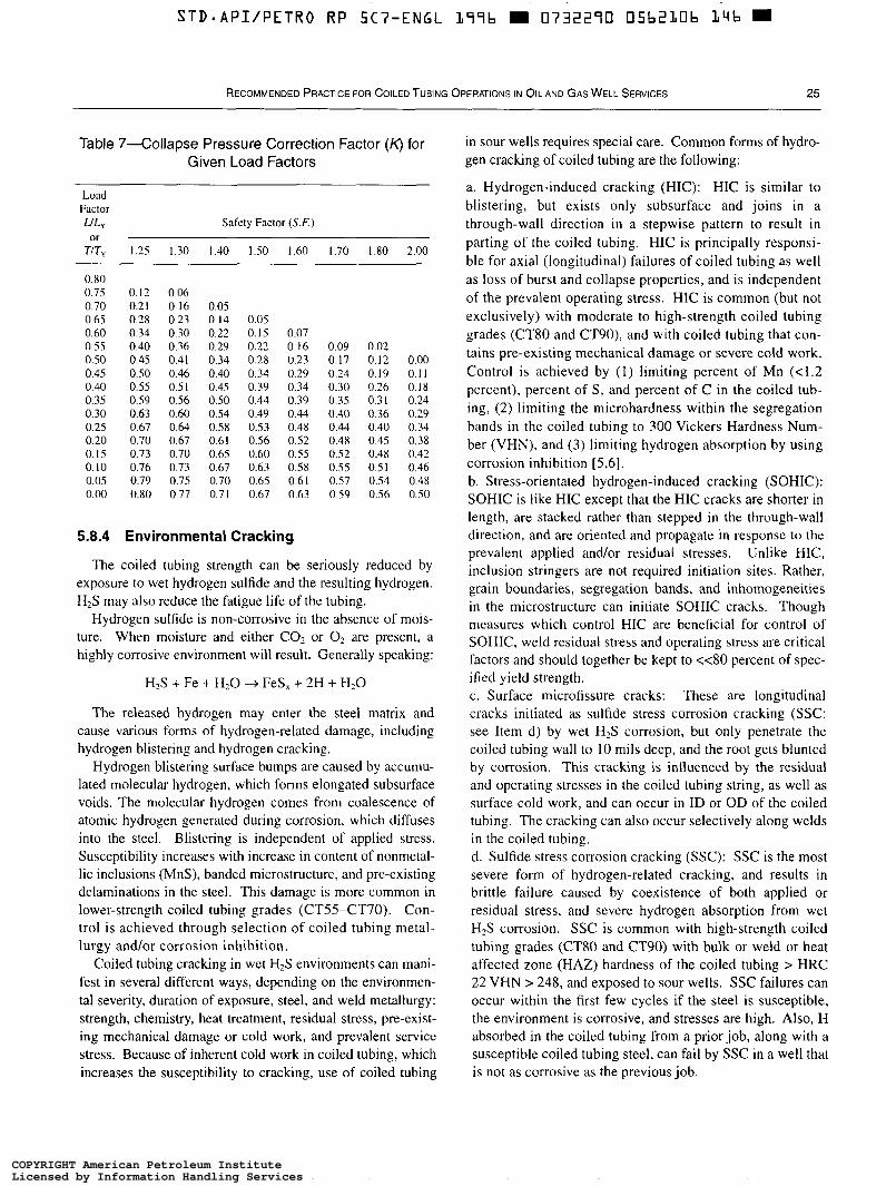
STD-API/PETRO RP 5C7-ENGL L97b m 0732290 05bZLOb L ~ q b
RECOMMENDED PRACTICE FOR COILED TUBING OPERATIONS IN OIL AND GAS WELL SERVICES 25
Table 7-Collapse Pressure Correction Factor (4 for Given Load Factors
Load Factor ULY Safety Factor (S.F.)
TIT, 1.25 1.30 1.40 1.50 1.60 1.70 1.80 2.00
0.80 0.75 0.12 0.06 0.70 0.21 O. I6 0.05 0.65 0.28 0.23 0.14 0.05 0.60 0.34 0.30 0.22 0.15 0.07 0.55 0.40 0.36 0.29 0.22 0.16 0.09 0.02 0.50 0.45 0.41 0.34 0.28 0.23 0.17 0.12 0.00 0.45 0.50 0.46 0.40 0.34 0.29 0.24 0.19 0.11 0.40 0.55 0.51 0.45 0.39 0.34 0.30 0.26 0.18 0.35 0.59 0.56 0.50 0.44 0.39 0.35 0.31 0.24 0.30 0.63 0.60 0.54 0.49 0.44 0.40 0.36 0.29 0.25 0.67 0.64 0.58 0.53 0.48 0.44 0.40 0.34 0.20 0.70 0.67 0.61 0.56 0.52 0.48 0.45 0.38 0.15 0.73 0.70 0.65 0.60 0.55 0.52 0.48 0.42 0.10 0.76 0.73 0.67 0.63 0.58 0.55 0.51 0.46 0.05 0.79 0.75 0.70 0.65 0.61 0.57 0.54 0.48 0.00 0.80 0.77 0.71 0.67 0.63 0.59 0.56 0.50
or
5.8.4 Environmental Cracking
The coiled tubing strength can be seriously reduced by exposure to wet hydrogen sulfide and the resulting hydrogen. HrS may also reduce the fatigue life of the tubing.
Hydrogen sulfide is non-corrosive in the absence of mois- ture. When moisture and either COr or O2 are present, a highly corrosive environment will result. Generally speaking:
H2S + Fe + HzO + Fes, + 2H + H 2 0
The released hydrogen may enter the steel matrix and cause various forms of hydrogen-related damage, including hydrogen blistering and hydrogen cracking.
Hydrogen blistering surface bumps are caused by accumu- lated molecular hydrogen, which forms elongated subsurface voids. The molecular hydrogen comes from coalescence of atomic hydrogen generated during corrosion, which diffuses into the steel. Blistering is independent of applied stress. Susceptibility increases with increase in content of nonmetal- lic inclusions (MnS), banded microstructure, and pre-existing delaminations in the steel. This damage is more common in lower-strength coiled tubing grades (CT.55-CT70). Con- trol is achieved through selection of coiled tubing metal- lurgy andlor corrosion inhibition.
Coiled tubing cracking in wet H2S environments can mani- fest in several different ways, depending on the environmen- tal severity, duration of exposure, steel, and weld metallurgy: strength, chemistry, heat treatment, residual stress, pre-exist- ing mechanical damage or cold work, and prevalent service stress. Because of inherent cold work in coiled tubing, which increases the susceptibility to cracking, use of coiled tubing
in sour wells requires special care. Common forms of hydro- gen cracking of coiled tubing are the following:
a. Hydrogen-induced cracking (HIC): HIC is similar to blistering, but exists only subsurface and joins in a through-wall direction in a stepwise pattern to result in parting of the coiled tubing. HIC is principally responsi- ble for axial (longitudinal) failures of coiled tubing as well as loss of burst and collapse properties, and is independent of the prevalent operating stress. HIC is common (but not exclusively) with moderate to high-strength coiled tubing grades (CT80 and CT90), and with coiled tubing that con- tains pre-existing mechanical damage or severe cold work. Control is achieved by (1) limiting percent of Mn (<1.2 percent), percent of S , and percent of C in the coiled tub- ing, (2) limiting the microhardness within the segregation bands in the coiled tubing to 300 Vickers Hardness Num- ber (VHN), and (3) limiting hydrogen absorption by using corrosion inhibition [5 ,6 ] . b. Stress-orientated hydrogen-induced cracking (SOHIC): SOHIC is like HIC except that the HIC cracks are shorter in length, are stacked rather than stepped in the through-wall direction, and are oriented and propagate in response to the prevalent applied and/or residual stresses. Unlike HIC, inclusion stringers are not required initiation sites. Rather, grain boundaries, segregation bands, and inhomogeneities in the microstructure can initiate SOHIC cracks. Though measures which control HIC are beneficial for control of SOHIC, weld residual stress and operating stress are critical factors and should together be kept to <<80 percent of spec- ified yield strength. c. Surface microfissure cracks: These are longitudinal cracks initiated as sulfide stress corrosion cracking (SSC: see Item d) by wet HIS corrosion, but only penetrate the coiled tubing wall to 10 mils deep, and the root gets blunted by corrosion. This cracking is influenced by the residual and operating stresses in the coiled tubing string, as well as surface cold work, and can occur in ID or OD of the coiled tubing. The cracking can also occur selectively along welds in the coiled tubing. d. Sulfide stress corrosion cracking (SSC): SSC is the most severe form of hydrogen-related cracking, and results in brittle failure caused by coexistence of both applied or residual stress, and severe hydrogen absorption from wet H,S corrosion. SSC is common with high-strength coiled tubing grades (CT80 and CT90) with bulk or weld or heat affected zone (HAZ) hardness of the coiled tubing > HRC 22 VHN > 248, and exposed to sour wells. SSC failures can occur within the first few cycles if the steel is susceptible, the environment is corrosive, and stresses are high. Also, H absorbed in the coiled tubing from a prior job, along with a susceptible coiled tubing steel, can fail by SSC in a well that is not as corrosive as the previous job.
COPYRIGHT American Petroleum InstituteLicensed by Information Handling ServicesCOPYRIGHT American Petroleum InstituteLicensed by Information Handling Services

STD-APIIPETRO RP 5C7-ENGL L97b H 0732270 O5b2L07 082 H
26 API RECOMMENDED PRACTICE 5C7
5.8.5 Specific Guidelines to Reduce the Risk of Coiled Tubing Failures in Wet, Sour Wells
Following is a list of guidelines aimed at reducing the risk of coiled-tubing failures in wet, sour wells:
a. HzS in brine with or without CO2 is more corrosive than H2S in oil. If working in a wellbore environment with HZS in brine, add inhibitor to circulating fluids. Risk of cracking in dry gas wells is low. b. Select steel with low S content and absence of banded microstructure, along with post-weld heat treatment above 1 1 SOOF. c. Verify microhardness in segregation bands is below 300 VHN and bulk hardness in weld, HAZ, or base metal should be less than HRC 22 (VHN < 248). d. Butt-welds are more susceptible to SSC than bias welds; therefore, cycling of butt welds in sour-well service should be minimized. e. It is recommended to perform a careful visual inspection of the coiled tubing outside diameter after the first 50 cycles when used in continuous H2S service or in numerous acidiz- ing or sour-gas well jobs. After 100 cycles in this service, the inspection should include a hydro test to assure pressure integrity. f. Hydrogen bake-out treatments (at 3W°F for 48 hours) may be performed after an extended duration of service in sour wells to extend the life of the coiled tubing string. g. End connectors induce mechanical damage which makes the coiled tubing more vulnerable. It is recommended to cut off connector damaged portions during exposure to sour wells. h. Use of coiled tubing field butt welds should be avoided for sour service. i. Wet H,S-assisted damage of coiled tubing is cumulative with the fatigue damage. Therefore, coiled tubing which has accumulated significant cycles in a sour well, for exam- ple, during cleanouts and workovers, will be more degraded than a coiled tubing used continuously (such as in a velocity string) in a sour well and should, therefore, be derated.
5.9 WELDS
Welds of various types are a fundamental feature of coiled tubing, and are of concern because the cycle life of certain welds can be significantly less than that of the base pipe. Being the weak link in the chain, the performance of welds is, therefore, of critical importance to the working condition of the tubing string as a whole.
5.9.1 Longitudinal (Seam) Weld
The longitudinal weld which runs the length of the coiled tubing, formed during manufacturing as the base strip, is rolled up into tubing in the mill.
Any problems with this weld are usually detected at the mill either during manufacture or subsequent pressure testing. Failures along the seam in the field are rare. Orientation of the weld with respect to the bending axis does not appear to significantly affect the observed fatigue life of the coiled tub- ing, and the longitudinal weld is generally disregarded when derating pipe.
5.9.2 Bias (or C/M) Weld The bias (or C M ) weld technique joins strips of base
metal, typically 3000 feet to 4000 feet long, to make a single strip of the required string length, prior to being rolled into tubing. The flat strip is cut and welded at a 45-degree angle, causing the weld to be helically distributed lengthwise when the strip is subsequently formed into tubing.
Since the weld is made in ideal conditions, with full con- trol over the geometry and weld penetration, the resulting weld is of high and consistent quality. Due to this, and the helical distribution of the weld along the coiled tubing axis, the bias weld performs well in fatigue tests. Experimental results indicate that the life of a bias weld approaches that of the base pipe, and there is relatively little variation from one weld to the next.
5.9.3 Butt-weld
A butt-weld is a method for joining lengths of existing tub- ing. The two ends to be joined are cut square, carefully aligned, and tungsten inert gas (T1G)-welded around the circumference. The resulting weld is perpendicular to the coiled tubing axis (unlike the bias weld) and, since the weld is made from the tubing exterior, the quality of the weld pene- tration through the tubing wall is paramount.
Two types of butt-welds are encountered and are explained in the following:
5.9.3.1 Automated (Factory) Butt-weld
Before the development of strip bias welds, all coiled tub- ing strings consisted of several lengths of preformed tubing butt-welded together using an automated welder at the tubing mill (hence the name factory weld). Made in carefully con- trolled conditions and with the advantages of automation, the quality of such welds can be very good, but nevertheless remain significantly inferior to bias welds. Automated weld- ers are expensive and therefore are relatively rare in the field, but are the preferred technique for field repairs.
5.9.3.2 Manual (Field) Butt-weld
Tubing can be butt-welded by hand using a TIG torch, and this is frequently the only option for a field repair. Good manual butt-welds require a very high level of skill. As a result, field butt-welds are the most problematic of all coiled tubing welds, and given the potential variability in quality, the
COPYRIGHT American Petroleum InstituteLicensed by Information Handling ServicesCOPYRIGHT American Petroleum InstituteLicensed by Information Handling Services

STD-API/PETRO RP SC7-ENGL L97b m 0732290 05b2L08 T39 m
RECOMMENDED PRACTICE FOR COILED TUBING OPERATIONS IN OIL AND GAS WELL SERVICES -
27
recommended practice based on experimental tests is to der- ate field butt-welds.
6 General Description of Coiled Tubing Surface Equipment
6.1 INTRODUCTION
This section gives recommended functional specifications for the major elements of coiled tubing surface equipment including the following:
a. Injector. b. Tubing-guide arch. c. Reel. d. Control and monitoring equipment. e. Power supply/prime mover. f. Coiled tubing tool connectors. g. Well control equipment.
6.2 INJECTOR
6.2.1 Functional Requirements
The following are general functional specifications which apply to any type of coiled tubing injector:
6.2.1.1 Tubing Size Range
The tubing size range is the sizes of coiled tubing that the injector is capable of running.
6.2.1.2 Maximum Pulling Force
The maximum pulling force is the maximum tensile force that the injector can apply to the coiled tubing immediately above the stripper at the manufacturer-recommended hydrau- lic operating pressure. The injector should be capable of a maximum pulling force that is 120 percent of the maximum force expected to pull the coiled tubing out of the well when at the total depth, including friction losses in the stripper. The injector and power supply should be capable of developing this force while the tubing is stationary and while moving at speeds up to 30 feet per minute.
6.2.1.3 Maximum Snubbing Force The maximum snubbing force is the maximum compres-
sive force the injector can apply to the coiled tubing imme- diately above the stripper at the manufacturer-recom- mended hydraulic operating pressure. The injector should be capable of a maximum snubbing force that is 120 per- cent of the maximum force expected to snub the coiled tub- ing into the well through the stripper and against the maxi- mum expected wellhead pressure. The injector and power supply should be capable of developing this force while the coiled tubing is stationary and while moving at speeds up to 30 feet per minute. Precautions should be taken to mini-
mize the unsupported length of coiled tubing between the injector and the stripper to prevent tube buckling at this maximum snubbing force.
6.2.1.4 Maximum Traction Maximum traction is the maximum axial traction force
that the injector can apply to push or pull the coiled tubing. A gripping force normal to the coiled tubing axis must be applied to the coiled tubing surface. This gripping force creates the friction necessary to allow the traction force to be applied without slippage between the coiled tubing and the gripping mechanism. The injector should be able to apply sufficient traction to the coiled tubing so that coiled tubing covered with normal protective lubricant will not slip through the injector at either the maximum pulling force or the maximum snubbing force. Damage to the coiled tubing should be minimized when the maximum traction necessary to normally operate the injector is applied. Provisions should be available to provide traction in the event of power supply or prime mover failure.
6.2.1.5 Maximum Speed Maximum speed is the maximum rate at which the injector
may be used to pull coiled tubing out of a well or run coiled tubing into a well.
6.2.1.6 Injector Support The injector must be supported to prevent a bending
moment under normal planned operating conditions (such as reel tension) from being applied to the wellhead large enough to cause damage to the wellhead or well-control stack. Any load due to the weight of the injector, well con- trol equipment, and the hanging weight of the coiled tubing that is transmitted to the wellhead should be transmitted along the axis of the wellhead.
6.2.1.7 Braking Systems
The injector should have a dynamic braking system that prevents the coiled tubing from moving uncontrollably due to load when no hydraulic pressure is being applied to the hydraulic motors. The dynamic braking system may allow some movement due to internal leakage of hydraulic compo- nents. The injector shall also have a secondary mechanical brake which is set automatically or manually when the injec- tor is stopped. Both of these braking systems must be capable of holding the maximum pulling force and the maximum snubbing force.
6.2.2 Coiled Tubing Injector Designs
There are several designs of coiled tubing injectors which are used to grip the tubing and provide forces to move the tubing into and out of the wellbore. Designs include opposed
COPYRIGHT American Petroleum InstituteLicensed by Information Handling ServicesCOPYRIGHT American Petroleum InstituteLicensed by Information Handling Services
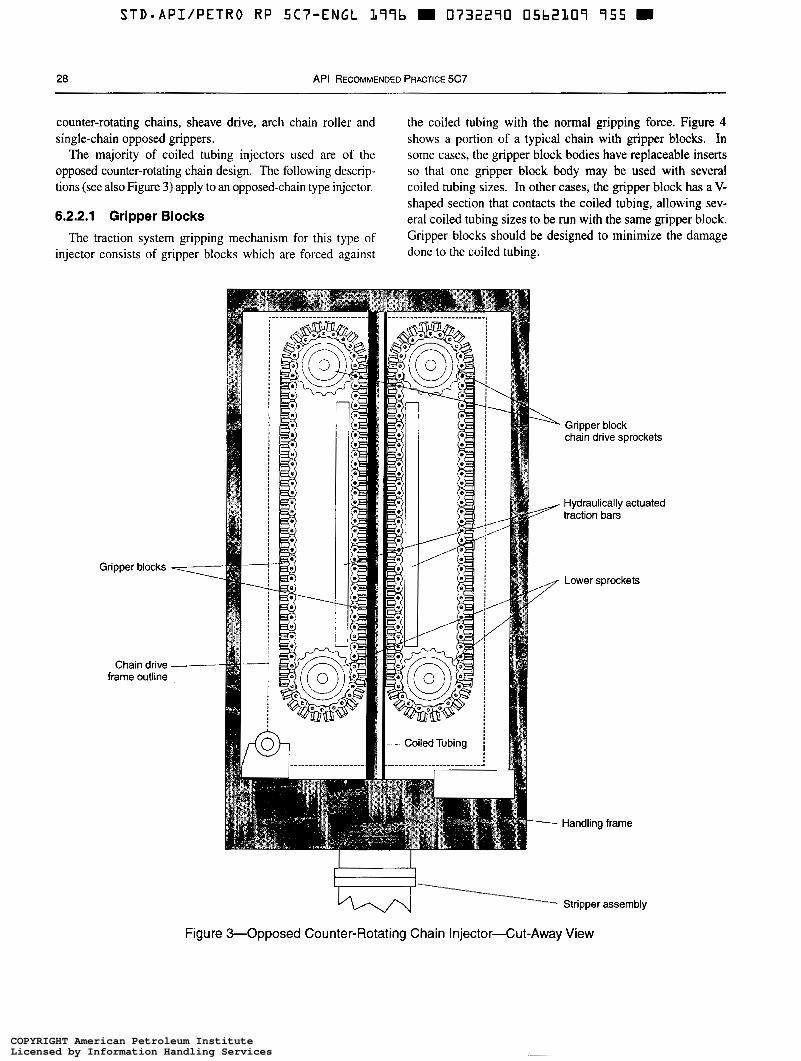
~~
STD-API/PETRO RP SC7-ENGL 199b m 0732290 05b2107 755 m
28 API RECOMMENDED PRACTICE 5C7
counter-rotating chains, sheave drive, arch chain roller and single-chain opposed grippers.
The majority of coiled tubing injectors used are of the opposed counter-rotating chain design. The following descrip- tions (see also Figure 3) apply to an opposed-chain type injector.
6.2.2.1 Gripper Blocks
The traction system gripping mechanism for this type of injector consists of gripper blocks which are forced against
the coiled tubing with the normal gripping force. Figure 4 shows a portion of a typical chain with gripper blocks. In some cases, the gripper block bodies have replaceable inserts so that one gripper block body may be used with several coiled tubing sizes. In other cases, the gripper block has a V- shaped section that contacts the coiled tubing, allowing sev- eral coiled tubing sizes to be run with the same gripper block. Gripper blocks should be designed to minimize the damage done to the coiled tubing.
Gripper blocks
Chain drive frame outline
A Gripper block chain drive sprockets
4 traction bars Hydraulically actuated
4 Lower sprockets
/
---" Handling frame
Stripper assembly
Figure 3-Opposed Counter-Rotating Chain Injector-Cut-Away View
COPYRIGHT American Petroleum InstituteLicensed by Information Handling ServicesCOPYRIGHT American Petroleum InstituteLicensed by Information Handling Services
S T D . A P I / P E T R O R P 5C7-ENGL L99b m 0732290 0 5 b 2 1 , ~ o m
RECOMMENDED PRACTICE FOR COILED TUBING OPERATIONS IN OIL AND GAS WELL SERVICES 29
6.2.2.2 Chain Support Systems
Figure 5 shows three types of chain support systems. In the first case (a) the chain contains cam rollers, as shown in Figure 4, which roll against flat support bars. In the second case (b) the back of the chain is flat and the rollers are con- tained in the support bars. A third design (c) uses a dual chain system with an inner chain supporting the outer chain.
6.2.2.3 Chain Traction
Figure 3 shows a typical mounting of the chains in the injector. Hydraulically actuated traction bars are used to force the gripper blocks against the coiled tubing to create the gripping force. This gripping force is typically increased by the operator when more traction is needed. If hydraulic cylinders are used to supply the traction pressure, an emer- gency system is required to maintain traction in case of a loss of hydraulic supply pressure. Usually this system con- sists of an accumulator and a manual hydraulic pump in the control cabin.
6.2.2.4 Chain Tension
Typically the chain tension must be increased when snub- bing to avoid buckling of the chain. If hydraulic cylinders are used to supply the tensioning pressure, an emergency system should be available to maintain chain tension in the case of a loss of hydraulic supply pressure. Usually this system consists of an accumulator and may include a man- ual hydraulic pump in the control cabin.
6.2.2.5 Drive Motors and Brakes
Hydraulic motors are used to drive the grippcr block chains by turning the chain drive sprockets. Different con- figurations are used with up to four motors driving the upper and lower sprockets. The hydraulic counter-balance system provides dynamic braking when hydraulic pressure is released. Many motors have built-in hydraulically released, mechanically actuated brakes that automatically lock when there is no hydraulic pressure to the motor. In other cases, separate external mechanical brakes are used.
6.2.2.6 Weight Indicator
The coiled tubing unit shall have a weight indicator which measures the tensile load in the coiled tubing just above the stripper. This weight measurement shall be dis- played to the operator during coiled tubing operations. There should also be an indicator which measures the com- pressive force in the coiled tubing below the injector when coiled tubing is being pushed or snubbed into the well. This compressive force is often referred to as negative weight. Some weight indicators are capable of measuring a limited amount of negative weight. If this type of weight indicator is being used, the snubbing force shall not exceed this lim-
ited amount during coiled tubing operations unless hydrau- lic motor pressure charts are available to determine snubbing forces.
6.3 TUBING-GUIDE ARCH
Certain types of injectors utilize a tubing-guide arch located on top of the injector (Figure 6 ) that guides the coiled tubing from the reel into the top of the injector. There are lower rollers and should be upper rollers which center the coiled tubing as it travels around the guide arch. The number, size, material, and spacing of the rollers vary significantly with different tubing-guide arch designs.
6.3.1 Radius
The tubing-guide arch radius (Figure 6 ) is defined as the radius of curvature of the centerline of the inner rollers (this determines the amount of bending fatigue damage; see 5.3). The bending radius of the tubing-guide arch is more impor- tant than the bending radius of the reel because twice as many bending cycles occur at the tubing-guide arch as occur at the reel. For coiled tubing used repeatedly in service and drilling applications, the tubing-guide arch radius should be at least 30 times the coiled tubing diameter. This factor may be less for coiled tubing which will be run only a few times (for example, permanent installations). Typical tubing-guide arch and reel core radii are shown in Table 8 for various coiled tubing diameters as compared to the yield radius of curvature for 70 thousand pounds per square inch yield strength materials.
6.3.2 Bending Stiffness
The reel tension applies a bending moment to the base of the tubing-guide arch. The tubing-guide arch shall be strong enough to withstand the bending caused by the required reel back-tension for the applicable tubing size.
6.3.3 Coiled Tubing Entry
The coiled tubing should enter and exit the tubing-guide arch tangent to the curve of the tubing-guide arch. Any abrupt bending angle through which the coiled tubing passes causes increased bending strains, increasing the fatigue damage.
6.3.4 Fleet Angle
Spooling of the coiled tubing back and forth across the width of the reel changes the fleet angle at which the coiled tubing approaches the tubing-guide arch. The fleet angle is the maximum angle between a line passing through the cen- ter of the tubing-guide arch and the center of the reel, and a line passing through the center of the tubing-guide arch and the flange of the reel. The end of the tubing-guide arch
COPYRIGHT American Petroleum InstituteLicensed by Information Handling ServicesCOPYRIGHT American Petroleum InstituteLicensed by Information Handling Services

D = Const
V-BLOCK SEMICIRCULAR BLOCK
I I Link plate -W Gripper block
Cam roller
a- Split pin
Figure &Typical Injector Chain System
COPYRIGHT American Petroleum InstituteLicensed by Information Handling ServicesCOPYRIGHT American Petroleum InstituteLicensed by Information Handling Services
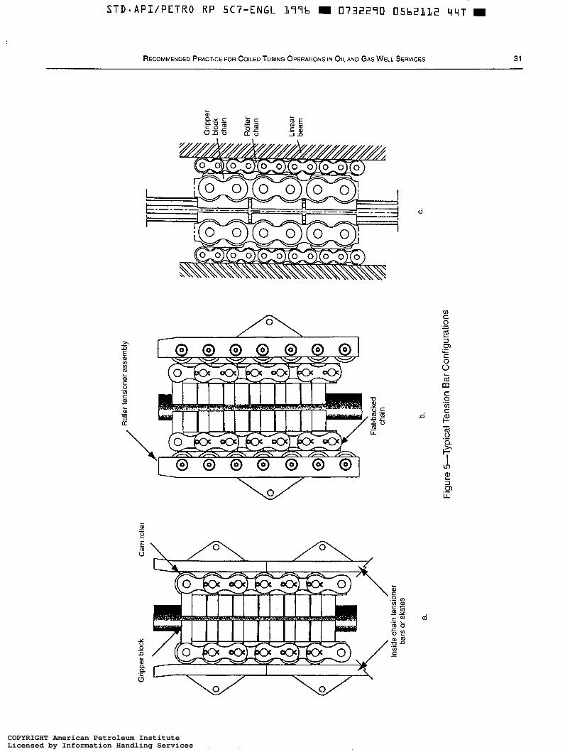
STD-API/PETRO RP 5C7-ENGL L77b M 0732270 05b2112 4 4 ~
RECOMMENDED PRACTICE FOR COILED TUBING OPERATIONS IN OIL AND GAS WELL SERVICES 31
COPYRIGHT American Petroleum InstituteLicensed by Information Handling ServicesCOPYRIGHT American Petroleum InstituteLicensed by Information Handling Services
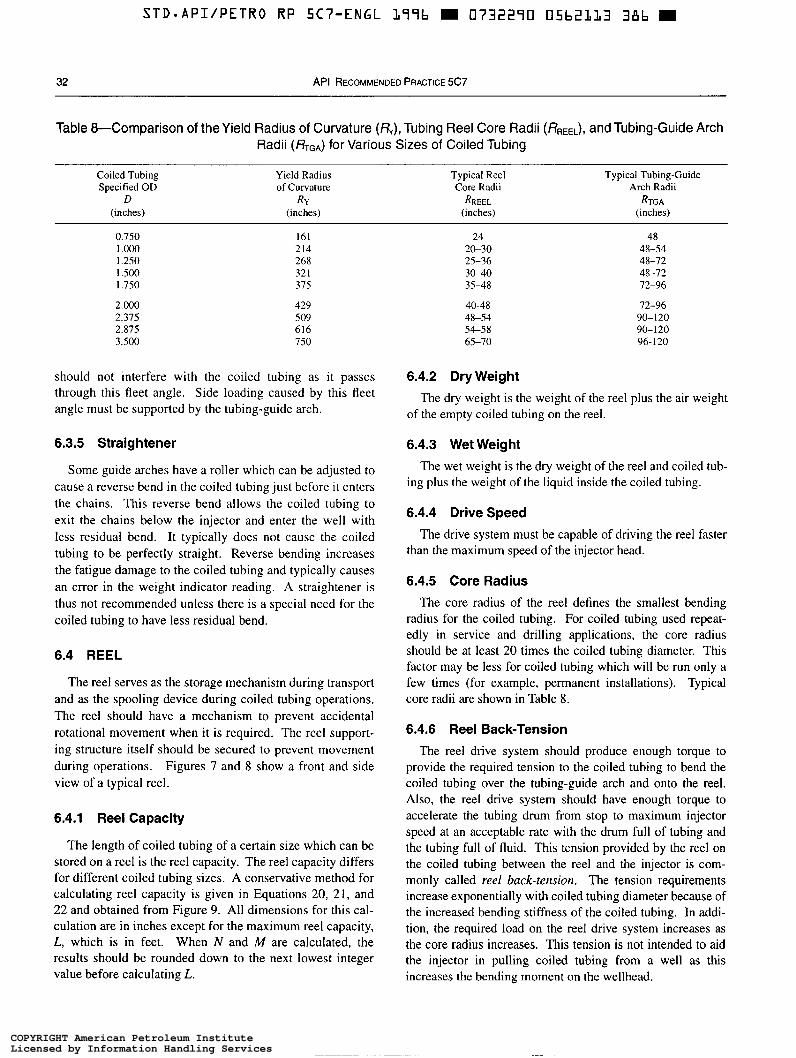
STD-APIIPETRO RP 5C7-ENGL L77b 0732270 05bZLL3 38b
32 API RECOMMENDED PRACTICE 5C7
Table &Comparison of the Yield Radius of Curvature (Ry), Tubing Reel Core Radii (&EEL), and Tubing-Guide Arch Radii (RTGA) for Various Sizes of Coiled Tubing
Coiled Tubing Yield Radius Typical Reel Typical Tubing-Guide Specified OD of Curvature Core Radii Arch Radii
D R Y RREEL RTGA (inches) (inches) (inches) (inches)
0.750 1 .o00 1.250 I S O O I .750
2.000 2.315 2.875 3.500
161 214 268 32 I 375
429 509 616 750
24 2&30 25-36 3&40 35-48
40-48 48-54 5 6 5 8 65-70
48 48-54 48-72 48-72 72-96
72-96 90-120 90-120 96- 120
should not interfere with the coiled tubing as it passes 6.4.2 Dry Weight through this fleet angle. Side loading caused by this fleet angle must be supported by the tubing-guide arch.
The dry weight is the weight of the reel plus the air weight of the empty coiled tubing on the reel.
6.3.5 Straightener
Some guide arches have a roller which can be adjusted to cause a reverse bend in the coiled tubing just before it enters the chains. This reverse bend allows the coiled tubing to exit the chains below the injector and enter the well with less residual bend. It typically does not cause the coiled tubing to be perfectly straight. Reverse bending increases the fatigue damage to the coiled tubing and typically causes an error in the weight indicator reading. A straightener is thus not recommended unless there is a special need for the coiled tubing to have less residual bend.
6.4 REEL
The reel serves as the storage mechanism during transport and as the spooling device during coiled tubing operations. The reel should have a mechanism to prevent accidental rotational movement when it is required. The reel support- ing structure itself should be secured to prevent movement during operations. Figures 7 and 8 show a front and side view of a typical reel.
6.4.1 Reel Capacity
The length of coiled tubing of a certain size which can be stored on a reel is the reel capacity. The reel capacity differs for different coiled tubing sizes. A conservative method for calculating reel capacity is given in Equations 20, 21, and 22 and obtained from Figure 9. All dimensions for this cal- culation are in inches except for the maximum reel capacity, L, which is in feet. When N and M are calculated, the results should be rounded down to the next lowest integer value before calculating L.
6.4.3 Wet Weight
The wet weight is the dry weight of the reel and coiled tub- ing plus the weight of the liquid inside the coiled tubing.
6.4.4 Drive Speed The drive system must be capable of driving the reel faster
than the maximum speed of the injector head.
6.4.5 Core Radius
The core radius of the reel defines the smallest bending radius for the coiled tubing. For coiled tubing used repeat- edly in service and drilling applications, the core radius should be at least 20 times the coiled tubing diameter. This factor may be less for coiled tubing which will be run only a few times (for example, permanent installations). Typical core radii are shown in Table 8.
6.4.6 Reel Back-Tension
The reel drive system should produce enough torque to provide the required tension to the coiled tubing to bend the coiled tubing over the tubing-guide arch and onto the reel. Also, the reel drive system should have enough torque to accelerate the tubing drum from stop to maximum injector speed at an acceptable rate with the drum full of tubing and the tubing full of fluid. This tension provided by the reel on the coiled tubing between the reel and the injector is com- monly called reel buck-tension. The tension requirements increase exponentially with coiled tubing diameter because of the increased bending stiffness of the coiled tubing. In addi- tion, the required load on the reel drive system increases as the core radius increases. This tension is not intended to aid the injector in pulling coiled tubing from a well as this increases the bending moment on the wellhead.
COPYRIGHT American Petroleum InstituteLicensed by Information Handling ServicesCOPYRIGHT American Petroleum InstituteLicensed by Information Handling Services
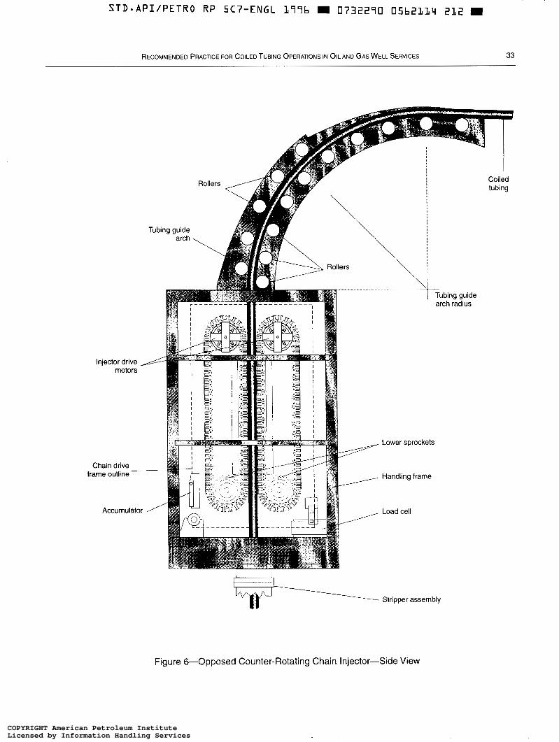
STD.API/PETRO RP 5C7-ENGL 177b m 0 7 3 2 2 9 0 05b2114 212 9
RECOMMENDED PRACTICE FOR COILED TUBING OPERATIONS IN O I L AND GAS WELL SERVICES 33
Injector drive - motors
Chain drive frame outline -
Accumulator
‘v+- Stripper assembly
Figure &Opposed Counter-Rotating Chain Injector-Side View
COPYRIGHT American Petroleum InstituteLicensed by Information Handling ServicesCOPYRIGHT American Petroleum InstituteLicensed by Information Handling Services
STD-API/PETRO RP 5Cï”ENGL 177b m 0732270 05b2115 157 m
34 API RECOMMENDED PRACTICE 5C7
6.4.7 Spring Energy
The coiled tubing stored on a reel has internal residual stresses that create a condition in which the tubing has the potential to unwrap and spring outward from the reel if the tubing back-tension is released. To prevent the coiled tubing from springing, the free end of the coiled tubing must always be kept in tension. During operations, the reel back-tension prevents the reel from springing. When not in operation, the free end of the coiled tubing must be restrained to prevent springing.
6.4.8 Brake
The reel brake is used to restrain the reel when it is not in motion. The brake can also minimize springing of the tubing on the reel in case of loss of hydraulic pressure and the subse- quent loss in reel back-tension. When the reel is being trans- ported, the brake should prevent rotation. The reel brake is not intended to prevent the coiled tubing from running into the well, as this increases the bending moment on the well- head and tubing-guide arch.
6.4.9 Levelwind
The levelwind is used to control the spooling of the coiled tubing onto the reel. A mechanical depth counter is usually mounted on the levelwind to measure the coiled tubing spooled on and off the reel. The levelwind must be strong enough to handle the bending and side loads of the coiled tub- ing. During transportation, the free end of the coiled tubing is usually clamped to the levelwind to prevent springing. The levelwind may be equipped with a hydraulically or pneumati- cally operated clamp which can be set to hold the coiled tub- ing at the levelwind.
6.4.10 Lubrication System
In many cases, the reel is equipped with a system for lubricating the outside of the coiled tubing to prevent atmo- spheric corrosion and reduce the frictional loads encoun- tered when injecting the coiled tubing through the energized stripper assembly.
The lubrication system shall conform to all local and fed- eral regulations. Sprayers that atomize lubricants onto the reel shall not be used with highly flammable materials.
6.4.11 Swivel and Piping
The reel is equipped with a swivel and piping to allow pumping through the coiled tubing while the reel is rotating. The swivel and piping shall have a working pressure rating at least as high as the pressure rating stipulated in 6.10.3, Item b, or at a pressure rating at least as high as the internal yield pressure of the coiled tubing, whichever meets the criteria for
the specified job. Special consideration should be given to cases in which the swivel and piping may come in contact with well fluids. These components shall be suitable for the type of service and fluids employed. H2S and high tempera- tures should be considered. At least one shut-off valve shall be incorporated between the coiled tubing and the swivel.
6.5 POWER SUPPLY/PRIME MOVER
Coiled-tubing unit power supplies are built in many dif- ferent configurations depending on the operating environ- ment. Most are powered by diesel engines, though some use electrical power. The power supply shall be capable of supplying enough hydraulic and electrical power to operate all of the coiled-tubing unit equipment at peak demand.
6.6 CONTROL AND MONITORING EQUIPMENT
6.6.1 Critical Job Parameters
6.6.1.1 Load Measurement
Load is defined as the tensile or compressive force in the coiled tubing just above the stripper. It is one of the most important measurements used to operate the coiled tubing unit. Load may be affected by several parameters other than the hanging weight of the coiled tubing, including wellhead pressure, stripper friction, reel back-tension, and the density of the fluids inside and outside the coiled tubing. Load shall be measured directly using a load cell which measures the force the coiled tubing is applying to the injector (see 4.2.2.6). A secondary load measurement may be obtained indirectly by measuring the hydraulic pressure applied to the injector motors.
6.6.1.2 Measured Depth
Measured depth is the length of coiled tubing that is deployed through the injector. Measured depth may be sig- nificantly different from the actual depth on the coiled tub- ing in the well due to stretch, thermal expansion, and so on. Measured depth can be directly measured in several places on a coiled tubing unit using a friction wheel which contacts the coiled tubing. Measured depth may also be obtained indirectly by measuring the rotation of the injector shafts. A coiled tubing unit shall not be operated without measured depth being displayed to the coiled tubing operator. Mea- sured depth should be recorded for use in fatigue calcula- tions. Some coiled tubing units have redundant depth measurement systems.
6.6.1.3 Speed Measurement
Speed may be calculated from the change in measured depth over a specified time period.
COPYRIGHT American Petroleum InstituteLicensed by Information Handling ServicesCOPYRIGHT American Petroleum InstituteLicensed by Information Handling Services
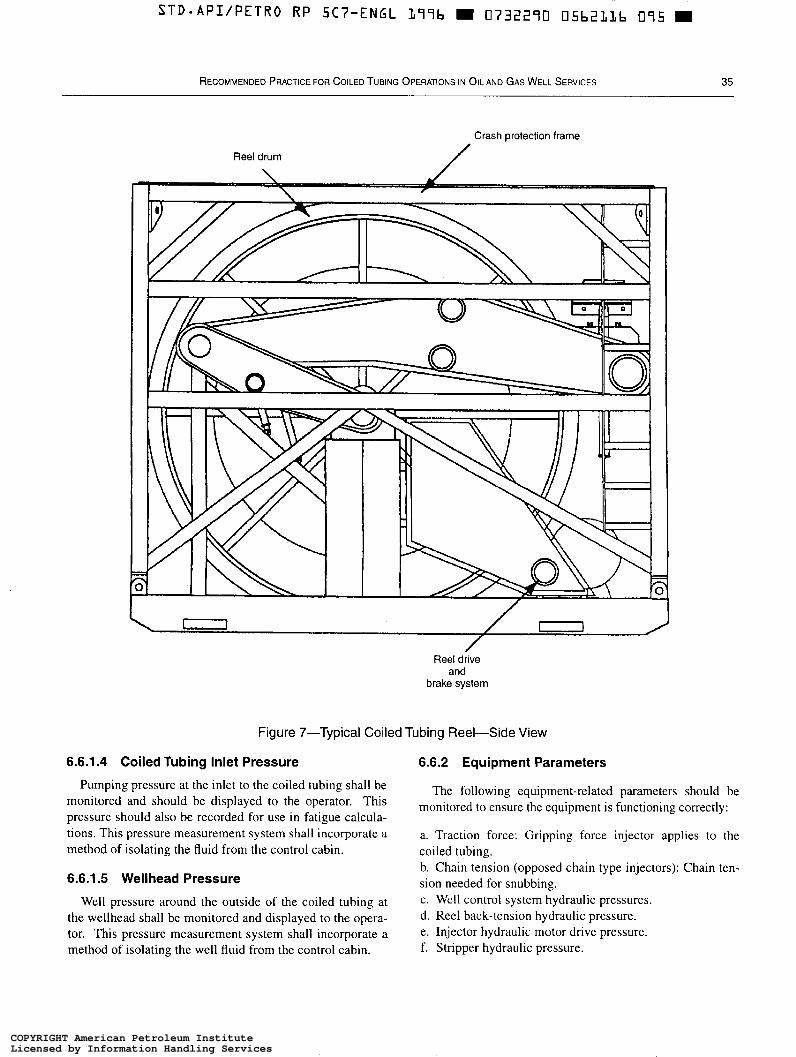
Reel drum
Crash Protection frame
/
0 O
Reel drive and
brake system
Figure 7-Typical Coiled Tubing Reel-Side View
6.6.1.4 Coiled Tubing Inlet Pressure 6.6.2 Equipment Parameters
Pumping pressure at the inlet to the coiled tubing shall be monitored and should be displayed to the operator. This pressure should also be recorded for use in fatigue calcula- tions. This pressure measurement system shall incorporate a method of isolating the fluid from the control cabin.
6.6.1.5 Wellhead Pressure
Well pressure around the outside of the coiled tubing at the wellhead shall be monitored and displayed to the opera- tor. This pressure measurement system shall incorporate a method of isolating the well fluid from the control cabin.
The following equipment-related parameters should be monitored to ensure the equipment is functioning correctly:
a. Traction force: Gripping force injector applies to the coiled tubing. b. Chain tension (opposed chain type injectors): Chain ten- sion needed for snubbing. c. Well control system hydraulic pressures. d. Reel back-tension hydraulic pressure. e. Injector hydraulic motor drive pressure. f. Stripper hydraulic pressure.
COPYRIGHT American Petroleum InstituteLicensed by Information Handling ServicesCOPYRIGHT American Petroleum InstituteLicensed by Information Handling Services
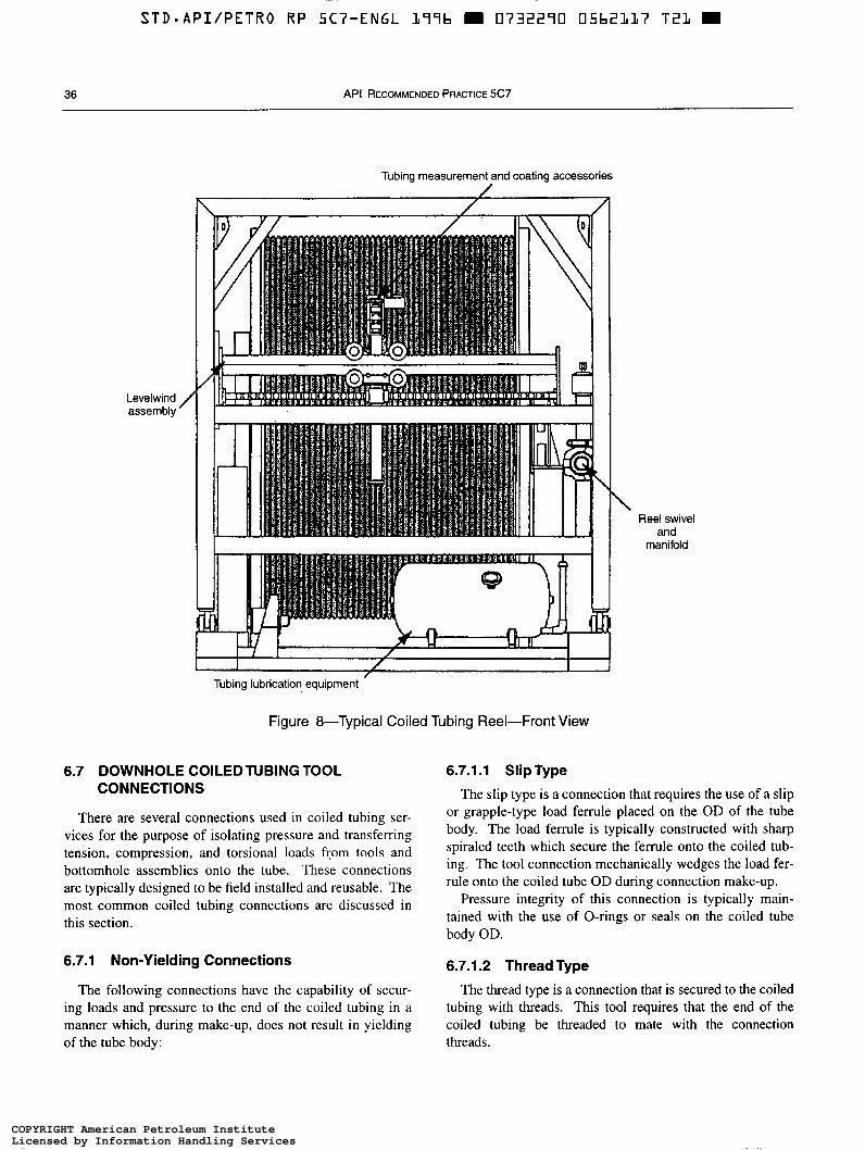
STD*API/PETRO RP SC7-ENGL L99b m 0732290 05bZLL7 T 2 1 W
36 API RECOMMENDED PRACTICE 5C7
Levelwind / assembly
Tubing measurement and coating accessories
L ,
I / I /
Tubing lubrication equipment
Figure 8-Typical Coiled Tubing Reel-Front View
6.7 DOWNHOLE COILEDTUBING TOOL 6.7.1.1 Slip Type CONNECTIONS
There are several connections used in coiled tubing ser- vices for the purpose of isolating pressure and transferring tension, compression, and torsional loads fcom tools and bottomhole assemblies onto the tube. These connections are typically designed to be field installed and reusable. The most common coiled tubing connections are discussed in this section.
6.7.1 Non-Yielding Connections
The following connections have the capability of secur- ing loads and pressure to the end of the coiled tubing in a manner which, during make-up, does not result i n yielding of the tube body:
\ Reel swivel
and manifold
The slip type is a connection that requires the use of a slip or grapple-type load ferrule placed on the OD of the tube body. The load ferrule is typically constructed with sharp spiraled teeth which secure the ferrule onto the coiled tub- ing. The tool connection mechanically wedges the load fer- rule onto the coiled tube OD during connection make-up.
Pressure integrity of this connection is typically main- tained with the use of O-rings or seals on the coiled tube body OD.
6.7.1.2 Thread Type The thread type is a connection that is secured to the coiled
tubing with threads. This tool requires that the end of the coiled tubing be threaded to mate with the connection threads.
COPYRIGHT American Petroleum InstituteLicensed by Information Handling ServicesCOPYRIGHT American Petroleum InstituteLicensed by Information Handling Services
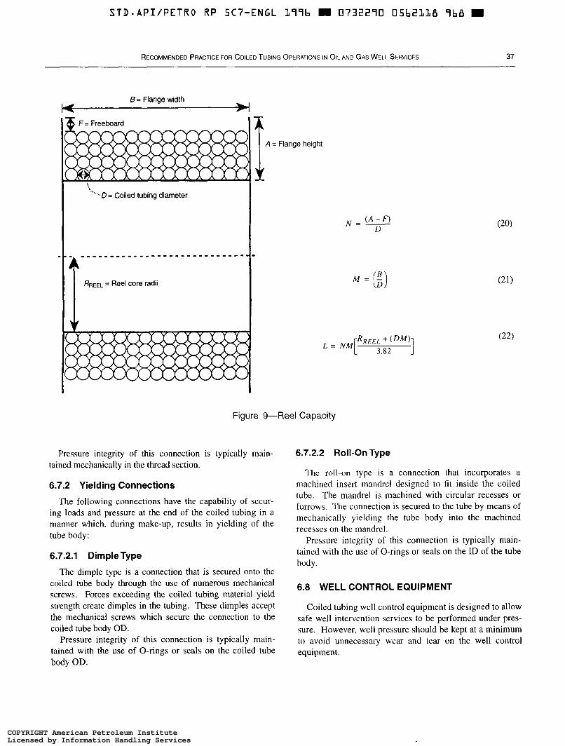
STD.API/PETRO RP 5C7-ENGL L99b 0732290 05b2LLB Yb8 m
RECOMMENDED PRACTICE FOR COILED TUBING OPERATIONS IN OIL AND GAS WELL SERVICES 37
8 = Flange width
I A = Flange height
Figure 9"Reel Capacity
Pressure integrity of this connection is typically main- tained mechanically in the thread section.
6.7.2 Yielding Connections
The following connections have the capability of secur- ing loads and pressure at the end of the coiled tubing i n a manner which, during make-up, results in yielding of the tube body:
6.7.2.1 DimpleType
The dimple type is a connection that is secured onto the coiled tube body through the use of numerous mechanical screws. Forces exceeding the coiled tubing material yield strength create dimples in the tubing. These dimples accept the mechanical screws which secure the connection to the coiled tube body OD.
Pressure integrity of this connection is typically main- tained with the use of O-rings or seals on the coiled tube body OD.
6.7.2.2 Roll-On Type
The roll-on type is a connection that incorporates a machined insert mandrel designed to fit inside the coiled tube. The mandrel is machined with circular recesses or furrows. The connection is secured to the tube by means of mechanically yielding the tube body into the machined recesses on the mandrel.
Pressure integrity of this connection is typically main- tained with the use of O-rings or seals on the ID of the tube body.
6.8 WELL CONTROL EQUIPMENT
Coiled tubing well control equipment is designed to allow safe well intervention services to be performed under pres- sure. However, well pressure should be kept at a minimum to avoid unnecessary wear and tear on the well control equipment.
COPYRIGHT American Petroleum InstituteLicensed by Information Handling ServicesCOPYRIGHT American Petroleum InstituteLicensed by Information Handling Services
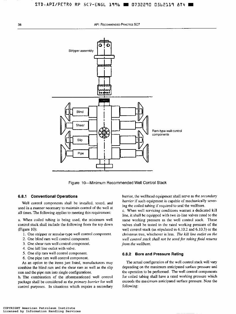
38 API RECOMMENDED PRACTICE 5C7
Stripper
Ram-type well components
m . .
control
W Figure 10-Minimum Recommended Well Control Stack
6.8.1 Conventional Operations
Well control components shall be installed, tested, and used in a manner necessary to maintain control of the well at all times. The following applies to meeting t h s requirement:
a. When coiled tubing is being used, the minimum well control stack shall include the following from the top down (Figure 10):
l . One stripper or annular-type well control component. 2. One blind ram well control component. 3. One shear ram well control component. 4. One kill line outlet with valve. 5 . One slip ram well control component. 6. One pipe ram well control component. As an option to the items just listed, manufacturers may
combine the blind r a m and the shear r a m as well as the slip r a m and the pipe r a m into single configurations. b. The combination of the aforementioned well control package shall be considered as the primmy barrier for well control purposes. In situations which require a secondary
barrier, the wellhead equipment shall serve as the secondary barrier if such equipment is capable of mechanically sever- ing the coiled tubing if required to seal the wellbore. c. When well servicing conditions warrant a dedicated kill line, it shall be equipped with two in-line valves rated to the same working pressure as the well control stack. These valves shall be tested to the rated working pressure of the well control stack (as stipulated in 6.10.2 and 6.10.3) or the christmas tree, whichever is less. The kill line outlet on the well control stack shall not be used for taking j h i d returns from the wellbore.
6.8.2 Bore and Pressure Rating
The actual configuration of the well control stack will vary depending on the maximum anticipated surface pressure and the operation to be performed. The well control components for coiled tubing shall have a rated working pressure which exceeds the maximum anticipated surface pressure. Note the following:
COPYRIGHT American Petroleum InstituteLicensed by Information Handling ServicesCOPYRIGHT American Petroleum InstituteLicensed by Information Handling Services

S T D - A P I I P E T R O R P 5Cï”ENGL L99b m 0732290 05b2120 5 L b m
RECOMMENDED PRACTICE FOR COILED TUBING OPERATIONS IN OIL AND GAS WELL SERVICES 39
a. Standard bore sizes for coiled tubing well control com- ponents are 2.56 inches, 3.06 inches, 4.06 inches, 5.12 inches, 6.38 inches and 7.06 inches. The typical working pressures for these components are 5,000, 10,000 and 15,000 pounds per square inch with test pressures of 10,000, 15,000 and 22,500 pounds per square inch gauge, respectively. b. All coiled tubing surface well control components shall be drift tested per API Specification 16A Section VI E8.4. For well control equipment bore sizes below 4x6 inches, refer to API Specification 6A, Table 11 for appropriate drift mandrel sizes.
6.8.3 Blind Rams
6.8.3.1 Blind rams isolate pressure from the well when the bore of the well control stack is unobstructed (Figure I I ) .
6.8.3.2 When the blind ram set has closed, the configura- tion of seals on each blind ram body is designed to use the pressure differential from below to assist in maintaining the ram in the closed position. The greater the pressure differen- tial acting from below to above the ram, the greater will be the force keeping the rams closed. Blind rams are not intended to seal when pressured from above.
6.8.3.3 All pressure-sealing rams shall have a method of equalizing the pressure across the rams prior to opening. This prevents severe seal damage which occurs if the cams are opened under differential pressure. Equalizing valves may be fitted as an integral part of the well control component or using exterior tubes.
6.8.3.4 The operation of the blind ram is independent of the coiled tubing size in use. Therefore, the blind ram does not need to be changed out when the well control stack is dressed for a change in coiled tubing size.
BLIND RAM
Figure 11-Blind Ram
SHEAR RAM
Figure 12-Shear Ram
6.8.4 Shear Rams
6.8.4.1 The shear rams shall be designed with the capa- bility to shear the wall thickness and yield strength of the specified coiled tubing OD size as test certified at the rated working pressure of the well control stack (Figure 12). The hydraulic system pressure required to effectively shear the coiled tubing (with a wellbore pressure at the rated working pressure of the well control component) must be below the maximum allowable working pressure of the prime mover hydraulic system. The hydraulic system pressure required for this operation will be provided by the manufacturer upon request.
Example: A 3.06-inch, 10,000-pound per square inch well control stack with a 3,000-pound per square inch hydraulic system will cleanly cut 1.75-inch OD, O. 156-inch wall, 70-thousand pound per square inch minimum yield coiled tubing, with 10,000-pound per square inch wellbore pressure at 2,700-pound per square inch or less hydraulic system pressure.
6.8.4.2 The shear blades shall be capable of two or more cuts of the heaviest wall and highest yield strength of the specified size of coiled tubing as test certified. The shear blades, after cutting the coiled tubing, should leave the OD of the coiled tubing as close as possible to the original coiled tubing OD, to allow for kill fluid to be pumped down the coiled tubing left in the well, and to facilitate proper fishing operations.
6.8.4.3 A test cut of the heaviest wall of the specified size of coiled tubing in service shall be made every 120 days (as a minimum test frequency) to verify performance of the shear rams. The hydraulic system pressure shall be recorded and the wellbore pressure effect calculated and added to the recorded hydraulic system pressure for future reference. The shear ram blades shall be inspected after each coiled
COPYRIGHT American Petroleum InstituteLicensed by Information Handling ServicesCOPYRIGHT American Petroleum InstituteLicensed by Information Handling Services
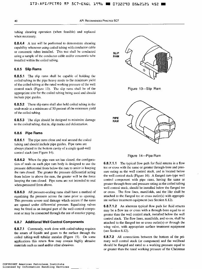
40 API RECOMMENDED PRACTICE 5C7
tubing shearing operation (when feasible) and replaced when necessary.
6.8.4.4 A test will be performed to demonstrate shearing capability whenever using coiled tubing with conductor cable or concentric tubes installed. This test shall be conducted using a sample of the conductor cable and/or concentric tube installed within the coiled tubing.
6.8.5 Slip Rams
6.8.5.1 The slip rams shall be capable of holding the coiled tubing in the pipe heavy mode to the minimum yield of the coiled tubing at the rated working pressure of the well control stack (Figure 13). The slip rams shall be of the appropriate size for the coiled tubing being used and should include pipe guides.
6.8.5.2 These slip rams shall also hold coiled tubing in the snub mode at a minimum of 50 percent of the minimum yield of the coiled tubing.
6.8.5.3 The slips should be designed to minimize damage to the coiled tubing, that is, slip marks and deformation.
6.8.6 Pipe Rams
6.8.6.1 The pipe rams close and seal around the coiled tubing and should include pipe guides. Pipe rams are always placed in the bottom cavity of a single quad-well control stack (see Figure 14).
6.8.6.2 When the pipe ram set has closed, the configura- tion of seals on each pipe ram body is designed to use the pressure differential from below the ram to assist in keeping the ram closed. The greater the pressure differential acting from below to above the ram, the greater will be the force keeping the ram closed. Pipe rams are not intended to seal when pressured from above.
6.8.6.3 All pressure-sealing rams shall have a method of equalizing the pressure across the rams prior to opening. This prevents severe seal damage which occurs if the rams are opened under differential pressure. Equalizing valves may be fitted as an integral part of the well control compo- nent or may be connected through the use of exterior piping.
6.8.7 Additional Well Control Components
6.8.7.1 Commonly, work done with coiled tubing requires the return of liquids and gases to the surface through the coiled tubing-well tubular annulus (Figure 15). On some applications this return flow may contain highly abrasive materials such as sand and/or other abrasives.
SLIP RAM
PIPE RAM
Figure 13-Slip Ram
n
Figure 14-Pipe Ram
6.8.7.1.1 The typical flow path for fluid returns is a flow tee or cross with the same or greater through-bore and pres- sure rating as the well control stack, and is located below the well control stack (Figure 16). A flanged ram-type well control component with pipe rams, having the same or greater through-bore and pressure rating as the coiled tubing well control stack, should be installed below the flanged tee or cross. The flow lines, manifolds, and the like shall be attached to the flanged tee or cross outlet(s) with appropri- ate surface treatment equipment (see Section 6.12).
6.8.7.1.2 An alternate typical flow path for fluid returns may be a flow tee or cross with a through-bore equal to or greater than the well control stack, installed below the well control stack. The flow lines, manifolds, and so on, shall be attached to the flanged tee or cross outlet(s) or through the wing valve, with appropriate surface treatment equipment (see Section 6.12).
6.8.7.2 All connections between the bottom of the pri- mary well control stack (or component) and the wellhead should be flanged and rated to a working pressure equal to or greater than the rated working pressure of the Christmas
COPYRIGHT American Petroleum InstituteLicensed by Information Handling ServicesCOPYRIGHT American Petroleum InstituteLicensed by Information Handling Services
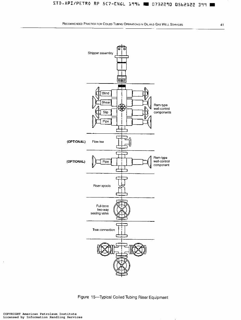
STD*API/PETRO RP SC7-ENGL L77b m 0732270 05b2L22 377 m
RECOMMENDED PRACTICE FOR COILED TUBING OPERATIONS IN OIL AND GAS WELL SERVICES 41
Stripper assembly
Ram-type well-control components
W
(OPTIONAL) Flow tee m Ram-type
(OPTIONAL) Pipe well-control component
Riser spools Ld m Full-bore two-way
sealing valve
Tree connection 111
Figure 15-Typical Coiled Tubing Riser Equipment
COPYRIGHT American Petroleum InstituteLicensed by Information Handling ServicesCOPYRIGHT American Petroleum InstituteLicensed by Information Handling Services
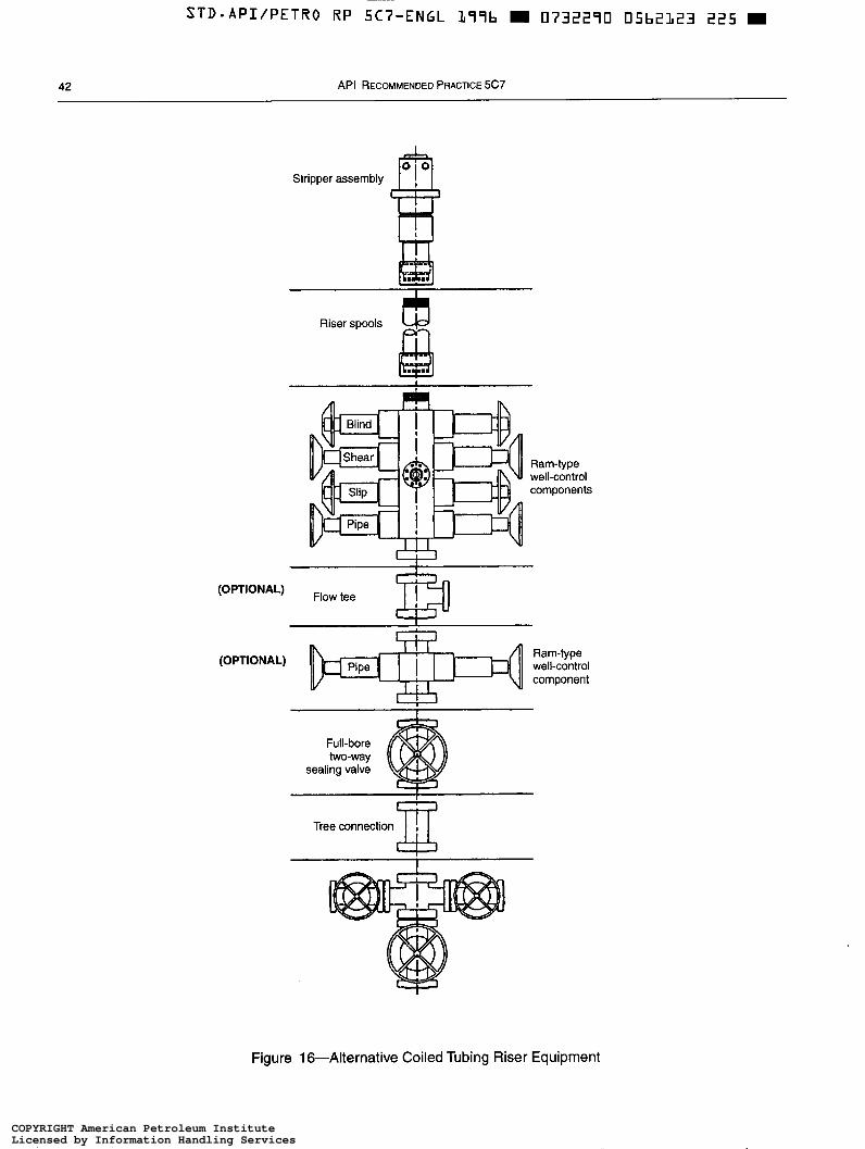
STD-API/PETRO RP 5C7-ENGL L77b W 0732270 05b2123 225 m
42 API RECOMMENDED PRACTICE 5C7
Stripper assembly
Riser spools
Ram-type well-control components
(OPTIONAL) Ram-type
component 1 1 1 1 well-control I I I r 1 1
Full-bore two-way
sealing valve
Tree connection
Figure 1 &Alternative Coiled Tubing Riser Equipment
COPYRIGHT American Petroleum InstituteLicensed by Information Handling ServicesCOPYRIGHT American Petroleum InstituteLicensed by Information Handling Services
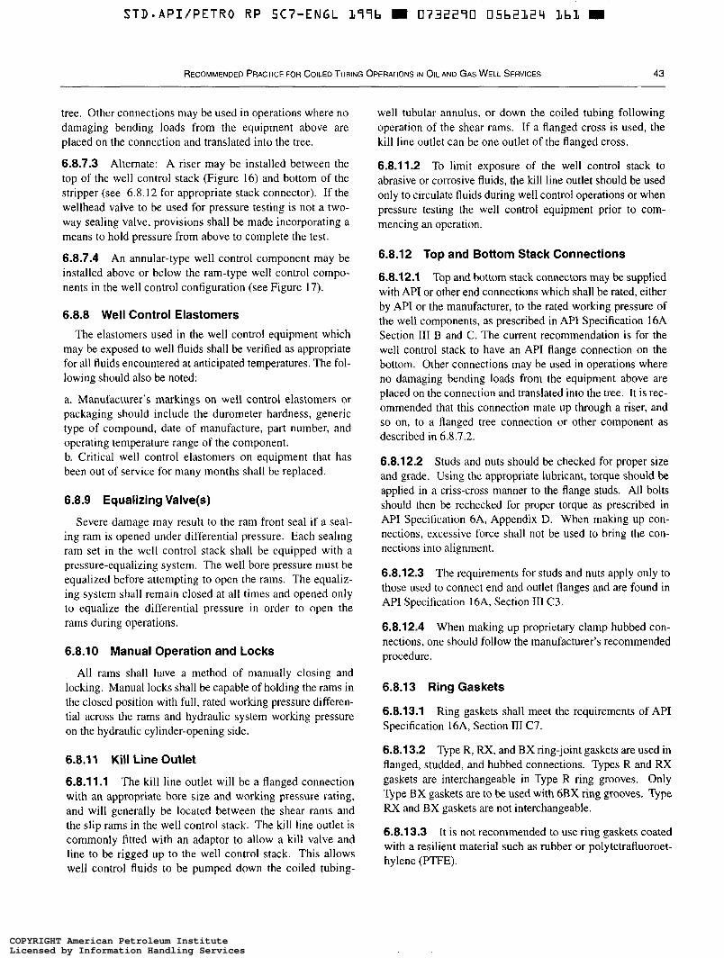
S T D * A P I / P E T R O R P 5C7-ENGL 177b 0732270 05b212"I L b 1
RECOMMENDED PRACTICE FOR COILED TUBING OPERATIONS IN OIL AND GAS WELL SERVICES 43
tree. Other connections may be used in operations where no damaging bending loads from the equipment above are placed on the connection and translated into the tree.
6.8.7.3 Alternate: A riser may be installed between the top of the well control stack (Figure 16) and bottom of the stripper (see 6.8.12 for appropriate stack connector). If the wellhead valve to be used for pressure testing is not a two- way sealing valve, provisions shall be made incorporating a means to hold pressure from above to complete the test.
6.8.7.4 An annular-type well control component may be installed above or below the ram-type well control compo- nents in the well control configuration (see Figure 17).
6.8.8 Well Control Elastomers
The elastomers used in the well control equipment which may be exposed to well fluids shall be verified as appropriate for all fluids encountered at anticipated temperatures. The fol- lowing should also be noted:
a. Manufacturer's markings on well control elastomers or packaging should include the durometer hardness, generic type of compound, date of manufacture, part number, and operating temperature range of the component. b. Critical well control elastomers on equipment that has been out of service for many months shall be replaced.
6.8.9 Equalizing Valve(s)
Severe damage may result to the ram front seal if a seal- ing ram is opened under differential pressure. Each sealing ram set in the well control stack shall be equipped with a pressure-equalizing system. The well bore pressure must be equalized before attempting to open the rams. The equaliz- ing system shall remain closed at all times and opened only to equalize the differential pressure in order to open the rams during operations.
6.8.10 Manual Operation and Locks
All rams shall have a method of manually closing and locking. Manual locks shall be capable of holding the rams in the closed position with full, rated workmg pressure differen- tial across the rams and hydraulic system working pressure on the hydraulic cylinder-opening side.
6.8.1 1 Kill Line Outlet
6.8.1 1.1 The kill line outlet will be a flanged connection with an appropriate bore size and working pressure rating, and will generally be located between the shear rams and the slip rams in the well control stack. The kill line outlet is commonly fitted with an adaptor to allow a kill valve and line to be rigged up to the well control stack. This allows well control fluids to be pumped down the coiled tubing-
well tubular annulus, or down the coiled tubing following operation of the shear rams. If a flanged cross is used, the kill line outlet can be one outlet of the flanged cross.
6.8.11.2 To limit exposure of the well control stack to abrasive or corrosive fluids, the kill line outlet should be used only to circulate fluids during well control operations or when pressure testing the well control equipment prior to com- mencing an operation.
6.8.12 Top and Bottom Stack Connections
6.8.12.1 Top and bottom stack connectors may be supplied with APT or other end connections which shall be rated, either by API or the manufacturer, to the rated working pressure of the well components, as prescribed in API Specification 16A Section III B and C. The current recommendation is for the well control stack to have an API flange connection on the bottom. Other connections may be used in operations where no damaging bending loads from the equipment above are placed on the connection and translated into the tree. It is rec- ommended that this connection mate up through a riser, and so on, to a fanged tree connection or other component as described in 6.8.7.2.
6.8.12.2 Studs and nuts should be checked for proper size and grade. Using the appropriate lubricant, torque should be applied in a criss-cross manner to the flange studs. All bolts should then be rechecked for proper torque as prescribed in API specification 6A, Appendix D. When malung up con- nections, excessive force shall not be used to bring the con- nections into alignment.
6.8.12.3 The requirements for studs and nuts apply only to those used to connect end and outlet flanges and are found in API Specification 16A, Section III C3.
6.8.12.4 When making up proprietary clamp hubbed con- nections, one should follow the manufacturer's recommended procedure.
6.8.13 Ring Gaskets
6.8.13.1 Ring gaskets shall meet the requirements of API Specification 16A, Section III C7.
6.8.13.2 Type R, R X , and BX ring-joint gaskets are used in flanged, studded, and hubbed connections. Types R and RX gaskets are interchangeable in Type R ring grooves. Only Type BX gaskets are to be used with 6BX ring grooves. Type RX and BX gaskets are not interchangeable.
6.8.13.3 It is not recommended to use ring gaskets coated with a resilient material such as rubber or polytetrafluoroet- hylene (PTFE).
COPYRIGHT American Petroleum InstituteLicensed by Information Handling ServicesCOPYRIGHT American Petroleum InstituteLicensed by Information Handling Services
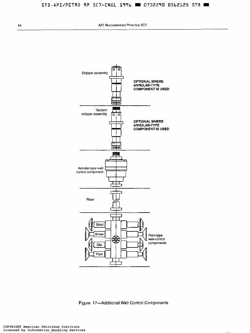
44 API RECOMMENDED PRACTICE 5C7
Stripper assembly a OPTIONAL WHERE
COMPONENT IS USED ANNULAR-TYPE
stripper assembly 6 Tandem
OPTIONAL WHERE
COMPONENT IS USED ANNULAR-TYPE
Annular-type well control component.
I
Riser
Ram-type well-control components
Figure 17-Additional Well Control Components
COPYRIGHT American Petroleum InstituteLicensed by Information Handling ServicesCOPYRIGHT American Petroleum InstituteLicensed by Information Handling Services
~
STD.API/PETRO R P 5C7-ENGL L77b m 0732290 O5b212b T 3 4 W
RECOMMENDED PRACTICE FOR COILED TUBING OPERATIONS IN OIL AND GAS WELL SERVICES 45
6.8.13.4 Due to the limited amount of deformation which a groove can make in a ring as it is compressed during installation, ring gaskets should not be reused.
6.8.14 Downhole Check Valve@)
6.8.14.1 A check valve assembly is typically attached to the coiled tubing connector at the downhole end of the coiled tubing to prevent wellbore fluids from entering the coiled tubing string in the event treatment fluids are not being pumped. In addition, the check valve assembly pro- vides an essential safety barrier against wellbore fluid influx up the coiled tubing in the event of a seal or joint failure in the BHA or if the tubing should fail or be damaged at the surface. If check valves are run, the check valve(s) assembly should be attached as close to the coiled tubing connection as is practical. To provide a contingency for failure, it is a general recommendation for two check valves (dual) to be fitted in series.
In operations where downhole check valves are not used, proper contingency plans must be prepared prior to each job.
In performing these functions, the check valve assembly shall be regarded as an item of well pressure control equipment.
6.8.14.2 Check valve designs may be broadly categorized into two groups, ball and seat check valves, and flapper check valves.
6.8.14.2.1 The ball and seat check valve is the most com- mon check valve, primarily due to its simple construction and ease of maintenance. Variations of design may use darts, cones or dome-shaped components instead of a ball to effect a seal. Some designs use a spring to ensure the ball or dart is effectively seated, while others rely on fluid movement.
The principal disadvantages of this check valve design include the restricted fluid flow area and bore obstruction caused by the ball or dart.
Since the through bore of the valve is obstructed, tools or applications requiring balls, darts, or plugs to be pumped through the workstring are incompatible with this type of check valve.
6.8.14.2.2 Full-bore flapper check valves are suitable for use on coiled tubing applications where balls, darts, or plugs are pumped through the coiled tubing, enabling actuation of tool functions below the check valve.
6.8.14.3 The selection of an appropriate check valve type or design should be made after considering the following points:
a. Treatment fluid characteristics include abrasive action, solids content/particle size, and chemical action. b. Maximum differential pressure acting on the check valve in the prescribed service.
c. Temperature and pressure applications which may re- quire special seals. d. Applications and tools requiring a ball, dart, or plug which must be compatible with the check valve.
6.9 WELL CONTROL EQUIPMENT FOR HYDROGEN SULFIDE SERVICE
6.9.1 Applicability
Well control equipment should comply with API Recom- mended Practice 53, Section 9, when the equipment may be exposed to fluids from hydrogen sulfide gas zones that could potentially result in the partial pressure of hydrogen-sulfide exceeding 0.05 pounds per square inch absolute in the gas phase at the maximum anticipated pressure. Equipment modifications below may be needed to comply.
6.9.2 Equipment Modifications
6.9.2.1 Equipment modifications should be considered since many metallic materials in a hydrogen sulfide environ- ment (sour service) are subject to a form of hydrogen embrittlement known as sulfîde stress cruckirrg (SSC). This type of spontaneous brittle failure is dependent on the met- allurgical properties of the material, the total stress or load (either internal or applied), and the corrosive environment. A list of acceptable materials is given in NACE MR-01-75.
6.9.2.2 A list of specific items to be changed on annular- type and ram-type well control equipment and valves for service in a hydrogen sulfide environment should be fur- nished by the manufacturer. As a guide, all metallic materi- als which could be exposed to hydrogen sulfide under probable operating conditions should be highly resistant to sulfide stress cracking.
6.9.2.3 The maximum acceptable hardness for all well control components, valves, and spools shall be in accor- dance with NACE MR-01-75.
6.9.2.4 Ring joint gaskets should meet the requirements of API Specification 16A, Section III C7.
6.9.2.5 All studs and nuts used in connection with flanges, clamps, and hubs should be selected in accordance with provisions of API Specification 16A, Section III C3.
6.9.2.6 All lines, crosses, valves, and fittings in the choke line and ki l l line should be constructed from materials meet- ing applicable requirements of API Specification SL and API Specification 6A and should be heat treated to the cor- rect hardness and other applicable requirements as stipu- lated in NACE MR-01-75.
6.9.2.7 Elastomers are subject to hydrogen sulfide attack. Elastomers which meet other requirements may be suitable
COPYRIGHT American Petroleum InstituteLicensed by Information Handling ServicesCOPYRIGHT American Petroleum InstituteLicensed by Information Handling Services
STD-APIIPETRO RP 5C7-ENGL L77b m 0732270 05b2127 770 m
46 API RECOMMENDED PRACTICE 5C7
for hydrogen sulfide service provided service fluids are properly treated. Service life shortens rapidly as tempera- ture increases from 150'F to 200'F. If return line tempera- tures in excess of 200°F are anticipated, the equipment manufacturer should be consulted. Elastomers should be changed out as soon as possible after exposure to hydrogen sulfide under pressure.
6.9.2.8 Changes prescribed by the equipment manufacturer to render equipment acceptable for service in a hydrogen sul- fide environment should not be overlooked in providing for replacement and repair parts.
6.10 WELL CONTROLTESTS AND DRILLS
The well control equipment including the well control stack, flow lines, kill lines, manifolds, risers, and so forth, shall comply with and be tested in accordance with existing API standards where applicable (as detailed in 6.10.2, 6.10.3, 6.12.2, 6.12.3, and 6.12.4) and meet operator and contractor specifications if such specifications exceed the requirements of the applicable regulations.
6.10.1 Pressure Tests
6.10.1.1 Annular-type and ram-type well control compo- nents shall be pressure tested. The recommended pressure test fluids are water or other suitable solids-free liquids. If liquid pumping equipment is not available on location, the pressure test may be conducted using nitrogen as the test fluid when performed in accordance with the appropriate safety guidelines for testing with energized fluids. All well control components shall be subjected to a low-pressure test (generally 200 to 300 pounds per square inch gauge for a minimum of 5 minutes) prior to conducting the high-pres- sure tests.
Note: When applying the low pressure, do not apply a higher pressure and then bleed down to the low test pressure. The higher pressure could initiate a seal that may continue to seal after pressure is lowered and, therefore, not be representative of a typical low-pressure condition.
6.10.1.2 A stable high test pressure should be maintained for at least 10 minutes.
6.10.1.3 Well control component pressure tests shall fall into two distinct categories:
a. Function pressure test: This pressure test is required to demonstrate the ability of the well control component to actu- ate and affect pressure seals as specified. Note that the func- tion pressure test will simultaneously demonstrate the pressure integrity of the well control stack, coiled tubing, pump line(s), kill line(s), manifold(s), and choke line(s). b. System pressure test: This pressure test is required to demonstrate the pressure integrity of all well control com-
ponents and connections. This test does not require actua- tion of rams or annular components.
6.1 0.2 Function Pressure Test: Annular-Type Component
Annular-type well control components shall be tested as follows:
a. In a concentric operation, annular-type well control com- ponents shall be tested below the sealing element to 70 per- cent of their rated working pressure or to the rated working pressure of the wellhead, whichever is less, except where noted by 6.10.2, Item b. b. As an alternative in cases where the rated working pres- sure of annular-type well control components substantially exceeds the maximum anticipated surface pressure, the annular well control components may be tested below the sealing element to the maximum anticipated surface pres- sure or higher. In no instance, shall the test pressure be less than the maximum anticipated surface pressure.
6.10.3 Function Pressure Test: Ram-Type Component
Ram-type well control components shall be pressure tested as follows:
a. In a concentric operation, ram-type well control compo- nents shall be tested below the rams to the rated working pressure of the well control stack or to the rated working pressure of the wellhead, whichever is less, except where noted by 6.10.3, Item h. b. As an alternative in cases where the rated working pres- sure of the ram-type well control components substantially exceeds the maximum anticipated surface pressure, the ram- type well control components may be tested below the rams to the maximum anticipated surface pressure or higher. In no instance shall the test pressure be less than the maximum anticipated surface pressure.
6.10.4 Well Control Equipment Pressure Test Frequency
Pressure tests on the well control equipment shall be con- ducted as follows:
a. Function pressure test: l . Upon initial installation of the hydraulic pressure control system. 2. At least once every 7 days when installed. 3. Prior to well testing operations. A period of more than 7 days between tests shall be
allowed when abnormal well operations (such as stuck coiled tubing) lasting more than 7 days prevent testing, provided the tests are performed before normal operations resume. b. System pressure test:
COPYRIGHT American Petroleum InstituteLicensed by Information Handling ServicesCOPYRIGHT American Petroleum InstituteLicensed by Information Handling Services

S T D . A P I / P E T R O R P 5C7-ENGL L77b m 0732270 05b2128 AO7 m
RECOMMENDED PRACTICE FOR COILED TUBING OPERATIONS IN OIL AND GAS WELL SERVICES 47
1. Upon initial installation. 2. Following any action that requires disconnecting a pressure seal in a well control component or in the well control stack.
6.1 0.5 Actuation Test
Ram-type well control components using coiled tubing shall be actuated daily or following any action which discon- nects the hydraulic system lines from the stack unless the coiled tubing is continuously in the well, or the bottom hole assembly will not clear the well control stack bore to ensure proper functioning. Annular-type well control components shall be actuated on the coiled tubing at least once each 7 days in conjunction with the function pressure test.
6.1 0.6 Records
The following applies to records:
a. All well control equipment tests and crew drills shall be recorded on the daily operations log. The results of all well control equipment and function tests should include, as a minimum ( 1 ) the testing sequence, (2) the low and high test pressures, (3) the duration of each test, (4) actuation time, and ( 5 ) the results of the respective component tests. b. Equipment problems and remedial actions taken during tests and drills shall be included in material entered on the daily operations log. c. Manufacturers should be informed of well control equip- ment that fails to perform in the field. API Specification 16A, Appendix G, includes guidelines for equipment failure reporting.
6.10.7 General Testing Considerations
All on-site personnel should be alerted when pressure test operations are being conducted. Only necessary personnel should remain in the test area. The following considerations should be noted:
a. Only personnel authorized by the well-site supervisor shall go into the test area to inspect for leaks when the equipment involved is under pressure. b. Tightening, repair, or any other work is to be done only after pressure has been released and all parties have agreed that there is no possibility of pressure being trapped. c. Pressure should be released only through pressure release lines. d. All lines, swivel joints, and connections that are used in the test procedures should be adequately secured. e. All fittings, connections, and piping used shall have pres- sure ratings equal to or greater than the maximum antici- pated working pressure.
6.1 0.8 Pressure Gauges
Pressure gauges and chart recorders should be used and all testing shall be recorded.
6.11 ACCUMULATORS
Accumulators are pressure vessels designed to store hydraulic fluid under pressure for operation of the hydraulic system functions. Accumulators shall be compatible with hydraulic system fluids, shall meet ASME Boiler and Pres- sure Vessel Code, Section VIII, Division 1 design require- ments and shall be documented with ASME UA- 1 certificates.
6.1 1.1 Accumulator Types and Interconnect of Accumulator System
6.1 1.1.1 Accumulator designs include bladder, piston, and float types. The selection of type may be based on user pref- erence and manufacturer’s recommendations considering the intended operating environment.
6.1 1.1.2 Accumulator systems with a capacity greater than 11 gallons shall be designed so that the loss of an individual accumulator shall not result in more than 50 percent loss of the total accumulator system capacity. An accumulator sys- tem consisting of a single accumulator with capacity of I l gallons or less shall have a manual hydraulic supply as a backup.
6.1 1.1.3 Supply pressure isolation valves and bleed-down valves shall be provided on each accumulator system to facil- itate checking the precharge pressure or draining the accumu- lators back to the hydraulic system fluid reservoir.
6.1 1.2 Precharging Accumulators
6.11.2.1 The precharge pressure in the hydraulic system accumulators serves to propel the hydraulic fluid stored for operation of the hydraulic system functions. The amount of precharge pressure is a variable depending on specific func- tional requirements of the components and the operating environment.
6.11.2.2 The precharge pressure shall be checked and adjusted to within 1 0 0 pounds per square inch of the recom- mended pressure upon installation of the hydraulic system and should be checked prior to the start of operations on each well. The accumulator precharge pressure can be checked only after bleeding off the hydraulic system fluid. Pre- charge pressure test intervals shall not exceed sixty days.
6.1 1.2.3 Because of the presence of combustible compo- nents in hydraulic fluids, accumulators shall be precharged only with nitrogen. Compressed air or oxygen shall not be used to precharge accumulators.
COPYRIGHT American Petroleum InstituteLicensed by Information Handling ServicesCOPYRIGHT American Petroleum InstituteLicensed by Information Handling Services
STD*API/PETRO RP 5C7-ENGL 177b m 0732290 05b2127 743 m
4a API RECOMMENDED PRACTICE 5C7
6.11.2.4 The recommended precharge pressures for the conditions specified shall be stated on a tag permanently attached to the accumulator. Recharge pressure shall not exceed the working pressure of the accumulator.
6.1 1.3 Accumulator Volumetric Requirements The well control components hydraulic system shall have
a minimum required accumulator volume (Vacc), with pumps inoperative, so that there is sufficient pressure to perform the close-open-close operating cycles as described in the following:
a. Close the slip rams. b. Close the pipe rams. c. Close the shear rams, and shear the coiled tubing. d. Close all other well control stack rams. e. Open all well control stack rams. f. Close all well control stack rams.
The accumulator(s) must have the capability of performing the aforementioned operation at the rated wellbore pressure and operating environmental temperature conditions. The time required to fill the accumulator(s) to achieve full operat- ing pressure and volume shall be recorded.
In an emergency well control component activation drill, the order of rams to be closed will be dictated by the situation at hand. However, for evaluating the minimum recom- mended accumulator pressures required, the order of ram selection for emergency activation is as follows:
a. Slip rams. b. Pipe rams. c. Shear rams. d. Blind rams.
6.1 1.4 Volumetric Capacity Calculations
The following is an example of how volumetric capacity can be calculated.
6.1 1.4.1 Boyle's Law Relation
The equation for the physical properties of nitrogen in the accumulator(s) can be written as follows in Equation 23:
Where:
P , = initial nitrogen pressure (pounds per square inch
V , = initial nitrogen volume (feet3). T, = initial nitrogen temperature ("Rankine). P2 = final nitrogen pressure (pounds per square inch
V, = final nitrogen volume (feet3).
gauge).
gauge).
T, = final nitrogen temperature ("Rankine).
6.1 1.4.2 Accumulator Volume
6.1 1.4.2.1 The volume of usable hydraulic system fluid (V,,) per accumulator is the difference between the volume of nitrogen at the initial precharge pressure (V@,) and its maximum compressed volume after hydraulic fluid has been pumped into the accumulator (VOmax). The total usable hydraulic system fluid volume (V,,,,,,) is equal to the usable hydraulic system fluid (V,,) per accumulator multiplied by the number of accumulators ( N A ) in the hydraulic system. See Equations 24 and 25.
V", = v,, - v,,, (24)
vt,tusc= x N A (25)
6.11.4.2.2 The total usable hydraulic system fluid vol- ume (V,,,,,,) must be greater than the minimum volume of hydraulic fluid needed to perform the well control stack close-open-close operating cycles desired.
6.11.4.2.3 The volume of fluid needed to operate each individual set of rams (close and open) is a function of the ram piston area, the piston rod area, and the stroke length of the ram. Once these volumes are determined, the total vol- ume of hydraulic fluid needed for a close-open-close operat- ing cycle (Vcm) on a quad stack can be determined from the following Equation 26:
Vcm = (4 X VCI~J + (4 X V&") + (4 X VClw) (26)
6.1 1.4.2.4 Once the minimum volume needed for cycling the four ram sets has been determined, the minimum required accumulator volume (Vacc) is figured as follows in Equation 27:
Where:
T,,,,,(OR) = the maximum hydraulic system temperature. T,(OR) = the initial precharge temperature.
6.1 1.4.2.5 The minimum required accumulator volume (Kcc) can now be compared to the total usable hydraulic sys- tem volume (V,,,,,) of the actual system used on the coiled tubing unit to verify that sufficient hydraulic system volume will be available for service.
6.1 1.4.3 Accumulator Pressures
6.1 1.4.3.1 The variable (P,) is the precharge pressure of the nitrogen bladder in the accumulator prior to filling with hydraulic fluid. P,,,,, is the maximum hydraulic system pres- sure when the accumulator is full. PC", is the minimum
COPYRIGHT American Petroleum InstituteLicensed by Information Handling ServicesCOPYRIGHT American Petroleum InstituteLicensed by Information Handling Services
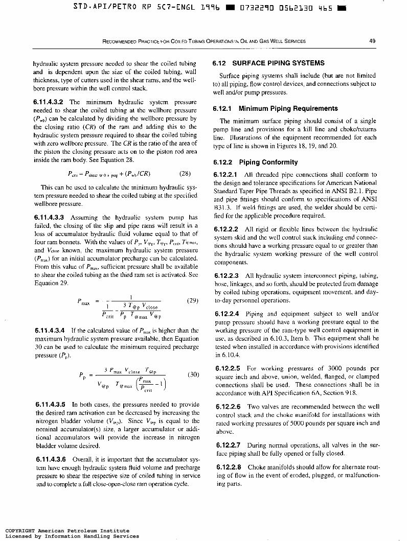
S T D - A P I / P E T R O R P 5C7-ENGL L77b m 0732270 05b2L30 9b5 m
RECOMMENDED PRACTICE FOR COILED TUBING OPERATIONS I N OIL AND GAS WELL SERVICES 49
hydraulic system pressure needed to shear the coiled tubing and is dependent upon the size of the coiled tubing, wall thickness, type of cutters used in the shear rams, and the well- bore pressure within the well control stack.
6.1 1.4.3.2 The minimum hydraulic system pressure needed to shear the coiled tubing at the wellbore pressure (Pwb) can be calculated by dividing the wellbore pressure by the closing ratio (CR) of the ram and adding this to the hydraulic system pressure required to shear the coiled tubing with zero wellbore pressure. The CR is the ratio of the area of the piston the closing pressure acts on to the piston rod area inside the ram body. See Equation 28.
Pm, = P b h c a r V O + PSlP + (pwh/cR) (28)
This can be used to calculate the minimum hydraulic sys- tem pressure needed to shear the coiled tubing at the specified wellbore pressure.
6.1 1.4.3.3 Assuming the hydraulic system pump has failed, the closing of the slip and pipe rams will result in a loss of accumulator hydraulic fluid volume equal to that of four ram bonnets. With the values of P,, V@,,,, T@>,,, P,,,, Tmax, and V,I,,, known, the maximum hydraulic system pressure (Pmax) for an initial accumulator precharge can be calculated. From this value of P,,,, suffìcient pressure shall be available to shear the coiled tubing as the third ram set is activated. See Equation 29.
6.1 1.4.3.4 If the calculated value of P,,,,, is higher than the maximum hydraulic system pressure available, then Equation 30 can be used to calculate the minimum required precharge pressure (P,).
6.11.4.3.5 In both cases, the pressures needed to provide the desired ram activation can be decreased by increasing the nitrogen bladder volume (V@,,). Since V@\, is equal to the nominal accumulator(s) size, a larger accumulator or addi- tional accumulators will provide the increase in nitrogen bladder volume desired.
6.11.4.3.6 Overall, it is important that the accumulator sys- tem have enough hydraulic system fluid volume and precharge pressure to shear the respective size of coiled tubing in service and to complete a ful l close-open-close ram operation cycle.
6.12 SURFACE PIPING SYSTEMS
Surface piping systems shall include (but are not limited to) all piping, flow control devices, and connections subject to well and/or pump pressures.
6.12.1 Minimum Piping Requirements
The minimum surface piping should consist of a single pump line and provisions for a kill line and chokeheturns line. Illustrations of the equipment recommended for each type of line is shown in Figures 18, 19, and 20.
6.12.2 Piping Conformity
6.12.2.1 All threaded pipe connections shall conform to the design and tolerance specifications for American National Standard Taper Pipe Threads as specified in ANSI B2. l . Pipe and pipe fittings should conform to specifications of ANSI B31.3. If weld fittings are used, the welder should be certi- fied for the applicable procedure required.
6.12.2.2 All rigid or flexible lines between the hydraulic system skid and the well control stack including end connec- tions should have a working pressure equal to or greater than the hydraulic system working pressure of the well control components.
6.12.2.3 All hydraulic system interconnect piping, tubing, hose, linkages, and so forth, should be protected from damage by coiled tubing operations, equipment movement, and day- to-day personnel operations.
6.12.2.4 Piping and equipment subject to well andor pump pressure should have a working pressure equal to the working pressure of the ram-type well control equipment in use, as described in 6.10.3, Item b. This equipment shall be tested when installed in accordance with provisions identified in 6.10.4.
6.12.2.5 For working pressures of 3000 pounds per square inch and above, union, welded, flanged, or clamped connections shall be used. These connections shall be in accordance with API Specification 6A, Section 918.
6.12.2.6 Two valves are recommended between the well control stack and the choke manifold for installations with rated working pressures of 5000 pounds per square inch and above.
6.12.2.7 During normal operations, all valves in the sur- face piping shall be fully opened or fully closed.
6.12.2.8 Choke manifolds should allow for alternate rout- ing of flow in the event of eroded, plugged, or malfunction- ing parts.
COPYRIGHT American Petroleum InstituteLicensed by Information Handling ServicesCOPYRIGHT American Petroleum InstituteLicensed by Information Handling Services
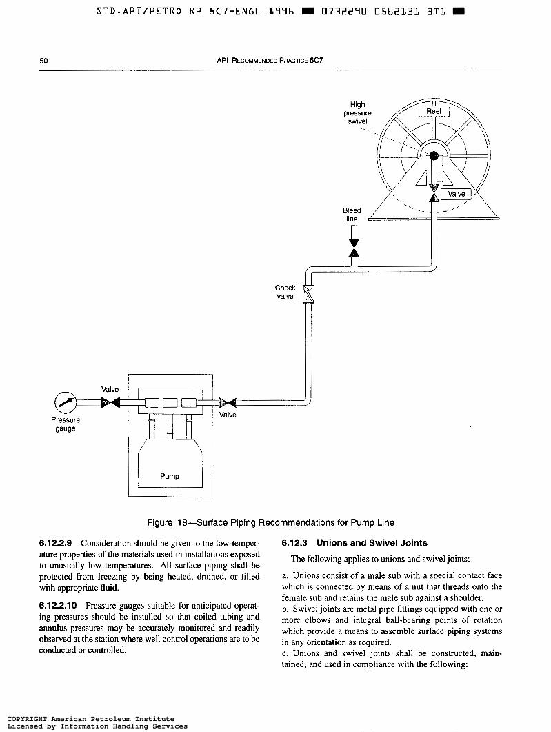
~~
STD-APIiPETRO RP 5C7-ENGL L77b m 0732290 O5b2131 3TL m
50 API RECOMMENDED PRACTICE 5c7
High pressure
swivel .
Bleed
Check valve 4 L
i’ I I
Figure 18”Surface Piping Recommendations for Pump Line
6.12.2.9 Consideration should be given to the low-temper- 6.12.3 Unions and Swivel Joints ature properties of the materials used in installations exposed to unusually low temperatures. All surface piping shall be protected from freezing by being heated, drained, or filled with appropriate fluid.
6.12.2.10 Pressure gauges suitable for anticipated operat- ing pressures should be installed so that coiled tubing and annulus pressures may be accurately monitored and readily observed at the station where well control operations are to be conducted or controlled.
The following applies to unions and swivel joints:
a. Unions consist of a male sub with a special contact face which is connected by means of a nut that threads onto the female sub and retains the male sub against a shoulder. b. Swivel joints are metal pipe fittings equipped with one or more elbows and integral ball-bearing points of rotation which provide a means to assemble surface piping systems in any orientation as required. c. Unions and swivel joints shall be constructed, main- tained, and used in compliance with the following:
COPYRIGHT American Petroleum InstituteLicensed by Information Handling ServicesCOPYRIGHT American Petroleum InstituteLicensed by Information Handling Services
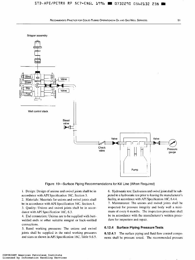
S T D . A P I / P E T R O R P S C ? - E N G L 177b m 0732290 05b2132 238 m
RECOMMENDED PRACTICE FOR COILED TUBING OPERATIONS IN OIL AND GAS WELL SERVICES 51
Stripper assembly
Well control stack
Check valve
Figure 19"Surface Piping Recommendations for Kill Line (When Required)
l . Design: Design of unions and swivel joints shall be in accordance with API Specification 16C, Section 3. 2. Materials: Materials for unions and swivel joints shall be in accordance with API Specification 16C, Section 4. 3. Quality: Unions and swivel joints shall be in accor- dance with API Specification 16C, 6.3. 4. End connection: Unions are to be supplied with butt- welded ends or other suitable integral or back-welded connections. 5. Rated working pressures: The unions and swivel joints shall be supplied in the rated working pressures and sizes as shown in API Specification 16C, Table 9.6.5.
6. Hydrostatic test: Each union and swivel joint shall be sub- jected to a hydrostatic test prior to leaving the manufacturer's facility, in accordance with API Specification 16C, 6.4.4. 7. Maintenance: The unions and swivel joints shall be inspected for pressure integrity and body wall a mini- mum of every 6 months. The inspection procedure shall be in accordance with the manufacturer's written proce- dure for inspection and repair.
6.12.4 Surface Piping Pressure Tests
6.12.4.1 The surface piping and fluid flow control compo- nents shall be pressure tested. The recommended pressure
COPYRIGHT American Petroleum InstituteLicensed by Information Handling ServicesCOPYRIGHT American Petroleum InstituteLicensed by Information Handling Services

52 API RECOMMENDED PRACTICE 5C7
I
Valve
Well control stack
Choke
I
Well control stack
I Q
L Returns tank
Figure 20-Surface Piping Recommendations for Choke/Returns Line
test fluids are water or other suitable solids-free liquids. If 6.12.4.3 A stable high test pressure should be maintained liquid pumping equipment is not available on location, the for at least 10 minutes.
when performed in accordance with the appropriate safety distinct categories: guidelines for testing with energized-fluids.
a. Function pressure test: This pressure test is required to 6.12.4.2 All surface piping and flow control devices shall demonstrate the ability of the flow control device to affect a be subjected to a low-pressure test (generally 200-300 pressure seal as specified.
prior to conducting the high-pressure tests. demonstrate the pressure integrity of all piping and flow
Note: When applying the low pressure, do not apply a higher pressure and control devices and connections. Note that the function
then bleed down to the low test pressure. The higher pressure could initiate pressure test simultaneously demonstrate the pressure a seal that may continue to seal after pressure is lowered and, therefore, not integrity of the coiled tubing, pump lin@), kill line(s), man- be representative of a typical low-pressure condition. ifold(s), and choke line(s).
Pressure test may be conducted using nitrogen as the test fluid 6.12.4.4 Surface piping tests fall into two
pounds Fr square inch gauge for a minimum Of minutes) b. System pressure test: This pressure test is required to
COPYRIGHT American Petroleum InstituteLicensed by Information Handling ServicesCOPYRIGHT American Petroleum InstituteLicensed by Information Handling Services
STD.API/PETRO RP 5CϔENGL L77b m 0732270 05bZL3V O00 m
RECOMMENDED PRACTICE FOR COILED TUBING OPERATIONS IN OIL AND GAS WELL SERVICES 53
6.12.4.5 Each valve in the surface piping system shall be sequentially function pressure tested at each isolation point to the pressure specified as follows:
a. Valves and flow control devices shall be tested to the rated working pressure of the coiled tubing in service, the rated working pressure of the wellhead, or the working pres- sure of the well control stack as stipulated in 6.10.2 and 6.10.3, whichever is suitable to perform the service, except where noted by 6.12.4.5, Item b. b. In cases where the rated working pressure of the well control stack substantially exceeds the maximum antici- pated surface pressure, the surface piping flow control devices may be alternately tested to the maximum antici- pated surface treatment pressure or higher. In no instance shall the test pressure be less than the maximum anticipated surface treatment pressure.
6.12.5 Surface Piping Pressure Test Frequency
Pressure tests on the surface piping and flow control devices shall be conducted as follows:
a. Function pressure test: l . Upon installation. 2. As part of any additional pressure test procedure if so stipulated.
b. System pressure test: l . Upon installation. 2. Following any action that requires disconnecting a pressure seal in a flow control device or in the surface piping system. Only the piping segment affected must be pressure tested.
7 Operational Guidelines and Contingencies
This section provides general guidelines that can be used to help design and execute safe and efficient coiled tubing operations. Operators, service companies, and equipment manufacturers may require or recommend additional well servicing practices and site-specific considerations. In addi- tion, regulatory authorities may require certain operational, safety, and environmental conditions to be met.
7.1 SCOPE
7.1.1 Guidelines
The coiled tubing operations guidelines apply to the major- ity of operations commonly executed as stand alone or rig supported.
Some distinction is made between onshore and offshore operations where appropriate. Many onshore operational pro- cedures can also apply to floater, fixed platform, satellite, and caisson work programs by modifying the rig-up procedure where applicable.
7.1.2 Contingencies
The purpose of contingency planning is to minimize response time or downtime in the event of an unplanned incident. In many cases, a delay in response leads to a wors- ening problem.
Contingency planning should not be confused with emer- gency procedures. Emergency procedures are responses to conditions which threaten well security or personnel safety. Such responses are the result of training, familiarity with the equipment, and knowledge of the current wellbore and site conditions.
Since the conditions on all jobs are variable, it is imprac- tical to detail all aspects of contingency planning for coiled tubing services. The guidelines provided are intended to assist with the preparation of plans which take into account the specific factors and local conditions associated with the job under review.
7.2 COILED TUBING APPLICATIONS
The guidelines and procedures detailed in this document are generally applicable to, but not limited to, the following coiled tubing operations:
a. Wellbore cleanouts. b. Unloading wells and initiating production. c. Formation stimulation. d. Cementing. e. Sand consolidation. f. Services in pipelines and flowlines. g. Through-tubing milling services. h. Coiled tubing conveyed tool services. i. Coiled tubing installations. j. Plugging and abandonment. k. Fishing services. 1. Profile modification services.
7.3 PRE-JOB PLANNING AND PREPARATION
All well intervention work must be based on a sound knowledge of current well conditions. Key to this require- ment is up-to-date information on the wellbore diagram, reservoir history, well location, coiled tubing performance capability, surface equipment, well control equipment, and proposed layout. The following information should be con- sidered for most coiled tubing applications.
7.3.1 Job Design
A planning meeting should be held, and all parties involved must have a clear understanding of the objectives of the operation. The intended work, services, and methods for the particular well operation should be outlined by the operator. Responsibility for provision of all equipment, materials, and services shall be delegated.
COPYRIGHT American Petroleum InstituteLicensed by Information Handling ServicesCOPYRIGHT American Petroleum InstituteLicensed by Information Handling Services
54 API RECOMMENDED PRACTICE 5C7
The following items outline the desired detail to be dis- cussed during the job design and pre-job meetings.
7.3.2 Wellbore-Physical Characteristics
Wellbore physical characteristics include the following:
a. Casing sizes, weights, grades, depths, and threaded connections. b. Tubing sizes, weights, grades, depths, and threaded connections. c. Dimensions, depths, and description of downhole com- pletion equipment. d. Directional survey. e. Type and density of fluids in the wellbore. f . Description of current completion including wellbore diagram. g. Location and dimension of obstructions or restrictions. h. Specifications of wellhead and related surface equipment. i. Location and type of wellbore safety devices. j . Known problems with the wellbore. k. Derating of casing or tubing pressure capacities.
7.3.3 Reservoir-History and Current Parameters
Reservoir history and current parameters include the following:
a. General well history (workovers, wireline work, problems). b. Reservoir characteristics. c. Description and location of all zones communicating with the wellbore. d. Initial and current shut-in and flowing tubing pressures. e. Initial and current shut-in and flowing bottomhole pressures. f. Maximum potential shut-in pressure. g. Flowing bottomhole pressures. h. Type(s) of produced fluids and maximum potential pro- duction rates. i. Condition which can promote erosion, corrosion, scale, or other problems. j . Known field problems.
7.3.4 Location-Physical, Environmental, and
7.3.4.1 Onshore
Regulatory Factors
Onshore location factors include the following:
a. Location plan, surface boundaries, and constraints. b. Environmental restrictions. c. Landowner restrictions. d. Governmental and regulatory agency constraints. e. Emergency shutdown and evacuation contingency plans. f. Other work in near proximity.
g. Impact of work performed on adjacent environment.
7.3.4.2 Offshore
Offshore location factors include the following:
a. Type of facility (floater, fixed platform, satellite, or caisson). b.
d. e. f. g. h.
C.
1.
Crane capacity and reach limitations. Pollution prevention and containment precautions. Other operations in near proximity. Surface and/or subsea support capabilities. Logistical support. Governmental and regulatory agency constraints. Emergency shutdown and evacuation contingency plans. Impact of work performed on adjacent environment.
7.3.5 Location-Equipment Layout
7.3.5.1 Onshore
Onshore location equipment layout considerations include the following:
a. Location constraints (load limit, overhead obstructions, and site dimensions). b. Identification and classification of hazardous areas. c. Dimensions and weights of service equipment. d. Placement and orientation of equipment. e. Location and description of remote control operator panels and emergency shutdown devices (ESD). f. Escape routes and accessibility. g. Tiedown locations and secured points.
7.3.5.2 Offshore
Offshore location equipment layout considerations include the following:
a. Dimensional drawing of deck and applicable loading constraints. b. Identification and classification of hazardous areas. c. Deck space constraints (equipment, piping, and the like). d. Dimensions and weights of service equipment. e. Placement and orientation of equipment. f. Location of remote control operator panels and ESDs. g. Escape routes and accessibility. h. Position of rig or jack-up boat (if applicable). i. Tiedown locations and secured points.
7.3.6 Well Control Equipment
The following applies to well control equipment:
a. Type, size, configuration, and pressure rating of well control equipment required. b. Responsibilities of personnel.
COPYRIGHT American Petroleum InstituteLicensed by Information Handling ServicesCOPYRIGHT American Petroleum InstituteLicensed by Information Handling Services
S T D - A P I / P E T R O RP 5Cï”ENGL L 9 9 b D 0732290 05bZL3b 9 8 3
RECOMMENDED PRACTICE FOR COILED TUBING OPERATIONS IN OIL AND GAS WELL SERVICES 55
c. Intended performance for service (pressure and function). d. Proposed bottomhole assemblies to be run. e. Review of onsite pressure testing procedure. f. Tree connection and crossover spool requirements.
7.3.7 Documentation and Safety Guidelines
Documentation and safety guidelines include the following:
a. Operator-supplied procedures and guidelines. b. Contractor-supplied procedures and guidelines. c. Health, safety, and environment contingency plans. d. Pre-job and safety meeting.
7.3.8 Coiled Tubing Equipment
The minimum equipment generally needed to safely and efficiently complete operations includes the following com- ponents: a. Coiled tubing string. b. Coiled tubing reel. c. Coiled tubing injector. d. Injector support and stabilizing equipment. e. Well control equipment and riser components. f. Control cabin. g. Power supply/prime mover. h. Maintenance and support equipment. i. Emergency contingency equipment.
In addition to these items, ancillary equipment needed for performing the desired service will be required. This equip- ment may include high-pressure positive displacement pumps, nitrogen pumps and tanks, high-pressure treating lines, rigup equipment and downhole tools.
7.4 EQUIPMENT CHECKS AND MAINTENANCE
7.4.1 Pre-Job Checks
Pre-job checklists should be carried with the coiled tub- ing unit. All equipment must be capable of meeting the requirements agreed upon in the preplanning meetings.
Prior to leaving the coiled tubing service company base, the following items should be checked:
a. b. C.
d. e. f. g. h.
Primary coiled tubing equipment. Ancillary equipment. Spare parts. Transport checks. Safety equipment. Materials. Third party rentals. Downhole tools.
i. Coiled tubing string that has remaining service life and physical requirements necessary to complete the planned job. j. Documentation.
7.4.2 Personnel Requirements
7.4.2.1 Concerning performance and job duties, personnel should have certification as required by governmental and regulatory agencies. The crew should be qualified and com- petent to perform the required operation per operator and ven- dor guidelines.
7.4.2.2 As appropriate, the coiled tubing service company shall provide crews with approved, accredited training in the following areas:
a. Well control. b. Firefighting. c. Personal protective equipment. d. Health safety and environment. e. Crane operations. f. Department of Transportation regulations.
7.5 JOB REVIEW
A pre-job meeting shall be held with all service personnel and operator employees involved either directly or indirectly in the operation.
The pre-job meeting should include, but not be limited to the following:
a. Identify the on-site representative in charge. b. Ensure that the detailed written job procedure and areas of responsibility shall be discussed. c. Review the expected hazards (particularly chemicals, flammable fluids, and energized fluids) contingencies, and emergency procedures at the wellsite. d. Discuss the pressure and operating limits of equipment and service. e. Review the procedure for pressure and function testing of surface equipment. f. Review the wellhead, downhole tubular, and downhole assembly schematics, noting all potential obstructions. A copy of the downhole schematic and bottomhole assembly diagrams should be in the control cabin at all times. g. Review the type and location of required personal protec- tive equipment. h. Review the type and location of fire extinguishers and other fire-fighting equipment. i. Review emergency well control equipment-operating procedure. j. Identify a smoking area on any service job (signs to be posted on land locations).
COPYRIGHT American Petroleum InstituteLicensed by Information Handling ServicesCOPYRIGHT American Petroleum InstituteLicensed by Information Handling Services
56 API RECOMMENDED PRACTICE 5C7
7.6 EQUIPMENT RIG-UP CONSIDERATIONS
7.6.1 Onshore and Offshore Operations
The following is a partial list of items which should be considered when rigging up for coiled tubing operations.
a. If possible, spot equipment upwind or crosswind of the wellhead. The unit should be aligned with the wellhead so the crane is not on the reel-wellhead line. b. Check wind speeds. Consideration shall be given to gusting, sudden wind direction shifts, debris, sand, or heavy rain. c. Verify proper legs or support equipment for the injector and pressure control stack. d. Make provisions for securing the injector to minimize movement and bending moments. e. The operator should be aware of and have authorized all wellhead operations. The number of turns required to open the master valve should be recorded. f. Verify the compatibility of the crossover from the well- head to the well control stack. g. Zero the counters with the bottomhole assembly at a suit- able reference point and record the reference point. h. Function-test all equipment. i. Check space available for optimum equipment rig up. j. Zero the weight indicator.
7.6.2 Semisubmersible Rig-Up
For semisubmersible service, a lift frame is generally used and requires special rig-up and operating procedures. These procedures shall be reviewed and agreed upon by the operator and the vendor.
7.7 EQUIPMENTESTING
The function and pressure-testing procedures, and associ- ated limits, detailed in this document should be used as a guide to enable thorough testing of the equipment and rig-up specific to each case. The following is a list of the minimum pressure test recommendations:
a. The well control equipment shall be tested and in com- pliance with 6.10.1 through 6.10.5. b. All pressure lines and valves shall be tested and in com- pliance with 6.12.4 and 6.12.5. c. The coiled tubing connector and check valve or other downhole tools, if installed, should be pressure tested to the pressure specified for the job.
7.8 COILEDTUBING SERVICE CONSIDERATIONS
The following are coiled tubing service considerations:
a. Good engineering judgement should be used to ensure safe coiled tubing service. These guidelines follow good industry practice for coiled tubing service work. b. The intentional pumping or production of hydrocarbon gas through coiled tubing is not recommended. c. Pumping or productionheversing of flammable liquids shall follow strict procedures and guidelines set by the oper- ator and service vendor as well as governmental and regula- tory agencies. d. Pumping of energized fluids and/or corrosive fluids shall follow strict procedures and guidelines set by the operator and service vendor. e. When reverse circulating, one should consider friction pressure drops, combined loading, and ovality on the col- lapse resistance of the coiled tubing as described in 5.7. f. Downhole check valve(s) should be used unless reverse circulating is anticipated. g. The well control stack kill line should not be used as the return line for circulating well fluids during normal operations.
7.9 COILED TUBING SERVICE STRING MANAGEMENT
Two common methods of tracking and recording the his- tory of coiled tubing service strings are described below. The data collected are used to determine if a string of coiled tub- ing is adequate for a given job. This data is kept current for the service life of the string to retirement.
7.9.1 Manual Method
The following is a manual record-keeping method for each string based on the trip method as described in 5.5.2. The data recorded include these:
a. Job date, well number, and operator. b. String identification and composition. c. Maximum job depth. d. Service pressure. e. Number of cycles, depth of cycles, and internal coiled tubing pressure imposed. f. Segment length cycled.
COPYRIGHT American Petroleum InstituteLicensed by Information Handling ServicesCOPYRIGHT American Petroleum InstituteLicensed by Information Handling Services
S T D - A P I I P E T R O R P 5 C 7 - E N G L L 9 1 b a 0732290 05bZL38 75b
RECOMMENDED PRACTICE FOR COILED TUBING OPERATIONS IN OIL AND GAS WELL SERVICES 57 ~~
g. Fluids pumped. 7.9.2 Modeling Method h. Bending radii involved. i. Location of all welds. j. Visual inspection. k. Amount of coiled tubing cut off and reason for cut off. 1. Well fluids. m. Maximum string pulls and depths. n. Wellhead pressure.
The modeling method uses empirical data and theoretical models to more accurately determine the remaining usable service life of the coiled tubing string. This method may incorporate automated data acquisition systems and in addi- tion to the manual method, data typically includes the following:
The trip method is adequate for many operations. a. Current outside coiled tubing diameter. b. Current coiled tubing ovality. c. Current coiled tubing wall thickness. d. Shorter interval recording.
COPYRIGHT American Petroleum InstituteLicensed by Information Handling ServicesCOPYRIGHT American Petroleum InstituteLicensed by Information Handling Services
STD*API/PETRO RP 5C7-ENGL L77b m 0732290 05b2L39 h72 m
APPENDIX A-GLOSSARY
Concerning terminology, an effort has been made to use definitions and abbreviations consistent with the API Glos- sary of Oi@eld Production Terminology (Definitions and Abbreviations), First Edition, January 1988.
The following is a list of the terms included in the recom- mended practice as commonly defined within the coiled tub- ing industry:
accumulator: A pressure vessel charged with nitrogen gas used to store hydraulic fluid under pressure for operation of pressure control equipment.
accumulator precharge: An initial nitrogen charge in an accumulator which is further compressed when the hydraulic fluid is pumped into the accumulator storing potential energy.
actuation test, well control component: The closing and opening of a well control component to assure mechani- cal functioning.
balance point: Footage of coiled tubing in the wellbore where the weight of the tubing is equal to the well pressure acting against the cross-sectional area. Note that this is a static condition with the pipe full of fluid and does not include frictional forces of the stripper assembly andor pipe rams, if engaged.
bending cycle: A bending cycle is said to be completed when the axial strain returns to zero from a loaded condition. The axial strain in coiled tubing is zero when the tubing is straight. A cycle, therefore, begins with the tubing straight and consists of one bending and one straightening sequence.
blind rams: The rams in a well control stack which are designed to seal against each other to effectively close the wellbore when there are no tools or pipe through the well control stack. The blind rams are not intended to seal against coiled tubing.
blowout: An uncontrolled flow of pressurized wellbore flu- ids andor formation fluids out of the wellbore or into lower pressured subsurface zones (underground blowout).
caisson: A single-wellhead marine completion structure.
check valve: A valve that allows flow through it in one direction only. This device is installed at the coiled tubing connector and allows fluid to be circulated down the string but prevents backflow. This device may be a ball-and-seat type or flapper type.
choke: A device with either a fixed or a variable aperture used to control the rate of flow of liquids and/or gas.
choke line valve: The valve(s) connected to the well con- trol stack which controls the flow to the choke.
Christmas tree: A term applied to the combination of valves and fittings assembled above the top of the tubing spool on a completed well to contain well pressure and con- trol the flow of hydrocarbons and other fluids.
circulation: The movement of fluid from the surface tank through the pump, coiled tubing, bottomhole assembly, annu- lar space in the wellbore, and back to the surface tank.
closing ratio: The ratio of the wellhead pressure to the hydraulic actuation pressure required to close the well control component.
coiled tubing: Continuous EW tubing spooled onto a reel which is used in concentric operations. This tubing can be run into and out of a well with or without surface pressure.
collapse: Flattening of the coiled tubing due to external pressure or external pressure combined with either tension or bending.
concentric operations: Well operations conducted using small diameter tubing inside conventional tubing or tubing- less completions. These operations are normally performed with the Christmas tree in place using a coiled tubing unit, wireline unit, hoisting unit, or small rig.
connections: Detachable devices for connecting coiled tubing to downhole tools.
control panel: An enclosure displaying an array of switches, push buttons, lights, valves, various pressure gauges, andor meters to control or monitor coiled tubing operating functions.
diametral growth: The increase in tubing diameter observed after following coiled tubing operations.
defect: A defect is an imperfection of sufficient magnitude to warrant rejection of the product.
drag: The algebraic sum of the resistance due to (a) the fric- tion between the coiled tubing and the well control equip- ment, (b) the friction between the coiled tubing and the wall of the wellbore, (c) the friction due to the coiled tubing pass- ing through fluid, and (d) the friction due to the flow of fluids either inside or outside of the coiled tubing.
elongation: The increase in gauge length of a tensile test specimen, expressed as a percent of the original gauge length.
fatigue: The process of progressive localized permanent structural change occurring in a material subjected to condi- tions which produce fluctuating stresses that may culminate in cracks or complete failure after a sufficient number of fluc- tuations.
59
COPYRIGHT American Petroleum InstituteLicensed by Information Handling ServicesCOPYRIGHT American Petroleum InstituteLicensed by Information Handling Services
STD*API/PETRO RP 5C7-ENGL L77b 0732270 05b2140 309 m
60 API RECOMMENDED PRACTICE 5C7
flow tee: The well-control stack component which provides the return fluid outlet.
function: Operation of a well control component, choke or kill valve, or any other component in one direction. For example, closing the blind rams is one function, and opening the blind rams is a separate function.
function pressure test: The pressure test which requires the well control component or flow control device to undergo actuation to demonstrate its ability to effect a seal.
gate valve: A valve which employs a sliding gate to open or close the flow passage. The valve may or may not be full- opening.
hardness: A measure of the hardness of a metal as deter- mined by pressing a hard steel ball or diamond penetrant into a smooth surface under standard conditions.
hydrostatic head: The pressure which exists at any point in the wellbore due to the weight of the column of fluid above that point.
imperfection: An imperfection is a material discontinuity or irregularity in the product detected by the methods outlined in this recommended practice.
kick: Intrusion of formation liquids or gas that results in an increase in pit volume or an increase in observed wellhead pressure.
kill line: A high-pressure line between the pumps and some point below a well control component. This line allows fluids to be pumped into the well or annulus with the well control component closed.
lift frame: A device used to facilitate movement of the injector on and off the wellhead.
manifold: An assemblage of pipe, valves, and fittings by which fluid from one or more sources is selectively directed to various systems or components.
maximum anticipated surface pressure: The highest pressure predicted to be encountered at the surface of a well. This pressure prediction is based upon a wellbore filled with gas from the surface to the completion interval.
opening ratio: The ratio of the well pressure to the hydrau- lic actuation pressure required to open the well control com- ponent.
pipe ram: The rams in a well control stack which are designed to seal around coiled tubing to close and isolate pressure in the annular space below the rams.
pipe/slip ram: The rams in a well control stack which are designed to provide the functions of both a pipe ram and a slip ram in one ram body.
plug valve: A valve whose mechanism consists of a plug with a hole through it on the same axis as the direction of fluid flow. Turning the plug 90 degrees opens or closes the valve. The valve may or may not be full-opening.
power fluid: Pressurized hydraulic fluid dedicated to the direct operation of functions.
precharge: See accumulator precharge.
pressure test, well control component: The process of performing an internal pressure test on the well control com- ponent or well control stack.
primary barrier: The primary barrier is the means which allows the coiled tubing service to be performed in underbal- anced conditions. Since coiled tubing service units are designed to operate with surface well pressure present, the primary barrier is the well control stack.
regulator (pressure): A hydraulic device that reduces upstream supply pressure to a desired (regulated) pressure. It may be manual or remotely operated and, once set, will auto- matically maintain the regulated output pressure unless reset to a different pressure.
reservoir: A storage tank for control fluids used to operate the well control components and other hydraulically actuated devices.
rig: The derrick, drawworks, and attendant surface equip- ment of a drilling or workover unit.
satellite: Subsea completion installation, including the tem- plate.
secondary barrier: The secondary barrier is the means which provides a contingency for maintaining well control in the event the primary barrier is unable to function properly. For coiled tubing service units, the secondary barrier may include additional surface well control components or kill weight fluids.
shear ram: The rams in a well control stack which are designed to shear the coiled tubing located directly across the ram position.
sheadseal ram: The rams in a well control stack which are designed to provide the functions of both a shear ram and a blind ram in one ram body.
shut-off valve: A valve that closes a hydraulic or pneu- matic supply line.
slip ram: The rams in a well control stack which are equipped with tubing slips that, when engaged, prevent movement of the coiled tubing but do not isolate pressure or control flow.
snubbing: Condition for working coiled tubing through an energized stripper, where wellbore pressure applied against
COPYRIGHT American Petroleum InstituteLicensed by Information Handling ServicesCOPYRIGHT American Petroleum InstituteLicensed by Information Handling Services
~ ~~
STDmAPIIPETRO RP 5C7-ENGL L77b m 0732270 05b2LqL 2 4 0 m ~~ ~~~ ~~~
RECOMMENDED PRACTICE FOR COILED TUBING OPERATIONS IN OIL AND GAS WELL SERVICES 61
the cross-sectional area of the tube creates an upward acting force greater than the weight of the tubing in the wellbore. In this condition, mechanical assistance is required to apply thrust to the tubing while injecting or to maintain control of the tubing when extracting. This condition is commonly called pipe-light operations.
spool: The total length of as-manufactured coiled tubing which is placed on a drum for storage andor transport. a spool may contain one or more coiled tubing strings.
stored hydraulic fluid volume: The fluid volume recov- erable from the accumulator system between the maximum designed accumulator operating pressure and the precharge pressure.
string: The makeup of a specific length of coiled tubing used for well intervention.
stripper: A device with a resilient elastomeric element used to effect a seal in the annulus. This device is used primarily to isolate well pressure from the atmosphere when injecting or extracting the coiled tubing in pressurized wellbores.
stripping: Condition for working coiled tubing through an energized stripper, where wellbore pressure applied against the cross-sectional area of the tube creates an upward acting force less than the weight of the tubing in the wellbore. In this condition, mechanical assistance is required to support the tensile load of the tubing and maintain control when injecting or extracting. This condition is commonly called pipe-heavy operations.
swabbing: The lowering of the hydrostatic pressure in the wellbore due to the interaction of the wellbore fluids with the concentric pipe and tools when the pipe and tool string are moved upwards in the wellbore.
swab valve: The uppermost valve in a vertical line on the Christmas tree, always above the flow-wing valve.
System Pressure Test: The integrity test used to verify the ability of the pipe and pressure containment equipment in the service to maintain a pressure seal.
tensile strength: The maximum tensile stresses which a material is capable of sustaining. Tensile strength is calcu- lated from the maximum load during a tension test carried to rupture and the original cross-sectional area of the specimen.
total depth (TD): The maximum measured depth of the wellbore.
transition point: The point on the tapered coiled tubing string where tubing segments of different wall thicknesses are welded together.
trip: The event which involves deployment of the coiled tub- ing string from the reel into the wellbore and the subsequent retrieval of the coiled tubing back onto the reel.
usable hydraulic pressure: The hydraulic fluid volume which can be recovered from the accumulator system between the maximum designed-accumulator operating pres- sure and the minimum operating pressure.
well control component, annular-type: A device which can form a seal in the annular space around any object in the wellbore or upon itself. Compression of a reinforccd elastomer packing element by hydraulic pressure effects the seal.
well control component, ram-type: A device designed to form a seal on the wellbore with or without coiled tub- ing in the well or to perform a specific operation on the coiled tubing body. Ram-type well control components include a set of blind rams, shear rams, slip rams. and pipe rams to effect the required wellbore seals or pcrform the specific physical action on the coilcd-tube body. Combination shear/seal and pipe/slip rams are available.
well control stack: An integral body or an assembly of well control components including ram-type componcnts, annular-type components, spools, valves, and nipples con- nected to the top of the wellbore to control well fluids.
well control equipment drill: A training procedure to ensure that coiled tubing personnel are familiar with correct operating practices to be followed in the use of well control equipment for blowout prevention.
wellhead: An assemblage of valves and spools located below the Christmas tree and above the casing strings for the purpose of hanging and isolating the various tubular strings.
yield strength: The stress at which a material exhibits a specified strain.
COPYRIGHT American Petroleum InstituteLicensed by Information Handling ServicesCOPYRIGHT American Petroleum InstituteLicensed by Information Handling Services
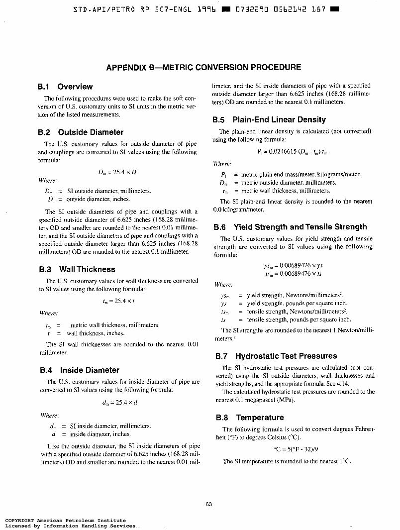
STD*API/PETRO R P SC7-ENGL 1 9 9 b E 0732290 05b2142 187 m
APPENDIX B-METRIC CONVERSION PROCEDURE
B.l Overview The following procedures were used to make the soft con-
version of U.S. customary units to SI units in the metric ver- sion of the listed measurements.
B.2 Outside Diameter The U.S. customary values for outside diameter of pipe
and couplings are converted to SI values using the following formula:
D, = 25.4 x D Where:
D,,, = SI outside diameter, millimeters. D = outside diameter, inches.
The SI outside diameters of pipe and couplings with a specified outside diameter of 6.625 inches (168.28 millime- ters OD and smaller are rounded to the nearest 0.01 millime- ter, and the SI outside diametm of pipe and couplings with a specified outside diameter larger than 6.625 inches (168.28 millimeters) OD are rounded to the nearest 0.1 millimeter.
8.3 Wall Thickness The U.S. customary values for wall thickness are converted
to SI values using the following formula:
tm = 25.4 x t
Where:
t, = metric wall thickness? millimeters. t = wall thickness, inches.
The SI wall thicknesses are rounded to the nearest 0.01 millimeter.
8.4 Inside Diameter The US. customary values for inside diameter of pipe are
converted to SI values using the following formula:
d, = 25.4 X d
Where:
d,,, = SI inside diameter, millimeters. d = inside diameter, inches.
Like the outsidc diameter, the SI inside diameters of pipe with a specified outside diameter of 6.625 inches (168.28 mil- limeters) OD and smaller are rounded to the nearest 0.01 mil-
limeter, and the SI inside diameters of pipe with a specified outside diameter larger than 6.625 inches (1 68.28 millime- ters) OD are rounded to the nearest 0.1 millimeters.
8.5 Plain-End Linear Density The plain-end linear density is calculated (not converted)
using the following formula:
P , = 0.0246615 (D, - tm) t ,
Where:
P, = metric plain end madmeter, kilograms/meter. D, = metric outside diameter, millimeters.
r,,, = metric wall thickness, millimeters.
The SI plain-end linear density is rounded to the nearest 0.0 lulogradmeter.
8.6 Yield Strength and Tensile Strength The U.S. customary values for yield strength and tensile
strength are converted to SI values using the following formula:
y,,, = 0.00689476 X YS
rs, = 0.00689476 X ts
Where:
YS,,, = yield strength, Newtons/millimeters*. ys = yield strength, pounds per square inch. ts", = tensile strength, Newtons/millimeters*. ts = tensile strength, pounds per square inch.
The SI strengths are rounded to the nearest 1 Newtodmilli- meters.*
B.7 Hydrostatic Test Pressures The SI hydrostatic test pressures are calculated (not con-
verted) using the SI outside diameters, wall thicknesses and yield strengths, and the appropriate formula. See 4.14.
The calculated hydrostatic test pressures are rounded to the nearest O. 1 megapascal (MPa).
B.8 Temperature The following formula is used to convert degrees Fahren-
heit ("F) to degrees Celsius ("C).
"C = 5("F - 32)/9
The SI temperature is rounded to the nearest 1 "C.
63
COPYRIGHT American Petroleum InstituteLicensed by Information Handling ServicesCOPYRIGHT American Petroleum InstituteLicensed by Information Handling Services
STD-APIIPETRO RP 5Cï”ENGL L77b m 0732270 05b2L43 013 m
64 API RECOMMENDED PRACTICE 5C7
B.9 Charpy Impact Energy B.10 Recommended Make-up Torque The U.S. customary values for impact energy are converted The U.S. customary values for recommended make-up
to SI values using the following formula: torque are calculated without rounding and are converted to
E,,,, = 1.35582 E, SI values using the following conversion factor:
Where: 1 pound-foot = 1.35582 Newton meters
E,, = Charpy impact energy, joule. E, = Charpy impact energy, pound-foot.
The SI energy values are rounded to the nearest joule.
The SI metric recommended make-up torques are rounded to the nearest 10 Newton meters.
COPYRIGHT American Petroleum InstituteLicensed by Information Handling ServicesCOPYRIGHT American Petroleum InstituteLicensed by Information Handling Services
STD.API/PETRO RP SC7-ENGL L77b E 0732270 05bZL1111 T 5 T 9
APPENDIX C-EMERGENCY RESPONSES AND CONTINGENCY PLANNING
The following emergency responses and contingency plans are offered as examples of typical responses to various emergency situations due to coiled tubing equipment and/or wellbore problems. These emergency responses and contin- gency plans are provided for information purposes only, and reflect typical action to be taken during the specified event.
C.l Emergency Well Control Operation In the event of an emergency situation arising where the
well has to be secured, the following steps should be taken:
a. Stop pipe movement and close slip and pipe rams. If time and circumstances permit, review all options with company and service representatives. b. Stop pumping. c. Close the shear rams to cut the coiled tubing. d. Pull the coiled tubing out of the well control stack to a point above the blind rams. e. Close the blind rams. f. Set up to circulate kill fluid through the coiled tubing remaining in the well.
Note: The decision to proceed beyond Step a should generally be made in consultation with the company representative except in the case where there is an immediate danger to personnel andor equipment, and the repre- sentative is not immediately accessible to be Involved i n the decision.
C.2 Contingency Plans A coiled tubing unit has several equipment components
which can possibly cause serious damage and injury if improperly used when correcting a developing problem. In addition, well control problems can quickly grow into a much larger situation or add to the complexity of the situation if handled improperly. Therefore, the operator and company representative should become familiar with potential prob- lems and solutions prior to performing the work.
The following are suggested contingencies to alleviate problems as described below. It is assumed that surface pres- sure will be present at the wellhead during these equipment failure emergencies.
C.3 Power Pack Failure In the case of power pack failure, the following steps
should be taken:
a. Hang-off coiled tubing in slips and manually lock. b. Close coiled-tubing pipe rams and manually lock. c. Apply the reel brake if i t is not fail-safe applied. d. Maintain circulation if required. A sand clean out is an exm- ple of a case in which continued circulation may be necessary. e. Repair or replace the power unit and resume operations.
C.4 Leaking Stripper Assembly In the case of a leaking stripper assembly, the following
steps should be taken:
a. Stop coiled tubing movement. b. Close the slip rams and lock manually. c. Close the pipe rams and lock manually. d. Energize the backup stripper, if installed. e. Bleed down the surface pressure within the well control stack through the kill spool or flow tee, and observe for pressure seal leaks across the pipe rams. f . Reduce the hydraulic pressure to the stripper assembly, and bleed down to relax the stripper element. g. Insure that the injector is in neutral and that the brake is engaged. h. Replace the stripper elements following the applicable procedure for the specific stripper assembly design.
C.4.1 CONVENTIONALTOP-ENTRY STRIPPER
To replace the conventional top-entry stripper, the follow- ing steps should be taken:
a. Unscrew the split retainer cap. b. Remove the old stripper elements. c. Inspect upper bushings for wear. d. Insert new stripper elements. e. Replace the split cap and energize the stripper assembly. f. Return injector to extraction and equalize the well con- trol stack pressure. g. Unlock and open the pipe rams. h. Unlock and open the slip rams. i. Resume operations.
C.4.2 SIDE DOOR STRIPPER ASSEMBLY
To replace the side door stripper assembly, the following steps should be taken:
a. Open the side doors on the stripper. b. Apply =lo0 to 200 pounds per square inch gauge hydrau- lic pressure to open the pressure containment cylinder. c. Remove the stripper element halves one at a time. Be aware that the upper brass bushings may fall down into the window once the supporting stripper elements are removed. d. Remove the split non-extrusion ring. e. Remove the brass bushing sets from above and below. Check for wear, and replace if necessary. f. Insert the brass bushings and split non-extrusion ring. g. Insert the new stripper elements. h. Apply hydraulic pressure to close the pressure contain- ment cylinder. i . Close the side doors.
65
COPYRIGHT American Petroleum InstituteLicensed by Information Handling ServicesCOPYRIGHT American Petroleum InstituteLicensed by Information Handling Services
~~ ~
S T D - A P I i P E T R O RP SC7-ENGL L996 m 0732290 05b2L45 996 m
66 API RECOMMENDED PRACTICE 5C7
j. Return the injector to extraction, and equalize the well control stack pressure. k. Unlock and open the pipe rams. I. Unlock and open the slip rams. m. Resume operations.
C.5 Collapsed Coiled Tubing Coiled tubing will collapse whenever the differential pres-
sure exerted against the OD exceeds the collapse limit of the pipe. This limit is also determined by the tensile load applied to the coiled tubing at the time and the overall condition of the pipe. A collapse condition generally occurs just below the stripper assembly and is often detected by a sharp increase in pump pressure while pumping down the coiled tubing.
When coiled tubing collapses, it will flatten, resembling a thin oval cylinder with the center touching. This increase in OD (or major axis) is usually greater than the wear bushing ID in the stripper assembly, and the collapse will usually be halted at the stripper. If the collapsed portion does make it into the stripper assembly, be cautious of discharged pressure as the stripper element will not effectively seal on the pipe.
C 5 1 COLLAPSE WITH COILED TUBING SHALLOW IN THE WELL
In the case of collapse with coiled tubing shallow in the well, the following steps should be taken:
a. Kill the well if it is not already dead. b. Release the stripper element pressure, and remove the stripper elements and retaining bushings. c. Pick up the coiled tubing slowly to determine the top of the collapsed pipe. d. Attempt to pull the collapsed portion of pipe through the injector very slowly while adjusting the chain pressure to the orientation of the collapsed pipe. Spool the collapsed pipe onto the reel. e. While pulling out of the hole slowly, watch for the transi- tion section to undamaged pipe. f. Reassemble the stripper assembly and finish pulling out of the hole. g. Replace coiled tubing, and determine the cause of col- lapse before entering the well again.
C 5 2 COLLAPSE WITH COILEDTUBING DEEP IN THE WELL
In the case of collapse with the coiled tubing deep in the well, the following steps should be taken:
a. Kill the well if it is not already dead. b. Release the stripper element pressure, and remove the stripper elements and retaining bushings. c. Pick up the coiled tubing slowly to determine the top of the collapsed pipe.
d. Run back into the hole with the coiled tubing until the undamaged portion of the pipe is across the well control stack components. e. Close the pipe and slip rams, and manually lock. f. Relax the injector chains to verify that the slip rams are holding. g. Cut the coiled tubing above the injector. h. Open the injector chains. Remove the injector from the coiled tubing, and set it off to the side. i. Attach a full tube clamp to the coiled tubing directly above the well control stack. j. Connect the crane or travelling block to the clamp and open the pipe and slip rams. k. Slowly pull the coiled tubing out of the well to the maxi- mum height of the crane or block. I . Attach a collapsed tube clamp to the coiled tubing directly above the well control stack, and cut the tubing above the bottom clamp. Connect the crane, and pull the collapsed coiled tubing out of the well. m. Continue alternating pulling, clamping, and cutting the coiled tubing until all of the collapsed section has been removed from the well and the transition section to undam- aged pipe is located above the well control stack. Ensure that there is enough competent pipe above the well control stack to thread the coiled tubing through the stripper and injector (>15 feet). n. Close the slip rams, and remove the clamp. o. Install and secure the injector onto the coiled tubing. Apply hydraulic pressure to the inside chains, and switch the injector to the extraction mode. Open the slip rams. p. Either connect the end of the coiled tubing to the other section of coiled tubing on the reel with a connector or install a valve onto the end of the coiled tubing and begin a new wrap on the reel. q. Reinstall the stripper bushings and elements. r. Finish pulling out of the hole, and replace the reel. Deter- mine the cause of collapse prior to entering the well again.
C.6 CoiledTubing Stuck in the Hole When a load greater than 80 percent of the yield strength
is required to pull the coiled tubing, the coiled tubing is defined as stuck. Before any additional pull force is applied, it is necessary to analyze the problems and take necessary precautions.
The coiled tubing can be stuck in the following situations:
a. Pump failure in cleanout operations (solids settle onto the top of the bottomhole assembly and around the pipe). b. Unexpected increases in drag. c. Obstructions in the wellbore or debris from perforation guns, and so forth. d. Differential sticking.
COPYRIGHT American Petroleum InstituteLicensed by Information Handling ServicesCOPYRIGHT American Petroleum InstituteLicensed by Information Handling Services

STD*API/PETRO RP 5Cï"ENGL L99b E 0732270 0 5 b 2 L 4 b 822 E
RECOMMENDED PRACTICE FOR COILED TUBING OPERATIONS I N OIL AND GAS W E L L SERVICES 67
The following approach should be considered in the event pipe is stuck:
a. Be aware that moving the coiled tubing up and down over the tubing-guide arch rapidly weakens the tubing. High pump pressures while working the pipe should be avoided if at all possible as this greatly accelerates the fatigue problem. (Check fatigue cycle log to assess if fur- ther cycling is possible.) h. Check for fluid returns, and attempt to maintain circula- tion if possible. Check pump pressure recorder to identify any pressure fluctuations. c. Compare current tubing weight with previous pick-up weight. d. Apply a tensile load to the coiled tubing of up to 80 per- cent of pipe tensile yield rating and hold. Monitor weight indicator for changes in weight.
C.7 Friction Stuck with Circulation C.7.1 If the weight indicator reading decreases after apply- ing the 80 percent pipe tensile yield load, it is likely that the pipe is friction stuck. The following options may exist:
a. Increase pipe buoyancy by circulating heavier fluids into the wellbore. Be aware of the risk of collapse. h. Pump friction-reducing fluids or additives, such as HEC, XCD or diesel. c. Displace the coiled tubing with a lighter fluid such as nitrogen or diesel to further increase buoyancy.
C.7.2 Work tubing free of stuck area by applying tensile loads on the coiled tubing up to 80 percent of the pipe tensile yield rating and watching for the load decrease on the weight indicator. Keep pumping fluids to maintain circulation, mini- mizing the internal pump pressure when cycling the pipe.
C.8 Mechanically Stuck With Circulation If the weight indicator load does not decrease after apply-
ing a tensile load of up to 80 percent of pipe tensile yield rat- ing, it is likely that the coiled tubing is mechanically stuck. Attempt to lower the coiled tubing into the well to determine if it is actually stuck at that point or if it is unable to pass through a restriction or upset in the completion pipe.
If the coiled tubing can be moved downward, then deter- mine the following:
a. If the pipe (or tools) could have been bent or buckled by setting down excessive weight or running into an obstruction. h. The type of connection used to connect the tool string to the coiled tubing. c. If any obstructions or restrictions can be identified by reviewing the pipe (and tools) position in the well compared to the well sketch.
The following options may exist:
a. Pump a ball to release the hydraulic disconnect if it is determined that the BHA is getting hung up. b. Ensure that the injector pulling limit is set at 80 percent of the coiled tubing tensile yield rating. Lower the coiled tubing 10 to 15 feet and attempt to pull the pipe past the pre- vious stuck point again. c. Kill the well, cut the coiled tubing at the surface and run á free point tool to determine the depth to the stuck point. Follow normal fishing procedures.
C.9 Mechanically Stuck and Cannot Circulate
If the pipe is mechanically stuck and cannot circulate, the following steps should be taken:
a. Pump the kill weight fluid down the coiled tubing. If it is not possible to pump down the coiled tubing, attempt to pump the kill weight fluid down the annulus (at pressures below the collapse pressure of the coiled tubing). h. Once the well is dead, cut the coiled tubing at the surface, and run a free-point tool. Follow normal fishing procedures.
C.10 Leak in the Riser or Connections Below the Well Control Stack
If there is a leak in the riser or connections below the well control stack, the following steps should be taken:
a. Stop the pump to determine if there is any flow or pres- sure at the surface. b. If there is no surface pressure, pull out of the hole with the coiled tubing while pumping a minimal amount to keep the hole full and to prevent swabbing. When the end of the coiled tubing reaches the well control stack, close the mas- ter valve and replacehepair the leaking riser section. c. If, in consultation with the company representative, it is deemed unsafe to pull the coiled tubing out of the hole with surface pressure present, then the well should be killed. d. The following steps should be taken to control and kill the well:
1. Prepare to pump the kill fluid. 2. Pump the kill fluid and lost circulation material (if required) downhole through the kill line on the tree. 3. Displace the hole completely with kill fluid.
Note: Ensure tubing is sufficiently off the bottom so that when shear-seal rams are used, the pipe will drop below the manual master valve on the Christmas tree.
e. If the situation becomes critical or is deemed unsafe, then do the following:
l . Close the slip rams. 2. Close the shear rams.
COPYRIGHT American Petroleum InstituteLicensed by Information Handling ServicesCOPYRIGHT American Petroleum InstituteLicensed by Information Handling Services
~
STD-APIIPETRO RP 5C7-ENGL L77b 0732270 05b2Lq7 7b7 m
68 API RECOMMENDED PRACTICE 5C7
3. Pick up the coiled tubing 1 to 2 feet and close the blind rams. 4. Open the slip rams to allow the coiled tubing to fall into the wellbore. 5 . Close the master valve while counting the turns, to be assured that it has closed properly.
C.11 Coiled Tubing Parted Between the Reel and Injector
In the case that the coiled tubing has parted between the reel and the injector, the following steps should be taken:
a. Close the slip rams. b. Close the pipe rams. c. If the downhole check valves are holding pressure (no flow through the coiled tubing at the surface), attempt to mechanically connect the broken pieces of the pipe and con- tinue to pull out of the hole. If the check valves are leaking, cut the coiled tubing using the shear rams. d. Pull up the coiled tubing 1 foot with the injector to remove the sheared end of the coiled tubing from across the blind rams. e. Close the blind rams. f. Chcck and compare the pressures above the blind rams, at the kill spool, and at the choke or flow tee. g. Attempt to bleed pressure above the blind ram prior to pulling the coiled tubing out of the stripper assembly. h. Initiate kill procedures using the bullhead method by pumping kill weight fluid through the kill flange outlet and down the coiled tubing. If this is not possible, pump the kill fluid through the flow tee. i. Once the well is dead, discuss options for retrieving the coiled tubing left in the well.
C.12 Coiled Tubing Parted Downhole If the coiled tubing has parted downhole, close the choke
and determine if the wellhead pressure is below the maxi- mum allowable working pressure of the coiled tubing. If the wellhead pressure exceeds the maximum allowable working pressure of the coiled tubing, go directly to the step in C.12, item f. Otherwise, follow these steps:
a. Record the tubing weight at the load cell to estimate the amount of pipe above the part. b. Attempt to establish injection down the coiled tubing. Circulate the kill weight fluid into the wellbore if available. c. If fluid injection down the coiled tubing is not possible, pump the kill fluid through the flow tee until the well is dead. If possible, bleed pressure as needed to minimize build-up of surface pressure. d. Pull the coiled tubing out of the well slowly; the location of the end of tubing is unknown. Be prepared to close the master valve in case the coiled tubing is accidentally pulled out of the stripper assembly.
e. Discuss options for retrieving the lost coiled tubing and additional kill procedures, if necessary. f. If the wellhead surface pressure approaches or exceeds the maximum allowable well pressure of the coiled tubing, begin pumping kill weight fluid through the coiled tubing. If fluid cannot be pumped through the coiled tubing, pump fluids through the kill or return spool while slowly pulling the coiled tubing out of the well. Do not exceed the rated collapse pressure of the coiled tubing. Be prepared to close the master valve if the coiled tubing is accidentally pulled out of the stripper assembly. Initiate or continue the kill pro- cedure using the bullhead method. g. If the wellhead pressure becomes critical (final alterna- tive), halt the extraction of the coiled tubing, close the slip and pipe rams, and activate the shear rams. Pick up the end of the coiled tubing = I to 2 feet and close the blind rams. h. Follow normal fishing procedures.
C.13 Coiled Tubing Parted Between Injector and Stripper Assembly
In the case that the coiled tubing parts between the injec- tor and the stripper assembly, the following steps should be followed:
a. Close the slips. b. Close the shear rams, and note the amount of instanta- neous hydraulic pressure needed to close the rams (to deter- mine if coiled tubing remained across the shear rams when closed or if the parted coiled tubing had dropped below the well control stack). c. If the instantaneous hydraulic pressure needed to activate the shear rams is below that required to cut the coiled tub- ing, close the blind rams and discuss options for fishing the coiled tubing out of the well. d. If it is suspected that there is coiled tubing remaining across the blind rams, close the gate valve, hydraulically activated ball valve, or the blindhhear ram assembly which is located above the wellhead. e. Bleed down the pressure in the riser assembly, and remove the injector. Discuss options for retrieving the coiled tubing.
Note: If the coiled tubing string was equipped with a check valve, there should be no fluid or pressure escaping from the ID of the coiled tubing. If the coiled tubing had not dropped downhole, it may not be necessary to close the shear or blind rams. Continue with the appropriate kill procedure and discuss options for retrieving the coiled tubing.
C.14 A Hole in the Coiled Tubing Above the Stripper (Run in the Hole)
In the case that there is a hole in the coiled tubing above the stripper, the following steps should be taken:
a. Stop the injector and the reel.
COPYRIGHT American Petroleum InstituteLicensed by Information Handling ServicesCOPYRIGHT American Petroleum InstituteLicensed by Information Handling Services
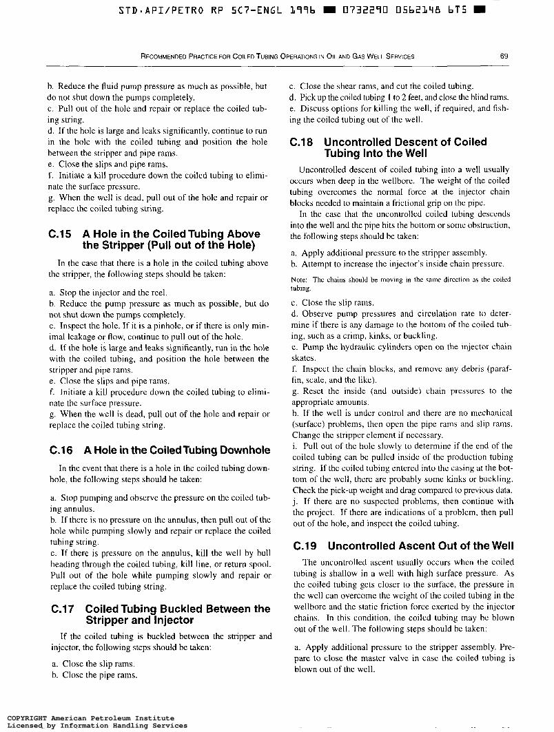
STD*API/PETRO RP 5Cï ”ENGL L77b m 0732270 05bZLqB bT5 ~~
RECOMMENDED PRACTICE FOR COILED TUBING OPERATIONS I N OIL AND GAS WELL SERVICES 69
h. Reduce the fluid pump pressure as much as possible, but do not shut down the pumps completely. c. Pull out of the hole and repair or replace the coiled tub- ing string. d. If the hole is large and leaks significantly, continue to run in the hole with the coiled tubing and position the hole between the stripper and pipe rams. e. Close the slips and pipe rams. f . Initiate a kill procedure down the coiled tubing to elimi- nate the surface pressure. g. When the well is dead, pull out of the hole and repair or replace the coiled tubing string.
C.15 A Hole in the CoiledTubing Above the Stripper (Pull out of the Hole)
In the case that there is a hole in the coiled tubing above the stripper, the following steps should be taken:
a. Stop the injector and the reel. b. Reduce the pump pressure as much as possible, but do not shut down the pumps completely. c. Inspect the hole. If it is a pinhole, or if there is only min- imal leakage or flow, continue to pull out of the hole. d. If the hole is large and leaks significantly, run in the hole with the coiled tubing, and position the hole between the stripper and pipe rams. e. Close the slips and pipe rams. f. Initiate a kill procedure down the coiled tubing to elimi- nate the surface pressure. g. When the well is dead, pull out of the hole and repair or replace the coiled tubing string.
C.16 A Hole in the CoiledTubing Downhole In the event that there is a hole in the coiled tubing down-
hole, the following steps should be taken:
a. Stop pumping and observe the pressure on the coiled tub- ing annulus. h. If there is no pressure on the annulus, then pull out of the hole while pumping slowly and repair or replace the coiled tubing string. c. If there is pressure on the annulus, kill the well by bull heading through the coiled tubing, kill line, or return spool. Pull out of the hole while pumping slowly and repair or replace the coiled tubing string.
C.17 Coiled Tubing Buckled Between the Stripper and Injector
If the coiled tubing is buckled between the stripper and injector, the following steps should be taken:
a. Close the slip rams. b. Close the pipe rams.
c. Close the shear rams, and cut the coiled tubing. d. Pick up the coiled tubing 1 to 2 feet, and close the blind rams. e. Discuss options for killing the well, if required, and fish- ing the coiled tubing out of the well.
C.18 Uncontrolled Descent of Coiled Tubing Into the Well
Uncontrolled descent of coiled tubing into a well usually occurs when deep in the wellbore. The weight of the coiled tubing overcomes the normal force at the injector chain blocks needed to maintain a frictional grip on the pipe.
In the case that the uncontrolled coiled tubing descends into the well and the pipe hits the bottom or some obstruction, the following steps should be taken:
a. Apply additional pressure to the stripper assembly. h. Attempt to increase the injector’s inside chain pressure.
Note: The chains should be moving in the same direction as the coiled tubing.
c. Close the slip rams. d. Observe pump pressures and circulation rate to deter- mine if there is any damage to the bottom of the coiled tub- ing, such as a crimp, kinks, or buckling. e. Pump the hydraulic cylinders open on the injector chain skates. f. Inspect the chain blocks, and remove any debris (paraf- fin, scale, and the like). g. Reset the inside (and outside) chain pressures to the appropriate amounts. h. If the well is under control and there are no mechanical (surface) problems, then open the pipe rams and slip rams. Change the stripper element if necessary. i. Pull out of the hole slowly to determine if the end of the coiled tubing can be pulled inside of the production tubing string. If the coiled tubing entered into the casing at the bot- tom of the well, there are probably some kinks or buckling. Check the pick-up weight and drag compared to previous data. j. If there are no suspected problems, then continue with the project. If there are indications of a problem, then pull out of the hole, and inspect the coiled tubing.
C.19 Uncontrolled Ascent Out of the Well The uncontrolled ascent usually occurs when the coiled
tubing is shallow in a well with high surface pressure. As the coiled tubing gets closer to the surface, the pressure in the well can overcome the weight of the coiled tubing in the wellbore and the static friction force exerted by the injector chains. In this condition, the coiled tubing may be blown out of the well. The following steps should be taken:
a. Apply additional pressure to the stripper assembly. Pre- pare to close the master valve in case the coiled tubing is blown out of the well.
COPYRIGHT American Petroleum InstituteLicensed by Information Handling ServicesCOPYRIGHT American Petroleum InstituteLicensed by Information Handling Services
b. Attempt to increase the injector’s inside chain pressure.
Note: The chains should be moving in the same direction as the coiled tubing.
c. If these attempts are unsuccessful, put the injector motors in neutral and close the slip rams. d. Once the pipe motion is halted, close the pipe rams and slips, if not already closed. e. Pump the hydraulic cylinders open on the injector chain skates. f. Inspect the chain blocks and remove any debris (paraffin, scale, etc.). g. Reset the inside (and outside) chain pressures to the appropriate amounts. h. If the well is under control and there are no mechanical problems, then open the pipe rams and slip rams. (Change stripper element if necessary.) i. Reduce the hydraulic pressure on the stripper element and pick up the coiled tubing enough to inspect the area of pipe held by the slips. j. Determine whether it will be necessary to repair/replace that section of coiled tubing prior to resuming the pipe extraction. Be extremely cautious while checking the area of pipe held by the slips since the pipe may be weakened and may fail with high-surface pressure present. k. Continue to pull out of the hole and close the master valve. Determine the cause for the uncontrolled movement of pipe prior to entering the well again. Replace or repair the coiled tubing string as required.
If the coiled tubing is blown out of the stripper assembly, close the blind rams and master valve as quickly as possible.
C.20 Crane Operations Crane operation should be limited to personnel with the
following minimum qualifications:
a. Certified, designated, and competent persons. b. Maintenance and test personnel, only insofar as it is nec- essary for the performance of their duties. c. Supervisor or other coiled tubing crew member with designated experienced person present.
In addition to the above, the operator should meet the fol- lowing requirements:
a. Be able to demonstrate the ability to read, comprehend and interpret all placards, operator’s manuals, safety codes and other information pertinent to correct, safe crane operation. b. Possess knowledge of emergency procedures and imple- mentation of same. c. Be familiar with all relevant safety standard codes and applicable governmental requirements. d. Recognize and be responsible for all maintenance requirements of the crane operated by him or trainees under his supervision. e. Be thoroughly familiar with the crane being operated and its control functions. f. Have read and fully comprehended the operating proce- dures as outlined in relevant procedures and standards.
Where required by government regulations, crane inspec- tions (and the frequency of these) must be carried out by a recognized authority. Records of the dates and results of the inspections must be maintained on the unit.
COPYRIGHT American Petroleum InstituteLicensed by Information Handling ServicesCOPYRIGHT American Petroleum InstituteLicensed by Information Handling Services
STD.API/PETRO RP 5C7-ENGL L77b D 0732270 05b2150 253 m
PC-0120C-12/96-1 6M ( )
COPYRIGHT American Petroleum InstituteLicensed by Information Handling ServicesCOPYRIGHT American Petroleum InstituteLicensed by Information Handling Services
STD.API/PETRO RP 5C7-ENGL 2 9 9 b E 0732270 05b2251 L9T
Additional copies available from API Publications and Distribution: (202) 682-8375
Information about API Publications, Programs and Services is available on the World Wide Web at: http://www.api.org
American 1220 L Street, Northwest Petroleum Washington, D.C. 20005-4070 Institute 202-682-8000 Order No. G05C71
COPYRIGHT American Petroleum InstituteLicensed by Information Handling ServicesCOPYRIGHT American Petroleum InstituteLicensed by Information Handling Services