apm-56-12 bending of circular plates with large...
TRANSCRIPT

APM-56-12
Bending of C ircu lar P lates W ith L arge Deflection
By STEWART WAY,1 EAST PITTSBURGH, PA.
I n th e d e s ig n o f t h i n p la te s b e n t by la te r a l lo a d in g ,
fo rm u la s based o n th e K ir c h h o f f th e o ry w h ic h neg lec ts
s tre tc h in g a n d s he a r in g i n t h e m id d le su rface a re q u i t e
sa tis fac to ry , p ro v id in g th e d e fle c tio ns are s m a ll c o m p a re d
to th e th ic k n e ss . I f d e fle c tio ns are o f t h e s am e o rde r as
th e th ic k n e ss , th e K ir c h h o f f th e o ry m a y y ie ld re su lts
w h ic h are c o n s id e ra b ly i n e rro r a n d the re fo re a m o re
rigo rous th e o ry w h ic h tak es a c c o u n t o f d e fo rm a t io n s i n
th e m id d le surface s h o u ld be a p p lie d . T he f u n d a m e n ta l
e q u a tio n s fo r th e m o re exact th e o ry are k n o w n ,2 a n d
a p p ro x im a te s o lu t io n s 3 have b een deve loped fo r th e case
o f a c irc u la r p la te .
T h is p ap e r gives th e gene ra l s o lu t io n o f t h e f u n d a m e n ta l
e q u a tio n s fo r th e case o f a c ir c u la r p la te b e n t t o a fig u re
o f re v o lu t io n . P a r t ic u la r s o lu t io n s a re fo u n d w h ic h
sa tis fy o ne o f th e tw o b o u n d a ry c o n d it io n s , a n d stresses
a n d de flec tions are c a lc u la te d f r o m these s o lu t io n s . B y
in te rp o la t io n , th e stresses a n d d e fle c tio ns are t h e n fo u n d
fo r p la te s s a t is fy in g b o th b o u n d a ry c o n d it io n s . T he
de flec tions are co m p a re d w ith e x p e r im e n ta l re s u lts a n d
w ith th e a p p ro x im a te fo rm u la s . I t is fo u n d t h a t these
de flec tions agree c lose ly w i th th e e x p e r im e n ta l re s u lts
a n d a lso w ith tho se o b ta in e d b y th e a p p ro x im a te m e th o d s
o f A . N ad a i a n d S . T im o sh e n k o , as s h o w n i n F ig s . 8 a n d 10.
D = Eh3/12(l — ft2) = flexural rigidity of the plate Wr, mt = radial and circumferential bending moments
per unit of length
p = radial displacement of points in the middle surface
Displacements and stresses are assumed to be functions of r only; that is, they have radial symmetry.
Loads and deflections will be taken as positive when downward and moments as positive when they tend to make the plate concave upward.
2 E x p b e s s io n s f o b S tr e s s e s a n d M o m e n ts i n T ebm s o p
D is p la c e m e n t s
Three assumptions are made as follows:
(1) The material is homogeneous, isotropic, and obeys Hooke’s law
(2) The curvature of a meridian may be replaced by d2w/dr2(3) Straight lines initially normal to the middle surface
remain straight and normal to that surface after bending.
It follows from the third assumption that if the radial and vertical displacements of every point in the middle surface are known the displacements of all points of the plate can be found.
The radial extension in the middle surface is
cFUNDAMENTAL EQUATIONS
1 N o m e n c la t t jb e
ONSIDER an initially flat circular plate of uniform thickness and let
a — radius h = thickness
p = load intensity, assumed uniform o>, a,', o>" = radial stresses at, a t , at" = circumferential stresses
2 = distance from middle surface, downward direction positive
r = distance from axis of symmetry to a point in the plate before deflection
w = vertical displacement of points of the middle surface relative to the center of the middle surface
tp = dw/dr E — Young’s modulus m = Poisson’s ratio
and the circumferential extension is
At a distance z from the middle surface there are the additional extensions due to bending
1 Research Laboratories, Westinghouse Electric & Manufacturing Co., East Pittsburgh, Pa.
1 Due to von K&rm&n, Enzyk. d. Math. Wiss., vol. 4, art. 27. See also A. Nadai, “Die Elastische Platten,” Springer, Berlin, 1925, p. 284.
3 Solutions such as that by A. Nadai and discussed in this paper.Contributed by the Applied Mechanics Division and presented at
the Annual Meeting, New York, N. Y .t December 4 to 8, 1933, of The A m e b ic a n S o c ie ty o f M e c h a n i c a l E n g in e e b s . This paper was prepared by the author as a thesis for a Doctor’s degree at the University of Michigan.
N o te : Statements and opinions advanced in papers are to be understood as individual expressions of their authors, and not those of the Society.
The middle surface extensions give rise to the membrane stresses a,' and at! which by Hooke’s law are as follows:
627
The extensions due to bending give rise to the following bending stresses
628 TRANSACTIONS OF THE AMERICAN SOCIETY OF MECHANICAL ENGINEERS
Summing the moments of o>" and at" from z = — h/2 to z
h/2 the following are obtained:
Hereafter a," and at' will be used to denote the outer-surface
bending stresses which are given by
A useful relation between p and the membrane stresses is given
by Hooke’s law and is
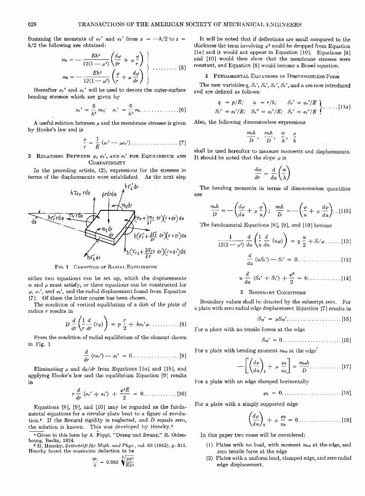
F ig . 1 C o n d it io n o f R a d ia l E q u il ib r iu m
either two equations can be set up, which the displacements
w and p must satisfy, or three equations can be constructed for
<p, a/, and at', and the radial displacement found from Equation
[7]. Of these the latter course has been chosen.
The condition of vertical equilibrium of a disk of the plate of
radius r results in
From the condition of radial equilibrium of the element shown
in Fig. 1
It will be noted that if deflections are small compared to the
thickness the term involving ^ could be dropped from Equation
[la] and it would not appear in Equation [10]. Equations [9]
and [10] would then show that the membrane stresses were
constant, and Equation [8] would become a Bessel equation.
4 F u n d a m e n t a l E q u a t io n s in D im e n s io n l e s s F o r m
The new variables q, S,', St', Sr", St", and u are now introduced
and are defined as follows:
The bending moments in terms of dimensionless quantities are
5 B o u n d a r y C o n d it io n s
Boundary values shall be denoted by the subscript zero. For
a plate with zero radial edge displacement Equation [7] results in
Eliminating p and dp/dr from Equations [la] and [16], and
applying Hooke’s law and the equilibrium Equation [9] results
For a plate with bending moment mr0 at the edger
Equations [8], [9], and [10] may be regarded as the funda
mental equations for a circular plate bent to a figure of revolu
tion.4 If the flexural rigidity is neglected, and D equals zero,
the solution is known. This was developed by Hencky.6
4 Given in this form by A. Foppl, “Drang und Zwang,” R . Olden- bourg, Berlin, 1924.
5' H. Hencky, Zeitschrift filr Math, und Phys., vol. 63 (1915), p. 311. Hencky found the maximum deflection to be
For a plate with a simply supported edge
In this paper two cases will be considered:
(1) Plates with no load, with moment mro at the edge, and
zero tensile force at the edge
(2) Plates with a uniform load, clamped edge, and zero radial
edge displacement.
The fundamental Equations [8], [9], and [10] become
For a plate with no tensile forces at the edge
Also, the following dimensionless expressions
shall be used hereafter to measure moments and displacements.
I t should be noted that the slope <p is3 R e l a t i o n s B e tw e e n <p, <rr', a n d a t' f o r E q u i l i b r i u m a n d
C o m p a t i b i l i t y
In the preceding article, (2), expressions for the stresses in
terms of the displacements were established. As the next step
For a plate with an edge clamped horizontally

APPLIED MECHANICS APM-56-12 629
GENERAL SOLUTION AND PARTICULAR SOLUTIONS
6 T h e G e n e r a l So l u t io n
A solution for Equations [12], [13], and [14] is now desired.
Either by successive differentiation of these equations or by a
consideration6 of the basic assumptions of the theory of elasticity,
it can be shown that all the derivatives of the displacements
p and w will exist at all points in the plate. The displacements,
extensions, and stresses may therefore be expanded in series of
positive powers of u. Since S,' is a symmetrical7 function of u
it can be expanded in a series of even powers of u and since <p
is an antisymmetrical function of u it can be expanded in a
series of odd powers of u.
As the starting point, therefore, let
and by differentiation of the <p series
and the radial displacement from Equation [7] is
The series expressions [20] to [24] along with the Equations
[27] and [28] constitute the general solution of the problem of
a plate bent to a figure of revolution by a uniform load.
The two constants Bo and Ci are not determined. When they
are assigned, all the other constants are determined by Equations
[27] and [28], and the quantities S /, Si', and <p are determined
by Equations [20], [21], and [22] for all points in the plate,
including the boundary. Fixing B0 and Ci is thus equivalent to
fixing the boundary conditions. I t will be noted that B0 is the
value of <Sr' at the center while Ci is proportional to the bending
moment at the center.
7 P a r t i c u l a r S o l u t i o n s f o r Z e r o L o a d a n d Z e r o E d g e
F o r c e 8
The following results apply to plates loaded by a distributed
bending moment at the edge as shown in Fig. 2.
We assume the value ix = 1/ t for
Poisson’s ratio. The method of ob
taining the required values consists
of assuming a pair of values for B0
and Ci and calculating all the other
constants Ck and Bt by Equations
[27] and [28]. The radius, u0, is
then determined so as to make iS'r0'
zero, and wo/h, mrJi/D , mtah/D,
hmr(0)/D, and Sr'(0) are calculated
from Equations [20] to [24], and
[116]. These calculations have been
made for eleven plates with the results
given in Table 1.
The values of Utfhmro/D are given
in Table 1, because it can be shown
from the general solution that all
plates of the type considered, for
which the values of uJhmro/D are the
same, will have the same deflection. In Fig. 3 is shown a curve
for W o/h for various values of u^hm^/D. This curve is ap-
F ig . 2 D i s t r i b u t e d
B e n d in g M o m e n t a t
E dg e o f C i r c u l a r P la t e
All quantities in which we may be interested can be found
therefore, if the constants Ck and Bk are known.
By substituting the series expressions for S /, St', and <p in
Equations [12] and [14], two sets of relations between the con
stants Bk and Ck are obtained:
* E. Trefftz in the “Handbuch der Physik,” vol. 6, p. 122.7 That is Sr’(u) = <S/(— «). If <p is an antisymmetrical function
ip(u) = —<p(—u).
F ig . 3 D e f l e c t io n o f C ir c u l a r P late W it h D is t r ib u t e d
B e n d in g M o m en t a t E d ge
8 One such particular solution is given by S. Timoshenko, “Theory of Elasticity,” St. Petersburg, Russia, 1916.
From the equilibrium Equation [13]
By integrating the series expression for <p
I he moments are given in terms of <p and atp/au by Equation
[116]. The bending stresses are related to the moments by

630 TRANSACTIONS OF THE AMERICAN SOCIETY OF MECHANICAL ENGINEERS
TABLE 1
m imroh mtoh mr(0)h
Plate wo wo/h D D
104Z?o =1 0 W
(0) 10<Ci
„ hm.ro
1 43.66 0.899 -14.43 -13.12 -10.61 1 3 -2.752 33.80 0.688 -17.07 -16.02 -14.16 1 4 -1.953 27.45 0.555 -20.03 -19.24 -17.69 1 5 -1.514 23.08 0.465 -23.18 -22.51 -21.23 1 6 -1.2365 52.66 1.614 -25.21 -19.68 -10.61 2 3 -6.996 42.92 1.282 -25.47 -21.38 -14.16 2 4 -4.697 36.00 1.059 -26.87 -23.64 -17.69 2 5 -3.488 30.87 0.899 -28.86 -26.24 -21.23 2 6 -2.759 36.36 1.759 -38 .3 -29.06 -14.16 3 4 -8.23
10 40.00 1.485 -37 .3 -30.15 -17.69 3 5 -5.9611 35.05 1.283 -38 .2 -32.06 -21.23 3 6 -4.69
plicable to plates of all radii, all edge moments, and all materials
of Poisson’s ratio l/t.
The elementary theory gives
This straight-line relation is shown in Fig. 3. For w0/h = 1,
the error in the elementary theory is seen to be 28 per cent.
8 P a r t i c u l a r S o l u t i o n s f o r P l a t e s W i t h L a t e r a l L o a d
a n d B o u n d a r y C o n d i t i o n w = 0
The following solutions apply to the case of plates with clamped
edges and uniform lateral loading. I t should be noted that
the solutions obtained are not expected to satisfy the condition
Po = 0.
Plate MO 10«Sro' 104S»' wo/h io‘C-:X lOiBo 10<Ci
1 46.34 1.636 1.374 0.405 -16.89 2.0 2.52 52.20 1.319 0.8192 0.629 -21.15 2.0 3.03 57.27 0.8454 0.0025 0.905 -25.91 2.0 3.54 44.12 1.178 0.9539 0.360 -16.02 1.5 2.55 49.13 0.9153 0.4988 0.542 -19.71 1.5 3.06 53.44 0.5376 -0.1648 0.761 -23.41 1.5 3.57 42.23 0.7114 0.5155 0.324 -15.28 1.0 2.58 46.59 0.4878 0.1291 0.478 -18.56 1.0 3.09 36.20 0.3671 0.2775 0.187 -11.64 0.5 2.0
10 40.60 0.2377 0.0603 0.296 -14.66 0.5 2.511 44.44 0.0444 -0.2631 0.427 -17.71 0.5 3.012 41.81 2.311 2.177 0.263 -13.56 2.5 2.013 49.05 2.081 1.770 0.464 -18.00 2.5 2.514 56.08 1.680 1.062 0.745 -23.09 2.5 3.015 62.27 1.050 -0.1025 1.117 -28.39 2.5 3.516 43.79 2.789 2.635 0.294 -14.27 3.0 2 .017 52.43 2.507 2.16 0.545 -19.44 3.0 2.518 61.23 1.965 1.143 0.933 -25.68 3.0 3.019 68.78 1.069 -0.563 1.453 -32.62 3.0 3.5
interested determined from the series expressions. In this
case the radius is found from the condition that the right-hand
member of Equation [21] vanishes when u = u<>. The results
of these calculations for nineteen plates are given in Table 2.
The bending moment at the edge is given simply by
since in this case ®o = 0.
9 S tr e s s e s a n d D e f l e c t i o n s i n L a t e r a l l y L o a d e d P l a t e s
W i t h B o t h B o u n d a r y C o n d i t io n s , <po — 0 a n d p0 = 0,
S a t i s f ie d
We group the plates in Table 2 according to common values
of Bo or Ci as follows:
Group Plates Common Property
a 1, 2, 3 104£o = 2b 4, 5, 6 10*B0 = 1 . 5c 1, 4, 7, 10 104Ci = 2 .5
d 2, 5, 8, 11 104Ci = 3 .0
e 12, 13, 14, 15 104J3o = 2 .5
f 16, 17, 18, 19 104Bo = 3.0
By interpolating between the results for the plates in any one
group in such a manner as to make Sto = M<Sro, data for a plate
having p0 = 0 is obtained. From group a data for plate a is
obtained, from group b data for plate b, etc. A typical set of
interpolation curves is shown in Fig. 5.
a b
TABLE 3
c d e /QUO4 6.321 4.561 1.818 3.196 8.635 11.71wo/h 0.800 0.637 0.296 0.482 0.970 1.152uoiSro/ 0.311 0.196 0.041 0.112 0.468 0.671Uo2Sro" 4.087 3.061 1.334 2.250 5.220 6.621Uo*Sr'(0) 0.616 0.392 0.085 0.226 0.900 1.258uo^S/'iO) 2.069 1.704 0.834 1.327 2.408 2.727
F i g . 4 C i r c u l a r P l a t e W i t h C l a m p e d E d g e a n d U n i f o r m
L a t e r a l L o a d
The manner of loading is shown in Fig. 4.
Values are first selected for n and q:
F ig . 5 I n t e r p o l a t i o n C u r v e s — P l a t e s 1 , 2 , a n d 3
Values are then assumed for B0 and Ci, the remaining con
stants calculated, and the various quantities in which we are

APPLIED MECHANICS APM-56-12 631
The results for plates o to / are given in Table
3. The stresses at the center are given and,
as has been noted, they depend on Bo and C1.
Stresses are multiplied by u02, for it can be
•shown that w/h and uo2<S will have constant
values at similarly situated points in all plates
with constant quo*.
The curves in Fig. 6 show the relation of wo/h
to quo4 and those in Fig. 7 show the membrane
and bending stresses at the center and the edge
for various values of wo/h. By definition of q
and u0, qu04 is equivalent to pa4/E h4.
A numerical example will illustrate the use
of these curves. Consider a plate of thickness
0.02 in., radius 2 in., and load 3 lb per sq in.
Let E ~ 30 X 10" lb per sq in. and let n = 0.3.
For this plate quo4 = 10. From Fig. 6 we see
that wo/h = 1.055 so that wo = 0.0211 in.
From Fig. 7 the stresses are
F i g . 8 C o m p a r i s o n o p N a d a i ’s T h e o r y a n d t h e M e m b r a n e
T h e o r y W i t h t h e “ E x a c t ” o r P o w e r S e r i e s T h e o r y , L i n e a r
T h e o r y , a n d T i m o s h e n k o ’s A p p r o x i m a t e T h e o r y
D e f l e c t i o n o f C i r c u l a r P l a t e W i t h t h e E d g e C l a m p e d
found by making a suitable transformation of the results in
Table 2. Space does not permit a discussion of this method
but the deflection curves for = 0.25 and m = 0.35 are shown
in Fig. 6. I t will be seen that variations in Poisson’s ratio have
very little effect on the behavior of the plate.
COM PARISON W ITH APPROX IM ATE FORMULAS
10 A p p r o x im a te M e t h o d s o f C o n s id e r in g M e m b r a n e
S tr e s s e s
Nadai and Timoshenko have used approximate methods
which seem to be reasonably accurate. Before discussing them,
the basic equations will be restated in a different form:
F i g . 7 S t r e s s e s a t E d g e a n d a t C e n t e r ( ju = 0.3)
The figures given in Table 3 apply only for Poisson’s ratio
M = 0.3. For other values of /x values for qu«i and Wn/h can be
Fio. 6
per sq in.

632 TRANSACTIONS OF THE AMERICAN SOCIETY OF MECHANICAL ENGINEERS
The first is equivalent to Equation [8] and the second is
Equation [9] with a,' and at' replaced by their values in terms
of p and tp.
Nadai8 assumes this expression for ip
and placing it in the second Equation [31], solves for p. The
resulting expression for p and expression [32] are then placed
in the first Equation [31 ] which is solved for p. The constants
c and n are then determined so as to make p as nearly a constant
as possible. Nadai gives the following equation for the maxi
mum deflection:
This is obtained when n = 0.25. In Fig. 8 a curve is shown
based on this formula and beside it a curve based on the power
series solution discussed in this paper. The agreement is seen
to be close.
The approximate method of Timoshenko10 is simpler. He
assumes that the radial displacement is given by
Therefore, a fairly accurate method of finding a*/Eh* was
thought to be to determine Lim.(p — >■ 0)wo/ph by experiment
at small pressures. For the various plates values of a*/Eh*
were found as follows:
A curve for Wo/h based on this formula also is shown in Fig. 8.
This approximation it will be seen errs on the safe side, while
the formula [33] errs on the unsafe side.
In Fig. 8 the curve obtained from Hencky’s membrane theory6
is shown also.
E XPER IM EN T A L RESULTS
11 A p p a r a t u s f o r T e s t in g
Experiments were made on circular plates of duralumin of
41/ 2-in. diameter and various thicknesses. All plates were
clamped at their edges and the method of clamping is shown in
Fig. 9. The compartment beneath the plate was filled with
water and the pressure controlled by means of a static head of
mercury. An Ames dial directly above the center of the plate
recorded the deflections.
Four plates of the following thicknesses were tested:
Plate 1........................................ h = 0.064 in.Plate 2 ........................................ h = 0.052 in.Plate 3 ........................................ h = 0 .0449 in.Plate 4 ........................................h = 0.032 in.
In all cases it was assumed that the value of Poisson’s ratio was
0.35.
12 R e s u l t s o p T e st s
As it was desirable to know the value of pa1/Eh* for each
measured deflection, a*/Eh* had to be found for each plate. Now
for very small deflections
F ig . 9 M et h o d o f (.’la m p in g E dg es o f C ir c u l a r P lates
The values of wo/h and pa*/Eh* obtained in the various tests
are recorded in Table 4.
Plate 1 Plate
TABLE
2
4
Plate 3 Plate 4wo/h quo* wo/h quo* wo/h quo4 wo/h quo*
0 0 0 0 0.002 0.01 0 00.075 0.437 0.067 0.42 0.162 0.98 0.387 2.510.153 0.939 0.138 0.84 0.376 2.36 0.527 3.580.234 1.440 0.229 1.40 0.550 3.75 0.-649 4.640.308 1.842 0.333 2.09 0.697 5.13 0.793 6.240.377 2.443 0.432 2.79 0.826 6.51 0.980 8.910.445 2.946 0.529 3.49 0.931 7.89 1.135 11.580.507 3.447 0.611 4.19 1.022 9.27 1.263 14.25
0.687 4.89 1.108 10.66 1.375 16.920.752 5.590.821 6.280.883 6.980.937 7.68
8 A. Nadai, “Die Elastische Platten,” Springer, Berlin, 1925, p.288. Nadai actually uses the Equations [31] in dimensionless form.
10 S. Timoshenko, “Vibration Problems in Engineering,” D. Van Nostrand Co., New York, 1928, p. 317.
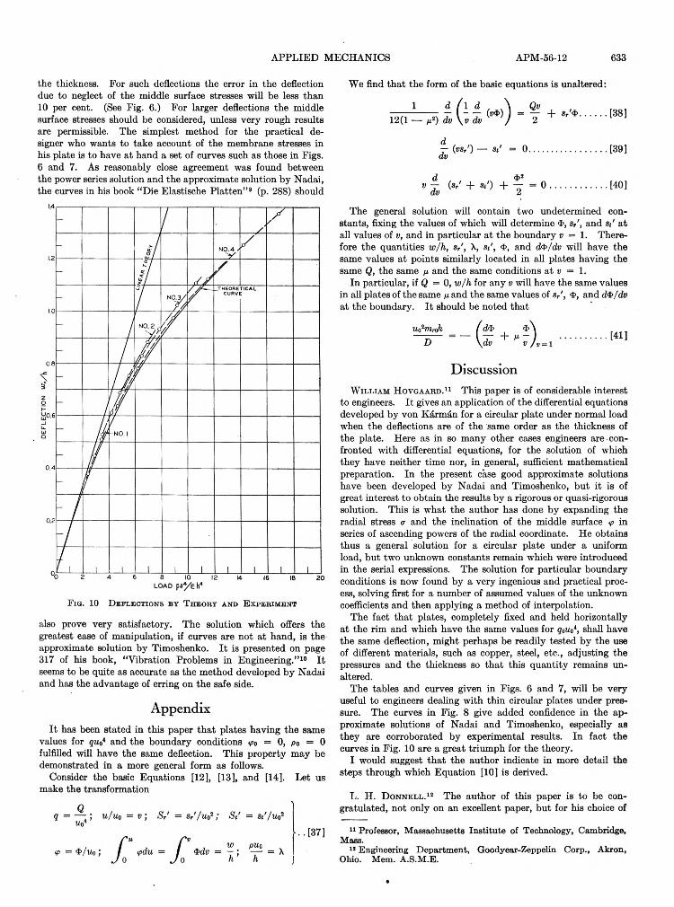
13 C o m p a r is o n W it h T h e o r y
In Fig. 10 the deflection curves found from the experiments
have been plotted together with the theoretical curve for n =
0.35.
I t will be noted that the difference between the values of
W o/h by theory and experiment is seldom more than 5 per cent.
I t will also be noted that the experimental curves always lie
above the theoretical curve. This latter fact would indicate
that part of the discrepancy is due to slipping and rotating at
the edges of the test plate. The fact that there is no apparent
relation between the plate thickness and the amount of dis
agreement shows, however, that edge slippage is not the only
explanation. A much more likely source of error in the experi
mental curve lies in the determination of a*/Eh*. To expect
a determination of this quantity within 4 per cent accuracy
would be very optimistic. On the whole, therefore, it must be
concluded that the agreement found between experiment and
theory is not at all bad.
14 S u g g e s t io n s f o r D e s ig n o f P l a t e s
For clamped circular plates with uniform loads the elementary
theory is applicable for maximum deflections less than 0.4 of
and that, for purposes of finding ci and C2, the deflection is of
the same form as in the elementary theory. He then minimizes
the potential energy of stretching to determine ci and c2, and
arrives at the following equation for the deflection:
APPLIED MECHANICS APM-56-12 633
the thickness. For such deflections the error in the deflection
due to neglect of the middle surface stresses will be less than
10 per cent. (See Fig. 6.) For larger deflections the middle
surface stresses should be considered, unless very rough results
are permissible. The simplest method for the practical de
signer who wants to take account of the membrane stresses in
his plate is to have at hand a set of curves such as those in Figs.
6 and 7. As reasonably close agreement was found between
the power series solution and the approximate solution by Nadai,
the curves in his book “Die Elastische Platten”9 (p. 288) should
Fio. 10 D e f l e c t i o n s b y T h e o r y a n d E x p e r i m e n t
also prove very satisfactory. The solution which offers the
greatest ease of manipulation, if curves are not at hand, is the
approximate solution by Timoshenko. I t is presented on page
317 of his book, “Vibration Problems in Engineering.” 10 It
seems to be quite as accurate as the method developed by Nadai
and has the advantage of erring on the safe side.
AppendixIt has been stated in this paper that plates having the same
values for quo* and the boundary conditions <po = 0, po = 0
fulfilled will have the same deflection. This property may be
demonstrated in a more general form as follows.
Consider the basic Equations [12], [13], and [14]. Let us
make the transformation
DiscussionW i l l i a m H o v g a a r d .11 This paper is of considerable interest
to engineers. I t gives an application of the differential equations
developed by von Kd,rm£n for a circular plate under normal load
when the deflections are of the same order as the thickness of
the plate. Here as in so many other cases engineers are con
fronted with differential equations, for the solution of which
they have neither time nor, in general, sufficient mathematical
preparation. In the present case good approximate solutions
have been developed by Nadai and Timoshenko, but it is of
great interest to obtain the results by a rigorous or quasi-rigorous
solution. This is what the author has done by expanding the
radial stress a and the inclination of the middle surface in
series of ascending powers of the radial coordinate. He obtains
thus a general solution for a circular plate under a uniform
load, but two unknown constants remain which were introduced
in the serial expressions. The solution for particular boundary
conditions is now found by a very ingenious and practical proc
ess, solving first for a number of assumed values of the unknown
coefficients and then applying a method of interpolation.
The fact that plates, completely fixed and held horizontally
at the rim and which have the same values for qoUt>*, shall have
the same deflection, might perhaps be readily tested by the use
of different materials, such as copper, steel, etc., adjusting the
pressures and the thickness so that this quantity remains un
altered.
The tables and curves given in Figs. 6 and 7, will be very
useful to engineers dealing with thin circular plates under pres
sure. The curves in Fig. 8 give added confidence in the ap
proximate solutions of Nadai and Timoshenko, especially as
they are corroborated by experimental results. In fact the
curves in Fig. 10 are a great triumph for the theory.
I would suggest that the author indicate in more detail the
steps through which Equation [10] is derived.
L. H. D o n n e l l . 12 The author of this paper is to be con
gratulated, not only on an excellent paper, but for his choice of
11 Professor, Massachusetts Institute of Technology, Cambridge, Mass.
12 Engineering Department, Goodyear-Zeppelin Corp., Akron, Ohio. Mem. A.S.M.E.
We find that the form of the basic equations is unaltered:
The general solution will contain two undetermined con
stants, fixing the values of which will determine $, s/, and s<' at
all values of v, and in particular at the boundary v = 1. There
fore the quantities w/h, s X, s/, 4>, and d$/dv will have the
same values at points similarly located in all plates having the
same Q, the same n and the same conditions at v = 1.
In particular, if Q = 0, w/h for any v will have the same values
in all plates of the same n and the same values of 3>, and di>/dv
at the boundary. I t should be noted that

634 TRANSACTIONS OF THE AMERICAN SOCIETY OF MECHANICAL ENGINEERS
a subject which is of much more practical importance than the attention it has hitherto received might indicate. In the case of the bending of beams, a large-deflection theory is needed only when the deflections are so great that the slope of the deflection curve is of the order of magnitude of one, that is, when the deflections are of the order of magnitude of the length of the beam. Such deflections are almost never experienced in practise, and engineers are thus prone to think of large-deflection theories as of academic interest only. But the situation is entirely different with flat or curved plates which are bent in such a way that stretching or compressing of the plate must accompany the flexure, as is the case when a developable surface is bent to a non- developable one. Then the simple theory of small deflections becomes inaccurate when the deflections are of the order of magnitude of the thickness, as is vividly illustrated by the results given in this paper. Such deflections are frequently met with in practise so that researches of this nature have great practical value.
The author develops an “exact” theory for his case and compares it with two previous more approximate large-deflection theories. The comparison shows that as far as deflections are concerned the approximate theories are sufficiently accurate for practical purposes. This is important, as it is advisable to have as many checks as possible on our approximate methods. However the author fails to give any comparison between the maximum stresses in the plate, as given by the exact and approximate methods, although such a comparison should be quite easy for him to make and would add greatly to the value of the paper. General experience has been that such approximate theories are less accurate in regard to stresses than deflections.
The writer believes that it will be necessary to use large deflection theories to satisfactorily explain and study a number of important phenomena in the buckling of flat and curved sheets. Thus it is well known that the ultimate strength of a flat sheet with clamped or supported edges, under edge compression, is usually much greater than the stability limit given by the well- known theories of Bryan and Timoshenko, based on small-deflec- tion theory. Dr. von K£rmdn has explained most of this difference as an edge effect, due to the edges being artificially prevented from buckling. But there is an additional strengthening effect having no connection with this. This might be called a “disk- wheel” effect as it is due to the bulging out of the sheet to something like the shape and hence something of the strength of a disk wheel. This effect can only be studied by a large-deflection theory. It has practical importance in the case of very thin plates or plates of a material with a high elastic limit. Also, in the buckling of thin cylinders or curved sheets under axial load,
experiments show many features which have never been satisfactorily explained by any theory based on small deflections. The writer has found that all these discrepancies can be explained by considering initial deviations from cylindrical shape
and using large deflection theory.
H. H e n c k y .13 The paper by Mr. Way is very valuable because the exact solution of his problem is very difficult and tedious to obtain and is nevertheless needed for a judgment on approximative methods. He discusses the methods of Nadai and Timoshenko and finds them fairly satisfactory.
I t is perhaps of interest to remark that these methods are only special cases of a more general method which was developed 18 years ago by G. B. Galerkin, of Leningrad. The method of Galerkin is one of unlimited adaptability to the precision required in any special case and deserves therefore a greater amount of publicity than it has had.
The problem in question is a two-dimensional one, the two
11 Lisbon, N. H. Mem. A.8.M.E.
with the integrations taken over the whole area of the plate.Until now we have not introduced anything of an approximate
character. Galerkin substitutes for w and p two series of arbitrary functions and extends the variations only over the arbitrary constants to be determined in the case in question. Consequently, using the fact that the variations are absolutely arbitrary, the two integrations yield just the needed number of equations to determine the constants. Naturally the functions have to be chosen so that the boundary conditions are satisfied.
The advantage of this method lies in the fact that by increasing the number of constants the method can be employed even if the exact solution is impossible to obtain as the case of a rectangular plate.
E. 0 . W a t e r s . 14 The author should be highly commended for giving to the engineering profession a simple, workable solution for a rather difficult problem. It is true that the general equations have been known for some time in differential form, but it is doubtful whether engineers have ever made much, if any, use of them. Now, thanks to the author’s labor of setting up the power series and solving the coefficients, together with his ingenious method of adjusting the results so as to fit the prescribed boundary conditions, it is possible to find the maximum deflection and the important stresses in a circular plate clamped at the edges, simply by referring to the proper curve in Fig. 6 or Fig. 7.
It is interesting to note how nearly accurate are the two approximate solutions mentioned by the author, as far as maximum deflection is concerned. In this connection, it should be pointed out that the solution by Timoshenko, Equation [35], was evidently worked out for m = 0.3. If m is changed to 0.25, the curve for this approximate solution would shift slightly to the left, in the manner indicated in Fig. 6, and the error on the side of safety would be greater. This, however, makes practically no difference as long as the proper value of m2 is used in the last term of Equation [35], as was apparently done in the paper.
The writer would like to place on record another approximate solution (not original) which gives practically the same maximum deflection as the Nadai and Timoshenko formulas, and in addition gives membrane stresses at the center and edge that agree substantially with the exact method. By multiplying equation [8] by r, differentiating and then dividing by r, the fundamental equation of equilibrium is obtained:
After performing the differentiation indicated in the third term, and using the relation between o>' and n ' given by Equation [9],
we have:
14 Associate Professor of Mechanical Engineering, Yale University, New Haven, Conn. Assoc-Mem. A.S.M.E.
dimensions being the displacement w perpendicular to the plate and the displacement p in the direction of the radius of the circular plate. Consequently we will have two equations of equilibrium to satisfy which we will call symbolically E(w) = 0 and E(p) = 0.
The first step is to substitute two integrations taken over the surface of the plate without changing anything essential.
This can be done by introducing two arbitrary variations S and Sp corresponding to the displacements w and p and writing:

APPLIED MECHANICS APM-56-12 635
where R, and Rt are the radial and tangential, radii of curvature of the middle surface. If there were no membrane stresses, the third term would vanish, the external work would be
or dr, and the equivalent strain energy of bending would be
wrdr. Load is proportional
to deflection. Now, if membrane stresses are considered, and we neglect all displacements except those normal to the middle surface, e/w = 1/R, and the strain energy of stretching may be expressed by multiplying the third term above by i/iui and integrating over the entire plate. The total external work is
no longer rp Cai I wrdr, but, siJ 0
From Equation [9]
From this relation, values for oy' and at' may be obtained:
To determine the constants of' integration, we have a,' and at finite when S = 0, and at’ = p.ar' when S = 1. Therefore
Returning to the approximate energy Equation [43], and sub
stituting the values of w and a,', the first term gives the
since the strain energy of stretching
is only a small part of the total, about 20 per cent when the deflection at the center equals the plate thickness, we may assume as an approximation that the straight line relation still holds, giving
Then we may assume a value for w in terms of r and a constant, perform the indicated operations, and solve for the constant or at least get a relation between it and p. The simplest assumption
as this is the expression for w when the
membrane stresses are neglected. Letting r = aS, we have from Equation [10]
All three of these equations agree well with the exact curves in Figs. 7 and 8, up to deflections of the order of w0/h = 1.25; both [46] and [47] err on the side of safety, and [48] is always less than [47] and is therefore not critical.
When we compare the bending stresses of the approximate method the agreement is very poor, and the reason is not hard to find. The approximate method gives the same bending stress as the linear theory, when expressed in terms of maximum deflection, because the approximate method assumes the same geometrical form for the bent plate as does the linear theory. Actually, the bent plate will tend to assume the form of a thin membrane, with very sharp curvature at the edge and fairly uniform curvature everywhere else. In consequence of this we have, by the exact method, extra large bending stresses at the edge and smaller bending stresses at the center. In this feature, if in no other, the exact solution developed by the author is clearly far superior to any approximate method which assumes a form for the bent plate similar to that given by the linear theory.
A close approximation to the true bending stress at the rim may be obtained by taking a slightly different form for the bent surface, say w = m>0(1 — <S2)(1 -f- kS2), and using the minimum energy principle for w0 and k. Assuming that k is a small correction whose powers higher than the first may be neglected, we have approximately k = 0.02 pa4/Ehi, which when substituted in the appropriate formula for <r,0" gives good agreement with the upper curve in Fig. 7.
A u t h o r ’s C l o s u r e
Equation [10], the origin of which may seem mysterious, can be obtained from Equations [lo] and [16] of the paper as follows:
second gives
When these are equated and reduced to the same form as Equations [33] or [35], and n is given the value 0.25, we have
Furthermore, when S is given the values 0 and 1 in Equations [44] and [45], and n = 0.3, we have the membrane stress at the center
and the radial membrane stress at the edge
From Equation [16]
dpIf we substitute for — in Equation [la] we obtain
dr
Now replace the extensions by stresses, using Hooke’s law

636 TRANSACTIONS £>F THE AMERICAN SOCIETY OF MECHANICAL ENGINEERS
Dr. Donnell brings up the question of the accuracy of the approximate methods in giving the stresses. The author recently made calculations for plates with Poisson’s ratio n = 1/4 in order to make this comparison. For pa*/Eh* = 9.19, stresses found by the “exact” theory and those found by Nadai are as
follows:
U*S Uo2Sr'(0) Uo’Src" U o*Sr'(0)
“Exact” 0.49 0.97 —5.46 2.35 Nadai 0.52 1.00 —5.55 2.32
It is seen that for the stresses, Nadai’s method errs on the safe side, except in the case of the bending stress at the center.
Equation [33], which comes from Nadai’s solution, does not make available the full accuracy of that solution, as it is only a first approximation of the results of the solution. If the values given in the table on page 297 of “Die Elastische Platten” had been used instead of Equation [33] in plotting the curve in Fig. 8, better agreement would have been found with the “exact” method. Furthermore, the error would have been on the safe side for wo/h — 1.
Professor Waters has shown another interesting approximate method which gives expressions for the membrane stresses. He
points out also that the numerical constant 0.488 in Equation [35] is based on an assumed Poisson’s ratio v = 0.3, and the author regrets this oversight. For m = 0.25 this constant should be 0.477.
By Equation [9] the right-hand member of Equation [51] is zero, and the left member can be transformed using Equation [9] to
give
or
or