app note xca assembly 160428 - xicato | making sense ... note xca...microsoft word - app note xca...
TRANSCRIPT
101 Daggett Drive San Jose, CA 95134
United States T +1 866 223 8395
©Xicato Inc. Application Note: XCA Design Guide 04/05/16 1
Application Note – Xicato XCA Assembly Guide Version 20160428
Introduction The purpose of this application note is to provide general guidance on assembling Xicato XCA LED arrays into luminaire assemblies. This document presents several methods for mechanical, thermal, and electrical connections within a luminaire.
General Handling When manually handling the XCA, it is important to hold the edges of the PCB and avoid touching the silicon/phosphor coating on top of the LED array as well as the integrated thermal pad underneath. These surfaces are sensitive to scratches, contamination, and debris which may decrease module performance. If any dust or debris accumulates on the silicon/phosphor coating, clean the surface by blowing on it with clean air or gently wipe the surface clean with isopropyl alcohol. The XCA array is classified as ESD Class 3B (HBM) and no special ESD handling procedures are required.
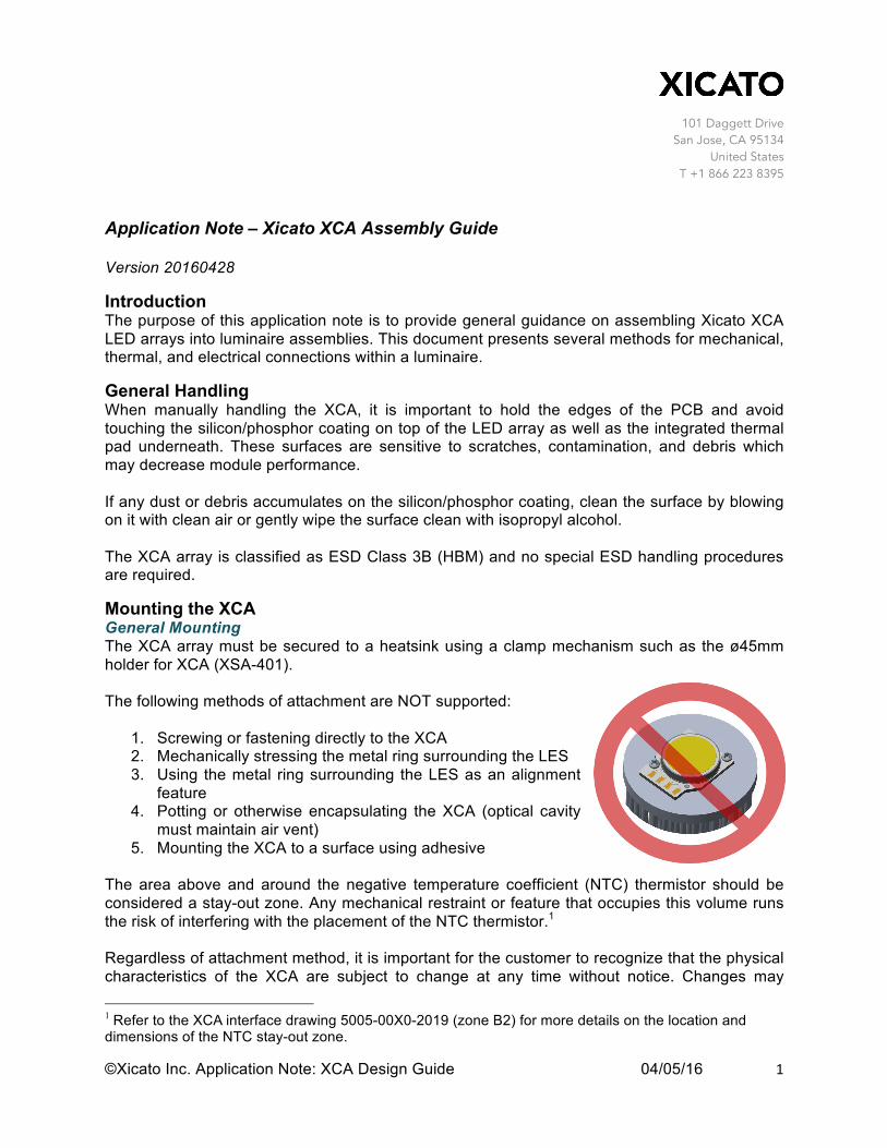
Mounting the XCA General Mounting The XCA array must be secured to a heatsink using a clamp mechanism such as the ø45mm holder for XCA (XSA-401). The following methods of attachment are NOT supported:
1. Screwing or fastening directly to the XCA 2. Mechanically stressing the metal ring surrounding the LES 3. Using the metal ring surrounding the LES as an alignment
feature 4. Potting or otherwise encapsulating the XCA (optical cavity
must maintain air vent) 5. Mounting the XCA to a surface using adhesive
The area above and around the negative temperature coefficient (NTC) thermistor should be considered a stay-out zone. Any mechanical restraint or feature that occupies this volume runs the risk of interfering with the placement of the NTC thermistor.1 Regardless of attachment method, it is important for the customer to recognize that the physical characteristics of the XCA are subject to change at any time without notice. Changes may
1 Refer to the XCA interface drawing 5005-00X0-2019 (zone B2) for more details on the location and dimensions of the NTC stay-out zone.

101 Daggett Drive San Jose, CA 95134
United States T +1 866 223 8395
©Xicato Inc. Application Note: XCA Design Guide 04/05/16 2
include (but are not limited to) exterior size and dimensions, location of LES and electrical contacts, weight, and material. Please consider this when designing attachment methods using XCA. It is not the responsibility of Xicato to inform the customer of these potential changes before they occur. Heatsink and Thermal Interface Heatsinks should be appropriately sized based on the drive current of the XCA and on the conditions in which the luminaire is installed. Any heatsink solution is acceptable as long as the XCA case temperature (TC) does not exceed 90°C in the installation environment. For effective thermal management, Xicato recommends that the heatsink have a surface flatness ≤ 0.1mm and no center hole present. In cases where a center hole exists, the diameter should be ≤ 12mm and the electrical power of the module should not exceed 30 watts for 19mm LES modules or 20 watts for 9mm LES modules. Important! - All XCA arrays ship with a pre-installed thermal pad. Do not add thermal grease, an additional thermal pad, or any other thermal interface material to the bottom surface of the XCA or the mating surface of the heatsink. The addition of an additional TIM will reduce the thermal performance of the heatsink. Mounting XCA with Xicato ø45mm Holder (XSA-401) Before using the ø45mm holder for XCA (XSA-401), solder all wire leads and allow the XCA to return to room temperature prior to handling.2 Place the XCA with wire leads attached on an appropriate heatsink and align the holder on top of the XCA such that the wire leads are routed through the opening on the side of the holder. Ensure the XCA has sufficient contact with the surface of the heatsink by visually verifying there are no air gaps between the integrated thermal pad and the top of the heatsink. Any gap between the thermal pad and the heatsink significantly decreases thermal performance. Attach the XCA holder to the heatsink using M3 x 0.5mm x 8mm screws. Torque the fasteners to between 3.5in·lbs (0.4N·m) and 3.8in·lbs (0.43N·m) using the three-hole pattern or between 5.4in·lbs (0.61N·m) and 5.8in·lbs (0.65N·m) for the two-hole pattern. Take caution not to exceed these values as this may damage the XCA or the holder. Xicato recommends using a spring lock washer with either a flat washer or adapter ring at all mounting locations to reduce the likelihood that the fasteners will loosen under shock, vibration, or thermal cycling. It is important for optic attachment that the combined height of the screw head, spring washer, and flat washer or adapter ring does not exceed the 3.8mm pocket depth.
Electrical Connections Gold plated contacts for soldering or spring finger contact connection are provided on XCA arrays for power delivery. 2 Refer to Electrical Connections section of this document for XCA soldering instructions.

101 Daggett Drive San Jose, CA 95134
United States T +1 866 223 8395
©Xicato Inc. Application Note: XCA Design Guide 04/05/16 3
Soldering When soldering wire leads to contact pads, Xicato recommends using Alpha HF-850 no-clean solder wire and a temperature controlled soldering iron such as a Metcal MX Series soldering system with an STTC-117 chisel tip. Since there is variability in available solder alloys and solder guns/irons, Xicato cannot make a specific soldering recommendation; therefore, the following general processes should be practiced.
1. Uniformly cover contact pad with solder. 2. Solder tin wires prior to soldering them to XCA contacts.
Angle of soldered wire with respect to the XCA board should be greater than 10°. See photo on right.
3. Soldering duration should be no longer than 5 seconds per connection.
4. Strain relief wires soldered to XCA to further protect solder joints and allow XCA to return to room temperature prior to handling.
Caution: Damage to the gold contact pads on the XCA or to wire insulation can occur when exposed to excessive heat for an extended period of time. Reworking of solder should be avoided if possible as repetitive soldering can cause long‑term degradation caused by solder flux building up around the solder pads. Be mindful of the XCA LES while soldering. Damage to LES can occur if hot solder or soldering iron makes contact with surface. An electrical short can occur if wire lead insulation is not trimmed properly. Ensure wire insulation is trimmed such that bare wire does not contact edge of PCB. Spring Finger Connection If electing to use spring finger contacts for electrical power delivery, Xicato recommends that the springs be gold plated.
TC Measurement Any point on the outside surface of the XCA thermal ring can be utilized as the array’s TC measurement location. This surface must be utilized for attaching a thermocouple in order to verify that the XCA array is running below its maximum design temperature limit of 90°C. Xicato recommends attaching the thermocouple using the following method accepted by UL1598-2008, Section 19.7.4, Rev January 11, 2010.
1. Verify that the intended TC location on the thermal ring is clean, dry, and free from debris. Any debris between the thermal ring and the thermocouple bead may add thermal resistance to the test and could deliver erroneous results.

101 Daggett Drive San Jose, CA 95134
United States T +1 866 223 8395
©Xicato Inc. Application Note: XCA Design Guide 04/05/16 4
2. Apply cyanoacrylate adhesive sparingly to the surface of the thermocouple bead. Press surface of bead to thermal ring immediately. Hold in place until bond sets per manufacturer’s instructions. Do not reposition.
3. In a separate mixing container, add recommended ratio of two-part thermally conductive adhesive and blend per adhesive manufacturer’s instructions. Avoid high mixing speeds which could entrap excessive amounts of air or cause overheating of the mixture resulting in reduced working life.
4. Apply the adhesive around the surfaces of the bonded thermocouple bead such that the bead is fully contained within the adhesive. Let the adhesive fully cure per the manufacturer’s instructions. If possible, stress relief the thermocouple wire to further protect the joint.
5. Xicato recommends inspecting the TC joint between thermal tests to ensure it is still attached properly.
Important! - The thermocouple bead must make direct, reliable contact with the surface of the thermal ring; otherwise, unknown thermal impedance between the thermal ring and the thermocouple appears. This could result in lower temperature readings. It is the responsibility of the test engineer or test party to ensure the thermocouple bead is properly attached to the TC point.
Above: Cross-section of Xicato recommended thermocouple attachment using XSA-401 housing.