app practitioner's guide
TRANSCRIPT

A PRACTITIONER'S GUIDE TO ADJUSTED PEAK PERFORMANCE
U.S. Department of Commerce Bureau of Industry and Security

ACKNOWLEDGEMENT The Department of Commerce would like to acknowledge the Information Systems Technical Advisory Committee (ISTAC) which developed the Adjusted Peak Performance formula, supported the adoption of this formula by the Wassenaar Arrangement, prepared the initial drafts of this document, and recommended that it be published by the Department. The ISTAC is a government sponsored technical advisory committee made up of industry and government representatives and administered by the Department of Commerce. The ISTAC advises the U.S. Government on U.S. export control matters as authorized under the Export Administration Act.
Page 2 of 32

Note
Please note that this document makes use of various proprietary trademarks and trade names (hereinafter "Proprietary Marks") as a means of identifying relevant products, systems and vendors. Use of these Proprietary Marks is for descriptive and identification purposes only. Any third-party use of these Proprietary Marks may require permission from their respective owners, as well as appropriate use of the ® and/or ™ symbols.
Page 3 of 32
A PRACTITIONER'S GUIDE TO
ADJUSTED PEAK PERFORMANCE
US Dept. of Commerce, BIS, Information Systems Technical Advisory Committee
December 2006 BACKGROUND On April 24, 2006 the US Department of Commerce implemented a new formula for calculating the performance of digital computers, replacing the Composite Theoretical Performance (CTP) formula, measured in Millions of Theoretical Operations per Second (MTOPS), with the Adjusted Peak Performance (APP) formula, measured in Weighted Teraflops (WT). The APP formula, like the CTP formula it replaced, was designed to determine computer performance for export control purposes. The CTP formula implemented in 1990 could no longer keep up with advances in microprocessor technology and computer architecture, and was therefore losing relevance in meeting national security objectives. The APP formula, derived from existing industry standards, is a more accurate differentiator between high-end, special-order, high-performance computers (HPCs) such as vector supercomputers, and commodity off-the-shelf systems. The APP formula restored the credibility for controlling HPCs by focusing controls on the high end of industry capability systems. The applications run on these systems demand exceptional floating-point performance. HPCs used for national security applications include vector supercomputers, massively-parallel processor systems, and proprietary cluster architectures. This practitioner’s guide is written as an aid to calculating the WT values of HPCs. A similar guide, A Practitioner's Guide to Composite Theoretical Performance, was published in November 1991 to accompany the implementation of the CTP formula. Like its predecessor, this practitioner’s guide recognizes that a rating system for export control of computers must be: easy to complete, independent of software, subject to governmental audit, and capable of producing a single rating number for a given computer. APP is simple, can usually be calculated with publicly available vendor literature, does not require actual benchmarks, and provides a reasonable degree of accuracy in ranking HPCs. Like CTP, it produces a peak number which can be thought of as a "not to exceed" value, independent of memory and I/O considerations. The only thing that matters is the computer's ability to produce 64-bit or larger floating-point arithmetic results per unit time. While the formula is new, many of the notes are either unchanged or adapted from CTP to APP. This allows exporters to follow familiar rules in determining APP values and classifying computers. APP
Page 4 of 32

separates computers into two broad categories by applying a simple weighting factor equal to 0.9 for vector computers and 0.3 for scalar (non-vector) computers. RATIONALE FOR CHANGING FROM CTP TO APP From August 1991 until April 2006 computer exports were evaluated on the basis of their performance, calculated in MTOPS using the CTP formula. This method worked effectively for more than a decade and applied to a broad range of computer products and architectures. The designers of the CTP formula anticipated a period in the evolution of processor and system design in which performance increased dramatically and Moore's Law allowed designs to become quite complex. This period of innovation saw clock frequencies increase by nearly two orders of magnitude and gate counts increase by at least three orders of magnitude. Multi-chip processors became single-chip microprocessors and even multiple processors on a die. As the technology and products evolved, experts agreed that the existing formula no longer correctly rank ordered real computational value. Specifically, systems built from commodity scalar processors were significantly overstated relative to true vector supercomputers. In addition, the CTP method had become increasingly difficult to calculate. In some cases its calculation required access to proprietary details of a given computer’s design. Even then experts had difficulty agreeing on the correct value. As a result, in 2005 the US and Japan proposed, and the members of the international export control regime, the Wassenaar Arrangement, unanimously accepted a new metric, Adjusted Peak Performance. Performance continues to be the defining attribute in selecting some computers for export controls. HPC application performance varies widely from system to system and some applications are better suited to a particular architecture than others are. In some cases compiler efficiency and software tuning can double the performance of an application. No single metric which is simple and does not require benchmarking can be expected to account for these things but the objective of APP is to reach a reasonable level of accuracy while maintaining fairness. Vector systems continue to be the acknowledged leaders in providing the highest efficiency on the broadest range of applications. APP applies a weighting factor of 0.9 based on observed percentage of peak performance on applications of interest. The next page is taken from the US Export Administration Regulations, Category 4 of the Commerce Control List (Supplement No. 1 to Part 774 of the EAR), and contains the APP formula for calculating the WT values of digital computers. Following that is a Q&A section and finally a number of examples of the APP formula calculated solely on the basis of publicly available information for representative computers.
TECHNICAL NOTE ON "ADJUSTED PEAK PERFORMANCE" ("APP")
Page 5 of 32

APP is an adjusted peak rate at which "digital computers" perform 64-bit or larger floating point additions and multiplications.
addition and multiplication, each operation is counted.
Note 2: For a pipelined processor the effective calculating rate R is the faster of the pipelined rate, once the pipeline is full, or the non-pipelined rate.
Abbreviations used in this Technical Note n number of processors in the "digital computer" i processor number (i,....n) ti processor cycle time (ti = 1/Fi) Note 3: The calculating rate R of each
contributing processor is to be calculated at its maximum value theoretically possible before the "APP" of the combination is derived. Simultaneous operations are assumed to exist when the computer manufacturer claims concurrent, parallel, or simultaneous operation or execution in a manual or brochure for the computer.
Fi processor frequency Ri peak floating point calculating rate Wi architecture adjustment factor APP is expressed in Weighted TeraFLOPS (WT), in units of 10**12 adjusted floating point operations per second, Outline of "APP" calculation method Note 4: Do not include processors that are
limited to input/output and peripheral functions (e.g., disk drive, communication and video display) when calculating APP.
1. For each processor i, determine the peak number of 64-bit or larger floating-point operations, FPOi, performed per cycle for each processor in the "digital computer". Note 5: APP values are not to be calculated
for processor combinations (inter)connected by "Local Area Networks", Wide Area Networks, I/O shared connections/devices, I/O controllers and any communication interconnection implemented by "software".
Note: In determining FPO, include only 64-bit or larger floating point additions and/or multiplications. All floating point operations must be expressed in operations per processor cycle; operations requiring multiple cycles may be expressed in fractional results per cycle. For processors not capable of performing calculations on floating-point operands of 64-bits or more the effective calculating rate R is zero.
Note 6: APP values must be calculated for 1) processor combinations containing processors specially designed to enhance performance by aggregation, operating simultaneously and sharing memory; or 2) multiple memory/processor combinations operating simultaneously utilizing specially designed hardware.
2. Calculate the floating point rate R for each processor Ri = FPOi/ti. Note 7: A "vector processor" is defined as a
processor with built-in instructions that perform multiple calculations on floating-point vectors (one-dimensional arrays of 64-bit or larger numbers) simultaneously, having at least 2 vector functional units and at least 8 vector registers of at least 64 elements each.
3. Calculate APP as APP = W1 x R1 + W2 x R2 + … + Wn x Rn. 4. For "vector processors", Wi = 0.9. For non-"vector processors", Wi = 0.3. Note 1: For processors that perform compound operations in a cycle, such as an
Page 6 of 32
CONSIDERATIONS IN APPLYING THE APP FORMULA Obviously, the first determination an exporter must make is whether the computer is capable of performing 64-bit or larger floating-point arithmetic. If it is not, the WT value is zero. A point of clarification has to do with the terminology used in computers: microprocessor, processor, core. Rather than attempting to precisely define the meaning and usage of each of these terms, one should note that in calculating APP it doesn’t matter what names are used for the computational facilities. In common usage, “core” refers to the smallest complete computational element in a digital computer that is visible to software. Many microprocessors consist of a single core. Newer microprocessors contain two or more cores. For the purpose of this guide and in order to be internally consistent, the term, “processor,” will be used to refer to a single core, regardless of how it is packaged or how many are contained on a single semiconductor chip. Q1: Is there a simple way to express the APP formula? A1: Yes. For the majority of computer systems today APP is simply the peak double-precision floating-point capacity of a computer (the sum of all processors to be aggregated) multiplied by either 0.9 for vector processors or 0.3 for everything else. The execution rate for each processor in the computer is: Frequency (in GHz) x Number of 64-bit (or larger) floating-point results per cycle x 10-3 Q2: How does one account for multi-core microprocessors? A2: For the purposes of calculating APP, it does not matter whether a computer uses processors comprised of multiple chips, a single chip, or a fraction of a chip. One simply adds up the contribution of all the processors in the computer, independent of how they are packaged, and apply the appropriate weighting factor to arrive at the APP value. Q3: How does one account for multi-threaded processors? A3: Multi-threaded processors are treated no differently than single-threaded processors. The processor has a peak floating-point performance based on the number of 64-bit floating-point results per unit time that the execution unit(s) produces. Multi-threading merely allows the processor to achieve a higher percentage of peak performance by increasing the utilization of the floating-point hardware. Q4: The microprocessors in a specific digital computer contain vector-like multimedia extensions. Does this mean they are to be considered vector processors in computing APP? A4: Note 7 in the APP method defines the capabilities that are required to be considered a vector processor: built-in vector instructions, at least 2 vector functional units, and at least 8 vector registers of at least 64 elements each. The multimedia extensions currently found in high
Page 7 of 32
volume microprocessors fall short of this mark and therefore would not be considered as vector processors. Q5: How does one rate the APP of a computer which has the ability to increase its performance upon paying the manufacturer an additional fee? A5: Assuming that only the manufacturer or his authorized agent can increase the performance of the computer, the APP is evaluated on an as-shipped basis, not based on the optional ability to go faster when enabled by the manufacturer. The system has a specific WT value when initially exported to the customer. At some later date if the performance is boosted the WT would be recalculated based on the additional capability. Q6: Some computers are made from a larger number of processors than the advertised count. Should they be counted in determining the APP? A6: APP rates the performance of a computer based on the hardware facilities which are not reserved for spares (in the event of a failure) or support functions such as the service processor or I/O processors. If some processors are "hidden" from the programmer and therefore unable to contribute floating-point results to the application then they are not counted in APP. Q7: When should the performance of nodes in a cluster be aggregated in determining the APP? A7: Consistent with past practice in applying CTP, APP Note 5 is interpreted to mean that common, industry-standard I/O-attached networks such as Ethernet, Fibre Channel, InfiniBand, Myrinet, PCI, and RapidIO do not require aggregation. The APP of an Ethernet-based cluster is the APP of a single (the fastest) node. Note 6 is interpreted to mean that clusters based on proprietary, high-performance networks such as SGI's NUMAlink and IBM's HPS do require aggregation of all nodes in calculating APP. Q8: How is the floating-point calculating rate determined? A8: What matters is the effective (i.e. visible to the programmer) rate at which results are produced. Intermediate results, speculative execution results, and other transitory effects are not counted towards APP. For example, some of the architectures are described as performing three simultaneous floating-point instructions per cycle. But if one of them is either a Load or a Store, it doesn't count as an arithmetic operation. The architecture, therefore, would actually produce two floating-point results per cycle and the APP would be based on this rate. Q9: How are non-homogeneous computers evaluated with respect to APP? A9: For systems comprising both scalar and vector floating-point capabilities, the weighted contributions of each should be added to determine the APP. In cases where they cannot be effectively mixed the APP is the greater of the scalar or vector performance. Q10: What about computers with different modes?
Page 8 of 32
A10: When a processor or computer is capable of operating in different modes the APP is computed on the basis of the mode which produces the highest WT number. Q11: How should APP be calculated for “reconfigurable” computers, typically those based on Field Programmable Gate Arrays (FPGAs) or incorporating FPGAs along with conventional processors? A11: FPGA-based computers represent an unusual case where proprietary vendor information may be required to establish an APP value. At present some FPGAs contain embedded microprocessors but they do not have the ability to perform double-precision floating-point arithmetic (and are typically used for housekeeping and other non-performance critical functions). Instead, in order to have a non-zero WT, FPGAs must implement floating-point logic in the cells, slices, or logic blocks. In some cases the manufacturer may supply libraries to program the FPGAs and in other cases the FPGA functionality is determined by the user. In any event, the WT is likely to be based on the manufacturer’s experience in compiling for the FPGA target.
Page 9 of 32
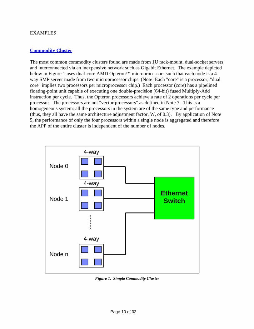
EXAMPLES Commodity Cluster The most common commodity clusters found are made from 1U rack-mount, dual-socket servers and interconnected via an inexpensive network such as Gigabit Ethernet. The example depicted below in Figure 1 uses dual-core AMD Opteron™ microprocessors such that each node is a 4-way SMP server made from two microprocessor chips. (Note: Each "core" is a processor; "dual core" implies two processors per microprocessor chip.) Each processor (core) has a pipelined floating-point unit capable of executing one double-precision (64-bit) fused Multiply-Add instruction per cycle. Thus, the Opteron processors achieve a rate of 2 operations per cycle per processor. The processors are not "vector processors" as defined in Note 7. This is a homogeneous system: all the processors in the system are of the same type and performance (thus, they all have the same architecture adjustment factor, W, of 0.3). By application of Note 5, the performance of only the four processors within a single node is aggregated and therefore the APP of the entire cluster is independent of the number of nodes.
4-way
Ethernet Switch
4-way
4-way
Node 0
Node 1
Node n
Figure 1. Simple Commodity Cluster
Page 10 of 32

Basic data: Processor frequency (clock speed) F = 2.6 GHz Processor cycle time (1/F) t = 384.615 ps. Floating-point operations FPO = 2 Architecture adjustment factor W = 0.3 Calculations: Floating-point rate (for a single processor) R = 2/384.615 = 0.0052 TF Alternatively (FGHz * FPO * 10-3) R = 2.6 * 2 * 10-3 = 0.0052 TF APP (for a single processor) = 0.3 * 0.0052 = 0.00156 WT APP (for a 4 processor node) = 0.3 * 0.0052 * 4 = 0.00624 WT APP (any number of nodes) = 0.3 * 0.0052 * 4 = 0.00624 WT
Page 11 of 32

Cray XT3 The Cray XT3 is a massively parallel processor (MPP) system consisting of hundreds to many thousands of commodity AMD Opteron single-core microprocessors connected by a proprietary 3D torus network. Each processor has a pipelined floating-point unit capable of executing one double-precision (64-bit) fused Multiply-Add instruction per cycle. Thus, the Opterons achieve a rate of 2 operations per cycle per processor. The processors are not "vector processors" as defined in Note 7. The XT3 is a homogeneous system: all the processors in the system are of the same type and performance (thus, they all have the same architecture adjustment factor, W). By application of Note 6, the performance of all the processors is aggregated on the basis of the specially-designed MPP network. Figure 2 shows a single processing element with one Opteron processor connected to the chip that performs the 3D Torus interconnection via 6 high-speed links. Figure 3 illustrates how a small, 3x3x3 element Torus is arranged – each node communicates directly with his 6 nearest neighbors. Sample calculations are given for large systems employing 1024 and 4096 processing elements.
AMD Opteron
Memory
NetworkHub
InterconnectLinks
Figure 2. XT3 Processing Element
Page 12 of 32

Figure 3. 3x3x3 Torus
Basic data: Processor frequency (clock speed) F = 2.6 GHz Processor cycle time (1/F) t = 384.615 ps. Floating-point operations FPO = 2 Architecture adjustment factor W = 0.3 Calculations: Floating-point rate (for a single processor) R = 2/384.615 = 0.0052 TF Alternatively (FGHz * FPO * 10-3) R = 2.6 * 2 * 10-3 = 0.0052 TF APP (for a single processor) = 0.3 * 0.0052 = 0.00156 WT APP (for 1024 processors) = 0.3 * 0.0052 * 1024 = 1.59744 WT APP (for 4096 processors) = 0.3 * 0.0052 * 4096 = 6.38976 WT
Page 13 of 32

Cray X1E The Cray X1E is the latest in a long line of Cray vector supercomputers. From an entry-level 16-processor configuration the architecture scales all the way to 8192 processors. Each MSP processor has 8 vector floating-point pipelines and delivers 18 GFLOPS (listed on the manufacturer’s data sheet) at a clock frequency of 1.13 GHz. A vector pipe executes one multiply and one add per cycle. Thus, the X1E achieves a rate of 16 operations per cycle per MSP processor. The processors do meet the definition of a "vector processors" as defined in Note 7 as they have the necessary vector instruction set, 8 pipes, and 128 vector registers of 64 words apiece. The X1E is a homogeneous system: all the processors in the system are of the same type and performance (thus, they all have the same architecture adjustment factor, W = 0.9). By application of Note 6, the performance of all the processors is aggregated on the basis of a specially-designed network (a set of parallel 2D Torus interconnects). Examples are given for a 16-processor, single node and a 1024 processor, 64-node systems, counting only the contribution of the vector units.
Basic data: Processor frequency (clock speed) F = 1.13 GHz Processor cycle time (1/F) t = 885 ps. Floating-point operations FPO = 16 Architecture adjustment factor W = 0.9 Calculations: Floating-point rate (for a single processor) R = 16/885 = 0.018 TF Alternatively (FGHz * FPO * 10-3) R = 1.13 * 16 * 10-3 = 0.018 TF APP (for a single processor) = 0.9 * 0.018 = 0.0163 WT
APP (for 16 processors) = 0.9 * 0.018 * 16 = 0.26 WT APP (for 1024 processors) = 0.9 * 0.018 * 1024 = 16.6 WT
Page 14 of 32

Dell™ PowerEdge 1855 The Dell™ PowerEdge™ 1855 features up to 10 blade servers in a 7U enclosure. Individual blades utilize single and dual core Intel® Xeon™ microprocessors with two sockets per blade. Blades are connected together using InfiniBand and 1000BaseT Ethernet links. Each processor (core) has a pipelined floating point unit capable of executing two double precision (64-bit) multiply or add instructions per cycle. The processors are not “vector processors” as defined in Note 7. Processor cores support multi-threading, but as noted in Q3, this does not effect the calculation of APP. By application of Note 5, performance is not aggregated beyond the two or four processors contained on a single blade. Single core microprocessors operate up to 3.8 GHz, dual core microprocessors operate at 2.8 GHz. Basic data (single processor core per socket): Processor frequency (clock speed) F = 3.8 GHz Processor cycle time (1/F) t = 263 ps. Floating-point operations FPO = 2 Architecture adjustment factor W = 0.3 Calculations: Floating-point rate (for a single processor) R = 2/263 = 0.0076 TF Alternatively (FGHz * FPO * 10-3) R = 3.6 * 2 * 10-3 = 0.0076 TF APP (for a single processor) = 0.3 * 0.0076 = 0.00228 WT Basic data (two processor cores per socket): Processor frequency (clock speed) F = 2.8 GHz Processor cycle time (1/F) t = 357 ps. Floating-point operations FPO = 2 Architecture adjustment factor W = 0.3 Calculations: Floating-point rate (for a single socket) R = 2/357 = 0.0056 TF Alternatively (FGHz * FPO * 10-3) R = 2.8 * 2 * 10-3 = 0.0056 TF APP (for a single socket) = 0.3 * 0.0056 = 0.00168 WT
Page 15 of 32

HP 9000 Superdome & Integrity Superdome The HP 9000 Superdome is a large non-uniform memory access (NUMA) system consisting of 4 to 128 HP PA8900 processors connected by a proprietary internal Crossbar switch. (While not important for this calculation, two processors are packaged on a common PA8900 silicon die). Each processor is a conventional PA8900 RISC microprocessor with two pipelined floating-point units. Each floating-point unit is capable of executing one double-precision (64-bit) fused Multiply-Add instruction per cycle. Thus, two operations per cycle times two floating-point units per processor yield a rate of 4 operations per cycle per processor. The processors are not "vector processors" as defined in Note 7. The HP 9000 Superdome is a homogeneous system: all the processors in the system are of the same type and performance (thus, they all have the same architecture adjustment factor, W). By application of Note 6, the performance of all the processors is aggregated on the basis of the specially-designed NUMA network. The faster of two available processor options is shown below, with examples of a 4-processor and 128-processor configuration. Basic data: Processor frequency (clock speed) F = 1.1 GHz Processor cycle time (1/F) t = 909 ps. Floating-point operations FPO = 4 Architecture adjustment factor W = 0.3 Calculations: Floating-point rate (for a single processor) R = 4/909 = 0.0044 TF Alternatively (FGHz * FPO * 10-3) R = 1.1 * 4 * 10-3 = 0.0044 TF APP (for a single processor) = 0.3 * 0.0044 = 0.00132 WT APP (for 4 processors) = 0.3 * 0.0044 * 4 = 0.00528 WT APP (for 128 processors) = 0.3 * 0.0044 * 128 = 0.1690 WT HP Integrity Superdome (homogenous and mixed processors) The HP Integrity Superdome is a large non-uniform memory access (NUMA) system consisting of 2 to 128 Intel Itanium 2 processors connected by a proprietary internal Crossbar switch. Each processor has two pipelined floating-point units capable of executing two double-precision (64-bit) fused Multiply-Add instruction per cycle apiece. Thus, the Itanium 2 processors achieve a rate of 4 operations per cycle per processor. The processors are not "vector processors" as defined in Note 7. In the HP Integrity Superdome all the processors have the same architecture adjustment factor, W. By application of Note 6, the performance of all the processors is aggregated on the basis of the specially-designed NUMA network. The faster of two available processor options is shown below, with examples of a 4-processor and 128-processor configuration. The HP Integrity can have a homogonous or mixed processor architecture configuration. For example, you can have a 64-processor system with a total of 64 Itanium 2 processors at 1.6 GHz. Or you can mix the processors and have for example 32 Itanium 2 processors at 1.6 GHz plus 32 PA8900 RISC processors at 1.1 GHz
Page 16 of 32
Basic data for Itanium 2 portion: Processor frequency (clock speed) F = 1.6 GHz Processor cycle time (1/F) t = 625 ps. Floating-point operations FPO = 4 Architecture adjustment factor W = 0.3
Basic data for PA8900 portion: Processor frequency (clock speed) F = 1.1 GHz Processor cycle time (1/F) t = 909 ps. Floating-point operations FPO = 4 Architecture adjustment factor W = 0.3 Calculations: Itanium 2 Calculation Floating-point rate (for a single processor) R = 4/625 = 0.0064 TF Alternatively (FGHz * FPO * 10-3) R = 1.6 * 4 * 10-3 = 0.0064 TF APP (for 32 processors) = 0.3 * 0.0064 * 32 = 0.0614 WT
PA8900 RISC Calculation Floating-point rate (for a single processor) R = 4/909 = 0.0044 TF
Alternatively (FGHz * FPO * 10-3) R = 1.1 * 4 * 10-3 = 0.0044 TF APP (for 32 processors) = 0.3 * 0.0044 * 32 = 0.0422 WT
Mixed (combining Itanium and PA8900) Calculation Total APP = (0.3 * 0.0064 * 32) + (0.3 * 0.0044 * 32) = 0.1036 WT = (0.0614) + (0.0422) = 0.1036 WT
(32 Itanium2 processors @ 1.6 GHz ) + (32 PA8900 processors @ 1.1 GHz)
HP zx6000 The HP zx6000 is a workstation/cluster computer utilizing the Intel® Itanium® 2 processor. Two processor nodes are connected together using Myrinet 2000 links. Each processor has two pipelined floating-point units capable of executing two double-precision (64-bit) fused Multiply-Add instruction per cycle apiece. Thus, the Itanium 2 processors achieve a rate of 4 operations per cycle per processor. The processors are not "vector processors" as defined in Note 7. By application of Note 5, performance is not aggregated beyond the two processors contained in a single node. Basic data: Processor frequency (clock speed) F = 1.5 GHz Processor cycle time (1/F) t = 667 ps. Floating-point operations FPO = 4 Architecture adjustment factor W = 0.3
Page 17 of 32

Calculations: Floating-point rate (for a single processor) R = 4/667 = 0.006 TF Alternatively (FGHz * FPO * 10-3) R = 1.5 * 4 * 10-3 = 0.006 TF APP (for a single processor) = 0.3 * 0.006 = 0.0018 WT APP (for 128 processors) = 0.3 * 0.006 * 2 = 0.0036 WT
Page 18 of 32

IBM BlueGene/L BlueGene/L is a massively parallel processor (MPP) computer consisting of many thousands of processors connected by a proprietary 3D torus network. Each processor is a conventional PowerPC 440 RISC microprocessor core with two pipelined floating-point units. (While not important for this calculation, two processors (cores) are packaged on a common silicon die along with the network hub as shown in Figure 4). Each floating-point unit is capable of executing one double-precision (64-bit) fused Multiply-Add instruction per cycle. Thus, two operations per cycle times two floating-point units per processor yield a rate of 4 operations per cycle per processor. The processors are not "vector processors" as defined in Note 7. BlueGene/L is a homogeneous system: all the processors in the system are of the same type and performance (thus, they all have the same architecture adjustment factor, W). By application of Note 6, the performance of all the processors is aggregated on the basis of the specially-designed MPP network. Examples are given for 1024 and 4096 processor systems.
PPC440Core
Memory
NetworkHub
L2 L3PPC440
Core
InterconnectLinks
Figure 4. BlueGene/L node
Basic data: Processor frequency (clock speed) F = 700 MHz Processor cycle time (1/F) t = 1,428.571 ps. Floating-point operations FPO = 4 Architecture adjustment factor W = 0.3 Calculations: Floating-point rate (for a single processor) R = 4/1428.571 = 0.0028 TF Alternatively (FGHz * FPO * 10-3) R = 0.7 * 4 * 10-3 = 0.0028 TF
APP (for a single processor) = 0.3 * 0.0028 = 0.00084 WT APP (for 1024 processors) = 0.3 * 0.0028 * 1024 = 0.86016 WT APP (for 4096 processors) = 0.3 * 0.0028 * 4096 = 3.44064 WT
Page 19 of 32
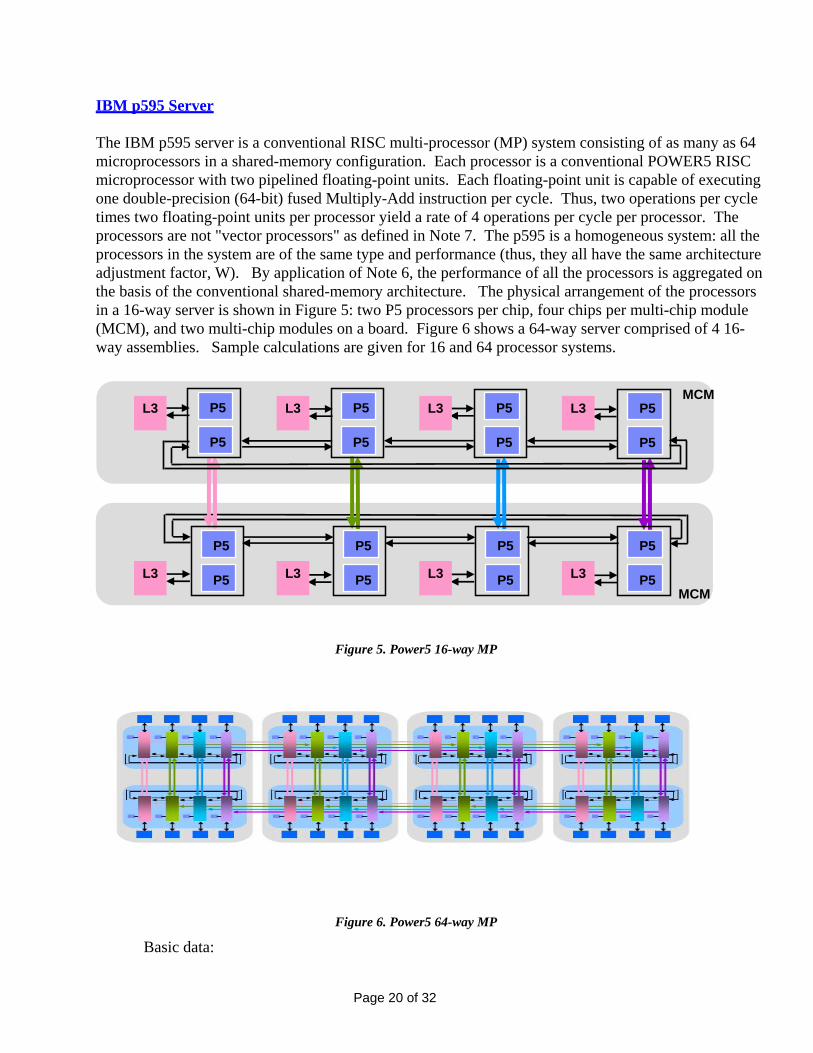
IBM p595 Server The IBM p595 server is a conventional RISC multi-processor (MP) system consisting of as many as 64 microprocessors in a shared-memory configuration. Each processor is a conventional POWER5 RISC microprocessor with two pipelined floating-point units. Each floating-point unit is capable of executing one double-precision (64-bit) fused Multiply-Add instruction per cycle. Thus, two operations per cycle times two floating-point units per processor yield a rate of 4 operations per cycle per processor. The processors are not "vector processors" as defined in Note 7. The p595 is a homogeneous system: all the processors in the system are of the same type and performance (thus, they all have the same architecture adjustment factor, W). By application of Note 6, the performance of all the processors is aggregated on the basis of the conventional shared-memory architecture. The physical arrangement of the processors in a 16-way server is shown in Figure 5: two P5 processors per chip, four chips per multi-chip module (MCM), and two multi-chip modules on a board. Figure 6 shows a 64-way server comprised of 4 16-way assemblies. Sample calculations are given for 16 and 64 processor systems.
MCM
MCM
L3
P5
P5
P5
P5
P5
P5
P5
P5
P5
P5
P5
P5
P5
P5
P5
P5
L3 L3 L3
L3 L3 L3 L3
Figure 5. Power5 16-way MP
Figure 6. Power5 64-way MP
Basic data:
Page 20 of 32
Processor frequency (clock speed) F = 1.9 GHz
0.3
t rate (for a single processor) R = 4/526.315 = 0.0076 TF
M Cluster1600
Processor cycle time (1/F) t = 526.315 ps. Floating-point operations FPO = 4 Architecture adjustment factor W = Calculations: Floating-poin Alternatively (FGHz * FPO * 10-3) R = 1.9 * 4 * 10-3 = 0.0076 TF
APP (for a single processor) = 0.3 * 0.0076 = 0.00228 WT APP (for 16 processors) = 0.3 * 0.0076 * 16 = 0.03648 WT APP (for 64 processors) = 0.3 * 0.0028 * 64 = 0.14592 WT IB
he IBM Cluster1600 system is a scalable system consisting of as many as 128 nodes, each of which is
ts.
ield a
the rk
the following example, two different node types based on the model p575 will be used: Node A has 8
he following example
Basic data for Node A: ncy (clock speed) F = 2.2 GHz
0.3
ncy (clock speed) F = 1.9 GHz
0.3
Ta pSeries RISC SMP server (such as the p595 shown above). The cluster allows for heterogeneous nodetypes, so nodes may not have the same number of processors or the same clock frequency. Each processor is a conventional POWER5 RISC microprocessor with two pipelined floating-point uniEach floating-point unit is capable of executing one double-precision (64-bit) fused Multiply-Add instruction per cycle. Thus, two operations per cycle times two floating-point units per processor yrate of 4 operations per cycle per processor. The processors are not "vector processors" as defined in Note 7. The Cluster1600 processors all have the same architecture adjustment factor, W. The Cluster1600 employs IBM's proprietary High Performance Switch and by application of Note 6,performance of all the processors is aggregated on the basis of this specially-designed Fat-tree netwohardware. Inprocessors operating at 2.2 GHz and the other, Node B, has 16 processors operating at 1.9 GHz. The calculations shown are for a hypothetical 48-node cluster which uses 12 of the 2.2 GHz "A" nodes and 36 of the "B" 1.9 GHz nodes. T Processor freque Processor cycle time (1/F) t = 454.545 ps. Floating-point operations FPO = 4 Architecture adjustment factor W = Basic data for Node B: Processor freque Processor cycle time (1/F) t = 526.315 ps. Floating-point operations FPO = 4 Architecture adjustment factor W =
Page 21 of 32

Calculations: Floating-point rate (for a single processor) RA = 4/454.545 = 0.0088 TF
6 TF
T
Alternatively (FGHz * FPO * 10-3) RA = 2.2 * 4 * 10-3 = 0.0088 TF
Floating-point rate (for a single processor) RB = 4/526.315 = 0.007 Alternatively (FGHz * FPO * 10-3) RB = 1.9 * 4 * 10-3 = 0.0076 TF
APP = (0.3 * 0.0088 * 8 * 12) + (0.3 * 0.0076 * 16 * 36) = 1.567 W (12 8-processor nodes @ 2.2 GHz ) + (36 16-processor nodes @ 1.9 GHz)
Page 22 of 32

NEC SX-8 The NEC SX-8 is a classical vector supercomputer consisting of anywhere from one to 4096 custom-designed vector processors. Each processor has 4 vector floating-point pipelines. A vector pipe, operating at 2 GHz, executes one multiply and one add per cycle. Thus, the SX-8 achieves a rate of 8 operations per cycle per processor. The processors do meet the definition of a "vector processors" as defined in Note 7 as they have the necessary vector instruction set, 4 pipes, and 64 vector registers of 256 words apiece. Each processor also has a scalar capability of 2 floating-point instructions per cycle. Since it is thought to be nearly impossible to simultaneously exploit all the scalar and vector pipes, for the purposes of calculating APP this peak scalar performance is not added to the peak vector performance. The APP is therefore that of the vector capability of the system. Figure 7 shows the organization of the system: a node comprised of 8 single-chip vector processors (CPUs) and associated memories are packaged on a board; multiple boards (nodes) communicate with each other through a crossbar switch. A maximum of 512 nodes are possible in a single system. The SX-8 is a homogeneous system: all the processors in the system are of the same type and performance (thus, they all have the same architecture adjustment factor, W). By application of Note 6, the performance of all the processors is aggregated on the basis of the specially-designed shared-memory hardware, and for multi-node systems the specially-designed Inter-node Crossbar Switch. Examples are given for an 8-processor, single node and a 512 processor, 64-node systems, counting only the contribution of the vector units.
Inter-node Crossbar Switch
8 CPU Node
8 CPU Node
8 CPU Node
8 CPU Node
Figure 7. SX-8 System Structure
Page 23 of 32

Basic data:
Processor frequency (clock speed) F = 2.0 GHz Processor cycle time (1/F) t = 500 ps. Floating-point operations FPO = 8 Architecture adjustment factor W = 0.9 Calculations: Floating-point rate (for a single processor) R = 8/500 = 0.016 TF Alternatively (FGHz * FPO * 10-3) R = 2.0 * 8 * 10-3 = 0.016 TF APP (for a single processor) = 0.9 * 0.016 = 0.0144 WT APP (for 8 processors) = 0.9 * 0.016 * 8 = 0.1152 WT APP (for 512 processors) = 0.9 * 0.016 * 512 = 7.3728 WT
Page 24 of 32

SGI Altix 3700 The SGI Altix 3700 is a large non-uniform memory access (NUMA) system consisting of as many as two thousand Intel Itanium 2 processors connected by a proprietary NUMAlink 4 network. Each processor has two pipelined floating-point units capable of executing two double-precision (64-bit) fused Multiply-Add instruction per cycle apiece. Thus, the Itanium 2 processors achieve a rate of 4 operations per cycle per processor. The processors are not "vector processors" as defined in Note 7. The Altix 3700 is a homogeneous system: all the processors in the system are of the same type and performance (thus, they all have the same architecture adjustment factor, W). By application of Note 6, the performance of all the processors is aggregated on the basis of the specially-designed NUMA network. The faster of two available processor options is shown below, with examples of a 64-processor and 512-processor configuration. Basic data: Processor frequency (clock speed) F = 1.6 GHz Processor cycle time (1/F) t = 625 ps. Floating-point operations FPO = 4 Architecture adjustment factor W = 0.3 Calculations: Floating-point rate (for a single processor) R = 4/625 = 0.0064 TF Alternatively (FGHz * FPO * 10-3) R = 1.6 * 4 * 10-3 = 0.0064 TF APP (for a single processor) = 0.3 * 0.0064 = 0.00192 WT APP (for 64 processors) = 0.3 * 0.0064 * 64 = 0.1229 WT APP (for 512 processors) = 0.3 * 0.0064 * 512 = 0.9830 WT SGI Altix 4700 The SGI Altix 4700 is a large non-uniform memory access (NUMA) system consisting of as many as 10240 Intel® Itanium® 2 processors organized as up to 20 nodes with up to 512 processors per node. The processors within a node are connected by a proprietary NUMAlink 4 network. Nodes are connected to other nodes through InfiniBand and Gigabit Ethernet links using commodity PCI-X adapter boards. Each processor has two pipelined floating-point units, with each capable of executing two double-precision (64-bit) fused Multiply-Add instruction per cycle. Thus, the Itanium 2 processors achieve a rate of 4 operations per cycle per processor. The processors are not "vector processors" as defined in Note 7. The Altix 4700 is a homogeneous system: all the processors in the system are of the same type and performance (thus, they all have the same architecture adjustment factor, W). By application of Note 6, the performance of all the processors within a node is aggregated on the basis of the specially-designed NUMA network. By application of Note 5, there is no aggregation across multiple nodes. For very large configurations built with multiple nodes the APP of the entire system is that of the largest single node. The faster of two available processor options is shown below, with examples of 64-processor (single node), 512-processor (single node), and 10240-processor (20 node) configurations.
Page 25 of 32
Basic data: Processor frequency (clock speed) F = 1.6 GHz Processor cycle time (1/F) t = 625 ps. Floating-point operations FPO = 4 Architecture adjustment factor W = 0.3 Calculations: Floating-point rate (for a single processor) R = 4/625 = 0.0064 TF Alternatively (FGHz * FPO * 10-3) R = 1.6 * 4 * 10-3 = 0.0064 TF APP (for a single processor) = 0.3 * 0.0064 = 0.00192 WT APP (for 64 processors) = 0.3 * 0.0064 * 64 = 0.1229 WT APP (for 512 processors) = 0.3 * 0.0064 * 512 = 0.9830 WT APP (for 10240 processors) = 0.3 * 0.0064 * 512 = 0.9830 WT
Page 26 of 32

SRC Computers SRC-7 The SRC-7 is a heterogeneous system consisting of both microprocessor based and reconfigurable MAP® processors. These are interconnected via a proprietary crossbar interconnect. Any mix of MAPs and μPs may be used in the system. The microprocessors are commodity single core Intel Xeon microprocessors operating at 3 GHz. Each processor has a pipelined floating point unit capable of executing two double precision (64-bit) multiply or add instructions per cycle. The processors are not “vector processors” as defined in Note 7. MAP processors are FPGA based with each MAP containing two Xilinx XC2VP100 FPGAs operating at a nominal frequency of 150 MHz and interconnected to act as one processing element. Because the clock rate and floating-point functionality of an FPGA is not determined at the time of manufacture, the system manufacturer must determine what the nominal maximum floating-point capability is, ignoring any external bandwidth limitations. In the SRC-7, each FPGA has empirically been found to perform up to 50 pipelined double-precision (64-bit) floating point operations that are each a mixture of Multiplies and Adds. Consequently each MAP can perform twice that or 100 pipelined double-precision (64-bit) floating point operations per clock. Since all systems must contain at least 1 microprocessor and 1 MAP processor interconnected via a proprietary Hi-Bar crossbar interconnect, by application of Note 6, the performance of all the processors is aggregated on the basis of the crossbar network. The processors are not "vector processors" as defined in Note 7. Examples are given for 1 μP/1 MAP and 16 μP/240 MAP systems.
PCI ExpressPCI Express
μμPP
MemoryMemory
SNAPSNAP™™MEMORYMEMORY MEMORYMEMORY
Hi-Bar Switch
MAPMAP®® MAPMAP®®MAPMAP®®
GPIOXGPIOX GPIOXGPIOX GPIOXGPIOX
GPIOGPIOPortsPorts
GPIOGPIOPortsPorts
GPIOGPIOPortsPorts
Figure 8. SRC-7 System Structure
Page 27 of 32
Basic data: Microprocessor frequency (clock speed) F = 3.0 GHz Microprocessor cycle time (1/F) t = 333.333 ps. Microprocessor floating-point operations FPO = 2 Microprocessor architecture adjustment factor W = 0.3
MAP processor frequency (clock speed) F = 150 MHz MAP processor cycle time (1/F) t = 6666.666 ps. MAP processor floating-point operations FPO = 100 MAP processor architecture adjustment factor W = 0.3 Calculations: Floating-point rate (for a single microprocessor) R = 2/333.333 = 0.0060 TF Alternatively (FGHz * FPO * 10-3) R = 3.0 * 2 * 10-3 = 0.0060 TF Floating-point rate (for a single MAP processor) R = 100/6666.666 = 0.0150 TF Alternatively (FGHz * FPO * 10-3) R = .15 * 100 * 10-3 = 0.0150 TF APP (1 μP/1 MAP) = (0.3 * 0.0060) + (0.3 * 0.0150) = .0063 WT APP (16 μP/240 MAP) = (0.3 * 0.0060 * 16) + (0.3 * 0.015 * 240) = .0288 + 1.080 = 1.1088 WT
Page 28 of 32
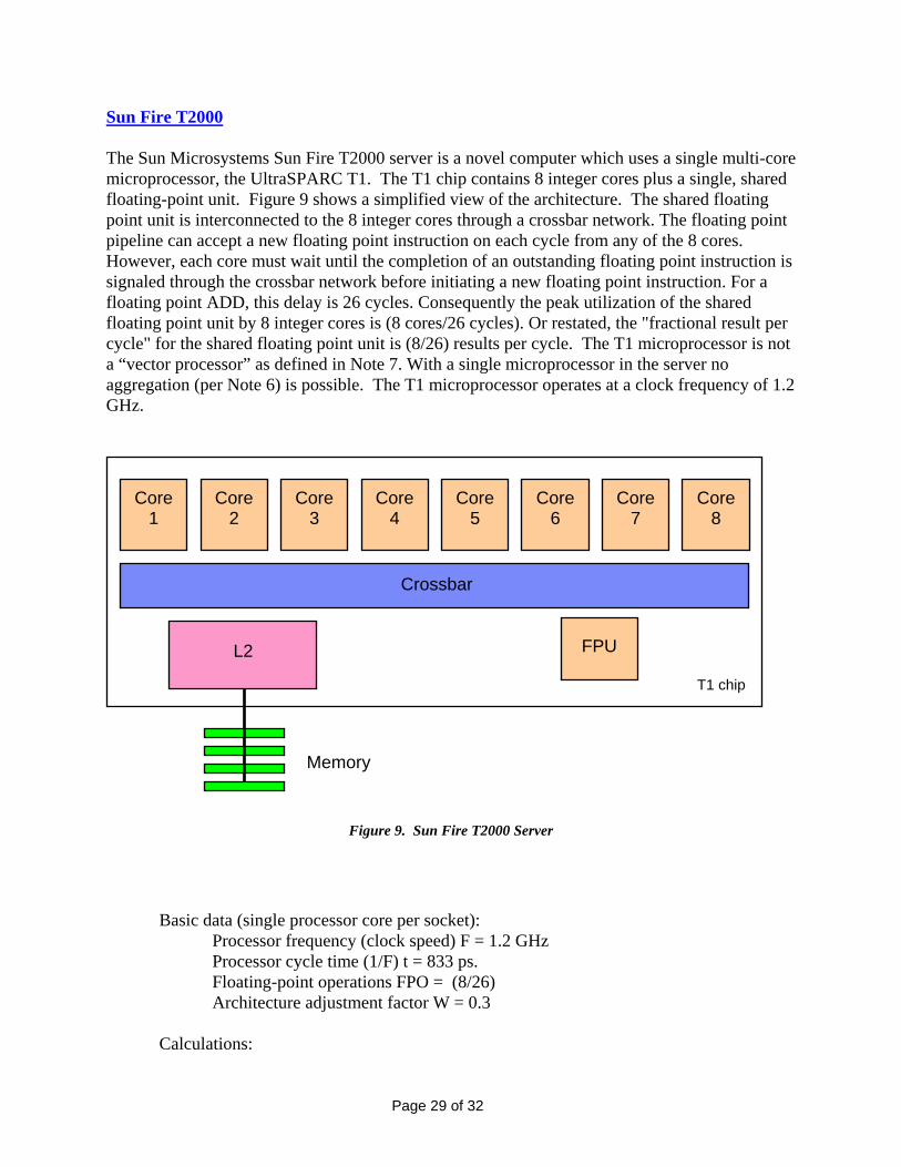
Sun Fire T2000 The Sun Microsystems Sun Fire T2000 server is a novel computer which uses a single multi-core microprocessor, the UltraSPARC T1. The T1 chip contains 8 integer cores plus a single, shared floating-point unit. Figure 9 shows a simplified view of the architecture. The shared floating point unit is interconnected to the 8 integer cores through a crossbar network. The floating point pipeline can accept a new floating point instruction on each cycle from any of the 8 cores. However, each core must wait until the completion of an outstanding floating point instruction is signaled through the crossbar network before initiating a new floating point instruction. For a floating point ADD, this delay is 26 cycles. Consequently the peak utilization of the shared floating point unit by 8 integer cores is (8 cores/26 cycles). Or restated, the "fractional result per cycle" for the shared floating point unit is (8/26) results per cycle. The T1 microprocessor is not a “vector processor” as defined in Note 7. With a single microprocessor in the server no aggregation (per Note 6) is possible. The T1 microprocessor operates at a clock frequency of 1.2 GHz.
Core 1
Memory
Crossbar
T1 chip
FPU L2
Core 2
Core 3
Core 4
Core 5
Core 6
Core 7
Core 8
Figure 9. Sun Fire T2000 Server
Basic data (single processor core per socket): Processor frequency (clock speed) F = 1.2 GHz Processor cycle time (1/F) t = 833 ps. Floating-point operations FPO = (8/26) Architecture adjustment factor W = 0.3 Calculations:
Page 29 of 32

Floating-point rate (for a single processor) R = (8/26)*(1/833) = 0.00037 TF Alternatively (FGHz * FPO * 10-3) R = 1.2 * (8/26)*1 * 10-3 = 0.00037 TF APP (for a single processor) = 0.3 * 0.00037 = 0.00011 WT
Page 30 of 32
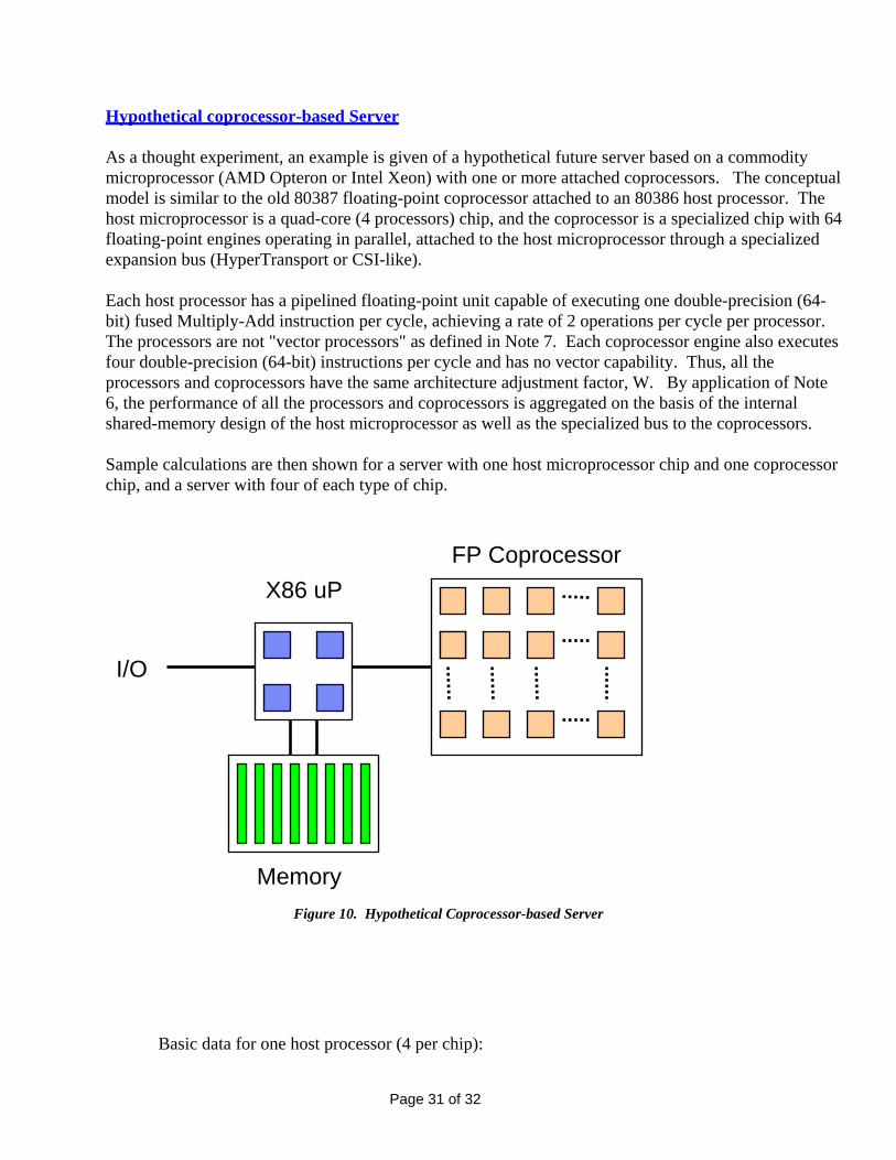
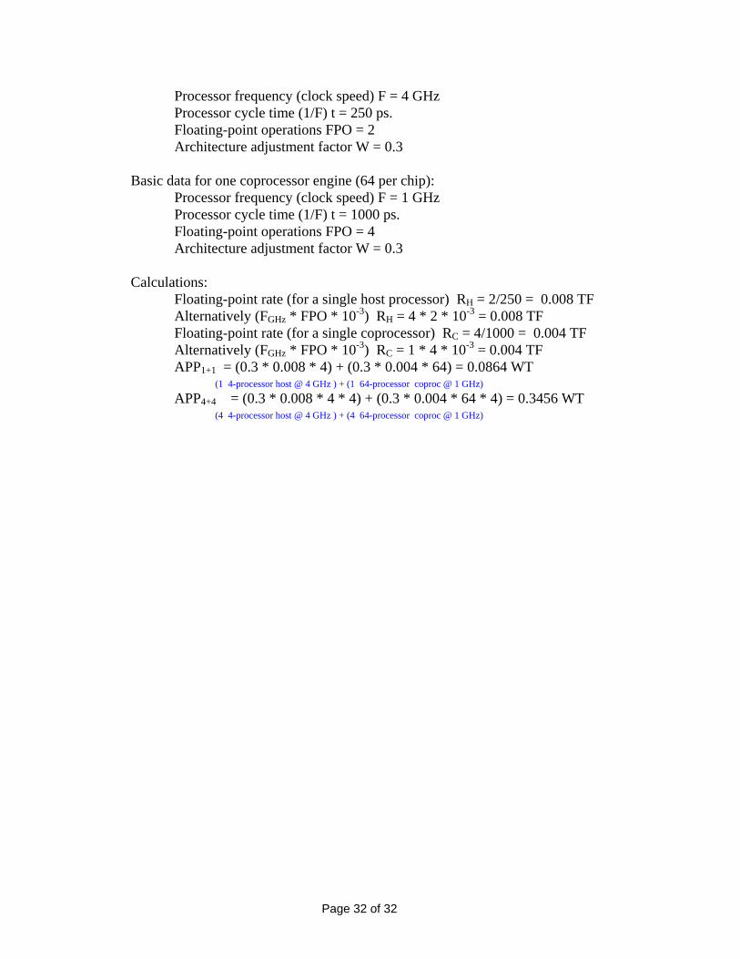
Hypothetical coprocessor-based Server As a thought experiment, an example is given of a hypothetical future server based on a commodity microprocessor (AMD Opteron or Intel Xeon) with one or more attached coprocessors. The conceptual model is similar to the old 80387 floating-point coprocessor attached to an 80386 host processor. The host microprocessor is a quad-core (4 processors) chip, and the coprocessor is a specialized chip with 64 floating-point engines operating in parallel, attached to the host microprocessor through a specialized expansion bus (HyperTransport or CSI-like). Each host processor has a pipelined floating-point unit capable of executing one double-precision (64-bit) fused Multiply-Add instruction per cycle, achieving a rate of 2 operations per cycle per processor. The processors are not "vector processors" as defined in Note 7. Each coprocessor engine also executes four double-precision (64-bit) instructions per cycle and has no vector capability. Thus, all the processors and coprocessors have the same architecture adjustment factor, W. By application of Note 6, the performance of all the processors and coprocessors is aggregated on the basis of the internal shared-memory design of the host microprocessor as well as the specialized bus to the coprocessors. Sample calculations are then shown for a server with one host microprocessor chip and one coprocessor chip, and a server with four of each type of chip.
X86 uP
Memory
I/O
FP Coprocessor
Figure 10. Hypothetical Coprocessor-based Server
Basic data for one host processor (4 per chip):
Page 31 of 32
GHz
0.3
Basic data for one coprocessor engine (64 per chip):
0.3
t rate (for a single host processor) RH = 2/250 = 0.008 TF
04 TF
4) = 0.3456 WT
Processor frequency (clock speed) F = 4 Processor cycle time (1/F) t = 250 ps. Floating-point operations FPO = 2 Architecture adjustment factor W = Processor frequency (clock speed) F = 1 GHz Processor cycle time (1/F) t = 1000 ps. Floating-point operations FPO = 4 Architecture adjustment factor W = Calculations: Floating-poin Alternatively (FGHz * FPO * 10-3) RH = 4 * 2 * 10-3 = 0.008 TF
Floating-point rate (for a single coprocessor) RC = 4/1000 = 0.0 Alternatively (FGHz * FPO * 10-3) RC = 1 * 4 * 10-3 = 0.004 TF
APP1+1 = (0.3 * 0.008 * 4) + (0.3 * 0.004 * 64) = 0.0864 WT (1 4-processor host @ 4 GHz ) + (1 64-processor coproc @ 1 GHz)
APP4+4 = (0.3 * 0.008 * 4 * 4) + (0.3 * 0.004 * 64 * (4 4-processor host @ 4 GHz ) + (4 64-processor coproc @ 1 GHz)
Page 32 of 32