apparatus and method for removing developer material
TRANSCRIPT
lllllllllllllllllllllllllllllllllllll|||||lllllllllllllllllllllllllllllllll United States Patent [19] Frankel et a1.
[54] APPARATUS AND METHOD FOR REMOVING DEVELOPER MATERIAL
[75] Inventors: Neil A. Frankel, Rochester; Edward J. Gutman, Webster; Larry G. Hogestyn, Ontario, all of NY.
[73] Assignee: Xerox Corporation, Stamford, Conn.
[21] Appl. No.: 886,222
[22] Filed: May 21, 1992
[51] Int. Cl.5 ........................................... .. G036 21/00
[52] US. Cl. .................................. .. 355/296; 355/271; 355/274
[58] Field of Search ............. .. 355/296, 301, 302, 303, 355/304, 204, 207, 208, 271, 274; 15/256.51,
256.52, 1.5; 118/652
[56] References Cited U.S. PATENT DOCUMENTS
4.076407 2/1978 Place. Jr. . 4.078,929 3/1978 Gundlach ............................ ., 96/].2
4.190,.348 2/1980 Friday . 4.533.236 8/1985 Garsin , 4.615.613 10/1986 Garsin .
4,999.673 3/1991 Bares ................................. .. 355/208
5.006.892 4/1991 Roehrs ct a]. 355/208 5,016.050 5/1991 Roehrs et al. 355/208 5.019.859 5/1991 Nash . . . . . . . . . . . . . . . . , ., 355/77
5.045.882 9/1991 Roehrs et al. ..................... .. 355/208
OTHER PUBLICATIONS
Lindblad. Nero R. and Pozzangher‘a, Darryl L., "Dual Electrostatic Brush Cleaner for Cleaning Multiple
Image input
mi
US00517559OA
Patent Number:
Date of Patent: 5,175,590
Dec. 29, 1992
[11]
[45]
Toner Types", Xerox Disclosure Journal, vol. 15, No. 6, Nov/Dec. 1990, pp. 463-466. Jackson, Mark 8., “Variable Detach Level Strategy to Facilitate Lead-Edge Stripping", Xerox Disclosure Jour nal, vol. 8, No. 2, Mar/Apr. 1983, pp. 143-144.
Primary Examiner—Richard L. Moses Attorney, Agent, or Firm-Gary B. Cohen
1571 ABSTRACT A printing machine of the type including an image receiving member having a charge retentive surface with a ?rst developed image being disposed in a ?rst zone and a second developed image being disposed in a second zone is provided. The printing machine prefera bly including a corona generator positioned adjacent the charge retentive surface and characterized by an electrical parameter; a ?rst control device for setting the electrical parameter to a ?rst level for disposing the ?rst developed image at a ?rst charge level as the ?rst developed image is passed by the corona generator; a second control device for changing the electrical pa rameter to a second level for disposing the second de veloped image at a second charge level as the second developed image is passed by the corona generator; and a cleaning member, contacting the charge retentive surface, for substantially removing both the ?rst devel oped image and a portion of the second developed image from the the charge retentive surface, wherein the capacity of the cleaning member to remove the ?rst developed image and the portion of the second devel oped image from the charge retentive surface depends on the magnitudes of the ?rst and second levels.
14 Claims, 7 Drawing Sheets
D 1A COM/ill"
1 116/
' nice A,
GINIIAYOI 3i

US. Patent Dec. 29, 1992 Sheet 1 of 7 ' 5,175,590
Vddp (VCAD)
Vblack bias
Vw (VWhite)
P/R POTENTIAL vco'or bias
Vtc
Vc Now)
0 __
\ 5' EX COLOR
PRIOR ART
US. Patent Dec. 29, 1992 Sheet 2 0f 7 5,175,590
BLACK _ - _ ' — .- \\\\\\\\\\\\\\\‘
BLACK 05v. CHARGED AREA DEV. ‘
- - - - P- - - — — — - — — ~ — 4 Vbb
Vw
----- — — - — - - - Vcb
DISCHARGED AREA DEV. COLOR ow
\\\\\\\\\\\\\\\ _, _ _ . _ .
COLOR
FIG. 1 B PRIOR ART

US. Patent Dec. 29, 1992 Sheet 3 of 7 5,175,590
Developer _ L Bias
44 \
\ /
512
FIG 2 Image ‘
6
f- 5 Developer Bias 40 AU

US. Patent I Dec. 29, 1992 Sheet 4 of7 5,175,590
FIG. 3
K10 T|'__':""'_"___"__"T'_—T'—""-_____— I I I l l l I I I I I I I.
[102 F.’
106
Mb ;\ (T 12 14
20
106'
G\ O :\106
FIG. 4
' ‘ 65
64] Q104s

US. Patent Dec. 29, 1992 Sheet 5 of 7 5,175,590
' 1_1q
E§V1 A40 I J
A/D CONVERTER ‘5V1 A54
IRD A38
\ \ 114 MACHINE "2
coumousa
D/A convsmsn E55
116 J K 34
PATCH GENERATOR
/
A 36
FIG. 5B
US. Patent Dec. 29, 1992 Sheet 6 0f 7 5,175,590
1,800
120
1.500 A 124
1,400‘ Brush '22
RPM 1.200
1,000
800
10 20 30 40 50
Preclean Current (microamps)
1,800 1
A % 120 1,600 ®,\ 124
SETPOINT 1.400 1 2 Brush 2
RPM 1.200
1.000
800
10 20 30 40 50
Preclean Current (microamps)
' US. Patent D 99999999 92 Sheet70f7 ' 5,175,590
FIG. 8
X \\ . A \
6° -50 -40
C AAAAAAAA SS AT
CLEANER NNNNN CE
Deta¢k Current (microamps)

5,175,590 1
APPARATUS AND METHOD FOR REMOVING DEVELOPER MATERIAL
The present invention relates generally a technique for cleaning developer material from a photoreceptive member and more particularly to an apparatus and method adapted to remove the developer material from document and interdocument zones of the photorecep tive member by changing an applied current level of a corona generating device as the zones are passed thereby.
In electrophotographic applications such as xerogra phy, a charge retentive surface is electrostatically charged and exposed to a light pattern of an original image to be reproduced for selectively discharging the surface in accordance therewith. The resulting pattern of charged and discharged areas on that surface form an electrostatic charge pattern (an electrostatic latent im age) conforming to the original image. The latent image is developed by contacting it with a ?nely divided elec trostatically attractable powder referred to as “toner". Toner is held on the image areas by the electrostatic charge on the surface. Thus, a toner image is produced in conformity with a light image of the original being reproduced. The toner image may then be transferred to a substrate (e.g., paper), and the image affixed thereto to form a permanent record of the image to be repro duced. Subsequent to development and transfer, excess toner left on the charge retentive surface is cleaned from the surface. The process is well known, and useful for light lens copying from an original, and printing applications from electronically generated or stored originals, where a charged surface may be imagewise discharged in a variety of ways. Although a preponderance of the toner forming the
image is transferred to the paper during transfer, some toner invariably remains on the charge retentive sur face, it being held thereto by relatively high electro static and/or mechanical forces. A commercially suc cessful mode of cleaning employed in automatic xerog raphy utilizes a brush with soft ?ber bristles which have suitable triboelectric characteristics. While the bristles are soft they are sufficiently firm to remove residual toner particles from the charge retentive surface. In addition, webs or belts of soft ?brous or tacky materials and other cleaning systems are known. A process referred to as “highlight color imaging"
has been accomplished by employing basic xerographic techniques. The concept of tri-level, highlight color xerography is described in the following patent:
U.S. Pat. No. 4,078,929, Patentee: Gundlach, Issued: Mar. 14, 1978.
U.S. Pat. No. 4,078,929 discloses the use of tri-level xerography as a means to achieve single-pass highlight color imaging. As disclosed therein the charge pattern is developed with toner particles of ?rst and second colors. The toner particles of one of the colors are posi tively charged and the toner particles of the other color are negatively charged. In one embodiment, the toner particles are supplied by a developer which comprises a mixture of triboelectrically relatively positive and rela tively negative carrier beads. The carrier beads support, respectively, the relatively negative and relatively posi tive toner particles. Such a developer is generally sup plied to the charge pattern by cascading it across the imaging surface supporting the charge pattern. In an other embodiment, the toner particles are presented to
20
25
35
45
55
65
2 the charge pattern by a pair of magnetic brushes. Each brush supplies a toner of one color and one charge. In yet another embodiment, the development systems are biased to about the background voltage. Such biasing results in a developed image of improved color sharp ness.
In highlight color xerography as taught by Gundlach, the xerographic contrast on the charge retentive surface or photoreceptor is divided into three levels, rather than two ‘levels as is the case in conventional xerogra phy. The photoreceptor is charged, typically to —-900 volts, and exposed imagewise, such that one image cor responding to charged image areas (which are subse quently developed by charged-area development, i.e. CAD) stays at the full photoreceptor potential (Vmd or Vddp). Vddp is the voltage on the photoreceptor due to the loss of voltage while the photoreceptor remains charged in the absence of light, otherwise known as dark decay. Another image is exposed to discharge the photoreceptor to its residual potential, i.e. Vdnd or V, (typically —l00 volts), which V6 corresponds to dis charged area images that are subsequently developed by discharged-area development (DAD). The background area is exposed so as to reduce the photoreceptor poten‘ tial to halfway between the Vmd and Vdad potentials, (typically -500 volts) and is referred to as Viv/me. The CAD developer is typically biased about 100 volts closer to Vmd than Vwhm, (about —600 volts), and the. DAD developer system is biased about 100 volts closer to Vdadthan Vwhm. (about ~400 volts). As will be appre ciated, the highlight color need not be a different color but may have other distinguishing characteristics. For example, one toner may be magnetic and the other non‘magnetic.
It is generally well known to control and adjust par ticular parameters of an electrophotographic printing machine. For example, individual control signals can be used to adjust operating elements of a printing machine, such as controlling development by control of the ratio of toner particles to carrier granules in the developer material and the electrical bias applied to the developer roller. Other control techniques compare a signal mea suring the re?ected light from a clean photoconductive member to a signal reflected from a developed test patch formed thereon. The resultant error signal regu lates toner dispensing to control the concentration of toner particles in the developer material on the photo conductive surface. Generally, the density of the devel oper material developed on the test patch is monitored by an infrared densitometer. In various applications, the photoreceptive member includes at least two document zones and an interdocument zone disposed therebe tween. Preferably, an image from a document is devel oped in the document zone while the test patch is devel oped in the interdocument zone. Typically, the test patch is formed in the interdocument zone so as not to interfere with imaging in the document zone. The fol lowing patents and applications pertain to arrangements for generating and monitoring toner density of devel oped test patches disposed in interdocument zones:
U.S. patent application Ser. No. 07/755,l93, Appli cants: Scheuer et al., Filed: Sep. 5, 1991.
U.S. patent application Ser. No. 07/755,197, Appli cants: Berman et al., Filed: Sep. 5, 1991.
U.S. Pat. No. 4,999,673, Patentee: Bares, Issued: Mar. 12, 1991.
U.S. Pat. No. 5,019,859, Patentee: Nash, Issued: May 28, 1991.

5,175,590 3
Ineffective cleaning can be encountered when a test patch is formed in the interdocument zone. That is, while much of toner is removed from the document zone during the transfer stage. all of the toner compris ing the test patch remains in the interdocument zone right up until the cleaning stage. Moreover. commonly during transfer and detack. the document and inter document zones are not charged to the same polarity levels. Indeed, these zones can even possess opposing polarities. The following references disclose systems adapted to clean a belt with zones of varying toner density:
U.S. Pat. No. 4,533,236, Patentee: Garsin. Issued: Aug. 6, 1985.
U.S. Pat. No. 4,615,613, Patentee: Garsin, Issued: Oct. 7, 1986.
U.S. Pat. No. 4,615,613 discloses a cleaning brush having different biases applied thereto in accordance the area of the charge retentive surface being cleaned. Preferably, when toner is being removed from the doc ument area of the charge retentive surface, one bias level is applied and when the interdocument area is being cleaned a different bias is applied.
Ineffective cleaning can also be encountered when using a typical highlight color apparatus in which ton ers of varying triboelectric characteristics are em ployed. For example, as explained in the following disclosure, it may be desirable to employ two electro static brushes with differing polarities to remove toners of differing preferences:
Lindblad. L. R. and Pozzanghera. D. L., Dual Elec trostatic Brush Cleaner for Cleaning Multiple Toner Types. Xerox Disclosure Journal, Vol. 15, No. 6 at pp. 463-466, Published: November/December 1990.
It is well known in the art to adjust a transfer voltage level in order to maximize transfer efficiency under changed transfer conditions, such as humidity changes. A general discussion of references in which transfer voltage level has been adjusted to maximize transfer ef?ciency can be found in the following patent:
U.S. Pat. No. 4,076,407, Patentee: Place, Jr., Issued: Feb. 28, 1978. The following references particularly relate to the
adjustment of transfer voltage levels to facilitate image transfer and/or stripping:
U.S. Pat. No. 4,190,348, Patentee: Friday, Issued: Feb. 26, 1980.
Jackson. M. 5., Variable Detack Level Strategy to Fa cilitate Lead-Edge Stripping. Xerox Disclosure Journal, Vol. 8, No. 2 at 143, Published: March/April 1983. The following patent application relates to adjusting
respective operating parameters of corona generating devices for removing a test patch during cycle up and runtime of a highlight color imaging device:
U.S. patent application Ser. No. 07/755,467, Appli cants: Macdonald et a1., Filed: Sep. 5, 1991.
U.S. patent application Ser. No. 07/755,467 discloses a technique in which single pass cleaning of developed patches during cycle up convergence ("cycle up”) is
‘ enabled by setting a plurality of corona generating de vices to a ?rst set of preselected values, and storing the values into a memory. A second set of values for setting the devices can be stored in the memory for cleaning during runtime (“runtime”). Preferably, the corona generating devices are operated with the ?rst set of preselected values during cycle up, and with the second set of preselected values during runtime.
O
30
55
60
65
4 While U.S. patent application Ser. No. 07/755,467
discloses an arrangement in which the electrical param eters of a set of corona generating devices can be ad justed prior to either cycle up or runtime for facilitating cleaning of developed test patches, it does not contem plate a technique in which the corona generating de vices can be switched during cycle up or runtime to compensate for density and charge level differences between the document and interdocument zones of the photoreceptor. Indeed, it would be desirable to provide an apparatus and method in which one or more of the corona generating devices could be switched between voltage levels to facilitate optimal cleaning of the devel oper material residuals from the document and inter document zones.
In accordance with a disclosed embodiment of the present invention there is provided a printing machine of the type including an image receiving member hav ing a charge retentive surface with a ?rst developed image being disposed in a ?rst zone and a second devel oped image being disposed in a second zone. The print ing machine preferably comprises a corona generator positioned adjacent the charge retentive surface and characterized by an electrical parameter; means for setting the electrical parameter to a ?rst level for dis posing the ?rst developed image at a ?rst charge level as the ?rst developed image is passed by the corona generator; means for changing the electrical parameter to a second level for disposing the second developed image at a second charge level as the second developed image is passed by the corona generator; and a cleaning member, contacting the charge retentive surface, for substantially removing both the ?rst developed image and a portion of the second developed image from the charge retentive surface, wherein the capacity of the cleaning member to remove the ?rst developed image and the portion of the second developed image from the charge retentive surface depends on the magnitudes of the ?rst and second levels.‘ These and other aspects of the invention will become
apparent from the following description, the descrip tion being used to illustrate a preferred embodiment of the invention when read in conjunction with the accom panying drawings. FIG. 1A is a plot of photoreceptor potential versus
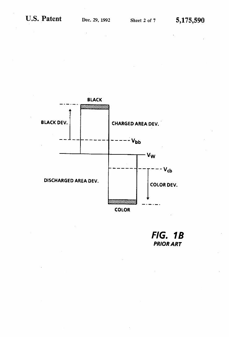
exposure, for a tri-level electrostatic latent image; FIG. 1B is a plot of photoreceptor potential repre
senting particular single-pass, highlight color latent image characteristics; FIG. 2 is a schematic, view of a printing machine
incorporating various features the present invention; FIG. 3 is a partial, plan view of a photoreceptive belt
used in the printing machine of FIG. 2; FIG. 4 is a blown-up, partial view of the printing
machine of FIG. 2 with sensing devices positioned about the photoreceptive belt; FIG. 5A is a schematic view of a control circuit used
to control various components of the printing machine of FIG. 2; .
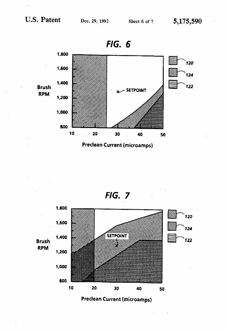
FIG. 5B is a schematic view of a corona generator with a shutter for selectively changing the emission therefrom; FIG. 6 is a cleaning latitude window showing accept
able set points for the printing machine of FIG. 2. the cleaning latitude window being developed without regard to optimal transfer or detack applied current levels;
5,175,590 5
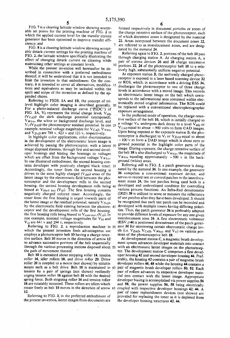
FIG. 7 is a cleaning latitude window showing accept able set points for the priming machine of FIG. 2 in which the applied current level for the transfer corona generator has been optimized to improve transfer effi ciency; and
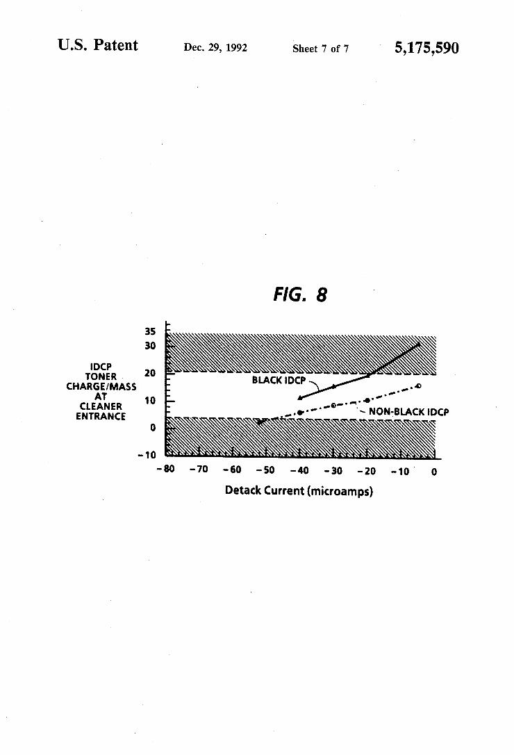
FIG. 8 is a cleaning latitude window showing accept able detack current settings for the printing machine of FIG. 2, the latitude window speci?cally illustrating the effect of changing detack current on cleaning while maintaining other settings at constant levels. While the present invention will hereinafter be de- '
scribed in connection with a preferred embodiment thereof, it will be understood that it is not intended to limit the invention to that embodiment. On the con trary, it is intended to cover all alternatives, modi?ca tions and equivalents as may be included within the spirit and scope of the invention as de?ned by the ap pended claims.
Referring to FIGS. 1A and 1B, the concept of tri level highlight color imaging is described generally. For a photo-induced discharge curve (“PIDC”) of FIG. 1A, V0 represents the initial charge level, vddp (VCAD) the dark discharge potential (unexposed), V whim, the white or background discharge level, and V6 (VDAD) the photoreceptor residual potential. In one example, nominal voltage magnitudes for VCAD, Vii/hm. and VDAD are 788 v, 423 v and 123 v, respectively.
In highlight color applications, color discrimination in the development of the electrostatic latent image is achieved by passing the photoreceptor, with a latent image disposed thereon, through ?rst and second devel oper housings and biasing the housings to voltages which are offset from the background voltage VW/mp. In one illustrated embodiment, the second housing con tains developer with positively charged black toner. Accordingly, the toner from the second housing is driven to the most highly charged (Vddp) areas of the latent image by the electrostatic field between the pho toreceptor and the development rolls in the second housing. the second housing development rolls being biased at Vb/art- big, (Vbb). The first housing contains negatively charged colored toner. Accordingly, the toner from the ?rst housing is urged towards parts of the latent image at the residual potential, namely V D41), by the electrostatic ?eld existing between the photore ceptor and the development rolls of the ?rst housing, the ?rst housing rolls being biased to Veg/0, bias, (V,,,). In one example, nominal voltage magnitudes for Vbb and Vd, are 641 v and 294 v, respectively.
Referring to FIG. 2, a reproduction machine in which the present invention ?nds advantageous use employs a photoreceptor belt 10 having a charge reten tive surface. Belt 10 moves in the direction of arrow 12 to advance successive portions of the belt sequentially through the various processing stations disposed about the path of movement thereof.
Belt 10 is entrained about stripping roller 14, tension roller 16, idler rollers 18, and drive roller 20. Drive roller 20 is coupled to a motor (not shown) by suitable means such as a belt drive. Belt 10 is maintained in tension by a pair of springs (not shown) resiliently' urging tension roller 16 against belt 10 with the desired spring force. Both stripping roller 14 and tension roller 16 are rotatably mounted. These rollers are idlers which rotate freely as belt 10 moves in the direction of arrow 12.
Referring to FIG. 3, in the preferred embodiment of the present invention, latent images from documents are
5
25
35
45
55
65
6 formed respectively in document portions or zones of the charge retentive surface of the photoreceptor, each of which document zones is designated by the numeral 22. Areas interposed between the document zones 22, are referred to as interdocument zones, and are desig nated by the numeral 24.
Referring again to FIG. 2, portions of the belt 10 pass through charging station A. At charging station A, a pair of corona devices 26 and 28 charge successive portions 22, 24 of the photoreceptor belt 10 to a rela tively high, substantially uniform negative potential. At exposure station B, the uniformly charged photo
receptor is exposed to a laser based scanning device 32 or ROS, which, in accordance with a driving ESS 34, discharges the photoreceptor to one of three charge levels in accordance with a stored image. This records an electrostatic latent image on the belt which corre. sponds to the informational area contained within elec tronically stored original information. The ROS could be replaced with a conventional electrophotographic exposure arrangement.
In the preferred mode‘ of operation, the charge reten tive surface of the belt 10, which is initially charged to a voltage V0, undergoes dark decay to a level Vddp or VCAD equal to about —9OO volts to form CAD images. Upon being exposed at the exposure station B, the pho toreceptor is discharged to Vc or VDAD equal to about - 100 v to form a DAD image which is about zero or ground potential in the highlight color parts of the image. During exposure, the charge retentive surface of the belt 10 is also discharged to V whim. the magnitude of Viv/mg equaling approximately —500 v in the back ground (white) areas.
Referring still to FIG. 2, a patch generator is desig nated by the numeral 36. In one example, the generator 36 comprises a conventional exposure device, and serves to record test or controlpatches in the interdocu ment zones 24, the test patches being used both in a developed and undeveloped condition for controlling various process functions. An Infra-Red densitometer (IRD) 38 is utilized to sense or measure the re?ectance of test patches after they have been developed. It should be recognized that each test patch can be recorded and developed with multiple toners having differing polari ties. Thus, the patch generator 36 is preferably adapted to provide different levels of exposure for any one given ' interdocument zone 24. A first electrostatic voltmeter (ESV1) 40 is positioned downstream of the patch gener ator 36 for monitoring certain electrostatic charge lev els (i.e. VDAD, VCAD, V whim, and V") on various por tions of the photoreceptive belt 10. At development station C, a magnetic brush develop
ment system advances developer materials into contact with an electrostatic latent images on the photorecep tor. The development station C comprises a ?rst devel oper housing 42 and second developer housing 44. Pref erably, the housing 42 contains a pair of magnetic brush developer rollers 46, 48 while the housing 44 contains a pair of magnetic brush developer rollers 50, 52. Each pair of rollers advances its respective developer mate rial into contact with the latent image. Appropriate developer biasing is accomplished via power supplies 56 and 58, the power supplies 56, 58 being electrically coupled with respective developer housings 42, 44. A pair of toner replenishment devices (not shown) are provided for replacing the toner as it is depleted from the developer housing structures 42, 44.

5,175,590 7
Color discrimination in the development of the elec trostatic latent image is achieved by passing the photo receptor past the two developer housings 42 and 44 in a single pass with the magnetic brush rolls 46, 48, 50 and 52 electrically biased to voltages which are offset from the background voltage Vmme in a direction depending on the polarity of toner in the housing. In the illustrated embodiment of FIG. 2, the housing 42 contains nega tively charged blue conductive magnetic brush (CMB) developer 60. Accordingly, the blue toner is driven to the least highly charged areas at the potential VDAD of the latent images by the electrostatic development ?eld (VD,4D—VM1O, hm) between the photoreceptor and the development rolls 46, 48. On the other hand, the hous ing 44 contains positively charged black toner 62. Ac cordingly, the black toner is urged towards the parts of the latent images at the most highly charged potential VCAD by the electrostatic development ?eld (V CAD-Vina“ bias) existing between the photoreceptor and the development rolls 50, 52. A second electrostatic voltmeter (ESVZ) 54 is positioned downstream of the ?rst developer housing 42 for monitoring certain elec trostatic charge levels (i.e. V 04 D, VCAD, V whim, V ,1, and V") on various portions of the photoreceptive belt 10.
Preferably, the rollers 46 and 48 are biased using a chopped DC bias via power supply 56, while the rollers 50 and 52 are biased using a chopped DC bias via power supply 58. The expression chopped DC (“CDC") bias refers to the process of alternating a developer housing between two potentials, namely a ?rst potential roughly representing the normal bias for the DAD developer, and a second potential roughly representing a bias that is considerably more negative than the normal bias. The ?rst potential is identi?ed as V5,”, Low while the second potential as V5,”, Hl'gh- Further details regarding CDC biasing are provided in US. Pat. application Ser. No. 440,913, the pertinent portions of which are incorpo rated herein by reference.
Because the composite image developed on the pho toreceptor consists of both positive and negative toner, a negative pretransfer dicorotron 64 is employed to condition the toner for effective transfer to a substrate using positive corona discharge. As will be appreciated from the discussion below, the concept of the invention would not be altered by conditioning the toner for transfer with negative corona discharge. Subsequent to providing pretransfer, belt 10 advances the developed latent image to transfer station D. At transfer station D, a sheet of support material such as a paper copy sheet is moved into contact with the developed latent images on belt 10 and a corona generating device 65 charges the copy sheet to the proper potential so that it is tacked to photoreceptor belt 10 and the toner powder image is attracted from photoreceptor belt 10 to the sheet. As will be appreciated by those skilled in the art, the gener ating device 65 could be replaced by, or used in con junction with, one of many known transfer devices, such a bias transfer roll of the type used in a Xerox 9700 printer (the term “Xerox” is a registered trademark of the Xerox Corporation), an acoustical transfer assist device of the type disclosed in US. Pat. No. 5,081,500 to Snelling and an electrostatic transport device of the type used in a Konica 9028 printing apparatus, without altering the concept of the present invention. After transfer, a corona generator 66 charges the copy sheet with an opposite polarity to detack the copy sheet for belt 10, whereupon the sheet is stripped from belt 10 at stripping roller 14. For each interdocument zone 24
15
25
35
45
50
60
65
8 (FIG. 3), charge from the corona generators 65-66 is applied to each zone 24 as it is passed by the generators 65-66.
Sheets of support material are advanced to transfer station D from supply trays 68, 70 and 72, which supply trays may hold different quantities, sizes and types of support materials. Sheets are advanced to transfer sta tion D along conveyor 76 and rollers 78. After transfer, the sheet continues to move in the direction of arrow 80 onto a conveyor 82 which advances the sheet to fusing station E.
Fusing station E, which includes a fuser assembly, indicated generally by the reference numeral 84, serves to permanently affix the transferred toner powder im ages to the sheets. Preferably, fuser assembly 84 in cludes a heated fuser roller 86 adapted to be pressure engaged with a back-up roller 88 with the toner powder images contacting fuser roller 86. In this manner, the toner powder image is permanently af?xed to the sheet.
After fusing, copy sheets bearing fused images are directed through decurler 90. Chute 92 guides the ad vancing sheet from decurler 90 to catch tray 94 or a ?nishing station for binding, stapling, collating etc. and, removal from the machine by the operator. Alterna tively, the sheet may be advanced to a duplex tray 98 from duplex gate 100 from which it will be returned to the processor and conveyor 76 for receiving second side copy. '
A pre-clean corona generating device 102 is provided for exposing the residual toner and contaminants (here inafter, collectively referred to as toner) to positive charges to thereby shift the charge distribution thereon in a positive direction for more effective removal at cleaning station F. The cleaning station F further in cludes an electrically insulative, rotatably mounted cleaning member designated by the numeral 104. In the preferred embodiment, the member 104 is a ?brous brush in contact with the surface of the belt 10. The insulative brush is capable of being charged up during rotation, via triboelectric interaction with other clean ing members, for attracting toner(s) of the opposite polarity. Alternatively, the brush could be a conductive brush adapted to be biased for attracting toner(s) of the opposite polarity. A conductive brush suited for such cleaning is disclosed in US. Pat. No. 4,819,026 to Lange et al., the pertinent portions of which are incorporated by reference. In another example, two brushes could be mounted in cleaning relationship relative to the surface of the belt 10 to achieve redundancy in cleaning. It is contemplated that residual toner remaining on charge retentive surface of belt 10 after transfer will be re claimed and returned to the developer station C by any one of several well known reclaim arrangements. As will be understood from the discussion below,
achievement of the present invention is facilitated by monitoring the position of belt 10 relative to the corona devices 64-66 and 102. Referring to FIG. 4, devices for sensing the position of belt 10 relative to such corona devices are each designated by the numeral 106. In one example, each of the sensors 106 is a re?ective type sensor or a switch adapted to sense the front edge and rear edge of a sheet as it is passed thereby. It is contem plated that any arrangement for monitoring the position of belt 10 relative to the corona devices 64-66 and 102 would be suitable for use with the present invention. Examples of other such arrangements include U.S. Pat. No. Re. 32,967 to St John et al., and US. Pat. No.

5,175,590 9 4,963,899 to Resch, III, the pertinent portions of which are incorporated by reference. '
Referring to FIG. 5A, a control circuit for use with the above-described xerographic engine is designated with the numeral 110. In the illustrated embodiment of FIG. 5A, the IRD 38, ESVl 40 and ESV2 54 are cou pled with a machine controller 112 by way of an A/D converter 114, while the E55 34, the patch generator 36 and the corona devices 64-66 and 102 are coupled with the controller 112 by way of a D/A converter 116. As will be appreciated by those skilled in the art, the ma chine controller 112 includes all of the appropriate cir cuitry for controlling the various devices coupled there with and suitable memory for storing reference values corresponding to any measurements received from the
5
0
ESVl, ESV2 or the IRD. In one embodiment the ma- - chine controller 112 could comprise a virtual machine control apparatus of the type disclosed in US. Pat. No. 4,475,156 to Federico et al.
In one contemplated aspect of the present invention, the respective applied current levels of the corona de vices 64-66 and 102 could be controlled by use of a mechanical shutter. For example, referring to FIG. SE, a spring loaded shutter could be movably mounted to an opening of one or more of the corona devices so that the corona devices could be selectively switched off. Alter natively, for any one of the devices 64-66 and 102. more than one corona emission device could be provided at that location so that the total emission levels at that location could be selectively changed by switching the . second device on and off.
Referring again to FIG. 5A. preselected current lev els are respectively applied across the corona devices 64-66 and 102 during cycle-up or runtime to enable efficient transfer, detack and cleaning. That is, the re spective applied current levels through the corona de vices 64-65 are set to obtain optimal transfer, while the
' respective applied current levels through corona de vices 66 and 102 are set to obtain optimal detack and cleaning. When images are developed in the document zones 22 (FIG. 3), little developer material remains on the belt 10 subsequent to transfer so that cleaning of the belt 10 is obtained by adjusting the corona device 102 and the cleaning brush 104 appropriately. When images are developed in both the document zones 22 and the interdocument zones 24, however, a problem in clean ing can arise since the developed patch in each inter document zone is not typically removed from the belt 10 prior to cleaning. The relatively high quantity of developer material on each developed patch can create a stress condition for the corona device 102. This stress condition can be aggravated if the polarity of each test patch is altered undesirably by the corona devices 64-66. In this case, to achieve desirable cleaning of the developed image in the interdocument zone 24, the settings for the corona device 102 and the cleaning brush 104 may be very different from those settings required to achieve desirable cleaning of the residual toner in the document zone 22. As will become evident from the discussion below, the stress condition to the corona device 102 can be eliminated substantially by selectively switching the applied current levels of one or more of the corona devices so that the developed image in each document zone is conditioned to one charge level while the developed image in each inter document zone is conditioned to another charge level. While the discussion below is for a highlight color ap plication, the concept underlying the present invention
35
55
60
65
10 applies with equal force to any printing machine appli cation in which one or more types of developer materi als are disposed in document and interdocument zones. For the example, as discussed in FIGS. 6-8, the co
rona devices 64-66 and 102 possess negative, positive, negative and positive polarities, respectively. Addition ally, a non-black developer material, such as a blue or red developer material, and black developer material are recorded and developed on the belt 10, as described above. It will be appreciated by those skilled in the art that the concept of the present invention would apply with equal force to those arrangements in which multi ple color developer materials are developed in the doc ument zone 22 arid/or the interdocument zone 24. Both of the non~b1ack and black developer materials are formed in the document and interdocument zones. It should be appreciated that each test patch can comprise one or both of the non-black and black toners.
Referring speci?cally to FIG. 6, a cleaning perfor mance latitude window for the non-black and black developer materials of the document and interdocument zones is shown. Hatched areas‘l20, 122 and 124, respec tively, represent the region in which the non-black residual from the document zone cleans poorly, the region in which non-black residual from the interdocu ment zone cleans poorly and the region in which black residual from the interdocument zone cleans poorly. No area representing the region in which the black residual from the document zone cleans poorly is shown since the black residual from the document zone can be cleaned sufficiently over a wide range of preclean cur rent settings. While the plot of FIG. 6 illustrates that acceptable cleaning levels can be obtained when pre clean current is between 30-35;; amps and brush speed is between lOOO~l800 RPM, it has been found that brush life is optimized and the developer materials are suitably conditioned for removal when a cleaning set~ point of 30;; amps and 1300 RPM is chosen.
In the present example, optimal transfer and detack of the nonblack and black developer materials from each document zone appears to be'obtained when the applied currents of the corona devices 64-66 are set at the fol lowing levels:
Pre-Transfer Voltage: ~700 v Transfer Current: +45p. amps Detack Current: ‘ 10p. amps.
Referring to FIG. 7, the effect of such transfer and detack parameters on the cleaning latitude window of FIG. 6 is shown. In particular when the pre-transfer, transfer and detack currents are maintained at the above-indicated levels, the black developer material in each interdocument zone becomes overcharged so that optimal cleaning cannot be achieved at the setpoint of FIG. 6.
Referring to FIG. 8, it has been found, for the present example, that excellent cleaning of the developed patch in the interdocument zone can be achieved when the black developer material of the interdocument zone (“Black IDCP") is conditioned with the corona device 102 to have a post pre-clean charge per unit mass in the range of 4-2lu coul/ g. For the illustrated approach of FIG. 8, optimal cleaning can be achieved by setting the detack current of the corona device 66 at — 30p amps as each interdocument zone is passed thereby and by set ting the detack current at — 10p. amps as each document zone is passed thereby.
In view of the discussion above, it will be understood that various techniques can be employed to determine
5,175,590 11
the position of the document and interdocument zones relative to the corona device 66 and to switch the ap plied current of the same between two or more levels. In particular, the sensing devices 106 can be used to determine when a copy sheet, and thus when one the document zones, has passed by the corona device 66. Additionally, referring to FIG. 5A, switching can be achieved by use of the machine controller 112. Alterna tively, switching could be achieved with a controlled shutter arrangement (FIG. 5B) or byproviding multiple corona devices 66 and selectively turning them on and off. Finally, the developer material in the document and interdocument zones can be charged precisely by using a narrow corona device 66 or by providing a relatively wide corona device 66 and pulsing it for relatively short durations.
It should be appreciated that while implementation of the present technique is shown with just the corona device 66, the inventive technique could be imple mented with any one of, or combination of, the corona devices 64-66 and 102. Additionally, it should recog nized that the concept underlying the inventive tech nique applies with equal force to any printing machine employing a developed test patch in an interdocument zone. For example, the inventive technique could be used to facilitate cleaning in both monochrome and process color systems. Numerous features of the present invention will be
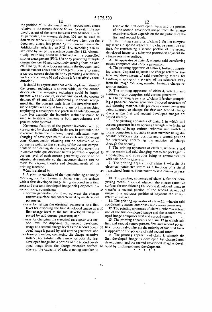
appreciated by those skilled in the art. In particular, the inventive technique disclosed herein alleviates over charging of developer material in each interdocument zone. Consequently, cleaning can be achieved at an optimal setpoint so that stressing of the various compo nents of the cleaning station is alleviated. Moreover, the inventive technique disclosed herein permits the applied current level of each corona generating device to be adjusted dynamically so that accommodation can be made for varying transfer and cleaning needs of the printing machine. What is claimed is: 1. A printing machine ofthe type including an image
receiving member having a charge retentive surface with a ?rst developed image being disposed in a ?rst zone and a second developed image being disposed in a second zone, comprising:
a corona generator positioned adjacent the charge retentive surface and characterized by an electrical parameter;
means for setting the electrical parameter to a ?rst level for disposing the ?rst developed image at a ?rst charge level as the ?rst developed image is passed by said corona generator; and
means for changing the electrical parameter to a sec ond level for disposing the second developed image at a second charge level as the second devel oped image is passed by said corona generator; and
a cleaning member, contacting the charge retentive surface, for substantially removing both the ?rst
5
5
20
55
developed image and a portion of the second devel- ' oped image from the charge retentive surface, wherein the capacity of said cleaning member to
65
O.
12 remove the ?rst developed image and the portion of the second developed image from the charge retentive surface depends on the magnitudes‘of the ?rst and second levels.
2. The printing apparatus of claim 1, further compris ing means, disposed adjacent the charge retentive sur face, for transferring a second portion of the second developed image to a substrate positioned adjacent the charge retentive surface.
3. The apparatus of claim 2, wherein said transferring means comprises said corona generator. ‘
4. The printing apparatus of claim 2, further compris ing means, disposed adjacent the charge retentive sur face and downstream of said transferring means, for assisting stripping of a portion of the substrate away from the image receiving member having a charge re tentive surface.
5. The printing apparatus of claim 4, wherein said assisting means comprises said corona generator.
6. The printing apparatus of claim 1 further compris ing a pre-clean corona generator disposed upstream of said cleaning member, said pre-clean corona generator being adapted to change the ?rst and second charge levels as the ?rst and second developed images are passed thereby.
7. The printing apparatus of claim 1 in which said corona generator has an opening through which charge is capable of being emitted, wherein said switching means comprises a movable shutter member being dis posable between a ?rst position and a second position for selectively controlling the emission of charge through the opening. ‘ _
8. The printing apparatus of claim 1, wherein a said setting means and said changing means are packaged in a controller, said controller being in communication with said corona generator.
9. The printing apparatus of claim 8 wherein the electrical parameter varies as a function of a signal transmitted from said controller to said corona genera tor.
10. The printing apparatus of claim 1, further com prising means, disposed adjacent the charge retentive surface, for conditioning the second developed image to transfer a second portion of the second developed image to a substrate positioned adjacent the charg: retentive surface.
11. The printing apparatus of claim 10, wherein said conditioning means comprises said corona generator.
12. The printing apparatus of claim 1, wherein at least one of the ?rst developed image and the second devel-. oped image comprises ?rst and second toners.
13. The printing apparatus of claim 12 in which said ?rst and second toners possess ?rst and second polari ties, respectively, wherein the polarity of said ?rst toner is opposite to the polarity of said second toner.
14. The printing apparatus of claim 1, wherein the ?rst developed image is developed by charged-area development and the second developed image is devel oped by discharged-area development.
6 $ # i t