apparatus to study action potentials. stimulus and response
TRANSCRIPT

Stimulator
knp
SomaAxon
Ringer's Bath
Recording Electrode #1
Reference Electrode
Recording Electrode #2
(+) (-)
Dam
Please imagine the electrodes to be in direct contact with the neuron.
Electrodes
Apparatus to Study Action Potentials

-70
-60
Em
(mV)
-60
-70
Trace #1 (near stimulator) Trace #2 (further from stim.)
stimulus stimulus
knp
Stimulus and Response

Rm
B
(+)
(-)
Cm
outside
inside
Membrane (between dotted lines)
knp
DC Generator
Membrane Model
The dc generator is very low capacity.
What does this means (structurally)?

ADP + Pi
ATP2 K+
3Na+
Na+/K+ ATPaseIon Channel or Gate
+
- - --
--
--
- -
- -
--
+ ++ +
+ ++
+
+ + + ++
excess neg. ions
excess + ions
knp
Membrane Components

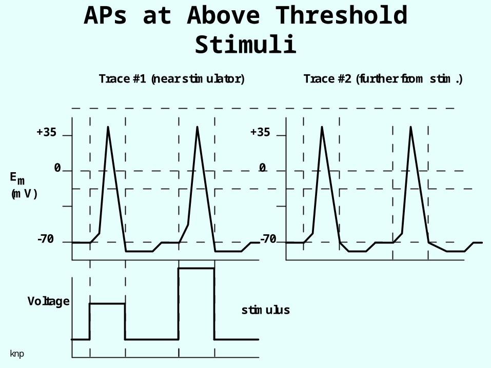
-70
Em
(mV)
-70
Trace #1 (near stimulator) Trace #2 (further from stim.)
stimulus
knp
Voltage
0
+35 +35
0
Action Potentials

-70
-60
Em
(mV)
-60
-70
Trace #1 (near stimulator) Trace #2 (further from stim.)
stimulus
knp
1.25XVoltage
Active Responses
-70
Em
(mV)
-70
Trace #1 (near stimulator) Trace #2 (further from stim.)
stimulus
knp
Voltage
0
+35 +35
0
APs at Above Threshold Stimuli

Graded vs. Action Potentials
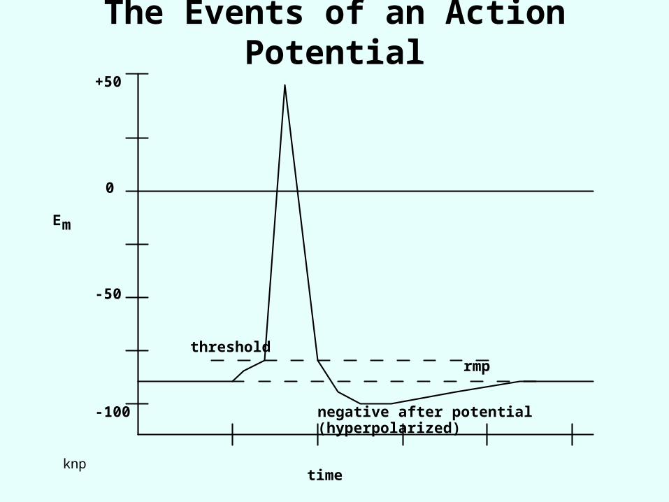
0
-50
-100
+50
thresholdrmp
negative after potential (hyperpolarized)
Em
timeknp
The Events of an Action Potential

Membrane Model #2
Cm
RK+ RCl-RNa+
BNa+BCl-BK+
This model is valid ONLY for a very thin section of the length of an axon (or muscle fiber).
This sort of model was hypothesized by the late 1940s

The Voltage Clamp, part 1
In order for Em to change, the total charge (Q) across the membrane capacitance (Cm) must change.
For Q to change, a current must flow. (Obviously!) However, any current associated with the membrane has two components:
• one associated with charging or discharging the Cm (called iC)
• another, iR, associated with current flow through the various parallel membrane resistances, lumped together as RM.• Thus: iM = iC + iR
We can only measure TOTAL membrane current, im directly.
But, we are most interested in the "resistive" current components because these are associated with ionic movements through channels and gates.
-- Is there a way to separate ir from the capacitive current, iC?
The Voltage Clamp, part 2

The Voltage Clamp, part 3
Recall that: QC EC *CM VC *CM
If we take the time derivative of the last equation (to get current flowing in or out of the capacitance, ic):
dQcdt
CMdVcdt
iC CMdVcdt
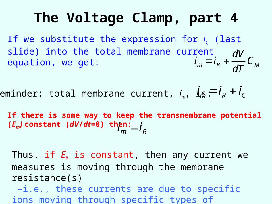
The Voltage Clamp, part 4If we substitute the expression for iC (last slide) into the total membrane current equation, we get:
im iR dV
dTCM
im iR iCReminder: total membrane current, im, is:
If there is some way to keep the transmembrane potential (Em) constant (dV/dt=0) then:im iR
Thus, if EM is constant, then any current we measures is moving through the membrane resistance(s) –i.e., these currents are due to specific ions moving through specific types of channels.

How can we keep Em constant during a time
(the AP) when Em normally changes rapidly?Answer: we use a device called the voltage clamp to
deliver a current to the inside of the cell -- initially to change Em to some new “clamped” voltage and then in such a way as to prevent Em from changing – i.e., in a way to hold Em constant. • The clamp senses minute changes in (dEm) due
to ions moving through membrane channels (rm) and into or out of the membrane capacitor, Cm.
• The clamp applies charge to the electrodes (a current) to stop this movement and keep Em essentially constant.
Thus, capacitive current is zero as is the resistive current. Whatever current was applied by the clamp was equal and opposite to whatever im “tried” to flow.

Feedback Amplifier Voltage
Amplifier
Current Monitoring Electrode
Current Electrodes
Current Delivery Electrode
Command Signal
+ - +
Em
Im
Feed- back Current
Voltage Sensing Electrode
Cm
Rmaxon
A Drawing of the Voltage Clamp
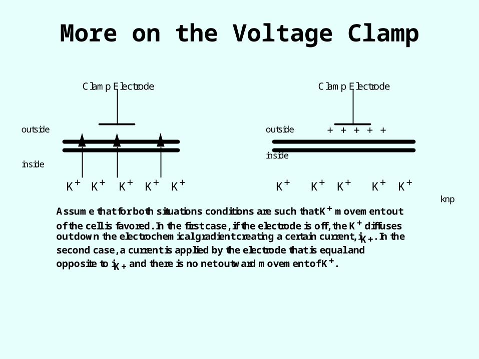
K+ K+ K+ K+K+ K+ K+ K+ K+ K+
outside outside
insideinside
Clamp Electrode Clamp Electrode
+ + + + +
Assume that for both situations conditions are such that K+ movement out
of the cell is favored. In the first case, if the electrode is off, the K+ diffuses out down the electrochemical gradient creating a certain current, iK+. In the
second case, a current is applied by the electrode that is equal and opposite to iK+ and there is no net outward movement of K+.
knp
More on the Voltage Clamp

Review of Membrane Model
Cm
RK+ RCl-RNa+
BNa+BCl-BK+
Let’s review what we think we know about current flows in a resting cell.

Out
In
time
0
Current
1 mv
2 mV
knp
Idealized Voltage Clamp, subthreshold

0
-50
-100
+50
thresholdrmp
negative after potential (hyperpolarized)
Em
timeknp
The Events of an Action Potential

in
out
0
C
urr
en
t (D
ire
ctio
n a
nd
Ma
gn
itu
de
)
knp
clamp at +10 mV
clamp at 0 mV
Super-threshold stimulus delivered
Voltage Clamp Data for a Stimulus that Would Elicit an AP in a Non-
Clamped Cell
Both of these clamp Em values are well above threshold and would normally elicit an AP.
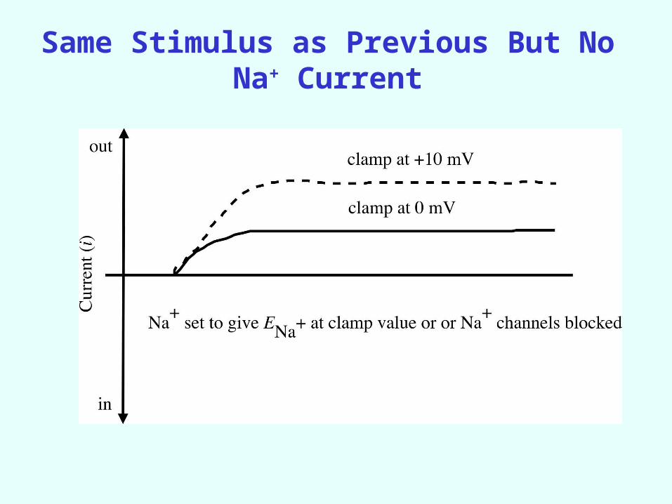
Same Stimulus as Previous But No Na+ Current

in
out
0
C
urr
en
t (D
ire
ctio
n a
nd
Ma
gn
itu
de
)
knp
INa+ Curves
IK+ curvesclamp = +10mV
clamp = 0 mV
clamp = 0 mV
clamp = +10 mV
Inward and Outward Currents at Two Clamp Potentials

Out
In
time0
Current
knp
- 65mV
- 64 mV
Clamp At Local Potential Values

Out
In
time0
Current
knp
- 65mV
- 64 mV
Outward Current Only At Local Potential Clamp Values

Out
In
time0
Current
knp
+ 100
+ 55
+ 40
+ 0
Clamp at High Depolarizations

Out
In
time0
Current
knp
+ 100
+ 55
+ 40
+ 0
Outward Currents at High Clamp Depolarizations

The emf for a particular ion (Eion) is the difference between Em and the ion's Nernst potential.
Thus: iion = Gion * (Em - Eion)
Using Clamp Data to Find Membrane Conductances
Ohm’s Law: iion = Eion * R-1ion
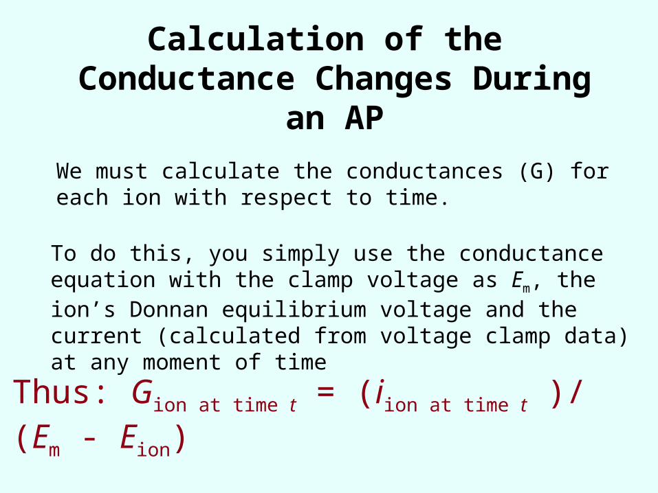
Calculation of the Conductance Changes During
an AP
We must calculate the conductances (G) for each ion with respect to time.
To do this, you simply use the conductance equation with the clamp voltage as Em, the ion’s Donnan equilibrium voltage and the current (calculated from voltage clamp data) at any moment of time
Thus: Gion at time t = (iion at time t )/ (Em - Eion)

Conductances During An AP

Finding Em with the Goldman-Hodgkin-Katz
Equation(a.k.a. Goldman or Goldman Field eq.)
EM 58 * logGcation1
*[cation1]in Gcation2*[cation2 ]in Ganion1
*[anion1]out
Gcation1*[cation1]out Gcation2
*[cation2 ]out Ganion1*[anion1]in

Cm
RK+ RCl-RNa+
BNa+BCl-BK+
Our Latest Membrane Model
Could this be further modified?

Populations of Channels and Voltage-Gated Channels
How do we modify our model to take into account several types of K+ channels?