appendix - 1990 mitsubishi mirage 4g63t all-wheel … hyundai elantra 16v... · configuration of...
TRANSCRIPT
APPENDIXReturn To Main Table of ContentsINTRODUCTION .. . . . . . . . . . . . . . . . . . . . . . . . . . . . . . . . . . . . . . . . . . . . . . 2S Y M B O L S .. . . . . . . . . . . . . . . . . . . . . . . . . . . . . . . . . . . . . . . . . . . . . . . . . . 6TROUBLESHOOTING INSTRUCTIONS . . . . . . . . . . . . . . . . 10FUSE AND RELAY INFORMATION .. . . . . . . . . . . . . . . . . . . . . 15POWER DISTRIBUTION ........................................ 18DASH FUSE BOX DETAILS .. . . . . . . . . . . . . . . . . . . . . . . . . . . . . . 22GROUND DISTRIBUTION .. . . . . . . . . . . . . . . . . . . . . . . . . . . . . . . . 32JOINT DISTRIBUTION ........................................ 44AIR BAG .......................................................... 166ANTI-LOCK BRAKE SYSTEM ............................. 162A/C COMPRESSOR CONTROLS . . . . . . . . . . . . . . 142A/T AND IGNITION KEY LOCK CONTROLS.. ........... 146BACK UP LAMPS ............................................. 116BLOWER CONTROLS......................................... 140BRAKE AND CHARGE WARNING SYSTEM . . . . . . . . . 98CHARGING SYSTEM......................................... 56ClGARETTE LIGHTER....................................... 90COOLING SYSTEM. . . . . . . . . . . . . . . . . . . . . . . . . . . . . . . . . . . . . . 58COURTESY LAMPS ............................................ 118CRUISE SPEED CONTROL SYSTEM. . . . . . . . . . . . . . . . . . . . 80DASH, CONSOLE AND SWITCH LAMPS... . . . . . . . . . . 122DAYTIME RUNNING LIGHTS (DRL) . . . . . . . . . . . . . . . . . . 102DIGITAL CLOCK ................................................. 134DOHC SYSTEM.................................................... 62ELECTRONIC LOCK UP CONTROL SYSTEM.. . . . . . . . . .84EXTERIOR LAMPS .. . . . . . . . . . . . . . . . . . . . . . . . . . . . . . . . . . . . . . . 106HEAD LAMPS ..................................................... 100HORNS ............................................................... 88IGNITION SYSTEM .......................................... 52INDICATORS/GAUGES ................................... 92/96PASSIVE SEATBELT SYSTEM . . . . . . . . . . . . . . . . . . . . . 158POWER DOOR LOCK. . . . . . . . . . . . . . . . . . . . . . . . . . . . . . . . 152POWER DOOR MIRROR . . . . . . . . . . . . . . . . . . . . 154POWER WINDOWS ......................................... 148SOUND SYSTEM/POWER ANTENNA .. . . . . . . . . . . . 130/132STARTING SYSTEM ........................................... 54STOP LAMPS .................................................... 110SUNROOF......................................................... 156TAC SYSTEM ................................................. 136TRUNK LID OPENER ........................................ 128TURN/HAZARD AND LAMPS ............................. 112VEHICLE SPEED SENSOR ... . . . . . . . . . . . . . . . . . . . . . . . . . . . . . 78CONFIGURATION OF CONNECTORS ........................... 168COMPONENT LOCATION . . . . . . . . . . . . . . . . . . . . . . . 182HARNESS LAYOUT. . . . . . . . . . . . . . . . . . . . . . . . . . . . . . . . . . 206

WS-2 INTRODUCTION
INTRODUCTIONThis Group consists of five major diagnostic sections for electrical problem troubleshooting.
• Schematic diagrams• Component location indexes• Harness layouts• Component location• Connector configurations
The starting point of each system section is the schematic diagram, these diagrams show how all the components worktogether, such as electrical current paths from power source to ground (via electrical load), switch connections at eachpositions, and other related circuit functions.It is important to fully understand how a circuit work prior to troubleshooting and diagnosis.
2.ORED/WHT 2.ORED/WHT
3.0RED/YEL
An Example of Schematic Diagram
INTRODUCTION WS-3
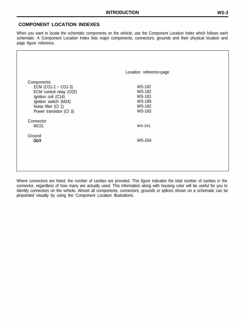
COMPONENT LOCATION INDEXES
When you want to locate the schematic components on the vehicle, use the Component Location Index which follows eachschematic. A Component Location Index lists major components, connectors, grounds and their physical location andpage figure reference.
ComponentsECM (CO1-2 ~ CO1-3)ECM control relay (C02)Ignition coil (C14)Ignition switch (M24)Noise filter (Cl 1)Power transistor (Cl 3)
ConnectorMC01
GroundG09
Location reference-page
WS-182WS-182WS-183WS-189WS-182WS-183
WS-201
WS-204
Where connectors are listed, the number of cavities are provided. This figure indicates the total number of cavities in theconnector, regardless of how many are actually used. This information along with housing color will be useful for you toidentify connectors on the vehicle. Almost all components, connectors, grounds or splices shown on a schematic can bepinpointed visually by using the Component Location Illustrations.
WS-4 INTRODUCTION
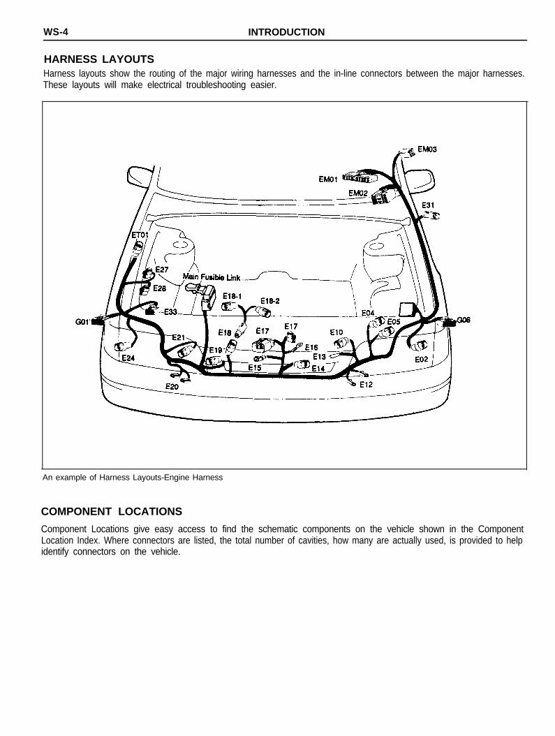
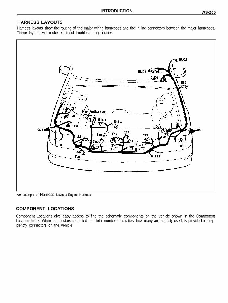
HARNESS LAYOUTSHarness layouts show the routing of the major wiring harnesses and the in-line connectors between the major harnesses.These layouts will make electrical troubleshooting easier.
An example of Harness Layouts-Engine Harness
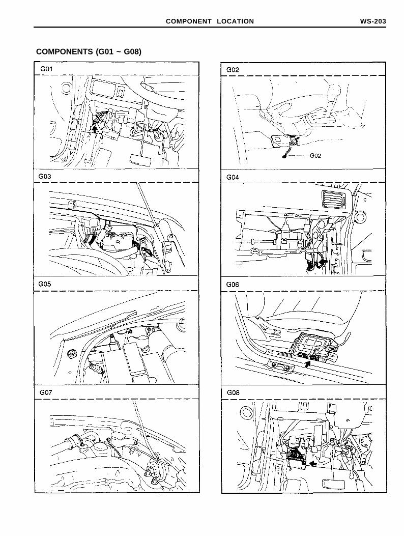
COMPONENT LOCATIONS
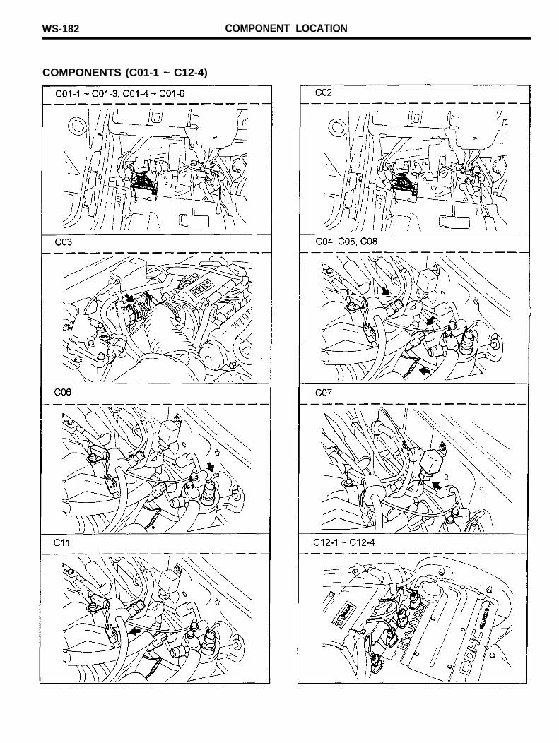
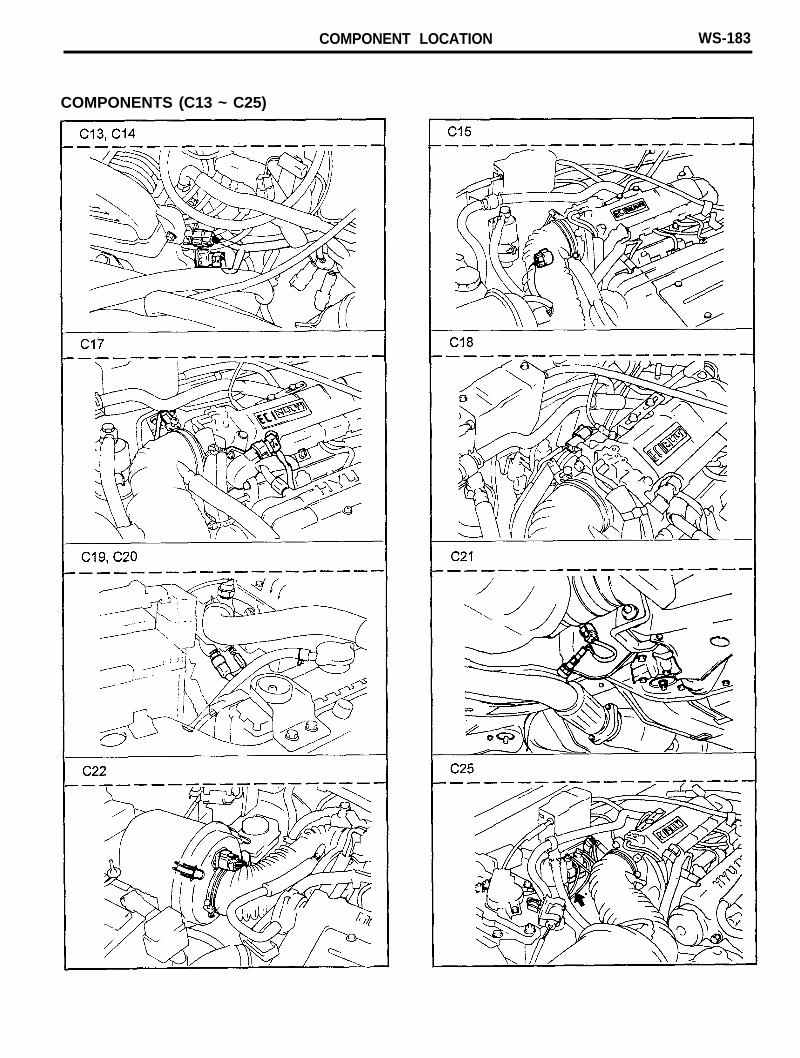
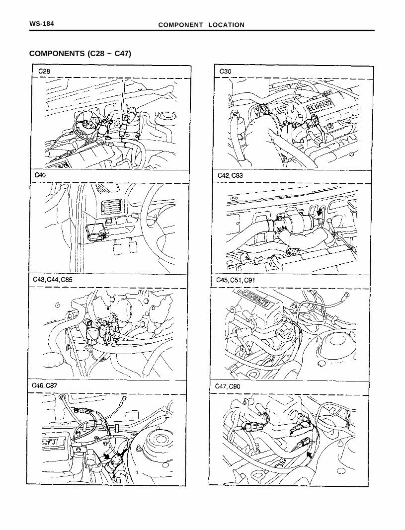
Component Locations give easy access to find the schematic components on the vehicle shown in the ComponentLocation Index. Where connectors are listed, the total number of cavities, how many are actually used, is provided to helpidentify connectors on the vehicle.
INTRODUCTION WS-5
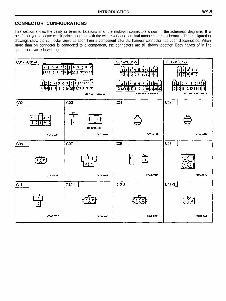
CONNECTOR CONFIGURATIONS
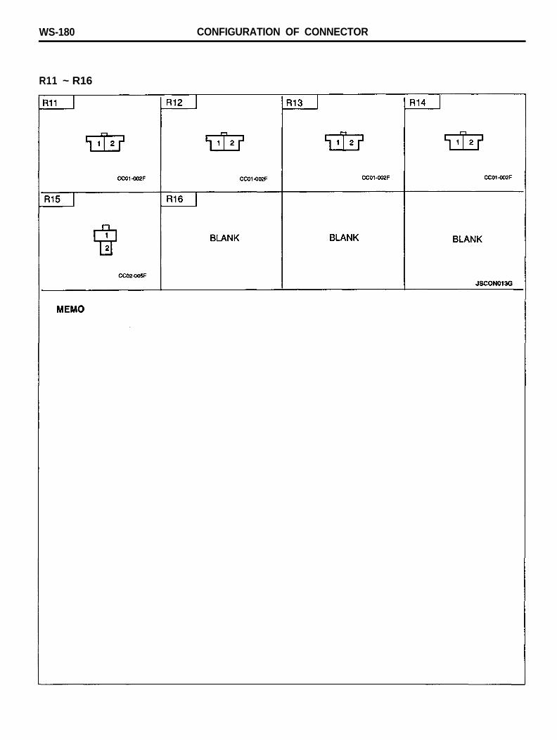
This section shows the cavity or terminal locations in all the multi-pin connectors shown in the schematic diagrams. It ishelpful for you to locate check points, together with the wire colors and terminal numbers in the schematic. The configurationdrawings show the connector views as seen from a component after the harness connector has been disconnected. Whenmore than on connector is connected to a component, the connectors are all shown together. Both halves of in lineconnectors are shown together.
SYMBOLS
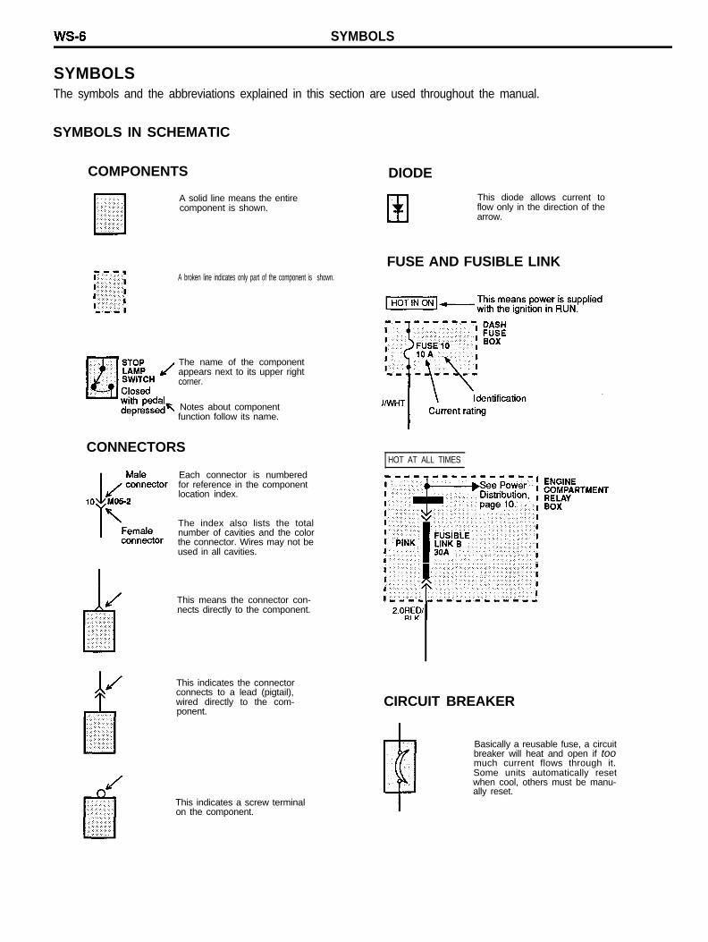
SYMBOLSThe symbols and the abbreviations explained in this section are used throughout the manual.
SYMBOLS IN SCHEMATIC
COMPONENTS DIODE
A solid line means the entirecomponent is shown.
A broken line indicates only part of the component is shown.
The name of the componentappears next to its upper rightcorner.
Notes about componentfunction follow its name.
CONNECTORS
Each connector is numberedfor reference in the componentlocation index.
The index also lists the totalnumber of cavities and the colorthe connector. Wires may not beused in all cavities.
This means the connector con-nects directly to the component.
This indicates the connectorconnects to a lead (pigtail),wired directly to the com-ponent.
This indicates a screw terminalon the component.
This diode allows current toflow only in the direction of thearrow.
FUSE AND FUSIBLE LINK
HOT AT ALL TIMES
CIRCUIT BREAKER
Basically a reusable fuse, a circuitbreaker will heat and open if toomuch current flows through it.Some units automatically resetwhen cool, others must be manu-ally reset.
SYMBOLS
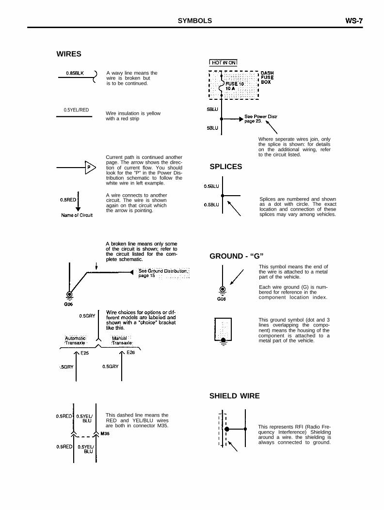
WIRES
A wavy line means thewire is broken butis to be continued.
0.5YEL/REDWire insulation is yellowwith a red strip
Current path is continued anotherpage. The arrow shows the direc-tion of current flow. You shouldlook for the ”P” in the Power Dis-tribution schematic to follow thewhite wire in left example.
A wire connects to anothercircuit. The wire is shownagain on that circuit whichthe arrow is pointing.
A broken line means only someA broken line means only someof the circuit is shown; refer toof the circuit is shown; refer tothe circuit listed for the com-the circuit listed for the com-plete schematic.plete schematic.
This dashed line means theRED and YEL/BLU wiresare both in connector M35.
Where seperate wires join, onlythe splice is shown: for detailson the additional wiring, referto the circuit listed.
SPLICES
Splices are numbered and shownas a dot with circle. The exactlocation and connection of thesesplices may vary among vehicles.
GROUND - “G”This symbol means the end ofthe wire is attached to a metalpart of the vehicle.
Each wire ground (G) is num-bered for reference in thecomponent location index.
This ground symbol (dot and 3lines overlapping the compo-nent) means the housing of thecomponent is attached to ametal part of the vehicle.
SHIELD WIRE
This represents RFI (Radio Fre-quency Interference) Shieldingaround a wire. the shielding isalways connected to ground.
WS-8 SYMBOLS
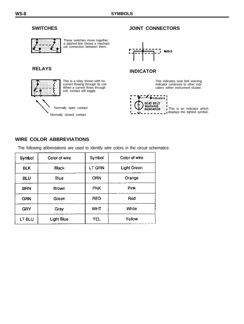
SWITCHES
RELAYS
JOINT CONNECTORS
These switches move together:a dashed line shows a mechani-cal connection between them.
INDICATOR
This is a relay shown with nocurrent flowing through its coil.
This indicates seat belt warningindicator continues to other indi-
When a current flows throughcoil, contact will toggle.
caters within instrument cluster.
Normally open contact
Normally closed contact
This is an indicator which displays the lighted symbol.
WIRE COLOR ABBREVIATIONS
The following abbreviations are used to identify wire colors in the circuit schematics:
SYMBOLS WS-9
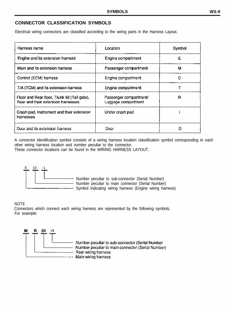
CONNECTOR CLASSIFICATION SYMBOLS
Electrical wiring connectors are classified according to the wiring parts in the Harness Layout.
A connector identification symbol consists of a wiring harness location classification symbol corresponding to eachother wiring harness location and number peculiar to the connector.These connector locations can be found in the WIRING HARNESS LAYOUT.
E 10 -1
Number peculiar to sub-connector (Serial Number)Number peculiar to main connector (Serial Number)Symbol indicating wiring harness (Engine wiring harness)
NOTEConnectors which connect each wiring harness are represented by the following symbols.For example:
WS-10 TROUBLESHOOTING INSTRUCTION
TROUBLESHOOTING INSTRUCTIONSTROUBLESHOOTING PROCEDURES
The following five-step troubleshooting procedure is recommended.
Step 1. Verify the customer complaints
Turn on all the components in the problem circuit to check the accuracy of the customer complaints. Note the symptoms.Do not begin disassembly or testing until you have narrowed down the probable causes.
Step 2. Read and analyze the schematic diagram
Locate the schematic for the problem circuit. Determine how the circuit is supposed to work by tracing the current pathsfrom the power source through the system components to ground. If you do not understand how the circuit should work,read the circuit operation text. Also check other circuits that share with the problem circuit. The name of circuits that sharethe same fuse, ground, or switch, for example, are referred to on each diagrams. Try to operate any shared circuits youdid not check in step 1. If the shared circuit works, the shared wiring is okay, and the cause must be within the wiring usedonly by the problem circuit. If several circuit fails at the same time, the fuse or ground is a likely cause.
Step 3. Inspect the circuit/component with the problem isolated
Make a circuit test to check the diagnosis you made in step 2. Remember that a logical, simple procedure is the key toefficient troubleshooting. Narrow down the probable causes using the Troubleshooting Hints, System Diagnosis Charts.Test for the most likely cause of failure first. try to make tests at points that are easily accessible.
Step 4. Repair the problem
Once the problem is found, make the necessary repairs.
Step 5. Make sure the circuit works
Repeat the system check to be sure you have repaired the problem. If the problem was a blown fuse, be sure to test allof the circuits on that fuse.
TROUBLESHOOTING INSTRUCTION WS-11
TROUBLESHOOTING EQUIPMENTS
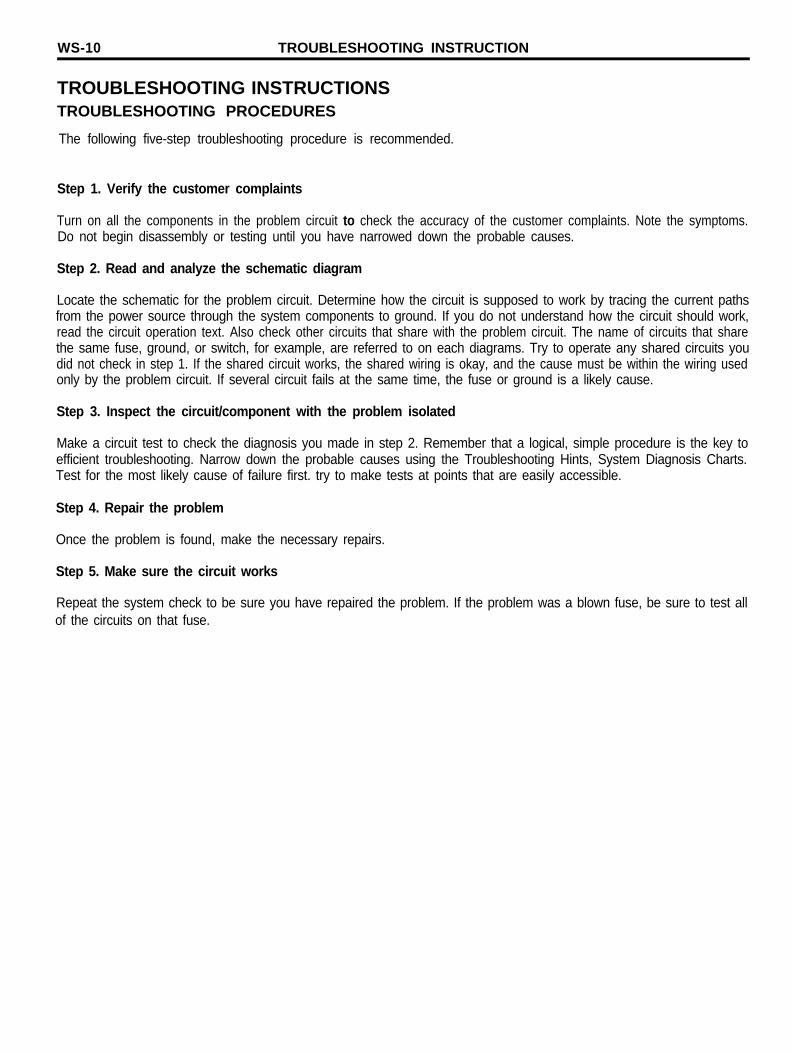
Voltmeter And Test Lamp
Use a test lamp or a voltmeter on circuits without solid-state units,use a test lamp to check for voltage. A test lamp is made up of 12-volt bulb with a pair of leads attached. After grounding one lead tovarious points along the circuit where voltage should be present.When the bulb goes on, there is voltage at the point being tested.
CAUTION:A number of circuits include solid-state modules such asElectronic Control Unit (ECU) used with computer commandcontrol injection. Voltage in these circuits should be testedonly with a 10-megohm or higher impedance digital voltmeter.Never use a test lamp on circuits that contain solid-state units.Damage to the units may result.
A voltmeter can be used in place of a test lamp. While a test lampshows whether the voltage is present or not, a voltmeter indicateshow much voltage there is.
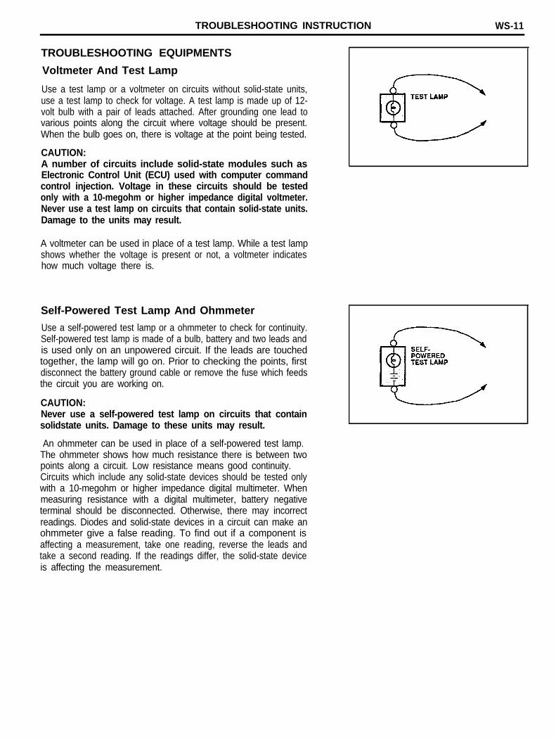
Self-Powered Test Lamp And Ohmmeter
Use a self-powered test lamp or a ohmmeter to check for continuity.Self-powered test lamp is made of a bulb, battery and two leads andis used only on an unpowered circuit. If the leads are touchedtogether, the lamp will go on. Prior to checking the points, firstdisconnect the battery ground cable or remove the fuse which feedsthe circuit you are working on.
CAUTION:Never use a self-powered test lamp on circuits that containsolidstate units. Damage to these units may result.
An ohmmeter can be used in place of a self-powered test lamp.The ohmmeter shows how much resistance there is between twopoints along a circuit. Low resistance means good continuity.Circuits which include any solid-state devices should be tested onlywith a 10-megohm or higher impedance digital multimeter. Whenmeasuring resistance with a digital multimeter, battery negativeterminal should be disconnected. Otherwise, there may incorrectreadings. Diodes and solid-state devices in a circuit can make anohmmeter give a false reading. To find out if a component isaffecting a measurement, take one reading, reverse the leads andtake a second reading. If the readings differ, the solid-state deviceis affecting the measurement.
WS-12 TROUBLESHOOTING INSTRUCTION
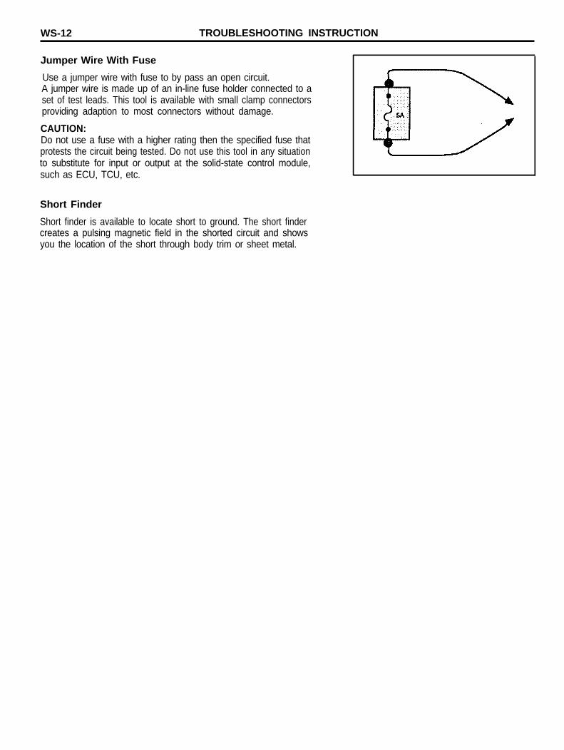
Jumper Wire With Fuse
Use a jumper wire with fuse to by pass an open circuit.A jumper wire is made up of an in-line fuse holder connected to aset of test leads. This tool is available with small clamp connectorsproviding adaption to most connectors without damage.
CAUTION:Do not use a fuse with a higher rating then the specified fuse thatprotests the circuit being tested. Do not use this tool in any situationto substitute for input or output at the solid-state control module,such as ECU, TCU, etc.
Short Finder
Short finder is available to locate short to ground. The short findercreates a pulsing magnetic field in the shorted circuit and showsyou the location of the short through body trim or sheet metal.
TROUBLESHOOTING INSTRUCTION WS-13
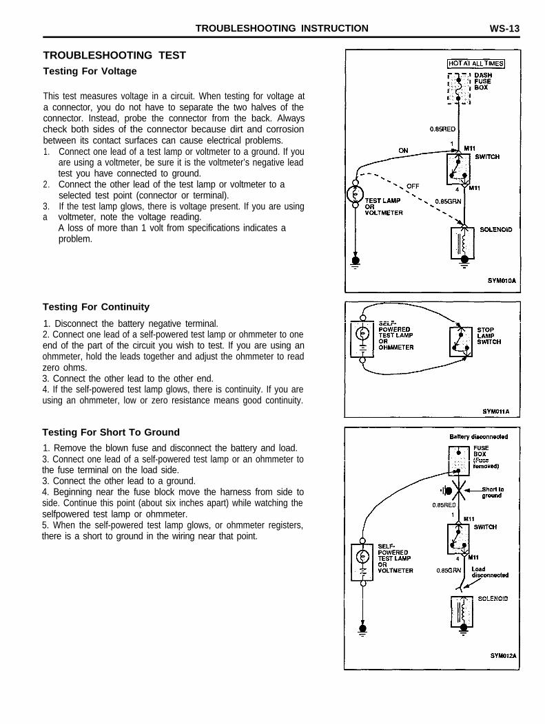
TROUBLESHOOTING TESTTesting For Voltage
This test measures voltage in a circuit. When testing for voltage ata connector, you do not have to separate the two halves of theconnector. Instead, probe the connector from the back. Alwayscheck both sides of the connector because dirt and corrosionbetween its contact surfaces can cause electrical problems.1. Connect one lead of a test lamp or voltmeter to a ground. If you
are using a voltmeter, be sure it is the voltmeter’s negative leadtest you have connected to ground.
2. Connect the other lead of the test lamp or voltmeter to aselected test point (connector or terminal).
3. If the test lamp glows, there is voltage present. If you are usinga voltmeter, note the voltage reading.
A loss of more than 1 volt from specifications indicates aproblem.
Testing For Continuity
1. Disconnect the battery negative terminal.2. Connect one lead of a self-powered test lamp or ohmmeter to oneend of the part of the circuit you wish to test. If you are using anohmmeter, hold the leads together and adjust the ohmmeter to readzero ohms.3. Connect the other lead to the other end.4. If the self-powered test lamp glows, there is continuity. If you areusing an ohmmeter, low or zero resistance means good continuity.
Testing For Short To Ground
1. Remove the blown fuse and disconnect the battery and load.3. Connect one lead of a self-powered test lamp or an ohmmeter tothe fuse terminal on the load side.3. Connect the other lead to a ground.4. Beginning near the fuse block move the harness from side toside. Continue this point (about six inches apart) while watching theselfpowered test lamp or ohmmeter.5. When the self-powered test lamp glows, or ohmmeter registers,there is a short to ground in the wiring near that point.
WS-14 TROUBLESHOOTING INSTRUCTION
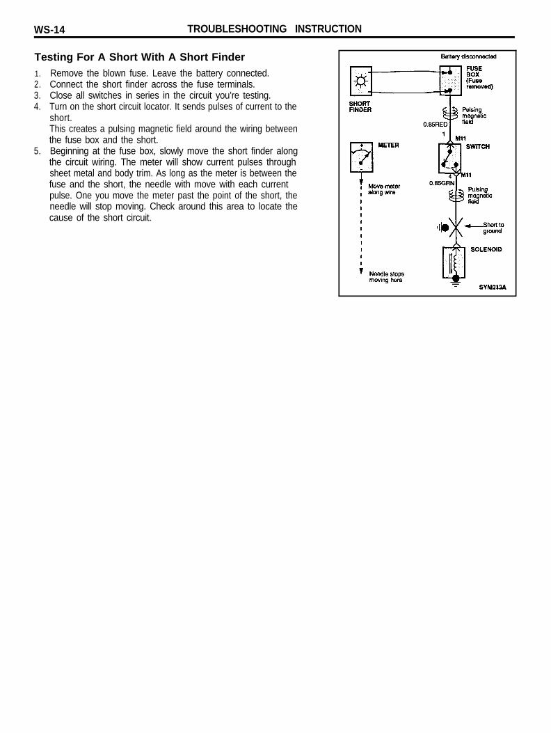
Testing For A Short With A Short Finder1. Remove the blown fuse. Leave the battery connected.2. Connect the short finder across the fuse terminals.3. Close all switches in series in the circuit you’re testing.4. Turn on the short circuit locator. It sends pulses of current to the
short.This creates a pulsing magnetic field around the wiring betweenthe fuse box and the short.
5. Beginning at the fuse box, slowly move the short finder alongthe circuit wiring. The meter will show current pulses throughsheet metal and body trim. As long as the meter is between thefuse and the short, the needle with move with each currentpulse. One you move the meter past the point of the short, theneedle will stop moving. Check around this area to locate thecause of the short circuit.
FUSE AND RELAY INFORMATION WS-15
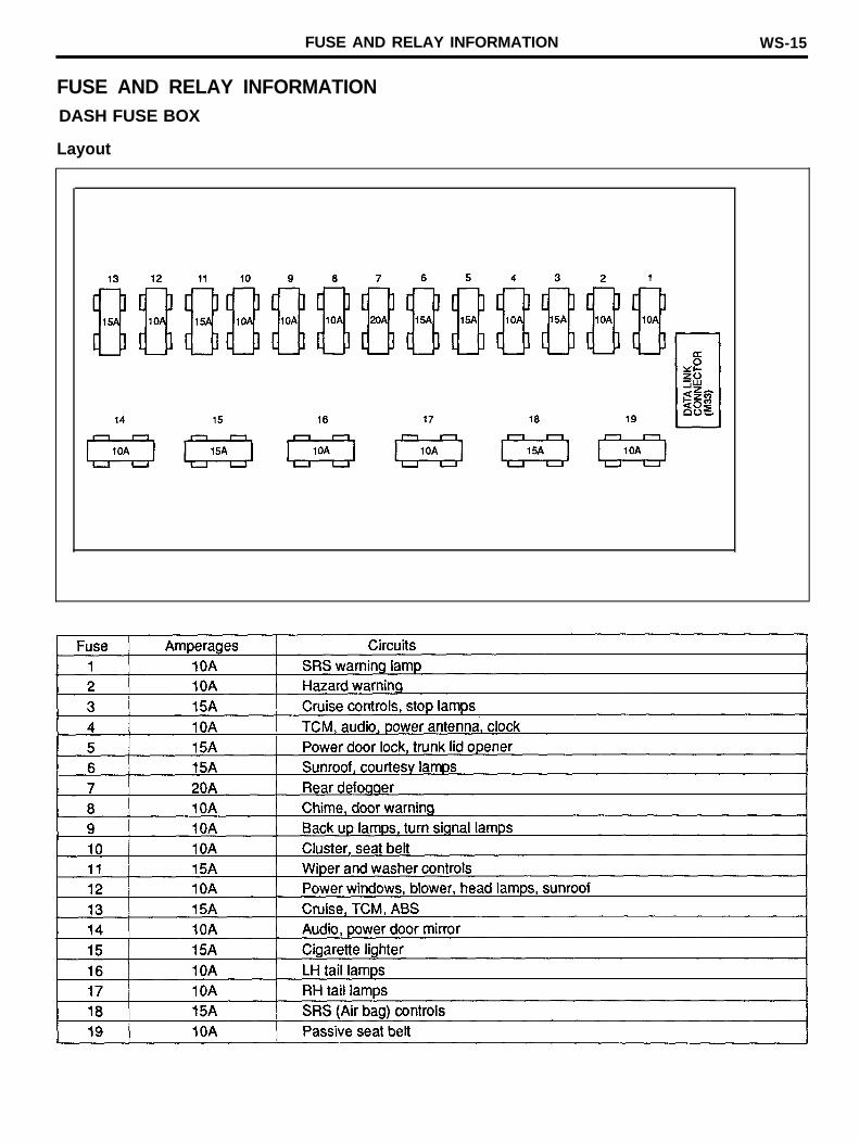
FUSE AND RELAY INFORMATIONDASH FUSE BOX
Layout
WS-16 TROUBLESHOOTING INSTRUCTION
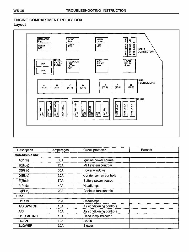
ENGINE COMPARTMENT RELAY BOXLayout
FUSE AND RELAY INFORMATION WS-17
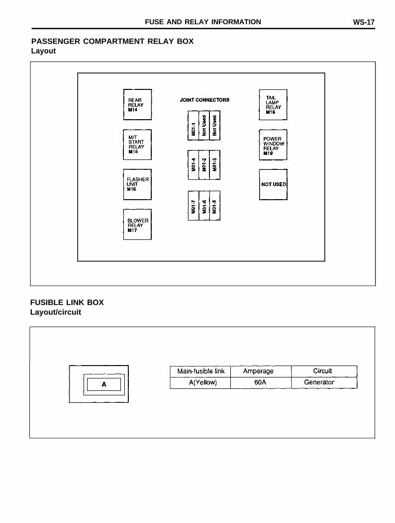
PASSENGER COMPARTMENT RELAY BOXLayout
FUSIBLE LINK BOXLayout/circuit
W S - 1 8 POWER DISTRIBUTION
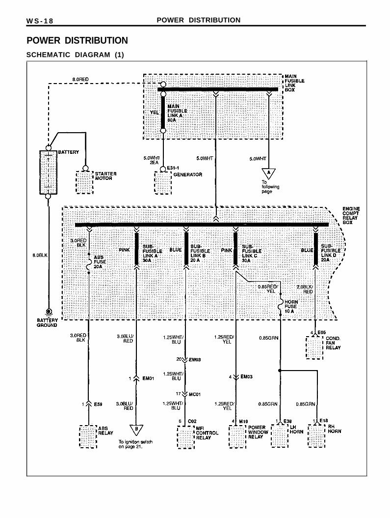
POWER DISTRIBUTIONSCHEMATIC DIAGRAM (1)
POWER DISTRIBUTION WS-19
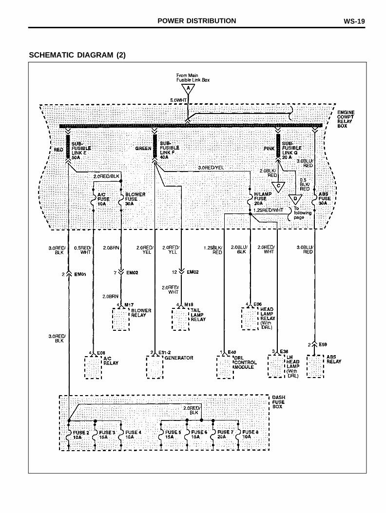
SCHEMATIC DIAGRAM (2)
WS-20 POWER DISTRIBUTION
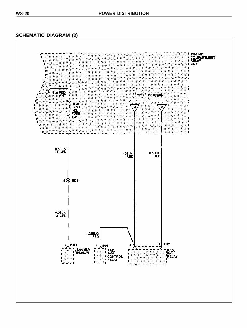
SCHEMATIC DIAGRAM (3)
POWER DISTRIBUTION WS-21
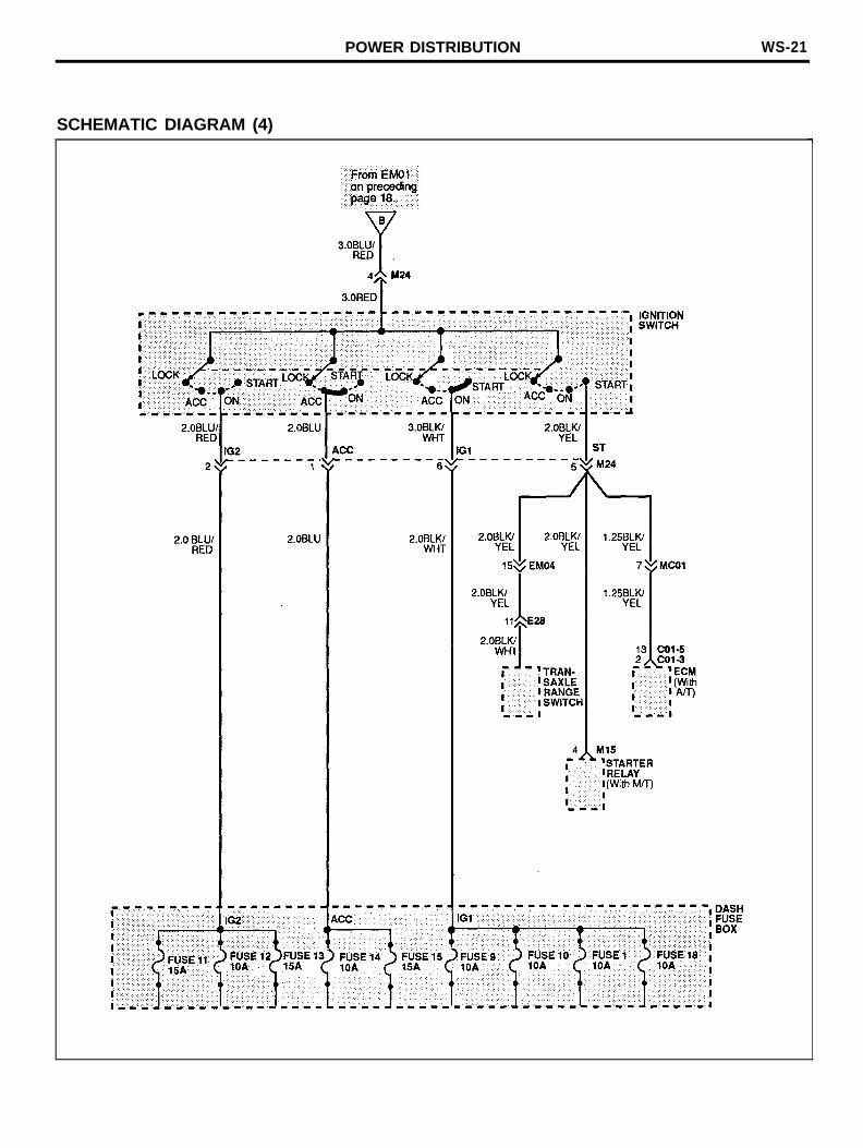
SCHEMATIC DIAGRAM (4)
WS-22 DASH FUSE BOX DETAILS
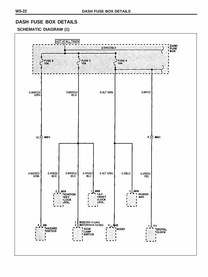
DASH FUSE BOX DETAILSSCHEMATIC DIAGRAM (1)
DASH FUSE DETAILS
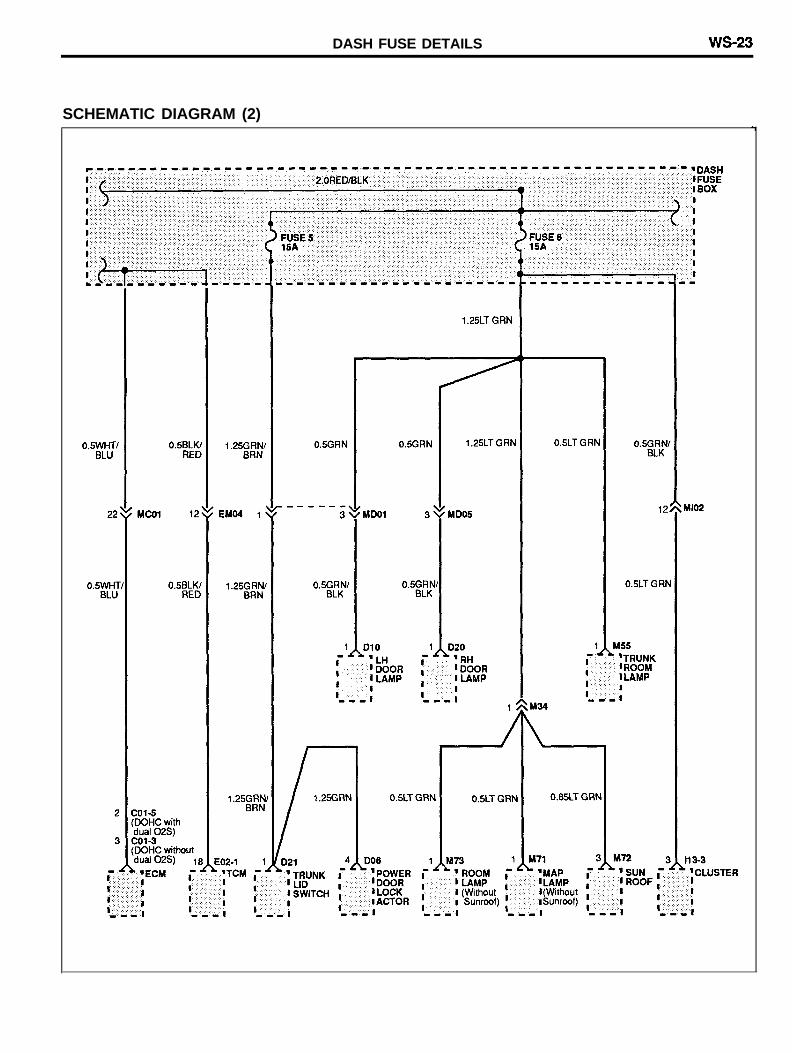
SCHEMATIC DIAGRAM (2)

WS-24 DASH FUSE BOX DETAILS
SCHEMATIC DIAGRAM (3)
DASH FUSE DETAILS WS-25
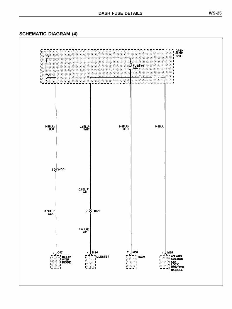
SCHEMATIC DIAGRAM (4)
WS-26 DASH FUSE BOX DETAILS
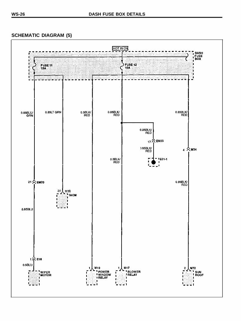
SCHEMATIC DIAGRAM (5)
DASH FUSE DETAILS WS-27
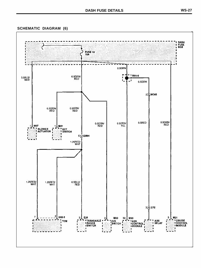
SCHEMATIC DIAGRAM (6)

WS-28 DASH FUSE BOX DETAILS
SCHEMATIC DIAGRAM (7)
DASH FUSE DETAILS
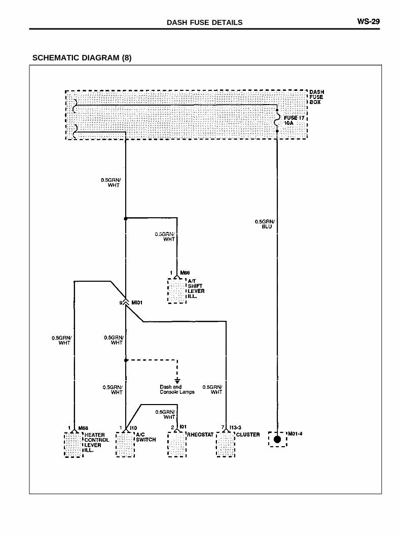
SCHEMATIC DIAGRAM (8)
WS-30 DASH FUSE BOX DETAILS
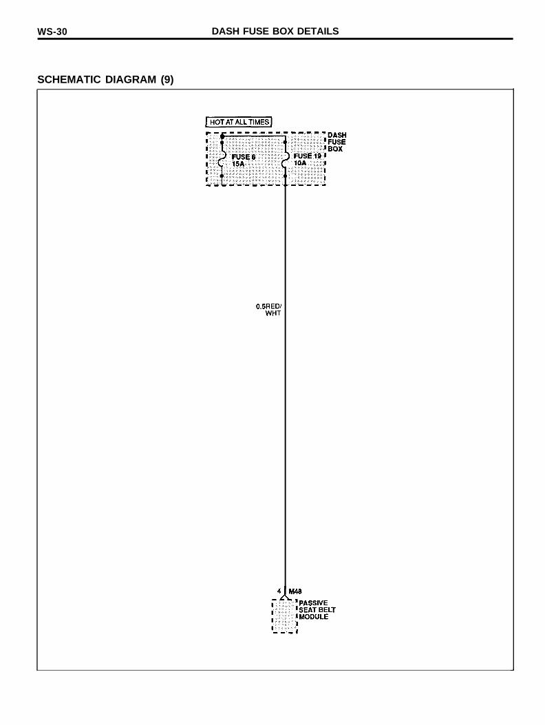
SCHEMATIC DIAGRAM (9)

DASH FUSE DETAILS WS-31
MEMO
WS-32 GROUND DISTRIBUTION
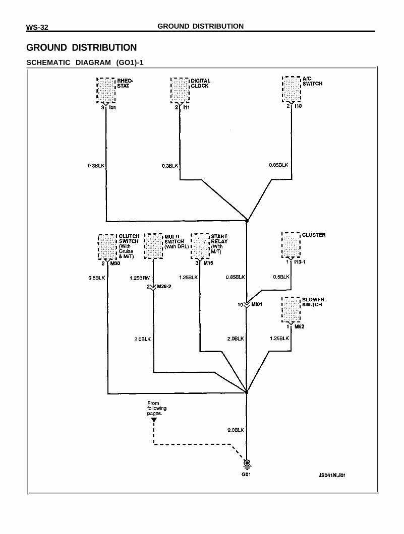
GROUND DISTRIBUTIONSCHEMATIC DIAGRAM (GO1)-1
GROUND DlSTRlBUTlON WS-33
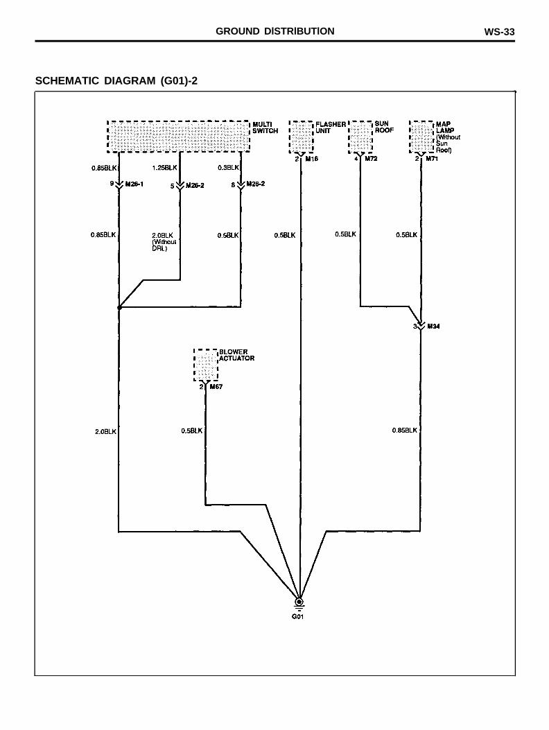
SCHEMATIC DIAGRAM (G01)-2
WS-34 GROUND DISTRIBUTION
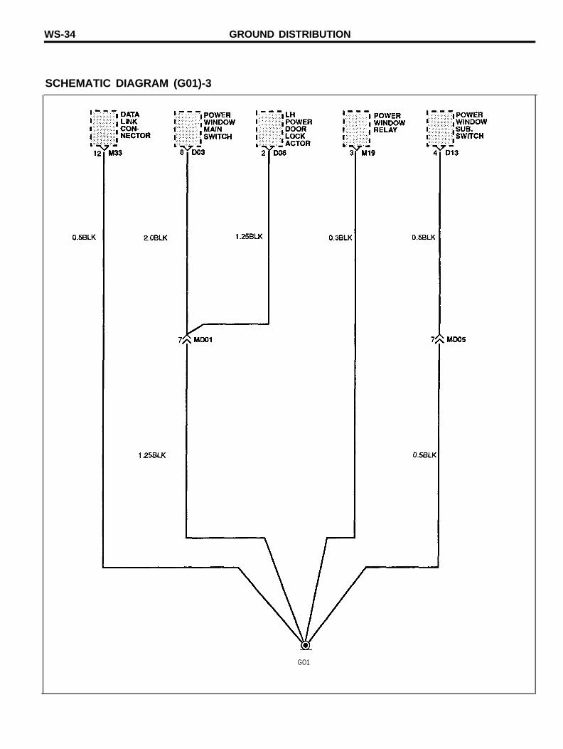
SCHEMATIC DIAGRAM (G01)-3
GO1
GROUND DISTRIBUTION WS-35
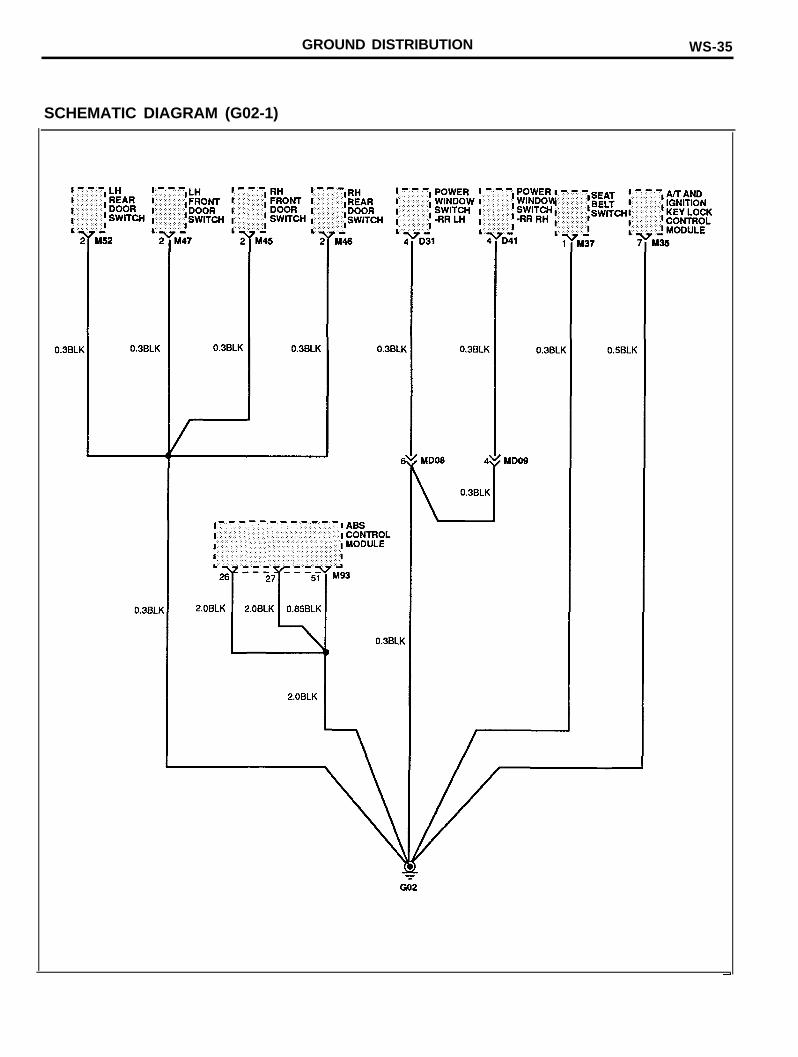
SCHEMATIC DIAGRAM (G02-1)
WS-36 GROUND DISTRIBUTION
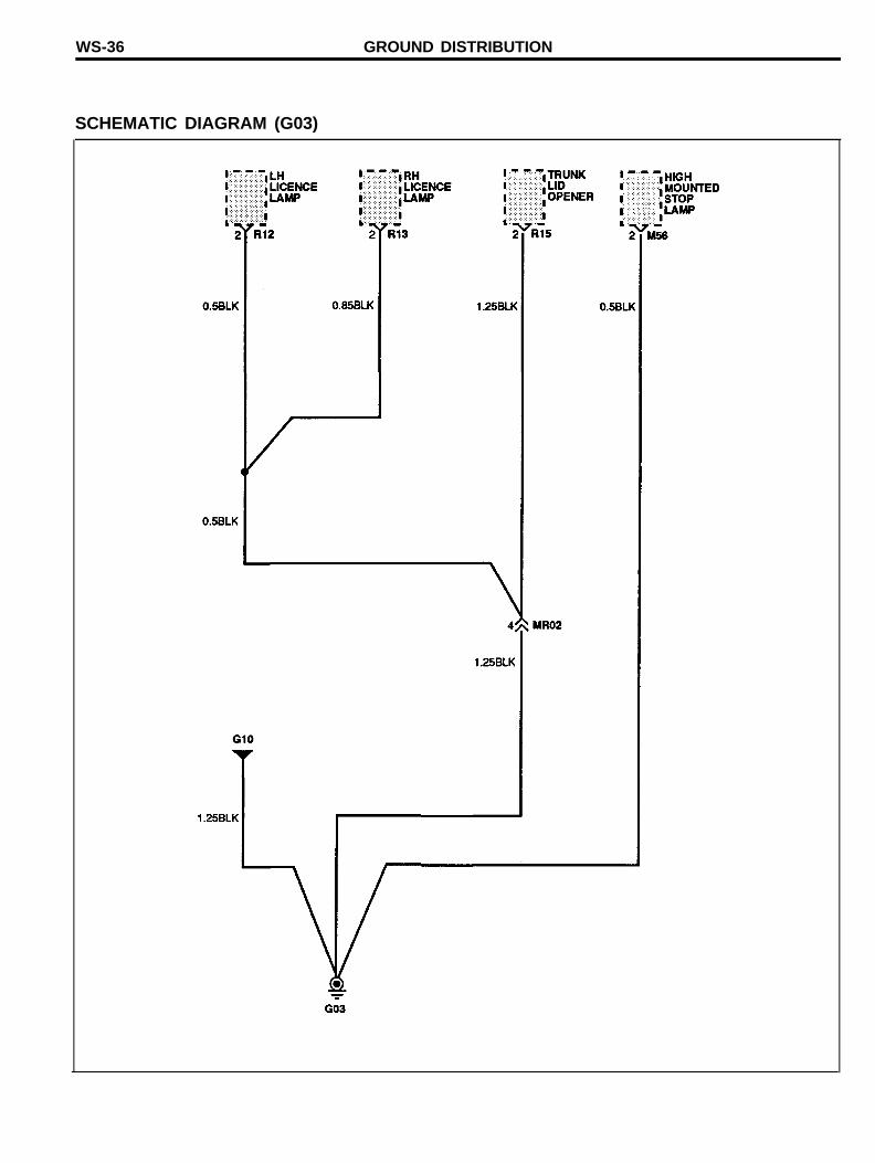
SCHEMATIC DIAGRAM (G03)
GROUND DISTRIBUTION WS-37
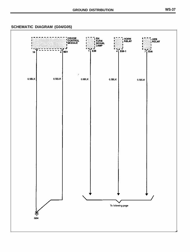
SCHEMATIC DIAGRAM (G04/G05)
WS-38 GROUND DISTRIBUTION
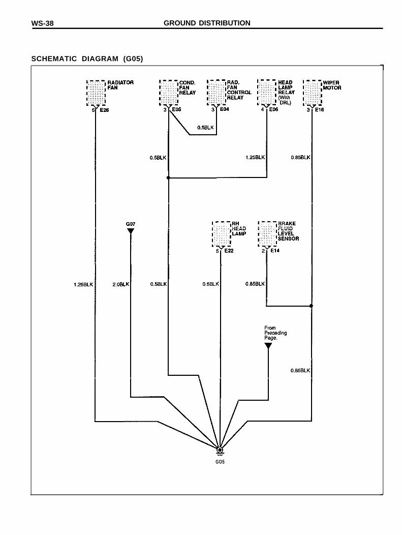
SCHEMATIC DIAGRAM (G05)
GO5
GROUND DISTRIBUTION WS-39
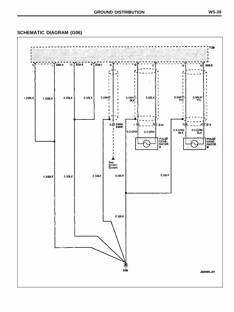
SCHEMATIC DIAGRAM (G06)
WS-40 GROUND DISTRIBUTION
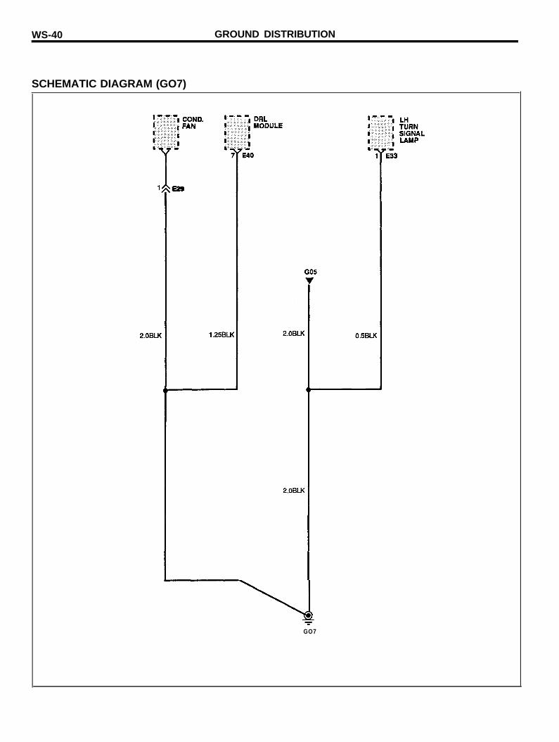
SCHEMATIC DIAGRAM (GO7)
E29
GO7
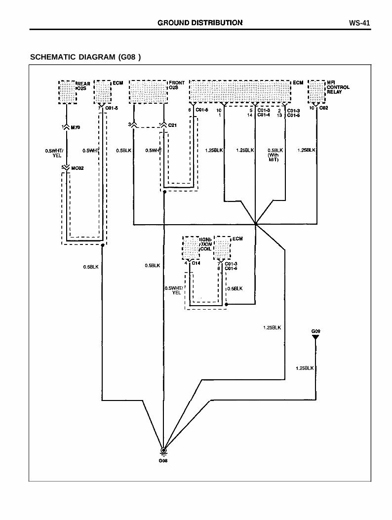
WS-41
SCHEMATIC DIAGRAM (G08 )
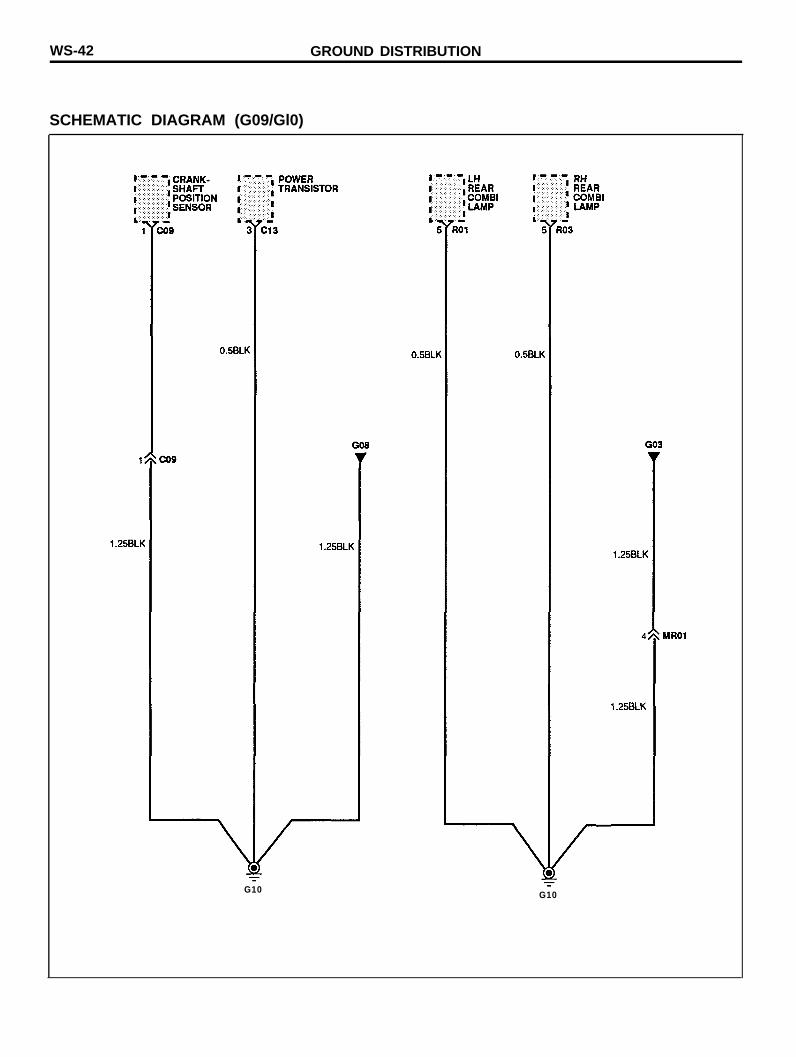
WS-42 GROUND DISTRIBUTION
SCHEMATIC DIAGRAM (G09/Gl0)
G10 G10
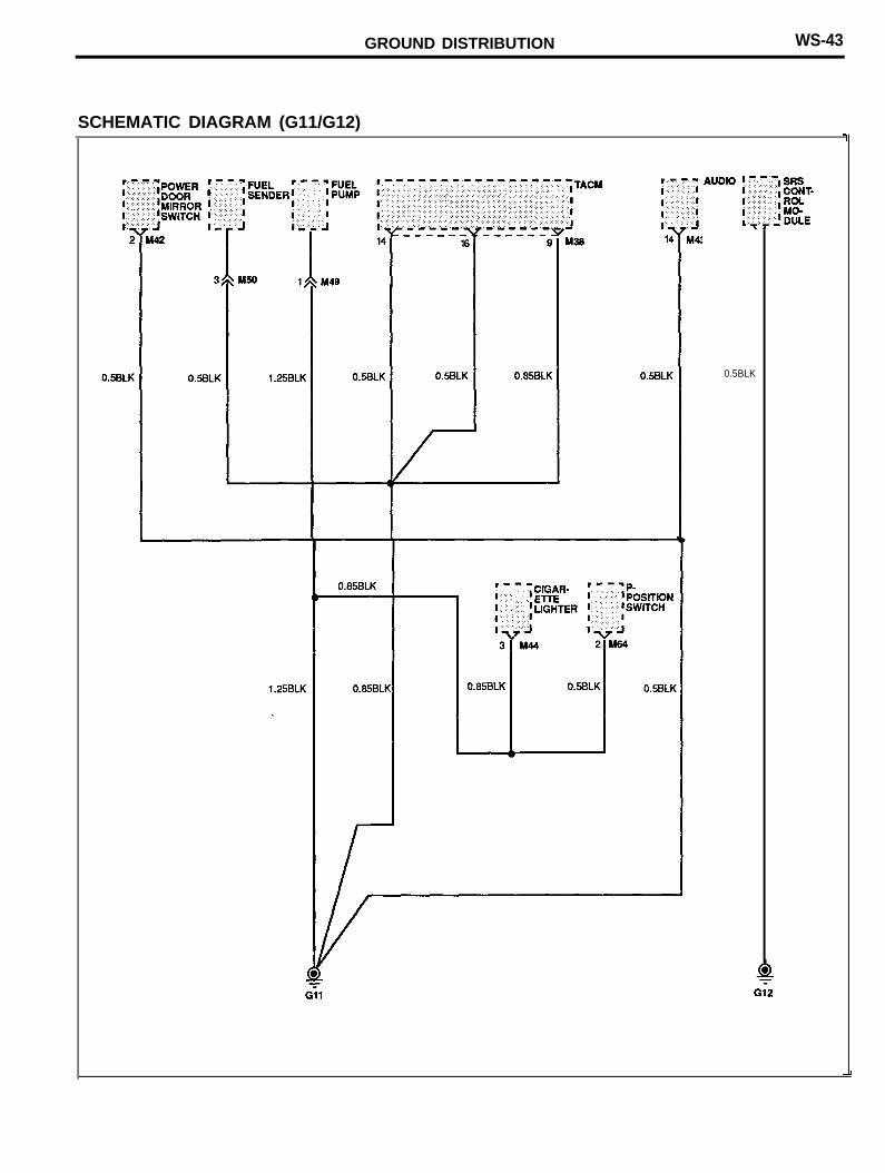
GROUND DISTRIBUTION WS-43
SCHEMATIC DIAGRAM (G11/G12)
0.5BLK
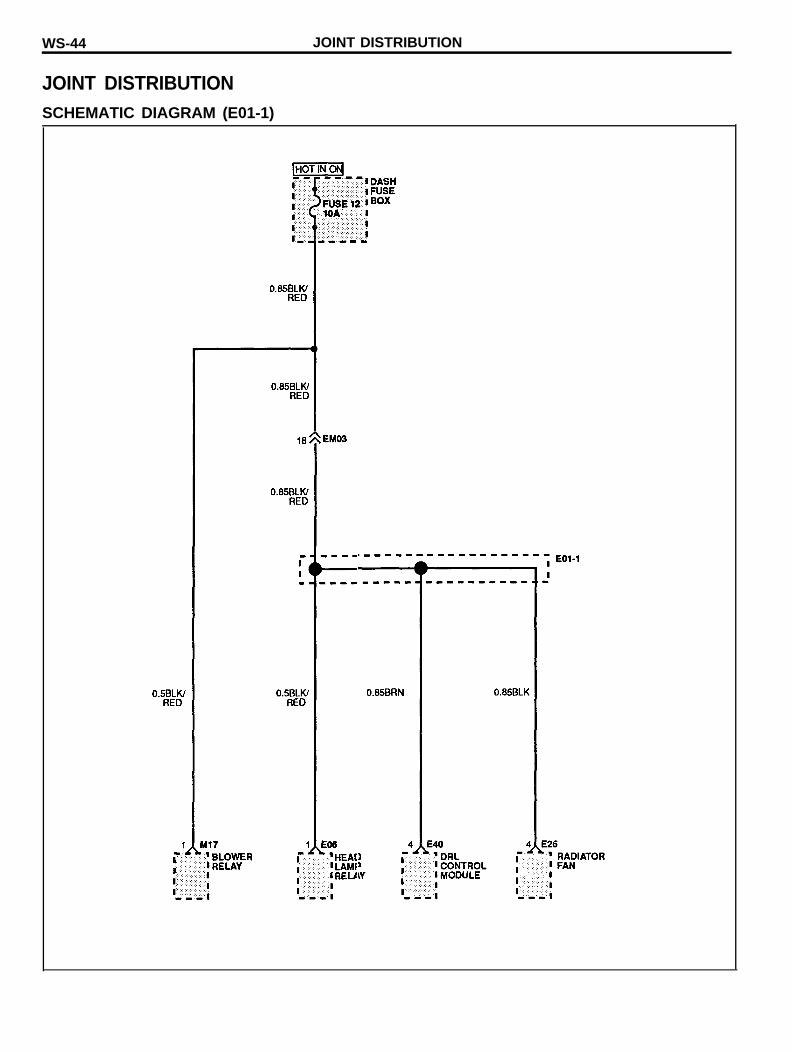
WS-44 JOINT DISTRIBUTION
JOINT DISTRIBUTIONSCHEMATIC DIAGRAM (E01-1)
JOINT DISTRIBUTION WS-45
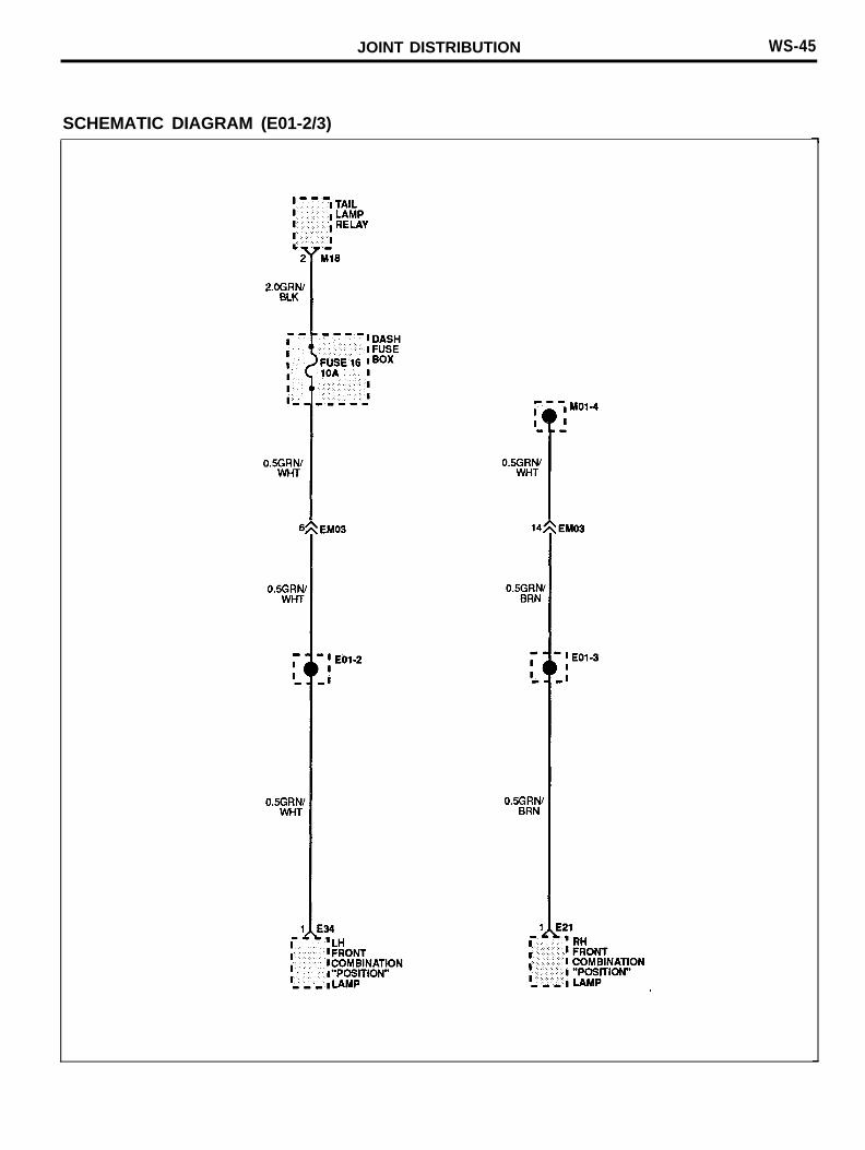
SCHEMATIC DIAGRAM (E01-2/3)
WS-46 JOINT DISTRIBUTION
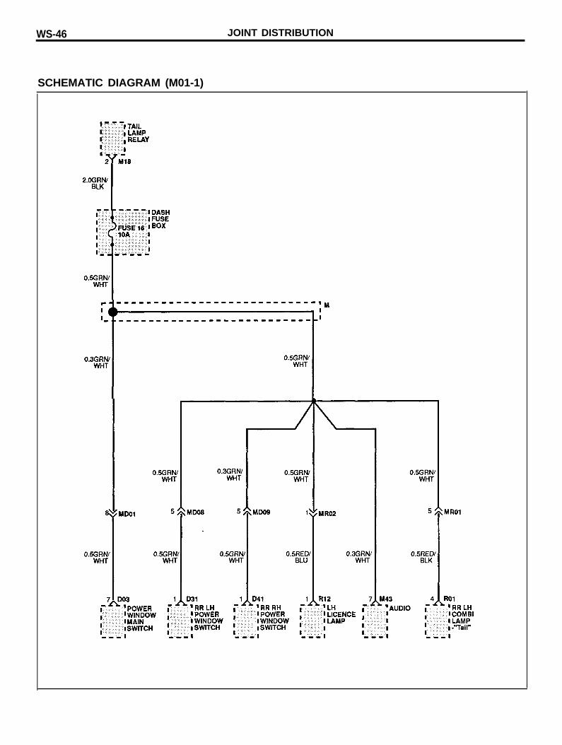
SCHEMATIC DIAGRAM (M01-1)
JOINT DISTRIBUTION WS-47
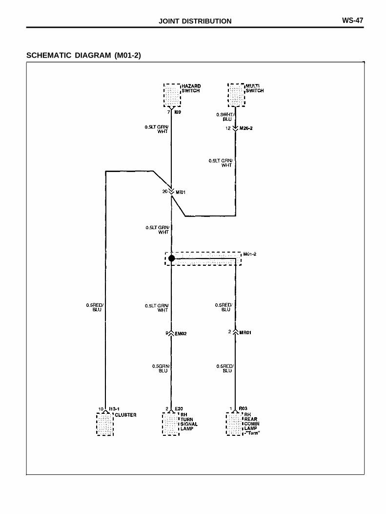
SCHEMATIC DIAGRAM (M01-2)
WS-48 JOINT DISTRIBUTION
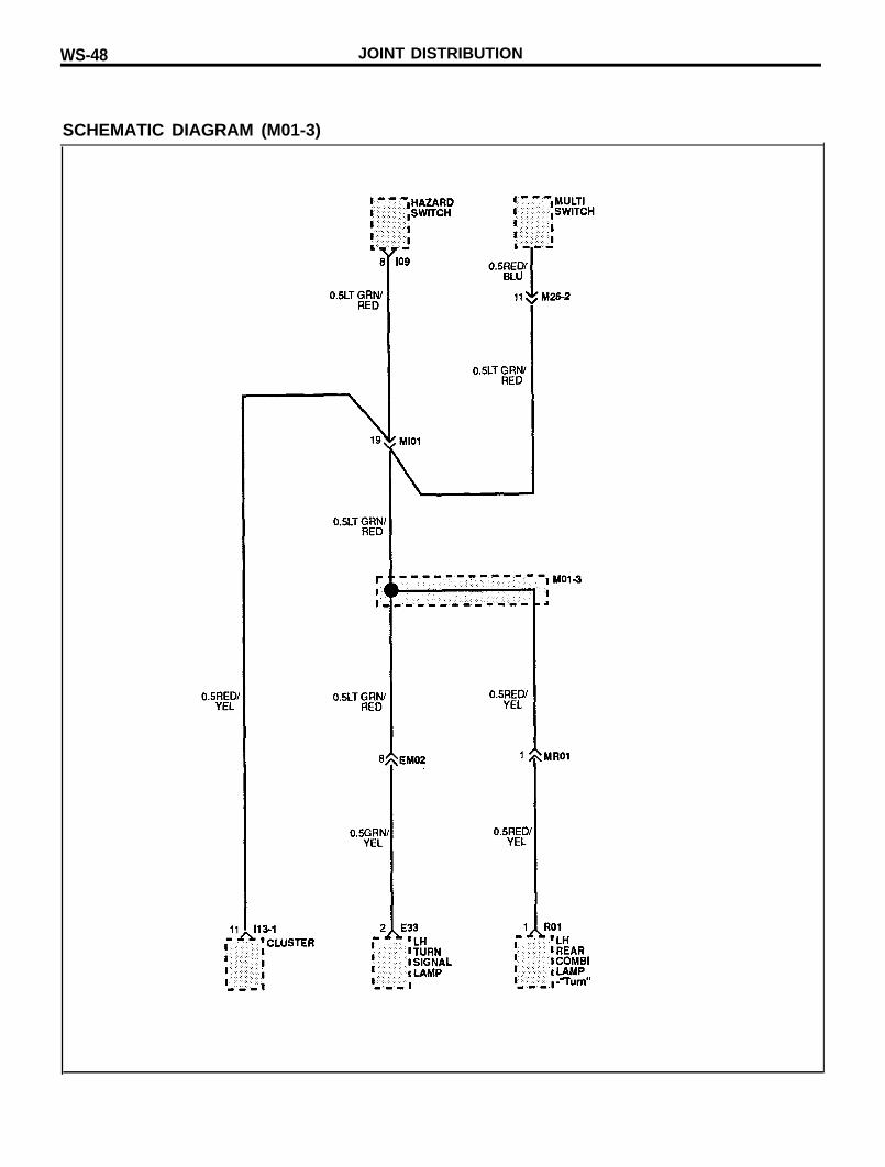
SCHEMATIC DIAGRAM (M01-3)
JOINT DISTRIBUTION
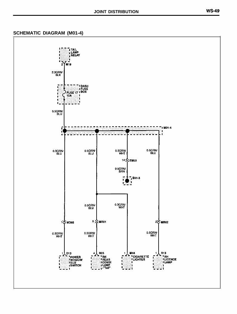
SCHEMATIC DIAGRAM (M01-4)
WS-50 JOINT DISTRIBUTION
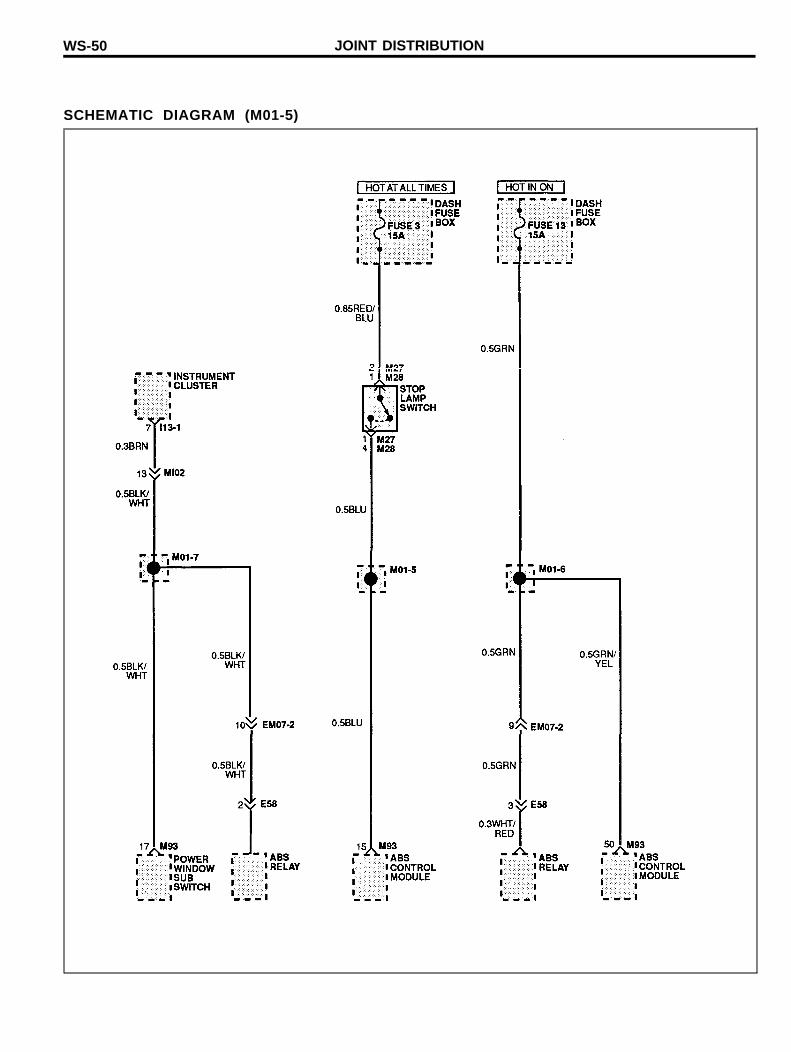
SCHEMATIC DIAGRAM (M01-5)

JOINT DISTRIBUTION
MEMO
WS-52
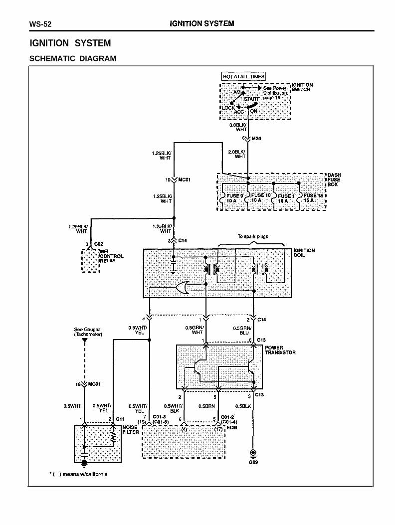
IGNITION SYSTEM
SCHEMATIC DIAGRAM
IGNITION SYSTEM WS-53
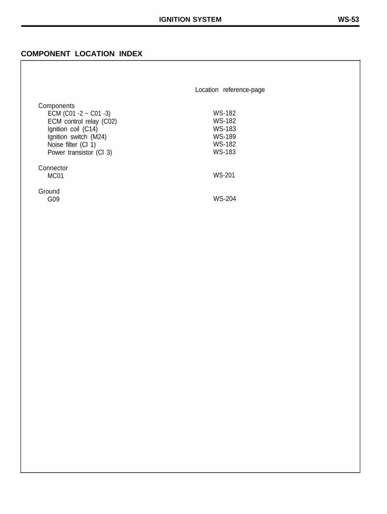
COMPONENT LOCATION INDEX
ComponentsECM (C01 -2 ~ C01 -3)ECM control relay (C02)Ignition coil (C14)Ignition switch (M24)Noise filter (Cl 1)Power transistor (Cl 3)
ConnectorMC01
GroundG09
Location reference-page
WS-182WS-182WS-183WS-189WS-182WS-183
WS-201
WS-204
WS-54 STARTING SYSTEM
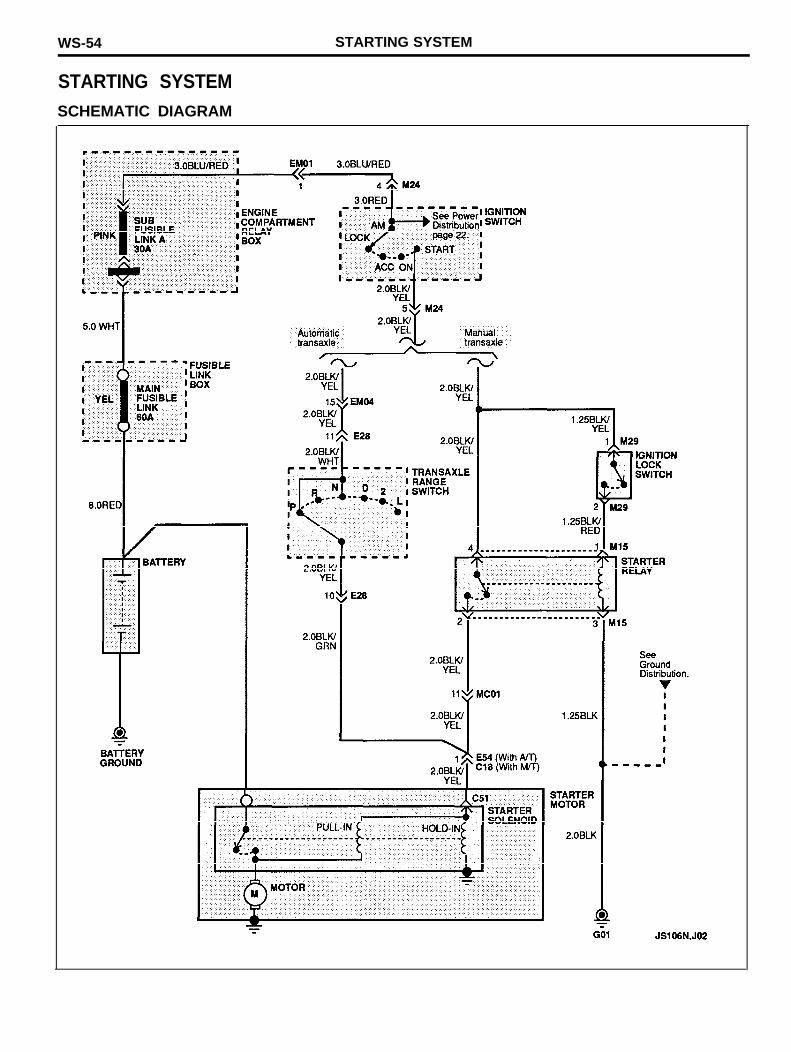
STARTING SYSTEMSCHEMATIC DIAGRAM
STARTING SYSTEM WS-55
COMPONENT LOCATION INDEX
ComponentsIgnition lock switch (M29)Starter motor (C18)Starter relay (M15)Transaxle range switch (E28)
ConnectorsEM04/EM05MC01
GroundG01
Location reference-page
WS-195WS-183WS-194WS-189
WS-191WS-201
WS-203
WS-56 CHARGING SYSTEM
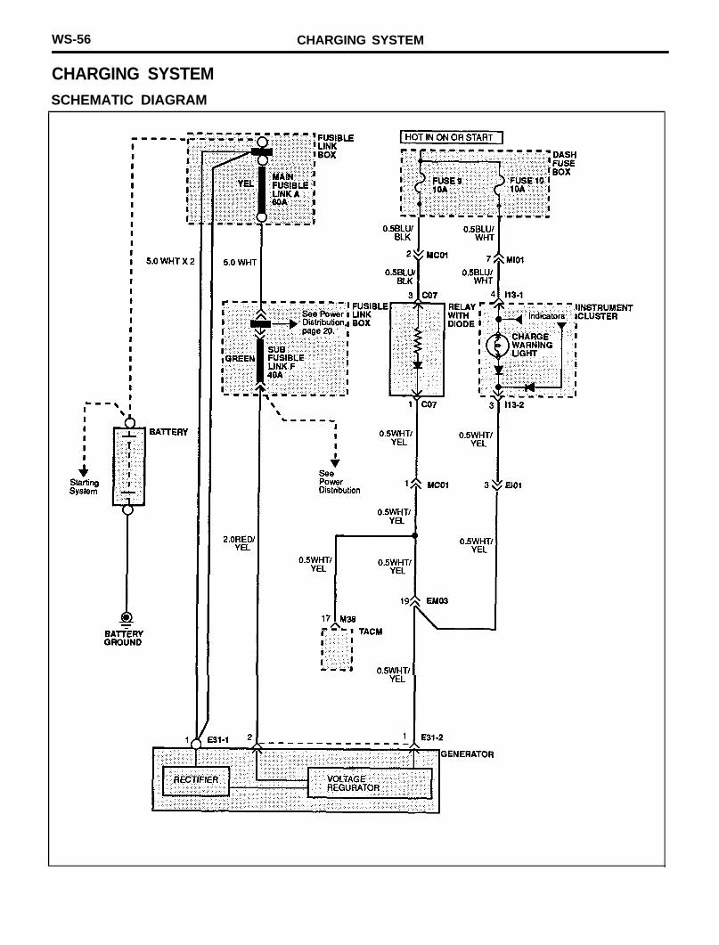
CHARGING SYSTEMSCHEMATIC DIAGRAM
CHARGING SYSTEM WS-57
COMPONENT LOCATION INDEX
ComponentsGenerator (E31-1 ~ E31-2)Instrument cluster (I13-1)Relay with diode (C07)
ConnectorsEl01EM03MC01
Location reference-page
WS-189WS-193WS-182
WS-192WS-191WS-201
WS-58 COOLING SYSTEM
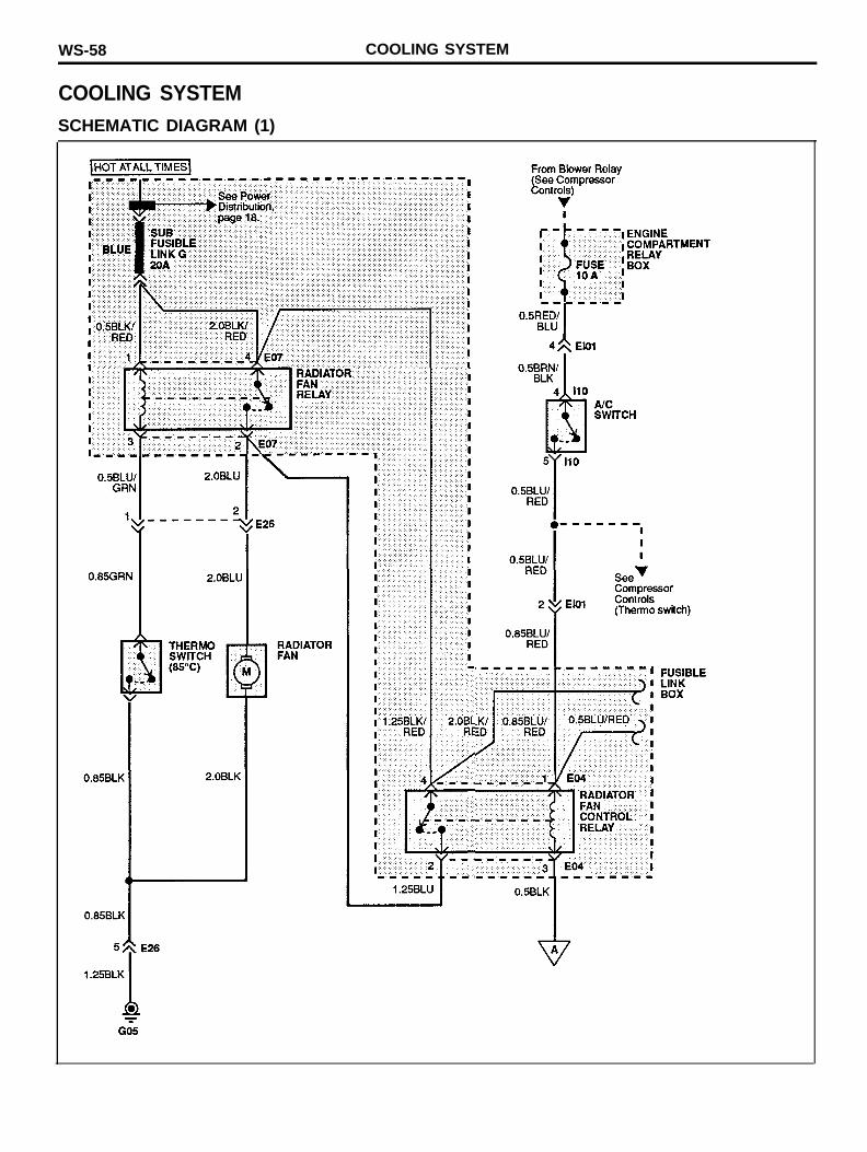
COOLING SYSTEMSCHEMATIC DIAGRAM (1)
COOLING SYSTEM WS-59
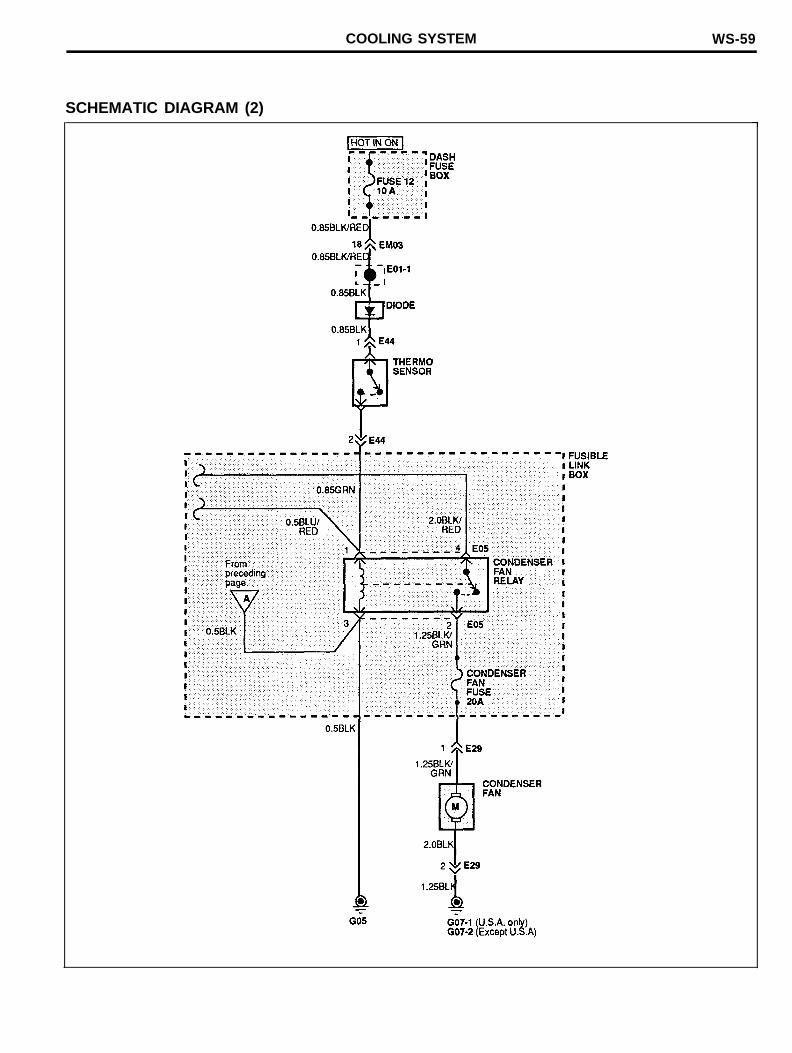
SCHEMATIC DIAGRAM (2)
WS-60 COOLING SYSTEM
COMPONENT LOCATION INDEX
ComponentsAC switch (110)Condenser fan (E29)Condenser fan control relay (E04)Condenser fan relay (E05)Radiator fan (E26)Radiator fan relay (E07)Thermo switch (E26-2)Thermo sensor (E44)
ConnectorsEl01EM03Ml01
GroundG05G07
Location reference-page
WS-193WS-189WS-188WS-188WS-189WS-188WS-189WS-190
WS-192WS-191WS-201
WS-203WS-203

COOLING SYSTEM WS-61
MEMO
WS-62 DOHC SYSTEM (For California)
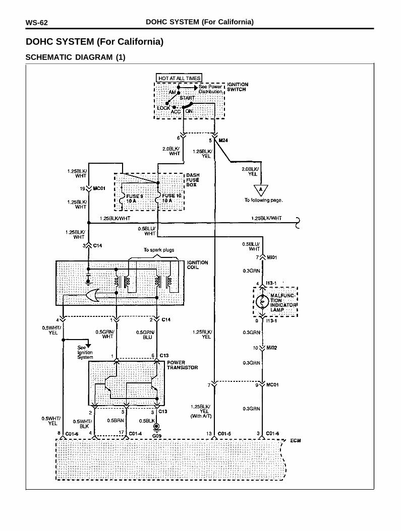
DOHC SYSTEM (For California)
SCHEMATIC DIAGRAM (1)
DOHC SYSTEM (For California) WS-63
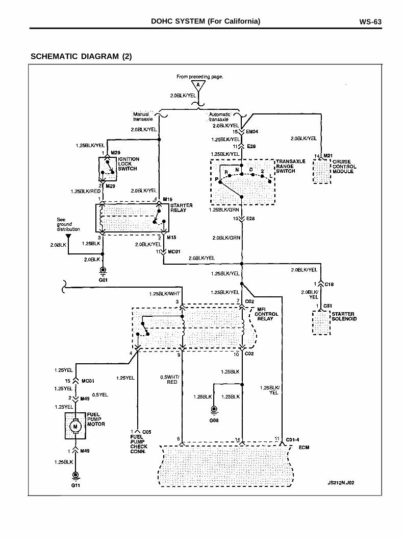
SCHEMATIC DIAGRAM (2)
WS-64 DOHC SYSTEM (For California)
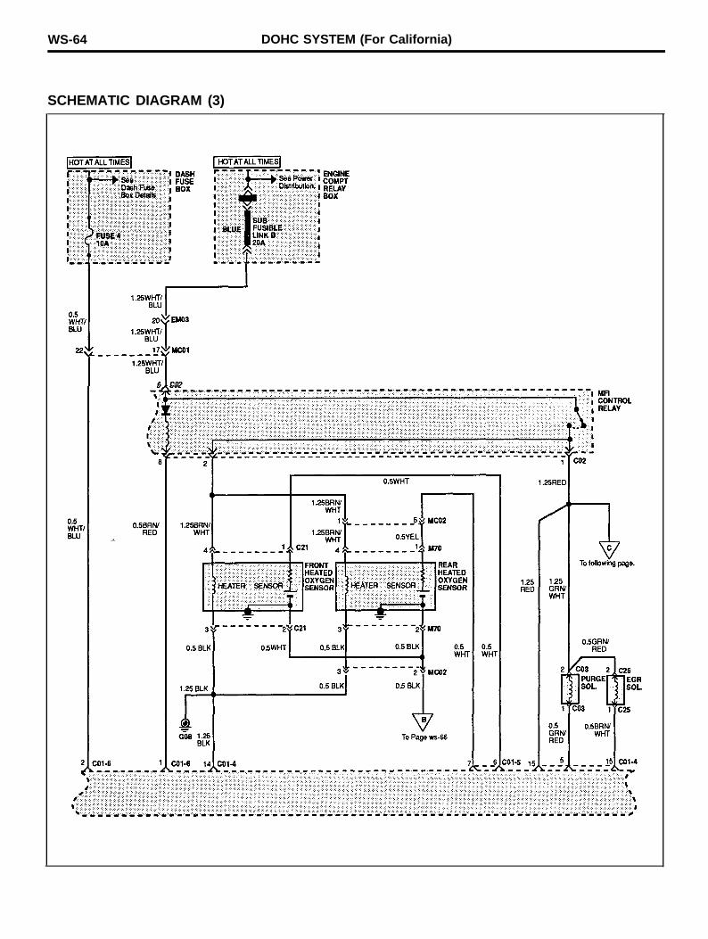
SCHEMATIC DIAGRAM (3)
DOHC SYSTEM (For California) WS-65
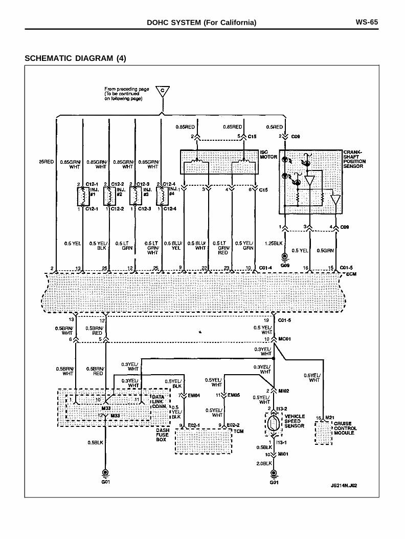
SCHEMATIC DIAGRAM (4)
DOHC SYSTEM (For California)
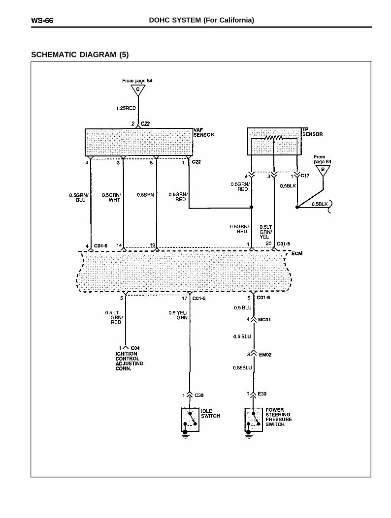
SCHEMATIC DIAGRAM (5)
DOHC SYSTEM (For California) WS-67
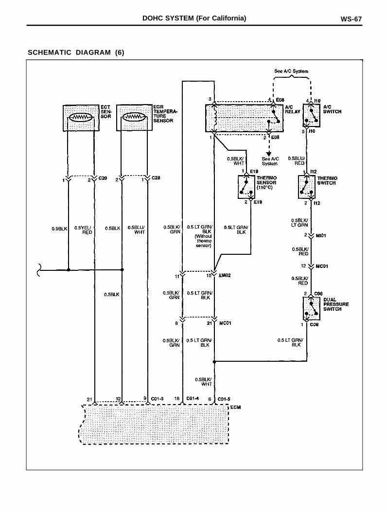
SCHEMATIC DIAGRAM (6)
WS-68 DOHC SYSTEM (For California)
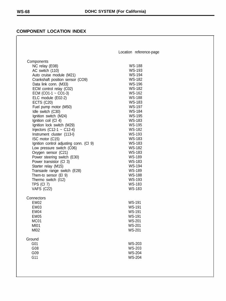
COMPONENT LOCATION INDEX
Location reference-page
ComponentsNC relay (E08)AC switch (110)Auto cruise module (M21)Crankshaft position sensor (CO9)Data link conn. (M33)ECM control relay (C02)ECM (CO1-1 ~ CO1-3)ELC module (E02-2)ECTS (C20)Fuel pump motor (M50)Idle switch (C30)Ignition switch (M24)Ignition coil (Cl 4)Ignition lock switch (M29)Injectors (C12-1 ~ C12-4)Instrument cluster (113-l)ISC motor (C15)Ignition control adjusting conn. (Cl 9)Low pressure switch (C06)Oxygen sensor (C21)Power steering switch (E30)Power transistor (Cl 3)Starter relay (M15)Transaxle range switch (E28)Them-to sensor (El 9)Thermo switch (I12)TPS (Cl 7)VAFS (C22)
WS-188WS-193WS-194WS-182WS-196WS-182WS-162WS-188WS-183WS-197WS-184WS-195WS-183WS-195WS-182WS-193WS-183WS-183WS-182WS-183WS-189WS-183WS-194WS-189WS-188WS-193WS-183WS-183
ConnectorsEM02EM03EM04EM05MC01Ml01Ml02
GroundG01G08G09G11
WS-191WS-191WS-191WS-191WS-201WS-201WS-201
WS-203WS-203WS-204WS-204

DOHC SYSTEM (For California) WS-69
MEMO
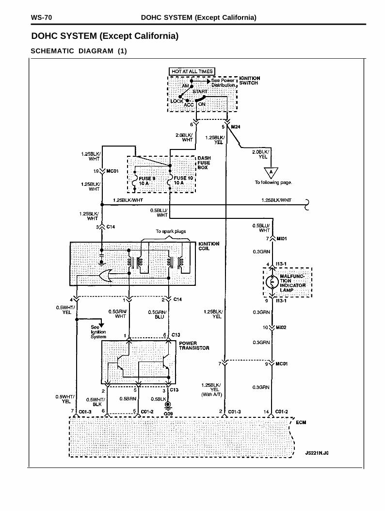
WS-70 DOHC SYSTEM (Except California)
DOHC SYSTEM (Except California)
SCHEMATIC DIAGRAM (1)
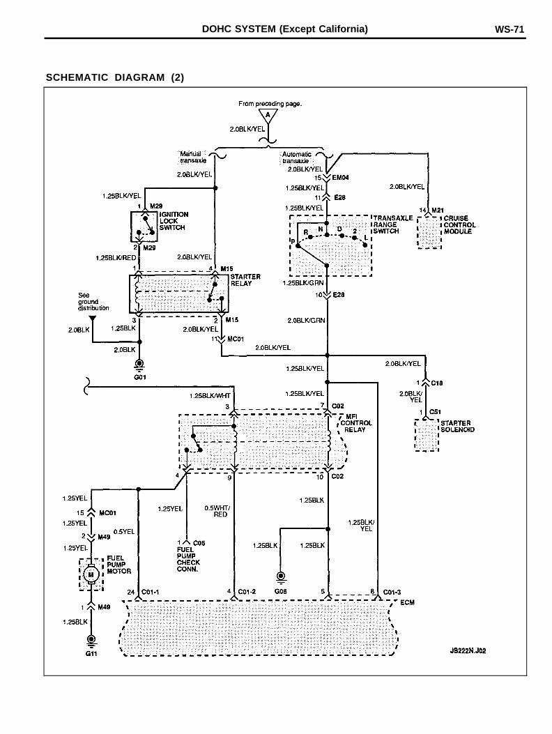
DOHC SYSTEM (Except California) WS-71
SCHEMATIC DIAGRAM (2)
WS-72 DOHC SYSTEM (Except California)
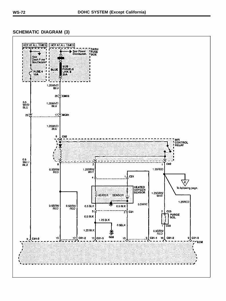
SCHEMATIC DIAGRAM (3)
DOHC SYSTEM (Except California) WS-73
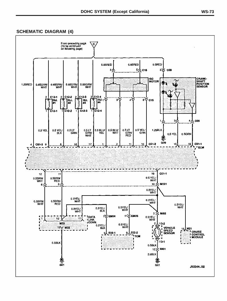
SCHEMATIC DIAGRAM (4)
WS-74 DOHC SYSTEM (Except California)
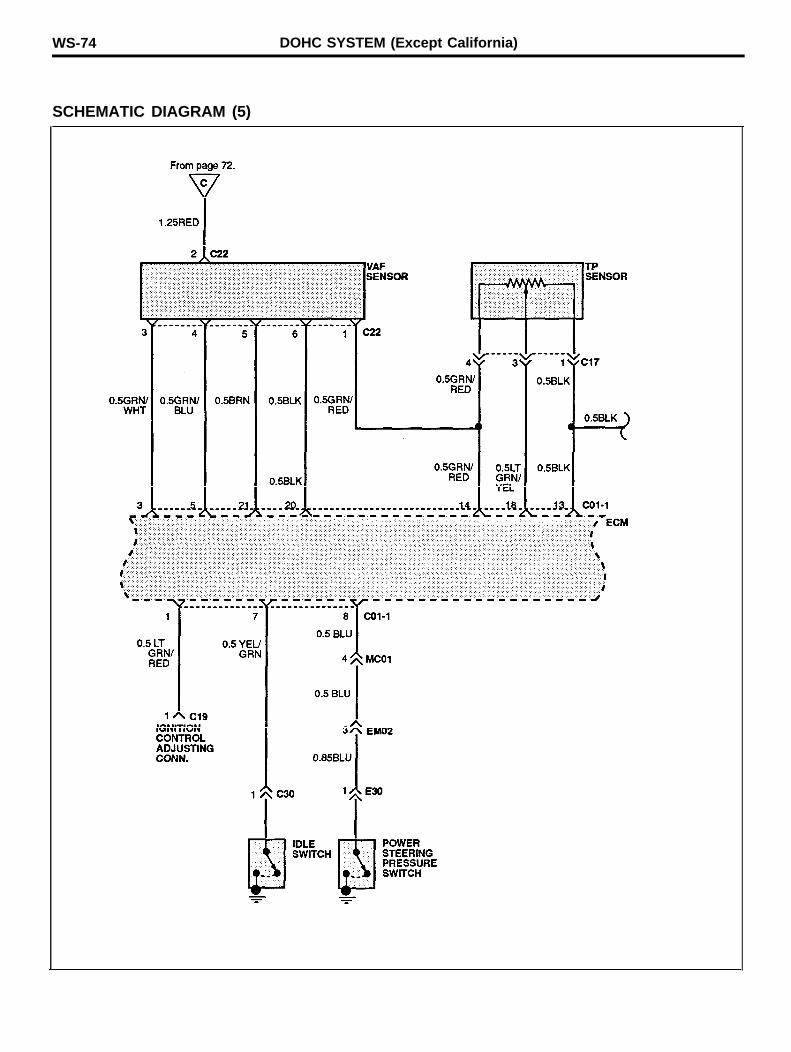
SCHEMATIC DIAGRAM (5)
DOHC SYSTEM (Except California) WS-75
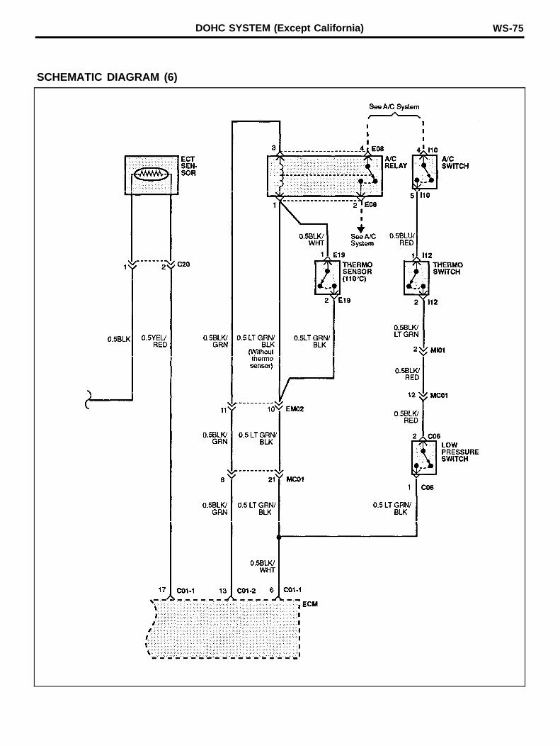
SCHEMATIC DIAGRAM (6)
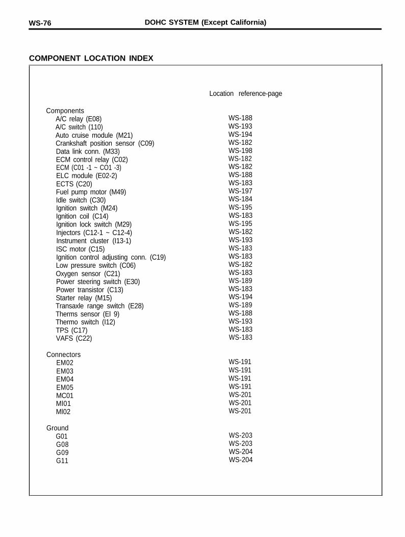
WS-76 DOHC SYSTEM (Except California)
COMPONENT LOCATION INDEX
Location reference-page
ComponentsA/C relay (E08)A/C switch (110)Auto cruise module (M21)Crankshaft position sensor (C09)Data link conn. (M33)ECM control relay (C02)ECM (C01 -1 ~ CO1 -3)ELC module (E02-2)ECTS (C20)Fuel pump motor (M49)Idle switch (C30)Ignition switch (M24)Ignition coil (C14)Ignition lock switch (M29)Injectors (C12-1 ~ C12-4)Instrument cluster (I13-1)ISC motor (C15)Ignition control adjusting conn. (C19)Low pressure switch (C06)Oxygen sensor (C21)Power steering switch (E30)Power transistor (C13)Starter relay (M15)Transaxle range switch (E28)Therms sensor (El 9)Thermo switch (I12)TPS (C17)VAFS (C22)
WS-188WS-193WS-194WS-182WS-198WS-182WS-182WS-188WS-183WS-197WS-184WS-195WS-183WS-195WS-182WS-193WS-183WS-183WS-182WS-183WS-189WS-183WS-194WS-189WS-188WS-193WS-183WS-183
ConnectorsEM02EM03EM04EM05MC01Ml01Ml02
GroundG01G08G09G11
WS-191WS-191WS-191WS-191WS-201WS-201WS-201
WS-203WS-203WS-204WS-204

DOHC SYSTEM (Except California) WS-77
MEMO
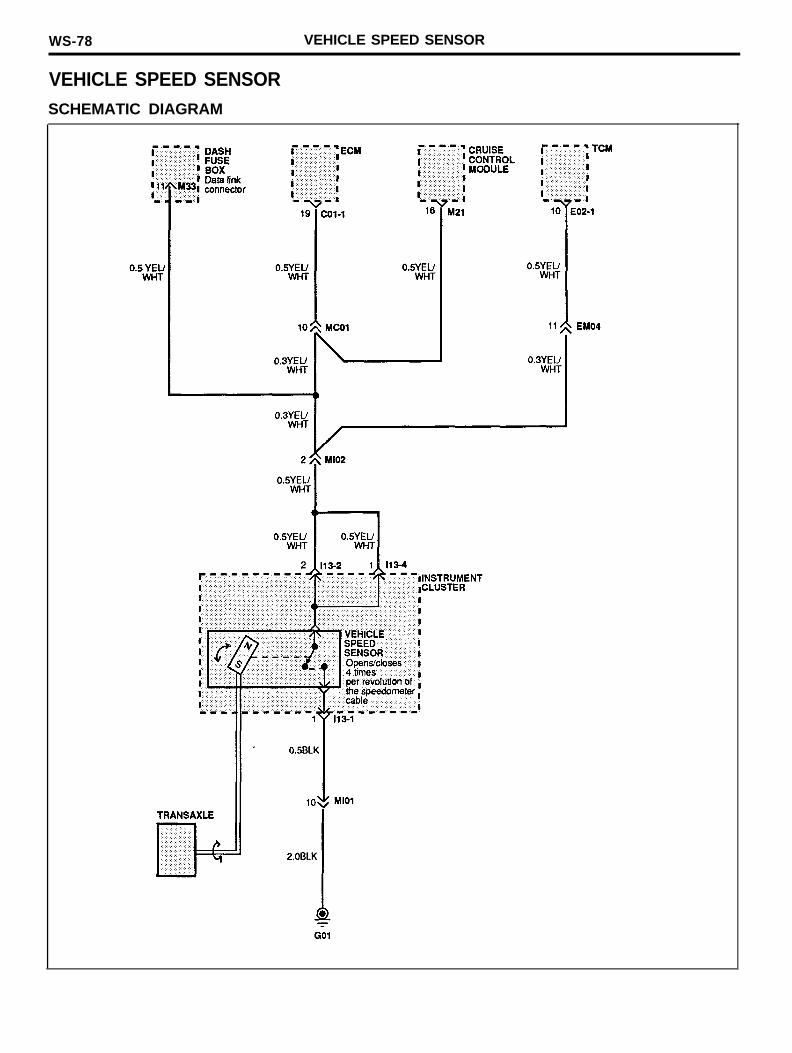
WS-78 VEHICLE SPEED SENSOR
VEHICLE SPEED SENSORSCHEMATIC DIAGRAM
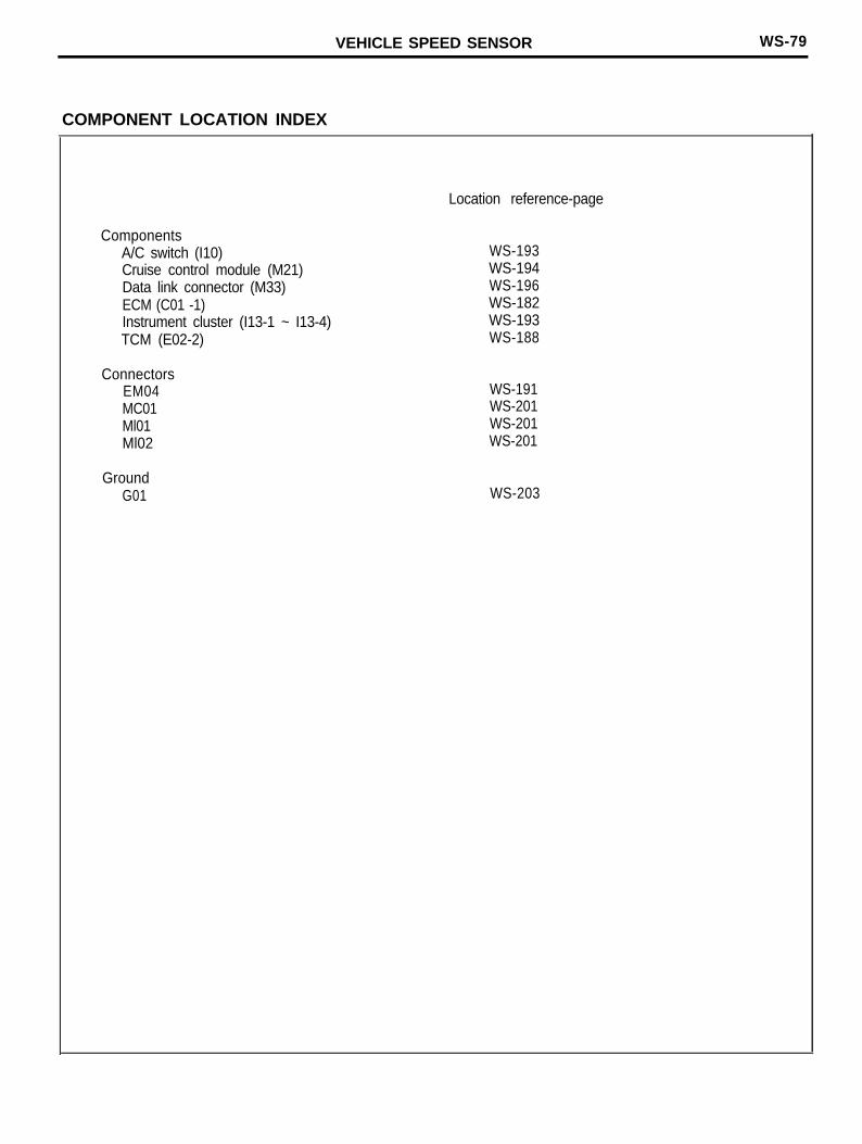
VEHICLE SPEED SENSOR WS-79
COMPONENT LOCATION INDEX
ComponentsA/C switch (I10)Cruise control module (M21)Data link connector (M33)ECM (C01 -1)Instrument cluster (I13-1 ~ I13-4)TCM (E02-2)
ConnectorsEM04MC01Ml01Ml02
GroundG01
Location reference-page
WS-193WS-194WS-196WS-182WS-193WS-188
WS-191WS-201WS-201WS-201
WS-203
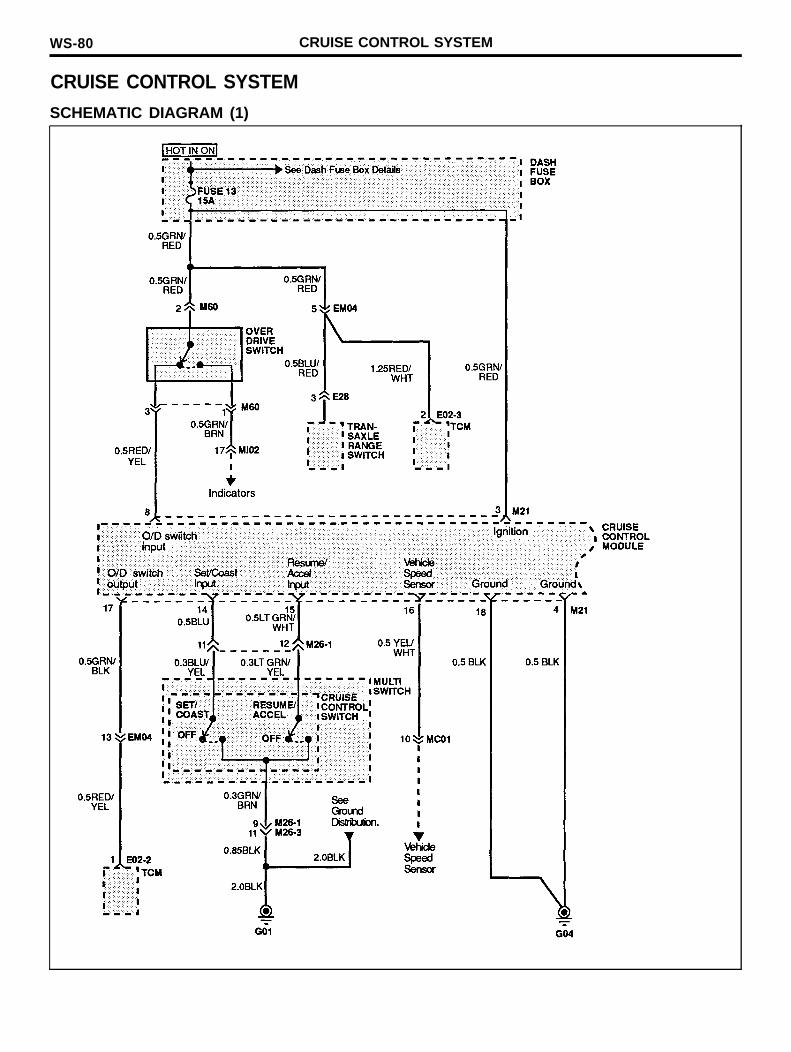
WS-80 CRUISE CONTROL SYSTEM
CRUISE CONTROL SYSTEM
SCHEMATIC DIAGRAM (1)
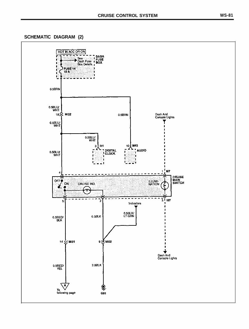
CRUISE CONTROL SYSTEM WS-81
SCHEMATlC DIAGRAM (2)
WS-82 CRUISE CONTROL SYSTEM
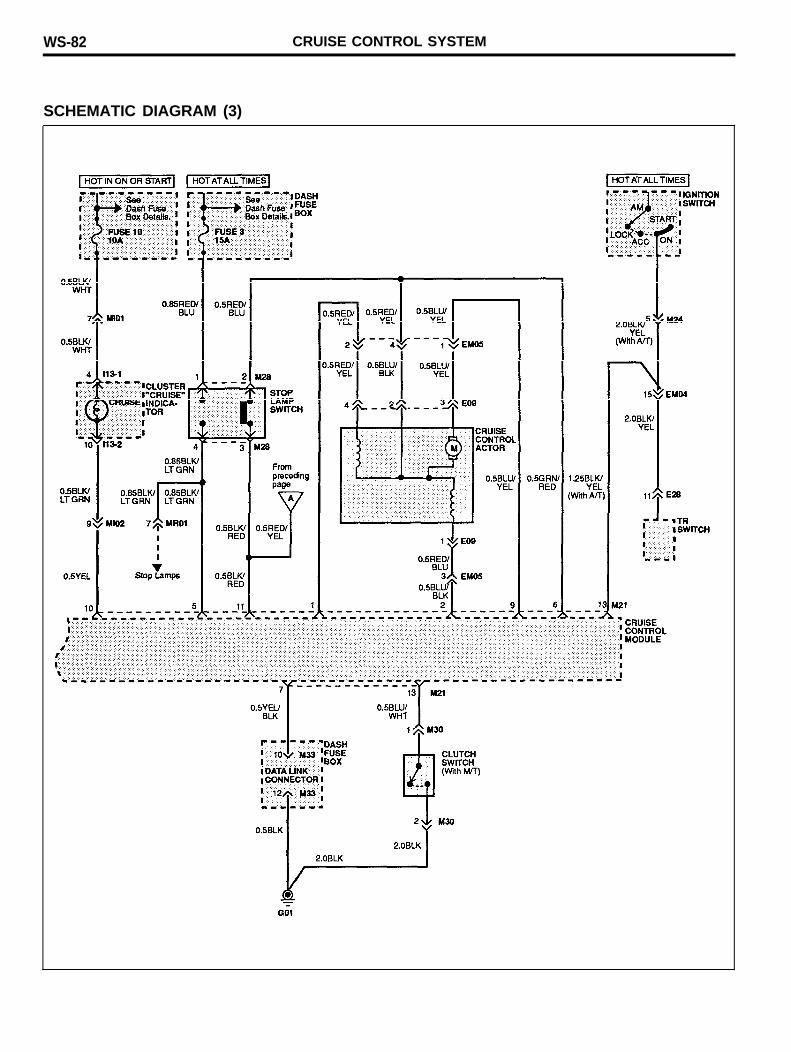
SCHEMATIC DIAGRAM (3)
CRUISE CONTROL SYSTEM WS-83
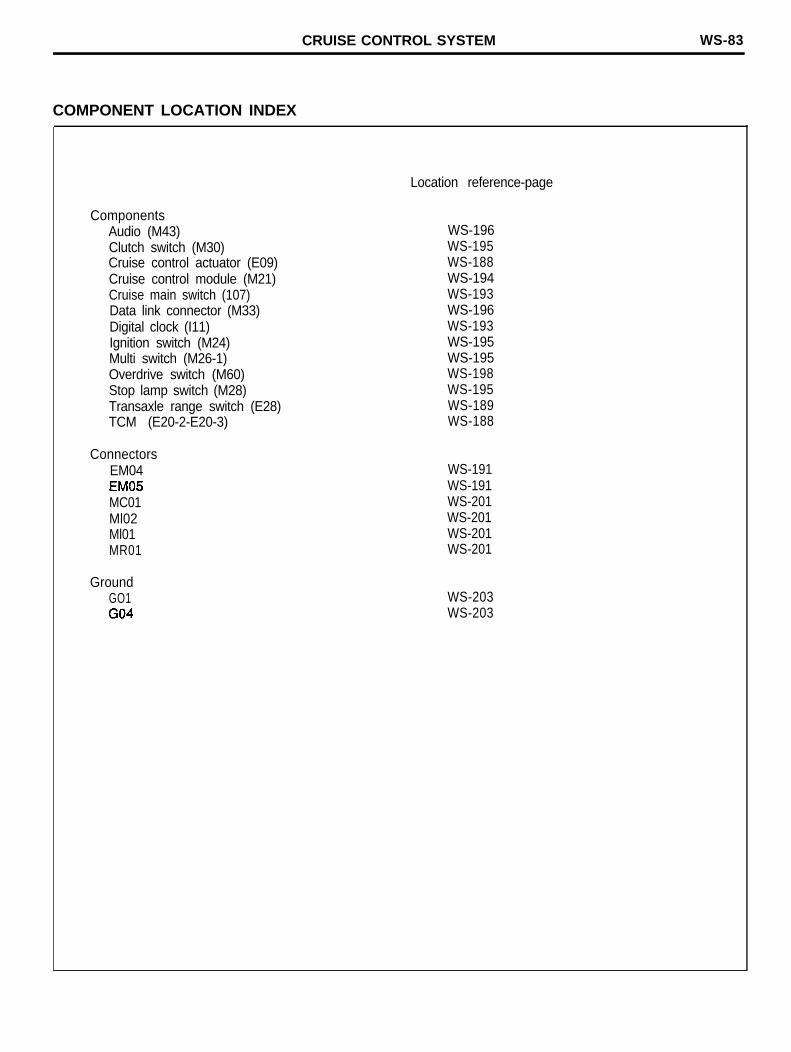
COMPONENT LOCATION INDEX
ComponentsAudio (M43)Clutch switch (M30)Cruise control actuator (E09)Cruise control module (M21)Cruise main switch (107)Data link connector (M33)Digital clock (I11)Ignition switch (M24)Multi switch (M26-1)Overdrive switch (M60)Stop lamp switch (M28)Transaxle range switch (E28)TCM (E20-2-E20-3)
ConnectorsEM04EM05(A/T)MC01Ml02Ml01MR01
GroundGO1G04
Location reference-page
WS-196WS-195WS-188WS-194WS-193WS-196WS-193WS-195WS-195WS-198WS-195WS-189WS-188
WS-191WS-191WS-201WS-201WS-201WS-201
WS-203WS-203
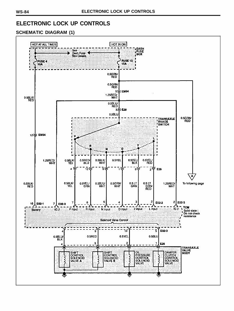
WS-84 ELECTRONIC LOCK UP CONTROLS
ELECTRONIC LOCK UP CONTROLSSCHEMATIC DIAGRAM (1)
ELECTRONIC LOCK UP CONTROLS WS-85
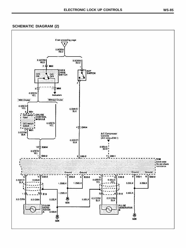
SCHEMATIC DIAGRAM (2)
WS-86 ELECTRONIC LOCK UP CONTROLS
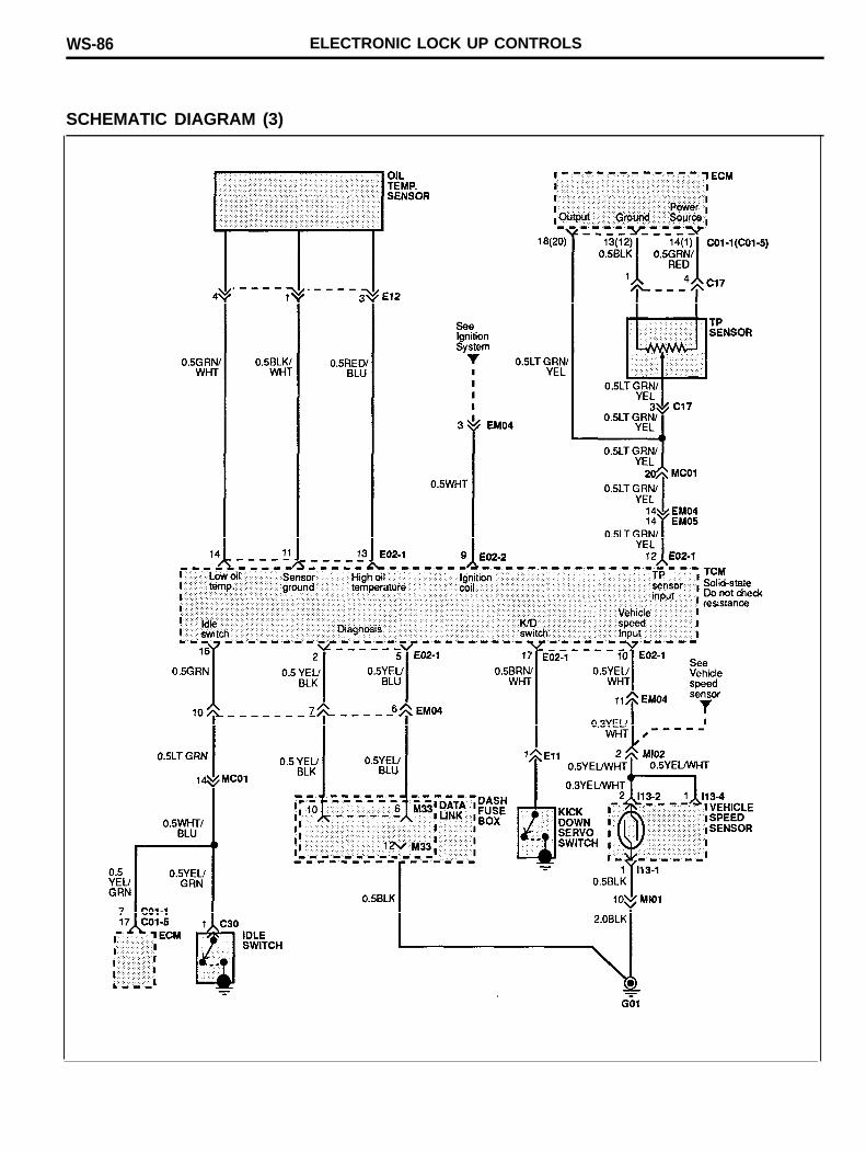
SCHEMATIC DIAGRAM (3)
ELECTRONIC LOCK UP CONTROLS WS-87
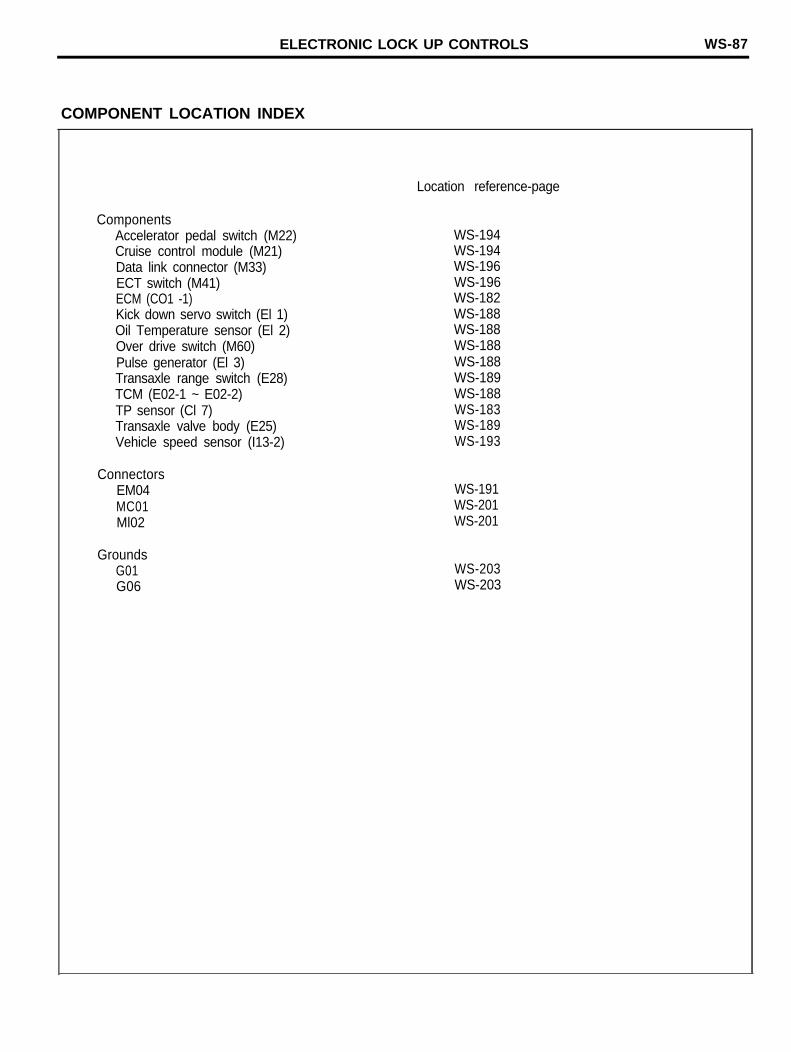
COMPONENT LOCATION INDEX
ComponentsAccelerator pedal switch (M22)Cruise control module (M21)Data link connector (M33)ECT switch (M41)ECM (CO1 -1)Kick down servo switch (El 1)Oil Temperature sensor (El 2)Over drive switch (M60)Pulse generator (El 3)Transaxle range switch (E28)TCM (E02-1 ~ E02-2)TP sensor (Cl 7)Transaxle valve body (E25)Vehicle speed sensor (I13-2)
ConnectorsEM04MC01Ml02
GroundsG01G06
Location reference-page
WS-194WS-194WS-196WS-196WS-182WS-188WS-188WS-188WS-188WS-189WS-188WS-183WS-189WS-193
WS-191WS-201WS-201
WS-203WS-203
WS-88 HORNS
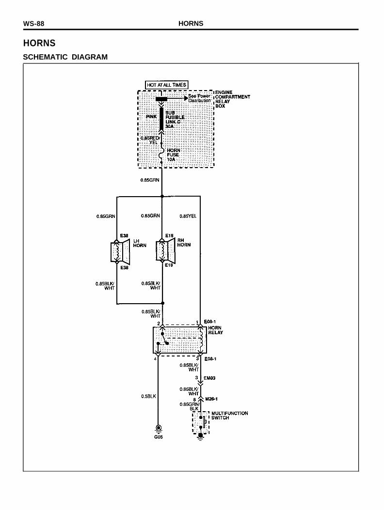
HORNSSCHEMATIC DIAGRAM
HORNS WS-89
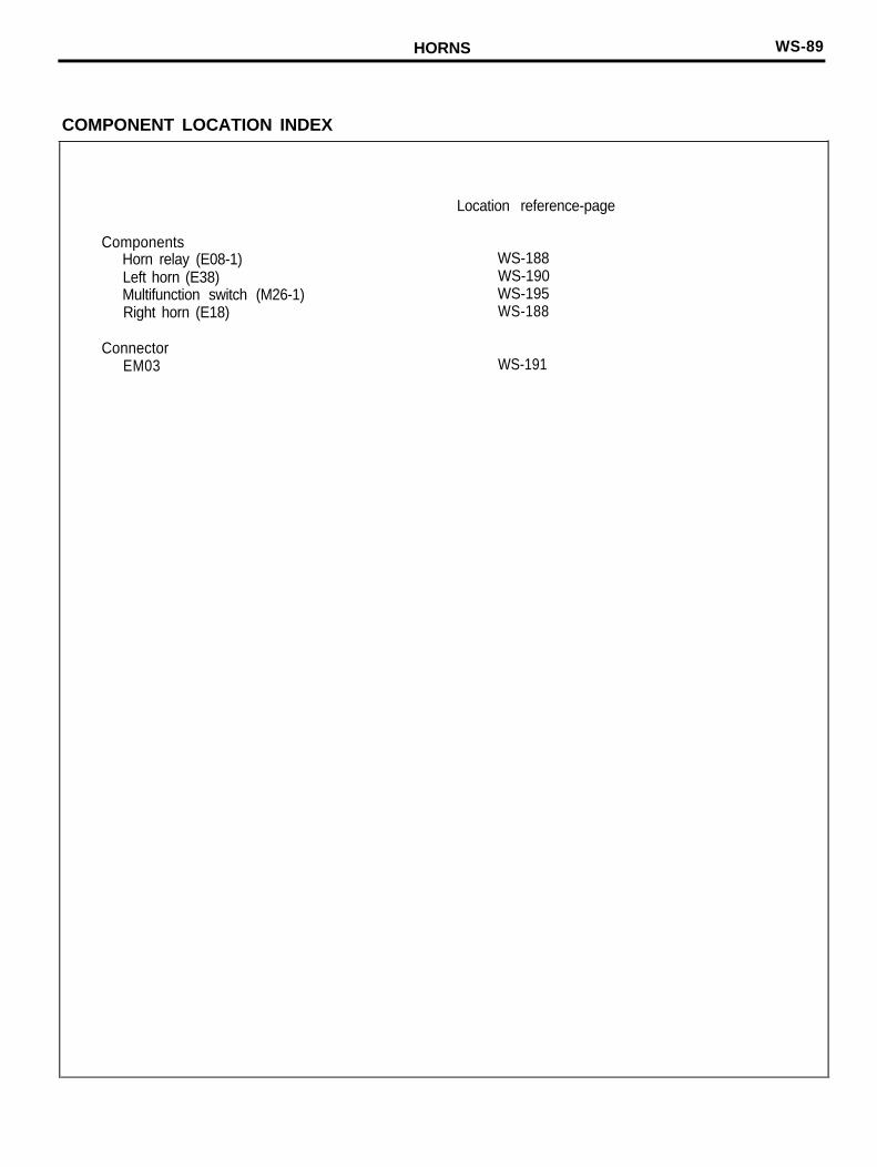
COMPONENT LOCATION INDEX
Location reference-page
ComponentsHorn relay (E08-1)Left horn (E38)Multifunction switch (M26-1)Right horn (E18)
WS-188WS-190WS-195WS-188
ConnectorEM03 WS-191

WS-90 ClGARETTE LIGHTER
CIGARETTE LIGHTERSCHEMATIC DIAGRAM
CIGARETTE LIGHTER WS-91
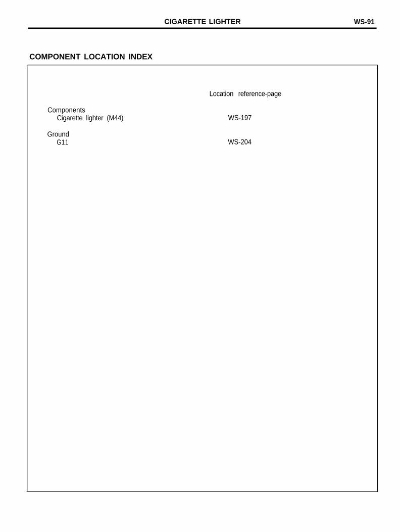
COMPONENT LOCATION INDEX
ComponentsCigarette lighter (M44)
GroundG11
Location reference-page
WS-197
WS-204
WS-92 INDICATORS
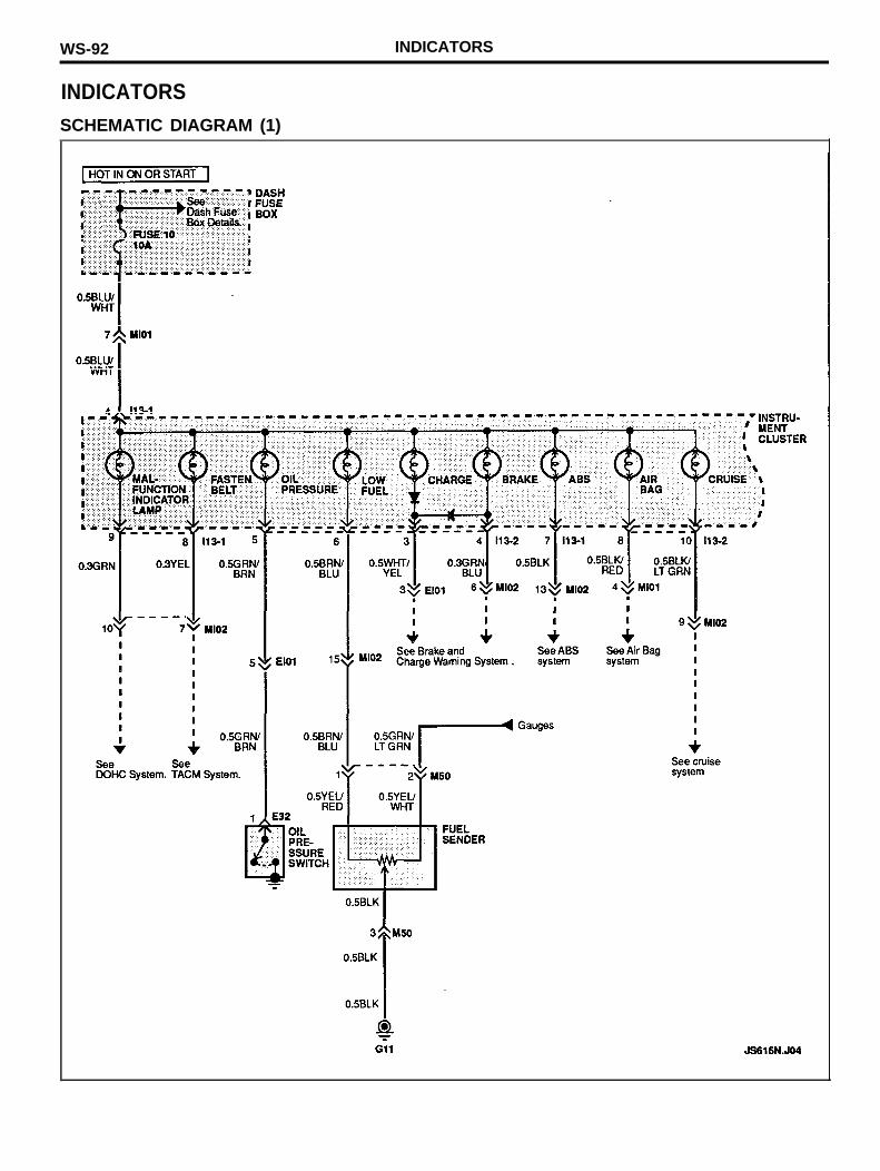
INDICATORSSCHEMATIC DIAGRAM (1)
INDICATORS WS-93
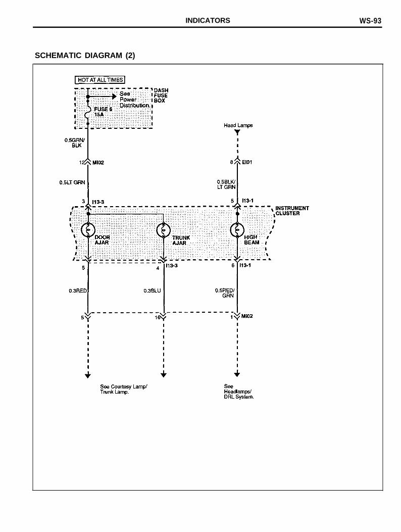
SCHEMATIC DIAGRAM (2)
WS-94 INDICATORS
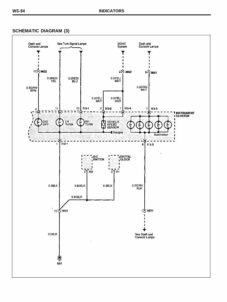
SCHEMATIC DIAGRAM (3)
INDICATORS WS-95
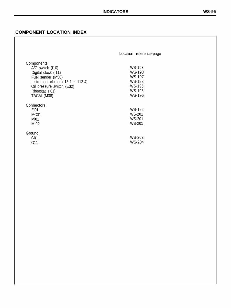
COMPONENT LOCATION INDEX
ComponentsA/C switch (I10)Digital clock (I11)Fuel sender (M50)Instrument cluster (I13-1 ~ 113-4)Oil pressure switch (E32)Rheostat (I01)TACM (M38)
ConnectorsEl01MC01Ml01Ml02
GroundG01G11
Location reference-page
WS-193WS-193WS-197WS-193WS-195WS-193WS-196
WS-192WS-201WS-201WS-201
WS-203WS-204
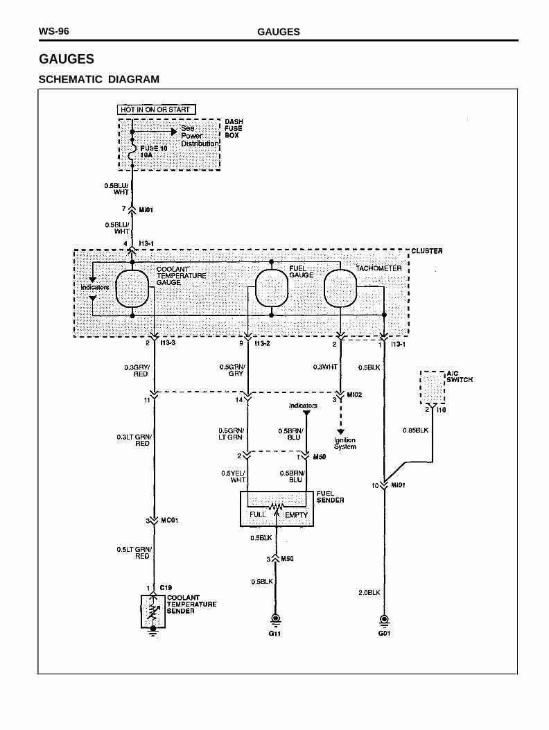
WS-96 GAUGES
GAUGESSCHEMATIC DIAGRAM
GAUGES WS-97
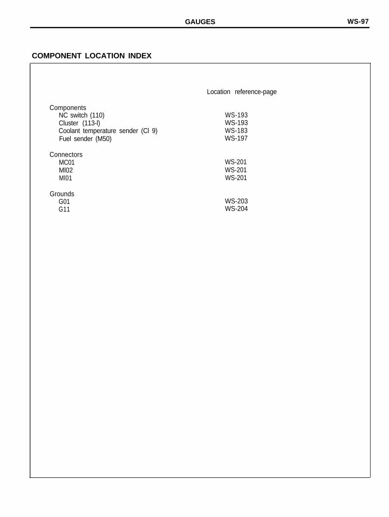
COMPONENT LOCATION INDEX
ComponentsNC switch (110)Cluster (113-l)Coolant temperature sender (Cl 9)Fuel sender (M50)
ConnectorsMC01Ml02Ml01
GroundsG01G11
Location reference-page
WS-193WS-193WS-183WS-197
WS-201WS-201WS-201
WS-203WS-204
WS-98 BRAKE AND CHARGE WARNING SYSTEM
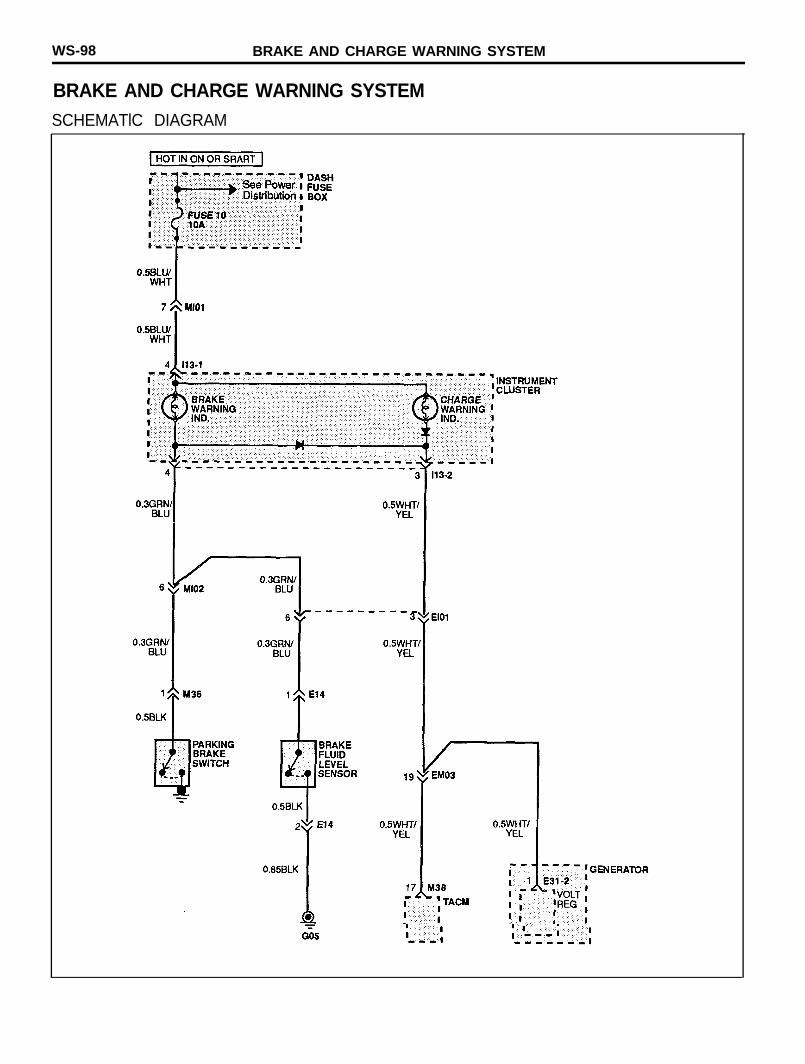
BRAKE AND CHARGE WARNING SYSTEMSCHEMATlC DIAGRAM
BRAKE AND CHARGE WARNING SYSTEM WS-99
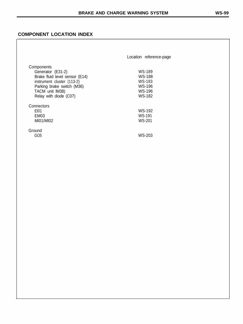
COMPONENT LOCATION INDEX
ComponentsGenerator (E31-2)Brake fluid level sensor (E14)instrument cluster (113-2)Parking brake switch (M36)TACM unit lM38)Relay with diode (C07)
ConnectorsEl01EM03Ml01/Ml02
GroundGO5
Location reference-page
WS-189WS-188WS-193WS-196WS-196WS-182
WS-192WS-191WS-201
WS-203
WS-100 HEAD LAMPS
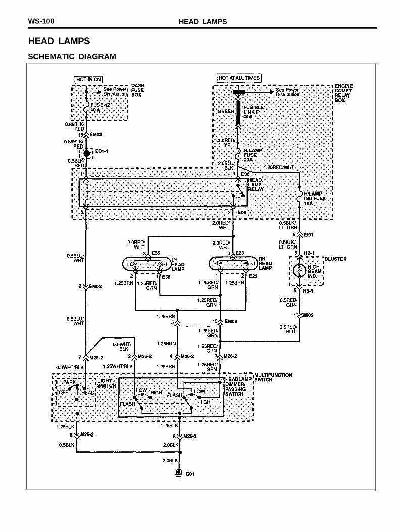
HEAD LAMPSSCHEMATIC DIAGRAM

HEAD LAMPS WS-101
COMPONENT LOCATION INDEX
Location reference-page
ComponentsCluster (I13-1)Head lamp relay (E06)LH head lamp (E36) .Multifunction switch (M26-2)RH head lamp (E23)
WS-193WS-188WS-190WS-195WS-188
ConnectorsEl01EM02EM03Ml02
GroundGO1
WS-192WS-191WS-191WS-201
WS-203
WS-102 DAYTIME RUNNING LIGHTS
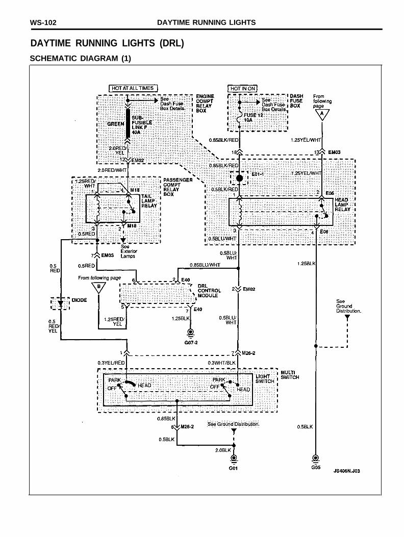
DAYTIME RUNNING LIGHTS (DRL)SCHEMATIC DIAGRAM (1)
DAYTIME RUNNING LIGHTS WS-103
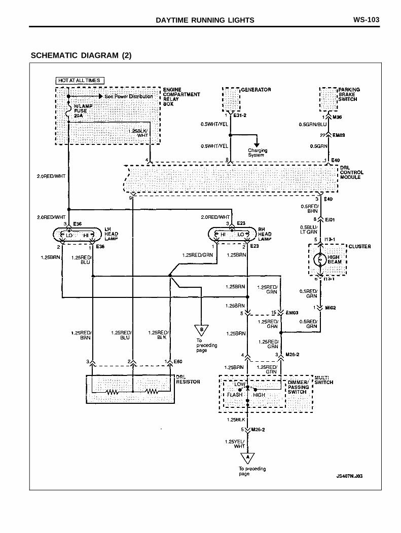
SCHEMATIC DIAGRAM (2)
WS-104 DAYTIME RUNNING LIGHTS
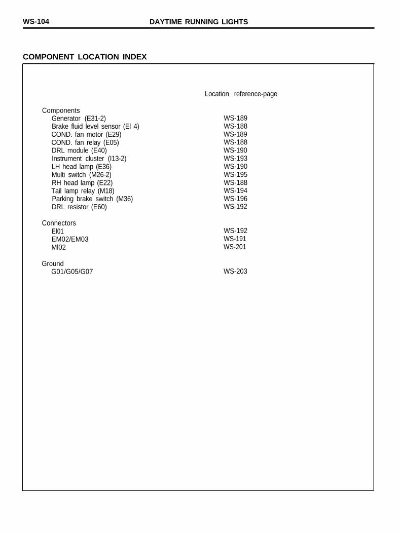
COMPONENT LOCATION INDEX
ComponentsGenerator (E31-2)Brake fluid level sensor (El 4)COND. fan motor (E29)COND. fan relay (E05)DRL module (E40)Instrument cluster (I13-2)LH head lamp (E36)Multi switch (M26-2)RH head lamp (E22)Tail lamp relay (M18)Parking brake switch (M36)DRL resistor (E60)
ConnectorsEl01EM02/EM03Ml02
GroundG01/G05/G07
Location reference-page
WS-189WS-188WS-189WS-188WS-190WS-193WS-190WS-195WS-188WS-194WS-196WS-192
WS-192WS-191WS-201
WS-203

DAYTIME RUNNING LIGHTS WS-105
MEMO
WS-106 EXTERIOR LAMPS
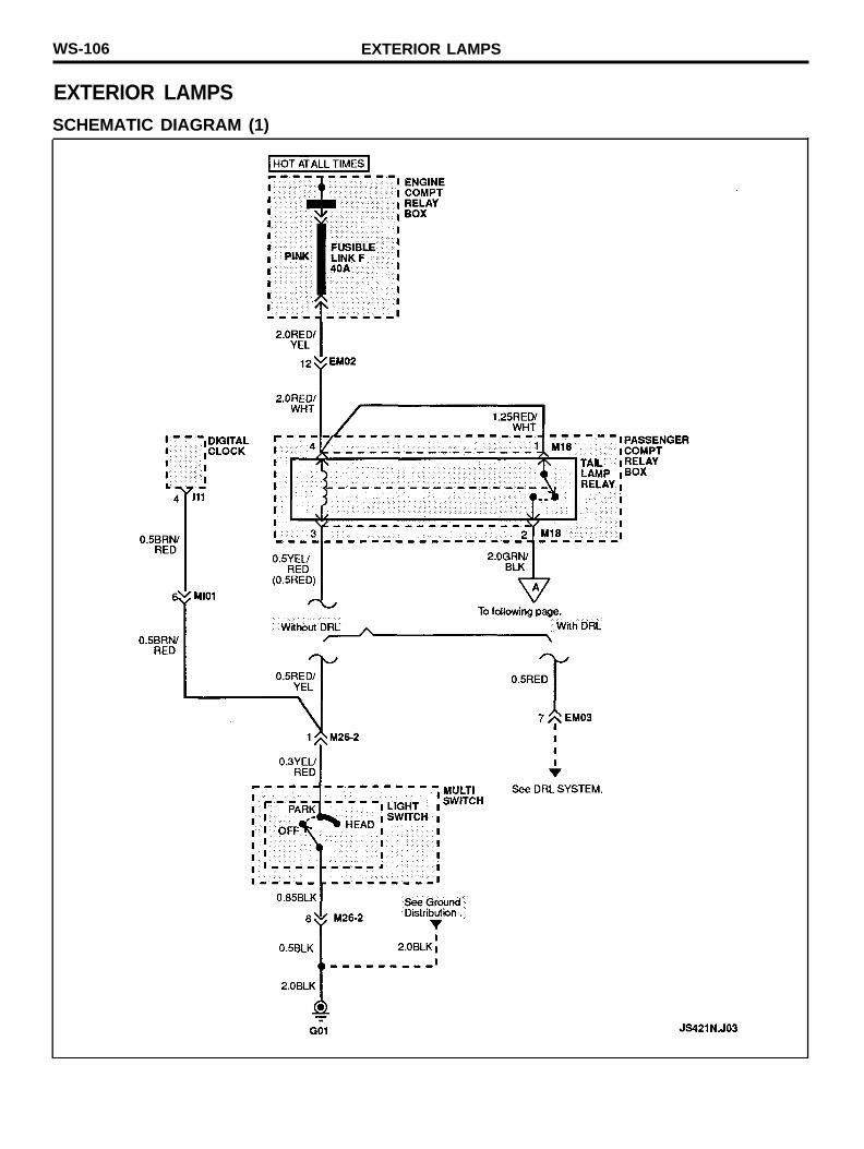
EXTERIOR LAMPSSCHEMATIC DIAGRAM (1)
EXTERIOR LAMPS WS-107
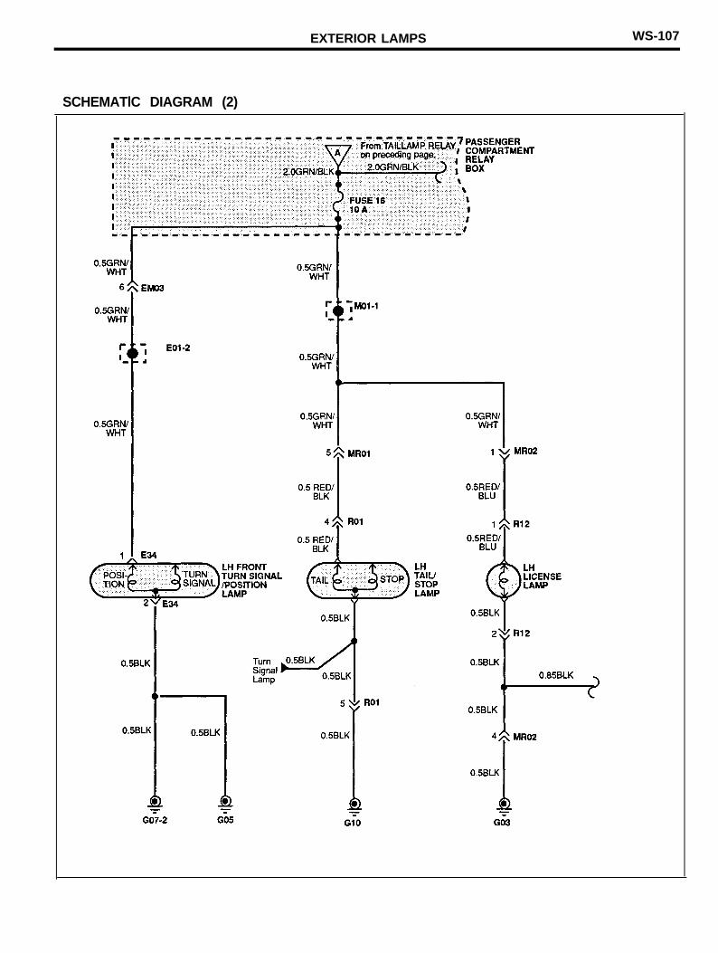
SCHEMATlC DIAGRAM (2)
WS-108 EXTERIOR LAMPS
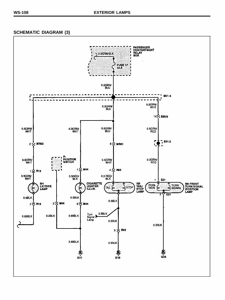
SCHEMATIC DIAGRAM (3)
EXTERIOR LAMPS WS-109
COMPONENT LOCATION INDEX
ComponentsTail lamp relay (M18)Multi switch (M26-2)Digital clock (I11)LH side marker lamp (E34)LH tail/top lamp (R01)LH license lamp (R12)Trunk lid opener (R15)RH license lamp (R13)Fuel pump (M49)Cigarette lighter illum. (M44)RH tail/stop lamp (R03)RH side marker lamp (E21)
ConnectorsEM02/EM03Ml01/MR01/MR02
GroundG01/G03G10/G11
Location reference-page
WS-194WS-195WS-193WS-190WS-202WS-202WS-202WS-202WS-197WS-197WS-202WS-188
WS-191WS-201
WS-203WS-204
WS-110 STOP LAMPS
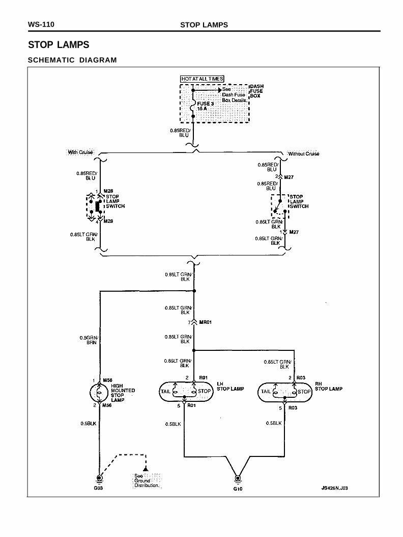
STOP LAMPSSCHEMATIC DIAGRAM
STOP LAMPS WS-111
COMPONENT LOCATION INDEX
Location reference-page
ComponentsHigh mounted stop lamp (M56)LH stop lamp (R01)RH stop lamp (R03)Stop lamp switch (M28)Stop lamp switch (M27)
WS-198WS-202WS-202WS-195WS-195
ConnectorMR01
GroundsGO3G10
WS-201
WS-203WS-204

WS-112 TURN/HAZARD LAMPS
TURN/HAZARD LAMPS
SCHEMATIC DIAGRAM (1)
TURN/HAZARD LAMPS WS-113
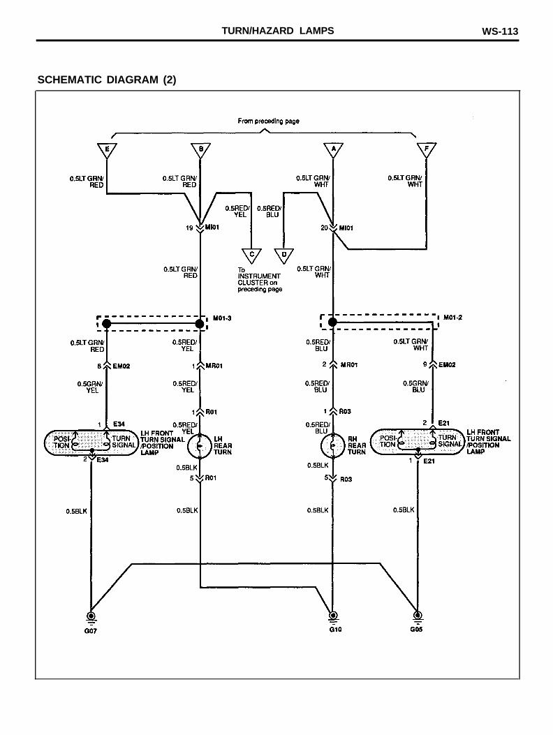
SCHEMATIC DIAGRAM (2)

WS-114 TURN/HAZARD LAMPS
COMPONENT LOCATION INDEX
ComponentsCluster (113-1, 113-2)Flasher unit (M16)Hazard switch (109)LH front turn (E33)LH rear turn (R01)Multi switch (M26-2)RH front turn (E20)RH rear turn (R03)
ConnectorsEM02Ml01MR01
GroundG01l/G05G10
Location reference-page
WS-193WS-194WS-193WS-190WS-202WS-195WS-188WS-202
WS-191WS-201WS-201
WS-203WS-204

TURN/HAZARD LAMPS WS-115
MEMO
WS-116 BACK UP LAMPS
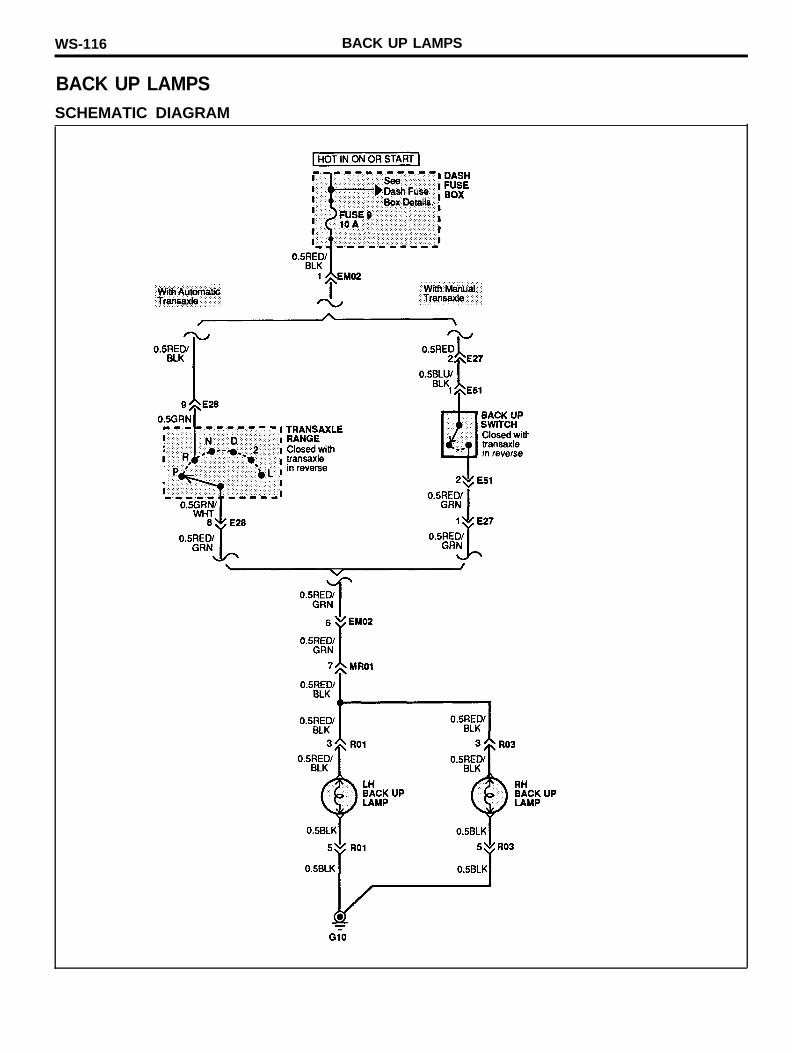
BACK UP LAMPSSCHEMATIC DIAGRAM

BACK UP LAMPS WS-117
COMPONENT LOCATION INDEX
Location reference-page
ComponentsTransaxle range switch (E28)LH back up lamp (R01)RH back up lamp (R03)
ConnectorsEM02MR01
GroundG10
WS-189WS-202WS-202
WS-191WS-201
WS-204
WS-118 COURTESY LAMPS
COURTESY LAMPS
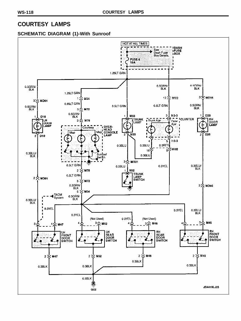
SCHEMATIC DIAGRAM (1)-With Sunroof
COURTESY LAMPS WS-119
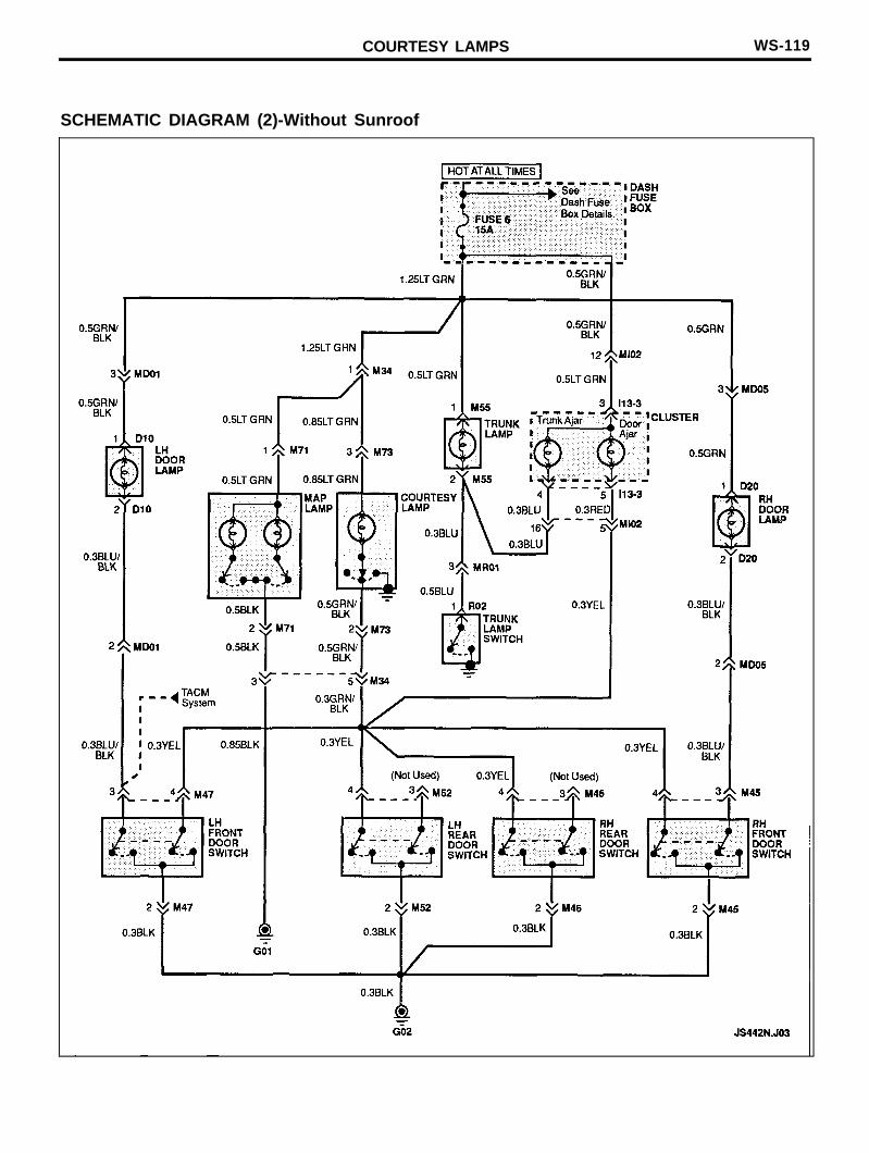
SCHEMATIC DIAGRAM (2)-Without Sunroof

WS-120 COURTESY LAMPS
COMPONENT LOCATION INDEX
ComponentsCluster (I13-3)Courtesy lamp (M73)LH door lamp (D10)LH front door switch (M47)LH rear door switch (M52)Map lamp (M71)Overhead console lamp (M78)RH door lamp (D20)RH front door switch (M45)RH rear door switch (M46)Trunk lamp (M55)Trunk lamp switch (R02)
ConnectorsMD01/MD05Ml02/MR01
GroundG02
Location reference-page
WS-193WS-199WS-186WS-197WS-197WS-199WS-199WS-187WS-197WS-197WS-198WS-202
WS-201WS-201
WS-203

COURTESY LAMPS WS-121
MEMO
WS-122 DASH, CONSOLE AND SWITCH LAMPS
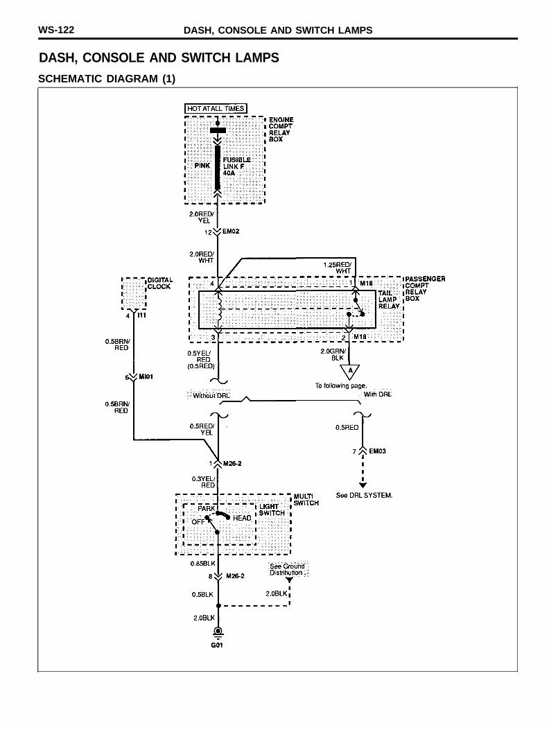
DASH, CONSOLE AND SWITCH LAMPSSCHEMATIC DIAGRAM (1)
DASH, CONSOLE AND SWITCH LAMPS WS-123
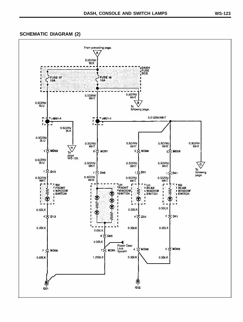
SCHEMATIC DIAGRAM (2)
WS-124 DASH, CONSOLE AND SWITCH LAMPS
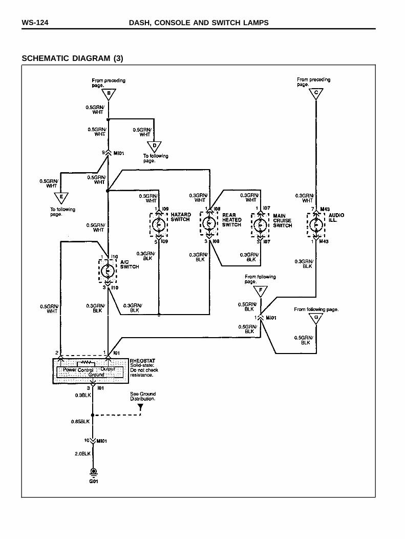
SCHEMATIC DIAGRAM (3)
DASH, CONSOLE AND SWITCH LAMPS WS-125
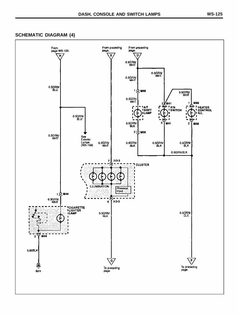
SCHEMATIC DIAGRAM (4)
WS-126 DASH, CONSOLE AND SWITCH LAMPS
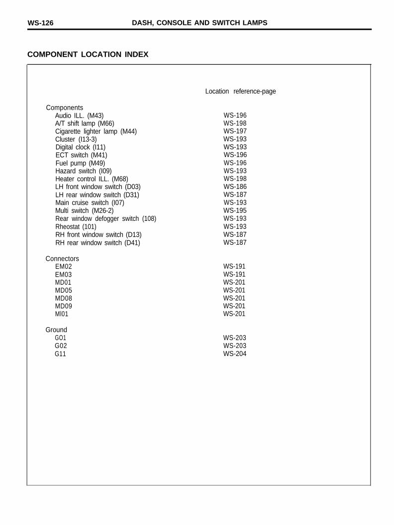
COMPONENT LOCATION INDEX
ComponentsAudio ILL. (M43) WS-196A/T shift lamp (M66) WS-198Cigarette lighter lamp (M44) WS-197Cluster (I13-3) WS-193Digital clock (I11) WS-193ECT switch (M41) WS-196Fuel pump (M49) WS-196Hazard switch (I09) WS-193Heater control ILL. (M68) WS-198LH front window switch (D03) WS-186LH rear window switch (D31) WS-187Main cruise switch (I07) WS-193Multi switch (M26-2) WS-195Rear window defogger switch (108) WS-193Rheostat (101) WS-193RH front window switch (D13) WS-187RH rear window switch (D41) WS-187
ConnectorsEM02EM03MD01MD05MD08MD09Ml01
GroundGO1G02G11
Location reference-page
WS-191WS-191WS-201WS-201WS-201WS-201WS-201
WS-203WS-203WS-204

DASH, CONSOLE AND SWITCH LAMPS WS-127
MEMO

WS-128 TRUNK LID OPENER
TRUNK LID OPENERSCHEMATIC DIAGRAM
TRUNK LID OPENER WS-129
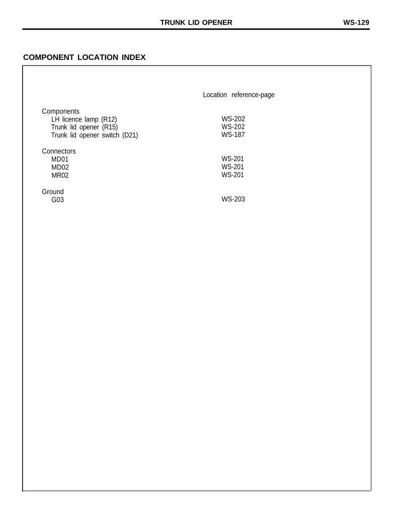
COMPONENT LOCATION INDEX
Location reference-page
ComponentsLH licence lamp (R12)Trunk lid opener (R15)Trunk lid opener switch (D21)
WS-202WS-202WS-187
ConnectorsMD01MD02MR02
GroundG03
WS-201WS-201WS-201
WS-203
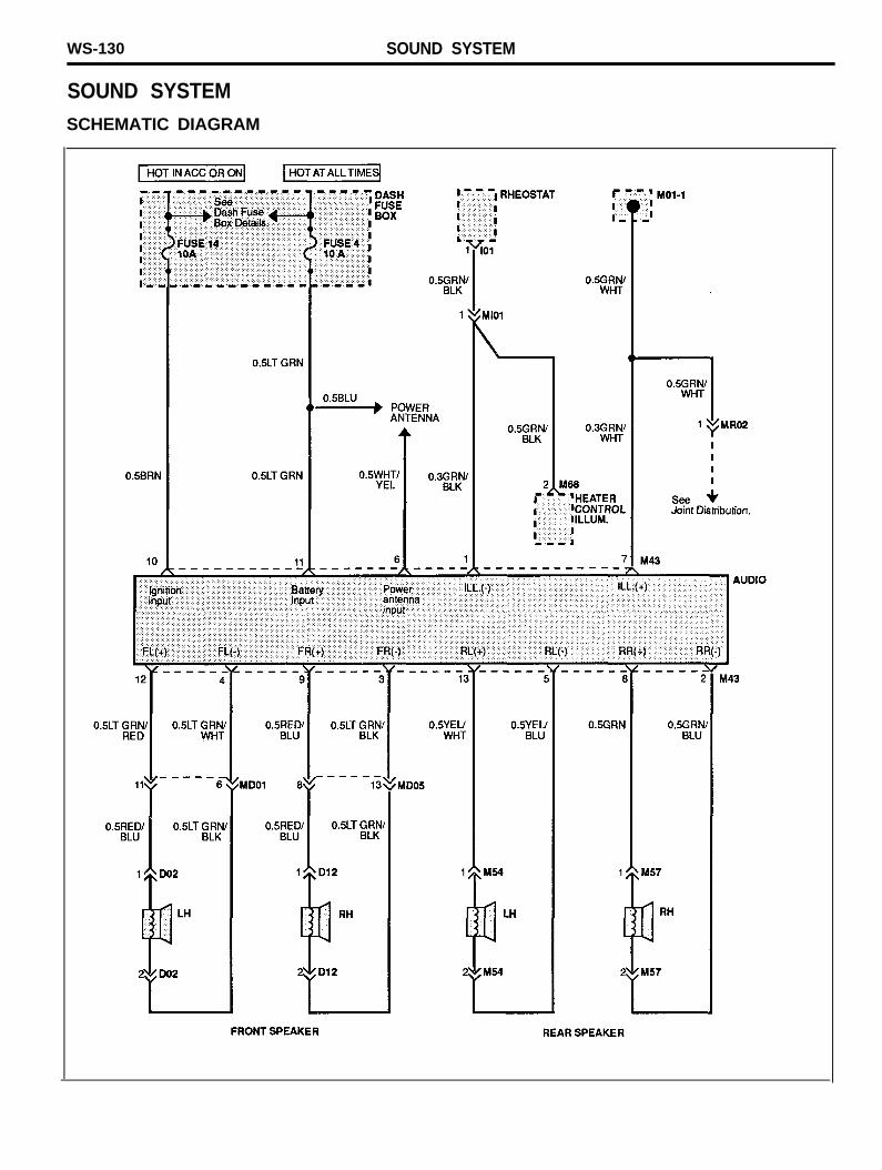
WS-130 SOUND SYSTEM
SOUND SYSTEMSCHEMATIC DIAGRAM
SOUND SYSTEM WS-131
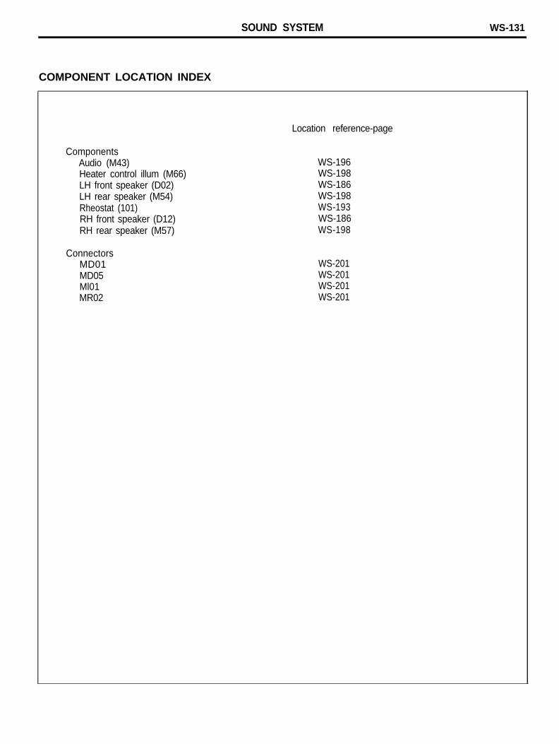
COMPONENT LOCATION INDEX
ComponentsAudio (M43)Heater control illum (M66)LH front speaker (D02)LH rear speaker (M54)Rheostat (101)RH front speaker (D12)RH rear speaker (M57)
ConnectorsMD01MD05Ml01MR02
Location reference-page
WS-196WS-198WS-186WS-198WS-193WS-186WS-198
WS-201WS-201WS-201WS-201
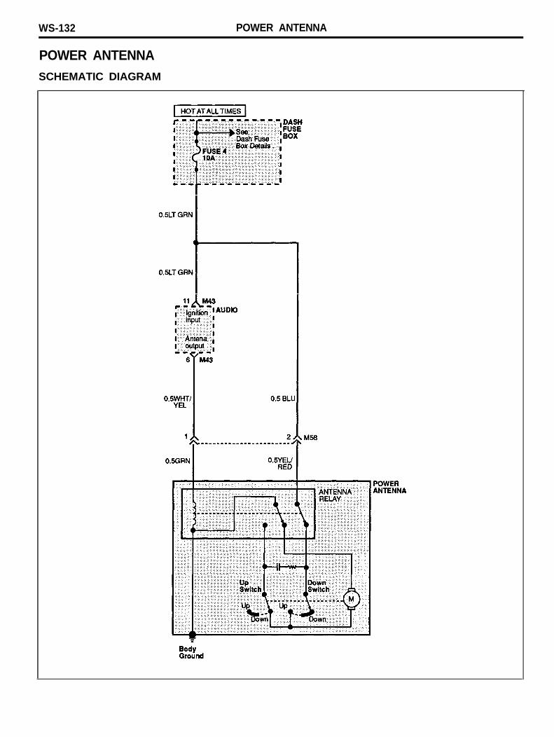
WS-132 POWER ANTENNA
POWER ANTENNASCHEMATIC DIAGRAM

POWER ANTENNA WS-133
COMPONENT LOCATION INDEX
ComponentsAntenna motor (M58)Audio (M43)
Location reference-page
WS-198WS-196
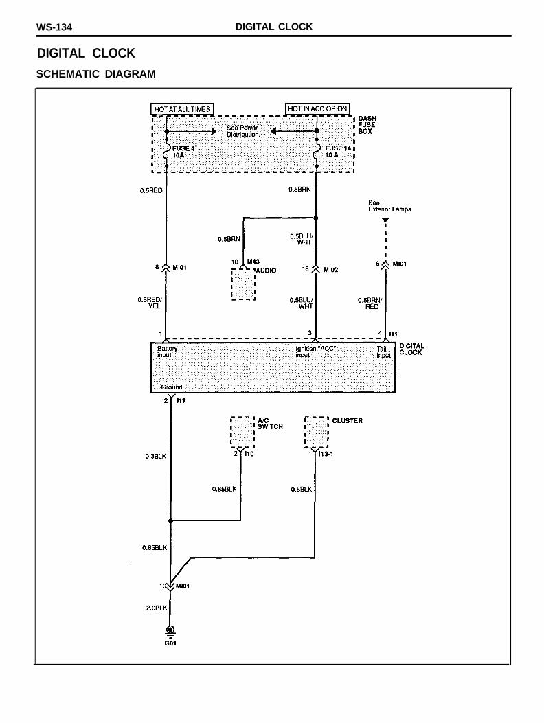
WS-134 DIGITAL CLOCK
DIGITAL CLOCKSCHEMATIC DIAGRAM
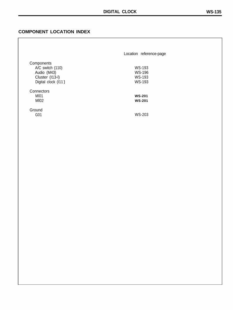
DIGITAL CLOCK WS-135
COMPONENT LOCATION INDEX
ComponentsA/C switch (110)Audio (M43)Cluster (I13-l)Digital clock (I11
ConnectorsMl01Ml02
GroundG01
Location reference-page
WS-193WS-196WS-193WS-193
WS-201WS-201
WS-203
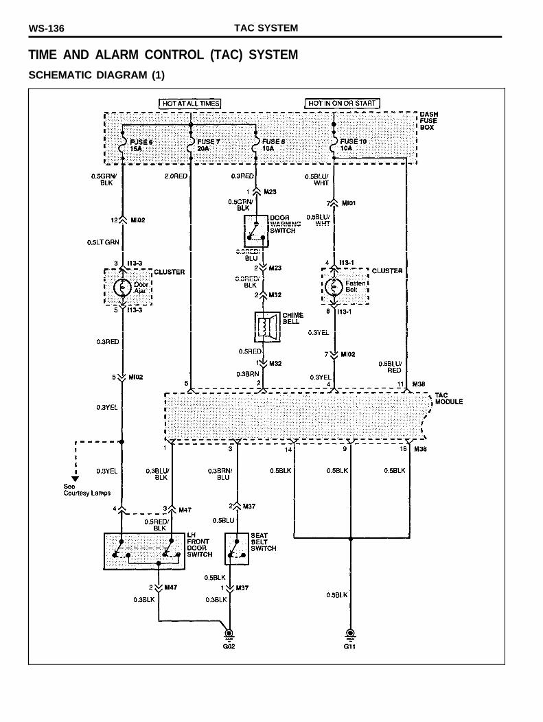
WS-136 TAC SYSTEM
TIME AND ALARM CONTROL (TAC) SYSTEMSCHEMATIC DIAGRAM (1)
TAC SYSTEM WS-137
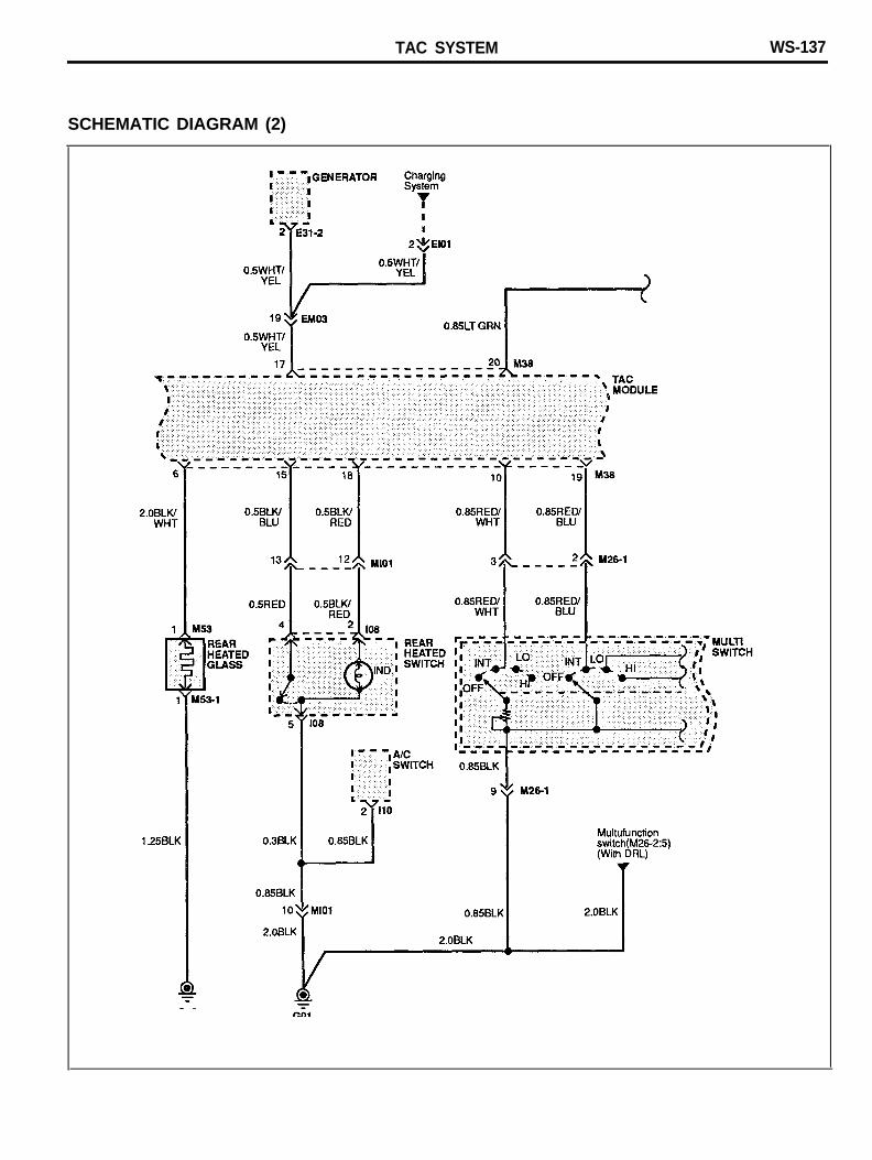
SCHEMATIC DIAGRAM (2)
WS-138 TAC SYSTEM
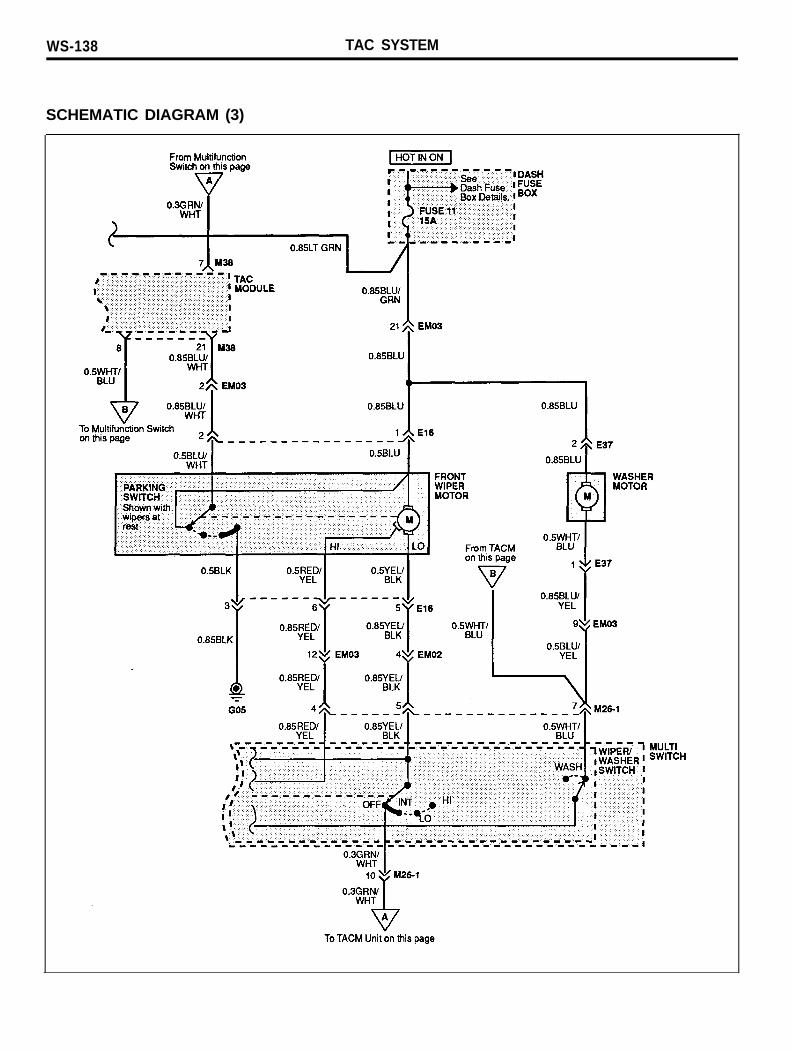
SCHEMATIC DIAGRAM (3)
TAC SYSTEM WS-139
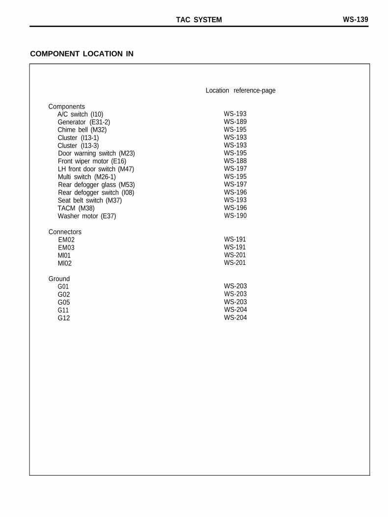
COMPONENT LOCATION IN
ComponentsA/C switch (I10)Generator (E31-2)Chime bell (M32)Cluster (I13-1)Cluster (I13-3)Door warning switch (M23)Front wiper motor (E16)LH front door switch (M47)Multi switch (M26-1)Rear defogger glass (M53)Rear defogger switch (I08)Seat belt switch (M37)TACM (M38)Washer motor (E37)
ConnectorsEM02EM03Ml01Ml02
GroundG01G02G05G11G12
Location reference-page
WS-193WS-189WS-195WS-193WS-193WS-195WS-188WS-197WS-195WS-197WS-196WS-193WS-196WS-190
WS-191WS-191WS-201WS-201
WS-203WS-203WS-203WS-204WS-204
WS-140 BLOWER CONTROLS
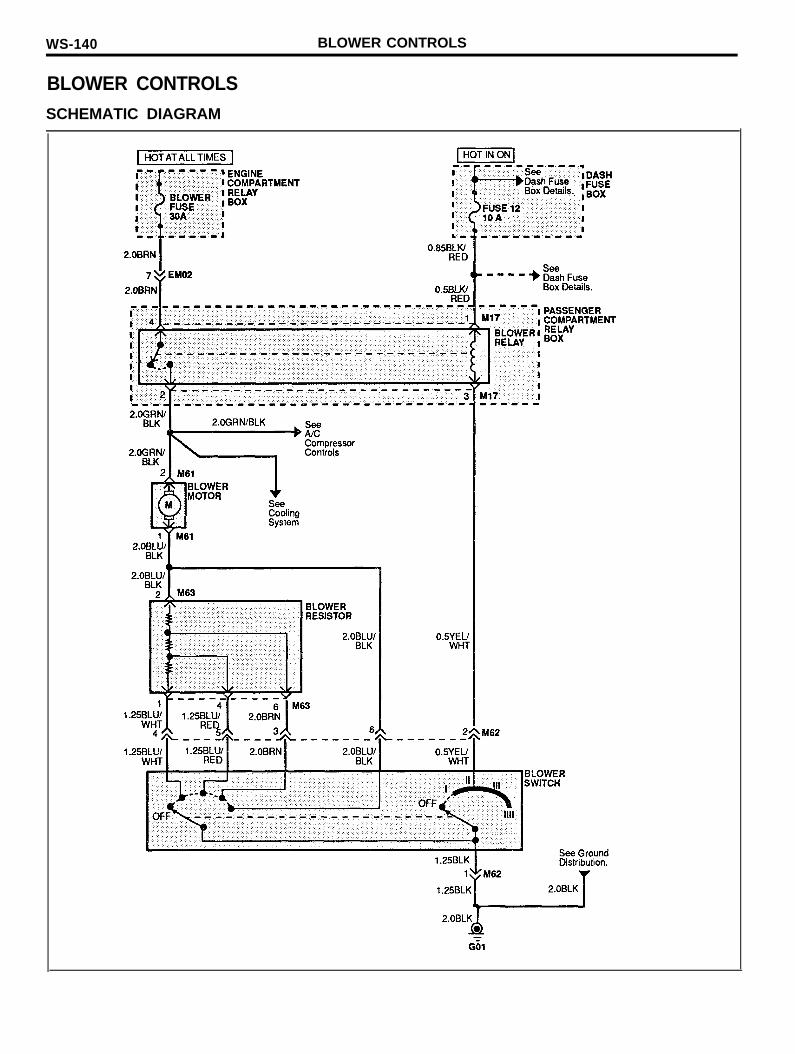
BLOWER CONTROLSSCHEMATIC DIAGRAM
BLOWER CONTROLS WS-141
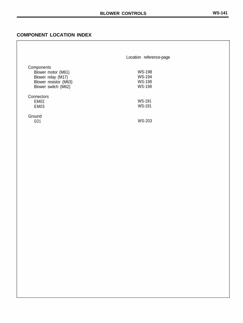
COMPONENT LOCATION INDEX
ComponentsBlower motor (M61)Blower relay (M17)Blower resistor (M63)Blower switch (M62)
ConnectorsEM02EM03
GroundGO1
Location reference-page
WS-198WS-194WS-198WS-198
WS-191WS-191
WS-203
WS-142 A/C COMPRESSOR CONTROLS
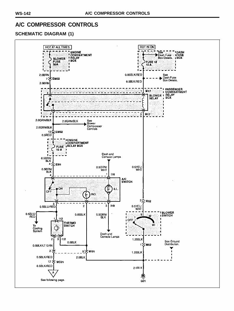
A/C COMPRESSOR CONTROLS
SCHEMATIC DIAGRAM (1)
A/C COMPRESSOR CONTROLS WS-143
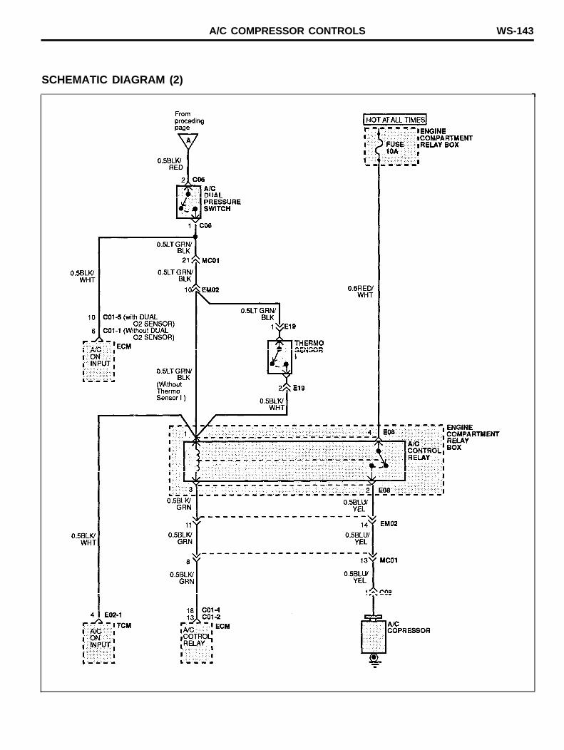
SCHEMATIC DIAGRAM (2)
WS-144 A/C COMPRESSOR CONTROLS
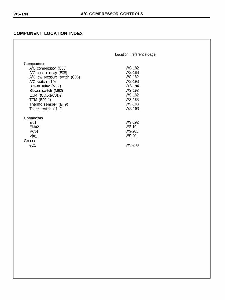
COMPONENT LOCATION INDEX
ComponentsA/C compressor (C08)A/C control relay (E08)A/C low pressure switch (C06)A/C switch (I10)Blower relay (M17)Blower switch (M62)ECM (CO1-1/C01-2)TCM (E02-1)Thermo sensor-l (El 9)Therm switch (I1 2)
ConnectorsEl01EM02MC01Ml01
GroundGO1
Location reference-page
WS-182WS-188WS-182WS-193WS-194WS-198WS-182WS-188WS-188WS-193
WS-192WS-191WS-201WS-201
WS-203

A/C COMPRESSOR CONTROLS WS-145
MEMO
WS-146 A/T AND IGNITION KEY LOCK CONTROLS
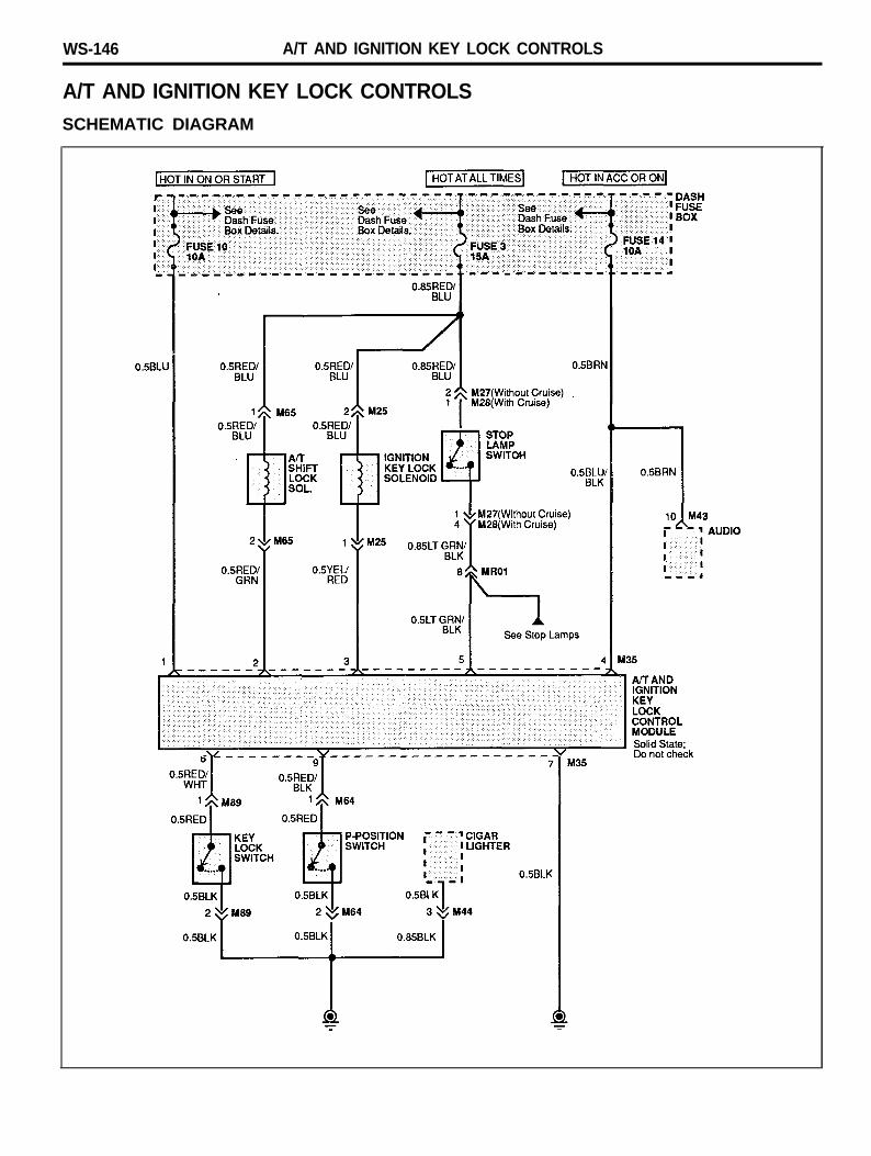
A/T AND IGNITION KEY LOCK CONTROLSSCHEMATIC DIAGRAM
A/T AND IGNITION KEY LOCK CONTROLS WS-147
COMPONENT LOCATION INDEX
ComponentsA/T and ignition key lock control module (M35)A/T shift lock sol. (M65)Audio (M43)Cigar lighter (M44)Ignition key lock solenoid (M25)P-position switch (M64)Stop lamp switch (M27/M28)
GroundG02G11
Location reference-page
WS-196WS-198WS-196WS-197WS-195WS-198WS-195
WS-203WS-204
WS-148
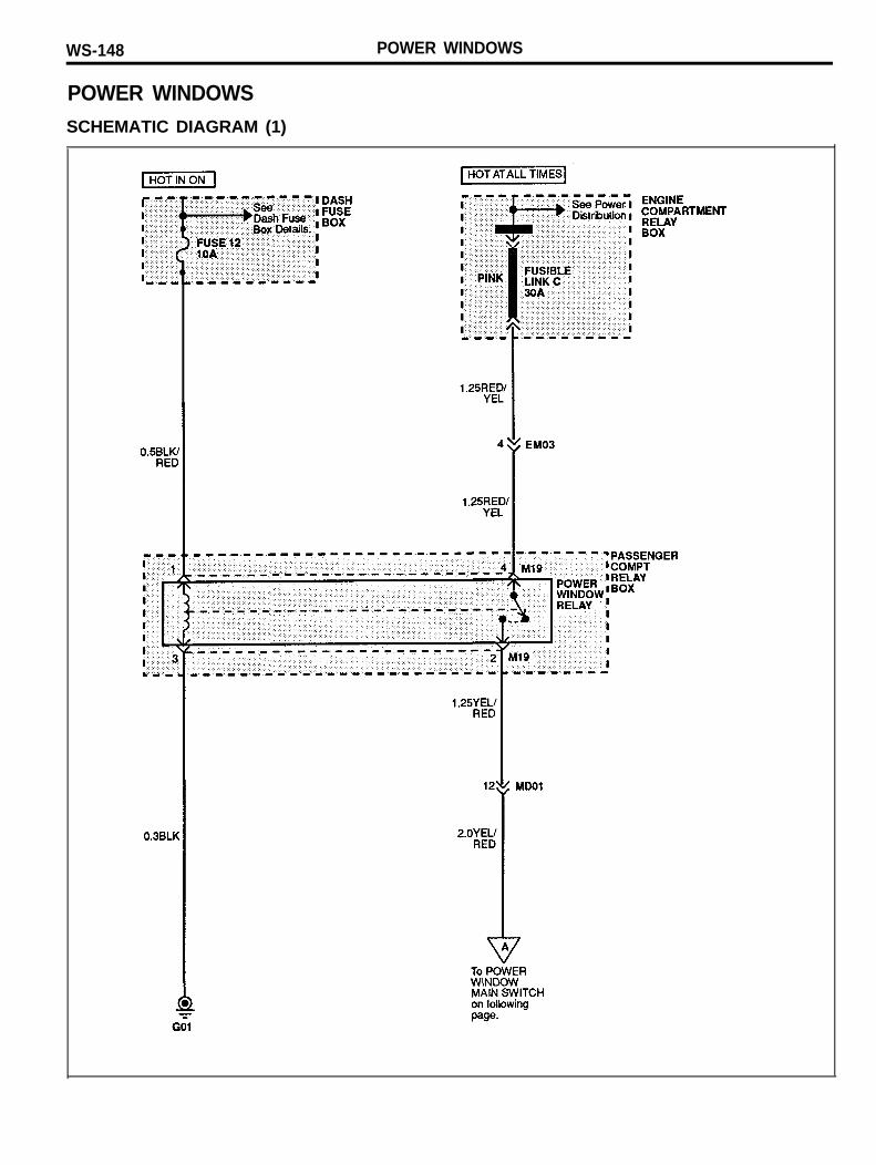
POWER WINDOWSSCHEMATIC DIAGRAM (1)
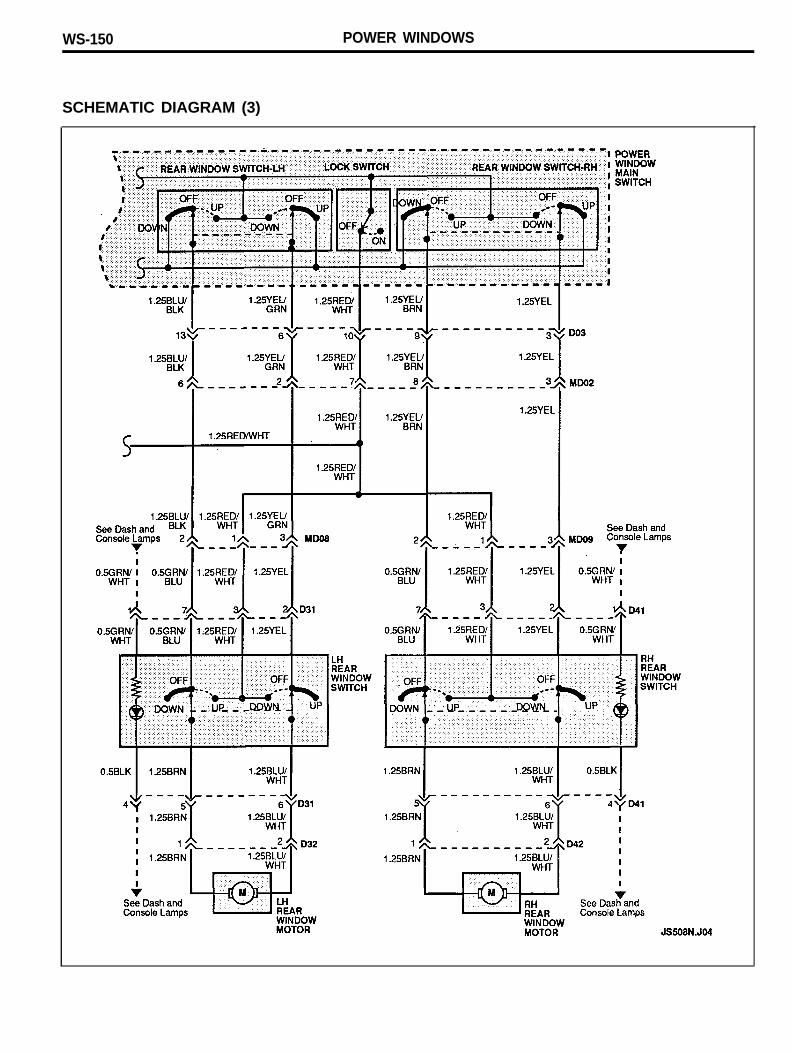
POWER WINDOWS
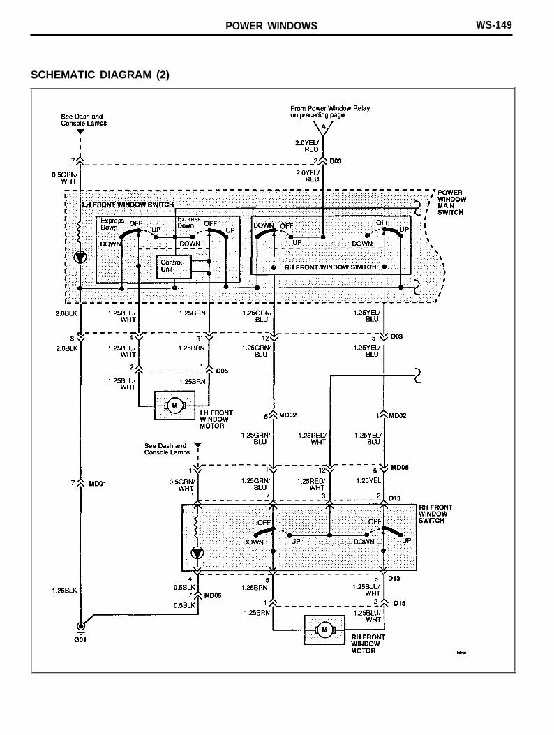
POWER WINDOWS WS-149
SCHEMATIC DIAGRAM (2)
WS-150 POWER WINDOWS
SCHEMATIC DIAGRAM (3)
POWER WINDOWS WS-151
COMPONENT LOCATION INDEX
ComponentsLH front window motor (D05)LH rear window motor (D32)LH rear window switch (D31)Power window main switch (D03)RH front window motor (D15)RH front window switch (D13)RH rear window motor (D42)RH rear window switch (D41)
ConnectorsEM03MD01MD02MD05MD08MD09
GroundG01
Location reference-page
WS-186WS-187WS-187WS-186WS-187WS-187WS-187WS-187
WS-191WS-201WS-201WS-201WS-201WS-201
WS-203
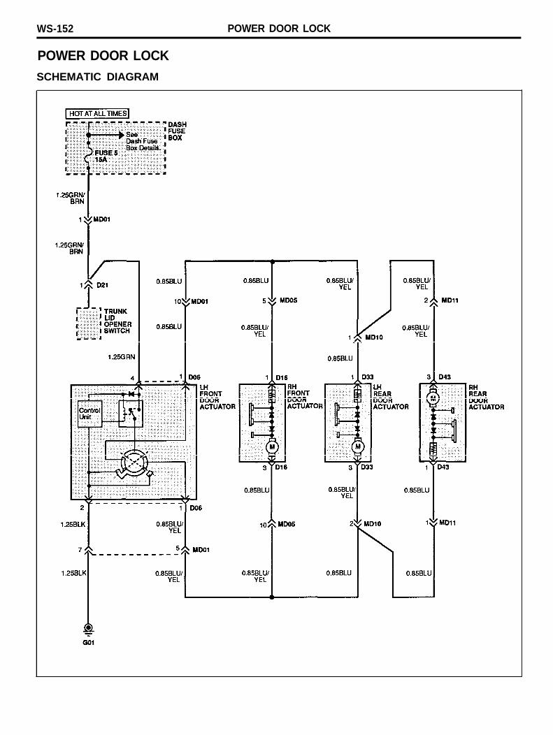
WS-152 POWER DOOR LOCK
POWER DOOR LOCKSCHEMATIC DIAGRAM
POWER DOOR LOCK WS-153
COMPONENT LOCATION INDEX
ComponentsLH front door actor (D06)LH rear door actor (D33)RH front door actor (D16)RH rear door actor (D43)Trunk lid opener switch (D21)
ConnectorsMD01MD05
GroundGO1
Location reference-page
WS-186WS-187WS-187WS-187WS-187
WS-201WS-201
WS-203
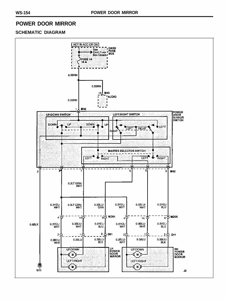
WS-154 POWER DOOR MIRROR
POWER DOOR MIRRORSCHEMATIC DIAGRAM
POWER DOOR MIRROR WS-155
COMPONENT LOCATION INDEX
ComponentsAudio (M43)LH power door mirror (D01)Power door mirror switch (M42)RH power door mirror (D11)
ConnectorsMD01MD05
GroundG11
Location reference-page
WS-196WS-186WS-196WS-187
WS-201WS-201
WS-204
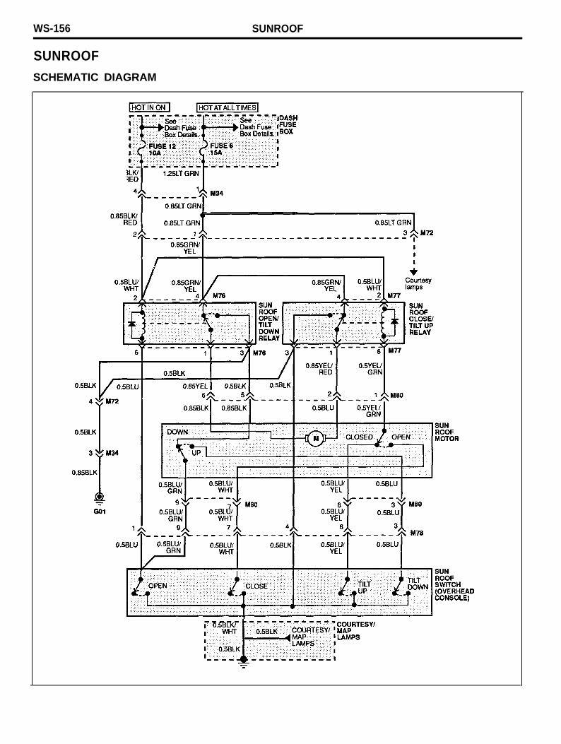
WS-156 SUNROOF
SUNROOFSCHEMATIC DIAGRAM
SUNROOF WS-157
COMPONENT LOCATION INDEX
ComponentsSun roof close/tilt up relay (M77)Sun roof motor (M80)Sun roof open/tilt down relay (M76)Sun roof switch (overhead console) (M78)
ConnectorsM34M72
GroundGO1
Location reference-page
WS-199WS-199WS-199WS-199
WS-196WS-199
WS-203
WS-158 PASSIVE SEAT BELTS
PASSIVE SEAT BELTS
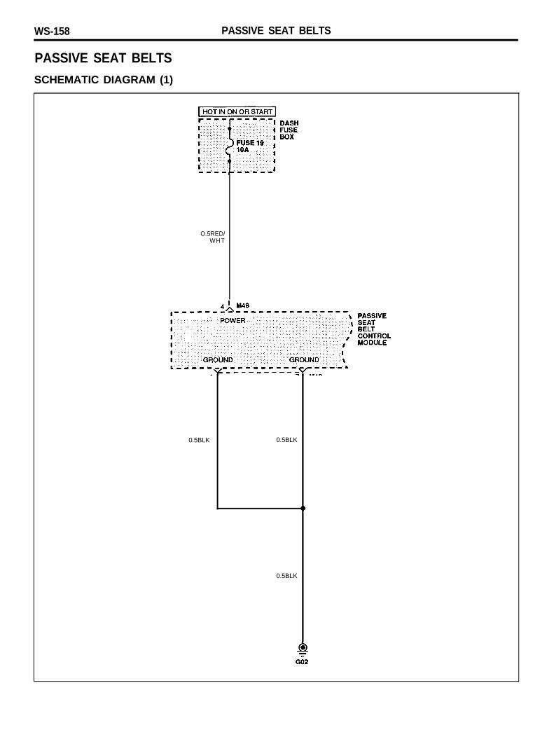
SCHEMATIC DIAGRAM (1)
O.5RED/WHT
0.5BLK 0.5BLK
0.5BLK
PASSIVE SEAT BELTS WS-159
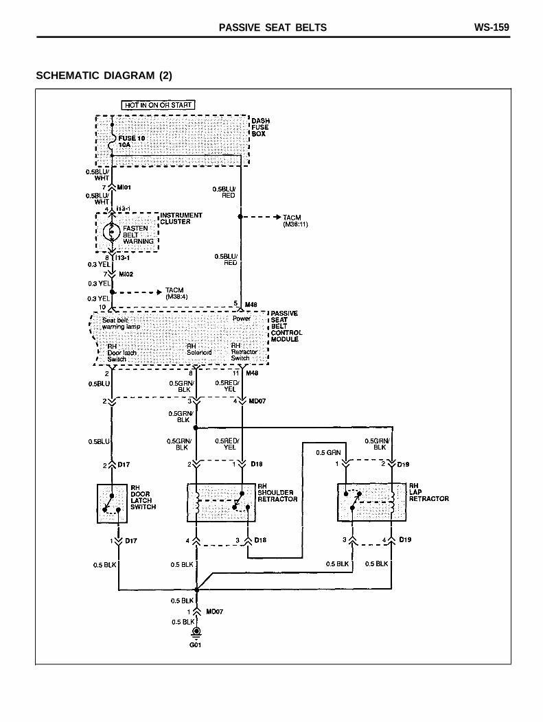
SCHEMATIC DIAGRAM (2)
WS-160 PASSIVE SEAT BELTS
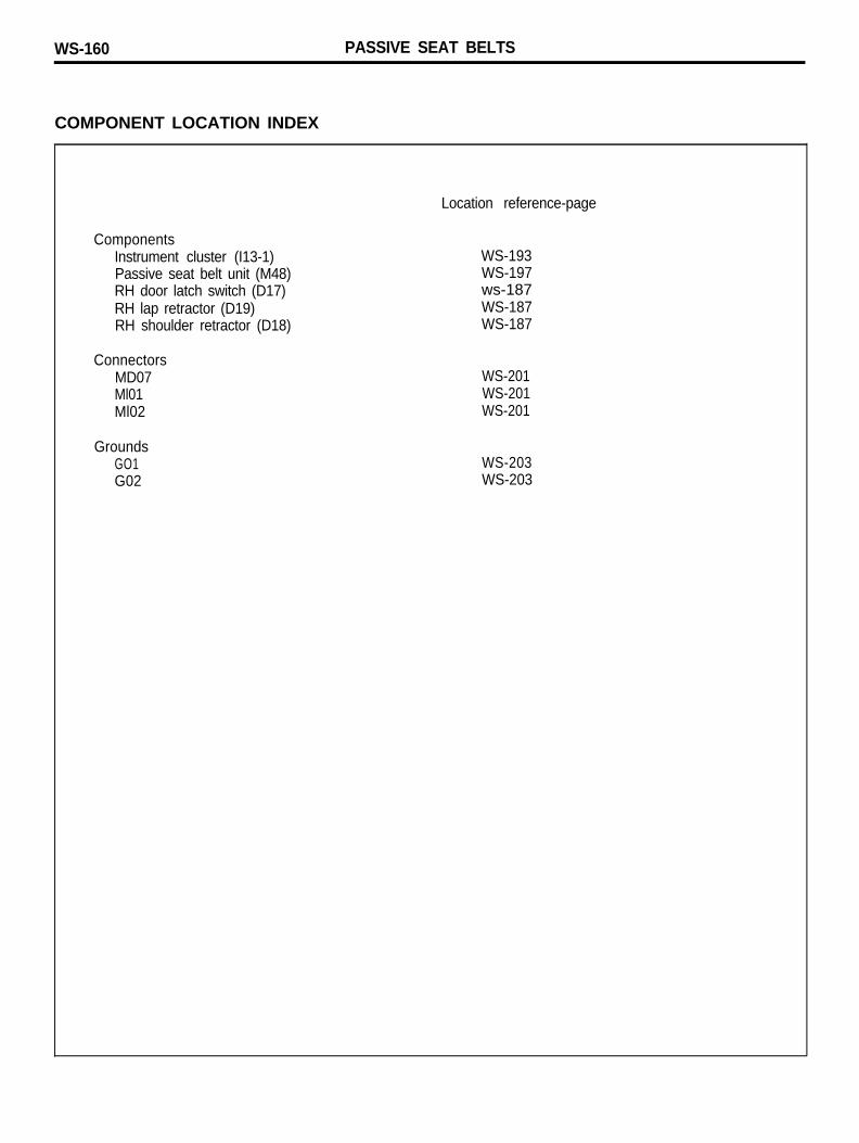
COMPONENT LOCATION INDEX
Location reference-page
ComponentsInstrument cluster (I13-1)Passive seat belt unit (M48)RH door latch switch (D17)RH lap retractor (D19)RH shoulder retractor (D18)
WS-193WS-197ws-187WS-187WS-187
ConnectorsMD07Ml01Ml02
WS-201WS-201WS-201
GroundsGO1G02
WS-203WS-203

PASSIVE SEAT BELTS WS-161
MEMO
WS-162 ANTI-LOCK BRAKE SYSTEM
ANTI-LOCK BRAKE SYSTEM
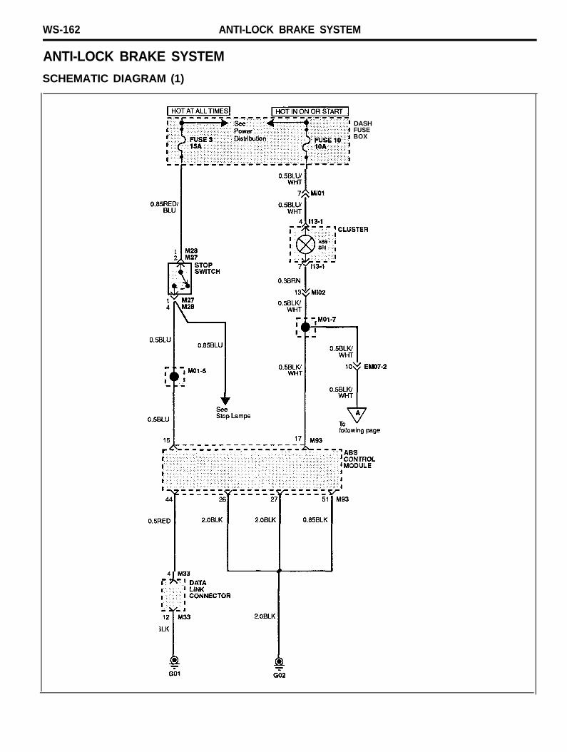
SCHEMATIC DIAGRAM (1)
DASHFUSEBOX
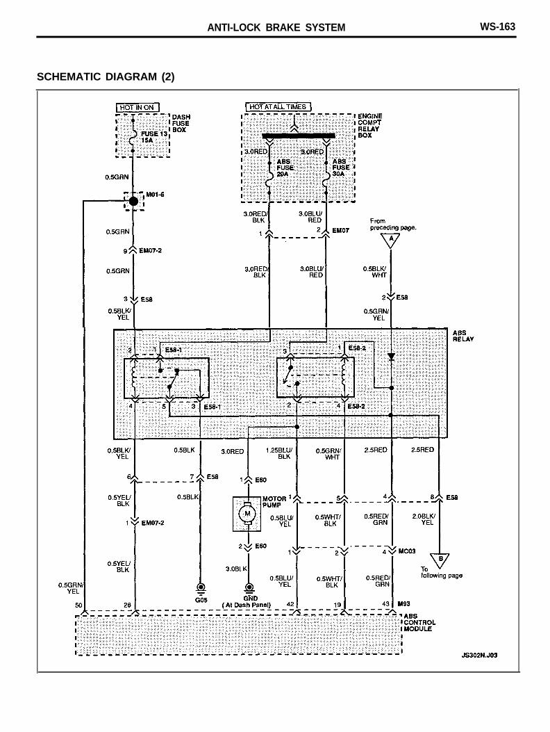
ANTI-LOCK BRAKE SYSTEM WS-163
SCHEMATIC DIAGRAM (2)
WS-164 ANTI-LOCK BRAKE SYSTEM
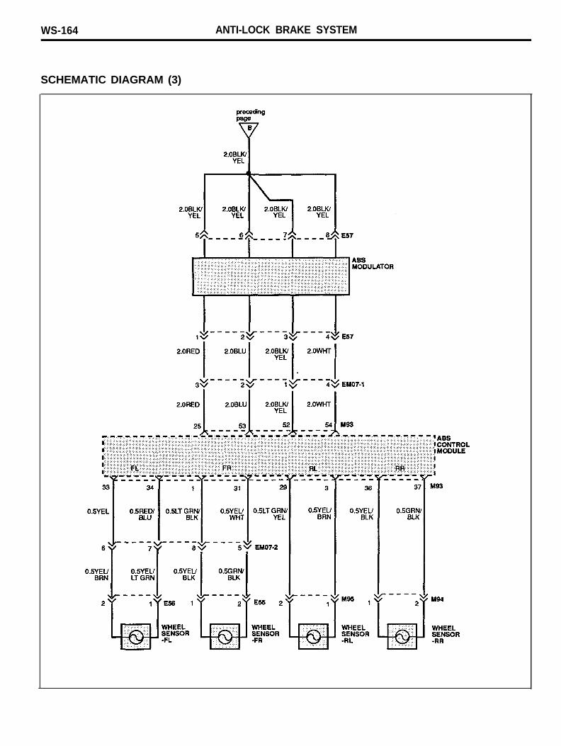
SCHEMATIC DIAGRAM (3)
ANTI-LOCK BRAKE SYSTEM WS-165
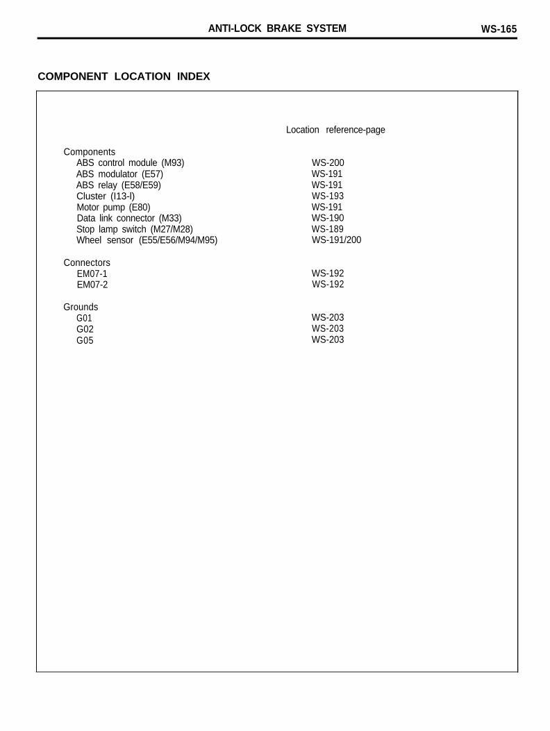
COMPONENT LOCATION INDEX
ComponentsABS control module (M93)ABS modulator (E57)ABS relay (E58/E59)Cluster (I13-l)Motor pump (E80)Data link connector (M33)Stop lamp switch (M27/M28)Wheel sensor (E55/E56/M94/M95)
ConnectorsEM07-1EM07-2
GroundsG01G02G05
Location reference-page
WS-200WS-191WS-191WS-193WS-191WS-190WS-189WS-191/200
WS-192WS-192
WS-203WS-203WS-203
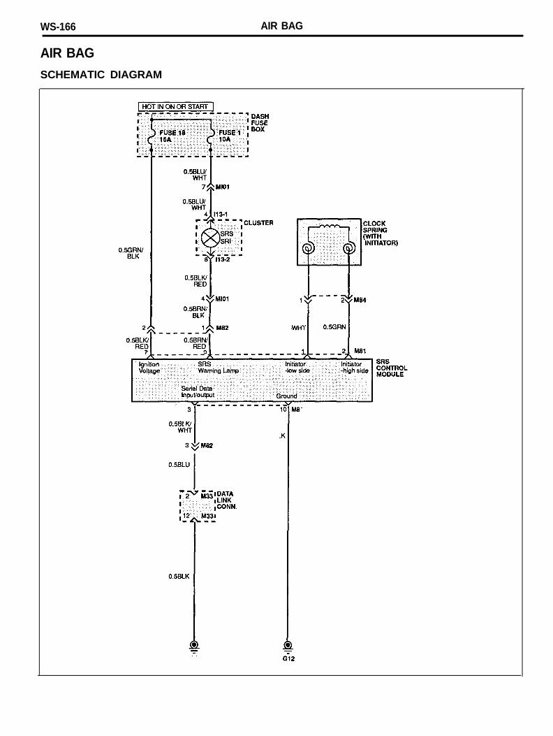
WS-166 AIR BAG
AIR BAG
SCHEMATIC DIAGRAM
AIR BAG WS-167
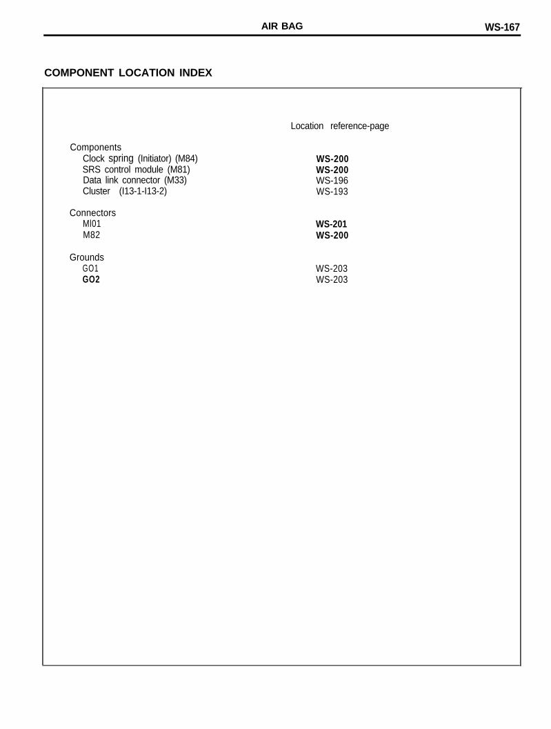
COMPONENT LOCATION INDEX
ComponentsClock spring (Initiator) (M84)SRS control module (M81)Data link connector (M33)Cluster (I13-1-I13-2)
ConnectorsMl01M82
GroundsGO1GO2
Location reference-page
WS-200WS-200WS-196WS-193
WS-201WS-200
WS-203WS-203
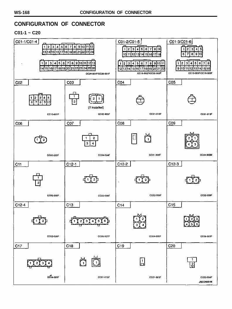
WS-168 CONFIGURATION OF CONNECTOR
CONFIGURATION OF CONNECTORC01-1 ~ C20
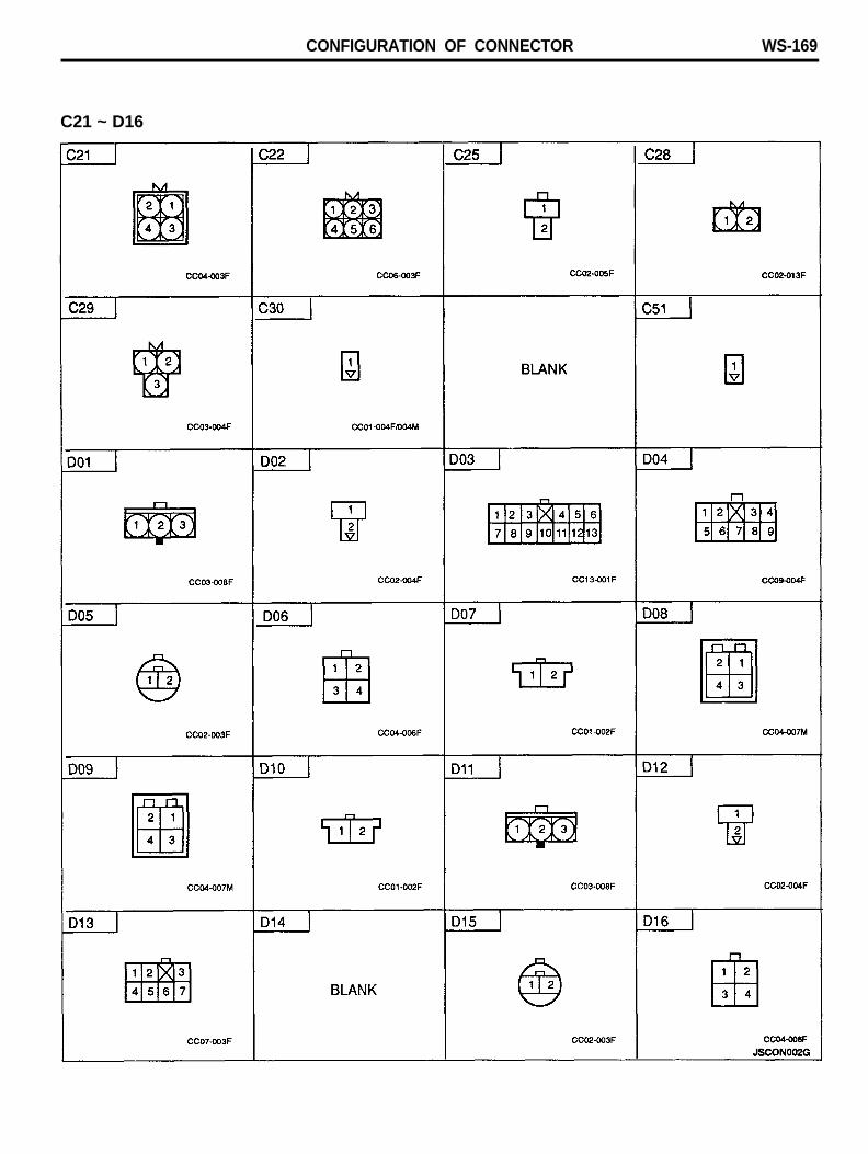
CONFIGURATION OF CONNECTOR WS-169
C21 ~ D16
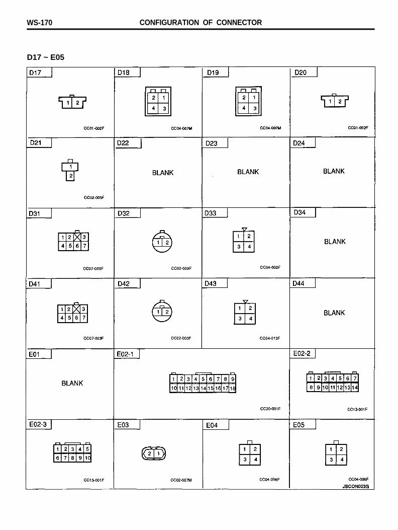
WS-170 CONFIGURATION OF CONNECTOR
D17 ~ E05

CONFIGURATION OF CONNECTOR WS-171
E06 ~ E29
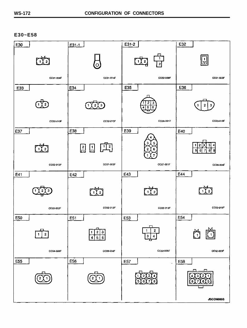
WS-172 CONFIGURATION OF CONNECTORS
E30~E58
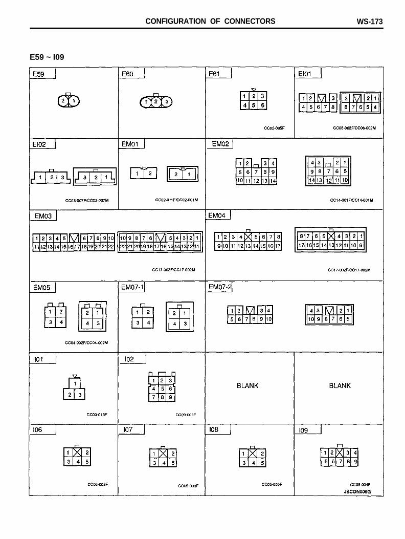
CONFIGURATION OF CONNECTORS WS-173
E59 ~ I09
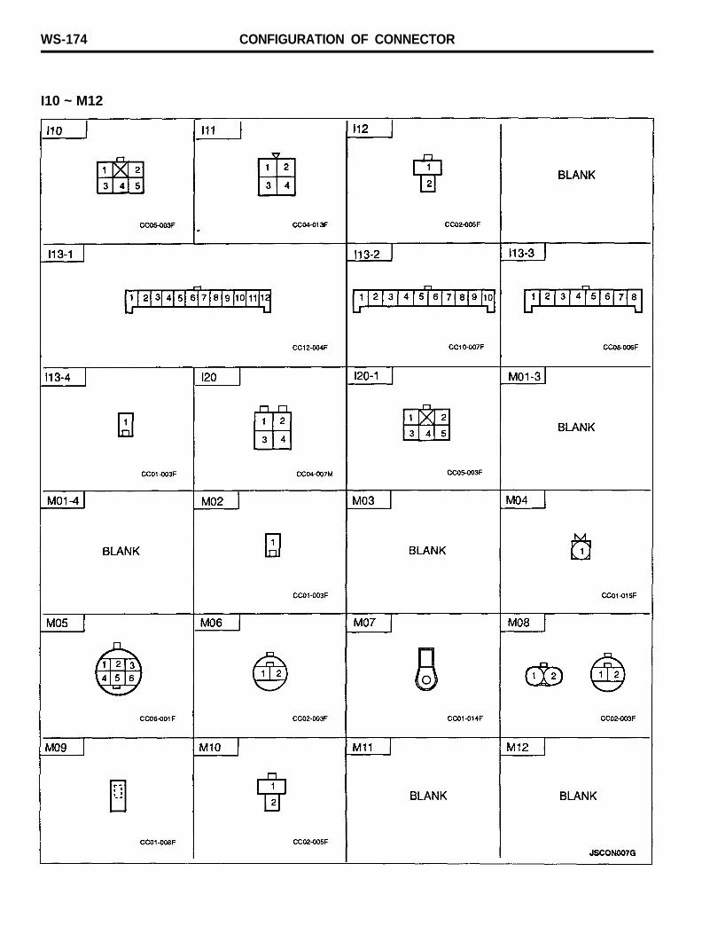
WS-174 CONFIGURATION OF CONNECTOR
I10 ~ M12
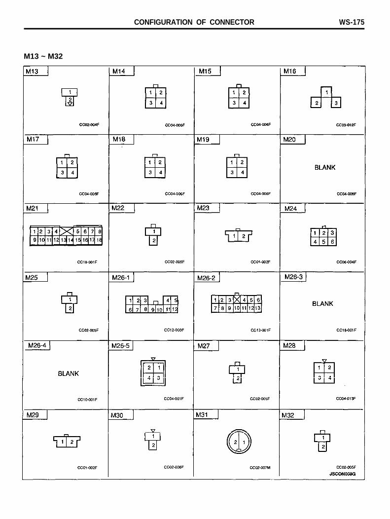
CONFIGURATION OF CONNECTOR WS-175
M13 ~ M32
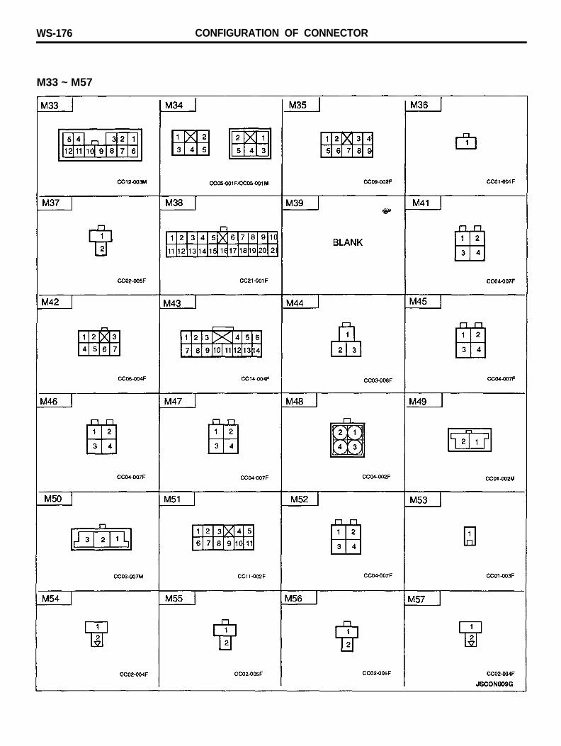
WS-176 CONFIGURATION OF CONNECTOR
M33 ~ M57
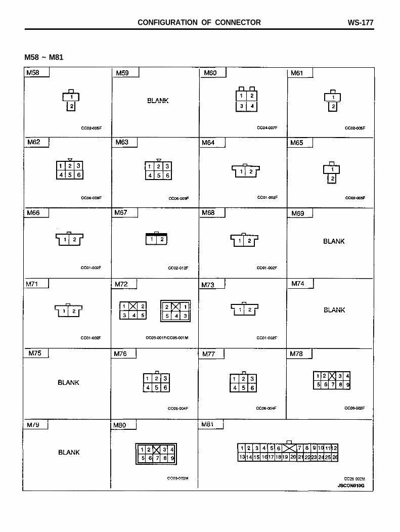
CONFIGURATION OF CONNECTOR WS-177
M58 ~ M81
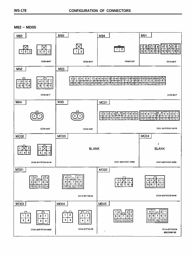
WS-178 CONFIGURATION OF CONNECTORS
M82 ~ MD05
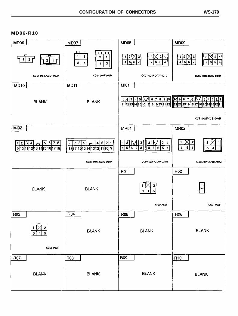
CONFIGURATION OF CONNECTORS WS-179
MD06-R10
WS-180 CONFIGURATION OF CONNECTOR
R11 ~ R16

CONFIGURATION OF CONNECTOR WS-181
MEMO
WS-182 COMPONENT LOCATION
COMPONENTS (C01-1 ~ C12-4)
COMPONENT LOCATION WS-183
COMPONENTS (C13 ~ C25)
WS-184 COMPONENT LOCATION
COMPONENTS (C28 ~ C47)
COMPONENT LOCATION WS-185
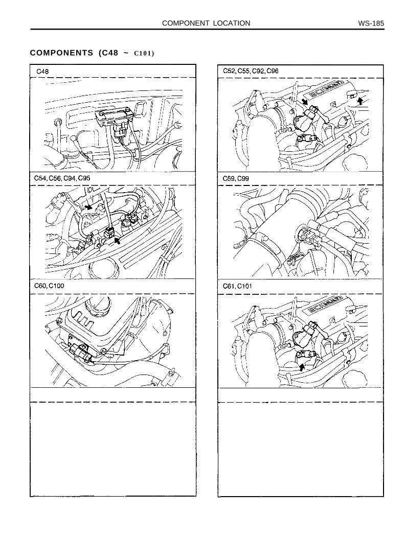
COMPONENTS (C48 ~ C101)
WS-186 COMPONENT LOCATION
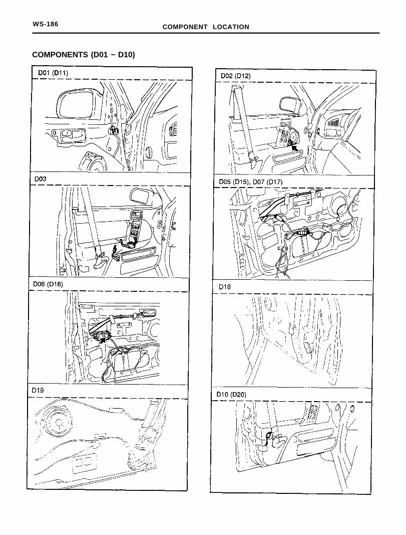
COMPONENTS (D01 ~ D10)
COMPONENT LOCATION WS-187
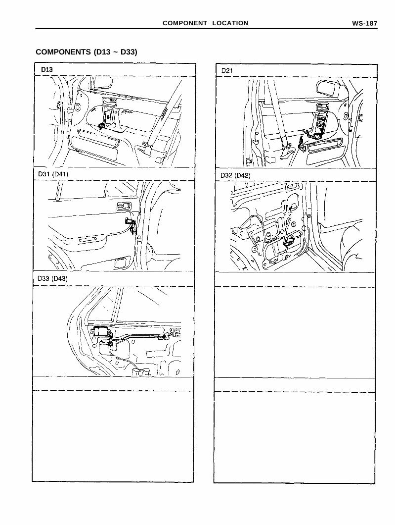
COMPONENTS (D13 ~ D33)
D13
WS-188 COMPONENT LOCATION
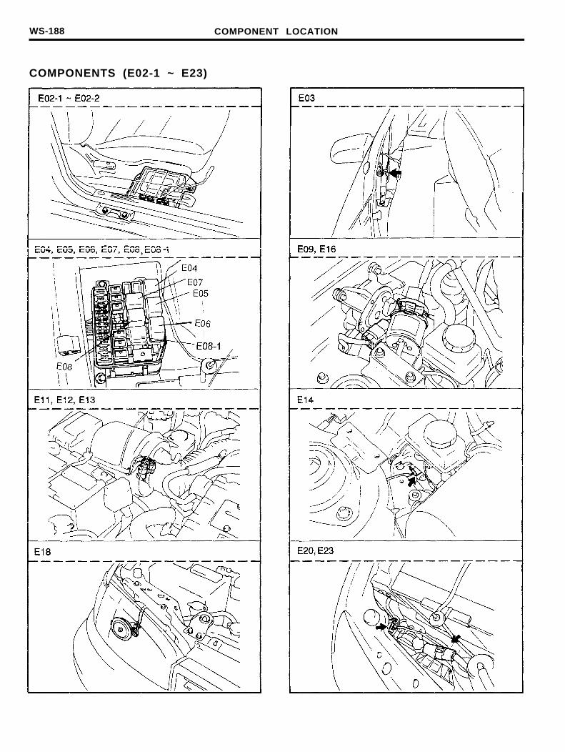
COMPONENTS (E02-1 ~ E23)
COMPONENT LOCATION WS-189
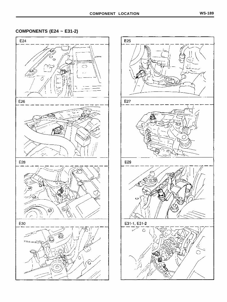
COMPONENTS (E24 ~ E31-2)
WS-190 COMPONENT LOCATION
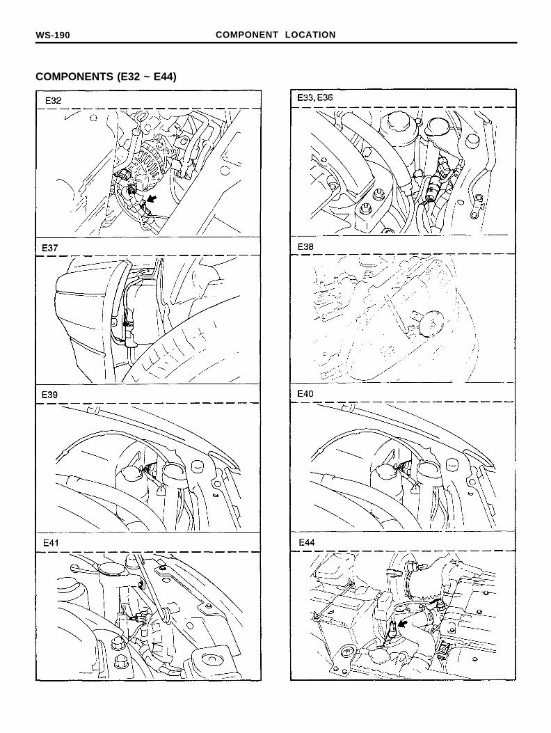
COMPONENTS (E32 ~ E44)
COMPONENT LOCATION WS-191
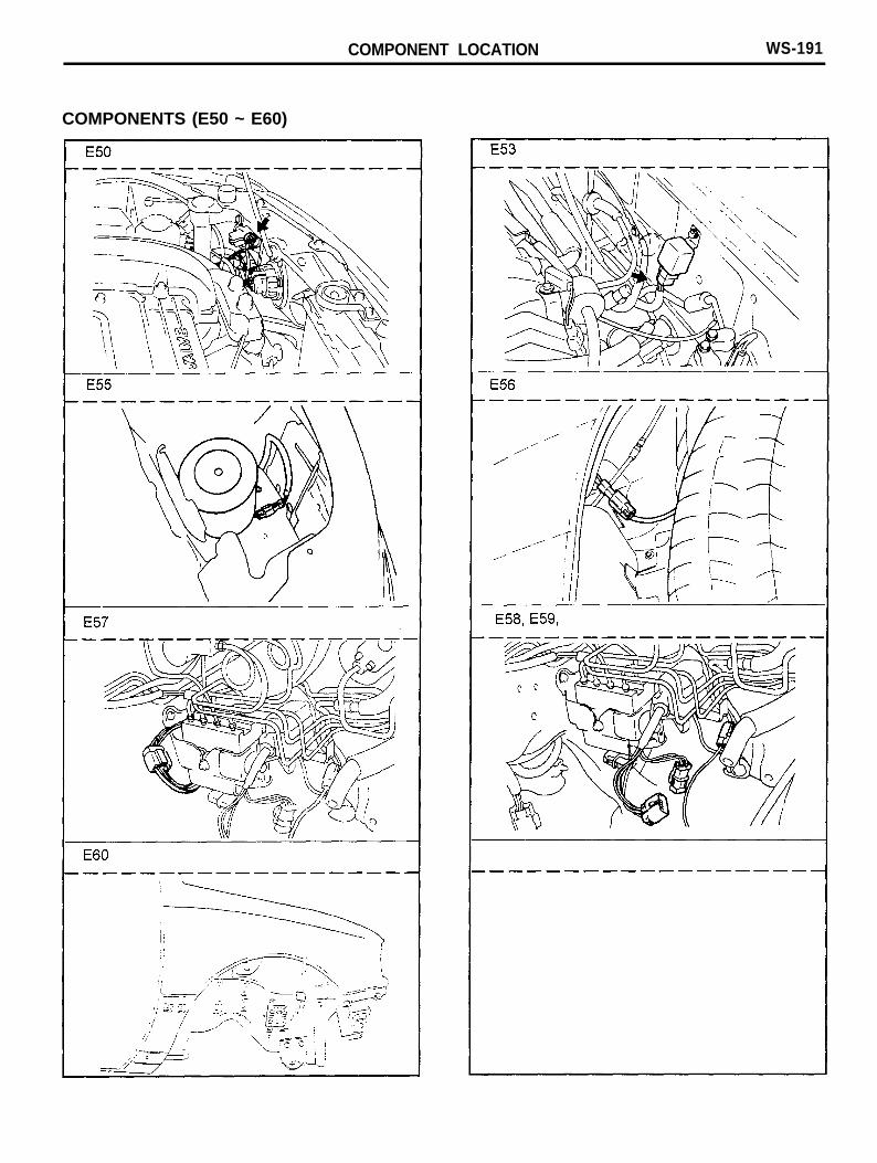
COMPONENTS (E50 ~ E60)
WS-192 COMPONENT LOCATION
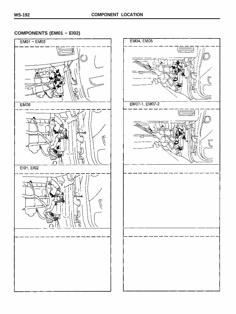
COMPONENTS (EM01 ~ El02)

r e s c a n w s - 1 9 3
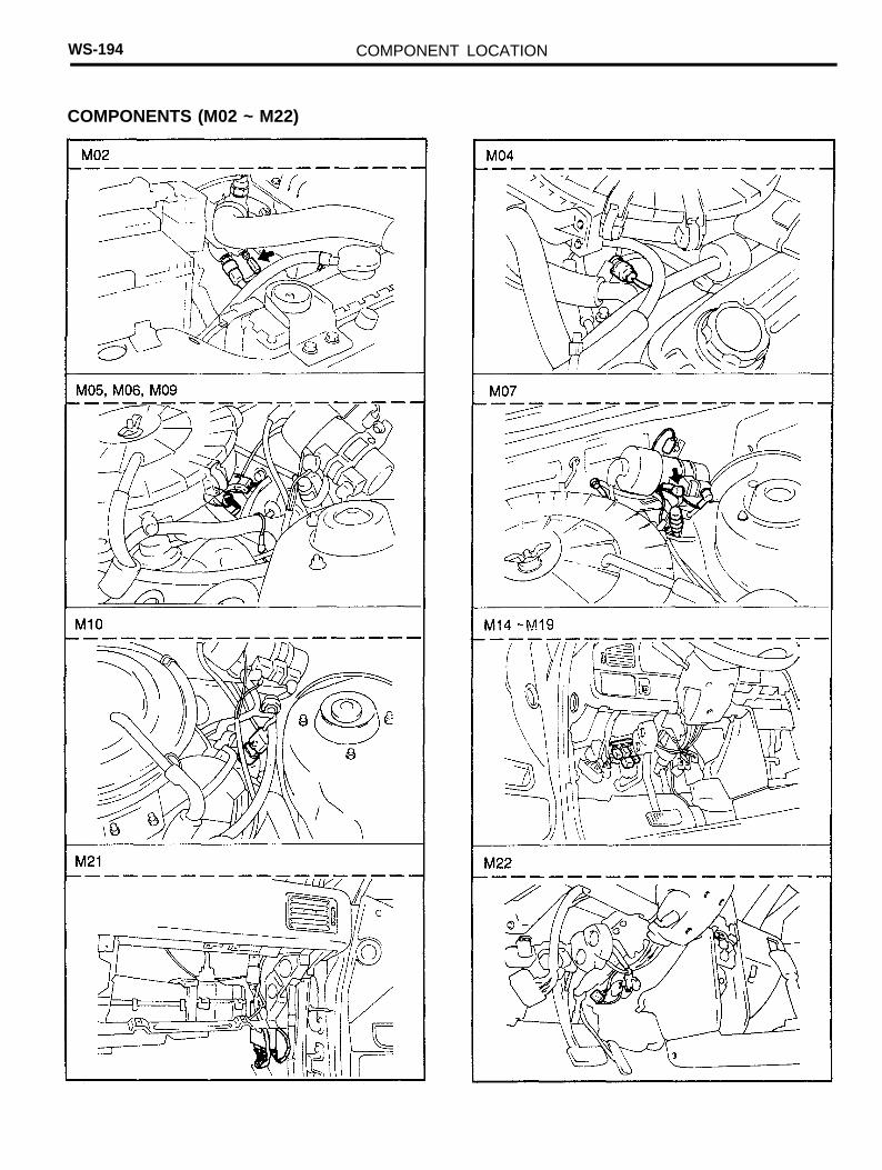
WS-194 COMPONENT LOCATION
COMPONENTS (M02 ~ M22)
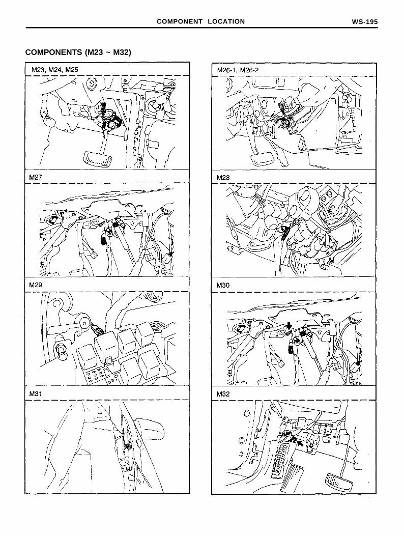
COMPONENT LOCATION WS-195
COMPONENTS (M23 ~ M32)
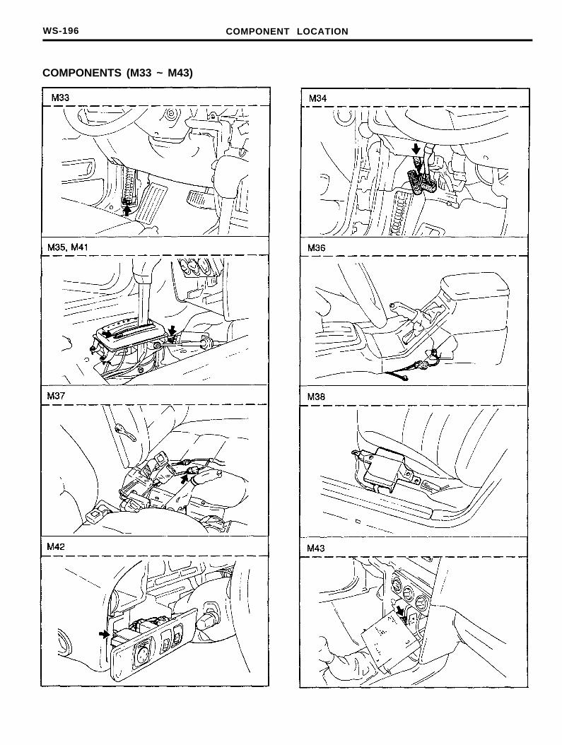
WS-196 COMPONENT LOCATION
COMPONENTS (M33 ~ M43)
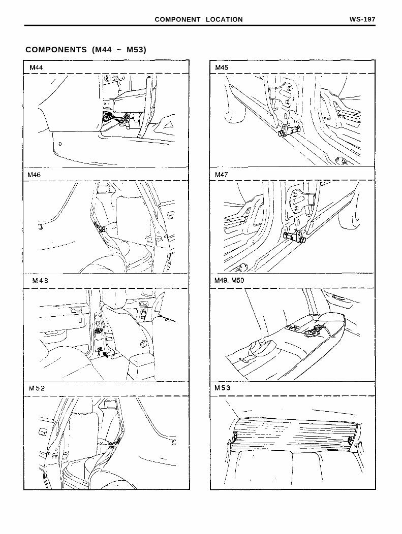
COMPONENT LOCATION WS-197
COMPONENTS (M44 ~ M53)
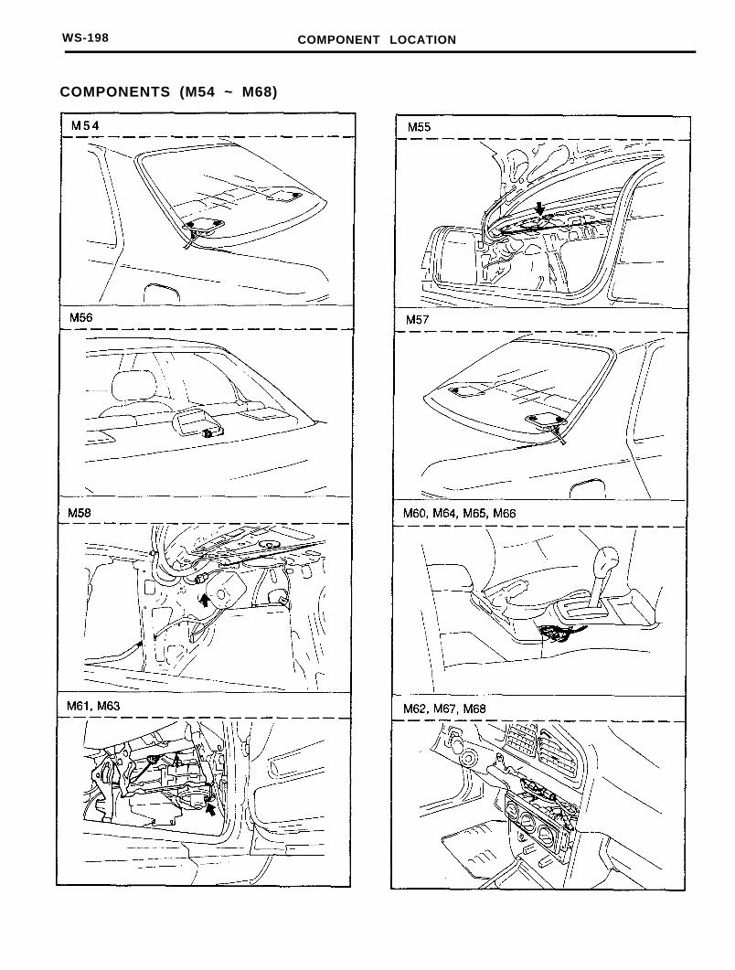
WS-198 COMPONENT LOCATION
COMPONENTS (M54 ~ M68)
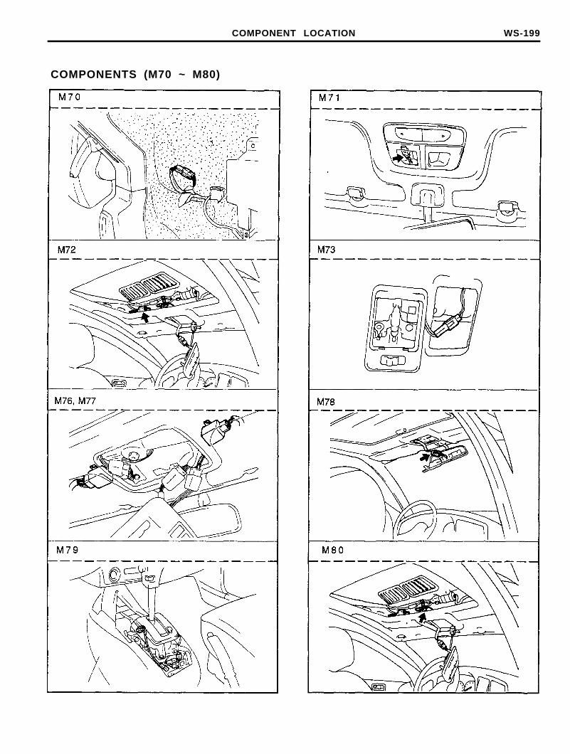
COMPONENT LOCATION WS-199
COMPONENTS (M70 ~ M80)
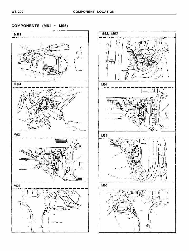
WS-200 COMPONENT LOCATION
COMPONENTS (M81 ~ M95)
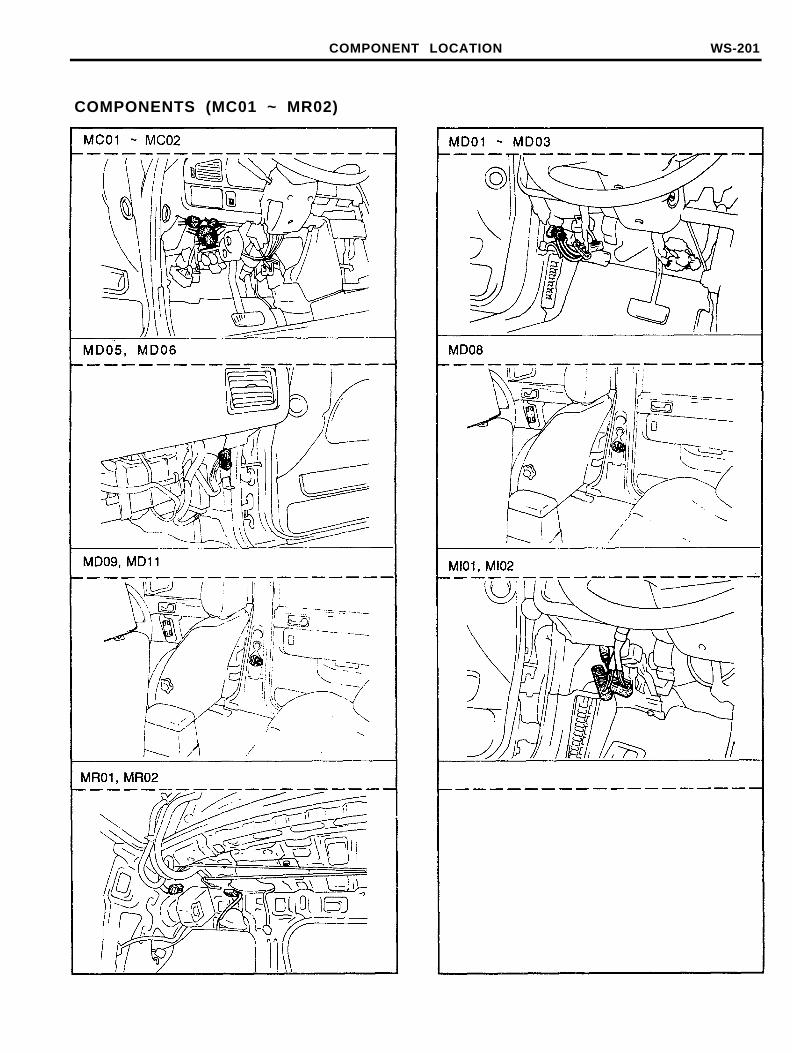
COMPONENT LOCATION WS-201
COMPONENTS (MC01 ~ MR02)

WS-202 COMPONENT LOCATION
COMPONENTS (R01 ~ R15)
COMPONENT LOCATION WS-203
COMPONENTS (G01 ~ G08)
WS-204 COMPONENT LOCATION
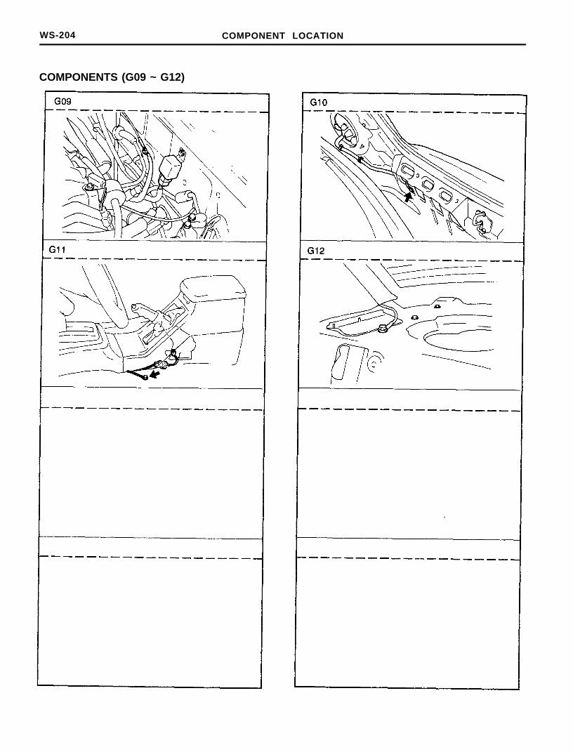
COMPONENTS (G09 ~ G12)
INTRODUCTION WS-205
HARNESS LAYOUTSHarness layouts show the routing of the major wiring harnesses and the in-line connectors between the major harnesses.These layouts will make electrical troubleshooting easier.
An example of Harness Layouts-Engine Harness
COMPONENT LOCATIONS
Component Locations give easy access to find the schematic components on the vehicle shown in the ComponentLocation Index. Where connectors are listed, the total number of cavities, how many are actually used, is provided to helpidentify connectors on the vehicle.
WS-206 HARNESS LAYOUT
HARNESS LAYOUT
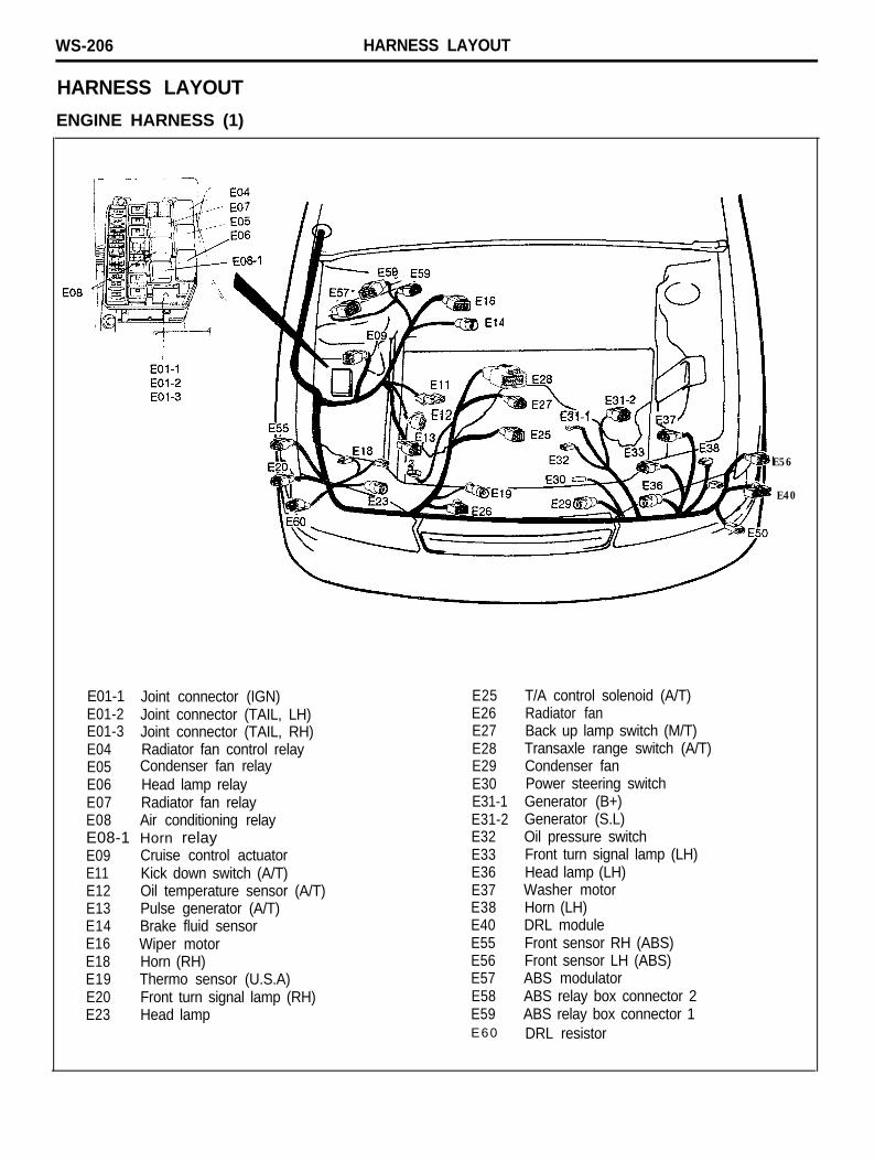
ENGINE HARNESS (1)
E56
E40
E01-1 Joint connector (IGN)E01-2 Joint connector (TAIL, LH)E01-3 Joint connector (TAIL, RH)E04 Radiator fan control relayE05 Condenser fan relayE06 Head lamp relayE07 Radiator fan relayE08 Air conditioning relayE08-1 Horn relayE09 Cruise control actuatorE11 Kick down switch (A/T)E12 Oil temperature sensor (A/T)E13 Pulse generator (A/T)E14 Brake fluid sensorE16 Wiper motorE18 Horn (RH)E19 Thermo sensor (U.S.A)E20 Front turn signal lamp (RH)E23 Head lamp
E25E26E27E28E29E30E31-1E31-2E32E33E36E37E38E40E55E56E57E58E59E60
T/A control solenoid (A/T)Radiator fanBack up lamp switch (M/T)Transaxle range switch (A/T)Condenser fanPower steering switchGenerator (B+)Generator (S.L)Oil pressure switchFront turn signal lamp (LH)Head lamp (LH)Washer motorHorn (LH)DRL moduleFront sensor RH (ABS)Front sensor LH (ABS)ABS modulatorABS relay box connector 2ABS relay box connector 1DRL resistor
HARNESS LAYOUT WS-207
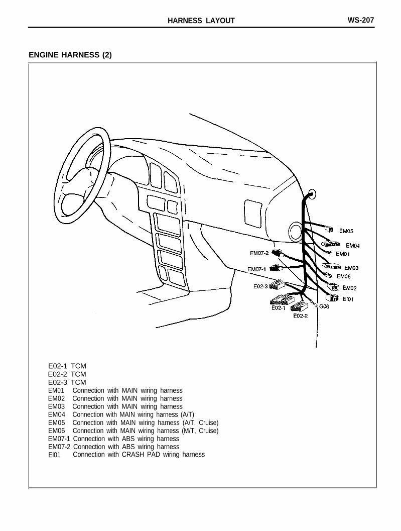
ENGINE HARNESS (2)
E02-1 TCME02-2 TCME02-3 TCMEM01 Connection with MAIN wiring harnessEM02 Connection with MAIN wiring harnessEM03 Connection with MAIN wiring harnessEM04 Connection with MAIN wiring harness (A/T)EM05 Connection with MAIN wiring harness (A/T, Cruise)EM06 Connection with MAIN wiring harness (M/T, Cruise)EM07-1 Connection with ABS wiring harnessEM07-2 Connection with ABS wiring harnessEl01 Connection with CRASH PAD wiring harness
WS-208 HARNESS LAYOUT
CONTROL HARNESS
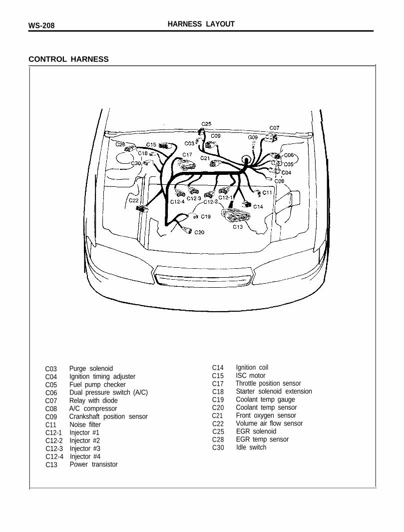
C03 Purge solenoidC04 Ignition timing adjusterC05 Fuel pump checkerC06 Dual pressure switch (A/C)C07 Relay with diodeC08 A/C compressorC09 Crankshaft position sensorC11 Noise filterC12-1 Injector #1C12-2 Injector #2C12-3 Injector #3C12-4 Injector #4C13 Power transistor
C14C15C17C18C19C20C21C22C25C28C30
Ignition coilISC motorThrottle position sensorStarter solenoid extensionCoolant temp gaugeCoolant temp sensorFront oxygen sensorVolume air flow sensorEGR solenoidEGR temp sensorIdle switch
HARNESS LAYOUT WS-209
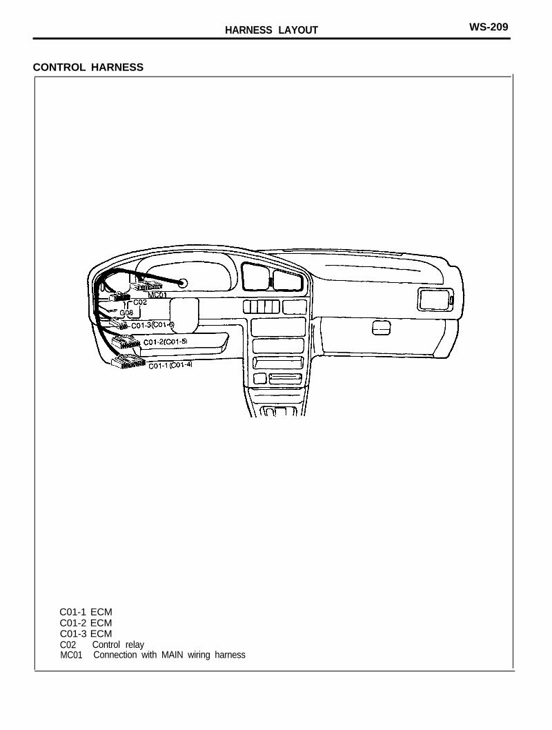
CONTROL HARNESS
C01-1 ECMC01-2 ECMC01-3 ECMC02 Control relayMC01 Connection with MAIN wiring harness
WS-210 HARNESS LAYOUT
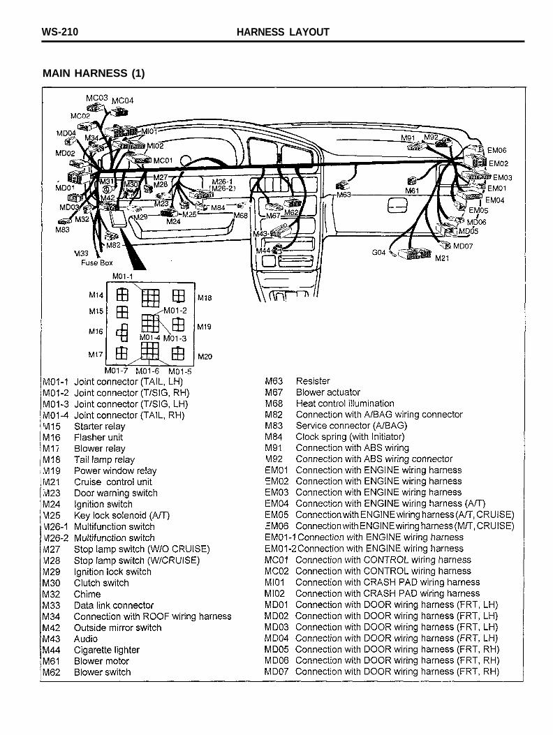
MAIN HARNESS (1)
HARNESS LAYOUT WS-211
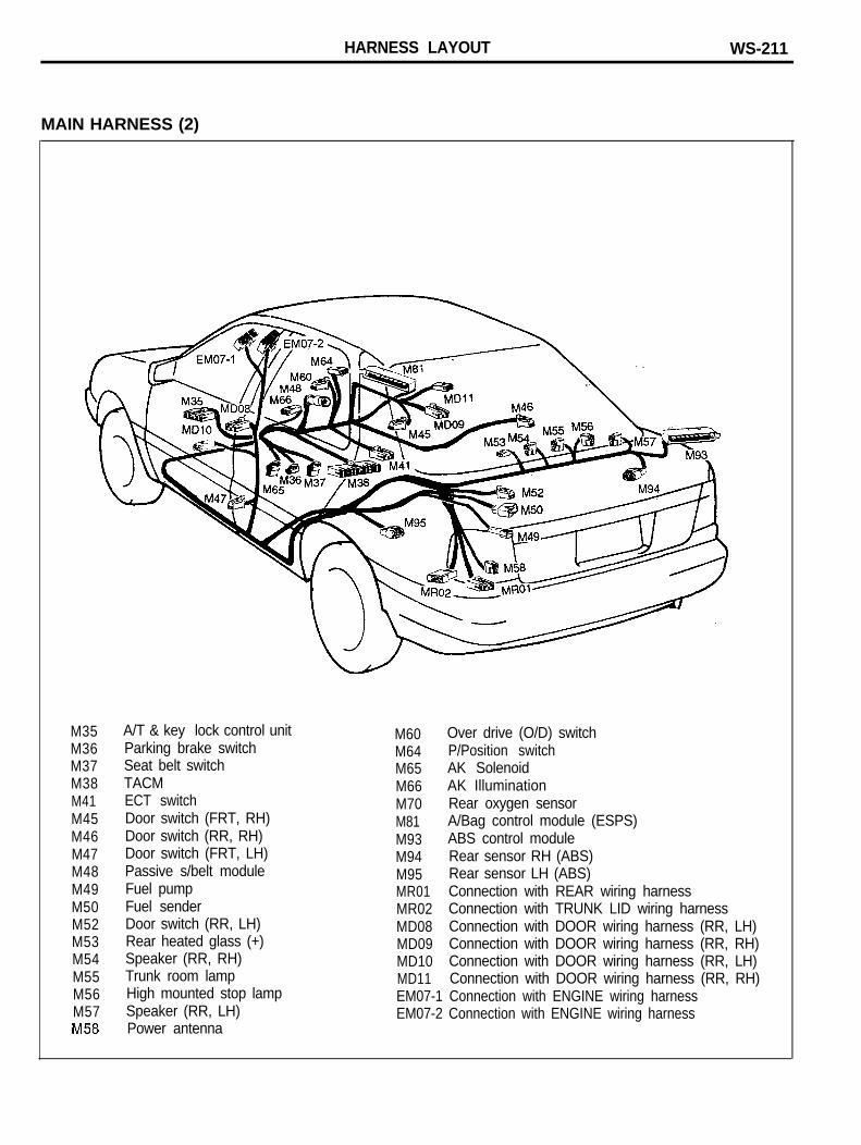
MAIN HARNESS (2)
M35M36M37M38M41M45M46M47M48M49M50M52M53M54M55M56M57
A/T & key lock control unitParking brake switchSeat belt switchTACMECT switchDoor switch (FRT, RH)Door switch (RR, RH)Door switch (FRT, LH)Passive s/belt moduleFuel pumpFuel senderDoor switch (RR, LH)Rear heated glass (+)Speaker (RR, RH)Trunk room lampHigh mounted stop lampSpeaker (RR, LH)Power antenna
M60 Over drive (O/D) switchM64 P/Position switchM65 AK SolenoidM66 AK IlluminationM70 Rear oxygen sensorM81 A/Bag control module (ESPS)M93 ABS control moduleM94 Rear sensor RH (ABS)M95 Rear sensor LH (ABS)MR01 Connection with REAR wiring harnessMR02 Connection with TRUNK LID wiring harnessMD08 Connection with DOOR wiring harness (RR, LH)MD09 Connection with DOOR wiring harness (RR, RH)MD10 Connection with DOOR wiring harness (RR, LH)MD11 Connection with DOOR wiring harness (RR, RH)EM07-1 Connection with ENGINE wiring harnessEM07-2 Connection with ENGINE wiring harness

WS-212 HARNESS LAYOUT
CRASH PAD HARNESS
I01 RheostatI07 Cruise switchI08 Rear defogger switchI09 Hazard switchI10 A/C switchI11 Digital clockI12 Thermo switchI13-1 ClusterI13-2 ClusterI13-3 ClusterI13-4 Reed switchMl01 Connection with Main harnessMl02 Connection with Main harnessEl01 Connection with Engine harness
HARNESS LAYOUT WS-213
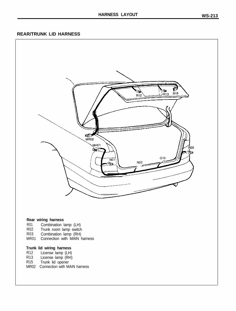
REAR/TRUNK LID HARNESS
Rear wiring harnessR01 Combination lamp (LH)R02 Trunk room lamp switchR03 Combination lamp (RH)MR01 Connection with MAIN harness
Trunk lid wiring harnessR12 License lamp (LH)R13 License lamp (RH)R15 Trunk lid openerMR02 Connection with MAIN harness
WS-214 HARNESS LAYOUT
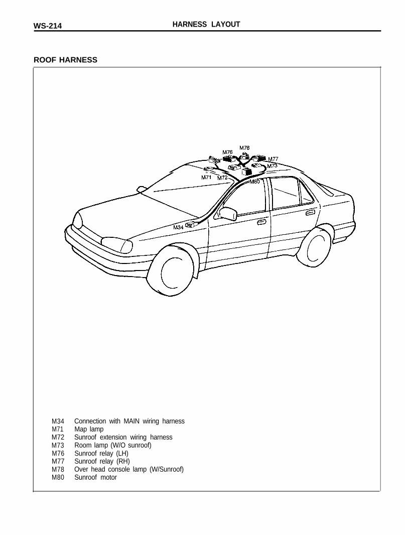
ROOF HARNESS
M34M71M72M73M76M77M78M80
Connection with MAIN wiring harnessMap lampSunroof extension wiring harnessRoom lamp (W/O sunroof)Sunroof relay (LH)Sunroof relay (RH)Over head console lamp (W/Sunroof)Sunroof motor
HARNESS LAYOUT WS-215
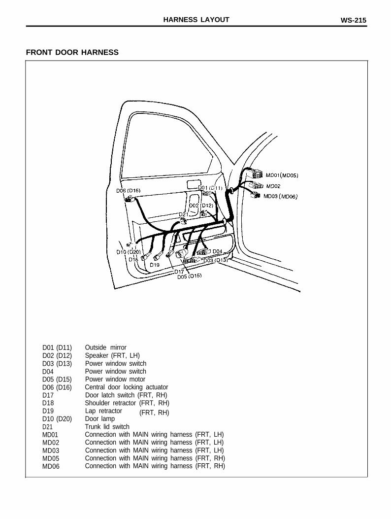
FRONT DOOR HARNESS
D01 (D11)D02 (D12)D03 (D13)D04D05 (D15)D06 (D16)D17D18D19D10 (D20)D21MD01MD02MD03MD05MD06
Outside mirrorSpeaker (FRT, LH)Power window switchPower window switchPower window motorCentral door locking actuatorDoor latch switch (FRT, RH)Shoulder retractor (FRT, RH)Lap retractorDoor lamp
(FRT, RH)
Trunk lid switchConnection with MAIN wiring harness (FRT, LH)Connection with MAIN wiring harness (FRT, LH)Connection with MAIN wiring harness (FRT, LH)Connection with MAIN wiring harness (FRT, RH)Connection with MAIN wiring harness (FRT, RH)
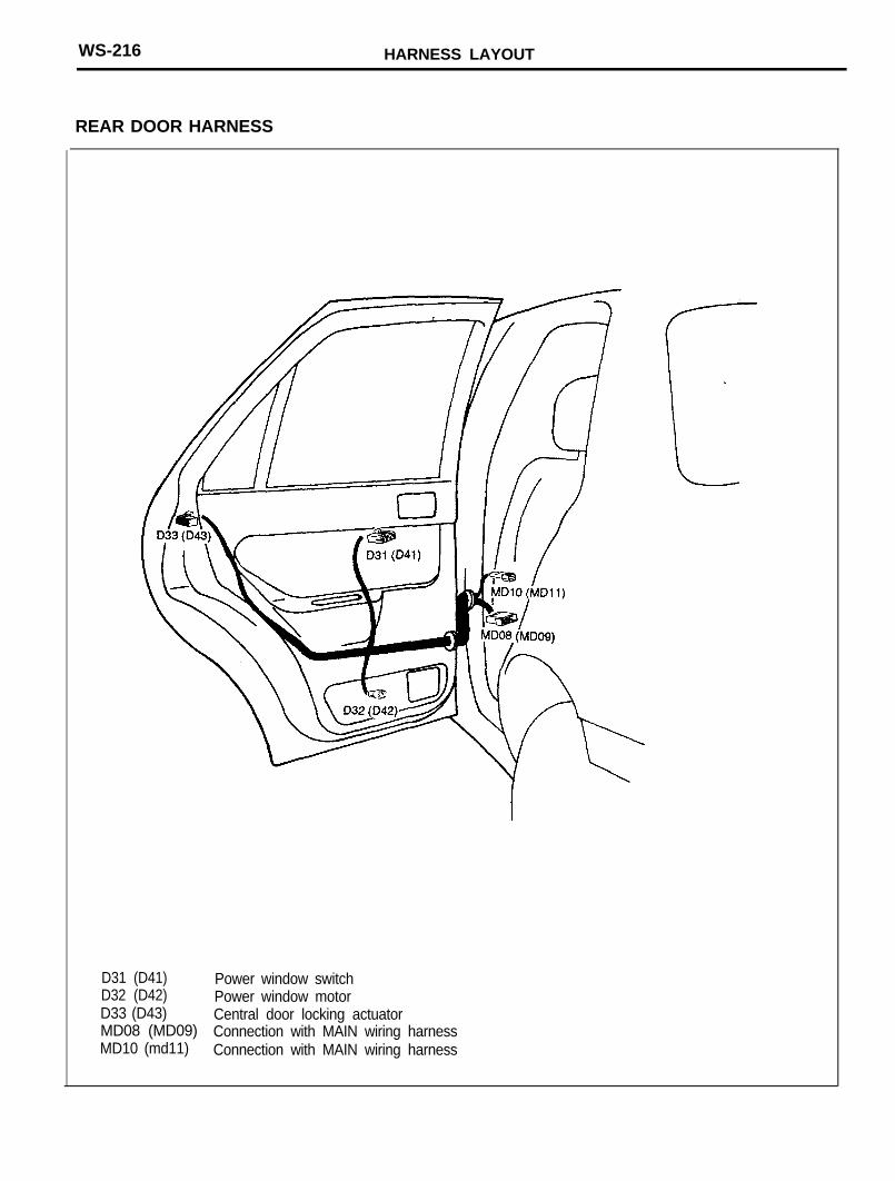
WS-216 HARNESS LAYOUT
REAR DOOR HARNESS
D31 (D41) Power window switchD32 (D42) Power window motorD33 (D43) Central door locking actuatorMD08 (MD09) Connection with MAIN wiring harnessMD10 (md11) Connection with MAIN wiring harness