appendix a geotechnical report - · pdf filegeotechnical investigation prairie industrial park...
TRANSCRIPT

APPENDIX A Geotechnical Report

GEOTECHNICAL INVESTIGATIONPRAIRIE INDUSTRIAL PARK
NEAR MAZENOD AND CAMIEL SYSWINNIPEG, MANITOBA
Submitted to:
Terracon Developments1 Terracon Place
Winnipeg, ManitobaR2J 4B3
Attention: Mr. Paul Kingerski
Submitted by:AMEC Environment & Infrastructure
A Division of AMEC Americas Limited440 Dovercourt DriveWinnipeg, Manitoba
R3Y 1N4
23 September 2013
AMEC File No. WX17188

Geotechnical Investigation Proposed Prairie Industrial Park Winnipeg, Manitoba
P:\Jobs\17100's\17180's\17188 - Terracon - St Boniface Industrial park\Geotech\Reporting\17188-00-Prairie Industrial Geotech (Roads) Report.doc Page ii
TABLE OF CONTENTS
PAGE
1.0 INTRODUCTION ............................................................................................................. 1
2.0 PROPOSED DEVELOPMENT ........................................................................................ 1
3.0 SITE CONDITIONS ......................................................................................................... 1
4.0 FIELD INVESTIGATON .................................................................................................. 2
5.0 LABORATORY TESTING ............................................................................................... 3
6.0 SUBSURFACE CONDITIONS ........................................................................................ 3
6.1 SLOUGHING AND SEEPAGE CONDITIONS ...................................................... 7
6.2 AUGER REFUSAL ............................................................................................... 7
7.0 DISCUSSIONS AND RECOMMENDATIONS ................................................................. 7
7.1 LIFT STATION ..................................................................................................... 7
7.1.1 General Evaluation .............................................................................. 7
7.1.2 Excavation Stability .............................................................................. 8
7.1.3 Lift Station Foundation ......................................................................... 9
7.1.4 Frost Considerations .......................................................................... 11
7.2 SITE GRADING & ROADWAYS ........................................................................ 11
7.3 PONDS .............................................................................................................. 12
7.4 PIPING .............................................................................................................. 13
7.4.1 Backfill ............................................................................................... 13
7.5 FOUNDATION CONCRETE TYPE .................................................................... 14
8.0 TESTING AND MONITORING ...................................................................................... 14
9.0 CLOSURE ..................................................................................................................... 16

Geotechnical Investigation Proposed Prairie Industrial Park Winnipeg, Manitoba
P:\Jobs\17100's\17180's\17188 - Terracon - St Boniface Industrial park\Geotech\Reporting\17188-00-Prairie Industrial Geotech (Roads) Report.doc Page iii
LIST OF TABLES
Table 1: Moisture Content Summary - Organic Clay ................................................................... 4
Table 2: Pocket Penetrometer Testing in Clay ............................................................................ 4
Table 3: Moisture Content Summary - Clay ................................................................................. 5
Table 4: Unconfined Compressive Strength Testing in Clay ........................................................ 5
Table 5: Hydrometer and Atterberg Limit Results - Glaciolacustrine Clay.................................... 5
Table 6: Moisture Content Summary - Silt ................................................................................... 6
Table 7: Hydrometer and Atterberg Limit Results – Silt ............................................................... 6
LIST OF APPENDICES
Appendix A Site Plan & Borehole Logs
Appendix B Lateral Earth Pressures

Geotechnical Investigation Proposed Prairie Industrial Park Winnipeg, Manitoba
17188-00-Prairie Industrial Geotech (Roads) Report.doc Page 1
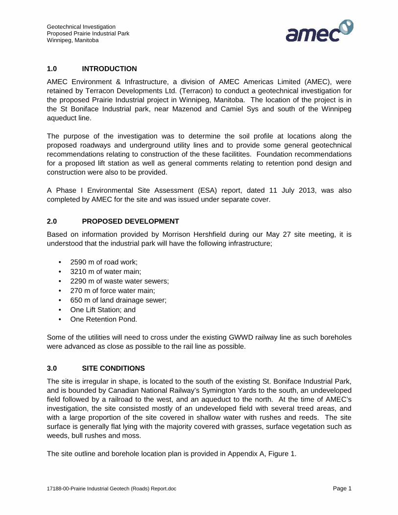
1.0 INTRODUCTION
AMEC Environment & Infrastructure, a division of AMEC Americas Limited (AMEC), were
retained by Terracon Developments Ltd. (Terracon) to conduct a geotechnical investigation for
the proposed Prairie Industrial project in Winnipeg, Manitoba. The location of the project is in
the St Boniface Industrial park, near Mazenod and Camiel Sys and south of the Winnipeg
aqueduct line.
The purpose of the investigation was to determine the soil profile at locations along the
proposed roadways and underground utility lines and to provide some general geotechnical
recommendations relating to construction of the these facilitites. Foundation recommendations
for a proposed lift station as well as general comments relating to retention pond design and
construction were also to be provided.
A Phase I Environmental Site Assessment (ESA) report, dated 11 July 2013, was also
completed by AMEC for the site and was issued under separate cover.
2.0 PROPOSED DEVELOPMENT
Based on information provided by Morrison Hershfield during our May 27 site meeting, it is
understood that the industrial park will have the following infrastructure;
• 2590 m of road work;
• 3210 m of water main;
• 2290 m of waste water sewers;
• 270 m of force water main;
• 650 m of land drainage sewer;
• One Lift Station; and
• One Retention Pond.
Some of the utilities will need to cross under the existing GWWD railway line as such boreholes
were advanced as close as possible to the rail line as possible.
3.0 SITE CONDITIONS
The site is irregular in shape, is located to the south of the existing St. Boniface Industrial Park,
and is bounded by Canadian National Railway’s Symington Yards to the south, an undeveloped
field followed by a railroad to the west, and an aqueduct to the north. At the time of AMEC’s
investigation, the site consisted mostly of an undeveloped field with several treed areas, and
with a large proportion of the site covered in shallow water with rushes and reeds. The site
surface is generally flat lying with the majority covered with grasses, surface vegetation such as
weeds, bull rushes and moss.
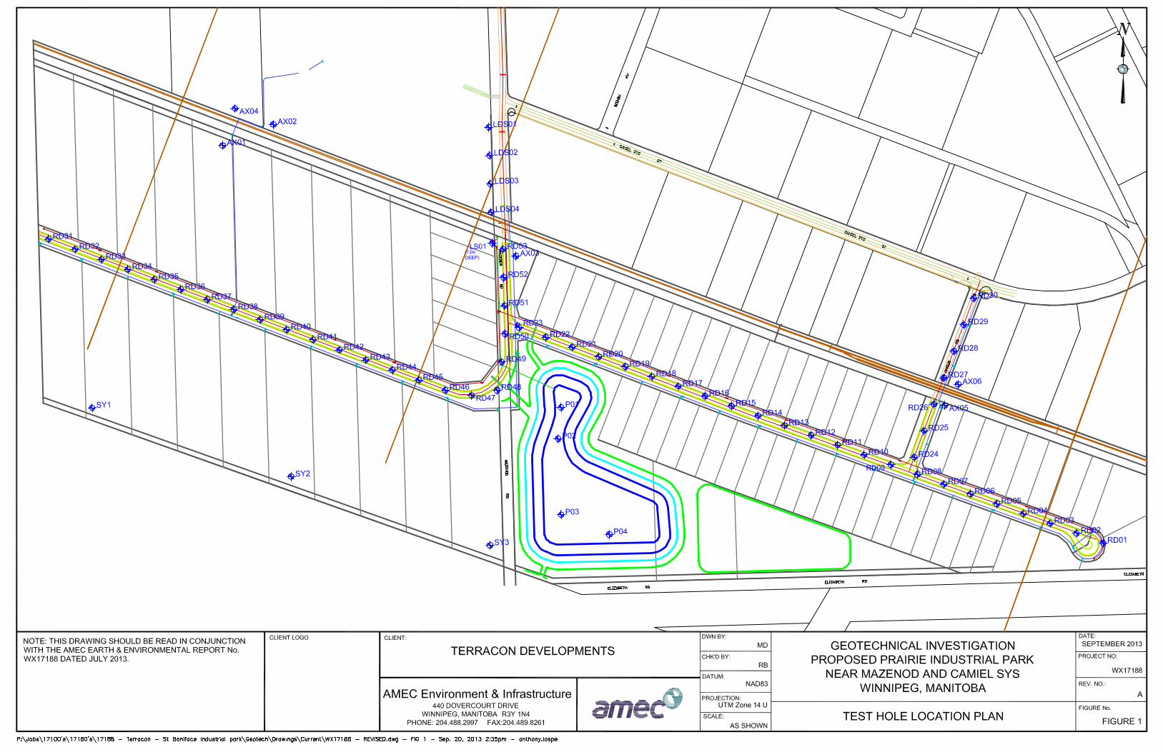
The site outline and borehole location plan is provided in Appendix A, Figure 1.

Geotechnical Investigation Proposed Prairie Industrial Park Winnipeg, Manitoba
17188-00-Prairie Industrial Geotech (Roads) Report.doc Page 2
4.0 FIELD INVESTIGATON
A geotechnical field investigation was conducted at the site between the dates of 11 July and 26
August 2013. The geotechnical investigation included the following boreholes;
- A total of 53 boreholes were completed along the proposed roadways (RD01 to
RD53). They were advanced every 50m along the proposed road, to a depth of 2m
below grade with every second borehole advanced to a depth of 6m below grade.
The boreholes were generally located along the centerline of the proposed road.
- A total of four boreholes (P01 to P04) were drilled to a depth of 9 m within the
proposed retention pond.
- One borehole (LS01) was advanced for the proposed lift station to a depth of 12m
below present grade.
- A total of 3 boreholes (AX03, AX04 and RD27) were advanced at 2 of the 3
proposed water main aqueduct crossings to a depth of about 9m below present
grade. The remaining planned crossing bore holes (AX01, AX02 and AX04 were not
accessible at the time of drilling.
- Three boreholes (LDS01 to LDS04) were advanced along Mazenod road north of
the aqueduct to a depth of about 6 to 7m below present grade for assessment of
soil conditions along the proposed Land Drainage Sewer (LDS).
- Three boreholes (SY01 to SY03) along the property boundary between Symington
yard and the site for environmental screening. These boreholes are provided for
information only in this report.
All boreholes were surveyed using AMEC’s survey grade GPS equipment. The majority of the
boreholes were completed by Maple Leaf Drilling Ltd., under the full-time supervision of AMEC
personnel. The boreholes were advanced with a track mounted drill rig equipped with 125 mm
diameter solid stem augers. Some supplemental drilling of the shallow boreholes were
advanced using hand augered equipment (i.e. 100mm diameter flight augers) operated by
AMEC field staff. The borehole locations are shown on the Borehole Location Plan, Figure 1 in
Appendix A.
All soils observed during borehole drilling were visually classified on site according to the
Modified Unified Soil Classification System. Sloughing, seepage and drilling conditions, as well
as any pertinent subsurface observations, were also recorded at the time of the investigation.
Disturbed soil samples were taken at regular intervals from the auger cuttings. Additional
sampling consisted of relatively undisturbed Shelby tube samples for the lift station foundation
design at borehole LS01. Testing conducted during the field investigation consisted of pocket
penetrometer tests at regular intervals in all of the boreholes.
Geotechnical Investigation Proposed Prairie Industrial Park Winnipeg, Manitoba
17188-00-Prairie Industrial Geotech (Roads) Report.doc Page 3
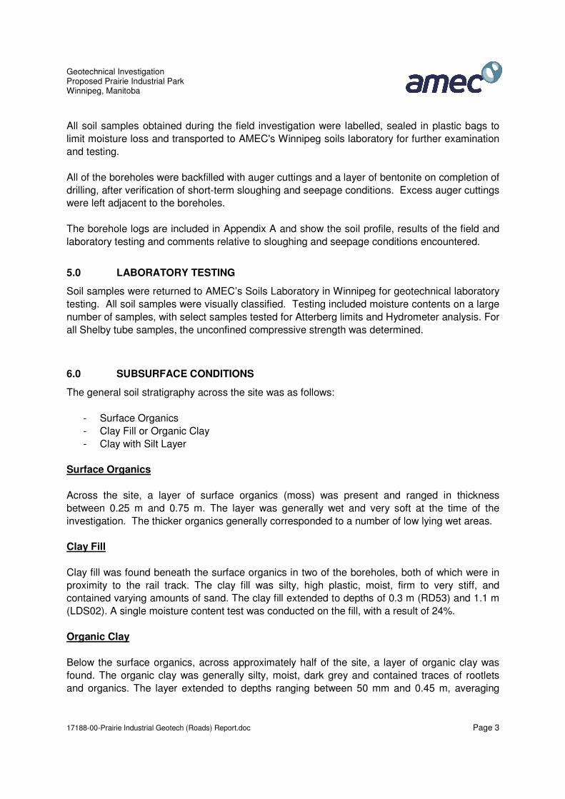
All soil samples obtained during the field investigation were labelled, sealed in plastic bags to
limit moisture loss and transported to AMEC's Winnipeg soils laboratory for further examination
and testing.
All of the boreholes were backfilled with auger cuttings and a layer of bentonite on completion of
drilling, after verification of short-term sloughing and seepage conditions. Excess auger cuttings
were left adjacent to the boreholes.
The borehole logs are included in Appendix A and show the soil profile, results of the field and
laboratory testing and comments relative to sloughing and seepage conditions encountered.
5.0 LABORATORY TESTING
Soil samples were returned to AMEC’s Soils Laboratory in Winnipeg for geotechnical laboratory
testing. All soil samples were visually classified. Testing included moisture contents on a large
number of samples, with select samples tested for Atterberg limits and Hydrometer analysis. For
all Shelby tube samples, the unconfined compressive strength was determined.
6.0 SUBSURFACE CONDITIONS
The general soil stratigraphy across the site was as follows:
- Surface Organics
- Clay Fill or Organic Clay
- Clay with Silt Layer
Surface Organics
Across the site, a layer of surface organics (moss) was present and ranged in thickness
between 0.25 m and 0.75 m. The layer was generally wet and very soft at the time of the
investigation. The thicker organics generally corresponded to a number of low lying wet areas.
Clay Fill
Clay fill was found beneath the surface organics in two of the boreholes, both of which were in
proximity to the rail track. The clay fill was silty, high plastic, moist, firm to very stiff, and
contained varying amounts of sand. The clay fill extended to depths of 0.3 m (RD53) and 1.1 m
(LDS02). A single moisture content test was conducted on the fill, with a result of 24%.
Organic Clay
Below the surface organics, across approximately half of the site, a layer of organic clay was
found. The organic clay was generally silty, moist, dark grey and contained traces of rootlets
and organics. The layer extended to depths ranging between 50 mm and 0.45 m, averaging
Geotechnical InvestigationProposed Prairie Industrial ParkWinnipeg, Manitoba
17188-00-Prairie Industrial Geotech (Roads) Report.doc Page 1
1.0 INTRODUCTION
AMEC Environment & Infrastructure, a division of AMEC Americas Limited (AMEC), wereretained by Terracon Developments Ltd. (Terracon) to conduct a geotechnical investigation forthe proposed Prairie Industrial project in Winnipeg, Manitoba. The location of the project is inthe St Boniface Industrial park, near Mazenod and Camiel Sys and south of the Winnipegaqueduct line.
The purpose of the investigation was to determine the soil profile at locations along theproposed roadways and underground utility lines and to provide some general geotechnicalrecommendations relating to construction of the these facilitites. Foundation recommendationsfor a proposed lift station as well as general comments relating to retention pond design andconstruction were also to be provided.
A Phase I Environmental Site Assessment (ESA) report, dated 11 July 2013, was alsocompleted by AMEC for the site and was issued under separate cover.
2.0 PROPOSED DEVELOPMENT
Based on information provided by Morrison Hershfield during our May 27 site meeting, it isunderstood that the industrial park will have the following infrastructure;
2590 m of road work; 3210 m of water main; 2290 m of waste water sewers; 270 m of force water main; 650 m of land drainage sewer; One Lift Station; and One Retention Pond.
Some of the utilities will need to cross under the existing GWWD railway line as such boreholeswere advanced as close as possible to the rail line as possible.
3.0 SITE CONDITIONS
The site is irregular in shape, is located to the south of the existing St. Boniface Industrial Park,and is bounded by Canadian National Railway’s Symington Yards to the south, an undevelopedfield followed by a railroad to the west, and an aqueduct to the north. At the time of AMEC’sinvestigation, the site consisted mostly of an undeveloped field with several treed areas, andwith a large proportion of the site covered in shallow water with rushes and reeds. The sitesurface is generally flat lying with the majority covered with grasses, surface vegetation such asweeds, bull rushes and moss.
The site outline and borehole location plan is provided in Appendix A, Figure 1.

Geotechnical InvestigationProposed Prairie Industrial ParkWinnipeg, Manitoba
17188-00-Prairie Industrial Geotech (Roads) Report.doc Page 2
4.0 FIELD INVESTIGATON
A geotechnical field investigation was conducted at the site between the dates of 11 July and 26August 2013. The geotechnical investigation included the following boreholes;
- A total of 53 boreholes were completed along the proposed roadways (RD01 toRD53). They were advanced every 50m along the proposed road, to a depth of 2mbelow grade with every second borehole advanced to a depth of 6m below grade.The boreholes were generally located along the centerline of the proposed road.
- A total of four boreholes (P01 to P04) were drilled to a depth of 9 m within theproposed retention pond.
- One borehole (LS01) was advanced for the proposed lift station to a depth of 12mbelow present grade.
- A total of 3 boreholes (AX03, AX04 and RD27) were advanced at 2 of the 3proposed water main aqueduct crossings to a depth of about 9m below presentgrade. The remaining planned crossing bore holes (AX01, AX02 and AX04 were notaccessible at the time of drilling.
- Three boreholes (LDS01 to LDS04) were advanced along Mazenod road north ofthe aqueduct to a depth of about 6 to 7m below present grade for assessment ofsoil conditions along the proposed Land Drainage Sewer (LDS).
- Three boreholes (SY01 to SY03) along the property boundary between Symingtonyard and the site for environmental screening. These boreholes are provided forinformation only in this report.
All boreholes were surveyed using AMEC’s survey grade GPS equipment. The majority of theboreholes were completed by Maple Leaf Drilling Ltd., under the full-time supervision of AMECpersonnel. The boreholes were advanced with a track mounted drill rig equipped with 125 mmdiameter solid stem augers. Some supplemental drilling of the shallow boreholes wereadvanced using hand augered equipment (i.e. 100mm diameter flight augers) operated byAMEC field staff. The borehole locations are shown on the Borehole Location Plan, Figure 1 inAppendix A.
All soils observed during borehole drilling were visually classified on site according to theModified Unified Soil Classification System. Sloughing, seepage and drilling conditions, as wellas any pertinent subsurface observations, were also recorded at the time of the investigation.Disturbed soil samples were taken at regular intervals from the auger cuttings. Additionalsampling consisted of relatively undisturbed Shelby tube samples for the lift station foundationdesign at borehole LS01. Testing conducted during the field investigation consisted of pocketpenetrometer tests at regular intervals in all of the boreholes.

Geotechnical InvestigationProposed Prairie Industrial ParkWinnipeg, Manitoba
17188-00-Prairie Industrial Geotech (Roads) Report.doc Page 3
All soil samples obtained during the field investigation were labelled, sealed in plastic bags tolimit moisture loss and transported to AMEC's Winnipeg soils laboratory for further examinationand testing.
All of the boreholes were backfilled with auger cuttings and a layer of bentonite on completion ofdrilling, after verification of short-term sloughing and seepage conditions. Excess auger cuttingswere left adjacent to the boreholes.
The borehole logs are included in Appendix A and show the soil profile, results of the field andlaboratory testing and comments relative to sloughing and seepage conditions encountered.
5.0 LABORATORY TESTING
Soil samples were returned to AMEC’s Soils Laboratory in Winnipeg for geotechnical laboratorytesting. All soil samples were visually classified. Testing included moisture contents on a largenumber of samples, with select samples tested for Atterberg limits and Hydrometer analysis. Forall Shelby tube samples, the unconfined compressive strength was determined.
6.0 SUBSURFACE CONDITIONS
The general soil stratigraphy across the site was as follows:
- Surface Organics- Clay Fill or Organic Clay- Clay with Silt Layer
Surface Organics
Across the site, a layer of surface organics (moss) was present and ranged in thicknessbetween 0.25 m and 0.75 m. The layer was generally wet and very soft at the time of theinvestigation. The thicker organics generally corresponded to a number of low lying wet areas.
Clay Fill
Clay fill was found beneath the surface organics in two of the boreholes, both of which were inproximity to the rail track. The clay fill was silty, high plastic, moist, firm to very stiff, andcontained varying amounts of sand. The clay fill extended to depths of 0.3 m (RD53) and 1.1 m(LDS02). A single moisture content test was conducted on the fill, with a result of 24%.
Organic Clay
Below the surface organics, across approximately half of the site, a layer of organic clay wasfound. The organic clay was generally silty, moist, dark grey and contained traces of rootletsand organics. The layer extended to depths ranging between 50 mm and 0.45 m, averaging

Geotechnical InvestigationProposed Prairie Industrial ParkWinnipeg, Manitoba
17188-00-Prairie Industrial Geotech (Roads) Report.doc Page 4
about 0.3 m. Laboratory testing of the organic clay was limited to moisture contentdetermination and two organic contents (ASTM D2974), with the results summarized in Table 1.
Table 1: Moisture Content Summary - Organic Clay
Number ofTests
MaximumMoisture
Content (%)
MinimumMoistureContent
(%)
AverageMoisture
Content (%)
Organic Content
12 50.0 27.0 43.1 5.3 % @ RD32 – 0.3m7.2 % @ RD26 – 0.3m
Native Clay with Silt Layer
Clay
The predominant soil encountered at the site was high plastic clay. The clay was encounteredbelow the surficial organic soils in all boreholes and extended to the maximum depths explored(12.2 m). The clay was generally described as silty, moist, stiff, and brownish grey. Occasionalthin silt laminations were present within the clay throughout the depths explored. Generally theshear strength of the clay decreased with increasing depth, becoming firm to stiff below depthsof about 5 m to 6 m. Sulphate inclusions and gypsum crystals were present within the clay,typically below about 3 m. The clay became mottled brown and grey, then grey with increasingdepth. Oxidation was also found within the clay, generally within the upper 7 m.
Field testing within the clay was limited to pocket penetrometers testing to assess relativeundrained shear strengths. Results of the testing is summarized in Table 2. While the maximumand minimum results from pocket penetrometers testing indicate a wide range of undrainedshear strengths, average undrained shear strengths were generally slightly above 100 kPa inthe upper 3 m to 6 m, decreasing to about 50 to 75 kPa below 6 m.
Table 2: Pocket Penetrometer Testing in Clay
Number of Tests
UndrainedShear Strength
Maximum(kPa)
UndrainedShear StrengthMinimum (kPa)
AverageShear Strength (kPa)
608 420 10 103
Laboratory testing of the clay material consisted of unconfined compressive strength testing,moisture content determination, Atterberg limit testing and hydrometer grain size analyses.
Moisture content testing, which is summarized in Table 4, indicated in-situ moisture contentsranging between about 23.6% and 58.6%. Generally moisture contents were highly variable in

Geotechnical InvestigationProposed Prairie Industrial ParkWinnipeg, Manitoba
17188-00-Prairie Industrial Geotech (Roads) Report.doc Page 5
the upper 3 m, varying between about 23% and 55%, while below 3 m moisture contents weremuch more closely grouped at between about 45% and 60%.
Table 3: Moisture Content Summary - Clay
Number of Tests Maximum MoistureContent (%)
Minimum MoistureContent (%)
Average MoistureContent (%)
255 58.6 23.6 39.3
Unconfined compressive strength testing, which is summarized in Table 4, indicated the clay tohave unconfined compressive strengths of about 75 to 90 kPa throughout it’s depth. Althoughslightly inconsistent with pocket penetrometers readings, which indicated a slight decreasingtrend in strength with depth, unconfined compressive strength testing is a more accuratedetermination of soil strength than are field pocket penetrometers tests, which are subject tosample disturbance which is greater with depth.
Table 4: Unconfined Compressive Strength Testing in Clay
Test DataUnconfined
Compressive Strength(kPa)
Strain (%)
LS01 Sample 7 – 4.6 m to 5.2 mLS01 Sample 10 – 7.6 m to 8.2 m
LS01 Sample 13 – 10.7m to 11.3 m
88.975.989.8
3.62.23.2
Hydrometer and Atterberg Limits tests were conducted on the clays encountered and aresummarized in Table 5. For the soils tested, hydrometer and Atterberg Limits results suggestthat the soil generally corresponds to a CH classification in the MUSCS. The percentage ofparticles was relatively consistent at 82 to 83% clay, 17 to 18% silt and no sand or gravel. Liquidlimits varied from about 83% to 94% and plastic limits were from 28% to 30%.
Table 5: Hydrometer and Atterberg Limit Results - Glaciolacustrine Clay
Hydrometer and Atterberg Limit Analyses Results
Sample Information %Clay
%Silt
%Sand
%Gravel
LiquidLimit
%
PlasticLimit
%MUSCS
RD20 Sample 4 – 1.0 mRD31 Sample 7 – 2.0 m
8382
1718
00
00
8394
3028
CHCH

Geotechnical InvestigationProposed Prairie Industrial ParkWinnipeg, Manitoba
17188-00-Prairie Industrial Geotech (Roads) Report.doc Page 6
Silt
Within the clay, a layer of silt was present in approximately half of the boreholes. The silt layerwas generally low plastic, moist, soft to firm and light brown. Traces of clay were generallyfound within the silt. The silt layer was found at depths ranging between 0.3 m to 2.3 m, andwas between 0.15 m and 1.4 m thick.
Laboratory testing of the silt material consisted of, moisture content determination, Atterberglimit testing, and hydrometer grain size analyses.
Moisture content testing, which is summarized in Table 6, indicated in-situ moisture contentsranging between about 19.7% and 42.2%. Moisture contents overall followed a slightlyincreasing trend with depth, however the degree of this increase was relatively small.
Table 6: Moisture Content Summary - Silt
Number of Tests Maximum MoistureContent (%)
Minimum MoistureContent (%)
Average MoistureContent (%)
30 42.2 19.7 26.4
Hydrometer and Atterberg Limits tests were conducted on the silts encountered and aresummarized in Table 7. For the soils tested, hydrometer and Atterberg Limits results suggestthat the soil generally corresponds to either a CI or CL-ML classification in the MUSCS. Thepercentage of particles varied between 21% and 56% clay, 44% to 46%%, 0 to 22% sand and0% to 11% gravel. Liquid limits varied from about 26% to 38% and plastic limits were the sameat 18%.
Table 7: Hydrometer and Atterberg Limit Results – Silt
Hydrometer and Atterberg Limit Analyses Results
Sample Information %Clay
%Silt
%Sand
%Gravel
LiquidLimit
%
PlasticLimit
%MUSCS
RD29 Sample 2 – 0.5 mRD39 Sample 2 – 0.5 m
2036
7960
14
00
2638
1818
CL-MLCI

Geotechnical InvestigationProposed Prairie Industrial ParkWinnipeg, Manitoba
17188-00-Prairie Industrial Geotech (Roads) Report.doc Page 7
6.1 SLOUGHING AND SEEPAGE CONDITIONS
The boreholes were left open for approximately 10 minutes after completion of drilling toobserve short-term sloughing and seepage conditions. Some slight to moderate seepage andsloughing was noted within the upper 3 m of some of the boreholes generally from the silt ororganic layers.
It should be noted that only short-term seepage and sloughing conditions were observed andthat ground water levels can fluctuate annually, seasonally or as a result of construction activity.
6.2 AUGER REFUSAL
Practical auger refusal was not observed in any of the boreholes advanced at the site.
7.0 DISCUSSIONS AND RECOMMENDATIONS
7.1 LIFT STATION
7.1.1 General Evaluation
The soil conditions encountered at the Lift Station borehole location (LS01) are consideredsuitable for design and construction of the Lift Station. It is anticipated that the Lift Station willmost likely comprise of a concrete structure supported on a clay subgrade. Based on thedesign embedment depth (i.e. 5m below grade) and expected light foundation loads, it isexpected that the tank foundation could be designed on the basis of maintaining a net bearingpressure of zero (ie weight of structure is equal to or less than the weight of the soil beingremoved).
The following sections provide discussion and recommendations as they pertain to design andconstruction of the lift station, specifically: ‘Ultimate’ bearing pressure, lateral earth pressures forbelow grade walls; temporary construction dewatering requirements; and foundation concretetype.

Geotechnical InvestigationProposed Prairie Industrial ParkWinnipeg, Manitoba
17188-00-Prairie Industrial Geotech (Roads) Report.doc Page 8
7.1.2 Excavation Stability
7.1.2.1 Shoring
Based on the proximity of the rail line, it is envisioned that shoring or some other form ofexcavation support will be required to maintain excavation stability for construction of the liftstation. The use of sloped excavations is likely not considered feasible to attain a baseelevation of about 5m below current grade, either from the perspective of available space toconstruct sloped walls, nor from a short or long term stability perspective. In this regard, anopen excavation would require side slopes of 2:1 or flatter, resulting in an extremely largeexcavation (25 m by 25 m at surface).
Currently, it is envisaged that suitable excavation support systems would consist of one of thefollowing:
A steel casing of sufficient diameter advanced to the required embedment using a pilingrig; or
A braced excavation box inclusive of lateral struts such that lateral support is provided toall four sides of the excavation. Due to the limited width of the excavation, the use ofinternal rakers would preclude work within the excavation, and as such, are notconsidered feasible for use as excavation support.
7.1.2.2 Lateral Earth Pressure
Given the firm to stiff consistency of the native clay overburden, the distribution of earthpressures against the walls of a braced shoring system will adopt the stress distributionillustrated in Figure B1, Appendix B. This figure should be used in sizing, and spacing of thestruts.
Notwithstanding strut support requirements, the factor of safety of the braced shoring againstbase heave of the underlying soft normally consolidated lacustrine clay should be checked. Thefollowing expression may be used to check the factor of safety with respect to base heave, FSb,:
s
ubb qH
SNFS
where: FSb = Factor of Safety against base heaveNb = Stability factor dependent upon geometry of the excavation (Assume 8.5 for
a rectangular foundation with a depth to embedment ratio of 2)Su = Undrained shear strength (Assume 35 kPa below base of excavation) = Bulk unit weight of the overburden (Assume 17 kN/m3)H = height of wall (m)qs = surcharge load (kN/m2)

Geotechnical InvestigationProposed Prairie Industrial ParkWinnipeg, Manitoba
17188-00-Prairie Industrial Geotech (Roads) Report.doc Page 9
To preclude having to extend the shoring beyond the base of the excavation, a minimum factorof safety of 1.5 must be maintained. Based on a proposed excavation depth of about 5 m belowcurrent grades, FSb is estimated to be about 2.0 assuming no surcharge loading adjacent to theexcavation. Where surcharge loading adjacent to the excavation decreases the factor of safetyto less than 1.5, the shoring must extend below the base of the excavation, and this officeshould be contacted for review and additional recommendations.
The effects of surcharge load should be applied where required. The surcharge consideredshould include the effects of loads from street traffic, construction equipment, and any otherloads that may be transferred to the walls of the excavation during the construction period.
7.1.2.3 Construction Dewatering
Significant seepage and sloughing within the clay overburden above the anticipated excavationdepth of about 5 m is not expected. Fluctuations in groundwater elevation can occur seasonallydue to heavy rains and/or rises in the river level and therefore depending on when constructionoccurs, changes in groundwater levels may occur.
It is anticipated that where groundwater is observed within the excavation, it could be managedunder normal conditions with an internal dewatering system comprised of construction sumpand submersible pumps.
Primary concerns associated with using an internal dewatering system include the risk of loss ofground or washing of fines. The washing of fines and/or loss of ground could result in thesiltation of collected groundwater, possibly resulting in a subsequent requirement to remove thefines (i.e. by sedimentation or filtering) prior to disposal in City storm sewers. Furthermore, theloss of ground is a serious concern where soils with potential for piping are present. Althoughthe soils at the site are not considered particularly susceptible to piping under the anticipatedexcavation conditions, the loss of ground behind the shoring should be monitored, particularlywhere any silt layers are observed.
7.1.3 Lift Station Foundation
7.1.3.1 Ultimate Bearing Pressure
As previously discussed, it is envisaged that the outfall chamber will comprise a concretefoundation bearing on a clay subgrade at about 5 m below existing grade. Based on soilconditions encountered at the borehole location (LS01), subgrade conditions within the footprintof the lift station are expected to consist of firm to stiff native highly plastic clay. Given the soilconditions noted at the site, it is recommended that an unfactored Ultimate Limit State (ULS)bearing pressure of 300 kPa could be assumed in design of the lift station. In order to limitsettlements to less than 25mm, the ‘serviceability’ limit state (SLS) should be designed for anapplied bearing pressure of 90 kPa, which is roughly the weight of the soil being removed. It iscautioned however that additional settlement potential could be induced by disturbance and/orsoftening of the subgrade during construction.
Geotechnical InvestigationProposed Prairie Industrial ParkWinnipeg, Manitoba
17188-00-Prairie Industrial Geotech (Roads) Report.doc Page 10
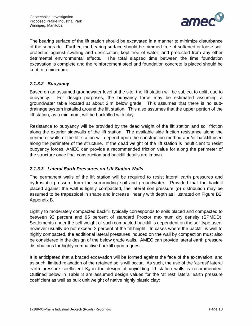
The bearing surface of the lift station should be excavated in a manner to minimize disturbanceof the subgrade. Further, the bearing surface should be trimmed free of softened or loose soil,protected against swelling and desiccation, kept free of water, and protected from any otherdetrimental environmental effects. The total elapsed time between the time foundationexcavation is complete and the reinforcement steel and foundation concrete is placed should bekept to a minimum.
7.1.3.2 Buoyancy
Based on an assumed groundwater level at the site, the lift station will be subject to uplift due tobuoyancy. For design purposes, the buoyancy force may be estimated assuming agroundwater table located at about 2 m below grade. This assumes that there is no sub-drainage system installed around the lift station. This also assumes that the upper pprtion of thelift station, as a minimum, will be backfilled with clay.
Resistance to buoyancy will be provided by the dead weight of the lift station and soil frictionalong the exterior sidewalls of the lift station. The available side friction resistance along theperimeter walls of the lift station will depend upon the construction method and/or backfill usedalong the perimeter of the structure. If the dead weight of the lift station is insufficient to resistbuoyancy forces, AMEC can provide a recommended friction value for along the perimeter ofthe structure once final construction and backfill details are known.
7.1.3.3 Lateral Earth Pressures on Lift Station Walls
The permanent walls of the lift station will be required to resist lateral earth pressures andhydrostatic pressure from the surrounding soil and groundwater. Provided that the backfillplaced against the wall is lightly compacted, the lateral soil pressure (p) distribution may beassumed to be trapezoidal in shape and increase linearly with depth as illustrated on Figure B2,Appendix B.
Lightly to moderately compacted backfill typically corresponds to soils placed and compacted tobetween 93 percent and 95 percent of standard Proctor maximum dry density (SPMDD).Settlements under the self weight of such compacted backfill is dependent on the soil type used,however usually do not exceed 2 percent of the fill height. In cases where the backfill is well tohighly compacted, the additional lateral pressures induced on the wall by compaction must alsobe considered in the design of the below grade walls. AMEC can provide lateral earth pressuredistributions for highly compactive backfill upon request.
It is anticipated that a braced excavation will be formed against the face of the excavation, andas such, limited relaxation of the retained soils will occur. As such, the use of the ‘at-rest’ lateralearth pressure coefficient Ko in the design of unyielding lift station walls is recommended.Outlined below in Table 8 are assumed design values for the ‘at rest’ lateral earth pressurecoefficient as well as bulk unit weight of native highly plastic clay:

Geotechnical InvestigationProposed Prairie Industrial ParkWinnipeg, Manitoba
17188-00-Prairie Industrial Geotech (Roads) Report.doc Page 11
Table 8: Lateral Earth Pressure Coefficients and Total Unit Weights for Light toModerately Compacted Soil
Soil Type Angle of Internal Friction, (°) ‘at-rest’ Earth Pressure, Ko
Total Unit Weight, (kN/m3)
Highly Plastic Clay 18 0.69 17Granular 30 0.50 20
The earth pressure coefficient outlined in Table 8 is unfactored, and does not include any factorof safety.
It is recommended that a cap of clay, concrete or asphalt be placed at the ground surfaceadjacent to the foundation walls to reduce the migration of surface water into the underlyinggranular backfill materials. If a clay cap is used, a minimum thickness of approximately 0.5 m isrecommended.
7.1.4 Frost Considerations
Based on local experience, an average annual frost penetration depth of 2.4 m is expected atthe site. With respect to the potential for adfreeze and frost heave of the lift station, the base ofthe lift station will be located well below the depth of frost penetration at a depth of about 5mbelow grade. As such, the risk of frost uplift of lift station is considered low to negligible.
However, notwithstanding the above, the lift station will be required to extend through the zoneof frost penetration. Portions of the lift station located within the depth of frost penetration mustbe structurally designed to resist increased lateral pressures induced by frost. In the case ofunyielding walls exposed to frost penetration above the groundwater table, it is recommendedthat Ko = 1.0, be used to account for lateral frost pressures1 .
7.2 SITE GRADING & ROADWAYS
Prior to rough site grading, fill areas and areas providing subgrade support (i.e. grade supportedslab footprints, pavement areas, etc.) should be cleared of trees, stumps, brush, ground plants,and matted vegetation. Trees, brush, stumps, roots, etc. should be removed from site.Furthermore, organic topsoil, mineral soils with an organic content greater than about 6 to 7percent (i.e. the surface organics noted on the logs as “moss”), and other deleterious materialshould be stripped and stockpiled outside of the footprint of cut and fill areas and areasproviding subgrade support. Low organic mineral soils such as the organic clay noted below thesurface organics (moss layer) containing less than 6 to 7 percent organic by weight may beconsidered relatively unaffected by the organic content from a subgrade suitability standpoint,and may be left in place in pavement areas, but should be removed from within buildingfootprints to preclude any requirement for the installation of a methane extraction system withincrawlspaces. Stockpiled topsoil and organic material may be re-used for landscaping only.
1 As per Canadian Foundation Engineering Manual, 3rd Edition, P. 429, an earth pressure coefficient K=1 should be used incombination with insulation for highly frost susceptible soils.

Geotechnical InvestigationProposed Prairie Industrial ParkWinnipeg, Manitoba
17188-00-Prairie Industrial Geotech (Roads) Report.doc Page 12
Based on the borehole information, the exposed subgrade following site clearing and strippingof unsuitable materials is expected to consist of highly plastic clay, organic clays with less than6 percent by organic content or potentially a shallow soft and wet silt layer. Typically, prior tothe placement of any fill to achieve subgrade design elevations or final surface grades, exposedcohesive subgrades are scarified, moisture conditioned to within two to three percent ofoptimum moisture content (OMC), and compacted to at least 95 percent of standard Proctormaximum dry density (SPMDD). However, in the case of areas having wet silts at or just belowsubgrade, which are highly susceptible to disturbance (i.e. rutting, spreading, etc.) underconcentrated loads, compaction of the natural subgrade may not be possible. This should beassessed at the time of construction.
It is understood that most of the roads constructed at the site will be raised well above thecurrent grades. Accordingly, the construction and performance of asphalt and concretepavements at this site will likely not be impacted in a significant way by the silt layers noted inthe boreholes. In this regard, raising of site grades should provide an overall benefit to longterm performance. Conversely, if there are areas where grades are at or below the current sitegrades, additional construction complications are likely to result and appropriate methods fordealing with the silt will be required. Given the thickness of the silt identified during theinvestigation, complete removal would likely not be cost effective and therefore other means oflimiting the impact of the silt should be considered. Traditionally in the Winnipeg area, siltsexposed at or near the subgrade elevation are sub-excavated to about 300 to 400mm below thedesign subgrade elevation and backfilled with 100 to 150mm crushed limestone rock placed ona geotextile fabric.
It is understood that standard Winnipeg road designs are to be utilized. Where requested,AMEC can provide site specific pavement designs, based on anticipated traffic loadings anddesign life.
7.3 PONDS
It is understood that a retention pond will be constructed as part of the industrial park. Fourboreholes were advanced within the pond areas and the soils conditions generally consisted ofnative high plastic clay with 3 of 4 holes having a silt layer noted in the upper 1 to 2m. It isunderstood that the standard City of Winnipeg retention pond design (consisting of a 7H:1Vslope below and above the summer water level) will be adopted. This City of Winnipeg designis understood to have been used successfully at numerous locations in the city and thereforerepresents an appropriate target level of stability (standard of practice) for the proposedretention pond.
Given the soil conditions noted (i.e. high plastic clay), typical excavation techniques areconsidered appropriate. Regardless of the slope design used in the pond area, special attentionshould be paid to any silt layers encountered during construction. Silt layers above the normalwater level should be daylighted in the pond slopes with an appropriate filter (granular ofsynthetic) to drain groundwater carried in the silt layer and avoid the accumulation of

Geotechnical InvestigationProposed Prairie Industrial ParkWinnipeg, Manitoba
17188-00-Prairie Industrial Geotech (Roads) Report.doc Page 13
groundwater pressures which can cause stability concerns. Under no circumstances should thesilt layer be capped with clay where it intersects the slope.
7.4 PIPING
Underground service utilities are commonly installed in the Winnipeg area using trenchingmethods. On that basis, typical construction methods are considered appropriate for theinstallation of underground utilities.
Standard excavation of trenches is considered suitable at this location for purposes of installingunderground services and piping, provided that trench excavations will be less than about 3 min depth. Trench excavations should include minimum slopes of 1:1. Alternatively, trench wallscan be cut vertical or near vertical provided that a trench cage is used to protect down holeworkers. As a minimum, all trench excavations should comply with the requirements of theManitoba Workplace Safety and Health Act and Guidelines, and the Workers CompensationBoard. The trenching work should be undertaken by experienced contractors and should alsobe closely supervised by knowledgeable safety personnel. Trench excavations whichexperience unusual difficulties should be brought to the immediate attention of the geotechnicalconsultant so that remedial work can be undertaken.
The trench should be cut to a width a minimum of 0.6 m plus the pipe diameter to accommodateplacement and compaction of granular bedding material. Bedding material at least 0.3 m thickplaced above and below the pipes should be used to provide suitable load distribution. Thebedding material should be nominally compacted to a maximum of 95% of standard Proctormaximum dry density (SPMDD). Excessive compaction of the bedding material should beavoided to prevent damage to the utilities.
It is understood that the the pipes will need to be protected from freezing conditions, which maybe accomplished by providing a sufficient thickness of cover material (soil or granular), utilizinginsulated and heat traced pipes or by providing a sufficient thickness of synthetic insulation.About 2.4 m of soil cover is generally sufficient in the Winnipeg area.
7.4.1 Backfill
Fill used to backfill trench excavations should be compacted to a standard that is in keeping withthe performance requirements of the finished area. If the area is not planned for an end use(such as for landscaping, staging areas, etc.), a minimum compaction standard and common fillmaterials could be considered. For finished areas that require a higher level of performance(such as roadways) a compaction level in the order of about 95 to 98% of SPMDD isrecommended. As well, select fill materials should be used and in this regard, the nativeexcavated soils are not recommended for such areas, as they can be difficult to compact withinconfined areas. Trench backfill should consist of materials consistent with the City of WinnipegStandard Construction specification for underground works.

Geotechnical InvestigationProposed Prairie Industrial ParkWinnipeg, Manitoba
17188-00-Prairie Industrial Geotech (Roads) Report.doc Page 14
7.5 FOUNDATION CONCRETE TYPE
Where concrete elements outlined in this report and all other concrete in contact with the localsoil will be subjected in service to weathering, sulphate attack, a corrosive environment, orsaturated conditions, the concrete should be designed, specified, and constructed inaccordance with concrete exposure classifications outlined in CSA standard A23.1-09, ConcreteMaterials and Methods of Concrete Construction. In addition, all concrete must be supplied inaccordance with current Manitoba and National Building Code requirements.
Based on AMEC’s experience in Winnipeg, water soluble sulphate concentrations in the soil aretypically in the range of 0.2% to 2.0%. As such, the degree of sulphate exposure at the site maybe considered as ‘severe’ in accordance with current CSA standards, and the use of sulphateresistance cement (Type HS or HSb) is recommended for concrete in contact with the local soil.Furthermore, air entrainment should be incorporated into any concrete elements that areexposed to freeze-thaw to enhance its durability.
It should be recognized that there may be structural and other considerations, which maynecessitate additional requirements for subsurface concrete mix design.
8.0 TESTING AND MONITORING
All engineering design recommendations presented in this report are based on the assumptionthat an adequate level of testing and monitoring will be provided during construction and that allconstruction will be carried out by a suitably qualified contractor experienced in foundation andearthworks construction. An adequate level of testing and monitoring is considered to be:
for excavations: - monitor the groundwater conditions prior to construction.- evaluate the excavation base after completion of excavation to
assess the basal stability and seepage conditions fordewatering assessment
- monitor the installation of sheet piles- monitor vertical and horizontal shoring movements
for foundations: - design review and review of the bearing surface prior toplacement of concrete.
for concrete construction: - testing of plastic and hardened concrete in accordance withCSA A23.1-09 and A23.2-09.
- review of concrete supplier’s mix designs for conformance withprescribed and/or performance concrete specifications.
AMEC requests the opportunity to review the design drawings and the installation of the liftstation to confirm that the geotechnical recommendations have been correctly interpreted.AMEC further requests the opportunity to review the soil and groundwater conditionsencountered as excavation proceed so that the assumptions made in preparing this report caneither be confirmed, or so that recommendations provided in this report can be modified toreflect such different conditions as are encountered.

Geotechnical InvestigationProposed Prairie Industrial ParkWinnipeg, Manitoba
17188-00-Prairie Industrial Geotech (Roads) Report.doc Page 15
The contractor should be advised that it is anticipated that the geotechnical engineer will not beon site on a full-time basis. Therefore, the timely reporting by contractor staff of unusual eventssuch as, but not limited to, loss of ground, changes in soil behaviour, movements of roadwaysurfaces and shoring, and changes in dewatering volumes will be very important in ensuring asuitably rapid response to potentially serious circumstances.
AMEC would be pleased to provide any further information that may be needed during designand to advise on the geotechnical aspects of specifications for inclusion in contract documents.

Geotechnical InvestigationProposed Prairie Industrial ParkWinnipeg, Manitoba
9.0 CLOSURE
The findings and recommendations presented herein for design of the proposed Lift Station anddevelopment are based on a geotechnical evaluation of the findings in the geotechnicalboreholes drilled at the site. If conditions are encountered that appear to be different from thoseshown in the borehole log and described in this report, or if the assumptions stated herein arenot in keeping with the design, AMEC should be notified and given the opportunity to review thecurrent recommendations in light of any new findings. Recommendations presented herein maynot be valid if an adequate level of inspection is not provided during construction, or if relevantbuilding code requirements are not met.
Soil conditions, by their nature, can be highly variable across a construction site. Theplacement of fill during and prior to construction activities on a site can contribute to variable soilconditions. A contingency amount should be included in the construction budget to allow for thepossibility of variations in soil conditions, which may result in modification of the design, and/orchanges in construction procedures.
This report has been prepared for the exclusive use of Terracon Developments, and theirdesign agents, for specific application to the development described within this report. The dataand recommendations provided herein should not be used for any other purpose, or by anyother parties, without review and written advice from AMEC.
The findings and recommendations of this report have been prepared in accordance withgenerally accepted soil and foundation engineering practices. No other warranty is made, eitherexpressed or implied.
Respectfully submitted,
AMEC Environmental & Infrastructurea division of AMEC Ame s Limited
/Trevor Gluck, . Eng.Senior Geote hnical Engineer
Reviewed By: Z<’Harley Pankratz, P. Eng. (VP: Eastern Prairies/Northern Al6árt’
— rz\
==Z4tfi
Certificate of Authorization
AMEC Environment & Infrastructure, a
Division of AMEC Americas Limited
No.555 D
17188-00-Prairie Industrial Geotech (Roads) Report.doc Page 16

Geotechnical InvestigationProposed Prairie Industrial ParkWinnipeg, Manitoba
P:\Jobs\17100's\17180's\17188 - Terracon - St Boniface Industrial park\Geotech\Reporting\17188-00-Prairie IndustrialGeotech (Roads) Report.doc
APPENDIX A
SITE PLAN&
BOREHOLE LOGS
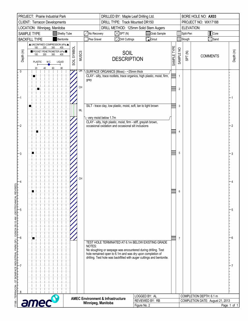
SURFACE ORGANICS (Moss) - ~25mm thickCLAY - silty, trace rootlets, trace organics, high plastic, moist, firm,grey
SILT - trace clay, low plastic, moist, soft, tan to light brown
- very moist below 1.7mCLAY - silty, high plastic, moist, firm - stiff, greyish brown,occasional oxidation and occasional silt inclusions
TEST HOLE TERMINATED AT 6.1m BELOW EXISTING GRADENOTES:No sloughing or seepage was encountered during drilling. Testhole remained open to 6.1m and was dry upon completion ofdrilling. Test hole was backfilled with auger cuttings and bentonite.
OR
CH
ML
CH
1
2
3
4
5
6
7
SOILDESCRIPTION
LOGGED BY: ALREVIEWED BY: RBFigure No. 2
Dep
th (m
)
200
Split-Pen
100 200 300 400
1
2
3
4
5
6
7
1
2
3
4
5
6
7
8
CoreShelby Tube
80
Dep
th (m
) 100 200 300 400
PLASTIC M.C.
COMPLETION DEPTH: 6.1 mCOMPLETION DATE: August 21, 2013
PROJECT: Prairie Industrial Park
CLIENT: Terracon Developments
LOCATION: Winnipeg, Manitoba
DRILLED BY: Maple Leaf Drilling Ltd.
DRILL TYPE: Track Mounted DR150
DRILL METHOD: 125mm Solid Stem Augers
BORE HOLE NO: AX03
PROJECT NO: WX17188
ELEVATION:
SAMPLE TYPE
60
Page 1 of 1
SandBACKFILL TYPE
SPT (N)
UNCONFINED COMPRESSION (kPa)
Drill Cuttings Grout
POCKET PENETROMETER (kPa)
LIQUID
Slough
No Recovery
Bentonite
40
Grab Sample
Pea Gravel
SOIL
SYM
BOL
COMMENTS
1718
8 -
TE
RR
AC
ON
- S
T B
ON
IFA
CE
IND
US
TR
IAL
PA
RK
.GP
J 1
3/09
/24
09:
15
AM
(G
EO
TE
CH
NIC
AL
RE
VIS
ED
)
AMEC Environment & InfrastructureWinnipeg, Manitoba
MU
SCS
SAM
PLE
TYPE
SPT
(N)
SAM
PLE
NO

SURFACE ORGANICS (Moss) - ~25mm thickORGANIC CLAY - silty, trace rootlets and organics, moist, darkgreyCLAY - silty, trace rootlets to 0.3m, high plastic, moist, stiff,brownish grey, occasional silt inclusions- greyish brown below 0.8m
- firm, brown, occasional sulphate inclusions below 2.3m
- trace sand, occasional to frequent sulphate inclusions at 3.1m
- firm to stiff, greyish brown below 4.6m
- firm, occasional to frequent silt inclusions ~3mm dia. below 6.1m
- soft to firm, dark greyish brown below 7.6m
- grey to dark grey below 8.5m
TEST HOLE TERMINATED AT 9.1m BELOW EXISTING GRADENOTES:Very slight squeezing was observed below 8.5m during drilling. Noseepage was encountered during drilling. Test hole remainedopen to 8.5m and was dry upon completion of drilling. Test holewas backfilled with auger cuttings and bentonite.
OROH
CH
1
2
3
4
5
6
7
8
9
SOILDESCRIPTION
LOGGED BY: ALREVIEWED BY: RBFigure No. 3
Dep
th (m
)
200
Split-Pen
100 200 300 400
1
2
3
4
5
6
7
8
9
10
1
2
3
4
5
6
7
8
9
10
11
CoreShelby Tube
80
Dep
th (m
) 100 200 300 400
PLASTIC M.C.
COMPLETION DEPTH: 9.1 mCOMPLETION DATE: July 12, 2013
PROJECT: Prairie Industrial Park
CLIENT: Terracon Developments
LOCATION: Winnipeg, Manitoba
DRILLED BY: Maple Leaf Drilling Ltd.
DRILL TYPE: Track Mounted DR150
DRILL METHOD: 125mm Solid Stem Augers
BORE HOLE NO: AX05
PROJECT NO: WX17188
ELEVATION:
SAMPLE TYPE
60
Page 1 of 1
SandBACKFILL TYPE
SPT (N)
UNCONFINED COMPRESSION (kPa)
Drill Cuttings Grout
POCKET PENETROMETER (kPa)
LIQUID
Slough
No Recovery
Bentonite
40
Grab Sample
Pea Gravel
SOIL
SYM
BOL
COMMENTS
1718
8 -
TE
RR
AC
ON
- S
T B
ON
IFA
CE
IND
US
TR
IAL
PA
RK
.GP
J 1
3/09
/24
09:
15
AM
(G
EO
TE
CH
NIC
AL
RE
VIS
ED
)
AMEC Environment & InfrastructureWinnipeg, Manitoba
MU
SCS
SAM
PLE
TYPE
SPT
(N)
SAM
PLE
NO

SURFACE ORGANICS (Moss) - ~25mm thickCLAY - silty, trace rootlets, high plastic, moist, stiff to very stiff,grey to dark grey, occasional oxidation inclusions
- trace fine grained sand, stiff, grey below 0.8m
- brown, stiff to firm below 1.5m- frequent silt lenses approximately 20mm thick from 1.5m to 1.7m
- firm below 2.3m
- occasional sulphate inclusions below 3m
- dark greyish brown below 4.6m
TEST HOLE TERMINATED AT 6.1m BELOW EXISTING GRADENOTES:- No sloughing or seepage was encountered during drilling. Testhole remained open to 6.1m and was dry upon completion ofdrilling. Test hole was backfilled with auger cuttings and bentonite.
OR
CH
1
2
3
4
5
6
7
SOILDESCRIPTION
LOGGED BY: ALREVIEWED BY: RBFigure No. 4
Dep
th (m
)
200
Split-Pen
100 200 300 400
1
2
3
4
5
6
7
1
2
3
4
5
6
7
8
CoreShelby Tube
80
Dep
th (m
) 100 200 300 400
PLASTIC M.C.
COMPLETION DEPTH: 6.1 mCOMPLETION DATE: August 26, 2013
PROJECT: Prairie Industrial Park
CLIENT: Terracon Developments
LOCATION: Winnipeg, Manitoba
DRILLED BY: Maple Leaf Drilling Ltd.
DRILL TYPE: Track Mounted DR150
DRILL METHOD: 125mm Solid Stem Augers
BORE HOLE NO: LDS01
PROJECT NO: WX17188
ELEVATION:
SAMPLE TYPE
60
Page 1 of 1
SandBACKFILL TYPE
SPT (N)
UNCONFINED COMPRESSION (kPa)
Drill Cuttings Grout
POCKET PENETROMETER (kPa)
LIQUID
Slough
No Recovery
Bentonite
40
Grab Sample
Pea Gravel
SOIL
SYM
BOL
COMMENTS
1718
8 -
TE
RR
AC
ON
- S
T B
ON
IFA
CE
IND
US
TR
IAL
PA
RK
.GP
J 1
3/09
/24
09:
15
AM
(G
EO
TE
CH
NIC
AL
RE
VIS
ED
)
AMEC Environment & InfrastructureWinnipeg, Manitoba
MU
SCS
SAM
PLE
TYPE
SPT
(N)
SAM
PLE
NO

SURFACE ORGANICS (Moss) - ~25mm thickCLAY (FILL) - silty, some sand, high plastic, moist, very stiff, darkgreyish brown
- grey, trace wood debris, frequent grey silt inclusions, hard below0.6m
CLAY - silty, trace rootlets, high plastic, moist, very stiff, darkgreyish brown, occasional sulphate inclusions
- frequent silt lenses approximately 20mm thick, firm, brown from2.1m to 2.3m
- greyish brown, occasional oxidation inclusions below 3m
- dark greyish brown below 4.6m
- grey to dark grey, soft, occasional to frequent sulphate inclusionsbelow 5.5m
TEST HOLE TERMINATED AT 6.1m BELOW EXISTING GRADENOTES:- No sloughing or seepage was encountered during drilling. Testhole remained open to 6.1m and was dry upon completion ofdrilling. Test hole was backfilled with auger cuttings and bentonite.
OR
CH
CH
1
2
3
4
5
6
7
SOILDESCRIPTION
LOGGED BY: ALREVIEWED BY: RBFigure No. 5
Dep
th (m
)
200
Split-Pen
100 200 300 400
1
2
3
4
5
6
7
1
2
3
4
5
6
7
8
CoreShelby Tube
80
Dep
th (m
) 100 200 300 400
PLASTIC M.C.
COMPLETION DEPTH: 6.1 mCOMPLETION DATE: August 26, 2013
PROJECT: Prairie Industrial Park
CLIENT: Terracon Developments
LOCATION: Winnipeg, Manitoba
DRILLED BY: Maple Leaf Drilling Ltd.
DRILL TYPE: Track Mounted DR150
DRILL METHOD: 125mm Solid Stem Augers
BORE HOLE NO: LDS02
PROJECT NO: WX17188
ELEVATION:
SAMPLE TYPE
60
Page 1 of 1
SandBACKFILL TYPE
SPT (N)
UNCONFINED COMPRESSION (kPa)
Drill Cuttings Grout
POCKET PENETROMETER (kPa)
LIQUID
Slough
No Recovery
Bentonite
40
Grab Sample
Pea Gravel
SOIL
SYM
BOL
COMMENTS
1718
8 -
TE
RR
AC
ON
- S
T B
ON
IFA
CE
IND
US
TR
IAL
PA
RK
.GP
J 1
3/09
/24
09:
15
AM
(G
EO
TE
CH
NIC
AL
RE
VIS
ED
)
AMEC Environment & InfrastructureWinnipeg, Manitoba
MU
SCS
SAM
PLE
TYPE
SPT
(N)
SAM
PLE
NO

SURFACE ORGANICS (Moss) - ~50mm thickCLAY - silty, trace fine grained sand, high plastic, moist, very stiff,greyish brown, occasional oxidation inclusions
- brown, stiff, occasional sulphate inclusions below 1.5m
- occasional sulphate lenses approximately 20mm thick, brown,firm from 2.1m to 2.3m
- occasional to frequent sulphate and oxidation inclusions, softbelow 3m
- occasional oxidation and sulphate inclusions below 4.6m
TEST HOLE TERMINATED AT 6.1m BELOW EXISTING GRADENOTES:- No sloughing or seepage was encountered during drilling. Testhole remained open to 6.1m and was dry upon completion ofdrilling. Test hole was backfilled with auger cuttings and bentonite.
OR
CH
1
2
3
4
5
6
7
SOILDESCRIPTION
LOGGED BY: ALREVIEWED BY: RBFigure No. 6
Dep
th (m
)
200
Split-Pen
100 200 300 400
1
2
3
4
5
6
7
1
2
3
4
5
6
7
8
CoreShelby Tube
80
Dep
th (m
) 100 200 300 400
PLASTIC M.C.
COMPLETION DEPTH: 6.1 mCOMPLETION DATE: August 26, 2013
PROJECT: Prairie Industrial Park
CLIENT: Terracon Developments
LOCATION: Winnipeg, Manitoba
DRILLED BY: Maple Leaf Drilling Ltd.
DRILL TYPE: Track Mounted DR150
DRILL METHOD: 125mm Solid Stem Augers
BORE HOLE NO: LDS03
PROJECT NO: WX17188
ELEVATION:
SAMPLE TYPE
60
Page 1 of 1
SandBACKFILL TYPE
SPT (N)
UNCONFINED COMPRESSION (kPa)
Drill Cuttings Grout
POCKET PENETROMETER (kPa)
LIQUID
Slough
No Recovery
Bentonite
40
Grab Sample
Pea Gravel
SOIL
SYM
BOL
COMMENTS
1718
8 -
TE
RR
AC
ON
- S
T B
ON
IFA
CE
IND
US
TR
IAL
PA
RK
.GP
J 1
3/09
/24
09:
15
AM
(G
EO
TE
CH
NIC
AL
RE
VIS
ED
)
AMEC Environment & InfrastructureWinnipeg, Manitoba
MU
SCS
SAM
PLE
TYPE
SPT
(N)
SAM
PLE
NO

SURFACE ORGANICS (Moss) - ~50mm thickCLAY - silty, high plastic, moist, stiff, greyish brown, occasionaloxidation inclusions
- brown, occasional sulphate and silt inclusions below 1.5m
- firm below 2.3m
- occasional to frequent sulphate, firm below 3m
- dark greyish brown below 4.6m
TEST HOLE TERMINATED AT 6.1m BELOW EXISTING GRADENOTES:- No sloughing or seepage was encountered during drilling. Testhole remained open to 6.1m and was dry upon completion ofdrilling. Test hole was backfilled with auger cuttings and bentonite.
OR
CH
1
2
3
4
5
6
7
SOILDESCRIPTION
LOGGED BY: ALREVIEWED BY: RBFigure No. 7
Dep
th (m
)
200
Split-Pen
100 200 300 400
1
2
3
4
5
6
7
1
2
3
4
5
6
7
8
CoreShelby Tube
80
Dep
th (m
) 100 200 300 400
PLASTIC M.C.
COMPLETION DEPTH: 6.1 mCOMPLETION DATE: August 26, 2013
PROJECT: Prairie Industrial Park
CLIENT: Terracon Developments
LOCATION: Winnipeg, Manitoba
DRILLED BY: Maple Leaf Drilling Ltd.
DRILL TYPE: Track Mounted DR150
DRILL METHOD: 125mm Solid Stem Augers
BORE HOLE NO: LDS04
PROJECT NO: WX17188
ELEVATION:
SAMPLE TYPE
60
Page 1 of 1
SandBACKFILL TYPE
SPT (N)
UNCONFINED COMPRESSION (kPa)
Drill Cuttings Grout
POCKET PENETROMETER (kPa)
LIQUID
Slough
No Recovery
Bentonite
40
Grab Sample
Pea Gravel
SOIL
SYM
BOL
COMMENTS
1718
8 -
TE
RR
AC
ON
- S
T B
ON
IFA
CE
IND
US
TR
IAL
PA
RK
.GP
J 1
3/09
/24
09:
15
AM
(G
EO
TE
CH
NIC
AL
RE
VIS
ED
)
AMEC Environment & InfrastructureWinnipeg, Manitoba
MU
SCS
SAM
PLE
TYPE
SPT
(N)
SAM
PLE
NO

SURFACE ORGANICS (Moss) - ~25mm thickCLAY - silty, trace rootlets, trace organics high plastic, moist, stiff,grey, occasional oxidation inclusions- no rootlets and organics, greyish brown below 0.8m
- firm to stiff, brown below 2.3m
- grey, stiff below 5.1m
- firm below 6.1m
- soft to firm below 9.1m
TEST HOLE TERMINATED AT 12.1m BELOW EXISTING GRADENOTES:No sloughing or seepage was encountered during drilling. Testhole remained open to 12.1m and was dry upon completion ofdrilling. Test hole was backfilled with auger cuttings and bentonite.
Unconfined CompressiveStrength @4.6m:88.9 kPa @ 3.6% Strain
Unconfined CompressiveStrength @4.6m:75.9 kPa @ 2.2% Strain
Unconfined CompressiveStrength @4.6m:89.8 kPa @ 3.2% Strain
OR
CH
1
2
3
4
5
6
7
8
9
10
11
12
13
14
SOILDESCRIPTION
LOGGED BY: ALREVIEWED BY: RBFigure No. 8
Dep
th (m
)
200
Split-Pen
100 200 300 400
1
2
3
4
5
6
7
8
9
10
11
12
13
1
2
3
4
5
6
7
8
9
10
11
12
13
14
CoreShelby Tube
80
Dep
th (m
) 100 200 300 400
PLASTIC M.C.
COMPLETION DEPTH: 12.2 mCOMPLETION DATE: August 21, 2013
PROJECT: Prairie Industrial Park
CLIENT: Terracon Developments
LOCATION: Winnipeg, Manitoba
DRILLED BY: Maple Leaf Drilling Ltd.
DRILL TYPE: Track Mounted DR150
DRILL METHOD: 125mm Solid Stem Augers
BORE HOLE NO: LS01
PROJECT NO: WX17188
ELEVATION:
SAMPLE TYPE
60
Page 1 of 1
SandBACKFILL TYPE
SPT (N)
UNCONFINED COMPRESSION (kPa)
Drill Cuttings Grout
POCKET PENETROMETER (kPa)
LIQUID
Slough
No Recovery
Bentonite
40
Grab Sample
Pea Gravel
SOIL
SYM
BOL
COMMENTS
1718
8 -
TE
RR
AC
ON
- S
T B
ON
IFA
CE
IND
US
TR
IAL
PA
RK
.GP
J 1
3/09
/24
09:
15
AM
(G
EO
TE
CH
NIC
AL
RE
VIS
ED
)
AMEC Environment & InfrastructureWinnipeg, Manitoba
MU
SCS
SAM
PLE
TYPE
SPT
(N)
SAM
PLE
NO

SURFACE ORGANICS (Moss) - ~25mm thickCLAY -silty, trace organics, trace rootlets, high plastic, moist, firm,mottled grey and dark grey
- stiff, greyish brown, frequent silt inclusions, no organics and norootlets below 0.8mSILT - trace clay, low plastic, moist, firm to soft, tan-brown,occasional oxide inclusions below 0.9mCLAY - silty, high plastic, moist, stiff to very stiff, brown, occasionalto frequent silt inclusions, occasional oxide inclusions
- firm, occasional silty inclusions below 2.3m
- soft, grey below 6.4m
TEST HOLE TERMINATED AT 9.1m BELOW EXISTING GRADENOTES:No sloughing or seepage was encountered during drilling. Testhole remained open to 9.1m and was dry upon completion ofdrilling. Test hole was backfilled with auger cuttings and bentonite.
OR
CH
ML
CH
1
23
4
5
6
7
8
9
10
SOILDESCRIPTION
LOGGED BY: ALREVIEWED BY: RBFigure No. 9
Dep
th (m
)
200
Split-Pen
100 200 300 400
1
2
3
4
5
6
7
8
9
10
1
2
3
4
5
6
7
8
9
10
11
CoreShelby Tube
80
Dep
th (m
) 100 200 300 400
PLASTIC M.C.
COMPLETION DEPTH: 9.1 mCOMPLETION DATE: August 21, 2013
PROJECT: Prairie Industrial Park
CLIENT: Terracon Developments
LOCATION: Winnipeg, Manitoba
DRILLED BY: Maple Leaf Drilling Ltd.
DRILL TYPE: Track Mounted DR150
DRILL METHOD: 125mm Solid Stem Augers
BORE HOLE NO: P01
PROJECT NO: WX17188
ELEVATION:
SAMPLE TYPE
60
Page 1 of 1
SandBACKFILL TYPE
SPT (N)
UNCONFINED COMPRESSION (kPa)
Drill Cuttings Grout
POCKET PENETROMETER (kPa)
LIQUID
Slough
No Recovery
Bentonite
40
Grab Sample
Pea Gravel
SOIL
SYM
BOL
COMMENTS
1718
8 -
TE
RR
AC
ON
- S
T B
ON
IFA
CE
IND
US
TR
IAL
PA
RK
.GP
J 1
3/09
/24
09:
15
AM
(G
EO
TE
CH
NIC
AL
RE
VIS
ED
)
AMEC Environment & InfrastructureWinnipeg, Manitoba
MU
SCS
SAM
PLE
TYPE
SPT
(N)
SAM
PLE
NO

SURFACE ORGANICS (Moss) - ~25mm thickCLAY -silty, high plastic, moist, stiff, mottled grey and dark grey
SILT - trace clay, low plastic, moist, soft, tan-brown
CLAY -silty, high plastic, moist, stiff to very stiff, greyish brown,occasional oxide inclusions, occasional sulfate inclusions
- firm to stiff, brown below 3.0m
- occasional silt inclusions below 4.6m
- soft, grey below 6.4m
TEST HOLE TERMINATED AT 9.1m BELOW EXISTING GRADENOTES:No sloughing or seepage was encountered during drilling. Testhole remained open to 9.1m and was dry upon completion ofdrilling. Test hole was backfilled with auger cuttings and bentonite.
OR
CH
ML
CH
1
2
3
4
5
6
7
8
9
SOILDESCRIPTION
LOGGED BY: ALREVIEWED BY: RBFigure No. 10
Dep
th (m
)
200
Split-Pen
100 200 300 400
1
2
3
4
5
6
7
8
9
10
1
2
3
4
5
6
7
8
9
10
11
CoreShelby Tube
80
Dep
th (m
) 100 200 300 400
PLASTIC M.C.
COMPLETION DEPTH: 9.1 mCOMPLETION DATE: August 21, 2013
PROJECT: Prairie Industrial Park
CLIENT: Terracon Developments
LOCATION: Winnipeg, Manitoba
DRILLED BY: Maple Leaf Drilling Ltd.
DRILL TYPE: Track Mounted DR150
DRILL METHOD: 125mm Solid Stem Augers
BORE HOLE NO: P02
PROJECT NO: WX17188
ELEVATION:
SAMPLE TYPE
60
Page 1 of 1
SandBACKFILL TYPE
SPT (N)
UNCONFINED COMPRESSION (kPa)
Drill Cuttings Grout
POCKET PENETROMETER (kPa)
LIQUID
Slough
No Recovery
Bentonite
40
Grab Sample
Pea Gravel
SOIL
SYM
BOL
COMMENTS
1718
8 -
TE
RR
AC
ON
- S
T B
ON
IFA
CE
IND
US
TR
IAL
PA
RK
.GP
J 1
3/09
/24
09:
15
AM
(G
EO
TE
CH
NIC
AL
RE
VIS
ED
)
AMEC Environment & InfrastructureWinnipeg, Manitoba
MU
SCS
SAM
PLE
TYPE
SPT
(N)
SAM
PLE
NO

SURFACE ORGANICS (Moss) - ~25mm thickCLAY - silty, high plastic, moist, stiff, greyish brown
- occasional silt inclusions, occasional sulfate inclusions below1.5m
- occasional oxide inclusions below 2.3m
- firm, brown below 3.0m
- occasional to frequent oxide inclusions below 4.6m
- grey, soft, no oxide inclusions below 6.7m
TEST HOLE TERMINATED AT 9.1m BELOW EXISTING GRADENOTES:No sloughing or seepage was encountered during drilling. Testhole remained open to 9.1m and was dry upon completion ofdrilling. Test hole was backfilled with auger cuttings and bentonite.
OR
CH
1
2
3
4
5
6
7
8
9
SOILDESCRIPTION
LOGGED BY: ALREVIEWED BY: RBFigure No. 11
Dep
th (m
)
200
Split-Pen
100 200 300 400
1
2
3
4
5
6
7
8
9
10
1
2
3
4
5
6
7
8
9
10
11
CoreShelby Tube
80
Dep
th (m
) 100 200 300 400
PLASTIC M.C.
COMPLETION DEPTH: 9.1 mCOMPLETION DATE: August 21, 2013
PROJECT: Prairie Industrial Park
CLIENT: Terracon Developments
LOCATION: Winnipeg, Manitoba
DRILLED BY: Maple Leaf Drilling Ltd.
DRILL TYPE: Track Mounted DR150
DRILL METHOD: 125mm Solid Stem Augers
BORE HOLE NO: P03
PROJECT NO: WX17188
ELEVATION:
SAMPLE TYPE
60
Page 1 of 1
SandBACKFILL TYPE
SPT (N)
UNCONFINED COMPRESSION (kPa)
Drill Cuttings Grout
POCKET PENETROMETER (kPa)
LIQUID
Slough
No Recovery
Bentonite
40
Grab Sample
Pea Gravel
SOIL
SYM
BOL
COMMENTS
1718
8 -
TE
RR
AC
ON
- S
T B
ON
IFA
CE
IND
US
TR
IAL
PA
RK
.GP
J 1
3/09
/24
09:
15
AM
(G
EO
TE
CH
NIC
AL
RE
VIS
ED
)
AMEC Environment & InfrastructureWinnipeg, Manitoba
MU
SCS
SAM
PLE
TYPE
SPT
(N)
SAM
PLE
NO

SURFACE ORGANICS (Moss) - ~25mm thickCLAY - silty, trace rootlets, trace organics, medium plastic, moist,very stiff, dark brownish grey
- greyish brown, occasional sulfate inclusions below 0.8m
SILT - trace clay, low plastic, damp, friable, crumbly, light brown totan, occasional sulfate and occasional oxide inclusionsCLAY - silty, high plastic, moist, very stiff, greyish brown,occasional sulfate and occasional silt inclusions- frequent silt layers (~25mm thick), firm to stiff, brown between1.5m and 1.m- stiff, brown, frequent silty and frequent sulfate inclusions below2.3m
- firm, occasional silt and occasional sulfate, and occasionaloxidation inclusions below 3.0m
- no sulfate inclusions below 4.6m
- grey, soft below 7.0m
TEST HOLE TERMINATED AT 9.1m BELOW EXISTING GRADENOTES:No sloughing or seepage was encountered during drilling. Testhole remained open to 9.1m and was dry upon completion ofdrilling. Test hole was backfilled with auger cuttings and bentonite.
OR
CH
ML
CH
1
2
3
45
6
7
8
9
10
11
SOILDESCRIPTION
LOGGED BY: ALREVIEWED BY: RBFigure No. 12
Dep
th (m
)
200
Split-Pen
100 200 300 400
1
2
3
4
5
6
7
8
9
10
1
2
3
4
5
6
7
8
9
10
11
CoreShelby Tube
80
Dep
th (m
) 100 200 300 400
PLASTIC M.C.
COMPLETION DEPTH: 9.1 mCOMPLETION DATE: August 21, 0201
PROJECT: Prairie Industrial Park
CLIENT: Terracon Developments
LOCATION: Winnipeg, Manitoba
DRILLED BY: Maple Leaf Drilling Ltd.
DRILL TYPE: Track Mounted DR150
DRILL METHOD: 125mm Solid Stem Augers
BORE HOLE NO: P04
PROJECT NO: WX17188
ELEVATION:
SAMPLE TYPE
60
Page 1 of 1
SandBACKFILL TYPE
SPT (N)
UNCONFINED COMPRESSION (kPa)
Drill Cuttings Grout
POCKET PENETROMETER (kPa)
LIQUID
Slough
No Recovery
Bentonite
40
Grab Sample
Pea Gravel
SOIL
SYM
BOL
COMMENTS
1718
8 -
TE
RR
AC
ON
- S
T B
ON
IFA
CE
IND
US
TR
IAL
PA
RK
.GP
J 1
3/09
/24
09:
15
AM
(G
EO
TE
CH
NIC
AL
RE
VIS
ED
)
AMEC Environment & InfrastructureWinnipeg, Manitoba
MU
SCS
SAM
PLE
TYPE
SPT
(N)
SAM
PLE
NO

SURFACE ORGANICS (Moss) - ~25mm thickORGANIC CLAY - silty, trace rootlets and organics, moist, darkgreyCLAY - silty, trace organics to 0.3m, high plastic, moist, firm tostiff, dark greyish brown- stiff, greyish brown below 0.6m
- occasional silt lenses ~25mm thick between 1.2m to 1.5m
TEST HOLE TERMINATED AT 6.1m BELOW EXISTING GRADENOTES:No sloughing or seepage was encountered during drilling. Testhole remained open to 6.1m and was dry upon completion ofdrilling. Test hole was backfilled with auger cuttings and bentonite.
OROH
CH
1
2
3
4
5
6
7
8
9
10
SOILDESCRIPTION
LOGGED BY: ALREVIEWED BY: RBFigure No. 13
Dep
th (m
)
200
Split-Pen
100 200 300 400
1
2
3
4
5
6
7
1
2
3
4
5
6
7
8
CoreShelby Tube
80
Dep
th (m
) 100 200 300 400
PLASTIC M.C.
COMPLETION DEPTH: 6.1 mCOMPLETION DATE: July 11, 2013
PROJECT: Prairie Industrial Park
CLIENT: Terracon Developments
LOCATION: Winnipeg, Manitoba
DRILLED BY: Maple Leaf Drilling Ltd.
DRILL TYPE: Track Mounted DR150
DRILL METHOD: 125mm Solid Stem Augers
BORE HOLE NO: RD01
PROJECT NO: WX17188
ELEVATION:
SAMPLE TYPE
60
Page 1 of 1
SandBACKFILL TYPE
SPT (N)
UNCONFINED COMPRESSION (kPa)
Drill Cuttings Grout
POCKET PENETROMETER (kPa)
LIQUID
Slough
No Recovery
Bentonite
40
Grab Sample
Pea Gravel
SOIL
SYM
BOL
COMMENTS
1718
8 -
TE
RR
AC
ON
- S
T B
ON
IFA
CE
IND
US
TR
IAL
PA
RK
.GP
J 1
3/09
/24
09:
15
AM
(G
EO
TE
CH
NIC
AL
RE
VIS
ED
)
AMEC Environment & InfrastructureWinnipeg, Manitoba
MU
SCS
SAM
PLE
TYPE
SPT
(N)
SAM
PLE
NO

SURFACE ORGANICS (Moss) - ~25mm thickORGANIC CLAY - silty, trace rootlets and organics, moist, darkgreyCLAY - silty, trace organics and rootlets to 0.3m, high plastic,moist, stiff, greyish brown
- brown, occasional silt inclusions below 1.2m
- firm below 3mTEST HOLE TERMINATED AT 3.1m BELOW EXISTING GRADENOTES:No sloughing or seepage was encountered during drilling. Testhole remained open to 3.1m and was dry upon completion ofdrilling. Test hole was backfilled with auger cuttings and bentonite.
OROH
CH
1
2
3
4
5
6
7
8
SOILDESCRIPTION
LOGGED BY: ALREVIEWED BY: RBFigure No. 14
Dep
th (m
)
200
Split-Pen
100 200 300 400
1
2
3
4
5
6
7
1
2
3
4
5
6
7
8
CoreShelby Tube
80
Dep
th (m
) 100 200 300 400
PLASTIC M.C.
COMPLETION DEPTH: 3.1 mCOMPLETION DATE: July 11, 2013
PROJECT: Prairie Industrial Park
CLIENT: Terracon Developments
LOCATION: Winnipeg, Manitoba
DRILLED BY: Maple Leaf Drilling Ltd.
DRILL TYPE: Track Mounted DR150
DRILL METHOD: 125mm Solid Stem Augers
BORE HOLE NO: RD02
PROJECT NO: WX17188
ELEVATION:
SAMPLE TYPE
60
Page 1 of 1
SandBACKFILL TYPE
SPT (N)
UNCONFINED COMPRESSION (kPa)
Drill Cuttings Grout
POCKET PENETROMETER (kPa)
LIQUID
Slough
No Recovery
Bentonite
40
Grab Sample
Pea Gravel
SOIL
SYM
BOL
COMMENTS
1718
8 -
TE
RR
AC
ON
- S
T B
ON
IFA
CE
IND
US
TR
IAL
PA
RK
.GP
J 1
3/09
/24
09:
15
AM
(G
EO
TE
CH
NIC
AL
RE
VIS
ED
)
AMEC Environment & InfrastructureWinnipeg, Manitoba
MU
SCS
SAM
PLE
TYPE
SPT
(N)
SAM
PLE
NO

SURFACE ORGANICS (Moss) - ~25mm thickORGANIC CLAY - silty, trace rootlets and organics, moist, darkgreyCLAY - silty, trace rootlets to 0.3m, high plastic, moist, stiff, darkgrey to black
- some silt and clay lenses ~15mm thick at 1.8mSILT - trace clay, low plastic, moist to very moist, firm, tan-brown,occasional oxidation inclusionsCLAY - silty, high plastic, moist, firm to stiff, greyish brown
- occasional silt inclusions below 4.6m
TEST HOLE TERMINATED AT 6.1m BELOW EXISTING GRADENOTES:- no sloughing or seepage was encountered during drilling. Testhole remained open to 6.1m and was dry upon completion ofdrilling. Test hole was backfilled with auger cuttings and bentonite.
OROH
CH
ML
CH
1
2
3
4
5
6
7
8
9
10
SOILDESCRIPTION
LOGGED BY: ALREVIEWED BY: RBFigure No. 15
Dep
th (m
)
200
Split-Pen
100 200 300 400
1
2
3
4
5
6
7
1
2
3
4
5
6
7
8
CoreShelby Tube
80
Dep
th (m
) 100 200 300 400
PLASTIC M.C.
COMPLETION DEPTH: 6.1 mCOMPLETION DATE: July 11, 2013
PROJECT: Prairie Industrial Park
CLIENT: Terracon Developments
LOCATION: Winnipeg, Manitoba
DRILLED BY: Maple Leaf Drilling Ltd.
DRILL TYPE: Track Mounted DR150
DRILL METHOD: 125mm Solid Stem Augers
BORE HOLE NO: RD03
PROJECT NO: WX17188
ELEVATION:
SAMPLE TYPE
60
Page 1 of 1
SandBACKFILL TYPE
SPT (N)
UNCONFINED COMPRESSION (kPa)
Drill Cuttings Grout
POCKET PENETROMETER (kPa)
LIQUID
Slough
No Recovery
Bentonite
40
Grab Sample
Pea Gravel
SOIL
SYM
BOL
COMMENTS
1718
8 -
TE
RR
AC
ON
- S
T B
ON
IFA
CE
IND
US
TR
IAL
PA
RK
.GP
J 1
3/09
/24
09:
15
AM
(G
EO
TE
CH
NIC
AL
RE
VIS
ED
)
AMEC Environment & InfrastructureWinnipeg, Manitoba
MU
SCS
SAM
PLE
TYPE
SPT
(N)
SAM
PLE
NO

SURFACE ORGANICS (Moss) - ~25mm thickORGANIC CLAY - silty, trace rootlets and organics, moist, darkgreyCLAY - silty, trace organics and rootlets to 0.6m, high plastic,moist, stiff, grey to dark grey
SILT - some clay, low to medium plastic, moist, firm, tan-brown
- moist to very moist, firm to soft below 1.8mCLAY - silty, high plastic, moist, stiff, greyish brown
TEST HOLE TERMINATED AT 3.1m BELOW EXISTING GRADENOTES:- No sloughing or seepage was encountered during drilling. Testhole remained open to 3.1m and was dry upon completion ofdrilling. Test hole was backfilled with auger cuttings and bentonite.
OROH
CH
ML
CH
1
2
3
4
5
6
7
8
SOILDESCRIPTION
LOGGED BY: ALREVIEWED BY: RBFigure No. 16
Dep
th (m
)
200
Split-Pen
100 200 300 400
1
2
3
4
5
6
7
1
2
3
4
5
6
7
8
CoreShelby Tube
80
Dep
th (m
) 100 200 300 400
PLASTIC M.C.
COMPLETION DEPTH: 3.1 mCOMPLETION DATE: July 11, 2013
PROJECT: Prairie Industrial Park
CLIENT: Terracon Developments
LOCATION: Winnipeg, Manitoba
DRILLED BY: Maple Leaf Drilling Ltd.
DRILL TYPE: Track Mounted DR150
DRILL METHOD: 125mm Solid Stem Augers
BORE HOLE NO: RD04
PROJECT NO: WX17188
ELEVATION:
SAMPLE TYPE
60
Page 1 of 1
SandBACKFILL TYPE
SPT (N)
UNCONFINED COMPRESSION (kPa)
Drill Cuttings Grout
POCKET PENETROMETER (kPa)
LIQUID
Slough
No Recovery
Bentonite
40
Grab Sample
Pea Gravel
SOIL
SYM
BOL
COMMENTS
1718
8 -
TE
RR
AC
ON
- S
T B
ON
IFA
CE
IND
US
TR
IAL
PA
RK
.GP
J 1
3/09
/24
09:
15
AM
(G
EO
TE
CH
NIC
AL
RE
VIS
ED
)
AMEC Environment & InfrastructureWinnipeg, Manitoba
MU
SCS
SAM
PLE
TYPE
SPT
(N)
SAM
PLE
NO

SURFACE ORGANICS (Moss) - ~25mm thickORGANIC CLAY - silty, trace rootlets and organics, moist, darkgreyCLAY - silty, trace organics and rootlets to 0.3m, high plastic,moist, stiff, dark grey to black
TEST HOLE TERMINATED AT 6.1m BELOW EXISTING GRADENOTES:- No sloughing or seepage was encountered during drilling. Testhole remained open to 6.1m and was dry upon completion ofdrilling. Test hole was backfilled with auger cuttings and bentonite.
OROH
CH
1
2
3
4
5
6
7
8
9
10
SOILDESCRIPTION
LOGGED BY: ALREVIEWED BY: RBFigure No. 17
Dep
th (m
)
200
Split-Pen
100 200 300 400
1
2
3
4
5
6
7
1
2
3
4
5
6
7
8
CoreShelby Tube
80
Dep
th (m
) 100 200 300 400
PLASTIC M.C.
COMPLETION DEPTH: 6.1 mCOMPLETION DATE: July 11, 2013
PROJECT: Prairie Industrial Park
CLIENT: Terracon Developments
LOCATION: Winnipeg, Manitoba
DRILLED BY: Maple Leaf Drilling Ltd.
DRILL TYPE: Track Mounted DR150
DRILL METHOD: 125mm Solid Stem Augers
BORE HOLE NO: RD05
PROJECT NO: WX17188
ELEVATION:
SAMPLE TYPE
60
Page 1 of 1
SandBACKFILL TYPE
SPT (N)
UNCONFINED COMPRESSION (kPa)
Drill Cuttings Grout
POCKET PENETROMETER (kPa)
LIQUID
Slough
No Recovery
Bentonite
40
Grab Sample
Pea Gravel
SOIL
SYM
BOL
COMMENTS
1718
8 -
TE
RR
AC
ON
- S
T B
ON
IFA
CE
IND
US
TR
IAL
PA
RK
.GP
J 1
3/09
/24
09:
15
AM
(G
EO
TE
CH
NIC
AL
RE
VIS
ED
)
AMEC Environment & InfrastructureWinnipeg, Manitoba
MU
SCS
SAM
PLE
TYPE
SPT
(N)
SAM
PLE
NO

SURFACE ORGANICS (Moss) - ~25mm thickORGANIC CLAY - silty, trace rootlets and organics, moist, darkgreyCLAY - silty, trace rootlets to 0.3m, high plastic, moist, stiff, darkgrey to black- greyish brown, occasional sulphate inclusions below 0.6m
- stiff, brown below 0.9m
TEST HOLE TERMINATED AT 3.1m BELOW EXISTING GRADENOTES:- No sloughing or seepage was encountered during drilling. Testhole remained open to 3.1m and was dry upon completion ofdrilling. Test hole was backfilled with auger cuttings and bentonite.
OROH
CH
1
2
3
4
5
6
7
8
SOILDESCRIPTION
LOGGED BY: ALREVIEWED BY: RBFigure No. 18
Dep
th (m
)
200
Split-Pen
100 200 300 400
1
2
3
4
5
6
7
1
2
3
4
5
6
7
8
CoreShelby Tube
80
Dep
th (m
) 100 200 300 400
PLASTIC M.C.
COMPLETION DEPTH: 3.1 mCOMPLETION DATE: July 11, 2013
PROJECT: Prairie Industrial Park
CLIENT: Terracon Developments
LOCATION: Winnipeg, Manitoba
DRILLED BY: Maple Leaf Drilling Ltd.
DRILL TYPE: Track Mounted DR150
DRILL METHOD: 125mm Solid Stem Augers
BORE HOLE NO: RD06
PROJECT NO: WX17188
ELEVATION:
SAMPLE TYPE
60
Page 1 of 1
SandBACKFILL TYPE
SPT (N)
UNCONFINED COMPRESSION (kPa)
Drill Cuttings Grout
POCKET PENETROMETER (kPa)
LIQUID
Slough
No Recovery
Bentonite
40
Grab Sample
Pea Gravel
SOIL
SYM
BOL
COMMENTS
1718
8 -
TE
RR
AC
ON
- S
T B
ON
IFA
CE
IND
US
TR
IAL
PA
RK
.GP
J 1
3/09
/24
09:
15
AM
(G
EO
TE
CH
NIC
AL
RE
VIS
ED
)
AMEC Environment & InfrastructureWinnipeg, Manitoba
MU
SCS
SAM
PLE
TYPE
SPT
(N)
SAM
PLE
NO

SURFACE ORGANICS (Moss) - ~25mm thickORGANIC CLAY - silty, trace rootlets and organics, moist, darkgreyCLAY - silty, trace rootlets to 0.3m, high plastic, moist, stiff, darkgrey- dark greyish brown below 0.6m
- brown, occasional sulphate inclusions below 1.5m
- firm below 2.1m
- occasional to frequent sulphate inclusions at 3.1m
- occasional sulphate inclusions below 4.6m
TEST HOLE TERMINATED AT 6.1m BELOW EXISTING GRADENOTES:- No sloughing or seepage was encountered during drilling. Testhole remained open to 6.1m and was dry upon completion ofdrilling. Test hole was backfilled with auger cuttings and bentonite.
OROH
CH
1
2
3
4
5
6
7
8
9
10
SOILDESCRIPTION
LOGGED BY: ALREVIEWED BY: RBFigure No. 19
Dep
th (m
)
200
Split-Pen
100 200 300 400
1
2
3
4
5
6
7
1
2
3
4
5
6
7
8
CoreShelby Tube
80
Dep
th (m
) 100 200 300 400
PLASTIC M.C.
COMPLETION DEPTH: 6.1 mCOMPLETION DATE: July 11, 2013
PROJECT: Prairie Industrial Park
CLIENT: Terracon Developments
LOCATION: Winnipeg, Manitoba
DRILLED BY: Maple Leaf Drilling Ltd.
DRILL TYPE: Track Mounted DR150
DRILL METHOD: 125mm Solid Stem Augers
BORE HOLE NO: RD07
PROJECT NO: WX17188
ELEVATION:
SAMPLE TYPE
60
Page 1 of 1
SandBACKFILL TYPE
SPT (N)
UNCONFINED COMPRESSION (kPa)
Drill Cuttings Grout
POCKET PENETROMETER (kPa)
LIQUID
Slough
No Recovery
Bentonite
40
Grab Sample
Pea Gravel
SOIL
SYM
BOL
COMMENTS
1718
8 -
TE
RR
AC
ON
- S
T B
ON
IFA
CE
IND
US
TR
IAL
PA
RK
.GP
J 1
3/09
/24
09:
15
AM
(G
EO
TE
CH
NIC
AL
RE
VIS
ED
)
AMEC Environment & InfrastructureWinnipeg, Manitoba
MU
SCS
SAM
PLE
TYPE
SPT
(N)
SAM
PLE
NO

SURFACE ORGANICS (Moss) - ~25mm thickORGANIC CLAY - silty, trace rootlets and organics, moist, darkgreyCLAY - silty, trace organics and rootlets to 0.3m, high plastic,moist, stiff, mottled dark grey and brown- greyish brown below 0.6m
- brown below 1.5m
- occasional silt lenses ~20mm thick at 1.8m
TEST HOLE TERMINATED AT 3.1m BELOW EXISTING GRADENOTES:- No sloughing or seepage was encountered during drilling. Testhole remained open to 3.1m and was dry upon completion ofdrilling. Test hole was backfilled with auger cuttings and bentonite.
OROH
CH
1
2
3
4
5
6
7
8
SOILDESCRIPTION
LOGGED BY: ALREVIEWED BY: RBFigure No. 20
Dep
th (m
)
200
Split-Pen
100 200 300 400
1
2
3
4
5
6
7
1
2
3
4
5
6
7
8
CoreShelby Tube
80
Dep
th (m
) 100 200 300 400
PLASTIC M.C.
COMPLETION DEPTH: 3.1 mCOMPLETION DATE: July 11, 2013
PROJECT: Prairie Industrial Park
CLIENT: Terracon Developments
LOCATION: Winnipeg, Manitoba
DRILLED BY: Maple Leaf Drilling Ltd.
DRILL TYPE: Track Mounted DR150
DRILL METHOD: 125mm Solid Stem Augers
BORE HOLE NO: RD08
PROJECT NO: WX17188
ELEVATION:
SAMPLE TYPE
60
Page 1 of 1
SandBACKFILL TYPE
SPT (N)
UNCONFINED COMPRESSION (kPa)
Drill Cuttings Grout
POCKET PENETROMETER (kPa)
LIQUID
Slough
No Recovery
Bentonite
40
Grab Sample
Pea Gravel
SOIL
SYM
BOL
COMMENTS
1718
8 -
TE
RR
AC
ON
- S
T B
ON
IFA
CE
IND
US
TR
IAL
PA
RK
.GP
J 1
3/09
/24
09:
15
AM
(G
EO
TE
CH
NIC
AL
RE
VIS
ED
)
AMEC Environment & InfrastructureWinnipeg, Manitoba
MU
SCS
SAM
PLE
TYPE
SPT
(N)
SAM
PLE
NO

SURFACE ORGANICS (Moss) - ~25mm thickORGANIC CLAY - silty, trace rootlets and organics, moist, darkgreyCLAY - silty, trace rootlets to 0.3m, high plastic, moist, firm, lightgrey to grey, frequent silt lenses ~10mm thick- soft to firm, greyish brown below 0.6m
- stiff, frequent silt lenses ~25mm thick below 0.9m
- brown, occasional oxidation inclusions below 1.2m
- firm, mottled grey and brown below 2.1m
- greyish brown below 3.1m
- soft to firm, dark greyish brown below 5.9mTEST HOLE TERMINATED AT 6.1m BELOW EXISTING GRADENOTES:- No sloughing or seepage was encountered during drilling. Testhole remained open to 6.1m and was dry upon completion ofdrilling. Test hole was backfilled with auger cuttings and bentonite.
OROH
CH
1
2
3
4
5
6
7
8
9
10
SOILDESCRIPTION
LOGGED BY: ALREVIEWED BY: RBFigure No. 21
Dep
th (m
)
200
Split-Pen
100 200 300 400
1
2
3
4
5
6
7
1
2
3
4
5
6
7
8
CoreShelby Tube
80
Dep
th (m
) 100 200 300 400
PLASTIC M.C.
COMPLETION DEPTH: 6.1 mCOMPLETION DATE: July 11, 2013
PROJECT: Prairie Industrial Park
CLIENT: Terracon Developments
LOCATION: Winnipeg, Manitoba
DRILLED BY: Maple Leaf Drilling Ltd.
DRILL TYPE: Track Mounted DR150
DRILL METHOD: 125mm Solid Stem Augers
BORE HOLE NO: RD09
PROJECT NO: WX17188
ELEVATION:
SAMPLE TYPE
60
Page 1 of 1
SandBACKFILL TYPE
SPT (N)
UNCONFINED COMPRESSION (kPa)
Drill Cuttings Grout
POCKET PENETROMETER (kPa)
LIQUID
Slough
No Recovery
Bentonite
40
Grab Sample
Pea Gravel
SOIL
SYM
BOL
COMMENTS
1718
8 -
TE
RR
AC
ON
- S
T B
ON
IFA
CE
IND
US
TR
IAL
PA
RK
.GP
J 1
3/09
/24
09:
15
AM
(G
EO
TE
CH
NIC
AL
RE
VIS
ED
)
AMEC Environment & InfrastructureWinnipeg, Manitoba
MU
SCS
SAM
PLE
TYPE
SPT
(N)
SAM
PLE
NO

SURFACE ORGANICS (Moss) - ~25mm thickORGANIC CLAY - silty, trace rootlets and organics, moist, darkgreyCLAY - silty, trace rootlets to 0.3m, high plastic, moist, firm,greyish brown, occasional oxidation inclusions
- stiff below 0.9m- firm to stiff, frequent silt inclusions below 1.1mSILT - trace clay, low plastic, very moist to wet, soft, tan-brown
CLAY - silty, high plastic, moist, firm to stiff, greyish brown
- firm, brownish grey below 2.9mTEST HOLE TERMINATED AT 3.1m BELOW EXISTING GRADENOTES:- No sloughing was encountered during drilling. Slight seepagewas observed below 1.7m below grade during drilling. Test holeremained open to 3.1m and water level was measured at 1.7mbelow grade upon completion of drilling. Test hole was backfilledwith auger cuttings and bentonite.
OROH
CH
ML
CH
1
2
3
4
5
6
7
8
SOILDESCRIPTION
LOGGED BY: ALREVIEWED BY: RBFigure No. 22
Dep
th (m
)
200
Split-Pen
100 200 300 400
1
2
3
4
5
6
7
1
2
3
4
5
6
7
8
CoreShelby Tube
80
Dep
th (m
) 100 200 300 400
PLASTIC M.C.
COMPLETION DEPTH: 3.1 mCOMPLETION DATE: July 11, 2013
PROJECT: Prairie Industrial Park
CLIENT: Terracon Developments
LOCATION: Winnipeg, Manitoba
DRILLED BY: Maple Leaf Drilling Ltd.
DRILL TYPE: Track Mounted DR150
DRILL METHOD: 125mm Solid Stem Augers
BORE HOLE NO: RD10
PROJECT NO: WX17188
ELEVATION:
SAMPLE TYPE
60
Page 1 of 1
SandBACKFILL TYPE
SPT (N)
UNCONFINED COMPRESSION (kPa)
Drill Cuttings Grout
POCKET PENETROMETER (kPa)
LIQUID
Slough
No Recovery
Bentonite
40
Grab Sample
Pea Gravel
SOIL
SYM
BOL
COMMENTS
1718
8 -
TE
RR
AC
ON
- S
T B
ON
IFA
CE
IND
US
TR
IAL
PA
RK
.GP
J 1
3/09
/24
09:
15
AM
(G
EO
TE
CH
NIC
AL
RE
VIS
ED
)
AMEC Environment & InfrastructureWinnipeg, Manitoba
MU
SCS
SAM
PLE
TYPE
SPT
(N)
SAM
PLE
NO
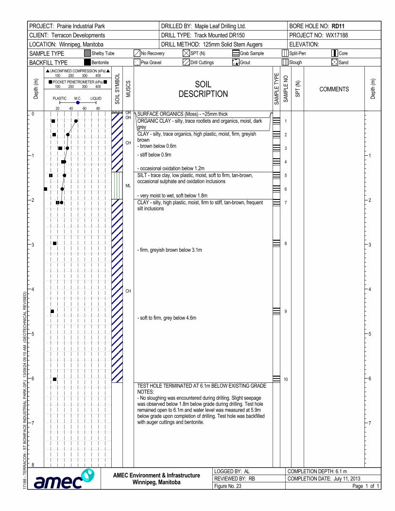
SURFACE ORGANICS (Moss) - ~25mm thickORGANIC CLAY - silty, trace rootlets and organics, moist, darkgreyCLAY - silty, trace organics, high plastic, moist, firm, greyishbrown- brown below 0.6m
- stiff below 0.9m
- occasional oxidation below 1.2mSILT - trace clay, low plastic, moist, soft to firm, tan-brown,occasional sulphate and oxidation inclusions
- very moist to wet, soft below 1.8mCLAY - silty, high plastic, moist, firm to stiff, tan-brown, frequentsilt inclusions
- firm, greyish brown below 3.1m
- soft to firm, grey below 4.6m
TEST HOLE TERMINATED AT 6.1m BELOW EXISTING GRADENOTES:- No sloughing was encountered during drilling. Slight seepagewas observed below 1.8m below grade during drilling. Test holeremained open to 6.1m and water level was measured at 5.9mbelow grade upon completion of drilling. Test hole was backfilledwith auger cuttings and bentonite.
OROH
CH
ML
CH
1
2
3
4
5
6
7
8
9
10
SOILDESCRIPTION
LOGGED BY: ALREVIEWED BY: RBFigure No. 23
Dep
th (m
)
200
Split-Pen
100 200 300 400
1
2
3
4
5
6
7
1
2
3
4
5
6
7
8
CoreShelby Tube
80
Dep
th (m
) 100 200 300 400
PLASTIC M.C.
COMPLETION DEPTH: 6.1 mCOMPLETION DATE: July 11, 2013
PROJECT: Prairie Industrial Park
CLIENT: Terracon Developments
LOCATION: Winnipeg, Manitoba
DRILLED BY: Maple Leaf Drilling Ltd.
DRILL TYPE: Track Mounted DR150
DRILL METHOD: 125mm Solid Stem Augers
BORE HOLE NO: RD11
PROJECT NO: WX17188
ELEVATION:
SAMPLE TYPE
60
Page 1 of 1
SandBACKFILL TYPE
SPT (N)
UNCONFINED COMPRESSION (kPa)
Drill Cuttings Grout
POCKET PENETROMETER (kPa)
LIQUID
Slough
No Recovery
Bentonite
40
Grab Sample
Pea Gravel
SOIL
SYM
BOL
COMMENTS
1718
8 -
TE
RR
AC
ON
- S
T B
ON
IFA
CE
IND
US
TR
IAL
PA
RK
.GP
J 1
3/09
/24
09:
15
AM
(G
EO
TE
CH
NIC
AL
RE
VIS
ED
)
AMEC Environment & InfrastructureWinnipeg, Manitoba
MU
SCS
SAM
PLE
TYPE
SPT
(N)
SAM
PLE
NO

SURFACE ORGANICS (Moss) - ~25mm thickORGANIC CLAY - silty, trace rootlets and organics, moist, darkgreyCLAY - silty, trace organics and rootlets to 0.3m, high plastic,moist, firm, greyish brown
- firm to stiff below 0.9m
- stiff, brown below 1.2m
- occasional sulphate and oxidation inclusions below 1.5m
- occasional to frequent oxidation and silt inclusions below 1.8m
SILT - trace clay, low plastic, very moist to wet, soft, tan-brown
CLAY - silty, high plastic, moist, firm, brown to tan, frequent siltinclusions
TEST HOLE TERMINATED AT 3.1m BELOW EXISTING GRADENOTES:- No sloughing was encountered during drilling. Slight seepagewas observed below 2.6m below grade during drilling. Test holeremained open to 3.1m and water level was measured at 2.9mbelow grade upon completion of drilling. Test hole was backfilledwith auger cuttings and bentonite.
OROH
CH
ML
CH
1
2
3
4
5
6
7
8
9
SOILDESCRIPTION
LOGGED BY: ALREVIEWED BY: RBFigure No. 24
Dep
th (m
)
200
Split-Pen
100 200 300 400
1
2
3
4
5
6
7
1
2
3
4
5
6
7
8
CoreShelby Tube
80
Dep
th (m
) 100 200 300 400
PLASTIC M.C.
COMPLETION DEPTH: 3.1 mCOMPLETION DATE: July 11, 2013
PROJECT: Prairie Industrial Park
CLIENT: Terracon Developments
LOCATION: Winnipeg, Manitoba
DRILLED BY: Maple Leaf Drilling Ltd.
DRILL TYPE: Track Mounted DR150
DRILL METHOD: 125mm Solid Stem Augers
BORE HOLE NO: RD12
PROJECT NO: WX17188
ELEVATION:
SAMPLE TYPE
60
Page 1 of 1
SandBACKFILL TYPE
SPT (N)
UNCONFINED COMPRESSION (kPa)
Drill Cuttings Grout
POCKET PENETROMETER (kPa)
LIQUID
Slough
No Recovery
Bentonite
40
Grab Sample
Pea Gravel
SOIL
SYM
BOL
COMMENTS
1718
8 -
TE
RR
AC
ON
- S
T B
ON
IFA
CE
IND
US
TR
IAL
PA
RK
.GP
J 1
3/09
/24
09:
15
AM
(G
EO
TE
CH
NIC
AL
RE
VIS
ED
)
AMEC Environment & InfrastructureWinnipeg, Manitoba
MU
SCS
SAM
PLE
TYPE
SPT
(N)
SAM
PLE
NO

SURFACE ORGANICS (Moss) - ~25mm thickORGANIC CLAY - silty, trace rootlets and organics, moist, darkgreyCLAY - silty, trace organic to 0.3m, high plastic, moist, firm, grey todark grey- mottled grey and brown below 0.6m
- stiff, brown below 0.9m
- occasional oxidation and sulphate inclusions below 1.5m
- firm below 1.8mSILT - trace clay, low plastic, moist to very moist, soft, tan-brown
CLAY - silty, high plastic, moist, firm to stiff, greyish brown,occasional silt inclusions
- firm, dark greyish brown below 4.6m
TEST HOLE TERMINATED AT 6.1m BELOW EXISTING GRADENOTES:- Very slight sloughing was encountered below 2.4m below gradeduring drilling. Moderate seepage was observed below 2.4mbelow grade during drilling. Test hole remained open to 5.8m andwater level was measured at 3.1m below grade upon completionof drilling. Test hole was backfilled with auger cuttings andbentonite.
OROH
CH
ML
CH
1
2
3
4
5
6
7
8
9
10
SOILDESCRIPTION
LOGGED BY: ALREVIEWED BY: RBFigure No. 25
Dep
th (m
)
200
Split-Pen
100 200 300 400
1
2
3
4
5
6
7
1
2
3
4
5
6
7
8
CoreShelby Tube
80
Dep
th (m
) 100 200 300 400
PLASTIC M.C.
COMPLETION DEPTH: 6.1 mCOMPLETION DATE: July 11, 2013
PROJECT: Prairie Industrial Park
CLIENT: Terracon Developments
LOCATION: Winnipeg, Manitoba
DRILLED BY: Maple Leaf Drilling Ltd.
DRILL TYPE: Track Mounted DR150
DRILL METHOD: 125mm Solid Stem Augers
BORE HOLE NO: RD13
PROJECT NO: WX17188
ELEVATION:
SAMPLE TYPE
60
Page 1 of 1
SandBACKFILL TYPE
SPT (N)
UNCONFINED COMPRESSION (kPa)
Drill Cuttings Grout
POCKET PENETROMETER (kPa)
LIQUID
Slough
No Recovery
Bentonite
40
Grab Sample
Pea Gravel
SOIL
SYM
BOL
COMMENTS
1718
8 -
TE
RR
AC
ON
- S
T B
ON
IFA
CE
IND
US
TR
IAL
PA
RK
.GP
J 1
3/09
/24
09:
15
AM
(G
EO
TE
CH
NIC
AL
RE
VIS
ED
)
AMEC Environment & InfrastructureWinnipeg, Manitoba
MU
SCS
SAM
PLE
TYPE
SPT
(N)
SAM
PLE
NO

SURFACE ORGANICS (Moss) - ~25mm thickORGANIC CLAY - silty, trace rootlets and organics, moist, darkgreyCLAY - silty, trace organics and rootlets to 0.3m, high plastic,moist, firm, grey to dark grey- greyish brown, occasional oxidation inclusions below 0.6m
- firm to stiff below 0.9m
- stiff below 1.2m
- brown below 1.5mSILT - some clay, low to medium plastic, moist, firm, tan-brown
CLAY - silty, high plastic, moist, stiff, tan-brown, occasional siltand oxidation inclusions
- firm to stiff, greyish brown below 2.7m
TEST HOLE TERMINATED AT 3.1m BELOW EXISTING GRADENOTES:- No sloughing or seepage was encountered during drilling. Testhole remained open to 3.1m and was dry upon completion ofdrilling. Test hole was backfilled with auger cuttings and bentonite.
OROH
CH
ML
CH
1
2
3
4
5
6
7
8
SOILDESCRIPTION
LOGGED BY: ALREVIEWED BY: RBFigure No. 26
Dep
th (m
)
200
Split-Pen
100 200 300 400
1
2
3
4
5
6
7
1
2
3
4
5
6
7
8
CoreShelby Tube
80
Dep
th (m
) 100 200 300 400
PLASTIC M.C.
COMPLETION DEPTH: 3.1 mCOMPLETION DATE: July 11, 2013
PROJECT: Prairie Industrial Park
CLIENT: Terracon Developments
LOCATION: Winnipeg, Manitoba
DRILLED BY: Maple Leaf Drilling Ltd.
DRILL TYPE: Track Mounted DR150
DRILL METHOD: 125mm Solid Stem Augers
BORE HOLE NO: RD14
PROJECT NO: WX17188
ELEVATION:
SAMPLE TYPE
60
Page 1 of 1
SandBACKFILL TYPE
SPT (N)
UNCONFINED COMPRESSION (kPa)
Drill Cuttings Grout
POCKET PENETROMETER (kPa)
LIQUID
Slough
No Recovery
Bentonite
40
Grab Sample
Pea Gravel
SOIL
SYM
BOL
COMMENTS
1718
8 -
TE
RR
AC
ON
- S
T B
ON
IFA
CE
IND
US
TR
IAL
PA
RK
.GP
J 1
3/09
/24
09:
15
AM
(G
EO
TE
CH
NIC
AL
RE
VIS
ED
)
AMEC Environment & InfrastructureWinnipeg, Manitoba
MU
SCS
SAM
PLE
TYPE
SPT
(N)
SAM
PLE
NO

SURFACE ORGANICS (Moss) - ~25mm thickORGANIC CLAY - silty, trace rootlets and organics, moist, darkgreyCLAY - silty, trace organics and rootlets to 0.3m, high plastic,moist, stiff, grey to dark grey
- greyish brown, occasional oxidation inclusions below 0.9mSILT - some clay, low plastic, moist, firm, tan-brown
CLAY - silty, high plastic, moist, stiff, greyish brown, occasional siltinclusions
- stiff to very stiff below 1.8m
- firm to stiff, dark greyish brown below 2.1m
- abundant silt lenses ~20mm thick, moist to very moist at 3.1m
- firm below 4.6m
- grey to dark grey below 5.9mTEST HOLE TERMINATED AT 6.1m BELOW EXISTING GRADENOTES:- No sloughing or seepage was encountered during drilling. Testhole remained open to 6.1m and was dry upon completion ofdrilling. Test hole was backfilled with auger cuttings and bentonite.
OROH
CH
ML
CH
1
2
3
4
5
6
7
8
9
10
SOILDESCRIPTION
LOGGED BY: ALREVIEWED BY: RBFigure No. 27
Dep
th (m
)
200
Split-Pen
100 200 300 400
1
2
3
4
5
6
7
1
2
3
4
5
6
7
8
CoreShelby Tube
80
Dep
th (m
) 100 200 300 400
PLASTIC M.C.
COMPLETION DEPTH: 6.1 mCOMPLETION DATE: July 11, 2013
PROJECT: Prairie Industrial Park
CLIENT: Terracon Developments
LOCATION: Winnipeg, Manitoba
DRILLED BY: Maple Leaf Drilling Ltd.
DRILL TYPE: Track Mounted DR150
DRILL METHOD: 125mm Solid Stem Augers
BORE HOLE NO: RD15
PROJECT NO: WX17188
ELEVATION:
SAMPLE TYPE
60
Page 1 of 1
SandBACKFILL TYPE
SPT (N)
UNCONFINED COMPRESSION (kPa)
Drill Cuttings Grout
POCKET PENETROMETER (kPa)
LIQUID
Slough
No Recovery
Bentonite
40
Grab Sample
Pea Gravel
SOIL
SYM
BOL
COMMENTS
1718
8 -
TE
RR
AC
ON
- S
T B
ON
IFA
CE
IND
US
TR
IAL
PA
RK
.GP
J 1
3/09
/24
09:
15
AM
(G
EO
TE
CH
NIC
AL
RE
VIS
ED
)
AMEC Environment & InfrastructureWinnipeg, Manitoba
MU
SCS
SAM
PLE
TYPE
SPT
(N)
SAM
PLE
NO
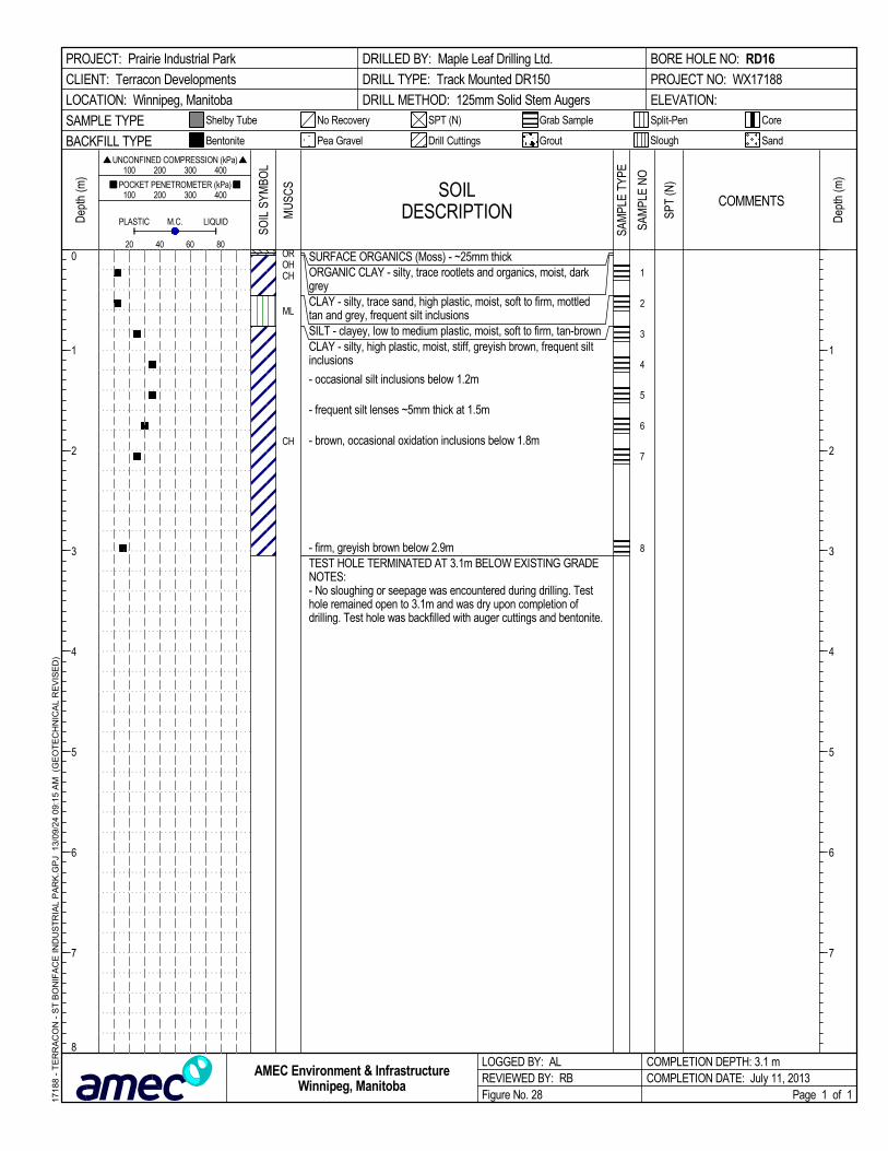
SURFACE ORGANICS (Moss) - ~25mm thickORGANIC CLAY - silty, trace rootlets and organics, moist, darkgreyCLAY - silty, trace sand, high plastic, moist, soft to firm, mottledtan and grey, frequent silt inclusionsSILT - clayey, low to medium plastic, moist, soft to firm, tan-brownCLAY - silty, high plastic, moist, stiff, greyish brown, frequent siltinclusions
- occasional silt inclusions below 1.2m
- frequent silt lenses ~5mm thick at 1.5m
- brown, occasional oxidation inclusions below 1.8m
- firm, greyish brown below 2.9mTEST HOLE TERMINATED AT 3.1m BELOW EXISTING GRADENOTES:- No sloughing or seepage was encountered during drilling. Testhole remained open to 3.1m and was dry upon completion ofdrilling. Test hole was backfilled with auger cuttings and bentonite.
OROHCH
ML
CH
1
2
3
4
5
6
7
8
SOILDESCRIPTION
LOGGED BY: ALREVIEWED BY: RBFigure No. 28
Dep
th (m
)
200
Split-Pen
100 200 300 400
1
2
3
4
5
6
7
1
2
3
4
5
6
7
8
CoreShelby Tube
80
Dep
th (m
) 100 200 300 400
PLASTIC M.C.
COMPLETION DEPTH: 3.1 mCOMPLETION DATE: July 11, 2013
PROJECT: Prairie Industrial Park
CLIENT: Terracon Developments
LOCATION: Winnipeg, Manitoba
DRILLED BY: Maple Leaf Drilling Ltd.
DRILL TYPE: Track Mounted DR150
DRILL METHOD: 125mm Solid Stem Augers
BORE HOLE NO: RD16
PROJECT NO: WX17188
ELEVATION:
SAMPLE TYPE
60
Page 1 of 1
SandBACKFILL TYPE
SPT (N)
UNCONFINED COMPRESSION (kPa)
Drill Cuttings Grout
POCKET PENETROMETER (kPa)
LIQUID
Slough
No Recovery
Bentonite
40
Grab Sample
Pea Gravel
SOIL
SYM
BOL
COMMENTS
1718
8 -
TE
RR
AC
ON
- S
T B
ON
IFA
CE
IND
US
TR
IAL
PA
RK
.GP
J 1
3/09
/24
09:
15
AM
(G
EO
TE
CH
NIC
AL
RE
VIS
ED
)
AMEC Environment & InfrastructureWinnipeg, Manitoba
MU
SCS
SAM
PLE
TYPE
SPT
(N)
SAM
PLE
NO

SURFACE ORGANICS (Moss) - ~25mm thickORGANIC CLAY - silty, trace rootlets and organics, moist, darkgreyCLAY - silty, trace organics lenses ~5mm thick to 0.3m, highplastic, moist, firm to stiff, mottled brown to dark grey- some organics at 0.6m
- stiff, brown below 0.9m
- greyish brown below 1.2m
- occasional sulphate inclusions below 1.8m
- firm, dark greyish brown below 3.1m
TEST HOLE TERMINATED AT 6.1m BELOW EXISTING GRADENOTES:- No sloughing or seepage was encountered during drilling. Testhole remained open to 6.1m and was dry upon completion ofdrilling. Test hole was backfilled with auger cuttings and bentonite.
OROH
CH
1
2
3
4
5
6
7
8
9
10
SOILDESCRIPTION
LOGGED BY: ALREVIEWED BY: RBFigure No. 29
Dep
th (m
)
200
Split-Pen
100 200 300 400
1
2
3
4
5
6
7
1
2
3
4
5
6
7
8
CoreShelby Tube
80
Dep
th (m
) 100 200 300 400
PLASTIC M.C.
COMPLETION DEPTH: 6.1 mCOMPLETION DATE: July 11, 2013
PROJECT: Prairie Industrial Park
CLIENT: Terracon Developments
LOCATION: Winnipeg, Manitoba
DRILLED BY: Maple Leaf Drilling Ltd.
DRILL TYPE: Track Mounted DR150
DRILL METHOD: 125mm Solid Stem Augers
BORE HOLE NO: RD17
PROJECT NO: WX17188
ELEVATION:
SAMPLE TYPE
60
Page 1 of 1
SandBACKFILL TYPE
SPT (N)
UNCONFINED COMPRESSION (kPa)
Drill Cuttings Grout
POCKET PENETROMETER (kPa)
LIQUID
Slough
No Recovery
Bentonite
40
Grab Sample
Pea Gravel
SOIL
SYM
BOL
COMMENTS
1718
8 -
TE
RR
AC
ON
- S
T B
ON
IFA
CE
IND
US
TR
IAL
PA
RK
.GP
J 1
3/09
/24
09:
15
AM
(G
EO
TE
CH
NIC
AL
RE
VIS
ED
)
AMEC Environment & InfrastructureWinnipeg, Manitoba
MU
SCS
SAM
PLE
TYPE
SPT
(N)
SAM
PLE
NO

SURFACE ORGANICS (Moss) - ~25mm thickORGANIC CLAY - silty, trace rootlets and organics, moist, darkgreyCLAY - silty, trace organics to 0.3m, high plastic, moist, firm tostiff, grey to dark grey- brown, occasional oxidation inclusions below 0.6m
- stiff below 0.9m
- very stiff, occasional to frequent oxidation inclusions below 1.5m
- mottled tan and brown, occasional to frequent sulphate andoxidation inclusions below 1.8mSILT - trace clay, low plastic, moist, soft to firm, tan-brown,occasional oxidation inclusions
CLAY - silty, high plastic, moist, stiff, greyish brown
TEST HOLE TERMINATED AT 3.1m BELOW EXISTING GRADENOTES:- No sloughing was encountered during drilling. Slight seepagewas observed below 1.7m below grade during drilling. Test holeremained open to 3.1m and water level was measured at 1.7mbelow grade upon completion of drilling. Test hole was backfilledwith auger cuttings and bentonite.
OROH
CH
ML
CH
1
2
3
4
5
6
7
8
SOILDESCRIPTION
LOGGED BY: ALREVIEWED BY: RBFigure No. 30
Dep
th (m
)
200
Split-Pen
100 200 300 400
1
2
3
4
5
6
7
1
2
3
4
5
6
7
8
CoreShelby Tube
80
Dep
th (m
) 100 200 300 400
PLASTIC M.C.
COMPLETION DEPTH: 3.1 mCOMPLETION DATE: July 11, 2013
PROJECT: Prairie Industrial Park
CLIENT: Terracon Developments
LOCATION: Winnipeg, Manitoba
DRILLED BY: Maple Leaf Drilling Ltd.
DRILL TYPE: Track Mounted DR150
DRILL METHOD: 125mm Solid Stem Augers
BORE HOLE NO: RD18
PROJECT NO: WX17188
ELEVATION:
SAMPLE TYPE
60
Page 1 of 1
SandBACKFILL TYPE
SPT (N)
UNCONFINED COMPRESSION (kPa)
Drill Cuttings Grout
POCKET PENETROMETER (kPa)
LIQUID
Slough
No Recovery
Bentonite
40
Grab Sample
Pea Gravel
SOIL
SYM
BOL
COMMENTS
1718
8 -
TE
RR
AC
ON
- S
T B
ON
IFA
CE
IND
US
TR
IAL
PA
RK
.GP
J 1
3/09
/24
09:
15
AM
(G
EO
TE
CH
NIC
AL
RE
VIS
ED
)
AMEC Environment & InfrastructureWinnipeg, Manitoba
MU
SCS
SAM
PLE
TYPE
SPT
(N)
SAM
PLE
NO

SURFACE ORGANICS (Moss) - ~25mm thickORGANIC CLAY - silty, trace rootlets and organics, moist, darkgreyCLAY - silty, some organics to 0.3m, high plastic, moist, firm, darkgrey to brown- stiff, greyish brown below 0.6m
- brown below 1.2m
- brown to light brown, occasional silt inclusions below 1.5m
- firm, greyish brown below 3.1m
- grey, occasional sulphate inclusions below 4.6m
TEST HOLE TERMINATED AT 6.1m BELOW EXISTING GRADENOTES:- No sloughing or seepage was encountered during drilling. Testhole remained open to 6.1m and was dry upon completion ofdrilling. Test hole was backfilled with auger cuttings and bentonite.
OROH
CH
1
2
3
4
5
6
7
8
9
10
SOILDESCRIPTION
LOGGED BY: ALREVIEWED BY: RBFigure No. 31
Dep
th (m
)
200
Split-Pen
100 200 300 400
1
2
3
4
5
6
7
1
2
3
4
5
6
7
8
CoreShelby Tube
80
Dep
th (m
) 100 200 300 400
PLASTIC M.C.
COMPLETION DEPTH: 6.1 mCOMPLETION DATE: July 11, 2013
PROJECT: Prairie Industrial Park
CLIENT: Terracon Developments
LOCATION: Winnipeg, Manitoba
DRILLED BY: Maple Leaf Drilling Ltd.
DRILL TYPE: Track Mounted DR150
DRILL METHOD: 125mm Solid Stem Augers
BORE HOLE NO: RD19
PROJECT NO: WX17188
ELEVATION:
SAMPLE TYPE
60
Page 1 of 1
SandBACKFILL TYPE
SPT (N)
UNCONFINED COMPRESSION (kPa)
Drill Cuttings Grout
POCKET PENETROMETER (kPa)
LIQUID
Slough
No Recovery
Bentonite
40
Grab Sample
Pea Gravel
SOIL
SYM
BOL
COMMENTS
1718
8 -
TE
RR
AC
ON
- S
T B
ON
IFA
CE
IND
US
TR
IAL
PA
RK
.GP
J 1
3/09
/24
09:
15
AM
(G
EO
TE
CH
NIC
AL
RE
VIS
ED
)
AMEC Environment & InfrastructureWinnipeg, Manitoba
MU
SCS
SAM
PLE
TYPE
SPT
(N)
SAM
PLE
NO

SURFACE ORGANICS (Moss) - ~25mm thickORGANIC CLAY - silty, trace rootlets and organics, moist, darkgreyCLAY - silty, trace organics to 0.3m, high plastic, moist, stiff,greyish brown, occasional oxidation inclusions- occasional rootlets to 0.8m
- brown, occasional sulphate and oxidation inclusions below 1.5m- occasional to frequent silt lenses ~10mm thick between 1.5m to1.7m
- firm below 2.7m
TEST HOLE TERMINATED AT 3.1m BELOW EXISTING GRADENOTES:- No sloughing or seepage was encountered during drilling. Testhole remained open to 3.1m and was dry upon completion ofdrilling. Test hole was backfilled with auger cuttings and bentonite.
Hydrometer Analysis Results@ "1.1m":Gravel= 0.0%Sand= 0.5%Silt= 16.5%Clay= 83.0%
OROH
CH
1
2
3
4
5
6
7
8
SOILDESCRIPTION
LOGGED BY: ALREVIEWED BY: RBFigure No. 32
Dep
th (m
)
200
Split-Pen
100 200 300 400
1
2
3
4
5
6
7
1
2
3
4
5
6
7
8
CoreShelby Tube
80
Dep
th (m
) 100 200 300 400
PLASTIC M.C.
COMPLETION DEPTH: 3.1 mCOMPLETION DATE: July 11, 2013
PROJECT: Prairie Industrial Park
CLIENT: Terracon Developments
LOCATION: Winnipeg, Manitoba
DRILLED BY: Maple Leaf Drilling Ltd.
DRILL TYPE: Track Mounted DR150
DRILL METHOD: 125mm Solid Stem Augers
BORE HOLE NO: RD20
PROJECT NO: WX17188
ELEVATION:
SAMPLE TYPE
60
Page 1 of 1
SandBACKFILL TYPE
SPT (N)
UNCONFINED COMPRESSION (kPa)
Drill Cuttings Grout
POCKET PENETROMETER (kPa)
LIQUID
Slough
No Recovery
Bentonite
40
Grab Sample
Pea Gravel
SOIL
SYM
BOL
COMMENTS
1718
8 -
TE
RR
AC
ON
- S
T B
ON
IFA
CE
IND
US
TR
IAL
PA
RK
.GP
J 1
3/09
/24
09:
15
AM
(G
EO
TE
CH
NIC
AL
RE
VIS
ED
)
AMEC Environment & InfrastructureWinnipeg, Manitoba
MU
SCS
SAM
PLE
TYPE
SPT
(N)
SAM
PLE
NO
30 83

SURFACE ORGANICS (Moss) - ~25mm thickORGANIC CLAY - silty, trace rootlets and organics, moist, darkgreyCLAY - silty, trace organics to 0.3m, high plastic, moist, stiff, darkgrey to grey, occasional oxidation inclusions- occasional silt inclusions below 0.6m
- greyish brown below 0.9m
- brown below 1.5m
- firm below 3.1m
- greyish brown below 4.6m
TEST HOLE TERMINATED AT 6.1m BELOW EXISTING GRADENOTES:- No sloughing or seepage was encountered during drilling. Testhole remained open to 6.1m and was dry upon completion ofdrilling. Test hole was backfilled with auger cuttings and bentonite.
OROH
CH
1
2
3
4
5
6
7
8
9
10
SOILDESCRIPTION
LOGGED BY: ALREVIEWED BY: RBFigure No. 33
Dep
th (m
)
200
Split-Pen
100 200 300 400
1
2
3
4
5
6
7
1
2
3
4
5
6
7
8
CoreShelby Tube
80
Dep
th (m
) 100 200 300 400
PLASTIC M.C.
COMPLETION DEPTH: 6.1 mCOMPLETION DATE: July 11, 2013
PROJECT: Prairie Industrial Park
CLIENT: Terracon Developments
LOCATION: Winnipeg, Manitoba
DRILLED BY: Maple Leaf Drilling Ltd.
DRILL TYPE: Track Mounted DR150
DRILL METHOD: 125mm Solid Stem Augers
BORE HOLE NO: RD21
PROJECT NO: WX17188
ELEVATION:
SAMPLE TYPE
60
Page 1 of 1
SandBACKFILL TYPE
SPT (N)
UNCONFINED COMPRESSION (kPa)
Drill Cuttings Grout
POCKET PENETROMETER (kPa)
LIQUID
Slough
No Recovery
Bentonite
40
Grab Sample
Pea Gravel
SOIL
SYM
BOL
COMMENTS
1718
8 -
TE
RR
AC
ON
- S
T B
ON
IFA
CE
IND
US
TR
IAL
PA
RK
.GP
J 1
3/09
/24
09:
15
AM
(G
EO
TE
CH
NIC
AL
RE
VIS
ED
)
AMEC Environment & InfrastructureWinnipeg, Manitoba
MU
SCS
SAM
PLE
TYPE
SPT
(N)
SAM
PLE
NO

SURFACE ORGANICS (Moss) - ~25mm thickORGANIC CLAY - silty, trace rootlets and organics, moist, darkgreyCLAY - silty, trace organics to 0.3m, high plastic, moist, stiff, darkgreyish brown, occasional rootlets and oxidation inclusionsSILT - some clay, low to medium plastic, moist, firm, mottled greyand brown
CLAY - silty, high plastic, moist, stiff, greyish brown, occasional siltinclusions
- stiff to very stiff below 1.5m
- firm to stiff below 2.1m
TEST HOLE TERMINATED AT 3.1m BELOW EXISTING GRADENOTES:- No sloughing or seepage was encountered during drilling. Testhole remained open to 3.1m and was dry upon completion ofdrilling. Test hole was backfilled with auger cuttings and bentonite.
OROH
CH
ML
CH
1
2
3
4
5
6
7
8
SOILDESCRIPTION
LOGGED BY: ALREVIEWED BY: RBFigure No. 34
Dep
th (m
)
200
Split-Pen
100 200 300 400
1
2
3
4
5
6
7
1
2
3
4
5
6
7
8
CoreShelby Tube
80
Dep
th (m
) 100 200 300 400
PLASTIC M.C.
COMPLETION DEPTH: 3.1 mCOMPLETION DATE: July 11, 2013
PROJECT: Prairie Industrial Park
CLIENT: Terracon Developments
LOCATION: Winnipeg, Manitoba
DRILLED BY: Maple Leaf Drilling Ltd.
DRILL TYPE: Track Mounted DR150
DRILL METHOD: 125mm Solid Stem Augers
BORE HOLE NO: RD22
PROJECT NO: WX17188
ELEVATION:
SAMPLE TYPE
60
Page 1 of 1
SandBACKFILL TYPE
SPT (N)
UNCONFINED COMPRESSION (kPa)
Drill Cuttings Grout
POCKET PENETROMETER (kPa)
LIQUID
Slough
No Recovery
Bentonite
40
Grab Sample
Pea Gravel
SOIL
SYM
BOL
COMMENTS
1718
8 -
TE
RR
AC
ON
- S
T B
ON
IFA
CE
IND
US
TR
IAL
PA
RK
.GP
J 1
3/09
/24
09:
15
AM
(G
EO
TE
CH
NIC
AL
RE
VIS
ED
)
AMEC Environment & InfrastructureWinnipeg, Manitoba
MU
SCS
SAM
PLE
TYPE
SPT
(N)
SAM
PLE
NO

SURFACE ORGANICS (Moss) - ~25mm thickORGANIC CLAY - silty, trace rootlets and organics, moist, darkgreyCLAY - silty, some organics, trace rootlets to 0.3m, high plastic,moist, stiff, grey to dark greySILT - trace clay, low plastic, moist, firm, tan-brown- soft to firm below 0.6m- moist to very moist, soft below 0.9m
- light grey to tan-brown, occasional oxidation inclusions below1.2m
CLAY - silty, high plastic, moist, stiff, greyish brown
- firm to stiff below 2.1m
- firm, occasional sulphate inclusions below 4.6m
TEST HOLE TERMINATED AT 6.1m BELOW EXISTING GRADENOTES:- No sloughing or seepage was encountered during drilling. Testhole remained open to 6.1m and was dry upon completion ofdrilling. Test hole was backfilled with auger cuttings and bentonite.
OROHCH
ML
CH
1
2
3
4
5
6
7
8
9
10
11
SOILDESCRIPTION
LOGGED BY: ALREVIEWED BY: RBFigure No. 35
Dep
th (m
)
200
Split-Pen
100 200 300 400
1
2
3
4
5
6
7
1
2
3
4
5
6
7
8
CoreShelby Tube
80
Dep
th (m
) 100 200 300 400
PLASTIC M.C.
COMPLETION DEPTH: 6.1 mCOMPLETION DATE: July 11, 2013
PROJECT: Prairie Industrial Park
CLIENT: Terracon Developments
LOCATION: Winnipeg, Manitoba
DRILLED BY: Maple Leaf Drilling Ltd.
DRILL TYPE: Track Mounted DR150
DRILL METHOD: 125mm Solid Stem Augers
BORE HOLE NO: RD23
PROJECT NO: WX17188
ELEVATION:
SAMPLE TYPE
60
Page 1 of 1
SandBACKFILL TYPE
SPT (N)
UNCONFINED COMPRESSION (kPa)
Drill Cuttings Grout
POCKET PENETROMETER (kPa)
LIQUID
Slough
No Recovery
Bentonite
40
Grab Sample
Pea Gravel
SOIL
SYM
BOL
COMMENTS
1718
8 -
TE
RR
AC
ON
- S
T B
ON
IFA
CE
IND
US
TR
IAL
PA
RK
.GP
J 1
3/09
/24
09:
15
AM
(G
EO
TE
CH
NIC
AL
RE
VIS
ED
)
AMEC Environment & InfrastructureWinnipeg, Manitoba
MU
SCS
SAM
PLE
TYPE
SPT
(N)
SAM
PLE
NO

SURFACE ORGANICS (Moss) - ~25mm thickCLAY - silty, high plastic, moist, stiff, grey
- greyish brown, occasional sulphate inclusions below 0.9mSILT - trace clay, low plastic, moist to very moist, soft, tan-brown
CLAY - silty, high plastic, moist, stiff, greyish brown, occasionalsulphate and silt inclusions
- very stiff, brown below 1.8m
- stiff, frequent silt lenses ~25mm thick between 2.1m and 2.3m
- grey below 2.9mTEST HOLE TERMINATED AT 3.1m BELOW EXISTING GRADENOTES:- No sloughing was encountered during drilling. Very slightseepage was observed below 1.4m below grade during drilling.Test hole remained open to 3.1m and was dry upon completion ofdrilling. Test hole was backfilled with auger cuttings and bentonite.
OR
CH
ML
CH
1
2
3
4
5
6
7
8
SOILDESCRIPTION
LOGGED BY: ALREVIEWED BY: RBFigure No. 36
Dep
th (m
)
200
Split-Pen
100 200 300 400
1
2
3
4
5
6
7
1
2
3
4
5
6
7
8
CoreShelby Tube
80
Dep
th (m
) 100 200 300 400
PLASTIC M.C.
COMPLETION DEPTH: 3.1 mCOMPLETION DATE: July 12, 2013
PROJECT: Prairie Industrial Park
CLIENT: Terracon Developments
LOCATION: Winnipeg, Manitoba
DRILLED BY: Maple Leaf Drilling Ltd.
DRILL TYPE: Track Mounted DR150
DRILL METHOD: 125mm Solid Stem Augers
BORE HOLE NO: RD24
PROJECT NO: WX17188
ELEVATION:
SAMPLE TYPE
60
Page 1 of 1
SandBACKFILL TYPE
SPT (N)
UNCONFINED COMPRESSION (kPa)
Drill Cuttings Grout
POCKET PENETROMETER (kPa)
LIQUID
Slough
No Recovery
Bentonite
40
Grab Sample
Pea Gravel
SOIL
SYM
BOL
COMMENTS
1718
8 -
TE
RR
AC
ON
- S
T B
ON
IFA
CE
IND
US
TR
IAL
PA
RK
.GP
J 1
3/09
/24
09:
15
AM
(G
EO
TE
CH
NIC
AL
RE
VIS
ED
)
AMEC Environment & InfrastructureWinnipeg, Manitoba
MU
SCS
SAM
PLE
TYPE
SPT
(N)
SAM
PLE
NO

SURFACE ORGANICS (Moss) - ~25mm thickORGANIC CLAY - silty, trace rootlets and organics, moist, darkgreyCLAY - silty, trace organics and rootlets to 0.3m, high plastic,moist, firm, dark greyish brown- stiff, brown, occasional silt inclusions below 0.6m
- firm, greyish brown, occasional oxidation inclusions below 2.1m
- soft to firm below 4.6m
TEST HOLE TERMINATED AT 6.1m BELOW EXISTING GRADENOTES:- No sloughing or seepage was encountered during drilling. Testhole remained open to 6.1m and was dry upon completion ofdrilling. Test hole was backfilled with auger cuttings and bentonite.
OROH
CH
1
2
3
4
5
6
7
8
9
10
SOILDESCRIPTION
LOGGED BY: ALREVIEWED BY: RBFigure No. 37
Dep
th (m
)
200
Split-Pen
100 200 300 400
1
2
3
4
5
6
7
1
2
3
4
5
6
7
8
CoreShelby Tube
80
Dep
th (m
) 100 200 300 400
PLASTIC M.C.
COMPLETION DEPTH: 6.1 mCOMPLETION DATE: July 12, 2013
PROJECT: Prairie Industrial Park
CLIENT: Terracon Developments
LOCATION: Winnipeg, Manitoba
DRILLED BY: Maple Leaf Drilling Ltd.
DRILL TYPE: Track Mounted DR150
DRILL METHOD: 125mm Solid Stem Augers
BORE HOLE NO: RD25
PROJECT NO: WX17188
ELEVATION:
SAMPLE TYPE
60
Page 1 of 1
SandBACKFILL TYPE
SPT (N)
UNCONFINED COMPRESSION (kPa)
Drill Cuttings Grout
POCKET PENETROMETER (kPa)
LIQUID
Slough
No Recovery
Bentonite
40
Grab Sample
Pea Gravel
SOIL
SYM
BOL
COMMENTS
1718
8 -
TE
RR
AC
ON
- S
T B
ON
IFA
CE
IND
US
TR
IAL
PA
RK
.GP
J 1
3/09
/24
09:
15
AM
(G
EO
TE
CH
NIC
AL
RE
VIS
ED
)
AMEC Environment & InfrastructureWinnipeg, Manitoba
MU
SCS
SAM
PLE
TYPE
SPT
(N)
SAM
PLE
NO

SURFACE ORGANICS (Moss) - ~25mm thickORGANIC CLAY - silty, high plastic, greyish brown, frequentrootletsCLAY - silty, high plastic, moist, stiff, greyish brown
- mottled brown below 0.9m- brown, occasional silt inclusions below 1.0m- stiff to very stiff below 1.2m
- frequent silt inclusions below 2.4m
- silt lamination at 2.9m- firm below 2.9mTEST HOLE TERMINATED 3.0m BELOW GRADENOTES:- No sloughing or seepage was encountered during drilling. Testhole remained open to 3.0m and was dry upon completion ofdrilling. Test hole was backfilled with auger cuttings.
OROH
CH
1
2
3
4
5
6
7
8
SOILDESCRIPTION
LOGGED BY: SKREVIEWED BY: RBFigure No. 38
Dep
th (m
)
200
Split-Pen
100 200 300 400
1
2
3
4
5
6
7
1
2
3
4
5
6
7
8
CoreShelby Tube
80
Dep
th (m
) 100 200 300 400
PLASTIC M.C.
COMPLETION DEPTH: 3 mCOMPLETION DATE: July 26, 2013
PROJECT: Prairie Industrial Park
CLIENT: Terracon Developments
LOCATION: Winnipeg, Manitoba
DRILLED BY: AMEC
DRILL METHOD: Hand Auger
BORE HOLE NO: RD26
PROJECT NO: WX17188
ELEVATION:
SAMPLE TYPE
60
Page 1 of 1
SandBACKFILL TYPE
SPT (N)
UNCONFINED COMPRESSION (kPa)
Drill Cuttings Grout
POCKET PENETROMETER (kPa)
LIQUID
Slough
No Recovery
Bentonite
40
Grab Sample
Pea Gravel
SOIL
SYM
BOL
COMMENTS
1718
8 -
TE
RR
AC
ON
- S
T B
ON
IFA
CE
IND
US
TR
IAL
PA
RK
.GP
J 1
3/09
/24
09:
15
AM
(G
EO
TE
CH
NIC
AL
RE
VIS
ED
)
AMEC Environment & InfrastructureWinnipeg, Manitoba
MU
SCS
SAM
PLE
TYPE
SPT
(N)
SAM
PLE
NO

SURFACE ORGANICS (Moss) - ~38mm thickCLAY - silty, trace fine grained sand, high plastic, moist, very stiff,greyish brown
- stiff below 0.9m
- occasional sulphate inclusions below 1.2m
- brown, occasional silt inclusions below 1.5m
- firm, dark greyish brown below 3m
- soft to firm below 4.6m
- grey below 5.5m
TEST HOLE TERMINATED AT 6.1m BELOW EXISTING GRADENOTES:- No sloughing and seepage encountered upon completion ofdrilling. Test hole remained open to 6.10m below grade uponcompletion. Test hole was backfilled with auger cuttings.
OR
CH
1
2
3
4
5
6
7
8
9
10
SOILDESCRIPTION
LOGGED BY: ALREVIEWED BY: RBFigure No. 39
Dep
th (m
)
200
Split-Pen
100 200 300 400
1
2
3
4
5
6
7
1
2
3
4
5
6
7
8
CoreShelby Tube
80
Dep
th (m
) 100 200 300 400
PLASTIC M.C.
COMPLETION DEPTH: 6.1 mCOMPLETION DATE: August 26, 2013
PROJECT: Prairie Industrial Park
CLIENT: Terracon Developments
LOCATION: Winnipeg, Manitoba
DRILLED BY: Maple Leaf Drilling Ltd.
DRILL TYPE: Track Mounted DR150
DRILL METHOD: 125mm Solid Stem Augers
BORE HOLE NO: RD27
PROJECT NO: WX17188
ELEVATION:
SAMPLE TYPE
60
Page 1 of 1
SandBACKFILL TYPE
SPT (N)
UNCONFINED COMPRESSION (kPa)
Drill Cuttings Grout
POCKET PENETROMETER (kPa)
LIQUID
Slough
No Recovery
Bentonite
40
Grab Sample
Pea Gravel
SOIL
SYM
BOL
COMMENTS
1718
8 -
TE
RR
AC
ON
- S
T B
ON
IFA
CE
IND
US
TR
IAL
PA
RK
.GP
J 1
3/09
/24
09:
15
AM
(G
EO
TE
CH
NIC
AL
RE
VIS
ED
)
AMEC Environment & InfrastructureWinnipeg, Manitoba
MU
SCS
SAM
PLE
TYPE
SPT
(N)
SAM
PLE
NO
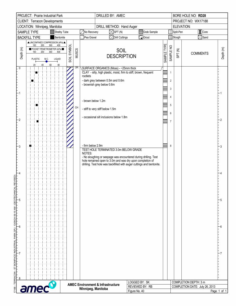
SURFACE ORGANICS (Moss) - ~25mm thickCLAY - silty, high plastic, moist, firm to stiff, brown, frequentrootlets- dark grey between 0.5m and 0.6m- brownish grey below 0.6m
- brown below 1.2m
- stiff to very stiff below 1.5m
- occasional silt inclusions below 1.8m
- firm below 2.9mTEST HOLE TERMINATED 3.0m BELOW GRADENOTES:- No sloughing or seepage was encountered during drilling. Testhole remained open to 3.0m and was dry upon completion ofdrilling. Test hole was backfilled with auger cuttings and bentonite.
OR
CH
1
2
3
4
5
6
7
8
SOILDESCRIPTION
LOGGED BY: SKREVIEWED BY: RBFigure No. 40
Dep
th (m
)
200
Split-Pen
100 200 300 400
1
2
3
4
5
6
7
1
2
3
4
5
6
7
8
CoreShelby Tube
80
Dep
th (m
) 100 200 300 400
PLASTIC M.C.
COMPLETION DEPTH: 3 mCOMPLETION DATE: July 26, 2013
PROJECT: Prairie Industrial Park
CLIENT: Terracon Developments
LOCATION: Winnipeg, Manitoba
DRILLED BY: AMEC
DRILL METHOD: Hand Auger
BORE HOLE NO: RD28
PROJECT NO: WX17188
ELEVATION:
SAMPLE TYPE
60
Page 1 of 1
SandBACKFILL TYPE
SPT (N)
UNCONFINED COMPRESSION (kPa)
Drill Cuttings Grout
POCKET PENETROMETER (kPa)
LIQUID
Slough
No Recovery
Bentonite
40
Grab Sample
Pea Gravel
SOIL
SYM
BOL
COMMENTS
1718
8 -
TE
RR
AC
ON
- S
T B
ON
IFA
CE
IND
US
TR
IAL
PA
RK
.GP
J 1
3/09
/24
09:
15
AM
(G
EO
TE
CH
NIC
AL
RE
VIS
ED
)
AMEC Environment & InfrastructureWinnipeg, Manitoba
MU
SCS
SAM
PLE
TYPE
SPT
(N)
SAM
PLE
NO

SURFACE ORGANICS (Moss) - ~38mm thickCLAY - silty, high plastic, moist, stiff, mottled grey and tan, stiff,frequent lenses approximately 20mm thickSILT - trace clay, low plastic, moist to very moist, soft to firm,tan-brown, occasional oxidation inclusions
- occasional clay lenses approximately 15mm thick, soft to firmbelow 0.9mCLAY - silty, high plastic, moist, stiff, greyish brown, occasional siltinclusionsSILT - trace clay, low plastic, moist, firm, tan-brownCLAY - silty, high plastic, moist, stiff, greyish brown, frequent siltinclusions
- firm, occasional sulphate and oxidation inclusions below 2.1m
TEST HOLE TERMINATED AT 6.1m BELOW EXISTING GRADENOTES:- No sloughing and seepage encountered upon completion ofdrilling. Test hole remained open to 6.10m below grade uponcompletion. Test hole was backfilled with auger cuttings.
Hydrometer Analysis Results@ "0.5m":Gravel= 0.0%Sand= 1.6%Silt= 78.5%Clay= 19.9%
OR
CH
ML
CH
ML
CH
1
2
3
4
5
6
7
8
9
10
SOILDESCRIPTION
LOGGED BY: ALREVIEWED BY: RBFigure No. 41
Dep
th (m
)
200
Split-Pen
100 200 300 400
1
2
3
4
5
6
7
1
2
3
4
5
6
7
8
CoreShelby Tube
80
Dep
th (m
) 100 200 300 400
PLASTIC M.C.
COMPLETION DEPTH: 6.1 mCOMPLETION DATE: August 26, 2013
PROJECT: Prairie Industrial Park
CLIENT: Terracon Developments
LOCATION: Winnipeg, Manitoba
DRILLED BY: Maple Leaf Drilling Ltd.
DRILL TYPE: Track Mounted DR150
DRILL METHOD: 125mm Solid Stem Augers
BORE HOLE NO: RD29
PROJECT NO: WX17188
ELEVATION:
SAMPLE TYPE
60
Page 1 of 1
SandBACKFILL TYPE
SPT (N)
UNCONFINED COMPRESSION (kPa)
Drill Cuttings Grout
POCKET PENETROMETER (kPa)
LIQUID
Slough
No Recovery
Bentonite
40
Grab Sample
Pea Gravel
SOIL
SYM
BOL
COMMENTS
1718
8 -
TE
RR
AC
ON
- S
T B
ON
IFA
CE
IND
US
TR
IAL
PA
RK
.GP
J 1
3/09
/24
09:
15
AM
(G
EO
TE
CH
NIC
AL
RE
VIS
ED
)
AMEC Environment & InfrastructureWinnipeg, Manitoba
MU
SCS
SAM
PLE
TYPE
SPT
(N)
SAM
PLE
NO
18 26

SURFACE ORGANICS (Moss) - ~25mm thickCLAY - silty, high plastic, moist, firm, brown, frequent siltinclusions, frequent rootlets- stiff to very stiff, dark grey, frequent rootlets between 0.5m and0.6m- firm, greyish brown, occasional rootlets at 1m
SILT - trace clay, low plastic, stiff, damp to moist, tan-brownCLAY - silty, high plastic, moist, stiff to very stiff, mottled brown,frequent silt inclusions
- frequent silt layers (~40mm thick) below 1.8m
TEST HOLE TERMINATED 3.0m BELOW GRADENOTES:- No sloughing or seepage was encountered during drilling. Testhole remained open to 3.0m and was dry upon completion ofdrilling. Test hole was backfilled with auger cuttings.
OR
CH
ML
CH
1
2
3
4
5
6
7
8
SOILDESCRIPTION
LOGGED BY: SKREVIEWED BY: RBFigure No. 42
Dep
th (m
)
200
Split-Pen
100 200 300 400
1
2
3
4
5
6
7
1
2
3
4
5
6
7
8
CoreShelby Tube
80
Dep
th (m
) 100 200 300 400
PLASTIC M.C.
COMPLETION DEPTH: 3 mCOMPLETION DATE: July 26, 2013
PROJECT: Prairie Industrial Park
CLIENT: Terracon Developments
LOCATION: Winnipeg, Manitoba
DRILLED BY: AMEC
DRILL METHOD: Hand Auger
BORE HOLE NO: RD30
PROJECT NO: WX17188
ELEVATION:
SAMPLE TYPE
60
Page 1 of 1
SandBACKFILL TYPE
SPT (N)
UNCONFINED COMPRESSION (kPa)
Drill Cuttings Grout
POCKET PENETROMETER (kPa)
LIQUID
Slough
No Recovery
Bentonite
40
Grab Sample
Pea Gravel
SOIL
SYM
BOL
COMMENTS
1718
8 -
TE
RR
AC
ON
- S
T B
ON
IFA
CE
IND
US
TR
IAL
PA
RK
.GP
J 1
3/09
/24
09:
15
AM
(G
EO
TE
CH
NIC
AL
RE
VIS
ED
)
AMEC Environment & InfrastructureWinnipeg, Manitoba
MU
SCS
SAM
PLE
TYPE
SPT
(N)
SAM
PLE
NO

SURFACE ORGANICS (Moss) - ~25mm thickCLAY - silty, trace rootlets, high plastic, moist, firm to stiff, grey todark grey
- no rootlets, stiff, occasional silt inclusions below 0.6m
- greyish brown, occasional sulphate inclusions below 0.9m
- 75mm thick silt layer at 1.2m
- brown below 1.5m
- occasional oxidation inclusions below 1.8m
- firm to stiff below 2.1m
- firm, brown to light brown below 3m
- occasional sulphate inclusions below 4.6m
TEST HOLE TERMINATED AT 6.1m BELOW EXISTING GRADENOTES:- No sloughing and seepage encountered upon completion ofdrilling. Test hole remained open to 6.10m below grade uponcompletion. Test hole was backfilled with auger cuttings.
Hydrometer Analysis Results@ "2.0m":Gravel= 0.0%Sand= 0.2%Silt= 18.2%Clay= 81.6%
OR
CH
1
2
3
4
5
6
7
8
9
10
SOILDESCRIPTION
LOGGED BY: ALREVIEWED BY: RBFigure No. 43
Dep
th (m
)
200
Split-Pen
100 200 300 400
1
2
3
4
5
6
7
1
2
3
4
5
6
7
8
CoreShelby Tube
80
Dep
th (m
) 100 200 300 400
PLASTIC M.C.
COMPLETION DEPTH: 6.1 mCOMPLETION DATE: August 26, 2013
PROJECT: Prairie Industrial Park
CLIENT: Terracon Developments
LOCATION: Winnipeg, Manitoba
DRILLED BY: Maple Leaf Drilling Ltd.
DRILL TYPE: Track Mounted DR150
DRILL METHOD: 125mm Solid Stem Augers
BORE HOLE NO: RD31
PROJECT NO: WX17188
ELEVATION:
SAMPLE TYPE
60
Page 1 of 1
SandBACKFILL TYPE
SPT (N)
UNCONFINED COMPRESSION (kPa)
Drill Cuttings Grout
POCKET PENETROMETER (kPa)
LIQUID
Slough
No Recovery
Bentonite
40
Grab Sample
Pea Gravel
SOIL
SYM
BOL
COMMENTS
1718
8 -
TE
RR
AC
ON
- S
T B
ON
IFA
CE
IND
US
TR
IAL
PA
RK
.GP
J 1
3/09
/24
09:
15
AM
(G
EO
TE
CH
NIC
AL
RE
VIS
ED
)
AMEC Environment & InfrastructureWinnipeg, Manitoba
MU
SCS
SAM
PLE
TYPE
SPT
(N)
SAM
PLE
NO
28 94

SURFACE ORGANICS (Moss) - ~25mm thickORGANIC CLAY - silty, high plastic, moist, firm, dark grey
CLAY - silty, high plastic, moist, firm to stiff, grey, occasionalrootlets- brown below 0.6m
- frequent silt layers (~10mm thick) to 1.4m
- mottled brown, occasional to frequent silt layers to 1.8m
- light brown below 1.7m
- occasional sulphate inclusions at 2.0m
- and silt between 2.6m and 2.7m- frequent silt inclusions at 2.7m- dark brown below 2.9mTEST HOLE TERMINATED AT 3.0m BELOW EXISTING GRADENOTES:- No sloughing observed, moderate seepage encountered at 1.0mbelow grade. Test hole remained open to 3.0m below grade anddepth to water at 1.0m below grade upon completion. Test holewas backfilled with auger cuttings.
OR
OH
CH
1
2
3
4
5
6
7
8
9
10
SOILDESCRIPTION
LOGGED BY: SKREVIEWED BY: RBFigure No. 44
Dep
th (m
)
200
Split-Pen
100 200 300 400
1
2
3
4
5
6
7
1
2
3
4
5
6
7
8
CoreShelby Tube
80
Dep
th (m
) 100 200 300 400
PLASTIC M.C.
COMPLETION DEPTH: 3 mCOMPLETION DATE: July 23, 2013
PROJECT: Prairie Industrial Park
CLIENT: Terracon Developments
LOCATION: Winnipeg, Manitoba
DRILLED BY: AMEC
DRILL METHOD: Hand Auger
BORE HOLE NO: RD32
PROJECT NO: WX17188
ELEVATION:
SAMPLE TYPE
60
Page 1 of 1
SandBACKFILL TYPE
SPT (N)
UNCONFINED COMPRESSION (kPa)
Drill Cuttings Grout
POCKET PENETROMETER (kPa)
LIQUID
Slough
No Recovery
Bentonite
40
Grab Sample
Pea Gravel
SOIL
SYM
BOL
COMMENTS
1718
8 -
TE
RR
AC
ON
- S
T B
ON
IFA
CE
IND
US
TR
IAL
PA
RK
.GP
J 1
3/09
/24
09:
15
AM
(G
EO
TE
CH
NIC
AL
RE
VIS
ED
)
AMEC Environment & InfrastructureWinnipeg, Manitoba
MU
SCS
SAM
PLE
TYPE
SPT
(N)
SAM
PLE
NO
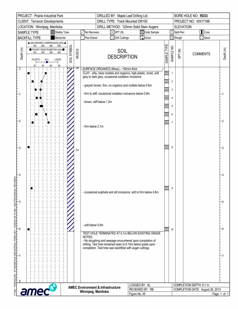
SURFACE ORGANICS (Moss) - ~50mm thickCLAY - silty, trace rootlets and organics, high plastic, moist, soft,grey to dark grey, occasional oxidation inclusions
- greyish brown, firm, no organics and rootlets below 0.6m
- firm to stiff, occasional oxidation inclusions below 0.9m
- brown, stiff below 1.2m
- firm below 2.1m
- occasional sulphate and silt inclusions, soft to firm below 4.6m
- soft below 5.8m
TEST HOLE TERMINATED AT 6.1m BELOW EXISTING GRADENOTES:- No sloughing and seepage encountered upon completion ofdrilling. Test hole remained open to 6.10m below grade uponcompletion. Test hole was backfilled with auger cuttings.
OR
CH
1
2
3
4
5
6
7
8
9
10
SOILDESCRIPTION
LOGGED BY: ALREVIEWED BY: RBFigure No. 45
Dep
th (m
)
200
Split-Pen
100 200 300 400
1
2
3
4
5
6
7
1
2
3
4
5
6
7
8
CoreShelby Tube
80
Dep
th (m
) 100 200 300 400
PLASTIC M.C.
COMPLETION DEPTH: 6.1 mCOMPLETION DATE: August 26, 2013
PROJECT: Prairie Industrial Park
CLIENT: Terracon Developments
LOCATION: Winnipeg, Manitoba
DRILLED BY: Maple Leaf Drilling Ltd.
DRILL TYPE: Track Mounted DR150
DRILL METHOD: 125mm Solid Stem Augers
BORE HOLE NO: RD33
PROJECT NO: WX17188
ELEVATION:
SAMPLE TYPE
60
Page 1 of 1
SandBACKFILL TYPE
SPT (N)
UNCONFINED COMPRESSION (kPa)
Drill Cuttings Grout
POCKET PENETROMETER (kPa)
LIQUID
Slough
No Recovery
Bentonite
40
Grab Sample
Pea Gravel
SOIL
SYM
BOL
COMMENTS
1718
8 -
TE
RR
AC
ON
- S
T B
ON
IFA
CE
IND
US
TR
IAL
PA
RK
.GP
J 1
3/09
/24
09:
15
AM
(G
EO
TE
CH
NIC
AL
RE
VIS
ED
)
AMEC Environment & InfrastructureWinnipeg, Manitoba
MU
SCS
SAM
PLE
TYPE
SPT
(N)
SAM
PLE
NO

SURFACE ORGANICS (Moss) - ~38mm thickORGANIC CLAY - silty, high plastic,moist, soft to firm, dark grey toblack, frequent rootletsCLAY - silty, high plastic, moist, firm to stiff, grey, occasionalrootlets
- abundant silt lamination
SILT - some clay, wet, soft, tan-brown
- firm, occasional oxide inclusions below 1.8m
CLAY - silty, high plastic, damp, very stiff, brown- very stiff below 2.6m
- stiff below 2.9mTEST HOLE TERMINATED 3.0m BELOW GRADENOTES:- No sloughing was encountered during drilling. Significantseepage observed from surface of grade. Test hole remainedopen to 3.0m and was filled with water to top of grade. Test holewas back filled with auger cuttings.
OR
OH
CH
ML
CH
1
2
3
4
5
6
7
8
9
10
SOILDESCRIPTION
LOGGED BY: SKREVIEWED BY: RBFigure No. 46
Dep
th (m
)
200
Split-Pen
100 200 300 400
1
2
3
4
5
6
7
1
2
3
4
5
6
7
8
CoreShelby Tube
80
Dep
th (m
) 100 200 300 400
PLASTIC M.C.
COMPLETION DEPTH: 3 mCOMPLETION DATE: July 23, 2013
PROJECT: Prairie Industrial Park
CLIENT: Terracon Developments
LOCATION: Winnipeg, Manitoba
DRILLED BY: AMEC
DRILL METHOD: Hand Auger
BORE HOLE NO: RD34
PROJECT NO: WX17188
ELEVATION:
SAMPLE TYPE
60
Page 1 of 1
SandBACKFILL TYPE
SPT (N)
UNCONFINED COMPRESSION (kPa)
Drill Cuttings Grout
POCKET PENETROMETER (kPa)
LIQUID
Slough
No Recovery
Bentonite
40
Grab Sample
Pea Gravel
SOIL
SYM
BOL
COMMENTS
1718
8 -
TE
RR
AC
ON
- S
T B
ON
IFA
CE
IND
US
TR
IAL
PA
RK
.GP
J 1
3/09
/24
09:
15
AM
(G
EO
TE
CH
NIC
AL
RE
VIS
ED
)
AMEC Environment & InfrastructureWinnipeg, Manitoba
MU
SCS
SAM
PLE
TYPE
SPT
(N)
SAM
PLE
NO

SURFACE ORGANICS (Moss) - ~50mm thickCLAY - silty, trace organics and rootlets, high plastic, moist, firm,greyish brown, occasional oxidation inclusions
- no organics and rootlets, stiff below 0.6m
- brown below 1.2m
- occasional silt inclusions, brown to light brown below 1.5m
SILT - trace clay, low plastic, moist to very moist, soft, tan-brown,occasional oxidation inclusions
CLAY - silty, high plastic, moist, firm to stiff, greyish brown,occasional oxidation and silt inclusions
- firm, grey below 4.6m
TEST HOLE TERMINATED 6.1m BELOW GRADENOTES:- No sloughing was encountered during drilling. Very slightseepage below 5.2m. Test hole remained open to 6.1m and wasfilled with water to top of grade. Test hole was back filled withauger cuttings.
OR
CH
ML
CH
1
2
3
4
5
6
7
8
9
10
SOILDESCRIPTION
LOGGED BY: ALREVIEWED BY: RBFigure No. 47
Dep
th (m
)
200
Split-Pen
100 200 300 400
1
2
3
4
5
6
7
1
2
3
4
5
6
7
8
CoreShelby Tube
80
Dep
th (m
) 100 200 300 400
PLASTIC M.C.
COMPLETION DEPTH: 6.1 mCOMPLETION DATE: August 26, 2013
PROJECT: Prairie Industrial Park
CLIENT: Terracon Developments
LOCATION: Winnipeg, Manitoba
DRILLED BY: Maple Leaf Drilling Ltd.
DRILL TYPE: Track Mounted DR150
DRILL METHOD: 125mm Solid Stem Augers
BORE HOLE NO: RD35
PROJECT NO: WX17188
ELEVATION:
SAMPLE TYPE
60
Page 1 of 1
SandBACKFILL TYPE
SPT (N)
UNCONFINED COMPRESSION (kPa)
Drill Cuttings Grout
POCKET PENETROMETER (kPa)
LIQUID
Slough
No Recovery
Bentonite
40
Grab Sample
Pea Gravel
SOIL
SYM
BOL
COMMENTS
1718
8 -
TE
RR
AC
ON
- S
T B
ON
IFA
CE
IND
US
TR
IAL
PA
RK
.GP
J 1
3/09
/24
09:
15
AM
(G
EO
TE
CH
NIC
AL
RE
VIS
ED
)
AMEC Environment & InfrastructureWinnipeg, Manitoba
MU
SCS
SAM
PLE
TYPE
SPT
(N)
SAM
PLE
NO

SURFACE ORGANICS (Moss) - ~25mm thickORGANIC CLAY - silty, high plastic, moist, firm, dark greyCLAY - silty, high plastic, moist, stiff, grey, frequent silt inclusions(~2mm thick)
SILT - some clay, some sand, trace gravel, moist, soft, tan-brown
- trace sand, frequent clay lamination below 1.4m
CLAY - silty, high plastic, moist, stiff, light brown to brown,occasional silt inclusions (~10mm thick)
- occasional sulfate inclusions below 2.1m
TEST HOLE TERMINATED 3.0m BELOW GRADENOTES:- No sloughing observed during drilling. Moderate seepageobserved 1.2m below grade. Test hole remained open to 3.0m anddepth to water upon completion was 1.2m below grade. Test holebackfilled with auger cuttings.
OROH
CH
ML
CH
1
2
3
4
5
6
7
8
9
10
SOILDESCRIPTION
LOGGED BY: SKREVIEWED BY: RBFigure No. 48
Dep
th (m
)
200
Split-Pen
100 200 300 400
1
2
3
4
5
6
7
1
2
3
4
5
6
7
8
CoreShelby Tube
80
Dep
th (m
) 100 200 300 400
PLASTIC M.C.
COMPLETION DEPTH: 3 mCOMPLETION DATE: July 24, 2013
PROJECT: Prairie Industrial Park
CLIENT: Terracon Developments
LOCATION: Winnipeg, Manitoba
DRILLED BY: AMEC
DRILL METHOD: Hand Auger
BORE HOLE NO: RD36
PROJECT NO: WX17188
ELEVATION:
SAMPLE TYPE
60
Page 1 of 1
SandBACKFILL TYPE
SPT (N)
UNCONFINED COMPRESSION (kPa)
Drill Cuttings Grout
POCKET PENETROMETER (kPa)
LIQUID
Slough
No Recovery
Bentonite
40
Grab Sample
Pea Gravel
SOIL
SYM
BOL
COMMENTS
1718
8 -
TE
RR
AC
ON
- S
T B
ON
IFA
CE
IND
US
TR
IAL
PA
RK
.GP
J 1
3/09
/24
09:
16
AM
(G
EO
TE
CH
NIC
AL
RE
VIS
ED
)
AMEC Environment & InfrastructureWinnipeg, Manitoba
MU
SCS
SAM
PLE
TYPE
SPT
(N)
SAM
PLE
NO

SURFACE ORGANICS (Moss) - ~35mm thickCLAY - silty, trace rootlets and organics, high plastic, damp tomoist, very stiff, dark grey, occasional oxidation inclusions
- dark grey to grey, stiff, moist, occasional silt inclusions below0.6mSILT - trace clay, low plastic, moist, soft to firm, tan-brown,occasional clay inclusions
- soft, moist to very moist below 1.2m
CLAY - silty, high plastic, moist, very stiff, brown
- stiff, occasional oxidation and silt inclusions below 2.1m
- greyish brown, firm below 3m
- occasional sulphate inclusions below 4.6m
TEST HOLE TERMINATED 6.1m BELOW GRADENOTES:- No sloughing or seepage was encountered during drilling. Testhole remained open to 6.1m and was dry upon completion ofdrilling. Test hole was backfilled with auger cuttings.
OR
CH
ML
CH
1
2
3
4
5
6
7
8
9
10
SOILDESCRIPTION
LOGGED BY: ALREVIEWED BY: RBFigure No. 49
Dep
th (m
)
200
Split-Pen
100 200 300 400
1
2
3
4
5
6
7
1
2
3
4
5
6
7
8
CoreShelby Tube
80
Dep
th (m
) 100 200 300 400
PLASTIC M.C.
COMPLETION DEPTH: 6.1 mCOMPLETION DATE: August 26, 2013
PROJECT: Prairie Industrial Park
CLIENT: Terracon Developments
LOCATION: Winnipeg, Manitoba
DRILLED BY: Maple Leaf Drilling Ltd.
DRILL TYPE: Track Mounted DR150
DRILL METHOD: 125mm Solid Stem Augers
BORE HOLE NO: RD37
PROJECT NO: WX17188
ELEVATION:
SAMPLE TYPE
60
Page 1 of 1
SandBACKFILL TYPE
SPT (N)
UNCONFINED COMPRESSION (kPa)
Drill Cuttings Grout
POCKET PENETROMETER (kPa)
LIQUID
Slough
No Recovery
Bentonite
40
Grab Sample
Pea Gravel
SOIL
SYM
BOL
COMMENTS
1718
8 -
TE
RR
AC
ON
- S
T B
ON
IFA
CE
IND
US
TR
IAL
PA
RK
.GP
J 1
3/09
/24
09:
16
AM
(G
EO
TE
CH
NIC
AL
RE
VIS
ED
)
AMEC Environment & InfrastructureWinnipeg, Manitoba
MU
SCS
SAM
PLE
TYPE
SPT
(N)
SAM
PLE
NO

SURFACE ORGANICS (Moss) - ~50mm thickCLAY - silty, trace organic rootlets, high plastic, moist, firm, darkgrey to grey, occasional sulphate inclusions
- stiff, grey, no organics, occasional silt inclusions below 0.6mSILT - trace clay, low plastic, moist, soft to firm, tan-brown
- tan, occasional grey clay streak approximately 3mm thick below1.2m- moist to very moist, soft below 1.5mCLAY - silty, high plastic, moist, stiff, greyish brown, occasionaloxidation inclusions
- firm to stiff, dark greyish brown below 2.1m
TEST HOLE TERMINATED 3.0m BELOW GRADENOTES:- No sloughing or seepage was encountered during drilling. Testhole remained open to 3.0m and was dry upon completion ofdrilling. Test hole was backfilled with auger cuttings.
OR
CH
ML
CH
1
2
3
4
5
6
7
8
SOILDESCRIPTION
LOGGED BY: ALREVIEWED BY: RBFigure No. 50
Dep
th (m
)
200
Split-Pen
100 200 300 400
1
2
3
4
5
6
7
1
2
3
4
5
6
7
8
CoreShelby Tube
80
Dep
th (m
) 100 200 300 400
PLASTIC M.C.
COMPLETION DEPTH: 3 mCOMPLETION DATE: August 26, 2013
PROJECT: Prairie Industrial Park
CLIENT: Terracon Developments
LOCATION: Winnipeg, Manitoba
DRILLED BY: Maple Leaf Drilling Ltd.
DRILL TYPE: Track Mounted DR150
DRILL METHOD: 125mm Solid Stem Augers
BORE HOLE NO: RD38
PROJECT NO: WX17188
ELEVATION:
SAMPLE TYPE
60
Page 1 of 1
SandBACKFILL TYPE
SPT (N)
UNCONFINED COMPRESSION (kPa)
Drill Cuttings Grout
POCKET PENETROMETER (kPa)
LIQUID
Slough
No Recovery
Bentonite
40
Grab Sample
Pea Gravel
SOIL
SYM
BOL
COMMENTS
1718
8 -
TE
RR
AC
ON
- S
T B
ON
IFA
CE
IND
US
TR
IAL
PA
RK
.GP
J 1
3/09
/24
09:
16
AM
(G
EO
TE
CH
NIC
AL
RE
VIS
ED
)
AMEC Environment & InfrastructureWinnipeg, Manitoba
MU
SCS
SAM
PLE
TYPE
SPT
(N)
SAM
PLE
NO
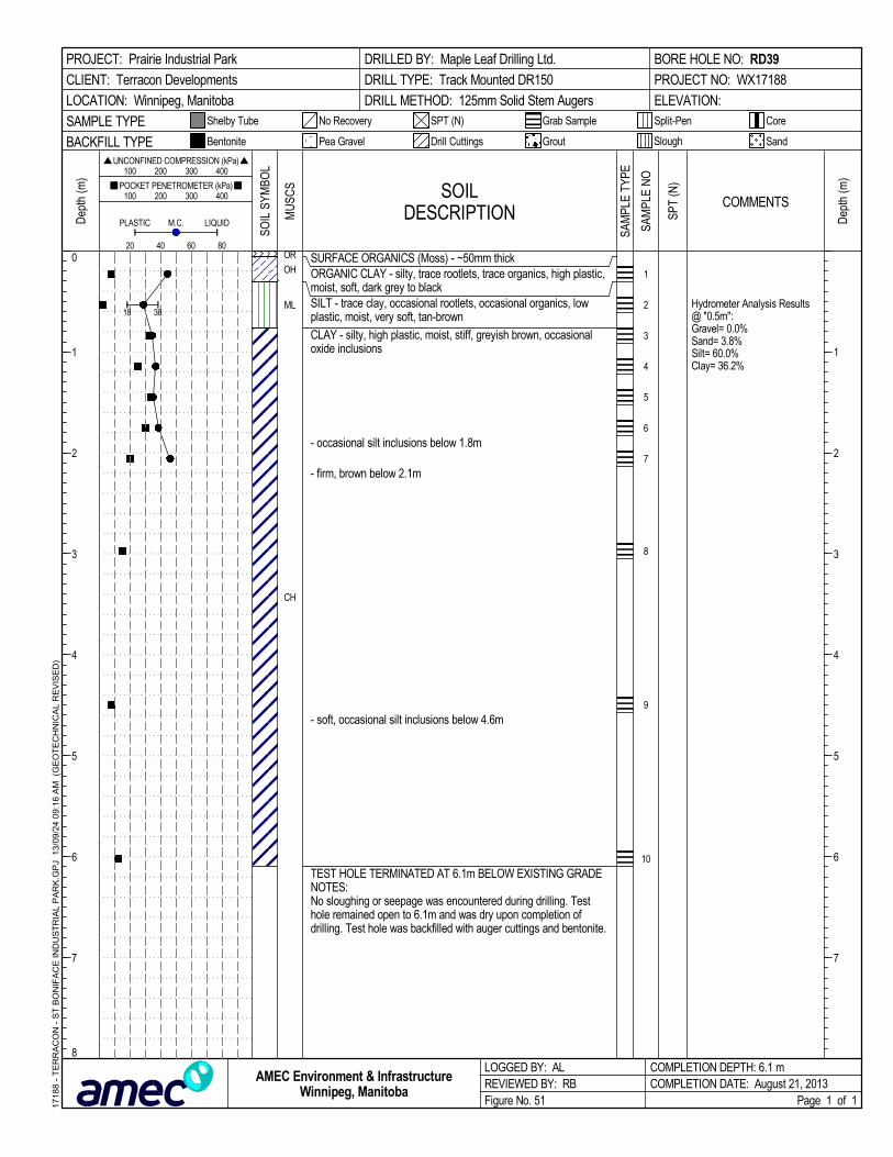
SURFACE ORGANICS (Moss) - ~50mm thickORGANIC CLAY - silty, trace rootlets, trace organics, high plastic,moist, soft, dark grey to blackSILT - trace clay, occasional rootlets, occasional organics, lowplastic, moist, very soft, tan-brown
CLAY - silty, high plastic, moist, stiff, greyish brown, occasionaloxide inclusions
- occasional silt inclusions below 1.8m
- firm, brown below 2.1m
- soft, occasional silt inclusions below 4.6m
TEST HOLE TERMINATED AT 6.1m BELOW EXISTING GRADENOTES:No sloughing or seepage was encountered during drilling. Testhole remained open to 6.1m and was dry upon completion ofdrilling. Test hole was backfilled with auger cuttings and bentonite.
Hydrometer Analysis Results@ "0.5m":Gravel= 0.0%Sand= 3.8%Silt= 60.0%Clay= 36.2%
OR
OH
ML
CH
1
2
3
4
5
6
7
8
9
10
SOILDESCRIPTION
LOGGED BY: ALREVIEWED BY: RBFigure No. 51
Dep
th (m
)
200
Split-Pen
100 200 300 400
1
2
3
4
5
6
7
1
2
3
4
5
6
7
8
CoreShelby Tube
80
Dep
th (m
) 100 200 300 400
PLASTIC M.C.
COMPLETION DEPTH: 6.1 mCOMPLETION DATE: August 21, 2013
PROJECT: Prairie Industrial Park
CLIENT: Terracon Developments
LOCATION: Winnipeg, Manitoba
DRILLED BY: Maple Leaf Drilling Ltd.
DRILL TYPE: Track Mounted DR150
DRILL METHOD: 125mm Solid Stem Augers
BORE HOLE NO: RD39
PROJECT NO: WX17188
ELEVATION:
SAMPLE TYPE
60
Page 1 of 1
SandBACKFILL TYPE
SPT (N)
UNCONFINED COMPRESSION (kPa)
Drill Cuttings Grout
POCKET PENETROMETER (kPa)
LIQUID
Slough
No Recovery
Bentonite
40
Grab Sample
Pea Gravel
SOIL
SYM
BOL
COMMENTS
1718
8 -
TE
RR
AC
ON
- S
T B
ON
IFA
CE
IND
US
TR
IAL
PA
RK
.GP
J 1
3/09
/24
09:
16
AM
(G
EO
TE
CH
NIC
AL
RE
VIS
ED
)
AMEC Environment & InfrastructureWinnipeg, Manitoba
MU
SCS
SAM
PLE
TYPE
SPT
(N)
SAM
PLE
NO
18 38

SURFACE ORGANICS (Moss) - ~ 75mm thickORGANIC CLAY - silty, high plastic, moist, firm, dark grey,occasional layers of rootlets (~5mm thick)CLAY - silty, high plastic, moist, firm, grey to dark grey
- firm to stiff below 0.8m
- brownish grey below 1.0m
- firm, occasional silt inclusions below 2.3m
- brown below 2.7m
TEST HOLE TERMINATED AT 3.0m BELOW EXISTING GRADENOTES:- No sloughing was encountered during drilling. Significantseepage observed from surface of grade. Test hole remainedopen to 3.0m and was filled with water to top of grade. Test holewas back filled with auger cuttings.
OR
OH
CH
1
2
3
4
5
6
7
8
9
10
SOILDESCRIPTION
LOGGED BY: SKREVIEWED BY: RBFigure No. 52
Dep
th (m
)
200
Split-Pen
100 200 300 400
1
2
3
4
5
6
7
1
2
3
4
5
6
7
8
CoreShelby Tube
80
Dep
th (m
) 100 200 300 400
PLASTIC M.C.
COMPLETION DEPTH: 3 mCOMPLETION DATE: July 24, 2013
PROJECT: Prairie Industrial Park
CLIENT: Terracon Developments
LOCATION: Winnipeg, Manitoba
DRILLED BY: AMEC
DRILL METHOD: Hand Auger
BORE HOLE NO: RD40
PROJECT NO: WX17188
ELEVATION:
SAMPLE TYPE
60
Page 1 of 1
SandBACKFILL TYPE
SPT (N)
UNCONFINED COMPRESSION (kPa)
Drill Cuttings Grout
POCKET PENETROMETER (kPa)
LIQUID
Slough
No Recovery
Bentonite
40
Grab Sample
Pea Gravel
SOIL
SYM
BOL
COMMENTS
1718
8 -
TE
RR
AC
ON
- S
T B
ON
IFA
CE
IND
US
TR
IAL
PA
RK
.GP
J 1
3/09
/24
09:
16
AM
(G
EO
TE
CH
NIC
AL
RE
VIS
ED
)
AMEC Environment & InfrastructureWinnipeg, Manitoba
MU
SCS
SAM
PLE
TYPE
SPT
(N)
SAM
PLE
NO
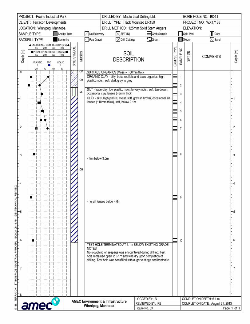
SURFACE ORGANICS (Moss) - ~50mm thickORGANIC CLAY - silty, trace rootlets and trace organics, highplastic, moist, soft, dark grey to grey
SILT - trace clay, low plastic, moist to very moist, soft, tan-brown,occasional clay lenses (~3mm thick)CLAY - silty, high plastic, moist, stiff, greyish brown, occasional siltlenses (~10mm thick), stiff, below 2.1m
- firm below 3.0m
- no silt lenses below 4.6m
TEST HOLE TERMINATED AT 6.1m BELOW EXISTING GRADENOTES:No sloughing or seepage was encountered during drilling. Testhole remained open to 6.1m and was dry upon completion ofdrilling. Test hole was backfilled with auger cuttings and bentonite.
OR
OH
ML
CH
1
2
3
4
5
6
7
8
9
10
SOILDESCRIPTION
LOGGED BY: ALREVIEWED BY: RBFigure No. 53
Dep
th (m
)
200
Split-Pen
100 200 300 400
1
2
3
4
5
6
7
1
2
3
4
5
6
7
8
CoreShelby Tube
80
Dep
th (m
) 100 200 300 400
PLASTIC M.C.
COMPLETION DEPTH: 6.1 mCOMPLETION DATE: August 21, 2013
PROJECT: Prairie Industrial Park
CLIENT: Terracon Developments
LOCATION: Winnipeg, Manitoba
DRILLED BY: Maple Leaf Drilling Ltd.
DRILL TYPE: Track Mounted DR150
DRILL METHOD: 125mm Solid Stem Augers
BORE HOLE NO: RD41
PROJECT NO: WX17188
ELEVATION:
SAMPLE TYPE
60
Page 1 of 1
SandBACKFILL TYPE
SPT (N)
UNCONFINED COMPRESSION (kPa)
Drill Cuttings Grout
POCKET PENETROMETER (kPa)
LIQUID
Slough
No Recovery
Bentonite
40
Grab Sample
Pea Gravel
SOIL
SYM
BOL
COMMENTS
1718
8 -
TE
RR
AC
ON
- S
T B
ON
IFA
CE
IND
US
TR
IAL
PA
RK
.GP
J 1
3/09
/24
09:
16
AM
(G
EO
TE
CH
NIC
AL
RE
VIS
ED
)
AMEC Environment & InfrastructureWinnipeg, Manitoba
MU
SCS
SAM
PLE
TYPE
SPT
(N)
SAM
PLE
NO

SURFACE ORGANICS (Moss) - ~38mmORGANIC CLAY - silty, medium to high plastic, moist, firm, darkgrey, abundant rootlets, occasional silt layers (~7mm thick)CLAY - silty, high plastic, moist, stiff, brownish grey, frequentrootlets
- brown below 1.5m
- abundant silt lamination and frequent silt inclusions between1.9m and 2.0m
TEST HOLE TERMINATED 3.0m BELOW GRADENOTES:- No sloughing was encountered during drilling. Significantseepage observed 40mm below grade from surface. Test holeremained open to 3.0m below grade, and filled with water to adepth of 40mm below grade. Test hole backfilled with augercuttings.
OR
OH
CH
1
2
3
4
5
6
7
8
SOILDESCRIPTION
LOGGED BY: SKREVIEWED BY: RBFigure No. 54
Dep
th (m
)
200
Split-Pen
100 200 300 400
1
2
3
4
5
6
7
1
2
3
4
5
6
7
8
CoreShelby Tube
80
Dep
th (m
) 100 200 300 400
PLASTIC M.C.
COMPLETION DEPTH: 3 mCOMPLETION DATE: July 26, 2013
PROJECT: Prairie Industrial Park
CLIENT: Terracon Developments
LOCATION: Winnipeg, Manitoba
DRILLED BY: AMEC
DRILL METHOD: Hand Auger
BORE HOLE NO: RD42
PROJECT NO: WX17188
ELEVATION:
SAMPLE TYPE
60
Page 1 of 1
SandBACKFILL TYPE
SPT (N)
UNCONFINED COMPRESSION (kPa)
Drill Cuttings Grout
POCKET PENETROMETER (kPa)
LIQUID
Slough
No Recovery
Bentonite
40
Grab Sample
Pea Gravel
SOIL
SYM
BOL
COMMENTS
1718
8 -
TE
RR
AC
ON
- S
T B
ON
IFA
CE
IND
US
TR
IAL
PA
RK
.GP
J 1
3/09
/24
09:
16
AM
(G
EO
TE
CH
NIC
AL
RE
VIS
ED
)
AMEC Environment & InfrastructureWinnipeg, Manitoba
MU
SCS
SAM
PLE
TYPE
SPT
(N)
SAM
PLE
NO

SURFACE ORGANICS (Moss) - ~25mm thickCLAY - silty, trace rootlets and trace organics, high plastic, moist,firm, greyish brown
- stiff, no rootlets and organics below 0.6m
- occasional silt and occasional silt inclusions below 1.2m
SILT - trace clay, low plastic, moist, soft, tan-brown, occasionaloxidation inclusionsCLAY - silty, high plastic, moist, stiff, greyish brown, occasional siltinclusions
- firm to stiff, brown below 2.1m
- firm to soft below 3m
TEST HOLE TERMINATED AT 6.1m BELOW EXISTING GRADENOTES:No sloughing or seepage was encountered during drilling. Testhole remained open to 6.1m and was dry upon completion ofdrilling. Test hole was backfilled with auger cuttings and bentonite.
OR
CH
ML
CH
1
2
3
4
5
6
7
8
9
10
SOILDESCRIPTION
LOGGED BY: ALREVIEWED BY: RBFigure No. 55
Dep
th (m
)
200
Split-Pen
100 200 300 400
1
2
3
4
5
6
7
1
2
3
4
5
6
7
8
CoreShelby Tube
80
Dep
th (m
) 100 200 300 400
PLASTIC M.C.
COMPLETION DEPTH: 6.1 mCOMPLETION DATE: August 21, 2013
PROJECT: Prairie Industrial Park
CLIENT: Terracon Developments
LOCATION: Winnipeg, Manitoba
DRILLED BY: Maple Leaf Drilling Ltd.
DRILL TYPE: Track Mounted DR150
DRILL METHOD: 125mm Solid Stem Augers
BORE HOLE NO: RD43
PROJECT NO: WX17188
ELEVATION:
SAMPLE TYPE
60
Page 1 of 1
SandBACKFILL TYPE
SPT (N)
UNCONFINED COMPRESSION (kPa)
Drill Cuttings Grout
POCKET PENETROMETER (kPa)
LIQUID
Slough
No Recovery
Bentonite
40
Grab Sample
Pea Gravel
SOIL
SYM
BOL
COMMENTS
1718
8 -
TE
RR
AC
ON
- S
T B
ON
IFA
CE
IND
US
TR
IAL
PA
RK
.GP
J 1
3/09
/24
09:
16
AM
(G
EO
TE
CH
NIC
AL
RE
VIS
ED
)
AMEC Environment & InfrastructureWinnipeg, Manitoba
MU
SCS
SAM
PLE
TYPE
SPT
(N)
SAM
PLE
NO
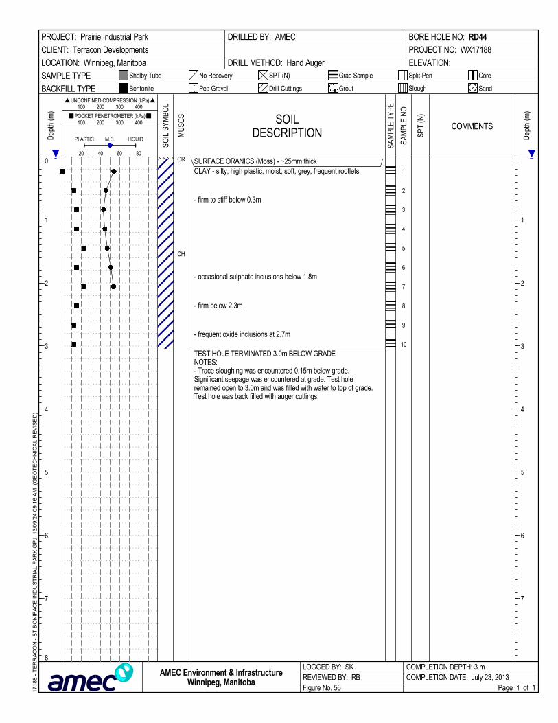
SURFACE ORANICS (Moss) - ~25mm thickCLAY - silty, high plastic, moist, soft, grey, frequent rootlets
- firm to stiff below 0.3m
- occasional sulphate inclusions below 1.8m
- firm below 2.3m
- frequent oxide inclusions at 2.7m
TEST HOLE TERMINATED 3.0m BELOW GRADENOTES:- Trace sloughing was encountered 0.15m below grade.Significant seepage was encountered at grade. Test holeremained open to 3.0m and was filled with water to top of grade.Test hole was back filled with auger cuttings.
OR
CH
1
2
3
4
5
6
7
8
9
10
SOILDESCRIPTION
LOGGED BY: SKREVIEWED BY: RBFigure No. 56
Dep
th (m
)
200
Split-Pen
100 200 300 400
1
2
3
4
5
6
7
1
2
3
4
5
6
7
8
CoreShelby Tube
80
Dep
th (m
) 100 200 300 400
PLASTIC M.C.
COMPLETION DEPTH: 3 mCOMPLETION DATE: July 23, 2013
PROJECT: Prairie Industrial Park
CLIENT: Terracon Developments
LOCATION: Winnipeg, Manitoba
DRILLED BY: AMEC
DRILL METHOD: Hand Auger
BORE HOLE NO: RD44
PROJECT NO: WX17188
ELEVATION:
SAMPLE TYPE
60
Page 1 of 1
SandBACKFILL TYPE
SPT (N)
UNCONFINED COMPRESSION (kPa)
Drill Cuttings Grout
POCKET PENETROMETER (kPa)
LIQUID
Slough
No Recovery
Bentonite
40
Grab Sample
Pea Gravel
SOIL
SYM
BOL
COMMENTS
1718
8 -
TE
RR
AC
ON
- S
T B
ON
IFA
CE
IND
US
TR
IAL
PA
RK
.GP
J 1
3/09
/24
09:
16
AM
(G
EO
TE
CH
NIC
AL
RE
VIS
ED
)
AMEC Environment & InfrastructureWinnipeg, Manitoba
MU
SCS
SAM
PLE
TYPE
SPT
(N)
SAM
PLE
NO
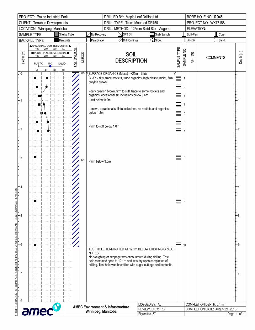
SURFACE ORGANICS (Moss) - ~25mm thickCLAY - silty, trace rootlets, trace organics, high plastic, moist, firm,greyish brown
- dark greyish brown, firm to stiff, trace to some rootlets andorganics, occasional silt inclusions below 0.6m- stiff below 0.9m
- brown, occasional sulfate inclusions, no rootlets and organicsbelow 1.2m
- firm to stiff below 1.8m
- firm below 3.0m
TEST HOLE TERMINATED AT 12.1m BELOW EXISTING GRADENOTES:No sloughing or seepage was encountered during drilling. Testhole remained open to 12.1m and was dry upon completion ofdrilling. Test hole was backfilled with auger cuttings and bentonite.
OR
CH
1
2
3
4
5
6
7
8
9
10
SOILDESCRIPTION
LOGGED BY: ALREVIEWED BY: RBFigure No. 57
Dep
th (m
)
200
Split-Pen
100 200 300 400
1
2
3
4
5
6
7
1
2
3
4
5
6
7
8
CoreShelby Tube
80
Dep
th (m
) 100 200 300 400
PLASTIC M.C.
COMPLETION DEPTH: 6.1 mCOMPLETION DATE: August 21, 2013
PROJECT: Prairie Industrial Park
CLIENT: Terracon Developments
LOCATION: Winnipeg, Manitoba
DRILLED BY: Maple Leaf Drilling Ltd.
DRILL TYPE: Track Mounted DR150
DRILL METHOD: 125mm Solid Stem Augers
BORE HOLE NO: RD45
PROJECT NO: WX17188
ELEVATION:
SAMPLE TYPE
60
Page 1 of 1
SandBACKFILL TYPE
SPT (N)
UNCONFINED COMPRESSION (kPa)
Drill Cuttings Grout
POCKET PENETROMETER (kPa)
LIQUID
Slough
No Recovery
Bentonite
40
Grab Sample
Pea Gravel
SOIL
SYM
BOL
COMMENTS
1718
8 -
TE
RR
AC
ON
- S
T B
ON
IFA
CE
IND
US
TR
IAL
PA
RK
.GP
J 1
3/09
/24
09:
16
AM
(G
EO
TE
CH
NIC
AL
RE
VIS
ED
)
AMEC Environment & InfrastructureWinnipeg, Manitoba
MU
SCS
SAM
PLE
TYPE
SPT
(N)
SAM
PLE
NO
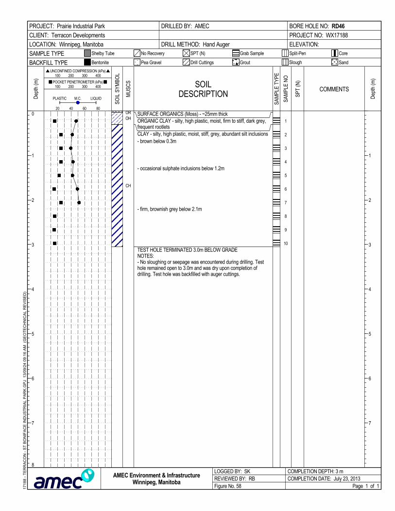
SURFACE ORGANICS (Moss) - ~25mm thickORGANIC CLAY - silty, high plastic, moist, firm to stiff, dark grey,frequent rootletsCLAY - silty, high plastic, moist, stiff, grey, abundant silt inclusions- brown below 0.3m
- occasional sulphate inclusions below 1.2m
- firm, brownish grey below 2.1m
TEST HOLE TERMINATED 3.0m BELOW GRADENOTES:- No sloughing or seepage was encountered during drilling. Testhole remained open to 3.0m and was dry upon completion ofdrilling. Test hole was backfilled with auger cuttings.
OROH
CH
1
2
3
4
5
6
7
8
9
10
SOILDESCRIPTION
LOGGED BY: SKREVIEWED BY: RBFigure No. 58
Dep
th (m
)
200
Split-Pen
100 200 300 400
1
2
3
4
5
6
7
1
2
3
4
5
6
7
8
CoreShelby Tube
80
Dep
th (m
) 100 200 300 400
PLASTIC M.C.
COMPLETION DEPTH: 3 mCOMPLETION DATE: July 23, 2013
PROJECT: Prairie Industrial Park
CLIENT: Terracon Developments
LOCATION: Winnipeg, Manitoba
DRILLED BY: AMEC
DRILL METHOD: Hand Auger
BORE HOLE NO: RD46
PROJECT NO: WX17188
ELEVATION:
SAMPLE TYPE
60
Page 1 of 1
SandBACKFILL TYPE
SPT (N)
UNCONFINED COMPRESSION (kPa)
Drill Cuttings Grout
POCKET PENETROMETER (kPa)
LIQUID
Slough
No Recovery
Bentonite
40
Grab Sample
Pea Gravel
SOIL
SYM
BOL
COMMENTS
1718
8 -
TE
RR
AC
ON
- S
T B
ON
IFA
CE
IND
US
TR
IAL
PA
RK
.GP
J 1
3/09
/24
09:
16
AM
(G
EO
TE
CH
NIC
AL
RE
VIS
ED
)
AMEC Environment & InfrastructureWinnipeg, Manitoba
MU
SCS
SAM
PLE
TYPE
SPT
(N)
SAM
PLE
NO

SURFACE ORGANICS (Moss) - ~25mm thickCLAY - silty, trace rootlets, high plastic, moist, stiff, dark grey toblack
CLAY - silty, high plastic, moist, stiff, dark greyish to brown,occasional organicsSILT - trace clay, low plastic, moist, firm to stiff, light brown,occasional grey clay inclusions
CLAY - silty, high plastic, moist, stiff, greyish brown, occasionalsulfate and occasional silt inclusions- brown below 1.7m
- firm to stiff below 1.8m
- firm to stiff below 4.6m
TEST HOLE TERMINATED AT 6.1m BELOW EXISTING GRADENOTES:No sloughing or seepage was encountered during drilling. Testhole remained open to 6.1m and was dry upon completion ofdrilling. Test hole was backfilled with auger cuttings and bentonite.
OR
OH
CH
ML
CH
1
2
3
4
5
6
7
8
9
10
SOILDESCRIPTION
LOGGED BY: ALREVIEWED BY: RBFigure No. 59
Dep
th (m
)
200
Split-Pen
100 200 300 400
1
2
3
4
5
6
7
1
2
3
4
5
6
7
8
CoreShelby Tube
80
Dep
th (m
) 100 200 300 400
PLASTIC M.C.
COMPLETION DEPTH: 6.1 mCOMPLETION DATE: August 21, 2013
PROJECT: Prairie Industrial Park
CLIENT: Terracon Developments
LOCATION: Winnipeg, Manitoba
DRILLED BY: Maple Leaf Drilling Ltd.
DRILL TYPE: Track Mounted DR150
DRILL METHOD: 125mm Solid Stem Augers
BORE HOLE NO: RD47
PROJECT NO: WX17188
ELEVATION:
SAMPLE TYPE
60
Page 1 of 1
SandBACKFILL TYPE
SPT (N)
UNCONFINED COMPRESSION (kPa)
Drill Cuttings Grout
POCKET PENETROMETER (kPa)
LIQUID
Slough
No Recovery
Bentonite
40
Grab Sample
Pea Gravel
SOIL
SYM
BOL
COMMENTS
1718
8 -
TE
RR
AC
ON
- S
T B
ON
IFA
CE
IND
US
TR
IAL
PA
RK
.GP
J 1
3/09
/24
09:
16
AM
(G
EO
TE
CH
NIC
AL
RE
VIS
ED
)
AMEC Environment & InfrastructureWinnipeg, Manitoba
MU
SCS
SAM
PLE
TYPE
SPT
(N)
SAM
PLE
NO

SURFACE ORGANICS (Moss) - ~25mm thickORGANIC CLAY - silty, high plastic, moist, stiff, dark greyCLAY - silty, high plastic, moist, stiff, brownish grey
- trace rootlets below 0.6m
- occasional silt lamination below 0.9mSILT - trace clay, low plastic, moist, soft, tan brown
CLAY - silty, high plastic, moist, very stiff, greyish brown, tracerootlets-occasional silt inclusions below 2.1m
- stiff below 2.7m
TEST HOLE TERMINATED 3.0m BELOW GRADENOTES:- Trace sloughing encountered between 1.2m to 1.3m. Slightseepage observed from 1.2m to 1.3m. Test hole remained open to3.0m below grade prior to backfilling. Depth to water was 2.0mbelow grade. Test hole back filled with auger cuttings.
OROH
CH
ML
CH
1
2
3
4
5
6
7
8
9
10
SOILDESCRIPTION
LOGGED BY: SKREVIEWED BY: RBFigure No. 60
Dep
th (m
)
200
Split-Pen
100 200 300 400
1
2
3
4
5
6
7
1
2
3
4
5
6
7
8
CoreShelby Tube
80
Dep
th (m
) 100 200 300 400
PLASTIC M.C.
COMPLETION DEPTH: 3 mCOMPLETION DATE: July 23, 2013
PROJECT: Prairie Industrial Park
CLIENT: Terracon Developments
LOCATION: Winnipeg, Manitoba
DRILLED BY: AMEC
DRILL METHOD: Hand Auger
BORE HOLE NO: RD48
PROJECT NO: WX17188
ELEVATION:
SAMPLE TYPE
60
Page 1 of 1
SandBACKFILL TYPE
SPT (N)
UNCONFINED COMPRESSION (kPa)
Drill Cuttings Grout
POCKET PENETROMETER (kPa)
LIQUID
Slough
No Recovery
Bentonite
40
Grab Sample
Pea Gravel
SOIL
SYM
BOL
COMMENTS
1718
8 -
TE
RR
AC
ON
- S
T B
ON
IFA
CE
IND
US
TR
IAL
PA
RK
.GP
J 1
3/09
/24
09:
16
AM
(G
EO
TE
CH
NIC
AL
RE
VIS
ED
)
AMEC Environment & InfrastructureWinnipeg, Manitoba
MU
SCS
SAM
PLE
TYPE
SPT
(N)
SAM
PLE
NO

SURFACE ORGANICS (Moss) - ~25mm thickORGANIC CLAY - silty, trace rootlets and organics, moist, darkgreyCLAY - silty, trace organics to 0.3m, high plastic, moist, stiff tovery stiff, grey to dark grey- stiff, greyish brown below 0.6m
- firm below 0.9mSILT - trace clay, low platic, moist, soft, tan-brown, occasional clayinclusions
- moist to very moist below 1.5mCLAY - silty, high plastic, moist, stiff, greyish brown, occasional siltinclusions
- occasional silt lenses ~20mm thick below 2.1m
- abundant silt lenses ~40mm thick between 3.1m to 3.2m
- soft, grey to dark grey below 4.6m
- occasional oxidation inclusions below 5.9mTEST HOLE TERMINATED AT 6.1m BELOW EXISTING GRADENOTES:- No sloughing or seepage was encountered during drilling. Testhole remained open to 6.1m and was dry upon completion ofdrilling. Test hole was backfilled with auger cuttings and bentonite.
OROH
CH
ML
CH
1
2
3
4
5
6
7
8
9
10
SOILDESCRIPTION
LOGGED BY: ALREVIEWED BY: RBFigure No. 61
Dep
th (m
)
200
Split-Pen
100 200 300 400
1
2
3
4
5
6
7
1
2
3
4
5
6
7
8
CoreShelby Tube
80
Dep
th (m
) 100 200 300 400
PLASTIC M.C.
COMPLETION DEPTH: 6.1 mCOMPLETION DATE: July 12, 2013
PROJECT: Prairie Industrial Park
CLIENT: Terracon Developments
LOCATION: Winnipeg, Manitoba
DRILLED BY: Maple Leaf Drilling Ltd.
DRILL TYPE: Track Mounted DR150
DRILL METHOD: 125mm Solid Stem Augers
BORE HOLE NO: RD49
PROJECT NO: WX17188
ELEVATION:
SAMPLE TYPE
60
Page 1 of 1
SandBACKFILL TYPE
SPT (N)
UNCONFINED COMPRESSION (kPa)
Drill Cuttings Grout
POCKET PENETROMETER (kPa)
LIQUID
Slough
No Recovery
Bentonite
40
Grab Sample
Pea Gravel
SOIL
SYM
BOL
COMMENTS
1718
8 -
TE
RR
AC
ON
- S
T B
ON
IFA
CE
IND
US
TR
IAL
PA
RK
.GP
J 1
3/09
/24
09:
16
AM
(G
EO
TE
CH
NIC
AL
RE
VIS
ED
)
AMEC Environment & InfrastructureWinnipeg, Manitoba
MU
SCS
SAM
PLE
TYPE
SPT
(N)
SAM
PLE
NO

SURFACE ORGANICS (Moss) - ~25mm thickORGANIC CLAY - silty, trace rootlets and organics, moist, darkgreyCLAY - silty, trace organics and rootlets to 0.3m, high plastic,moist, soft to firm, dark greySILT - trace clay, low plastic, moist, soft, tan-brown, occasionalclay lenses ~10mm thick
CLAY - silty, high plastic, moist, very stiff, greyish brown, frequentsilt lenses ~15mm thick
- light greyish brown, occasional silt inclusions below 1.5m
- stiff, greyish brown below 1.8m
- firm below 2.1m
TEST HOLE TERMINATED AT 3.1m BELOW EXISTING GRADENOTES:- No sloughing or seepage was encountered during drilling. Testhole remained open to 3.1m and was dry upon completion ofdrilling. Test hole was backfilled with auger cuttings and bentonite.
OROHCH
ML
CH
1
2
3
4
5
6
7
8
SOILDESCRIPTION
LOGGED BY: ALREVIEWED BY: RBFigure No. 62
Dep
th (m
)
200
Split-Pen
100 200 300 400
1
2
3
4
5
6
7
1
2
3
4
5
6
7
8
CoreShelby Tube
80
Dep
th (m
) 100 200 300 400
PLASTIC M.C.
COMPLETION DEPTH: 3.1 mCOMPLETION DATE: July 12, 2013
PROJECT: Prairie Industrial Park
CLIENT: Terracon Developments
LOCATION: Winnipeg, Manitoba
DRILLED BY: Maple Leaf Drilling Ltd.
DRILL TYPE: Track Mounted DR150
DRILL METHOD: 125mm Solid Stem Augers
BORE HOLE NO: RD50
PROJECT NO: WX17188
ELEVATION:
SAMPLE TYPE
60
Page 1 of 1
SandBACKFILL TYPE
SPT (N)
UNCONFINED COMPRESSION (kPa)
Drill Cuttings Grout
POCKET PENETROMETER (kPa)
LIQUID
Slough
No Recovery
Bentonite
40
Grab Sample
Pea Gravel
SOIL
SYM
BOL
COMMENTS
1718
8 -
TE
RR
AC
ON
- S
T B
ON
IFA
CE
IND
US
TR
IAL
PA
RK
.GP
J 1
3/09
/24
09:
16
AM
(G
EO
TE
CH
NIC
AL
RE
VIS
ED
)
AMEC Environment & InfrastructureWinnipeg, Manitoba
MU
SCS
SAM
PLE
TYPE
SPT
(N)
SAM
PLE
NO

SURFACE ORGANICS (Moss) - ~25mm thickORGANIC CLAY - silty, trace rootlets and organics, moist, darkgreyCLAY - silty, trace organics and rootlets to 0.3m, high plastic,moist, stiff, grey to dark grey, occasional sulphate inclusions- greyish brown, occasional silt lenses ~5mm thick below 0.6m
- firm, occasional oxidation inclusions below 0.9mSILT - trace clay, low platic, moist, soft, tan-brown, occasionaloxidation inclusions
- moist to very moist below 1.5mCLAY - silty, high plastic, moist, stiff, brown, occasional siltinclusions
- firm, abundant silt lenses ~25mm thick between 2.1m and 2.3m
- stiff, greyish brown, occasional sulphate inclusions below 3.1m
- firm, dark greyish brown below 4.6m
- soft to firm, grey below 5.5m
TEST HOLE TERMINATED AT 6.1m BELOW EXISTING GRADENOTES:- Slight to moderate sloughing and moderate seepage wasencountered 1.1m below grade during drilling. Test hole remainedopen to 1.2m and was dry upon completion of drilling. Test holewas backfilled with auger cuttings and bentonite.
OROH
CH
ML
CH
1
2
3
4
5
6
7
8
9
10
SOILDESCRIPTION
LOGGED BY: ALREVIEWED BY: RBFigure No. 63
Dep
th (m
)
200
Split-Pen
100 200 300 400
1
2
3
4
5
6
7
1
2
3
4
5
6
7
8
CoreShelby Tube
80
Dep
th (m
) 100 200 300 400
PLASTIC M.C.
COMPLETION DEPTH: 6.1 mCOMPLETION DATE: July 12, 2013
PROJECT: Prairie Industrial Park
CLIENT: Terracon Developments
LOCATION: Winnipeg, Manitoba
DRILLED BY: Maple Leaf Drilling Ltd.
DRILL TYPE: Track Mounted DR150
DRILL METHOD: 125mm Solid Stem Augers
BORE HOLE NO: RD51
PROJECT NO: WX17188
ELEVATION:
SAMPLE TYPE
60
Page 1 of 1
SandBACKFILL TYPE
SPT (N)
UNCONFINED COMPRESSION (kPa)
Drill Cuttings Grout
POCKET PENETROMETER (kPa)
LIQUID
Slough
No Recovery
Bentonite
40
Grab Sample
Pea Gravel
SOIL
SYM
BOL
COMMENTS
1718
8 -
TE
RR
AC
ON
- S
T B
ON
IFA
CE
IND
US
TR
IAL
PA
RK
.GP
J 1
3/09
/24
09:
16
AM
(G
EO
TE
CH
NIC
AL
RE
VIS
ED
)
AMEC Environment & InfrastructureWinnipeg, Manitoba
MU
SCS
SAM
PLE
TYPE
SPT
(N)
SAM
PLE
NO

SURFACE ORGANICS (Moss) - ~25mm thickORGANIC CLAY - silty, trace rootlets and organics, moist, darkgreyCLAY - silty, trace sand, gravel and rootlets to 0.3m, high plastic,moist, firm to stiff, dark grey to brown- stiff, grey to dark grey below 0.6m
- dark greyish brown, occasional oxidation inclusions below 0.9m
- greyish brown, frequent silt lenses ~15mm thick below 1.8m
- abundant silt inclusions between 2.3m to 2.6m
TEST HOLE TERMINATED AT 3.1m BELOW EXISTING GRADENOTES:- No sloughing or seepage was encountered during drilling. Testhole remained open to 3.1m and was dry upon completion ofdrilling. Test hole was backfilled with auger cuttings and bentonite.
OROH
CH
1
2
3
4
5
6
7
8
9
SOILDESCRIPTION
LOGGED BY: ALREVIEWED BY: RBFigure No. 64
Dep
th (m
)
200
Split-Pen
100 200 300 400
1
2
3
4
5
6
7
1
2
3
4
5
6
7
8
CoreShelby Tube
80
Dep
th (m
) 100 200 300 400
PLASTIC M.C.
COMPLETION DEPTH: 3.1 mCOMPLETION DATE: July 12, 2013
PROJECT: Prairie Industrial Park
CLIENT: Terracon Developments
LOCATION: Winnipeg, Manitoba
DRILLED BY: Maple Leaf Drilling Ltd.
DRILL TYPE: Track Mounted DR150
DRILL METHOD: 125mm Solid Stem Augers
BORE HOLE NO: RD52
PROJECT NO: WX17188
ELEVATION:
SAMPLE TYPE
60
Page 1 of 1
SandBACKFILL TYPE
SPT (N)
UNCONFINED COMPRESSION (kPa)
Drill Cuttings Grout
POCKET PENETROMETER (kPa)
LIQUID
Slough
No Recovery
Bentonite
40
Grab Sample
Pea Gravel
SOIL
SYM
BOL
COMMENTS
1718
8 -
TE
RR
AC
ON
- S
T B
ON
IFA
CE
IND
US
TR
IAL
PA
RK
.GP
J 1
3/09
/24
09:
16
AM
(G
EO
TE
CH
NIC
AL
RE
VIS
ED
)
AMEC Environment & InfrastructureWinnipeg, Manitoba
MU
SCS
SAM
PLE
TYPE
SPT
(N)
SAM
PLE
NO

SURFACE ORGANICS (Moss) - ~25mm thickORGANIC CLAY - silty, trace rootlets and organics, moist, darkgreyCLAY (FILL) - silty, some sand to sandy, trace gravel and rootlets,high plastic, moist, firm, dark greyish brownCLAY - silty, trace organics and rootlets to 0.5m, high plastic,moist, stiff, grey to dark grey, occasional sulphate inclusions- dark greyish brown below 0.9m
- greyish brown below 1.5m
- brown, occasional silt inclusions below 1.8m
- firm, abundant silt lenses ~25mm thick at 2.4m
- occasional to frequent silt inclusions below 4.6m
- soft, grey below 5.5m
TEST HOLE TERMINATED AT 6.1m BELOW EXISTING GRADENOTES:- No sloughing or seepage was encountered during drilling. Testhole remained open to 6.1m and was dry upon completion ofdrilling. Test hole was backfilled with auger cuttings and bentonite.
OROHCH
CH
1
2
3
4
5
6
7
8
9
10
11
SOILDESCRIPTION
LOGGED BY: ALREVIEWED BY: RBFigure No. 65
Dep
th (m
)
200
Split-Pen
100 200 300 400
1
2
3
4
5
6
7
1
2
3
4
5
6
7
8
CoreShelby Tube
80
Dep
th (m
) 100 200 300 400
PLASTIC M.C.
COMPLETION DEPTH: 9.1 mCOMPLETION DATE: July 12, 2013
PROJECT: Prairie Industrial Park
CLIENT: Terracon Developments
LOCATION: Winnipeg, Manitoba
DRILLED BY: Maple Leaf Drilling Ltd.
DRILL TYPE: Track Mounted DR150
DRILL METHOD: 125mm Solid Stem Augers
BORE HOLE NO: RD53
PROJECT NO: WX17188
ELEVATION:
SAMPLE TYPE
60
Page 1 of 1
SandBACKFILL TYPE
SPT (N)
UNCONFINED COMPRESSION (kPa)
Drill Cuttings Grout
POCKET PENETROMETER (kPa)
LIQUID
Slough
No Recovery
Bentonite
40
Grab Sample
Pea Gravel
SOIL
SYM
BOL
COMMENTS
1718
8 -
TE
RR
AC
ON
- S
T B
ON
IFA
CE
IND
US
TR
IAL
PA
RK
.GP
J 1
3/09
/24
09:
16
AM
(G
EO
TE
CH
NIC
AL
RE
VIS
ED
)
AMEC Environment & InfrastructureWinnipeg, Manitoba
MU
SCS
SAM
PLE
TYPE
SPT
(N)
SAM
PLE
NO

SURFACE ORGANICS (Moss) - ~25mm thickCLAY - silty, high plastic, moist, stiff, greyish brown
SILT - trace clay, low plastic, moist, soft, tan-brown, occasionaloxidation inclusions
CLAY - silty, high plastic, moist, firm, greyish brown, occasionalsulphate and silt inclusions
TEST HOLE TERMINATED AT 3.0m BELOW EXISTING GRADENOTES:- No sloughing or seepage was encountered during drilling. Testhole remained open to 3.0m and was dry upon completion ofdrilling. Test hole was backfilled with auger cuttings and bentonite.
OR
CH
ML
CH
1
2
3
4
5
SOILDESCRIPTION
LOGGED BY: ALREVIEWED BY: RBFigure No. 66
Dep
th (m
)
200
Split-Pen
100 200 300 400
1
2
3
4
5
6
7
1
2
3
4
5
6
7
8
CoreShelby Tube
80
Dep
th (m
) 100 200 300 400
PLASTIC M.C.
COMPLETION DEPTH: 3 mCOMPLETION DATE: August 26, 2013
PROJECT: Prairie Industrial Park
CLIENT: Terracon Developments
LOCATION: Winnipeg, Manitoba
DRILLED BY: Maple Leaf Drilling Ltd.
DRILL TYPE: Track Mounted DR150
DRILL METHOD: 125mm Solid Stem Augers
BORE HOLE NO: SY01
PROJECT NO: WX17188
ELEVATION:
SAMPLE TYPE
60
Page 1 of 1
SandBACKFILL TYPE
SPT (N)
UNCONFINED COMPRESSION (kPa)
Drill Cuttings Grout
POCKET PENETROMETER (kPa)
LIQUID
Slough
No Recovery
Bentonite
40
Grab Sample
Pea Gravel
SOIL
SYM
BOL
COMMENTS
1718
8 -
TE
RR
AC
ON
- S
T B
ON
IFA
CE
IND
US
TR
IAL
PA
RK
.GP
J 1
3/09
/24
09:
16
AM
(G
EO
TE
CH
NIC
AL
RE
VIS
ED
)
AMEC Environment & InfrastructureWinnipeg, Manitoba
MU
SCS
SAM
PLE
TYPE
SPT
(N)
SAM
PLE
NO

SURFACE ORGANICS (Moss) - ~25mm thickCLAY - silty, high plastic, moist, stiff to very stiff, grey, occasionaloxidation and sulphate inclusions, trace rootlets
- grey to dark grey, stiff below 0.8m
- brown, occasional sulphate inclusions, no rootlets below 1.5m
- firm below 2.3m- greyish brown below 2.4m
TEST HOLE TERMINATED AT 3.0m BELOW EXISTING GRADENOTES:- No sloughing or seepage was encountered during drilling. Testhole remained open to 3.0m and was dry upon completion ofdrilling. Test hole was backfilled with auger cuttings and bentonite.
OR
CH
1
2
3
4
5
SOILDESCRIPTION
LOGGED BY: ALREVIEWED BY: RBFigure No. 67
Dep
th (m
)
200
Split-Pen
100 200 300 400
1
2
3
4
5
6
7
1
2
3
4
5
6
7
8
CoreShelby Tube
80
Dep
th (m
) 100 200 300 400
PLASTIC M.C.
COMPLETION DEPTH: 3 mCOMPLETION DATE: August 26, 2013
PROJECT: Prairie Industrial Park
CLIENT: Terracon Developments
LOCATION: Winnipeg, Manitoba
DRILLED BY: Maple Leaf Drilling Ltd.
DRILL TYPE: Track Mounted DR150
DRILL METHOD: 125mm Solid Stem Augers
BORE HOLE NO: SY02
PROJECT NO: WX17188
ELEVATION:
SAMPLE TYPE
60
Page 1 of 1
SandBACKFILL TYPE
SPT (N)
UNCONFINED COMPRESSION (kPa)
Drill Cuttings Grout
POCKET PENETROMETER (kPa)
LIQUID
Slough
No Recovery
Bentonite
40
Grab Sample
Pea Gravel
SOIL
SYM
BOL
COMMENTS
1718
8 -
TE
RR
AC
ON
- S
T B
ON
IFA
CE
IND
US
TR
IAL
PA
RK
.GP
J 1
3/09
/24
09:
16
AM
(G
EO
TE
CH
NIC
AL
RE
VIS
ED
)
AMEC Environment & InfrastructureWinnipeg, Manitoba
MU
SCS
SAM
PLE
TYPE
SPT
(N)
SAM
PLE
NO
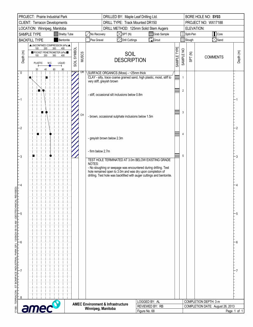
SURFACE ORGANICS (Moss) - ~25mm thickCLAY - silty, trace coarse grained sand, high plastic, moist, stiff tovery stiff, greyish brown
- stiff, occasional silt inclusions below 0.8m
- brown, occasional sulphate inclusions below 1.5m
- greyish brown below 2.3m
- firm below 2.7m
TEST HOLE TERMINATED AT 3.0m BELOW EXISTING GRADENOTES:- No sloughing or seepage was encountered during drilling. Testhole remained open to 3.0m and was dry upon completion ofdrilling. Test hole was backfilled with auger cuttings and bentonite.
OR
CH
1
2
3
4
5
SOILDESCRIPTION
LOGGED BY: ALREVIEWED BY: RBFigure No. 68
Dep
th (m
)
200
Split-Pen
100 200 300 400
1
2
3
4
5
6
7
1
2
3
4
5
6
7
8
CoreShelby Tube
80
Dep
th (m
) 100 200 300 400
PLASTIC M.C.
COMPLETION DEPTH: 3 mCOMPLETION DATE: August 26, 2013
PROJECT: Prairie Industrial Park
CLIENT: Terracon Developments
LOCATION: Winnipeg, Manitoba
DRILLED BY: Maple Leaf Drilling Ltd.
DRILL TYPE: Track Mounted DR150
DRILL METHOD: 125mm Solid Stem Augers
BORE HOLE NO: SY03
PROJECT NO: WX17188
ELEVATION:
SAMPLE TYPE
60
Page 1 of 1
SandBACKFILL TYPE
SPT (N)
UNCONFINED COMPRESSION (kPa)
Drill Cuttings Grout
POCKET PENETROMETER (kPa)
LIQUID
Slough
No Recovery
Bentonite
40
Grab Sample
Pea Gravel
SOIL
SYM
BOL
COMMENTS
1718
8 -
TE
RR
AC
ON
- S
T B
ON
IFA
CE
IND
US
TR
IAL
PA
RK
.GP
J 1
3/09
/24
09:
16
AM
(G
EO
TE
CH
NIC
AL
RE
VIS
ED
)
AMEC Environment & InfrastructureWinnipeg, Manitoba
MU
SCS
SAM
PLE
TYPE
SPT
(N)
SAM
PLE
NO

Geotechnical InvestigationProposed Prairie Industrial ParkWinnipeg, Manitoba
P:\Jobs\17100's\17180's\17188 - Terracon - St Boniface Industrial park\Geotech\Reporting\17188-00-Prairie Industrial Geotech (Roads) Report.doc
APPENDIX B
LATERAL EARTH PRESSURES

P
h
= H
o
- m4s
u
CLIENT:
-
PROJECTION:
-
DATUM:
GEOTECHNICAL INVESTIGATION
PRAIRIE INDUSTRIAL PARK
NEAR MAZENOD AND CAMIEL SYS
WINNIPEG, MANITOBA
TITLE:
PROJECT:
FIGURE No.:
REV. No.:
FIGURE B1
PROJECT No.:
wx17188
B
DWN BY:
CHK'D BY:
SEPTEMBER 2013
DATE:
SCALE:
TG
NOT TO SCALE
AL
LATERAL EARTH PRESSURE DISTRIBUTION FOR
TEMPORARY BRACED EXCAVATIONS IN SOFT,
NORMALLY CONSOLIDATED CLAY
TERRACON DEVELOPMENTS
440 DOVERCOURT DRIVE
WINNIPEG, MANITOBA R3Y 1N4
PHONE: 204.488.2997 FAX:204.489.8261

P
h
= K (h-hw
) + K 'hw
+
w
hw
CLIENT:
-
PROJECTION:
-
DATUM:
GEOTECHNICAL INVESTIGATION
PRAIRIE INDUSTRIAL PARK
NEAR MAZENOD AND CAMIEL SYS
WINNIPEG, MANITOBA
TITLE:
PROJECT:
FIGURE No.:
REV. No.:
FIGURE B2
PROJECT No.:
WX17188
B
DWN BY:
CHK'D BY:
SEPTEMBER2013
DATE:
SCALE:
TG
NOT TO SCALE
AL
LATERAL EARTH PRESSURES
ON PERMANENT GATE CHAMBER WALLS
TERRACON DEVELOPMENTS
440 DOVERCOURT DRIVE
WINNIPEG, MANITOBA R3Y 1N4
PHONE: 204.488.2997 FAX:204.489.8261

Stantec Consulting Ltd. 500–311 Portage Avenue, Winnipeg MB R3B 2B9
November 24, 2015 File: 116809351
Attention: Maqbool Hussain 500 – 311 Portage Avenue Winnipeg, MB R3B 2B9
Dear Mr. Hussain,
Reference: St. Boniface Industrial Lift Station
Stantec was retained to perform a geotechnical investigation to evaluate the existing soils conditions and provide foundation recommendations for the proposed St. Boniface Industrial Lift Station located in Winnipeg, Manitoba. The purpose of the geotechnical investigation was to determine subsurface conditions and provide foundation recommendations. In addition to the foundation review, a slope stability analysis of proposed excavations was also performed in order to determine the maximum side slopes during excavation for the tanks.
Outlined below is a description of the proposed lift station, a summary of the geotechnical investigation, foundation recommendations and the results of the slope stability analysis.
1.0 PROPOSED LIFT STATION The project site is located within the St. Boniface Industrial Park, just east of Mazenod Road as shown on Figure 1 in Appendix B. The proposed works at this site consists of the design and construction of the St. Boniface Industrial Lift Station. The currently proposed Lift Station consists of the following:
• Two discrete 3 m diameter by 10 m deep tanks. To facilitate a connection of the tanks near the tank base, it is likely that the tanks will be installed by mass excavation, and would be founded on a common concrete slab;
• A heated building will be constructed overtop one of the tanks
2.0 GEOTECHNICAL INVESTIGATION The geotechnical drilling and sampling program was performed on November 19, 2015, with drilling services provided by Maple Leaf Drilling Ltd. and continuous Stantec supervision. The drilling was performed using a track mounted Mobile B37X drill rig. One testhole was drilled at this site, with the location shown on Figure 1 in Appendix B. The testhole was drilled approximately 15 m south of the proposed lift station location. Partially frozen/wet conditions created poor rig access and therefore the testhole was drilled at the closest feasible location to the proposed lift station (photograph included within Appendix B). The drilling program consisted of advancing 125 mm solid stem augers through the native overburden materials to power auger refusal. Overburden soil samples were retrieved directly off the auger flights at approximately 0.75 to 1.5 m intervals. Attempts were also made to advance 35 mm inside diameter split spoon samples in cohesionless samples to obtain Standard Penetration Test (SPT) “N” values. All samples were visually inspected in the field for material types and consistency.
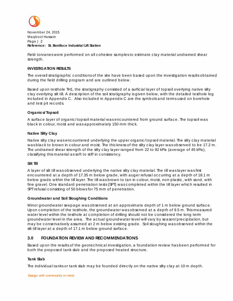
November 24, 2015 Maqbool Hussain Page | 2 Reference: St. Boniface Industrial Lift Station
Field torvanes were performed on all cohesive samples to estimate clay material undrained shear strength.
INVESTIGATION RESULTS
The overall stratigraphic conditions of the site have been based upon the investigation results obtained during the field drilling program and are outlined below.
Based upon testhole TH1, the stratigraphy consisted of a surficial layer of topsoil overlying native silty clay overlying silt till. A description of the soil stratigraphy is given below, with the detailed testhole log included in Appendix C. Also included in Appendix C are the symbols and terms used on borehole and test pit records.
Organics/Topsoil
A surface layer of organic/topsoil material was encountered from ground surface. The topsoil was black in colour, moist and was approximately 150 mm thick.
Native Silty Clay
Native silty clay was encountered underlying the upper organic/topsoil material. The silty clay material was black to brown in colour and moist. The thickness of the silty clay layer was observed to be 17.2 m. The undrained shear strength of the silty clay layer ranged from 22 to 92 kPa (average of 45 kPa), classifying this material as soft to stiff in consistency.
Silt Till
A layer of silt till was observed underlying the native silty clay material. The till was layer was first encountered at a depth of 17.35 m below grade, with auger refusal occurring at a depth of 18.1 m below grade within the till layer. The till was brown to tan in colour, moist, non-plastic, with sand, with fine gravel. One standard penetration tests (SPT) was completed within the till layer which resulted in SPT refusal consisting of 50 blows for 75 mm of penetration.
Groundwater and Soil Sloughing Conditions
Minor groundwater seepage was observed at an approximate depth of 1 m below ground surface. Upon completion of the testhole, the groundwater was observed at a depth of 9.5 m. This measured water level within the testhole at completion of drilling should not be considered the long term groundwater level in the area. The actual groundwater level will vary by season/precipitation, but may be conservatively assumed at 2 m below existing grade. Soil sloughing was observed within the silt till layer at a depth of 17.1 m below ground surface.
3.0 FOUNDATION REVIEW AND RECOMMENDATIONS Based upon the results of the geotechnical investigation, a foundation review has been performed for both the proposed tank slab and the proposed heated structure.
Tank Slab
The individual tanks or tank slab may be founded directly on the native silty clay at 10 m depth.

November 24, 2015 Maqbool Hussain Page | 3 Reference: St. Boniface Industrial Lift Station
Bearing capacity at 10 m depth may be taken as the bearing capacity at ULS at 10 m depth, plus the total weight of soil removed for each tank, minus the weight of the tank and any water or sewage within the tank.
For design purposes, a bearing capacity at the underside of the tanks may be taken as 300 kPa (at ULS and SLS), minus the weight of the tanks and its contents (i.e. water, sewage, etc).
The empty tanks would have a buoyant force of 700 kN (not including the weight of the tank, and assuming a groundwater level at surface to represent the worst case scenario). Assuming the tank remains empty, the buoyant force would be resisted by friction along the sidewalls of the tank. This frictional resistance would be dependent on the tank installation methodology, and whether the sidewalls of the tank are in contact with native clay or granular backfill. Assuming native clay contact, the uplift shaft resistance may be taken as 1100 kN at ULS. Assuming granular backfill is in contact with the tank sidewalls (and GWL at 2 m below ground surface), the uplift shaft resistance is 1000 kN at ULS. Based upon the above, it would therefore appear that buoyancy failure is not a concern for the proposed tanks.
Building Foundation
The foundation for the proposed building is dependent on the tank installation methodology. If the tanks can be installed without the need for mass excavation (i.e. soil removal via auger and tanks lowered into place), the building foundation could likely be cast-in-place concrete friction piles. Our current understanding of the tank installation consists of a mass excavation with the excavation material (i.e. native clay) used to backfill the excavation once the tank installation is complete. The recompaction of the native clay to the in-situ density is not considered practical, and some long term settlement of the recompacted material is likely. Settlement of the recompacted material would induce downdrag forces on friction piles, and therefore friction piles are not recommended.
The proposed building foundation should therefore consist of driven end bearing piles that are driven to refusal in the underlying till. The surface of the till layer was encountered at a depth of 17.4 m below ground surface, with pile end and bearing refusal likely at approximately 18 m depth below existing grade.
The driven piles may consist of either precast concrete piles or steel piles. Pile capacities at ultimate limit states (ULS) are provided for driven precast concrete piles and driven steel piles in Table 1 and Table 2 below, respectively. For design purposes, the pile capacity at Serviceability Limit State (SLS) may be taken as the ULS capacity. The unfactored downdrag force along the upper 10 m of the pile length has been included in the tables below.
Table 1- Driven Precast Concrete Pile Capacity
Pile Diameter Pile Capacity at ULS Unfactored Downdrag Force Refusal Criteria
305 mm 550 kN 350 kN 5 Blows/ 25 mm
356 mm 750 kN 400 kN 8 Blows/ 25 mm
400 mm 1000 kN 450 kN 12 Blows/25 mm

November 24, 2015 Maqbool Hussain Page | 4 Reference: St. Boniface Industrial Lift Station
The refusal criteria indicated in the above table should be achieved at least 3 times for the final resistance. The hammer should be capable of delivering a minimum rated energy of 40 kJ/Blow. Pre-boring to a depth of approximately 3 m should be considered for all driven piles to enhance pile alignment and reduce vibration levels during pile driving. The prebored hole diameter should be slightly larger than the nominal pile diameter. All piles should be driven continuously to their required depth once driving is initiated. Pile heave for piles within 5 pile diameters of each other should be monitored and redriving should be done where pile heave occurs. Pile spacing should not be less than 2.5 pile diameters, measured center to center. Precast concrete piles driven to practical refusal will develop the majority of their capacity from toe resistance, and therefore, a reduction in pile capacity is generally not required for group action. If pile groups are required for the proposed additions, we should be contacted to review the requirement for a group reduction factor.
Table 2- Driven Steel Pile Capacity
Pile Size Pile Capacity at ULS Unfactored Downdrag Force Refusal Criteria
HP310x110 1200 kN 300 kN 20 Blows/ 25 mm
Recommendations for design and installation of steel H piles are provided below.
1. Pile spacing within pile groups should be a minimum of 2.5 pile diameters measured centre to centre. Provided that pile heave is monitored and piles are redriven when pile heave is observed, no reduction in pile capacity is required due to group action. Redriving of all piles in groups should be specified along with the requirement to monitor pile heave.
2. Prior to the pile installation, the piles should be inspected to confirm that the material specifications are satisfied. As a minimum, steel H-piles should meet the requirements of CAN/CSA-G40.20/G40.21, Grade 350 W. The piles should be free from protrusions, which could create voids in the soil around the pile during driving.
3. The piles should be fitted with a driving shoe to help minimize damage to the end of the pile during the driving process. The driving shoe should not extent beyond the outside face of the pile to prevent disturbance of the soils adjacent to the pile as it is being driven.
4. The maximum compression and tension stresses developed within any pile during installation
(commonly referred to as the driving stresses) should be limited to 0.9 Fy.
5. The piles should be driven to practical refusal with a diesel hammer having a minimum rated energy of 50 kJ per blow. Practical pile refusal can generally be considered to be three consecutive sets of 20 blows per 25 mm of pile penetration.
6. Monitoring of the pile installation by an experienced inspector is recommended to verify that the piles are installed in accordance with design assumptions and the driving criteria are satisfied. For each pile, a complete driving record in terms of the number of blows per 300 mm of penetration should be recorded.
Because of the potential settlement of the recompacted clay material, the building floor should be supported by a structural slab.

November 24, 2015 Maqbool Hussain Page | 5 Reference: St. Boniface Industrial Lift Station
4.0 STABILITY REVIEW OF TANK EXCAVATION As stated previously, it is our current understanding that the proposed tanks will be installed using a mass excavation that is 10 m deep. A slope stability review has been performed to identify the maximum side slopes that can be utilized during the excavation. The slope stability analysis was performed using the software SLOPE\W, developed by Geoslope International Inc. The computer model investigates a large number of potential failure surfaces and depending on the method of analysis used can present the results in the form of contours of computed factors of safety against sliding.
The stability of a slope is typically generalized as a ratio of the forces that drive the failure divided by the forces that resist failure. The unitless fraction is called a Factor of Safety (FS). Factors of Safety that are unity (1.0) or less indicate that driving forces exceed resisting forces and from a geotechnical engineering perspective the slip has failed or is highly unstable.
As per the Canadian Foundation Engineering Manual (CFEM), temporary excavations in clay material should be reviewed using undrained strength parameters. The temporary excavation side slope geometry should be such that a minimum overall slip surface Factor of Safety (FS) of 1. 5 be maintained for this site.
The slope stability review has consisted of evaluating the FS for the critical overall slip surface for assumed excavation side slopes of 1H:1V, 2H:1V, and 3H:1V. For the analysis, as undrained shear strength of 45 KPa has been used for the native clay material. The results of the slope stability analysis are included in Appendix D. As shown, a temporary excavation side slope of 2H:1V is required to meet the target of FS of 1.5.
5.0 ANCILLARY ISSUES The following is a summary of recommendations related to the temporary excavation.
• As material is excavated, it should be stockpiled no closer than 20 m from the edge of the excavation. The height of the stockpile should be a maximum of 5 m.
• During the temporary excavation, there should be no need for significant dewatering, as groundwater infiltration is expected to be minimal. Any surface or groundwater infiltration into the excavation should be pumped to an appropriate discharge point.
• The analysis for the side slope stability has assumed a temporary condition. As such, the time that the excavation remains open should be minimized, and no longer than 3 weeks.
• When the excavated material is placed back in the excavation, it should be placed in lifts not exceeding 200 mm and be compacted to a minimum of 97% the materials Standard Proctor Maximum Dry Density (SPMDD) within 4% of the optimum moisture content.
60. CLOSURE
This report has been prepared for the sole benefit of St. Boniface Industrial Lift Station and its agents, and may not be used by any third party without the express written consent of Stantec Consulting Ltd.


APPENDIX A STATEMENT OF GENERAL CONDITIONS
November 24, 2015 Maqbool Hussain Appendix A: Statement of Terms and Conditions
USE OF THIS REPORT: This report has been prepared for the sole benefit of the Client or its agent and may not be used by any third party without the express written consent of Stantec and the Client. Any use which a third party makes of this report is the responsibility of such third party.
BASIS OF THE REPORT: The information, opinions, and/or recommendations made in this report are in accordance with Stantec’s present understanding of the site specific project as described by the Client. The applicability of these is restricted to the site conditions encountered at the time of the investigation or study. If the proposed site specific project differs or is modified from what is described in this report or if the site conditions are altered, this report is no longer valid unless Stantec is requested by the Client to review and revise the report to reflect the differing or modified project specifics and/or the altered site conditions.
STANDARD OF CARE: Preparation of this report, and all associated work, was carried out in accordance with the normally accepted standard of care in the state or province of execution for the specific professional service provided to the Client. No other warranty is made.
INTERPRETATION OF SITE CONDITIONS: Soil, rock, or other material descriptions, and statements regarding their condition, made in this report are based on site conditions encountered by Stantec at the time of the work and at the specific testing and/or sampling locations. Classifications and statements of condition have been made in accordance with normally accepted practices which are judgmental in nature; no specific description should be considered exact, but rather reflective of the anticipated material behavior. Extrapolation of in situ conditions can only be made to some limited extent beyond the sampling or test points. The extent depends on variability of the soil, rock and groundwater conditions as influenced by geological processes, construction activity, and site use.
VARYING OR UNEXPECTED CONDITIONS: Should any site or subsurface conditions be encountered that are different from those described in this report or encountered at the test locations, Stantec must be notified immediately to assess if the varying or unexpected conditions are substantial and if reassessments of the report conclusions or recommendations are required. Stantec will not be responsible to any party for damages incurred as a result of failing to notify Stantec that differing site or sub-surface conditions are present upon becoming aware of such conditions.
PLANNING, DESIGN, OR CONSTRUCTION: Development or design plans and specifications should be reviewed by Stantec, sufficiently ahead of initiating the next project stage (property acquisition, tender, construction, etc), to confirm that this report completely addresses the elaborated project specifics and that the contents of this report have been properly interpreted. Specialty quality assurance services (field observations and testing) during construction are a necessary part of the evaluation of sub-subsurface conditions and site preparation works. Site work relating to the recommendations included in this report should only be carried out in the presence of a qualified geotechnical engineer; Stantec cannot be responsible for site work carried out without being present

APPENDIX B SITE LOCATION


Project No. 116809351
Photo 1: View of frozen/wet area, looking northwest – November 19, 2015
Photo 2: View of drilling operation – November 19, 2015

APPENDIX C TESTHOLE LOG

SYMBOLS AND TERMS USED ON BOREHOLE AND TEST PIT RECORDS – JULY 2014 Page 1 of 3
SYMBOLS AND TERMS USED ON BOREHOLE AND TEST PIT RECORDS
SOIL DESCRIPTION
Terminology describing common soil genesis:
Rootmat - vegetation, roots and moss with organic matter and topsoil typically forming a
mattress at the ground surface
Topsoil - mixture of soil and humus capable of supporting vegetative growth
Peat - mixture of visible and invisible fragments of decayed organic matter
Till - unstratified glacial deposit which may range from clay to boulders
Fill - material below the surface identified as placed by humans (excluding buried services)
Terminology describing soil structure:
Desiccated - having visible signs of weathering by oxidization of clay minerals, shrinkage cracks, etc.
Fissured - having cracks, and hence a blocky structure
Varved - composed of regular alternating layers of silt and clay
Stratified - composed of alternating successions of different soil types, e.g. silt and sand
Layer - > 75 mm in thickness
Seam - 2 mm to 75 mm in thickness
Parting - < 2 mm in thickness
Terminology describing soil types:
The classification of soil types are made on the basis of grain size and plasticity in accordance with the Unified
Soil Classification System (USCS) (ASTM D 2487 or D 2488) which excludes particles larger than 75 mm. For
particles larger than 75 mm, and for defining percent clay fraction in hydrometer results, definitions proposed by
Canadian Foundation Engineering Manual, 4th Edition are used. The USCS provides a group symbol (e.g. SM)
and group name (e.g. silty sand) for identification.
Terminology describing cobbles, boulders, and non-matrix materials (organic matter or debris):
Terminology describing materials outside the USCS, (e.g. particles larger than 75 mm, visible organic matter, and
construction debris) is based upon the proportion of these materials present:
Trace, or occasional Less than 10%
Some 10-20%
Frequent > 20%
Terminology describing compactness of cohesionless soils:
The standard terminology to describe cohesionless soils includes compactness (formerly "relative density"), as
determined by the Standard Penetration Test (SPT) N-Value - also known as N-Index. The SPT N-Value is described
further on page 3. A relationship between compactness condition and N-Value is shown in the following table.
Compactness Condition SPT N-Value
Very Loose <4
Loose 4-10
Compact 10-30
Dense 30-50
Very Dense >50
Terminology describing consistency of cohesive soils:
The standard terminology to describe cohesive soils includes the consistency, which is based on undrained shear
strength as measured by in situ vane tests, penetrometer tests, or unconfined compression tests. Consistency
may be crudely estimated from SPT N-Value based on the correlation shown in the following table (Terzaghi and
Peck, 1967). The correlation to SPT N-Value is used with caution as it is only very approximate.
Consistency Undrained Shear Strength Approximate
SPT N-Value kips/sq.ft. kPa
Very Soft <0.25 <12.5 <2
Soft 0.25 - 0.5 12.5 - 25 2-4
Firm 0.5 - 1.0 25 - 50 4-8
Stiff 1.0 - 2.0 50 – 100 8-15
Very Stiff 2.0 - 4.0 100 - 200 15-30
Hard >4.0 >200 >30

SYMBOLS AND TERMS USED ON BOREHOLE AND TEST PIT RECORDS – JULY 2014 Page 2 of 3
ROCK DESCRIPTION
Except where specified below, terminology for describing rock is as defined by the International Society for Rock
Mechanics (ISRM) 2007 publication “The Complete ISRM Suggested Methods for Rock Characterization, Testing
and Monitoring: 1974-2006”
Terminology describing rock quality:
RQD Rock Mass Quality Alternate (Colloquial) Rock Mass Quality
0-25 Very Poor Quality Very Severely Fractured Crushed
25-50 Poor Quality Severely Fractured Shattered or Very Blocky
50-75 Fair Quality Fractured Blocky
75-90 Good Quality Moderately Jointed Sound
90-100 Excellent Quality Intact Very Sound
RQD (Rock Quality Designation) denotes the percentage of intact and sound rock retrieved from a borehole of
any orientation. All pieces of intact and sound rock core equal to or greater than 100 mm (4 in.) long are
summed and divided by the total length of the core run. RQD is determined in accordance with ASTM D6032.
SCR (Solid Core Recovery) denotes the percentage of solid core (cylindrical) retrieved from a borehole of any
orientation. All pieces of solid (cylindrical) core are summed and divided by the total length of the core run (It
excludes all portions of core pieces that are not fully cylindrical as well as crushed or rubble zones).
Fracture Index (FI) is defined as the number of naturally occurring fractures within a given length of core. The
Fracture Index is reported as a simple count of natural occurring fractures.
Terminology describing rock with respect to discontinuity and bedding spacing:
Spacing (mm) Discontinuities Spacing
Bedding
>6000 Extremely Wide -
2000-6000 Very Wide Very Thick
600-2000 Wide Thick
200-600 Moderate Medium
60-200 Close Thin
20-60 Very Close Very Thin
<20 Extremely Close Laminated
<6 - Thinly Laminated
Terminology describing rock strength:
Strength Classification Grade Unconfined Compressive Strength (MPa)
Extremely Weak R0 <1
Very Weak R1 1 – 5
Weak R2 5 – 25
Medium Strong R3 25 – 50
Strong R4 50 – 100
Very Strong R5 100 – 250
Extremely Strong R6 >250
Terminology describing rock weathering:
Term Symbol Description
Fresh W1 No visible signs of rock weathering. Slight discoloration along major
discontinuities
Slightly W2 Discoloration indicates weathering of rock on discontinuity surfaces.
All the rock material may be discolored.
Moderately W3 Less than half the rock is decomposed and/or disintegrated into soil.
Highly W4 More than half the rock is decomposed and/or disintegrated into soil.
Completely W5 All the rock material is decomposed and/or disintegrated into soil.
The original mass structure is still largely intact.
Residual Soil W6 All the rock converted to soil. Structure and fabric destroyed.

SYMBOLS AND TERMS USED ON BOREHOLE AND TEST PIT RECORDS – JULY 2014 Page 3 of 3
STRATA PLOT
Strata plots symbolize the soil or bedrock description. They are combinations of the following basic symbols. The
dimensions within the strata symbols are not indicative of the particle size, layer thickness, etc.
Boulders
Cobbles
Gravel
Sand Silt Clay Organics Asphalt Concrete Fill Igneous
Bedrock
Meta-
morphic
Bedrock
Sedi-
mentary
Bedrock
SAMPLE TYPE
SS Split spoon sample (obtained by
performing the Standard Penetration Test)
ST Shelby tube or thin wall tube
DP Direct-Push sample (small diameter tube
sampler hydraulically advanced)
PS Piston sample
BS Bulk sample
HQ, NQ, BQ, etc. Rock core samples obtained with the use
of standard size diamond coring bits.
RECOVERY
For soil samples, the recovery is recorded as the length of the soil sample recovered. For rock core, recovery is
defined as the total cumulative length of all core recovered in the core barrel divided by the length drilled and
is recorded as a percentage on a per run basis.
N-VALUE
Numbers in this column are the field results of the Standard Penetration Test: the number of blows of a 140 pound
(63.5 kg) hammer falling 30 inches (760 mm), required to drive a 2 inch (50.8 mm) O.D. split spoon sampler one
foot (300 mm) into the soil. In accordance with ASTM D1586, the N-Value equals the sum of the number of blows
(N) required to drive the sampler over the interval of 6 to 18 in. (150 to 450 mm). However, when a 24 in. (610
mm) sampler is used, the number of blows (N) required to drive the sampler over the interval of 12 to 24 in. (300
to 610 mm) may be reported if this value is lower. For split spoon samples where insufficient penetration was
achieved and N-Values cannot be presented, the number of blows are reported over sampler penetration in
millimetres (e.g. 50/75). Some design methods make use of N-values corrected for various factors such as
overburden pressure, energy ratio, borehole diameter, etc. No corrections have been applied to the N-values
presented on the log.
DYNAMIC CONE PENETRATION TEST (DCPT)
Dynamic cone penetration tests are performed using a standard 60 degree apex cone connected to ‘A’ size
drill rods with the same standard fall height and weight as the Standard Penetration Test. The DCPT value is the
number of blows of the hammer required to drive the cone one foot (300 mm) into the soil. The DCPT is used as a
probe to assess soil variability.
OTHER TESTS
S Sieve analysis
H Hydrometer analysis
k Laboratory permeability
γ Unit weight
Gs Specific gravity of soil particles
CD Consolidated drained triaxial
CU Consolidated undrained triaxial with pore
pressure measurements
UU Unconsolidated undrained triaxial
DS Direct Shear
C Consolidation
Qu Unconfined compression
Ip
Point Load Index (Ip on Borehole Record equals
Ip(50) in which the index is corrected to a
reference diameter of 50 mm)
WATER LEVEL MEASUREMENT
measured in standpipe,
piezometer, or well
inferred
Single packer permeability test;
test interval from depth shown to
bottom of borehole
Double packer permeability test;
test interval as indicated
Falling head permeability test
using casing
Falling head permeability test
using well point or piezometer

TP
CL
ML
Topsoil
Silty Clay- Black, moist, high plasticity, firm to stiff, someoxidization- trace organics at 0.3 m- tan to light brown, soft below 0.5 m- soft below 0.8 m- minor seepage at 1 m- stiff below 1.2 m
- light brown to dark brown below 3 m
- firm below 9.2 m
GS
GS
GS
GS
GS
GS
SO
IL S
YM
BO
L
DE
PT
H (
m)
DE
PT
H (
ft)
SOIL DESCRIPTION
0
1
2
3
4
5
6
7
8
9
10
0
2
4
6
8
10
12
14
16
18
20
22
24
26
28
30
32
34
SO
IL T
YP
E
ST - Shelby TubeKDB
Reviewed by:
Logged by:Sample Type: GS - Grab Sample SPT - Standard Penetration TestVT - Shear Vane Test
PiezometerBackfill Type: Bentonite Drill Cuttings Sand
PT - Piston Tube
Slough
DRILLING DATE
CLIENT
PROJECT
LOCATION
DATUM
ELEVATION
DRILLING CO.
5526671640168
TESTHOLE
TBD m
PROJECT No. 116809351NORTHING
EASTINGSt. Boniface, Winnipeg, MB
St. Boniface Lift StationCity of Winnipeg
RECORDTH1
DRILLING METHODMaple Leaf Clay AugerNovember 19, 2015
SAMPLES
TY
PE
NU
MB
ER
MO
IST
UR
EC
ON
TE
NT
(%
)
Moisture Content & Atterberg LimitsP
Pocket Penetrometer (kPa)
Insitu Shear Vane (kPa)
W
Standard Penetration Test, blows/0.3m
10 20 30 40 50 60 70 80 90
LWW
50kPa 100kPa 150kPa 200kPa
Torvane on Grab Samples (kPa)

TL
Silt Till- Tan to light brown, moist, low plasticity, with sand,with fine gravel
Auger refusal in silt till at 18.1 m depth- Drill time: 9:30 am to 12:00 pm- Minor groundwater seepage at 1 m depth- Testhole open to 17.1 m upon removal of augers atcompletion of drilling- Groundwater level observed at a depth of 9.4 mupon completion of drilling- Testhole backfilled with clay cuttings, sealed at topand bottom with bentonite chips
GS
GS
GS
GSSS
cont'd
SO
IL S
YM
BO
L
DE
PT
H (
m)
DE
PT
H (
ft)
SOIL DESCRIPTION
11
12
13
14
15
16
17
18
19
20
34
36
38
40
42
44
46
48
50
52
54
56
58
60
62
64
66
68
SO
IL T
YP
E
ST - Shelby TubeKDB
Reviewed by:
Logged by:Sample Type: GS - Grab Sample SPT - Standard Penetration TestVT - Shear Vane Test
PiezometerBackfill Type: Bentonite Drill Cuttings Sand
PT - Piston Tube
Slough
DRILLING DATE
CLIENT
PROJECT
LOCATION
DATUM
ELEVATION
DRILLING CO.
5526671640168
TESTHOLE
TBD m
PROJECT No. 116809351NORTHING
EASTINGSt. Boniface, Winnipeg, MB
St. Boniface Lift StationCity of Winnipeg
RECORDTH1
DRILLING METHODMaple Leaf Clay AugerNovember 19, 2015
SAMPLES
TY
PE
NU
MB
ER
MO
IST
UR
EC
ON
TE
NT
(%
)
Moisture Content & Atterberg LimitsP
Pocket Penetrometer (kPa)
Insitu Shear Vane (kPa)
W
Standard Penetration Test, blows/0.3m
10 20 30 40 50 60 70 80 90
LWW
50kPa 100kPa 150kPa 200kPa
Torvane on Grab Samples (kPa)
>>50/75mm
>>50/75mm

APPENDIX D SLOPE STABILITY REVIEW

1.427
1
Name: Silty Clay (TSA) Model: Undrained (Phi=0) Unit Weight: 18 kN/m³ Cohesion': 45 kPa Name: Silt Till (TSA) Model: Undrained (Phi=0) Unit Weight: 20 kN/m³ Cohesion': 100 kPa
1
Figure D1Distance-20 -15 -10 -5 0 5 10 15 20 25 30 35 40 45 50
Ele
vatio
n
0
2
4
6
8
10
12
14
16
18
20
22
24
Ele
vatio
n
0
2
4
6
8
10
12
14
16
18
20
22
24

1.515
2
Name: Silty Clay (TSA) Model: Undrained (Phi=0) Unit Weight: 18 kN/m³ Cohesion': 45 kPa Name: Silt Till (TSA) Model: Undrained (Phi=0) Unit Weight: 20 kN/m³ Cohesion': 100 kPa
1
Figure D2Distance-20 -15 -10 -5 0 5 10 15 20 25 30 35 40 45 50
Ele
vatio
n
0
2
4
6
8
10
12
14
16
18
20
22
24
Ele
vatio
n
0
2
4
6
8
10
12
14
16
18
20
22
24

1.652
3
Name: Silty Clay (TSA) Model: Undrained (Phi=0) Unit Weight: 18 kN/m³ Cohesion': 45 kPa Name: Silt Till (TSA) Model: Undrained (Phi=0) Unit Weight: 20 kN/m³ Cohesion': 100 kPa
1
Figure D3Distance-20 -15 -10 -5 0 5 10 15 20 25 30 35 40 45 50
Ele
vatio
n
0
2
4
6
8
10
12
14
16
18
20
22
24
Ele
vatio
n
0
2
4
6
8
10
12
14
16
18
20
22
24