appendix a - hydra flow west · appendix a quick line ... we suggest the use of the following tools...
TRANSCRIPT

QUICK LINEpipes and fittings for compressed air
APPENDIX AQUICK LINE SYSTEM - INSTALLATION GUIDE

QUICK LINEpipes and fittings for compressed air
AIRC
OM IN
STAL
LATI
ON G
UIDE
I N D E X
• Necessary tools for installation• Correct installations• Fittings• Qlflex hose• Bracketing systems• Quick branches• Manifolds • Pneumatic controlled valves• Accessories
Pg. 34579
11131517
Information provided in this document were compiled according to our science and conscience and are representative of state of art. Information, data and pictures of Aircom products herein supplied are not binding and are supplied as a guide only. We reserve the right to introduce possible technical modifications without notice. We recommend to always check effective suitability of the product/s for the intended use. Any reprint or copying of this document and its annexes, or of part of them, requires prior written consent from Aircom Srl. All rights reserved. (E. and O. E.)

QUICK LINEpipes and fittings for compressed air
AIRC
OM IN
STAL
LATI
ON G
UIDE
We suggest the use of the following tools for a correct installation of Aircom piping systems
NECESSARY TOOLS FOR INSTALLATION
CHAMFERING CONE for a correct external and internal pipe de-burring
SPECIFIC WRENCH for AIRCOM ring nut, which allows an efficient tightening.
SOCKET DEPTH METER which allows to point out the correct internal stop of a fitting on pipes of all sizes
DRILL for the quick branches installation.HOLE SAW 3/8” ÷ 1/2” dia. - essential in assembling quick branches; it enables to make the hole through which the ideal air quantity flows to the drop leg.
SCREWDRIVER - necessary to open the brackets during pipe clamping.
HEXAGONAL METRIC MALE WRENCH for the tightening of quick branches.
UNIVERSAL PLIER to hold the fitting body during the assembling.
GASKET LUBRICANT – it allows a correct gasket lubrication and an easier introduction of the pipe so to avoid any damage on its surface. We suggest the use of liquid soap in water because it contains no oils or greases and keeps the piping system clean.
FELT-TIPPED PEN to mark assembling fittings and accessories.
RULE to measure dimensions, depths, slopes., etc.
PIPECUTTER for a correct vertical pipe cut avoiding any deburrring.
DEBURRING TOOL to clean the hole created during the quick branch execution.
3

QUICK LINEpipes and fittings for compressed air
AIRC
OM IN
STAL
LATI
ON G
UIDE
CORRECT INSTALLATIONSAIRCOM QUICK LINE allows to reduce installation, maintenance and running costs.
However the installation has to be well-done by following the supplied indications with the maximum precision in order to obtain the requested safety, reliability and performance results.
Pipelines have to follow a light slope towards a condensation collection and draining point.
It’s advisable not to lay the system underground in order to grant its constant maintenance and the possibility of future intervention; in case of underground canalization, provide the system with suitable inspection sump pits.
Avoid any condition which may cause pipeline misalignment.
Support all heavy accessories assembled on the line before and after their position (valves, filters, hoses)
A good filtration level is always recommended; It will enable to keep a good quality air for many years.
Seal all threads accurately using suitable products in correct quantities
All maintenance operations and AIRCOM pipeline modifications must be performed by authorised, trained, specialised personal, those interventions have to be carried out with the pipeline empty.
It’s always advisable to foresee the possibility of sectioning parts of the pipeline which are liable to maintenance, not to be obliged to stop the piping system totally.
4

QUICK LINEpipes and fittings for compressed air
AIRC
OM IN
STAL
LATI
ON G
UIDE
1
FITTINGS
32
=< 7°
“QUICK LINE” Aircom fittings may be assembled both on aluminum and “CLASSIC” line uPVC pipes. “QUICK LINE” Aircom system is extremely simple and quick to install, doesn’t need the use of expensive and complicated tools.A few operations and the fitting is assembled
Brake Housing
Body
O-Ring Seal
Bushing
Ring Nut
Clamping Ring
Anti-Unscrewing brake
Tightening indicator
ALWAYS CHECK THE PRESENCE OF ALL COMPONENTS AND THEIR CORRECT POSITION
Make a neat and straight cut at the desired size, afterwords check the pipe’s surface condition (there have not to be any visible scratchings, abrasions or bruises which may cause leaks).
Maximum inclination tolerance to pipe cut.
The cut has to be done, as much as possible, with the right angle (at 90° to the pipe axis)
Fully tighten the ring nut without excessive force to the area indicated by the tightening indicator arrow.
Chamfer the pipe extremity on the pipe external surface and remove any scrap along the internal diameter edge.
Remove cut scraps, dust and swarfs which may be present inside the pipe; this is important in order to avoid future problems to pneumatic equipments.
5

QUICK LINEpipes and fittings for compressed air
AIRC
OM IN
STAL
LATI
ON G
UIDE
4 Unscrew the nut, which you have previously completely tightened by making a half counter clockwise turn. This will increase the distance between the body and the nut in the area indicated by the arrow.
5 Introduce the pipe into the fitting pushing it to the stop at the end of the socket. To make it easier, lubricate the end of the pipe and/or the contact surface of the O-Ring gasket with a liquid soap solution or vaseline grease.
Mark the depth indicated by the socket depth meter on the pipe.
Do Not use sliding means like oils or greases of uncertain compatibility. In doubt, please, contact us.
Connections made with AIRCOM “QUICK LINE” system do not need any waiting period; pressure may be introduced immediately.
Tightening Indicator
Ring Nut
Anti-unscrewing brake
7 A correct fitting tightening will bring the ring nut base to stop around the middle of the tightening indicator. The nut brake will act as anti-screwing in case of light vibrations.
6 Fully tighten the ring nut. Usually for the dia. 1/2” up to 1” it is sufficient to screw them by hand.
For larger diameters tighten by hand to stop, then further rotate up to 180° maximum using a pin wrench of suitable size.
6
QUICK LINEpipes and fittings for compressed air
AIRC
OM IN
STAL
LATI
ON G
UIDE
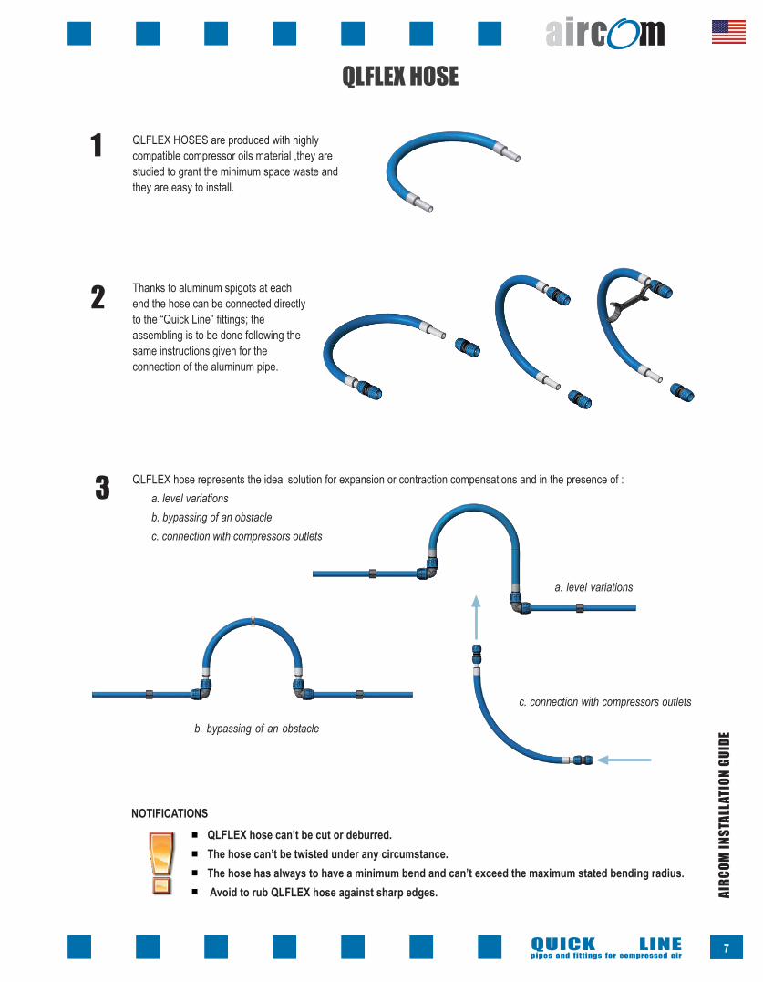
QLFLEX HOSE
QLFLEX HOSES are produced with highly compatible compressor oils material ,they are studied to grant the minimum space waste and they are easy to install.
1
Thanks to aluminum spigots at each end the hose can be connected directly to the “Quick Line” fittings; the assembling is to be done following the same instructions given for the connection of the aluminum pipe.
2
QLFLEX hose represents the ideal solution for expansion or contraction compensations and in the presence of : a. level variationsb. bypassing of an obstacle c. connection with compressors outlets
3
c. connection with compressors outlets
a. level variations
b. bypassing of an obstacle
NOTIFICATIONSQLFLEX hose can’t be cut or deburred. The hose can’t be twisted under any circumstance. The hose has always to have a minimum bend and can’t exceed the maximum stated bending radius. Avoid to rub QLFLEX hose against sharp edges.
7

QUICK LINEpipes and fittings for compressed air
AIRC
OM IN
STAL
LATI
ON G
UIDE
Using QLFLEX hoses, as expansion/contraction compensator, we recommend following the directions stated below.
EXPANSION/CONTRACTION COMPENSATION
b. “Omega” has to always be shaped upwards to avoid possible condensate collections in the piping system.
a. Execute the so called “Lira” (lyre) or “Omega” shapes by connecting QLFLEX hose to two 90° elbows; NEVER connect the hose with two couplings.
c. We suggest to fix QLFLEX hose in central position between its ends by using an electrician steel bracket.
We suggest to fix the aluminum
pipelines by positioning Aircom pipe brackets near
the two elbows connected to the
QLFLEX hose.
8
CORRECT INSTALLATION
NO
NO

QUICK LINEpipes and fittings for compressed air
AIRC
OM IN
STAL
LATI
ON G
UIDE
BRACKETING SYSTEMSAluminum pipe bracketing has always to be made by using the special DIRFEM8 pipe brackets expressly designed to allow pipes sliding through them in case of expansion or contraction.
1 DIRFEM8 pipe
brackets are designed to operate both
vertically and
horizontally.
Use a screwdriver to open the pipe bracket by raising its closing tongue.
2
3 All pipe brackets packaging contain M8 hexagonal nut to be inserted in the inside of the bracket (by using a threaded bar). It’s also possible to use self-tapping screws with a screw anchor in case of installation on walls.
9
4 By using the above said threaded bar with its lock nut it’s possible to fix the pipe bracket to any clamping system.

QUICK LINEpipes and fittings for compressed air
AIRC
OM IN
STAL
LATI
ON G
UIDE
5
For a correct bracket installation and spacing for the various pipe diameters we suggest to fix the pipe bracket as showed at our technical catalogue.
In case of need, DIRSPE spacers are also available to be added under the pipe bracket base, to compensate for pipe diameter reduction.
10
BRACKETS SPACINGBrackets spacing follows standard tables executed according to pipe diameter and temperature and weight of the transported fluid.
Diameter
mm - inches16 - 1/2”20 - 3/4”25 - 1”32 - 1.1/4”40 - 1.1/2”50 - 2”63 - 2.1/2”
Spacing expressed in feet with reference to maximum temperature Δ
ΔT< 68 °F781012141414
ΔT 86 °F77810121212
ΔT 104 °F5578
101010
Spacing in feet (ft) related to the maximum temperature difference “ΔT”
2 Quick Line D 20x17 PN 13 Bar 200 PSI - 174 PSI for Canada 21/07
D max
φ
Brackets are positioned avoiding any contact with fittings or other accessories liable to block the sliding of the pipe.In case of horizontal or vertical pipeline installation at a height from 0 up to 10 feet from the ground it’s advisable to double the bracket quantity so to fix better the pipeline to the structure.

AIRC
OM IN
STAL
LATI
ON G
UIDE
QUICK BRANCHESAIRCOM quick branches have been designed to allow the final user to get a quick drop-leg without cutting the main pipeline.
Moreover, thanks to its special design, the air offtake of the drop leg is above the condensation level to grant an excellent air quality.
Closing bolt
Hole template
Reference notch
Off take air collecting
point above condensate
level
Quick branches can also be used horizontally as a traverse beginning (with the hole in the upper part of the pipe) or as a condensation drainer (with the hole in the lower part of the pipe).
QUICK LINEpipes and fittings for compressed air
11

AIRC
OM IN
STAL
LATI
ON G
UIDE
INSTALLATION GUIDE
Remove the branch and clean the hole with the help of the special deburring tool 5
4 Drill a hole in the pipe by means of a hole saw inside the template
2 Mark the chosen position near the reference notches
Position the drop leg according to the applicative requirement 1
Fix the branch and align the reference notches again to marks6
Rotate the branch by 180° and position it near the reference marks previously marked 3
QUICK LINEpipes and fittings for compressed air
12

AIRC
OM IN
STAL
LATI
ON G
UIDE
MANIFOLDS
COUPLING TYPESFour different types of inlet connections may be used :
SOLVENT WELDING UNION FOR PVC PIPE
PREASSEMBLED BALL VALVE
NPT- National Pipe Thread Taper- ANSI B1.20.1 GAS THREAD UNION
STANDARD QL PIPE CONNECTION
Manifolds assure an ideal compressed air supply for any use (pneumatic tools, air blow guns, pneumatic machines)Their fixing both on wall or on workbenches grants high steadiness.
Body made of 15% glass fiber for added strength
Threaded inserts in overmoulded aluminum.
QUICK LINEpipes and fittings for compressed air
13

AIRC
OM IN
STAL
LATI
ON G
UIDE
MANIFOLD FOR WALL MOUNTINGIt allows to get a single or double ½” port with a ¼” FPT hole for condensate discharge underneath (double outlet manifolds) must be drilled out.
MULTIPORT MANIFOLDThe most recent 9-ways model allows versatile and specific uses at the machine or on workbenches.
6-threaded 3/8” FPT ports
3-threaded 1/4” FPT ports
1 additional ½” threaded FPT port which allows in series connection
creating a real manifold.
Manifolds have their outlets turned downwards at 45° to the wall; this characteristic reduces possible risks of accident for the operator in case of casual coupling ejection.
SAFETY
45°
QUICK LINEpipes and fittings for compressed air
14

AIRC
OM IN
STAL
LATI
ON G
UIDE
- during maintenance operations
- when some parts of the system need to be isolated
- in case of failures when an immediate stop of the compressed air supply is basic for safety reasons for operators and equipments; to automate the closing and opening timing of the plant’s different branches.
CodeQLVAVIP032 QLVAVIP040QLVAVIP050QLVAVIP063
QLVAVIP Pneumatic single action Valve
D1.¼”1.½”
2”2.½”
D1 D
LI
L1
E
Wt.2.763.134.665.81
D13.53.54.35.5
L7.98.39.611.4
L13.63.64.35.5
I1.91.92.22.4
E2.43.03.43.8
C1.41.42.83.7
The need and the usefulness of a servo controlled valve is particularly necessary:
PNEUMATIC CONTROLLED VALVES
In large compressed air piping systems isolating the main lines or the drop branches are usually done with normal ball valves.
These drop valves are often installed in positions difficult to reach, usually situated near the ceiling of the building and therefore normally ladders or operators elevating devices have to be used for their operation.
SAFETY ON-OFF VALVE SPECIFICALLY DESIGNED TO INTERCEPT THE COMPRESSED AIR OF THE PIPING SYSTEM
It should be noted that, when pressure lowers at 36 psi, the valve shuts off automatically; in case of failures in the piping system, the valve shuts off and those departments which are non directly interested may go on with their usual working operatons.
This pneumatic controlled valve is a valuable alternative to manual valves and it offers the operator the possibility to close and open the distribution of compressed air to any section, descent or system area confortably from the “floor” or from an automation panel.
SAFETY ON-OFF VALVE SPECIFICALLY DESIGNED TO
INTERCEPT THE COMPRESSED AIR OF THE PIPING SYSTEM
QUICK LINEpipes and fittings for compressed air
15
Legend
Wt. Weigth (Lbs.)D Socket diameter (in)L Length (in)I Interax (in)E Overall outside diameter ring nut (in)C Socket Depth
5 mm tappings

AIRC
OM IN
STAL
LATI
ON G
UIDE
OFFON
OPERATION
TECHNICAL SPECIFICATIONS- Service temperature from -68°F up to + 176°F- Maximum service pressure 230 psi- Minimum service pressure 36 psi- M5 Pilot ports (no high flow is requested)- A 1 mm pneumatic switch and tube is sufficient to operate a 4” valve- The valve can operate up to 230 psi and it has no particular needs of air filtration and
lubrication.- The valve is not affected by the presence of condensation.
CONSTRUCTIVE MATERIAL- Anodized aluminum- Passivated steel Spring- Polyurethane slide- NBR O-Ring gaskets
The valve looks like a normally closed valve; it uses the internal pressure of the pipeline to open and stop the compressed air flow. The air necessary to the piloting is the air normally present upstream of the valve itself without any additional external energy. The operation is obtained by using the piloting kit connected to the valve. If not adequately controlled the valve change over to a close valve automatically when the internal pressure lows down to 36 psi; it reaches its maximum flow rate with a pressure of approx. 50 psi in the pipeline. The pressure of the pipeline is always available at the “pilot pressure” outlet; by means of a simple pneumatic or electro-pneumatic switch it is possible to direct this pressure towards the “closing port” thus getting the immediate closing of the valve.
EXAMPLE OF PLANT APPLICATION
Main ring
Crossings
Pneumatic control valve
Subring of working "islands"
Machinery side
QUICK LINEpipes and fittings for compressed air
16

AIRC
OM IN
STAL
LATI
ON G
UIDE
Wrench (max dimensions)
12.2”
4.6”
Ø50 mm2”
Ø40 mm - 1.½”
9.4”
3.2”
Ø25 mm - 1”
Ø32 mm1.¼”
8.4”
Ø16 mm - ½”
2.4”
Ø20 mm¾”
ACCESSORIES
QUICK LINEpipes and fittings for compressed air
17
Pipe insertion meter
4.4” 2.6” 1.5”
0.7”
0.5”
8.6”
0.5”
0.7”
3.5”2” 3.1”
8.6”
2.2” 3.1”
8.6”
0.6”
0.7”
3.3”
2.8” 3.3” 2.5”
0.6”
0.6”
8.6”
AIRCOM wrench allows a correct nut tightening without any damage of the
fitting.The wrench is expressly designed for use
with AIRCOM Quick Line system.
The mark will be done with any common marker and should appear close to the nut end in order to check the correct depth of the pipe insertion into the fitting.
Aircom “insertion meter” is a necessary tool for safe and proper fittings assembly.
The “insertion meter” provides a correct marking of the fittings insertion depth on the pipe, for each pipe size.

AIRC
OM IN
STAL
LATI
ON G
UIDE
MPT Quick line spigot
D
d
LL1
MALE THREADED SPIGOT
This product allows to reduce the fittings quantity in the compressor room for all the connections between the compressor and the treatment groups and relative by-passes.
COMPRESSOR AIR DRYER
The male threaded spigot is a special hollow cylinder of aluminum alloy with a male conic gas thread for airtight couplings according NPT- National Pipe Thread Taper- ANSI B1.20.1 at one end and a plain pipe segment of size identical to QLTUAL pipe on the other end.
QUICK LINEpipes and fittings for compressed air
18
QLPUNM
CodeQLPUNM020048NPTQLPUNM020068NPTQLPUNM025088NPTQLPUNM032108NPTQLPUNM040128NPTQLPUNM063168NPTQLPUNM080248NPT
Wt..08.09.16.21.34
1.141.49
D (in)3/4"3/4"1"
1.1/4"1.1/2"2.1/2"
3"
d (in)1/2"3/4"1"
1.1/4"1.1/2"
2”3”
L (in)3.7”3.8”4.3”4.7”5.3”6.2”6.7”
L1 (in)0.5”0.5”0.6”0.7”0.8”0.9”1.0”
Wt. : Weight in Lbs.

AIRC
OM IN
STAL
LATI
ON G
UIDE
QUICK LINEpipes and fittings for compressed air

QUICK LINEpipes and fittings for compressed air
AIRC
OM IN
STAL
LATI
ON
Rev. 1 - May 2011
AIRCOM USA, Inc.9805-M NorthCross Center Court - Huntersville, NC 28078 - USAPh. 704-987-2088 - Fax 704-987-2048www.aircom.us.com - [email protected]