appendix a water/wastewater plan review checklist
TRANSCRIPT

Water and Wastewater Engineering Department
AAPPPPEENNDDIIXX AA
WWaatteerrWWaasstteewwaatteerr PPllaann RReevviieeww CChheecckklliisstt
PO Box 147117 Inter-Office Box A111 Gainesville FL 32614-7117
Phone 3523931644 Fax 3523343480 Revised 91913
1
Gainesville Regional Utilities WWW Plan Review Checklist
Project__________________________________________Date__________________ Engineer_________________________________________
Yes No NA1 A Cover Sheet that includes a Project Location Map with nearby
andor adjacent streets labeled ___ ___ ___
2 Cover sheet signed and sealed by engineer-of-record ___ ___ ___
Certification by engineer that WWWRCW system design is in accordance with GRU Design Standards
___ ___ ___
PE license is valid and PE seal reads ldquoProfessional Engineerrdquo (Confirm at wwwmyfloridalicensecom)
___ ___ ___
Cover sheet reads ldquoFor Review Onlyrdquo ___ ___ ___ 3 A Drawing Index that clearly identifies the names and sheet
numbers of all drawings under review also on the Cover Sheet ___ ___ ___
4 The following information must appear on all sheets
The design engineers name ___ ___ ___ The project name in lower right corner ___ ___ ___ The phase to be constructed ___ ___ ___
5 A legible Utility Master Site Plan shall be part of the project
drawings and shall clearly depicting the following
Water and wastewater systems ___ ___ ___ Electric transformers and pedestals in relation to the WWW
systems (minimum 10rsquo horizontal separation transformers and water meters on opposite property corners)
___ ___ ___
6 All phases of construction shall be clearly shown ___ ___ ___ 7 All plan sheets shall be to scale with the scale clearly noted on each
drawing ___ ___ ___
8 All plan sheets shall have an arrow indicating the direction north
(pointing up or to the right) ___ ___ ___
9 The Utility Master Site Plan shall be a maximum 1rdquo = 40rsquo scale ___ ___ ___ 10 If the entire project area does not fit on one sheet at this scale then
it shall be printed on multiple sheets ___ ___ ___
A key map shall be provided on each sheet indicating the ___ ___ ___
PO Box 147117 Inter-Office Box A111 Gainesville FL 32614-7117
Phone 3523931644 Fax 3523343480 Revised 91913
2
location of the related sheet within the project 11 When multiple pages are used a map of the entire project area on a
single drawing with limited labeling shall be included ___ ___ ___
12 Mandatory Plan and Profile Sheets shall be drawn at 1rdquo = 20rsquo or 1rdquo =
30rsquo (preferred) horizontal scale and 1rdquo = 2rsquo to 1rdquo = 5rsquo vertical scale ___ ___ ___
13 Each Plan and Profile Sheet shall display the plan view above the
profile view and each shall depict the same length of utility installation The plan shall be aligned vertically with the profile
___ ___ ___
14 The Plan and Profile Sheet plan view shall show the following
water mains ___ ___ ___ valves ___ ___ ___ fittings ___ ___ ___ fire hydrants ___ ___ ___ services ___ ___ ___ meters ___ ___ ___ blowoff assemblies ___ ___ ___ wastewater mains ___ ___ ___ manholes ___ ___ ___ wyes ___ ___ ___ laterals ___ ___ ___ cleanouts ___ ___ ___ reclaimed water mains ___ ___ ___ force mains ___ ___ ___ storm water lines ___ ___ ___ electric lines ___ ___ ___ gas lines ___ ___ ___ paving ___ ___ ___ curbs and gutters ___ ___ ___ right-of-way lines ___ ___ ___ property lines ___ ___ ___ and all existing and proposed features ___ ___ ___
15 A wastewater structure schedule shall be included on all sheets on
which the structure is shown (ie the Utility Master Site Plan Plan and Profile sheets etc)
___ ___ ___
16 The Plan and Profile Sheet profile view shall show the existing and
proposed finished grade over proposed and existing gravity wastewater mains
___ ___ ___
17 All wastewater gravity lines and wastewater force mains shall be
shown in profile view ___ ___ ___
18 All stormwater lines in close proximity to depicted wastewater water
and reclaimed water mains shall also be shown in profile view ___ ___ ___
19 All crossings (stormwater wastewater reclaimed water and water
mains) and all additional relevant utility information shall be included ___ ___ ___
PO Box 147117 Inter-Office Box A111 Gainesville FL 32614-7117
Phone 3523931644 Fax 3523343480 Revised 91913
3
20 Master paving and drainage plan reflecting all stormwater facilities retention or detention ponds with elevations
Clearly indicate design high water level and 100 year critical event floodplain elevations
___ ___ ___
Wetland delineationsetback lines creeks and ponds indicated
___ ___ ___
Drainage structure locations elevations sizes and slopes ___ ___ ___ 21 Analysis of manhole submergence during flood events (to be
performed by GRU) ___ ___ ___
22 Proposed Subdivision Plat (if applicable) ___ ___ ___ 23 Boundary Survey Legal Description and Parcel Number ___ ___ ___ 24 GRU Energy Delivery Electric System Design reflecting proposed
WWW utility design ___ ___ ___
25 Note on cover pageplans as ldquoElectric Design Provided by GRU
Energy Deliveryrdquo ___ ___ ___
26 Landscape Plans shall show existing and proposed tree locations
and species and shall include all potable water reclaimed water and wastewater utilities shown clearly (labeling optional)
___ ___ ___
27 Utility Space Allocation Cross-sections for each different roadway
section alley and Public Utility Easement (PUE) shall be included showing proposed and existing tree types and locations and complying with the Utility Separation Table (Appendix C GRU Standards)
___ ___ ___
28 Proposed trees depicted on the utility allocations shall include those
within 20 feet of all right-of-way lines ___ ___ ___
29 Water meters shall be shown at the right-of-way where applicable ___ ___ ___ 30 Show temporary construction water source ___ ___ ___ 31 For multi-family and non-residential projects buildings shall be
master metered or served by grouped potable water meter gangs with no more than 12 meters per gang
___ ___ ___
32 For potable water meters 15rdquo or greater the Engineer-of-Record
shall submit a detailed water demand estimate signed and sealed by a Professional Engineer reflecting Average Daily Flow and Peak Hourly Demand calculations with supporting documentation for review and approval by GRU
___ ___ ___
33 Fire hydrants no more than 500rsquo from farthest side of the building (as
the truck drives) and 1000rsquo (as the truck drives) ndash minimum two required
___ ___ ___
34 Show required blowoff assemblies and sample points ___ ___ ___
PO Box 147117 Inter-Office Box A111 Gainesville FL 32614-7117
Phone 3523931644 Fax 3523343480 Revised 91913
4
35 Control valves shall be provided on each branch of potable water main tees (3 valves per tee may be required at GRUrsquos discretion)
___ ___ ___
36 Indicate tap location and size (Contractor coordinate with GRU 48
hours in advance GRU to install Contractor to connect) ___ ___ ___
37 Indicate all required backflow preventers and types (to be installed
by contractor) If Backflow preventers are not shown indicate source of irrigation water
___ ___ ___
38 All materials shown on the plans shall be clearly labeled including
but not limited to
pipe ___ ___ ___ valves ___ ___ ___ fire hydrants ___ ___ ___ fire sprinkler lines ___ ___ ___ water meters ___ ___ ___ backflow preventers ___ ___ ___ fittings ___ ___ ___ manholes ___ ___ ___ services ___ ___ ___ clean outs etc ___ ___ ___
with associated elevations sizes types material slopes and appurtenances Materials shall be labeled on each sheet on which the materials are shown
39 All wastewater design information shall be shown including the
following
pipe sizes ___ ___ ___ pipe lengths ___ ___ ___ pipe materials ___ ___ ___ pipe slopes ___ ___ ___ manhole top elevations ___ ___ ___ manhole invert elevations ___ ___ ___ cleanout top elevations ___ ___ ___ cleanout invert elevations ___ ___ ___
40 Potable and Wastewater Demand calculations The following information shall be provided
AutoCAD Drawing file of Water and Wastewater Utilities with pipe sizes fittings and valves clearly labeled (this file will be used by GRU Strategic Planning to model the proposed water system)
___ ___ ___
Average and Peak Water Demand calculations based on one ERC (Equivalent Residential Connection where 1 ERC = 350 GPD) per single-family residential 70 GPD per bedroom for multi-family residential and FAC 64-E for commercial development (Note GRU uses a peaking factor of 25 based on the Recommended Standards for Wastewater Facilities (ldquoTen State Standardsrdquo) 1997 Edition Chapter 10 Figure 1 but will accept other peaking factors with documentation
___ ___ ___
Peak Fire Line Demand at 20 psig ___ ___ ___ Signed and sealed ISO fire flow calculations (2008 Edition) for ___ ___ ___
PO Box 147117 Inter-Office Box A111 Gainesville FL 32614-7117
Phone 3523931644 Fax 3523343480 Revised 91913
5
all phases Copy of Development Master Plan including Phasing Schedule
if applicable ___ ___ ___
Peak Wastewater generation rate (Provide Calcs based on Source) Note If wastewater is industrial and concentrations of certain chemicals exist then applicant must secure an Industrial User Permit (contact Fred Williams at 393-1698)
___ ___ ___
41 Based on required flow (total of peak potable demand peak fire line
demand and ISO fire flow calcs) GRU WaterWastewater Engineering shall determine if adequate flow is available by one of the following methods
Based on fire flow tests and analysis of the surrounding water system (attach copy of test results)
___ ___ ___
Based on Maximum Line Length Table (attach copy of GIS map with selected loop(s) highlighted along with any other pertinent information such as copy of line length table notes etc)
___ ___ ___
If neither of the above methods is applicable forward project to Strategic Planning for modeling
___ ___ ___
42 Any existing potable water reclaimed water and wastewater service
stub-outs to subject parcels from adjacent development are to be included in the drawings
___ ___ ___
43 Proposed off-site utility extensions to the point of WWW service
availability ___ ___ ___
44 All proposed potable water reclaimed water and wastewater
service stub-outs from subject parcels to adjacent potentially developable sites are to be included in the drawings
___ ___ ___
Oversizing required (to be determined by GRU) ___ ___ ___
45 When connecting wastewater to existing manhole the following note
shall be included ldquoCore-drill manhole for installation of wastewater pipe Install pipe with Kor-n-Seal or equal boot Grout annular space with non-shrink grout Coordinate with GRU inspector 48 hours in advancerdquo
___ ___ ___
46 When connecting a wastewater force main to an existing manhole
Raven lining (or equal) is required in the manhole In the case of a connection to a proposed manhole the lining shall be HDPE
___ ___ ___
47 Presentation of manhole information is recommended to be in a
ldquoSanitary Sewer Structures Schedulerdquo format but in any case must be shown on all sheets where manhole is drawn
___ ___ ___
48 Locate show and label existing utilities that cross or are adjacent to
the property or project construction area ___ ___ ___
49 Elevations (manhole and cleanout tops and inverts) and pipe sizes
of all existing wastewater facilities that cross andor are adjacent to the property
___ ___ ___
PO Box 147117 Inter-Office Box A111 Gainesville FL 32614-7117
Phone 3523931644 Fax 3523343480 Revised 91913
6
50 The design drawings shall indicate any required grease oil sand or
lint separators andor other pre-treatment systems required as part of the wastewater system (Contact Fred Williams at 393-1698 for grease trap permit)
___ ___ ___
51 All existing and proposed utility easements shall be shown with
dimensions ___ ___ ___
52 Existing and proposed site contour elevations shall be shown at
minimum 2-foot intervals ___ ___ ___
53 Building minimum finished floor elevations shall be shown ___ ___ ___ 54 Sewer backwater valves must be shown when finished floor
elevation does not meet requirements ___ ___ ___
55 Lot numbers and street names If lsquoofficialrsquo street names are not
available for initial plan submittals include temporary street designations Revise subsequent submittals when official street name labels are available
___ ___ ___
56 ALL of the following GRU standard utility notes must be shown on
utility plans in the order shown
a Provide a statement identifying any associated utility permits
that are required by City County FDOT FDEP or other agency or that none are required
___ ___ ___
b The utility plan and plat shows all Public Utility Easements
(PUErsquos) in a metes and bounds format Upon GRUrsquos approval of plans for developments not being platted Owner may choose to grant the metes and bounds easements as shown or a blanket easement over the entire property provided facilities are installed within the prescribed distances as shown on the utility plans and in accordance with the Utility Separation Requirements Table in Appendix C of the GRU WWWRCW Design Standards
___ ___ ___
c All construction materials and methods for potable water
wastewater and reclaimed water systems shall be in conformance with GRUs most recent Potable Water Wastewater and Reclaimed Water System Design Standards and Approved Materials Manual
___ ___ ___
d Potable Water and Wastewater mains shall maintain a
minimum 10 feet horizontal and 15 foot vertical separation ___ ___ ___
e A minimum horizontal separation of 10 feet for potable water
mains wastewater force mains and reclaimed water mains and 15 feet for gravity wastewater mains shall be provided and maintained from trees buildings transformers and all permanent structures Live Oak trees require an additional
___ ___ ___
PO Box 147117 Inter-Office Box A111 Gainesville FL 32614-7117
Phone 3523931644 Fax 3523343480 Revised 91913
7
5 feet of horizontal clearance Service laterals require 5 feet less clearance for each of the utilities note that water service laterals shall be installed within 3rdquo sleeves (See Appendix C GRU Standards ndash Horizontal Separation Distances for Parallel and Perpendicular Clearance from Other Objects Table)
f Potable water services requiring a separate water meter
shall be provided to each lot building or parcel Effective October 1 2007 for commercial multifamily and institutional developments the Developer shall be responsible for installing potable water services and Yoke Assembly Package up to and including the meter yoke box (installed at final grade) and associated appurtenances for meters 1rdquo and smaller (see GRU WWWRCW Construction Detail W ndash 80) with a one-year warranty
___ ___ ___
g 2 valves located in paved areas including sidewalks shall
be GRU approved cast iron resilient seat gate valves with standard 2 operating nut threaded with brass nipple between the valves and tapping saddle or tapped tee
___ ___ ___
h Water mains 4rdquo in diameter and greater placed under
roadways shall be cement lined ductile iron pipe (CLDIP) extending 5 feet past the back of curb (3 feet within City of Gainesville limits) Tracer wire installed on PVC water mains shall continue across the CLDIP sections
___ ___ ___
i 1rdquo and 2rdquo water service crossings located under roadways
shall be encased in 3rdquo SCH 40 PVC extending 5rsquo past the back of curb (3 feet inside City of Gainesville limits)
___ ___ ___
j Anchoring tees couplings and bends shall be used on all
fire hydrant assemblies ___ ___ ___
k All pressurized main fittings shall be mechanical joint with
restrained joint glands a sufficient length of the pipe connected to the fittings shall be mechanically restrained to provide reaction as specified on the Restrained Joint Standard in the Construction Details of the GRU Standards (W ndash 28 amp 29 RCW ndash 28 amp 29 and WW ndash 24 amp 25) Calculations for required restraint length must be provided if the specified restraint length due to soil type or depth of cover differs from those provided on these details
___ ___ ___
l All sanitary wastewater service laterals shall be min 4rdquo
diameter PVC (SDR 35) at 100 min slope unless otherwise labeled
___ ___ ___
m Wastewater cleanout covers located within pavement and
sidewalks adjacent to paved areas shall be rated for traffic load bearing Wastewater cleanout covers in other
___ ___ ___
PO Box 147117 Inter-Office Box A111 Gainesville FL 32614-7117
Phone 3523931644 Fax 3523343480 Revised 91913
8
sidewalkswalkways shall be brass with a square recess
n Manholes which are not installed under pavement shall have a rim elevation at least 6rdquo above finished grade and a 101 slope to finished grade
___ ___ ___
o Unless otherwise noted on the plans the finished floor
elevations of buildings shall be a minimum of 6rdquo above the lowest upstream manhole top If this is infeasible a wastewater service lateral backwater valve (BWV) is required on the customer side of the cleanout
___ ___ ___
p When a potable or reclaimed water main or a wastewater
force main is routed within 10 ft of an electric transformer a 20 ft length of DIP shall be centered on the transformer with mechanical restraint at each end No fittings or valves shall occur within 10 ft of the nearest edge of the transformer A minimum clearance of 3rsquo shall be maintained between the main and the transformer
___ ___ ___
57 Typical cross sections for all roadways shall be included ___ ___ ___ 58 Road crossing details for bore and jacks and open cuts shall be
provided The crossing details shall show all existing and proposed utilities including surveyed elevations and field locations Entrance and receiving pit location and dimensions shall be included
___ ___ ___
59 Building footprints decorative masonry walls fences signs berms
and landscaped buffer areas shall be shown and labeled on the plans
___ ___ ___
60 Each side of a RW shall include a minimum 5 feet wide PUE
Additional PUErsquos may be required to ensure adequate separation for utilities
___ ___ ___
61 Indicate the source of irrigation water ___ ___ ___ 62 Provide appropriateadequate backflow prevention (BFP) for public
water supply in accordance with the GRU Standards Section V G Backflow Prevention If a DDC BFP is specified on a fire-line the engineer must certify that the fire protection system will use plain water only (no chemicals or antifreeze)
___ ___ ___
63 GRU Standard WW Lift Station design drawings for GRU OampM
stations (Private OampM WW lift stations shall include signed and sealed design calculations ie system head curve pump curvespecs etc)
___ ___ ___
64 Lift Station Capacity and pump operating point shall be checked by
GRU ___ ___ ___
65 Force mains shall be shown on plan and profile with plug valves and
air release valves ___ ___ ___
PO Box 147117 Inter-Office Box A111 Gainesville FL 32614-7117
Phone 3523931644 Fax 3523343480 Revised 91913
9
66 Show air conditioning condensate water drain line and clearly note that it shall not connect to GRU wastewater
___ ___ ___
Water and Wastewater Engineering Department ndash February 2008
AAPPPPEENNDDIIXX BB
CCoonnttrraaccttoorr RReessppoonnssiibbiilliittiieess
Contractor Responsibilities Call John Worley at 352-393-1633 at least 48 hours in advance to notify GRU when work will begin at the site The Contractor shall schedule a preconstruction meeting on-site with GRU Inspector Contractor shall coordinate with GRU WWW System Inspector to perform work in progress inspections at various times during construction including but not limited to the following items POTABLE WATERRECLAIMED WATER
1 Inspection of connections to existing GRU infrastructure and backfill on main line 2 Visual inspection of all mechanical joint restraints and thrust blocks before backfilling 3 Contractor shall coordinate with GRU Inspector prior to sterilization and pressure testing
(note reclaimed water lines do not require sterilization) 4 Coordinate with Inspector and Murphree WTP staff to take two water samples for
bacteriological testing on two consecutive days (note does not apply to reclaimed water systems)
5 Coordinate with Inspector to arrange a date and time for ldquowalkthroughrdquo with Water Department (note before walkthrough all mains must be flushed hydrant plumbing and valve boxes brought to grade and services shall be vertical with caps off) A written report of discrepancies (if any) shall be prepared by the Water Department and given to the Inspector and Contractor
6 Contractor shall notify Inspector when discrepancies are repaired so that Inspector may coordinate with Water Department for re-inspection
7 When the system has passed inspection Contractor shall furnish record drawings and certified costs Inspector shall then close-out job and a Completion Letter shall be sent by GRU to the Developer Engineer of Record and Contractor
WASTEWATER
1 Inspection of connections to existing GRU infrastructure and backfill (with Type A-3) on main line
2 Inspection to confirm proper grade per GRU Standards and drawings on mainline wyes and laterals
3 Inspection of completed wastewater system including manhole inverts 4 Coordinate with Inspector to arrange for TV inspection of wastewater system (note prior
to TV inspection laterals must be flushed the entire circumference of mains jet cleaned and all debris removed) A written report of any discrepancies found shall be prepared by the Wastewater Department and provided to the Inspector
5 Contractor shall notify Inspector when discrepancies are repaired so that Inspector may coordinate with Wastewater Department for re-inspection
6 When the system has passed inspection Contractor shall furnish record drawings and certified costs Inspector shall then close-out job and a Completion Letter shall be sent by GRU to the Developer Engineer of Record and Contractor
Water and Wastewater Engineering Department
AAPPPPEENNDDIIXX CC
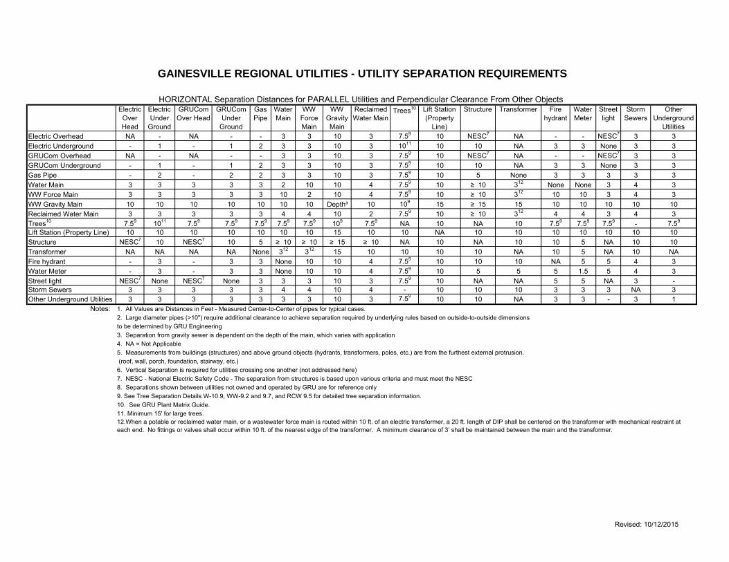
HHoorriizzoonnttaall SSeeppaarraattiioonn DDiissttaanncceess ffoorr PPaarraalllleell UUttiilliittiieess aanndd PPeerrppeennddiiccuullaarr
CClleeaarraannccee ffrroomm ootthheerr OObbjjeeccttss
Electric Overhead NA - NA - - 3 3 10 3 759 10 NESC7 NA - - NESC7 3 3Electric Underground - 1 - 1 2 3 3 10 3 1011 10 10 NA 3 3 None 3 3GRUCom Overhead NA - NA - - 3 3 10 3 759 10 NESC7 NA - - NESC7 3 3GRUCom Underground - 1 - 1 2 3 3 10 3 759 10 10 NA 3 3 None 3 3Gas Pipe - 2 - 2 2 3 3 10 3 759 10 5 None 3 3 3 3 3Water Main 3 3 3 3 3 2 10 10 4 759 10 ge 10 312 None None 3 4 3WW Force Main 3 3 3 3 3 10 2 10 4 759 10 ge 10 312 10 10 3 4 3WW Gravity Main 10 10 10 10 10 10 10 Depthsup3 10 109 15 ge 15 15 10 10 10 10 10Reclaimed Water Main 3 3 3 3 3 4 4 10 2 759 10 ge 10 312 4 4 3 4 3Trees10 759 1011 759 759 759 759 759 109 759 NA 10 NA 10 759 759 759 - 759
Lift Station (Property Line) 10 10 10 10 10 10 10 15 10 10 NA 10 10 10 10 10 10 10Structure NESC7 10 NESC7 10 5 ge 10 ge 10 ge 15 ge 10 NA 10 NA 10 10 5 NA 10 10Transformer NA NA NA NA None 312 312 15 10 10 10 10 NA 10 5 NA 10 NAFire hydrant - 3 - 3 3 None 10 10 4 759 10 10 10 NA 5 5 4 3Water Meter - 3 - 3 3 None 10 10 4 759 10 5 5 5 15 5 4 3Street light NESC7 None NESC7 None 3 3 3 10 3 759 10 NA NA 5 5 NA 3 -Storm Sewers 3 3 3 3 3 4 4 10 4 - 10 10 10 3 3 3 NA 3Other Underground Utilities 3 3 3 3 3 3 3 10 3 759 10 10 NA 3 3 - 3 1
Notes 1 All Values are Distances in Feet - Measured Center-to-Center of pipes for typical cases 2 Large diameter pipes (gt10) require additional clearance to achieve separation required by underlying rules based on outside-to-outside dimensionsto be determined by GRU Engineering3 Separation from gravity sewer is dependent on the depth of the main which varies with application4 NA = Not Applicable5 Measurements from buildings (structures) and above ground objects (hydrants transformers poles etc) are from the furthest external protrusion (roof wall porch foundation stairway etc)6 Vertical Separation is required for utilities crossing one another (not addressed here)7 NESC - National Electric Safety Code - The separation from structures is based upon various criteria and must meet the NESC8 Separations shown between utilities not owned and operated by GRU are for reference only9 See Tree Separation Details W-109 WW-92 and 97 and RCW 95 for detailed tree separation information10 See GRU Plant Matrix Guide11 Minimum 15 for large trees
HORIZONTAL Separation Distances for PARALLEL Utilities and Perpendicular Clearance From Other ObjectsWW
Force Main
Gas Pipe
Street light
GAINESVILLE REGIONAL UTILITIES - UTILITY SEPARATION REQUIREMENTS
GRUCom Over Head
GRUCom Under
Ground
Water Main
Structure Transformer Other Underground
Utilities
Trees10 Storm Sewers
Fire hydrant
Lift Station (Property
Line)
WW Gravity Main
Reclaimed Water Main
Electric Over Head
Electric Under
Ground
Water Meter
12When a potable or reclaimed water main or a wastewater force main is routed within 10 ft of an electric transformer a 20 ft length of DIP shall be centered on the transformer with mechanical restraint at each end No fittings or valves shall occur within 10 ft of the nearest edge of the transformer A minimum clearance of 3rsquo shall be maintained between the main and the transformer
Revised 10122015
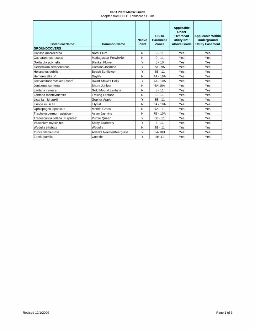
GRU Plant Matrix GuideAdapted from FDOT Landscape Guide
Botanical Name Common NameNative Plant
USDA Hardiness
Zones
Applicable Under
Overhead Utility gt21
Above Grade
Applicable Within Underground
Utility EasementGROUNDCOVERS
Carissa macrocarpa Natal Plum N 9 - 11 Yes Yes
Catharanthus roseus Madagascar Perwinkle N 9 - 11 Yes Yes
Gaillardia pulchella Blanket Flower Y 5 - 10 Yes Yes
Gelsemium sempervirens Carolina Jasmine Y 7A - 9A Yes Yes
Helianthus debilis Beach Sunflower Y 8B - 11 Yes Yes
Hemerocallis x Daylily N 4A - 10A Yes Yes
Ilex vomitoria Stokes Dwarf Dwarf Stokes Holly Y 7A - 10A Yes Yes
Juniperus conferta Shore Juniper N 6A-10A Yes Yes
Lantana camara Gold Mound Lantana N 8 - 11 Yes Yes
Lantana montevidensis Trailing Lantana N 8 - 11 Yes Yes
Licania michauxii Gopher Apple Y 8B - 11 Yes Yes
Liriope muscari Lilyturf N 6A - 10A Yes Yes
Ophiopogon japonicus Mondo Grass N 7A - 11 Yes Yes
Trachelospermum asiaticum Asian Jasmine N 7B - 10A Yes Yes
Tradescantia pallida Purpurea Purple Queen Y 8B - 11 Yes Yes
Vaccinium myrsinites Shiny Blueberry Y 3 - 11 Yes Yes
Wedelia trilobata Wedelia N 8B - 11 Yes Yes
Yucca filamentosa Adams NeedleBeargrass Y 5A-10B Yes Yes
Zamia pumila Coontie Y 8B-11 Yes Yes
Revised 1212009 Page 1 of 5
GRU Plant Matrix GuideAdapted from FDOT Landscape Guide
Botanical Name Common NameNative Plant
USDA Hardiness
Zones
Applicable Under
Overhead Utility gt21
Above Grade
Applicable Within Underground
Utility EasementSHRUBSAbelia x grandiflora Glossy Abelia N 5A - 9A Yes YesAcalypha wilkesiana Copperleaf N 9A - 11 Yes YesCaesalpinia pulcherrima Dwarf Poinciana N 8 - 11 Yes YesCallicarpa americana L American Beautyberry N 6 - 10 Yes YesCephalanthus occidentalis Common Buttonbush Y 4A - 10A Yes YesCleyera japonica Japanese Cleyera N 6B - 8 Yes YesCortaderia selloana Pampus Grass N 8 - 10 Yes YesForestiera segregata Florida Privet Y 8B - 11 Yes YesHamelia patens Firebush Y 9A - 11 Yes YesIlex cornuta Burfordii Burford Holly N 8 - 9 Yes YesIlex cornuta Dwarf Burford Dwarf Burford Holly N 8 - 9 Yes YesIlex crenata Japanese Holly N 6A - 9A Yes YesIlex vomitoria Yaupon Holly N 8 - 10 Yes YesJasminum mesnyi Primrose Jasmine N 8 - 10 Yes YesJuniperus x spp x Juniper N 3 - 9 Yes YesLeucophyllum frutescens Texas Sage N 8A - 10A Yes YesLigustrum japonicum Japanese Privet N 7B - 10B Yes YesLycium carolinianum Berry Christmas Y 7B - 11 Yes YesLyonia ferruginea Rusty LyoniaCrookedwood Y 8 - 10 Yes YesMalvaviscus arboreus Turks Cap N 9 - 11 Yes YesMyrica cerifera Wax Myrtle Y 7B-11 Yes YesNandina domestica Heavenly Bamboo N 6 - 9 Yes YesNerium oleander Oleander N 8 - 10 Yes YesOsmanthus americanus Wild Olive Y 5B-9A Yes YesPrunus angustifolia Chickasaw Plum Y 6A-9A Yes YesPyracantha coccinea FirethornRosaceae N 5 - 9 Yes YesRapanea punctata Myrsine Y 8B-11 Yes YesRhaphiolepis indica Indian Hawthorn N 8A-11 Yes YesRhus copallina Shining Sumac Y 5A-10A Yes YesSabal minor Dwarf Palmetto Y 7B-11 Yes YesScaevola aemula Fairy Fanflower N 9A-11 Yes YesSerenoa repens Saw Palmetto Y 8A-11 Yes YesSeverinia buxifolia Boxthorn Y 8B-10 Yes YesSpartina bakeri Sand Cordgrass Y 8B-11 Yes YesViburnum obovatum Walters Walters Viburnum Y 7A-10A Yes YesYucca aloifolia Spanish Bayonet Y 8 - 11 Yes YesYucca gloriosa Mound Lily Y 7 - 11 Yes YesZamia maritima Cardboard Palm N 9 - 11 Yes Yes
Revised 1212009 Page 2 of 5
GRU Plant Matrix GuideAdapted from FDOT Landscape Guide
Botanical Name Common NameNative Plant
USDA Hardiness
Zones
Applicable Under
Overhead Utility gt21
Above Grade
Applicable Within Underground
Utility EasementTREESAcer barbatum Florida Maple Y 7A-9B Yes NoAcer rubrum Red Maple Y 4A-9A No NoBetula nigra River Birch Y 4A-9A No YesCarpinus caroliniana American Hornbeam Y 3A-9A No NoCarya aquatica Water Hickory Y 6B-9A No NoCarya glabra Pignut Hickory Y 5A-9A No NoCarya illinoinensis Pecan Y 5B-9A No NoCeltis laevigata Sugarberry Y 5A-10A No NoCercis canadensis Redbud Y 5A-9A No YesChionanthus virginicus Fringe Tree Y 3A-9A Yes YesCornus florida Dogwood Y 5A-9A Yes YesFraxinus pennsylvanica Green Ash Y 3A-9A No NoGordonia lasianthus Loblolly Bay Y 6A-9B No NoHalesia diptera Snowdrop Tree Y 5A-8B Yes YesIlex cassine Dahoon Holly Y 7A-11 No YesIlex opaca American Holly Y 5B-9A No NoIlex vomitoria Yaupon Holly Y 7A-10A Yes YesIlex vomitoria pendula Weeping Holly Y 7A-10A Yes YesIlex x attenuata Savannah Savannah Holly Y 6A-9B No NoJuglans nigra Black Walnut Y 5A-9A No NoJuniperus virginiana silicicola Southern Red Cedar Y 8A-10A No NoLagerstroemia indica spp Crape Myrtle Y 7A-9A Yes YesLigustrum japonicum Chinese Privet Tree N 8A-11 Yes YesLiquidambar styraciflua Sweetgum Y 5B-10A No NoLiriodendron tulipifera Tulip Poplar Y 5A-9A No NoMagnolia grandiflora Southern Magnolia Y 7A-10A No NoMagnolia virginiana Sweetbay Y 5A-10A No NoMyrica cerifera Wax Myrtle Y 7B-11 Yes YesNoronhia emarginata Madagassgar Olive N 8B-11 Yes YesNyssa sylvatica Black Tupelo Y 4B-9A No NoOchrosia elliptica Kopsia - Elliptic Yellowwood N 8B-11 Yes YesOstrya virginiana American Hop Hornbeam Y 3A-9A No NoParkinsonia aculeata Jerusalem Thorn N 8 - 11 Yes YesPersea borbonia Florida Red Bay Y 7B-11 No NoPhotinia x fraseri Red Tip Photinia N 7 - 9 Yes YesPinus clausa Sand Pine Y 7A-10A No NoPinus elliottii Slash Pine Y 7A-11 No NoPinus palustrus Longleaf Pine Y 7A-10A No NoPinus taeda Loblolly Pine Y 6B-9A No No
Revised 1212009 Page 3 of 5
GRU Plant Matrix GuideAdapted from FDOT Landscape Guide
Botanical Name Common NameNative Plant
USDA Hardiness
Zones
Applicable Under
Overhead Utility gt21
Above Grade
Applicable Within Underground
Utility EasementTREES (contd)Plumeria x spp Frangipani N 9 - 11 No NoPodocarpus gracilior Weeping Yew N 8 - 10 Yes YesPopulus deltoides Eastern Cottonwood Y 2A-9A No NoPrunus angustifolia Chickasaw Plum Y 6A-9A Yes YesPrunus caroliniana Cherry Laurel Y 7 - 9 Yes YesPrunus umbellata Flatwoods Plum Y 8A-9A Yes YesQuercus chapmanii Chapman Oak Y 8B-11 No NoQuercus hemisphaerica Laurel Oak Y 6B-10A No NoQuercus laevis Turkey Oak Y 7B-9A No NoQuercus myrtifolia Myrtle Oak Y 9A-11 No NoQuercus nigra Water Oak Y 7 - 10 No NoQuercus shumardii Shumard Oak Y 5B-9A No NoQuercus virginiana Live Oak Y 7B-10B No NoTaxodium ascendens Pond Cypress Y 5B-9A No NoTaxodium distichum Bald Cypress Y 5A-10A No NoTerminalia catappa Tropical Almond N 8B-11 No NoUlmus alata Winged Elm Y 6A-9A No NoUlmus americana floridana American Elm Y 8A-9A No NoUlmus parvifolia x spp Chinese Elm N 5 - 9 No NoViburnum rufidulum Southern Black Haw Y 5B-9A Yes YesXimenia americana Tallowwood Plum Y 8B-11 Yes Yes
Revised 1212009 Page 4 of 5
GRU Plant Matrix GuideAdapted from FDOT Landscape Guide
Botanical Name Common NameNative Plant
USDA Hardiness
Zones
Applicable Under
Overhead Utility gt25
Above Grade
Applicable Within Underground
Utility EasementPALMSBeaucarnea recurvata Ponytail Palm N 9 - 12 No YesButia capitata Pindo Palm Y 8B-11 No YesChamaerops humilis European fan Palm N 8A-11 Yes YesLivistona chinensis Chinese Fan Palm N 9 - 11 No YesLivistona decipens Ribbon Palm N 9 - 11 No YesPhoenix canariensis Canary Island Date Palm N 9 - 11 No NoPhoenix dactylifera x spp Edible Date Palm N 9 - 11 No NoPhoenix reclinata Senegal Date Palm N 9 - 11 No NoPhoenix sylvestris Wild Date Palm N 9 - 11 No NoPseudophoenix sargentii Florida Cherry Palm Y 8 - 11 No YesSabal palmetto Cabbage Palm Y 8B-11 No YesSyagrus romanzoffiana Queen Palm N 9 - 11 No YesSyagrus schizophylla Arikury Palm N 9 - 11 No YesThrinax radiata Florida Thatch Palm Y 8B-11 No YesTrachycarpus fortunei Windmill Palm N 7B -10 No YesWashingtonia robusta Washington Palm N 9 - 11 No Yes
Botanical Name Common NameNative Plant
USDA Hardiness
Zones
Applicable Under
Overhead Utility gt25
Above Grade
Applicable Within Underground
Utility EasementVINESAllamanda cathartica Common Allamanda N 9 - 11 No YesAntigonon leptopus Coral Vine N 8 - 10 No YesBougainvillea x spp Bougainvillea N 9 - 11 No YesCampsis radicans Trumpet Creeper Y 6 -10 No YesFicus pumila Creeping Fig N 8 - 11 No YesGelsemium sempervirens Carolina Jasmine Y 7A-9A No YesLonicera japonica Honeysuckle N 4 - 10 No YesPentalinon luteum Yellow Mandevilla Y 8 - 11 No YesPseudogynoxys chenopodioides Mexican Flame N 8 - 11 No YesPyrostegia venusta Flame Vine N 9 - 11 No YesThunbergia grandiflora Sky Flower N 8 - 11 No YesTrachelospermum asiaticum Asian Jasmine N 7B-10A No YesTrachelospermum asiaticum variegata Variegated Asian Jasmine N 7B-10A No YesTrachelospermum jasminoides Confederate Jasmine N 8 - 10 No YesTrachelospermum jasminoides var Variegated Confed Jasmine N 8 - 10 No YesWisteria sinensis Chinese Wisteria N 3 - 9 No Yes
Revised 1212009 Page 5 of 5
Water and Wastewater Engineering Department
AAPPPPEENNDDIIXX DD
UUttiilliittyy AAggrreeeemmeenntt FFoorrmmss
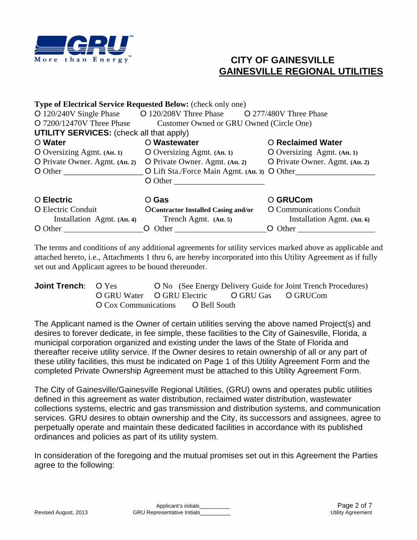
CITY OF GAINESVILLE GAINESVILLE REGIONAL UTILITIES
Applicantrsquos initials__________ Page 1 of 7 Revised August 2013 GRU Representative Initials__________ Utility Agreement
UTILITY AGREEMENT THIS AGREEMENT TO BE COMPLETED PRIOR TO APPROVAL OF PLANS BY GRU Applicant OwnerDeveloper
Name Contact Person Mailing Address Zip
Phone Fax E-Mail Engineer
Name Mailing Address Zip Phone Fax E-Mail
Property Description Section Township Range Grant _____________ Tax Parcel No Acreage Development Name Street Address or Detailed Location Project Meeting Date Approximate Construction Start Date Type of Development and Number of Units Below (check only one) O Single Family _____total units O Multifamily _____total units _____ total bedrooms O Commercial O Industrial Size and Number of Water Meter(s) Below
Amt Building Type
Number of BRTotal Area (sq ft)
Avg Daily Flow (gpd)
Peak Flow (gpm)
Meter Size (in)
Water Meter Numbers for Meters to be Removed (for Connection Charge Credit)
If Removing Meters that Serve Multi-Family units Provide total number of Bedrooms _________
CITY OF GAINESVILLE GAINESVILLE REGIONAL UTILITIES
Applicantrsquos initials__________ Page 2 of 7 Revised August 2013 GRU Representative Initials__________ Utility Agreement
Type of Electrical Service Requested Below (check only one) O 120240V Single Phase O 120208V Three Phase O 277480V Three Phase O 720012470V Three Phase Customer Owned or GRU Owned (Circle One) UTILITY SERVICES (check all that apply) O Water O Wastewater O Reclaimed Water O Oversizing Agmt (Att 1) O Oversizing Agmt (Att 1) O Oversizing Agmt (Att 1)
O Private Owner Agmt (Att 2) O Private Owner Agmt (Att 2) O Private Owner Agmt (Att 2) O Other O Lift StaForce Main Agmt (Att 3) O Other O Other O Electric O Gas O GRUCom O Electric Conduit OContractor Installed Casing andor O Communications Conduit
Installation Agmt (Att 4) Trench Agmt (Att 5) Installation Agmt (Att 6) O Other O Other O Other
The terms and conditions of any additional agreements for utility services marked above as applicable and attached hereto ie Attachments 1 thru 6 are hereby incorporated into this Utility Agreement as if fully set out and Applicant agrees to be bound thereunder Joint Trench O Yes O No (See Energy Delivery Guide for Joint Trench Procedures) O GRU Water O GRU Electric O GRU Gas O GRUCom O Cox Communications O Bell South The Applicant named is the Owner of certain utilities serving the above named Project(s) and desires to forever dedicate in fee simple these facilities to the City of Gainesville Florida a municipal corporation organized and existing under the laws of the State of Florida and thereafter receive utility service If the Owner desires to retain ownership of all or any part of these utility facilities this must be indicated on Page 1 of this Utility Agreement Form and the completed Private Ownership Agreement must be attached to this Utility Agreement Form The City of GainesvilleGainesville Regional Utilities (GRU) owns and operates public utilities defined in this agreement as water distribution reclaimed water distribution wastewater collections systems electric and gas transmission and distribution systems and communication services GRU desires to obtain ownership and the City its successors and assignees agree to perpetually operate and maintain these dedicated facilities in accordance with its published ordinances and policies as part of its utility system In consideration of the foregoing and the mutual promises set out in this Agreement the Parties agree to the following
CITY OF GAINESVILLE GAINESVILLE REGIONAL UTILITIES
Applicantrsquos initials__________ Page 3 of 7 Revised August 2013 GRU Representative Initials__________ Utility Agreement
A) APPLICANTS OBLIGATIONS
1 INSTALLATION The Applicant hereby represents and warrants that all utilities subject to this agreement shall be installed as specified by utility plans approved by GRU and in accordance with the prevailing edition of the following policies and standards which are by this reference incorporated into this agreement as if fully set out
City of Gainesville Code of Ordinances Gainesville Regional Utilitiesrsquo
Water and Wastewater Standards amp Approved Materials Manual Electric Distribution Approved Materials Manual Electric Distribution Construction Standards Manual Gas Standards and Approved Materials Manual Energy Delivery Service Guide Telecommunications Conduit Installation Standards Vegetation Management Design Standards
If there is a conflict in any of these standards the utility that is the subject of this application has precedence If more than one utility is the subject GRU shall determine the order of precedence and so inform the Applicant in writing To the extent that any utility systems installed are not in compliance with these policies or standards the developer is responsible to correct any deficiencies to bring these systems to an acceptable condition as determined by GRU GRU reserves the right to deny service to the Applicant upon notification that the subject service is in non-conformance with applicable standards or utility plans approved by GRU
NOTWITHSTANDING any other provision of this agreement it is understood that in the event the ordinances or policies of GRU regarding developer installed utility facilities to be accepted by GRU are amended after the execution of this agreement then in such event the amended ordinance(s) or policy(s) shall apply to those utility facilities constructed after the effective date of such amendments
2 MATERIALS AND EQUIPMENT ADDED TO THE SYSTEM The Applicant agrees that
GRU retains the sole right to specify the size type and design of all utility systems and any other incidental components that may be required or added to the utility system
3 PAYMENT REQUIREMENTS All monies paid to GRU relating to service to a particular
location shall be paid by the Applicant in accordance with the rates and charges which are in effect at the time payment is made prior to rendering service
CITY OF GAINESVILLE GAINESVILLE REGIONAL UTILITIES
Applicantrsquos initials__________ Page 4 of 7 Revised August 2013 GRU Representative Initials__________ Utility Agreement
4 RIGHTS OF WAY AND EASEMENTS In accordance with the Gainesville Code of Ordinances the Applicant shall grant or shall cause to be granted to GRU without cost all on-site and off-site rights-of-way easements deeded lands and privileges for the proposed phase and all future phases of the subject project which of GRU in the exercise of its sole discretion may deem necessary for the rendering and maintaining of any existing or proposed utility facilities and services andor for connecting and expanding utility service to adjacent property or new development and as indicated on approved construction drawings (including but not limited to easements and rights-of-way granted to the City of Gainesville via easement documents and fee simple deeds or dedicated by recorded plat Whereas a GRU lift station is required GRU requires a minimum 50 foot by 50 foot site deeded to GRU conveyed by a warranty deed Applicant shall supply to GRU any surveys and metes and bounds legal descriptions and sketches prepared by a registered land surveyor as needed for GRUrsquos preparation of any instruments of conveyance or other legal documents as required for the subject project
5 OBSTRUCTIONS WITHIN EASEMENTS The Applicant agrees that no structures
including but not limited to buildings obstacles signs walls vegetation or fences where GRU in the exercise of its sole discretion deems such structures unreasonably interferes with the operation and maintenance of its facilities shall be located constructed or created within any easement areas Applicant hereby assumes all risk of loss for any structures placed within any easement area Any permanent structures placed within an easement creates an encroachment therefore GRU will require removal at Applicantrsquos expense and that the Applicant indemnify and hold harmless GRU from all claims and suits for damage to property and injuries to persons including death arising out of or relating to the existence or removal of the encroachment or GRUrsquos operation and maintenance of its utility facilities within the easement area and as related to the existence of the encroachment
Moveable fences may be permitted within easement areas provided they are placed so as
to allow ready access to utility facilities and provide a working space of not less than six feet (6rsquo) from fire hydrants and manhole centers ten feet (10rsquo) from the opening side of any pad mounted equipment and three feet (3rsquo) from water meters valve box centers and the other three sides of any pad mounted equipment
6 INGRESS AND EGRESS The Applicant shall provide ingress and egress to Gainesville
Regional Utilities at no charge for the purpose of accessing the utility systems as identified in the approved construction drawings
7 CONVEYANCE OF FACILITIES The Applicant shall convey to GRU legal title to all
developer installed utility systems as constructed in accordance with the approved construction drawings free of any claims liens encroachments or encumbrances Upon execution of this agreement by both parties and upon acceptance of the subject facilities by GRU the Applicant shall be released from and GRU will accept all
CITY OF GAINESVILLE GAINESVILLE REGIONAL UTILITIES
Applicantrsquos initials__________ Page 5 of 7 Revised August 2013 GRU Representative Initials__________ Utility Agreement
responsibility for the operation and maintenance of those facilities other than the obligations of this Paragraph 7 and as expressly stipulated or described in the Applicants Guarantee of the Work (See Line 9 Below)
8 CERTIFIED COST Upon completion of construction and prior to acceptance by GRU
of the completed utility facilities GRU may require the Applicant to furnish to GRU a certified cost summary describing property units conveyed to GRU on forms to be provided GRU retains the sole right to specify and the applicant agrees to construct any oversizing or extensions that in the opinion of GRU are necessary to provide utility service to adjacent or future sites The Applicant certifies that all requested oversizing of facilities shall be completed in accordance with the terms and conditions of the applicable Oversizing Agreement if any and shall be specifically identified in the Certified Cost summary
9 APPLICANTS GUARANTEE OF THE WORK The Applicant shall guarantee all
materials and workmanship for a period of one year after the date of the completion letter If any work should require repair or replacement due to faulty workmanship or failure of materials within a period of one (1) year of the date of the completion letter the Applicant shall make all repairs required to bring the system(s) to an acceptable condition as determined by GRU The cost of all repairs during this maintenance period shall be the responsibility of the Applicant
10 CONSTRUCTION PLAN APPROVAL The Applicant shall obtain a Construction Permit from GRU prior to the start of construction Substantial and progressive construction must begin in accordance with the approved plans within six (6) months from the date of the completion letter or the permit for construction shall expire If the Construction Permit expires the Applicant shall be required to resubmit an application to GRU or receive a written extension to the approval date from GRU The expired plans shall be subject to review and modifications which may be necessary to bring the plans into compliance with the standards specifications and policies in affect at the time the re-application is made Any additional connection charges resulting from new charges imposed or amendments to changes occurring post-plan expiration must be paid by the Applicant prior to rendering service 11 INDEMNIFYHOLD HARMLESS The Developer shall be solely responsible for
indemnify and hold GRU its officers and employees harmless from any loss cost injury or damages to any persons or property caused as a result of the installation of utility facilities subject to this agreement
CITY OF GAINESVILLE GAINESVILLE REGIONAL UTILITIES
Applicantrsquos initials__________ Page 6 of 7 Revised August 2013 GRU Representative Initials__________ Utility Agreement
12 ADDITIONAL FORMS This Utility Agreement must include all the Agreements and
Forms as indicated on Page 1 The Applicant must comply with the obligations as specified in the attached agreements
B) GAINESVILLE REGIONAL UTILITIES OBLIGATIONS
1 GRU agrees that upon acceptable completion and testing of the utility systems in the
approved phases of the subject project and subject to Applicants guarantee of the work to accept responsibility for the perpetual operation and maintenance of these facilities in accordance with all Federal State and local requirements and in accordance with prudent utility practices
2 GRU shall provide utility service to the extent utility system capacity is available
to all individual properties within approved phases of the subject project in accordance with current Utility Service Policies and City of Gainesville Code of Ordinances upon receipt of the following
3 acceptance and release by the Florida Department of Environmental
Protection (FDEP) andor other permitting agencies where applicable and payment of all appropriate fees by the Applicant and payment of any
applicable connection charges by the customer and acceptable instruments of conveyance granted to GRU without cost for all
on-site and off-site rights-of-way easements and privileges necessary for GRU to install operate and maintain the requested utility facilities for service to the subject project
C) GENERAL 1 This Agreement constitutes the entire agreement between the parties with respect to
the subject matter herein 2 This Agreement shall be construed in accordance with the laws of the State of Florida 3 Should any litigation arise out of this Agreement the same shall be prosecuted in the
Circuit Court of the 8th Judicial Court Alachua County Florida or the state court having jurisdiction and so located
4 No modifications of this Agreement shall be effective unless in writing signed by both parties
CITY OF GAINESVILLE GAINESVILLE REGIONAL UTILITIES
Applicantrsquos initials__________ Page 7 of 7 Revised August 2013 GRU Representative Initials__________ Utility Agreement
DATED this day of 200
APPLICANT OR AUTHORIZED REPRESENTATIVE CITY OF GAINESVILLE (Letter of Authorization to GRU required GAINESVILLE REGIONAL UTILITIES if not signed by Applicant) By By
(Please Print) (Please Print)
Signature Signature
Title Title
PLEASE NOTE The waterwastewater infrastructure (Developer) fees will be invoiced once the Utility Construction Permit is issued These fees can include extension of water or sewer mains meters connection charges Inspection fees etc The entity responsible for the payment of the invoice must be a Gainesville Regional Utilities (GRU) customer or have an approved application with GRU Customer Service Please visit wwwgrucomMyBusinessCustomerServiceStartYourServiceaspx for the current application and process instruction
ADDENDUM TO UTILITY AGREEMENT Section A Number 11 INDEMNIFYHOLD HARMLESS
Developer understands that the referenced indemnity includes 1) any construction of utility facilities by the developer on private property or in a County or State Road Right-of-Way as specified by utility plans approved by Gainesville Regional Utilities (GRU) and 2) any loss cost or damages payable under the conditions of any permit(s) issued for such installation by County or State agencies APPLICANT OR AUTHORIZED REPRESENTATIVE By_______________________________________ (Please Print) Signature__________________________________ Title______________________________________ Date______________________________________
Attachment 1
WATER ANDOR WASTEWATER OVERSIZING AGREEMENT THIS AGREEMENT TO BE COMPLETED PRIOR TO APPROVAL OF PLANS BY GRU Applicant Name _____________________________ Date ____________________ Development Name ____________________________________________________________ (The Project) Description of Oversizing Requirements (Please Be Specific)
Water Wastewater Reclaimed Water _______________________________________________________________________________________
_______________________________________________________________________________________
_______________________________________________________________________________________
_______________________________________________________________________________________
_______________________________________________________________________________________
_______________________________________________________________________________________
_______________________________________________________________________________________
_______________________________________________________________________________________
_______________________________________________________________________________________
Oversizing Reimbursement Amount _____________________________ The Applicant named above is the developer of certain water distribution wastewater pumping andor wastewater collection facilities serving the above named project The City of GainesvilleGainesville Regional Utilities (GRU) has established policies within its Code of Ordinances including but not limited to the provisions of Chapter 27 thereof to ensure the development of water distribution and wastewater collection systems which serve the public in a coordinated and efficient manner The Ordinances prescribe the mechanisms to provide for necessary oversizing of developer constructed facilities The City through its utility system Gainesville Regional Utilities (GRU) has requested the oversizing of certain of those water andor wastewater facilities In consideration of the foregoing and the mutual promises set out below the parties agree to the following Revised March 5 2007 Applicants initials ___________ Page 1 of 2
GRU Representative initials __________
A) APPLICANTS OBLIGATIONS 1 Oversizing Cost Estimate The Applicant shall provide GRU a written itemized cost estimate
covering the minimum facilities required to serve the subject project and a written itemized cost estimate covering the actual facilities to be constructed These estimates shall identify the incremental construction engineering and interest costs (subject to restrictions) associated with the requested oversizing The estimates shall be signed and sealed by a Professional Engineer registered in the State of Florida attesting to the fact that the cost estimates are based upon the best available and most recent cost information for similar work Interest cost estimates shall be based upon the incremental oversizing cost estimates referenced above the Applicantrsquos current borrowing rate and the expected time to complete the project This estimate must be submitted to and approved by GRU prior to approval of plans by GRU or its designated engineer
2 Installation The Applicant agrees to construct all oversized facilities in accordance with the plans approved by GRU or its designated engineer
3 Invoicing The Applicant shall invoice GRU for the approved oversizing amount following completion of that portion of the water andor wastewater facilities to be oversized within six months of the completion letter The invoice shall not exceed the oversizing reimbursement amount agreed upon and shall be based upon the Contractors actual final prices and quantities The invoice shall be signed and sealed by a Professional Engineer registered in the State of Florida certifying to the validity of the contract prices and quantities and actual interest costs shall be certified by the lender The final invoice amount will be subject to GRU concurrence
4 Reimbursement The Applicant understands that reimbursement for change orders or additions shall only be made for items which have received prior written approval from GRU The Applicant agrees that there will be no compensation monetary or otherwise for the connection of additional properties to facilities installed by the Applicant and conveyed to GRU B) GAINESVILLE REGIONAL UTILITIES OBLIGATIONS 1 Utilization GRU in its sole discretion may without restriction utilize the water distribution andor wastewater pumping and collection facilities in whatever manner necessary in accordance with the GRUs policies to provide andor improve utility service to the subject project or the surrounding areas 2 Estimate GRU shall review the oversizing estimate and establish an eligible amount for reimbursement The reimbursement amount is subject to the approval of GRU The amount of the oversizing reimbursement may be adjusted by GRU in accordance with the procedures contained in the City of Gainesville Code of Ordinances 3 Reimbursement Following completion and acceptance by GRU of the water distribution andor wastewater pumping and collection facilities constructed on the above named project(s) and upon receipt from the Applicant of an original written invoice to GRU the engineers certified cost estimate and the Contractors final signed contract unit prices and quantities and provided that all conditions of this Agreement have been satisfactorily met GRU shall within 30 days of receipt of the request issue an approval for payment to GRU accounting DATED this __________ day of __________ 20____ APPLICANT OR AUTHORIZED REPRESENTATIVE CITY OF GAINESVILLE Letter of Authorization to GRU required GAINESVILLE REGIONAL UTILITIES if not signed by Applicant By _______________________________________ By ________________________________ (Please Print) (Please Print) Signature _________________________________ Signature ___________________________ Title _____________________________________ Title _______________________________ Revised March 5 2007 Page 2 of 2 Attachment 1
Page 1 of 8
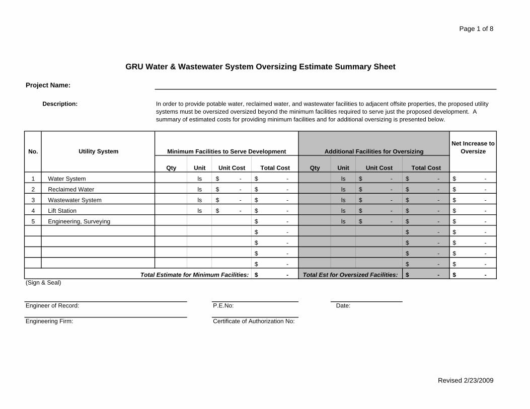
GRU Water amp Wastewater System Oversizing Estimate Summary Sheet
Project Name
Description In order to provide potable water reclaimed water and wastewater facilities to adjacent offsite properties the proposed utility systems must be oversized oversized beyond the minimum facilities required to serve just the proposed development A summary of estimated costs for providing minimum facilities and for additional oversizing is presented below
No Utility System Minimum Facilities to Serve Development Additional Facilities for OversizingNet Increase to
Oversize
Qty Unit Unit Cost Total Cost Qty Unit Unit Cost Total Cost
1 Water System ls -$ -$ ls -$ -$ -$
2 Reclaimed Water ls -$ -$ ls -$ -$ -$
3 Wastewater System ls -$ -$ ls -$ -$ -$
4 Lift Station ls -$ -$ ls -$ -$ -$
5 Engineering Surveying -$ ls -$ -$ -$
-$ -$ -$
-$ -$ -$
-$ -$ -$
-$ -$ -$
Total Estimate for Minimum Facilities -$ Total Est for Oversized Facilities -$ -$ (Sign amp Seal)
Engineer of Record PENo Date
Engineering Firm Certificate of Authorization No
Revised 2232009
Page 2 of 8
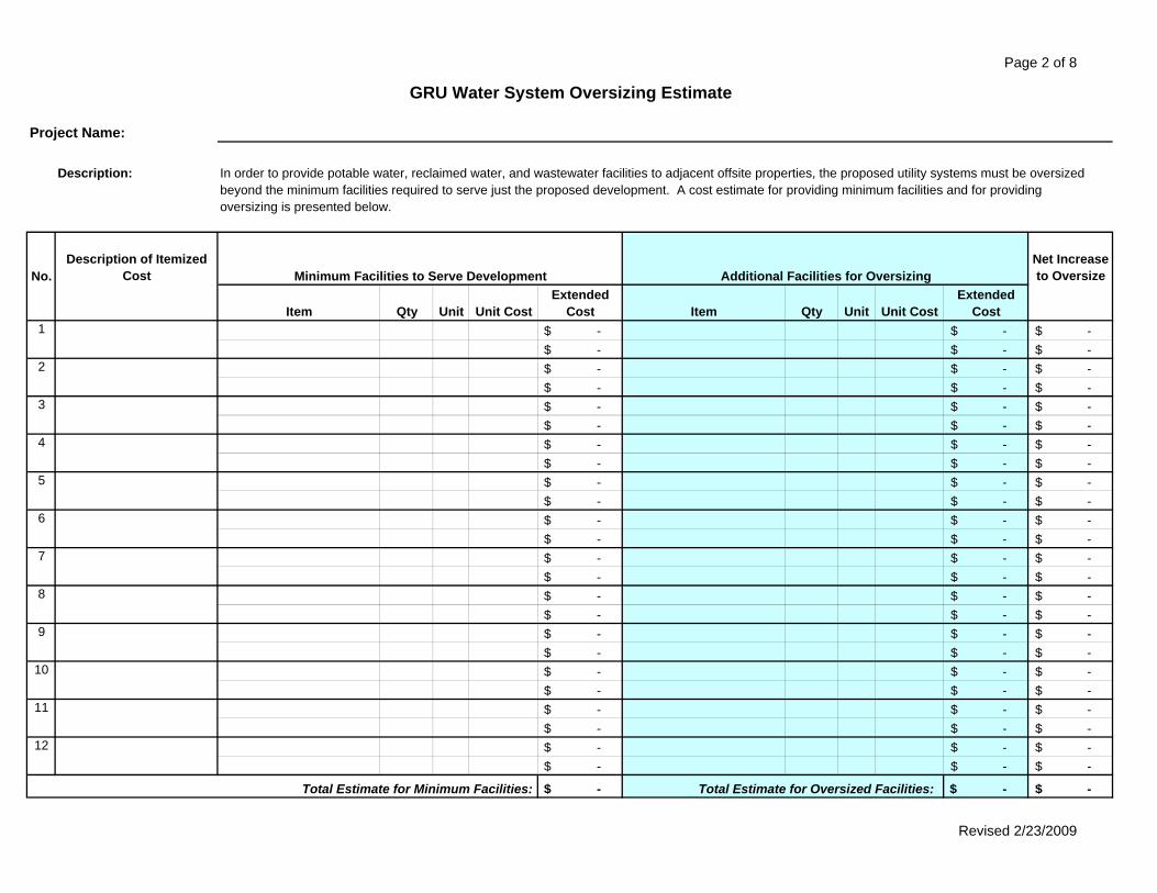
GRU Water System Oversizing Estimate
Project Name
Description In order to provide potable water reclaimed water and wastewater facilities to adjacent offsite properties the proposed utility systems must be oversizedbeyond the minimum facilities required to serve just the proposed development A cost estimate for providing minimum facilities and for providingoversizing is presented below
NoDescription of Itemized
Cost Minimum Facilities to Serve Development Additional Facilities for OversizingNet Increase to Oversize
Item Qty Unit Unit CostExtended
Cost Item Qty Unit Unit CostExtended
Cost1 -$ -$ -$
-$ -$ -$ 2 -$ -$ -$
-$ -$ -$ 3 -$ -$ -$
-$ -$ -$ 4 -$ -$ -$
-$ -$ -$ 5 -$ -$ -$
-$ -$ -$ 6 -$ -$ -$
-$ -$ -$ 7 -$ -$ -$
-$ -$ -$ 8 -$ -$ -$
-$ -$ -$ 9 -$ -$ -$
-$ -$ -$ 10 -$ -$ -$
-$ -$ -$ 11 -$ -$ -$
-$ -$ -$ 12 -$ -$ -$
-$ -$ -$
Total Estimate for Minimum Facilities -$ Total Estimate for Oversized Facilities -$ -$
Revised 2232009
Page 3 of 8
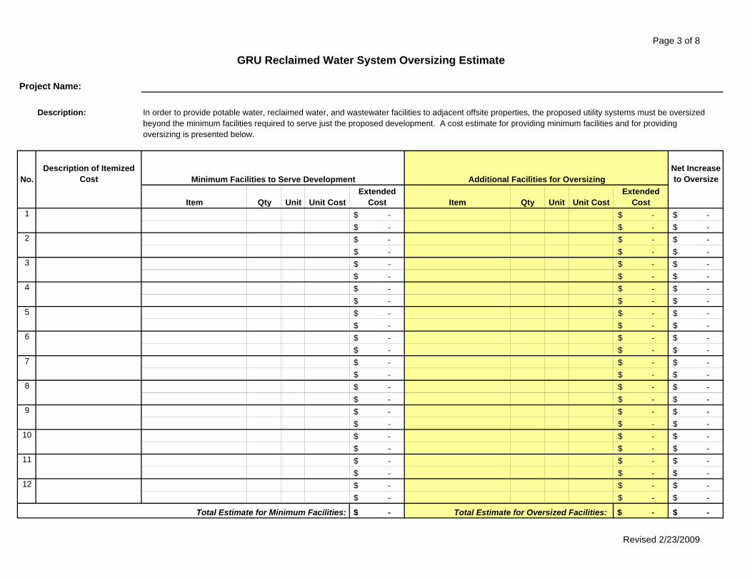
GRU Reclaimed Water System Oversizing Estimate
Project Name
Description In order to provide potable water reclaimed water and wastewater facilities to adjacent offsite properties the proposed utility systems must be oversizedbeyond the minimum facilities required to serve just the proposed development A cost estimate for providing minimum facilities and for providingoversizing is presented below
NoDescription of Itemized
Cost Minimum Facilities to Serve Development Additional Facilities for OversizingNet Increase to Oversize
Item Qty Unit Unit CostExtended
Cost Item Qty Unit Unit CostExtended
Cost1 -$ -$ -$
-$ -$ -$ 2 -$ -$ -$
-$ -$ -$ 3 -$ -$ -$
-$ -$ -$ 4 -$ -$ -$
-$ -$ -$ 5 -$ -$ -$
-$ -$ -$ 6 -$ -$ -$
-$ -$ -$ 7 -$ -$ -$
-$ -$ -$ 8 -$ -$ -$
-$ -$ -$ 9 -$ -$ -$
-$ -$ -$ 10 -$ -$ -$
-$ -$ -$ 11 -$ -$ -$
-$ -$ -$ 12 -$ -$ -$
-$ -$ -$
Total Estimate for Minimum Facilities -$ Total Estimate for Oversized Facilities -$ -$
Revised 2232009
Page 4 of 8
GRU Wastewater System Oversizing Estimate
Project Name
Description In order to provide potable water reclaimed water and wastewater facilities to adjacent offsite properties the proposed utility systems must be oversizedbeyond the minimum facilities required to serve just the proposed development A cost estimate for providing minimum facilities and for providingoversizing is presented below
NoDescription of Itemized
Cost Minimum Facilities to Serve Development Additional Facilities for OversizingNet Increase to Oversize
Item Qty Unit Unit CostExtended
Cost Item Qty Unit Unit CostExtended
Cost1 -$ -$ -$
-$ -$ -$ 2 -$ -$ -$
-$ -$ -$ 3 -$ -$ -$
-$ -$ -$ 4 -$ -$ -$
-$ -$ -$ 5 -$ -$ -$
-$ -$ -$ 6 -$ -$ -$
-$ -$ -$ 7 -$ -$ -$
-$ -$ -$ 8 -$ -$ -$
-$ -$ -$ 9 -$ -$ -$
-$ -$ -$ 10 -$ -$ -$
-$ -$ -$ 11 -$ -$ -$
-$ -$ -$ 12 -$ -$ -$
-$ -$ -$
Total Estimate for Minimum Facilities -$ Total Estimate for Oversized Facilities -$ -$
Revised 2232009
Page 5 of 8
GRU Lift Station Oversizing Estimate
Project Name
Description In order to provide potable water reclaimed water and wastewater facilities to adjacent offsite properties the proposed utility systems must be oversizedbeyond the minimum facilities required to serve just the proposed development A cost estimate for providing minimum facilities and for providingoversizing is presented below
NoDescription of Itemized
Cost Minimum Facilities to Serve Development Additional Facilities for OversizingNet Increase to Oversize
Item Qty Unit Unit CostExtended
Cost Item Qty Unit Unit CostExtended
Cost1 -$ -$ -$
-$ -$ -$ 2 -$ -$ -$
-$ -$ -$ 3 -$ -$ -$
-$ -$ -$ 4 -$ -$ -$
-$ -$ -$ 5 -$ -$ -$
-$ -$ -$ 6 -$ -$ -$
-$ -$ -$ 7 -$ -$ -$
-$ -$ -$ 8 -$ -$ -$
-$ -$ -$ 9 -$ -$ -$
-$ -$ -$ 10 -$ -$ -$
-$ -$ -$ 11 -$ -$ -$
-$ -$ -$ 12 -$ -$ -$
-$ -$ -$
Total Estimate for Minimum Facilities -$ Total Estimate for Oversized Facilities -$ -$
Revised 2232009
Page 6 of 8
GRU Force Main Rebate Calculations
Project Name
Lift Station Design Data
Number of Residential Units units
Lift Station Capacity (Peak Flow) gpm or gpd
Lift Station Peaking Factor 250
Lift Station Average Daily Flow 0 gpd 250 = gpd
Equivalent Residential Connection (ERC)
Average Daily Flow per Connection gpd
Equivalent Residential Connection gpd 0 = ERC
Force Main Cost Estimate
Total Force Main Construction Costs
GRU Paid Force Main Oversizing
Developers Net Costs
Force Main Cost Estimate by Segment
Force Main Segment Length Percent Pro-Rata Cost
Total Length of Force Main
Onsite Force Main
Offsite Force Main
Rebate amp Cost Share
Connect to FM via Lift Station per ERC =
Connect to Onsite FM per ERC (50 of Total) =
Connect to Offsite FM per ERC (50 of Offsite) =
Developers Cost Share units x =
Maximum Possible Developer Rebate - =
Revised 2232009
Page 7 of 8
GRU Lift Station Rebate Calculations
Project Name
Lift Station Design Data
Number of Residential Units units
Lift Station Capacity (Peak Flow) gpm or gpd
Lift Station Peaking Factor 250
Lift Station Average Daily Flow gpd 250 = gpd
Equivalent Residential Connection (ERC)
Average Daily Flow per Connection gpd
Equivalent Residential Connection gpd = ERCs
Lift Station Cost Estimate
Total Lift Station Construction Costs
GRU Paid Lift Station Oversizing
Developers Net Costs
Rebate amp Cost Share
Rebate Charge per ERC =
Developers Cost Share units x =
Maximum Possible Developer Rebate - =
Revised 2232009
Page 8 of 8
Description
Item Quantity Unit PriceTotal Unit
CostItem Quantity Unit Price
Total Unit Cost
Force Main Estimate Sub-Total Force Main Net Increase Estimate Sub-Total
Lift Station Estimate Sub-Total Lift Station Net Increase Estimate Sub-Total
Total Estimate to Provide Minimum Facilities Total Net Increase Estimate for Oversizing
Combined Total for Providing Minimum and Oversizing Facilities
(Sign amp Seal)
Engineer of Record PENo Date
Engineering Firm Certificate of Authorization No
Cost Estimate for Lift Station Force Main Reimbursement AgreementProject Name
In order to provide wastewater services to offsite properties to the east west and south the proposed lift station and force main must be oversized beyond the minimum facilities required to serve just the proposed Weatherly development A cost estimate for providing minimum wastewater services and for providing additional facilities for oversizing is presented below
Net Increase to Provide Oversize
NoDescription of Itemized Cost
Minimum Facilities to Serve Development Additional Facilities for Oversizing
Force Main1
Lift Station2
Revised 2232009
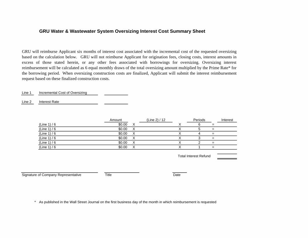
GRU Water amp Wastewater System Oversizing Interest Cost Summary Sheet
Line 1 Incremental Cost of Oversizing
Line 2 Interest Rate
Amount (Line 2) 12 Periods Interest(Line 1) 6 $000 X X 6 =(Line 1) 6 $000 X X 5 =(Line 1) 6 $000 X X 4 =(Line 1) 6 $000 X X 3 =(Line 1) 6 $000 X X 2 =(Line 1) 6 $000 X X 1 =
Total Interest Refund
Signature of Company Representative Title Date
As published in the Wall Street Journal on the first business day of the month in which reimbursement is requested
GRU will reimburse Applicant six months of interest cost associated with the incremental cost of the requested oversizingbased on the calculation below GRU will not reimburse Applicant for origination fees closing costs interest amounts inexcess of those stated herein or any other fees associated with borrowings for oversizing Oversizing interestreimbursement will be calculated as 6 equal monthly draws of the total oversizing amount multiplied by the Prime Rate forthe borrowing period When oversizing construction costs are finalized Applicant will submit the interest reimbursementrequest based on these finalized construction costs
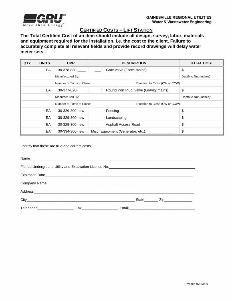
CERTIFIED COSTS ndash LIFT STATION
The Total Certified Cost of an item should include all design survey labor materials and equipment required for the installation ie the cost to the client Failure to accurately complete all relevant fields and provide record drawings will delay water meter sets
Revised 022309
Project name Location GRU Job Numbers ( oversizing)
QTY UNITS CPR DESCRIPTION TOTAL COST
EA 30-333-300-0149 5 HP Flygt Pumps amp Accessories $
EA 30-333-300-0153 10 HP Flygt Pumps amp Accessories $
EA 30-333-300-____ ___ HP Flygt Pumps amp Accessories $
EA 30-333-300-0129 Quality Controls Duplex Control Panel amp Accessories $
EA 30-333-300-0130 Quality Controls Triplex Control Panel amp Accessories $
EA 30-377-830-0034 Manhole - 4rsquo or 6rsquo $
EA 30-336-300-0175 Valve vault ndash 4rsquox6rsquo or 6rsquox6rsquo $
EA 30-336-300-0173 Wetwell - duplex $
EA 30-336-300-0174 Wetwell - triplex $
EA 30-378-830-210 4 Plug valve (Force mains) $
Manufactured By Depth to Nut (inches)
Number of Turns to Close Direction to Close (CW or CCW)
EA 30-378-830-0220 6rdquo Plug valve (Force mains) $
Manufactured By Depth to Nut (inches)
Number of Turns to Close Direction to Close (CW or CCW)
EA 30-378-830-0230 8 Plug valve (Force mains) $
Manufactured By Depth to Nut (inches)
Number of Turns to Close Direction to Close (CW or CCW)
EA 30-378-830-____ ___ Plug valve (Force mains) $
Manufactured By Depth to Nut (inches)
Number of Turns to Close Direction to Close (CW or CCW)
EA 30-378-830-0334 4 Gate valve (Force mains) $
Manufactured By Depth to Nut (inches)
Number of Turns to Close Direction to Close (CW or CCW)
EA 30-378-830-0336 6 Gate valve (Force mains) $
Manufactured By Depth to Nut (inches)
Number of Turns to Close Direction to Close (CW or CCW)
CERTIFIED COSTS ndash LIFT STATION
The Total Certified Cost of an item should include all design survey labor materials and equipment required for the installation ie the cost to the client Failure to accurately complete all relevant fields and provide record drawings will delay water meter sets
Revised 022309
QTY UNITS CPR DESCRIPTION TOTAL COST
EA 30-378-830-____ ___ Gate valve (Force mains) $
Manufactured By Depth to Nut (inches)
Number of Turns to Close Direction to Close (CW or CCW)
EA 30-377-820-____ ___ Round Port Plug valve (Gravity mains) $
Manufactured By Depth to Nut (inches)
Number of Turns to Close Direction to Close (CW or CCW)
EA 30-329-300-new Fencing $
EA 30-329-300-new Landscaping $
EA 30-329-300-new Asphalt Access Road $
EA 30-334-300-new Misc Equipment (Generator etc) ______________ $
I certify that these are true and correct costs Name__________________________________________________________________________________ Florida Underground Utility and Excavation License No___________________________________________ Expiration Date__________________________________________________________________________ Company Name__________________________________________________________________________ Address________________________________________________________________________________ City______________________________________________________ State_______ Zip______________ Telephone__________________ Fax__________________ Email_________________________________
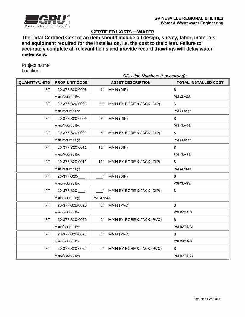
CERTIFIED COSTS ndash WATER
The Total Certified Cost of an item should include all design survey labor materials and equipment required for the installation ie the cost to the client Failure to accurately complete all relevant fields and provide record drawings will delay water meter sets
Revised 022309
Project name Location
GRU Job Numbers ( oversizing)
QUANTITYUNITS PROP UNIT CODE ASSET DESCRIPTION TOTAL INSTALLED COST
FT 20-377-820-0008 6 MAIN (DIP) $
Manufactured By PSI CLASS
FT 20-377-820-0008 6 MAIN BY BORE amp JACK (DIP) $
Manufactured By PSI CLASS
FT 20-377-820-0009 8 MAIN (DIP) $
Manufactured By PSI CLASS
FT 20-377-820-0009 8 MAIN BY BORE amp JACK (DIP) $
Manufactured By PSI CLASS
FT 20-377-820-0011 12 MAIN (DIP) $
Manufactured By PSI CLASS
FT 20-377-820-0011 12 MAIN BY BORE amp JACK (DIP) $
Manufactured By PSI CLASS
FT 20-377-820-___ ___ MAIN (DIP) $
Manufactured By PSI CLASS
FT 20-377-820-___ ___ MAIN BY BORE amp JACK (DIP) $
Manufactured By PSI CLASS
FT 20-377-820-0020 2 MAIN (PVC) $
Manufactured By PSI RATING
FT 20-377-820-0020 2 MAIN BY BORE amp JACK (PVC) $
Manufactured By PSI RATING
FT 20-377-820-0022 4 MAIN (PVC) $
Manufactured By PSI RATING
FT 20-377-820-0022 4 MAIN BY BORE amp JACK (PVC) $
Manufactured By PSI RATING
CERTIFIED COSTS ndash WATER
The Total Certified Cost of an item should include all design survey labor materials and equipment required for the installation ie the cost to the client Failure to accurately complete all relevant fields and provide record drawings will delay water meter sets
Revised 022309
FT 20-377-820-0023 6 MAIN (PVC) $
Manufactured By PSI RATING
FT 20-377-820-0023 6 MAIN BY BORE amp JACK (PVC) $
Manufactured By PSI RATING
FT 20-377-820-0024 8 MAIN (PVC) $
Manufactured By PSI RATING
FT 20-377-820-0024 8 MAIN BY BORE amp JACK (PVC) $
Manufactured By PSI RATING
FT 20-377-820-____ ___MAIN (PVC) $
Manufactured By PSI RATING
FT 20-377-820-____ ___MAIN BY BORE amp JACK (PVC) $
Manufactured By PSI RATING
FT 20-377-____ ___rdquo MAIN (HDPE) $
Manufactured By PSI RATING
FT 20-377-____ ___rdquo MAIN BY DIRECTIONAL BORE(HDPE) $
Manufactured By PSI RATING
EA 20-377-820-0032 2 GATE VALVE amp BOX $
Manufactured By Depth to Nut (inches)included on Record Drawings (please initial)
EA 20-377-820-0034 4 GATE VALVE amp BOX $
Manufactured By Depth to Nut (inches)included on Record Drawings (please initial)
EA 20-377-820-0035 6 GATE VALVE amp BOX $
Manufactured By Depth to Nut (inches)included on Record Drawings (please initial)
EA 20-377-820-0036 8 GATE VALVE amp BOX $
Manufactured By Depth to Nut (inches)included on Record Drawings (please initial)
EA 20-377-820-0038 12 GATE VALVE amp BOX $
Manufactured By Depth to Nut (inches)included on Record Drawings (please initial)
EA 20-377-820-____ ___ VALVE amp BOX (TYPE_________) $
Manufactured By Depth to Nut (inches)included on Record Drawings (please initial)
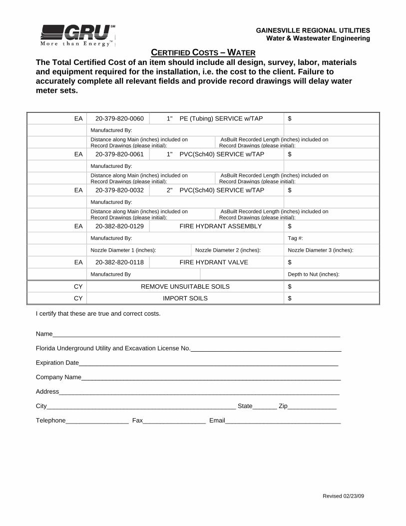
CERTIFIED COSTS ndash WATER
The Total Certified Cost of an item should include all design survey labor materials and equipment required for the installation ie the cost to the client Failure to accurately complete all relevant fields and provide record drawings will delay water meter sets
Revised 022309
EA 20-379-820-0060 1 PE (Tubing) SERVICE wTAP $
Manufactured By
Distance along Main (inches) included on Record Drawings (please initial)
AsBuilt Recorded Length (inches) included on Record Drawings (please initial)
EA 20-379-820-0061 1 PVC(Sch40) SERVICE wTAP $
Manufactured By
Distance along Main (inches) included on Record Drawings (please initial)
AsBuilt Recorded Length (inches) included on Record Drawings (please initial)
EA 20-379-820-0032 2 PVC(Sch40) SERVICE wTAP $
Manufactured By
Distance along Main (inches) included on Record Drawings (please initial)
AsBuilt Recorded Length (inches) included on Record Drawings (please initial)
EA 20-382-820-0129 FIRE HYDRANT ASSEMBLY $
Manufactured By Tag
Nozzle Diameter 1 (inches) Nozzle Diameter 2 (inches) Nozzle Diameter 3 (inches)
EA 20-382-820-0118 FIRE HYDRANT VALVE $
Manufactured By Depth to Nut (inches)
CY REMOVE UNSUITABLE SOILS $
CY IMPORT SOILS $
I certify that these are true and correct costs Name__________________________________________________________________________________ Florida Underground Utility and Excavation License No___________________________________________ Expiration Date__________________________________________________________________________ Company Name__________________________________________________________________________ Address________________________________________________________________________________ City______________________________________________________ State_______ Zip______________ Telephone__________________ Fax__________________ Email_________________________________
CERTIFIED COSTS ndash RECLAIMED WATER
The Total Certified Cost of an item should include all design survey labor materials and equipment required for the installation ie the cost to the client Failure to accurately complete all relevant fields and provide record drawings will delay water meter sets
Revised 022309
Project name Location
GRU Job Numbers ( oversizing)
QUANTITYUNITS PROP UNIT CODE ASSET DESCRIPTION TOTAL INSTALLED
COST
FT 30-387-820-0007 4 MAIN (DIP) $
Manufactured By PSI CLASS
FT 30-387-820-0007 4 MAIN BY BORE amp JACK (DIP) $
Manufactured By PSI CLASS
FT 30-387-820-0008 6 MAIN (DIP) $
Manufactured By PSI CLASS
FT 30-387-820-0008 6 MAIN BY BORE amp JACK (DIP) $
Manufactured By PSI CLASS
FT 30-387-820-0009 8 MAIN (DIP) $
Manufactured By PSI CLASS
FT 30-387-820-0009 8 MAIN BY BORE amp JACK (DIP) $
Manufactured By PSI CLASS
FT 30-387-820-____ ___ MAIN (DIP) $
Manufactured By PSI CLASS
FT 30-387-820-____ ___ MAIN BY BORE amp JACK (DIP) $
Manufactured By PSI CLASS
FT 30-387-830-0430 2 MAIN (PVC) $
Manufactured By PSI RATING
FT 30-387-830-0430 2 MAIN BY BORE amp JACK (PVC) $
Manufactured By PSI RATING
FT 30-387-830-0431 4 MAIN (PVC) $
Manufactured By PSI RATING
FT 30-387-830-0431 4 MAIN BY BORE amp JACK (PVC) $
Manufactured By PSI RATING
FT 30-387-830-0420 6 MAIN (PVC) $
Manufactured By PSI RATING
CERTIFIED COSTS ndash RECLAIMED WATER
The Total Certified Cost of an item should include all design survey labor materials and equipment required for the installation ie the cost to the client Failure to accurately complete all relevant fields and provide record drawings will delay water meter sets
Revised 022309
QUANTITYUNITS PROP UNIT CODE ASSET DESCRIPTION TOTAL INSTALLED
COST
FT 30-387-830-0420 6 MAIN BY BORE amp JACK (PVC) $
Manufactured By PSI RATING
FT 30-387-830-0438 8 MAIN (PVC) $
Manufactured By PSI RATING
FT 30-387-830-0438 8 MAIN BY BORE amp JACK (PVC) $
Manufactured By PSI RATING
FT 30-387-830-____ ___ MAIN (PVC) $
Manufactured By PSI RATING
FT 30-387-830-____ ___ MAIN BY BORE amp JACK (PVC) $
Manufactured By PSI RATING
EA 30-387-820-0032 2 GATE VALVE amp BOX $
Manufactured By Depth to Nut (inches)included on Record Drawings (please initial)
EA 30-387-820-0034 4 GATE VALVE amp BOX $
Manufactured By Depth to Nut (inches)included on Record Drawings (please initial)
EA 30-387-820-0035 6 GATE VALVE amp BOX $
Manufactured By Depth to Nut (inches)included on Record Drawings (please initial)
EA 30-387-820-0036 8 GATE VALVE amp BOX $
Manufactured By Depth to Nut (inches)included on Record Drawings (please initial)
EA 30-387-820-____ ___ GATE VALVE amp BOX $
Manufactured By Depth to Nut (inches)included on Record Drawings (please initial)
EA 30-387-820-0060 1 PE (Tubing) SERVICE wTAP $
Manufactured By
Distance along Main (inches) included on Record Drawings (please initial)
AsBuilt Recorded Length (inches) included on Record Drawings (please initial)
EA 30-387-820-0460 1 PVC(Sch40) SERVICE wTAP $
Manufactured By
Distance along Main (inches) included on Record Drawings (please initial)
AsBuilt Recorded Length (inches) included on Record Drawings (please initial) EA
30-387-820-0061 2 PVC(Sch40) SERVICE wTAP $
Manufactured By
CERTIFIED COSTS ndash RECLAIMED WATER
The Total Certified Cost of an item should include all design survey labor materials and equipment required for the installation ie the cost to the client Failure to accurately complete all relevant fields and provide record drawings will delay water meter sets
Revised 022309
QUANTITYUNITS PROP UNIT CODE ASSET DESCRIPTION TOTAL INSTALLED
COST
Distance along Main (inches) included on Record Drawings (please initial)
AsBuilt Recorded Length (inches) included on Record Drawings (please initial)
CY REMOVE UNSUITABLE SOILS $
CY IMPORT SOILS $
I certify that these are true and correct costs Name__________________________________________________________________________________ Florida Underground Utility and Excavation License No___________________________________________ Expiration Date__________________________________________________________________________ Company Name__________________________________________________________________________ Address________________________________________________________________________________ City______________________________________________________ State_______ Zip______________ Telephone__________________ Fax__________________ Email_________________________________
CERTIFIED COSTS ndash WASTEWATER
The Total Certified Cost of an item should include all design survey labor materials and equipment required for the installation ie the cost to the client Failure to accurately complete all relevant fields and provide record drawings will delay water meter sets
Revised 022309
Project name Location
GRU Job Numbers ( oversizing)
QUANTITY UNITS CPR DESCRIPTION TOTAL
INSTALLED COST
FT 30-377-830-0030 8 GRAVITY MAIN 3rsquo ndash 14rsquo DEPTH (DR-35 PVC) $
Manufactured By PSI Rating
FT 30-377-830-0030 8 GRAVITY MAIN 15rsquo ndash 20rsquo DEPTH (DR-26 PVC) $
Manufactured By PSI Rating
FT 30-377-830-0030 8 GRAVITY MAIN 21rsquo ndash 25rsquo DEPTH (DR-18 PVC) $
Manufactured By PSI Rating
FT 30-377-830-0030 8 GRAVITY MAIN BY BORE amp JACK (PVC) $
Manufactured By PSI Rating
FT 30-377-830-0030 8 GRAVITY MAIN BY HDD (PVC) $
Manufactured By PSI Rating
FT 30-377-830-0032 12 GRAVITY MAIN 3rsquo ndash 14rsquo DEPTH (DR-35 PVC) $
Manufactured By PSI Rating
FT 30-377-830-0032 12 GRAVITY MAIN 15rsquo ndash 20rsquo DEPTH (DR-26 PVC) $
Manufactured By PSI Rating
FT 30-377-830-0032 12 GRAVITY MAIN 21rsquo ndash 25rsquo DEPTH (DR-18 PVC) $
Manufactured By PSI Rating
FT 30-377-830-0032 12 GRAVITY MAIN BY BORE amp JACK (PVC) $
Manufactured By PSI Rating
FT 30-377-830-0032 12 GRAVITY MAIN BY HDD (PVC) $
Manufactured By PSI Rating
FT 30-377-___ ___ GRAVITY MAIN 3rsquo ndash 14rsquo DEPTH (DR-35 PVC) $
Manufactured By PSI Rating
FT 30-377-___ ___ GRAVITY MAIN 15rsquo ndash 20rsquo DEPTH (DR-26 PVC) $
Manufactured By PSI Rating
FT 30-377-___ ___ GRAVITY MAIN 21rsquo ndash 25rsquo DEPTH (DR-18 PVC) $
Manufactured By PSI Rating
CERTIFIED COSTS ndash WASTEWATER
The Total Certified Cost of an item should include all design survey labor materials and equipment required for the installation ie the cost to the client Failure to accurately complete all relevant fields and provide record drawings will delay water meter sets
Revised 022309
FT 30-377-___ ___ GRAVITY MAIN BY BORE amp JACK (PVC) $
Manufactured By PSI Rating
FT 30-377-___ ___ GRAVITY MAIN BY HDD (PVC) $
Manufactured By PSI Rating
FT 30-377-830-0058 8 GRAVITY MAIN 3rsquo ndash 14rsquo DEPTH (DIP) $
Manufactured By PSI Rating
FT 30-377-830-0058 8 GRAVITY MAIN 15rsquo ndash 20rsquo DEPTH (DIP) $
Manufactured By PSI Rating
FT 30-377-830-0058 8 GRAVITY MAIN 21rsquo ndash 25rsquo DEPTH (DIP) $
Manufactured By PSI Rating
FT 30-377-830-0058 8 GRAVITY MAIN BY BORE amp JACK (DIP) $
Manufactured By PSI Rating
FT 30-377-830-0062 12 GRAVITY MAIN 3rsquo ndash 14rsquo DEPTH (DIP) $
Manufactured By PSI Rating
FT 30-377-830-0062 12 GRAVITY MAIN 15rsquo ndash 20rsquo DEPTH (DIP) $
Manufactured By PSI Rating
FT 30-377-830-0062 12 GRAVITY MAIN 21rsquo ndash 25rsquo DEPTH (DIP) $
Manufactured By PSI Rating
FT 30-377-830-0062 12 GRAVITY MAIN BY BORE amp JACK (DIP) $
Manufactured By PSI Rating
FT 30-377-____ ___ GRAVITY MAIN 3rsquo ndash 14rsquo DEPTH (DIP) $
Manufactured By PSI Rating
FT 30-377-____ ___ GRAVITY MAIN 15rsquo ndash 20rsquo DEPTH (DIP) $
Manufactured By PSI Rating
FT 30-377-____ ___ GRAVITY MAIN 21rsquo ndash 25rsquo DEPTH (DIP) $
Manufactured By PSI Rating
FT 30-377-____ ___ GRAVITY MAIN BY BORE amp JACK (DIP) $
Manufactured By PSI Rating
CERTIFIED COSTS ndash WASTEWATER
The Total Certified Cost of an item should include all design survey labor materials and equipment required for the installation ie the cost to the client Failure to accurately complete all relevant fields and provide record drawings will delay water meter sets
Revised 022309
FT 30-377-____ ___rdquo GRAVITY MAIN 3rsquo ndash 14rsquo DEPTH (HDPE) $
Manufactured By PSI Rating
FT 30-377-____ ___rdquo GRAVITY MAIN 15rsquo ndash 20rsquo DEPTH (HDPE) $
Manufactured By PSI Rating
FT 30-377-____ ___rdquo GRAVITY MAIN 21rsquo ndash 25rsquo DEPTH (HDPE) $
Manufactured By PSI Rating
FT 30-377-____ ___rdquo GRAVITY MAIN BY BORE amp JACK (HDPE) $
Manufactured By PSI Rating
FT 30-377-____ ___rdquo GRAVITY MAIN BY HDD (HDPE) $
Manufactured By PSI Rating
EA 30-377-830-0034 MANHOLE 3rsquo ndash 14rsquo (4rsquo Diameter) $
Manufactured By Elevations Included on Record Drawings (Please initial)
EA 30-377-830-0034 MANHOLE 15rsquo ndash 20rsquo (6rsquo Diameter) $
Manufactured By Elevations Included on Record Drawings (Please initial)
EA 30-377-830-0034 MANHOLE 21rsquo ndash 25rsquo DEPTH (6rsquo Diameter) $
Manufactured By Elevations Included on Record Drawings (Please initial)
FT 30-378-830-0104 4 FORCE MAIN (PVC) $
Manufactured By PSI Rating
FT 30-378-830-0104 4 FORCE MAIN BY BORE amp JACK (PVC) $
Manufactured By PSI Rating
FT 30-378-830-0104 4 FORCE MAIN BY HDD (PVC) $
Manufactured By PSI Rating
FT 30-378-830-0106 6 FORCE MAIN (PVC) $
Manufactured By PSI Rating
FT 30-378-830-0106 6 FORCE MAIN BY BORE amp JACK (PVC) $
Manufactured By PSI Rating
FT 30-378-830-0106 6 FORCE MAIN BY HDD (PVC) $
Manufactured By PSI Rating
CERTIFIED COSTS ndash WASTEWATER
The Total Certified Cost of an item should include all design survey labor materials and equipment required for the installation ie the cost to the client Failure to accurately complete all relevant fields and provide record drawings will delay water meter sets
Revised 022309
FT 30-378-830-0108 8 FORCE MAIN (PVC) $
Manufactured By PSI Rating
FT 30-378-830-0108 8 FORCE MAIN BY BORE amp JACK (PVC) $
Manufactured By PSI Rating
FT 30-378-830-0108 8 FORCE MAIN BY HDD (PVC) $
Manufactured By PSI Rating
FT 30-378 ___ FORCE MAIN (PVC) $
Manufactured By PSI Rating
FT 30-378 ___ FORCE MAIN BY BORE amp JACK (PVC) $
Manufactured By PSI Rating
FT 30-378 ___ FORCE MAIN BY HDD (PVC) $
Manufactured By PSI Rating
FT 30-378-____ ___rdquo FORCE MAIN (HDPE) $
Manufactured By PSI Rating
FT 30-378-____ ___rdquo FORCE MAIN BY BORE amp JACK (HDPE) $
Manufactured By PSI Rating
FT 30-378-____ ___rdquo FORCE MAIN BY HDD (HDPE) $
Manufactured By PSI Rating
LS XX-XXX-XXX-XXXX RAVEN LINING FOR EXISTING MANHOLE CONNECTED TO NEW FORCE MAIN
$
EA 30-378-830-0210 4 PLUG VALVE $
Manufactured By Depth to Nut (inches) included on Record Drawings (please initial)
Number of Turns to Close Direction to Close (CW or CCW)
EA 30-378-830-0220 6 PLUG VALVE $
Manufactured By Depth to Nut (inches)
EA 30-378-830-0230 8 PLUG VALVE $
Manufactured By Depth to Nut (inches)
EA 30-378-___ ___ PLUG VALVE $
Manufactured By Depth to Nut (inches)
EA 30-378-___ ___ AIR RELEASE VALVE $
Manufactured By Depth to Nut (inches)
EA 30-378-830-0120 MANHOLE (for Air Release Valve)
CERTIFIED COSTS ndash WASTEWATER
The Total Certified Cost of an item should include all design survey labor materials and equipment required for the installation ie the cost to the client Failure to accurately complete all relevant fields and provide record drawings will delay water meter sets
Revised 022309
Manufactured By
EA 30-379-830-0414 4 SERVICE LATERAL $
Manufactured By
Distance along Main (in feet) included on Record Drawing (please initial)
AsBuilt Recorded Length included on Record Drawing (please initial)
EA 30-379-830-0416 6 SERVICE LATERAL $
Manufactured By
Distance along Main (in feet) included on Record Drawing (please initial)
AsBuilt Recorded Length included on Record Drawing (please initial)
CY XX-XXX-XXX-XXXX REMOVE UNSUITABLE SOILS $
CY XX-XXX-XXX-XXXX IMPORT SOILS $ I certify that these are true and correct costs Name__________________________________________________________________________________ Florida Underground Utility and Excavation License No___________________________________________ Expiration Date__________________________________________________________________________ Company Name__________________________________________________________________________ Address________________________________________________________________________________ City______________________________________________________ State_______ Zip______________ Telephone__________________ Fax__________________ Email_________________________________
Revised 022309
CERTIFIED COSTS ndash DEVELOPER SUPPLEMENTAL FORM
This form shall be completed by the Developer or their authorized agent and will be used to supplement the Certified Costs received directly from the Contractor Please include all design survey applicable fees and all other charges required for the installation ie the total cost to the clientdeveloper Failure to provide this information along with the Certified Costs will delay water meter sets PROJECT NAME____________________________________________
Description of Charges Cost
Total Cost of Water System Paid to Contractor Total Cost of Wastewater System Paid to Contractor Total Cost of Reclaimed Water System Paid to Contractor Total Cost of Lift Station System Paid to Contractor Engineering Surveying Easements Legal Fees
Additional Item Additional Item Additional Item Additional Item Additional Item
Total Paid for WaterWastewater Systems INFORMATION PROVIDED ABOVE ACCURATELY IDENTIFIES THE COSTS ASSOCIATED WITH THE INSTALLATION OF THE WATERWASTEWATER SYSTEMS PAID BY THE DEVELOPER IN THEIR ENTIRETY COMPLETED BY_________________________________________________ SIGNATURE_____________________________________________________ COMPANY______________________________________________________ PHONE NUMBER_________________________________________________
Attachment 2
WATER ANDOR WASTEWATER PRIVATE OR PARTIAL OWNERSHIP AGREEMENT
THIS AGREEMENT TO BE COMPLETED PRIOR TO APPROVAL OF PLANS BY GRU Applicant Name ______________________________ DATE ______________________ Development Name ____________________________________________________________________ (The Project) Description of Facilities to be Maintained by GRU (State none or give specific description of partially maintained facility)
Water Wastewater Reclaimed Water ______________________________________________________________________________________ ______________________________________________________________________________________ ______________________________________________________________________________________ ______________________________________________________________________________________ ______________________________________________________________________________________ ______________________________________________________________________________________ Description of Facilities to be Maintained by Applicant (State entire or give specific description of partially maintained facility)
Water Wastewater Reclaimed Water ______________________________________________________________________________________ ______________________________________________________________________________________ ______________________________________________________________________________________ ______________________________________________________________________________________ ______________________________________________________________________________________ ______________________________________________________________________________________ The Applicant being the owner of certain water distribution wastewater pumping andor wastewater collection facilities serving the above named project desires to perpetually maintain and operate all or a portion of said facilities and to connect the same to the existing central water distribution andor wastewater collection facility owned and operated by GRU The City of GainesvilleGainesville Regional Utilities (GRU) owns and operates public utilities defined in this agreement as water distribution reclaimed water distribution wastewater collection systems electric and gas transmission and distribution systems and communication services Revised October 18 2006 Applicants initials ___________ Page 1 of 3 GRU Representative Initials ________ Attachment 2
In consideration of these facts and the mutual promises set out in this Agreement the parties agree to the following A) APPLICANTS OBLIGATIONS 1 Operation and Maintenance The Applicant hereby accepts the sole responsibility for the perpetual
operation and maintenance of the facilities described above as to be maintained by Applicant in accordance with all State Federal and Local requirements The Applicant shall be responsible for water and wastewater system inspection fees To ensure continuous adequate utility service and to ensure a clean orderly and presentable appearance the Applicant shall perform maintenance and repairs with due diligence and in accordance with generally acceptable utility practice to the water andor wastewater systems maintained by the Applicant subject to this agreement
The Applicant shall submit proof of registration with Sunshine One Call of Florida Inc and the name and license number of the underground utility maintenance entity to GRU herewith
a) Sunshine One Call Member Code
b) Maintenance Entity License
The Applicant shall be solely responsible for maintaining utility service to the properties maintained by the Applicant subject to this agreement and for the reestablishment of service at its own cost in a timely and prudent manner In instances of utility disruptions beyond the control of the Applicant the Applicant shall provide temporary wastewater service during periods of power outage in consideration of reasonable practicality for the conditions present and to provide continuous water service during periods of long term disruptions as far as practical The applicant understands that water andor wastewater service may by interrupted by GRU at any time during periods of maintenance or failure of GRUs central systems Upon notification by GRU of a service interruption (contact persons name ___________________________ and phone number ________________) the Owner shall be responsible to place all wastewater pumping equipment in the off position and shall be required to provide on-site storage disposal of wastewater during service interruption periods The applicant shall also provide temporary water service if required by whatever means necessary
In the event the Applicant decides to sell this property GRU shall be notified and the responsibilities of this agreement shall be transferred to the new owner and remain in full effect 2 Future Modifications The Applicant shall at Applicants expense make all future modifications to its facilities which may be required to provide acceptable and continuous utility service to the subject project in accordance with all prevailing City of Gainesville Ordinances The Applicant shall upgrade the water andor wastewater systems as necessary to maintain service to the subject project The applicant understands that these required upgrades may result from changes in GRUs water distribution andor wastewater collection and force main systems These changes may include but are not limited to changes in line pressure Revised October 18 2006 Applicants Initials __________ Page 2 of 3 GRU Representative Initials ____________ Attachment 2
3 IndemnityHold Harmless The Applicant shall be solely responsible for indemnify and hold GRU its officers and employees harmless from any damages to persons property or facilities arising from operation and maintenance of those water andor wastewater systems maintained by the Applicant subject to this Agreement 4 Resale The Applicant acknowledges that the resale of GRU potable water for profit is prohibited Charges for water service shall at a maximum recover the cost of potable water and any costs Associated with the operation maintenance and administration of the on-site distribution system 5 Permits The Applicant shall make application for and secure all required construction and operating permits from the Florida Department of Environmental Protection (FDEP) and all other applicable Federal State and Local agencies The Applicant shall also submit to GRU written release and authorization from FDEP and other permitting agencies to place the water andor wastewater systems into operation prior to the rendering of service by GRU B) GAINESVILLE REGIONAL UTILITES OBLIGATIONS Following payment of all appropriate fees by the Applicant and payment of any applicable
connection charges by the customer and receipt of all permits in Paragraph 5 above GRU agrees to provide utility service to the extent water andor wastewater treatment plant and system capacity is available to all individual properties within the subject project and to provide meters and metering appurtenances and services as required to provide water andor wastewater service in accordance with the prevailing Water and Wastewater service Policies and the City of Gainesville Ordinance
Dated this _______ day of __________________ 200___ APPLICANT OR AUTHORIZED REPRESENTATIVE CITY OF GAINESVILLE (Letter of Authorization to GRU required if not GAINESVILLE REGIONAL UTILITIES signed by Applicant)
By __________________________________________ By_________________________________________ (Please Print) (Please Print) Signature _____________________________________ Signature ___________________________________ Title _________________________________________ Title _______________________________________
Revised October 18 2006 Page 3 of 3 Attachment 2
Attachment 3
LIFT STATIONFORCE MAIN REIMBURSEMENT AGREEMENT
THIS AGREEMENT TO BE COMPLETED PRIOR TO APPROVAL OF PLANS BY GRU
Applicant Name ______________________________ Date _________________ Development Name __________________________________________________________ (The Project) The City of GainesvilleGainesville Regional Utilities (GRU) has established policies within its Code of Ordinances to ensure the development of wastewater collection systems that service the public in a coordinated and efficient manner The Ordinances provide the mechanisms to allow for the reimbursement to the developer for certain constructed facilities when these facilities are utilized to provide utility service to properties outside of the original development The Applicant named above is the developer of certain wastewater pumping andor wastewater collection facilities serving the above named project The City through its utility systems Gainesville Regional Utilities (GRU) has determined that the wastewater facilities installed by the Applicant will provide utility service to properties outside the above named project provided that capacity is available at the time this service is required In consideration of the foregoing and the mutual promises set out below the parties agree to the following Applicants Obligations
1 The Applicant shall provide GRU a written itemized cost estimate covering the minimum facilities required to serve the subject project and a written itemized cost estimate covering the actual facilities to be constructed These estimates shall identify the incremental construction engineering and finance costs associated with the facilities subject to reimbursement The estimates shall be signed and sealed by a Professional Engineer registered in the State of Florida attesting to the fact that the cost estimates are based upon best available and most recent cost information for similar work
2 The Applicant shall provide GRU an itemized reimbursement schedule based upon the Contractorrsquos actual
final unit prices and quantities following completion and acceptance of the waterwastewater facilities The schedule shall be signed and sealed by a professional engineer registered in the State of Florida attesting to the validity of the contract prices and quantities The final reimbursement amount will be subject to GRU concurrence
3 The Applicant understands that reimbursement for change orders or additions shall only be made for items that have received prior written approval from GRU
4 The Applicant agrees that there will be no additional compensation monetary or otherwise other than that
provided for in this agreement for the connection of additional properties to facilities installed by the Applicant and conveyed to GRU
Revised March 20 2004 Applicants initials ________ Page 1 of 5 GRU Representative initials _________
5 The Applicant agrees to notify GRU of any changes in the status of the Corporation or legal entity authorized to receive the approved reimbursement Failure to notify GRU may result in forfeiture of all or part of any reimbursement 6 The Applicant agrees that he may receive no more than the maximum rebate total amount The maximum
amount is the amount above the Applicantrsquos share of the facility cost The Applicantrsquos share of the cost is based upon the capacity utilized for the Applicantrsquos entire development including any undeveloped portions or phases
7 The Applicant agrees to hold GRU harmless in the event of any disputes
8 The Applicant agrees to provide equal access to the subject utility system to any properties that may be served
by the subject utility system Gainesville Regional Utilities Obligations
1 GRU shall review the facility construction costs and establish an eligible amount for reimbursement
2 GRU shall determine the facility capacity based upon practices policies and system conditions in effect at the time the determination is made
3 GRU shall determine the reimbursement amount using the facility capacity and approved costs The
reimbursement amount shall be collected on an equivalent residential connection ERC basis The reimbursement amount ( See Page 4 APPROVED REIMBURSEMENT AMOUNTS) is incorporated herein as part of this agreement
4 The reimbursement amount is based upon the Applicantrsquos actual cost and the estimated system capacity of
facilities paid for by the Applicant including oversizing costs for improvements requested and paid for by GRU
5 The reimbursement amount is subject to the approval of GRU The amount of the oversizing reimbursement
may be adjusted by the City in accordance with the procedures contained in the City of Gainesville Code of Ordinances
6 The reimbursement amount and unit rate shall be fixed in this agreement and shall not be adjusted for inflation
changes in capacity or any other related reason
7 The developer shall be entitled to the reimbursement for a period of ten years following completion and acceptance of the wastewater facilities or until such time as the Applicant receives the accumulated maximum rebate amount
8 GRU in its sole discretion may without restriction utilize the water distribution andor wastewater pumping
and collection facilities in whatever manner necessary in accordance with the City of Gainesvillersquos policies to provide andor improve utility service to the subject project andor surrounding areas
9 Following completion and acceptance by GRU of the water distribution andor wastewater pumping and
collection facilities constructed on the above named project(s) and upon receipt from the Applicant of the engineerrsquos certified cost estimate and the contractorrsquos final signed contract unit prices and quantities and provided that all conditions of this agreement have been satisfactorily met Gainesville Regional Utilities shall 1) charge a lift station rebate fee to any properties discharging flow to the applicants lift station provided that the discharging party is able to connect to the applicants collection system without the aid of any pumping systems and 2) charge a force main rebate fee to any properties connecting directly to the applicants force main
Revised March 20 2004 Applicants initials ________ Page 2 of 5 GRU Representative initials _________
10 The rebate fee(s) will be charged at the agreed upon rate for the number of equivalent residential connections
which are actually connecting to the applicantrsquos system Connections to the pump station shall pay the pump station rebate charge and 100 of the off-site and on-site force main rebate charge Connections to the force main at a point located on the proposed development property shall pay 50 of the total force main rebate charge Connections to the force main at a point which is located outside of the proposed development property shall pay 50 of the off-site force main rebate charge as listed below
11 GRU shall reimburse the total amount of the rebate fees collected to the Applicant within 60 days of receipt of
the rebate fees
12 The reimbursement shall be paid to the Applicant at the address in the Utility Agreement
13 This reimbursement agreement shall not apply to any pump stations that are abandoned and taken out of service as part of GRUrsquos system improvements GRU shall have the right to make such modifications to the utility facilities covered by this agreement at its sole discretion for reasons that are considered to be in the best interest of GRU
14 Any rebate fees collected by GRU or its agent under this agreement shall become the sole property of the City
of Gainesville in the event that GRU is unable to make the reimbursement payment to the Applicant
15 GRU shall have full authority to resolve any disputes concerning the amount or application of the rebate charge andor reimbursement provided for in this agreement
16 GRU reserves the right to adjust andor modify the rebate amount if due to circumstances andor system
conditions it is determined that an alternative method of providing service exist which may provide a different cost of service and if connection to the subject utility system is determined to be in the best interest of the City
See Page 4 APPROVED REIMBURSEMENT AMOUNTS
Revised March 20 2004 Applicants initials ________ Page 3 of 5 GRU Representative initials _________
APPROVED REIMBURSEMENT AMOUNT PROJECT _________________________________________ SYSTEM __________________________________________ PUMP STATION DESCRIPTION PUMP STATION REBATE AMOUNT $_____________ PER EQUIVALENT RESIDENTIAL CONNECTION MAXIMUM $ _____________ TOTAL PUMP STATION REBATE FORCE MAIN DESCRIPTION FORCE MAIN REBATE ndash CONNECT TO PUMP STATION AMOUNT $ _____________ PER EQUIVALENT RESIDENTIAL CONNECTION DESCRIPTION ON-SITE FORCE MAIN REBATE AMOUNT $_____________ PER EQUIVALENT RESIDENTIAL CONNECTION DESCRIPTION OFF-SITE FORCE MAIN REBATE AMOUNT $_____________ PER EQUIVALENT RESIDENTIAL CONNECTION MAXIMUM $_____________ TOTAL FORCE MAIN REBATE REBATE PERIOD _________________________ through ______________________ This agreement constitutes the full and complete arrangements between GRU and the Developer No other agreements except those specifically stated herein are required of either party
Revised March 20 2004 Applicants initials ________ Page 4 of 5 GRU Representative initials _________
Should any dispute arise out of any interpretations of language in this agreement GRU shall be the final arbitrator for resolution DATED this ________ day of __________________ 200___ APPLICANT OR AUTHORIZED REPRESENTATIVE CITY OF GAINESVILLE Letter of Authorization to GRU required GAINESVILLE REGIONAL UTILITES If not signed by Applicant By __________________________________________ By __________________________________ (Please Print) (Please Print) Signature _____________________________________ Signature _____________________________ Title _________________________________________ Title _________________________________ Revised March 20 2004 Page 5 of 5
Attachment 7
RECLAIMED WATER REIMBURSEMENT AGREEMENT THIS AGREEMENT TO BE COMPLETED PRIOR TO APPROVAL OF PLANS BY GRU Applicant Name __________________________ DATE ____________________ Development Name ______________________________________________________ (The Project) Description of Reclaimed Water Facilities (Please Be Specific)
RESIDENTIAL
Lot Size (Ac) of Lots
lt02
020 - 033
033 ndash 060
06 - 08
gt08
COMMERCIAL
Description Area (sqft)
WATER FEATURES
Description Area (sqft)
Reimbursement Amount Revised March 5 2007 Applicantrsquos initials ________ Page 1 of 3 GRU Representative initials _________
The Applicant named above is the developer of reclaimed water facilities serving the above name project The City of GainesvilleGainesville Regional Utilities (GRU) has established policies (Refer to these directly) to ensure the development of reclaimed water systems to serve the public are constructed in a coordinated and efficient manner These policies prescribe the mechanisms to provide for the installation of developer constructed reclaimed water facilities The City through its utility system Gainesville Regional Utilities (GRU) has requested the installation of reclaimed water facilities In consideration of the foregoing and the mutual promises set out below the parties agree to the following A) APPLICANTS OBLIGATIONS
1 Installation Cost Estimate The Applicant shall provide GRU a written itemized cost estimate covering the
reclaimed water facilities required to serve the subject project This estimate shall identify the construction engineering and interest costs (subject to restrictions) associated with the requested installation The estimates shall be signed and sealed by a Professional Engineer registered in the State of Florida attesting to the fact that the cost estimates are based upon the best available and most recent cost information for similar work Interest cost estimates shall be based upon the construction costs referenced above the Applicantrsquos current borrowing rate and the expected time to complete the project This estimate must be submitted to and approved by GRU prior to approval of plans by GRU or its designated engineer
2 Reclaimed Water Usage Estimate The Applicant shall provide GRU a written itemized usage estimate covering
the reclaimed water facilities required to serve the subject project This usage estimate shall identify the total number of lots and their size using reclaimed water This usage estimate shall also include the total area and type of usage for all other areas to be served by reclaimed water This usage shall be signed and sealed by a Professional Engineer registered in the State of Florida This usage must be submitted to and approved by GRU prior to approval of plans by GRU or its designated engineer
3 Installation The Applicant agrees to construct all reclaimed water facilities in accordance with the plans
approved by GRU or its designated engineer 4 Application Rates The Applicant shall apply reclaimed water at a rate of 125 inches per week in perpetuity to
all commercial areas referenced in this Agreement The Applicant shall conform to all applicable local county state and federal permits and regulations
5 Maintenance The Applicant shall maintain all private reclaimed water systems (ie - irrigation systems water
features) in perpetuity In the event that a sinkhole forms the Applicant must stop reclaimed water flow and notify Gainesville Regional Utilities immediately The Applicant must plug or isolate the sinkhole as soon as practical Reclaimed water flow shall not be reintroduced without the approval of Gainesville Regional Utilities
6 Invoicing The Applicant shall invoice GRU for the reimbursement amount following completion of the
reclaimed water facilities within six months of the completion letter The invoice shall include an itemized usage schedule and itemized construction cost based upon the actual final installation The invoice shall be signed and sealed by a Professional Engineer registered in the State of Florida certifying to the validity of the installed reclaimed water facilityrsquos usage quantities and actual interest costs shall be certified by the lender The final invoice amount will be subject to GRU concurrence
7 Reimbursement The Applicant understands that reimbursement for change orders or additions shall only be
made for items which have received prior written approval from GRU The Applicant agrees that there will be no compensation monetary or otherwise for the connection of additional properties to facilities installed by the Applicant and conveyed to GRU
Revised March 5 2007 Applicantrsquos initials _______ Page 2 of 3 GRU Representative initials _______
B) GAINESVILLE REGIONAL UTILITIES OBLIGATIONS 1 Utilization GRU in its sole discretion may without restriction utilize the reclaimed water distribution facilities in
any manner necessary in accordance with the GRUrsquos policies to provide andor improve utility service to the subject project or the surrounding areas
2 Estimate GRU shall review the construction cost estimate and reclaimed water usage estimate and establish
an eligible amount for reimbursement The reimbursement amount is subject to the approval of GRU The amount of the reimbursement may be adjusted by GRU in accordance with the procedures contained in the City of Gainesville Code of Ordinances
3 Reimbursement Following completion and acceptance by GRU of the reclaimed water facilities constructed on
the above named project(s) and upon receipt from the Applicant of an original written invoice to GRU the engineerrsquos certified usage quantities and provided that all conditions of this Agreement have been satisfactorily met GRU shall within 30 days of receipt of the request issue an approval for payment
DATED this day of 20
APPLICANT OR AUTHORIZED REPRESENTATIVE CITY OF GAINESVILLE Letter of Authorization to GRU required GAINESVILLE REGIONAL UTILITIES if not signed by Applicant By By
(Please Print) (Please Print)
Signature Signature ___________________________
Title _________________________________ Title _______________________________
Revised March 5 2007 Page 3 of 3
Water and Wastewater Engineering Department ndash March 2010
AAPPPPEENNDDIIXX EE
GGuuiiddee ffoorr DDeetteerrmmiinnaattiioonn ooff RReeqquuiirreedd FFiirree FFlloowwcopycopy-- IInnssuurraannccee SSeerrvviicceess
OOffffiiccee 22000088
EDITION 05-2008 COPYRIGHT ISO PROPERTIES INC 2001 2006 2008
GUIDE FOR DETERMINATION
OF NEEDED FIRE FLOW
545 Washington Boulevard
Jersey City New Jersey 07310-1686
(800) 888-4ISO (4476)
wwwisocom
wwwisomitigationcom
EDITION 05-2008 COPYRIGHT ISO PROPERTIES INC 2001 2006 2008
EDITION 05-2008 COPYRIGHT ISO PROPERTIES INC 2001 2006 2008
FOREWORD
ISO has prepared this guide as an aid in estimating the amount of water that should be available for
municipal fire protection ISO calls this the needed fire flow This publication is only a guide and requires
knowledge and experience in fire protection engineering for its effective application
EDITION 05-2008 COPYRIGHT ISO PROPERTIES INC 2005 2006 2008
INDEX
Prefacehelliphelliphelliphelliphelliphelliphelliphelliphelliphelliphelliphelliphelliphelliphelliphelliphelliphelliphelliphelliphelliphelliphelliphelliphelliphelliphelliphelliphelliphelliphelliphellip i
Chapter 1 ndash Needed Fire Flow Formula helliphelliphelliphelliphelliphelliphelliphelliphelliphelliphelliphelliphelliphelliphelliphelliphelliphelliphellip 1
Chapter 2 ndash Type of Construction (Ci) and Effective Area (Ai)helliphelliphelliphelliphelliphelliphelliphelliphelliphelliphellip 2
Chapter 3 ndash Occupancy Factor (Oi) helliphelliphelliphelliphelliphelliphelliphelliphelliphelliphelliphelliphelliphelliphelliphelliphelliphelliphelliphelliphellip 10
Chapter 4 ndash Exposure (Xi) and Communication (Pi) Factor helliphelliphelliphelliphelliphelliphelliphelliphelliphelliphelliphellip15
Chapter 5 ndash Separate Classifications of Buildings helliphelliphelliphelliphelliphelliphelliphelliphelliphelliphelliphelliphelliphelliphellip 19
Chapter 6 ndash Determining Recognition of Automatic Sprinkler Systems helliphelliphelliphelliphelliphelliphellip 21
Chapter 7 ndash Other Considerations for Determining Needed Fire Flow (NFF) helliphelliphelliphellip 22
Chapter 8 ndashExamples helliphelliphelliphelliphelliphelliphelliphelliphelliphelliphelliphelliphelliphelliphelliphelliphelliphelliphelliphelliphelliphelliphelliphelliphellip 23
Appendix A ndash Needed Fire FlowEffective Area Table helliphelliphelliphelliphelliphelliphelliphelliphelliphelliphelliphelliphellip 26
EDITION 05-2008 - i - COPYRIGHT ISO PROPERTIES INC 2005 2006 2008
PREFACE
ISO is the premier source of information products and services related to property and liability risk For
a broad spectrum of types of insurance ISO provides statistical actuarial underwriting and claims
information and analyses consulting and technical services policy language information about specific
locations fraud-identification tools and data processing In the United States and around the world ISO
serves insurers reinsurers agents brokers self-insureds risk managers insurance regulators fire
departments and other governmental agencies
One of ISOs important services is to evaluate the fire suppression delivery systems of jurisdictions
around the country The result of those reviews is a classification number that ISO distributes to insurers
Insurance companies use the Public Protection Classification (PPCtrade) information to help establish fair
premiums for fire insurance ndash generally offering lower premiums in communities with better fire
protection
ISO uses the Fire Suppression Rating Schedule (FSRS) to define the criteria used in the evaluation of a
communitys fire defenses Within the FSRS a section titled Needed Fire Flow outlines the
methodology for determining the amount of water necessary for providing fire protection at selected
locations throughout the community ISO uses the needed fire flows to
1 Determine the communitys basic fire flow The basic fire flow is the fifth highest needed fire
flow in the community ISO uses the basic fire flow to determine the number of apparatus the
size of apparatus fire pumps and special fire-fighting equipment needed in the community
2 Determine the adequacy of the water supply and delivery system ISO calculates the needed fire
flow for selected properties and then determines the water flow capabilities at these sites ISO
then calculates a ratio considering the need (needed fire flow) and the availability (water flow
capability) ISO uses that ratio in calculating the credit points identified in the FSRS
ISO developed the needed fire flow through a review of actual large-loss fires ISO recorded the average
fire flow and other important factors including construction type occupancy type area of the building
and exposures Those factors are the foundation of the needed fire flow formula
The following pages include a number of excerpts from another ISO document the Specific Commercial
Property Evaluation Schedule (SCOPES) ISO uses the SCOPES manual to weigh features of individual
properties for the purpose of defining the buildings vulnerability to fire loss Insurers also use this
information in their underwriting and ratemaking decisions
EDITION 05-2008 - 1 - COPYRIGHT ISO PROPERTIES INC 2001 2006 2008
CHAPTER 1
Needed Fire Flow Formula
To estimate the amount of water needed to fight a fire in an individual nonsprinklered building ISO uses
the formula
NFF = (Ci)(Oi)[(10+(X+P)i]
where
NFFi = the needed fire flow in gallons per minute (gpm)
Ci = a factor related to the type of construction
Oi = a factor related to the type of occupancy
X = a factor related to the exposure buildings
P = a factor related to the communication between buildings
To calculate the needed fire flow of a building you will need to determine the predominant type (class) of
construction size (effective area) of the building predominant type (class) of occupancy exposure from
the property and the factor for communication to another building
Here is a summary of the step-by-step process
Step 1 Determine the predominant construction type and the associated factor (F)
Step 2 Determine the effective area (Ai)
Step 3 Substitute the values for F and A into the formula Ci=18F(Ai)05
and calculate the
construction factor (Ci)
Step 4 Round off the construction factor (Ci) to the nearest 250 gpm
Step 5 Determine the predominant occupancy type and the associated factor (Oi)
Step 6 Determine if there is an exposure charge by identifying the construction type and
length-height value of the exposure building as well as the distance (in feet) to the
exposure building Also make note of any openings and protection of those openings
in the wall facing the subject building (the building the needed fire flow is being
calculated on) The factor related to the exposure building is (X)
Step 7 Determine if there is a communication charge by identifying the combustibility of the
passageway whether the passageway is open or closed the length and a description
of any protection provided in the passageway openings The factor related to the
communications between buildings is (P)
Step 8 Substitute the values for the factors in the formula NFFi = (Ci)(Oi)[10+(X+P)i] to
determine the needed fire flow
Further details of the step-by-step process are provided in the following pages
Note ISO does not determine a needed fire flow for buildings rated and coded by ISO as protected by an
automatic sprinkler system meeting applicable National Fire Protection Association standards See
Chapter 6 Determining Recognition of Automatic Sprinkler Systems for more information
EDITION 05-2008 - 2 - COPYRIGHT ISO PROPERTIES INC 2001 2006 2008
CHAPTER 2
Type of Construction (Ci) and Effective Area (Ai)
To determine the portion of the needed fire flow attributed to the construction and area of the selected
building ISO uses the formula
Ci = 18F (Ai) 05
Where
F = coefficient related to the class of construction
F = 15 for Construction Class 1 (wood frame construction)
= 10 for Construction Class 2 (joisted masonry construction)
= 08 for Construction Class 3 (noncombustible construction
and Construction Class 4 (masonry noncombustible construction)
= 06 for Construction Class 5 (modified fire-resistive construction)
and Construction Class 6 (fire-resistive construction)
Ai = effective area
Appendix A provides Ci for a range of construction classes (F) and effective areas (Ai)
1 Construct ion Materials and Assemblies
ISO uses the following definitions to determine the construction class for a building
a Combustible Wood or other materials that will ignite and burn when subjected to fire
including materials with a listed flame-spread rating greater than 25 Also included are assemblies
or combinations of combustible materials with other materials such as the following
(1) Metal walls or floors sheathed on either interior or exterior surfaces (with or without air space)
with wood or other combustible materials (flame-spread rating over 25)
(2) Metal floors or roofs with combustible insulation or other combustible ceiling material
attached to the underside of the floor or interior surface of the roof deck or within 18 of the
horizontal supports
(3) Combustible wall materials with an exterior surface of brick stone or other masonry materials
(commonly known as masonry veneer)
(4) Noncombustible wall or roof construction on a skeleton wood frame (commonly known as
wood-iron clad)
(5) Combustible wall or roof construction on a noncombustible or slow burning frame
EDITION 05-2008 - 3 - COPYRIGHT ISO PROPERTIES INC 2001 2006 2008
(6) Composite assemblies of noncombustible materials with combustible materials such as a
combustible core between two noncombustible panels or a noncombustible panel with a
combustible insulation material (flame-spread rating over 25)
(7) Composite assemblies of noncombustible or slow burning materials combined with foamed
plastic materials (with any flame-spread rating) unless the foamed plastic materials qualify as
slow burning (Refer to Item f below)
(8) Combustible assemblies which are listed as having not less than a one-hour rating
b Fire-resist ive Noncombustible materials or assemblies which have a fire-resistance rating of
not less than one hour
c Masonry Adobe brick cement concrete gypsum blocks hollow concrete blocks stone tile
and similar materials with a minimum thickness of 4
d Noncombust ib le Materials no part of which will ignite and burn when subjected to fire such
as aluminum asbestos board glass gypsum board plaster slate steel and similar materials Also
included are
(1) Fire-resistive and protected-metal assemblies with a fire-resistance rating of less than one
hour
(2) Materials or composite materials with a listed surface-flame-spread rating of 0 and of such
composition that surfaces that would be exposed by cutting through the material in any way
would not have a listed flame-spread rating greater than 0
(3) Masonry walls less than 4 thick which are not a part of combustible walls (masonry
veneer)
Note Combustible nailing (furring) strips fastened directly to noncombustible supports shall
not affect the classification of noncombustible walls floors or roofs
e Protected metal Metal which is protected by materials so that the resulting assembly has a
fire-resistance rating of not less than one hour
f Slow burning Materials with a listed flame-spread rating greater than 0 but not greater than
25 except foamed plastic materials shall be rated as slow burning if such materials or coverings
meet one of the conditions in (1) or (2) below
An acceptable thermal barrier includes those which have been tested as part of a field-fabricated
or factory-manufactured composite assembly which has passed one of the acceptable wall or
ceiling panel tests when applied over foamed plastic material of a thickness and listed flame-
spread rating not greater than that used in the composite assembly tested Where any material is
of a type which falls or drips to the floor of the furnace during the flame-spread test the flame-
spread rating of the material when not protected by a thermal barrier shall be based on the
flame-spread rating of the material on the floor of the furnace where this flame-spread is higher
than the flame-spread of the material on the furnace ceiling In all other cases the normal flame-
spread rating of the material on the furnace ceiling shall be used
EDITION 05-2008 - 4 - COPYRIGHT ISO PROPERTIES INC 2001 2006 2008
(1) An acceptable thermal barrier consisting of 12 or greater noncombustible material such as
plaster cement or gypsum board when used over foamed plastic material having a listed
flame-spread rating not greater than 25
(2) An acceptable thermal barrier which is listed with not less than a 15-minute finish rating when
used over foamed plastic material having a listed flame-spread rating not greater than 25
Note 1 Combustible nailing (furring) strips fastened directly to slow burning supports shall not
affect the classification of slow burning walls floors or roofs
Note 2 Lumber and lumber products shall be eligible for consideration as slow burning only
when all the ceilings and the walls are treated with a listed flame-retardant impregnation
which meets all of the following requirements
(1) Impregnation-treated materials shall be properly identified as having a flame-spread
rating of 25 or less
(2) Such identification shall indicate that there is no evidence of significant progressive
combustion when subjected to at least 30 minutes test duration
(3) Such identification shall indicate that the material has a permanent treatment not
subject to deterioration from the effects of weathering exposure to moisture or
humidity etc (This requirement only applies where the treated material is exposed to
the weather or moisture) However combustible nailing (furring) strips doors trim
and the top surfaces of combustible floors shall not be required to be treated
g Unprotected metal Metal with no fire-resistive protection or with a fire-resistance rating of
less than one hour
2 Classif ication of Basic Construct ion Types
ISO classifies construction types into six different categories
Construction Class 6 (fire-resistive construction)
Construction Class 5 (modified fire-resistive construction)
Construction Class 4 (masonry noncombustible construction)
Construction Class 3 (noncombustible construction)
Construction Class 2 (joisted masonry construction)
Construction Class 1 (wood frame construction)
Note In applying the rules below ISO disregards below-grade basement walls and the construction
of the lowest floor (usually concrete)
a Fire-resist ive (Construction Class 6) Buildings constructed of any combination of the
following materials
Exterior walls or exterior structural frame
EDITION 05-2008 - 5 - COPYRIGHT ISO PROPERTIES INC 2001 2006 2008
bull Solid masonry including reinforced concrete not less than 4 inches in thickness
bull Hollow masonry not less than 12 inches in thickness
bull Hollow masonry less than 12 inches but not less than 8 inches in thickness with a listed
fire-resistance rating of not less than two hours
bull Assemblies with a fire-resistance rating of not less than two hours
Note Panel or curtain sections of masonry may be of any thickness
Floors and roof
bull Monolithic floors and roof of reinforced concrete with slabs not less than 4 inches in
thickness
bull Construction known as joist systems (or pan-type construction) with slabs supported by
concrete joists spaced not more than 36 inches on centers with a slab thickness not less than
2 inches
bull Floor and roof assemblies with a fire-resistance rating of not less than two hours
Structural metal supports
bull Horizontal and vertical load bearing protected metal supports (including prestressed concrete
units) with a fire-resistance rating of not less than two hours
Note Wherever in the SCOPES reference is made to pre-stressed this term shall also
include post-tensioned
b Modified f ire-resist ive (Construction Class 5) Buildings with exterior walls floors
and roof constructed of masonry materials described in a above deficient in thickness but not
less than 4 inches or fire-resistive materials described in a above with a fire-resistance rating of
less than two hours but not less than one hour
c Masonry noncombustib le (Construct ion Class 4) Buildings with exterior walls of fire-
resistive construction (not less than one hour) or of masonry not less than 4 inches in thickness
and with noncombustible or slow burning floors and roof (including noncombustible or slow
burning roof decks on noncombustible or slow burning supports regardless of the type of
insulation on the roof surface)
d Noncombust ib le (Construct ion Class 3) Buildings with exterior walls floors and roof
of noncombustible or slow burning materials supported by noncombustible or slow burning
supports (including noncombustible or slow burning roof decks on noncombustible or slow
burning supports regardless of the type of insulation on the roof surface)
e Joisted masonry (Construct ion Class 2) Buildings with exterior walls of fire-resistive
construction (not less than one hour) or of masonry and with combustible floors and roof
EDITION 05-2008 - 6 - COPYRIGHT ISO PROPERTIES INC 2001 2006 2008
f Frame (Construction Class 1) Buildings with exterior walls floors and roof of
combustible construction or buildings with exterior walls of noncombustible or slow burning
construction with combustible floors and roof
Notes applicable to construction-type definitions above
Note 1 Masonry or fire-resistive walls with panels composed of glass noncombustible slow
burning combustible or open sections shall retain their classification as masonry or fire-
resistive provided that such panels are in or supported by a structural frame of masonry
or protected metal (two hours fire resistance if in walls classed as Construction Class 6
one hour in classes 2 4 or 5) Similarly masonry or fire-resistive floors with wood or
other combustible surfacing in buildings otherwise subject to Construction Classes 5 or 6
shall retain their classification as Classes 5 or 6
Note 2 Noncombustible or slow burning roof deck with an exterior surface of combustible
materials such as combustible insulation felt asphalt or tar shall retain its classification
as noncombustible or slow burning
3 Crosswalk to Other Construct ion Types
The International Code Council (ICC) and the National Fire Protection Association (NFPA) have
their own classification of construction types These classifications are used in the codes and
standards that they promulgate and are unique to their organizationrsquos publications Below is a table
that generally compares ISOrsquos construction types to those of these other organizations
Construction Types
ISO
SCOPES
Definition
ISO
Construction
Class
International Code
(ICC)
NFPA 220
NFPA
5000
Standard
Code
1997
(SBCCI)
National
1999
(BOCA)
Uniform
Code
1997
(ICBO)
Wood
frame 1 V B V V VI 5B V
Ordinary
(joisted
masonry)
2 III A III III V 3 IIIV
Non-
combustible
(all metal)
3 II B II II IV 2C 11-N
Non-
combustible
(masonry)
4 II A II III IV 2B II- 1 hr
Modified ndash
fire
resistive
5 II A II II II 1B II fire
resistive
Fire
resistive 6 I A I I I 1A I
Heavy
timber 2 IV IV IV III 4 IV
EDITION 05-2008 - 7 - COPYRIGHT ISO PROPERTIES INC 2001 2006 2008
4 Classif ication of Mixed Construct ion
In buildings constructed as defined in two or more classes above ISO determines the appropriate
construction class as follows
Note In applying these rules ISO disregards basement walls and the lowest floor level
a Fire-resist ive Any building with 66 23 or over of the total wall area and 66 23 or over of
the total floor and roof area constructed as defined in Construction Class 6
b Modified f ire-resist ive Any building with 66 23 or over of the total wall area and 66
23 or over of the total floor and roof area constructed as defined in Construction Class 5 or
Any building with 66 23 or over of the total wall area and 66 23 or over of the total floor and
roof area constructed as defined in Construction Classes 5 and 6 but with neither type in itself
equaling 66 23 or over of the total area
c Masonry noncombustib le Any building with 66 23 or over of the total wall area and 66
23 or over of the total floor and roof area constructed as defined in Construction Class 4 or
Any building not qualifying under a or b above with 66 23 or over of the total wall area and
66 23 or over of the total floor and roof area constructed as defined in two or more of
Construction Classes 4 5 and 6 but with no single type in itself equaling 66 23 or over of the
total area
d Noncombust ib le Any building with 66 23 or over of the total wall area and 66 23 or over
of the total floor and roof area constructed as defined in Construction Class 3 or
Any building not qualifying under a through c above with 66 23 or over of the total wall area
and 66 23 or over of the total floor and roof area constructed as defined in two or more of
Construction Classes 3 4 5 and 6 but with no single type in itself equaling 66 23 or over of
the total area
e Joisted masonry Any building not qualifying under a through d above with 66 23 or over
of the total wall area constructed as described in Construction Class 2 or
Any building not qualifying under a through d above with 66 23 or over of the total wall area
and 66 23 or over of the total floor and roof area constructed as defined in two or more of
Construction Classes 2 3 4 5 and 6 but with no single type in itself equaling 66 23 or over of
the total area
f Frame Any building not qualifying under a through e above or any building with over 33 13
of the total wall area of combustible construction regardless of the type of construction of the
balance of the building
5 Determining Effect ive Area (Ai)
EDITION 05-2008 - 8 - COPYRIGHT ISO PROPERTIES INC 2001 2006 2008
In the portion of the needed fire flow formula attributed to the construction and area of the subject
building
Ci = 18F (Ai) 05
The factor ldquoAirdquo is the ldquoeffective areardquo of the subject building
a Exempt areas
Disregard the following in the determination of the effective area
bull In nonsprinklered buildings or buildings which do not qualify for sprinkler credit (see Chapter
6 ldquoDetermining Recognition of Automatic Sprinkler Systemsrdquo) disregard floor areas
(including basement and subbasement) where the entire floor is protected by an acceptable
system of automatic sprinklers or other acceptable automatic fire protection systems provided
that there are no Combustibility Class C-5 occupancies on the floor (see ldquoOccupancy Factorrdquo
ie Rapid burning or flash burning)
bull Basement and subbasement areas which are vacant or are used for building maintenance or
which are occupied by occupancies having C-1 or C-2 contents combustibility (see
ldquoOccupancy Factorrdquo) regardless of the combustibility class applicable to the building A
basement is a story of a building which is 50 or more below grade unless such story is
accessible at grade level on one or more sides A story which is less than 50 below grade
shall also be considered a basement if such story is wholly enclosed by blank masonry
foundation walls
bull In breweries malt mills and other similar occupancies disregard perforated (slatted) operating
decks which contain no storage
bull Roof structures sheds or similar attachments
bull Courts without roofs
bull Areas of mezzanines less than 25 times the square foot area of the floor immediately below
b Modificat ion for divis ion walls
An acceptable division wall shall be constructed entirely of noncombustible materials with a fire-
resistance rating of not less than one hour or of masonry materials and shall
(1) Extend from one exterior wall to another (or form an enclosed area within the building)
(2) Extend from one masonry or fire-resistive floor to another masonry or fire-resistive floor
or from a masonry or fire-resistive floor to a roof of any construction
(3) Have all openings through the wall protected by an automatic or self-closing labeled
Class B (not less than one-hour) fire door
Where division walls meet the above requirements the maximum area on any floor used to
determine the effective area shall be the largest undivided area plus 50 times the second largest
undivided area on that floor
EDITION 05-2008 - 9 - COPYRIGHT ISO PROPERTIES INC 2001 2006 2008
c Effect ive area calculat ion
After modification for division walls as provided above the effective area shall be the total square
foot area of the largest floor in the building plus the following percentage of the total area of the
other floors
(1) Buildings classified as Construction Classes 1 - 4 50 of all other floors
(2) Buildings classified as Construction Classes 5 or 6
(a) If all vertical openings in the building are protected (see 4d ldquoProtection
requirementsrdquo below) 25 times the remaining area not exceeding the two other
largest floors
(b) If one or more vertical openings in the building are unprotected (see 4d
ldquoProtection requirementsrdquo below) 50 times the remaining area not exceeding 8
other floors with unprotected openings
Note The effective area determined under item 4c(2)(b) above shall not be less
than the effective area that would be determined under item 4c(2)(a) above if
all openings were protected
d Protection requirements
The protection requirements for vertical openings are only applicable in buildings of Construction
Class 5 or 6 The type of protection for vertical openings shall be based on the construction of the
enclosure walls and the type of door or other device used for the protection of openings in the
enclosure
The following materials are acceptable for one-hour construction in enclosure walls 4-inch brick
4-inch reinforced concrete 6-inch hollow block 6-inch tile or masonry or noncombustible
materials listed with a fire-resistance rating of not less than one hour
Protec ted openings
Enclosures shall have walls of masonry or fire-resistive construction with a fire-
resistance rating of not less than one hour
Doors shall be automatic or self-closing and be labeled for Class B opening protection
(not less than one-hour rating)
Elevator doors shall be of metal or metal-covered construction so arranged that the
doors must normally be closed for operation of the elevator
Unprotec ted openings
Unprotected floor openings Also includes doors or enclosures not meeting the
minimum requirements for protected openings above
EDITION 05-2008 - 10 - COPYRIGHT ISO PROPERTIES INC 2001 2006 2008
5 Maximum and Minimum Value of Ci
The value of Ci shall not exceed
8000 gpm for Construction Class 1 and 2
6000 gpm for Construction Class 3 4 5 and 6
6000 gpm for a 1-story building of any class of construction
The value of Ci shall not be less than 500 gpm
ISO rounds the calculated value of Ci to the nearest 250 gpm
EDITION 05-2008 - 11 - COPYRIGHT ISO PROPERTIES INC 2001 2006 2008
CHAPTER 3
Occupancy Factor (Oi)
The factors below reflect the influence of the occupancy in the subject building on the needed fire flow
Occupancy Combustibility Class Occupancy Factor (Oi)
C-1 (Noncombustible) 075
C-2 (Limited-combustible) 085
C-3 (Combustible) 100
C-4 (Free-burning) 115
C-5 (Rapid burning) 125
1 Determining Occupancy Type
Occupancy combustibility classifications reflect the effect of the combustibility of contents on the
building structure ISO uses the following definitions to determine the combustibility classification of
an occupancy
a Noncombust ible (C-1) - Merchandise or materials including furniture stock or equipment
which in permissible quantities does not in themselves constitute an active fuel for the spread of
fire
No occupancy shall be eligible for this classification which contains a sufficient concentration of
combustible material to cause structural damage OR which contains a sufficient continuity of
combustible materials so that a fire could spread beyond the vicinity of origin
The maximum amount of combustible materials in any 10000 square-foot section of an occupancy
otherwise containing noncombustible materials shall not exceed 1000 board feet of lumber or over
2 barrels (110 gallons) of combustible liquids or greases or equivalent amounts of other
combustible materials Further the maximum total area containing combustible material in an
occupancy otherwise containing noncombustible materials shall not exceed 5 of the total square
foot area of that occupancy
Note In determining the applicability of C-1 combustible interior walls or partitions (including
combustible finish) mezzanines racks shelves bins and similar combustible construction
shall be considered combustible material
Examples of occupancies which may (subject to survey) be eligible for C-1 classification include
those storing asbestos clay glass marble stone or metal products and some metalworking
occupancies
b Limited-combustible (C-2) - Merchandise or materials including furniture stock or
equipment of low combustibility with limited concentrations of combustible materials
Examples of occupancies classified as C-2 include banks barber shops beauty shops clubs
habitational occupancies hospitals and offices
EDITION 05-2008 - 12 - COPYRIGHT ISO PROPERTIES INC 2001 2006 2008
Occupancies classified as C-2 in the occupancy classification list may be eligible for C-1
classification provided that such occupancy meets all of the requirements for C-1 classification
Note For manufacturing occupancies where over 20 of the total square foot area of the
occupancy contains storage of combustible material or materials crated or wrapped in
combustible containers the combustibility class applicable to the occupancy shall not be
less than C-3
c Combustible (C-3) - Merchandise or materials including furniture stock or equipment of
moderate combustibility
Examples of occupancies classified as C-3 include food markets most wholesale and retail
occupancies etc
Occupancies classified as C-3 in the occupancy classification list may be eligible for C-2
classification provided that the total square foot area containing combustible material does not
exceed 10 of the total square foot area of the occupancy
Note For the purpose of the above rule combustible interior walls or partitions (including
combustible finish) racks shelves bins and similar combustible construction shall be
considered combustible material
d Free-burning (C-4) - Merchandise or materials including furniture stock or equipment
which burn freely constituting an active fuel
Examples of occupancies classified as C-4 include cotton bales furniture stock and wood
products
e Rapid burning or f lash burning (C-5) - Merchandise or materials including furniture
stock or equipment which either
(1) burn with a great intensity
(2) spontaneously ignite and are difficult to extinguish
(3) give off flammable or explosive vapors at ordinary temperatures
(4) as a result of an industrial processing produce large quantities of dust or other finely
divided debris subject to flash fire or explosion
Examples of occupancies classified as C-5 include ammunition excelsior explosives mattress
manufacturing matches and upholsterers
2 Determining Occupancy Combustibility Classif ication in Multip le Occupancy
Build ings
In sole occupancy buildings or in multiple-occupancy buildings with occupancies subject to a
single-occupancy classification the occupancy classification applicable to the occupant(s) shall
also apply to the building
EDITION 05-2008 - 13 - COPYRIGHT ISO PROPERTIES INC 2001 2006 2008
In multiple-occupancy buildings with occupancies having different occupancy classifications the
occupancy classification applicable to the building shall be determined according to the total floor
area (including basements and subbasements) occupied by each occupancy as follows
Note Basement and subbasement areas which are either vacant or used for building services or
building maintenance shall be considered C-2 combustibility Where such areas are used for other
purposes the combustibility class for those areas shall be determined according to the
combustibility class of their occupancies
bull C-1 combustibility shall apply ONLY where 95 or more of the total floor area of the building
is occupied by C-1 occupants and there are no C-5 occupancies
bull C-2 combustibility shall apply to buildings which
a do not qualify as C-1 above but where 90 or more of the total floor area of the
building is occupied by C-1 and C-2 occupancies OR
b are classified as CSP Construction Class 5 or 6 AND where 80 or more of the total
floor area of the building is occupied by C-1 and C-2 occupancies AND NOT MORE
THAN 5 of the total floor area is occupied by C-5 occupancies
bull C-4 combustibility shall apply to any building containing C-4 occupants where the combined
total area occupied by C-4 and C-5 (if any) occupants is 25 OR MORE OF THE TOTAL
FLOOR AREA of the building provided the C-5 occupancies occupy in total less than 15
of the total floor area
bull C-5 combustibility shall apply to any building where 15 OR MORE OF THE TOTAL
FLOOR AREA is occupied by C-5 occupancies
bull C-3 combustibility shall apply to any building not provided for above
EDITION 05-2008 - 14 - COPYRIGHT ISO PROPERTIES INC 2001 2006 2008
Occupancy Type Examples
Noncombust ib le (C-1) - Merchandise or materials including furniture stock or equipment which in
permissible quantities do not in themselves constitute an active fuel for the spread of fire
C-1 occupancy type examples
Asbestos storage Metal products storage
Clay storage Stone storage
Marble storage
Limited-combust ib le (C-2) - Merchandise or materials including furniture stock or equipment of
low combustibility with limited concentrations of combustible materials
C-2 occupancy type examples
Airport bus railroad terminal Jail
Apartment Library
Artists studio Medical laboratory
Auto repair shop Motel
Auto showroom Museum
Aviary Nursing home
Barber shop Office
Church Pet grooming shop
Cold storage warehouse Photographers studio
Day care center Radio station
Educational institution Recreation center
Gasoline service station Rooming house
Greenhouse Undertaking establishment
Health club
Combust ible (C-3) - Merchandise or materials including furniture stock or equipment of moderate
combustibility
C-3 occupancy type examples
Auto parts store Municipal storage building
Auto repair training school Nursery sales outlet store
Bakery Pavilion or dance hall
Boat sales (where storage 15) Pet shop
Book store Photographic supplies
Bowling establishment Printer
Casino Restaurant
Commercial laundry Sandwich shop
Contractor equipment storage Shoe repair
Department store (where storage 15) Sporting goods (where storage 15)
Dry cleaner (no flammable fluids) Supermarket
Gift shop (where storage 15) Theater
Hardware store (where storage 15) Vacant building
Leather processing Wearing apparel factory (except furs)
EDITION 05-2008 - 15 - COPYRIGHT ISO PROPERTIES INC 2001 2006 2008
Free-burning (C-4) - Merchandise or materials including furniture stock or equipment which burn
freely constituting an active fuel
C-4 occupancy type examples
Aircraft hangers Packaging and crating
Cabinet making Paper products manufacturing
Combustible metals (eg magnesium) Petroleum bulk distribution center
Dry cleaner (using flammable fluids) Stables
Feed store (with gt 13 ton of hay ) Tire manufacturing
Fur apparel manufacturing Tire recapping or retreading
Furniture manufacturing Wax products (candles etc)
Kennels Woodworking shop
Lumber
Rapid burning or f lash burning (C-5) - Merchandise or materials including furniture stock or
equipment which either
(1) burn with a great intensity
(2) spontaneously ignite and are difficult to extinguish
(3) give off flammable or explosive vapors at ordinary temperatures
(4) as a result of an industrial processing produce large quantities of dust or other finely divided
debris subject to flash fire or explosion
C-5 occupancy type examples
Ammunition Matches
Feed mill (with gt 7 tons of hay amp straw ) Mattress factory
Fireworks Nitrocellulose-based plastics
Flammable compressed gases Painting with flammables or combustibles
Flammable liquids Rag storage
Flour mill Upholstering shop
Highly flammable solids Waste paper storage
EDITION 05-2008 - 16 - COPYRIGHT ISO PROPERTIES INC 2001 2006 2008
CHAPTER 4
Exposure and Communication Factor (Xi + Pi)
The factors developed in this item reflect the influence of adjoining and connected buildings on the
needed fire flow An exposure building has a wall 100 feet or less from a wall of the subject building A
communicating building has a passageway to the subject building ISO develops a value for the exposure
to another building for the side with the highest charge Likewise ISO develops a value for a
communication to another building for the side with the highest charge The formula is
(Xi + Pi) with a maximum value of 060
1 Exposures (Table 330A)
The factor for X depends upon the construction and length-height value (length of wall in feet times
height in stories) of the exposure building and the distance between facing walls of the subject
building and the exposure building Table 330A of the FSRS gives the factors When there is no
exposure on a side Xi = 0
a Construction of facing wall of exposure ndash ISO considers the wall construction of the exposure
The exposure factor used considers only the side of the subject building with the highest factor
b Length-height value of the facing wall of the exposure ndash ISO determines the length-height value
of the facing wall of the exposure by multiplying the length of the facing wall of the exposure in
feet by the height of the exposure in stories ISO considers buildings five stories or more in height
as five stories Each 15 feet or fraction thereof equals one story
c Exposure distance ndash The distance in feet from the subject building to the exposure building
measured to the nearest foot between the nearest points of the buildings Where either the subject
building or the exposure is at a diagonal to the other building ISO increases the exposure
distance by 10 feet
d Construction of facing wall of subject building ndash The wall construction of the subject building
2 Exposure except ions
The following conditions rule out exposure charges from adjacent buildings
bull Buildings rated sprinklered (See Chapter 6 Determining Recognition of Automatic Sprinkler
Systems)
bull Buildings rated as habitational including their appurtenant outbuildings
bull Buildings of Construction Class 5 or 6
bull Buildings of Construction Class 3 or 4 with C-1 or C-2 contents combustibility class applicable to
the building
EDITION 05-2008 - 17 - COPYRIGHT ISO PROPERTIES INC 2001 2006 2008
TABLE 330A FACTOR FOR EXPOSURE (Xi)
Construction of Facing Wall of Exposure Building Classes
2 4 5 amp 6 Construction of Facing Wall of Subject Building
Distance in Feet to the Exposure Building
Length-Height of Facing Wall of Exposure Building
13
Unprotected Openings
Semiprotected Openings (wired glass or outside open sprinklers)
Blank Wall
1-100 022 021 016 0
101-200 023 022 017 0
201-300 024 023 018 0
301-400 025 024 019 0
Frame Metal or
Masonry with
Openings
0 ndash 10
Over 400 025 025 020 0
11 - 30 1-100 017 015 011 0
101-200 018 016 012 0
201-300 019 018 014 0
301-400 020 019 015 0
Over 400 020 019 015 0
31 - 60 1-100 012 010 007 0
101-200 013 011 008 0
201-300 014 013 010 0
301-400 015 014 011 0
Over 400 015 015 012 0
61 - 100 1-100 008 006 004 0
101-200 008 007 005 0
201-300 009 008 006 0
301-400 010 009 007 0
Over 400 010 010 008 0
Blank
Masonry
Wall
Facing wall of the exposure building is higher than the subject building
Use the above table EXCEPT use only the length-height of the facing wall of the exposure building
ABOVE the height of the facing wall of the subject building Buildings five stories or over in
height consider as five stories
When the height of the facing wall of the exposure building is the same or lower than the height of
the facing wall of the subject building Xi = 0
EDITION 05-2008 - 18 - COPYRIGHT ISO PROPERTIES INC 2001 2006 2008
3 Communications (Table 330B)
The factor for P depends upon the protection for communicating party-wall openings and the length
and construction of communications between fire divisions Table 330B of the FSRS gives the
factors When more than one communication type exists in any one side wall apply only the largest
factor P for that side When there is no communication on a side Pi = 0
a Communications with combustible construction - An open passageway must be open on top or at
least one side
b Fire-resistive noncombustible or slow burning communications ndash ISO considers the type of
construction found within the passageway
c Description of protection of passageway openings ndash The protection for the openings to the
passageway by Class A or B single or double fire door
4 Communications Except ions
The following conditions rule out charges for communication with other separately rated buildings
bull Buildings rated sprinklered (See Chapter 6 Determining Recognition of Automatic Sprinkler
Systems)
bull Buildings rated as habitational including their appurtenant outbuildings
bull Buildings of Construction Class 5 or 6
bull Buildings of Construction Class 3 or 4 with C-1 or C-2 contents combustibility class applicable to
the building
EDITION 05-2008 - 19 - COPYRIGHT ISO PROPERTIES INC 2001 2006 2008
TABLE 330B FACTOR FOR COMMUNICATIONS (Pi)
Fire-resistive Noncombustible or Slow burning Communications
Communications with Combustible Construction
Open Enclosed Open Enclosed
Description of
Protection of
Passageway
Openings
Any
Length
10 Ft
or
Less
11 Ft
to
20 Ft
21 Ft
to
50 Ft
+
10 Ft
or
Less
11 Ft
to
20 Ft
21 Ft
to
50 Ft
+
10 Ft
or
Less
11 Ft
to
20 Ft
21 Ft
to
50 Ft
+
Unprotected 0 ++ 030 020 030 020 010 ++ ++ 030
Single Class A
Fire Door at
One End of
Passageway
0
020
010
0
020
015
0
030
020
010
Single Class B
Fire Door at
One End of
Passageway
0
030
020
010
025
020
010
035
025
015
Single Class A
Fire Door at
Each End or
Double Class A
Fire Doors at
One End of
Passageway
0
0
0
0
0
0
0
0
0
0
Single Class B
Fire Door at
Each End or
Double Class B
Fire Doors at
One End of
Passageway
0
010
005
0
0
0
0
015
010
0
+ For over 50 feet Pi = 0
++ For unprotected passageways of this length consider the 2 buildings as a single fire division
Note When a party wall has communicating openings protected by a single automatic or self-closing
Class B fire door it qualifies as a division wall for reduction of area Where communications are
protected by a recognized water curtain the value of Pi is 0
EDITION 05-2008 - 20 - COPYRIGHT ISO PROPERTIES INC 2001 2006 2008
CHAPTER 5
Separate Classifications of Buildings
ISO classifies the following as separate buildings
a Buildings separated by two independent walls with no common or continuous combustible roof
that meet all of the requirements under either (1) (2) or (3) below
(1) Where there is no communication between the two buildings
(2) Where the independent walls have communicating passageways constructed and protected as
follows
(a) A passageway open on the top or at least one side
(b) An enclosed passageway of glass noncombustible slow burning or fire-resistive
construction more than 10 feet in length (or if combustible more than 20 feet in length)
(c) An enclosed passageway of glass noncombustible slow burning or fire-resistive
construction 10 feet or less in length (or if combustible 20 feet or less in length)
provided that any such passageway is protected on at least one end by an automatic or
self-closing labeled Class A fire door installed in a masonry wall section in accordance
with standards
Where one or both of the communicating buildings qualify for sprinkler credit under
ISOs Specific Commercial Property Evaluation Schedule (see Chapter 6 Determining
Recognition for Automatic Sprinkler Systems) the above rules (including the Class A
door requirement) apply However where acceptable sprinklers are installed over the
communication in a masonry wall in the sprinklered building such sprinklers are
acceptable in lieu of the Class A door
NOTE A passageway is a structure providing communication between two otherwise
separate buildings Passageways must not contain contents Enclosed
passageways must not be more than 15 feet in width (least dimension)
Passageways open on the top or at least one side shall not be more than 25 feet
in width (least dimension) Any communicating structure that contains
contents or is more than 15 feet in width if enclosed or is more than 25 feet in
width if open is a structure subject to all of the requirements regarding
separate classification under this item
(3) Where the independent walls have no communications or where the two buildings have
passageways constructed and protected as provided above ISO classifies each building
separately with appropriate charges for exposure and communication (if any) under Chapter 4
Exposure and Communication Factor
b Buildings separated by one continuous masonry party wall conforming to all of the following
requirements
EDITION 05-2008 - 21 - COPYRIGHT ISO PROPERTIES INC 2001 2006 2008
(1) The party wall is constructed of brick or reinforced concrete not less than 6 inches in
thickness OR reinforced concrete building units (or filled blocks) with a fire-resistance
rating of not less than two hours and not less than 6 inches in thickness OR other
masonry materials not less than 8 inches in thickness
(2) The party wall rises to the underside of AND is in direct contact with a fire-resistive
masonry or noncombustible roof OR pierces a slow burning or combustible roof In
addition no combustible material extends across any parapet that pierces a slow burning
or combustible roof
(3) The party wall extends to the interior surface of AND is in direct contact with a fire-
resistive masonry or noncombustible wall OR pierces a slow burning or combustible
wall In addition combustible cornices canopies or other combustible material do not
extend across the party wall
(4) All load bearing structural metal members in the party wall are protected metal (not less
than one hour)
(5) At least a single automatic or self-closing labeled Class A fire door protects all access
communications through the party wall Where one or both of the communicating
buildings qualify for sprinkler credit under ISOs Specific Commercial Property
Evaluation Schedule (see Chapter 6 Determining Recognition for Automatic Sprinkler
Systems) acceptable sprinklers installed over the communications are acceptable in lieu
of the Class A door
A single labeled 1 hour damper protects all communications caused by air conditioning
andor heating ducts piercing a party wall
Note 1 Where unprotected metal noncombustible or combustible wall floor or roof
supports are continuous through a masonry wall such a wall is not be acceptable
for separate classification
Note 2 ISO ignores the usual openings provided for common utilities when their size is
limited to that necessary to provide for normal clearances and vibration such
openings are the rule rather than the exception and their effect is included in the
overall analysis ISO also ignores openings protected by one-hour listed firestop
systems ISO may also ignore abnormally large openings when mortar or other
masonry material fills the excessive clearances
ISO classifies all buildings not eligible for separate classification under a or b as a single
building
EDITION 05-2008 - 22 - COPYRIGHT ISO PROPERTIES INC 2001 2006 2008
CHAPTER 6
Determining Recognition of Automatic Sprinkler Systems
ISO uses the Specific Commercial Property Evaluation Schedule (SCOPES) to evaluate sprinkler
protection of a property The criteria within the SCOPES manual permit determination of the percentage
of credit for the sprinkler protection For ISO to rate and code the property as a sprinklered property it
must score at least 10 points (out of the initial 100 points available) in ISOs automatic sprinkler grading
A grading of 100 points represents the value of a two-source (water supply) wet-pipe or dry-pipe
installation standard in all respects where no unusual conditions of construction or occupancy exist In
addition the system must be installed and maintained as outlined in the National Fire Protection
Association (NFPA) Standard 13 Standard for the Installation of Sprinkler Systems NFPA 25 Standard
for the Inspection Testing and Maintenance of Water-Based Fire Protection Systems and other NFPA
standards as appropriate
ISO classifies a property as a sprinklered property if it meets the following minimum conditions
The sprinklered building has assured maintenance Shut down idle or vacant structures have
acceptable watchman or waterflow and control-valve supervision (remote or central station) or a
caretaker A caretaker is a responsible person who visits the premises not less than weekly
The usable unsprinklered area does not exceed
a) 25 of the total area in buildings with an Occupancy Combustibility Class of C-1
b) 20 of the total area in buildings with an Occupancy Combustibility Class of C-2 or C-3
c) 10000 square feet or 15 of the total area in buildings with an Occupancy Combustibility
Class of C-4
d) 5000 square feet or 10 of the total square foot area in buildings with an Occupancy
Combustibility Class of C-5
See Chapter 3 Occupancy Factor for definitions of the occupancy combustibility classes
Note the area limitations above do not include unused unsprinklered areas such as underfloor
areas attic areas etc However ISO classifies usable vacant areas as used areas ISO considers
areas with obstructed sprinkler protection as unsprinklered
Installation has evidence of flushing and hydrostatic tests of both the underground and overhead
piping in accordance with NFPA Standard 13
A full flow main drain test has been witnessed within the last 48 months
Dry-pipe installations have evidence of a satisfactory or partly satisfactory dry-pipe trip test
conducted within the last 48 months
Fire-pump installations have evidence and results of a fire-pump test conducted within the last 48
months
Where all 1- and 2-family dwellings in an entire subdivision or other definable area are protected with a
residential sprinkler system meeting the requirements of NFPA 13D Standard for Sprinkler Systems in
One- and Two- Family Dwellings and Mobile Homes a reduction in the needed fire flow may be
appropriate Where evidence is available to document the installation of these systems the needed fire
flow for such installations may be reduced to 500 gpm at 20 psi No allowance will be made for
EDITION 05-2008 - 23 - COPYRIGHT ISO PROPERTIES INC 2001 2006 2008
individual 1- and 2-family dwellings provided with residential sprinkler systems when interspersed with
similar non-sprinklered 1- and 2-family dwellings
Where residential occupancies up to and including four stories in height are protected with an automatic
fire sprinkler system installed in accordance with NFPA 13R Standard for the Installation of Sprinkler
Systems in residential Occupancies up to and including Four Stories in Height a reduction of the needed
fire flow may be appropriate Where evidence is available from local fire or building officials to
document the installation approval testing and maintenance of these systems as defined in Chapter 6 of
the Standard the needed fire flow shall be the greater of the base of riser demand or 1000 gpm at 20 psi
whichever is greater except when the calculated nonsprinklered needed fire flow is less than 1000 gpm
the lesser demand should be used Residential occupancies are as specified in NFPA 101 Life Safety
Codereg include (1) Apartment buildings (2) Lodging and rooming houses (3) Board and care facilities
and (4) Hotels motels and dormitories
EDITION 05-2008 - 24 - COPYRIGHT ISO PROPERTIES INC 2001 2006 2008
CHAPTER 7
Other Considerations for Determining Needed Fire Flow (NFFi)
bull When the subject building or exposure buildings have a wood-shingle roof covering and ISO
determines that the roof can contribute to spreading fires ISO adds 500 gpm to the needed fire flow
bull The maximum needed fire flow is 12000 gpm The minimum is 500 gpm
bull ISO rounds the final calculation of needed fire flow to the nearest 250 gpm if less than 2500 gpm and
to the nearest 500 gpm if greater than 2500 gpm
bull For 1- and 2-family dwellings not exceeding 2 stories in height ISO uses the following needed fire
flows
DISTANCE BETWEEN BUILDINGS NEEDED FIRE FLOW
More than 100 500 gpm
31-100 750 gpm
11-30 1000 gpm
10 or less 1500 gpm
bull For other types of habitational buildings the maximum needed fire flow is 3500 gpm
EDITION 05-2008 - 25 - COPYRIGHT ISO PROPERTIES INC 2001 2006 2008
CHAPTER 8
Examples
Example 1
CONSTRUCTION TYPE
Construction Class 1 (wood frame construction)
Construction type coefficient (F) = 15
Effective area (Ai) = 2250
Ci = 18F (Ai)05
Ci = 18(15) (2250)05
Ci = 27 (4743)
Ci = 128072
Ci = 1250 (rounded to the nearest 250 gpm)
OCCUPANCY TYPE
Contractor equipment storage
Occupancy combustibility class C-3 (Combustible)
Occupancy factor (Oi) = 100
EXPOSURES AND COMMUNICATIONS
None
Exposure and communication factor (X + P)i = 000
CALCULATION
NFFi = (Ci)(Oi)[10+(X+P)i]
NFFi = (1250)(100)[10+(000)]
NFFi = (1250)(100)(100)
NFFi = 1250 gpm
1-story
Wood frame
Contractor equipment storage
2250 sq ft
No exposures or communications
30 ft
75 ft
EDITION 05-2008 - 26 - COPYRIGHT ISO PROPERTIES INC 2001 2006 2008
Example 2
CONSTRUCTION TYPE
Construction Class 2 (joisted masonry construction)
Construction type coefficient (F) = 10
Effective area (Ai) = 21000 (ground floor + of second floor area)
Ci = 18F (Ai)05
Ci = 18(10) (21000)05
Ci = 18 (14491)
Ci = 260845
Ci = 2500 (rounded to the nearest 250 gpm)
OCCUPANCY TYPE
Furniture manufacturing
Occupancy combustibility class C-4 (free-burning)
Occupancy factor (Oi) = 115
EXPOSURES AND COMMUNICATIONS
None
Exposure and communication factor (X + P)i = 000
CALCULATION
NFFi = (Ci)(Oi)[10+(X+P)]
NFFi = (2500)(115)[1+(000)]
NFFi = (2500)(115)(100)
NFFi = 2875
NFFi = 3000 gpm (because it is greater than 2500 ISO rounds the NFF to the nearest 500 gpm)
2-story
Masonry walls wood-joisted roof and floors
Concrete on Grade
Furniture manufacturing
Ground floor = 14000 sq ft
No exposures or communications
80 ft
175 ft
EDITION 05-2008 - 27 - COPYRIGHT ISO PROPERTIES INC 2001 2006 2008
Example 3
CONSTRUCTION TYPE
Construction Class 1 (wood-frame construction)
Construction type coefficient (F) = 15
Effective area (Ai) = 2655 (ground floor + of second floor area)
Ci = 18F (Ai)05
Ci = 18(15) (2655)05
Ci = 27(5153)
Ci = 139131
Ci = 1500 (rounded to the nearest 250 gpm)
OCCUPANCY TYPE
Cabinet making (occupies over 25 of the total floor of the building)
Occupancy combustibility class C-4 (free-burning)
Occupancy factor (Oi) = 115
EXPOSURES AND COMMUNICATIONS
Exposure charge for Building A = 014
Exposure charge for Building B = 017
The building with the highest charge is Building B
Exposure factor (Xi) = 017
Communication (Pi) charge = none
Exposure and communication factor (X + P)i = 017
CALCULATION
NFFi = (C)(O)[10+(X+P)]
NFFi = (1500)(115)[1+(017)]
NFFi = (1500)(115)(117)
NFFi = 2018
NFFi = 2000 gpm
12 ft
11 ft
1 and 2-story
Wood frame
1st floor (2250 sq ft) = Restaurant
2nd
floor (600 sq ft) = cabinet making
Exposures on 2 sides
30 ft
75 ft
27 ft
2nd
floor
120 ft
Frame walls
2-stories
Length-Height =
2 x 28 or 56 ft
28 ft
Exposure -- Building A
Exposure -
Building B Subject Building
Masonry walls with semi-protected openings on side facing subject building
2-stories
Length-Height = 120 x 2 or 240 ft
EDITION 05-2008 - 28 - COPYRIGHT ISO PROPERTIES INC 2001 2006 2008
APPENDIX A
Needed Fire FlowEffective Area Table
TYPE OF CONSTRUCTION FACTOR AS DETERMINED BY RANGE IN EFFECTIVE AREA
Class 1 2 34 56
Factor (F) 15 10 08 06
Effective Area (Ai) Effective Area (Ai) Effective Area (Ai) Effective Area (Ai)
(Ci) At Least Not Over At Least Not Over At Least Not Over At Least Not Over
500 0 535 0 1205 0 1883 0 3348
750 536 1050 1206 2363 1884 3692 3349 6564
1000 1051 1736 2364 3906 3693 6103 6565 10850
1250 1737 2593 3907 5835 6104 9117 10851 16209
1500 2594 3622 5836 8150 9118 12734 16210 22639
1750 3623 4822 8151 10852 12735 16954 22640 30140
2000 4823 6194 10853 13937 16955 21776 30141 38714
2250 6195 7737 13938 17409 21777 27202 38715 48359
2500 7738 9452 17410 21267 27203 33230 48360 59076
2750 9453 11338 21268 25511 33231 39861 59077 70864
3000 11339 13395 25512 30140 39862 47095 70865 83724
3250 13396 15624 30141 35156 47096 54931 83725 97656
3500 15625 18025 35157 40557 54932 63374 97657 112659
3750 18026 20597 40558 46344 63375 72413 112660 128734
4000 20598 23341 46345 52517 72414 82058 128735 145881
4250 23342 26256 52518 59076 82059 92306 145882 164100
4500 26257 29342 59077 66020 92307 103156 164101 183390
4750 29343 32600 66021 73350 103157 114610 183391 203751
5000 32601 36029 73351 81066 114611 126666 203752 225185
5250 36030 39630 81067 89168 126667 139325 225186 247690
5500 39631 43402 89169 97656 139326 152587 247691 271267
5750 43403 47346 97657 106529 152588 166452 271268 295915
6000 47347 51461 106530 115788 166453 295916
6250 51462 55748 115789 125434
6500 55749 60206 125435 135464
6750 60207 64836 135465 145881
7000 64837 69637 145882 156684
7250 69638 74609 156685 167872
7500 74610 79753 167873 179446
7750 79754 85069 179447 191406
8000 85070 191407
EDITION 05-2008 - 29 - COPYRIGHT ISO PROPERTIES INC 2001 2006 2008
Project
Location
15
sqft
1
Front
0
Back
0
Left
0
Right
0
Number of stories of exposure wall
construction of facing wall of exposure building (p 4)
(Round to the nearest 250 gpm See p 10 for maximum and minimum values of C i)
3
5
7
0
Distance (ft) to the exposure buildingNumber of stories of exposure wall
construction of facing wall of exposure building (p 4) 5 Length of exposure wall
Length x number of stories
0
Factor for exposure (Xi) from Table 330A (p 17)
Number of stories of exposure wallDistance (ft) to the exposure building 5
Factor for exposure (Xi) from Table 330A (p 17)
7
5
Number of stories of exposure wall
Factor for exposure (Xi) from Table 330A (p 17)
Length x number of stories Opening Protection in exposure wall 1
Exposures (p 16)
Subject BuildingConstruction Class (p 4)Area of largest floor in the building (if modifications are made for division walls (p 8) the
1
Occupancy Factor (Oi) (p 11)
sq ftwalls must be shown on the site plan)Total area of all other floors (if modifications are made for division walls (p 8) the division
Length x number of stories
Effective Area (Ai) (p 9)
Type of Occupancy
Distance (ft) to the exposure building
sq ft (Show calculations below)
7
Length of exposure wall
Length of exposure wall
Length of exposure wall
Length x number of stories
ISO Needed Fire Flow (NFF) Worksheet (Page references are to the appropriate sections in the ISO Guide for Determination of Needed Fire Flow)
0
0
construction of facing wall of exposure building (p 4) Distance (ft) to the exposure building
0Needed Fire Flow attributed to construction (Ci) (per formula (p 2))
Petition Number Date
Checked By
division walls must be shown on the site plan)
Engineer
construction coefficient (F) (p 2)
Opening Protection in exposure wall
Opening Protection in exposure wall
Opening Protection in exposure wall 1
1
construction of facing wall of exposure building (p 4)
1
7
Factor for exposure (Xi) from Table 330A (p 17)
Wood Frame Construction
Combustible (C-3)
ISO Fire Flow Worksheet Developed by Gainesville Fire Rescue Page 1 of 2
NFF= NAME x 1 x [ 1 + ( 0 + 0 )
NFF= NAME
NFF= NAME
6Passageway Opening Protection Communications (p 18)
1
5
Construction class of communication (Table 330B)
Is communication open or enclosedLength of communication (in feet)
5
0
Calculation of Needed Fire Flow (p 1)
and communications use the single side with the highest charge)
Factor for Communications (Pi) from Table 330B on p19)
Note ISO evaluates hydrant distribution by examining the number and type of hydrants within 1000 feet of each representative building They also look at the distance from each such hydrant to the subject building measured as apparatus can lay hose
gpm per ISO requirements)gpm (rounded to nearest
not more than the credit that would apply based on the number and type of outlets) Hydrantsfrom 301 feet to 600 feet from the subject building may receive credit for up to 670 gpm (but not more than the credit that would apply based on the number and type of outlets) Andhydrants from 601 feet to 1000 feet from the subject building receive credit for 250 gpm Under certain circumstances when all fire department pumpers carry sufficient large-diameter hose ISO may allow maximum credit for hydrants up to 1000 feet from the subject building
More than one fire hydrant may be required for proper distribution of water per ISO requirements
Hydrants with at least one large pumper outlet may receive credit for up to 1000 gpm Hydrants with at least two hose outlets but no pumper outlet may receive credit for up to 750 gpm And hydrants with only one hose outlet may receive credit for up to 500 gpm
Hydrants within 300 feet of the subject building may receive credit for up to 1000 gpm (but
NFF=(Ci)(Oi)[10+(X+P)i] (substitute values as determined above For exposures
gpm
ISO Fire Flow Worksheet Developed by Gainesville Fire Rescue Page 2 of 2
Water and Wastewater Engineering Department
AAPPPPEENNDDIIXX FF
GGRRUU UUttiilliittyy DDaattaa RReeqquueesstt FFoorrmm
(This form is available in its original Word doc format email ingramrdgrucom to request a copy)
GAINESVILLE REGIONAL UTILITIES
GRU UTILITY DATA REQUEST FORM Name Date Company E-Mail Phone Project Manager
Project Name
Area of Interest Address
Other Info Tax Parcel Id Map Grid Subdivision
(CHECK ALL THAT APPLY)
Utility data requested Electric Gas Water Wastewater Reclaim Fiber
Fire-Flow General Service Areas Map (Solar ect) Other
Description (If Other)
Data requests will be addressed in the order they are received and will be fulfilled within 5 working days (Fire Flows completed and data provided within 10 working days) All requests shall be submitted using this form in a digital format BY E-MAIL sent to the following addresses WaterWastewaterReclaim worleyjwgrucom Electric johnstonjmgrucom Gas frienddegrucom GRUcom hirschscgrucom All fax or telephone requests will be referred to the completion of this form THROUGH E-MAIL DISCLAIMER The data depicted on this map has been prepared exclusively for the internal use of The City of Gainesville Gainesville Regional Utilities which assumes no liability for errors or omissions in the information on the map No other person may rely upon its accuracy for any purpose nor should any person use the information displayed in lieu of strict compliance with applicable provisions of Chapter 556 Florida Statutes
Water and Wastewater Engineering Department ndash February 2008
AAPPPPEENNDDIIXX GG
AAllaacchhuuaa CCoouunnttyy PPuubblliicc WWoorrkkss UUttiilliittyy AAccccoommmmooddaattiioonn GGuuiiddee
1
ALACHUA COUNTY PUBLIC WORKS UTILITY ACCOMMODATION GUIDE Alachua County Public Works intends to utilize the Florida Department of Transportation (FDOT) Utility Accommodation Manual for installation guidelines to the greatest extent possible This guide shall be utilized to provide exceptions to the referenced FDOT standards The following items are exceptions to the FDOT Utility Accommodation Manual PERMITTING 1) Applications shall be submitted on the Utility Permit form Appendix A 2) Permit applications shall be accompanied by the appropriate fee as established by resolution of the Board of County Commissioners 3) All reference to the Local Maintenance Engineer the District Maintenance Engineer or the District Permit Engineer shall be understood to mean the County Engineer 4) All permits submitted for approval shall be originals in triplicate 5) Pictures of the proposed work are not required unless specifically requested during the approval review process 6) Emergency repair initiated to protect life and property may be initiated immediately and the County Engineer or his designee shall be notified immediately A permit application must be initiated the following business day NON-COMPLIANCE 1) Permit non-compliance will be addressed in accordance with the Utility Installation Ordinance ACCOMMODATION STANDARDS 1) Permits for installations on rights-of-way designated as ldquoScenic Roadsrdquo by act of the Board of County Commissioners shall conform to all stipulations of the respective Ordinance for utility installations 2) Clear recovery zone dimensions shall be governed by the FDOT Manual of Uniform Minimum Standards for Design Construction and Maintenance for Streets and Highways (Green Book) when dimensions reflected in the Accommodation Manual are less restrictive
2
PAVEMENT CUTTING 1) Cutting of the asphalt surface of an existing County maintained roadway will only be allowed in extenuating circumstances Pavement cuts that are allowed shall have the asphalt surface replaced within 24 hours with open cut restoration performed in accordance with FDOT Index No 307 most current edition using the flowable fill option Thickness of limerock base may be replaced with Type ldquoSrdquo asphaltic concrete at the rate of 25 of asphalt for 6 of limerock base LOCATION CRITERIA 1) All underground installations shall be placed parallel to the roadway or right-of-way as far back from the edge of the roadway as possible Congestion due to existing facilities will not be grounds for approval of any installation detrimental to the roadway integrity 2) No underground utilities installed parallel to the roadway shall be installed in the shoulder area of a rural roadway or within 4 of the back of curb on a curb and gutter roadway UNDERGROUND CROSSINGS 1) Underground crossings of existing roads may be installed by jacking boring or directional bore Directional boring will be restricted from areas known to contain flint rock of enough concentration to deflect the true plane of the installation Crossing of existing roadways with any pressurized line will require that the utility line be placed in a casing On new construction all service lines of any utility will be in a casing however water mains may be installed without a casing when the main is constructed of ductile iron pipe (DIP) 2) All crossings installed either by direct bury or by boring will have the ends of the casing no closer than 8 from the edge of the pavement on rural roads with paved shoulders 13 on rural roads without a paved shoulder and no closer than 5 from the back of the curb on a curb and gutter roadway Casing lengths may be required to be longer in order to facilitate known future widening or reconstruction All jacked bored or directional bored crossings are subject to require pressure testing to a minimum of 20 psi for 24 hours prior to the installation of the utility line if there are any concerns about the integrity of the casing after installation 3) Alachua County Construction Inspections shall be notified 24 hours prior to the start of a roadway crossing by directional bore or by jack and bore The assigned inspector and the utility contractor making the crossing shall meet on site prior to the excavation of any bore pits The area shall be evaluated to prevent damage to any underground drainage structures under drain sidewalk or any other structural portion of the roadway ACCESS TO UTILITY FACILITIES 1) Any utility facility which requires frequent access such as communication huts lift stations junction boxes or any other similar facility shall have permanent driveway access constructed
3
Such driveway access shall be permitted in accordance with the Alachua County Access Management Ordinance prior to construction THIS DOCUMENT MAY BE REVISED AS NECESSARY IN ORDER TO PROMOTE TECHNOLOGY ADDRESS SITE SPECIFIC CIRCUMSTANCES OR TO IDENTIFY FURTHER DIFFERENCES WITH THE FDOT UTILITY ACCOMMODATION MANUAL AS THEY OCCUR OR ARE IDENTIFIED CURRENT DATE OF THIS REVISION NO 2 IS AUGUST 1 2002 VEngineeringPublicJMKUTILITY ACCOMODATION GUIDEdoc
Water and Wastewater Engineering Department ndash February 2008
AAPPPPEENNDDIIXX HH
JJooiinntt AAllaacchhuuaa CCoouunnttyy UUttiilliittyy PPeerrmmiitt
DEVELOPER INSTALLED EXTENSIONS Permit Fee GRU File No
JOINT ALACHUA COUNTY UTILITY PERMIT COMPLIANCE WITH STATE STATUTE 33740 THRU 337408 PERMIT NO ________________ Date ______________________________ Permit Approved Yes ( ) No ( ) Subject County Road No Between Road No and Road No CO-PERMITTEE GAINESVILLE REGIONAL UTILITIES co REAL ESTATE DEPT Phone No 334-3400 ext 1221 Permittees Address PO Box 147117 Sta A-130 Gainesville FL 32614-7117 Contact Person CO-PERMITTEE___________________________________________ Phone No Permittees Address __________________________________________________________________________________________ ContactPerson IF CONTRACTOR IS TO DO WORK Contractors Name ________________________________________________________Phone No Contractors Address Contact Person NOTE Fill out fully if Contractor is not known notify County as soon as that information is available Requesting permission from the Alachua County Public Works Department hereinafter call The Department to construct operate and maintain
________________________________________________________________________________________________________________________________________________________________________________________________________________________________________________________________________________________________________________________________________________________________________________________________________________
1 Proposed work is within the corporate limits of a municipality Yes ( ) No ( ) Name of municipality City of Gainesville A letter of concurrence from municipality is attached Yes ( ) No ( ) 2 Applicant declares that prior to filing this application he has ascertained the location of all existing utilities both aerial and
underground A letter of notification was mailed on _____________________ to the following utilities
________________________________________________________________________________________________________________________________________________________________________________________________________
3 State right-of-way is involved Yes ( ) No ( ) 4 It is expressly stipulated that this permit is a license for permissive use only and that the placing of facilities upon public
property pursuant to this permit shall not operate to create or vest any property right in said holder 5 Whenever necessary for construction repair improvement maintenance safe and efficient operation alteration or relocation
of all or any portion of said highway as determined by the Public Works Department any or all of said poles wires pipes cables or other facilities and appurtenances authorized hereunder shall be immediately removed from said highway or reset or relocated thereon as required by the Public Works Department and at the expense of the permittee unless reimbursement is authorized
6 All work shall meet Department standards and be performed under the supervision of the Public Works Department 7 All materials and equipment shall be subject to inspection by the Public Works Department 8 All Department property shall be restored to its original condition as far as practical in keeping with Department
specifications and in a manner satisfactory to the Department 9 All installations shall conform to the Departments Utility Accommodation Guide in effect the date permit is approved 10 The attached sketch covering details of this installation shall be made a part of this permit 11 The permittee shall commence actual construction in good faith within sixty (60) days from the date of said permit approval
and shall be completed within 120 days This permit expires at the end of 60 days if no work has begun 12 The construction and maintenance of such utility shall not interfere with the property and rights of a prior permittee 13 Special Conditions (1) Re-grade seed fertilize and mulch all disturbed areas and (2) The City of Gainesville shall
have no rights or obligations hereunder until such time as the facilities have been accepted in writing by the City of Gainesville
14 Special Instructions All traffic control will be in accordance with the most recent Roadway and Traffic Design
Standards Section No 600 issued by the Department of Transportation (FDOT) All utility installation will be in accordance with the most current issue of the FDOT Utility Accommodation Guide
15 It is understood and agreed that the rights and privileges herein set out are granted only to the extent of the Countys right
title and interest in the land to be entered upon and used by the permittee The Permittee agrees in consideration of the benefits derived by the granting of this permit and the Countys coordination of the Permittees facilities with other utilities and transportation facilities on this right-of-way the Permittee will to the extent permitted by and in accordance with FS 76828 at all times assume all risk of and indemnify defend and save harmless Alachua County its Department of Public Works employees and agents from and against any and all loss damage cost or expense arising from Permitteersquos negligent acts or omissions or the negligent acts or omissions of Permitteersquos Officers or employees in the exercise or attempted exercises by said holder of the aforesaid rights and privileges During construction all safety regulations of the State and County shall be observed and the permittee must take such measures including placing and display of safety devices as may be necessary in order to safely conduct the public through the project area in accordance with the State and Federal traffic safety standards
The Permittee further agrees in consideration of the aforesaid benefits the permittee will hold harmless and indemnify
Alachua County its Public Works Department employees and agents against all loss and damage to the Permittees facilities and property including loss of use and loss of income in accordance with the provisions of FS 76828 as amended
The Permittee shall be solely responsible for relocation of its facilities in the event of future roadway improvements 16 The Office of the Public Works Department named in paragraph six shall be notified forty-eight (48) hours in advance before
starting work 17 In the case of non compliance with the Departments requirements this permit is void and the facility will have to be made to
comply with such requirements or be removed from the RW at no cost to the Department Submitted by Co-Permittee (As to Operations and Maintenance) BY GAINESVILLE REGIONAL UTILITIES _____________________________________________ ________________________________ Signature Attested _______________________ Land Rights Coordinator Co-Permittee (As to Construction) BY _____________________________________ __________________________________________ Signature Title ______________________________________ Roadway construction is proposed or underway Yes ( ) No ( ) Proposed installation is in accordance with Yes ( ) No ( ) Alachua Countys Accommodation Guide Approved by _______________________________________ ___________________________________ County Engineer Date ACPW USE ONLY DATE WORK STARTED COMPLETED ACPW ACCEPTANCE (Initial by Inspector) DEPTH METHOD LOCATION RESTORATION TRAFFIC CONTROL AND SIGNING INSPECTED BY REMARKS
Water and Wastewater Engineering Department ndash December 2008
AAPPPPEENNDDIIXX II
SSttaattee ooff FFlloorriiddaa DDeeppaarrttmmeenntt ooff TTrraannssppoorrttaattiioonn UUttiilliittyy PPeerrmmiitt
Page 1 of 2
RULE 14-46 STATE OF FLORIDA DEPARTMENT OF TRANSPORTATION
UTILITY PERMIT710-010-85UTILITIES
OGC 0810
PERMIT NO SECTION NO STATE ROAD COUNTY
FDOT construction is proposed or underway Yes No Financial Project ID
Is this work related to an approved Utility Work Schedule Yes No If yes Document Number
PERMITTEE
ADDRESS TELEPHONE NUMBER ( ) -
CITYSTATEZIP
The above PERMITTEE requests permission from the State of Florida Department of Transportation hereinafter called the FDOT to construct operate and maintain the following
FROM TO
Submitted for the PERMITTEE by Name and Company
(Typed or Printed Legibly) Contact Information
AddressTelephoneE-Mail (if applicable) Signature Date
1 The Permittee declares that prior to filing this application the location of all existing utilities that it owns or has an interest in both aerial and underground are accurately shown on the plans and a letter of notification was mailed on ______________ to the following utilities known to be involved or potentially impacted in the area of the proposed installation ___________________________________________________________________
2 The local Maintenance or Resident Engineer hereafter referred to as the FDOT Engineer shall be notified a minimum of forty eight (48) hours in advance prior to starting work and again immediately upon completion of work The FDOTrsquos Engineer is ________________ located at _______________________________________ Telephone Number __________________ The Permitteersquos employee responsible for MOT is _______________________________________________________ Telephone Number _____________ (This name may beprovided at the time of the forty eight (48) hour advance notice prior to starting work)
3 All work materials and equipment shall be subject to inspection and approval by the FDOT Engineer 4 All plans and installations shall conform to the requirements of the FDOTrsquos UAM in effect as of the date this permit is approved by FDOT and shall be
made a part of this permit This provision shall not limit the authority of the FDOT under Paragraph 8 of this Permit 5 This Permittee shall commence actual construction in good faith within days after issuance of permit and shall be completed
within days after the permitted work has begun If the beginning date is more than sixty (60) days from the date of permit approval the Permittee must review the permit with the FDOT Engineer to make sure no changes have occurred to the Transportation Facility that would affect the permitted construction
6 The construction and maintenance of such utility shall not interfere with the property and rights of a prior Permittee 7 It is expressly stipulated that this permit is a license for permissive use only and that the placing of utilities upon public property pursuant to this permit
shall not operate to create or vest any property right in said holder except as provided in executed subordination and Railroad Utility Agreements 8 Pursuant to Section 337403 Florida Statues any utility placed upon under over or along any public road or publicly owned rail corridor that is found
by FDOT to be unreasonably interfering in any way with the convenient safe or continuous use or maintenance improvement extension or expansion of such public road or publicly owned rail corridor shall upon thirty (30) days written notice to the utility or its agent by FDOT be removed or relocated by such utility at its own expense except as provided in Section 337403(1) Florida Statues and except for reimbursement rights set forth in previously executed subordination and Railroad Utility Agreements and shall apply to all successors and assigns for the permitted facility
9 It is agreed that in the event the relocation of said utilities are scheduled to be done simultaneously with the FDOTrsquos construction work the Permittee will coordinate with the FDOT before proceeding and shall cooperate with the FDOTrsquos contractor to arrange the sequence of work so as not to delay the work of the FDOTrsquos contractor defend any legal claims of the FDOTrsquos contractor due to delays caused by the Permitteersquos failure to comply with the approved schedule and shall comply with all provisions of the law and the FDOTrsquos current UAM The Permittee shall not be responsible for delay beyond its control
10 In the case of non-compliance with the FDOTrsquos requirements in effect as of the date this permit is approved this permit is void and the facility will have to be brought into compliance or removed from the RW at no cost to the FDOT except for reimbursement rights set forth in previously executed subordination and Railroad Utility Agreements This provision shall not limit the authority of the FDOT under Paragraph 8 of this Permit
11 It is understood and agreed that the rights and privileges herein set out are granted only to the extent of the Statersquos right title and interest in the land to be entered upon and used by the Permittee and the Permittee will at all times and to the extent permitted by law assume all risk of and indemnify defend and save harmless the State of Florida and the FDOT from and against any and all loss damage cost or expense arising in any manner on account of the exercise or attempted exercises by said Permittee of the aforesaid rights and privileges
12 During construction all safety regulations of the FDOT shall be observed and the Permittee must take measures including placing and the display of safety devices that may be necessary in order to safely conduct the public through the project area in accordance with the Federal MUTCD as amended by the UAM
13 Should the Permittee be desirous of keeping its utilities in place and out of service the Permittee by execution of this permit acknowledges its present and continuing ownership of its utilities located between and within the FDOTrsquos RW as set forth above Whenever the Permittee removes its facilities it shall be at the Permitteersquos sole cost and expense The Permittee at its sole expense shall promptly remove said out of service utilities whenever the FDOT determines said removal is in the public interest
14 In the event contaminated soil is encountered by the Permittee or anyone within the permitted construction limits the Permittee shall immediately cease work and notify the FDOT The FDOT shall notify the Permittee of any suspension or revocation of the permit to allow contamination assessment and remediation Said suspension or revocation shall remain in effect until otherwise notified by FDOT
15 For any excavation construction maintenance or support activities performed by or on behalf of the FDOT within its RW the Permittee may be required by the FDOT or its agents to perform the following activities with respect to a Permitteersquos facilities physically expose or direct exposure of
Page 2 of 2
RULE 14-46 STATE OF FLORIDA DEPARTMENT OF TRANSPORTATION
UTILITY PERMIT710-010-85UTILITIES
OGC 0810
underground facilities provide any necessary support to facilities andor cover de-energize or alter aerial facilities as deemed necessary for protection and safety
16 Pursuant to Section 337401(2) Florida Statutes the permit shall require the permit holder to be responsible for damage resulting from the issuance of the permit The FDOT may initiate injunctive proceedings as provided in s12069 to enforce provisions of this subsection or any rule or order issued or entered into pursuant thereto
17 Pursuant to Section 337402 Florida Statutes when any public road or publicly owned rail corridor is damaged or impaired in any way because of the installation inspection or repair of a utility located on such road or publicly owned rail corridor the owner of the utility shall at his or her own expense restore the road or publicly owned rail corridor to its original condition before such damage If the owner fails to make such restoration the authority is authorized to do so and charge the cost thereof against the owner under the provisions of s337404
18 The Permittee shall comply with all provisions of Chapter 556 Florida Statutes Underground Facilities Damage Prevention and Safety Act 19 Special FDOT instructions
It is understood and agreed that commencement by the Permittee is acknowledgment and acceptance of the binding nature of all the above listed permit conditions and special instructions
20 By receipt of this permit the Permittee acknowledges responsibility to comply with Section 11907 Florida Statutes 21 By the below signature the Permittee hereby represents that no change to the FDOTrsquos standard Utility Permit form as incorporated by reference into
Rule 14-46001 for this Utility Permit has been made which has not been previously called to the attention of the FDOT (and signified to by checking the appropriate box below) by a separate attached written document showing all changes and the written and dated approval of the FDOT Engineer Are there attachments reflecting changes to the standard form NO YES If Yes pages are attached
PERMITTEE SIGNATURE DATE
Name amp Title of Authorized Permittee or Agent (Typed or Printed Legibly)
APPROVED BY ISSUEDATE
District Maintenance Engineer or Designee
UTILITY PERMIT FINAL INSPECTION CERTIFICATION
DATE
DATE WORK STARTED
DATE WORK COMPLETED
INSPECTED BY (Permittee or Agent)
CHANGE APPROVED BY DATE
District Maintenance Engineer or Designee
I the undersigned Permittee do hereby CERTIFY that the utility construction approved by the above numbered permit was inspected and installed in accordance with the approved plans made a part of this permit and in accordance with the FDOTrsquos current UAM All plan changes have been approved by the FDOTrsquos Engineer and are attached to this permit I also certify that the work area has been left in as good or better condition than when the work was begun
PERMITTEE SIGNATURE DATE
Name amp Title of Authorized Permittee or Agent (Typed or Printed Legibly)
CC District Permit Office Permittee
Note This form is also available athttpwwwdotstateflusonestoppermitting
Florida Departmellt ofTransportation RICl( SCOTT 605 Suwannee Street ANANTH PRASAD GOVERNOR SECRETARYTallahassee FL 32399-0450
MEMORANDUM
To ALL FDOT Driveway Utility Pennit Applicants In Alachua Clay Duval and St Johns Counties
From Pennit Engineer Coordinator
Subject National Pollutant Discharge Elimination System (NPDES) Permits
The Department is requesting that a Copy of your Notice of Intent (NOI) application or letter to use the Generic Permit for Storm Water Discharge from Large and Small Construction Activities pursuant to Florida Department of Environmental Protection Rule 62-621 F10rida Administrative Code be submitted as part of your application
Please complete the applicable items below
Project Name ________________________________________________________________
Project Address Location _____________________________________________________
________ I certify that the referenced project is over 10 Acre of disturbed area and a copy of the NOI is attached for your records
________ I certify that the referenced project is less than 10 Acre of disturbed area and an NOI is not required
Signature _______________ _______________________________________________________ ___
Printed Name _________________________________Owner _ Agent _ Contractor _Developer
The Drainage Connection Permit will not be issued without this completed document
wvvvdotstateflus
Water and Wastewater Engineering Department
AAPPPPEENNDDIIXX JJ
GGuuiiddeelliinneess ffoorr PPrreeppaarriinngg CCoouunnttyySSttaattee PPeerrmmiittss
Xu0240WampWWStandards1) Design Standards - 12-08 (Current Version)7) AppendicesJ1) Appendix J (Guidelines for Preparing Permits)doc (Rev 7910)
GUIDELINES FOR PREPARING COUNTYSTATE PERMITS PLAN VIEW MUST SHOW THE FOLLOWING
1 Key map with location of proposed facility and north arrow
2 Beginning and ending limits of project and offset to known landmark or nearest road in feet
3 Sidewalk andor bike path and dimensions (include off-set distances from proposed installation)
4 Total right-of-way width
5 Pavement and width (include off-set distances from proposed installation)
6 Median and width
7 All known existing underground and overhead utilities in area of proposed construction
8 Location inside the right-of-way of proposed installations
9 Total length of overhead and underground installations
10 Casing and material size type and method of installation for underground lines
11 Location must reference the distance to the closest County or State Road in feet
12 County or State Road number
13 Electric Voltages on electric cables and sizes or classes of proposed poles Gas Operating pressure on gas lines TYPICAL CROSS SECTION MUST SHOW THE FOLLOWING
1 Sidewalk andor bike path dimensions
2 Total right-of-way width
3 Pavement and width
4 Median and width
5 Curb and gutter
6 All known existing underground and overhead utilities in area of proposed construction including FDOT storm sewers (Contact all utilities for locations ie Bellsouth AT amp T Cable TV GRU Depts - Electric Gas WWW)
7 Minimum depth of underground installation
8 Minimum height of overhead installation
9 Pole distances from centerline of road and from curb and gutter
10 Location inside the right-of-way of proposed installation
11 Casing or material size type depth (36 minimum) and method of installation for underground lines (Must be an approved method of installation)
DRAWINGS AND ADDITIONAL DOCUMENTS REQUIRED COUNTY 4 original drawings + PDF File (E-mail to boyds1grucom) STATE 6 original drawings + PDF File (E-mail to boyds1grucom)
Addendum to Utility Agreement if applicable Original signed NPDES (National Pollutant Discharge Elimination System) Form MOT
CLOSEOUT (The following should be returned to the GRU Real Estate Division as soon as the work is complete and inspected) COUNTY Return a copy of the Approval Memorandum with Completion Information STATE Return a copy of the Approved Utility Permit with Final Inspection Certification on Page 2
completed
Water and Wastewater Engineering Department
AAPPPPEENNDDIIXX KK
GGRRUU PPrriivvaattee LLiifftt SSttaattiioonn CChheecckklliisstt
`1111111111 GAINESVILLE REGIONAL UTILITIES
WATER amp WASTEWATER ENGINEERING
GRU WWWE Private Lift Station Permit Checklist PROJECT ENGINEER WWTP Drawing signed amp sealed Date
LIFT STATION COMMENT 2 pumps Pump detailsspecscurve System head curve Calculations signedsealed Emergency pump-out High level alarm Sufficient wetwell volume Generator receptacle RPZ backflow device Enclosure (fence) Flotation Calculations FORCE MAINS Minimum diameter (4) Pipe material AWWA C-900 Piping = (SDR14 200psi SDR18 150psi SDR25 100psi) If lt4 Piping = NSF Sch 40 or 80 Leakage test Thrustblock DetailsRestraining Joints Minimum cover Horizontal separation from Water (6) Vertical separation (18) Air amp vacuum relief valves Minimum Velocity (2 fps) DETAILED PLANS
(Ch 20 10-State Stds) INVERTED SIPHONS
DREDGE amp FILL PERMIT REQ Responsibility of Engineer of Record
Reviewer Okay to permit ndash Date
- A0) Appendix A Sufficiency Review - Cover
- A1) Appendix A City-GRU Sufficiency Review
- A11_ Appendix A _City-GRU Optional Plan Review Checklist_
- A2) Appendix A Sufficiency Review
- A21_ Appendix A _GRU Optional Plan Review Checklist_
- B0) Appendix B Contractor Responsibilities - Cover
- B1) Appendix B Contractor Responsibilities
- C0) Appendix C Horizontal Separation - Cover
- C1) Appendix C (Horizontal Separation)
- C11) Appendix C (Horizontal Separation in City Limits)
- C12) GRU Plant Matrix
- C2) Appendix C (Horizontal Separation in City limits)
- C3) GRU Plant Matrix
- D0) Appendix D UTILITY AGREEMENT - Cover
- D1) Appendix D UTILITY AGREEMENT
- D2) Appendix D UTILITY AGREEMENT Addendum
- D3) Appendix D Attachment 1 WW OS Agmt
- D4) Appendix D Attachment 1A GRUOversizingRebateCalcs (PDF Version)
- D41) Appendix D Attachment 1A GRUOversizingInterestReimbursementCalcs (PDF Version)
- D5) Appendix D Lift Station Certified Costs
- D6) Appendix D Potable Water Certified Costs
- D7) Appendix D Reclaimed Water Certified Costs
- D8) Appendix D Wastewater Certified Costs
- D81) Appendix D Certified Costs- Developer Supplemental Form
- D9) Appendix D Attachment 2 WW Dev app pvt main agmt
- D10) Appendix D Attachment 3 PS FM Reimb Agmt
- D11) Appendix D Attachment 7 RCW Reimb Agmt
- E0) Appendix E ISO Fire Flow - Cover
- E1) Appendix E (2008 Guide for Determination of Required Fire Flow)
- E2) Appendix E (Fire Flow Template)
- F0) Appendix F _data request form - Cover
- F1) Appendix F data request form
- G0) Appendix G UTILITY ACCOMODATION GUIDE - Cover
- G1) Appendix G UTILITY ACCOMODATION GUIDE
- H0) Appendix H JOINTCountyPermit frm - Cover
- H1) Appendix H JOINTCountyPermit frm
- I0) Appendix I FDOT Permit - Cover
- I1) Appendix I FDOT Permit
- I2) Appendix I (FDOT NPDES Memorandum)
- J0) Appendix J Guidelines for Preparing Permits - Cover
- J1) Appendix J Guidelines for Preparing Permits
- K0) Appendix K GRU Private Lift Station Checklist - Cover
- K1) Appendix K Private Lift Station Checklist
-
PO Box 147117 Inter-Office Box A111 Gainesville FL 32614-7117
Phone 3523931644 Fax 3523343480 Revised 91913
1
Gainesville Regional Utilities WWW Plan Review Checklist
Project__________________________________________Date__________________ Engineer_________________________________________
Yes No NA1 A Cover Sheet that includes a Project Location Map with nearby
andor adjacent streets labeled ___ ___ ___
2 Cover sheet signed and sealed by engineer-of-record ___ ___ ___
Certification by engineer that WWWRCW system design is in accordance with GRU Design Standards
___ ___ ___
PE license is valid and PE seal reads ldquoProfessional Engineerrdquo (Confirm at wwwmyfloridalicensecom)
___ ___ ___
Cover sheet reads ldquoFor Review Onlyrdquo ___ ___ ___ 3 A Drawing Index that clearly identifies the names and sheet
numbers of all drawings under review also on the Cover Sheet ___ ___ ___
4 The following information must appear on all sheets
The design engineers name ___ ___ ___ The project name in lower right corner ___ ___ ___ The phase to be constructed ___ ___ ___
5 A legible Utility Master Site Plan shall be part of the project
drawings and shall clearly depicting the following
Water and wastewater systems ___ ___ ___ Electric transformers and pedestals in relation to the WWW
systems (minimum 10rsquo horizontal separation transformers and water meters on opposite property corners)
___ ___ ___
6 All phases of construction shall be clearly shown ___ ___ ___ 7 All plan sheets shall be to scale with the scale clearly noted on each
drawing ___ ___ ___
8 All plan sheets shall have an arrow indicating the direction north
(pointing up or to the right) ___ ___ ___
9 The Utility Master Site Plan shall be a maximum 1rdquo = 40rsquo scale ___ ___ ___ 10 If the entire project area does not fit on one sheet at this scale then
it shall be printed on multiple sheets ___ ___ ___
A key map shall be provided on each sheet indicating the ___ ___ ___
PO Box 147117 Inter-Office Box A111 Gainesville FL 32614-7117
Phone 3523931644 Fax 3523343480 Revised 91913
2
location of the related sheet within the project 11 When multiple pages are used a map of the entire project area on a
single drawing with limited labeling shall be included ___ ___ ___
12 Mandatory Plan and Profile Sheets shall be drawn at 1rdquo = 20rsquo or 1rdquo =
30rsquo (preferred) horizontal scale and 1rdquo = 2rsquo to 1rdquo = 5rsquo vertical scale ___ ___ ___
13 Each Plan and Profile Sheet shall display the plan view above the
profile view and each shall depict the same length of utility installation The plan shall be aligned vertically with the profile
___ ___ ___
14 The Plan and Profile Sheet plan view shall show the following
water mains ___ ___ ___ valves ___ ___ ___ fittings ___ ___ ___ fire hydrants ___ ___ ___ services ___ ___ ___ meters ___ ___ ___ blowoff assemblies ___ ___ ___ wastewater mains ___ ___ ___ manholes ___ ___ ___ wyes ___ ___ ___ laterals ___ ___ ___ cleanouts ___ ___ ___ reclaimed water mains ___ ___ ___ force mains ___ ___ ___ storm water lines ___ ___ ___ electric lines ___ ___ ___ gas lines ___ ___ ___ paving ___ ___ ___ curbs and gutters ___ ___ ___ right-of-way lines ___ ___ ___ property lines ___ ___ ___ and all existing and proposed features ___ ___ ___
15 A wastewater structure schedule shall be included on all sheets on
which the structure is shown (ie the Utility Master Site Plan Plan and Profile sheets etc)
___ ___ ___
16 The Plan and Profile Sheet profile view shall show the existing and
proposed finished grade over proposed and existing gravity wastewater mains
___ ___ ___
17 All wastewater gravity lines and wastewater force mains shall be
shown in profile view ___ ___ ___
18 All stormwater lines in close proximity to depicted wastewater water
and reclaimed water mains shall also be shown in profile view ___ ___ ___
19 All crossings (stormwater wastewater reclaimed water and water
mains) and all additional relevant utility information shall be included ___ ___ ___
PO Box 147117 Inter-Office Box A111 Gainesville FL 32614-7117
Phone 3523931644 Fax 3523343480 Revised 91913
3
20 Master paving and drainage plan reflecting all stormwater facilities retention or detention ponds with elevations
Clearly indicate design high water level and 100 year critical event floodplain elevations
___ ___ ___
Wetland delineationsetback lines creeks and ponds indicated
___ ___ ___
Drainage structure locations elevations sizes and slopes ___ ___ ___ 21 Analysis of manhole submergence during flood events (to be
performed by GRU) ___ ___ ___
22 Proposed Subdivision Plat (if applicable) ___ ___ ___ 23 Boundary Survey Legal Description and Parcel Number ___ ___ ___ 24 GRU Energy Delivery Electric System Design reflecting proposed
WWW utility design ___ ___ ___
25 Note on cover pageplans as ldquoElectric Design Provided by GRU
Energy Deliveryrdquo ___ ___ ___
26 Landscape Plans shall show existing and proposed tree locations
and species and shall include all potable water reclaimed water and wastewater utilities shown clearly (labeling optional)
___ ___ ___
27 Utility Space Allocation Cross-sections for each different roadway
section alley and Public Utility Easement (PUE) shall be included showing proposed and existing tree types and locations and complying with the Utility Separation Table (Appendix C GRU Standards)
___ ___ ___
28 Proposed trees depicted on the utility allocations shall include those
within 20 feet of all right-of-way lines ___ ___ ___
29 Water meters shall be shown at the right-of-way where applicable ___ ___ ___ 30 Show temporary construction water source ___ ___ ___ 31 For multi-family and non-residential projects buildings shall be
master metered or served by grouped potable water meter gangs with no more than 12 meters per gang
___ ___ ___
32 For potable water meters 15rdquo or greater the Engineer-of-Record
shall submit a detailed water demand estimate signed and sealed by a Professional Engineer reflecting Average Daily Flow and Peak Hourly Demand calculations with supporting documentation for review and approval by GRU
___ ___ ___
33 Fire hydrants no more than 500rsquo from farthest side of the building (as
the truck drives) and 1000rsquo (as the truck drives) ndash minimum two required
___ ___ ___
34 Show required blowoff assemblies and sample points ___ ___ ___
PO Box 147117 Inter-Office Box A111 Gainesville FL 32614-7117
Phone 3523931644 Fax 3523343480 Revised 91913
4
35 Control valves shall be provided on each branch of potable water main tees (3 valves per tee may be required at GRUrsquos discretion)
___ ___ ___
36 Indicate tap location and size (Contractor coordinate with GRU 48
hours in advance GRU to install Contractor to connect) ___ ___ ___
37 Indicate all required backflow preventers and types (to be installed
by contractor) If Backflow preventers are not shown indicate source of irrigation water
___ ___ ___
38 All materials shown on the plans shall be clearly labeled including
but not limited to
pipe ___ ___ ___ valves ___ ___ ___ fire hydrants ___ ___ ___ fire sprinkler lines ___ ___ ___ water meters ___ ___ ___ backflow preventers ___ ___ ___ fittings ___ ___ ___ manholes ___ ___ ___ services ___ ___ ___ clean outs etc ___ ___ ___
with associated elevations sizes types material slopes and appurtenances Materials shall be labeled on each sheet on which the materials are shown
39 All wastewater design information shall be shown including the
following
pipe sizes ___ ___ ___ pipe lengths ___ ___ ___ pipe materials ___ ___ ___ pipe slopes ___ ___ ___ manhole top elevations ___ ___ ___ manhole invert elevations ___ ___ ___ cleanout top elevations ___ ___ ___ cleanout invert elevations ___ ___ ___
40 Potable and Wastewater Demand calculations The following information shall be provided
AutoCAD Drawing file of Water and Wastewater Utilities with pipe sizes fittings and valves clearly labeled (this file will be used by GRU Strategic Planning to model the proposed water system)
___ ___ ___
Average and Peak Water Demand calculations based on one ERC (Equivalent Residential Connection where 1 ERC = 350 GPD) per single-family residential 70 GPD per bedroom for multi-family residential and FAC 64-E for commercial development (Note GRU uses a peaking factor of 25 based on the Recommended Standards for Wastewater Facilities (ldquoTen State Standardsrdquo) 1997 Edition Chapter 10 Figure 1 but will accept other peaking factors with documentation
___ ___ ___
Peak Fire Line Demand at 20 psig ___ ___ ___ Signed and sealed ISO fire flow calculations (2008 Edition) for ___ ___ ___
PO Box 147117 Inter-Office Box A111 Gainesville FL 32614-7117
Phone 3523931644 Fax 3523343480 Revised 91913
5
all phases Copy of Development Master Plan including Phasing Schedule
if applicable ___ ___ ___
Peak Wastewater generation rate (Provide Calcs based on Source) Note If wastewater is industrial and concentrations of certain chemicals exist then applicant must secure an Industrial User Permit (contact Fred Williams at 393-1698)
___ ___ ___
41 Based on required flow (total of peak potable demand peak fire line
demand and ISO fire flow calcs) GRU WaterWastewater Engineering shall determine if adequate flow is available by one of the following methods
Based on fire flow tests and analysis of the surrounding water system (attach copy of test results)
___ ___ ___
Based on Maximum Line Length Table (attach copy of GIS map with selected loop(s) highlighted along with any other pertinent information such as copy of line length table notes etc)
___ ___ ___
If neither of the above methods is applicable forward project to Strategic Planning for modeling
___ ___ ___
42 Any existing potable water reclaimed water and wastewater service
stub-outs to subject parcels from adjacent development are to be included in the drawings
___ ___ ___
43 Proposed off-site utility extensions to the point of WWW service
availability ___ ___ ___
44 All proposed potable water reclaimed water and wastewater
service stub-outs from subject parcels to adjacent potentially developable sites are to be included in the drawings
___ ___ ___
Oversizing required (to be determined by GRU) ___ ___ ___
45 When connecting wastewater to existing manhole the following note
shall be included ldquoCore-drill manhole for installation of wastewater pipe Install pipe with Kor-n-Seal or equal boot Grout annular space with non-shrink grout Coordinate with GRU inspector 48 hours in advancerdquo
___ ___ ___
46 When connecting a wastewater force main to an existing manhole
Raven lining (or equal) is required in the manhole In the case of a connection to a proposed manhole the lining shall be HDPE
___ ___ ___
47 Presentation of manhole information is recommended to be in a
ldquoSanitary Sewer Structures Schedulerdquo format but in any case must be shown on all sheets where manhole is drawn
___ ___ ___
48 Locate show and label existing utilities that cross or are adjacent to
the property or project construction area ___ ___ ___
49 Elevations (manhole and cleanout tops and inverts) and pipe sizes
of all existing wastewater facilities that cross andor are adjacent to the property
___ ___ ___
PO Box 147117 Inter-Office Box A111 Gainesville FL 32614-7117
Phone 3523931644 Fax 3523343480 Revised 91913
6
50 The design drawings shall indicate any required grease oil sand or
lint separators andor other pre-treatment systems required as part of the wastewater system (Contact Fred Williams at 393-1698 for grease trap permit)
___ ___ ___
51 All existing and proposed utility easements shall be shown with
dimensions ___ ___ ___
52 Existing and proposed site contour elevations shall be shown at
minimum 2-foot intervals ___ ___ ___
53 Building minimum finished floor elevations shall be shown ___ ___ ___ 54 Sewer backwater valves must be shown when finished floor
elevation does not meet requirements ___ ___ ___
55 Lot numbers and street names If lsquoofficialrsquo street names are not
available for initial plan submittals include temporary street designations Revise subsequent submittals when official street name labels are available
___ ___ ___
56 ALL of the following GRU standard utility notes must be shown on
utility plans in the order shown
a Provide a statement identifying any associated utility permits
that are required by City County FDOT FDEP or other agency or that none are required
___ ___ ___
b The utility plan and plat shows all Public Utility Easements
(PUErsquos) in a metes and bounds format Upon GRUrsquos approval of plans for developments not being platted Owner may choose to grant the metes and bounds easements as shown or a blanket easement over the entire property provided facilities are installed within the prescribed distances as shown on the utility plans and in accordance with the Utility Separation Requirements Table in Appendix C of the GRU WWWRCW Design Standards
___ ___ ___
c All construction materials and methods for potable water
wastewater and reclaimed water systems shall be in conformance with GRUs most recent Potable Water Wastewater and Reclaimed Water System Design Standards and Approved Materials Manual
___ ___ ___
d Potable Water and Wastewater mains shall maintain a
minimum 10 feet horizontal and 15 foot vertical separation ___ ___ ___
e A minimum horizontal separation of 10 feet for potable water
mains wastewater force mains and reclaimed water mains and 15 feet for gravity wastewater mains shall be provided and maintained from trees buildings transformers and all permanent structures Live Oak trees require an additional
___ ___ ___
PO Box 147117 Inter-Office Box A111 Gainesville FL 32614-7117
Phone 3523931644 Fax 3523343480 Revised 91913
7
5 feet of horizontal clearance Service laterals require 5 feet less clearance for each of the utilities note that water service laterals shall be installed within 3rdquo sleeves (See Appendix C GRU Standards ndash Horizontal Separation Distances for Parallel and Perpendicular Clearance from Other Objects Table)
f Potable water services requiring a separate water meter
shall be provided to each lot building or parcel Effective October 1 2007 for commercial multifamily and institutional developments the Developer shall be responsible for installing potable water services and Yoke Assembly Package up to and including the meter yoke box (installed at final grade) and associated appurtenances for meters 1rdquo and smaller (see GRU WWWRCW Construction Detail W ndash 80) with a one-year warranty
___ ___ ___
g 2 valves located in paved areas including sidewalks shall
be GRU approved cast iron resilient seat gate valves with standard 2 operating nut threaded with brass nipple between the valves and tapping saddle or tapped tee
___ ___ ___
h Water mains 4rdquo in diameter and greater placed under
roadways shall be cement lined ductile iron pipe (CLDIP) extending 5 feet past the back of curb (3 feet within City of Gainesville limits) Tracer wire installed on PVC water mains shall continue across the CLDIP sections
___ ___ ___
i 1rdquo and 2rdquo water service crossings located under roadways
shall be encased in 3rdquo SCH 40 PVC extending 5rsquo past the back of curb (3 feet inside City of Gainesville limits)
___ ___ ___
j Anchoring tees couplings and bends shall be used on all
fire hydrant assemblies ___ ___ ___
k All pressurized main fittings shall be mechanical joint with
restrained joint glands a sufficient length of the pipe connected to the fittings shall be mechanically restrained to provide reaction as specified on the Restrained Joint Standard in the Construction Details of the GRU Standards (W ndash 28 amp 29 RCW ndash 28 amp 29 and WW ndash 24 amp 25) Calculations for required restraint length must be provided if the specified restraint length due to soil type or depth of cover differs from those provided on these details
___ ___ ___
l All sanitary wastewater service laterals shall be min 4rdquo
diameter PVC (SDR 35) at 100 min slope unless otherwise labeled
___ ___ ___
m Wastewater cleanout covers located within pavement and
sidewalks adjacent to paved areas shall be rated for traffic load bearing Wastewater cleanout covers in other
___ ___ ___
PO Box 147117 Inter-Office Box A111 Gainesville FL 32614-7117
Phone 3523931644 Fax 3523343480 Revised 91913
8
sidewalkswalkways shall be brass with a square recess
n Manholes which are not installed under pavement shall have a rim elevation at least 6rdquo above finished grade and a 101 slope to finished grade
___ ___ ___
o Unless otherwise noted on the plans the finished floor
elevations of buildings shall be a minimum of 6rdquo above the lowest upstream manhole top If this is infeasible a wastewater service lateral backwater valve (BWV) is required on the customer side of the cleanout
___ ___ ___
p When a potable or reclaimed water main or a wastewater
force main is routed within 10 ft of an electric transformer a 20 ft length of DIP shall be centered on the transformer with mechanical restraint at each end No fittings or valves shall occur within 10 ft of the nearest edge of the transformer A minimum clearance of 3rsquo shall be maintained between the main and the transformer
___ ___ ___
57 Typical cross sections for all roadways shall be included ___ ___ ___ 58 Road crossing details for bore and jacks and open cuts shall be
provided The crossing details shall show all existing and proposed utilities including surveyed elevations and field locations Entrance and receiving pit location and dimensions shall be included
___ ___ ___
59 Building footprints decorative masonry walls fences signs berms
and landscaped buffer areas shall be shown and labeled on the plans
___ ___ ___
60 Each side of a RW shall include a minimum 5 feet wide PUE
Additional PUErsquos may be required to ensure adequate separation for utilities
___ ___ ___
61 Indicate the source of irrigation water ___ ___ ___ 62 Provide appropriateadequate backflow prevention (BFP) for public
water supply in accordance with the GRU Standards Section V G Backflow Prevention If a DDC BFP is specified on a fire-line the engineer must certify that the fire protection system will use plain water only (no chemicals or antifreeze)
___ ___ ___
63 GRU Standard WW Lift Station design drawings for GRU OampM
stations (Private OampM WW lift stations shall include signed and sealed design calculations ie system head curve pump curvespecs etc)
___ ___ ___
64 Lift Station Capacity and pump operating point shall be checked by
GRU ___ ___ ___
65 Force mains shall be shown on plan and profile with plug valves and
air release valves ___ ___ ___
PO Box 147117 Inter-Office Box A111 Gainesville FL 32614-7117
Phone 3523931644 Fax 3523343480 Revised 91913
9
66 Show air conditioning condensate water drain line and clearly note that it shall not connect to GRU wastewater
___ ___ ___
Water and Wastewater Engineering Department ndash February 2008
AAPPPPEENNDDIIXX BB
CCoonnttrraaccttoorr RReessppoonnssiibbiilliittiieess
Contractor Responsibilities Call John Worley at 352-393-1633 at least 48 hours in advance to notify GRU when work will begin at the site The Contractor shall schedule a preconstruction meeting on-site with GRU Inspector Contractor shall coordinate with GRU WWW System Inspector to perform work in progress inspections at various times during construction including but not limited to the following items POTABLE WATERRECLAIMED WATER
1 Inspection of connections to existing GRU infrastructure and backfill on main line 2 Visual inspection of all mechanical joint restraints and thrust blocks before backfilling 3 Contractor shall coordinate with GRU Inspector prior to sterilization and pressure testing
(note reclaimed water lines do not require sterilization) 4 Coordinate with Inspector and Murphree WTP staff to take two water samples for
bacteriological testing on two consecutive days (note does not apply to reclaimed water systems)
5 Coordinate with Inspector to arrange a date and time for ldquowalkthroughrdquo with Water Department (note before walkthrough all mains must be flushed hydrant plumbing and valve boxes brought to grade and services shall be vertical with caps off) A written report of discrepancies (if any) shall be prepared by the Water Department and given to the Inspector and Contractor
6 Contractor shall notify Inspector when discrepancies are repaired so that Inspector may coordinate with Water Department for re-inspection
7 When the system has passed inspection Contractor shall furnish record drawings and certified costs Inspector shall then close-out job and a Completion Letter shall be sent by GRU to the Developer Engineer of Record and Contractor
WASTEWATER
1 Inspection of connections to existing GRU infrastructure and backfill (with Type A-3) on main line
2 Inspection to confirm proper grade per GRU Standards and drawings on mainline wyes and laterals
3 Inspection of completed wastewater system including manhole inverts 4 Coordinate with Inspector to arrange for TV inspection of wastewater system (note prior
to TV inspection laterals must be flushed the entire circumference of mains jet cleaned and all debris removed) A written report of any discrepancies found shall be prepared by the Wastewater Department and provided to the Inspector
5 Contractor shall notify Inspector when discrepancies are repaired so that Inspector may coordinate with Wastewater Department for re-inspection
6 When the system has passed inspection Contractor shall furnish record drawings and certified costs Inspector shall then close-out job and a Completion Letter shall be sent by GRU to the Developer Engineer of Record and Contractor
Water and Wastewater Engineering Department
AAPPPPEENNDDIIXX CC
HHoorriizzoonnttaall SSeeppaarraattiioonn DDiissttaanncceess ffoorr PPaarraalllleell UUttiilliittiieess aanndd PPeerrppeennddiiccuullaarr
CClleeaarraannccee ffrroomm ootthheerr OObbjjeeccttss
Electric Overhead NA - NA - - 3 3 10 3 759 10 NESC7 NA - - NESC7 3 3Electric Underground - 1 - 1 2 3 3 10 3 1011 10 10 NA 3 3 None 3 3GRUCom Overhead NA - NA - - 3 3 10 3 759 10 NESC7 NA - - NESC7 3 3GRUCom Underground - 1 - 1 2 3 3 10 3 759 10 10 NA 3 3 None 3 3Gas Pipe - 2 - 2 2 3 3 10 3 759 10 5 None 3 3 3 3 3Water Main 3 3 3 3 3 2 10 10 4 759 10 ge 10 312 None None 3 4 3WW Force Main 3 3 3 3 3 10 2 10 4 759 10 ge 10 312 10 10 3 4 3WW Gravity Main 10 10 10 10 10 10 10 Depthsup3 10 109 15 ge 15 15 10 10 10 10 10Reclaimed Water Main 3 3 3 3 3 4 4 10 2 759 10 ge 10 312 4 4 3 4 3Trees10 759 1011 759 759 759 759 759 109 759 NA 10 NA 10 759 759 759 - 759
Lift Station (Property Line) 10 10 10 10 10 10 10 15 10 10 NA 10 10 10 10 10 10 10Structure NESC7 10 NESC7 10 5 ge 10 ge 10 ge 15 ge 10 NA 10 NA 10 10 5 NA 10 10Transformer NA NA NA NA None 312 312 15 10 10 10 10 NA 10 5 NA 10 NAFire hydrant - 3 - 3 3 None 10 10 4 759 10 10 10 NA 5 5 4 3Water Meter - 3 - 3 3 None 10 10 4 759 10 5 5 5 15 5 4 3Street light NESC7 None NESC7 None 3 3 3 10 3 759 10 NA NA 5 5 NA 3 -Storm Sewers 3 3 3 3 3 4 4 10 4 - 10 10 10 3 3 3 NA 3Other Underground Utilities 3 3 3 3 3 3 3 10 3 759 10 10 NA 3 3 - 3 1
Notes 1 All Values are Distances in Feet - Measured Center-to-Center of pipes for typical cases 2 Large diameter pipes (gt10) require additional clearance to achieve separation required by underlying rules based on outside-to-outside dimensionsto be determined by GRU Engineering3 Separation from gravity sewer is dependent on the depth of the main which varies with application4 NA = Not Applicable5 Measurements from buildings (structures) and above ground objects (hydrants transformers poles etc) are from the furthest external protrusion (roof wall porch foundation stairway etc)6 Vertical Separation is required for utilities crossing one another (not addressed here)7 NESC - National Electric Safety Code - The separation from structures is based upon various criteria and must meet the NESC8 Separations shown between utilities not owned and operated by GRU are for reference only9 See Tree Separation Details W-109 WW-92 and 97 and RCW 95 for detailed tree separation information10 See GRU Plant Matrix Guide11 Minimum 15 for large trees
HORIZONTAL Separation Distances for PARALLEL Utilities and Perpendicular Clearance From Other ObjectsWW
Force Main
Gas Pipe
Street light
GAINESVILLE REGIONAL UTILITIES - UTILITY SEPARATION REQUIREMENTS
GRUCom Over Head
GRUCom Under
Ground
Water Main
Structure Transformer Other Underground
Utilities
Trees10 Storm Sewers
Fire hydrant
Lift Station (Property
Line)
WW Gravity Main
Reclaimed Water Main
Electric Over Head
Electric Under
Ground
Water Meter
12When a potable or reclaimed water main or a wastewater force main is routed within 10 ft of an electric transformer a 20 ft length of DIP shall be centered on the transformer with mechanical restraint at each end No fittings or valves shall occur within 10 ft of the nearest edge of the transformer A minimum clearance of 3rsquo shall be maintained between the main and the transformer
Revised 10122015
GRU Plant Matrix GuideAdapted from FDOT Landscape Guide
Botanical Name Common NameNative Plant
USDA Hardiness
Zones
Applicable Under
Overhead Utility gt21
Above Grade
Applicable Within Underground
Utility EasementGROUNDCOVERS
Carissa macrocarpa Natal Plum N 9 - 11 Yes Yes
Catharanthus roseus Madagascar Perwinkle N 9 - 11 Yes Yes
Gaillardia pulchella Blanket Flower Y 5 - 10 Yes Yes
Gelsemium sempervirens Carolina Jasmine Y 7A - 9A Yes Yes
Helianthus debilis Beach Sunflower Y 8B - 11 Yes Yes
Hemerocallis x Daylily N 4A - 10A Yes Yes
Ilex vomitoria Stokes Dwarf Dwarf Stokes Holly Y 7A - 10A Yes Yes
Juniperus conferta Shore Juniper N 6A-10A Yes Yes
Lantana camara Gold Mound Lantana N 8 - 11 Yes Yes
Lantana montevidensis Trailing Lantana N 8 - 11 Yes Yes
Licania michauxii Gopher Apple Y 8B - 11 Yes Yes
Liriope muscari Lilyturf N 6A - 10A Yes Yes
Ophiopogon japonicus Mondo Grass N 7A - 11 Yes Yes
Trachelospermum asiaticum Asian Jasmine N 7B - 10A Yes Yes
Tradescantia pallida Purpurea Purple Queen Y 8B - 11 Yes Yes
Vaccinium myrsinites Shiny Blueberry Y 3 - 11 Yes Yes
Wedelia trilobata Wedelia N 8B - 11 Yes Yes
Yucca filamentosa Adams NeedleBeargrass Y 5A-10B Yes Yes
Zamia pumila Coontie Y 8B-11 Yes Yes
Revised 1212009 Page 1 of 5
GRU Plant Matrix GuideAdapted from FDOT Landscape Guide
Botanical Name Common NameNative Plant
USDA Hardiness
Zones
Applicable Under
Overhead Utility gt21
Above Grade
Applicable Within Underground
Utility EasementSHRUBSAbelia x grandiflora Glossy Abelia N 5A - 9A Yes YesAcalypha wilkesiana Copperleaf N 9A - 11 Yes YesCaesalpinia pulcherrima Dwarf Poinciana N 8 - 11 Yes YesCallicarpa americana L American Beautyberry N 6 - 10 Yes YesCephalanthus occidentalis Common Buttonbush Y 4A - 10A Yes YesCleyera japonica Japanese Cleyera N 6B - 8 Yes YesCortaderia selloana Pampus Grass N 8 - 10 Yes YesForestiera segregata Florida Privet Y 8B - 11 Yes YesHamelia patens Firebush Y 9A - 11 Yes YesIlex cornuta Burfordii Burford Holly N 8 - 9 Yes YesIlex cornuta Dwarf Burford Dwarf Burford Holly N 8 - 9 Yes YesIlex crenata Japanese Holly N 6A - 9A Yes YesIlex vomitoria Yaupon Holly N 8 - 10 Yes YesJasminum mesnyi Primrose Jasmine N 8 - 10 Yes YesJuniperus x spp x Juniper N 3 - 9 Yes YesLeucophyllum frutescens Texas Sage N 8A - 10A Yes YesLigustrum japonicum Japanese Privet N 7B - 10B Yes YesLycium carolinianum Berry Christmas Y 7B - 11 Yes YesLyonia ferruginea Rusty LyoniaCrookedwood Y 8 - 10 Yes YesMalvaviscus arboreus Turks Cap N 9 - 11 Yes YesMyrica cerifera Wax Myrtle Y 7B-11 Yes YesNandina domestica Heavenly Bamboo N 6 - 9 Yes YesNerium oleander Oleander N 8 - 10 Yes YesOsmanthus americanus Wild Olive Y 5B-9A Yes YesPrunus angustifolia Chickasaw Plum Y 6A-9A Yes YesPyracantha coccinea FirethornRosaceae N 5 - 9 Yes YesRapanea punctata Myrsine Y 8B-11 Yes YesRhaphiolepis indica Indian Hawthorn N 8A-11 Yes YesRhus copallina Shining Sumac Y 5A-10A Yes YesSabal minor Dwarf Palmetto Y 7B-11 Yes YesScaevola aemula Fairy Fanflower N 9A-11 Yes YesSerenoa repens Saw Palmetto Y 8A-11 Yes YesSeverinia buxifolia Boxthorn Y 8B-10 Yes YesSpartina bakeri Sand Cordgrass Y 8B-11 Yes YesViburnum obovatum Walters Walters Viburnum Y 7A-10A Yes YesYucca aloifolia Spanish Bayonet Y 8 - 11 Yes YesYucca gloriosa Mound Lily Y 7 - 11 Yes YesZamia maritima Cardboard Palm N 9 - 11 Yes Yes
Revised 1212009 Page 2 of 5
GRU Plant Matrix GuideAdapted from FDOT Landscape Guide
Botanical Name Common NameNative Plant
USDA Hardiness
Zones
Applicable Under
Overhead Utility gt21
Above Grade
Applicable Within Underground
Utility EasementTREESAcer barbatum Florida Maple Y 7A-9B Yes NoAcer rubrum Red Maple Y 4A-9A No NoBetula nigra River Birch Y 4A-9A No YesCarpinus caroliniana American Hornbeam Y 3A-9A No NoCarya aquatica Water Hickory Y 6B-9A No NoCarya glabra Pignut Hickory Y 5A-9A No NoCarya illinoinensis Pecan Y 5B-9A No NoCeltis laevigata Sugarberry Y 5A-10A No NoCercis canadensis Redbud Y 5A-9A No YesChionanthus virginicus Fringe Tree Y 3A-9A Yes YesCornus florida Dogwood Y 5A-9A Yes YesFraxinus pennsylvanica Green Ash Y 3A-9A No NoGordonia lasianthus Loblolly Bay Y 6A-9B No NoHalesia diptera Snowdrop Tree Y 5A-8B Yes YesIlex cassine Dahoon Holly Y 7A-11 No YesIlex opaca American Holly Y 5B-9A No NoIlex vomitoria Yaupon Holly Y 7A-10A Yes YesIlex vomitoria pendula Weeping Holly Y 7A-10A Yes YesIlex x attenuata Savannah Savannah Holly Y 6A-9B No NoJuglans nigra Black Walnut Y 5A-9A No NoJuniperus virginiana silicicola Southern Red Cedar Y 8A-10A No NoLagerstroemia indica spp Crape Myrtle Y 7A-9A Yes YesLigustrum japonicum Chinese Privet Tree N 8A-11 Yes YesLiquidambar styraciflua Sweetgum Y 5B-10A No NoLiriodendron tulipifera Tulip Poplar Y 5A-9A No NoMagnolia grandiflora Southern Magnolia Y 7A-10A No NoMagnolia virginiana Sweetbay Y 5A-10A No NoMyrica cerifera Wax Myrtle Y 7B-11 Yes YesNoronhia emarginata Madagassgar Olive N 8B-11 Yes YesNyssa sylvatica Black Tupelo Y 4B-9A No NoOchrosia elliptica Kopsia - Elliptic Yellowwood N 8B-11 Yes YesOstrya virginiana American Hop Hornbeam Y 3A-9A No NoParkinsonia aculeata Jerusalem Thorn N 8 - 11 Yes YesPersea borbonia Florida Red Bay Y 7B-11 No NoPhotinia x fraseri Red Tip Photinia N 7 - 9 Yes YesPinus clausa Sand Pine Y 7A-10A No NoPinus elliottii Slash Pine Y 7A-11 No NoPinus palustrus Longleaf Pine Y 7A-10A No NoPinus taeda Loblolly Pine Y 6B-9A No No
Revised 1212009 Page 3 of 5
GRU Plant Matrix GuideAdapted from FDOT Landscape Guide
Botanical Name Common NameNative Plant
USDA Hardiness
Zones
Applicable Under
Overhead Utility gt21
Above Grade
Applicable Within Underground
Utility EasementTREES (contd)Plumeria x spp Frangipani N 9 - 11 No NoPodocarpus gracilior Weeping Yew N 8 - 10 Yes YesPopulus deltoides Eastern Cottonwood Y 2A-9A No NoPrunus angustifolia Chickasaw Plum Y 6A-9A Yes YesPrunus caroliniana Cherry Laurel Y 7 - 9 Yes YesPrunus umbellata Flatwoods Plum Y 8A-9A Yes YesQuercus chapmanii Chapman Oak Y 8B-11 No NoQuercus hemisphaerica Laurel Oak Y 6B-10A No NoQuercus laevis Turkey Oak Y 7B-9A No NoQuercus myrtifolia Myrtle Oak Y 9A-11 No NoQuercus nigra Water Oak Y 7 - 10 No NoQuercus shumardii Shumard Oak Y 5B-9A No NoQuercus virginiana Live Oak Y 7B-10B No NoTaxodium ascendens Pond Cypress Y 5B-9A No NoTaxodium distichum Bald Cypress Y 5A-10A No NoTerminalia catappa Tropical Almond N 8B-11 No NoUlmus alata Winged Elm Y 6A-9A No NoUlmus americana floridana American Elm Y 8A-9A No NoUlmus parvifolia x spp Chinese Elm N 5 - 9 No NoViburnum rufidulum Southern Black Haw Y 5B-9A Yes YesXimenia americana Tallowwood Plum Y 8B-11 Yes Yes
Revised 1212009 Page 4 of 5
GRU Plant Matrix GuideAdapted from FDOT Landscape Guide
Botanical Name Common NameNative Plant
USDA Hardiness
Zones
Applicable Under
Overhead Utility gt25
Above Grade
Applicable Within Underground
Utility EasementPALMSBeaucarnea recurvata Ponytail Palm N 9 - 12 No YesButia capitata Pindo Palm Y 8B-11 No YesChamaerops humilis European fan Palm N 8A-11 Yes YesLivistona chinensis Chinese Fan Palm N 9 - 11 No YesLivistona decipens Ribbon Palm N 9 - 11 No YesPhoenix canariensis Canary Island Date Palm N 9 - 11 No NoPhoenix dactylifera x spp Edible Date Palm N 9 - 11 No NoPhoenix reclinata Senegal Date Palm N 9 - 11 No NoPhoenix sylvestris Wild Date Palm N 9 - 11 No NoPseudophoenix sargentii Florida Cherry Palm Y 8 - 11 No YesSabal palmetto Cabbage Palm Y 8B-11 No YesSyagrus romanzoffiana Queen Palm N 9 - 11 No YesSyagrus schizophylla Arikury Palm N 9 - 11 No YesThrinax radiata Florida Thatch Palm Y 8B-11 No YesTrachycarpus fortunei Windmill Palm N 7B -10 No YesWashingtonia robusta Washington Palm N 9 - 11 No Yes
Botanical Name Common NameNative Plant
USDA Hardiness
Zones
Applicable Under
Overhead Utility gt25
Above Grade
Applicable Within Underground
Utility EasementVINESAllamanda cathartica Common Allamanda N 9 - 11 No YesAntigonon leptopus Coral Vine N 8 - 10 No YesBougainvillea x spp Bougainvillea N 9 - 11 No YesCampsis radicans Trumpet Creeper Y 6 -10 No YesFicus pumila Creeping Fig N 8 - 11 No YesGelsemium sempervirens Carolina Jasmine Y 7A-9A No YesLonicera japonica Honeysuckle N 4 - 10 No YesPentalinon luteum Yellow Mandevilla Y 8 - 11 No YesPseudogynoxys chenopodioides Mexican Flame N 8 - 11 No YesPyrostegia venusta Flame Vine N 9 - 11 No YesThunbergia grandiflora Sky Flower N 8 - 11 No YesTrachelospermum asiaticum Asian Jasmine N 7B-10A No YesTrachelospermum asiaticum variegata Variegated Asian Jasmine N 7B-10A No YesTrachelospermum jasminoides Confederate Jasmine N 8 - 10 No YesTrachelospermum jasminoides var Variegated Confed Jasmine N 8 - 10 No YesWisteria sinensis Chinese Wisteria N 3 - 9 No Yes
Revised 1212009 Page 5 of 5
Water and Wastewater Engineering Department
AAPPPPEENNDDIIXX DD
UUttiilliittyy AAggrreeeemmeenntt FFoorrmmss
CITY OF GAINESVILLE GAINESVILLE REGIONAL UTILITIES
Applicantrsquos initials__________ Page 1 of 7 Revised August 2013 GRU Representative Initials__________ Utility Agreement
UTILITY AGREEMENT THIS AGREEMENT TO BE COMPLETED PRIOR TO APPROVAL OF PLANS BY GRU Applicant OwnerDeveloper
Name Contact Person Mailing Address Zip
Phone Fax E-Mail Engineer
Name Mailing Address Zip Phone Fax E-Mail
Property Description Section Township Range Grant _____________ Tax Parcel No Acreage Development Name Street Address or Detailed Location Project Meeting Date Approximate Construction Start Date Type of Development and Number of Units Below (check only one) O Single Family _____total units O Multifamily _____total units _____ total bedrooms O Commercial O Industrial Size and Number of Water Meter(s) Below
Amt Building Type
Number of BRTotal Area (sq ft)
Avg Daily Flow (gpd)
Peak Flow (gpm)
Meter Size (in)
Water Meter Numbers for Meters to be Removed (for Connection Charge Credit)
If Removing Meters that Serve Multi-Family units Provide total number of Bedrooms _________
CITY OF GAINESVILLE GAINESVILLE REGIONAL UTILITIES
Applicantrsquos initials__________ Page 2 of 7 Revised August 2013 GRU Representative Initials__________ Utility Agreement
Type of Electrical Service Requested Below (check only one) O 120240V Single Phase O 120208V Three Phase O 277480V Three Phase O 720012470V Three Phase Customer Owned or GRU Owned (Circle One) UTILITY SERVICES (check all that apply) O Water O Wastewater O Reclaimed Water O Oversizing Agmt (Att 1) O Oversizing Agmt (Att 1) O Oversizing Agmt (Att 1)
O Private Owner Agmt (Att 2) O Private Owner Agmt (Att 2) O Private Owner Agmt (Att 2) O Other O Lift StaForce Main Agmt (Att 3) O Other O Other O Electric O Gas O GRUCom O Electric Conduit OContractor Installed Casing andor O Communications Conduit
Installation Agmt (Att 4) Trench Agmt (Att 5) Installation Agmt (Att 6) O Other O Other O Other
The terms and conditions of any additional agreements for utility services marked above as applicable and attached hereto ie Attachments 1 thru 6 are hereby incorporated into this Utility Agreement as if fully set out and Applicant agrees to be bound thereunder Joint Trench O Yes O No (See Energy Delivery Guide for Joint Trench Procedures) O GRU Water O GRU Electric O GRU Gas O GRUCom O Cox Communications O Bell South The Applicant named is the Owner of certain utilities serving the above named Project(s) and desires to forever dedicate in fee simple these facilities to the City of Gainesville Florida a municipal corporation organized and existing under the laws of the State of Florida and thereafter receive utility service If the Owner desires to retain ownership of all or any part of these utility facilities this must be indicated on Page 1 of this Utility Agreement Form and the completed Private Ownership Agreement must be attached to this Utility Agreement Form The City of GainesvilleGainesville Regional Utilities (GRU) owns and operates public utilities defined in this agreement as water distribution reclaimed water distribution wastewater collections systems electric and gas transmission and distribution systems and communication services GRU desires to obtain ownership and the City its successors and assignees agree to perpetually operate and maintain these dedicated facilities in accordance with its published ordinances and policies as part of its utility system In consideration of the foregoing and the mutual promises set out in this Agreement the Parties agree to the following
CITY OF GAINESVILLE GAINESVILLE REGIONAL UTILITIES
Applicantrsquos initials__________ Page 3 of 7 Revised August 2013 GRU Representative Initials__________ Utility Agreement
A) APPLICANTS OBLIGATIONS
1 INSTALLATION The Applicant hereby represents and warrants that all utilities subject to this agreement shall be installed as specified by utility plans approved by GRU and in accordance with the prevailing edition of the following policies and standards which are by this reference incorporated into this agreement as if fully set out
City of Gainesville Code of Ordinances Gainesville Regional Utilitiesrsquo
Water and Wastewater Standards amp Approved Materials Manual Electric Distribution Approved Materials Manual Electric Distribution Construction Standards Manual Gas Standards and Approved Materials Manual Energy Delivery Service Guide Telecommunications Conduit Installation Standards Vegetation Management Design Standards
If there is a conflict in any of these standards the utility that is the subject of this application has precedence If more than one utility is the subject GRU shall determine the order of precedence and so inform the Applicant in writing To the extent that any utility systems installed are not in compliance with these policies or standards the developer is responsible to correct any deficiencies to bring these systems to an acceptable condition as determined by GRU GRU reserves the right to deny service to the Applicant upon notification that the subject service is in non-conformance with applicable standards or utility plans approved by GRU
NOTWITHSTANDING any other provision of this agreement it is understood that in the event the ordinances or policies of GRU regarding developer installed utility facilities to be accepted by GRU are amended after the execution of this agreement then in such event the amended ordinance(s) or policy(s) shall apply to those utility facilities constructed after the effective date of such amendments
2 MATERIALS AND EQUIPMENT ADDED TO THE SYSTEM The Applicant agrees that
GRU retains the sole right to specify the size type and design of all utility systems and any other incidental components that may be required or added to the utility system
3 PAYMENT REQUIREMENTS All monies paid to GRU relating to service to a particular
location shall be paid by the Applicant in accordance with the rates and charges which are in effect at the time payment is made prior to rendering service
CITY OF GAINESVILLE GAINESVILLE REGIONAL UTILITIES
Applicantrsquos initials__________ Page 4 of 7 Revised August 2013 GRU Representative Initials__________ Utility Agreement
4 RIGHTS OF WAY AND EASEMENTS In accordance with the Gainesville Code of Ordinances the Applicant shall grant or shall cause to be granted to GRU without cost all on-site and off-site rights-of-way easements deeded lands and privileges for the proposed phase and all future phases of the subject project which of GRU in the exercise of its sole discretion may deem necessary for the rendering and maintaining of any existing or proposed utility facilities and services andor for connecting and expanding utility service to adjacent property or new development and as indicated on approved construction drawings (including but not limited to easements and rights-of-way granted to the City of Gainesville via easement documents and fee simple deeds or dedicated by recorded plat Whereas a GRU lift station is required GRU requires a minimum 50 foot by 50 foot site deeded to GRU conveyed by a warranty deed Applicant shall supply to GRU any surveys and metes and bounds legal descriptions and sketches prepared by a registered land surveyor as needed for GRUrsquos preparation of any instruments of conveyance or other legal documents as required for the subject project
5 OBSTRUCTIONS WITHIN EASEMENTS The Applicant agrees that no structures
including but not limited to buildings obstacles signs walls vegetation or fences where GRU in the exercise of its sole discretion deems such structures unreasonably interferes with the operation and maintenance of its facilities shall be located constructed or created within any easement areas Applicant hereby assumes all risk of loss for any structures placed within any easement area Any permanent structures placed within an easement creates an encroachment therefore GRU will require removal at Applicantrsquos expense and that the Applicant indemnify and hold harmless GRU from all claims and suits for damage to property and injuries to persons including death arising out of or relating to the existence or removal of the encroachment or GRUrsquos operation and maintenance of its utility facilities within the easement area and as related to the existence of the encroachment
Moveable fences may be permitted within easement areas provided they are placed so as
to allow ready access to utility facilities and provide a working space of not less than six feet (6rsquo) from fire hydrants and manhole centers ten feet (10rsquo) from the opening side of any pad mounted equipment and three feet (3rsquo) from water meters valve box centers and the other three sides of any pad mounted equipment
6 INGRESS AND EGRESS The Applicant shall provide ingress and egress to Gainesville
Regional Utilities at no charge for the purpose of accessing the utility systems as identified in the approved construction drawings
7 CONVEYANCE OF FACILITIES The Applicant shall convey to GRU legal title to all
developer installed utility systems as constructed in accordance with the approved construction drawings free of any claims liens encroachments or encumbrances Upon execution of this agreement by both parties and upon acceptance of the subject facilities by GRU the Applicant shall be released from and GRU will accept all
CITY OF GAINESVILLE GAINESVILLE REGIONAL UTILITIES
Applicantrsquos initials__________ Page 5 of 7 Revised August 2013 GRU Representative Initials__________ Utility Agreement
responsibility for the operation and maintenance of those facilities other than the obligations of this Paragraph 7 and as expressly stipulated or described in the Applicants Guarantee of the Work (See Line 9 Below)
8 CERTIFIED COST Upon completion of construction and prior to acceptance by GRU
of the completed utility facilities GRU may require the Applicant to furnish to GRU a certified cost summary describing property units conveyed to GRU on forms to be provided GRU retains the sole right to specify and the applicant agrees to construct any oversizing or extensions that in the opinion of GRU are necessary to provide utility service to adjacent or future sites The Applicant certifies that all requested oversizing of facilities shall be completed in accordance with the terms and conditions of the applicable Oversizing Agreement if any and shall be specifically identified in the Certified Cost summary
9 APPLICANTS GUARANTEE OF THE WORK The Applicant shall guarantee all
materials and workmanship for a period of one year after the date of the completion letter If any work should require repair or replacement due to faulty workmanship or failure of materials within a period of one (1) year of the date of the completion letter the Applicant shall make all repairs required to bring the system(s) to an acceptable condition as determined by GRU The cost of all repairs during this maintenance period shall be the responsibility of the Applicant
10 CONSTRUCTION PLAN APPROVAL The Applicant shall obtain a Construction Permit from GRU prior to the start of construction Substantial and progressive construction must begin in accordance with the approved plans within six (6) months from the date of the completion letter or the permit for construction shall expire If the Construction Permit expires the Applicant shall be required to resubmit an application to GRU or receive a written extension to the approval date from GRU The expired plans shall be subject to review and modifications which may be necessary to bring the plans into compliance with the standards specifications and policies in affect at the time the re-application is made Any additional connection charges resulting from new charges imposed or amendments to changes occurring post-plan expiration must be paid by the Applicant prior to rendering service 11 INDEMNIFYHOLD HARMLESS The Developer shall be solely responsible for
indemnify and hold GRU its officers and employees harmless from any loss cost injury or damages to any persons or property caused as a result of the installation of utility facilities subject to this agreement
CITY OF GAINESVILLE GAINESVILLE REGIONAL UTILITIES
Applicantrsquos initials__________ Page 6 of 7 Revised August 2013 GRU Representative Initials__________ Utility Agreement
12 ADDITIONAL FORMS This Utility Agreement must include all the Agreements and
Forms as indicated on Page 1 The Applicant must comply with the obligations as specified in the attached agreements
B) GAINESVILLE REGIONAL UTILITIES OBLIGATIONS
1 GRU agrees that upon acceptable completion and testing of the utility systems in the
approved phases of the subject project and subject to Applicants guarantee of the work to accept responsibility for the perpetual operation and maintenance of these facilities in accordance with all Federal State and local requirements and in accordance with prudent utility practices
2 GRU shall provide utility service to the extent utility system capacity is available
to all individual properties within approved phases of the subject project in accordance with current Utility Service Policies and City of Gainesville Code of Ordinances upon receipt of the following
3 acceptance and release by the Florida Department of Environmental
Protection (FDEP) andor other permitting agencies where applicable and payment of all appropriate fees by the Applicant and payment of any
applicable connection charges by the customer and acceptable instruments of conveyance granted to GRU without cost for all
on-site and off-site rights-of-way easements and privileges necessary for GRU to install operate and maintain the requested utility facilities for service to the subject project
C) GENERAL 1 This Agreement constitutes the entire agreement between the parties with respect to
the subject matter herein 2 This Agreement shall be construed in accordance with the laws of the State of Florida 3 Should any litigation arise out of this Agreement the same shall be prosecuted in the
Circuit Court of the 8th Judicial Court Alachua County Florida or the state court having jurisdiction and so located
4 No modifications of this Agreement shall be effective unless in writing signed by both parties
CITY OF GAINESVILLE GAINESVILLE REGIONAL UTILITIES
Applicantrsquos initials__________ Page 7 of 7 Revised August 2013 GRU Representative Initials__________ Utility Agreement
DATED this day of 200
APPLICANT OR AUTHORIZED REPRESENTATIVE CITY OF GAINESVILLE (Letter of Authorization to GRU required GAINESVILLE REGIONAL UTILITIES if not signed by Applicant) By By
(Please Print) (Please Print)
Signature Signature
Title Title
PLEASE NOTE The waterwastewater infrastructure (Developer) fees will be invoiced once the Utility Construction Permit is issued These fees can include extension of water or sewer mains meters connection charges Inspection fees etc The entity responsible for the payment of the invoice must be a Gainesville Regional Utilities (GRU) customer or have an approved application with GRU Customer Service Please visit wwwgrucomMyBusinessCustomerServiceStartYourServiceaspx for the current application and process instruction
ADDENDUM TO UTILITY AGREEMENT Section A Number 11 INDEMNIFYHOLD HARMLESS
Developer understands that the referenced indemnity includes 1) any construction of utility facilities by the developer on private property or in a County or State Road Right-of-Way as specified by utility plans approved by Gainesville Regional Utilities (GRU) and 2) any loss cost or damages payable under the conditions of any permit(s) issued for such installation by County or State agencies APPLICANT OR AUTHORIZED REPRESENTATIVE By_______________________________________ (Please Print) Signature__________________________________ Title______________________________________ Date______________________________________
Attachment 1
WATER ANDOR WASTEWATER OVERSIZING AGREEMENT THIS AGREEMENT TO BE COMPLETED PRIOR TO APPROVAL OF PLANS BY GRU Applicant Name _____________________________ Date ____________________ Development Name ____________________________________________________________ (The Project) Description of Oversizing Requirements (Please Be Specific)
Water Wastewater Reclaimed Water _______________________________________________________________________________________
_______________________________________________________________________________________
_______________________________________________________________________________________
_______________________________________________________________________________________
_______________________________________________________________________________________
_______________________________________________________________________________________
_______________________________________________________________________________________
_______________________________________________________________________________________
_______________________________________________________________________________________
Oversizing Reimbursement Amount _____________________________ The Applicant named above is the developer of certain water distribution wastewater pumping andor wastewater collection facilities serving the above named project The City of GainesvilleGainesville Regional Utilities (GRU) has established policies within its Code of Ordinances including but not limited to the provisions of Chapter 27 thereof to ensure the development of water distribution and wastewater collection systems which serve the public in a coordinated and efficient manner The Ordinances prescribe the mechanisms to provide for necessary oversizing of developer constructed facilities The City through its utility system Gainesville Regional Utilities (GRU) has requested the oversizing of certain of those water andor wastewater facilities In consideration of the foregoing and the mutual promises set out below the parties agree to the following Revised March 5 2007 Applicants initials ___________ Page 1 of 2
GRU Representative initials __________
A) APPLICANTS OBLIGATIONS 1 Oversizing Cost Estimate The Applicant shall provide GRU a written itemized cost estimate
covering the minimum facilities required to serve the subject project and a written itemized cost estimate covering the actual facilities to be constructed These estimates shall identify the incremental construction engineering and interest costs (subject to restrictions) associated with the requested oversizing The estimates shall be signed and sealed by a Professional Engineer registered in the State of Florida attesting to the fact that the cost estimates are based upon the best available and most recent cost information for similar work Interest cost estimates shall be based upon the incremental oversizing cost estimates referenced above the Applicantrsquos current borrowing rate and the expected time to complete the project This estimate must be submitted to and approved by GRU prior to approval of plans by GRU or its designated engineer
2 Installation The Applicant agrees to construct all oversized facilities in accordance with the plans approved by GRU or its designated engineer
3 Invoicing The Applicant shall invoice GRU for the approved oversizing amount following completion of that portion of the water andor wastewater facilities to be oversized within six months of the completion letter The invoice shall not exceed the oversizing reimbursement amount agreed upon and shall be based upon the Contractors actual final prices and quantities The invoice shall be signed and sealed by a Professional Engineer registered in the State of Florida certifying to the validity of the contract prices and quantities and actual interest costs shall be certified by the lender The final invoice amount will be subject to GRU concurrence
4 Reimbursement The Applicant understands that reimbursement for change orders or additions shall only be made for items which have received prior written approval from GRU The Applicant agrees that there will be no compensation monetary or otherwise for the connection of additional properties to facilities installed by the Applicant and conveyed to GRU B) GAINESVILLE REGIONAL UTILITIES OBLIGATIONS 1 Utilization GRU in its sole discretion may without restriction utilize the water distribution andor wastewater pumping and collection facilities in whatever manner necessary in accordance with the GRUs policies to provide andor improve utility service to the subject project or the surrounding areas 2 Estimate GRU shall review the oversizing estimate and establish an eligible amount for reimbursement The reimbursement amount is subject to the approval of GRU The amount of the oversizing reimbursement may be adjusted by GRU in accordance with the procedures contained in the City of Gainesville Code of Ordinances 3 Reimbursement Following completion and acceptance by GRU of the water distribution andor wastewater pumping and collection facilities constructed on the above named project(s) and upon receipt from the Applicant of an original written invoice to GRU the engineers certified cost estimate and the Contractors final signed contract unit prices and quantities and provided that all conditions of this Agreement have been satisfactorily met GRU shall within 30 days of receipt of the request issue an approval for payment to GRU accounting DATED this __________ day of __________ 20____ APPLICANT OR AUTHORIZED REPRESENTATIVE CITY OF GAINESVILLE Letter of Authorization to GRU required GAINESVILLE REGIONAL UTILITIES if not signed by Applicant By _______________________________________ By ________________________________ (Please Print) (Please Print) Signature _________________________________ Signature ___________________________ Title _____________________________________ Title _______________________________ Revised March 5 2007 Page 2 of 2 Attachment 1
Page 1 of 8
GRU Water amp Wastewater System Oversizing Estimate Summary Sheet
Project Name
Description In order to provide potable water reclaimed water and wastewater facilities to adjacent offsite properties the proposed utility systems must be oversized oversized beyond the minimum facilities required to serve just the proposed development A summary of estimated costs for providing minimum facilities and for additional oversizing is presented below
No Utility System Minimum Facilities to Serve Development Additional Facilities for OversizingNet Increase to
Oversize
Qty Unit Unit Cost Total Cost Qty Unit Unit Cost Total Cost
1 Water System ls -$ -$ ls -$ -$ -$
2 Reclaimed Water ls -$ -$ ls -$ -$ -$
3 Wastewater System ls -$ -$ ls -$ -$ -$
4 Lift Station ls -$ -$ ls -$ -$ -$
5 Engineering Surveying -$ ls -$ -$ -$
-$ -$ -$
-$ -$ -$
-$ -$ -$
-$ -$ -$
Total Estimate for Minimum Facilities -$ Total Est for Oversized Facilities -$ -$ (Sign amp Seal)
Engineer of Record PENo Date
Engineering Firm Certificate of Authorization No
Revised 2232009
Page 2 of 8
GRU Water System Oversizing Estimate
Project Name
Description In order to provide potable water reclaimed water and wastewater facilities to adjacent offsite properties the proposed utility systems must be oversizedbeyond the minimum facilities required to serve just the proposed development A cost estimate for providing minimum facilities and for providingoversizing is presented below
NoDescription of Itemized
Cost Minimum Facilities to Serve Development Additional Facilities for OversizingNet Increase to Oversize
Item Qty Unit Unit CostExtended
Cost Item Qty Unit Unit CostExtended
Cost1 -$ -$ -$
-$ -$ -$ 2 -$ -$ -$
-$ -$ -$ 3 -$ -$ -$
-$ -$ -$ 4 -$ -$ -$
-$ -$ -$ 5 -$ -$ -$
-$ -$ -$ 6 -$ -$ -$
-$ -$ -$ 7 -$ -$ -$
-$ -$ -$ 8 -$ -$ -$
-$ -$ -$ 9 -$ -$ -$
-$ -$ -$ 10 -$ -$ -$
-$ -$ -$ 11 -$ -$ -$
-$ -$ -$ 12 -$ -$ -$
-$ -$ -$
Total Estimate for Minimum Facilities -$ Total Estimate for Oversized Facilities -$ -$
Revised 2232009
Page 3 of 8
GRU Reclaimed Water System Oversizing Estimate
Project Name
Description In order to provide potable water reclaimed water and wastewater facilities to adjacent offsite properties the proposed utility systems must be oversizedbeyond the minimum facilities required to serve just the proposed development A cost estimate for providing minimum facilities and for providingoversizing is presented below
NoDescription of Itemized
Cost Minimum Facilities to Serve Development Additional Facilities for OversizingNet Increase to Oversize
Item Qty Unit Unit CostExtended
Cost Item Qty Unit Unit CostExtended
Cost1 -$ -$ -$
-$ -$ -$ 2 -$ -$ -$
-$ -$ -$ 3 -$ -$ -$
-$ -$ -$ 4 -$ -$ -$
-$ -$ -$ 5 -$ -$ -$
-$ -$ -$ 6 -$ -$ -$
-$ -$ -$ 7 -$ -$ -$
-$ -$ -$ 8 -$ -$ -$
-$ -$ -$ 9 -$ -$ -$
-$ -$ -$ 10 -$ -$ -$
-$ -$ -$ 11 -$ -$ -$
-$ -$ -$ 12 -$ -$ -$
-$ -$ -$
Total Estimate for Minimum Facilities -$ Total Estimate for Oversized Facilities -$ -$
Revised 2232009
Page 4 of 8
GRU Wastewater System Oversizing Estimate
Project Name
Description In order to provide potable water reclaimed water and wastewater facilities to adjacent offsite properties the proposed utility systems must be oversizedbeyond the minimum facilities required to serve just the proposed development A cost estimate for providing minimum facilities and for providingoversizing is presented below
NoDescription of Itemized
Cost Minimum Facilities to Serve Development Additional Facilities for OversizingNet Increase to Oversize
Item Qty Unit Unit CostExtended
Cost Item Qty Unit Unit CostExtended
Cost1 -$ -$ -$
-$ -$ -$ 2 -$ -$ -$
-$ -$ -$ 3 -$ -$ -$
-$ -$ -$ 4 -$ -$ -$
-$ -$ -$ 5 -$ -$ -$
-$ -$ -$ 6 -$ -$ -$
-$ -$ -$ 7 -$ -$ -$
-$ -$ -$ 8 -$ -$ -$
-$ -$ -$ 9 -$ -$ -$
-$ -$ -$ 10 -$ -$ -$
-$ -$ -$ 11 -$ -$ -$
-$ -$ -$ 12 -$ -$ -$
-$ -$ -$
Total Estimate for Minimum Facilities -$ Total Estimate for Oversized Facilities -$ -$
Revised 2232009
Page 5 of 8
GRU Lift Station Oversizing Estimate
Project Name
Description In order to provide potable water reclaimed water and wastewater facilities to adjacent offsite properties the proposed utility systems must be oversizedbeyond the minimum facilities required to serve just the proposed development A cost estimate for providing minimum facilities and for providingoversizing is presented below
NoDescription of Itemized
Cost Minimum Facilities to Serve Development Additional Facilities for OversizingNet Increase to Oversize
Item Qty Unit Unit CostExtended
Cost Item Qty Unit Unit CostExtended
Cost1 -$ -$ -$
-$ -$ -$ 2 -$ -$ -$
-$ -$ -$ 3 -$ -$ -$
-$ -$ -$ 4 -$ -$ -$
-$ -$ -$ 5 -$ -$ -$
-$ -$ -$ 6 -$ -$ -$
-$ -$ -$ 7 -$ -$ -$
-$ -$ -$ 8 -$ -$ -$
-$ -$ -$ 9 -$ -$ -$
-$ -$ -$ 10 -$ -$ -$
-$ -$ -$ 11 -$ -$ -$
-$ -$ -$ 12 -$ -$ -$
-$ -$ -$
Total Estimate for Minimum Facilities -$ Total Estimate for Oversized Facilities -$ -$
Revised 2232009
Page 6 of 8
GRU Force Main Rebate Calculations
Project Name
Lift Station Design Data
Number of Residential Units units
Lift Station Capacity (Peak Flow) gpm or gpd
Lift Station Peaking Factor 250
Lift Station Average Daily Flow 0 gpd 250 = gpd
Equivalent Residential Connection (ERC)
Average Daily Flow per Connection gpd
Equivalent Residential Connection gpd 0 = ERC
Force Main Cost Estimate
Total Force Main Construction Costs
GRU Paid Force Main Oversizing
Developers Net Costs
Force Main Cost Estimate by Segment
Force Main Segment Length Percent Pro-Rata Cost
Total Length of Force Main
Onsite Force Main
Offsite Force Main
Rebate amp Cost Share
Connect to FM via Lift Station per ERC =
Connect to Onsite FM per ERC (50 of Total) =
Connect to Offsite FM per ERC (50 of Offsite) =
Developers Cost Share units x =
Maximum Possible Developer Rebate - =
Revised 2232009
Page 7 of 8
GRU Lift Station Rebate Calculations
Project Name
Lift Station Design Data
Number of Residential Units units
Lift Station Capacity (Peak Flow) gpm or gpd
Lift Station Peaking Factor 250
Lift Station Average Daily Flow gpd 250 = gpd
Equivalent Residential Connection (ERC)
Average Daily Flow per Connection gpd
Equivalent Residential Connection gpd = ERCs
Lift Station Cost Estimate
Total Lift Station Construction Costs
GRU Paid Lift Station Oversizing
Developers Net Costs
Rebate amp Cost Share
Rebate Charge per ERC =
Developers Cost Share units x =
Maximum Possible Developer Rebate - =
Revised 2232009
Page 8 of 8
Description
Item Quantity Unit PriceTotal Unit
CostItem Quantity Unit Price
Total Unit Cost
Force Main Estimate Sub-Total Force Main Net Increase Estimate Sub-Total
Lift Station Estimate Sub-Total Lift Station Net Increase Estimate Sub-Total
Total Estimate to Provide Minimum Facilities Total Net Increase Estimate for Oversizing
Combined Total for Providing Minimum and Oversizing Facilities
(Sign amp Seal)
Engineer of Record PENo Date
Engineering Firm Certificate of Authorization No
Cost Estimate for Lift Station Force Main Reimbursement AgreementProject Name
In order to provide wastewater services to offsite properties to the east west and south the proposed lift station and force main must be oversized beyond the minimum facilities required to serve just the proposed Weatherly development A cost estimate for providing minimum wastewater services and for providing additional facilities for oversizing is presented below
Net Increase to Provide Oversize
NoDescription of Itemized Cost
Minimum Facilities to Serve Development Additional Facilities for Oversizing
Force Main1
Lift Station2
Revised 2232009
GRU Water amp Wastewater System Oversizing Interest Cost Summary Sheet
Line 1 Incremental Cost of Oversizing
Line 2 Interest Rate
Amount (Line 2) 12 Periods Interest(Line 1) 6 $000 X X 6 =(Line 1) 6 $000 X X 5 =(Line 1) 6 $000 X X 4 =(Line 1) 6 $000 X X 3 =(Line 1) 6 $000 X X 2 =(Line 1) 6 $000 X X 1 =
Total Interest Refund
Signature of Company Representative Title Date
As published in the Wall Street Journal on the first business day of the month in which reimbursement is requested
GRU will reimburse Applicant six months of interest cost associated with the incremental cost of the requested oversizingbased on the calculation below GRU will not reimburse Applicant for origination fees closing costs interest amounts inexcess of those stated herein or any other fees associated with borrowings for oversizing Oversizing interestreimbursement will be calculated as 6 equal monthly draws of the total oversizing amount multiplied by the Prime Rate forthe borrowing period When oversizing construction costs are finalized Applicant will submit the interest reimbursementrequest based on these finalized construction costs
CERTIFIED COSTS ndash LIFT STATION
The Total Certified Cost of an item should include all design survey labor materials and equipment required for the installation ie the cost to the client Failure to accurately complete all relevant fields and provide record drawings will delay water meter sets
Revised 022309
Project name Location GRU Job Numbers ( oversizing)
QTY UNITS CPR DESCRIPTION TOTAL COST
EA 30-333-300-0149 5 HP Flygt Pumps amp Accessories $
EA 30-333-300-0153 10 HP Flygt Pumps amp Accessories $
EA 30-333-300-____ ___ HP Flygt Pumps amp Accessories $
EA 30-333-300-0129 Quality Controls Duplex Control Panel amp Accessories $
EA 30-333-300-0130 Quality Controls Triplex Control Panel amp Accessories $
EA 30-377-830-0034 Manhole - 4rsquo or 6rsquo $
EA 30-336-300-0175 Valve vault ndash 4rsquox6rsquo or 6rsquox6rsquo $
EA 30-336-300-0173 Wetwell - duplex $
EA 30-336-300-0174 Wetwell - triplex $
EA 30-378-830-210 4 Plug valve (Force mains) $
Manufactured By Depth to Nut (inches)
Number of Turns to Close Direction to Close (CW or CCW)
EA 30-378-830-0220 6rdquo Plug valve (Force mains) $
Manufactured By Depth to Nut (inches)
Number of Turns to Close Direction to Close (CW or CCW)
EA 30-378-830-0230 8 Plug valve (Force mains) $
Manufactured By Depth to Nut (inches)
Number of Turns to Close Direction to Close (CW or CCW)
EA 30-378-830-____ ___ Plug valve (Force mains) $
Manufactured By Depth to Nut (inches)
Number of Turns to Close Direction to Close (CW or CCW)
EA 30-378-830-0334 4 Gate valve (Force mains) $
Manufactured By Depth to Nut (inches)
Number of Turns to Close Direction to Close (CW or CCW)
EA 30-378-830-0336 6 Gate valve (Force mains) $
Manufactured By Depth to Nut (inches)
Number of Turns to Close Direction to Close (CW or CCW)
CERTIFIED COSTS ndash LIFT STATION
The Total Certified Cost of an item should include all design survey labor materials and equipment required for the installation ie the cost to the client Failure to accurately complete all relevant fields and provide record drawings will delay water meter sets
Revised 022309
QTY UNITS CPR DESCRIPTION TOTAL COST
EA 30-378-830-____ ___ Gate valve (Force mains) $
Manufactured By Depth to Nut (inches)
Number of Turns to Close Direction to Close (CW or CCW)
EA 30-377-820-____ ___ Round Port Plug valve (Gravity mains) $
Manufactured By Depth to Nut (inches)
Number of Turns to Close Direction to Close (CW or CCW)
EA 30-329-300-new Fencing $
EA 30-329-300-new Landscaping $
EA 30-329-300-new Asphalt Access Road $
EA 30-334-300-new Misc Equipment (Generator etc) ______________ $
I certify that these are true and correct costs Name__________________________________________________________________________________ Florida Underground Utility and Excavation License No___________________________________________ Expiration Date__________________________________________________________________________ Company Name__________________________________________________________________________ Address________________________________________________________________________________ City______________________________________________________ State_______ Zip______________ Telephone__________________ Fax__________________ Email_________________________________
CERTIFIED COSTS ndash WATER
The Total Certified Cost of an item should include all design survey labor materials and equipment required for the installation ie the cost to the client Failure to accurately complete all relevant fields and provide record drawings will delay water meter sets
Revised 022309
Project name Location
GRU Job Numbers ( oversizing)
QUANTITYUNITS PROP UNIT CODE ASSET DESCRIPTION TOTAL INSTALLED COST
FT 20-377-820-0008 6 MAIN (DIP) $
Manufactured By PSI CLASS
FT 20-377-820-0008 6 MAIN BY BORE amp JACK (DIP) $
Manufactured By PSI CLASS
FT 20-377-820-0009 8 MAIN (DIP) $
Manufactured By PSI CLASS
FT 20-377-820-0009 8 MAIN BY BORE amp JACK (DIP) $
Manufactured By PSI CLASS
FT 20-377-820-0011 12 MAIN (DIP) $
Manufactured By PSI CLASS
FT 20-377-820-0011 12 MAIN BY BORE amp JACK (DIP) $
Manufactured By PSI CLASS
FT 20-377-820-___ ___ MAIN (DIP) $
Manufactured By PSI CLASS
FT 20-377-820-___ ___ MAIN BY BORE amp JACK (DIP) $
Manufactured By PSI CLASS
FT 20-377-820-0020 2 MAIN (PVC) $
Manufactured By PSI RATING
FT 20-377-820-0020 2 MAIN BY BORE amp JACK (PVC) $
Manufactured By PSI RATING
FT 20-377-820-0022 4 MAIN (PVC) $
Manufactured By PSI RATING
FT 20-377-820-0022 4 MAIN BY BORE amp JACK (PVC) $
Manufactured By PSI RATING
CERTIFIED COSTS ndash WATER
The Total Certified Cost of an item should include all design survey labor materials and equipment required for the installation ie the cost to the client Failure to accurately complete all relevant fields and provide record drawings will delay water meter sets
Revised 022309
FT 20-377-820-0023 6 MAIN (PVC) $
Manufactured By PSI RATING
FT 20-377-820-0023 6 MAIN BY BORE amp JACK (PVC) $
Manufactured By PSI RATING
FT 20-377-820-0024 8 MAIN (PVC) $
Manufactured By PSI RATING
FT 20-377-820-0024 8 MAIN BY BORE amp JACK (PVC) $
Manufactured By PSI RATING
FT 20-377-820-____ ___MAIN (PVC) $
Manufactured By PSI RATING
FT 20-377-820-____ ___MAIN BY BORE amp JACK (PVC) $
Manufactured By PSI RATING
FT 20-377-____ ___rdquo MAIN (HDPE) $
Manufactured By PSI RATING
FT 20-377-____ ___rdquo MAIN BY DIRECTIONAL BORE(HDPE) $
Manufactured By PSI RATING
EA 20-377-820-0032 2 GATE VALVE amp BOX $
Manufactured By Depth to Nut (inches)included on Record Drawings (please initial)
EA 20-377-820-0034 4 GATE VALVE amp BOX $
Manufactured By Depth to Nut (inches)included on Record Drawings (please initial)
EA 20-377-820-0035 6 GATE VALVE amp BOX $
Manufactured By Depth to Nut (inches)included on Record Drawings (please initial)
EA 20-377-820-0036 8 GATE VALVE amp BOX $
Manufactured By Depth to Nut (inches)included on Record Drawings (please initial)
EA 20-377-820-0038 12 GATE VALVE amp BOX $
Manufactured By Depth to Nut (inches)included on Record Drawings (please initial)
EA 20-377-820-____ ___ VALVE amp BOX (TYPE_________) $
Manufactured By Depth to Nut (inches)included on Record Drawings (please initial)
CERTIFIED COSTS ndash WATER
The Total Certified Cost of an item should include all design survey labor materials and equipment required for the installation ie the cost to the client Failure to accurately complete all relevant fields and provide record drawings will delay water meter sets
Revised 022309
EA 20-379-820-0060 1 PE (Tubing) SERVICE wTAP $
Manufactured By
Distance along Main (inches) included on Record Drawings (please initial)
AsBuilt Recorded Length (inches) included on Record Drawings (please initial)
EA 20-379-820-0061 1 PVC(Sch40) SERVICE wTAP $
Manufactured By
Distance along Main (inches) included on Record Drawings (please initial)
AsBuilt Recorded Length (inches) included on Record Drawings (please initial)
EA 20-379-820-0032 2 PVC(Sch40) SERVICE wTAP $
Manufactured By
Distance along Main (inches) included on Record Drawings (please initial)
AsBuilt Recorded Length (inches) included on Record Drawings (please initial)
EA 20-382-820-0129 FIRE HYDRANT ASSEMBLY $
Manufactured By Tag
Nozzle Diameter 1 (inches) Nozzle Diameter 2 (inches) Nozzle Diameter 3 (inches)
EA 20-382-820-0118 FIRE HYDRANT VALVE $
Manufactured By Depth to Nut (inches)
CY REMOVE UNSUITABLE SOILS $
CY IMPORT SOILS $
I certify that these are true and correct costs Name__________________________________________________________________________________ Florida Underground Utility and Excavation License No___________________________________________ Expiration Date__________________________________________________________________________ Company Name__________________________________________________________________________ Address________________________________________________________________________________ City______________________________________________________ State_______ Zip______________ Telephone__________________ Fax__________________ Email_________________________________
CERTIFIED COSTS ndash RECLAIMED WATER
The Total Certified Cost of an item should include all design survey labor materials and equipment required for the installation ie the cost to the client Failure to accurately complete all relevant fields and provide record drawings will delay water meter sets
Revised 022309
Project name Location
GRU Job Numbers ( oversizing)
QUANTITYUNITS PROP UNIT CODE ASSET DESCRIPTION TOTAL INSTALLED
COST
FT 30-387-820-0007 4 MAIN (DIP) $
Manufactured By PSI CLASS
FT 30-387-820-0007 4 MAIN BY BORE amp JACK (DIP) $
Manufactured By PSI CLASS
FT 30-387-820-0008 6 MAIN (DIP) $
Manufactured By PSI CLASS
FT 30-387-820-0008 6 MAIN BY BORE amp JACK (DIP) $
Manufactured By PSI CLASS
FT 30-387-820-0009 8 MAIN (DIP) $
Manufactured By PSI CLASS
FT 30-387-820-0009 8 MAIN BY BORE amp JACK (DIP) $
Manufactured By PSI CLASS
FT 30-387-820-____ ___ MAIN (DIP) $
Manufactured By PSI CLASS
FT 30-387-820-____ ___ MAIN BY BORE amp JACK (DIP) $
Manufactured By PSI CLASS
FT 30-387-830-0430 2 MAIN (PVC) $
Manufactured By PSI RATING
FT 30-387-830-0430 2 MAIN BY BORE amp JACK (PVC) $
Manufactured By PSI RATING
FT 30-387-830-0431 4 MAIN (PVC) $
Manufactured By PSI RATING
FT 30-387-830-0431 4 MAIN BY BORE amp JACK (PVC) $
Manufactured By PSI RATING
FT 30-387-830-0420 6 MAIN (PVC) $
Manufactured By PSI RATING
CERTIFIED COSTS ndash RECLAIMED WATER
The Total Certified Cost of an item should include all design survey labor materials and equipment required for the installation ie the cost to the client Failure to accurately complete all relevant fields and provide record drawings will delay water meter sets
Revised 022309
QUANTITYUNITS PROP UNIT CODE ASSET DESCRIPTION TOTAL INSTALLED
COST
FT 30-387-830-0420 6 MAIN BY BORE amp JACK (PVC) $
Manufactured By PSI RATING
FT 30-387-830-0438 8 MAIN (PVC) $
Manufactured By PSI RATING
FT 30-387-830-0438 8 MAIN BY BORE amp JACK (PVC) $
Manufactured By PSI RATING
FT 30-387-830-____ ___ MAIN (PVC) $
Manufactured By PSI RATING
FT 30-387-830-____ ___ MAIN BY BORE amp JACK (PVC) $
Manufactured By PSI RATING
EA 30-387-820-0032 2 GATE VALVE amp BOX $
Manufactured By Depth to Nut (inches)included on Record Drawings (please initial)
EA 30-387-820-0034 4 GATE VALVE amp BOX $
Manufactured By Depth to Nut (inches)included on Record Drawings (please initial)
EA 30-387-820-0035 6 GATE VALVE amp BOX $
Manufactured By Depth to Nut (inches)included on Record Drawings (please initial)
EA 30-387-820-0036 8 GATE VALVE amp BOX $
Manufactured By Depth to Nut (inches)included on Record Drawings (please initial)
EA 30-387-820-____ ___ GATE VALVE amp BOX $
Manufactured By Depth to Nut (inches)included on Record Drawings (please initial)
EA 30-387-820-0060 1 PE (Tubing) SERVICE wTAP $
Manufactured By
Distance along Main (inches) included on Record Drawings (please initial)
AsBuilt Recorded Length (inches) included on Record Drawings (please initial)
EA 30-387-820-0460 1 PVC(Sch40) SERVICE wTAP $
Manufactured By
Distance along Main (inches) included on Record Drawings (please initial)
AsBuilt Recorded Length (inches) included on Record Drawings (please initial) EA
30-387-820-0061 2 PVC(Sch40) SERVICE wTAP $
Manufactured By
CERTIFIED COSTS ndash RECLAIMED WATER
The Total Certified Cost of an item should include all design survey labor materials and equipment required for the installation ie the cost to the client Failure to accurately complete all relevant fields and provide record drawings will delay water meter sets
Revised 022309
QUANTITYUNITS PROP UNIT CODE ASSET DESCRIPTION TOTAL INSTALLED
COST
Distance along Main (inches) included on Record Drawings (please initial)
AsBuilt Recorded Length (inches) included on Record Drawings (please initial)
CY REMOVE UNSUITABLE SOILS $
CY IMPORT SOILS $
I certify that these are true and correct costs Name__________________________________________________________________________________ Florida Underground Utility and Excavation License No___________________________________________ Expiration Date__________________________________________________________________________ Company Name__________________________________________________________________________ Address________________________________________________________________________________ City______________________________________________________ State_______ Zip______________ Telephone__________________ Fax__________________ Email_________________________________
CERTIFIED COSTS ndash WASTEWATER
The Total Certified Cost of an item should include all design survey labor materials and equipment required for the installation ie the cost to the client Failure to accurately complete all relevant fields and provide record drawings will delay water meter sets
Revised 022309
Project name Location
GRU Job Numbers ( oversizing)
QUANTITY UNITS CPR DESCRIPTION TOTAL
INSTALLED COST
FT 30-377-830-0030 8 GRAVITY MAIN 3rsquo ndash 14rsquo DEPTH (DR-35 PVC) $
Manufactured By PSI Rating
FT 30-377-830-0030 8 GRAVITY MAIN 15rsquo ndash 20rsquo DEPTH (DR-26 PVC) $
Manufactured By PSI Rating
FT 30-377-830-0030 8 GRAVITY MAIN 21rsquo ndash 25rsquo DEPTH (DR-18 PVC) $
Manufactured By PSI Rating
FT 30-377-830-0030 8 GRAVITY MAIN BY BORE amp JACK (PVC) $
Manufactured By PSI Rating
FT 30-377-830-0030 8 GRAVITY MAIN BY HDD (PVC) $
Manufactured By PSI Rating
FT 30-377-830-0032 12 GRAVITY MAIN 3rsquo ndash 14rsquo DEPTH (DR-35 PVC) $
Manufactured By PSI Rating
FT 30-377-830-0032 12 GRAVITY MAIN 15rsquo ndash 20rsquo DEPTH (DR-26 PVC) $
Manufactured By PSI Rating
FT 30-377-830-0032 12 GRAVITY MAIN 21rsquo ndash 25rsquo DEPTH (DR-18 PVC) $
Manufactured By PSI Rating
FT 30-377-830-0032 12 GRAVITY MAIN BY BORE amp JACK (PVC) $
Manufactured By PSI Rating
FT 30-377-830-0032 12 GRAVITY MAIN BY HDD (PVC) $
Manufactured By PSI Rating
FT 30-377-___ ___ GRAVITY MAIN 3rsquo ndash 14rsquo DEPTH (DR-35 PVC) $
Manufactured By PSI Rating
FT 30-377-___ ___ GRAVITY MAIN 15rsquo ndash 20rsquo DEPTH (DR-26 PVC) $
Manufactured By PSI Rating
FT 30-377-___ ___ GRAVITY MAIN 21rsquo ndash 25rsquo DEPTH (DR-18 PVC) $
Manufactured By PSI Rating
CERTIFIED COSTS ndash WASTEWATER
The Total Certified Cost of an item should include all design survey labor materials and equipment required for the installation ie the cost to the client Failure to accurately complete all relevant fields and provide record drawings will delay water meter sets
Revised 022309
FT 30-377-___ ___ GRAVITY MAIN BY BORE amp JACK (PVC) $
Manufactured By PSI Rating
FT 30-377-___ ___ GRAVITY MAIN BY HDD (PVC) $
Manufactured By PSI Rating
FT 30-377-830-0058 8 GRAVITY MAIN 3rsquo ndash 14rsquo DEPTH (DIP) $
Manufactured By PSI Rating
FT 30-377-830-0058 8 GRAVITY MAIN 15rsquo ndash 20rsquo DEPTH (DIP) $
Manufactured By PSI Rating
FT 30-377-830-0058 8 GRAVITY MAIN 21rsquo ndash 25rsquo DEPTH (DIP) $
Manufactured By PSI Rating
FT 30-377-830-0058 8 GRAVITY MAIN BY BORE amp JACK (DIP) $
Manufactured By PSI Rating
FT 30-377-830-0062 12 GRAVITY MAIN 3rsquo ndash 14rsquo DEPTH (DIP) $
Manufactured By PSI Rating
FT 30-377-830-0062 12 GRAVITY MAIN 15rsquo ndash 20rsquo DEPTH (DIP) $
Manufactured By PSI Rating
FT 30-377-830-0062 12 GRAVITY MAIN 21rsquo ndash 25rsquo DEPTH (DIP) $
Manufactured By PSI Rating
FT 30-377-830-0062 12 GRAVITY MAIN BY BORE amp JACK (DIP) $
Manufactured By PSI Rating
FT 30-377-____ ___ GRAVITY MAIN 3rsquo ndash 14rsquo DEPTH (DIP) $
Manufactured By PSI Rating
FT 30-377-____ ___ GRAVITY MAIN 15rsquo ndash 20rsquo DEPTH (DIP) $
Manufactured By PSI Rating
FT 30-377-____ ___ GRAVITY MAIN 21rsquo ndash 25rsquo DEPTH (DIP) $
Manufactured By PSI Rating
FT 30-377-____ ___ GRAVITY MAIN BY BORE amp JACK (DIP) $
Manufactured By PSI Rating
CERTIFIED COSTS ndash WASTEWATER
The Total Certified Cost of an item should include all design survey labor materials and equipment required for the installation ie the cost to the client Failure to accurately complete all relevant fields and provide record drawings will delay water meter sets
Revised 022309
FT 30-377-____ ___rdquo GRAVITY MAIN 3rsquo ndash 14rsquo DEPTH (HDPE) $
Manufactured By PSI Rating
FT 30-377-____ ___rdquo GRAVITY MAIN 15rsquo ndash 20rsquo DEPTH (HDPE) $
Manufactured By PSI Rating
FT 30-377-____ ___rdquo GRAVITY MAIN 21rsquo ndash 25rsquo DEPTH (HDPE) $
Manufactured By PSI Rating
FT 30-377-____ ___rdquo GRAVITY MAIN BY BORE amp JACK (HDPE) $
Manufactured By PSI Rating
FT 30-377-____ ___rdquo GRAVITY MAIN BY HDD (HDPE) $
Manufactured By PSI Rating
EA 30-377-830-0034 MANHOLE 3rsquo ndash 14rsquo (4rsquo Diameter) $
Manufactured By Elevations Included on Record Drawings (Please initial)
EA 30-377-830-0034 MANHOLE 15rsquo ndash 20rsquo (6rsquo Diameter) $
Manufactured By Elevations Included on Record Drawings (Please initial)
EA 30-377-830-0034 MANHOLE 21rsquo ndash 25rsquo DEPTH (6rsquo Diameter) $
Manufactured By Elevations Included on Record Drawings (Please initial)
FT 30-378-830-0104 4 FORCE MAIN (PVC) $
Manufactured By PSI Rating
FT 30-378-830-0104 4 FORCE MAIN BY BORE amp JACK (PVC) $
Manufactured By PSI Rating
FT 30-378-830-0104 4 FORCE MAIN BY HDD (PVC) $
Manufactured By PSI Rating
FT 30-378-830-0106 6 FORCE MAIN (PVC) $
Manufactured By PSI Rating
FT 30-378-830-0106 6 FORCE MAIN BY BORE amp JACK (PVC) $
Manufactured By PSI Rating
FT 30-378-830-0106 6 FORCE MAIN BY HDD (PVC) $
Manufactured By PSI Rating
CERTIFIED COSTS ndash WASTEWATER
The Total Certified Cost of an item should include all design survey labor materials and equipment required for the installation ie the cost to the client Failure to accurately complete all relevant fields and provide record drawings will delay water meter sets
Revised 022309
FT 30-378-830-0108 8 FORCE MAIN (PVC) $
Manufactured By PSI Rating
FT 30-378-830-0108 8 FORCE MAIN BY BORE amp JACK (PVC) $
Manufactured By PSI Rating
FT 30-378-830-0108 8 FORCE MAIN BY HDD (PVC) $
Manufactured By PSI Rating
FT 30-378 ___ FORCE MAIN (PVC) $
Manufactured By PSI Rating
FT 30-378 ___ FORCE MAIN BY BORE amp JACK (PVC) $
Manufactured By PSI Rating
FT 30-378 ___ FORCE MAIN BY HDD (PVC) $
Manufactured By PSI Rating
FT 30-378-____ ___rdquo FORCE MAIN (HDPE) $
Manufactured By PSI Rating
FT 30-378-____ ___rdquo FORCE MAIN BY BORE amp JACK (HDPE) $
Manufactured By PSI Rating
FT 30-378-____ ___rdquo FORCE MAIN BY HDD (HDPE) $
Manufactured By PSI Rating
LS XX-XXX-XXX-XXXX RAVEN LINING FOR EXISTING MANHOLE CONNECTED TO NEW FORCE MAIN
$
EA 30-378-830-0210 4 PLUG VALVE $
Manufactured By Depth to Nut (inches) included on Record Drawings (please initial)
Number of Turns to Close Direction to Close (CW or CCW)
EA 30-378-830-0220 6 PLUG VALVE $
Manufactured By Depth to Nut (inches)
EA 30-378-830-0230 8 PLUG VALVE $
Manufactured By Depth to Nut (inches)
EA 30-378-___ ___ PLUG VALVE $
Manufactured By Depth to Nut (inches)
EA 30-378-___ ___ AIR RELEASE VALVE $
Manufactured By Depth to Nut (inches)
EA 30-378-830-0120 MANHOLE (for Air Release Valve)
CERTIFIED COSTS ndash WASTEWATER
The Total Certified Cost of an item should include all design survey labor materials and equipment required for the installation ie the cost to the client Failure to accurately complete all relevant fields and provide record drawings will delay water meter sets
Revised 022309
Manufactured By
EA 30-379-830-0414 4 SERVICE LATERAL $
Manufactured By
Distance along Main (in feet) included on Record Drawing (please initial)
AsBuilt Recorded Length included on Record Drawing (please initial)
EA 30-379-830-0416 6 SERVICE LATERAL $
Manufactured By
Distance along Main (in feet) included on Record Drawing (please initial)
AsBuilt Recorded Length included on Record Drawing (please initial)
CY XX-XXX-XXX-XXXX REMOVE UNSUITABLE SOILS $
CY XX-XXX-XXX-XXXX IMPORT SOILS $ I certify that these are true and correct costs Name__________________________________________________________________________________ Florida Underground Utility and Excavation License No___________________________________________ Expiration Date__________________________________________________________________________ Company Name__________________________________________________________________________ Address________________________________________________________________________________ City______________________________________________________ State_______ Zip______________ Telephone__________________ Fax__________________ Email_________________________________
Revised 022309
CERTIFIED COSTS ndash DEVELOPER SUPPLEMENTAL FORM
This form shall be completed by the Developer or their authorized agent and will be used to supplement the Certified Costs received directly from the Contractor Please include all design survey applicable fees and all other charges required for the installation ie the total cost to the clientdeveloper Failure to provide this information along with the Certified Costs will delay water meter sets PROJECT NAME____________________________________________
Description of Charges Cost
Total Cost of Water System Paid to Contractor Total Cost of Wastewater System Paid to Contractor Total Cost of Reclaimed Water System Paid to Contractor Total Cost of Lift Station System Paid to Contractor Engineering Surveying Easements Legal Fees
Additional Item Additional Item Additional Item Additional Item Additional Item
Total Paid for WaterWastewater Systems INFORMATION PROVIDED ABOVE ACCURATELY IDENTIFIES THE COSTS ASSOCIATED WITH THE INSTALLATION OF THE WATERWASTEWATER SYSTEMS PAID BY THE DEVELOPER IN THEIR ENTIRETY COMPLETED BY_________________________________________________ SIGNATURE_____________________________________________________ COMPANY______________________________________________________ PHONE NUMBER_________________________________________________
Attachment 2
WATER ANDOR WASTEWATER PRIVATE OR PARTIAL OWNERSHIP AGREEMENT
THIS AGREEMENT TO BE COMPLETED PRIOR TO APPROVAL OF PLANS BY GRU Applicant Name ______________________________ DATE ______________________ Development Name ____________________________________________________________________ (The Project) Description of Facilities to be Maintained by GRU (State none or give specific description of partially maintained facility)
Water Wastewater Reclaimed Water ______________________________________________________________________________________ ______________________________________________________________________________________ ______________________________________________________________________________________ ______________________________________________________________________________________ ______________________________________________________________________________________ ______________________________________________________________________________________ Description of Facilities to be Maintained by Applicant (State entire or give specific description of partially maintained facility)
Water Wastewater Reclaimed Water ______________________________________________________________________________________ ______________________________________________________________________________________ ______________________________________________________________________________________ ______________________________________________________________________________________ ______________________________________________________________________________________ ______________________________________________________________________________________ The Applicant being the owner of certain water distribution wastewater pumping andor wastewater collection facilities serving the above named project desires to perpetually maintain and operate all or a portion of said facilities and to connect the same to the existing central water distribution andor wastewater collection facility owned and operated by GRU The City of GainesvilleGainesville Regional Utilities (GRU) owns and operates public utilities defined in this agreement as water distribution reclaimed water distribution wastewater collection systems electric and gas transmission and distribution systems and communication services Revised October 18 2006 Applicants initials ___________ Page 1 of 3 GRU Representative Initials ________ Attachment 2
In consideration of these facts and the mutual promises set out in this Agreement the parties agree to the following A) APPLICANTS OBLIGATIONS 1 Operation and Maintenance The Applicant hereby accepts the sole responsibility for the perpetual
operation and maintenance of the facilities described above as to be maintained by Applicant in accordance with all State Federal and Local requirements The Applicant shall be responsible for water and wastewater system inspection fees To ensure continuous adequate utility service and to ensure a clean orderly and presentable appearance the Applicant shall perform maintenance and repairs with due diligence and in accordance with generally acceptable utility practice to the water andor wastewater systems maintained by the Applicant subject to this agreement
The Applicant shall submit proof of registration with Sunshine One Call of Florida Inc and the name and license number of the underground utility maintenance entity to GRU herewith
a) Sunshine One Call Member Code
b) Maintenance Entity License
The Applicant shall be solely responsible for maintaining utility service to the properties maintained by the Applicant subject to this agreement and for the reestablishment of service at its own cost in a timely and prudent manner In instances of utility disruptions beyond the control of the Applicant the Applicant shall provide temporary wastewater service during periods of power outage in consideration of reasonable practicality for the conditions present and to provide continuous water service during periods of long term disruptions as far as practical The applicant understands that water andor wastewater service may by interrupted by GRU at any time during periods of maintenance or failure of GRUs central systems Upon notification by GRU of a service interruption (contact persons name ___________________________ and phone number ________________) the Owner shall be responsible to place all wastewater pumping equipment in the off position and shall be required to provide on-site storage disposal of wastewater during service interruption periods The applicant shall also provide temporary water service if required by whatever means necessary
In the event the Applicant decides to sell this property GRU shall be notified and the responsibilities of this agreement shall be transferred to the new owner and remain in full effect 2 Future Modifications The Applicant shall at Applicants expense make all future modifications to its facilities which may be required to provide acceptable and continuous utility service to the subject project in accordance with all prevailing City of Gainesville Ordinances The Applicant shall upgrade the water andor wastewater systems as necessary to maintain service to the subject project The applicant understands that these required upgrades may result from changes in GRUs water distribution andor wastewater collection and force main systems These changes may include but are not limited to changes in line pressure Revised October 18 2006 Applicants Initials __________ Page 2 of 3 GRU Representative Initials ____________ Attachment 2
3 IndemnityHold Harmless The Applicant shall be solely responsible for indemnify and hold GRU its officers and employees harmless from any damages to persons property or facilities arising from operation and maintenance of those water andor wastewater systems maintained by the Applicant subject to this Agreement 4 Resale The Applicant acknowledges that the resale of GRU potable water for profit is prohibited Charges for water service shall at a maximum recover the cost of potable water and any costs Associated with the operation maintenance and administration of the on-site distribution system 5 Permits The Applicant shall make application for and secure all required construction and operating permits from the Florida Department of Environmental Protection (FDEP) and all other applicable Federal State and Local agencies The Applicant shall also submit to GRU written release and authorization from FDEP and other permitting agencies to place the water andor wastewater systems into operation prior to the rendering of service by GRU B) GAINESVILLE REGIONAL UTILITES OBLIGATIONS Following payment of all appropriate fees by the Applicant and payment of any applicable
connection charges by the customer and receipt of all permits in Paragraph 5 above GRU agrees to provide utility service to the extent water andor wastewater treatment plant and system capacity is available to all individual properties within the subject project and to provide meters and metering appurtenances and services as required to provide water andor wastewater service in accordance with the prevailing Water and Wastewater service Policies and the City of Gainesville Ordinance
Dated this _______ day of __________________ 200___ APPLICANT OR AUTHORIZED REPRESENTATIVE CITY OF GAINESVILLE (Letter of Authorization to GRU required if not GAINESVILLE REGIONAL UTILITIES signed by Applicant)
By __________________________________________ By_________________________________________ (Please Print) (Please Print) Signature _____________________________________ Signature ___________________________________ Title _________________________________________ Title _______________________________________
Revised October 18 2006 Page 3 of 3 Attachment 2
Attachment 3
LIFT STATIONFORCE MAIN REIMBURSEMENT AGREEMENT
THIS AGREEMENT TO BE COMPLETED PRIOR TO APPROVAL OF PLANS BY GRU
Applicant Name ______________________________ Date _________________ Development Name __________________________________________________________ (The Project) The City of GainesvilleGainesville Regional Utilities (GRU) has established policies within its Code of Ordinances to ensure the development of wastewater collection systems that service the public in a coordinated and efficient manner The Ordinances provide the mechanisms to allow for the reimbursement to the developer for certain constructed facilities when these facilities are utilized to provide utility service to properties outside of the original development The Applicant named above is the developer of certain wastewater pumping andor wastewater collection facilities serving the above named project The City through its utility systems Gainesville Regional Utilities (GRU) has determined that the wastewater facilities installed by the Applicant will provide utility service to properties outside the above named project provided that capacity is available at the time this service is required In consideration of the foregoing and the mutual promises set out below the parties agree to the following Applicants Obligations
1 The Applicant shall provide GRU a written itemized cost estimate covering the minimum facilities required to serve the subject project and a written itemized cost estimate covering the actual facilities to be constructed These estimates shall identify the incremental construction engineering and finance costs associated with the facilities subject to reimbursement The estimates shall be signed and sealed by a Professional Engineer registered in the State of Florida attesting to the fact that the cost estimates are based upon best available and most recent cost information for similar work
2 The Applicant shall provide GRU an itemized reimbursement schedule based upon the Contractorrsquos actual
final unit prices and quantities following completion and acceptance of the waterwastewater facilities The schedule shall be signed and sealed by a professional engineer registered in the State of Florida attesting to the validity of the contract prices and quantities The final reimbursement amount will be subject to GRU concurrence
3 The Applicant understands that reimbursement for change orders or additions shall only be made for items that have received prior written approval from GRU
4 The Applicant agrees that there will be no additional compensation monetary or otherwise other than that
provided for in this agreement for the connection of additional properties to facilities installed by the Applicant and conveyed to GRU
Revised March 20 2004 Applicants initials ________ Page 1 of 5 GRU Representative initials _________
5 The Applicant agrees to notify GRU of any changes in the status of the Corporation or legal entity authorized to receive the approved reimbursement Failure to notify GRU may result in forfeiture of all or part of any reimbursement 6 The Applicant agrees that he may receive no more than the maximum rebate total amount The maximum
amount is the amount above the Applicantrsquos share of the facility cost The Applicantrsquos share of the cost is based upon the capacity utilized for the Applicantrsquos entire development including any undeveloped portions or phases
7 The Applicant agrees to hold GRU harmless in the event of any disputes
8 The Applicant agrees to provide equal access to the subject utility system to any properties that may be served
by the subject utility system Gainesville Regional Utilities Obligations
1 GRU shall review the facility construction costs and establish an eligible amount for reimbursement
2 GRU shall determine the facility capacity based upon practices policies and system conditions in effect at the time the determination is made
3 GRU shall determine the reimbursement amount using the facility capacity and approved costs The
reimbursement amount shall be collected on an equivalent residential connection ERC basis The reimbursement amount ( See Page 4 APPROVED REIMBURSEMENT AMOUNTS) is incorporated herein as part of this agreement
4 The reimbursement amount is based upon the Applicantrsquos actual cost and the estimated system capacity of
facilities paid for by the Applicant including oversizing costs for improvements requested and paid for by GRU
5 The reimbursement amount is subject to the approval of GRU The amount of the oversizing reimbursement
may be adjusted by the City in accordance with the procedures contained in the City of Gainesville Code of Ordinances
6 The reimbursement amount and unit rate shall be fixed in this agreement and shall not be adjusted for inflation
changes in capacity or any other related reason
7 The developer shall be entitled to the reimbursement for a period of ten years following completion and acceptance of the wastewater facilities or until such time as the Applicant receives the accumulated maximum rebate amount
8 GRU in its sole discretion may without restriction utilize the water distribution andor wastewater pumping
and collection facilities in whatever manner necessary in accordance with the City of Gainesvillersquos policies to provide andor improve utility service to the subject project andor surrounding areas
9 Following completion and acceptance by GRU of the water distribution andor wastewater pumping and
collection facilities constructed on the above named project(s) and upon receipt from the Applicant of the engineerrsquos certified cost estimate and the contractorrsquos final signed contract unit prices and quantities and provided that all conditions of this agreement have been satisfactorily met Gainesville Regional Utilities shall 1) charge a lift station rebate fee to any properties discharging flow to the applicants lift station provided that the discharging party is able to connect to the applicants collection system without the aid of any pumping systems and 2) charge a force main rebate fee to any properties connecting directly to the applicants force main
Revised March 20 2004 Applicants initials ________ Page 2 of 5 GRU Representative initials _________
10 The rebate fee(s) will be charged at the agreed upon rate for the number of equivalent residential connections
which are actually connecting to the applicantrsquos system Connections to the pump station shall pay the pump station rebate charge and 100 of the off-site and on-site force main rebate charge Connections to the force main at a point located on the proposed development property shall pay 50 of the total force main rebate charge Connections to the force main at a point which is located outside of the proposed development property shall pay 50 of the off-site force main rebate charge as listed below
11 GRU shall reimburse the total amount of the rebate fees collected to the Applicant within 60 days of receipt of
the rebate fees
12 The reimbursement shall be paid to the Applicant at the address in the Utility Agreement
13 This reimbursement agreement shall not apply to any pump stations that are abandoned and taken out of service as part of GRUrsquos system improvements GRU shall have the right to make such modifications to the utility facilities covered by this agreement at its sole discretion for reasons that are considered to be in the best interest of GRU
14 Any rebate fees collected by GRU or its agent under this agreement shall become the sole property of the City
of Gainesville in the event that GRU is unable to make the reimbursement payment to the Applicant
15 GRU shall have full authority to resolve any disputes concerning the amount or application of the rebate charge andor reimbursement provided for in this agreement
16 GRU reserves the right to adjust andor modify the rebate amount if due to circumstances andor system
conditions it is determined that an alternative method of providing service exist which may provide a different cost of service and if connection to the subject utility system is determined to be in the best interest of the City
See Page 4 APPROVED REIMBURSEMENT AMOUNTS
Revised March 20 2004 Applicants initials ________ Page 3 of 5 GRU Representative initials _________
APPROVED REIMBURSEMENT AMOUNT PROJECT _________________________________________ SYSTEM __________________________________________ PUMP STATION DESCRIPTION PUMP STATION REBATE AMOUNT $_____________ PER EQUIVALENT RESIDENTIAL CONNECTION MAXIMUM $ _____________ TOTAL PUMP STATION REBATE FORCE MAIN DESCRIPTION FORCE MAIN REBATE ndash CONNECT TO PUMP STATION AMOUNT $ _____________ PER EQUIVALENT RESIDENTIAL CONNECTION DESCRIPTION ON-SITE FORCE MAIN REBATE AMOUNT $_____________ PER EQUIVALENT RESIDENTIAL CONNECTION DESCRIPTION OFF-SITE FORCE MAIN REBATE AMOUNT $_____________ PER EQUIVALENT RESIDENTIAL CONNECTION MAXIMUM $_____________ TOTAL FORCE MAIN REBATE REBATE PERIOD _________________________ through ______________________ This agreement constitutes the full and complete arrangements between GRU and the Developer No other agreements except those specifically stated herein are required of either party
Revised March 20 2004 Applicants initials ________ Page 4 of 5 GRU Representative initials _________
Should any dispute arise out of any interpretations of language in this agreement GRU shall be the final arbitrator for resolution DATED this ________ day of __________________ 200___ APPLICANT OR AUTHORIZED REPRESENTATIVE CITY OF GAINESVILLE Letter of Authorization to GRU required GAINESVILLE REGIONAL UTILITES If not signed by Applicant By __________________________________________ By __________________________________ (Please Print) (Please Print) Signature _____________________________________ Signature _____________________________ Title _________________________________________ Title _________________________________ Revised March 20 2004 Page 5 of 5
Attachment 7
RECLAIMED WATER REIMBURSEMENT AGREEMENT THIS AGREEMENT TO BE COMPLETED PRIOR TO APPROVAL OF PLANS BY GRU Applicant Name __________________________ DATE ____________________ Development Name ______________________________________________________ (The Project) Description of Reclaimed Water Facilities (Please Be Specific)
RESIDENTIAL
Lot Size (Ac) of Lots
lt02
020 - 033
033 ndash 060
06 - 08
gt08
COMMERCIAL
Description Area (sqft)
WATER FEATURES
Description Area (sqft)
Reimbursement Amount Revised March 5 2007 Applicantrsquos initials ________ Page 1 of 3 GRU Representative initials _________
The Applicant named above is the developer of reclaimed water facilities serving the above name project The City of GainesvilleGainesville Regional Utilities (GRU) has established policies (Refer to these directly) to ensure the development of reclaimed water systems to serve the public are constructed in a coordinated and efficient manner These policies prescribe the mechanisms to provide for the installation of developer constructed reclaimed water facilities The City through its utility system Gainesville Regional Utilities (GRU) has requested the installation of reclaimed water facilities In consideration of the foregoing and the mutual promises set out below the parties agree to the following A) APPLICANTS OBLIGATIONS
1 Installation Cost Estimate The Applicant shall provide GRU a written itemized cost estimate covering the
reclaimed water facilities required to serve the subject project This estimate shall identify the construction engineering and interest costs (subject to restrictions) associated with the requested installation The estimates shall be signed and sealed by a Professional Engineer registered in the State of Florida attesting to the fact that the cost estimates are based upon the best available and most recent cost information for similar work Interest cost estimates shall be based upon the construction costs referenced above the Applicantrsquos current borrowing rate and the expected time to complete the project This estimate must be submitted to and approved by GRU prior to approval of plans by GRU or its designated engineer
2 Reclaimed Water Usage Estimate The Applicant shall provide GRU a written itemized usage estimate covering
the reclaimed water facilities required to serve the subject project This usage estimate shall identify the total number of lots and their size using reclaimed water This usage estimate shall also include the total area and type of usage for all other areas to be served by reclaimed water This usage shall be signed and sealed by a Professional Engineer registered in the State of Florida This usage must be submitted to and approved by GRU prior to approval of plans by GRU or its designated engineer
3 Installation The Applicant agrees to construct all reclaimed water facilities in accordance with the plans
approved by GRU or its designated engineer 4 Application Rates The Applicant shall apply reclaimed water at a rate of 125 inches per week in perpetuity to
all commercial areas referenced in this Agreement The Applicant shall conform to all applicable local county state and federal permits and regulations
5 Maintenance The Applicant shall maintain all private reclaimed water systems (ie - irrigation systems water
features) in perpetuity In the event that a sinkhole forms the Applicant must stop reclaimed water flow and notify Gainesville Regional Utilities immediately The Applicant must plug or isolate the sinkhole as soon as practical Reclaimed water flow shall not be reintroduced without the approval of Gainesville Regional Utilities
6 Invoicing The Applicant shall invoice GRU for the reimbursement amount following completion of the
reclaimed water facilities within six months of the completion letter The invoice shall include an itemized usage schedule and itemized construction cost based upon the actual final installation The invoice shall be signed and sealed by a Professional Engineer registered in the State of Florida certifying to the validity of the installed reclaimed water facilityrsquos usage quantities and actual interest costs shall be certified by the lender The final invoice amount will be subject to GRU concurrence
7 Reimbursement The Applicant understands that reimbursement for change orders or additions shall only be
made for items which have received prior written approval from GRU The Applicant agrees that there will be no compensation monetary or otherwise for the connection of additional properties to facilities installed by the Applicant and conveyed to GRU
Revised March 5 2007 Applicantrsquos initials _______ Page 2 of 3 GRU Representative initials _______
B) GAINESVILLE REGIONAL UTILITIES OBLIGATIONS 1 Utilization GRU in its sole discretion may without restriction utilize the reclaimed water distribution facilities in
any manner necessary in accordance with the GRUrsquos policies to provide andor improve utility service to the subject project or the surrounding areas
2 Estimate GRU shall review the construction cost estimate and reclaimed water usage estimate and establish
an eligible amount for reimbursement The reimbursement amount is subject to the approval of GRU The amount of the reimbursement may be adjusted by GRU in accordance with the procedures contained in the City of Gainesville Code of Ordinances
3 Reimbursement Following completion and acceptance by GRU of the reclaimed water facilities constructed on
the above named project(s) and upon receipt from the Applicant of an original written invoice to GRU the engineerrsquos certified usage quantities and provided that all conditions of this Agreement have been satisfactorily met GRU shall within 30 days of receipt of the request issue an approval for payment
DATED this day of 20
APPLICANT OR AUTHORIZED REPRESENTATIVE CITY OF GAINESVILLE Letter of Authorization to GRU required GAINESVILLE REGIONAL UTILITIES if not signed by Applicant By By
(Please Print) (Please Print)
Signature Signature ___________________________
Title _________________________________ Title _______________________________
Revised March 5 2007 Page 3 of 3
Water and Wastewater Engineering Department ndash March 2010
AAPPPPEENNDDIIXX EE
GGuuiiddee ffoorr DDeetteerrmmiinnaattiioonn ooff RReeqquuiirreedd FFiirree FFlloowwcopycopy-- IInnssuurraannccee SSeerrvviicceess
OOffffiiccee 22000088
EDITION 05-2008 COPYRIGHT ISO PROPERTIES INC 2001 2006 2008
GUIDE FOR DETERMINATION
OF NEEDED FIRE FLOW
545 Washington Boulevard
Jersey City New Jersey 07310-1686
(800) 888-4ISO (4476)
wwwisocom
wwwisomitigationcom
EDITION 05-2008 COPYRIGHT ISO PROPERTIES INC 2001 2006 2008
EDITION 05-2008 COPYRIGHT ISO PROPERTIES INC 2001 2006 2008
FOREWORD
ISO has prepared this guide as an aid in estimating the amount of water that should be available for
municipal fire protection ISO calls this the needed fire flow This publication is only a guide and requires
knowledge and experience in fire protection engineering for its effective application
EDITION 05-2008 COPYRIGHT ISO PROPERTIES INC 2005 2006 2008
INDEX
Prefacehelliphelliphelliphelliphelliphelliphelliphelliphelliphelliphelliphelliphelliphelliphelliphelliphelliphelliphelliphelliphelliphelliphelliphelliphelliphelliphelliphelliphelliphelliphelliphellip i
Chapter 1 ndash Needed Fire Flow Formula helliphelliphelliphelliphelliphelliphelliphelliphelliphelliphelliphelliphelliphelliphelliphelliphelliphelliphellip 1
Chapter 2 ndash Type of Construction (Ci) and Effective Area (Ai)helliphelliphelliphelliphelliphelliphelliphelliphelliphelliphellip 2
Chapter 3 ndash Occupancy Factor (Oi) helliphelliphelliphelliphelliphelliphelliphelliphelliphelliphelliphelliphelliphelliphelliphelliphelliphelliphelliphelliphellip 10
Chapter 4 ndash Exposure (Xi) and Communication (Pi) Factor helliphelliphelliphelliphelliphelliphelliphelliphelliphelliphelliphellip15
Chapter 5 ndash Separate Classifications of Buildings helliphelliphelliphelliphelliphelliphelliphelliphelliphelliphelliphelliphelliphelliphellip 19
Chapter 6 ndash Determining Recognition of Automatic Sprinkler Systems helliphelliphelliphelliphelliphelliphellip 21
Chapter 7 ndash Other Considerations for Determining Needed Fire Flow (NFF) helliphelliphelliphellip 22
Chapter 8 ndashExamples helliphelliphelliphelliphelliphelliphelliphelliphelliphelliphelliphelliphelliphelliphelliphelliphelliphelliphelliphelliphelliphelliphelliphelliphellip 23
Appendix A ndash Needed Fire FlowEffective Area Table helliphelliphelliphelliphelliphelliphelliphelliphelliphelliphelliphelliphellip 26
EDITION 05-2008 - i - COPYRIGHT ISO PROPERTIES INC 2005 2006 2008
PREFACE
ISO is the premier source of information products and services related to property and liability risk For
a broad spectrum of types of insurance ISO provides statistical actuarial underwriting and claims
information and analyses consulting and technical services policy language information about specific
locations fraud-identification tools and data processing In the United States and around the world ISO
serves insurers reinsurers agents brokers self-insureds risk managers insurance regulators fire
departments and other governmental agencies
One of ISOs important services is to evaluate the fire suppression delivery systems of jurisdictions
around the country The result of those reviews is a classification number that ISO distributes to insurers
Insurance companies use the Public Protection Classification (PPCtrade) information to help establish fair
premiums for fire insurance ndash generally offering lower premiums in communities with better fire
protection
ISO uses the Fire Suppression Rating Schedule (FSRS) to define the criteria used in the evaluation of a
communitys fire defenses Within the FSRS a section titled Needed Fire Flow outlines the
methodology for determining the amount of water necessary for providing fire protection at selected
locations throughout the community ISO uses the needed fire flows to
1 Determine the communitys basic fire flow The basic fire flow is the fifth highest needed fire
flow in the community ISO uses the basic fire flow to determine the number of apparatus the
size of apparatus fire pumps and special fire-fighting equipment needed in the community
2 Determine the adequacy of the water supply and delivery system ISO calculates the needed fire
flow for selected properties and then determines the water flow capabilities at these sites ISO
then calculates a ratio considering the need (needed fire flow) and the availability (water flow
capability) ISO uses that ratio in calculating the credit points identified in the FSRS
ISO developed the needed fire flow through a review of actual large-loss fires ISO recorded the average
fire flow and other important factors including construction type occupancy type area of the building
and exposures Those factors are the foundation of the needed fire flow formula
The following pages include a number of excerpts from another ISO document the Specific Commercial
Property Evaluation Schedule (SCOPES) ISO uses the SCOPES manual to weigh features of individual
properties for the purpose of defining the buildings vulnerability to fire loss Insurers also use this
information in their underwriting and ratemaking decisions
EDITION 05-2008 - 1 - COPYRIGHT ISO PROPERTIES INC 2001 2006 2008
CHAPTER 1
Needed Fire Flow Formula
To estimate the amount of water needed to fight a fire in an individual nonsprinklered building ISO uses
the formula
NFF = (Ci)(Oi)[(10+(X+P)i]
where
NFFi = the needed fire flow in gallons per minute (gpm)
Ci = a factor related to the type of construction
Oi = a factor related to the type of occupancy
X = a factor related to the exposure buildings
P = a factor related to the communication between buildings
To calculate the needed fire flow of a building you will need to determine the predominant type (class) of
construction size (effective area) of the building predominant type (class) of occupancy exposure from
the property and the factor for communication to another building
Here is a summary of the step-by-step process
Step 1 Determine the predominant construction type and the associated factor (F)
Step 2 Determine the effective area (Ai)
Step 3 Substitute the values for F and A into the formula Ci=18F(Ai)05
and calculate the
construction factor (Ci)
Step 4 Round off the construction factor (Ci) to the nearest 250 gpm
Step 5 Determine the predominant occupancy type and the associated factor (Oi)
Step 6 Determine if there is an exposure charge by identifying the construction type and
length-height value of the exposure building as well as the distance (in feet) to the
exposure building Also make note of any openings and protection of those openings
in the wall facing the subject building (the building the needed fire flow is being
calculated on) The factor related to the exposure building is (X)
Step 7 Determine if there is a communication charge by identifying the combustibility of the
passageway whether the passageway is open or closed the length and a description
of any protection provided in the passageway openings The factor related to the
communications between buildings is (P)
Step 8 Substitute the values for the factors in the formula NFFi = (Ci)(Oi)[10+(X+P)i] to
determine the needed fire flow
Further details of the step-by-step process are provided in the following pages
Note ISO does not determine a needed fire flow for buildings rated and coded by ISO as protected by an
automatic sprinkler system meeting applicable National Fire Protection Association standards See
Chapter 6 Determining Recognition of Automatic Sprinkler Systems for more information
EDITION 05-2008 - 2 - COPYRIGHT ISO PROPERTIES INC 2001 2006 2008
CHAPTER 2
Type of Construction (Ci) and Effective Area (Ai)
To determine the portion of the needed fire flow attributed to the construction and area of the selected
building ISO uses the formula
Ci = 18F (Ai) 05
Where
F = coefficient related to the class of construction
F = 15 for Construction Class 1 (wood frame construction)
= 10 for Construction Class 2 (joisted masonry construction)
= 08 for Construction Class 3 (noncombustible construction
and Construction Class 4 (masonry noncombustible construction)
= 06 for Construction Class 5 (modified fire-resistive construction)
and Construction Class 6 (fire-resistive construction)
Ai = effective area
Appendix A provides Ci for a range of construction classes (F) and effective areas (Ai)
1 Construct ion Materials and Assemblies
ISO uses the following definitions to determine the construction class for a building
a Combustible Wood or other materials that will ignite and burn when subjected to fire
including materials with a listed flame-spread rating greater than 25 Also included are assemblies
or combinations of combustible materials with other materials such as the following
(1) Metal walls or floors sheathed on either interior or exterior surfaces (with or without air space)
with wood or other combustible materials (flame-spread rating over 25)
(2) Metal floors or roofs with combustible insulation or other combustible ceiling material
attached to the underside of the floor or interior surface of the roof deck or within 18 of the
horizontal supports
(3) Combustible wall materials with an exterior surface of brick stone or other masonry materials
(commonly known as masonry veneer)
(4) Noncombustible wall or roof construction on a skeleton wood frame (commonly known as
wood-iron clad)
(5) Combustible wall or roof construction on a noncombustible or slow burning frame
EDITION 05-2008 - 3 - COPYRIGHT ISO PROPERTIES INC 2001 2006 2008
(6) Composite assemblies of noncombustible materials with combustible materials such as a
combustible core between two noncombustible panels or a noncombustible panel with a
combustible insulation material (flame-spread rating over 25)
(7) Composite assemblies of noncombustible or slow burning materials combined with foamed
plastic materials (with any flame-spread rating) unless the foamed plastic materials qualify as
slow burning (Refer to Item f below)
(8) Combustible assemblies which are listed as having not less than a one-hour rating
b Fire-resist ive Noncombustible materials or assemblies which have a fire-resistance rating of
not less than one hour
c Masonry Adobe brick cement concrete gypsum blocks hollow concrete blocks stone tile
and similar materials with a minimum thickness of 4
d Noncombust ib le Materials no part of which will ignite and burn when subjected to fire such
as aluminum asbestos board glass gypsum board plaster slate steel and similar materials Also
included are
(1) Fire-resistive and protected-metal assemblies with a fire-resistance rating of less than one
hour
(2) Materials or composite materials with a listed surface-flame-spread rating of 0 and of such
composition that surfaces that would be exposed by cutting through the material in any way
would not have a listed flame-spread rating greater than 0
(3) Masonry walls less than 4 thick which are not a part of combustible walls (masonry
veneer)
Note Combustible nailing (furring) strips fastened directly to noncombustible supports shall
not affect the classification of noncombustible walls floors or roofs
e Protected metal Metal which is protected by materials so that the resulting assembly has a
fire-resistance rating of not less than one hour
f Slow burning Materials with a listed flame-spread rating greater than 0 but not greater than
25 except foamed plastic materials shall be rated as slow burning if such materials or coverings
meet one of the conditions in (1) or (2) below
An acceptable thermal barrier includes those which have been tested as part of a field-fabricated
or factory-manufactured composite assembly which has passed one of the acceptable wall or
ceiling panel tests when applied over foamed plastic material of a thickness and listed flame-
spread rating not greater than that used in the composite assembly tested Where any material is
of a type which falls or drips to the floor of the furnace during the flame-spread test the flame-
spread rating of the material when not protected by a thermal barrier shall be based on the
flame-spread rating of the material on the floor of the furnace where this flame-spread is higher
than the flame-spread of the material on the furnace ceiling In all other cases the normal flame-
spread rating of the material on the furnace ceiling shall be used
EDITION 05-2008 - 4 - COPYRIGHT ISO PROPERTIES INC 2001 2006 2008
(1) An acceptable thermal barrier consisting of 12 or greater noncombustible material such as
plaster cement or gypsum board when used over foamed plastic material having a listed
flame-spread rating not greater than 25
(2) An acceptable thermal barrier which is listed with not less than a 15-minute finish rating when
used over foamed plastic material having a listed flame-spread rating not greater than 25
Note 1 Combustible nailing (furring) strips fastened directly to slow burning supports shall not
affect the classification of slow burning walls floors or roofs
Note 2 Lumber and lumber products shall be eligible for consideration as slow burning only
when all the ceilings and the walls are treated with a listed flame-retardant impregnation
which meets all of the following requirements
(1) Impregnation-treated materials shall be properly identified as having a flame-spread
rating of 25 or less
(2) Such identification shall indicate that there is no evidence of significant progressive
combustion when subjected to at least 30 minutes test duration
(3) Such identification shall indicate that the material has a permanent treatment not
subject to deterioration from the effects of weathering exposure to moisture or
humidity etc (This requirement only applies where the treated material is exposed to
the weather or moisture) However combustible nailing (furring) strips doors trim
and the top surfaces of combustible floors shall not be required to be treated
g Unprotected metal Metal with no fire-resistive protection or with a fire-resistance rating of
less than one hour
2 Classif ication of Basic Construct ion Types
ISO classifies construction types into six different categories
Construction Class 6 (fire-resistive construction)
Construction Class 5 (modified fire-resistive construction)
Construction Class 4 (masonry noncombustible construction)
Construction Class 3 (noncombustible construction)
Construction Class 2 (joisted masonry construction)
Construction Class 1 (wood frame construction)
Note In applying the rules below ISO disregards below-grade basement walls and the construction
of the lowest floor (usually concrete)
a Fire-resist ive (Construction Class 6) Buildings constructed of any combination of the
following materials
Exterior walls or exterior structural frame
EDITION 05-2008 - 5 - COPYRIGHT ISO PROPERTIES INC 2001 2006 2008
bull Solid masonry including reinforced concrete not less than 4 inches in thickness
bull Hollow masonry not less than 12 inches in thickness
bull Hollow masonry less than 12 inches but not less than 8 inches in thickness with a listed
fire-resistance rating of not less than two hours
bull Assemblies with a fire-resistance rating of not less than two hours
Note Panel or curtain sections of masonry may be of any thickness
Floors and roof
bull Monolithic floors and roof of reinforced concrete with slabs not less than 4 inches in
thickness
bull Construction known as joist systems (or pan-type construction) with slabs supported by
concrete joists spaced not more than 36 inches on centers with a slab thickness not less than
2 inches
bull Floor and roof assemblies with a fire-resistance rating of not less than two hours
Structural metal supports
bull Horizontal and vertical load bearing protected metal supports (including prestressed concrete
units) with a fire-resistance rating of not less than two hours
Note Wherever in the SCOPES reference is made to pre-stressed this term shall also
include post-tensioned
b Modified f ire-resist ive (Construction Class 5) Buildings with exterior walls floors
and roof constructed of masonry materials described in a above deficient in thickness but not
less than 4 inches or fire-resistive materials described in a above with a fire-resistance rating of
less than two hours but not less than one hour
c Masonry noncombustib le (Construct ion Class 4) Buildings with exterior walls of fire-
resistive construction (not less than one hour) or of masonry not less than 4 inches in thickness
and with noncombustible or slow burning floors and roof (including noncombustible or slow
burning roof decks on noncombustible or slow burning supports regardless of the type of
insulation on the roof surface)
d Noncombust ib le (Construct ion Class 3) Buildings with exterior walls floors and roof
of noncombustible or slow burning materials supported by noncombustible or slow burning
supports (including noncombustible or slow burning roof decks on noncombustible or slow
burning supports regardless of the type of insulation on the roof surface)
e Joisted masonry (Construct ion Class 2) Buildings with exterior walls of fire-resistive
construction (not less than one hour) or of masonry and with combustible floors and roof
EDITION 05-2008 - 6 - COPYRIGHT ISO PROPERTIES INC 2001 2006 2008
f Frame (Construction Class 1) Buildings with exterior walls floors and roof of
combustible construction or buildings with exterior walls of noncombustible or slow burning
construction with combustible floors and roof
Notes applicable to construction-type definitions above
Note 1 Masonry or fire-resistive walls with panels composed of glass noncombustible slow
burning combustible or open sections shall retain their classification as masonry or fire-
resistive provided that such panels are in or supported by a structural frame of masonry
or protected metal (two hours fire resistance if in walls classed as Construction Class 6
one hour in classes 2 4 or 5) Similarly masonry or fire-resistive floors with wood or
other combustible surfacing in buildings otherwise subject to Construction Classes 5 or 6
shall retain their classification as Classes 5 or 6
Note 2 Noncombustible or slow burning roof deck with an exterior surface of combustible
materials such as combustible insulation felt asphalt or tar shall retain its classification
as noncombustible or slow burning
3 Crosswalk to Other Construct ion Types
The International Code Council (ICC) and the National Fire Protection Association (NFPA) have
their own classification of construction types These classifications are used in the codes and
standards that they promulgate and are unique to their organizationrsquos publications Below is a table
that generally compares ISOrsquos construction types to those of these other organizations
Construction Types
ISO
SCOPES
Definition
ISO
Construction
Class
International Code
(ICC)
NFPA 220
NFPA
5000
Standard
Code
1997
(SBCCI)
National
1999
(BOCA)
Uniform
Code
1997
(ICBO)
Wood
frame 1 V B V V VI 5B V
Ordinary
(joisted
masonry)
2 III A III III V 3 IIIV
Non-
combustible
(all metal)
3 II B II II IV 2C 11-N
Non-
combustible
(masonry)
4 II A II III IV 2B II- 1 hr
Modified ndash
fire
resistive
5 II A II II II 1B II fire
resistive
Fire
resistive 6 I A I I I 1A I
Heavy
timber 2 IV IV IV III 4 IV
EDITION 05-2008 - 7 - COPYRIGHT ISO PROPERTIES INC 2001 2006 2008
4 Classif ication of Mixed Construct ion
In buildings constructed as defined in two or more classes above ISO determines the appropriate
construction class as follows
Note In applying these rules ISO disregards basement walls and the lowest floor level
a Fire-resist ive Any building with 66 23 or over of the total wall area and 66 23 or over of
the total floor and roof area constructed as defined in Construction Class 6
b Modified f ire-resist ive Any building with 66 23 or over of the total wall area and 66
23 or over of the total floor and roof area constructed as defined in Construction Class 5 or
Any building with 66 23 or over of the total wall area and 66 23 or over of the total floor and
roof area constructed as defined in Construction Classes 5 and 6 but with neither type in itself
equaling 66 23 or over of the total area
c Masonry noncombustib le Any building with 66 23 or over of the total wall area and 66
23 or over of the total floor and roof area constructed as defined in Construction Class 4 or
Any building not qualifying under a or b above with 66 23 or over of the total wall area and
66 23 or over of the total floor and roof area constructed as defined in two or more of
Construction Classes 4 5 and 6 but with no single type in itself equaling 66 23 or over of the
total area
d Noncombust ib le Any building with 66 23 or over of the total wall area and 66 23 or over
of the total floor and roof area constructed as defined in Construction Class 3 or
Any building not qualifying under a through c above with 66 23 or over of the total wall area
and 66 23 or over of the total floor and roof area constructed as defined in two or more of
Construction Classes 3 4 5 and 6 but with no single type in itself equaling 66 23 or over of
the total area
e Joisted masonry Any building not qualifying under a through d above with 66 23 or over
of the total wall area constructed as described in Construction Class 2 or
Any building not qualifying under a through d above with 66 23 or over of the total wall area
and 66 23 or over of the total floor and roof area constructed as defined in two or more of
Construction Classes 2 3 4 5 and 6 but with no single type in itself equaling 66 23 or over of
the total area
f Frame Any building not qualifying under a through e above or any building with over 33 13
of the total wall area of combustible construction regardless of the type of construction of the
balance of the building
5 Determining Effect ive Area (Ai)
EDITION 05-2008 - 8 - COPYRIGHT ISO PROPERTIES INC 2001 2006 2008
In the portion of the needed fire flow formula attributed to the construction and area of the subject
building
Ci = 18F (Ai) 05
The factor ldquoAirdquo is the ldquoeffective areardquo of the subject building
a Exempt areas
Disregard the following in the determination of the effective area
bull In nonsprinklered buildings or buildings which do not qualify for sprinkler credit (see Chapter
6 ldquoDetermining Recognition of Automatic Sprinkler Systemsrdquo) disregard floor areas
(including basement and subbasement) where the entire floor is protected by an acceptable
system of automatic sprinklers or other acceptable automatic fire protection systems provided
that there are no Combustibility Class C-5 occupancies on the floor (see ldquoOccupancy Factorrdquo
ie Rapid burning or flash burning)
bull Basement and subbasement areas which are vacant or are used for building maintenance or
which are occupied by occupancies having C-1 or C-2 contents combustibility (see
ldquoOccupancy Factorrdquo) regardless of the combustibility class applicable to the building A
basement is a story of a building which is 50 or more below grade unless such story is
accessible at grade level on one or more sides A story which is less than 50 below grade
shall also be considered a basement if such story is wholly enclosed by blank masonry
foundation walls
bull In breweries malt mills and other similar occupancies disregard perforated (slatted) operating
decks which contain no storage
bull Roof structures sheds or similar attachments
bull Courts without roofs
bull Areas of mezzanines less than 25 times the square foot area of the floor immediately below
b Modificat ion for divis ion walls
An acceptable division wall shall be constructed entirely of noncombustible materials with a fire-
resistance rating of not less than one hour or of masonry materials and shall
(1) Extend from one exterior wall to another (or form an enclosed area within the building)
(2) Extend from one masonry or fire-resistive floor to another masonry or fire-resistive floor
or from a masonry or fire-resistive floor to a roof of any construction
(3) Have all openings through the wall protected by an automatic or self-closing labeled
Class B (not less than one-hour) fire door
Where division walls meet the above requirements the maximum area on any floor used to
determine the effective area shall be the largest undivided area plus 50 times the second largest
undivided area on that floor
EDITION 05-2008 - 9 - COPYRIGHT ISO PROPERTIES INC 2001 2006 2008
c Effect ive area calculat ion
After modification for division walls as provided above the effective area shall be the total square
foot area of the largest floor in the building plus the following percentage of the total area of the
other floors
(1) Buildings classified as Construction Classes 1 - 4 50 of all other floors
(2) Buildings classified as Construction Classes 5 or 6
(a) If all vertical openings in the building are protected (see 4d ldquoProtection
requirementsrdquo below) 25 times the remaining area not exceeding the two other
largest floors
(b) If one or more vertical openings in the building are unprotected (see 4d
ldquoProtection requirementsrdquo below) 50 times the remaining area not exceeding 8
other floors with unprotected openings
Note The effective area determined under item 4c(2)(b) above shall not be less
than the effective area that would be determined under item 4c(2)(a) above if
all openings were protected
d Protection requirements
The protection requirements for vertical openings are only applicable in buildings of Construction
Class 5 or 6 The type of protection for vertical openings shall be based on the construction of the
enclosure walls and the type of door or other device used for the protection of openings in the
enclosure
The following materials are acceptable for one-hour construction in enclosure walls 4-inch brick
4-inch reinforced concrete 6-inch hollow block 6-inch tile or masonry or noncombustible
materials listed with a fire-resistance rating of not less than one hour
Protec ted openings
Enclosures shall have walls of masonry or fire-resistive construction with a fire-
resistance rating of not less than one hour
Doors shall be automatic or self-closing and be labeled for Class B opening protection
(not less than one-hour rating)
Elevator doors shall be of metal or metal-covered construction so arranged that the
doors must normally be closed for operation of the elevator
Unprotec ted openings
Unprotected floor openings Also includes doors or enclosures not meeting the
minimum requirements for protected openings above
EDITION 05-2008 - 10 - COPYRIGHT ISO PROPERTIES INC 2001 2006 2008
5 Maximum and Minimum Value of Ci
The value of Ci shall not exceed
8000 gpm for Construction Class 1 and 2
6000 gpm for Construction Class 3 4 5 and 6
6000 gpm for a 1-story building of any class of construction
The value of Ci shall not be less than 500 gpm
ISO rounds the calculated value of Ci to the nearest 250 gpm
EDITION 05-2008 - 11 - COPYRIGHT ISO PROPERTIES INC 2001 2006 2008
CHAPTER 3
Occupancy Factor (Oi)
The factors below reflect the influence of the occupancy in the subject building on the needed fire flow
Occupancy Combustibility Class Occupancy Factor (Oi)
C-1 (Noncombustible) 075
C-2 (Limited-combustible) 085
C-3 (Combustible) 100
C-4 (Free-burning) 115
C-5 (Rapid burning) 125
1 Determining Occupancy Type
Occupancy combustibility classifications reflect the effect of the combustibility of contents on the
building structure ISO uses the following definitions to determine the combustibility classification of
an occupancy
a Noncombust ible (C-1) - Merchandise or materials including furniture stock or equipment
which in permissible quantities does not in themselves constitute an active fuel for the spread of
fire
No occupancy shall be eligible for this classification which contains a sufficient concentration of
combustible material to cause structural damage OR which contains a sufficient continuity of
combustible materials so that a fire could spread beyond the vicinity of origin
The maximum amount of combustible materials in any 10000 square-foot section of an occupancy
otherwise containing noncombustible materials shall not exceed 1000 board feet of lumber or over
2 barrels (110 gallons) of combustible liquids or greases or equivalent amounts of other
combustible materials Further the maximum total area containing combustible material in an
occupancy otherwise containing noncombustible materials shall not exceed 5 of the total square
foot area of that occupancy
Note In determining the applicability of C-1 combustible interior walls or partitions (including
combustible finish) mezzanines racks shelves bins and similar combustible construction
shall be considered combustible material
Examples of occupancies which may (subject to survey) be eligible for C-1 classification include
those storing asbestos clay glass marble stone or metal products and some metalworking
occupancies
b Limited-combustible (C-2) - Merchandise or materials including furniture stock or
equipment of low combustibility with limited concentrations of combustible materials
Examples of occupancies classified as C-2 include banks barber shops beauty shops clubs
habitational occupancies hospitals and offices
EDITION 05-2008 - 12 - COPYRIGHT ISO PROPERTIES INC 2001 2006 2008
Occupancies classified as C-2 in the occupancy classification list may be eligible for C-1
classification provided that such occupancy meets all of the requirements for C-1 classification
Note For manufacturing occupancies where over 20 of the total square foot area of the
occupancy contains storage of combustible material or materials crated or wrapped in
combustible containers the combustibility class applicable to the occupancy shall not be
less than C-3
c Combustible (C-3) - Merchandise or materials including furniture stock or equipment of
moderate combustibility
Examples of occupancies classified as C-3 include food markets most wholesale and retail
occupancies etc
Occupancies classified as C-3 in the occupancy classification list may be eligible for C-2
classification provided that the total square foot area containing combustible material does not
exceed 10 of the total square foot area of the occupancy
Note For the purpose of the above rule combustible interior walls or partitions (including
combustible finish) racks shelves bins and similar combustible construction shall be
considered combustible material
d Free-burning (C-4) - Merchandise or materials including furniture stock or equipment
which burn freely constituting an active fuel
Examples of occupancies classified as C-4 include cotton bales furniture stock and wood
products
e Rapid burning or f lash burning (C-5) - Merchandise or materials including furniture
stock or equipment which either
(1) burn with a great intensity
(2) spontaneously ignite and are difficult to extinguish
(3) give off flammable or explosive vapors at ordinary temperatures
(4) as a result of an industrial processing produce large quantities of dust or other finely
divided debris subject to flash fire or explosion
Examples of occupancies classified as C-5 include ammunition excelsior explosives mattress
manufacturing matches and upholsterers
2 Determining Occupancy Combustibility Classif ication in Multip le Occupancy
Build ings
In sole occupancy buildings or in multiple-occupancy buildings with occupancies subject to a
single-occupancy classification the occupancy classification applicable to the occupant(s) shall
also apply to the building
EDITION 05-2008 - 13 - COPYRIGHT ISO PROPERTIES INC 2001 2006 2008
In multiple-occupancy buildings with occupancies having different occupancy classifications the
occupancy classification applicable to the building shall be determined according to the total floor
area (including basements and subbasements) occupied by each occupancy as follows
Note Basement and subbasement areas which are either vacant or used for building services or
building maintenance shall be considered C-2 combustibility Where such areas are used for other
purposes the combustibility class for those areas shall be determined according to the
combustibility class of their occupancies
bull C-1 combustibility shall apply ONLY where 95 or more of the total floor area of the building
is occupied by C-1 occupants and there are no C-5 occupancies
bull C-2 combustibility shall apply to buildings which
a do not qualify as C-1 above but where 90 or more of the total floor area of the
building is occupied by C-1 and C-2 occupancies OR
b are classified as CSP Construction Class 5 or 6 AND where 80 or more of the total
floor area of the building is occupied by C-1 and C-2 occupancies AND NOT MORE
THAN 5 of the total floor area is occupied by C-5 occupancies
bull C-4 combustibility shall apply to any building containing C-4 occupants where the combined
total area occupied by C-4 and C-5 (if any) occupants is 25 OR MORE OF THE TOTAL
FLOOR AREA of the building provided the C-5 occupancies occupy in total less than 15
of the total floor area
bull C-5 combustibility shall apply to any building where 15 OR MORE OF THE TOTAL
FLOOR AREA is occupied by C-5 occupancies
bull C-3 combustibility shall apply to any building not provided for above
EDITION 05-2008 - 14 - COPYRIGHT ISO PROPERTIES INC 2001 2006 2008
Occupancy Type Examples
Noncombust ib le (C-1) - Merchandise or materials including furniture stock or equipment which in
permissible quantities do not in themselves constitute an active fuel for the spread of fire
C-1 occupancy type examples
Asbestos storage Metal products storage
Clay storage Stone storage
Marble storage
Limited-combust ib le (C-2) - Merchandise or materials including furniture stock or equipment of
low combustibility with limited concentrations of combustible materials
C-2 occupancy type examples
Airport bus railroad terminal Jail
Apartment Library
Artists studio Medical laboratory
Auto repair shop Motel
Auto showroom Museum
Aviary Nursing home
Barber shop Office
Church Pet grooming shop
Cold storage warehouse Photographers studio
Day care center Radio station
Educational institution Recreation center
Gasoline service station Rooming house
Greenhouse Undertaking establishment
Health club
Combust ible (C-3) - Merchandise or materials including furniture stock or equipment of moderate
combustibility
C-3 occupancy type examples
Auto parts store Municipal storage building
Auto repair training school Nursery sales outlet store
Bakery Pavilion or dance hall
Boat sales (where storage 15) Pet shop
Book store Photographic supplies
Bowling establishment Printer
Casino Restaurant
Commercial laundry Sandwich shop
Contractor equipment storage Shoe repair
Department store (where storage 15) Sporting goods (where storage 15)
Dry cleaner (no flammable fluids) Supermarket
Gift shop (where storage 15) Theater
Hardware store (where storage 15) Vacant building
Leather processing Wearing apparel factory (except furs)
EDITION 05-2008 - 15 - COPYRIGHT ISO PROPERTIES INC 2001 2006 2008
Free-burning (C-4) - Merchandise or materials including furniture stock or equipment which burn
freely constituting an active fuel
C-4 occupancy type examples
Aircraft hangers Packaging and crating
Cabinet making Paper products manufacturing
Combustible metals (eg magnesium) Petroleum bulk distribution center
Dry cleaner (using flammable fluids) Stables
Feed store (with gt 13 ton of hay ) Tire manufacturing
Fur apparel manufacturing Tire recapping or retreading
Furniture manufacturing Wax products (candles etc)
Kennels Woodworking shop
Lumber
Rapid burning or f lash burning (C-5) - Merchandise or materials including furniture stock or
equipment which either
(1) burn with a great intensity
(2) spontaneously ignite and are difficult to extinguish
(3) give off flammable or explosive vapors at ordinary temperatures
(4) as a result of an industrial processing produce large quantities of dust or other finely divided
debris subject to flash fire or explosion
C-5 occupancy type examples
Ammunition Matches
Feed mill (with gt 7 tons of hay amp straw ) Mattress factory
Fireworks Nitrocellulose-based plastics
Flammable compressed gases Painting with flammables or combustibles
Flammable liquids Rag storage
Flour mill Upholstering shop
Highly flammable solids Waste paper storage
EDITION 05-2008 - 16 - COPYRIGHT ISO PROPERTIES INC 2001 2006 2008
CHAPTER 4
Exposure and Communication Factor (Xi + Pi)
The factors developed in this item reflect the influence of adjoining and connected buildings on the
needed fire flow An exposure building has a wall 100 feet or less from a wall of the subject building A
communicating building has a passageway to the subject building ISO develops a value for the exposure
to another building for the side with the highest charge Likewise ISO develops a value for a
communication to another building for the side with the highest charge The formula is
(Xi + Pi) with a maximum value of 060
1 Exposures (Table 330A)
The factor for X depends upon the construction and length-height value (length of wall in feet times
height in stories) of the exposure building and the distance between facing walls of the subject
building and the exposure building Table 330A of the FSRS gives the factors When there is no
exposure on a side Xi = 0
a Construction of facing wall of exposure ndash ISO considers the wall construction of the exposure
The exposure factor used considers only the side of the subject building with the highest factor
b Length-height value of the facing wall of the exposure ndash ISO determines the length-height value
of the facing wall of the exposure by multiplying the length of the facing wall of the exposure in
feet by the height of the exposure in stories ISO considers buildings five stories or more in height
as five stories Each 15 feet or fraction thereof equals one story
c Exposure distance ndash The distance in feet from the subject building to the exposure building
measured to the nearest foot between the nearest points of the buildings Where either the subject
building or the exposure is at a diagonal to the other building ISO increases the exposure
distance by 10 feet
d Construction of facing wall of subject building ndash The wall construction of the subject building
2 Exposure except ions
The following conditions rule out exposure charges from adjacent buildings
bull Buildings rated sprinklered (See Chapter 6 Determining Recognition of Automatic Sprinkler
Systems)
bull Buildings rated as habitational including their appurtenant outbuildings
bull Buildings of Construction Class 5 or 6
bull Buildings of Construction Class 3 or 4 with C-1 or C-2 contents combustibility class applicable to
the building
EDITION 05-2008 - 17 - COPYRIGHT ISO PROPERTIES INC 2001 2006 2008
TABLE 330A FACTOR FOR EXPOSURE (Xi)
Construction of Facing Wall of Exposure Building Classes
2 4 5 amp 6 Construction of Facing Wall of Subject Building
Distance in Feet to the Exposure Building
Length-Height of Facing Wall of Exposure Building
13
Unprotected Openings
Semiprotected Openings (wired glass or outside open sprinklers)
Blank Wall
1-100 022 021 016 0
101-200 023 022 017 0
201-300 024 023 018 0
301-400 025 024 019 0
Frame Metal or
Masonry with
Openings
0 ndash 10
Over 400 025 025 020 0
11 - 30 1-100 017 015 011 0
101-200 018 016 012 0
201-300 019 018 014 0
301-400 020 019 015 0
Over 400 020 019 015 0
31 - 60 1-100 012 010 007 0
101-200 013 011 008 0
201-300 014 013 010 0
301-400 015 014 011 0
Over 400 015 015 012 0
61 - 100 1-100 008 006 004 0
101-200 008 007 005 0
201-300 009 008 006 0
301-400 010 009 007 0
Over 400 010 010 008 0
Blank
Masonry
Wall
Facing wall of the exposure building is higher than the subject building
Use the above table EXCEPT use only the length-height of the facing wall of the exposure building
ABOVE the height of the facing wall of the subject building Buildings five stories or over in
height consider as five stories
When the height of the facing wall of the exposure building is the same or lower than the height of
the facing wall of the subject building Xi = 0
EDITION 05-2008 - 18 - COPYRIGHT ISO PROPERTIES INC 2001 2006 2008
3 Communications (Table 330B)
The factor for P depends upon the protection for communicating party-wall openings and the length
and construction of communications between fire divisions Table 330B of the FSRS gives the
factors When more than one communication type exists in any one side wall apply only the largest
factor P for that side When there is no communication on a side Pi = 0
a Communications with combustible construction - An open passageway must be open on top or at
least one side
b Fire-resistive noncombustible or slow burning communications ndash ISO considers the type of
construction found within the passageway
c Description of protection of passageway openings ndash The protection for the openings to the
passageway by Class A or B single or double fire door
4 Communications Except ions
The following conditions rule out charges for communication with other separately rated buildings
bull Buildings rated sprinklered (See Chapter 6 Determining Recognition of Automatic Sprinkler
Systems)
bull Buildings rated as habitational including their appurtenant outbuildings
bull Buildings of Construction Class 5 or 6
bull Buildings of Construction Class 3 or 4 with C-1 or C-2 contents combustibility class applicable to
the building
EDITION 05-2008 - 19 - COPYRIGHT ISO PROPERTIES INC 2001 2006 2008
TABLE 330B FACTOR FOR COMMUNICATIONS (Pi)
Fire-resistive Noncombustible or Slow burning Communications
Communications with Combustible Construction
Open Enclosed Open Enclosed
Description of
Protection of
Passageway
Openings
Any
Length
10 Ft
or
Less
11 Ft
to
20 Ft
21 Ft
to
50 Ft
+
10 Ft
or
Less
11 Ft
to
20 Ft
21 Ft
to
50 Ft
+
10 Ft
or
Less
11 Ft
to
20 Ft
21 Ft
to
50 Ft
+
Unprotected 0 ++ 030 020 030 020 010 ++ ++ 030
Single Class A
Fire Door at
One End of
Passageway
0
020
010
0
020
015
0
030
020
010
Single Class B
Fire Door at
One End of
Passageway
0
030
020
010
025
020
010
035
025
015
Single Class A
Fire Door at
Each End or
Double Class A
Fire Doors at
One End of
Passageway
0
0
0
0
0
0
0
0
0
0
Single Class B
Fire Door at
Each End or
Double Class B
Fire Doors at
One End of
Passageway
0
010
005
0
0
0
0
015
010
0
+ For over 50 feet Pi = 0
++ For unprotected passageways of this length consider the 2 buildings as a single fire division
Note When a party wall has communicating openings protected by a single automatic or self-closing
Class B fire door it qualifies as a division wall for reduction of area Where communications are
protected by a recognized water curtain the value of Pi is 0
EDITION 05-2008 - 20 - COPYRIGHT ISO PROPERTIES INC 2001 2006 2008
CHAPTER 5
Separate Classifications of Buildings
ISO classifies the following as separate buildings
a Buildings separated by two independent walls with no common or continuous combustible roof
that meet all of the requirements under either (1) (2) or (3) below
(1) Where there is no communication between the two buildings
(2) Where the independent walls have communicating passageways constructed and protected as
follows
(a) A passageway open on the top or at least one side
(b) An enclosed passageway of glass noncombustible slow burning or fire-resistive
construction more than 10 feet in length (or if combustible more than 20 feet in length)
(c) An enclosed passageway of glass noncombustible slow burning or fire-resistive
construction 10 feet or less in length (or if combustible 20 feet or less in length)
provided that any such passageway is protected on at least one end by an automatic or
self-closing labeled Class A fire door installed in a masonry wall section in accordance
with standards
Where one or both of the communicating buildings qualify for sprinkler credit under
ISOs Specific Commercial Property Evaluation Schedule (see Chapter 6 Determining
Recognition for Automatic Sprinkler Systems) the above rules (including the Class A
door requirement) apply However where acceptable sprinklers are installed over the
communication in a masonry wall in the sprinklered building such sprinklers are
acceptable in lieu of the Class A door
NOTE A passageway is a structure providing communication between two otherwise
separate buildings Passageways must not contain contents Enclosed
passageways must not be more than 15 feet in width (least dimension)
Passageways open on the top or at least one side shall not be more than 25 feet
in width (least dimension) Any communicating structure that contains
contents or is more than 15 feet in width if enclosed or is more than 25 feet in
width if open is a structure subject to all of the requirements regarding
separate classification under this item
(3) Where the independent walls have no communications or where the two buildings have
passageways constructed and protected as provided above ISO classifies each building
separately with appropriate charges for exposure and communication (if any) under Chapter 4
Exposure and Communication Factor
b Buildings separated by one continuous masonry party wall conforming to all of the following
requirements
EDITION 05-2008 - 21 - COPYRIGHT ISO PROPERTIES INC 2001 2006 2008
(1) The party wall is constructed of brick or reinforced concrete not less than 6 inches in
thickness OR reinforced concrete building units (or filled blocks) with a fire-resistance
rating of not less than two hours and not less than 6 inches in thickness OR other
masonry materials not less than 8 inches in thickness
(2) The party wall rises to the underside of AND is in direct contact with a fire-resistive
masonry or noncombustible roof OR pierces a slow burning or combustible roof In
addition no combustible material extends across any parapet that pierces a slow burning
or combustible roof
(3) The party wall extends to the interior surface of AND is in direct contact with a fire-
resistive masonry or noncombustible wall OR pierces a slow burning or combustible
wall In addition combustible cornices canopies or other combustible material do not
extend across the party wall
(4) All load bearing structural metal members in the party wall are protected metal (not less
than one hour)
(5) At least a single automatic or self-closing labeled Class A fire door protects all access
communications through the party wall Where one or both of the communicating
buildings qualify for sprinkler credit under ISOs Specific Commercial Property
Evaluation Schedule (see Chapter 6 Determining Recognition for Automatic Sprinkler
Systems) acceptable sprinklers installed over the communications are acceptable in lieu
of the Class A door
A single labeled 1 hour damper protects all communications caused by air conditioning
andor heating ducts piercing a party wall
Note 1 Where unprotected metal noncombustible or combustible wall floor or roof
supports are continuous through a masonry wall such a wall is not be acceptable
for separate classification
Note 2 ISO ignores the usual openings provided for common utilities when their size is
limited to that necessary to provide for normal clearances and vibration such
openings are the rule rather than the exception and their effect is included in the
overall analysis ISO also ignores openings protected by one-hour listed firestop
systems ISO may also ignore abnormally large openings when mortar or other
masonry material fills the excessive clearances
ISO classifies all buildings not eligible for separate classification under a or b as a single
building
EDITION 05-2008 - 22 - COPYRIGHT ISO PROPERTIES INC 2001 2006 2008
CHAPTER 6
Determining Recognition of Automatic Sprinkler Systems
ISO uses the Specific Commercial Property Evaluation Schedule (SCOPES) to evaluate sprinkler
protection of a property The criteria within the SCOPES manual permit determination of the percentage
of credit for the sprinkler protection For ISO to rate and code the property as a sprinklered property it
must score at least 10 points (out of the initial 100 points available) in ISOs automatic sprinkler grading
A grading of 100 points represents the value of a two-source (water supply) wet-pipe or dry-pipe
installation standard in all respects where no unusual conditions of construction or occupancy exist In
addition the system must be installed and maintained as outlined in the National Fire Protection
Association (NFPA) Standard 13 Standard for the Installation of Sprinkler Systems NFPA 25 Standard
for the Inspection Testing and Maintenance of Water-Based Fire Protection Systems and other NFPA
standards as appropriate
ISO classifies a property as a sprinklered property if it meets the following minimum conditions
The sprinklered building has assured maintenance Shut down idle or vacant structures have
acceptable watchman or waterflow and control-valve supervision (remote or central station) or a
caretaker A caretaker is a responsible person who visits the premises not less than weekly
The usable unsprinklered area does not exceed
a) 25 of the total area in buildings with an Occupancy Combustibility Class of C-1
b) 20 of the total area in buildings with an Occupancy Combustibility Class of C-2 or C-3
c) 10000 square feet or 15 of the total area in buildings with an Occupancy Combustibility
Class of C-4
d) 5000 square feet or 10 of the total square foot area in buildings with an Occupancy
Combustibility Class of C-5
See Chapter 3 Occupancy Factor for definitions of the occupancy combustibility classes
Note the area limitations above do not include unused unsprinklered areas such as underfloor
areas attic areas etc However ISO classifies usable vacant areas as used areas ISO considers
areas with obstructed sprinkler protection as unsprinklered
Installation has evidence of flushing and hydrostatic tests of both the underground and overhead
piping in accordance with NFPA Standard 13
A full flow main drain test has been witnessed within the last 48 months
Dry-pipe installations have evidence of a satisfactory or partly satisfactory dry-pipe trip test
conducted within the last 48 months
Fire-pump installations have evidence and results of a fire-pump test conducted within the last 48
months
Where all 1- and 2-family dwellings in an entire subdivision or other definable area are protected with a
residential sprinkler system meeting the requirements of NFPA 13D Standard for Sprinkler Systems in
One- and Two- Family Dwellings and Mobile Homes a reduction in the needed fire flow may be
appropriate Where evidence is available to document the installation of these systems the needed fire
flow for such installations may be reduced to 500 gpm at 20 psi No allowance will be made for
EDITION 05-2008 - 23 - COPYRIGHT ISO PROPERTIES INC 2001 2006 2008
individual 1- and 2-family dwellings provided with residential sprinkler systems when interspersed with
similar non-sprinklered 1- and 2-family dwellings
Where residential occupancies up to and including four stories in height are protected with an automatic
fire sprinkler system installed in accordance with NFPA 13R Standard for the Installation of Sprinkler
Systems in residential Occupancies up to and including Four Stories in Height a reduction of the needed
fire flow may be appropriate Where evidence is available from local fire or building officials to
document the installation approval testing and maintenance of these systems as defined in Chapter 6 of
the Standard the needed fire flow shall be the greater of the base of riser demand or 1000 gpm at 20 psi
whichever is greater except when the calculated nonsprinklered needed fire flow is less than 1000 gpm
the lesser demand should be used Residential occupancies are as specified in NFPA 101 Life Safety
Codereg include (1) Apartment buildings (2) Lodging and rooming houses (3) Board and care facilities
and (4) Hotels motels and dormitories
EDITION 05-2008 - 24 - COPYRIGHT ISO PROPERTIES INC 2001 2006 2008
CHAPTER 7
Other Considerations for Determining Needed Fire Flow (NFFi)
bull When the subject building or exposure buildings have a wood-shingle roof covering and ISO
determines that the roof can contribute to spreading fires ISO adds 500 gpm to the needed fire flow
bull The maximum needed fire flow is 12000 gpm The minimum is 500 gpm
bull ISO rounds the final calculation of needed fire flow to the nearest 250 gpm if less than 2500 gpm and
to the nearest 500 gpm if greater than 2500 gpm
bull For 1- and 2-family dwellings not exceeding 2 stories in height ISO uses the following needed fire
flows
DISTANCE BETWEEN BUILDINGS NEEDED FIRE FLOW
More than 100 500 gpm
31-100 750 gpm
11-30 1000 gpm
10 or less 1500 gpm
bull For other types of habitational buildings the maximum needed fire flow is 3500 gpm
EDITION 05-2008 - 25 - COPYRIGHT ISO PROPERTIES INC 2001 2006 2008
CHAPTER 8
Examples
Example 1
CONSTRUCTION TYPE
Construction Class 1 (wood frame construction)
Construction type coefficient (F) = 15
Effective area (Ai) = 2250
Ci = 18F (Ai)05
Ci = 18(15) (2250)05
Ci = 27 (4743)
Ci = 128072
Ci = 1250 (rounded to the nearest 250 gpm)
OCCUPANCY TYPE
Contractor equipment storage
Occupancy combustibility class C-3 (Combustible)
Occupancy factor (Oi) = 100
EXPOSURES AND COMMUNICATIONS
None
Exposure and communication factor (X + P)i = 000
CALCULATION
NFFi = (Ci)(Oi)[10+(X+P)i]
NFFi = (1250)(100)[10+(000)]
NFFi = (1250)(100)(100)
NFFi = 1250 gpm
1-story
Wood frame
Contractor equipment storage
2250 sq ft
No exposures or communications
30 ft
75 ft
EDITION 05-2008 - 26 - COPYRIGHT ISO PROPERTIES INC 2001 2006 2008
Example 2
CONSTRUCTION TYPE
Construction Class 2 (joisted masonry construction)
Construction type coefficient (F) = 10
Effective area (Ai) = 21000 (ground floor + of second floor area)
Ci = 18F (Ai)05
Ci = 18(10) (21000)05
Ci = 18 (14491)
Ci = 260845
Ci = 2500 (rounded to the nearest 250 gpm)
OCCUPANCY TYPE
Furniture manufacturing
Occupancy combustibility class C-4 (free-burning)
Occupancy factor (Oi) = 115
EXPOSURES AND COMMUNICATIONS
None
Exposure and communication factor (X + P)i = 000
CALCULATION
NFFi = (Ci)(Oi)[10+(X+P)]
NFFi = (2500)(115)[1+(000)]
NFFi = (2500)(115)(100)
NFFi = 2875
NFFi = 3000 gpm (because it is greater than 2500 ISO rounds the NFF to the nearest 500 gpm)
2-story
Masonry walls wood-joisted roof and floors
Concrete on Grade
Furniture manufacturing
Ground floor = 14000 sq ft
No exposures or communications
80 ft
175 ft
EDITION 05-2008 - 27 - COPYRIGHT ISO PROPERTIES INC 2001 2006 2008
Example 3
CONSTRUCTION TYPE
Construction Class 1 (wood-frame construction)
Construction type coefficient (F) = 15
Effective area (Ai) = 2655 (ground floor + of second floor area)
Ci = 18F (Ai)05
Ci = 18(15) (2655)05
Ci = 27(5153)
Ci = 139131
Ci = 1500 (rounded to the nearest 250 gpm)
OCCUPANCY TYPE
Cabinet making (occupies over 25 of the total floor of the building)
Occupancy combustibility class C-4 (free-burning)
Occupancy factor (Oi) = 115
EXPOSURES AND COMMUNICATIONS
Exposure charge for Building A = 014
Exposure charge for Building B = 017
The building with the highest charge is Building B
Exposure factor (Xi) = 017
Communication (Pi) charge = none
Exposure and communication factor (X + P)i = 017
CALCULATION
NFFi = (C)(O)[10+(X+P)]
NFFi = (1500)(115)[1+(017)]
NFFi = (1500)(115)(117)
NFFi = 2018
NFFi = 2000 gpm
12 ft
11 ft
1 and 2-story
Wood frame
1st floor (2250 sq ft) = Restaurant
2nd
floor (600 sq ft) = cabinet making
Exposures on 2 sides
30 ft
75 ft
27 ft
2nd
floor
120 ft
Frame walls
2-stories
Length-Height =
2 x 28 or 56 ft
28 ft
Exposure -- Building A
Exposure -
Building B Subject Building
Masonry walls with semi-protected openings on side facing subject building
2-stories
Length-Height = 120 x 2 or 240 ft
EDITION 05-2008 - 28 - COPYRIGHT ISO PROPERTIES INC 2001 2006 2008
APPENDIX A
Needed Fire FlowEffective Area Table
TYPE OF CONSTRUCTION FACTOR AS DETERMINED BY RANGE IN EFFECTIVE AREA
Class 1 2 34 56
Factor (F) 15 10 08 06
Effective Area (Ai) Effective Area (Ai) Effective Area (Ai) Effective Area (Ai)
(Ci) At Least Not Over At Least Not Over At Least Not Over At Least Not Over
500 0 535 0 1205 0 1883 0 3348
750 536 1050 1206 2363 1884 3692 3349 6564
1000 1051 1736 2364 3906 3693 6103 6565 10850
1250 1737 2593 3907 5835 6104 9117 10851 16209
1500 2594 3622 5836 8150 9118 12734 16210 22639
1750 3623 4822 8151 10852 12735 16954 22640 30140
2000 4823 6194 10853 13937 16955 21776 30141 38714
2250 6195 7737 13938 17409 21777 27202 38715 48359
2500 7738 9452 17410 21267 27203 33230 48360 59076
2750 9453 11338 21268 25511 33231 39861 59077 70864
3000 11339 13395 25512 30140 39862 47095 70865 83724
3250 13396 15624 30141 35156 47096 54931 83725 97656
3500 15625 18025 35157 40557 54932 63374 97657 112659
3750 18026 20597 40558 46344 63375 72413 112660 128734
4000 20598 23341 46345 52517 72414 82058 128735 145881
4250 23342 26256 52518 59076 82059 92306 145882 164100
4500 26257 29342 59077 66020 92307 103156 164101 183390
4750 29343 32600 66021 73350 103157 114610 183391 203751
5000 32601 36029 73351 81066 114611 126666 203752 225185
5250 36030 39630 81067 89168 126667 139325 225186 247690
5500 39631 43402 89169 97656 139326 152587 247691 271267
5750 43403 47346 97657 106529 152588 166452 271268 295915
6000 47347 51461 106530 115788 166453 295916
6250 51462 55748 115789 125434
6500 55749 60206 125435 135464
6750 60207 64836 135465 145881
7000 64837 69637 145882 156684
7250 69638 74609 156685 167872
7500 74610 79753 167873 179446
7750 79754 85069 179447 191406
8000 85070 191407
EDITION 05-2008 - 29 - COPYRIGHT ISO PROPERTIES INC 2001 2006 2008
Project
Location
15
sqft
1
Front
0
Back
0
Left
0
Right
0
Number of stories of exposure wall
construction of facing wall of exposure building (p 4)
(Round to the nearest 250 gpm See p 10 for maximum and minimum values of C i)
3
5
7
0
Distance (ft) to the exposure buildingNumber of stories of exposure wall
construction of facing wall of exposure building (p 4) 5 Length of exposure wall
Length x number of stories
0
Factor for exposure (Xi) from Table 330A (p 17)
Number of stories of exposure wallDistance (ft) to the exposure building 5
Factor for exposure (Xi) from Table 330A (p 17)
7
5
Number of stories of exposure wall
Factor for exposure (Xi) from Table 330A (p 17)
Length x number of stories Opening Protection in exposure wall 1
Exposures (p 16)
Subject BuildingConstruction Class (p 4)Area of largest floor in the building (if modifications are made for division walls (p 8) the
1
Occupancy Factor (Oi) (p 11)
sq ftwalls must be shown on the site plan)Total area of all other floors (if modifications are made for division walls (p 8) the division
Length x number of stories
Effective Area (Ai) (p 9)
Type of Occupancy
Distance (ft) to the exposure building
sq ft (Show calculations below)
7
Length of exposure wall
Length of exposure wall
Length of exposure wall
Length x number of stories
ISO Needed Fire Flow (NFF) Worksheet (Page references are to the appropriate sections in the ISO Guide for Determination of Needed Fire Flow)
0
0
construction of facing wall of exposure building (p 4) Distance (ft) to the exposure building
0Needed Fire Flow attributed to construction (Ci) (per formula (p 2))
Petition Number Date
Checked By
division walls must be shown on the site plan)
Engineer
construction coefficient (F) (p 2)
Opening Protection in exposure wall
Opening Protection in exposure wall
Opening Protection in exposure wall 1
1
construction of facing wall of exposure building (p 4)
1
7
Factor for exposure (Xi) from Table 330A (p 17)
Wood Frame Construction
Combustible (C-3)
ISO Fire Flow Worksheet Developed by Gainesville Fire Rescue Page 1 of 2
NFF= NAME x 1 x [ 1 + ( 0 + 0 )
NFF= NAME
NFF= NAME
6Passageway Opening Protection Communications (p 18)
1
5
Construction class of communication (Table 330B)
Is communication open or enclosedLength of communication (in feet)
5
0
Calculation of Needed Fire Flow (p 1)
and communications use the single side with the highest charge)
Factor for Communications (Pi) from Table 330B on p19)
Note ISO evaluates hydrant distribution by examining the number and type of hydrants within 1000 feet of each representative building They also look at the distance from each such hydrant to the subject building measured as apparatus can lay hose
gpm per ISO requirements)gpm (rounded to nearest
not more than the credit that would apply based on the number and type of outlets) Hydrantsfrom 301 feet to 600 feet from the subject building may receive credit for up to 670 gpm (but not more than the credit that would apply based on the number and type of outlets) Andhydrants from 601 feet to 1000 feet from the subject building receive credit for 250 gpm Under certain circumstances when all fire department pumpers carry sufficient large-diameter hose ISO may allow maximum credit for hydrants up to 1000 feet from the subject building
More than one fire hydrant may be required for proper distribution of water per ISO requirements
Hydrants with at least one large pumper outlet may receive credit for up to 1000 gpm Hydrants with at least two hose outlets but no pumper outlet may receive credit for up to 750 gpm And hydrants with only one hose outlet may receive credit for up to 500 gpm
Hydrants within 300 feet of the subject building may receive credit for up to 1000 gpm (but
NFF=(Ci)(Oi)[10+(X+P)i] (substitute values as determined above For exposures
gpm
ISO Fire Flow Worksheet Developed by Gainesville Fire Rescue Page 2 of 2
Water and Wastewater Engineering Department
AAPPPPEENNDDIIXX FF
GGRRUU UUttiilliittyy DDaattaa RReeqquueesstt FFoorrmm
(This form is available in its original Word doc format email ingramrdgrucom to request a copy)
GAINESVILLE REGIONAL UTILITIES
GRU UTILITY DATA REQUEST FORM Name Date Company E-Mail Phone Project Manager
Project Name
Area of Interest Address
Other Info Tax Parcel Id Map Grid Subdivision
(CHECK ALL THAT APPLY)
Utility data requested Electric Gas Water Wastewater Reclaim Fiber
Fire-Flow General Service Areas Map (Solar ect) Other
Description (If Other)
Data requests will be addressed in the order they are received and will be fulfilled within 5 working days (Fire Flows completed and data provided within 10 working days) All requests shall be submitted using this form in a digital format BY E-MAIL sent to the following addresses WaterWastewaterReclaim worleyjwgrucom Electric johnstonjmgrucom Gas frienddegrucom GRUcom hirschscgrucom All fax or telephone requests will be referred to the completion of this form THROUGH E-MAIL DISCLAIMER The data depicted on this map has been prepared exclusively for the internal use of The City of Gainesville Gainesville Regional Utilities which assumes no liability for errors or omissions in the information on the map No other person may rely upon its accuracy for any purpose nor should any person use the information displayed in lieu of strict compliance with applicable provisions of Chapter 556 Florida Statutes
Water and Wastewater Engineering Department ndash February 2008
AAPPPPEENNDDIIXX GG
AAllaacchhuuaa CCoouunnttyy PPuubblliicc WWoorrkkss UUttiilliittyy AAccccoommmmooddaattiioonn GGuuiiddee
1
ALACHUA COUNTY PUBLIC WORKS UTILITY ACCOMMODATION GUIDE Alachua County Public Works intends to utilize the Florida Department of Transportation (FDOT) Utility Accommodation Manual for installation guidelines to the greatest extent possible This guide shall be utilized to provide exceptions to the referenced FDOT standards The following items are exceptions to the FDOT Utility Accommodation Manual PERMITTING 1) Applications shall be submitted on the Utility Permit form Appendix A 2) Permit applications shall be accompanied by the appropriate fee as established by resolution of the Board of County Commissioners 3) All reference to the Local Maintenance Engineer the District Maintenance Engineer or the District Permit Engineer shall be understood to mean the County Engineer 4) All permits submitted for approval shall be originals in triplicate 5) Pictures of the proposed work are not required unless specifically requested during the approval review process 6) Emergency repair initiated to protect life and property may be initiated immediately and the County Engineer or his designee shall be notified immediately A permit application must be initiated the following business day NON-COMPLIANCE 1) Permit non-compliance will be addressed in accordance with the Utility Installation Ordinance ACCOMMODATION STANDARDS 1) Permits for installations on rights-of-way designated as ldquoScenic Roadsrdquo by act of the Board of County Commissioners shall conform to all stipulations of the respective Ordinance for utility installations 2) Clear recovery zone dimensions shall be governed by the FDOT Manual of Uniform Minimum Standards for Design Construction and Maintenance for Streets and Highways (Green Book) when dimensions reflected in the Accommodation Manual are less restrictive
2
PAVEMENT CUTTING 1) Cutting of the asphalt surface of an existing County maintained roadway will only be allowed in extenuating circumstances Pavement cuts that are allowed shall have the asphalt surface replaced within 24 hours with open cut restoration performed in accordance with FDOT Index No 307 most current edition using the flowable fill option Thickness of limerock base may be replaced with Type ldquoSrdquo asphaltic concrete at the rate of 25 of asphalt for 6 of limerock base LOCATION CRITERIA 1) All underground installations shall be placed parallel to the roadway or right-of-way as far back from the edge of the roadway as possible Congestion due to existing facilities will not be grounds for approval of any installation detrimental to the roadway integrity 2) No underground utilities installed parallel to the roadway shall be installed in the shoulder area of a rural roadway or within 4 of the back of curb on a curb and gutter roadway UNDERGROUND CROSSINGS 1) Underground crossings of existing roads may be installed by jacking boring or directional bore Directional boring will be restricted from areas known to contain flint rock of enough concentration to deflect the true plane of the installation Crossing of existing roadways with any pressurized line will require that the utility line be placed in a casing On new construction all service lines of any utility will be in a casing however water mains may be installed without a casing when the main is constructed of ductile iron pipe (DIP) 2) All crossings installed either by direct bury or by boring will have the ends of the casing no closer than 8 from the edge of the pavement on rural roads with paved shoulders 13 on rural roads without a paved shoulder and no closer than 5 from the back of the curb on a curb and gutter roadway Casing lengths may be required to be longer in order to facilitate known future widening or reconstruction All jacked bored or directional bored crossings are subject to require pressure testing to a minimum of 20 psi for 24 hours prior to the installation of the utility line if there are any concerns about the integrity of the casing after installation 3) Alachua County Construction Inspections shall be notified 24 hours prior to the start of a roadway crossing by directional bore or by jack and bore The assigned inspector and the utility contractor making the crossing shall meet on site prior to the excavation of any bore pits The area shall be evaluated to prevent damage to any underground drainage structures under drain sidewalk or any other structural portion of the roadway ACCESS TO UTILITY FACILITIES 1) Any utility facility which requires frequent access such as communication huts lift stations junction boxes or any other similar facility shall have permanent driveway access constructed
3
Such driveway access shall be permitted in accordance with the Alachua County Access Management Ordinance prior to construction THIS DOCUMENT MAY BE REVISED AS NECESSARY IN ORDER TO PROMOTE TECHNOLOGY ADDRESS SITE SPECIFIC CIRCUMSTANCES OR TO IDENTIFY FURTHER DIFFERENCES WITH THE FDOT UTILITY ACCOMMODATION MANUAL AS THEY OCCUR OR ARE IDENTIFIED CURRENT DATE OF THIS REVISION NO 2 IS AUGUST 1 2002 VEngineeringPublicJMKUTILITY ACCOMODATION GUIDEdoc
Water and Wastewater Engineering Department ndash February 2008
AAPPPPEENNDDIIXX HH
JJooiinntt AAllaacchhuuaa CCoouunnttyy UUttiilliittyy PPeerrmmiitt
DEVELOPER INSTALLED EXTENSIONS Permit Fee GRU File No
JOINT ALACHUA COUNTY UTILITY PERMIT COMPLIANCE WITH STATE STATUTE 33740 THRU 337408 PERMIT NO ________________ Date ______________________________ Permit Approved Yes ( ) No ( ) Subject County Road No Between Road No and Road No CO-PERMITTEE GAINESVILLE REGIONAL UTILITIES co REAL ESTATE DEPT Phone No 334-3400 ext 1221 Permittees Address PO Box 147117 Sta A-130 Gainesville FL 32614-7117 Contact Person CO-PERMITTEE___________________________________________ Phone No Permittees Address __________________________________________________________________________________________ ContactPerson IF CONTRACTOR IS TO DO WORK Contractors Name ________________________________________________________Phone No Contractors Address Contact Person NOTE Fill out fully if Contractor is not known notify County as soon as that information is available Requesting permission from the Alachua County Public Works Department hereinafter call The Department to construct operate and maintain
________________________________________________________________________________________________________________________________________________________________________________________________________________________________________________________________________________________________________________________________________________________________________________________________________________
1 Proposed work is within the corporate limits of a municipality Yes ( ) No ( ) Name of municipality City of Gainesville A letter of concurrence from municipality is attached Yes ( ) No ( ) 2 Applicant declares that prior to filing this application he has ascertained the location of all existing utilities both aerial and
underground A letter of notification was mailed on _____________________ to the following utilities
________________________________________________________________________________________________________________________________________________________________________________________________________
3 State right-of-way is involved Yes ( ) No ( ) 4 It is expressly stipulated that this permit is a license for permissive use only and that the placing of facilities upon public
property pursuant to this permit shall not operate to create or vest any property right in said holder 5 Whenever necessary for construction repair improvement maintenance safe and efficient operation alteration or relocation
of all or any portion of said highway as determined by the Public Works Department any or all of said poles wires pipes cables or other facilities and appurtenances authorized hereunder shall be immediately removed from said highway or reset or relocated thereon as required by the Public Works Department and at the expense of the permittee unless reimbursement is authorized
6 All work shall meet Department standards and be performed under the supervision of the Public Works Department 7 All materials and equipment shall be subject to inspection by the Public Works Department 8 All Department property shall be restored to its original condition as far as practical in keeping with Department
specifications and in a manner satisfactory to the Department 9 All installations shall conform to the Departments Utility Accommodation Guide in effect the date permit is approved 10 The attached sketch covering details of this installation shall be made a part of this permit 11 The permittee shall commence actual construction in good faith within sixty (60) days from the date of said permit approval
and shall be completed within 120 days This permit expires at the end of 60 days if no work has begun 12 The construction and maintenance of such utility shall not interfere with the property and rights of a prior permittee 13 Special Conditions (1) Re-grade seed fertilize and mulch all disturbed areas and (2) The City of Gainesville shall
have no rights or obligations hereunder until such time as the facilities have been accepted in writing by the City of Gainesville
14 Special Instructions All traffic control will be in accordance with the most recent Roadway and Traffic Design
Standards Section No 600 issued by the Department of Transportation (FDOT) All utility installation will be in accordance with the most current issue of the FDOT Utility Accommodation Guide
15 It is understood and agreed that the rights and privileges herein set out are granted only to the extent of the Countys right
title and interest in the land to be entered upon and used by the permittee The Permittee agrees in consideration of the benefits derived by the granting of this permit and the Countys coordination of the Permittees facilities with other utilities and transportation facilities on this right-of-way the Permittee will to the extent permitted by and in accordance with FS 76828 at all times assume all risk of and indemnify defend and save harmless Alachua County its Department of Public Works employees and agents from and against any and all loss damage cost or expense arising from Permitteersquos negligent acts or omissions or the negligent acts or omissions of Permitteersquos Officers or employees in the exercise or attempted exercises by said holder of the aforesaid rights and privileges During construction all safety regulations of the State and County shall be observed and the permittee must take such measures including placing and display of safety devices as may be necessary in order to safely conduct the public through the project area in accordance with the State and Federal traffic safety standards
The Permittee further agrees in consideration of the aforesaid benefits the permittee will hold harmless and indemnify
Alachua County its Public Works Department employees and agents against all loss and damage to the Permittees facilities and property including loss of use and loss of income in accordance with the provisions of FS 76828 as amended
The Permittee shall be solely responsible for relocation of its facilities in the event of future roadway improvements 16 The Office of the Public Works Department named in paragraph six shall be notified forty-eight (48) hours in advance before
starting work 17 In the case of non compliance with the Departments requirements this permit is void and the facility will have to be made to
comply with such requirements or be removed from the RW at no cost to the Department Submitted by Co-Permittee (As to Operations and Maintenance) BY GAINESVILLE REGIONAL UTILITIES _____________________________________________ ________________________________ Signature Attested _______________________ Land Rights Coordinator Co-Permittee (As to Construction) BY _____________________________________ __________________________________________ Signature Title ______________________________________ Roadway construction is proposed or underway Yes ( ) No ( ) Proposed installation is in accordance with Yes ( ) No ( ) Alachua Countys Accommodation Guide Approved by _______________________________________ ___________________________________ County Engineer Date ACPW USE ONLY DATE WORK STARTED COMPLETED ACPW ACCEPTANCE (Initial by Inspector) DEPTH METHOD LOCATION RESTORATION TRAFFIC CONTROL AND SIGNING INSPECTED BY REMARKS
Water and Wastewater Engineering Department ndash December 2008
AAPPPPEENNDDIIXX II
SSttaattee ooff FFlloorriiddaa DDeeppaarrttmmeenntt ooff TTrraannssppoorrttaattiioonn UUttiilliittyy PPeerrmmiitt
Page 1 of 2
RULE 14-46 STATE OF FLORIDA DEPARTMENT OF TRANSPORTATION
UTILITY PERMIT710-010-85UTILITIES
OGC 0810
PERMIT NO SECTION NO STATE ROAD COUNTY
FDOT construction is proposed or underway Yes No Financial Project ID
Is this work related to an approved Utility Work Schedule Yes No If yes Document Number
PERMITTEE
ADDRESS TELEPHONE NUMBER ( ) -
CITYSTATEZIP
The above PERMITTEE requests permission from the State of Florida Department of Transportation hereinafter called the FDOT to construct operate and maintain the following
FROM TO
Submitted for the PERMITTEE by Name and Company
(Typed or Printed Legibly) Contact Information
AddressTelephoneE-Mail (if applicable) Signature Date
1 The Permittee declares that prior to filing this application the location of all existing utilities that it owns or has an interest in both aerial and underground are accurately shown on the plans and a letter of notification was mailed on ______________ to the following utilities known to be involved or potentially impacted in the area of the proposed installation ___________________________________________________________________
2 The local Maintenance or Resident Engineer hereafter referred to as the FDOT Engineer shall be notified a minimum of forty eight (48) hours in advance prior to starting work and again immediately upon completion of work The FDOTrsquos Engineer is ________________ located at _______________________________________ Telephone Number __________________ The Permitteersquos employee responsible for MOT is _______________________________________________________ Telephone Number _____________ (This name may beprovided at the time of the forty eight (48) hour advance notice prior to starting work)
3 All work materials and equipment shall be subject to inspection and approval by the FDOT Engineer 4 All plans and installations shall conform to the requirements of the FDOTrsquos UAM in effect as of the date this permit is approved by FDOT and shall be
made a part of this permit This provision shall not limit the authority of the FDOT under Paragraph 8 of this Permit 5 This Permittee shall commence actual construction in good faith within days after issuance of permit and shall be completed
within days after the permitted work has begun If the beginning date is more than sixty (60) days from the date of permit approval the Permittee must review the permit with the FDOT Engineer to make sure no changes have occurred to the Transportation Facility that would affect the permitted construction
6 The construction and maintenance of such utility shall not interfere with the property and rights of a prior Permittee 7 It is expressly stipulated that this permit is a license for permissive use only and that the placing of utilities upon public property pursuant to this permit
shall not operate to create or vest any property right in said holder except as provided in executed subordination and Railroad Utility Agreements 8 Pursuant to Section 337403 Florida Statues any utility placed upon under over or along any public road or publicly owned rail corridor that is found
by FDOT to be unreasonably interfering in any way with the convenient safe or continuous use or maintenance improvement extension or expansion of such public road or publicly owned rail corridor shall upon thirty (30) days written notice to the utility or its agent by FDOT be removed or relocated by such utility at its own expense except as provided in Section 337403(1) Florida Statues and except for reimbursement rights set forth in previously executed subordination and Railroad Utility Agreements and shall apply to all successors and assigns for the permitted facility
9 It is agreed that in the event the relocation of said utilities are scheduled to be done simultaneously with the FDOTrsquos construction work the Permittee will coordinate with the FDOT before proceeding and shall cooperate with the FDOTrsquos contractor to arrange the sequence of work so as not to delay the work of the FDOTrsquos contractor defend any legal claims of the FDOTrsquos contractor due to delays caused by the Permitteersquos failure to comply with the approved schedule and shall comply with all provisions of the law and the FDOTrsquos current UAM The Permittee shall not be responsible for delay beyond its control
10 In the case of non-compliance with the FDOTrsquos requirements in effect as of the date this permit is approved this permit is void and the facility will have to be brought into compliance or removed from the RW at no cost to the FDOT except for reimbursement rights set forth in previously executed subordination and Railroad Utility Agreements This provision shall not limit the authority of the FDOT under Paragraph 8 of this Permit
11 It is understood and agreed that the rights and privileges herein set out are granted only to the extent of the Statersquos right title and interest in the land to be entered upon and used by the Permittee and the Permittee will at all times and to the extent permitted by law assume all risk of and indemnify defend and save harmless the State of Florida and the FDOT from and against any and all loss damage cost or expense arising in any manner on account of the exercise or attempted exercises by said Permittee of the aforesaid rights and privileges
12 During construction all safety regulations of the FDOT shall be observed and the Permittee must take measures including placing and the display of safety devices that may be necessary in order to safely conduct the public through the project area in accordance with the Federal MUTCD as amended by the UAM
13 Should the Permittee be desirous of keeping its utilities in place and out of service the Permittee by execution of this permit acknowledges its present and continuing ownership of its utilities located between and within the FDOTrsquos RW as set forth above Whenever the Permittee removes its facilities it shall be at the Permitteersquos sole cost and expense The Permittee at its sole expense shall promptly remove said out of service utilities whenever the FDOT determines said removal is in the public interest
14 In the event contaminated soil is encountered by the Permittee or anyone within the permitted construction limits the Permittee shall immediately cease work and notify the FDOT The FDOT shall notify the Permittee of any suspension or revocation of the permit to allow contamination assessment and remediation Said suspension or revocation shall remain in effect until otherwise notified by FDOT
15 For any excavation construction maintenance or support activities performed by or on behalf of the FDOT within its RW the Permittee may be required by the FDOT or its agents to perform the following activities with respect to a Permitteersquos facilities physically expose or direct exposure of
Page 2 of 2
RULE 14-46 STATE OF FLORIDA DEPARTMENT OF TRANSPORTATION
UTILITY PERMIT710-010-85UTILITIES
OGC 0810
underground facilities provide any necessary support to facilities andor cover de-energize or alter aerial facilities as deemed necessary for protection and safety
16 Pursuant to Section 337401(2) Florida Statutes the permit shall require the permit holder to be responsible for damage resulting from the issuance of the permit The FDOT may initiate injunctive proceedings as provided in s12069 to enforce provisions of this subsection or any rule or order issued or entered into pursuant thereto
17 Pursuant to Section 337402 Florida Statutes when any public road or publicly owned rail corridor is damaged or impaired in any way because of the installation inspection or repair of a utility located on such road or publicly owned rail corridor the owner of the utility shall at his or her own expense restore the road or publicly owned rail corridor to its original condition before such damage If the owner fails to make such restoration the authority is authorized to do so and charge the cost thereof against the owner under the provisions of s337404
18 The Permittee shall comply with all provisions of Chapter 556 Florida Statutes Underground Facilities Damage Prevention and Safety Act 19 Special FDOT instructions
It is understood and agreed that commencement by the Permittee is acknowledgment and acceptance of the binding nature of all the above listed permit conditions and special instructions
20 By receipt of this permit the Permittee acknowledges responsibility to comply with Section 11907 Florida Statutes 21 By the below signature the Permittee hereby represents that no change to the FDOTrsquos standard Utility Permit form as incorporated by reference into
Rule 14-46001 for this Utility Permit has been made which has not been previously called to the attention of the FDOT (and signified to by checking the appropriate box below) by a separate attached written document showing all changes and the written and dated approval of the FDOT Engineer Are there attachments reflecting changes to the standard form NO YES If Yes pages are attached
PERMITTEE SIGNATURE DATE
Name amp Title of Authorized Permittee or Agent (Typed or Printed Legibly)
APPROVED BY ISSUEDATE
District Maintenance Engineer or Designee
UTILITY PERMIT FINAL INSPECTION CERTIFICATION
DATE
DATE WORK STARTED
DATE WORK COMPLETED
INSPECTED BY (Permittee or Agent)
CHANGE APPROVED BY DATE
District Maintenance Engineer or Designee
I the undersigned Permittee do hereby CERTIFY that the utility construction approved by the above numbered permit was inspected and installed in accordance with the approved plans made a part of this permit and in accordance with the FDOTrsquos current UAM All plan changes have been approved by the FDOTrsquos Engineer and are attached to this permit I also certify that the work area has been left in as good or better condition than when the work was begun
PERMITTEE SIGNATURE DATE
Name amp Title of Authorized Permittee or Agent (Typed or Printed Legibly)
CC District Permit Office Permittee
Note This form is also available athttpwwwdotstateflusonestoppermitting
Florida Departmellt ofTransportation RICl( SCOTT 605 Suwannee Street ANANTH PRASAD GOVERNOR SECRETARYTallahassee FL 32399-0450
MEMORANDUM
To ALL FDOT Driveway Utility Pennit Applicants In Alachua Clay Duval and St Johns Counties
From Pennit Engineer Coordinator
Subject National Pollutant Discharge Elimination System (NPDES) Permits
The Department is requesting that a Copy of your Notice of Intent (NOI) application or letter to use the Generic Permit for Storm Water Discharge from Large and Small Construction Activities pursuant to Florida Department of Environmental Protection Rule 62-621 F10rida Administrative Code be submitted as part of your application
Please complete the applicable items below
Project Name ________________________________________________________________
Project Address Location _____________________________________________________
________ I certify that the referenced project is over 10 Acre of disturbed area and a copy of the NOI is attached for your records
________ I certify that the referenced project is less than 10 Acre of disturbed area and an NOI is not required
Signature _______________ _______________________________________________________ ___
Printed Name _________________________________Owner _ Agent _ Contractor _Developer
The Drainage Connection Permit will not be issued without this completed document
wvvvdotstateflus
Water and Wastewater Engineering Department
AAPPPPEENNDDIIXX JJ
GGuuiiddeelliinneess ffoorr PPrreeppaarriinngg CCoouunnttyySSttaattee PPeerrmmiittss
Xu0240WampWWStandards1) Design Standards - 12-08 (Current Version)7) AppendicesJ1) Appendix J (Guidelines for Preparing Permits)doc (Rev 7910)
GUIDELINES FOR PREPARING COUNTYSTATE PERMITS PLAN VIEW MUST SHOW THE FOLLOWING
1 Key map with location of proposed facility and north arrow
2 Beginning and ending limits of project and offset to known landmark or nearest road in feet
3 Sidewalk andor bike path and dimensions (include off-set distances from proposed installation)
4 Total right-of-way width
5 Pavement and width (include off-set distances from proposed installation)
6 Median and width
7 All known existing underground and overhead utilities in area of proposed construction
8 Location inside the right-of-way of proposed installations
9 Total length of overhead and underground installations
10 Casing and material size type and method of installation for underground lines
11 Location must reference the distance to the closest County or State Road in feet
12 County or State Road number
13 Electric Voltages on electric cables and sizes or classes of proposed poles Gas Operating pressure on gas lines TYPICAL CROSS SECTION MUST SHOW THE FOLLOWING
1 Sidewalk andor bike path dimensions
2 Total right-of-way width
3 Pavement and width
4 Median and width
5 Curb and gutter
6 All known existing underground and overhead utilities in area of proposed construction including FDOT storm sewers (Contact all utilities for locations ie Bellsouth AT amp T Cable TV GRU Depts - Electric Gas WWW)
7 Minimum depth of underground installation
8 Minimum height of overhead installation
9 Pole distances from centerline of road and from curb and gutter
10 Location inside the right-of-way of proposed installation
11 Casing or material size type depth (36 minimum) and method of installation for underground lines (Must be an approved method of installation)
DRAWINGS AND ADDITIONAL DOCUMENTS REQUIRED COUNTY 4 original drawings + PDF File (E-mail to boyds1grucom) STATE 6 original drawings + PDF File (E-mail to boyds1grucom)
Addendum to Utility Agreement if applicable Original signed NPDES (National Pollutant Discharge Elimination System) Form MOT
CLOSEOUT (The following should be returned to the GRU Real Estate Division as soon as the work is complete and inspected) COUNTY Return a copy of the Approval Memorandum with Completion Information STATE Return a copy of the Approved Utility Permit with Final Inspection Certification on Page 2
completed
Water and Wastewater Engineering Department
AAPPPPEENNDDIIXX KK
GGRRUU PPrriivvaattee LLiifftt SSttaattiioonn CChheecckklliisstt
`1111111111 GAINESVILLE REGIONAL UTILITIES
WATER amp WASTEWATER ENGINEERING
GRU WWWE Private Lift Station Permit Checklist PROJECT ENGINEER WWTP Drawing signed amp sealed Date
LIFT STATION COMMENT 2 pumps Pump detailsspecscurve System head curve Calculations signedsealed Emergency pump-out High level alarm Sufficient wetwell volume Generator receptacle RPZ backflow device Enclosure (fence) Flotation Calculations FORCE MAINS Minimum diameter (4) Pipe material AWWA C-900 Piping = (SDR14 200psi SDR18 150psi SDR25 100psi) If lt4 Piping = NSF Sch 40 or 80 Leakage test Thrustblock DetailsRestraining Joints Minimum cover Horizontal separation from Water (6) Vertical separation (18) Air amp vacuum relief valves Minimum Velocity (2 fps) DETAILED PLANS
(Ch 20 10-State Stds) INVERTED SIPHONS
DREDGE amp FILL PERMIT REQ Responsibility of Engineer of Record
Reviewer Okay to permit ndash Date
- A0) Appendix A Sufficiency Review - Cover
- A1) Appendix A City-GRU Sufficiency Review
- A11_ Appendix A _City-GRU Optional Plan Review Checklist_
- A2) Appendix A Sufficiency Review
- A21_ Appendix A _GRU Optional Plan Review Checklist_
- B0) Appendix B Contractor Responsibilities - Cover
- B1) Appendix B Contractor Responsibilities
- C0) Appendix C Horizontal Separation - Cover
- C1) Appendix C (Horizontal Separation)
- C11) Appendix C (Horizontal Separation in City Limits)
- C12) GRU Plant Matrix
- C2) Appendix C (Horizontal Separation in City limits)
- C3) GRU Plant Matrix
- D0) Appendix D UTILITY AGREEMENT - Cover
- D1) Appendix D UTILITY AGREEMENT
- D2) Appendix D UTILITY AGREEMENT Addendum
- D3) Appendix D Attachment 1 WW OS Agmt
- D4) Appendix D Attachment 1A GRUOversizingRebateCalcs (PDF Version)
- D41) Appendix D Attachment 1A GRUOversizingInterestReimbursementCalcs (PDF Version)
- D5) Appendix D Lift Station Certified Costs
- D6) Appendix D Potable Water Certified Costs
- D7) Appendix D Reclaimed Water Certified Costs
- D8) Appendix D Wastewater Certified Costs
- D81) Appendix D Certified Costs- Developer Supplemental Form
- D9) Appendix D Attachment 2 WW Dev app pvt main agmt
- D10) Appendix D Attachment 3 PS FM Reimb Agmt
- D11) Appendix D Attachment 7 RCW Reimb Agmt
- E0) Appendix E ISO Fire Flow - Cover
- E1) Appendix E (2008 Guide for Determination of Required Fire Flow)
- E2) Appendix E (Fire Flow Template)
- F0) Appendix F _data request form - Cover
- F1) Appendix F data request form
- G0) Appendix G UTILITY ACCOMODATION GUIDE - Cover
- G1) Appendix G UTILITY ACCOMODATION GUIDE
- H0) Appendix H JOINTCountyPermit frm - Cover
- H1) Appendix H JOINTCountyPermit frm
- I0) Appendix I FDOT Permit - Cover
- I1) Appendix I FDOT Permit
- I2) Appendix I (FDOT NPDES Memorandum)
- J0) Appendix J Guidelines for Preparing Permits - Cover
- J1) Appendix J Guidelines for Preparing Permits
- K0) Appendix K GRU Private Lift Station Checklist - Cover
- K1) Appendix K Private Lift Station Checklist
-

PO Box 147117 Inter-Office Box A111 Gainesville FL 32614-7117
Phone 3523931644 Fax 3523343480 Revised 91913
2
location of the related sheet within the project 11 When multiple pages are used a map of the entire project area on a
single drawing with limited labeling shall be included ___ ___ ___
12 Mandatory Plan and Profile Sheets shall be drawn at 1rdquo = 20rsquo or 1rdquo =
30rsquo (preferred) horizontal scale and 1rdquo = 2rsquo to 1rdquo = 5rsquo vertical scale ___ ___ ___
13 Each Plan and Profile Sheet shall display the plan view above the
profile view and each shall depict the same length of utility installation The plan shall be aligned vertically with the profile
___ ___ ___
14 The Plan and Profile Sheet plan view shall show the following
water mains ___ ___ ___ valves ___ ___ ___ fittings ___ ___ ___ fire hydrants ___ ___ ___ services ___ ___ ___ meters ___ ___ ___ blowoff assemblies ___ ___ ___ wastewater mains ___ ___ ___ manholes ___ ___ ___ wyes ___ ___ ___ laterals ___ ___ ___ cleanouts ___ ___ ___ reclaimed water mains ___ ___ ___ force mains ___ ___ ___ storm water lines ___ ___ ___ electric lines ___ ___ ___ gas lines ___ ___ ___ paving ___ ___ ___ curbs and gutters ___ ___ ___ right-of-way lines ___ ___ ___ property lines ___ ___ ___ and all existing and proposed features ___ ___ ___
15 A wastewater structure schedule shall be included on all sheets on
which the structure is shown (ie the Utility Master Site Plan Plan and Profile sheets etc)
___ ___ ___
16 The Plan and Profile Sheet profile view shall show the existing and
proposed finished grade over proposed and existing gravity wastewater mains
___ ___ ___
17 All wastewater gravity lines and wastewater force mains shall be
shown in profile view ___ ___ ___
18 All stormwater lines in close proximity to depicted wastewater water
and reclaimed water mains shall also be shown in profile view ___ ___ ___
19 All crossings (stormwater wastewater reclaimed water and water
mains) and all additional relevant utility information shall be included ___ ___ ___
PO Box 147117 Inter-Office Box A111 Gainesville FL 32614-7117
Phone 3523931644 Fax 3523343480 Revised 91913
3
20 Master paving and drainage plan reflecting all stormwater facilities retention or detention ponds with elevations
Clearly indicate design high water level and 100 year critical event floodplain elevations
___ ___ ___
Wetland delineationsetback lines creeks and ponds indicated
___ ___ ___
Drainage structure locations elevations sizes and slopes ___ ___ ___ 21 Analysis of manhole submergence during flood events (to be
performed by GRU) ___ ___ ___
22 Proposed Subdivision Plat (if applicable) ___ ___ ___ 23 Boundary Survey Legal Description and Parcel Number ___ ___ ___ 24 GRU Energy Delivery Electric System Design reflecting proposed
WWW utility design ___ ___ ___
25 Note on cover pageplans as ldquoElectric Design Provided by GRU
Energy Deliveryrdquo ___ ___ ___
26 Landscape Plans shall show existing and proposed tree locations
and species and shall include all potable water reclaimed water and wastewater utilities shown clearly (labeling optional)
___ ___ ___
27 Utility Space Allocation Cross-sections for each different roadway
section alley and Public Utility Easement (PUE) shall be included showing proposed and existing tree types and locations and complying with the Utility Separation Table (Appendix C GRU Standards)
___ ___ ___
28 Proposed trees depicted on the utility allocations shall include those
within 20 feet of all right-of-way lines ___ ___ ___
29 Water meters shall be shown at the right-of-way where applicable ___ ___ ___ 30 Show temporary construction water source ___ ___ ___ 31 For multi-family and non-residential projects buildings shall be
master metered or served by grouped potable water meter gangs with no more than 12 meters per gang
___ ___ ___
32 For potable water meters 15rdquo or greater the Engineer-of-Record
shall submit a detailed water demand estimate signed and sealed by a Professional Engineer reflecting Average Daily Flow and Peak Hourly Demand calculations with supporting documentation for review and approval by GRU
___ ___ ___
33 Fire hydrants no more than 500rsquo from farthest side of the building (as
the truck drives) and 1000rsquo (as the truck drives) ndash minimum two required
___ ___ ___
34 Show required blowoff assemblies and sample points ___ ___ ___
PO Box 147117 Inter-Office Box A111 Gainesville FL 32614-7117
Phone 3523931644 Fax 3523343480 Revised 91913
4
35 Control valves shall be provided on each branch of potable water main tees (3 valves per tee may be required at GRUrsquos discretion)
___ ___ ___
36 Indicate tap location and size (Contractor coordinate with GRU 48
hours in advance GRU to install Contractor to connect) ___ ___ ___
37 Indicate all required backflow preventers and types (to be installed
by contractor) If Backflow preventers are not shown indicate source of irrigation water
___ ___ ___
38 All materials shown on the plans shall be clearly labeled including
but not limited to
pipe ___ ___ ___ valves ___ ___ ___ fire hydrants ___ ___ ___ fire sprinkler lines ___ ___ ___ water meters ___ ___ ___ backflow preventers ___ ___ ___ fittings ___ ___ ___ manholes ___ ___ ___ services ___ ___ ___ clean outs etc ___ ___ ___
with associated elevations sizes types material slopes and appurtenances Materials shall be labeled on each sheet on which the materials are shown
39 All wastewater design information shall be shown including the
following
pipe sizes ___ ___ ___ pipe lengths ___ ___ ___ pipe materials ___ ___ ___ pipe slopes ___ ___ ___ manhole top elevations ___ ___ ___ manhole invert elevations ___ ___ ___ cleanout top elevations ___ ___ ___ cleanout invert elevations ___ ___ ___
40 Potable and Wastewater Demand calculations The following information shall be provided
AutoCAD Drawing file of Water and Wastewater Utilities with pipe sizes fittings and valves clearly labeled (this file will be used by GRU Strategic Planning to model the proposed water system)
___ ___ ___
Average and Peak Water Demand calculations based on one ERC (Equivalent Residential Connection where 1 ERC = 350 GPD) per single-family residential 70 GPD per bedroom for multi-family residential and FAC 64-E for commercial development (Note GRU uses a peaking factor of 25 based on the Recommended Standards for Wastewater Facilities (ldquoTen State Standardsrdquo) 1997 Edition Chapter 10 Figure 1 but will accept other peaking factors with documentation
___ ___ ___
Peak Fire Line Demand at 20 psig ___ ___ ___ Signed and sealed ISO fire flow calculations (2008 Edition) for ___ ___ ___
PO Box 147117 Inter-Office Box A111 Gainesville FL 32614-7117
Phone 3523931644 Fax 3523343480 Revised 91913
5
all phases Copy of Development Master Plan including Phasing Schedule
if applicable ___ ___ ___
Peak Wastewater generation rate (Provide Calcs based on Source) Note If wastewater is industrial and concentrations of certain chemicals exist then applicant must secure an Industrial User Permit (contact Fred Williams at 393-1698)
___ ___ ___
41 Based on required flow (total of peak potable demand peak fire line
demand and ISO fire flow calcs) GRU WaterWastewater Engineering shall determine if adequate flow is available by one of the following methods
Based on fire flow tests and analysis of the surrounding water system (attach copy of test results)
___ ___ ___
Based on Maximum Line Length Table (attach copy of GIS map with selected loop(s) highlighted along with any other pertinent information such as copy of line length table notes etc)
___ ___ ___
If neither of the above methods is applicable forward project to Strategic Planning for modeling
___ ___ ___
42 Any existing potable water reclaimed water and wastewater service
stub-outs to subject parcels from adjacent development are to be included in the drawings
___ ___ ___
43 Proposed off-site utility extensions to the point of WWW service
availability ___ ___ ___
44 All proposed potable water reclaimed water and wastewater
service stub-outs from subject parcels to adjacent potentially developable sites are to be included in the drawings
___ ___ ___
Oversizing required (to be determined by GRU) ___ ___ ___
45 When connecting wastewater to existing manhole the following note
shall be included ldquoCore-drill manhole for installation of wastewater pipe Install pipe with Kor-n-Seal or equal boot Grout annular space with non-shrink grout Coordinate with GRU inspector 48 hours in advancerdquo
___ ___ ___
46 When connecting a wastewater force main to an existing manhole
Raven lining (or equal) is required in the manhole In the case of a connection to a proposed manhole the lining shall be HDPE
___ ___ ___
47 Presentation of manhole information is recommended to be in a
ldquoSanitary Sewer Structures Schedulerdquo format but in any case must be shown on all sheets where manhole is drawn
___ ___ ___
48 Locate show and label existing utilities that cross or are adjacent to
the property or project construction area ___ ___ ___
49 Elevations (manhole and cleanout tops and inverts) and pipe sizes
of all existing wastewater facilities that cross andor are adjacent to the property
___ ___ ___
PO Box 147117 Inter-Office Box A111 Gainesville FL 32614-7117
Phone 3523931644 Fax 3523343480 Revised 91913
6
50 The design drawings shall indicate any required grease oil sand or
lint separators andor other pre-treatment systems required as part of the wastewater system (Contact Fred Williams at 393-1698 for grease trap permit)
___ ___ ___
51 All existing and proposed utility easements shall be shown with
dimensions ___ ___ ___
52 Existing and proposed site contour elevations shall be shown at
minimum 2-foot intervals ___ ___ ___
53 Building minimum finished floor elevations shall be shown ___ ___ ___ 54 Sewer backwater valves must be shown when finished floor
elevation does not meet requirements ___ ___ ___
55 Lot numbers and street names If lsquoofficialrsquo street names are not
available for initial plan submittals include temporary street designations Revise subsequent submittals when official street name labels are available
___ ___ ___
56 ALL of the following GRU standard utility notes must be shown on
utility plans in the order shown
a Provide a statement identifying any associated utility permits
that are required by City County FDOT FDEP or other agency or that none are required
___ ___ ___
b The utility plan and plat shows all Public Utility Easements
(PUErsquos) in a metes and bounds format Upon GRUrsquos approval of plans for developments not being platted Owner may choose to grant the metes and bounds easements as shown or a blanket easement over the entire property provided facilities are installed within the prescribed distances as shown on the utility plans and in accordance with the Utility Separation Requirements Table in Appendix C of the GRU WWWRCW Design Standards
___ ___ ___
c All construction materials and methods for potable water
wastewater and reclaimed water systems shall be in conformance with GRUs most recent Potable Water Wastewater and Reclaimed Water System Design Standards and Approved Materials Manual
___ ___ ___
d Potable Water and Wastewater mains shall maintain a
minimum 10 feet horizontal and 15 foot vertical separation ___ ___ ___
e A minimum horizontal separation of 10 feet for potable water
mains wastewater force mains and reclaimed water mains and 15 feet for gravity wastewater mains shall be provided and maintained from trees buildings transformers and all permanent structures Live Oak trees require an additional
___ ___ ___
PO Box 147117 Inter-Office Box A111 Gainesville FL 32614-7117
Phone 3523931644 Fax 3523343480 Revised 91913
7
5 feet of horizontal clearance Service laterals require 5 feet less clearance for each of the utilities note that water service laterals shall be installed within 3rdquo sleeves (See Appendix C GRU Standards ndash Horizontal Separation Distances for Parallel and Perpendicular Clearance from Other Objects Table)
f Potable water services requiring a separate water meter
shall be provided to each lot building or parcel Effective October 1 2007 for commercial multifamily and institutional developments the Developer shall be responsible for installing potable water services and Yoke Assembly Package up to and including the meter yoke box (installed at final grade) and associated appurtenances for meters 1rdquo and smaller (see GRU WWWRCW Construction Detail W ndash 80) with a one-year warranty
___ ___ ___
g 2 valves located in paved areas including sidewalks shall
be GRU approved cast iron resilient seat gate valves with standard 2 operating nut threaded with brass nipple between the valves and tapping saddle or tapped tee
___ ___ ___
h Water mains 4rdquo in diameter and greater placed under
roadways shall be cement lined ductile iron pipe (CLDIP) extending 5 feet past the back of curb (3 feet within City of Gainesville limits) Tracer wire installed on PVC water mains shall continue across the CLDIP sections
___ ___ ___
i 1rdquo and 2rdquo water service crossings located under roadways
shall be encased in 3rdquo SCH 40 PVC extending 5rsquo past the back of curb (3 feet inside City of Gainesville limits)
___ ___ ___
j Anchoring tees couplings and bends shall be used on all
fire hydrant assemblies ___ ___ ___
k All pressurized main fittings shall be mechanical joint with
restrained joint glands a sufficient length of the pipe connected to the fittings shall be mechanically restrained to provide reaction as specified on the Restrained Joint Standard in the Construction Details of the GRU Standards (W ndash 28 amp 29 RCW ndash 28 amp 29 and WW ndash 24 amp 25) Calculations for required restraint length must be provided if the specified restraint length due to soil type or depth of cover differs from those provided on these details
___ ___ ___
l All sanitary wastewater service laterals shall be min 4rdquo
diameter PVC (SDR 35) at 100 min slope unless otherwise labeled
___ ___ ___
m Wastewater cleanout covers located within pavement and
sidewalks adjacent to paved areas shall be rated for traffic load bearing Wastewater cleanout covers in other
___ ___ ___
PO Box 147117 Inter-Office Box A111 Gainesville FL 32614-7117
Phone 3523931644 Fax 3523343480 Revised 91913
8
sidewalkswalkways shall be brass with a square recess
n Manholes which are not installed under pavement shall have a rim elevation at least 6rdquo above finished grade and a 101 slope to finished grade
___ ___ ___
o Unless otherwise noted on the plans the finished floor
elevations of buildings shall be a minimum of 6rdquo above the lowest upstream manhole top If this is infeasible a wastewater service lateral backwater valve (BWV) is required on the customer side of the cleanout
___ ___ ___
p When a potable or reclaimed water main or a wastewater
force main is routed within 10 ft of an electric transformer a 20 ft length of DIP shall be centered on the transformer with mechanical restraint at each end No fittings or valves shall occur within 10 ft of the nearest edge of the transformer A minimum clearance of 3rsquo shall be maintained between the main and the transformer
___ ___ ___
57 Typical cross sections for all roadways shall be included ___ ___ ___ 58 Road crossing details for bore and jacks and open cuts shall be
provided The crossing details shall show all existing and proposed utilities including surveyed elevations and field locations Entrance and receiving pit location and dimensions shall be included
___ ___ ___
59 Building footprints decorative masonry walls fences signs berms
and landscaped buffer areas shall be shown and labeled on the plans
___ ___ ___
60 Each side of a RW shall include a minimum 5 feet wide PUE
Additional PUErsquos may be required to ensure adequate separation for utilities
___ ___ ___
61 Indicate the source of irrigation water ___ ___ ___ 62 Provide appropriateadequate backflow prevention (BFP) for public
water supply in accordance with the GRU Standards Section V G Backflow Prevention If a DDC BFP is specified on a fire-line the engineer must certify that the fire protection system will use plain water only (no chemicals or antifreeze)
___ ___ ___
63 GRU Standard WW Lift Station design drawings for GRU OampM
stations (Private OampM WW lift stations shall include signed and sealed design calculations ie system head curve pump curvespecs etc)
___ ___ ___
64 Lift Station Capacity and pump operating point shall be checked by
GRU ___ ___ ___
65 Force mains shall be shown on plan and profile with plug valves and
air release valves ___ ___ ___
PO Box 147117 Inter-Office Box A111 Gainesville FL 32614-7117
Phone 3523931644 Fax 3523343480 Revised 91913
9
66 Show air conditioning condensate water drain line and clearly note that it shall not connect to GRU wastewater
___ ___ ___
Water and Wastewater Engineering Department ndash February 2008
AAPPPPEENNDDIIXX BB
CCoonnttrraaccttoorr RReessppoonnssiibbiilliittiieess
Contractor Responsibilities Call John Worley at 352-393-1633 at least 48 hours in advance to notify GRU when work will begin at the site The Contractor shall schedule a preconstruction meeting on-site with GRU Inspector Contractor shall coordinate with GRU WWW System Inspector to perform work in progress inspections at various times during construction including but not limited to the following items POTABLE WATERRECLAIMED WATER
1 Inspection of connections to existing GRU infrastructure and backfill on main line 2 Visual inspection of all mechanical joint restraints and thrust blocks before backfilling 3 Contractor shall coordinate with GRU Inspector prior to sterilization and pressure testing
(note reclaimed water lines do not require sterilization) 4 Coordinate with Inspector and Murphree WTP staff to take two water samples for
bacteriological testing on two consecutive days (note does not apply to reclaimed water systems)
5 Coordinate with Inspector to arrange a date and time for ldquowalkthroughrdquo with Water Department (note before walkthrough all mains must be flushed hydrant plumbing and valve boxes brought to grade and services shall be vertical with caps off) A written report of discrepancies (if any) shall be prepared by the Water Department and given to the Inspector and Contractor
6 Contractor shall notify Inspector when discrepancies are repaired so that Inspector may coordinate with Water Department for re-inspection
7 When the system has passed inspection Contractor shall furnish record drawings and certified costs Inspector shall then close-out job and a Completion Letter shall be sent by GRU to the Developer Engineer of Record and Contractor
WASTEWATER
1 Inspection of connections to existing GRU infrastructure and backfill (with Type A-3) on main line
2 Inspection to confirm proper grade per GRU Standards and drawings on mainline wyes and laterals
3 Inspection of completed wastewater system including manhole inverts 4 Coordinate with Inspector to arrange for TV inspection of wastewater system (note prior
to TV inspection laterals must be flushed the entire circumference of mains jet cleaned and all debris removed) A written report of any discrepancies found shall be prepared by the Wastewater Department and provided to the Inspector
5 Contractor shall notify Inspector when discrepancies are repaired so that Inspector may coordinate with Wastewater Department for re-inspection
6 When the system has passed inspection Contractor shall furnish record drawings and certified costs Inspector shall then close-out job and a Completion Letter shall be sent by GRU to the Developer Engineer of Record and Contractor
Water and Wastewater Engineering Department
AAPPPPEENNDDIIXX CC
HHoorriizzoonnttaall SSeeppaarraattiioonn DDiissttaanncceess ffoorr PPaarraalllleell UUttiilliittiieess aanndd PPeerrppeennddiiccuullaarr
CClleeaarraannccee ffrroomm ootthheerr OObbjjeeccttss
Electric Overhead NA - NA - - 3 3 10 3 759 10 NESC7 NA - - NESC7 3 3Electric Underground - 1 - 1 2 3 3 10 3 1011 10 10 NA 3 3 None 3 3GRUCom Overhead NA - NA - - 3 3 10 3 759 10 NESC7 NA - - NESC7 3 3GRUCom Underground - 1 - 1 2 3 3 10 3 759 10 10 NA 3 3 None 3 3Gas Pipe - 2 - 2 2 3 3 10 3 759 10 5 None 3 3 3 3 3Water Main 3 3 3 3 3 2 10 10 4 759 10 ge 10 312 None None 3 4 3WW Force Main 3 3 3 3 3 10 2 10 4 759 10 ge 10 312 10 10 3 4 3WW Gravity Main 10 10 10 10 10 10 10 Depthsup3 10 109 15 ge 15 15 10 10 10 10 10Reclaimed Water Main 3 3 3 3 3 4 4 10 2 759 10 ge 10 312 4 4 3 4 3Trees10 759 1011 759 759 759 759 759 109 759 NA 10 NA 10 759 759 759 - 759
Lift Station (Property Line) 10 10 10 10 10 10 10 15 10 10 NA 10 10 10 10 10 10 10Structure NESC7 10 NESC7 10 5 ge 10 ge 10 ge 15 ge 10 NA 10 NA 10 10 5 NA 10 10Transformer NA NA NA NA None 312 312 15 10 10 10 10 NA 10 5 NA 10 NAFire hydrant - 3 - 3 3 None 10 10 4 759 10 10 10 NA 5 5 4 3Water Meter - 3 - 3 3 None 10 10 4 759 10 5 5 5 15 5 4 3Street light NESC7 None NESC7 None 3 3 3 10 3 759 10 NA NA 5 5 NA 3 -Storm Sewers 3 3 3 3 3 4 4 10 4 - 10 10 10 3 3 3 NA 3Other Underground Utilities 3 3 3 3 3 3 3 10 3 759 10 10 NA 3 3 - 3 1
Notes 1 All Values are Distances in Feet - Measured Center-to-Center of pipes for typical cases 2 Large diameter pipes (gt10) require additional clearance to achieve separation required by underlying rules based on outside-to-outside dimensionsto be determined by GRU Engineering3 Separation from gravity sewer is dependent on the depth of the main which varies with application4 NA = Not Applicable5 Measurements from buildings (structures) and above ground objects (hydrants transformers poles etc) are from the furthest external protrusion (roof wall porch foundation stairway etc)6 Vertical Separation is required for utilities crossing one another (not addressed here)7 NESC - National Electric Safety Code - The separation from structures is based upon various criteria and must meet the NESC8 Separations shown between utilities not owned and operated by GRU are for reference only9 See Tree Separation Details W-109 WW-92 and 97 and RCW 95 for detailed tree separation information10 See GRU Plant Matrix Guide11 Minimum 15 for large trees
HORIZONTAL Separation Distances for PARALLEL Utilities and Perpendicular Clearance From Other ObjectsWW
Force Main
Gas Pipe
Street light
GAINESVILLE REGIONAL UTILITIES - UTILITY SEPARATION REQUIREMENTS
GRUCom Over Head
GRUCom Under
Ground
Water Main
Structure Transformer Other Underground
Utilities
Trees10 Storm Sewers
Fire hydrant
Lift Station (Property
Line)
WW Gravity Main
Reclaimed Water Main
Electric Over Head
Electric Under
Ground
Water Meter
12When a potable or reclaimed water main or a wastewater force main is routed within 10 ft of an electric transformer a 20 ft length of DIP shall be centered on the transformer with mechanical restraint at each end No fittings or valves shall occur within 10 ft of the nearest edge of the transformer A minimum clearance of 3rsquo shall be maintained between the main and the transformer
Revised 10122015
GRU Plant Matrix GuideAdapted from FDOT Landscape Guide
Botanical Name Common NameNative Plant
USDA Hardiness
Zones
Applicable Under
Overhead Utility gt21
Above Grade
Applicable Within Underground
Utility EasementGROUNDCOVERS
Carissa macrocarpa Natal Plum N 9 - 11 Yes Yes
Catharanthus roseus Madagascar Perwinkle N 9 - 11 Yes Yes
Gaillardia pulchella Blanket Flower Y 5 - 10 Yes Yes
Gelsemium sempervirens Carolina Jasmine Y 7A - 9A Yes Yes
Helianthus debilis Beach Sunflower Y 8B - 11 Yes Yes
Hemerocallis x Daylily N 4A - 10A Yes Yes
Ilex vomitoria Stokes Dwarf Dwarf Stokes Holly Y 7A - 10A Yes Yes
Juniperus conferta Shore Juniper N 6A-10A Yes Yes
Lantana camara Gold Mound Lantana N 8 - 11 Yes Yes
Lantana montevidensis Trailing Lantana N 8 - 11 Yes Yes
Licania michauxii Gopher Apple Y 8B - 11 Yes Yes
Liriope muscari Lilyturf N 6A - 10A Yes Yes
Ophiopogon japonicus Mondo Grass N 7A - 11 Yes Yes
Trachelospermum asiaticum Asian Jasmine N 7B - 10A Yes Yes
Tradescantia pallida Purpurea Purple Queen Y 8B - 11 Yes Yes
Vaccinium myrsinites Shiny Blueberry Y 3 - 11 Yes Yes
Wedelia trilobata Wedelia N 8B - 11 Yes Yes
Yucca filamentosa Adams NeedleBeargrass Y 5A-10B Yes Yes
Zamia pumila Coontie Y 8B-11 Yes Yes
Revised 1212009 Page 1 of 5
GRU Plant Matrix GuideAdapted from FDOT Landscape Guide
Botanical Name Common NameNative Plant
USDA Hardiness
Zones
Applicable Under
Overhead Utility gt21
Above Grade
Applicable Within Underground
Utility EasementSHRUBSAbelia x grandiflora Glossy Abelia N 5A - 9A Yes YesAcalypha wilkesiana Copperleaf N 9A - 11 Yes YesCaesalpinia pulcherrima Dwarf Poinciana N 8 - 11 Yes YesCallicarpa americana L American Beautyberry N 6 - 10 Yes YesCephalanthus occidentalis Common Buttonbush Y 4A - 10A Yes YesCleyera japonica Japanese Cleyera N 6B - 8 Yes YesCortaderia selloana Pampus Grass N 8 - 10 Yes YesForestiera segregata Florida Privet Y 8B - 11 Yes YesHamelia patens Firebush Y 9A - 11 Yes YesIlex cornuta Burfordii Burford Holly N 8 - 9 Yes YesIlex cornuta Dwarf Burford Dwarf Burford Holly N 8 - 9 Yes YesIlex crenata Japanese Holly N 6A - 9A Yes YesIlex vomitoria Yaupon Holly N 8 - 10 Yes YesJasminum mesnyi Primrose Jasmine N 8 - 10 Yes YesJuniperus x spp x Juniper N 3 - 9 Yes YesLeucophyllum frutescens Texas Sage N 8A - 10A Yes YesLigustrum japonicum Japanese Privet N 7B - 10B Yes YesLycium carolinianum Berry Christmas Y 7B - 11 Yes YesLyonia ferruginea Rusty LyoniaCrookedwood Y 8 - 10 Yes YesMalvaviscus arboreus Turks Cap N 9 - 11 Yes YesMyrica cerifera Wax Myrtle Y 7B-11 Yes YesNandina domestica Heavenly Bamboo N 6 - 9 Yes YesNerium oleander Oleander N 8 - 10 Yes YesOsmanthus americanus Wild Olive Y 5B-9A Yes YesPrunus angustifolia Chickasaw Plum Y 6A-9A Yes YesPyracantha coccinea FirethornRosaceae N 5 - 9 Yes YesRapanea punctata Myrsine Y 8B-11 Yes YesRhaphiolepis indica Indian Hawthorn N 8A-11 Yes YesRhus copallina Shining Sumac Y 5A-10A Yes YesSabal minor Dwarf Palmetto Y 7B-11 Yes YesScaevola aemula Fairy Fanflower N 9A-11 Yes YesSerenoa repens Saw Palmetto Y 8A-11 Yes YesSeverinia buxifolia Boxthorn Y 8B-10 Yes YesSpartina bakeri Sand Cordgrass Y 8B-11 Yes YesViburnum obovatum Walters Walters Viburnum Y 7A-10A Yes YesYucca aloifolia Spanish Bayonet Y 8 - 11 Yes YesYucca gloriosa Mound Lily Y 7 - 11 Yes YesZamia maritima Cardboard Palm N 9 - 11 Yes Yes
Revised 1212009 Page 2 of 5
GRU Plant Matrix GuideAdapted from FDOT Landscape Guide
Botanical Name Common NameNative Plant
USDA Hardiness
Zones
Applicable Under
Overhead Utility gt21
Above Grade
Applicable Within Underground
Utility EasementTREESAcer barbatum Florida Maple Y 7A-9B Yes NoAcer rubrum Red Maple Y 4A-9A No NoBetula nigra River Birch Y 4A-9A No YesCarpinus caroliniana American Hornbeam Y 3A-9A No NoCarya aquatica Water Hickory Y 6B-9A No NoCarya glabra Pignut Hickory Y 5A-9A No NoCarya illinoinensis Pecan Y 5B-9A No NoCeltis laevigata Sugarberry Y 5A-10A No NoCercis canadensis Redbud Y 5A-9A No YesChionanthus virginicus Fringe Tree Y 3A-9A Yes YesCornus florida Dogwood Y 5A-9A Yes YesFraxinus pennsylvanica Green Ash Y 3A-9A No NoGordonia lasianthus Loblolly Bay Y 6A-9B No NoHalesia diptera Snowdrop Tree Y 5A-8B Yes YesIlex cassine Dahoon Holly Y 7A-11 No YesIlex opaca American Holly Y 5B-9A No NoIlex vomitoria Yaupon Holly Y 7A-10A Yes YesIlex vomitoria pendula Weeping Holly Y 7A-10A Yes YesIlex x attenuata Savannah Savannah Holly Y 6A-9B No NoJuglans nigra Black Walnut Y 5A-9A No NoJuniperus virginiana silicicola Southern Red Cedar Y 8A-10A No NoLagerstroemia indica spp Crape Myrtle Y 7A-9A Yes YesLigustrum japonicum Chinese Privet Tree N 8A-11 Yes YesLiquidambar styraciflua Sweetgum Y 5B-10A No NoLiriodendron tulipifera Tulip Poplar Y 5A-9A No NoMagnolia grandiflora Southern Magnolia Y 7A-10A No NoMagnolia virginiana Sweetbay Y 5A-10A No NoMyrica cerifera Wax Myrtle Y 7B-11 Yes YesNoronhia emarginata Madagassgar Olive N 8B-11 Yes YesNyssa sylvatica Black Tupelo Y 4B-9A No NoOchrosia elliptica Kopsia - Elliptic Yellowwood N 8B-11 Yes YesOstrya virginiana American Hop Hornbeam Y 3A-9A No NoParkinsonia aculeata Jerusalem Thorn N 8 - 11 Yes YesPersea borbonia Florida Red Bay Y 7B-11 No NoPhotinia x fraseri Red Tip Photinia N 7 - 9 Yes YesPinus clausa Sand Pine Y 7A-10A No NoPinus elliottii Slash Pine Y 7A-11 No NoPinus palustrus Longleaf Pine Y 7A-10A No NoPinus taeda Loblolly Pine Y 6B-9A No No
Revised 1212009 Page 3 of 5
GRU Plant Matrix GuideAdapted from FDOT Landscape Guide
Botanical Name Common NameNative Plant
USDA Hardiness
Zones
Applicable Under
Overhead Utility gt21
Above Grade
Applicable Within Underground
Utility EasementTREES (contd)Plumeria x spp Frangipani N 9 - 11 No NoPodocarpus gracilior Weeping Yew N 8 - 10 Yes YesPopulus deltoides Eastern Cottonwood Y 2A-9A No NoPrunus angustifolia Chickasaw Plum Y 6A-9A Yes YesPrunus caroliniana Cherry Laurel Y 7 - 9 Yes YesPrunus umbellata Flatwoods Plum Y 8A-9A Yes YesQuercus chapmanii Chapman Oak Y 8B-11 No NoQuercus hemisphaerica Laurel Oak Y 6B-10A No NoQuercus laevis Turkey Oak Y 7B-9A No NoQuercus myrtifolia Myrtle Oak Y 9A-11 No NoQuercus nigra Water Oak Y 7 - 10 No NoQuercus shumardii Shumard Oak Y 5B-9A No NoQuercus virginiana Live Oak Y 7B-10B No NoTaxodium ascendens Pond Cypress Y 5B-9A No NoTaxodium distichum Bald Cypress Y 5A-10A No NoTerminalia catappa Tropical Almond N 8B-11 No NoUlmus alata Winged Elm Y 6A-9A No NoUlmus americana floridana American Elm Y 8A-9A No NoUlmus parvifolia x spp Chinese Elm N 5 - 9 No NoViburnum rufidulum Southern Black Haw Y 5B-9A Yes YesXimenia americana Tallowwood Plum Y 8B-11 Yes Yes
Revised 1212009 Page 4 of 5
GRU Plant Matrix GuideAdapted from FDOT Landscape Guide
Botanical Name Common NameNative Plant
USDA Hardiness
Zones
Applicable Under
Overhead Utility gt25
Above Grade
Applicable Within Underground
Utility EasementPALMSBeaucarnea recurvata Ponytail Palm N 9 - 12 No YesButia capitata Pindo Palm Y 8B-11 No YesChamaerops humilis European fan Palm N 8A-11 Yes YesLivistona chinensis Chinese Fan Palm N 9 - 11 No YesLivistona decipens Ribbon Palm N 9 - 11 No YesPhoenix canariensis Canary Island Date Palm N 9 - 11 No NoPhoenix dactylifera x spp Edible Date Palm N 9 - 11 No NoPhoenix reclinata Senegal Date Palm N 9 - 11 No NoPhoenix sylvestris Wild Date Palm N 9 - 11 No NoPseudophoenix sargentii Florida Cherry Palm Y 8 - 11 No YesSabal palmetto Cabbage Palm Y 8B-11 No YesSyagrus romanzoffiana Queen Palm N 9 - 11 No YesSyagrus schizophylla Arikury Palm N 9 - 11 No YesThrinax radiata Florida Thatch Palm Y 8B-11 No YesTrachycarpus fortunei Windmill Palm N 7B -10 No YesWashingtonia robusta Washington Palm N 9 - 11 No Yes
Botanical Name Common NameNative Plant
USDA Hardiness
Zones
Applicable Under
Overhead Utility gt25
Above Grade
Applicable Within Underground
Utility EasementVINESAllamanda cathartica Common Allamanda N 9 - 11 No YesAntigonon leptopus Coral Vine N 8 - 10 No YesBougainvillea x spp Bougainvillea N 9 - 11 No YesCampsis radicans Trumpet Creeper Y 6 -10 No YesFicus pumila Creeping Fig N 8 - 11 No YesGelsemium sempervirens Carolina Jasmine Y 7A-9A No YesLonicera japonica Honeysuckle N 4 - 10 No YesPentalinon luteum Yellow Mandevilla Y 8 - 11 No YesPseudogynoxys chenopodioides Mexican Flame N 8 - 11 No YesPyrostegia venusta Flame Vine N 9 - 11 No YesThunbergia grandiflora Sky Flower N 8 - 11 No YesTrachelospermum asiaticum Asian Jasmine N 7B-10A No YesTrachelospermum asiaticum variegata Variegated Asian Jasmine N 7B-10A No YesTrachelospermum jasminoides Confederate Jasmine N 8 - 10 No YesTrachelospermum jasminoides var Variegated Confed Jasmine N 8 - 10 No YesWisteria sinensis Chinese Wisteria N 3 - 9 No Yes
Revised 1212009 Page 5 of 5
Water and Wastewater Engineering Department
AAPPPPEENNDDIIXX DD
UUttiilliittyy AAggrreeeemmeenntt FFoorrmmss
CITY OF GAINESVILLE GAINESVILLE REGIONAL UTILITIES
Applicantrsquos initials__________ Page 1 of 7 Revised August 2013 GRU Representative Initials__________ Utility Agreement
UTILITY AGREEMENT THIS AGREEMENT TO BE COMPLETED PRIOR TO APPROVAL OF PLANS BY GRU Applicant OwnerDeveloper
Name Contact Person Mailing Address Zip
Phone Fax E-Mail Engineer
Name Mailing Address Zip Phone Fax E-Mail
Property Description Section Township Range Grant _____________ Tax Parcel No Acreage Development Name Street Address or Detailed Location Project Meeting Date Approximate Construction Start Date Type of Development and Number of Units Below (check only one) O Single Family _____total units O Multifamily _____total units _____ total bedrooms O Commercial O Industrial Size and Number of Water Meter(s) Below
Amt Building Type
Number of BRTotal Area (sq ft)
Avg Daily Flow (gpd)
Peak Flow (gpm)
Meter Size (in)
Water Meter Numbers for Meters to be Removed (for Connection Charge Credit)
If Removing Meters that Serve Multi-Family units Provide total number of Bedrooms _________
CITY OF GAINESVILLE GAINESVILLE REGIONAL UTILITIES
Applicantrsquos initials__________ Page 2 of 7 Revised August 2013 GRU Representative Initials__________ Utility Agreement
Type of Electrical Service Requested Below (check only one) O 120240V Single Phase O 120208V Three Phase O 277480V Three Phase O 720012470V Three Phase Customer Owned or GRU Owned (Circle One) UTILITY SERVICES (check all that apply) O Water O Wastewater O Reclaimed Water O Oversizing Agmt (Att 1) O Oversizing Agmt (Att 1) O Oversizing Agmt (Att 1)
O Private Owner Agmt (Att 2) O Private Owner Agmt (Att 2) O Private Owner Agmt (Att 2) O Other O Lift StaForce Main Agmt (Att 3) O Other O Other O Electric O Gas O GRUCom O Electric Conduit OContractor Installed Casing andor O Communications Conduit
Installation Agmt (Att 4) Trench Agmt (Att 5) Installation Agmt (Att 6) O Other O Other O Other
The terms and conditions of any additional agreements for utility services marked above as applicable and attached hereto ie Attachments 1 thru 6 are hereby incorporated into this Utility Agreement as if fully set out and Applicant agrees to be bound thereunder Joint Trench O Yes O No (See Energy Delivery Guide for Joint Trench Procedures) O GRU Water O GRU Electric O GRU Gas O GRUCom O Cox Communications O Bell South The Applicant named is the Owner of certain utilities serving the above named Project(s) and desires to forever dedicate in fee simple these facilities to the City of Gainesville Florida a municipal corporation organized and existing under the laws of the State of Florida and thereafter receive utility service If the Owner desires to retain ownership of all or any part of these utility facilities this must be indicated on Page 1 of this Utility Agreement Form and the completed Private Ownership Agreement must be attached to this Utility Agreement Form The City of GainesvilleGainesville Regional Utilities (GRU) owns and operates public utilities defined in this agreement as water distribution reclaimed water distribution wastewater collections systems electric and gas transmission and distribution systems and communication services GRU desires to obtain ownership and the City its successors and assignees agree to perpetually operate and maintain these dedicated facilities in accordance with its published ordinances and policies as part of its utility system In consideration of the foregoing and the mutual promises set out in this Agreement the Parties agree to the following
CITY OF GAINESVILLE GAINESVILLE REGIONAL UTILITIES
Applicantrsquos initials__________ Page 3 of 7 Revised August 2013 GRU Representative Initials__________ Utility Agreement
A) APPLICANTS OBLIGATIONS
1 INSTALLATION The Applicant hereby represents and warrants that all utilities subject to this agreement shall be installed as specified by utility plans approved by GRU and in accordance with the prevailing edition of the following policies and standards which are by this reference incorporated into this agreement as if fully set out
City of Gainesville Code of Ordinances Gainesville Regional Utilitiesrsquo
Water and Wastewater Standards amp Approved Materials Manual Electric Distribution Approved Materials Manual Electric Distribution Construction Standards Manual Gas Standards and Approved Materials Manual Energy Delivery Service Guide Telecommunications Conduit Installation Standards Vegetation Management Design Standards
If there is a conflict in any of these standards the utility that is the subject of this application has precedence If more than one utility is the subject GRU shall determine the order of precedence and so inform the Applicant in writing To the extent that any utility systems installed are not in compliance with these policies or standards the developer is responsible to correct any deficiencies to bring these systems to an acceptable condition as determined by GRU GRU reserves the right to deny service to the Applicant upon notification that the subject service is in non-conformance with applicable standards or utility plans approved by GRU
NOTWITHSTANDING any other provision of this agreement it is understood that in the event the ordinances or policies of GRU regarding developer installed utility facilities to be accepted by GRU are amended after the execution of this agreement then in such event the amended ordinance(s) or policy(s) shall apply to those utility facilities constructed after the effective date of such amendments
2 MATERIALS AND EQUIPMENT ADDED TO THE SYSTEM The Applicant agrees that
GRU retains the sole right to specify the size type and design of all utility systems and any other incidental components that may be required or added to the utility system
3 PAYMENT REQUIREMENTS All monies paid to GRU relating to service to a particular
location shall be paid by the Applicant in accordance with the rates and charges which are in effect at the time payment is made prior to rendering service
CITY OF GAINESVILLE GAINESVILLE REGIONAL UTILITIES
Applicantrsquos initials__________ Page 4 of 7 Revised August 2013 GRU Representative Initials__________ Utility Agreement
4 RIGHTS OF WAY AND EASEMENTS In accordance with the Gainesville Code of Ordinances the Applicant shall grant or shall cause to be granted to GRU without cost all on-site and off-site rights-of-way easements deeded lands and privileges for the proposed phase and all future phases of the subject project which of GRU in the exercise of its sole discretion may deem necessary for the rendering and maintaining of any existing or proposed utility facilities and services andor for connecting and expanding utility service to adjacent property or new development and as indicated on approved construction drawings (including but not limited to easements and rights-of-way granted to the City of Gainesville via easement documents and fee simple deeds or dedicated by recorded plat Whereas a GRU lift station is required GRU requires a minimum 50 foot by 50 foot site deeded to GRU conveyed by a warranty deed Applicant shall supply to GRU any surveys and metes and bounds legal descriptions and sketches prepared by a registered land surveyor as needed for GRUrsquos preparation of any instruments of conveyance or other legal documents as required for the subject project
5 OBSTRUCTIONS WITHIN EASEMENTS The Applicant agrees that no structures
including but not limited to buildings obstacles signs walls vegetation or fences where GRU in the exercise of its sole discretion deems such structures unreasonably interferes with the operation and maintenance of its facilities shall be located constructed or created within any easement areas Applicant hereby assumes all risk of loss for any structures placed within any easement area Any permanent structures placed within an easement creates an encroachment therefore GRU will require removal at Applicantrsquos expense and that the Applicant indemnify and hold harmless GRU from all claims and suits for damage to property and injuries to persons including death arising out of or relating to the existence or removal of the encroachment or GRUrsquos operation and maintenance of its utility facilities within the easement area and as related to the existence of the encroachment
Moveable fences may be permitted within easement areas provided they are placed so as
to allow ready access to utility facilities and provide a working space of not less than six feet (6rsquo) from fire hydrants and manhole centers ten feet (10rsquo) from the opening side of any pad mounted equipment and three feet (3rsquo) from water meters valve box centers and the other three sides of any pad mounted equipment
6 INGRESS AND EGRESS The Applicant shall provide ingress and egress to Gainesville
Regional Utilities at no charge for the purpose of accessing the utility systems as identified in the approved construction drawings
7 CONVEYANCE OF FACILITIES The Applicant shall convey to GRU legal title to all
developer installed utility systems as constructed in accordance with the approved construction drawings free of any claims liens encroachments or encumbrances Upon execution of this agreement by both parties and upon acceptance of the subject facilities by GRU the Applicant shall be released from and GRU will accept all
CITY OF GAINESVILLE GAINESVILLE REGIONAL UTILITIES
Applicantrsquos initials__________ Page 5 of 7 Revised August 2013 GRU Representative Initials__________ Utility Agreement
responsibility for the operation and maintenance of those facilities other than the obligations of this Paragraph 7 and as expressly stipulated or described in the Applicants Guarantee of the Work (See Line 9 Below)
8 CERTIFIED COST Upon completion of construction and prior to acceptance by GRU
of the completed utility facilities GRU may require the Applicant to furnish to GRU a certified cost summary describing property units conveyed to GRU on forms to be provided GRU retains the sole right to specify and the applicant agrees to construct any oversizing or extensions that in the opinion of GRU are necessary to provide utility service to adjacent or future sites The Applicant certifies that all requested oversizing of facilities shall be completed in accordance with the terms and conditions of the applicable Oversizing Agreement if any and shall be specifically identified in the Certified Cost summary
9 APPLICANTS GUARANTEE OF THE WORK The Applicant shall guarantee all
materials and workmanship for a period of one year after the date of the completion letter If any work should require repair or replacement due to faulty workmanship or failure of materials within a period of one (1) year of the date of the completion letter the Applicant shall make all repairs required to bring the system(s) to an acceptable condition as determined by GRU The cost of all repairs during this maintenance period shall be the responsibility of the Applicant
10 CONSTRUCTION PLAN APPROVAL The Applicant shall obtain a Construction Permit from GRU prior to the start of construction Substantial and progressive construction must begin in accordance with the approved plans within six (6) months from the date of the completion letter or the permit for construction shall expire If the Construction Permit expires the Applicant shall be required to resubmit an application to GRU or receive a written extension to the approval date from GRU The expired plans shall be subject to review and modifications which may be necessary to bring the plans into compliance with the standards specifications and policies in affect at the time the re-application is made Any additional connection charges resulting from new charges imposed or amendments to changes occurring post-plan expiration must be paid by the Applicant prior to rendering service 11 INDEMNIFYHOLD HARMLESS The Developer shall be solely responsible for
indemnify and hold GRU its officers and employees harmless from any loss cost injury or damages to any persons or property caused as a result of the installation of utility facilities subject to this agreement
CITY OF GAINESVILLE GAINESVILLE REGIONAL UTILITIES
Applicantrsquos initials__________ Page 6 of 7 Revised August 2013 GRU Representative Initials__________ Utility Agreement
12 ADDITIONAL FORMS This Utility Agreement must include all the Agreements and
Forms as indicated on Page 1 The Applicant must comply with the obligations as specified in the attached agreements
B) GAINESVILLE REGIONAL UTILITIES OBLIGATIONS
1 GRU agrees that upon acceptable completion and testing of the utility systems in the
approved phases of the subject project and subject to Applicants guarantee of the work to accept responsibility for the perpetual operation and maintenance of these facilities in accordance with all Federal State and local requirements and in accordance with prudent utility practices
2 GRU shall provide utility service to the extent utility system capacity is available
to all individual properties within approved phases of the subject project in accordance with current Utility Service Policies and City of Gainesville Code of Ordinances upon receipt of the following
3 acceptance and release by the Florida Department of Environmental
Protection (FDEP) andor other permitting agencies where applicable and payment of all appropriate fees by the Applicant and payment of any
applicable connection charges by the customer and acceptable instruments of conveyance granted to GRU without cost for all
on-site and off-site rights-of-way easements and privileges necessary for GRU to install operate and maintain the requested utility facilities for service to the subject project
C) GENERAL 1 This Agreement constitutes the entire agreement between the parties with respect to
the subject matter herein 2 This Agreement shall be construed in accordance with the laws of the State of Florida 3 Should any litigation arise out of this Agreement the same shall be prosecuted in the
Circuit Court of the 8th Judicial Court Alachua County Florida or the state court having jurisdiction and so located
4 No modifications of this Agreement shall be effective unless in writing signed by both parties
CITY OF GAINESVILLE GAINESVILLE REGIONAL UTILITIES
Applicantrsquos initials__________ Page 7 of 7 Revised August 2013 GRU Representative Initials__________ Utility Agreement
DATED this day of 200
APPLICANT OR AUTHORIZED REPRESENTATIVE CITY OF GAINESVILLE (Letter of Authorization to GRU required GAINESVILLE REGIONAL UTILITIES if not signed by Applicant) By By
(Please Print) (Please Print)
Signature Signature
Title Title
PLEASE NOTE The waterwastewater infrastructure (Developer) fees will be invoiced once the Utility Construction Permit is issued These fees can include extension of water or sewer mains meters connection charges Inspection fees etc The entity responsible for the payment of the invoice must be a Gainesville Regional Utilities (GRU) customer or have an approved application with GRU Customer Service Please visit wwwgrucomMyBusinessCustomerServiceStartYourServiceaspx for the current application and process instruction
ADDENDUM TO UTILITY AGREEMENT Section A Number 11 INDEMNIFYHOLD HARMLESS
Developer understands that the referenced indemnity includes 1) any construction of utility facilities by the developer on private property or in a County or State Road Right-of-Way as specified by utility plans approved by Gainesville Regional Utilities (GRU) and 2) any loss cost or damages payable under the conditions of any permit(s) issued for such installation by County or State agencies APPLICANT OR AUTHORIZED REPRESENTATIVE By_______________________________________ (Please Print) Signature__________________________________ Title______________________________________ Date______________________________________
Attachment 1
WATER ANDOR WASTEWATER OVERSIZING AGREEMENT THIS AGREEMENT TO BE COMPLETED PRIOR TO APPROVAL OF PLANS BY GRU Applicant Name _____________________________ Date ____________________ Development Name ____________________________________________________________ (The Project) Description of Oversizing Requirements (Please Be Specific)
Water Wastewater Reclaimed Water _______________________________________________________________________________________
_______________________________________________________________________________________
_______________________________________________________________________________________
_______________________________________________________________________________________
_______________________________________________________________________________________
_______________________________________________________________________________________
_______________________________________________________________________________________
_______________________________________________________________________________________
_______________________________________________________________________________________
Oversizing Reimbursement Amount _____________________________ The Applicant named above is the developer of certain water distribution wastewater pumping andor wastewater collection facilities serving the above named project The City of GainesvilleGainesville Regional Utilities (GRU) has established policies within its Code of Ordinances including but not limited to the provisions of Chapter 27 thereof to ensure the development of water distribution and wastewater collection systems which serve the public in a coordinated and efficient manner The Ordinances prescribe the mechanisms to provide for necessary oversizing of developer constructed facilities The City through its utility system Gainesville Regional Utilities (GRU) has requested the oversizing of certain of those water andor wastewater facilities In consideration of the foregoing and the mutual promises set out below the parties agree to the following Revised March 5 2007 Applicants initials ___________ Page 1 of 2
GRU Representative initials __________
A) APPLICANTS OBLIGATIONS 1 Oversizing Cost Estimate The Applicant shall provide GRU a written itemized cost estimate
covering the minimum facilities required to serve the subject project and a written itemized cost estimate covering the actual facilities to be constructed These estimates shall identify the incremental construction engineering and interest costs (subject to restrictions) associated with the requested oversizing The estimates shall be signed and sealed by a Professional Engineer registered in the State of Florida attesting to the fact that the cost estimates are based upon the best available and most recent cost information for similar work Interest cost estimates shall be based upon the incremental oversizing cost estimates referenced above the Applicantrsquos current borrowing rate and the expected time to complete the project This estimate must be submitted to and approved by GRU prior to approval of plans by GRU or its designated engineer
2 Installation The Applicant agrees to construct all oversized facilities in accordance with the plans approved by GRU or its designated engineer
3 Invoicing The Applicant shall invoice GRU for the approved oversizing amount following completion of that portion of the water andor wastewater facilities to be oversized within six months of the completion letter The invoice shall not exceed the oversizing reimbursement amount agreed upon and shall be based upon the Contractors actual final prices and quantities The invoice shall be signed and sealed by a Professional Engineer registered in the State of Florida certifying to the validity of the contract prices and quantities and actual interest costs shall be certified by the lender The final invoice amount will be subject to GRU concurrence
4 Reimbursement The Applicant understands that reimbursement for change orders or additions shall only be made for items which have received prior written approval from GRU The Applicant agrees that there will be no compensation monetary or otherwise for the connection of additional properties to facilities installed by the Applicant and conveyed to GRU B) GAINESVILLE REGIONAL UTILITIES OBLIGATIONS 1 Utilization GRU in its sole discretion may without restriction utilize the water distribution andor wastewater pumping and collection facilities in whatever manner necessary in accordance with the GRUs policies to provide andor improve utility service to the subject project or the surrounding areas 2 Estimate GRU shall review the oversizing estimate and establish an eligible amount for reimbursement The reimbursement amount is subject to the approval of GRU The amount of the oversizing reimbursement may be adjusted by GRU in accordance with the procedures contained in the City of Gainesville Code of Ordinances 3 Reimbursement Following completion and acceptance by GRU of the water distribution andor wastewater pumping and collection facilities constructed on the above named project(s) and upon receipt from the Applicant of an original written invoice to GRU the engineers certified cost estimate and the Contractors final signed contract unit prices and quantities and provided that all conditions of this Agreement have been satisfactorily met GRU shall within 30 days of receipt of the request issue an approval for payment to GRU accounting DATED this __________ day of __________ 20____ APPLICANT OR AUTHORIZED REPRESENTATIVE CITY OF GAINESVILLE Letter of Authorization to GRU required GAINESVILLE REGIONAL UTILITIES if not signed by Applicant By _______________________________________ By ________________________________ (Please Print) (Please Print) Signature _________________________________ Signature ___________________________ Title _____________________________________ Title _______________________________ Revised March 5 2007 Page 2 of 2 Attachment 1
Page 1 of 8
GRU Water amp Wastewater System Oversizing Estimate Summary Sheet
Project Name
Description In order to provide potable water reclaimed water and wastewater facilities to adjacent offsite properties the proposed utility systems must be oversized oversized beyond the minimum facilities required to serve just the proposed development A summary of estimated costs for providing minimum facilities and for additional oversizing is presented below
No Utility System Minimum Facilities to Serve Development Additional Facilities for OversizingNet Increase to
Oversize
Qty Unit Unit Cost Total Cost Qty Unit Unit Cost Total Cost
1 Water System ls -$ -$ ls -$ -$ -$
2 Reclaimed Water ls -$ -$ ls -$ -$ -$
3 Wastewater System ls -$ -$ ls -$ -$ -$
4 Lift Station ls -$ -$ ls -$ -$ -$
5 Engineering Surveying -$ ls -$ -$ -$
-$ -$ -$
-$ -$ -$
-$ -$ -$
-$ -$ -$
Total Estimate for Minimum Facilities -$ Total Est for Oversized Facilities -$ -$ (Sign amp Seal)
Engineer of Record PENo Date
Engineering Firm Certificate of Authorization No
Revised 2232009
Page 2 of 8
GRU Water System Oversizing Estimate
Project Name
Description In order to provide potable water reclaimed water and wastewater facilities to adjacent offsite properties the proposed utility systems must be oversizedbeyond the minimum facilities required to serve just the proposed development A cost estimate for providing minimum facilities and for providingoversizing is presented below
NoDescription of Itemized
Cost Minimum Facilities to Serve Development Additional Facilities for OversizingNet Increase to Oversize
Item Qty Unit Unit CostExtended
Cost Item Qty Unit Unit CostExtended
Cost1 -$ -$ -$
-$ -$ -$ 2 -$ -$ -$
-$ -$ -$ 3 -$ -$ -$
-$ -$ -$ 4 -$ -$ -$
-$ -$ -$ 5 -$ -$ -$
-$ -$ -$ 6 -$ -$ -$
-$ -$ -$ 7 -$ -$ -$
-$ -$ -$ 8 -$ -$ -$
-$ -$ -$ 9 -$ -$ -$
-$ -$ -$ 10 -$ -$ -$
-$ -$ -$ 11 -$ -$ -$
-$ -$ -$ 12 -$ -$ -$
-$ -$ -$
Total Estimate for Minimum Facilities -$ Total Estimate for Oversized Facilities -$ -$
Revised 2232009
Page 3 of 8
GRU Reclaimed Water System Oversizing Estimate
Project Name
Description In order to provide potable water reclaimed water and wastewater facilities to adjacent offsite properties the proposed utility systems must be oversizedbeyond the minimum facilities required to serve just the proposed development A cost estimate for providing minimum facilities and for providingoversizing is presented below
NoDescription of Itemized
Cost Minimum Facilities to Serve Development Additional Facilities for OversizingNet Increase to Oversize
Item Qty Unit Unit CostExtended
Cost Item Qty Unit Unit CostExtended
Cost1 -$ -$ -$
-$ -$ -$ 2 -$ -$ -$
-$ -$ -$ 3 -$ -$ -$
-$ -$ -$ 4 -$ -$ -$
-$ -$ -$ 5 -$ -$ -$
-$ -$ -$ 6 -$ -$ -$
-$ -$ -$ 7 -$ -$ -$
-$ -$ -$ 8 -$ -$ -$
-$ -$ -$ 9 -$ -$ -$
-$ -$ -$ 10 -$ -$ -$
-$ -$ -$ 11 -$ -$ -$
-$ -$ -$ 12 -$ -$ -$
-$ -$ -$
Total Estimate for Minimum Facilities -$ Total Estimate for Oversized Facilities -$ -$
Revised 2232009
Page 4 of 8
GRU Wastewater System Oversizing Estimate
Project Name
Description In order to provide potable water reclaimed water and wastewater facilities to adjacent offsite properties the proposed utility systems must be oversizedbeyond the minimum facilities required to serve just the proposed development A cost estimate for providing minimum facilities and for providingoversizing is presented below
NoDescription of Itemized
Cost Minimum Facilities to Serve Development Additional Facilities for OversizingNet Increase to Oversize
Item Qty Unit Unit CostExtended
Cost Item Qty Unit Unit CostExtended
Cost1 -$ -$ -$
-$ -$ -$ 2 -$ -$ -$
-$ -$ -$ 3 -$ -$ -$
-$ -$ -$ 4 -$ -$ -$
-$ -$ -$ 5 -$ -$ -$
-$ -$ -$ 6 -$ -$ -$
-$ -$ -$ 7 -$ -$ -$
-$ -$ -$ 8 -$ -$ -$
-$ -$ -$ 9 -$ -$ -$
-$ -$ -$ 10 -$ -$ -$
-$ -$ -$ 11 -$ -$ -$
-$ -$ -$ 12 -$ -$ -$
-$ -$ -$
Total Estimate for Minimum Facilities -$ Total Estimate for Oversized Facilities -$ -$
Revised 2232009
Page 5 of 8
GRU Lift Station Oversizing Estimate
Project Name
Description In order to provide potable water reclaimed water and wastewater facilities to adjacent offsite properties the proposed utility systems must be oversizedbeyond the minimum facilities required to serve just the proposed development A cost estimate for providing minimum facilities and for providingoversizing is presented below
NoDescription of Itemized
Cost Minimum Facilities to Serve Development Additional Facilities for OversizingNet Increase to Oversize
Item Qty Unit Unit CostExtended
Cost Item Qty Unit Unit CostExtended
Cost1 -$ -$ -$
-$ -$ -$ 2 -$ -$ -$
-$ -$ -$ 3 -$ -$ -$
-$ -$ -$ 4 -$ -$ -$
-$ -$ -$ 5 -$ -$ -$
-$ -$ -$ 6 -$ -$ -$
-$ -$ -$ 7 -$ -$ -$
-$ -$ -$ 8 -$ -$ -$
-$ -$ -$ 9 -$ -$ -$
-$ -$ -$ 10 -$ -$ -$
-$ -$ -$ 11 -$ -$ -$
-$ -$ -$ 12 -$ -$ -$
-$ -$ -$
Total Estimate for Minimum Facilities -$ Total Estimate for Oversized Facilities -$ -$
Revised 2232009
Page 6 of 8
GRU Force Main Rebate Calculations
Project Name
Lift Station Design Data
Number of Residential Units units
Lift Station Capacity (Peak Flow) gpm or gpd
Lift Station Peaking Factor 250
Lift Station Average Daily Flow 0 gpd 250 = gpd
Equivalent Residential Connection (ERC)
Average Daily Flow per Connection gpd
Equivalent Residential Connection gpd 0 = ERC
Force Main Cost Estimate
Total Force Main Construction Costs
GRU Paid Force Main Oversizing
Developers Net Costs
Force Main Cost Estimate by Segment
Force Main Segment Length Percent Pro-Rata Cost
Total Length of Force Main
Onsite Force Main
Offsite Force Main
Rebate amp Cost Share
Connect to FM via Lift Station per ERC =
Connect to Onsite FM per ERC (50 of Total) =
Connect to Offsite FM per ERC (50 of Offsite) =
Developers Cost Share units x =
Maximum Possible Developer Rebate - =
Revised 2232009
Page 7 of 8
GRU Lift Station Rebate Calculations
Project Name
Lift Station Design Data
Number of Residential Units units
Lift Station Capacity (Peak Flow) gpm or gpd
Lift Station Peaking Factor 250
Lift Station Average Daily Flow gpd 250 = gpd
Equivalent Residential Connection (ERC)
Average Daily Flow per Connection gpd
Equivalent Residential Connection gpd = ERCs
Lift Station Cost Estimate
Total Lift Station Construction Costs
GRU Paid Lift Station Oversizing
Developers Net Costs
Rebate amp Cost Share
Rebate Charge per ERC =
Developers Cost Share units x =
Maximum Possible Developer Rebate - =
Revised 2232009
Page 8 of 8
Description
Item Quantity Unit PriceTotal Unit
CostItem Quantity Unit Price
Total Unit Cost
Force Main Estimate Sub-Total Force Main Net Increase Estimate Sub-Total
Lift Station Estimate Sub-Total Lift Station Net Increase Estimate Sub-Total
Total Estimate to Provide Minimum Facilities Total Net Increase Estimate for Oversizing
Combined Total for Providing Minimum and Oversizing Facilities
(Sign amp Seal)
Engineer of Record PENo Date
Engineering Firm Certificate of Authorization No
Cost Estimate for Lift Station Force Main Reimbursement AgreementProject Name
In order to provide wastewater services to offsite properties to the east west and south the proposed lift station and force main must be oversized beyond the minimum facilities required to serve just the proposed Weatherly development A cost estimate for providing minimum wastewater services and for providing additional facilities for oversizing is presented below
Net Increase to Provide Oversize
NoDescription of Itemized Cost
Minimum Facilities to Serve Development Additional Facilities for Oversizing
Force Main1
Lift Station2
Revised 2232009
GRU Water amp Wastewater System Oversizing Interest Cost Summary Sheet
Line 1 Incremental Cost of Oversizing
Line 2 Interest Rate
Amount (Line 2) 12 Periods Interest(Line 1) 6 $000 X X 6 =(Line 1) 6 $000 X X 5 =(Line 1) 6 $000 X X 4 =(Line 1) 6 $000 X X 3 =(Line 1) 6 $000 X X 2 =(Line 1) 6 $000 X X 1 =
Total Interest Refund
Signature of Company Representative Title Date
As published in the Wall Street Journal on the first business day of the month in which reimbursement is requested
GRU will reimburse Applicant six months of interest cost associated with the incremental cost of the requested oversizingbased on the calculation below GRU will not reimburse Applicant for origination fees closing costs interest amounts inexcess of those stated herein or any other fees associated with borrowings for oversizing Oversizing interestreimbursement will be calculated as 6 equal monthly draws of the total oversizing amount multiplied by the Prime Rate forthe borrowing period When oversizing construction costs are finalized Applicant will submit the interest reimbursementrequest based on these finalized construction costs
CERTIFIED COSTS ndash LIFT STATION
The Total Certified Cost of an item should include all design survey labor materials and equipment required for the installation ie the cost to the client Failure to accurately complete all relevant fields and provide record drawings will delay water meter sets
Revised 022309
Project name Location GRU Job Numbers ( oversizing)
QTY UNITS CPR DESCRIPTION TOTAL COST
EA 30-333-300-0149 5 HP Flygt Pumps amp Accessories $
EA 30-333-300-0153 10 HP Flygt Pumps amp Accessories $
EA 30-333-300-____ ___ HP Flygt Pumps amp Accessories $
EA 30-333-300-0129 Quality Controls Duplex Control Panel amp Accessories $
EA 30-333-300-0130 Quality Controls Triplex Control Panel amp Accessories $
EA 30-377-830-0034 Manhole - 4rsquo or 6rsquo $
EA 30-336-300-0175 Valve vault ndash 4rsquox6rsquo or 6rsquox6rsquo $
EA 30-336-300-0173 Wetwell - duplex $
EA 30-336-300-0174 Wetwell - triplex $
EA 30-378-830-210 4 Plug valve (Force mains) $
Manufactured By Depth to Nut (inches)
Number of Turns to Close Direction to Close (CW or CCW)
EA 30-378-830-0220 6rdquo Plug valve (Force mains) $
Manufactured By Depth to Nut (inches)
Number of Turns to Close Direction to Close (CW or CCW)
EA 30-378-830-0230 8 Plug valve (Force mains) $
Manufactured By Depth to Nut (inches)
Number of Turns to Close Direction to Close (CW or CCW)
EA 30-378-830-____ ___ Plug valve (Force mains) $
Manufactured By Depth to Nut (inches)
Number of Turns to Close Direction to Close (CW or CCW)
EA 30-378-830-0334 4 Gate valve (Force mains) $
Manufactured By Depth to Nut (inches)
Number of Turns to Close Direction to Close (CW or CCW)
EA 30-378-830-0336 6 Gate valve (Force mains) $
Manufactured By Depth to Nut (inches)
Number of Turns to Close Direction to Close (CW or CCW)
CERTIFIED COSTS ndash LIFT STATION
The Total Certified Cost of an item should include all design survey labor materials and equipment required for the installation ie the cost to the client Failure to accurately complete all relevant fields and provide record drawings will delay water meter sets
Revised 022309
QTY UNITS CPR DESCRIPTION TOTAL COST
EA 30-378-830-____ ___ Gate valve (Force mains) $
Manufactured By Depth to Nut (inches)
Number of Turns to Close Direction to Close (CW or CCW)
EA 30-377-820-____ ___ Round Port Plug valve (Gravity mains) $
Manufactured By Depth to Nut (inches)
Number of Turns to Close Direction to Close (CW or CCW)
EA 30-329-300-new Fencing $
EA 30-329-300-new Landscaping $
EA 30-329-300-new Asphalt Access Road $
EA 30-334-300-new Misc Equipment (Generator etc) ______________ $
I certify that these are true and correct costs Name__________________________________________________________________________________ Florida Underground Utility and Excavation License No___________________________________________ Expiration Date__________________________________________________________________________ Company Name__________________________________________________________________________ Address________________________________________________________________________________ City______________________________________________________ State_______ Zip______________ Telephone__________________ Fax__________________ Email_________________________________
CERTIFIED COSTS ndash WATER
The Total Certified Cost of an item should include all design survey labor materials and equipment required for the installation ie the cost to the client Failure to accurately complete all relevant fields and provide record drawings will delay water meter sets
Revised 022309
Project name Location
GRU Job Numbers ( oversizing)
QUANTITYUNITS PROP UNIT CODE ASSET DESCRIPTION TOTAL INSTALLED COST
FT 20-377-820-0008 6 MAIN (DIP) $
Manufactured By PSI CLASS
FT 20-377-820-0008 6 MAIN BY BORE amp JACK (DIP) $
Manufactured By PSI CLASS
FT 20-377-820-0009 8 MAIN (DIP) $
Manufactured By PSI CLASS
FT 20-377-820-0009 8 MAIN BY BORE amp JACK (DIP) $
Manufactured By PSI CLASS
FT 20-377-820-0011 12 MAIN (DIP) $
Manufactured By PSI CLASS
FT 20-377-820-0011 12 MAIN BY BORE amp JACK (DIP) $
Manufactured By PSI CLASS
FT 20-377-820-___ ___ MAIN (DIP) $
Manufactured By PSI CLASS
FT 20-377-820-___ ___ MAIN BY BORE amp JACK (DIP) $
Manufactured By PSI CLASS
FT 20-377-820-0020 2 MAIN (PVC) $
Manufactured By PSI RATING
FT 20-377-820-0020 2 MAIN BY BORE amp JACK (PVC) $
Manufactured By PSI RATING
FT 20-377-820-0022 4 MAIN (PVC) $
Manufactured By PSI RATING
FT 20-377-820-0022 4 MAIN BY BORE amp JACK (PVC) $
Manufactured By PSI RATING
CERTIFIED COSTS ndash WATER
The Total Certified Cost of an item should include all design survey labor materials and equipment required for the installation ie the cost to the client Failure to accurately complete all relevant fields and provide record drawings will delay water meter sets
Revised 022309
FT 20-377-820-0023 6 MAIN (PVC) $
Manufactured By PSI RATING
FT 20-377-820-0023 6 MAIN BY BORE amp JACK (PVC) $
Manufactured By PSI RATING
FT 20-377-820-0024 8 MAIN (PVC) $
Manufactured By PSI RATING
FT 20-377-820-0024 8 MAIN BY BORE amp JACK (PVC) $
Manufactured By PSI RATING
FT 20-377-820-____ ___MAIN (PVC) $
Manufactured By PSI RATING
FT 20-377-820-____ ___MAIN BY BORE amp JACK (PVC) $
Manufactured By PSI RATING
FT 20-377-____ ___rdquo MAIN (HDPE) $
Manufactured By PSI RATING
FT 20-377-____ ___rdquo MAIN BY DIRECTIONAL BORE(HDPE) $
Manufactured By PSI RATING
EA 20-377-820-0032 2 GATE VALVE amp BOX $
Manufactured By Depth to Nut (inches)included on Record Drawings (please initial)
EA 20-377-820-0034 4 GATE VALVE amp BOX $
Manufactured By Depth to Nut (inches)included on Record Drawings (please initial)
EA 20-377-820-0035 6 GATE VALVE amp BOX $
Manufactured By Depth to Nut (inches)included on Record Drawings (please initial)
EA 20-377-820-0036 8 GATE VALVE amp BOX $
Manufactured By Depth to Nut (inches)included on Record Drawings (please initial)
EA 20-377-820-0038 12 GATE VALVE amp BOX $
Manufactured By Depth to Nut (inches)included on Record Drawings (please initial)
EA 20-377-820-____ ___ VALVE amp BOX (TYPE_________) $
Manufactured By Depth to Nut (inches)included on Record Drawings (please initial)
CERTIFIED COSTS ndash WATER
The Total Certified Cost of an item should include all design survey labor materials and equipment required for the installation ie the cost to the client Failure to accurately complete all relevant fields and provide record drawings will delay water meter sets
Revised 022309
EA 20-379-820-0060 1 PE (Tubing) SERVICE wTAP $
Manufactured By
Distance along Main (inches) included on Record Drawings (please initial)
AsBuilt Recorded Length (inches) included on Record Drawings (please initial)
EA 20-379-820-0061 1 PVC(Sch40) SERVICE wTAP $
Manufactured By
Distance along Main (inches) included on Record Drawings (please initial)
AsBuilt Recorded Length (inches) included on Record Drawings (please initial)
EA 20-379-820-0032 2 PVC(Sch40) SERVICE wTAP $
Manufactured By
Distance along Main (inches) included on Record Drawings (please initial)
AsBuilt Recorded Length (inches) included on Record Drawings (please initial)
EA 20-382-820-0129 FIRE HYDRANT ASSEMBLY $
Manufactured By Tag
Nozzle Diameter 1 (inches) Nozzle Diameter 2 (inches) Nozzle Diameter 3 (inches)
EA 20-382-820-0118 FIRE HYDRANT VALVE $
Manufactured By Depth to Nut (inches)
CY REMOVE UNSUITABLE SOILS $
CY IMPORT SOILS $
I certify that these are true and correct costs Name__________________________________________________________________________________ Florida Underground Utility and Excavation License No___________________________________________ Expiration Date__________________________________________________________________________ Company Name__________________________________________________________________________ Address________________________________________________________________________________ City______________________________________________________ State_______ Zip______________ Telephone__________________ Fax__________________ Email_________________________________
CERTIFIED COSTS ndash RECLAIMED WATER
The Total Certified Cost of an item should include all design survey labor materials and equipment required for the installation ie the cost to the client Failure to accurately complete all relevant fields and provide record drawings will delay water meter sets
Revised 022309
Project name Location
GRU Job Numbers ( oversizing)
QUANTITYUNITS PROP UNIT CODE ASSET DESCRIPTION TOTAL INSTALLED
COST
FT 30-387-820-0007 4 MAIN (DIP) $
Manufactured By PSI CLASS
FT 30-387-820-0007 4 MAIN BY BORE amp JACK (DIP) $
Manufactured By PSI CLASS
FT 30-387-820-0008 6 MAIN (DIP) $
Manufactured By PSI CLASS
FT 30-387-820-0008 6 MAIN BY BORE amp JACK (DIP) $
Manufactured By PSI CLASS
FT 30-387-820-0009 8 MAIN (DIP) $
Manufactured By PSI CLASS
FT 30-387-820-0009 8 MAIN BY BORE amp JACK (DIP) $
Manufactured By PSI CLASS
FT 30-387-820-____ ___ MAIN (DIP) $
Manufactured By PSI CLASS
FT 30-387-820-____ ___ MAIN BY BORE amp JACK (DIP) $
Manufactured By PSI CLASS
FT 30-387-830-0430 2 MAIN (PVC) $
Manufactured By PSI RATING
FT 30-387-830-0430 2 MAIN BY BORE amp JACK (PVC) $
Manufactured By PSI RATING
FT 30-387-830-0431 4 MAIN (PVC) $
Manufactured By PSI RATING
FT 30-387-830-0431 4 MAIN BY BORE amp JACK (PVC) $
Manufactured By PSI RATING
FT 30-387-830-0420 6 MAIN (PVC) $
Manufactured By PSI RATING
CERTIFIED COSTS ndash RECLAIMED WATER
The Total Certified Cost of an item should include all design survey labor materials and equipment required for the installation ie the cost to the client Failure to accurately complete all relevant fields and provide record drawings will delay water meter sets
Revised 022309
QUANTITYUNITS PROP UNIT CODE ASSET DESCRIPTION TOTAL INSTALLED
COST
FT 30-387-830-0420 6 MAIN BY BORE amp JACK (PVC) $
Manufactured By PSI RATING
FT 30-387-830-0438 8 MAIN (PVC) $
Manufactured By PSI RATING
FT 30-387-830-0438 8 MAIN BY BORE amp JACK (PVC) $
Manufactured By PSI RATING
FT 30-387-830-____ ___ MAIN (PVC) $
Manufactured By PSI RATING
FT 30-387-830-____ ___ MAIN BY BORE amp JACK (PVC) $
Manufactured By PSI RATING
EA 30-387-820-0032 2 GATE VALVE amp BOX $
Manufactured By Depth to Nut (inches)included on Record Drawings (please initial)
EA 30-387-820-0034 4 GATE VALVE amp BOX $
Manufactured By Depth to Nut (inches)included on Record Drawings (please initial)
EA 30-387-820-0035 6 GATE VALVE amp BOX $
Manufactured By Depth to Nut (inches)included on Record Drawings (please initial)
EA 30-387-820-0036 8 GATE VALVE amp BOX $
Manufactured By Depth to Nut (inches)included on Record Drawings (please initial)
EA 30-387-820-____ ___ GATE VALVE amp BOX $
Manufactured By Depth to Nut (inches)included on Record Drawings (please initial)
EA 30-387-820-0060 1 PE (Tubing) SERVICE wTAP $
Manufactured By
Distance along Main (inches) included on Record Drawings (please initial)
AsBuilt Recorded Length (inches) included on Record Drawings (please initial)
EA 30-387-820-0460 1 PVC(Sch40) SERVICE wTAP $
Manufactured By
Distance along Main (inches) included on Record Drawings (please initial)
AsBuilt Recorded Length (inches) included on Record Drawings (please initial) EA
30-387-820-0061 2 PVC(Sch40) SERVICE wTAP $
Manufactured By
CERTIFIED COSTS ndash RECLAIMED WATER
The Total Certified Cost of an item should include all design survey labor materials and equipment required for the installation ie the cost to the client Failure to accurately complete all relevant fields and provide record drawings will delay water meter sets
Revised 022309
QUANTITYUNITS PROP UNIT CODE ASSET DESCRIPTION TOTAL INSTALLED
COST
Distance along Main (inches) included on Record Drawings (please initial)
AsBuilt Recorded Length (inches) included on Record Drawings (please initial)
CY REMOVE UNSUITABLE SOILS $
CY IMPORT SOILS $
I certify that these are true and correct costs Name__________________________________________________________________________________ Florida Underground Utility and Excavation License No___________________________________________ Expiration Date__________________________________________________________________________ Company Name__________________________________________________________________________ Address________________________________________________________________________________ City______________________________________________________ State_______ Zip______________ Telephone__________________ Fax__________________ Email_________________________________
CERTIFIED COSTS ndash WASTEWATER
The Total Certified Cost of an item should include all design survey labor materials and equipment required for the installation ie the cost to the client Failure to accurately complete all relevant fields and provide record drawings will delay water meter sets
Revised 022309
Project name Location
GRU Job Numbers ( oversizing)
QUANTITY UNITS CPR DESCRIPTION TOTAL
INSTALLED COST
FT 30-377-830-0030 8 GRAVITY MAIN 3rsquo ndash 14rsquo DEPTH (DR-35 PVC) $
Manufactured By PSI Rating
FT 30-377-830-0030 8 GRAVITY MAIN 15rsquo ndash 20rsquo DEPTH (DR-26 PVC) $
Manufactured By PSI Rating
FT 30-377-830-0030 8 GRAVITY MAIN 21rsquo ndash 25rsquo DEPTH (DR-18 PVC) $
Manufactured By PSI Rating
FT 30-377-830-0030 8 GRAVITY MAIN BY BORE amp JACK (PVC) $
Manufactured By PSI Rating
FT 30-377-830-0030 8 GRAVITY MAIN BY HDD (PVC) $
Manufactured By PSI Rating
FT 30-377-830-0032 12 GRAVITY MAIN 3rsquo ndash 14rsquo DEPTH (DR-35 PVC) $
Manufactured By PSI Rating
FT 30-377-830-0032 12 GRAVITY MAIN 15rsquo ndash 20rsquo DEPTH (DR-26 PVC) $
Manufactured By PSI Rating
FT 30-377-830-0032 12 GRAVITY MAIN 21rsquo ndash 25rsquo DEPTH (DR-18 PVC) $
Manufactured By PSI Rating
FT 30-377-830-0032 12 GRAVITY MAIN BY BORE amp JACK (PVC) $
Manufactured By PSI Rating
FT 30-377-830-0032 12 GRAVITY MAIN BY HDD (PVC) $
Manufactured By PSI Rating
FT 30-377-___ ___ GRAVITY MAIN 3rsquo ndash 14rsquo DEPTH (DR-35 PVC) $
Manufactured By PSI Rating
FT 30-377-___ ___ GRAVITY MAIN 15rsquo ndash 20rsquo DEPTH (DR-26 PVC) $
Manufactured By PSI Rating
FT 30-377-___ ___ GRAVITY MAIN 21rsquo ndash 25rsquo DEPTH (DR-18 PVC) $
Manufactured By PSI Rating
CERTIFIED COSTS ndash WASTEWATER
The Total Certified Cost of an item should include all design survey labor materials and equipment required for the installation ie the cost to the client Failure to accurately complete all relevant fields and provide record drawings will delay water meter sets
Revised 022309
FT 30-377-___ ___ GRAVITY MAIN BY BORE amp JACK (PVC) $
Manufactured By PSI Rating
FT 30-377-___ ___ GRAVITY MAIN BY HDD (PVC) $
Manufactured By PSI Rating
FT 30-377-830-0058 8 GRAVITY MAIN 3rsquo ndash 14rsquo DEPTH (DIP) $
Manufactured By PSI Rating
FT 30-377-830-0058 8 GRAVITY MAIN 15rsquo ndash 20rsquo DEPTH (DIP) $
Manufactured By PSI Rating
FT 30-377-830-0058 8 GRAVITY MAIN 21rsquo ndash 25rsquo DEPTH (DIP) $
Manufactured By PSI Rating
FT 30-377-830-0058 8 GRAVITY MAIN BY BORE amp JACK (DIP) $
Manufactured By PSI Rating
FT 30-377-830-0062 12 GRAVITY MAIN 3rsquo ndash 14rsquo DEPTH (DIP) $
Manufactured By PSI Rating
FT 30-377-830-0062 12 GRAVITY MAIN 15rsquo ndash 20rsquo DEPTH (DIP) $
Manufactured By PSI Rating
FT 30-377-830-0062 12 GRAVITY MAIN 21rsquo ndash 25rsquo DEPTH (DIP) $
Manufactured By PSI Rating
FT 30-377-830-0062 12 GRAVITY MAIN BY BORE amp JACK (DIP) $
Manufactured By PSI Rating
FT 30-377-____ ___ GRAVITY MAIN 3rsquo ndash 14rsquo DEPTH (DIP) $
Manufactured By PSI Rating
FT 30-377-____ ___ GRAVITY MAIN 15rsquo ndash 20rsquo DEPTH (DIP) $
Manufactured By PSI Rating
FT 30-377-____ ___ GRAVITY MAIN 21rsquo ndash 25rsquo DEPTH (DIP) $
Manufactured By PSI Rating
FT 30-377-____ ___ GRAVITY MAIN BY BORE amp JACK (DIP) $
Manufactured By PSI Rating
CERTIFIED COSTS ndash WASTEWATER
The Total Certified Cost of an item should include all design survey labor materials and equipment required for the installation ie the cost to the client Failure to accurately complete all relevant fields and provide record drawings will delay water meter sets
Revised 022309
FT 30-377-____ ___rdquo GRAVITY MAIN 3rsquo ndash 14rsquo DEPTH (HDPE) $
Manufactured By PSI Rating
FT 30-377-____ ___rdquo GRAVITY MAIN 15rsquo ndash 20rsquo DEPTH (HDPE) $
Manufactured By PSI Rating
FT 30-377-____ ___rdquo GRAVITY MAIN 21rsquo ndash 25rsquo DEPTH (HDPE) $
Manufactured By PSI Rating
FT 30-377-____ ___rdquo GRAVITY MAIN BY BORE amp JACK (HDPE) $
Manufactured By PSI Rating
FT 30-377-____ ___rdquo GRAVITY MAIN BY HDD (HDPE) $
Manufactured By PSI Rating
EA 30-377-830-0034 MANHOLE 3rsquo ndash 14rsquo (4rsquo Diameter) $
Manufactured By Elevations Included on Record Drawings (Please initial)
EA 30-377-830-0034 MANHOLE 15rsquo ndash 20rsquo (6rsquo Diameter) $
Manufactured By Elevations Included on Record Drawings (Please initial)
EA 30-377-830-0034 MANHOLE 21rsquo ndash 25rsquo DEPTH (6rsquo Diameter) $
Manufactured By Elevations Included on Record Drawings (Please initial)
FT 30-378-830-0104 4 FORCE MAIN (PVC) $
Manufactured By PSI Rating
FT 30-378-830-0104 4 FORCE MAIN BY BORE amp JACK (PVC) $
Manufactured By PSI Rating
FT 30-378-830-0104 4 FORCE MAIN BY HDD (PVC) $
Manufactured By PSI Rating
FT 30-378-830-0106 6 FORCE MAIN (PVC) $
Manufactured By PSI Rating
FT 30-378-830-0106 6 FORCE MAIN BY BORE amp JACK (PVC) $
Manufactured By PSI Rating
FT 30-378-830-0106 6 FORCE MAIN BY HDD (PVC) $
Manufactured By PSI Rating
CERTIFIED COSTS ndash WASTEWATER
The Total Certified Cost of an item should include all design survey labor materials and equipment required for the installation ie the cost to the client Failure to accurately complete all relevant fields and provide record drawings will delay water meter sets
Revised 022309
FT 30-378-830-0108 8 FORCE MAIN (PVC) $
Manufactured By PSI Rating
FT 30-378-830-0108 8 FORCE MAIN BY BORE amp JACK (PVC) $
Manufactured By PSI Rating
FT 30-378-830-0108 8 FORCE MAIN BY HDD (PVC) $
Manufactured By PSI Rating
FT 30-378 ___ FORCE MAIN (PVC) $
Manufactured By PSI Rating
FT 30-378 ___ FORCE MAIN BY BORE amp JACK (PVC) $
Manufactured By PSI Rating
FT 30-378 ___ FORCE MAIN BY HDD (PVC) $
Manufactured By PSI Rating
FT 30-378-____ ___rdquo FORCE MAIN (HDPE) $
Manufactured By PSI Rating
FT 30-378-____ ___rdquo FORCE MAIN BY BORE amp JACK (HDPE) $
Manufactured By PSI Rating
FT 30-378-____ ___rdquo FORCE MAIN BY HDD (HDPE) $
Manufactured By PSI Rating
LS XX-XXX-XXX-XXXX RAVEN LINING FOR EXISTING MANHOLE CONNECTED TO NEW FORCE MAIN
$
EA 30-378-830-0210 4 PLUG VALVE $
Manufactured By Depth to Nut (inches) included on Record Drawings (please initial)
Number of Turns to Close Direction to Close (CW or CCW)
EA 30-378-830-0220 6 PLUG VALVE $
Manufactured By Depth to Nut (inches)
EA 30-378-830-0230 8 PLUG VALVE $
Manufactured By Depth to Nut (inches)
EA 30-378-___ ___ PLUG VALVE $
Manufactured By Depth to Nut (inches)
EA 30-378-___ ___ AIR RELEASE VALVE $
Manufactured By Depth to Nut (inches)
EA 30-378-830-0120 MANHOLE (for Air Release Valve)
CERTIFIED COSTS ndash WASTEWATER
The Total Certified Cost of an item should include all design survey labor materials and equipment required for the installation ie the cost to the client Failure to accurately complete all relevant fields and provide record drawings will delay water meter sets
Revised 022309
Manufactured By
EA 30-379-830-0414 4 SERVICE LATERAL $
Manufactured By
Distance along Main (in feet) included on Record Drawing (please initial)
AsBuilt Recorded Length included on Record Drawing (please initial)
EA 30-379-830-0416 6 SERVICE LATERAL $
Manufactured By
Distance along Main (in feet) included on Record Drawing (please initial)
AsBuilt Recorded Length included on Record Drawing (please initial)
CY XX-XXX-XXX-XXXX REMOVE UNSUITABLE SOILS $
CY XX-XXX-XXX-XXXX IMPORT SOILS $ I certify that these are true and correct costs Name__________________________________________________________________________________ Florida Underground Utility and Excavation License No___________________________________________ Expiration Date__________________________________________________________________________ Company Name__________________________________________________________________________ Address________________________________________________________________________________ City______________________________________________________ State_______ Zip______________ Telephone__________________ Fax__________________ Email_________________________________
Revised 022309
CERTIFIED COSTS ndash DEVELOPER SUPPLEMENTAL FORM
This form shall be completed by the Developer or their authorized agent and will be used to supplement the Certified Costs received directly from the Contractor Please include all design survey applicable fees and all other charges required for the installation ie the total cost to the clientdeveloper Failure to provide this information along with the Certified Costs will delay water meter sets PROJECT NAME____________________________________________
Description of Charges Cost
Total Cost of Water System Paid to Contractor Total Cost of Wastewater System Paid to Contractor Total Cost of Reclaimed Water System Paid to Contractor Total Cost of Lift Station System Paid to Contractor Engineering Surveying Easements Legal Fees
Additional Item Additional Item Additional Item Additional Item Additional Item
Total Paid for WaterWastewater Systems INFORMATION PROVIDED ABOVE ACCURATELY IDENTIFIES THE COSTS ASSOCIATED WITH THE INSTALLATION OF THE WATERWASTEWATER SYSTEMS PAID BY THE DEVELOPER IN THEIR ENTIRETY COMPLETED BY_________________________________________________ SIGNATURE_____________________________________________________ COMPANY______________________________________________________ PHONE NUMBER_________________________________________________
Attachment 2
WATER ANDOR WASTEWATER PRIVATE OR PARTIAL OWNERSHIP AGREEMENT
THIS AGREEMENT TO BE COMPLETED PRIOR TO APPROVAL OF PLANS BY GRU Applicant Name ______________________________ DATE ______________________ Development Name ____________________________________________________________________ (The Project) Description of Facilities to be Maintained by GRU (State none or give specific description of partially maintained facility)
Water Wastewater Reclaimed Water ______________________________________________________________________________________ ______________________________________________________________________________________ ______________________________________________________________________________________ ______________________________________________________________________________________ ______________________________________________________________________________________ ______________________________________________________________________________________ Description of Facilities to be Maintained by Applicant (State entire or give specific description of partially maintained facility)
Water Wastewater Reclaimed Water ______________________________________________________________________________________ ______________________________________________________________________________________ ______________________________________________________________________________________ ______________________________________________________________________________________ ______________________________________________________________________________________ ______________________________________________________________________________________ The Applicant being the owner of certain water distribution wastewater pumping andor wastewater collection facilities serving the above named project desires to perpetually maintain and operate all or a portion of said facilities and to connect the same to the existing central water distribution andor wastewater collection facility owned and operated by GRU The City of GainesvilleGainesville Regional Utilities (GRU) owns and operates public utilities defined in this agreement as water distribution reclaimed water distribution wastewater collection systems electric and gas transmission and distribution systems and communication services Revised October 18 2006 Applicants initials ___________ Page 1 of 3 GRU Representative Initials ________ Attachment 2
In consideration of these facts and the mutual promises set out in this Agreement the parties agree to the following A) APPLICANTS OBLIGATIONS 1 Operation and Maintenance The Applicant hereby accepts the sole responsibility for the perpetual
operation and maintenance of the facilities described above as to be maintained by Applicant in accordance with all State Federal and Local requirements The Applicant shall be responsible for water and wastewater system inspection fees To ensure continuous adequate utility service and to ensure a clean orderly and presentable appearance the Applicant shall perform maintenance and repairs with due diligence and in accordance with generally acceptable utility practice to the water andor wastewater systems maintained by the Applicant subject to this agreement
The Applicant shall submit proof of registration with Sunshine One Call of Florida Inc and the name and license number of the underground utility maintenance entity to GRU herewith
a) Sunshine One Call Member Code
b) Maintenance Entity License
The Applicant shall be solely responsible for maintaining utility service to the properties maintained by the Applicant subject to this agreement and for the reestablishment of service at its own cost in a timely and prudent manner In instances of utility disruptions beyond the control of the Applicant the Applicant shall provide temporary wastewater service during periods of power outage in consideration of reasonable practicality for the conditions present and to provide continuous water service during periods of long term disruptions as far as practical The applicant understands that water andor wastewater service may by interrupted by GRU at any time during periods of maintenance or failure of GRUs central systems Upon notification by GRU of a service interruption (contact persons name ___________________________ and phone number ________________) the Owner shall be responsible to place all wastewater pumping equipment in the off position and shall be required to provide on-site storage disposal of wastewater during service interruption periods The applicant shall also provide temporary water service if required by whatever means necessary
In the event the Applicant decides to sell this property GRU shall be notified and the responsibilities of this agreement shall be transferred to the new owner and remain in full effect 2 Future Modifications The Applicant shall at Applicants expense make all future modifications to its facilities which may be required to provide acceptable and continuous utility service to the subject project in accordance with all prevailing City of Gainesville Ordinances The Applicant shall upgrade the water andor wastewater systems as necessary to maintain service to the subject project The applicant understands that these required upgrades may result from changes in GRUs water distribution andor wastewater collection and force main systems These changes may include but are not limited to changes in line pressure Revised October 18 2006 Applicants Initials __________ Page 2 of 3 GRU Representative Initials ____________ Attachment 2
3 IndemnityHold Harmless The Applicant shall be solely responsible for indemnify and hold GRU its officers and employees harmless from any damages to persons property or facilities arising from operation and maintenance of those water andor wastewater systems maintained by the Applicant subject to this Agreement 4 Resale The Applicant acknowledges that the resale of GRU potable water for profit is prohibited Charges for water service shall at a maximum recover the cost of potable water and any costs Associated with the operation maintenance and administration of the on-site distribution system 5 Permits The Applicant shall make application for and secure all required construction and operating permits from the Florida Department of Environmental Protection (FDEP) and all other applicable Federal State and Local agencies The Applicant shall also submit to GRU written release and authorization from FDEP and other permitting agencies to place the water andor wastewater systems into operation prior to the rendering of service by GRU B) GAINESVILLE REGIONAL UTILITES OBLIGATIONS Following payment of all appropriate fees by the Applicant and payment of any applicable
connection charges by the customer and receipt of all permits in Paragraph 5 above GRU agrees to provide utility service to the extent water andor wastewater treatment plant and system capacity is available to all individual properties within the subject project and to provide meters and metering appurtenances and services as required to provide water andor wastewater service in accordance with the prevailing Water and Wastewater service Policies and the City of Gainesville Ordinance
Dated this _______ day of __________________ 200___ APPLICANT OR AUTHORIZED REPRESENTATIVE CITY OF GAINESVILLE (Letter of Authorization to GRU required if not GAINESVILLE REGIONAL UTILITIES signed by Applicant)
By __________________________________________ By_________________________________________ (Please Print) (Please Print) Signature _____________________________________ Signature ___________________________________ Title _________________________________________ Title _______________________________________
Revised October 18 2006 Page 3 of 3 Attachment 2
Attachment 3
LIFT STATIONFORCE MAIN REIMBURSEMENT AGREEMENT
THIS AGREEMENT TO BE COMPLETED PRIOR TO APPROVAL OF PLANS BY GRU
Applicant Name ______________________________ Date _________________ Development Name __________________________________________________________ (The Project) The City of GainesvilleGainesville Regional Utilities (GRU) has established policies within its Code of Ordinances to ensure the development of wastewater collection systems that service the public in a coordinated and efficient manner The Ordinances provide the mechanisms to allow for the reimbursement to the developer for certain constructed facilities when these facilities are utilized to provide utility service to properties outside of the original development The Applicant named above is the developer of certain wastewater pumping andor wastewater collection facilities serving the above named project The City through its utility systems Gainesville Regional Utilities (GRU) has determined that the wastewater facilities installed by the Applicant will provide utility service to properties outside the above named project provided that capacity is available at the time this service is required In consideration of the foregoing and the mutual promises set out below the parties agree to the following Applicants Obligations
1 The Applicant shall provide GRU a written itemized cost estimate covering the minimum facilities required to serve the subject project and a written itemized cost estimate covering the actual facilities to be constructed These estimates shall identify the incremental construction engineering and finance costs associated with the facilities subject to reimbursement The estimates shall be signed and sealed by a Professional Engineer registered in the State of Florida attesting to the fact that the cost estimates are based upon best available and most recent cost information for similar work
2 The Applicant shall provide GRU an itemized reimbursement schedule based upon the Contractorrsquos actual
final unit prices and quantities following completion and acceptance of the waterwastewater facilities The schedule shall be signed and sealed by a professional engineer registered in the State of Florida attesting to the validity of the contract prices and quantities The final reimbursement amount will be subject to GRU concurrence
3 The Applicant understands that reimbursement for change orders or additions shall only be made for items that have received prior written approval from GRU
4 The Applicant agrees that there will be no additional compensation monetary or otherwise other than that
provided for in this agreement for the connection of additional properties to facilities installed by the Applicant and conveyed to GRU
Revised March 20 2004 Applicants initials ________ Page 1 of 5 GRU Representative initials _________
5 The Applicant agrees to notify GRU of any changes in the status of the Corporation or legal entity authorized to receive the approved reimbursement Failure to notify GRU may result in forfeiture of all or part of any reimbursement 6 The Applicant agrees that he may receive no more than the maximum rebate total amount The maximum
amount is the amount above the Applicantrsquos share of the facility cost The Applicantrsquos share of the cost is based upon the capacity utilized for the Applicantrsquos entire development including any undeveloped portions or phases
7 The Applicant agrees to hold GRU harmless in the event of any disputes
8 The Applicant agrees to provide equal access to the subject utility system to any properties that may be served
by the subject utility system Gainesville Regional Utilities Obligations
1 GRU shall review the facility construction costs and establish an eligible amount for reimbursement
2 GRU shall determine the facility capacity based upon practices policies and system conditions in effect at the time the determination is made
3 GRU shall determine the reimbursement amount using the facility capacity and approved costs The
reimbursement amount shall be collected on an equivalent residential connection ERC basis The reimbursement amount ( See Page 4 APPROVED REIMBURSEMENT AMOUNTS) is incorporated herein as part of this agreement
4 The reimbursement amount is based upon the Applicantrsquos actual cost and the estimated system capacity of
facilities paid for by the Applicant including oversizing costs for improvements requested and paid for by GRU
5 The reimbursement amount is subject to the approval of GRU The amount of the oversizing reimbursement
may be adjusted by the City in accordance with the procedures contained in the City of Gainesville Code of Ordinances
6 The reimbursement amount and unit rate shall be fixed in this agreement and shall not be adjusted for inflation
changes in capacity or any other related reason
7 The developer shall be entitled to the reimbursement for a period of ten years following completion and acceptance of the wastewater facilities or until such time as the Applicant receives the accumulated maximum rebate amount
8 GRU in its sole discretion may without restriction utilize the water distribution andor wastewater pumping
and collection facilities in whatever manner necessary in accordance with the City of Gainesvillersquos policies to provide andor improve utility service to the subject project andor surrounding areas
9 Following completion and acceptance by GRU of the water distribution andor wastewater pumping and
collection facilities constructed on the above named project(s) and upon receipt from the Applicant of the engineerrsquos certified cost estimate and the contractorrsquos final signed contract unit prices and quantities and provided that all conditions of this agreement have been satisfactorily met Gainesville Regional Utilities shall 1) charge a lift station rebate fee to any properties discharging flow to the applicants lift station provided that the discharging party is able to connect to the applicants collection system without the aid of any pumping systems and 2) charge a force main rebate fee to any properties connecting directly to the applicants force main
Revised March 20 2004 Applicants initials ________ Page 2 of 5 GRU Representative initials _________
10 The rebate fee(s) will be charged at the agreed upon rate for the number of equivalent residential connections
which are actually connecting to the applicantrsquos system Connections to the pump station shall pay the pump station rebate charge and 100 of the off-site and on-site force main rebate charge Connections to the force main at a point located on the proposed development property shall pay 50 of the total force main rebate charge Connections to the force main at a point which is located outside of the proposed development property shall pay 50 of the off-site force main rebate charge as listed below
11 GRU shall reimburse the total amount of the rebate fees collected to the Applicant within 60 days of receipt of
the rebate fees
12 The reimbursement shall be paid to the Applicant at the address in the Utility Agreement
13 This reimbursement agreement shall not apply to any pump stations that are abandoned and taken out of service as part of GRUrsquos system improvements GRU shall have the right to make such modifications to the utility facilities covered by this agreement at its sole discretion for reasons that are considered to be in the best interest of GRU
14 Any rebate fees collected by GRU or its agent under this agreement shall become the sole property of the City
of Gainesville in the event that GRU is unable to make the reimbursement payment to the Applicant
15 GRU shall have full authority to resolve any disputes concerning the amount or application of the rebate charge andor reimbursement provided for in this agreement
16 GRU reserves the right to adjust andor modify the rebate amount if due to circumstances andor system
conditions it is determined that an alternative method of providing service exist which may provide a different cost of service and if connection to the subject utility system is determined to be in the best interest of the City
See Page 4 APPROVED REIMBURSEMENT AMOUNTS
Revised March 20 2004 Applicants initials ________ Page 3 of 5 GRU Representative initials _________
APPROVED REIMBURSEMENT AMOUNT PROJECT _________________________________________ SYSTEM __________________________________________ PUMP STATION DESCRIPTION PUMP STATION REBATE AMOUNT $_____________ PER EQUIVALENT RESIDENTIAL CONNECTION MAXIMUM $ _____________ TOTAL PUMP STATION REBATE FORCE MAIN DESCRIPTION FORCE MAIN REBATE ndash CONNECT TO PUMP STATION AMOUNT $ _____________ PER EQUIVALENT RESIDENTIAL CONNECTION DESCRIPTION ON-SITE FORCE MAIN REBATE AMOUNT $_____________ PER EQUIVALENT RESIDENTIAL CONNECTION DESCRIPTION OFF-SITE FORCE MAIN REBATE AMOUNT $_____________ PER EQUIVALENT RESIDENTIAL CONNECTION MAXIMUM $_____________ TOTAL FORCE MAIN REBATE REBATE PERIOD _________________________ through ______________________ This agreement constitutes the full and complete arrangements between GRU and the Developer No other agreements except those specifically stated herein are required of either party
Revised March 20 2004 Applicants initials ________ Page 4 of 5 GRU Representative initials _________
Should any dispute arise out of any interpretations of language in this agreement GRU shall be the final arbitrator for resolution DATED this ________ day of __________________ 200___ APPLICANT OR AUTHORIZED REPRESENTATIVE CITY OF GAINESVILLE Letter of Authorization to GRU required GAINESVILLE REGIONAL UTILITES If not signed by Applicant By __________________________________________ By __________________________________ (Please Print) (Please Print) Signature _____________________________________ Signature _____________________________ Title _________________________________________ Title _________________________________ Revised March 20 2004 Page 5 of 5
Attachment 7
RECLAIMED WATER REIMBURSEMENT AGREEMENT THIS AGREEMENT TO BE COMPLETED PRIOR TO APPROVAL OF PLANS BY GRU Applicant Name __________________________ DATE ____________________ Development Name ______________________________________________________ (The Project) Description of Reclaimed Water Facilities (Please Be Specific)
RESIDENTIAL
Lot Size (Ac) of Lots
lt02
020 - 033
033 ndash 060
06 - 08
gt08
COMMERCIAL
Description Area (sqft)
WATER FEATURES
Description Area (sqft)
Reimbursement Amount Revised March 5 2007 Applicantrsquos initials ________ Page 1 of 3 GRU Representative initials _________
The Applicant named above is the developer of reclaimed water facilities serving the above name project The City of GainesvilleGainesville Regional Utilities (GRU) has established policies (Refer to these directly) to ensure the development of reclaimed water systems to serve the public are constructed in a coordinated and efficient manner These policies prescribe the mechanisms to provide for the installation of developer constructed reclaimed water facilities The City through its utility system Gainesville Regional Utilities (GRU) has requested the installation of reclaimed water facilities In consideration of the foregoing and the mutual promises set out below the parties agree to the following A) APPLICANTS OBLIGATIONS
1 Installation Cost Estimate The Applicant shall provide GRU a written itemized cost estimate covering the
reclaimed water facilities required to serve the subject project This estimate shall identify the construction engineering and interest costs (subject to restrictions) associated with the requested installation The estimates shall be signed and sealed by a Professional Engineer registered in the State of Florida attesting to the fact that the cost estimates are based upon the best available and most recent cost information for similar work Interest cost estimates shall be based upon the construction costs referenced above the Applicantrsquos current borrowing rate and the expected time to complete the project This estimate must be submitted to and approved by GRU prior to approval of plans by GRU or its designated engineer
2 Reclaimed Water Usage Estimate The Applicant shall provide GRU a written itemized usage estimate covering
the reclaimed water facilities required to serve the subject project This usage estimate shall identify the total number of lots and their size using reclaimed water This usage estimate shall also include the total area and type of usage for all other areas to be served by reclaimed water This usage shall be signed and sealed by a Professional Engineer registered in the State of Florida This usage must be submitted to and approved by GRU prior to approval of plans by GRU or its designated engineer
3 Installation The Applicant agrees to construct all reclaimed water facilities in accordance with the plans
approved by GRU or its designated engineer 4 Application Rates The Applicant shall apply reclaimed water at a rate of 125 inches per week in perpetuity to
all commercial areas referenced in this Agreement The Applicant shall conform to all applicable local county state and federal permits and regulations
5 Maintenance The Applicant shall maintain all private reclaimed water systems (ie - irrigation systems water
features) in perpetuity In the event that a sinkhole forms the Applicant must stop reclaimed water flow and notify Gainesville Regional Utilities immediately The Applicant must plug or isolate the sinkhole as soon as practical Reclaimed water flow shall not be reintroduced without the approval of Gainesville Regional Utilities
6 Invoicing The Applicant shall invoice GRU for the reimbursement amount following completion of the
reclaimed water facilities within six months of the completion letter The invoice shall include an itemized usage schedule and itemized construction cost based upon the actual final installation The invoice shall be signed and sealed by a Professional Engineer registered in the State of Florida certifying to the validity of the installed reclaimed water facilityrsquos usage quantities and actual interest costs shall be certified by the lender The final invoice amount will be subject to GRU concurrence
7 Reimbursement The Applicant understands that reimbursement for change orders or additions shall only be
made for items which have received prior written approval from GRU The Applicant agrees that there will be no compensation monetary or otherwise for the connection of additional properties to facilities installed by the Applicant and conveyed to GRU
Revised March 5 2007 Applicantrsquos initials _______ Page 2 of 3 GRU Representative initials _______
B) GAINESVILLE REGIONAL UTILITIES OBLIGATIONS 1 Utilization GRU in its sole discretion may without restriction utilize the reclaimed water distribution facilities in
any manner necessary in accordance with the GRUrsquos policies to provide andor improve utility service to the subject project or the surrounding areas
2 Estimate GRU shall review the construction cost estimate and reclaimed water usage estimate and establish
an eligible amount for reimbursement The reimbursement amount is subject to the approval of GRU The amount of the reimbursement may be adjusted by GRU in accordance with the procedures contained in the City of Gainesville Code of Ordinances
3 Reimbursement Following completion and acceptance by GRU of the reclaimed water facilities constructed on
the above named project(s) and upon receipt from the Applicant of an original written invoice to GRU the engineerrsquos certified usage quantities and provided that all conditions of this Agreement have been satisfactorily met GRU shall within 30 days of receipt of the request issue an approval for payment
DATED this day of 20
APPLICANT OR AUTHORIZED REPRESENTATIVE CITY OF GAINESVILLE Letter of Authorization to GRU required GAINESVILLE REGIONAL UTILITIES if not signed by Applicant By By
(Please Print) (Please Print)
Signature Signature ___________________________
Title _________________________________ Title _______________________________
Revised March 5 2007 Page 3 of 3
Water and Wastewater Engineering Department ndash March 2010
AAPPPPEENNDDIIXX EE
GGuuiiddee ffoorr DDeetteerrmmiinnaattiioonn ooff RReeqquuiirreedd FFiirree FFlloowwcopycopy-- IInnssuurraannccee SSeerrvviicceess
OOffffiiccee 22000088
EDITION 05-2008 COPYRIGHT ISO PROPERTIES INC 2001 2006 2008
GUIDE FOR DETERMINATION
OF NEEDED FIRE FLOW
545 Washington Boulevard
Jersey City New Jersey 07310-1686
(800) 888-4ISO (4476)
wwwisocom
wwwisomitigationcom
EDITION 05-2008 COPYRIGHT ISO PROPERTIES INC 2001 2006 2008
EDITION 05-2008 COPYRIGHT ISO PROPERTIES INC 2001 2006 2008
FOREWORD
ISO has prepared this guide as an aid in estimating the amount of water that should be available for
municipal fire protection ISO calls this the needed fire flow This publication is only a guide and requires
knowledge and experience in fire protection engineering for its effective application
EDITION 05-2008 COPYRIGHT ISO PROPERTIES INC 2005 2006 2008
INDEX
Prefacehelliphelliphelliphelliphelliphelliphelliphelliphelliphelliphelliphelliphelliphelliphelliphelliphelliphelliphelliphelliphelliphelliphelliphelliphelliphelliphelliphelliphelliphelliphelliphellip i
Chapter 1 ndash Needed Fire Flow Formula helliphelliphelliphelliphelliphelliphelliphelliphelliphelliphelliphelliphelliphelliphelliphelliphelliphelliphellip 1
Chapter 2 ndash Type of Construction (Ci) and Effective Area (Ai)helliphelliphelliphelliphelliphelliphelliphelliphelliphelliphellip 2
Chapter 3 ndash Occupancy Factor (Oi) helliphelliphelliphelliphelliphelliphelliphelliphelliphelliphelliphelliphelliphelliphelliphelliphelliphelliphelliphelliphellip 10
Chapter 4 ndash Exposure (Xi) and Communication (Pi) Factor helliphelliphelliphelliphelliphelliphelliphelliphelliphelliphelliphellip15
Chapter 5 ndash Separate Classifications of Buildings helliphelliphelliphelliphelliphelliphelliphelliphelliphelliphelliphelliphelliphelliphellip 19
Chapter 6 ndash Determining Recognition of Automatic Sprinkler Systems helliphelliphelliphelliphelliphelliphellip 21
Chapter 7 ndash Other Considerations for Determining Needed Fire Flow (NFF) helliphelliphelliphellip 22
Chapter 8 ndashExamples helliphelliphelliphelliphelliphelliphelliphelliphelliphelliphelliphelliphelliphelliphelliphelliphelliphelliphelliphelliphelliphelliphelliphelliphellip 23
Appendix A ndash Needed Fire FlowEffective Area Table helliphelliphelliphelliphelliphelliphelliphelliphelliphelliphelliphelliphellip 26
EDITION 05-2008 - i - COPYRIGHT ISO PROPERTIES INC 2005 2006 2008
PREFACE
ISO is the premier source of information products and services related to property and liability risk For
a broad spectrum of types of insurance ISO provides statistical actuarial underwriting and claims
information and analyses consulting and technical services policy language information about specific
locations fraud-identification tools and data processing In the United States and around the world ISO
serves insurers reinsurers agents brokers self-insureds risk managers insurance regulators fire
departments and other governmental agencies
One of ISOs important services is to evaluate the fire suppression delivery systems of jurisdictions
around the country The result of those reviews is a classification number that ISO distributes to insurers
Insurance companies use the Public Protection Classification (PPCtrade) information to help establish fair
premiums for fire insurance ndash generally offering lower premiums in communities with better fire
protection
ISO uses the Fire Suppression Rating Schedule (FSRS) to define the criteria used in the evaluation of a
communitys fire defenses Within the FSRS a section titled Needed Fire Flow outlines the
methodology for determining the amount of water necessary for providing fire protection at selected
locations throughout the community ISO uses the needed fire flows to
1 Determine the communitys basic fire flow The basic fire flow is the fifth highest needed fire
flow in the community ISO uses the basic fire flow to determine the number of apparatus the
size of apparatus fire pumps and special fire-fighting equipment needed in the community
2 Determine the adequacy of the water supply and delivery system ISO calculates the needed fire
flow for selected properties and then determines the water flow capabilities at these sites ISO
then calculates a ratio considering the need (needed fire flow) and the availability (water flow
capability) ISO uses that ratio in calculating the credit points identified in the FSRS
ISO developed the needed fire flow through a review of actual large-loss fires ISO recorded the average
fire flow and other important factors including construction type occupancy type area of the building
and exposures Those factors are the foundation of the needed fire flow formula
The following pages include a number of excerpts from another ISO document the Specific Commercial
Property Evaluation Schedule (SCOPES) ISO uses the SCOPES manual to weigh features of individual
properties for the purpose of defining the buildings vulnerability to fire loss Insurers also use this
information in their underwriting and ratemaking decisions
EDITION 05-2008 - 1 - COPYRIGHT ISO PROPERTIES INC 2001 2006 2008
CHAPTER 1
Needed Fire Flow Formula
To estimate the amount of water needed to fight a fire in an individual nonsprinklered building ISO uses
the formula
NFF = (Ci)(Oi)[(10+(X+P)i]
where
NFFi = the needed fire flow in gallons per minute (gpm)
Ci = a factor related to the type of construction
Oi = a factor related to the type of occupancy
X = a factor related to the exposure buildings
P = a factor related to the communication between buildings
To calculate the needed fire flow of a building you will need to determine the predominant type (class) of
construction size (effective area) of the building predominant type (class) of occupancy exposure from
the property and the factor for communication to another building
Here is a summary of the step-by-step process
Step 1 Determine the predominant construction type and the associated factor (F)
Step 2 Determine the effective area (Ai)
Step 3 Substitute the values for F and A into the formula Ci=18F(Ai)05
and calculate the
construction factor (Ci)
Step 4 Round off the construction factor (Ci) to the nearest 250 gpm
Step 5 Determine the predominant occupancy type and the associated factor (Oi)
Step 6 Determine if there is an exposure charge by identifying the construction type and
length-height value of the exposure building as well as the distance (in feet) to the
exposure building Also make note of any openings and protection of those openings
in the wall facing the subject building (the building the needed fire flow is being
calculated on) The factor related to the exposure building is (X)
Step 7 Determine if there is a communication charge by identifying the combustibility of the
passageway whether the passageway is open or closed the length and a description
of any protection provided in the passageway openings The factor related to the
communications between buildings is (P)
Step 8 Substitute the values for the factors in the formula NFFi = (Ci)(Oi)[10+(X+P)i] to
determine the needed fire flow
Further details of the step-by-step process are provided in the following pages
Note ISO does not determine a needed fire flow for buildings rated and coded by ISO as protected by an
automatic sprinkler system meeting applicable National Fire Protection Association standards See
Chapter 6 Determining Recognition of Automatic Sprinkler Systems for more information
EDITION 05-2008 - 2 - COPYRIGHT ISO PROPERTIES INC 2001 2006 2008
CHAPTER 2
Type of Construction (Ci) and Effective Area (Ai)
To determine the portion of the needed fire flow attributed to the construction and area of the selected
building ISO uses the formula
Ci = 18F (Ai) 05
Where
F = coefficient related to the class of construction
F = 15 for Construction Class 1 (wood frame construction)
= 10 for Construction Class 2 (joisted masonry construction)
= 08 for Construction Class 3 (noncombustible construction
and Construction Class 4 (masonry noncombustible construction)
= 06 for Construction Class 5 (modified fire-resistive construction)
and Construction Class 6 (fire-resistive construction)
Ai = effective area
Appendix A provides Ci for a range of construction classes (F) and effective areas (Ai)
1 Construct ion Materials and Assemblies
ISO uses the following definitions to determine the construction class for a building
a Combustible Wood or other materials that will ignite and burn when subjected to fire
including materials with a listed flame-spread rating greater than 25 Also included are assemblies
or combinations of combustible materials with other materials such as the following
(1) Metal walls or floors sheathed on either interior or exterior surfaces (with or without air space)
with wood or other combustible materials (flame-spread rating over 25)
(2) Metal floors or roofs with combustible insulation or other combustible ceiling material
attached to the underside of the floor or interior surface of the roof deck or within 18 of the
horizontal supports
(3) Combustible wall materials with an exterior surface of brick stone or other masonry materials
(commonly known as masonry veneer)
(4) Noncombustible wall or roof construction on a skeleton wood frame (commonly known as
wood-iron clad)
(5) Combustible wall or roof construction on a noncombustible or slow burning frame
EDITION 05-2008 - 3 - COPYRIGHT ISO PROPERTIES INC 2001 2006 2008
(6) Composite assemblies of noncombustible materials with combustible materials such as a
combustible core between two noncombustible panels or a noncombustible panel with a
combustible insulation material (flame-spread rating over 25)
(7) Composite assemblies of noncombustible or slow burning materials combined with foamed
plastic materials (with any flame-spread rating) unless the foamed plastic materials qualify as
slow burning (Refer to Item f below)
(8) Combustible assemblies which are listed as having not less than a one-hour rating
b Fire-resist ive Noncombustible materials or assemblies which have a fire-resistance rating of
not less than one hour
c Masonry Adobe brick cement concrete gypsum blocks hollow concrete blocks stone tile
and similar materials with a minimum thickness of 4
d Noncombust ib le Materials no part of which will ignite and burn when subjected to fire such
as aluminum asbestos board glass gypsum board plaster slate steel and similar materials Also
included are
(1) Fire-resistive and protected-metal assemblies with a fire-resistance rating of less than one
hour
(2) Materials or composite materials with a listed surface-flame-spread rating of 0 and of such
composition that surfaces that would be exposed by cutting through the material in any way
would not have a listed flame-spread rating greater than 0
(3) Masonry walls less than 4 thick which are not a part of combustible walls (masonry
veneer)
Note Combustible nailing (furring) strips fastened directly to noncombustible supports shall
not affect the classification of noncombustible walls floors or roofs
e Protected metal Metal which is protected by materials so that the resulting assembly has a
fire-resistance rating of not less than one hour
f Slow burning Materials with a listed flame-spread rating greater than 0 but not greater than
25 except foamed plastic materials shall be rated as slow burning if such materials or coverings
meet one of the conditions in (1) or (2) below
An acceptable thermal barrier includes those which have been tested as part of a field-fabricated
or factory-manufactured composite assembly which has passed one of the acceptable wall or
ceiling panel tests when applied over foamed plastic material of a thickness and listed flame-
spread rating not greater than that used in the composite assembly tested Where any material is
of a type which falls or drips to the floor of the furnace during the flame-spread test the flame-
spread rating of the material when not protected by a thermal barrier shall be based on the
flame-spread rating of the material on the floor of the furnace where this flame-spread is higher
than the flame-spread of the material on the furnace ceiling In all other cases the normal flame-
spread rating of the material on the furnace ceiling shall be used
EDITION 05-2008 - 4 - COPYRIGHT ISO PROPERTIES INC 2001 2006 2008
(1) An acceptable thermal barrier consisting of 12 or greater noncombustible material such as
plaster cement or gypsum board when used over foamed plastic material having a listed
flame-spread rating not greater than 25
(2) An acceptable thermal barrier which is listed with not less than a 15-minute finish rating when
used over foamed plastic material having a listed flame-spread rating not greater than 25
Note 1 Combustible nailing (furring) strips fastened directly to slow burning supports shall not
affect the classification of slow burning walls floors or roofs
Note 2 Lumber and lumber products shall be eligible for consideration as slow burning only
when all the ceilings and the walls are treated with a listed flame-retardant impregnation
which meets all of the following requirements
(1) Impregnation-treated materials shall be properly identified as having a flame-spread
rating of 25 or less
(2) Such identification shall indicate that there is no evidence of significant progressive
combustion when subjected to at least 30 minutes test duration
(3) Such identification shall indicate that the material has a permanent treatment not
subject to deterioration from the effects of weathering exposure to moisture or
humidity etc (This requirement only applies where the treated material is exposed to
the weather or moisture) However combustible nailing (furring) strips doors trim
and the top surfaces of combustible floors shall not be required to be treated
g Unprotected metal Metal with no fire-resistive protection or with a fire-resistance rating of
less than one hour
2 Classif ication of Basic Construct ion Types
ISO classifies construction types into six different categories
Construction Class 6 (fire-resistive construction)
Construction Class 5 (modified fire-resistive construction)
Construction Class 4 (masonry noncombustible construction)
Construction Class 3 (noncombustible construction)
Construction Class 2 (joisted masonry construction)
Construction Class 1 (wood frame construction)
Note In applying the rules below ISO disregards below-grade basement walls and the construction
of the lowest floor (usually concrete)
a Fire-resist ive (Construction Class 6) Buildings constructed of any combination of the
following materials
Exterior walls or exterior structural frame
EDITION 05-2008 - 5 - COPYRIGHT ISO PROPERTIES INC 2001 2006 2008
bull Solid masonry including reinforced concrete not less than 4 inches in thickness
bull Hollow masonry not less than 12 inches in thickness
bull Hollow masonry less than 12 inches but not less than 8 inches in thickness with a listed
fire-resistance rating of not less than two hours
bull Assemblies with a fire-resistance rating of not less than two hours
Note Panel or curtain sections of masonry may be of any thickness
Floors and roof
bull Monolithic floors and roof of reinforced concrete with slabs not less than 4 inches in
thickness
bull Construction known as joist systems (or pan-type construction) with slabs supported by
concrete joists spaced not more than 36 inches on centers with a slab thickness not less than
2 inches
bull Floor and roof assemblies with a fire-resistance rating of not less than two hours
Structural metal supports
bull Horizontal and vertical load bearing protected metal supports (including prestressed concrete
units) with a fire-resistance rating of not less than two hours
Note Wherever in the SCOPES reference is made to pre-stressed this term shall also
include post-tensioned
b Modified f ire-resist ive (Construction Class 5) Buildings with exterior walls floors
and roof constructed of masonry materials described in a above deficient in thickness but not
less than 4 inches or fire-resistive materials described in a above with a fire-resistance rating of
less than two hours but not less than one hour
c Masonry noncombustib le (Construct ion Class 4) Buildings with exterior walls of fire-
resistive construction (not less than one hour) or of masonry not less than 4 inches in thickness
and with noncombustible or slow burning floors and roof (including noncombustible or slow
burning roof decks on noncombustible or slow burning supports regardless of the type of
insulation on the roof surface)
d Noncombust ib le (Construct ion Class 3) Buildings with exterior walls floors and roof
of noncombustible or slow burning materials supported by noncombustible or slow burning
supports (including noncombustible or slow burning roof decks on noncombustible or slow
burning supports regardless of the type of insulation on the roof surface)
e Joisted masonry (Construct ion Class 2) Buildings with exterior walls of fire-resistive
construction (not less than one hour) or of masonry and with combustible floors and roof
EDITION 05-2008 - 6 - COPYRIGHT ISO PROPERTIES INC 2001 2006 2008
f Frame (Construction Class 1) Buildings with exterior walls floors and roof of
combustible construction or buildings with exterior walls of noncombustible or slow burning
construction with combustible floors and roof
Notes applicable to construction-type definitions above
Note 1 Masonry or fire-resistive walls with panels composed of glass noncombustible slow
burning combustible or open sections shall retain their classification as masonry or fire-
resistive provided that such panels are in or supported by a structural frame of masonry
or protected metal (two hours fire resistance if in walls classed as Construction Class 6
one hour in classes 2 4 or 5) Similarly masonry or fire-resistive floors with wood or
other combustible surfacing in buildings otherwise subject to Construction Classes 5 or 6
shall retain their classification as Classes 5 or 6
Note 2 Noncombustible or slow burning roof deck with an exterior surface of combustible
materials such as combustible insulation felt asphalt or tar shall retain its classification
as noncombustible or slow burning
3 Crosswalk to Other Construct ion Types
The International Code Council (ICC) and the National Fire Protection Association (NFPA) have
their own classification of construction types These classifications are used in the codes and
standards that they promulgate and are unique to their organizationrsquos publications Below is a table
that generally compares ISOrsquos construction types to those of these other organizations
Construction Types
ISO
SCOPES
Definition
ISO
Construction
Class
International Code
(ICC)
NFPA 220
NFPA
5000
Standard
Code
1997
(SBCCI)
National
1999
(BOCA)
Uniform
Code
1997
(ICBO)
Wood
frame 1 V B V V VI 5B V
Ordinary
(joisted
masonry)
2 III A III III V 3 IIIV
Non-
combustible
(all metal)
3 II B II II IV 2C 11-N
Non-
combustible
(masonry)
4 II A II III IV 2B II- 1 hr
Modified ndash
fire
resistive
5 II A II II II 1B II fire
resistive
Fire
resistive 6 I A I I I 1A I
Heavy
timber 2 IV IV IV III 4 IV
EDITION 05-2008 - 7 - COPYRIGHT ISO PROPERTIES INC 2001 2006 2008
4 Classif ication of Mixed Construct ion
In buildings constructed as defined in two or more classes above ISO determines the appropriate
construction class as follows
Note In applying these rules ISO disregards basement walls and the lowest floor level
a Fire-resist ive Any building with 66 23 or over of the total wall area and 66 23 or over of
the total floor and roof area constructed as defined in Construction Class 6
b Modified f ire-resist ive Any building with 66 23 or over of the total wall area and 66
23 or over of the total floor and roof area constructed as defined in Construction Class 5 or
Any building with 66 23 or over of the total wall area and 66 23 or over of the total floor and
roof area constructed as defined in Construction Classes 5 and 6 but with neither type in itself
equaling 66 23 or over of the total area
c Masonry noncombustib le Any building with 66 23 or over of the total wall area and 66
23 or over of the total floor and roof area constructed as defined in Construction Class 4 or
Any building not qualifying under a or b above with 66 23 or over of the total wall area and
66 23 or over of the total floor and roof area constructed as defined in two or more of
Construction Classes 4 5 and 6 but with no single type in itself equaling 66 23 or over of the
total area
d Noncombust ib le Any building with 66 23 or over of the total wall area and 66 23 or over
of the total floor and roof area constructed as defined in Construction Class 3 or
Any building not qualifying under a through c above with 66 23 or over of the total wall area
and 66 23 or over of the total floor and roof area constructed as defined in two or more of
Construction Classes 3 4 5 and 6 but with no single type in itself equaling 66 23 or over of
the total area
e Joisted masonry Any building not qualifying under a through d above with 66 23 or over
of the total wall area constructed as described in Construction Class 2 or
Any building not qualifying under a through d above with 66 23 or over of the total wall area
and 66 23 or over of the total floor and roof area constructed as defined in two or more of
Construction Classes 2 3 4 5 and 6 but with no single type in itself equaling 66 23 or over of
the total area
f Frame Any building not qualifying under a through e above or any building with over 33 13
of the total wall area of combustible construction regardless of the type of construction of the
balance of the building
5 Determining Effect ive Area (Ai)
EDITION 05-2008 - 8 - COPYRIGHT ISO PROPERTIES INC 2001 2006 2008
In the portion of the needed fire flow formula attributed to the construction and area of the subject
building
Ci = 18F (Ai) 05
The factor ldquoAirdquo is the ldquoeffective areardquo of the subject building
a Exempt areas
Disregard the following in the determination of the effective area
bull In nonsprinklered buildings or buildings which do not qualify for sprinkler credit (see Chapter
6 ldquoDetermining Recognition of Automatic Sprinkler Systemsrdquo) disregard floor areas
(including basement and subbasement) where the entire floor is protected by an acceptable
system of automatic sprinklers or other acceptable automatic fire protection systems provided
that there are no Combustibility Class C-5 occupancies on the floor (see ldquoOccupancy Factorrdquo
ie Rapid burning or flash burning)
bull Basement and subbasement areas which are vacant or are used for building maintenance or
which are occupied by occupancies having C-1 or C-2 contents combustibility (see
ldquoOccupancy Factorrdquo) regardless of the combustibility class applicable to the building A
basement is a story of a building which is 50 or more below grade unless such story is
accessible at grade level on one or more sides A story which is less than 50 below grade
shall also be considered a basement if such story is wholly enclosed by blank masonry
foundation walls
bull In breweries malt mills and other similar occupancies disregard perforated (slatted) operating
decks which contain no storage
bull Roof structures sheds or similar attachments
bull Courts without roofs
bull Areas of mezzanines less than 25 times the square foot area of the floor immediately below
b Modificat ion for divis ion walls
An acceptable division wall shall be constructed entirely of noncombustible materials with a fire-
resistance rating of not less than one hour or of masonry materials and shall
(1) Extend from one exterior wall to another (or form an enclosed area within the building)
(2) Extend from one masonry or fire-resistive floor to another masonry or fire-resistive floor
or from a masonry or fire-resistive floor to a roof of any construction
(3) Have all openings through the wall protected by an automatic or self-closing labeled
Class B (not less than one-hour) fire door
Where division walls meet the above requirements the maximum area on any floor used to
determine the effective area shall be the largest undivided area plus 50 times the second largest
undivided area on that floor
EDITION 05-2008 - 9 - COPYRIGHT ISO PROPERTIES INC 2001 2006 2008
c Effect ive area calculat ion
After modification for division walls as provided above the effective area shall be the total square
foot area of the largest floor in the building plus the following percentage of the total area of the
other floors
(1) Buildings classified as Construction Classes 1 - 4 50 of all other floors
(2) Buildings classified as Construction Classes 5 or 6
(a) If all vertical openings in the building are protected (see 4d ldquoProtection
requirementsrdquo below) 25 times the remaining area not exceeding the two other
largest floors
(b) If one or more vertical openings in the building are unprotected (see 4d
ldquoProtection requirementsrdquo below) 50 times the remaining area not exceeding 8
other floors with unprotected openings
Note The effective area determined under item 4c(2)(b) above shall not be less
than the effective area that would be determined under item 4c(2)(a) above if
all openings were protected
d Protection requirements
The protection requirements for vertical openings are only applicable in buildings of Construction
Class 5 or 6 The type of protection for vertical openings shall be based on the construction of the
enclosure walls and the type of door or other device used for the protection of openings in the
enclosure
The following materials are acceptable for one-hour construction in enclosure walls 4-inch brick
4-inch reinforced concrete 6-inch hollow block 6-inch tile or masonry or noncombustible
materials listed with a fire-resistance rating of not less than one hour
Protec ted openings
Enclosures shall have walls of masonry or fire-resistive construction with a fire-
resistance rating of not less than one hour
Doors shall be automatic or self-closing and be labeled for Class B opening protection
(not less than one-hour rating)
Elevator doors shall be of metal or metal-covered construction so arranged that the
doors must normally be closed for operation of the elevator
Unprotec ted openings
Unprotected floor openings Also includes doors or enclosures not meeting the
minimum requirements for protected openings above
EDITION 05-2008 - 10 - COPYRIGHT ISO PROPERTIES INC 2001 2006 2008
5 Maximum and Minimum Value of Ci
The value of Ci shall not exceed
8000 gpm for Construction Class 1 and 2
6000 gpm for Construction Class 3 4 5 and 6
6000 gpm for a 1-story building of any class of construction
The value of Ci shall not be less than 500 gpm
ISO rounds the calculated value of Ci to the nearest 250 gpm
EDITION 05-2008 - 11 - COPYRIGHT ISO PROPERTIES INC 2001 2006 2008
CHAPTER 3
Occupancy Factor (Oi)
The factors below reflect the influence of the occupancy in the subject building on the needed fire flow
Occupancy Combustibility Class Occupancy Factor (Oi)
C-1 (Noncombustible) 075
C-2 (Limited-combustible) 085
C-3 (Combustible) 100
C-4 (Free-burning) 115
C-5 (Rapid burning) 125
1 Determining Occupancy Type
Occupancy combustibility classifications reflect the effect of the combustibility of contents on the
building structure ISO uses the following definitions to determine the combustibility classification of
an occupancy
a Noncombust ible (C-1) - Merchandise or materials including furniture stock or equipment
which in permissible quantities does not in themselves constitute an active fuel for the spread of
fire
No occupancy shall be eligible for this classification which contains a sufficient concentration of
combustible material to cause structural damage OR which contains a sufficient continuity of
combustible materials so that a fire could spread beyond the vicinity of origin
The maximum amount of combustible materials in any 10000 square-foot section of an occupancy
otherwise containing noncombustible materials shall not exceed 1000 board feet of lumber or over
2 barrels (110 gallons) of combustible liquids or greases or equivalent amounts of other
combustible materials Further the maximum total area containing combustible material in an
occupancy otherwise containing noncombustible materials shall not exceed 5 of the total square
foot area of that occupancy
Note In determining the applicability of C-1 combustible interior walls or partitions (including
combustible finish) mezzanines racks shelves bins and similar combustible construction
shall be considered combustible material
Examples of occupancies which may (subject to survey) be eligible for C-1 classification include
those storing asbestos clay glass marble stone or metal products and some metalworking
occupancies
b Limited-combustible (C-2) - Merchandise or materials including furniture stock or
equipment of low combustibility with limited concentrations of combustible materials
Examples of occupancies classified as C-2 include banks barber shops beauty shops clubs
habitational occupancies hospitals and offices
EDITION 05-2008 - 12 - COPYRIGHT ISO PROPERTIES INC 2001 2006 2008
Occupancies classified as C-2 in the occupancy classification list may be eligible for C-1
classification provided that such occupancy meets all of the requirements for C-1 classification
Note For manufacturing occupancies where over 20 of the total square foot area of the
occupancy contains storage of combustible material or materials crated or wrapped in
combustible containers the combustibility class applicable to the occupancy shall not be
less than C-3
c Combustible (C-3) - Merchandise or materials including furniture stock or equipment of
moderate combustibility
Examples of occupancies classified as C-3 include food markets most wholesale and retail
occupancies etc
Occupancies classified as C-3 in the occupancy classification list may be eligible for C-2
classification provided that the total square foot area containing combustible material does not
exceed 10 of the total square foot area of the occupancy
Note For the purpose of the above rule combustible interior walls or partitions (including
combustible finish) racks shelves bins and similar combustible construction shall be
considered combustible material
d Free-burning (C-4) - Merchandise or materials including furniture stock or equipment
which burn freely constituting an active fuel
Examples of occupancies classified as C-4 include cotton bales furniture stock and wood
products
e Rapid burning or f lash burning (C-5) - Merchandise or materials including furniture
stock or equipment which either
(1) burn with a great intensity
(2) spontaneously ignite and are difficult to extinguish
(3) give off flammable or explosive vapors at ordinary temperatures
(4) as a result of an industrial processing produce large quantities of dust or other finely
divided debris subject to flash fire or explosion
Examples of occupancies classified as C-5 include ammunition excelsior explosives mattress
manufacturing matches and upholsterers
2 Determining Occupancy Combustibility Classif ication in Multip le Occupancy
Build ings
In sole occupancy buildings or in multiple-occupancy buildings with occupancies subject to a
single-occupancy classification the occupancy classification applicable to the occupant(s) shall
also apply to the building
EDITION 05-2008 - 13 - COPYRIGHT ISO PROPERTIES INC 2001 2006 2008
In multiple-occupancy buildings with occupancies having different occupancy classifications the
occupancy classification applicable to the building shall be determined according to the total floor
area (including basements and subbasements) occupied by each occupancy as follows
Note Basement and subbasement areas which are either vacant or used for building services or
building maintenance shall be considered C-2 combustibility Where such areas are used for other
purposes the combustibility class for those areas shall be determined according to the
combustibility class of their occupancies
bull C-1 combustibility shall apply ONLY where 95 or more of the total floor area of the building
is occupied by C-1 occupants and there are no C-5 occupancies
bull C-2 combustibility shall apply to buildings which
a do not qualify as C-1 above but where 90 or more of the total floor area of the
building is occupied by C-1 and C-2 occupancies OR
b are classified as CSP Construction Class 5 or 6 AND where 80 or more of the total
floor area of the building is occupied by C-1 and C-2 occupancies AND NOT MORE
THAN 5 of the total floor area is occupied by C-5 occupancies
bull C-4 combustibility shall apply to any building containing C-4 occupants where the combined
total area occupied by C-4 and C-5 (if any) occupants is 25 OR MORE OF THE TOTAL
FLOOR AREA of the building provided the C-5 occupancies occupy in total less than 15
of the total floor area
bull C-5 combustibility shall apply to any building where 15 OR MORE OF THE TOTAL
FLOOR AREA is occupied by C-5 occupancies
bull C-3 combustibility shall apply to any building not provided for above
EDITION 05-2008 - 14 - COPYRIGHT ISO PROPERTIES INC 2001 2006 2008
Occupancy Type Examples
Noncombust ib le (C-1) - Merchandise or materials including furniture stock or equipment which in
permissible quantities do not in themselves constitute an active fuel for the spread of fire
C-1 occupancy type examples
Asbestos storage Metal products storage
Clay storage Stone storage
Marble storage
Limited-combust ib le (C-2) - Merchandise or materials including furniture stock or equipment of
low combustibility with limited concentrations of combustible materials
C-2 occupancy type examples
Airport bus railroad terminal Jail
Apartment Library
Artists studio Medical laboratory
Auto repair shop Motel
Auto showroom Museum
Aviary Nursing home
Barber shop Office
Church Pet grooming shop
Cold storage warehouse Photographers studio
Day care center Radio station
Educational institution Recreation center
Gasoline service station Rooming house
Greenhouse Undertaking establishment
Health club
Combust ible (C-3) - Merchandise or materials including furniture stock or equipment of moderate
combustibility
C-3 occupancy type examples
Auto parts store Municipal storage building
Auto repair training school Nursery sales outlet store
Bakery Pavilion or dance hall
Boat sales (where storage 15) Pet shop
Book store Photographic supplies
Bowling establishment Printer
Casino Restaurant
Commercial laundry Sandwich shop
Contractor equipment storage Shoe repair
Department store (where storage 15) Sporting goods (where storage 15)
Dry cleaner (no flammable fluids) Supermarket
Gift shop (where storage 15) Theater
Hardware store (where storage 15) Vacant building
Leather processing Wearing apparel factory (except furs)
EDITION 05-2008 - 15 - COPYRIGHT ISO PROPERTIES INC 2001 2006 2008
Free-burning (C-4) - Merchandise or materials including furniture stock or equipment which burn
freely constituting an active fuel
C-4 occupancy type examples
Aircraft hangers Packaging and crating
Cabinet making Paper products manufacturing
Combustible metals (eg magnesium) Petroleum bulk distribution center
Dry cleaner (using flammable fluids) Stables
Feed store (with gt 13 ton of hay ) Tire manufacturing
Fur apparel manufacturing Tire recapping or retreading
Furniture manufacturing Wax products (candles etc)
Kennels Woodworking shop
Lumber
Rapid burning or f lash burning (C-5) - Merchandise or materials including furniture stock or
equipment which either
(1) burn with a great intensity
(2) spontaneously ignite and are difficult to extinguish
(3) give off flammable or explosive vapors at ordinary temperatures
(4) as a result of an industrial processing produce large quantities of dust or other finely divided
debris subject to flash fire or explosion
C-5 occupancy type examples
Ammunition Matches
Feed mill (with gt 7 tons of hay amp straw ) Mattress factory
Fireworks Nitrocellulose-based plastics
Flammable compressed gases Painting with flammables or combustibles
Flammable liquids Rag storage
Flour mill Upholstering shop
Highly flammable solids Waste paper storage
EDITION 05-2008 - 16 - COPYRIGHT ISO PROPERTIES INC 2001 2006 2008
CHAPTER 4
Exposure and Communication Factor (Xi + Pi)
The factors developed in this item reflect the influence of adjoining and connected buildings on the
needed fire flow An exposure building has a wall 100 feet or less from a wall of the subject building A
communicating building has a passageway to the subject building ISO develops a value for the exposure
to another building for the side with the highest charge Likewise ISO develops a value for a
communication to another building for the side with the highest charge The formula is
(Xi + Pi) with a maximum value of 060
1 Exposures (Table 330A)
The factor for X depends upon the construction and length-height value (length of wall in feet times
height in stories) of the exposure building and the distance between facing walls of the subject
building and the exposure building Table 330A of the FSRS gives the factors When there is no
exposure on a side Xi = 0
a Construction of facing wall of exposure ndash ISO considers the wall construction of the exposure
The exposure factor used considers only the side of the subject building with the highest factor
b Length-height value of the facing wall of the exposure ndash ISO determines the length-height value
of the facing wall of the exposure by multiplying the length of the facing wall of the exposure in
feet by the height of the exposure in stories ISO considers buildings five stories or more in height
as five stories Each 15 feet or fraction thereof equals one story
c Exposure distance ndash The distance in feet from the subject building to the exposure building
measured to the nearest foot between the nearest points of the buildings Where either the subject
building or the exposure is at a diagonal to the other building ISO increases the exposure
distance by 10 feet
d Construction of facing wall of subject building ndash The wall construction of the subject building
2 Exposure except ions
The following conditions rule out exposure charges from adjacent buildings
bull Buildings rated sprinklered (See Chapter 6 Determining Recognition of Automatic Sprinkler
Systems)
bull Buildings rated as habitational including their appurtenant outbuildings
bull Buildings of Construction Class 5 or 6
bull Buildings of Construction Class 3 or 4 with C-1 or C-2 contents combustibility class applicable to
the building
EDITION 05-2008 - 17 - COPYRIGHT ISO PROPERTIES INC 2001 2006 2008
TABLE 330A FACTOR FOR EXPOSURE (Xi)
Construction of Facing Wall of Exposure Building Classes
2 4 5 amp 6 Construction of Facing Wall of Subject Building
Distance in Feet to the Exposure Building
Length-Height of Facing Wall of Exposure Building
13
Unprotected Openings
Semiprotected Openings (wired glass or outside open sprinklers)
Blank Wall
1-100 022 021 016 0
101-200 023 022 017 0
201-300 024 023 018 0
301-400 025 024 019 0
Frame Metal or
Masonry with
Openings
0 ndash 10
Over 400 025 025 020 0
11 - 30 1-100 017 015 011 0
101-200 018 016 012 0
201-300 019 018 014 0
301-400 020 019 015 0
Over 400 020 019 015 0
31 - 60 1-100 012 010 007 0
101-200 013 011 008 0
201-300 014 013 010 0
301-400 015 014 011 0
Over 400 015 015 012 0
61 - 100 1-100 008 006 004 0
101-200 008 007 005 0
201-300 009 008 006 0
301-400 010 009 007 0
Over 400 010 010 008 0
Blank
Masonry
Wall
Facing wall of the exposure building is higher than the subject building
Use the above table EXCEPT use only the length-height of the facing wall of the exposure building
ABOVE the height of the facing wall of the subject building Buildings five stories or over in
height consider as five stories
When the height of the facing wall of the exposure building is the same or lower than the height of
the facing wall of the subject building Xi = 0
EDITION 05-2008 - 18 - COPYRIGHT ISO PROPERTIES INC 2001 2006 2008
3 Communications (Table 330B)
The factor for P depends upon the protection for communicating party-wall openings and the length
and construction of communications between fire divisions Table 330B of the FSRS gives the
factors When more than one communication type exists in any one side wall apply only the largest
factor P for that side When there is no communication on a side Pi = 0
a Communications with combustible construction - An open passageway must be open on top or at
least one side
b Fire-resistive noncombustible or slow burning communications ndash ISO considers the type of
construction found within the passageway
c Description of protection of passageway openings ndash The protection for the openings to the
passageway by Class A or B single or double fire door
4 Communications Except ions
The following conditions rule out charges for communication with other separately rated buildings
bull Buildings rated sprinklered (See Chapter 6 Determining Recognition of Automatic Sprinkler
Systems)
bull Buildings rated as habitational including their appurtenant outbuildings
bull Buildings of Construction Class 5 or 6
bull Buildings of Construction Class 3 or 4 with C-1 or C-2 contents combustibility class applicable to
the building
EDITION 05-2008 - 19 - COPYRIGHT ISO PROPERTIES INC 2001 2006 2008
TABLE 330B FACTOR FOR COMMUNICATIONS (Pi)
Fire-resistive Noncombustible or Slow burning Communications
Communications with Combustible Construction
Open Enclosed Open Enclosed
Description of
Protection of
Passageway
Openings
Any
Length
10 Ft
or
Less
11 Ft
to
20 Ft
21 Ft
to
50 Ft
+
10 Ft
or
Less
11 Ft
to
20 Ft
21 Ft
to
50 Ft
+
10 Ft
or
Less
11 Ft
to
20 Ft
21 Ft
to
50 Ft
+
Unprotected 0 ++ 030 020 030 020 010 ++ ++ 030
Single Class A
Fire Door at
One End of
Passageway
0
020
010
0
020
015
0
030
020
010
Single Class B
Fire Door at
One End of
Passageway
0
030
020
010
025
020
010
035
025
015
Single Class A
Fire Door at
Each End or
Double Class A
Fire Doors at
One End of
Passageway
0
0
0
0
0
0
0
0
0
0
Single Class B
Fire Door at
Each End or
Double Class B
Fire Doors at
One End of
Passageway
0
010
005
0
0
0
0
015
010
0
+ For over 50 feet Pi = 0
++ For unprotected passageways of this length consider the 2 buildings as a single fire division
Note When a party wall has communicating openings protected by a single automatic or self-closing
Class B fire door it qualifies as a division wall for reduction of area Where communications are
protected by a recognized water curtain the value of Pi is 0
EDITION 05-2008 - 20 - COPYRIGHT ISO PROPERTIES INC 2001 2006 2008
CHAPTER 5
Separate Classifications of Buildings
ISO classifies the following as separate buildings
a Buildings separated by two independent walls with no common or continuous combustible roof
that meet all of the requirements under either (1) (2) or (3) below
(1) Where there is no communication between the two buildings
(2) Where the independent walls have communicating passageways constructed and protected as
follows
(a) A passageway open on the top or at least one side
(b) An enclosed passageway of glass noncombustible slow burning or fire-resistive
construction more than 10 feet in length (or if combustible more than 20 feet in length)
(c) An enclosed passageway of glass noncombustible slow burning or fire-resistive
construction 10 feet or less in length (or if combustible 20 feet or less in length)
provided that any such passageway is protected on at least one end by an automatic or
self-closing labeled Class A fire door installed in a masonry wall section in accordance
with standards
Where one or both of the communicating buildings qualify for sprinkler credit under
ISOs Specific Commercial Property Evaluation Schedule (see Chapter 6 Determining
Recognition for Automatic Sprinkler Systems) the above rules (including the Class A
door requirement) apply However where acceptable sprinklers are installed over the
communication in a masonry wall in the sprinklered building such sprinklers are
acceptable in lieu of the Class A door
NOTE A passageway is a structure providing communication between two otherwise
separate buildings Passageways must not contain contents Enclosed
passageways must not be more than 15 feet in width (least dimension)
Passageways open on the top or at least one side shall not be more than 25 feet
in width (least dimension) Any communicating structure that contains
contents or is more than 15 feet in width if enclosed or is more than 25 feet in
width if open is a structure subject to all of the requirements regarding
separate classification under this item
(3) Where the independent walls have no communications or where the two buildings have
passageways constructed and protected as provided above ISO classifies each building
separately with appropriate charges for exposure and communication (if any) under Chapter 4
Exposure and Communication Factor
b Buildings separated by one continuous masonry party wall conforming to all of the following
requirements
EDITION 05-2008 - 21 - COPYRIGHT ISO PROPERTIES INC 2001 2006 2008
(1) The party wall is constructed of brick or reinforced concrete not less than 6 inches in
thickness OR reinforced concrete building units (or filled blocks) with a fire-resistance
rating of not less than two hours and not less than 6 inches in thickness OR other
masonry materials not less than 8 inches in thickness
(2) The party wall rises to the underside of AND is in direct contact with a fire-resistive
masonry or noncombustible roof OR pierces a slow burning or combustible roof In
addition no combustible material extends across any parapet that pierces a slow burning
or combustible roof
(3) The party wall extends to the interior surface of AND is in direct contact with a fire-
resistive masonry or noncombustible wall OR pierces a slow burning or combustible
wall In addition combustible cornices canopies or other combustible material do not
extend across the party wall
(4) All load bearing structural metal members in the party wall are protected metal (not less
than one hour)
(5) At least a single automatic or self-closing labeled Class A fire door protects all access
communications through the party wall Where one or both of the communicating
buildings qualify for sprinkler credit under ISOs Specific Commercial Property
Evaluation Schedule (see Chapter 6 Determining Recognition for Automatic Sprinkler
Systems) acceptable sprinklers installed over the communications are acceptable in lieu
of the Class A door
A single labeled 1 hour damper protects all communications caused by air conditioning
andor heating ducts piercing a party wall
Note 1 Where unprotected metal noncombustible or combustible wall floor or roof
supports are continuous through a masonry wall such a wall is not be acceptable
for separate classification
Note 2 ISO ignores the usual openings provided for common utilities when their size is
limited to that necessary to provide for normal clearances and vibration such
openings are the rule rather than the exception and their effect is included in the
overall analysis ISO also ignores openings protected by one-hour listed firestop
systems ISO may also ignore abnormally large openings when mortar or other
masonry material fills the excessive clearances
ISO classifies all buildings not eligible for separate classification under a or b as a single
building
EDITION 05-2008 - 22 - COPYRIGHT ISO PROPERTIES INC 2001 2006 2008
CHAPTER 6
Determining Recognition of Automatic Sprinkler Systems
ISO uses the Specific Commercial Property Evaluation Schedule (SCOPES) to evaluate sprinkler
protection of a property The criteria within the SCOPES manual permit determination of the percentage
of credit for the sprinkler protection For ISO to rate and code the property as a sprinklered property it
must score at least 10 points (out of the initial 100 points available) in ISOs automatic sprinkler grading
A grading of 100 points represents the value of a two-source (water supply) wet-pipe or dry-pipe
installation standard in all respects where no unusual conditions of construction or occupancy exist In
addition the system must be installed and maintained as outlined in the National Fire Protection
Association (NFPA) Standard 13 Standard for the Installation of Sprinkler Systems NFPA 25 Standard
for the Inspection Testing and Maintenance of Water-Based Fire Protection Systems and other NFPA
standards as appropriate
ISO classifies a property as a sprinklered property if it meets the following minimum conditions
The sprinklered building has assured maintenance Shut down idle or vacant structures have
acceptable watchman or waterflow and control-valve supervision (remote or central station) or a
caretaker A caretaker is a responsible person who visits the premises not less than weekly
The usable unsprinklered area does not exceed
a) 25 of the total area in buildings with an Occupancy Combustibility Class of C-1
b) 20 of the total area in buildings with an Occupancy Combustibility Class of C-2 or C-3
c) 10000 square feet or 15 of the total area in buildings with an Occupancy Combustibility
Class of C-4
d) 5000 square feet or 10 of the total square foot area in buildings with an Occupancy
Combustibility Class of C-5
See Chapter 3 Occupancy Factor for definitions of the occupancy combustibility classes
Note the area limitations above do not include unused unsprinklered areas such as underfloor
areas attic areas etc However ISO classifies usable vacant areas as used areas ISO considers
areas with obstructed sprinkler protection as unsprinklered
Installation has evidence of flushing and hydrostatic tests of both the underground and overhead
piping in accordance with NFPA Standard 13
A full flow main drain test has been witnessed within the last 48 months
Dry-pipe installations have evidence of a satisfactory or partly satisfactory dry-pipe trip test
conducted within the last 48 months
Fire-pump installations have evidence and results of a fire-pump test conducted within the last 48
months
Where all 1- and 2-family dwellings in an entire subdivision or other definable area are protected with a
residential sprinkler system meeting the requirements of NFPA 13D Standard for Sprinkler Systems in
One- and Two- Family Dwellings and Mobile Homes a reduction in the needed fire flow may be
appropriate Where evidence is available to document the installation of these systems the needed fire
flow for such installations may be reduced to 500 gpm at 20 psi No allowance will be made for
EDITION 05-2008 - 23 - COPYRIGHT ISO PROPERTIES INC 2001 2006 2008
individual 1- and 2-family dwellings provided with residential sprinkler systems when interspersed with
similar non-sprinklered 1- and 2-family dwellings
Where residential occupancies up to and including four stories in height are protected with an automatic
fire sprinkler system installed in accordance with NFPA 13R Standard for the Installation of Sprinkler
Systems in residential Occupancies up to and including Four Stories in Height a reduction of the needed
fire flow may be appropriate Where evidence is available from local fire or building officials to
document the installation approval testing and maintenance of these systems as defined in Chapter 6 of
the Standard the needed fire flow shall be the greater of the base of riser demand or 1000 gpm at 20 psi
whichever is greater except when the calculated nonsprinklered needed fire flow is less than 1000 gpm
the lesser demand should be used Residential occupancies are as specified in NFPA 101 Life Safety
Codereg include (1) Apartment buildings (2) Lodging and rooming houses (3) Board and care facilities
and (4) Hotels motels and dormitories
EDITION 05-2008 - 24 - COPYRIGHT ISO PROPERTIES INC 2001 2006 2008
CHAPTER 7
Other Considerations for Determining Needed Fire Flow (NFFi)
bull When the subject building or exposure buildings have a wood-shingle roof covering and ISO
determines that the roof can contribute to spreading fires ISO adds 500 gpm to the needed fire flow
bull The maximum needed fire flow is 12000 gpm The minimum is 500 gpm
bull ISO rounds the final calculation of needed fire flow to the nearest 250 gpm if less than 2500 gpm and
to the nearest 500 gpm if greater than 2500 gpm
bull For 1- and 2-family dwellings not exceeding 2 stories in height ISO uses the following needed fire
flows
DISTANCE BETWEEN BUILDINGS NEEDED FIRE FLOW
More than 100 500 gpm
31-100 750 gpm
11-30 1000 gpm
10 or less 1500 gpm
bull For other types of habitational buildings the maximum needed fire flow is 3500 gpm
EDITION 05-2008 - 25 - COPYRIGHT ISO PROPERTIES INC 2001 2006 2008
CHAPTER 8
Examples
Example 1
CONSTRUCTION TYPE
Construction Class 1 (wood frame construction)
Construction type coefficient (F) = 15
Effective area (Ai) = 2250
Ci = 18F (Ai)05
Ci = 18(15) (2250)05
Ci = 27 (4743)
Ci = 128072
Ci = 1250 (rounded to the nearest 250 gpm)
OCCUPANCY TYPE
Contractor equipment storage
Occupancy combustibility class C-3 (Combustible)
Occupancy factor (Oi) = 100
EXPOSURES AND COMMUNICATIONS
None
Exposure and communication factor (X + P)i = 000
CALCULATION
NFFi = (Ci)(Oi)[10+(X+P)i]
NFFi = (1250)(100)[10+(000)]
NFFi = (1250)(100)(100)
NFFi = 1250 gpm
1-story
Wood frame
Contractor equipment storage
2250 sq ft
No exposures or communications
30 ft
75 ft
EDITION 05-2008 - 26 - COPYRIGHT ISO PROPERTIES INC 2001 2006 2008
Example 2
CONSTRUCTION TYPE
Construction Class 2 (joisted masonry construction)
Construction type coefficient (F) = 10
Effective area (Ai) = 21000 (ground floor + of second floor area)
Ci = 18F (Ai)05
Ci = 18(10) (21000)05
Ci = 18 (14491)
Ci = 260845
Ci = 2500 (rounded to the nearest 250 gpm)
OCCUPANCY TYPE
Furniture manufacturing
Occupancy combustibility class C-4 (free-burning)
Occupancy factor (Oi) = 115
EXPOSURES AND COMMUNICATIONS
None
Exposure and communication factor (X + P)i = 000
CALCULATION
NFFi = (Ci)(Oi)[10+(X+P)]
NFFi = (2500)(115)[1+(000)]
NFFi = (2500)(115)(100)
NFFi = 2875
NFFi = 3000 gpm (because it is greater than 2500 ISO rounds the NFF to the nearest 500 gpm)
2-story
Masonry walls wood-joisted roof and floors
Concrete on Grade
Furniture manufacturing
Ground floor = 14000 sq ft
No exposures or communications
80 ft
175 ft
EDITION 05-2008 - 27 - COPYRIGHT ISO PROPERTIES INC 2001 2006 2008
Example 3
CONSTRUCTION TYPE
Construction Class 1 (wood-frame construction)
Construction type coefficient (F) = 15
Effective area (Ai) = 2655 (ground floor + of second floor area)
Ci = 18F (Ai)05
Ci = 18(15) (2655)05
Ci = 27(5153)
Ci = 139131
Ci = 1500 (rounded to the nearest 250 gpm)
OCCUPANCY TYPE
Cabinet making (occupies over 25 of the total floor of the building)
Occupancy combustibility class C-4 (free-burning)
Occupancy factor (Oi) = 115
EXPOSURES AND COMMUNICATIONS
Exposure charge for Building A = 014
Exposure charge for Building B = 017
The building with the highest charge is Building B
Exposure factor (Xi) = 017
Communication (Pi) charge = none
Exposure and communication factor (X + P)i = 017
CALCULATION
NFFi = (C)(O)[10+(X+P)]
NFFi = (1500)(115)[1+(017)]
NFFi = (1500)(115)(117)
NFFi = 2018
NFFi = 2000 gpm
12 ft
11 ft
1 and 2-story
Wood frame
1st floor (2250 sq ft) = Restaurant
2nd
floor (600 sq ft) = cabinet making
Exposures on 2 sides
30 ft
75 ft
27 ft
2nd
floor
120 ft
Frame walls
2-stories
Length-Height =
2 x 28 or 56 ft
28 ft
Exposure -- Building A
Exposure -
Building B Subject Building
Masonry walls with semi-protected openings on side facing subject building
2-stories
Length-Height = 120 x 2 or 240 ft
EDITION 05-2008 - 28 - COPYRIGHT ISO PROPERTIES INC 2001 2006 2008
APPENDIX A
Needed Fire FlowEffective Area Table
TYPE OF CONSTRUCTION FACTOR AS DETERMINED BY RANGE IN EFFECTIVE AREA
Class 1 2 34 56
Factor (F) 15 10 08 06
Effective Area (Ai) Effective Area (Ai) Effective Area (Ai) Effective Area (Ai)
(Ci) At Least Not Over At Least Not Over At Least Not Over At Least Not Over
500 0 535 0 1205 0 1883 0 3348
750 536 1050 1206 2363 1884 3692 3349 6564
1000 1051 1736 2364 3906 3693 6103 6565 10850
1250 1737 2593 3907 5835 6104 9117 10851 16209
1500 2594 3622 5836 8150 9118 12734 16210 22639
1750 3623 4822 8151 10852 12735 16954 22640 30140
2000 4823 6194 10853 13937 16955 21776 30141 38714
2250 6195 7737 13938 17409 21777 27202 38715 48359
2500 7738 9452 17410 21267 27203 33230 48360 59076
2750 9453 11338 21268 25511 33231 39861 59077 70864
3000 11339 13395 25512 30140 39862 47095 70865 83724
3250 13396 15624 30141 35156 47096 54931 83725 97656
3500 15625 18025 35157 40557 54932 63374 97657 112659
3750 18026 20597 40558 46344 63375 72413 112660 128734
4000 20598 23341 46345 52517 72414 82058 128735 145881
4250 23342 26256 52518 59076 82059 92306 145882 164100
4500 26257 29342 59077 66020 92307 103156 164101 183390
4750 29343 32600 66021 73350 103157 114610 183391 203751
5000 32601 36029 73351 81066 114611 126666 203752 225185
5250 36030 39630 81067 89168 126667 139325 225186 247690
5500 39631 43402 89169 97656 139326 152587 247691 271267
5750 43403 47346 97657 106529 152588 166452 271268 295915
6000 47347 51461 106530 115788 166453 295916
6250 51462 55748 115789 125434
6500 55749 60206 125435 135464
6750 60207 64836 135465 145881
7000 64837 69637 145882 156684
7250 69638 74609 156685 167872
7500 74610 79753 167873 179446
7750 79754 85069 179447 191406
8000 85070 191407
EDITION 05-2008 - 29 - COPYRIGHT ISO PROPERTIES INC 2001 2006 2008
Project
Location
15
sqft
1
Front
0
Back
0
Left
0
Right
0
Number of stories of exposure wall
construction of facing wall of exposure building (p 4)
(Round to the nearest 250 gpm See p 10 for maximum and minimum values of C i)
3
5
7
0
Distance (ft) to the exposure buildingNumber of stories of exposure wall
construction of facing wall of exposure building (p 4) 5 Length of exposure wall
Length x number of stories
0
Factor for exposure (Xi) from Table 330A (p 17)
Number of stories of exposure wallDistance (ft) to the exposure building 5
Factor for exposure (Xi) from Table 330A (p 17)
7
5
Number of stories of exposure wall
Factor for exposure (Xi) from Table 330A (p 17)
Length x number of stories Opening Protection in exposure wall 1
Exposures (p 16)
Subject BuildingConstruction Class (p 4)Area of largest floor in the building (if modifications are made for division walls (p 8) the
1
Occupancy Factor (Oi) (p 11)
sq ftwalls must be shown on the site plan)Total area of all other floors (if modifications are made for division walls (p 8) the division
Length x number of stories
Effective Area (Ai) (p 9)
Type of Occupancy
Distance (ft) to the exposure building
sq ft (Show calculations below)
7
Length of exposure wall
Length of exposure wall
Length of exposure wall
Length x number of stories
ISO Needed Fire Flow (NFF) Worksheet (Page references are to the appropriate sections in the ISO Guide for Determination of Needed Fire Flow)
0
0
construction of facing wall of exposure building (p 4) Distance (ft) to the exposure building
0Needed Fire Flow attributed to construction (Ci) (per formula (p 2))
Petition Number Date
Checked By
division walls must be shown on the site plan)
Engineer
construction coefficient (F) (p 2)
Opening Protection in exposure wall
Opening Protection in exposure wall
Opening Protection in exposure wall 1
1
construction of facing wall of exposure building (p 4)
1
7
Factor for exposure (Xi) from Table 330A (p 17)
Wood Frame Construction
Combustible (C-3)
ISO Fire Flow Worksheet Developed by Gainesville Fire Rescue Page 1 of 2
NFF= NAME x 1 x [ 1 + ( 0 + 0 )
NFF= NAME
NFF= NAME
6Passageway Opening Protection Communications (p 18)
1
5
Construction class of communication (Table 330B)
Is communication open or enclosedLength of communication (in feet)
5
0
Calculation of Needed Fire Flow (p 1)
and communications use the single side with the highest charge)
Factor for Communications (Pi) from Table 330B on p19)
Note ISO evaluates hydrant distribution by examining the number and type of hydrants within 1000 feet of each representative building They also look at the distance from each such hydrant to the subject building measured as apparatus can lay hose
gpm per ISO requirements)gpm (rounded to nearest
not more than the credit that would apply based on the number and type of outlets) Hydrantsfrom 301 feet to 600 feet from the subject building may receive credit for up to 670 gpm (but not more than the credit that would apply based on the number and type of outlets) Andhydrants from 601 feet to 1000 feet from the subject building receive credit for 250 gpm Under certain circumstances when all fire department pumpers carry sufficient large-diameter hose ISO may allow maximum credit for hydrants up to 1000 feet from the subject building
More than one fire hydrant may be required for proper distribution of water per ISO requirements
Hydrants with at least one large pumper outlet may receive credit for up to 1000 gpm Hydrants with at least two hose outlets but no pumper outlet may receive credit for up to 750 gpm And hydrants with only one hose outlet may receive credit for up to 500 gpm
Hydrants within 300 feet of the subject building may receive credit for up to 1000 gpm (but
NFF=(Ci)(Oi)[10+(X+P)i] (substitute values as determined above For exposures
gpm
ISO Fire Flow Worksheet Developed by Gainesville Fire Rescue Page 2 of 2
Water and Wastewater Engineering Department
AAPPPPEENNDDIIXX FF
GGRRUU UUttiilliittyy DDaattaa RReeqquueesstt FFoorrmm
(This form is available in its original Word doc format email ingramrdgrucom to request a copy)
GAINESVILLE REGIONAL UTILITIES
GRU UTILITY DATA REQUEST FORM Name Date Company E-Mail Phone Project Manager
Project Name
Area of Interest Address
Other Info Tax Parcel Id Map Grid Subdivision
(CHECK ALL THAT APPLY)
Utility data requested Electric Gas Water Wastewater Reclaim Fiber
Fire-Flow General Service Areas Map (Solar ect) Other
Description (If Other)
Data requests will be addressed in the order they are received and will be fulfilled within 5 working days (Fire Flows completed and data provided within 10 working days) All requests shall be submitted using this form in a digital format BY E-MAIL sent to the following addresses WaterWastewaterReclaim worleyjwgrucom Electric johnstonjmgrucom Gas frienddegrucom GRUcom hirschscgrucom All fax or telephone requests will be referred to the completion of this form THROUGH E-MAIL DISCLAIMER The data depicted on this map has been prepared exclusively for the internal use of The City of Gainesville Gainesville Regional Utilities which assumes no liability for errors or omissions in the information on the map No other person may rely upon its accuracy for any purpose nor should any person use the information displayed in lieu of strict compliance with applicable provisions of Chapter 556 Florida Statutes
Water and Wastewater Engineering Department ndash February 2008
AAPPPPEENNDDIIXX GG
AAllaacchhuuaa CCoouunnttyy PPuubblliicc WWoorrkkss UUttiilliittyy AAccccoommmmooddaattiioonn GGuuiiddee
1
ALACHUA COUNTY PUBLIC WORKS UTILITY ACCOMMODATION GUIDE Alachua County Public Works intends to utilize the Florida Department of Transportation (FDOT) Utility Accommodation Manual for installation guidelines to the greatest extent possible This guide shall be utilized to provide exceptions to the referenced FDOT standards The following items are exceptions to the FDOT Utility Accommodation Manual PERMITTING 1) Applications shall be submitted on the Utility Permit form Appendix A 2) Permit applications shall be accompanied by the appropriate fee as established by resolution of the Board of County Commissioners 3) All reference to the Local Maintenance Engineer the District Maintenance Engineer or the District Permit Engineer shall be understood to mean the County Engineer 4) All permits submitted for approval shall be originals in triplicate 5) Pictures of the proposed work are not required unless specifically requested during the approval review process 6) Emergency repair initiated to protect life and property may be initiated immediately and the County Engineer or his designee shall be notified immediately A permit application must be initiated the following business day NON-COMPLIANCE 1) Permit non-compliance will be addressed in accordance with the Utility Installation Ordinance ACCOMMODATION STANDARDS 1) Permits for installations on rights-of-way designated as ldquoScenic Roadsrdquo by act of the Board of County Commissioners shall conform to all stipulations of the respective Ordinance for utility installations 2) Clear recovery zone dimensions shall be governed by the FDOT Manual of Uniform Minimum Standards for Design Construction and Maintenance for Streets and Highways (Green Book) when dimensions reflected in the Accommodation Manual are less restrictive
2
PAVEMENT CUTTING 1) Cutting of the asphalt surface of an existing County maintained roadway will only be allowed in extenuating circumstances Pavement cuts that are allowed shall have the asphalt surface replaced within 24 hours with open cut restoration performed in accordance with FDOT Index No 307 most current edition using the flowable fill option Thickness of limerock base may be replaced with Type ldquoSrdquo asphaltic concrete at the rate of 25 of asphalt for 6 of limerock base LOCATION CRITERIA 1) All underground installations shall be placed parallel to the roadway or right-of-way as far back from the edge of the roadway as possible Congestion due to existing facilities will not be grounds for approval of any installation detrimental to the roadway integrity 2) No underground utilities installed parallel to the roadway shall be installed in the shoulder area of a rural roadway or within 4 of the back of curb on a curb and gutter roadway UNDERGROUND CROSSINGS 1) Underground crossings of existing roads may be installed by jacking boring or directional bore Directional boring will be restricted from areas known to contain flint rock of enough concentration to deflect the true plane of the installation Crossing of existing roadways with any pressurized line will require that the utility line be placed in a casing On new construction all service lines of any utility will be in a casing however water mains may be installed without a casing when the main is constructed of ductile iron pipe (DIP) 2) All crossings installed either by direct bury or by boring will have the ends of the casing no closer than 8 from the edge of the pavement on rural roads with paved shoulders 13 on rural roads without a paved shoulder and no closer than 5 from the back of the curb on a curb and gutter roadway Casing lengths may be required to be longer in order to facilitate known future widening or reconstruction All jacked bored or directional bored crossings are subject to require pressure testing to a minimum of 20 psi for 24 hours prior to the installation of the utility line if there are any concerns about the integrity of the casing after installation 3) Alachua County Construction Inspections shall be notified 24 hours prior to the start of a roadway crossing by directional bore or by jack and bore The assigned inspector and the utility contractor making the crossing shall meet on site prior to the excavation of any bore pits The area shall be evaluated to prevent damage to any underground drainage structures under drain sidewalk or any other structural portion of the roadway ACCESS TO UTILITY FACILITIES 1) Any utility facility which requires frequent access such as communication huts lift stations junction boxes or any other similar facility shall have permanent driveway access constructed
3
Such driveway access shall be permitted in accordance with the Alachua County Access Management Ordinance prior to construction THIS DOCUMENT MAY BE REVISED AS NECESSARY IN ORDER TO PROMOTE TECHNOLOGY ADDRESS SITE SPECIFIC CIRCUMSTANCES OR TO IDENTIFY FURTHER DIFFERENCES WITH THE FDOT UTILITY ACCOMMODATION MANUAL AS THEY OCCUR OR ARE IDENTIFIED CURRENT DATE OF THIS REVISION NO 2 IS AUGUST 1 2002 VEngineeringPublicJMKUTILITY ACCOMODATION GUIDEdoc
Water and Wastewater Engineering Department ndash February 2008
AAPPPPEENNDDIIXX HH
JJooiinntt AAllaacchhuuaa CCoouunnttyy UUttiilliittyy PPeerrmmiitt
DEVELOPER INSTALLED EXTENSIONS Permit Fee GRU File No
JOINT ALACHUA COUNTY UTILITY PERMIT COMPLIANCE WITH STATE STATUTE 33740 THRU 337408 PERMIT NO ________________ Date ______________________________ Permit Approved Yes ( ) No ( ) Subject County Road No Between Road No and Road No CO-PERMITTEE GAINESVILLE REGIONAL UTILITIES co REAL ESTATE DEPT Phone No 334-3400 ext 1221 Permittees Address PO Box 147117 Sta A-130 Gainesville FL 32614-7117 Contact Person CO-PERMITTEE___________________________________________ Phone No Permittees Address __________________________________________________________________________________________ ContactPerson IF CONTRACTOR IS TO DO WORK Contractors Name ________________________________________________________Phone No Contractors Address Contact Person NOTE Fill out fully if Contractor is not known notify County as soon as that information is available Requesting permission from the Alachua County Public Works Department hereinafter call The Department to construct operate and maintain
________________________________________________________________________________________________________________________________________________________________________________________________________________________________________________________________________________________________________________________________________________________________________________________________________________
1 Proposed work is within the corporate limits of a municipality Yes ( ) No ( ) Name of municipality City of Gainesville A letter of concurrence from municipality is attached Yes ( ) No ( ) 2 Applicant declares that prior to filing this application he has ascertained the location of all existing utilities both aerial and
underground A letter of notification was mailed on _____________________ to the following utilities
________________________________________________________________________________________________________________________________________________________________________________________________________
3 State right-of-way is involved Yes ( ) No ( ) 4 It is expressly stipulated that this permit is a license for permissive use only and that the placing of facilities upon public
property pursuant to this permit shall not operate to create or vest any property right in said holder 5 Whenever necessary for construction repair improvement maintenance safe and efficient operation alteration or relocation
of all or any portion of said highway as determined by the Public Works Department any or all of said poles wires pipes cables or other facilities and appurtenances authorized hereunder shall be immediately removed from said highway or reset or relocated thereon as required by the Public Works Department and at the expense of the permittee unless reimbursement is authorized
6 All work shall meet Department standards and be performed under the supervision of the Public Works Department 7 All materials and equipment shall be subject to inspection by the Public Works Department 8 All Department property shall be restored to its original condition as far as practical in keeping with Department
specifications and in a manner satisfactory to the Department 9 All installations shall conform to the Departments Utility Accommodation Guide in effect the date permit is approved 10 The attached sketch covering details of this installation shall be made a part of this permit 11 The permittee shall commence actual construction in good faith within sixty (60) days from the date of said permit approval
and shall be completed within 120 days This permit expires at the end of 60 days if no work has begun 12 The construction and maintenance of such utility shall not interfere with the property and rights of a prior permittee 13 Special Conditions (1) Re-grade seed fertilize and mulch all disturbed areas and (2) The City of Gainesville shall
have no rights or obligations hereunder until such time as the facilities have been accepted in writing by the City of Gainesville
14 Special Instructions All traffic control will be in accordance with the most recent Roadway and Traffic Design
Standards Section No 600 issued by the Department of Transportation (FDOT) All utility installation will be in accordance with the most current issue of the FDOT Utility Accommodation Guide
15 It is understood and agreed that the rights and privileges herein set out are granted only to the extent of the Countys right
title and interest in the land to be entered upon and used by the permittee The Permittee agrees in consideration of the benefits derived by the granting of this permit and the Countys coordination of the Permittees facilities with other utilities and transportation facilities on this right-of-way the Permittee will to the extent permitted by and in accordance with FS 76828 at all times assume all risk of and indemnify defend and save harmless Alachua County its Department of Public Works employees and agents from and against any and all loss damage cost or expense arising from Permitteersquos negligent acts or omissions or the negligent acts or omissions of Permitteersquos Officers or employees in the exercise or attempted exercises by said holder of the aforesaid rights and privileges During construction all safety regulations of the State and County shall be observed and the permittee must take such measures including placing and display of safety devices as may be necessary in order to safely conduct the public through the project area in accordance with the State and Federal traffic safety standards
The Permittee further agrees in consideration of the aforesaid benefits the permittee will hold harmless and indemnify
Alachua County its Public Works Department employees and agents against all loss and damage to the Permittees facilities and property including loss of use and loss of income in accordance with the provisions of FS 76828 as amended
The Permittee shall be solely responsible for relocation of its facilities in the event of future roadway improvements 16 The Office of the Public Works Department named in paragraph six shall be notified forty-eight (48) hours in advance before
starting work 17 In the case of non compliance with the Departments requirements this permit is void and the facility will have to be made to
comply with such requirements or be removed from the RW at no cost to the Department Submitted by Co-Permittee (As to Operations and Maintenance) BY GAINESVILLE REGIONAL UTILITIES _____________________________________________ ________________________________ Signature Attested _______________________ Land Rights Coordinator Co-Permittee (As to Construction) BY _____________________________________ __________________________________________ Signature Title ______________________________________ Roadway construction is proposed or underway Yes ( ) No ( ) Proposed installation is in accordance with Yes ( ) No ( ) Alachua Countys Accommodation Guide Approved by _______________________________________ ___________________________________ County Engineer Date ACPW USE ONLY DATE WORK STARTED COMPLETED ACPW ACCEPTANCE (Initial by Inspector) DEPTH METHOD LOCATION RESTORATION TRAFFIC CONTROL AND SIGNING INSPECTED BY REMARKS
Water and Wastewater Engineering Department ndash December 2008
AAPPPPEENNDDIIXX II
SSttaattee ooff FFlloorriiddaa DDeeppaarrttmmeenntt ooff TTrraannssppoorrttaattiioonn UUttiilliittyy PPeerrmmiitt
Page 1 of 2
RULE 14-46 STATE OF FLORIDA DEPARTMENT OF TRANSPORTATION
UTILITY PERMIT710-010-85UTILITIES
OGC 0810
PERMIT NO SECTION NO STATE ROAD COUNTY
FDOT construction is proposed or underway Yes No Financial Project ID
Is this work related to an approved Utility Work Schedule Yes No If yes Document Number
PERMITTEE
ADDRESS TELEPHONE NUMBER ( ) -
CITYSTATEZIP
The above PERMITTEE requests permission from the State of Florida Department of Transportation hereinafter called the FDOT to construct operate and maintain the following
FROM TO
Submitted for the PERMITTEE by Name and Company
(Typed or Printed Legibly) Contact Information
AddressTelephoneE-Mail (if applicable) Signature Date
1 The Permittee declares that prior to filing this application the location of all existing utilities that it owns or has an interest in both aerial and underground are accurately shown on the plans and a letter of notification was mailed on ______________ to the following utilities known to be involved or potentially impacted in the area of the proposed installation ___________________________________________________________________
2 The local Maintenance or Resident Engineer hereafter referred to as the FDOT Engineer shall be notified a minimum of forty eight (48) hours in advance prior to starting work and again immediately upon completion of work The FDOTrsquos Engineer is ________________ located at _______________________________________ Telephone Number __________________ The Permitteersquos employee responsible for MOT is _______________________________________________________ Telephone Number _____________ (This name may beprovided at the time of the forty eight (48) hour advance notice prior to starting work)
3 All work materials and equipment shall be subject to inspection and approval by the FDOT Engineer 4 All plans and installations shall conform to the requirements of the FDOTrsquos UAM in effect as of the date this permit is approved by FDOT and shall be
made a part of this permit This provision shall not limit the authority of the FDOT under Paragraph 8 of this Permit 5 This Permittee shall commence actual construction in good faith within days after issuance of permit and shall be completed
within days after the permitted work has begun If the beginning date is more than sixty (60) days from the date of permit approval the Permittee must review the permit with the FDOT Engineer to make sure no changes have occurred to the Transportation Facility that would affect the permitted construction
6 The construction and maintenance of such utility shall not interfere with the property and rights of a prior Permittee 7 It is expressly stipulated that this permit is a license for permissive use only and that the placing of utilities upon public property pursuant to this permit
shall not operate to create or vest any property right in said holder except as provided in executed subordination and Railroad Utility Agreements 8 Pursuant to Section 337403 Florida Statues any utility placed upon under over or along any public road or publicly owned rail corridor that is found
by FDOT to be unreasonably interfering in any way with the convenient safe or continuous use or maintenance improvement extension or expansion of such public road or publicly owned rail corridor shall upon thirty (30) days written notice to the utility or its agent by FDOT be removed or relocated by such utility at its own expense except as provided in Section 337403(1) Florida Statues and except for reimbursement rights set forth in previously executed subordination and Railroad Utility Agreements and shall apply to all successors and assigns for the permitted facility
9 It is agreed that in the event the relocation of said utilities are scheduled to be done simultaneously with the FDOTrsquos construction work the Permittee will coordinate with the FDOT before proceeding and shall cooperate with the FDOTrsquos contractor to arrange the sequence of work so as not to delay the work of the FDOTrsquos contractor defend any legal claims of the FDOTrsquos contractor due to delays caused by the Permitteersquos failure to comply with the approved schedule and shall comply with all provisions of the law and the FDOTrsquos current UAM The Permittee shall not be responsible for delay beyond its control
10 In the case of non-compliance with the FDOTrsquos requirements in effect as of the date this permit is approved this permit is void and the facility will have to be brought into compliance or removed from the RW at no cost to the FDOT except for reimbursement rights set forth in previously executed subordination and Railroad Utility Agreements This provision shall not limit the authority of the FDOT under Paragraph 8 of this Permit
11 It is understood and agreed that the rights and privileges herein set out are granted only to the extent of the Statersquos right title and interest in the land to be entered upon and used by the Permittee and the Permittee will at all times and to the extent permitted by law assume all risk of and indemnify defend and save harmless the State of Florida and the FDOT from and against any and all loss damage cost or expense arising in any manner on account of the exercise or attempted exercises by said Permittee of the aforesaid rights and privileges
12 During construction all safety regulations of the FDOT shall be observed and the Permittee must take measures including placing and the display of safety devices that may be necessary in order to safely conduct the public through the project area in accordance with the Federal MUTCD as amended by the UAM
13 Should the Permittee be desirous of keeping its utilities in place and out of service the Permittee by execution of this permit acknowledges its present and continuing ownership of its utilities located between and within the FDOTrsquos RW as set forth above Whenever the Permittee removes its facilities it shall be at the Permitteersquos sole cost and expense The Permittee at its sole expense shall promptly remove said out of service utilities whenever the FDOT determines said removal is in the public interest
14 In the event contaminated soil is encountered by the Permittee or anyone within the permitted construction limits the Permittee shall immediately cease work and notify the FDOT The FDOT shall notify the Permittee of any suspension or revocation of the permit to allow contamination assessment and remediation Said suspension or revocation shall remain in effect until otherwise notified by FDOT
15 For any excavation construction maintenance or support activities performed by or on behalf of the FDOT within its RW the Permittee may be required by the FDOT or its agents to perform the following activities with respect to a Permitteersquos facilities physically expose or direct exposure of
Page 2 of 2
RULE 14-46 STATE OF FLORIDA DEPARTMENT OF TRANSPORTATION
UTILITY PERMIT710-010-85UTILITIES
OGC 0810
underground facilities provide any necessary support to facilities andor cover de-energize or alter aerial facilities as deemed necessary for protection and safety
16 Pursuant to Section 337401(2) Florida Statutes the permit shall require the permit holder to be responsible for damage resulting from the issuance of the permit The FDOT may initiate injunctive proceedings as provided in s12069 to enforce provisions of this subsection or any rule or order issued or entered into pursuant thereto
17 Pursuant to Section 337402 Florida Statutes when any public road or publicly owned rail corridor is damaged or impaired in any way because of the installation inspection or repair of a utility located on such road or publicly owned rail corridor the owner of the utility shall at his or her own expense restore the road or publicly owned rail corridor to its original condition before such damage If the owner fails to make such restoration the authority is authorized to do so and charge the cost thereof against the owner under the provisions of s337404
18 The Permittee shall comply with all provisions of Chapter 556 Florida Statutes Underground Facilities Damage Prevention and Safety Act 19 Special FDOT instructions
It is understood and agreed that commencement by the Permittee is acknowledgment and acceptance of the binding nature of all the above listed permit conditions and special instructions
20 By receipt of this permit the Permittee acknowledges responsibility to comply with Section 11907 Florida Statutes 21 By the below signature the Permittee hereby represents that no change to the FDOTrsquos standard Utility Permit form as incorporated by reference into
Rule 14-46001 for this Utility Permit has been made which has not been previously called to the attention of the FDOT (and signified to by checking the appropriate box below) by a separate attached written document showing all changes and the written and dated approval of the FDOT Engineer Are there attachments reflecting changes to the standard form NO YES If Yes pages are attached
PERMITTEE SIGNATURE DATE
Name amp Title of Authorized Permittee or Agent (Typed or Printed Legibly)
APPROVED BY ISSUEDATE
District Maintenance Engineer or Designee
UTILITY PERMIT FINAL INSPECTION CERTIFICATION
DATE
DATE WORK STARTED
DATE WORK COMPLETED
INSPECTED BY (Permittee or Agent)
CHANGE APPROVED BY DATE
District Maintenance Engineer or Designee
I the undersigned Permittee do hereby CERTIFY that the utility construction approved by the above numbered permit was inspected and installed in accordance with the approved plans made a part of this permit and in accordance with the FDOTrsquos current UAM All plan changes have been approved by the FDOTrsquos Engineer and are attached to this permit I also certify that the work area has been left in as good or better condition than when the work was begun
PERMITTEE SIGNATURE DATE
Name amp Title of Authorized Permittee or Agent (Typed or Printed Legibly)
CC District Permit Office Permittee
Note This form is also available athttpwwwdotstateflusonestoppermitting
Florida Departmellt ofTransportation RICl( SCOTT 605 Suwannee Street ANANTH PRASAD GOVERNOR SECRETARYTallahassee FL 32399-0450
MEMORANDUM
To ALL FDOT Driveway Utility Pennit Applicants In Alachua Clay Duval and St Johns Counties
From Pennit Engineer Coordinator
Subject National Pollutant Discharge Elimination System (NPDES) Permits
The Department is requesting that a Copy of your Notice of Intent (NOI) application or letter to use the Generic Permit for Storm Water Discharge from Large and Small Construction Activities pursuant to Florida Department of Environmental Protection Rule 62-621 F10rida Administrative Code be submitted as part of your application
Please complete the applicable items below
Project Name ________________________________________________________________
Project Address Location _____________________________________________________
________ I certify that the referenced project is over 10 Acre of disturbed area and a copy of the NOI is attached for your records
________ I certify that the referenced project is less than 10 Acre of disturbed area and an NOI is not required
Signature _______________ _______________________________________________________ ___
Printed Name _________________________________Owner _ Agent _ Contractor _Developer
The Drainage Connection Permit will not be issued without this completed document
wvvvdotstateflus
Water and Wastewater Engineering Department
AAPPPPEENNDDIIXX JJ
GGuuiiddeelliinneess ffoorr PPrreeppaarriinngg CCoouunnttyySSttaattee PPeerrmmiittss
Xu0240WampWWStandards1) Design Standards - 12-08 (Current Version)7) AppendicesJ1) Appendix J (Guidelines for Preparing Permits)doc (Rev 7910)
GUIDELINES FOR PREPARING COUNTYSTATE PERMITS PLAN VIEW MUST SHOW THE FOLLOWING
1 Key map with location of proposed facility and north arrow
2 Beginning and ending limits of project and offset to known landmark or nearest road in feet
3 Sidewalk andor bike path and dimensions (include off-set distances from proposed installation)
4 Total right-of-way width
5 Pavement and width (include off-set distances from proposed installation)
6 Median and width
7 All known existing underground and overhead utilities in area of proposed construction
8 Location inside the right-of-way of proposed installations
9 Total length of overhead and underground installations
10 Casing and material size type and method of installation for underground lines
11 Location must reference the distance to the closest County or State Road in feet
12 County or State Road number
13 Electric Voltages on electric cables and sizes or classes of proposed poles Gas Operating pressure on gas lines TYPICAL CROSS SECTION MUST SHOW THE FOLLOWING
1 Sidewalk andor bike path dimensions
2 Total right-of-way width
3 Pavement and width
4 Median and width
5 Curb and gutter
6 All known existing underground and overhead utilities in area of proposed construction including FDOT storm sewers (Contact all utilities for locations ie Bellsouth AT amp T Cable TV GRU Depts - Electric Gas WWW)
7 Minimum depth of underground installation
8 Minimum height of overhead installation
9 Pole distances from centerline of road and from curb and gutter
10 Location inside the right-of-way of proposed installation
11 Casing or material size type depth (36 minimum) and method of installation for underground lines (Must be an approved method of installation)
DRAWINGS AND ADDITIONAL DOCUMENTS REQUIRED COUNTY 4 original drawings + PDF File (E-mail to boyds1grucom) STATE 6 original drawings + PDF File (E-mail to boyds1grucom)
Addendum to Utility Agreement if applicable Original signed NPDES (National Pollutant Discharge Elimination System) Form MOT
CLOSEOUT (The following should be returned to the GRU Real Estate Division as soon as the work is complete and inspected) COUNTY Return a copy of the Approval Memorandum with Completion Information STATE Return a copy of the Approved Utility Permit with Final Inspection Certification on Page 2
completed
Water and Wastewater Engineering Department
AAPPPPEENNDDIIXX KK
GGRRUU PPrriivvaattee LLiifftt SSttaattiioonn CChheecckklliisstt
`1111111111 GAINESVILLE REGIONAL UTILITIES
WATER amp WASTEWATER ENGINEERING
GRU WWWE Private Lift Station Permit Checklist PROJECT ENGINEER WWTP Drawing signed amp sealed Date
LIFT STATION COMMENT 2 pumps Pump detailsspecscurve System head curve Calculations signedsealed Emergency pump-out High level alarm Sufficient wetwell volume Generator receptacle RPZ backflow device Enclosure (fence) Flotation Calculations FORCE MAINS Minimum diameter (4) Pipe material AWWA C-900 Piping = (SDR14 200psi SDR18 150psi SDR25 100psi) If lt4 Piping = NSF Sch 40 or 80 Leakage test Thrustblock DetailsRestraining Joints Minimum cover Horizontal separation from Water (6) Vertical separation (18) Air amp vacuum relief valves Minimum Velocity (2 fps) DETAILED PLANS
(Ch 20 10-State Stds) INVERTED SIPHONS
DREDGE amp FILL PERMIT REQ Responsibility of Engineer of Record
Reviewer Okay to permit ndash Date
- A0) Appendix A Sufficiency Review - Cover
- A1) Appendix A City-GRU Sufficiency Review
- A11_ Appendix A _City-GRU Optional Plan Review Checklist_
- A2) Appendix A Sufficiency Review
- A21_ Appendix A _GRU Optional Plan Review Checklist_
- B0) Appendix B Contractor Responsibilities - Cover
- B1) Appendix B Contractor Responsibilities
- C0) Appendix C Horizontal Separation - Cover
- C1) Appendix C (Horizontal Separation)
- C11) Appendix C (Horizontal Separation in City Limits)
- C12) GRU Plant Matrix
- C2) Appendix C (Horizontal Separation in City limits)
- C3) GRU Plant Matrix
- D0) Appendix D UTILITY AGREEMENT - Cover
- D1) Appendix D UTILITY AGREEMENT
- D2) Appendix D UTILITY AGREEMENT Addendum
- D3) Appendix D Attachment 1 WW OS Agmt
- D4) Appendix D Attachment 1A GRUOversizingRebateCalcs (PDF Version)
- D41) Appendix D Attachment 1A GRUOversizingInterestReimbursementCalcs (PDF Version)
- D5) Appendix D Lift Station Certified Costs
- D6) Appendix D Potable Water Certified Costs
- D7) Appendix D Reclaimed Water Certified Costs
- D8) Appendix D Wastewater Certified Costs
- D81) Appendix D Certified Costs- Developer Supplemental Form
- D9) Appendix D Attachment 2 WW Dev app pvt main agmt
- D10) Appendix D Attachment 3 PS FM Reimb Agmt
- D11) Appendix D Attachment 7 RCW Reimb Agmt
- E0) Appendix E ISO Fire Flow - Cover
- E1) Appendix E (2008 Guide for Determination of Required Fire Flow)
- E2) Appendix E (Fire Flow Template)
- F0) Appendix F _data request form - Cover
- F1) Appendix F data request form
- G0) Appendix G UTILITY ACCOMODATION GUIDE - Cover
- G1) Appendix G UTILITY ACCOMODATION GUIDE
- H0) Appendix H JOINTCountyPermit frm - Cover
- H1) Appendix H JOINTCountyPermit frm
- I0) Appendix I FDOT Permit - Cover
- I1) Appendix I FDOT Permit
- I2) Appendix I (FDOT NPDES Memorandum)
- J0) Appendix J Guidelines for Preparing Permits - Cover
- J1) Appendix J Guidelines for Preparing Permits
- K0) Appendix K GRU Private Lift Station Checklist - Cover
- K1) Appendix K Private Lift Station Checklist
-
PO Box 147117 Inter-Office Box A111 Gainesville FL 32614-7117
Phone 3523931644 Fax 3523343480 Revised 91913
3
20 Master paving and drainage plan reflecting all stormwater facilities retention or detention ponds with elevations
Clearly indicate design high water level and 100 year critical event floodplain elevations
___ ___ ___
Wetland delineationsetback lines creeks and ponds indicated
___ ___ ___
Drainage structure locations elevations sizes and slopes ___ ___ ___ 21 Analysis of manhole submergence during flood events (to be
performed by GRU) ___ ___ ___
22 Proposed Subdivision Plat (if applicable) ___ ___ ___ 23 Boundary Survey Legal Description and Parcel Number ___ ___ ___ 24 GRU Energy Delivery Electric System Design reflecting proposed
WWW utility design ___ ___ ___
25 Note on cover pageplans as ldquoElectric Design Provided by GRU
Energy Deliveryrdquo ___ ___ ___
26 Landscape Plans shall show existing and proposed tree locations
and species and shall include all potable water reclaimed water and wastewater utilities shown clearly (labeling optional)
___ ___ ___
27 Utility Space Allocation Cross-sections for each different roadway
section alley and Public Utility Easement (PUE) shall be included showing proposed and existing tree types and locations and complying with the Utility Separation Table (Appendix C GRU Standards)
___ ___ ___
28 Proposed trees depicted on the utility allocations shall include those
within 20 feet of all right-of-way lines ___ ___ ___
29 Water meters shall be shown at the right-of-way where applicable ___ ___ ___ 30 Show temporary construction water source ___ ___ ___ 31 For multi-family and non-residential projects buildings shall be
master metered or served by grouped potable water meter gangs with no more than 12 meters per gang
___ ___ ___
32 For potable water meters 15rdquo or greater the Engineer-of-Record
shall submit a detailed water demand estimate signed and sealed by a Professional Engineer reflecting Average Daily Flow and Peak Hourly Demand calculations with supporting documentation for review and approval by GRU
___ ___ ___
33 Fire hydrants no more than 500rsquo from farthest side of the building (as
the truck drives) and 1000rsquo (as the truck drives) ndash minimum two required
___ ___ ___
34 Show required blowoff assemblies and sample points ___ ___ ___
PO Box 147117 Inter-Office Box A111 Gainesville FL 32614-7117
Phone 3523931644 Fax 3523343480 Revised 91913
4
35 Control valves shall be provided on each branch of potable water main tees (3 valves per tee may be required at GRUrsquos discretion)
___ ___ ___
36 Indicate tap location and size (Contractor coordinate with GRU 48
hours in advance GRU to install Contractor to connect) ___ ___ ___
37 Indicate all required backflow preventers and types (to be installed
by contractor) If Backflow preventers are not shown indicate source of irrigation water
___ ___ ___
38 All materials shown on the plans shall be clearly labeled including
but not limited to
pipe ___ ___ ___ valves ___ ___ ___ fire hydrants ___ ___ ___ fire sprinkler lines ___ ___ ___ water meters ___ ___ ___ backflow preventers ___ ___ ___ fittings ___ ___ ___ manholes ___ ___ ___ services ___ ___ ___ clean outs etc ___ ___ ___
with associated elevations sizes types material slopes and appurtenances Materials shall be labeled on each sheet on which the materials are shown
39 All wastewater design information shall be shown including the
following
pipe sizes ___ ___ ___ pipe lengths ___ ___ ___ pipe materials ___ ___ ___ pipe slopes ___ ___ ___ manhole top elevations ___ ___ ___ manhole invert elevations ___ ___ ___ cleanout top elevations ___ ___ ___ cleanout invert elevations ___ ___ ___
40 Potable and Wastewater Demand calculations The following information shall be provided
AutoCAD Drawing file of Water and Wastewater Utilities with pipe sizes fittings and valves clearly labeled (this file will be used by GRU Strategic Planning to model the proposed water system)
___ ___ ___
Average and Peak Water Demand calculations based on one ERC (Equivalent Residential Connection where 1 ERC = 350 GPD) per single-family residential 70 GPD per bedroom for multi-family residential and FAC 64-E for commercial development (Note GRU uses a peaking factor of 25 based on the Recommended Standards for Wastewater Facilities (ldquoTen State Standardsrdquo) 1997 Edition Chapter 10 Figure 1 but will accept other peaking factors with documentation
___ ___ ___
Peak Fire Line Demand at 20 psig ___ ___ ___ Signed and sealed ISO fire flow calculations (2008 Edition) for ___ ___ ___
PO Box 147117 Inter-Office Box A111 Gainesville FL 32614-7117
Phone 3523931644 Fax 3523343480 Revised 91913
5
all phases Copy of Development Master Plan including Phasing Schedule
if applicable ___ ___ ___
Peak Wastewater generation rate (Provide Calcs based on Source) Note If wastewater is industrial and concentrations of certain chemicals exist then applicant must secure an Industrial User Permit (contact Fred Williams at 393-1698)
___ ___ ___
41 Based on required flow (total of peak potable demand peak fire line
demand and ISO fire flow calcs) GRU WaterWastewater Engineering shall determine if adequate flow is available by one of the following methods
Based on fire flow tests and analysis of the surrounding water system (attach copy of test results)
___ ___ ___
Based on Maximum Line Length Table (attach copy of GIS map with selected loop(s) highlighted along with any other pertinent information such as copy of line length table notes etc)
___ ___ ___
If neither of the above methods is applicable forward project to Strategic Planning for modeling
___ ___ ___
42 Any existing potable water reclaimed water and wastewater service
stub-outs to subject parcels from adjacent development are to be included in the drawings
___ ___ ___
43 Proposed off-site utility extensions to the point of WWW service
availability ___ ___ ___
44 All proposed potable water reclaimed water and wastewater
service stub-outs from subject parcels to adjacent potentially developable sites are to be included in the drawings
___ ___ ___
Oversizing required (to be determined by GRU) ___ ___ ___
45 When connecting wastewater to existing manhole the following note
shall be included ldquoCore-drill manhole for installation of wastewater pipe Install pipe with Kor-n-Seal or equal boot Grout annular space with non-shrink grout Coordinate with GRU inspector 48 hours in advancerdquo
___ ___ ___
46 When connecting a wastewater force main to an existing manhole
Raven lining (or equal) is required in the manhole In the case of a connection to a proposed manhole the lining shall be HDPE
___ ___ ___
47 Presentation of manhole information is recommended to be in a
ldquoSanitary Sewer Structures Schedulerdquo format but in any case must be shown on all sheets where manhole is drawn
___ ___ ___
48 Locate show and label existing utilities that cross or are adjacent to
the property or project construction area ___ ___ ___
49 Elevations (manhole and cleanout tops and inverts) and pipe sizes
of all existing wastewater facilities that cross andor are adjacent to the property
___ ___ ___
PO Box 147117 Inter-Office Box A111 Gainesville FL 32614-7117
Phone 3523931644 Fax 3523343480 Revised 91913
6
50 The design drawings shall indicate any required grease oil sand or
lint separators andor other pre-treatment systems required as part of the wastewater system (Contact Fred Williams at 393-1698 for grease trap permit)
___ ___ ___
51 All existing and proposed utility easements shall be shown with
dimensions ___ ___ ___
52 Existing and proposed site contour elevations shall be shown at
minimum 2-foot intervals ___ ___ ___
53 Building minimum finished floor elevations shall be shown ___ ___ ___ 54 Sewer backwater valves must be shown when finished floor
elevation does not meet requirements ___ ___ ___
55 Lot numbers and street names If lsquoofficialrsquo street names are not
available for initial plan submittals include temporary street designations Revise subsequent submittals when official street name labels are available
___ ___ ___
56 ALL of the following GRU standard utility notes must be shown on
utility plans in the order shown
a Provide a statement identifying any associated utility permits
that are required by City County FDOT FDEP or other agency or that none are required
___ ___ ___
b The utility plan and plat shows all Public Utility Easements
(PUErsquos) in a metes and bounds format Upon GRUrsquos approval of plans for developments not being platted Owner may choose to grant the metes and bounds easements as shown or a blanket easement over the entire property provided facilities are installed within the prescribed distances as shown on the utility plans and in accordance with the Utility Separation Requirements Table in Appendix C of the GRU WWWRCW Design Standards
___ ___ ___
c All construction materials and methods for potable water
wastewater and reclaimed water systems shall be in conformance with GRUs most recent Potable Water Wastewater and Reclaimed Water System Design Standards and Approved Materials Manual
___ ___ ___
d Potable Water and Wastewater mains shall maintain a
minimum 10 feet horizontal and 15 foot vertical separation ___ ___ ___
e A minimum horizontal separation of 10 feet for potable water
mains wastewater force mains and reclaimed water mains and 15 feet for gravity wastewater mains shall be provided and maintained from trees buildings transformers and all permanent structures Live Oak trees require an additional
___ ___ ___
PO Box 147117 Inter-Office Box A111 Gainesville FL 32614-7117
Phone 3523931644 Fax 3523343480 Revised 91913
7
5 feet of horizontal clearance Service laterals require 5 feet less clearance for each of the utilities note that water service laterals shall be installed within 3rdquo sleeves (See Appendix C GRU Standards ndash Horizontal Separation Distances for Parallel and Perpendicular Clearance from Other Objects Table)
f Potable water services requiring a separate water meter
shall be provided to each lot building or parcel Effective October 1 2007 for commercial multifamily and institutional developments the Developer shall be responsible for installing potable water services and Yoke Assembly Package up to and including the meter yoke box (installed at final grade) and associated appurtenances for meters 1rdquo and smaller (see GRU WWWRCW Construction Detail W ndash 80) with a one-year warranty
___ ___ ___
g 2 valves located in paved areas including sidewalks shall
be GRU approved cast iron resilient seat gate valves with standard 2 operating nut threaded with brass nipple between the valves and tapping saddle or tapped tee
___ ___ ___
h Water mains 4rdquo in diameter and greater placed under
roadways shall be cement lined ductile iron pipe (CLDIP) extending 5 feet past the back of curb (3 feet within City of Gainesville limits) Tracer wire installed on PVC water mains shall continue across the CLDIP sections
___ ___ ___
i 1rdquo and 2rdquo water service crossings located under roadways
shall be encased in 3rdquo SCH 40 PVC extending 5rsquo past the back of curb (3 feet inside City of Gainesville limits)
___ ___ ___
j Anchoring tees couplings and bends shall be used on all
fire hydrant assemblies ___ ___ ___
k All pressurized main fittings shall be mechanical joint with
restrained joint glands a sufficient length of the pipe connected to the fittings shall be mechanically restrained to provide reaction as specified on the Restrained Joint Standard in the Construction Details of the GRU Standards (W ndash 28 amp 29 RCW ndash 28 amp 29 and WW ndash 24 amp 25) Calculations for required restraint length must be provided if the specified restraint length due to soil type or depth of cover differs from those provided on these details
___ ___ ___
l All sanitary wastewater service laterals shall be min 4rdquo
diameter PVC (SDR 35) at 100 min slope unless otherwise labeled
___ ___ ___
m Wastewater cleanout covers located within pavement and
sidewalks adjacent to paved areas shall be rated for traffic load bearing Wastewater cleanout covers in other
___ ___ ___
PO Box 147117 Inter-Office Box A111 Gainesville FL 32614-7117
Phone 3523931644 Fax 3523343480 Revised 91913
8
sidewalkswalkways shall be brass with a square recess
n Manholes which are not installed under pavement shall have a rim elevation at least 6rdquo above finished grade and a 101 slope to finished grade
___ ___ ___
o Unless otherwise noted on the plans the finished floor
elevations of buildings shall be a minimum of 6rdquo above the lowest upstream manhole top If this is infeasible a wastewater service lateral backwater valve (BWV) is required on the customer side of the cleanout
___ ___ ___
p When a potable or reclaimed water main or a wastewater
force main is routed within 10 ft of an electric transformer a 20 ft length of DIP shall be centered on the transformer with mechanical restraint at each end No fittings or valves shall occur within 10 ft of the nearest edge of the transformer A minimum clearance of 3rsquo shall be maintained between the main and the transformer
___ ___ ___
57 Typical cross sections for all roadways shall be included ___ ___ ___ 58 Road crossing details for bore and jacks and open cuts shall be
provided The crossing details shall show all existing and proposed utilities including surveyed elevations and field locations Entrance and receiving pit location and dimensions shall be included
___ ___ ___
59 Building footprints decorative masonry walls fences signs berms
and landscaped buffer areas shall be shown and labeled on the plans
___ ___ ___
60 Each side of a RW shall include a minimum 5 feet wide PUE
Additional PUErsquos may be required to ensure adequate separation for utilities
___ ___ ___
61 Indicate the source of irrigation water ___ ___ ___ 62 Provide appropriateadequate backflow prevention (BFP) for public
water supply in accordance with the GRU Standards Section V G Backflow Prevention If a DDC BFP is specified on a fire-line the engineer must certify that the fire protection system will use plain water only (no chemicals or antifreeze)
___ ___ ___
63 GRU Standard WW Lift Station design drawings for GRU OampM
stations (Private OampM WW lift stations shall include signed and sealed design calculations ie system head curve pump curvespecs etc)
___ ___ ___
64 Lift Station Capacity and pump operating point shall be checked by
GRU ___ ___ ___
65 Force mains shall be shown on plan and profile with plug valves and
air release valves ___ ___ ___
PO Box 147117 Inter-Office Box A111 Gainesville FL 32614-7117
Phone 3523931644 Fax 3523343480 Revised 91913
9
66 Show air conditioning condensate water drain line and clearly note that it shall not connect to GRU wastewater
___ ___ ___
Water and Wastewater Engineering Department ndash February 2008
AAPPPPEENNDDIIXX BB
CCoonnttrraaccttoorr RReessppoonnssiibbiilliittiieess
Contractor Responsibilities Call John Worley at 352-393-1633 at least 48 hours in advance to notify GRU when work will begin at the site The Contractor shall schedule a preconstruction meeting on-site with GRU Inspector Contractor shall coordinate with GRU WWW System Inspector to perform work in progress inspections at various times during construction including but not limited to the following items POTABLE WATERRECLAIMED WATER
1 Inspection of connections to existing GRU infrastructure and backfill on main line 2 Visual inspection of all mechanical joint restraints and thrust blocks before backfilling 3 Contractor shall coordinate with GRU Inspector prior to sterilization and pressure testing
(note reclaimed water lines do not require sterilization) 4 Coordinate with Inspector and Murphree WTP staff to take two water samples for
bacteriological testing on two consecutive days (note does not apply to reclaimed water systems)
5 Coordinate with Inspector to arrange a date and time for ldquowalkthroughrdquo with Water Department (note before walkthrough all mains must be flushed hydrant plumbing and valve boxes brought to grade and services shall be vertical with caps off) A written report of discrepancies (if any) shall be prepared by the Water Department and given to the Inspector and Contractor
6 Contractor shall notify Inspector when discrepancies are repaired so that Inspector may coordinate with Water Department for re-inspection
7 When the system has passed inspection Contractor shall furnish record drawings and certified costs Inspector shall then close-out job and a Completion Letter shall be sent by GRU to the Developer Engineer of Record and Contractor
WASTEWATER
1 Inspection of connections to existing GRU infrastructure and backfill (with Type A-3) on main line
2 Inspection to confirm proper grade per GRU Standards and drawings on mainline wyes and laterals
3 Inspection of completed wastewater system including manhole inverts 4 Coordinate with Inspector to arrange for TV inspection of wastewater system (note prior
to TV inspection laterals must be flushed the entire circumference of mains jet cleaned and all debris removed) A written report of any discrepancies found shall be prepared by the Wastewater Department and provided to the Inspector
5 Contractor shall notify Inspector when discrepancies are repaired so that Inspector may coordinate with Wastewater Department for re-inspection
6 When the system has passed inspection Contractor shall furnish record drawings and certified costs Inspector shall then close-out job and a Completion Letter shall be sent by GRU to the Developer Engineer of Record and Contractor
Water and Wastewater Engineering Department
AAPPPPEENNDDIIXX CC
HHoorriizzoonnttaall SSeeppaarraattiioonn DDiissttaanncceess ffoorr PPaarraalllleell UUttiilliittiieess aanndd PPeerrppeennddiiccuullaarr
CClleeaarraannccee ffrroomm ootthheerr OObbjjeeccttss
Electric Overhead NA - NA - - 3 3 10 3 759 10 NESC7 NA - - NESC7 3 3Electric Underground - 1 - 1 2 3 3 10 3 1011 10 10 NA 3 3 None 3 3GRUCom Overhead NA - NA - - 3 3 10 3 759 10 NESC7 NA - - NESC7 3 3GRUCom Underground - 1 - 1 2 3 3 10 3 759 10 10 NA 3 3 None 3 3Gas Pipe - 2 - 2 2 3 3 10 3 759 10 5 None 3 3 3 3 3Water Main 3 3 3 3 3 2 10 10 4 759 10 ge 10 312 None None 3 4 3WW Force Main 3 3 3 3 3 10 2 10 4 759 10 ge 10 312 10 10 3 4 3WW Gravity Main 10 10 10 10 10 10 10 Depthsup3 10 109 15 ge 15 15 10 10 10 10 10Reclaimed Water Main 3 3 3 3 3 4 4 10 2 759 10 ge 10 312 4 4 3 4 3Trees10 759 1011 759 759 759 759 759 109 759 NA 10 NA 10 759 759 759 - 759
Lift Station (Property Line) 10 10 10 10 10 10 10 15 10 10 NA 10 10 10 10 10 10 10Structure NESC7 10 NESC7 10 5 ge 10 ge 10 ge 15 ge 10 NA 10 NA 10 10 5 NA 10 10Transformer NA NA NA NA None 312 312 15 10 10 10 10 NA 10 5 NA 10 NAFire hydrant - 3 - 3 3 None 10 10 4 759 10 10 10 NA 5 5 4 3Water Meter - 3 - 3 3 None 10 10 4 759 10 5 5 5 15 5 4 3Street light NESC7 None NESC7 None 3 3 3 10 3 759 10 NA NA 5 5 NA 3 -Storm Sewers 3 3 3 3 3 4 4 10 4 - 10 10 10 3 3 3 NA 3Other Underground Utilities 3 3 3 3 3 3 3 10 3 759 10 10 NA 3 3 - 3 1
Notes 1 All Values are Distances in Feet - Measured Center-to-Center of pipes for typical cases 2 Large diameter pipes (gt10) require additional clearance to achieve separation required by underlying rules based on outside-to-outside dimensionsto be determined by GRU Engineering3 Separation from gravity sewer is dependent on the depth of the main which varies with application4 NA = Not Applicable5 Measurements from buildings (structures) and above ground objects (hydrants transformers poles etc) are from the furthest external protrusion (roof wall porch foundation stairway etc)6 Vertical Separation is required for utilities crossing one another (not addressed here)7 NESC - National Electric Safety Code - The separation from structures is based upon various criteria and must meet the NESC8 Separations shown between utilities not owned and operated by GRU are for reference only9 See Tree Separation Details W-109 WW-92 and 97 and RCW 95 for detailed tree separation information10 See GRU Plant Matrix Guide11 Minimum 15 for large trees
HORIZONTAL Separation Distances for PARALLEL Utilities and Perpendicular Clearance From Other ObjectsWW
Force Main
Gas Pipe
Street light
GAINESVILLE REGIONAL UTILITIES - UTILITY SEPARATION REQUIREMENTS
GRUCom Over Head
GRUCom Under
Ground
Water Main
Structure Transformer Other Underground
Utilities
Trees10 Storm Sewers
Fire hydrant
Lift Station (Property
Line)
WW Gravity Main
Reclaimed Water Main
Electric Over Head
Electric Under
Ground
Water Meter
12When a potable or reclaimed water main or a wastewater force main is routed within 10 ft of an electric transformer a 20 ft length of DIP shall be centered on the transformer with mechanical restraint at each end No fittings or valves shall occur within 10 ft of the nearest edge of the transformer A minimum clearance of 3rsquo shall be maintained between the main and the transformer
Revised 10122015
GRU Plant Matrix GuideAdapted from FDOT Landscape Guide
Botanical Name Common NameNative Plant
USDA Hardiness
Zones
Applicable Under
Overhead Utility gt21
Above Grade
Applicable Within Underground
Utility EasementGROUNDCOVERS
Carissa macrocarpa Natal Plum N 9 - 11 Yes Yes
Catharanthus roseus Madagascar Perwinkle N 9 - 11 Yes Yes
Gaillardia pulchella Blanket Flower Y 5 - 10 Yes Yes
Gelsemium sempervirens Carolina Jasmine Y 7A - 9A Yes Yes
Helianthus debilis Beach Sunflower Y 8B - 11 Yes Yes
Hemerocallis x Daylily N 4A - 10A Yes Yes
Ilex vomitoria Stokes Dwarf Dwarf Stokes Holly Y 7A - 10A Yes Yes
Juniperus conferta Shore Juniper N 6A-10A Yes Yes
Lantana camara Gold Mound Lantana N 8 - 11 Yes Yes
Lantana montevidensis Trailing Lantana N 8 - 11 Yes Yes
Licania michauxii Gopher Apple Y 8B - 11 Yes Yes
Liriope muscari Lilyturf N 6A - 10A Yes Yes
Ophiopogon japonicus Mondo Grass N 7A - 11 Yes Yes
Trachelospermum asiaticum Asian Jasmine N 7B - 10A Yes Yes
Tradescantia pallida Purpurea Purple Queen Y 8B - 11 Yes Yes
Vaccinium myrsinites Shiny Blueberry Y 3 - 11 Yes Yes
Wedelia trilobata Wedelia N 8B - 11 Yes Yes
Yucca filamentosa Adams NeedleBeargrass Y 5A-10B Yes Yes
Zamia pumila Coontie Y 8B-11 Yes Yes
Revised 1212009 Page 1 of 5
GRU Plant Matrix GuideAdapted from FDOT Landscape Guide
Botanical Name Common NameNative Plant
USDA Hardiness
Zones
Applicable Under
Overhead Utility gt21
Above Grade
Applicable Within Underground
Utility EasementSHRUBSAbelia x grandiflora Glossy Abelia N 5A - 9A Yes YesAcalypha wilkesiana Copperleaf N 9A - 11 Yes YesCaesalpinia pulcherrima Dwarf Poinciana N 8 - 11 Yes YesCallicarpa americana L American Beautyberry N 6 - 10 Yes YesCephalanthus occidentalis Common Buttonbush Y 4A - 10A Yes YesCleyera japonica Japanese Cleyera N 6B - 8 Yes YesCortaderia selloana Pampus Grass N 8 - 10 Yes YesForestiera segregata Florida Privet Y 8B - 11 Yes YesHamelia patens Firebush Y 9A - 11 Yes YesIlex cornuta Burfordii Burford Holly N 8 - 9 Yes YesIlex cornuta Dwarf Burford Dwarf Burford Holly N 8 - 9 Yes YesIlex crenata Japanese Holly N 6A - 9A Yes YesIlex vomitoria Yaupon Holly N 8 - 10 Yes YesJasminum mesnyi Primrose Jasmine N 8 - 10 Yes YesJuniperus x spp x Juniper N 3 - 9 Yes YesLeucophyllum frutescens Texas Sage N 8A - 10A Yes YesLigustrum japonicum Japanese Privet N 7B - 10B Yes YesLycium carolinianum Berry Christmas Y 7B - 11 Yes YesLyonia ferruginea Rusty LyoniaCrookedwood Y 8 - 10 Yes YesMalvaviscus arboreus Turks Cap N 9 - 11 Yes YesMyrica cerifera Wax Myrtle Y 7B-11 Yes YesNandina domestica Heavenly Bamboo N 6 - 9 Yes YesNerium oleander Oleander N 8 - 10 Yes YesOsmanthus americanus Wild Olive Y 5B-9A Yes YesPrunus angustifolia Chickasaw Plum Y 6A-9A Yes YesPyracantha coccinea FirethornRosaceae N 5 - 9 Yes YesRapanea punctata Myrsine Y 8B-11 Yes YesRhaphiolepis indica Indian Hawthorn N 8A-11 Yes YesRhus copallina Shining Sumac Y 5A-10A Yes YesSabal minor Dwarf Palmetto Y 7B-11 Yes YesScaevola aemula Fairy Fanflower N 9A-11 Yes YesSerenoa repens Saw Palmetto Y 8A-11 Yes YesSeverinia buxifolia Boxthorn Y 8B-10 Yes YesSpartina bakeri Sand Cordgrass Y 8B-11 Yes YesViburnum obovatum Walters Walters Viburnum Y 7A-10A Yes YesYucca aloifolia Spanish Bayonet Y 8 - 11 Yes YesYucca gloriosa Mound Lily Y 7 - 11 Yes YesZamia maritima Cardboard Palm N 9 - 11 Yes Yes
Revised 1212009 Page 2 of 5
GRU Plant Matrix GuideAdapted from FDOT Landscape Guide
Botanical Name Common NameNative Plant
USDA Hardiness
Zones
Applicable Under
Overhead Utility gt21
Above Grade
Applicable Within Underground
Utility EasementTREESAcer barbatum Florida Maple Y 7A-9B Yes NoAcer rubrum Red Maple Y 4A-9A No NoBetula nigra River Birch Y 4A-9A No YesCarpinus caroliniana American Hornbeam Y 3A-9A No NoCarya aquatica Water Hickory Y 6B-9A No NoCarya glabra Pignut Hickory Y 5A-9A No NoCarya illinoinensis Pecan Y 5B-9A No NoCeltis laevigata Sugarberry Y 5A-10A No NoCercis canadensis Redbud Y 5A-9A No YesChionanthus virginicus Fringe Tree Y 3A-9A Yes YesCornus florida Dogwood Y 5A-9A Yes YesFraxinus pennsylvanica Green Ash Y 3A-9A No NoGordonia lasianthus Loblolly Bay Y 6A-9B No NoHalesia diptera Snowdrop Tree Y 5A-8B Yes YesIlex cassine Dahoon Holly Y 7A-11 No YesIlex opaca American Holly Y 5B-9A No NoIlex vomitoria Yaupon Holly Y 7A-10A Yes YesIlex vomitoria pendula Weeping Holly Y 7A-10A Yes YesIlex x attenuata Savannah Savannah Holly Y 6A-9B No NoJuglans nigra Black Walnut Y 5A-9A No NoJuniperus virginiana silicicola Southern Red Cedar Y 8A-10A No NoLagerstroemia indica spp Crape Myrtle Y 7A-9A Yes YesLigustrum japonicum Chinese Privet Tree N 8A-11 Yes YesLiquidambar styraciflua Sweetgum Y 5B-10A No NoLiriodendron tulipifera Tulip Poplar Y 5A-9A No NoMagnolia grandiflora Southern Magnolia Y 7A-10A No NoMagnolia virginiana Sweetbay Y 5A-10A No NoMyrica cerifera Wax Myrtle Y 7B-11 Yes YesNoronhia emarginata Madagassgar Olive N 8B-11 Yes YesNyssa sylvatica Black Tupelo Y 4B-9A No NoOchrosia elliptica Kopsia - Elliptic Yellowwood N 8B-11 Yes YesOstrya virginiana American Hop Hornbeam Y 3A-9A No NoParkinsonia aculeata Jerusalem Thorn N 8 - 11 Yes YesPersea borbonia Florida Red Bay Y 7B-11 No NoPhotinia x fraseri Red Tip Photinia N 7 - 9 Yes YesPinus clausa Sand Pine Y 7A-10A No NoPinus elliottii Slash Pine Y 7A-11 No NoPinus palustrus Longleaf Pine Y 7A-10A No NoPinus taeda Loblolly Pine Y 6B-9A No No
Revised 1212009 Page 3 of 5
GRU Plant Matrix GuideAdapted from FDOT Landscape Guide
Botanical Name Common NameNative Plant
USDA Hardiness
Zones
Applicable Under
Overhead Utility gt21
Above Grade
Applicable Within Underground
Utility EasementTREES (contd)Plumeria x spp Frangipani N 9 - 11 No NoPodocarpus gracilior Weeping Yew N 8 - 10 Yes YesPopulus deltoides Eastern Cottonwood Y 2A-9A No NoPrunus angustifolia Chickasaw Plum Y 6A-9A Yes YesPrunus caroliniana Cherry Laurel Y 7 - 9 Yes YesPrunus umbellata Flatwoods Plum Y 8A-9A Yes YesQuercus chapmanii Chapman Oak Y 8B-11 No NoQuercus hemisphaerica Laurel Oak Y 6B-10A No NoQuercus laevis Turkey Oak Y 7B-9A No NoQuercus myrtifolia Myrtle Oak Y 9A-11 No NoQuercus nigra Water Oak Y 7 - 10 No NoQuercus shumardii Shumard Oak Y 5B-9A No NoQuercus virginiana Live Oak Y 7B-10B No NoTaxodium ascendens Pond Cypress Y 5B-9A No NoTaxodium distichum Bald Cypress Y 5A-10A No NoTerminalia catappa Tropical Almond N 8B-11 No NoUlmus alata Winged Elm Y 6A-9A No NoUlmus americana floridana American Elm Y 8A-9A No NoUlmus parvifolia x spp Chinese Elm N 5 - 9 No NoViburnum rufidulum Southern Black Haw Y 5B-9A Yes YesXimenia americana Tallowwood Plum Y 8B-11 Yes Yes
Revised 1212009 Page 4 of 5
GRU Plant Matrix GuideAdapted from FDOT Landscape Guide
Botanical Name Common NameNative Plant
USDA Hardiness
Zones
Applicable Under
Overhead Utility gt25
Above Grade
Applicable Within Underground
Utility EasementPALMSBeaucarnea recurvata Ponytail Palm N 9 - 12 No YesButia capitata Pindo Palm Y 8B-11 No YesChamaerops humilis European fan Palm N 8A-11 Yes YesLivistona chinensis Chinese Fan Palm N 9 - 11 No YesLivistona decipens Ribbon Palm N 9 - 11 No YesPhoenix canariensis Canary Island Date Palm N 9 - 11 No NoPhoenix dactylifera x spp Edible Date Palm N 9 - 11 No NoPhoenix reclinata Senegal Date Palm N 9 - 11 No NoPhoenix sylvestris Wild Date Palm N 9 - 11 No NoPseudophoenix sargentii Florida Cherry Palm Y 8 - 11 No YesSabal palmetto Cabbage Palm Y 8B-11 No YesSyagrus romanzoffiana Queen Palm N 9 - 11 No YesSyagrus schizophylla Arikury Palm N 9 - 11 No YesThrinax radiata Florida Thatch Palm Y 8B-11 No YesTrachycarpus fortunei Windmill Palm N 7B -10 No YesWashingtonia robusta Washington Palm N 9 - 11 No Yes
Botanical Name Common NameNative Plant
USDA Hardiness
Zones
Applicable Under
Overhead Utility gt25
Above Grade
Applicable Within Underground
Utility EasementVINESAllamanda cathartica Common Allamanda N 9 - 11 No YesAntigonon leptopus Coral Vine N 8 - 10 No YesBougainvillea x spp Bougainvillea N 9 - 11 No YesCampsis radicans Trumpet Creeper Y 6 -10 No YesFicus pumila Creeping Fig N 8 - 11 No YesGelsemium sempervirens Carolina Jasmine Y 7A-9A No YesLonicera japonica Honeysuckle N 4 - 10 No YesPentalinon luteum Yellow Mandevilla Y 8 - 11 No YesPseudogynoxys chenopodioides Mexican Flame N 8 - 11 No YesPyrostegia venusta Flame Vine N 9 - 11 No YesThunbergia grandiflora Sky Flower N 8 - 11 No YesTrachelospermum asiaticum Asian Jasmine N 7B-10A No YesTrachelospermum asiaticum variegata Variegated Asian Jasmine N 7B-10A No YesTrachelospermum jasminoides Confederate Jasmine N 8 - 10 No YesTrachelospermum jasminoides var Variegated Confed Jasmine N 8 - 10 No YesWisteria sinensis Chinese Wisteria N 3 - 9 No Yes
Revised 1212009 Page 5 of 5
Water and Wastewater Engineering Department
AAPPPPEENNDDIIXX DD
UUttiilliittyy AAggrreeeemmeenntt FFoorrmmss
CITY OF GAINESVILLE GAINESVILLE REGIONAL UTILITIES
Applicantrsquos initials__________ Page 1 of 7 Revised August 2013 GRU Representative Initials__________ Utility Agreement
UTILITY AGREEMENT THIS AGREEMENT TO BE COMPLETED PRIOR TO APPROVAL OF PLANS BY GRU Applicant OwnerDeveloper
Name Contact Person Mailing Address Zip
Phone Fax E-Mail Engineer
Name Mailing Address Zip Phone Fax E-Mail
Property Description Section Township Range Grant _____________ Tax Parcel No Acreage Development Name Street Address or Detailed Location Project Meeting Date Approximate Construction Start Date Type of Development and Number of Units Below (check only one) O Single Family _____total units O Multifamily _____total units _____ total bedrooms O Commercial O Industrial Size and Number of Water Meter(s) Below
Amt Building Type
Number of BRTotal Area (sq ft)
Avg Daily Flow (gpd)
Peak Flow (gpm)
Meter Size (in)
Water Meter Numbers for Meters to be Removed (for Connection Charge Credit)
If Removing Meters that Serve Multi-Family units Provide total number of Bedrooms _________
CITY OF GAINESVILLE GAINESVILLE REGIONAL UTILITIES
Applicantrsquos initials__________ Page 2 of 7 Revised August 2013 GRU Representative Initials__________ Utility Agreement
Type of Electrical Service Requested Below (check only one) O 120240V Single Phase O 120208V Three Phase O 277480V Three Phase O 720012470V Three Phase Customer Owned or GRU Owned (Circle One) UTILITY SERVICES (check all that apply) O Water O Wastewater O Reclaimed Water O Oversizing Agmt (Att 1) O Oversizing Agmt (Att 1) O Oversizing Agmt (Att 1)
O Private Owner Agmt (Att 2) O Private Owner Agmt (Att 2) O Private Owner Agmt (Att 2) O Other O Lift StaForce Main Agmt (Att 3) O Other O Other O Electric O Gas O GRUCom O Electric Conduit OContractor Installed Casing andor O Communications Conduit
Installation Agmt (Att 4) Trench Agmt (Att 5) Installation Agmt (Att 6) O Other O Other O Other
The terms and conditions of any additional agreements for utility services marked above as applicable and attached hereto ie Attachments 1 thru 6 are hereby incorporated into this Utility Agreement as if fully set out and Applicant agrees to be bound thereunder Joint Trench O Yes O No (See Energy Delivery Guide for Joint Trench Procedures) O GRU Water O GRU Electric O GRU Gas O GRUCom O Cox Communications O Bell South The Applicant named is the Owner of certain utilities serving the above named Project(s) and desires to forever dedicate in fee simple these facilities to the City of Gainesville Florida a municipal corporation organized and existing under the laws of the State of Florida and thereafter receive utility service If the Owner desires to retain ownership of all or any part of these utility facilities this must be indicated on Page 1 of this Utility Agreement Form and the completed Private Ownership Agreement must be attached to this Utility Agreement Form The City of GainesvilleGainesville Regional Utilities (GRU) owns and operates public utilities defined in this agreement as water distribution reclaimed water distribution wastewater collections systems electric and gas transmission and distribution systems and communication services GRU desires to obtain ownership and the City its successors and assignees agree to perpetually operate and maintain these dedicated facilities in accordance with its published ordinances and policies as part of its utility system In consideration of the foregoing and the mutual promises set out in this Agreement the Parties agree to the following
CITY OF GAINESVILLE GAINESVILLE REGIONAL UTILITIES
Applicantrsquos initials__________ Page 3 of 7 Revised August 2013 GRU Representative Initials__________ Utility Agreement
A) APPLICANTS OBLIGATIONS
1 INSTALLATION The Applicant hereby represents and warrants that all utilities subject to this agreement shall be installed as specified by utility plans approved by GRU and in accordance with the prevailing edition of the following policies and standards which are by this reference incorporated into this agreement as if fully set out
City of Gainesville Code of Ordinances Gainesville Regional Utilitiesrsquo
Water and Wastewater Standards amp Approved Materials Manual Electric Distribution Approved Materials Manual Electric Distribution Construction Standards Manual Gas Standards and Approved Materials Manual Energy Delivery Service Guide Telecommunications Conduit Installation Standards Vegetation Management Design Standards
If there is a conflict in any of these standards the utility that is the subject of this application has precedence If more than one utility is the subject GRU shall determine the order of precedence and so inform the Applicant in writing To the extent that any utility systems installed are not in compliance with these policies or standards the developer is responsible to correct any deficiencies to bring these systems to an acceptable condition as determined by GRU GRU reserves the right to deny service to the Applicant upon notification that the subject service is in non-conformance with applicable standards or utility plans approved by GRU
NOTWITHSTANDING any other provision of this agreement it is understood that in the event the ordinances or policies of GRU regarding developer installed utility facilities to be accepted by GRU are amended after the execution of this agreement then in such event the amended ordinance(s) or policy(s) shall apply to those utility facilities constructed after the effective date of such amendments
2 MATERIALS AND EQUIPMENT ADDED TO THE SYSTEM The Applicant agrees that
GRU retains the sole right to specify the size type and design of all utility systems and any other incidental components that may be required or added to the utility system
3 PAYMENT REQUIREMENTS All monies paid to GRU relating to service to a particular
location shall be paid by the Applicant in accordance with the rates and charges which are in effect at the time payment is made prior to rendering service
CITY OF GAINESVILLE GAINESVILLE REGIONAL UTILITIES
Applicantrsquos initials__________ Page 4 of 7 Revised August 2013 GRU Representative Initials__________ Utility Agreement
4 RIGHTS OF WAY AND EASEMENTS In accordance with the Gainesville Code of Ordinances the Applicant shall grant or shall cause to be granted to GRU without cost all on-site and off-site rights-of-way easements deeded lands and privileges for the proposed phase and all future phases of the subject project which of GRU in the exercise of its sole discretion may deem necessary for the rendering and maintaining of any existing or proposed utility facilities and services andor for connecting and expanding utility service to adjacent property or new development and as indicated on approved construction drawings (including but not limited to easements and rights-of-way granted to the City of Gainesville via easement documents and fee simple deeds or dedicated by recorded plat Whereas a GRU lift station is required GRU requires a minimum 50 foot by 50 foot site deeded to GRU conveyed by a warranty deed Applicant shall supply to GRU any surveys and metes and bounds legal descriptions and sketches prepared by a registered land surveyor as needed for GRUrsquos preparation of any instruments of conveyance or other legal documents as required for the subject project
5 OBSTRUCTIONS WITHIN EASEMENTS The Applicant agrees that no structures
including but not limited to buildings obstacles signs walls vegetation or fences where GRU in the exercise of its sole discretion deems such structures unreasonably interferes with the operation and maintenance of its facilities shall be located constructed or created within any easement areas Applicant hereby assumes all risk of loss for any structures placed within any easement area Any permanent structures placed within an easement creates an encroachment therefore GRU will require removal at Applicantrsquos expense and that the Applicant indemnify and hold harmless GRU from all claims and suits for damage to property and injuries to persons including death arising out of or relating to the existence or removal of the encroachment or GRUrsquos operation and maintenance of its utility facilities within the easement area and as related to the existence of the encroachment
Moveable fences may be permitted within easement areas provided they are placed so as
to allow ready access to utility facilities and provide a working space of not less than six feet (6rsquo) from fire hydrants and manhole centers ten feet (10rsquo) from the opening side of any pad mounted equipment and three feet (3rsquo) from water meters valve box centers and the other three sides of any pad mounted equipment
6 INGRESS AND EGRESS The Applicant shall provide ingress and egress to Gainesville
Regional Utilities at no charge for the purpose of accessing the utility systems as identified in the approved construction drawings
7 CONVEYANCE OF FACILITIES The Applicant shall convey to GRU legal title to all
developer installed utility systems as constructed in accordance with the approved construction drawings free of any claims liens encroachments or encumbrances Upon execution of this agreement by both parties and upon acceptance of the subject facilities by GRU the Applicant shall be released from and GRU will accept all
CITY OF GAINESVILLE GAINESVILLE REGIONAL UTILITIES
Applicantrsquos initials__________ Page 5 of 7 Revised August 2013 GRU Representative Initials__________ Utility Agreement
responsibility for the operation and maintenance of those facilities other than the obligations of this Paragraph 7 and as expressly stipulated or described in the Applicants Guarantee of the Work (See Line 9 Below)
8 CERTIFIED COST Upon completion of construction and prior to acceptance by GRU
of the completed utility facilities GRU may require the Applicant to furnish to GRU a certified cost summary describing property units conveyed to GRU on forms to be provided GRU retains the sole right to specify and the applicant agrees to construct any oversizing or extensions that in the opinion of GRU are necessary to provide utility service to adjacent or future sites The Applicant certifies that all requested oversizing of facilities shall be completed in accordance with the terms and conditions of the applicable Oversizing Agreement if any and shall be specifically identified in the Certified Cost summary
9 APPLICANTS GUARANTEE OF THE WORK The Applicant shall guarantee all
materials and workmanship for a period of one year after the date of the completion letter If any work should require repair or replacement due to faulty workmanship or failure of materials within a period of one (1) year of the date of the completion letter the Applicant shall make all repairs required to bring the system(s) to an acceptable condition as determined by GRU The cost of all repairs during this maintenance period shall be the responsibility of the Applicant
10 CONSTRUCTION PLAN APPROVAL The Applicant shall obtain a Construction Permit from GRU prior to the start of construction Substantial and progressive construction must begin in accordance with the approved plans within six (6) months from the date of the completion letter or the permit for construction shall expire If the Construction Permit expires the Applicant shall be required to resubmit an application to GRU or receive a written extension to the approval date from GRU The expired plans shall be subject to review and modifications which may be necessary to bring the plans into compliance with the standards specifications and policies in affect at the time the re-application is made Any additional connection charges resulting from new charges imposed or amendments to changes occurring post-plan expiration must be paid by the Applicant prior to rendering service 11 INDEMNIFYHOLD HARMLESS The Developer shall be solely responsible for
indemnify and hold GRU its officers and employees harmless from any loss cost injury or damages to any persons or property caused as a result of the installation of utility facilities subject to this agreement
CITY OF GAINESVILLE GAINESVILLE REGIONAL UTILITIES
Applicantrsquos initials__________ Page 6 of 7 Revised August 2013 GRU Representative Initials__________ Utility Agreement
12 ADDITIONAL FORMS This Utility Agreement must include all the Agreements and
Forms as indicated on Page 1 The Applicant must comply with the obligations as specified in the attached agreements
B) GAINESVILLE REGIONAL UTILITIES OBLIGATIONS
1 GRU agrees that upon acceptable completion and testing of the utility systems in the
approved phases of the subject project and subject to Applicants guarantee of the work to accept responsibility for the perpetual operation and maintenance of these facilities in accordance with all Federal State and local requirements and in accordance with prudent utility practices
2 GRU shall provide utility service to the extent utility system capacity is available
to all individual properties within approved phases of the subject project in accordance with current Utility Service Policies and City of Gainesville Code of Ordinances upon receipt of the following
3 acceptance and release by the Florida Department of Environmental
Protection (FDEP) andor other permitting agencies where applicable and payment of all appropriate fees by the Applicant and payment of any
applicable connection charges by the customer and acceptable instruments of conveyance granted to GRU without cost for all
on-site and off-site rights-of-way easements and privileges necessary for GRU to install operate and maintain the requested utility facilities for service to the subject project
C) GENERAL 1 This Agreement constitutes the entire agreement between the parties with respect to
the subject matter herein 2 This Agreement shall be construed in accordance with the laws of the State of Florida 3 Should any litigation arise out of this Agreement the same shall be prosecuted in the
Circuit Court of the 8th Judicial Court Alachua County Florida or the state court having jurisdiction and so located
4 No modifications of this Agreement shall be effective unless in writing signed by both parties
CITY OF GAINESVILLE GAINESVILLE REGIONAL UTILITIES
Applicantrsquos initials__________ Page 7 of 7 Revised August 2013 GRU Representative Initials__________ Utility Agreement
DATED this day of 200
APPLICANT OR AUTHORIZED REPRESENTATIVE CITY OF GAINESVILLE (Letter of Authorization to GRU required GAINESVILLE REGIONAL UTILITIES if not signed by Applicant) By By
(Please Print) (Please Print)
Signature Signature
Title Title
PLEASE NOTE The waterwastewater infrastructure (Developer) fees will be invoiced once the Utility Construction Permit is issued These fees can include extension of water or sewer mains meters connection charges Inspection fees etc The entity responsible for the payment of the invoice must be a Gainesville Regional Utilities (GRU) customer or have an approved application with GRU Customer Service Please visit wwwgrucomMyBusinessCustomerServiceStartYourServiceaspx for the current application and process instruction
ADDENDUM TO UTILITY AGREEMENT Section A Number 11 INDEMNIFYHOLD HARMLESS
Developer understands that the referenced indemnity includes 1) any construction of utility facilities by the developer on private property or in a County or State Road Right-of-Way as specified by utility plans approved by Gainesville Regional Utilities (GRU) and 2) any loss cost or damages payable under the conditions of any permit(s) issued for such installation by County or State agencies APPLICANT OR AUTHORIZED REPRESENTATIVE By_______________________________________ (Please Print) Signature__________________________________ Title______________________________________ Date______________________________________
Attachment 1
WATER ANDOR WASTEWATER OVERSIZING AGREEMENT THIS AGREEMENT TO BE COMPLETED PRIOR TO APPROVAL OF PLANS BY GRU Applicant Name _____________________________ Date ____________________ Development Name ____________________________________________________________ (The Project) Description of Oversizing Requirements (Please Be Specific)
Water Wastewater Reclaimed Water _______________________________________________________________________________________
_______________________________________________________________________________________
_______________________________________________________________________________________
_______________________________________________________________________________________
_______________________________________________________________________________________
_______________________________________________________________________________________
_______________________________________________________________________________________
_______________________________________________________________________________________
_______________________________________________________________________________________
Oversizing Reimbursement Amount _____________________________ The Applicant named above is the developer of certain water distribution wastewater pumping andor wastewater collection facilities serving the above named project The City of GainesvilleGainesville Regional Utilities (GRU) has established policies within its Code of Ordinances including but not limited to the provisions of Chapter 27 thereof to ensure the development of water distribution and wastewater collection systems which serve the public in a coordinated and efficient manner The Ordinances prescribe the mechanisms to provide for necessary oversizing of developer constructed facilities The City through its utility system Gainesville Regional Utilities (GRU) has requested the oversizing of certain of those water andor wastewater facilities In consideration of the foregoing and the mutual promises set out below the parties agree to the following Revised March 5 2007 Applicants initials ___________ Page 1 of 2
GRU Representative initials __________
A) APPLICANTS OBLIGATIONS 1 Oversizing Cost Estimate The Applicant shall provide GRU a written itemized cost estimate
covering the minimum facilities required to serve the subject project and a written itemized cost estimate covering the actual facilities to be constructed These estimates shall identify the incremental construction engineering and interest costs (subject to restrictions) associated with the requested oversizing The estimates shall be signed and sealed by a Professional Engineer registered in the State of Florida attesting to the fact that the cost estimates are based upon the best available and most recent cost information for similar work Interest cost estimates shall be based upon the incremental oversizing cost estimates referenced above the Applicantrsquos current borrowing rate and the expected time to complete the project This estimate must be submitted to and approved by GRU prior to approval of plans by GRU or its designated engineer
2 Installation The Applicant agrees to construct all oversized facilities in accordance with the plans approved by GRU or its designated engineer
3 Invoicing The Applicant shall invoice GRU for the approved oversizing amount following completion of that portion of the water andor wastewater facilities to be oversized within six months of the completion letter The invoice shall not exceed the oversizing reimbursement amount agreed upon and shall be based upon the Contractors actual final prices and quantities The invoice shall be signed and sealed by a Professional Engineer registered in the State of Florida certifying to the validity of the contract prices and quantities and actual interest costs shall be certified by the lender The final invoice amount will be subject to GRU concurrence
4 Reimbursement The Applicant understands that reimbursement for change orders or additions shall only be made for items which have received prior written approval from GRU The Applicant agrees that there will be no compensation monetary or otherwise for the connection of additional properties to facilities installed by the Applicant and conveyed to GRU B) GAINESVILLE REGIONAL UTILITIES OBLIGATIONS 1 Utilization GRU in its sole discretion may without restriction utilize the water distribution andor wastewater pumping and collection facilities in whatever manner necessary in accordance with the GRUs policies to provide andor improve utility service to the subject project or the surrounding areas 2 Estimate GRU shall review the oversizing estimate and establish an eligible amount for reimbursement The reimbursement amount is subject to the approval of GRU The amount of the oversizing reimbursement may be adjusted by GRU in accordance with the procedures contained in the City of Gainesville Code of Ordinances 3 Reimbursement Following completion and acceptance by GRU of the water distribution andor wastewater pumping and collection facilities constructed on the above named project(s) and upon receipt from the Applicant of an original written invoice to GRU the engineers certified cost estimate and the Contractors final signed contract unit prices and quantities and provided that all conditions of this Agreement have been satisfactorily met GRU shall within 30 days of receipt of the request issue an approval for payment to GRU accounting DATED this __________ day of __________ 20____ APPLICANT OR AUTHORIZED REPRESENTATIVE CITY OF GAINESVILLE Letter of Authorization to GRU required GAINESVILLE REGIONAL UTILITIES if not signed by Applicant By _______________________________________ By ________________________________ (Please Print) (Please Print) Signature _________________________________ Signature ___________________________ Title _____________________________________ Title _______________________________ Revised March 5 2007 Page 2 of 2 Attachment 1
Page 1 of 8
GRU Water amp Wastewater System Oversizing Estimate Summary Sheet
Project Name
Description In order to provide potable water reclaimed water and wastewater facilities to adjacent offsite properties the proposed utility systems must be oversized oversized beyond the minimum facilities required to serve just the proposed development A summary of estimated costs for providing minimum facilities and for additional oversizing is presented below
No Utility System Minimum Facilities to Serve Development Additional Facilities for OversizingNet Increase to
Oversize
Qty Unit Unit Cost Total Cost Qty Unit Unit Cost Total Cost
1 Water System ls -$ -$ ls -$ -$ -$
2 Reclaimed Water ls -$ -$ ls -$ -$ -$
3 Wastewater System ls -$ -$ ls -$ -$ -$
4 Lift Station ls -$ -$ ls -$ -$ -$
5 Engineering Surveying -$ ls -$ -$ -$
-$ -$ -$
-$ -$ -$
-$ -$ -$
-$ -$ -$
Total Estimate for Minimum Facilities -$ Total Est for Oversized Facilities -$ -$ (Sign amp Seal)
Engineer of Record PENo Date
Engineering Firm Certificate of Authorization No
Revised 2232009
Page 2 of 8
GRU Water System Oversizing Estimate
Project Name
Description In order to provide potable water reclaimed water and wastewater facilities to adjacent offsite properties the proposed utility systems must be oversizedbeyond the minimum facilities required to serve just the proposed development A cost estimate for providing minimum facilities and for providingoversizing is presented below
NoDescription of Itemized
Cost Minimum Facilities to Serve Development Additional Facilities for OversizingNet Increase to Oversize
Item Qty Unit Unit CostExtended
Cost Item Qty Unit Unit CostExtended
Cost1 -$ -$ -$
-$ -$ -$ 2 -$ -$ -$
-$ -$ -$ 3 -$ -$ -$
-$ -$ -$ 4 -$ -$ -$
-$ -$ -$ 5 -$ -$ -$
-$ -$ -$ 6 -$ -$ -$
-$ -$ -$ 7 -$ -$ -$
-$ -$ -$ 8 -$ -$ -$
-$ -$ -$ 9 -$ -$ -$
-$ -$ -$ 10 -$ -$ -$
-$ -$ -$ 11 -$ -$ -$
-$ -$ -$ 12 -$ -$ -$
-$ -$ -$
Total Estimate for Minimum Facilities -$ Total Estimate for Oversized Facilities -$ -$
Revised 2232009
Page 3 of 8
GRU Reclaimed Water System Oversizing Estimate
Project Name
Description In order to provide potable water reclaimed water and wastewater facilities to adjacent offsite properties the proposed utility systems must be oversizedbeyond the minimum facilities required to serve just the proposed development A cost estimate for providing minimum facilities and for providingoversizing is presented below
NoDescription of Itemized
Cost Minimum Facilities to Serve Development Additional Facilities for OversizingNet Increase to Oversize
Item Qty Unit Unit CostExtended
Cost Item Qty Unit Unit CostExtended
Cost1 -$ -$ -$
-$ -$ -$ 2 -$ -$ -$
-$ -$ -$ 3 -$ -$ -$
-$ -$ -$ 4 -$ -$ -$
-$ -$ -$ 5 -$ -$ -$
-$ -$ -$ 6 -$ -$ -$
-$ -$ -$ 7 -$ -$ -$
-$ -$ -$ 8 -$ -$ -$
-$ -$ -$ 9 -$ -$ -$
-$ -$ -$ 10 -$ -$ -$
-$ -$ -$ 11 -$ -$ -$
-$ -$ -$ 12 -$ -$ -$
-$ -$ -$
Total Estimate for Minimum Facilities -$ Total Estimate for Oversized Facilities -$ -$
Revised 2232009
Page 4 of 8
GRU Wastewater System Oversizing Estimate
Project Name
Description In order to provide potable water reclaimed water and wastewater facilities to adjacent offsite properties the proposed utility systems must be oversizedbeyond the minimum facilities required to serve just the proposed development A cost estimate for providing minimum facilities and for providingoversizing is presented below
NoDescription of Itemized
Cost Minimum Facilities to Serve Development Additional Facilities for OversizingNet Increase to Oversize
Item Qty Unit Unit CostExtended
Cost Item Qty Unit Unit CostExtended
Cost1 -$ -$ -$
-$ -$ -$ 2 -$ -$ -$
-$ -$ -$ 3 -$ -$ -$
-$ -$ -$ 4 -$ -$ -$
-$ -$ -$ 5 -$ -$ -$
-$ -$ -$ 6 -$ -$ -$
-$ -$ -$ 7 -$ -$ -$
-$ -$ -$ 8 -$ -$ -$
-$ -$ -$ 9 -$ -$ -$
-$ -$ -$ 10 -$ -$ -$
-$ -$ -$ 11 -$ -$ -$
-$ -$ -$ 12 -$ -$ -$
-$ -$ -$
Total Estimate for Minimum Facilities -$ Total Estimate for Oversized Facilities -$ -$
Revised 2232009
Page 5 of 8
GRU Lift Station Oversizing Estimate
Project Name
Description In order to provide potable water reclaimed water and wastewater facilities to adjacent offsite properties the proposed utility systems must be oversizedbeyond the minimum facilities required to serve just the proposed development A cost estimate for providing minimum facilities and for providingoversizing is presented below
NoDescription of Itemized
Cost Minimum Facilities to Serve Development Additional Facilities for OversizingNet Increase to Oversize
Item Qty Unit Unit CostExtended
Cost Item Qty Unit Unit CostExtended
Cost1 -$ -$ -$
-$ -$ -$ 2 -$ -$ -$
-$ -$ -$ 3 -$ -$ -$
-$ -$ -$ 4 -$ -$ -$
-$ -$ -$ 5 -$ -$ -$
-$ -$ -$ 6 -$ -$ -$
-$ -$ -$ 7 -$ -$ -$
-$ -$ -$ 8 -$ -$ -$
-$ -$ -$ 9 -$ -$ -$
-$ -$ -$ 10 -$ -$ -$
-$ -$ -$ 11 -$ -$ -$
-$ -$ -$ 12 -$ -$ -$
-$ -$ -$
Total Estimate for Minimum Facilities -$ Total Estimate for Oversized Facilities -$ -$
Revised 2232009
Page 6 of 8
GRU Force Main Rebate Calculations
Project Name
Lift Station Design Data
Number of Residential Units units
Lift Station Capacity (Peak Flow) gpm or gpd
Lift Station Peaking Factor 250
Lift Station Average Daily Flow 0 gpd 250 = gpd
Equivalent Residential Connection (ERC)
Average Daily Flow per Connection gpd
Equivalent Residential Connection gpd 0 = ERC
Force Main Cost Estimate
Total Force Main Construction Costs
GRU Paid Force Main Oversizing
Developers Net Costs
Force Main Cost Estimate by Segment
Force Main Segment Length Percent Pro-Rata Cost
Total Length of Force Main
Onsite Force Main
Offsite Force Main
Rebate amp Cost Share
Connect to FM via Lift Station per ERC =
Connect to Onsite FM per ERC (50 of Total) =
Connect to Offsite FM per ERC (50 of Offsite) =
Developers Cost Share units x =
Maximum Possible Developer Rebate - =
Revised 2232009
Page 7 of 8
GRU Lift Station Rebate Calculations
Project Name
Lift Station Design Data
Number of Residential Units units
Lift Station Capacity (Peak Flow) gpm or gpd
Lift Station Peaking Factor 250
Lift Station Average Daily Flow gpd 250 = gpd
Equivalent Residential Connection (ERC)
Average Daily Flow per Connection gpd
Equivalent Residential Connection gpd = ERCs
Lift Station Cost Estimate
Total Lift Station Construction Costs
GRU Paid Lift Station Oversizing
Developers Net Costs
Rebate amp Cost Share
Rebate Charge per ERC =
Developers Cost Share units x =
Maximum Possible Developer Rebate - =
Revised 2232009
Page 8 of 8
Description
Item Quantity Unit PriceTotal Unit
CostItem Quantity Unit Price
Total Unit Cost
Force Main Estimate Sub-Total Force Main Net Increase Estimate Sub-Total
Lift Station Estimate Sub-Total Lift Station Net Increase Estimate Sub-Total
Total Estimate to Provide Minimum Facilities Total Net Increase Estimate for Oversizing
Combined Total for Providing Minimum and Oversizing Facilities
(Sign amp Seal)
Engineer of Record PENo Date
Engineering Firm Certificate of Authorization No
Cost Estimate for Lift Station Force Main Reimbursement AgreementProject Name
In order to provide wastewater services to offsite properties to the east west and south the proposed lift station and force main must be oversized beyond the minimum facilities required to serve just the proposed Weatherly development A cost estimate for providing minimum wastewater services and for providing additional facilities for oversizing is presented below
Net Increase to Provide Oversize
NoDescription of Itemized Cost
Minimum Facilities to Serve Development Additional Facilities for Oversizing
Force Main1
Lift Station2
Revised 2232009
GRU Water amp Wastewater System Oversizing Interest Cost Summary Sheet
Line 1 Incremental Cost of Oversizing
Line 2 Interest Rate
Amount (Line 2) 12 Periods Interest(Line 1) 6 $000 X X 6 =(Line 1) 6 $000 X X 5 =(Line 1) 6 $000 X X 4 =(Line 1) 6 $000 X X 3 =(Line 1) 6 $000 X X 2 =(Line 1) 6 $000 X X 1 =
Total Interest Refund
Signature of Company Representative Title Date
As published in the Wall Street Journal on the first business day of the month in which reimbursement is requested
GRU will reimburse Applicant six months of interest cost associated with the incremental cost of the requested oversizingbased on the calculation below GRU will not reimburse Applicant for origination fees closing costs interest amounts inexcess of those stated herein or any other fees associated with borrowings for oversizing Oversizing interestreimbursement will be calculated as 6 equal monthly draws of the total oversizing amount multiplied by the Prime Rate forthe borrowing period When oversizing construction costs are finalized Applicant will submit the interest reimbursementrequest based on these finalized construction costs
CERTIFIED COSTS ndash LIFT STATION
The Total Certified Cost of an item should include all design survey labor materials and equipment required for the installation ie the cost to the client Failure to accurately complete all relevant fields and provide record drawings will delay water meter sets
Revised 022309
Project name Location GRU Job Numbers ( oversizing)
QTY UNITS CPR DESCRIPTION TOTAL COST
EA 30-333-300-0149 5 HP Flygt Pumps amp Accessories $
EA 30-333-300-0153 10 HP Flygt Pumps amp Accessories $
EA 30-333-300-____ ___ HP Flygt Pumps amp Accessories $
EA 30-333-300-0129 Quality Controls Duplex Control Panel amp Accessories $
EA 30-333-300-0130 Quality Controls Triplex Control Panel amp Accessories $
EA 30-377-830-0034 Manhole - 4rsquo or 6rsquo $
EA 30-336-300-0175 Valve vault ndash 4rsquox6rsquo or 6rsquox6rsquo $
EA 30-336-300-0173 Wetwell - duplex $
EA 30-336-300-0174 Wetwell - triplex $
EA 30-378-830-210 4 Plug valve (Force mains) $
Manufactured By Depth to Nut (inches)
Number of Turns to Close Direction to Close (CW or CCW)
EA 30-378-830-0220 6rdquo Plug valve (Force mains) $
Manufactured By Depth to Nut (inches)
Number of Turns to Close Direction to Close (CW or CCW)
EA 30-378-830-0230 8 Plug valve (Force mains) $
Manufactured By Depth to Nut (inches)
Number of Turns to Close Direction to Close (CW or CCW)
EA 30-378-830-____ ___ Plug valve (Force mains) $
Manufactured By Depth to Nut (inches)
Number of Turns to Close Direction to Close (CW or CCW)
EA 30-378-830-0334 4 Gate valve (Force mains) $
Manufactured By Depth to Nut (inches)
Number of Turns to Close Direction to Close (CW or CCW)
EA 30-378-830-0336 6 Gate valve (Force mains) $
Manufactured By Depth to Nut (inches)
Number of Turns to Close Direction to Close (CW or CCW)
CERTIFIED COSTS ndash LIFT STATION
The Total Certified Cost of an item should include all design survey labor materials and equipment required for the installation ie the cost to the client Failure to accurately complete all relevant fields and provide record drawings will delay water meter sets
Revised 022309
QTY UNITS CPR DESCRIPTION TOTAL COST
EA 30-378-830-____ ___ Gate valve (Force mains) $
Manufactured By Depth to Nut (inches)
Number of Turns to Close Direction to Close (CW or CCW)
EA 30-377-820-____ ___ Round Port Plug valve (Gravity mains) $
Manufactured By Depth to Nut (inches)
Number of Turns to Close Direction to Close (CW or CCW)
EA 30-329-300-new Fencing $
EA 30-329-300-new Landscaping $
EA 30-329-300-new Asphalt Access Road $
EA 30-334-300-new Misc Equipment (Generator etc) ______________ $
I certify that these are true and correct costs Name__________________________________________________________________________________ Florida Underground Utility and Excavation License No___________________________________________ Expiration Date__________________________________________________________________________ Company Name__________________________________________________________________________ Address________________________________________________________________________________ City______________________________________________________ State_______ Zip______________ Telephone__________________ Fax__________________ Email_________________________________
CERTIFIED COSTS ndash WATER
The Total Certified Cost of an item should include all design survey labor materials and equipment required for the installation ie the cost to the client Failure to accurately complete all relevant fields and provide record drawings will delay water meter sets
Revised 022309
Project name Location
GRU Job Numbers ( oversizing)
QUANTITYUNITS PROP UNIT CODE ASSET DESCRIPTION TOTAL INSTALLED COST
FT 20-377-820-0008 6 MAIN (DIP) $
Manufactured By PSI CLASS
FT 20-377-820-0008 6 MAIN BY BORE amp JACK (DIP) $
Manufactured By PSI CLASS
FT 20-377-820-0009 8 MAIN (DIP) $
Manufactured By PSI CLASS
FT 20-377-820-0009 8 MAIN BY BORE amp JACK (DIP) $
Manufactured By PSI CLASS
FT 20-377-820-0011 12 MAIN (DIP) $
Manufactured By PSI CLASS
FT 20-377-820-0011 12 MAIN BY BORE amp JACK (DIP) $
Manufactured By PSI CLASS
FT 20-377-820-___ ___ MAIN (DIP) $
Manufactured By PSI CLASS
FT 20-377-820-___ ___ MAIN BY BORE amp JACK (DIP) $
Manufactured By PSI CLASS
FT 20-377-820-0020 2 MAIN (PVC) $
Manufactured By PSI RATING
FT 20-377-820-0020 2 MAIN BY BORE amp JACK (PVC) $
Manufactured By PSI RATING
FT 20-377-820-0022 4 MAIN (PVC) $
Manufactured By PSI RATING
FT 20-377-820-0022 4 MAIN BY BORE amp JACK (PVC) $
Manufactured By PSI RATING
CERTIFIED COSTS ndash WATER
The Total Certified Cost of an item should include all design survey labor materials and equipment required for the installation ie the cost to the client Failure to accurately complete all relevant fields and provide record drawings will delay water meter sets
Revised 022309
FT 20-377-820-0023 6 MAIN (PVC) $
Manufactured By PSI RATING
FT 20-377-820-0023 6 MAIN BY BORE amp JACK (PVC) $
Manufactured By PSI RATING
FT 20-377-820-0024 8 MAIN (PVC) $
Manufactured By PSI RATING
FT 20-377-820-0024 8 MAIN BY BORE amp JACK (PVC) $
Manufactured By PSI RATING
FT 20-377-820-____ ___MAIN (PVC) $
Manufactured By PSI RATING
FT 20-377-820-____ ___MAIN BY BORE amp JACK (PVC) $
Manufactured By PSI RATING
FT 20-377-____ ___rdquo MAIN (HDPE) $
Manufactured By PSI RATING
FT 20-377-____ ___rdquo MAIN BY DIRECTIONAL BORE(HDPE) $
Manufactured By PSI RATING
EA 20-377-820-0032 2 GATE VALVE amp BOX $
Manufactured By Depth to Nut (inches)included on Record Drawings (please initial)
EA 20-377-820-0034 4 GATE VALVE amp BOX $
Manufactured By Depth to Nut (inches)included on Record Drawings (please initial)
EA 20-377-820-0035 6 GATE VALVE amp BOX $
Manufactured By Depth to Nut (inches)included on Record Drawings (please initial)
EA 20-377-820-0036 8 GATE VALVE amp BOX $
Manufactured By Depth to Nut (inches)included on Record Drawings (please initial)
EA 20-377-820-0038 12 GATE VALVE amp BOX $
Manufactured By Depth to Nut (inches)included on Record Drawings (please initial)
EA 20-377-820-____ ___ VALVE amp BOX (TYPE_________) $
Manufactured By Depth to Nut (inches)included on Record Drawings (please initial)
CERTIFIED COSTS ndash WATER
The Total Certified Cost of an item should include all design survey labor materials and equipment required for the installation ie the cost to the client Failure to accurately complete all relevant fields and provide record drawings will delay water meter sets
Revised 022309
EA 20-379-820-0060 1 PE (Tubing) SERVICE wTAP $
Manufactured By
Distance along Main (inches) included on Record Drawings (please initial)
AsBuilt Recorded Length (inches) included on Record Drawings (please initial)
EA 20-379-820-0061 1 PVC(Sch40) SERVICE wTAP $
Manufactured By
Distance along Main (inches) included on Record Drawings (please initial)
AsBuilt Recorded Length (inches) included on Record Drawings (please initial)
EA 20-379-820-0032 2 PVC(Sch40) SERVICE wTAP $
Manufactured By
Distance along Main (inches) included on Record Drawings (please initial)
AsBuilt Recorded Length (inches) included on Record Drawings (please initial)
EA 20-382-820-0129 FIRE HYDRANT ASSEMBLY $
Manufactured By Tag
Nozzle Diameter 1 (inches) Nozzle Diameter 2 (inches) Nozzle Diameter 3 (inches)
EA 20-382-820-0118 FIRE HYDRANT VALVE $
Manufactured By Depth to Nut (inches)
CY REMOVE UNSUITABLE SOILS $
CY IMPORT SOILS $
I certify that these are true and correct costs Name__________________________________________________________________________________ Florida Underground Utility and Excavation License No___________________________________________ Expiration Date__________________________________________________________________________ Company Name__________________________________________________________________________ Address________________________________________________________________________________ City______________________________________________________ State_______ Zip______________ Telephone__________________ Fax__________________ Email_________________________________
CERTIFIED COSTS ndash RECLAIMED WATER
The Total Certified Cost of an item should include all design survey labor materials and equipment required for the installation ie the cost to the client Failure to accurately complete all relevant fields and provide record drawings will delay water meter sets
Revised 022309
Project name Location
GRU Job Numbers ( oversizing)
QUANTITYUNITS PROP UNIT CODE ASSET DESCRIPTION TOTAL INSTALLED
COST
FT 30-387-820-0007 4 MAIN (DIP) $
Manufactured By PSI CLASS
FT 30-387-820-0007 4 MAIN BY BORE amp JACK (DIP) $
Manufactured By PSI CLASS
FT 30-387-820-0008 6 MAIN (DIP) $
Manufactured By PSI CLASS
FT 30-387-820-0008 6 MAIN BY BORE amp JACK (DIP) $
Manufactured By PSI CLASS
FT 30-387-820-0009 8 MAIN (DIP) $
Manufactured By PSI CLASS
FT 30-387-820-0009 8 MAIN BY BORE amp JACK (DIP) $
Manufactured By PSI CLASS
FT 30-387-820-____ ___ MAIN (DIP) $
Manufactured By PSI CLASS
FT 30-387-820-____ ___ MAIN BY BORE amp JACK (DIP) $
Manufactured By PSI CLASS
FT 30-387-830-0430 2 MAIN (PVC) $
Manufactured By PSI RATING
FT 30-387-830-0430 2 MAIN BY BORE amp JACK (PVC) $
Manufactured By PSI RATING
FT 30-387-830-0431 4 MAIN (PVC) $
Manufactured By PSI RATING
FT 30-387-830-0431 4 MAIN BY BORE amp JACK (PVC) $
Manufactured By PSI RATING
FT 30-387-830-0420 6 MAIN (PVC) $
Manufactured By PSI RATING
CERTIFIED COSTS ndash RECLAIMED WATER
The Total Certified Cost of an item should include all design survey labor materials and equipment required for the installation ie the cost to the client Failure to accurately complete all relevant fields and provide record drawings will delay water meter sets
Revised 022309
QUANTITYUNITS PROP UNIT CODE ASSET DESCRIPTION TOTAL INSTALLED
COST
FT 30-387-830-0420 6 MAIN BY BORE amp JACK (PVC) $
Manufactured By PSI RATING
FT 30-387-830-0438 8 MAIN (PVC) $
Manufactured By PSI RATING
FT 30-387-830-0438 8 MAIN BY BORE amp JACK (PVC) $
Manufactured By PSI RATING
FT 30-387-830-____ ___ MAIN (PVC) $
Manufactured By PSI RATING
FT 30-387-830-____ ___ MAIN BY BORE amp JACK (PVC) $
Manufactured By PSI RATING
EA 30-387-820-0032 2 GATE VALVE amp BOX $
Manufactured By Depth to Nut (inches)included on Record Drawings (please initial)
EA 30-387-820-0034 4 GATE VALVE amp BOX $
Manufactured By Depth to Nut (inches)included on Record Drawings (please initial)
EA 30-387-820-0035 6 GATE VALVE amp BOX $
Manufactured By Depth to Nut (inches)included on Record Drawings (please initial)
EA 30-387-820-0036 8 GATE VALVE amp BOX $
Manufactured By Depth to Nut (inches)included on Record Drawings (please initial)
EA 30-387-820-____ ___ GATE VALVE amp BOX $
Manufactured By Depth to Nut (inches)included on Record Drawings (please initial)
EA 30-387-820-0060 1 PE (Tubing) SERVICE wTAP $
Manufactured By
Distance along Main (inches) included on Record Drawings (please initial)
AsBuilt Recorded Length (inches) included on Record Drawings (please initial)
EA 30-387-820-0460 1 PVC(Sch40) SERVICE wTAP $
Manufactured By
Distance along Main (inches) included on Record Drawings (please initial)
AsBuilt Recorded Length (inches) included on Record Drawings (please initial) EA
30-387-820-0061 2 PVC(Sch40) SERVICE wTAP $
Manufactured By
CERTIFIED COSTS ndash RECLAIMED WATER
The Total Certified Cost of an item should include all design survey labor materials and equipment required for the installation ie the cost to the client Failure to accurately complete all relevant fields and provide record drawings will delay water meter sets
Revised 022309
QUANTITYUNITS PROP UNIT CODE ASSET DESCRIPTION TOTAL INSTALLED
COST
Distance along Main (inches) included on Record Drawings (please initial)
AsBuilt Recorded Length (inches) included on Record Drawings (please initial)
CY REMOVE UNSUITABLE SOILS $
CY IMPORT SOILS $
I certify that these are true and correct costs Name__________________________________________________________________________________ Florida Underground Utility and Excavation License No___________________________________________ Expiration Date__________________________________________________________________________ Company Name__________________________________________________________________________ Address________________________________________________________________________________ City______________________________________________________ State_______ Zip______________ Telephone__________________ Fax__________________ Email_________________________________
CERTIFIED COSTS ndash WASTEWATER
The Total Certified Cost of an item should include all design survey labor materials and equipment required for the installation ie the cost to the client Failure to accurately complete all relevant fields and provide record drawings will delay water meter sets
Revised 022309
Project name Location
GRU Job Numbers ( oversizing)
QUANTITY UNITS CPR DESCRIPTION TOTAL
INSTALLED COST
FT 30-377-830-0030 8 GRAVITY MAIN 3rsquo ndash 14rsquo DEPTH (DR-35 PVC) $
Manufactured By PSI Rating
FT 30-377-830-0030 8 GRAVITY MAIN 15rsquo ndash 20rsquo DEPTH (DR-26 PVC) $
Manufactured By PSI Rating
FT 30-377-830-0030 8 GRAVITY MAIN 21rsquo ndash 25rsquo DEPTH (DR-18 PVC) $
Manufactured By PSI Rating
FT 30-377-830-0030 8 GRAVITY MAIN BY BORE amp JACK (PVC) $
Manufactured By PSI Rating
FT 30-377-830-0030 8 GRAVITY MAIN BY HDD (PVC) $
Manufactured By PSI Rating
FT 30-377-830-0032 12 GRAVITY MAIN 3rsquo ndash 14rsquo DEPTH (DR-35 PVC) $
Manufactured By PSI Rating
FT 30-377-830-0032 12 GRAVITY MAIN 15rsquo ndash 20rsquo DEPTH (DR-26 PVC) $
Manufactured By PSI Rating
FT 30-377-830-0032 12 GRAVITY MAIN 21rsquo ndash 25rsquo DEPTH (DR-18 PVC) $
Manufactured By PSI Rating
FT 30-377-830-0032 12 GRAVITY MAIN BY BORE amp JACK (PVC) $
Manufactured By PSI Rating
FT 30-377-830-0032 12 GRAVITY MAIN BY HDD (PVC) $
Manufactured By PSI Rating
FT 30-377-___ ___ GRAVITY MAIN 3rsquo ndash 14rsquo DEPTH (DR-35 PVC) $
Manufactured By PSI Rating
FT 30-377-___ ___ GRAVITY MAIN 15rsquo ndash 20rsquo DEPTH (DR-26 PVC) $
Manufactured By PSI Rating
FT 30-377-___ ___ GRAVITY MAIN 21rsquo ndash 25rsquo DEPTH (DR-18 PVC) $
Manufactured By PSI Rating
CERTIFIED COSTS ndash WASTEWATER
The Total Certified Cost of an item should include all design survey labor materials and equipment required for the installation ie the cost to the client Failure to accurately complete all relevant fields and provide record drawings will delay water meter sets
Revised 022309
FT 30-377-___ ___ GRAVITY MAIN BY BORE amp JACK (PVC) $
Manufactured By PSI Rating
FT 30-377-___ ___ GRAVITY MAIN BY HDD (PVC) $
Manufactured By PSI Rating
FT 30-377-830-0058 8 GRAVITY MAIN 3rsquo ndash 14rsquo DEPTH (DIP) $
Manufactured By PSI Rating
FT 30-377-830-0058 8 GRAVITY MAIN 15rsquo ndash 20rsquo DEPTH (DIP) $
Manufactured By PSI Rating
FT 30-377-830-0058 8 GRAVITY MAIN 21rsquo ndash 25rsquo DEPTH (DIP) $
Manufactured By PSI Rating
FT 30-377-830-0058 8 GRAVITY MAIN BY BORE amp JACK (DIP) $
Manufactured By PSI Rating
FT 30-377-830-0062 12 GRAVITY MAIN 3rsquo ndash 14rsquo DEPTH (DIP) $
Manufactured By PSI Rating
FT 30-377-830-0062 12 GRAVITY MAIN 15rsquo ndash 20rsquo DEPTH (DIP) $
Manufactured By PSI Rating
FT 30-377-830-0062 12 GRAVITY MAIN 21rsquo ndash 25rsquo DEPTH (DIP) $
Manufactured By PSI Rating
FT 30-377-830-0062 12 GRAVITY MAIN BY BORE amp JACK (DIP) $
Manufactured By PSI Rating
FT 30-377-____ ___ GRAVITY MAIN 3rsquo ndash 14rsquo DEPTH (DIP) $
Manufactured By PSI Rating
FT 30-377-____ ___ GRAVITY MAIN 15rsquo ndash 20rsquo DEPTH (DIP) $
Manufactured By PSI Rating
FT 30-377-____ ___ GRAVITY MAIN 21rsquo ndash 25rsquo DEPTH (DIP) $
Manufactured By PSI Rating
FT 30-377-____ ___ GRAVITY MAIN BY BORE amp JACK (DIP) $
Manufactured By PSI Rating
CERTIFIED COSTS ndash WASTEWATER
The Total Certified Cost of an item should include all design survey labor materials and equipment required for the installation ie the cost to the client Failure to accurately complete all relevant fields and provide record drawings will delay water meter sets
Revised 022309
FT 30-377-____ ___rdquo GRAVITY MAIN 3rsquo ndash 14rsquo DEPTH (HDPE) $
Manufactured By PSI Rating
FT 30-377-____ ___rdquo GRAVITY MAIN 15rsquo ndash 20rsquo DEPTH (HDPE) $
Manufactured By PSI Rating
FT 30-377-____ ___rdquo GRAVITY MAIN 21rsquo ndash 25rsquo DEPTH (HDPE) $
Manufactured By PSI Rating
FT 30-377-____ ___rdquo GRAVITY MAIN BY BORE amp JACK (HDPE) $
Manufactured By PSI Rating
FT 30-377-____ ___rdquo GRAVITY MAIN BY HDD (HDPE) $
Manufactured By PSI Rating
EA 30-377-830-0034 MANHOLE 3rsquo ndash 14rsquo (4rsquo Diameter) $
Manufactured By Elevations Included on Record Drawings (Please initial)
EA 30-377-830-0034 MANHOLE 15rsquo ndash 20rsquo (6rsquo Diameter) $
Manufactured By Elevations Included on Record Drawings (Please initial)
EA 30-377-830-0034 MANHOLE 21rsquo ndash 25rsquo DEPTH (6rsquo Diameter) $
Manufactured By Elevations Included on Record Drawings (Please initial)
FT 30-378-830-0104 4 FORCE MAIN (PVC) $
Manufactured By PSI Rating
FT 30-378-830-0104 4 FORCE MAIN BY BORE amp JACK (PVC) $
Manufactured By PSI Rating
FT 30-378-830-0104 4 FORCE MAIN BY HDD (PVC) $
Manufactured By PSI Rating
FT 30-378-830-0106 6 FORCE MAIN (PVC) $
Manufactured By PSI Rating
FT 30-378-830-0106 6 FORCE MAIN BY BORE amp JACK (PVC) $
Manufactured By PSI Rating
FT 30-378-830-0106 6 FORCE MAIN BY HDD (PVC) $
Manufactured By PSI Rating
CERTIFIED COSTS ndash WASTEWATER
The Total Certified Cost of an item should include all design survey labor materials and equipment required for the installation ie the cost to the client Failure to accurately complete all relevant fields and provide record drawings will delay water meter sets
Revised 022309
FT 30-378-830-0108 8 FORCE MAIN (PVC) $
Manufactured By PSI Rating
FT 30-378-830-0108 8 FORCE MAIN BY BORE amp JACK (PVC) $
Manufactured By PSI Rating
FT 30-378-830-0108 8 FORCE MAIN BY HDD (PVC) $
Manufactured By PSI Rating
FT 30-378 ___ FORCE MAIN (PVC) $
Manufactured By PSI Rating
FT 30-378 ___ FORCE MAIN BY BORE amp JACK (PVC) $
Manufactured By PSI Rating
FT 30-378 ___ FORCE MAIN BY HDD (PVC) $
Manufactured By PSI Rating
FT 30-378-____ ___rdquo FORCE MAIN (HDPE) $
Manufactured By PSI Rating
FT 30-378-____ ___rdquo FORCE MAIN BY BORE amp JACK (HDPE) $
Manufactured By PSI Rating
FT 30-378-____ ___rdquo FORCE MAIN BY HDD (HDPE) $
Manufactured By PSI Rating
LS XX-XXX-XXX-XXXX RAVEN LINING FOR EXISTING MANHOLE CONNECTED TO NEW FORCE MAIN
$
EA 30-378-830-0210 4 PLUG VALVE $
Manufactured By Depth to Nut (inches) included on Record Drawings (please initial)
Number of Turns to Close Direction to Close (CW or CCW)
EA 30-378-830-0220 6 PLUG VALVE $
Manufactured By Depth to Nut (inches)
EA 30-378-830-0230 8 PLUG VALVE $
Manufactured By Depth to Nut (inches)
EA 30-378-___ ___ PLUG VALVE $
Manufactured By Depth to Nut (inches)
EA 30-378-___ ___ AIR RELEASE VALVE $
Manufactured By Depth to Nut (inches)
EA 30-378-830-0120 MANHOLE (for Air Release Valve)
CERTIFIED COSTS ndash WASTEWATER
The Total Certified Cost of an item should include all design survey labor materials and equipment required for the installation ie the cost to the client Failure to accurately complete all relevant fields and provide record drawings will delay water meter sets
Revised 022309
Manufactured By
EA 30-379-830-0414 4 SERVICE LATERAL $
Manufactured By
Distance along Main (in feet) included on Record Drawing (please initial)
AsBuilt Recorded Length included on Record Drawing (please initial)
EA 30-379-830-0416 6 SERVICE LATERAL $
Manufactured By
Distance along Main (in feet) included on Record Drawing (please initial)
AsBuilt Recorded Length included on Record Drawing (please initial)
CY XX-XXX-XXX-XXXX REMOVE UNSUITABLE SOILS $
CY XX-XXX-XXX-XXXX IMPORT SOILS $ I certify that these are true and correct costs Name__________________________________________________________________________________ Florida Underground Utility and Excavation License No___________________________________________ Expiration Date__________________________________________________________________________ Company Name__________________________________________________________________________ Address________________________________________________________________________________ City______________________________________________________ State_______ Zip______________ Telephone__________________ Fax__________________ Email_________________________________
Revised 022309
CERTIFIED COSTS ndash DEVELOPER SUPPLEMENTAL FORM
This form shall be completed by the Developer or their authorized agent and will be used to supplement the Certified Costs received directly from the Contractor Please include all design survey applicable fees and all other charges required for the installation ie the total cost to the clientdeveloper Failure to provide this information along with the Certified Costs will delay water meter sets PROJECT NAME____________________________________________
Description of Charges Cost
Total Cost of Water System Paid to Contractor Total Cost of Wastewater System Paid to Contractor Total Cost of Reclaimed Water System Paid to Contractor Total Cost of Lift Station System Paid to Contractor Engineering Surveying Easements Legal Fees
Additional Item Additional Item Additional Item Additional Item Additional Item
Total Paid for WaterWastewater Systems INFORMATION PROVIDED ABOVE ACCURATELY IDENTIFIES THE COSTS ASSOCIATED WITH THE INSTALLATION OF THE WATERWASTEWATER SYSTEMS PAID BY THE DEVELOPER IN THEIR ENTIRETY COMPLETED BY_________________________________________________ SIGNATURE_____________________________________________________ COMPANY______________________________________________________ PHONE NUMBER_________________________________________________
Attachment 2
WATER ANDOR WASTEWATER PRIVATE OR PARTIAL OWNERSHIP AGREEMENT
THIS AGREEMENT TO BE COMPLETED PRIOR TO APPROVAL OF PLANS BY GRU Applicant Name ______________________________ DATE ______________________ Development Name ____________________________________________________________________ (The Project) Description of Facilities to be Maintained by GRU (State none or give specific description of partially maintained facility)
Water Wastewater Reclaimed Water ______________________________________________________________________________________ ______________________________________________________________________________________ ______________________________________________________________________________________ ______________________________________________________________________________________ ______________________________________________________________________________________ ______________________________________________________________________________________ Description of Facilities to be Maintained by Applicant (State entire or give specific description of partially maintained facility)
Water Wastewater Reclaimed Water ______________________________________________________________________________________ ______________________________________________________________________________________ ______________________________________________________________________________________ ______________________________________________________________________________________ ______________________________________________________________________________________ ______________________________________________________________________________________ The Applicant being the owner of certain water distribution wastewater pumping andor wastewater collection facilities serving the above named project desires to perpetually maintain and operate all or a portion of said facilities and to connect the same to the existing central water distribution andor wastewater collection facility owned and operated by GRU The City of GainesvilleGainesville Regional Utilities (GRU) owns and operates public utilities defined in this agreement as water distribution reclaimed water distribution wastewater collection systems electric and gas transmission and distribution systems and communication services Revised October 18 2006 Applicants initials ___________ Page 1 of 3 GRU Representative Initials ________ Attachment 2
In consideration of these facts and the mutual promises set out in this Agreement the parties agree to the following A) APPLICANTS OBLIGATIONS 1 Operation and Maintenance The Applicant hereby accepts the sole responsibility for the perpetual
operation and maintenance of the facilities described above as to be maintained by Applicant in accordance with all State Federal and Local requirements The Applicant shall be responsible for water and wastewater system inspection fees To ensure continuous adequate utility service and to ensure a clean orderly and presentable appearance the Applicant shall perform maintenance and repairs with due diligence and in accordance with generally acceptable utility practice to the water andor wastewater systems maintained by the Applicant subject to this agreement
The Applicant shall submit proof of registration with Sunshine One Call of Florida Inc and the name and license number of the underground utility maintenance entity to GRU herewith
a) Sunshine One Call Member Code
b) Maintenance Entity License
The Applicant shall be solely responsible for maintaining utility service to the properties maintained by the Applicant subject to this agreement and for the reestablishment of service at its own cost in a timely and prudent manner In instances of utility disruptions beyond the control of the Applicant the Applicant shall provide temporary wastewater service during periods of power outage in consideration of reasonable practicality for the conditions present and to provide continuous water service during periods of long term disruptions as far as practical The applicant understands that water andor wastewater service may by interrupted by GRU at any time during periods of maintenance or failure of GRUs central systems Upon notification by GRU of a service interruption (contact persons name ___________________________ and phone number ________________) the Owner shall be responsible to place all wastewater pumping equipment in the off position and shall be required to provide on-site storage disposal of wastewater during service interruption periods The applicant shall also provide temporary water service if required by whatever means necessary
In the event the Applicant decides to sell this property GRU shall be notified and the responsibilities of this agreement shall be transferred to the new owner and remain in full effect 2 Future Modifications The Applicant shall at Applicants expense make all future modifications to its facilities which may be required to provide acceptable and continuous utility service to the subject project in accordance with all prevailing City of Gainesville Ordinances The Applicant shall upgrade the water andor wastewater systems as necessary to maintain service to the subject project The applicant understands that these required upgrades may result from changes in GRUs water distribution andor wastewater collection and force main systems These changes may include but are not limited to changes in line pressure Revised October 18 2006 Applicants Initials __________ Page 2 of 3 GRU Representative Initials ____________ Attachment 2
3 IndemnityHold Harmless The Applicant shall be solely responsible for indemnify and hold GRU its officers and employees harmless from any damages to persons property or facilities arising from operation and maintenance of those water andor wastewater systems maintained by the Applicant subject to this Agreement 4 Resale The Applicant acknowledges that the resale of GRU potable water for profit is prohibited Charges for water service shall at a maximum recover the cost of potable water and any costs Associated with the operation maintenance and administration of the on-site distribution system 5 Permits The Applicant shall make application for and secure all required construction and operating permits from the Florida Department of Environmental Protection (FDEP) and all other applicable Federal State and Local agencies The Applicant shall also submit to GRU written release and authorization from FDEP and other permitting agencies to place the water andor wastewater systems into operation prior to the rendering of service by GRU B) GAINESVILLE REGIONAL UTILITES OBLIGATIONS Following payment of all appropriate fees by the Applicant and payment of any applicable
connection charges by the customer and receipt of all permits in Paragraph 5 above GRU agrees to provide utility service to the extent water andor wastewater treatment plant and system capacity is available to all individual properties within the subject project and to provide meters and metering appurtenances and services as required to provide water andor wastewater service in accordance with the prevailing Water and Wastewater service Policies and the City of Gainesville Ordinance
Dated this _______ day of __________________ 200___ APPLICANT OR AUTHORIZED REPRESENTATIVE CITY OF GAINESVILLE (Letter of Authorization to GRU required if not GAINESVILLE REGIONAL UTILITIES signed by Applicant)
By __________________________________________ By_________________________________________ (Please Print) (Please Print) Signature _____________________________________ Signature ___________________________________ Title _________________________________________ Title _______________________________________
Revised October 18 2006 Page 3 of 3 Attachment 2
Attachment 3
LIFT STATIONFORCE MAIN REIMBURSEMENT AGREEMENT
THIS AGREEMENT TO BE COMPLETED PRIOR TO APPROVAL OF PLANS BY GRU
Applicant Name ______________________________ Date _________________ Development Name __________________________________________________________ (The Project) The City of GainesvilleGainesville Regional Utilities (GRU) has established policies within its Code of Ordinances to ensure the development of wastewater collection systems that service the public in a coordinated and efficient manner The Ordinances provide the mechanisms to allow for the reimbursement to the developer for certain constructed facilities when these facilities are utilized to provide utility service to properties outside of the original development The Applicant named above is the developer of certain wastewater pumping andor wastewater collection facilities serving the above named project The City through its utility systems Gainesville Regional Utilities (GRU) has determined that the wastewater facilities installed by the Applicant will provide utility service to properties outside the above named project provided that capacity is available at the time this service is required In consideration of the foregoing and the mutual promises set out below the parties agree to the following Applicants Obligations
1 The Applicant shall provide GRU a written itemized cost estimate covering the minimum facilities required to serve the subject project and a written itemized cost estimate covering the actual facilities to be constructed These estimates shall identify the incremental construction engineering and finance costs associated with the facilities subject to reimbursement The estimates shall be signed and sealed by a Professional Engineer registered in the State of Florida attesting to the fact that the cost estimates are based upon best available and most recent cost information for similar work
2 The Applicant shall provide GRU an itemized reimbursement schedule based upon the Contractorrsquos actual
final unit prices and quantities following completion and acceptance of the waterwastewater facilities The schedule shall be signed and sealed by a professional engineer registered in the State of Florida attesting to the validity of the contract prices and quantities The final reimbursement amount will be subject to GRU concurrence
3 The Applicant understands that reimbursement for change orders or additions shall only be made for items that have received prior written approval from GRU
4 The Applicant agrees that there will be no additional compensation monetary or otherwise other than that
provided for in this agreement for the connection of additional properties to facilities installed by the Applicant and conveyed to GRU
Revised March 20 2004 Applicants initials ________ Page 1 of 5 GRU Representative initials _________
5 The Applicant agrees to notify GRU of any changes in the status of the Corporation or legal entity authorized to receive the approved reimbursement Failure to notify GRU may result in forfeiture of all or part of any reimbursement 6 The Applicant agrees that he may receive no more than the maximum rebate total amount The maximum
amount is the amount above the Applicantrsquos share of the facility cost The Applicantrsquos share of the cost is based upon the capacity utilized for the Applicantrsquos entire development including any undeveloped portions or phases
7 The Applicant agrees to hold GRU harmless in the event of any disputes
8 The Applicant agrees to provide equal access to the subject utility system to any properties that may be served
by the subject utility system Gainesville Regional Utilities Obligations
1 GRU shall review the facility construction costs and establish an eligible amount for reimbursement
2 GRU shall determine the facility capacity based upon practices policies and system conditions in effect at the time the determination is made
3 GRU shall determine the reimbursement amount using the facility capacity and approved costs The
reimbursement amount shall be collected on an equivalent residential connection ERC basis The reimbursement amount ( See Page 4 APPROVED REIMBURSEMENT AMOUNTS) is incorporated herein as part of this agreement
4 The reimbursement amount is based upon the Applicantrsquos actual cost and the estimated system capacity of
facilities paid for by the Applicant including oversizing costs for improvements requested and paid for by GRU
5 The reimbursement amount is subject to the approval of GRU The amount of the oversizing reimbursement
may be adjusted by the City in accordance with the procedures contained in the City of Gainesville Code of Ordinances
6 The reimbursement amount and unit rate shall be fixed in this agreement and shall not be adjusted for inflation
changes in capacity or any other related reason
7 The developer shall be entitled to the reimbursement for a period of ten years following completion and acceptance of the wastewater facilities or until such time as the Applicant receives the accumulated maximum rebate amount
8 GRU in its sole discretion may without restriction utilize the water distribution andor wastewater pumping
and collection facilities in whatever manner necessary in accordance with the City of Gainesvillersquos policies to provide andor improve utility service to the subject project andor surrounding areas
9 Following completion and acceptance by GRU of the water distribution andor wastewater pumping and
collection facilities constructed on the above named project(s) and upon receipt from the Applicant of the engineerrsquos certified cost estimate and the contractorrsquos final signed contract unit prices and quantities and provided that all conditions of this agreement have been satisfactorily met Gainesville Regional Utilities shall 1) charge a lift station rebate fee to any properties discharging flow to the applicants lift station provided that the discharging party is able to connect to the applicants collection system without the aid of any pumping systems and 2) charge a force main rebate fee to any properties connecting directly to the applicants force main
Revised March 20 2004 Applicants initials ________ Page 2 of 5 GRU Representative initials _________
10 The rebate fee(s) will be charged at the agreed upon rate for the number of equivalent residential connections
which are actually connecting to the applicantrsquos system Connections to the pump station shall pay the pump station rebate charge and 100 of the off-site and on-site force main rebate charge Connections to the force main at a point located on the proposed development property shall pay 50 of the total force main rebate charge Connections to the force main at a point which is located outside of the proposed development property shall pay 50 of the off-site force main rebate charge as listed below
11 GRU shall reimburse the total amount of the rebate fees collected to the Applicant within 60 days of receipt of
the rebate fees
12 The reimbursement shall be paid to the Applicant at the address in the Utility Agreement
13 This reimbursement agreement shall not apply to any pump stations that are abandoned and taken out of service as part of GRUrsquos system improvements GRU shall have the right to make such modifications to the utility facilities covered by this agreement at its sole discretion for reasons that are considered to be in the best interest of GRU
14 Any rebate fees collected by GRU or its agent under this agreement shall become the sole property of the City
of Gainesville in the event that GRU is unable to make the reimbursement payment to the Applicant
15 GRU shall have full authority to resolve any disputes concerning the amount or application of the rebate charge andor reimbursement provided for in this agreement
16 GRU reserves the right to adjust andor modify the rebate amount if due to circumstances andor system
conditions it is determined that an alternative method of providing service exist which may provide a different cost of service and if connection to the subject utility system is determined to be in the best interest of the City
See Page 4 APPROVED REIMBURSEMENT AMOUNTS
Revised March 20 2004 Applicants initials ________ Page 3 of 5 GRU Representative initials _________
APPROVED REIMBURSEMENT AMOUNT PROJECT _________________________________________ SYSTEM __________________________________________ PUMP STATION DESCRIPTION PUMP STATION REBATE AMOUNT $_____________ PER EQUIVALENT RESIDENTIAL CONNECTION MAXIMUM $ _____________ TOTAL PUMP STATION REBATE FORCE MAIN DESCRIPTION FORCE MAIN REBATE ndash CONNECT TO PUMP STATION AMOUNT $ _____________ PER EQUIVALENT RESIDENTIAL CONNECTION DESCRIPTION ON-SITE FORCE MAIN REBATE AMOUNT $_____________ PER EQUIVALENT RESIDENTIAL CONNECTION DESCRIPTION OFF-SITE FORCE MAIN REBATE AMOUNT $_____________ PER EQUIVALENT RESIDENTIAL CONNECTION MAXIMUM $_____________ TOTAL FORCE MAIN REBATE REBATE PERIOD _________________________ through ______________________ This agreement constitutes the full and complete arrangements between GRU and the Developer No other agreements except those specifically stated herein are required of either party
Revised March 20 2004 Applicants initials ________ Page 4 of 5 GRU Representative initials _________
Should any dispute arise out of any interpretations of language in this agreement GRU shall be the final arbitrator for resolution DATED this ________ day of __________________ 200___ APPLICANT OR AUTHORIZED REPRESENTATIVE CITY OF GAINESVILLE Letter of Authorization to GRU required GAINESVILLE REGIONAL UTILITES If not signed by Applicant By __________________________________________ By __________________________________ (Please Print) (Please Print) Signature _____________________________________ Signature _____________________________ Title _________________________________________ Title _________________________________ Revised March 20 2004 Page 5 of 5
Attachment 7
RECLAIMED WATER REIMBURSEMENT AGREEMENT THIS AGREEMENT TO BE COMPLETED PRIOR TO APPROVAL OF PLANS BY GRU Applicant Name __________________________ DATE ____________________ Development Name ______________________________________________________ (The Project) Description of Reclaimed Water Facilities (Please Be Specific)
RESIDENTIAL
Lot Size (Ac) of Lots
lt02
020 - 033
033 ndash 060
06 - 08
gt08
COMMERCIAL
Description Area (sqft)
WATER FEATURES
Description Area (sqft)
Reimbursement Amount Revised March 5 2007 Applicantrsquos initials ________ Page 1 of 3 GRU Representative initials _________
The Applicant named above is the developer of reclaimed water facilities serving the above name project The City of GainesvilleGainesville Regional Utilities (GRU) has established policies (Refer to these directly) to ensure the development of reclaimed water systems to serve the public are constructed in a coordinated and efficient manner These policies prescribe the mechanisms to provide for the installation of developer constructed reclaimed water facilities The City through its utility system Gainesville Regional Utilities (GRU) has requested the installation of reclaimed water facilities In consideration of the foregoing and the mutual promises set out below the parties agree to the following A) APPLICANTS OBLIGATIONS
1 Installation Cost Estimate The Applicant shall provide GRU a written itemized cost estimate covering the
reclaimed water facilities required to serve the subject project This estimate shall identify the construction engineering and interest costs (subject to restrictions) associated with the requested installation The estimates shall be signed and sealed by a Professional Engineer registered in the State of Florida attesting to the fact that the cost estimates are based upon the best available and most recent cost information for similar work Interest cost estimates shall be based upon the construction costs referenced above the Applicantrsquos current borrowing rate and the expected time to complete the project This estimate must be submitted to and approved by GRU prior to approval of plans by GRU or its designated engineer
2 Reclaimed Water Usage Estimate The Applicant shall provide GRU a written itemized usage estimate covering
the reclaimed water facilities required to serve the subject project This usage estimate shall identify the total number of lots and their size using reclaimed water This usage estimate shall also include the total area and type of usage for all other areas to be served by reclaimed water This usage shall be signed and sealed by a Professional Engineer registered in the State of Florida This usage must be submitted to and approved by GRU prior to approval of plans by GRU or its designated engineer
3 Installation The Applicant agrees to construct all reclaimed water facilities in accordance with the plans
approved by GRU or its designated engineer 4 Application Rates The Applicant shall apply reclaimed water at a rate of 125 inches per week in perpetuity to
all commercial areas referenced in this Agreement The Applicant shall conform to all applicable local county state and federal permits and regulations
5 Maintenance The Applicant shall maintain all private reclaimed water systems (ie - irrigation systems water
features) in perpetuity In the event that a sinkhole forms the Applicant must stop reclaimed water flow and notify Gainesville Regional Utilities immediately The Applicant must plug or isolate the sinkhole as soon as practical Reclaimed water flow shall not be reintroduced without the approval of Gainesville Regional Utilities
6 Invoicing The Applicant shall invoice GRU for the reimbursement amount following completion of the
reclaimed water facilities within six months of the completion letter The invoice shall include an itemized usage schedule and itemized construction cost based upon the actual final installation The invoice shall be signed and sealed by a Professional Engineer registered in the State of Florida certifying to the validity of the installed reclaimed water facilityrsquos usage quantities and actual interest costs shall be certified by the lender The final invoice amount will be subject to GRU concurrence
7 Reimbursement The Applicant understands that reimbursement for change orders or additions shall only be
made for items which have received prior written approval from GRU The Applicant agrees that there will be no compensation monetary or otherwise for the connection of additional properties to facilities installed by the Applicant and conveyed to GRU
Revised March 5 2007 Applicantrsquos initials _______ Page 2 of 3 GRU Representative initials _______
B) GAINESVILLE REGIONAL UTILITIES OBLIGATIONS 1 Utilization GRU in its sole discretion may without restriction utilize the reclaimed water distribution facilities in
any manner necessary in accordance with the GRUrsquos policies to provide andor improve utility service to the subject project or the surrounding areas
2 Estimate GRU shall review the construction cost estimate and reclaimed water usage estimate and establish
an eligible amount for reimbursement The reimbursement amount is subject to the approval of GRU The amount of the reimbursement may be adjusted by GRU in accordance with the procedures contained in the City of Gainesville Code of Ordinances
3 Reimbursement Following completion and acceptance by GRU of the reclaimed water facilities constructed on
the above named project(s) and upon receipt from the Applicant of an original written invoice to GRU the engineerrsquos certified usage quantities and provided that all conditions of this Agreement have been satisfactorily met GRU shall within 30 days of receipt of the request issue an approval for payment
DATED this day of 20
APPLICANT OR AUTHORIZED REPRESENTATIVE CITY OF GAINESVILLE Letter of Authorization to GRU required GAINESVILLE REGIONAL UTILITIES if not signed by Applicant By By
(Please Print) (Please Print)
Signature Signature ___________________________
Title _________________________________ Title _______________________________
Revised March 5 2007 Page 3 of 3
Water and Wastewater Engineering Department ndash March 2010
AAPPPPEENNDDIIXX EE
GGuuiiddee ffoorr DDeetteerrmmiinnaattiioonn ooff RReeqquuiirreedd FFiirree FFlloowwcopycopy-- IInnssuurraannccee SSeerrvviicceess
OOffffiiccee 22000088
EDITION 05-2008 COPYRIGHT ISO PROPERTIES INC 2001 2006 2008
GUIDE FOR DETERMINATION
OF NEEDED FIRE FLOW
545 Washington Boulevard
Jersey City New Jersey 07310-1686
(800) 888-4ISO (4476)
wwwisocom
wwwisomitigationcom
EDITION 05-2008 COPYRIGHT ISO PROPERTIES INC 2001 2006 2008
EDITION 05-2008 COPYRIGHT ISO PROPERTIES INC 2001 2006 2008
FOREWORD
ISO has prepared this guide as an aid in estimating the amount of water that should be available for
municipal fire protection ISO calls this the needed fire flow This publication is only a guide and requires
knowledge and experience in fire protection engineering for its effective application
EDITION 05-2008 COPYRIGHT ISO PROPERTIES INC 2005 2006 2008
INDEX
Prefacehelliphelliphelliphelliphelliphelliphelliphelliphelliphelliphelliphelliphelliphelliphelliphelliphelliphelliphelliphelliphelliphelliphelliphelliphelliphelliphelliphelliphelliphelliphelliphellip i
Chapter 1 ndash Needed Fire Flow Formula helliphelliphelliphelliphelliphelliphelliphelliphelliphelliphelliphelliphelliphelliphelliphelliphelliphelliphellip 1
Chapter 2 ndash Type of Construction (Ci) and Effective Area (Ai)helliphelliphelliphelliphelliphelliphelliphelliphelliphelliphellip 2
Chapter 3 ndash Occupancy Factor (Oi) helliphelliphelliphelliphelliphelliphelliphelliphelliphelliphelliphelliphelliphelliphelliphelliphelliphelliphelliphelliphellip 10
Chapter 4 ndash Exposure (Xi) and Communication (Pi) Factor helliphelliphelliphelliphelliphelliphelliphelliphelliphelliphelliphellip15
Chapter 5 ndash Separate Classifications of Buildings helliphelliphelliphelliphelliphelliphelliphelliphelliphelliphelliphelliphelliphelliphellip 19
Chapter 6 ndash Determining Recognition of Automatic Sprinkler Systems helliphelliphelliphelliphelliphelliphellip 21
Chapter 7 ndash Other Considerations for Determining Needed Fire Flow (NFF) helliphelliphelliphellip 22
Chapter 8 ndashExamples helliphelliphelliphelliphelliphelliphelliphelliphelliphelliphelliphelliphelliphelliphelliphelliphelliphelliphelliphelliphelliphelliphelliphelliphellip 23
Appendix A ndash Needed Fire FlowEffective Area Table helliphelliphelliphelliphelliphelliphelliphelliphelliphelliphelliphelliphellip 26
EDITION 05-2008 - i - COPYRIGHT ISO PROPERTIES INC 2005 2006 2008
PREFACE
ISO is the premier source of information products and services related to property and liability risk For
a broad spectrum of types of insurance ISO provides statistical actuarial underwriting and claims
information and analyses consulting and technical services policy language information about specific
locations fraud-identification tools and data processing In the United States and around the world ISO
serves insurers reinsurers agents brokers self-insureds risk managers insurance regulators fire
departments and other governmental agencies
One of ISOs important services is to evaluate the fire suppression delivery systems of jurisdictions
around the country The result of those reviews is a classification number that ISO distributes to insurers
Insurance companies use the Public Protection Classification (PPCtrade) information to help establish fair
premiums for fire insurance ndash generally offering lower premiums in communities with better fire
protection
ISO uses the Fire Suppression Rating Schedule (FSRS) to define the criteria used in the evaluation of a
communitys fire defenses Within the FSRS a section titled Needed Fire Flow outlines the
methodology for determining the amount of water necessary for providing fire protection at selected
locations throughout the community ISO uses the needed fire flows to
1 Determine the communitys basic fire flow The basic fire flow is the fifth highest needed fire
flow in the community ISO uses the basic fire flow to determine the number of apparatus the
size of apparatus fire pumps and special fire-fighting equipment needed in the community
2 Determine the adequacy of the water supply and delivery system ISO calculates the needed fire
flow for selected properties and then determines the water flow capabilities at these sites ISO
then calculates a ratio considering the need (needed fire flow) and the availability (water flow
capability) ISO uses that ratio in calculating the credit points identified in the FSRS
ISO developed the needed fire flow through a review of actual large-loss fires ISO recorded the average
fire flow and other important factors including construction type occupancy type area of the building
and exposures Those factors are the foundation of the needed fire flow formula
The following pages include a number of excerpts from another ISO document the Specific Commercial
Property Evaluation Schedule (SCOPES) ISO uses the SCOPES manual to weigh features of individual
properties for the purpose of defining the buildings vulnerability to fire loss Insurers also use this
information in their underwriting and ratemaking decisions
EDITION 05-2008 - 1 - COPYRIGHT ISO PROPERTIES INC 2001 2006 2008
CHAPTER 1
Needed Fire Flow Formula
To estimate the amount of water needed to fight a fire in an individual nonsprinklered building ISO uses
the formula
NFF = (Ci)(Oi)[(10+(X+P)i]
where
NFFi = the needed fire flow in gallons per minute (gpm)
Ci = a factor related to the type of construction
Oi = a factor related to the type of occupancy
X = a factor related to the exposure buildings
P = a factor related to the communication between buildings
To calculate the needed fire flow of a building you will need to determine the predominant type (class) of
construction size (effective area) of the building predominant type (class) of occupancy exposure from
the property and the factor for communication to another building
Here is a summary of the step-by-step process
Step 1 Determine the predominant construction type and the associated factor (F)
Step 2 Determine the effective area (Ai)
Step 3 Substitute the values for F and A into the formula Ci=18F(Ai)05
and calculate the
construction factor (Ci)
Step 4 Round off the construction factor (Ci) to the nearest 250 gpm
Step 5 Determine the predominant occupancy type and the associated factor (Oi)
Step 6 Determine if there is an exposure charge by identifying the construction type and
length-height value of the exposure building as well as the distance (in feet) to the
exposure building Also make note of any openings and protection of those openings
in the wall facing the subject building (the building the needed fire flow is being
calculated on) The factor related to the exposure building is (X)
Step 7 Determine if there is a communication charge by identifying the combustibility of the
passageway whether the passageway is open or closed the length and a description
of any protection provided in the passageway openings The factor related to the
communications between buildings is (P)
Step 8 Substitute the values for the factors in the formula NFFi = (Ci)(Oi)[10+(X+P)i] to
determine the needed fire flow
Further details of the step-by-step process are provided in the following pages
Note ISO does not determine a needed fire flow for buildings rated and coded by ISO as protected by an
automatic sprinkler system meeting applicable National Fire Protection Association standards See
Chapter 6 Determining Recognition of Automatic Sprinkler Systems for more information
EDITION 05-2008 - 2 - COPYRIGHT ISO PROPERTIES INC 2001 2006 2008
CHAPTER 2
Type of Construction (Ci) and Effective Area (Ai)
To determine the portion of the needed fire flow attributed to the construction and area of the selected
building ISO uses the formula
Ci = 18F (Ai) 05
Where
F = coefficient related to the class of construction
F = 15 for Construction Class 1 (wood frame construction)
= 10 for Construction Class 2 (joisted masonry construction)
= 08 for Construction Class 3 (noncombustible construction
and Construction Class 4 (masonry noncombustible construction)
= 06 for Construction Class 5 (modified fire-resistive construction)
and Construction Class 6 (fire-resistive construction)
Ai = effective area
Appendix A provides Ci for a range of construction classes (F) and effective areas (Ai)
1 Construct ion Materials and Assemblies
ISO uses the following definitions to determine the construction class for a building
a Combustible Wood or other materials that will ignite and burn when subjected to fire
including materials with a listed flame-spread rating greater than 25 Also included are assemblies
or combinations of combustible materials with other materials such as the following
(1) Metal walls or floors sheathed on either interior or exterior surfaces (with or without air space)
with wood or other combustible materials (flame-spread rating over 25)
(2) Metal floors or roofs with combustible insulation or other combustible ceiling material
attached to the underside of the floor or interior surface of the roof deck or within 18 of the
horizontal supports
(3) Combustible wall materials with an exterior surface of brick stone or other masonry materials
(commonly known as masonry veneer)
(4) Noncombustible wall or roof construction on a skeleton wood frame (commonly known as
wood-iron clad)
(5) Combustible wall or roof construction on a noncombustible or slow burning frame
EDITION 05-2008 - 3 - COPYRIGHT ISO PROPERTIES INC 2001 2006 2008
(6) Composite assemblies of noncombustible materials with combustible materials such as a
combustible core between two noncombustible panels or a noncombustible panel with a
combustible insulation material (flame-spread rating over 25)
(7) Composite assemblies of noncombustible or slow burning materials combined with foamed
plastic materials (with any flame-spread rating) unless the foamed plastic materials qualify as
slow burning (Refer to Item f below)
(8) Combustible assemblies which are listed as having not less than a one-hour rating
b Fire-resist ive Noncombustible materials or assemblies which have a fire-resistance rating of
not less than one hour
c Masonry Adobe brick cement concrete gypsum blocks hollow concrete blocks stone tile
and similar materials with a minimum thickness of 4
d Noncombust ib le Materials no part of which will ignite and burn when subjected to fire such
as aluminum asbestos board glass gypsum board plaster slate steel and similar materials Also
included are
(1) Fire-resistive and protected-metal assemblies with a fire-resistance rating of less than one
hour
(2) Materials or composite materials with a listed surface-flame-spread rating of 0 and of such
composition that surfaces that would be exposed by cutting through the material in any way
would not have a listed flame-spread rating greater than 0
(3) Masonry walls less than 4 thick which are not a part of combustible walls (masonry
veneer)
Note Combustible nailing (furring) strips fastened directly to noncombustible supports shall
not affect the classification of noncombustible walls floors or roofs
e Protected metal Metal which is protected by materials so that the resulting assembly has a
fire-resistance rating of not less than one hour
f Slow burning Materials with a listed flame-spread rating greater than 0 but not greater than
25 except foamed plastic materials shall be rated as slow burning if such materials or coverings
meet one of the conditions in (1) or (2) below
An acceptable thermal barrier includes those which have been tested as part of a field-fabricated
or factory-manufactured composite assembly which has passed one of the acceptable wall or
ceiling panel tests when applied over foamed plastic material of a thickness and listed flame-
spread rating not greater than that used in the composite assembly tested Where any material is
of a type which falls or drips to the floor of the furnace during the flame-spread test the flame-
spread rating of the material when not protected by a thermal barrier shall be based on the
flame-spread rating of the material on the floor of the furnace where this flame-spread is higher
than the flame-spread of the material on the furnace ceiling In all other cases the normal flame-
spread rating of the material on the furnace ceiling shall be used
EDITION 05-2008 - 4 - COPYRIGHT ISO PROPERTIES INC 2001 2006 2008
(1) An acceptable thermal barrier consisting of 12 or greater noncombustible material such as
plaster cement or gypsum board when used over foamed plastic material having a listed
flame-spread rating not greater than 25
(2) An acceptable thermal barrier which is listed with not less than a 15-minute finish rating when
used over foamed plastic material having a listed flame-spread rating not greater than 25
Note 1 Combustible nailing (furring) strips fastened directly to slow burning supports shall not
affect the classification of slow burning walls floors or roofs
Note 2 Lumber and lumber products shall be eligible for consideration as slow burning only
when all the ceilings and the walls are treated with a listed flame-retardant impregnation
which meets all of the following requirements
(1) Impregnation-treated materials shall be properly identified as having a flame-spread
rating of 25 or less
(2) Such identification shall indicate that there is no evidence of significant progressive
combustion when subjected to at least 30 minutes test duration
(3) Such identification shall indicate that the material has a permanent treatment not
subject to deterioration from the effects of weathering exposure to moisture or
humidity etc (This requirement only applies where the treated material is exposed to
the weather or moisture) However combustible nailing (furring) strips doors trim
and the top surfaces of combustible floors shall not be required to be treated
g Unprotected metal Metal with no fire-resistive protection or with a fire-resistance rating of
less than one hour
2 Classif ication of Basic Construct ion Types
ISO classifies construction types into six different categories
Construction Class 6 (fire-resistive construction)
Construction Class 5 (modified fire-resistive construction)
Construction Class 4 (masonry noncombustible construction)
Construction Class 3 (noncombustible construction)
Construction Class 2 (joisted masonry construction)
Construction Class 1 (wood frame construction)
Note In applying the rules below ISO disregards below-grade basement walls and the construction
of the lowest floor (usually concrete)
a Fire-resist ive (Construction Class 6) Buildings constructed of any combination of the
following materials
Exterior walls or exterior structural frame
EDITION 05-2008 - 5 - COPYRIGHT ISO PROPERTIES INC 2001 2006 2008
bull Solid masonry including reinforced concrete not less than 4 inches in thickness
bull Hollow masonry not less than 12 inches in thickness
bull Hollow masonry less than 12 inches but not less than 8 inches in thickness with a listed
fire-resistance rating of not less than two hours
bull Assemblies with a fire-resistance rating of not less than two hours
Note Panel or curtain sections of masonry may be of any thickness
Floors and roof
bull Monolithic floors and roof of reinforced concrete with slabs not less than 4 inches in
thickness
bull Construction known as joist systems (or pan-type construction) with slabs supported by
concrete joists spaced not more than 36 inches on centers with a slab thickness not less than
2 inches
bull Floor and roof assemblies with a fire-resistance rating of not less than two hours
Structural metal supports
bull Horizontal and vertical load bearing protected metal supports (including prestressed concrete
units) with a fire-resistance rating of not less than two hours
Note Wherever in the SCOPES reference is made to pre-stressed this term shall also
include post-tensioned
b Modified f ire-resist ive (Construction Class 5) Buildings with exterior walls floors
and roof constructed of masonry materials described in a above deficient in thickness but not
less than 4 inches or fire-resistive materials described in a above with a fire-resistance rating of
less than two hours but not less than one hour
c Masonry noncombustib le (Construct ion Class 4) Buildings with exterior walls of fire-
resistive construction (not less than one hour) or of masonry not less than 4 inches in thickness
and with noncombustible or slow burning floors and roof (including noncombustible or slow
burning roof decks on noncombustible or slow burning supports regardless of the type of
insulation on the roof surface)
d Noncombust ib le (Construct ion Class 3) Buildings with exterior walls floors and roof
of noncombustible or slow burning materials supported by noncombustible or slow burning
supports (including noncombustible or slow burning roof decks on noncombustible or slow
burning supports regardless of the type of insulation on the roof surface)
e Joisted masonry (Construct ion Class 2) Buildings with exterior walls of fire-resistive
construction (not less than one hour) or of masonry and with combustible floors and roof
EDITION 05-2008 - 6 - COPYRIGHT ISO PROPERTIES INC 2001 2006 2008
f Frame (Construction Class 1) Buildings with exterior walls floors and roof of
combustible construction or buildings with exterior walls of noncombustible or slow burning
construction with combustible floors and roof
Notes applicable to construction-type definitions above
Note 1 Masonry or fire-resistive walls with panels composed of glass noncombustible slow
burning combustible or open sections shall retain their classification as masonry or fire-
resistive provided that such panels are in or supported by a structural frame of masonry
or protected metal (two hours fire resistance if in walls classed as Construction Class 6
one hour in classes 2 4 or 5) Similarly masonry or fire-resistive floors with wood or
other combustible surfacing in buildings otherwise subject to Construction Classes 5 or 6
shall retain their classification as Classes 5 or 6
Note 2 Noncombustible or slow burning roof deck with an exterior surface of combustible
materials such as combustible insulation felt asphalt or tar shall retain its classification
as noncombustible or slow burning
3 Crosswalk to Other Construct ion Types
The International Code Council (ICC) and the National Fire Protection Association (NFPA) have
their own classification of construction types These classifications are used in the codes and
standards that they promulgate and are unique to their organizationrsquos publications Below is a table
that generally compares ISOrsquos construction types to those of these other organizations
Construction Types
ISO
SCOPES
Definition
ISO
Construction
Class
International Code
(ICC)
NFPA 220
NFPA
5000
Standard
Code
1997
(SBCCI)
National
1999
(BOCA)
Uniform
Code
1997
(ICBO)
Wood
frame 1 V B V V VI 5B V
Ordinary
(joisted
masonry)
2 III A III III V 3 IIIV
Non-
combustible
(all metal)
3 II B II II IV 2C 11-N
Non-
combustible
(masonry)
4 II A II III IV 2B II- 1 hr
Modified ndash
fire
resistive
5 II A II II II 1B II fire
resistive
Fire
resistive 6 I A I I I 1A I
Heavy
timber 2 IV IV IV III 4 IV
EDITION 05-2008 - 7 - COPYRIGHT ISO PROPERTIES INC 2001 2006 2008
4 Classif ication of Mixed Construct ion
In buildings constructed as defined in two or more classes above ISO determines the appropriate
construction class as follows
Note In applying these rules ISO disregards basement walls and the lowest floor level
a Fire-resist ive Any building with 66 23 or over of the total wall area and 66 23 or over of
the total floor and roof area constructed as defined in Construction Class 6
b Modified f ire-resist ive Any building with 66 23 or over of the total wall area and 66
23 or over of the total floor and roof area constructed as defined in Construction Class 5 or
Any building with 66 23 or over of the total wall area and 66 23 or over of the total floor and
roof area constructed as defined in Construction Classes 5 and 6 but with neither type in itself
equaling 66 23 or over of the total area
c Masonry noncombustib le Any building with 66 23 or over of the total wall area and 66
23 or over of the total floor and roof area constructed as defined in Construction Class 4 or
Any building not qualifying under a or b above with 66 23 or over of the total wall area and
66 23 or over of the total floor and roof area constructed as defined in two or more of
Construction Classes 4 5 and 6 but with no single type in itself equaling 66 23 or over of the
total area
d Noncombust ib le Any building with 66 23 or over of the total wall area and 66 23 or over
of the total floor and roof area constructed as defined in Construction Class 3 or
Any building not qualifying under a through c above with 66 23 or over of the total wall area
and 66 23 or over of the total floor and roof area constructed as defined in two or more of
Construction Classes 3 4 5 and 6 but with no single type in itself equaling 66 23 or over of
the total area
e Joisted masonry Any building not qualifying under a through d above with 66 23 or over
of the total wall area constructed as described in Construction Class 2 or
Any building not qualifying under a through d above with 66 23 or over of the total wall area
and 66 23 or over of the total floor and roof area constructed as defined in two or more of
Construction Classes 2 3 4 5 and 6 but with no single type in itself equaling 66 23 or over of
the total area
f Frame Any building not qualifying under a through e above or any building with over 33 13
of the total wall area of combustible construction regardless of the type of construction of the
balance of the building
5 Determining Effect ive Area (Ai)
EDITION 05-2008 - 8 - COPYRIGHT ISO PROPERTIES INC 2001 2006 2008
In the portion of the needed fire flow formula attributed to the construction and area of the subject
building
Ci = 18F (Ai) 05
The factor ldquoAirdquo is the ldquoeffective areardquo of the subject building
a Exempt areas
Disregard the following in the determination of the effective area
bull In nonsprinklered buildings or buildings which do not qualify for sprinkler credit (see Chapter
6 ldquoDetermining Recognition of Automatic Sprinkler Systemsrdquo) disregard floor areas
(including basement and subbasement) where the entire floor is protected by an acceptable
system of automatic sprinklers or other acceptable automatic fire protection systems provided
that there are no Combustibility Class C-5 occupancies on the floor (see ldquoOccupancy Factorrdquo
ie Rapid burning or flash burning)
bull Basement and subbasement areas which are vacant or are used for building maintenance or
which are occupied by occupancies having C-1 or C-2 contents combustibility (see
ldquoOccupancy Factorrdquo) regardless of the combustibility class applicable to the building A
basement is a story of a building which is 50 or more below grade unless such story is
accessible at grade level on one or more sides A story which is less than 50 below grade
shall also be considered a basement if such story is wholly enclosed by blank masonry
foundation walls
bull In breweries malt mills and other similar occupancies disregard perforated (slatted) operating
decks which contain no storage
bull Roof structures sheds or similar attachments
bull Courts without roofs
bull Areas of mezzanines less than 25 times the square foot area of the floor immediately below
b Modificat ion for divis ion walls
An acceptable division wall shall be constructed entirely of noncombustible materials with a fire-
resistance rating of not less than one hour or of masonry materials and shall
(1) Extend from one exterior wall to another (or form an enclosed area within the building)
(2) Extend from one masonry or fire-resistive floor to another masonry or fire-resistive floor
or from a masonry or fire-resistive floor to a roof of any construction
(3) Have all openings through the wall protected by an automatic or self-closing labeled
Class B (not less than one-hour) fire door
Where division walls meet the above requirements the maximum area on any floor used to
determine the effective area shall be the largest undivided area plus 50 times the second largest
undivided area on that floor
EDITION 05-2008 - 9 - COPYRIGHT ISO PROPERTIES INC 2001 2006 2008
c Effect ive area calculat ion
After modification for division walls as provided above the effective area shall be the total square
foot area of the largest floor in the building plus the following percentage of the total area of the
other floors
(1) Buildings classified as Construction Classes 1 - 4 50 of all other floors
(2) Buildings classified as Construction Classes 5 or 6
(a) If all vertical openings in the building are protected (see 4d ldquoProtection
requirementsrdquo below) 25 times the remaining area not exceeding the two other
largest floors
(b) If one or more vertical openings in the building are unprotected (see 4d
ldquoProtection requirementsrdquo below) 50 times the remaining area not exceeding 8
other floors with unprotected openings
Note The effective area determined under item 4c(2)(b) above shall not be less
than the effective area that would be determined under item 4c(2)(a) above if
all openings were protected
d Protection requirements
The protection requirements for vertical openings are only applicable in buildings of Construction
Class 5 or 6 The type of protection for vertical openings shall be based on the construction of the
enclosure walls and the type of door or other device used for the protection of openings in the
enclosure
The following materials are acceptable for one-hour construction in enclosure walls 4-inch brick
4-inch reinforced concrete 6-inch hollow block 6-inch tile or masonry or noncombustible
materials listed with a fire-resistance rating of not less than one hour
Protec ted openings
Enclosures shall have walls of masonry or fire-resistive construction with a fire-
resistance rating of not less than one hour
Doors shall be automatic or self-closing and be labeled for Class B opening protection
(not less than one-hour rating)
Elevator doors shall be of metal or metal-covered construction so arranged that the
doors must normally be closed for operation of the elevator
Unprotec ted openings
Unprotected floor openings Also includes doors or enclosures not meeting the
minimum requirements for protected openings above
EDITION 05-2008 - 10 - COPYRIGHT ISO PROPERTIES INC 2001 2006 2008
5 Maximum and Minimum Value of Ci
The value of Ci shall not exceed
8000 gpm for Construction Class 1 and 2
6000 gpm for Construction Class 3 4 5 and 6
6000 gpm for a 1-story building of any class of construction
The value of Ci shall not be less than 500 gpm
ISO rounds the calculated value of Ci to the nearest 250 gpm
EDITION 05-2008 - 11 - COPYRIGHT ISO PROPERTIES INC 2001 2006 2008
CHAPTER 3
Occupancy Factor (Oi)
The factors below reflect the influence of the occupancy in the subject building on the needed fire flow
Occupancy Combustibility Class Occupancy Factor (Oi)
C-1 (Noncombustible) 075
C-2 (Limited-combustible) 085
C-3 (Combustible) 100
C-4 (Free-burning) 115
C-5 (Rapid burning) 125
1 Determining Occupancy Type
Occupancy combustibility classifications reflect the effect of the combustibility of contents on the
building structure ISO uses the following definitions to determine the combustibility classification of
an occupancy
a Noncombust ible (C-1) - Merchandise or materials including furniture stock or equipment
which in permissible quantities does not in themselves constitute an active fuel for the spread of
fire
No occupancy shall be eligible for this classification which contains a sufficient concentration of
combustible material to cause structural damage OR which contains a sufficient continuity of
combustible materials so that a fire could spread beyond the vicinity of origin
The maximum amount of combustible materials in any 10000 square-foot section of an occupancy
otherwise containing noncombustible materials shall not exceed 1000 board feet of lumber or over
2 barrels (110 gallons) of combustible liquids or greases or equivalent amounts of other
combustible materials Further the maximum total area containing combustible material in an
occupancy otherwise containing noncombustible materials shall not exceed 5 of the total square
foot area of that occupancy
Note In determining the applicability of C-1 combustible interior walls or partitions (including
combustible finish) mezzanines racks shelves bins and similar combustible construction
shall be considered combustible material
Examples of occupancies which may (subject to survey) be eligible for C-1 classification include
those storing asbestos clay glass marble stone or metal products and some metalworking
occupancies
b Limited-combustible (C-2) - Merchandise or materials including furniture stock or
equipment of low combustibility with limited concentrations of combustible materials
Examples of occupancies classified as C-2 include banks barber shops beauty shops clubs
habitational occupancies hospitals and offices
EDITION 05-2008 - 12 - COPYRIGHT ISO PROPERTIES INC 2001 2006 2008
Occupancies classified as C-2 in the occupancy classification list may be eligible for C-1
classification provided that such occupancy meets all of the requirements for C-1 classification
Note For manufacturing occupancies where over 20 of the total square foot area of the
occupancy contains storage of combustible material or materials crated or wrapped in
combustible containers the combustibility class applicable to the occupancy shall not be
less than C-3
c Combustible (C-3) - Merchandise or materials including furniture stock or equipment of
moderate combustibility
Examples of occupancies classified as C-3 include food markets most wholesale and retail
occupancies etc
Occupancies classified as C-3 in the occupancy classification list may be eligible for C-2
classification provided that the total square foot area containing combustible material does not
exceed 10 of the total square foot area of the occupancy
Note For the purpose of the above rule combustible interior walls or partitions (including
combustible finish) racks shelves bins and similar combustible construction shall be
considered combustible material
d Free-burning (C-4) - Merchandise or materials including furniture stock or equipment
which burn freely constituting an active fuel
Examples of occupancies classified as C-4 include cotton bales furniture stock and wood
products
e Rapid burning or f lash burning (C-5) - Merchandise or materials including furniture
stock or equipment which either
(1) burn with a great intensity
(2) spontaneously ignite and are difficult to extinguish
(3) give off flammable or explosive vapors at ordinary temperatures
(4) as a result of an industrial processing produce large quantities of dust or other finely
divided debris subject to flash fire or explosion
Examples of occupancies classified as C-5 include ammunition excelsior explosives mattress
manufacturing matches and upholsterers
2 Determining Occupancy Combustibility Classif ication in Multip le Occupancy
Build ings
In sole occupancy buildings or in multiple-occupancy buildings with occupancies subject to a
single-occupancy classification the occupancy classification applicable to the occupant(s) shall
also apply to the building
EDITION 05-2008 - 13 - COPYRIGHT ISO PROPERTIES INC 2001 2006 2008
In multiple-occupancy buildings with occupancies having different occupancy classifications the
occupancy classification applicable to the building shall be determined according to the total floor
area (including basements and subbasements) occupied by each occupancy as follows
Note Basement and subbasement areas which are either vacant or used for building services or
building maintenance shall be considered C-2 combustibility Where such areas are used for other
purposes the combustibility class for those areas shall be determined according to the
combustibility class of their occupancies
bull C-1 combustibility shall apply ONLY where 95 or more of the total floor area of the building
is occupied by C-1 occupants and there are no C-5 occupancies
bull C-2 combustibility shall apply to buildings which
a do not qualify as C-1 above but where 90 or more of the total floor area of the
building is occupied by C-1 and C-2 occupancies OR
b are classified as CSP Construction Class 5 or 6 AND where 80 or more of the total
floor area of the building is occupied by C-1 and C-2 occupancies AND NOT MORE
THAN 5 of the total floor area is occupied by C-5 occupancies
bull C-4 combustibility shall apply to any building containing C-4 occupants where the combined
total area occupied by C-4 and C-5 (if any) occupants is 25 OR MORE OF THE TOTAL
FLOOR AREA of the building provided the C-5 occupancies occupy in total less than 15
of the total floor area
bull C-5 combustibility shall apply to any building where 15 OR MORE OF THE TOTAL
FLOOR AREA is occupied by C-5 occupancies
bull C-3 combustibility shall apply to any building not provided for above
EDITION 05-2008 - 14 - COPYRIGHT ISO PROPERTIES INC 2001 2006 2008
Occupancy Type Examples
Noncombust ib le (C-1) - Merchandise or materials including furniture stock or equipment which in
permissible quantities do not in themselves constitute an active fuel for the spread of fire
C-1 occupancy type examples
Asbestos storage Metal products storage
Clay storage Stone storage
Marble storage
Limited-combust ib le (C-2) - Merchandise or materials including furniture stock or equipment of
low combustibility with limited concentrations of combustible materials
C-2 occupancy type examples
Airport bus railroad terminal Jail
Apartment Library
Artists studio Medical laboratory
Auto repair shop Motel
Auto showroom Museum
Aviary Nursing home
Barber shop Office
Church Pet grooming shop
Cold storage warehouse Photographers studio
Day care center Radio station
Educational institution Recreation center
Gasoline service station Rooming house
Greenhouse Undertaking establishment
Health club
Combust ible (C-3) - Merchandise or materials including furniture stock or equipment of moderate
combustibility
C-3 occupancy type examples
Auto parts store Municipal storage building
Auto repair training school Nursery sales outlet store
Bakery Pavilion or dance hall
Boat sales (where storage 15) Pet shop
Book store Photographic supplies
Bowling establishment Printer
Casino Restaurant
Commercial laundry Sandwich shop
Contractor equipment storage Shoe repair
Department store (where storage 15) Sporting goods (where storage 15)
Dry cleaner (no flammable fluids) Supermarket
Gift shop (where storage 15) Theater
Hardware store (where storage 15) Vacant building
Leather processing Wearing apparel factory (except furs)
EDITION 05-2008 - 15 - COPYRIGHT ISO PROPERTIES INC 2001 2006 2008
Free-burning (C-4) - Merchandise or materials including furniture stock or equipment which burn
freely constituting an active fuel
C-4 occupancy type examples
Aircraft hangers Packaging and crating
Cabinet making Paper products manufacturing
Combustible metals (eg magnesium) Petroleum bulk distribution center
Dry cleaner (using flammable fluids) Stables
Feed store (with gt 13 ton of hay ) Tire manufacturing
Fur apparel manufacturing Tire recapping or retreading
Furniture manufacturing Wax products (candles etc)
Kennels Woodworking shop
Lumber
Rapid burning or f lash burning (C-5) - Merchandise or materials including furniture stock or
equipment which either
(1) burn with a great intensity
(2) spontaneously ignite and are difficult to extinguish
(3) give off flammable or explosive vapors at ordinary temperatures
(4) as a result of an industrial processing produce large quantities of dust or other finely divided
debris subject to flash fire or explosion
C-5 occupancy type examples
Ammunition Matches
Feed mill (with gt 7 tons of hay amp straw ) Mattress factory
Fireworks Nitrocellulose-based plastics
Flammable compressed gases Painting with flammables or combustibles
Flammable liquids Rag storage
Flour mill Upholstering shop
Highly flammable solids Waste paper storage
EDITION 05-2008 - 16 - COPYRIGHT ISO PROPERTIES INC 2001 2006 2008
CHAPTER 4
Exposure and Communication Factor (Xi + Pi)
The factors developed in this item reflect the influence of adjoining and connected buildings on the
needed fire flow An exposure building has a wall 100 feet or less from a wall of the subject building A
communicating building has a passageway to the subject building ISO develops a value for the exposure
to another building for the side with the highest charge Likewise ISO develops a value for a
communication to another building for the side with the highest charge The formula is
(Xi + Pi) with a maximum value of 060
1 Exposures (Table 330A)
The factor for X depends upon the construction and length-height value (length of wall in feet times
height in stories) of the exposure building and the distance between facing walls of the subject
building and the exposure building Table 330A of the FSRS gives the factors When there is no
exposure on a side Xi = 0
a Construction of facing wall of exposure ndash ISO considers the wall construction of the exposure
The exposure factor used considers only the side of the subject building with the highest factor
b Length-height value of the facing wall of the exposure ndash ISO determines the length-height value
of the facing wall of the exposure by multiplying the length of the facing wall of the exposure in
feet by the height of the exposure in stories ISO considers buildings five stories or more in height
as five stories Each 15 feet or fraction thereof equals one story
c Exposure distance ndash The distance in feet from the subject building to the exposure building
measured to the nearest foot between the nearest points of the buildings Where either the subject
building or the exposure is at a diagonal to the other building ISO increases the exposure
distance by 10 feet
d Construction of facing wall of subject building ndash The wall construction of the subject building
2 Exposure except ions
The following conditions rule out exposure charges from adjacent buildings
bull Buildings rated sprinklered (See Chapter 6 Determining Recognition of Automatic Sprinkler
Systems)
bull Buildings rated as habitational including their appurtenant outbuildings
bull Buildings of Construction Class 5 or 6
bull Buildings of Construction Class 3 or 4 with C-1 or C-2 contents combustibility class applicable to
the building
EDITION 05-2008 - 17 - COPYRIGHT ISO PROPERTIES INC 2001 2006 2008
TABLE 330A FACTOR FOR EXPOSURE (Xi)
Construction of Facing Wall of Exposure Building Classes
2 4 5 amp 6 Construction of Facing Wall of Subject Building
Distance in Feet to the Exposure Building
Length-Height of Facing Wall of Exposure Building
13
Unprotected Openings
Semiprotected Openings (wired glass or outside open sprinklers)
Blank Wall
1-100 022 021 016 0
101-200 023 022 017 0
201-300 024 023 018 0
301-400 025 024 019 0
Frame Metal or
Masonry with
Openings
0 ndash 10
Over 400 025 025 020 0
11 - 30 1-100 017 015 011 0
101-200 018 016 012 0
201-300 019 018 014 0
301-400 020 019 015 0
Over 400 020 019 015 0
31 - 60 1-100 012 010 007 0
101-200 013 011 008 0
201-300 014 013 010 0
301-400 015 014 011 0
Over 400 015 015 012 0
61 - 100 1-100 008 006 004 0
101-200 008 007 005 0
201-300 009 008 006 0
301-400 010 009 007 0
Over 400 010 010 008 0
Blank
Masonry
Wall
Facing wall of the exposure building is higher than the subject building
Use the above table EXCEPT use only the length-height of the facing wall of the exposure building
ABOVE the height of the facing wall of the subject building Buildings five stories or over in
height consider as five stories
When the height of the facing wall of the exposure building is the same or lower than the height of
the facing wall of the subject building Xi = 0
EDITION 05-2008 - 18 - COPYRIGHT ISO PROPERTIES INC 2001 2006 2008
3 Communications (Table 330B)
The factor for P depends upon the protection for communicating party-wall openings and the length
and construction of communications between fire divisions Table 330B of the FSRS gives the
factors When more than one communication type exists in any one side wall apply only the largest
factor P for that side When there is no communication on a side Pi = 0
a Communications with combustible construction - An open passageway must be open on top or at
least one side
b Fire-resistive noncombustible or slow burning communications ndash ISO considers the type of
construction found within the passageway
c Description of protection of passageway openings ndash The protection for the openings to the
passageway by Class A or B single or double fire door
4 Communications Except ions
The following conditions rule out charges for communication with other separately rated buildings
bull Buildings rated sprinklered (See Chapter 6 Determining Recognition of Automatic Sprinkler
Systems)
bull Buildings rated as habitational including their appurtenant outbuildings
bull Buildings of Construction Class 5 or 6
bull Buildings of Construction Class 3 or 4 with C-1 or C-2 contents combustibility class applicable to
the building
EDITION 05-2008 - 19 - COPYRIGHT ISO PROPERTIES INC 2001 2006 2008
TABLE 330B FACTOR FOR COMMUNICATIONS (Pi)
Fire-resistive Noncombustible or Slow burning Communications
Communications with Combustible Construction
Open Enclosed Open Enclosed
Description of
Protection of
Passageway
Openings
Any
Length
10 Ft
or
Less
11 Ft
to
20 Ft
21 Ft
to
50 Ft
+
10 Ft
or
Less
11 Ft
to
20 Ft
21 Ft
to
50 Ft
+
10 Ft
or
Less
11 Ft
to
20 Ft
21 Ft
to
50 Ft
+
Unprotected 0 ++ 030 020 030 020 010 ++ ++ 030
Single Class A
Fire Door at
One End of
Passageway
0
020
010
0
020
015
0
030
020
010
Single Class B
Fire Door at
One End of
Passageway
0
030
020
010
025
020
010
035
025
015
Single Class A
Fire Door at
Each End or
Double Class A
Fire Doors at
One End of
Passageway
0
0
0
0
0
0
0
0
0
0
Single Class B
Fire Door at
Each End or
Double Class B
Fire Doors at
One End of
Passageway
0
010
005
0
0
0
0
015
010
0
+ For over 50 feet Pi = 0
++ For unprotected passageways of this length consider the 2 buildings as a single fire division
Note When a party wall has communicating openings protected by a single automatic or self-closing
Class B fire door it qualifies as a division wall for reduction of area Where communications are
protected by a recognized water curtain the value of Pi is 0
EDITION 05-2008 - 20 - COPYRIGHT ISO PROPERTIES INC 2001 2006 2008
CHAPTER 5
Separate Classifications of Buildings
ISO classifies the following as separate buildings
a Buildings separated by two independent walls with no common or continuous combustible roof
that meet all of the requirements under either (1) (2) or (3) below
(1) Where there is no communication between the two buildings
(2) Where the independent walls have communicating passageways constructed and protected as
follows
(a) A passageway open on the top or at least one side
(b) An enclosed passageway of glass noncombustible slow burning or fire-resistive
construction more than 10 feet in length (or if combustible more than 20 feet in length)
(c) An enclosed passageway of glass noncombustible slow burning or fire-resistive
construction 10 feet or less in length (or if combustible 20 feet or less in length)
provided that any such passageway is protected on at least one end by an automatic or
self-closing labeled Class A fire door installed in a masonry wall section in accordance
with standards
Where one or both of the communicating buildings qualify for sprinkler credit under
ISOs Specific Commercial Property Evaluation Schedule (see Chapter 6 Determining
Recognition for Automatic Sprinkler Systems) the above rules (including the Class A
door requirement) apply However where acceptable sprinklers are installed over the
communication in a masonry wall in the sprinklered building such sprinklers are
acceptable in lieu of the Class A door
NOTE A passageway is a structure providing communication between two otherwise
separate buildings Passageways must not contain contents Enclosed
passageways must not be more than 15 feet in width (least dimension)
Passageways open on the top or at least one side shall not be more than 25 feet
in width (least dimension) Any communicating structure that contains
contents or is more than 15 feet in width if enclosed or is more than 25 feet in
width if open is a structure subject to all of the requirements regarding
separate classification under this item
(3) Where the independent walls have no communications or where the two buildings have
passageways constructed and protected as provided above ISO classifies each building
separately with appropriate charges for exposure and communication (if any) under Chapter 4
Exposure and Communication Factor
b Buildings separated by one continuous masonry party wall conforming to all of the following
requirements
EDITION 05-2008 - 21 - COPYRIGHT ISO PROPERTIES INC 2001 2006 2008
(1) The party wall is constructed of brick or reinforced concrete not less than 6 inches in
thickness OR reinforced concrete building units (or filled blocks) with a fire-resistance
rating of not less than two hours and not less than 6 inches in thickness OR other
masonry materials not less than 8 inches in thickness
(2) The party wall rises to the underside of AND is in direct contact with a fire-resistive
masonry or noncombustible roof OR pierces a slow burning or combustible roof In
addition no combustible material extends across any parapet that pierces a slow burning
or combustible roof
(3) The party wall extends to the interior surface of AND is in direct contact with a fire-
resistive masonry or noncombustible wall OR pierces a slow burning or combustible
wall In addition combustible cornices canopies or other combustible material do not
extend across the party wall
(4) All load bearing structural metal members in the party wall are protected metal (not less
than one hour)
(5) At least a single automatic or self-closing labeled Class A fire door protects all access
communications through the party wall Where one or both of the communicating
buildings qualify for sprinkler credit under ISOs Specific Commercial Property
Evaluation Schedule (see Chapter 6 Determining Recognition for Automatic Sprinkler
Systems) acceptable sprinklers installed over the communications are acceptable in lieu
of the Class A door
A single labeled 1 hour damper protects all communications caused by air conditioning
andor heating ducts piercing a party wall
Note 1 Where unprotected metal noncombustible or combustible wall floor or roof
supports are continuous through a masonry wall such a wall is not be acceptable
for separate classification
Note 2 ISO ignores the usual openings provided for common utilities when their size is
limited to that necessary to provide for normal clearances and vibration such
openings are the rule rather than the exception and their effect is included in the
overall analysis ISO also ignores openings protected by one-hour listed firestop
systems ISO may also ignore abnormally large openings when mortar or other
masonry material fills the excessive clearances
ISO classifies all buildings not eligible for separate classification under a or b as a single
building
EDITION 05-2008 - 22 - COPYRIGHT ISO PROPERTIES INC 2001 2006 2008
CHAPTER 6
Determining Recognition of Automatic Sprinkler Systems
ISO uses the Specific Commercial Property Evaluation Schedule (SCOPES) to evaluate sprinkler
protection of a property The criteria within the SCOPES manual permit determination of the percentage
of credit for the sprinkler protection For ISO to rate and code the property as a sprinklered property it
must score at least 10 points (out of the initial 100 points available) in ISOs automatic sprinkler grading
A grading of 100 points represents the value of a two-source (water supply) wet-pipe or dry-pipe
installation standard in all respects where no unusual conditions of construction or occupancy exist In
addition the system must be installed and maintained as outlined in the National Fire Protection
Association (NFPA) Standard 13 Standard for the Installation of Sprinkler Systems NFPA 25 Standard
for the Inspection Testing and Maintenance of Water-Based Fire Protection Systems and other NFPA
standards as appropriate
ISO classifies a property as a sprinklered property if it meets the following minimum conditions
The sprinklered building has assured maintenance Shut down idle or vacant structures have
acceptable watchman or waterflow and control-valve supervision (remote or central station) or a
caretaker A caretaker is a responsible person who visits the premises not less than weekly
The usable unsprinklered area does not exceed
a) 25 of the total area in buildings with an Occupancy Combustibility Class of C-1
b) 20 of the total area in buildings with an Occupancy Combustibility Class of C-2 or C-3
c) 10000 square feet or 15 of the total area in buildings with an Occupancy Combustibility
Class of C-4
d) 5000 square feet or 10 of the total square foot area in buildings with an Occupancy
Combustibility Class of C-5
See Chapter 3 Occupancy Factor for definitions of the occupancy combustibility classes
Note the area limitations above do not include unused unsprinklered areas such as underfloor
areas attic areas etc However ISO classifies usable vacant areas as used areas ISO considers
areas with obstructed sprinkler protection as unsprinklered
Installation has evidence of flushing and hydrostatic tests of both the underground and overhead
piping in accordance with NFPA Standard 13
A full flow main drain test has been witnessed within the last 48 months
Dry-pipe installations have evidence of a satisfactory or partly satisfactory dry-pipe trip test
conducted within the last 48 months
Fire-pump installations have evidence and results of a fire-pump test conducted within the last 48
months
Where all 1- and 2-family dwellings in an entire subdivision or other definable area are protected with a
residential sprinkler system meeting the requirements of NFPA 13D Standard for Sprinkler Systems in
One- and Two- Family Dwellings and Mobile Homes a reduction in the needed fire flow may be
appropriate Where evidence is available to document the installation of these systems the needed fire
flow for such installations may be reduced to 500 gpm at 20 psi No allowance will be made for
EDITION 05-2008 - 23 - COPYRIGHT ISO PROPERTIES INC 2001 2006 2008
individual 1- and 2-family dwellings provided with residential sprinkler systems when interspersed with
similar non-sprinklered 1- and 2-family dwellings
Where residential occupancies up to and including four stories in height are protected with an automatic
fire sprinkler system installed in accordance with NFPA 13R Standard for the Installation of Sprinkler
Systems in residential Occupancies up to and including Four Stories in Height a reduction of the needed
fire flow may be appropriate Where evidence is available from local fire or building officials to
document the installation approval testing and maintenance of these systems as defined in Chapter 6 of
the Standard the needed fire flow shall be the greater of the base of riser demand or 1000 gpm at 20 psi
whichever is greater except when the calculated nonsprinklered needed fire flow is less than 1000 gpm
the lesser demand should be used Residential occupancies are as specified in NFPA 101 Life Safety
Codereg include (1) Apartment buildings (2) Lodging and rooming houses (3) Board and care facilities
and (4) Hotels motels and dormitories
EDITION 05-2008 - 24 - COPYRIGHT ISO PROPERTIES INC 2001 2006 2008
CHAPTER 7
Other Considerations for Determining Needed Fire Flow (NFFi)
bull When the subject building or exposure buildings have a wood-shingle roof covering and ISO
determines that the roof can contribute to spreading fires ISO adds 500 gpm to the needed fire flow
bull The maximum needed fire flow is 12000 gpm The minimum is 500 gpm
bull ISO rounds the final calculation of needed fire flow to the nearest 250 gpm if less than 2500 gpm and
to the nearest 500 gpm if greater than 2500 gpm
bull For 1- and 2-family dwellings not exceeding 2 stories in height ISO uses the following needed fire
flows
DISTANCE BETWEEN BUILDINGS NEEDED FIRE FLOW
More than 100 500 gpm
31-100 750 gpm
11-30 1000 gpm
10 or less 1500 gpm
bull For other types of habitational buildings the maximum needed fire flow is 3500 gpm
EDITION 05-2008 - 25 - COPYRIGHT ISO PROPERTIES INC 2001 2006 2008
CHAPTER 8
Examples
Example 1
CONSTRUCTION TYPE
Construction Class 1 (wood frame construction)
Construction type coefficient (F) = 15
Effective area (Ai) = 2250
Ci = 18F (Ai)05
Ci = 18(15) (2250)05
Ci = 27 (4743)
Ci = 128072
Ci = 1250 (rounded to the nearest 250 gpm)
OCCUPANCY TYPE
Contractor equipment storage
Occupancy combustibility class C-3 (Combustible)
Occupancy factor (Oi) = 100
EXPOSURES AND COMMUNICATIONS
None
Exposure and communication factor (X + P)i = 000
CALCULATION
NFFi = (Ci)(Oi)[10+(X+P)i]
NFFi = (1250)(100)[10+(000)]
NFFi = (1250)(100)(100)
NFFi = 1250 gpm
1-story
Wood frame
Contractor equipment storage
2250 sq ft
No exposures or communications
30 ft
75 ft
EDITION 05-2008 - 26 - COPYRIGHT ISO PROPERTIES INC 2001 2006 2008
Example 2
CONSTRUCTION TYPE
Construction Class 2 (joisted masonry construction)
Construction type coefficient (F) = 10
Effective area (Ai) = 21000 (ground floor + of second floor area)
Ci = 18F (Ai)05
Ci = 18(10) (21000)05
Ci = 18 (14491)
Ci = 260845
Ci = 2500 (rounded to the nearest 250 gpm)
OCCUPANCY TYPE
Furniture manufacturing
Occupancy combustibility class C-4 (free-burning)
Occupancy factor (Oi) = 115
EXPOSURES AND COMMUNICATIONS
None
Exposure and communication factor (X + P)i = 000
CALCULATION
NFFi = (Ci)(Oi)[10+(X+P)]
NFFi = (2500)(115)[1+(000)]
NFFi = (2500)(115)(100)
NFFi = 2875
NFFi = 3000 gpm (because it is greater than 2500 ISO rounds the NFF to the nearest 500 gpm)
2-story
Masonry walls wood-joisted roof and floors
Concrete on Grade
Furniture manufacturing
Ground floor = 14000 sq ft
No exposures or communications
80 ft
175 ft
EDITION 05-2008 - 27 - COPYRIGHT ISO PROPERTIES INC 2001 2006 2008
Example 3
CONSTRUCTION TYPE
Construction Class 1 (wood-frame construction)
Construction type coefficient (F) = 15
Effective area (Ai) = 2655 (ground floor + of second floor area)
Ci = 18F (Ai)05
Ci = 18(15) (2655)05
Ci = 27(5153)
Ci = 139131
Ci = 1500 (rounded to the nearest 250 gpm)
OCCUPANCY TYPE
Cabinet making (occupies over 25 of the total floor of the building)
Occupancy combustibility class C-4 (free-burning)
Occupancy factor (Oi) = 115
EXPOSURES AND COMMUNICATIONS
Exposure charge for Building A = 014
Exposure charge for Building B = 017
The building with the highest charge is Building B
Exposure factor (Xi) = 017
Communication (Pi) charge = none
Exposure and communication factor (X + P)i = 017
CALCULATION
NFFi = (C)(O)[10+(X+P)]
NFFi = (1500)(115)[1+(017)]
NFFi = (1500)(115)(117)
NFFi = 2018
NFFi = 2000 gpm
12 ft
11 ft
1 and 2-story
Wood frame
1st floor (2250 sq ft) = Restaurant
2nd
floor (600 sq ft) = cabinet making
Exposures on 2 sides
30 ft
75 ft
27 ft
2nd
floor
120 ft
Frame walls
2-stories
Length-Height =
2 x 28 or 56 ft
28 ft
Exposure -- Building A
Exposure -
Building B Subject Building
Masonry walls with semi-protected openings on side facing subject building
2-stories
Length-Height = 120 x 2 or 240 ft
EDITION 05-2008 - 28 - COPYRIGHT ISO PROPERTIES INC 2001 2006 2008
APPENDIX A
Needed Fire FlowEffective Area Table
TYPE OF CONSTRUCTION FACTOR AS DETERMINED BY RANGE IN EFFECTIVE AREA
Class 1 2 34 56
Factor (F) 15 10 08 06
Effective Area (Ai) Effective Area (Ai) Effective Area (Ai) Effective Area (Ai)
(Ci) At Least Not Over At Least Not Over At Least Not Over At Least Not Over
500 0 535 0 1205 0 1883 0 3348
750 536 1050 1206 2363 1884 3692 3349 6564
1000 1051 1736 2364 3906 3693 6103 6565 10850
1250 1737 2593 3907 5835 6104 9117 10851 16209
1500 2594 3622 5836 8150 9118 12734 16210 22639
1750 3623 4822 8151 10852 12735 16954 22640 30140
2000 4823 6194 10853 13937 16955 21776 30141 38714
2250 6195 7737 13938 17409 21777 27202 38715 48359
2500 7738 9452 17410 21267 27203 33230 48360 59076
2750 9453 11338 21268 25511 33231 39861 59077 70864
3000 11339 13395 25512 30140 39862 47095 70865 83724
3250 13396 15624 30141 35156 47096 54931 83725 97656
3500 15625 18025 35157 40557 54932 63374 97657 112659
3750 18026 20597 40558 46344 63375 72413 112660 128734
4000 20598 23341 46345 52517 72414 82058 128735 145881
4250 23342 26256 52518 59076 82059 92306 145882 164100
4500 26257 29342 59077 66020 92307 103156 164101 183390
4750 29343 32600 66021 73350 103157 114610 183391 203751
5000 32601 36029 73351 81066 114611 126666 203752 225185
5250 36030 39630 81067 89168 126667 139325 225186 247690
5500 39631 43402 89169 97656 139326 152587 247691 271267
5750 43403 47346 97657 106529 152588 166452 271268 295915
6000 47347 51461 106530 115788 166453 295916
6250 51462 55748 115789 125434
6500 55749 60206 125435 135464
6750 60207 64836 135465 145881
7000 64837 69637 145882 156684
7250 69638 74609 156685 167872
7500 74610 79753 167873 179446
7750 79754 85069 179447 191406
8000 85070 191407
EDITION 05-2008 - 29 - COPYRIGHT ISO PROPERTIES INC 2001 2006 2008
Project
Location
15
sqft
1
Front
0
Back
0
Left
0
Right
0
Number of stories of exposure wall
construction of facing wall of exposure building (p 4)
(Round to the nearest 250 gpm See p 10 for maximum and minimum values of C i)
3
5
7
0
Distance (ft) to the exposure buildingNumber of stories of exposure wall
construction of facing wall of exposure building (p 4) 5 Length of exposure wall
Length x number of stories
0
Factor for exposure (Xi) from Table 330A (p 17)
Number of stories of exposure wallDistance (ft) to the exposure building 5
Factor for exposure (Xi) from Table 330A (p 17)
7
5
Number of stories of exposure wall
Factor for exposure (Xi) from Table 330A (p 17)
Length x number of stories Opening Protection in exposure wall 1
Exposures (p 16)
Subject BuildingConstruction Class (p 4)Area of largest floor in the building (if modifications are made for division walls (p 8) the
1
Occupancy Factor (Oi) (p 11)
sq ftwalls must be shown on the site plan)Total area of all other floors (if modifications are made for division walls (p 8) the division
Length x number of stories
Effective Area (Ai) (p 9)
Type of Occupancy
Distance (ft) to the exposure building
sq ft (Show calculations below)
7
Length of exposure wall
Length of exposure wall
Length of exposure wall
Length x number of stories
ISO Needed Fire Flow (NFF) Worksheet (Page references are to the appropriate sections in the ISO Guide for Determination of Needed Fire Flow)
0
0
construction of facing wall of exposure building (p 4) Distance (ft) to the exposure building
0Needed Fire Flow attributed to construction (Ci) (per formula (p 2))
Petition Number Date
Checked By
division walls must be shown on the site plan)
Engineer
construction coefficient (F) (p 2)
Opening Protection in exposure wall
Opening Protection in exposure wall
Opening Protection in exposure wall 1
1
construction of facing wall of exposure building (p 4)
1
7
Factor for exposure (Xi) from Table 330A (p 17)
Wood Frame Construction
Combustible (C-3)
ISO Fire Flow Worksheet Developed by Gainesville Fire Rescue Page 1 of 2
NFF= NAME x 1 x [ 1 + ( 0 + 0 )
NFF= NAME
NFF= NAME
6Passageway Opening Protection Communications (p 18)
1
5
Construction class of communication (Table 330B)
Is communication open or enclosedLength of communication (in feet)
5
0
Calculation of Needed Fire Flow (p 1)
and communications use the single side with the highest charge)
Factor for Communications (Pi) from Table 330B on p19)
Note ISO evaluates hydrant distribution by examining the number and type of hydrants within 1000 feet of each representative building They also look at the distance from each such hydrant to the subject building measured as apparatus can lay hose
gpm per ISO requirements)gpm (rounded to nearest
not more than the credit that would apply based on the number and type of outlets) Hydrantsfrom 301 feet to 600 feet from the subject building may receive credit for up to 670 gpm (but not more than the credit that would apply based on the number and type of outlets) Andhydrants from 601 feet to 1000 feet from the subject building receive credit for 250 gpm Under certain circumstances when all fire department pumpers carry sufficient large-diameter hose ISO may allow maximum credit for hydrants up to 1000 feet from the subject building
More than one fire hydrant may be required for proper distribution of water per ISO requirements
Hydrants with at least one large pumper outlet may receive credit for up to 1000 gpm Hydrants with at least two hose outlets but no pumper outlet may receive credit for up to 750 gpm And hydrants with only one hose outlet may receive credit for up to 500 gpm
Hydrants within 300 feet of the subject building may receive credit for up to 1000 gpm (but
NFF=(Ci)(Oi)[10+(X+P)i] (substitute values as determined above For exposures
gpm
ISO Fire Flow Worksheet Developed by Gainesville Fire Rescue Page 2 of 2
Water and Wastewater Engineering Department
AAPPPPEENNDDIIXX FF
GGRRUU UUttiilliittyy DDaattaa RReeqquueesstt FFoorrmm
(This form is available in its original Word doc format email ingramrdgrucom to request a copy)
GAINESVILLE REGIONAL UTILITIES
GRU UTILITY DATA REQUEST FORM Name Date Company E-Mail Phone Project Manager
Project Name
Area of Interest Address
Other Info Tax Parcel Id Map Grid Subdivision
(CHECK ALL THAT APPLY)
Utility data requested Electric Gas Water Wastewater Reclaim Fiber
Fire-Flow General Service Areas Map (Solar ect) Other
Description (If Other)
Data requests will be addressed in the order they are received and will be fulfilled within 5 working days (Fire Flows completed and data provided within 10 working days) All requests shall be submitted using this form in a digital format BY E-MAIL sent to the following addresses WaterWastewaterReclaim worleyjwgrucom Electric johnstonjmgrucom Gas frienddegrucom GRUcom hirschscgrucom All fax or telephone requests will be referred to the completion of this form THROUGH E-MAIL DISCLAIMER The data depicted on this map has been prepared exclusively for the internal use of The City of Gainesville Gainesville Regional Utilities which assumes no liability for errors or omissions in the information on the map No other person may rely upon its accuracy for any purpose nor should any person use the information displayed in lieu of strict compliance with applicable provisions of Chapter 556 Florida Statutes
Water and Wastewater Engineering Department ndash February 2008
AAPPPPEENNDDIIXX GG
AAllaacchhuuaa CCoouunnttyy PPuubblliicc WWoorrkkss UUttiilliittyy AAccccoommmmooddaattiioonn GGuuiiddee
1
ALACHUA COUNTY PUBLIC WORKS UTILITY ACCOMMODATION GUIDE Alachua County Public Works intends to utilize the Florida Department of Transportation (FDOT) Utility Accommodation Manual for installation guidelines to the greatest extent possible This guide shall be utilized to provide exceptions to the referenced FDOT standards The following items are exceptions to the FDOT Utility Accommodation Manual PERMITTING 1) Applications shall be submitted on the Utility Permit form Appendix A 2) Permit applications shall be accompanied by the appropriate fee as established by resolution of the Board of County Commissioners 3) All reference to the Local Maintenance Engineer the District Maintenance Engineer or the District Permit Engineer shall be understood to mean the County Engineer 4) All permits submitted for approval shall be originals in triplicate 5) Pictures of the proposed work are not required unless specifically requested during the approval review process 6) Emergency repair initiated to protect life and property may be initiated immediately and the County Engineer or his designee shall be notified immediately A permit application must be initiated the following business day NON-COMPLIANCE 1) Permit non-compliance will be addressed in accordance with the Utility Installation Ordinance ACCOMMODATION STANDARDS 1) Permits for installations on rights-of-way designated as ldquoScenic Roadsrdquo by act of the Board of County Commissioners shall conform to all stipulations of the respective Ordinance for utility installations 2) Clear recovery zone dimensions shall be governed by the FDOT Manual of Uniform Minimum Standards for Design Construction and Maintenance for Streets and Highways (Green Book) when dimensions reflected in the Accommodation Manual are less restrictive
2
PAVEMENT CUTTING 1) Cutting of the asphalt surface of an existing County maintained roadway will only be allowed in extenuating circumstances Pavement cuts that are allowed shall have the asphalt surface replaced within 24 hours with open cut restoration performed in accordance with FDOT Index No 307 most current edition using the flowable fill option Thickness of limerock base may be replaced with Type ldquoSrdquo asphaltic concrete at the rate of 25 of asphalt for 6 of limerock base LOCATION CRITERIA 1) All underground installations shall be placed parallel to the roadway or right-of-way as far back from the edge of the roadway as possible Congestion due to existing facilities will not be grounds for approval of any installation detrimental to the roadway integrity 2) No underground utilities installed parallel to the roadway shall be installed in the shoulder area of a rural roadway or within 4 of the back of curb on a curb and gutter roadway UNDERGROUND CROSSINGS 1) Underground crossings of existing roads may be installed by jacking boring or directional bore Directional boring will be restricted from areas known to contain flint rock of enough concentration to deflect the true plane of the installation Crossing of existing roadways with any pressurized line will require that the utility line be placed in a casing On new construction all service lines of any utility will be in a casing however water mains may be installed without a casing when the main is constructed of ductile iron pipe (DIP) 2) All crossings installed either by direct bury or by boring will have the ends of the casing no closer than 8 from the edge of the pavement on rural roads with paved shoulders 13 on rural roads without a paved shoulder and no closer than 5 from the back of the curb on a curb and gutter roadway Casing lengths may be required to be longer in order to facilitate known future widening or reconstruction All jacked bored or directional bored crossings are subject to require pressure testing to a minimum of 20 psi for 24 hours prior to the installation of the utility line if there are any concerns about the integrity of the casing after installation 3) Alachua County Construction Inspections shall be notified 24 hours prior to the start of a roadway crossing by directional bore or by jack and bore The assigned inspector and the utility contractor making the crossing shall meet on site prior to the excavation of any bore pits The area shall be evaluated to prevent damage to any underground drainage structures under drain sidewalk or any other structural portion of the roadway ACCESS TO UTILITY FACILITIES 1) Any utility facility which requires frequent access such as communication huts lift stations junction boxes or any other similar facility shall have permanent driveway access constructed
3
Such driveway access shall be permitted in accordance with the Alachua County Access Management Ordinance prior to construction THIS DOCUMENT MAY BE REVISED AS NECESSARY IN ORDER TO PROMOTE TECHNOLOGY ADDRESS SITE SPECIFIC CIRCUMSTANCES OR TO IDENTIFY FURTHER DIFFERENCES WITH THE FDOT UTILITY ACCOMMODATION MANUAL AS THEY OCCUR OR ARE IDENTIFIED CURRENT DATE OF THIS REVISION NO 2 IS AUGUST 1 2002 VEngineeringPublicJMKUTILITY ACCOMODATION GUIDEdoc
Water and Wastewater Engineering Department ndash February 2008
AAPPPPEENNDDIIXX HH
JJooiinntt AAllaacchhuuaa CCoouunnttyy UUttiilliittyy PPeerrmmiitt
DEVELOPER INSTALLED EXTENSIONS Permit Fee GRU File No
JOINT ALACHUA COUNTY UTILITY PERMIT COMPLIANCE WITH STATE STATUTE 33740 THRU 337408 PERMIT NO ________________ Date ______________________________ Permit Approved Yes ( ) No ( ) Subject County Road No Between Road No and Road No CO-PERMITTEE GAINESVILLE REGIONAL UTILITIES co REAL ESTATE DEPT Phone No 334-3400 ext 1221 Permittees Address PO Box 147117 Sta A-130 Gainesville FL 32614-7117 Contact Person CO-PERMITTEE___________________________________________ Phone No Permittees Address __________________________________________________________________________________________ ContactPerson IF CONTRACTOR IS TO DO WORK Contractors Name ________________________________________________________Phone No Contractors Address Contact Person NOTE Fill out fully if Contractor is not known notify County as soon as that information is available Requesting permission from the Alachua County Public Works Department hereinafter call The Department to construct operate and maintain
________________________________________________________________________________________________________________________________________________________________________________________________________________________________________________________________________________________________________________________________________________________________________________________________________________
1 Proposed work is within the corporate limits of a municipality Yes ( ) No ( ) Name of municipality City of Gainesville A letter of concurrence from municipality is attached Yes ( ) No ( ) 2 Applicant declares that prior to filing this application he has ascertained the location of all existing utilities both aerial and
underground A letter of notification was mailed on _____________________ to the following utilities
________________________________________________________________________________________________________________________________________________________________________________________________________
3 State right-of-way is involved Yes ( ) No ( ) 4 It is expressly stipulated that this permit is a license for permissive use only and that the placing of facilities upon public
property pursuant to this permit shall not operate to create or vest any property right in said holder 5 Whenever necessary for construction repair improvement maintenance safe and efficient operation alteration or relocation
of all or any portion of said highway as determined by the Public Works Department any or all of said poles wires pipes cables or other facilities and appurtenances authorized hereunder shall be immediately removed from said highway or reset or relocated thereon as required by the Public Works Department and at the expense of the permittee unless reimbursement is authorized
6 All work shall meet Department standards and be performed under the supervision of the Public Works Department 7 All materials and equipment shall be subject to inspection by the Public Works Department 8 All Department property shall be restored to its original condition as far as practical in keeping with Department
specifications and in a manner satisfactory to the Department 9 All installations shall conform to the Departments Utility Accommodation Guide in effect the date permit is approved 10 The attached sketch covering details of this installation shall be made a part of this permit 11 The permittee shall commence actual construction in good faith within sixty (60) days from the date of said permit approval
and shall be completed within 120 days This permit expires at the end of 60 days if no work has begun 12 The construction and maintenance of such utility shall not interfere with the property and rights of a prior permittee 13 Special Conditions (1) Re-grade seed fertilize and mulch all disturbed areas and (2) The City of Gainesville shall
have no rights or obligations hereunder until such time as the facilities have been accepted in writing by the City of Gainesville
14 Special Instructions All traffic control will be in accordance with the most recent Roadway and Traffic Design
Standards Section No 600 issued by the Department of Transportation (FDOT) All utility installation will be in accordance with the most current issue of the FDOT Utility Accommodation Guide
15 It is understood and agreed that the rights and privileges herein set out are granted only to the extent of the Countys right
title and interest in the land to be entered upon and used by the permittee The Permittee agrees in consideration of the benefits derived by the granting of this permit and the Countys coordination of the Permittees facilities with other utilities and transportation facilities on this right-of-way the Permittee will to the extent permitted by and in accordance with FS 76828 at all times assume all risk of and indemnify defend and save harmless Alachua County its Department of Public Works employees and agents from and against any and all loss damage cost or expense arising from Permitteersquos negligent acts or omissions or the negligent acts or omissions of Permitteersquos Officers or employees in the exercise or attempted exercises by said holder of the aforesaid rights and privileges During construction all safety regulations of the State and County shall be observed and the permittee must take such measures including placing and display of safety devices as may be necessary in order to safely conduct the public through the project area in accordance with the State and Federal traffic safety standards
The Permittee further agrees in consideration of the aforesaid benefits the permittee will hold harmless and indemnify
Alachua County its Public Works Department employees and agents against all loss and damage to the Permittees facilities and property including loss of use and loss of income in accordance with the provisions of FS 76828 as amended
The Permittee shall be solely responsible for relocation of its facilities in the event of future roadway improvements 16 The Office of the Public Works Department named in paragraph six shall be notified forty-eight (48) hours in advance before
starting work 17 In the case of non compliance with the Departments requirements this permit is void and the facility will have to be made to
comply with such requirements or be removed from the RW at no cost to the Department Submitted by Co-Permittee (As to Operations and Maintenance) BY GAINESVILLE REGIONAL UTILITIES _____________________________________________ ________________________________ Signature Attested _______________________ Land Rights Coordinator Co-Permittee (As to Construction) BY _____________________________________ __________________________________________ Signature Title ______________________________________ Roadway construction is proposed or underway Yes ( ) No ( ) Proposed installation is in accordance with Yes ( ) No ( ) Alachua Countys Accommodation Guide Approved by _______________________________________ ___________________________________ County Engineer Date ACPW USE ONLY DATE WORK STARTED COMPLETED ACPW ACCEPTANCE (Initial by Inspector) DEPTH METHOD LOCATION RESTORATION TRAFFIC CONTROL AND SIGNING INSPECTED BY REMARKS
Water and Wastewater Engineering Department ndash December 2008
AAPPPPEENNDDIIXX II
SSttaattee ooff FFlloorriiddaa DDeeppaarrttmmeenntt ooff TTrraannssppoorrttaattiioonn UUttiilliittyy PPeerrmmiitt
Page 1 of 2
RULE 14-46 STATE OF FLORIDA DEPARTMENT OF TRANSPORTATION
UTILITY PERMIT710-010-85UTILITIES
OGC 0810
PERMIT NO SECTION NO STATE ROAD COUNTY
FDOT construction is proposed or underway Yes No Financial Project ID
Is this work related to an approved Utility Work Schedule Yes No If yes Document Number
PERMITTEE
ADDRESS TELEPHONE NUMBER ( ) -
CITYSTATEZIP
The above PERMITTEE requests permission from the State of Florida Department of Transportation hereinafter called the FDOT to construct operate and maintain the following
FROM TO
Submitted for the PERMITTEE by Name and Company
(Typed or Printed Legibly) Contact Information
AddressTelephoneE-Mail (if applicable) Signature Date
1 The Permittee declares that prior to filing this application the location of all existing utilities that it owns or has an interest in both aerial and underground are accurately shown on the plans and a letter of notification was mailed on ______________ to the following utilities known to be involved or potentially impacted in the area of the proposed installation ___________________________________________________________________
2 The local Maintenance or Resident Engineer hereafter referred to as the FDOT Engineer shall be notified a minimum of forty eight (48) hours in advance prior to starting work and again immediately upon completion of work The FDOTrsquos Engineer is ________________ located at _______________________________________ Telephone Number __________________ The Permitteersquos employee responsible for MOT is _______________________________________________________ Telephone Number _____________ (This name may beprovided at the time of the forty eight (48) hour advance notice prior to starting work)
3 All work materials and equipment shall be subject to inspection and approval by the FDOT Engineer 4 All plans and installations shall conform to the requirements of the FDOTrsquos UAM in effect as of the date this permit is approved by FDOT and shall be
made a part of this permit This provision shall not limit the authority of the FDOT under Paragraph 8 of this Permit 5 This Permittee shall commence actual construction in good faith within days after issuance of permit and shall be completed
within days after the permitted work has begun If the beginning date is more than sixty (60) days from the date of permit approval the Permittee must review the permit with the FDOT Engineer to make sure no changes have occurred to the Transportation Facility that would affect the permitted construction
6 The construction and maintenance of such utility shall not interfere with the property and rights of a prior Permittee 7 It is expressly stipulated that this permit is a license for permissive use only and that the placing of utilities upon public property pursuant to this permit
shall not operate to create or vest any property right in said holder except as provided in executed subordination and Railroad Utility Agreements 8 Pursuant to Section 337403 Florida Statues any utility placed upon under over or along any public road or publicly owned rail corridor that is found
by FDOT to be unreasonably interfering in any way with the convenient safe or continuous use or maintenance improvement extension or expansion of such public road or publicly owned rail corridor shall upon thirty (30) days written notice to the utility or its agent by FDOT be removed or relocated by such utility at its own expense except as provided in Section 337403(1) Florida Statues and except for reimbursement rights set forth in previously executed subordination and Railroad Utility Agreements and shall apply to all successors and assigns for the permitted facility
9 It is agreed that in the event the relocation of said utilities are scheduled to be done simultaneously with the FDOTrsquos construction work the Permittee will coordinate with the FDOT before proceeding and shall cooperate with the FDOTrsquos contractor to arrange the sequence of work so as not to delay the work of the FDOTrsquos contractor defend any legal claims of the FDOTrsquos contractor due to delays caused by the Permitteersquos failure to comply with the approved schedule and shall comply with all provisions of the law and the FDOTrsquos current UAM The Permittee shall not be responsible for delay beyond its control
10 In the case of non-compliance with the FDOTrsquos requirements in effect as of the date this permit is approved this permit is void and the facility will have to be brought into compliance or removed from the RW at no cost to the FDOT except for reimbursement rights set forth in previously executed subordination and Railroad Utility Agreements This provision shall not limit the authority of the FDOT under Paragraph 8 of this Permit
11 It is understood and agreed that the rights and privileges herein set out are granted only to the extent of the Statersquos right title and interest in the land to be entered upon and used by the Permittee and the Permittee will at all times and to the extent permitted by law assume all risk of and indemnify defend and save harmless the State of Florida and the FDOT from and against any and all loss damage cost or expense arising in any manner on account of the exercise or attempted exercises by said Permittee of the aforesaid rights and privileges
12 During construction all safety regulations of the FDOT shall be observed and the Permittee must take measures including placing and the display of safety devices that may be necessary in order to safely conduct the public through the project area in accordance with the Federal MUTCD as amended by the UAM
13 Should the Permittee be desirous of keeping its utilities in place and out of service the Permittee by execution of this permit acknowledges its present and continuing ownership of its utilities located between and within the FDOTrsquos RW as set forth above Whenever the Permittee removes its facilities it shall be at the Permitteersquos sole cost and expense The Permittee at its sole expense shall promptly remove said out of service utilities whenever the FDOT determines said removal is in the public interest
14 In the event contaminated soil is encountered by the Permittee or anyone within the permitted construction limits the Permittee shall immediately cease work and notify the FDOT The FDOT shall notify the Permittee of any suspension or revocation of the permit to allow contamination assessment and remediation Said suspension or revocation shall remain in effect until otherwise notified by FDOT
15 For any excavation construction maintenance or support activities performed by or on behalf of the FDOT within its RW the Permittee may be required by the FDOT or its agents to perform the following activities with respect to a Permitteersquos facilities physically expose or direct exposure of
Page 2 of 2
RULE 14-46 STATE OF FLORIDA DEPARTMENT OF TRANSPORTATION
UTILITY PERMIT710-010-85UTILITIES
OGC 0810
underground facilities provide any necessary support to facilities andor cover de-energize or alter aerial facilities as deemed necessary for protection and safety
16 Pursuant to Section 337401(2) Florida Statutes the permit shall require the permit holder to be responsible for damage resulting from the issuance of the permit The FDOT may initiate injunctive proceedings as provided in s12069 to enforce provisions of this subsection or any rule or order issued or entered into pursuant thereto
17 Pursuant to Section 337402 Florida Statutes when any public road or publicly owned rail corridor is damaged or impaired in any way because of the installation inspection or repair of a utility located on such road or publicly owned rail corridor the owner of the utility shall at his or her own expense restore the road or publicly owned rail corridor to its original condition before such damage If the owner fails to make such restoration the authority is authorized to do so and charge the cost thereof against the owner under the provisions of s337404
18 The Permittee shall comply with all provisions of Chapter 556 Florida Statutes Underground Facilities Damage Prevention and Safety Act 19 Special FDOT instructions
It is understood and agreed that commencement by the Permittee is acknowledgment and acceptance of the binding nature of all the above listed permit conditions and special instructions
20 By receipt of this permit the Permittee acknowledges responsibility to comply with Section 11907 Florida Statutes 21 By the below signature the Permittee hereby represents that no change to the FDOTrsquos standard Utility Permit form as incorporated by reference into
Rule 14-46001 for this Utility Permit has been made which has not been previously called to the attention of the FDOT (and signified to by checking the appropriate box below) by a separate attached written document showing all changes and the written and dated approval of the FDOT Engineer Are there attachments reflecting changes to the standard form NO YES If Yes pages are attached
PERMITTEE SIGNATURE DATE
Name amp Title of Authorized Permittee or Agent (Typed or Printed Legibly)
APPROVED BY ISSUEDATE
District Maintenance Engineer or Designee
UTILITY PERMIT FINAL INSPECTION CERTIFICATION
DATE
DATE WORK STARTED
DATE WORK COMPLETED
INSPECTED BY (Permittee or Agent)
CHANGE APPROVED BY DATE
District Maintenance Engineer or Designee
I the undersigned Permittee do hereby CERTIFY that the utility construction approved by the above numbered permit was inspected and installed in accordance with the approved plans made a part of this permit and in accordance with the FDOTrsquos current UAM All plan changes have been approved by the FDOTrsquos Engineer and are attached to this permit I also certify that the work area has been left in as good or better condition than when the work was begun
PERMITTEE SIGNATURE DATE
Name amp Title of Authorized Permittee or Agent (Typed or Printed Legibly)
CC District Permit Office Permittee
Note This form is also available athttpwwwdotstateflusonestoppermitting
Florida Departmellt ofTransportation RICl( SCOTT 605 Suwannee Street ANANTH PRASAD GOVERNOR SECRETARYTallahassee FL 32399-0450
MEMORANDUM
To ALL FDOT Driveway Utility Pennit Applicants In Alachua Clay Duval and St Johns Counties
From Pennit Engineer Coordinator
Subject National Pollutant Discharge Elimination System (NPDES) Permits
The Department is requesting that a Copy of your Notice of Intent (NOI) application or letter to use the Generic Permit for Storm Water Discharge from Large and Small Construction Activities pursuant to Florida Department of Environmental Protection Rule 62-621 F10rida Administrative Code be submitted as part of your application
Please complete the applicable items below
Project Name ________________________________________________________________
Project Address Location _____________________________________________________
________ I certify that the referenced project is over 10 Acre of disturbed area and a copy of the NOI is attached for your records
________ I certify that the referenced project is less than 10 Acre of disturbed area and an NOI is not required
Signature _______________ _______________________________________________________ ___
Printed Name _________________________________Owner _ Agent _ Contractor _Developer
The Drainage Connection Permit will not be issued without this completed document
wvvvdotstateflus
Water and Wastewater Engineering Department
AAPPPPEENNDDIIXX JJ
GGuuiiddeelliinneess ffoorr PPrreeppaarriinngg CCoouunnttyySSttaattee PPeerrmmiittss
Xu0240WampWWStandards1) Design Standards - 12-08 (Current Version)7) AppendicesJ1) Appendix J (Guidelines for Preparing Permits)doc (Rev 7910)
GUIDELINES FOR PREPARING COUNTYSTATE PERMITS PLAN VIEW MUST SHOW THE FOLLOWING
1 Key map with location of proposed facility and north arrow
2 Beginning and ending limits of project and offset to known landmark or nearest road in feet
3 Sidewalk andor bike path and dimensions (include off-set distances from proposed installation)
4 Total right-of-way width
5 Pavement and width (include off-set distances from proposed installation)
6 Median and width
7 All known existing underground and overhead utilities in area of proposed construction
8 Location inside the right-of-way of proposed installations
9 Total length of overhead and underground installations
10 Casing and material size type and method of installation for underground lines
11 Location must reference the distance to the closest County or State Road in feet
12 County or State Road number
13 Electric Voltages on electric cables and sizes or classes of proposed poles Gas Operating pressure on gas lines TYPICAL CROSS SECTION MUST SHOW THE FOLLOWING
1 Sidewalk andor bike path dimensions
2 Total right-of-way width
3 Pavement and width
4 Median and width
5 Curb and gutter
6 All known existing underground and overhead utilities in area of proposed construction including FDOT storm sewers (Contact all utilities for locations ie Bellsouth AT amp T Cable TV GRU Depts - Electric Gas WWW)
7 Minimum depth of underground installation
8 Minimum height of overhead installation
9 Pole distances from centerline of road and from curb and gutter
10 Location inside the right-of-way of proposed installation
11 Casing or material size type depth (36 minimum) and method of installation for underground lines (Must be an approved method of installation)
DRAWINGS AND ADDITIONAL DOCUMENTS REQUIRED COUNTY 4 original drawings + PDF File (E-mail to boyds1grucom) STATE 6 original drawings + PDF File (E-mail to boyds1grucom)
Addendum to Utility Agreement if applicable Original signed NPDES (National Pollutant Discharge Elimination System) Form MOT
CLOSEOUT (The following should be returned to the GRU Real Estate Division as soon as the work is complete and inspected) COUNTY Return a copy of the Approval Memorandum with Completion Information STATE Return a copy of the Approved Utility Permit with Final Inspection Certification on Page 2
completed
Water and Wastewater Engineering Department
AAPPPPEENNDDIIXX KK
GGRRUU PPrriivvaattee LLiifftt SSttaattiioonn CChheecckklliisstt
`1111111111 GAINESVILLE REGIONAL UTILITIES
WATER amp WASTEWATER ENGINEERING
GRU WWWE Private Lift Station Permit Checklist PROJECT ENGINEER WWTP Drawing signed amp sealed Date
LIFT STATION COMMENT 2 pumps Pump detailsspecscurve System head curve Calculations signedsealed Emergency pump-out High level alarm Sufficient wetwell volume Generator receptacle RPZ backflow device Enclosure (fence) Flotation Calculations FORCE MAINS Minimum diameter (4) Pipe material AWWA C-900 Piping = (SDR14 200psi SDR18 150psi SDR25 100psi) If lt4 Piping = NSF Sch 40 or 80 Leakage test Thrustblock DetailsRestraining Joints Minimum cover Horizontal separation from Water (6) Vertical separation (18) Air amp vacuum relief valves Minimum Velocity (2 fps) DETAILED PLANS
(Ch 20 10-State Stds) INVERTED SIPHONS
DREDGE amp FILL PERMIT REQ Responsibility of Engineer of Record
Reviewer Okay to permit ndash Date
- A0) Appendix A Sufficiency Review - Cover
- A1) Appendix A City-GRU Sufficiency Review
- A11_ Appendix A _City-GRU Optional Plan Review Checklist_
- A2) Appendix A Sufficiency Review
- A21_ Appendix A _GRU Optional Plan Review Checklist_
- B0) Appendix B Contractor Responsibilities - Cover
- B1) Appendix B Contractor Responsibilities
- C0) Appendix C Horizontal Separation - Cover
- C1) Appendix C (Horizontal Separation)
- C11) Appendix C (Horizontal Separation in City Limits)
- C12) GRU Plant Matrix
- C2) Appendix C (Horizontal Separation in City limits)
- C3) GRU Plant Matrix
- D0) Appendix D UTILITY AGREEMENT - Cover
- D1) Appendix D UTILITY AGREEMENT
- D2) Appendix D UTILITY AGREEMENT Addendum
- D3) Appendix D Attachment 1 WW OS Agmt
- D4) Appendix D Attachment 1A GRUOversizingRebateCalcs (PDF Version)
- D41) Appendix D Attachment 1A GRUOversizingInterestReimbursementCalcs (PDF Version)
- D5) Appendix D Lift Station Certified Costs
- D6) Appendix D Potable Water Certified Costs
- D7) Appendix D Reclaimed Water Certified Costs
- D8) Appendix D Wastewater Certified Costs
- D81) Appendix D Certified Costs- Developer Supplemental Form
- D9) Appendix D Attachment 2 WW Dev app pvt main agmt
- D10) Appendix D Attachment 3 PS FM Reimb Agmt
- D11) Appendix D Attachment 7 RCW Reimb Agmt
- E0) Appendix E ISO Fire Flow - Cover
- E1) Appendix E (2008 Guide for Determination of Required Fire Flow)
- E2) Appendix E (Fire Flow Template)
- F0) Appendix F _data request form - Cover
- F1) Appendix F data request form
- G0) Appendix G UTILITY ACCOMODATION GUIDE - Cover
- G1) Appendix G UTILITY ACCOMODATION GUIDE
- H0) Appendix H JOINTCountyPermit frm - Cover
- H1) Appendix H JOINTCountyPermit frm
- I0) Appendix I FDOT Permit - Cover
- I1) Appendix I FDOT Permit
- I2) Appendix I (FDOT NPDES Memorandum)
- J0) Appendix J Guidelines for Preparing Permits - Cover
- J1) Appendix J Guidelines for Preparing Permits
- K0) Appendix K GRU Private Lift Station Checklist - Cover
- K1) Appendix K Private Lift Station Checklist
-

PO Box 147117 Inter-Office Box A111 Gainesville FL 32614-7117
Phone 3523931644 Fax 3523343480 Revised 91913
5
all phases Copy of Development Master Plan including Phasing Schedule
if applicable ___ ___ ___
Peak Wastewater generation rate (Provide Calcs based on Source) Note If wastewater is industrial and concentrations of certain chemicals exist then applicant must secure an Industrial User Permit (contact Fred Williams at 393-1698)
___ ___ ___
41 Based on required flow (total of peak potable demand peak fire line
demand and ISO fire flow calcs) GRU WaterWastewater Engineering shall determine if adequate flow is available by one of the following methods
Based on fire flow tests and analysis of the surrounding water system (attach copy of test results)
___ ___ ___
Based on Maximum Line Length Table (attach copy of GIS map with selected loop(s) highlighted along with any other pertinent information such as copy of line length table notes etc)
___ ___ ___
If neither of the above methods is applicable forward project to Strategic Planning for modeling
___ ___ ___
42 Any existing potable water reclaimed water and wastewater service
stub-outs to subject parcels from adjacent development are to be included in the drawings
___ ___ ___
43 Proposed off-site utility extensions to the point of WWW service
availability ___ ___ ___
44 All proposed potable water reclaimed water and wastewater
service stub-outs from subject parcels to adjacent potentially developable sites are to be included in the drawings
___ ___ ___
Oversizing required (to be determined by GRU) ___ ___ ___
45 When connecting wastewater to existing manhole the following note
shall be included ldquoCore-drill manhole for installation of wastewater pipe Install pipe with Kor-n-Seal or equal boot Grout annular space with non-shrink grout Coordinate with GRU inspector 48 hours in advancerdquo
___ ___ ___
46 When connecting a wastewater force main to an existing manhole
Raven lining (or equal) is required in the manhole In the case of a connection to a proposed manhole the lining shall be HDPE
___ ___ ___
47 Presentation of manhole information is recommended to be in a
ldquoSanitary Sewer Structures Schedulerdquo format but in any case must be shown on all sheets where manhole is drawn
___ ___ ___
48 Locate show and label existing utilities that cross or are adjacent to
the property or project construction area ___ ___ ___
49 Elevations (manhole and cleanout tops and inverts) and pipe sizes
of all existing wastewater facilities that cross andor are adjacent to the property
___ ___ ___
PO Box 147117 Inter-Office Box A111 Gainesville FL 32614-7117
Phone 3523931644 Fax 3523343480 Revised 91913
6
50 The design drawings shall indicate any required grease oil sand or
lint separators andor other pre-treatment systems required as part of the wastewater system (Contact Fred Williams at 393-1698 for grease trap permit)
___ ___ ___
51 All existing and proposed utility easements shall be shown with
dimensions ___ ___ ___
52 Existing and proposed site contour elevations shall be shown at
minimum 2-foot intervals ___ ___ ___
53 Building minimum finished floor elevations shall be shown ___ ___ ___ 54 Sewer backwater valves must be shown when finished floor
elevation does not meet requirements ___ ___ ___
55 Lot numbers and street names If lsquoofficialrsquo street names are not
available for initial plan submittals include temporary street designations Revise subsequent submittals when official street name labels are available
___ ___ ___
56 ALL of the following GRU standard utility notes must be shown on
utility plans in the order shown
a Provide a statement identifying any associated utility permits
that are required by City County FDOT FDEP or other agency or that none are required
___ ___ ___
b The utility plan and plat shows all Public Utility Easements
(PUErsquos) in a metes and bounds format Upon GRUrsquos approval of plans for developments not being platted Owner may choose to grant the metes and bounds easements as shown or a blanket easement over the entire property provided facilities are installed within the prescribed distances as shown on the utility plans and in accordance with the Utility Separation Requirements Table in Appendix C of the GRU WWWRCW Design Standards
___ ___ ___
c All construction materials and methods for potable water
wastewater and reclaimed water systems shall be in conformance with GRUs most recent Potable Water Wastewater and Reclaimed Water System Design Standards and Approved Materials Manual
___ ___ ___
d Potable Water and Wastewater mains shall maintain a
minimum 10 feet horizontal and 15 foot vertical separation ___ ___ ___
e A minimum horizontal separation of 10 feet for potable water
mains wastewater force mains and reclaimed water mains and 15 feet for gravity wastewater mains shall be provided and maintained from trees buildings transformers and all permanent structures Live Oak trees require an additional
___ ___ ___
PO Box 147117 Inter-Office Box A111 Gainesville FL 32614-7117
Phone 3523931644 Fax 3523343480 Revised 91913
7
5 feet of horizontal clearance Service laterals require 5 feet less clearance for each of the utilities note that water service laterals shall be installed within 3rdquo sleeves (See Appendix C GRU Standards ndash Horizontal Separation Distances for Parallel and Perpendicular Clearance from Other Objects Table)
f Potable water services requiring a separate water meter
shall be provided to each lot building or parcel Effective October 1 2007 for commercial multifamily and institutional developments the Developer shall be responsible for installing potable water services and Yoke Assembly Package up to and including the meter yoke box (installed at final grade) and associated appurtenances for meters 1rdquo and smaller (see GRU WWWRCW Construction Detail W ndash 80) with a one-year warranty
___ ___ ___
g 2 valves located in paved areas including sidewalks shall
be GRU approved cast iron resilient seat gate valves with standard 2 operating nut threaded with brass nipple between the valves and tapping saddle or tapped tee
___ ___ ___
h Water mains 4rdquo in diameter and greater placed under
roadways shall be cement lined ductile iron pipe (CLDIP) extending 5 feet past the back of curb (3 feet within City of Gainesville limits) Tracer wire installed on PVC water mains shall continue across the CLDIP sections
___ ___ ___
i 1rdquo and 2rdquo water service crossings located under roadways
shall be encased in 3rdquo SCH 40 PVC extending 5rsquo past the back of curb (3 feet inside City of Gainesville limits)
___ ___ ___
j Anchoring tees couplings and bends shall be used on all
fire hydrant assemblies ___ ___ ___
k All pressurized main fittings shall be mechanical joint with
restrained joint glands a sufficient length of the pipe connected to the fittings shall be mechanically restrained to provide reaction as specified on the Restrained Joint Standard in the Construction Details of the GRU Standards (W ndash 28 amp 29 RCW ndash 28 amp 29 and WW ndash 24 amp 25) Calculations for required restraint length must be provided if the specified restraint length due to soil type or depth of cover differs from those provided on these details
___ ___ ___
l All sanitary wastewater service laterals shall be min 4rdquo
diameter PVC (SDR 35) at 100 min slope unless otherwise labeled
___ ___ ___
m Wastewater cleanout covers located within pavement and
sidewalks adjacent to paved areas shall be rated for traffic load bearing Wastewater cleanout covers in other
___ ___ ___
PO Box 147117 Inter-Office Box A111 Gainesville FL 32614-7117
Phone 3523931644 Fax 3523343480 Revised 91913
8
sidewalkswalkways shall be brass with a square recess
n Manholes which are not installed under pavement shall have a rim elevation at least 6rdquo above finished grade and a 101 slope to finished grade
___ ___ ___
o Unless otherwise noted on the plans the finished floor
elevations of buildings shall be a minimum of 6rdquo above the lowest upstream manhole top If this is infeasible a wastewater service lateral backwater valve (BWV) is required on the customer side of the cleanout
___ ___ ___
p When a potable or reclaimed water main or a wastewater
force main is routed within 10 ft of an electric transformer a 20 ft length of DIP shall be centered on the transformer with mechanical restraint at each end No fittings or valves shall occur within 10 ft of the nearest edge of the transformer A minimum clearance of 3rsquo shall be maintained between the main and the transformer
___ ___ ___
57 Typical cross sections for all roadways shall be included ___ ___ ___ 58 Road crossing details for bore and jacks and open cuts shall be
provided The crossing details shall show all existing and proposed utilities including surveyed elevations and field locations Entrance and receiving pit location and dimensions shall be included
___ ___ ___
59 Building footprints decorative masonry walls fences signs berms
and landscaped buffer areas shall be shown and labeled on the plans
___ ___ ___
60 Each side of a RW shall include a minimum 5 feet wide PUE
Additional PUErsquos may be required to ensure adequate separation for utilities
___ ___ ___
61 Indicate the source of irrigation water ___ ___ ___ 62 Provide appropriateadequate backflow prevention (BFP) for public
water supply in accordance with the GRU Standards Section V G Backflow Prevention If a DDC BFP is specified on a fire-line the engineer must certify that the fire protection system will use plain water only (no chemicals or antifreeze)
___ ___ ___
63 GRU Standard WW Lift Station design drawings for GRU OampM
stations (Private OampM WW lift stations shall include signed and sealed design calculations ie system head curve pump curvespecs etc)
___ ___ ___
64 Lift Station Capacity and pump operating point shall be checked by
GRU ___ ___ ___
65 Force mains shall be shown on plan and profile with plug valves and
air release valves ___ ___ ___
PO Box 147117 Inter-Office Box A111 Gainesville FL 32614-7117
Phone 3523931644 Fax 3523343480 Revised 91913
9
66 Show air conditioning condensate water drain line and clearly note that it shall not connect to GRU wastewater
___ ___ ___
Water and Wastewater Engineering Department ndash February 2008
AAPPPPEENNDDIIXX BB
CCoonnttrraaccttoorr RReessppoonnssiibbiilliittiieess
Contractor Responsibilities Call John Worley at 352-393-1633 at least 48 hours in advance to notify GRU when work will begin at the site The Contractor shall schedule a preconstruction meeting on-site with GRU Inspector Contractor shall coordinate with GRU WWW System Inspector to perform work in progress inspections at various times during construction including but not limited to the following items POTABLE WATERRECLAIMED WATER
1 Inspection of connections to existing GRU infrastructure and backfill on main line 2 Visual inspection of all mechanical joint restraints and thrust blocks before backfilling 3 Contractor shall coordinate with GRU Inspector prior to sterilization and pressure testing
(note reclaimed water lines do not require sterilization) 4 Coordinate with Inspector and Murphree WTP staff to take two water samples for
bacteriological testing on two consecutive days (note does not apply to reclaimed water systems)
5 Coordinate with Inspector to arrange a date and time for ldquowalkthroughrdquo with Water Department (note before walkthrough all mains must be flushed hydrant plumbing and valve boxes brought to grade and services shall be vertical with caps off) A written report of discrepancies (if any) shall be prepared by the Water Department and given to the Inspector and Contractor
6 Contractor shall notify Inspector when discrepancies are repaired so that Inspector may coordinate with Water Department for re-inspection
7 When the system has passed inspection Contractor shall furnish record drawings and certified costs Inspector shall then close-out job and a Completion Letter shall be sent by GRU to the Developer Engineer of Record and Contractor
WASTEWATER
1 Inspection of connections to existing GRU infrastructure and backfill (with Type A-3) on main line
2 Inspection to confirm proper grade per GRU Standards and drawings on mainline wyes and laterals
3 Inspection of completed wastewater system including manhole inverts 4 Coordinate with Inspector to arrange for TV inspection of wastewater system (note prior
to TV inspection laterals must be flushed the entire circumference of mains jet cleaned and all debris removed) A written report of any discrepancies found shall be prepared by the Wastewater Department and provided to the Inspector
5 Contractor shall notify Inspector when discrepancies are repaired so that Inspector may coordinate with Wastewater Department for re-inspection
6 When the system has passed inspection Contractor shall furnish record drawings and certified costs Inspector shall then close-out job and a Completion Letter shall be sent by GRU to the Developer Engineer of Record and Contractor
Water and Wastewater Engineering Department
AAPPPPEENNDDIIXX CC
HHoorriizzoonnttaall SSeeppaarraattiioonn DDiissttaanncceess ffoorr PPaarraalllleell UUttiilliittiieess aanndd PPeerrppeennddiiccuullaarr
CClleeaarraannccee ffrroomm ootthheerr OObbjjeeccttss
Electric Overhead NA - NA - - 3 3 10 3 759 10 NESC7 NA - - NESC7 3 3Electric Underground - 1 - 1 2 3 3 10 3 1011 10 10 NA 3 3 None 3 3GRUCom Overhead NA - NA - - 3 3 10 3 759 10 NESC7 NA - - NESC7 3 3GRUCom Underground - 1 - 1 2 3 3 10 3 759 10 10 NA 3 3 None 3 3Gas Pipe - 2 - 2 2 3 3 10 3 759 10 5 None 3 3 3 3 3Water Main 3 3 3 3 3 2 10 10 4 759 10 ge 10 312 None None 3 4 3WW Force Main 3 3 3 3 3 10 2 10 4 759 10 ge 10 312 10 10 3 4 3WW Gravity Main 10 10 10 10 10 10 10 Depthsup3 10 109 15 ge 15 15 10 10 10 10 10Reclaimed Water Main 3 3 3 3 3 4 4 10 2 759 10 ge 10 312 4 4 3 4 3Trees10 759 1011 759 759 759 759 759 109 759 NA 10 NA 10 759 759 759 - 759
Lift Station (Property Line) 10 10 10 10 10 10 10 15 10 10 NA 10 10 10 10 10 10 10Structure NESC7 10 NESC7 10 5 ge 10 ge 10 ge 15 ge 10 NA 10 NA 10 10 5 NA 10 10Transformer NA NA NA NA None 312 312 15 10 10 10 10 NA 10 5 NA 10 NAFire hydrant - 3 - 3 3 None 10 10 4 759 10 10 10 NA 5 5 4 3Water Meter - 3 - 3 3 None 10 10 4 759 10 5 5 5 15 5 4 3Street light NESC7 None NESC7 None 3 3 3 10 3 759 10 NA NA 5 5 NA 3 -Storm Sewers 3 3 3 3 3 4 4 10 4 - 10 10 10 3 3 3 NA 3Other Underground Utilities 3 3 3 3 3 3 3 10 3 759 10 10 NA 3 3 - 3 1
Notes 1 All Values are Distances in Feet - Measured Center-to-Center of pipes for typical cases 2 Large diameter pipes (gt10) require additional clearance to achieve separation required by underlying rules based on outside-to-outside dimensionsto be determined by GRU Engineering3 Separation from gravity sewer is dependent on the depth of the main which varies with application4 NA = Not Applicable5 Measurements from buildings (structures) and above ground objects (hydrants transformers poles etc) are from the furthest external protrusion (roof wall porch foundation stairway etc)6 Vertical Separation is required for utilities crossing one another (not addressed here)7 NESC - National Electric Safety Code - The separation from structures is based upon various criteria and must meet the NESC8 Separations shown between utilities not owned and operated by GRU are for reference only9 See Tree Separation Details W-109 WW-92 and 97 and RCW 95 for detailed tree separation information10 See GRU Plant Matrix Guide11 Minimum 15 for large trees
HORIZONTAL Separation Distances for PARALLEL Utilities and Perpendicular Clearance From Other ObjectsWW
Force Main
Gas Pipe
Street light
GAINESVILLE REGIONAL UTILITIES - UTILITY SEPARATION REQUIREMENTS
GRUCom Over Head
GRUCom Under
Ground
Water Main
Structure Transformer Other Underground
Utilities
Trees10 Storm Sewers
Fire hydrant
Lift Station (Property
Line)
WW Gravity Main
Reclaimed Water Main
Electric Over Head
Electric Under
Ground
Water Meter
12When a potable or reclaimed water main or a wastewater force main is routed within 10 ft of an electric transformer a 20 ft length of DIP shall be centered on the transformer with mechanical restraint at each end No fittings or valves shall occur within 10 ft of the nearest edge of the transformer A minimum clearance of 3rsquo shall be maintained between the main and the transformer
Revised 10122015
GRU Plant Matrix GuideAdapted from FDOT Landscape Guide
Botanical Name Common NameNative Plant
USDA Hardiness
Zones
Applicable Under
Overhead Utility gt21
Above Grade
Applicable Within Underground
Utility EasementGROUNDCOVERS
Carissa macrocarpa Natal Plum N 9 - 11 Yes Yes
Catharanthus roseus Madagascar Perwinkle N 9 - 11 Yes Yes
Gaillardia pulchella Blanket Flower Y 5 - 10 Yes Yes
Gelsemium sempervirens Carolina Jasmine Y 7A - 9A Yes Yes
Helianthus debilis Beach Sunflower Y 8B - 11 Yes Yes
Hemerocallis x Daylily N 4A - 10A Yes Yes
Ilex vomitoria Stokes Dwarf Dwarf Stokes Holly Y 7A - 10A Yes Yes
Juniperus conferta Shore Juniper N 6A-10A Yes Yes
Lantana camara Gold Mound Lantana N 8 - 11 Yes Yes
Lantana montevidensis Trailing Lantana N 8 - 11 Yes Yes
Licania michauxii Gopher Apple Y 8B - 11 Yes Yes
Liriope muscari Lilyturf N 6A - 10A Yes Yes
Ophiopogon japonicus Mondo Grass N 7A - 11 Yes Yes
Trachelospermum asiaticum Asian Jasmine N 7B - 10A Yes Yes
Tradescantia pallida Purpurea Purple Queen Y 8B - 11 Yes Yes
Vaccinium myrsinites Shiny Blueberry Y 3 - 11 Yes Yes
Wedelia trilobata Wedelia N 8B - 11 Yes Yes
Yucca filamentosa Adams NeedleBeargrass Y 5A-10B Yes Yes
Zamia pumila Coontie Y 8B-11 Yes Yes
Revised 1212009 Page 1 of 5
GRU Plant Matrix GuideAdapted from FDOT Landscape Guide
Botanical Name Common NameNative Plant
USDA Hardiness
Zones
Applicable Under
Overhead Utility gt21
Above Grade
Applicable Within Underground
Utility EasementSHRUBSAbelia x grandiflora Glossy Abelia N 5A - 9A Yes YesAcalypha wilkesiana Copperleaf N 9A - 11 Yes YesCaesalpinia pulcherrima Dwarf Poinciana N 8 - 11 Yes YesCallicarpa americana L American Beautyberry N 6 - 10 Yes YesCephalanthus occidentalis Common Buttonbush Y 4A - 10A Yes YesCleyera japonica Japanese Cleyera N 6B - 8 Yes YesCortaderia selloana Pampus Grass N 8 - 10 Yes YesForestiera segregata Florida Privet Y 8B - 11 Yes YesHamelia patens Firebush Y 9A - 11 Yes YesIlex cornuta Burfordii Burford Holly N 8 - 9 Yes YesIlex cornuta Dwarf Burford Dwarf Burford Holly N 8 - 9 Yes YesIlex crenata Japanese Holly N 6A - 9A Yes YesIlex vomitoria Yaupon Holly N 8 - 10 Yes YesJasminum mesnyi Primrose Jasmine N 8 - 10 Yes YesJuniperus x spp x Juniper N 3 - 9 Yes YesLeucophyllum frutescens Texas Sage N 8A - 10A Yes YesLigustrum japonicum Japanese Privet N 7B - 10B Yes YesLycium carolinianum Berry Christmas Y 7B - 11 Yes YesLyonia ferruginea Rusty LyoniaCrookedwood Y 8 - 10 Yes YesMalvaviscus arboreus Turks Cap N 9 - 11 Yes YesMyrica cerifera Wax Myrtle Y 7B-11 Yes YesNandina domestica Heavenly Bamboo N 6 - 9 Yes YesNerium oleander Oleander N 8 - 10 Yes YesOsmanthus americanus Wild Olive Y 5B-9A Yes YesPrunus angustifolia Chickasaw Plum Y 6A-9A Yes YesPyracantha coccinea FirethornRosaceae N 5 - 9 Yes YesRapanea punctata Myrsine Y 8B-11 Yes YesRhaphiolepis indica Indian Hawthorn N 8A-11 Yes YesRhus copallina Shining Sumac Y 5A-10A Yes YesSabal minor Dwarf Palmetto Y 7B-11 Yes YesScaevola aemula Fairy Fanflower N 9A-11 Yes YesSerenoa repens Saw Palmetto Y 8A-11 Yes YesSeverinia buxifolia Boxthorn Y 8B-10 Yes YesSpartina bakeri Sand Cordgrass Y 8B-11 Yes YesViburnum obovatum Walters Walters Viburnum Y 7A-10A Yes YesYucca aloifolia Spanish Bayonet Y 8 - 11 Yes YesYucca gloriosa Mound Lily Y 7 - 11 Yes YesZamia maritima Cardboard Palm N 9 - 11 Yes Yes
Revised 1212009 Page 2 of 5
GRU Plant Matrix GuideAdapted from FDOT Landscape Guide
Botanical Name Common NameNative Plant
USDA Hardiness
Zones
Applicable Under
Overhead Utility gt21
Above Grade
Applicable Within Underground
Utility EasementTREESAcer barbatum Florida Maple Y 7A-9B Yes NoAcer rubrum Red Maple Y 4A-9A No NoBetula nigra River Birch Y 4A-9A No YesCarpinus caroliniana American Hornbeam Y 3A-9A No NoCarya aquatica Water Hickory Y 6B-9A No NoCarya glabra Pignut Hickory Y 5A-9A No NoCarya illinoinensis Pecan Y 5B-9A No NoCeltis laevigata Sugarberry Y 5A-10A No NoCercis canadensis Redbud Y 5A-9A No YesChionanthus virginicus Fringe Tree Y 3A-9A Yes YesCornus florida Dogwood Y 5A-9A Yes YesFraxinus pennsylvanica Green Ash Y 3A-9A No NoGordonia lasianthus Loblolly Bay Y 6A-9B No NoHalesia diptera Snowdrop Tree Y 5A-8B Yes YesIlex cassine Dahoon Holly Y 7A-11 No YesIlex opaca American Holly Y 5B-9A No NoIlex vomitoria Yaupon Holly Y 7A-10A Yes YesIlex vomitoria pendula Weeping Holly Y 7A-10A Yes YesIlex x attenuata Savannah Savannah Holly Y 6A-9B No NoJuglans nigra Black Walnut Y 5A-9A No NoJuniperus virginiana silicicola Southern Red Cedar Y 8A-10A No NoLagerstroemia indica spp Crape Myrtle Y 7A-9A Yes YesLigustrum japonicum Chinese Privet Tree N 8A-11 Yes YesLiquidambar styraciflua Sweetgum Y 5B-10A No NoLiriodendron tulipifera Tulip Poplar Y 5A-9A No NoMagnolia grandiflora Southern Magnolia Y 7A-10A No NoMagnolia virginiana Sweetbay Y 5A-10A No NoMyrica cerifera Wax Myrtle Y 7B-11 Yes YesNoronhia emarginata Madagassgar Olive N 8B-11 Yes YesNyssa sylvatica Black Tupelo Y 4B-9A No NoOchrosia elliptica Kopsia - Elliptic Yellowwood N 8B-11 Yes YesOstrya virginiana American Hop Hornbeam Y 3A-9A No NoParkinsonia aculeata Jerusalem Thorn N 8 - 11 Yes YesPersea borbonia Florida Red Bay Y 7B-11 No NoPhotinia x fraseri Red Tip Photinia N 7 - 9 Yes YesPinus clausa Sand Pine Y 7A-10A No NoPinus elliottii Slash Pine Y 7A-11 No NoPinus palustrus Longleaf Pine Y 7A-10A No NoPinus taeda Loblolly Pine Y 6B-9A No No
Revised 1212009 Page 3 of 5
GRU Plant Matrix GuideAdapted from FDOT Landscape Guide
Botanical Name Common NameNative Plant
USDA Hardiness
Zones
Applicable Under
Overhead Utility gt21
Above Grade
Applicable Within Underground
Utility EasementTREES (contd)Plumeria x spp Frangipani N 9 - 11 No NoPodocarpus gracilior Weeping Yew N 8 - 10 Yes YesPopulus deltoides Eastern Cottonwood Y 2A-9A No NoPrunus angustifolia Chickasaw Plum Y 6A-9A Yes YesPrunus caroliniana Cherry Laurel Y 7 - 9 Yes YesPrunus umbellata Flatwoods Plum Y 8A-9A Yes YesQuercus chapmanii Chapman Oak Y 8B-11 No NoQuercus hemisphaerica Laurel Oak Y 6B-10A No NoQuercus laevis Turkey Oak Y 7B-9A No NoQuercus myrtifolia Myrtle Oak Y 9A-11 No NoQuercus nigra Water Oak Y 7 - 10 No NoQuercus shumardii Shumard Oak Y 5B-9A No NoQuercus virginiana Live Oak Y 7B-10B No NoTaxodium ascendens Pond Cypress Y 5B-9A No NoTaxodium distichum Bald Cypress Y 5A-10A No NoTerminalia catappa Tropical Almond N 8B-11 No NoUlmus alata Winged Elm Y 6A-9A No NoUlmus americana floridana American Elm Y 8A-9A No NoUlmus parvifolia x spp Chinese Elm N 5 - 9 No NoViburnum rufidulum Southern Black Haw Y 5B-9A Yes YesXimenia americana Tallowwood Plum Y 8B-11 Yes Yes
Revised 1212009 Page 4 of 5
GRU Plant Matrix GuideAdapted from FDOT Landscape Guide
Botanical Name Common NameNative Plant
USDA Hardiness
Zones
Applicable Under
Overhead Utility gt25
Above Grade
Applicable Within Underground
Utility EasementPALMSBeaucarnea recurvata Ponytail Palm N 9 - 12 No YesButia capitata Pindo Palm Y 8B-11 No YesChamaerops humilis European fan Palm N 8A-11 Yes YesLivistona chinensis Chinese Fan Palm N 9 - 11 No YesLivistona decipens Ribbon Palm N 9 - 11 No YesPhoenix canariensis Canary Island Date Palm N 9 - 11 No NoPhoenix dactylifera x spp Edible Date Palm N 9 - 11 No NoPhoenix reclinata Senegal Date Palm N 9 - 11 No NoPhoenix sylvestris Wild Date Palm N 9 - 11 No NoPseudophoenix sargentii Florida Cherry Palm Y 8 - 11 No YesSabal palmetto Cabbage Palm Y 8B-11 No YesSyagrus romanzoffiana Queen Palm N 9 - 11 No YesSyagrus schizophylla Arikury Palm N 9 - 11 No YesThrinax radiata Florida Thatch Palm Y 8B-11 No YesTrachycarpus fortunei Windmill Palm N 7B -10 No YesWashingtonia robusta Washington Palm N 9 - 11 No Yes
Botanical Name Common NameNative Plant
USDA Hardiness
Zones
Applicable Under
Overhead Utility gt25
Above Grade
Applicable Within Underground
Utility EasementVINESAllamanda cathartica Common Allamanda N 9 - 11 No YesAntigonon leptopus Coral Vine N 8 - 10 No YesBougainvillea x spp Bougainvillea N 9 - 11 No YesCampsis radicans Trumpet Creeper Y 6 -10 No YesFicus pumila Creeping Fig N 8 - 11 No YesGelsemium sempervirens Carolina Jasmine Y 7A-9A No YesLonicera japonica Honeysuckle N 4 - 10 No YesPentalinon luteum Yellow Mandevilla Y 8 - 11 No YesPseudogynoxys chenopodioides Mexican Flame N 8 - 11 No YesPyrostegia venusta Flame Vine N 9 - 11 No YesThunbergia grandiflora Sky Flower N 8 - 11 No YesTrachelospermum asiaticum Asian Jasmine N 7B-10A No YesTrachelospermum asiaticum variegata Variegated Asian Jasmine N 7B-10A No YesTrachelospermum jasminoides Confederate Jasmine N 8 - 10 No YesTrachelospermum jasminoides var Variegated Confed Jasmine N 8 - 10 No YesWisteria sinensis Chinese Wisteria N 3 - 9 No Yes
Revised 1212009 Page 5 of 5
Water and Wastewater Engineering Department
AAPPPPEENNDDIIXX DD
UUttiilliittyy AAggrreeeemmeenntt FFoorrmmss
CITY OF GAINESVILLE GAINESVILLE REGIONAL UTILITIES
Applicantrsquos initials__________ Page 1 of 7 Revised August 2013 GRU Representative Initials__________ Utility Agreement
UTILITY AGREEMENT THIS AGREEMENT TO BE COMPLETED PRIOR TO APPROVAL OF PLANS BY GRU Applicant OwnerDeveloper
Name Contact Person Mailing Address Zip
Phone Fax E-Mail Engineer
Name Mailing Address Zip Phone Fax E-Mail
Property Description Section Township Range Grant _____________ Tax Parcel No Acreage Development Name Street Address or Detailed Location Project Meeting Date Approximate Construction Start Date Type of Development and Number of Units Below (check only one) O Single Family _____total units O Multifamily _____total units _____ total bedrooms O Commercial O Industrial Size and Number of Water Meter(s) Below
Amt Building Type
Number of BRTotal Area (sq ft)
Avg Daily Flow (gpd)
Peak Flow (gpm)
Meter Size (in)
Water Meter Numbers for Meters to be Removed (for Connection Charge Credit)
If Removing Meters that Serve Multi-Family units Provide total number of Bedrooms _________
CITY OF GAINESVILLE GAINESVILLE REGIONAL UTILITIES
Applicantrsquos initials__________ Page 2 of 7 Revised August 2013 GRU Representative Initials__________ Utility Agreement
Type of Electrical Service Requested Below (check only one) O 120240V Single Phase O 120208V Three Phase O 277480V Three Phase O 720012470V Three Phase Customer Owned or GRU Owned (Circle One) UTILITY SERVICES (check all that apply) O Water O Wastewater O Reclaimed Water O Oversizing Agmt (Att 1) O Oversizing Agmt (Att 1) O Oversizing Agmt (Att 1)
O Private Owner Agmt (Att 2) O Private Owner Agmt (Att 2) O Private Owner Agmt (Att 2) O Other O Lift StaForce Main Agmt (Att 3) O Other O Other O Electric O Gas O GRUCom O Electric Conduit OContractor Installed Casing andor O Communications Conduit
Installation Agmt (Att 4) Trench Agmt (Att 5) Installation Agmt (Att 6) O Other O Other O Other
The terms and conditions of any additional agreements for utility services marked above as applicable and attached hereto ie Attachments 1 thru 6 are hereby incorporated into this Utility Agreement as if fully set out and Applicant agrees to be bound thereunder Joint Trench O Yes O No (See Energy Delivery Guide for Joint Trench Procedures) O GRU Water O GRU Electric O GRU Gas O GRUCom O Cox Communications O Bell South The Applicant named is the Owner of certain utilities serving the above named Project(s) and desires to forever dedicate in fee simple these facilities to the City of Gainesville Florida a municipal corporation organized and existing under the laws of the State of Florida and thereafter receive utility service If the Owner desires to retain ownership of all or any part of these utility facilities this must be indicated on Page 1 of this Utility Agreement Form and the completed Private Ownership Agreement must be attached to this Utility Agreement Form The City of GainesvilleGainesville Regional Utilities (GRU) owns and operates public utilities defined in this agreement as water distribution reclaimed water distribution wastewater collections systems electric and gas transmission and distribution systems and communication services GRU desires to obtain ownership and the City its successors and assignees agree to perpetually operate and maintain these dedicated facilities in accordance with its published ordinances and policies as part of its utility system In consideration of the foregoing and the mutual promises set out in this Agreement the Parties agree to the following
CITY OF GAINESVILLE GAINESVILLE REGIONAL UTILITIES
Applicantrsquos initials__________ Page 3 of 7 Revised August 2013 GRU Representative Initials__________ Utility Agreement
A) APPLICANTS OBLIGATIONS
1 INSTALLATION The Applicant hereby represents and warrants that all utilities subject to this agreement shall be installed as specified by utility plans approved by GRU and in accordance with the prevailing edition of the following policies and standards which are by this reference incorporated into this agreement as if fully set out
City of Gainesville Code of Ordinances Gainesville Regional Utilitiesrsquo
Water and Wastewater Standards amp Approved Materials Manual Electric Distribution Approved Materials Manual Electric Distribution Construction Standards Manual Gas Standards and Approved Materials Manual Energy Delivery Service Guide Telecommunications Conduit Installation Standards Vegetation Management Design Standards
If there is a conflict in any of these standards the utility that is the subject of this application has precedence If more than one utility is the subject GRU shall determine the order of precedence and so inform the Applicant in writing To the extent that any utility systems installed are not in compliance with these policies or standards the developer is responsible to correct any deficiencies to bring these systems to an acceptable condition as determined by GRU GRU reserves the right to deny service to the Applicant upon notification that the subject service is in non-conformance with applicable standards or utility plans approved by GRU
NOTWITHSTANDING any other provision of this agreement it is understood that in the event the ordinances or policies of GRU regarding developer installed utility facilities to be accepted by GRU are amended after the execution of this agreement then in such event the amended ordinance(s) or policy(s) shall apply to those utility facilities constructed after the effective date of such amendments
2 MATERIALS AND EQUIPMENT ADDED TO THE SYSTEM The Applicant agrees that
GRU retains the sole right to specify the size type and design of all utility systems and any other incidental components that may be required or added to the utility system
3 PAYMENT REQUIREMENTS All monies paid to GRU relating to service to a particular
location shall be paid by the Applicant in accordance with the rates and charges which are in effect at the time payment is made prior to rendering service
CITY OF GAINESVILLE GAINESVILLE REGIONAL UTILITIES
Applicantrsquos initials__________ Page 4 of 7 Revised August 2013 GRU Representative Initials__________ Utility Agreement
4 RIGHTS OF WAY AND EASEMENTS In accordance with the Gainesville Code of Ordinances the Applicant shall grant or shall cause to be granted to GRU without cost all on-site and off-site rights-of-way easements deeded lands and privileges for the proposed phase and all future phases of the subject project which of GRU in the exercise of its sole discretion may deem necessary for the rendering and maintaining of any existing or proposed utility facilities and services andor for connecting and expanding utility service to adjacent property or new development and as indicated on approved construction drawings (including but not limited to easements and rights-of-way granted to the City of Gainesville via easement documents and fee simple deeds or dedicated by recorded plat Whereas a GRU lift station is required GRU requires a minimum 50 foot by 50 foot site deeded to GRU conveyed by a warranty deed Applicant shall supply to GRU any surveys and metes and bounds legal descriptions and sketches prepared by a registered land surveyor as needed for GRUrsquos preparation of any instruments of conveyance or other legal documents as required for the subject project
5 OBSTRUCTIONS WITHIN EASEMENTS The Applicant agrees that no structures
including but not limited to buildings obstacles signs walls vegetation or fences where GRU in the exercise of its sole discretion deems such structures unreasonably interferes with the operation and maintenance of its facilities shall be located constructed or created within any easement areas Applicant hereby assumes all risk of loss for any structures placed within any easement area Any permanent structures placed within an easement creates an encroachment therefore GRU will require removal at Applicantrsquos expense and that the Applicant indemnify and hold harmless GRU from all claims and suits for damage to property and injuries to persons including death arising out of or relating to the existence or removal of the encroachment or GRUrsquos operation and maintenance of its utility facilities within the easement area and as related to the existence of the encroachment
Moveable fences may be permitted within easement areas provided they are placed so as
to allow ready access to utility facilities and provide a working space of not less than six feet (6rsquo) from fire hydrants and manhole centers ten feet (10rsquo) from the opening side of any pad mounted equipment and three feet (3rsquo) from water meters valve box centers and the other three sides of any pad mounted equipment
6 INGRESS AND EGRESS The Applicant shall provide ingress and egress to Gainesville
Regional Utilities at no charge for the purpose of accessing the utility systems as identified in the approved construction drawings
7 CONVEYANCE OF FACILITIES The Applicant shall convey to GRU legal title to all
developer installed utility systems as constructed in accordance with the approved construction drawings free of any claims liens encroachments or encumbrances Upon execution of this agreement by both parties and upon acceptance of the subject facilities by GRU the Applicant shall be released from and GRU will accept all
CITY OF GAINESVILLE GAINESVILLE REGIONAL UTILITIES
Applicantrsquos initials__________ Page 5 of 7 Revised August 2013 GRU Representative Initials__________ Utility Agreement
responsibility for the operation and maintenance of those facilities other than the obligations of this Paragraph 7 and as expressly stipulated or described in the Applicants Guarantee of the Work (See Line 9 Below)
8 CERTIFIED COST Upon completion of construction and prior to acceptance by GRU
of the completed utility facilities GRU may require the Applicant to furnish to GRU a certified cost summary describing property units conveyed to GRU on forms to be provided GRU retains the sole right to specify and the applicant agrees to construct any oversizing or extensions that in the opinion of GRU are necessary to provide utility service to adjacent or future sites The Applicant certifies that all requested oversizing of facilities shall be completed in accordance with the terms and conditions of the applicable Oversizing Agreement if any and shall be specifically identified in the Certified Cost summary
9 APPLICANTS GUARANTEE OF THE WORK The Applicant shall guarantee all
materials and workmanship for a period of one year after the date of the completion letter If any work should require repair or replacement due to faulty workmanship or failure of materials within a period of one (1) year of the date of the completion letter the Applicant shall make all repairs required to bring the system(s) to an acceptable condition as determined by GRU The cost of all repairs during this maintenance period shall be the responsibility of the Applicant
10 CONSTRUCTION PLAN APPROVAL The Applicant shall obtain a Construction Permit from GRU prior to the start of construction Substantial and progressive construction must begin in accordance with the approved plans within six (6) months from the date of the completion letter or the permit for construction shall expire If the Construction Permit expires the Applicant shall be required to resubmit an application to GRU or receive a written extension to the approval date from GRU The expired plans shall be subject to review and modifications which may be necessary to bring the plans into compliance with the standards specifications and policies in affect at the time the re-application is made Any additional connection charges resulting from new charges imposed or amendments to changes occurring post-plan expiration must be paid by the Applicant prior to rendering service 11 INDEMNIFYHOLD HARMLESS The Developer shall be solely responsible for
indemnify and hold GRU its officers and employees harmless from any loss cost injury or damages to any persons or property caused as a result of the installation of utility facilities subject to this agreement
CITY OF GAINESVILLE GAINESVILLE REGIONAL UTILITIES
Applicantrsquos initials__________ Page 6 of 7 Revised August 2013 GRU Representative Initials__________ Utility Agreement
12 ADDITIONAL FORMS This Utility Agreement must include all the Agreements and
Forms as indicated on Page 1 The Applicant must comply with the obligations as specified in the attached agreements
B) GAINESVILLE REGIONAL UTILITIES OBLIGATIONS
1 GRU agrees that upon acceptable completion and testing of the utility systems in the
approved phases of the subject project and subject to Applicants guarantee of the work to accept responsibility for the perpetual operation and maintenance of these facilities in accordance with all Federal State and local requirements and in accordance with prudent utility practices
2 GRU shall provide utility service to the extent utility system capacity is available
to all individual properties within approved phases of the subject project in accordance with current Utility Service Policies and City of Gainesville Code of Ordinances upon receipt of the following
3 acceptance and release by the Florida Department of Environmental
Protection (FDEP) andor other permitting agencies where applicable and payment of all appropriate fees by the Applicant and payment of any
applicable connection charges by the customer and acceptable instruments of conveyance granted to GRU without cost for all
on-site and off-site rights-of-way easements and privileges necessary for GRU to install operate and maintain the requested utility facilities for service to the subject project
C) GENERAL 1 This Agreement constitutes the entire agreement between the parties with respect to
the subject matter herein 2 This Agreement shall be construed in accordance with the laws of the State of Florida 3 Should any litigation arise out of this Agreement the same shall be prosecuted in the
Circuit Court of the 8th Judicial Court Alachua County Florida or the state court having jurisdiction and so located
4 No modifications of this Agreement shall be effective unless in writing signed by both parties
CITY OF GAINESVILLE GAINESVILLE REGIONAL UTILITIES
Applicantrsquos initials__________ Page 7 of 7 Revised August 2013 GRU Representative Initials__________ Utility Agreement
DATED this day of 200
APPLICANT OR AUTHORIZED REPRESENTATIVE CITY OF GAINESVILLE (Letter of Authorization to GRU required GAINESVILLE REGIONAL UTILITIES if not signed by Applicant) By By
(Please Print) (Please Print)
Signature Signature
Title Title
PLEASE NOTE The waterwastewater infrastructure (Developer) fees will be invoiced once the Utility Construction Permit is issued These fees can include extension of water or sewer mains meters connection charges Inspection fees etc The entity responsible for the payment of the invoice must be a Gainesville Regional Utilities (GRU) customer or have an approved application with GRU Customer Service Please visit wwwgrucomMyBusinessCustomerServiceStartYourServiceaspx for the current application and process instruction
ADDENDUM TO UTILITY AGREEMENT Section A Number 11 INDEMNIFYHOLD HARMLESS
Developer understands that the referenced indemnity includes 1) any construction of utility facilities by the developer on private property or in a County or State Road Right-of-Way as specified by utility plans approved by Gainesville Regional Utilities (GRU) and 2) any loss cost or damages payable under the conditions of any permit(s) issued for such installation by County or State agencies APPLICANT OR AUTHORIZED REPRESENTATIVE By_______________________________________ (Please Print) Signature__________________________________ Title______________________________________ Date______________________________________
Attachment 1
WATER ANDOR WASTEWATER OVERSIZING AGREEMENT THIS AGREEMENT TO BE COMPLETED PRIOR TO APPROVAL OF PLANS BY GRU Applicant Name _____________________________ Date ____________________ Development Name ____________________________________________________________ (The Project) Description of Oversizing Requirements (Please Be Specific)
Water Wastewater Reclaimed Water _______________________________________________________________________________________
_______________________________________________________________________________________
_______________________________________________________________________________________
_______________________________________________________________________________________
_______________________________________________________________________________________
_______________________________________________________________________________________
_______________________________________________________________________________________
_______________________________________________________________________________________
_______________________________________________________________________________________
Oversizing Reimbursement Amount _____________________________ The Applicant named above is the developer of certain water distribution wastewater pumping andor wastewater collection facilities serving the above named project The City of GainesvilleGainesville Regional Utilities (GRU) has established policies within its Code of Ordinances including but not limited to the provisions of Chapter 27 thereof to ensure the development of water distribution and wastewater collection systems which serve the public in a coordinated and efficient manner The Ordinances prescribe the mechanisms to provide for necessary oversizing of developer constructed facilities The City through its utility system Gainesville Regional Utilities (GRU) has requested the oversizing of certain of those water andor wastewater facilities In consideration of the foregoing and the mutual promises set out below the parties agree to the following Revised March 5 2007 Applicants initials ___________ Page 1 of 2
GRU Representative initials __________
A) APPLICANTS OBLIGATIONS 1 Oversizing Cost Estimate The Applicant shall provide GRU a written itemized cost estimate
covering the minimum facilities required to serve the subject project and a written itemized cost estimate covering the actual facilities to be constructed These estimates shall identify the incremental construction engineering and interest costs (subject to restrictions) associated with the requested oversizing The estimates shall be signed and sealed by a Professional Engineer registered in the State of Florida attesting to the fact that the cost estimates are based upon the best available and most recent cost information for similar work Interest cost estimates shall be based upon the incremental oversizing cost estimates referenced above the Applicantrsquos current borrowing rate and the expected time to complete the project This estimate must be submitted to and approved by GRU prior to approval of plans by GRU or its designated engineer
2 Installation The Applicant agrees to construct all oversized facilities in accordance with the plans approved by GRU or its designated engineer
3 Invoicing The Applicant shall invoice GRU for the approved oversizing amount following completion of that portion of the water andor wastewater facilities to be oversized within six months of the completion letter The invoice shall not exceed the oversizing reimbursement amount agreed upon and shall be based upon the Contractors actual final prices and quantities The invoice shall be signed and sealed by a Professional Engineer registered in the State of Florida certifying to the validity of the contract prices and quantities and actual interest costs shall be certified by the lender The final invoice amount will be subject to GRU concurrence
4 Reimbursement The Applicant understands that reimbursement for change orders or additions shall only be made for items which have received prior written approval from GRU The Applicant agrees that there will be no compensation monetary or otherwise for the connection of additional properties to facilities installed by the Applicant and conveyed to GRU B) GAINESVILLE REGIONAL UTILITIES OBLIGATIONS 1 Utilization GRU in its sole discretion may without restriction utilize the water distribution andor wastewater pumping and collection facilities in whatever manner necessary in accordance with the GRUs policies to provide andor improve utility service to the subject project or the surrounding areas 2 Estimate GRU shall review the oversizing estimate and establish an eligible amount for reimbursement The reimbursement amount is subject to the approval of GRU The amount of the oversizing reimbursement may be adjusted by GRU in accordance with the procedures contained in the City of Gainesville Code of Ordinances 3 Reimbursement Following completion and acceptance by GRU of the water distribution andor wastewater pumping and collection facilities constructed on the above named project(s) and upon receipt from the Applicant of an original written invoice to GRU the engineers certified cost estimate and the Contractors final signed contract unit prices and quantities and provided that all conditions of this Agreement have been satisfactorily met GRU shall within 30 days of receipt of the request issue an approval for payment to GRU accounting DATED this __________ day of __________ 20____ APPLICANT OR AUTHORIZED REPRESENTATIVE CITY OF GAINESVILLE Letter of Authorization to GRU required GAINESVILLE REGIONAL UTILITIES if not signed by Applicant By _______________________________________ By ________________________________ (Please Print) (Please Print) Signature _________________________________ Signature ___________________________ Title _____________________________________ Title _______________________________ Revised March 5 2007 Page 2 of 2 Attachment 1
Page 1 of 8
GRU Water amp Wastewater System Oversizing Estimate Summary Sheet
Project Name
Description In order to provide potable water reclaimed water and wastewater facilities to adjacent offsite properties the proposed utility systems must be oversized oversized beyond the minimum facilities required to serve just the proposed development A summary of estimated costs for providing minimum facilities and for additional oversizing is presented below
No Utility System Minimum Facilities to Serve Development Additional Facilities for OversizingNet Increase to
Oversize
Qty Unit Unit Cost Total Cost Qty Unit Unit Cost Total Cost
1 Water System ls -$ -$ ls -$ -$ -$
2 Reclaimed Water ls -$ -$ ls -$ -$ -$
3 Wastewater System ls -$ -$ ls -$ -$ -$
4 Lift Station ls -$ -$ ls -$ -$ -$
5 Engineering Surveying -$ ls -$ -$ -$
-$ -$ -$
-$ -$ -$
-$ -$ -$
-$ -$ -$
Total Estimate for Minimum Facilities -$ Total Est for Oversized Facilities -$ -$ (Sign amp Seal)
Engineer of Record PENo Date
Engineering Firm Certificate of Authorization No
Revised 2232009
Page 2 of 8
GRU Water System Oversizing Estimate
Project Name
Description In order to provide potable water reclaimed water and wastewater facilities to adjacent offsite properties the proposed utility systems must be oversizedbeyond the minimum facilities required to serve just the proposed development A cost estimate for providing minimum facilities and for providingoversizing is presented below
NoDescription of Itemized
Cost Minimum Facilities to Serve Development Additional Facilities for OversizingNet Increase to Oversize
Item Qty Unit Unit CostExtended
Cost Item Qty Unit Unit CostExtended
Cost1 -$ -$ -$
-$ -$ -$ 2 -$ -$ -$
-$ -$ -$ 3 -$ -$ -$
-$ -$ -$ 4 -$ -$ -$
-$ -$ -$ 5 -$ -$ -$
-$ -$ -$ 6 -$ -$ -$
-$ -$ -$ 7 -$ -$ -$
-$ -$ -$ 8 -$ -$ -$
-$ -$ -$ 9 -$ -$ -$
-$ -$ -$ 10 -$ -$ -$
-$ -$ -$ 11 -$ -$ -$
-$ -$ -$ 12 -$ -$ -$
-$ -$ -$
Total Estimate for Minimum Facilities -$ Total Estimate for Oversized Facilities -$ -$
Revised 2232009
Page 3 of 8
GRU Reclaimed Water System Oversizing Estimate
Project Name
Description In order to provide potable water reclaimed water and wastewater facilities to adjacent offsite properties the proposed utility systems must be oversizedbeyond the minimum facilities required to serve just the proposed development A cost estimate for providing minimum facilities and for providingoversizing is presented below
NoDescription of Itemized
Cost Minimum Facilities to Serve Development Additional Facilities for OversizingNet Increase to Oversize
Item Qty Unit Unit CostExtended
Cost Item Qty Unit Unit CostExtended
Cost1 -$ -$ -$
-$ -$ -$ 2 -$ -$ -$
-$ -$ -$ 3 -$ -$ -$
-$ -$ -$ 4 -$ -$ -$
-$ -$ -$ 5 -$ -$ -$
-$ -$ -$ 6 -$ -$ -$
-$ -$ -$ 7 -$ -$ -$
-$ -$ -$ 8 -$ -$ -$
-$ -$ -$ 9 -$ -$ -$
-$ -$ -$ 10 -$ -$ -$
-$ -$ -$ 11 -$ -$ -$
-$ -$ -$ 12 -$ -$ -$
-$ -$ -$
Total Estimate for Minimum Facilities -$ Total Estimate for Oversized Facilities -$ -$
Revised 2232009
Page 4 of 8
GRU Wastewater System Oversizing Estimate
Project Name
Description In order to provide potable water reclaimed water and wastewater facilities to adjacent offsite properties the proposed utility systems must be oversizedbeyond the minimum facilities required to serve just the proposed development A cost estimate for providing minimum facilities and for providingoversizing is presented below
NoDescription of Itemized
Cost Minimum Facilities to Serve Development Additional Facilities for OversizingNet Increase to Oversize
Item Qty Unit Unit CostExtended
Cost Item Qty Unit Unit CostExtended
Cost1 -$ -$ -$
-$ -$ -$ 2 -$ -$ -$
-$ -$ -$ 3 -$ -$ -$
-$ -$ -$ 4 -$ -$ -$
-$ -$ -$ 5 -$ -$ -$
-$ -$ -$ 6 -$ -$ -$
-$ -$ -$ 7 -$ -$ -$
-$ -$ -$ 8 -$ -$ -$
-$ -$ -$ 9 -$ -$ -$
-$ -$ -$ 10 -$ -$ -$
-$ -$ -$ 11 -$ -$ -$
-$ -$ -$ 12 -$ -$ -$
-$ -$ -$
Total Estimate for Minimum Facilities -$ Total Estimate for Oversized Facilities -$ -$
Revised 2232009
Page 5 of 8
GRU Lift Station Oversizing Estimate
Project Name
Description In order to provide potable water reclaimed water and wastewater facilities to adjacent offsite properties the proposed utility systems must be oversizedbeyond the minimum facilities required to serve just the proposed development A cost estimate for providing minimum facilities and for providingoversizing is presented below
NoDescription of Itemized
Cost Minimum Facilities to Serve Development Additional Facilities for OversizingNet Increase to Oversize
Item Qty Unit Unit CostExtended
Cost Item Qty Unit Unit CostExtended
Cost1 -$ -$ -$
-$ -$ -$ 2 -$ -$ -$
-$ -$ -$ 3 -$ -$ -$
-$ -$ -$ 4 -$ -$ -$
-$ -$ -$ 5 -$ -$ -$
-$ -$ -$ 6 -$ -$ -$
-$ -$ -$ 7 -$ -$ -$
-$ -$ -$ 8 -$ -$ -$
-$ -$ -$ 9 -$ -$ -$
-$ -$ -$ 10 -$ -$ -$
-$ -$ -$ 11 -$ -$ -$
-$ -$ -$ 12 -$ -$ -$
-$ -$ -$
Total Estimate for Minimum Facilities -$ Total Estimate for Oversized Facilities -$ -$
Revised 2232009
Page 6 of 8
GRU Force Main Rebate Calculations
Project Name
Lift Station Design Data
Number of Residential Units units
Lift Station Capacity (Peak Flow) gpm or gpd
Lift Station Peaking Factor 250
Lift Station Average Daily Flow 0 gpd 250 = gpd
Equivalent Residential Connection (ERC)
Average Daily Flow per Connection gpd
Equivalent Residential Connection gpd 0 = ERC
Force Main Cost Estimate
Total Force Main Construction Costs
GRU Paid Force Main Oversizing
Developers Net Costs
Force Main Cost Estimate by Segment
Force Main Segment Length Percent Pro-Rata Cost
Total Length of Force Main
Onsite Force Main
Offsite Force Main
Rebate amp Cost Share
Connect to FM via Lift Station per ERC =
Connect to Onsite FM per ERC (50 of Total) =
Connect to Offsite FM per ERC (50 of Offsite) =
Developers Cost Share units x =
Maximum Possible Developer Rebate - =
Revised 2232009
Page 7 of 8
GRU Lift Station Rebate Calculations
Project Name
Lift Station Design Data
Number of Residential Units units
Lift Station Capacity (Peak Flow) gpm or gpd
Lift Station Peaking Factor 250
Lift Station Average Daily Flow gpd 250 = gpd
Equivalent Residential Connection (ERC)
Average Daily Flow per Connection gpd
Equivalent Residential Connection gpd = ERCs
Lift Station Cost Estimate
Total Lift Station Construction Costs
GRU Paid Lift Station Oversizing
Developers Net Costs
Rebate amp Cost Share
Rebate Charge per ERC =
Developers Cost Share units x =
Maximum Possible Developer Rebate - =
Revised 2232009
Page 8 of 8
Description
Item Quantity Unit PriceTotal Unit
CostItem Quantity Unit Price
Total Unit Cost
Force Main Estimate Sub-Total Force Main Net Increase Estimate Sub-Total
Lift Station Estimate Sub-Total Lift Station Net Increase Estimate Sub-Total
Total Estimate to Provide Minimum Facilities Total Net Increase Estimate for Oversizing
Combined Total for Providing Minimum and Oversizing Facilities
(Sign amp Seal)
Engineer of Record PENo Date
Engineering Firm Certificate of Authorization No
Cost Estimate for Lift Station Force Main Reimbursement AgreementProject Name
In order to provide wastewater services to offsite properties to the east west and south the proposed lift station and force main must be oversized beyond the minimum facilities required to serve just the proposed Weatherly development A cost estimate for providing minimum wastewater services and for providing additional facilities for oversizing is presented below
Net Increase to Provide Oversize
NoDescription of Itemized Cost
Minimum Facilities to Serve Development Additional Facilities for Oversizing
Force Main1
Lift Station2
Revised 2232009
GRU Water amp Wastewater System Oversizing Interest Cost Summary Sheet
Line 1 Incremental Cost of Oversizing
Line 2 Interest Rate
Amount (Line 2) 12 Periods Interest(Line 1) 6 $000 X X 6 =(Line 1) 6 $000 X X 5 =(Line 1) 6 $000 X X 4 =(Line 1) 6 $000 X X 3 =(Line 1) 6 $000 X X 2 =(Line 1) 6 $000 X X 1 =
Total Interest Refund
Signature of Company Representative Title Date
As published in the Wall Street Journal on the first business day of the month in which reimbursement is requested
GRU will reimburse Applicant six months of interest cost associated with the incremental cost of the requested oversizingbased on the calculation below GRU will not reimburse Applicant for origination fees closing costs interest amounts inexcess of those stated herein or any other fees associated with borrowings for oversizing Oversizing interestreimbursement will be calculated as 6 equal monthly draws of the total oversizing amount multiplied by the Prime Rate forthe borrowing period When oversizing construction costs are finalized Applicant will submit the interest reimbursementrequest based on these finalized construction costs
CERTIFIED COSTS ndash LIFT STATION
The Total Certified Cost of an item should include all design survey labor materials and equipment required for the installation ie the cost to the client Failure to accurately complete all relevant fields and provide record drawings will delay water meter sets
Revised 022309
Project name Location GRU Job Numbers ( oversizing)
QTY UNITS CPR DESCRIPTION TOTAL COST
EA 30-333-300-0149 5 HP Flygt Pumps amp Accessories $
EA 30-333-300-0153 10 HP Flygt Pumps amp Accessories $
EA 30-333-300-____ ___ HP Flygt Pumps amp Accessories $
EA 30-333-300-0129 Quality Controls Duplex Control Panel amp Accessories $
EA 30-333-300-0130 Quality Controls Triplex Control Panel amp Accessories $
EA 30-377-830-0034 Manhole - 4rsquo or 6rsquo $
EA 30-336-300-0175 Valve vault ndash 4rsquox6rsquo or 6rsquox6rsquo $
EA 30-336-300-0173 Wetwell - duplex $
EA 30-336-300-0174 Wetwell - triplex $
EA 30-378-830-210 4 Plug valve (Force mains) $
Manufactured By Depth to Nut (inches)
Number of Turns to Close Direction to Close (CW or CCW)
EA 30-378-830-0220 6rdquo Plug valve (Force mains) $
Manufactured By Depth to Nut (inches)
Number of Turns to Close Direction to Close (CW or CCW)
EA 30-378-830-0230 8 Plug valve (Force mains) $
Manufactured By Depth to Nut (inches)
Number of Turns to Close Direction to Close (CW or CCW)
EA 30-378-830-____ ___ Plug valve (Force mains) $
Manufactured By Depth to Nut (inches)
Number of Turns to Close Direction to Close (CW or CCW)
EA 30-378-830-0334 4 Gate valve (Force mains) $
Manufactured By Depth to Nut (inches)
Number of Turns to Close Direction to Close (CW or CCW)
EA 30-378-830-0336 6 Gate valve (Force mains) $
Manufactured By Depth to Nut (inches)
Number of Turns to Close Direction to Close (CW or CCW)
CERTIFIED COSTS ndash LIFT STATION
The Total Certified Cost of an item should include all design survey labor materials and equipment required for the installation ie the cost to the client Failure to accurately complete all relevant fields and provide record drawings will delay water meter sets
Revised 022309
QTY UNITS CPR DESCRIPTION TOTAL COST
EA 30-378-830-____ ___ Gate valve (Force mains) $
Manufactured By Depth to Nut (inches)
Number of Turns to Close Direction to Close (CW or CCW)
EA 30-377-820-____ ___ Round Port Plug valve (Gravity mains) $
Manufactured By Depth to Nut (inches)
Number of Turns to Close Direction to Close (CW or CCW)
EA 30-329-300-new Fencing $
EA 30-329-300-new Landscaping $
EA 30-329-300-new Asphalt Access Road $
EA 30-334-300-new Misc Equipment (Generator etc) ______________ $
I certify that these are true and correct costs Name__________________________________________________________________________________ Florida Underground Utility and Excavation License No___________________________________________ Expiration Date__________________________________________________________________________ Company Name__________________________________________________________________________ Address________________________________________________________________________________ City______________________________________________________ State_______ Zip______________ Telephone__________________ Fax__________________ Email_________________________________
CERTIFIED COSTS ndash WATER
The Total Certified Cost of an item should include all design survey labor materials and equipment required for the installation ie the cost to the client Failure to accurately complete all relevant fields and provide record drawings will delay water meter sets
Revised 022309
Project name Location
GRU Job Numbers ( oversizing)
QUANTITYUNITS PROP UNIT CODE ASSET DESCRIPTION TOTAL INSTALLED COST
FT 20-377-820-0008 6 MAIN (DIP) $
Manufactured By PSI CLASS
FT 20-377-820-0008 6 MAIN BY BORE amp JACK (DIP) $
Manufactured By PSI CLASS
FT 20-377-820-0009 8 MAIN (DIP) $
Manufactured By PSI CLASS
FT 20-377-820-0009 8 MAIN BY BORE amp JACK (DIP) $
Manufactured By PSI CLASS
FT 20-377-820-0011 12 MAIN (DIP) $
Manufactured By PSI CLASS
FT 20-377-820-0011 12 MAIN BY BORE amp JACK (DIP) $
Manufactured By PSI CLASS
FT 20-377-820-___ ___ MAIN (DIP) $
Manufactured By PSI CLASS
FT 20-377-820-___ ___ MAIN BY BORE amp JACK (DIP) $
Manufactured By PSI CLASS
FT 20-377-820-0020 2 MAIN (PVC) $
Manufactured By PSI RATING
FT 20-377-820-0020 2 MAIN BY BORE amp JACK (PVC) $
Manufactured By PSI RATING
FT 20-377-820-0022 4 MAIN (PVC) $
Manufactured By PSI RATING
FT 20-377-820-0022 4 MAIN BY BORE amp JACK (PVC) $
Manufactured By PSI RATING
CERTIFIED COSTS ndash WATER
The Total Certified Cost of an item should include all design survey labor materials and equipment required for the installation ie the cost to the client Failure to accurately complete all relevant fields and provide record drawings will delay water meter sets
Revised 022309
FT 20-377-820-0023 6 MAIN (PVC) $
Manufactured By PSI RATING
FT 20-377-820-0023 6 MAIN BY BORE amp JACK (PVC) $
Manufactured By PSI RATING
FT 20-377-820-0024 8 MAIN (PVC) $
Manufactured By PSI RATING
FT 20-377-820-0024 8 MAIN BY BORE amp JACK (PVC) $
Manufactured By PSI RATING
FT 20-377-820-____ ___MAIN (PVC) $
Manufactured By PSI RATING
FT 20-377-820-____ ___MAIN BY BORE amp JACK (PVC) $
Manufactured By PSI RATING
FT 20-377-____ ___rdquo MAIN (HDPE) $
Manufactured By PSI RATING
FT 20-377-____ ___rdquo MAIN BY DIRECTIONAL BORE(HDPE) $
Manufactured By PSI RATING
EA 20-377-820-0032 2 GATE VALVE amp BOX $
Manufactured By Depth to Nut (inches)included on Record Drawings (please initial)
EA 20-377-820-0034 4 GATE VALVE amp BOX $
Manufactured By Depth to Nut (inches)included on Record Drawings (please initial)
EA 20-377-820-0035 6 GATE VALVE amp BOX $
Manufactured By Depth to Nut (inches)included on Record Drawings (please initial)
EA 20-377-820-0036 8 GATE VALVE amp BOX $
Manufactured By Depth to Nut (inches)included on Record Drawings (please initial)
EA 20-377-820-0038 12 GATE VALVE amp BOX $
Manufactured By Depth to Nut (inches)included on Record Drawings (please initial)
EA 20-377-820-____ ___ VALVE amp BOX (TYPE_________) $
Manufactured By Depth to Nut (inches)included on Record Drawings (please initial)
CERTIFIED COSTS ndash WATER
The Total Certified Cost of an item should include all design survey labor materials and equipment required for the installation ie the cost to the client Failure to accurately complete all relevant fields and provide record drawings will delay water meter sets
Revised 022309
EA 20-379-820-0060 1 PE (Tubing) SERVICE wTAP $
Manufactured By
Distance along Main (inches) included on Record Drawings (please initial)
AsBuilt Recorded Length (inches) included on Record Drawings (please initial)
EA 20-379-820-0061 1 PVC(Sch40) SERVICE wTAP $
Manufactured By
Distance along Main (inches) included on Record Drawings (please initial)
AsBuilt Recorded Length (inches) included on Record Drawings (please initial)
EA 20-379-820-0032 2 PVC(Sch40) SERVICE wTAP $
Manufactured By
Distance along Main (inches) included on Record Drawings (please initial)
AsBuilt Recorded Length (inches) included on Record Drawings (please initial)
EA 20-382-820-0129 FIRE HYDRANT ASSEMBLY $
Manufactured By Tag
Nozzle Diameter 1 (inches) Nozzle Diameter 2 (inches) Nozzle Diameter 3 (inches)
EA 20-382-820-0118 FIRE HYDRANT VALVE $
Manufactured By Depth to Nut (inches)
CY REMOVE UNSUITABLE SOILS $
CY IMPORT SOILS $
I certify that these are true and correct costs Name__________________________________________________________________________________ Florida Underground Utility and Excavation License No___________________________________________ Expiration Date__________________________________________________________________________ Company Name__________________________________________________________________________ Address________________________________________________________________________________ City______________________________________________________ State_______ Zip______________ Telephone__________________ Fax__________________ Email_________________________________
CERTIFIED COSTS ndash RECLAIMED WATER
The Total Certified Cost of an item should include all design survey labor materials and equipment required for the installation ie the cost to the client Failure to accurately complete all relevant fields and provide record drawings will delay water meter sets
Revised 022309
Project name Location
GRU Job Numbers ( oversizing)
QUANTITYUNITS PROP UNIT CODE ASSET DESCRIPTION TOTAL INSTALLED
COST
FT 30-387-820-0007 4 MAIN (DIP) $
Manufactured By PSI CLASS
FT 30-387-820-0007 4 MAIN BY BORE amp JACK (DIP) $
Manufactured By PSI CLASS
FT 30-387-820-0008 6 MAIN (DIP) $
Manufactured By PSI CLASS
FT 30-387-820-0008 6 MAIN BY BORE amp JACK (DIP) $
Manufactured By PSI CLASS
FT 30-387-820-0009 8 MAIN (DIP) $
Manufactured By PSI CLASS
FT 30-387-820-0009 8 MAIN BY BORE amp JACK (DIP) $
Manufactured By PSI CLASS
FT 30-387-820-____ ___ MAIN (DIP) $
Manufactured By PSI CLASS
FT 30-387-820-____ ___ MAIN BY BORE amp JACK (DIP) $
Manufactured By PSI CLASS
FT 30-387-830-0430 2 MAIN (PVC) $
Manufactured By PSI RATING
FT 30-387-830-0430 2 MAIN BY BORE amp JACK (PVC) $
Manufactured By PSI RATING
FT 30-387-830-0431 4 MAIN (PVC) $
Manufactured By PSI RATING
FT 30-387-830-0431 4 MAIN BY BORE amp JACK (PVC) $
Manufactured By PSI RATING
FT 30-387-830-0420 6 MAIN (PVC) $
Manufactured By PSI RATING
CERTIFIED COSTS ndash RECLAIMED WATER
The Total Certified Cost of an item should include all design survey labor materials and equipment required for the installation ie the cost to the client Failure to accurately complete all relevant fields and provide record drawings will delay water meter sets
Revised 022309
QUANTITYUNITS PROP UNIT CODE ASSET DESCRIPTION TOTAL INSTALLED
COST
FT 30-387-830-0420 6 MAIN BY BORE amp JACK (PVC) $
Manufactured By PSI RATING
FT 30-387-830-0438 8 MAIN (PVC) $
Manufactured By PSI RATING
FT 30-387-830-0438 8 MAIN BY BORE amp JACK (PVC) $
Manufactured By PSI RATING
FT 30-387-830-____ ___ MAIN (PVC) $
Manufactured By PSI RATING
FT 30-387-830-____ ___ MAIN BY BORE amp JACK (PVC) $
Manufactured By PSI RATING
EA 30-387-820-0032 2 GATE VALVE amp BOX $
Manufactured By Depth to Nut (inches)included on Record Drawings (please initial)
EA 30-387-820-0034 4 GATE VALVE amp BOX $
Manufactured By Depth to Nut (inches)included on Record Drawings (please initial)
EA 30-387-820-0035 6 GATE VALVE amp BOX $
Manufactured By Depth to Nut (inches)included on Record Drawings (please initial)
EA 30-387-820-0036 8 GATE VALVE amp BOX $
Manufactured By Depth to Nut (inches)included on Record Drawings (please initial)
EA 30-387-820-____ ___ GATE VALVE amp BOX $
Manufactured By Depth to Nut (inches)included on Record Drawings (please initial)
EA 30-387-820-0060 1 PE (Tubing) SERVICE wTAP $
Manufactured By
Distance along Main (inches) included on Record Drawings (please initial)
AsBuilt Recorded Length (inches) included on Record Drawings (please initial)
EA 30-387-820-0460 1 PVC(Sch40) SERVICE wTAP $
Manufactured By
Distance along Main (inches) included on Record Drawings (please initial)
AsBuilt Recorded Length (inches) included on Record Drawings (please initial) EA
30-387-820-0061 2 PVC(Sch40) SERVICE wTAP $
Manufactured By
CERTIFIED COSTS ndash RECLAIMED WATER
The Total Certified Cost of an item should include all design survey labor materials and equipment required for the installation ie the cost to the client Failure to accurately complete all relevant fields and provide record drawings will delay water meter sets
Revised 022309
QUANTITYUNITS PROP UNIT CODE ASSET DESCRIPTION TOTAL INSTALLED
COST
Distance along Main (inches) included on Record Drawings (please initial)
AsBuilt Recorded Length (inches) included on Record Drawings (please initial)
CY REMOVE UNSUITABLE SOILS $
CY IMPORT SOILS $
I certify that these are true and correct costs Name__________________________________________________________________________________ Florida Underground Utility and Excavation License No___________________________________________ Expiration Date__________________________________________________________________________ Company Name__________________________________________________________________________ Address________________________________________________________________________________ City______________________________________________________ State_______ Zip______________ Telephone__________________ Fax__________________ Email_________________________________
CERTIFIED COSTS ndash WASTEWATER
The Total Certified Cost of an item should include all design survey labor materials and equipment required for the installation ie the cost to the client Failure to accurately complete all relevant fields and provide record drawings will delay water meter sets
Revised 022309
Project name Location
GRU Job Numbers ( oversizing)
QUANTITY UNITS CPR DESCRIPTION TOTAL
INSTALLED COST
FT 30-377-830-0030 8 GRAVITY MAIN 3rsquo ndash 14rsquo DEPTH (DR-35 PVC) $
Manufactured By PSI Rating
FT 30-377-830-0030 8 GRAVITY MAIN 15rsquo ndash 20rsquo DEPTH (DR-26 PVC) $
Manufactured By PSI Rating
FT 30-377-830-0030 8 GRAVITY MAIN 21rsquo ndash 25rsquo DEPTH (DR-18 PVC) $
Manufactured By PSI Rating
FT 30-377-830-0030 8 GRAVITY MAIN BY BORE amp JACK (PVC) $
Manufactured By PSI Rating
FT 30-377-830-0030 8 GRAVITY MAIN BY HDD (PVC) $
Manufactured By PSI Rating
FT 30-377-830-0032 12 GRAVITY MAIN 3rsquo ndash 14rsquo DEPTH (DR-35 PVC) $
Manufactured By PSI Rating
FT 30-377-830-0032 12 GRAVITY MAIN 15rsquo ndash 20rsquo DEPTH (DR-26 PVC) $
Manufactured By PSI Rating
FT 30-377-830-0032 12 GRAVITY MAIN 21rsquo ndash 25rsquo DEPTH (DR-18 PVC) $
Manufactured By PSI Rating
FT 30-377-830-0032 12 GRAVITY MAIN BY BORE amp JACK (PVC) $
Manufactured By PSI Rating
FT 30-377-830-0032 12 GRAVITY MAIN BY HDD (PVC) $
Manufactured By PSI Rating
FT 30-377-___ ___ GRAVITY MAIN 3rsquo ndash 14rsquo DEPTH (DR-35 PVC) $
Manufactured By PSI Rating
FT 30-377-___ ___ GRAVITY MAIN 15rsquo ndash 20rsquo DEPTH (DR-26 PVC) $
Manufactured By PSI Rating
FT 30-377-___ ___ GRAVITY MAIN 21rsquo ndash 25rsquo DEPTH (DR-18 PVC) $
Manufactured By PSI Rating
CERTIFIED COSTS ndash WASTEWATER
The Total Certified Cost of an item should include all design survey labor materials and equipment required for the installation ie the cost to the client Failure to accurately complete all relevant fields and provide record drawings will delay water meter sets
Revised 022309
FT 30-377-___ ___ GRAVITY MAIN BY BORE amp JACK (PVC) $
Manufactured By PSI Rating
FT 30-377-___ ___ GRAVITY MAIN BY HDD (PVC) $
Manufactured By PSI Rating
FT 30-377-830-0058 8 GRAVITY MAIN 3rsquo ndash 14rsquo DEPTH (DIP) $
Manufactured By PSI Rating
FT 30-377-830-0058 8 GRAVITY MAIN 15rsquo ndash 20rsquo DEPTH (DIP) $
Manufactured By PSI Rating
FT 30-377-830-0058 8 GRAVITY MAIN 21rsquo ndash 25rsquo DEPTH (DIP) $
Manufactured By PSI Rating
FT 30-377-830-0058 8 GRAVITY MAIN BY BORE amp JACK (DIP) $
Manufactured By PSI Rating
FT 30-377-830-0062 12 GRAVITY MAIN 3rsquo ndash 14rsquo DEPTH (DIP) $
Manufactured By PSI Rating
FT 30-377-830-0062 12 GRAVITY MAIN 15rsquo ndash 20rsquo DEPTH (DIP) $
Manufactured By PSI Rating
FT 30-377-830-0062 12 GRAVITY MAIN 21rsquo ndash 25rsquo DEPTH (DIP) $
Manufactured By PSI Rating
FT 30-377-830-0062 12 GRAVITY MAIN BY BORE amp JACK (DIP) $
Manufactured By PSI Rating
FT 30-377-____ ___ GRAVITY MAIN 3rsquo ndash 14rsquo DEPTH (DIP) $
Manufactured By PSI Rating
FT 30-377-____ ___ GRAVITY MAIN 15rsquo ndash 20rsquo DEPTH (DIP) $
Manufactured By PSI Rating
FT 30-377-____ ___ GRAVITY MAIN 21rsquo ndash 25rsquo DEPTH (DIP) $
Manufactured By PSI Rating
FT 30-377-____ ___ GRAVITY MAIN BY BORE amp JACK (DIP) $
Manufactured By PSI Rating
CERTIFIED COSTS ndash WASTEWATER
The Total Certified Cost of an item should include all design survey labor materials and equipment required for the installation ie the cost to the client Failure to accurately complete all relevant fields and provide record drawings will delay water meter sets
Revised 022309
FT 30-377-____ ___rdquo GRAVITY MAIN 3rsquo ndash 14rsquo DEPTH (HDPE) $
Manufactured By PSI Rating
FT 30-377-____ ___rdquo GRAVITY MAIN 15rsquo ndash 20rsquo DEPTH (HDPE) $
Manufactured By PSI Rating
FT 30-377-____ ___rdquo GRAVITY MAIN 21rsquo ndash 25rsquo DEPTH (HDPE) $
Manufactured By PSI Rating
FT 30-377-____ ___rdquo GRAVITY MAIN BY BORE amp JACK (HDPE) $
Manufactured By PSI Rating
FT 30-377-____ ___rdquo GRAVITY MAIN BY HDD (HDPE) $
Manufactured By PSI Rating
EA 30-377-830-0034 MANHOLE 3rsquo ndash 14rsquo (4rsquo Diameter) $
Manufactured By Elevations Included on Record Drawings (Please initial)
EA 30-377-830-0034 MANHOLE 15rsquo ndash 20rsquo (6rsquo Diameter) $
Manufactured By Elevations Included on Record Drawings (Please initial)
EA 30-377-830-0034 MANHOLE 21rsquo ndash 25rsquo DEPTH (6rsquo Diameter) $
Manufactured By Elevations Included on Record Drawings (Please initial)
FT 30-378-830-0104 4 FORCE MAIN (PVC) $
Manufactured By PSI Rating
FT 30-378-830-0104 4 FORCE MAIN BY BORE amp JACK (PVC) $
Manufactured By PSI Rating
FT 30-378-830-0104 4 FORCE MAIN BY HDD (PVC) $
Manufactured By PSI Rating
FT 30-378-830-0106 6 FORCE MAIN (PVC) $
Manufactured By PSI Rating
FT 30-378-830-0106 6 FORCE MAIN BY BORE amp JACK (PVC) $
Manufactured By PSI Rating
FT 30-378-830-0106 6 FORCE MAIN BY HDD (PVC) $
Manufactured By PSI Rating
CERTIFIED COSTS ndash WASTEWATER
The Total Certified Cost of an item should include all design survey labor materials and equipment required for the installation ie the cost to the client Failure to accurately complete all relevant fields and provide record drawings will delay water meter sets
Revised 022309
FT 30-378-830-0108 8 FORCE MAIN (PVC) $
Manufactured By PSI Rating
FT 30-378-830-0108 8 FORCE MAIN BY BORE amp JACK (PVC) $
Manufactured By PSI Rating
FT 30-378-830-0108 8 FORCE MAIN BY HDD (PVC) $
Manufactured By PSI Rating
FT 30-378 ___ FORCE MAIN (PVC) $
Manufactured By PSI Rating
FT 30-378 ___ FORCE MAIN BY BORE amp JACK (PVC) $
Manufactured By PSI Rating
FT 30-378 ___ FORCE MAIN BY HDD (PVC) $
Manufactured By PSI Rating
FT 30-378-____ ___rdquo FORCE MAIN (HDPE) $
Manufactured By PSI Rating
FT 30-378-____ ___rdquo FORCE MAIN BY BORE amp JACK (HDPE) $
Manufactured By PSI Rating
FT 30-378-____ ___rdquo FORCE MAIN BY HDD (HDPE) $
Manufactured By PSI Rating
LS XX-XXX-XXX-XXXX RAVEN LINING FOR EXISTING MANHOLE CONNECTED TO NEW FORCE MAIN
$
EA 30-378-830-0210 4 PLUG VALVE $
Manufactured By Depth to Nut (inches) included on Record Drawings (please initial)
Number of Turns to Close Direction to Close (CW or CCW)
EA 30-378-830-0220 6 PLUG VALVE $
Manufactured By Depth to Nut (inches)
EA 30-378-830-0230 8 PLUG VALVE $
Manufactured By Depth to Nut (inches)
EA 30-378-___ ___ PLUG VALVE $
Manufactured By Depth to Nut (inches)
EA 30-378-___ ___ AIR RELEASE VALVE $
Manufactured By Depth to Nut (inches)
EA 30-378-830-0120 MANHOLE (for Air Release Valve)
CERTIFIED COSTS ndash WASTEWATER
The Total Certified Cost of an item should include all design survey labor materials and equipment required for the installation ie the cost to the client Failure to accurately complete all relevant fields and provide record drawings will delay water meter sets
Revised 022309
Manufactured By
EA 30-379-830-0414 4 SERVICE LATERAL $
Manufactured By
Distance along Main (in feet) included on Record Drawing (please initial)
AsBuilt Recorded Length included on Record Drawing (please initial)
EA 30-379-830-0416 6 SERVICE LATERAL $
Manufactured By
Distance along Main (in feet) included on Record Drawing (please initial)
AsBuilt Recorded Length included on Record Drawing (please initial)
CY XX-XXX-XXX-XXXX REMOVE UNSUITABLE SOILS $
CY XX-XXX-XXX-XXXX IMPORT SOILS $ I certify that these are true and correct costs Name__________________________________________________________________________________ Florida Underground Utility and Excavation License No___________________________________________ Expiration Date__________________________________________________________________________ Company Name__________________________________________________________________________ Address________________________________________________________________________________ City______________________________________________________ State_______ Zip______________ Telephone__________________ Fax__________________ Email_________________________________
Revised 022309
CERTIFIED COSTS ndash DEVELOPER SUPPLEMENTAL FORM
This form shall be completed by the Developer or their authorized agent and will be used to supplement the Certified Costs received directly from the Contractor Please include all design survey applicable fees and all other charges required for the installation ie the total cost to the clientdeveloper Failure to provide this information along with the Certified Costs will delay water meter sets PROJECT NAME____________________________________________
Description of Charges Cost
Total Cost of Water System Paid to Contractor Total Cost of Wastewater System Paid to Contractor Total Cost of Reclaimed Water System Paid to Contractor Total Cost of Lift Station System Paid to Contractor Engineering Surveying Easements Legal Fees
Additional Item Additional Item Additional Item Additional Item Additional Item
Total Paid for WaterWastewater Systems INFORMATION PROVIDED ABOVE ACCURATELY IDENTIFIES THE COSTS ASSOCIATED WITH THE INSTALLATION OF THE WATERWASTEWATER SYSTEMS PAID BY THE DEVELOPER IN THEIR ENTIRETY COMPLETED BY_________________________________________________ SIGNATURE_____________________________________________________ COMPANY______________________________________________________ PHONE NUMBER_________________________________________________
Attachment 2
WATER ANDOR WASTEWATER PRIVATE OR PARTIAL OWNERSHIP AGREEMENT
THIS AGREEMENT TO BE COMPLETED PRIOR TO APPROVAL OF PLANS BY GRU Applicant Name ______________________________ DATE ______________________ Development Name ____________________________________________________________________ (The Project) Description of Facilities to be Maintained by GRU (State none or give specific description of partially maintained facility)
Water Wastewater Reclaimed Water ______________________________________________________________________________________ ______________________________________________________________________________________ ______________________________________________________________________________________ ______________________________________________________________________________________ ______________________________________________________________________________________ ______________________________________________________________________________________ Description of Facilities to be Maintained by Applicant (State entire or give specific description of partially maintained facility)
Water Wastewater Reclaimed Water ______________________________________________________________________________________ ______________________________________________________________________________________ ______________________________________________________________________________________ ______________________________________________________________________________________ ______________________________________________________________________________________ ______________________________________________________________________________________ The Applicant being the owner of certain water distribution wastewater pumping andor wastewater collection facilities serving the above named project desires to perpetually maintain and operate all or a portion of said facilities and to connect the same to the existing central water distribution andor wastewater collection facility owned and operated by GRU The City of GainesvilleGainesville Regional Utilities (GRU) owns and operates public utilities defined in this agreement as water distribution reclaimed water distribution wastewater collection systems electric and gas transmission and distribution systems and communication services Revised October 18 2006 Applicants initials ___________ Page 1 of 3 GRU Representative Initials ________ Attachment 2
In consideration of these facts and the mutual promises set out in this Agreement the parties agree to the following A) APPLICANTS OBLIGATIONS 1 Operation and Maintenance The Applicant hereby accepts the sole responsibility for the perpetual
operation and maintenance of the facilities described above as to be maintained by Applicant in accordance with all State Federal and Local requirements The Applicant shall be responsible for water and wastewater system inspection fees To ensure continuous adequate utility service and to ensure a clean orderly and presentable appearance the Applicant shall perform maintenance and repairs with due diligence and in accordance with generally acceptable utility practice to the water andor wastewater systems maintained by the Applicant subject to this agreement
The Applicant shall submit proof of registration with Sunshine One Call of Florida Inc and the name and license number of the underground utility maintenance entity to GRU herewith
a) Sunshine One Call Member Code
b) Maintenance Entity License
The Applicant shall be solely responsible for maintaining utility service to the properties maintained by the Applicant subject to this agreement and for the reestablishment of service at its own cost in a timely and prudent manner In instances of utility disruptions beyond the control of the Applicant the Applicant shall provide temporary wastewater service during periods of power outage in consideration of reasonable practicality for the conditions present and to provide continuous water service during periods of long term disruptions as far as practical The applicant understands that water andor wastewater service may by interrupted by GRU at any time during periods of maintenance or failure of GRUs central systems Upon notification by GRU of a service interruption (contact persons name ___________________________ and phone number ________________) the Owner shall be responsible to place all wastewater pumping equipment in the off position and shall be required to provide on-site storage disposal of wastewater during service interruption periods The applicant shall also provide temporary water service if required by whatever means necessary
In the event the Applicant decides to sell this property GRU shall be notified and the responsibilities of this agreement shall be transferred to the new owner and remain in full effect 2 Future Modifications The Applicant shall at Applicants expense make all future modifications to its facilities which may be required to provide acceptable and continuous utility service to the subject project in accordance with all prevailing City of Gainesville Ordinances The Applicant shall upgrade the water andor wastewater systems as necessary to maintain service to the subject project The applicant understands that these required upgrades may result from changes in GRUs water distribution andor wastewater collection and force main systems These changes may include but are not limited to changes in line pressure Revised October 18 2006 Applicants Initials __________ Page 2 of 3 GRU Representative Initials ____________ Attachment 2
3 IndemnityHold Harmless The Applicant shall be solely responsible for indemnify and hold GRU its officers and employees harmless from any damages to persons property or facilities arising from operation and maintenance of those water andor wastewater systems maintained by the Applicant subject to this Agreement 4 Resale The Applicant acknowledges that the resale of GRU potable water for profit is prohibited Charges for water service shall at a maximum recover the cost of potable water and any costs Associated with the operation maintenance and administration of the on-site distribution system 5 Permits The Applicant shall make application for and secure all required construction and operating permits from the Florida Department of Environmental Protection (FDEP) and all other applicable Federal State and Local agencies The Applicant shall also submit to GRU written release and authorization from FDEP and other permitting agencies to place the water andor wastewater systems into operation prior to the rendering of service by GRU B) GAINESVILLE REGIONAL UTILITES OBLIGATIONS Following payment of all appropriate fees by the Applicant and payment of any applicable
connection charges by the customer and receipt of all permits in Paragraph 5 above GRU agrees to provide utility service to the extent water andor wastewater treatment plant and system capacity is available to all individual properties within the subject project and to provide meters and metering appurtenances and services as required to provide water andor wastewater service in accordance with the prevailing Water and Wastewater service Policies and the City of Gainesville Ordinance
Dated this _______ day of __________________ 200___ APPLICANT OR AUTHORIZED REPRESENTATIVE CITY OF GAINESVILLE (Letter of Authorization to GRU required if not GAINESVILLE REGIONAL UTILITIES signed by Applicant)
By __________________________________________ By_________________________________________ (Please Print) (Please Print) Signature _____________________________________ Signature ___________________________________ Title _________________________________________ Title _______________________________________
Revised October 18 2006 Page 3 of 3 Attachment 2
Attachment 3
LIFT STATIONFORCE MAIN REIMBURSEMENT AGREEMENT
THIS AGREEMENT TO BE COMPLETED PRIOR TO APPROVAL OF PLANS BY GRU
Applicant Name ______________________________ Date _________________ Development Name __________________________________________________________ (The Project) The City of GainesvilleGainesville Regional Utilities (GRU) has established policies within its Code of Ordinances to ensure the development of wastewater collection systems that service the public in a coordinated and efficient manner The Ordinances provide the mechanisms to allow for the reimbursement to the developer for certain constructed facilities when these facilities are utilized to provide utility service to properties outside of the original development The Applicant named above is the developer of certain wastewater pumping andor wastewater collection facilities serving the above named project The City through its utility systems Gainesville Regional Utilities (GRU) has determined that the wastewater facilities installed by the Applicant will provide utility service to properties outside the above named project provided that capacity is available at the time this service is required In consideration of the foregoing and the mutual promises set out below the parties agree to the following Applicants Obligations
1 The Applicant shall provide GRU a written itemized cost estimate covering the minimum facilities required to serve the subject project and a written itemized cost estimate covering the actual facilities to be constructed These estimates shall identify the incremental construction engineering and finance costs associated with the facilities subject to reimbursement The estimates shall be signed and sealed by a Professional Engineer registered in the State of Florida attesting to the fact that the cost estimates are based upon best available and most recent cost information for similar work
2 The Applicant shall provide GRU an itemized reimbursement schedule based upon the Contractorrsquos actual
final unit prices and quantities following completion and acceptance of the waterwastewater facilities The schedule shall be signed and sealed by a professional engineer registered in the State of Florida attesting to the validity of the contract prices and quantities The final reimbursement amount will be subject to GRU concurrence
3 The Applicant understands that reimbursement for change orders or additions shall only be made for items that have received prior written approval from GRU
4 The Applicant agrees that there will be no additional compensation monetary or otherwise other than that
provided for in this agreement for the connection of additional properties to facilities installed by the Applicant and conveyed to GRU
Revised March 20 2004 Applicants initials ________ Page 1 of 5 GRU Representative initials _________
5 The Applicant agrees to notify GRU of any changes in the status of the Corporation or legal entity authorized to receive the approved reimbursement Failure to notify GRU may result in forfeiture of all or part of any reimbursement 6 The Applicant agrees that he may receive no more than the maximum rebate total amount The maximum
amount is the amount above the Applicantrsquos share of the facility cost The Applicantrsquos share of the cost is based upon the capacity utilized for the Applicantrsquos entire development including any undeveloped portions or phases
7 The Applicant agrees to hold GRU harmless in the event of any disputes
8 The Applicant agrees to provide equal access to the subject utility system to any properties that may be served
by the subject utility system Gainesville Regional Utilities Obligations
1 GRU shall review the facility construction costs and establish an eligible amount for reimbursement
2 GRU shall determine the facility capacity based upon practices policies and system conditions in effect at the time the determination is made
3 GRU shall determine the reimbursement amount using the facility capacity and approved costs The
reimbursement amount shall be collected on an equivalent residential connection ERC basis The reimbursement amount ( See Page 4 APPROVED REIMBURSEMENT AMOUNTS) is incorporated herein as part of this agreement
4 The reimbursement amount is based upon the Applicantrsquos actual cost and the estimated system capacity of
facilities paid for by the Applicant including oversizing costs for improvements requested and paid for by GRU
5 The reimbursement amount is subject to the approval of GRU The amount of the oversizing reimbursement
may be adjusted by the City in accordance with the procedures contained in the City of Gainesville Code of Ordinances
6 The reimbursement amount and unit rate shall be fixed in this agreement and shall not be adjusted for inflation
changes in capacity or any other related reason
7 The developer shall be entitled to the reimbursement for a period of ten years following completion and acceptance of the wastewater facilities or until such time as the Applicant receives the accumulated maximum rebate amount
8 GRU in its sole discretion may without restriction utilize the water distribution andor wastewater pumping
and collection facilities in whatever manner necessary in accordance with the City of Gainesvillersquos policies to provide andor improve utility service to the subject project andor surrounding areas
9 Following completion and acceptance by GRU of the water distribution andor wastewater pumping and
collection facilities constructed on the above named project(s) and upon receipt from the Applicant of the engineerrsquos certified cost estimate and the contractorrsquos final signed contract unit prices and quantities and provided that all conditions of this agreement have been satisfactorily met Gainesville Regional Utilities shall 1) charge a lift station rebate fee to any properties discharging flow to the applicants lift station provided that the discharging party is able to connect to the applicants collection system without the aid of any pumping systems and 2) charge a force main rebate fee to any properties connecting directly to the applicants force main
Revised March 20 2004 Applicants initials ________ Page 2 of 5 GRU Representative initials _________
10 The rebate fee(s) will be charged at the agreed upon rate for the number of equivalent residential connections
which are actually connecting to the applicantrsquos system Connections to the pump station shall pay the pump station rebate charge and 100 of the off-site and on-site force main rebate charge Connections to the force main at a point located on the proposed development property shall pay 50 of the total force main rebate charge Connections to the force main at a point which is located outside of the proposed development property shall pay 50 of the off-site force main rebate charge as listed below
11 GRU shall reimburse the total amount of the rebate fees collected to the Applicant within 60 days of receipt of
the rebate fees
12 The reimbursement shall be paid to the Applicant at the address in the Utility Agreement
13 This reimbursement agreement shall not apply to any pump stations that are abandoned and taken out of service as part of GRUrsquos system improvements GRU shall have the right to make such modifications to the utility facilities covered by this agreement at its sole discretion for reasons that are considered to be in the best interest of GRU
14 Any rebate fees collected by GRU or its agent under this agreement shall become the sole property of the City
of Gainesville in the event that GRU is unable to make the reimbursement payment to the Applicant
15 GRU shall have full authority to resolve any disputes concerning the amount or application of the rebate charge andor reimbursement provided for in this agreement
16 GRU reserves the right to adjust andor modify the rebate amount if due to circumstances andor system
conditions it is determined that an alternative method of providing service exist which may provide a different cost of service and if connection to the subject utility system is determined to be in the best interest of the City
See Page 4 APPROVED REIMBURSEMENT AMOUNTS
Revised March 20 2004 Applicants initials ________ Page 3 of 5 GRU Representative initials _________
APPROVED REIMBURSEMENT AMOUNT PROJECT _________________________________________ SYSTEM __________________________________________ PUMP STATION DESCRIPTION PUMP STATION REBATE AMOUNT $_____________ PER EQUIVALENT RESIDENTIAL CONNECTION MAXIMUM $ _____________ TOTAL PUMP STATION REBATE FORCE MAIN DESCRIPTION FORCE MAIN REBATE ndash CONNECT TO PUMP STATION AMOUNT $ _____________ PER EQUIVALENT RESIDENTIAL CONNECTION DESCRIPTION ON-SITE FORCE MAIN REBATE AMOUNT $_____________ PER EQUIVALENT RESIDENTIAL CONNECTION DESCRIPTION OFF-SITE FORCE MAIN REBATE AMOUNT $_____________ PER EQUIVALENT RESIDENTIAL CONNECTION MAXIMUM $_____________ TOTAL FORCE MAIN REBATE REBATE PERIOD _________________________ through ______________________ This agreement constitutes the full and complete arrangements between GRU and the Developer No other agreements except those specifically stated herein are required of either party
Revised March 20 2004 Applicants initials ________ Page 4 of 5 GRU Representative initials _________
Should any dispute arise out of any interpretations of language in this agreement GRU shall be the final arbitrator for resolution DATED this ________ day of __________________ 200___ APPLICANT OR AUTHORIZED REPRESENTATIVE CITY OF GAINESVILLE Letter of Authorization to GRU required GAINESVILLE REGIONAL UTILITES If not signed by Applicant By __________________________________________ By __________________________________ (Please Print) (Please Print) Signature _____________________________________ Signature _____________________________ Title _________________________________________ Title _________________________________ Revised March 20 2004 Page 5 of 5
Attachment 7
RECLAIMED WATER REIMBURSEMENT AGREEMENT THIS AGREEMENT TO BE COMPLETED PRIOR TO APPROVAL OF PLANS BY GRU Applicant Name __________________________ DATE ____________________ Development Name ______________________________________________________ (The Project) Description of Reclaimed Water Facilities (Please Be Specific)
RESIDENTIAL
Lot Size (Ac) of Lots
lt02
020 - 033
033 ndash 060
06 - 08
gt08
COMMERCIAL
Description Area (sqft)
WATER FEATURES
Description Area (sqft)
Reimbursement Amount Revised March 5 2007 Applicantrsquos initials ________ Page 1 of 3 GRU Representative initials _________
The Applicant named above is the developer of reclaimed water facilities serving the above name project The City of GainesvilleGainesville Regional Utilities (GRU) has established policies (Refer to these directly) to ensure the development of reclaimed water systems to serve the public are constructed in a coordinated and efficient manner These policies prescribe the mechanisms to provide for the installation of developer constructed reclaimed water facilities The City through its utility system Gainesville Regional Utilities (GRU) has requested the installation of reclaimed water facilities In consideration of the foregoing and the mutual promises set out below the parties agree to the following A) APPLICANTS OBLIGATIONS
1 Installation Cost Estimate The Applicant shall provide GRU a written itemized cost estimate covering the
reclaimed water facilities required to serve the subject project This estimate shall identify the construction engineering and interest costs (subject to restrictions) associated with the requested installation The estimates shall be signed and sealed by a Professional Engineer registered in the State of Florida attesting to the fact that the cost estimates are based upon the best available and most recent cost information for similar work Interest cost estimates shall be based upon the construction costs referenced above the Applicantrsquos current borrowing rate and the expected time to complete the project This estimate must be submitted to and approved by GRU prior to approval of plans by GRU or its designated engineer
2 Reclaimed Water Usage Estimate The Applicant shall provide GRU a written itemized usage estimate covering
the reclaimed water facilities required to serve the subject project This usage estimate shall identify the total number of lots and their size using reclaimed water This usage estimate shall also include the total area and type of usage for all other areas to be served by reclaimed water This usage shall be signed and sealed by a Professional Engineer registered in the State of Florida This usage must be submitted to and approved by GRU prior to approval of plans by GRU or its designated engineer
3 Installation The Applicant agrees to construct all reclaimed water facilities in accordance with the plans
approved by GRU or its designated engineer 4 Application Rates The Applicant shall apply reclaimed water at a rate of 125 inches per week in perpetuity to
all commercial areas referenced in this Agreement The Applicant shall conform to all applicable local county state and federal permits and regulations
5 Maintenance The Applicant shall maintain all private reclaimed water systems (ie - irrigation systems water
features) in perpetuity In the event that a sinkhole forms the Applicant must stop reclaimed water flow and notify Gainesville Regional Utilities immediately The Applicant must plug or isolate the sinkhole as soon as practical Reclaimed water flow shall not be reintroduced without the approval of Gainesville Regional Utilities
6 Invoicing The Applicant shall invoice GRU for the reimbursement amount following completion of the
reclaimed water facilities within six months of the completion letter The invoice shall include an itemized usage schedule and itemized construction cost based upon the actual final installation The invoice shall be signed and sealed by a Professional Engineer registered in the State of Florida certifying to the validity of the installed reclaimed water facilityrsquos usage quantities and actual interest costs shall be certified by the lender The final invoice amount will be subject to GRU concurrence
7 Reimbursement The Applicant understands that reimbursement for change orders or additions shall only be
made for items which have received prior written approval from GRU The Applicant agrees that there will be no compensation monetary or otherwise for the connection of additional properties to facilities installed by the Applicant and conveyed to GRU
Revised March 5 2007 Applicantrsquos initials _______ Page 2 of 3 GRU Representative initials _______
B) GAINESVILLE REGIONAL UTILITIES OBLIGATIONS 1 Utilization GRU in its sole discretion may without restriction utilize the reclaimed water distribution facilities in
any manner necessary in accordance with the GRUrsquos policies to provide andor improve utility service to the subject project or the surrounding areas
2 Estimate GRU shall review the construction cost estimate and reclaimed water usage estimate and establish
an eligible amount for reimbursement The reimbursement amount is subject to the approval of GRU The amount of the reimbursement may be adjusted by GRU in accordance with the procedures contained in the City of Gainesville Code of Ordinances
3 Reimbursement Following completion and acceptance by GRU of the reclaimed water facilities constructed on
the above named project(s) and upon receipt from the Applicant of an original written invoice to GRU the engineerrsquos certified usage quantities and provided that all conditions of this Agreement have been satisfactorily met GRU shall within 30 days of receipt of the request issue an approval for payment
DATED this day of 20
APPLICANT OR AUTHORIZED REPRESENTATIVE CITY OF GAINESVILLE Letter of Authorization to GRU required GAINESVILLE REGIONAL UTILITIES if not signed by Applicant By By
(Please Print) (Please Print)
Signature Signature ___________________________
Title _________________________________ Title _______________________________
Revised March 5 2007 Page 3 of 3
Water and Wastewater Engineering Department ndash March 2010
AAPPPPEENNDDIIXX EE
GGuuiiddee ffoorr DDeetteerrmmiinnaattiioonn ooff RReeqquuiirreedd FFiirree FFlloowwcopycopy-- IInnssuurraannccee SSeerrvviicceess
OOffffiiccee 22000088
EDITION 05-2008 COPYRIGHT ISO PROPERTIES INC 2001 2006 2008
GUIDE FOR DETERMINATION
OF NEEDED FIRE FLOW
545 Washington Boulevard
Jersey City New Jersey 07310-1686
(800) 888-4ISO (4476)
wwwisocom
wwwisomitigationcom
EDITION 05-2008 COPYRIGHT ISO PROPERTIES INC 2001 2006 2008
EDITION 05-2008 COPYRIGHT ISO PROPERTIES INC 2001 2006 2008
FOREWORD
ISO has prepared this guide as an aid in estimating the amount of water that should be available for
municipal fire protection ISO calls this the needed fire flow This publication is only a guide and requires
knowledge and experience in fire protection engineering for its effective application
EDITION 05-2008 COPYRIGHT ISO PROPERTIES INC 2005 2006 2008
INDEX
Prefacehelliphelliphelliphelliphelliphelliphelliphelliphelliphelliphelliphelliphelliphelliphelliphelliphelliphelliphelliphelliphelliphelliphelliphelliphelliphelliphelliphelliphelliphelliphelliphellip i
Chapter 1 ndash Needed Fire Flow Formula helliphelliphelliphelliphelliphelliphelliphelliphelliphelliphelliphelliphelliphelliphelliphelliphelliphelliphellip 1
Chapter 2 ndash Type of Construction (Ci) and Effective Area (Ai)helliphelliphelliphelliphelliphelliphelliphelliphelliphelliphellip 2
Chapter 3 ndash Occupancy Factor (Oi) helliphelliphelliphelliphelliphelliphelliphelliphelliphelliphelliphelliphelliphelliphelliphelliphelliphelliphelliphelliphellip 10
Chapter 4 ndash Exposure (Xi) and Communication (Pi) Factor helliphelliphelliphelliphelliphelliphelliphelliphelliphelliphelliphellip15
Chapter 5 ndash Separate Classifications of Buildings helliphelliphelliphelliphelliphelliphelliphelliphelliphelliphelliphelliphelliphelliphellip 19
Chapter 6 ndash Determining Recognition of Automatic Sprinkler Systems helliphelliphelliphelliphelliphelliphellip 21
Chapter 7 ndash Other Considerations for Determining Needed Fire Flow (NFF) helliphelliphelliphellip 22
Chapter 8 ndashExamples helliphelliphelliphelliphelliphelliphelliphelliphelliphelliphelliphelliphelliphelliphelliphelliphelliphelliphelliphelliphelliphelliphelliphelliphellip 23
Appendix A ndash Needed Fire FlowEffective Area Table helliphelliphelliphelliphelliphelliphelliphelliphelliphelliphelliphelliphellip 26
EDITION 05-2008 - i - COPYRIGHT ISO PROPERTIES INC 2005 2006 2008
PREFACE
ISO is the premier source of information products and services related to property and liability risk For
a broad spectrum of types of insurance ISO provides statistical actuarial underwriting and claims
information and analyses consulting and technical services policy language information about specific
locations fraud-identification tools and data processing In the United States and around the world ISO
serves insurers reinsurers agents brokers self-insureds risk managers insurance regulators fire
departments and other governmental agencies
One of ISOs important services is to evaluate the fire suppression delivery systems of jurisdictions
around the country The result of those reviews is a classification number that ISO distributes to insurers
Insurance companies use the Public Protection Classification (PPCtrade) information to help establish fair
premiums for fire insurance ndash generally offering lower premiums in communities with better fire
protection
ISO uses the Fire Suppression Rating Schedule (FSRS) to define the criteria used in the evaluation of a
communitys fire defenses Within the FSRS a section titled Needed Fire Flow outlines the
methodology for determining the amount of water necessary for providing fire protection at selected
locations throughout the community ISO uses the needed fire flows to
1 Determine the communitys basic fire flow The basic fire flow is the fifth highest needed fire
flow in the community ISO uses the basic fire flow to determine the number of apparatus the
size of apparatus fire pumps and special fire-fighting equipment needed in the community
2 Determine the adequacy of the water supply and delivery system ISO calculates the needed fire
flow for selected properties and then determines the water flow capabilities at these sites ISO
then calculates a ratio considering the need (needed fire flow) and the availability (water flow
capability) ISO uses that ratio in calculating the credit points identified in the FSRS
ISO developed the needed fire flow through a review of actual large-loss fires ISO recorded the average
fire flow and other important factors including construction type occupancy type area of the building
and exposures Those factors are the foundation of the needed fire flow formula
The following pages include a number of excerpts from another ISO document the Specific Commercial
Property Evaluation Schedule (SCOPES) ISO uses the SCOPES manual to weigh features of individual
properties for the purpose of defining the buildings vulnerability to fire loss Insurers also use this
information in their underwriting and ratemaking decisions
EDITION 05-2008 - 1 - COPYRIGHT ISO PROPERTIES INC 2001 2006 2008
CHAPTER 1
Needed Fire Flow Formula
To estimate the amount of water needed to fight a fire in an individual nonsprinklered building ISO uses
the formula
NFF = (Ci)(Oi)[(10+(X+P)i]
where
NFFi = the needed fire flow in gallons per minute (gpm)
Ci = a factor related to the type of construction
Oi = a factor related to the type of occupancy
X = a factor related to the exposure buildings
P = a factor related to the communication between buildings
To calculate the needed fire flow of a building you will need to determine the predominant type (class) of
construction size (effective area) of the building predominant type (class) of occupancy exposure from
the property and the factor for communication to another building
Here is a summary of the step-by-step process
Step 1 Determine the predominant construction type and the associated factor (F)
Step 2 Determine the effective area (Ai)
Step 3 Substitute the values for F and A into the formula Ci=18F(Ai)05
and calculate the
construction factor (Ci)
Step 4 Round off the construction factor (Ci) to the nearest 250 gpm
Step 5 Determine the predominant occupancy type and the associated factor (Oi)
Step 6 Determine if there is an exposure charge by identifying the construction type and
length-height value of the exposure building as well as the distance (in feet) to the
exposure building Also make note of any openings and protection of those openings
in the wall facing the subject building (the building the needed fire flow is being
calculated on) The factor related to the exposure building is (X)
Step 7 Determine if there is a communication charge by identifying the combustibility of the
passageway whether the passageway is open or closed the length and a description
of any protection provided in the passageway openings The factor related to the
communications between buildings is (P)
Step 8 Substitute the values for the factors in the formula NFFi = (Ci)(Oi)[10+(X+P)i] to
determine the needed fire flow
Further details of the step-by-step process are provided in the following pages
Note ISO does not determine a needed fire flow for buildings rated and coded by ISO as protected by an
automatic sprinkler system meeting applicable National Fire Protection Association standards See
Chapter 6 Determining Recognition of Automatic Sprinkler Systems for more information
EDITION 05-2008 - 2 - COPYRIGHT ISO PROPERTIES INC 2001 2006 2008
CHAPTER 2
Type of Construction (Ci) and Effective Area (Ai)
To determine the portion of the needed fire flow attributed to the construction and area of the selected
building ISO uses the formula
Ci = 18F (Ai) 05
Where
F = coefficient related to the class of construction
F = 15 for Construction Class 1 (wood frame construction)
= 10 for Construction Class 2 (joisted masonry construction)
= 08 for Construction Class 3 (noncombustible construction
and Construction Class 4 (masonry noncombustible construction)
= 06 for Construction Class 5 (modified fire-resistive construction)
and Construction Class 6 (fire-resistive construction)
Ai = effective area
Appendix A provides Ci for a range of construction classes (F) and effective areas (Ai)
1 Construct ion Materials and Assemblies
ISO uses the following definitions to determine the construction class for a building
a Combustible Wood or other materials that will ignite and burn when subjected to fire
including materials with a listed flame-spread rating greater than 25 Also included are assemblies
or combinations of combustible materials with other materials such as the following
(1) Metal walls or floors sheathed on either interior or exterior surfaces (with or without air space)
with wood or other combustible materials (flame-spread rating over 25)
(2) Metal floors or roofs with combustible insulation or other combustible ceiling material
attached to the underside of the floor or interior surface of the roof deck or within 18 of the
horizontal supports
(3) Combustible wall materials with an exterior surface of brick stone or other masonry materials
(commonly known as masonry veneer)
(4) Noncombustible wall or roof construction on a skeleton wood frame (commonly known as
wood-iron clad)
(5) Combustible wall or roof construction on a noncombustible or slow burning frame
EDITION 05-2008 - 3 - COPYRIGHT ISO PROPERTIES INC 2001 2006 2008
(6) Composite assemblies of noncombustible materials with combustible materials such as a
combustible core between two noncombustible panels or a noncombustible panel with a
combustible insulation material (flame-spread rating over 25)
(7) Composite assemblies of noncombustible or slow burning materials combined with foamed
plastic materials (with any flame-spread rating) unless the foamed plastic materials qualify as
slow burning (Refer to Item f below)
(8) Combustible assemblies which are listed as having not less than a one-hour rating
b Fire-resist ive Noncombustible materials or assemblies which have a fire-resistance rating of
not less than one hour
c Masonry Adobe brick cement concrete gypsum blocks hollow concrete blocks stone tile
and similar materials with a minimum thickness of 4
d Noncombust ib le Materials no part of which will ignite and burn when subjected to fire such
as aluminum asbestos board glass gypsum board plaster slate steel and similar materials Also
included are
(1) Fire-resistive and protected-metal assemblies with a fire-resistance rating of less than one
hour
(2) Materials or composite materials with a listed surface-flame-spread rating of 0 and of such
composition that surfaces that would be exposed by cutting through the material in any way
would not have a listed flame-spread rating greater than 0
(3) Masonry walls less than 4 thick which are not a part of combustible walls (masonry
veneer)
Note Combustible nailing (furring) strips fastened directly to noncombustible supports shall
not affect the classification of noncombustible walls floors or roofs
e Protected metal Metal which is protected by materials so that the resulting assembly has a
fire-resistance rating of not less than one hour
f Slow burning Materials with a listed flame-spread rating greater than 0 but not greater than
25 except foamed plastic materials shall be rated as slow burning if such materials or coverings
meet one of the conditions in (1) or (2) below
An acceptable thermal barrier includes those which have been tested as part of a field-fabricated
or factory-manufactured composite assembly which has passed one of the acceptable wall or
ceiling panel tests when applied over foamed plastic material of a thickness and listed flame-
spread rating not greater than that used in the composite assembly tested Where any material is
of a type which falls or drips to the floor of the furnace during the flame-spread test the flame-
spread rating of the material when not protected by a thermal barrier shall be based on the
flame-spread rating of the material on the floor of the furnace where this flame-spread is higher
than the flame-spread of the material on the furnace ceiling In all other cases the normal flame-
spread rating of the material on the furnace ceiling shall be used
EDITION 05-2008 - 4 - COPYRIGHT ISO PROPERTIES INC 2001 2006 2008
(1) An acceptable thermal barrier consisting of 12 or greater noncombustible material such as
plaster cement or gypsum board when used over foamed plastic material having a listed
flame-spread rating not greater than 25
(2) An acceptable thermal barrier which is listed with not less than a 15-minute finish rating when
used over foamed plastic material having a listed flame-spread rating not greater than 25
Note 1 Combustible nailing (furring) strips fastened directly to slow burning supports shall not
affect the classification of slow burning walls floors or roofs
Note 2 Lumber and lumber products shall be eligible for consideration as slow burning only
when all the ceilings and the walls are treated with a listed flame-retardant impregnation
which meets all of the following requirements
(1) Impregnation-treated materials shall be properly identified as having a flame-spread
rating of 25 or less
(2) Such identification shall indicate that there is no evidence of significant progressive
combustion when subjected to at least 30 minutes test duration
(3) Such identification shall indicate that the material has a permanent treatment not
subject to deterioration from the effects of weathering exposure to moisture or
humidity etc (This requirement only applies where the treated material is exposed to
the weather or moisture) However combustible nailing (furring) strips doors trim
and the top surfaces of combustible floors shall not be required to be treated
g Unprotected metal Metal with no fire-resistive protection or with a fire-resistance rating of
less than one hour
2 Classif ication of Basic Construct ion Types
ISO classifies construction types into six different categories
Construction Class 6 (fire-resistive construction)
Construction Class 5 (modified fire-resistive construction)
Construction Class 4 (masonry noncombustible construction)
Construction Class 3 (noncombustible construction)
Construction Class 2 (joisted masonry construction)
Construction Class 1 (wood frame construction)
Note In applying the rules below ISO disregards below-grade basement walls and the construction
of the lowest floor (usually concrete)
a Fire-resist ive (Construction Class 6) Buildings constructed of any combination of the
following materials
Exterior walls or exterior structural frame
EDITION 05-2008 - 5 - COPYRIGHT ISO PROPERTIES INC 2001 2006 2008
bull Solid masonry including reinforced concrete not less than 4 inches in thickness
bull Hollow masonry not less than 12 inches in thickness
bull Hollow masonry less than 12 inches but not less than 8 inches in thickness with a listed
fire-resistance rating of not less than two hours
bull Assemblies with a fire-resistance rating of not less than two hours
Note Panel or curtain sections of masonry may be of any thickness
Floors and roof
bull Monolithic floors and roof of reinforced concrete with slabs not less than 4 inches in
thickness
bull Construction known as joist systems (or pan-type construction) with slabs supported by
concrete joists spaced not more than 36 inches on centers with a slab thickness not less than
2 inches
bull Floor and roof assemblies with a fire-resistance rating of not less than two hours
Structural metal supports
bull Horizontal and vertical load bearing protected metal supports (including prestressed concrete
units) with a fire-resistance rating of not less than two hours
Note Wherever in the SCOPES reference is made to pre-stressed this term shall also
include post-tensioned
b Modified f ire-resist ive (Construction Class 5) Buildings with exterior walls floors
and roof constructed of masonry materials described in a above deficient in thickness but not
less than 4 inches or fire-resistive materials described in a above with a fire-resistance rating of
less than two hours but not less than one hour
c Masonry noncombustib le (Construct ion Class 4) Buildings with exterior walls of fire-
resistive construction (not less than one hour) or of masonry not less than 4 inches in thickness
and with noncombustible or slow burning floors and roof (including noncombustible or slow
burning roof decks on noncombustible or slow burning supports regardless of the type of
insulation on the roof surface)
d Noncombust ib le (Construct ion Class 3) Buildings with exterior walls floors and roof
of noncombustible or slow burning materials supported by noncombustible or slow burning
supports (including noncombustible or slow burning roof decks on noncombustible or slow
burning supports regardless of the type of insulation on the roof surface)
e Joisted masonry (Construct ion Class 2) Buildings with exterior walls of fire-resistive
construction (not less than one hour) or of masonry and with combustible floors and roof
EDITION 05-2008 - 6 - COPYRIGHT ISO PROPERTIES INC 2001 2006 2008
f Frame (Construction Class 1) Buildings with exterior walls floors and roof of
combustible construction or buildings with exterior walls of noncombustible or slow burning
construction with combustible floors and roof
Notes applicable to construction-type definitions above
Note 1 Masonry or fire-resistive walls with panels composed of glass noncombustible slow
burning combustible or open sections shall retain their classification as masonry or fire-
resistive provided that such panels are in or supported by a structural frame of masonry
or protected metal (two hours fire resistance if in walls classed as Construction Class 6
one hour in classes 2 4 or 5) Similarly masonry or fire-resistive floors with wood or
other combustible surfacing in buildings otherwise subject to Construction Classes 5 or 6
shall retain their classification as Classes 5 or 6
Note 2 Noncombustible or slow burning roof deck with an exterior surface of combustible
materials such as combustible insulation felt asphalt or tar shall retain its classification
as noncombustible or slow burning
3 Crosswalk to Other Construct ion Types
The International Code Council (ICC) and the National Fire Protection Association (NFPA) have
their own classification of construction types These classifications are used in the codes and
standards that they promulgate and are unique to their organizationrsquos publications Below is a table
that generally compares ISOrsquos construction types to those of these other organizations
Construction Types
ISO
SCOPES
Definition
ISO
Construction
Class
International Code
(ICC)
NFPA 220
NFPA
5000
Standard
Code
1997
(SBCCI)
National
1999
(BOCA)
Uniform
Code
1997
(ICBO)
Wood
frame 1 V B V V VI 5B V
Ordinary
(joisted
masonry)
2 III A III III V 3 IIIV
Non-
combustible
(all metal)
3 II B II II IV 2C 11-N
Non-
combustible
(masonry)
4 II A II III IV 2B II- 1 hr
Modified ndash
fire
resistive
5 II A II II II 1B II fire
resistive
Fire
resistive 6 I A I I I 1A I
Heavy
timber 2 IV IV IV III 4 IV
EDITION 05-2008 - 7 - COPYRIGHT ISO PROPERTIES INC 2001 2006 2008
4 Classif ication of Mixed Construct ion
In buildings constructed as defined in two or more classes above ISO determines the appropriate
construction class as follows
Note In applying these rules ISO disregards basement walls and the lowest floor level
a Fire-resist ive Any building with 66 23 or over of the total wall area and 66 23 or over of
the total floor and roof area constructed as defined in Construction Class 6
b Modified f ire-resist ive Any building with 66 23 or over of the total wall area and 66
23 or over of the total floor and roof area constructed as defined in Construction Class 5 or
Any building with 66 23 or over of the total wall area and 66 23 or over of the total floor and
roof area constructed as defined in Construction Classes 5 and 6 but with neither type in itself
equaling 66 23 or over of the total area
c Masonry noncombustib le Any building with 66 23 or over of the total wall area and 66
23 or over of the total floor and roof area constructed as defined in Construction Class 4 or
Any building not qualifying under a or b above with 66 23 or over of the total wall area and
66 23 or over of the total floor and roof area constructed as defined in two or more of
Construction Classes 4 5 and 6 but with no single type in itself equaling 66 23 or over of the
total area
d Noncombust ib le Any building with 66 23 or over of the total wall area and 66 23 or over
of the total floor and roof area constructed as defined in Construction Class 3 or
Any building not qualifying under a through c above with 66 23 or over of the total wall area
and 66 23 or over of the total floor and roof area constructed as defined in two or more of
Construction Classes 3 4 5 and 6 but with no single type in itself equaling 66 23 or over of
the total area
e Joisted masonry Any building not qualifying under a through d above with 66 23 or over
of the total wall area constructed as described in Construction Class 2 or
Any building not qualifying under a through d above with 66 23 or over of the total wall area
and 66 23 or over of the total floor and roof area constructed as defined in two or more of
Construction Classes 2 3 4 5 and 6 but with no single type in itself equaling 66 23 or over of
the total area
f Frame Any building not qualifying under a through e above or any building with over 33 13
of the total wall area of combustible construction regardless of the type of construction of the
balance of the building
5 Determining Effect ive Area (Ai)
EDITION 05-2008 - 8 - COPYRIGHT ISO PROPERTIES INC 2001 2006 2008
In the portion of the needed fire flow formula attributed to the construction and area of the subject
building
Ci = 18F (Ai) 05
The factor ldquoAirdquo is the ldquoeffective areardquo of the subject building
a Exempt areas
Disregard the following in the determination of the effective area
bull In nonsprinklered buildings or buildings which do not qualify for sprinkler credit (see Chapter
6 ldquoDetermining Recognition of Automatic Sprinkler Systemsrdquo) disregard floor areas
(including basement and subbasement) where the entire floor is protected by an acceptable
system of automatic sprinklers or other acceptable automatic fire protection systems provided
that there are no Combustibility Class C-5 occupancies on the floor (see ldquoOccupancy Factorrdquo
ie Rapid burning or flash burning)
bull Basement and subbasement areas which are vacant or are used for building maintenance or
which are occupied by occupancies having C-1 or C-2 contents combustibility (see
ldquoOccupancy Factorrdquo) regardless of the combustibility class applicable to the building A
basement is a story of a building which is 50 or more below grade unless such story is
accessible at grade level on one or more sides A story which is less than 50 below grade
shall also be considered a basement if such story is wholly enclosed by blank masonry
foundation walls
bull In breweries malt mills and other similar occupancies disregard perforated (slatted) operating
decks which contain no storage
bull Roof structures sheds or similar attachments
bull Courts without roofs
bull Areas of mezzanines less than 25 times the square foot area of the floor immediately below
b Modificat ion for divis ion walls
An acceptable division wall shall be constructed entirely of noncombustible materials with a fire-
resistance rating of not less than one hour or of masonry materials and shall
(1) Extend from one exterior wall to another (or form an enclosed area within the building)
(2) Extend from one masonry or fire-resistive floor to another masonry or fire-resistive floor
or from a masonry or fire-resistive floor to a roof of any construction
(3) Have all openings through the wall protected by an automatic or self-closing labeled
Class B (not less than one-hour) fire door
Where division walls meet the above requirements the maximum area on any floor used to
determine the effective area shall be the largest undivided area plus 50 times the second largest
undivided area on that floor
EDITION 05-2008 - 9 - COPYRIGHT ISO PROPERTIES INC 2001 2006 2008
c Effect ive area calculat ion
After modification for division walls as provided above the effective area shall be the total square
foot area of the largest floor in the building plus the following percentage of the total area of the
other floors
(1) Buildings classified as Construction Classes 1 - 4 50 of all other floors
(2) Buildings classified as Construction Classes 5 or 6
(a) If all vertical openings in the building are protected (see 4d ldquoProtection
requirementsrdquo below) 25 times the remaining area not exceeding the two other
largest floors
(b) If one or more vertical openings in the building are unprotected (see 4d
ldquoProtection requirementsrdquo below) 50 times the remaining area not exceeding 8
other floors with unprotected openings
Note The effective area determined under item 4c(2)(b) above shall not be less
than the effective area that would be determined under item 4c(2)(a) above if
all openings were protected
d Protection requirements
The protection requirements for vertical openings are only applicable in buildings of Construction
Class 5 or 6 The type of protection for vertical openings shall be based on the construction of the
enclosure walls and the type of door or other device used for the protection of openings in the
enclosure
The following materials are acceptable for one-hour construction in enclosure walls 4-inch brick
4-inch reinforced concrete 6-inch hollow block 6-inch tile or masonry or noncombustible
materials listed with a fire-resistance rating of not less than one hour
Protec ted openings
Enclosures shall have walls of masonry or fire-resistive construction with a fire-
resistance rating of not less than one hour
Doors shall be automatic or self-closing and be labeled for Class B opening protection
(not less than one-hour rating)
Elevator doors shall be of metal or metal-covered construction so arranged that the
doors must normally be closed for operation of the elevator
Unprotec ted openings
Unprotected floor openings Also includes doors or enclosures not meeting the
minimum requirements for protected openings above
EDITION 05-2008 - 10 - COPYRIGHT ISO PROPERTIES INC 2001 2006 2008
5 Maximum and Minimum Value of Ci
The value of Ci shall not exceed
8000 gpm for Construction Class 1 and 2
6000 gpm for Construction Class 3 4 5 and 6
6000 gpm for a 1-story building of any class of construction
The value of Ci shall not be less than 500 gpm
ISO rounds the calculated value of Ci to the nearest 250 gpm
EDITION 05-2008 - 11 - COPYRIGHT ISO PROPERTIES INC 2001 2006 2008
CHAPTER 3
Occupancy Factor (Oi)
The factors below reflect the influence of the occupancy in the subject building on the needed fire flow
Occupancy Combustibility Class Occupancy Factor (Oi)
C-1 (Noncombustible) 075
C-2 (Limited-combustible) 085
C-3 (Combustible) 100
C-4 (Free-burning) 115
C-5 (Rapid burning) 125
1 Determining Occupancy Type
Occupancy combustibility classifications reflect the effect of the combustibility of contents on the
building structure ISO uses the following definitions to determine the combustibility classification of
an occupancy
a Noncombust ible (C-1) - Merchandise or materials including furniture stock or equipment
which in permissible quantities does not in themselves constitute an active fuel for the spread of
fire
No occupancy shall be eligible for this classification which contains a sufficient concentration of
combustible material to cause structural damage OR which contains a sufficient continuity of
combustible materials so that a fire could spread beyond the vicinity of origin
The maximum amount of combustible materials in any 10000 square-foot section of an occupancy
otherwise containing noncombustible materials shall not exceed 1000 board feet of lumber or over
2 barrels (110 gallons) of combustible liquids or greases or equivalent amounts of other
combustible materials Further the maximum total area containing combustible material in an
occupancy otherwise containing noncombustible materials shall not exceed 5 of the total square
foot area of that occupancy
Note In determining the applicability of C-1 combustible interior walls or partitions (including
combustible finish) mezzanines racks shelves bins and similar combustible construction
shall be considered combustible material
Examples of occupancies which may (subject to survey) be eligible for C-1 classification include
those storing asbestos clay glass marble stone or metal products and some metalworking
occupancies
b Limited-combustible (C-2) - Merchandise or materials including furniture stock or
equipment of low combustibility with limited concentrations of combustible materials
Examples of occupancies classified as C-2 include banks barber shops beauty shops clubs
habitational occupancies hospitals and offices
EDITION 05-2008 - 12 - COPYRIGHT ISO PROPERTIES INC 2001 2006 2008
Occupancies classified as C-2 in the occupancy classification list may be eligible for C-1
classification provided that such occupancy meets all of the requirements for C-1 classification
Note For manufacturing occupancies where over 20 of the total square foot area of the
occupancy contains storage of combustible material or materials crated or wrapped in
combustible containers the combustibility class applicable to the occupancy shall not be
less than C-3
c Combustible (C-3) - Merchandise or materials including furniture stock or equipment of
moderate combustibility
Examples of occupancies classified as C-3 include food markets most wholesale and retail
occupancies etc
Occupancies classified as C-3 in the occupancy classification list may be eligible for C-2
classification provided that the total square foot area containing combustible material does not
exceed 10 of the total square foot area of the occupancy
Note For the purpose of the above rule combustible interior walls or partitions (including
combustible finish) racks shelves bins and similar combustible construction shall be
considered combustible material
d Free-burning (C-4) - Merchandise or materials including furniture stock or equipment
which burn freely constituting an active fuel
Examples of occupancies classified as C-4 include cotton bales furniture stock and wood
products
e Rapid burning or f lash burning (C-5) - Merchandise or materials including furniture
stock or equipment which either
(1) burn with a great intensity
(2) spontaneously ignite and are difficult to extinguish
(3) give off flammable or explosive vapors at ordinary temperatures
(4) as a result of an industrial processing produce large quantities of dust or other finely
divided debris subject to flash fire or explosion
Examples of occupancies classified as C-5 include ammunition excelsior explosives mattress
manufacturing matches and upholsterers
2 Determining Occupancy Combustibility Classif ication in Multip le Occupancy
Build ings
In sole occupancy buildings or in multiple-occupancy buildings with occupancies subject to a
single-occupancy classification the occupancy classification applicable to the occupant(s) shall
also apply to the building
EDITION 05-2008 - 13 - COPYRIGHT ISO PROPERTIES INC 2001 2006 2008
In multiple-occupancy buildings with occupancies having different occupancy classifications the
occupancy classification applicable to the building shall be determined according to the total floor
area (including basements and subbasements) occupied by each occupancy as follows
Note Basement and subbasement areas which are either vacant or used for building services or
building maintenance shall be considered C-2 combustibility Where such areas are used for other
purposes the combustibility class for those areas shall be determined according to the
combustibility class of their occupancies
bull C-1 combustibility shall apply ONLY where 95 or more of the total floor area of the building
is occupied by C-1 occupants and there are no C-5 occupancies
bull C-2 combustibility shall apply to buildings which
a do not qualify as C-1 above but where 90 or more of the total floor area of the
building is occupied by C-1 and C-2 occupancies OR
b are classified as CSP Construction Class 5 or 6 AND where 80 or more of the total
floor area of the building is occupied by C-1 and C-2 occupancies AND NOT MORE
THAN 5 of the total floor area is occupied by C-5 occupancies
bull C-4 combustibility shall apply to any building containing C-4 occupants where the combined
total area occupied by C-4 and C-5 (if any) occupants is 25 OR MORE OF THE TOTAL
FLOOR AREA of the building provided the C-5 occupancies occupy in total less than 15
of the total floor area
bull C-5 combustibility shall apply to any building where 15 OR MORE OF THE TOTAL
FLOOR AREA is occupied by C-5 occupancies
bull C-3 combustibility shall apply to any building not provided for above
EDITION 05-2008 - 14 - COPYRIGHT ISO PROPERTIES INC 2001 2006 2008
Occupancy Type Examples
Noncombust ib le (C-1) - Merchandise or materials including furniture stock or equipment which in
permissible quantities do not in themselves constitute an active fuel for the spread of fire
C-1 occupancy type examples
Asbestos storage Metal products storage
Clay storage Stone storage
Marble storage
Limited-combust ib le (C-2) - Merchandise or materials including furniture stock or equipment of
low combustibility with limited concentrations of combustible materials
C-2 occupancy type examples
Airport bus railroad terminal Jail
Apartment Library
Artists studio Medical laboratory
Auto repair shop Motel
Auto showroom Museum
Aviary Nursing home
Barber shop Office
Church Pet grooming shop
Cold storage warehouse Photographers studio
Day care center Radio station
Educational institution Recreation center
Gasoline service station Rooming house
Greenhouse Undertaking establishment
Health club
Combust ible (C-3) - Merchandise or materials including furniture stock or equipment of moderate
combustibility
C-3 occupancy type examples
Auto parts store Municipal storage building
Auto repair training school Nursery sales outlet store
Bakery Pavilion or dance hall
Boat sales (where storage 15) Pet shop
Book store Photographic supplies
Bowling establishment Printer
Casino Restaurant
Commercial laundry Sandwich shop
Contractor equipment storage Shoe repair
Department store (where storage 15) Sporting goods (where storage 15)
Dry cleaner (no flammable fluids) Supermarket
Gift shop (where storage 15) Theater
Hardware store (where storage 15) Vacant building
Leather processing Wearing apparel factory (except furs)
EDITION 05-2008 - 15 - COPYRIGHT ISO PROPERTIES INC 2001 2006 2008
Free-burning (C-4) - Merchandise or materials including furniture stock or equipment which burn
freely constituting an active fuel
C-4 occupancy type examples
Aircraft hangers Packaging and crating
Cabinet making Paper products manufacturing
Combustible metals (eg magnesium) Petroleum bulk distribution center
Dry cleaner (using flammable fluids) Stables
Feed store (with gt 13 ton of hay ) Tire manufacturing
Fur apparel manufacturing Tire recapping or retreading
Furniture manufacturing Wax products (candles etc)
Kennels Woodworking shop
Lumber
Rapid burning or f lash burning (C-5) - Merchandise or materials including furniture stock or
equipment which either
(1) burn with a great intensity
(2) spontaneously ignite and are difficult to extinguish
(3) give off flammable or explosive vapors at ordinary temperatures
(4) as a result of an industrial processing produce large quantities of dust or other finely divided
debris subject to flash fire or explosion
C-5 occupancy type examples
Ammunition Matches
Feed mill (with gt 7 tons of hay amp straw ) Mattress factory
Fireworks Nitrocellulose-based plastics
Flammable compressed gases Painting with flammables or combustibles
Flammable liquids Rag storage
Flour mill Upholstering shop
Highly flammable solids Waste paper storage
EDITION 05-2008 - 16 - COPYRIGHT ISO PROPERTIES INC 2001 2006 2008
CHAPTER 4
Exposure and Communication Factor (Xi + Pi)
The factors developed in this item reflect the influence of adjoining and connected buildings on the
needed fire flow An exposure building has a wall 100 feet or less from a wall of the subject building A
communicating building has a passageway to the subject building ISO develops a value for the exposure
to another building for the side with the highest charge Likewise ISO develops a value for a
communication to another building for the side with the highest charge The formula is
(Xi + Pi) with a maximum value of 060
1 Exposures (Table 330A)
The factor for X depends upon the construction and length-height value (length of wall in feet times
height in stories) of the exposure building and the distance between facing walls of the subject
building and the exposure building Table 330A of the FSRS gives the factors When there is no
exposure on a side Xi = 0
a Construction of facing wall of exposure ndash ISO considers the wall construction of the exposure
The exposure factor used considers only the side of the subject building with the highest factor
b Length-height value of the facing wall of the exposure ndash ISO determines the length-height value
of the facing wall of the exposure by multiplying the length of the facing wall of the exposure in
feet by the height of the exposure in stories ISO considers buildings five stories or more in height
as five stories Each 15 feet or fraction thereof equals one story
c Exposure distance ndash The distance in feet from the subject building to the exposure building
measured to the nearest foot between the nearest points of the buildings Where either the subject
building or the exposure is at a diagonal to the other building ISO increases the exposure
distance by 10 feet
d Construction of facing wall of subject building ndash The wall construction of the subject building
2 Exposure except ions
The following conditions rule out exposure charges from adjacent buildings
bull Buildings rated sprinklered (See Chapter 6 Determining Recognition of Automatic Sprinkler
Systems)
bull Buildings rated as habitational including their appurtenant outbuildings
bull Buildings of Construction Class 5 or 6
bull Buildings of Construction Class 3 or 4 with C-1 or C-2 contents combustibility class applicable to
the building
EDITION 05-2008 - 17 - COPYRIGHT ISO PROPERTIES INC 2001 2006 2008
TABLE 330A FACTOR FOR EXPOSURE (Xi)
Construction of Facing Wall of Exposure Building Classes
2 4 5 amp 6 Construction of Facing Wall of Subject Building
Distance in Feet to the Exposure Building
Length-Height of Facing Wall of Exposure Building
13
Unprotected Openings
Semiprotected Openings (wired glass or outside open sprinklers)
Blank Wall
1-100 022 021 016 0
101-200 023 022 017 0
201-300 024 023 018 0
301-400 025 024 019 0
Frame Metal or
Masonry with
Openings
0 ndash 10
Over 400 025 025 020 0
11 - 30 1-100 017 015 011 0
101-200 018 016 012 0
201-300 019 018 014 0
301-400 020 019 015 0
Over 400 020 019 015 0
31 - 60 1-100 012 010 007 0
101-200 013 011 008 0
201-300 014 013 010 0
301-400 015 014 011 0
Over 400 015 015 012 0
61 - 100 1-100 008 006 004 0
101-200 008 007 005 0
201-300 009 008 006 0
301-400 010 009 007 0
Over 400 010 010 008 0
Blank
Masonry
Wall
Facing wall of the exposure building is higher than the subject building
Use the above table EXCEPT use only the length-height of the facing wall of the exposure building
ABOVE the height of the facing wall of the subject building Buildings five stories or over in
height consider as five stories
When the height of the facing wall of the exposure building is the same or lower than the height of
the facing wall of the subject building Xi = 0
EDITION 05-2008 - 18 - COPYRIGHT ISO PROPERTIES INC 2001 2006 2008
3 Communications (Table 330B)
The factor for P depends upon the protection for communicating party-wall openings and the length
and construction of communications between fire divisions Table 330B of the FSRS gives the
factors When more than one communication type exists in any one side wall apply only the largest
factor P for that side When there is no communication on a side Pi = 0
a Communications with combustible construction - An open passageway must be open on top or at
least one side
b Fire-resistive noncombustible or slow burning communications ndash ISO considers the type of
construction found within the passageway
c Description of protection of passageway openings ndash The protection for the openings to the
passageway by Class A or B single or double fire door
4 Communications Except ions
The following conditions rule out charges for communication with other separately rated buildings
bull Buildings rated sprinklered (See Chapter 6 Determining Recognition of Automatic Sprinkler
Systems)
bull Buildings rated as habitational including their appurtenant outbuildings
bull Buildings of Construction Class 5 or 6
bull Buildings of Construction Class 3 or 4 with C-1 or C-2 contents combustibility class applicable to
the building
EDITION 05-2008 - 19 - COPYRIGHT ISO PROPERTIES INC 2001 2006 2008
TABLE 330B FACTOR FOR COMMUNICATIONS (Pi)
Fire-resistive Noncombustible or Slow burning Communications
Communications with Combustible Construction
Open Enclosed Open Enclosed
Description of
Protection of
Passageway
Openings
Any
Length
10 Ft
or
Less
11 Ft
to
20 Ft
21 Ft
to
50 Ft
+
10 Ft
or
Less
11 Ft
to
20 Ft
21 Ft
to
50 Ft
+
10 Ft
or
Less
11 Ft
to
20 Ft
21 Ft
to
50 Ft
+
Unprotected 0 ++ 030 020 030 020 010 ++ ++ 030
Single Class A
Fire Door at
One End of
Passageway
0
020
010
0
020
015
0
030
020
010
Single Class B
Fire Door at
One End of
Passageway
0
030
020
010
025
020
010
035
025
015
Single Class A
Fire Door at
Each End or
Double Class A
Fire Doors at
One End of
Passageway
0
0
0
0
0
0
0
0
0
0
Single Class B
Fire Door at
Each End or
Double Class B
Fire Doors at
One End of
Passageway
0
010
005
0
0
0
0
015
010
0
+ For over 50 feet Pi = 0
++ For unprotected passageways of this length consider the 2 buildings as a single fire division
Note When a party wall has communicating openings protected by a single automatic or self-closing
Class B fire door it qualifies as a division wall for reduction of area Where communications are
protected by a recognized water curtain the value of Pi is 0
EDITION 05-2008 - 20 - COPYRIGHT ISO PROPERTIES INC 2001 2006 2008
CHAPTER 5
Separate Classifications of Buildings
ISO classifies the following as separate buildings
a Buildings separated by two independent walls with no common or continuous combustible roof
that meet all of the requirements under either (1) (2) or (3) below
(1) Where there is no communication between the two buildings
(2) Where the independent walls have communicating passageways constructed and protected as
follows
(a) A passageway open on the top or at least one side
(b) An enclosed passageway of glass noncombustible slow burning or fire-resistive
construction more than 10 feet in length (or if combustible more than 20 feet in length)
(c) An enclosed passageway of glass noncombustible slow burning or fire-resistive
construction 10 feet or less in length (or if combustible 20 feet or less in length)
provided that any such passageway is protected on at least one end by an automatic or
self-closing labeled Class A fire door installed in a masonry wall section in accordance
with standards
Where one or both of the communicating buildings qualify for sprinkler credit under
ISOs Specific Commercial Property Evaluation Schedule (see Chapter 6 Determining
Recognition for Automatic Sprinkler Systems) the above rules (including the Class A
door requirement) apply However where acceptable sprinklers are installed over the
communication in a masonry wall in the sprinklered building such sprinklers are
acceptable in lieu of the Class A door
NOTE A passageway is a structure providing communication between two otherwise
separate buildings Passageways must not contain contents Enclosed
passageways must not be more than 15 feet in width (least dimension)
Passageways open on the top or at least one side shall not be more than 25 feet
in width (least dimension) Any communicating structure that contains
contents or is more than 15 feet in width if enclosed or is more than 25 feet in
width if open is a structure subject to all of the requirements regarding
separate classification under this item
(3) Where the independent walls have no communications or where the two buildings have
passageways constructed and protected as provided above ISO classifies each building
separately with appropriate charges for exposure and communication (if any) under Chapter 4
Exposure and Communication Factor
b Buildings separated by one continuous masonry party wall conforming to all of the following
requirements
EDITION 05-2008 - 21 - COPYRIGHT ISO PROPERTIES INC 2001 2006 2008
(1) The party wall is constructed of brick or reinforced concrete not less than 6 inches in
thickness OR reinforced concrete building units (or filled blocks) with a fire-resistance
rating of not less than two hours and not less than 6 inches in thickness OR other
masonry materials not less than 8 inches in thickness
(2) The party wall rises to the underside of AND is in direct contact with a fire-resistive
masonry or noncombustible roof OR pierces a slow burning or combustible roof In
addition no combustible material extends across any parapet that pierces a slow burning
or combustible roof
(3) The party wall extends to the interior surface of AND is in direct contact with a fire-
resistive masonry or noncombustible wall OR pierces a slow burning or combustible
wall In addition combustible cornices canopies or other combustible material do not
extend across the party wall
(4) All load bearing structural metal members in the party wall are protected metal (not less
than one hour)
(5) At least a single automatic or self-closing labeled Class A fire door protects all access
communications through the party wall Where one or both of the communicating
buildings qualify for sprinkler credit under ISOs Specific Commercial Property
Evaluation Schedule (see Chapter 6 Determining Recognition for Automatic Sprinkler
Systems) acceptable sprinklers installed over the communications are acceptable in lieu
of the Class A door
A single labeled 1 hour damper protects all communications caused by air conditioning
andor heating ducts piercing a party wall
Note 1 Where unprotected metal noncombustible or combustible wall floor or roof
supports are continuous through a masonry wall such a wall is not be acceptable
for separate classification
Note 2 ISO ignores the usual openings provided for common utilities when their size is
limited to that necessary to provide for normal clearances and vibration such
openings are the rule rather than the exception and their effect is included in the
overall analysis ISO also ignores openings protected by one-hour listed firestop
systems ISO may also ignore abnormally large openings when mortar or other
masonry material fills the excessive clearances
ISO classifies all buildings not eligible for separate classification under a or b as a single
building
EDITION 05-2008 - 22 - COPYRIGHT ISO PROPERTIES INC 2001 2006 2008
CHAPTER 6
Determining Recognition of Automatic Sprinkler Systems
ISO uses the Specific Commercial Property Evaluation Schedule (SCOPES) to evaluate sprinkler
protection of a property The criteria within the SCOPES manual permit determination of the percentage
of credit for the sprinkler protection For ISO to rate and code the property as a sprinklered property it
must score at least 10 points (out of the initial 100 points available) in ISOs automatic sprinkler grading
A grading of 100 points represents the value of a two-source (water supply) wet-pipe or dry-pipe
installation standard in all respects where no unusual conditions of construction or occupancy exist In
addition the system must be installed and maintained as outlined in the National Fire Protection
Association (NFPA) Standard 13 Standard for the Installation of Sprinkler Systems NFPA 25 Standard
for the Inspection Testing and Maintenance of Water-Based Fire Protection Systems and other NFPA
standards as appropriate
ISO classifies a property as a sprinklered property if it meets the following minimum conditions
The sprinklered building has assured maintenance Shut down idle or vacant structures have
acceptable watchman or waterflow and control-valve supervision (remote or central station) or a
caretaker A caretaker is a responsible person who visits the premises not less than weekly
The usable unsprinklered area does not exceed
a) 25 of the total area in buildings with an Occupancy Combustibility Class of C-1
b) 20 of the total area in buildings with an Occupancy Combustibility Class of C-2 or C-3
c) 10000 square feet or 15 of the total area in buildings with an Occupancy Combustibility
Class of C-4
d) 5000 square feet or 10 of the total square foot area in buildings with an Occupancy
Combustibility Class of C-5
See Chapter 3 Occupancy Factor for definitions of the occupancy combustibility classes
Note the area limitations above do not include unused unsprinklered areas such as underfloor
areas attic areas etc However ISO classifies usable vacant areas as used areas ISO considers
areas with obstructed sprinkler protection as unsprinklered
Installation has evidence of flushing and hydrostatic tests of both the underground and overhead
piping in accordance with NFPA Standard 13
A full flow main drain test has been witnessed within the last 48 months
Dry-pipe installations have evidence of a satisfactory or partly satisfactory dry-pipe trip test
conducted within the last 48 months
Fire-pump installations have evidence and results of a fire-pump test conducted within the last 48
months
Where all 1- and 2-family dwellings in an entire subdivision or other definable area are protected with a
residential sprinkler system meeting the requirements of NFPA 13D Standard for Sprinkler Systems in
One- and Two- Family Dwellings and Mobile Homes a reduction in the needed fire flow may be
appropriate Where evidence is available to document the installation of these systems the needed fire
flow for such installations may be reduced to 500 gpm at 20 psi No allowance will be made for
EDITION 05-2008 - 23 - COPYRIGHT ISO PROPERTIES INC 2001 2006 2008
individual 1- and 2-family dwellings provided with residential sprinkler systems when interspersed with
similar non-sprinklered 1- and 2-family dwellings
Where residential occupancies up to and including four stories in height are protected with an automatic
fire sprinkler system installed in accordance with NFPA 13R Standard for the Installation of Sprinkler
Systems in residential Occupancies up to and including Four Stories in Height a reduction of the needed
fire flow may be appropriate Where evidence is available from local fire or building officials to
document the installation approval testing and maintenance of these systems as defined in Chapter 6 of
the Standard the needed fire flow shall be the greater of the base of riser demand or 1000 gpm at 20 psi
whichever is greater except when the calculated nonsprinklered needed fire flow is less than 1000 gpm
the lesser demand should be used Residential occupancies are as specified in NFPA 101 Life Safety
Codereg include (1) Apartment buildings (2) Lodging and rooming houses (3) Board and care facilities
and (4) Hotels motels and dormitories
EDITION 05-2008 - 24 - COPYRIGHT ISO PROPERTIES INC 2001 2006 2008
CHAPTER 7
Other Considerations for Determining Needed Fire Flow (NFFi)
bull When the subject building or exposure buildings have a wood-shingle roof covering and ISO
determines that the roof can contribute to spreading fires ISO adds 500 gpm to the needed fire flow
bull The maximum needed fire flow is 12000 gpm The minimum is 500 gpm
bull ISO rounds the final calculation of needed fire flow to the nearest 250 gpm if less than 2500 gpm and
to the nearest 500 gpm if greater than 2500 gpm
bull For 1- and 2-family dwellings not exceeding 2 stories in height ISO uses the following needed fire
flows
DISTANCE BETWEEN BUILDINGS NEEDED FIRE FLOW
More than 100 500 gpm
31-100 750 gpm
11-30 1000 gpm
10 or less 1500 gpm
bull For other types of habitational buildings the maximum needed fire flow is 3500 gpm
EDITION 05-2008 - 25 - COPYRIGHT ISO PROPERTIES INC 2001 2006 2008
CHAPTER 8
Examples
Example 1
CONSTRUCTION TYPE
Construction Class 1 (wood frame construction)
Construction type coefficient (F) = 15
Effective area (Ai) = 2250
Ci = 18F (Ai)05
Ci = 18(15) (2250)05
Ci = 27 (4743)
Ci = 128072
Ci = 1250 (rounded to the nearest 250 gpm)
OCCUPANCY TYPE
Contractor equipment storage
Occupancy combustibility class C-3 (Combustible)
Occupancy factor (Oi) = 100
EXPOSURES AND COMMUNICATIONS
None
Exposure and communication factor (X + P)i = 000
CALCULATION
NFFi = (Ci)(Oi)[10+(X+P)i]
NFFi = (1250)(100)[10+(000)]
NFFi = (1250)(100)(100)
NFFi = 1250 gpm
1-story
Wood frame
Contractor equipment storage
2250 sq ft
No exposures or communications
30 ft
75 ft
EDITION 05-2008 - 26 - COPYRIGHT ISO PROPERTIES INC 2001 2006 2008
Example 2
CONSTRUCTION TYPE
Construction Class 2 (joisted masonry construction)
Construction type coefficient (F) = 10
Effective area (Ai) = 21000 (ground floor + of second floor area)
Ci = 18F (Ai)05
Ci = 18(10) (21000)05
Ci = 18 (14491)
Ci = 260845
Ci = 2500 (rounded to the nearest 250 gpm)
OCCUPANCY TYPE
Furniture manufacturing
Occupancy combustibility class C-4 (free-burning)
Occupancy factor (Oi) = 115
EXPOSURES AND COMMUNICATIONS
None
Exposure and communication factor (X + P)i = 000
CALCULATION
NFFi = (Ci)(Oi)[10+(X+P)]
NFFi = (2500)(115)[1+(000)]
NFFi = (2500)(115)(100)
NFFi = 2875
NFFi = 3000 gpm (because it is greater than 2500 ISO rounds the NFF to the nearest 500 gpm)
2-story
Masonry walls wood-joisted roof and floors
Concrete on Grade
Furniture manufacturing
Ground floor = 14000 sq ft
No exposures or communications
80 ft
175 ft
EDITION 05-2008 - 27 - COPYRIGHT ISO PROPERTIES INC 2001 2006 2008
Example 3
CONSTRUCTION TYPE
Construction Class 1 (wood-frame construction)
Construction type coefficient (F) = 15
Effective area (Ai) = 2655 (ground floor + of second floor area)
Ci = 18F (Ai)05
Ci = 18(15) (2655)05
Ci = 27(5153)
Ci = 139131
Ci = 1500 (rounded to the nearest 250 gpm)
OCCUPANCY TYPE
Cabinet making (occupies over 25 of the total floor of the building)
Occupancy combustibility class C-4 (free-burning)
Occupancy factor (Oi) = 115
EXPOSURES AND COMMUNICATIONS
Exposure charge for Building A = 014
Exposure charge for Building B = 017
The building with the highest charge is Building B
Exposure factor (Xi) = 017
Communication (Pi) charge = none
Exposure and communication factor (X + P)i = 017
CALCULATION
NFFi = (C)(O)[10+(X+P)]
NFFi = (1500)(115)[1+(017)]
NFFi = (1500)(115)(117)
NFFi = 2018
NFFi = 2000 gpm
12 ft
11 ft
1 and 2-story
Wood frame
1st floor (2250 sq ft) = Restaurant
2nd
floor (600 sq ft) = cabinet making
Exposures on 2 sides
30 ft
75 ft
27 ft
2nd
floor
120 ft
Frame walls
2-stories
Length-Height =
2 x 28 or 56 ft
28 ft
Exposure -- Building A
Exposure -
Building B Subject Building
Masonry walls with semi-protected openings on side facing subject building
2-stories
Length-Height = 120 x 2 or 240 ft
EDITION 05-2008 - 28 - COPYRIGHT ISO PROPERTIES INC 2001 2006 2008
APPENDIX A
Needed Fire FlowEffective Area Table
TYPE OF CONSTRUCTION FACTOR AS DETERMINED BY RANGE IN EFFECTIVE AREA
Class 1 2 34 56
Factor (F) 15 10 08 06
Effective Area (Ai) Effective Area (Ai) Effective Area (Ai) Effective Area (Ai)
(Ci) At Least Not Over At Least Not Over At Least Not Over At Least Not Over
500 0 535 0 1205 0 1883 0 3348
750 536 1050 1206 2363 1884 3692 3349 6564
1000 1051 1736 2364 3906 3693 6103 6565 10850
1250 1737 2593 3907 5835 6104 9117 10851 16209
1500 2594 3622 5836 8150 9118 12734 16210 22639
1750 3623 4822 8151 10852 12735 16954 22640 30140
2000 4823 6194 10853 13937 16955 21776 30141 38714
2250 6195 7737 13938 17409 21777 27202 38715 48359
2500 7738 9452 17410 21267 27203 33230 48360 59076
2750 9453 11338 21268 25511 33231 39861 59077 70864
3000 11339 13395 25512 30140 39862 47095 70865 83724
3250 13396 15624 30141 35156 47096 54931 83725 97656
3500 15625 18025 35157 40557 54932 63374 97657 112659
3750 18026 20597 40558 46344 63375 72413 112660 128734
4000 20598 23341 46345 52517 72414 82058 128735 145881
4250 23342 26256 52518 59076 82059 92306 145882 164100
4500 26257 29342 59077 66020 92307 103156 164101 183390
4750 29343 32600 66021 73350 103157 114610 183391 203751
5000 32601 36029 73351 81066 114611 126666 203752 225185
5250 36030 39630 81067 89168 126667 139325 225186 247690
5500 39631 43402 89169 97656 139326 152587 247691 271267
5750 43403 47346 97657 106529 152588 166452 271268 295915
6000 47347 51461 106530 115788 166453 295916
6250 51462 55748 115789 125434
6500 55749 60206 125435 135464
6750 60207 64836 135465 145881
7000 64837 69637 145882 156684
7250 69638 74609 156685 167872
7500 74610 79753 167873 179446
7750 79754 85069 179447 191406
8000 85070 191407
EDITION 05-2008 - 29 - COPYRIGHT ISO PROPERTIES INC 2001 2006 2008
Project
Location
15
sqft
1
Front
0
Back
0
Left
0
Right
0
Number of stories of exposure wall
construction of facing wall of exposure building (p 4)
(Round to the nearest 250 gpm See p 10 for maximum and minimum values of C i)
3
5
7
0
Distance (ft) to the exposure buildingNumber of stories of exposure wall
construction of facing wall of exposure building (p 4) 5 Length of exposure wall
Length x number of stories
0
Factor for exposure (Xi) from Table 330A (p 17)
Number of stories of exposure wallDistance (ft) to the exposure building 5
Factor for exposure (Xi) from Table 330A (p 17)
7
5
Number of stories of exposure wall
Factor for exposure (Xi) from Table 330A (p 17)
Length x number of stories Opening Protection in exposure wall 1
Exposures (p 16)
Subject BuildingConstruction Class (p 4)Area of largest floor in the building (if modifications are made for division walls (p 8) the
1
Occupancy Factor (Oi) (p 11)
sq ftwalls must be shown on the site plan)Total area of all other floors (if modifications are made for division walls (p 8) the division
Length x number of stories
Effective Area (Ai) (p 9)
Type of Occupancy
Distance (ft) to the exposure building
sq ft (Show calculations below)
7
Length of exposure wall
Length of exposure wall
Length of exposure wall
Length x number of stories
ISO Needed Fire Flow (NFF) Worksheet (Page references are to the appropriate sections in the ISO Guide for Determination of Needed Fire Flow)
0
0
construction of facing wall of exposure building (p 4) Distance (ft) to the exposure building
0Needed Fire Flow attributed to construction (Ci) (per formula (p 2))
Petition Number Date
Checked By
division walls must be shown on the site plan)
Engineer
construction coefficient (F) (p 2)
Opening Protection in exposure wall
Opening Protection in exposure wall
Opening Protection in exposure wall 1
1
construction of facing wall of exposure building (p 4)
1
7
Factor for exposure (Xi) from Table 330A (p 17)
Wood Frame Construction
Combustible (C-3)
ISO Fire Flow Worksheet Developed by Gainesville Fire Rescue Page 1 of 2
NFF= NAME x 1 x [ 1 + ( 0 + 0 )
NFF= NAME
NFF= NAME
6Passageway Opening Protection Communications (p 18)
1
5
Construction class of communication (Table 330B)
Is communication open or enclosedLength of communication (in feet)
5
0
Calculation of Needed Fire Flow (p 1)
and communications use the single side with the highest charge)
Factor for Communications (Pi) from Table 330B on p19)
Note ISO evaluates hydrant distribution by examining the number and type of hydrants within 1000 feet of each representative building They also look at the distance from each such hydrant to the subject building measured as apparatus can lay hose
gpm per ISO requirements)gpm (rounded to nearest
not more than the credit that would apply based on the number and type of outlets) Hydrantsfrom 301 feet to 600 feet from the subject building may receive credit for up to 670 gpm (but not more than the credit that would apply based on the number and type of outlets) Andhydrants from 601 feet to 1000 feet from the subject building receive credit for 250 gpm Under certain circumstances when all fire department pumpers carry sufficient large-diameter hose ISO may allow maximum credit for hydrants up to 1000 feet from the subject building
More than one fire hydrant may be required for proper distribution of water per ISO requirements
Hydrants with at least one large pumper outlet may receive credit for up to 1000 gpm Hydrants with at least two hose outlets but no pumper outlet may receive credit for up to 750 gpm And hydrants with only one hose outlet may receive credit for up to 500 gpm
Hydrants within 300 feet of the subject building may receive credit for up to 1000 gpm (but
NFF=(Ci)(Oi)[10+(X+P)i] (substitute values as determined above For exposures
gpm
ISO Fire Flow Worksheet Developed by Gainesville Fire Rescue Page 2 of 2
Water and Wastewater Engineering Department
AAPPPPEENNDDIIXX FF
GGRRUU UUttiilliittyy DDaattaa RReeqquueesstt FFoorrmm
(This form is available in its original Word doc format email ingramrdgrucom to request a copy)
GAINESVILLE REGIONAL UTILITIES
GRU UTILITY DATA REQUEST FORM Name Date Company E-Mail Phone Project Manager
Project Name
Area of Interest Address
Other Info Tax Parcel Id Map Grid Subdivision
(CHECK ALL THAT APPLY)
Utility data requested Electric Gas Water Wastewater Reclaim Fiber
Fire-Flow General Service Areas Map (Solar ect) Other
Description (If Other)
Data requests will be addressed in the order they are received and will be fulfilled within 5 working days (Fire Flows completed and data provided within 10 working days) All requests shall be submitted using this form in a digital format BY E-MAIL sent to the following addresses WaterWastewaterReclaim worleyjwgrucom Electric johnstonjmgrucom Gas frienddegrucom GRUcom hirschscgrucom All fax or telephone requests will be referred to the completion of this form THROUGH E-MAIL DISCLAIMER The data depicted on this map has been prepared exclusively for the internal use of The City of Gainesville Gainesville Regional Utilities which assumes no liability for errors or omissions in the information on the map No other person may rely upon its accuracy for any purpose nor should any person use the information displayed in lieu of strict compliance with applicable provisions of Chapter 556 Florida Statutes
Water and Wastewater Engineering Department ndash February 2008
AAPPPPEENNDDIIXX GG
AAllaacchhuuaa CCoouunnttyy PPuubblliicc WWoorrkkss UUttiilliittyy AAccccoommmmooddaattiioonn GGuuiiddee
1
ALACHUA COUNTY PUBLIC WORKS UTILITY ACCOMMODATION GUIDE Alachua County Public Works intends to utilize the Florida Department of Transportation (FDOT) Utility Accommodation Manual for installation guidelines to the greatest extent possible This guide shall be utilized to provide exceptions to the referenced FDOT standards The following items are exceptions to the FDOT Utility Accommodation Manual PERMITTING 1) Applications shall be submitted on the Utility Permit form Appendix A 2) Permit applications shall be accompanied by the appropriate fee as established by resolution of the Board of County Commissioners 3) All reference to the Local Maintenance Engineer the District Maintenance Engineer or the District Permit Engineer shall be understood to mean the County Engineer 4) All permits submitted for approval shall be originals in triplicate 5) Pictures of the proposed work are not required unless specifically requested during the approval review process 6) Emergency repair initiated to protect life and property may be initiated immediately and the County Engineer or his designee shall be notified immediately A permit application must be initiated the following business day NON-COMPLIANCE 1) Permit non-compliance will be addressed in accordance with the Utility Installation Ordinance ACCOMMODATION STANDARDS 1) Permits for installations on rights-of-way designated as ldquoScenic Roadsrdquo by act of the Board of County Commissioners shall conform to all stipulations of the respective Ordinance for utility installations 2) Clear recovery zone dimensions shall be governed by the FDOT Manual of Uniform Minimum Standards for Design Construction and Maintenance for Streets and Highways (Green Book) when dimensions reflected in the Accommodation Manual are less restrictive
2
PAVEMENT CUTTING 1) Cutting of the asphalt surface of an existing County maintained roadway will only be allowed in extenuating circumstances Pavement cuts that are allowed shall have the asphalt surface replaced within 24 hours with open cut restoration performed in accordance with FDOT Index No 307 most current edition using the flowable fill option Thickness of limerock base may be replaced with Type ldquoSrdquo asphaltic concrete at the rate of 25 of asphalt for 6 of limerock base LOCATION CRITERIA 1) All underground installations shall be placed parallel to the roadway or right-of-way as far back from the edge of the roadway as possible Congestion due to existing facilities will not be grounds for approval of any installation detrimental to the roadway integrity 2) No underground utilities installed parallel to the roadway shall be installed in the shoulder area of a rural roadway or within 4 of the back of curb on a curb and gutter roadway UNDERGROUND CROSSINGS 1) Underground crossings of existing roads may be installed by jacking boring or directional bore Directional boring will be restricted from areas known to contain flint rock of enough concentration to deflect the true plane of the installation Crossing of existing roadways with any pressurized line will require that the utility line be placed in a casing On new construction all service lines of any utility will be in a casing however water mains may be installed without a casing when the main is constructed of ductile iron pipe (DIP) 2) All crossings installed either by direct bury or by boring will have the ends of the casing no closer than 8 from the edge of the pavement on rural roads with paved shoulders 13 on rural roads without a paved shoulder and no closer than 5 from the back of the curb on a curb and gutter roadway Casing lengths may be required to be longer in order to facilitate known future widening or reconstruction All jacked bored or directional bored crossings are subject to require pressure testing to a minimum of 20 psi for 24 hours prior to the installation of the utility line if there are any concerns about the integrity of the casing after installation 3) Alachua County Construction Inspections shall be notified 24 hours prior to the start of a roadway crossing by directional bore or by jack and bore The assigned inspector and the utility contractor making the crossing shall meet on site prior to the excavation of any bore pits The area shall be evaluated to prevent damage to any underground drainage structures under drain sidewalk or any other structural portion of the roadway ACCESS TO UTILITY FACILITIES 1) Any utility facility which requires frequent access such as communication huts lift stations junction boxes or any other similar facility shall have permanent driveway access constructed
3
Such driveway access shall be permitted in accordance with the Alachua County Access Management Ordinance prior to construction THIS DOCUMENT MAY BE REVISED AS NECESSARY IN ORDER TO PROMOTE TECHNOLOGY ADDRESS SITE SPECIFIC CIRCUMSTANCES OR TO IDENTIFY FURTHER DIFFERENCES WITH THE FDOT UTILITY ACCOMMODATION MANUAL AS THEY OCCUR OR ARE IDENTIFIED CURRENT DATE OF THIS REVISION NO 2 IS AUGUST 1 2002 VEngineeringPublicJMKUTILITY ACCOMODATION GUIDEdoc
Water and Wastewater Engineering Department ndash February 2008
AAPPPPEENNDDIIXX HH
JJooiinntt AAllaacchhuuaa CCoouunnttyy UUttiilliittyy PPeerrmmiitt
DEVELOPER INSTALLED EXTENSIONS Permit Fee GRU File No
JOINT ALACHUA COUNTY UTILITY PERMIT COMPLIANCE WITH STATE STATUTE 33740 THRU 337408 PERMIT NO ________________ Date ______________________________ Permit Approved Yes ( ) No ( ) Subject County Road No Between Road No and Road No CO-PERMITTEE GAINESVILLE REGIONAL UTILITIES co REAL ESTATE DEPT Phone No 334-3400 ext 1221 Permittees Address PO Box 147117 Sta A-130 Gainesville FL 32614-7117 Contact Person CO-PERMITTEE___________________________________________ Phone No Permittees Address __________________________________________________________________________________________ ContactPerson IF CONTRACTOR IS TO DO WORK Contractors Name ________________________________________________________Phone No Contractors Address Contact Person NOTE Fill out fully if Contractor is not known notify County as soon as that information is available Requesting permission from the Alachua County Public Works Department hereinafter call The Department to construct operate and maintain
________________________________________________________________________________________________________________________________________________________________________________________________________________________________________________________________________________________________________________________________________________________________________________________________________________
1 Proposed work is within the corporate limits of a municipality Yes ( ) No ( ) Name of municipality City of Gainesville A letter of concurrence from municipality is attached Yes ( ) No ( ) 2 Applicant declares that prior to filing this application he has ascertained the location of all existing utilities both aerial and
underground A letter of notification was mailed on _____________________ to the following utilities
________________________________________________________________________________________________________________________________________________________________________________________________________
3 State right-of-way is involved Yes ( ) No ( ) 4 It is expressly stipulated that this permit is a license for permissive use only and that the placing of facilities upon public
property pursuant to this permit shall not operate to create or vest any property right in said holder 5 Whenever necessary for construction repair improvement maintenance safe and efficient operation alteration or relocation
of all or any portion of said highway as determined by the Public Works Department any or all of said poles wires pipes cables or other facilities and appurtenances authorized hereunder shall be immediately removed from said highway or reset or relocated thereon as required by the Public Works Department and at the expense of the permittee unless reimbursement is authorized
6 All work shall meet Department standards and be performed under the supervision of the Public Works Department 7 All materials and equipment shall be subject to inspection by the Public Works Department 8 All Department property shall be restored to its original condition as far as practical in keeping with Department
specifications and in a manner satisfactory to the Department 9 All installations shall conform to the Departments Utility Accommodation Guide in effect the date permit is approved 10 The attached sketch covering details of this installation shall be made a part of this permit 11 The permittee shall commence actual construction in good faith within sixty (60) days from the date of said permit approval
and shall be completed within 120 days This permit expires at the end of 60 days if no work has begun 12 The construction and maintenance of such utility shall not interfere with the property and rights of a prior permittee 13 Special Conditions (1) Re-grade seed fertilize and mulch all disturbed areas and (2) The City of Gainesville shall
have no rights or obligations hereunder until such time as the facilities have been accepted in writing by the City of Gainesville
14 Special Instructions All traffic control will be in accordance with the most recent Roadway and Traffic Design
Standards Section No 600 issued by the Department of Transportation (FDOT) All utility installation will be in accordance with the most current issue of the FDOT Utility Accommodation Guide
15 It is understood and agreed that the rights and privileges herein set out are granted only to the extent of the Countys right
title and interest in the land to be entered upon and used by the permittee The Permittee agrees in consideration of the benefits derived by the granting of this permit and the Countys coordination of the Permittees facilities with other utilities and transportation facilities on this right-of-way the Permittee will to the extent permitted by and in accordance with FS 76828 at all times assume all risk of and indemnify defend and save harmless Alachua County its Department of Public Works employees and agents from and against any and all loss damage cost or expense arising from Permitteersquos negligent acts or omissions or the negligent acts or omissions of Permitteersquos Officers or employees in the exercise or attempted exercises by said holder of the aforesaid rights and privileges During construction all safety regulations of the State and County shall be observed and the permittee must take such measures including placing and display of safety devices as may be necessary in order to safely conduct the public through the project area in accordance with the State and Federal traffic safety standards
The Permittee further agrees in consideration of the aforesaid benefits the permittee will hold harmless and indemnify
Alachua County its Public Works Department employees and agents against all loss and damage to the Permittees facilities and property including loss of use and loss of income in accordance with the provisions of FS 76828 as amended
The Permittee shall be solely responsible for relocation of its facilities in the event of future roadway improvements 16 The Office of the Public Works Department named in paragraph six shall be notified forty-eight (48) hours in advance before
starting work 17 In the case of non compliance with the Departments requirements this permit is void and the facility will have to be made to
comply with such requirements or be removed from the RW at no cost to the Department Submitted by Co-Permittee (As to Operations and Maintenance) BY GAINESVILLE REGIONAL UTILITIES _____________________________________________ ________________________________ Signature Attested _______________________ Land Rights Coordinator Co-Permittee (As to Construction) BY _____________________________________ __________________________________________ Signature Title ______________________________________ Roadway construction is proposed or underway Yes ( ) No ( ) Proposed installation is in accordance with Yes ( ) No ( ) Alachua Countys Accommodation Guide Approved by _______________________________________ ___________________________________ County Engineer Date ACPW USE ONLY DATE WORK STARTED COMPLETED ACPW ACCEPTANCE (Initial by Inspector) DEPTH METHOD LOCATION RESTORATION TRAFFIC CONTROL AND SIGNING INSPECTED BY REMARKS
Water and Wastewater Engineering Department ndash December 2008
AAPPPPEENNDDIIXX II
SSttaattee ooff FFlloorriiddaa DDeeppaarrttmmeenntt ooff TTrraannssppoorrttaattiioonn UUttiilliittyy PPeerrmmiitt
Page 1 of 2
RULE 14-46 STATE OF FLORIDA DEPARTMENT OF TRANSPORTATION
UTILITY PERMIT710-010-85UTILITIES
OGC 0810
PERMIT NO SECTION NO STATE ROAD COUNTY
FDOT construction is proposed or underway Yes No Financial Project ID
Is this work related to an approved Utility Work Schedule Yes No If yes Document Number
PERMITTEE
ADDRESS TELEPHONE NUMBER ( ) -
CITYSTATEZIP
The above PERMITTEE requests permission from the State of Florida Department of Transportation hereinafter called the FDOT to construct operate and maintain the following
FROM TO
Submitted for the PERMITTEE by Name and Company
(Typed or Printed Legibly) Contact Information
AddressTelephoneE-Mail (if applicable) Signature Date
1 The Permittee declares that prior to filing this application the location of all existing utilities that it owns or has an interest in both aerial and underground are accurately shown on the plans and a letter of notification was mailed on ______________ to the following utilities known to be involved or potentially impacted in the area of the proposed installation ___________________________________________________________________
2 The local Maintenance or Resident Engineer hereafter referred to as the FDOT Engineer shall be notified a minimum of forty eight (48) hours in advance prior to starting work and again immediately upon completion of work The FDOTrsquos Engineer is ________________ located at _______________________________________ Telephone Number __________________ The Permitteersquos employee responsible for MOT is _______________________________________________________ Telephone Number _____________ (This name may beprovided at the time of the forty eight (48) hour advance notice prior to starting work)
3 All work materials and equipment shall be subject to inspection and approval by the FDOT Engineer 4 All plans and installations shall conform to the requirements of the FDOTrsquos UAM in effect as of the date this permit is approved by FDOT and shall be
made a part of this permit This provision shall not limit the authority of the FDOT under Paragraph 8 of this Permit 5 This Permittee shall commence actual construction in good faith within days after issuance of permit and shall be completed
within days after the permitted work has begun If the beginning date is more than sixty (60) days from the date of permit approval the Permittee must review the permit with the FDOT Engineer to make sure no changes have occurred to the Transportation Facility that would affect the permitted construction
6 The construction and maintenance of such utility shall not interfere with the property and rights of a prior Permittee 7 It is expressly stipulated that this permit is a license for permissive use only and that the placing of utilities upon public property pursuant to this permit
shall not operate to create or vest any property right in said holder except as provided in executed subordination and Railroad Utility Agreements 8 Pursuant to Section 337403 Florida Statues any utility placed upon under over or along any public road or publicly owned rail corridor that is found
by FDOT to be unreasonably interfering in any way with the convenient safe or continuous use or maintenance improvement extension or expansion of such public road or publicly owned rail corridor shall upon thirty (30) days written notice to the utility or its agent by FDOT be removed or relocated by such utility at its own expense except as provided in Section 337403(1) Florida Statues and except for reimbursement rights set forth in previously executed subordination and Railroad Utility Agreements and shall apply to all successors and assigns for the permitted facility
9 It is agreed that in the event the relocation of said utilities are scheduled to be done simultaneously with the FDOTrsquos construction work the Permittee will coordinate with the FDOT before proceeding and shall cooperate with the FDOTrsquos contractor to arrange the sequence of work so as not to delay the work of the FDOTrsquos contractor defend any legal claims of the FDOTrsquos contractor due to delays caused by the Permitteersquos failure to comply with the approved schedule and shall comply with all provisions of the law and the FDOTrsquos current UAM The Permittee shall not be responsible for delay beyond its control
10 In the case of non-compliance with the FDOTrsquos requirements in effect as of the date this permit is approved this permit is void and the facility will have to be brought into compliance or removed from the RW at no cost to the FDOT except for reimbursement rights set forth in previously executed subordination and Railroad Utility Agreements This provision shall not limit the authority of the FDOT under Paragraph 8 of this Permit
11 It is understood and agreed that the rights and privileges herein set out are granted only to the extent of the Statersquos right title and interest in the land to be entered upon and used by the Permittee and the Permittee will at all times and to the extent permitted by law assume all risk of and indemnify defend and save harmless the State of Florida and the FDOT from and against any and all loss damage cost or expense arising in any manner on account of the exercise or attempted exercises by said Permittee of the aforesaid rights and privileges
12 During construction all safety regulations of the FDOT shall be observed and the Permittee must take measures including placing and the display of safety devices that may be necessary in order to safely conduct the public through the project area in accordance with the Federal MUTCD as amended by the UAM
13 Should the Permittee be desirous of keeping its utilities in place and out of service the Permittee by execution of this permit acknowledges its present and continuing ownership of its utilities located between and within the FDOTrsquos RW as set forth above Whenever the Permittee removes its facilities it shall be at the Permitteersquos sole cost and expense The Permittee at its sole expense shall promptly remove said out of service utilities whenever the FDOT determines said removal is in the public interest
14 In the event contaminated soil is encountered by the Permittee or anyone within the permitted construction limits the Permittee shall immediately cease work and notify the FDOT The FDOT shall notify the Permittee of any suspension or revocation of the permit to allow contamination assessment and remediation Said suspension or revocation shall remain in effect until otherwise notified by FDOT
15 For any excavation construction maintenance or support activities performed by or on behalf of the FDOT within its RW the Permittee may be required by the FDOT or its agents to perform the following activities with respect to a Permitteersquos facilities physically expose or direct exposure of
Page 2 of 2
RULE 14-46 STATE OF FLORIDA DEPARTMENT OF TRANSPORTATION
UTILITY PERMIT710-010-85UTILITIES
OGC 0810
underground facilities provide any necessary support to facilities andor cover de-energize or alter aerial facilities as deemed necessary for protection and safety
16 Pursuant to Section 337401(2) Florida Statutes the permit shall require the permit holder to be responsible for damage resulting from the issuance of the permit The FDOT may initiate injunctive proceedings as provided in s12069 to enforce provisions of this subsection or any rule or order issued or entered into pursuant thereto
17 Pursuant to Section 337402 Florida Statutes when any public road or publicly owned rail corridor is damaged or impaired in any way because of the installation inspection or repair of a utility located on such road or publicly owned rail corridor the owner of the utility shall at his or her own expense restore the road or publicly owned rail corridor to its original condition before such damage If the owner fails to make such restoration the authority is authorized to do so and charge the cost thereof against the owner under the provisions of s337404
18 The Permittee shall comply with all provisions of Chapter 556 Florida Statutes Underground Facilities Damage Prevention and Safety Act 19 Special FDOT instructions
It is understood and agreed that commencement by the Permittee is acknowledgment and acceptance of the binding nature of all the above listed permit conditions and special instructions
20 By receipt of this permit the Permittee acknowledges responsibility to comply with Section 11907 Florida Statutes 21 By the below signature the Permittee hereby represents that no change to the FDOTrsquos standard Utility Permit form as incorporated by reference into
Rule 14-46001 for this Utility Permit has been made which has not been previously called to the attention of the FDOT (and signified to by checking the appropriate box below) by a separate attached written document showing all changes and the written and dated approval of the FDOT Engineer Are there attachments reflecting changes to the standard form NO YES If Yes pages are attached
PERMITTEE SIGNATURE DATE
Name amp Title of Authorized Permittee or Agent (Typed or Printed Legibly)
APPROVED BY ISSUEDATE
District Maintenance Engineer or Designee
UTILITY PERMIT FINAL INSPECTION CERTIFICATION
DATE
DATE WORK STARTED
DATE WORK COMPLETED
INSPECTED BY (Permittee or Agent)
CHANGE APPROVED BY DATE
District Maintenance Engineer or Designee
I the undersigned Permittee do hereby CERTIFY that the utility construction approved by the above numbered permit was inspected and installed in accordance with the approved plans made a part of this permit and in accordance with the FDOTrsquos current UAM All plan changes have been approved by the FDOTrsquos Engineer and are attached to this permit I also certify that the work area has been left in as good or better condition than when the work was begun
PERMITTEE SIGNATURE DATE
Name amp Title of Authorized Permittee or Agent (Typed or Printed Legibly)
CC District Permit Office Permittee
Note This form is also available athttpwwwdotstateflusonestoppermitting
Florida Departmellt ofTransportation RICl( SCOTT 605 Suwannee Street ANANTH PRASAD GOVERNOR SECRETARYTallahassee FL 32399-0450
MEMORANDUM
To ALL FDOT Driveway Utility Pennit Applicants In Alachua Clay Duval and St Johns Counties
From Pennit Engineer Coordinator
Subject National Pollutant Discharge Elimination System (NPDES) Permits
The Department is requesting that a Copy of your Notice of Intent (NOI) application or letter to use the Generic Permit for Storm Water Discharge from Large and Small Construction Activities pursuant to Florida Department of Environmental Protection Rule 62-621 F10rida Administrative Code be submitted as part of your application
Please complete the applicable items below
Project Name ________________________________________________________________
Project Address Location _____________________________________________________
________ I certify that the referenced project is over 10 Acre of disturbed area and a copy of the NOI is attached for your records
________ I certify that the referenced project is less than 10 Acre of disturbed area and an NOI is not required
Signature _______________ _______________________________________________________ ___
Printed Name _________________________________Owner _ Agent _ Contractor _Developer
The Drainage Connection Permit will not be issued without this completed document
wvvvdotstateflus
Water and Wastewater Engineering Department
AAPPPPEENNDDIIXX JJ
GGuuiiddeelliinneess ffoorr PPrreeppaarriinngg CCoouunnttyySSttaattee PPeerrmmiittss
Xu0240WampWWStandards1) Design Standards - 12-08 (Current Version)7) AppendicesJ1) Appendix J (Guidelines for Preparing Permits)doc (Rev 7910)
GUIDELINES FOR PREPARING COUNTYSTATE PERMITS PLAN VIEW MUST SHOW THE FOLLOWING
1 Key map with location of proposed facility and north arrow
2 Beginning and ending limits of project and offset to known landmark or nearest road in feet
3 Sidewalk andor bike path and dimensions (include off-set distances from proposed installation)
4 Total right-of-way width
5 Pavement and width (include off-set distances from proposed installation)
6 Median and width
7 All known existing underground and overhead utilities in area of proposed construction
8 Location inside the right-of-way of proposed installations
9 Total length of overhead and underground installations
10 Casing and material size type and method of installation for underground lines
11 Location must reference the distance to the closest County or State Road in feet
12 County or State Road number
13 Electric Voltages on electric cables and sizes or classes of proposed poles Gas Operating pressure on gas lines TYPICAL CROSS SECTION MUST SHOW THE FOLLOWING
1 Sidewalk andor bike path dimensions
2 Total right-of-way width
3 Pavement and width
4 Median and width
5 Curb and gutter
6 All known existing underground and overhead utilities in area of proposed construction including FDOT storm sewers (Contact all utilities for locations ie Bellsouth AT amp T Cable TV GRU Depts - Electric Gas WWW)
7 Minimum depth of underground installation
8 Minimum height of overhead installation
9 Pole distances from centerline of road and from curb and gutter
10 Location inside the right-of-way of proposed installation
11 Casing or material size type depth (36 minimum) and method of installation for underground lines (Must be an approved method of installation)
DRAWINGS AND ADDITIONAL DOCUMENTS REQUIRED COUNTY 4 original drawings + PDF File (E-mail to boyds1grucom) STATE 6 original drawings + PDF File (E-mail to boyds1grucom)
Addendum to Utility Agreement if applicable Original signed NPDES (National Pollutant Discharge Elimination System) Form MOT
CLOSEOUT (The following should be returned to the GRU Real Estate Division as soon as the work is complete and inspected) COUNTY Return a copy of the Approval Memorandum with Completion Information STATE Return a copy of the Approved Utility Permit with Final Inspection Certification on Page 2
completed
Water and Wastewater Engineering Department
AAPPPPEENNDDIIXX KK
GGRRUU PPrriivvaattee LLiifftt SSttaattiioonn CChheecckklliisstt
`1111111111 GAINESVILLE REGIONAL UTILITIES
WATER amp WASTEWATER ENGINEERING
GRU WWWE Private Lift Station Permit Checklist PROJECT ENGINEER WWTP Drawing signed amp sealed Date
LIFT STATION COMMENT 2 pumps Pump detailsspecscurve System head curve Calculations signedsealed Emergency pump-out High level alarm Sufficient wetwell volume Generator receptacle RPZ backflow device Enclosure (fence) Flotation Calculations FORCE MAINS Minimum diameter (4) Pipe material AWWA C-900 Piping = (SDR14 200psi SDR18 150psi SDR25 100psi) If lt4 Piping = NSF Sch 40 or 80 Leakage test Thrustblock DetailsRestraining Joints Minimum cover Horizontal separation from Water (6) Vertical separation (18) Air amp vacuum relief valves Minimum Velocity (2 fps) DETAILED PLANS
(Ch 20 10-State Stds) INVERTED SIPHONS
DREDGE amp FILL PERMIT REQ Responsibility of Engineer of Record
Reviewer Okay to permit ndash Date
- A0) Appendix A Sufficiency Review - Cover
- A1) Appendix A City-GRU Sufficiency Review
- A11_ Appendix A _City-GRU Optional Plan Review Checklist_
- A2) Appendix A Sufficiency Review
- A21_ Appendix A _GRU Optional Plan Review Checklist_
- B0) Appendix B Contractor Responsibilities - Cover
- B1) Appendix B Contractor Responsibilities
- C0) Appendix C Horizontal Separation - Cover
- C1) Appendix C (Horizontal Separation)
- C11) Appendix C (Horizontal Separation in City Limits)
- C12) GRU Plant Matrix
- C2) Appendix C (Horizontal Separation in City limits)
- C3) GRU Plant Matrix
- D0) Appendix D UTILITY AGREEMENT - Cover
- D1) Appendix D UTILITY AGREEMENT
- D2) Appendix D UTILITY AGREEMENT Addendum
- D3) Appendix D Attachment 1 WW OS Agmt
- D4) Appendix D Attachment 1A GRUOversizingRebateCalcs (PDF Version)
- D41) Appendix D Attachment 1A GRUOversizingInterestReimbursementCalcs (PDF Version)
- D5) Appendix D Lift Station Certified Costs
- D6) Appendix D Potable Water Certified Costs
- D7) Appendix D Reclaimed Water Certified Costs
- D8) Appendix D Wastewater Certified Costs
- D81) Appendix D Certified Costs- Developer Supplemental Form
- D9) Appendix D Attachment 2 WW Dev app pvt main agmt
- D10) Appendix D Attachment 3 PS FM Reimb Agmt
- D11) Appendix D Attachment 7 RCW Reimb Agmt
- E0) Appendix E ISO Fire Flow - Cover
- E1) Appendix E (2008 Guide for Determination of Required Fire Flow)
- E2) Appendix E (Fire Flow Template)
- F0) Appendix F _data request form - Cover
- F1) Appendix F data request form
- G0) Appendix G UTILITY ACCOMODATION GUIDE - Cover
- G1) Appendix G UTILITY ACCOMODATION GUIDE
- H0) Appendix H JOINTCountyPermit frm - Cover
- H1) Appendix H JOINTCountyPermit frm
- I0) Appendix I FDOT Permit - Cover
- I1) Appendix I FDOT Permit
- I2) Appendix I (FDOT NPDES Memorandum)
- J0) Appendix J Guidelines for Preparing Permits - Cover
- J1) Appendix J Guidelines for Preparing Permits
- K0) Appendix K GRU Private Lift Station Checklist - Cover
- K1) Appendix K Private Lift Station Checklist
-
PO Box 147117 Inter-Office Box A111 Gainesville FL 32614-7117
Phone 3523931644 Fax 3523343480 Revised 91913
6
50 The design drawings shall indicate any required grease oil sand or
lint separators andor other pre-treatment systems required as part of the wastewater system (Contact Fred Williams at 393-1698 for grease trap permit)
___ ___ ___
51 All existing and proposed utility easements shall be shown with
dimensions ___ ___ ___
52 Existing and proposed site contour elevations shall be shown at
minimum 2-foot intervals ___ ___ ___
53 Building minimum finished floor elevations shall be shown ___ ___ ___ 54 Sewer backwater valves must be shown when finished floor
elevation does not meet requirements ___ ___ ___
55 Lot numbers and street names If lsquoofficialrsquo street names are not
available for initial plan submittals include temporary street designations Revise subsequent submittals when official street name labels are available
___ ___ ___
56 ALL of the following GRU standard utility notes must be shown on
utility plans in the order shown
a Provide a statement identifying any associated utility permits
that are required by City County FDOT FDEP or other agency or that none are required
___ ___ ___
b The utility plan and plat shows all Public Utility Easements
(PUErsquos) in a metes and bounds format Upon GRUrsquos approval of plans for developments not being platted Owner may choose to grant the metes and bounds easements as shown or a blanket easement over the entire property provided facilities are installed within the prescribed distances as shown on the utility plans and in accordance with the Utility Separation Requirements Table in Appendix C of the GRU WWWRCW Design Standards
___ ___ ___
c All construction materials and methods for potable water
wastewater and reclaimed water systems shall be in conformance with GRUs most recent Potable Water Wastewater and Reclaimed Water System Design Standards and Approved Materials Manual
___ ___ ___
d Potable Water and Wastewater mains shall maintain a
minimum 10 feet horizontal and 15 foot vertical separation ___ ___ ___
e A minimum horizontal separation of 10 feet for potable water
mains wastewater force mains and reclaimed water mains and 15 feet for gravity wastewater mains shall be provided and maintained from trees buildings transformers and all permanent structures Live Oak trees require an additional
___ ___ ___
PO Box 147117 Inter-Office Box A111 Gainesville FL 32614-7117
Phone 3523931644 Fax 3523343480 Revised 91913
7
5 feet of horizontal clearance Service laterals require 5 feet less clearance for each of the utilities note that water service laterals shall be installed within 3rdquo sleeves (See Appendix C GRU Standards ndash Horizontal Separation Distances for Parallel and Perpendicular Clearance from Other Objects Table)
f Potable water services requiring a separate water meter
shall be provided to each lot building or parcel Effective October 1 2007 for commercial multifamily and institutional developments the Developer shall be responsible for installing potable water services and Yoke Assembly Package up to and including the meter yoke box (installed at final grade) and associated appurtenances for meters 1rdquo and smaller (see GRU WWWRCW Construction Detail W ndash 80) with a one-year warranty
___ ___ ___
g 2 valves located in paved areas including sidewalks shall
be GRU approved cast iron resilient seat gate valves with standard 2 operating nut threaded with brass nipple between the valves and tapping saddle or tapped tee
___ ___ ___
h Water mains 4rdquo in diameter and greater placed under
roadways shall be cement lined ductile iron pipe (CLDIP) extending 5 feet past the back of curb (3 feet within City of Gainesville limits) Tracer wire installed on PVC water mains shall continue across the CLDIP sections
___ ___ ___
i 1rdquo and 2rdquo water service crossings located under roadways
shall be encased in 3rdquo SCH 40 PVC extending 5rsquo past the back of curb (3 feet inside City of Gainesville limits)
___ ___ ___
j Anchoring tees couplings and bends shall be used on all
fire hydrant assemblies ___ ___ ___
k All pressurized main fittings shall be mechanical joint with
restrained joint glands a sufficient length of the pipe connected to the fittings shall be mechanically restrained to provide reaction as specified on the Restrained Joint Standard in the Construction Details of the GRU Standards (W ndash 28 amp 29 RCW ndash 28 amp 29 and WW ndash 24 amp 25) Calculations for required restraint length must be provided if the specified restraint length due to soil type or depth of cover differs from those provided on these details
___ ___ ___
l All sanitary wastewater service laterals shall be min 4rdquo
diameter PVC (SDR 35) at 100 min slope unless otherwise labeled
___ ___ ___
m Wastewater cleanout covers located within pavement and
sidewalks adjacent to paved areas shall be rated for traffic load bearing Wastewater cleanout covers in other
___ ___ ___
PO Box 147117 Inter-Office Box A111 Gainesville FL 32614-7117
Phone 3523931644 Fax 3523343480 Revised 91913
8
sidewalkswalkways shall be brass with a square recess
n Manholes which are not installed under pavement shall have a rim elevation at least 6rdquo above finished grade and a 101 slope to finished grade
___ ___ ___
o Unless otherwise noted on the plans the finished floor
elevations of buildings shall be a minimum of 6rdquo above the lowest upstream manhole top If this is infeasible a wastewater service lateral backwater valve (BWV) is required on the customer side of the cleanout
___ ___ ___
p When a potable or reclaimed water main or a wastewater
force main is routed within 10 ft of an electric transformer a 20 ft length of DIP shall be centered on the transformer with mechanical restraint at each end No fittings or valves shall occur within 10 ft of the nearest edge of the transformer A minimum clearance of 3rsquo shall be maintained between the main and the transformer
___ ___ ___
57 Typical cross sections for all roadways shall be included ___ ___ ___ 58 Road crossing details for bore and jacks and open cuts shall be
provided The crossing details shall show all existing and proposed utilities including surveyed elevations and field locations Entrance and receiving pit location and dimensions shall be included
___ ___ ___
59 Building footprints decorative masonry walls fences signs berms
and landscaped buffer areas shall be shown and labeled on the plans
___ ___ ___
60 Each side of a RW shall include a minimum 5 feet wide PUE
Additional PUErsquos may be required to ensure adequate separation for utilities
___ ___ ___
61 Indicate the source of irrigation water ___ ___ ___ 62 Provide appropriateadequate backflow prevention (BFP) for public
water supply in accordance with the GRU Standards Section V G Backflow Prevention If a DDC BFP is specified on a fire-line the engineer must certify that the fire protection system will use plain water only (no chemicals or antifreeze)
___ ___ ___
63 GRU Standard WW Lift Station design drawings for GRU OampM
stations (Private OampM WW lift stations shall include signed and sealed design calculations ie system head curve pump curvespecs etc)
___ ___ ___
64 Lift Station Capacity and pump operating point shall be checked by
GRU ___ ___ ___
65 Force mains shall be shown on plan and profile with plug valves and
air release valves ___ ___ ___
PO Box 147117 Inter-Office Box A111 Gainesville FL 32614-7117
Phone 3523931644 Fax 3523343480 Revised 91913
9
66 Show air conditioning condensate water drain line and clearly note that it shall not connect to GRU wastewater
___ ___ ___
Water and Wastewater Engineering Department ndash February 2008
AAPPPPEENNDDIIXX BB
CCoonnttrraaccttoorr RReessppoonnssiibbiilliittiieess
Contractor Responsibilities Call John Worley at 352-393-1633 at least 48 hours in advance to notify GRU when work will begin at the site The Contractor shall schedule a preconstruction meeting on-site with GRU Inspector Contractor shall coordinate with GRU WWW System Inspector to perform work in progress inspections at various times during construction including but not limited to the following items POTABLE WATERRECLAIMED WATER
1 Inspection of connections to existing GRU infrastructure and backfill on main line 2 Visual inspection of all mechanical joint restraints and thrust blocks before backfilling 3 Contractor shall coordinate with GRU Inspector prior to sterilization and pressure testing
(note reclaimed water lines do not require sterilization) 4 Coordinate with Inspector and Murphree WTP staff to take two water samples for
bacteriological testing on two consecutive days (note does not apply to reclaimed water systems)
5 Coordinate with Inspector to arrange a date and time for ldquowalkthroughrdquo with Water Department (note before walkthrough all mains must be flushed hydrant plumbing and valve boxes brought to grade and services shall be vertical with caps off) A written report of discrepancies (if any) shall be prepared by the Water Department and given to the Inspector and Contractor
6 Contractor shall notify Inspector when discrepancies are repaired so that Inspector may coordinate with Water Department for re-inspection
7 When the system has passed inspection Contractor shall furnish record drawings and certified costs Inspector shall then close-out job and a Completion Letter shall be sent by GRU to the Developer Engineer of Record and Contractor
WASTEWATER
1 Inspection of connections to existing GRU infrastructure and backfill (with Type A-3) on main line
2 Inspection to confirm proper grade per GRU Standards and drawings on mainline wyes and laterals
3 Inspection of completed wastewater system including manhole inverts 4 Coordinate with Inspector to arrange for TV inspection of wastewater system (note prior
to TV inspection laterals must be flushed the entire circumference of mains jet cleaned and all debris removed) A written report of any discrepancies found shall be prepared by the Wastewater Department and provided to the Inspector
5 Contractor shall notify Inspector when discrepancies are repaired so that Inspector may coordinate with Wastewater Department for re-inspection
6 When the system has passed inspection Contractor shall furnish record drawings and certified costs Inspector shall then close-out job and a Completion Letter shall be sent by GRU to the Developer Engineer of Record and Contractor
Water and Wastewater Engineering Department
AAPPPPEENNDDIIXX CC
HHoorriizzoonnttaall SSeeppaarraattiioonn DDiissttaanncceess ffoorr PPaarraalllleell UUttiilliittiieess aanndd PPeerrppeennddiiccuullaarr
CClleeaarraannccee ffrroomm ootthheerr OObbjjeeccttss
Electric Overhead NA - NA - - 3 3 10 3 759 10 NESC7 NA - - NESC7 3 3Electric Underground - 1 - 1 2 3 3 10 3 1011 10 10 NA 3 3 None 3 3GRUCom Overhead NA - NA - - 3 3 10 3 759 10 NESC7 NA - - NESC7 3 3GRUCom Underground - 1 - 1 2 3 3 10 3 759 10 10 NA 3 3 None 3 3Gas Pipe - 2 - 2 2 3 3 10 3 759 10 5 None 3 3 3 3 3Water Main 3 3 3 3 3 2 10 10 4 759 10 ge 10 312 None None 3 4 3WW Force Main 3 3 3 3 3 10 2 10 4 759 10 ge 10 312 10 10 3 4 3WW Gravity Main 10 10 10 10 10 10 10 Depthsup3 10 109 15 ge 15 15 10 10 10 10 10Reclaimed Water Main 3 3 3 3 3 4 4 10 2 759 10 ge 10 312 4 4 3 4 3Trees10 759 1011 759 759 759 759 759 109 759 NA 10 NA 10 759 759 759 - 759
Lift Station (Property Line) 10 10 10 10 10 10 10 15 10 10 NA 10 10 10 10 10 10 10Structure NESC7 10 NESC7 10 5 ge 10 ge 10 ge 15 ge 10 NA 10 NA 10 10 5 NA 10 10Transformer NA NA NA NA None 312 312 15 10 10 10 10 NA 10 5 NA 10 NAFire hydrant - 3 - 3 3 None 10 10 4 759 10 10 10 NA 5 5 4 3Water Meter - 3 - 3 3 None 10 10 4 759 10 5 5 5 15 5 4 3Street light NESC7 None NESC7 None 3 3 3 10 3 759 10 NA NA 5 5 NA 3 -Storm Sewers 3 3 3 3 3 4 4 10 4 - 10 10 10 3 3 3 NA 3Other Underground Utilities 3 3 3 3 3 3 3 10 3 759 10 10 NA 3 3 - 3 1
Notes 1 All Values are Distances in Feet - Measured Center-to-Center of pipes for typical cases 2 Large diameter pipes (gt10) require additional clearance to achieve separation required by underlying rules based on outside-to-outside dimensionsto be determined by GRU Engineering3 Separation from gravity sewer is dependent on the depth of the main which varies with application4 NA = Not Applicable5 Measurements from buildings (structures) and above ground objects (hydrants transformers poles etc) are from the furthest external protrusion (roof wall porch foundation stairway etc)6 Vertical Separation is required for utilities crossing one another (not addressed here)7 NESC - National Electric Safety Code - The separation from structures is based upon various criteria and must meet the NESC8 Separations shown between utilities not owned and operated by GRU are for reference only9 See Tree Separation Details W-109 WW-92 and 97 and RCW 95 for detailed tree separation information10 See GRU Plant Matrix Guide11 Minimum 15 for large trees
HORIZONTAL Separation Distances for PARALLEL Utilities and Perpendicular Clearance From Other ObjectsWW
Force Main
Gas Pipe
Street light
GAINESVILLE REGIONAL UTILITIES - UTILITY SEPARATION REQUIREMENTS
GRUCom Over Head
GRUCom Under
Ground
Water Main
Structure Transformer Other Underground
Utilities
Trees10 Storm Sewers
Fire hydrant
Lift Station (Property
Line)
WW Gravity Main
Reclaimed Water Main
Electric Over Head
Electric Under
Ground
Water Meter
12When a potable or reclaimed water main or a wastewater force main is routed within 10 ft of an electric transformer a 20 ft length of DIP shall be centered on the transformer with mechanical restraint at each end No fittings or valves shall occur within 10 ft of the nearest edge of the transformer A minimum clearance of 3rsquo shall be maintained between the main and the transformer
Revised 10122015
GRU Plant Matrix GuideAdapted from FDOT Landscape Guide
Botanical Name Common NameNative Plant
USDA Hardiness
Zones
Applicable Under
Overhead Utility gt21
Above Grade
Applicable Within Underground
Utility EasementGROUNDCOVERS
Carissa macrocarpa Natal Plum N 9 - 11 Yes Yes
Catharanthus roseus Madagascar Perwinkle N 9 - 11 Yes Yes
Gaillardia pulchella Blanket Flower Y 5 - 10 Yes Yes
Gelsemium sempervirens Carolina Jasmine Y 7A - 9A Yes Yes
Helianthus debilis Beach Sunflower Y 8B - 11 Yes Yes
Hemerocallis x Daylily N 4A - 10A Yes Yes
Ilex vomitoria Stokes Dwarf Dwarf Stokes Holly Y 7A - 10A Yes Yes
Juniperus conferta Shore Juniper N 6A-10A Yes Yes
Lantana camara Gold Mound Lantana N 8 - 11 Yes Yes
Lantana montevidensis Trailing Lantana N 8 - 11 Yes Yes
Licania michauxii Gopher Apple Y 8B - 11 Yes Yes
Liriope muscari Lilyturf N 6A - 10A Yes Yes
Ophiopogon japonicus Mondo Grass N 7A - 11 Yes Yes
Trachelospermum asiaticum Asian Jasmine N 7B - 10A Yes Yes
Tradescantia pallida Purpurea Purple Queen Y 8B - 11 Yes Yes
Vaccinium myrsinites Shiny Blueberry Y 3 - 11 Yes Yes
Wedelia trilobata Wedelia N 8B - 11 Yes Yes
Yucca filamentosa Adams NeedleBeargrass Y 5A-10B Yes Yes
Zamia pumila Coontie Y 8B-11 Yes Yes
Revised 1212009 Page 1 of 5
GRU Plant Matrix GuideAdapted from FDOT Landscape Guide
Botanical Name Common NameNative Plant
USDA Hardiness
Zones
Applicable Under
Overhead Utility gt21
Above Grade
Applicable Within Underground
Utility EasementSHRUBSAbelia x grandiflora Glossy Abelia N 5A - 9A Yes YesAcalypha wilkesiana Copperleaf N 9A - 11 Yes YesCaesalpinia pulcherrima Dwarf Poinciana N 8 - 11 Yes YesCallicarpa americana L American Beautyberry N 6 - 10 Yes YesCephalanthus occidentalis Common Buttonbush Y 4A - 10A Yes YesCleyera japonica Japanese Cleyera N 6B - 8 Yes YesCortaderia selloana Pampus Grass N 8 - 10 Yes YesForestiera segregata Florida Privet Y 8B - 11 Yes YesHamelia patens Firebush Y 9A - 11 Yes YesIlex cornuta Burfordii Burford Holly N 8 - 9 Yes YesIlex cornuta Dwarf Burford Dwarf Burford Holly N 8 - 9 Yes YesIlex crenata Japanese Holly N 6A - 9A Yes YesIlex vomitoria Yaupon Holly N 8 - 10 Yes YesJasminum mesnyi Primrose Jasmine N 8 - 10 Yes YesJuniperus x spp x Juniper N 3 - 9 Yes YesLeucophyllum frutescens Texas Sage N 8A - 10A Yes YesLigustrum japonicum Japanese Privet N 7B - 10B Yes YesLycium carolinianum Berry Christmas Y 7B - 11 Yes YesLyonia ferruginea Rusty LyoniaCrookedwood Y 8 - 10 Yes YesMalvaviscus arboreus Turks Cap N 9 - 11 Yes YesMyrica cerifera Wax Myrtle Y 7B-11 Yes YesNandina domestica Heavenly Bamboo N 6 - 9 Yes YesNerium oleander Oleander N 8 - 10 Yes YesOsmanthus americanus Wild Olive Y 5B-9A Yes YesPrunus angustifolia Chickasaw Plum Y 6A-9A Yes YesPyracantha coccinea FirethornRosaceae N 5 - 9 Yes YesRapanea punctata Myrsine Y 8B-11 Yes YesRhaphiolepis indica Indian Hawthorn N 8A-11 Yes YesRhus copallina Shining Sumac Y 5A-10A Yes YesSabal minor Dwarf Palmetto Y 7B-11 Yes YesScaevola aemula Fairy Fanflower N 9A-11 Yes YesSerenoa repens Saw Palmetto Y 8A-11 Yes YesSeverinia buxifolia Boxthorn Y 8B-10 Yes YesSpartina bakeri Sand Cordgrass Y 8B-11 Yes YesViburnum obovatum Walters Walters Viburnum Y 7A-10A Yes YesYucca aloifolia Spanish Bayonet Y 8 - 11 Yes YesYucca gloriosa Mound Lily Y 7 - 11 Yes YesZamia maritima Cardboard Palm N 9 - 11 Yes Yes
Revised 1212009 Page 2 of 5
GRU Plant Matrix GuideAdapted from FDOT Landscape Guide
Botanical Name Common NameNative Plant
USDA Hardiness
Zones
Applicable Under
Overhead Utility gt21
Above Grade
Applicable Within Underground
Utility EasementTREESAcer barbatum Florida Maple Y 7A-9B Yes NoAcer rubrum Red Maple Y 4A-9A No NoBetula nigra River Birch Y 4A-9A No YesCarpinus caroliniana American Hornbeam Y 3A-9A No NoCarya aquatica Water Hickory Y 6B-9A No NoCarya glabra Pignut Hickory Y 5A-9A No NoCarya illinoinensis Pecan Y 5B-9A No NoCeltis laevigata Sugarberry Y 5A-10A No NoCercis canadensis Redbud Y 5A-9A No YesChionanthus virginicus Fringe Tree Y 3A-9A Yes YesCornus florida Dogwood Y 5A-9A Yes YesFraxinus pennsylvanica Green Ash Y 3A-9A No NoGordonia lasianthus Loblolly Bay Y 6A-9B No NoHalesia diptera Snowdrop Tree Y 5A-8B Yes YesIlex cassine Dahoon Holly Y 7A-11 No YesIlex opaca American Holly Y 5B-9A No NoIlex vomitoria Yaupon Holly Y 7A-10A Yes YesIlex vomitoria pendula Weeping Holly Y 7A-10A Yes YesIlex x attenuata Savannah Savannah Holly Y 6A-9B No NoJuglans nigra Black Walnut Y 5A-9A No NoJuniperus virginiana silicicola Southern Red Cedar Y 8A-10A No NoLagerstroemia indica spp Crape Myrtle Y 7A-9A Yes YesLigustrum japonicum Chinese Privet Tree N 8A-11 Yes YesLiquidambar styraciflua Sweetgum Y 5B-10A No NoLiriodendron tulipifera Tulip Poplar Y 5A-9A No NoMagnolia grandiflora Southern Magnolia Y 7A-10A No NoMagnolia virginiana Sweetbay Y 5A-10A No NoMyrica cerifera Wax Myrtle Y 7B-11 Yes YesNoronhia emarginata Madagassgar Olive N 8B-11 Yes YesNyssa sylvatica Black Tupelo Y 4B-9A No NoOchrosia elliptica Kopsia - Elliptic Yellowwood N 8B-11 Yes YesOstrya virginiana American Hop Hornbeam Y 3A-9A No NoParkinsonia aculeata Jerusalem Thorn N 8 - 11 Yes YesPersea borbonia Florida Red Bay Y 7B-11 No NoPhotinia x fraseri Red Tip Photinia N 7 - 9 Yes YesPinus clausa Sand Pine Y 7A-10A No NoPinus elliottii Slash Pine Y 7A-11 No NoPinus palustrus Longleaf Pine Y 7A-10A No NoPinus taeda Loblolly Pine Y 6B-9A No No
Revised 1212009 Page 3 of 5
GRU Plant Matrix GuideAdapted from FDOT Landscape Guide
Botanical Name Common NameNative Plant
USDA Hardiness
Zones
Applicable Under
Overhead Utility gt21
Above Grade
Applicable Within Underground
Utility EasementTREES (contd)Plumeria x spp Frangipani N 9 - 11 No NoPodocarpus gracilior Weeping Yew N 8 - 10 Yes YesPopulus deltoides Eastern Cottonwood Y 2A-9A No NoPrunus angustifolia Chickasaw Plum Y 6A-9A Yes YesPrunus caroliniana Cherry Laurel Y 7 - 9 Yes YesPrunus umbellata Flatwoods Plum Y 8A-9A Yes YesQuercus chapmanii Chapman Oak Y 8B-11 No NoQuercus hemisphaerica Laurel Oak Y 6B-10A No NoQuercus laevis Turkey Oak Y 7B-9A No NoQuercus myrtifolia Myrtle Oak Y 9A-11 No NoQuercus nigra Water Oak Y 7 - 10 No NoQuercus shumardii Shumard Oak Y 5B-9A No NoQuercus virginiana Live Oak Y 7B-10B No NoTaxodium ascendens Pond Cypress Y 5B-9A No NoTaxodium distichum Bald Cypress Y 5A-10A No NoTerminalia catappa Tropical Almond N 8B-11 No NoUlmus alata Winged Elm Y 6A-9A No NoUlmus americana floridana American Elm Y 8A-9A No NoUlmus parvifolia x spp Chinese Elm N 5 - 9 No NoViburnum rufidulum Southern Black Haw Y 5B-9A Yes YesXimenia americana Tallowwood Plum Y 8B-11 Yes Yes
Revised 1212009 Page 4 of 5
GRU Plant Matrix GuideAdapted from FDOT Landscape Guide
Botanical Name Common NameNative Plant
USDA Hardiness
Zones
Applicable Under
Overhead Utility gt25
Above Grade
Applicable Within Underground
Utility EasementPALMSBeaucarnea recurvata Ponytail Palm N 9 - 12 No YesButia capitata Pindo Palm Y 8B-11 No YesChamaerops humilis European fan Palm N 8A-11 Yes YesLivistona chinensis Chinese Fan Palm N 9 - 11 No YesLivistona decipens Ribbon Palm N 9 - 11 No YesPhoenix canariensis Canary Island Date Palm N 9 - 11 No NoPhoenix dactylifera x spp Edible Date Palm N 9 - 11 No NoPhoenix reclinata Senegal Date Palm N 9 - 11 No NoPhoenix sylvestris Wild Date Palm N 9 - 11 No NoPseudophoenix sargentii Florida Cherry Palm Y 8 - 11 No YesSabal palmetto Cabbage Palm Y 8B-11 No YesSyagrus romanzoffiana Queen Palm N 9 - 11 No YesSyagrus schizophylla Arikury Palm N 9 - 11 No YesThrinax radiata Florida Thatch Palm Y 8B-11 No YesTrachycarpus fortunei Windmill Palm N 7B -10 No YesWashingtonia robusta Washington Palm N 9 - 11 No Yes
Botanical Name Common NameNative Plant
USDA Hardiness
Zones
Applicable Under
Overhead Utility gt25
Above Grade
Applicable Within Underground
Utility EasementVINESAllamanda cathartica Common Allamanda N 9 - 11 No YesAntigonon leptopus Coral Vine N 8 - 10 No YesBougainvillea x spp Bougainvillea N 9 - 11 No YesCampsis radicans Trumpet Creeper Y 6 -10 No YesFicus pumila Creeping Fig N 8 - 11 No YesGelsemium sempervirens Carolina Jasmine Y 7A-9A No YesLonicera japonica Honeysuckle N 4 - 10 No YesPentalinon luteum Yellow Mandevilla Y 8 - 11 No YesPseudogynoxys chenopodioides Mexican Flame N 8 - 11 No YesPyrostegia venusta Flame Vine N 9 - 11 No YesThunbergia grandiflora Sky Flower N 8 - 11 No YesTrachelospermum asiaticum Asian Jasmine N 7B-10A No YesTrachelospermum asiaticum variegata Variegated Asian Jasmine N 7B-10A No YesTrachelospermum jasminoides Confederate Jasmine N 8 - 10 No YesTrachelospermum jasminoides var Variegated Confed Jasmine N 8 - 10 No YesWisteria sinensis Chinese Wisteria N 3 - 9 No Yes
Revised 1212009 Page 5 of 5
Water and Wastewater Engineering Department
AAPPPPEENNDDIIXX DD
UUttiilliittyy AAggrreeeemmeenntt FFoorrmmss
CITY OF GAINESVILLE GAINESVILLE REGIONAL UTILITIES
Applicantrsquos initials__________ Page 1 of 7 Revised August 2013 GRU Representative Initials__________ Utility Agreement
UTILITY AGREEMENT THIS AGREEMENT TO BE COMPLETED PRIOR TO APPROVAL OF PLANS BY GRU Applicant OwnerDeveloper
Name Contact Person Mailing Address Zip
Phone Fax E-Mail Engineer
Name Mailing Address Zip Phone Fax E-Mail
Property Description Section Township Range Grant _____________ Tax Parcel No Acreage Development Name Street Address or Detailed Location Project Meeting Date Approximate Construction Start Date Type of Development and Number of Units Below (check only one) O Single Family _____total units O Multifamily _____total units _____ total bedrooms O Commercial O Industrial Size and Number of Water Meter(s) Below
Amt Building Type
Number of BRTotal Area (sq ft)
Avg Daily Flow (gpd)
Peak Flow (gpm)
Meter Size (in)
Water Meter Numbers for Meters to be Removed (for Connection Charge Credit)
If Removing Meters that Serve Multi-Family units Provide total number of Bedrooms _________
CITY OF GAINESVILLE GAINESVILLE REGIONAL UTILITIES
Applicantrsquos initials__________ Page 2 of 7 Revised August 2013 GRU Representative Initials__________ Utility Agreement
Type of Electrical Service Requested Below (check only one) O 120240V Single Phase O 120208V Three Phase O 277480V Three Phase O 720012470V Three Phase Customer Owned or GRU Owned (Circle One) UTILITY SERVICES (check all that apply) O Water O Wastewater O Reclaimed Water O Oversizing Agmt (Att 1) O Oversizing Agmt (Att 1) O Oversizing Agmt (Att 1)
O Private Owner Agmt (Att 2) O Private Owner Agmt (Att 2) O Private Owner Agmt (Att 2) O Other O Lift StaForce Main Agmt (Att 3) O Other O Other O Electric O Gas O GRUCom O Electric Conduit OContractor Installed Casing andor O Communications Conduit
Installation Agmt (Att 4) Trench Agmt (Att 5) Installation Agmt (Att 6) O Other O Other O Other
The terms and conditions of any additional agreements for utility services marked above as applicable and attached hereto ie Attachments 1 thru 6 are hereby incorporated into this Utility Agreement as if fully set out and Applicant agrees to be bound thereunder Joint Trench O Yes O No (See Energy Delivery Guide for Joint Trench Procedures) O GRU Water O GRU Electric O GRU Gas O GRUCom O Cox Communications O Bell South The Applicant named is the Owner of certain utilities serving the above named Project(s) and desires to forever dedicate in fee simple these facilities to the City of Gainesville Florida a municipal corporation organized and existing under the laws of the State of Florida and thereafter receive utility service If the Owner desires to retain ownership of all or any part of these utility facilities this must be indicated on Page 1 of this Utility Agreement Form and the completed Private Ownership Agreement must be attached to this Utility Agreement Form The City of GainesvilleGainesville Regional Utilities (GRU) owns and operates public utilities defined in this agreement as water distribution reclaimed water distribution wastewater collections systems electric and gas transmission and distribution systems and communication services GRU desires to obtain ownership and the City its successors and assignees agree to perpetually operate and maintain these dedicated facilities in accordance with its published ordinances and policies as part of its utility system In consideration of the foregoing and the mutual promises set out in this Agreement the Parties agree to the following
CITY OF GAINESVILLE GAINESVILLE REGIONAL UTILITIES
Applicantrsquos initials__________ Page 3 of 7 Revised August 2013 GRU Representative Initials__________ Utility Agreement
A) APPLICANTS OBLIGATIONS
1 INSTALLATION The Applicant hereby represents and warrants that all utilities subject to this agreement shall be installed as specified by utility plans approved by GRU and in accordance with the prevailing edition of the following policies and standards which are by this reference incorporated into this agreement as if fully set out
City of Gainesville Code of Ordinances Gainesville Regional Utilitiesrsquo
Water and Wastewater Standards amp Approved Materials Manual Electric Distribution Approved Materials Manual Electric Distribution Construction Standards Manual Gas Standards and Approved Materials Manual Energy Delivery Service Guide Telecommunications Conduit Installation Standards Vegetation Management Design Standards
If there is a conflict in any of these standards the utility that is the subject of this application has precedence If more than one utility is the subject GRU shall determine the order of precedence and so inform the Applicant in writing To the extent that any utility systems installed are not in compliance with these policies or standards the developer is responsible to correct any deficiencies to bring these systems to an acceptable condition as determined by GRU GRU reserves the right to deny service to the Applicant upon notification that the subject service is in non-conformance with applicable standards or utility plans approved by GRU
NOTWITHSTANDING any other provision of this agreement it is understood that in the event the ordinances or policies of GRU regarding developer installed utility facilities to be accepted by GRU are amended after the execution of this agreement then in such event the amended ordinance(s) or policy(s) shall apply to those utility facilities constructed after the effective date of such amendments
2 MATERIALS AND EQUIPMENT ADDED TO THE SYSTEM The Applicant agrees that
GRU retains the sole right to specify the size type and design of all utility systems and any other incidental components that may be required or added to the utility system
3 PAYMENT REQUIREMENTS All monies paid to GRU relating to service to a particular
location shall be paid by the Applicant in accordance with the rates and charges which are in effect at the time payment is made prior to rendering service
CITY OF GAINESVILLE GAINESVILLE REGIONAL UTILITIES
Applicantrsquos initials__________ Page 4 of 7 Revised August 2013 GRU Representative Initials__________ Utility Agreement
4 RIGHTS OF WAY AND EASEMENTS In accordance with the Gainesville Code of Ordinances the Applicant shall grant or shall cause to be granted to GRU without cost all on-site and off-site rights-of-way easements deeded lands and privileges for the proposed phase and all future phases of the subject project which of GRU in the exercise of its sole discretion may deem necessary for the rendering and maintaining of any existing or proposed utility facilities and services andor for connecting and expanding utility service to adjacent property or new development and as indicated on approved construction drawings (including but not limited to easements and rights-of-way granted to the City of Gainesville via easement documents and fee simple deeds or dedicated by recorded plat Whereas a GRU lift station is required GRU requires a minimum 50 foot by 50 foot site deeded to GRU conveyed by a warranty deed Applicant shall supply to GRU any surveys and metes and bounds legal descriptions and sketches prepared by a registered land surveyor as needed for GRUrsquos preparation of any instruments of conveyance or other legal documents as required for the subject project
5 OBSTRUCTIONS WITHIN EASEMENTS The Applicant agrees that no structures
including but not limited to buildings obstacles signs walls vegetation or fences where GRU in the exercise of its sole discretion deems such structures unreasonably interferes with the operation and maintenance of its facilities shall be located constructed or created within any easement areas Applicant hereby assumes all risk of loss for any structures placed within any easement area Any permanent structures placed within an easement creates an encroachment therefore GRU will require removal at Applicantrsquos expense and that the Applicant indemnify and hold harmless GRU from all claims and suits for damage to property and injuries to persons including death arising out of or relating to the existence or removal of the encroachment or GRUrsquos operation and maintenance of its utility facilities within the easement area and as related to the existence of the encroachment
Moveable fences may be permitted within easement areas provided they are placed so as
to allow ready access to utility facilities and provide a working space of not less than six feet (6rsquo) from fire hydrants and manhole centers ten feet (10rsquo) from the opening side of any pad mounted equipment and three feet (3rsquo) from water meters valve box centers and the other three sides of any pad mounted equipment
6 INGRESS AND EGRESS The Applicant shall provide ingress and egress to Gainesville
Regional Utilities at no charge for the purpose of accessing the utility systems as identified in the approved construction drawings
7 CONVEYANCE OF FACILITIES The Applicant shall convey to GRU legal title to all
developer installed utility systems as constructed in accordance with the approved construction drawings free of any claims liens encroachments or encumbrances Upon execution of this agreement by both parties and upon acceptance of the subject facilities by GRU the Applicant shall be released from and GRU will accept all
CITY OF GAINESVILLE GAINESVILLE REGIONAL UTILITIES
Applicantrsquos initials__________ Page 5 of 7 Revised August 2013 GRU Representative Initials__________ Utility Agreement
responsibility for the operation and maintenance of those facilities other than the obligations of this Paragraph 7 and as expressly stipulated or described in the Applicants Guarantee of the Work (See Line 9 Below)
8 CERTIFIED COST Upon completion of construction and prior to acceptance by GRU
of the completed utility facilities GRU may require the Applicant to furnish to GRU a certified cost summary describing property units conveyed to GRU on forms to be provided GRU retains the sole right to specify and the applicant agrees to construct any oversizing or extensions that in the opinion of GRU are necessary to provide utility service to adjacent or future sites The Applicant certifies that all requested oversizing of facilities shall be completed in accordance with the terms and conditions of the applicable Oversizing Agreement if any and shall be specifically identified in the Certified Cost summary
9 APPLICANTS GUARANTEE OF THE WORK The Applicant shall guarantee all
materials and workmanship for a period of one year after the date of the completion letter If any work should require repair or replacement due to faulty workmanship or failure of materials within a period of one (1) year of the date of the completion letter the Applicant shall make all repairs required to bring the system(s) to an acceptable condition as determined by GRU The cost of all repairs during this maintenance period shall be the responsibility of the Applicant
10 CONSTRUCTION PLAN APPROVAL The Applicant shall obtain a Construction Permit from GRU prior to the start of construction Substantial and progressive construction must begin in accordance with the approved plans within six (6) months from the date of the completion letter or the permit for construction shall expire If the Construction Permit expires the Applicant shall be required to resubmit an application to GRU or receive a written extension to the approval date from GRU The expired plans shall be subject to review and modifications which may be necessary to bring the plans into compliance with the standards specifications and policies in affect at the time the re-application is made Any additional connection charges resulting from new charges imposed or amendments to changes occurring post-plan expiration must be paid by the Applicant prior to rendering service 11 INDEMNIFYHOLD HARMLESS The Developer shall be solely responsible for
indemnify and hold GRU its officers and employees harmless from any loss cost injury or damages to any persons or property caused as a result of the installation of utility facilities subject to this agreement
CITY OF GAINESVILLE GAINESVILLE REGIONAL UTILITIES
Applicantrsquos initials__________ Page 6 of 7 Revised August 2013 GRU Representative Initials__________ Utility Agreement
12 ADDITIONAL FORMS This Utility Agreement must include all the Agreements and
Forms as indicated on Page 1 The Applicant must comply with the obligations as specified in the attached agreements
B) GAINESVILLE REGIONAL UTILITIES OBLIGATIONS
1 GRU agrees that upon acceptable completion and testing of the utility systems in the
approved phases of the subject project and subject to Applicants guarantee of the work to accept responsibility for the perpetual operation and maintenance of these facilities in accordance with all Federal State and local requirements and in accordance with prudent utility practices
2 GRU shall provide utility service to the extent utility system capacity is available
to all individual properties within approved phases of the subject project in accordance with current Utility Service Policies and City of Gainesville Code of Ordinances upon receipt of the following
3 acceptance and release by the Florida Department of Environmental
Protection (FDEP) andor other permitting agencies where applicable and payment of all appropriate fees by the Applicant and payment of any
applicable connection charges by the customer and acceptable instruments of conveyance granted to GRU without cost for all
on-site and off-site rights-of-way easements and privileges necessary for GRU to install operate and maintain the requested utility facilities for service to the subject project
C) GENERAL 1 This Agreement constitutes the entire agreement between the parties with respect to
the subject matter herein 2 This Agreement shall be construed in accordance with the laws of the State of Florida 3 Should any litigation arise out of this Agreement the same shall be prosecuted in the
Circuit Court of the 8th Judicial Court Alachua County Florida or the state court having jurisdiction and so located
4 No modifications of this Agreement shall be effective unless in writing signed by both parties
CITY OF GAINESVILLE GAINESVILLE REGIONAL UTILITIES
Applicantrsquos initials__________ Page 7 of 7 Revised August 2013 GRU Representative Initials__________ Utility Agreement
DATED this day of 200
APPLICANT OR AUTHORIZED REPRESENTATIVE CITY OF GAINESVILLE (Letter of Authorization to GRU required GAINESVILLE REGIONAL UTILITIES if not signed by Applicant) By By
(Please Print) (Please Print)
Signature Signature
Title Title
PLEASE NOTE The waterwastewater infrastructure (Developer) fees will be invoiced once the Utility Construction Permit is issued These fees can include extension of water or sewer mains meters connection charges Inspection fees etc The entity responsible for the payment of the invoice must be a Gainesville Regional Utilities (GRU) customer or have an approved application with GRU Customer Service Please visit wwwgrucomMyBusinessCustomerServiceStartYourServiceaspx for the current application and process instruction
ADDENDUM TO UTILITY AGREEMENT Section A Number 11 INDEMNIFYHOLD HARMLESS
Developer understands that the referenced indemnity includes 1) any construction of utility facilities by the developer on private property or in a County or State Road Right-of-Way as specified by utility plans approved by Gainesville Regional Utilities (GRU) and 2) any loss cost or damages payable under the conditions of any permit(s) issued for such installation by County or State agencies APPLICANT OR AUTHORIZED REPRESENTATIVE By_______________________________________ (Please Print) Signature__________________________________ Title______________________________________ Date______________________________________
Attachment 1
WATER ANDOR WASTEWATER OVERSIZING AGREEMENT THIS AGREEMENT TO BE COMPLETED PRIOR TO APPROVAL OF PLANS BY GRU Applicant Name _____________________________ Date ____________________ Development Name ____________________________________________________________ (The Project) Description of Oversizing Requirements (Please Be Specific)
Water Wastewater Reclaimed Water _______________________________________________________________________________________
_______________________________________________________________________________________
_______________________________________________________________________________________
_______________________________________________________________________________________
_______________________________________________________________________________________
_______________________________________________________________________________________
_______________________________________________________________________________________
_______________________________________________________________________________________
_______________________________________________________________________________________
Oversizing Reimbursement Amount _____________________________ The Applicant named above is the developer of certain water distribution wastewater pumping andor wastewater collection facilities serving the above named project The City of GainesvilleGainesville Regional Utilities (GRU) has established policies within its Code of Ordinances including but not limited to the provisions of Chapter 27 thereof to ensure the development of water distribution and wastewater collection systems which serve the public in a coordinated and efficient manner The Ordinances prescribe the mechanisms to provide for necessary oversizing of developer constructed facilities The City through its utility system Gainesville Regional Utilities (GRU) has requested the oversizing of certain of those water andor wastewater facilities In consideration of the foregoing and the mutual promises set out below the parties agree to the following Revised March 5 2007 Applicants initials ___________ Page 1 of 2
GRU Representative initials __________
A) APPLICANTS OBLIGATIONS 1 Oversizing Cost Estimate The Applicant shall provide GRU a written itemized cost estimate
covering the minimum facilities required to serve the subject project and a written itemized cost estimate covering the actual facilities to be constructed These estimates shall identify the incremental construction engineering and interest costs (subject to restrictions) associated with the requested oversizing The estimates shall be signed and sealed by a Professional Engineer registered in the State of Florida attesting to the fact that the cost estimates are based upon the best available and most recent cost information for similar work Interest cost estimates shall be based upon the incremental oversizing cost estimates referenced above the Applicantrsquos current borrowing rate and the expected time to complete the project This estimate must be submitted to and approved by GRU prior to approval of plans by GRU or its designated engineer
2 Installation The Applicant agrees to construct all oversized facilities in accordance with the plans approved by GRU or its designated engineer
3 Invoicing The Applicant shall invoice GRU for the approved oversizing amount following completion of that portion of the water andor wastewater facilities to be oversized within six months of the completion letter The invoice shall not exceed the oversizing reimbursement amount agreed upon and shall be based upon the Contractors actual final prices and quantities The invoice shall be signed and sealed by a Professional Engineer registered in the State of Florida certifying to the validity of the contract prices and quantities and actual interest costs shall be certified by the lender The final invoice amount will be subject to GRU concurrence
4 Reimbursement The Applicant understands that reimbursement for change orders or additions shall only be made for items which have received prior written approval from GRU The Applicant agrees that there will be no compensation monetary or otherwise for the connection of additional properties to facilities installed by the Applicant and conveyed to GRU B) GAINESVILLE REGIONAL UTILITIES OBLIGATIONS 1 Utilization GRU in its sole discretion may without restriction utilize the water distribution andor wastewater pumping and collection facilities in whatever manner necessary in accordance with the GRUs policies to provide andor improve utility service to the subject project or the surrounding areas 2 Estimate GRU shall review the oversizing estimate and establish an eligible amount for reimbursement The reimbursement amount is subject to the approval of GRU The amount of the oversizing reimbursement may be adjusted by GRU in accordance with the procedures contained in the City of Gainesville Code of Ordinances 3 Reimbursement Following completion and acceptance by GRU of the water distribution andor wastewater pumping and collection facilities constructed on the above named project(s) and upon receipt from the Applicant of an original written invoice to GRU the engineers certified cost estimate and the Contractors final signed contract unit prices and quantities and provided that all conditions of this Agreement have been satisfactorily met GRU shall within 30 days of receipt of the request issue an approval for payment to GRU accounting DATED this __________ day of __________ 20____ APPLICANT OR AUTHORIZED REPRESENTATIVE CITY OF GAINESVILLE Letter of Authorization to GRU required GAINESVILLE REGIONAL UTILITIES if not signed by Applicant By _______________________________________ By ________________________________ (Please Print) (Please Print) Signature _________________________________ Signature ___________________________ Title _____________________________________ Title _______________________________ Revised March 5 2007 Page 2 of 2 Attachment 1
Page 1 of 8
GRU Water amp Wastewater System Oversizing Estimate Summary Sheet
Project Name
Description In order to provide potable water reclaimed water and wastewater facilities to adjacent offsite properties the proposed utility systems must be oversized oversized beyond the minimum facilities required to serve just the proposed development A summary of estimated costs for providing minimum facilities and for additional oversizing is presented below
No Utility System Minimum Facilities to Serve Development Additional Facilities for OversizingNet Increase to
Oversize
Qty Unit Unit Cost Total Cost Qty Unit Unit Cost Total Cost
1 Water System ls -$ -$ ls -$ -$ -$
2 Reclaimed Water ls -$ -$ ls -$ -$ -$
3 Wastewater System ls -$ -$ ls -$ -$ -$
4 Lift Station ls -$ -$ ls -$ -$ -$
5 Engineering Surveying -$ ls -$ -$ -$
-$ -$ -$
-$ -$ -$
-$ -$ -$
-$ -$ -$
Total Estimate for Minimum Facilities -$ Total Est for Oversized Facilities -$ -$ (Sign amp Seal)
Engineer of Record PENo Date
Engineering Firm Certificate of Authorization No
Revised 2232009
Page 2 of 8
GRU Water System Oversizing Estimate
Project Name
Description In order to provide potable water reclaimed water and wastewater facilities to adjacent offsite properties the proposed utility systems must be oversizedbeyond the minimum facilities required to serve just the proposed development A cost estimate for providing minimum facilities and for providingoversizing is presented below
NoDescription of Itemized
Cost Minimum Facilities to Serve Development Additional Facilities for OversizingNet Increase to Oversize
Item Qty Unit Unit CostExtended
Cost Item Qty Unit Unit CostExtended
Cost1 -$ -$ -$
-$ -$ -$ 2 -$ -$ -$
-$ -$ -$ 3 -$ -$ -$
-$ -$ -$ 4 -$ -$ -$
-$ -$ -$ 5 -$ -$ -$
-$ -$ -$ 6 -$ -$ -$
-$ -$ -$ 7 -$ -$ -$
-$ -$ -$ 8 -$ -$ -$
-$ -$ -$ 9 -$ -$ -$
-$ -$ -$ 10 -$ -$ -$
-$ -$ -$ 11 -$ -$ -$
-$ -$ -$ 12 -$ -$ -$
-$ -$ -$
Total Estimate for Minimum Facilities -$ Total Estimate for Oversized Facilities -$ -$
Revised 2232009
Page 3 of 8
GRU Reclaimed Water System Oversizing Estimate
Project Name
Description In order to provide potable water reclaimed water and wastewater facilities to adjacent offsite properties the proposed utility systems must be oversizedbeyond the minimum facilities required to serve just the proposed development A cost estimate for providing minimum facilities and for providingoversizing is presented below
NoDescription of Itemized
Cost Minimum Facilities to Serve Development Additional Facilities for OversizingNet Increase to Oversize
Item Qty Unit Unit CostExtended
Cost Item Qty Unit Unit CostExtended
Cost1 -$ -$ -$
-$ -$ -$ 2 -$ -$ -$
-$ -$ -$ 3 -$ -$ -$
-$ -$ -$ 4 -$ -$ -$
-$ -$ -$ 5 -$ -$ -$
-$ -$ -$ 6 -$ -$ -$
-$ -$ -$ 7 -$ -$ -$
-$ -$ -$ 8 -$ -$ -$
-$ -$ -$ 9 -$ -$ -$
-$ -$ -$ 10 -$ -$ -$
-$ -$ -$ 11 -$ -$ -$
-$ -$ -$ 12 -$ -$ -$
-$ -$ -$
Total Estimate for Minimum Facilities -$ Total Estimate for Oversized Facilities -$ -$
Revised 2232009
Page 4 of 8
GRU Wastewater System Oversizing Estimate
Project Name
Description In order to provide potable water reclaimed water and wastewater facilities to adjacent offsite properties the proposed utility systems must be oversizedbeyond the minimum facilities required to serve just the proposed development A cost estimate for providing minimum facilities and for providingoversizing is presented below
NoDescription of Itemized
Cost Minimum Facilities to Serve Development Additional Facilities for OversizingNet Increase to Oversize
Item Qty Unit Unit CostExtended
Cost Item Qty Unit Unit CostExtended
Cost1 -$ -$ -$
-$ -$ -$ 2 -$ -$ -$
-$ -$ -$ 3 -$ -$ -$
-$ -$ -$ 4 -$ -$ -$
-$ -$ -$ 5 -$ -$ -$
-$ -$ -$ 6 -$ -$ -$
-$ -$ -$ 7 -$ -$ -$
-$ -$ -$ 8 -$ -$ -$
-$ -$ -$ 9 -$ -$ -$
-$ -$ -$ 10 -$ -$ -$
-$ -$ -$ 11 -$ -$ -$
-$ -$ -$ 12 -$ -$ -$
-$ -$ -$
Total Estimate for Minimum Facilities -$ Total Estimate for Oversized Facilities -$ -$
Revised 2232009
Page 5 of 8
GRU Lift Station Oversizing Estimate
Project Name
Description In order to provide potable water reclaimed water and wastewater facilities to adjacent offsite properties the proposed utility systems must be oversizedbeyond the minimum facilities required to serve just the proposed development A cost estimate for providing minimum facilities and for providingoversizing is presented below
NoDescription of Itemized
Cost Minimum Facilities to Serve Development Additional Facilities for OversizingNet Increase to Oversize
Item Qty Unit Unit CostExtended
Cost Item Qty Unit Unit CostExtended
Cost1 -$ -$ -$
-$ -$ -$ 2 -$ -$ -$
-$ -$ -$ 3 -$ -$ -$
-$ -$ -$ 4 -$ -$ -$
-$ -$ -$ 5 -$ -$ -$
-$ -$ -$ 6 -$ -$ -$
-$ -$ -$ 7 -$ -$ -$
-$ -$ -$ 8 -$ -$ -$
-$ -$ -$ 9 -$ -$ -$
-$ -$ -$ 10 -$ -$ -$
-$ -$ -$ 11 -$ -$ -$
-$ -$ -$ 12 -$ -$ -$
-$ -$ -$
Total Estimate for Minimum Facilities -$ Total Estimate for Oversized Facilities -$ -$
Revised 2232009
Page 6 of 8
GRU Force Main Rebate Calculations
Project Name
Lift Station Design Data
Number of Residential Units units
Lift Station Capacity (Peak Flow) gpm or gpd
Lift Station Peaking Factor 250
Lift Station Average Daily Flow 0 gpd 250 = gpd
Equivalent Residential Connection (ERC)
Average Daily Flow per Connection gpd
Equivalent Residential Connection gpd 0 = ERC
Force Main Cost Estimate
Total Force Main Construction Costs
GRU Paid Force Main Oversizing
Developers Net Costs
Force Main Cost Estimate by Segment
Force Main Segment Length Percent Pro-Rata Cost
Total Length of Force Main
Onsite Force Main
Offsite Force Main
Rebate amp Cost Share
Connect to FM via Lift Station per ERC =
Connect to Onsite FM per ERC (50 of Total) =
Connect to Offsite FM per ERC (50 of Offsite) =
Developers Cost Share units x =
Maximum Possible Developer Rebate - =
Revised 2232009
Page 7 of 8
GRU Lift Station Rebate Calculations
Project Name
Lift Station Design Data
Number of Residential Units units
Lift Station Capacity (Peak Flow) gpm or gpd
Lift Station Peaking Factor 250
Lift Station Average Daily Flow gpd 250 = gpd
Equivalent Residential Connection (ERC)
Average Daily Flow per Connection gpd
Equivalent Residential Connection gpd = ERCs
Lift Station Cost Estimate
Total Lift Station Construction Costs
GRU Paid Lift Station Oversizing
Developers Net Costs
Rebate amp Cost Share
Rebate Charge per ERC =
Developers Cost Share units x =
Maximum Possible Developer Rebate - =
Revised 2232009
Page 8 of 8
Description
Item Quantity Unit PriceTotal Unit
CostItem Quantity Unit Price
Total Unit Cost
Force Main Estimate Sub-Total Force Main Net Increase Estimate Sub-Total
Lift Station Estimate Sub-Total Lift Station Net Increase Estimate Sub-Total
Total Estimate to Provide Minimum Facilities Total Net Increase Estimate for Oversizing
Combined Total for Providing Minimum and Oversizing Facilities
(Sign amp Seal)
Engineer of Record PENo Date
Engineering Firm Certificate of Authorization No
Cost Estimate for Lift Station Force Main Reimbursement AgreementProject Name
In order to provide wastewater services to offsite properties to the east west and south the proposed lift station and force main must be oversized beyond the minimum facilities required to serve just the proposed Weatherly development A cost estimate for providing minimum wastewater services and for providing additional facilities for oversizing is presented below
Net Increase to Provide Oversize
NoDescription of Itemized Cost
Minimum Facilities to Serve Development Additional Facilities for Oversizing
Force Main1
Lift Station2
Revised 2232009
GRU Water amp Wastewater System Oversizing Interest Cost Summary Sheet
Line 1 Incremental Cost of Oversizing
Line 2 Interest Rate
Amount (Line 2) 12 Periods Interest(Line 1) 6 $000 X X 6 =(Line 1) 6 $000 X X 5 =(Line 1) 6 $000 X X 4 =(Line 1) 6 $000 X X 3 =(Line 1) 6 $000 X X 2 =(Line 1) 6 $000 X X 1 =
Total Interest Refund
Signature of Company Representative Title Date
As published in the Wall Street Journal on the first business day of the month in which reimbursement is requested
GRU will reimburse Applicant six months of interest cost associated with the incremental cost of the requested oversizingbased on the calculation below GRU will not reimburse Applicant for origination fees closing costs interest amounts inexcess of those stated herein or any other fees associated with borrowings for oversizing Oversizing interestreimbursement will be calculated as 6 equal monthly draws of the total oversizing amount multiplied by the Prime Rate forthe borrowing period When oversizing construction costs are finalized Applicant will submit the interest reimbursementrequest based on these finalized construction costs
CERTIFIED COSTS ndash LIFT STATION
The Total Certified Cost of an item should include all design survey labor materials and equipment required for the installation ie the cost to the client Failure to accurately complete all relevant fields and provide record drawings will delay water meter sets
Revised 022309
Project name Location GRU Job Numbers ( oversizing)
QTY UNITS CPR DESCRIPTION TOTAL COST
EA 30-333-300-0149 5 HP Flygt Pumps amp Accessories $
EA 30-333-300-0153 10 HP Flygt Pumps amp Accessories $
EA 30-333-300-____ ___ HP Flygt Pumps amp Accessories $
EA 30-333-300-0129 Quality Controls Duplex Control Panel amp Accessories $
EA 30-333-300-0130 Quality Controls Triplex Control Panel amp Accessories $
EA 30-377-830-0034 Manhole - 4rsquo or 6rsquo $
EA 30-336-300-0175 Valve vault ndash 4rsquox6rsquo or 6rsquox6rsquo $
EA 30-336-300-0173 Wetwell - duplex $
EA 30-336-300-0174 Wetwell - triplex $
EA 30-378-830-210 4 Plug valve (Force mains) $
Manufactured By Depth to Nut (inches)
Number of Turns to Close Direction to Close (CW or CCW)
EA 30-378-830-0220 6rdquo Plug valve (Force mains) $
Manufactured By Depth to Nut (inches)
Number of Turns to Close Direction to Close (CW or CCW)
EA 30-378-830-0230 8 Plug valve (Force mains) $
Manufactured By Depth to Nut (inches)
Number of Turns to Close Direction to Close (CW or CCW)
EA 30-378-830-____ ___ Plug valve (Force mains) $
Manufactured By Depth to Nut (inches)
Number of Turns to Close Direction to Close (CW or CCW)
EA 30-378-830-0334 4 Gate valve (Force mains) $
Manufactured By Depth to Nut (inches)
Number of Turns to Close Direction to Close (CW or CCW)
EA 30-378-830-0336 6 Gate valve (Force mains) $
Manufactured By Depth to Nut (inches)
Number of Turns to Close Direction to Close (CW or CCW)
CERTIFIED COSTS ndash LIFT STATION
The Total Certified Cost of an item should include all design survey labor materials and equipment required for the installation ie the cost to the client Failure to accurately complete all relevant fields and provide record drawings will delay water meter sets
Revised 022309
QTY UNITS CPR DESCRIPTION TOTAL COST
EA 30-378-830-____ ___ Gate valve (Force mains) $
Manufactured By Depth to Nut (inches)
Number of Turns to Close Direction to Close (CW or CCW)
EA 30-377-820-____ ___ Round Port Plug valve (Gravity mains) $
Manufactured By Depth to Nut (inches)
Number of Turns to Close Direction to Close (CW or CCW)
EA 30-329-300-new Fencing $
EA 30-329-300-new Landscaping $
EA 30-329-300-new Asphalt Access Road $
EA 30-334-300-new Misc Equipment (Generator etc) ______________ $
I certify that these are true and correct costs Name__________________________________________________________________________________ Florida Underground Utility and Excavation License No___________________________________________ Expiration Date__________________________________________________________________________ Company Name__________________________________________________________________________ Address________________________________________________________________________________ City______________________________________________________ State_______ Zip______________ Telephone__________________ Fax__________________ Email_________________________________
CERTIFIED COSTS ndash WATER
The Total Certified Cost of an item should include all design survey labor materials and equipment required for the installation ie the cost to the client Failure to accurately complete all relevant fields and provide record drawings will delay water meter sets
Revised 022309
Project name Location
GRU Job Numbers ( oversizing)
QUANTITYUNITS PROP UNIT CODE ASSET DESCRIPTION TOTAL INSTALLED COST
FT 20-377-820-0008 6 MAIN (DIP) $
Manufactured By PSI CLASS
FT 20-377-820-0008 6 MAIN BY BORE amp JACK (DIP) $
Manufactured By PSI CLASS
FT 20-377-820-0009 8 MAIN (DIP) $
Manufactured By PSI CLASS
FT 20-377-820-0009 8 MAIN BY BORE amp JACK (DIP) $
Manufactured By PSI CLASS
FT 20-377-820-0011 12 MAIN (DIP) $
Manufactured By PSI CLASS
FT 20-377-820-0011 12 MAIN BY BORE amp JACK (DIP) $
Manufactured By PSI CLASS
FT 20-377-820-___ ___ MAIN (DIP) $
Manufactured By PSI CLASS
FT 20-377-820-___ ___ MAIN BY BORE amp JACK (DIP) $
Manufactured By PSI CLASS
FT 20-377-820-0020 2 MAIN (PVC) $
Manufactured By PSI RATING
FT 20-377-820-0020 2 MAIN BY BORE amp JACK (PVC) $
Manufactured By PSI RATING
FT 20-377-820-0022 4 MAIN (PVC) $
Manufactured By PSI RATING
FT 20-377-820-0022 4 MAIN BY BORE amp JACK (PVC) $
Manufactured By PSI RATING
CERTIFIED COSTS ndash WATER
The Total Certified Cost of an item should include all design survey labor materials and equipment required for the installation ie the cost to the client Failure to accurately complete all relevant fields and provide record drawings will delay water meter sets
Revised 022309
FT 20-377-820-0023 6 MAIN (PVC) $
Manufactured By PSI RATING
FT 20-377-820-0023 6 MAIN BY BORE amp JACK (PVC) $
Manufactured By PSI RATING
FT 20-377-820-0024 8 MAIN (PVC) $
Manufactured By PSI RATING
FT 20-377-820-0024 8 MAIN BY BORE amp JACK (PVC) $
Manufactured By PSI RATING
FT 20-377-820-____ ___MAIN (PVC) $
Manufactured By PSI RATING
FT 20-377-820-____ ___MAIN BY BORE amp JACK (PVC) $
Manufactured By PSI RATING
FT 20-377-____ ___rdquo MAIN (HDPE) $
Manufactured By PSI RATING
FT 20-377-____ ___rdquo MAIN BY DIRECTIONAL BORE(HDPE) $
Manufactured By PSI RATING
EA 20-377-820-0032 2 GATE VALVE amp BOX $
Manufactured By Depth to Nut (inches)included on Record Drawings (please initial)
EA 20-377-820-0034 4 GATE VALVE amp BOX $
Manufactured By Depth to Nut (inches)included on Record Drawings (please initial)
EA 20-377-820-0035 6 GATE VALVE amp BOX $
Manufactured By Depth to Nut (inches)included on Record Drawings (please initial)
EA 20-377-820-0036 8 GATE VALVE amp BOX $
Manufactured By Depth to Nut (inches)included on Record Drawings (please initial)
EA 20-377-820-0038 12 GATE VALVE amp BOX $
Manufactured By Depth to Nut (inches)included on Record Drawings (please initial)
EA 20-377-820-____ ___ VALVE amp BOX (TYPE_________) $
Manufactured By Depth to Nut (inches)included on Record Drawings (please initial)
CERTIFIED COSTS ndash WATER
The Total Certified Cost of an item should include all design survey labor materials and equipment required for the installation ie the cost to the client Failure to accurately complete all relevant fields and provide record drawings will delay water meter sets
Revised 022309
EA 20-379-820-0060 1 PE (Tubing) SERVICE wTAP $
Manufactured By
Distance along Main (inches) included on Record Drawings (please initial)
AsBuilt Recorded Length (inches) included on Record Drawings (please initial)
EA 20-379-820-0061 1 PVC(Sch40) SERVICE wTAP $
Manufactured By
Distance along Main (inches) included on Record Drawings (please initial)
AsBuilt Recorded Length (inches) included on Record Drawings (please initial)
EA 20-379-820-0032 2 PVC(Sch40) SERVICE wTAP $
Manufactured By
Distance along Main (inches) included on Record Drawings (please initial)
AsBuilt Recorded Length (inches) included on Record Drawings (please initial)
EA 20-382-820-0129 FIRE HYDRANT ASSEMBLY $
Manufactured By Tag
Nozzle Diameter 1 (inches) Nozzle Diameter 2 (inches) Nozzle Diameter 3 (inches)
EA 20-382-820-0118 FIRE HYDRANT VALVE $
Manufactured By Depth to Nut (inches)
CY REMOVE UNSUITABLE SOILS $
CY IMPORT SOILS $
I certify that these are true and correct costs Name__________________________________________________________________________________ Florida Underground Utility and Excavation License No___________________________________________ Expiration Date__________________________________________________________________________ Company Name__________________________________________________________________________ Address________________________________________________________________________________ City______________________________________________________ State_______ Zip______________ Telephone__________________ Fax__________________ Email_________________________________
CERTIFIED COSTS ndash RECLAIMED WATER
The Total Certified Cost of an item should include all design survey labor materials and equipment required for the installation ie the cost to the client Failure to accurately complete all relevant fields and provide record drawings will delay water meter sets
Revised 022309
Project name Location
GRU Job Numbers ( oversizing)
QUANTITYUNITS PROP UNIT CODE ASSET DESCRIPTION TOTAL INSTALLED
COST
FT 30-387-820-0007 4 MAIN (DIP) $
Manufactured By PSI CLASS
FT 30-387-820-0007 4 MAIN BY BORE amp JACK (DIP) $
Manufactured By PSI CLASS
FT 30-387-820-0008 6 MAIN (DIP) $
Manufactured By PSI CLASS
FT 30-387-820-0008 6 MAIN BY BORE amp JACK (DIP) $
Manufactured By PSI CLASS
FT 30-387-820-0009 8 MAIN (DIP) $
Manufactured By PSI CLASS
FT 30-387-820-0009 8 MAIN BY BORE amp JACK (DIP) $
Manufactured By PSI CLASS
FT 30-387-820-____ ___ MAIN (DIP) $
Manufactured By PSI CLASS
FT 30-387-820-____ ___ MAIN BY BORE amp JACK (DIP) $
Manufactured By PSI CLASS
FT 30-387-830-0430 2 MAIN (PVC) $
Manufactured By PSI RATING
FT 30-387-830-0430 2 MAIN BY BORE amp JACK (PVC) $
Manufactured By PSI RATING
FT 30-387-830-0431 4 MAIN (PVC) $
Manufactured By PSI RATING
FT 30-387-830-0431 4 MAIN BY BORE amp JACK (PVC) $
Manufactured By PSI RATING
FT 30-387-830-0420 6 MAIN (PVC) $
Manufactured By PSI RATING
CERTIFIED COSTS ndash RECLAIMED WATER
The Total Certified Cost of an item should include all design survey labor materials and equipment required for the installation ie the cost to the client Failure to accurately complete all relevant fields and provide record drawings will delay water meter sets
Revised 022309
QUANTITYUNITS PROP UNIT CODE ASSET DESCRIPTION TOTAL INSTALLED
COST
FT 30-387-830-0420 6 MAIN BY BORE amp JACK (PVC) $
Manufactured By PSI RATING
FT 30-387-830-0438 8 MAIN (PVC) $
Manufactured By PSI RATING
FT 30-387-830-0438 8 MAIN BY BORE amp JACK (PVC) $
Manufactured By PSI RATING
FT 30-387-830-____ ___ MAIN (PVC) $
Manufactured By PSI RATING
FT 30-387-830-____ ___ MAIN BY BORE amp JACK (PVC) $
Manufactured By PSI RATING
EA 30-387-820-0032 2 GATE VALVE amp BOX $
Manufactured By Depth to Nut (inches)included on Record Drawings (please initial)
EA 30-387-820-0034 4 GATE VALVE amp BOX $
Manufactured By Depth to Nut (inches)included on Record Drawings (please initial)
EA 30-387-820-0035 6 GATE VALVE amp BOX $
Manufactured By Depth to Nut (inches)included on Record Drawings (please initial)
EA 30-387-820-0036 8 GATE VALVE amp BOX $
Manufactured By Depth to Nut (inches)included on Record Drawings (please initial)
EA 30-387-820-____ ___ GATE VALVE amp BOX $
Manufactured By Depth to Nut (inches)included on Record Drawings (please initial)
EA 30-387-820-0060 1 PE (Tubing) SERVICE wTAP $
Manufactured By
Distance along Main (inches) included on Record Drawings (please initial)
AsBuilt Recorded Length (inches) included on Record Drawings (please initial)
EA 30-387-820-0460 1 PVC(Sch40) SERVICE wTAP $
Manufactured By
Distance along Main (inches) included on Record Drawings (please initial)
AsBuilt Recorded Length (inches) included on Record Drawings (please initial) EA
30-387-820-0061 2 PVC(Sch40) SERVICE wTAP $
Manufactured By
CERTIFIED COSTS ndash RECLAIMED WATER
The Total Certified Cost of an item should include all design survey labor materials and equipment required for the installation ie the cost to the client Failure to accurately complete all relevant fields and provide record drawings will delay water meter sets
Revised 022309
QUANTITYUNITS PROP UNIT CODE ASSET DESCRIPTION TOTAL INSTALLED
COST
Distance along Main (inches) included on Record Drawings (please initial)
AsBuilt Recorded Length (inches) included on Record Drawings (please initial)
CY REMOVE UNSUITABLE SOILS $
CY IMPORT SOILS $
I certify that these are true and correct costs Name__________________________________________________________________________________ Florida Underground Utility and Excavation License No___________________________________________ Expiration Date__________________________________________________________________________ Company Name__________________________________________________________________________ Address________________________________________________________________________________ City______________________________________________________ State_______ Zip______________ Telephone__________________ Fax__________________ Email_________________________________
CERTIFIED COSTS ndash WASTEWATER
The Total Certified Cost of an item should include all design survey labor materials and equipment required for the installation ie the cost to the client Failure to accurately complete all relevant fields and provide record drawings will delay water meter sets
Revised 022309
Project name Location
GRU Job Numbers ( oversizing)
QUANTITY UNITS CPR DESCRIPTION TOTAL
INSTALLED COST
FT 30-377-830-0030 8 GRAVITY MAIN 3rsquo ndash 14rsquo DEPTH (DR-35 PVC) $
Manufactured By PSI Rating
FT 30-377-830-0030 8 GRAVITY MAIN 15rsquo ndash 20rsquo DEPTH (DR-26 PVC) $
Manufactured By PSI Rating
FT 30-377-830-0030 8 GRAVITY MAIN 21rsquo ndash 25rsquo DEPTH (DR-18 PVC) $
Manufactured By PSI Rating
FT 30-377-830-0030 8 GRAVITY MAIN BY BORE amp JACK (PVC) $
Manufactured By PSI Rating
FT 30-377-830-0030 8 GRAVITY MAIN BY HDD (PVC) $
Manufactured By PSI Rating
FT 30-377-830-0032 12 GRAVITY MAIN 3rsquo ndash 14rsquo DEPTH (DR-35 PVC) $
Manufactured By PSI Rating
FT 30-377-830-0032 12 GRAVITY MAIN 15rsquo ndash 20rsquo DEPTH (DR-26 PVC) $
Manufactured By PSI Rating
FT 30-377-830-0032 12 GRAVITY MAIN 21rsquo ndash 25rsquo DEPTH (DR-18 PVC) $
Manufactured By PSI Rating
FT 30-377-830-0032 12 GRAVITY MAIN BY BORE amp JACK (PVC) $
Manufactured By PSI Rating
FT 30-377-830-0032 12 GRAVITY MAIN BY HDD (PVC) $
Manufactured By PSI Rating
FT 30-377-___ ___ GRAVITY MAIN 3rsquo ndash 14rsquo DEPTH (DR-35 PVC) $
Manufactured By PSI Rating
FT 30-377-___ ___ GRAVITY MAIN 15rsquo ndash 20rsquo DEPTH (DR-26 PVC) $
Manufactured By PSI Rating
FT 30-377-___ ___ GRAVITY MAIN 21rsquo ndash 25rsquo DEPTH (DR-18 PVC) $
Manufactured By PSI Rating
CERTIFIED COSTS ndash WASTEWATER
The Total Certified Cost of an item should include all design survey labor materials and equipment required for the installation ie the cost to the client Failure to accurately complete all relevant fields and provide record drawings will delay water meter sets
Revised 022309
FT 30-377-___ ___ GRAVITY MAIN BY BORE amp JACK (PVC) $
Manufactured By PSI Rating
FT 30-377-___ ___ GRAVITY MAIN BY HDD (PVC) $
Manufactured By PSI Rating
FT 30-377-830-0058 8 GRAVITY MAIN 3rsquo ndash 14rsquo DEPTH (DIP) $
Manufactured By PSI Rating
FT 30-377-830-0058 8 GRAVITY MAIN 15rsquo ndash 20rsquo DEPTH (DIP) $
Manufactured By PSI Rating
FT 30-377-830-0058 8 GRAVITY MAIN 21rsquo ndash 25rsquo DEPTH (DIP) $
Manufactured By PSI Rating
FT 30-377-830-0058 8 GRAVITY MAIN BY BORE amp JACK (DIP) $
Manufactured By PSI Rating
FT 30-377-830-0062 12 GRAVITY MAIN 3rsquo ndash 14rsquo DEPTH (DIP) $
Manufactured By PSI Rating
FT 30-377-830-0062 12 GRAVITY MAIN 15rsquo ndash 20rsquo DEPTH (DIP) $
Manufactured By PSI Rating
FT 30-377-830-0062 12 GRAVITY MAIN 21rsquo ndash 25rsquo DEPTH (DIP) $
Manufactured By PSI Rating
FT 30-377-830-0062 12 GRAVITY MAIN BY BORE amp JACK (DIP) $
Manufactured By PSI Rating
FT 30-377-____ ___ GRAVITY MAIN 3rsquo ndash 14rsquo DEPTH (DIP) $
Manufactured By PSI Rating
FT 30-377-____ ___ GRAVITY MAIN 15rsquo ndash 20rsquo DEPTH (DIP) $
Manufactured By PSI Rating
FT 30-377-____ ___ GRAVITY MAIN 21rsquo ndash 25rsquo DEPTH (DIP) $
Manufactured By PSI Rating
FT 30-377-____ ___ GRAVITY MAIN BY BORE amp JACK (DIP) $
Manufactured By PSI Rating
CERTIFIED COSTS ndash WASTEWATER
The Total Certified Cost of an item should include all design survey labor materials and equipment required for the installation ie the cost to the client Failure to accurately complete all relevant fields and provide record drawings will delay water meter sets
Revised 022309
FT 30-377-____ ___rdquo GRAVITY MAIN 3rsquo ndash 14rsquo DEPTH (HDPE) $
Manufactured By PSI Rating
FT 30-377-____ ___rdquo GRAVITY MAIN 15rsquo ndash 20rsquo DEPTH (HDPE) $
Manufactured By PSI Rating
FT 30-377-____ ___rdquo GRAVITY MAIN 21rsquo ndash 25rsquo DEPTH (HDPE) $
Manufactured By PSI Rating
FT 30-377-____ ___rdquo GRAVITY MAIN BY BORE amp JACK (HDPE) $
Manufactured By PSI Rating
FT 30-377-____ ___rdquo GRAVITY MAIN BY HDD (HDPE) $
Manufactured By PSI Rating
EA 30-377-830-0034 MANHOLE 3rsquo ndash 14rsquo (4rsquo Diameter) $
Manufactured By Elevations Included on Record Drawings (Please initial)
EA 30-377-830-0034 MANHOLE 15rsquo ndash 20rsquo (6rsquo Diameter) $
Manufactured By Elevations Included on Record Drawings (Please initial)
EA 30-377-830-0034 MANHOLE 21rsquo ndash 25rsquo DEPTH (6rsquo Diameter) $
Manufactured By Elevations Included on Record Drawings (Please initial)
FT 30-378-830-0104 4 FORCE MAIN (PVC) $
Manufactured By PSI Rating
FT 30-378-830-0104 4 FORCE MAIN BY BORE amp JACK (PVC) $
Manufactured By PSI Rating
FT 30-378-830-0104 4 FORCE MAIN BY HDD (PVC) $
Manufactured By PSI Rating
FT 30-378-830-0106 6 FORCE MAIN (PVC) $
Manufactured By PSI Rating
FT 30-378-830-0106 6 FORCE MAIN BY BORE amp JACK (PVC) $
Manufactured By PSI Rating
FT 30-378-830-0106 6 FORCE MAIN BY HDD (PVC) $
Manufactured By PSI Rating
CERTIFIED COSTS ndash WASTEWATER
The Total Certified Cost of an item should include all design survey labor materials and equipment required for the installation ie the cost to the client Failure to accurately complete all relevant fields and provide record drawings will delay water meter sets
Revised 022309
FT 30-378-830-0108 8 FORCE MAIN (PVC) $
Manufactured By PSI Rating
FT 30-378-830-0108 8 FORCE MAIN BY BORE amp JACK (PVC) $
Manufactured By PSI Rating
FT 30-378-830-0108 8 FORCE MAIN BY HDD (PVC) $
Manufactured By PSI Rating
FT 30-378 ___ FORCE MAIN (PVC) $
Manufactured By PSI Rating
FT 30-378 ___ FORCE MAIN BY BORE amp JACK (PVC) $
Manufactured By PSI Rating
FT 30-378 ___ FORCE MAIN BY HDD (PVC) $
Manufactured By PSI Rating
FT 30-378-____ ___rdquo FORCE MAIN (HDPE) $
Manufactured By PSI Rating
FT 30-378-____ ___rdquo FORCE MAIN BY BORE amp JACK (HDPE) $
Manufactured By PSI Rating
FT 30-378-____ ___rdquo FORCE MAIN BY HDD (HDPE) $
Manufactured By PSI Rating
LS XX-XXX-XXX-XXXX RAVEN LINING FOR EXISTING MANHOLE CONNECTED TO NEW FORCE MAIN
$
EA 30-378-830-0210 4 PLUG VALVE $
Manufactured By Depth to Nut (inches) included on Record Drawings (please initial)
Number of Turns to Close Direction to Close (CW or CCW)
EA 30-378-830-0220 6 PLUG VALVE $
Manufactured By Depth to Nut (inches)
EA 30-378-830-0230 8 PLUG VALVE $
Manufactured By Depth to Nut (inches)
EA 30-378-___ ___ PLUG VALVE $
Manufactured By Depth to Nut (inches)
EA 30-378-___ ___ AIR RELEASE VALVE $
Manufactured By Depth to Nut (inches)
EA 30-378-830-0120 MANHOLE (for Air Release Valve)
CERTIFIED COSTS ndash WASTEWATER
The Total Certified Cost of an item should include all design survey labor materials and equipment required for the installation ie the cost to the client Failure to accurately complete all relevant fields and provide record drawings will delay water meter sets
Revised 022309
Manufactured By
EA 30-379-830-0414 4 SERVICE LATERAL $
Manufactured By
Distance along Main (in feet) included on Record Drawing (please initial)
AsBuilt Recorded Length included on Record Drawing (please initial)
EA 30-379-830-0416 6 SERVICE LATERAL $
Manufactured By
Distance along Main (in feet) included on Record Drawing (please initial)
AsBuilt Recorded Length included on Record Drawing (please initial)
CY XX-XXX-XXX-XXXX REMOVE UNSUITABLE SOILS $
CY XX-XXX-XXX-XXXX IMPORT SOILS $ I certify that these are true and correct costs Name__________________________________________________________________________________ Florida Underground Utility and Excavation License No___________________________________________ Expiration Date__________________________________________________________________________ Company Name__________________________________________________________________________ Address________________________________________________________________________________ City______________________________________________________ State_______ Zip______________ Telephone__________________ Fax__________________ Email_________________________________
Revised 022309
CERTIFIED COSTS ndash DEVELOPER SUPPLEMENTAL FORM
This form shall be completed by the Developer or their authorized agent and will be used to supplement the Certified Costs received directly from the Contractor Please include all design survey applicable fees and all other charges required for the installation ie the total cost to the clientdeveloper Failure to provide this information along with the Certified Costs will delay water meter sets PROJECT NAME____________________________________________
Description of Charges Cost
Total Cost of Water System Paid to Contractor Total Cost of Wastewater System Paid to Contractor Total Cost of Reclaimed Water System Paid to Contractor Total Cost of Lift Station System Paid to Contractor Engineering Surveying Easements Legal Fees
Additional Item Additional Item Additional Item Additional Item Additional Item
Total Paid for WaterWastewater Systems INFORMATION PROVIDED ABOVE ACCURATELY IDENTIFIES THE COSTS ASSOCIATED WITH THE INSTALLATION OF THE WATERWASTEWATER SYSTEMS PAID BY THE DEVELOPER IN THEIR ENTIRETY COMPLETED BY_________________________________________________ SIGNATURE_____________________________________________________ COMPANY______________________________________________________ PHONE NUMBER_________________________________________________
Attachment 2
WATER ANDOR WASTEWATER PRIVATE OR PARTIAL OWNERSHIP AGREEMENT
THIS AGREEMENT TO BE COMPLETED PRIOR TO APPROVAL OF PLANS BY GRU Applicant Name ______________________________ DATE ______________________ Development Name ____________________________________________________________________ (The Project) Description of Facilities to be Maintained by GRU (State none or give specific description of partially maintained facility)
Water Wastewater Reclaimed Water ______________________________________________________________________________________ ______________________________________________________________________________________ ______________________________________________________________________________________ ______________________________________________________________________________________ ______________________________________________________________________________________ ______________________________________________________________________________________ Description of Facilities to be Maintained by Applicant (State entire or give specific description of partially maintained facility)
Water Wastewater Reclaimed Water ______________________________________________________________________________________ ______________________________________________________________________________________ ______________________________________________________________________________________ ______________________________________________________________________________________ ______________________________________________________________________________________ ______________________________________________________________________________________ The Applicant being the owner of certain water distribution wastewater pumping andor wastewater collection facilities serving the above named project desires to perpetually maintain and operate all or a portion of said facilities and to connect the same to the existing central water distribution andor wastewater collection facility owned and operated by GRU The City of GainesvilleGainesville Regional Utilities (GRU) owns and operates public utilities defined in this agreement as water distribution reclaimed water distribution wastewater collection systems electric and gas transmission and distribution systems and communication services Revised October 18 2006 Applicants initials ___________ Page 1 of 3 GRU Representative Initials ________ Attachment 2
In consideration of these facts and the mutual promises set out in this Agreement the parties agree to the following A) APPLICANTS OBLIGATIONS 1 Operation and Maintenance The Applicant hereby accepts the sole responsibility for the perpetual
operation and maintenance of the facilities described above as to be maintained by Applicant in accordance with all State Federal and Local requirements The Applicant shall be responsible for water and wastewater system inspection fees To ensure continuous adequate utility service and to ensure a clean orderly and presentable appearance the Applicant shall perform maintenance and repairs with due diligence and in accordance with generally acceptable utility practice to the water andor wastewater systems maintained by the Applicant subject to this agreement
The Applicant shall submit proof of registration with Sunshine One Call of Florida Inc and the name and license number of the underground utility maintenance entity to GRU herewith
a) Sunshine One Call Member Code
b) Maintenance Entity License
The Applicant shall be solely responsible for maintaining utility service to the properties maintained by the Applicant subject to this agreement and for the reestablishment of service at its own cost in a timely and prudent manner In instances of utility disruptions beyond the control of the Applicant the Applicant shall provide temporary wastewater service during periods of power outage in consideration of reasonable practicality for the conditions present and to provide continuous water service during periods of long term disruptions as far as practical The applicant understands that water andor wastewater service may by interrupted by GRU at any time during periods of maintenance or failure of GRUs central systems Upon notification by GRU of a service interruption (contact persons name ___________________________ and phone number ________________) the Owner shall be responsible to place all wastewater pumping equipment in the off position and shall be required to provide on-site storage disposal of wastewater during service interruption periods The applicant shall also provide temporary water service if required by whatever means necessary
In the event the Applicant decides to sell this property GRU shall be notified and the responsibilities of this agreement shall be transferred to the new owner and remain in full effect 2 Future Modifications The Applicant shall at Applicants expense make all future modifications to its facilities which may be required to provide acceptable and continuous utility service to the subject project in accordance with all prevailing City of Gainesville Ordinances The Applicant shall upgrade the water andor wastewater systems as necessary to maintain service to the subject project The applicant understands that these required upgrades may result from changes in GRUs water distribution andor wastewater collection and force main systems These changes may include but are not limited to changes in line pressure Revised October 18 2006 Applicants Initials __________ Page 2 of 3 GRU Representative Initials ____________ Attachment 2
3 IndemnityHold Harmless The Applicant shall be solely responsible for indemnify and hold GRU its officers and employees harmless from any damages to persons property or facilities arising from operation and maintenance of those water andor wastewater systems maintained by the Applicant subject to this Agreement 4 Resale The Applicant acknowledges that the resale of GRU potable water for profit is prohibited Charges for water service shall at a maximum recover the cost of potable water and any costs Associated with the operation maintenance and administration of the on-site distribution system 5 Permits The Applicant shall make application for and secure all required construction and operating permits from the Florida Department of Environmental Protection (FDEP) and all other applicable Federal State and Local agencies The Applicant shall also submit to GRU written release and authorization from FDEP and other permitting agencies to place the water andor wastewater systems into operation prior to the rendering of service by GRU B) GAINESVILLE REGIONAL UTILITES OBLIGATIONS Following payment of all appropriate fees by the Applicant and payment of any applicable
connection charges by the customer and receipt of all permits in Paragraph 5 above GRU agrees to provide utility service to the extent water andor wastewater treatment plant and system capacity is available to all individual properties within the subject project and to provide meters and metering appurtenances and services as required to provide water andor wastewater service in accordance with the prevailing Water and Wastewater service Policies and the City of Gainesville Ordinance
Dated this _______ day of __________________ 200___ APPLICANT OR AUTHORIZED REPRESENTATIVE CITY OF GAINESVILLE (Letter of Authorization to GRU required if not GAINESVILLE REGIONAL UTILITIES signed by Applicant)
By __________________________________________ By_________________________________________ (Please Print) (Please Print) Signature _____________________________________ Signature ___________________________________ Title _________________________________________ Title _______________________________________
Revised October 18 2006 Page 3 of 3 Attachment 2
Attachment 3
LIFT STATIONFORCE MAIN REIMBURSEMENT AGREEMENT
THIS AGREEMENT TO BE COMPLETED PRIOR TO APPROVAL OF PLANS BY GRU
Applicant Name ______________________________ Date _________________ Development Name __________________________________________________________ (The Project) The City of GainesvilleGainesville Regional Utilities (GRU) has established policies within its Code of Ordinances to ensure the development of wastewater collection systems that service the public in a coordinated and efficient manner The Ordinances provide the mechanisms to allow for the reimbursement to the developer for certain constructed facilities when these facilities are utilized to provide utility service to properties outside of the original development The Applicant named above is the developer of certain wastewater pumping andor wastewater collection facilities serving the above named project The City through its utility systems Gainesville Regional Utilities (GRU) has determined that the wastewater facilities installed by the Applicant will provide utility service to properties outside the above named project provided that capacity is available at the time this service is required In consideration of the foregoing and the mutual promises set out below the parties agree to the following Applicants Obligations
1 The Applicant shall provide GRU a written itemized cost estimate covering the minimum facilities required to serve the subject project and a written itemized cost estimate covering the actual facilities to be constructed These estimates shall identify the incremental construction engineering and finance costs associated with the facilities subject to reimbursement The estimates shall be signed and sealed by a Professional Engineer registered in the State of Florida attesting to the fact that the cost estimates are based upon best available and most recent cost information for similar work
2 The Applicant shall provide GRU an itemized reimbursement schedule based upon the Contractorrsquos actual
final unit prices and quantities following completion and acceptance of the waterwastewater facilities The schedule shall be signed and sealed by a professional engineer registered in the State of Florida attesting to the validity of the contract prices and quantities The final reimbursement amount will be subject to GRU concurrence
3 The Applicant understands that reimbursement for change orders or additions shall only be made for items that have received prior written approval from GRU
4 The Applicant agrees that there will be no additional compensation monetary or otherwise other than that
provided for in this agreement for the connection of additional properties to facilities installed by the Applicant and conveyed to GRU
Revised March 20 2004 Applicants initials ________ Page 1 of 5 GRU Representative initials _________
5 The Applicant agrees to notify GRU of any changes in the status of the Corporation or legal entity authorized to receive the approved reimbursement Failure to notify GRU may result in forfeiture of all or part of any reimbursement 6 The Applicant agrees that he may receive no more than the maximum rebate total amount The maximum
amount is the amount above the Applicantrsquos share of the facility cost The Applicantrsquos share of the cost is based upon the capacity utilized for the Applicantrsquos entire development including any undeveloped portions or phases
7 The Applicant agrees to hold GRU harmless in the event of any disputes
8 The Applicant agrees to provide equal access to the subject utility system to any properties that may be served
by the subject utility system Gainesville Regional Utilities Obligations
1 GRU shall review the facility construction costs and establish an eligible amount for reimbursement
2 GRU shall determine the facility capacity based upon practices policies and system conditions in effect at the time the determination is made
3 GRU shall determine the reimbursement amount using the facility capacity and approved costs The
reimbursement amount shall be collected on an equivalent residential connection ERC basis The reimbursement amount ( See Page 4 APPROVED REIMBURSEMENT AMOUNTS) is incorporated herein as part of this agreement
4 The reimbursement amount is based upon the Applicantrsquos actual cost and the estimated system capacity of
facilities paid for by the Applicant including oversizing costs for improvements requested and paid for by GRU
5 The reimbursement amount is subject to the approval of GRU The amount of the oversizing reimbursement
may be adjusted by the City in accordance with the procedures contained in the City of Gainesville Code of Ordinances
6 The reimbursement amount and unit rate shall be fixed in this agreement and shall not be adjusted for inflation
changes in capacity or any other related reason
7 The developer shall be entitled to the reimbursement for a period of ten years following completion and acceptance of the wastewater facilities or until such time as the Applicant receives the accumulated maximum rebate amount
8 GRU in its sole discretion may without restriction utilize the water distribution andor wastewater pumping
and collection facilities in whatever manner necessary in accordance with the City of Gainesvillersquos policies to provide andor improve utility service to the subject project andor surrounding areas
9 Following completion and acceptance by GRU of the water distribution andor wastewater pumping and
collection facilities constructed on the above named project(s) and upon receipt from the Applicant of the engineerrsquos certified cost estimate and the contractorrsquos final signed contract unit prices and quantities and provided that all conditions of this agreement have been satisfactorily met Gainesville Regional Utilities shall 1) charge a lift station rebate fee to any properties discharging flow to the applicants lift station provided that the discharging party is able to connect to the applicants collection system without the aid of any pumping systems and 2) charge a force main rebate fee to any properties connecting directly to the applicants force main
Revised March 20 2004 Applicants initials ________ Page 2 of 5 GRU Representative initials _________
10 The rebate fee(s) will be charged at the agreed upon rate for the number of equivalent residential connections
which are actually connecting to the applicantrsquos system Connections to the pump station shall pay the pump station rebate charge and 100 of the off-site and on-site force main rebate charge Connections to the force main at a point located on the proposed development property shall pay 50 of the total force main rebate charge Connections to the force main at a point which is located outside of the proposed development property shall pay 50 of the off-site force main rebate charge as listed below
11 GRU shall reimburse the total amount of the rebate fees collected to the Applicant within 60 days of receipt of
the rebate fees
12 The reimbursement shall be paid to the Applicant at the address in the Utility Agreement
13 This reimbursement agreement shall not apply to any pump stations that are abandoned and taken out of service as part of GRUrsquos system improvements GRU shall have the right to make such modifications to the utility facilities covered by this agreement at its sole discretion for reasons that are considered to be in the best interest of GRU
14 Any rebate fees collected by GRU or its agent under this agreement shall become the sole property of the City
of Gainesville in the event that GRU is unable to make the reimbursement payment to the Applicant
15 GRU shall have full authority to resolve any disputes concerning the amount or application of the rebate charge andor reimbursement provided for in this agreement
16 GRU reserves the right to adjust andor modify the rebate amount if due to circumstances andor system
conditions it is determined that an alternative method of providing service exist which may provide a different cost of service and if connection to the subject utility system is determined to be in the best interest of the City
See Page 4 APPROVED REIMBURSEMENT AMOUNTS
Revised March 20 2004 Applicants initials ________ Page 3 of 5 GRU Representative initials _________
APPROVED REIMBURSEMENT AMOUNT PROJECT _________________________________________ SYSTEM __________________________________________ PUMP STATION DESCRIPTION PUMP STATION REBATE AMOUNT $_____________ PER EQUIVALENT RESIDENTIAL CONNECTION MAXIMUM $ _____________ TOTAL PUMP STATION REBATE FORCE MAIN DESCRIPTION FORCE MAIN REBATE ndash CONNECT TO PUMP STATION AMOUNT $ _____________ PER EQUIVALENT RESIDENTIAL CONNECTION DESCRIPTION ON-SITE FORCE MAIN REBATE AMOUNT $_____________ PER EQUIVALENT RESIDENTIAL CONNECTION DESCRIPTION OFF-SITE FORCE MAIN REBATE AMOUNT $_____________ PER EQUIVALENT RESIDENTIAL CONNECTION MAXIMUM $_____________ TOTAL FORCE MAIN REBATE REBATE PERIOD _________________________ through ______________________ This agreement constitutes the full and complete arrangements between GRU and the Developer No other agreements except those specifically stated herein are required of either party
Revised March 20 2004 Applicants initials ________ Page 4 of 5 GRU Representative initials _________
Should any dispute arise out of any interpretations of language in this agreement GRU shall be the final arbitrator for resolution DATED this ________ day of __________________ 200___ APPLICANT OR AUTHORIZED REPRESENTATIVE CITY OF GAINESVILLE Letter of Authorization to GRU required GAINESVILLE REGIONAL UTILITES If not signed by Applicant By __________________________________________ By __________________________________ (Please Print) (Please Print) Signature _____________________________________ Signature _____________________________ Title _________________________________________ Title _________________________________ Revised March 20 2004 Page 5 of 5
Attachment 7
RECLAIMED WATER REIMBURSEMENT AGREEMENT THIS AGREEMENT TO BE COMPLETED PRIOR TO APPROVAL OF PLANS BY GRU Applicant Name __________________________ DATE ____________________ Development Name ______________________________________________________ (The Project) Description of Reclaimed Water Facilities (Please Be Specific)
RESIDENTIAL
Lot Size (Ac) of Lots
lt02
020 - 033
033 ndash 060
06 - 08
gt08
COMMERCIAL
Description Area (sqft)
WATER FEATURES
Description Area (sqft)
Reimbursement Amount Revised March 5 2007 Applicantrsquos initials ________ Page 1 of 3 GRU Representative initials _________
The Applicant named above is the developer of reclaimed water facilities serving the above name project The City of GainesvilleGainesville Regional Utilities (GRU) has established policies (Refer to these directly) to ensure the development of reclaimed water systems to serve the public are constructed in a coordinated and efficient manner These policies prescribe the mechanisms to provide for the installation of developer constructed reclaimed water facilities The City through its utility system Gainesville Regional Utilities (GRU) has requested the installation of reclaimed water facilities In consideration of the foregoing and the mutual promises set out below the parties agree to the following A) APPLICANTS OBLIGATIONS
1 Installation Cost Estimate The Applicant shall provide GRU a written itemized cost estimate covering the
reclaimed water facilities required to serve the subject project This estimate shall identify the construction engineering and interest costs (subject to restrictions) associated with the requested installation The estimates shall be signed and sealed by a Professional Engineer registered in the State of Florida attesting to the fact that the cost estimates are based upon the best available and most recent cost information for similar work Interest cost estimates shall be based upon the construction costs referenced above the Applicantrsquos current borrowing rate and the expected time to complete the project This estimate must be submitted to and approved by GRU prior to approval of plans by GRU or its designated engineer
2 Reclaimed Water Usage Estimate The Applicant shall provide GRU a written itemized usage estimate covering
the reclaimed water facilities required to serve the subject project This usage estimate shall identify the total number of lots and their size using reclaimed water This usage estimate shall also include the total area and type of usage for all other areas to be served by reclaimed water This usage shall be signed and sealed by a Professional Engineer registered in the State of Florida This usage must be submitted to and approved by GRU prior to approval of plans by GRU or its designated engineer
3 Installation The Applicant agrees to construct all reclaimed water facilities in accordance with the plans
approved by GRU or its designated engineer 4 Application Rates The Applicant shall apply reclaimed water at a rate of 125 inches per week in perpetuity to
all commercial areas referenced in this Agreement The Applicant shall conform to all applicable local county state and federal permits and regulations
5 Maintenance The Applicant shall maintain all private reclaimed water systems (ie - irrigation systems water
features) in perpetuity In the event that a sinkhole forms the Applicant must stop reclaimed water flow and notify Gainesville Regional Utilities immediately The Applicant must plug or isolate the sinkhole as soon as practical Reclaimed water flow shall not be reintroduced without the approval of Gainesville Regional Utilities
6 Invoicing The Applicant shall invoice GRU for the reimbursement amount following completion of the
reclaimed water facilities within six months of the completion letter The invoice shall include an itemized usage schedule and itemized construction cost based upon the actual final installation The invoice shall be signed and sealed by a Professional Engineer registered in the State of Florida certifying to the validity of the installed reclaimed water facilityrsquos usage quantities and actual interest costs shall be certified by the lender The final invoice amount will be subject to GRU concurrence
7 Reimbursement The Applicant understands that reimbursement for change orders or additions shall only be
made for items which have received prior written approval from GRU The Applicant agrees that there will be no compensation monetary or otherwise for the connection of additional properties to facilities installed by the Applicant and conveyed to GRU
Revised March 5 2007 Applicantrsquos initials _______ Page 2 of 3 GRU Representative initials _______
B) GAINESVILLE REGIONAL UTILITIES OBLIGATIONS 1 Utilization GRU in its sole discretion may without restriction utilize the reclaimed water distribution facilities in
any manner necessary in accordance with the GRUrsquos policies to provide andor improve utility service to the subject project or the surrounding areas
2 Estimate GRU shall review the construction cost estimate and reclaimed water usage estimate and establish
an eligible amount for reimbursement The reimbursement amount is subject to the approval of GRU The amount of the reimbursement may be adjusted by GRU in accordance with the procedures contained in the City of Gainesville Code of Ordinances
3 Reimbursement Following completion and acceptance by GRU of the reclaimed water facilities constructed on
the above named project(s) and upon receipt from the Applicant of an original written invoice to GRU the engineerrsquos certified usage quantities and provided that all conditions of this Agreement have been satisfactorily met GRU shall within 30 days of receipt of the request issue an approval for payment
DATED this day of 20
APPLICANT OR AUTHORIZED REPRESENTATIVE CITY OF GAINESVILLE Letter of Authorization to GRU required GAINESVILLE REGIONAL UTILITIES if not signed by Applicant By By
(Please Print) (Please Print)
Signature Signature ___________________________
Title _________________________________ Title _______________________________
Revised March 5 2007 Page 3 of 3
Water and Wastewater Engineering Department ndash March 2010
AAPPPPEENNDDIIXX EE
GGuuiiddee ffoorr DDeetteerrmmiinnaattiioonn ooff RReeqquuiirreedd FFiirree FFlloowwcopycopy-- IInnssuurraannccee SSeerrvviicceess
OOffffiiccee 22000088
EDITION 05-2008 COPYRIGHT ISO PROPERTIES INC 2001 2006 2008
GUIDE FOR DETERMINATION
OF NEEDED FIRE FLOW
545 Washington Boulevard
Jersey City New Jersey 07310-1686
(800) 888-4ISO (4476)
wwwisocom
wwwisomitigationcom
EDITION 05-2008 COPYRIGHT ISO PROPERTIES INC 2001 2006 2008
EDITION 05-2008 COPYRIGHT ISO PROPERTIES INC 2001 2006 2008
FOREWORD
ISO has prepared this guide as an aid in estimating the amount of water that should be available for
municipal fire protection ISO calls this the needed fire flow This publication is only a guide and requires
knowledge and experience in fire protection engineering for its effective application
EDITION 05-2008 COPYRIGHT ISO PROPERTIES INC 2005 2006 2008
INDEX
Prefacehelliphelliphelliphelliphelliphelliphelliphelliphelliphelliphelliphelliphelliphelliphelliphelliphelliphelliphelliphelliphelliphelliphelliphelliphelliphelliphelliphelliphelliphelliphelliphellip i
Chapter 1 ndash Needed Fire Flow Formula helliphelliphelliphelliphelliphelliphelliphelliphelliphelliphelliphelliphelliphelliphelliphelliphelliphelliphellip 1
Chapter 2 ndash Type of Construction (Ci) and Effective Area (Ai)helliphelliphelliphelliphelliphelliphelliphelliphelliphelliphellip 2
Chapter 3 ndash Occupancy Factor (Oi) helliphelliphelliphelliphelliphelliphelliphelliphelliphelliphelliphelliphelliphelliphelliphelliphelliphelliphelliphelliphellip 10
Chapter 4 ndash Exposure (Xi) and Communication (Pi) Factor helliphelliphelliphelliphelliphelliphelliphelliphelliphelliphelliphellip15
Chapter 5 ndash Separate Classifications of Buildings helliphelliphelliphelliphelliphelliphelliphelliphelliphelliphelliphelliphelliphelliphellip 19
Chapter 6 ndash Determining Recognition of Automatic Sprinkler Systems helliphelliphelliphelliphelliphelliphellip 21
Chapter 7 ndash Other Considerations for Determining Needed Fire Flow (NFF) helliphelliphelliphellip 22
Chapter 8 ndashExamples helliphelliphelliphelliphelliphelliphelliphelliphelliphelliphelliphelliphelliphelliphelliphelliphelliphelliphelliphelliphelliphelliphelliphelliphellip 23
Appendix A ndash Needed Fire FlowEffective Area Table helliphelliphelliphelliphelliphelliphelliphelliphelliphelliphelliphelliphellip 26
EDITION 05-2008 - i - COPYRIGHT ISO PROPERTIES INC 2005 2006 2008
PREFACE
ISO is the premier source of information products and services related to property and liability risk For
a broad spectrum of types of insurance ISO provides statistical actuarial underwriting and claims
information and analyses consulting and technical services policy language information about specific
locations fraud-identification tools and data processing In the United States and around the world ISO
serves insurers reinsurers agents brokers self-insureds risk managers insurance regulators fire
departments and other governmental agencies
One of ISOs important services is to evaluate the fire suppression delivery systems of jurisdictions
around the country The result of those reviews is a classification number that ISO distributes to insurers
Insurance companies use the Public Protection Classification (PPCtrade) information to help establish fair
premiums for fire insurance ndash generally offering lower premiums in communities with better fire
protection
ISO uses the Fire Suppression Rating Schedule (FSRS) to define the criteria used in the evaluation of a
communitys fire defenses Within the FSRS a section titled Needed Fire Flow outlines the
methodology for determining the amount of water necessary for providing fire protection at selected
locations throughout the community ISO uses the needed fire flows to
1 Determine the communitys basic fire flow The basic fire flow is the fifth highest needed fire
flow in the community ISO uses the basic fire flow to determine the number of apparatus the
size of apparatus fire pumps and special fire-fighting equipment needed in the community
2 Determine the adequacy of the water supply and delivery system ISO calculates the needed fire
flow for selected properties and then determines the water flow capabilities at these sites ISO
then calculates a ratio considering the need (needed fire flow) and the availability (water flow
capability) ISO uses that ratio in calculating the credit points identified in the FSRS
ISO developed the needed fire flow through a review of actual large-loss fires ISO recorded the average
fire flow and other important factors including construction type occupancy type area of the building
and exposures Those factors are the foundation of the needed fire flow formula
The following pages include a number of excerpts from another ISO document the Specific Commercial
Property Evaluation Schedule (SCOPES) ISO uses the SCOPES manual to weigh features of individual
properties for the purpose of defining the buildings vulnerability to fire loss Insurers also use this
information in their underwriting and ratemaking decisions
EDITION 05-2008 - 1 - COPYRIGHT ISO PROPERTIES INC 2001 2006 2008
CHAPTER 1
Needed Fire Flow Formula
To estimate the amount of water needed to fight a fire in an individual nonsprinklered building ISO uses
the formula
NFF = (Ci)(Oi)[(10+(X+P)i]
where
NFFi = the needed fire flow in gallons per minute (gpm)
Ci = a factor related to the type of construction
Oi = a factor related to the type of occupancy
X = a factor related to the exposure buildings
P = a factor related to the communication between buildings
To calculate the needed fire flow of a building you will need to determine the predominant type (class) of
construction size (effective area) of the building predominant type (class) of occupancy exposure from
the property and the factor for communication to another building
Here is a summary of the step-by-step process
Step 1 Determine the predominant construction type and the associated factor (F)
Step 2 Determine the effective area (Ai)
Step 3 Substitute the values for F and A into the formula Ci=18F(Ai)05
and calculate the
construction factor (Ci)
Step 4 Round off the construction factor (Ci) to the nearest 250 gpm
Step 5 Determine the predominant occupancy type and the associated factor (Oi)
Step 6 Determine if there is an exposure charge by identifying the construction type and
length-height value of the exposure building as well as the distance (in feet) to the
exposure building Also make note of any openings and protection of those openings
in the wall facing the subject building (the building the needed fire flow is being
calculated on) The factor related to the exposure building is (X)
Step 7 Determine if there is a communication charge by identifying the combustibility of the
passageway whether the passageway is open or closed the length and a description
of any protection provided in the passageway openings The factor related to the
communications between buildings is (P)
Step 8 Substitute the values for the factors in the formula NFFi = (Ci)(Oi)[10+(X+P)i] to
determine the needed fire flow
Further details of the step-by-step process are provided in the following pages
Note ISO does not determine a needed fire flow for buildings rated and coded by ISO as protected by an
automatic sprinkler system meeting applicable National Fire Protection Association standards See
Chapter 6 Determining Recognition of Automatic Sprinkler Systems for more information
EDITION 05-2008 - 2 - COPYRIGHT ISO PROPERTIES INC 2001 2006 2008
CHAPTER 2
Type of Construction (Ci) and Effective Area (Ai)
To determine the portion of the needed fire flow attributed to the construction and area of the selected
building ISO uses the formula
Ci = 18F (Ai) 05
Where
F = coefficient related to the class of construction
F = 15 for Construction Class 1 (wood frame construction)
= 10 for Construction Class 2 (joisted masonry construction)
= 08 for Construction Class 3 (noncombustible construction
and Construction Class 4 (masonry noncombustible construction)
= 06 for Construction Class 5 (modified fire-resistive construction)
and Construction Class 6 (fire-resistive construction)
Ai = effective area
Appendix A provides Ci for a range of construction classes (F) and effective areas (Ai)
1 Construct ion Materials and Assemblies
ISO uses the following definitions to determine the construction class for a building
a Combustible Wood or other materials that will ignite and burn when subjected to fire
including materials with a listed flame-spread rating greater than 25 Also included are assemblies
or combinations of combustible materials with other materials such as the following
(1) Metal walls or floors sheathed on either interior or exterior surfaces (with or without air space)
with wood or other combustible materials (flame-spread rating over 25)
(2) Metal floors or roofs with combustible insulation or other combustible ceiling material
attached to the underside of the floor or interior surface of the roof deck or within 18 of the
horizontal supports
(3) Combustible wall materials with an exterior surface of brick stone or other masonry materials
(commonly known as masonry veneer)
(4) Noncombustible wall or roof construction on a skeleton wood frame (commonly known as
wood-iron clad)
(5) Combustible wall or roof construction on a noncombustible or slow burning frame
EDITION 05-2008 - 3 - COPYRIGHT ISO PROPERTIES INC 2001 2006 2008
(6) Composite assemblies of noncombustible materials with combustible materials such as a
combustible core between two noncombustible panels or a noncombustible panel with a
combustible insulation material (flame-spread rating over 25)
(7) Composite assemblies of noncombustible or slow burning materials combined with foamed
plastic materials (with any flame-spread rating) unless the foamed plastic materials qualify as
slow burning (Refer to Item f below)
(8) Combustible assemblies which are listed as having not less than a one-hour rating
b Fire-resist ive Noncombustible materials or assemblies which have a fire-resistance rating of
not less than one hour
c Masonry Adobe brick cement concrete gypsum blocks hollow concrete blocks stone tile
and similar materials with a minimum thickness of 4
d Noncombust ib le Materials no part of which will ignite and burn when subjected to fire such
as aluminum asbestos board glass gypsum board plaster slate steel and similar materials Also
included are
(1) Fire-resistive and protected-metal assemblies with a fire-resistance rating of less than one
hour
(2) Materials or composite materials with a listed surface-flame-spread rating of 0 and of such
composition that surfaces that would be exposed by cutting through the material in any way
would not have a listed flame-spread rating greater than 0
(3) Masonry walls less than 4 thick which are not a part of combustible walls (masonry
veneer)
Note Combustible nailing (furring) strips fastened directly to noncombustible supports shall
not affect the classification of noncombustible walls floors or roofs
e Protected metal Metal which is protected by materials so that the resulting assembly has a
fire-resistance rating of not less than one hour
f Slow burning Materials with a listed flame-spread rating greater than 0 but not greater than
25 except foamed plastic materials shall be rated as slow burning if such materials or coverings
meet one of the conditions in (1) or (2) below
An acceptable thermal barrier includes those which have been tested as part of a field-fabricated
or factory-manufactured composite assembly which has passed one of the acceptable wall or
ceiling panel tests when applied over foamed plastic material of a thickness and listed flame-
spread rating not greater than that used in the composite assembly tested Where any material is
of a type which falls or drips to the floor of the furnace during the flame-spread test the flame-
spread rating of the material when not protected by a thermal barrier shall be based on the
flame-spread rating of the material on the floor of the furnace where this flame-spread is higher
than the flame-spread of the material on the furnace ceiling In all other cases the normal flame-
spread rating of the material on the furnace ceiling shall be used
EDITION 05-2008 - 4 - COPYRIGHT ISO PROPERTIES INC 2001 2006 2008
(1) An acceptable thermal barrier consisting of 12 or greater noncombustible material such as
plaster cement or gypsum board when used over foamed plastic material having a listed
flame-spread rating not greater than 25
(2) An acceptable thermal barrier which is listed with not less than a 15-minute finish rating when
used over foamed plastic material having a listed flame-spread rating not greater than 25
Note 1 Combustible nailing (furring) strips fastened directly to slow burning supports shall not
affect the classification of slow burning walls floors or roofs
Note 2 Lumber and lumber products shall be eligible for consideration as slow burning only
when all the ceilings and the walls are treated with a listed flame-retardant impregnation
which meets all of the following requirements
(1) Impregnation-treated materials shall be properly identified as having a flame-spread
rating of 25 or less
(2) Such identification shall indicate that there is no evidence of significant progressive
combustion when subjected to at least 30 minutes test duration
(3) Such identification shall indicate that the material has a permanent treatment not
subject to deterioration from the effects of weathering exposure to moisture or
humidity etc (This requirement only applies where the treated material is exposed to
the weather or moisture) However combustible nailing (furring) strips doors trim
and the top surfaces of combustible floors shall not be required to be treated
g Unprotected metal Metal with no fire-resistive protection or with a fire-resistance rating of
less than one hour
2 Classif ication of Basic Construct ion Types
ISO classifies construction types into six different categories
Construction Class 6 (fire-resistive construction)
Construction Class 5 (modified fire-resistive construction)
Construction Class 4 (masonry noncombustible construction)
Construction Class 3 (noncombustible construction)
Construction Class 2 (joisted masonry construction)
Construction Class 1 (wood frame construction)
Note In applying the rules below ISO disregards below-grade basement walls and the construction
of the lowest floor (usually concrete)
a Fire-resist ive (Construction Class 6) Buildings constructed of any combination of the
following materials
Exterior walls or exterior structural frame
EDITION 05-2008 - 5 - COPYRIGHT ISO PROPERTIES INC 2001 2006 2008
bull Solid masonry including reinforced concrete not less than 4 inches in thickness
bull Hollow masonry not less than 12 inches in thickness
bull Hollow masonry less than 12 inches but not less than 8 inches in thickness with a listed
fire-resistance rating of not less than two hours
bull Assemblies with a fire-resistance rating of not less than two hours
Note Panel or curtain sections of masonry may be of any thickness
Floors and roof
bull Monolithic floors and roof of reinforced concrete with slabs not less than 4 inches in
thickness
bull Construction known as joist systems (or pan-type construction) with slabs supported by
concrete joists spaced not more than 36 inches on centers with a slab thickness not less than
2 inches
bull Floor and roof assemblies with a fire-resistance rating of not less than two hours
Structural metal supports
bull Horizontal and vertical load bearing protected metal supports (including prestressed concrete
units) with a fire-resistance rating of not less than two hours
Note Wherever in the SCOPES reference is made to pre-stressed this term shall also
include post-tensioned
b Modified f ire-resist ive (Construction Class 5) Buildings with exterior walls floors
and roof constructed of masonry materials described in a above deficient in thickness but not
less than 4 inches or fire-resistive materials described in a above with a fire-resistance rating of
less than two hours but not less than one hour
c Masonry noncombustib le (Construct ion Class 4) Buildings with exterior walls of fire-
resistive construction (not less than one hour) or of masonry not less than 4 inches in thickness
and with noncombustible or slow burning floors and roof (including noncombustible or slow
burning roof decks on noncombustible or slow burning supports regardless of the type of
insulation on the roof surface)
d Noncombust ib le (Construct ion Class 3) Buildings with exterior walls floors and roof
of noncombustible or slow burning materials supported by noncombustible or slow burning
supports (including noncombustible or slow burning roof decks on noncombustible or slow
burning supports regardless of the type of insulation on the roof surface)
e Joisted masonry (Construct ion Class 2) Buildings with exterior walls of fire-resistive
construction (not less than one hour) or of masonry and with combustible floors and roof
EDITION 05-2008 - 6 - COPYRIGHT ISO PROPERTIES INC 2001 2006 2008
f Frame (Construction Class 1) Buildings with exterior walls floors and roof of
combustible construction or buildings with exterior walls of noncombustible or slow burning
construction with combustible floors and roof
Notes applicable to construction-type definitions above
Note 1 Masonry or fire-resistive walls with panels composed of glass noncombustible slow
burning combustible or open sections shall retain their classification as masonry or fire-
resistive provided that such panels are in or supported by a structural frame of masonry
or protected metal (two hours fire resistance if in walls classed as Construction Class 6
one hour in classes 2 4 or 5) Similarly masonry or fire-resistive floors with wood or
other combustible surfacing in buildings otherwise subject to Construction Classes 5 or 6
shall retain their classification as Classes 5 or 6
Note 2 Noncombustible or slow burning roof deck with an exterior surface of combustible
materials such as combustible insulation felt asphalt or tar shall retain its classification
as noncombustible or slow burning
3 Crosswalk to Other Construct ion Types
The International Code Council (ICC) and the National Fire Protection Association (NFPA) have
their own classification of construction types These classifications are used in the codes and
standards that they promulgate and are unique to their organizationrsquos publications Below is a table
that generally compares ISOrsquos construction types to those of these other organizations
Construction Types
ISO
SCOPES
Definition
ISO
Construction
Class
International Code
(ICC)
NFPA 220
NFPA
5000
Standard
Code
1997
(SBCCI)
National
1999
(BOCA)
Uniform
Code
1997
(ICBO)
Wood
frame 1 V B V V VI 5B V
Ordinary
(joisted
masonry)
2 III A III III V 3 IIIV
Non-
combustible
(all metal)
3 II B II II IV 2C 11-N
Non-
combustible
(masonry)
4 II A II III IV 2B II- 1 hr
Modified ndash
fire
resistive
5 II A II II II 1B II fire
resistive
Fire
resistive 6 I A I I I 1A I
Heavy
timber 2 IV IV IV III 4 IV
EDITION 05-2008 - 7 - COPYRIGHT ISO PROPERTIES INC 2001 2006 2008
4 Classif ication of Mixed Construct ion
In buildings constructed as defined in two or more classes above ISO determines the appropriate
construction class as follows
Note In applying these rules ISO disregards basement walls and the lowest floor level
a Fire-resist ive Any building with 66 23 or over of the total wall area and 66 23 or over of
the total floor and roof area constructed as defined in Construction Class 6
b Modified f ire-resist ive Any building with 66 23 or over of the total wall area and 66
23 or over of the total floor and roof area constructed as defined in Construction Class 5 or
Any building with 66 23 or over of the total wall area and 66 23 or over of the total floor and
roof area constructed as defined in Construction Classes 5 and 6 but with neither type in itself
equaling 66 23 or over of the total area
c Masonry noncombustib le Any building with 66 23 or over of the total wall area and 66
23 or over of the total floor and roof area constructed as defined in Construction Class 4 or
Any building not qualifying under a or b above with 66 23 or over of the total wall area and
66 23 or over of the total floor and roof area constructed as defined in two or more of
Construction Classes 4 5 and 6 but with no single type in itself equaling 66 23 or over of the
total area
d Noncombust ib le Any building with 66 23 or over of the total wall area and 66 23 or over
of the total floor and roof area constructed as defined in Construction Class 3 or
Any building not qualifying under a through c above with 66 23 or over of the total wall area
and 66 23 or over of the total floor and roof area constructed as defined in two or more of
Construction Classes 3 4 5 and 6 but with no single type in itself equaling 66 23 or over of
the total area
e Joisted masonry Any building not qualifying under a through d above with 66 23 or over
of the total wall area constructed as described in Construction Class 2 or
Any building not qualifying under a through d above with 66 23 or over of the total wall area
and 66 23 or over of the total floor and roof area constructed as defined in two or more of
Construction Classes 2 3 4 5 and 6 but with no single type in itself equaling 66 23 or over of
the total area
f Frame Any building not qualifying under a through e above or any building with over 33 13
of the total wall area of combustible construction regardless of the type of construction of the
balance of the building
5 Determining Effect ive Area (Ai)
EDITION 05-2008 - 8 - COPYRIGHT ISO PROPERTIES INC 2001 2006 2008
In the portion of the needed fire flow formula attributed to the construction and area of the subject
building
Ci = 18F (Ai) 05
The factor ldquoAirdquo is the ldquoeffective areardquo of the subject building
a Exempt areas
Disregard the following in the determination of the effective area
bull In nonsprinklered buildings or buildings which do not qualify for sprinkler credit (see Chapter
6 ldquoDetermining Recognition of Automatic Sprinkler Systemsrdquo) disregard floor areas
(including basement and subbasement) where the entire floor is protected by an acceptable
system of automatic sprinklers or other acceptable automatic fire protection systems provided
that there are no Combustibility Class C-5 occupancies on the floor (see ldquoOccupancy Factorrdquo
ie Rapid burning or flash burning)
bull Basement and subbasement areas which are vacant or are used for building maintenance or
which are occupied by occupancies having C-1 or C-2 contents combustibility (see
ldquoOccupancy Factorrdquo) regardless of the combustibility class applicable to the building A
basement is a story of a building which is 50 or more below grade unless such story is
accessible at grade level on one or more sides A story which is less than 50 below grade
shall also be considered a basement if such story is wholly enclosed by blank masonry
foundation walls
bull In breweries malt mills and other similar occupancies disregard perforated (slatted) operating
decks which contain no storage
bull Roof structures sheds or similar attachments
bull Courts without roofs
bull Areas of mezzanines less than 25 times the square foot area of the floor immediately below
b Modificat ion for divis ion walls
An acceptable division wall shall be constructed entirely of noncombustible materials with a fire-
resistance rating of not less than one hour or of masonry materials and shall
(1) Extend from one exterior wall to another (or form an enclosed area within the building)
(2) Extend from one masonry or fire-resistive floor to another masonry or fire-resistive floor
or from a masonry or fire-resistive floor to a roof of any construction
(3) Have all openings through the wall protected by an automatic or self-closing labeled
Class B (not less than one-hour) fire door
Where division walls meet the above requirements the maximum area on any floor used to
determine the effective area shall be the largest undivided area plus 50 times the second largest
undivided area on that floor
EDITION 05-2008 - 9 - COPYRIGHT ISO PROPERTIES INC 2001 2006 2008
c Effect ive area calculat ion
After modification for division walls as provided above the effective area shall be the total square
foot area of the largest floor in the building plus the following percentage of the total area of the
other floors
(1) Buildings classified as Construction Classes 1 - 4 50 of all other floors
(2) Buildings classified as Construction Classes 5 or 6
(a) If all vertical openings in the building are protected (see 4d ldquoProtection
requirementsrdquo below) 25 times the remaining area not exceeding the two other
largest floors
(b) If one or more vertical openings in the building are unprotected (see 4d
ldquoProtection requirementsrdquo below) 50 times the remaining area not exceeding 8
other floors with unprotected openings
Note The effective area determined under item 4c(2)(b) above shall not be less
than the effective area that would be determined under item 4c(2)(a) above if
all openings were protected
d Protection requirements
The protection requirements for vertical openings are only applicable in buildings of Construction
Class 5 or 6 The type of protection for vertical openings shall be based on the construction of the
enclosure walls and the type of door or other device used for the protection of openings in the
enclosure
The following materials are acceptable for one-hour construction in enclosure walls 4-inch brick
4-inch reinforced concrete 6-inch hollow block 6-inch tile or masonry or noncombustible
materials listed with a fire-resistance rating of not less than one hour
Protec ted openings
Enclosures shall have walls of masonry or fire-resistive construction with a fire-
resistance rating of not less than one hour
Doors shall be automatic or self-closing and be labeled for Class B opening protection
(not less than one-hour rating)
Elevator doors shall be of metal or metal-covered construction so arranged that the
doors must normally be closed for operation of the elevator
Unprotec ted openings
Unprotected floor openings Also includes doors or enclosures not meeting the
minimum requirements for protected openings above
EDITION 05-2008 - 10 - COPYRIGHT ISO PROPERTIES INC 2001 2006 2008
5 Maximum and Minimum Value of Ci
The value of Ci shall not exceed
8000 gpm for Construction Class 1 and 2
6000 gpm for Construction Class 3 4 5 and 6
6000 gpm for a 1-story building of any class of construction
The value of Ci shall not be less than 500 gpm
ISO rounds the calculated value of Ci to the nearest 250 gpm
EDITION 05-2008 - 11 - COPYRIGHT ISO PROPERTIES INC 2001 2006 2008
CHAPTER 3
Occupancy Factor (Oi)
The factors below reflect the influence of the occupancy in the subject building on the needed fire flow
Occupancy Combustibility Class Occupancy Factor (Oi)
C-1 (Noncombustible) 075
C-2 (Limited-combustible) 085
C-3 (Combustible) 100
C-4 (Free-burning) 115
C-5 (Rapid burning) 125
1 Determining Occupancy Type
Occupancy combustibility classifications reflect the effect of the combustibility of contents on the
building structure ISO uses the following definitions to determine the combustibility classification of
an occupancy
a Noncombust ible (C-1) - Merchandise or materials including furniture stock or equipment
which in permissible quantities does not in themselves constitute an active fuel for the spread of
fire
No occupancy shall be eligible for this classification which contains a sufficient concentration of
combustible material to cause structural damage OR which contains a sufficient continuity of
combustible materials so that a fire could spread beyond the vicinity of origin
The maximum amount of combustible materials in any 10000 square-foot section of an occupancy
otherwise containing noncombustible materials shall not exceed 1000 board feet of lumber or over
2 barrels (110 gallons) of combustible liquids or greases or equivalent amounts of other
combustible materials Further the maximum total area containing combustible material in an
occupancy otherwise containing noncombustible materials shall not exceed 5 of the total square
foot area of that occupancy
Note In determining the applicability of C-1 combustible interior walls or partitions (including
combustible finish) mezzanines racks shelves bins and similar combustible construction
shall be considered combustible material
Examples of occupancies which may (subject to survey) be eligible for C-1 classification include
those storing asbestos clay glass marble stone or metal products and some metalworking
occupancies
b Limited-combustible (C-2) - Merchandise or materials including furniture stock or
equipment of low combustibility with limited concentrations of combustible materials
Examples of occupancies classified as C-2 include banks barber shops beauty shops clubs
habitational occupancies hospitals and offices
EDITION 05-2008 - 12 - COPYRIGHT ISO PROPERTIES INC 2001 2006 2008
Occupancies classified as C-2 in the occupancy classification list may be eligible for C-1
classification provided that such occupancy meets all of the requirements for C-1 classification
Note For manufacturing occupancies where over 20 of the total square foot area of the
occupancy contains storage of combustible material or materials crated or wrapped in
combustible containers the combustibility class applicable to the occupancy shall not be
less than C-3
c Combustible (C-3) - Merchandise or materials including furniture stock or equipment of
moderate combustibility
Examples of occupancies classified as C-3 include food markets most wholesale and retail
occupancies etc
Occupancies classified as C-3 in the occupancy classification list may be eligible for C-2
classification provided that the total square foot area containing combustible material does not
exceed 10 of the total square foot area of the occupancy
Note For the purpose of the above rule combustible interior walls or partitions (including
combustible finish) racks shelves bins and similar combustible construction shall be
considered combustible material
d Free-burning (C-4) - Merchandise or materials including furniture stock or equipment
which burn freely constituting an active fuel
Examples of occupancies classified as C-4 include cotton bales furniture stock and wood
products
e Rapid burning or f lash burning (C-5) - Merchandise or materials including furniture
stock or equipment which either
(1) burn with a great intensity
(2) spontaneously ignite and are difficult to extinguish
(3) give off flammable or explosive vapors at ordinary temperatures
(4) as a result of an industrial processing produce large quantities of dust or other finely
divided debris subject to flash fire or explosion
Examples of occupancies classified as C-5 include ammunition excelsior explosives mattress
manufacturing matches and upholsterers
2 Determining Occupancy Combustibility Classif ication in Multip le Occupancy
Build ings
In sole occupancy buildings or in multiple-occupancy buildings with occupancies subject to a
single-occupancy classification the occupancy classification applicable to the occupant(s) shall
also apply to the building
EDITION 05-2008 - 13 - COPYRIGHT ISO PROPERTIES INC 2001 2006 2008
In multiple-occupancy buildings with occupancies having different occupancy classifications the
occupancy classification applicable to the building shall be determined according to the total floor
area (including basements and subbasements) occupied by each occupancy as follows
Note Basement and subbasement areas which are either vacant or used for building services or
building maintenance shall be considered C-2 combustibility Where such areas are used for other
purposes the combustibility class for those areas shall be determined according to the
combustibility class of their occupancies
bull C-1 combustibility shall apply ONLY where 95 or more of the total floor area of the building
is occupied by C-1 occupants and there are no C-5 occupancies
bull C-2 combustibility shall apply to buildings which
a do not qualify as C-1 above but where 90 or more of the total floor area of the
building is occupied by C-1 and C-2 occupancies OR
b are classified as CSP Construction Class 5 or 6 AND where 80 or more of the total
floor area of the building is occupied by C-1 and C-2 occupancies AND NOT MORE
THAN 5 of the total floor area is occupied by C-5 occupancies
bull C-4 combustibility shall apply to any building containing C-4 occupants where the combined
total area occupied by C-4 and C-5 (if any) occupants is 25 OR MORE OF THE TOTAL
FLOOR AREA of the building provided the C-5 occupancies occupy in total less than 15
of the total floor area
bull C-5 combustibility shall apply to any building where 15 OR MORE OF THE TOTAL
FLOOR AREA is occupied by C-5 occupancies
bull C-3 combustibility shall apply to any building not provided for above
EDITION 05-2008 - 14 - COPYRIGHT ISO PROPERTIES INC 2001 2006 2008
Occupancy Type Examples
Noncombust ib le (C-1) - Merchandise or materials including furniture stock or equipment which in
permissible quantities do not in themselves constitute an active fuel for the spread of fire
C-1 occupancy type examples
Asbestos storage Metal products storage
Clay storage Stone storage
Marble storage
Limited-combust ib le (C-2) - Merchandise or materials including furniture stock or equipment of
low combustibility with limited concentrations of combustible materials
C-2 occupancy type examples
Airport bus railroad terminal Jail
Apartment Library
Artists studio Medical laboratory
Auto repair shop Motel
Auto showroom Museum
Aviary Nursing home
Barber shop Office
Church Pet grooming shop
Cold storage warehouse Photographers studio
Day care center Radio station
Educational institution Recreation center
Gasoline service station Rooming house
Greenhouse Undertaking establishment
Health club
Combust ible (C-3) - Merchandise or materials including furniture stock or equipment of moderate
combustibility
C-3 occupancy type examples
Auto parts store Municipal storage building
Auto repair training school Nursery sales outlet store
Bakery Pavilion or dance hall
Boat sales (where storage 15) Pet shop
Book store Photographic supplies
Bowling establishment Printer
Casino Restaurant
Commercial laundry Sandwich shop
Contractor equipment storage Shoe repair
Department store (where storage 15) Sporting goods (where storage 15)
Dry cleaner (no flammable fluids) Supermarket
Gift shop (where storage 15) Theater
Hardware store (where storage 15) Vacant building
Leather processing Wearing apparel factory (except furs)
EDITION 05-2008 - 15 - COPYRIGHT ISO PROPERTIES INC 2001 2006 2008
Free-burning (C-4) - Merchandise or materials including furniture stock or equipment which burn
freely constituting an active fuel
C-4 occupancy type examples
Aircraft hangers Packaging and crating
Cabinet making Paper products manufacturing
Combustible metals (eg magnesium) Petroleum bulk distribution center
Dry cleaner (using flammable fluids) Stables
Feed store (with gt 13 ton of hay ) Tire manufacturing
Fur apparel manufacturing Tire recapping or retreading
Furniture manufacturing Wax products (candles etc)
Kennels Woodworking shop
Lumber
Rapid burning or f lash burning (C-5) - Merchandise or materials including furniture stock or
equipment which either
(1) burn with a great intensity
(2) spontaneously ignite and are difficult to extinguish
(3) give off flammable or explosive vapors at ordinary temperatures
(4) as a result of an industrial processing produce large quantities of dust or other finely divided
debris subject to flash fire or explosion
C-5 occupancy type examples
Ammunition Matches
Feed mill (with gt 7 tons of hay amp straw ) Mattress factory
Fireworks Nitrocellulose-based plastics
Flammable compressed gases Painting with flammables or combustibles
Flammable liquids Rag storage
Flour mill Upholstering shop
Highly flammable solids Waste paper storage
EDITION 05-2008 - 16 - COPYRIGHT ISO PROPERTIES INC 2001 2006 2008
CHAPTER 4
Exposure and Communication Factor (Xi + Pi)
The factors developed in this item reflect the influence of adjoining and connected buildings on the
needed fire flow An exposure building has a wall 100 feet or less from a wall of the subject building A
communicating building has a passageway to the subject building ISO develops a value for the exposure
to another building for the side with the highest charge Likewise ISO develops a value for a
communication to another building for the side with the highest charge The formula is
(Xi + Pi) with a maximum value of 060
1 Exposures (Table 330A)
The factor for X depends upon the construction and length-height value (length of wall in feet times
height in stories) of the exposure building and the distance between facing walls of the subject
building and the exposure building Table 330A of the FSRS gives the factors When there is no
exposure on a side Xi = 0
a Construction of facing wall of exposure ndash ISO considers the wall construction of the exposure
The exposure factor used considers only the side of the subject building with the highest factor
b Length-height value of the facing wall of the exposure ndash ISO determines the length-height value
of the facing wall of the exposure by multiplying the length of the facing wall of the exposure in
feet by the height of the exposure in stories ISO considers buildings five stories or more in height
as five stories Each 15 feet or fraction thereof equals one story
c Exposure distance ndash The distance in feet from the subject building to the exposure building
measured to the nearest foot between the nearest points of the buildings Where either the subject
building or the exposure is at a diagonal to the other building ISO increases the exposure
distance by 10 feet
d Construction of facing wall of subject building ndash The wall construction of the subject building
2 Exposure except ions
The following conditions rule out exposure charges from adjacent buildings
bull Buildings rated sprinklered (See Chapter 6 Determining Recognition of Automatic Sprinkler
Systems)
bull Buildings rated as habitational including their appurtenant outbuildings
bull Buildings of Construction Class 5 or 6
bull Buildings of Construction Class 3 or 4 with C-1 or C-2 contents combustibility class applicable to
the building
EDITION 05-2008 - 17 - COPYRIGHT ISO PROPERTIES INC 2001 2006 2008
TABLE 330A FACTOR FOR EXPOSURE (Xi)
Construction of Facing Wall of Exposure Building Classes
2 4 5 amp 6 Construction of Facing Wall of Subject Building
Distance in Feet to the Exposure Building
Length-Height of Facing Wall of Exposure Building
13
Unprotected Openings
Semiprotected Openings (wired glass or outside open sprinklers)
Blank Wall
1-100 022 021 016 0
101-200 023 022 017 0
201-300 024 023 018 0
301-400 025 024 019 0
Frame Metal or
Masonry with
Openings
0 ndash 10
Over 400 025 025 020 0
11 - 30 1-100 017 015 011 0
101-200 018 016 012 0
201-300 019 018 014 0
301-400 020 019 015 0
Over 400 020 019 015 0
31 - 60 1-100 012 010 007 0
101-200 013 011 008 0
201-300 014 013 010 0
301-400 015 014 011 0
Over 400 015 015 012 0
61 - 100 1-100 008 006 004 0
101-200 008 007 005 0
201-300 009 008 006 0
301-400 010 009 007 0
Over 400 010 010 008 0
Blank
Masonry
Wall
Facing wall of the exposure building is higher than the subject building
Use the above table EXCEPT use only the length-height of the facing wall of the exposure building
ABOVE the height of the facing wall of the subject building Buildings five stories or over in
height consider as five stories
When the height of the facing wall of the exposure building is the same or lower than the height of
the facing wall of the subject building Xi = 0
EDITION 05-2008 - 18 - COPYRIGHT ISO PROPERTIES INC 2001 2006 2008
3 Communications (Table 330B)
The factor for P depends upon the protection for communicating party-wall openings and the length
and construction of communications between fire divisions Table 330B of the FSRS gives the
factors When more than one communication type exists in any one side wall apply only the largest
factor P for that side When there is no communication on a side Pi = 0
a Communications with combustible construction - An open passageway must be open on top or at
least one side
b Fire-resistive noncombustible or slow burning communications ndash ISO considers the type of
construction found within the passageway
c Description of protection of passageway openings ndash The protection for the openings to the
passageway by Class A or B single or double fire door
4 Communications Except ions
The following conditions rule out charges for communication with other separately rated buildings
bull Buildings rated sprinklered (See Chapter 6 Determining Recognition of Automatic Sprinkler
Systems)
bull Buildings rated as habitational including their appurtenant outbuildings
bull Buildings of Construction Class 5 or 6
bull Buildings of Construction Class 3 or 4 with C-1 or C-2 contents combustibility class applicable to
the building
EDITION 05-2008 - 19 - COPYRIGHT ISO PROPERTIES INC 2001 2006 2008
TABLE 330B FACTOR FOR COMMUNICATIONS (Pi)
Fire-resistive Noncombustible or Slow burning Communications
Communications with Combustible Construction
Open Enclosed Open Enclosed
Description of
Protection of
Passageway
Openings
Any
Length
10 Ft
or
Less
11 Ft
to
20 Ft
21 Ft
to
50 Ft
+
10 Ft
or
Less
11 Ft
to
20 Ft
21 Ft
to
50 Ft
+
10 Ft
or
Less
11 Ft
to
20 Ft
21 Ft
to
50 Ft
+
Unprotected 0 ++ 030 020 030 020 010 ++ ++ 030
Single Class A
Fire Door at
One End of
Passageway
0
020
010
0
020
015
0
030
020
010
Single Class B
Fire Door at
One End of
Passageway
0
030
020
010
025
020
010
035
025
015
Single Class A
Fire Door at
Each End or
Double Class A
Fire Doors at
One End of
Passageway
0
0
0
0
0
0
0
0
0
0
Single Class B
Fire Door at
Each End or
Double Class B
Fire Doors at
One End of
Passageway
0
010
005
0
0
0
0
015
010
0
+ For over 50 feet Pi = 0
++ For unprotected passageways of this length consider the 2 buildings as a single fire division
Note When a party wall has communicating openings protected by a single automatic or self-closing
Class B fire door it qualifies as a division wall for reduction of area Where communications are
protected by a recognized water curtain the value of Pi is 0
EDITION 05-2008 - 20 - COPYRIGHT ISO PROPERTIES INC 2001 2006 2008
CHAPTER 5
Separate Classifications of Buildings
ISO classifies the following as separate buildings
a Buildings separated by two independent walls with no common or continuous combustible roof
that meet all of the requirements under either (1) (2) or (3) below
(1) Where there is no communication between the two buildings
(2) Where the independent walls have communicating passageways constructed and protected as
follows
(a) A passageway open on the top or at least one side
(b) An enclosed passageway of glass noncombustible slow burning or fire-resistive
construction more than 10 feet in length (or if combustible more than 20 feet in length)
(c) An enclosed passageway of glass noncombustible slow burning or fire-resistive
construction 10 feet or less in length (or if combustible 20 feet or less in length)
provided that any such passageway is protected on at least one end by an automatic or
self-closing labeled Class A fire door installed in a masonry wall section in accordance
with standards
Where one or both of the communicating buildings qualify for sprinkler credit under
ISOs Specific Commercial Property Evaluation Schedule (see Chapter 6 Determining
Recognition for Automatic Sprinkler Systems) the above rules (including the Class A
door requirement) apply However where acceptable sprinklers are installed over the
communication in a masonry wall in the sprinklered building such sprinklers are
acceptable in lieu of the Class A door
NOTE A passageway is a structure providing communication between two otherwise
separate buildings Passageways must not contain contents Enclosed
passageways must not be more than 15 feet in width (least dimension)
Passageways open on the top or at least one side shall not be more than 25 feet
in width (least dimension) Any communicating structure that contains
contents or is more than 15 feet in width if enclosed or is more than 25 feet in
width if open is a structure subject to all of the requirements regarding
separate classification under this item
(3) Where the independent walls have no communications or where the two buildings have
passageways constructed and protected as provided above ISO classifies each building
separately with appropriate charges for exposure and communication (if any) under Chapter 4
Exposure and Communication Factor
b Buildings separated by one continuous masonry party wall conforming to all of the following
requirements
EDITION 05-2008 - 21 - COPYRIGHT ISO PROPERTIES INC 2001 2006 2008
(1) The party wall is constructed of brick or reinforced concrete not less than 6 inches in
thickness OR reinforced concrete building units (or filled blocks) with a fire-resistance
rating of not less than two hours and not less than 6 inches in thickness OR other
masonry materials not less than 8 inches in thickness
(2) The party wall rises to the underside of AND is in direct contact with a fire-resistive
masonry or noncombustible roof OR pierces a slow burning or combustible roof In
addition no combustible material extends across any parapet that pierces a slow burning
or combustible roof
(3) The party wall extends to the interior surface of AND is in direct contact with a fire-
resistive masonry or noncombustible wall OR pierces a slow burning or combustible
wall In addition combustible cornices canopies or other combustible material do not
extend across the party wall
(4) All load bearing structural metal members in the party wall are protected metal (not less
than one hour)
(5) At least a single automatic or self-closing labeled Class A fire door protects all access
communications through the party wall Where one or both of the communicating
buildings qualify for sprinkler credit under ISOs Specific Commercial Property
Evaluation Schedule (see Chapter 6 Determining Recognition for Automatic Sprinkler
Systems) acceptable sprinklers installed over the communications are acceptable in lieu
of the Class A door
A single labeled 1 hour damper protects all communications caused by air conditioning
andor heating ducts piercing a party wall
Note 1 Where unprotected metal noncombustible or combustible wall floor or roof
supports are continuous through a masonry wall such a wall is not be acceptable
for separate classification
Note 2 ISO ignores the usual openings provided for common utilities when their size is
limited to that necessary to provide for normal clearances and vibration such
openings are the rule rather than the exception and their effect is included in the
overall analysis ISO also ignores openings protected by one-hour listed firestop
systems ISO may also ignore abnormally large openings when mortar or other
masonry material fills the excessive clearances
ISO classifies all buildings not eligible for separate classification under a or b as a single
building
EDITION 05-2008 - 22 - COPYRIGHT ISO PROPERTIES INC 2001 2006 2008
CHAPTER 6
Determining Recognition of Automatic Sprinkler Systems
ISO uses the Specific Commercial Property Evaluation Schedule (SCOPES) to evaluate sprinkler
protection of a property The criteria within the SCOPES manual permit determination of the percentage
of credit for the sprinkler protection For ISO to rate and code the property as a sprinklered property it
must score at least 10 points (out of the initial 100 points available) in ISOs automatic sprinkler grading
A grading of 100 points represents the value of a two-source (water supply) wet-pipe or dry-pipe
installation standard in all respects where no unusual conditions of construction or occupancy exist In
addition the system must be installed and maintained as outlined in the National Fire Protection
Association (NFPA) Standard 13 Standard for the Installation of Sprinkler Systems NFPA 25 Standard
for the Inspection Testing and Maintenance of Water-Based Fire Protection Systems and other NFPA
standards as appropriate
ISO classifies a property as a sprinklered property if it meets the following minimum conditions
The sprinklered building has assured maintenance Shut down idle or vacant structures have
acceptable watchman or waterflow and control-valve supervision (remote or central station) or a
caretaker A caretaker is a responsible person who visits the premises not less than weekly
The usable unsprinklered area does not exceed
a) 25 of the total area in buildings with an Occupancy Combustibility Class of C-1
b) 20 of the total area in buildings with an Occupancy Combustibility Class of C-2 or C-3
c) 10000 square feet or 15 of the total area in buildings with an Occupancy Combustibility
Class of C-4
d) 5000 square feet or 10 of the total square foot area in buildings with an Occupancy
Combustibility Class of C-5
See Chapter 3 Occupancy Factor for definitions of the occupancy combustibility classes
Note the area limitations above do not include unused unsprinklered areas such as underfloor
areas attic areas etc However ISO classifies usable vacant areas as used areas ISO considers
areas with obstructed sprinkler protection as unsprinklered
Installation has evidence of flushing and hydrostatic tests of both the underground and overhead
piping in accordance with NFPA Standard 13
A full flow main drain test has been witnessed within the last 48 months
Dry-pipe installations have evidence of a satisfactory or partly satisfactory dry-pipe trip test
conducted within the last 48 months
Fire-pump installations have evidence and results of a fire-pump test conducted within the last 48
months
Where all 1- and 2-family dwellings in an entire subdivision or other definable area are protected with a
residential sprinkler system meeting the requirements of NFPA 13D Standard for Sprinkler Systems in
One- and Two- Family Dwellings and Mobile Homes a reduction in the needed fire flow may be
appropriate Where evidence is available to document the installation of these systems the needed fire
flow for such installations may be reduced to 500 gpm at 20 psi No allowance will be made for
EDITION 05-2008 - 23 - COPYRIGHT ISO PROPERTIES INC 2001 2006 2008
individual 1- and 2-family dwellings provided with residential sprinkler systems when interspersed with
similar non-sprinklered 1- and 2-family dwellings
Where residential occupancies up to and including four stories in height are protected with an automatic
fire sprinkler system installed in accordance with NFPA 13R Standard for the Installation of Sprinkler
Systems in residential Occupancies up to and including Four Stories in Height a reduction of the needed
fire flow may be appropriate Where evidence is available from local fire or building officials to
document the installation approval testing and maintenance of these systems as defined in Chapter 6 of
the Standard the needed fire flow shall be the greater of the base of riser demand or 1000 gpm at 20 psi
whichever is greater except when the calculated nonsprinklered needed fire flow is less than 1000 gpm
the lesser demand should be used Residential occupancies are as specified in NFPA 101 Life Safety
Codereg include (1) Apartment buildings (2) Lodging and rooming houses (3) Board and care facilities
and (4) Hotels motels and dormitories
EDITION 05-2008 - 24 - COPYRIGHT ISO PROPERTIES INC 2001 2006 2008
CHAPTER 7
Other Considerations for Determining Needed Fire Flow (NFFi)
bull When the subject building or exposure buildings have a wood-shingle roof covering and ISO
determines that the roof can contribute to spreading fires ISO adds 500 gpm to the needed fire flow
bull The maximum needed fire flow is 12000 gpm The minimum is 500 gpm
bull ISO rounds the final calculation of needed fire flow to the nearest 250 gpm if less than 2500 gpm and
to the nearest 500 gpm if greater than 2500 gpm
bull For 1- and 2-family dwellings not exceeding 2 stories in height ISO uses the following needed fire
flows
DISTANCE BETWEEN BUILDINGS NEEDED FIRE FLOW
More than 100 500 gpm
31-100 750 gpm
11-30 1000 gpm
10 or less 1500 gpm
bull For other types of habitational buildings the maximum needed fire flow is 3500 gpm
EDITION 05-2008 - 25 - COPYRIGHT ISO PROPERTIES INC 2001 2006 2008
CHAPTER 8
Examples
Example 1
CONSTRUCTION TYPE
Construction Class 1 (wood frame construction)
Construction type coefficient (F) = 15
Effective area (Ai) = 2250
Ci = 18F (Ai)05
Ci = 18(15) (2250)05
Ci = 27 (4743)
Ci = 128072
Ci = 1250 (rounded to the nearest 250 gpm)
OCCUPANCY TYPE
Contractor equipment storage
Occupancy combustibility class C-3 (Combustible)
Occupancy factor (Oi) = 100
EXPOSURES AND COMMUNICATIONS
None
Exposure and communication factor (X + P)i = 000
CALCULATION
NFFi = (Ci)(Oi)[10+(X+P)i]
NFFi = (1250)(100)[10+(000)]
NFFi = (1250)(100)(100)
NFFi = 1250 gpm
1-story
Wood frame
Contractor equipment storage
2250 sq ft
No exposures or communications
30 ft
75 ft
EDITION 05-2008 - 26 - COPYRIGHT ISO PROPERTIES INC 2001 2006 2008
Example 2
CONSTRUCTION TYPE
Construction Class 2 (joisted masonry construction)
Construction type coefficient (F) = 10
Effective area (Ai) = 21000 (ground floor + of second floor area)
Ci = 18F (Ai)05
Ci = 18(10) (21000)05
Ci = 18 (14491)
Ci = 260845
Ci = 2500 (rounded to the nearest 250 gpm)
OCCUPANCY TYPE
Furniture manufacturing
Occupancy combustibility class C-4 (free-burning)
Occupancy factor (Oi) = 115
EXPOSURES AND COMMUNICATIONS
None
Exposure and communication factor (X + P)i = 000
CALCULATION
NFFi = (Ci)(Oi)[10+(X+P)]
NFFi = (2500)(115)[1+(000)]
NFFi = (2500)(115)(100)
NFFi = 2875
NFFi = 3000 gpm (because it is greater than 2500 ISO rounds the NFF to the nearest 500 gpm)
2-story
Masonry walls wood-joisted roof and floors
Concrete on Grade
Furniture manufacturing
Ground floor = 14000 sq ft
No exposures or communications
80 ft
175 ft
EDITION 05-2008 - 27 - COPYRIGHT ISO PROPERTIES INC 2001 2006 2008
Example 3
CONSTRUCTION TYPE
Construction Class 1 (wood-frame construction)
Construction type coefficient (F) = 15
Effective area (Ai) = 2655 (ground floor + of second floor area)
Ci = 18F (Ai)05
Ci = 18(15) (2655)05
Ci = 27(5153)
Ci = 139131
Ci = 1500 (rounded to the nearest 250 gpm)
OCCUPANCY TYPE
Cabinet making (occupies over 25 of the total floor of the building)
Occupancy combustibility class C-4 (free-burning)
Occupancy factor (Oi) = 115
EXPOSURES AND COMMUNICATIONS
Exposure charge for Building A = 014
Exposure charge for Building B = 017
The building with the highest charge is Building B
Exposure factor (Xi) = 017
Communication (Pi) charge = none
Exposure and communication factor (X + P)i = 017
CALCULATION
NFFi = (C)(O)[10+(X+P)]
NFFi = (1500)(115)[1+(017)]
NFFi = (1500)(115)(117)
NFFi = 2018
NFFi = 2000 gpm
12 ft
11 ft
1 and 2-story
Wood frame
1st floor (2250 sq ft) = Restaurant
2nd
floor (600 sq ft) = cabinet making
Exposures on 2 sides
30 ft
75 ft
27 ft
2nd
floor
120 ft
Frame walls
2-stories
Length-Height =
2 x 28 or 56 ft
28 ft
Exposure -- Building A
Exposure -
Building B Subject Building
Masonry walls with semi-protected openings on side facing subject building
2-stories
Length-Height = 120 x 2 or 240 ft
EDITION 05-2008 - 28 - COPYRIGHT ISO PROPERTIES INC 2001 2006 2008
APPENDIX A
Needed Fire FlowEffective Area Table
TYPE OF CONSTRUCTION FACTOR AS DETERMINED BY RANGE IN EFFECTIVE AREA
Class 1 2 34 56
Factor (F) 15 10 08 06
Effective Area (Ai) Effective Area (Ai) Effective Area (Ai) Effective Area (Ai)
(Ci) At Least Not Over At Least Not Over At Least Not Over At Least Not Over
500 0 535 0 1205 0 1883 0 3348
750 536 1050 1206 2363 1884 3692 3349 6564
1000 1051 1736 2364 3906 3693 6103 6565 10850
1250 1737 2593 3907 5835 6104 9117 10851 16209
1500 2594 3622 5836 8150 9118 12734 16210 22639
1750 3623 4822 8151 10852 12735 16954 22640 30140
2000 4823 6194 10853 13937 16955 21776 30141 38714
2250 6195 7737 13938 17409 21777 27202 38715 48359
2500 7738 9452 17410 21267 27203 33230 48360 59076
2750 9453 11338 21268 25511 33231 39861 59077 70864
3000 11339 13395 25512 30140 39862 47095 70865 83724
3250 13396 15624 30141 35156 47096 54931 83725 97656
3500 15625 18025 35157 40557 54932 63374 97657 112659
3750 18026 20597 40558 46344 63375 72413 112660 128734
4000 20598 23341 46345 52517 72414 82058 128735 145881
4250 23342 26256 52518 59076 82059 92306 145882 164100
4500 26257 29342 59077 66020 92307 103156 164101 183390
4750 29343 32600 66021 73350 103157 114610 183391 203751
5000 32601 36029 73351 81066 114611 126666 203752 225185
5250 36030 39630 81067 89168 126667 139325 225186 247690
5500 39631 43402 89169 97656 139326 152587 247691 271267
5750 43403 47346 97657 106529 152588 166452 271268 295915
6000 47347 51461 106530 115788 166453 295916
6250 51462 55748 115789 125434
6500 55749 60206 125435 135464
6750 60207 64836 135465 145881
7000 64837 69637 145882 156684
7250 69638 74609 156685 167872
7500 74610 79753 167873 179446
7750 79754 85069 179447 191406
8000 85070 191407
EDITION 05-2008 - 29 - COPYRIGHT ISO PROPERTIES INC 2001 2006 2008
Project
Location
15
sqft
1
Front
0
Back
0
Left
0
Right
0
Number of stories of exposure wall
construction of facing wall of exposure building (p 4)
(Round to the nearest 250 gpm See p 10 for maximum and minimum values of C i)
3
5
7
0
Distance (ft) to the exposure buildingNumber of stories of exposure wall
construction of facing wall of exposure building (p 4) 5 Length of exposure wall
Length x number of stories
0
Factor for exposure (Xi) from Table 330A (p 17)
Number of stories of exposure wallDistance (ft) to the exposure building 5
Factor for exposure (Xi) from Table 330A (p 17)
7
5
Number of stories of exposure wall
Factor for exposure (Xi) from Table 330A (p 17)
Length x number of stories Opening Protection in exposure wall 1
Exposures (p 16)
Subject BuildingConstruction Class (p 4)Area of largest floor in the building (if modifications are made for division walls (p 8) the
1
Occupancy Factor (Oi) (p 11)
sq ftwalls must be shown on the site plan)Total area of all other floors (if modifications are made for division walls (p 8) the division
Length x number of stories
Effective Area (Ai) (p 9)
Type of Occupancy
Distance (ft) to the exposure building
sq ft (Show calculations below)
7
Length of exposure wall
Length of exposure wall
Length of exposure wall
Length x number of stories
ISO Needed Fire Flow (NFF) Worksheet (Page references are to the appropriate sections in the ISO Guide for Determination of Needed Fire Flow)
0
0
construction of facing wall of exposure building (p 4) Distance (ft) to the exposure building
0Needed Fire Flow attributed to construction (Ci) (per formula (p 2))
Petition Number Date
Checked By
division walls must be shown on the site plan)
Engineer
construction coefficient (F) (p 2)
Opening Protection in exposure wall
Opening Protection in exposure wall
Opening Protection in exposure wall 1
1
construction of facing wall of exposure building (p 4)
1
7
Factor for exposure (Xi) from Table 330A (p 17)
Wood Frame Construction
Combustible (C-3)
ISO Fire Flow Worksheet Developed by Gainesville Fire Rescue Page 1 of 2
NFF= NAME x 1 x [ 1 + ( 0 + 0 )
NFF= NAME
NFF= NAME
6Passageway Opening Protection Communications (p 18)
1
5
Construction class of communication (Table 330B)
Is communication open or enclosedLength of communication (in feet)
5
0
Calculation of Needed Fire Flow (p 1)
and communications use the single side with the highest charge)
Factor for Communications (Pi) from Table 330B on p19)
Note ISO evaluates hydrant distribution by examining the number and type of hydrants within 1000 feet of each representative building They also look at the distance from each such hydrant to the subject building measured as apparatus can lay hose
gpm per ISO requirements)gpm (rounded to nearest
not more than the credit that would apply based on the number and type of outlets) Hydrantsfrom 301 feet to 600 feet from the subject building may receive credit for up to 670 gpm (but not more than the credit that would apply based on the number and type of outlets) Andhydrants from 601 feet to 1000 feet from the subject building receive credit for 250 gpm Under certain circumstances when all fire department pumpers carry sufficient large-diameter hose ISO may allow maximum credit for hydrants up to 1000 feet from the subject building
More than one fire hydrant may be required for proper distribution of water per ISO requirements
Hydrants with at least one large pumper outlet may receive credit for up to 1000 gpm Hydrants with at least two hose outlets but no pumper outlet may receive credit for up to 750 gpm And hydrants with only one hose outlet may receive credit for up to 500 gpm
Hydrants within 300 feet of the subject building may receive credit for up to 1000 gpm (but
NFF=(Ci)(Oi)[10+(X+P)i] (substitute values as determined above For exposures
gpm
ISO Fire Flow Worksheet Developed by Gainesville Fire Rescue Page 2 of 2
Water and Wastewater Engineering Department
AAPPPPEENNDDIIXX FF
GGRRUU UUttiilliittyy DDaattaa RReeqquueesstt FFoorrmm
(This form is available in its original Word doc format email ingramrdgrucom to request a copy)
GAINESVILLE REGIONAL UTILITIES
GRU UTILITY DATA REQUEST FORM Name Date Company E-Mail Phone Project Manager
Project Name
Area of Interest Address
Other Info Tax Parcel Id Map Grid Subdivision
(CHECK ALL THAT APPLY)
Utility data requested Electric Gas Water Wastewater Reclaim Fiber
Fire-Flow General Service Areas Map (Solar ect) Other
Description (If Other)
Data requests will be addressed in the order they are received and will be fulfilled within 5 working days (Fire Flows completed and data provided within 10 working days) All requests shall be submitted using this form in a digital format BY E-MAIL sent to the following addresses WaterWastewaterReclaim worleyjwgrucom Electric johnstonjmgrucom Gas frienddegrucom GRUcom hirschscgrucom All fax or telephone requests will be referred to the completion of this form THROUGH E-MAIL DISCLAIMER The data depicted on this map has been prepared exclusively for the internal use of The City of Gainesville Gainesville Regional Utilities which assumes no liability for errors or omissions in the information on the map No other person may rely upon its accuracy for any purpose nor should any person use the information displayed in lieu of strict compliance with applicable provisions of Chapter 556 Florida Statutes
Water and Wastewater Engineering Department ndash February 2008
AAPPPPEENNDDIIXX GG
AAllaacchhuuaa CCoouunnttyy PPuubblliicc WWoorrkkss UUttiilliittyy AAccccoommmmooddaattiioonn GGuuiiddee
1
ALACHUA COUNTY PUBLIC WORKS UTILITY ACCOMMODATION GUIDE Alachua County Public Works intends to utilize the Florida Department of Transportation (FDOT) Utility Accommodation Manual for installation guidelines to the greatest extent possible This guide shall be utilized to provide exceptions to the referenced FDOT standards The following items are exceptions to the FDOT Utility Accommodation Manual PERMITTING 1) Applications shall be submitted on the Utility Permit form Appendix A 2) Permit applications shall be accompanied by the appropriate fee as established by resolution of the Board of County Commissioners 3) All reference to the Local Maintenance Engineer the District Maintenance Engineer or the District Permit Engineer shall be understood to mean the County Engineer 4) All permits submitted for approval shall be originals in triplicate 5) Pictures of the proposed work are not required unless specifically requested during the approval review process 6) Emergency repair initiated to protect life and property may be initiated immediately and the County Engineer or his designee shall be notified immediately A permit application must be initiated the following business day NON-COMPLIANCE 1) Permit non-compliance will be addressed in accordance with the Utility Installation Ordinance ACCOMMODATION STANDARDS 1) Permits for installations on rights-of-way designated as ldquoScenic Roadsrdquo by act of the Board of County Commissioners shall conform to all stipulations of the respective Ordinance for utility installations 2) Clear recovery zone dimensions shall be governed by the FDOT Manual of Uniform Minimum Standards for Design Construction and Maintenance for Streets and Highways (Green Book) when dimensions reflected in the Accommodation Manual are less restrictive
2
PAVEMENT CUTTING 1) Cutting of the asphalt surface of an existing County maintained roadway will only be allowed in extenuating circumstances Pavement cuts that are allowed shall have the asphalt surface replaced within 24 hours with open cut restoration performed in accordance with FDOT Index No 307 most current edition using the flowable fill option Thickness of limerock base may be replaced with Type ldquoSrdquo asphaltic concrete at the rate of 25 of asphalt for 6 of limerock base LOCATION CRITERIA 1) All underground installations shall be placed parallel to the roadway or right-of-way as far back from the edge of the roadway as possible Congestion due to existing facilities will not be grounds for approval of any installation detrimental to the roadway integrity 2) No underground utilities installed parallel to the roadway shall be installed in the shoulder area of a rural roadway or within 4 of the back of curb on a curb and gutter roadway UNDERGROUND CROSSINGS 1) Underground crossings of existing roads may be installed by jacking boring or directional bore Directional boring will be restricted from areas known to contain flint rock of enough concentration to deflect the true plane of the installation Crossing of existing roadways with any pressurized line will require that the utility line be placed in a casing On new construction all service lines of any utility will be in a casing however water mains may be installed without a casing when the main is constructed of ductile iron pipe (DIP) 2) All crossings installed either by direct bury or by boring will have the ends of the casing no closer than 8 from the edge of the pavement on rural roads with paved shoulders 13 on rural roads without a paved shoulder and no closer than 5 from the back of the curb on a curb and gutter roadway Casing lengths may be required to be longer in order to facilitate known future widening or reconstruction All jacked bored or directional bored crossings are subject to require pressure testing to a minimum of 20 psi for 24 hours prior to the installation of the utility line if there are any concerns about the integrity of the casing after installation 3) Alachua County Construction Inspections shall be notified 24 hours prior to the start of a roadway crossing by directional bore or by jack and bore The assigned inspector and the utility contractor making the crossing shall meet on site prior to the excavation of any bore pits The area shall be evaluated to prevent damage to any underground drainage structures under drain sidewalk or any other structural portion of the roadway ACCESS TO UTILITY FACILITIES 1) Any utility facility which requires frequent access such as communication huts lift stations junction boxes or any other similar facility shall have permanent driveway access constructed
3
Such driveway access shall be permitted in accordance with the Alachua County Access Management Ordinance prior to construction THIS DOCUMENT MAY BE REVISED AS NECESSARY IN ORDER TO PROMOTE TECHNOLOGY ADDRESS SITE SPECIFIC CIRCUMSTANCES OR TO IDENTIFY FURTHER DIFFERENCES WITH THE FDOT UTILITY ACCOMMODATION MANUAL AS THEY OCCUR OR ARE IDENTIFIED CURRENT DATE OF THIS REVISION NO 2 IS AUGUST 1 2002 VEngineeringPublicJMKUTILITY ACCOMODATION GUIDEdoc
Water and Wastewater Engineering Department ndash February 2008
AAPPPPEENNDDIIXX HH
JJooiinntt AAllaacchhuuaa CCoouunnttyy UUttiilliittyy PPeerrmmiitt
DEVELOPER INSTALLED EXTENSIONS Permit Fee GRU File No
JOINT ALACHUA COUNTY UTILITY PERMIT COMPLIANCE WITH STATE STATUTE 33740 THRU 337408 PERMIT NO ________________ Date ______________________________ Permit Approved Yes ( ) No ( ) Subject County Road No Between Road No and Road No CO-PERMITTEE GAINESVILLE REGIONAL UTILITIES co REAL ESTATE DEPT Phone No 334-3400 ext 1221 Permittees Address PO Box 147117 Sta A-130 Gainesville FL 32614-7117 Contact Person CO-PERMITTEE___________________________________________ Phone No Permittees Address __________________________________________________________________________________________ ContactPerson IF CONTRACTOR IS TO DO WORK Contractors Name ________________________________________________________Phone No Contractors Address Contact Person NOTE Fill out fully if Contractor is not known notify County as soon as that information is available Requesting permission from the Alachua County Public Works Department hereinafter call The Department to construct operate and maintain
________________________________________________________________________________________________________________________________________________________________________________________________________________________________________________________________________________________________________________________________________________________________________________________________________________
1 Proposed work is within the corporate limits of a municipality Yes ( ) No ( ) Name of municipality City of Gainesville A letter of concurrence from municipality is attached Yes ( ) No ( ) 2 Applicant declares that prior to filing this application he has ascertained the location of all existing utilities both aerial and
underground A letter of notification was mailed on _____________________ to the following utilities
________________________________________________________________________________________________________________________________________________________________________________________________________
3 State right-of-way is involved Yes ( ) No ( ) 4 It is expressly stipulated that this permit is a license for permissive use only and that the placing of facilities upon public
property pursuant to this permit shall not operate to create or vest any property right in said holder 5 Whenever necessary for construction repair improvement maintenance safe and efficient operation alteration or relocation
of all or any portion of said highway as determined by the Public Works Department any or all of said poles wires pipes cables or other facilities and appurtenances authorized hereunder shall be immediately removed from said highway or reset or relocated thereon as required by the Public Works Department and at the expense of the permittee unless reimbursement is authorized
6 All work shall meet Department standards and be performed under the supervision of the Public Works Department 7 All materials and equipment shall be subject to inspection by the Public Works Department 8 All Department property shall be restored to its original condition as far as practical in keeping with Department
specifications and in a manner satisfactory to the Department 9 All installations shall conform to the Departments Utility Accommodation Guide in effect the date permit is approved 10 The attached sketch covering details of this installation shall be made a part of this permit 11 The permittee shall commence actual construction in good faith within sixty (60) days from the date of said permit approval
and shall be completed within 120 days This permit expires at the end of 60 days if no work has begun 12 The construction and maintenance of such utility shall not interfere with the property and rights of a prior permittee 13 Special Conditions (1) Re-grade seed fertilize and mulch all disturbed areas and (2) The City of Gainesville shall
have no rights or obligations hereunder until such time as the facilities have been accepted in writing by the City of Gainesville
14 Special Instructions All traffic control will be in accordance with the most recent Roadway and Traffic Design
Standards Section No 600 issued by the Department of Transportation (FDOT) All utility installation will be in accordance with the most current issue of the FDOT Utility Accommodation Guide
15 It is understood and agreed that the rights and privileges herein set out are granted only to the extent of the Countys right
title and interest in the land to be entered upon and used by the permittee The Permittee agrees in consideration of the benefits derived by the granting of this permit and the Countys coordination of the Permittees facilities with other utilities and transportation facilities on this right-of-way the Permittee will to the extent permitted by and in accordance with FS 76828 at all times assume all risk of and indemnify defend and save harmless Alachua County its Department of Public Works employees and agents from and against any and all loss damage cost or expense arising from Permitteersquos negligent acts or omissions or the negligent acts or omissions of Permitteersquos Officers or employees in the exercise or attempted exercises by said holder of the aforesaid rights and privileges During construction all safety regulations of the State and County shall be observed and the permittee must take such measures including placing and display of safety devices as may be necessary in order to safely conduct the public through the project area in accordance with the State and Federal traffic safety standards
The Permittee further agrees in consideration of the aforesaid benefits the permittee will hold harmless and indemnify
Alachua County its Public Works Department employees and agents against all loss and damage to the Permittees facilities and property including loss of use and loss of income in accordance with the provisions of FS 76828 as amended
The Permittee shall be solely responsible for relocation of its facilities in the event of future roadway improvements 16 The Office of the Public Works Department named in paragraph six shall be notified forty-eight (48) hours in advance before
starting work 17 In the case of non compliance with the Departments requirements this permit is void and the facility will have to be made to
comply with such requirements or be removed from the RW at no cost to the Department Submitted by Co-Permittee (As to Operations and Maintenance) BY GAINESVILLE REGIONAL UTILITIES _____________________________________________ ________________________________ Signature Attested _______________________ Land Rights Coordinator Co-Permittee (As to Construction) BY _____________________________________ __________________________________________ Signature Title ______________________________________ Roadway construction is proposed or underway Yes ( ) No ( ) Proposed installation is in accordance with Yes ( ) No ( ) Alachua Countys Accommodation Guide Approved by _______________________________________ ___________________________________ County Engineer Date ACPW USE ONLY DATE WORK STARTED COMPLETED ACPW ACCEPTANCE (Initial by Inspector) DEPTH METHOD LOCATION RESTORATION TRAFFIC CONTROL AND SIGNING INSPECTED BY REMARKS
Water and Wastewater Engineering Department ndash December 2008
AAPPPPEENNDDIIXX II
SSttaattee ooff FFlloorriiddaa DDeeppaarrttmmeenntt ooff TTrraannssppoorrttaattiioonn UUttiilliittyy PPeerrmmiitt
Page 1 of 2
RULE 14-46 STATE OF FLORIDA DEPARTMENT OF TRANSPORTATION
UTILITY PERMIT710-010-85UTILITIES
OGC 0810
PERMIT NO SECTION NO STATE ROAD COUNTY
FDOT construction is proposed or underway Yes No Financial Project ID
Is this work related to an approved Utility Work Schedule Yes No If yes Document Number
PERMITTEE
ADDRESS TELEPHONE NUMBER ( ) -
CITYSTATEZIP
The above PERMITTEE requests permission from the State of Florida Department of Transportation hereinafter called the FDOT to construct operate and maintain the following
FROM TO
Submitted for the PERMITTEE by Name and Company
(Typed or Printed Legibly) Contact Information
AddressTelephoneE-Mail (if applicable) Signature Date
1 The Permittee declares that prior to filing this application the location of all existing utilities that it owns or has an interest in both aerial and underground are accurately shown on the plans and a letter of notification was mailed on ______________ to the following utilities known to be involved or potentially impacted in the area of the proposed installation ___________________________________________________________________
2 The local Maintenance or Resident Engineer hereafter referred to as the FDOT Engineer shall be notified a minimum of forty eight (48) hours in advance prior to starting work and again immediately upon completion of work The FDOTrsquos Engineer is ________________ located at _______________________________________ Telephone Number __________________ The Permitteersquos employee responsible for MOT is _______________________________________________________ Telephone Number _____________ (This name may beprovided at the time of the forty eight (48) hour advance notice prior to starting work)
3 All work materials and equipment shall be subject to inspection and approval by the FDOT Engineer 4 All plans and installations shall conform to the requirements of the FDOTrsquos UAM in effect as of the date this permit is approved by FDOT and shall be
made a part of this permit This provision shall not limit the authority of the FDOT under Paragraph 8 of this Permit 5 This Permittee shall commence actual construction in good faith within days after issuance of permit and shall be completed
within days after the permitted work has begun If the beginning date is more than sixty (60) days from the date of permit approval the Permittee must review the permit with the FDOT Engineer to make sure no changes have occurred to the Transportation Facility that would affect the permitted construction
6 The construction and maintenance of such utility shall not interfere with the property and rights of a prior Permittee 7 It is expressly stipulated that this permit is a license for permissive use only and that the placing of utilities upon public property pursuant to this permit
shall not operate to create or vest any property right in said holder except as provided in executed subordination and Railroad Utility Agreements 8 Pursuant to Section 337403 Florida Statues any utility placed upon under over or along any public road or publicly owned rail corridor that is found
by FDOT to be unreasonably interfering in any way with the convenient safe or continuous use or maintenance improvement extension or expansion of such public road or publicly owned rail corridor shall upon thirty (30) days written notice to the utility or its agent by FDOT be removed or relocated by such utility at its own expense except as provided in Section 337403(1) Florida Statues and except for reimbursement rights set forth in previously executed subordination and Railroad Utility Agreements and shall apply to all successors and assigns for the permitted facility
9 It is agreed that in the event the relocation of said utilities are scheduled to be done simultaneously with the FDOTrsquos construction work the Permittee will coordinate with the FDOT before proceeding and shall cooperate with the FDOTrsquos contractor to arrange the sequence of work so as not to delay the work of the FDOTrsquos contractor defend any legal claims of the FDOTrsquos contractor due to delays caused by the Permitteersquos failure to comply with the approved schedule and shall comply with all provisions of the law and the FDOTrsquos current UAM The Permittee shall not be responsible for delay beyond its control
10 In the case of non-compliance with the FDOTrsquos requirements in effect as of the date this permit is approved this permit is void and the facility will have to be brought into compliance or removed from the RW at no cost to the FDOT except for reimbursement rights set forth in previously executed subordination and Railroad Utility Agreements This provision shall not limit the authority of the FDOT under Paragraph 8 of this Permit
11 It is understood and agreed that the rights and privileges herein set out are granted only to the extent of the Statersquos right title and interest in the land to be entered upon and used by the Permittee and the Permittee will at all times and to the extent permitted by law assume all risk of and indemnify defend and save harmless the State of Florida and the FDOT from and against any and all loss damage cost or expense arising in any manner on account of the exercise or attempted exercises by said Permittee of the aforesaid rights and privileges
12 During construction all safety regulations of the FDOT shall be observed and the Permittee must take measures including placing and the display of safety devices that may be necessary in order to safely conduct the public through the project area in accordance with the Federal MUTCD as amended by the UAM
13 Should the Permittee be desirous of keeping its utilities in place and out of service the Permittee by execution of this permit acknowledges its present and continuing ownership of its utilities located between and within the FDOTrsquos RW as set forth above Whenever the Permittee removes its facilities it shall be at the Permitteersquos sole cost and expense The Permittee at its sole expense shall promptly remove said out of service utilities whenever the FDOT determines said removal is in the public interest
14 In the event contaminated soil is encountered by the Permittee or anyone within the permitted construction limits the Permittee shall immediately cease work and notify the FDOT The FDOT shall notify the Permittee of any suspension or revocation of the permit to allow contamination assessment and remediation Said suspension or revocation shall remain in effect until otherwise notified by FDOT
15 For any excavation construction maintenance or support activities performed by or on behalf of the FDOT within its RW the Permittee may be required by the FDOT or its agents to perform the following activities with respect to a Permitteersquos facilities physically expose or direct exposure of
Page 2 of 2
RULE 14-46 STATE OF FLORIDA DEPARTMENT OF TRANSPORTATION
UTILITY PERMIT710-010-85UTILITIES
OGC 0810
underground facilities provide any necessary support to facilities andor cover de-energize or alter aerial facilities as deemed necessary for protection and safety
16 Pursuant to Section 337401(2) Florida Statutes the permit shall require the permit holder to be responsible for damage resulting from the issuance of the permit The FDOT may initiate injunctive proceedings as provided in s12069 to enforce provisions of this subsection or any rule or order issued or entered into pursuant thereto
17 Pursuant to Section 337402 Florida Statutes when any public road or publicly owned rail corridor is damaged or impaired in any way because of the installation inspection or repair of a utility located on such road or publicly owned rail corridor the owner of the utility shall at his or her own expense restore the road or publicly owned rail corridor to its original condition before such damage If the owner fails to make such restoration the authority is authorized to do so and charge the cost thereof against the owner under the provisions of s337404
18 The Permittee shall comply with all provisions of Chapter 556 Florida Statutes Underground Facilities Damage Prevention and Safety Act 19 Special FDOT instructions
It is understood and agreed that commencement by the Permittee is acknowledgment and acceptance of the binding nature of all the above listed permit conditions and special instructions
20 By receipt of this permit the Permittee acknowledges responsibility to comply with Section 11907 Florida Statutes 21 By the below signature the Permittee hereby represents that no change to the FDOTrsquos standard Utility Permit form as incorporated by reference into
Rule 14-46001 for this Utility Permit has been made which has not been previously called to the attention of the FDOT (and signified to by checking the appropriate box below) by a separate attached written document showing all changes and the written and dated approval of the FDOT Engineer Are there attachments reflecting changes to the standard form NO YES If Yes pages are attached
PERMITTEE SIGNATURE DATE
Name amp Title of Authorized Permittee or Agent (Typed or Printed Legibly)
APPROVED BY ISSUEDATE
District Maintenance Engineer or Designee
UTILITY PERMIT FINAL INSPECTION CERTIFICATION
DATE
DATE WORK STARTED
DATE WORK COMPLETED
INSPECTED BY (Permittee or Agent)
CHANGE APPROVED BY DATE
District Maintenance Engineer or Designee
I the undersigned Permittee do hereby CERTIFY that the utility construction approved by the above numbered permit was inspected and installed in accordance with the approved plans made a part of this permit and in accordance with the FDOTrsquos current UAM All plan changes have been approved by the FDOTrsquos Engineer and are attached to this permit I also certify that the work area has been left in as good or better condition than when the work was begun
PERMITTEE SIGNATURE DATE
Name amp Title of Authorized Permittee or Agent (Typed or Printed Legibly)
CC District Permit Office Permittee
Note This form is also available athttpwwwdotstateflusonestoppermitting
Florida Departmellt ofTransportation RICl( SCOTT 605 Suwannee Street ANANTH PRASAD GOVERNOR SECRETARYTallahassee FL 32399-0450
MEMORANDUM
To ALL FDOT Driveway Utility Pennit Applicants In Alachua Clay Duval and St Johns Counties
From Pennit Engineer Coordinator
Subject National Pollutant Discharge Elimination System (NPDES) Permits
The Department is requesting that a Copy of your Notice of Intent (NOI) application or letter to use the Generic Permit for Storm Water Discharge from Large and Small Construction Activities pursuant to Florida Department of Environmental Protection Rule 62-621 F10rida Administrative Code be submitted as part of your application
Please complete the applicable items below
Project Name ________________________________________________________________
Project Address Location _____________________________________________________
________ I certify that the referenced project is over 10 Acre of disturbed area and a copy of the NOI is attached for your records
________ I certify that the referenced project is less than 10 Acre of disturbed area and an NOI is not required
Signature _______________ _______________________________________________________ ___
Printed Name _________________________________Owner _ Agent _ Contractor _Developer
The Drainage Connection Permit will not be issued without this completed document
wvvvdotstateflus
Water and Wastewater Engineering Department
AAPPPPEENNDDIIXX JJ
GGuuiiddeelliinneess ffoorr PPrreeppaarriinngg CCoouunnttyySSttaattee PPeerrmmiittss
Xu0240WampWWStandards1) Design Standards - 12-08 (Current Version)7) AppendicesJ1) Appendix J (Guidelines for Preparing Permits)doc (Rev 7910)
GUIDELINES FOR PREPARING COUNTYSTATE PERMITS PLAN VIEW MUST SHOW THE FOLLOWING
1 Key map with location of proposed facility and north arrow
2 Beginning and ending limits of project and offset to known landmark or nearest road in feet
3 Sidewalk andor bike path and dimensions (include off-set distances from proposed installation)
4 Total right-of-way width
5 Pavement and width (include off-set distances from proposed installation)
6 Median and width
7 All known existing underground and overhead utilities in area of proposed construction
8 Location inside the right-of-way of proposed installations
9 Total length of overhead and underground installations
10 Casing and material size type and method of installation for underground lines
11 Location must reference the distance to the closest County or State Road in feet
12 County or State Road number
13 Electric Voltages on electric cables and sizes or classes of proposed poles Gas Operating pressure on gas lines TYPICAL CROSS SECTION MUST SHOW THE FOLLOWING
1 Sidewalk andor bike path dimensions
2 Total right-of-way width
3 Pavement and width
4 Median and width
5 Curb and gutter
6 All known existing underground and overhead utilities in area of proposed construction including FDOT storm sewers (Contact all utilities for locations ie Bellsouth AT amp T Cable TV GRU Depts - Electric Gas WWW)
7 Minimum depth of underground installation
8 Minimum height of overhead installation
9 Pole distances from centerline of road and from curb and gutter
10 Location inside the right-of-way of proposed installation
11 Casing or material size type depth (36 minimum) and method of installation for underground lines (Must be an approved method of installation)
DRAWINGS AND ADDITIONAL DOCUMENTS REQUIRED COUNTY 4 original drawings + PDF File (E-mail to boyds1grucom) STATE 6 original drawings + PDF File (E-mail to boyds1grucom)
Addendum to Utility Agreement if applicable Original signed NPDES (National Pollutant Discharge Elimination System) Form MOT
CLOSEOUT (The following should be returned to the GRU Real Estate Division as soon as the work is complete and inspected) COUNTY Return a copy of the Approval Memorandum with Completion Information STATE Return a copy of the Approved Utility Permit with Final Inspection Certification on Page 2
completed
Water and Wastewater Engineering Department
AAPPPPEENNDDIIXX KK
GGRRUU PPrriivvaattee LLiifftt SSttaattiioonn CChheecckklliisstt
`1111111111 GAINESVILLE REGIONAL UTILITIES
WATER amp WASTEWATER ENGINEERING
GRU WWWE Private Lift Station Permit Checklist PROJECT ENGINEER WWTP Drawing signed amp sealed Date
LIFT STATION COMMENT 2 pumps Pump detailsspecscurve System head curve Calculations signedsealed Emergency pump-out High level alarm Sufficient wetwell volume Generator receptacle RPZ backflow device Enclosure (fence) Flotation Calculations FORCE MAINS Minimum diameter (4) Pipe material AWWA C-900 Piping = (SDR14 200psi SDR18 150psi SDR25 100psi) If lt4 Piping = NSF Sch 40 or 80 Leakage test Thrustblock DetailsRestraining Joints Minimum cover Horizontal separation from Water (6) Vertical separation (18) Air amp vacuum relief valves Minimum Velocity (2 fps) DETAILED PLANS
(Ch 20 10-State Stds) INVERTED SIPHONS
DREDGE amp FILL PERMIT REQ Responsibility of Engineer of Record
Reviewer Okay to permit ndash Date
- A0) Appendix A Sufficiency Review - Cover
- A1) Appendix A City-GRU Sufficiency Review
- A11_ Appendix A _City-GRU Optional Plan Review Checklist_
- A2) Appendix A Sufficiency Review
- A21_ Appendix A _GRU Optional Plan Review Checklist_
- B0) Appendix B Contractor Responsibilities - Cover
- B1) Appendix B Contractor Responsibilities
- C0) Appendix C Horizontal Separation - Cover
- C1) Appendix C (Horizontal Separation)
- C11) Appendix C (Horizontal Separation in City Limits)
- C12) GRU Plant Matrix
- C2) Appendix C (Horizontal Separation in City limits)
- C3) GRU Plant Matrix
- D0) Appendix D UTILITY AGREEMENT - Cover
- D1) Appendix D UTILITY AGREEMENT
- D2) Appendix D UTILITY AGREEMENT Addendum
- D3) Appendix D Attachment 1 WW OS Agmt
- D4) Appendix D Attachment 1A GRUOversizingRebateCalcs (PDF Version)
- D41) Appendix D Attachment 1A GRUOversizingInterestReimbursementCalcs (PDF Version)
- D5) Appendix D Lift Station Certified Costs
- D6) Appendix D Potable Water Certified Costs
- D7) Appendix D Reclaimed Water Certified Costs
- D8) Appendix D Wastewater Certified Costs
- D81) Appendix D Certified Costs- Developer Supplemental Form
- D9) Appendix D Attachment 2 WW Dev app pvt main agmt
- D10) Appendix D Attachment 3 PS FM Reimb Agmt
- D11) Appendix D Attachment 7 RCW Reimb Agmt
- E0) Appendix E ISO Fire Flow - Cover
- E1) Appendix E (2008 Guide for Determination of Required Fire Flow)
- E2) Appendix E (Fire Flow Template)
- F0) Appendix F _data request form - Cover
- F1) Appendix F data request form
- G0) Appendix G UTILITY ACCOMODATION GUIDE - Cover
- G1) Appendix G UTILITY ACCOMODATION GUIDE
- H0) Appendix H JOINTCountyPermit frm - Cover
- H1) Appendix H JOINTCountyPermit frm
- I0) Appendix I FDOT Permit - Cover
- I1) Appendix I FDOT Permit
- I2) Appendix I (FDOT NPDES Memorandum)
- J0) Appendix J Guidelines for Preparing Permits - Cover
- J1) Appendix J Guidelines for Preparing Permits
- K0) Appendix K GRU Private Lift Station Checklist - Cover
- K1) Appendix K Private Lift Station Checklist
-

PO Box 147117 Inter-Office Box A111 Gainesville FL 32614-7117
Phone 3523931644 Fax 3523343480 Revised 91913
7
5 feet of horizontal clearance Service laterals require 5 feet less clearance for each of the utilities note that water service laterals shall be installed within 3rdquo sleeves (See Appendix C GRU Standards ndash Horizontal Separation Distances for Parallel and Perpendicular Clearance from Other Objects Table)
f Potable water services requiring a separate water meter
shall be provided to each lot building or parcel Effective October 1 2007 for commercial multifamily and institutional developments the Developer shall be responsible for installing potable water services and Yoke Assembly Package up to and including the meter yoke box (installed at final grade) and associated appurtenances for meters 1rdquo and smaller (see GRU WWWRCW Construction Detail W ndash 80) with a one-year warranty
___ ___ ___
g 2 valves located in paved areas including sidewalks shall
be GRU approved cast iron resilient seat gate valves with standard 2 operating nut threaded with brass nipple between the valves and tapping saddle or tapped tee
___ ___ ___
h Water mains 4rdquo in diameter and greater placed under
roadways shall be cement lined ductile iron pipe (CLDIP) extending 5 feet past the back of curb (3 feet within City of Gainesville limits) Tracer wire installed on PVC water mains shall continue across the CLDIP sections
___ ___ ___
i 1rdquo and 2rdquo water service crossings located under roadways
shall be encased in 3rdquo SCH 40 PVC extending 5rsquo past the back of curb (3 feet inside City of Gainesville limits)
___ ___ ___
j Anchoring tees couplings and bends shall be used on all
fire hydrant assemblies ___ ___ ___
k All pressurized main fittings shall be mechanical joint with
restrained joint glands a sufficient length of the pipe connected to the fittings shall be mechanically restrained to provide reaction as specified on the Restrained Joint Standard in the Construction Details of the GRU Standards (W ndash 28 amp 29 RCW ndash 28 amp 29 and WW ndash 24 amp 25) Calculations for required restraint length must be provided if the specified restraint length due to soil type or depth of cover differs from those provided on these details
___ ___ ___
l All sanitary wastewater service laterals shall be min 4rdquo
diameter PVC (SDR 35) at 100 min slope unless otherwise labeled
___ ___ ___
m Wastewater cleanout covers located within pavement and
sidewalks adjacent to paved areas shall be rated for traffic load bearing Wastewater cleanout covers in other
___ ___ ___
PO Box 147117 Inter-Office Box A111 Gainesville FL 32614-7117
Phone 3523931644 Fax 3523343480 Revised 91913
8
sidewalkswalkways shall be brass with a square recess
n Manholes which are not installed under pavement shall have a rim elevation at least 6rdquo above finished grade and a 101 slope to finished grade
___ ___ ___
o Unless otherwise noted on the plans the finished floor
elevations of buildings shall be a minimum of 6rdquo above the lowest upstream manhole top If this is infeasible a wastewater service lateral backwater valve (BWV) is required on the customer side of the cleanout
___ ___ ___
p When a potable or reclaimed water main or a wastewater
force main is routed within 10 ft of an electric transformer a 20 ft length of DIP shall be centered on the transformer with mechanical restraint at each end No fittings or valves shall occur within 10 ft of the nearest edge of the transformer A minimum clearance of 3rsquo shall be maintained between the main and the transformer
___ ___ ___
57 Typical cross sections for all roadways shall be included ___ ___ ___ 58 Road crossing details for bore and jacks and open cuts shall be
provided The crossing details shall show all existing and proposed utilities including surveyed elevations and field locations Entrance and receiving pit location and dimensions shall be included
___ ___ ___
59 Building footprints decorative masonry walls fences signs berms
and landscaped buffer areas shall be shown and labeled on the plans
___ ___ ___
60 Each side of a RW shall include a minimum 5 feet wide PUE
Additional PUErsquos may be required to ensure adequate separation for utilities
___ ___ ___
61 Indicate the source of irrigation water ___ ___ ___ 62 Provide appropriateadequate backflow prevention (BFP) for public
water supply in accordance with the GRU Standards Section V G Backflow Prevention If a DDC BFP is specified on a fire-line the engineer must certify that the fire protection system will use plain water only (no chemicals or antifreeze)
___ ___ ___
63 GRU Standard WW Lift Station design drawings for GRU OampM
stations (Private OampM WW lift stations shall include signed and sealed design calculations ie system head curve pump curvespecs etc)
___ ___ ___
64 Lift Station Capacity and pump operating point shall be checked by
GRU ___ ___ ___
65 Force mains shall be shown on plan and profile with plug valves and
air release valves ___ ___ ___
PO Box 147117 Inter-Office Box A111 Gainesville FL 32614-7117
Phone 3523931644 Fax 3523343480 Revised 91913
9
66 Show air conditioning condensate water drain line and clearly note that it shall not connect to GRU wastewater
___ ___ ___
Water and Wastewater Engineering Department ndash February 2008
AAPPPPEENNDDIIXX BB
CCoonnttrraaccttoorr RReessppoonnssiibbiilliittiieess
Contractor Responsibilities Call John Worley at 352-393-1633 at least 48 hours in advance to notify GRU when work will begin at the site The Contractor shall schedule a preconstruction meeting on-site with GRU Inspector Contractor shall coordinate with GRU WWW System Inspector to perform work in progress inspections at various times during construction including but not limited to the following items POTABLE WATERRECLAIMED WATER
1 Inspection of connections to existing GRU infrastructure and backfill on main line 2 Visual inspection of all mechanical joint restraints and thrust blocks before backfilling 3 Contractor shall coordinate with GRU Inspector prior to sterilization and pressure testing
(note reclaimed water lines do not require sterilization) 4 Coordinate with Inspector and Murphree WTP staff to take two water samples for
bacteriological testing on two consecutive days (note does not apply to reclaimed water systems)
5 Coordinate with Inspector to arrange a date and time for ldquowalkthroughrdquo with Water Department (note before walkthrough all mains must be flushed hydrant plumbing and valve boxes brought to grade and services shall be vertical with caps off) A written report of discrepancies (if any) shall be prepared by the Water Department and given to the Inspector and Contractor
6 Contractor shall notify Inspector when discrepancies are repaired so that Inspector may coordinate with Water Department for re-inspection
7 When the system has passed inspection Contractor shall furnish record drawings and certified costs Inspector shall then close-out job and a Completion Letter shall be sent by GRU to the Developer Engineer of Record and Contractor
WASTEWATER
1 Inspection of connections to existing GRU infrastructure and backfill (with Type A-3) on main line
2 Inspection to confirm proper grade per GRU Standards and drawings on mainline wyes and laterals
3 Inspection of completed wastewater system including manhole inverts 4 Coordinate with Inspector to arrange for TV inspection of wastewater system (note prior
to TV inspection laterals must be flushed the entire circumference of mains jet cleaned and all debris removed) A written report of any discrepancies found shall be prepared by the Wastewater Department and provided to the Inspector
5 Contractor shall notify Inspector when discrepancies are repaired so that Inspector may coordinate with Wastewater Department for re-inspection
6 When the system has passed inspection Contractor shall furnish record drawings and certified costs Inspector shall then close-out job and a Completion Letter shall be sent by GRU to the Developer Engineer of Record and Contractor
Water and Wastewater Engineering Department
AAPPPPEENNDDIIXX CC
HHoorriizzoonnttaall SSeeppaarraattiioonn DDiissttaanncceess ffoorr PPaarraalllleell UUttiilliittiieess aanndd PPeerrppeennddiiccuullaarr
CClleeaarraannccee ffrroomm ootthheerr OObbjjeeccttss
Electric Overhead NA - NA - - 3 3 10 3 759 10 NESC7 NA - - NESC7 3 3Electric Underground - 1 - 1 2 3 3 10 3 1011 10 10 NA 3 3 None 3 3GRUCom Overhead NA - NA - - 3 3 10 3 759 10 NESC7 NA - - NESC7 3 3GRUCom Underground - 1 - 1 2 3 3 10 3 759 10 10 NA 3 3 None 3 3Gas Pipe - 2 - 2 2 3 3 10 3 759 10 5 None 3 3 3 3 3Water Main 3 3 3 3 3 2 10 10 4 759 10 ge 10 312 None None 3 4 3WW Force Main 3 3 3 3 3 10 2 10 4 759 10 ge 10 312 10 10 3 4 3WW Gravity Main 10 10 10 10 10 10 10 Depthsup3 10 109 15 ge 15 15 10 10 10 10 10Reclaimed Water Main 3 3 3 3 3 4 4 10 2 759 10 ge 10 312 4 4 3 4 3Trees10 759 1011 759 759 759 759 759 109 759 NA 10 NA 10 759 759 759 - 759
Lift Station (Property Line) 10 10 10 10 10 10 10 15 10 10 NA 10 10 10 10 10 10 10Structure NESC7 10 NESC7 10 5 ge 10 ge 10 ge 15 ge 10 NA 10 NA 10 10 5 NA 10 10Transformer NA NA NA NA None 312 312 15 10 10 10 10 NA 10 5 NA 10 NAFire hydrant - 3 - 3 3 None 10 10 4 759 10 10 10 NA 5 5 4 3Water Meter - 3 - 3 3 None 10 10 4 759 10 5 5 5 15 5 4 3Street light NESC7 None NESC7 None 3 3 3 10 3 759 10 NA NA 5 5 NA 3 -Storm Sewers 3 3 3 3 3 4 4 10 4 - 10 10 10 3 3 3 NA 3Other Underground Utilities 3 3 3 3 3 3 3 10 3 759 10 10 NA 3 3 - 3 1
Notes 1 All Values are Distances in Feet - Measured Center-to-Center of pipes for typical cases 2 Large diameter pipes (gt10) require additional clearance to achieve separation required by underlying rules based on outside-to-outside dimensionsto be determined by GRU Engineering3 Separation from gravity sewer is dependent on the depth of the main which varies with application4 NA = Not Applicable5 Measurements from buildings (structures) and above ground objects (hydrants transformers poles etc) are from the furthest external protrusion (roof wall porch foundation stairway etc)6 Vertical Separation is required for utilities crossing one another (not addressed here)7 NESC - National Electric Safety Code - The separation from structures is based upon various criteria and must meet the NESC8 Separations shown between utilities not owned and operated by GRU are for reference only9 See Tree Separation Details W-109 WW-92 and 97 and RCW 95 for detailed tree separation information10 See GRU Plant Matrix Guide11 Minimum 15 for large trees
HORIZONTAL Separation Distances for PARALLEL Utilities and Perpendicular Clearance From Other ObjectsWW
Force Main
Gas Pipe
Street light
GAINESVILLE REGIONAL UTILITIES - UTILITY SEPARATION REQUIREMENTS
GRUCom Over Head
GRUCom Under
Ground
Water Main
Structure Transformer Other Underground
Utilities
Trees10 Storm Sewers
Fire hydrant
Lift Station (Property
Line)
WW Gravity Main
Reclaimed Water Main
Electric Over Head
Electric Under
Ground
Water Meter
12When a potable or reclaimed water main or a wastewater force main is routed within 10 ft of an electric transformer a 20 ft length of DIP shall be centered on the transformer with mechanical restraint at each end No fittings or valves shall occur within 10 ft of the nearest edge of the transformer A minimum clearance of 3rsquo shall be maintained between the main and the transformer
Revised 10122015
GRU Plant Matrix GuideAdapted from FDOT Landscape Guide
Botanical Name Common NameNative Plant
USDA Hardiness
Zones
Applicable Under
Overhead Utility gt21
Above Grade
Applicable Within Underground
Utility EasementGROUNDCOVERS
Carissa macrocarpa Natal Plum N 9 - 11 Yes Yes
Catharanthus roseus Madagascar Perwinkle N 9 - 11 Yes Yes
Gaillardia pulchella Blanket Flower Y 5 - 10 Yes Yes
Gelsemium sempervirens Carolina Jasmine Y 7A - 9A Yes Yes
Helianthus debilis Beach Sunflower Y 8B - 11 Yes Yes
Hemerocallis x Daylily N 4A - 10A Yes Yes
Ilex vomitoria Stokes Dwarf Dwarf Stokes Holly Y 7A - 10A Yes Yes
Juniperus conferta Shore Juniper N 6A-10A Yes Yes
Lantana camara Gold Mound Lantana N 8 - 11 Yes Yes
Lantana montevidensis Trailing Lantana N 8 - 11 Yes Yes
Licania michauxii Gopher Apple Y 8B - 11 Yes Yes
Liriope muscari Lilyturf N 6A - 10A Yes Yes
Ophiopogon japonicus Mondo Grass N 7A - 11 Yes Yes
Trachelospermum asiaticum Asian Jasmine N 7B - 10A Yes Yes
Tradescantia pallida Purpurea Purple Queen Y 8B - 11 Yes Yes
Vaccinium myrsinites Shiny Blueberry Y 3 - 11 Yes Yes
Wedelia trilobata Wedelia N 8B - 11 Yes Yes
Yucca filamentosa Adams NeedleBeargrass Y 5A-10B Yes Yes
Zamia pumila Coontie Y 8B-11 Yes Yes
Revised 1212009 Page 1 of 5
GRU Plant Matrix GuideAdapted from FDOT Landscape Guide
Botanical Name Common NameNative Plant
USDA Hardiness
Zones
Applicable Under
Overhead Utility gt21
Above Grade
Applicable Within Underground
Utility EasementSHRUBSAbelia x grandiflora Glossy Abelia N 5A - 9A Yes YesAcalypha wilkesiana Copperleaf N 9A - 11 Yes YesCaesalpinia pulcherrima Dwarf Poinciana N 8 - 11 Yes YesCallicarpa americana L American Beautyberry N 6 - 10 Yes YesCephalanthus occidentalis Common Buttonbush Y 4A - 10A Yes YesCleyera japonica Japanese Cleyera N 6B - 8 Yes YesCortaderia selloana Pampus Grass N 8 - 10 Yes YesForestiera segregata Florida Privet Y 8B - 11 Yes YesHamelia patens Firebush Y 9A - 11 Yes YesIlex cornuta Burfordii Burford Holly N 8 - 9 Yes YesIlex cornuta Dwarf Burford Dwarf Burford Holly N 8 - 9 Yes YesIlex crenata Japanese Holly N 6A - 9A Yes YesIlex vomitoria Yaupon Holly N 8 - 10 Yes YesJasminum mesnyi Primrose Jasmine N 8 - 10 Yes YesJuniperus x spp x Juniper N 3 - 9 Yes YesLeucophyllum frutescens Texas Sage N 8A - 10A Yes YesLigustrum japonicum Japanese Privet N 7B - 10B Yes YesLycium carolinianum Berry Christmas Y 7B - 11 Yes YesLyonia ferruginea Rusty LyoniaCrookedwood Y 8 - 10 Yes YesMalvaviscus arboreus Turks Cap N 9 - 11 Yes YesMyrica cerifera Wax Myrtle Y 7B-11 Yes YesNandina domestica Heavenly Bamboo N 6 - 9 Yes YesNerium oleander Oleander N 8 - 10 Yes YesOsmanthus americanus Wild Olive Y 5B-9A Yes YesPrunus angustifolia Chickasaw Plum Y 6A-9A Yes YesPyracantha coccinea FirethornRosaceae N 5 - 9 Yes YesRapanea punctata Myrsine Y 8B-11 Yes YesRhaphiolepis indica Indian Hawthorn N 8A-11 Yes YesRhus copallina Shining Sumac Y 5A-10A Yes YesSabal minor Dwarf Palmetto Y 7B-11 Yes YesScaevola aemula Fairy Fanflower N 9A-11 Yes YesSerenoa repens Saw Palmetto Y 8A-11 Yes YesSeverinia buxifolia Boxthorn Y 8B-10 Yes YesSpartina bakeri Sand Cordgrass Y 8B-11 Yes YesViburnum obovatum Walters Walters Viburnum Y 7A-10A Yes YesYucca aloifolia Spanish Bayonet Y 8 - 11 Yes YesYucca gloriosa Mound Lily Y 7 - 11 Yes YesZamia maritima Cardboard Palm N 9 - 11 Yes Yes
Revised 1212009 Page 2 of 5
GRU Plant Matrix GuideAdapted from FDOT Landscape Guide
Botanical Name Common NameNative Plant
USDA Hardiness
Zones
Applicable Under
Overhead Utility gt21
Above Grade
Applicable Within Underground
Utility EasementTREESAcer barbatum Florida Maple Y 7A-9B Yes NoAcer rubrum Red Maple Y 4A-9A No NoBetula nigra River Birch Y 4A-9A No YesCarpinus caroliniana American Hornbeam Y 3A-9A No NoCarya aquatica Water Hickory Y 6B-9A No NoCarya glabra Pignut Hickory Y 5A-9A No NoCarya illinoinensis Pecan Y 5B-9A No NoCeltis laevigata Sugarberry Y 5A-10A No NoCercis canadensis Redbud Y 5A-9A No YesChionanthus virginicus Fringe Tree Y 3A-9A Yes YesCornus florida Dogwood Y 5A-9A Yes YesFraxinus pennsylvanica Green Ash Y 3A-9A No NoGordonia lasianthus Loblolly Bay Y 6A-9B No NoHalesia diptera Snowdrop Tree Y 5A-8B Yes YesIlex cassine Dahoon Holly Y 7A-11 No YesIlex opaca American Holly Y 5B-9A No NoIlex vomitoria Yaupon Holly Y 7A-10A Yes YesIlex vomitoria pendula Weeping Holly Y 7A-10A Yes YesIlex x attenuata Savannah Savannah Holly Y 6A-9B No NoJuglans nigra Black Walnut Y 5A-9A No NoJuniperus virginiana silicicola Southern Red Cedar Y 8A-10A No NoLagerstroemia indica spp Crape Myrtle Y 7A-9A Yes YesLigustrum japonicum Chinese Privet Tree N 8A-11 Yes YesLiquidambar styraciflua Sweetgum Y 5B-10A No NoLiriodendron tulipifera Tulip Poplar Y 5A-9A No NoMagnolia grandiflora Southern Magnolia Y 7A-10A No NoMagnolia virginiana Sweetbay Y 5A-10A No NoMyrica cerifera Wax Myrtle Y 7B-11 Yes YesNoronhia emarginata Madagassgar Olive N 8B-11 Yes YesNyssa sylvatica Black Tupelo Y 4B-9A No NoOchrosia elliptica Kopsia - Elliptic Yellowwood N 8B-11 Yes YesOstrya virginiana American Hop Hornbeam Y 3A-9A No NoParkinsonia aculeata Jerusalem Thorn N 8 - 11 Yes YesPersea borbonia Florida Red Bay Y 7B-11 No NoPhotinia x fraseri Red Tip Photinia N 7 - 9 Yes YesPinus clausa Sand Pine Y 7A-10A No NoPinus elliottii Slash Pine Y 7A-11 No NoPinus palustrus Longleaf Pine Y 7A-10A No NoPinus taeda Loblolly Pine Y 6B-9A No No
Revised 1212009 Page 3 of 5
GRU Plant Matrix GuideAdapted from FDOT Landscape Guide
Botanical Name Common NameNative Plant
USDA Hardiness
Zones
Applicable Under
Overhead Utility gt21
Above Grade
Applicable Within Underground
Utility EasementTREES (contd)Plumeria x spp Frangipani N 9 - 11 No NoPodocarpus gracilior Weeping Yew N 8 - 10 Yes YesPopulus deltoides Eastern Cottonwood Y 2A-9A No NoPrunus angustifolia Chickasaw Plum Y 6A-9A Yes YesPrunus caroliniana Cherry Laurel Y 7 - 9 Yes YesPrunus umbellata Flatwoods Plum Y 8A-9A Yes YesQuercus chapmanii Chapman Oak Y 8B-11 No NoQuercus hemisphaerica Laurel Oak Y 6B-10A No NoQuercus laevis Turkey Oak Y 7B-9A No NoQuercus myrtifolia Myrtle Oak Y 9A-11 No NoQuercus nigra Water Oak Y 7 - 10 No NoQuercus shumardii Shumard Oak Y 5B-9A No NoQuercus virginiana Live Oak Y 7B-10B No NoTaxodium ascendens Pond Cypress Y 5B-9A No NoTaxodium distichum Bald Cypress Y 5A-10A No NoTerminalia catappa Tropical Almond N 8B-11 No NoUlmus alata Winged Elm Y 6A-9A No NoUlmus americana floridana American Elm Y 8A-9A No NoUlmus parvifolia x spp Chinese Elm N 5 - 9 No NoViburnum rufidulum Southern Black Haw Y 5B-9A Yes YesXimenia americana Tallowwood Plum Y 8B-11 Yes Yes
Revised 1212009 Page 4 of 5
GRU Plant Matrix GuideAdapted from FDOT Landscape Guide
Botanical Name Common NameNative Plant
USDA Hardiness
Zones
Applicable Under
Overhead Utility gt25
Above Grade
Applicable Within Underground
Utility EasementPALMSBeaucarnea recurvata Ponytail Palm N 9 - 12 No YesButia capitata Pindo Palm Y 8B-11 No YesChamaerops humilis European fan Palm N 8A-11 Yes YesLivistona chinensis Chinese Fan Palm N 9 - 11 No YesLivistona decipens Ribbon Palm N 9 - 11 No YesPhoenix canariensis Canary Island Date Palm N 9 - 11 No NoPhoenix dactylifera x spp Edible Date Palm N 9 - 11 No NoPhoenix reclinata Senegal Date Palm N 9 - 11 No NoPhoenix sylvestris Wild Date Palm N 9 - 11 No NoPseudophoenix sargentii Florida Cherry Palm Y 8 - 11 No YesSabal palmetto Cabbage Palm Y 8B-11 No YesSyagrus romanzoffiana Queen Palm N 9 - 11 No YesSyagrus schizophylla Arikury Palm N 9 - 11 No YesThrinax radiata Florida Thatch Palm Y 8B-11 No YesTrachycarpus fortunei Windmill Palm N 7B -10 No YesWashingtonia robusta Washington Palm N 9 - 11 No Yes
Botanical Name Common NameNative Plant
USDA Hardiness
Zones
Applicable Under
Overhead Utility gt25
Above Grade
Applicable Within Underground
Utility EasementVINESAllamanda cathartica Common Allamanda N 9 - 11 No YesAntigonon leptopus Coral Vine N 8 - 10 No YesBougainvillea x spp Bougainvillea N 9 - 11 No YesCampsis radicans Trumpet Creeper Y 6 -10 No YesFicus pumila Creeping Fig N 8 - 11 No YesGelsemium sempervirens Carolina Jasmine Y 7A-9A No YesLonicera japonica Honeysuckle N 4 - 10 No YesPentalinon luteum Yellow Mandevilla Y 8 - 11 No YesPseudogynoxys chenopodioides Mexican Flame N 8 - 11 No YesPyrostegia venusta Flame Vine N 9 - 11 No YesThunbergia grandiflora Sky Flower N 8 - 11 No YesTrachelospermum asiaticum Asian Jasmine N 7B-10A No YesTrachelospermum asiaticum variegata Variegated Asian Jasmine N 7B-10A No YesTrachelospermum jasminoides Confederate Jasmine N 8 - 10 No YesTrachelospermum jasminoides var Variegated Confed Jasmine N 8 - 10 No YesWisteria sinensis Chinese Wisteria N 3 - 9 No Yes
Revised 1212009 Page 5 of 5
Water and Wastewater Engineering Department
AAPPPPEENNDDIIXX DD
UUttiilliittyy AAggrreeeemmeenntt FFoorrmmss
CITY OF GAINESVILLE GAINESVILLE REGIONAL UTILITIES
Applicantrsquos initials__________ Page 1 of 7 Revised August 2013 GRU Representative Initials__________ Utility Agreement
UTILITY AGREEMENT THIS AGREEMENT TO BE COMPLETED PRIOR TO APPROVAL OF PLANS BY GRU Applicant OwnerDeveloper
Name Contact Person Mailing Address Zip
Phone Fax E-Mail Engineer
Name Mailing Address Zip Phone Fax E-Mail
Property Description Section Township Range Grant _____________ Tax Parcel No Acreage Development Name Street Address or Detailed Location Project Meeting Date Approximate Construction Start Date Type of Development and Number of Units Below (check only one) O Single Family _____total units O Multifamily _____total units _____ total bedrooms O Commercial O Industrial Size and Number of Water Meter(s) Below
Amt Building Type
Number of BRTotal Area (sq ft)
Avg Daily Flow (gpd)
Peak Flow (gpm)
Meter Size (in)
Water Meter Numbers for Meters to be Removed (for Connection Charge Credit)
If Removing Meters that Serve Multi-Family units Provide total number of Bedrooms _________
CITY OF GAINESVILLE GAINESVILLE REGIONAL UTILITIES
Applicantrsquos initials__________ Page 2 of 7 Revised August 2013 GRU Representative Initials__________ Utility Agreement
Type of Electrical Service Requested Below (check only one) O 120240V Single Phase O 120208V Three Phase O 277480V Three Phase O 720012470V Three Phase Customer Owned or GRU Owned (Circle One) UTILITY SERVICES (check all that apply) O Water O Wastewater O Reclaimed Water O Oversizing Agmt (Att 1) O Oversizing Agmt (Att 1) O Oversizing Agmt (Att 1)
O Private Owner Agmt (Att 2) O Private Owner Agmt (Att 2) O Private Owner Agmt (Att 2) O Other O Lift StaForce Main Agmt (Att 3) O Other O Other O Electric O Gas O GRUCom O Electric Conduit OContractor Installed Casing andor O Communications Conduit
Installation Agmt (Att 4) Trench Agmt (Att 5) Installation Agmt (Att 6) O Other O Other O Other
The terms and conditions of any additional agreements for utility services marked above as applicable and attached hereto ie Attachments 1 thru 6 are hereby incorporated into this Utility Agreement as if fully set out and Applicant agrees to be bound thereunder Joint Trench O Yes O No (See Energy Delivery Guide for Joint Trench Procedures) O GRU Water O GRU Electric O GRU Gas O GRUCom O Cox Communications O Bell South The Applicant named is the Owner of certain utilities serving the above named Project(s) and desires to forever dedicate in fee simple these facilities to the City of Gainesville Florida a municipal corporation organized and existing under the laws of the State of Florida and thereafter receive utility service If the Owner desires to retain ownership of all or any part of these utility facilities this must be indicated on Page 1 of this Utility Agreement Form and the completed Private Ownership Agreement must be attached to this Utility Agreement Form The City of GainesvilleGainesville Regional Utilities (GRU) owns and operates public utilities defined in this agreement as water distribution reclaimed water distribution wastewater collections systems electric and gas transmission and distribution systems and communication services GRU desires to obtain ownership and the City its successors and assignees agree to perpetually operate and maintain these dedicated facilities in accordance with its published ordinances and policies as part of its utility system In consideration of the foregoing and the mutual promises set out in this Agreement the Parties agree to the following
CITY OF GAINESVILLE GAINESVILLE REGIONAL UTILITIES
Applicantrsquos initials__________ Page 3 of 7 Revised August 2013 GRU Representative Initials__________ Utility Agreement
A) APPLICANTS OBLIGATIONS
1 INSTALLATION The Applicant hereby represents and warrants that all utilities subject to this agreement shall be installed as specified by utility plans approved by GRU and in accordance with the prevailing edition of the following policies and standards which are by this reference incorporated into this agreement as if fully set out
City of Gainesville Code of Ordinances Gainesville Regional Utilitiesrsquo
Water and Wastewater Standards amp Approved Materials Manual Electric Distribution Approved Materials Manual Electric Distribution Construction Standards Manual Gas Standards and Approved Materials Manual Energy Delivery Service Guide Telecommunications Conduit Installation Standards Vegetation Management Design Standards
If there is a conflict in any of these standards the utility that is the subject of this application has precedence If more than one utility is the subject GRU shall determine the order of precedence and so inform the Applicant in writing To the extent that any utility systems installed are not in compliance with these policies or standards the developer is responsible to correct any deficiencies to bring these systems to an acceptable condition as determined by GRU GRU reserves the right to deny service to the Applicant upon notification that the subject service is in non-conformance with applicable standards or utility plans approved by GRU
NOTWITHSTANDING any other provision of this agreement it is understood that in the event the ordinances or policies of GRU regarding developer installed utility facilities to be accepted by GRU are amended after the execution of this agreement then in such event the amended ordinance(s) or policy(s) shall apply to those utility facilities constructed after the effective date of such amendments
2 MATERIALS AND EQUIPMENT ADDED TO THE SYSTEM The Applicant agrees that
GRU retains the sole right to specify the size type and design of all utility systems and any other incidental components that may be required or added to the utility system
3 PAYMENT REQUIREMENTS All monies paid to GRU relating to service to a particular
location shall be paid by the Applicant in accordance with the rates and charges which are in effect at the time payment is made prior to rendering service
CITY OF GAINESVILLE GAINESVILLE REGIONAL UTILITIES
Applicantrsquos initials__________ Page 4 of 7 Revised August 2013 GRU Representative Initials__________ Utility Agreement
4 RIGHTS OF WAY AND EASEMENTS In accordance with the Gainesville Code of Ordinances the Applicant shall grant or shall cause to be granted to GRU without cost all on-site and off-site rights-of-way easements deeded lands and privileges for the proposed phase and all future phases of the subject project which of GRU in the exercise of its sole discretion may deem necessary for the rendering and maintaining of any existing or proposed utility facilities and services andor for connecting and expanding utility service to adjacent property or new development and as indicated on approved construction drawings (including but not limited to easements and rights-of-way granted to the City of Gainesville via easement documents and fee simple deeds or dedicated by recorded plat Whereas a GRU lift station is required GRU requires a minimum 50 foot by 50 foot site deeded to GRU conveyed by a warranty deed Applicant shall supply to GRU any surveys and metes and bounds legal descriptions and sketches prepared by a registered land surveyor as needed for GRUrsquos preparation of any instruments of conveyance or other legal documents as required for the subject project
5 OBSTRUCTIONS WITHIN EASEMENTS The Applicant agrees that no structures
including but not limited to buildings obstacles signs walls vegetation or fences where GRU in the exercise of its sole discretion deems such structures unreasonably interferes with the operation and maintenance of its facilities shall be located constructed or created within any easement areas Applicant hereby assumes all risk of loss for any structures placed within any easement area Any permanent structures placed within an easement creates an encroachment therefore GRU will require removal at Applicantrsquos expense and that the Applicant indemnify and hold harmless GRU from all claims and suits for damage to property and injuries to persons including death arising out of or relating to the existence or removal of the encroachment or GRUrsquos operation and maintenance of its utility facilities within the easement area and as related to the existence of the encroachment
Moveable fences may be permitted within easement areas provided they are placed so as
to allow ready access to utility facilities and provide a working space of not less than six feet (6rsquo) from fire hydrants and manhole centers ten feet (10rsquo) from the opening side of any pad mounted equipment and three feet (3rsquo) from water meters valve box centers and the other three sides of any pad mounted equipment
6 INGRESS AND EGRESS The Applicant shall provide ingress and egress to Gainesville
Regional Utilities at no charge for the purpose of accessing the utility systems as identified in the approved construction drawings
7 CONVEYANCE OF FACILITIES The Applicant shall convey to GRU legal title to all
developer installed utility systems as constructed in accordance with the approved construction drawings free of any claims liens encroachments or encumbrances Upon execution of this agreement by both parties and upon acceptance of the subject facilities by GRU the Applicant shall be released from and GRU will accept all
CITY OF GAINESVILLE GAINESVILLE REGIONAL UTILITIES
Applicantrsquos initials__________ Page 5 of 7 Revised August 2013 GRU Representative Initials__________ Utility Agreement
responsibility for the operation and maintenance of those facilities other than the obligations of this Paragraph 7 and as expressly stipulated or described in the Applicants Guarantee of the Work (See Line 9 Below)
8 CERTIFIED COST Upon completion of construction and prior to acceptance by GRU
of the completed utility facilities GRU may require the Applicant to furnish to GRU a certified cost summary describing property units conveyed to GRU on forms to be provided GRU retains the sole right to specify and the applicant agrees to construct any oversizing or extensions that in the opinion of GRU are necessary to provide utility service to adjacent or future sites The Applicant certifies that all requested oversizing of facilities shall be completed in accordance with the terms and conditions of the applicable Oversizing Agreement if any and shall be specifically identified in the Certified Cost summary
9 APPLICANTS GUARANTEE OF THE WORK The Applicant shall guarantee all
materials and workmanship for a period of one year after the date of the completion letter If any work should require repair or replacement due to faulty workmanship or failure of materials within a period of one (1) year of the date of the completion letter the Applicant shall make all repairs required to bring the system(s) to an acceptable condition as determined by GRU The cost of all repairs during this maintenance period shall be the responsibility of the Applicant
10 CONSTRUCTION PLAN APPROVAL The Applicant shall obtain a Construction Permit from GRU prior to the start of construction Substantial and progressive construction must begin in accordance with the approved plans within six (6) months from the date of the completion letter or the permit for construction shall expire If the Construction Permit expires the Applicant shall be required to resubmit an application to GRU or receive a written extension to the approval date from GRU The expired plans shall be subject to review and modifications which may be necessary to bring the plans into compliance with the standards specifications and policies in affect at the time the re-application is made Any additional connection charges resulting from new charges imposed or amendments to changes occurring post-plan expiration must be paid by the Applicant prior to rendering service 11 INDEMNIFYHOLD HARMLESS The Developer shall be solely responsible for
indemnify and hold GRU its officers and employees harmless from any loss cost injury or damages to any persons or property caused as a result of the installation of utility facilities subject to this agreement
CITY OF GAINESVILLE GAINESVILLE REGIONAL UTILITIES
Applicantrsquos initials__________ Page 6 of 7 Revised August 2013 GRU Representative Initials__________ Utility Agreement
12 ADDITIONAL FORMS This Utility Agreement must include all the Agreements and
Forms as indicated on Page 1 The Applicant must comply with the obligations as specified in the attached agreements
B) GAINESVILLE REGIONAL UTILITIES OBLIGATIONS
1 GRU agrees that upon acceptable completion and testing of the utility systems in the
approved phases of the subject project and subject to Applicants guarantee of the work to accept responsibility for the perpetual operation and maintenance of these facilities in accordance with all Federal State and local requirements and in accordance with prudent utility practices
2 GRU shall provide utility service to the extent utility system capacity is available
to all individual properties within approved phases of the subject project in accordance with current Utility Service Policies and City of Gainesville Code of Ordinances upon receipt of the following
3 acceptance and release by the Florida Department of Environmental
Protection (FDEP) andor other permitting agencies where applicable and payment of all appropriate fees by the Applicant and payment of any
applicable connection charges by the customer and acceptable instruments of conveyance granted to GRU without cost for all
on-site and off-site rights-of-way easements and privileges necessary for GRU to install operate and maintain the requested utility facilities for service to the subject project
C) GENERAL 1 This Agreement constitutes the entire agreement between the parties with respect to
the subject matter herein 2 This Agreement shall be construed in accordance with the laws of the State of Florida 3 Should any litigation arise out of this Agreement the same shall be prosecuted in the
Circuit Court of the 8th Judicial Court Alachua County Florida or the state court having jurisdiction and so located
4 No modifications of this Agreement shall be effective unless in writing signed by both parties
CITY OF GAINESVILLE GAINESVILLE REGIONAL UTILITIES
Applicantrsquos initials__________ Page 7 of 7 Revised August 2013 GRU Representative Initials__________ Utility Agreement
DATED this day of 200
APPLICANT OR AUTHORIZED REPRESENTATIVE CITY OF GAINESVILLE (Letter of Authorization to GRU required GAINESVILLE REGIONAL UTILITIES if not signed by Applicant) By By
(Please Print) (Please Print)
Signature Signature
Title Title
PLEASE NOTE The waterwastewater infrastructure (Developer) fees will be invoiced once the Utility Construction Permit is issued These fees can include extension of water or sewer mains meters connection charges Inspection fees etc The entity responsible for the payment of the invoice must be a Gainesville Regional Utilities (GRU) customer or have an approved application with GRU Customer Service Please visit wwwgrucomMyBusinessCustomerServiceStartYourServiceaspx for the current application and process instruction
ADDENDUM TO UTILITY AGREEMENT Section A Number 11 INDEMNIFYHOLD HARMLESS
Developer understands that the referenced indemnity includes 1) any construction of utility facilities by the developer on private property or in a County or State Road Right-of-Way as specified by utility plans approved by Gainesville Regional Utilities (GRU) and 2) any loss cost or damages payable under the conditions of any permit(s) issued for such installation by County or State agencies APPLICANT OR AUTHORIZED REPRESENTATIVE By_______________________________________ (Please Print) Signature__________________________________ Title______________________________________ Date______________________________________
Attachment 1
WATER ANDOR WASTEWATER OVERSIZING AGREEMENT THIS AGREEMENT TO BE COMPLETED PRIOR TO APPROVAL OF PLANS BY GRU Applicant Name _____________________________ Date ____________________ Development Name ____________________________________________________________ (The Project) Description of Oversizing Requirements (Please Be Specific)
Water Wastewater Reclaimed Water _______________________________________________________________________________________
_______________________________________________________________________________________
_______________________________________________________________________________________
_______________________________________________________________________________________
_______________________________________________________________________________________
_______________________________________________________________________________________
_______________________________________________________________________________________
_______________________________________________________________________________________
_______________________________________________________________________________________
Oversizing Reimbursement Amount _____________________________ The Applicant named above is the developer of certain water distribution wastewater pumping andor wastewater collection facilities serving the above named project The City of GainesvilleGainesville Regional Utilities (GRU) has established policies within its Code of Ordinances including but not limited to the provisions of Chapter 27 thereof to ensure the development of water distribution and wastewater collection systems which serve the public in a coordinated and efficient manner The Ordinances prescribe the mechanisms to provide for necessary oversizing of developer constructed facilities The City through its utility system Gainesville Regional Utilities (GRU) has requested the oversizing of certain of those water andor wastewater facilities In consideration of the foregoing and the mutual promises set out below the parties agree to the following Revised March 5 2007 Applicants initials ___________ Page 1 of 2
GRU Representative initials __________
A) APPLICANTS OBLIGATIONS 1 Oversizing Cost Estimate The Applicant shall provide GRU a written itemized cost estimate
covering the minimum facilities required to serve the subject project and a written itemized cost estimate covering the actual facilities to be constructed These estimates shall identify the incremental construction engineering and interest costs (subject to restrictions) associated with the requested oversizing The estimates shall be signed and sealed by a Professional Engineer registered in the State of Florida attesting to the fact that the cost estimates are based upon the best available and most recent cost information for similar work Interest cost estimates shall be based upon the incremental oversizing cost estimates referenced above the Applicantrsquos current borrowing rate and the expected time to complete the project This estimate must be submitted to and approved by GRU prior to approval of plans by GRU or its designated engineer
2 Installation The Applicant agrees to construct all oversized facilities in accordance with the plans approved by GRU or its designated engineer
3 Invoicing The Applicant shall invoice GRU for the approved oversizing amount following completion of that portion of the water andor wastewater facilities to be oversized within six months of the completion letter The invoice shall not exceed the oversizing reimbursement amount agreed upon and shall be based upon the Contractors actual final prices and quantities The invoice shall be signed and sealed by a Professional Engineer registered in the State of Florida certifying to the validity of the contract prices and quantities and actual interest costs shall be certified by the lender The final invoice amount will be subject to GRU concurrence
4 Reimbursement The Applicant understands that reimbursement for change orders or additions shall only be made for items which have received prior written approval from GRU The Applicant agrees that there will be no compensation monetary or otherwise for the connection of additional properties to facilities installed by the Applicant and conveyed to GRU B) GAINESVILLE REGIONAL UTILITIES OBLIGATIONS 1 Utilization GRU in its sole discretion may without restriction utilize the water distribution andor wastewater pumping and collection facilities in whatever manner necessary in accordance with the GRUs policies to provide andor improve utility service to the subject project or the surrounding areas 2 Estimate GRU shall review the oversizing estimate and establish an eligible amount for reimbursement The reimbursement amount is subject to the approval of GRU The amount of the oversizing reimbursement may be adjusted by GRU in accordance with the procedures contained in the City of Gainesville Code of Ordinances 3 Reimbursement Following completion and acceptance by GRU of the water distribution andor wastewater pumping and collection facilities constructed on the above named project(s) and upon receipt from the Applicant of an original written invoice to GRU the engineers certified cost estimate and the Contractors final signed contract unit prices and quantities and provided that all conditions of this Agreement have been satisfactorily met GRU shall within 30 days of receipt of the request issue an approval for payment to GRU accounting DATED this __________ day of __________ 20____ APPLICANT OR AUTHORIZED REPRESENTATIVE CITY OF GAINESVILLE Letter of Authorization to GRU required GAINESVILLE REGIONAL UTILITIES if not signed by Applicant By _______________________________________ By ________________________________ (Please Print) (Please Print) Signature _________________________________ Signature ___________________________ Title _____________________________________ Title _______________________________ Revised March 5 2007 Page 2 of 2 Attachment 1
Page 1 of 8
GRU Water amp Wastewater System Oversizing Estimate Summary Sheet
Project Name
Description In order to provide potable water reclaimed water and wastewater facilities to adjacent offsite properties the proposed utility systems must be oversized oversized beyond the minimum facilities required to serve just the proposed development A summary of estimated costs for providing minimum facilities and for additional oversizing is presented below
No Utility System Minimum Facilities to Serve Development Additional Facilities for OversizingNet Increase to
Oversize
Qty Unit Unit Cost Total Cost Qty Unit Unit Cost Total Cost
1 Water System ls -$ -$ ls -$ -$ -$
2 Reclaimed Water ls -$ -$ ls -$ -$ -$
3 Wastewater System ls -$ -$ ls -$ -$ -$
4 Lift Station ls -$ -$ ls -$ -$ -$
5 Engineering Surveying -$ ls -$ -$ -$
-$ -$ -$
-$ -$ -$
-$ -$ -$
-$ -$ -$
Total Estimate for Minimum Facilities -$ Total Est for Oversized Facilities -$ -$ (Sign amp Seal)
Engineer of Record PENo Date
Engineering Firm Certificate of Authorization No
Revised 2232009
Page 2 of 8
GRU Water System Oversizing Estimate
Project Name
Description In order to provide potable water reclaimed water and wastewater facilities to adjacent offsite properties the proposed utility systems must be oversizedbeyond the minimum facilities required to serve just the proposed development A cost estimate for providing minimum facilities and for providingoversizing is presented below
NoDescription of Itemized
Cost Minimum Facilities to Serve Development Additional Facilities for OversizingNet Increase to Oversize
Item Qty Unit Unit CostExtended
Cost Item Qty Unit Unit CostExtended
Cost1 -$ -$ -$
-$ -$ -$ 2 -$ -$ -$
-$ -$ -$ 3 -$ -$ -$
-$ -$ -$ 4 -$ -$ -$
-$ -$ -$ 5 -$ -$ -$
-$ -$ -$ 6 -$ -$ -$
-$ -$ -$ 7 -$ -$ -$
-$ -$ -$ 8 -$ -$ -$
-$ -$ -$ 9 -$ -$ -$
-$ -$ -$ 10 -$ -$ -$
-$ -$ -$ 11 -$ -$ -$
-$ -$ -$ 12 -$ -$ -$
-$ -$ -$
Total Estimate for Minimum Facilities -$ Total Estimate for Oversized Facilities -$ -$
Revised 2232009
Page 3 of 8
GRU Reclaimed Water System Oversizing Estimate
Project Name
Description In order to provide potable water reclaimed water and wastewater facilities to adjacent offsite properties the proposed utility systems must be oversizedbeyond the minimum facilities required to serve just the proposed development A cost estimate for providing minimum facilities and for providingoversizing is presented below
NoDescription of Itemized
Cost Minimum Facilities to Serve Development Additional Facilities for OversizingNet Increase to Oversize
Item Qty Unit Unit CostExtended
Cost Item Qty Unit Unit CostExtended
Cost1 -$ -$ -$
-$ -$ -$ 2 -$ -$ -$
-$ -$ -$ 3 -$ -$ -$
-$ -$ -$ 4 -$ -$ -$
-$ -$ -$ 5 -$ -$ -$
-$ -$ -$ 6 -$ -$ -$
-$ -$ -$ 7 -$ -$ -$
-$ -$ -$ 8 -$ -$ -$
-$ -$ -$ 9 -$ -$ -$
-$ -$ -$ 10 -$ -$ -$
-$ -$ -$ 11 -$ -$ -$
-$ -$ -$ 12 -$ -$ -$
-$ -$ -$
Total Estimate for Minimum Facilities -$ Total Estimate for Oversized Facilities -$ -$
Revised 2232009
Page 4 of 8
GRU Wastewater System Oversizing Estimate
Project Name
Description In order to provide potable water reclaimed water and wastewater facilities to adjacent offsite properties the proposed utility systems must be oversizedbeyond the minimum facilities required to serve just the proposed development A cost estimate for providing minimum facilities and for providingoversizing is presented below
NoDescription of Itemized
Cost Minimum Facilities to Serve Development Additional Facilities for OversizingNet Increase to Oversize
Item Qty Unit Unit CostExtended
Cost Item Qty Unit Unit CostExtended
Cost1 -$ -$ -$
-$ -$ -$ 2 -$ -$ -$
-$ -$ -$ 3 -$ -$ -$
-$ -$ -$ 4 -$ -$ -$
-$ -$ -$ 5 -$ -$ -$
-$ -$ -$ 6 -$ -$ -$
-$ -$ -$ 7 -$ -$ -$
-$ -$ -$ 8 -$ -$ -$
-$ -$ -$ 9 -$ -$ -$
-$ -$ -$ 10 -$ -$ -$
-$ -$ -$ 11 -$ -$ -$
-$ -$ -$ 12 -$ -$ -$
-$ -$ -$
Total Estimate for Minimum Facilities -$ Total Estimate for Oversized Facilities -$ -$
Revised 2232009
Page 5 of 8
GRU Lift Station Oversizing Estimate
Project Name
Description In order to provide potable water reclaimed water and wastewater facilities to adjacent offsite properties the proposed utility systems must be oversizedbeyond the minimum facilities required to serve just the proposed development A cost estimate for providing minimum facilities and for providingoversizing is presented below
NoDescription of Itemized
Cost Minimum Facilities to Serve Development Additional Facilities for OversizingNet Increase to Oversize
Item Qty Unit Unit CostExtended
Cost Item Qty Unit Unit CostExtended
Cost1 -$ -$ -$
-$ -$ -$ 2 -$ -$ -$
-$ -$ -$ 3 -$ -$ -$
-$ -$ -$ 4 -$ -$ -$
-$ -$ -$ 5 -$ -$ -$
-$ -$ -$ 6 -$ -$ -$
-$ -$ -$ 7 -$ -$ -$
-$ -$ -$ 8 -$ -$ -$
-$ -$ -$ 9 -$ -$ -$
-$ -$ -$ 10 -$ -$ -$
-$ -$ -$ 11 -$ -$ -$
-$ -$ -$ 12 -$ -$ -$
-$ -$ -$
Total Estimate for Minimum Facilities -$ Total Estimate for Oversized Facilities -$ -$
Revised 2232009
Page 6 of 8
GRU Force Main Rebate Calculations
Project Name
Lift Station Design Data
Number of Residential Units units
Lift Station Capacity (Peak Flow) gpm or gpd
Lift Station Peaking Factor 250
Lift Station Average Daily Flow 0 gpd 250 = gpd
Equivalent Residential Connection (ERC)
Average Daily Flow per Connection gpd
Equivalent Residential Connection gpd 0 = ERC
Force Main Cost Estimate
Total Force Main Construction Costs
GRU Paid Force Main Oversizing
Developers Net Costs
Force Main Cost Estimate by Segment
Force Main Segment Length Percent Pro-Rata Cost
Total Length of Force Main
Onsite Force Main
Offsite Force Main
Rebate amp Cost Share
Connect to FM via Lift Station per ERC =
Connect to Onsite FM per ERC (50 of Total) =
Connect to Offsite FM per ERC (50 of Offsite) =
Developers Cost Share units x =
Maximum Possible Developer Rebate - =
Revised 2232009
Page 7 of 8
GRU Lift Station Rebate Calculations
Project Name
Lift Station Design Data
Number of Residential Units units
Lift Station Capacity (Peak Flow) gpm or gpd
Lift Station Peaking Factor 250
Lift Station Average Daily Flow gpd 250 = gpd
Equivalent Residential Connection (ERC)
Average Daily Flow per Connection gpd
Equivalent Residential Connection gpd = ERCs
Lift Station Cost Estimate
Total Lift Station Construction Costs
GRU Paid Lift Station Oversizing
Developers Net Costs
Rebate amp Cost Share
Rebate Charge per ERC =
Developers Cost Share units x =
Maximum Possible Developer Rebate - =
Revised 2232009
Page 8 of 8
Description
Item Quantity Unit PriceTotal Unit
CostItem Quantity Unit Price
Total Unit Cost
Force Main Estimate Sub-Total Force Main Net Increase Estimate Sub-Total
Lift Station Estimate Sub-Total Lift Station Net Increase Estimate Sub-Total
Total Estimate to Provide Minimum Facilities Total Net Increase Estimate for Oversizing
Combined Total for Providing Minimum and Oversizing Facilities
(Sign amp Seal)
Engineer of Record PENo Date
Engineering Firm Certificate of Authorization No
Cost Estimate for Lift Station Force Main Reimbursement AgreementProject Name
In order to provide wastewater services to offsite properties to the east west and south the proposed lift station and force main must be oversized beyond the minimum facilities required to serve just the proposed Weatherly development A cost estimate for providing minimum wastewater services and for providing additional facilities for oversizing is presented below
Net Increase to Provide Oversize
NoDescription of Itemized Cost
Minimum Facilities to Serve Development Additional Facilities for Oversizing
Force Main1
Lift Station2
Revised 2232009
GRU Water amp Wastewater System Oversizing Interest Cost Summary Sheet
Line 1 Incremental Cost of Oversizing
Line 2 Interest Rate
Amount (Line 2) 12 Periods Interest(Line 1) 6 $000 X X 6 =(Line 1) 6 $000 X X 5 =(Line 1) 6 $000 X X 4 =(Line 1) 6 $000 X X 3 =(Line 1) 6 $000 X X 2 =(Line 1) 6 $000 X X 1 =
Total Interest Refund
Signature of Company Representative Title Date
As published in the Wall Street Journal on the first business day of the month in which reimbursement is requested
GRU will reimburse Applicant six months of interest cost associated with the incremental cost of the requested oversizingbased on the calculation below GRU will not reimburse Applicant for origination fees closing costs interest amounts inexcess of those stated herein or any other fees associated with borrowings for oversizing Oversizing interestreimbursement will be calculated as 6 equal monthly draws of the total oversizing amount multiplied by the Prime Rate forthe borrowing period When oversizing construction costs are finalized Applicant will submit the interest reimbursementrequest based on these finalized construction costs
CERTIFIED COSTS ndash LIFT STATION
The Total Certified Cost of an item should include all design survey labor materials and equipment required for the installation ie the cost to the client Failure to accurately complete all relevant fields and provide record drawings will delay water meter sets
Revised 022309
Project name Location GRU Job Numbers ( oversizing)
QTY UNITS CPR DESCRIPTION TOTAL COST
EA 30-333-300-0149 5 HP Flygt Pumps amp Accessories $
EA 30-333-300-0153 10 HP Flygt Pumps amp Accessories $
EA 30-333-300-____ ___ HP Flygt Pumps amp Accessories $
EA 30-333-300-0129 Quality Controls Duplex Control Panel amp Accessories $
EA 30-333-300-0130 Quality Controls Triplex Control Panel amp Accessories $
EA 30-377-830-0034 Manhole - 4rsquo or 6rsquo $
EA 30-336-300-0175 Valve vault ndash 4rsquox6rsquo or 6rsquox6rsquo $
EA 30-336-300-0173 Wetwell - duplex $
EA 30-336-300-0174 Wetwell - triplex $
EA 30-378-830-210 4 Plug valve (Force mains) $
Manufactured By Depth to Nut (inches)
Number of Turns to Close Direction to Close (CW or CCW)
EA 30-378-830-0220 6rdquo Plug valve (Force mains) $
Manufactured By Depth to Nut (inches)
Number of Turns to Close Direction to Close (CW or CCW)
EA 30-378-830-0230 8 Plug valve (Force mains) $
Manufactured By Depth to Nut (inches)
Number of Turns to Close Direction to Close (CW or CCW)
EA 30-378-830-____ ___ Plug valve (Force mains) $
Manufactured By Depth to Nut (inches)
Number of Turns to Close Direction to Close (CW or CCW)
EA 30-378-830-0334 4 Gate valve (Force mains) $
Manufactured By Depth to Nut (inches)
Number of Turns to Close Direction to Close (CW or CCW)
EA 30-378-830-0336 6 Gate valve (Force mains) $
Manufactured By Depth to Nut (inches)
Number of Turns to Close Direction to Close (CW or CCW)
CERTIFIED COSTS ndash LIFT STATION
The Total Certified Cost of an item should include all design survey labor materials and equipment required for the installation ie the cost to the client Failure to accurately complete all relevant fields and provide record drawings will delay water meter sets
Revised 022309
QTY UNITS CPR DESCRIPTION TOTAL COST
EA 30-378-830-____ ___ Gate valve (Force mains) $
Manufactured By Depth to Nut (inches)
Number of Turns to Close Direction to Close (CW or CCW)
EA 30-377-820-____ ___ Round Port Plug valve (Gravity mains) $
Manufactured By Depth to Nut (inches)
Number of Turns to Close Direction to Close (CW or CCW)
EA 30-329-300-new Fencing $
EA 30-329-300-new Landscaping $
EA 30-329-300-new Asphalt Access Road $
EA 30-334-300-new Misc Equipment (Generator etc) ______________ $
I certify that these are true and correct costs Name__________________________________________________________________________________ Florida Underground Utility and Excavation License No___________________________________________ Expiration Date__________________________________________________________________________ Company Name__________________________________________________________________________ Address________________________________________________________________________________ City______________________________________________________ State_______ Zip______________ Telephone__________________ Fax__________________ Email_________________________________
CERTIFIED COSTS ndash WATER
The Total Certified Cost of an item should include all design survey labor materials and equipment required for the installation ie the cost to the client Failure to accurately complete all relevant fields and provide record drawings will delay water meter sets
Revised 022309
Project name Location
GRU Job Numbers ( oversizing)
QUANTITYUNITS PROP UNIT CODE ASSET DESCRIPTION TOTAL INSTALLED COST
FT 20-377-820-0008 6 MAIN (DIP) $
Manufactured By PSI CLASS
FT 20-377-820-0008 6 MAIN BY BORE amp JACK (DIP) $
Manufactured By PSI CLASS
FT 20-377-820-0009 8 MAIN (DIP) $
Manufactured By PSI CLASS
FT 20-377-820-0009 8 MAIN BY BORE amp JACK (DIP) $
Manufactured By PSI CLASS
FT 20-377-820-0011 12 MAIN (DIP) $
Manufactured By PSI CLASS
FT 20-377-820-0011 12 MAIN BY BORE amp JACK (DIP) $
Manufactured By PSI CLASS
FT 20-377-820-___ ___ MAIN (DIP) $
Manufactured By PSI CLASS
FT 20-377-820-___ ___ MAIN BY BORE amp JACK (DIP) $
Manufactured By PSI CLASS
FT 20-377-820-0020 2 MAIN (PVC) $
Manufactured By PSI RATING
FT 20-377-820-0020 2 MAIN BY BORE amp JACK (PVC) $
Manufactured By PSI RATING
FT 20-377-820-0022 4 MAIN (PVC) $
Manufactured By PSI RATING
FT 20-377-820-0022 4 MAIN BY BORE amp JACK (PVC) $
Manufactured By PSI RATING
CERTIFIED COSTS ndash WATER
The Total Certified Cost of an item should include all design survey labor materials and equipment required for the installation ie the cost to the client Failure to accurately complete all relevant fields and provide record drawings will delay water meter sets
Revised 022309
FT 20-377-820-0023 6 MAIN (PVC) $
Manufactured By PSI RATING
FT 20-377-820-0023 6 MAIN BY BORE amp JACK (PVC) $
Manufactured By PSI RATING
FT 20-377-820-0024 8 MAIN (PVC) $
Manufactured By PSI RATING
FT 20-377-820-0024 8 MAIN BY BORE amp JACK (PVC) $
Manufactured By PSI RATING
FT 20-377-820-____ ___MAIN (PVC) $
Manufactured By PSI RATING
FT 20-377-820-____ ___MAIN BY BORE amp JACK (PVC) $
Manufactured By PSI RATING
FT 20-377-____ ___rdquo MAIN (HDPE) $
Manufactured By PSI RATING
FT 20-377-____ ___rdquo MAIN BY DIRECTIONAL BORE(HDPE) $
Manufactured By PSI RATING
EA 20-377-820-0032 2 GATE VALVE amp BOX $
Manufactured By Depth to Nut (inches)included on Record Drawings (please initial)
EA 20-377-820-0034 4 GATE VALVE amp BOX $
Manufactured By Depth to Nut (inches)included on Record Drawings (please initial)
EA 20-377-820-0035 6 GATE VALVE amp BOX $
Manufactured By Depth to Nut (inches)included on Record Drawings (please initial)
EA 20-377-820-0036 8 GATE VALVE amp BOX $
Manufactured By Depth to Nut (inches)included on Record Drawings (please initial)
EA 20-377-820-0038 12 GATE VALVE amp BOX $
Manufactured By Depth to Nut (inches)included on Record Drawings (please initial)
EA 20-377-820-____ ___ VALVE amp BOX (TYPE_________) $
Manufactured By Depth to Nut (inches)included on Record Drawings (please initial)
CERTIFIED COSTS ndash WATER
The Total Certified Cost of an item should include all design survey labor materials and equipment required for the installation ie the cost to the client Failure to accurately complete all relevant fields and provide record drawings will delay water meter sets
Revised 022309
EA 20-379-820-0060 1 PE (Tubing) SERVICE wTAP $
Manufactured By
Distance along Main (inches) included on Record Drawings (please initial)
AsBuilt Recorded Length (inches) included on Record Drawings (please initial)
EA 20-379-820-0061 1 PVC(Sch40) SERVICE wTAP $
Manufactured By
Distance along Main (inches) included on Record Drawings (please initial)
AsBuilt Recorded Length (inches) included on Record Drawings (please initial)
EA 20-379-820-0032 2 PVC(Sch40) SERVICE wTAP $
Manufactured By
Distance along Main (inches) included on Record Drawings (please initial)
AsBuilt Recorded Length (inches) included on Record Drawings (please initial)
EA 20-382-820-0129 FIRE HYDRANT ASSEMBLY $
Manufactured By Tag
Nozzle Diameter 1 (inches) Nozzle Diameter 2 (inches) Nozzle Diameter 3 (inches)
EA 20-382-820-0118 FIRE HYDRANT VALVE $
Manufactured By Depth to Nut (inches)
CY REMOVE UNSUITABLE SOILS $
CY IMPORT SOILS $
I certify that these are true and correct costs Name__________________________________________________________________________________ Florida Underground Utility and Excavation License No___________________________________________ Expiration Date__________________________________________________________________________ Company Name__________________________________________________________________________ Address________________________________________________________________________________ City______________________________________________________ State_______ Zip______________ Telephone__________________ Fax__________________ Email_________________________________
CERTIFIED COSTS ndash RECLAIMED WATER
The Total Certified Cost of an item should include all design survey labor materials and equipment required for the installation ie the cost to the client Failure to accurately complete all relevant fields and provide record drawings will delay water meter sets
Revised 022309
Project name Location
GRU Job Numbers ( oversizing)
QUANTITYUNITS PROP UNIT CODE ASSET DESCRIPTION TOTAL INSTALLED
COST
FT 30-387-820-0007 4 MAIN (DIP) $
Manufactured By PSI CLASS
FT 30-387-820-0007 4 MAIN BY BORE amp JACK (DIP) $
Manufactured By PSI CLASS
FT 30-387-820-0008 6 MAIN (DIP) $
Manufactured By PSI CLASS
FT 30-387-820-0008 6 MAIN BY BORE amp JACK (DIP) $
Manufactured By PSI CLASS
FT 30-387-820-0009 8 MAIN (DIP) $
Manufactured By PSI CLASS
FT 30-387-820-0009 8 MAIN BY BORE amp JACK (DIP) $
Manufactured By PSI CLASS
FT 30-387-820-____ ___ MAIN (DIP) $
Manufactured By PSI CLASS
FT 30-387-820-____ ___ MAIN BY BORE amp JACK (DIP) $
Manufactured By PSI CLASS
FT 30-387-830-0430 2 MAIN (PVC) $
Manufactured By PSI RATING
FT 30-387-830-0430 2 MAIN BY BORE amp JACK (PVC) $
Manufactured By PSI RATING
FT 30-387-830-0431 4 MAIN (PVC) $
Manufactured By PSI RATING
FT 30-387-830-0431 4 MAIN BY BORE amp JACK (PVC) $
Manufactured By PSI RATING
FT 30-387-830-0420 6 MAIN (PVC) $
Manufactured By PSI RATING
CERTIFIED COSTS ndash RECLAIMED WATER
The Total Certified Cost of an item should include all design survey labor materials and equipment required for the installation ie the cost to the client Failure to accurately complete all relevant fields and provide record drawings will delay water meter sets
Revised 022309
QUANTITYUNITS PROP UNIT CODE ASSET DESCRIPTION TOTAL INSTALLED
COST
FT 30-387-830-0420 6 MAIN BY BORE amp JACK (PVC) $
Manufactured By PSI RATING
FT 30-387-830-0438 8 MAIN (PVC) $
Manufactured By PSI RATING
FT 30-387-830-0438 8 MAIN BY BORE amp JACK (PVC) $
Manufactured By PSI RATING
FT 30-387-830-____ ___ MAIN (PVC) $
Manufactured By PSI RATING
FT 30-387-830-____ ___ MAIN BY BORE amp JACK (PVC) $
Manufactured By PSI RATING
EA 30-387-820-0032 2 GATE VALVE amp BOX $
Manufactured By Depth to Nut (inches)included on Record Drawings (please initial)
EA 30-387-820-0034 4 GATE VALVE amp BOX $
Manufactured By Depth to Nut (inches)included on Record Drawings (please initial)
EA 30-387-820-0035 6 GATE VALVE amp BOX $
Manufactured By Depth to Nut (inches)included on Record Drawings (please initial)
EA 30-387-820-0036 8 GATE VALVE amp BOX $
Manufactured By Depth to Nut (inches)included on Record Drawings (please initial)
EA 30-387-820-____ ___ GATE VALVE amp BOX $
Manufactured By Depth to Nut (inches)included on Record Drawings (please initial)
EA 30-387-820-0060 1 PE (Tubing) SERVICE wTAP $
Manufactured By
Distance along Main (inches) included on Record Drawings (please initial)
AsBuilt Recorded Length (inches) included on Record Drawings (please initial)
EA 30-387-820-0460 1 PVC(Sch40) SERVICE wTAP $
Manufactured By
Distance along Main (inches) included on Record Drawings (please initial)
AsBuilt Recorded Length (inches) included on Record Drawings (please initial) EA
30-387-820-0061 2 PVC(Sch40) SERVICE wTAP $
Manufactured By
CERTIFIED COSTS ndash RECLAIMED WATER
The Total Certified Cost of an item should include all design survey labor materials and equipment required for the installation ie the cost to the client Failure to accurately complete all relevant fields and provide record drawings will delay water meter sets
Revised 022309
QUANTITYUNITS PROP UNIT CODE ASSET DESCRIPTION TOTAL INSTALLED
COST
Distance along Main (inches) included on Record Drawings (please initial)
AsBuilt Recorded Length (inches) included on Record Drawings (please initial)
CY REMOVE UNSUITABLE SOILS $
CY IMPORT SOILS $
I certify that these are true and correct costs Name__________________________________________________________________________________ Florida Underground Utility and Excavation License No___________________________________________ Expiration Date__________________________________________________________________________ Company Name__________________________________________________________________________ Address________________________________________________________________________________ City______________________________________________________ State_______ Zip______________ Telephone__________________ Fax__________________ Email_________________________________
CERTIFIED COSTS ndash WASTEWATER
The Total Certified Cost of an item should include all design survey labor materials and equipment required for the installation ie the cost to the client Failure to accurately complete all relevant fields and provide record drawings will delay water meter sets
Revised 022309
Project name Location
GRU Job Numbers ( oversizing)
QUANTITY UNITS CPR DESCRIPTION TOTAL
INSTALLED COST
FT 30-377-830-0030 8 GRAVITY MAIN 3rsquo ndash 14rsquo DEPTH (DR-35 PVC) $
Manufactured By PSI Rating
FT 30-377-830-0030 8 GRAVITY MAIN 15rsquo ndash 20rsquo DEPTH (DR-26 PVC) $
Manufactured By PSI Rating
FT 30-377-830-0030 8 GRAVITY MAIN 21rsquo ndash 25rsquo DEPTH (DR-18 PVC) $
Manufactured By PSI Rating
FT 30-377-830-0030 8 GRAVITY MAIN BY BORE amp JACK (PVC) $
Manufactured By PSI Rating
FT 30-377-830-0030 8 GRAVITY MAIN BY HDD (PVC) $
Manufactured By PSI Rating
FT 30-377-830-0032 12 GRAVITY MAIN 3rsquo ndash 14rsquo DEPTH (DR-35 PVC) $
Manufactured By PSI Rating
FT 30-377-830-0032 12 GRAVITY MAIN 15rsquo ndash 20rsquo DEPTH (DR-26 PVC) $
Manufactured By PSI Rating
FT 30-377-830-0032 12 GRAVITY MAIN 21rsquo ndash 25rsquo DEPTH (DR-18 PVC) $
Manufactured By PSI Rating
FT 30-377-830-0032 12 GRAVITY MAIN BY BORE amp JACK (PVC) $
Manufactured By PSI Rating
FT 30-377-830-0032 12 GRAVITY MAIN BY HDD (PVC) $
Manufactured By PSI Rating
FT 30-377-___ ___ GRAVITY MAIN 3rsquo ndash 14rsquo DEPTH (DR-35 PVC) $
Manufactured By PSI Rating
FT 30-377-___ ___ GRAVITY MAIN 15rsquo ndash 20rsquo DEPTH (DR-26 PVC) $
Manufactured By PSI Rating
FT 30-377-___ ___ GRAVITY MAIN 21rsquo ndash 25rsquo DEPTH (DR-18 PVC) $
Manufactured By PSI Rating
CERTIFIED COSTS ndash WASTEWATER
The Total Certified Cost of an item should include all design survey labor materials and equipment required for the installation ie the cost to the client Failure to accurately complete all relevant fields and provide record drawings will delay water meter sets
Revised 022309
FT 30-377-___ ___ GRAVITY MAIN BY BORE amp JACK (PVC) $
Manufactured By PSI Rating
FT 30-377-___ ___ GRAVITY MAIN BY HDD (PVC) $
Manufactured By PSI Rating
FT 30-377-830-0058 8 GRAVITY MAIN 3rsquo ndash 14rsquo DEPTH (DIP) $
Manufactured By PSI Rating
FT 30-377-830-0058 8 GRAVITY MAIN 15rsquo ndash 20rsquo DEPTH (DIP) $
Manufactured By PSI Rating
FT 30-377-830-0058 8 GRAVITY MAIN 21rsquo ndash 25rsquo DEPTH (DIP) $
Manufactured By PSI Rating
FT 30-377-830-0058 8 GRAVITY MAIN BY BORE amp JACK (DIP) $
Manufactured By PSI Rating
FT 30-377-830-0062 12 GRAVITY MAIN 3rsquo ndash 14rsquo DEPTH (DIP) $
Manufactured By PSI Rating
FT 30-377-830-0062 12 GRAVITY MAIN 15rsquo ndash 20rsquo DEPTH (DIP) $
Manufactured By PSI Rating
FT 30-377-830-0062 12 GRAVITY MAIN 21rsquo ndash 25rsquo DEPTH (DIP) $
Manufactured By PSI Rating
FT 30-377-830-0062 12 GRAVITY MAIN BY BORE amp JACK (DIP) $
Manufactured By PSI Rating
FT 30-377-____ ___ GRAVITY MAIN 3rsquo ndash 14rsquo DEPTH (DIP) $
Manufactured By PSI Rating
FT 30-377-____ ___ GRAVITY MAIN 15rsquo ndash 20rsquo DEPTH (DIP) $
Manufactured By PSI Rating
FT 30-377-____ ___ GRAVITY MAIN 21rsquo ndash 25rsquo DEPTH (DIP) $
Manufactured By PSI Rating
FT 30-377-____ ___ GRAVITY MAIN BY BORE amp JACK (DIP) $
Manufactured By PSI Rating
CERTIFIED COSTS ndash WASTEWATER
The Total Certified Cost of an item should include all design survey labor materials and equipment required for the installation ie the cost to the client Failure to accurately complete all relevant fields and provide record drawings will delay water meter sets
Revised 022309
FT 30-377-____ ___rdquo GRAVITY MAIN 3rsquo ndash 14rsquo DEPTH (HDPE) $
Manufactured By PSI Rating
FT 30-377-____ ___rdquo GRAVITY MAIN 15rsquo ndash 20rsquo DEPTH (HDPE) $
Manufactured By PSI Rating
FT 30-377-____ ___rdquo GRAVITY MAIN 21rsquo ndash 25rsquo DEPTH (HDPE) $
Manufactured By PSI Rating
FT 30-377-____ ___rdquo GRAVITY MAIN BY BORE amp JACK (HDPE) $
Manufactured By PSI Rating
FT 30-377-____ ___rdquo GRAVITY MAIN BY HDD (HDPE) $
Manufactured By PSI Rating
EA 30-377-830-0034 MANHOLE 3rsquo ndash 14rsquo (4rsquo Diameter) $
Manufactured By Elevations Included on Record Drawings (Please initial)
EA 30-377-830-0034 MANHOLE 15rsquo ndash 20rsquo (6rsquo Diameter) $
Manufactured By Elevations Included on Record Drawings (Please initial)
EA 30-377-830-0034 MANHOLE 21rsquo ndash 25rsquo DEPTH (6rsquo Diameter) $
Manufactured By Elevations Included on Record Drawings (Please initial)
FT 30-378-830-0104 4 FORCE MAIN (PVC) $
Manufactured By PSI Rating
FT 30-378-830-0104 4 FORCE MAIN BY BORE amp JACK (PVC) $
Manufactured By PSI Rating
FT 30-378-830-0104 4 FORCE MAIN BY HDD (PVC) $
Manufactured By PSI Rating
FT 30-378-830-0106 6 FORCE MAIN (PVC) $
Manufactured By PSI Rating
FT 30-378-830-0106 6 FORCE MAIN BY BORE amp JACK (PVC) $
Manufactured By PSI Rating
FT 30-378-830-0106 6 FORCE MAIN BY HDD (PVC) $
Manufactured By PSI Rating
CERTIFIED COSTS ndash WASTEWATER
The Total Certified Cost of an item should include all design survey labor materials and equipment required for the installation ie the cost to the client Failure to accurately complete all relevant fields and provide record drawings will delay water meter sets
Revised 022309
FT 30-378-830-0108 8 FORCE MAIN (PVC) $
Manufactured By PSI Rating
FT 30-378-830-0108 8 FORCE MAIN BY BORE amp JACK (PVC) $
Manufactured By PSI Rating
FT 30-378-830-0108 8 FORCE MAIN BY HDD (PVC) $
Manufactured By PSI Rating
FT 30-378 ___ FORCE MAIN (PVC) $
Manufactured By PSI Rating
FT 30-378 ___ FORCE MAIN BY BORE amp JACK (PVC) $
Manufactured By PSI Rating
FT 30-378 ___ FORCE MAIN BY HDD (PVC) $
Manufactured By PSI Rating
FT 30-378-____ ___rdquo FORCE MAIN (HDPE) $
Manufactured By PSI Rating
FT 30-378-____ ___rdquo FORCE MAIN BY BORE amp JACK (HDPE) $
Manufactured By PSI Rating
FT 30-378-____ ___rdquo FORCE MAIN BY HDD (HDPE) $
Manufactured By PSI Rating
LS XX-XXX-XXX-XXXX RAVEN LINING FOR EXISTING MANHOLE CONNECTED TO NEW FORCE MAIN
$
EA 30-378-830-0210 4 PLUG VALVE $
Manufactured By Depth to Nut (inches) included on Record Drawings (please initial)
Number of Turns to Close Direction to Close (CW or CCW)
EA 30-378-830-0220 6 PLUG VALVE $
Manufactured By Depth to Nut (inches)
EA 30-378-830-0230 8 PLUG VALVE $
Manufactured By Depth to Nut (inches)
EA 30-378-___ ___ PLUG VALVE $
Manufactured By Depth to Nut (inches)
EA 30-378-___ ___ AIR RELEASE VALVE $
Manufactured By Depth to Nut (inches)
EA 30-378-830-0120 MANHOLE (for Air Release Valve)
CERTIFIED COSTS ndash WASTEWATER
The Total Certified Cost of an item should include all design survey labor materials and equipment required for the installation ie the cost to the client Failure to accurately complete all relevant fields and provide record drawings will delay water meter sets
Revised 022309
Manufactured By
EA 30-379-830-0414 4 SERVICE LATERAL $
Manufactured By
Distance along Main (in feet) included on Record Drawing (please initial)
AsBuilt Recorded Length included on Record Drawing (please initial)
EA 30-379-830-0416 6 SERVICE LATERAL $
Manufactured By
Distance along Main (in feet) included on Record Drawing (please initial)
AsBuilt Recorded Length included on Record Drawing (please initial)
CY XX-XXX-XXX-XXXX REMOVE UNSUITABLE SOILS $
CY XX-XXX-XXX-XXXX IMPORT SOILS $ I certify that these are true and correct costs Name__________________________________________________________________________________ Florida Underground Utility and Excavation License No___________________________________________ Expiration Date__________________________________________________________________________ Company Name__________________________________________________________________________ Address________________________________________________________________________________ City______________________________________________________ State_______ Zip______________ Telephone__________________ Fax__________________ Email_________________________________
Revised 022309
CERTIFIED COSTS ndash DEVELOPER SUPPLEMENTAL FORM
This form shall be completed by the Developer or their authorized agent and will be used to supplement the Certified Costs received directly from the Contractor Please include all design survey applicable fees and all other charges required for the installation ie the total cost to the clientdeveloper Failure to provide this information along with the Certified Costs will delay water meter sets PROJECT NAME____________________________________________
Description of Charges Cost
Total Cost of Water System Paid to Contractor Total Cost of Wastewater System Paid to Contractor Total Cost of Reclaimed Water System Paid to Contractor Total Cost of Lift Station System Paid to Contractor Engineering Surveying Easements Legal Fees
Additional Item Additional Item Additional Item Additional Item Additional Item
Total Paid for WaterWastewater Systems INFORMATION PROVIDED ABOVE ACCURATELY IDENTIFIES THE COSTS ASSOCIATED WITH THE INSTALLATION OF THE WATERWASTEWATER SYSTEMS PAID BY THE DEVELOPER IN THEIR ENTIRETY COMPLETED BY_________________________________________________ SIGNATURE_____________________________________________________ COMPANY______________________________________________________ PHONE NUMBER_________________________________________________
Attachment 2
WATER ANDOR WASTEWATER PRIVATE OR PARTIAL OWNERSHIP AGREEMENT
THIS AGREEMENT TO BE COMPLETED PRIOR TO APPROVAL OF PLANS BY GRU Applicant Name ______________________________ DATE ______________________ Development Name ____________________________________________________________________ (The Project) Description of Facilities to be Maintained by GRU (State none or give specific description of partially maintained facility)
Water Wastewater Reclaimed Water ______________________________________________________________________________________ ______________________________________________________________________________________ ______________________________________________________________________________________ ______________________________________________________________________________________ ______________________________________________________________________________________ ______________________________________________________________________________________ Description of Facilities to be Maintained by Applicant (State entire or give specific description of partially maintained facility)
Water Wastewater Reclaimed Water ______________________________________________________________________________________ ______________________________________________________________________________________ ______________________________________________________________________________________ ______________________________________________________________________________________ ______________________________________________________________________________________ ______________________________________________________________________________________ The Applicant being the owner of certain water distribution wastewater pumping andor wastewater collection facilities serving the above named project desires to perpetually maintain and operate all or a portion of said facilities and to connect the same to the existing central water distribution andor wastewater collection facility owned and operated by GRU The City of GainesvilleGainesville Regional Utilities (GRU) owns and operates public utilities defined in this agreement as water distribution reclaimed water distribution wastewater collection systems electric and gas transmission and distribution systems and communication services Revised October 18 2006 Applicants initials ___________ Page 1 of 3 GRU Representative Initials ________ Attachment 2
In consideration of these facts and the mutual promises set out in this Agreement the parties agree to the following A) APPLICANTS OBLIGATIONS 1 Operation and Maintenance The Applicant hereby accepts the sole responsibility for the perpetual
operation and maintenance of the facilities described above as to be maintained by Applicant in accordance with all State Federal and Local requirements The Applicant shall be responsible for water and wastewater system inspection fees To ensure continuous adequate utility service and to ensure a clean orderly and presentable appearance the Applicant shall perform maintenance and repairs with due diligence and in accordance with generally acceptable utility practice to the water andor wastewater systems maintained by the Applicant subject to this agreement
The Applicant shall submit proof of registration with Sunshine One Call of Florida Inc and the name and license number of the underground utility maintenance entity to GRU herewith
a) Sunshine One Call Member Code
b) Maintenance Entity License
The Applicant shall be solely responsible for maintaining utility service to the properties maintained by the Applicant subject to this agreement and for the reestablishment of service at its own cost in a timely and prudent manner In instances of utility disruptions beyond the control of the Applicant the Applicant shall provide temporary wastewater service during periods of power outage in consideration of reasonable practicality for the conditions present and to provide continuous water service during periods of long term disruptions as far as practical The applicant understands that water andor wastewater service may by interrupted by GRU at any time during periods of maintenance or failure of GRUs central systems Upon notification by GRU of a service interruption (contact persons name ___________________________ and phone number ________________) the Owner shall be responsible to place all wastewater pumping equipment in the off position and shall be required to provide on-site storage disposal of wastewater during service interruption periods The applicant shall also provide temporary water service if required by whatever means necessary
In the event the Applicant decides to sell this property GRU shall be notified and the responsibilities of this agreement shall be transferred to the new owner and remain in full effect 2 Future Modifications The Applicant shall at Applicants expense make all future modifications to its facilities which may be required to provide acceptable and continuous utility service to the subject project in accordance with all prevailing City of Gainesville Ordinances The Applicant shall upgrade the water andor wastewater systems as necessary to maintain service to the subject project The applicant understands that these required upgrades may result from changes in GRUs water distribution andor wastewater collection and force main systems These changes may include but are not limited to changes in line pressure Revised October 18 2006 Applicants Initials __________ Page 2 of 3 GRU Representative Initials ____________ Attachment 2
3 IndemnityHold Harmless The Applicant shall be solely responsible for indemnify and hold GRU its officers and employees harmless from any damages to persons property or facilities arising from operation and maintenance of those water andor wastewater systems maintained by the Applicant subject to this Agreement 4 Resale The Applicant acknowledges that the resale of GRU potable water for profit is prohibited Charges for water service shall at a maximum recover the cost of potable water and any costs Associated with the operation maintenance and administration of the on-site distribution system 5 Permits The Applicant shall make application for and secure all required construction and operating permits from the Florida Department of Environmental Protection (FDEP) and all other applicable Federal State and Local agencies The Applicant shall also submit to GRU written release and authorization from FDEP and other permitting agencies to place the water andor wastewater systems into operation prior to the rendering of service by GRU B) GAINESVILLE REGIONAL UTILITES OBLIGATIONS Following payment of all appropriate fees by the Applicant and payment of any applicable
connection charges by the customer and receipt of all permits in Paragraph 5 above GRU agrees to provide utility service to the extent water andor wastewater treatment plant and system capacity is available to all individual properties within the subject project and to provide meters and metering appurtenances and services as required to provide water andor wastewater service in accordance with the prevailing Water and Wastewater service Policies and the City of Gainesville Ordinance
Dated this _______ day of __________________ 200___ APPLICANT OR AUTHORIZED REPRESENTATIVE CITY OF GAINESVILLE (Letter of Authorization to GRU required if not GAINESVILLE REGIONAL UTILITIES signed by Applicant)
By __________________________________________ By_________________________________________ (Please Print) (Please Print) Signature _____________________________________ Signature ___________________________________ Title _________________________________________ Title _______________________________________
Revised October 18 2006 Page 3 of 3 Attachment 2
Attachment 3
LIFT STATIONFORCE MAIN REIMBURSEMENT AGREEMENT
THIS AGREEMENT TO BE COMPLETED PRIOR TO APPROVAL OF PLANS BY GRU
Applicant Name ______________________________ Date _________________ Development Name __________________________________________________________ (The Project) The City of GainesvilleGainesville Regional Utilities (GRU) has established policies within its Code of Ordinances to ensure the development of wastewater collection systems that service the public in a coordinated and efficient manner The Ordinances provide the mechanisms to allow for the reimbursement to the developer for certain constructed facilities when these facilities are utilized to provide utility service to properties outside of the original development The Applicant named above is the developer of certain wastewater pumping andor wastewater collection facilities serving the above named project The City through its utility systems Gainesville Regional Utilities (GRU) has determined that the wastewater facilities installed by the Applicant will provide utility service to properties outside the above named project provided that capacity is available at the time this service is required In consideration of the foregoing and the mutual promises set out below the parties agree to the following Applicants Obligations
1 The Applicant shall provide GRU a written itemized cost estimate covering the minimum facilities required to serve the subject project and a written itemized cost estimate covering the actual facilities to be constructed These estimates shall identify the incremental construction engineering and finance costs associated with the facilities subject to reimbursement The estimates shall be signed and sealed by a Professional Engineer registered in the State of Florida attesting to the fact that the cost estimates are based upon best available and most recent cost information for similar work
2 The Applicant shall provide GRU an itemized reimbursement schedule based upon the Contractorrsquos actual
final unit prices and quantities following completion and acceptance of the waterwastewater facilities The schedule shall be signed and sealed by a professional engineer registered in the State of Florida attesting to the validity of the contract prices and quantities The final reimbursement amount will be subject to GRU concurrence
3 The Applicant understands that reimbursement for change orders or additions shall only be made for items that have received prior written approval from GRU
4 The Applicant agrees that there will be no additional compensation monetary or otherwise other than that
provided for in this agreement for the connection of additional properties to facilities installed by the Applicant and conveyed to GRU
Revised March 20 2004 Applicants initials ________ Page 1 of 5 GRU Representative initials _________
5 The Applicant agrees to notify GRU of any changes in the status of the Corporation or legal entity authorized to receive the approved reimbursement Failure to notify GRU may result in forfeiture of all or part of any reimbursement 6 The Applicant agrees that he may receive no more than the maximum rebate total amount The maximum
amount is the amount above the Applicantrsquos share of the facility cost The Applicantrsquos share of the cost is based upon the capacity utilized for the Applicantrsquos entire development including any undeveloped portions or phases
7 The Applicant agrees to hold GRU harmless in the event of any disputes
8 The Applicant agrees to provide equal access to the subject utility system to any properties that may be served
by the subject utility system Gainesville Regional Utilities Obligations
1 GRU shall review the facility construction costs and establish an eligible amount for reimbursement
2 GRU shall determine the facility capacity based upon practices policies and system conditions in effect at the time the determination is made
3 GRU shall determine the reimbursement amount using the facility capacity and approved costs The
reimbursement amount shall be collected on an equivalent residential connection ERC basis The reimbursement amount ( See Page 4 APPROVED REIMBURSEMENT AMOUNTS) is incorporated herein as part of this agreement
4 The reimbursement amount is based upon the Applicantrsquos actual cost and the estimated system capacity of
facilities paid for by the Applicant including oversizing costs for improvements requested and paid for by GRU
5 The reimbursement amount is subject to the approval of GRU The amount of the oversizing reimbursement
may be adjusted by the City in accordance with the procedures contained in the City of Gainesville Code of Ordinances
6 The reimbursement amount and unit rate shall be fixed in this agreement and shall not be adjusted for inflation
changes in capacity or any other related reason
7 The developer shall be entitled to the reimbursement for a period of ten years following completion and acceptance of the wastewater facilities or until such time as the Applicant receives the accumulated maximum rebate amount
8 GRU in its sole discretion may without restriction utilize the water distribution andor wastewater pumping
and collection facilities in whatever manner necessary in accordance with the City of Gainesvillersquos policies to provide andor improve utility service to the subject project andor surrounding areas
9 Following completion and acceptance by GRU of the water distribution andor wastewater pumping and
collection facilities constructed on the above named project(s) and upon receipt from the Applicant of the engineerrsquos certified cost estimate and the contractorrsquos final signed contract unit prices and quantities and provided that all conditions of this agreement have been satisfactorily met Gainesville Regional Utilities shall 1) charge a lift station rebate fee to any properties discharging flow to the applicants lift station provided that the discharging party is able to connect to the applicants collection system without the aid of any pumping systems and 2) charge a force main rebate fee to any properties connecting directly to the applicants force main
Revised March 20 2004 Applicants initials ________ Page 2 of 5 GRU Representative initials _________
10 The rebate fee(s) will be charged at the agreed upon rate for the number of equivalent residential connections
which are actually connecting to the applicantrsquos system Connections to the pump station shall pay the pump station rebate charge and 100 of the off-site and on-site force main rebate charge Connections to the force main at a point located on the proposed development property shall pay 50 of the total force main rebate charge Connections to the force main at a point which is located outside of the proposed development property shall pay 50 of the off-site force main rebate charge as listed below
11 GRU shall reimburse the total amount of the rebate fees collected to the Applicant within 60 days of receipt of
the rebate fees
12 The reimbursement shall be paid to the Applicant at the address in the Utility Agreement
13 This reimbursement agreement shall not apply to any pump stations that are abandoned and taken out of service as part of GRUrsquos system improvements GRU shall have the right to make such modifications to the utility facilities covered by this agreement at its sole discretion for reasons that are considered to be in the best interest of GRU
14 Any rebate fees collected by GRU or its agent under this agreement shall become the sole property of the City
of Gainesville in the event that GRU is unable to make the reimbursement payment to the Applicant
15 GRU shall have full authority to resolve any disputes concerning the amount or application of the rebate charge andor reimbursement provided for in this agreement
16 GRU reserves the right to adjust andor modify the rebate amount if due to circumstances andor system
conditions it is determined that an alternative method of providing service exist which may provide a different cost of service and if connection to the subject utility system is determined to be in the best interest of the City
See Page 4 APPROVED REIMBURSEMENT AMOUNTS
Revised March 20 2004 Applicants initials ________ Page 3 of 5 GRU Representative initials _________
APPROVED REIMBURSEMENT AMOUNT PROJECT _________________________________________ SYSTEM __________________________________________ PUMP STATION DESCRIPTION PUMP STATION REBATE AMOUNT $_____________ PER EQUIVALENT RESIDENTIAL CONNECTION MAXIMUM $ _____________ TOTAL PUMP STATION REBATE FORCE MAIN DESCRIPTION FORCE MAIN REBATE ndash CONNECT TO PUMP STATION AMOUNT $ _____________ PER EQUIVALENT RESIDENTIAL CONNECTION DESCRIPTION ON-SITE FORCE MAIN REBATE AMOUNT $_____________ PER EQUIVALENT RESIDENTIAL CONNECTION DESCRIPTION OFF-SITE FORCE MAIN REBATE AMOUNT $_____________ PER EQUIVALENT RESIDENTIAL CONNECTION MAXIMUM $_____________ TOTAL FORCE MAIN REBATE REBATE PERIOD _________________________ through ______________________ This agreement constitutes the full and complete arrangements between GRU and the Developer No other agreements except those specifically stated herein are required of either party
Revised March 20 2004 Applicants initials ________ Page 4 of 5 GRU Representative initials _________
Should any dispute arise out of any interpretations of language in this agreement GRU shall be the final arbitrator for resolution DATED this ________ day of __________________ 200___ APPLICANT OR AUTHORIZED REPRESENTATIVE CITY OF GAINESVILLE Letter of Authorization to GRU required GAINESVILLE REGIONAL UTILITES If not signed by Applicant By __________________________________________ By __________________________________ (Please Print) (Please Print) Signature _____________________________________ Signature _____________________________ Title _________________________________________ Title _________________________________ Revised March 20 2004 Page 5 of 5
Attachment 7
RECLAIMED WATER REIMBURSEMENT AGREEMENT THIS AGREEMENT TO BE COMPLETED PRIOR TO APPROVAL OF PLANS BY GRU Applicant Name __________________________ DATE ____________________ Development Name ______________________________________________________ (The Project) Description of Reclaimed Water Facilities (Please Be Specific)
RESIDENTIAL
Lot Size (Ac) of Lots
lt02
020 - 033
033 ndash 060
06 - 08
gt08
COMMERCIAL
Description Area (sqft)
WATER FEATURES
Description Area (sqft)
Reimbursement Amount Revised March 5 2007 Applicantrsquos initials ________ Page 1 of 3 GRU Representative initials _________
The Applicant named above is the developer of reclaimed water facilities serving the above name project The City of GainesvilleGainesville Regional Utilities (GRU) has established policies (Refer to these directly) to ensure the development of reclaimed water systems to serve the public are constructed in a coordinated and efficient manner These policies prescribe the mechanisms to provide for the installation of developer constructed reclaimed water facilities The City through its utility system Gainesville Regional Utilities (GRU) has requested the installation of reclaimed water facilities In consideration of the foregoing and the mutual promises set out below the parties agree to the following A) APPLICANTS OBLIGATIONS
1 Installation Cost Estimate The Applicant shall provide GRU a written itemized cost estimate covering the
reclaimed water facilities required to serve the subject project This estimate shall identify the construction engineering and interest costs (subject to restrictions) associated with the requested installation The estimates shall be signed and sealed by a Professional Engineer registered in the State of Florida attesting to the fact that the cost estimates are based upon the best available and most recent cost information for similar work Interest cost estimates shall be based upon the construction costs referenced above the Applicantrsquos current borrowing rate and the expected time to complete the project This estimate must be submitted to and approved by GRU prior to approval of plans by GRU or its designated engineer
2 Reclaimed Water Usage Estimate The Applicant shall provide GRU a written itemized usage estimate covering
the reclaimed water facilities required to serve the subject project This usage estimate shall identify the total number of lots and their size using reclaimed water This usage estimate shall also include the total area and type of usage for all other areas to be served by reclaimed water This usage shall be signed and sealed by a Professional Engineer registered in the State of Florida This usage must be submitted to and approved by GRU prior to approval of plans by GRU or its designated engineer
3 Installation The Applicant agrees to construct all reclaimed water facilities in accordance with the plans
approved by GRU or its designated engineer 4 Application Rates The Applicant shall apply reclaimed water at a rate of 125 inches per week in perpetuity to
all commercial areas referenced in this Agreement The Applicant shall conform to all applicable local county state and federal permits and regulations
5 Maintenance The Applicant shall maintain all private reclaimed water systems (ie - irrigation systems water
features) in perpetuity In the event that a sinkhole forms the Applicant must stop reclaimed water flow and notify Gainesville Regional Utilities immediately The Applicant must plug or isolate the sinkhole as soon as practical Reclaimed water flow shall not be reintroduced without the approval of Gainesville Regional Utilities
6 Invoicing The Applicant shall invoice GRU for the reimbursement amount following completion of the
reclaimed water facilities within six months of the completion letter The invoice shall include an itemized usage schedule and itemized construction cost based upon the actual final installation The invoice shall be signed and sealed by a Professional Engineer registered in the State of Florida certifying to the validity of the installed reclaimed water facilityrsquos usage quantities and actual interest costs shall be certified by the lender The final invoice amount will be subject to GRU concurrence
7 Reimbursement The Applicant understands that reimbursement for change orders or additions shall only be
made for items which have received prior written approval from GRU The Applicant agrees that there will be no compensation monetary or otherwise for the connection of additional properties to facilities installed by the Applicant and conveyed to GRU
Revised March 5 2007 Applicantrsquos initials _______ Page 2 of 3 GRU Representative initials _______
B) GAINESVILLE REGIONAL UTILITIES OBLIGATIONS 1 Utilization GRU in its sole discretion may without restriction utilize the reclaimed water distribution facilities in
any manner necessary in accordance with the GRUrsquos policies to provide andor improve utility service to the subject project or the surrounding areas
2 Estimate GRU shall review the construction cost estimate and reclaimed water usage estimate and establish
an eligible amount for reimbursement The reimbursement amount is subject to the approval of GRU The amount of the reimbursement may be adjusted by GRU in accordance with the procedures contained in the City of Gainesville Code of Ordinances
3 Reimbursement Following completion and acceptance by GRU of the reclaimed water facilities constructed on
the above named project(s) and upon receipt from the Applicant of an original written invoice to GRU the engineerrsquos certified usage quantities and provided that all conditions of this Agreement have been satisfactorily met GRU shall within 30 days of receipt of the request issue an approval for payment
DATED this day of 20
APPLICANT OR AUTHORIZED REPRESENTATIVE CITY OF GAINESVILLE Letter of Authorization to GRU required GAINESVILLE REGIONAL UTILITIES if not signed by Applicant By By
(Please Print) (Please Print)
Signature Signature ___________________________
Title _________________________________ Title _______________________________
Revised March 5 2007 Page 3 of 3
Water and Wastewater Engineering Department ndash March 2010
AAPPPPEENNDDIIXX EE
GGuuiiddee ffoorr DDeetteerrmmiinnaattiioonn ooff RReeqquuiirreedd FFiirree FFlloowwcopycopy-- IInnssuurraannccee SSeerrvviicceess
OOffffiiccee 22000088
EDITION 05-2008 COPYRIGHT ISO PROPERTIES INC 2001 2006 2008
GUIDE FOR DETERMINATION
OF NEEDED FIRE FLOW
545 Washington Boulevard
Jersey City New Jersey 07310-1686
(800) 888-4ISO (4476)
wwwisocom
wwwisomitigationcom
EDITION 05-2008 COPYRIGHT ISO PROPERTIES INC 2001 2006 2008
EDITION 05-2008 COPYRIGHT ISO PROPERTIES INC 2001 2006 2008
FOREWORD
ISO has prepared this guide as an aid in estimating the amount of water that should be available for
municipal fire protection ISO calls this the needed fire flow This publication is only a guide and requires
knowledge and experience in fire protection engineering for its effective application
EDITION 05-2008 COPYRIGHT ISO PROPERTIES INC 2005 2006 2008
INDEX
Prefacehelliphelliphelliphelliphelliphelliphelliphelliphelliphelliphelliphelliphelliphelliphelliphelliphelliphelliphelliphelliphelliphelliphelliphelliphelliphelliphelliphelliphelliphelliphelliphellip i
Chapter 1 ndash Needed Fire Flow Formula helliphelliphelliphelliphelliphelliphelliphelliphelliphelliphelliphelliphelliphelliphelliphelliphelliphelliphellip 1
Chapter 2 ndash Type of Construction (Ci) and Effective Area (Ai)helliphelliphelliphelliphelliphelliphelliphelliphelliphelliphellip 2
Chapter 3 ndash Occupancy Factor (Oi) helliphelliphelliphelliphelliphelliphelliphelliphelliphelliphelliphelliphelliphelliphelliphelliphelliphelliphelliphelliphellip 10
Chapter 4 ndash Exposure (Xi) and Communication (Pi) Factor helliphelliphelliphelliphelliphelliphelliphelliphelliphelliphelliphellip15
Chapter 5 ndash Separate Classifications of Buildings helliphelliphelliphelliphelliphelliphelliphelliphelliphelliphelliphelliphelliphelliphellip 19
Chapter 6 ndash Determining Recognition of Automatic Sprinkler Systems helliphelliphelliphelliphelliphelliphellip 21
Chapter 7 ndash Other Considerations for Determining Needed Fire Flow (NFF) helliphelliphelliphellip 22
Chapter 8 ndashExamples helliphelliphelliphelliphelliphelliphelliphelliphelliphelliphelliphelliphelliphelliphelliphelliphelliphelliphelliphelliphelliphelliphelliphelliphellip 23
Appendix A ndash Needed Fire FlowEffective Area Table helliphelliphelliphelliphelliphelliphelliphelliphelliphelliphelliphelliphellip 26
EDITION 05-2008 - i - COPYRIGHT ISO PROPERTIES INC 2005 2006 2008
PREFACE
ISO is the premier source of information products and services related to property and liability risk For
a broad spectrum of types of insurance ISO provides statistical actuarial underwriting and claims
information and analyses consulting and technical services policy language information about specific
locations fraud-identification tools and data processing In the United States and around the world ISO
serves insurers reinsurers agents brokers self-insureds risk managers insurance regulators fire
departments and other governmental agencies
One of ISOs important services is to evaluate the fire suppression delivery systems of jurisdictions
around the country The result of those reviews is a classification number that ISO distributes to insurers
Insurance companies use the Public Protection Classification (PPCtrade) information to help establish fair
premiums for fire insurance ndash generally offering lower premiums in communities with better fire
protection
ISO uses the Fire Suppression Rating Schedule (FSRS) to define the criteria used in the evaluation of a
communitys fire defenses Within the FSRS a section titled Needed Fire Flow outlines the
methodology for determining the amount of water necessary for providing fire protection at selected
locations throughout the community ISO uses the needed fire flows to
1 Determine the communitys basic fire flow The basic fire flow is the fifth highest needed fire
flow in the community ISO uses the basic fire flow to determine the number of apparatus the
size of apparatus fire pumps and special fire-fighting equipment needed in the community
2 Determine the adequacy of the water supply and delivery system ISO calculates the needed fire
flow for selected properties and then determines the water flow capabilities at these sites ISO
then calculates a ratio considering the need (needed fire flow) and the availability (water flow
capability) ISO uses that ratio in calculating the credit points identified in the FSRS
ISO developed the needed fire flow through a review of actual large-loss fires ISO recorded the average
fire flow and other important factors including construction type occupancy type area of the building
and exposures Those factors are the foundation of the needed fire flow formula
The following pages include a number of excerpts from another ISO document the Specific Commercial
Property Evaluation Schedule (SCOPES) ISO uses the SCOPES manual to weigh features of individual
properties for the purpose of defining the buildings vulnerability to fire loss Insurers also use this
information in their underwriting and ratemaking decisions
EDITION 05-2008 - 1 - COPYRIGHT ISO PROPERTIES INC 2001 2006 2008
CHAPTER 1
Needed Fire Flow Formula
To estimate the amount of water needed to fight a fire in an individual nonsprinklered building ISO uses
the formula
NFF = (Ci)(Oi)[(10+(X+P)i]
where
NFFi = the needed fire flow in gallons per minute (gpm)
Ci = a factor related to the type of construction
Oi = a factor related to the type of occupancy
X = a factor related to the exposure buildings
P = a factor related to the communication between buildings
To calculate the needed fire flow of a building you will need to determine the predominant type (class) of
construction size (effective area) of the building predominant type (class) of occupancy exposure from
the property and the factor for communication to another building
Here is a summary of the step-by-step process
Step 1 Determine the predominant construction type and the associated factor (F)
Step 2 Determine the effective area (Ai)
Step 3 Substitute the values for F and A into the formula Ci=18F(Ai)05
and calculate the
construction factor (Ci)
Step 4 Round off the construction factor (Ci) to the nearest 250 gpm
Step 5 Determine the predominant occupancy type and the associated factor (Oi)
Step 6 Determine if there is an exposure charge by identifying the construction type and
length-height value of the exposure building as well as the distance (in feet) to the
exposure building Also make note of any openings and protection of those openings
in the wall facing the subject building (the building the needed fire flow is being
calculated on) The factor related to the exposure building is (X)
Step 7 Determine if there is a communication charge by identifying the combustibility of the
passageway whether the passageway is open or closed the length and a description
of any protection provided in the passageway openings The factor related to the
communications between buildings is (P)
Step 8 Substitute the values for the factors in the formula NFFi = (Ci)(Oi)[10+(X+P)i] to
determine the needed fire flow
Further details of the step-by-step process are provided in the following pages
Note ISO does not determine a needed fire flow for buildings rated and coded by ISO as protected by an
automatic sprinkler system meeting applicable National Fire Protection Association standards See
Chapter 6 Determining Recognition of Automatic Sprinkler Systems for more information
EDITION 05-2008 - 2 - COPYRIGHT ISO PROPERTIES INC 2001 2006 2008
CHAPTER 2
Type of Construction (Ci) and Effective Area (Ai)
To determine the portion of the needed fire flow attributed to the construction and area of the selected
building ISO uses the formula
Ci = 18F (Ai) 05
Where
F = coefficient related to the class of construction
F = 15 for Construction Class 1 (wood frame construction)
= 10 for Construction Class 2 (joisted masonry construction)
= 08 for Construction Class 3 (noncombustible construction
and Construction Class 4 (masonry noncombustible construction)
= 06 for Construction Class 5 (modified fire-resistive construction)
and Construction Class 6 (fire-resistive construction)
Ai = effective area
Appendix A provides Ci for a range of construction classes (F) and effective areas (Ai)
1 Construct ion Materials and Assemblies
ISO uses the following definitions to determine the construction class for a building
a Combustible Wood or other materials that will ignite and burn when subjected to fire
including materials with a listed flame-spread rating greater than 25 Also included are assemblies
or combinations of combustible materials with other materials such as the following
(1) Metal walls or floors sheathed on either interior or exterior surfaces (with or without air space)
with wood or other combustible materials (flame-spread rating over 25)
(2) Metal floors or roofs with combustible insulation or other combustible ceiling material
attached to the underside of the floor or interior surface of the roof deck or within 18 of the
horizontal supports
(3) Combustible wall materials with an exterior surface of brick stone or other masonry materials
(commonly known as masonry veneer)
(4) Noncombustible wall or roof construction on a skeleton wood frame (commonly known as
wood-iron clad)
(5) Combustible wall or roof construction on a noncombustible or slow burning frame
EDITION 05-2008 - 3 - COPYRIGHT ISO PROPERTIES INC 2001 2006 2008
(6) Composite assemblies of noncombustible materials with combustible materials such as a
combustible core between two noncombustible panels or a noncombustible panel with a
combustible insulation material (flame-spread rating over 25)
(7) Composite assemblies of noncombustible or slow burning materials combined with foamed
plastic materials (with any flame-spread rating) unless the foamed plastic materials qualify as
slow burning (Refer to Item f below)
(8) Combustible assemblies which are listed as having not less than a one-hour rating
b Fire-resist ive Noncombustible materials or assemblies which have a fire-resistance rating of
not less than one hour
c Masonry Adobe brick cement concrete gypsum blocks hollow concrete blocks stone tile
and similar materials with a minimum thickness of 4
d Noncombust ib le Materials no part of which will ignite and burn when subjected to fire such
as aluminum asbestos board glass gypsum board plaster slate steel and similar materials Also
included are
(1) Fire-resistive and protected-metal assemblies with a fire-resistance rating of less than one
hour
(2) Materials or composite materials with a listed surface-flame-spread rating of 0 and of such
composition that surfaces that would be exposed by cutting through the material in any way
would not have a listed flame-spread rating greater than 0
(3) Masonry walls less than 4 thick which are not a part of combustible walls (masonry
veneer)
Note Combustible nailing (furring) strips fastened directly to noncombustible supports shall
not affect the classification of noncombustible walls floors or roofs
e Protected metal Metal which is protected by materials so that the resulting assembly has a
fire-resistance rating of not less than one hour
f Slow burning Materials with a listed flame-spread rating greater than 0 but not greater than
25 except foamed plastic materials shall be rated as slow burning if such materials or coverings
meet one of the conditions in (1) or (2) below
An acceptable thermal barrier includes those which have been tested as part of a field-fabricated
or factory-manufactured composite assembly which has passed one of the acceptable wall or
ceiling panel tests when applied over foamed plastic material of a thickness and listed flame-
spread rating not greater than that used in the composite assembly tested Where any material is
of a type which falls or drips to the floor of the furnace during the flame-spread test the flame-
spread rating of the material when not protected by a thermal barrier shall be based on the
flame-spread rating of the material on the floor of the furnace where this flame-spread is higher
than the flame-spread of the material on the furnace ceiling In all other cases the normal flame-
spread rating of the material on the furnace ceiling shall be used
EDITION 05-2008 - 4 - COPYRIGHT ISO PROPERTIES INC 2001 2006 2008
(1) An acceptable thermal barrier consisting of 12 or greater noncombustible material such as
plaster cement or gypsum board when used over foamed plastic material having a listed
flame-spread rating not greater than 25
(2) An acceptable thermal barrier which is listed with not less than a 15-minute finish rating when
used over foamed plastic material having a listed flame-spread rating not greater than 25
Note 1 Combustible nailing (furring) strips fastened directly to slow burning supports shall not
affect the classification of slow burning walls floors or roofs
Note 2 Lumber and lumber products shall be eligible for consideration as slow burning only
when all the ceilings and the walls are treated with a listed flame-retardant impregnation
which meets all of the following requirements
(1) Impregnation-treated materials shall be properly identified as having a flame-spread
rating of 25 or less
(2) Such identification shall indicate that there is no evidence of significant progressive
combustion when subjected to at least 30 minutes test duration
(3) Such identification shall indicate that the material has a permanent treatment not
subject to deterioration from the effects of weathering exposure to moisture or
humidity etc (This requirement only applies where the treated material is exposed to
the weather or moisture) However combustible nailing (furring) strips doors trim
and the top surfaces of combustible floors shall not be required to be treated
g Unprotected metal Metal with no fire-resistive protection or with a fire-resistance rating of
less than one hour
2 Classif ication of Basic Construct ion Types
ISO classifies construction types into six different categories
Construction Class 6 (fire-resistive construction)
Construction Class 5 (modified fire-resistive construction)
Construction Class 4 (masonry noncombustible construction)
Construction Class 3 (noncombustible construction)
Construction Class 2 (joisted masonry construction)
Construction Class 1 (wood frame construction)
Note In applying the rules below ISO disregards below-grade basement walls and the construction
of the lowest floor (usually concrete)
a Fire-resist ive (Construction Class 6) Buildings constructed of any combination of the
following materials
Exterior walls or exterior structural frame
EDITION 05-2008 - 5 - COPYRIGHT ISO PROPERTIES INC 2001 2006 2008
bull Solid masonry including reinforced concrete not less than 4 inches in thickness
bull Hollow masonry not less than 12 inches in thickness
bull Hollow masonry less than 12 inches but not less than 8 inches in thickness with a listed
fire-resistance rating of not less than two hours
bull Assemblies with a fire-resistance rating of not less than two hours
Note Panel or curtain sections of masonry may be of any thickness
Floors and roof
bull Monolithic floors and roof of reinforced concrete with slabs not less than 4 inches in
thickness
bull Construction known as joist systems (or pan-type construction) with slabs supported by
concrete joists spaced not more than 36 inches on centers with a slab thickness not less than
2 inches
bull Floor and roof assemblies with a fire-resistance rating of not less than two hours
Structural metal supports
bull Horizontal and vertical load bearing protected metal supports (including prestressed concrete
units) with a fire-resistance rating of not less than two hours
Note Wherever in the SCOPES reference is made to pre-stressed this term shall also
include post-tensioned
b Modified f ire-resist ive (Construction Class 5) Buildings with exterior walls floors
and roof constructed of masonry materials described in a above deficient in thickness but not
less than 4 inches or fire-resistive materials described in a above with a fire-resistance rating of
less than two hours but not less than one hour
c Masonry noncombustib le (Construct ion Class 4) Buildings with exterior walls of fire-
resistive construction (not less than one hour) or of masonry not less than 4 inches in thickness
and with noncombustible or slow burning floors and roof (including noncombustible or slow
burning roof decks on noncombustible or slow burning supports regardless of the type of
insulation on the roof surface)
d Noncombust ib le (Construct ion Class 3) Buildings with exterior walls floors and roof
of noncombustible or slow burning materials supported by noncombustible or slow burning
supports (including noncombustible or slow burning roof decks on noncombustible or slow
burning supports regardless of the type of insulation on the roof surface)
e Joisted masonry (Construct ion Class 2) Buildings with exterior walls of fire-resistive
construction (not less than one hour) or of masonry and with combustible floors and roof
EDITION 05-2008 - 6 - COPYRIGHT ISO PROPERTIES INC 2001 2006 2008
f Frame (Construction Class 1) Buildings with exterior walls floors and roof of
combustible construction or buildings with exterior walls of noncombustible or slow burning
construction with combustible floors and roof
Notes applicable to construction-type definitions above
Note 1 Masonry or fire-resistive walls with panels composed of glass noncombustible slow
burning combustible or open sections shall retain their classification as masonry or fire-
resistive provided that such panels are in or supported by a structural frame of masonry
or protected metal (two hours fire resistance if in walls classed as Construction Class 6
one hour in classes 2 4 or 5) Similarly masonry or fire-resistive floors with wood or
other combustible surfacing in buildings otherwise subject to Construction Classes 5 or 6
shall retain their classification as Classes 5 or 6
Note 2 Noncombustible or slow burning roof deck with an exterior surface of combustible
materials such as combustible insulation felt asphalt or tar shall retain its classification
as noncombustible or slow burning
3 Crosswalk to Other Construct ion Types
The International Code Council (ICC) and the National Fire Protection Association (NFPA) have
their own classification of construction types These classifications are used in the codes and
standards that they promulgate and are unique to their organizationrsquos publications Below is a table
that generally compares ISOrsquos construction types to those of these other organizations
Construction Types
ISO
SCOPES
Definition
ISO
Construction
Class
International Code
(ICC)
NFPA 220
NFPA
5000
Standard
Code
1997
(SBCCI)
National
1999
(BOCA)
Uniform
Code
1997
(ICBO)
Wood
frame 1 V B V V VI 5B V
Ordinary
(joisted
masonry)
2 III A III III V 3 IIIV
Non-
combustible
(all metal)
3 II B II II IV 2C 11-N
Non-
combustible
(masonry)
4 II A II III IV 2B II- 1 hr
Modified ndash
fire
resistive
5 II A II II II 1B II fire
resistive
Fire
resistive 6 I A I I I 1A I
Heavy
timber 2 IV IV IV III 4 IV
EDITION 05-2008 - 7 - COPYRIGHT ISO PROPERTIES INC 2001 2006 2008
4 Classif ication of Mixed Construct ion
In buildings constructed as defined in two or more classes above ISO determines the appropriate
construction class as follows
Note In applying these rules ISO disregards basement walls and the lowest floor level
a Fire-resist ive Any building with 66 23 or over of the total wall area and 66 23 or over of
the total floor and roof area constructed as defined in Construction Class 6
b Modified f ire-resist ive Any building with 66 23 or over of the total wall area and 66
23 or over of the total floor and roof area constructed as defined in Construction Class 5 or
Any building with 66 23 or over of the total wall area and 66 23 or over of the total floor and
roof area constructed as defined in Construction Classes 5 and 6 but with neither type in itself
equaling 66 23 or over of the total area
c Masonry noncombustib le Any building with 66 23 or over of the total wall area and 66
23 or over of the total floor and roof area constructed as defined in Construction Class 4 or
Any building not qualifying under a or b above with 66 23 or over of the total wall area and
66 23 or over of the total floor and roof area constructed as defined in two or more of
Construction Classes 4 5 and 6 but with no single type in itself equaling 66 23 or over of the
total area
d Noncombust ib le Any building with 66 23 or over of the total wall area and 66 23 or over
of the total floor and roof area constructed as defined in Construction Class 3 or
Any building not qualifying under a through c above with 66 23 or over of the total wall area
and 66 23 or over of the total floor and roof area constructed as defined in two or more of
Construction Classes 3 4 5 and 6 but with no single type in itself equaling 66 23 or over of
the total area
e Joisted masonry Any building not qualifying under a through d above with 66 23 or over
of the total wall area constructed as described in Construction Class 2 or
Any building not qualifying under a through d above with 66 23 or over of the total wall area
and 66 23 or over of the total floor and roof area constructed as defined in two or more of
Construction Classes 2 3 4 5 and 6 but with no single type in itself equaling 66 23 or over of
the total area
f Frame Any building not qualifying under a through e above or any building with over 33 13
of the total wall area of combustible construction regardless of the type of construction of the
balance of the building
5 Determining Effect ive Area (Ai)
EDITION 05-2008 - 8 - COPYRIGHT ISO PROPERTIES INC 2001 2006 2008
In the portion of the needed fire flow formula attributed to the construction and area of the subject
building
Ci = 18F (Ai) 05
The factor ldquoAirdquo is the ldquoeffective areardquo of the subject building
a Exempt areas
Disregard the following in the determination of the effective area
bull In nonsprinklered buildings or buildings which do not qualify for sprinkler credit (see Chapter
6 ldquoDetermining Recognition of Automatic Sprinkler Systemsrdquo) disregard floor areas
(including basement and subbasement) where the entire floor is protected by an acceptable
system of automatic sprinklers or other acceptable automatic fire protection systems provided
that there are no Combustibility Class C-5 occupancies on the floor (see ldquoOccupancy Factorrdquo
ie Rapid burning or flash burning)
bull Basement and subbasement areas which are vacant or are used for building maintenance or
which are occupied by occupancies having C-1 or C-2 contents combustibility (see
ldquoOccupancy Factorrdquo) regardless of the combustibility class applicable to the building A
basement is a story of a building which is 50 or more below grade unless such story is
accessible at grade level on one or more sides A story which is less than 50 below grade
shall also be considered a basement if such story is wholly enclosed by blank masonry
foundation walls
bull In breweries malt mills and other similar occupancies disregard perforated (slatted) operating
decks which contain no storage
bull Roof structures sheds or similar attachments
bull Courts without roofs
bull Areas of mezzanines less than 25 times the square foot area of the floor immediately below
b Modificat ion for divis ion walls
An acceptable division wall shall be constructed entirely of noncombustible materials with a fire-
resistance rating of not less than one hour or of masonry materials and shall
(1) Extend from one exterior wall to another (or form an enclosed area within the building)
(2) Extend from one masonry or fire-resistive floor to another masonry or fire-resistive floor
or from a masonry or fire-resistive floor to a roof of any construction
(3) Have all openings through the wall protected by an automatic or self-closing labeled
Class B (not less than one-hour) fire door
Where division walls meet the above requirements the maximum area on any floor used to
determine the effective area shall be the largest undivided area plus 50 times the second largest
undivided area on that floor
EDITION 05-2008 - 9 - COPYRIGHT ISO PROPERTIES INC 2001 2006 2008
c Effect ive area calculat ion
After modification for division walls as provided above the effective area shall be the total square
foot area of the largest floor in the building plus the following percentage of the total area of the
other floors
(1) Buildings classified as Construction Classes 1 - 4 50 of all other floors
(2) Buildings classified as Construction Classes 5 or 6
(a) If all vertical openings in the building are protected (see 4d ldquoProtection
requirementsrdquo below) 25 times the remaining area not exceeding the two other
largest floors
(b) If one or more vertical openings in the building are unprotected (see 4d
ldquoProtection requirementsrdquo below) 50 times the remaining area not exceeding 8
other floors with unprotected openings
Note The effective area determined under item 4c(2)(b) above shall not be less
than the effective area that would be determined under item 4c(2)(a) above if
all openings were protected
d Protection requirements
The protection requirements for vertical openings are only applicable in buildings of Construction
Class 5 or 6 The type of protection for vertical openings shall be based on the construction of the
enclosure walls and the type of door or other device used for the protection of openings in the
enclosure
The following materials are acceptable for one-hour construction in enclosure walls 4-inch brick
4-inch reinforced concrete 6-inch hollow block 6-inch tile or masonry or noncombustible
materials listed with a fire-resistance rating of not less than one hour
Protec ted openings
Enclosures shall have walls of masonry or fire-resistive construction with a fire-
resistance rating of not less than one hour
Doors shall be automatic or self-closing and be labeled for Class B opening protection
(not less than one-hour rating)
Elevator doors shall be of metal or metal-covered construction so arranged that the
doors must normally be closed for operation of the elevator
Unprotec ted openings
Unprotected floor openings Also includes doors or enclosures not meeting the
minimum requirements for protected openings above
EDITION 05-2008 - 10 - COPYRIGHT ISO PROPERTIES INC 2001 2006 2008
5 Maximum and Minimum Value of Ci
The value of Ci shall not exceed
8000 gpm for Construction Class 1 and 2
6000 gpm for Construction Class 3 4 5 and 6
6000 gpm for a 1-story building of any class of construction
The value of Ci shall not be less than 500 gpm
ISO rounds the calculated value of Ci to the nearest 250 gpm
EDITION 05-2008 - 11 - COPYRIGHT ISO PROPERTIES INC 2001 2006 2008
CHAPTER 3
Occupancy Factor (Oi)
The factors below reflect the influence of the occupancy in the subject building on the needed fire flow
Occupancy Combustibility Class Occupancy Factor (Oi)
C-1 (Noncombustible) 075
C-2 (Limited-combustible) 085
C-3 (Combustible) 100
C-4 (Free-burning) 115
C-5 (Rapid burning) 125
1 Determining Occupancy Type
Occupancy combustibility classifications reflect the effect of the combustibility of contents on the
building structure ISO uses the following definitions to determine the combustibility classification of
an occupancy
a Noncombust ible (C-1) - Merchandise or materials including furniture stock or equipment
which in permissible quantities does not in themselves constitute an active fuel for the spread of
fire
No occupancy shall be eligible for this classification which contains a sufficient concentration of
combustible material to cause structural damage OR which contains a sufficient continuity of
combustible materials so that a fire could spread beyond the vicinity of origin
The maximum amount of combustible materials in any 10000 square-foot section of an occupancy
otherwise containing noncombustible materials shall not exceed 1000 board feet of lumber or over
2 barrels (110 gallons) of combustible liquids or greases or equivalent amounts of other
combustible materials Further the maximum total area containing combustible material in an
occupancy otherwise containing noncombustible materials shall not exceed 5 of the total square
foot area of that occupancy
Note In determining the applicability of C-1 combustible interior walls or partitions (including
combustible finish) mezzanines racks shelves bins and similar combustible construction
shall be considered combustible material
Examples of occupancies which may (subject to survey) be eligible for C-1 classification include
those storing asbestos clay glass marble stone or metal products and some metalworking
occupancies
b Limited-combustible (C-2) - Merchandise or materials including furniture stock or
equipment of low combustibility with limited concentrations of combustible materials
Examples of occupancies classified as C-2 include banks barber shops beauty shops clubs
habitational occupancies hospitals and offices
EDITION 05-2008 - 12 - COPYRIGHT ISO PROPERTIES INC 2001 2006 2008
Occupancies classified as C-2 in the occupancy classification list may be eligible for C-1
classification provided that such occupancy meets all of the requirements for C-1 classification
Note For manufacturing occupancies where over 20 of the total square foot area of the
occupancy contains storage of combustible material or materials crated or wrapped in
combustible containers the combustibility class applicable to the occupancy shall not be
less than C-3
c Combustible (C-3) - Merchandise or materials including furniture stock or equipment of
moderate combustibility
Examples of occupancies classified as C-3 include food markets most wholesale and retail
occupancies etc
Occupancies classified as C-3 in the occupancy classification list may be eligible for C-2
classification provided that the total square foot area containing combustible material does not
exceed 10 of the total square foot area of the occupancy
Note For the purpose of the above rule combustible interior walls or partitions (including
combustible finish) racks shelves bins and similar combustible construction shall be
considered combustible material
d Free-burning (C-4) - Merchandise or materials including furniture stock or equipment
which burn freely constituting an active fuel
Examples of occupancies classified as C-4 include cotton bales furniture stock and wood
products
e Rapid burning or f lash burning (C-5) - Merchandise or materials including furniture
stock or equipment which either
(1) burn with a great intensity
(2) spontaneously ignite and are difficult to extinguish
(3) give off flammable or explosive vapors at ordinary temperatures
(4) as a result of an industrial processing produce large quantities of dust or other finely
divided debris subject to flash fire or explosion
Examples of occupancies classified as C-5 include ammunition excelsior explosives mattress
manufacturing matches and upholsterers
2 Determining Occupancy Combustibility Classif ication in Multip le Occupancy
Build ings
In sole occupancy buildings or in multiple-occupancy buildings with occupancies subject to a
single-occupancy classification the occupancy classification applicable to the occupant(s) shall
also apply to the building
EDITION 05-2008 - 13 - COPYRIGHT ISO PROPERTIES INC 2001 2006 2008
In multiple-occupancy buildings with occupancies having different occupancy classifications the
occupancy classification applicable to the building shall be determined according to the total floor
area (including basements and subbasements) occupied by each occupancy as follows
Note Basement and subbasement areas which are either vacant or used for building services or
building maintenance shall be considered C-2 combustibility Where such areas are used for other
purposes the combustibility class for those areas shall be determined according to the
combustibility class of their occupancies
bull C-1 combustibility shall apply ONLY where 95 or more of the total floor area of the building
is occupied by C-1 occupants and there are no C-5 occupancies
bull C-2 combustibility shall apply to buildings which
a do not qualify as C-1 above but where 90 or more of the total floor area of the
building is occupied by C-1 and C-2 occupancies OR
b are classified as CSP Construction Class 5 or 6 AND where 80 or more of the total
floor area of the building is occupied by C-1 and C-2 occupancies AND NOT MORE
THAN 5 of the total floor area is occupied by C-5 occupancies
bull C-4 combustibility shall apply to any building containing C-4 occupants where the combined
total area occupied by C-4 and C-5 (if any) occupants is 25 OR MORE OF THE TOTAL
FLOOR AREA of the building provided the C-5 occupancies occupy in total less than 15
of the total floor area
bull C-5 combustibility shall apply to any building where 15 OR MORE OF THE TOTAL
FLOOR AREA is occupied by C-5 occupancies
bull C-3 combustibility shall apply to any building not provided for above
EDITION 05-2008 - 14 - COPYRIGHT ISO PROPERTIES INC 2001 2006 2008
Occupancy Type Examples
Noncombust ib le (C-1) - Merchandise or materials including furniture stock or equipment which in
permissible quantities do not in themselves constitute an active fuel for the spread of fire
C-1 occupancy type examples
Asbestos storage Metal products storage
Clay storage Stone storage
Marble storage
Limited-combust ib le (C-2) - Merchandise or materials including furniture stock or equipment of
low combustibility with limited concentrations of combustible materials
C-2 occupancy type examples
Airport bus railroad terminal Jail
Apartment Library
Artists studio Medical laboratory
Auto repair shop Motel
Auto showroom Museum
Aviary Nursing home
Barber shop Office
Church Pet grooming shop
Cold storage warehouse Photographers studio
Day care center Radio station
Educational institution Recreation center
Gasoline service station Rooming house
Greenhouse Undertaking establishment
Health club
Combust ible (C-3) - Merchandise or materials including furniture stock or equipment of moderate
combustibility
C-3 occupancy type examples
Auto parts store Municipal storage building
Auto repair training school Nursery sales outlet store
Bakery Pavilion or dance hall
Boat sales (where storage 15) Pet shop
Book store Photographic supplies
Bowling establishment Printer
Casino Restaurant
Commercial laundry Sandwich shop
Contractor equipment storage Shoe repair
Department store (where storage 15) Sporting goods (where storage 15)
Dry cleaner (no flammable fluids) Supermarket
Gift shop (where storage 15) Theater
Hardware store (where storage 15) Vacant building
Leather processing Wearing apparel factory (except furs)
EDITION 05-2008 - 15 - COPYRIGHT ISO PROPERTIES INC 2001 2006 2008
Free-burning (C-4) - Merchandise or materials including furniture stock or equipment which burn
freely constituting an active fuel
C-4 occupancy type examples
Aircraft hangers Packaging and crating
Cabinet making Paper products manufacturing
Combustible metals (eg magnesium) Petroleum bulk distribution center
Dry cleaner (using flammable fluids) Stables
Feed store (with gt 13 ton of hay ) Tire manufacturing
Fur apparel manufacturing Tire recapping or retreading
Furniture manufacturing Wax products (candles etc)
Kennels Woodworking shop
Lumber
Rapid burning or f lash burning (C-5) - Merchandise or materials including furniture stock or
equipment which either
(1) burn with a great intensity
(2) spontaneously ignite and are difficult to extinguish
(3) give off flammable or explosive vapors at ordinary temperatures
(4) as a result of an industrial processing produce large quantities of dust or other finely divided
debris subject to flash fire or explosion
C-5 occupancy type examples
Ammunition Matches
Feed mill (with gt 7 tons of hay amp straw ) Mattress factory
Fireworks Nitrocellulose-based plastics
Flammable compressed gases Painting with flammables or combustibles
Flammable liquids Rag storage
Flour mill Upholstering shop
Highly flammable solids Waste paper storage
EDITION 05-2008 - 16 - COPYRIGHT ISO PROPERTIES INC 2001 2006 2008
CHAPTER 4
Exposure and Communication Factor (Xi + Pi)
The factors developed in this item reflect the influence of adjoining and connected buildings on the
needed fire flow An exposure building has a wall 100 feet or less from a wall of the subject building A
communicating building has a passageway to the subject building ISO develops a value for the exposure
to another building for the side with the highest charge Likewise ISO develops a value for a
communication to another building for the side with the highest charge The formula is
(Xi + Pi) with a maximum value of 060
1 Exposures (Table 330A)
The factor for X depends upon the construction and length-height value (length of wall in feet times
height in stories) of the exposure building and the distance between facing walls of the subject
building and the exposure building Table 330A of the FSRS gives the factors When there is no
exposure on a side Xi = 0
a Construction of facing wall of exposure ndash ISO considers the wall construction of the exposure
The exposure factor used considers only the side of the subject building with the highest factor
b Length-height value of the facing wall of the exposure ndash ISO determines the length-height value
of the facing wall of the exposure by multiplying the length of the facing wall of the exposure in
feet by the height of the exposure in stories ISO considers buildings five stories or more in height
as five stories Each 15 feet or fraction thereof equals one story
c Exposure distance ndash The distance in feet from the subject building to the exposure building
measured to the nearest foot between the nearest points of the buildings Where either the subject
building or the exposure is at a diagonal to the other building ISO increases the exposure
distance by 10 feet
d Construction of facing wall of subject building ndash The wall construction of the subject building
2 Exposure except ions
The following conditions rule out exposure charges from adjacent buildings
bull Buildings rated sprinklered (See Chapter 6 Determining Recognition of Automatic Sprinkler
Systems)
bull Buildings rated as habitational including their appurtenant outbuildings
bull Buildings of Construction Class 5 or 6
bull Buildings of Construction Class 3 or 4 with C-1 or C-2 contents combustibility class applicable to
the building
EDITION 05-2008 - 17 - COPYRIGHT ISO PROPERTIES INC 2001 2006 2008
TABLE 330A FACTOR FOR EXPOSURE (Xi)
Construction of Facing Wall of Exposure Building Classes
2 4 5 amp 6 Construction of Facing Wall of Subject Building
Distance in Feet to the Exposure Building
Length-Height of Facing Wall of Exposure Building
13
Unprotected Openings
Semiprotected Openings (wired glass or outside open sprinklers)
Blank Wall
1-100 022 021 016 0
101-200 023 022 017 0
201-300 024 023 018 0
301-400 025 024 019 0
Frame Metal or
Masonry with
Openings
0 ndash 10
Over 400 025 025 020 0
11 - 30 1-100 017 015 011 0
101-200 018 016 012 0
201-300 019 018 014 0
301-400 020 019 015 0
Over 400 020 019 015 0
31 - 60 1-100 012 010 007 0
101-200 013 011 008 0
201-300 014 013 010 0
301-400 015 014 011 0
Over 400 015 015 012 0
61 - 100 1-100 008 006 004 0
101-200 008 007 005 0
201-300 009 008 006 0
301-400 010 009 007 0
Over 400 010 010 008 0
Blank
Masonry
Wall
Facing wall of the exposure building is higher than the subject building
Use the above table EXCEPT use only the length-height of the facing wall of the exposure building
ABOVE the height of the facing wall of the subject building Buildings five stories or over in
height consider as five stories
When the height of the facing wall of the exposure building is the same or lower than the height of
the facing wall of the subject building Xi = 0
EDITION 05-2008 - 18 - COPYRIGHT ISO PROPERTIES INC 2001 2006 2008
3 Communications (Table 330B)
The factor for P depends upon the protection for communicating party-wall openings and the length
and construction of communications between fire divisions Table 330B of the FSRS gives the
factors When more than one communication type exists in any one side wall apply only the largest
factor P for that side When there is no communication on a side Pi = 0
a Communications with combustible construction - An open passageway must be open on top or at
least one side
b Fire-resistive noncombustible or slow burning communications ndash ISO considers the type of
construction found within the passageway
c Description of protection of passageway openings ndash The protection for the openings to the
passageway by Class A or B single or double fire door
4 Communications Except ions
The following conditions rule out charges for communication with other separately rated buildings
bull Buildings rated sprinklered (See Chapter 6 Determining Recognition of Automatic Sprinkler
Systems)
bull Buildings rated as habitational including their appurtenant outbuildings
bull Buildings of Construction Class 5 or 6
bull Buildings of Construction Class 3 or 4 with C-1 or C-2 contents combustibility class applicable to
the building
EDITION 05-2008 - 19 - COPYRIGHT ISO PROPERTIES INC 2001 2006 2008
TABLE 330B FACTOR FOR COMMUNICATIONS (Pi)
Fire-resistive Noncombustible or Slow burning Communications
Communications with Combustible Construction
Open Enclosed Open Enclosed
Description of
Protection of
Passageway
Openings
Any
Length
10 Ft
or
Less
11 Ft
to
20 Ft
21 Ft
to
50 Ft
+
10 Ft
or
Less
11 Ft
to
20 Ft
21 Ft
to
50 Ft
+
10 Ft
or
Less
11 Ft
to
20 Ft
21 Ft
to
50 Ft
+
Unprotected 0 ++ 030 020 030 020 010 ++ ++ 030
Single Class A
Fire Door at
One End of
Passageway
0
020
010
0
020
015
0
030
020
010
Single Class B
Fire Door at
One End of
Passageway
0
030
020
010
025
020
010
035
025
015
Single Class A
Fire Door at
Each End or
Double Class A
Fire Doors at
One End of
Passageway
0
0
0
0
0
0
0
0
0
0
Single Class B
Fire Door at
Each End or
Double Class B
Fire Doors at
One End of
Passageway
0
010
005
0
0
0
0
015
010
0
+ For over 50 feet Pi = 0
++ For unprotected passageways of this length consider the 2 buildings as a single fire division
Note When a party wall has communicating openings protected by a single automatic or self-closing
Class B fire door it qualifies as a division wall for reduction of area Where communications are
protected by a recognized water curtain the value of Pi is 0
EDITION 05-2008 - 20 - COPYRIGHT ISO PROPERTIES INC 2001 2006 2008
CHAPTER 5
Separate Classifications of Buildings
ISO classifies the following as separate buildings
a Buildings separated by two independent walls with no common or continuous combustible roof
that meet all of the requirements under either (1) (2) or (3) below
(1) Where there is no communication between the two buildings
(2) Where the independent walls have communicating passageways constructed and protected as
follows
(a) A passageway open on the top or at least one side
(b) An enclosed passageway of glass noncombustible slow burning or fire-resistive
construction more than 10 feet in length (or if combustible more than 20 feet in length)
(c) An enclosed passageway of glass noncombustible slow burning or fire-resistive
construction 10 feet or less in length (or if combustible 20 feet or less in length)
provided that any such passageway is protected on at least one end by an automatic or
self-closing labeled Class A fire door installed in a masonry wall section in accordance
with standards
Where one or both of the communicating buildings qualify for sprinkler credit under
ISOs Specific Commercial Property Evaluation Schedule (see Chapter 6 Determining
Recognition for Automatic Sprinkler Systems) the above rules (including the Class A
door requirement) apply However where acceptable sprinklers are installed over the
communication in a masonry wall in the sprinklered building such sprinklers are
acceptable in lieu of the Class A door
NOTE A passageway is a structure providing communication between two otherwise
separate buildings Passageways must not contain contents Enclosed
passageways must not be more than 15 feet in width (least dimension)
Passageways open on the top or at least one side shall not be more than 25 feet
in width (least dimension) Any communicating structure that contains
contents or is more than 15 feet in width if enclosed or is more than 25 feet in
width if open is a structure subject to all of the requirements regarding
separate classification under this item
(3) Where the independent walls have no communications or where the two buildings have
passageways constructed and protected as provided above ISO classifies each building
separately with appropriate charges for exposure and communication (if any) under Chapter 4
Exposure and Communication Factor
b Buildings separated by one continuous masonry party wall conforming to all of the following
requirements
EDITION 05-2008 - 21 - COPYRIGHT ISO PROPERTIES INC 2001 2006 2008
(1) The party wall is constructed of brick or reinforced concrete not less than 6 inches in
thickness OR reinforced concrete building units (or filled blocks) with a fire-resistance
rating of not less than two hours and not less than 6 inches in thickness OR other
masonry materials not less than 8 inches in thickness
(2) The party wall rises to the underside of AND is in direct contact with a fire-resistive
masonry or noncombustible roof OR pierces a slow burning or combustible roof In
addition no combustible material extends across any parapet that pierces a slow burning
or combustible roof
(3) The party wall extends to the interior surface of AND is in direct contact with a fire-
resistive masonry or noncombustible wall OR pierces a slow burning or combustible
wall In addition combustible cornices canopies or other combustible material do not
extend across the party wall
(4) All load bearing structural metal members in the party wall are protected metal (not less
than one hour)
(5) At least a single automatic or self-closing labeled Class A fire door protects all access
communications through the party wall Where one or both of the communicating
buildings qualify for sprinkler credit under ISOs Specific Commercial Property
Evaluation Schedule (see Chapter 6 Determining Recognition for Automatic Sprinkler
Systems) acceptable sprinklers installed over the communications are acceptable in lieu
of the Class A door
A single labeled 1 hour damper protects all communications caused by air conditioning
andor heating ducts piercing a party wall
Note 1 Where unprotected metal noncombustible or combustible wall floor or roof
supports are continuous through a masonry wall such a wall is not be acceptable
for separate classification
Note 2 ISO ignores the usual openings provided for common utilities when their size is
limited to that necessary to provide for normal clearances and vibration such
openings are the rule rather than the exception and their effect is included in the
overall analysis ISO also ignores openings protected by one-hour listed firestop
systems ISO may also ignore abnormally large openings when mortar or other
masonry material fills the excessive clearances
ISO classifies all buildings not eligible for separate classification under a or b as a single
building
EDITION 05-2008 - 22 - COPYRIGHT ISO PROPERTIES INC 2001 2006 2008
CHAPTER 6
Determining Recognition of Automatic Sprinkler Systems
ISO uses the Specific Commercial Property Evaluation Schedule (SCOPES) to evaluate sprinkler
protection of a property The criteria within the SCOPES manual permit determination of the percentage
of credit for the sprinkler protection For ISO to rate and code the property as a sprinklered property it
must score at least 10 points (out of the initial 100 points available) in ISOs automatic sprinkler grading
A grading of 100 points represents the value of a two-source (water supply) wet-pipe or dry-pipe
installation standard in all respects where no unusual conditions of construction or occupancy exist In
addition the system must be installed and maintained as outlined in the National Fire Protection
Association (NFPA) Standard 13 Standard for the Installation of Sprinkler Systems NFPA 25 Standard
for the Inspection Testing and Maintenance of Water-Based Fire Protection Systems and other NFPA
standards as appropriate
ISO classifies a property as a sprinklered property if it meets the following minimum conditions
The sprinklered building has assured maintenance Shut down idle or vacant structures have
acceptable watchman or waterflow and control-valve supervision (remote or central station) or a
caretaker A caretaker is a responsible person who visits the premises not less than weekly
The usable unsprinklered area does not exceed
a) 25 of the total area in buildings with an Occupancy Combustibility Class of C-1
b) 20 of the total area in buildings with an Occupancy Combustibility Class of C-2 or C-3
c) 10000 square feet or 15 of the total area in buildings with an Occupancy Combustibility
Class of C-4
d) 5000 square feet or 10 of the total square foot area in buildings with an Occupancy
Combustibility Class of C-5
See Chapter 3 Occupancy Factor for definitions of the occupancy combustibility classes
Note the area limitations above do not include unused unsprinklered areas such as underfloor
areas attic areas etc However ISO classifies usable vacant areas as used areas ISO considers
areas with obstructed sprinkler protection as unsprinklered
Installation has evidence of flushing and hydrostatic tests of both the underground and overhead
piping in accordance with NFPA Standard 13
A full flow main drain test has been witnessed within the last 48 months
Dry-pipe installations have evidence of a satisfactory or partly satisfactory dry-pipe trip test
conducted within the last 48 months
Fire-pump installations have evidence and results of a fire-pump test conducted within the last 48
months
Where all 1- and 2-family dwellings in an entire subdivision or other definable area are protected with a
residential sprinkler system meeting the requirements of NFPA 13D Standard for Sprinkler Systems in
One- and Two- Family Dwellings and Mobile Homes a reduction in the needed fire flow may be
appropriate Where evidence is available to document the installation of these systems the needed fire
flow for such installations may be reduced to 500 gpm at 20 psi No allowance will be made for
EDITION 05-2008 - 23 - COPYRIGHT ISO PROPERTIES INC 2001 2006 2008
individual 1- and 2-family dwellings provided with residential sprinkler systems when interspersed with
similar non-sprinklered 1- and 2-family dwellings
Where residential occupancies up to and including four stories in height are protected with an automatic
fire sprinkler system installed in accordance with NFPA 13R Standard for the Installation of Sprinkler
Systems in residential Occupancies up to and including Four Stories in Height a reduction of the needed
fire flow may be appropriate Where evidence is available from local fire or building officials to
document the installation approval testing and maintenance of these systems as defined in Chapter 6 of
the Standard the needed fire flow shall be the greater of the base of riser demand or 1000 gpm at 20 psi
whichever is greater except when the calculated nonsprinklered needed fire flow is less than 1000 gpm
the lesser demand should be used Residential occupancies are as specified in NFPA 101 Life Safety
Codereg include (1) Apartment buildings (2) Lodging and rooming houses (3) Board and care facilities
and (4) Hotels motels and dormitories
EDITION 05-2008 - 24 - COPYRIGHT ISO PROPERTIES INC 2001 2006 2008
CHAPTER 7
Other Considerations for Determining Needed Fire Flow (NFFi)
bull When the subject building or exposure buildings have a wood-shingle roof covering and ISO
determines that the roof can contribute to spreading fires ISO adds 500 gpm to the needed fire flow
bull The maximum needed fire flow is 12000 gpm The minimum is 500 gpm
bull ISO rounds the final calculation of needed fire flow to the nearest 250 gpm if less than 2500 gpm and
to the nearest 500 gpm if greater than 2500 gpm
bull For 1- and 2-family dwellings not exceeding 2 stories in height ISO uses the following needed fire
flows
DISTANCE BETWEEN BUILDINGS NEEDED FIRE FLOW
More than 100 500 gpm
31-100 750 gpm
11-30 1000 gpm
10 or less 1500 gpm
bull For other types of habitational buildings the maximum needed fire flow is 3500 gpm
EDITION 05-2008 - 25 - COPYRIGHT ISO PROPERTIES INC 2001 2006 2008
CHAPTER 8
Examples
Example 1
CONSTRUCTION TYPE
Construction Class 1 (wood frame construction)
Construction type coefficient (F) = 15
Effective area (Ai) = 2250
Ci = 18F (Ai)05
Ci = 18(15) (2250)05
Ci = 27 (4743)
Ci = 128072
Ci = 1250 (rounded to the nearest 250 gpm)
OCCUPANCY TYPE
Contractor equipment storage
Occupancy combustibility class C-3 (Combustible)
Occupancy factor (Oi) = 100
EXPOSURES AND COMMUNICATIONS
None
Exposure and communication factor (X + P)i = 000
CALCULATION
NFFi = (Ci)(Oi)[10+(X+P)i]
NFFi = (1250)(100)[10+(000)]
NFFi = (1250)(100)(100)
NFFi = 1250 gpm
1-story
Wood frame
Contractor equipment storage
2250 sq ft
No exposures or communications
30 ft
75 ft
EDITION 05-2008 - 26 - COPYRIGHT ISO PROPERTIES INC 2001 2006 2008
Example 2
CONSTRUCTION TYPE
Construction Class 2 (joisted masonry construction)
Construction type coefficient (F) = 10
Effective area (Ai) = 21000 (ground floor + of second floor area)
Ci = 18F (Ai)05
Ci = 18(10) (21000)05
Ci = 18 (14491)
Ci = 260845
Ci = 2500 (rounded to the nearest 250 gpm)
OCCUPANCY TYPE
Furniture manufacturing
Occupancy combustibility class C-4 (free-burning)
Occupancy factor (Oi) = 115
EXPOSURES AND COMMUNICATIONS
None
Exposure and communication factor (X + P)i = 000
CALCULATION
NFFi = (Ci)(Oi)[10+(X+P)]
NFFi = (2500)(115)[1+(000)]
NFFi = (2500)(115)(100)
NFFi = 2875
NFFi = 3000 gpm (because it is greater than 2500 ISO rounds the NFF to the nearest 500 gpm)
2-story
Masonry walls wood-joisted roof and floors
Concrete on Grade
Furniture manufacturing
Ground floor = 14000 sq ft
No exposures or communications
80 ft
175 ft
EDITION 05-2008 - 27 - COPYRIGHT ISO PROPERTIES INC 2001 2006 2008
Example 3
CONSTRUCTION TYPE
Construction Class 1 (wood-frame construction)
Construction type coefficient (F) = 15
Effective area (Ai) = 2655 (ground floor + of second floor area)
Ci = 18F (Ai)05
Ci = 18(15) (2655)05
Ci = 27(5153)
Ci = 139131
Ci = 1500 (rounded to the nearest 250 gpm)
OCCUPANCY TYPE
Cabinet making (occupies over 25 of the total floor of the building)
Occupancy combustibility class C-4 (free-burning)
Occupancy factor (Oi) = 115
EXPOSURES AND COMMUNICATIONS
Exposure charge for Building A = 014
Exposure charge for Building B = 017
The building with the highest charge is Building B
Exposure factor (Xi) = 017
Communication (Pi) charge = none
Exposure and communication factor (X + P)i = 017
CALCULATION
NFFi = (C)(O)[10+(X+P)]
NFFi = (1500)(115)[1+(017)]
NFFi = (1500)(115)(117)
NFFi = 2018
NFFi = 2000 gpm
12 ft
11 ft
1 and 2-story
Wood frame
1st floor (2250 sq ft) = Restaurant
2nd
floor (600 sq ft) = cabinet making
Exposures on 2 sides
30 ft
75 ft
27 ft
2nd
floor
120 ft
Frame walls
2-stories
Length-Height =
2 x 28 or 56 ft
28 ft
Exposure -- Building A
Exposure -
Building B Subject Building
Masonry walls with semi-protected openings on side facing subject building
2-stories
Length-Height = 120 x 2 or 240 ft
EDITION 05-2008 - 28 - COPYRIGHT ISO PROPERTIES INC 2001 2006 2008
APPENDIX A
Needed Fire FlowEffective Area Table
TYPE OF CONSTRUCTION FACTOR AS DETERMINED BY RANGE IN EFFECTIVE AREA
Class 1 2 34 56
Factor (F) 15 10 08 06
Effective Area (Ai) Effective Area (Ai) Effective Area (Ai) Effective Area (Ai)
(Ci) At Least Not Over At Least Not Over At Least Not Over At Least Not Over
500 0 535 0 1205 0 1883 0 3348
750 536 1050 1206 2363 1884 3692 3349 6564
1000 1051 1736 2364 3906 3693 6103 6565 10850
1250 1737 2593 3907 5835 6104 9117 10851 16209
1500 2594 3622 5836 8150 9118 12734 16210 22639
1750 3623 4822 8151 10852 12735 16954 22640 30140
2000 4823 6194 10853 13937 16955 21776 30141 38714
2250 6195 7737 13938 17409 21777 27202 38715 48359
2500 7738 9452 17410 21267 27203 33230 48360 59076
2750 9453 11338 21268 25511 33231 39861 59077 70864
3000 11339 13395 25512 30140 39862 47095 70865 83724
3250 13396 15624 30141 35156 47096 54931 83725 97656
3500 15625 18025 35157 40557 54932 63374 97657 112659
3750 18026 20597 40558 46344 63375 72413 112660 128734
4000 20598 23341 46345 52517 72414 82058 128735 145881
4250 23342 26256 52518 59076 82059 92306 145882 164100
4500 26257 29342 59077 66020 92307 103156 164101 183390
4750 29343 32600 66021 73350 103157 114610 183391 203751
5000 32601 36029 73351 81066 114611 126666 203752 225185
5250 36030 39630 81067 89168 126667 139325 225186 247690
5500 39631 43402 89169 97656 139326 152587 247691 271267
5750 43403 47346 97657 106529 152588 166452 271268 295915
6000 47347 51461 106530 115788 166453 295916
6250 51462 55748 115789 125434
6500 55749 60206 125435 135464
6750 60207 64836 135465 145881
7000 64837 69637 145882 156684
7250 69638 74609 156685 167872
7500 74610 79753 167873 179446
7750 79754 85069 179447 191406
8000 85070 191407
EDITION 05-2008 - 29 - COPYRIGHT ISO PROPERTIES INC 2001 2006 2008
Project
Location
15
sqft
1
Front
0
Back
0
Left
0
Right
0
Number of stories of exposure wall
construction of facing wall of exposure building (p 4)
(Round to the nearest 250 gpm See p 10 for maximum and minimum values of C i)
3
5
7
0
Distance (ft) to the exposure buildingNumber of stories of exposure wall
construction of facing wall of exposure building (p 4) 5 Length of exposure wall
Length x number of stories
0
Factor for exposure (Xi) from Table 330A (p 17)
Number of stories of exposure wallDistance (ft) to the exposure building 5
Factor for exposure (Xi) from Table 330A (p 17)
7
5
Number of stories of exposure wall
Factor for exposure (Xi) from Table 330A (p 17)
Length x number of stories Opening Protection in exposure wall 1
Exposures (p 16)
Subject BuildingConstruction Class (p 4)Area of largest floor in the building (if modifications are made for division walls (p 8) the
1
Occupancy Factor (Oi) (p 11)
sq ftwalls must be shown on the site plan)Total area of all other floors (if modifications are made for division walls (p 8) the division
Length x number of stories
Effective Area (Ai) (p 9)
Type of Occupancy
Distance (ft) to the exposure building
sq ft (Show calculations below)
7
Length of exposure wall
Length of exposure wall
Length of exposure wall
Length x number of stories
ISO Needed Fire Flow (NFF) Worksheet (Page references are to the appropriate sections in the ISO Guide for Determination of Needed Fire Flow)
0
0
construction of facing wall of exposure building (p 4) Distance (ft) to the exposure building
0Needed Fire Flow attributed to construction (Ci) (per formula (p 2))
Petition Number Date
Checked By
division walls must be shown on the site plan)
Engineer
construction coefficient (F) (p 2)
Opening Protection in exposure wall
Opening Protection in exposure wall
Opening Protection in exposure wall 1
1
construction of facing wall of exposure building (p 4)
1
7
Factor for exposure (Xi) from Table 330A (p 17)
Wood Frame Construction
Combustible (C-3)
ISO Fire Flow Worksheet Developed by Gainesville Fire Rescue Page 1 of 2
NFF= NAME x 1 x [ 1 + ( 0 + 0 )
NFF= NAME
NFF= NAME
6Passageway Opening Protection Communications (p 18)
1
5
Construction class of communication (Table 330B)
Is communication open or enclosedLength of communication (in feet)
5
0
Calculation of Needed Fire Flow (p 1)
and communications use the single side with the highest charge)
Factor for Communications (Pi) from Table 330B on p19)
Note ISO evaluates hydrant distribution by examining the number and type of hydrants within 1000 feet of each representative building They also look at the distance from each such hydrant to the subject building measured as apparatus can lay hose
gpm per ISO requirements)gpm (rounded to nearest
not more than the credit that would apply based on the number and type of outlets) Hydrantsfrom 301 feet to 600 feet from the subject building may receive credit for up to 670 gpm (but not more than the credit that would apply based on the number and type of outlets) Andhydrants from 601 feet to 1000 feet from the subject building receive credit for 250 gpm Under certain circumstances when all fire department pumpers carry sufficient large-diameter hose ISO may allow maximum credit for hydrants up to 1000 feet from the subject building
More than one fire hydrant may be required for proper distribution of water per ISO requirements
Hydrants with at least one large pumper outlet may receive credit for up to 1000 gpm Hydrants with at least two hose outlets but no pumper outlet may receive credit for up to 750 gpm And hydrants with only one hose outlet may receive credit for up to 500 gpm
Hydrants within 300 feet of the subject building may receive credit for up to 1000 gpm (but
NFF=(Ci)(Oi)[10+(X+P)i] (substitute values as determined above For exposures
gpm
ISO Fire Flow Worksheet Developed by Gainesville Fire Rescue Page 2 of 2
Water and Wastewater Engineering Department
AAPPPPEENNDDIIXX FF
GGRRUU UUttiilliittyy DDaattaa RReeqquueesstt FFoorrmm
(This form is available in its original Word doc format email ingramrdgrucom to request a copy)
GAINESVILLE REGIONAL UTILITIES
GRU UTILITY DATA REQUEST FORM Name Date Company E-Mail Phone Project Manager
Project Name
Area of Interest Address
Other Info Tax Parcel Id Map Grid Subdivision
(CHECK ALL THAT APPLY)
Utility data requested Electric Gas Water Wastewater Reclaim Fiber
Fire-Flow General Service Areas Map (Solar ect) Other
Description (If Other)
Data requests will be addressed in the order they are received and will be fulfilled within 5 working days (Fire Flows completed and data provided within 10 working days) All requests shall be submitted using this form in a digital format BY E-MAIL sent to the following addresses WaterWastewaterReclaim worleyjwgrucom Electric johnstonjmgrucom Gas frienddegrucom GRUcom hirschscgrucom All fax or telephone requests will be referred to the completion of this form THROUGH E-MAIL DISCLAIMER The data depicted on this map has been prepared exclusively for the internal use of The City of Gainesville Gainesville Regional Utilities which assumes no liability for errors or omissions in the information on the map No other person may rely upon its accuracy for any purpose nor should any person use the information displayed in lieu of strict compliance with applicable provisions of Chapter 556 Florida Statutes
Water and Wastewater Engineering Department ndash February 2008
AAPPPPEENNDDIIXX GG
AAllaacchhuuaa CCoouunnttyy PPuubblliicc WWoorrkkss UUttiilliittyy AAccccoommmmooddaattiioonn GGuuiiddee
1
ALACHUA COUNTY PUBLIC WORKS UTILITY ACCOMMODATION GUIDE Alachua County Public Works intends to utilize the Florida Department of Transportation (FDOT) Utility Accommodation Manual for installation guidelines to the greatest extent possible This guide shall be utilized to provide exceptions to the referenced FDOT standards The following items are exceptions to the FDOT Utility Accommodation Manual PERMITTING 1) Applications shall be submitted on the Utility Permit form Appendix A 2) Permit applications shall be accompanied by the appropriate fee as established by resolution of the Board of County Commissioners 3) All reference to the Local Maintenance Engineer the District Maintenance Engineer or the District Permit Engineer shall be understood to mean the County Engineer 4) All permits submitted for approval shall be originals in triplicate 5) Pictures of the proposed work are not required unless specifically requested during the approval review process 6) Emergency repair initiated to protect life and property may be initiated immediately and the County Engineer or his designee shall be notified immediately A permit application must be initiated the following business day NON-COMPLIANCE 1) Permit non-compliance will be addressed in accordance with the Utility Installation Ordinance ACCOMMODATION STANDARDS 1) Permits for installations on rights-of-way designated as ldquoScenic Roadsrdquo by act of the Board of County Commissioners shall conform to all stipulations of the respective Ordinance for utility installations 2) Clear recovery zone dimensions shall be governed by the FDOT Manual of Uniform Minimum Standards for Design Construction and Maintenance for Streets and Highways (Green Book) when dimensions reflected in the Accommodation Manual are less restrictive
2
PAVEMENT CUTTING 1) Cutting of the asphalt surface of an existing County maintained roadway will only be allowed in extenuating circumstances Pavement cuts that are allowed shall have the asphalt surface replaced within 24 hours with open cut restoration performed in accordance with FDOT Index No 307 most current edition using the flowable fill option Thickness of limerock base may be replaced with Type ldquoSrdquo asphaltic concrete at the rate of 25 of asphalt for 6 of limerock base LOCATION CRITERIA 1) All underground installations shall be placed parallel to the roadway or right-of-way as far back from the edge of the roadway as possible Congestion due to existing facilities will not be grounds for approval of any installation detrimental to the roadway integrity 2) No underground utilities installed parallel to the roadway shall be installed in the shoulder area of a rural roadway or within 4 of the back of curb on a curb and gutter roadway UNDERGROUND CROSSINGS 1) Underground crossings of existing roads may be installed by jacking boring or directional bore Directional boring will be restricted from areas known to contain flint rock of enough concentration to deflect the true plane of the installation Crossing of existing roadways with any pressurized line will require that the utility line be placed in a casing On new construction all service lines of any utility will be in a casing however water mains may be installed without a casing when the main is constructed of ductile iron pipe (DIP) 2) All crossings installed either by direct bury or by boring will have the ends of the casing no closer than 8 from the edge of the pavement on rural roads with paved shoulders 13 on rural roads without a paved shoulder and no closer than 5 from the back of the curb on a curb and gutter roadway Casing lengths may be required to be longer in order to facilitate known future widening or reconstruction All jacked bored or directional bored crossings are subject to require pressure testing to a minimum of 20 psi for 24 hours prior to the installation of the utility line if there are any concerns about the integrity of the casing after installation 3) Alachua County Construction Inspections shall be notified 24 hours prior to the start of a roadway crossing by directional bore or by jack and bore The assigned inspector and the utility contractor making the crossing shall meet on site prior to the excavation of any bore pits The area shall be evaluated to prevent damage to any underground drainage structures under drain sidewalk or any other structural portion of the roadway ACCESS TO UTILITY FACILITIES 1) Any utility facility which requires frequent access such as communication huts lift stations junction boxes or any other similar facility shall have permanent driveway access constructed
3
Such driveway access shall be permitted in accordance with the Alachua County Access Management Ordinance prior to construction THIS DOCUMENT MAY BE REVISED AS NECESSARY IN ORDER TO PROMOTE TECHNOLOGY ADDRESS SITE SPECIFIC CIRCUMSTANCES OR TO IDENTIFY FURTHER DIFFERENCES WITH THE FDOT UTILITY ACCOMMODATION MANUAL AS THEY OCCUR OR ARE IDENTIFIED CURRENT DATE OF THIS REVISION NO 2 IS AUGUST 1 2002 VEngineeringPublicJMKUTILITY ACCOMODATION GUIDEdoc
Water and Wastewater Engineering Department ndash February 2008
AAPPPPEENNDDIIXX HH
JJooiinntt AAllaacchhuuaa CCoouunnttyy UUttiilliittyy PPeerrmmiitt
DEVELOPER INSTALLED EXTENSIONS Permit Fee GRU File No
JOINT ALACHUA COUNTY UTILITY PERMIT COMPLIANCE WITH STATE STATUTE 33740 THRU 337408 PERMIT NO ________________ Date ______________________________ Permit Approved Yes ( ) No ( ) Subject County Road No Between Road No and Road No CO-PERMITTEE GAINESVILLE REGIONAL UTILITIES co REAL ESTATE DEPT Phone No 334-3400 ext 1221 Permittees Address PO Box 147117 Sta A-130 Gainesville FL 32614-7117 Contact Person CO-PERMITTEE___________________________________________ Phone No Permittees Address __________________________________________________________________________________________ ContactPerson IF CONTRACTOR IS TO DO WORK Contractors Name ________________________________________________________Phone No Contractors Address Contact Person NOTE Fill out fully if Contractor is not known notify County as soon as that information is available Requesting permission from the Alachua County Public Works Department hereinafter call The Department to construct operate and maintain
________________________________________________________________________________________________________________________________________________________________________________________________________________________________________________________________________________________________________________________________________________________________________________________________________________
1 Proposed work is within the corporate limits of a municipality Yes ( ) No ( ) Name of municipality City of Gainesville A letter of concurrence from municipality is attached Yes ( ) No ( ) 2 Applicant declares that prior to filing this application he has ascertained the location of all existing utilities both aerial and
underground A letter of notification was mailed on _____________________ to the following utilities
________________________________________________________________________________________________________________________________________________________________________________________________________
3 State right-of-way is involved Yes ( ) No ( ) 4 It is expressly stipulated that this permit is a license for permissive use only and that the placing of facilities upon public
property pursuant to this permit shall not operate to create or vest any property right in said holder 5 Whenever necessary for construction repair improvement maintenance safe and efficient operation alteration or relocation
of all or any portion of said highway as determined by the Public Works Department any or all of said poles wires pipes cables or other facilities and appurtenances authorized hereunder shall be immediately removed from said highway or reset or relocated thereon as required by the Public Works Department and at the expense of the permittee unless reimbursement is authorized
6 All work shall meet Department standards and be performed under the supervision of the Public Works Department 7 All materials and equipment shall be subject to inspection by the Public Works Department 8 All Department property shall be restored to its original condition as far as practical in keeping with Department
specifications and in a manner satisfactory to the Department 9 All installations shall conform to the Departments Utility Accommodation Guide in effect the date permit is approved 10 The attached sketch covering details of this installation shall be made a part of this permit 11 The permittee shall commence actual construction in good faith within sixty (60) days from the date of said permit approval
and shall be completed within 120 days This permit expires at the end of 60 days if no work has begun 12 The construction and maintenance of such utility shall not interfere with the property and rights of a prior permittee 13 Special Conditions (1) Re-grade seed fertilize and mulch all disturbed areas and (2) The City of Gainesville shall
have no rights or obligations hereunder until such time as the facilities have been accepted in writing by the City of Gainesville
14 Special Instructions All traffic control will be in accordance with the most recent Roadway and Traffic Design
Standards Section No 600 issued by the Department of Transportation (FDOT) All utility installation will be in accordance with the most current issue of the FDOT Utility Accommodation Guide
15 It is understood and agreed that the rights and privileges herein set out are granted only to the extent of the Countys right
title and interest in the land to be entered upon and used by the permittee The Permittee agrees in consideration of the benefits derived by the granting of this permit and the Countys coordination of the Permittees facilities with other utilities and transportation facilities on this right-of-way the Permittee will to the extent permitted by and in accordance with FS 76828 at all times assume all risk of and indemnify defend and save harmless Alachua County its Department of Public Works employees and agents from and against any and all loss damage cost or expense arising from Permitteersquos negligent acts or omissions or the negligent acts or omissions of Permitteersquos Officers or employees in the exercise or attempted exercises by said holder of the aforesaid rights and privileges During construction all safety regulations of the State and County shall be observed and the permittee must take such measures including placing and display of safety devices as may be necessary in order to safely conduct the public through the project area in accordance with the State and Federal traffic safety standards
The Permittee further agrees in consideration of the aforesaid benefits the permittee will hold harmless and indemnify
Alachua County its Public Works Department employees and agents against all loss and damage to the Permittees facilities and property including loss of use and loss of income in accordance with the provisions of FS 76828 as amended
The Permittee shall be solely responsible for relocation of its facilities in the event of future roadway improvements 16 The Office of the Public Works Department named in paragraph six shall be notified forty-eight (48) hours in advance before
starting work 17 In the case of non compliance with the Departments requirements this permit is void and the facility will have to be made to
comply with such requirements or be removed from the RW at no cost to the Department Submitted by Co-Permittee (As to Operations and Maintenance) BY GAINESVILLE REGIONAL UTILITIES _____________________________________________ ________________________________ Signature Attested _______________________ Land Rights Coordinator Co-Permittee (As to Construction) BY _____________________________________ __________________________________________ Signature Title ______________________________________ Roadway construction is proposed or underway Yes ( ) No ( ) Proposed installation is in accordance with Yes ( ) No ( ) Alachua Countys Accommodation Guide Approved by _______________________________________ ___________________________________ County Engineer Date ACPW USE ONLY DATE WORK STARTED COMPLETED ACPW ACCEPTANCE (Initial by Inspector) DEPTH METHOD LOCATION RESTORATION TRAFFIC CONTROL AND SIGNING INSPECTED BY REMARKS
Water and Wastewater Engineering Department ndash December 2008
AAPPPPEENNDDIIXX II
SSttaattee ooff FFlloorriiddaa DDeeppaarrttmmeenntt ooff TTrraannssppoorrttaattiioonn UUttiilliittyy PPeerrmmiitt
Page 1 of 2
RULE 14-46 STATE OF FLORIDA DEPARTMENT OF TRANSPORTATION
UTILITY PERMIT710-010-85UTILITIES
OGC 0810
PERMIT NO SECTION NO STATE ROAD COUNTY
FDOT construction is proposed or underway Yes No Financial Project ID
Is this work related to an approved Utility Work Schedule Yes No If yes Document Number
PERMITTEE
ADDRESS TELEPHONE NUMBER ( ) -
CITYSTATEZIP
The above PERMITTEE requests permission from the State of Florida Department of Transportation hereinafter called the FDOT to construct operate and maintain the following
FROM TO
Submitted for the PERMITTEE by Name and Company
(Typed or Printed Legibly) Contact Information
AddressTelephoneE-Mail (if applicable) Signature Date
1 The Permittee declares that prior to filing this application the location of all existing utilities that it owns or has an interest in both aerial and underground are accurately shown on the plans and a letter of notification was mailed on ______________ to the following utilities known to be involved or potentially impacted in the area of the proposed installation ___________________________________________________________________
2 The local Maintenance or Resident Engineer hereafter referred to as the FDOT Engineer shall be notified a minimum of forty eight (48) hours in advance prior to starting work and again immediately upon completion of work The FDOTrsquos Engineer is ________________ located at _______________________________________ Telephone Number __________________ The Permitteersquos employee responsible for MOT is _______________________________________________________ Telephone Number _____________ (This name may beprovided at the time of the forty eight (48) hour advance notice prior to starting work)
3 All work materials and equipment shall be subject to inspection and approval by the FDOT Engineer 4 All plans and installations shall conform to the requirements of the FDOTrsquos UAM in effect as of the date this permit is approved by FDOT and shall be
made a part of this permit This provision shall not limit the authority of the FDOT under Paragraph 8 of this Permit 5 This Permittee shall commence actual construction in good faith within days after issuance of permit and shall be completed
within days after the permitted work has begun If the beginning date is more than sixty (60) days from the date of permit approval the Permittee must review the permit with the FDOT Engineer to make sure no changes have occurred to the Transportation Facility that would affect the permitted construction
6 The construction and maintenance of such utility shall not interfere with the property and rights of a prior Permittee 7 It is expressly stipulated that this permit is a license for permissive use only and that the placing of utilities upon public property pursuant to this permit
shall not operate to create or vest any property right in said holder except as provided in executed subordination and Railroad Utility Agreements 8 Pursuant to Section 337403 Florida Statues any utility placed upon under over or along any public road or publicly owned rail corridor that is found
by FDOT to be unreasonably interfering in any way with the convenient safe or continuous use or maintenance improvement extension or expansion of such public road or publicly owned rail corridor shall upon thirty (30) days written notice to the utility or its agent by FDOT be removed or relocated by such utility at its own expense except as provided in Section 337403(1) Florida Statues and except for reimbursement rights set forth in previously executed subordination and Railroad Utility Agreements and shall apply to all successors and assigns for the permitted facility
9 It is agreed that in the event the relocation of said utilities are scheduled to be done simultaneously with the FDOTrsquos construction work the Permittee will coordinate with the FDOT before proceeding and shall cooperate with the FDOTrsquos contractor to arrange the sequence of work so as not to delay the work of the FDOTrsquos contractor defend any legal claims of the FDOTrsquos contractor due to delays caused by the Permitteersquos failure to comply with the approved schedule and shall comply with all provisions of the law and the FDOTrsquos current UAM The Permittee shall not be responsible for delay beyond its control
10 In the case of non-compliance with the FDOTrsquos requirements in effect as of the date this permit is approved this permit is void and the facility will have to be brought into compliance or removed from the RW at no cost to the FDOT except for reimbursement rights set forth in previously executed subordination and Railroad Utility Agreements This provision shall not limit the authority of the FDOT under Paragraph 8 of this Permit
11 It is understood and agreed that the rights and privileges herein set out are granted only to the extent of the Statersquos right title and interest in the land to be entered upon and used by the Permittee and the Permittee will at all times and to the extent permitted by law assume all risk of and indemnify defend and save harmless the State of Florida and the FDOT from and against any and all loss damage cost or expense arising in any manner on account of the exercise or attempted exercises by said Permittee of the aforesaid rights and privileges
12 During construction all safety regulations of the FDOT shall be observed and the Permittee must take measures including placing and the display of safety devices that may be necessary in order to safely conduct the public through the project area in accordance with the Federal MUTCD as amended by the UAM
13 Should the Permittee be desirous of keeping its utilities in place and out of service the Permittee by execution of this permit acknowledges its present and continuing ownership of its utilities located between and within the FDOTrsquos RW as set forth above Whenever the Permittee removes its facilities it shall be at the Permitteersquos sole cost and expense The Permittee at its sole expense shall promptly remove said out of service utilities whenever the FDOT determines said removal is in the public interest
14 In the event contaminated soil is encountered by the Permittee or anyone within the permitted construction limits the Permittee shall immediately cease work and notify the FDOT The FDOT shall notify the Permittee of any suspension or revocation of the permit to allow contamination assessment and remediation Said suspension or revocation shall remain in effect until otherwise notified by FDOT
15 For any excavation construction maintenance or support activities performed by or on behalf of the FDOT within its RW the Permittee may be required by the FDOT or its agents to perform the following activities with respect to a Permitteersquos facilities physically expose or direct exposure of
Page 2 of 2
RULE 14-46 STATE OF FLORIDA DEPARTMENT OF TRANSPORTATION
UTILITY PERMIT710-010-85UTILITIES
OGC 0810
underground facilities provide any necessary support to facilities andor cover de-energize or alter aerial facilities as deemed necessary for protection and safety
16 Pursuant to Section 337401(2) Florida Statutes the permit shall require the permit holder to be responsible for damage resulting from the issuance of the permit The FDOT may initiate injunctive proceedings as provided in s12069 to enforce provisions of this subsection or any rule or order issued or entered into pursuant thereto
17 Pursuant to Section 337402 Florida Statutes when any public road or publicly owned rail corridor is damaged or impaired in any way because of the installation inspection or repair of a utility located on such road or publicly owned rail corridor the owner of the utility shall at his or her own expense restore the road or publicly owned rail corridor to its original condition before such damage If the owner fails to make such restoration the authority is authorized to do so and charge the cost thereof against the owner under the provisions of s337404
18 The Permittee shall comply with all provisions of Chapter 556 Florida Statutes Underground Facilities Damage Prevention and Safety Act 19 Special FDOT instructions
It is understood and agreed that commencement by the Permittee is acknowledgment and acceptance of the binding nature of all the above listed permit conditions and special instructions
20 By receipt of this permit the Permittee acknowledges responsibility to comply with Section 11907 Florida Statutes 21 By the below signature the Permittee hereby represents that no change to the FDOTrsquos standard Utility Permit form as incorporated by reference into
Rule 14-46001 for this Utility Permit has been made which has not been previously called to the attention of the FDOT (and signified to by checking the appropriate box below) by a separate attached written document showing all changes and the written and dated approval of the FDOT Engineer Are there attachments reflecting changes to the standard form NO YES If Yes pages are attached
PERMITTEE SIGNATURE DATE
Name amp Title of Authorized Permittee or Agent (Typed or Printed Legibly)
APPROVED BY ISSUEDATE
District Maintenance Engineer or Designee
UTILITY PERMIT FINAL INSPECTION CERTIFICATION
DATE
DATE WORK STARTED
DATE WORK COMPLETED
INSPECTED BY (Permittee or Agent)
CHANGE APPROVED BY DATE
District Maintenance Engineer or Designee
I the undersigned Permittee do hereby CERTIFY that the utility construction approved by the above numbered permit was inspected and installed in accordance with the approved plans made a part of this permit and in accordance with the FDOTrsquos current UAM All plan changes have been approved by the FDOTrsquos Engineer and are attached to this permit I also certify that the work area has been left in as good or better condition than when the work was begun
PERMITTEE SIGNATURE DATE
Name amp Title of Authorized Permittee or Agent (Typed or Printed Legibly)
CC District Permit Office Permittee
Note This form is also available athttpwwwdotstateflusonestoppermitting
Florida Departmellt ofTransportation RICl( SCOTT 605 Suwannee Street ANANTH PRASAD GOVERNOR SECRETARYTallahassee FL 32399-0450
MEMORANDUM
To ALL FDOT Driveway Utility Pennit Applicants In Alachua Clay Duval and St Johns Counties
From Pennit Engineer Coordinator
Subject National Pollutant Discharge Elimination System (NPDES) Permits
The Department is requesting that a Copy of your Notice of Intent (NOI) application or letter to use the Generic Permit for Storm Water Discharge from Large and Small Construction Activities pursuant to Florida Department of Environmental Protection Rule 62-621 F10rida Administrative Code be submitted as part of your application
Please complete the applicable items below
Project Name ________________________________________________________________
Project Address Location _____________________________________________________
________ I certify that the referenced project is over 10 Acre of disturbed area and a copy of the NOI is attached for your records
________ I certify that the referenced project is less than 10 Acre of disturbed area and an NOI is not required
Signature _______________ _______________________________________________________ ___
Printed Name _________________________________Owner _ Agent _ Contractor _Developer
The Drainage Connection Permit will not be issued without this completed document
wvvvdotstateflus
Water and Wastewater Engineering Department
AAPPPPEENNDDIIXX JJ
GGuuiiddeelliinneess ffoorr PPrreeppaarriinngg CCoouunnttyySSttaattee PPeerrmmiittss
Xu0240WampWWStandards1) Design Standards - 12-08 (Current Version)7) AppendicesJ1) Appendix J (Guidelines for Preparing Permits)doc (Rev 7910)
GUIDELINES FOR PREPARING COUNTYSTATE PERMITS PLAN VIEW MUST SHOW THE FOLLOWING
1 Key map with location of proposed facility and north arrow
2 Beginning and ending limits of project and offset to known landmark or nearest road in feet
3 Sidewalk andor bike path and dimensions (include off-set distances from proposed installation)
4 Total right-of-way width
5 Pavement and width (include off-set distances from proposed installation)
6 Median and width
7 All known existing underground and overhead utilities in area of proposed construction
8 Location inside the right-of-way of proposed installations
9 Total length of overhead and underground installations
10 Casing and material size type and method of installation for underground lines
11 Location must reference the distance to the closest County or State Road in feet
12 County or State Road number
13 Electric Voltages on electric cables and sizes or classes of proposed poles Gas Operating pressure on gas lines TYPICAL CROSS SECTION MUST SHOW THE FOLLOWING
1 Sidewalk andor bike path dimensions
2 Total right-of-way width
3 Pavement and width
4 Median and width
5 Curb and gutter
6 All known existing underground and overhead utilities in area of proposed construction including FDOT storm sewers (Contact all utilities for locations ie Bellsouth AT amp T Cable TV GRU Depts - Electric Gas WWW)
7 Minimum depth of underground installation
8 Minimum height of overhead installation
9 Pole distances from centerline of road and from curb and gutter
10 Location inside the right-of-way of proposed installation
11 Casing or material size type depth (36 minimum) and method of installation for underground lines (Must be an approved method of installation)
DRAWINGS AND ADDITIONAL DOCUMENTS REQUIRED COUNTY 4 original drawings + PDF File (E-mail to boyds1grucom) STATE 6 original drawings + PDF File (E-mail to boyds1grucom)
Addendum to Utility Agreement if applicable Original signed NPDES (National Pollutant Discharge Elimination System) Form MOT
CLOSEOUT (The following should be returned to the GRU Real Estate Division as soon as the work is complete and inspected) COUNTY Return a copy of the Approval Memorandum with Completion Information STATE Return a copy of the Approved Utility Permit with Final Inspection Certification on Page 2
completed
Water and Wastewater Engineering Department
AAPPPPEENNDDIIXX KK
GGRRUU PPrriivvaattee LLiifftt SSttaattiioonn CChheecckklliisstt
`1111111111 GAINESVILLE REGIONAL UTILITIES
WATER amp WASTEWATER ENGINEERING
GRU WWWE Private Lift Station Permit Checklist PROJECT ENGINEER WWTP Drawing signed amp sealed Date
LIFT STATION COMMENT 2 pumps Pump detailsspecscurve System head curve Calculations signedsealed Emergency pump-out High level alarm Sufficient wetwell volume Generator receptacle RPZ backflow device Enclosure (fence) Flotation Calculations FORCE MAINS Minimum diameter (4) Pipe material AWWA C-900 Piping = (SDR14 200psi SDR18 150psi SDR25 100psi) If lt4 Piping = NSF Sch 40 or 80 Leakage test Thrustblock DetailsRestraining Joints Minimum cover Horizontal separation from Water (6) Vertical separation (18) Air amp vacuum relief valves Minimum Velocity (2 fps) DETAILED PLANS
(Ch 20 10-State Stds) INVERTED SIPHONS
DREDGE amp FILL PERMIT REQ Responsibility of Engineer of Record
Reviewer Okay to permit ndash Date
- A0) Appendix A Sufficiency Review - Cover
- A1) Appendix A City-GRU Sufficiency Review
- A11_ Appendix A _City-GRU Optional Plan Review Checklist_
- A2) Appendix A Sufficiency Review
- A21_ Appendix A _GRU Optional Plan Review Checklist_
- B0) Appendix B Contractor Responsibilities - Cover
- B1) Appendix B Contractor Responsibilities
- C0) Appendix C Horizontal Separation - Cover
- C1) Appendix C (Horizontal Separation)
- C11) Appendix C (Horizontal Separation in City Limits)
- C12) GRU Plant Matrix
- C2) Appendix C (Horizontal Separation in City limits)
- C3) GRU Plant Matrix
- D0) Appendix D UTILITY AGREEMENT - Cover
- D1) Appendix D UTILITY AGREEMENT
- D2) Appendix D UTILITY AGREEMENT Addendum
- D3) Appendix D Attachment 1 WW OS Agmt
- D4) Appendix D Attachment 1A GRUOversizingRebateCalcs (PDF Version)
- D41) Appendix D Attachment 1A GRUOversizingInterestReimbursementCalcs (PDF Version)
- D5) Appendix D Lift Station Certified Costs
- D6) Appendix D Potable Water Certified Costs
- D7) Appendix D Reclaimed Water Certified Costs
- D8) Appendix D Wastewater Certified Costs
- D81) Appendix D Certified Costs- Developer Supplemental Form
- D9) Appendix D Attachment 2 WW Dev app pvt main agmt
- D10) Appendix D Attachment 3 PS FM Reimb Agmt
- D11) Appendix D Attachment 7 RCW Reimb Agmt
- E0) Appendix E ISO Fire Flow - Cover
- E1) Appendix E (2008 Guide for Determination of Required Fire Flow)
- E2) Appendix E (Fire Flow Template)
- F0) Appendix F _data request form - Cover
- F1) Appendix F data request form
- G0) Appendix G UTILITY ACCOMODATION GUIDE - Cover
- G1) Appendix G UTILITY ACCOMODATION GUIDE
- H0) Appendix H JOINTCountyPermit frm - Cover
- H1) Appendix H JOINTCountyPermit frm
- I0) Appendix I FDOT Permit - Cover
- I1) Appendix I FDOT Permit
- I2) Appendix I (FDOT NPDES Memorandum)
- J0) Appendix J Guidelines for Preparing Permits - Cover
- J1) Appendix J Guidelines for Preparing Permits
- K0) Appendix K GRU Private Lift Station Checklist - Cover
- K1) Appendix K Private Lift Station Checklist
-

PO Box 147117 Inter-Office Box A111 Gainesville FL 32614-7117
Phone 3523931644 Fax 3523343480 Revised 91913
9
66 Show air conditioning condensate water drain line and clearly note that it shall not connect to GRU wastewater
___ ___ ___
Water and Wastewater Engineering Department ndash February 2008
AAPPPPEENNDDIIXX BB
CCoonnttrraaccttoorr RReessppoonnssiibbiilliittiieess
Contractor Responsibilities Call John Worley at 352-393-1633 at least 48 hours in advance to notify GRU when work will begin at the site The Contractor shall schedule a preconstruction meeting on-site with GRU Inspector Contractor shall coordinate with GRU WWW System Inspector to perform work in progress inspections at various times during construction including but not limited to the following items POTABLE WATERRECLAIMED WATER
1 Inspection of connections to existing GRU infrastructure and backfill on main line 2 Visual inspection of all mechanical joint restraints and thrust blocks before backfilling 3 Contractor shall coordinate with GRU Inspector prior to sterilization and pressure testing
(note reclaimed water lines do not require sterilization) 4 Coordinate with Inspector and Murphree WTP staff to take two water samples for
bacteriological testing on two consecutive days (note does not apply to reclaimed water systems)
5 Coordinate with Inspector to arrange a date and time for ldquowalkthroughrdquo with Water Department (note before walkthrough all mains must be flushed hydrant plumbing and valve boxes brought to grade and services shall be vertical with caps off) A written report of discrepancies (if any) shall be prepared by the Water Department and given to the Inspector and Contractor
6 Contractor shall notify Inspector when discrepancies are repaired so that Inspector may coordinate with Water Department for re-inspection
7 When the system has passed inspection Contractor shall furnish record drawings and certified costs Inspector shall then close-out job and a Completion Letter shall be sent by GRU to the Developer Engineer of Record and Contractor
WASTEWATER
1 Inspection of connections to existing GRU infrastructure and backfill (with Type A-3) on main line
2 Inspection to confirm proper grade per GRU Standards and drawings on mainline wyes and laterals
3 Inspection of completed wastewater system including manhole inverts 4 Coordinate with Inspector to arrange for TV inspection of wastewater system (note prior
to TV inspection laterals must be flushed the entire circumference of mains jet cleaned and all debris removed) A written report of any discrepancies found shall be prepared by the Wastewater Department and provided to the Inspector
5 Contractor shall notify Inspector when discrepancies are repaired so that Inspector may coordinate with Wastewater Department for re-inspection
6 When the system has passed inspection Contractor shall furnish record drawings and certified costs Inspector shall then close-out job and a Completion Letter shall be sent by GRU to the Developer Engineer of Record and Contractor
Water and Wastewater Engineering Department
AAPPPPEENNDDIIXX CC
HHoorriizzoonnttaall SSeeppaarraattiioonn DDiissttaanncceess ffoorr PPaarraalllleell UUttiilliittiieess aanndd PPeerrppeennddiiccuullaarr
CClleeaarraannccee ffrroomm ootthheerr OObbjjeeccttss
Electric Overhead NA - NA - - 3 3 10 3 759 10 NESC7 NA - - NESC7 3 3Electric Underground - 1 - 1 2 3 3 10 3 1011 10 10 NA 3 3 None 3 3GRUCom Overhead NA - NA - - 3 3 10 3 759 10 NESC7 NA - - NESC7 3 3GRUCom Underground - 1 - 1 2 3 3 10 3 759 10 10 NA 3 3 None 3 3Gas Pipe - 2 - 2 2 3 3 10 3 759 10 5 None 3 3 3 3 3Water Main 3 3 3 3 3 2 10 10 4 759 10 ge 10 312 None None 3 4 3WW Force Main 3 3 3 3 3 10 2 10 4 759 10 ge 10 312 10 10 3 4 3WW Gravity Main 10 10 10 10 10 10 10 Depthsup3 10 109 15 ge 15 15 10 10 10 10 10Reclaimed Water Main 3 3 3 3 3 4 4 10 2 759 10 ge 10 312 4 4 3 4 3Trees10 759 1011 759 759 759 759 759 109 759 NA 10 NA 10 759 759 759 - 759
Lift Station (Property Line) 10 10 10 10 10 10 10 15 10 10 NA 10 10 10 10 10 10 10Structure NESC7 10 NESC7 10 5 ge 10 ge 10 ge 15 ge 10 NA 10 NA 10 10 5 NA 10 10Transformer NA NA NA NA None 312 312 15 10 10 10 10 NA 10 5 NA 10 NAFire hydrant - 3 - 3 3 None 10 10 4 759 10 10 10 NA 5 5 4 3Water Meter - 3 - 3 3 None 10 10 4 759 10 5 5 5 15 5 4 3Street light NESC7 None NESC7 None 3 3 3 10 3 759 10 NA NA 5 5 NA 3 -Storm Sewers 3 3 3 3 3 4 4 10 4 - 10 10 10 3 3 3 NA 3Other Underground Utilities 3 3 3 3 3 3 3 10 3 759 10 10 NA 3 3 - 3 1
Notes 1 All Values are Distances in Feet - Measured Center-to-Center of pipes for typical cases 2 Large diameter pipes (gt10) require additional clearance to achieve separation required by underlying rules based on outside-to-outside dimensionsto be determined by GRU Engineering3 Separation from gravity sewer is dependent on the depth of the main which varies with application4 NA = Not Applicable5 Measurements from buildings (structures) and above ground objects (hydrants transformers poles etc) are from the furthest external protrusion (roof wall porch foundation stairway etc)6 Vertical Separation is required for utilities crossing one another (not addressed here)7 NESC - National Electric Safety Code - The separation from structures is based upon various criteria and must meet the NESC8 Separations shown between utilities not owned and operated by GRU are for reference only9 See Tree Separation Details W-109 WW-92 and 97 and RCW 95 for detailed tree separation information10 See GRU Plant Matrix Guide11 Minimum 15 for large trees
HORIZONTAL Separation Distances for PARALLEL Utilities and Perpendicular Clearance From Other ObjectsWW
Force Main
Gas Pipe
Street light
GAINESVILLE REGIONAL UTILITIES - UTILITY SEPARATION REQUIREMENTS
GRUCom Over Head
GRUCom Under
Ground
Water Main
Structure Transformer Other Underground
Utilities
Trees10 Storm Sewers
Fire hydrant
Lift Station (Property
Line)
WW Gravity Main
Reclaimed Water Main
Electric Over Head
Electric Under
Ground
Water Meter
12When a potable or reclaimed water main or a wastewater force main is routed within 10 ft of an electric transformer a 20 ft length of DIP shall be centered on the transformer with mechanical restraint at each end No fittings or valves shall occur within 10 ft of the nearest edge of the transformer A minimum clearance of 3rsquo shall be maintained between the main and the transformer
Revised 10122015
GRU Plant Matrix GuideAdapted from FDOT Landscape Guide
Botanical Name Common NameNative Plant
USDA Hardiness
Zones
Applicable Under
Overhead Utility gt21
Above Grade
Applicable Within Underground
Utility EasementGROUNDCOVERS
Carissa macrocarpa Natal Plum N 9 - 11 Yes Yes
Catharanthus roseus Madagascar Perwinkle N 9 - 11 Yes Yes
Gaillardia pulchella Blanket Flower Y 5 - 10 Yes Yes
Gelsemium sempervirens Carolina Jasmine Y 7A - 9A Yes Yes
Helianthus debilis Beach Sunflower Y 8B - 11 Yes Yes
Hemerocallis x Daylily N 4A - 10A Yes Yes
Ilex vomitoria Stokes Dwarf Dwarf Stokes Holly Y 7A - 10A Yes Yes
Juniperus conferta Shore Juniper N 6A-10A Yes Yes
Lantana camara Gold Mound Lantana N 8 - 11 Yes Yes
Lantana montevidensis Trailing Lantana N 8 - 11 Yes Yes
Licania michauxii Gopher Apple Y 8B - 11 Yes Yes
Liriope muscari Lilyturf N 6A - 10A Yes Yes
Ophiopogon japonicus Mondo Grass N 7A - 11 Yes Yes
Trachelospermum asiaticum Asian Jasmine N 7B - 10A Yes Yes
Tradescantia pallida Purpurea Purple Queen Y 8B - 11 Yes Yes
Vaccinium myrsinites Shiny Blueberry Y 3 - 11 Yes Yes
Wedelia trilobata Wedelia N 8B - 11 Yes Yes
Yucca filamentosa Adams NeedleBeargrass Y 5A-10B Yes Yes
Zamia pumila Coontie Y 8B-11 Yes Yes
Revised 1212009 Page 1 of 5
GRU Plant Matrix GuideAdapted from FDOT Landscape Guide
Botanical Name Common NameNative Plant
USDA Hardiness
Zones
Applicable Under
Overhead Utility gt21
Above Grade
Applicable Within Underground
Utility EasementSHRUBSAbelia x grandiflora Glossy Abelia N 5A - 9A Yes YesAcalypha wilkesiana Copperleaf N 9A - 11 Yes YesCaesalpinia pulcherrima Dwarf Poinciana N 8 - 11 Yes YesCallicarpa americana L American Beautyberry N 6 - 10 Yes YesCephalanthus occidentalis Common Buttonbush Y 4A - 10A Yes YesCleyera japonica Japanese Cleyera N 6B - 8 Yes YesCortaderia selloana Pampus Grass N 8 - 10 Yes YesForestiera segregata Florida Privet Y 8B - 11 Yes YesHamelia patens Firebush Y 9A - 11 Yes YesIlex cornuta Burfordii Burford Holly N 8 - 9 Yes YesIlex cornuta Dwarf Burford Dwarf Burford Holly N 8 - 9 Yes YesIlex crenata Japanese Holly N 6A - 9A Yes YesIlex vomitoria Yaupon Holly N 8 - 10 Yes YesJasminum mesnyi Primrose Jasmine N 8 - 10 Yes YesJuniperus x spp x Juniper N 3 - 9 Yes YesLeucophyllum frutescens Texas Sage N 8A - 10A Yes YesLigustrum japonicum Japanese Privet N 7B - 10B Yes YesLycium carolinianum Berry Christmas Y 7B - 11 Yes YesLyonia ferruginea Rusty LyoniaCrookedwood Y 8 - 10 Yes YesMalvaviscus arboreus Turks Cap N 9 - 11 Yes YesMyrica cerifera Wax Myrtle Y 7B-11 Yes YesNandina domestica Heavenly Bamboo N 6 - 9 Yes YesNerium oleander Oleander N 8 - 10 Yes YesOsmanthus americanus Wild Olive Y 5B-9A Yes YesPrunus angustifolia Chickasaw Plum Y 6A-9A Yes YesPyracantha coccinea FirethornRosaceae N 5 - 9 Yes YesRapanea punctata Myrsine Y 8B-11 Yes YesRhaphiolepis indica Indian Hawthorn N 8A-11 Yes YesRhus copallina Shining Sumac Y 5A-10A Yes YesSabal minor Dwarf Palmetto Y 7B-11 Yes YesScaevola aemula Fairy Fanflower N 9A-11 Yes YesSerenoa repens Saw Palmetto Y 8A-11 Yes YesSeverinia buxifolia Boxthorn Y 8B-10 Yes YesSpartina bakeri Sand Cordgrass Y 8B-11 Yes YesViburnum obovatum Walters Walters Viburnum Y 7A-10A Yes YesYucca aloifolia Spanish Bayonet Y 8 - 11 Yes YesYucca gloriosa Mound Lily Y 7 - 11 Yes YesZamia maritima Cardboard Palm N 9 - 11 Yes Yes
Revised 1212009 Page 2 of 5
GRU Plant Matrix GuideAdapted from FDOT Landscape Guide
Botanical Name Common NameNative Plant
USDA Hardiness
Zones
Applicable Under
Overhead Utility gt21
Above Grade
Applicable Within Underground
Utility EasementTREESAcer barbatum Florida Maple Y 7A-9B Yes NoAcer rubrum Red Maple Y 4A-9A No NoBetula nigra River Birch Y 4A-9A No YesCarpinus caroliniana American Hornbeam Y 3A-9A No NoCarya aquatica Water Hickory Y 6B-9A No NoCarya glabra Pignut Hickory Y 5A-9A No NoCarya illinoinensis Pecan Y 5B-9A No NoCeltis laevigata Sugarberry Y 5A-10A No NoCercis canadensis Redbud Y 5A-9A No YesChionanthus virginicus Fringe Tree Y 3A-9A Yes YesCornus florida Dogwood Y 5A-9A Yes YesFraxinus pennsylvanica Green Ash Y 3A-9A No NoGordonia lasianthus Loblolly Bay Y 6A-9B No NoHalesia diptera Snowdrop Tree Y 5A-8B Yes YesIlex cassine Dahoon Holly Y 7A-11 No YesIlex opaca American Holly Y 5B-9A No NoIlex vomitoria Yaupon Holly Y 7A-10A Yes YesIlex vomitoria pendula Weeping Holly Y 7A-10A Yes YesIlex x attenuata Savannah Savannah Holly Y 6A-9B No NoJuglans nigra Black Walnut Y 5A-9A No NoJuniperus virginiana silicicola Southern Red Cedar Y 8A-10A No NoLagerstroemia indica spp Crape Myrtle Y 7A-9A Yes YesLigustrum japonicum Chinese Privet Tree N 8A-11 Yes YesLiquidambar styraciflua Sweetgum Y 5B-10A No NoLiriodendron tulipifera Tulip Poplar Y 5A-9A No NoMagnolia grandiflora Southern Magnolia Y 7A-10A No NoMagnolia virginiana Sweetbay Y 5A-10A No NoMyrica cerifera Wax Myrtle Y 7B-11 Yes YesNoronhia emarginata Madagassgar Olive N 8B-11 Yes YesNyssa sylvatica Black Tupelo Y 4B-9A No NoOchrosia elliptica Kopsia - Elliptic Yellowwood N 8B-11 Yes YesOstrya virginiana American Hop Hornbeam Y 3A-9A No NoParkinsonia aculeata Jerusalem Thorn N 8 - 11 Yes YesPersea borbonia Florida Red Bay Y 7B-11 No NoPhotinia x fraseri Red Tip Photinia N 7 - 9 Yes YesPinus clausa Sand Pine Y 7A-10A No NoPinus elliottii Slash Pine Y 7A-11 No NoPinus palustrus Longleaf Pine Y 7A-10A No NoPinus taeda Loblolly Pine Y 6B-9A No No
Revised 1212009 Page 3 of 5
GRU Plant Matrix GuideAdapted from FDOT Landscape Guide
Botanical Name Common NameNative Plant
USDA Hardiness
Zones
Applicable Under
Overhead Utility gt21
Above Grade
Applicable Within Underground
Utility EasementTREES (contd)Plumeria x spp Frangipani N 9 - 11 No NoPodocarpus gracilior Weeping Yew N 8 - 10 Yes YesPopulus deltoides Eastern Cottonwood Y 2A-9A No NoPrunus angustifolia Chickasaw Plum Y 6A-9A Yes YesPrunus caroliniana Cherry Laurel Y 7 - 9 Yes YesPrunus umbellata Flatwoods Plum Y 8A-9A Yes YesQuercus chapmanii Chapman Oak Y 8B-11 No NoQuercus hemisphaerica Laurel Oak Y 6B-10A No NoQuercus laevis Turkey Oak Y 7B-9A No NoQuercus myrtifolia Myrtle Oak Y 9A-11 No NoQuercus nigra Water Oak Y 7 - 10 No NoQuercus shumardii Shumard Oak Y 5B-9A No NoQuercus virginiana Live Oak Y 7B-10B No NoTaxodium ascendens Pond Cypress Y 5B-9A No NoTaxodium distichum Bald Cypress Y 5A-10A No NoTerminalia catappa Tropical Almond N 8B-11 No NoUlmus alata Winged Elm Y 6A-9A No NoUlmus americana floridana American Elm Y 8A-9A No NoUlmus parvifolia x spp Chinese Elm N 5 - 9 No NoViburnum rufidulum Southern Black Haw Y 5B-9A Yes YesXimenia americana Tallowwood Plum Y 8B-11 Yes Yes
Revised 1212009 Page 4 of 5
GRU Plant Matrix GuideAdapted from FDOT Landscape Guide
Botanical Name Common NameNative Plant
USDA Hardiness
Zones
Applicable Under
Overhead Utility gt25
Above Grade
Applicable Within Underground
Utility EasementPALMSBeaucarnea recurvata Ponytail Palm N 9 - 12 No YesButia capitata Pindo Palm Y 8B-11 No YesChamaerops humilis European fan Palm N 8A-11 Yes YesLivistona chinensis Chinese Fan Palm N 9 - 11 No YesLivistona decipens Ribbon Palm N 9 - 11 No YesPhoenix canariensis Canary Island Date Palm N 9 - 11 No NoPhoenix dactylifera x spp Edible Date Palm N 9 - 11 No NoPhoenix reclinata Senegal Date Palm N 9 - 11 No NoPhoenix sylvestris Wild Date Palm N 9 - 11 No NoPseudophoenix sargentii Florida Cherry Palm Y 8 - 11 No YesSabal palmetto Cabbage Palm Y 8B-11 No YesSyagrus romanzoffiana Queen Palm N 9 - 11 No YesSyagrus schizophylla Arikury Palm N 9 - 11 No YesThrinax radiata Florida Thatch Palm Y 8B-11 No YesTrachycarpus fortunei Windmill Palm N 7B -10 No YesWashingtonia robusta Washington Palm N 9 - 11 No Yes
Botanical Name Common NameNative Plant
USDA Hardiness
Zones
Applicable Under
Overhead Utility gt25
Above Grade
Applicable Within Underground
Utility EasementVINESAllamanda cathartica Common Allamanda N 9 - 11 No YesAntigonon leptopus Coral Vine N 8 - 10 No YesBougainvillea x spp Bougainvillea N 9 - 11 No YesCampsis radicans Trumpet Creeper Y 6 -10 No YesFicus pumila Creeping Fig N 8 - 11 No YesGelsemium sempervirens Carolina Jasmine Y 7A-9A No YesLonicera japonica Honeysuckle N 4 - 10 No YesPentalinon luteum Yellow Mandevilla Y 8 - 11 No YesPseudogynoxys chenopodioides Mexican Flame N 8 - 11 No YesPyrostegia venusta Flame Vine N 9 - 11 No YesThunbergia grandiflora Sky Flower N 8 - 11 No YesTrachelospermum asiaticum Asian Jasmine N 7B-10A No YesTrachelospermum asiaticum variegata Variegated Asian Jasmine N 7B-10A No YesTrachelospermum jasminoides Confederate Jasmine N 8 - 10 No YesTrachelospermum jasminoides var Variegated Confed Jasmine N 8 - 10 No YesWisteria sinensis Chinese Wisteria N 3 - 9 No Yes
Revised 1212009 Page 5 of 5
Water and Wastewater Engineering Department
AAPPPPEENNDDIIXX DD
UUttiilliittyy AAggrreeeemmeenntt FFoorrmmss
CITY OF GAINESVILLE GAINESVILLE REGIONAL UTILITIES
Applicantrsquos initials__________ Page 1 of 7 Revised August 2013 GRU Representative Initials__________ Utility Agreement
UTILITY AGREEMENT THIS AGREEMENT TO BE COMPLETED PRIOR TO APPROVAL OF PLANS BY GRU Applicant OwnerDeveloper
Name Contact Person Mailing Address Zip
Phone Fax E-Mail Engineer
Name Mailing Address Zip Phone Fax E-Mail
Property Description Section Township Range Grant _____________ Tax Parcel No Acreage Development Name Street Address or Detailed Location Project Meeting Date Approximate Construction Start Date Type of Development and Number of Units Below (check only one) O Single Family _____total units O Multifamily _____total units _____ total bedrooms O Commercial O Industrial Size and Number of Water Meter(s) Below
Amt Building Type
Number of BRTotal Area (sq ft)
Avg Daily Flow (gpd)
Peak Flow (gpm)
Meter Size (in)
Water Meter Numbers for Meters to be Removed (for Connection Charge Credit)
If Removing Meters that Serve Multi-Family units Provide total number of Bedrooms _________
CITY OF GAINESVILLE GAINESVILLE REGIONAL UTILITIES
Applicantrsquos initials__________ Page 2 of 7 Revised August 2013 GRU Representative Initials__________ Utility Agreement
Type of Electrical Service Requested Below (check only one) O 120240V Single Phase O 120208V Three Phase O 277480V Three Phase O 720012470V Three Phase Customer Owned or GRU Owned (Circle One) UTILITY SERVICES (check all that apply) O Water O Wastewater O Reclaimed Water O Oversizing Agmt (Att 1) O Oversizing Agmt (Att 1) O Oversizing Agmt (Att 1)
O Private Owner Agmt (Att 2) O Private Owner Agmt (Att 2) O Private Owner Agmt (Att 2) O Other O Lift StaForce Main Agmt (Att 3) O Other O Other O Electric O Gas O GRUCom O Electric Conduit OContractor Installed Casing andor O Communications Conduit
Installation Agmt (Att 4) Trench Agmt (Att 5) Installation Agmt (Att 6) O Other O Other O Other
The terms and conditions of any additional agreements for utility services marked above as applicable and attached hereto ie Attachments 1 thru 6 are hereby incorporated into this Utility Agreement as if fully set out and Applicant agrees to be bound thereunder Joint Trench O Yes O No (See Energy Delivery Guide for Joint Trench Procedures) O GRU Water O GRU Electric O GRU Gas O GRUCom O Cox Communications O Bell South The Applicant named is the Owner of certain utilities serving the above named Project(s) and desires to forever dedicate in fee simple these facilities to the City of Gainesville Florida a municipal corporation organized and existing under the laws of the State of Florida and thereafter receive utility service If the Owner desires to retain ownership of all or any part of these utility facilities this must be indicated on Page 1 of this Utility Agreement Form and the completed Private Ownership Agreement must be attached to this Utility Agreement Form The City of GainesvilleGainesville Regional Utilities (GRU) owns and operates public utilities defined in this agreement as water distribution reclaimed water distribution wastewater collections systems electric and gas transmission and distribution systems and communication services GRU desires to obtain ownership and the City its successors and assignees agree to perpetually operate and maintain these dedicated facilities in accordance with its published ordinances and policies as part of its utility system In consideration of the foregoing and the mutual promises set out in this Agreement the Parties agree to the following
CITY OF GAINESVILLE GAINESVILLE REGIONAL UTILITIES
Applicantrsquos initials__________ Page 3 of 7 Revised August 2013 GRU Representative Initials__________ Utility Agreement
A) APPLICANTS OBLIGATIONS
1 INSTALLATION The Applicant hereby represents and warrants that all utilities subject to this agreement shall be installed as specified by utility plans approved by GRU and in accordance with the prevailing edition of the following policies and standards which are by this reference incorporated into this agreement as if fully set out
City of Gainesville Code of Ordinances Gainesville Regional Utilitiesrsquo
Water and Wastewater Standards amp Approved Materials Manual Electric Distribution Approved Materials Manual Electric Distribution Construction Standards Manual Gas Standards and Approved Materials Manual Energy Delivery Service Guide Telecommunications Conduit Installation Standards Vegetation Management Design Standards
If there is a conflict in any of these standards the utility that is the subject of this application has precedence If more than one utility is the subject GRU shall determine the order of precedence and so inform the Applicant in writing To the extent that any utility systems installed are not in compliance with these policies or standards the developer is responsible to correct any deficiencies to bring these systems to an acceptable condition as determined by GRU GRU reserves the right to deny service to the Applicant upon notification that the subject service is in non-conformance with applicable standards or utility plans approved by GRU
NOTWITHSTANDING any other provision of this agreement it is understood that in the event the ordinances or policies of GRU regarding developer installed utility facilities to be accepted by GRU are amended after the execution of this agreement then in such event the amended ordinance(s) or policy(s) shall apply to those utility facilities constructed after the effective date of such amendments
2 MATERIALS AND EQUIPMENT ADDED TO THE SYSTEM The Applicant agrees that
GRU retains the sole right to specify the size type and design of all utility systems and any other incidental components that may be required or added to the utility system
3 PAYMENT REQUIREMENTS All monies paid to GRU relating to service to a particular
location shall be paid by the Applicant in accordance with the rates and charges which are in effect at the time payment is made prior to rendering service
CITY OF GAINESVILLE GAINESVILLE REGIONAL UTILITIES
Applicantrsquos initials__________ Page 4 of 7 Revised August 2013 GRU Representative Initials__________ Utility Agreement
4 RIGHTS OF WAY AND EASEMENTS In accordance with the Gainesville Code of Ordinances the Applicant shall grant or shall cause to be granted to GRU without cost all on-site and off-site rights-of-way easements deeded lands and privileges for the proposed phase and all future phases of the subject project which of GRU in the exercise of its sole discretion may deem necessary for the rendering and maintaining of any existing or proposed utility facilities and services andor for connecting and expanding utility service to adjacent property or new development and as indicated on approved construction drawings (including but not limited to easements and rights-of-way granted to the City of Gainesville via easement documents and fee simple deeds or dedicated by recorded plat Whereas a GRU lift station is required GRU requires a minimum 50 foot by 50 foot site deeded to GRU conveyed by a warranty deed Applicant shall supply to GRU any surveys and metes and bounds legal descriptions and sketches prepared by a registered land surveyor as needed for GRUrsquos preparation of any instruments of conveyance or other legal documents as required for the subject project
5 OBSTRUCTIONS WITHIN EASEMENTS The Applicant agrees that no structures
including but not limited to buildings obstacles signs walls vegetation or fences where GRU in the exercise of its sole discretion deems such structures unreasonably interferes with the operation and maintenance of its facilities shall be located constructed or created within any easement areas Applicant hereby assumes all risk of loss for any structures placed within any easement area Any permanent structures placed within an easement creates an encroachment therefore GRU will require removal at Applicantrsquos expense and that the Applicant indemnify and hold harmless GRU from all claims and suits for damage to property and injuries to persons including death arising out of or relating to the existence or removal of the encroachment or GRUrsquos operation and maintenance of its utility facilities within the easement area and as related to the existence of the encroachment
Moveable fences may be permitted within easement areas provided they are placed so as
to allow ready access to utility facilities and provide a working space of not less than six feet (6rsquo) from fire hydrants and manhole centers ten feet (10rsquo) from the opening side of any pad mounted equipment and three feet (3rsquo) from water meters valve box centers and the other three sides of any pad mounted equipment
6 INGRESS AND EGRESS The Applicant shall provide ingress and egress to Gainesville
Regional Utilities at no charge for the purpose of accessing the utility systems as identified in the approved construction drawings
7 CONVEYANCE OF FACILITIES The Applicant shall convey to GRU legal title to all
developer installed utility systems as constructed in accordance with the approved construction drawings free of any claims liens encroachments or encumbrances Upon execution of this agreement by both parties and upon acceptance of the subject facilities by GRU the Applicant shall be released from and GRU will accept all
CITY OF GAINESVILLE GAINESVILLE REGIONAL UTILITIES
Applicantrsquos initials__________ Page 5 of 7 Revised August 2013 GRU Representative Initials__________ Utility Agreement
responsibility for the operation and maintenance of those facilities other than the obligations of this Paragraph 7 and as expressly stipulated or described in the Applicants Guarantee of the Work (See Line 9 Below)
8 CERTIFIED COST Upon completion of construction and prior to acceptance by GRU
of the completed utility facilities GRU may require the Applicant to furnish to GRU a certified cost summary describing property units conveyed to GRU on forms to be provided GRU retains the sole right to specify and the applicant agrees to construct any oversizing or extensions that in the opinion of GRU are necessary to provide utility service to adjacent or future sites The Applicant certifies that all requested oversizing of facilities shall be completed in accordance with the terms and conditions of the applicable Oversizing Agreement if any and shall be specifically identified in the Certified Cost summary
9 APPLICANTS GUARANTEE OF THE WORK The Applicant shall guarantee all
materials and workmanship for a period of one year after the date of the completion letter If any work should require repair or replacement due to faulty workmanship or failure of materials within a period of one (1) year of the date of the completion letter the Applicant shall make all repairs required to bring the system(s) to an acceptable condition as determined by GRU The cost of all repairs during this maintenance period shall be the responsibility of the Applicant
10 CONSTRUCTION PLAN APPROVAL The Applicant shall obtain a Construction Permit from GRU prior to the start of construction Substantial and progressive construction must begin in accordance with the approved plans within six (6) months from the date of the completion letter or the permit for construction shall expire If the Construction Permit expires the Applicant shall be required to resubmit an application to GRU or receive a written extension to the approval date from GRU The expired plans shall be subject to review and modifications which may be necessary to bring the plans into compliance with the standards specifications and policies in affect at the time the re-application is made Any additional connection charges resulting from new charges imposed or amendments to changes occurring post-plan expiration must be paid by the Applicant prior to rendering service 11 INDEMNIFYHOLD HARMLESS The Developer shall be solely responsible for
indemnify and hold GRU its officers and employees harmless from any loss cost injury or damages to any persons or property caused as a result of the installation of utility facilities subject to this agreement
CITY OF GAINESVILLE GAINESVILLE REGIONAL UTILITIES
Applicantrsquos initials__________ Page 6 of 7 Revised August 2013 GRU Representative Initials__________ Utility Agreement
12 ADDITIONAL FORMS This Utility Agreement must include all the Agreements and
Forms as indicated on Page 1 The Applicant must comply with the obligations as specified in the attached agreements
B) GAINESVILLE REGIONAL UTILITIES OBLIGATIONS
1 GRU agrees that upon acceptable completion and testing of the utility systems in the
approved phases of the subject project and subject to Applicants guarantee of the work to accept responsibility for the perpetual operation and maintenance of these facilities in accordance with all Federal State and local requirements and in accordance with prudent utility practices
2 GRU shall provide utility service to the extent utility system capacity is available
to all individual properties within approved phases of the subject project in accordance with current Utility Service Policies and City of Gainesville Code of Ordinances upon receipt of the following
3 acceptance and release by the Florida Department of Environmental
Protection (FDEP) andor other permitting agencies where applicable and payment of all appropriate fees by the Applicant and payment of any
applicable connection charges by the customer and acceptable instruments of conveyance granted to GRU without cost for all
on-site and off-site rights-of-way easements and privileges necessary for GRU to install operate and maintain the requested utility facilities for service to the subject project
C) GENERAL 1 This Agreement constitutes the entire agreement between the parties with respect to
the subject matter herein 2 This Agreement shall be construed in accordance with the laws of the State of Florida 3 Should any litigation arise out of this Agreement the same shall be prosecuted in the
Circuit Court of the 8th Judicial Court Alachua County Florida or the state court having jurisdiction and so located
4 No modifications of this Agreement shall be effective unless in writing signed by both parties
CITY OF GAINESVILLE GAINESVILLE REGIONAL UTILITIES
Applicantrsquos initials__________ Page 7 of 7 Revised August 2013 GRU Representative Initials__________ Utility Agreement
DATED this day of 200
APPLICANT OR AUTHORIZED REPRESENTATIVE CITY OF GAINESVILLE (Letter of Authorization to GRU required GAINESVILLE REGIONAL UTILITIES if not signed by Applicant) By By
(Please Print) (Please Print)
Signature Signature
Title Title
PLEASE NOTE The waterwastewater infrastructure (Developer) fees will be invoiced once the Utility Construction Permit is issued These fees can include extension of water or sewer mains meters connection charges Inspection fees etc The entity responsible for the payment of the invoice must be a Gainesville Regional Utilities (GRU) customer or have an approved application with GRU Customer Service Please visit wwwgrucomMyBusinessCustomerServiceStartYourServiceaspx for the current application and process instruction
ADDENDUM TO UTILITY AGREEMENT Section A Number 11 INDEMNIFYHOLD HARMLESS
Developer understands that the referenced indemnity includes 1) any construction of utility facilities by the developer on private property or in a County or State Road Right-of-Way as specified by utility plans approved by Gainesville Regional Utilities (GRU) and 2) any loss cost or damages payable under the conditions of any permit(s) issued for such installation by County or State agencies APPLICANT OR AUTHORIZED REPRESENTATIVE By_______________________________________ (Please Print) Signature__________________________________ Title______________________________________ Date______________________________________
Attachment 1
WATER ANDOR WASTEWATER OVERSIZING AGREEMENT THIS AGREEMENT TO BE COMPLETED PRIOR TO APPROVAL OF PLANS BY GRU Applicant Name _____________________________ Date ____________________ Development Name ____________________________________________________________ (The Project) Description of Oversizing Requirements (Please Be Specific)
Water Wastewater Reclaimed Water _______________________________________________________________________________________
_______________________________________________________________________________________
_______________________________________________________________________________________
_______________________________________________________________________________________
_______________________________________________________________________________________
_______________________________________________________________________________________
_______________________________________________________________________________________
_______________________________________________________________________________________
_______________________________________________________________________________________
Oversizing Reimbursement Amount _____________________________ The Applicant named above is the developer of certain water distribution wastewater pumping andor wastewater collection facilities serving the above named project The City of GainesvilleGainesville Regional Utilities (GRU) has established policies within its Code of Ordinances including but not limited to the provisions of Chapter 27 thereof to ensure the development of water distribution and wastewater collection systems which serve the public in a coordinated and efficient manner The Ordinances prescribe the mechanisms to provide for necessary oversizing of developer constructed facilities The City through its utility system Gainesville Regional Utilities (GRU) has requested the oversizing of certain of those water andor wastewater facilities In consideration of the foregoing and the mutual promises set out below the parties agree to the following Revised March 5 2007 Applicants initials ___________ Page 1 of 2
GRU Representative initials __________
A) APPLICANTS OBLIGATIONS 1 Oversizing Cost Estimate The Applicant shall provide GRU a written itemized cost estimate
covering the minimum facilities required to serve the subject project and a written itemized cost estimate covering the actual facilities to be constructed These estimates shall identify the incremental construction engineering and interest costs (subject to restrictions) associated with the requested oversizing The estimates shall be signed and sealed by a Professional Engineer registered in the State of Florida attesting to the fact that the cost estimates are based upon the best available and most recent cost information for similar work Interest cost estimates shall be based upon the incremental oversizing cost estimates referenced above the Applicantrsquos current borrowing rate and the expected time to complete the project This estimate must be submitted to and approved by GRU prior to approval of plans by GRU or its designated engineer
2 Installation The Applicant agrees to construct all oversized facilities in accordance with the plans approved by GRU or its designated engineer
3 Invoicing The Applicant shall invoice GRU for the approved oversizing amount following completion of that portion of the water andor wastewater facilities to be oversized within six months of the completion letter The invoice shall not exceed the oversizing reimbursement amount agreed upon and shall be based upon the Contractors actual final prices and quantities The invoice shall be signed and sealed by a Professional Engineer registered in the State of Florida certifying to the validity of the contract prices and quantities and actual interest costs shall be certified by the lender The final invoice amount will be subject to GRU concurrence
4 Reimbursement The Applicant understands that reimbursement for change orders or additions shall only be made for items which have received prior written approval from GRU The Applicant agrees that there will be no compensation monetary or otherwise for the connection of additional properties to facilities installed by the Applicant and conveyed to GRU B) GAINESVILLE REGIONAL UTILITIES OBLIGATIONS 1 Utilization GRU in its sole discretion may without restriction utilize the water distribution andor wastewater pumping and collection facilities in whatever manner necessary in accordance with the GRUs policies to provide andor improve utility service to the subject project or the surrounding areas 2 Estimate GRU shall review the oversizing estimate and establish an eligible amount for reimbursement The reimbursement amount is subject to the approval of GRU The amount of the oversizing reimbursement may be adjusted by GRU in accordance with the procedures contained in the City of Gainesville Code of Ordinances 3 Reimbursement Following completion and acceptance by GRU of the water distribution andor wastewater pumping and collection facilities constructed on the above named project(s) and upon receipt from the Applicant of an original written invoice to GRU the engineers certified cost estimate and the Contractors final signed contract unit prices and quantities and provided that all conditions of this Agreement have been satisfactorily met GRU shall within 30 days of receipt of the request issue an approval for payment to GRU accounting DATED this __________ day of __________ 20____ APPLICANT OR AUTHORIZED REPRESENTATIVE CITY OF GAINESVILLE Letter of Authorization to GRU required GAINESVILLE REGIONAL UTILITIES if not signed by Applicant By _______________________________________ By ________________________________ (Please Print) (Please Print) Signature _________________________________ Signature ___________________________ Title _____________________________________ Title _______________________________ Revised March 5 2007 Page 2 of 2 Attachment 1
Page 1 of 8
GRU Water amp Wastewater System Oversizing Estimate Summary Sheet
Project Name
Description In order to provide potable water reclaimed water and wastewater facilities to adjacent offsite properties the proposed utility systems must be oversized oversized beyond the minimum facilities required to serve just the proposed development A summary of estimated costs for providing minimum facilities and for additional oversizing is presented below
No Utility System Minimum Facilities to Serve Development Additional Facilities for OversizingNet Increase to
Oversize
Qty Unit Unit Cost Total Cost Qty Unit Unit Cost Total Cost
1 Water System ls -$ -$ ls -$ -$ -$
2 Reclaimed Water ls -$ -$ ls -$ -$ -$
3 Wastewater System ls -$ -$ ls -$ -$ -$
4 Lift Station ls -$ -$ ls -$ -$ -$
5 Engineering Surveying -$ ls -$ -$ -$
-$ -$ -$
-$ -$ -$
-$ -$ -$
-$ -$ -$
Total Estimate for Minimum Facilities -$ Total Est for Oversized Facilities -$ -$ (Sign amp Seal)
Engineer of Record PENo Date
Engineering Firm Certificate of Authorization No
Revised 2232009
Page 2 of 8
GRU Water System Oversizing Estimate
Project Name
Description In order to provide potable water reclaimed water and wastewater facilities to adjacent offsite properties the proposed utility systems must be oversizedbeyond the minimum facilities required to serve just the proposed development A cost estimate for providing minimum facilities and for providingoversizing is presented below
NoDescription of Itemized
Cost Minimum Facilities to Serve Development Additional Facilities for OversizingNet Increase to Oversize
Item Qty Unit Unit CostExtended
Cost Item Qty Unit Unit CostExtended
Cost1 -$ -$ -$
-$ -$ -$ 2 -$ -$ -$
-$ -$ -$ 3 -$ -$ -$
-$ -$ -$ 4 -$ -$ -$
-$ -$ -$ 5 -$ -$ -$
-$ -$ -$ 6 -$ -$ -$
-$ -$ -$ 7 -$ -$ -$
-$ -$ -$ 8 -$ -$ -$
-$ -$ -$ 9 -$ -$ -$
-$ -$ -$ 10 -$ -$ -$
-$ -$ -$ 11 -$ -$ -$
-$ -$ -$ 12 -$ -$ -$
-$ -$ -$
Total Estimate for Minimum Facilities -$ Total Estimate for Oversized Facilities -$ -$
Revised 2232009
Page 3 of 8
GRU Reclaimed Water System Oversizing Estimate
Project Name
Description In order to provide potable water reclaimed water and wastewater facilities to adjacent offsite properties the proposed utility systems must be oversizedbeyond the minimum facilities required to serve just the proposed development A cost estimate for providing minimum facilities and for providingoversizing is presented below
NoDescription of Itemized
Cost Minimum Facilities to Serve Development Additional Facilities for OversizingNet Increase to Oversize
Item Qty Unit Unit CostExtended
Cost Item Qty Unit Unit CostExtended
Cost1 -$ -$ -$
-$ -$ -$ 2 -$ -$ -$
-$ -$ -$ 3 -$ -$ -$
-$ -$ -$ 4 -$ -$ -$
-$ -$ -$ 5 -$ -$ -$
-$ -$ -$ 6 -$ -$ -$
-$ -$ -$ 7 -$ -$ -$
-$ -$ -$ 8 -$ -$ -$
-$ -$ -$ 9 -$ -$ -$
-$ -$ -$ 10 -$ -$ -$
-$ -$ -$ 11 -$ -$ -$
-$ -$ -$ 12 -$ -$ -$
-$ -$ -$
Total Estimate for Minimum Facilities -$ Total Estimate for Oversized Facilities -$ -$
Revised 2232009
Page 4 of 8
GRU Wastewater System Oversizing Estimate
Project Name
Description In order to provide potable water reclaimed water and wastewater facilities to adjacent offsite properties the proposed utility systems must be oversizedbeyond the minimum facilities required to serve just the proposed development A cost estimate for providing minimum facilities and for providingoversizing is presented below
NoDescription of Itemized
Cost Minimum Facilities to Serve Development Additional Facilities for OversizingNet Increase to Oversize
Item Qty Unit Unit CostExtended
Cost Item Qty Unit Unit CostExtended
Cost1 -$ -$ -$
-$ -$ -$ 2 -$ -$ -$
-$ -$ -$ 3 -$ -$ -$
-$ -$ -$ 4 -$ -$ -$
-$ -$ -$ 5 -$ -$ -$
-$ -$ -$ 6 -$ -$ -$
-$ -$ -$ 7 -$ -$ -$
-$ -$ -$ 8 -$ -$ -$
-$ -$ -$ 9 -$ -$ -$
-$ -$ -$ 10 -$ -$ -$
-$ -$ -$ 11 -$ -$ -$
-$ -$ -$ 12 -$ -$ -$
-$ -$ -$
Total Estimate for Minimum Facilities -$ Total Estimate for Oversized Facilities -$ -$
Revised 2232009
Page 5 of 8
GRU Lift Station Oversizing Estimate
Project Name
Description In order to provide potable water reclaimed water and wastewater facilities to adjacent offsite properties the proposed utility systems must be oversizedbeyond the minimum facilities required to serve just the proposed development A cost estimate for providing minimum facilities and for providingoversizing is presented below
NoDescription of Itemized
Cost Minimum Facilities to Serve Development Additional Facilities for OversizingNet Increase to Oversize
Item Qty Unit Unit CostExtended
Cost Item Qty Unit Unit CostExtended
Cost1 -$ -$ -$
-$ -$ -$ 2 -$ -$ -$
-$ -$ -$ 3 -$ -$ -$
-$ -$ -$ 4 -$ -$ -$
-$ -$ -$ 5 -$ -$ -$
-$ -$ -$ 6 -$ -$ -$
-$ -$ -$ 7 -$ -$ -$
-$ -$ -$ 8 -$ -$ -$
-$ -$ -$ 9 -$ -$ -$
-$ -$ -$ 10 -$ -$ -$
-$ -$ -$ 11 -$ -$ -$
-$ -$ -$ 12 -$ -$ -$
-$ -$ -$
Total Estimate for Minimum Facilities -$ Total Estimate for Oversized Facilities -$ -$
Revised 2232009
Page 6 of 8
GRU Force Main Rebate Calculations
Project Name
Lift Station Design Data
Number of Residential Units units
Lift Station Capacity (Peak Flow) gpm or gpd
Lift Station Peaking Factor 250
Lift Station Average Daily Flow 0 gpd 250 = gpd
Equivalent Residential Connection (ERC)
Average Daily Flow per Connection gpd
Equivalent Residential Connection gpd 0 = ERC
Force Main Cost Estimate
Total Force Main Construction Costs
GRU Paid Force Main Oversizing
Developers Net Costs
Force Main Cost Estimate by Segment
Force Main Segment Length Percent Pro-Rata Cost
Total Length of Force Main
Onsite Force Main
Offsite Force Main
Rebate amp Cost Share
Connect to FM via Lift Station per ERC =
Connect to Onsite FM per ERC (50 of Total) =
Connect to Offsite FM per ERC (50 of Offsite) =
Developers Cost Share units x =
Maximum Possible Developer Rebate - =
Revised 2232009
Page 7 of 8
GRU Lift Station Rebate Calculations
Project Name
Lift Station Design Data
Number of Residential Units units
Lift Station Capacity (Peak Flow) gpm or gpd
Lift Station Peaking Factor 250
Lift Station Average Daily Flow gpd 250 = gpd
Equivalent Residential Connection (ERC)
Average Daily Flow per Connection gpd
Equivalent Residential Connection gpd = ERCs
Lift Station Cost Estimate
Total Lift Station Construction Costs
GRU Paid Lift Station Oversizing
Developers Net Costs
Rebate amp Cost Share
Rebate Charge per ERC =
Developers Cost Share units x =
Maximum Possible Developer Rebate - =
Revised 2232009
Page 8 of 8
Description
Item Quantity Unit PriceTotal Unit
CostItem Quantity Unit Price
Total Unit Cost
Force Main Estimate Sub-Total Force Main Net Increase Estimate Sub-Total
Lift Station Estimate Sub-Total Lift Station Net Increase Estimate Sub-Total
Total Estimate to Provide Minimum Facilities Total Net Increase Estimate for Oversizing
Combined Total for Providing Minimum and Oversizing Facilities
(Sign amp Seal)
Engineer of Record PENo Date
Engineering Firm Certificate of Authorization No
Cost Estimate for Lift Station Force Main Reimbursement AgreementProject Name
In order to provide wastewater services to offsite properties to the east west and south the proposed lift station and force main must be oversized beyond the minimum facilities required to serve just the proposed Weatherly development A cost estimate for providing minimum wastewater services and for providing additional facilities for oversizing is presented below
Net Increase to Provide Oversize
NoDescription of Itemized Cost
Minimum Facilities to Serve Development Additional Facilities for Oversizing
Force Main1
Lift Station2
Revised 2232009
GRU Water amp Wastewater System Oversizing Interest Cost Summary Sheet
Line 1 Incremental Cost of Oversizing
Line 2 Interest Rate
Amount (Line 2) 12 Periods Interest(Line 1) 6 $000 X X 6 =(Line 1) 6 $000 X X 5 =(Line 1) 6 $000 X X 4 =(Line 1) 6 $000 X X 3 =(Line 1) 6 $000 X X 2 =(Line 1) 6 $000 X X 1 =
Total Interest Refund
Signature of Company Representative Title Date
As published in the Wall Street Journal on the first business day of the month in which reimbursement is requested
GRU will reimburse Applicant six months of interest cost associated with the incremental cost of the requested oversizingbased on the calculation below GRU will not reimburse Applicant for origination fees closing costs interest amounts inexcess of those stated herein or any other fees associated with borrowings for oversizing Oversizing interestreimbursement will be calculated as 6 equal monthly draws of the total oversizing amount multiplied by the Prime Rate forthe borrowing period When oversizing construction costs are finalized Applicant will submit the interest reimbursementrequest based on these finalized construction costs
CERTIFIED COSTS ndash LIFT STATION
The Total Certified Cost of an item should include all design survey labor materials and equipment required for the installation ie the cost to the client Failure to accurately complete all relevant fields and provide record drawings will delay water meter sets
Revised 022309
Project name Location GRU Job Numbers ( oversizing)
QTY UNITS CPR DESCRIPTION TOTAL COST
EA 30-333-300-0149 5 HP Flygt Pumps amp Accessories $
EA 30-333-300-0153 10 HP Flygt Pumps amp Accessories $
EA 30-333-300-____ ___ HP Flygt Pumps amp Accessories $
EA 30-333-300-0129 Quality Controls Duplex Control Panel amp Accessories $
EA 30-333-300-0130 Quality Controls Triplex Control Panel amp Accessories $
EA 30-377-830-0034 Manhole - 4rsquo or 6rsquo $
EA 30-336-300-0175 Valve vault ndash 4rsquox6rsquo or 6rsquox6rsquo $
EA 30-336-300-0173 Wetwell - duplex $
EA 30-336-300-0174 Wetwell - triplex $
EA 30-378-830-210 4 Plug valve (Force mains) $
Manufactured By Depth to Nut (inches)
Number of Turns to Close Direction to Close (CW or CCW)
EA 30-378-830-0220 6rdquo Plug valve (Force mains) $
Manufactured By Depth to Nut (inches)
Number of Turns to Close Direction to Close (CW or CCW)
EA 30-378-830-0230 8 Plug valve (Force mains) $
Manufactured By Depth to Nut (inches)
Number of Turns to Close Direction to Close (CW or CCW)
EA 30-378-830-____ ___ Plug valve (Force mains) $
Manufactured By Depth to Nut (inches)
Number of Turns to Close Direction to Close (CW or CCW)
EA 30-378-830-0334 4 Gate valve (Force mains) $
Manufactured By Depth to Nut (inches)
Number of Turns to Close Direction to Close (CW or CCW)
EA 30-378-830-0336 6 Gate valve (Force mains) $
Manufactured By Depth to Nut (inches)
Number of Turns to Close Direction to Close (CW or CCW)
CERTIFIED COSTS ndash LIFT STATION
The Total Certified Cost of an item should include all design survey labor materials and equipment required for the installation ie the cost to the client Failure to accurately complete all relevant fields and provide record drawings will delay water meter sets
Revised 022309
QTY UNITS CPR DESCRIPTION TOTAL COST
EA 30-378-830-____ ___ Gate valve (Force mains) $
Manufactured By Depth to Nut (inches)
Number of Turns to Close Direction to Close (CW or CCW)
EA 30-377-820-____ ___ Round Port Plug valve (Gravity mains) $
Manufactured By Depth to Nut (inches)
Number of Turns to Close Direction to Close (CW or CCW)
EA 30-329-300-new Fencing $
EA 30-329-300-new Landscaping $
EA 30-329-300-new Asphalt Access Road $
EA 30-334-300-new Misc Equipment (Generator etc) ______________ $
I certify that these are true and correct costs Name__________________________________________________________________________________ Florida Underground Utility and Excavation License No___________________________________________ Expiration Date__________________________________________________________________________ Company Name__________________________________________________________________________ Address________________________________________________________________________________ City______________________________________________________ State_______ Zip______________ Telephone__________________ Fax__________________ Email_________________________________
CERTIFIED COSTS ndash WATER
The Total Certified Cost of an item should include all design survey labor materials and equipment required for the installation ie the cost to the client Failure to accurately complete all relevant fields and provide record drawings will delay water meter sets
Revised 022309
Project name Location
GRU Job Numbers ( oversizing)
QUANTITYUNITS PROP UNIT CODE ASSET DESCRIPTION TOTAL INSTALLED COST
FT 20-377-820-0008 6 MAIN (DIP) $
Manufactured By PSI CLASS
FT 20-377-820-0008 6 MAIN BY BORE amp JACK (DIP) $
Manufactured By PSI CLASS
FT 20-377-820-0009 8 MAIN (DIP) $
Manufactured By PSI CLASS
FT 20-377-820-0009 8 MAIN BY BORE amp JACK (DIP) $
Manufactured By PSI CLASS
FT 20-377-820-0011 12 MAIN (DIP) $
Manufactured By PSI CLASS
FT 20-377-820-0011 12 MAIN BY BORE amp JACK (DIP) $
Manufactured By PSI CLASS
FT 20-377-820-___ ___ MAIN (DIP) $
Manufactured By PSI CLASS
FT 20-377-820-___ ___ MAIN BY BORE amp JACK (DIP) $
Manufactured By PSI CLASS
FT 20-377-820-0020 2 MAIN (PVC) $
Manufactured By PSI RATING
FT 20-377-820-0020 2 MAIN BY BORE amp JACK (PVC) $
Manufactured By PSI RATING
FT 20-377-820-0022 4 MAIN (PVC) $
Manufactured By PSI RATING
FT 20-377-820-0022 4 MAIN BY BORE amp JACK (PVC) $
Manufactured By PSI RATING
CERTIFIED COSTS ndash WATER
The Total Certified Cost of an item should include all design survey labor materials and equipment required for the installation ie the cost to the client Failure to accurately complete all relevant fields and provide record drawings will delay water meter sets
Revised 022309
FT 20-377-820-0023 6 MAIN (PVC) $
Manufactured By PSI RATING
FT 20-377-820-0023 6 MAIN BY BORE amp JACK (PVC) $
Manufactured By PSI RATING
FT 20-377-820-0024 8 MAIN (PVC) $
Manufactured By PSI RATING
FT 20-377-820-0024 8 MAIN BY BORE amp JACK (PVC) $
Manufactured By PSI RATING
FT 20-377-820-____ ___MAIN (PVC) $
Manufactured By PSI RATING
FT 20-377-820-____ ___MAIN BY BORE amp JACK (PVC) $
Manufactured By PSI RATING
FT 20-377-____ ___rdquo MAIN (HDPE) $
Manufactured By PSI RATING
FT 20-377-____ ___rdquo MAIN BY DIRECTIONAL BORE(HDPE) $
Manufactured By PSI RATING
EA 20-377-820-0032 2 GATE VALVE amp BOX $
Manufactured By Depth to Nut (inches)included on Record Drawings (please initial)
EA 20-377-820-0034 4 GATE VALVE amp BOX $
Manufactured By Depth to Nut (inches)included on Record Drawings (please initial)
EA 20-377-820-0035 6 GATE VALVE amp BOX $
Manufactured By Depth to Nut (inches)included on Record Drawings (please initial)
EA 20-377-820-0036 8 GATE VALVE amp BOX $
Manufactured By Depth to Nut (inches)included on Record Drawings (please initial)
EA 20-377-820-0038 12 GATE VALVE amp BOX $
Manufactured By Depth to Nut (inches)included on Record Drawings (please initial)
EA 20-377-820-____ ___ VALVE amp BOX (TYPE_________) $
Manufactured By Depth to Nut (inches)included on Record Drawings (please initial)
CERTIFIED COSTS ndash WATER
The Total Certified Cost of an item should include all design survey labor materials and equipment required for the installation ie the cost to the client Failure to accurately complete all relevant fields and provide record drawings will delay water meter sets
Revised 022309
EA 20-379-820-0060 1 PE (Tubing) SERVICE wTAP $
Manufactured By
Distance along Main (inches) included on Record Drawings (please initial)
AsBuilt Recorded Length (inches) included on Record Drawings (please initial)
EA 20-379-820-0061 1 PVC(Sch40) SERVICE wTAP $
Manufactured By
Distance along Main (inches) included on Record Drawings (please initial)
AsBuilt Recorded Length (inches) included on Record Drawings (please initial)
EA 20-379-820-0032 2 PVC(Sch40) SERVICE wTAP $
Manufactured By
Distance along Main (inches) included on Record Drawings (please initial)
AsBuilt Recorded Length (inches) included on Record Drawings (please initial)
EA 20-382-820-0129 FIRE HYDRANT ASSEMBLY $
Manufactured By Tag
Nozzle Diameter 1 (inches) Nozzle Diameter 2 (inches) Nozzle Diameter 3 (inches)
EA 20-382-820-0118 FIRE HYDRANT VALVE $
Manufactured By Depth to Nut (inches)
CY REMOVE UNSUITABLE SOILS $
CY IMPORT SOILS $
I certify that these are true and correct costs Name__________________________________________________________________________________ Florida Underground Utility and Excavation License No___________________________________________ Expiration Date__________________________________________________________________________ Company Name__________________________________________________________________________ Address________________________________________________________________________________ City______________________________________________________ State_______ Zip______________ Telephone__________________ Fax__________________ Email_________________________________
CERTIFIED COSTS ndash RECLAIMED WATER
The Total Certified Cost of an item should include all design survey labor materials and equipment required for the installation ie the cost to the client Failure to accurately complete all relevant fields and provide record drawings will delay water meter sets
Revised 022309
Project name Location
GRU Job Numbers ( oversizing)
QUANTITYUNITS PROP UNIT CODE ASSET DESCRIPTION TOTAL INSTALLED
COST
FT 30-387-820-0007 4 MAIN (DIP) $
Manufactured By PSI CLASS
FT 30-387-820-0007 4 MAIN BY BORE amp JACK (DIP) $
Manufactured By PSI CLASS
FT 30-387-820-0008 6 MAIN (DIP) $
Manufactured By PSI CLASS
FT 30-387-820-0008 6 MAIN BY BORE amp JACK (DIP) $
Manufactured By PSI CLASS
FT 30-387-820-0009 8 MAIN (DIP) $
Manufactured By PSI CLASS
FT 30-387-820-0009 8 MAIN BY BORE amp JACK (DIP) $
Manufactured By PSI CLASS
FT 30-387-820-____ ___ MAIN (DIP) $
Manufactured By PSI CLASS
FT 30-387-820-____ ___ MAIN BY BORE amp JACK (DIP) $
Manufactured By PSI CLASS
FT 30-387-830-0430 2 MAIN (PVC) $
Manufactured By PSI RATING
FT 30-387-830-0430 2 MAIN BY BORE amp JACK (PVC) $
Manufactured By PSI RATING
FT 30-387-830-0431 4 MAIN (PVC) $
Manufactured By PSI RATING
FT 30-387-830-0431 4 MAIN BY BORE amp JACK (PVC) $
Manufactured By PSI RATING
FT 30-387-830-0420 6 MAIN (PVC) $
Manufactured By PSI RATING
CERTIFIED COSTS ndash RECLAIMED WATER
The Total Certified Cost of an item should include all design survey labor materials and equipment required for the installation ie the cost to the client Failure to accurately complete all relevant fields and provide record drawings will delay water meter sets
Revised 022309
QUANTITYUNITS PROP UNIT CODE ASSET DESCRIPTION TOTAL INSTALLED
COST
FT 30-387-830-0420 6 MAIN BY BORE amp JACK (PVC) $
Manufactured By PSI RATING
FT 30-387-830-0438 8 MAIN (PVC) $
Manufactured By PSI RATING
FT 30-387-830-0438 8 MAIN BY BORE amp JACK (PVC) $
Manufactured By PSI RATING
FT 30-387-830-____ ___ MAIN (PVC) $
Manufactured By PSI RATING
FT 30-387-830-____ ___ MAIN BY BORE amp JACK (PVC) $
Manufactured By PSI RATING
EA 30-387-820-0032 2 GATE VALVE amp BOX $
Manufactured By Depth to Nut (inches)included on Record Drawings (please initial)
EA 30-387-820-0034 4 GATE VALVE amp BOX $
Manufactured By Depth to Nut (inches)included on Record Drawings (please initial)
EA 30-387-820-0035 6 GATE VALVE amp BOX $
Manufactured By Depth to Nut (inches)included on Record Drawings (please initial)
EA 30-387-820-0036 8 GATE VALVE amp BOX $
Manufactured By Depth to Nut (inches)included on Record Drawings (please initial)
EA 30-387-820-____ ___ GATE VALVE amp BOX $
Manufactured By Depth to Nut (inches)included on Record Drawings (please initial)
EA 30-387-820-0060 1 PE (Tubing) SERVICE wTAP $
Manufactured By
Distance along Main (inches) included on Record Drawings (please initial)
AsBuilt Recorded Length (inches) included on Record Drawings (please initial)
EA 30-387-820-0460 1 PVC(Sch40) SERVICE wTAP $
Manufactured By
Distance along Main (inches) included on Record Drawings (please initial)
AsBuilt Recorded Length (inches) included on Record Drawings (please initial) EA
30-387-820-0061 2 PVC(Sch40) SERVICE wTAP $
Manufactured By
CERTIFIED COSTS ndash RECLAIMED WATER
The Total Certified Cost of an item should include all design survey labor materials and equipment required for the installation ie the cost to the client Failure to accurately complete all relevant fields and provide record drawings will delay water meter sets
Revised 022309
QUANTITYUNITS PROP UNIT CODE ASSET DESCRIPTION TOTAL INSTALLED
COST
Distance along Main (inches) included on Record Drawings (please initial)
AsBuilt Recorded Length (inches) included on Record Drawings (please initial)
CY REMOVE UNSUITABLE SOILS $
CY IMPORT SOILS $
I certify that these are true and correct costs Name__________________________________________________________________________________ Florida Underground Utility and Excavation License No___________________________________________ Expiration Date__________________________________________________________________________ Company Name__________________________________________________________________________ Address________________________________________________________________________________ City______________________________________________________ State_______ Zip______________ Telephone__________________ Fax__________________ Email_________________________________
CERTIFIED COSTS ndash WASTEWATER
The Total Certified Cost of an item should include all design survey labor materials and equipment required for the installation ie the cost to the client Failure to accurately complete all relevant fields and provide record drawings will delay water meter sets
Revised 022309
Project name Location
GRU Job Numbers ( oversizing)
QUANTITY UNITS CPR DESCRIPTION TOTAL
INSTALLED COST
FT 30-377-830-0030 8 GRAVITY MAIN 3rsquo ndash 14rsquo DEPTH (DR-35 PVC) $
Manufactured By PSI Rating
FT 30-377-830-0030 8 GRAVITY MAIN 15rsquo ndash 20rsquo DEPTH (DR-26 PVC) $
Manufactured By PSI Rating
FT 30-377-830-0030 8 GRAVITY MAIN 21rsquo ndash 25rsquo DEPTH (DR-18 PVC) $
Manufactured By PSI Rating
FT 30-377-830-0030 8 GRAVITY MAIN BY BORE amp JACK (PVC) $
Manufactured By PSI Rating
FT 30-377-830-0030 8 GRAVITY MAIN BY HDD (PVC) $
Manufactured By PSI Rating
FT 30-377-830-0032 12 GRAVITY MAIN 3rsquo ndash 14rsquo DEPTH (DR-35 PVC) $
Manufactured By PSI Rating
FT 30-377-830-0032 12 GRAVITY MAIN 15rsquo ndash 20rsquo DEPTH (DR-26 PVC) $
Manufactured By PSI Rating
FT 30-377-830-0032 12 GRAVITY MAIN 21rsquo ndash 25rsquo DEPTH (DR-18 PVC) $
Manufactured By PSI Rating
FT 30-377-830-0032 12 GRAVITY MAIN BY BORE amp JACK (PVC) $
Manufactured By PSI Rating
FT 30-377-830-0032 12 GRAVITY MAIN BY HDD (PVC) $
Manufactured By PSI Rating
FT 30-377-___ ___ GRAVITY MAIN 3rsquo ndash 14rsquo DEPTH (DR-35 PVC) $
Manufactured By PSI Rating
FT 30-377-___ ___ GRAVITY MAIN 15rsquo ndash 20rsquo DEPTH (DR-26 PVC) $
Manufactured By PSI Rating
FT 30-377-___ ___ GRAVITY MAIN 21rsquo ndash 25rsquo DEPTH (DR-18 PVC) $
Manufactured By PSI Rating
CERTIFIED COSTS ndash WASTEWATER
The Total Certified Cost of an item should include all design survey labor materials and equipment required for the installation ie the cost to the client Failure to accurately complete all relevant fields and provide record drawings will delay water meter sets
Revised 022309
FT 30-377-___ ___ GRAVITY MAIN BY BORE amp JACK (PVC) $
Manufactured By PSI Rating
FT 30-377-___ ___ GRAVITY MAIN BY HDD (PVC) $
Manufactured By PSI Rating
FT 30-377-830-0058 8 GRAVITY MAIN 3rsquo ndash 14rsquo DEPTH (DIP) $
Manufactured By PSI Rating
FT 30-377-830-0058 8 GRAVITY MAIN 15rsquo ndash 20rsquo DEPTH (DIP) $
Manufactured By PSI Rating
FT 30-377-830-0058 8 GRAVITY MAIN 21rsquo ndash 25rsquo DEPTH (DIP) $
Manufactured By PSI Rating
FT 30-377-830-0058 8 GRAVITY MAIN BY BORE amp JACK (DIP) $
Manufactured By PSI Rating
FT 30-377-830-0062 12 GRAVITY MAIN 3rsquo ndash 14rsquo DEPTH (DIP) $
Manufactured By PSI Rating
FT 30-377-830-0062 12 GRAVITY MAIN 15rsquo ndash 20rsquo DEPTH (DIP) $
Manufactured By PSI Rating
FT 30-377-830-0062 12 GRAVITY MAIN 21rsquo ndash 25rsquo DEPTH (DIP) $
Manufactured By PSI Rating
FT 30-377-830-0062 12 GRAVITY MAIN BY BORE amp JACK (DIP) $
Manufactured By PSI Rating
FT 30-377-____ ___ GRAVITY MAIN 3rsquo ndash 14rsquo DEPTH (DIP) $
Manufactured By PSI Rating
FT 30-377-____ ___ GRAVITY MAIN 15rsquo ndash 20rsquo DEPTH (DIP) $
Manufactured By PSI Rating
FT 30-377-____ ___ GRAVITY MAIN 21rsquo ndash 25rsquo DEPTH (DIP) $
Manufactured By PSI Rating
FT 30-377-____ ___ GRAVITY MAIN BY BORE amp JACK (DIP) $
Manufactured By PSI Rating
CERTIFIED COSTS ndash WASTEWATER
The Total Certified Cost of an item should include all design survey labor materials and equipment required for the installation ie the cost to the client Failure to accurately complete all relevant fields and provide record drawings will delay water meter sets
Revised 022309
FT 30-377-____ ___rdquo GRAVITY MAIN 3rsquo ndash 14rsquo DEPTH (HDPE) $
Manufactured By PSI Rating
FT 30-377-____ ___rdquo GRAVITY MAIN 15rsquo ndash 20rsquo DEPTH (HDPE) $
Manufactured By PSI Rating
FT 30-377-____ ___rdquo GRAVITY MAIN 21rsquo ndash 25rsquo DEPTH (HDPE) $
Manufactured By PSI Rating
FT 30-377-____ ___rdquo GRAVITY MAIN BY BORE amp JACK (HDPE) $
Manufactured By PSI Rating
FT 30-377-____ ___rdquo GRAVITY MAIN BY HDD (HDPE) $
Manufactured By PSI Rating
EA 30-377-830-0034 MANHOLE 3rsquo ndash 14rsquo (4rsquo Diameter) $
Manufactured By Elevations Included on Record Drawings (Please initial)
EA 30-377-830-0034 MANHOLE 15rsquo ndash 20rsquo (6rsquo Diameter) $
Manufactured By Elevations Included on Record Drawings (Please initial)
EA 30-377-830-0034 MANHOLE 21rsquo ndash 25rsquo DEPTH (6rsquo Diameter) $
Manufactured By Elevations Included on Record Drawings (Please initial)
FT 30-378-830-0104 4 FORCE MAIN (PVC) $
Manufactured By PSI Rating
FT 30-378-830-0104 4 FORCE MAIN BY BORE amp JACK (PVC) $
Manufactured By PSI Rating
FT 30-378-830-0104 4 FORCE MAIN BY HDD (PVC) $
Manufactured By PSI Rating
FT 30-378-830-0106 6 FORCE MAIN (PVC) $
Manufactured By PSI Rating
FT 30-378-830-0106 6 FORCE MAIN BY BORE amp JACK (PVC) $
Manufactured By PSI Rating
FT 30-378-830-0106 6 FORCE MAIN BY HDD (PVC) $
Manufactured By PSI Rating
CERTIFIED COSTS ndash WASTEWATER
The Total Certified Cost of an item should include all design survey labor materials and equipment required for the installation ie the cost to the client Failure to accurately complete all relevant fields and provide record drawings will delay water meter sets
Revised 022309
FT 30-378-830-0108 8 FORCE MAIN (PVC) $
Manufactured By PSI Rating
FT 30-378-830-0108 8 FORCE MAIN BY BORE amp JACK (PVC) $
Manufactured By PSI Rating
FT 30-378-830-0108 8 FORCE MAIN BY HDD (PVC) $
Manufactured By PSI Rating
FT 30-378 ___ FORCE MAIN (PVC) $
Manufactured By PSI Rating
FT 30-378 ___ FORCE MAIN BY BORE amp JACK (PVC) $
Manufactured By PSI Rating
FT 30-378 ___ FORCE MAIN BY HDD (PVC) $
Manufactured By PSI Rating
FT 30-378-____ ___rdquo FORCE MAIN (HDPE) $
Manufactured By PSI Rating
FT 30-378-____ ___rdquo FORCE MAIN BY BORE amp JACK (HDPE) $
Manufactured By PSI Rating
FT 30-378-____ ___rdquo FORCE MAIN BY HDD (HDPE) $
Manufactured By PSI Rating
LS XX-XXX-XXX-XXXX RAVEN LINING FOR EXISTING MANHOLE CONNECTED TO NEW FORCE MAIN
$
EA 30-378-830-0210 4 PLUG VALVE $
Manufactured By Depth to Nut (inches) included on Record Drawings (please initial)
Number of Turns to Close Direction to Close (CW or CCW)
EA 30-378-830-0220 6 PLUG VALVE $
Manufactured By Depth to Nut (inches)
EA 30-378-830-0230 8 PLUG VALVE $
Manufactured By Depth to Nut (inches)
EA 30-378-___ ___ PLUG VALVE $
Manufactured By Depth to Nut (inches)
EA 30-378-___ ___ AIR RELEASE VALVE $
Manufactured By Depth to Nut (inches)
EA 30-378-830-0120 MANHOLE (for Air Release Valve)
CERTIFIED COSTS ndash WASTEWATER
The Total Certified Cost of an item should include all design survey labor materials and equipment required for the installation ie the cost to the client Failure to accurately complete all relevant fields and provide record drawings will delay water meter sets
Revised 022309
Manufactured By
EA 30-379-830-0414 4 SERVICE LATERAL $
Manufactured By
Distance along Main (in feet) included on Record Drawing (please initial)
AsBuilt Recorded Length included on Record Drawing (please initial)
EA 30-379-830-0416 6 SERVICE LATERAL $
Manufactured By
Distance along Main (in feet) included on Record Drawing (please initial)
AsBuilt Recorded Length included on Record Drawing (please initial)
CY XX-XXX-XXX-XXXX REMOVE UNSUITABLE SOILS $
CY XX-XXX-XXX-XXXX IMPORT SOILS $ I certify that these are true and correct costs Name__________________________________________________________________________________ Florida Underground Utility and Excavation License No___________________________________________ Expiration Date__________________________________________________________________________ Company Name__________________________________________________________________________ Address________________________________________________________________________________ City______________________________________________________ State_______ Zip______________ Telephone__________________ Fax__________________ Email_________________________________
Revised 022309
CERTIFIED COSTS ndash DEVELOPER SUPPLEMENTAL FORM
This form shall be completed by the Developer or their authorized agent and will be used to supplement the Certified Costs received directly from the Contractor Please include all design survey applicable fees and all other charges required for the installation ie the total cost to the clientdeveloper Failure to provide this information along with the Certified Costs will delay water meter sets PROJECT NAME____________________________________________
Description of Charges Cost
Total Cost of Water System Paid to Contractor Total Cost of Wastewater System Paid to Contractor Total Cost of Reclaimed Water System Paid to Contractor Total Cost of Lift Station System Paid to Contractor Engineering Surveying Easements Legal Fees
Additional Item Additional Item Additional Item Additional Item Additional Item
Total Paid for WaterWastewater Systems INFORMATION PROVIDED ABOVE ACCURATELY IDENTIFIES THE COSTS ASSOCIATED WITH THE INSTALLATION OF THE WATERWASTEWATER SYSTEMS PAID BY THE DEVELOPER IN THEIR ENTIRETY COMPLETED BY_________________________________________________ SIGNATURE_____________________________________________________ COMPANY______________________________________________________ PHONE NUMBER_________________________________________________
Attachment 2
WATER ANDOR WASTEWATER PRIVATE OR PARTIAL OWNERSHIP AGREEMENT
THIS AGREEMENT TO BE COMPLETED PRIOR TO APPROVAL OF PLANS BY GRU Applicant Name ______________________________ DATE ______________________ Development Name ____________________________________________________________________ (The Project) Description of Facilities to be Maintained by GRU (State none or give specific description of partially maintained facility)
Water Wastewater Reclaimed Water ______________________________________________________________________________________ ______________________________________________________________________________________ ______________________________________________________________________________________ ______________________________________________________________________________________ ______________________________________________________________________________________ ______________________________________________________________________________________ Description of Facilities to be Maintained by Applicant (State entire or give specific description of partially maintained facility)
Water Wastewater Reclaimed Water ______________________________________________________________________________________ ______________________________________________________________________________________ ______________________________________________________________________________________ ______________________________________________________________________________________ ______________________________________________________________________________________ ______________________________________________________________________________________ The Applicant being the owner of certain water distribution wastewater pumping andor wastewater collection facilities serving the above named project desires to perpetually maintain and operate all or a portion of said facilities and to connect the same to the existing central water distribution andor wastewater collection facility owned and operated by GRU The City of GainesvilleGainesville Regional Utilities (GRU) owns and operates public utilities defined in this agreement as water distribution reclaimed water distribution wastewater collection systems electric and gas transmission and distribution systems and communication services Revised October 18 2006 Applicants initials ___________ Page 1 of 3 GRU Representative Initials ________ Attachment 2
In consideration of these facts and the mutual promises set out in this Agreement the parties agree to the following A) APPLICANTS OBLIGATIONS 1 Operation and Maintenance The Applicant hereby accepts the sole responsibility for the perpetual
operation and maintenance of the facilities described above as to be maintained by Applicant in accordance with all State Federal and Local requirements The Applicant shall be responsible for water and wastewater system inspection fees To ensure continuous adequate utility service and to ensure a clean orderly and presentable appearance the Applicant shall perform maintenance and repairs with due diligence and in accordance with generally acceptable utility practice to the water andor wastewater systems maintained by the Applicant subject to this agreement
The Applicant shall submit proof of registration with Sunshine One Call of Florida Inc and the name and license number of the underground utility maintenance entity to GRU herewith
a) Sunshine One Call Member Code
b) Maintenance Entity License
The Applicant shall be solely responsible for maintaining utility service to the properties maintained by the Applicant subject to this agreement and for the reestablishment of service at its own cost in a timely and prudent manner In instances of utility disruptions beyond the control of the Applicant the Applicant shall provide temporary wastewater service during periods of power outage in consideration of reasonable practicality for the conditions present and to provide continuous water service during periods of long term disruptions as far as practical The applicant understands that water andor wastewater service may by interrupted by GRU at any time during periods of maintenance or failure of GRUs central systems Upon notification by GRU of a service interruption (contact persons name ___________________________ and phone number ________________) the Owner shall be responsible to place all wastewater pumping equipment in the off position and shall be required to provide on-site storage disposal of wastewater during service interruption periods The applicant shall also provide temporary water service if required by whatever means necessary
In the event the Applicant decides to sell this property GRU shall be notified and the responsibilities of this agreement shall be transferred to the new owner and remain in full effect 2 Future Modifications The Applicant shall at Applicants expense make all future modifications to its facilities which may be required to provide acceptable and continuous utility service to the subject project in accordance with all prevailing City of Gainesville Ordinances The Applicant shall upgrade the water andor wastewater systems as necessary to maintain service to the subject project The applicant understands that these required upgrades may result from changes in GRUs water distribution andor wastewater collection and force main systems These changes may include but are not limited to changes in line pressure Revised October 18 2006 Applicants Initials __________ Page 2 of 3 GRU Representative Initials ____________ Attachment 2
3 IndemnityHold Harmless The Applicant shall be solely responsible for indemnify and hold GRU its officers and employees harmless from any damages to persons property or facilities arising from operation and maintenance of those water andor wastewater systems maintained by the Applicant subject to this Agreement 4 Resale The Applicant acknowledges that the resale of GRU potable water for profit is prohibited Charges for water service shall at a maximum recover the cost of potable water and any costs Associated with the operation maintenance and administration of the on-site distribution system 5 Permits The Applicant shall make application for and secure all required construction and operating permits from the Florida Department of Environmental Protection (FDEP) and all other applicable Federal State and Local agencies The Applicant shall also submit to GRU written release and authorization from FDEP and other permitting agencies to place the water andor wastewater systems into operation prior to the rendering of service by GRU B) GAINESVILLE REGIONAL UTILITES OBLIGATIONS Following payment of all appropriate fees by the Applicant and payment of any applicable
connection charges by the customer and receipt of all permits in Paragraph 5 above GRU agrees to provide utility service to the extent water andor wastewater treatment plant and system capacity is available to all individual properties within the subject project and to provide meters and metering appurtenances and services as required to provide water andor wastewater service in accordance with the prevailing Water and Wastewater service Policies and the City of Gainesville Ordinance
Dated this _______ day of __________________ 200___ APPLICANT OR AUTHORIZED REPRESENTATIVE CITY OF GAINESVILLE (Letter of Authorization to GRU required if not GAINESVILLE REGIONAL UTILITIES signed by Applicant)
By __________________________________________ By_________________________________________ (Please Print) (Please Print) Signature _____________________________________ Signature ___________________________________ Title _________________________________________ Title _______________________________________
Revised October 18 2006 Page 3 of 3 Attachment 2
Attachment 3
LIFT STATIONFORCE MAIN REIMBURSEMENT AGREEMENT
THIS AGREEMENT TO BE COMPLETED PRIOR TO APPROVAL OF PLANS BY GRU
Applicant Name ______________________________ Date _________________ Development Name __________________________________________________________ (The Project) The City of GainesvilleGainesville Regional Utilities (GRU) has established policies within its Code of Ordinances to ensure the development of wastewater collection systems that service the public in a coordinated and efficient manner The Ordinances provide the mechanisms to allow for the reimbursement to the developer for certain constructed facilities when these facilities are utilized to provide utility service to properties outside of the original development The Applicant named above is the developer of certain wastewater pumping andor wastewater collection facilities serving the above named project The City through its utility systems Gainesville Regional Utilities (GRU) has determined that the wastewater facilities installed by the Applicant will provide utility service to properties outside the above named project provided that capacity is available at the time this service is required In consideration of the foregoing and the mutual promises set out below the parties agree to the following Applicants Obligations
1 The Applicant shall provide GRU a written itemized cost estimate covering the minimum facilities required to serve the subject project and a written itemized cost estimate covering the actual facilities to be constructed These estimates shall identify the incremental construction engineering and finance costs associated with the facilities subject to reimbursement The estimates shall be signed and sealed by a Professional Engineer registered in the State of Florida attesting to the fact that the cost estimates are based upon best available and most recent cost information for similar work
2 The Applicant shall provide GRU an itemized reimbursement schedule based upon the Contractorrsquos actual
final unit prices and quantities following completion and acceptance of the waterwastewater facilities The schedule shall be signed and sealed by a professional engineer registered in the State of Florida attesting to the validity of the contract prices and quantities The final reimbursement amount will be subject to GRU concurrence
3 The Applicant understands that reimbursement for change orders or additions shall only be made for items that have received prior written approval from GRU
4 The Applicant agrees that there will be no additional compensation monetary or otherwise other than that
provided for in this agreement for the connection of additional properties to facilities installed by the Applicant and conveyed to GRU
Revised March 20 2004 Applicants initials ________ Page 1 of 5 GRU Representative initials _________
5 The Applicant agrees to notify GRU of any changes in the status of the Corporation or legal entity authorized to receive the approved reimbursement Failure to notify GRU may result in forfeiture of all or part of any reimbursement 6 The Applicant agrees that he may receive no more than the maximum rebate total amount The maximum
amount is the amount above the Applicantrsquos share of the facility cost The Applicantrsquos share of the cost is based upon the capacity utilized for the Applicantrsquos entire development including any undeveloped portions or phases
7 The Applicant agrees to hold GRU harmless in the event of any disputes
8 The Applicant agrees to provide equal access to the subject utility system to any properties that may be served
by the subject utility system Gainesville Regional Utilities Obligations
1 GRU shall review the facility construction costs and establish an eligible amount for reimbursement
2 GRU shall determine the facility capacity based upon practices policies and system conditions in effect at the time the determination is made
3 GRU shall determine the reimbursement amount using the facility capacity and approved costs The
reimbursement amount shall be collected on an equivalent residential connection ERC basis The reimbursement amount ( See Page 4 APPROVED REIMBURSEMENT AMOUNTS) is incorporated herein as part of this agreement
4 The reimbursement amount is based upon the Applicantrsquos actual cost and the estimated system capacity of
facilities paid for by the Applicant including oversizing costs for improvements requested and paid for by GRU
5 The reimbursement amount is subject to the approval of GRU The amount of the oversizing reimbursement
may be adjusted by the City in accordance with the procedures contained in the City of Gainesville Code of Ordinances
6 The reimbursement amount and unit rate shall be fixed in this agreement and shall not be adjusted for inflation
changes in capacity or any other related reason
7 The developer shall be entitled to the reimbursement for a period of ten years following completion and acceptance of the wastewater facilities or until such time as the Applicant receives the accumulated maximum rebate amount
8 GRU in its sole discretion may without restriction utilize the water distribution andor wastewater pumping
and collection facilities in whatever manner necessary in accordance with the City of Gainesvillersquos policies to provide andor improve utility service to the subject project andor surrounding areas
9 Following completion and acceptance by GRU of the water distribution andor wastewater pumping and
collection facilities constructed on the above named project(s) and upon receipt from the Applicant of the engineerrsquos certified cost estimate and the contractorrsquos final signed contract unit prices and quantities and provided that all conditions of this agreement have been satisfactorily met Gainesville Regional Utilities shall 1) charge a lift station rebate fee to any properties discharging flow to the applicants lift station provided that the discharging party is able to connect to the applicants collection system without the aid of any pumping systems and 2) charge a force main rebate fee to any properties connecting directly to the applicants force main
Revised March 20 2004 Applicants initials ________ Page 2 of 5 GRU Representative initials _________
10 The rebate fee(s) will be charged at the agreed upon rate for the number of equivalent residential connections
which are actually connecting to the applicantrsquos system Connections to the pump station shall pay the pump station rebate charge and 100 of the off-site and on-site force main rebate charge Connections to the force main at a point located on the proposed development property shall pay 50 of the total force main rebate charge Connections to the force main at a point which is located outside of the proposed development property shall pay 50 of the off-site force main rebate charge as listed below
11 GRU shall reimburse the total amount of the rebate fees collected to the Applicant within 60 days of receipt of
the rebate fees
12 The reimbursement shall be paid to the Applicant at the address in the Utility Agreement
13 This reimbursement agreement shall not apply to any pump stations that are abandoned and taken out of service as part of GRUrsquos system improvements GRU shall have the right to make such modifications to the utility facilities covered by this agreement at its sole discretion for reasons that are considered to be in the best interest of GRU
14 Any rebate fees collected by GRU or its agent under this agreement shall become the sole property of the City
of Gainesville in the event that GRU is unable to make the reimbursement payment to the Applicant
15 GRU shall have full authority to resolve any disputes concerning the amount or application of the rebate charge andor reimbursement provided for in this agreement
16 GRU reserves the right to adjust andor modify the rebate amount if due to circumstances andor system
conditions it is determined that an alternative method of providing service exist which may provide a different cost of service and if connection to the subject utility system is determined to be in the best interest of the City
See Page 4 APPROVED REIMBURSEMENT AMOUNTS
Revised March 20 2004 Applicants initials ________ Page 3 of 5 GRU Representative initials _________
APPROVED REIMBURSEMENT AMOUNT PROJECT _________________________________________ SYSTEM __________________________________________ PUMP STATION DESCRIPTION PUMP STATION REBATE AMOUNT $_____________ PER EQUIVALENT RESIDENTIAL CONNECTION MAXIMUM $ _____________ TOTAL PUMP STATION REBATE FORCE MAIN DESCRIPTION FORCE MAIN REBATE ndash CONNECT TO PUMP STATION AMOUNT $ _____________ PER EQUIVALENT RESIDENTIAL CONNECTION DESCRIPTION ON-SITE FORCE MAIN REBATE AMOUNT $_____________ PER EQUIVALENT RESIDENTIAL CONNECTION DESCRIPTION OFF-SITE FORCE MAIN REBATE AMOUNT $_____________ PER EQUIVALENT RESIDENTIAL CONNECTION MAXIMUM $_____________ TOTAL FORCE MAIN REBATE REBATE PERIOD _________________________ through ______________________ This agreement constitutes the full and complete arrangements between GRU and the Developer No other agreements except those specifically stated herein are required of either party
Revised March 20 2004 Applicants initials ________ Page 4 of 5 GRU Representative initials _________
Should any dispute arise out of any interpretations of language in this agreement GRU shall be the final arbitrator for resolution DATED this ________ day of __________________ 200___ APPLICANT OR AUTHORIZED REPRESENTATIVE CITY OF GAINESVILLE Letter of Authorization to GRU required GAINESVILLE REGIONAL UTILITES If not signed by Applicant By __________________________________________ By __________________________________ (Please Print) (Please Print) Signature _____________________________________ Signature _____________________________ Title _________________________________________ Title _________________________________ Revised March 20 2004 Page 5 of 5
Attachment 7
RECLAIMED WATER REIMBURSEMENT AGREEMENT THIS AGREEMENT TO BE COMPLETED PRIOR TO APPROVAL OF PLANS BY GRU Applicant Name __________________________ DATE ____________________ Development Name ______________________________________________________ (The Project) Description of Reclaimed Water Facilities (Please Be Specific)
RESIDENTIAL
Lot Size (Ac) of Lots
lt02
020 - 033
033 ndash 060
06 - 08
gt08
COMMERCIAL
Description Area (sqft)
WATER FEATURES
Description Area (sqft)
Reimbursement Amount Revised March 5 2007 Applicantrsquos initials ________ Page 1 of 3 GRU Representative initials _________
The Applicant named above is the developer of reclaimed water facilities serving the above name project The City of GainesvilleGainesville Regional Utilities (GRU) has established policies (Refer to these directly) to ensure the development of reclaimed water systems to serve the public are constructed in a coordinated and efficient manner These policies prescribe the mechanisms to provide for the installation of developer constructed reclaimed water facilities The City through its utility system Gainesville Regional Utilities (GRU) has requested the installation of reclaimed water facilities In consideration of the foregoing and the mutual promises set out below the parties agree to the following A) APPLICANTS OBLIGATIONS
1 Installation Cost Estimate The Applicant shall provide GRU a written itemized cost estimate covering the
reclaimed water facilities required to serve the subject project This estimate shall identify the construction engineering and interest costs (subject to restrictions) associated with the requested installation The estimates shall be signed and sealed by a Professional Engineer registered in the State of Florida attesting to the fact that the cost estimates are based upon the best available and most recent cost information for similar work Interest cost estimates shall be based upon the construction costs referenced above the Applicantrsquos current borrowing rate and the expected time to complete the project This estimate must be submitted to and approved by GRU prior to approval of plans by GRU or its designated engineer
2 Reclaimed Water Usage Estimate The Applicant shall provide GRU a written itemized usage estimate covering
the reclaimed water facilities required to serve the subject project This usage estimate shall identify the total number of lots and their size using reclaimed water This usage estimate shall also include the total area and type of usage for all other areas to be served by reclaimed water This usage shall be signed and sealed by a Professional Engineer registered in the State of Florida This usage must be submitted to and approved by GRU prior to approval of plans by GRU or its designated engineer
3 Installation The Applicant agrees to construct all reclaimed water facilities in accordance with the plans
approved by GRU or its designated engineer 4 Application Rates The Applicant shall apply reclaimed water at a rate of 125 inches per week in perpetuity to
all commercial areas referenced in this Agreement The Applicant shall conform to all applicable local county state and federal permits and regulations
5 Maintenance The Applicant shall maintain all private reclaimed water systems (ie - irrigation systems water
features) in perpetuity In the event that a sinkhole forms the Applicant must stop reclaimed water flow and notify Gainesville Regional Utilities immediately The Applicant must plug or isolate the sinkhole as soon as practical Reclaimed water flow shall not be reintroduced without the approval of Gainesville Regional Utilities
6 Invoicing The Applicant shall invoice GRU for the reimbursement amount following completion of the
reclaimed water facilities within six months of the completion letter The invoice shall include an itemized usage schedule and itemized construction cost based upon the actual final installation The invoice shall be signed and sealed by a Professional Engineer registered in the State of Florida certifying to the validity of the installed reclaimed water facilityrsquos usage quantities and actual interest costs shall be certified by the lender The final invoice amount will be subject to GRU concurrence
7 Reimbursement The Applicant understands that reimbursement for change orders or additions shall only be
made for items which have received prior written approval from GRU The Applicant agrees that there will be no compensation monetary or otherwise for the connection of additional properties to facilities installed by the Applicant and conveyed to GRU
Revised March 5 2007 Applicantrsquos initials _______ Page 2 of 3 GRU Representative initials _______
B) GAINESVILLE REGIONAL UTILITIES OBLIGATIONS 1 Utilization GRU in its sole discretion may without restriction utilize the reclaimed water distribution facilities in
any manner necessary in accordance with the GRUrsquos policies to provide andor improve utility service to the subject project or the surrounding areas
2 Estimate GRU shall review the construction cost estimate and reclaimed water usage estimate and establish
an eligible amount for reimbursement The reimbursement amount is subject to the approval of GRU The amount of the reimbursement may be adjusted by GRU in accordance with the procedures contained in the City of Gainesville Code of Ordinances
3 Reimbursement Following completion and acceptance by GRU of the reclaimed water facilities constructed on
the above named project(s) and upon receipt from the Applicant of an original written invoice to GRU the engineerrsquos certified usage quantities and provided that all conditions of this Agreement have been satisfactorily met GRU shall within 30 days of receipt of the request issue an approval for payment
DATED this day of 20
APPLICANT OR AUTHORIZED REPRESENTATIVE CITY OF GAINESVILLE Letter of Authorization to GRU required GAINESVILLE REGIONAL UTILITIES if not signed by Applicant By By
(Please Print) (Please Print)
Signature Signature ___________________________
Title _________________________________ Title _______________________________
Revised March 5 2007 Page 3 of 3
Water and Wastewater Engineering Department ndash March 2010
AAPPPPEENNDDIIXX EE
GGuuiiddee ffoorr DDeetteerrmmiinnaattiioonn ooff RReeqquuiirreedd FFiirree FFlloowwcopycopy-- IInnssuurraannccee SSeerrvviicceess
OOffffiiccee 22000088
EDITION 05-2008 COPYRIGHT ISO PROPERTIES INC 2001 2006 2008
GUIDE FOR DETERMINATION
OF NEEDED FIRE FLOW
545 Washington Boulevard
Jersey City New Jersey 07310-1686
(800) 888-4ISO (4476)
wwwisocom
wwwisomitigationcom
EDITION 05-2008 COPYRIGHT ISO PROPERTIES INC 2001 2006 2008
EDITION 05-2008 COPYRIGHT ISO PROPERTIES INC 2001 2006 2008
FOREWORD
ISO has prepared this guide as an aid in estimating the amount of water that should be available for
municipal fire protection ISO calls this the needed fire flow This publication is only a guide and requires
knowledge and experience in fire protection engineering for its effective application
EDITION 05-2008 COPYRIGHT ISO PROPERTIES INC 2005 2006 2008
INDEX
Prefacehelliphelliphelliphelliphelliphelliphelliphelliphelliphelliphelliphelliphelliphelliphelliphelliphelliphelliphelliphelliphelliphelliphelliphelliphelliphelliphelliphelliphelliphelliphelliphellip i
Chapter 1 ndash Needed Fire Flow Formula helliphelliphelliphelliphelliphelliphelliphelliphelliphelliphelliphelliphelliphelliphelliphelliphelliphelliphellip 1
Chapter 2 ndash Type of Construction (Ci) and Effective Area (Ai)helliphelliphelliphelliphelliphelliphelliphelliphelliphelliphellip 2
Chapter 3 ndash Occupancy Factor (Oi) helliphelliphelliphelliphelliphelliphelliphelliphelliphelliphelliphelliphelliphelliphelliphelliphelliphelliphelliphelliphellip 10
Chapter 4 ndash Exposure (Xi) and Communication (Pi) Factor helliphelliphelliphelliphelliphelliphelliphelliphelliphelliphelliphellip15
Chapter 5 ndash Separate Classifications of Buildings helliphelliphelliphelliphelliphelliphelliphelliphelliphelliphelliphelliphelliphelliphellip 19
Chapter 6 ndash Determining Recognition of Automatic Sprinkler Systems helliphelliphelliphelliphelliphelliphellip 21
Chapter 7 ndash Other Considerations for Determining Needed Fire Flow (NFF) helliphelliphelliphellip 22
Chapter 8 ndashExamples helliphelliphelliphelliphelliphelliphelliphelliphelliphelliphelliphelliphelliphelliphelliphelliphelliphelliphelliphelliphelliphelliphelliphelliphellip 23
Appendix A ndash Needed Fire FlowEffective Area Table helliphelliphelliphelliphelliphelliphelliphelliphelliphelliphelliphelliphellip 26
EDITION 05-2008 - i - COPYRIGHT ISO PROPERTIES INC 2005 2006 2008
PREFACE
ISO is the premier source of information products and services related to property and liability risk For
a broad spectrum of types of insurance ISO provides statistical actuarial underwriting and claims
information and analyses consulting and technical services policy language information about specific
locations fraud-identification tools and data processing In the United States and around the world ISO
serves insurers reinsurers agents brokers self-insureds risk managers insurance regulators fire
departments and other governmental agencies
One of ISOs important services is to evaluate the fire suppression delivery systems of jurisdictions
around the country The result of those reviews is a classification number that ISO distributes to insurers
Insurance companies use the Public Protection Classification (PPCtrade) information to help establish fair
premiums for fire insurance ndash generally offering lower premiums in communities with better fire
protection
ISO uses the Fire Suppression Rating Schedule (FSRS) to define the criteria used in the evaluation of a
communitys fire defenses Within the FSRS a section titled Needed Fire Flow outlines the
methodology for determining the amount of water necessary for providing fire protection at selected
locations throughout the community ISO uses the needed fire flows to
1 Determine the communitys basic fire flow The basic fire flow is the fifth highest needed fire
flow in the community ISO uses the basic fire flow to determine the number of apparatus the
size of apparatus fire pumps and special fire-fighting equipment needed in the community
2 Determine the adequacy of the water supply and delivery system ISO calculates the needed fire
flow for selected properties and then determines the water flow capabilities at these sites ISO
then calculates a ratio considering the need (needed fire flow) and the availability (water flow
capability) ISO uses that ratio in calculating the credit points identified in the FSRS
ISO developed the needed fire flow through a review of actual large-loss fires ISO recorded the average
fire flow and other important factors including construction type occupancy type area of the building
and exposures Those factors are the foundation of the needed fire flow formula
The following pages include a number of excerpts from another ISO document the Specific Commercial
Property Evaluation Schedule (SCOPES) ISO uses the SCOPES manual to weigh features of individual
properties for the purpose of defining the buildings vulnerability to fire loss Insurers also use this
information in their underwriting and ratemaking decisions
EDITION 05-2008 - 1 - COPYRIGHT ISO PROPERTIES INC 2001 2006 2008
CHAPTER 1
Needed Fire Flow Formula
To estimate the amount of water needed to fight a fire in an individual nonsprinklered building ISO uses
the formula
NFF = (Ci)(Oi)[(10+(X+P)i]
where
NFFi = the needed fire flow in gallons per minute (gpm)
Ci = a factor related to the type of construction
Oi = a factor related to the type of occupancy
X = a factor related to the exposure buildings
P = a factor related to the communication between buildings
To calculate the needed fire flow of a building you will need to determine the predominant type (class) of
construction size (effective area) of the building predominant type (class) of occupancy exposure from
the property and the factor for communication to another building
Here is a summary of the step-by-step process
Step 1 Determine the predominant construction type and the associated factor (F)
Step 2 Determine the effective area (Ai)
Step 3 Substitute the values for F and A into the formula Ci=18F(Ai)05
and calculate the
construction factor (Ci)
Step 4 Round off the construction factor (Ci) to the nearest 250 gpm
Step 5 Determine the predominant occupancy type and the associated factor (Oi)
Step 6 Determine if there is an exposure charge by identifying the construction type and
length-height value of the exposure building as well as the distance (in feet) to the
exposure building Also make note of any openings and protection of those openings
in the wall facing the subject building (the building the needed fire flow is being
calculated on) The factor related to the exposure building is (X)
Step 7 Determine if there is a communication charge by identifying the combustibility of the
passageway whether the passageway is open or closed the length and a description
of any protection provided in the passageway openings The factor related to the
communications between buildings is (P)
Step 8 Substitute the values for the factors in the formula NFFi = (Ci)(Oi)[10+(X+P)i] to
determine the needed fire flow
Further details of the step-by-step process are provided in the following pages
Note ISO does not determine a needed fire flow for buildings rated and coded by ISO as protected by an
automatic sprinkler system meeting applicable National Fire Protection Association standards See
Chapter 6 Determining Recognition of Automatic Sprinkler Systems for more information
EDITION 05-2008 - 2 - COPYRIGHT ISO PROPERTIES INC 2001 2006 2008
CHAPTER 2
Type of Construction (Ci) and Effective Area (Ai)
To determine the portion of the needed fire flow attributed to the construction and area of the selected
building ISO uses the formula
Ci = 18F (Ai) 05
Where
F = coefficient related to the class of construction
F = 15 for Construction Class 1 (wood frame construction)
= 10 for Construction Class 2 (joisted masonry construction)
= 08 for Construction Class 3 (noncombustible construction
and Construction Class 4 (masonry noncombustible construction)
= 06 for Construction Class 5 (modified fire-resistive construction)
and Construction Class 6 (fire-resistive construction)
Ai = effective area
Appendix A provides Ci for a range of construction classes (F) and effective areas (Ai)
1 Construct ion Materials and Assemblies
ISO uses the following definitions to determine the construction class for a building
a Combustible Wood or other materials that will ignite and burn when subjected to fire
including materials with a listed flame-spread rating greater than 25 Also included are assemblies
or combinations of combustible materials with other materials such as the following
(1) Metal walls or floors sheathed on either interior or exterior surfaces (with or without air space)
with wood or other combustible materials (flame-spread rating over 25)
(2) Metal floors or roofs with combustible insulation or other combustible ceiling material
attached to the underside of the floor or interior surface of the roof deck or within 18 of the
horizontal supports
(3) Combustible wall materials with an exterior surface of brick stone or other masonry materials
(commonly known as masonry veneer)
(4) Noncombustible wall or roof construction on a skeleton wood frame (commonly known as
wood-iron clad)
(5) Combustible wall or roof construction on a noncombustible or slow burning frame
EDITION 05-2008 - 3 - COPYRIGHT ISO PROPERTIES INC 2001 2006 2008
(6) Composite assemblies of noncombustible materials with combustible materials such as a
combustible core between two noncombustible panels or a noncombustible panel with a
combustible insulation material (flame-spread rating over 25)
(7) Composite assemblies of noncombustible or slow burning materials combined with foamed
plastic materials (with any flame-spread rating) unless the foamed plastic materials qualify as
slow burning (Refer to Item f below)
(8) Combustible assemblies which are listed as having not less than a one-hour rating
b Fire-resist ive Noncombustible materials or assemblies which have a fire-resistance rating of
not less than one hour
c Masonry Adobe brick cement concrete gypsum blocks hollow concrete blocks stone tile
and similar materials with a minimum thickness of 4
d Noncombust ib le Materials no part of which will ignite and burn when subjected to fire such
as aluminum asbestos board glass gypsum board plaster slate steel and similar materials Also
included are
(1) Fire-resistive and protected-metal assemblies with a fire-resistance rating of less than one
hour
(2) Materials or composite materials with a listed surface-flame-spread rating of 0 and of such
composition that surfaces that would be exposed by cutting through the material in any way
would not have a listed flame-spread rating greater than 0
(3) Masonry walls less than 4 thick which are not a part of combustible walls (masonry
veneer)
Note Combustible nailing (furring) strips fastened directly to noncombustible supports shall
not affect the classification of noncombustible walls floors or roofs
e Protected metal Metal which is protected by materials so that the resulting assembly has a
fire-resistance rating of not less than one hour
f Slow burning Materials with a listed flame-spread rating greater than 0 but not greater than
25 except foamed plastic materials shall be rated as slow burning if such materials or coverings
meet one of the conditions in (1) or (2) below
An acceptable thermal barrier includes those which have been tested as part of a field-fabricated
or factory-manufactured composite assembly which has passed one of the acceptable wall or
ceiling panel tests when applied over foamed plastic material of a thickness and listed flame-
spread rating not greater than that used in the composite assembly tested Where any material is
of a type which falls or drips to the floor of the furnace during the flame-spread test the flame-
spread rating of the material when not protected by a thermal barrier shall be based on the
flame-spread rating of the material on the floor of the furnace where this flame-spread is higher
than the flame-spread of the material on the furnace ceiling In all other cases the normal flame-
spread rating of the material on the furnace ceiling shall be used
EDITION 05-2008 - 4 - COPYRIGHT ISO PROPERTIES INC 2001 2006 2008
(1) An acceptable thermal barrier consisting of 12 or greater noncombustible material such as
plaster cement or gypsum board when used over foamed plastic material having a listed
flame-spread rating not greater than 25
(2) An acceptable thermal barrier which is listed with not less than a 15-minute finish rating when
used over foamed plastic material having a listed flame-spread rating not greater than 25
Note 1 Combustible nailing (furring) strips fastened directly to slow burning supports shall not
affect the classification of slow burning walls floors or roofs
Note 2 Lumber and lumber products shall be eligible for consideration as slow burning only
when all the ceilings and the walls are treated with a listed flame-retardant impregnation
which meets all of the following requirements
(1) Impregnation-treated materials shall be properly identified as having a flame-spread
rating of 25 or less
(2) Such identification shall indicate that there is no evidence of significant progressive
combustion when subjected to at least 30 minutes test duration
(3) Such identification shall indicate that the material has a permanent treatment not
subject to deterioration from the effects of weathering exposure to moisture or
humidity etc (This requirement only applies where the treated material is exposed to
the weather or moisture) However combustible nailing (furring) strips doors trim
and the top surfaces of combustible floors shall not be required to be treated
g Unprotected metal Metal with no fire-resistive protection or with a fire-resistance rating of
less than one hour
2 Classif ication of Basic Construct ion Types
ISO classifies construction types into six different categories
Construction Class 6 (fire-resistive construction)
Construction Class 5 (modified fire-resistive construction)
Construction Class 4 (masonry noncombustible construction)
Construction Class 3 (noncombustible construction)
Construction Class 2 (joisted masonry construction)
Construction Class 1 (wood frame construction)
Note In applying the rules below ISO disregards below-grade basement walls and the construction
of the lowest floor (usually concrete)
a Fire-resist ive (Construction Class 6) Buildings constructed of any combination of the
following materials
Exterior walls or exterior structural frame
EDITION 05-2008 - 5 - COPYRIGHT ISO PROPERTIES INC 2001 2006 2008
bull Solid masonry including reinforced concrete not less than 4 inches in thickness
bull Hollow masonry not less than 12 inches in thickness
bull Hollow masonry less than 12 inches but not less than 8 inches in thickness with a listed
fire-resistance rating of not less than two hours
bull Assemblies with a fire-resistance rating of not less than two hours
Note Panel or curtain sections of masonry may be of any thickness
Floors and roof
bull Monolithic floors and roof of reinforced concrete with slabs not less than 4 inches in
thickness
bull Construction known as joist systems (or pan-type construction) with slabs supported by
concrete joists spaced not more than 36 inches on centers with a slab thickness not less than
2 inches
bull Floor and roof assemblies with a fire-resistance rating of not less than two hours
Structural metal supports
bull Horizontal and vertical load bearing protected metal supports (including prestressed concrete
units) with a fire-resistance rating of not less than two hours
Note Wherever in the SCOPES reference is made to pre-stressed this term shall also
include post-tensioned
b Modified f ire-resist ive (Construction Class 5) Buildings with exterior walls floors
and roof constructed of masonry materials described in a above deficient in thickness but not
less than 4 inches or fire-resistive materials described in a above with a fire-resistance rating of
less than two hours but not less than one hour
c Masonry noncombustib le (Construct ion Class 4) Buildings with exterior walls of fire-
resistive construction (not less than one hour) or of masonry not less than 4 inches in thickness
and with noncombustible or slow burning floors and roof (including noncombustible or slow
burning roof decks on noncombustible or slow burning supports regardless of the type of
insulation on the roof surface)
d Noncombust ib le (Construct ion Class 3) Buildings with exterior walls floors and roof
of noncombustible or slow burning materials supported by noncombustible or slow burning
supports (including noncombustible or slow burning roof decks on noncombustible or slow
burning supports regardless of the type of insulation on the roof surface)
e Joisted masonry (Construct ion Class 2) Buildings with exterior walls of fire-resistive
construction (not less than one hour) or of masonry and with combustible floors and roof
EDITION 05-2008 - 6 - COPYRIGHT ISO PROPERTIES INC 2001 2006 2008
f Frame (Construction Class 1) Buildings with exterior walls floors and roof of
combustible construction or buildings with exterior walls of noncombustible or slow burning
construction with combustible floors and roof
Notes applicable to construction-type definitions above
Note 1 Masonry or fire-resistive walls with panels composed of glass noncombustible slow
burning combustible or open sections shall retain their classification as masonry or fire-
resistive provided that such panels are in or supported by a structural frame of masonry
or protected metal (two hours fire resistance if in walls classed as Construction Class 6
one hour in classes 2 4 or 5) Similarly masonry or fire-resistive floors with wood or
other combustible surfacing in buildings otherwise subject to Construction Classes 5 or 6
shall retain their classification as Classes 5 or 6
Note 2 Noncombustible or slow burning roof deck with an exterior surface of combustible
materials such as combustible insulation felt asphalt or tar shall retain its classification
as noncombustible or slow burning
3 Crosswalk to Other Construct ion Types
The International Code Council (ICC) and the National Fire Protection Association (NFPA) have
their own classification of construction types These classifications are used in the codes and
standards that they promulgate and are unique to their organizationrsquos publications Below is a table
that generally compares ISOrsquos construction types to those of these other organizations
Construction Types
ISO
SCOPES
Definition
ISO
Construction
Class
International Code
(ICC)
NFPA 220
NFPA
5000
Standard
Code
1997
(SBCCI)
National
1999
(BOCA)
Uniform
Code
1997
(ICBO)
Wood
frame 1 V B V V VI 5B V
Ordinary
(joisted
masonry)
2 III A III III V 3 IIIV
Non-
combustible
(all metal)
3 II B II II IV 2C 11-N
Non-
combustible
(masonry)
4 II A II III IV 2B II- 1 hr
Modified ndash
fire
resistive
5 II A II II II 1B II fire
resistive
Fire
resistive 6 I A I I I 1A I
Heavy
timber 2 IV IV IV III 4 IV
EDITION 05-2008 - 7 - COPYRIGHT ISO PROPERTIES INC 2001 2006 2008
4 Classif ication of Mixed Construct ion
In buildings constructed as defined in two or more classes above ISO determines the appropriate
construction class as follows
Note In applying these rules ISO disregards basement walls and the lowest floor level
a Fire-resist ive Any building with 66 23 or over of the total wall area and 66 23 or over of
the total floor and roof area constructed as defined in Construction Class 6
b Modified f ire-resist ive Any building with 66 23 or over of the total wall area and 66
23 or over of the total floor and roof area constructed as defined in Construction Class 5 or
Any building with 66 23 or over of the total wall area and 66 23 or over of the total floor and
roof area constructed as defined in Construction Classes 5 and 6 but with neither type in itself
equaling 66 23 or over of the total area
c Masonry noncombustib le Any building with 66 23 or over of the total wall area and 66
23 or over of the total floor and roof area constructed as defined in Construction Class 4 or
Any building not qualifying under a or b above with 66 23 or over of the total wall area and
66 23 or over of the total floor and roof area constructed as defined in two or more of
Construction Classes 4 5 and 6 but with no single type in itself equaling 66 23 or over of the
total area
d Noncombust ib le Any building with 66 23 or over of the total wall area and 66 23 or over
of the total floor and roof area constructed as defined in Construction Class 3 or
Any building not qualifying under a through c above with 66 23 or over of the total wall area
and 66 23 or over of the total floor and roof area constructed as defined in two or more of
Construction Classes 3 4 5 and 6 but with no single type in itself equaling 66 23 or over of
the total area
e Joisted masonry Any building not qualifying under a through d above with 66 23 or over
of the total wall area constructed as described in Construction Class 2 or
Any building not qualifying under a through d above with 66 23 or over of the total wall area
and 66 23 or over of the total floor and roof area constructed as defined in two or more of
Construction Classes 2 3 4 5 and 6 but with no single type in itself equaling 66 23 or over of
the total area
f Frame Any building not qualifying under a through e above or any building with over 33 13
of the total wall area of combustible construction regardless of the type of construction of the
balance of the building
5 Determining Effect ive Area (Ai)
EDITION 05-2008 - 8 - COPYRIGHT ISO PROPERTIES INC 2001 2006 2008
In the portion of the needed fire flow formula attributed to the construction and area of the subject
building
Ci = 18F (Ai) 05
The factor ldquoAirdquo is the ldquoeffective areardquo of the subject building
a Exempt areas
Disregard the following in the determination of the effective area
bull In nonsprinklered buildings or buildings which do not qualify for sprinkler credit (see Chapter
6 ldquoDetermining Recognition of Automatic Sprinkler Systemsrdquo) disregard floor areas
(including basement and subbasement) where the entire floor is protected by an acceptable
system of automatic sprinklers or other acceptable automatic fire protection systems provided
that there are no Combustibility Class C-5 occupancies on the floor (see ldquoOccupancy Factorrdquo
ie Rapid burning or flash burning)
bull Basement and subbasement areas which are vacant or are used for building maintenance or
which are occupied by occupancies having C-1 or C-2 contents combustibility (see
ldquoOccupancy Factorrdquo) regardless of the combustibility class applicable to the building A
basement is a story of a building which is 50 or more below grade unless such story is
accessible at grade level on one or more sides A story which is less than 50 below grade
shall also be considered a basement if such story is wholly enclosed by blank masonry
foundation walls
bull In breweries malt mills and other similar occupancies disregard perforated (slatted) operating
decks which contain no storage
bull Roof structures sheds or similar attachments
bull Courts without roofs
bull Areas of mezzanines less than 25 times the square foot area of the floor immediately below
b Modificat ion for divis ion walls
An acceptable division wall shall be constructed entirely of noncombustible materials with a fire-
resistance rating of not less than one hour or of masonry materials and shall
(1) Extend from one exterior wall to another (or form an enclosed area within the building)
(2) Extend from one masonry or fire-resistive floor to another masonry or fire-resistive floor
or from a masonry or fire-resistive floor to a roof of any construction
(3) Have all openings through the wall protected by an automatic or self-closing labeled
Class B (not less than one-hour) fire door
Where division walls meet the above requirements the maximum area on any floor used to
determine the effective area shall be the largest undivided area plus 50 times the second largest
undivided area on that floor
EDITION 05-2008 - 9 - COPYRIGHT ISO PROPERTIES INC 2001 2006 2008
c Effect ive area calculat ion
After modification for division walls as provided above the effective area shall be the total square
foot area of the largest floor in the building plus the following percentage of the total area of the
other floors
(1) Buildings classified as Construction Classes 1 - 4 50 of all other floors
(2) Buildings classified as Construction Classes 5 or 6
(a) If all vertical openings in the building are protected (see 4d ldquoProtection
requirementsrdquo below) 25 times the remaining area not exceeding the two other
largest floors
(b) If one or more vertical openings in the building are unprotected (see 4d
ldquoProtection requirementsrdquo below) 50 times the remaining area not exceeding 8
other floors with unprotected openings
Note The effective area determined under item 4c(2)(b) above shall not be less
than the effective area that would be determined under item 4c(2)(a) above if
all openings were protected
d Protection requirements
The protection requirements for vertical openings are only applicable in buildings of Construction
Class 5 or 6 The type of protection for vertical openings shall be based on the construction of the
enclosure walls and the type of door or other device used for the protection of openings in the
enclosure
The following materials are acceptable for one-hour construction in enclosure walls 4-inch brick
4-inch reinforced concrete 6-inch hollow block 6-inch tile or masonry or noncombustible
materials listed with a fire-resistance rating of not less than one hour
Protec ted openings
Enclosures shall have walls of masonry or fire-resistive construction with a fire-
resistance rating of not less than one hour
Doors shall be automatic or self-closing and be labeled for Class B opening protection
(not less than one-hour rating)
Elevator doors shall be of metal or metal-covered construction so arranged that the
doors must normally be closed for operation of the elevator
Unprotec ted openings
Unprotected floor openings Also includes doors or enclosures not meeting the
minimum requirements for protected openings above
EDITION 05-2008 - 10 - COPYRIGHT ISO PROPERTIES INC 2001 2006 2008
5 Maximum and Minimum Value of Ci
The value of Ci shall not exceed
8000 gpm for Construction Class 1 and 2
6000 gpm for Construction Class 3 4 5 and 6
6000 gpm for a 1-story building of any class of construction
The value of Ci shall not be less than 500 gpm
ISO rounds the calculated value of Ci to the nearest 250 gpm
EDITION 05-2008 - 11 - COPYRIGHT ISO PROPERTIES INC 2001 2006 2008
CHAPTER 3
Occupancy Factor (Oi)
The factors below reflect the influence of the occupancy in the subject building on the needed fire flow
Occupancy Combustibility Class Occupancy Factor (Oi)
C-1 (Noncombustible) 075
C-2 (Limited-combustible) 085
C-3 (Combustible) 100
C-4 (Free-burning) 115
C-5 (Rapid burning) 125
1 Determining Occupancy Type
Occupancy combustibility classifications reflect the effect of the combustibility of contents on the
building structure ISO uses the following definitions to determine the combustibility classification of
an occupancy
a Noncombust ible (C-1) - Merchandise or materials including furniture stock or equipment
which in permissible quantities does not in themselves constitute an active fuel for the spread of
fire
No occupancy shall be eligible for this classification which contains a sufficient concentration of
combustible material to cause structural damage OR which contains a sufficient continuity of
combustible materials so that a fire could spread beyond the vicinity of origin
The maximum amount of combustible materials in any 10000 square-foot section of an occupancy
otherwise containing noncombustible materials shall not exceed 1000 board feet of lumber or over
2 barrels (110 gallons) of combustible liquids or greases or equivalent amounts of other
combustible materials Further the maximum total area containing combustible material in an
occupancy otherwise containing noncombustible materials shall not exceed 5 of the total square
foot area of that occupancy
Note In determining the applicability of C-1 combustible interior walls or partitions (including
combustible finish) mezzanines racks shelves bins and similar combustible construction
shall be considered combustible material
Examples of occupancies which may (subject to survey) be eligible for C-1 classification include
those storing asbestos clay glass marble stone or metal products and some metalworking
occupancies
b Limited-combustible (C-2) - Merchandise or materials including furniture stock or
equipment of low combustibility with limited concentrations of combustible materials
Examples of occupancies classified as C-2 include banks barber shops beauty shops clubs
habitational occupancies hospitals and offices
EDITION 05-2008 - 12 - COPYRIGHT ISO PROPERTIES INC 2001 2006 2008
Occupancies classified as C-2 in the occupancy classification list may be eligible for C-1
classification provided that such occupancy meets all of the requirements for C-1 classification
Note For manufacturing occupancies where over 20 of the total square foot area of the
occupancy contains storage of combustible material or materials crated or wrapped in
combustible containers the combustibility class applicable to the occupancy shall not be
less than C-3
c Combustible (C-3) - Merchandise or materials including furniture stock or equipment of
moderate combustibility
Examples of occupancies classified as C-3 include food markets most wholesale and retail
occupancies etc
Occupancies classified as C-3 in the occupancy classification list may be eligible for C-2
classification provided that the total square foot area containing combustible material does not
exceed 10 of the total square foot area of the occupancy
Note For the purpose of the above rule combustible interior walls or partitions (including
combustible finish) racks shelves bins and similar combustible construction shall be
considered combustible material
d Free-burning (C-4) - Merchandise or materials including furniture stock or equipment
which burn freely constituting an active fuel
Examples of occupancies classified as C-4 include cotton bales furniture stock and wood
products
e Rapid burning or f lash burning (C-5) - Merchandise or materials including furniture
stock or equipment which either
(1) burn with a great intensity
(2) spontaneously ignite and are difficult to extinguish
(3) give off flammable or explosive vapors at ordinary temperatures
(4) as a result of an industrial processing produce large quantities of dust or other finely
divided debris subject to flash fire or explosion
Examples of occupancies classified as C-5 include ammunition excelsior explosives mattress
manufacturing matches and upholsterers
2 Determining Occupancy Combustibility Classif ication in Multip le Occupancy
Build ings
In sole occupancy buildings or in multiple-occupancy buildings with occupancies subject to a
single-occupancy classification the occupancy classification applicable to the occupant(s) shall
also apply to the building
EDITION 05-2008 - 13 - COPYRIGHT ISO PROPERTIES INC 2001 2006 2008
In multiple-occupancy buildings with occupancies having different occupancy classifications the
occupancy classification applicable to the building shall be determined according to the total floor
area (including basements and subbasements) occupied by each occupancy as follows
Note Basement and subbasement areas which are either vacant or used for building services or
building maintenance shall be considered C-2 combustibility Where such areas are used for other
purposes the combustibility class for those areas shall be determined according to the
combustibility class of their occupancies
bull C-1 combustibility shall apply ONLY where 95 or more of the total floor area of the building
is occupied by C-1 occupants and there are no C-5 occupancies
bull C-2 combustibility shall apply to buildings which
a do not qualify as C-1 above but where 90 or more of the total floor area of the
building is occupied by C-1 and C-2 occupancies OR
b are classified as CSP Construction Class 5 or 6 AND where 80 or more of the total
floor area of the building is occupied by C-1 and C-2 occupancies AND NOT MORE
THAN 5 of the total floor area is occupied by C-5 occupancies
bull C-4 combustibility shall apply to any building containing C-4 occupants where the combined
total area occupied by C-4 and C-5 (if any) occupants is 25 OR MORE OF THE TOTAL
FLOOR AREA of the building provided the C-5 occupancies occupy in total less than 15
of the total floor area
bull C-5 combustibility shall apply to any building where 15 OR MORE OF THE TOTAL
FLOOR AREA is occupied by C-5 occupancies
bull C-3 combustibility shall apply to any building not provided for above
EDITION 05-2008 - 14 - COPYRIGHT ISO PROPERTIES INC 2001 2006 2008
Occupancy Type Examples
Noncombust ib le (C-1) - Merchandise or materials including furniture stock or equipment which in
permissible quantities do not in themselves constitute an active fuel for the spread of fire
C-1 occupancy type examples
Asbestos storage Metal products storage
Clay storage Stone storage
Marble storage
Limited-combust ib le (C-2) - Merchandise or materials including furniture stock or equipment of
low combustibility with limited concentrations of combustible materials
C-2 occupancy type examples
Airport bus railroad terminal Jail
Apartment Library
Artists studio Medical laboratory
Auto repair shop Motel
Auto showroom Museum
Aviary Nursing home
Barber shop Office
Church Pet grooming shop
Cold storage warehouse Photographers studio
Day care center Radio station
Educational institution Recreation center
Gasoline service station Rooming house
Greenhouse Undertaking establishment
Health club
Combust ible (C-3) - Merchandise or materials including furniture stock or equipment of moderate
combustibility
C-3 occupancy type examples
Auto parts store Municipal storage building
Auto repair training school Nursery sales outlet store
Bakery Pavilion or dance hall
Boat sales (where storage 15) Pet shop
Book store Photographic supplies
Bowling establishment Printer
Casino Restaurant
Commercial laundry Sandwich shop
Contractor equipment storage Shoe repair
Department store (where storage 15) Sporting goods (where storage 15)
Dry cleaner (no flammable fluids) Supermarket
Gift shop (where storage 15) Theater
Hardware store (where storage 15) Vacant building
Leather processing Wearing apparel factory (except furs)
EDITION 05-2008 - 15 - COPYRIGHT ISO PROPERTIES INC 2001 2006 2008
Free-burning (C-4) - Merchandise or materials including furniture stock or equipment which burn
freely constituting an active fuel
C-4 occupancy type examples
Aircraft hangers Packaging and crating
Cabinet making Paper products manufacturing
Combustible metals (eg magnesium) Petroleum bulk distribution center
Dry cleaner (using flammable fluids) Stables
Feed store (with gt 13 ton of hay ) Tire manufacturing
Fur apparel manufacturing Tire recapping or retreading
Furniture manufacturing Wax products (candles etc)
Kennels Woodworking shop
Lumber
Rapid burning or f lash burning (C-5) - Merchandise or materials including furniture stock or
equipment which either
(1) burn with a great intensity
(2) spontaneously ignite and are difficult to extinguish
(3) give off flammable or explosive vapors at ordinary temperatures
(4) as a result of an industrial processing produce large quantities of dust or other finely divided
debris subject to flash fire or explosion
C-5 occupancy type examples
Ammunition Matches
Feed mill (with gt 7 tons of hay amp straw ) Mattress factory
Fireworks Nitrocellulose-based plastics
Flammable compressed gases Painting with flammables or combustibles
Flammable liquids Rag storage
Flour mill Upholstering shop
Highly flammable solids Waste paper storage
EDITION 05-2008 - 16 - COPYRIGHT ISO PROPERTIES INC 2001 2006 2008
CHAPTER 4
Exposure and Communication Factor (Xi + Pi)
The factors developed in this item reflect the influence of adjoining and connected buildings on the
needed fire flow An exposure building has a wall 100 feet or less from a wall of the subject building A
communicating building has a passageway to the subject building ISO develops a value for the exposure
to another building for the side with the highest charge Likewise ISO develops a value for a
communication to another building for the side with the highest charge The formula is
(Xi + Pi) with a maximum value of 060
1 Exposures (Table 330A)
The factor for X depends upon the construction and length-height value (length of wall in feet times
height in stories) of the exposure building and the distance between facing walls of the subject
building and the exposure building Table 330A of the FSRS gives the factors When there is no
exposure on a side Xi = 0
a Construction of facing wall of exposure ndash ISO considers the wall construction of the exposure
The exposure factor used considers only the side of the subject building with the highest factor
b Length-height value of the facing wall of the exposure ndash ISO determines the length-height value
of the facing wall of the exposure by multiplying the length of the facing wall of the exposure in
feet by the height of the exposure in stories ISO considers buildings five stories or more in height
as five stories Each 15 feet or fraction thereof equals one story
c Exposure distance ndash The distance in feet from the subject building to the exposure building
measured to the nearest foot between the nearest points of the buildings Where either the subject
building or the exposure is at a diagonal to the other building ISO increases the exposure
distance by 10 feet
d Construction of facing wall of subject building ndash The wall construction of the subject building
2 Exposure except ions
The following conditions rule out exposure charges from adjacent buildings
bull Buildings rated sprinklered (See Chapter 6 Determining Recognition of Automatic Sprinkler
Systems)
bull Buildings rated as habitational including their appurtenant outbuildings
bull Buildings of Construction Class 5 or 6
bull Buildings of Construction Class 3 or 4 with C-1 or C-2 contents combustibility class applicable to
the building
EDITION 05-2008 - 17 - COPYRIGHT ISO PROPERTIES INC 2001 2006 2008
TABLE 330A FACTOR FOR EXPOSURE (Xi)
Construction of Facing Wall of Exposure Building Classes
2 4 5 amp 6 Construction of Facing Wall of Subject Building
Distance in Feet to the Exposure Building
Length-Height of Facing Wall of Exposure Building
13
Unprotected Openings
Semiprotected Openings (wired glass or outside open sprinklers)
Blank Wall
1-100 022 021 016 0
101-200 023 022 017 0
201-300 024 023 018 0
301-400 025 024 019 0
Frame Metal or
Masonry with
Openings
0 ndash 10
Over 400 025 025 020 0
11 - 30 1-100 017 015 011 0
101-200 018 016 012 0
201-300 019 018 014 0
301-400 020 019 015 0
Over 400 020 019 015 0
31 - 60 1-100 012 010 007 0
101-200 013 011 008 0
201-300 014 013 010 0
301-400 015 014 011 0
Over 400 015 015 012 0
61 - 100 1-100 008 006 004 0
101-200 008 007 005 0
201-300 009 008 006 0
301-400 010 009 007 0
Over 400 010 010 008 0
Blank
Masonry
Wall
Facing wall of the exposure building is higher than the subject building
Use the above table EXCEPT use only the length-height of the facing wall of the exposure building
ABOVE the height of the facing wall of the subject building Buildings five stories or over in
height consider as five stories
When the height of the facing wall of the exposure building is the same or lower than the height of
the facing wall of the subject building Xi = 0
EDITION 05-2008 - 18 - COPYRIGHT ISO PROPERTIES INC 2001 2006 2008
3 Communications (Table 330B)
The factor for P depends upon the protection for communicating party-wall openings and the length
and construction of communications between fire divisions Table 330B of the FSRS gives the
factors When more than one communication type exists in any one side wall apply only the largest
factor P for that side When there is no communication on a side Pi = 0
a Communications with combustible construction - An open passageway must be open on top or at
least one side
b Fire-resistive noncombustible or slow burning communications ndash ISO considers the type of
construction found within the passageway
c Description of protection of passageway openings ndash The protection for the openings to the
passageway by Class A or B single or double fire door
4 Communications Except ions
The following conditions rule out charges for communication with other separately rated buildings
bull Buildings rated sprinklered (See Chapter 6 Determining Recognition of Automatic Sprinkler
Systems)
bull Buildings rated as habitational including their appurtenant outbuildings
bull Buildings of Construction Class 5 or 6
bull Buildings of Construction Class 3 or 4 with C-1 or C-2 contents combustibility class applicable to
the building
EDITION 05-2008 - 19 - COPYRIGHT ISO PROPERTIES INC 2001 2006 2008
TABLE 330B FACTOR FOR COMMUNICATIONS (Pi)
Fire-resistive Noncombustible or Slow burning Communications
Communications with Combustible Construction
Open Enclosed Open Enclosed
Description of
Protection of
Passageway
Openings
Any
Length
10 Ft
or
Less
11 Ft
to
20 Ft
21 Ft
to
50 Ft
+
10 Ft
or
Less
11 Ft
to
20 Ft
21 Ft
to
50 Ft
+
10 Ft
or
Less
11 Ft
to
20 Ft
21 Ft
to
50 Ft
+
Unprotected 0 ++ 030 020 030 020 010 ++ ++ 030
Single Class A
Fire Door at
One End of
Passageway
0
020
010
0
020
015
0
030
020
010
Single Class B
Fire Door at
One End of
Passageway
0
030
020
010
025
020
010
035
025
015
Single Class A
Fire Door at
Each End or
Double Class A
Fire Doors at
One End of
Passageway
0
0
0
0
0
0
0
0
0
0
Single Class B
Fire Door at
Each End or
Double Class B
Fire Doors at
One End of
Passageway
0
010
005
0
0
0
0
015
010
0
+ For over 50 feet Pi = 0
++ For unprotected passageways of this length consider the 2 buildings as a single fire division
Note When a party wall has communicating openings protected by a single automatic or self-closing
Class B fire door it qualifies as a division wall for reduction of area Where communications are
protected by a recognized water curtain the value of Pi is 0
EDITION 05-2008 - 20 - COPYRIGHT ISO PROPERTIES INC 2001 2006 2008
CHAPTER 5
Separate Classifications of Buildings
ISO classifies the following as separate buildings
a Buildings separated by two independent walls with no common or continuous combustible roof
that meet all of the requirements under either (1) (2) or (3) below
(1) Where there is no communication between the two buildings
(2) Where the independent walls have communicating passageways constructed and protected as
follows
(a) A passageway open on the top or at least one side
(b) An enclosed passageway of glass noncombustible slow burning or fire-resistive
construction more than 10 feet in length (or if combustible more than 20 feet in length)
(c) An enclosed passageway of glass noncombustible slow burning or fire-resistive
construction 10 feet or less in length (or if combustible 20 feet or less in length)
provided that any such passageway is protected on at least one end by an automatic or
self-closing labeled Class A fire door installed in a masonry wall section in accordance
with standards
Where one or both of the communicating buildings qualify for sprinkler credit under
ISOs Specific Commercial Property Evaluation Schedule (see Chapter 6 Determining
Recognition for Automatic Sprinkler Systems) the above rules (including the Class A
door requirement) apply However where acceptable sprinklers are installed over the
communication in a masonry wall in the sprinklered building such sprinklers are
acceptable in lieu of the Class A door
NOTE A passageway is a structure providing communication between two otherwise
separate buildings Passageways must not contain contents Enclosed
passageways must not be more than 15 feet in width (least dimension)
Passageways open on the top or at least one side shall not be more than 25 feet
in width (least dimension) Any communicating structure that contains
contents or is more than 15 feet in width if enclosed or is more than 25 feet in
width if open is a structure subject to all of the requirements regarding
separate classification under this item
(3) Where the independent walls have no communications or where the two buildings have
passageways constructed and protected as provided above ISO classifies each building
separately with appropriate charges for exposure and communication (if any) under Chapter 4
Exposure and Communication Factor
b Buildings separated by one continuous masonry party wall conforming to all of the following
requirements
EDITION 05-2008 - 21 - COPYRIGHT ISO PROPERTIES INC 2001 2006 2008
(1) The party wall is constructed of brick or reinforced concrete not less than 6 inches in
thickness OR reinforced concrete building units (or filled blocks) with a fire-resistance
rating of not less than two hours and not less than 6 inches in thickness OR other
masonry materials not less than 8 inches in thickness
(2) The party wall rises to the underside of AND is in direct contact with a fire-resistive
masonry or noncombustible roof OR pierces a slow burning or combustible roof In
addition no combustible material extends across any parapet that pierces a slow burning
or combustible roof
(3) The party wall extends to the interior surface of AND is in direct contact with a fire-
resistive masonry or noncombustible wall OR pierces a slow burning or combustible
wall In addition combustible cornices canopies or other combustible material do not
extend across the party wall
(4) All load bearing structural metal members in the party wall are protected metal (not less
than one hour)
(5) At least a single automatic or self-closing labeled Class A fire door protects all access
communications through the party wall Where one or both of the communicating
buildings qualify for sprinkler credit under ISOs Specific Commercial Property
Evaluation Schedule (see Chapter 6 Determining Recognition for Automatic Sprinkler
Systems) acceptable sprinklers installed over the communications are acceptable in lieu
of the Class A door
A single labeled 1 hour damper protects all communications caused by air conditioning
andor heating ducts piercing a party wall
Note 1 Where unprotected metal noncombustible or combustible wall floor or roof
supports are continuous through a masonry wall such a wall is not be acceptable
for separate classification
Note 2 ISO ignores the usual openings provided for common utilities when their size is
limited to that necessary to provide for normal clearances and vibration such
openings are the rule rather than the exception and their effect is included in the
overall analysis ISO also ignores openings protected by one-hour listed firestop
systems ISO may also ignore abnormally large openings when mortar or other
masonry material fills the excessive clearances
ISO classifies all buildings not eligible for separate classification under a or b as a single
building
EDITION 05-2008 - 22 - COPYRIGHT ISO PROPERTIES INC 2001 2006 2008
CHAPTER 6
Determining Recognition of Automatic Sprinkler Systems
ISO uses the Specific Commercial Property Evaluation Schedule (SCOPES) to evaluate sprinkler
protection of a property The criteria within the SCOPES manual permit determination of the percentage
of credit for the sprinkler protection For ISO to rate and code the property as a sprinklered property it
must score at least 10 points (out of the initial 100 points available) in ISOs automatic sprinkler grading
A grading of 100 points represents the value of a two-source (water supply) wet-pipe or dry-pipe
installation standard in all respects where no unusual conditions of construction or occupancy exist In
addition the system must be installed and maintained as outlined in the National Fire Protection
Association (NFPA) Standard 13 Standard for the Installation of Sprinkler Systems NFPA 25 Standard
for the Inspection Testing and Maintenance of Water-Based Fire Protection Systems and other NFPA
standards as appropriate
ISO classifies a property as a sprinklered property if it meets the following minimum conditions
The sprinklered building has assured maintenance Shut down idle or vacant structures have
acceptable watchman or waterflow and control-valve supervision (remote or central station) or a
caretaker A caretaker is a responsible person who visits the premises not less than weekly
The usable unsprinklered area does not exceed
a) 25 of the total area in buildings with an Occupancy Combustibility Class of C-1
b) 20 of the total area in buildings with an Occupancy Combustibility Class of C-2 or C-3
c) 10000 square feet or 15 of the total area in buildings with an Occupancy Combustibility
Class of C-4
d) 5000 square feet or 10 of the total square foot area in buildings with an Occupancy
Combustibility Class of C-5
See Chapter 3 Occupancy Factor for definitions of the occupancy combustibility classes
Note the area limitations above do not include unused unsprinklered areas such as underfloor
areas attic areas etc However ISO classifies usable vacant areas as used areas ISO considers
areas with obstructed sprinkler protection as unsprinklered
Installation has evidence of flushing and hydrostatic tests of both the underground and overhead
piping in accordance with NFPA Standard 13
A full flow main drain test has been witnessed within the last 48 months
Dry-pipe installations have evidence of a satisfactory or partly satisfactory dry-pipe trip test
conducted within the last 48 months
Fire-pump installations have evidence and results of a fire-pump test conducted within the last 48
months
Where all 1- and 2-family dwellings in an entire subdivision or other definable area are protected with a
residential sprinkler system meeting the requirements of NFPA 13D Standard for Sprinkler Systems in
One- and Two- Family Dwellings and Mobile Homes a reduction in the needed fire flow may be
appropriate Where evidence is available to document the installation of these systems the needed fire
flow for such installations may be reduced to 500 gpm at 20 psi No allowance will be made for
EDITION 05-2008 - 23 - COPYRIGHT ISO PROPERTIES INC 2001 2006 2008
individual 1- and 2-family dwellings provided with residential sprinkler systems when interspersed with
similar non-sprinklered 1- and 2-family dwellings
Where residential occupancies up to and including four stories in height are protected with an automatic
fire sprinkler system installed in accordance with NFPA 13R Standard for the Installation of Sprinkler
Systems in residential Occupancies up to and including Four Stories in Height a reduction of the needed
fire flow may be appropriate Where evidence is available from local fire or building officials to
document the installation approval testing and maintenance of these systems as defined in Chapter 6 of
the Standard the needed fire flow shall be the greater of the base of riser demand or 1000 gpm at 20 psi
whichever is greater except when the calculated nonsprinklered needed fire flow is less than 1000 gpm
the lesser demand should be used Residential occupancies are as specified in NFPA 101 Life Safety
Codereg include (1) Apartment buildings (2) Lodging and rooming houses (3) Board and care facilities
and (4) Hotels motels and dormitories
EDITION 05-2008 - 24 - COPYRIGHT ISO PROPERTIES INC 2001 2006 2008
CHAPTER 7
Other Considerations for Determining Needed Fire Flow (NFFi)
bull When the subject building or exposure buildings have a wood-shingle roof covering and ISO
determines that the roof can contribute to spreading fires ISO adds 500 gpm to the needed fire flow
bull The maximum needed fire flow is 12000 gpm The minimum is 500 gpm
bull ISO rounds the final calculation of needed fire flow to the nearest 250 gpm if less than 2500 gpm and
to the nearest 500 gpm if greater than 2500 gpm
bull For 1- and 2-family dwellings not exceeding 2 stories in height ISO uses the following needed fire
flows
DISTANCE BETWEEN BUILDINGS NEEDED FIRE FLOW
More than 100 500 gpm
31-100 750 gpm
11-30 1000 gpm
10 or less 1500 gpm
bull For other types of habitational buildings the maximum needed fire flow is 3500 gpm
EDITION 05-2008 - 25 - COPYRIGHT ISO PROPERTIES INC 2001 2006 2008
CHAPTER 8
Examples
Example 1
CONSTRUCTION TYPE
Construction Class 1 (wood frame construction)
Construction type coefficient (F) = 15
Effective area (Ai) = 2250
Ci = 18F (Ai)05
Ci = 18(15) (2250)05
Ci = 27 (4743)
Ci = 128072
Ci = 1250 (rounded to the nearest 250 gpm)
OCCUPANCY TYPE
Contractor equipment storage
Occupancy combustibility class C-3 (Combustible)
Occupancy factor (Oi) = 100
EXPOSURES AND COMMUNICATIONS
None
Exposure and communication factor (X + P)i = 000
CALCULATION
NFFi = (Ci)(Oi)[10+(X+P)i]
NFFi = (1250)(100)[10+(000)]
NFFi = (1250)(100)(100)
NFFi = 1250 gpm
1-story
Wood frame
Contractor equipment storage
2250 sq ft
No exposures or communications
30 ft
75 ft
EDITION 05-2008 - 26 - COPYRIGHT ISO PROPERTIES INC 2001 2006 2008
Example 2
CONSTRUCTION TYPE
Construction Class 2 (joisted masonry construction)
Construction type coefficient (F) = 10
Effective area (Ai) = 21000 (ground floor + of second floor area)
Ci = 18F (Ai)05
Ci = 18(10) (21000)05
Ci = 18 (14491)
Ci = 260845
Ci = 2500 (rounded to the nearest 250 gpm)
OCCUPANCY TYPE
Furniture manufacturing
Occupancy combustibility class C-4 (free-burning)
Occupancy factor (Oi) = 115
EXPOSURES AND COMMUNICATIONS
None
Exposure and communication factor (X + P)i = 000
CALCULATION
NFFi = (Ci)(Oi)[10+(X+P)]
NFFi = (2500)(115)[1+(000)]
NFFi = (2500)(115)(100)
NFFi = 2875
NFFi = 3000 gpm (because it is greater than 2500 ISO rounds the NFF to the nearest 500 gpm)
2-story
Masonry walls wood-joisted roof and floors
Concrete on Grade
Furniture manufacturing
Ground floor = 14000 sq ft
No exposures or communications
80 ft
175 ft
EDITION 05-2008 - 27 - COPYRIGHT ISO PROPERTIES INC 2001 2006 2008
Example 3
CONSTRUCTION TYPE
Construction Class 1 (wood-frame construction)
Construction type coefficient (F) = 15
Effective area (Ai) = 2655 (ground floor + of second floor area)
Ci = 18F (Ai)05
Ci = 18(15) (2655)05
Ci = 27(5153)
Ci = 139131
Ci = 1500 (rounded to the nearest 250 gpm)
OCCUPANCY TYPE
Cabinet making (occupies over 25 of the total floor of the building)
Occupancy combustibility class C-4 (free-burning)
Occupancy factor (Oi) = 115
EXPOSURES AND COMMUNICATIONS
Exposure charge for Building A = 014
Exposure charge for Building B = 017
The building with the highest charge is Building B
Exposure factor (Xi) = 017
Communication (Pi) charge = none
Exposure and communication factor (X + P)i = 017
CALCULATION
NFFi = (C)(O)[10+(X+P)]
NFFi = (1500)(115)[1+(017)]
NFFi = (1500)(115)(117)
NFFi = 2018
NFFi = 2000 gpm
12 ft
11 ft
1 and 2-story
Wood frame
1st floor (2250 sq ft) = Restaurant
2nd
floor (600 sq ft) = cabinet making
Exposures on 2 sides
30 ft
75 ft
27 ft
2nd
floor
120 ft
Frame walls
2-stories
Length-Height =
2 x 28 or 56 ft
28 ft
Exposure -- Building A
Exposure -
Building B Subject Building
Masonry walls with semi-protected openings on side facing subject building
2-stories
Length-Height = 120 x 2 or 240 ft
EDITION 05-2008 - 28 - COPYRIGHT ISO PROPERTIES INC 2001 2006 2008
APPENDIX A
Needed Fire FlowEffective Area Table
TYPE OF CONSTRUCTION FACTOR AS DETERMINED BY RANGE IN EFFECTIVE AREA
Class 1 2 34 56
Factor (F) 15 10 08 06
Effective Area (Ai) Effective Area (Ai) Effective Area (Ai) Effective Area (Ai)
(Ci) At Least Not Over At Least Not Over At Least Not Over At Least Not Over
500 0 535 0 1205 0 1883 0 3348
750 536 1050 1206 2363 1884 3692 3349 6564
1000 1051 1736 2364 3906 3693 6103 6565 10850
1250 1737 2593 3907 5835 6104 9117 10851 16209
1500 2594 3622 5836 8150 9118 12734 16210 22639
1750 3623 4822 8151 10852 12735 16954 22640 30140
2000 4823 6194 10853 13937 16955 21776 30141 38714
2250 6195 7737 13938 17409 21777 27202 38715 48359
2500 7738 9452 17410 21267 27203 33230 48360 59076
2750 9453 11338 21268 25511 33231 39861 59077 70864
3000 11339 13395 25512 30140 39862 47095 70865 83724
3250 13396 15624 30141 35156 47096 54931 83725 97656
3500 15625 18025 35157 40557 54932 63374 97657 112659
3750 18026 20597 40558 46344 63375 72413 112660 128734
4000 20598 23341 46345 52517 72414 82058 128735 145881
4250 23342 26256 52518 59076 82059 92306 145882 164100
4500 26257 29342 59077 66020 92307 103156 164101 183390
4750 29343 32600 66021 73350 103157 114610 183391 203751
5000 32601 36029 73351 81066 114611 126666 203752 225185
5250 36030 39630 81067 89168 126667 139325 225186 247690
5500 39631 43402 89169 97656 139326 152587 247691 271267
5750 43403 47346 97657 106529 152588 166452 271268 295915
6000 47347 51461 106530 115788 166453 295916
6250 51462 55748 115789 125434
6500 55749 60206 125435 135464
6750 60207 64836 135465 145881
7000 64837 69637 145882 156684
7250 69638 74609 156685 167872
7500 74610 79753 167873 179446
7750 79754 85069 179447 191406
8000 85070 191407
EDITION 05-2008 - 29 - COPYRIGHT ISO PROPERTIES INC 2001 2006 2008
Project
Location
15
sqft
1
Front
0
Back
0
Left
0
Right
0
Number of stories of exposure wall
construction of facing wall of exposure building (p 4)
(Round to the nearest 250 gpm See p 10 for maximum and minimum values of C i)
3
5
7
0
Distance (ft) to the exposure buildingNumber of stories of exposure wall
construction of facing wall of exposure building (p 4) 5 Length of exposure wall
Length x number of stories
0
Factor for exposure (Xi) from Table 330A (p 17)
Number of stories of exposure wallDistance (ft) to the exposure building 5
Factor for exposure (Xi) from Table 330A (p 17)
7
5
Number of stories of exposure wall
Factor for exposure (Xi) from Table 330A (p 17)
Length x number of stories Opening Protection in exposure wall 1
Exposures (p 16)
Subject BuildingConstruction Class (p 4)Area of largest floor in the building (if modifications are made for division walls (p 8) the
1
Occupancy Factor (Oi) (p 11)
sq ftwalls must be shown on the site plan)Total area of all other floors (if modifications are made for division walls (p 8) the division
Length x number of stories
Effective Area (Ai) (p 9)
Type of Occupancy
Distance (ft) to the exposure building
sq ft (Show calculations below)
7
Length of exposure wall
Length of exposure wall
Length of exposure wall
Length x number of stories
ISO Needed Fire Flow (NFF) Worksheet (Page references are to the appropriate sections in the ISO Guide for Determination of Needed Fire Flow)
0
0
construction of facing wall of exposure building (p 4) Distance (ft) to the exposure building
0Needed Fire Flow attributed to construction (Ci) (per formula (p 2))
Petition Number Date
Checked By
division walls must be shown on the site plan)
Engineer
construction coefficient (F) (p 2)
Opening Protection in exposure wall
Opening Protection in exposure wall
Opening Protection in exposure wall 1
1
construction of facing wall of exposure building (p 4)
1
7
Factor for exposure (Xi) from Table 330A (p 17)
Wood Frame Construction
Combustible (C-3)
ISO Fire Flow Worksheet Developed by Gainesville Fire Rescue Page 1 of 2
NFF= NAME x 1 x [ 1 + ( 0 + 0 )
NFF= NAME
NFF= NAME
6Passageway Opening Protection Communications (p 18)
1
5
Construction class of communication (Table 330B)
Is communication open or enclosedLength of communication (in feet)
5
0
Calculation of Needed Fire Flow (p 1)
and communications use the single side with the highest charge)
Factor for Communications (Pi) from Table 330B on p19)
Note ISO evaluates hydrant distribution by examining the number and type of hydrants within 1000 feet of each representative building They also look at the distance from each such hydrant to the subject building measured as apparatus can lay hose
gpm per ISO requirements)gpm (rounded to nearest
not more than the credit that would apply based on the number and type of outlets) Hydrantsfrom 301 feet to 600 feet from the subject building may receive credit for up to 670 gpm (but not more than the credit that would apply based on the number and type of outlets) Andhydrants from 601 feet to 1000 feet from the subject building receive credit for 250 gpm Under certain circumstances when all fire department pumpers carry sufficient large-diameter hose ISO may allow maximum credit for hydrants up to 1000 feet from the subject building
More than one fire hydrant may be required for proper distribution of water per ISO requirements
Hydrants with at least one large pumper outlet may receive credit for up to 1000 gpm Hydrants with at least two hose outlets but no pumper outlet may receive credit for up to 750 gpm And hydrants with only one hose outlet may receive credit for up to 500 gpm
Hydrants within 300 feet of the subject building may receive credit for up to 1000 gpm (but
NFF=(Ci)(Oi)[10+(X+P)i] (substitute values as determined above For exposures
gpm
ISO Fire Flow Worksheet Developed by Gainesville Fire Rescue Page 2 of 2
Water and Wastewater Engineering Department
AAPPPPEENNDDIIXX FF
GGRRUU UUttiilliittyy DDaattaa RReeqquueesstt FFoorrmm
(This form is available in its original Word doc format email ingramrdgrucom to request a copy)
GAINESVILLE REGIONAL UTILITIES
GRU UTILITY DATA REQUEST FORM Name Date Company E-Mail Phone Project Manager
Project Name
Area of Interest Address
Other Info Tax Parcel Id Map Grid Subdivision
(CHECK ALL THAT APPLY)
Utility data requested Electric Gas Water Wastewater Reclaim Fiber
Fire-Flow General Service Areas Map (Solar ect) Other
Description (If Other)
Data requests will be addressed in the order they are received and will be fulfilled within 5 working days (Fire Flows completed and data provided within 10 working days) All requests shall be submitted using this form in a digital format BY E-MAIL sent to the following addresses WaterWastewaterReclaim worleyjwgrucom Electric johnstonjmgrucom Gas frienddegrucom GRUcom hirschscgrucom All fax or telephone requests will be referred to the completion of this form THROUGH E-MAIL DISCLAIMER The data depicted on this map has been prepared exclusively for the internal use of The City of Gainesville Gainesville Regional Utilities which assumes no liability for errors or omissions in the information on the map No other person may rely upon its accuracy for any purpose nor should any person use the information displayed in lieu of strict compliance with applicable provisions of Chapter 556 Florida Statutes
Water and Wastewater Engineering Department ndash February 2008
AAPPPPEENNDDIIXX GG
AAllaacchhuuaa CCoouunnttyy PPuubblliicc WWoorrkkss UUttiilliittyy AAccccoommmmooddaattiioonn GGuuiiddee
1
ALACHUA COUNTY PUBLIC WORKS UTILITY ACCOMMODATION GUIDE Alachua County Public Works intends to utilize the Florida Department of Transportation (FDOT) Utility Accommodation Manual for installation guidelines to the greatest extent possible This guide shall be utilized to provide exceptions to the referenced FDOT standards The following items are exceptions to the FDOT Utility Accommodation Manual PERMITTING 1) Applications shall be submitted on the Utility Permit form Appendix A 2) Permit applications shall be accompanied by the appropriate fee as established by resolution of the Board of County Commissioners 3) All reference to the Local Maintenance Engineer the District Maintenance Engineer or the District Permit Engineer shall be understood to mean the County Engineer 4) All permits submitted for approval shall be originals in triplicate 5) Pictures of the proposed work are not required unless specifically requested during the approval review process 6) Emergency repair initiated to protect life and property may be initiated immediately and the County Engineer or his designee shall be notified immediately A permit application must be initiated the following business day NON-COMPLIANCE 1) Permit non-compliance will be addressed in accordance with the Utility Installation Ordinance ACCOMMODATION STANDARDS 1) Permits for installations on rights-of-way designated as ldquoScenic Roadsrdquo by act of the Board of County Commissioners shall conform to all stipulations of the respective Ordinance for utility installations 2) Clear recovery zone dimensions shall be governed by the FDOT Manual of Uniform Minimum Standards for Design Construction and Maintenance for Streets and Highways (Green Book) when dimensions reflected in the Accommodation Manual are less restrictive
2
PAVEMENT CUTTING 1) Cutting of the asphalt surface of an existing County maintained roadway will only be allowed in extenuating circumstances Pavement cuts that are allowed shall have the asphalt surface replaced within 24 hours with open cut restoration performed in accordance with FDOT Index No 307 most current edition using the flowable fill option Thickness of limerock base may be replaced with Type ldquoSrdquo asphaltic concrete at the rate of 25 of asphalt for 6 of limerock base LOCATION CRITERIA 1) All underground installations shall be placed parallel to the roadway or right-of-way as far back from the edge of the roadway as possible Congestion due to existing facilities will not be grounds for approval of any installation detrimental to the roadway integrity 2) No underground utilities installed parallel to the roadway shall be installed in the shoulder area of a rural roadway or within 4 of the back of curb on a curb and gutter roadway UNDERGROUND CROSSINGS 1) Underground crossings of existing roads may be installed by jacking boring or directional bore Directional boring will be restricted from areas known to contain flint rock of enough concentration to deflect the true plane of the installation Crossing of existing roadways with any pressurized line will require that the utility line be placed in a casing On new construction all service lines of any utility will be in a casing however water mains may be installed without a casing when the main is constructed of ductile iron pipe (DIP) 2) All crossings installed either by direct bury or by boring will have the ends of the casing no closer than 8 from the edge of the pavement on rural roads with paved shoulders 13 on rural roads without a paved shoulder and no closer than 5 from the back of the curb on a curb and gutter roadway Casing lengths may be required to be longer in order to facilitate known future widening or reconstruction All jacked bored or directional bored crossings are subject to require pressure testing to a minimum of 20 psi for 24 hours prior to the installation of the utility line if there are any concerns about the integrity of the casing after installation 3) Alachua County Construction Inspections shall be notified 24 hours prior to the start of a roadway crossing by directional bore or by jack and bore The assigned inspector and the utility contractor making the crossing shall meet on site prior to the excavation of any bore pits The area shall be evaluated to prevent damage to any underground drainage structures under drain sidewalk or any other structural portion of the roadway ACCESS TO UTILITY FACILITIES 1) Any utility facility which requires frequent access such as communication huts lift stations junction boxes or any other similar facility shall have permanent driveway access constructed
3
Such driveway access shall be permitted in accordance with the Alachua County Access Management Ordinance prior to construction THIS DOCUMENT MAY BE REVISED AS NECESSARY IN ORDER TO PROMOTE TECHNOLOGY ADDRESS SITE SPECIFIC CIRCUMSTANCES OR TO IDENTIFY FURTHER DIFFERENCES WITH THE FDOT UTILITY ACCOMMODATION MANUAL AS THEY OCCUR OR ARE IDENTIFIED CURRENT DATE OF THIS REVISION NO 2 IS AUGUST 1 2002 VEngineeringPublicJMKUTILITY ACCOMODATION GUIDEdoc
Water and Wastewater Engineering Department ndash February 2008
AAPPPPEENNDDIIXX HH
JJooiinntt AAllaacchhuuaa CCoouunnttyy UUttiilliittyy PPeerrmmiitt
DEVELOPER INSTALLED EXTENSIONS Permit Fee GRU File No
JOINT ALACHUA COUNTY UTILITY PERMIT COMPLIANCE WITH STATE STATUTE 33740 THRU 337408 PERMIT NO ________________ Date ______________________________ Permit Approved Yes ( ) No ( ) Subject County Road No Between Road No and Road No CO-PERMITTEE GAINESVILLE REGIONAL UTILITIES co REAL ESTATE DEPT Phone No 334-3400 ext 1221 Permittees Address PO Box 147117 Sta A-130 Gainesville FL 32614-7117 Contact Person CO-PERMITTEE___________________________________________ Phone No Permittees Address __________________________________________________________________________________________ ContactPerson IF CONTRACTOR IS TO DO WORK Contractors Name ________________________________________________________Phone No Contractors Address Contact Person NOTE Fill out fully if Contractor is not known notify County as soon as that information is available Requesting permission from the Alachua County Public Works Department hereinafter call The Department to construct operate and maintain
________________________________________________________________________________________________________________________________________________________________________________________________________________________________________________________________________________________________________________________________________________________________________________________________________________
1 Proposed work is within the corporate limits of a municipality Yes ( ) No ( ) Name of municipality City of Gainesville A letter of concurrence from municipality is attached Yes ( ) No ( ) 2 Applicant declares that prior to filing this application he has ascertained the location of all existing utilities both aerial and
underground A letter of notification was mailed on _____________________ to the following utilities
________________________________________________________________________________________________________________________________________________________________________________________________________
3 State right-of-way is involved Yes ( ) No ( ) 4 It is expressly stipulated that this permit is a license for permissive use only and that the placing of facilities upon public
property pursuant to this permit shall not operate to create or vest any property right in said holder 5 Whenever necessary for construction repair improvement maintenance safe and efficient operation alteration or relocation
of all or any portion of said highway as determined by the Public Works Department any or all of said poles wires pipes cables or other facilities and appurtenances authorized hereunder shall be immediately removed from said highway or reset or relocated thereon as required by the Public Works Department and at the expense of the permittee unless reimbursement is authorized
6 All work shall meet Department standards and be performed under the supervision of the Public Works Department 7 All materials and equipment shall be subject to inspection by the Public Works Department 8 All Department property shall be restored to its original condition as far as practical in keeping with Department
specifications and in a manner satisfactory to the Department 9 All installations shall conform to the Departments Utility Accommodation Guide in effect the date permit is approved 10 The attached sketch covering details of this installation shall be made a part of this permit 11 The permittee shall commence actual construction in good faith within sixty (60) days from the date of said permit approval
and shall be completed within 120 days This permit expires at the end of 60 days if no work has begun 12 The construction and maintenance of such utility shall not interfere with the property and rights of a prior permittee 13 Special Conditions (1) Re-grade seed fertilize and mulch all disturbed areas and (2) The City of Gainesville shall
have no rights or obligations hereunder until such time as the facilities have been accepted in writing by the City of Gainesville
14 Special Instructions All traffic control will be in accordance with the most recent Roadway and Traffic Design
Standards Section No 600 issued by the Department of Transportation (FDOT) All utility installation will be in accordance with the most current issue of the FDOT Utility Accommodation Guide
15 It is understood and agreed that the rights and privileges herein set out are granted only to the extent of the Countys right
title and interest in the land to be entered upon and used by the permittee The Permittee agrees in consideration of the benefits derived by the granting of this permit and the Countys coordination of the Permittees facilities with other utilities and transportation facilities on this right-of-way the Permittee will to the extent permitted by and in accordance with FS 76828 at all times assume all risk of and indemnify defend and save harmless Alachua County its Department of Public Works employees and agents from and against any and all loss damage cost or expense arising from Permitteersquos negligent acts or omissions or the negligent acts or omissions of Permitteersquos Officers or employees in the exercise or attempted exercises by said holder of the aforesaid rights and privileges During construction all safety regulations of the State and County shall be observed and the permittee must take such measures including placing and display of safety devices as may be necessary in order to safely conduct the public through the project area in accordance with the State and Federal traffic safety standards
The Permittee further agrees in consideration of the aforesaid benefits the permittee will hold harmless and indemnify
Alachua County its Public Works Department employees and agents against all loss and damage to the Permittees facilities and property including loss of use and loss of income in accordance with the provisions of FS 76828 as amended
The Permittee shall be solely responsible for relocation of its facilities in the event of future roadway improvements 16 The Office of the Public Works Department named in paragraph six shall be notified forty-eight (48) hours in advance before
starting work 17 In the case of non compliance with the Departments requirements this permit is void and the facility will have to be made to
comply with such requirements or be removed from the RW at no cost to the Department Submitted by Co-Permittee (As to Operations and Maintenance) BY GAINESVILLE REGIONAL UTILITIES _____________________________________________ ________________________________ Signature Attested _______________________ Land Rights Coordinator Co-Permittee (As to Construction) BY _____________________________________ __________________________________________ Signature Title ______________________________________ Roadway construction is proposed or underway Yes ( ) No ( ) Proposed installation is in accordance with Yes ( ) No ( ) Alachua Countys Accommodation Guide Approved by _______________________________________ ___________________________________ County Engineer Date ACPW USE ONLY DATE WORK STARTED COMPLETED ACPW ACCEPTANCE (Initial by Inspector) DEPTH METHOD LOCATION RESTORATION TRAFFIC CONTROL AND SIGNING INSPECTED BY REMARKS
Water and Wastewater Engineering Department ndash December 2008
AAPPPPEENNDDIIXX II
SSttaattee ooff FFlloorriiddaa DDeeppaarrttmmeenntt ooff TTrraannssppoorrttaattiioonn UUttiilliittyy PPeerrmmiitt
Page 1 of 2
RULE 14-46 STATE OF FLORIDA DEPARTMENT OF TRANSPORTATION
UTILITY PERMIT710-010-85UTILITIES
OGC 0810
PERMIT NO SECTION NO STATE ROAD COUNTY
FDOT construction is proposed or underway Yes No Financial Project ID
Is this work related to an approved Utility Work Schedule Yes No If yes Document Number
PERMITTEE
ADDRESS TELEPHONE NUMBER ( ) -
CITYSTATEZIP
The above PERMITTEE requests permission from the State of Florida Department of Transportation hereinafter called the FDOT to construct operate and maintain the following
FROM TO
Submitted for the PERMITTEE by Name and Company
(Typed or Printed Legibly) Contact Information
AddressTelephoneE-Mail (if applicable) Signature Date
1 The Permittee declares that prior to filing this application the location of all existing utilities that it owns or has an interest in both aerial and underground are accurately shown on the plans and a letter of notification was mailed on ______________ to the following utilities known to be involved or potentially impacted in the area of the proposed installation ___________________________________________________________________
2 The local Maintenance or Resident Engineer hereafter referred to as the FDOT Engineer shall be notified a minimum of forty eight (48) hours in advance prior to starting work and again immediately upon completion of work The FDOTrsquos Engineer is ________________ located at _______________________________________ Telephone Number __________________ The Permitteersquos employee responsible for MOT is _______________________________________________________ Telephone Number _____________ (This name may beprovided at the time of the forty eight (48) hour advance notice prior to starting work)
3 All work materials and equipment shall be subject to inspection and approval by the FDOT Engineer 4 All plans and installations shall conform to the requirements of the FDOTrsquos UAM in effect as of the date this permit is approved by FDOT and shall be
made a part of this permit This provision shall not limit the authority of the FDOT under Paragraph 8 of this Permit 5 This Permittee shall commence actual construction in good faith within days after issuance of permit and shall be completed
within days after the permitted work has begun If the beginning date is more than sixty (60) days from the date of permit approval the Permittee must review the permit with the FDOT Engineer to make sure no changes have occurred to the Transportation Facility that would affect the permitted construction
6 The construction and maintenance of such utility shall not interfere with the property and rights of a prior Permittee 7 It is expressly stipulated that this permit is a license for permissive use only and that the placing of utilities upon public property pursuant to this permit
shall not operate to create or vest any property right in said holder except as provided in executed subordination and Railroad Utility Agreements 8 Pursuant to Section 337403 Florida Statues any utility placed upon under over or along any public road or publicly owned rail corridor that is found
by FDOT to be unreasonably interfering in any way with the convenient safe or continuous use or maintenance improvement extension or expansion of such public road or publicly owned rail corridor shall upon thirty (30) days written notice to the utility or its agent by FDOT be removed or relocated by such utility at its own expense except as provided in Section 337403(1) Florida Statues and except for reimbursement rights set forth in previously executed subordination and Railroad Utility Agreements and shall apply to all successors and assigns for the permitted facility
9 It is agreed that in the event the relocation of said utilities are scheduled to be done simultaneously with the FDOTrsquos construction work the Permittee will coordinate with the FDOT before proceeding and shall cooperate with the FDOTrsquos contractor to arrange the sequence of work so as not to delay the work of the FDOTrsquos contractor defend any legal claims of the FDOTrsquos contractor due to delays caused by the Permitteersquos failure to comply with the approved schedule and shall comply with all provisions of the law and the FDOTrsquos current UAM The Permittee shall not be responsible for delay beyond its control
10 In the case of non-compliance with the FDOTrsquos requirements in effect as of the date this permit is approved this permit is void and the facility will have to be brought into compliance or removed from the RW at no cost to the FDOT except for reimbursement rights set forth in previously executed subordination and Railroad Utility Agreements This provision shall not limit the authority of the FDOT under Paragraph 8 of this Permit
11 It is understood and agreed that the rights and privileges herein set out are granted only to the extent of the Statersquos right title and interest in the land to be entered upon and used by the Permittee and the Permittee will at all times and to the extent permitted by law assume all risk of and indemnify defend and save harmless the State of Florida and the FDOT from and against any and all loss damage cost or expense arising in any manner on account of the exercise or attempted exercises by said Permittee of the aforesaid rights and privileges
12 During construction all safety regulations of the FDOT shall be observed and the Permittee must take measures including placing and the display of safety devices that may be necessary in order to safely conduct the public through the project area in accordance with the Federal MUTCD as amended by the UAM
13 Should the Permittee be desirous of keeping its utilities in place and out of service the Permittee by execution of this permit acknowledges its present and continuing ownership of its utilities located between and within the FDOTrsquos RW as set forth above Whenever the Permittee removes its facilities it shall be at the Permitteersquos sole cost and expense The Permittee at its sole expense shall promptly remove said out of service utilities whenever the FDOT determines said removal is in the public interest
14 In the event contaminated soil is encountered by the Permittee or anyone within the permitted construction limits the Permittee shall immediately cease work and notify the FDOT The FDOT shall notify the Permittee of any suspension or revocation of the permit to allow contamination assessment and remediation Said suspension or revocation shall remain in effect until otherwise notified by FDOT
15 For any excavation construction maintenance or support activities performed by or on behalf of the FDOT within its RW the Permittee may be required by the FDOT or its agents to perform the following activities with respect to a Permitteersquos facilities physically expose or direct exposure of
Page 2 of 2
RULE 14-46 STATE OF FLORIDA DEPARTMENT OF TRANSPORTATION
UTILITY PERMIT710-010-85UTILITIES
OGC 0810
underground facilities provide any necessary support to facilities andor cover de-energize or alter aerial facilities as deemed necessary for protection and safety
16 Pursuant to Section 337401(2) Florida Statutes the permit shall require the permit holder to be responsible for damage resulting from the issuance of the permit The FDOT may initiate injunctive proceedings as provided in s12069 to enforce provisions of this subsection or any rule or order issued or entered into pursuant thereto
17 Pursuant to Section 337402 Florida Statutes when any public road or publicly owned rail corridor is damaged or impaired in any way because of the installation inspection or repair of a utility located on such road or publicly owned rail corridor the owner of the utility shall at his or her own expense restore the road or publicly owned rail corridor to its original condition before such damage If the owner fails to make such restoration the authority is authorized to do so and charge the cost thereof against the owner under the provisions of s337404
18 The Permittee shall comply with all provisions of Chapter 556 Florida Statutes Underground Facilities Damage Prevention and Safety Act 19 Special FDOT instructions
It is understood and agreed that commencement by the Permittee is acknowledgment and acceptance of the binding nature of all the above listed permit conditions and special instructions
20 By receipt of this permit the Permittee acknowledges responsibility to comply with Section 11907 Florida Statutes 21 By the below signature the Permittee hereby represents that no change to the FDOTrsquos standard Utility Permit form as incorporated by reference into
Rule 14-46001 for this Utility Permit has been made which has not been previously called to the attention of the FDOT (and signified to by checking the appropriate box below) by a separate attached written document showing all changes and the written and dated approval of the FDOT Engineer Are there attachments reflecting changes to the standard form NO YES If Yes pages are attached
PERMITTEE SIGNATURE DATE
Name amp Title of Authorized Permittee or Agent (Typed or Printed Legibly)
APPROVED BY ISSUEDATE
District Maintenance Engineer or Designee
UTILITY PERMIT FINAL INSPECTION CERTIFICATION
DATE
DATE WORK STARTED
DATE WORK COMPLETED
INSPECTED BY (Permittee or Agent)
CHANGE APPROVED BY DATE
District Maintenance Engineer or Designee
I the undersigned Permittee do hereby CERTIFY that the utility construction approved by the above numbered permit was inspected and installed in accordance with the approved plans made a part of this permit and in accordance with the FDOTrsquos current UAM All plan changes have been approved by the FDOTrsquos Engineer and are attached to this permit I also certify that the work area has been left in as good or better condition than when the work was begun
PERMITTEE SIGNATURE DATE
Name amp Title of Authorized Permittee or Agent (Typed or Printed Legibly)
CC District Permit Office Permittee
Note This form is also available athttpwwwdotstateflusonestoppermitting
Florida Departmellt ofTransportation RICl( SCOTT 605 Suwannee Street ANANTH PRASAD GOVERNOR SECRETARYTallahassee FL 32399-0450
MEMORANDUM
To ALL FDOT Driveway Utility Pennit Applicants In Alachua Clay Duval and St Johns Counties
From Pennit Engineer Coordinator
Subject National Pollutant Discharge Elimination System (NPDES) Permits
The Department is requesting that a Copy of your Notice of Intent (NOI) application or letter to use the Generic Permit for Storm Water Discharge from Large and Small Construction Activities pursuant to Florida Department of Environmental Protection Rule 62-621 F10rida Administrative Code be submitted as part of your application
Please complete the applicable items below
Project Name ________________________________________________________________
Project Address Location _____________________________________________________
________ I certify that the referenced project is over 10 Acre of disturbed area and a copy of the NOI is attached for your records
________ I certify that the referenced project is less than 10 Acre of disturbed area and an NOI is not required
Signature _______________ _______________________________________________________ ___
Printed Name _________________________________Owner _ Agent _ Contractor _Developer
The Drainage Connection Permit will not be issued without this completed document
wvvvdotstateflus
Water and Wastewater Engineering Department
AAPPPPEENNDDIIXX JJ
GGuuiiddeelliinneess ffoorr PPrreeppaarriinngg CCoouunnttyySSttaattee PPeerrmmiittss
Xu0240WampWWStandards1) Design Standards - 12-08 (Current Version)7) AppendicesJ1) Appendix J (Guidelines for Preparing Permits)doc (Rev 7910)
GUIDELINES FOR PREPARING COUNTYSTATE PERMITS PLAN VIEW MUST SHOW THE FOLLOWING
1 Key map with location of proposed facility and north arrow
2 Beginning and ending limits of project and offset to known landmark or nearest road in feet
3 Sidewalk andor bike path and dimensions (include off-set distances from proposed installation)
4 Total right-of-way width
5 Pavement and width (include off-set distances from proposed installation)
6 Median and width
7 All known existing underground and overhead utilities in area of proposed construction
8 Location inside the right-of-way of proposed installations
9 Total length of overhead and underground installations
10 Casing and material size type and method of installation for underground lines
11 Location must reference the distance to the closest County or State Road in feet
12 County or State Road number
13 Electric Voltages on electric cables and sizes or classes of proposed poles Gas Operating pressure on gas lines TYPICAL CROSS SECTION MUST SHOW THE FOLLOWING
1 Sidewalk andor bike path dimensions
2 Total right-of-way width
3 Pavement and width
4 Median and width
5 Curb and gutter
6 All known existing underground and overhead utilities in area of proposed construction including FDOT storm sewers (Contact all utilities for locations ie Bellsouth AT amp T Cable TV GRU Depts - Electric Gas WWW)
7 Minimum depth of underground installation
8 Minimum height of overhead installation
9 Pole distances from centerline of road and from curb and gutter
10 Location inside the right-of-way of proposed installation
11 Casing or material size type depth (36 minimum) and method of installation for underground lines (Must be an approved method of installation)
DRAWINGS AND ADDITIONAL DOCUMENTS REQUIRED COUNTY 4 original drawings + PDF File (E-mail to boyds1grucom) STATE 6 original drawings + PDF File (E-mail to boyds1grucom)
Addendum to Utility Agreement if applicable Original signed NPDES (National Pollutant Discharge Elimination System) Form MOT
CLOSEOUT (The following should be returned to the GRU Real Estate Division as soon as the work is complete and inspected) COUNTY Return a copy of the Approval Memorandum with Completion Information STATE Return a copy of the Approved Utility Permit with Final Inspection Certification on Page 2
completed
Water and Wastewater Engineering Department
AAPPPPEENNDDIIXX KK
GGRRUU PPrriivvaattee LLiifftt SSttaattiioonn CChheecckklliisstt
`1111111111 GAINESVILLE REGIONAL UTILITIES
WATER amp WASTEWATER ENGINEERING
GRU WWWE Private Lift Station Permit Checklist PROJECT ENGINEER WWTP Drawing signed amp sealed Date
LIFT STATION COMMENT 2 pumps Pump detailsspecscurve System head curve Calculations signedsealed Emergency pump-out High level alarm Sufficient wetwell volume Generator receptacle RPZ backflow device Enclosure (fence) Flotation Calculations FORCE MAINS Minimum diameter (4) Pipe material AWWA C-900 Piping = (SDR14 200psi SDR18 150psi SDR25 100psi) If lt4 Piping = NSF Sch 40 or 80 Leakage test Thrustblock DetailsRestraining Joints Minimum cover Horizontal separation from Water (6) Vertical separation (18) Air amp vacuum relief valves Minimum Velocity (2 fps) DETAILED PLANS
(Ch 20 10-State Stds) INVERTED SIPHONS
DREDGE amp FILL PERMIT REQ Responsibility of Engineer of Record
Reviewer Okay to permit ndash Date
- A0) Appendix A Sufficiency Review - Cover
- A1) Appendix A City-GRU Sufficiency Review
- A11_ Appendix A _City-GRU Optional Plan Review Checklist_
- A2) Appendix A Sufficiency Review
- A21_ Appendix A _GRU Optional Plan Review Checklist_
- B0) Appendix B Contractor Responsibilities - Cover
- B1) Appendix B Contractor Responsibilities
- C0) Appendix C Horizontal Separation - Cover
- C1) Appendix C (Horizontal Separation)
- C11) Appendix C (Horizontal Separation in City Limits)
- C12) GRU Plant Matrix
- C2) Appendix C (Horizontal Separation in City limits)
- C3) GRU Plant Matrix
- D0) Appendix D UTILITY AGREEMENT - Cover
- D1) Appendix D UTILITY AGREEMENT
- D2) Appendix D UTILITY AGREEMENT Addendum
- D3) Appendix D Attachment 1 WW OS Agmt
- D4) Appendix D Attachment 1A GRUOversizingRebateCalcs (PDF Version)
- D41) Appendix D Attachment 1A GRUOversizingInterestReimbursementCalcs (PDF Version)
- D5) Appendix D Lift Station Certified Costs
- D6) Appendix D Potable Water Certified Costs
- D7) Appendix D Reclaimed Water Certified Costs
- D8) Appendix D Wastewater Certified Costs
- D81) Appendix D Certified Costs- Developer Supplemental Form
- D9) Appendix D Attachment 2 WW Dev app pvt main agmt
- D10) Appendix D Attachment 3 PS FM Reimb Agmt
- D11) Appendix D Attachment 7 RCW Reimb Agmt
- E0) Appendix E ISO Fire Flow - Cover
- E1) Appendix E (2008 Guide for Determination of Required Fire Flow)
- E2) Appendix E (Fire Flow Template)
- F0) Appendix F _data request form - Cover
- F1) Appendix F data request form
- G0) Appendix G UTILITY ACCOMODATION GUIDE - Cover
- G1) Appendix G UTILITY ACCOMODATION GUIDE
- H0) Appendix H JOINTCountyPermit frm - Cover
- H1) Appendix H JOINTCountyPermit frm
- I0) Appendix I FDOT Permit - Cover
- I1) Appendix I FDOT Permit
- I2) Appendix I (FDOT NPDES Memorandum)
- J0) Appendix J Guidelines for Preparing Permits - Cover
- J1) Appendix J Guidelines for Preparing Permits
- K0) Appendix K GRU Private Lift Station Checklist - Cover
- K1) Appendix K Private Lift Station Checklist
-