appendix c fuel gas - ecodes.biz · 10. lp-gas equipment for vaporization, gas mixing and gas...
TRANSCRIPT

APPENDIX C
FUEL GAS
SECTION C101GENERAL
C101.2 Scope. This appendix shall apply to the installation offuel- gas piping systems, fuel gas appliances, gaseous hydro-gen systems and related accessories in accordance with Sec-tions C101.2.1 through C101.2.5.
Exception: Detached one- and two-family dwellings andmultiple single-family dwellings (townhouses) not morethan three stories high with separate means of egress andtheir accessory structures shall comply with the ResidentialSpecialty Code.
C101.2.1 Gaseous hydrogen systems. Gaseous hydrogensystems shall be regulated by Section C701.
C101.2.2 Piping systems. These regulations cover pipingsystems for natural gas with an operating pressure of 125pounds per square inch gauge (psig) (862 kPa gauge) orless, and for LP-gas with an operating pressure of 20 psig(140 kPa gauge) or less, except as provided in SectionC402.6. Coverage shall extend from the point of delivery tothe outlet of the appliance shutoff valves. Piping systemrequirements shall include design, materials, components,fabrication, assembly, installation, testing and inspection.
C101.2.3 Gas appliances. Requirements for gas appliancesand related accessories shall include installation, combus-tion and ventilation air and venting and connections to pip-ing systems.
C101.2.4 Systems, appliances and equipment outsidethe scope. This code shall not apply to the following:
1. Portable fuel-gas appliances and equipment of alltypes that is not connected to a fixed fuel piping sys-tem.
2. Raw material (feedstock) applications except forpiping to special atmosphere generators.
3. Oxygen-fuel gas cutting and welding systems.
4. Industrial gas applications using gases such as acet-ylene and acetylenic compounds, hydrogen, ammo-nia, carbon monoxide, oxygen and nitrogen.
5. Petroleum refineries, pipeline compressor or pump-ing stations, loading terminals, compoundingplants, refinery tank farms and natural gas process-ing plants.
6. Integrated chemical plants or portions of such plantswhere flammable or combustible liquids or gasesare produced by, or used in, chemical reactions.
7. LP-gas installations at utility gas plants.
8. Liquefied natural gas (LNG) installations.
9. Proprietary items of equipment, apparatus or instru-ments such as gas-generating sets, compressors andcalorimeters.
10. LP-gas equipment for vaporization, gas mixing andgas manufacturing.
11. Temporary fuel-gas piping or hoses for buildingsunder construction or renovation that is not tobecome part of the permanent piping system.
12. Installation of LP-gas systems for railroad switchheating.
13. Installation of hydrogen gas, LP-gas and com-pressed natural gas (CNG) systems on vehicles.
14. Except as provided in Section C401.1.1, gas piping,meters, gas pressure regulators and other appurte-nances used by the serving gas supplier in the distri-bution of gas, other than undiluted LP-gas.
15. Building design and construction, except as speci-fied herein.
16. Piping systems for mixtures of gas and air within theflammable range with an operating pressure greaterthan 10 psig (69 kPa gauge).
17. Portable fuel cell appliances that are neither con-nected to a fixed piping system nor interconnectedto a power grid.
C101.3 Intent. The purpose of this code or appendix is to pro-vide minimum standards to safeguard life or limb, health, prop-erty and public welfare by regulating and controlling thedesign, construction, installation, quality of materials and loca-tion of fuel gas systems.
C101.4 Severability. If a section, subsection, sentence, clauseor phrase of this code or appendix is, for any reason, held to beunconstitutional, such decision shall not affect the validity ofthe remaining portions of this code.
SECTION C102INSPECTIONS AND TESTING
C102.1 General. The code official is authorized to conductsuch inspections as are deemed necessary to determine compli-ance with the provisions of this code. Construction or work forwhich a permit is required shall be subject to inspection by thecode official, and such construction or work shall remainaccessible and exposed for inspection purposes until approved.Approval as a result of an inspection shall not be construed tobe an approval of a violation of the provisions of this code or ofother ordinances of the jurisdiction. Inspections presuming togive authority to violate or cancel the provisions of this code orof other ordinances of the jurisdiction shall not be valid.
C102.2 Required inspections and testing. The code official,upon notification from the permit holder or the permit holder’sagent, shall make the following inspections and other suchinspections as necessary, and shall either release that portion ofthe construction or notify the permit holder or the permitholder’s agent of violations that are required to be corrected.
2010 OREGON MECHANICAL SPECIALTY CODE 129.1
>
>
>
>
>
>
1M:\data\CODES\STATE CODES\Oregon\2010\Mechanical Specialty\Final VP\18_AppC_FuelGas_Oregon_Mech_2010.vpTuesday, January 05, 2010 10:39:46 AM
Color profile: Generic CMYK printer profileComposite Default screen

The holder of the permit shall be responsible for schedulingsuch inspections.
1. Underground inspection shall be made after trenches orditches are excavated and bedded, piping is installed andbefore backfill is put in place. When excavated soil con-tains rocks, broken concrete, frozen chunks and otherrubble that would damage or break the piping or causecorrosive action, clean backfill shall be on the job site.
2. Rough-in inspection shall be made after the roof, fram-ing, fireblocking and bracing are in place and compo-nents to be concealed are complete, and prior to theinstallation of wall or ceiling membranes.
3. Final inspection shall be made upon completion of theinstallation.
The requirements of this section shall not be considered toprohibit the operation of any heating appliance installed toreplace existing heating appliance serving an occupied portionof a structure in the event a request for inspection of such heat-ing appliance has been filed with the department not more than48 hours after replacement work is completed, and before anyportion of such appliance is concealed by any permanent por-tion of the structure.
C102.3 Testing. Installations shall be tested as required in thiscode and in accordance with Sections C102.3.1 throughC102.3.3. Tests shall be made by the permit holder andobserved by the code official.
C102.3.1 New, altered, extended or repaired installa-tions. New installations and parts of existing installations,which have been altered, extended, renovated or repaired,shall be tested as prescribed herein to disclose leaks anddefects.
C102.3.2 Apparatus, instruments, material and laborfor tests. Apparatus, instruments, material and laborrequired for testing an installation or part thereof shall befurnished by the permit holder.
C102.3.3 Reinspection and testing. Where any work orinstallation does not pass an initial test or inspection, thenecessary corrections shall be made so as to achieve compli-ance with this code. The work or installation shall then beresubmitted to the code official for inspection and testing.
C102.4 Approval. After the prescribed tests and inspectionsindicate that the work complies in all respects with this appen-dix, a notice of approval shall be issued by the code official.
C102.4.1 Revocation. The code official is authorized to, inwriting, suspend or revoke a notice of approval issued underthe provisions of this code wherever the notice is issued inerror, or on the basis of incorrect information supplied orwhere it is determined that the building or structure, prem-ise, or portion thereof is in violation of any ordinance or reg-ulation or any of the provisions of this code.
C102.5 Temporary connection. The code official shall havethe authority to allow the temporary connection of an installa-tion to the sources of energy for the purpose of testing theinstallation or for use under a temporary certificate of occu-pancy.
C102.6 Connection of service utilities. A person shall notmake connections from a utility, source of energy, fuel orpower to any building or system that is regulated by this codefor which a permit is required until authorized by the code offi-cial.
SECTION C103TEMPORARY EQUIPMENT, SYSTEMS AND USES
C103.1 General. The code official is authorized to issue a per-mit for temporary equipment, systems and uses. Such permitsshall be limited as to time of service, but shall not be permittedfor more than 180 days. The code official is authorized to grantextensions for demonstrated cause.
C103.2 Conformance. Temporary equipment, systems anduses shall conform to the structural strength, fire safety, meansof egress, accessibility, light, ventilation and sanitary require-ments of this code as necessary to ensure the public health,safety and general welfare.
C103.3 Temporary utilities. The code official is authorized togive permission to temporarily supply utilities before an instal-lation has been fully completed and the final certificate of com-pletion has been issued. The part covered by the temporarycertificate shall comply with the requirements specified fortemporary lighting, heat or power in the code.
C103.4 Termination of approval. The code official is autho-rized to terminate such permit for a temporary structure or useand to order the temporary structure or use to be discontinued.
SECTION C201GENERAL
C201.1 Scope. Unless otherwise expressly stated, the follow-ing words and terms shall, for the purposes of this code andstandard, have the meanings indicated in this chapter.
C201.2 Interchangeability. Words used in the present tenseinclude the future; words in the masculine gender include thefeminine and neuter; the singular number includes the pluraland the plural, the singular.
C201.3 Terms defined in other codes. Where terms are notdefined in this code and are defined in the Building Code, FireCode, Electrical Code or Plumbing Code, such terms shallhave meanings ascribed to them as in those codes.
C201.4 Terms not defined. Where terms are not definedthrough the methods authorized by this section, such termsshall have ordinarily accepted meanings such as the contextimplies.
Words of common usage are given their plain, natural andordinary meanings. Words that have well-defined legal mean-ings are given those meanings.
SECTION C202GENERAL DEFINITIONS
ACCESS (TO). That which enables a device, appliance orequipment to be reached by ready access or by a means that
129.2 2010 OREGON MECHANICAL SPECIALTY CODE
APPENDIX C
>
>
2M:\data\CODES\STATE CODES\Oregon\2010\Mechanical Specialty\Final VP\18_AppC_FuelGas_Oregon_Mech_2010.vpTuesday, January 05, 2010 10:39:46 AM
Color profile: Generic CMYK printer profileComposite Default screen

first requires the removal or movement of a panel, door or simi-lar obstruction (see also “Ready access”).
AIR CONDITIONER, GAS-FIRED. A gas-burning, auto-matically operated appliance for supplying cooled and/ordehumidified air or chilled liquid.
AIR CONDITIONING. The treatment of air so as to controlsimultaneously the temperature, humidity, cleanness and dis-tribution of the air to meet the requirements of a conditionedspace.
AIR-HANDLING UNIT. A blower or fan used for the pur-pose of distributing supply air to a room, space or area.
AIR, MAKEUP. Air that is provided to replace air beingexhausted.
ANODELESS RISER. A transition assembly in which plasticpiping is installed and terminated above ground outside of abuilding.
APPLIANCE. Any apparatus or device that utilizes gas as afuel or raw material to produce light, heat, power, refrigerationor air conditioning.
APPLIANCE, AUTOMATICALLY CONTROLLED.Appliances equipped with an automatic burner ignition andsafety shutoff device and other automatic devices whichaccomplish complete turn-on and shutoff of the gas to the mainburner or burners, and graduate the gas supply to the burner orburners, but do not affect complete shutoff of the gas.
APPLIANCE, FAN-ASSISTED COMBUSTION. Anappliance equipped with an integral mechanical means toeither draw or force products of combustion through the com-bustion chamber or heat exchanger.
APPLIANCE TYPE.
Low-heat appliance (residential appliance). Any appli-ance in which the products of combustion at the point ofentrance to the flue under normal operating conditions havea temperature of 1,000°F (538°C) or less.
Medium-heat appliance. Any appliance in which theproducts of combustion at the point of entrance to the flueunder normal operating conditions have a temperature ofmore than 1,000°F (538°C), but not greater than 2,000°F(1093°C).
APPLIANCE, UNVENTED. An appliance designed orinstalled in such a manner that the products of combustion arenot conveyed by a vent or chimney directly to the outside atmo-sphere.
APPLIANCE, VENTED. An appliance designed andinstalled in such a manner that all of the products of combus-tion are conveyed directly from the appliance to the outsideatmosphere through an approved chimney or vent system.
ATMOSPHERIC PRESSURE. The pressure of the weight ofair and water vapor on the surface of the earth, approximately14.7 pounds per square inch (psi) (101 kPa absolute) at sealevel.
AUTOMATIC IGNITION. Ignition of gas at the burner(s)when the gas controlling device is turned on, includingreignition if the flames on the burner(s) have been extinguished
by means other than by the closing of the gas controllingdevice.
BAFFLE. An object placed in an appliance to change thedirection of or retard the flow of air, air-gas mixtures or fluegases.
BAROMETRIC DRAFT REGULATOR. A balanceddamper device attached to a chimney, vent connector, breech-ing or flue gas manifold to protect combustion appliances bycontrolling chimney draft. A double-acting barometric draftregulator is one whose balancing damper is free to move ineither direction to protect combustion appliances from bothexcessive draft and backdraft.
BONDING JUMPER. A conductor installed to electricallyconnect metallic gas piping to the grounding electrode system.
BRAZING. A metal-joining process wherein coalescence isproduced by the use of a nonferrous filler metal having a melt-ing point above 1,000°F (538°C), but lower than that of thebase metal being joined. The filler material is distributedbetween the closely fitted surfaces of the joint by capillaryaction.
BROILER. A general term including salamanders, barbecuesand other appliances cooking primarily by radiated heat,excepting toasters.
BTU. Abbreviation for British thermal unit, which is the quan-tity of heat required to raise the temperature of 1 pound (454 g)of water 1°F (0.56°C) (1 Btu = 1055 J).
BURNER. A device for the final conveyance of the gas, or amixture of gas and air, to the combustion zone.
Induced-draft. A burner that depends on draft induced by afan that is an integral part of the appliance and is locateddownstream from the burner.
Power. A burner in which gas, air or both are supplied atpressures exceeding, for gas, the line pressure, and for air,atmospheric pressure, with this added pressure beingapplied at the burner.
CHIMNEY. A primarily vertical structure containing one ormore flues, for the purpose of carrying gaseous products ofcombustion and air from an appliance to the outside atmo-sphere.
Factory-built chimney. A listed and labeled chimney com-posed of factory-made components, assembled in the fieldin accordance with manufacturer’s instructions and the con-ditions of the listing.
Masonry chimney. A field-constructed chimney composedof solid masonry units, bricks, stones or concrete.
Metal chimney. A field-constructed chimney of metal.
CLEARANCE. The minimum distance through air measuredbetween the heat-producing surface of the mechanical appli-ance, device or equipment and the surface of the combustiblematerial or assembly.
COMBUSTION. In the context of this code, refers to the rapidoxidation of fuel accompanied by the production of heat or heatand light.
2010 OREGON MECHANICAL SPECIALTY CODE 129.3
APPENDIX C
>
>
>
>
>
3M:\data\CODES\STATE CODES\Oregon\2010\Mechanical Specialty\Final VP\18_AppC_FuelGas_Oregon_Mech_2010.vpTuesday, January 05, 2010 10:39:46 AM
Color profile: Generic CMYK printer profileComposite Default screen

COMBUSTION AIR. Air necessary for complete combus-tion of a fuel, including theoretical air and excess air.
COMBUSTION CHAMBER. The portion of an appliancewithin which combustion occurs.
COMBUSTION PRODUCTS. Constituents resulting fromthe combustion of a fuel with the oxygen of the air, includinginert gases, but excluding excess air.
CONCEALED LOCATION. A location that cannot beaccessed without damaging permanent parts of the buildingstructure or finish surface. Spaces above, below or behindreadily removable panels or doors shall not be considered asconcealed.
CONCEALED PIPING. Piping that is located in a concealedlocation (see “Concealed location”).
CONDENSATE. The liquid that condenses from a gas(including flue gas) caused by a reduction in temperature orincrease in pressure.
CONNECTOR, APPLIANCE (Fuel). Rigid metallic pipeand fittings, semirigid metallic tubing and fittings or a listedand labeled device that connects an appliance to the gas pipingsystem.
CONNECTOR, CHIMNEY OR VENT. The pipe that con-nects an appliance to a chimney or vent.
CONTROL. A manual or automatic device designed to regu-late the gas, air, water or electrical supply to, or operation of, amechanical system.
CONVERSION BURNER. A unit consisting of a burner andits controls for installation in an appliance originally utilizinganother fuel.
COUNTER APPLIANCES. Appliances such as coffee brew-ers and coffee urns and any appurtenant water-heating appli-ance, food and dish warmers, hot plates, griddles, wafflebakers and other appliances designed for installation on or in acounter.
CUBIC FOOT. The amount of gas that occupies 1 cubic foot(0.02832 m3) when at a temperature of 60°F (16°C), saturatedwith water vapor and under a pressure equivalent to that of 30inches of mercury (101 kPa).
DAMPER. A manually or automatically controlled device toregulate draft or the rate of flow of air or combustion gases.
DECORATIVE APPLIANCE, VENTED. A vented appli-ance wherein the primary function lies in the aesthetic effect ofthe flames.
DECORATIVE APPLIANCES FOR INSTALLATION INVENTED FIREPLACES. A vented appliance designed forinstallation within the fire chamber of a vented fireplace,wherein the primary function lies in the aesthetic effect of theflames.
DEMAND. The maximum amount of gas input required perunit of time, usually expressed in cubic feet per hour, or Btu/h(1 Btu/h = 0.2931 W).
DESIGN FLOOD ELEVATION. The elevation of the“design flood,” including wave height, relative to the datumspecified on the community’s legally designated flood hazardmap.
DILUTION AIR. Air that is introduced into a draft hood andis mixed with the flue gases.
DIRECT-VENT APPLIANCES. Appliances that are con-structed and installed so that all air for combustion is deriveddirectly from the outside atmosphere and all flue gases are dis-charged directly to the outside atmosphere.
DRAFT. The pressure difference existing between the appli-ance or any component part and the atmosphere, that causes acontinuous flow of air and products of combustion through thegas passages of the appliance to the atmosphere.
Mechanical or induced draft. The pressure difference cre-ated by the action of a fan, blower or ejector that is locatedbetween the appliance and the chimney or vent termination.
Natural draft. The pressure difference created by a vent orchimney because of its height, and the temperature differ-ence between the flue gases and the atmosphere.
DRAFT HOOD. A nonadjustable device built into an appli-ance, or made as part of the vent connector from an appliance,that is designed to (1) provide for ready escape of the flue gasesfrom the appliance in the event of no draft, backdraft or stop-page beyond the draft hood, (2) prevent a backdraft from enter-ing the appliance, and (3) neutralize the effect of stack action ofthe chimney or gas vent upon operation of the appliance.
DRAFT REGULATOR. A device that functions to maintain adesired draft in the appliance by automatically reducing thedraft to the desired value.
DRIP. The container placed at a low point in a system of pipingto collect condensate and from which the condensate is remov-able.
DRY GAS. A gas having a moisture and hydrocarbon dewpoint below any normal temperature to which the gas piping isexposed.
DUCT FURNACE. A warm-air furnace normally installed inan air distribution duct to supply warm air for heating. This def-inition shall apply only to a warm-air heating appliance thatdepends for air circulation on a blower not furnished as part ofthe furnace.
DUCT SYSTEM. A continuous passageway for the transmis-sion of air that, in addition to ducts, includes duct fittings,dampers, plenums, fans and accessory air-handling equipment.
EQUIPMENT. Apparatus and devices other than appliances.
EXTERIOR MASONRY CHIMNEYS. Masonry chimneysexposed to the outdoors on one or more sides below the roofline.
FIRING VALVE. A valve of the plug and barrel type designedfor use with gas, and equipped with a lever handle for manualoperation and a dial to indicate the percentage of opening.
129.4 2010 OREGON MECHANICAL SPECIALTY CODE
APPENDIX C
>
>
>
4M:\data\CODES\STATE CODES\Oregon\2010\Mechanical Specialty\Final VP\18_AppC_FuelGas_Oregon_Mech_2010.vpTuesday, January 05, 2010 10:39:46 AM
Color profile: Generic CMYK printer profileComposite Default screen

FLAME SAFEGUARD. A device that will automaticallyshut off the fuel supply to a main burner or group of burnerswhen the means of ignition of such burners becomes inopera-tive, and when flame failure occurs on the burner or group ofburners.
FLOOD HAZARD AREA. The greater of the following twoareas:
1. The area within a floodplain subject to a 1 percent orgreater chance of flooding in any given year.
2. This area designated as a flood hazard area on a commu-nity’s flood hazard map, or otherwise legally designated.
FLOOR FURNACE. A completely self-contained furnacesuspended from the floor of the space being heated, taking airfor combustion from outside such space and with means forobserving flames and lighting the appliance from such space.
Fan type. A floor furnace equipped with a fan which pro-vides the primary means for circulating air.
Gravity type. A floor furnace depending primarily uponcirculation of air by gravity. This classification shall alsoinclude floor furnaces equipped with booster-type fanswhich do not materially restrict free circulation of air bygravity flow when such fans are not in operation.
FLUE, APPLIANCE. The passage(s) within an appliancethrough which combustion products pass from the combustionchamber of the appliance to the draft hood inlet opening on anappliance equipped with a draft hood or to the outlet of theappliance on an appliance not equipped with a draft hood.
FLUE COLLAR. That portion of an appliance designed forthe attachment of a draft hood, vent connector or venting sys-tem.
FLUE GASES. Products of combustion plus excess air inappliance flues or heat exchangers.
FLUE LINER (LINING). A system or material used to formthe inside surface of a flue in a chimney or vent, for the purposeof protecting the surrounding structure from the effects of com-bustion products and for conveying combustion products with-out leakage to the atmosphere.
FUEL GAS. A natural gas, manufactured gas, liquefied petro-leum gas or mixtures of these gases.
FUEL GAS UTILIZATION EQUIPMENT. See “Appli-ance.”
FURNACE. A completely self-contained heating unit that isdesigned to supply heated air to spaces remote from or adjacentto the appliance location.
FURNACE, CENTRAL. A self-contained appliance forheating air by transfer of heat of combustion through metal tothe air, and designed to supply heated air through ducts tospaces remote from or adjacent to the appliance location.
Downflow furnace. A furnace designed with airflow dis-charge vertically downward at or near the bottom of the fur-nace.
Forced air furnace with cooling unit. A single-packageunit, consisting of a gas-fired forced-air furnace of one ofthe types listed below combined with an electrically or fuelgas-powered summer air-conditioning system, contained ina common casing.
Forced-air type. A central furnace equipped with a fan orblower which provides the primary means for circulation ofair.
Gravity furnace with booster fan. A furnace equippedwith a booster fan that does not materially restrict free circu-lation of air by gravity flow when the fan is not in operation.
Gravity type. A central furnace depending primarily on cir-culation of air by gravity.
Horizontal forced-air type. A furnace with airflowthrough the appliance essentially in a horizontal path.
Multiple-position furnace. A furnace designed so that itcan be installed with the airflow discharge in the upflow,horizontal or downflow direction.
Upflow furnace. A furnace designed with airflow dis-charge vertically upward at or near the top of the furnace.This classification includes “highboy” furnaces with theblower mounted below the heating element and “lowboy”furnaces with the blower mounted beside the heating ele-ment.
FURNACE, ENCLOSED. A specific heating, or heating andventilating, furnace incorporating an integral total enclosureand using only outside air for combustion.
FURNACE PLENUM. An air compartment or chamber towhich one or more ducts are connected and which forms part ofan air distribution system.
GAS CONVENIENCE OUTLET. A permanently mounted,manually operated device that provides the means for connect-ing an appliance to, and disconnecting an appliance from, thesupply piping. The device includes an integral, manually oper-ated valve with a nondisplaceable valve member and isdesigned so that disconnection of an appliance only occurswhen the manually operated valve is in the closed position.
GAS PIPING. An installation of pipe, valves or fittingsinstalled on a premises or in a building and utilized to conveyfuel gas.
GASEOUS HYDROGEN SYSTEM. See Section C702.1.
HAZARDOUS LOCATION. Any location considered to be afire hazard for flammable vapors, dust, combustible fibers orother highly combustible substances. The location is not neces-sarily categorized in the building code as a high-hazard groupclassification.
HOUSE PIPING. See “Piping system.”
HYDROGEN CUT-OFF ROOM. See Section C702.1.
HYDROGEN GENERATING APPLIANCE. See Section702.1.
2010 OREGON MECHANICAL SPECIALTY CODE 129.5
APPENDIX C
➡
5M:\data\CODES\STATE CODES\Oregon\2010\Mechanical Specialty\Final VP\18_AppC_FuelGas_Oregon_Mech_2010.vpTuesday, January 05, 2010 10:39:47 AM
Color profile: Generic CMYK printer profileComposite Default screen

IGNITION PILOT. A pilot that operates during the lightingcycle and discontinues during main burner operation.
IGNITION SOURCE. A flame, spark or hot surface capableof igniting flammable vapors or fumes. Such sources includeappliance burners, burner ignitors and electrical switchingdevices.
INCINERATOR. An appliance used to reduce combustiblerefuse material to ashes and which is manufactured, sold andinstalled as a complete unit.
INDUSTRIAL AIR HEATERS, DIRECT-FIREDNONRECIRCULATING. A heater in which all the productsof combustion generated by the burners are released into the airstream being heated. The purpose of the heater is to offsetbuilding heat loss by heating only outdoor air.
INDUSTRIAL AIR HEATERS, DIRECT-FIRED RECIR-CULATING. A heater in which all the products of combustiongenerated by the burners are released into the air stream beingheated. The purpose of the heater is to offset building heat lossby heating outdoor air, and, if applicable, indoor air.
INFRARED RADIANT HEATER. A heater that directs asubstantial amount of its energy output in the form of infraredradiant energy into the area to be heated. Such heaters are ofeither the vented or unvented type.
JOINT, FLANGED. A joint made by bolting together a pair offlanged ends.
JOINT, FLARED. A metal-to-metal compression joint inwhich a conical spread is made on the end of a tube that is com-pressed by a flare nut against a mating flare.
JOINT, MECHANICAL. A general form of gas-tight jointsobtained by the joining of metal parts through a positive-hold-ing mechanical construction, such as flanged joint, threadedjoint, flared joint or compression joint.
JOINT, PLASTIC ADHESIVE. A joint made in thermosetplastic piping by the use of an adhesive substance which formsa continuous bond between the mating surfaces without dis-solving either one of them.
JOINT, PLASTIC HEAT FUSION. A joint made in thermo-plastic piping by heating the parts sufficiently to permit fusionof the materials when the parts are pressed together.
JOINT, WELDED. A gas-tight joint obtained by the joiningof metal parts in molten state.
LABELED. Equipment, materials or products to which havebeen affixed a label, seal, symbol or other identifying mark of anationally recognized testing laboratory, inspection agency orother organization concerned with product evaluation thatmaintains periodic inspection of the production of theabove-labeled items and whose labeling indicates either thatthe equipment, material or product meets identified standardsor has been tested and found suitable for a specified purpose.
LEAK CHECK. An operation performed on a gas piping sys-tem to verify that the system does not leak.
LIMIT CONTROL. A device responsive to changes in pres-sure, temperature or level for turning on, shutting off or throt-tling the gas supply to an appliance.
LIQUEFIED PETROLEUM GAS or LPG (LP-GAS). Liq-uefied petroleum gas composed predominately of propane,propylene, butanes or butylenes, or mixtures thereof that is gas-eous under normal atmospheric conditions, but is capable ofbeing liquefied under moderate pressure at normal tempera-tures.
LISTED. Equipment, materials, products or services includedin a list published by an organization acceptable to the codeofficial and concerned with evaluation of products or servicesthat maintains periodic inspection of production of listedequipment or materials or periodic evaluation of services andwhose listing states either that the equipment, material, productor service meets identified standards or has been tested andfound suitable for a specified purpose.
LOG LIGHTER. A manually operated solid fuel ignitionappliance for installation in a vented solid fuel-burning fire-place.
LUBRICATED PLUG-TYPE VALVE. A valve of the plugand barrel type provided with means for maintaining a lubri-cant between the bearing surfaces.
MAIN BURNER. A device or group of devices essentiallyforming an integral unit for the final conveyance of gas or amixture of gas and air to the combustion zone, and on whichcombustion takes place to accomplish the function for whichthe appliance is designed.
METER. The instrument installed to measure the volume ofgas delivered through it.
MODULATING. Modulating or throttling is the action of acontrol from its maximum to minimum position in either pre-determined steps or increments of movement as caused by itsactuating medium.
OFFSET(VENT). A combination of approved bends thatmakes two changes in direction bringing one section of the ventout of line but into a line parallel with the other section.
ORIFICE. The opening in a cap, spud or other device wherebythe flow of gas is limited and through which the gas is dis-charged to the burner.
OUTLET. The point at which a gas-fired appliance connectsto the gas piping system.
OXYGEN DEPLETION SAFETY SHUTOFF SYSTEM(ODS). A system designed to act to shut off the gas supply tothe main and pilot burners if the oxygen in the surroundingatmosphere is reduced below a predetermined level.
PILOT. A small flame that is utilized to ignite the gas at themain burner or burners.
PIPING. Where used in this code, “piping” refers to eitherpipe or tubing, or both.
Pipe. A rigid conduit of iron, steel, copper, brass or plastic.
Tubing. Semirigid conduit of copper, aluminum, plastic orsteel.
129.6 2010 OREGON MECHANICAL SPECIALTY CODE
APPENDIX C
>
>
6M:\data\CODES\STATE CODES\Oregon\2010\Mechanical Specialty\Final VP\18_AppC_FuelGas_Oregon_Mech_2010.vpTuesday, January 05, 2010 10:39:47 AM
Color profile: Generic CMYK printer profileComposite Default screen

PIPING SYSTEM. All fuel piping, valves and fittings fromthe outlet of the point of delivery to the outlets of the applianceshutoff valves.
PLASTIC, THERMOPLASTIC. A plastic that is capable ofbeing repeatedly softened by increase of temperature and hard-ened by decrease of temperature.
POINT OF DELIVERY. For natural gas systems, the point ofdelivery is the outlet of the service meter assembly or the outletof the service regulator or service shutoff valve where a meteris not provided. Where a valve is provided at the outlet of theservice meter assembly, such valve shall be considered to bedownstream of the point of delivery. For undiluted liquefiedpetroleum gas systems, the point of delivery shall be consid-ered to be the outlet of the first-stage pressure regulator thatprovides utilization pressure exclusive of line gas regulators, inthe system.
PORTABLE FUEL CELL APPLIANCE. A fuel cell gener-ator of electricity, which is not fixed in place. A portable fuelcell appliance utilizes a cord and plug connection to a grid-iso-lated load and has an integral fuel supply.
PRESSURE DROP. The loss in pressure due to friction orobstruction in pipes, valves, fittings, regulators and burners.
PRESSURE TEST. An operation performed to verify thegas-tight integrity of gas piping following its installation ormodification.
PURGE. To free a gas conduit of air or gas, or a mixture of gasand air.
QUICK-DISCONNECT DEVICE. A hand-operated devicethat provides a means for connecting and disconnecting anappliance or an appliance connector to a gas supply and that isequipped with an automatic means to shut off the gas supplywhen the device is disconnected.
READY ACCESS (TO). That which enables a device, appli-ance or equipment to be directly reached, without requiring theremoval or movement of any panel, door or similar obstruction(see “Access”).
REGULATOR. A device for controlling and maintaining auniform supply pressure, either pounds-to-inches water col-umn (MP regulator) or inches-to-inches water column (appli-ance regulator).
REGULATOR, GAS APPLIANCE. A pressure regulator forcontrolling pressure to the manifold of the appliance. Types ofappliance regulators are as follows:
Adjustable.
1. Spring type, limited adjustment. A regulator in whichthe regulating force acting upon the diaphragm isderived principally from a spring, the loading ofwhich is adjustable over a range of not more than 15percent of the outlet pressure at the midpoint of theadjustment range.
2. Spring type, standard adjustment. A regulator inwhich the regulating force acting upon the diaphragmis derived principally from a spring, the loading of
which is adjustable. The adjustment means shall beconcealed.
Multistage. A regulator for use with a single gas whoseadjustment means is capable of being positioned manuallyor automatically to two or more predetermined outlet pres-sure settings. Each of these settings shall be adjustable ornonadjustable. The regulator may modulate outlet pressuresautomatically between its maximum and minimum prede-termined outlet pressure settings.
Nonadjustable.
1. Spring type, nonadjustable. A regulator in which theregulating force acting upon the diaphragm is derivedprincipally from a spring, the loading of which is notfield adjustable.
2. Weight type. A regulator in which the regulatingforce acting upon the diaphragm is derived from aweight or combination of weights.
REGULATOR, LINE GAS PRESSURE. A device placed ina gas line between the service pressure regulator and the appli-ance for controlling, maintaining or reducing the pressure inthat portion of the piping system downstream of the device.
REGULATOR, MEDIUM-PRESSURE (MP Regulator).A line pressure regulator that reduces gas pressure from therange of greater than 0.5 psig (3.4 kPa) and less than or equal to5 psig (34.5 kPa) to a lower pressure.
REGULATOR, PRESSURE. A device placed in a gas line forreducing, controlling and maintaining the pressure in that por-tion of the piping system downstream of the device.
REGULATOR, SERVICE PRESSURE. A device installedby the serving gas supplier to reduce and limit the service linepressure to delivery pressure.
RELIEF OPENING. The opening provided in a draft hood topermit the ready escape to the atmosphere of the flue productsfrom the draft hood in the event of no draft, back draft or stop-page beyond the draft hood, and to permit air into the draft hoodin the event of a strong chimney updraft.
RISER, GAS. A vertical pipe supplying fuel gas.
ROOM HEATER, UNVENTED. See “Unvented roomheater.”
ROOM HEATER, VENTED. A free-standing heating unitused for direct heating of the space in and adjacent to that inwhich the unit is located (see also “Vented room heater”).
ROOM LARGE IN COMPARISON WITH SIZE OFTHE APPLIANCE. Rooms having a volume equal to at least12 times the total volume of a furnace, water heater or air-con-ditioning appliance and at least 16 times the total volume of aboiler. Total volume of the appliance is determined from exte-rior dimensions and is to include fan compartments andburner vestibules, when used. When the actual ceiling heightof a room is greater than 8 feet (2438 mm), the volume of theroom is figured on the basis of a ceiling height of 8 feet (2438mm).
2010 OREGON MECHANICAL SPECIALTY CODE 129.7
APPENDIX C
> >
7M:\data\CODES\STATE CODES\Oregon\2010\Mechanical Specialty\Final VP\18_AppC_FuelGas_Oregon_Mech_2010.vpTuesday, January 05, 2010 10:39:47 AM
Color profile: Generic CMYK printer profileComposite Default screen

SAFETY SHUTOFF DEVICE. See “Flame safeguard.”
SHAFT. An enclosed space extending through one or morestories of a building, connecting vertical openings in succes-sive floors, or floors and the roof.
SPECIFIC GRAVITY. As applied to gas, specific gravity isthe ratio of the weight of a given volume to that of the same vol-ume of air, both measured under the same condition.
STATIONARY FUEL CELL POWER PLANT. A self-con-tained package or factory-matched packages which constitutean automatically operated assembly of integrated systems forgenerating electrical energy and recoverable thermal energythat is permanently connected and fixed in place.
THERMOSTAT.
Electric switch type. A device that senses changes in tem-perature and controls electrically, by means of separatecomponents, the flow of gas to the burner(s) to maintainselected temperatures.
Integral gas valve type. An automatic device, actuated bytemperature changes, designed to control the gas supply tothe burner(s) in order to maintain temperatures between pre-determined limits, and in which the thermal actuating ele-ment is an integral part of the device.
1. Graduating thermostat. A thermostat in which themotion of the valve is approximately in direct propor-tion to the effective motion of the thermal elementinduced by temperature change.
2. Snap-acting thermostat. A thermostat in which thethermostatic valve travels instantly from the closed tothe open position, and vice versa.
TRANSITION FITTINGS, PLASTIC TO STEEL. Anadapter for joining plastic pipe to steel pipe. The purpose of thisfitting is to provide a permanent, pressure-tight connectionbetween two materials which cannot be joined directly one toanother.
UNIT HEATER.
High-static pressure type. A self-contained, automati-cally controlled, vented appliance having integral meansfor circulation of air against 0.2 inch (15 mm H2O) orgreater static pressure. Such appliance is equipped withprovisions for attaching an outlet air duct and, where theappliance is for indoor installation remote from the spaceto be heated, is also equipped with provisions for attachingan inlet air duct.
Low-static pressure type. A self-contained, automaticallycontrolled, vented appliance, intended for installation in thespace to be heated without the use of ducts, having integralmeans for circulation of air. Such units are allowed to beequipped with louvers or face extensions made in accor-dance with the manufacturer’s specifications.
UNVENTED ROOM HEATER. An unvented heating appli-ance designed for stationary installation and utilized to providecomfort heating. Such appliances provide radiant heat or con-vection heat by gravity or fan circulation directly from theheater and do not utilize ducts.
VALVE. A device used in piping to control the gas supply toany section of a system of piping or to an appliance.
Appliance shutoff. A valve located in the piping system,used to isolate individual appliances for purposes such asservice or replacement.
Automatic. An automatic or semiautomatic device consist-ing essentially of a valve and operator that control the gassupply to the burner(s) during operation of an appliance.The operator shall be actuated by application of gas pressureon a flexible diaphragm, by electrical means, by mechanicalmeans, or by other approved means.
Automatic gas shutoff. A valve used in conjunction with anautomatic gas shutoff device to shut off the gas supply to awater-heating system. It shall be constructed integrally withthe gas shutoff device or shall be a separate assembly.
Individual main burner. A valve that controls the gas sup-ply to an individual main burner.
Main burner control. A valve that controls the gas supplyto the main burner manifold.
Manual main gas-control. A manually operated valve inthe gas line for the purpose of completely turning on or shut-ting off the gas supply to the appliance, except to pilot orpilots that are provided with independent shutoff.
Manual reset. An automatic shutoff valve installed in thegas supply piping and set to shut off when unsafe conditionsoccur. The device remains closed until manually reopened.
Service shutoff. A valve, installed by the serving gas sup-plier between the service meter or source of supply and thecustomer piping system, to shut off the entire piping system.
VENT. A pipe or other conduit composed of factory-madecomponents, containing a passageway for conveying combus-tion products and air to the atmosphere, listed and labeled foruse with a specific type or class of appliance.
Special gas vent. A vent listed and labeled for use withlisted Category II, III and IV appliances.
Type B vent. A vent listed and labeled for use with appli-ances with draft hoods and other Category I appliances thatare listed for use with Type B vents.
Type BW vent. A vent listed and labeled for use with wallfurnaces.
Type L vent. A vent listed and labeled for use with appli-ances that are listed for use with Type L or Type B vents.
VENT CONNECTOR. See “Connector.”
VENT GASES. Products of combustion from appliances plusexcess air plus dilution air in the vent connector, gas vent orchimney above the draft hood or draft regulator.
VENT PIPING.
Breather. Piping run from a pressure-regulating device tothe outdoors, designed to provide a reference to atmo-spheric pressure. If the device incorporates an integral pres-sure relief mechanism, a breather vent can also serve as arelief vent.
129.8 2010 OREGON MECHANICAL SPECIALTY CODE
APPENDIX C
>
>
8M:\data\CODES\STATE CODES\Oregon\2010\Mechanical Specialty\Final VP\18_AppC_FuelGas_Oregon_Mech_2010.vpTuesday, January 05, 2010 10:39:47 AM
Color profile: Generic CMYK printer profileComposite Default screen

Relief. Piping run from a pressure-regulating or pres-sure-limiting device to the outdoors, designed to provide forthe safe venting of gas in the event of excessive pressure inthe gas piping system.
VENTED APPLIANCE CATEGORIES. Appliances thatare categorized for the purpose of vent selection are classifiedinto the following four categories:
Category I. An appliance that operates with a nonpositivevent static pressure and with a vent gas temperature thatavoids excessive condensate production in the vent.
Category II. An appliance that operates with a nonpositivevent static pressure and with a vent gas temperature that iscapable of causing excessive condensate production in thevent.
Category III. An appliance that operates with a positivevent static pressure and with a vent gas temperature thatavoids excessive condensate production in the vent.
Category IV. An appliance that operates with a positivevent static pressure and with a vent gas temperature that iscapable of causing excessive condensate production in thevent.
VENTED ROOM HEATER. A vented self-contained,free-standing, nonrecessed appliance for furnishing warm airto the space in which it is installed, directly from the heaterwithout duct connections.
VENTED WALL FURNACE. A self-contained vented appli-ance complete with grilles or equivalent, designed for incorpo-ration in or permanent attachment to the structure of a building,mobile home or travel trailer, and furnishing heated air circu-lated by gravity or by a fan directly into the space to be heatedthrough openings in the casing. This definition shall excludefloor furnaces, unit heaters and central furnaces as hereindefined.
VENTING SYSTEM. A continuous open passageway fromthe flue collar or draft hood of an appliance to the outside atmo-sphere for the purpose of removing flue or vent gases. A vent-ing system is usually composed of a vent or a chimney and ventconnector, if used, assembled to form the open passageway.
Forced-draft venting system. A portion of a venting sys-tem using a fan or other mechanical means to cause theremoval of flue or vent gases under positive static vent pres-sure.
Induced draft venting system. A portion of a venting sys-tem using a fan or other mechanical means to cause theremoval of flue or vent gases under nonpositive static ventpressure.
Mechanical draft venting system. A venting systemdesigned to remove flue or vent gases by mechanical means,that consists of an induced draft portion under nonpositivestatic pressure or a forced draft portion under positive staticpressure.
Natural draft venting system. A venting system designedto remove flue or vent gases under nonpositive static ventpressure entirely by natural draft.
WALL HEATER, UNVENTED-TYPE. A room heater of thetype designed for insertion in or attachment to a wall or parti-tion. Such heater does not incorporate concealed ventingarrangements in its construction and discharges all products ofcombustion through the front into the room being heated.
SECTION C301GENERAL
C301.1 Scope. This section shall govern the approval andinstallation of all equipment and appliances that comprise partsof the installations regulated by this appendix in accordancewith Section C101.2.
Equipment and appliances shall not be installed, altered orused in violation of this code. The fuel input rate to equipmentshall not be increased in excess of the approved Btu/h (W) rat-ing at the altitude where it is being used.
C301.1.1 Other fuels. The requirements for combustionand dilution air for gas-fired appliances shall be governedby Section C304. The requirements for combustion anddilution air for appliances operating with fuels other thanfuel gas shall be regulated by Chapter 7.
C301.2 Energy utilization. Heating, ventilating and air-con-ditioning systems of all structures shall be designed andinstalled for efficient utilization of energy in accordance withthe Energy Code.
C301.3 Listed and labeled. Appliances regulated by this codeshall be listed and labeled for the application in which they areused unless otherwise approved in accordance with Section105.
C301.4 Fuel types. Appliances shall be designed for use withthe type of fuel gas that will be supplied to them.
C301.4.1 Appliance fuel conversion. Appliances shall notbe converted to utilize a different fuel gas except wherecomplete instructions for such conversion are provided inthe installation instructions, by the serving gas supplier orby the appliance manufacturer.
SECTION C302STRUCTURAL SAFETY
C302.1 Structural safety. See Chapter 3, Section 302.
SECTION C303APPLIANCE LOCATION
C303.1 General. Appliances shall be located as required bythis section, specific requirements elsewhere in this appendixand the conditions of the equipment and appliance listing.
C303.2 Hazardous locations. Appliances shall not be locatedin a hazardous location unless listed and approved for the spe-cific installation.
C303.3 Prohibited locations. Appliances shall not be locatedin sleeping rooms, bathrooms, toilet rooms, storage closets orsurgical rooms, or in a space that opens only into such rooms or
2010 OREGON MECHANICAL SPECIALTY CODE 129.9
APPENDIX C
>
>
>
>
9M:\data\CODES\STATE CODES\Oregon\2010\Mechanical Specialty\Final VP\18_AppC_FuelGas_Oregon_Mech_2010.vpTuesday, January 05, 2010 10:39:47 AM
Color profile: Generic CMYK printer profileComposite Default screen

spaces, except where the installation complies with one of thefollowing:
1. The appliance is a direct-vent appliance installed inaccordance with the conditions of the listing and themanufacturer’s instructions.
2. Vented room heaters, wall furnaces, vented decorativeappliances, vented gas fireplaces, vented gas fireplaceheaters and decorative appliances for installation invented solid fuel-burning fireplaces are installed inrooms that meet the required volume criteria of SectionC304.5.
3. A single wall-mounted unvented room heater is installedin a bathroom and such unvented room heater isequipped as specified in Section C621.6 and has an inputrating not greater than 6,000 Btu/h (1.76 kW). The bath-room shall meet the required volume criteria of SectionC304.5.
4. A single wall-mounted unvented room heater isinstalled in a bedroom and such unvented room heater isequipped as specified in Section C621.6 and has aninput rating not greater than 10,000 Btu/h (2.93 kW).The bedroom shall meet the required volume criteria ofSection C304.5.
5. The appliance is installed in a room or space that opensonly into a bedroom or bathroom, and such room orspace is used for no other purpose and is provided with asolid weather-stripped door equipped with an approvedself- closing device. All combustion air shall be takendirectly from the outdoors in accordance with SectionC304.6.
C303.4 Protection from vehicle impact damage. Appliancesshall not be installed in a location subject to vehicle impactdamage except where protected by an approved means. SeeFigure C304.1.
C303.5 Indoor locations. Furnaces and boilers installed inclosets and alcoves shall be listed for such installation.
C303.6 Outdoor locations. Appliances installed in outdoorlocations shall be listed for outdoor installation.
C303.7 Pit locations. Appliances installed in pits or excava-tions shall not come in direct contact with the surroundingsoil. The sides of the pit or excavation shall be held back aminimum of 12 inches (305 mm) from the appliance. Wherethe depth exceeds 12 inches (305 mm) below adjoining grade,the walls of the pit or excavation shall be lined with concreteor masonry, such concrete or masonry shall extend a mini-mum of 4 inches (102 mm) above adjoining grade and shallhave sufficient lateral load-bearing capacity to resist collapse.The appliance shall be protected from flooding in anapproved manner.
SECTION C304COMBUSTION, VENTILATION AND DILUTION AIR
C304.1 General. Air for combustion, ventilation and dilutionof flue gases for appliances installed in buildings shall be pro-vided by application of one of the methods prescribed in Sec-tions C304.5 through C304.9. Where the requirements ofSection C304.5 are not met, outdoor air shall be introduced inaccordance with one of the methods prescribed in SectionsC304.6 through C304.9. Direct-vent appliances, gas appli-ances of other than natural draft design and vented gas appli-ances other than Category I shall be provided with combustion,ventilation and dilution air in accordance with the appliancemanufacturer’s instructions.
Exception: Type 1 clothes dryers that are provided withmakeup air in accordance with Section 504.5.
C304.2 Appliance location. Appliances shall be located so asnot to interfere with proper circulation of combustion, ventila-tion and dilution air.
C304.3 Draft hood/regulator location. Where used, a drafthood or a barometric draft regulator shall be installed in thesame room or enclosure as the appliance served so as to preventany difference in pressure between the hood or regulator andthe combustion air supply.
C304.4 Makeup air provisions. Where exhaust fans, clothesdryers and kitchen ventilation systems interfere with the opera-tion of appliances, makeup air shall be provided.
C304.4.1 Special conditions. In buildings containingcombustion appliances, equipment or fireplaces notequipped with forced or induced draft or separated fromthe habitable area where an individual exhaust applianceexceeds 350 cfm (165.2L/s), makeup air of sufficientquantity to equal that being exhausted shall be supplied tothe area being ventilated. In such cases, the minimum sizemakeup air duct shall be 6 inches (152 mm) in diameter orequivalent in area.
C304.5 Indoor combustion air. The required volume ofindoor air shall be determined in accordance with SectionC304.5.1 or C304.5.2, except that where the air infiltrationrate is known to be less than 0.40 air changes per hour (ACH),Section C304.5.2 shall be used. The total required volumeshall be the sum of the required volume calculated for allappliances located within the space. Rooms communicatingdirectly with the space in which the appliances are installedthrough openings not furnished with doors, and through com-bustion air openings sized and located in accordance withSection C304.5.3, are considered to be part of the requiredvolume.
C304.5.1 Standard method. The minimum required vol-ume shall be 50 cubic feet per 1,000 Btu/h (4.8 m3/kW) ofthe appliance input rating.
129.10 2010 OREGON MECHANICAL SPECIALTY CODE
APPENDIX C
>
10M:\data\CODES\STATE CODES\Oregon\2010\Mechanical Specialty\Final VP\18_AppC_FuelGas_Oregon_Mech_2010.vpTuesday, January 05, 2010 10:39:47 AM
Color profile: Generic CMYK printer profileComposite Default screen

2010 OREGON MECHANICAL SPECIALTY CODE 129.11
APPENDIX C
FIGURE C304.1ILLUSTRATIONS OF NORMAL VEHICLE PATH AND RECOMMENDED TYPES OF PROTECTION
11M:\data\CODES\STATE CODES\Oregon\2010\Mechanical Specialty\Final VP\18_AppC_FuelGas_Oregon_Mech_2010.vpTuesday, January 05, 2010 10:39:49 AM
Color profile: Generic CMYK printer profileComposite Default screen

C304.5.2 Known air-infiltration-rate method. Where theair infiltration rate of a structure is known, the minimumrequired volume shall be determined as follows:
For appliances other than fan-assisted, calculate volumeusing Equation 3-1.
Required Volumeother ≥ ⎛⎝⎜
⎞⎠⎟
21
1 000
3ft
Btu / hrACH
I other
,
(Equation 3-1)
For fan-assisted appliances, calculate volume usingEquation 3-2.
Required Volumefan ≥⎛⎝⎜
⎞⎠⎟
15 3ft
1,000 Btu / hrACH
I fan
(Equation 3-2)
where:
Iother = All appliances other than fan assisted (input inBtu/h).
Ifan = Fan-assisted appliance (input in Btu/h).
ACH = Air change per hour (percent of volume of spaceexchanged per hour, expressed as a decimal).
For purposes of this calculation, an infiltration rategreater than 0.60 ACH shall not be used in Equations 3-1and 3-2.
C304.5.3 Indoor opening size and location. Openingsused to connect indoor spaces shall be sized and located inaccordance with Sections C304.5.3.1 and C304.5.3.2 (seeFigure C304.5.3).
C304.5.3.1 Combining spaces on the same story. Eachopening shall have a minimum free area of 1 square inchper 1,000 Btu/h (2,200 mm2/kW) of the total input ratingof all appliances in the space, but not less than 100 squareinches (0.06 m2). One opening shall commence within12 inches (305 mm) of the top and one opening shallcommence within 12 inches (305 mm) of the bottom ofthe enclosure. The minimum dimension of air openingsshall be not less than 3 inches (76 mm).
C304.5.3.2 Combining spaces in different stories. Thevolumes of spaces in different stories shall be consideredas communicating spaces where such spaces are con-nected by one or more openings in doors or floors havinga total minimum free area of 2 square inches per 1,000Btu/h (4402 mm2/kW) of total input rating of all appli-ances.
C304.6 Outdoor combustion air. Outdoor combustion airshall be provided through opening(s) to the outdoors inaccordance with Section C304.6.1 or C304.6.2. The mini-mum dimension of air openings shall be not less than 3inches (76 mm).
C304.6.1 Two-permanent-openings method. Two perma-nent openings, one commencing within 12 inches (305 mm)of the top and one commencing within 12 inches (305 mm)of the bottom of the enclosure, shall be provided. The open-
ings shall communicate directly, or by ducts, with theoutdoors or spaces that freely communicate with the out-doors.
Where directly communicating with the outdoors, orwhere communicating with the outdoors through verticalducts, each opening shall have a minimum free area of 1square inch per 4,000 Btu/h (550 mm2/kW) of total inputrating of all appliances in the enclosure [see FiguresC304.6.1(1) and C304.6.1(2)].
Where communicating with the outdoors through hori-zontal ducts, each opening shall have a minimum free areaof not less than 1 square inch per 2,000 Btu/h (1,100mm2/kW) of total input rating of all appliances in the enclo-sure [see Figure C304.6.1(3)].
C304.6.2 One-permanent-opening method. One perma-nent opening, commencing within 12 inches (305 mm) ofthe top of the enclosure, shall be provided. The applianceshall have clearances of at least 1 inch (25 mm) from thesides and back and 6 inches (152 mm) from the front of theappliance. The opening shall directly communicate withthe outdoors or through a vertical or horizontal duct to theoutdoors, or spaces that freely communicate with the out-doors (see Figure C304.6.2) and shall have a minimumfree area of 1 square inch per 3,000 Btu/h (734 mm2/kW) ofthe total input rating of all appliances located in the enclo-sure and not less than the sum of the areas of all vent con-nectors in the space.
C304.7 Combination indoor and outdoor combustion air.The use of a combination of indoor and outdoor combustion airshall be in accordance with Sections C304.7.1 throughC304.7.3.
C304.7.1 Indoor openings. Where used, openings con-necting the interior spaces shall comply with SectionC304.5.3.
C304.7.2 Outdoor opening location. Outdoor opening(s)shall be located in accordance with Section C304.6.
C304.7.3 Outdoor opening(s) size. The outdoor open-ing(s) size shall be calculated in accordance with the follow-ing:
1. The ratio of interior spaces shall be the available vol-ume of all communicating spaces divided by therequired volume.
2. The outdoor size reduction factor shall be one minusthe ratio of interior spaces.
3. The minimum size of outdoor opening(s) shall be thefull size of outdoor opening(s) calculated in accor-dance with Section C304.6, multiplied by the reduc-tion factor. The minimum dimension of air openingsshall be not less than 3 inches (76 mm).
C304.8 Engineered installations. Engineered combustion airinstallations shall provide an adequate supply of combustion,ventilation and dilution air and shall be approved.
C304.9 Mechanical combustion air supply. Where all com-bustion air is provided by a mechanical air supply system, thecombustion air shall be supplied from the outdoors at a rate notless than 0.35 cubic feet per minute per 1,000 Btu/h (0.034
129.12 2010 OREGON MECHANICAL SPECIALTY CODE
APPENDIX C
12M:\data\CODES\STATE CODES\Oregon\2010\Mechanical Specialty\Final VP\18_AppC_FuelGas_Oregon_Mech_2010.vpTuesday, January 05, 2010 10:39:50 AM
Color profile: Generic CMYK printer profileComposite Default screen

m3/min per kW) of total input rating of all appliances locatedwithin the space.
C304.9.1 Makeup air. Where exhaust fans are installed,makeup air shall be provided to replace the exhausted air.
C304.9.2 Appliance interlock. Each of the appliancesserved shall be interlocked with the mechanical air supplysystem to prevent main burner operation when the mechani-cal air supply system is not in operation.
C304.9.3 Combined combustion air and ventilation airsystem. Where combustion air is provided by the building’smechanical ventilation system, the system shall provide thespecified combustion air rate in addition to the required ven-tilation air.
C304.10 Louvers and grilles. The required size of openingsfor combustion, ventilation and dilution air shall be based onthe net free area of each opening. Where the free area througha design of louver, grille or screen is known, it shall be used incalculating the size opening required to provide the free areaspecified. Where the design and free area of louvers andgrilles are not known, it shall be assumed that wood louverswill have 25-percent free area and metal louvers and grilleswill have 75-percent free area. Screens shall have a mesh sizenot smaller than 1/4 inch (6.4 mm). Nonmotorized louvers andgrilles shall be fixed in the open position. Motorized louversshall be interlocked with the appliance so that they are provento be in the full open position prior to main burner ignition andduring main burner operation. Means shall be provided to pre-vent the main burner from igniting if the louvers fail to openduring burner start-up and to shut down the main burner if thelouvers close during operation.
2010 OREGON MECHANICAL SPECIALTY CODE 129.13
APPENDIX C
FIGURE C304.5.3ALL AIR FROM INSIDE THE BUILDING
(see Section C304.5.3)
For SI: 1 foot = 304.8 mm.
FIGURE C304.6.1(2)ALL AIR FROM OUTDOORS THROUGH VENTILATED ATTIC
(see Section C304.6.1)
FIGURE C304.6.1(1)ALL AIR FROM OUTDOORS—INLET AIR FROM VENTILATED
CRAWL SPACE AND OUTLET AIR TO VENTILATED ATTIC(see Section C304.6.1)
13M:\data\CODES\STATE CODES\Oregon\2010\Mechanical Specialty\Final VP\18_AppC_FuelGas_Oregon_Mech_2010.vpTuesday, January 05, 2010 10:39:56 AM
Color profile: Generic CMYK printer profileComposite Default screen

C304.11 Combustion air ducts. Combustion air ducts shallcomply with all of the following:
1. Ducts shall be constructed of galvanized steel complyingwith Chapter 6 or of a material having equivalent corro-sion resistance, strength and rigidity.
Exception: Within dwellings units, unobstructedstud and joist spaces shall not be prohibited from con-veying combustion air, provided that not more thanone required fireblock is removed.
2. Ducts shall terminate in an unobstructed space allowingfree movement of combustion air to the appliances.
3. Ducts shall serve a single enclosure.
4. Ducts shall not serve both upper and lower combustionair openings where both such openings are used. Theseparation between ducts serving upper and lower com-bustion air openings shall be maintained to the source ofcombustion air.
5. Ducts shall not be screened where terminating in an atticspace.
6. Horizontal upper combustion airducts shall not slopedownward toward the source of combustion air.
7. The remaining space surrounding a chimney liner, gasvent, special gas vent or plastic piping installed within amasonry, metal or factory-built chimney shall not beused to supply combustion air.
Exception: Direct-vent gas-fired appliancesdesigned for installation in a solid fuel-burning fire-place where installed in accordance with the manu-facturer’s instructions.
8. Combustion air intake openings located on the exteriorof a building shall have the lowest side of such openingslocated not less than 12 inches (305 mm) vertically fromthe adjoining finished ground level.
C304.12 Protection from fumes and gases. Where corrosiveor flammable process fumes or gases, other than products ofcombustion, are present, means for the disposal of such fumesor gases shall be provided. Such fumes or gases include carbonmonoxide, hydrogen sulfide, ammonia, chlorine andhalogenated hydrocarbons.
In barbershops, beauty shops and other facilities wherechemicals that generate corrosive or flammable products, suchas aerosol sprays, are routinely used, nondirect vent-type appli-ances shall be located in a mechanical room separated or parti-tioned off from other areas with provisions for combustion airand dilution air from the outdoors. Direct-vent appliances shallbe installed in accordance with the appliance manufacturer’sinstallation instructions.
SECTION C305INSTALLATION
C305.1 General. Equipment and appliances shall be installedas required by the terms of their approval, in accordance withthe conditions of listing, the manufacturer’s instructions andthis code. Manufacturers’ installation instructions shall beavailable on the job site at the time of inspection. Where a codeprovision is less restrictive than the conditions of the listing ofthe equipment or appliance or the manufacturer’s installationinstructions, the conditions of the listing and the manufac-turer’s installation instructions shall apply.
Unlisted appliances approved in accordance with SectionC301.3 shall be limited to uses recommended by the manufac-turer and shall be installed in accordance with the manufac-turer’s instructions, the provisions of this code and therequirements determined by the code official.
C305.2 Hazardous area. Equipment and appliances having anignition source shall not be installed in Group H occupancies or
129.14 2010 OREGON MECHANICAL SPECIALTY CODE
APPENDIX C
FIGURE C304.6.1(3)ALL AIR FROM OUTDOORS
(see Section C304.6.1)
>
FIGURE C304.6.2SINGLE COMBUSTION AIR OPENING,
ALL AIR FROM THE OUTDOORS(see Section C304.6.2)
14M:\data\CODES\STATE CODES\Oregon\2010\Mechanical Specialty\Final VP\18_AppC_FuelGas_Oregon_Mech_2010.vpWednesday, January 27, 2010 10:18:31 AM
Color profile: Generic CMYK printer profileComposite Default screen

control areas where open use, handling or dispensing of com-bustible, flammable or explosive materials occurs.
C305.3 Elevation of ignition source. Heating and/or coolingequipment and water heaters covered by this code, located in agarage, that generate a glow, spark or flame capable of ignitingflammable vapors shall be installed with sources of ignition atleast 18 inches (457 mm) above the floor level.
Exception: Elevation of the ignition source is not requiredfor appliances that are listed as flammable vapor ignitionresistant.
C305.3.1 Installation in residential garages. In residentialgarages where appliances are installed in a separate,enclosed space having access only from outside of thegarage, such appliances shall be permitted to be installed atfloor level, provided that the required combustion air istaken from the exterior of the garage.
C305.3.2 Parking garages. Connection of a parkinggarage with any room in which there is a fuel-fired appli-ance shall be by means of a vestibule providing a two-door-way separation, except that a single door is permitted wherethe sources of ignition in the appliance are elevated inaccordance with Section C305.3.
Exception: This section shall not apply to applianceinstallations complying with Section C305.4.
C305.4 Public garages. Appliances located in public garages,motor fuel-dispensing facilities, repair garages or other areasfrequented by motor vehicles shall be installed a minimum of 8feet (2438 mm) above the floor. Where motor vehicles arecapable of passing under an appliance, the appliance shall beinstalled at the clearances required by the appliance manufac-turer and not less than 1 foot (305 mm) higher than the tallestvehicle garage door opening.
Exception: The requirements of this section shall not applywhere the appliances are protected from motor vehicleimpact and installed in accordance with Section C305.3.
C305.5 Private garages. Appliances located in privategarages shall be installed with a minimum clearance of 6 feet(1829 mm) above the floor.
Exception: The requirements of this section shall not applywhere the appliances are protected from motor vehicleimpact and installed in accordance with Section C305.3 (seeFigure C304.1).
C305.6 Construction and protection. Boiler rooms and fur-nace rooms shall be protected as required by the BuildingCode.
C305.7 Clearances from grade. Equipment and appliancesinstalled at grade level shall be supported on a level concreteslab or other approved material extending not less than3-inches (76 mm) above adjoining grade or shall be suspendednot less than 6 inches (152 mm) above adjoining grade. Suchsupports shall be installed in accordance with the manufac-turer’s installation instructions.
C305.8 Clearances to combustible construction. Heat-pro-ducing equipment and appliances shall be installed to maintainthe required clearances to combustible construction as speci-
fied in the listing and manufacturer’s instructions. Such clear-ances shall be reduced only in accordance with Section 308.Clearances to combustibles shall include such considerationsas door swing, drawer pull, overhead projections or shelvingand window swing. Devices, such as door stops or limits andclosers, shall not be used to provide the required clearances.
C305.9 Parking structures. Appliances installed in enclosed,basement and underground parking structures shall be installedin accordance with NFPA 88A.
C305.10 Repair garages. Appliances installed in repairgarages shall be installed in a detached building or room, sepa-rated from repair areas by walls or partitions, floors or floor-ceiling assemblies that are constructed so as to prohibit thetransmission of vapors and having a fire-resistance rating ofnot less than 1 hour, and that have no openings in the wall sepa-rating the repair area within 8 feet (2438 mm) of the floor. Wallpenetrations shall be firestopped. Air for combustion purposesshall be obtained from the outdoors. The appliance room shallnot be used for the storage of combustible materials.
Exceptions:
1. Overhead heaters where installed not less than 8 feet(2438 mm) above the floor shall be permitted.
2. Heating appliances for vehicle repair areas wherethere is no dispensing or transferring of Class I or IIflammable or combustible liquids or liquefied petro-leum gas shall be installed in accordance with NFPA30A.
C305.11 Installation in aircraft hangars. Heaters in aircrafthangars shall be installed in accordance with NFPA 409.
C305.12 Avoid strain on gas piping. Appliances shall be sup-ported and connected to the piping so as not to exert unduestrain on the connections.
SECTION C306ACCESS AND SERVICE SPACE
C306.1 Access for maintenance and replacement. Appli-ances shall be accessible for inspection, service, repair andreplacement without disabling the function of a fire-resis-tance-rated assembly or removing permanent construction,other appliances, or any other piping or ducts not connected tothe appliance being inspected, serviced, repaired or replaced.A level working space at least 30 inches deep and 30 incheswide (762 mm by 762 mm) shall be provided in front of thecontrol side to service an appliance.
C306.2 Appliances in rooms. Rooms containing appliancesshall be provided with a door and an unobstructed passagewaymeasuring not less than 36 inches (914 mm) wide and 80 inches(2032 mm) high.
Exception: Within a dwelling unit, appliances installed in acompartment, alcove, basement or similar space shall be pro-vided with access by an opening or door and an unobstructedpassageway measuring not less than 24 inches (610 mm)wide and large enough to allow removal of the largest appli-ance in the space, provided that a level service space of notless than 30 inches (762 mm) deep and the height of the appli-
2010 OREGON MECHANICAL SPECIALTY CODE 129.15
APPENDIX C
>
15M:\data\CODES\STATE CODES\Oregon\2010\Mechanical Specialty\Final VP\18_AppC_FuelGas_Oregon_Mech_2010.vpTuesday, January 05, 2010 10:40:01 AM
Color profile: Generic CMYK printer profileComposite Default screen

ance, but not less than 30 inches (762 mm), is present at thefront or service side of the appliance with the door open.
C306.3 Appliances in attics. Attics containing appliances shallbe provided with an opening and unobstructed passageway largeenough to allow removal of the largest appliance. The passage-way shall not be less than 30 inches (762 mm) high and 22 inches(559 mm) wide and not more than 20 feet (6096 mm) in lengthmeasured along the centerline of the passageway from the open-ing to the appliance. The passageway shall have continuoussolid flooring not less than 24 inches (610 mm) wide. A level ser-vice space not less than 30 inches (762 mm) deep and 30 inches(762 mm) wide shall be present at the front or service side of theappliance. The clear access opening dimensions shall be a mini-mum of 20 inches by 30 inches (508 mm by 762 mm), and largeenough to allow removal of the largest appliance.
Exceptions:
1. The passageway and level service space are notrequired where the appliance is capable of being ser-viced and removed through the required opening.
2. Where the passageway is not less than 6 feet (1829mm) high for its entire length, the passageway shallbe not greater than 50 feet (15 250 mm) in length.
C306.3.1 Electrical requirements. A luminaire controlledby a switch located at the required passageway opening anda receptacle outlet shall be provided at or near the appliancelocation in accordance with the Electrical Code.
C306.4 Appliances under floors. Under-floor spaces contain-ing appliances shall be provided with an access opening andunobstructed passageway large enough to remove the largestappliance. The passageway shall not be less than 30 inches(762 mm) high and 22 inches (559 mm) wide, nor more than 20feet (6096 mm) in length measured along the centerline of thepassageway from the opening to the appliance. A level servicespace not less than 30 inches (762 mm) deep and 30 inches (762mm) wide shall be present at the front or service side of theappliance. If the depth of the passageway or the service spaceexceeds 12 inches (305 mm) below the adjoining grade, thewalls of the passageway shall be lined with concrete ormasonry extending 4 inches (102 mm) above the adjoininggrade and having sufficient lateral-bearing capacity to resistcollapse. The clear access opening dimensions shall be a mini-mum of 22 inches by 30 inches (559 mm by 762 mm), and largeenough to allow removal of the largest appliance.
Exceptions:
1. The passageway is not required where the level ser-vice space is present when the access is open and theappliance is capable of being serviced and removedthrough the required opening.
2. Where the passageway is not less than 6 feet high(1829 mm) for its entire length, the passageway shallnot be limited in length.
C306.4.1 Electrical requirements. A luminaire controlledby a switch located at the required passageway opening anda receptacle outlet shall be provided at or near the appliancelocation in accordance with the Electrical Code.
C306.5 Equipment and appliances on roofs or elevatedstructures. Where equipment requiring access and appliancesare installed on roofs or elevated structures at a height exceed-ing 16 feet (4877 mm), such access shall be provided by a per-manent approved means of access, the extent of which shall befrom grade or floor level to the equipment and appliances’ levelservice space. Such access shall not require climbing overobstructions greater than 30 inches (762 mm) high or walkingon roofs having a slope greater than 4 units vertical in 12 unitshorizontal (33-percent slope). Where access involves climbingover parapet walls, the height shall be measured to the top of theparapet wall.
Exception: This section shall not apply to the replacement,repair or maintenance of an existing appliance or piece ofequipment lawfully in existence at the time of the adoptionof this code.
Permanent ladders installed to provide the required accessshall comply with the following minimum design criteria:
1. The side railing shall extend above the parapet or roofedge not less than 30 inches (762 mm).
2. Ladders shall have rung spacing not to exceed 14 inches(356 mm) on center.
3. Ladders shall have a toe spacing not less than 6 inches(152 mm) deep.
4. There shall be a minimum of 18 inches (457 mm)between rails.
5. Rungs shall have a minimum 0.75-inch (19 mm) diame-ter and be capable of withstanding a 300-pound (136.1kg) load.
6. Ladders over 30 feet (9144 mm) in height shall be pro-vided with offset sections and landings capable of with-standing 100 pounds per square foot (488.2 kg/m2).Landing dimensions shall be not less than 18 inches (457mm) and not less than the width of the ladder served. Aguardrail shall be provided on all open sides of the land-ing.
7. Ladders shall be protected against corrosion byapproved means.
Catwalks installed to provide the required access shall be notless than 24 inches (610 mm) wide and shall have railings asrequired for service platforms.
Exception: This section shall not apply to Group R-3 occu-pancies.
C306.5.1 Sloped roofs. Where appliances, equipment, fansor other components that require service are installed on aroof having a slope of 3 units vertical in 12 units horizontal(25-percent slope) or greater and having an edge more than30 inches (762 mm) above grade at such edge, a level plat-form shall be provided on each side of the appliance or equip-ment to which access is required for service, repair ormaintenance. The platform shall be not less than 30 inches(762 mm) in any dimension and shall be provided withguards. The guards shall extend not less than 42 inches (1067mm) above the platform, shall be constructed so as to preventthe passage of a 21-inch-diameter (533 mm) sphere and shallcomply with the loading requirements for guards specified in
129.16 2010 OREGON MECHANICAL SPECIALTY CODE
APPENDIX C
16M:\data\CODES\STATE CODES\Oregon\2010\Mechanical Specialty\Final VP\18_AppC_FuelGas_Oregon_Mech_2010.vpTuesday, January 05, 2010 10:40:01 AM
Color profile: Generic CMYK printer profileComposite Default screen

the Building Code. Access shall not require walking on roofshaving a slope greater than 4 units vertical in 12 units hori-zontal (33-percent slope). Where access involves obstruc-tions greater than 30 inches (762 mm) in height, suchobstructions shall be provided with ladders installed in accor-dance with Section 306.5 or stairs installed in accordancewith the requirements specified in the Building Code in thepath of travel to and from appliances, fans or equipmentrequiring service.
Exception: This section shall not apply to the replace-ment, repair or maintenance of an existing appliance orpiece of equipment lawfully in existence at the time of theadoption of this code.
C306.5.2 Electrical requirements. A receptacle outletshall be provided at or near the appliance location in accor-dance with the Electrical Code.
C306.6 Guards. Guards shall be provided where appliances orother components that require service are located within 10 feet(3048 mm) of a roof edge or open side of a walking surface andsuch edge or open side is located more than 30 inches (762 mm)above the floor, roof or grade below. The guard shall extend notless than 30 inches (762 mm) beyond each end of such appli-ances or components and the top of the guard shall be locatednot less than 42 inches (1067 mm) above the elevated surfaceadjacent to the guard. The guard shall be constructed so as toprevent the passage of a 21-inch-diameter (533 mm) sphereand shall comply with the loading requirements for guardsspecified in the Building Code.
Exception: This section shall not apply to the replacement,repair or maintenance of an existing appliance or piece ofequipment lawfully in existence at the time of the adoptionof this code.
SECTION C307CONDENSATE DISPOSAL
Note: For additional information on condensate disposal seeChapter 3, Section 307.
C307.1 Evaporators and cooling coils. Condensate drainagesystems shall be provided for equipment and appliances con-taining evaporators and cooling coils in accordance with thissection and Section 307.
C307.2 Fuel-burning appliances. Liquid combustionby-products of condensing appliances shall be collected anddischarged to an approved plumbing fixture or disposal area inaccordance with the manufacturer’s installation instructions.Condensate piping shall be of approved corrosion-resistantmaterial and shall not be smaller than the drain connection onthe appliance. Such piping shall maintain a minimum slope inthe direction of discharge of not less than one-eighth unit verti-cal in 12 units horizontal (1-percent slope).
C307.3 Drain pipe materials and sizes. Components of thecondensate disposal system shall be cast iron, galvanized steel,copper, cross-linked polyethylene, polybutylene, polyethyl-ene, ABS, CPVC or PVC pipe or tubing. All components shallbe selected for the pressure and temperature rating of the instal-lation. Condensate waste and drain line size shall be not less
than 3/4-inch (19 mm) internal diameter and shall not decreasein size from the drain pan connection to the place of condensatedisposal. Where the drain pipes from more than one unit aremanifolded together for condensate drainage, the pipe or tub-ing shall be sized in accordance with an approved method.
C307.4 Traps. Condensate drains shall be trapped as requiredby the equipment or appliance manufacturer.
C307.5 Auxiliary drain pan. Category IV condensing appli-ances shall be provided with an auxiliary drain pan where dam-age to any building component will occur as a result of stoppagein the condensate drainage system. Such pan shall be installed inaccordance with the applicable provisions of Section 307.
Exception: An auxiliary drain pan shall not be required forappliances that automatically shut down operation in theevent of a stoppage in the condensate drainage system.
SECTION C308CLEARANCE REDUCTION
C308.1 Scope. This section shall govern the reduction inrequired clearances to combustible materials and combustibleassemblies for chimneys, vents, appliances, devices and equip-ment. Clearance requirements for gas-fired air-conditioningequipment and gas-fired central heating boilers and furnacesshall comply with Sections C308.3 and C308.4.
C308.2 Reduction table. The allowable clearance reductionshall be based on one of the methods specified in Table C308.2or shall utilize an assembly listed for such application. Whererequired clearances are not listed in Table C308.2, the reducedclearances shall be determined by linear interpolation betweenthe distances listed in the table. Reduced clearances shall not bederived by extrapolation below the range of the table. Thereduction of the required clearances to combustibles for listedand labeled appliances and equipment shall be in accordancewith the requirements of this section except that such clear-ances shall not be reduced where reduction is specifically pro-hibited by the terms of the appliance or equipment listing [seeFigures C308.2(1) through C308.2(3)].
C308.3 Clearances for indoor air-conditioning appliances.Clearance requirements for indoor air-conditioning appliancesshall comply with Sections C308.3.1 through C308.3.5.
C308.3.1 Appliances installed in rooms that are large incomparison with the size of the appliance. Air-condition-ing appliances installed in rooms that are large in comparisonwith the size of the appliance shall be installed with clear-ances in accordance with the manufacturer’s instructions.
C308.3.2 Appliances installed in rooms that are not largein comparison with the size of the appliance. Air-condi-tioning appliances installed in rooms that are not large incomparison with the size of the appliance, such as alcovesand closets, shall be listed for such installations and installedin accordance with the manufacturer’s instructions. Listedclearances shall not be reduced by the protection methodsdescribed in Table C308.2, regardless of whether the enclo-sure is of combustible or noncombustible material.
C308.3.3 Clearance reduction. Air-conditioning appli-ances installed in rooms that are large in comparison with
2010 OREGON MECHANICAL SPECIALTY CODE 129.17
APPENDIX C
>
>
>
17M:\data\CODES\STATE CODES\Oregon\2010\Mechanical Specialty\Final VP\18_AppC_FuelGas_Oregon_Mech_2010.vpTuesday, January 05, 2010 10:40:01 AM
Color profile: Generic CMYK printer profileComposite Default screen

the size of the appliance shall be permitted to be installedwith reduced clearances to combustible material, providedthe combustible material or appliance is protected asdescribed in Table C308.2.
C308.3.4 Plenum clearances. Where the furnace plenum isadjacent to plaster on metal lath or noncombustible materialattached to combustible material, the clearance shall be mea-sured to the surface of the plaster or other noncombustible
finish where the clearance specified is 2 inches (51 mm) orless.
C308.3.5 Clearance from supply ducts. Air-conditioningappliances shall have the clearance from supply ductswithin 3 feet (914 mm) of the furnace plenum be not lessthan that specified from the furnace plenum. Clearance isnot necessary beyond this distance.
129.18 2010 OREGON MECHANICAL SPECIALTY CODE
APPENDIX C
TABLE C308.2a through k
REDUCTION OF CLEARANCES WITH SPECIFIED FORMS OF PROTECTION
TYPE OF PROTECTION APPLIED TOAND COVERING ALL SURFACES OF COMBUSTIBLE
MATERIAL WITHIN THE DISTANCE SPECIFIED AS THEREQUIRED CLEARANCE WITH NO PROTECTION[see Figures C308.2(1), C308.2(2), and C308.2(3)]
WHERE THE REQUIRED CLEARANCE WITH NO PROTECTION FROMAPPLIANCE, VENT CONNECTOR, OR SINGLE-WALL METAL PIPE IS: (inches)
36 18 12 9 6
Allowable clearances with specified protection (inches)
Use Column 1 for clearances above appliance or horizontal connector. Use Column 2for clearances from appliance, vertical connector and single-wall metal pipe.
AboveCol. 1
Sidesand rear
Col. 2AboveCol. 1
Sidesand rear
Col. 2AboveCol. 1
Sidesand rear
Col. 2AboveCol. 1
Sidesand rear
Col. 2AboveCol. 1
Sidesand rear
Col. 2
1. 31/2-inch-thick masonry wall without ventilated air-space — 24 — 12 — 9 — 6 — 5
2. 1/2-inch insulation board over 1-inch glass fiber ormineral wool batts 24 18 12 9 9 6 6 5 4 3
3. 0.024-inch (nominal 24 gage) sheet metal over 1-inchglass fiber or mineral wool batts reinforced with wireon rear face with ventilated airspace
18 12 9 6 6 4 5 3 3 3
4. 31/2-inch-thick masonry wall with ventilated air-space — 12 — 6 — 6 — 6 — 6
5. 0.024-inch (nominal 24 gage) sheet metal with ven-tilated airspace 18 12 9 6 6 4 5 3 3 2
6. 1/2-inch-thick insulation board with ventilated air-space 18 12 9 6 6 4 5 3 3 3
7. 0.024-inch (nominal 24 gage) sheet metal with ven-tilated airspace over 0.024-inch (nominal 24 gage)sheet metal with ventilated airspace
18 12 9 6 6 4 5 3 3 3
8. 1-inch glass fiber or mineral wool batts sandwichedbetween two sheets 0.024-inch (nominal 24 gage)sheet metal with ventilated airspace
18 12 9 6 6 4 5 3 3 3
For SI: 1 inch = 25.4 mm, °C = [(°F - 32)/1.8], 1 pound per cubic foot = 16.02 kg/m3, 1 Btu per inch per square foot per hour per °F = 0.144 W/m2 · K.a. Reduction of clearances from combustible materials shall not interfere with combustion air, draft hood clearance and relief, and accessibility of servicing.b. All clearances shall be measured from the outer surface of the combustible material to the nearest point on the surface of the appliance, disregarding any interven-
ing protection applied to the combustible material.c. Spacers and ties shall be of noncombustible material. No spacer or tie shall be used directly opposite an appliance or connector.d. For all clearance reduction systems using a ventilated airspace, adequate provision for air circulation shall be provided as described [see Figures C308.2(2) and
C308.2(3)].e. There shall be at least 1 inch between clearance reduction systems and combustible walls and ceilings for reduction systems using ventilated airspace.f. Where a wall protector is mounted on a single flat wall away from corners, it shall have a minimum 1-inch air gap. To provide air circulation, the bottom and top
edges, or only the side and top edges, or all edges shall be left open.g. Mineral wool batts (blanket or board) shall have a minimum density of 8 pounds per cubic foot and a minimum melting point of 1500°F.h. Insulation material used as part of a clearance reduction system shall have a thermal conductivity of 1.0 Btu per inch per square foot per hour per °F or less.i. There shall be at least 1 inch between the appliance and the protector. In no case shall the clearance between the appliance and the combustible surface be reduced
below that allowed in this table.j. All clearances and thicknesses are minimum; larger clearances and thicknesses are acceptable.k. Listed single-wall connectors shall be installed in accordance with the manufacturer’s installation instructions.
18M:\data\CODES\STATE CODES\Oregon\2010\Mechanical Specialty\Final VP\18_AppC_FuelGas_Oregon_Mech_2010.vpTuesday, January 05, 2010 10:40:01 AM
Color profile: Generic CMYK printer profileComposite Default screen
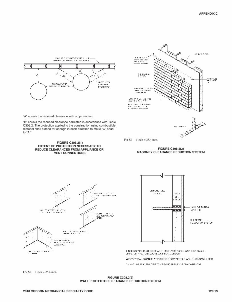
2010 OREGON MECHANICAL SPECIALTY CODE 129.19
APPENDIX C
For SI: 1 inch = 25.4 mm.
FIGURE C308.2(3)MASONRY CLEARANCE REDUCTION SYSTEM
“A” equals the reduced clearance with no protection.
“B” equals the reduced clearance permitted in accordance with TableC308.2. The protection applied to the construction using combustiblematerial shall extend far enough in each direction to make “C” equalto “A.”
FIGURE C308.2(1)EXTENT OF PROTECTION NECESSARY TO
REDUCE CLEARANCES FROM APPLIANCE ORVENT CONNECTIONS
For SI: 1 inch = 25.4 mm.
FIGURE C308.2(2)WALL PROTECTOR CLEARANCE REDUCTION SYSTEM
19M:\data\CODES\STATE CODES\Oregon\2010\Mechanical Specialty\Final VP\18_AppC_FuelGas_Oregon_Mech_2010.vpTuesday, January 05, 2010 10:40:05 AM
Color profile: Generic CMYK printer profileComposite Default screen

C308.4 Central-heating boilers and furnaces. Clearancerequirements for central-heating boilers and furnaces shall com-ply with Sections C308.4.1 through C308.4.6. The clearance tothese appliances shall not interfere with combustion air; drafthood clearance and relief; and accessibility for servicing.
C308.4.1 Appliances installed in rooms that are large incomparison with the size of the appliance. Central-heat-ing furnaces and low-pressure boilers installed in roomslarge in comparison with the size of the appliance shall beinstalled with clearances in accordance with the manufac-turer’s instructions.
C308.4.2 Appliances installed in rooms that are not largein comparison with the size of the appliance. Central- heat-ing furnaces and low-pressure boilers installed in rooms thatare not large in comparison with the size of the appliance,such as alcoves and closets, shall be listed for such installa-tions. Listed clearances shall not be reduced by the protectionmethods described in Table C308.2 and illustrated in FiguresC308.2(1) through C308.2(3), regardless of whether theenclosure is of combustible or noncombustible material.
C308.4.3 Clearance reduction. Central-heating furnacesand low-pressure boilers installed in rooms that are large incomparison with the size of the appliance shall be permittedto be installed with reduced clearances to combustible mate-rial provided the combustible material or appliance is pro-tected as described in Table C308.2.
C308.4.4 Clearance for servicing appliances. Front clear-ance shall be sufficient for servicing the burner and the fur-nace or boiler.
C308.4.5 Plenum clearances. Where the furnace plenum isadjacent to plaster on metal lath or noncombustible materialattached to combustible material, the clearance shall be mea-sured to the surface of the plaster or other noncombustible fin-ish where the clearance specified is 2 inches (51 mm) or less.
C308.4.6 Clearance from supply ducts. Central-heatingfurnaces shall have the clearance from supply ducts within3 feet (914 mm) of the furnace plenum be not less than thatspecified from the furnace plenum. No clearance is neces-sary beyond this distance.
SECTION C309ELECTRICAL
C309.1 Grounding. Gas piping shall not be used as a ground-ing electrode.
C309.2 Connections. Electrical connections between appli-ances and the building wiring, including the grounding of theappliances, shall conform to the Electrical Code.
SECTION C310ELECTRICAL BONDING
C310.1 Pipe and tubing. Each above- ground portion of a gaspiping system that is likely to become energized shall be electri-cally continuous and bonded to an effective ground-fault currentpath. Gas piping shall be considered to be bonded where it isconnected to appliances that are connected to the equipmentgrounding conductor of the circuit supplying that appliance.
SECTION C401GENERAL
C401.1 Scope. This section shall govern the installation andmodification of piping systems. The applicability of this codeto piping systems extends from the point of delivery to the con-nections with the appliances and includes the design, materials,components, fabrication, assembly, installation, testing andinspection of such piping systems.
C401.1.1 Utility piping systems located within buildings.Utility service piping located within buildings shall beinstalled in accordance with the structural safety and fireprotection provisions of the Building Code.
C401.2 Liquefied petroleum gas storage. The storage systemfor liquefied petroleum gas shall be designed and installed inaccordance with the Fire Code and NFPA 58.
C401.3 Modifications to existing systems. In modifying oradding to existing piping systems, sizes shall be maintained inaccordance with this chapter.
C401.4 Additional appliances. Where an additional appli-ance is to be served, the existing piping shall be checked todetermine if it has adequate capacity for all appliances served.If inadequate, the existing system shall be enlarged as requiredor separate piping of adequate capacity shall be provided.
C401.5 Identification. For other than steel pipe, exposed pip-ing shall be identified by a yellow label marked “Gas” in blackletters. The marking shall be spaced at intervals not exceeding5 feet (1524 mm). The marking shall not be required on pipelocated in the same room as the appliance served.
C401.6 Interconnections. Where two or more meters areinstalled on the same premises but supply separate consumers,the piping systems shall not be interconnected on the outlet sideof the meters.
C401.7 Piping meter identification. Piping from multiplemeter installations shall be marked with an approved perma-nent identification by the installer so that the piping systemsupplied by each meter is readily identifiable.
C401.8 Minimum sizes. All pipe utilized for the installation,extension and alteration of any piping system shall be sized tosupply the full number of outlets for the intended purpose andshall be sized in accordance with Section C402.
SECTION C402PIPE SIZING
C402.1 General considerations. Piping systems shall be ofsuch size and so installed as to provide a supply of gas suffi-cient to meet the maximum demand and supply gas to eachappliance inlet at not less than the minimum supply pressurerequired by the appliance.
129.20 2010 OREGON MECHANICAL SPECIALTY CODE
APPENDIX C
>
>>
Notice of installation. A “Notice of Installation” is required by theState Fire Marshal for all LP-gas tank installations. For installationrequirements of LP-gas tanks and tubing or piping up to the firststage regulator, see Article 82 of the Fire Code.
20M:\data\CODES\STATE CODES\Oregon\2010\Mechanical Specialty\Final VP\18_AppC_FuelGas_Oregon_Mech_2010.vpTuesday, January 05, 2010 10:40:05 AM
Color profile: Generic CMYK printer profileComposite Default screen

C402.2 Maximum gas demand. The volume of gas to be pro-vided, in cubic feet per hour, shall be determined directlyfrom the manufacturer’s input ratings of the appliancesserved. Where an input rating is not indicated, the gas sup-plier, appliance manufacturer or a qualified agency shall becontacted, or the rating from Table C402.2 shall be used forestimating the volume of gas to be supplied.
The total connected hourly load shall be used as the basis forpipe sizing, assuming that all appliances could be operating atfull capacity simultaneously. Where a diversity of load can beestablished, pipe sizing shall be permitted to be based on suchloads.
C402.3 Sizing. Gas piping shall be sized in accordance withone of the following:
1. Pipe sizing tables or sizing equations in accordance withSection C402.4.
2. The sizing tables included in a listed piping system’smanufacturer’s installation instructions.
3. Other approved methods.
C402.4 Sizing tables and equations. Where Tables C402.4(1)through C402.4(35) are used to size piping or tubing, the pipelength shall be determined in accordance with SectionC402.4.1, C402.4.2 or C402.4.3.
Where Equations 4-1 and 4-2 are used to size piping or tub-ing, the pipe or tubing shall have smooth inside walls and thepipe length shall be determined in accordance with SectionC402.4.1, C402.4.2 or C402.4.3.
1. Low-pressure gas equation [Less than 11/2 pounds persquare inch (psi) (10.3 kPa)]:
DQ
H
C Lr
=
×⎛⎝⎜
⎞⎠⎟
0 381
0 206
1917
.
.
.Δ
(Equation 4-1)
2. High-pressure gas equation [11/2 psi (10.3 kPa) andabove]:
( )D
Q
P P Y
C Lr
=− ×
×
⎡
⎣⎢⎢
⎤
⎦⎥⎥
0 381
12
22
0 206
1893
.
.
.
(Equation 4-2)
where:
D = Inside diameter of pipe, inches (mm).
Q = Input rate appliance(s), cubic feet per hour at 60°F(16°C) and 30-inch mercury column.
P1 = Upstream pressure, psia (P1 + 14.7).
P2 = Downstream pressure, psia (P2 + 14.7).
L = Equivalent length of pipe, feet.
ΔH = Pressure drop, inch water column(27.7 inch water column = 1 psi).
TABLE C402.2APPROXIMATE GAS INPUT FOR TYPICAL APPLIANCES
APPLIANCEINPUT BTU/H
(Approx.)
Space Heating Units
Hydronic boiler
Single family 100,000
Multifamily, per unit 60,000
Warm-air furnace
Single family 100,000
Multifamily, per unit 60,000
Space and Water Heating Units
Hydronic boiler
Single family 120,000
Multifamily, per unit 75,000
Water Heating Appliances
Water heater, automatic instantaneous
Capacity at 2 gal./minute 142,800
Capacity at 4 gal./minute 285,000
Capacity at 6 gal./minute 428,400
Water heater, automatic storage, 30- to 40-gal. tank 35,000
Water heater, automatic storage, 50-gal. tank 50,000
Water heater, domestic, circulating or side-arm 35,000
Cooking Appliances
Built-in oven or broiler unit, domestic 25,000
Built-in top unit, domestic 40,000
Range, free-standing, domestic 65,000
Other Appliances
Barbecue 40,000
Clothes dryer, Type 1 (domestic) 35,000
Gas fireplace, direct-vent 40,000
Gas light 2,500
Gas log 80,000
Refrigerator 3,000
For SI: 1 British thermal unit per hour = 0.293 W, 1 gallon = 3.785 L,1 gallon per minute = 3.785 L/m.
TABLE C402.4Cr AND Y VALUES FOR NATURAL GAS AND
UNDILUTED PROPANE AT STANDARD CONDITIONS
GAS
EQUATION FACTORS
Cr Y
Natural gas 0.6094 0.9992
Undiluted propane 1.2462 0.9910
For SI: 1 cubic foot = 0.028 m3, 1 foot = 305 mm, 1-inch water column =0.2488 kPa, 1 pound per square inch = 6.895 kPa, 1 British thermalunit per hour = 0.293 W.
C402.4.1 Longest length method. The pipe size of eachsection of gas piping shall be determined using the longestlength of piping from the point of delivery to the mostremote outlet and the load of the section.
C402.4.2 Branch length method. Pipe shall be sized as fol-lows:
1. Pipe size of each section of the longest pipe run fromthe point of delivery to the most remote outlet shall be
2010 OREGON MECHANICAL SPECIALTY CODE 129.21
APPENDIX C
>
21M:\data\CODES\STATE CODES\Oregon\2010\Mechanical Specialty\Final VP\18_AppC_FuelGas_Oregon_Mech_2010.vpTuesday, January 05, 2010 10:40:05 AM
Color profile: Generic CMYK printer profileComposite Default screen

determined using the longest run of piping and theload of the section.
2. The pipe size of each section of branch piping notpreviously sized shall be determined using thelength of piping from the point of delivery to themost remote outlet in each branch and the load of thesection.
C402.4.3 Hybrid pressure. The pipe size for each sectionof higher pressure gas piping shall be determined using thelongest length of piping from the point of delivery to themost remote line pressure regulator. The pipe size from theline pressure regulator to each outlet shall be determinedusing the length of piping from the regulator to the mostremote outlet served by the regulator.
C402.5 Allowable pressure drop. The design pressure loss inany piping system under maximum probable flow conditions,from the point of delivery to the inlet connection of the appli-ance, shall be such that the supply pressure at the appliance isgreater than or equal to the minimum pressure required by theappliance.
C402.6 Maximum design operating pressure. The maxi-mum design operating pressure for piping systems locatedinside buildings shall not exceed 5 pounds per square inchgauge (psig) (34 kPa gauge) except where one or more of thefollowing conditions are met:
1. The piping system is welded.
2. The piping is located in a ventilated chase or otherwiseenclosed for protection against accidental gas accumula-tion.
3. The piping is located inside buildings or separate areas ofbuildings used exclusively for:
3.1. Industrial processing or heating;
3.2. Research;
3.3. Warehousing; or
3.4. Boiler or mechanical rooms.
4. The piping is a temporary installation for buildings underconstruction.
5. The piping serves appliances or equipment used for agri-cultural purposes.
6. The piping system is an LP-gas piping system with adesign operating pressure greater than 20 psi (137.9 kPa)and complies with NFPA 58.
C402.6.1 Liquefied petroleum gas systems. LP-gas sys-tems designed to operate below -5°F (-21°C) or with butaneor a propane-butane mix shall be designed to either accom-modate liquid LP-gas or prevent LP-gas vapor from con-densing into a liquid.
SECTION C403PIPING MATERIALS
C403.1 General. Materials used for piping systems shall com-ply with the requirements of this chapter or shall be approved.
C403.2 Used materials. Pipe, fittings, valves and other materi-als shall not be used again except where they are free of foreignmaterials and have been ascertained to be adequate for the ser-vice intended.
C403.3 Metallic pipe. Metallic pipe shall comply with Sec-tions C403.3.1 through C403.3.4.
C403.3.1 Cast iron. Cast-iron pipe shall not be used.
C403.3.2 Steel. Steel and wrought-iron pipe shall be at leastof standard weight (Schedule 40) and shall comply with oneof the following standards:
1. ASME B 36.10, 10M;
2. ASTM A 53/A53M; or
3. ASTM A 106.
C403.3.3 Copper and brass. Copper and brass pipe shallnot be used if the gas contains more than an average of 0.3grains of hydrogen sulfide per 100 standard cubic feet of gas(0.7 milligrams per 100 liters). Threaded copper, brass andaluminum-alloy pipe shall not be used with gases corrosiveto such materials.
C403.3.4 Aluminum. Aluminum-alloy pipe shall complywith ASTM B 241 (except that the use of alloy 5456 is pro-hibited), and shall be marked at each end of each length indi-cating compliance. Aluminum-alloy pipe shall be coated toprotect against external corrosion where it is in contact withmasonry, plaster or insulation, or is subject to repeatedwettings by such liquids as water, detergents or sewage. Alu-minum-alloy pipe shall not be used in exterior locations orunderground.
C403.4 Metallic tubing. Seamless copper, aluminum alloyand steel tubing shall not be used with gases corrosive to suchmaterials.
C403.4.1 Steel tubing. Steel tubing shall comply withASTM A 254.
C403.4.2 Copper and brass tubing. Copper tubing shallcomply with Standard Type K or L of ASTM B 88 or ASTMB 280.
Copper and brass tubing shall not be used if the gas con-tains more than an average of 0.3 grains of hydrogen sulfideper 100 standard cubic feet of gas (0.7 milligrams per 100liters).
C403.4.3 Aluminum tubing. Aluminum-alloy tubing shallcomply with ASTM B 210 or ASTM B 241. Alumi-num-alloy tubing shall be coated to protect against externalcorrosion where it is in contact with masonry, plaster orinsulation, or is subject to repeated wettings by such liquidsas water, detergent or sewage.
Aluminum-alloy tubing shall not be used in exterior loca-tions or underground.
129.22 2010 OREGON MECHANICAL SPECIALTY CODE
APPENDIX C
➡License requirements. LP-gas installers must be licensed by theState Fire Marshal in accordance with ORS 480.432 through480.436.
>
22M:\data\CODES\STATE CODES\Oregon\2010\Mechanical Specialty\Final VP\18_AppC_FuelGas_Oregon_Mech_2010.vpTuesday, January 05, 2010 10:40:05 AM
Color profile: Generic CMYK printer profileComposite Default screen
C403.4.4 Corrugated stainless steel tubing. Corrugatedstainless steel tubing shall be listed in accordance withANSI LC 1/CSA 6.26.
C403.5 Plastic pipe, tubing and fittings. Plastic pipe, tubingand fittings used to supply fuel gas shall conform to ASTM D2513. Pipe shall be marked “Gas” and “ASTM D 2513.”
C403.5.1 Anodeless risers. Plastic pipe, tubing andanodeless risers shall comply with the following:
1. Factory-assembled anodeless risers shall be recom-mended by the manufacturer for the gas used andshall be leak tested by the manufacturer in accordancewith written procedures.
2. Service head adapters and field-assembled anodelessrisers incorporating service head adapters shall berecommended by the manufacturer for the gas used,and shall be designed and certified to meet therequirements of Category I of ASTM D 2513, andU.S. Department of Transportation, Code of FederalRegulations, Title 49, Part 192.281(e). The manufac-turer shall provide the user with qualified installationinstructions as prescribed by the U.S. Department ofTransportation, Code of Federal Regulations, Title49, Part 192.283(b).
C403.5.2 LP-gas systems. The use of plastic pipe, tubingand fittings in undiluted liquefied petroleum gas piping sys-tems shall be in accordance with NFPA 58.
C403.5.3 Regulator vent piping. Plastic pipe, tubing andfittings used to connect regulator vents to remote vent termi-nations shall be PVC conforming to ANSI/UL 651. PVCvent piping shall not be installed indoors.
C403.6 Workmanship and defects. Pipe, tubing and fittingsshall be clear and free from cutting burrs and defects in struc-ture or threading, and shall be thoroughly brushed, and chipand scale blown.
Defects in pipe, tubing and fittings shall not be repaired.Defective pipe, tubing and fittings shall be replaced (see Sec-tion C406.1.2).
C403.7 Protective coating. Where in contact with material oratmosphere exerting a corrosive action, metallic piping and fit-tings coated with a corrosion-resistant material shall be used.External or internal coatings or linings used on piping or com-ponents shall not be considered as adding strength.
C403.8 Metallic pipe threads. Metallic pipe and fitting threadsshall be taper pipe threads and shall comply with ASME B1.20.1.
C403.8.1 Damaged threads. Pipe with threads that arestripped, chipped, corroded or otherwise damaged shall notbe used. Where a weld opens during the operation of cuttingor threading, that portion of the pipe shall not be used.
C403.8.2 Number of threads. Field threading of metallicpipe shall be in accordance with Table C403.8.2.
C403.8.3 Thread compounds. Thread (joint) compounds(pipe dope) shall be resistant to the action of liquefied petro-leum gas or to any other chemical constituents of the gasesto be conducted through the piping.
TABLE C403.8.2SPECIFICATIONS FOR THREADING METALLIC PIPE
IRON PIPE SIZE(inches)
APPROXIMATE LENGTH OFTHREADED PORTION (inches)
APPROXIMATE NUMBEROF THREADS TO BE CUT
1/23/4 10
3/43/4 10
1 7/8 10
11/4 1 11
11/2 1 11
2 1 11
21/2 11/2 12
3 11/2 12
4 15/8 13
For SI: 1 inch = 25.4 mm.
2010 OREGON MECHANICAL SPECIALTY CODE 129.23
APPENDIX C
23M:\data\CODES\STATE CODES\Oregon\2010\Mechanical Specialty\Final VP\18_AppC_FuelGas_Oregon_Mech_2010.vpTuesday, January 05, 2010 10:40:05 AM
Color profile: Generic CMYK printer profileComposite Default screen

129.24 2010 OREGON MECHANICAL SPECIALTY CODE
APPENDIX C
TABLE C402.4(1)SCHEDULE 40 METALLIC PIPE
Gas Natural
Inlet Pressure Less than 2 psi
Pressure Drop 0.3 in. w.c.
Specific Gravity 0.60
PIPE SIZE (inch)
Nominal 1/23/4 1 11/4 11/2 2 21/2 3 4 5 6 8 10 12
Actual ID 0.622 0.824 1.049 1.380 1.610 2.067 2.469 3.068 4.026 5.047 6.065 7.981 10.020 11.938
Length (ft) Capacity in Cubic Feet of Gas Per Hour
10 131 273 514 1,060 1,580 3,050 4,860 8,580 17,500 31,700 51,300 105,000 191,000 303,000
20 90 188 353 726 1,090 2,090 3,340 5,900 12,000 21,800 35,300 72,400 132,000 208,000
30 72 151 284 583 873 1,680 2,680 4,740 9,660 17,500 28,300 58,200 106,000 167,000
40 62 129 243 499 747 1,440 2,290 4,050 8,270 15,000 24,200 49,800 90,400 143,000
50 55 114 215 442 662 1,280 2,030 3,590 7,330 13,300 21,500 44,100 80,100 127,000
60 50 104 195 400 600 1,160 1,840 3,260 6,640 12,000 19,500 40,000 72,600 115,000
70 46 95 179 368 552 1,060 1,690 3,000 6,110 11,100 17,900 36,800 66,800 106,000
80 42 89 167 343 514 989 1,580 2,790 5,680 10,300 16,700 34,200 62,100 98,400
90 40 83 157 322 482 928 1,480 2,610 5,330 9,650 15,600 32,100 58,300 92,300
100 38 79 148 304 455 877 1,400 2,470 5,040 9,110 14,800 30,300 55,100 87,200
125 33 70 131 269 403 777 1,240 2,190 4,460 8,080 13,100 26,900 48,800 77,300
150 30 63 119 244 366 704 1,120 1,980 4,050 7,320 11,900 24,300 44,200 70,000
175 28 58 109 224 336 648 1,030 1,820 3,720 6,730 10,900 22,400 40,700 64,400
200 26 54 102 209 313 602 960 1,700 3,460 6,260 10,100 20,800 37,900 59,900
250 23 48 90 185 277 534 851 1,500 3,070 5,550 8,990 18,500 33,500 53,100
300 21 43 82 168 251 484 771 1,360 2,780 5,030 8,150 16,700 30,400 48,100
350 19 40 75 154 231 445 709 1,250 2,560 4,630 7,490 15,400 28,000 44,300
400 18 37 70 143 215 414 660 1,170 2,380 4,310 6,970 14,300 26,000 41,200
450 17 35 66 135 202 389 619 1,090 2,230 4,040 6,540 13,400 24,400 38,600
500 16 33 62 127 191 367 585 1,030 2,110 3,820 6,180 12,700 23,100 36,500
550 15 31 59 121 181 349 556 982 2,000 3,620 5,870 12,100 21,900 34,700
600 14 30 56 115 173 333 530 937 1,910 3,460 5,600 11,500 20,900 33,100
650 14 29 54 110 165 318 508 897 1,830 3,310 5,360 11,000 20,000 31,700
700 13 27 52 106 159 306 488 862 1,760 3,180 5,150 10,600 19,200 30,400
750 13 26 50 102 153 295 470 830 1,690 3,060 4,960 10,200 18,500 29,300
800 12 26 48 99 148 285 454 802 1,640 2,960 4,790 9,840 17,900 28,300
850 12 25 46 95 143 275 439 776 1,580 2,860 4,640 9,530 17,300 27,400
900 11 24 45 93 139 267 426 752 1,530 2,780 4,500 9,240 16,800 26,600
950 11 23 44 90 135 259 413 731 1,490 2,700 4,370 8,970 16,300 25,800
1,000 11 23 43 87 131 252 402 711 1,450 2,620 4,250 8,720 15,800 25,100
1,100 10 21 40 83 124 240 382 675 1,380 2,490 4,030 8,290 15,100 23,800
1,200 NA 20 39 79 119 229 364 644 1,310 2,380 3,850 7,910 14,400 22,700
1,300 NA 20 37 76 114 219 349 617 1,260 2,280 3,680 7,570 13,700 21,800
1,400 NA 19 35 73 109 210 335 592 1,210 2,190 3,540 7,270 13,200 20,900
1,500 NA 18 34 70 105 203 323 571 1,160 2,110 3,410 7,010 12,700 20,100
1,600 NA 18 33 68 102 196 312 551 1,120 2,030 3,290 6,770 12,300 19,500
1,700 NA 17 32 66 98 189 302 533 1,090 1,970 3,190 6,550 11,900 18,800
1,800 NA 16 31 64 95 184 293 517 1,050 1,910 3,090 6,350 11,500 18,300
1,900 NA 16 30 62 93 178 284 502 1,020 1,850 3,000 6,170 11,200 17,700
2,000 NA 16 29 60 90 173 276 488 1,000 1,800 2,920 6,000 10,900 17,200
For SI: 1 inch = 25.4 mm, 1 foot = 304.8 mm, 1 pound per square inch = 6.895kPa, 1-inch water column = 0.2488 kPa,1 British thermal unit per hour = 0.2931 W, 1 cubic foot per hour = 0.0283 m3/h, 1 degree = 0.01745 rad.
Notes:1. NA means a flow of less than 10 cfh.2. All table entries have been rounded to three significant digits.
24M:\data\CODES\STATE CODES\Oregon\2010\Mechanical Specialty\Final VP\18_AppC_FuelGas_Oregon_Mech_2010.vpTuesday, January 05, 2010 10:40:06 AM
Color profile: Generic CMYK printer profileComposite Default screen
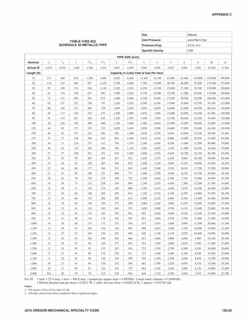
2010 OREGON MECHANICAL SPECIALTY CODE 129.25
APPENDIX C
TABLE C402.4(2)SCHEDULE 40 METALLIC PIPE
Gas Natural
Inlet Pressure Less than 2 psi
Pressure Drop 0.5 in. w.c.
Specific Gravity 0.60
PIPE SIZE (inch)
Nominal 1/23/4 1 11/4 11/2 2 21/2 3 4 5 6 8 10 12
Actual ID 0.622 0.824 1.049 1.380 1.610 2.067 2.469 3.068 4.026 5.047 6.065 7.981 10.020 11.938
Length (ft) Capacity in Cubic Feet of Gas Per Hour
10 172 360 678 1,390 2,090 4,020 6,400 11,300 23,100 41,800 67,600 139,000 252,000 399,000
20 118 247 466 957 1,430 2,760 4,400 7,780 15,900 28,700 46,500 95,500 173,000 275,000
30 95 199 374 768 1,150 2,220 3,530 6,250 12,700 23,000 37,300 76,700 139,000 220,000
40 81 170 320 657 985 1,900 3,020 5,350 10,900 19,700 31,900 65,600 119,000 189,000
50 72 151 284 583 873 1,680 2,680 4,740 9,660 17,500 28,300 58,200 106,000 167,000
60 65 137 257 528 791 1,520 2,430 4,290 8,760 15,800 25,600 52,700 95,700 152,000
70 60 126 237 486 728 1,400 2,230 3,950 8,050 14,600 23,600 48,500 88,100 139,000
80 56 117 220 452 677 1,300 2,080 3,670 7,490 13,600 22,000 45,100 81,900 130,000
90 52 110 207 424 635 1,220 1,950 3,450 7,030 12,700 20,600 42,300 76,900 122,000
100 50 104 195 400 600 1,160 1,840 3,260 6,640 12,000 19,500 40,000 72,600 115,000
125 44 92 173 355 532 1,020 1,630 2,890 5,890 10,600 17,200 35,400 64,300 102,000
150 40 83 157 322 482 928 1,480 2,610 5,330 9,650 15,600 32,100 58,300 92,300
175 37 77 144 296 443 854 1,360 2,410 4,910 8,880 14,400 29,500 53,600 84,900
200 34 71 134 275 412 794 1,270 2,240 4,560 8,260 13,400 27,500 49,900 79,000
250 30 63 119 244 366 704 1,120 1,980 4,050 7,320 11,900 24,300 44,200 70,000
300 27 57 108 221 331 638 1,020 1,800 3,670 6,630 10,700 22,100 40,100 63,400
350 25 53 99 203 305 587 935 1,650 3,370 6,100 9,880 20,300 36,900 58,400
400 23 49 92 189 283 546 870 1,540 3,140 5,680 9,190 18,900 34,300 54,300
450 22 46 86 177 266 512 816 1,440 2,940 5,330 8,620 17,700 32,200 50,900
500 21 43 82 168 251 484 771 1,360 2,780 5,030 8,150 16,700 30,400 48,100
550 20 41 78 159 239 459 732 1,290 2,640 4,780 7,740 15,900 28,900 45,700
600 19 39 74 152 228 438 699 1,240 2,520 4,560 7,380 15,200 27,500 43,600
650 18 38 71 145 218 420 669 1,180 2,410 4,360 7,070 14,500 26,400 41,800
700 17 36 68 140 209 403 643 1,140 2,320 4,190 6,790 14,000 25,300 40,100
750 17 35 66 135 202 389 619 1,090 2,230 4,040 6,540 13,400 24,400 38,600
800 16 34 63 130 195 375 598 1,060 2,160 3,900 6,320 13,000 23,600 37,300
850 16 33 61 126 189 363 579 1,020 2,090 3,780 6,110 12,600 22,800 36,100
900 15 32 59 122 183 352 561 992 2,020 3,660 5,930 12,200 22,100 35,000
950 15 31 58 118 178 342 545 963 1,960 3,550 5,760 11,800 21,500 34,000
1,000 14 30 56 115 173 333 530 937 1,910 3,460 5,600 11,500 20,900 33,100
1,100 14 28 53 109 164 316 503 890 1,810 3,280 5,320 10,900 19,800 31,400
1,200 13 27 51 104 156 301 480 849 1,730 3,130 5,070 10,400 18,900 30,000
1,300 12 26 49 100 150 289 460 813 1,660 3,000 4,860 9,980 18,100 28,700
1,400 12 25 47 96 144 277 442 781 1,590 2,880 4,670 9,590 17,400 27,600
1,500 11 24 45 93 139 267 426 752 1,530 2,780 4,500 9,240 16,800 26,600
1,600 11 23 44 89 134 258 411 727 1,480 2,680 4,340 8,920 16,200 25,600
1,700 11 22 42 86 130 250 398 703 1,430 2,590 4,200 8,630 15,700 24,800
1,800 10 22 41 84 126 242 386 682 1,390 2,520 4,070 8,370 15,200 24,100
1,900 10 21 40 81 122 235 375 662 1,350 2,440 3,960 8,130 14,800 23,400
2,000 NA 20 39 79 119 229 364 644 1,310 2,380 3,850 7,910 14,400 22,700
For SI: 1 inch = 25.4 mm, 1 foot = 304.8 mm, 1 pound per square inch = 6.895kPa, 1-inch water column = 0.2488 kPa,1 British thermal unit per hour = 0.2931 W, 1 cubic foot per hour = 0.0283 m3/h, 1 degree = 0.01745 rad.
Notes:1. NA means a flow of less than 10 cfh.2. All table entries have been rounded to three significant digits.
25M:\data\CODES\STATE CODES\Oregon\2010\Mechanical Specialty\Final VP\18_AppC_FuelGas_Oregon_Mech_2010.vpTuesday, January 05, 2010 10:40:06 AM
Color profile: Generic CMYK printer profileComposite Default screen

129.26 2010 OREGON MECHANICAL SPECIALTY CODE
APPENDIX C
TABLE C402.4(3)SCHEDULE 40 METALLIC PIPE
Gas Natural
Inlet Pressure 2.0 psi
Pressure Drop 1.0 psi
Specific Gravity 0.60
PIPE SIZE (inch)
Nominal 1/23/4 1 11/4 11/2 2 21/2 3 4
Actual ID 0.622 0.824 1.049 1.380 1.610 2.067 2.469 3.068 4.026
Length (ft) Capacity in Cubic Feet of Gas Per Hour
10 1,510 3,040 5,560 11,400 17,100 32,900 52,500 92,800 189,000
20 1,070 2,150 3,930 8,070 12,100 23,300 37,100 65,600 134,000
30 869 1,760 3,210 6,590 9,880 19,000 30,300 53,600 109,000
40 753 1,520 2,780 5,710 8,550 16,500 26,300 46,400 94,700
50 673 1,360 2,490 5,110 7,650 14,700 23,500 41,500 84,700
60 615 1,240 2,270 4,660 6,980 13,500 21,400 37,900 77,300
70 569 1,150 2,100 4,320 6,470 12,500 19,900 35,100 71,600
80 532 1,080 1,970 4,040 6,050 11,700 18,600 32,800 67,000
90 502 1,010 1,850 3,810 5,700 11,000 17,500 30,900 63,100
100 462 934 1,710 3,510 5,260 10,100 16,100 28,500 58,200
125 414 836 1,530 3,140 4,700 9,060 14,400 25,500 52,100
150 372 751 1,370 2,820 4,220 8,130 13,000 22,900 46,700
175 344 695 1,270 2,601 3,910 7,530 12,000 21,200 43,300
200 318 642 1,170 2,410 3,610 6,960 11,100 19,600 40,000
250 279 583 1,040 2,140 3,210 6,180 9,850 17,400 35,500
300 253 528 945 1,940 2,910 5,600 8,920 15,800 32,200
350 232 486 869 1,790 2,670 5,150 8,210 14,500 29,600
400 216 452 809 1,660 2,490 4,790 7,640 13,500 27,500
450 203 424 759 1,560 2,330 4,500 7,170 12,700 25,800
500 192 401 717 1,470 2,210 4,250 6,770 12,000 24,400
550 182 381 681 1,400 2,090 4,030 6,430 11,400 23,200
600 174 363 650 1,330 2,000 3,850 6,130 10,800 22,100
650 166 348 622 1,280 1,910 3,680 5,870 10,400 21,200
700 160 334 598 1,230 1,840 3,540 5,640 9,970 20,300
750 154 322 576 1,180 1,770 3,410 5,440 9,610 19,600
800 149 311 556 1,140 1,710 3,290 5,250 9,280 18,900
850 144 301 538 1,100 1,650 3,190 5,080 8,980 18,300
900 139 292 522 1,070 1,600 3,090 4,930 8,710 17,800
950 135 283 507 1,040 1,560 3,000 4,780 8,460 17,200
1,000 132 275 493 1,010 1,520 2,920 4,650 8,220 16,800
1,100 125 262 468 960 1,440 2,770 4,420 7,810 15,900
1,200 119 250 446 917 1,370 2,640 4,220 7,450 15,200
1,300 114 239 427 878 1,320 2,530 4,040 7,140 14,600
1,400 110 230 411 843 1,260 2,430 3,880 6,860 14,000
1,500 106 221 396 812 1,220 2,340 3,740 6,600 13,500
1,600 102 214 382 784 1,180 2,260 3,610 6,380 13,000
1,700 99 207 370 759 1,140 2,190 3,490 6,170 12,600
1,800 96 200 358 736 1,100 2,120 3,390 5,980 12,200
1,900 93 195 348 715 1,070 2,060 3,290 5,810 11,900
2,000 91 189 339 695 1,040 2,010 3,200 5,650 11,500
For SI: 1 inch = 25.4 mm, 1 foot = 304.8 mm, 1 pound per square inch = 6.895kPa, 1-inch water column = 0.2488 kPa,1 British thermal unit per hour = 0.2931 W, 1 cubic foot per hour = 0.0283 m3/h, 1 degree = 0.01745 rad.
Note: All table entries have been rounded to three significant digits.
26M:\data\CODES\STATE CODES\Oregon\2010\Mechanical Specialty\Final VP\18_AppC_FuelGas_Oregon_Mech_2010.vpTuesday, January 05, 2010 10:40:06 AM
Color profile: Generic CMYK printer profileComposite Default screen

2010 OREGON MECHANICAL SPECIALTY CODE 129.27
APPENDIX C
TABLE C402.4(3a)SCHEDULE 40 METALLIC PIPE
Gas Natural
Inlet Pressure 2.0 psi
Pressure Drop 0.2 psi (10%)
Specific Gravity 0.60
PIPE SIZE (inch)
Nominal 1 11/4 11/2 2 21/2 3 31/2 4 5 6
Actual ID 1.049 1.380 1.610 2.067 2.469 3.068 3.548 4.026 5.047 6.065
Length (ft)
50 1,112 2,283 3,421 6,589 10,501 18,564 27,181 37,865 68,504 110,924
100 764 1,569 2,351 4,528 7,217 12,759 18,681 26,025 47,082 76,237
150 614 1,260 1,888 3,636 5,796 10,246 15,002 20,899 37,809 61,221
200 525 1,079 1,616 3,112 4,961 8,769 12,840 17,887 32,359 52,397
250 466 956 1,432 2,758 4,396 7,772 11,379 15,853 28,680 46,439
300 422 866 1,298 2,499 3,983 7,042 10,311 14,364 25,986 42,077
400 361 741 1,111 2,139 3,409 6,027 8,825 12,293 22,240 36,012
500 320 657 984 1,896 3,022 5,342 7,821 10,895 19,711 31,917
1000 220 452 677 1,303 2,077 3,671 5,375 7,488 13,547 21,936
1500 177 363 543 1,046 1,668 2,948 4,317 6,013 10,879 17,616
2000 151 310 465 896 1,427 2,523 3,694 5,147 9,311 15,077
For SI: 1 inch = 25.4 mm, 1 foot = 304.8 mm, 1 pound per square inch = 6.895kPa, 1-inch water column = 0.2488 kPa,1 British thermal unit per hour = 0.2931 W, 1 cubic foot per hour = 0.0283 m3/h, 1 degree = 0.01745 rad.
Note: All table entries have been rounded to three significant digits.
27M:\data\CODES\STATE CODES\Oregon\2010\Mechanical Specialty\Final VP\18_AppC_FuelGas_Oregon_Mech_2010.vpTuesday, January 05, 2010 10:40:06 AM
Color profile: Generic CMYK printer profileComposite Default screen

129.28 2010 OREGON MECHANICAL SPECIALTY CODE
APPENDIX C
TABLE C402.4(4)SCHEDULE 40 METALLIC PIPE
Gas Natural
Inlet Pressure 3.0 psi
Pressure Drop 2.0 psi
Specific Gravity 0.60
PIPE SIZE (inch)
Nominal 1/23/4 1 11/4 11/2 2 21/2 3 4
Actual ID 0.622 0.824 1.049 1.380 1.610 2.067 2.469 3.068 4.026
Length (ft) Capacity in Cubic Feet of Gas Per Hour
10 2,350 4,920 9,270 19,000 28,500 54,900 87,500 155,000 316,000
20 1,620 3,380 6,370 13,100 19,600 37,700 60,100 106,000 217,000
30 1,300 2,720 5,110 10,500 15,700 30,300 48,300 85,400 174,000
40 1,110 2,320 4,380 8,990 13,500 25,900 41,300 73,100 149,000
50 985 2,060 3,880 7,970 11,900 23,000 36,600 64,800 132,000
60 892 1,870 3,520 7,220 10,800 20,800 33,200 58,700 120,000
70 821 1,720 3,230 6,640 9,950 19,200 30,500 54,000 110,000
80 764 1,600 3,010 6,180 9,260 17,800 28,400 50,200 102,000
90 717 1,500 2,820 5,800 8,680 16,700 26,700 47,100 96,100
100 677 1,420 2,670 5,470 8,200 15,800 25,200 44,500 90,800
125 600 1,250 2,360 4,850 7,270 14,000 22,300 39,500 80,500
150 544 1,140 2,140 4,400 6,590 12,700 20,200 35,700 72,900
175 500 1,050 1,970 4,040 6,060 11,700 18,600 32,900 67,100
200 465 973 1,830 3,760 5,640 10,900 17,300 30,600 62,400
250 412 862 1,620 3,330 5,000 9,620 15,300 27,100 55,300
300 374 781 1,470 3,020 4,530 8,720 13,900 24,600 50,100
350 344 719 1,350 2,780 4,170 8,020 12,800 22,600 46,100
400 320 669 1,260 2,590 3,870 7,460 11,900 21,000 42,900
450 300 627 1,180 2,430 3,640 7,000 11,200 19,700 40,200
500 283 593 1,120 2,290 3,430 6,610 10,500 18,600 38,000
550 269 563 1,060 2,180 3,260 6,280 10,000 17,700 36,100
600 257 537 1,010 2,080 3,110 5,990 9,550 16,900 34,400
650 246 514 969 1,990 2,980 5,740 9,150 16,200 33,000
700 236 494 931 1,910 2,860 5,510 8,790 15,500 31,700
750 228 476 897 1,840 2,760 5,310 8,470 15,000 30,500
800 220 460 866 1,780 2,660 5,130 8,180 14,500 29,500
850 213 445 838 1,720 2,580 4,960 7,910 14,000 28,500
900 206 431 812 1,670 2,500 4,810 7,670 13,600 27,700
950 200 419 789 1,620 2,430 4,670 7,450 13,200 26,900
1,000 195 407 767 1,580 2,360 4,550 7,240 12,800 26,100
1,100 185 387 729 1,500 2,240 4,320 6,890 12,200 24,800
1,200 177 369 695 1,430 2,140 4,120 6,570 11,600 23,700
1,300 169 353 666 1,370 2,050 3,940 6,290 11,100 22,700
1,400 162 340 640 1,310 1,970 3,790 6,040 10,700 21,800
1,500 156 327 616 1,270 1,900 3,650 5,820 10,300 21,000
1,600 151 316 595 1,220 1,830 3,530 5,620 10,000 20,300
1,700 146 306 576 1,180 1,770 3,410 5,440 9,610 19,600
1,800 142 296 558 1,150 1,720 3,310 5,270 9,320 19,000
1,900 138 288 542 1,110 1,670 3,210 5,120 9,050 18,400
2,000 134 280 527 1,080 1,620 3,120 4,980 8,800 18,000
For SI: 1 inch = 25.4 mm, 1 foot = 304.8 mm, 1 pound per square inch = 6.895kPa, 1-inch water column = 0.2488 kPa,1 British thermal unit per hour = 0.2931 W, 1 cubic foot per hour = 0.0283 m3/h, 1 degree = 0.01745 rad.
Note: All table entries have been rounded to three significant digits.
28M:\data\CODES\STATE CODES\Oregon\2010\Mechanical Specialty\Final VP\18_AppC_FuelGas_Oregon_Mech_2010.vpTuesday, January 05, 2010 10:40:06 AM
Color profile: Generic CMYK printer profileComposite Default screen

2010 OREGON MECHANICAL SPECIALTY CODE 129.29
APPENDIX C
TABLE C402.4(5)SCHEDULE 40 METALLIC PIPE
Gas Natural
Inlet Pressure 5.0 psi
Pressure Drop 3.5 psi
Specific Gravity 0.60
PIPE SIZE (inch)
Nominal 1/23/4 1 11/4 11/2 2 21/2 3 4
Actual ID 0.622 0.824 1.049 1.380 1.610 2.067 2.469 3.068 4.026
Length (ft) Capacity in Cubic Feet of Gas Per Hour
10 3,190 6,430 11,800 24,200 36,200 69,700 111,000 196,000 401,000
20 2,250 4,550 8,320 17,100 25,600 49,300 78,600 139,000 283,000
30 1,840 3,720 6,790 14,000 20,900 40,300 64,200 113,000 231,000
40 1,590 3,220 5,880 12,100 18,100 34,900 55,600 98,200 200,000
50 1,430 2,880 5,260 10,800 16,200 31,200 49,700 87,900 179,000
60 1,300 2,630 4,800 9,860 14,800 28,500 45,400 80,200 164,000
70 1,200 2,430 4,450 9,130 13,700 26,400 42,000 74,300 151,000
80 1,150 2,330 4,260 8,540 12,800 24,700 39,300 69,500 142,000
90 1,060 2,150 3,920 8,050 12,100 23,200 37,000 65,500 134,000
100 979 1,980 3,620 7,430 11,100 21,400 34,200 60,400 123,000
125 876 1,770 3,240 6,640 9,950 19,200 30,600 54,000 110,000
150 786 1,590 2,910 5,960 8,940 17,200 27,400 48,500 98,900
175 728 1,470 2,690 5,520 8,270 15,900 25,400 44,900 91,600
200 673 1,360 2,490 5,100 7,650 14,700 23,500 41,500 84,700
250 558 1,170 2,200 4,510 6,760 13,000 20,800 36,700 74,900
300 506 1,060 1,990 4,090 6,130 11,800 18,800 33,300 67,800
350 465 973 1,830 3,760 5,640 10,900 17,300 30,600 62,400
400 433 905 1,710 3,500 5,250 10,100 16,100 28,500 58,100
450 406 849 1,600 3,290 4,920 9,480 15,100 26,700 54,500
500 384 802 1,510 3,100 4,650 8,950 14,300 25,200 51,500
550 364 762 1,440 2,950 4,420 8,500 13,600 24,000 48,900
600 348 727 1,370 2,810 4,210 8,110 12,900 22,900 46,600
650 333 696 1,310 2,690 4,030 7,770 12,400 21,900 44,600
700 320 669 1,260 2,590 3,880 7,460 11,900 21,000 42,900
750 308 644 1,210 2,490 3,730 7,190 11,500 20,300 41,300
800 298 622 1,170 2,410 3,610 6,940 11,100 19,600 39,900
850 288 602 1,130 2,330 3,490 6,720 10,700 18,900 38,600
900 279 584 1,100 2,260 3,380 6,520 10,400 18,400 37,400
950 271 567 1,070 2,190 3,290 6,330 10,100 17,800 36,400
1,000 264 551 1,040 2,130 3,200 6,150 9,810 17,300 35,400
1,100 250 524 987 2,030 3,030 5,840 9,320 16,500 33,600
1,200 239 500 941 1,930 2,900 5,580 8,890 15,700 32,000
1,300 229 478 901 1,850 2,770 5,340 8,510 15,000 30,700
1,400 220 460 866 1,780 2,660 5,130 8,180 14,500 29,500
1,500 212 443 834 1,710 2,570 4,940 7,880 13,900 28,400
1,600 205 428 806 1,650 2,480 4,770 7,610 13,400 27,400
1,700 198 414 780 1,600 2,400 4,620 7,360 13,000 26,500
1,800 192 401 756 1,550 2,330 4,480 7,140 12,600 25,700
1,900 186 390 734 1,510 2,260 4,350 6,930 12,300 25,000
2,000 181 379 714 1,470 2,200 4,230 6,740 11,900 24,300
For SI: 1 inch = 25.4 mm, 1 foot = 304.8 mm, 1 pound per square inch = 6.895kPa, 1-inch water column = 0.2488 kPa,1 British thermal unit per hour = 0.2931 W, 1 cubic foot per hour = 0.0283 m3/h, 1 degree = 0.01745 rad.
Note: All table entries have been rounded to three significant digits.
29M:\data\CODES\STATE CODES\Oregon\2010\Mechanical Specialty\Final VP\18_AppC_FuelGas_Oregon_Mech_2010.vpTuesday, January 05, 2010 10:40:07 AM
Color profile: Generic CMYK printer profileComposite Default screen

129.30 2010 OREGON MECHANICAL SPECIALTY CODE
APPENDIX C
TABLE C402.4(5a)SCHEDULE 40 METALLIC PIPE
Gas Natural
Inlet Pressure 5.0 psi
Pressure Drop 0.5 psi
Specific Gravity 0.60
PIPE SIZE (inch)
FlowDesignation 1 11/4 11/2 2 21/2 3 31/2 4 5 6
Actual ID 1.049 1.380 1.610 2.067 2.469 3.068 3.548 4.026 5.047 6.065
Length (ft) Capacity in Cubic Feet of Gas Per Hour
50 1,989 4,084 6,120 11,786 18,785 33,209 48,623 67,736 122,544 198,427
100 1,367 2,807 4,206 8,101 12,911 22,824 33,418 46,555 84,224 136,378
150 1,098 2,254 3,378 6,505 10,368 18,329 26,836 37,385 67,635 109,516
200 940 1,929 2,891 5,567 8,874 15,687 22,968 31,997 57,887 93,732
250 833 1,710 2,562 4,934 7,865 13,903 20,356 28,358 51,304 83,073
300 755 1,549 2,321 4,471 7,126 12,597 18,444 25,694 46,485 75,270
400 646 1,326 1,987 3,827 6,099 10,782 15,786 21,991 39,785 64,421
500 572 1,175 1,761 3,391 5,405 9,556 13,991 19,490 35,261 57,095
1000 393 808 1,210 2,331 3,715 6,568 9,616 13,396 24,235 39,241
1500 316 649 972 1,872 2,983 5,274 7,722 10,757 19,461 31,512
2000 270 555 832 1,602 2,553 4,514 6,609 9,207 16,656 26,970
For SI: 1 inch = 25.4 mm, 1 foot = 304.8 mm, 1 pound per square inch = 6.895kPa, 1-inch water column = 0.2488 kPa,1 British thermal unit per hour = 0.2931 W, 1 cubic foot per hour = 0.0283 m3/h, 1 degree = 0.01745 rad.
30M:\data\CODES\STATE CODES\Oregon\2010\Mechanical Specialty\Final VP\18_AppC_FuelGas_Oregon_Mech_2010.vpTuesday, January 05, 2010 10:40:07 AM
Color profile: Generic CMYK printer profileComposite Default screen

2010 OREGON MECHANICAL SPECIALTY CODE 129.31
APPENDIX C
TABLE C402.4(6)SEMIRIGID COPPER TUBING
Gas Natural
Inlet Pressure Less than 2 psi
Pressure Drop 0.3 in. w.c.
Specific Gravity 0.60
TUBE SIZE (inch)
NominalK & L 1/4
3/81/2
5/83/4 1 11/4 11/2 2
ACR 3/81/2
5/83/4
7/8 11/8 13/8 — —
Outside 0.375 0.500 0.625 0.750 0.875 1.125 1.375 1.625 2.125
Inside 0.305 0.402 0.527 0.652 0.745 0.995 1.245 1.481 1.959
Length (ft) Capacity in Cubic Feet of Gas Per Hour
10 20 42 85 148 210 448 806 1,270 2,650
20 14 29 58 102 144 308 554 873 1,820
30 11 23 47 82 116 247 445 701 1,460
40 10 20 40 70 99 211 381 600 1,250
50 NA 17 35 62 88 187 337 532 1,110
60 NA 16 32 56 79 170 306 482 1,000
70 NA 14 29 52 73 156 281 443 924
80 NA 13 27 48 68 145 262 413 859
90 NA 13 26 45 64 136 245 387 806
100 NA 12 24 43 60 129 232 366 761
125 NA 11 22 38 53 114 206 324 675
150 NA 10 20 34 48 103 186 294 612
175 NA NA 18 31 45 95 171 270 563
200 NA NA 17 29 41 89 159 251 523
250 NA NA 15 26 37 78 141 223 464
300 NA NA 13 23 33 71 128 202 420
350 NA NA 12 22 31 65 118 186 387
400 NA NA 11 20 28 61 110 173 360
450 NA NA 11 19 27 57 103 162 338
500 NA NA 10 18 25 54 97 153 319
550 NA NA NA 17 24 51 92 145 303
600 NA NA NA 16 23 49 88 139 289
650 NA NA NA 15 22 47 84 133 277
700 NA NA NA 15 21 45 81 128 266
750 NA NA NA 14 20 43 78 123 256
800 NA NA NA 14 20 42 75 119 247
850 NA NA NA 13 19 40 73 115 239
900 NA NA NA 13 18 39 71 111 232
950 NA NA NA 13 18 38 69 108 225
1,000 NA NA NA 12 17 37 67 105 219
1,100 NA NA NA 12 16 35 63 100 208
1,200 NA NA NA 11 16 34 60 95 199
1,300 NA NA NA 11 15 32 58 91 190
1,400 NA NA NA 10 14 31 56 88 183
1,500 NA NA NA NA 14 30 54 84 176
1,600 NA NA NA NA 13 29 52 82 170
1,700 NA NA NA NA 13 28 50 79 164
1,800 NA NA NA NA 13 27 49 77 159
1,900 NA NA NA NA 12 26 47 74 155
2,000 NA NA NA NA 12 25 46 72 151
For SI: 1 inch = 25.4 mm, 1 foot = 304.8 mm, 1 pound per square inch = 6.895kPa, 1-inch water column = 0.2488 kPa,1 British thermal unit per hour = 0.2931 W, 1 cubic foot per hour = 0.0283 m3/h, 1 degree = 0.01745 rad.
Notes:1. Table capacities are based on Type K copper tubing inside diameter (shown), which has the smallest inside diameter of the copper tubing products.2. NA means a flow of less than 10 cfh.3. All table entries have been rounded to three significant digits.
31M:\data\CODES\STATE CODES\Oregon\2010\Mechanical Specialty\Final VP\18_AppC_FuelGas_Oregon_Mech_2010.vpTuesday, January 05, 2010 10:40:07 AM
Color profile: Generic CMYK printer profileComposite Default screen

129.32 2010 OREGON MECHANICAL SPECIALTY CODE
APPENDIX C
TABLE C402.4(7)SEMIRIGID COPPER TUBING
Gas Natural
Inlet Pressure Less than 2 psi
Pressure Drop 0.5 in. w.c.
Specific Gravity 0.60
TUBE SIZE (inch)
NominalK & L 1/4
3/81/2
5/83/4 1 11/4 11/2 2
ACR 3/81/2
5/83/4
7/8 11/8 13/8 — —
Outside 0.375 0.500 0.625 0.750 0.875 1.125 1.375 1.625 2.125
Inside 0.305 0.402 0.527 0.652 0.745 0.995 1.245 1.481 1.959
Length (ft) Capacity in Cubic Feet of Gas Per Hour
10 27 55 111 195 276 590 1,060 1,680 3,490
20 18 38 77 134 190 406 730 1,150 2,400
30 15 30 61 107 152 326 586 925 1,930
40 13 26 53 92 131 279 502 791 1,650
50 11 23 47 82 116 247 445 701 1,460
60 10 21 42 74 105 224 403 635 1,320
70 NA 19 39 68 96 206 371 585 1,220
80 NA 18 36 63 90 192 345 544 1,130
90 NA 17 34 59 84 180 324 510 1,060
100 NA 16 32 56 79 170 306 482 1,000
125 NA 14 28 50 70 151 271 427 890
150 NA 13 26 45 64 136 245 387 806
175 NA 12 24 41 59 125 226 356 742
200 NA 11 22 39 55 117 210 331 690
250 NA NA 20 34 48 103 186 294 612
300 NA NA 18 31 44 94 169 266 554
350 NA NA 16 28 40 86 155 245 510
400 NA NA 15 26 38 80 144 228 474
450 NA NA 14 25 35 75 135 214 445
500 NA NA 13 23 33 71 128 202 420
550 NA NA 13 22 32 68 122 192 399
600 NA NA 12 21 30 64 116 183 381
650 NA NA 12 20 29 62 111 175 365
700 NA NA 11 20 28 59 107 168 350
750 NA NA 11 19 27 57 103 162 338
800 NA NA 10 18 26 55 99 156 326
850 NA NA 10 18 25 53 96 151 315
900 NA NA NA 17 24 52 93 147 306
950 NA NA NA 17 24 50 90 143 297
1,000 NA NA NA 16 23 49 88 139 289
1,100 NA NA NA 15 22 46 84 132 274
1,200 NA NA NA 15 21 44 80 126 262
1,300 NA NA NA 14 20 42 76 120 251
1,400 NA NA NA 13 19 41 73 116 241
1,500 NA NA NA 13 18 39 71 111 232
1,600 NA NA NA 13 18 38 68 108 224
1,700 NA NA NA 12 17 37 66 104 217
1,800 NA NA NA 12 17 36 64 101 210
1,900 NA NA NA 11 16 35 62 98 204
2,000 NA NA NA 11 16 34 60 95 199
For SI: 1 inch = 25.4 mm, 1 foot = 304.8 mm, 1 pound per square inch = 6.895kPa, 1-inch water column = 0.2488 kPa,1 British thermal unit per hour = 0.2931 W, 1 cubic foot per hour = 0.0283 m3/h, 1 degree = 0.01745 rad.
Notes:1. Table capacities are based on Type K copper tubing inside diameter (shown), which has the smallest inside diameter of the copper tubing products.2. NA means a flow of less than 10 cfh.3. All table entries have been rounded to three significant digits.
32M:\data\CODES\STATE CODES\Oregon\2010\Mechanical Specialty\Final VP\18_AppC_FuelGas_Oregon_Mech_2010.vpTuesday, January 05, 2010 10:40:07 AM
Color profile: Generic CMYK printer profileComposite Default screen

2010 OREGON MECHANICAL SPECIALTY CODE 129.33
APPENDIX C
TABLE C402.4(8)SEMIRIGID COPPER TUBING
Gas Natural
Inlet Pressure Less than 2 psi
Pressure Drop 1.0 in. w.c.
Specific Gravity 0.60
INTENDED USE: SIZING BETWEEN HOUSE LINE REGULATOR AND THE APPLIANCE
TUBE SIZE (inch)
NominalK & L 1/4
3/81/2
5/83/4 1 11/4 11/2 2
ACR 3/81/2
5/83/4
7/8 11/8 13/8 — —
Outside 0.375 0.500 0.625 0.750 0.875 1.125 1.375 1.625 2.125
Inside 0.305 0.402 0.527 0.652 0.745 0.995 1.245 1.481 1.959
Length (ft) Capacity in Cubic Feet of Gas Per Hour
10 39 80 162 283 402 859 1,550 2,440 5,080
20 27 55 111 195 276 590 1,060 1,680 3,490
30 21 44 89 156 222 474 853 1,350 2,800
40 18 38 77 134 190 406 730 1,150 2,400
50 16 33 68 119 168 359 647 1,020 2,130
60 15 30 61 107 152 326 586 925 1,930
70 13 28 57 99 140 300 539 851 1,770
80 13 26 53 92 131 279 502 791 1,650
90 12 24 49 86 122 262 471 742 1,550
100 11 23 47 82 116 247 445 701 1,460
125 NA 20 41 72 103 219 394 622 1,290
150 NA 18 37 65 93 198 357 563 1,170
175 NA 17 34 60 85 183 329 518 1,080
200 NA 16 32 56 79 170 306 482 1,000
250 NA 14 28 50 70 151 271 427 890
300 NA 13 26 45 64 136 245 387 806
350 NA 12 24 41 59 125 226 356 742
400 NA 11 22 39 55 117 210 331 690
450 NA 10 21 36 51 110 197 311 647
500 NA NA 20 34 48 103 186 294 612
550 NA NA 19 32 46 98 177 279 581
600 NA NA 18 31 44 94 169 266 554
650 NA NA 17 30 42 90 162 255 531
700 NA NA 16 28 40 86 155 245 510
750 NA NA 16 27 39 83 150 236 491
800 NA NA 15 26 38 80 144 228 474
850 NA NA 15 26 36 78 140 220 459
900 NA NA 14 25 35 75 135 214 445
950 NA NA 14 24 34 73 132 207 432
1,000 NA NA 13 23 33 71 128 202 420
1,100 NA NA 13 22 32 68 122 192 399
1,200 NA NA 12 21 30 64 116 183 381
1,300 NA NA 12 20 29 62 111 175 365
1,400 NA NA 11 20 28 59 107 168 350
1,500 NA NA 11 19 27 57 103 162 338
1,600 NA NA 10 18 26 55 99 156 326
1,700 NA NA 10 18 25 53 96 151 315
1,800 NA NA NA 17 24 52 93 147 306
1,900 NA NA NA 17 24 50 90 143 297
2,000 NA NA NA 16 23 49 88 139 289
For SI: 1 inch = 25.4 mm, 1 foot = 304.8 mm, 1 pound per square inch = 6.895kPa, 1-inch water column = 0.2488 kPa,1 British thermal unit per hour = 0.2931 W, 1 cubic foot per hour = 0.0283 m3/h, 1 degree = 0.01745 rad.
Notes:1. Table capacities are based on Type K copper tubing inside diameter (shown), which has the smallest inside diameter of the copper tubing products.2. NA means a flow of less than 10 cfh.3. All table entries have been rounded to three significant digits.
33M:\data\CODES\STATE CODES\Oregon\2010\Mechanical Specialty\Final VP\18_AppC_FuelGas_Oregon_Mech_2010.vpTuesday, January 05, 2010 10:40:07 AM
Color profile: Generic CMYK printer profileComposite Default screen

129.34 2010 OREGON MECHANICAL SPECIALTY CODE
APPENDIX C
TABLE C402.4(9)SEMIRIGID COPPER TUBING
Gas Natural
Inlet Pressure Less than 2.0 psi
Pressure Drop 17.0 in w.c.
Specific Gravity 0.60
TUBE SIZE (inch)
NominalK & L 1/4
3/81/2
5/83/4 1 11/4 11/2 2
ACR 3/81/2
5/83/4
7/8 11/8 13/8 — —
Outside 0.375 0.500 0.625 0.750 0.875 1.125 1.375 1.625 2.125
Inside 0.305 0.402 0.527 0.652 0.745 0.995 1.245 1.481 1.959
Length (ft) Capacity in Cubic Feet of Gas Per Hour
10 190 391 796 1,390 1,970 4,220 7,590 12,000 24,900
20 130 269 547 956 1,360 2,900 5,220 8,230 17,100
30 105 216 439 768 1,090 2,330 4,190 6,610 13,800
40 90 185 376 657 932 1,990 3,590 5,650 11,800
50 79 164 333 582 826 1,770 3,180 5,010 10,400
60 72 148 302 528 749 1,600 2,880 4,540 9,460
70 66 137 278 486 689 1,470 2,650 4,180 8,700
80 62 127 258 452 641 1,370 2,460 3,890 8,090
90 58 119 243 424 601 1,280 2,310 3,650 7,590
100 55 113 229 400 568 1,210 2,180 3,440 7,170
125 48 100 203 355 503 1,080 1,940 3,050 6,360
150 44 90 184 321 456 974 1,750 2,770 5,760
175 40 83 169 296 420 896 1,610 2,540 5,300
200 38 77 157 275 390 834 1,500 2,370 4,930
250 33 69 140 244 346 739 1,330 2,100 4,370
300 30 62 126 221 313 670 1,210 1,900 3,960
350 28 57 116 203 288 616 1,110 1,750 3,640
400 26 53 108 189 268 573 1,030 1,630 3,390
450 24 50 102 177 252 538 968 1,530 3,180
500 23 47 96 168 238 508 914 1,440 3,000
550 22 45 91 159 226 482 868 1,370 2,850
600 21 43 87 152 215 460 829 1,310 2,720
650 20 41 83 145 206 441 793 1,250 2,610
700 19 39 80 140 198 423 762 1,200 2,500
750 18 38 77 135 191 408 734 1,160 2,410
800 18 37 74 130 184 394 709 1,120 2,330
850 17 35 72 126 178 381 686 1,080 2,250
900 17 34 70 122 173 370 665 1,050 2,180
950 16 33 68 118 168 359 646 1,020 2,120
1,000 16 32 66 115 163 349 628 991 2,060
1,100 15 31 63 109 155 332 597 941 1,960
1,200 14 29 60 104 148 316 569 898 1,870
1,300 14 28 57 100 142 303 545 860 1,790
1,400 13 27 55 96 136 291 524 826 1,720
1,500 13 26 53 93 131 280 505 796 1,660
1,600 12 25 51 89 127 271 487 768 1,600
1,700 12 24 49 86 123 262 472 744 1,550
1,800 11 24 48 84 119 254 457 721 1,500
1,900 11 23 47 81 115 247 444 700 1,460
2,000 11 22 45 79 112 240 432 681 1,420
For SI: 1 inch = 25.4 mm, 1 foot = 304.8 mm, 1 pound per square inch = 6.895kPa, 1-inch water column = 0.2488 kPa,1 British thermal unit per hour = 0.2931 W, 1 cubic foot per hour = 0.0283 m3/h, 1 degree = 0.01745 rad.
Notes:1. Table capacities are based on Type K copper tubing inside diameter (shown), which has the smallest inside diameter of the copper tubing products.2. All table entries have been rounded to three significant digits.
34M:\data\CODES\STATE CODES\Oregon\2010\Mechanical Specialty\Final VP\18_AppC_FuelGas_Oregon_Mech_2010.vpTuesday, January 05, 2010 10:40:08 AM
Color profile: Generic CMYK printer profileComposite Default screen

2010 OREGON MECHANICAL SPECIALTY CODE 129.35
APPENDIX C
TABLE C402.4(10)SEMIRIGID COPPER TUBING
Gas Natural
Inlet Pressure 2.0 psi
Pressure Drop 1.0 psi
Specific Gravity 0.60
TUBE SIZE (inch)
NominalK & L 1/4
3/81/2
5/83/4 1 11/4 11/2 2
ACR 3/81/2
5/83/4
7/8 11/8 13/8 — —
Outside 0.375 0.500 0.625 0.750 0.875 1.125 1.375 1.625 2.125
Inside 0.305 0.402 0.527 0.652 0.745 0.995 1.245 1.481 1.959
Length (ft) Capacity in Cubic Feet of Gas Per Hour
10 245 506 1,030 1,800 2,550 5,450 9,820 15,500 32,200
20 169 348 708 1,240 1,760 3,750 6,750 10,600 22,200
30 135 279 568 993 1,410 3,010 5,420 8,550 17,800
40 116 239 486 850 1,210 2,580 4,640 7,310 15,200
50 103 212 431 754 1,070 2,280 4,110 6,480 13,500
60 93 192 391 683 969 2,070 3,730 5,870 12,200
70 86 177 359 628 891 1,900 3,430 5,400 11,300
80 80 164 334 584 829 1,770 3,190 5,030 10,500
90 75 154 314 548 778 1,660 2,990 4,720 9,820
100 71 146 296 518 735 1,570 2,830 4,450 9,280
125 63 129 263 459 651 1,390 2,500 3,950 8,220
150 57 117 238 416 590 1,260 2,270 3,580 7,450
175 52 108 219 383 543 1,160 2,090 3,290 6,850
200 49 100 204 356 505 1,080 1,940 3,060 6,380
250 43 89 181 315 448 956 1,720 2,710 5,650
300 39 80 164 286 406 866 1,560 2,460 5,120
350 36 74 150 263 373 797 1,430 2,260 4,710
400 33 69 140 245 347 741 1,330 2,100 4,380
450 31 65 131 230 326 696 1,250 1,970 4,110
500 30 61 124 217 308 657 1,180 1,870 3,880
550 28 58 118 206 292 624 1,120 1,770 3,690
600 27 55 112 196 279 595 1,070 1,690 3,520
650 26 53 108 188 267 570 1,030 1,620 3,370
700 25 51 103 181 256 548 986 1,550 3,240
750 24 49 100 174 247 528 950 1,500 3,120
800 23 47 96 168 239 510 917 1,450 3,010
850 22 46 93 163 231 493 888 1,400 2,920
900 22 44 90 158 224 478 861 1,360 2,830
950 21 43 88 153 217 464 836 1,320 2,740
1,000 20 42 85 149 211 452 813 1,280 2,670
1,100 19 40 81 142 201 429 772 1,220 2,540
1,200 18 38 77 135 192 409 737 1,160 2,420
1,300 18 36 74 129 183 392 705 1,110 2,320
1,400 17 35 71 124 176 376 678 1,070 2,230
1,500 16 34 68 120 170 363 653 1,030 2,140
1,600 16 33 66 116 164 350 630 994 2,070
1,700 15 31 64 112 159 339 610 962 2,000
1,800 15 30 62 108 154 329 592 933 1,940
1,900 14 30 60 105 149 319 575 906 1,890
2,000 14 29 59 102 145 310 559 881 1,830
For SI: 1 inch = 25.4 mm, 1 foot = 304.8 mm, 1 pound per square inch = 6.895kPa, 1-inch water column = 0.2488 kPa,1 British thermal unit per hour = 0.2931 W, 1 cubic foot per hour = 0.0283 m3/h, 1 degree = 0.01745 rad.
Notes:1. Table capacities are based on Type K copper tubing inside diameter (shown), which has the smallest inside diameter of the copper tubing products.2. All table entries have been rounded to three significant digits.
35M:\data\CODES\STATE CODES\Oregon\2010\Mechanical Specialty\Final VP\18_AppC_FuelGas_Oregon_Mech_2010.vpTuesday, January 05, 2010 10:40:08 AM
Color profile: Generic CMYK printer profileComposite Default screen

129.36 2010 OREGON MECHANICAL SPECIALTY CODE
APPENDIX C
TABLE C402.4(11)SEMIRIGID COPPER TUBING
Gas Natural
Inlet Pressure 2.0 psi
Pressure Drop 1.5 psi
Specific Gravity 0.60
INTENDED USEPipe sizing between point of delivery and the house line regulator.
Total load supplied by a single house line regulator not exceeding 150 cubic feet per hour.
TUBE SIZE (inch)
NominalK & L 1/4
3/81/2
5/83/4 1 11/4 11/2 2
ACR 3/81/2
5/83/4
7/8 11/8 13/8 — —
Outside 0.375 0.500 0.625 0.750 0.875 1.125 1.375 1.625 2.125
Inside 0.305 0.402 0.527 0.652 0.745 0.995 1.245 1.481 1.959
Length (ft) Capacity in Cubic Feet of Gas Per Hour
10 303 625 1,270 2,220 3,150 6,740 12,100 19,100 39,800
20 208 430 874 1,530 2,170 4,630 8,330 13,100 27,400
30 167 345 702 1,230 1,740 3,720 6,690 10,600 22,000
40 143 295 601 1,050 1,490 3,180 5,730 9,030 18,800
50 127 262 532 931 1,320 2,820 5,080 8,000 16,700
60 115 237 482 843 1,200 2,560 4,600 7,250 15,100
70 106 218 444 776 1,100 2,350 4,230 6,670 13,900
80 98 203 413 722 1,020 2,190 3,940 6,210 12,900
90 92 190 387 677 961 2,050 3,690 5,820 12,100
100 87 180 366 640 907 1,940 3,490 5,500 11,500
125 77 159 324 567 804 1,720 3,090 4,880 10,200
150 70 144 294 514 729 1,560 2,800 4,420 9,200
175 64 133 270 472 670 1,430 2,580 4,060 8,460
200 60 124 252 440 624 1,330 2,400 3,780 7,870
250 53 110 223 390 553 1,180 2,130 3,350 6,980
300 48 99 202 353 501 1,070 1,930 3,040 6,320
350 44 91 186 325 461 984 1,770 2,790 5,820
400 41 85 173 302 429 916 1,650 2,600 5,410
450 39 80 162 283 402 859 1,550 2,440 5,080
500 36 75 153 268 380 811 1,460 2,300 4,800
550 35 72 146 254 361 771 1,390 2,190 4,560
600 33 68 139 243 344 735 1,320 2,090 4,350
650 32 65 133 232 330 704 1,270 2,000 4,160
700 30 63 128 223 317 676 1,220 1,920 4,000
750 29 60 123 215 305 652 1,170 1,850 3,850
800 28 58 119 208 295 629 1,130 1,790 3,720
850 27 57 115 201 285 609 1,100 1,730 3,600
900 27 55 111 195 276 590 1,060 1,680 3,490
950 26 53 108 189 268 573 1,030 1,630 3,390
1,000 25 52 105 184 261 558 1,000 1,580 3,300
1,100 24 49 100 175 248 530 954 1,500 3,130
1,200 23 47 95 167 237 505 910 1,430 2,990
1,300 22 45 91 160 227 484 871 1,370 2,860
1,400 21 43 88 153 218 465 837 1,320 2,750
1,500 20 42 85 148 210 448 806 1,270 2,650
1,600 19 40 82 143 202 432 779 1,230 2,560
1,700 19 39 79 138 196 419 753 1,190 2,470
1,800 18 38 77 134 190 406 731 1,150 2,400
1,900 18 37 74 130 184 394 709 1,120 2,330
2,000 17 36 72 126 179 383 690 1,090 2,270
For SI: 1 inch = 25.4 mm, 1 foot = 304.8 mm, 1 pound per square inch = 6.895kPa, 1-inch water column = 0.2488 kPa,1 British thermal unit per hour = 0.2931 W, 1 cubic foot per hour = 0.0283 m3/h, 1 degree = 0.01745 rad.
Notes:1. Table capacities are based on Type K copper tubing inside diameter (shown), which has the smallest inside diameter of the copper tubing products.2. Where this table is used to size the tubing upstream of a line pressure regulator, the pipe or tubing downstream of the line pressure regulator shall be sized using a pressure drop not greater
than 1 inch w.c.3. All table entries have been rounded to three significant digits.
36M:\data\CODES\STATE CODES\Oregon\2010\Mechanical Specialty\Final VP\18_AppC_FuelGas_Oregon_Mech_2010.vpTuesday, January 05, 2010 10:40:08 AM
Color profile: Generic CMYK printer profileComposite Default screen

2010 OREGON MECHANICAL SPECIALTY CODE 129.37
APPENDIX C
TABLE C402.4(12)SEMIRIGID COPPER TUBING
Gas Natural
Inlet Pressure 5.0 psi
Pressure Drop 3.5 psi
Specific Gravity 0.60
TUBE SIZE (inch)
NominalK & L 1/4
3/81/2
5/83/4 1 11/4 11/2 2
ACR 3/81/2
5/83/4
7/8 11/8 13/8 — —
Outside 0.375 0.500 0.625 0.750 0.875 1.125 1.375 1.625 2.125
Inside 0.305 0.402 0.527 0.652 0.745 0.995 1.245 1.481 1.959
Length (ft) Capacity in Cubic Feet of Gas Per Hour
10 511 1,050 2,140 3,750 5,320 11,400 20,400 32,200 67,100
20 351 724 1,470 2,580 3,650 7,800 14,000 22,200 46,100
30 282 582 1,180 2,070 2,930 6,270 11,300 17,800 37,000
40 241 498 1,010 1,770 2,510 5,360 9,660 15,200 31,700
50 214 441 898 1,570 2,230 4,750 8,560 13,500 28,100
60 194 400 813 1,420 2,020 4,310 7,750 12,200 25,500
70 178 368 748 1,310 1,860 3,960 7,130 11,200 23,400
80 166 342 696 1,220 1,730 3,690 6,640 10,500 21,800
90 156 321 653 1,140 1,620 3,460 6,230 9,820 20,400
100 147 303 617 1,080 1,530 3,270 5,880 9,270 19,300
125 130 269 547 955 1,360 2,900 5,210 8,220 17,100
150 118 243 495 866 1,230 2,620 4,720 7,450 15,500
175 109 224 456 796 1,130 2,410 4,350 6,850 14,300
200 101 208 424 741 1,050 2,250 4,040 6,370 13,300
250 90 185 376 657 932 1,990 3,580 5,650 11,800
300 81 167 340 595 844 1,800 3,250 5,120 10,700
350 75 154 313 547 777 1,660 2,990 4,710 9,810
400 69 143 291 509 722 1,540 2,780 4,380 9,120
450 65 134 273 478 678 1,450 2,610 4,110 8,560
500 62 127 258 451 640 1,370 2,460 3,880 8,090
550 58 121 245 429 608 1,300 2,340 3,690 7,680
600 56 115 234 409 580 1,240 2,230 3,520 7,330
650 53 110 224 392 556 1,190 2,140 3,370 7,020
700 51 106 215 376 534 1,140 2,050 3,240 6,740
750 49 102 207 362 514 1,100 1,980 3,120 6,490
800 48 98 200 350 497 1,060 1,910 3,010 6,270
850 46 95 194 339 481 1,030 1,850 2,910 6,070
900 45 92 188 328 466 1,000 1,790 2,820 5,880
950 43 90 182 319 452 967 1,740 2,740 5,710
1,000 42 87 177 310 440 940 1,690 2,670 5,560
1,100 40 83 169 295 418 893 1,610 2,530 5,280
1,200 38 79 161 281 399 852 1,530 2,420 5,040
1,300 37 76 154 269 382 816 1,470 2,320 4,820
1,400 35 73 148 259 367 784 1,410 2,220 4,630
1,500 34 70 143 249 353 755 1,360 2,140 4,460
1,600 33 68 138 241 341 729 1,310 2,070 4,310
1,700 32 65 133 233 330 705 1,270 2,000 4,170
1,800 31 63 129 226 320 684 1,230 1,940 4,040
1,900 30 62 125 219 311 664 1,200 1,890 3,930
2,000 29 60 122 213 302 646 1,160 1,830 3,820
For SI: 1 inch = 25.4 mm, 1 foot = 304.8 mm, 1 pound per square inch = 6.895kPa, 1-inch water column = 0.2488 kPa,1 British thermal unit per hour = 0.2931 W, 1 cubic foot per hour = 0.0283 m3/h, 1 degree = 0.01745 rad.
Notes:1. Table capacities are based on Type K copper tubing inside diameter (shown), which has the smallest inside diameter of the copper tubing products.2. All table entries have been rounded to three significant digits.
37M:\data\CODES\STATE CODES\Oregon\2010\Mechanical Specialty\Final VP\18_AppC_FuelGas_Oregon_Mech_2010.vpTuesday, January 05, 2010 10:40:08 AM
Color profile: Generic CMYK printer profileComposite Default screen

129.38 2010 OREGON MECHANICAL SPECIALTY CODE
APPENDIX C
TABLE 402.4(13)CORRUGATED STAINLESS STEEL TUBING (CSST)
Gas Natural
Inlet Pressure Less than 2 psi
Pressure Drop 0.5 in. w.c.
Specific Gravity 0.60
TUBE SIZE (EHD)
FlowDesignation 13 15 18 19 23 25 30 31 37 39 46 48 60 62
Length (ft) Capacity in Cubic Feet of Gas Per Hour
5 46 63 115 134 225 270 471 546 895 1,037 1,790 2,070 3,660 4,140
10 32 44 82 95 161 192 330 383 639 746 1,260 1,470 2,600 2,930
15 25 35 66 77 132 157 267 310 524 615 1,030 1,200 2,140 2,400
20 22 31 58 67 116 137 231 269 456 536 888 1,050 1,850 2,080
25 19 27 52 60 104 122 206 240 409 482 793 936 1,660 1,860
30 18 25 47 55 96 112 188 218 374 442 723 856 1,520 1,700
40 15 21 41 47 83 97 162 188 325 386 625 742 1,320 1,470
50 13 19 37 42 75 87 144 168 292 347 559 665 1,180 1,320
60 12 17 34 38 68 80 131 153 267 318 509 608 1,080 1,200
70 11 16 31 36 63 74 121 141 248 295 471 563 1,000 1,110
80 10 15 29 33 60 69 113 132 232 277 440 527 940 1,040
90 10 14 28 32 57 65 107 125 219 262 415 498 887 983
100 9 13 26 30 54 62 101 118 208 249 393 472 843 933
150 7 10 20 23 42 48 78 91 171 205 320 387 691 762
200 6 9 18 21 38 44 71 82 148 179 277 336 600 661
250 5 8 16 19 34 39 63 74 133 161 247 301 538 591
300 5 7 15 17 32 36 57 67 95 148 226 275 492 540
For SI: 1 inch = 25.4 mm, 1 foot = 304.8 mm, 1 pound per square inch = 6.895kPa, 1-inch water column = 0.2488 kPa,1 British thermal unit per hour = 0.2931 W, 1 cubic foot per hour = 0.0283 m3/h, 1 degree = 0.01745 rad.
Notes:1. Table includes losses for four 90-degree bends and two end fittings. Tubing runs with larger numbers of bends and/or fittings shall be increased by an equivalent
length of tubing to the following equation: L = 1.3n, where L is additional length (feet) of tubing and n is the number of additional fittings and/or bends.2. EHD—Equivalent Hydraulic Diameter, which is a measure of the relative hydraulic efficiency between different tubing sizes. The greater the value of EHD, the
greater the gas capacity of the tubing.3. All table entries have been rounded to three significant digits.
38M:\data\CODES\STATE CODES\Oregon\2010\Mechanical Specialty\Final VP\18_AppC_FuelGas_Oregon_Mech_2010.vpTuesday, January 05, 2010 10:40:08 AM
Color profile: Generic CMYK printer profileComposite Default screen

2010 OREGON MECHANICAL SPECIALTY CODE 129.39
APPENDIX C
TABLE C402.4(14)CORRUGATED STAINLESS STEEL TUBING (CSST)
Gas Natural
Inlet Pressure Less than 2 psi
Pressure Drop 3.0 in. w.c.
Specific Gravity 0.60
TUBE SIZE (EHD)
FlowDesignation 13 15 18 19 23 25 30 31 37 46 48 60 62
Length (ft) Capacity in Cubic Feet of Gas Per Hour
5 120 160 277 327 529 649 1,180 1,370 2,140 4,430 5,010 8,800 10,100
10 83 112 197 231 380 462 828 958 1,530 3,200 3,560 6,270 7,160
15 67 90 161 189 313 379 673 778 1,250 2,540 2,910 5,140 5,850
20 57 78 140 164 273 329 580 672 1,090 2,200 2,530 4,460 5,070
25 51 69 125 147 245 295 518 599 978 1,960 2,270 4,000 4,540
30 46 63 115 134 225 270 471 546 895 1,790 2,070 3,660 4,140
40 39 54 100 116 196 234 407 471 778 1,550 1,800 3,180 3,590
50 35 48 89 104 176 210 363 421 698 1,380 1,610 2,850 3,210
60 32 44 82 95 161 192 330 383 639 1,260 1,470 2,600 2,930
70 29 41 76 88 150 178 306 355 593 1,170 1,360 2,420 2,720
80 27 38 71 82 141 167 285 331 555 1,090 1,280 2,260 2,540
90 26 36 67 77 133 157 268 311 524 1,030 1,200 2,140 2,400
100 24 34 63 73 126 149 254 295 498 974 1,140 2,030 2,280
150 19 27 52 60 104 122 206 240 409 793 936 1,660 1,860
200 17 23 45 52 91 106 178 207 355 686 812 1,440 1,610
250 15 21 40 46 82 95 159 184 319 613 728 1,290 1,440
300 13 19 37 42 75 87 144 168 234 559 665 1,180 1,320
For SI: 1 inch = 25.4 mm, 1 foot = 304.8 mm, 1 pound per square inch = 6.895kPa, 1-inch water column = 0.2488 kPa,1 British thermal unit per hour = 0.2931 W, 1 cubic foot per hour = 0.0283 m3/h, 1 degree = 0.01745 rad.
Notes:1. Table includes losses for four 90-degree bends and two end fittings. Tubing runs with larger numbers of bends and/or fittings shall be increased by an equivalent
length of tubing to the following equation: L = 1.3n where L is additional length (feet) of tubing and n is the number of additional fittings and/or bends.2. EHD—Equivalent Hydraulic Diameter, which is a measure of the relative hydraulic efficiency between different tubing sizes. The greater the value of EHD, the
greater the gas capacity of the tubing.3. All table entries have been rounded to three significant digits.
39M:\data\CODES\STATE CODES\Oregon\2010\Mechanical Specialty\Final VP\18_AppC_FuelGas_Oregon_Mech_2010.vpTuesday, January 05, 2010 10:40:09 AM
Color profile: Generic CMYK printer profileComposite Default screen

129.40 2010 OREGON MECHANICAL SPECIALTY CODE
APPENDIX C
TABLE C402.4(15)CORRUGATED STAINLESS STEEL TUBING (CSST)
Gas Natural
Inlet Pressure Less than 2 psi
Pressure Drop 6.0 in. w.c.
Specific Gravity 0.60
TUBE SIZE (EHD)
FlowDesignation 13 15 18 19 23 25 30 31 37 46 48 60 62
Length (ft) Capacity in Cubic Feet of Gas Per Hour
5 173 229 389 461 737 911 1,690 1,950 3,000 6,280 7,050 12,400 14,260
10 120 160 277 327 529 649 1,180 1,370 2,140 4,430 5,010 8,800 10,100
15 96 130 227 267 436 532 960 1,110 1,760 3,610 4,100 7,210 8,260
20 83 112 197 231 380 462 828 958 1,530 3,120 3,560 6,270 7,160
25 74 99 176 207 342 414 739 855 1,370 2,790 3,190 5,620 6,400
30 67 90 161 189 313 379 673 778 1,250 2,540 2,910 5,140 5,850
40 57 78 140 164 273 329 580 672 1,090 2,200 2,530 4,460 5,070
50 51 69 125 147 245 295 518 599 978 1,960 2,270 4,000 4,540
60 46 63 115 134 225 270 471 546 895 1,790 2,070 3,660 4,140
70 42 58 106 124 209 250 435 505 830 1,660 1,920 3,390 3,840
80 39 54 100 116 196 234 407 471 778 1,550 1,800 3,180 3,590
90 37 51 94 109 185 221 383 444 735 1,460 1,700 3,000 3,390
100 35 48 89 104 176 210 363 421 698 1,380 1,610 2,850 3,210
150 28 39 73 85 145 172 294 342 573 1,130 1,320 2,340 2,630
200 24 34 63 73 126 149 254 295 498 974 1,140 2,030 2,280
250 21 30 57 66 114 134 226 263 447 870 1,020 1,820 2,040
300 19 27 52 60 104 122 206 240 409 793 936 1,660 1,860
For SI: 1 inch = 25.4 mm, 1 foot = 304.8 mm, 1 pound per square inch = 6.895kPa, 1-inch water column = 0.2488 kPa,1 British thermal unit per hour = 0.2931 W, 1 cubic foot per hour = 0.0283 m3/h, 1 degree = 0.01745 rad.
Notes:1. Table includes losses for four 90-degree bends and two end fittings. Tubing runs with larger numbers of bends and/or fittings shall be increased by an equivalent
length of tubing to the following equation: L = 1.3n where L is additional length (feet) of tubing and n is the number of additional fittings and/or bends.2. EHD—Equivalent Hydraulic Diameter, which is a measure of the relative hydraulic efficiency between different tubing sizes. The greater the value of EHD, the
greater the gas capacity of the tubing.3. All table entries have been rounded to three significant digits.
40M:\data\CODES\STATE CODES\Oregon\2010\Mechanical Specialty\Final VP\18_AppC_FuelGas_Oregon_Mech_2010.vpTuesday, January 05, 2010 10:40:09 AM
Color profile: Generic CMYK printer profileComposite Default screen

2010 OREGON MECHANICAL SPECIALTY CODE 129.41
APPENDIX C
TABLE C402.4(16)CORRUGATED STAINLESS STEEL TUBING (CSST)
Gas Natural
Inlet Pressure 2.0 psi
Pressure Drop 1.0 psi
Specific Gravity 0.60
TUBE SIZE (EHD)
FlowDesignation 13 15 18 19 23 25 30 31 37 39 46 48 60 62
Length (ft) Capacity in Cubic Feet of Gas Per Hour
10 270 353 587 700 1,100 1,370 2,590 2,990 4,510 5,037 9,600 10,700 18,600 21,600
25 166 220 374 444 709 876 1,620 1,870 2,890 3,258 6,040 6,780 11,900 13,700
30 151 200 342 405 650 801 1,480 1,700 2,640 2,987 5,510 6,200 10,900 12,500
40 129 172 297 351 567 696 1,270 1,470 2,300 2,605 4,760 5,380 9,440 10,900
50 115 154 266 314 510 624 1,140 1,310 2,060 2,343 4,260 4,820 8,470 9,720
75 93 124 218 257 420 512 922 1,070 1,690 1,932 3,470 3,950 6,940 7,940
80 89 120 211 249 407 496 892 1,030 1,640 1,874 3,360 3,820 6,730 7,690
100 79 107 189 222 366 445 795 920 1,470 1,685 3,000 3,420 6,030 6,880
150 64 87 155 182 302 364 646 748 1,210 1,389 2,440 2,800 4,940 5,620
200 55 75 135 157 263 317 557 645 1,050 1,212 2,110 2,430 4,290 4,870
250 49 67 121 141 236 284 497 576 941 1,090 1,890 2,180 3,850 4,360
300 44 61 110 129 217 260 453 525 862 999 1,720 1,990 3,520 3,980
400 38 52 96 111 189 225 390 453 749 871 1,490 1,730 3,060 3,450
500 34 46 86 100 170 202 348 404 552 783 1,330 1,550 2,740 3,090
For SI: 1 inch = 25.4 mm, 1 foot = 304.8 mm, 1 pound per square inch = 6.895kPa, 1-inch water column = 0.2488 kPa,1 British thermal unit per hour = 0.2931 W, 1 cubic foot per hour = 0.0283 m3/h, 1 degree = 0.01745 rad.
Notes:1. Table does not include effect of pressure drop across the line regulator. Where regulator loss exceeds 3/4 psi, DO NOT USE THIS TABLE. Consult with the regula-
tor manufacturer for pressure drops and capacity factors. Pressure drops across a regulator may vary with flow rate.2. CAUTION: Capacities shown in the table might exceed maximum capacity for a selected regulator. Consult with the regulator or tubing manufacturer for guid-
ance.3. Table includes losses for four 90-degree bends and two end fittings. Tubing runs with larger numbers of bends and/or fittings shall be increased by an equivalent
length of tubing to the following equation: L = 1.3n where L is additional length (feet) of tubing and n is the number of additional fittings and/or bends.4. EHD—Equivalent Hydraulic Diameter, which is a measure of the relative hydraulic efficiency between different tubing sizes. The greater the value of EHD, the
greater the gas capacity of the tubing.5. All table entries have been rounded to three significant digits.
41M:\data\CODES\STATE CODES\Oregon\2010\Mechanical Specialty\Final VP\18_AppC_FuelGas_Oregon_Mech_2010.vpTuesday, January 05, 2010 10:40:09 AM
Color profile: Generic CMYK printer profileComposite Default screen

129.42 2010 OREGON MECHANICAL SPECIALTY CODE
APPENDIX C
TABLE C402.4(17)CORRUGATED STAINLESS STEEL TUBING (CSST)
Gas Natural
Inlet Pressure 5.0 psi
Pressure Drop 3.5 psi
Specific Gravity 0.60
TUBE SIZE (EHD)
FlowDesignation 13 15 18 19 23 25 30 31 37 39 46 48 60 62
Length (ft) Capacity in Cubic Feet of Gas Per Hour
10 523 674 1,080 1,300 2,000 2,530 4,920 5,660 8,300 9,140 18,100 19,800 34,400 40,400
25 322 420 691 827 1,290 1,620 3,080 3,540 5,310 5,911 11,400 12,600 22,000 25,600
30 292 382 632 755 1,180 1,480 2,800 3,230 4,860 5,420 10,400 11,500 20,100 23,400
40 251 329 549 654 1,030 1,280 2,420 2,790 4,230 4,727 8,970 10,000 17,400 20,200
50 223 293 492 586 926 1,150 2,160 2,490 3,790 4,251 8,020 8,930 15,600 18,100
75 180 238 403 479 763 944 1,750 2,020 3,110 3,506 6,530 7,320 12,800 14,800
80 174 230 391 463 740 915 1,690 1,960 3,020 3,400 6,320 7,090 12,400 14,300
100 154 205 350 415 665 820 1,510 1,740 2,710 3,057 5,650 6,350 11,100 12,800
150 124 166 287 339 548 672 1,230 1,420 2,220 2,521 4,600 5,200 9,130 10,500
200 107 143 249 294 478 584 1,060 1,220 1,930 2,199 3,980 4,510 7,930 9,090
250 95 128 223 263 430 524 945 1,090 1,730 1,977 3,550 4,040 7,110 8,140
300 86 116 204 240 394 479 860 995 1,590 1,813 3,240 3,690 6,500 7,430
400 74 100 177 208 343 416 742 858 1,380 1,581 2,800 3,210 5,650 6,440
500 66 89 159 186 309 373 662 766 1,040 1,422 2,500 2,870 5,060 5,760
For SI: 1 inch = 25.4 mm, 1 foot = 304.8 mm, 1 pound per square inch = 6.895kPa, 1-inch water column = 0.2488 kPa,1 British thermal unit per hour = 0.2931 W, 1 cubic foot per hour = 0.0283 m3/h, 1 degree = 0.01745 rad.
Notes:1. Table does not include effect of pressure drop across the line regulator. Where regulator loss exceeds 3/4 psi, DO NOT USE THIS TABLE. Consult with the regula-
tor manufacturer for pressure drops and capacity factors. Pressure drops across a regulator may vary with flow rate.2. CAUTION: Capacities shown in the table might exceed maximum capacity for a selected regulator. Consult with the regulator or tubing manufacturer for guid-
ance.3. Table includes losses for four 90-degree bends and two end fittings. Tubing runs with larger numbers of bends and/or fittings shall be increased by an equivalent
length of tubing to the following equation: L = 1.3n where L is additional length (feet) of tubing and n is the number of additional fittings and/or bends.4. EHD—Equivalent Hydraulic Diameter, which is a measure of the relative hydraulic efficiency between different tubing sizes. The greater the value of EHD, the
greater the gas capacity of the tubing.5. All table entries have been rounded to three significant digits.
42M:\data\CODES\STATE CODES\Oregon\2010\Mechanical Specialty\Final VP\18_AppC_FuelGas_Oregon_Mech_2010.vpTuesday, January 05, 2010 10:40:09 AM
Color profile: Generic CMYK printer profileComposite Default screen

2010 OREGON MECHANICAL SPECIALTY CODE 129.43
APPENDIX C
TABLE 402.4(18)POLYETHYLENE PLASTIC PIPE
Gas Natural
Inlet Pressure Less than 2 psi
Pressure Drop 0.3 in. w.c.
Specific Gravity 0.60
PIPE SIZE (inch)
Nominal OD 1/23/4 1 11/4 11/2 2
Designation SDR 9.33 SDR 11.0 SDR 11.00 SDR 10.00 SDR 11.00 SDR 11.00
Actual ID 0.660 0.860 1.077 1.328 1.554 1.943
Length (ft) Capacity in Cubic Feet of Gas per Hour
10 153 305 551 955 1,440 2,590
20 105 210 379 656 991 1,780
30 84 169 304 527 796 1,430
40 72 144 260 451 681 1,220
50 64 128 231 400 604 1,080
60 58 116 209 362 547 983
70 53 107 192 333 503 904
80 50 99 179 310 468 841
90 46 93 168 291 439 789
100 44 88 159 275 415 745
125 39 78 141 243 368 661
150 35 71 127 221 333 598
175 32 65 117 203 306 551
200 30 60 109 189 285 512
250 27 54 97 167 253 454
300 24 48 88 152 229 411
350 22 45 81 139 211 378
400 21 42 75 130 196 352
450 19 39 70 122 184 330
500 18 37 66 115 174 312
For SI: 1 inch = 25.4 mm, 1 foot = 304.8 mm, 1 pound per square inch = 6.895kPa, 1-inch water column = 0.2488 kPa,1 British thermal unit per hour = 0.2931 W, 1 cubic foot per hour = 0.0283 m3/h, 1 degree = 0.01745 rad.
Note: All table entries have been rounded to three significant digits.
43M:\data\CODES\STATE CODES\Oregon\2010\Mechanical Specialty\Final VP\18_AppC_FuelGas_Oregon_Mech_2010.vpTuesday, January 05, 2010 10:40:09 AM
Color profile: Generic CMYK printer profileComposite Default screen

129.44 2010 OREGON MECHANICAL SPECIALTY CODE
APPENDIX C
TABLE C402.4(19)POLYETHYLENE PLASTIC PIPE
Gas Natural
Inlet Pressure Less than 2 psi
Pressure Drop 0.5 in. w.c.
Specific Gravity 0.60
PIPE SIZE (inch)
Nominal OD 1/23/4 1 11/4 11/2 2
Designation SDR 9.33 SDR 11.0 SDR 11.00 SDR 10.00 SDR 11.00 SDR 11.00
Actual ID 0.660 0.860 1.077 1.328 1.554 1.943
Length (ft) Capacity in Cubic Feet of Gas per Hour
10 201 403 726 1,260 1,900 3,410
20 138 277 499 865 1,310 2,350
30 111 222 401 695 1,050 1,880
40 95 190 343 594 898 1,610
50 84 169 304 527 796 1,430
60 76 153 276 477 721 1,300
70 70 140 254 439 663 1,190
80 65 131 236 409 617 1,110
90 61 123 221 383 579 1,040
100 58 116 209 362 547 983
125 51 103 185 321 485 871
150 46 93 168 291 439 789
175 43 86 154 268 404 726
200 40 80 144 249 376 675
250 35 71 127 221 333 598
300 32 64 115 200 302 542
350 29 59 106 184 278 499
400 27 55 99 171 258 464
450 26 51 93 160 242 435
500 24 48 88 152 229 411
For SI: 1 inch = 25.4 mm, 1 foot = 304.8 mm, 1 pound per square inch = 6.895kPa, 1-inch water column = 0.2488 kPa,1 British thermal unit per hour = 0.2931 W, 1 cubic foot per hour = 0.0283 m3/h, 1 degree = 0.01745 rad.
Note: All table entries have been rounded to three significant digits.
44M:\data\CODES\STATE CODES\Oregon\2010\Mechanical Specialty\Final VP\18_AppC_FuelGas_Oregon_Mech_2010.vpTuesday, January 05, 2010 10:40:09 AM
Color profile: Generic CMYK printer profileComposite Default screen

2010 OREGON MECHANICAL SPECIALTY CODE 129.45
APPENDIX C
TABLE C402.4(20)POLYETHYLENE PLASTIC PIPE
Gas Natural
Inlet Pressure 2.0 psi
Pressure Drop 1.0 psi
Specific Gravity 0.60
PIPE SIZE (inch)
Nominal OD 1/23/4 1 11/4 11/2 2
Designation SDR 9.33 SDR 11.0 SDR 11.00 SDR 10.00 SDR 11.00 SDR 11.00
Actual ID 0.660 0.860 1.077 1.328 1.554 1.943
Length (ft) Capacity in Cubic Feet of Gas per Hour
10 1,860 3,720 6,710 11,600 17,600 31,600
20 1,280 2,560 4,610 7,990 12,100 21,700
30 1,030 2,050 3,710 6,420 9,690 17,400
40 878 1,760 3,170 5,490 8,300 14,900
50 778 1,560 2,810 4,870 7,350 13,200
60 705 1,410 2,550 4,410 6,660 12,000
70 649 1,300 2,340 4,060 6,130 11,000
80 603 1,210 2,180 3,780 5,700 10,200
90 566 1,130 2,050 3,540 5,350 9,610
100 535 1,070 1,930 3,350 5,050 9,080
125 474 949 1,710 2,970 4,480 8,050
150 429 860 1,550 2,690 4,060 7,290
175 395 791 1,430 2,470 3,730 6,710
200 368 736 1,330 2,300 3,470 6,240
250 326 652 1,180 2,040 3,080 5,530
300 295 591 1,070 1,850 2,790 5,010
350 272 544 981 1,700 2,570 4,610
400 253 506 913 1,580 2,390 4,290
450 237 475 856 1,480 2,240 4,020
500 224 448 809 1,400 2,120 3,800
550 213 426 768 1,330 2,010 3,610
600 203 406 733 1,270 1,920 3,440
650 194 389 702 1,220 1,840 3,300
700 187 374 674 1,170 1,760 3,170
750 180 360 649 1,130 1,700 3,050
800 174 348 627 1,090 1,640 2,950
850 168 336 607 1,050 1,590 2,850
900 163 326 588 1,020 1,540 2,770
950 158 317 572 990 1,500 2,690
1,000 154 308 556 963 1,450 2,610
1,100 146 293 528 915 1,380 2,480
1,200 139 279 504 873 1,320 2,370
1,300 134 267 482 836 1,260 2,270
1,400 128 257 463 803 1,210 2,180
1,500 124 247 446 773 1,170 2,100
1,600 119 239 431 747 1,130 2,030
1,700 115 231 417 723 1,090 1,960
1,800 112 224 404 701 1,060 1,900
1,900 109 218 393 680 1,030 1,850
2,000 106 212 382 662 1,000 1,800
For SI: 1 inch = 25.4 mm, 1 foot = 304.8 mm, 1 pound per square inch = 6.895 kPa, 1-inch water column = 0.2488 kPa,1 British thermal unit per hour = 0.2931 W, 1 cubic foot per hour = 0.0283 m3/h, 1 degree = 0.01745 rad.
Note: All table entries have been rounded to three significant digits.
45M:\data\CODES\STATE CODES\Oregon\2010\Mechanical Specialty\Final VP\18_AppC_FuelGas_Oregon_Mech_2010.vpTuesday, January 05, 2010 10:40:09 AM
Color profile: Generic CMYK printer profileComposite Default screen

129.46 2010 OREGON MECHANICAL SPECIALTY CODE
APPENDIX C
TABLE C402.4(21)POLYETHYLENE PLASTIC TUBING
Gas Natural
Inlet Pressure Less than 2.0 psi
Pressure Drop 0.3 in. w.c.
Specific Gravity 0.60
PLASTIC TUBING SIZE (CTS) (inch)
Nominal OD 1/23/4
Designation SDR 7.00 SDR 11.00
Actual ID 0.445 0.927
Length (ft) Capacity in Cubic Feet of Gas per Hour
10 54 372
20 37 256
30 30 205
40 26 176
50 23 156
60 21 141
70 19 130
80 18 121
90 17 113
100 16 107
125 14 95
150 13 86
175 12 79
200 11 74
225 10 69
250 NA 65
275 NA 62
300 NA 59
350 NA 54
400 NA 51
450 NA 47
500 NA 45
For SI: 1 inch = 25.4 mm, 1 foot = 304.8 mm,1 pound per square inch = 6.895 kPa,1-inch water column = 0.2488 kPa,1 British thermal unit per hour = 0.2931 W,1 cubic foot per hour = 0.0283 m3/h, 1 degree = 0.01745 rad.
Notes:1. NA means a flow of less than 10 cfh.2. All table entries have been rounded to three significant digits.
TABLE C402.4(22)POLYETHYLENE PLASTIC TUBING
Gas Natural
Inlet Pressure Less than 2.0 psi
Pressure Drop 0.5 in. w.c.
Specific Gravity 0.60
PLASTIC TUBING SIZE (CTS) (inch)
Nominal OD 1/23/4
Designation SDR 7.00 SDR 11.00
Actual ID 0.445 0.927
Length (ft) Capacity in Cubic Feet of Gas per Hour
10 72 490
20 49 337
30 39 271
40 34 232
50 30 205
60 27 186
70 25 171
80 23 159
90 22 149
100 21 141
125 18 125
150 17 113
175 15 104
200 14 97
225 13 91
250 12 86
275 11 82
300 11 78
350 10 72
400 NA 67
450 NA 63
500 NA 59
For SI: 1 inch = 25.4 mm, 1 foot = 304.8 mm,1 pound per square inch = 6.895 kPa,1-inch water column = 0.2488 kPa,1 British thermal unit per hour = 0.2931 W,1 cubic foot per hour = 0.0283 m3/h, 1 degree = 0.01745 rad.
Notes:1. NA means a flow of less than 10 cfh.2. All table entries have been rounded to three significant digits.
46M:\data\CODES\STATE CODES\Oregon\2010\Mechanical Specialty\Final VP\18_AppC_FuelGas_Oregon_Mech_2010.vpTuesday, January 05, 2010 10:40:10 AM
Color profile: Generic CMYK printer profileComposite Default screen
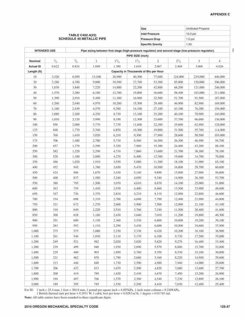
2010 OREGON MECHANICAL SPECIALTY CODE 129.47
APPENDIX C
TABLE C402.4(23)SCHEDULE 40 METALLIC PIPE
Gas Undiluted Propane
Inlet Pressure 10.0 psi
Pressure Drop 1.0 psi
Specific Gravity 1.50
INTENDED USE Pipe sizing between first stage (high-pressure regulator) and second stage (low-pressure regulator).
PIPE SIZE (inch)
Nominal 1/23/4 1 11/4 11/2 2 21/2 3 4
Actual ID 0.622 0.824 1.049 1.380 1.610 2.067 2.469 3.068 4.026
Length (ft) Capacity in Thousands of Btu per Hour
10 3,320 6,950 13,100 26,900 40,300 77,600 124,000 219,000 446,000
20 2,280 4,780 9,000 18,500 27,700 53,300 85,000 150,000 306,000
30 1,830 3,840 7,220 14,800 22,200 42,800 68,200 121,000 246,000
40 1,570 3,280 6,180 12,700 19,000 36,600 58,400 103,000 211,000
50 1,390 2,910 5,480 11,300 16,900 32,500 51,700 91,500 187,000
60 1,260 2,640 4,970 10,200 15,300 29,400 46,900 82,900 169,000
70 1,160 2,430 4,570 9,380 14,100 27,100 43,100 76,300 156,000
80 1,080 2,260 4,250 8,730 13,100 25,200 40,100 70,900 145,000
90 1,010 2,120 3,990 8,190 12,300 23,600 37,700 66,600 136,000
100 956 2,000 3,770 7,730 11,600 22,300 35,600 62,900 128,000
125 848 1,770 3,340 6,850 10,300 19,800 31,500 55,700 114,000
150 768 1,610 3,020 6,210 9,300 17,900 28,600 50,500 103,000
175 706 1,480 2,780 5,710 8,560 16,500 26,300 46,500 94,700
200 657 1,370 2,590 5,320 7,960 15,300 24,400 43,200 88,100
250 582 1,220 2,290 4,710 7,060 13,600 21,700 38,300 78,100
300 528 1,100 2,080 4,270 6,400 12,300 19,600 34,700 70,800
350 486 1,020 1,910 3,930 5,880 11,300 18,100 31,900 65,100
400 452 945 1,780 3,650 5,470 10,500 16,800 29,700 60,600
450 424 886 1,670 3,430 5,140 9,890 15,800 27,900 56,800
500 400 837 1,580 3,240 4,850 9,340 14,900 26,300 53,700
550 380 795 1,500 3,070 4,610 8,870 14,100 25,000 51,000
600 363 759 1,430 2,930 4,400 8,460 13,500 23,900 48,600
650 347 726 1,370 2,810 4,210 8,110 12,900 22,800 46,600
700 334 698 1,310 2,700 4,040 7,790 12,400 21,900 44,800
750 321 672 1,270 2,600 3,900 7,500 12,000 21,100 43,100
800 310 649 1,220 2,510 3,760 7,240 11,500 20,400 41,600
850 300 628 1,180 2,430 3,640 7,010 11,200 19,800 40,300
900 291 609 1,150 2,360 3,530 6,800 10,800 19,200 39,100
950 283 592 1,110 2,290 3,430 6,600 10,500 18,600 37,900
1,000 275 575 1,080 2,230 3,330 6,420 10,200 18,100 36,900
1,100 261 546 1,030 2,110 3,170 6,100 9,720 17,200 35,000
1,200 249 521 982 2,020 3,020 5,820 9,270 16,400 33,400
1,300 239 499 940 1,930 2,890 5,570 8,880 15,700 32,000
1,400 229 480 903 1,850 2,780 5,350 8,530 15,100 30,800
1,500 221 462 870 1,790 2,680 5,160 8,220 14,500 29,600
1,600 213 446 840 1,730 2,590 4,980 7,940 14,000 28,600
1,700 206 432 813 1,670 2,500 4,820 7,680 13,600 27,700
1,800 200 419 789 1,620 2,430 4,670 7,450 13,200 26,900
1,900 194 407 766 1,570 2,360 4,540 7,230 12,800 26,100
2,000 189 395 745 1,530 2,290 4,410 7,030 12,400 25,400
For SI: 1 inch = 25.4 mm, 1 foot = 304.8 mm, 1 pound per square inch = 6.895kPa, 1-inch water column = 0.2488 kPa,1 British thermal unit per hour = 0.2931 W, 1 cubic foot per hour = 0.0283 m3/h, 1 degree = 0.01745 rad.
Note: All table entries have been rounded to three significant digits.
47M:\data\CODES\STATE CODES\Oregon\2010\Mechanical Specialty\Final VP\18_AppC_FuelGas_Oregon_Mech_2010.vpTuesday, January 05, 2010 10:40:10 AM
Color profile: Generic CMYK printer profileComposite Default screen

129.48 2010 OREGON MECHANICAL SPECIALTY CODE
APPENDIX C
TABLE C402.4(24)SCHEDULE 40 METALLIC PIPE
Gas Undiluted Propane
Inlet Pressure 10.0 psi
Pressure Drop 3.0 psi
Specific Gravity 1.50
INTENDED USE Pipe sizing between first stage (high-pressure regulator) and second stage (low-pressure regulator).
PIPE SIZE (inch)
Nominal 1/23/4 1 11/4 11/2 2 21/2 3 4
Actual ID 0.622 0.824 1.049 1.380 1.610 2.067 2.469 3.068 4.026
Length (ft) Capacity in Thousands of Btu per Hour
10 5,890 12,300 23,200 47,600 71,300 137,000 219,000 387,000 789,000
20 4,050 8,460 15,900 32,700 49,000 94,400 150,000 266,000 543,000
30 3,250 6,790 12,800 26,300 39,400 75,800 121,000 214,000 436,000
40 2,780 5,810 11,000 22,500 33,700 64,900 103,000 183,000 373,000
50 2,460 5,150 9,710 19,900 29,900 57,500 91,600 162,000 330,000
60 2,230 4,670 8,790 18,100 27,100 52,100 83,000 147,000 299,000
70 2,050 4,300 8,090 16,600 24,900 47,900 76,400 135,000 275,000
80 1,910 4,000 7,530 15,500 23,200 44,600 71,100 126,000 256,000
90 1,790 3,750 7,060 14,500 21,700 41,800 66,700 118,000 240,000
100 1,690 3,540 6,670 13,700 20,500 39,500 63,000 111,000 227,000
125 1,500 3,140 5,910 12,100 18,200 35,000 55,800 98,700 201,000
150 1,360 2,840 5,360 11,000 16,500 31,700 50,600 89,400 182,000
175 1,250 2,620 4,930 10,100 15,200 29,200 46,500 82,300 167,800
200 1,160 2,430 4,580 9,410 14,100 27,200 43,300 76,500 156,100
250 1,030 2,160 4,060 8,340 12,500 24,100 38,400 67,800 138,400
300 935 1,950 3,680 7,560 11,300 21,800 34,800 61,500 125,400
350 860 1,800 3,390 6,950 10,400 20,100 32,000 56,500 115,300
400 800 1,670 3,150 6,470 9,690 18,700 29,800 52,600 107,300
450 751 1,570 2,960 6,070 9,090 17,500 27,900 49,400 100,700
500 709 1,480 2,790 5,730 8,590 16,500 26,400 46,600 95,100
550 673 1,410 2,650 5,450 8,160 15,700 25,000 44,300 90,300
600 642 1,340 2,530 5,200 7,780 15,000 23,900 42,200 86,200
650 615 1,290 2,420 4,980 7,450 14,400 22,900 40,500 82,500
700 591 1,240 2,330 4,780 7,160 13,800 22,000 38,900 79,300
750 569 1,190 2,240 4,600 6,900 13,300 21,200 37,400 76,400
800 550 1,150 2,170 4,450 6,660 12,800 20,500 36,200 73,700
850 532 1,110 2,100 4,300 6,450 12,400 19,800 35,000 71,400
900 516 1,080 2,030 4,170 6,250 12,000 19,200 33,900 69,200
950 501 1,050 1,970 4,050 6,070 11,700 18,600 32,900 67,200
1,000 487 1,020 1,920 3,940 5,900 11,400 18,100 32,000 65,400
1,100 463 968 1,820 3,740 5,610 10,800 17,200 30,400 62,100
1,200 442 923 1,740 3,570 5,350 10,300 16,400 29,000 59,200
1,300 423 884 1,670 3,420 5,120 9,870 15,700 27,800 56,700
1,400 406 849 1,600 3,280 4,920 9,480 15,100 26,700 54,500
1,500 391 818 1,540 3,160 4,740 9,130 14,600 25,700 52,500
1,600 378 790 1,490 3,060 4,580 8,820 14,100 24,800 50,700
1,700 366 765 1,440 2,960 4,430 8,530 13,600 24,000 49,000
1,800 355 741 1,400 2,870 4,300 8,270 13,200 23,300 47,600
1,900 344 720 1,360 2,780 4,170 8,040 12,800 22,600 46,200
2,000 335 700 1,320 2,710 4,060 7,820 12,500 22,000 44,900
For SI: 1 inch = 25.4 mm, 1 foot = 304.8 mm, 1 pound per square inch = 6.895kPa, 1-inch water column = 0.2488 kPa,1 British thermal unit per hour = 0.2931 W, 1 cubic foot per hour = 0.0283 m3/h, 1 degree = 0.01745 rad.
Note: All table entries have been rounded to three significant digits.
48M:\data\CODES\STATE CODES\Oregon\2010\Mechanical Specialty\Final VP\18_AppC_FuelGas_Oregon_Mech_2010.vpTuesday, January 05, 2010 10:40:10 AM
Color profile: Generic CMYK printer profileComposite Default screen

2010 OREGON MECHANICAL SPECIALTY CODE 129.49
APPENDIX C
TABLE C402.4(25)SCHEDULE 40 METALLIC PIPE
Gas Undiluted Propane
Inlet Pressure 2.0 psi
Pressure Drop 1.0 psi
Specific Gravity 1.50
INTENDED USE Pipe sizing between 2 psig service and line pressure regulator.
PIPE SIZE (inch)
Nominal 1/23/4 1 11/4 11/2 2 21/2 3 4
Actual ID 0.622 0.824 1.049 1.380 1.610 2.067 2.469 3.068 4.026
Length (ft) Capacity in Thousands of Btu per Hour
10 2,680 5,590 10,500 21,600 32,400 62,400 99,500 176,000 359,000
20 1,840 3,850 7,240 14,900 22,300 42,900 68,400 121,000 247,000
30 1,480 3,090 5,820 11,900 17,900 34,500 54,900 97,100 198,000
40 1,260 2,640 4,980 10,200 15,300 29,500 47,000 83,100 170,000
50 1,120 2,340 4,410 9,060 13,600 26,100 41,700 73,700 150,000
60 1,010 2,120 4,000 8,210 12,300 23,700 37,700 66,700 136,000
70 934 1,950 3,680 7,550 11,300 21,800 34,700 61,400 125,000
80 869 1,820 3,420 7,020 10,500 20,300 32,300 57,100 116,000
90 815 1,700 3,210 6,590 9,880 19,000 30,300 53,600 109,000
100 770 1,610 3,030 6,230 9,330 18,000 28,600 50,600 103,000
125 682 1,430 2,690 5,520 8,270 15,900 25,400 44,900 91,500
150 618 1,290 2,440 5,000 7,490 14,400 23,000 40,700 82,900
175 569 1,190 2,240 4,600 6,890 13,300 21,200 37,400 76,300
200 529 1,110 2,080 4,280 6,410 12,300 19,700 34,800 71,000
250 469 981 1,850 3,790 5,680 10,900 17,400 30,800 62,900
300 425 889 1,670 3,440 5,150 9,920 15,800 27,900 57,000
350 391 817 1,540 3,160 4,740 9,120 14,500 25,700 52,400
400 364 760 1,430 2,940 4,410 8,490 13,500 23,900 48,800
450 341 714 1,340 2,760 4,130 7,960 12,700 22,400 45,800
500 322 674 1,270 2,610 3,910 7,520 12,000 21,200 43,200
550 306 640 1,210 2,480 3,710 7,140 11,400 20,100 41,100
600 292 611 1,150 2,360 3,540 6,820 10,900 19,200 39,200
650 280 585 1,100 2,260 3,390 6,530 10,400 18,400 37,500
700 269 562 1,060 2,170 3,260 6,270 9,990 17,700 36,000
750 259 541 1,020 2,090 3,140 6,040 9,630 17,000 34,700
800 250 523 985 2,020 3,030 5,830 9,300 16,400 33,500
850 242 506 953 1,960 2,930 5,640 9,000 15,900 32,400
900 235 490 924 1,900 2,840 5,470 8,720 15,400 31,500
950 228 476 897 1,840 2,760 5,310 8,470 15,000 30,500
1,000 222 463 873 1,790 2,680 5,170 8,240 14,600 29,700
1,100 210 440 829 1,700 2,550 4,910 7,830 13,800 28,200
1,200 201 420 791 1,620 2,430 4,680 7,470 13,200 26,900
1,300 192 402 757 1,550 2,330 4,490 7,150 12,600 25,800
1,400 185 386 727 1,490 2,240 4,310 6,870 12,100 24,800
1,500 178 372 701 1,440 2,160 4,150 6,620 11,700 23,900
1,600 172 359 677 1,390 2,080 4,010 6,390 11,300 23,000
1,700 166 348 655 1,340 2,010 3,880 6,180 10,900 22,300
1,800 161 337 635 1,300 1,950 3,760 6,000 10,600 21,600
1,900 157 327 617 1,270 1,900 3,650 5,820 10,300 21,000
2,000 152 318 600 1,230 1,840 3,550 5,660 10,000 20,400
For SI: 1 inch = 25.4 mm, 1 foot = 304.8 mm, 1 pound per square inch = 6.895kPa, 1-inch water column = 0.2488 kPa,1 British thermal unit per hour = 0.2931 W, 1 cubic foot per hour = 0.0283 m3/h, 1 degree = 0.01745 rad.
Note: All table entries have been rounded to three significant digits.
49M:\data\CODES\STATE CODES\Oregon\2010\Mechanical Specialty\Final VP\18_AppC_FuelGas_Oregon_Mech_2010.vpTuesday, January 05, 2010 10:40:10 AM
Color profile: Generic CMYK printer profileComposite Default screen

129.50 2010 OREGON MECHANICAL SPECIALTY CODE
APPENDIX C
TABLE C402.4(26)SCHEDULE 40 METALLIC PIPE
Gas Undiluted Propane
Inlet Pressure 11.0 in. w.c.
Pressure Drop 0.5 in. w.c.
Specific Gravity 1.50
INTENDED USE Pipe sizing between single- or second-stage (low pressure) regulator and appliance.
PIPE SIZE (inch)
Nominal 1/23/4 1 11/4 11/2 2 21/2 3 4
Actual ID 0.622 0.824 1.049 1.380 1.610 2.067 2.469 3.068 4.026
Length (ft) Capacity in Thousands of Btu per Hour
10 291 608 1,150 2,350 3,520 6,790 10,800 19,100 39,000
20 200 418 787 1,620 2,420 4,660 7,430 13,100 26,800
30 160 336 632 1,300 1,940 3,750 5,970 10,600 21,500
40 137 287 541 1,110 1,660 3,210 5,110 9,030 18,400
50 122 255 480 985 1,480 2,840 4,530 8,000 16,300
60 110 231 434 892 1,340 2,570 4,100 7,250 14,800
80 101 212 400 821 1,230 2,370 3,770 6,670 13,600
100 94 197 372 763 1,140 2,200 3,510 6,210 12,700
125 89 185 349 716 1,070 2,070 3,290 5,820 11,900
150 84 175 330 677 1,010 1,950 3,110 5,500 11,200
175 74 155 292 600 899 1,730 2,760 4,880 9,950
200 67 140 265 543 814 1,570 2,500 4,420 9,010
250 62 129 243 500 749 1,440 2,300 4,060 8,290
300 58 120 227 465 697 1,340 2,140 3,780 7,710
350 51 107 201 412 618 1,190 1,900 3,350 6,840
400 46 97 182 373 560 1,080 1,720 3,040 6,190
450 42 89 167 344 515 991 1,580 2,790 5,700
500 40 83 156 320 479 922 1,470 2,600 5,300
550 37 78 146 300 449 865 1,380 2,440 4,970
600 35 73 138 283 424 817 1,300 2,300 4,700
650 33 70 131 269 403 776 1,240 2,190 4,460
700 32 66 125 257 385 741 1,180 2,090 4,260
750 30 64 120 246 368 709 1,130 2,000 4,080
800 29 61 115 236 354 681 1,090 1,920 3,920
850 28 59 111 227 341 656 1,050 1,850 3,770
900 27 57 107 220 329 634 1,010 1,790 3,640
950 26 55 104 213 319 613 978 1,730 3,530
1,000 25 53 100 206 309 595 948 1,680 3,420
1,100 25 52 97 200 300 578 921 1,630 3,320
1,200 24 50 95 195 292 562 895 1,580 3,230
1,300 23 48 90 185 277 534 850 1,500 3,070
1,400 22 46 86 176 264 509 811 1,430 2,930
1,500 21 44 82 169 253 487 777 1,370 2,800
1,600 20 42 79 162 243 468 746 1,320 2,690
1,700 19 40 76 156 234 451 719 1,270 2,590
1,800 19 39 74 151 226 436 694 1,230 2,500
1,900 18 38 71 146 219 422 672 1,190 2,420
2,000 18 37 69 142 212 409 652 1,150 2,350
For SI: 1 inch = 25.4 mm, 1 foot = 304.8 mm, 1 pound per square inch = 6.895kPa, 1-inch water column = 0.2488 kPa,1 British thermal unit per hour = 0.2931 W, 1 cubic foot per hour = 0.0283 m3/h, 1 degree = 0.01745 rad.
Note: All table entries have been rounded to three significant digits.
50M:\data\CODES\STATE CODES\Oregon\2010\Mechanical Specialty\Final VP\18_AppC_FuelGas_Oregon_Mech_2010.vpTuesday, January 05, 2010 10:40:10 AM
Color profile: Generic CMYK printer profileComposite Default screen
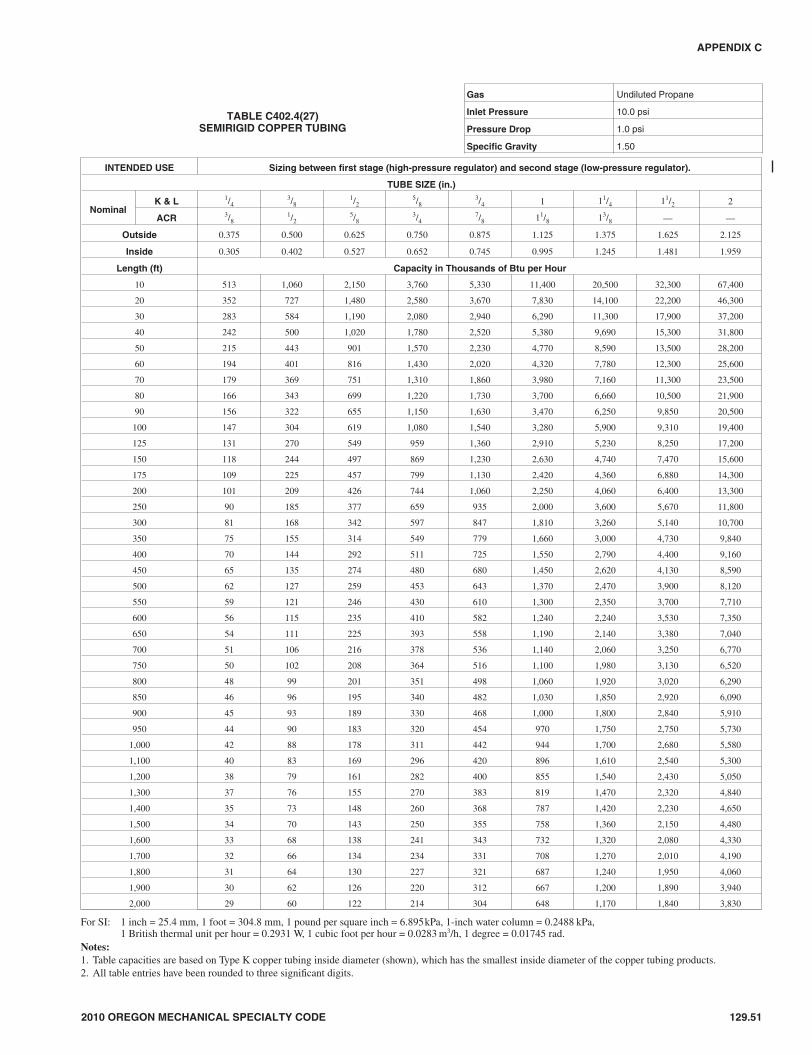
2010 OREGON MECHANICAL SPECIALTY CODE 129.51
APPENDIX C
TABLE C402.4(27)SEMIRIGID COPPER TUBING
Gas Undiluted Propane
Inlet Pressure 10.0 psi
Pressure Drop 1.0 psi
Specific Gravity 1.50
INTENDED USE Sizing between first stage (high-pressure regulator) and second stage (low-pressure regulator).
TUBE SIZE (in.)
NominalK & L 1/4
3/81/2
5/83/4 1 11/4 11/2 2
ACR 3/81/2
5/83/4
7/8 11/8 13/8 — —
Outside 0.375 0.500 0.625 0.750 0.875 1.125 1.375 1.625 2.125
Inside 0.305 0.402 0.527 0.652 0.745 0.995 1.245 1.481 1.959
Length (ft) Capacity in Thousands of Btu per Hour
10 513 1,060 2,150 3,760 5,330 11,400 20,500 32,300 67,400
20 352 727 1,480 2,580 3,670 7,830 14,100 22,200 46,300
30 283 584 1,190 2,080 2,940 6,290 11,300 17,900 37,200
40 242 500 1,020 1,780 2,520 5,380 9,690 15,300 31,800
50 215 443 901 1,570 2,230 4,770 8,590 13,500 28,200
60 194 401 816 1,430 2,020 4,320 7,780 12,300 25,600
70 179 369 751 1,310 1,860 3,980 7,160 11,300 23,500
80 166 343 699 1,220 1,730 3,700 6,660 10,500 21,900
90 156 322 655 1,150 1,630 3,470 6,250 9,850 20,500
100 147 304 619 1,080 1,540 3,280 5,900 9,310 19,400
125 131 270 549 959 1,360 2,910 5,230 8,250 17,200
150 118 244 497 869 1,230 2,630 4,740 7,470 15,600
175 109 225 457 799 1,130 2,420 4,360 6,880 14,300
200 101 209 426 744 1,060 2,250 4,060 6,400 13,300
250 90 185 377 659 935 2,000 3,600 5,670 11,800
300 81 168 342 597 847 1,810 3,260 5,140 10,700
350 75 155 314 549 779 1,660 3,000 4,730 9,840
400 70 144 292 511 725 1,550 2,790 4,400 9,160
450 65 135 274 480 680 1,450 2,620 4,130 8,590
500 62 127 259 453 643 1,370 2,470 3,900 8,120
550 59 121 246 430 610 1,300 2,350 3,700 7,710
600 56 115 235 410 582 1,240 2,240 3,530 7,350
650 54 111 225 393 558 1,190 2,140 3,380 7,040
700 51 106 216 378 536 1,140 2,060 3,250 6,770
750 50 102 208 364 516 1,100 1,980 3,130 6,520
800 48 99 201 351 498 1,060 1,920 3,020 6,290
850 46 96 195 340 482 1,030 1,850 2,920 6,090
900 45 93 189 330 468 1,000 1,800 2,840 5,910
950 44 90 183 320 454 970 1,750 2,750 5,730
1,000 42 88 178 311 442 944 1,700 2,680 5,580
1,100 40 83 169 296 420 896 1,610 2,540 5,300
1,200 38 79 161 282 400 855 1,540 2,430 5,050
1,300 37 76 155 270 383 819 1,470 2,320 4,840
1,400 35 73 148 260 368 787 1,420 2,230 4,650
1,500 34 70 143 250 355 758 1,360 2,150 4,480
1,600 33 68 138 241 343 732 1,320 2,080 4,330
1,700 32 66 134 234 331 708 1,270 2,010 4,190
1,800 31 64 130 227 321 687 1,240 1,950 4,060
1,900 30 62 126 220 312 667 1,200 1,890 3,940
2,000 29 60 122 214 304 648 1,170 1,840 3,830
For SI: 1 inch = 25.4 mm, 1 foot = 304.8 mm, 1 pound per square inch = 6.895kPa, 1-inch water column = 0.2488 kPa,1 British thermal unit per hour = 0.2931 W, 1 cubic foot per hour = 0.0283 m3/h, 1 degree = 0.01745 rad.
Notes:1. Table capacities are based on Type K copper tubing inside diameter (shown), which has the smallest inside diameter of the copper tubing products.2. All table entries have been rounded to three significant digits.
51M:\data\CODES\STATE CODES\Oregon\2010\Mechanical Specialty\Final VP\18_AppC_FuelGas_Oregon_Mech_2010.vpTuesday, January 05, 2010 10:40:11 AM
Color profile: Generic CMYK printer profileComposite Default screen

129.52 2010 OREGON MECHANICAL SPECIALTY CODE
APPENDIX C
TABLE C402.4(28)SEMIRIGID COPPER TUBING
Gas Undiluted Propane
Inlet Pressure 11.0 in. w.c.
Pressure Drop 0.5 in. w.c.
Specific Gravity 1.50
INTENDED USE Sizing between single or second stage (low-pressure regulator) and appliance.
TUBE SIZE (inch)
NominalK & L 1/4
3/81/2
5/83/4 1 11/4 11/2 2
ACR 3/81/2
5/83/4
7/8 11/8 13/8 — —
Outside 0.375 0.500 0.625 0.750 0.875 1.125 1.375 1.625 2.125
Inside 0.305 0.402 0.527 0.652 0.745 0.995 1.245 1.481 1.959
Length (ft) Capacity in Thousands of Btu per Hour
10 45 93 188 329 467 997 1,800 2,830 5,890
20 31 64 129 226 321 685 1,230 1,950 4,050
30 25 51 104 182 258 550 991 1,560 3,250
40 21 44 89 155 220 471 848 1,340 2,780
50 19 39 79 138 195 417 752 1,180 2,470
60 17 35 71 125 177 378 681 1,070 2,240
70 16 32 66 115 163 348 626 988 2,060
80 15 30 61 107 152 324 583 919 1,910
90 14 28 57 100 142 304 547 862 1,800
100 13 27 54 95 134 287 517 814 1,700
125 11 24 48 84 119 254 458 722 1,500
150 10 21 44 76 108 230 415 654 1,360
175 NA 20 40 70 99 212 382 602 1,250
200 NA 18 37 65 92 197 355 560 1,170
250 NA 16 33 58 82 175 315 496 1,030
300 NA 15 30 52 74 158 285 449 936
350 NA 14 28 48 68 146 262 414 861
400 NA 13 26 45 63 136 244 385 801
450 NA 12 24 42 60 127 229 361 752
500 NA 11 23 40 56 120 216 341 710
550 NA 11 22 38 53 114 205 324 674
600 NA 10 21 36 51 109 196 309 643
650 NA NA 20 34 49 104 188 296 616
700 NA NA 19 33 47 100 180 284 592
750 NA NA 18 32 45 96 174 274 570
800 NA NA 18 31 44 93 168 264 551
850 NA NA 17 30 42 90 162 256 533
900 NA NA 17 29 41 87 157 248 517
950 NA NA 16 28 40 85 153 241 502
1,000 NA NA 16 27 39 83 149 234 488
1,100 NA NA 15 26 37 78 141 223 464
1,200 NA NA 14 25 35 75 135 212 442
1,300 NA NA 14 24 34 72 129 203 423
1,400 NA NA 13 23 32 69 124 195 407
1,500 NA NA 13 22 31 66 119 188 392
1,600 NA NA 12 21 30 64 115 182 378
1,700 NA NA 12 20 29 62 112 176 366
1,800 NA NA 11 20 28 60 108 170 355
1,900 NA NA 11 19 27 58 105 166 345
2,000 NA NA 11 19 27 57 102 161 335
For SI: 1 inch = 25.4 mm, 1 foot = 304.8 mm, 1 pound per square inch = 6.895kPa, 1-inch water column = 0.2488 kPa,1 British thermal unit per hour = 0.2931 W, 1 cubic foot per hour = 0.0283 m3/h, 1 degree = 0.01745 rad.
Notes:1. Table capacities are based on Type K copper tubing inside diameter (shown), which has the smallest inside diameter of the copper tubing products.2. NA means a flow of less than 10,000 Btu/hr.3. All table entries have been rounded to three significant digits.
52M:\data\CODES\STATE CODES\Oregon\2010\Mechanical Specialty\Final VP\18_AppC_FuelGas_Oregon_Mech_2010.vpTuesday, January 05, 2010 10:40:11 AM
Color profile: Generic CMYK printer profileComposite Default screen

2010 OREGON MECHANICAL SPECIALTY CODE 129.53
APPENDIX C
TABLE C402.4(29)SEMIRIGID COPPER TUBING
Gas Undiluted Propane
Inlet Pressure 2.0 psi
Pressure Drop 1.0 psi
Specific Gravity 1.50
INTENDED USE Tube sizing between 2 psig service and line pressure regulator.
TUBE SIZE (inch)
NominalK & L 1/4
3/81/2
5/83/4 1 11/4 11/2 2
ACR 3/81/2
5/83/4
7/8 11/8 13/8 — —
Outside 0.375 0.500 0.625 0.750 0.875 1.125 1.375 1.625 2.125
Inside 0.305 0.402 0.527 0.652 0.745 0.995 1.245 1.481 1.959
Length (ft) Capacity in Thousands of Btu per Hour
10 413 852 1,730 3,030 4,300 9,170 16,500 26,000 54,200
20 284 585 1,190 2,080 2,950 6,310 11,400 17,900 37,300
30 228 470 956 1,670 2,370 5,060 9,120 14,400 29,900
40 195 402 818 1,430 2,030 4,330 7,800 12,300 25,600
50 173 356 725 1,270 1,800 3,840 6,920 10,900 22,700
60 157 323 657 1,150 1,630 3,480 6,270 9,880 20,600
70 144 297 605 1,060 1,500 3,200 5,760 9,090 18,900
80 134 276 562 983 1,390 2,980 5,360 8,450 17,600
90 126 259 528 922 1,310 2,790 5,030 7,930 16,500
100 119 245 498 871 1,240 2,640 4,750 7,490 15,600
125 105 217 442 772 1,100 2,340 4,210 6,640 13,800
150 95 197 400 700 992 2,120 3,820 6,020 12,500
175 88 181 368 644 913 1,950 3,510 5,540 11,500
200 82 168 343 599 849 1,810 3,270 5,150 10,700
250 72 149 304 531 753 1,610 2,900 4,560 9,510
300 66 135 275 481 682 1,460 2,620 4,140 8,610
350 60 124 253 442 628 1,340 2,410 3,800 7,920
400 56 116 235 411 584 1,250 2,250 3,540 7,370
450 53 109 221 386 548 1,170 2,110 3,320 6,920
500 50 103 209 365 517 1,110 1,990 3,140 6,530
550 47 97 198 346 491 1,050 1,890 2,980 6,210
600 45 93 189 330 469 1,000 1,800 2,840 5,920
650 43 89 181 316 449 959 1,730 2,720 5,670
700 41 86 174 304 431 921 1,660 2,620 5,450
750 40 82 168 293 415 888 1,600 2,520 5,250
800 39 80 162 283 401 857 1,540 2,430 5,070
850 37 77 157 274 388 829 1,490 2,350 4,900
900 36 75 152 265 376 804 1,450 2,280 4,750
950 35 72 147 258 366 781 1,410 2,220 4,620
1,000 34 71 143 251 356 760 1,370 2,160 4,490
1,100 32 67 136 238 338 721 1,300 2,050 4,270
1,200 31 64 130 227 322 688 1,240 1,950 4,070
1,300 30 61 124 217 309 659 1,190 1,870 3,900
1,400 28 59 120 209 296 633 1,140 1,800 3,740
1,500 27 57 115 201 286 610 1,100 1,730 3,610
1,600 26 55 111 194 276 589 1,060 1,670 3,480
1,700 26 53 108 188 267 570 1,030 1,620 3,370
1,800 25 51 104 182 259 553 1,000 1,570 3,270
1,900 24 50 101 177 251 537 966 1,520 3,170
2,000 23 48 99 172 244 522 940 1,480 3,090
For SI: 1 inch = 25.4 mm, 1 foot = 304.8 mm, 1 pound per square inch = 6.895kPa, 1-inch water column = 0.2488 kPa,1 British thermal unit per hour = 0.2931 W, 1 cubic foot per hour = 0.0283 m3/h, 1 degree = 0.01745 rad.
Notes:1. Table capacities are based on Type K copper tubing inside diameter (shown), which has the smallest inside diameter of the copper tubing products.2. All table entries have been rounded to three significant digits.
53M:\data\CODES\STATE CODES\Oregon\2010\Mechanical Specialty\Final VP\18_AppC_FuelGas_Oregon_Mech_2010.vpTuesday, January 05, 2010 10:40:11 AM
Color profile: Generic CMYK printer profileComposite Default screen

129.54 2010 OREGON MECHANICAL SPECIALTY CODE
APPENDIX C
TABLE C402.4(30)CORRUGATED STAINLESS STEEL TUBING (CSST)
Gas Undiluted Propane
Inlet Pressure 11.0 in. w.c.
Pressure Drop 0.5 in. w.c.
Specific Gravity 1.50
INTENDED USE: SIZING BETWEEN SINGLE OR SECOND STAGE (Low Pressure) REGULATOR AND THE APPLIANCE SHUTOFF VALVE
TUBE SIZE (EHD)
FlowDesignation 13 15 18 19 23 25 30 31 37 39 46 48 60 62
Length (ft) Capacity in Thousands of Btu per Hour
5 72 99 181 211 355 426 744 863 1,420 1,638 2,830 3,270 5,780 6,550
10 50 69 129 150 254 303 521 605 971 1,179 1,990 2,320 4,110 4,640
15 39 55 104 121 208 248 422 490 775 972 1,620 1,900 3,370 3,790
20 34 49 91 106 183 216 365 425 661 847 1,400 1,650 2,930 3,290
25 30 42 82 94 164 192 325 379 583 762 1,250 1,480 2,630 2,940
30 28 39 74 87 151 177 297 344 528 698 1,140 1,350 2,400 2,680
40 23 33 64 74 131 153 256 297 449 610 988 1,170 2,090 2,330
50 20 30 58 66 118 137 227 265 397 548 884 1,050 1,870 2,080
60 19 26 53 60 107 126 207 241 359 502 805 961 1,710 1,900
70 17 25 49 57 99 117 191 222 330 466 745 890 1,590 1,760
80 15 23 45 52 94 109 178 208 307 438 696 833 1,490 1,650
90 15 22 44 50 90 102 169 197 286 414 656 787 1,400 1,550
100 14 20 41 47 85 98 159 186 270 393 621 746 1,330 1,480
150 11 15 31 36 66 75 123 143 217 324 506 611 1,090 1,210
200 9 14 28 33 60 69 112 129 183 283 438 531 948 1,050
250 8 12 25 30 53 61 99 117 163 254 390 476 850 934
300 8 11 23 26 50 57 90 107 147 234 357 434 777 854
For SI: 1 inch = 25.4 mm, 1 foot = 304.8 mm, 1 pound per square inch = 6.895kPa, 1-inch water column = 0.2488 kPa,1 British thermal unit per hour = 0.2931 W, 1 cubic foot per hour = 0.0283 m3/h, 1 degree = 0.01745 rad.
Notes:1. Table includes losses for four 90-degree bends and two end fittings. Tubing runs with larger numbers of bends and/or fittings shall be increased by an equivalent
length of tubing to the following equation: L = 1.3n where L is additional length (feet) of tubing and n is the number of additional fittings and/or bends.2. EHD—Equivalent Hydraulic Diameter, which is a measure of the relative hydraulic efficiency between different tubing sizes. The greater the value of EHD, the
greater the gas capacity of the tubing.3. All table entries have been rounded to three significant digits.
54M:\data\CODES\STATE CODES\Oregon\2010\Mechanical Specialty\Final VP\18_AppC_FuelGas_Oregon_Mech_2010.vpTuesday, January 05, 2010 10:40:11 AM
Color profile: Generic CMYK printer profileComposite Default screen

2010 OREGON MECHANICAL SPECIALTY CODE 129.55
APPENDIX C
TABLE C402.4(31)CORRUGATED STAINLESS STEEL TUBING (CSST)
Gas Undiluted Propane
Inlet Pressure 2.0 psi
Pressure Drop 1.0 psi
Specific Gravity 1.50
INTENDED USE: SIZING BETWEEN 2 PSI SERVICE AND THE LINE PRESSURE REGULATOR
TUBE SIZE (EHD)
FlowDesignation 13 15 18 19 23 25 30 31 37 39 46 48 60 62
Length (ft) Capacity in Thousands of Btu per Hour
10 426 558 927 1,110 1,740 2,170 4,100 4,720 7,130 7,958 15,200 16,800 29,400 34,200
25 262 347 591 701 1,120 1,380 2,560 2,950 4,560 5,147 9,550 10,700 18,800 21,700
30 238 316 540 640 1,030 1,270 2,330 2,690 4,180 4,719 8,710 9,790 17,200 19,800
40 203 271 469 554 896 1,100 2,010 2,320 3,630 4,116 7,530 8,500 14,900 17,200
50 181 243 420 496 806 986 1,790 2,070 3,260 3,702 6,730 7,610 13,400 15,400
75 147 196 344 406 663 809 1,460 1,690 2,680 3,053 5,480 6,230 11,000 12,600
80 140 189 333 393 643 768 1,410 1,630 2,590 2,961 5,300 6,040 10,600 12,200
100 124 169 298 350 578 703 1,260 1,450 2,330 2,662 4,740 5,410 9,530 10,900
150 101 137 245 287 477 575 1,020 1,180 1,910 2,195 3,860 4,430 7,810 8,890
200 86 118 213 248 415 501 880 1,020 1,660 1,915 3,340 3,840 6,780 7,710
250 77 105 191 222 373 448 785 910 1,490 1,722 2,980 3,440 6,080 6,900
300 69 96 173 203 343 411 716 829 1,360 1,578 2,720 3,150 5,560 6,300
400 60 82 151 175 298 355 616 716 1,160 1,376 2,350 2,730 4,830 5,460
500 53 72 135 158 268 319 550 638 1,030 1,237 2,100 2,450 4,330 4,880
For SI: 1 inch = 25.4 mm, 1 foot = 304.8 mm, 1 pound per square inch = 6.895kPa, 1-inch water column = 0.2488 kPa,1 British thermal unit per hour = 0.2931 W, 1 cubic foot per hour = 0.0283 m3/h, 1 degree = 0.01745 rad.
Notes:1. Table does not include effect of pressure drop across the line regulator. Where regulator loss exceeds 1/2 psi (based on 13 in. w.c. outlet pressure), DO NOT USE
THIS TABLE. Consult with the regulator manufacturer for pressure drops and capacity factors. Pressure drops across a regulator may vary with flow rate.2. CAUTION: Capacities shown in the table might exceed maximum capacity for a selected regulator. Consult with the regulator or tubing manufacturer for guid-
ance.3. Table includes losses for four 90-degree bends and two end fittings. Tubing runs with larger numbers of bends and/or fittings shall be increased by an equivalent
length of tubing to the following equation: L = 1.3n where L is additional length (feet) of tubing and n is the number of additional fittings and/or bends.4. EHD—Equivalent Hydraulic Diameter, which is a measure of the relative hydraulic efficiency between different tubing sizes. The greater the value of EHD, the
greater the gas capacity of the tubing.5. All table entries have been rounded to three significant digits.
55M:\data\CODES\STATE CODES\Oregon\2010\Mechanical Specialty\Final VP\18_AppC_FuelGas_Oregon_Mech_2010.vpTuesday, January 05, 2010 10:40:11 AM
Color profile: Generic CMYK printer profileComposite Default screen

129.56 2010 OREGON MECHANICAL SPECIALTY CODE
APPENDIX C
TABLE C402.4(32)CORRUGATED STAINLESS STEEL TUBING (CSST)
Gas Undiluted Propane
Inlet Pressure 5.0 psi
Pressure Drop 3.5 psi
Specific Gravity 1.50
TUBE SIZE (EHD)
FlowDesignation 13 15 18 19 23 25 30 31 37 39 46 48 60 62
Length (ft) Capacity in Thousands of Btu per Hour
10 826 1,070 1,710 2,060 3,150 4,000 7,830 8,950 13,100 14,441 28,600 31,200 54,400 63,800
25 509 664 1,090 1,310 2,040 2,550 4,860 5,600 8,400 9,339 18,000 19,900 34,700 40,400
30 461 603 999 1,190 1,870 2,340 4,430 5,100 7,680 8,564 16,400 18,200 31,700 36,900
40 396 520 867 1,030 1,630 2,030 3,820 4,400 6,680 7,469 14,200 15,800 27,600 32,000
50 352 463 777 926 1,460 1,820 3,410 3,930 5,990 6,717 12,700 14,100 24,700 28,600
75 284 376 637 757 1,210 1,490 2,770 3,190 4,920 5,539 10,300 11,600 20,300 23,400
80 275 363 618 731 1,170 1,450 2,680 3,090 4,770 5,372 9,990 11,200 19,600 22,700
100 243 324 553 656 1,050 1,300 2,390 2,760 4,280 4,830 8,930 10,000 17,600 20,300
150 196 262 453 535 866 1,060 1,940 2,240 3,510 3,983 7,270 8,210 14,400 16,600
200 169 226 393 464 755 923 1,680 1,930 3,050 3,474 6,290 7,130 12,500 14,400
250 150 202 352 415 679 828 1,490 1,730 2,740 3,124 5,620 6,390 11,200 12,900
300 136 183 322 379 622 757 1,360 1,570 2,510 2,865 5,120 5,840 10,300 11,700
400 117 158 279 328 542 657 1,170 1,360 2,180 2,498 4,430 5,070 8,920 10,200
500 104 140 251 294 488 589 1,050 1,210 1,950 2,247 3,960 4,540 8,000 9,110
For SI: 1 inch = 25.4 mm, 1 foot = 304.8 mm, 1 pound per square inch = 6.895kPa, 1-inch water column = 0.2488 kPa,1 British thermal unit per hour = 0.2931 W, 1 cubic foot per hour = 0.0283 m3/h, 1 degree = 0.01745 rad.
Notes:1. Table does not include effect of pressure drop across line regulator. Where regulator loss exceeds1 psi, DO NOT USE THIS TABLE. Consult with the regulator
manufacturer for pressure drops and capacity factors. Pressure drop across regulator may vary with the flow rate.2. CAUTION: Capacities shown in the table might exceed maximum capacity of selected regulator. Consult with the tubing manufacturer for guidance.3. Table includes losses for four 90-degree bends and two end fittings. Tubing runs with larger numbers of bends and/or fittings shall be increased by an equivalent
length of tubing to the following equation: L = 1.3n where L is additional length (feet) of tubing and n is the number of additional fittings and/or bends.4. EHD— Equivalent Hydraulic Diameter, which is a measure of the relative hydraulic efficiency between different tubing sizes. The greater the value of EHD, the
greater the gas capacity of the tubing.5. All table entries have been rounded to three significant digits.
56M:\data\CODES\STATE CODES\Oregon\2010\Mechanical Specialty\Final VP\18_AppC_FuelGas_Oregon_Mech_2010.vpTuesday, January 05, 2010 10:40:11 AM
Color profile: Generic CMYK printer profileComposite Default screen

2010 OREGON MECHANICAL SPECIALTY CODE 129.57
APPENDIX C
TABLE C402.4(33)POLYETHYLENE PLASTIC PIPE
Gas Undiluted Propane
Inlet Pressure 11.0 in. w.c.
Pressure Drop 0.5 in. w.c.
Specific Gravity 1.50
INTENDED USE PE pipe sizing between integral two-stage regulator at tank or second stage (low-pressure regulator) and building.
PIPE SIZE (inch)
Nominal OD 1/23/4 1 11/4 11/2 2
Designation SDR 9.33 SDR 11.0 SDR 11.00 SDR 10.00 SDR 11.00 SDR 11.00
Actual ID 0.660 0.860 1.077 1.328 1.554 1.943
Length (ft) Capacity in Thousands of Btu per Hour
10 340 680 1,230 2,130 3,210 5,770
20 233 468 844 1,460 2,210 3,970
30 187 375 677 1,170 1,770 3,180
40 160 321 580 1,000 1,520 2,730
50 142 285 514 890 1,340 2,420
60 129 258 466 807 1,220 2,190
70 119 237 428 742 1,120 2,010
80 110 221 398 690 1,040 1,870
90 103 207 374 648 978 1,760
100 98 196 353 612 924 1,660
125 87 173 313 542 819 1,470
150 78 157 284 491 742 1,330
175 72 145 261 452 683 1,230
200 67 135 243 420 635 1,140
250 60 119 215 373 563 1,010
300 54 108 195 338 510 916
350 50 99 179 311 469 843
400 46 92 167 289 436 784
450 43 87 157 271 409 736
500 41 82 148 256 387 695
For SI: 1 inch = 25.4 mm, 1 foot = 304.8 mm, 1 pound per square inch = 6.895kPa, 1-inch water column = 0.2488 kPa,1 British thermal unit per hour = 0.2931 W, 1 cubic foot per hour = 0.0283 m3/h, 1 degree = 0.01745 rad.
Note: All table entries have been rounded to three significant digits.
57M:\data\CODES\STATE CODES\Oregon\2010\Mechanical Specialty\Final VP\18_AppC_FuelGas_Oregon_Mech_2010.vpTuesday, January 05, 2010 10:40:12 AM
Color profile: Generic CMYK printer profileComposite Default screen

129.58 2010 OREGON MECHANICAL SPECIALTY CODE
APPENDIX C
TABLE C402.4(34)POLYETHYLENE PLASTIC PIPE
Gas Undiluted Propane
Inlet Pressure 2.0 psi
Pressure Drop 1.0 psi
Specific Gravity 1.50
INTENDED USE PE pipe sizing between 2 psig service regulator and line pressure regulator.
PIPE SIZE (inch)
Nominal OD 1/23/4 1 11/4 11/2 2
Designation SDR 9.33 SDR 11.0 SDR 11.00 SDR 10.00 SDR 11.00 SDR 11.00
Actual ID 0.660 0.860 1.077 1.328 1.554 1.943
Length (ft) Capacity in Thousands of Btu per Hour
10 3,130 6,260 11,300 19,600 29,500 53,100
20 2,150 4,300 7,760 13,400 20,300 36,500
30 1,730 3,450 6,230 10,800 16,300 29,300
40 1,480 2,960 5,330 9,240 14,000 25,100
50 1,310 2,620 4,730 8,190 12,400 22,200
60 1,190 2,370 4,280 7,420 11,200 20,100
70 1,090 2,180 3,940 6,830 10,300 18,500
80 1,010 2,030 3,670 6,350 9,590 17,200
90 952 1,910 3,440 5,960 9,000 16,200
100 899 1,800 3,250 5,630 8,500 15,300
125 797 1,600 2,880 4,990 7,530 13,500
150 722 1,450 2,610 4,520 6,830 12,300
175 664 1,330 2,400 4,160 6,280 11,300
200 618 1,240 2,230 3,870 5,840 10,500
250 548 1,100 1,980 3,430 5,180 9,300
300 496 994 1,790 3,110 4,690 8,430
350 457 914 1,650 2,860 4,320 7,760
400 425 851 1,530 2,660 4,020 7,220
450 399 798 1,440 2,500 3,770 6,770
500 377 754 1,360 2,360 3,560 6,390
550 358 716 1,290 2,240 3,380 6,070
600 341 683 1,230 2,140 3,220 5,790
650 327 654 1,180 2,040 3,090 5,550
700 314 628 1,130 1,960 2,970 5,330
750 302 605 1,090 1,890 2,860 5,140
800 292 585 1,050 1,830 2,760 4,960
850 283 566 1,020 1,770 2,670 4,800
900 274 549 990 1,710 2,590 4,650
950 266 533 961 1,670 2,520 4,520
1,000 259 518 935 1,620 2,450 4,400
1,100 246 492 888 1,540 2,320 4,170
1,200 234 470 847 1,470 2,220 3,980
1,300 225 450 811 1,410 2,120 3,810
1,400 216 432 779 1,350 2,040 3,660
1,500 208 416 751 1,300 1,960 3,530
1,600 201 402 725 1,260 1,900 3,410
1,700 194 389 702 1,220 1,840 3,300
1,800 188 377 680 1,180 1,780 3,200
1,900 183 366 661 1,140 1,730 3,110
2,000 178 356 643 1,110 1,680 3,020
For SI: 1 inch = 25.4 mm, 1 foot = 304.8 mm, 1 pound per square inch = 6.895kPa, 1-inch water column = 0.2488 kPa,1 British thermal unit per hour = 0.2931 W, 1 cubic foot per hour = 0.0283 m3/h, 1 degree = 0.01745 rad.
Note: All table entries have been rounded to three significant digits.
58M:\data\CODES\STATE CODES\Oregon\2010\Mechanical Specialty\Final VP\18_AppC_FuelGas_Oregon_Mech_2010.vpTuesday, January 05, 2010 10:40:12 AM
Color profile: Generic CMYK printer profileComposite Default screen

2010 OREGON MECHANICAL SPECIALTY CODE 129.59
APPENDIX C
TABLE C402.4(35)POLYETHYLENE PLASTIC PIPE
Gas Undiluted Propane
Inlet Pressure 11.0 in. w.c.
Pressure Drop 0.5 in. w.c.
Specific Gravity 1.50
INTENDED USE PE pipe sizing between integral two-stage regulator at tank or second stage (low-pressure regulator) and building.
Plastic Tubing Size (CTS) (inch)
Nominal OD 1/2 1
Designation SDR 7.00 SDR 11.00
Actual ID 0.445 0.927
Length (ft) Capacity in Cubic Feet of Gas per Hour
10 121 828
20 83 569
30 67 457
40 57 391
50 51 347
60 46 314
70 42 289
80 39 269
90 37 252
100 35 238
125 31 211
150 28 191
175 26 176
200 24 164
225 22 154
250 21 145
275 20 138
300 19 132
350 18 121
400 16 113
450 15 106
500 15 100
For SI: 1 inch = 25.4 mm, 1 foot = 304.8 mm,1 pound per square inch = 6.895 kPa,1-inch water column = 0.2488 kPa,1 British thermal unit per hour = 0.2931 W,1 cubic foot per hour = 0.0283 m3/h, 1 degree = 0.01745 rad.
Note: All table entries have been rounded to three significant digits.
59M:\data\CODES\STATE CODES\Oregon\2010\Mechanical Specialty\Final VP\18_AppC_FuelGas_Oregon_Mech_2010.vpTuesday, January 05, 2010 10:40:12 AM
Color profile: Generic CMYK printer profileComposite Default screen

C403.9 Metallic piping joints and fittings. The type of pipingjoint used shall be suitable for the pressure-temperature condi-tions and shall be selected giving consideration to joint tight-ness and mechanical strength under the service conditions. Thejoint shall be able to sustain the maximum end force caused bythe internal pressure and any additional forces caused by tem-perature expansion or contraction, vibration, fatigue or theweight of the pipe and its contents.
C403.9.1 Pipe joints. Pipe joints shall be threaded, flanged,brazed or welded. Where nonferrous pipe is brazed, thebrazing materials shall have a melting point in excess of1,000°F (538°C). Brazing alloys shall not contain more than0.05-percent phosphorus.
C403.9.2 Tubing joints. Tubing joints shall be made withapproved gas tubing fittings, brazed with a material having amelting point in excess of 1,000°F (538°C) or made withpress-connect fittings complying with ANSI LC-4. Brazingalloys shall not contain more than 0.05-percent phosphorus.
C403.9.3 Flared joints. Flared joints shall be used only insystems constructed from nonferrous pipe and tubing whereexperience or tests have demonstrated that the joint is suit-able for the conditions and where provisions are made in thedesign to prevent separation of the joints.
C403.9.4 Metallic fittings. Metallic fittings shall complywith the following:
1. Threaded fittings in sizes larger than 4 inches (102mm) shall not be used except where approved.
2. Fittings used with steel or wrought-iron pipe shall besteel, brass, bronze, malleable iron or cast iron.
3. Fittings used with copper or brass pipe shall be cop-per, brass or bronze.
4. Fittings used with aluminum-alloy pipe shall be ofaluminum alloy.
5. Cast-iron fittings:
5.1. Flanges shall be permitted.
5.2. Bushings shall not be used.
5.3. Fittings shall not be used in systems contain-ing flammable gas-air mixtures.
5.4. Fittings in sizes 4 inches (102 mm) and largershall not be used indoors except where ap-proved.
5.5. Fittings in sizes 6 inches (152 mm) and largershall not be used except where approved.
6. Aluminum-alloy fittings. Threads shall not form thejoint seal.
7. Zinc aluminum-alloy fittings. Fittings shall not beused in systems containing flammable gas-air mix-tures.
8. Special fittings. Fittings such as couplings, propri-etary-type joints, saddle tees, gland-type compres-sion fittings, and flared, flareless or compression-type
tubing fittings shall be: used within the fitting manu-facturer’s pressure-temperature recommendations;used within the service conditions anticipated withrespect to vibration, fatigue, thermal expansion orcontraction; installed or braced to prevent separationof the joint by gas pressure or external physical dam-age; and shall be approved.
C403.10 Plastic pipe, joints and fittings. Plastic pipe, tubingand fittings shall be joined in accordance with the manufac-turer’s instructions. Such joint shall comply with the following:
1. The joint shall be designed and installed so that the longi-tudinal pull-out resistance of the joint will be at leastequal to the tensile strength of the plastic piping material.
2. Heat-fusion joints shall be made in accordance withqualified procedures that have been established andproven by test to produce gas-tight joints at least asstrong as the pipe or tubing being joined. Joints shall bemade with the joining method recommended by the pipemanufacturer. Heat fusion fittings shall be marked“ASTM D 2513.”
3. Where compression-type mechanical joints are used, thegasket material in the fitting shall be compatible with theplastic piping and with the gas distributed by the system.An internal tubular rigid stiffener shall be used in con-junction with the fitting. The stiffener shall be flush withthe end of the pipe or tubing and shall extend at least tothe outside end of the compression fitting when installed.The stiffener shall be free of rough or sharp edges andshall not be a force fit in the plastic. Split tubular stiffen-ers shall not be used.
4. Plastic piping joints and fittings for use in liquefiedpetroleum gas piping systems shall be in accordancewith NFPA 58.
C403.11 Flanges. All flanges shall comply with ASME B16.1,ASME B16.20 or MSS SP-6. The pressure-temperature ratingsshall equal or exceed that required by the application.
C403.11.1 Flange facings. Standard facings shall be per-mitted for use under this code. Where 150-pound (1034kPa) pressure-rated steel flanges are bolted to Class 125cast-iron flanges, the raised face on the steel flange shall beremoved.
C403.11.2 Lapped flanges. Lapped flanges shall be usedonly above ground or in exposed locations accessible forinspection.
C403.12 Flange gaskets. Material for gaskets shall be capableof withstanding the design temperature and pressure of the pip-ing system, and the chemical constituents of the gas being con-ducted, without change to its chemical and physical properties.The effects of fire exposure to the joint shall be considered inchoosing material. Acceptable materials include metal ormetal-jacketed asbestos (plain or corrugated), asbestos, andaluminum “O” rings and spiral wound metal gaskets. When aflanged joint is opened, the gasket shall be replaced. Full-facegaskets shall be used with all bronze and cast-iron flanges.
129.60 2010 OREGON MECHANICAL SPECIALTY CODE
APPENDIX C
60M:\data\CODES\STATE CODES\Oregon\2010\Mechanical Specialty\Final VP\18_AppC_FuelGas_Oregon_Mech_2010.vpTuesday, January 05, 2010 10:40:12 AM
Color profile: Generic CMYK printer profileComposite Default screen
SECTION C404PIPING SYSTEM INSTALLATION
C404.1 Prohibited locations. Piping shall not be installed inor through a ducted supply, return or exhaust, or a clotheschute, chimney or gas vent, dumbwaiter or elevator shaft. Pip-ing installed downstream of the point of delivery shall notextend through any townhouse unit other than the unit servedby such piping.
C404.2 Piping in solid partitions and walls. Concealed pip-ing shall not be located in solid partitions and solid walls,unless installed in a chase or casing.
C404.3 Piping in concealed locations. Portions of a pipingsystem installed in concealed locations shall not have unions,tubing fittings, right and left couplings, bushings, compressioncouplings and swing joints made by combinations of fittings.
Exceptions:
1. Tubing joined by brazing.
2. Fittings listed for use in concealed locations.
C404.4 Underground penetrations prohibited. Gas pipingshall not penetrate building foundation walls at any point belowgrade. Gas piping shall enter and exit a building at a point abovegrade and the annular space between the pipe and the wall shallbe sealed.
C404.5 Protection against physical damage. In concealedlocations, where piping other than black or galvanized steel isinstalled through holes or notches in wood studs, joists, raftersor similar members less than 11/2 inches (38 mm) from the near-est edge of the member, the pipe shall be protected by shieldplates. Protective steel shield plates having a minimum thick-ness of 0.0575 inch (1.463 mm) (No. 16 gage) shall cover thearea of the pipe where the member is notched or bored and shallextend a minimum of 2 inches (51 mm) above sole plates,below top plates and to each side of a stud, joist or rafter.
C404.6 Piping in solid floors. Piping in solid floors shall belaid in channels in the floor and covered in a manner that willallow access to the piping with a minimum amount of damageto the building. Where such piping is subject to exposure toexcessive moisture or corrosive substances, the piping shall beprotected in an approved manner. As an alternative to installa-tion in channels, the piping shall be installed in a conduit ofSchedule 40 steel, wrought iron, PVC or ABS pipe in accor-dance with Section C404.6.1 or C404.6.2.
C404.6.1 Conduit with one end terminating outdoors.The conduit shall extend into an occupiable portion of thebuilding and, at the point where the conduit terminates in thebuilding, the space between the conduit and the gas pipingshall be sealed to prevent the possible entrance of any gasleakage. The conduit shall extend not less than 2 inches (51mm) beyond the point where the pipe emerges from thefloor. If the end sealing is capable of withstanding the fullpressure of the gas pipe, the conduit shall be designed for thesame pressure as the pipe. Such conduit shall extend not lessthan 4 inches (102 mm) outside the building, shall be ventedabove grade to the outdoors and shall be installed so as pre-vent the entrance of water and insects.
C404.6.2 Conduit with both ends terminating indoors.Where the conduit originates and terminates within thesame building, the conduit shall originate and terminate inan accessible portion of the building and shall not be sealed.The conduit shall extend not less than 2 inches (51 mm)beyond the point where the pipe emerges from the floor.
C404.7 Above-ground outdoor piping. All piping installedoutdoors shall be elevated not less than 31/2 inches (152 mm)above ground and where installed across roof surfaces, shall beelevated not less than 31/2 inches (152 mm) above the roof sur-face. Piping installed above ground, outdoors, and installedacross the surface of roofs shall be securely supported andlocated where it will be protected from physical damage. Wherepassing through an outside wall, the piping shall also be pro-tected against corrosion by coating or wrapping with an inertmaterial. Where piping is encased in a protective pipe sleeve, theannular space between the piping and the sleeve shall be sealed.
C404.8 Isolation. Metallic piping and metallic tubing that con-veys fuel gas from an LP-gas storage container shall be pro-vided with an approved dielectric fitting to electrically isolatethe underground portion of the pipe or tube from the aboveground portion that enters a building. Such dielectric fittingshall be installed above ground, outdoors.
C404.9 Corrosion and covering protection. Nonmetallic gaspiping and coated and cathodically protected piping shall havea minimum of 18 inches (457 mm) of earth cover or otherequivalent protection. Risers, including prefabricated risersinserted with plastic pipe, shall be metallic and protected in anapproved manner to a point of at least 6 inches (153 mm) abovegrade. When a riser connects to plastic pipe underground, thehorizontal metallic portion underground shall be at least 30inches (762 mm) in length before connecting to the plastic ser-vice pipe. An approved transition fitting or adapter shall beused where the plastic joins the metallic riser.
Ferrous metals in exposed exterior locations shall be pro-tected from corrosion in a manner approved by the buildingofficial after consulting with the gas supplier.
Ferrous pipes installed underground shall not be placed incontact with other metallic objects, such as pipes or wires.
Zinc coatings (galvanizing) shall not be deemed adequateprotection for piping below grade. Ferrous gas piping installedunderground in exterior locations shall be protected from cor-rosion by either:
C404.9.1 Coated and cathodically protected pipe. All gaspipe protective coatings shall be approved types, machineapplied and conform to recognized standards. Field wrap-ping shall provide equivalent protection and restricted tothose short sections and fittings necessarily stripped forthreading or welding. Underground coated and wrapped gaspiping shall be cathodically protected with galvanic anodesor rectifiers and electrically isolated from the rest of the sys-tem by insulating unions 6 inches (153 mm) above grade.
C404.9.2 Unwrapped (bare) pipe and special covering.Unwrapped ferrous gas piping being installed undergroundin exterior locations shall be protected from corrosion bybeing installed within a minimum 6-inch (153 mm) protec-tive bed of sand around the gas piping, the pipe being cen-
2010 OREGON MECHANICAL SPECIALTY CODE 129.61
APPENDIX C
>
61M:\data\CODES\STATE CODES\Oregon\2010\Mechanical Specialty\Final VP\18_AppC_FuelGas_Oregon_Mech_2010.vpTuesday, January 05, 2010 10:40:12 AM
Color profile: Generic CMYK printer profileComposite Default screen

trally located within the sand backfill, and all suchhorizontal piping shall have a minimum of 18 inches (457mm) of earth cover or other equivalent protection. Under-ground piping shall be electrically isolated from the rest ofthe system by insulating unions placed a minimum of 6inches (153 mm) above grade.
C404.9.3 Electrical isolation of fuel gas piping. Under-ground ferrous gas piping shall be electrically isolated fromthe rest of the gas system with listed or approved isolationfittings installed a minimum of 6 inches (153 mm) abovegrade.
C404.10 Minimum burial depth. Underground piping sys-tems shall be installed a minimum depth of 18 inches (305 mm)below grade, except as provided for in Section C404.10.1.
C404.10.1 Individual outside appliances. Individual linesto outside lights, grills or other appliances shall be installeda minimum of 8 inches (203 mm) below finished grade, pro-vided that such installation is approved and is installed inlocations not susceptible to physical damage.
C404.11 Trenches. The trench shall be graded so that the pipehas a firm, substantially continuous bearing on the bottom ofthe trench.
C404.11.1 Underground gas pipe separation. Under-ground gas piping shall be separated vertically or horizon-tally from other underground piping as follows:
1. Sewer pipe – not less than 18 inches (457 mm) fromany underground sewer line.
2. Water pipe – not less than 12 inches (305 mm) fromany underground water line.
3. Drainage pipe – not less than 12 inches (305 mm)from any underground drainage line.
C404.12 Piping underground beneath buildings. Pipinginstalled underground beneath buildings is prohibited exceptwhere the piping is encased in a conduit of wrought iron, plas-tic pipe, steel pipe or other approved conduit material designedto withstand the superimposed loads. The conduit shall be pro-tected from corrosion in accordance with Section C404.9 andshall be installed in accordance with Section C404.12.1 orC404.12.2.
C404.12.1 Conduit with one end terminating outdoors.The conduit shall extend into an occupiable portion of thebuilding and, at the point where the conduit terminates in thebuilding, the space between the conduit and the gas pipingshall be sealed to prevent the possible entrance of any gasleakage. The conduit shall extend not less than 2 inches (51mm) beyond the point where the pipe emerges from thefloor. Where the end sealing is capable of withstanding thefull pressure of the gas pipe, the conduit shall be designedfor the same pressure as the pipe. Such conduit shall extendnot less than 4 inches (102 mm) outside of the building, shallbe vented above grade to the outdoors and shall be installedso as to prevent the entrance of water and insects.
C404.12.2 Conduit with both ends terminating indoors.Where the conduit originates and terminates within thesame building, the conduit shall originate and terminate inan accessible portion of the building and shall not be sealed.
The conduit shall extend not less than 2 inches (51 mm)beyond the point where the pipe emerges from the floor.
C404.13 Outlet closures. Gas outlets that do not connect toappliances shall be capped gas tight.
Exception: Listed and labeled flush-mounted-type quick-disconnect devices and listed and labeled gas convenienceoutlets shall be installed in accordance with the manufac-turer’s installation instructions.
C404.14 Location of outlets. The unthreaded portion of pip-ing outlets shall extend not less than l inch (25 mm) through fin-ished ceilings and walls and where extending through floors oroutdoor patios and slabs, shall not be less than 2 inches (51mm) above them. The outlet fitting or piping shall be securelysupported. Outlets shall not be placed behind doors. Outletsshall be located in the room or space where the appliance isinstalled.
Exception: Listed and labeled flush-mounted-type quick-disconnect devices and listed and labeled gas convenienceoutlets shall be installed in accordance with the manufac-turer’s installation instructions.
C404.15 Plastic pipe. The installation of plastic pipe shallcomply with Sections C404.15.1 through C404.15.3.
C404.15.1 Limitations. Plastic pipe shall be installed out-doors underground only. Plastic pipe shall not be usedwithin or under any building or slab or be operated at pres-sures greater than 100 psig (689 kPa) for natural gas or 30psig (207 kPa) for LP-gas.
Exceptions:
1. Plastic pipe shall be permitted to terminate aboveground outside of buildings where installed inpremanufactured anodeless risers or service headadapter risers that are installed in accordance withthe manufacturer’s installation instructions.
2. Plastic pipe shall be permitted to terminate with awall head adapter within buildings where the plas-tic pipe is inserted in a piping material for fuel gasuse in buildings.
3. Plastic pipe shall be permitted under outdoor patio,walkway and driveway slabs provided that theburial depth complies with Section C404.10.
C404.15.2 Connections. Connections made outdoors andunderground between metallic and plastic piping shall bemade only with transition fittings conforming with ASTMD 2513 Category I or ASTM F 1973.
C404.15.3 Tracer. A yellow insulated copper tracer wire orother approved conductor shall be installed adjacent tounderground nonmetallic piping. Access shall be providedto the tracer wire or the tracer wire shall terminate aboveground at each end of the nonmetallic piping. The tracerwire size shall not be less than 18 AWG and the insulationtype shall be suitable for direct burial.
C404.16 Prohibited devices. A device shall not be placedinside the piping or fittings that will reduce the cross-sectionalarea or otherwise obstruct the free flow of gas.
Exception: Approved gas filters.
129.62 2010 OREGON MECHANICAL SPECIALTY CODE
APPENDIX C
62M:\data\CODES\STATE CODES\Oregon\2010\Mechanical Specialty\Final VP\18_AppC_FuelGas_Oregon_Mech_2010.vpTuesday, January 05, 2010 10:40:12 AM
Color profile: Generic CMYK printer profileComposite Default screen

C404.17 Testing of piping. Before any system of piping is putin service or concealed, it shall be tested to ensure that it is gastight. Testing, inspection and purging of piping systems shallcomply with Section C406.
SECTION C405PIPING BENDS AND CHANGES IN DIRECTION
C405.1 General. Changes in direction of pipe shall be permit-ted to be made by the use of fittings, factory bends or fieldbends.
C405.2 Metallic pipe. Metallic pipe bends shall comply withthe following:
1. Bends shall be made only with bending tools and proce-dures intended for that purpose.
2. All bends shall be smooth and free from buckling, cracksor other evidence of mechanical damage.
3. The longitudinal weld of the pipe shall be near the neutralaxis of the bend.
4. Pipe shall not be bent through an arc of more than 90degrees (1.6 rad).
5. The inside radius of a bend shall be not less than six timesthe outside diameter of the pipe.
405.3 Plastic pipe. Plastic pipe bends shall comply with thefollowing:
1. The pipe shall not be damaged and the internal diameterof the pipe shall not be effectively reduced.
2. Joints shall not be located in pipe bends.
3. The radius of the inner curve of such bends shall not beless than 25 times the inside diameter of the pipe.
4. Where the piping manufacturer specifies the use of spe-cial bending tools or procedures, such tools or proce-dures shall be used.
C405.4 Elbows. Factory-made welding elbows or transversesegments cut therefrom shall have an arc length measuredalong the crotch at least 1 inch (25 mm) in pipe sizes 2 inches(51 mm) and larger.
SECTION C406INSPECTION, TESTING AND PURGING
C406.1 General. Prior to acceptance and initial operation, allpiping installations shall be inspected and pressure tested todetermine that the materials, design, fabrication and installa-tion practices comply with the requirements of this code.
C406.1.1 Inspections. Inspection shall consist of visualexamination, during or after manufacture, fabrication,assembly or pressure tests as appropriate. Supplementarytypes of nondestructive inspection techniques, such as mag-netic-particle, radiographic, ultrasonic, etc., shall not berequired unless specifically listed herein or in the engineer-ing design.
C406.1.1.1 Rough piping inspection. This inspectionshall be made after piping authorized by the permit has
been installed and before such piping has been coveredor concealed or a fixture or appliance has been attachedthereto. This inspection shall include a determinationthat the gas piping size, material and installation meet therequirements of this appendix.
C406.1.1.2 Final piping inspection. This inspectionshall be made after piping authorized by the permit hasbeen installed and after all portions thereof which are tobe covered or concealed are so concealed and after fix-tures, appliances or shutoff valves have been attachedthereto.
C406.1.2 Repairs and additions. In the event repairs oradditions are made after the pressure test, the affected pip-ing shall be tested.
Minor repairs and additions are not required to be pres-sure tested provided that the work is inspected and connec-tions are tested with a noncorrosive leak-detecting fluid orother approved leak-detecting methods.
C406.1.3 New branches. Where new branches are installedto new appliances, only the newly installed branches shallbe required to be pressure tested. Connections between thenew piping and the existing piping shall be tested with anoncorrosive leak-detecting fluid or other approved leak-detecting methods.
C406.1.4 Section testing. A piping system shall be permittedto be tested as a complete unit or in sections. Under no cir-cumstances shall a valve in a line be used as a bulkheadbetween gas in one section of the piping system and testmedium in an adjacent section, unless two valves are installedin series with a valved “telltale” located between these valves.A valve shall not be subjected to the test pressure unless it canbe determined that the valve, including the valve-closingmechanism, is designed to safely withstand the test pressure.
C406.1.5 Regulators and valve assemblies. Regulator andvalve assemblies fabricated independently of the pipingsystem in which they are to be installed shall be permitted tobe tested with inert gas or air at the time of fabrication.
C406.2 Test medium. The test medium shall be air, nitrogen,carbon dioxide or an inert gas. Oxygen shall not be used.
C406.3 Test preparation. Pipe joints, including welds, shallbe left exposed for examination during the test.
Exception: Covered or concealed pipe end joints that havebeen previously tested in accordance with this appendix.
C406.3.1 Expansion joints. Expansion joints shall be pro-vided with temporary restraints, if required, for the addi-tional thrust load under test.
C406.3.2 Appliance and equipment isolation. Appliancesand equipment that are not to be included in the test shall beeither disconnected from the piping or isolated by blanks,blind flanges or caps. Flanged joints at which blinds areinserted to blank off other equipment during the test shallnot be required to be tested.
C406.3.3 Appliance and equipment disconnection. Wherethe piping system is connected to appliances or equipmentdesigned for operating pressures of less than the test pressure,
2010 OREGON MECHANICAL SPECIALTY CODE 129.63
APPENDIX C
63M:\data\CODES\STATE CODES\Oregon\2010\Mechanical Specialty\Final VP\18_AppC_FuelGas_Oregon_Mech_2010.vpTuesday, January 05, 2010 10:40:12 AM
Color profile: Generic CMYK printer profileComposite Default screen

such appliances or equipment shall be isolated from the pip-ing system by disconnecting them and capping the outlet(s).
C406.3.4 Valve isolation. Where the piping system is con-nected to appliances or equipment designed for operatingpressures equal to or greater than the test pressure, suchappliances or equipment shall be isolated from the pipingsystem by closing the individual appliance or equipmentshutoff valve(s).
C406.3.5 Testing precautions. All testing of piping sys-tems shall be done with due regard for the safety of employ-ees and the public during the test. Bulkheads, anchorage,and bracing suitably designed to resist test pressures shall beinstalled if necessary. Prior to testing, the interior of the pipeshall be cleared of all foreign material.
C406.4 Test pressure measurement. Test pressure shall bemeasured with a manometer or with a pressure-measuringdevice designed and calibrated to read, record or indicate apressure loss caused by leakage during the pressure test period.The source of pressure shall be isolated before the pressuretests are made. Mechanical gauges used to measure test pres-sures shall have a range such that the highest end of the scale isnot greater than five times the test pressure.
C406.4.1 Test pressure. Gas-piping systems under 14inches (3.5 kPa) water column pressure shall be tested at apressure of not less than 10 pounds per square inch (69 kPa)gauge. Test pressures shall be held for not less than 15 min-utes with no perceptible drop in pressure. For welded pipingand piping carrying gas at pressures exceeding 14 incheswater column (3484 Pa) pressure, the test pressure shall beat least 60 pounds per square inch (0.0422 kg/mm2) for notless than 30 minutes.
Exception: Testing, inspection and purging of gas-pip-ing systems performed by using NFPA 54 shall be per-mitted.
SECTION C407PIPING SUPPORT
C407.1 General. Piping shall be provided with support inaccordance with Section C407.2.
C407.2 Design and installation. Piping shall be supportedwith pipe hooks, metal pipe straps, bands, brackets, hangers orbuilding structural components, suitable for the size of piping,of adequate strength and quality, and located at intervals so asto prevent or damp out excessive vibration. Piping shall beanchored to prevent undue strains on connected appliances andshall not be supported by other piping. Pipe hangers and sup-ports shall conform to the requirements of MSS SP-58 andshall be spaced in accordance with Section C415. Supports,hangers and anchors shall be installed so as not to interfere withthe free expansion and contraction of the piping betweenanchors. All parts of the supporting equipment shall bedesigned and installed so they will not be disengaged by move-ment of the supported piping.
SECTION C408DRIPS AND SLOPED PIPING
C408.1 Slopes. Piping for other than dry gas conditions shallbe sloped not less than 1/4 inch in 15 feet (6.3 mm in 4572 mm)to prevent traps.
C408.2 Drips. Where wet gas exists, a drip shall be provided atany point in the line of pipe where condensate could collect. Adrip shall also be provided at the outlet of the meter and shall beinstalled so as to constitute a trap wherein an accumulation ofcondensate will shut off the flow of gas before the condensatewill run back into the meter.
C408.3 Location of drips. Drips shall be provided with readyaccess to permit cleaning or emptying. A drip shall not belocated where the condensate is subject to freezing.
C408.4 Sediment trap. Where a sediment trap is not incorpo-rated as part of the appliance, a sediment trap shall be installeddownstream of the appliance shutoff valve as close to the inletof the appliance as practical. The sediment trap shall be either atee fitting having a capped nipple of any length installed verti-cally in the bottommost opening of the tee or other deviceapproved as an effective sediment trap. Illuminating appli-ances, ranges, clothes dryers and outdoor grills need not be soequipped.
SECTION C409SHUTOFF VALVES
C409.1 General. Piping systems shall be provided with shut-off valves in accordance with this section.
C409.1.1 Valve approval. Shutoff valves shall be of anapproved type; shall be constructed of materials compatiblewith the piping; and shall comply with the standard that isapplicable for the pressure and application, in accordancewith Table C409.1.1.
C409.1.2 Prohibited locations. Shutoff valves shall be pro-hibited in concealed locations and furnace plenums.
C409.1.3 Access to shutoff valves. Shutoff valves shall belocated in places so as to provide access for operation andshall be installed so as to be protected from damage.
C409.2 Meter valve. Every meter shall be equipped with ashutoff valve located on the supply side of the meter.
C409.3 Shutoff valves for multiple-house line systems.Where a single meter is used to supply gas to more than onebuilding or tenant, a separate shutoff valve shall be provided foreach building or tenant.
C409.3.1 Multiple tenant buildings. In multiple tenantbuildings, where a common piping system is installed tosupply other than one- and two-family dwellings, shutoffvalves shall be provided for each tenant. Each tenant shallhave access to the shutoff valve serving that tenant’s space.
C409.3.2 Individual buildings. In a common system serv-ing more than one building, shutoff valves shall be installedoutdoors at each building.
C409.3.3 Identification of shutoff valves. Each house lineshutoff valve shall be plainly marked with an identification
129.64 2010 OREGON MECHANICAL SPECIALTY CODE
APPENDIX C
>
>
64M:\data\CODES\STATE CODES\Oregon\2010\Mechanical Specialty\Final VP\18_AppC_FuelGas_Oregon_Mech_2010.vpTuesday, January 05, 2010 10:40:13 AM
Color profile: Generic CMYK printer profileComposite Default screen

tag attached by the installer so that the piping systems sup-plied by such valves are readily identified.
C409.4 MP regulator valves. A listed shutoff valve shall beinstalled immediately ahead of each MP regulator.
C409.5 Appliance shutoff valve. Each appliance shall be pro-vided with a shutoff valve in accordance with SectionC409.5.1, C409.5.2 or C409.5.3.
C409.5.1 Located within same room. The shutoff valveshall be located in the same room as the appliance. The shut-off valve shall be within 6 feet (1829 mm) of the appliance,and shall be installed upstream of the union, connector orquick disconnect device it serves. Such shutoff valves shallbe provided with access. Appliance shutoff valves locatedin the firebox of a fireplace shall be installed in accordancewith the appliance manufacturer’s instructions.
C409.5.2 Vented decorative appliances and room heat-ers. Shutoff valves for vented decorative appliances, roomheaters and decorative appliances for installation in ventedfireplaces shall be permitted to be installed in an area remotefrom the appliances where such valves are provided withready access. Such valves shall be permanently identifiedand shall serve no other appliance. The piping from theshutoff valve to within 6 feet (1829 mm) of the applianceshall be designed, sized and installed in accordance withSections C401 through C408.
C409.5.3 Located at manifold. Where the applianceshutoff valve is installed at a manifold, such shutoff valveshall be located within 50 feet (15 240 mm) of the appli-ance served and shall be readily accessible and perma-nently identified. The piping from the manifold to within 6feet (1829 mm) of the appliance shall be designed, sizedand installed in accordance with Sections C401 throughC408.
C409.6 Shutoff valve for laboratories. Where providedwith two or more fuel gas outlets, including table-, bench- andhood-mounted outlets, each laboratory space in educational,research, commercial and industrial occupancies shall be pro-vided with a single dedicated shutoff valve through which allsuch gas outlets shall be supplied. The dedicated shutoff valveshall be readily accessible, located within the laboratoryspace served, located adjacent to the egress door from thespace and shall be identified by approved signage stating“Gas Shutoff.”
SECTION C410FLOW CONTROLS
C410.1 Pressure regulators. A line pressure regulator shall beinstalled where the appliance is designed to operate at a lowerpressure than the supply pressure. Line gas pressure regulatorsshall be listed as complying with ANSI Z21.80. Access shall beprovided to pressure regulators. Pressure regulators shall be pro-tected from physical damage. Regulators installed on the exte-rior of the building shall be approved for outdoor installation.
C410.2 MP regulators. MP pressure regulators shall complywith the following:
1. The MP regulator shall be approved and shall be suitablefor the inlet and outlet gas pressures for the application.
2. The MP regulator shall maintain a reduced outlet pres-sure under lockup (no-flow) conditions.
3. The capacity of the MP regulator, determined by pub-lished ratings of its manufacturer, shall be adequate tosupply the appliances served.
4. The MP pressure regulator shall be provided with access.Where located indoors, the regulator shall be vented to theoutdoors or shall be equipped with a leak-limiting device,in either case complying with Section C410.3.
5. A tee fitting with one opening capped or plugged shall beinstalled between the MP regulator and its upstreamshutoff valve. Such tee fitting shall be positioned toallow connection of a pressure-measuring instrumentand to serve as a sediment trap.
6. A tee fitting with one opening capped or plugged shall beinstalled not less than 10 pipe diameters downstream ofthe MP regulator outlet. Such tee fitting shall be posi-tioned to allow connection of a pressure-measuringinstrument.
C410.3 Liquefied petroleum gas regulators. LP-gas secondstage and 2 psi regulators, as defined by NFPA 58, shall beinstalled in accordance with the following:
1. Regulators installed outdoors shall be protected frommotor vehicle impact. For examples of approved typesof protection, see Figure C304.1.
2. Regulator vent discharge shall be located not less than 3feet (915 mm) horizontally from openings below thepoint of discharge and not less than 5 feet (1525 mm) inany direction from exterior sources of ignition, openingsinto direct-vent appliances or mechanical ventilation airintakes.
3. Venting of regulators shall comply with Sections C410.4and C410.4.1.
C410.4 Venting of regulators. Pressure regulators that require avent shall be vented directly to the outdoors. The vent shall bedesigned to prevent the entry of insects, water and foreign objects.
Exception: A vent to the outdoors is not required for regula-tors equipped with and labeled for utilization with anapproved vent-limiting device installed in accordance withthe manufacturer’s instructions.
C410.4.1 Vent piping. Vent piping for relief vents andbreather vents shall be constructed of materials allowed forgas piping in accordance with Section C403. Vent pipingshall be not smaller than the vent connection on the pressureregulating device. Vent piping serving relief vents and com-bination relief and breather vents shall be run independentlyto the outdoors and shall serve only a single device vent.Regulator vent piping shall not exceed the length specifiedin the regulator manufacturer’s installation instructions.
2010 OREGON MECHANICAL SPECIALTY CODE 129.65
APPENDIX C
>
➡
65M:\data\CODES\STATE CODES\Oregon\2010\Mechanical Specialty\Final VP\18_AppC_FuelGas_Oregon_Mech_2010.vpTuesday, January 05, 2010 10:40:13 AM
Color profile: Generic CMYK printer profileComposite Default screen

SECTION C411APPLIANCE CONNECTIONS
C411.1 Connecting appliances. Except as required by Sec-tion C411.1.1, appliances shall be connected to the piping sys-tem by one of the following:
1. Rigid metallic pipe and fittings.
2. Corrugated stainless steel tubing (CSST) where installedin accordance with the manufacturer’s instructions.
3. Semirigid metallic tubing and metallic fittings. Lengthsshall not exceed 6 feet (1829 mm) and shall be locatedentirely in the same room as the appliance. Semirigidmetallic tubing shall not enter a motor-operated appli-ance through an unprotected knockout opening.
4. Listed and labeled appliance connectors in compliancewith ANSI Z21.24 and installed in accordance with themanufacturer’s installation instructions and locatedentirely in the same room as the appliance.
5. Listed and labeled quick-disconnect devices used in con-junction with listed and labeled appliance connectors.
6. Listed and labeled convenience outlets used in conjunc-tion with listed and labeled appliance connectors.
7. Listed and labeled outdoor appliance connectors incompliance with ANSI Z21.75/CSA 6.27 and installedin accordance with the manufacturer’s installationinstructions.
C411.1.1 Commercial cooking appliances. Commercialcooking appliances installed on casters and appliances thatare moved for cleaning and sanitation purposes shall be con-nected to the piping system with an appliance connectorlisted as complying with ANSI Z21.69 or in accordancewith Item 1 or 3 of Section C411.1.
C411.1.2 Protection against damage. Connectors and tub-ing shall be installed so as to be protected against physicaldamage.
C411.1.3 Connector installation. Appliance fuel connec-tors shall be installed in accordance with the manufacturer’sinstructions and Sections C411.1.3.1 through C411.1.3.4.
C411.1.3.1 Maximum length. Connectors shall have anoverall length not to exceed 6 feet (1829 mm). Measure-ment shall be made along the centerline of the connector.Only one connector shall be used for each appliance.
Exception: Rigid metallic piping used to connect anappliance to the piping system shall be permitted tohave a total length greater than 6 feet (1829 mm), pro-vided that the connecting pipe is sized as part of thepiping system in accordance with Section C402 andthe location of the appliance shutoff valve complieswith Section C409.5.
C411.1.3.2 Minimum size. Connectors shall have thecapacity for the total demand of the connected appliance.
C411.1.3.3 Prohibited locations and penetrations. Con-nectors shall not be concealed within, or extended through,walls, floors, partitions, ceilings or appliance housings.
Exceptions:
1. Connectors constructed of materials allowedfor piping systems in accordance with Section403 shall be permitted to pass through walls,floors, partitions and ceilings where installed inaccordance with Section C409.5.2 or C409.5.3.
2. Rigid steel pipe connectors shall be permittedto extend through openings in appliance hous-ings.
3. Fireplace inserts that are factory equipped withgrommets, sleeves or other means of protectionin accordance with the listing of the appliance.
4. Semirigid tubing and listed connectors shall bepermitted to extend through an opening in anappliance housing, cabinet or casing where thetubing or connector is protected against damage.
C411.1.3.4 Shutoff valve. A shutoff valve not less thanthe nominal size of the connector shall be installed aheadof the connector in accordance with Section C409.5.
C411.1.4 Movable appliances. Where appliances areequipped with casters or are otherwise subject to periodicmovement or relocation for purposes such as routine clean-ing and maintenance, such appliances shall be connected tothe supply system piping by means of an approved flexibleconnector designed and labeled for the application. Suchflexible connectors shall be installed and protected againstphysical damage in accordance with the manufacturer’sinstallation instructions.
C411.1.5 Connection of gas engine-powered air condi-tioners. Internal combustion engines shall not be rigidlyconnected to the gas supply piping.
129.66 2010 OREGON MECHANICAL SPECIALTY CODE
APPENDIX C
TABLE C409.1.1MANUAL GAS VALVE STANDARDS
VALVE STANDARDS
APPLIANCE SHUTOFFVALVE APPLICATION UP
TO 1/2 psig PRESSURE
OTHER VALVE APPLICATIONS
UP TO 1/2 psigPRESSURE
UP TO 2 psigPRESSURE
UP TO 5 psigPRESSURE
UP TO 125 psigPRESSURE
ANSI Z21.15 X — — — —
CSA Requirement 3-88 X X Xa Xb —
ASME B16.44 X X Xa Xb —
ASME B16.33 X X X X X
For SI: 1 pound per square inch gauge = 6.895 kPa.a. If labeled 2G.b. If labeled 5G.
>
➡
66M:\data\CODES\STATE CODES\Oregon\2010\Mechanical Specialty\Final VP\18_AppC_FuelGas_Oregon_Mech_2010.vpTuesday, January 05, 2010 10:40:13 AM
Color profile: Generic CMYK printer profileComposite Default screen

C411.1.6 Unions. A union fitting shall be provided forappliances connected by rigid metallic pipe. Such unionsshall be accessible and located within 6 feet (1829 mm) ofthe appliance.
C411.2 Suspended low-intensity infrared tube heaters. Sus-pended low-intensity infrared tube heaters shall be connectedto the building piping system with a connector listed for theapplication complying with ANSI Z21.24/CGA 6.10. The con-nector shall be installed as specified by the tube heater manu-facturer’s instructions.
SECTION C412LIQUEFIED PETROLEUM GAS MOTOR
VEHICLE FUEL-DISPENSING FACILITIESC412.1 General. Motor fuel-dispensing facilities for LP-gasfuel shall be in accordance with the Fire Code.
SECTION C413COMPRESSED NATURAL GAS MOTOR
VEHICLE FUEL-DISPENSING FACILITIESC413.1 General. Commercial motor fuel-dispensing facilitiesusing CNG fuel shall be in accordance with the Fire Code.
C413.2 Residential fueling appliance installation. Residen-tial fueling appliances shall be installed in accordance withSections C413.2.1 through C413.2.3.
C413.2.1 Gas connections. Residential fueling appliancesshall be connected to the premises’ gas piping system with-out causing damage to the piping system or the connectionto the internal appliance apparatus.
C413.2.2 Outdoor installation. Residential fueling appli-ances located outdoors shall be installed on a firm, non-combustible base.
C413.2.3 Indoor installation. Where located indoors, resi-dential fueling appliances shall be vented to the outdoors. Agas detector set to operate at one-fifth of the lower limit offlammability of natural gas shall be installed in the room orspace containing the appliance. The detector shall belocated within 6 inches (152 mm) of the highest point in theroom or space. The detector shall stop the operation of theappliance and activate an audible or a visual alarm.
SECTION C414SUPPLEMENTAL AND STANDBY GAS SUPPLY
C414.1 Special supplementary gas. Where air, oxygen or otherspecial supplementary gas is introduced into the gas piping sys-tem, an approved backflow preventer shall be installed. Thebackflow preventer shall be on the gas line to the equipment orappliance supplied by the special gas and located between thesource of the special gas and the gas meter. Where oxygen is used,installation shall be in accordance with NFPA 51.
C414.2 Interconnections for standby fuels. Where supplemen-tary gas for standby use is connected downstream from a meter ora service regulator where a meter is not provided, a device to pre-vent backflow shall be installed. A three-way valve installed toadmit the standby supply and at the same time shut off the regularsupply shall be permitted to be used for this purpose.
SECTION C415PIPING SUPPORT INTERVALS
C415.1 Interval of support. Piping shall be supported at inter-vals not exceeding the spacing specified in Table C415.1. Spac-ing of supports for CSST shall be in accordance with the CSSTmanufacturer’s instructions.
TABLE C415.1SUPPORT OF PIPING
STEEL PIPE,NOMINAL SIZE
OF PIPE(inches)
SPACING OFSUPPORTS
(feet)
NOMINALSIZE OF TUBING(SMOOTH-WALL)
(inch O.D.)
SPACING OFSUPPORTS
(feet)
1/2 6 1/2 43/4 or 1 8 5/8 or 3/4 6
11/4 or larger(horizontal) 10
7/8 or 1(horizontal) 8
11/4 or larger(vertical)
Every floorlevel
1 or larger(vertical)
Every floorlevel
For SI: 1 inch = 25.4 mm, 1 foot = 304.8 mm.
SECTION C416FUEL-GAS EQUIPMENT AND INSTALLATIONS IN
MANUFACTURED STRUCTURE (MOBILE HOME ORRECREATIONAL VEHICLE) PARKS
C416.1 Required gas supply. The minimum hourly volume ofgas required at each manufactured structure (mobile home orrecreational vehicle) lot outlet or any section of the manufac-tured structures park gas piping system shall be calculated asshown in Table C416.1.
Required gas supply for buildings or other fuel-gas-consum-ing appliances connected to the manufactured structure parkgas piping system shall be calculated as provided in this code.
TABLE C416.1MINIMUM DEMAND FACTORS FOR CALCULATING GAS
PIPING SYSTEMS IN MANUFACTURED STRUCTURE PARKS
NUMBER OFMANUFACTURED
STRUCTURE LOTS
DEMAND FACTOR BTU/HMANUFACTURED STRUCTURE
LOT x 0.293 071 FOR W
1 250,000
2 234,000
3 208,000
4 198,000
5 184,000
6 174,000
7 166,000
8 162,000
9 158,000
10 154,000
11-20 132,000
21-30 124,000
31-40 118,000
41-60 112,000
Over 60 102,000
For SI: 1 Btu/h = 0.2931 W.
2010 OREGON MECHANICAL SPECIALTY CODE 129.67
APPENDIX C
>>
>
>
>
67M:\data\CODES\STATE CODES\Oregon\2010\Mechanical Specialty\Final VP\18_AppC_FuelGas_Oregon_Mech_2010.vpTuesday, January 05, 2010 10:40:13 AM
Color profile: Generic CMYK printer profileComposite Default screen

C416.2 Mechanical protection. Customer-owned gas outletrisers, regulators, meters, valves or other exposed equipmentshall be protected from mechanical damage. Such protectionmay consist of posts, fencing or other permanent barriers.
Atmospherically controlled regulators shall be installed insuch a manner that moisture cannot enter the regulator vent andaccumulate above the diaphragm. When the regulator vent maybe obstructed by snow or ice, shields, hoods or other suitabledevices shall be provided to guard against obstruction of thevent opening.
C416.3 Gas meters. Customer-owned meters shall be installedin ventilated and accessible locations, not closer than 3 feet(914 mm) to sources of ignition.
When meters are installed, they shall not depend on the gasoutlet riser for support, but shall be adequately supported by apost or bracket placed on a firm footing, or other approvedmeans providing equivalent support.
C416.4 Gas piping size. The size of each section of natural gasor LP-gas piping systems shall be determined as specified inthis appendix.
SECTION C417OVERPRESSURE PROTECTION DEVICES
C417.1 General. Overpressure protection devices shall be pro-vided in accordance with this section to prevent the pressure inthe piping system from exceeding the pressure that wouldcause unsafe operation of any connected and properly adjustedappliances.
C417.2 Protection methods.The requirements of this sectionshall be considered to be met and a piping system deemed tohave overpressure protection where a service or line pressureregulator plus one other device are installed such that the fol-lowing occur:
1. Each device limits the pressure to a value that does notexceed the maximum working pressure of the down-stream system.
2. The individual failure of either device does not result inthe overpressurization of the downstream system.
C417.3 Where required. A pressure-relieving or pres-sure-limiting device shall not be required where: (1) the gasdoes not contain materials that could seriously interfere withthe operation of the service or line pressure regulator; (2) theoperating pressure of the gas source is 60 psi (414 kPa) or less;and (3) the service or line pressure regulator has all of the fol-lowing design features or characteristics:
1. Pipe connections to the service or line regulator do notexceed 2 inches (51 mm) nominal diameter.
2. The regulator is self-contained with no external static orcontrol piping.
3. The regulator has a single port valve with an orificediameter not greater than that recommended by the man-ufacturer for the maximum gas pressure at the regulatorinlet.
4. The valve seat is made of resilient material designed towithstand abrasion of the gas, impurities in the gas andcutting by the valve, and to resist permanent deformationwhere it is pressed against the valve port.
5. The regulator is capable, under normal operating condi-tions, of regulating the downstream pressure within thenecessary limits of accuracy and of limiting the dis-charge pressure under no-flow conditions to not morethan 150 percent of the discharge pressure maintainedunder flow conditions.
C417.4 Devices. Pressure-relieving or pressure-limitingdevices shall be one of the following:
1. Spring-loaded relief device.
2. Pilot-loaded back pressure regulator used as a reliefvalve and designed so that failure of the pilot system orexternal control piping will cause the regulator reliefvalve to open.
3. A monitoring regulator installed in series with the ser-vice or line pressure regulator.
4. A series regulator installed upstream from the service orline regulator and set to continuously limit the pressureon the inlet of the service or line regulator to the maxi-mum working pressure of the downstream piping sys-tem.
5. An automatic shutoff device installed in series with theservice or line pressure regulator and set to shut off whenthe pressure on the downstream piping system reachesthe maximum working pressure or some other predeter-mined pressure less than the maximum working pres-sure. This device shall be designed so that it will remainclosed until manually reset.
6. A liquid seal relief device that can be set to open accu-rately and consistently at the desired pressure.
The devices shall be installed either as an integral part of theservice or line pressure regulator or as separate units. Whereseparate pressure-relieving or pressure-limiting devices areinstalled, they shall comply with Sections C417.4.1 throughC417.4.6.
C417.4.1 Construction and installation. Pressure reliev-ing and pressure-limiting devices shall be constructed ofmaterials so that the operation of the devices will not beimpaired by corrosion of external parts by the atmosphere orof internal parts by the gas. Pressure-relieving and pres-sure-limiting devices shall be designed and installed so thatthey can be operated to determine whether the valve is free.The devices shall also be designed and installed so that theycan be tested to determine the pressure at which they willoperate and examined for leakage when in the closed posi-tion.
C417.4.2 External control piping. External control pipingshall be protected from falling objects, excavations andother causes of damage and shall be designed and installedso that damage to any control piping will not render both theregulator and the overpressure protective device inopera-tive.
129.68 2010 OREGON MECHANICAL SPECIALTY CODE
APPENDIX C
>
68M:\data\CODES\STATE CODES\Oregon\2010\Mechanical Specialty\Final VP\18_AppC_FuelGas_Oregon_Mech_2010.vpTuesday, January 05, 2010 10:40:13 AM
Color profile: Generic CMYK printer profileComposite Default screen

C417.4.3 Setting. Each pressure-relieving or pressure-lim-iting device shall be set so that the pressure does not exceeda safe level beyond the maximum allowable working pres-sure for the connected piping and appliances.
C417.4.4 Unauthorized operation. Precautions shall betaken to prevent unauthorized operation of any shutoff valvethat will make a pressure-relieving valve or pressure-limit-ing device inoperative. The following are acceptable meth-ods for complying with this provision:
1. The valve shall be locked in the open position.
2. Duplicate relief valves shall be installed, each havingadequate capacity to protect the system, and the iso-lating valves and three-way valves shall be arrangedso that only one safety device can be rendered inoper-ative at a time.
C417.4.5 Vents. The discharge stacks, vents and outlet partsof all pressure-relieving and pressure-limiting devices shallbe located so that gas is safely discharged to the outdoors.Discharge stacks and vents shall be designed to prevent theentry of water, insects and other foreign material that couldcause blockage. The discharge stack or vent line shall be atleast the same size as the outlet of the pressure-relievingdevice.
C417.4.6 Size of fittings, pipe and openings. The fittings,pipe and openings located between the system to be pro-tected and the pressure-relieving device shall be sized toprevent hammering of the valve and to prevent impairmentof relief capacity.
SECTION C501GENERAL
C501.1 Scope. This appendix shall govern the installation,repair and approval of factory-built chimneys, chimney liners,vents and connectors and the utilization of masonry chimneysserving gas-fired appliances. The requirements for the installa-tion, repair and approval of factory-built chimneys, chimneyliners, vents and connectors serving appliances burning fuelsother than fuel gas shall be regulated by this code. The con-struction, repair and approval of masonry chimneys shall beregulated by the Building Code.
C501.2 General. Every appliance shall discharge the productsof combustion to the outdoors, except for appliances exemptedby Section C501.8.
C501.3 Masonry chimneys. Masonry chimneys shall be con-structed in accordance with the Building Code.
C501.4 Minimum size of chimney or vent. Chimneys andvents shall be sized in accordance with Sections C503 andC504.
C501.5 Abandoned inlet openings. Abandoned inlet open-ings in chimneys and vents shall be closed by an approvedmethod.
C501.6 Positive pressure. Where an appliance equipped witha mechanical forced draft system creates a positive pressure inthe venting system, the venting system shall be designed forpositive pressure applications.
C501.7 Connection to fireplace. Connection of appliances tochimney flues serving fireplaces shall be in accordance withSections C501.7.1 through C501.7.3.
C501.7.1 Closure and access. A noncombustible seal shallbe provided below the point of connection to prevent entryof room air into the flue. Means shall be provided for accessto the flue for inspection and cleaning.
C501.7.2 Connection to factory-built fireplace flue. Anappliance shall not be connected to a flue serving a fac-tory-built fireplace unless the appliance is specificallylisted for such installation. The connection shall be made inaccordance with the appliance manufacturer’s installationinstructions.
C501.7.3 Connection to masonry fireplace flue. A con-nector shall extend from the appliance to the flue serving amasonry fireplace such that the flue gases are exhausteddirectly into the flue. The connector shall be accessible orremovable for inspection and cleaning of both the connectorand the flue. Listed direct connection devices shall beinstalled in accordance with their listing.
C501.8 Appliances not required to be vented. The followingappliances shall not be required to be vented.
1. Ranges.
2. Built-in domestic cooking units listed and marked foroptional venting.
3. Hot plates and laundry stoves.
4. Type 1 clothes dryers (Type 1 clothes dryers shall beexhausted in accordance with the requirements ofChapter 5, Section 513).
5. A single booster-type automatic instantaneous waterheater, where designed and used solely for the sanitiz-ing rinse requirements of a dishwashing machine, pro-vided that the heater is installed in a commercialkitchen having a mechanical exhaust system. Whereinstalled in this manner, the draft hood, if required,shall be in place and unaltered and the draft hood outletshall be not less than 36 inches (914 mm) vertically and6 inches (152 mm) horizontally from any surface otherthan the heater.
6. Refrigerators.
7. Counter appliances.
8. Room heaters listed for unvented use.
9. Direct-fired makeup air heaters.
10. Other appliances listed for unvented use and not pro-vided with flue collars.
11. Specialized appliances of limited input such as labora-tory burners and gas lights.
Where the appliances listed in Items 5 through 11 above areinstalled so that the aggregate input rating exceeds 20 Britishthermal units (Btu) per hour per cubic feet (207 watts per m3) ofvolume of the room or space in which such appliances areinstalled, one or more shall be provided with venting systemsor other approved means for conveying the vent gases to theoutdoor atmosphere so that the aggregate input rating of the
2010 OREGON MECHANICAL SPECIALTY CODE 129.69
APPENDIX C
>
>
>
>
>
69M:\data\CODES\STATE CODES\Oregon\2010\Mechanical Specialty\Final VP\18_AppC_FuelGas_Oregon_Mech_2010.vpTuesday, January 05, 2010 10:40:13 AM
Color profile: Generic CMYK printer profileComposite Default screen

remaining unvented appliances does not exceed 20 Btu perhour per cubic foot (207 watts per m3). Where the room orspace in which the appliance is installed is directly connectedto another room or space by a doorway, archway or other open-ing of comparable size that cannot be closed, the volume ofsuch adjacent room or space shall be permitted to be includedin the calculations.
C501.9 Chimney entrance. Connectors shall connect to amasonry chimney flue at a point not less than 12 inches (305mm) above the lowest portion of the interior of the chimneyflue.
C501.10 Connections to exhauster. Appliance connections toa chimney or vent equipped with a power exhauster shall bemade on the inlet side of the exhauster. Joints on the positivepressure side of the exhauster shall be sealed to preventflue-gas leakage as specified by the manufacturer’s installationinstructions for the exhauster.
C501.11 Masonry chimneys. Masonry chimneys utilized tovent appliances shall be sized as specified in the manufacturer’sinstallation instructions for the appliances being vented andSection C503.
C501.12 Residential and low-heat appliances flue liningsystems. Flue lining systems for use with residential-type andlow-heat appliances shall be limited to the following:
1. Clay flue lining complying with the requirements ofASTM C 315 or equivalent. Clay flue lining shall beinstalled in accordance with the Building Code.
2. Listed chimney lining systems complying with UL 1777.
3. Other approved materials that will resist, without crack-ing, softening or corrosion, flue gases and condensate attemperatures up to 1,800°F (982°C).
C501.13 Category I appliance flue lining systems. Flue lin-ing systems for use with Category I appliances shall be limitedto the following:
1. Flue lining systems complying with Section C501.12.
2. Chimney lining systems listed and labeled for use withgas appliances with draft hoods and other Category I gasappliances listed and labeled for use with Type B vents.
C501.14 Category II, III and IV appliance venting systems.The design, sizing and installation of vents for Category II, IIIand IV appliances shall be in accordance with the appliancemanufacturer’s installation instructions.
C501.15 Existing chimneys and vents. Where an appliance ispermanently disconnected from an existing chimney or vent, orwhere an appliance is connected to an existing chimney or ventduring the process of a new installation, the chimney or ventshall comply with Sections C501.15.1 through C501.15.4.
C501.15.1 Size. The chimney or vent shall be resized asnecessary to control flue gas condensation in the interior ofthe chimney or vent and to provide the appliance or appli-ances served with the required draft. For Category I appli-ances, the resizing shall be in accordance with SectionC502.
C501.15.2 Flue passageways. The flue gas passagewayshall be free of obstructions and combustible deposits and
shall be cleaned if previously used for venting a solid or liq-uid fuel-burning appliance or fireplace. The flue liner,chimney inner wall or vent inner wall shall be continuousand shall be free of cracks, gaps, perforations or other dam-age or deterioration which would allow the escape of com-bustion products, including gases, moisture and creosote.
C501.15.3 Cleanout. Masonry chimney flues shall be pro-vided with a cleanout opening having a minimum height of6 inches (152 mm). The upper edge of the opening shall belocated not less than 6 inches (152 mm) below the lowestchimney inlet opening. The cleanout shall be provided witha tight-fitting, noncombustible cover.
C501.15.4 Clearances. Chimneys and vents shall have air-space clearance to combustibles in accordance with theBuilding Code and the chimney or vent manufacturer’sinstallation instructions.
Exception: Masonry chimneys without the required air-space clearances shall be permitted to be used if lined orrelined with a chimney lining system listed for use inchimneys with reduced clearances in accordance withUL 1777. The chimney clearance shall be not less thanpermitted by the terms of the chimney liner listing andthe manufacturer’s instructions.
C501.15.4.1 Fireblocking. Noncombustible fireblock-ing shall be provided in accordance with the BuildingCode.
SECTION C502VENTS
C502.1 General. All vents, except as provided in Section503.7, shall be listed and labeled. Type B and BW vents shallbe tested in accordance with UL 441. Type L vents shall betested in accordance with UL 641. Vents for Category II and IIIappliances shall be tested in accordance with UL 1738. Plasticvents for Category IV appliances shall not be required to belisted and labeled where such vents are as specified by theappliance manufacturer and are installed in accordance withthe appliance manufacturer’s installation instructions.
C502.2 Connectors required. Connectors shall be used toconnect appliances to the vertical chimney or vent, exceptwhere the chimney or vent is attached directly to the appliance.Vent connector size, material, construction and installationshall be in accordance with Section C503.
C502.3 Vent application. The application of vents shall be inaccordance with Table C503.4.
C502.4 Insulation shield. Where vents pass through insulatedassemblies, an insulation shield constructed of steel having aminimum thickness of 0.0187 inch (0.4712 mm) (No. 26 gage)shall be installed to provide clearance between the vent and theinsulation material. The clearance shall not be less than theclearance to combustibles specified by the vent manufacturer’sinstallation instructions. Where vents pass through attic space,the shield shall terminate not less than 2 inches (51 mm) abovethe insulation materials and shall be secured in place to preventdisplacement. Insulation shields provided as part of a listed
129.70 2010 OREGON MECHANICAL SPECIALTY CODE
APPENDIX C
>
70M:\data\CODES\STATE CODES\Oregon\2010\Mechanical Specialty\Final VP\18_AppC_FuelGas_Oregon_Mech_2010.vpTuesday, January 05, 2010 10:40:14 AM
Color profile: Generic CMYK printer profileComposite Default screen

vent system shall be installed in accordance with the manufac-turer’s installation instructions.
C502.5 Installation. Vent systems shall be sized, installed andterminated in accordance with the vent and appliance manu-facturer’s installation instructions and Section C503.
C502.6 Support of vents. All portions of vents shall be ade-quately supported for the design and weight of the materialsemployed.
C502.7 Protection against physical damage. In concealedlocations, where a vent is installed through holes or notches instuds, joists, rafters or similar members less than 11/2 inches (38mm) from the nearest edge of the member, the vent shall be pro-tected by shield plates in accordance with Section 305.5 orC404.5.
SECTION C503 (IFGS)VENTING OF APPLIANCES
C503.1 General. This section recognizes that the choice ofventing materials and the methods of installation of ventingsystems are dependent on the operating characteristics of theappliance being vented. The operating characteristics ofvented appliances can be categorized with respect to: (1) posi-tive or negative pressure within the venting system; and (2)whether or not the appliance generates flue or vent gases thatmight condense in the venting system. See Section C202 forthe definitions of these vented appliance categories.
C503.2 Venting systems required. Except as permitted inSections C503.2.1 through C503.2.4 and C501.8, all appli-ances shall be connected to venting systems.
C503.2.1 Ventilating hoods. Ventilating hoods and exhaustsystems shall be permitted to be used to vent appliancesinstalled in commercial applications (see Section C503.3.4)and to vent industrial appliances, such as where the processitself requires fume disposal.
C503.2.2 Well-ventilated spaces. Where located in a largeand well-ventilated space, industrial appliances shall bepermitted to be operated by discharging the flue gasesdirectly into the space.
C503.2.3 Direct-vent appliances. Listed direct-vent appli-ances shall be installed in accordance with the manufac-turer’s instructions and Section C503.8, Item 3.
C503.2.4 Appliances with integral vents. Appliancesincorporating integral venting means shall be consideredproperly vented where installed in accordance with themanufacturer’s instructions and Section C503.8, Items 1and 2.
C503.3 Design and construction. A venting system shall bedesigned and constructed so as to develop a positive flow ade-quate to convey flue or vent gases to the outdoors.
C503.3.1 Appliance draft requirements. A venting sys-tem shall satisfy the draft requirements of the appliance inaccordance with the manufacturer’s instructions.
C503.3.2 Design and construction. Appliances required tobe vented shall be connected to a venting system designed
and installed in accordance with the provisions of SectionsC503.4 through C503.16.
C503.3.3 Mechanical draft systems. Mechanical draftsystems shall comply with the following:
1. Mechanical draft systems shall be listed and shall beinstalled in accordance with the manufacturer’sinstallation instructions for both the appliance and themechanical draft system.
2. Appliances, except incinerators, requiring ventingshall be permitted to be vented by means of mechani-cal draft systems of either forced or induced draftdesign.
3. Forced draft systems and all portions of induced draftsystems under positive pressure during operationshall be designed and installed so as to prevent leak-age of flue or vent gases into a building.
4. Vent connectors serving appliances vented by naturaldraft shall not be connected into any portion ofmechanical draft systems operating under positivepressure.
5. Where a mechanical draft system is employed, provi-sions shall be made to prevent the flow of gas to themain burners when the draft system is not performingso as to satisfy the operating requirements of theappliance for safe performance.
6. The exit terminals of mechanical draft systems shallbe not less than 7 feet (2134 mm) above finishedground level where located adjacent to public walk-ways and shall be located as specified in SectionC503.8, Items 1 and 2.
C503.3.4 Ventilating hoods and exhaust systems. Venti-lating hoods and exhaust systems shall be permitted to beused to vent appliances installed in commercial applica-tions. Where automatically operated appliances, other thancommercial cooking appliances, are vented through a venti-lating hood or exhaust system equipped with a damper orwith a power means of exhaust, provisions shall be made toallow the flow of gas to the main burners only when thedamper is open to a position to properly vent the applianceand when the power means of exhaust is in operation.
C503.3.5 Air ducts and furnace plenums. Venting sys-tems shall not extend into or pass through any fabricated airduct or furnace plenum.
C503.3.6 Above-ceiling air-handling spaces. Where aventing system passes through an above-ceiling air-han-dling space or other nonducted portion of an air-handlingsystem, the venting system shall conform to one of the fol-lowing requirements:
1. The venting system shall be a listed special gas vent;other venting system serving a Category III or Cate-gory IV appliance; or other positive pressure vent,with joints sealed in accordance with the appliance orvent manufacturer’s instructions.
2. The venting system shall be installed such that fittingsand joints between sections are not installed in theabove-ceiling space.
2010 OREGON MECHANICAL SPECIALTY CODE 129.71
APPENDIX C
71M:\data\CODES\STATE CODES\Oregon\2010\Mechanical Specialty\Final VP\18_AppC_FuelGas_Oregon_Mech_2010.vpTuesday, January 05, 2010 10:40:14 AM
Color profile: Generic CMYK printer profileComposite Default screen
3. The venting system shall be installed in a conduit orenclosure with sealed joints separating the interior ofthe conduit or enclosure from the ceiling space.
C503.4 Type of venting system to be used. The type of vent-ing system to be used shall be in accordance with Table C503.4.
C503.4.1 Plastic piping. Plastic piping used for ventingappliances listed for use with such venting materials shall beapproved.
C503.4.1.1 Plastic vent joints. Plastic pipe and fittingsused to vent appliances shall be installed in accordancewith the appliance manufacturer’s installation instruc-tions. Where a primer is required, it shall be of a contrast-ing color.
C503.4.2 Special gas vent. Special gas vent shall be listedand installed in accordance with the special gas vent manu-facturer’s installation instructions.
C503.5 Masonry, metal and factory-built chimneys.Masonry, metal and factory-built chimneys shall comply withSections C503.5.1 through C503.5.10.
C503.5.1 Factory-built chimneys. Factory-built chimneysshall be installed in accordance with the manufacturer’sinstallation instructions. Factory-built chimneys used tovent appliances that operate at a positive vent pressure shallbe listed for such application.
C503.5.2 Metal chimneys. Metal chimneys shall be builtand installed in accordance with NFPA 211.
C503.5.3 Masonry chimneys. Masonry chimneys shall bebuilt and installed in accordance with the Building Code andshall be lined with approved clay flue lining, a listed chim-ney lining system or other approved material that will resistcorrosion, erosion, softening or cracking from vent gases attemperatures up to 1,800°F (982°C).
Exception: Masonry chimney flues serving listed gasappliances with draft hoods, Category I appliances andother gas appliances listed for use with Type B vents shallbe permitted to be lined with a chimney lining systemspecifically listed for use only with such appliances. Theliner shall be installed in accordance with the liner manu-facturer’s installation instructions. A permanent identi-fying label shall be attached at the point where theconnection is to be made to the liner. The label shall read:“This chimney liner is for appliances that burn gas only.Do not connect to solid or liquid fuel-burning appliancesor incinerators.”
For installation of gas vents in existing masonry chim-neys, see Section C503.6.3.
C503.5.4 Chimney termination. Chimneys for residential-type or low-heat appliances shall extend at least 3 feet (914mm) above the highest point where they pass through a roofof a building and at least 2 feet (610 mm) higher than any por-tion of a building within a horizontal distance of 10 feet (3048mm) (see Figure C503.5.4). Chimneys for medium-heatappliances shall extend at least 10 feet (3048 mm) higher thanany portion of any building within 25 feet (7620 mm). Chim-neys shall extend at least 5 feet (1524 mm) above the highestconnected appliance draft hood outlet or flue collar. Decora-
tive shrouds shall not be installed at the termination of fac-tory-built chimneys except where such shrouds are listed andlabeled for use with the specific factory-built chimney systemand are installed in accordance with the manufacturer’sinstallation instructions.
C503.5.5 Size of chimneys. The effective area of a chimneyventing system serving listed appliances with draft hoods,Category I appliances and other appliances listed for usewith Type B vents shall be determined in accordance withone of the following methods:
1. The provisions of Section C504.
2. For sizing an individual chimney venting system for asingle appliance with a draft hood, the effective areasof the vent connector and chimney flue shall be notless than the area of the appliance flue collar or drafthood outlet, nor greater than seven times the drafthood outlet area.
3. For sizing a chimney venting system connected totwo appliances with draft hoods, the effective area ofthe chimney flue shall be not less than the area of thelarger draft hood outlet plus 50 percent of the area ofthe smaller draft hood outlet, nor greater than seventimes the smallest draft hood outlet area.
4. Chimney venting systems using mechanical draftshall be sized in accordance with approved engineer-ing methods.
5. Other approved engineering methods.
C503.5.6 Inspection of chimneys. Before replacing anexisting appliance or connecting a vent connector to a chim-ney, the chimney passageway shall be examined to ascertainthat it is clear and free of obstructions and it shall be cleanedif previously used for venting solid or liquid fuel-burningappliances or fireplaces.
C503.5.6.1 Chimney lining. Chimneys shall be lined inaccordance with NFPA 211.
Exception: Where an existing chimney complieswith Sections C503.5.6 through C503.5.6.3 and itssizing is in accordance with Section C503.5.5, its con-tinued use shall be allowed where the appliancevented by such chimney is replaced by an applianceof similar type, input rating and efficiency.
C503.5.6.2 Unsafe chimneys. Where inspection revealsthat an existing chimney is not safe for the intendedapplication, it shall be repaired, rebuilt, lined, relined orreplaced with a vent or chimney to conform to the Build-ing Code or this code, and it shall be suitable for theappliances to be vented.
C503.5.7 Chimneys serving appliances burning otherfuels. Chimneys serving appliances burning other fuelsshall comply with Sections C503.5.7.1 through C503.5.7.4.
C503.5.7.1 Solid fuel-burning appliances. An appli-ance shall not be connected to a chimney flue serving aseparate appliance designed to burn solid fuel.
C503.5.7.2 Liquid fuel-burning appliances. Whereone chimney flue serves gas appliances and liquid
129.72 2010 OREGON MECHANICAL SPECIALTY CODE
APPENDIX C
➡
>
72M:\data\CODES\STATE CODES\Oregon\2010\Mechanical Specialty\Final VP\18_AppC_FuelGas_Oregon_Mech_2010.vpTuesday, January 05, 2010 10:40:14 AM
Color profile: Generic CMYK printer profileComposite Default screen

fuel-burning appliances, the appliances shall be con-nected through separate openings or shall be connectedthrough a single opening where joined by a suitable fit-ting located as close as practical to the chimney. Wheretwo or more openings are provided into one chimneyflue, they shall be at different levels. Where the appli-ances are automatically controlled, they shall beequipped with safety shutoff devices.
C503.5.7.3 Combination gas and solid fuel-burningappliances. A combination gas- and solid fuel-burningappliance shall be permitted to be connected to a singlechimney flue where equipped with a manual reset deviceto shut off gas to the main burner in the event of sustainedbackdraft or flue gas spillage. The chimney flue shall besized to properly vent the appliance.
C503.5.7.4 Combination gas- and oil fuel-burningappliances. A listed combination gas- and oil fuel-burn-ing appliance shall be permitted to be connected to a sin-gle chimney flue. The chimney flue shall be sized toproperly vent the appliance.
C503.5.8 Support of chimneys. All portions of chimneysshall be supported for the design and weight of the materialsemployed. Factory-built chimneys shall be supported and
spaced in accordance with the manufacturer’s installationinstructions.
C503.5.9 Cleanouts. Where a chimney that formerly car-ried flue products from liquid or solid fuel-burning appli-ances is used with an appliance using fuel gas, an accessiblecleanout shall be provided. The cleanout shall have atight-fitting cover and shall be installed so its upper edge isat least 6 inches (152 mm) below the lower edge of the low-est chimney inlet opening.
C503.5.10 Space surrounding lining or vent. The remain-ing space surrounding a chimney liner, gas vent, special gasvent or plastic piping installed within a masonry chimneyflue shall not be used to vent another appliance. The inser-tion of another liner or vent within the chimney as providedin this code and the liner or vent manufacturer’s instructionsshall not be prohibited.
The remaining space surrounding a chimney liner, gasvent, special gas vent or plastic piping installed within amasonry, metal or factory-built chimney shall not be used tosupply combustion air. Such space shall not be prohibitedfrom supplying combustion air to direct-vent appliancesdesigned for installation in a solid fuel-burning fireplace andinstalled in accordance with the manufacturer’s installationinstructions.
2010 OREGON MECHANICAL SPECIALTY CODE 129.73
APPENDIX C
TABLE C503.4TYPE OF VENTING SYSTEM TO BE USED
APPLIANCES TYPE OF VENTING SYSTEM
Listed Category I appliancesListed appliances equipped with draft hoodAppliances listed for use with Type B gas vent
Type B gas vent (Section C503.6)Chimney (Section C503.5)Single-wall metal pipe (Section C503.7)Listed chimney lining system for gas venting (Section C503.5.3)Special gas vent listed for these appliances (Section C503.4.2)
Listed vented wall furnaces Type B-W gas vent (Sections C503.6, C608)
Category II appliances As specified or furnished by manufacturers of listed appliances(Sections C503.4.1, C503.4.2)
Category III appliances As specified or furnished by manufacturers of listed appliances(Sections C503.4.1, C503.4.2)
Category IV appliances As specified or furnished by manufacturers of listed appliances(Sections C503.4.1, C503.4.2)
Incinerators, indoors Chimney (Section C503.5)
Incinerators, outdoors Single-wall metal pipe (Sections C503.7, C503.7.6)
Appliances that can be converted for use with solid fuel Chimney (Section C503.5)
Unlisted combination gas and oil-burning appliances Chimney (Section C503.5)
Listed combination gas and oil-burning appliances Type L vent (Section C503.6) or chimney (Section C503.5)
Combination gas and solid fuel-burning appliances Chimney (Section C503.5)
Appliances listed for use with chimneys only Chimney (Section C503.5)
Unlisted appliances Chimney (Section C503.5)
Decorative appliances in vented fireplaces Chimney
Gas-fired toilets Single-wall metal pipe (Section C626)
Direct-vent appliances See Section C503.2.3
Appliances with integral vent See Section C503.2.4
73M:\data\CODES\STATE CODES\Oregon\2010\Mechanical Specialty\Final VP\18_AppC_FuelGas_Oregon_Mech_2010.vpTuesday, January 05, 2010 10:40:14 AM
Color profile: Generic CMYK printer profileComposite Default screen

C503.6 Gas vents. Gas vents shall comply with SectionsC503.6.1 through C503.6.13 (see Section C202, Definitions).
C503.6.1 Installation, general. Gas vents shall be installedin accordance with the manufacturer’s installation instruc-tions.
C503.6.2 Type B-W vent capacity. A Type B-W gas ventshall have a listed capacity not less than that of the listedvented wall furnace to which it is connected.
C503.6.3 Gas vents installed within masonry chimneys.Gas vents installed within masonry chimneys shall beinstalled in accordance with the manufacturer’s installationinstructions. Gas vents installed within masonry chimneysshall be identified with a permanent label installed at thepoint where the vent enters the chimney. The label shall con-tain the following language: “This gas vent is for appliancesthat burn gas. Do not connect to solid or liquid fuel-burningappliances or incinerators.”
C503.6.4 Gas vent terminations. A gas vent shall termi-nate in accordance with one of the following:
1. Gas vents that are 12 inches (305 mm) or less in sizeand located not less than 8 feet (2438 mm) from a ver-tical wall or similar obstruction shall terminate abovethe roof in accordance with Figure C503.6.4.
2. Gas vents that are over 12 inches (305 mm) in size orare located less than 8 feet (2438 mm) from a verticalwall or similar obstruction shall terminate not lessthan 2 feet (610 mm) above the highest point wherethey pass through the roof and not less than 2 feet (610mm) above any portion of a building within 10 feet(3048 mm) horizontally.
3. As provided for industrial appliances in SectionC503.2.2.
4. As provided for direct-vent systems in SectionC503.2.3.
5. As provided for appliances with integral vents in Sec-tion C503.2.4.
6. As provided for mechanical draft systems in SectionC503.3.3.
7. As provided for ventilating hoods and exhaust sys-tems in Section C503.3.4.
C503.6.4.1 Decorative shrouds. Decorative shroudsshall not be installed at the termination of gas ventsexcept where such shrouds are listed for use with the spe-cific gas venting system and are installed in accordancewith manufacturer’s installation instructions.
C503.6.5 Minimum height. A Type B or L gas vent shallterminate at least 5 feet (1524 mm) in vertical height abovethe highest connected appliance draft hood or flue collar. AType B-W gas vent shall terminate at least 12 feet (3658mm) in vertical height above the bottom of the wall furnace.
C503.6.6 Roof terminations. Gas vents shall extendthrough the roof flashing, roof jack or roof thimble and ter-minate with a listed cap or listed roof assembly.
129.74 2010 OREGON MECHANICAL SPECIALTY CODE
APPENDIX C
For SI: 1 inch = 25.4 mm, 1 foot = 304.8 mm.
FIGURE C503.5.4TYPICAL TERMINATION LOCATIONS FOR
CHIMNEYS AND SINGLE-WALL METAL PIPES SERVINGRESIDENTIAL-TYPE AND LOW-HEAT EQUIPMENT
74M:\data\CODES\STATE CODES\Oregon\2010\Mechanical Specialty\Final VP\18_AppC_FuelGas_Oregon_Mech_2010.vpTuesday, January 05, 2010 10:40:16 AM
Color profile: Generic CMYK printer profileComposite Default screen

C503.6.7 Forced air inlets. Gas vents shall terminate notless than 3 feet (914 mm) above any forced air inlet locatedwithin 10 feet (3048 mm).
C503.6.8 Exterior wall penetrations. A gas vent extend-ing through an exterior wall shall not terminate adjacent tothe wall or below eaves or parapets, except as provided inSections C503.2.3 and C503.3.3.
C503.6.9 Size of gas vents. Venting systems shall be sized andconstructed in accordance with Section C504 or otherapproved engineering methods and the gas vent and appliancemanufacturer’s installation instructions.
C503.6.9.1 Category I appliances. The sizing of natu-ral draft venting systems serving one or more listedappliances equipped with a draft hood or applianceslisted for use with Type B gas vent, installed in a singlestory of a building, shall be in accordance with one of thefollowing methods:
1. The provisions of Section C504.
2. For sizing an individual gas vent for a single,draft-hood-equipped appliance, the effective area ofthe vent connector and the gas vent shall be not lessthan the area of the appliance draft hood outlet, norgreater than seven times the draft hood outlet area.
3. For sizing a gas vent connected to two applianceswith draft hoods, the effective area of the vent shallbe not less than the area of the larger draft hoodoutlet plus 50 percent of the area of the smallerdraft hood outlet, nor greater than seven times thesmaller draft hood outlet area.
4. Approved engineering practices.
C503.6.9.2 Vent offsets. Type B and L vents sized inaccordance with Item 2 or 3 of Section C503.6.9.1 shallextend in a generally vertical direction with offsets notexceeding 45 degrees (0.79 rad), except that a vent systemhaving not more than one 60-degree (1.04 rad) offset shallbe permitted. Any angle greater than 45 degrees (0.79 rad)from the vertical is considered horizontal. The total hori-zontal distance of a vent plus the horizontal vent connectorserving draft hood-equipped appliances shall be notgreater than 75 percent of the vertical height of the vent.
C503.6.9.3 Category II, III and IV appliances. Thesizing of gas vents for Category II, III and IV appliancesshall be in accordance with the appliance manufacturer’sinstructions.
C503.6.9.4 Mechanical draft. Chimney venting sys-tems using mechanical draft shall be sized in accordancewith approved engineering methods.
C503.6.10 Gas vents serving appliances on more thanone floor. A common gas vent shall be permitted in multi-story installations to vent Category I appliances located onmore than one floor level, provided that the venting systemis designed and installed in accordance with approved engi-neering methods. For the purpose of this section, crawl
spaces, basements and attics shall be considered as floorlevels.
C503.6.10.1 Appliance separation. All appliances con-nected to the common vent shall be located in rooms sep-arated from occupiable space. Each of these rooms shallhave provisions for an adequate supply of combustion,ventilation and dilution air that is not supplied from anoccupiable space (see Figure C503.6.10.1).
C503.6.10.2 Sizing. The size of the connectors and com-mon segments of multistory venting systems for appli-ances listed for use with Type B double-wall gas ventsshall be in accordance with Table C504.3(1), providedthat:
1. The available total height (H) for each segment ofa multistory venting system is the vertical distancebetween the level of the highest draft hood outletor flue collar on that floor and the centerline of thenext highest interconnection tee (see FigureC-B-13).
2. The size of the connector for a segment is deter-mined from the appliance input rating and avail-able connector rise, and shall not be smaller thanthe draft hood outlet or flue collar size.
3. The size of the common vertical segment, and ofthe interconnection tee at the base of that segment,shall be based on the total appliance input ratingentering that segment and its available total height.
C503.6.11 Support of gas vents. Gas vents shall be sup-ported and spaced in accordance with the manufacturer’sinstallation instructions.
C503.6.12 Marking. In those localities where solid and liq-uid fuels are used extensively, gas vents shall be perma-nently identified by a label attached to the wall or ceiling at apoint where the vent connector enters the gas vent. Thedetermination of where such localities exist shall be madeby the code official. The label shall read:
“This gas vent is for appliances that burn gas. Do not con-nect to solid or liquid fuel-burning appliances or incinera-tors.”
C503.6.13 Fastener penetrations. Screws, rivets and otherfasteners shall not penetrate the inner wall of double-wallgas vents, except at the transition from an appliance drafthood outlet, a flue collar or a single-wall metal connector toa double-wall vent.
C503.7 Single-wall metal pipe. Single-wall metal pipe ventsshall comply with Sections C503.7.1 through C503.7.13.
C503.7.1 Construction. Single-wall metal pipe shall beconstructed of galvanized sheet steel not less than 0.0304inch (0.7 mm) thick, or other approved, noncombustible,corrosion-resistant material.
C503.7.2 Cold climate. Uninsulated single-wall metal pipeshall not be used outdoors for venting appliances in regionswhere the 99-percent winter design temperature is below32ºF (0ºC).
2010 OREGON MECHANICAL SPECIALTY CODE 129.75
APPENDIX C
75M:\data\CODES\STATE CODES\Oregon\2010\Mechanical Specialty\Final VP\18_AppC_FuelGas_Oregon_Mech_2010.vpTuesday, January 05, 2010 10:40:16 AM
Color profile: Generic CMYK printer profileComposite Default screen

C503.7.3 Termination. Single-wall metal pipe shall termi-nate at least 5 feet (1524 mm) in vertical height above thehighest connected appliance draft hood outlet or flue collar.Single-wall metal pipe shall extend at least 2 feet (610 mm)above the highest point where it passes through a roof of abuilding and at least 2 feet (610 mm) higher than any portionof a building within a horizontal distance of 10 feet (3048mm) (see Figure C503.5.4). An approved cap or roof assem-bly shall be attached to the terminus of a single-wall metalpipe (see also Section C503.7.9, Item 3).
C503.7.4 Limitations of use. Single-wall metal pipe shallbe used only for runs directly from the space in which theappliance is located through the roof or exterior wall to theoutdoor atmosphere.
C503.7.5 Roof penetrations. A pipe passing through a roofshall extend without interruption through the roof flashing,roof jack or roof thimble. Where a single-wall metal pipepasses through a roof constructed of combustible material, anoncombustible, nonventilating thimble shall be used at thepoint of passage. The thimble shall extend at least 18 inches(457 mm) above and 6 inches (152 mm) below the roof withthe annular space open at the bottom and closed only at thetop. The thimble shall be sized in accordance with SectionC503.7.7.
C503.7.6 Installation. Single-wall metal pipe shall notoriginate in any unoccupied attic or concealed space andshall not pass through any attic, inside wall, concealed spaceor floor. The installation of a single-wall metal pipe throughan exterior combustible wall shall comply with SectionC503.7.7. Single-wall metal pipe used for venting an incin-erator shall be exposed and readily examinable for its fulllength and shall have suitable clearances maintained.
C503.7.7 Single-wall penetrations of combustible walls.A single-wall metal pipe shall not pass through a combusti-ble exterior wall unless guarded at the point of passage by aventilated metal thimble not smaller than the following:
1. For listed appliances equipped with draft hoods andappliances listed for use with Type B gas vents, thethimble shall be not less than 4 inches (102 mm)larger in diameter than the metal pipe. Where there isa run of not less than 6 feet (1829 mm) of metal pipein the open between the draft hood outlet and thethimble, the thimble shall be permitted to be not lessthan 2 inches (51 mm) larger in diameter than themetal pipe.
2. For unlisted appliances having draft hoods, the thim-ble shall be not less than 6 inches (152 mm) larger indiameter than the metal pipe.
3. For residential and low-heat appliances, the thimbleshall be not less than 12 inches (305 mm) larger indiameter than the metal pipe.
Exception: In lieu of thimble protection, all combustiblematerial in the wall shall be removed a sufficient distancefrom the metal pipe to provide the specified clearancefrom such metal pipe to combustible material. Any mate-rial used to close up such opening shall be noncombusti-ble.
129.76 2010 OREGON MECHANICAL SPECIALTY CODE
APPENDIX C
ROOF SLOPE H (min) ft
Flat to 6/12 1.0
Over 6/12 to 7/12 1.25
Over 7/12 to 8/12 1.5
Over 8/12 to 9/12 2.0
Over 9/12 to 10/12 2.5
Over 10/12 to 11/12 3.25
Over 11/12 to 12/12 4.0
Over 12/12 to 14/12 5.0
Over 14/12 to 16/12 6.0
Over 16/12 to 18/12 7.0
Over 18/12 to 20/12 7.5
Over 20/12 to 21/12 8.0
For SI: 1 inch = 25.4 mm, 1 foot = 304.8 mm.
FIGURE C503.6.4TERMINATION LOCATIONS FOR GAS VENTS WITH
LISTED CAPS 12 INCHES OR LESS IN SIZE AT LEAST8 FEET FROM A VERTICAL WALL
FIGURE C503.6.10.1PLAN VIEW OF PRACTICAL SEPARATION METHOD
FOR MULTISTORY GAS VENTING
76M:\data\CODES\STATE CODES\Oregon\2010\Mechanical Specialty\Final VP\18_AppC_FuelGas_Oregon_Mech_2010.vpTuesday, January 05, 2010 10:40:18 AM
Color profile: Generic CMYK printer profileComposite Default screen

C503.7.8 Clearances. Minimum clearances from sin-gle-wall metal pipe to combustible material shall be inaccordance with Table C503.10.5. The clearance from sin-gle-wall metal pipe to combustible material shall be permit-ted to be reduced where the combustible material isprotected as specified for vent connectors in Table C308.2.
C503.7.9 Size of single-wall metal pipe. A venting systemconstructed of single-wall metal pipe shall be sized in accor-dance with one of the following methods and the appliancemanufacturer’s instructions:
1. For a draft-hood-equipped appliance, in accordancewith Section C504.
2. For a venting system for a single appliance with adraft hood, the areas of the connector and the pipeeach shall be not less than the area of the applianceflue collar or draft hood outlet, whichever is smaller.The vent area shall not be greater than seven times thedraft hood outlet area.
3. Other approved engineering methods.
C503.7.10 Pipe geometry. Any shaped single-wall metalpipe shall be permitted to be used, provided that its equiva-lent effective area is equal to the effective area of the roundpipe for which it is substituted, and provided that the mini-mum internal dimension of the pipe is not less than 2 inches(51 mm).
C503.7.11 Termination capacity. The vent cap or a roofassembly shall have a venting capacity not less than that ofthe pipe to which it is attached.
C503.7.12 Support of single-wall metal pipe. All portionsof single-wall metal pipe shall be supported for the designand weight of the material employed.
C503.7.13 Marking. Single-wall metal pipe shall complywith the marking provisions of Section C503.6.12.
C503.8 Venting system termination location. The location ofventing system terminations shall comply with the following(see Appendix C-C):
1. A mechanical draft venting system shall terminate atleast 3 feet (914 mm) above any forced-air inlet locatedwithin 10 feet (3048 mm).
Exceptions:
1. This provision shall not apply to the combus-tion air intake of a direct-vent appliance.
2. This provision shall not apply to the separationof the integral outdoor air inlet and flue gas dis-charge of listed outdoor appliances.
2. A mechanical draft venting system, excluding direct-vent appliances, shall terminate at least 4 feet (1219 mm)below, 4 feet (1219 mm) horizontally from, or 1 foot(305 mm) above any door, operable window or gravityair inlet into any building. The bottom of the vent termi-nal shall be located at least 12 inches (305 mm) abovefinished ground level.
3. The vent terminal of a direct-vent appliance with aninput of 10,000 Btu per hour (3 kW) or less shall be
located at least 6 inches (152 mm) from any air openinginto a building, and such an appliance with an input over10,000 Btu per hour (3 kW) but not over 50,000 Btu perhour (14.7 kW) shall be installed with a 9-inch (230 mm)vent termination clearance, and an appliance with aninput over 50,000 Btu/h (14.7 kW) shall have at least a12-inch (305 mm) vent termination clearance. The bot-tom of the vent terminal and the air intake shall belocated at least 12 inches (305 mm) above finishedground level.
4. Through-the-wall vents for Category II and IV appli-ances and noncategorized condensing appliances shallnot terminate over public walkways or over an areawhere condensate or vapor could create a nuisance orhazard or could be detrimental to the operation of regula-tors, relief valves or other equipment. Where local expe-rience indicates that condensate is a problem withCategory I and III appliances, this provision shall alsoapply. Drains for condensate shall be installed in accor-dance with the manufacturer’s installation instructions.
C503.9 Condensation drainage. Provisions shall be made tocollect and dispose of condensate from venting systems serv-ing Category II and IV appliances and noncategorized con-densing appliances in accordance with Section C503.8, Item 4.Where local experience indicates that condensation is a prob-lem, provision shall be made to drain off and dispose of con-densate from venting systems serving Category I and IIIappliances in accordance with Section C503.8, Item 4.
C503.10 Vent connectors for Category I appliances. Ventconnectors for Category I appliances shall comply with Sec-tions C503.10.1 through C503.10.15.
C503.10.1 Where required. A vent connector shall be usedto connect an appliance to a gas vent, chimney or sin-gle-wall metal pipe, except where the gas vent, chimney orsingle-wall metal pipe is directly connected to the appli-ance.
C503.10.2 Materials. Vent connectors shall be constructed inaccordance with Sections C503.10.2.1 through C503.10.2.5.
C503.10.2.1 General. A vent connector shall be made ofnoncombustible corrosion-resistant material capable ofwithstanding the vent gas temperature produced by theappliance and of sufficient thickness to withstand physi-cal damage.
C503.10.2.2 Vent connectors located in uncondi-tioned areas. Where the vent connector used for anappliance having a draft hood or a Category I applianceis located in or passes through attics, crawl spaces orother unconditioned spaces, that portion of the vent con-nector shall be listed Type B, Type L or listed vent mate-rial having equivalent insulation properties.
Exception: Single-wall metal pipe located within theexterior walls of the building in areas having a local99-percent winter design temperature of 5°F (-15°C)or higher shall be permitted to be used in uncondi-tioned spaces other than attics, garages and crawlspaces.
2010 OREGON MECHANICAL SPECIALTY CODE 129.77
APPENDIX C
77M:\data\CODES\STATE CODES\Oregon\2010\Mechanical Specialty\Final VP\18_AppC_FuelGas_Oregon_Mech_2010.vpTuesday, January 05, 2010 10:40:18 AM
Color profile: Generic CMYK printer profileComposite Default screen
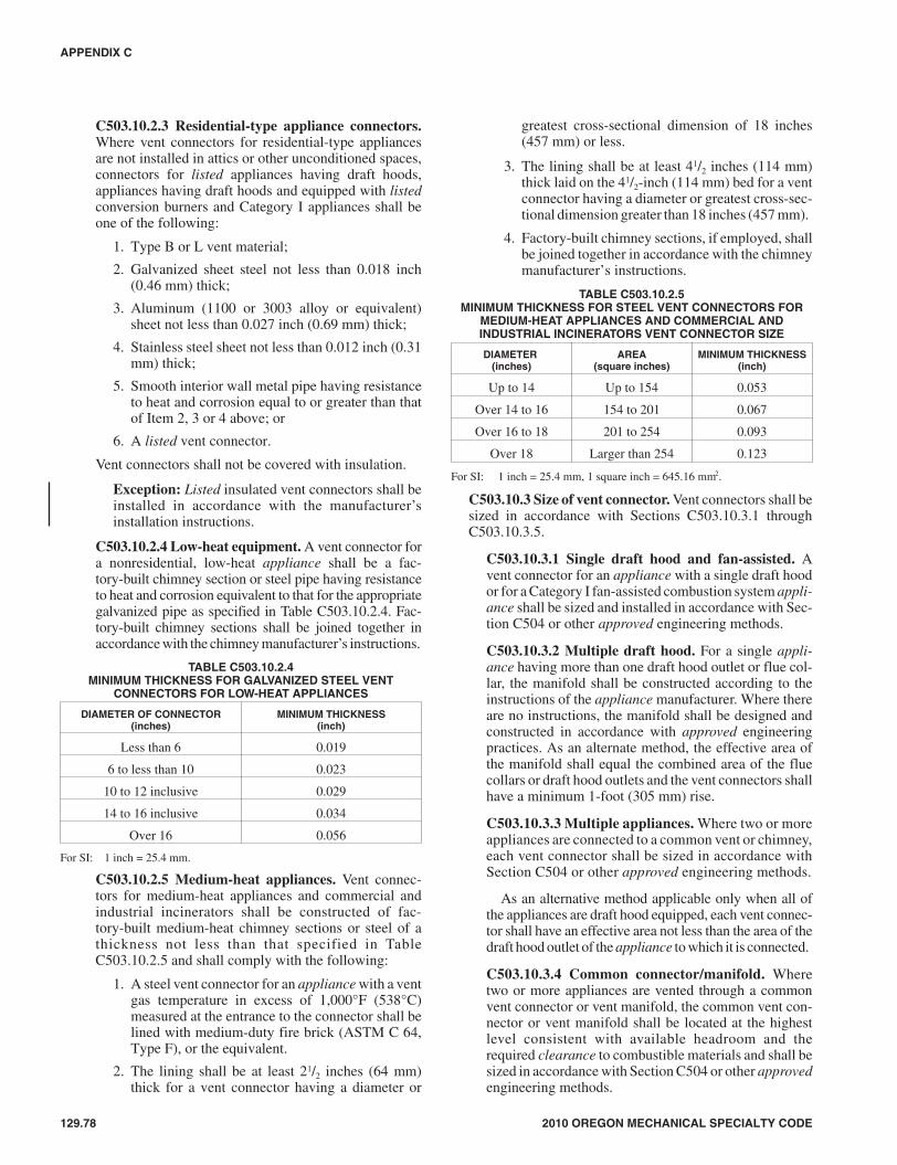
C503.10.2.3 Residential-type appliance connectors.Where vent connectors for residential-type appliancesare not installed in attics or other unconditioned spaces,connectors for listed appliances having draft hoods,appliances having draft hoods and equipped with listedconversion burners and Category I appliances shall beone of the following:
1. Type B or L vent material;
2. Galvanized sheet steel not less than 0.018 inch(0.46 mm) thick;
3. Aluminum (1100 or 3003 alloy or equivalent)sheet not less than 0.027 inch (0.69 mm) thick;
4. Stainless steel sheet not less than 0.012 inch (0.31mm) thick;
5. Smooth interior wall metal pipe having resistanceto heat and corrosion equal to or greater than thatof Item 2, 3 or 4 above; or
6. A listed vent connector.
Vent connectors shall not be covered with insulation.
Exception: Listed insulated vent connectors shall beinstalled in accordance with the manufacturer’sinstallation instructions.
C503.10.2.4 Low-heat equipment. A vent connector fora nonresidential, low-heat appliance shall be a fac-tory-built chimney section or steel pipe having resistanceto heat and corrosion equivalent to that for the appropriategalvanized pipe as specified in Table C503.10.2.4. Fac-tory-built chimney sections shall be joined together inaccordance with the chimney manufacturer’s instructions.
TABLE C503.10.2.4MINIMUM THICKNESS FOR GALVANIZED STEEL VENT
CONNECTORS FOR LOW-HEAT APPLIANCES
DIAMETER OF CONNECTOR(inches)
MINIMUM THICKNESS(inch)
Less than 6 0.019
6 to less than 10 0.023
10 to 12 inclusive 0.029
14 to 16 inclusive 0.034
Over 16 0.056
For SI: 1 inch = 25.4 mm.
C503.10.2.5 Medium-heat appliances. Vent connec-tors for medium-heat appliances and commercial andindustrial incinerators shall be constructed of fac-tory-built medium-heat chimney sections or steel of athickness not less than that specified in TableC503.10.2.5 and shall comply with the following:
1. A steel vent connector for an appliance with a ventgas temperature in excess of 1,000°F (538°C)measured at the entrance to the connector shall belined with medium-duty fire brick (ASTM C 64,Type F), or the equivalent.
2. The lining shall be at least 21/2 inches (64 mm)thick for a vent connector having a diameter or
greatest cross-sectional dimension of 18 inches(457 mm) or less.
3. The lining shall be at least 41/2 inches (114 mm)thick laid on the 41/2-inch (114 mm) bed for a ventconnector having a diameter or greatest cross-sec-tional dimension greater than 18 inches (457 mm).
4. Factory-built chimney sections, if employed, shallbe joined together in accordance with the chimneymanufacturer’s instructions.
TABLE C503.10.2.5MINIMUM THICKNESS FOR STEEL VENT CONNECTORS FOR
MEDIUM-HEAT APPLIANCES AND COMMERCIAL ANDINDUSTRIAL INCINERATORS VENT CONNECTOR SIZE
DIAMETER(inches)
AREA(square inches)
MINIMUM THICKNESS(inch)
Up to 14 Up to 154 0.053
Over 14 to 16 154 to 201 0.067
Over 16 to 18 201 to 254 0.093
Over 18 Larger than 254 0.123
For SI: 1 inch = 25.4 mm, 1 square inch = 645.16 mm2.
C503.10.3 Size of vent connector. Vent connectors shall besized in accordance with Sections C503.10.3.1 throughC503.10.3.5.
C503.10.3.1 Single draft hood and fan-assisted. Avent connector for an appliance with a single draft hoodor for a Category I fan-assisted combustion system appli-ance shall be sized and installed in accordance with Sec-tion C504 or other approved engineering methods.
C503.10.3.2 Multiple draft hood. For a single appli-ance having more than one draft hood outlet or flue col-lar, the manifold shall be constructed according to theinstructions of the appliance manufacturer. Where thereare no instructions, the manifold shall be designed andconstructed in accordance with approved engineeringpractices. As an alternate method, the effective area ofthe manifold shall equal the combined area of the fluecollars or draft hood outlets and the vent connectors shallhave a minimum 1-foot (305 mm) rise.
C503.10.3.3 Multiple appliances. Where two or moreappliances are connected to a common vent or chimney,each vent connector shall be sized in accordance withSection C504 or other approved engineering methods.
As an alternative method applicable only when all ofthe appliances are draft hood equipped, each vent connec-tor shall have an effective area not less than the area of thedraft hood outlet of the appliance to which it is connected.
C503.10.3.4 Common connector/manifold. Wheretwo or more appliances are vented through a commonvent connector or vent manifold, the common vent con-nector or vent manifold shall be located at the highestlevel consistent with available headroom and therequired clearance to combustible materials and shall besized in accordance with Section C504 or other approvedengineering methods.
129.78 2010 OREGON MECHANICAL SPECIALTY CODE
APPENDIX C
78M:\data\CODES\STATE CODES\Oregon\2010\Mechanical Specialty\Final VP\18_AppC_FuelGas_Oregon_Mech_2010.vpTuesday, January 05, 2010 10:40:18 AM
Color profile: Generic CMYK printer profileComposite Default screen

As an alternate method applicable only where thereare two draft hood-equipped appliances, the effectivearea of the common vent connector or vent manifold andall junction fittings shall be not less than the area of thelarger vent connector plus 50 percent of the area of thesmaller flue collar outlet.
C503.10.3.5 Size increase. Where the size of a vent con-nector is increased to overcome installation limitationsand obtain connector capacity equal to the applianceinput, the size increase shall be made at the appliancedraft hood outlet.
C503.10.4 Two or more appliances connected to a singlevent or chimney. Where two or more vent connectors entera common gas vent, chimney flue or single-wall metal pipe,the smaller connector shall enter at the highest level consis-tent with the available headroom or clearance to combusti-ble material. Vent connectors serving Category I appliancesshall not be connected to any portion of a mechanical draftsystem operating under positive static pressure, such asthose serving Category III or IV appliances.
C503.10.4.1 Two or more openings. Where two ormore openings are provided into one chimney flue orvent, the openings shall be at different levels, or the con-nectors shall be attached to the vertical portion of thechimney or vent at an angle of 45 degrees (0.79 rad) orless relative to the vertical.
C503.10.5 Clearance. Minimum clearances from vent con-nectors to combustible material shall be in accordance withTable C503.10.5.
Exception: The clearance between a vent connector andcombustible material shall be permitted to be reducedwhere the combustible material is protected as specifiedfor vent connectors in Table C308.2.
C503.10.6 Flow resistance. A vent connector shall beinstalled so as to avoid turns or other construction featuresthat create excessive resistance to flow of vent gases.
C503.10.7 Joints. Joints between sections of connector pip-ing and connections to flue collars and draft hood outletsshall be fastened by one of the following methods:
1. Sheet metal screws.
2. Vent connectors of listed vent material assembled andconnected to flue collars or draft hood outlets inaccordance with the manufacturers’ instructions.
3. Other approved means.
C503.10.8 Slope. A vent connector shall be installed with-out dips or sags and shall slope upward toward the vent orchimney at least 1/4 inch per foot (21 mm/m).
Exception: Vent connectors attached to a mechanicaldraft system installed in accordance with the applianceand draft system manufacturers’ instructions.
C503.10.9 Length of vent connector. A vent connectorshall be as short as practical and the appliance located asclose as practical to the chimney or vent. The maximum hor-izontal length of a single-wall connector shall be 75 percentof the height of the chimney or vent except for engineeredsystems. The maximum horizontal length of a Type B dou-ble-wall connector shall be 100 percent of the height of thechimney or vent except for engineered systems.
C503.10.10 Support. A vent connector shall be supportedfor the design and weight of the material employed to main-tain clearances and prevent physical damage and separationof joints.
C503.10.11 Chimney connection. Where entering a flue ina masonry or metal chimney, the vent connector shall beinstalled above the extreme bottom to avoid stoppage.Where a thimble or slip joint is used to facilitate removal ofthe connector, the connector shall be firmly attached to orinserted into the thimble or slip joint to prevent the connec-tor from falling out. Means shall be employed to prevent theconnector from entering so far as to restrict the spacebetween its end and the opposite wall of the chimney flue(see Section C501.9).
2010 OREGON MECHANICAL SPECIALTY CODE 129.79
APPENDIX C
TABLE C503.10.5a
CLEARANCES FOR CONNECTORS
APPLIANCE
MINIMUM DISTANCE FROM COMBUSTIBLE MATERIAL
Listed Type B gasvent material
Listed Type Lvent material
Single-wallmetal pipe
Factory-builtchimney sections
Listed appliances with draft hoods and appliances listed foruse with Type B gas vents As listed As listed 6 inches As listed
Residential boilers and furnaces with listed gas conversionburner and with draft hood 6 inches 6 inches 9 inches As listed
Residential appliances listed for use with Type L vents Not permitted As listed 9 inches As listed
Listed gas-fired toilets Not permitted As listed As listed As listed
Unlisted residential appliances with draft hood Not permitted 6 inches 9 inches As listed
Residential and low-heat appliances other than above Not permitted 9 inches 18 inches As listed
Medium-heat appliances Not permitted Not permitted 36 inches As listed
For SI: 1 inch = 25.4 mm.a. These clearances shall apply unless the manufacturer’s installation instructions for a listed appliance or connector specify different clearances, in which case the
listed clearances shall apply.
79M:\data\CODES\STATE CODES\Oregon\2010\Mechanical Specialty\Final VP\18_AppC_FuelGas_Oregon_Mech_2010.vpTuesday, January 05, 2010 10:40:18 AM
Color profile: Generic CMYK printer profileComposite Default screen

C503.10.12 Inspection. The entire length of a vent connec-tor shall be provided with ready access for inspection,cleaning and replacement.
C503.10.13 Fireplaces. A vent connector shall not be con-nected to a chimney flue serving a fireplace unless the fire-place flue opening is permanently sealed.
C503.10.14 Passage through ceilings, floors or walls. Sin-gle-wall metal pipe connectors shall not pass through any wall,floor or ceiling except as permitted by Section C503.7.4.
C503.10.15 Medium-heat connectors. Vent connectorsfor medium-heat appliances shall not pass through walls orpartitions constructed of combustible material.
C503.11 Vent connectors for Category II, III and IV appli-ances. Vent connectors for Category II, III and IV appliancesshall be as specified for the venting systems in accordance withSection C503.4.
C503.12 Draft hoods and draft controls. The installation ofdraft hoods and draft controls shall comply with SectionsC503.12.1 through C503.12.7.
C503.12.1 Appliances requiring draft hoods. Ventedappliances shall be installed with draft hoods.
Exception: Dual oven-type combination ranges; incin-erators; direct-vent appliances; fan-assisted combustionsystem appliances; appliances requiring chimney draftfor operation; single firebox boilers equipped with con-version burners with inputs greater than 400,000 Btu perhour (117 kW); appliances equipped with blast, power orpressure burners that are not listed for use with drafthoods; and appliances designed for forced venting.
C503.12.2 Installation. A draft hood supplied with orforming a part of a listed vented appliance shall be installedwithout alteration, exactly as furnished and specified by theappliance manufacturer.
C503.12.2.1 Draft hood required. If a draft hood is notsupplied by the appliance manufacturer where one isrequired, a draft hood shall be installed, shall be of alisted or approved type and, in the absence of otherinstructions, shall be of the same size as the applianceflue collar. Where a draft hood is required with a conver-sion burner, it shall be of a listed or approved type.
C503.12.2.2 Special design draft hood. Where it isdetermined that a draft hood of special design is neededor preferable for a particular installation, the installationshall be in accordance with the recommendations of theappliance manufacturer and shall be approved.
C503.12.3 Draft control devices. Where a draft controldevice is part of the appliance or is supplied by the appliancemanufacturer, it shall be installed in accordance with themanufacturer’s instructions. In the absence of manufacturer’sinstructions, the device shall be attached to the flue collar ofthe appliance or as near to the appliance as practical.
C503.12.4 Additional devices. Appliances (except inciner-ators) requiring a controlled chimney draft shall be permit-ted to be equipped with a listed double-acting barometric-
draft regulator installed and adjusted in accordance with themanufacturer’s instructions.
C503.12.5 Location. Draft hoods and barometric draft reg-ulators shall be installed in the same room or enclosure asthe appliance in such a manner as to prevent any differencein pressure between the hood or regulator and the combus-tion air supply.
C503.12.6 Positioning. Draft hoods and draft regulatorsshall be installed in the position for which they weredesigned with reference to the horizontal and vertical planesand shall be located so that the relief opening is notobstructed by any part of the appliance or adjacent con-struction. The appliance and its draft hood shall be locatedso that the relief opening is accessible for checking ventoperation.
C503.12.7 Clearance. A draft hood shall be located so itsrelief opening is not less than 6 inches (152 mm) from anysurface except that of the appliance it serves and the ventingsystem to which the draft hood is connected. Where agreater or lesser clearance is indicated on the appliancelabel, the clearance shall be not less than that specified onthe label. Such clearances shall not be reduced.
C503.13 Manually operated dampers. A manually operateddamper shall not be placed in the vent connector for any appli-ance. Fixed baffles shall not be classified as manually operateddampers.
C503.14 Automatically operated vent dampers. An auto-matically operated vent damper shall be of a listed type.
C503.15 Obstructions. Devices that retard the flow of ventgases shall not be installed in a vent connector, chimney orvent. The following shall not be considered as obstructions:
1. Draft regulators and safety controls specifically listed forinstallation in venting systems and installed in accor-dance with the manufacturer’s installation instructions.
2. Approved draft regulators and safety controls that aredesigned and installed in accordance with approvedengineering methods.
3. Listed heat reclaimers and automatically operated ventdampers installed in accordance with the manufacturer’sinstallation instructions.
4. Approved economizers, heat reclaimers and recuperatorsinstalled in venting systems of appliances not required tobe equipped with draft hoods, provided that the appliancemanufacturer’s instructions cover the installation of sucha device in the venting system and performance in accor-dance with Sections C503.3 and C503.3.1 is obtained.
5. Vent dampers serving listed appliances installed inaccordance with Sections C504.2.1 and C504.3.1 orother approved engineering methods.
C503.16 Outside wall penetrations. Where vents, includingthose for direct-vent appliances, penetrate outside walls ofbuildings, the annular spaces around such penetrations shall bepermanently sealed using approved materials to prevent entryof combustion products into the building.
129.80 2010 OREGON MECHANICAL SPECIALTY CODE
APPENDIX C
➡
80M:\data\CODES\STATE CODES\Oregon\2010\Mechanical Specialty\Final VP\18_AppC_FuelGas_Oregon_Mech_2010.vpTuesday, January 05, 2010 10:40:18 AM
Color profile: Generic CMYK printer profileComposite Default screen

2010 OREGON MECHANICAL SPECIALTY CODE 129.81
APPENDIX C
SECTION C504SIZING OF CATEGORY I APPLIANCE
VENTING SYSTEMSC504.1 Definitions. The following definitions apply to thetables in this section.
APPLIANCE CATEGORIZED VENT DIAMETER/AREA. The minimum vent area/diameter permissible for Cate-gory I appliances to maintain a nonpositive vent static pressurewhen tested in accordance with nationally recognized standards.
FAN-ASSISTED COMBUSTION SYSTEM. An applianceequipped with an integral mechanical means to either draw orforce products of combustion through the combustion chamberor heat exchanger.
FAN Min. The minimum input rating of a Category I fan-assisted appliance attached to a vent or connector.
FAN Max. The maximum input rating of a Category I fan-assisted appliance attached to a vent or connector.
NAT Max. The maximum input rating of a Category Idraft-hood-equipped appliance attached to a vent or connector.
FAN + FAN. The maximum combined appliance input ratingof two or more Category I fan-assisted appliances attached tothe common vent.
FAN + NAT. The maximum combined appliance input ratingof one or more Category I fan-assisted appliances and one ormore Category I draft-hood-equipped appliances attached tothe common vent.
NA. Vent configuration is not allowed due to potential for con-densate formation or pressurization of the venting system, ornot applicable due to physical or geometric restraints.
NAT + NAT. The maximum combined appliance input ratingof two or more Category I draft-hood-equipped appliancesattached to the common vent.
C504.2 Application of single-appliance vent TablesC504.2(1) through C504.2(6). The application of TablesC504.2(1) through C504.2(6) shall be subject to the require-ments of Sections C504.2.1 through C504.2.16.
C504.2.1 Vent obstructions. These venting tables shall notbe used where obstructions, as described in SectionC503.15, are installed in the venting system. The installa-tion of vents serving listed appliances with vent dampersshall be in accordance with the appliance manufacturer’sinstructions or in accordance with the following:
1. The maximum capacity of the vent system shall bedetermined using the “NAT Max” column.
2. The minimum capacity shall be determined as if theappliance were a fan-assisted appliance, using the“FAN Min” column to determine the minimum capac-ity of the vent system. Where the corresponding “FANMin” is “NA,” the vent configuration shall not be per-mitted and an alternative venting configuration shall beutilized.
C504.2.2 Minimum size. Where the vent size determinedfrom the tables is smaller than the appliance draft hood out-let or flue collar, the smaller size shall be permitted to beused provided that all of the following requirements are met:
1. The total vent height (H) is at least 10 feet (3048 mm).
2. Vents for appliance draft hood outlets or flue collars12 inches (305 mm) in diameter or smaller are notreduced more than one table size.
3. Vents for appliance draft hood outlets or flue collarslarger than 12 inches (305 mm) in diameter are notreduced more than two table sizes.
4. The maximum capacity listed in the tables for afan-assisted appliance is reduced by 10 percent (0.90× maximum table capacity).
5. The draft hood outlet is greater than 4 inches (102mm) in diameter. Do not connect a 3-inch-diameter(76 mm) vent to a 4-inch-diameter (102 mm) drafthood outlet. This provision shall not apply tofan-assisted appliances.
C504.2.3 Vent offsets. Single-appliance venting configura-tions with zero (0) lateral lengths in Tables C504.2(1),C504.2(2) and C504.2(5) shall not have elbows in the ventingsystem. Single-appliance venting configurations with laterallengths include two 90-degree (1.57 rad) elbows. For eachadditional elbow up to and including 45 degrees (0.79 rad),the maximum capacity listed in the venting tables shall bereduced by 5 percent. For each additional elbow greater than45 degrees (0.79 rad) up to and including 90 degrees (1.57rad), the maximum capacity listed in the venting tables shallbe reduced by 10 percent. Where multiple offsets occur in avent, the total lateral length of all offsets combined shall notexceed that specified in Tables C504.2(1) through C504.2(5).
C504.2.4 Zero lateral. Zero (0) lateral (L) shall apply onlyto a straight vertical vent attached to a top outlet draft hoodor flue collar.
C504.2.5 High-altitude installations. Sea-level input rat-ings shall be used when determining maximum capacity forhigh altitude installation. Actual input (derated for altitude)shall be used for determining minimum capacity for highaltitude installation.
C504.2.6 Multiple input rate appliances. For applianceswith more than one input rate, the minimum vent capacity(FAN Min) determined from the tables shall be less than thelowest appliance input rating, and the maximum ventcapacity (FAN Max/NAT Max) determined from the tablesshall be greater than the highest appliance rating input.
C504.2.7 Liner system sizing and connections. Listedcorrugated metallic chimney liner systems in masonrychimneys shall be sized by using Table C504.2(1) orC504.2(2) for Type B vents with the maximum capacityreduced by 20 percent (0.80 × maximum capacity) and theminimum capacity as shown in Table C504.2(1) orC504.2(2). Corrugated metallic liner systems installedwith bends or offsets shall have their maximum capacityfurther reduced in accordance with Section C504.2.3. The20-percent reduction for corrugated metallic chimneyliner systems includes an allowance for one long-radius90-degree (1.57 rad) turn at the bottom of the liner.
Connections between chimney liners and listed double-wall connectors shall be made with listed adapters designedfor such purpose.
81M:\data\CODES\STATE CODES\Oregon\2010\Mechanical Specialty\Final VP\18_AppC_FuelGas_Oregon_Mech_2010.vpTuesday, January 05, 2010 10:40:18 AM
Color profile: Generic CMYK printer profileComposite Default screen

129.82 2010 OREGON MECHANICAL SPECIALTY CODE
APPENDIX C
HE
IGH
T(H
)(f
eet)
LA
TE
RA
L(L
)(f
eet)
VE
NT
DIA
ME
TE
R—
( D)
inch
es
34
56
78
9
AP
PL
IAN
CE
INP
UT
RA
TIN
GIN
TH
OU
SA
ND
SO
FB
TU
/H
FA
NN
AT
FA
NN
AT
FA
NN
AT
FA
NN
AT
FA
NN
AT
FA
NN
AT
FA
NN
AT
Min
Max
Max
Min
Max
Max
Min
Max
Max
Min
Max
Max
Min
Max
Max
Min
Max
Max
Min
Max
Max
6
00
7846
015
286
025
114
10
375
205
052
428
50
698
370
089
747
0
213
5136
1897
6727
157
105
3223
215
744
321
217
5342
528
563
543
370
421
4934
3094
6439
153
103
5022
715
366
316
211
7941
927
993
536
362
625
4632
3691
6147
149
100
5922
314
978
310
205
9341
327
311
053
035
4
8
00
8450
016
594
027
615
50
415
235
058
332
00
780
415
01,
006
537
212
5740
1610
975
2517
812
028
263
180
4236
524
750
483
322
6061
941
8
523
5338
3210
371
4217
111
553
255
173
7035
623
783
473
313
9960
740
7
828
4935
3998
6651
164
109
6424
716
584
347
227
9946
330
311
759
639
6
10
00
8853
017
510
00
295
166
044
725
50
631
345
084
745
00
1,09
658
5
212
6142
1711
881
2319
412
926
289
195
4040
227
348
533
355
5768
445
7
523
5740
3211
377
4118
712
452
280
188
6839
226
381
522
346
9567
144
6
1030
5136
4110
470
5417
611
567
267
175
8837
624
510
450
433
012
265
142
7
15
00
9458
019
111
20
327
187
050
228
50
716
390
097
052
50
1,26
368
2
211
6948
1513
693
2022
615
022
339
225
3847
531
645
633
414
5381
554
4
522
6545
3013
087
3921
914
249
330
217
6446
330
076
620
403
9080
052
9
1029
5941
4012
182
5120
613
564
315
208
8444
528
899
600
386
116
777
507
1535
5337
4811
276
6119
512
876
301
198
9842
927
511
558
037
313
475
549
1
20
00
9761
020
211
90
349
202
054
030
70
776
430
01,
057
575
01,
384
752
210
7551
1414
910
018
250
166
2037
724
933
531
346
4171
147
050
917
612
521
7148
2914
396
3824
216
047
367
241
6251
933
773
697
460
8690
259
9
1028
6444
3813
389
5022
915
062
351
228
8149
932
195
675
443
112
877
576
1534
5840
4612
484
5921
714
273
337
217
9448
130
811
165
442
712
985
355
7
2048
5235
5511
678
6920
613
484
322
206
107
464
295
125
634
410
145
830
537
(con
tinu
ed)
TA
BL
EC
504.
2(1)
TY
PE
BD
OU
BL
E-W
AL
LG
AS
VE
NT
Nu
mb
ero
fA
pp
lian
ces
Sing
le
Ap
plia
nce
Typ
eC
ateg
ory
I
Ap
plia
nce
Ven
tC
on
nec
tio
nC
onne
cted
dire
ctly
tove
nt
82M:\data\CODES\STATE CODES\Oregon\2010\Mechanical Specialty\Final VP\18_AppC_FuelGas_Oregon_Mech_2010.vpTuesday, January 05, 2010 10:40:19 AM
Color profile: Generic CMYK printer profileComposite Default screen

2010 OREGON MECHANICAL SPECIALTY CODE 129.83
APPENDIX C
HE
IGH
T(H
)(f
eet)
LA
TE
RA
L(L
)(f
eet)
VE
NT
DIA
ME
TE
R—
( D)
inch
es
34
56
78
9
AP
PL
IAN
CE
INP
UT
RA
TIN
GIN
TH
OU
SA
ND
SO
FB
TU
/H
FA
NN
AT
FA
NN
AT
FA
NN
AT
FA
NN
AT
FA
NN
AT
FA
NN
AT
FA
NN
AT
Min
Max
Max
Min
Max
Max
Min
Max
Max
Min
Max
Max
Min
Max
Max
Min
Max
Max
Min
Max
Max
30
00
100
640
213
128
037
422
00
587
336
085
347
50
1,17
365
00
1,54
885
5
29
8156
1316
611
214
283
185
1843
228
027
613
394
3382
653
542
1,07
270
0
521
7754
2816
010
836
275
176
4542
127
358
600
385
6981
152
482
1,05
568
8
1027
7050
3715
010
248
262
171
5940
526
177
580
371
9178
850
710
71,
028
668
1533
64N
A44
141
9657
249
163
7038
924
990
560
357
105
765
490
124
1,00
264
8
2056
58N
A53
132
9066
237
154
8037
423
710
254
234
311
974
347
313
997
762
8
30N
AN
AN
A73
113
NA
8821
4N
A10
434
621
913
150
732
114
970
244
417
192
959
4
50
00
101
670
216
134
039
723
20
633
363
093
251
80
1,29
770
80
1,73
095
2
28
8661
1118
312
214
320
206
1549
731
422
715
445
2697
561
533
1,27
681
3
520
82N
A27
177
119
3531
220
043
487
308
5570
243
865
960
605
771,
259
798
1026
76N
A35
168
114
4529
919
056
471
298
7368
142
686
935
589
101
1,23
077
3
1559
70N
A42
158
NA
5428
718
066
455
288
8566
241
310
091
157
211
71,
203
747
20N
AN
AN
A50
149
NA
6327
516
976
440
278
9764
240
111
388
855
613
11,
176
722
30N
AN
AN
A69
131
NA
8425
0N
A99
410
259
123
605
376
141
844
522
161
1,12
567
0
100
0N
AN
AN
A0
218
NA
040
7N
A0
665
400
099
756
00
1,41
177
00
1,90
81,
040
2N
AN
AN
A10
194
NA
1235
4N
A13
566
375
1883
151
021
1,15
570
025
1,53
693
5
5N
AN
AN
A26
189
NA
3334
7N
A40
557
369
5282
050
460
1,14
169
271
1,51
992
6
10N
AN
AN
A33
182
NA
4333
5N
A53
542
361
6880
149
380
1,11
867
994
1,49
291
0
15N
AN
AN
A40
174
NA
5032
1N
A62
528
353
8078
248
293
1,09
566
610
91,
465
895
20N
AN
AN
A47
166
NA
5931
1N
A71
513
344
9076
347
110
51,
073
653
122
1,43
888
0
30N
AN
AN
AN
AN
AN
A78
290
NA
9248
3N
A11
572
644
913
11,
029
627
149
1,38
784
9
50N
AN
AN
AN
AN
AN
AN
AN
AN
A14
742
8N
A18
065
140
519
794
457
521
71,
288
787
(con
tinu
ed)
TA
BL
EC
504.
2(1)
—co
nti
nu
edT
YP
EB
DO
UB
LE
-WA
LL
GA
SV
EN
T
Nu
mb
ero
fA
pp
lian
ces
Sing
le
Ap
plia
nce
Typ
eC
ateg
ory
I
Ap
plia
nce
Ven
tC
on
nec
tio
nC
onne
cted
dire
ctly
tove
nt
83M:\data\CODES\STATE CODES\Oregon\2010\Mechanical Specialty\Final VP\18_AppC_FuelGas_Oregon_Mech_2010.vpTuesday, January 05, 2010 10:40:19 AM
Color profile: Generic CMYK printer profileComposite Default screen

129.84 2010 OREGON MECHANICAL SPECIALTY CODE
APPENDIX C
HE
IGH
T(H
)(f
eet)
LATE
RA
L(L
)(f
eet)
VE
NT
DIA
ME
TE
R—
(D)
inch
es
1012
1416
1820
2224
AP
PL
IAN
CE
INP
UT
RA
TIN
GIN
TH
OU
SA
ND
SO
FB
TU
/H
FA
NN
AT
FA
NN
AT
FA
NN
AT
FA
NN
AT
FA
NN
AT
FA
NN
AT
FA
NN
AT
FA
NN
AT
Min
Max
Max
Min
Max
Max
Min
Max
Max
Min
Max
Max
Min
Max
Max
Min
Max
Max
Min
Max
Max
Min
Max
Max
6
00
1,12
157
00
1,64
585
00
2,26
71,
170
02,
983
1,53
00
3,80
21,
960
04,
721
2,43
00
5,73
72,
950
06,
853
3,52
0
275
675
455
103
982
650
138
1,34
689
017
81,
769
1,17
022
52,
250
1,48
029
62,
782
1,85
036
03,
377
2,22
042
64,
030
2,67
0
411
066
844
514
797
564
019
11,
338
880
242
1,76
11,
160
300
2,24
21,
475
390
2,77
41,
835
469
3,37
02,
215
555
4,02
32,
660
612
866
143
517
196
763
021
91,
330
870
276
1,75
31,
150
341
2,23
51,
470
437
2,76
71,
820
523
3,36
32,
210
618
4,01
72,
650
8
00
1,26
166
00
1,85
897
00
2,57
11,
320
03,
399
1,74
00
4,33
32,
220
05,
387
2,75
00
6,55
53,
360
07,
838
4,01
0
271
770
515
981,
124
745
130
1,54
31,
020
168
2,03
01,
340
212
2,58
41,
700
278
3,19
62,
110
336
3,88
22,
560
401
4,63
43,
050
511
575
850
315
41,
110
733
199
1,52
81,
010
251
2,01
31,
330
311
2,56
31,
685
398
3,18
02,
090
476
3,86
32,
545
562
4,61
23,
040
813
774
649
018
01,
097
720
231
1,51
41,
000
289
2,00
01,
320
354
2,55
21,
670
450
3,16
32,
070
537
3,85
02,
530
630
4,60
23,
030
10
00
1,37
772
00
2,03
61,
060
02,
825
1,45
00
3,74
21,
925
04,
782
2,45
00
5,95
53,
050
07,
254
3,71
00
8,68
24,
450
268
852
560
931,
244
850
124
1,71
31,
130
161
2,25
61,
480
202
2,86
81,
890
264
3,55
62,
340
319
4,32
22,
840
378
5,15
33,
390
511
283
954
714
91,
229
829
192
1,69
61,
105
243
2,23
81,
461
300
2,84
91,
871
382
3,53
62,
318
458
4,30
12,
818
540
5,13
23,
371
1014
281
752
518
71,
204
795
238
1,66
91,
080
298
2,20
91,
430
364
2,81
81,
840
459
3,50
42,
280
546
4,26
82,
780
641
5,09
93,
340
15
00
1,59
684
00
2,38
01,
240
03,
323
1,72
00
4,42
32,
270
05,
678
2,90
00
7,09
93,
620
08,
665
4,41
00
10,3
935,
300
263
1,01
967
586
1,49
598
511
42,
062
1,35
014
72,
719
1,77
018
63,
467
2,26
023
94,
304
2,80
029
05,
232
3,41
034
66,
251
4,08
0
510
51,
003
660
140
1,47
696
718
22,
041
1,32
722
92,
696
1,74
828
33,
442
2,23
535
54,
278
2,77
742
65,
204
3,38
550
16,
222
4,05
7
1013
597
763
517
71,
446
936
227
2,00
91,
289
283
2,65
91,
712
346
3,40
22,
193
432
4,23
42,
739
510
5,15
93,
343
599
6,17
54,
019
1515
595
361
020
21,
418
905
257
1,97
61,
250
318
2,62
31,
675
385
3,36
32,
150
479
4,19
22,
700
564
5,11
53,
300
665
6,12
93,
980
20
00
1,75
693
00
2,63
71,
350
03,
701
1,90
00
4,94
82,
520
06,
376
3,25
00
7,98
84,
060
09,
785
4,98
00
11,7
536,
000
259
1,15
075
581
1,69
41,
100
107
2,34
31,
520
139
3,09
72,
000
175
3,95
52,
570
220
4,91
63,
200
269
5,98
33,
910
321
7,15
44,
700
510
11,
133
738
135
1,67
41,
079
174
2,32
01,
498
219
3,07
11,
978
270
3,92
62,
544
337
4,88
53,
174
403
5,95
03,
880
475
7,11
94,
662
1013
01,
105
710
172
1,64
11,
045
220
2,28
21,
460
273
3,02
91,
940
334
3,88
02,
500
413
4,83
53,
130
489
5,89
63,
830
573
7,06
34,
600
1515
01,
078
688
195
1,60
91,
018
248
2,24
51,
425
306
2,98
81,
910
372
3,83
52,
465
459
4,78
63,
090
541
5,84
43,
795
631
7,00
74,
575
2016
71,
052
665
217
1,57
899
027
32,
210
1,39
033
52,
948
1,88
040
43,
791
2,43
049
54,
737
3,05
058
55,
792
3,76
068
96,
953
4,55
0
(con
tinu
ed)
TA
BL
EC
504.
2(1)
—co
nti
nu
edT
YP
EB
DO
UB
LE
-WA
LL
GA
SV
EN
T
Nu
mb
ero
fA
pp
lian
ces
Sing
le
Ap
plia
nce
Typ
eC
ateg
ory
I
Ap
plia
nce
Ven
tC
on
nec
tio
nC
onne
cted
dire
ctly
tove
nt
84M:\data\CODES\STATE CODES\Oregon\2010\Mechanical Specialty\Final VP\18_AppC_FuelGas_Oregon_Mech_2010.vpTuesday, January 05, 2010 10:40:19 AM
Color profile: Generic CMYK printer profileComposite Default screen

2010 OREGON MECHANICAL SPECIALTY CODE 129.85
APPENDIX C
HE
IGH
T(H
)(f
eet)
LATE
RA
L(L
)(f
eet)
VE
NT
DIA
ME
TE
R—
(D)
inch
es
1012
1416
1820
2224
AP
PL
IAN
CE
INP
UT
RA
TIN
GIN
TH
OU
SA
ND
SO
FB
TU
/H
FA
NN
AT
FA
NN
AT
FA
NN
AT
FA
NN
AT
FA
NN
AT
FA
NN
AT
FA
NN
AT
FA
NN
AT
Min
Max
Max
Min
Max
Max
Min
Max
Max
Min
Max
Max
Min
Max
Max
Min
Max
Max
Min
Max
Max
Min
Max
Max
30
00
1,97
71,
060
03,
004
1,55
00
4,25
22,
170
05,
725
2,92
00
7,42
03,
770
09,
341
4,75
00
11,4
835,
850
013
,848
7,06
0
254
1,35
186
574
2,00
41,
310
982,
786
1,80
012
73,
696
2,38
015
94,
734
3,05
019
95,
900
3,81
024
17,
194
4,65
028
58,
617
5,60
0
596
1,33
285
112
71,
981
1,28
916
42,
759
1,77
520
63,
666
2,35
025
24,
701
3,02
031
25,
863
3,78
337
37,
155
4,62
243
98,
574
5,55
2
1012
51,
301
829
164
1,94
41,
254
209
2,71
61,
733
259
3,61
72,
300
316
4,64
72,
970
386
5,80
33,
739
456
7,09
04,
574
535
8,50
55,
471
1514
31,
272
807
187
1,90
81,
220
237
2,67
41,
692
292
3,57
02,
250
354
4,59
42,
920
431
5,74
43,
695
507
7,02
64,
527
590
8,43
75,
391
2016
01,
243
784
207
1,87
31,
185
260
2,63
31,
650
319
3,52
32,
200
384
4,54
22,
870
467
5,68
63,
650
548
6,96
44,
480
639
8,37
05,
310
3019
51,
189
745
246
1,80
71,
130
305
2,55
51,
585
369
3,43
32,
130
440
4,44
22,
785
540
5,57
43,
565
635
6,84
24,
375
739
8,23
95,
225
50
00
2,23
11,
195
03,
441
1,82
50
4,93
42,
550
06,
711
3,44
00
8,77
44,
460
011
,129
5,63
50
13,7
676,
940
016
,694
8,43
0
241
1,62
01,
010
662,
431
1,51
386
3,40
92,
125
113
4,55
42,
840
141
5,86
43,
670
171
7,33
94,
630
209
8,98
05,
695
251
10,7
886,
860
590
1,60
099
611
82,
406
1,49
515
13,
380
2,10
219
14,
520
2,81
323
45,
826
3,63
928
37,
295
4,59
733
68,
933
5,65
439
410
,737
6,81
8
1011
81,
567
972
154
2,36
61,
466
196
3,33
22,
064
243
4,46
42,
767
295
5,76
33,
585
355
7,22
44,
542
419
8,85
55,
585
491
10,6
526,
749
1513
61,
536
948
177
2,32
71,
437
222
3,28
52,
026
274
4,40
92,
721
330
5,70
13,
534
396
7,15
54,
511
465
8,77
95,
546
542
10,5
706,
710
2015
11,
505
924
195
2,28
81,
408
244
3,23
91,
987
300
4,35
62,
675
361
5,64
13,
481
433
7,08
64,
479
506
8,70
45,
506
586
10,4
886,
670
3018
31,
446
876
232
2,21
41,
349
287
3,15
01,
910
347
4,25
32,
631
412
5,52
33,
431
494
6,95
34,
421
577
8,55
75,
444
672
10,3
286,
603
100
00
2,49
11,
310
03,
925
2,05
00
5,72
92,
950
07,
914
4,05
00
10,4
855,
300
013
,454
6,70
00
16,8
178,
600
020
,578
10,3
00
230
1,97
51,
170
443,
027
1,82
072
4,31
32,
550
955,
834
3,50
012
07,
591
4,60
013
89,
577
5,80
016
911
,803
7,20
020
414
,264
8,80
0
582
1,95
51,
159
107
3,00
21,
803
136
4,28
22,
531
172
5,79
73,
475
208
7,54
84,
566
245
9,52
85,
769
293
11,7
487,
162
341
14,2
048,
756
1010
81,
923
1,14
214
22,
961
1,77
518
04,
231
2,50
022
35,
737
3,43
426
87,
478
4,50
931
89,
447
5,71
737
411
,658
7,10
043
614
,105
8,68
3
1512
61,
892
1,12
416
32,
920
1,74
720
64,
182
2,46
925
25,
678
3,39
230
47,
409
4,45
135
89,
367
5,66
541
811
,569
7,03
748
714
,007
8,61
0
2014
11,
861
1,10
718
12,
880
1,71
922
64,
133
2,43
827
75,
619
3,35
133
07,
341
4,39
438
79,
289
5,61
345
211
,482
6,97
552
313
,910
8,53
7
3017
01,
802
1,07
121
52,
803
1,66
326
54,
037
2,37
531
95,
505
3,26
737
87,
209
4,27
944
69,
136
5,50
951
411
,310
6,85
059
213
,720
8,39
1
5024
11,
688
1,00
029
22,
657
1,55
035
03,
856
2,25
041
55,
289
3,10
048
66,
956
4,05
057
28,
841
5,30
065
910
,979
6,60
075
213
,354
8,10
0
For
SI:
1in
ch=
25.4
mm
,1fo
ot=
304.
8m
m,1
Bri
tish
ther
mal
unit
per
hour
=0.
2931
W.
TA
BL
EC
504.
2(1)
—co
nti
nu
edT
YP
EB
DO
UB
LE
-WA
LL
GA
SV
EN
T
Nu
mb
ero
fA
pp
lian
ces
Sing
le
Ap
plia
nce
Typ
eC
ateg
ory
I
Ap
plia
nce
Ven
tC
on
nec
tio
nC
onne
cted
dire
ctly
tove
nt
85M:\data\CODES\STATE CODES\Oregon\2010\Mechanical Specialty\Final VP\18_AppC_FuelGas_Oregon_Mech_2010.vpTuesday, January 05, 2010 10:40:20 AM
Color profile: Generic CMYK printer profileComposite Default screen

129.86 2010 OREGON MECHANICAL SPECIALTY CODE
APPENDIX C
HE
IGH
T(H
)(f
eet)
LA
TE
RA
L(L
)(f
eet)
VE
NT
DIA
ME
TE
R—
(D)
inch
es
34
56
78
910
12
AP
PL
IAN
CE
INP
UT
RA
TIN
GIN
TH
OU
SA
ND
SO
FB
TU
/H
FA
NN
AT
FA
NN
AT
FA
NN
AT
FA
NN
AT
FA
NN
AT
FA
NN
AT
FA
NN
AT
FA
NN
AT
FA
NN
AT
Min
Max
Max
Min
Max
Max
Min
Max
Max
Min
Max
Max
Min
Max
Max
Min
Max
Max
Min
Max
Max
Min
Max
Max
Min
Max
Max
6
038
7745
5915
185
8524
914
012
637
320
416
552
228
421
169
536
926
789
446
937
11,
118
569
537
1,63
984
9
239
5136
6096
6685
156
104
123
231
156
159
320
213
201
423
284
251
541
368
347
673
453
498
979
648
4N
AN
A33
7492
6310
215
210
214
622
515
218
731
320
823
741
627
729
553
336
040
966
444
358
497
163
8
6N
AN
A31
8389
6011
414
799
163
220
148
207
307
203
263
409
271
327
526
352
449
656
433
638
962
627
8
037
8350
5816
493
8327
315
412
341
223
416
158
031
920
677
741
425
81,
002
536
360
1,25
765
852
11,
852
967
239
5639
5910
875
8317
611
912
126
117
915
536
324
619
748
232
124
661
741
733
976
851
348
61,
120
743
5N
AN
A37
7710
269
107
168
114
151
252
171
193
352
235
245
470
311
305
604
404
418
754
500
598
1,10
473
0
8N
AN
A33
9095
6412
216
110
717
524
316
322
334
222
528
045
830
034
459
139
247
074
048
666
51,
089
715
10
037
8753
5717
499
8229
316
512
044
425
415
862
834
420
284
444
925
31,
093
584
351
1,37
371
850
72,
031
1,05
7
239
6141
5911
780
8219
312
811
928
719
415
340
027
219
353
135
424
268
145
633
284
955
947
51,
242
848
552
5639
7611
176
105
185
122
148
277
186
190
388
261
241
518
344
299
667
443
409
834
544
584
1,22
482
5
10N
AN
A34
9710
068
132
171
112
188
261
171
237
369
241
296
497
325
363
643
423
492
808
520
688
1,19
478
8
15
036
9357
5619
011
180
325
186
116
499
283
153
713
388
195
966
523
244
1,25
968
133
61,
591
838
488
2,37
41,
237
238
6947
5713
693
8022
514
911
533
722
414
847
331
418
763
141
323
281
254
331
91,
015
673
457
1,49
198
3
551
6344
7512
886
102
216
140
144
326
217
182
459
298
231
616
400
287
795
526
392
997
657
562
1,46
996
3
10N
AN
A39
9511
679
128
201
131
182
308
203
228
438
284
284
592
381
349
768
501
470
966
628
664
1,43
392
8
15N
AN
AN
AN
AN
A72
158
186
124
220
290
192
272
418
269
334
568
367
404
742
484
540
937
601
750
1,39
989
4
20
035
9660
5420
011
878
346
201
114
537
306
149
772
428
190
1,05
357
323
81,
379
750
326
1,75
192
747
32,
631
1,34
6
237
7450
5614
899
7824
816
511
337
524
814
452
834
418
270
846
822
791
461
130
91,
146
754
443
1,68
91,
098
550
6847
7314
094
100
239
158
141
363
239
178
514
334
224
692
457
279
896
596
381
1,12
673
454
71,
665
1,07
4
10N
AN
A41
9312
986
125
223
146
177
344
224
222
491
316
277
666
437
339
866
570
457
1,09
270
264
61,
626
1,03
7
15N
AN
AN
AN
AN
A80
155
208
136
216
325
210
264
469
301
325
640
419
393
838
549
526
1,06
067
773
01,
587
1,00
5
20N
AN
AN
AN
AN
AN
A18
619
212
625
430
619
630
944
828
537
461
640
044
881
052
659
21,
028
651
808
1,55
097
3
(con
tinu
ed)
TA
BL
EC
504.
2(2)
TY
PE
BD
OU
BL
E-W
AL
LG
AS
VE
NT
Nu
mb
ero
fA
pp
lian
ces
Sing
le
Ap
plia
nce
Typ
eC
ateg
ory
I
Ap
plia
nce
Ven
tC
on
nec
tio
nSi
ngle
-wal
lmet
alco
nnec
tor
86M:\data\CODES\STATE CODES\Oregon\2010\Mechanical Specialty\Final VP\18_AppC_FuelGas_Oregon_Mech_2010.vpTuesday, January 05, 2010 10:40:20 AM
Color profile: Generic CMYK printer profileComposite Default screen

2010 OREGON MECHANICAL SPECIALTY CODE 129.87
APPENDIX C
HE
IGH
T(H
)(f
eet)
LA
TE
RA
L(L
)(f
eet)
VE
NT
DIA
ME
TE
R—
(D)
inch
es
34
56
78
910
12
AP
PL
IAN
CE
INP
UT
RA
TIN
GIN
TH
OU
SA
ND
SO
FB
TU
/H
FA
NN
AT
FA
NN
AT
FA
NN
AT
FA
NN
AT
FA
NN
AT
FA
NN
AT
FA
NN
AT
FA
NN
AT
FA
NN
AT
Min
Max
Max
Min
Max
Max
Min
Max
Max
Min
Max
Max
Min
Max
Max
Min
Max
Max
Min
Max
Max
Min
Max
Max
Min
Max
Max
30
034
9963
5321
112
776
372
219
110
584
334
144
849
472
184
1,16
864
722
91,
542
852
312
1,97
11,
056
454
2,99
61,
545
237
8056
5516
411
176
281
183
109
429
279
139
610
392
175
823
533
219
1,06
969
829
61,
346
863
424
1,99
91,
308
549
7452
7215
710
698
271
173
136
417
271
171
595
382
215
806
521
269
1,04
968
436
61,
324
846
524
1,97
11,
283
10N
AN
AN
A91
144
9812
225
516
817
139
725
721
357
036
726
577
750
132
71,
017
662
440
1,28
782
162
01,
927
1,23
4
15N
AN
AN
A11
513
1N
A15
123
915
720
837
724
225
554
734
931
275
048
137
998
563
850
71,
251
794
702
1,88
41,
205
20N
AN
AN
AN
AN
AN
A18
122
3N
A24
635
722
829
852
433
336
072
346
143
395
561
557
01,
216
768
780
1,84
11,
166
30N
AN
AN
AN
AN
AN
AN
AN
AN
AN
AN
AN
A38
947
730
546
167
042
654
189
557
470
41,
147
720
937
1,75
91,
101
50
033
9966
5121
313
373
394
230
105
629
361
138
928
515
176
1,29
270
422
01,
724
948
295
2,22
31,
189
428
3,43
21,
818
236
8461
5318
112
173
318
205
104
495
312
133
712
443
168
971
613
209
1,27
381
128
01,
615
1,00
740
12,
426
1,50
9
548
80N
A70
174
117
9430
819
813
148
230
516
469
643
520
495
360
225
71,
252
795
347
1,59
199
149
62,
396
1,49
0
10N
AN
AN
A89
160
NA
118
292
186
162
461
292
203
671
420
253
923
583
313
1,21
776
541
81,
551
963
589
2,34
71,
455
15N
AN
AN
A11
214
8N
A14
527
517
419
944
128
024
464
640
529
989
456
236
31,
183
736
481
1,51
293
466
82,
299
1,42
1
20N
AN
AN
AN
AN
AN
A17
625
7N
A23
642
026
728
562
238
934
586
654
341
51,
150
708
544
1,47
390
674
12,
251
1,38
7
30N
AN
AN
AN
AN
AN
AN
AN
AN
A31
537
6N
A37
357
3N
A44
280
950
252
11,
086
649
674
1,39
984
889
22,
159
1,31
8
100
0N
AN
AN
A49
214
NA
6940
3N
A10
065
939
513
199
155
516
61,
404
765
207
1,90
01,
033
273
2,47
91,
300
395
3,91
22,
042
2N
AN
AN
A51
192
NA
7035
1N
A98
563
373
125
828
508
158
1,15
269
819
61,
532
933
259
1,97
01,
168
371
3,02
11,
817
5N
AN
AN
A67
186
NA
9034
2N
A12
555
136
615
681
350
119
41,
134
688
240
1,51
192
132
21,
945
1,15
346
02,
990
1,79
6
10N
AN
AN
A85
175
NA
113
324
NA
153
532
354
191
789
486
238
1,10
467
229
31,
477
902
389
1,90
51,
133
547
2,93
81,
763
15N
AN
AN
A13
216
2N
A13
831
0N
A18
851
134
323
076
447
328
11,
075
656
342
1,44
388
444
71,
865
1,11
061
82,
888
1,73
0
20N
AN
AN
AN
AN
AN
A16
829
5N
A22
448
7N
A27
073
945
832
51,
046
639
391
1,41
086
450
71,
825
1,08
769
02,
838
1,69
6
30N
AN
AN
AN
AN
AN
A23
126
4N
A30
144
8N
A35
568
5N
A41
898
8N
A49
11,
343
824
631
1,74
71,
041
834
2,73
91,
627
50N
AN
AN
AN
AN
AN
AN
AN
AN
AN
AN
AN
A54
058
4N
A61
786
6N
A71
11,
205
NA
895
1,59
1N
A1,
138
2,54
71,
489
For
SI:
1in
ch=
25.4
mm
,1fo
ot=
304.
8m
m,1
Bri
tish
ther
mal
unit
per
hour
=0.
2931
W.
TA
BL
EC
504.
2(2)
—co
nti
nu
edT
YP
EB
DO
UB
LE
-WA
LL
GA
SV
EN
T
Nu
mb
ero
fA
pp
lian
ces
Sing
le
Ap
plia
nce
Typ
eC
ateg
ory
I
Ap
plia
nce
Ven
tC
on
nec
tio
nSi
ngle
-wal
lmet
alco
nnec
tor
87M:\data\CODES\STATE CODES\Oregon\2010\Mechanical Specialty\Final VP\18_AppC_FuelGas_Oregon_Mech_2010.vpTuesday, January 05, 2010 10:40:20 AM
Color profile: Generic CMYK printer profileComposite Default screen

129.88 2010 OREGON MECHANICAL SPECIALTY CODE
APPENDIX C
HE
IGH
T(H
)(f
eet)
LA
TE
RA
L(L
)(f
eet)
TY
PE
BD
OU
BL
E-W
AL
LC
ON
NE
CT
OR
DIA
ME
TE
R—
( D)
inch
esto
be
use
dw
ith
chim
ney
area
sw
ith
inth
esi
zelim
its
atb
ott
om
34
56
78
910
12
AP
PL
IAN
CE
INP
UT
RA
TIN
GIN
TH
OU
SA
ND
SO
FB
TU
/H
FA
NN
AT
FA
NN
AT
FA
NN
AT
FA
NN
AT
FA
NN
AT
FA
NN
AT
FA
NN
AT
FA
NN
AT
FA
NN
AT
Min
Max
Max
Min
Max
Max
Min
Max
Max
Min
Max
Max
Min
Max
Max
Min
Max
Max
Min
Max
Max
Min
Max
Max
Min
Max
Max
62
NA
NA
28N
AN
A52
NA
NA
86N
AN
A13
0N
AN
A18
0N
AN
A24
7N
AN
A32
0N
AN
A40
1N
AN
A58
1
5N
AN
A25
NA
NA
49N
AN
A82
NA
NA
117
NA
NA
165
NA
NA
231
NA
NA
298
NA
NA
376
NA
NA
561
8
2N
AN
A29
NA
NA
55N
AN
A93
NA
NA
145
NA
NA
198
NA
NA
266
8459
035
010
072
844
613
91,
024
651
5N
AN
A26
NA
NA
52N
AN
A88
NA
NA
134
NA
NA
183
NA
NA
247
NA
NA
328
149
711
423
201
1,00
764
0
8N
AN
A24
NA
NA
48N
AN
A83
NA
NA
127
NA
NA
175
NA
NA
239
NA
NA
318
173
695
410
231
990
623
10
2N
AN
A31
NA
NA
61N
AN
A10
3N
AN
A16
2N
AN
A22
168
519
298
8265
538
898
810
491
136
1,14
472
4
5N
AN
A28
NA
NA
57N
AN
A96
NA
NA
148
NA
NA
204
NA
NA
277
124
638
365
146
791
466
196
1,12
471
2
10N
AN
A25
NA
NA
50N
AN
A87
NA
NA
139
NA
NA
191
NA
NA
263
155
610
347
182
762
444
240
1,09
366
8
15
2N
AN
A35
NA
NA
67N
AN
A11
4N
AN
A17
953
475
250
6461
333
677
779
441
9296
856
212
71,
376
841
5N
AN
A35
NA
NA
62N
AN
A10
7N
AN
A16
4N
AN
A23
199
594
313
118
759
416
139
946
533
186
1,35
282
8
10N
AN
A28
NA
NA
55N
AN
A97
NA
NA
153
NA
NA
216
126
565
296
148
727
394
173
912
567
229
1,31
577
7
15N
AN
AN
AN
AN
A48
NA
NA
89N
AN
A14
1N
AN
A20
1N
AN
A28
117
169
837
519
888
048
525
91,
280
742
20
2N
AN
A38
NA
NA
74N
AN
A12
4N
AN
A20
151
522
274
6167
837
573
867
491
871,
083
627
121
1,54
895
3
5N
AN
A36
NA
NA
68N
AN
A11
6N
AN
A18
480
503
254
9565
835
011
384
546
313
31,
059
597
179
1,52
393
3
10N
AN
AN
AN
AN
A60
NA
NA
107
NA
NA
172
NA
NA
237
122
627
332
143
811
440
167
1,02
256
622
11,
482
879
15N
AN
AN
AN
AN
AN
AN
AN
A97
NA
NA
159
NA
NA
220
NA
NA
314
165
780
418
191
987
541
251
1,44
384
0
20N
AN
AN
AN
AN
AN
AN
AN
A83
NA
NA
148
NA
NA
206
NA
NA
296
186
750
397
214
955
513
277
1,40
680
7
(con
tinu
ed)
TA
BL
EC
504.
2(3)
MA
SO
NR
YC
HIM
NE
Y
Nu
mb
ero
fA
pp
lian
ces
Sing
le
Ap
plia
nce
Typ
eC
ateg
ory
I
Ap
plia
nce
Ven
tC
on
nec
tio
nT
ype
Bdo
uble
-wal
lcon
nect
or
88M:\data\CODES\STATE CODES\Oregon\2010\Mechanical Specialty\Final VP\18_AppC_FuelGas_Oregon_Mech_2010.vpTuesday, January 05, 2010 10:40:21 AM
Color profile: Generic CMYK printer profileComposite Default screen

2010 OREGON MECHANICAL SPECIALTY CODE 129.89
APPENDIX C
HE
IGH
T(H
)(f
eet)
LA
TE
RA
L(L
)(f
eet)
TY
PE
BD
OU
BL
E-W
AL
LC
ON
NE
CT
OR
DIA
ME
TE
R—
( D)
inch
esto
be
use
dw
ith
chim
ney
area
sw
ith
inth
esi
zelim
its
atb
ott
om
34
56
78
910
12
AP
PL
IAN
CE
INP
UT
RA
TIN
GIN
TH
OU
SA
ND
SO
FB
TU
/H
FA
NN
AT
FA
NN
AT
FA
NN
AT
FA
NN
AT
FA
NN
AT
FA
NN
AT
FA
NN
AT
FA
NN
AT
FA
NN
AT
Min
Max
Max
Min
Max
Max
Min
Max
Max
Min
Max
Max
Min
Max
Max
Min
Max
Max
Min
Max
Max
Min
Max
Max
Min
Max
Max
30
2N
AN
A41
NA
NA
82N
AN
A13
7N
AN
A21
647
581
303
5776
242
168
985
558
811,
240
717
111
1,79
31,
112
5N
AN
AN
AN
AN
A76
NA
NA
128
NA
NA
198
7556
128
190
741
393
106
962
526
125
1,21
668
316
91,
766
1,09
4
10N
AN
AN
AN
AN
A67
NA
NA
115
NA
NA
184
NA
NA
263
115
709
373
135
927
500
158
1,17
664
821
01,
721
1,02
5
15N
AN
AN
AN
AN
AN
AN
AN
A10
7N
AN
A17
1N
AN
A24
3N
AN
A35
315
689
347
618
11,
139
621
239
1,67
998
1
20N
AN
AN
AN
AN
AN
AN
AN
A91
NA
NA
159
NA
NA
227
NA
NA
332
176
860
450
203
1,10
359
226
41,
638
940
30N
AN
AN
AN
AN
AN
AN
AN
AN
AN
AN
AN
AN
AN
A18
8N
AN
A28
8N
AN
A41
624
91,
035
555
318
1,56
087
7
50
2N
AN
AN
AN
AN
A92
NA
NA
161
NA
NA
251
NA
NA
351
5184
047
761
1,10
663
372
1,41
381
299
2,08
01,
243
5N
AN
AN
AN
AN
AN
AN
AN
A15
1N
AN
A23
0N
AN
A32
383
819
445
981,
083
596
116
1,38
777
415
52,
052
1,22
5
10N
AN
AN
AN
AN
AN
AN
AN
A13
8N
AN
A21
5N
AN
A30
4N
AN
A42
412
61,
047
567
147
1,34
773
319
52,
006
1,14
7
15N
AN
AN
AN
AN
AN
AN
AN
A12
7N
AN
A19
9N
AN
A28
2N
AN
A40
014
61,
010
539
170
1,30
770
222
21,
961
1,09
9
20N
AN
AN
AN
AN
AN
AN
AN
AN
AN
AN
A18
5N
AN
A26
4N
AN
A37
616
597
751
119
01,
269
669
246
1,91
61,
050
30N
AN
AN
AN
AN
AN
AN
AN
AN
AN
AN
AN
AN
AN
AN
AN
AN
A32
7N
AN
A46
823
31,
196
623
295
1,83
298
4
Min
imum
Inte
rnal
Are
aof
Chi
mne
y(s
quar
ein
ches
)12
1928
3850
6378
9513
2
Max
imum
Inte
rnal
Are
aof
Chi
mne
y(s
quar
ein
ches
)Se
ven
tim
esth
eli
sted
appl
ianc
eca
tego
rize
dve
ntar
ea,f
lue
coll
arar
eaor
draf
thoo
dou
tlet
area
.
For
SI:
1in
ch=
25.4
mm
,1sq
uare
inch
=64
5.16
mm
2 ,1fo
ot=
304.
8m
m,1
Bri
tish
ther
mal
unit
per
hour
=0.
2931
W.
TA
BL
EC
504.
2(3)
—co
nti
nu
edM
AS
ON
RY
CH
IMN
EY
Nu
mb
ero
fA
pp
lian
ces
Sing
le
Ap
plia
nce
Typ
eC
ateg
ory
I
Ap
plia
nce
Ven
tC
on
nec
tio
nT
ype
Bdo
uble
-wal
lcon
nect
or
89M:\data\CODES\STATE CODES\Oregon\2010\Mechanical Specialty\Final VP\18_AppC_FuelGas_Oregon_Mech_2010.vpTuesday, January 05, 2010 10:40:21 AM
Color profile: Generic CMYK printer profileComposite Default screen

129.90 2010 OREGON MECHANICAL SPECIALTY CODE
APPENDIX C
HE
IGH
T(H
)(f
eet)
LA
TE
RA
L(L
)(f
eet)
SIN
GL
E-W
AL
LM
ET
AL
CO
NN
EC
TO
RD
IAM
ET
ER
—( D
)in
ches
tob
eu
sed
wit
hch
imn
eyar
eas
wit
hin
the
size
limit
sat
bo
tto
m
34
56
78
910
12
AP
PL
IAN
CE
INP
UT
RA
TIN
GIN
TH
OU
SA
ND
SO
FB
TU
/H
FA
NN
AT
FA
NN
AT
FA
NN
AT
FA
NN
AT
FA
NN
AT
FA
NN
AT
FA
NN
AT
FA
NN
AT
FA
NN
AT
Min
Max
Max
Min
Max
Max
Min
Max
Max
Min
Max
Max
Min
Max
Max
Min
Max
Max
Min
Max
Max
Min
Max
Max
Min
Max
Max
62
NA
NA
28N
AN
A52
NA
NA
86N
AN
A13
0N
AN
A18
0N
AN
A24
7N
AN
A31
9N
AN
A40
0N
AN
A58
0
5N
AN
A25
NA
NA
48N
AN
A81
NA
NA
116
NA
NA
164
NA
NA
230
NA
NA
297
NA
NA
375
NA
NA
560
8
2N
AN
A29
NA
NA
55N
AN
A93
NA
NA
145
NA
NA
197
NA
NA
265
NA
NA
349
382
725
445
549
1,02
165
0
5N
AN
A26
NA
NA
51N
AN
A87
NA
NA
133
NA
NA
182
NA
NA
246
NA
NA
327
NA
NA
422
673
1,00
363
8
8N
AN
A23
NA
NA
47N
AN
A82
NA
NA
126
NA
NA
174
NA
NA
237
NA
NA
317
NA
NA
408
747
985
621
10
2N
AN
A31
NA
NA
61N
AN
A10
2N
AN
A16
1N
AN
A22
021
651
829
727
165
438
737
380
849
053
61,
142
722
5N
AN
A28
NA
NA
56N
AN
A95
NA
NA
147
NA
NA
203
NA
NA
276
334
635
364
459
789
465
657
1,12
171
0
10N
AN
A24
NA
NA
49N
AN
A86
NA
NA
137
NA
NA
189
NA
NA
261
NA
NA
345
547
758
441
771
1,08
866
5
15
2N
AN
A35
NA
NA
67N
AN
A11
3N
AN
A17
816
647
324
921
161
133
526
477
644
036
296
556
052
01,
373
840
5N
AN
A32
NA
NA
61N
AN
A10
6N
AN
A16
3N
AN
A23
026
159
131
232
577
541
444
494
253
163
71,
348
825
10N
AN
A27
NA
NA
54N
AN
A96
NA
NA
151
NA
NA
214
NA
NA
294
392
722
392
531
907
504
749
1,30
977
4
15N
AN
AN
AN
AN
A46
NA
NA
87N
AN
A13
8N
AN
A19
8N
AN
A27
845
269
237
260
687
348
184
11,
272
738
20
2N
AN
A38
NA
NA
73N
AN
A12
3N
AN
A20
016
352
027
320
667
537
425
886
449
025
21,
079
625
508
1,54
495
0
5N
AN
A35
NA
NA
67N
AN
A11
5N
AN
A18
380
NA
252
255
655
348
317
842
461
433
1,05
559
462
31,
518
930
10N
AN
AN
AN
AN
A59
NA
NA
105
NA
NA
170
NA
NA
235
312
622
330
382
806
437
517
1,01
656
273
31,
475
875
15N
AN
AN
AN
AN
AN
AN
AN
A95
NA
NA
156
NA
NA
217
NA
NA
311
442
773
414
591
979
539
823
1,43
483
5
20N
AN
AN
AN
AN
AN
AN
AN
A80
NA
NA
144
NA
NA
202
NA
NA
292
NA
NA
392
663
944
510
911
1,39
480
0
(con
tinu
ed)
TA
BL
EC
504.
2(4)
MA
SO
NR
YC
HIM
NE
Y
Nu
mb
ero
fA
pp
lian
ces
Sing
le
Ap
plia
nce
Typ
eC
ateg
ory
I
Ap
plia
nce
Ven
tC
on
nec
tio
nSi
ngle
-wal
lmet
alco
nnec
tor
90M:\data\CODES\STATE CODES\Oregon\2010\Mechanical Specialty\Final VP\18_AppC_FuelGas_Oregon_Mech_2010.vpTuesday, January 05, 2010 10:40:21 AM
Color profile: Generic CMYK printer profileComposite Default screen

2010 OREGON MECHANICAL SPECIALTY CODE 129.91
APPENDIX C
HE
IGH
T(H
)(f
eet)
LA
TE
RA
L(L
)(f
eet)
SIN
GL
E-W
AL
LM
ET
AL
CO
NN
EC
TO
RD
IAM
ET
ER
—( D
)in
ches
tob
eu
sed
wit
hch
imn
eyar
eas
wit
hin
the
size
limit
sat
bo
tto
m
34
56
78
910
12
AP
PL
IAN
CE
INP
UT
RA
TIN
GIN
TH
OU
SA
ND
SO
FB
TU
/H
FA
NN
AT
FA
NN
AT
FA
NN
AT
FA
NN
AT
FA
NN
AT
FA
NN
AT
FA
NN
AT
FA
NN
AT
FA
NN
AT
Min
Max
Max
Min
Max
Max
Min
Max
Max
Min
Max
Max
Min
Max
Max
Min
Max
Max
Min
Max
Max
Min
Max
Max
Min
Max
Max
30
2N
AN
A41
NA
NA
81N
AN
A13
6N
AN
A21
515
857
830
220
075
942
024
998
255
634
01,
237
715
489
1,78
91,
110
5N
AN
AN
AN
AN
A75
NA
NA
127
NA
NA
196
NA
NA
279
245
737
391
306
958
524
417
1,21
068
060
01,
760
1,09
0
10N
AN
AN
AN
AN
A66
NA
NA
113
NA
NA
182
NA
NA
260
300
703
370
370
920
496
500
1,16
864
470
81,
713
1,02
0
15N
AN
AN
AN
AN
AN
AN
AN
A10
5N
AN
A16
8N
AN
A24
0N
AN
A34
942
888
447
157
21,
128
615
798
1,66
897
5
20N
AN
AN
AN
AN
AN
AN
AN
A88
NA
NA
155
NA
NA
223
NA
NA
327
NA
NA
445
643
1,08
958
588
31,
624
932
30N
AN
AN
AN
AN
AN
AN
AN
AN
AN
AN
AN
AN
AN
A18
2N
AN
A28
1N
AN
A40
8N
AN
A54
41,
055
1,53
986
5
50
2N
AN
AN
AN
AN
A91
NA
NA
160
NA
NA
250
NA
NA
350
191
837
475
238
1,10
363
132
31,
408
810
463
2,07
61,
240
5N
AN
AN
AN
AN
AN
AN
AN
A14
9N
AN
A22
8N
AN
A32
1N
AN
A44
229
31,
078
593
398
1,38
177
057
12,
044
1,22
0
10N
AN
AN
AN
AN
AN
AN
AN
A13
6N
AN
A21
2N
AN
A30
1N
AN
A42
035
51,
038
562
447
1,33
772
867
41,
994
1,14
0
15N
AN
AN
AN
AN
AN
AN
AN
A12
4N
AN
A19
5N
AN
A27
8N
AN
A39
5N
AN
A53
354
61,
294
695
761
1,94
51,
090
20N
AN
AN
AN
AN
AN
AN
AN
AN
AN
AN
A18
0N
AN
A25
8N
AN
A37
0N
AN
A50
461
61,
251
660
844
1,89
81,
040
30N
AN
AN
AN
AN
A48
NA
NA
NA
NA
NA
NA
NA
NA
NA
NA
NA
318
NA
NA
458
NA
NA
610
1,00
91,
805
970
Min
imum
Inte
rnal
Are
aof
Chi
mne
y(s
quar
ein
ches
)
1219
2838
5063
7895
132
Max
imum
Inte
rnal
Are
aof
Chi
mne
y(s
quar
ein
ches
)
Seve
nti
mes
the
list
edap
plia
nce
cate
gori
zed
vent
area
,flu
eco
llar
area
ordr
afth
ood
outl
etar
ea.
For
SI:
1in
ch=
25.4
mm
,1sq
uare
inch
=64
5.16
mm
2 ,1fo
ot=
304.
8m
m,1
Bri
tish
ther
mal
unit
per
hour
=0.
2931
W.
TA
BL
EC
504.
2(4)
—co
nti
nu
edM
AS
ON
RY
CH
IMN
EY
Nu
mb
ero
fA
pp
lian
ces
Sing
le
Ap
plia
nce
Typ
eC
ateg
ory
I
Ap
plia
nce
Ven
tC
on
nec
tio
nSi
ngle
-wal
lmet
alco
nnec
tor
91M:\data\CODES\STATE CODES\Oregon\2010\Mechanical Specialty\Final VP\18_AppC_FuelGas_Oregon_Mech_2010.vpTuesday, January 05, 2010 10:40:21 AM
Color profile: Generic CMYK printer profileComposite Default screen

129.92 2010 OREGON MECHANICAL SPECIALTY CODE
APPENDIX C
HEIGHT(H)
(feet)
LATERAL(L)
(feet)
VENT DIAMETER—(D) inches
3 4 5 6 7 8 10 12
MAXIMUM APPLIANCE INPUT RATING IN THOUSANDS OF BTU/H
6
0 39 70 116 170 232 312 500 750
2 31 55 94 141 194 260 415 620
5 28 51 88 128 177 242 390 600
8
0 42 76 126 185 252 340 542 815
2 32 61 102 154 210 284 451 680
5 29 56 95 141 194 264 430 648
10 24 49 86 131 180 250 406 625
10
0 45 84 138 202 279 372 606 912
2 35 67 111 168 233 311 505 760
5 32 61 104 153 215 289 480 724
10 27 54 94 143 200 274 455 700
15 NA 46 84 130 186 258 432 666
15
0 49 91 151 223 312 420 684 1,040
2 39 72 122 186 260 350 570 865
5 35 67 110 170 240 325 540 825
10 30 58 103 158 223 308 514 795
15 NA 50 93 144 207 291 488 760
20 NA NA 82 132 195 273 466 726
20
0 53 101 163 252 342 470 770 1,190
2 42 80 136 210 286 392 641 990
5 38 74 123 192 264 364 610 945
10 32 65 115 178 246 345 571 910
15 NA 55 104 163 228 326 550 870
20 NA NA 91 149 214 306 525 832
30
0 56 108 183 276 384 529 878 1,370
2 44 84 148 230 320 441 730 1,140
5 NA 78 137 210 296 410 694 1,080
10 NA 68 125 196 274 388 656 1,050
15 NA NA 113 177 258 366 625 1,000
20 NA NA 99 163 240 344 596 960
30 NA NA NA NA 192 295 540 890
50
0 NA 120 210 310 443 590 980 1,550
2 NA 95 171 260 370 492 820 1,290
5 NA NA 159 234 342 474 780 1,230
10 NA NA 146 221 318 456 730 1,190
15 NA NA NA 200 292 407 705 1,130
20 NA NA NA 185 276 384 670 1,080
30 NA NA NA NA 222 330 605 1,010
For SI: 1 inch = 25.4 mm, 1 foot = 304.8 mm, 1 British thermal unit per hour = 0.2931 W.
TABLE C504.2(5)SINGLE-WALL METAL PIPE OR TYPE B
ASBESTOS CEMENT VENT
Number of Appliances Single
Appliance Type Draft hood equipped
Appliance Vent Connection Connected directly to pipe or vent
92M:\data\CODES\STATE CODES\Oregon\2010\Mechanical Specialty\Final VP\18_AppC_FuelGas_Oregon_Mech_2010.vpTuesday, January 05, 2010 10:40:22 AM
Color profile: Generic CMYK printer profileComposite Default screen

2010 OREGON MECHANICAL SPECIALTY CODE 129.93
APPENDIX C
MINIMUM ALLOWABLE INPUT RATING OF SPACE-HEATING APPLIANCEIN THOUSANDS OF BTU PER HOUR
VENT HEIGHT(feet)
Internal area of chimney (square inches)
12 19 28 38 50 63 78 113
37°F or Greater Local 99% Winter Design Temperature: 37°F or Greater
6 0 0 0 0 0 0 0 0
8 0 0 0 0 0 0 0 0
10 0 0 0 0 0 0 0 0
15 NA 0 0 0 0 0 0 0
20 NA NA 123 190 249 184 0 0
30 NA NA NA NA NA 393 334 0
50 NA NA NA NA NA NA NA 579
27 to 36°F Local 99% Winter Design Temperature: 27 to 36°F
6 0 0 68 116 156 180 212 266
8 0 0 82 127 167 187 214 263
10 0 51 97 141 183 201 225 265
15 NA NA NA NA 233 253 274 305
20 NA NA NA NA NA 307 330 362
30 NA NA NA NA NA 419 445 485
50 NA NA NA NA NA NA NA 763
17 to 26°F Local 99% Winter Design Temperature: 17 to 26°F
6 NA NA NA NA NA 215 259 349
8 NA NA NA NA 197 226 264 352
10 NA NA NA NA 214 245 278 358
15 NA NA NA NA NA 296 331 398
20 NA NA NA NA NA 352 387 457
30 NA NA NA NA NA NA 507 581
50 NA NA NA NA NA NA NA NA
5 to 16°F Local 99% Winter Design Temperature: 5 to 16°F
6 NA NA NA NA NA NA NA 416
8 NA NA NA NA NA NA 312 423
10 NA NA NA NA NA 289 331 430
15 NA NA NA NA NA NA 393 485
20 NA NA NA NA NA NA 450 547
30 NA NA NA NA NA NA NA 682
50 NA NA NA NA NA NA NA 972
-10 to 4°F Local 99% Winter Design Temperature: -10 to 4°F
6 NA NA NA NA NA NA NA 484
8 NA NA NA NA NA NA NA 494
10 NA NA NA NA NA NA NA 513
15 NA NA NA NA NA NA NA 586
20 NA NA NA NA NA NA NA 650
30 NA NA NA NA NA NA NA 805
50 NA NA NA NA NA NA NA 1,003
-11°F or Lower Local 99% Winter Design Temperature: -11°F or Lower
Not recommended for any vent configurations
For SI: °C = (°F - 32)/1.8, 1 inch = 25.4 mm, 1 foot = 304.8 mm, 1 British thermal unit per hour = 0.2931 W.Note: See Figure C-B-19 in Appendix C-B for a map showing local 99 percent winter design temperatures in the United States.
TABLE C504.2(6)EXTERIOR MASONRY CHIMNEY
Number of Appliances Single
Appliance Type NAT
Appliance Vent Connection Type B double-wall connector
93M:\data\CODES\STATE CODES\Oregon\2010\Mechanical Specialty\Final VP\18_AppC_FuelGas_Oregon_Mech_2010.vpTuesday, January 05, 2010 10:40:22 AM
Color profile: Generic CMYK printer profileComposite Default screen
C504.2.8 Vent area and diameter. Where the vertical venthas a larger diameter than the vent connector, the verticalvent diameter shall be used to determine the minimum ventcapacity, and the connector diameter shall be used to deter-mine the maximum vent capacity. The flow area of the verti-cal vent shall not exceed seven times the flow area of thelisted appliance categorized vent area, flue collar area ordraft hood outlet area unless designed in accordance withapproved engineering methods.
C504.2.9 Chimney and vent locations. Tables C504.2(1),C504.2(2), C504.2(3), C504.2(4) and C504.2(5) shall beused only for chimneys and vents not exposed to the out-doors below the roof line. A Type B vent or listed chimneylining system passing through an unused masonry chimneyflue shall not be considered to be exposed to the outdoors. AType B vent shall not be considered to be exposed to the out-doors where it passes through an unventilated enclosure orchase insulated to a value of not less than R8.
Table C504.2(3) in combination with Table C504.2(6)shall be used for clay-tile-lined exterior masonry chimneys,provided that all of the following are met:
1. Vent connector is a Type B double wall.
2. Vent connector length is limited to 11/2 feet for eachinch (18 mm per mm) of vent connector diameter.
3. The appliance is draft hood equipped.
4. The input rating is less than the maximum capacitygiven by Table C504.2(3).
5. For a water heater, the outdoor design temperature isnot less than 5°F (-15°C).
6. For a space-heating appliance, the input rating isgreater than the minimum capacity given by TableC504.2(6).
C504.2.10 Corrugated vent connector size. Corrugatedvent connectors shall be not smaller than the listed appli-ance categorized vent diameter, flue collar diameter or drafthood outlet diameter.
C504.2.11 Vent connector size limitation. Vent connec-tors shall not be increased in size more than two sizes greaterthan the listed appliance categorized vent diameter, flue col-lar diameter or draft hood outlet diameter.
C504.2.12 Component commingling. In a single run of ventor vent connector, different diameters and types of vent andconnector components shall be permitted to be used, pro-vided that all such sizes and types are permitted by the tables.
C504.2.13 Draft hood conversion accessories. Draft hoodconversion accessories for use with masonry chimneysventing listed Category I fan-assisted appliances shall belisted and installed in accordance with the manufacturer’sinstallation instructions for such listed accessories.
C504.2.14 Table interpolation. Interpolation shall be per-mitted in calculating capacities for vent dimensions that fallbetween the table entries (see Example 3, Appendix C-B).
C504.2.15 Extrapolation prohibited. Extrapolationbeyond the table entries shall not be permitted.
C504.2.16 Engineering calculations. For vent heights lessthan 6 feet (1829 mm) and greater than shown in the tables,engineering methods shall be used to calculate vent capacities.
C504.3 Application of multiple appliance vent TablesC504.3(1) through C504.3(7). The application of TablesC504.3(1) through C504.3(7) shall be subject to the require-ments of Sections C504.3.1 through C504.3.27.
C504.3.1 Vent obstructions. These venting tables shall notbe used where obstructions, as described in SectionC503.15, are installed in the venting system. The installa-tion of vents serving listed appliances with vent dampersshall be in accordance with the appliance manufacturer’sinstructions or in accordance with the following:
1. The maximum capacity of the vent connector shall bedetermined using the NAT Max column.
2. The maximum capacity of the vertical vent or chim-ney shall be determined using the FAN+NAT columnwhen the second appliance is a fan-assisted appliance,or the NAT+NAT column when the second applianceis equipped with a draft hood.
3. The minimum capacity shall be determined as if theappliance were a fan-assisted appliance.
3.1. The minimum capacity of the vent connectorshall be determined using the FAN Min col-umn.
3.2. The FAN+FAN column shall be used wherethe second appliance is a fan-assisted appli-ance, and the FAN+NAT column shall beused where the second appliance is equippedwith a draft hood, to determine whether thevertical vent or chimney configuration is notpermitted (NA). Where the vent configurationis NA, the vent configuration shall not be per-mitted and an alternative venting configura-tion shall be utilized.
C504.3.2 Connector length limit. The vent connector shallbe routed to the vent utilizing the shortest possible route.Except as provided in Section C504.3.3, the maximum ventconnector horizontal length shall be 11/2 feet for each inch(18 mm per mm) of connector diameter as shown in TableC504.3.2.
C504.3.3 Connectors with longer lengths. Connectorswith longer horizontal lengths than those listed in SectionC504.3.2 are permitted under the following conditions:
1. The maximum capacity (FAN Max or NAT Max) ofthe vent connector shall be reduced 10 percent for eachadditional multiple of the length allowed by SectionC504.3.2. For example, the maximum length listed inTable C504.3.2 for a 4-inch (102 mm) connector is 6feet (1829 mm). With a connector length greater than 6feet (1829 mm) but not exceeding 12 feet (3658 mm),the maximum capacity must be reduced by 10 percent(0.90 × maximum vent connector capacity). With aconnector length greater than 12 feet (3658 mm) butnot exceeding 18 feet (5486 mm), the maximum
129.94 2010 OREGON MECHANICAL SPECIALTY CODE
APPENDIX C
➡
94M:\data\CODES\STATE CODES\Oregon\2010\Mechanical Specialty\Final VP\18_AppC_FuelGas_Oregon_Mech_2010.vpTuesday, January 05, 2010 10:40:22 AM
Color profile: Generic CMYK printer profileComposite Default screen

capacity must be reduced by 20 percent (0.80 × maxi-mum vent capacity).
2. For a connector serving a fan-assisted appliance, theminimum capacity (FAN Min) of the connector shallbe determined by referring to the corresponding sin-gle appliance table. For Type B double-wall connec-tors, Table C504.2(1) shall be used. For single-wallconnectors, Table C504.2(2) shall be used. Theheight (H) and lateral (L) shall be measured accordingto the procedures for a single-appliance vent, as if theother appliances were not present.
TABLE C504.3.2MAXIMUM VENT CONNECTOR LENGTH
CONNECTOR DIAMETER MAXIMUM(inches)
CONNECTOR HORIZONTALLENGTH (feet)
3 41/2
4 6
5 71/2
6 9
7 101/2
8 12
9 131/2
10 15
12 18
14 21
16 24
18 27
20 30
22 33
24 36
For SI: 1 inch = 25.4 mm, 1 foot = 304.8 mm.
C504.3.4 Vent connector manifold. Where the vent con-nectors are combined prior to entering the vertical portion ofthe common vent to form a common vent manifold, the sizeof the common vent manifold and the common vent shall bedetermined by applying a 10-percent reduction (0.90 ×maximum common vent capacity) to the common ventcapacity part of the common vent tables. The length of thecommon vent connector manifold (Lm) shall not exceed 11/2
feet for each inch (18 mm per mm) of common vent connec-tor manifold diameter (D) (see Figure C-B-11).
C504.3.5 Common vertical vent offset. Where the com-mon vertical vent is offset, the maximum capacity of thecommon vent shall be reduced in accordance with SectionC504.3.6. The horizontal length of the common vent offset(Lo) shall not exceed 11/2 feet for each inch (18 mm per mm)of common vent diameter (D). Where multiple offsets occurin a common vent, the total horizontal length of all offsetscombined shall not exceed 11/2 feet for each inch (18 mm permm) of common vent diameter (D).
C504.3.6 Elbows in vents. For each elbow up to and includ-ing 45 degrees (0.79 rad) in the common vent, the maximumcommon vent capacity listed in the venting tables shall bereduced by 5 percent. For each elbow greater than 45
degrees (0.79 rad) up to and including 90 degrees (1.57 rad),the maximum common vent capacity listed in the ventingtables shall be reduced by 10 percent.
C504.3.7 Elbows in connectors. The vent connectorcapacities listed in the common vent sizing tables includeallowance for two 90-degree (1.57 rad) elbows. For eachadditional elbow up to and including 45 degrees (0.79 rad),the maximum vent connector capacity listed in the ventingtables shall be reduced by 5 percent. For each elbow greaterthan 45 degrees (0.79 rad) up to and including 90 degrees(1.57 rad), the maximum vent connector capacity listed inthe venting tables shall be reduced by 10 percent.
C504.3.8 Common vent minimum size. The cross-sec-tional area of the common vent shall be equal to or greaterthan the cross-sectional area of the largest connector.
C504.3.9 Common vent fittings. At the point where tee orwye fittings connect to a common vent, the opening size ofthe fitting shall be equal to the size of the common vent.Such fittings shall not be prohibited from having reduced-size openings at the point of connection of appliance ventconnectors.
C504.3.9.1 Tee and wye fittings. Tee and wye fittingsconnected to a common gas vent shall be considered aspart of the common gas vent and shall be constructed ofmaterials consistent with that of the common gas vent.
C504.3.10 High-altitude installations. Sea-level input rat-ings shall be used when determining maximum capacity forhigh-altitude installation. Actual input (derated for altitude)shall be used for determining minimum capacity forhigh-altitude installation.
C504.3.11 Connector rise measurement. Connector rise(R) for each appliance connector shall be measured from thedraft hood outlet or flue collar to the centerline where thevent gas streams come together.
C504.3.12 Vent height measurement. For multiple appli-ances all located on one floor, available total height (H) shallbe measured from the highest draft hood outlet or flue collarup to the level of the outlet of the common vent.
C504.3.13 Multistory height measurement. For multi-story installations, available total height (H) for each seg-ment of the system shall be the vertical distance between thehighest draft hood outlet or flue collar entering that segmentand the centerline of the next higher interconnection tee (seeFigure C-B-13).
C504.3.14 Multistory lowest portion sizing. The size ofthe lowest connector and of the vertical vent leading to thelowest interconnection of a multistory system shall be inaccordance with Table C504.2(1) or C504.2(2) for availabletotal height (H) up to the lowest interconnection (see FigureC-B-14).
C504.3.15 Multistory common vents. Where used in mul-tistory systems, vertical common vents shall be Type B dou-ble wall and shall be installed with a listed vent cap.
C504.3.16 Multistory common vent offsets. Offsets inmultistory common vent systems shall be limited to a sin-
2010 OREGON MECHANICAL SPECIALTY CODE 129.95
APPENDIX C
95M:\data\CODES\STATE CODES\Oregon\2010\Mechanical Specialty\Final VP\18_AppC_FuelGas_Oregon_Mech_2010.vpTuesday, January 05, 2010 10:40:22 AM
Color profile: Generic CMYK printer profileComposite Default screen

129.96 2010 OREGON MECHANICAL SPECIALTY CODE
APPENDIX C
gle offset in each system, and systems with an offset shallcomply with all of the following:
1. The offset angle shall not exceed 45 degrees (0.79 rad)from vertical.
2. The horizontal length of the offset shall not exceed 11/2
feet for each inch (18 mm per mm) of common ventdiameter of the segment in which the offset is located.
3. For the segment of the common vertical vent contain-ing the offset, the common vent capacity listed in thecommon venting tables shall be reduced by 20 per-cent (0.80 × maximum common vent capacity).
4. A multistory common vent shall not be reduced insize above the offset.
C504.3.17 Vertical vent maximum size. Where two ormore appliances are connected to a vertical vent or chimney,the flow area of the largest section of vertical vent or chim-ney shall not exceed seven times the smallest listed appli-ance categorized vent areas, flue collar area or draft hoodoutlet area unless designed in accordance with approvedengineering methods.
C504.3.18 Multiple input rate appliances. For applianceswith more than one input rate, the minimum vent connectorcapacity (FAN Min) determined from the tables shall be lessthan the lowest appliance input rating, and the maximumvent connector capacity (FAN Max or NAT Max) deter-mined from the tables shall be greater than the highest appli-ance input rating.
C504.3.19 Liner system sizing and connections. Listed,corrugated metallic chimney liner systems in masonry chim-neys shall be sized by using Table C504.3(1) or C504.3(2) forType B vents, with the maximum capacity reduced by 20 per-cent (0.80 × maximum capacity) and the minimum capacityas shown in Table C504.3(1) or C504.3(2). Corrugated metal-lic liner systems installed with bends or offsets shall have theirmaximum capacity further reduced in accordance with Sec-tions C504.3.5 and C504.3.6. The 20-percent reduction forcorrugated metallic chimney liner systems includes an allow-ance for one long-radius 90-degree (1.57 rad) turn at the bot-tom of the liner. Where double-wall connectors are required,tee and wye fittings used to connect to the common vent chim-ney liner shall be listed double-wall fittings. Connectionsbetween chimney liners and listed double-wall fittings shall bemade with listed adapter fittings designed for such purpose.
C504.3.20 Chimney and vent location. Tables C504.3(1),C504.3(2), C504.3(3), C504.3(4) and C504.3(5) shall beused only for chimneys and vents not exposed to the out-doors below the roof line. A Type B vent or listed chimneylining system passing through an unused masonry chimneyflue shall not be considered to be exposed to the outdoors. AType B vent shall not be considered to be exposed to the out-doors where it passes through an unventilated enclosure orchase insulated to a value of not less than R8.
Tables C504.3(6) and C504.3(7) shall be used for clay-tile-lined exterior masonry chimneys, provided that all of the fol-lowing conditions are met:
1. Vent connector is Type B double wall.
2. At least one appliance is draft hood equipped.
3. The combined appliance input rating is less than themaximum capacity given by Table C504.3(6a) forNAT+NAT or Table C504.3(7a) for FAN+NAT.
4. The input rating of each space-heating appliance isgreater than the minimum input rating given by TableC504.3(6b) for NAT+NAT or Table C504.3(7b) forFAN+NAT.
5. The vent connector sizing is in accordance with TableC504.3(3).
C504.3.21 Connector maximum and minimum size. Ventconnectors shall not be increased in size more than two sizesgreater than the listed appliance categorized vent diameter,flue collar diameter or draft hood outlet diameter. Vent con-nectors for draft hood-equipped appliances shall not besmaller than the draft hood outlet diameter. Where a vent con-nector size(s) determined from the tables for a fan-assistedappliance(s) is smaller than the flue collar diameter, the use ofthe smaller size(s) shall be permitted provided that the instal-lation complies with all of the following conditions:
1. Vent connectors for fan-assisted appliance flue collars12 inches (305 mm) in diameter or smaller are notreduced by more than one table size [e.g., 12 inches to10 inches (305 mm to 254 mm) is a one-size reduction]and those larger than 12 inches (305 mm) in diameterare not reduced more than two table sizes [e.g., 24inches to 20 inches (610 mm to 508 mm) is a two-sizereduction].
2. The fan-assisted appliance(s) is common vented witha draft-hood-equipped appliances(s).
3. The vent connector has a smooth interior wall.
C504.3.22 Component commingling. All combinations ofpipe sizes, single-wall and double-wall metal pipe shall beallowed within any connector run(s) or within the commonvent, provided that all of the appropriate tables permit all ofthe desired sizes and types of pipe, as if they were used for theentire length of the subject connector or vent. Where sin-gle-wall and Type B double-wall metal pipes are used forvent connectors within the same venting system, the commonvent must be sized using Table C504.3(2) or C504.3(4), asappropriate.
C504.3.23 Draft hood conversion accessories. Draft hoodconversion accessories for use with masonry chimneysventing listed Category I fan-assisted appliances shall belisted and installed in accordance with the manufacturer’sinstallation instructions for such listed accessories.
C504.3.24 Multiple sizes permitted. Where a table permitsmore than one diameter of pipe to be used for a connector orvent, all the permitted sizes shall be permitted to be used.
C504.3.25 Table interpolation. Interpolation shall be per-mitted in calculating capacities for vent dimensions that fallbetween table entries (see Appendix C-B, Example 3).
C504.3.26 Extrapolation prohibited. Extrapolationbeyond the table entries shall not be permitted.
C504.3.27 Engineering calculations. For vent heights lessthan 6 feet (1829 mm) and greater than shown in the tables,engineering methods shall be used to calculate vent capacities.
➡
96M:\data\CODES\STATE CODES\Oregon\2010\Mechanical Specialty\Final VP\18_AppC_FuelGas_Oregon_Mech_2010.vpTuesday, January 05, 2010 10:40:22 AM
Color profile: Generic CMYK printer profileComposite Default screen

2010 OREGON MECHANICAL SPECIALTY CODE 129.97
APPENDIX C
VENT CONNECTOR CAPACITY
VENTHEIGHT
(H)(feet)
CONNECTORRISE(R)
(feet)
TYPE B DOUBLE-WALL VENT AND CONNECTOR DIAMETER—(D) inches
3 4 5 6 7 8 9 10
APPLIANCE INPUT RATING LIMITS IN THOUSANDS OF BTU/H
FAN NAT FAN NAT FAN NAT FAN NAT FAN NAT FAN NAT FAN NAT FAN NAT
Min Max Max Min Max Max Min Max Max Min Max Max Min Max Max Min Max Max Min Max Max Min Max Max
6
1 22 37 26 35 66 46 46 106 72 58 164 104 77 225 142 92 296 185 109 376 237 128 466 289
2 23 41 31 37 75 55 48 121 86 60 183 124 79 253 168 95 333 220 112 424 282 131 526 345
3 24 44 35 38 81 62 49 132 96 62 199 139 82 275 189 97 363 248 114 463 317 134 575 386
8
1 22 40 27 35 72 48 49 114 76 64 176 109 84 243 148 100 320 194 118 408 248 138 507 303
2 23 44 32 36 80 57 51 128 90 66 195 129 86 269 175 103 356 230 121 454 294 141 564 358
3 24 47 36 37 87 64 53 139 101 67 210 145 88 290 198 105 384 258 123 492 330 143 612 402
10
1 22 43 28 34 78 50 49 123 78 65 189 113 89 257 154 106 341 200 125 436 257 146 542 314
2 23 47 33 36 86 59 51 136 93 67 206 134 91 282 182 109 374 238 128 479 305 149 596 372
3 24 50 37 37 92 67 52 146 104 69 220 150 94 303 205 111 402 268 131 515 342 152 642 417
15
1 21 50 30 33 89 53 47 142 83 64 220 120 88 298 163 110 389 214 134 493 273 162 609 333
2 22 53 35 35 96 63 49 153 99 66 235 142 91 320 193 112 419 253 137 532 323 165 658 394
3 24 55 40 36 102 71 51 163 111 68 248 160 93 339 218 115 445 286 140 565 365 167 700 444
20
1 21 54 31 33 99 56 46 157 87 62 246 125 86 334 171 107 436 224 131 552 285 158 681 347
2 22 57 37 34 105 66 48 167 104 64 259 149 89 354 202 110 463 265 134 587 339 161 725 414
3 23 60 42 35 110 74 50 176 116 66 271 168 91 371 228 113 486 300 137 618 383 164 764 466
30
1 20 62 33 31 113 59 45 181 93 60 288 134 83 391 182 103 512 238 125 649 305 151 802 372
2 21 64 39 33 118 70 47 190 110 62 299 158 85 408 215 105 535 282 129 679 360 155 840 439
3 22 66 44 34 123 79 48 198 124 64 309 178 88 423 242 108 555 317 132 706 405 158 874 494
50
1 19 71 36 30 133 64 43 216 101 57 349 145 78 477 197 97 627 257 120 797 330 144 984 403
2 21 73 43 32 137 76 45 223 119 59 358 172 81 490 234 100 645 306 123 820 392 148 1,014 478
3 22 75 48 33 141 86 46 229 134 61 366 194 83 502 263 103 661 343 126 842 441 151 1,043 538
100
1 18 82 37 28 158 66 40 262 104 53 442 150 73 611 204 91 810 266 112 1,038 341 135 1,285 417
2 19 83 44 30 161 79 42 267 123 55 447 178 75 619 242 94 822 316 115 1,054 405 139 1,306 494
3 20 84 50 31 163 89 44 272 138 57 452 109 78 627 272 97 834 355 118 1,069 455 142 1,327 555
COMMON VENT CAPACITY
VENTHEIGHT
(H)(feet)
TYPE B DOUBLE-WALL COMMON VENT DIAMETER—(D) inches
4 5 6 7 8 9 10
COMBINED APPLIANCE INPUT RATING IN THOUSANDS OF BTU/H
FAN+FAN
FAN+NAT
NAT+NAT
FAN+FAN
FAN+NAT
NAT+NAT
FAN+FAN
FAN+NAT
NAT+NAT
FAN+FAN
FAN+NAT
NAT+NAT
FAN+FAN
FAN+NAT
NAT+NAT
FAN+FAN
FAN+NAT
NAT+NAT
FAN+FAN
FAN+NAT
NAT+NAT
6 92 81 65 140 116 103 204 161 147 309 248 200 404 314 260 547 434 335 672 520 410
8 101 90 73 155 129 114 224 178 163 339 275 223 444 348 290 602 480 378 740 577 465
10 110 97 79 169 141 124 243 194 178 367 299 242 477 377 315 649 522 405 800 627 495
15 125 112 91 195 164 144 283 228 206 427 352 280 556 444 365 753 612 465 924 733 565
20 136 123 102 215 183 160 314 255 229 475 394 310 621 499 405 842 688 523 1,035 826 640
30 152 138 118 244 210 185 361 297 266 547 459 360 720 585 470 979 808 605 1,209 975 740
50 167 153 134 279 244 214 421 353 310 641 547 423 854 706 550 1,164 977 705 1,451 1,188 860
100 175 163 NA 311 277 NA 489 421 NA 751 658 479 1,025 873 625 1,408 1,215 800 1,784 1,502 975
(continued)
TABLE C504.3(1)TYPE B DOUBLE-WALL VENT
Number of Appliances Two or more
Appliance Type Category I
Appliance Vent Connection Type B double-wall connector
97M:\data\CODES\STATE CODES\Oregon\2010\Mechanical Specialty\Final VP\18_AppC_FuelGas_Oregon_Mech_2010.vpTuesday, January 05, 2010 10:40:23 AM
Color profile: Generic CMYK printer profileComposite Default screen

129.98 2010 OREGON MECHANICAL SPECIALTY CODE
APPENDIX C
COMMON VENT CAPACITY
VENTHEIGHT
(H)(feet)
TYPE B DOUBLE-WALL COMMON VENT DIAMETER—(D) inches
12 14 16 18 20 22 24
COMBINED APPLIANCE INPUT RATING IN THOUSANDS OF BTU/H
FAN+FAN
FAN+NAT
NAT+NAT
FAN+FAN
FAN+NAT
NAT+NAT
FAN+FAN
FAN+NAT
NAT+NAT
FAN+FAN
FAN+NAT
NAT+NAT
FAN+FAN
FAN+NAT
NAT+NAT
FAN+FAN
FAN+NAT
NAT+NAT
FAN+FAN
FAN+NAT
NAT+NAT
6 900 696 588 1,284 990 815 1,735 1,336 1,065 2,253 1,732 1,345 2,838 2,180 1,660 3,488 2,677 1970 4,206 3,226 2,390
8 994 773 652 1,423 1,103 912 1,927 1,491 1,190 2,507 1,936 1,510 3,162 2,439 1,860 3,890 2,998 2,200 4,695 3,616 2,680
10 1,076 841 712 1,542 1,200 995 2,093 1,625 1,300 2,727 2,113 1645 3,444 2,665 2,030 4,241 3,278 2,400 5,123 3,957 2,920
15 1,247 986 825 1,794 1,410 1,158 2,440 1,910 1,510 3,184 2,484 1,910 4,026 3,133 2,360 4,971 3,862 2,790 6,016 4,670 3,400
20 1,405 1,116 916 2,006 1,588 1,290 2,722 2,147 1,690 3,561 2,798 2,140 4,548 3,552 2,640 5,573 4,352 3,120 6,749 5,261 3,800
30 1,658 1,327 1,025 2,373 1,892 1,525 3,220 2,558 1,990 4,197 3,326 2,520 5,303 4,193 3,110 6,539 5,157 3,680 7,940 6,247 4,480
50 2,024 1,640 1,280 2,911 2,347 1,863 3,964 3,183 2,430 5,184 4,149 3,075 6,567 5,240 3,800 8,116 6,458 4,500 9,837 7,813 5,475
100 2,569 2,131 1,670 3,732 3,076 2,450 5,125 4,202 3,200 6,749 5,509 4,050 8,597 6,986 5,000 10,681 8,648 5,920 13,004 10,499 7,200
For SI: 1 inch = 25.4 mm, 1 foot = 304.8 mm, 1 British thermal unit per hour = 0.2931 W.
VENT CONNECTOR CAPACITY
VENTHEIGHT
(H)(feet)
CONNECTORRISE(R)
(feet)
TYPE B DOUBLE-WALL VENT AND DIAMETER—(D) inches
12 14 16 18 20 22 24
APPLIANCE INPUT RATING LIMITS IN THOUSANDS OF BTU/H
FAN NAT FAN NAT FAN NAT FAN NAT FAN NAT FAN NAT FAN NAT
Min Max Max Min Max Max Min Max Max Min Max Max Min Max Max Min Max Max Min Max Max
6
2 174 764 496 223 1,046 653 281 1,371 853 346 1,772 1,080 NA NA NA NA NA NA NA NA NA
4 180 897 616 230 1,231 827 287 1,617 1,081 352 2,069 1,370 NA NA NA NA NA NA NA NA NA
6 NA NA NA NA NA NA NA NA NA NA NA NA NA NA NA NA NA NA NA NA NA
8
2 186 822 516 238 1,126 696 298 1,478 910 365 1,920 1,150 NA NA NA NA NA NA NA NA NA
4 192 952 644 244 1,307 884 305 1,719 1,150 372 2,211 1,460 471 2,737 1,800 560 3,319 2,180 662 3,957 2,590
6 198 1,050 772 252 1,445 1,072 313 1,902 1,390 380 2,434 1,770 478 3,018 2,180 568 3,665 2,640 669 4,373 3,130
10
2 196 870 536 249 1,195 730 311 1,570 955 379 2,049 1,205 NA NA NA NA NA NA NA NA NA
4 201 997 664 256 1,371 924 318 1,804 1,205 387 2,332 1,535 486 2,887 1,890 581 3,502 2,280 686 4,175 2,710
6 207 1,095 792 263 1,509 1,118 325 1,989 1,455 395 2,556 1,865 494 3,169 2,290 589 3,849 2,760 694 4,593 3,270
15
2 214 967 568 272 1,334 790 336 1,760 1,030 408 2,317 1,305 NA NA NA NA NA NA NA NA NA
4 221 1,085 712 279 1,499 1,006 344 1,978 1,320 416 2,579 1,665 523 3,197 2,060 624 3,881 2,490 734 4,631 2,960
6 228 1,181 856 286 1,632 1,222 351 2,157 1,610 424 2,796 2,025 533 3,470 2,510 634 4,216 3,030 743 5,035 3,600
20
2 223 1,051 596 291 1,443 840 357 1,911 1,095 430 2,533 1,385 NA NA NA NA NA NA NA NA NA
4 230 1,162 748 298 1,597 1,064 365 2,116 1,395 438 2,778 1,765 554 3,447 2,180 661 4,190 2,630 772 5,005 3,130
6 237 1,253 900 307 1,726 1,288 373 2,287 1,695 450 2,984 2,145 567 3,708 2,650 671 4,511 3,190 785 5,392 3,790
30
2 216 1,217 632 286 1,664 910 367 2,183 1,190 461 2,891 1,540 NA NA NA NA NA NA NA NA NA
4 223 1,316 792 294 1,802 1,160 376 2,366 1,510 474 3,110 1,920 619 3,840 2,365 728 4,861 2,860 847 5,606 3,410
6 231 1,400 952 303 1,920 1,410 384 2,524 1,830 485 3,299 2,340 632 4,080 2,875 741 4,976 3,480 860 5,961 4,150
50
2 206 1,479 689 273 2,023 1,007 350 2,659 1,315 435 3,548 1,665 NA NA NA NA NA NA NA NA NA
4 213 1,561 860 281 2,139 1,291 359 2,814 1,685 447 3,730 2,135 580 4,601 2,633 709 5,569 3,185 851 6,633 3,790
6 221 1,631 1,031 290 2,242 1,575 369 2,951 2,055 461 3,893 2,605 594 4,808 3,208 724 5,826 3,885 867 6,943 4,620
100
2 192 1,923 712 254 2,644 1,050 326 3,490 1,370 402 4,707 1,740 NA NA NA NA NA NA NA NA NA
4 200 1,984 888 263 2,731 1,346 336 3,606 1,760 414 4,842 2,220 523 5,982 2,750 639 7,254 3,330 769 8,650 3,950
6 208 2,035 1,064 272 2,811 1,642 346 3,714 2,150 426 4,968 2,700 539 6,143 3,350 654 7,453 4,070 786 8,892 4,810
TABLE C504.3(1)—continuedTYPE B DOUBLE-WALL VENT
Number of Appliances Two or more
Appliance Type Category I
Appliance Vent Connection Type B double-wall connector
98M:\data\CODES\STATE CODES\Oregon\2010\Mechanical Specialty\Final VP\18_AppC_FuelGas_Oregon_Mech_2010.vpTuesday, January 05, 2010 10:40:23 AM
Color profile: Generic CMYK printer profileComposite Default screen

2010 OREGON MECHANICAL SPECIALTY CODE 129.99
APPENDIX C
COMMON VENT CAPACITY
VENTHEIGHT
(H)(feet)
TYPE B DOUBLE-WALL COMMON VENT DIAMETER—(D) inches
4 5 6 7 8 9 10
COMBINED APPLIANCE INPUT RATING IN THOUSANDS OF BTU/H
FAN+FAN
FAN+NAT
NAT+NAT
FAN+FAN
FAN+NAT
NAT+NAT
FAN+FAN
FAN+NAT
NAT+NAT
FAN+FAN
FAN+NAT
NAT+NAT
FAN+FAN
FAN+NAT
NAT+NAT
FAN+FAN
FAN+NAT
NAT+NAT
FAN+FAN
FAN+NAT
NAT+NAT
6 NA 78 64 NA 113 99 200 158 144 304 244 196 398 310 257 541 429 332 665 515 407
8 NA 87 71 NA 126 111 218 173 159 331 269 218 436 342 285 592 473 373 730 569 460
10 NA 94 76 163 137 120 237 189 174 357 292 236 467 369 309 638 512 398 787 617 487
15 121 108 88 189 159 140 275 221 200 416 343 274 544 434 357 738 599 456 905 718 553
20 131 118 98 208 177 156 305 247 223 463 383 302 606 487 395 824 673 512 1,013 808 626
30 145 132 113 236 202 180 350 286 257 533 446 349 703 570 459 958 790 593 1,183 952 723
50 159 145 128 268 233 208 406 337 296 622 529 410 833 686 535 1,139 954 689 1,418 1,157 838
100 166 153 NA 297 263 NA 469 398 NA 726 633 464 999 846 606 1,378 1,185 780 1,741 1,459 948
For SI: 1 inch = 25.4 mm, 1 foot = 304.8 mm, 1 British thermal unit per hour = 0.2931 W.
VENT CONNECTOR CAPACITY
VENTHEIGHT
(H)(feet)
CONNECTORRISE(R)
(feet)
SINGLE-WALL METAL VENT CONNECTOR DIAMETER—(D) inches
3 4 5 6 7 8 9 10
APPLIANCE INPUT RATING LIMITS IN THOUSANDS OF BTU/H
FAN NAT FAN NAT FAN NAT FAN NAT FAN NAT FAN NAT FAN NAT FAN NAT
Min Max Max Min Max Max Min Max Max Min Max Max Min Max Max Min Max Max Min Max Max Min Max Max
6
1 NA NA 26 NA NA 46 NA NA 71 NA NA 102 207 223 140 262 293 183 325 373 234 447 463 286
2 NA NA 31 NA NA 55 NA NA 85 168 182 123 215 251 167 271 331 219 334 422 281 458 524 344
3 NA NA 34 NA NA 62 121 131 95 175 198 138 222 273 188 279 361 247 344 462 316 468 574 385
8
1 NA NA 27 NA NA 48 NA NA 75 NA NA 106 226 240 145 285 316 191 352 403 244 481 502 299
2 NA NA 32 NA NA 57 125 126 89 184 193 127 234 266 173 293 353 228 360 450 292 492 560 355
3 NA NA 35 NA NA 64 130 138 100 191 208 144 241 287 197 302 381 256 370 489 328 501 609 400
10
1 NA NA 28 NA NA 50 119 121 77 182 186 110 240 253 150 302 335 196 372 429 252 506 534 308
2 NA NA 33 84 85 59 124 134 91 189 203 132 248 278 183 311 369 235 381 473 302 517 589 368
3 NA NA 36 89 91 67 129 144 102 197 217 148 257 299 203 320 398 265 391 511 339 528 637 413
15
1 NA NA 29 79 87 52 116 138 81 177 214 116 238 291 158 312 380 208 397 482 266 556 596 324
2 NA NA 34 83 94 62 121 150 97 185 230 138 246 314 189 321 411 248 407 522 317 568 646 387
3 NA NA 39 87 100 70 127 160 109 193 243 157 255 333 215 331 438 281 418 557 360 579 690 437
20
1 49 56 30 78 97 54 115 152 84 175 238 120 233 325 165 306 425 217 390 538 276 546 664 336
2 52 59 36 82 103 64 120 163 101 182 252 144 243 346 197 317 453 259 400 574 331 558 709 403
3 55 62 40 87 107 72 125 172 113 190 264 164 252 363 223 326 476 294 412 607 375 570 750 457
30
1 47 60 31 77 110 57 112 175 89 169 278 129 226 380 175 296 497 230 378 630 294 528 779 358
2 51 62 37 81 115 67 117 185 106 177 290 152 236 397 208 307 521 274 389 662 349 541 819 425
3 54 64 42 85 119 76 122 193 120 185 300 172 244 412 235 316 542 309 400 690 394 555 855 482
50
1 46 69 34 75 128 60 109 207 96 162 336 137 217 460 188 284 604 245 364 768 314 507 951 384
2 49 71 40 79 132 72 114 215 113 170 345 164 226 473 223 294 623 293 376 793 375 520 983 458
3 52 72 45 83 136 82 119 221 123 178 353 186 235 486 252 304 640 331 387 816 423 535 1,013 518
100
1 45 79 34 71 150 61 104 249 98 153 424 140 205 585 192 269 774 249 345 993 321 476 1,236 393
2 48 80 41 75 153 73 110 255 115 160 428 167 212 593 228 279 788 299 358 1,011 383 490 1,259 469
3 51 81 46 79 157 85 114 260 129 168 433 190 222 603 256 289 801 339 368 1,027 431 506 1,280 527
TABLE C504.3(2)TYPE B DOUBLE-WALL VENT
Number of Appliances Two or more
Appliance Type Category I
Appliance Vent Connection Single-wall metal connector
99M:\data\CODES\STATE CODES\Oregon\2010\Mechanical Specialty\Final VP\18_AppC_FuelGas_Oregon_Mech_2010.vpTuesday, January 05, 2010 10:40:23 AM
Color profile: Generic CMYK printer profileComposite Default screen

129.100 2010 OREGON MECHANICAL SPECIALTY CODE
APPENDIX C
COMMON VENT CAPACITY
VENTHEIGHT
(H)(feet)
MINIMUM INTERNAL AREA OF MASONRY CHIMNEY FLUE (square inches)
12 19 28 38 50 63 78 113
COMBINED APPLIANCE INPUT RATING IN THOUSANDS OF BTU/H
FAN+FAN
FAN+NAT
NAT+NAT
FAN+FAN
FAN+NAT
NAT+NAT
FAN+FAN
FAN+NAT
NAT+NAT
FAN+FAN
FAN+NAT
NAT+NAT
FAN+FAN
FAN+NAT
NAT+NAT
FAN+FAN
FAN+NAT
NAT+NAT
FAN+FAN
FAN+NAT
NAT+NAT
FAN+FAN
FAN+NAT
NAT+NAT
6 NA 74 25 NA 119 46 NA 178 71 NA 257 103 NA 351 143 NA 458 188 NA 582 246 1,041 853 NA
8 NA 80 28 NA 130 53 NA 193 82 NA 279 119 NA 384 163 NA 501 218 724 636 278 1,144 937 408
10 NA 84 31 NA 138 56 NA 207 90 NA 299 131 NA 409 177 606 538 236 776 686 302 1,226 1,010 454
15 NA NA 36 NA 152 67 NA 233 106 NA 334 152 523 467 212 682 611 283 874 781 365 1,374 1,156 546
20 NA NA 41 NA NA 75 NA 250 122 NA 368 172 565 508 243 742 668 325 955 858 419 1,513 1,286 648
30 NA NA NA NA NA NA NA 270 137 NA 404 198 615 564 278 816 747 381 1,062 969 496 1,702 1,473 749
50 NA NA NA NA NA NA NA NA NA NA NA NA NA 620 328 879 831 461 1,165 1,089 606 1,905 1,692 922
100 NA NA NA NA NA NA NA NA NA NA NA NA NA NA 348 NA NA 499 NA NA 669 2,053 1,921 1,058
For SI: 1 inch = 25.4 mm, 1 square inch = 645.16 mm2, 1 foot = 304.8 mm, 1 British thermal unit per hour = 0.2931 W.
VENT CONNECTOR CAPACITY
VENTHEIGHT
(H)(feet)
CONNECTORRISE(R)
(feet)
TYPE B DOUBLE-WALL VENT CONNECTOR DIAMETER—(D) inches
3 4 5 6 7 8 9 10
APPLIANCE INPUT RATING LIMITS IN THOUSANDS OF BTU/H
FAN NAT FAN NAT FAN NAT FAN NAT FAN NAT FAN NAT FAN NAT FAN NAT
Min Max Max Min Max Max Min Max Max Min Max Max Min Max Max Min Max Max Min Max Max Min Max Max
6
1 24 33 21 39 62 40 52 106 67 65 194 101 87 274 141 104 370 201 124 479 253 145 599 319
2 26 43 28 41 79 52 53 133 85 67 230 124 89 324 173 107 436 232 127 562 300 148 694 378
3 27 49 34 42 92 61 55 155 97 69 262 143 91 369 203 109 491 270 129 633 349 151 795 439
8
1 24 39 22 39 72 41 55 117 69 71 213 105 94 304 148 113 414 210 134 539 267 156 682 335
2 26 47 29 40 87 53 57 140 86 73 246 127 97 350 179 116 473 240 137 615 311 160 776 394
3 27 52 34 42 97 62 59 159 98 75 269 145 99 383 206 119 517 276 139 672 358 163 848 452
10
1 24 42 22 38 80 42 55 130 71 74 232 108 101 324 153 120 444 216 142 582 277 165 739 348
2 26 50 29 40 93 54 57 153 87 76 261 129 103 366 184 123 498 247 145 652 321 168 825 407
3 27 55 35 41 105 63 58 170 100 78 284 148 106 397 209 126 540 281 147 705 366 171 893 463
15
1 24 48 23 38 93 44 54 154 74 72 277 114 100 384 164 125 511 229 153 658 297 184 824 375
2 25 55 31 39 105 55 56 174 89 74 299 134 103 419 192 128 558 260 156 718 339 187 900 432
3 26 59 35 41 115 64 57 189 102 76 319 153 105 448 215 131 597 292 159 760 382 190 960 486
20
1 24 52 24 37 102 46 53 172 77 71 313 119 98 437 173 123 584 239 150 752 312 180 943 397
2 25 58 31 39 114 56 55 190 91 73 335 138 101 467 199 126 625 270 153 805 354 184 1,011 452
3 26 63 35 40 123 65 57 204 104 75 353 157 104 493 222 129 661 301 156 851 396 187 1,067 505
30
1 24 54 25 37 111 48 52 192 82 69 357 127 96 504 187 119 680 255 145 883 337 175 1,115 432
2 25 60 32 38 122 58 54 208 95 72 376 145 99 531 209 122 715 287 149 928 378 179 1,171 484
3 26 64 36 40 131 66 56 221 107 74 392 163 101 554 233 125 746 317 152 968 418 182 1,220 535
50
1 23 51 25 36 116 51 51 209 89 67 405 143 92 582 213 115 798 294 140 1,049 392 168 1,334 506
2 24 59 32 37 127 61 53 225 102 70 421 161 95 604 235 118 827 326 143 1,085 433 172 1,379 558
3 26 64 36 39 135 69 55 237 115 72 435 80 98 624 260 121 854 357 147 1,118 474 176 1,421 611
100
1 23 46 24 35 108 50 49 208 92 65 428 155 88 640 237 109 907 334 134 1,222 454 161 1,589 596
2 24 53 31 37 120 60 51 224 105 67 444 174 92 660 260 113 933 368 138 1,253 497 165 1,626 651
3 25 59 35 38 130 68 53 237 118 69 458 193 94 679 285 116 956 399 141 1,282 540 169 1,661 705
TABLE C504.3(3)MASONRY CHIMNEY
Number of Appliances Two or more
Appliance Type Category I
Appliance Vent Connection Type B double-wall connector
100M:\data\CODES\STATE CODES\Oregon\2010\Mechanical Specialty\Final VP\18_AppC_FuelGas_Oregon_Mech_2010.vpTuesday, January 05, 2010 10:40:24 AM
Color profile: Generic CMYK printer profileComposite Default screen

2010 OREGON MECHANICAL SPECIALTY CODE 129.101
APPENDIX C
COMMON VENT CAPACITY
VENTHEIGHT
(H)(feet)
MINIMUM INTERNAL AREA OF MASONRY CHIMNEY FLUE (square inches)
12 19 28 38 50 63 78 113
COMBINED APPLIANCE INPUT RATING IN THOUSANDS OF BTU/H
FAN+FAN
FAN+NAT
NAT+NAT
FAN+FAN
FAN+NAT
NAT+NAT
FAN+FAN
FAN+NAT
NAT+NAT
FAN+FAN
FAN+NAT
NAT+NAT
FAN+FAN
FAN+NAT
NAT+NAT
FAN+FAN
FAN+NAT
NAT+NAT
FAN+FAN
FAN+NAT
NAT+NAT
FAN+FAN
FAN+NAT
NAT+NAT
6 NA NA 25 NA 118 45 NA 176 71 NA 255 102 NA 348 142 NA 455 187 NA 579 245 NA 846 NA
8 NA NA 28 NA 128 52 NA 190 81 NA 276 118 NA 380 162 NA 497 217 NA 633 277 1,136 928 405
10 NA NA 31 NA 136 56 NA 205 89 NA 295 129 NA 405 175 NA 532 234 171 680 300 1,216 1,000 450
15 NA NA 36 NA NA 66 NA 230 105 NA 335 150 NA 400 210 677 602 280 866 772 360 1,359 1,139 540
20 NA NA NA NA NA 74 NA 247 120 NA 362 170 NA 503 240 765 661 321 947 849 415 1,495 1,264 640
30 NA NA NA NA NA NA NA NA 135 NA 398 195 NA 558 275 808 739 377 1,052 957 490 1,682 1,447 740
50 NA NA NA NA NA NA NA NA NA NA NA NA NA 612 325 NA 821 456 1,152 1,076 600 1,879 1,672 910
100 NA NA NA NA NA NA NA NA NA NA NA NA NA NA NA NA NA 494 NA NA 663 2,006 1,885 1,046
For SI: 1 inch = 25.4 mm, 1 square inch = 645.16 mm2, 1 foot = 304.8 mm, 1 British thermal unit per hour = 0.2931 W.
VENT CONNECTOR CAPACITY
VENTHEIGHT
(H)(feet)
CONNECTORRISE(R)
(feet)
SINGLE-WALL METAL VENT CONNECTOR DIAMETER—(D) inches
3 4 5 6 7 8 9 10
APPLIANCE INPUT RATING LIMITS IN THOUSANDS OF BTU/H
FAN NAT FAN NAT FAN NAT FAN NAT FAN NAT FAN NAT FAN NAT FAN NAT
Min Max Max Min Max Max Min Max Max Min Max Max Min Max Max Min Max Max Min Max Max Min Max Max
6
1 NA NA 21 NA NA 39 NA NA 66 179 191 100 231 271 140 292 366 200 362 474 252 499 594 316
2 NA NA 28 NA NA 52 NA NA 84 186 227 123 239 321 172 301 432 231 373 557 299 509 696 376
3 NA NA 34 NA NA 61 134 153 97 193 258 142 247 365 202 309 491 269 381 634 348 519 793 437
8
1 NA NA 21 NA NA 40 NA NA 68 195 208 103 250 298 146 313 407 207 387 530 263 529 672 331
2 NA NA 28 NA NA 52 137 139 85 202 240 125 258 343 177 323 465 238 397 607 309 540 766 391
3 NA NA 34 NA NA 62 143 156 98 210 264 145 266 376 205 332 509 274 407 663 356 551 838 450
10
1 NA NA 22 NA NA 41 130 151 70 202 225 106 267 316 151 333 434 213 410 571 273 558 727 343
2 NA NA 29 NA NA 53 136 150 86 210 255 128 276 358 181 343 489 244 420 640 317 569 813 403
3 NA NA 34 97 102 62 143 166 99 217 277 147 284 389 207 352 530 279 430 694 363 580 880 459
15
1 NA NA 23 NA NA 43 129 151 73 199 271 112 268 376 161 349 502 225 445 646 291 623 808 366
2 NA NA 30 92 103 54 135 170 88 207 295 132 277 411 189 359 548 256 456 706 334 634 884 424
3 NA NA 34 96 112 63 141 185 101 215 315 151 286 439 213 368 586 289 466 755 378 646 945 479
20
1 NA NA 23 87 99 45 128 167 76 197 303 117 265 425 169 345 569 235 439 734 306 614 921 347
2 NA NA 30 91 111 55 134 185 90 205 325 136 274 455 195 355 610 266 450 787 348 627 986 443
3 NA NA 35 96 119 64 140 199 103 213 343 154 282 481 219 365 644 298 461 831 391 639 1,042 496
30
1 NA NA 24 86 108 47 126 187 80 193 347 124 259 492 183 338 665 250 430 864 330 600 1,089 421
2 NA NA 31 91 119 57 132 203 93 201 366 142 269 518 205 348 699 282 442 908 372 613 1,145 473
3 NA NA 35 95 127 65 138 216 105 209 381 160 277 540 229 358 729 312 452 946 412 626 1,193 524
50
1 NA NA 24 85 113 50 124 204 87 188 392 139 252 567 208 328 778 287 417 1,022 383 582 1,302 492
2 NA NA 31 89 123 60 130 218 100 196 408 158 262 588 230 339 806 320 429 1,058 425 596 1,346 545
3 NA NA 35 94 131 68 136 231 112 205 422 176 271 607 255 349 831 351 440 1,090 466 610 1,386 597
100
1 NA NA 23 84 104 49 122 200 89 182 410 151 243 617 232 315 875 328 402 1,181 444 560 1,537 580
2 NA NA 30 88 115 59 127 215 102 190 425 169 253 636 254 326 899 361 415 1,210 488 575 1,570 634
3 NA NA 34 93 124 67 133 228 115 199 438 188 262 654 279 337 921 392 427 1,238 529 589 1,604 687
TABLE C504.3(4)MASONRY CHIMNEY
Number of Appliances Two or more
Appliance Type Category I
Appliance Vent Connection Single-wall metal connector
101M:\data\CODES\STATE CODES\Oregon\2010\Mechanical Specialty\Final VP\18_AppC_FuelGas_Oregon_Mech_2010.vpTuesday, January 05, 2010 10:40:24 AM
Color profile: Generic CMYK printer profileComposite Default screen

129.102 2010 OREGON MECHANICAL SPECIALTY CODE
APPENDIX C
VENT CONNECTOR CAPACITY
TOTAL VENTHEIGHT
(H)(feet)
CONNECTORRISE(R)
(feet)
VENT CONNECTOR DIAMETER—(D) inches
3 4 5 6 7 8
MAXIMUM APPLIANCE INPUT RATING IN THOUSANDS OF BTU/H
6-8
1 21 40 68 102 146 205
2 28 53 86 124 178 235
3 34 61 98 147 204 275
15
1 23 44 77 117 179 240
2 30 56 92 134 194 265
3 35 64 102 155 216 298
30 and up
1 25 49 84 129 190 270
2 31 58 97 145 211 295
3 36 68 107 164 232 321
COMMON VENT CAPACITY
TOTAL VENTHEIGHT
(H)(feet)
COMMON VENT DIAMETER—(D) inches
4 5 6 7 8 10 12
COMBINED APPLIANCE INPUT RATING IN THOUSANDS OF BTU/H
6 48 78 111 155 205 320 NA
8 55 89 128 175 234 365 505
10 59 95 136 190 250 395 560
15 71 115 168 228 305 480 690
20 80 129 186 260 340 550 790
30 NA 147 215 300 400 650 940
50 NA NA NA 360 490 810 1,190
For SI: 1 inch = 25.4 mm, 1 foot = 304.8 mm, 1 British thermal unit per hour = 0.2931 W.
TABLE C504.3(5)SINGLE-WALL METAL PIPE OR TYPE ASBESTOS CEMENT VENT
Number of Appliances Two or more
Appliance Type Draft hood-equipped
Appliance Vent Connection Direct to pipe or vent
102M:\data\CODES\STATE CODES\Oregon\2010\Mechanical Specialty\Final VP\18_AppC_FuelGas_Oregon_Mech_2010.vpTuesday, January 05, 2010 10:40:24 AM
Color profile: Generic CMYK printer profileComposite Default screen

2010 OREGON MECHANICAL SPECIALTY CODE 129.103
APPENDIX C
TABLE C504.3(6b)EXTERIOR MASONRY CHIMNEY—continued
Minimum Allowable Input Rating ofSpace-heating Appliance in Thousands of Btu per Hour
VENTHEIGHT
(feet)
INTERNAL AREA OF CHIMNEY (square inches)
12 19 28 38 50 63 78 113
17 to26ºF Local 99% Winter Design Temperature: 17 to 26ºF
6 NA NA NA NA NA NA NA NA
8 NA NA NA NA NA NA 264 352
10 NA NA NA NA NA NA 278 358
15 NA NA NA NA NA NA 331 398
20 NA NA NA NA NA NA 387 457
30 NA NA NA NA NA NA NA 581
50 NA NA NA NA NA NA NA 862
100 NA NA NA NA NA NA NA NA
5 to16ºF Local 99% Winter Design Temperature: 5 to 16°F
6 NA NA NA NA NA NA NA NA
8 NA NA NA NA NA NA NA NA
10 NA NA NA NA NA NA NA 430
15 NA NA NA NA NA NA NA 485
20 NA NA NA NA NA NA NA 547
30 NA NA NA NA NA NA NA 682
50 NA NA NA NA NA NA NA NA
100 NA NA NA NA NA NA NA NA
4ºF orLower Local 99% Winter Design Temperature: 4ºF or Lower
Not recommended for any vent configurations
For SI: °C = (°F - 32)/1.8, 1 inch = 25.4 mm, 1 square inch = 645.16 mm2,1 foot = 304.8 mm, 1 British thermal unit per hour = 0.2931 W.
Note: See Figure C-B-19 in Appendix C-B for a map showing local 99percent winter design temperatures in the United States.
Combined Appliance MaximumInput Rating in Thousands of Btu per Hour
VENTHEIGHT
(feet)
INTERNAL AREA OF CHIMNEY (square inches)
12 19 28 38 50 63 78 113
6 25 46 71 103 143 188 246 NA
8 28 53 82 119 163 218 278 408
10 31 56 90 131 177 236 302 454
15 NA 67 106 152 212 283 365 546
20 NA NA NA NA NA 325 419 648
30 NA NA NA NA NA NA 496 749
50 NA NA NA NA NA NA NA 922
100 NA NA NA NA NA NA NA NA
TABLE C504.3(6a)EXTERIOR MASONRY CHIMNEY
Number ofAppliances Two or more
ApplianceType NAT + NAT
Appliance VentConnection
Type Bdouble-wallconnector
TABLE C504.3(6b)EXTERIOR MASONRY CHIMNEY
Number ofAppliances Two or more
ApplianceType NAT + NAT
Appliance VentConnection
Type Bdouble-wallconnector
Minimum Allowable Input Rating ofSpace-heating Appliance in Thousands of Btu per Hour
VENTHEIGHT
(feet)
INTERNAL AREA OF CHIMNEY (square inches)
12 19 28 38 50 63 78 113
37ºF orGreater Local 99% Winter Design Temperature: 37ºF or Greater
6 0 0 0 0 0 0 0 NA
8 0 0 0 0 0 0 0 0
10 0 0 0 0 0 0 0 0
15 NA 0 0 0 0 0 0 0
20 NA NA NA NA NA 184 0 0
30 NA NA NA NA NA 393 334 0
50 NA NA NA NA NA NA NA 579
100 NA NA NA NA NA NA NA NA27 to36ºF Local 99% Winter Design Temperature: 27 to 36ºF
6 0 0 68 NA NA 180 212 NA
8 0 0 82 NA NA 187 214 263
10 0 51 NA NA NA 201 225 265
15 NA NA NA NA NA 253 274 305
20 NA NA NA NA NA 307 330 362
30 NA NA NA NA NA NA 445 485
50 NA NA NA NA NA NA NA 763
100 NA NA NA NA NA NA NA NA
103M:\data\CODES\STATE CODES\Oregon\2010\Mechanical Specialty\Final VP\18_AppC_FuelGas_Oregon_Mech_2010.vpTuesday, January 05, 2010 10:40:24 AM
Color profile: Generic CMYK printer profileComposite Default screen

129.104 2010 OREGON MECHANICAL SPECIALTY CODE
APPENDIX C
Combined Appliance MaximumInput Rating in Thousands of Btu per Hour
VENTHEIGHT
(feet)
INTERNAL AREA OF CHIMNEY (square inches)
12 19 28 38 50 63 78 113
6 74 119 178 257 351 458 582 853
8 80 130 193 279 384 501 636 937
10 84 138 207 299 409 538 686 1,010
15 NA 152 233 334 467 611 781 1,156
20 NA NA 250 368 508 668 858 1,286
30 NA NA NA 404 564 747 969 1,473
50 NA NA NA NA NA 831 1,089 1,692
100 NA NA NA NA NA NA NA 1,921
TABLE C504.3(7b)EXTERIOR MASONRY CHIMNEY—continued
Minimum Allowable Input Rating ofSpace-heating Appliance in Thousands of Btu per Hour
VENTHEIGHT
(feet)
INTERNAL AREA OF CHIMNEY (square inches)
12 19 28 38 50 63 78 113
17 to26ºF Local 99% Winter Design Temperature: 17 to 26ºF
6 0 55 99 141 182 215 259 349
8 52 74 111 154 197 226 264 352
10 NA 90 125 169 214 245 278 358
15 NA NA 167 212 263 296 331 398
20 NA NA 212 258 316 352 387 457
30 NA NA NA 362 429 470 507 581
50 NA NA NA NA NA 723 766 862
100 NA NA NA NA NA NA NA 1,6695 to16ºF Local 99% Winter Design Temperature: 5 to 16ºF
6 NA 78 121 166 214 252 301 416
8 NA 94 135 182 230 269 312 423
10 NA 111 149 198 250 289 331 430
15 NA NA 193 247 305 346 393 485
20 NA NA NA 293 360 408 450 547
30 NA NA NA 377 450 531 580 682
50 NA NA NA NA NA 797 853 972
100 NA NA NA NA NA NA NA 1,833-10 to
4ºF Local 99% Winter Design Temperature: -10 to 4ºF
6 NA NA 145 196 249 296 349 484
8 NA NA 159 213 269 320 371 494
10 NA NA 175 231 292 339 397 513
15 NA NA NA 283 351 404 457 586
20 NA NA NA 333 408 468 528 650
30 NA NA NA NA NA 603 667 805
50 NA NA NA NA NA NA 955 1,003
100 NA NA NA NA NA NA NA NA-11ºF orLower Local 99% Winter Design Temperature: -11ºF or Lower
Not recommended for any vent configurations
For SI: ºC = (°F - 32)/1.8, 1 inch = 25.4 mm, 1 square inch = 645.16 mm2,1 foot = 304.8 mm, 1 British thermal unit per hour = 0.2931 W.
Note: See Figure C-B-19 in Appendix C-B for a map showing local99 percent winter design temperatures in the United States.
TABLE C504.3(7a)EXTERIOR MASONRY CHIMNEY
Number ofAppliances Two or more
ApplianceType FAN + NAT
Appliance VentConnection
Type Bdouble-wallconnector
TABLE C504.3(7b)EXTERIOR MASONRY CHIMNEY
Number ofAppliances Two or more
ApplianceType FAN + NAT
Appliance VentConnection
Type Bdouble-wallconnector
Minimum Allowable Input Rating ofSpace-heating Appliance in Thousands of Btu per Hour
VENTHEIGHT
(feet)
INTERNAL AREA OF CHIMNEY (square inches)
12 19 28 38 50 63 78 113
37ºF orGreater Local 99% Winter Design Temperature: 37°F or Greater
6 0 0 0 0 0 0 0 0
8 0 0 0 0 0 0 0 0
10 0 0 0 0 0 0 0 0
15 NA 0 0 0 0 0 0 0
20 NA NA 123 190 249 184 0 0
30 NA NA NA 334 398 393 334 0
50 NA NA NA NA NA 714 707 579
100 NA NA NA NA NA NA NA 1,60027 to36ºF Local 99% Winter Design Temperature: 27 to 36ºF
6 0 0 68 116 156 180 212 266
8 0 0 82 127 167 187 214 263
10 0 51 97 141 183 210 225 265
15 NA 111 142 183 233 253 274 305
20 NA NA 187 230 284 307 330 362
30 NA NA NA 330 319 419 445 485
50 NA NA NA NA NA 672 705 763
100 NA NA NA NA NA NA NA 1,554
104M:\data\CODES\STATE CODES\Oregon\2010\Mechanical Specialty\Final VP\18_AppC_FuelGas_Oregon_Mech_2010.vpTuesday, January 05, 2010 10:40:25 AM
Color profile: Generic CMYK printer profileComposite Default screen

SECTION C505DIRECT-VENT, INTEGRAL VENT,
MECHANICAL VENT ANDVENTILATION/EXHAUST HOOD VENTING
C505.1 General. The installation of direct-vent and integralvent appliances shall be in accordance with Section C503.Mechanical venting systems shall be designed and installed inaccordance with Section C503. Exhaust hood venting used inconjunction with commercial cooking operations shall bedesigned and installed in accordance with Section 507.
SECTION C506FACTORY-BUILT CHIMNEYS
C506.1 Building heating appliances. Factory-built chimneysfor building heating appliances producing flue gases having atemperature not greater than 1,000°F (538°C), measured at theentrance to the chimney, shall be listed and labeled in accor-dance with UL 103 and shall be installed and terminated inaccordance with the manufacturer’s installation instructions.
C506.2 Support. Where factory-built chimneys are supportedby structural members, such as joists and rafters, such mem-bers shall be designed to support the additional load.
C506.3 Medium-heat appliances. Factory-built chimneys formedium-heat appliances producing flue gases having a tem-perature above 1,000°F (538°C), measured at the entrance tothe chimney, shall be listed and labeled in accordance with UL959 and shall be installed and terminated in accordance withthe manufacturer’s installation instructions.
SECTION C601GENERAL
C601.1 Scope. This chapter shall govern the approval, installa-tion, construction, alteration and repair of the appliances andequipment specifically identified herein.
SECTION C602DECORATIVE APPLIANCES
FOR INSTALLATION IN FIREPLACES
C602.1 General. Decorative appliances for installation inapproved solid fuel-burning fireplaces shall be tested in accor-dance with ANSI Z21.60 and shall be installed in accordancewith the manufacturer’s installation instructions. Manuallylighted natural gas decorative appliances shall be tested inaccordance with ANSI Z21.84.
C602.2 Flame safeguard device. Decorative appliances forinstallation in approved solid fuel-burning fireplaces, with theexception of those tested in accordance with ANSI Z21.84,shall utilize a direct ignition device, an ignitor or a pilot flameto ignite the fuel at the main burner, and shall be equipped witha flame safeguard device. The flame safeguard device shallautomatically shut off the fuel supply to a main burner or groupof burners when the means of ignition of such burners becomesinoperative.
C602.3 Prohibited installations. Decorative appliances forinstallation in fireplaces shall not be installed where prohibitedby Section C303.3.
SECTION C603LOG LIGHTERS
C603.1 General. Log lighters shall be installed in accordancewith the manufacturer’s installation instructions.
SECTION C604VENTED GAS FIREPLACES
(DECORATIVE APPLIANCES)C604.1 General. Vented gas fireplaces shall be tested in accor-dance with ANSI Z21.50, shall be installed in accordance withthe manufacturer’s installation instructions and shall bedesigned and equipped as specified in Section C602.2.
C604.2 Access. Panels, grilles and access doors that arerequired to be removed for normal servicing operations shallnot be attached to the building.
SECTION C605VENTED GAS FIREPLACE HEATERS
C605.1 General. Vented gas fireplace heaters shall be installedin accordance with the manufacturer’s installation instructions,shall be tested in accordance with ANSI Z21.88 and shall bedesigned and equipped as specified in Section C602.2.
SECTION C606INCINERATORS AND CREMATORIES
C606.1 General. Incinerators and crematories shall beinstalled in accordance with the manufacturer’s installationinstructions.
SECTION C607COMMERCIAL-INDUSTRIAL INCINERATORS
C607.1 Incinerators, commercial-industrial. Commercial-industrial-type incinerators shall be constructed and installedin accordance with NFPA 82.
SECTION C608VENTED WALL FURNACES
C608.1 General. Vented wall furnaces shall be tested in accor-dance with ANSI Z21.86/CSA 2.32 and shall be installed inaccordance with the manufacturer’s installation instructions.
C608.2 Venting. Vented wall furnaces shall be vented in accor-dance with Section C503.
C608.3 Location. Vented wall furnaces shall be located so asnot to cause a fire hazard to walls, floors, combustible furnish-ings or doors. Vented wall furnaces installed between bath-rooms and adjoining rooms shall not circulate air frombathrooms to other parts of the building.
2010 OREGON MECHANICAL SPECIALTY CODE 129.105
APPENDIX C
>>
>
105M:\data\CODES\STATE CODES\Oregon\2010\Mechanical Specialty\Final VP\18_AppC_FuelGas_Oregon_Mech_2010.vpTuesday, January 05, 2010 10:40:25 AM
Color profile: Generic CMYK printer profileComposite Default screen

C608.4 Door swing. Vented wall furnaces shall be located sothat a door cannot swing within 12 inches (305 mm) of an airinlet or air outlet of such furnace measured at right angles to theopening. Doorstops or door closers shall not be installed toobtain this clearance.
C608.5 Ducts prohibited. Ducts shall not be attached to wallfurnaces. Casing extension boots shall not be installed unlesslisted as part of the appliance.
C608.6 Access. Vented wall furnaces shall be provided withaccess for cleaning of heating surfaces, removal of burners,replacement of sections, motors, controls, filters and otherworking parts, and for adjustments and lubrication of partsrequiring such attention. Panels, grilles and access doors thatare required to be removed for normal servicing operationsshall not be attached to the building construction.
SECTION C609FLOOR FURNACES
C609.1 General. Floor furnaces shall be tested in accordancewith ANSI Z21.86/CSA 2.32 and shall be installed in accor-dance with the manufacturer’s installation instructions.
C609.2 Placement. The following provisions apply to floorfurnaces:
1. Floors. Floor furnaces shall not be installed in the floor ofany doorway, stairway landing, aisle or passageway ofany enclosure, public or private, or in an exitway fromany such room or space.
2. Walls and corners. The register of a floor furnace with ahorizontal warm-air outlet shall not be placed closer than6 inches (152 mm) to the nearest wall. A distance of atleast 18 inches (457 mm) from two adjoining sides of thefloor furnace register to walls shall be provided to elimi-nate the necessity of occupants walking over thewarm-air discharge. The remaining sides shall be per-mitted to be placed not closer than 6 inches (152 mm) to awall. Wall-register models shall not be placed closer than6 inches (152 mm) to a corner.
3. Draperies. The furnace shall be placed so that a door,drapery or similar object cannot be nearer than 12 inches(305 mm) to any portion of the register of the furnace.
4. Floor construction. Floor furnaces shall not be installedin concrete floor construction built on grade.
5. Thermostat. The controlling thermostat for a floor fur-nace shall be located within the same room or space asthe floor furnace or shall be located in an adjacent roomor space that is permanently open to the room or spacecontaining the floor furnace.
C609.3 Bracing. The floor around the furnace shall be bracedand headed with a support framework designed in accordancewith the Building Code.
C609.4 Clearance. The lowest portion of the floor furnaceshall have not less than a 6-inch (152 mm) clearance from thegrade level; except where the lower 6-inch (152 mm) portion ofthe floor furnace is sealed by the manufacturer to prevententrance of water, the minimum clearance shall be not less than
2 inches (51 mm). Where such clearances cannot be provided,the ground below and to the sides shall be excavated to form apit under the furnace so that the required clearance is providedbeneath the lowest portion of the furnace. A 12-inch (305 mm)minimum clearance shall be provided on all sides except thecontrol side, which shall have an 18-inch (457 mm) minimumclearance.
C609.5 First floor installation. Where the basement storylevel below the floor in which a floor furnace is installed is uti-lized as habitable space, such floor furnaces shall be enclosedas specified in Section C609.6 and shall project into anonhabitable space.
C609.6 Upper floor installations. Floor furnaces installed inupper stories of buildings shall project below into nonhabitablespace and shall be separated from the nonhabitable space by anenclosure constructed of noncombustible materials. The floorfurnace shall be provided with access, clearance to all sidesand bottom of not less than 6 inches (152 mm) and combustionair in accordance with Section C304.
SECTION C610DUCT FURNACES
C610.1 General. Duct furnaces shall be tested in accordancewith ANSI Z83.8 or UL 795 and shall be installed in accor-dance with the manufacturer’s installation instructions.
C610.2 Access panels. Ducts connected to duct furnaces shallhave removable access panels on both the upstream and down-stream sides of the furnace.
C610.3 Location of draft hood and controls. The controls,combustion air inlets and draft hoods for duct furnaces shall belocated outside of the ducts. The draft hood shall be located inthe same enclosure from which combustion air is taken.
C610. 4 Circulating air. Where a duct furnace is installed sothat supply ducts convey air to areas outside the space contain-ing the furnace, the return air shall also be conveyed by aduct(s) sealed to the furnace casing and terminating outside thespace containing the furnace.
The duct furnace shall be installed on the positive pressureside of the circulating air blower.
SECTION C611NONRECIRCULATING DIRECT-FIRED
INDUSTRIAL AIR HEATERSC611.1 General. Nonrecirculating direct-fired industrial airheaters shall be listed to ANSI Z83.4/CSA 3.7 and shall beinstalled in accordance with the manufacturer’s instructions.
C611.2 Installation. Nonrecirculating direct-fired industrialair heaters shall not be used to supply any area containingsleeping quarters. Nonrecirculating direct-fired industrial airheaters shall be installed only in industrial or commercialoccupancies. Nonrecirculating direct-fired industrial air heat-ers shall be permitted to provide ventilation air.
C611.3 Clearance from combustible materials .Nonrecirculating direct-fired industrial air heaters shall beinstalled with a clearance from combustible materials of not
129.106 2010 OREGON MECHANICAL SPECIALTY CODE
APPENDIX C
106M:\data\CODES\STATE CODES\Oregon\2010\Mechanical Specialty\Final VP\18_AppC_FuelGas_Oregon_Mech_2010.vpTuesday, January 05, 2010 10:40:25 AM
Color profile: Generic CMYK printer profileComposite Default screen

less than that shown on the rating plate and in the manufac-turer’s instructions.
C611.4 Supply air. All air handled by a nonrecirculatingdirect-fired industrial air heater, including combustion air,shall be ducted directly from the outdoors.
C611.5 Outdoor air louvers. If outdoor air louvers of eitherthe manual or automatic type are used, such devices shall beproven to be in the open position prior to allowing the mainburners to operate.
C611.6 Atmospheric vents and gas reliefs or bleeds.Nonrecirculating direct-fired industrial air heaters with valvetrain components equipped with atmospheric vents or gasreliefs or bleeds shall have their atmospheric vent lines or gasreliefs or bleeds lead to the outdoors. Means shall be employedon these lines to prevent water from entering and to preventblockage by insects and foreign matter. An atmospheric ventline shall not be required to be provided on a valve train compo-nent equipped with a listed vent limiter.
C611.7 Relief opening. The design of the installation shallinclude provisions to permit nonrecirculating direct-firedindustrial air heaters to operate at rated capacity withoutoverpressurizing the space served by the heaters by taking intoaccount the structure’s designed infiltration rate, providingproperly designed relief openings or an interlocked powerexhaust system, or a combination of these methods. The struc-ture’s designed infiltration rate and the size of relief openingsshall be determined by approved engineering methods. Reliefopenings shall be permitted to be louvers or counterbalancedgravity dampers. Motorized dampers or closable louvers shallbe permitted to be used, provided they are verified to be in theirfull open position prior to main burner operation.
C611.8 Access. Nonrecirculating direct-fired industrial airheaters shall be provided with access for removal of burners;replacement of motors, controls, filters and other workingparts; and for adjustment and lubrication of parts requiringmaintenance.
C611.9 Purging. Inlet ducting, where used, shall be purged bynot less than four air changes prior to an ignition attempt.
SECTION C612RECIRCULATING DIRECT-FIRED
INDUSTRIAL AIR HEATERSC612.1 General. Recirculating direct-fired industrial air heat-ers shall be listed to ANSI Z83.18 and shall be installed inaccordance with the manufacturer’s installation instructions.
C612.2 Location. Recirculating direct-fired industrial airheaters shall be installed only in industrial and commercialoccupancies. Recirculating direct-fired air heaters shall notserve any area containing sleeping quarters. Recirculatingdirect-fired industrial air heaters shall not be installed in haz-ardous locations or in buildings that contain flammable solids,liquids or gases, explosive materials or substances that canbecome toxic when exposed to flame or heat.
C612.3 Installation. Direct-fired industrial air heaters shall bepermitted to be installed in accordance with their listing and themanufacturer’s instructions. Direct-fired industrial air heaters
shall be installed only in industrial or commercial occupancies.Direct-fired industrial air heaters shall be permitted to providefresh air ventilation.
C612.4 Clearance from combustible materials. Direct-firedindustrial air heaters shall be installed with a clearance fromcombustible material of not less than that shown on the labeland in the manufacturer’s instructions.
C612.5 Air supply. Air to direct-fired industrial air heatersshall be taken from the building, ducted directly from outdoors,or a combination of both. Direct-fired industrial air heatersshall incorporate a means to supply outside ventilation air tothe space at a rate of not less than 4 cubic feet per minute per1,000 Btu per hour (0.38 m3 per min per kW) of rated input ofthe heater. If a separate means is used to supply ventilation air,an interlock shall be provided so as to lock out the main burneroperation until the mechanical means is verified. Where out-side air dampers or closing louvers are used, they shall be veri-fied to be in the open position prior to main burner operation.
C612.6 Atmospheric vents, gas reliefs or bleeds. Direct-firedindustrial air heaters with valve train components equippedwith atmospheric vents, gas reliefs or bleeds shall have theiratmospheric vent lines and gas reliefs or bleeds lead to the out-doors.
Means shall be employed on these lines to prevent waterfrom entering and to prevent blockage by insects and foreignmatter. An atmospheric vent line shall not be required to be pro-vided on a valve train component equipped with a listed ventlimiter.
C612.7 Relief opening. The design of the installation shallinclude adequate provision to permit direct-fired industrial airheaters to operate at rated capacity by taking into account thestructure’s designed infiltration rate, providing properlydesigned relief openings or an interlocked power exhaust sys-tem, or a combination of these methods. The structure’sdesigned infiltration rate and the size of relief openings shall bedetermined by approved engineering methods. Relief openingsshall be permitted to be louvers or counterbalanced gravitydampers. Motorized dampers or closable louvers shall be per-mitted to be used, provided they are verified to be in their fullopen position prior to main burner operation.
SECTION C613CLOTHES DRYERS
C613.1 General. Clothes dryers shall be tested in accordancewith ANSI Z21.5.1 or ANSI Z21.5.2 and shall be installed inaccordance with the manufacturer’s installation instructionsand Chapter 5.
SECTION C614CLOTHES DRYER EXHAUST
614.1 Installation. See Chapter 5, Section 504.
2010 OREGON MECHANICAL SPECIALTY CODE 129.107
APPENDIX C
>
107M:\data\CODES\STATE CODES\Oregon\2010\Mechanical Specialty\Final VP\18_AppC_FuelGas_Oregon_Mech_2010.vpTuesday, January 05, 2010 10:40:25 AM
Color profile: Generic CMYK printer profileComposite Default screen

SECTION C615SAUNA HEATERS
C615.1 General. Sauna heaters shall be installed in accor-dance with the manufacturer’s installation instructions andChapter 9.
C615.2 Combustion and dilution air intakes. Sauna heatersof other than the direct-vent type shall be installed with thedraft hood and combustion air intake located outside the saunaroom. Where the combustion air inlet and the draft hood are ina dressing room adjacent to the sauna room, there shall be pro-visions to prevent physically blocking the combustion air inletand the draft hood inlet, and to prevent physical contact withthe draft hood and vent assembly, or warning notices shall beposted to avoid such contact. Any warning notice shall be eas-ily readable, shall contrast with its background and the wordingshall be in letters not less than 1/4 inch (6.4 mm) high.
C615.3 Combustion and ventilation air. Combustion airshall not be taken from inside the sauna room. Combustion andventilation air for a sauna heater not of the direct-vent type shallbe provided to the area in which the combustion air inlet anddraft hood are located in accordance with Section C304.
SECTION C616ENGINE AND GAS TURBINE-
POWERED EQUIPMENTC616.1 Powered equipment. Permanently installed equip-ment powered by internal combustion engines and turbinesshall be installed in accordance with the manufacturer’s instal-lation instructions and NFPA 37. Stationary engine generatorassemblies shall meet the requirements of UL 2200.
C616.2 Gas supply connection. Equipment powered by inter-nal combustion engines and turbines shall not be rigidly con-nected to the gas supply piping.
SECTION C617POOL AND SPA HEATERS
C617.1 General. Pool and spa heaters shall be tested in accor-dance with ANSI Z21.56 and shall be installed in accordancewith the manufacturer’s installation instructions.
SECTION C618FORCED-AIR WARM-AIR FURNACES
C618.1 General. Forced-air warm-air furnaces shall be testedin accordance with ANSI Z21.47 or UL 795 and shall beinstalled in accordance with the manufacturer’s installationinstructions.
C618.2 Forced-air furnaces. The minimum unobstructedtotal area of the outside and return air ducts or openings to aforced-air warm-air furnace shall be not less than 2 squareinches for each 1,000 Btu/h (4402 mm2/W) output ratingcapacity of the furnace and not less than that specified in thefurnace manufacturer’s installation instructions. The minimumunobstructed total area of supply ducts from a forced-airwarm-air furnace shall be not less than 2 square inches for each1,000 Btu/h (4402 mm2/W) output rating capacity of the fur-
nace and not less than that specified in the furnacemanufacturer’s installation instructions.
Exception: The total area of the supply air ducts and outsideand return air ducts shall not be required to be larger than theminimum size required by the furnace manufacturer’sinstallation instructions.
C618.3 Dampers. Volume dampers shall not be placed in theair inlet to a furnace in a manner that will reduce the required airto the furnace.
C618.4 Circulating air ducts for forced-air warm-air fur-naces. Circulating air for fuel-burning, forced-air-type, warm-air furnaces shall be conducted into the blower housing fromoutside the furnace enclosure by continuous air-tight ducts.
C618.5 Prohibited sources. Outside or return air for aforced-air heating system shall not be taken from the followinglocations:
1. Closer than 10 feet (3048 mm) from an appliance ventoutlet, a vent opening from a plumbing drainage systemor the discharge outlet of an exhaust fan, unless the outletis 3 feet (914 mm) above the outside air inlet.
Exception: Listed outdoor appliances which provideboth circulating air and vent discharge.
2. Where there is the presence of objectionable odors,fumes or flammable vapors; or where located less than10 feet (3048 mm) above the surface of any abutting pub-lic way or driveway; or where located at grade level by asidewalk, street, alley or driveway.
3. A hazardous or insanitary location or a refrigerationmachinery room as defined in Chapter 2.
4. A room or space, the volume of which is less than 25 per-cent of the entire volume served by such system. Whereconnected by a permanent opening having an area sizedin accordance with Section C618.2, adjoining rooms orspaces shall be considered as a single room or space forthe purpose of determining the volume of such rooms orspaces.
Exception: The minimum volume requirement shallnot apply where the amount of return air taken from aroom or space is less than or equal to the amount ofsupply air delivered to such room or space.
5. A room or space containing an appliance where such aroom or space serves as the sole source of return air.
Exception: This shall not apply where:
1. The appliance is a direct-vent appliance or anappliance not requiring a vent in accordancewith Section C501.8.
2. The room or space complies with the followingrequirements:
2.1. The return air shall be taken from aroom or space having a volume exceed-ing 1 cubic foot for each 10 Btu/h (9.6L/W) of combined input rating of allfuel-burning appliances therein.
129.108 2010 OREGON MECHANICAL SPECIALTY CODE
APPENDIX C
>
>
108M:\data\CODES\STATE CODES\Oregon\2010\Mechanical Specialty\Final VP\18_AppC_FuelGas_Oregon_Mech_2010.vpTuesday, January 05, 2010 10:40:25 AM
Color profile: Generic CMYK printer profileComposite Default screen

2.2. The volume of supply air dischargedback into the same space shall beapproximately equal to the volume ofreturn air taken from the space.
2.3. Return-air inlets shall not be locatedwithin 10 feet (3048 mm) of any appli-ance firebox or draft hood in the sameroom or space.
3. Rooms or spaces containing solid fuel-burningappliances, provided that return-air inlets arelocated not less than 10 feet (3048 mm) fromthe firebox of such appliances.
6. A closet, bathroom, toilet room, kitchen, garage,mechanical room, boiler room, furnace room or attic.
Exception: Where return air intakes are located notless than 10 feet (3048 mm) from cooking appliancesand serve only the kitchen area, taking return air froma kitchen area shall not be prohibited.
7. A crawl space by means of direct connection to the returnside of a forced air system.
C618.6 Screen. Required outdoor air inlets for residential por-tions of a building shall be covered with a screen having1/4-inch (6.4 mm) openings. Required outdoor air inlets servinga nonresidential portion of a building shall be covered withscreen having openings larger than 1/4 inch (6.4 mm) and notlarger than 1 inch (25 mm).
C618.7 Return-air limitation. Return air from one dwellingunit shall not be discharged into another dwelling unit.
C618.8 Furnace plenums and air ducts. Where a furnace isinstalled so that supply ducts carry air circulated by the furnaceto areas outside of the space containing the furnace, the returnair shall also be handled by a duct(s) sealed to the furnace cas-ing and terminating outside of the space containing the furnace.
SECTION C619CONVERSION BURNERS
C619.1 Conversion burners. The installation of conversionburners shall conform to ANSI Z21.8.
SECTION C620UNIT HEATERS
C620.1 General. Unit heaters shall be tested in accordancewith ANSI Z83.8 and shall be installed in accordance with themanufacturer’s installation instructions.
C620.2 Support. Suspended-type unit heaters shall be sup-ported by elements that are designed and constructed to accom-modate the weight and dynamic loads. Hangers and bracketsshall be of noncombustible material.
C620.3 Ductwork. Ducts shall not be connected to a unitheater unless the heater is listed for such installation.
C620.4 Clearance. Suspended-type unit heaters shall beinstalled with clearances to combustible materials of not lessthan 18 inches (457 mm) at the sides, 12 inches (305 mm) at the
bottom and 6 inches (152 mm) above the top where the unitheater has an internal draft hood or 1 inch (25 mm) above thetop of the sloping side of the vertical draft hood.
Floor-mounted-type unit heaters shall be installed withclearances to combustible materials at the back and one sideonly of not less than 6 inches (152 mm). Where the flue gasesare vented horizontally, the 6-inch (152 mm) clearance shall bemeasured from the draft hood or vent instead of the rear wall ofthe unit heater. Floor-mounted-type unit heaters shall not beinstalled on combustible floors unless listed for such installa-tion.
Clearances for servicing all unit heaters shall be in accor-dance with the manufacturer’s installation instructions.
Exception: Unit heaters listed for reduced clearance shallbe permitted to be installed with such clearances in accor-dance with their listing and the manufacturer’s instructions.
C620.5 Installation in commercial garages and aircrafthangars. Unit heaters installed in garages for more than threemotor vehicles or in aircraft hangars shall be installed in accor-dance with Sections C305.9, C305.10 and C305.11.
SECTION C621UNVENTED ROOM HEATERS
C621.1 General. Unvented room heaters shall be tested inaccordance with ANSI Z21.11.2 and shall be installed in accor-dance with the conditions of the listing and the manufacturer’sinstallation instructions.
C621.2 Prohibited use. One or more unvented room heatersshall not be used as the sole source of comfort heating in adwelling unit.
C621.3 Input rating. Unvented room heaters shall not have aninput rating in excess of 40,000 Btu/h (11.7 kW).
C621.4 Prohibited locations. Unvented room heaters shall notbe installed within occupancies in Groups A, E and I. The loca-tion of unvented room heaters shall also comply with Section303.3.
C621.5 Room or space volume. The aggregate input ratingof all unvented appliances installed in a room or space shallnot exceed 20 Btu/h per cubic foot (207 W/m3) of volume ofsuch room or space. Where the room or space in which theappliances are installed is directly connected to another roomor space by a doorway, archway or other opening of compara-ble size that cannot be closed, the volume of such adjacentroom or space shall be permitted to be included in the calcula-tions.
C621.6 Oxygen-depletion safety system. Unvented roomheaters shall be equipped with an oxygen-depletion-sensitivesafety shutoff system. The system shall shut off the gas supplyto the main and pilot burners when the oxygen in the surround-ing atmosphere is depleted to the percent concentration speci-fied by the manufacturer, but not lower than 18 percent. Thesystem shall not incorporate field adjustment means capable ofchanging the set point at which the system acts to shut off thegas supply to the room heater.
2010 OREGON MECHANICAL SPECIALTY CODE 129.109
APPENDIX C
>
109M:\data\CODES\STATE CODES\Oregon\2010\Mechanical Specialty\Final VP\18_AppC_FuelGas_Oregon_Mech_2010.vpTuesday, January 05, 2010 10:40:25 AM
Color profile: Generic CMYK printer profileComposite Default screen

C621.7 Unvented decorative room heaters. An unventeddecorative room heater shall not be installed in a factory-builtfireplace unless the fireplace system has been specificallytested, listed and labeled for such use in accordance with UL127.
C621.7.1 Ventless firebox enclosures. Ventless fireboxenclosures used with unvented decorative room heatersshall be listed as complying with ANSI Z21.91.
SECTION C622VENTED ROOM HEATERS
C622.1 General. Vented room heaters shall be tested in accor-dance with ANSI Z21.86/CSA 2.32, shall be designed andequipped as specified in Section C602.2 and shall be installedin accordance with the manufacturer’s installation instructions.
SECTION C623COOKING APPLIANCES
C623.1 Cooking appliances. Cooking appliances that aredesigned for permanent installation, including ranges, ovens,stoves, broilers, grills, fryers, griddles, hot plates and barbe-cues, shall be tested in accordance with ANSI Z21.1, ANSIZ21.58 or ANSI Z83.11 and shall be installed in accordancewith the manufacturer’s installation instructions.
C623.2 Prohibited location. Cooking appliances designed,tested, listed and labeled for use in commercial occupanciesshall not be installed within dwelling units or within any areawhere domestic cooking operations occur.
C623.3 Domestic appliances. Cooking appliances installedwithin dwelling units and within areas where domestic cookingoperations occur shall be listed and labeled as household-typeappliances for domestic use.
C623.4 Domestic range installation. Domestic rangesinstalled on combustible floors shall be set on their own basesor legs and shall be installed with clearances of not less thanthat shown on the label.
C623.5 Open-top broiler unit hoods. A ventilating hood shallbe provided above a domestic open-top broiler unit, unless oth-erwise listed for forced down draft ventilation.
C623.5.1 Clearances. A minimum clearance of 24 inches(610 mm) shall be maintained between the cooking top andcombustible material above the hood. The hood shall be atleast as wide as the open-top broiler unit and be centeredover the unit.
C623.6 Vertical clearance above cooking top. Householdcooking appliances shall have a vertical clearance above thecooking top of not less than 30 inches (760 mm) to combustiblematerial and metal cabinets. A minimum clearance of 24inches (610 mm) is permitted where one of the following isinstalled:
1. The underside of the combustible material or metal cabi-net above the cooking top is protected with not less than1/4-inch (6 mm) insulating millboard covered with sheetmetal not less than 0.0122 inch (0.3 mm) thick.
2. A metal ventilating hood constructed of sheet metal notless than 0.0122 inch (0.3 mm) thick is installed abovethe cooking top with a clearance of not less than 1/4 inch(6.4 mm) between the hood and the underside of thecombustible material or metal cabinet. The hood shallhave a width not less than the width of the appliance andshall be centered over the appliance.
3. A listed cooking appliance or microwave oven isinstalled over a listed cooking appliance and in compli-ance with the terms of the manufacturer’s installationinstructions for the upper appliance.
SECTION C624WATER HEATERS
C624.1 General. Water heaters shall be tested in accordancewith ANSI Z 21.10.1 and ANSI Z 21.10.3 and shall be installedin accordance with the manufacturer’s installation instructionsWater heaters utilizing fuels other than fuel gas shall be regu-lated by Chapter 10.
C624.1.1 Installation requirements. The requirements forwater heaters relative to sizing, relief valves, drain pans andscald protection shall be in accordance with the PlumbingCode.
C624.2 Water heaters utilized for space heating. Water heat-ers utilized both to supply potable hot water and provide hotwater for space-heating applications shall be listed and labeledfor such applications by the manufacturer and shall be installedin accordance with the manufacturer’s installation instructions,this code and the Plumbing Code.
SECTION C625REFRIGERATORS
C625.1 General. Refrigerators shall be tested in accordancewith ANSI Z21.19 and shall be installed in accordance with themanufacturer’s installation instructions.
Refrigerators shall be provided with adequate clearances forventilation at the top and back, and shall be installed in accor-dance with the manufacturer’s instructions. If such instructionsare not available, at least 2 inches (51 mm) shall be providedbetween the back of the refrigerator and the wall and at least 12inches (305 mm) above the top.
SECTION C626GAS-FIRED TOILETS
C626.1 General. Gas-fired toilets shall be tested in accordancewith ANSI Z21.61 and installed in accordance with the manu-facturer’s installation instructions.
C626.2 Clearance. A gas-fired toilet shall be installed inaccordance with its listing and the manufacturer’s instructions,provided that the clearance shall in any case be sufficient toafford ready access for use, cleanout and necessary servicing.
129.110 2010 OREGON MECHANICAL SPECIALTY CODE
APPENDIX C
>
110M:\data\CODES\STATE CODES\Oregon\2010\Mechanical Specialty\Final VP\18_AppC_FuelGas_Oregon_Mech_2010.vpTuesday, January 05, 2010 10:40:25 AM
Color profile: Generic CMYK printer profileComposite Default screen

SECTION C627AIR-CONDITIONING APPLIANCES
C627.1 General. Gas-fired air-conditioning appliances shallbe tested in accordance with ANSI Z21.40.1 or ANSI Z21.40.2and shall be installed in accordance with the manufacturer’sinstallation instructions.
C627.2 Independent piping. Gas piping serving heatingappliances shall be permitted to also serve cooling applianceswhere such heating and cooling appliances cannot be operatedsimultaneously (see Section C402).
C627.3 Connection of gas engine-powered air conditioners.To protect against the effects of normal vibration in service, gasengines shall not be rigidly connected to the gas supply piping.
C627.4 Clearances for indoor installation. Air-conditioningappliances installed in rooms other than alcoves and closetsshall be installed with clearances not less than those specifiedin Section C308.3 except that air-conditioning applianceslisted for installation at lesser clearances than those specified inSection C308.3 shall be permitted to be installed in accordancewith such listing and the manufacturer’s instructions andair-conditioning appliances listed for installation at greaterclearances than those specified in Section C308.3 shall beinstalled in accordance with such listing and the manufac-turer’s instructions.
Air-conditioning appliances installed in rooms other thanalcoves and closets shall be permitted to be installed withreduced clearances to combustible material, provided that thecombustible material is protected in accordance with TableC308.2.
C627.5 Alcove and closet installation. Air-conditioningappliances installed in spaces such as alcoves and closets shallbe specifically listed for such installation and installed inaccordance with the terms of such listing. The installationclearances for air-conditioning appliances in alcoves and clos-ets shall not be reduced by the protection methods described inTable C308.2.
C627.6 Installation. Air-conditioning appliances shall beinstalled in accordance with the manufacturer’s instructions.Unless the appliance is listed for installation on a combustiblesurface such as a floor or roof, or unless the surface is protectedin an approved manner, the appliance shall be installed on asurface of noncombustible construction with noncombustiblematerial and surface finish and with no combustible materialagainst the underside thereof.
C627.7 Plenums and air ducts. A plenum supplied as a part ofthe air-conditioning appliance shall be installed in accordancewith the appliance manufacturer’s instructions. Where a ple-num is not supplied with the appliance, such plenum shall beinstalled in accordance with the fabrication and installationinstructions provided by the plenum and appliance manufac-turer. The method of connecting supply and return ducts shallfacilitate proper circulation of air.
Where the air-conditioning appliance is installed within aspace separated from the spaces served by the appliance, the aircirculated by the appliance shall be conveyed by ducts that aresealed to the casing of the appliance and that separate the circu-lating air from the combustion and ventilation air.
C627.8 Refrigeration coils. A refrigeration coil shall not beinstalled in conjunction with a forced-air furnace where circu-lation of cooled air is provided by the furnace blower, unlessthe blower has sufficient capacity to overcome the externalstatic resistance imposed by the duct system and cooling coil atthe air throughput necessary for heating or cooling, whicheveris greater. Furnaces shall not be located upstream from coolingunits, unless the cooling unit is designed or equipped so as notto develop excessive temperature or pressure. Refrigerationcoils shall be installed in parallel with or on the downstreamside of central furnaces to avoid condensation in the heatingelement, unless the furnace has been specifically listed fordownstream installation. With a parallel flow arrangement, thedampers or other means used to control flow of air shall be suf-ficiently tight to prevent any circulation of cooled air throughthe furnace.
Means shall be provided for disposal of condensate and toprevent dripping of condensate onto the heating element.
C627.9 Cooling units used with heating boilers. Boilers,where used in conjunction with refrigeration systems, shall beinstalled so that the chilled medium is piped in parallel with theheating boiler with appropriate valves to prevent the chilledmedium from entering the heating boiler. Where hot waterheating boilers are connected to heating coils located inair-handling units where they might be exposed to refrigeratedair circulation, such boiler piping systems shall be equippedwith flow control valves or other automatic means to preventgravity circulation of the boiler water during the cooling cycle.
C627.10 Switches in electrical supply line. Means for inter-rupting the electrical supply to the air-conditioning applianceand to its associated cooling tower (if supplied and installed in alocation remote from the air conditioner) shall be providedwithin sight of and not over 50 feet (15 240 mm) from the airconditioner and cooling tower.
SECTION C628ILLUMINATING APPLIANCES
C628.1 General. Illuminating appliances shall be tested inaccordance with ANSI Z21.42 and shall be installed in accor-dance with the manufacturer’s installation instructions.
C628.2 Mounting on buildings. Illuminating appliancesdesigned for wall or ceiling mounting shall be securelyattached to substantial structures in such a manner that they arenot dependent on the gas piping for support.
C628.3 Mounting on posts. Illuminating appliances designedfor post mounting shall be securely and rigidly attached to apost. Posts shall be rigidly mounted. The strength and rigidityof posts greater than 3 feet (914 mm) in height shall be at leastequivalent to that of a 21/2-inch-diameter (64 mm) post con-structed of 0.064-inch-thick (1.6-mm) steel or a 1-inch (25.4mm) Schedule 40 steel pipe. Posts 3 feet (914 mm) or less inheight shall not be smaller than a 3/4-inch (19.1 mm) Schedule40 steel pipe. Drain openings shall be provided near the base ofposts where there is a possibility of water collecting insidethem.
C628.4 Appliance pressure regulators. Where an appliancepressure regulator is not supplied with an illuminating appli-
2010 OREGON MECHANICAL SPECIALTY CODE 129.111
APPENDIX C
111M:\data\CODES\STATE CODES\Oregon\2010\Mechanical Specialty\Final VP\18_AppC_FuelGas_Oregon_Mech_2010.vpTuesday, January 05, 2010 10:40:26 AM
Color profile: Generic CMYK printer profileComposite Default screen

ance and the service line is not equipped with a service pressureregulator, an appliance pressure regulator shall be installed inthe line to the illuminating appliance. For multiple installa-tions, one regulator of adequate capacity shall be permitted toserve more than one illuminating appliance.
SECTION C629SMALL CERAMIC KILNS
C629.1 General. Ceramic kilns with a maximum interior vol-ume of 20 cubic feet (0.566 m3) and used for hobby and non-commercial purposes shall be installed in accordance with themanufacturer’s installation instructions and the provisions ofthis code.
C629.2 Unlisted fuel-gas kiln installation. Unlisted fuel-gaskilns shall be installed in accordance with the manufacturer’sinstallation instructions and the provisions of this appendix.
C629.2.1 Installations inside buildings. In addition toother requirements specified in this code, interior installa-tion shall also comply with Sections C629.2.1.1 throughC629.2.1.5.
C629.2.1.1 Clearances for interior installation. Thesides and tops of kilns shall be located a minimum of 18inches (457 mm) from any noncombustible wall surfaceand 3 feet (914 mm) from any combustible wall surface.Kilns shall be installed on noncombustible flooring, con-sisting of at least 2 inches (51 mm) of solid masonry orconcrete extending at least 12 inches (305 mm) beyondthe base or supporting members of the kiln.
Exception: These clearances may be reduced, pro-vided independent testing is provided to andapproved by the building official.
C629.2.1.2 Control side clearance. The clearance onthe control side of a kiln shall not be reduced to less than30 inches (762 mm).
C629.2.1.3 Hoods. A canopy type hood shall beinstalled directly above each kiln. The face opening areaof the hood shall be equal to or greater than the top hori-zontal surface area of the kiln. The hood shall be con-structed of not less than 0.030 -inch (0.76 mm) (No. 22U.S. gage) galvanized steel or equivalent and be sup-ported at a height of between 12 inches and 30 inches(305 mm and 762 mm) above the kiln by noncombustiblesupports.
Exception: Electric kilns installed with listed exhaustblowers may be used when marked as being suitablefor the kiln and installed in accordance with manufac-turer’s instructions.
C629.2.1.4 Gravity ventilation ducts. Each kiln hoodshall be connected to a gravity ventilation duct extendingin a vertical direction to outside the building. This ductshall be of the same construction as the hood and shallhave a cross-sectional area of not less than one-fifteenthof the face opening of the hood. The duct shall terminatea minimum of 12 inches (305 mm) above any portion of abuilding within 4 feet (1219 mm) and terminate no lessthan 4 feet (1219 mm) from any openable windows or
other opening into the building or adjacent property line.The duct to the outside shall be shielded, without reduc-tion of duct area, to prevent entrance of rain into the duct.The duct shall be supported at each section bynoncombustible supports.
C629.2.1.5 Hood and duct clearances. Every hood andduct serving a fuel-burning kiln shall have a clearancefrom combustible construction of at least 18 inches (457mm). This clearance may be reduced in accordance withTable C308.2.
C629.2.1.5.1 Makeup air. Provisions shall be madefor makeup air to enter the room in which a kiln isinstalled at a rate at least equal to the air beingremoved through the kiln hood.
C629.2.2 Exterior installations. Kilns shall be installedwith minimum clearances as specified in SectionC629.2.1.1. Kilns located under a roof and enclosed by twoor more vertical wall surfaces shall have a hood and gravityventilation duct installed to comply with SectionsC629.2.1.3, C629.2.1.4 and C629.2.1.5.
SECTION C630INFRARED RADIANT HEATERS
C630.1 General. Infrared radiant heaters shall be tested inaccordance with ANSI Z83.6 and shall be installed in accor-dance with the manufacturer’s installation instructions.
C630.2 Support. Infrared radiant heaters shall be fixed in aposition independent of gas and electric supply lines. Hangersand brackets shall be of noncombustible material.
C630.3 Combustion and ventilation air. Where unventedinfrared heaters are installed, natural or mechanical meansshall provide outdoor ventilation air at a rate of not less than 4cfm per 1,000 Btu/h (0.38 m3/min/kW) of the aggregate inputrating of all such heaters installed in the space. Exhaust open-ings for removing flue products shall be above the level of theheaters.
C630.4 Installation in commercial garages and aircraft han-gars. Overhead infrared heaters installed in garages for morethan three motor vehicles or in aircraft hangars shall be installedin accordance with Sections C305.9, C305.10 and C305.11.
SECTION C631BOILERS
C631.1 Standards. Boilers shall be listed in accordance withChapter 10.
C631.3 Clearance to combustible materials. Clearances tocombustible materials shall be in accordance with SectionC308.4.
SECTION C632STATIONARY FUEL-CELL POWER SYSTEMS
C632.1 General. Stationary fuel-cell power systems having apower output not exceeding 10 MW shall be tested in accor-dance with ANSI CSA America FC 1 and shall be installed inaccordance with the manufacturer’s installation instructions,NFPA 853, the Building Code and the Fire Code.
129.112 2010 OREGON MECHANICAL SPECIALTY CODE
APPENDIX C
>
>
112M:\data\CODES\STATE CODES\Oregon\2010\Mechanical Specialty\Final VP\18_AppC_FuelGas_Oregon_Mech_2010.vpTuesday, January 05, 2010 10:40:26 AM
Color profile: Generic CMYK printer profileComposite Default screen

SECTION C633CHIMNEY DAMPER OPENING AREA
C633.1 Free opening area of chimney dampers. Where anunlisted decorative appliance for installation in a vented fire-place is installed, the fireplace damper shall have a permanentfree opening equal to or greater than specified in Table C633.1.
SECTION C634GASEOUS HYDROGEN SYSTEMS
C634.1 Installation. The installation of gaseous hydrogensystems shall be in accordance with the applicable require-ments of this code, the Fire Code and the Building Code.
SECTION C701GENERAL
C701.1 Scope. The installation of gaseous hydrogen systemsshall comply with this chapter and Chapters 30 and 35 of theFire Code. Compressed gases shall also comply with Chapter27 of the Fire Code for general requirements. Containers pro-vided with pyrophoric material shall also comply with Chapter41 of the Fire Code. Containers having residual gaseous hydro-gen shall be considered as full for the purposes of the controlsrequired.
C701.2 Permits. Permits shall be required as set forth in Sec-tion 106 and as required by the Fire Code.
SECTION C702GENERAL DEFINITIONS
C702.1 Definitions. The following words and terms shall, forthe purposes of this chapter and as used elsewhere in this code,have the meanings shown herein.
GASEOUS HYDROGEN SYSTEM. An assembly of piping,devices and apparatus designed to generate, store, contain, dis-tribute or transport a nontoxic, gaseous hydrogen containingmixture having at least 95-percent hydrogen gas by volume andnot more than 1-percent oxygen by volume. Gaseous hydrogensystems consist of items such as compressed gas containers,
reactors and appurtenances, including pressure regulators,pressure relief devices, manifolds, pumps, compressors andinterconnecting piping and tubing and controls.
HYDROGEN CUTOFF ROOM. A room or space which isintended exclusively to house a gaseous hydrogen system.
HYDROGEN-GENERATING APPLIANCE. A self-con-tained package or factory-matched packages of integrated sys-tems for generating gaseous hydrogen. Hydrogen-generatingappliances utilize electrolysis, reformation, chemical or otherprocesses to generate hydrogen.
SECTION C703GENERAL REQUIREMENTS
C703.1 Hydrogen-generating and refueling operations.Ventilation shall be required in accordance with SectionC703.1.1, C703.1.2 or C703.1.3 in public garages, privategarages, repair garages, automotive motor fuel-dispensingfacilities and parking garages that contain hydrogen-generat-ing appliances or refueling systems. For the purpose of this sec-tion, rooms or spaces that are not part of the living space of adwelling unit and that communicate directly with a privategarage through openings shall be considered to be part of theprivate garage.
C703.1.1 Natural ventilation. Indoor locations intendedfor hydrogen-generating or refueling operations shall belimited to a maximum floor area of 850 square feet (79 m2)and shall communicate with the outdoors in accordancewith Sections C703.1.1.1 and C703.1.1.2. The maximumrated output capacity of hydrogen generating appliancesshall not exceed 4 standard cubic feet per minute (0.00189m3/s) of hydrogen for each 250 square feet (23.2 m2) of floorarea in such spaces. The minimum cross-sectional dimen-sion of air openings shall be 3 inches (76 mm). Where ductsare used, they shall be of the same cross-sectional area as thefree area of the openings to which they connect. In suchlocations, equipment and appliances having an ignitionsource shall be located such that the source of ignition is notwithin 12 inches (305 mm) of the ceiling.
2010 OREGON MECHANICAL SPECIALTY CODE 129.113
APPENDIX C
TABLE C633.1FREE OPENING AREA OF CHIMNEY DAMPER FOR VENTING FLUE GASES
FROM UNLISTED DECORATIVE APPLIANCES FOR INSTALLATION IN VENTED FIREPLACES
CHIMNEY HEIGHT(feet)
MINIMUM PERMANENT FREE OPENING (square inches)a
8 13 20 29 39 51 64
Appliance input rating (Btu per hour)
6 7,800 14,000 23,200 34,000 46,400 62,400 80,000
8 8,400 15,200 25,200 37,000 50,400 68,000 86,000
10 9,000 16,800 27,600 40,400 55,800 74,400 96,400
15 9,800 18,200 30,200 44,600 62,400 84,000 108,800
20 10,600 20,200 32,600 50,400 68,400 94,000 122,200
30 11,200 21,600 36,600 55,200 76,800 105,800 138,600
For SI: 1 inch = 25.4 mm, 1 foot = 304.8 mm, 1 square inch = 645.16m2, 1 British thermal unit per hour = 0.2931 W.a. The first six minimum permanent free openings (8 to 51 square inches) correspond approximately to the cross-sectional areas of chimneys having diameters of 3
through 8 inches, respectively. The 64-square-inch opening corresponds to the cross-sectional area of standard 8-inch by 8-inch chimney tile.
113M:\data\CODES\STATE CODES\Oregon\2010\Mechanical Specialty\Final VP\18_AppC_FuelGas_Oregon_Mech_2010.vpTuesday, January 05, 2010 10:40:26 AM
Color profile: Generic CMYK printer profileComposite Default screen

C703.1.1.1 Two openings. Two permanent openingsshall be provided within the garage. The upper openingshall be located entirely within 12 inches (305 mm) of theceiling of the garage. The lower opening shall be locatedentirely within 12 inches (305 mm) of the floor of thegarage. Both openings shall be provided in the sameexterior wall. The openings shall communicate directlywith the outdoors and shall have a minimum free area of1/2 square foot per 1,000 cubic feet (1 m2/610 m3) ofgarage volume.
C703.1.1.2 Louvers and grilles. In calculating the freearea required by Section C703.1.1.1, the required size ofopenings shall be based on the net free area of each open-ing. If the free area through a design of louver or grille isknown, it shall be used in calculating the size openingrequired to provide the free area specified. If the designand free area are not known, it shall be assumed thatwood louvers will have 25-percent free area and metallouvers and grilles will have 75-percent free area. Lou-vers and grilles shall be fixed in the open position.
C703.1.2 Mechanical ventilation. Indoor locationsintended for hydrogen-generating or refueling operationsshall be ventilated in accordance with Section 502.16. Insuch locations, equipment and appliances having an ignitionsource shall be located such that the source of ignition isbelow the mechanical ventilation outlet(s).
C703.1.3 Specially engineered installations. As an alter-native to the provisions of Section C703.1.1 and C703.1.2,the necessary supply of air for ventilation and dilution offlammable gases shall be provided by an approved engi-neered system.
C703.2 Containers, cylinders and tanks. Compressed gascontainers, cylinders and tanks shall comply with Chapters 30and 35 of the Fire Code.
C703.2.1 Limitations for indoor storage and use. Flam-mable gas cylinders in occupancies regulated by the Resi-dential Specialty Code shall not exceed 250 cubic feet (7.1m3) at normal temperature and pressure (NTP).
C703.2.2 Design and construction. Compressed gas con-tainers, cylinders and tanks shall be designed, constructedand tested in accordance with the Chapter 27 of the FireCode, ASME Boiler and Pressure Vessel Code (SectionVIII) or DOTn 49 CFR, Parts 100-180.
C703.3 Pressure relief devices. Pressure relief devices shallbe provided in accordance with Sections C703.3.1 throughC703.3.8. Pressure relief devices shall be sized and selected inaccordance with CGA S-1.1, CGA S-1.2 and CGA S-1.3.
C703.3.1 Valves between pressure relief devices and con-tainers. Valves including shutoffs, check valves and othermechanical restrictions shall not be installed between thepressure relief device and container being protected by therelief device.
Exception: A locked-open shutoff valve on containersequipped with multiple pressure-relief device installa-tions where the arrangement of the valves provides the
full required flow through the minimum number ofrequired relief devices at all times.
C703.3.2 Installation. Valves and other mechanical restric-tions shall not be located between the pressure relief deviceand the point of release to the atmosphere.
C703.3.3 Containers. Containers shall be provided withpressure relief devices in accordance with the ASME Boilerand Pressure Vessel Code (Section VIII), DOTn 49 CFR,Parts 100-180 and Section C703.3.7.
C703.3.4 Vessels other than containers. Vessels other thancontainers shall be protected with pressure relief devices inaccordance with the ASME Boiler and Pressure Vessel Code(Section VIII), or DOTn 49 CFR, Parts 100-180.
C703.3.5 Sizing. Pressure relief devices shall be sized inaccordance with the specifications to which the containerwas fabricated. The relief device shall be sized to prevent themaximum design pressure of the container or system frombeing exceeded.
C703.3.6 Protection. Pressure relief devices and any asso-ciated vent piping shall be designed, installed and located sothat their operation will not be affected by water or otherdebris accumulating inside the vent or obstructing the vent.
C703.3.7 Access. Pressure relief devices shall be locatedsuch that they are provided with ready access for inspectionand repair.
C703.3.8 Configuration. Pressure relief devices shall bearranged to discharge unobstructed in accordance with Sec-tion 2209 of the Fire Code. Discharge shall be directed to theoutdoors in such a manner as to prevent impingement ofescaping gas on personnel, containers, equipment and adja-cent structures and to prevent introduction of escaping gasinto enclosed spaces. The discharge shall not terminateunder eaves or canopies.
Exception: This section shall not apply to DOTn-speci-fied containers with an internal volume of 2 cubic feet(0.057 m3) or less.
C703.4 Venting. Relief device vents shall be terminated in anapproved location in accordance with Section 2209 of the FireCode.
C703.5 Security. Compressed gas containers, cylinders, tanksand systems shall be secured against accidental dislodgementin accordance with Chapter 30 of the Fire Code.
C703.6 Electrical wiring and equipment. Electrical wiringand equipment shall comply with the Electrical Code.
SECTION C704PIPING, USE AND HANDLING
C704.1 Applicability. Use and handling of containers, cylin-ders, tanks and hydrogen gas systems shall comply with thissection. Gaseous hydrogen systems, equipment and machineryshall be listed or approved.
C704.1.1 Controls. Compressed gas system controls shallbe designed to prevent materials from entering or leavingprocess or reaction systems at other than the intended time,
129.114 2010 OREGON MECHANICAL SPECIALTY CODE
APPENDIX C
114M:\data\CODES\STATE CODES\Oregon\2010\Mechanical Specialty\Final VP\18_AppC_FuelGas_Oregon_Mech_2010.vpTuesday, January 05, 2010 10:40:26 AM
Color profile: Generic CMYK printer profileComposite Default screen

rate or path. Automatic controls shall be designed to be failsafe in accordance with accepted engineering practice.
C704.1.2 Piping systems. Piping, tubing, valves and fit-tings conveying gaseous hydrogen shall be designed andinstalled in accordance with Sections C704.1.2.1 throughC704.1.2.5.1, Chapter 27 of the Fire Code, and ASMEB31.3. Cast-iron pipe, valves and fittings shall not be used.
C704.1.2.1 Sizing. Gaseous hydrogen piping shall besized in accordance with approved engineering methods.
C704.1.2.2 Identification of hydrogen piping systems.Hydrogen piping systems shall be marked in accordancewith ANSI A13.1. Markings used for piping systemsshall consist of the name of the contents and shall includea direction-of-flow arrow. Markings shall be provided atall of the following locations:
1. At each valve.
2. At wall, floor and ceiling penetrations.
3. At each change of direction.
4. At intervals not exceeding 20 feet (6096 mm).
C704.1.2.3 Piping design and construction. Pipingand tubing materials shall be 300 series stainless steel ormaterials listed or approved for hydrogen service and theuse intended through the full range of operating condi-tions to which they will be subjected. Piping systemsshall be designed and constructed to provide allowancefor expansion, contraction, vibration, settlement and fireexposure.
C704.1.2.3.1 Prohibited locations. Piping shall notbe installed in or through a circulating air duct;clothes chute; chimney or gas vent; ventilating duct;dumbwaiter; or elevator shaft. Piping shall not beconcealed or covered by the surface of any wall, flooror ceiling.
C704.1.2.3.2 Interior piping. Except for throughpenetrations, piping located inside of buildings shallbe installed in exposed locations and provided withready access for visual inspection.
C704.1.2.3.3 Underground piping. Undergroundpiping, including joints and fittings, shall be protectedfrom corrosion and installed in accordance withapproved engineered methods.
C704.1.2.3.4 Piping through foundation wall.Underground piping shall not penetrate the outerfoundation or basement wall of a building.
C704.1.2.3.5 Protection against physical damage.Where piping other than stainless steel piping, stain-less steel tubing or black steel is installed throughholes or notches in wood studs, joists, rafters or simi-lar members less than 11/2 inches (38 mm) from thenearest edge of the member, the pipe shall be pro-tected by shield plates. Shield plates shall be a mini-mum of 1/16-inch-thick (1.6 mm) steel, shall cover thearea of the pipe where the member is notched or boredand shall extend a minimum of 4 inches (102 mm)
above sole plates, below top plates and to each side ofa stud, joist or rafter.
C704.1.2.3.6 Piping outdoors. Piping installedabove ground, outdoors, shall be securely supportedand located where it will be protected from physicaldamage. Piping passing through an exterior wall of abuilding shall be encased in a protective pipe sleeve.The annular space between the piping and the sleeveshall be sealed from the inside such that the sleeve isventilated to the outdoors. Where passing through anexterior wall of a building, the piping shall also beprotected against corrosion by coating or wrappingwith an inert material. Below-ground piping shall beprotected against corrosion.
C704.1.2.3.7 Settlement. Piping passing throughconcrete or masonry walls shall be protected againstdifferential settlement.
C704.1.2.4 Joints. Joints in piping and tubing in hydro-gen service shall be listed as complying with ASMEB31.3 to include the use of welded, brazed, flared,socket, slip and compression fittings. Gaskets and seal-ants used in hydrogen service shall be listed as comply-ing with ASME B31.3. Threaded and flangedconnections shall not be used in areas other than hydro-gen cutoff rooms and outdoors.
C704.1.2.4.1 Brazed joints. Brazing alloys shallhave a melting point greater than 1,000°F (538°C).
C704.1.2.4.2 Electrical continuity. Mechanicaljoints shall maintain electrical continuity through thejoint or a bonding jumper shall be installed around thejoint.
C704.1.2.5 Valves and piping components. Valves,regulators and piping components shall be listed orapproved for hydrogen service, shall be provided withaccess and shall be designed and constructed to with-stand the maximum pressure to which such componentswill be subjected.
C704.1.2.5.1 Shutoff valves on storage containersand tanks. Shutoff valves shall be provided on allstorage container and tank connections except forpressure relief devices. Shutoff valves shall be pro-vided with ready access.
C704.2 Upright use. Compressed gas containers, cylindersand tanks, except those with a water volume less than 1.3 gal-lons (5 L) and those designed for use in a horizontal position,shall be used in an upright position with the valve end up. Anupright position shall include conditions where the container,cylinder or tank axis is inclined as much as 45 degrees (0.79rad) from the vertical.
C704.3 Material-specific regulations. In addition to therequirements of this section, indoor and outdoor use of hydro-gen compressed gas shall comply with the material-specificprovisions of Chapters 30 and 35 of the Fire Code.
C704.4 Handling. The handling of compressed gas contain-ers, cylinders and tanks shall comply with Chapter 27 of theFire Code.
2010 OREGON MECHANICAL SPECIALTY CODE 129.115
APPENDIX C
115M:\data\CODES\STATE CODES\Oregon\2010\Mechanical Specialty\Final VP\18_AppC_FuelGas_Oregon_Mech_2010.vpTuesday, January 05, 2010 10:40:26 AM
Color profile: Generic CMYK printer profileComposite Default screen

SECTION C705TESTING OF HYDROGEN PIPING SYSTEMS
C705.1 General. Prior to acceptance and initial operation, allpiping installations shall be inspected and pressure tested todetermine that the materials, design fabrication and installationpractices comply with the requirements of this code.
C705.2 Inspections. Inspections shall consist of a visualexamination of the entire piping system installation and a pres-sure test. Hydrogen piping systems shall be inspected in accor-dance with this code. Inspection methods such as outlined inASME B31.3 shall be permitted where specified by the designengineer and approved by the code official. Inspections shall beconducted or verified by the code official prior to system opera-tion.
C705.3 Pressure tests. A hydrostatic or pneumatic leak testshall be performed. Testing of hydrogen piping systems shallutilize testing procedures identified in ASME B31.3 or otherapproved methods, provided that the testing is performed inaccordance with the minimum provisions specified in SectionsC705.3.1 through C705.4.1.
C705.3.1 Hydrostatic leak tests. The hydrostatic test pres-sure shall be not less than one-and-one-half times the maxi-mum working pressure, and not less than 100 psig (689.5kPa gauge).
C705.3.2 Pneumatic leak tests. The pneumatic test pres-sure shall be not less than one-and-one-half times the maxi-mum working pressure for systems less than 125 psig (862kPa gauge) and not less than 5 psig (34.5 kPa gauge), which-ever is greater. For working pressures at or above 125 psig(862 kPa gauge), the pneumatic test pressure shall be notless than 110 percent of the maximum working pressure.
C705.3.3 Test limits. Where the test pressure exceeds 125psig (862 kPa gauge), the test pressure shall not exceed avalue that produces hoop stress in the piping greater than 50percent of the specified minimum yield strength of the pipe.
C705.3.4 Test medium. Deionized water shall be utilized toperform hydrostatic pressure testing and shall be obtainedfrom a potable source. The medium utilized to performpneumatic pressure testing shall be air, nitrogen, carbondioxide or an inert gas; oxygen shall not be used.
C705.3.5 Test duration. The minimum test duration shallbe 1/2 hour. The test duration shall be not less than 1/2 hour foreach 500 cubic feet (14.2 m3) of pipe volume or fractionthereof. For piping systems having a volume of more than24,000 cubic feet (680 m3), the duration of the test shall notbe required to exceed 24 hours. The test pressure required inSections C705.3.1 and C705.3.2 shall be maintained for theentire duration of the test.
C705.3.6 Test gauges. Gauges used for testing shall be asfollows:
1. Tests requiring a pressure of 10 psig (68.95 kPagauge) or less shall utilize a testing gauge havingincrements of 0.10 psi (0.6895 kPa) or less.
2. Tests requiring a pressure greater than 10 psig (68.98kPa gauge) but less than or equal to 100 psig (689.5
kPa gauge) shall utilize a testing gauge having incre-ments of 1 psi (6.895 kPa) or less.
3. Tests requiring a pressure greater than 100 psig(689.5 kPa gauge) shall utilize a testing gauge havingincrements of 2 psi (13.79 kPa) or less.
Exception: Measuring devices having an equivalentlevel of accuracy and resolution shall be permitted wherespecified by the design engineer and approved by thecode official.
C705.3.7 Test preparation. Pipe joints, including welds,shall be left exposed for examination during the test.
C705.3.7.1 Expansion joints. Expansion joints shall beprovided with temporary restraints, if required, for theadditional thrust load under test.
C705.3.7.2 Equipment disconnection. Where the pip-ing system is connected to appliances, equipment orcomponents designed for operating pressures of lessthan the test pressure, such appliances, equipment andcomponents shall be isolated from the piping system bydisconnecting them and capping the outlet(s).
C705.3.7.3 Equipment isolation. Where the piping sys-tem is connected to appliances, equipment or compo-nents designed for operating pressures equal to or greaterthan the test pressure, such appliances, equipment andcomponents shall be isolated from the piping system byclosing the individual appliance, equipment or compo-nent shutoff valve(s).
C705.4 Detection of leaks and defects. The piping systemshall withstand the test pressure specified for the test durationspecified without showing any evidence of leakage or otherdefects. Any reduction of test pressures as indicated by pres-sure gauges shall indicate a leak within the system. Piping sys-tems shall not be approved except where this reduction inpressure is attributed to some other cause.
C705.4.1 Corrections. Where leakage or other defects areidentified, the affected portions of the piping system shall berepaired and retested.
C705.5 Purging of gaseous hydrogen piping systems. Purg-ing shall comply with Sections C705.5.1 through C705.5.4.
C705.5.1 Removal from service. Where piping is to beopened for servicing, addition or modification, the sectionto be worked on shall be isolated from the supply at the near-est convenient point and the line pressure vented to the out-doors. The remaining gas in this section of pipe shall bedisplaced with an inert gas.
C705.5.2 Placing in operation. Prior to placing the systeminto operation, the air in the piping system shall be displacedwith inert gas. The inert gas flow shall be continued withoutinterruption until the vented gas is free of air. The inert gasshall then be displaced with hydrogen until the vented gas isfree of inert gas. The point of discharge shall not be left unat-tended during purging. After purging, the vent opening shallbe closed.
C705.5.3 Discharge of purged gases. The open end of pip-ing systems being purged shall not discharge into confined
129.116 2010 OREGON MECHANICAL SPECIALTY CODE
APPENDIX C
116M:\data\CODES\STATE CODES\Oregon\2010\Mechanical Specialty\Final VP\18_AppC_FuelGas_Oregon_Mech_2010.vpTuesday, January 05, 2010 10:40:26 AM
Color profile: Generic CMYK printer profileComposite Default screen

spaces or areas where there are sources of ignition exceptwhere precautions are taken to perform this operation in asafe manner by ventilation of the space, control of purgingrate and elimination of all hazardous conditions.
C705.5.3.1 Vent pipe outlets for purging. Vent pipeoutlets for purging shall be located such that the inert gasand fuel gas is released outdoors and not less than 8 feet(2438 mm) above the adjacent ground level. Gases shallbe discharged upward or horizontally away from adja-cent walls to assist in dispersion. Vent outlets shall belocated such that the gas will not be trapped by eaves orother obstructions and shall be at least 5 feet (1524 mm)from building openings and lot lines of properties thatcan be built upon.
C705.5.4 Placing equipment in operation. After the pip-ing has been placed in operation, all equipment shall bepurged in accordance with Section C707.2 and then placedin operation, as necessary.
SECTION C706LOCATION OF GASEOUS HYDROGEN SYSTEMS
C706.1 General. The location and installation of gaseoushydrogen systems shall be in accordance with Sections C706.2and C706.3.
Exception: Stationary fuel-cell power plants in accordancewith Section C632.
C706.2 Indoor gaseous hydrogen systems. Gaseous hydro-gen systems shall be located in indoor rooms or areas in accor-dance with one of the following:
1. Inside a building in a hydrogen cutoff room designed andconstructed in accordance with Section 421 of the Build-ing Code;
2. Inside a building not in a hydrogen cutoff room wherethe gaseous hydrogen system is listed and labeled forindoor installation and installed in accordance with themanufacturer’s installation instructions; and
3. Inside a building in a dedicated hydrogen fuel dispensingarea having an aggregate hydrogen delivery capacity notgreater than 12 SCFM and designed and constructed inaccordance with Section C703.1.
C706.3 Outdoor gaseous hydrogen systems. Gaseous hydro-gen systems shall be located outdoors in accordance with Sec-tion 2209.3.2 of the Fire Code.
SECTION C707OPERATION AND MAINTENANCE OF
GASEOUS HYDROGEN SYSTEMS
C707.1 Maintenance. Gaseous hydrogen systems and detec-tion devices shall be maintained in accordance with the FireCode and the manufacturer’s installation instructions.
C707.2 Purging. Purging of gaseous hydrogen systems, otherthan piping systems purged in accordance with SectionC705.5, shall be in accordance with Section 2211.8 of the FireCode or in accordance with the system manufacturer’s instruc-tions.
SECTION C708DESIGN OF LIQUEFIED HYDROGEN SYSTEMS
ASSOCIATED WITH HYDROGENVAPORIZATION OPERATIONS
C708.1 General. The design of liquefied hydrogen systemsshall comply with Chapter 32 of the Fire Code.
2010 OREGON MECHANICAL SPECIALTY CODE 129.117
APPENDIX C
117M:\data\CODES\STATE CODES\Oregon\2010\Mechanical Specialty\Final VP\18_AppC_FuelGas_Oregon_Mech_2010.vpTuesday, January 05, 2010 10:40:26 AM
Color profile: Generic CMYK printer profileComposite Default screen

129.118 2010 OREGON MECHANICAL SPECIALTY CODE
APPENDIX C
SECTION C-8REFERENCED STANDARDS
This section lists the standards that are referenced in various sections of Appendix C. The standards are listed herein by thepromulgating agency of the standard, the standard identification, the effective date and title, and the section or sections ofAppendix C that reference the standard. The application of the referenced standards shall be as specified in Section 102.8 of thiscode.
American National Standards Institute25 West 43rd StreetFourth FloorNew York, NY 10036ANSI
Standard Referencedreference in codenumber Title section number
ANSI A13.1-96 Scheme for the Identification of Piping Systems . . . . . . . . . . . . . . . . . . . . . . . . . . . . . . . . . . . . . . . . . . . . . . . . . . . . . .C704.1.2.2
ANSI CSA-America FC 1-03 Stationery Fuel Cell Power Systems . . . . . . . . . . . . . . . . . . . . . . . . . . . . . . . . . . . . . . . . . . . . . . . . . . . . . . . . . . . . . . . . . .C632.1
LC 1—97 Interior Gas Piping Systems Using Corrugated Stainless Steel Tubing—with Addenda LC1a-1999 and LC1b-2001. . . . . . . . . . . . . . . . . . . . . . . . . . . . . . . . . . . . . . . . . . . . . . . . . . . . . . . . . .C403.5.4
ANSI LC-4—07 Press-connect Copper and Copper Alloy Fittings for Use In Fuel Gas Distribution Systems . . . . . . . . . . . . . . . . . . . . C403.10.2
Z21.1—03 Household Cooking Gas Appliances—with Addenda Z21.1a-2003 and Z21.1b-2003. . . . . . . . . . . . . . . . . . . . . . . . . . . . C623.1
Z21.5.1—02 Gas Clothes Dryers—Volume I—Type 1 Clothes Dryers—with Addenda Z21.5.1a-2003. . . . . . . . . . . . . . . . . . . . . . . . . C613.1
Z21.5.2—01 Gas Clothes Dryers—Volume II—Type 2 Clothes Dryers—with Addenda Z21.5.2a-2003and Z21.5.2b-2003 . . . . . . . . . . . . . . . . . . . . . . . . . . . . . . . . . . . . . . . . . . . . . . . . . . . . . . . . . . . . . . . . . . . . . . .C613.1, C614.3
Z21.8—94 (R2002) Installation of Domestic Gas Conversion Burners . . . . . . . . . . . . . . . . . . . . . . . . . . . . . . . . . . . . . . . . . . . . . . . . . . . . . . . .C619.1
Z21.10.1—04 Gas Water Heaters—Volume I—Storage, Water Heaters with Input Ratings of 75,000 Btu per Hour or Less . . . . . . . . . C624.1
Z21.10.3—01 Gas Water Heaters—Volume III—Storage, Water Heaters with Input Ratings Above 75,000 Btu per hour,Circulating and Instantaneous—with Addenda Z21.10.3a-2003 and Z21.10.3b-2004. . . . . . . . . . . . . . . . . . . . . . . . . . C624.1
Z21.11.2—02 Gas-fired Room Heaters—Volume II—Unvented Room Heaters—with Addenda Z21.11.2a-2003 . . . . . . . . . . . . . . . . . C621.1
Z21.15—97 (R2003) Manually Operated Gas Valves for Appliances, Appliance Connector Valves and Hose End Valves—with Addenda Z21.15a-2001(R2003) . . . . . . . . . . . . . . . . . . . . . . . . . . . . . . . . . . . . . . . . . . . . . . . . . . . . . . . . . . . . . .C409.1.1
Z21.19—02 Refrigerators Using Gas (R1999) Fuel. . . . . . . . . . . . . . . . . . . . . . . . . . . . . . . . . . . . . . . . . . . . . . . . . . . . . . . . . . . . . . . . .C625.1
Z21.24—97 Connectors for Gas Appliances . . . . . . . . . . . . . . . . . . . . . . . . . . . . . . . . . . . . . . . . . . . . . . . . . . . . . . . . . . . . . . . . . . . . . .C411.1
Z21.40.1—96 (R2002) Gas-fired Heat Activated Air Conditioning and Heat Pump Appliances—with Addendum Z21.40.1a-1997 (R2002) . . . C627.1
Z21.40.2—96 (R2002) Gas-fired Work Activated Air Conditioning and Heat Pump Appliances (Internal Combustion)—withAddendum Z21.40.2a-1997 (R2002) . . . . . . . . . . . . . . . . . . . . . . . . . . . . . . . . . . . . . . . . . . . . . . . . . . . . . . . . . . . . . . . .C627.1
Z21.42—93 (R2002) Gas-fired Illuminating Appliances . . . . . . . . . . . . . . . . . . . . . . . . . . . . . . . . . . . . . . . . . . . . . . . . . . . . . . . . . . . . . . . . . . . .C628.1
Z21.47—03 Gas-fired Central Furnaces. . . . . . . . . . . . . . . . . . . . . . . . . . . . . . . . . . . . . . . . . . . . . . . . . . . . . . . . . . . . . . . . . . . . . . . . . .C618.1
Z21.50—03 Vented Gas Fireplaces—with Addenda Z21.50a-2003 . . . . . . . . . . . . . . . . . . . . . . . . . . . . . . . . . . . . . . . . . . . . . . . . . . . .C604.1
Z21.56—01 Gas-fired Pool Heaters—with Addenda Z21.56a-2004 and Z21.56b-2004. . . . . . . . . . . . . . . . . . . . . . . . . . . . . . . . . . . . .C617.1
Z21.58—95 (R2002) Outdoor Cooking Gas Appliances—with Addendum Z21.58a-1998 (R2002) and Z21.58b-2002. . . . . . . . . . . . . . . . . . . C623.1
Z21.60—03 Decorative Gas Appliances for Installation in Solid-fuel Burning Fireplaces—with Addenda Z21.60a-2003. . . . . . . . . . C602.1
Z21.61—83 (R1996) Toilets, Gas-fired . . . . . . . . . . . . . . . . . . . . . . . . . . . . . . . . . . . . . . . . . . . . . . . . . . . . . . . . . . . . . . . . . . . . . . . . . . . . . . . . .C626.1
Z21.69—02 Connectors for Movable Gas Appliances—with Addenda Z21.69a-2003 . . . . . . . . . . . . . . . . . . . . . . . . . . . . . . . . . . . .C411.1.1
Z21.75/CSA 6.27—01 Connectors for Outdoor Gas Appliances and Manufactured Homes. . . . . . . . . . . . . . . . . . . . . . . . . . . . . . . . . . . . . . . . . .C411.1
Z21.80—03 Line Pressure Regulators . . . . . . . . . . . . . . . . . . . . . . . . . . . . . . . . . . . . . . . . . . . . . . . . . . . . . . . . . . . . . . . . . . . . . . . . . . .C410.1
Z21.84—02 Manually-lighted, Natural Gas Decorative Gas Appliances for Installation inSolid Fuel Burning Fireplaces—with Addenda Z21.84a-2003 . . . . . . . . . . . . . . . . . . . . . . . . . . . . . . . . . . . . .C602.1, C602.2
Z21.86—04 Gas-fired Vented Space Heating Appliances . . . . . . . . . . . . . . . . . . . . . . . . . . . . . . . . . . . . . . . . . . . . . .C608.1, C609.1, C622.1
Z21.88—02 Vented Gas Fireplace Heaters—with Addenda Z21.88a-2003 and Z21.88b-2004 . . . . . . . . . . . . . . . . . . . . . . . . . . . . . . . C605.1
Z21.91—01 Ventless Firebox Enclosures for Gas-fired Unvented Decorative Room Heaters . . . . . . . . . . . . . . . . . . . . . . . . . . . . . . . C621.7.1
Z83.4—03 Nonrecirculating Direct-gas-fired Industrial Air Heaters. . . . . . . . . . . . . . . . . . . . . . . . . . . . . . . . . . . . . . . . . . . . . . . . . . .C611.1
Z83.6—90 (R1998) Gas-fired Infrared Heaters . . . . . . . . . . . . . . . . . . . . . . . . . . . . . . . . . . . . . . . . . . . . . . . . . . . . . . . . . . . . . . . . . . . . . . . . . .C630.1
Z83.8—02 Gas Unit Heaters and Gas-fired Duct Furnaces . . . . . . . . . . . . . . . . . . . . . . . . . . . . . . . . . . . . . . . . . . . . . . . . . . . . . . . . . .C620.1
Z83.11—02 Gas Food Service Equipment—with Addenda Z83.11a-2004. . . . . . . . . . . . . . . . . . . . . . . . . . . . . . . . . . . . . . . . . . . . . . .C623.1
Z83.18—00 Recirculating Direct Gas-fired Industrial Air Heaters—with Addenda Z83.18a-2001 and Z83.18b-2003. . . . . . . . . . . . . C612.1
118M:\data\CODES\STATE CODES\Oregon\2010\Mechanical Specialty\Final VP\18_AppC_FuelGas_Oregon_Mech_2010.vpTuesday, January 05, 2010 10:40:27 AM
Color profile: Generic CMYK printer profileComposite Default screen

2010 OREGON MECHANICAL SPECIALTY CODE 129.119
APPENDIX C
American Society of Mechanical EngineersThree Park AvenueNew York, NY 10016-5990ASME
Standard Referencedreference in codenumber Title section number
B1.20.1—83 (Reaffirmed 2006) Pipe Threads, General Purpose (inch) . . . . . . . . . . . . . . . . . . . . . . . . . . . . . . . . . . . . . . . . . . . . . . . . . . . . . . . . . . . . . . . . .C403.9
B16.1—2005 (Reaffirmed 2004) Cast-iron Pipe Flanges and Flanged Fittings, Class 25, 125 and 250 . . . . . . . . . . . . . . . . . . . . . . . . . . . . . . . . . . . . . . . .C403.12
B16.20—98 Metallic Gaskets for Pipe Flanges Ring-joint, Spiral-wound and Jacketed. . . . . . . . . . . . . . . . . . . . . . . . . . . . . . . . . . . .C403.12
B16.33—02 Manually Operated Metallic Gas Valves for Use in Gas Piping Systems up to 125 psig (Sizes 1/2 through 2) . . . . . . . . C409.1.1
B16.44—2002 Manually Operated Metallic Gas Valves for Use in Aboveground Piping Systems Up to 5 psi . . . . . . . . . . . . . . . . . . . C409.1.1
B31.3—04 Process Piping . . . . . . . . . . . . . . . . . . . . . . . . . . . . . . . . . . . . . . . . . . . . . . . . . . . . . . . . . .C704.1.2, C704.1.2.4, C705.2, C705.3
B36.10M—2004 Welded and Seamless Wrought-steel Pipe . . . . . . . . . . . . . . . . . . . . . . . . . . . . . . . . . . . . . . . . . . . . . . . . . . . . . . . . . . . .C403.4.2
BPVC—04 ASME Boiler & Pressure Vessel Code (2001 Edition) . . . . . . . . . . . . . . . . . . . . . . . . . . . . . . . . . .C703.2.2, C703.3.3, C703.3.4
ASTM International100 Barr Harbor DriveWest Conshohocken, PA 19428-2959ASTM
Standard Referencedreference in codenumber Title section number
A 53/A 53M—06a Specification for Pipe, Steel, Black and Hot Dipped Zinc-coated Welded and Seamless . . . . . . . . . . . . . . . . . . . . . . . . C403.4.2
A 106/A 106M—06a Specification for Seamless Carbon Steel Pipe for High-temperature Service . . . . . . . . . . . . . . . . . . . . . . . . . . . . . . . . .C403.4.2
A 254—97 (2002) Specification for Copper Brazed Steel Tubing . . . . . . . . . . . . . . . . . . . . . . . . . . . . . . . . . . . . . . . . . . . . . . . . . . . . . . . . .C403.5.1
B 88—03 Specification for Seamless Copper Water Tube . . . . . . . . . . . . . . . . . . . . . . . . . . . . . . . . . . . . . . . . . . . . . . . . . . . . . . . .C403.5.2
B 210—02 Specification for Aluminum and Aluminum-alloy Drawn Seamless Tubes . . . . . . . . . . . . . . . . . . . . . . . . . . . . . . . . . . .C403.5.3
B 241/B 241M—02 Specification for Aluminum and Aluminum-alloy, Seamless Pipe and Seamless Extruded Tube. . . . . . . . . . C403.4.4, C403.5.3
C 315—07 Specification for Clay Flue Liners and Chimney Pots . . . . . . . . . . . . . . . . . . . . . . . . . . . . . . . . . . . . . . . . . . . . . . . . . . . .C501.12
D 2513—07a Specification for Thermoplastic Gas Pressure Pipe, Tubing and Fittings. . . . . . . . . . . . . C403.6, C403.6.1, C403.11, C404.15.2
F 1973—05 Standard Specification for Factory Assembled Anodeless Risers andTransition Fittings in Polyethylene (PE) and Polyamide 11 (PA11) Fuel Gas Distribution Systems. . . . . . . . . . . . . C404.15.2
Compressed Gas Association1725 Jefferson Davis Highway, 5th FloorArlington, VA 22202-4102CGA
Standard Referencedreference in codenumber Title section number
S-1.1—(2002) Pressure Relief Device Standards—Part 1—Cylinders for Compressed Gases . . . . . . . . . . . . . . . . . . . . . . . . . . . . . . . . .C703.3
S-1.2—(1995) Pressure Relief Device Standards—Part 2—Cargo and Portable Tanks for Compressed Gases. . . . . . . . . . . . . . . . . . . . . C703.3
S-1.3—(1995) Pressure Relief Device Standards—Part 3—Stationary Storage Containers for Compressed Gases . . . . . . . . . . . . . . . . . C703.3
CSA America Inc.8501 E. Pleasant Valley Rd.Cleveland, OH USA 44131-5575CSA
Standard Referencedreference in codenumber Title section number
ANSI CSA America FC1-03 Stationary Fuel Cell Power Systems . . . . . . . . . . . . . . . . . . . . . . . . . . . . . . . . . . . . . . . . . . . . . . . . . . . . . . . . . . . . . . . . . .C633.1
CSA Requirement 3-88 Manually Operated Gas Valves for Use in House Piping Systems. . . . . . . . . . . . . . . . . . . . . . . . . . . . . . . . . . . . . . . . . .C409.1.1
119M:\data\CODES\STATE CODES\Oregon\2010\Mechanical Specialty\Final VP\18_AppC_FuelGas_Oregon_Mech_2010.vpTuesday, January 05, 2010 10:40:27 AM
Color profile: Generic CMYK printer profileComposite Default screen

129.120 2010 OREGON MECHANICAL SPECIALTY CODE
APPENDIX C
Department of Transportation400 Seventh St. SW.Washington, DC 20590DOTn
Standard Referencedreference in codenumber Title section number
49 CFR,Parts 192.281(e) & 192.283 (b) Transportation of Natural and Other Gas by Pipeline: Minimum Federal Safety Standards . . . . . . . . . . . . . . . . . . . . . . C403.6.1
49 CFR Parts 100-180 Hazardous Materials Regulations . . . . . . . . . . . . . . . . . . . . . . . . . . . . . . . . . . . . . . . . . . . . . . . . . .C703.2.2, C703.3.3, C703.3.4
Manufacturers Standardization Society ofthe Valve and Fittings Industry127 Park Street, NortheastVienna, VA 22180MSS
Standard Referencedreference in codenumber Title section number
SP-6—01 Standard Finishes for Contact Faces of Pipe Flanges and Connecting-end Flanges of Valves and Fittings . . . . . . . . . . . C403.12
SP-58—93 Pipe Hangers and Supports—Materials, Design and Manufacture . . . . . . . . . . . . . . . . . . . . . . . . . . . . . . . . . . . . . . . . . . .C407.2
National Fire Protection Association1 Batterymarch ParkQuincy, MA 02269-9101NFPA
Standard Referencedreference in codenumber Title section number
37—06 Installation and Use of Stationary Combustion Engines and Gas Turbines. . . . . . . . . . . . . . . . . . . . . . . . . . . . . . . . . . . . .C616.1
51—02 Design and Installation of Oxygen-fuel Gas Systems for Welding, Cutting and Allied Processes. . . . . . . . . . . . . . . . . . . C414.1
54—09 National Fuel Gas Code. . . . . . . . . . . . . . . . . . . . . . . . . . . . . . . . . . . . . . . . . . . . . . . . . . . . . . . . . . . . . . . . . . . . . . . . . . .C406.4.1
58—08 Liquefied Petroleum Gas Code . . . . . . . . . . . . . . . . . . . . . . . . . . . . . . . . . . . . . . . . . .C401.2, 402.6, C403.5.2, C403.10, C410.3
82—04 Incinerators, Waste and Linen Handling Systems and Equipment . . . . . . . . . . . . . . . . . . . . . . . . . . . . . . . . . . . . . . . . . . .C607.1
88A—02 Parking Structures. . . . . . . . . . . . . . . . . . . . . . . . . . . . . . . . . . . . . . . . . . . . . . . . . . . . . . . . . . . . . . . . . . . . . . . . . . . . . . . . .C305.9
211—06 Chimneys, Fireplaces, Vents and Solid Fuel-burning Appliances. . . . . . . . . . . . . . . . . . . . . . . . . . . . . . . . . C503.5.2, C503.5.6.1
409—01 Aircraft Hangars . . . . . . . . . . . . . . . . . . . . . . . . . . . . . . . . . . . . . . . . . . . . . . . . . . . . . . . . . . . . . . . . . . . . . . . . . . . . . . . . .C305.11
853—07 Installation of Stationary Fuel Cell Power Systems. . . . . . . . . . . . . . . . . . . . . . . . . . . . . . . . . . . . . . . . . . . . . . . . . . . . . . .C633.1
Underwriters Laboratories Inc.333 Pfingsten RoadNorthbrook, IL 60062UL
Standard Referencedreference in codenumber Title section number
103—2001 Factory-built Chimneys, Residential Type and Building Heating Appliances—with Revisions through June 2006 . . . . . . . . . . . . . . . . . . . . . . . . . . . . . . . . . . . . . . . . . . . . . . . . . . . . . . . . . . . . . . . . . .C506.1
127—96 Factory-built Fireplaces—with Revisions through 2006 . . . . . . . . . . . . . . . . . . . . . . . . . . . . . . . . . . . . . . . . . . . . . . . . . . .C621.7
441—96 Gas Vents—with Revisions through August 2006. . . . . . . . . . . . . . . . . . . . . . . . . . . . . . . . . . . . . . . . . . . . . . . . . . . . . . . .C502.1
641—95 Type L Low-temperature Venting Systems—with Revisions through April 1999 . . . . . . . . . . . . . . . . . . . . . . . . . . . . . . . C502.1
651—05 Schedule 40 and 80 Rigid PVC Conduit and Fittings. . . . . . . . . . . . . . . . . . . . . . . . . . . . . . . . . . . . . . . . . . . . . . . . . . . .C403.6.3
795—2006 Commercial-industrial Gas Heating Equipment. . . . . . . . . . . . . . . . . . . . . . . . . . . . . . . . . . . . . . . . . . . . . . . . . . .C610.1, C618.1
959—01 Medium Heat Appliance Factory-built Chimneys—with Revisions through September 2006. . . . . . . . . . . . . . . . . . . . . . C506.3
1738—06 Venting Systems for Gas Burning Appliances, Categories II, III and IV . . . . . . . . . . . . . . . . . . . . . . . . . . . . . . . . . . . . . .C502.1
1777—04 Standard for Chimney Liners. . . . . . . . . . . . . . . . . . . . . . . . . . . . . . . . . . . . . . . . . . . . . . . . . . . . . . . . . . . . . .C501.12, C501.15.4
2200—04 Stationary Engine Generator Assemblies. . . . . . . . . . . . . . . . . . . . . . . . . . . . . . . . . . . . . . . . . . . . . . . . . . . . . . . . . . . . . . .C616.1
120M:\data\CODES\STATE CODES\Oregon\2010\Mechanical Specialty\Final VP\18_AppC_FuelGas_Oregon_Mech_2010.vpTuesday, January 05, 2010 10:40:27 AM
Color profile: Generic CMYK printer profileComposite Default screen