appendix c preliminary channel stability … c – preliminary channel stability assessment ......
TRANSCRIPT

Appendix C – Preliminary Channel Stability Assessment Restoration Plan for the Clark Fork River and Blackfoot River near Milltown Dam - October 2005
C-1
APPENDIX C
PRELIMINARY CHANNEL STABILITY ASSESSMENT C.1 CHANNEL STABILITY APPROACH AND METHODS Several approaches exist for developing design criteria and evaluating channel stability for river reconstruction efforts. Approaches are generally categorized as analog, empirical or analytical methods. Analog methods rely on field measurements from stable reference reaches to develop dimensionless ratios for pattern, cross section and profile characteristics that are applied to design reaches. Empirical methods use regime equations and regional hydraulic geometry relationships to predict hydraulic properties. Analytical methods employ numerical models to simulate hydraulic conditions for a range input variables. Due to theoretical assumptions and limitations that are unique to each method, an unacceptable range of answers typically results. Therefore, the standard channel stability assessment involves using a combination of several methods and relying on experience, practicality and judgment to interpret the results. In the absence of a standardized approach to stream channel design, the design team used a combination of elements from several techniques that represent the best available methods for developing design criteria for restoration designs. Interpreting results, measuring channel stability and establishing acceptable design thresholds relied on the experience and judgment of the designers, the application of standard hydraulic principles and not necessarily an established or accepted set of design criteria. As described in Section 3, analog, empirical, and analytical methods provided the basis for developing a range of design channel dimensions, and were used to predict the most probable cross section, plan form and profile dimensions for the CFR and BFR. Final channel dimensions were established through a trial and error process that included several iterations of channel stability analyses. The methods used to complete the channel stability analysis focused on refining the cross section, plan form and profile dimensions until acceptable values were observed for each hydraulic parameter considered to influence the dynamic equilibrium of river hydraulics. Acceptable values were assumed to be a range of values that best achieved dynamic equilibrium among hydraulic parameters, anticipated sediment size and anticipated sediment supply. Emphasis was placed on the results of analog methods for the selection of cross section, plan form and profile dimensions with considerable consideration given to sediment supply and sediment size. A range of +/-15% around a mean value for a specific hydraulic parameter was considered to be the guideline for the variation that a newly constructed river can accommodate before dynamic equilibrium is disrupted and instability is triggered. Although a statistical analysis was not employed, this guideline, along with additional consideration of reference reach conditions, was employed as threshold design criteria for channel stability and maintaining dynamic equilibrium. For reporting purposes, only the final iteration of analyses was reported in Appendix C – Preliminary Channel Stability Assessment. In terms of the analyses in Appendix C, channel stability represents a condition where several hydraulic variables are balanced to achieve a state of dynamic equilibrium that approximates

Appendix C – Preliminary Channel Stability Assessment Restoration Plan for the Clark Fork River and Blackfoot River near Milltown Dam - October 2005
C-2
reference conditions, satisfies traditional hydraulic design principles and considers results from the best available regime equations. Channel stability implies that although the channel pattern may change over time, the channel’s cross section area and slope remain consistent. Under stable conditions, rates of erosion and deposition are approximately balanced as the channel pattern changes. The scale of this project along with the public health risks and implications of failure on surrounding infrastructure resulted in an intensive data collection effort that allowed the use of several methods to evaluate channel stability and predict stable, post-dam-removal river and floodplain conditions. As discussed in Appendix B, significant effort was devoted to data collection on selected reference reaches on the CFR and BFR both upstream and downstream of the restoration project area. These reaches are assumed to be stable and functioning in a state of dynamic equilibrium. In addition to displaying stability, the reference reaches possess the desired biological environment for aquatic wildlife and riparian vegetation species. For these reasons, emphasis was placed on methods that derived results from reference reach data. Figure C-1 identifies the location of the selected reference reaches in relation to the restoration project area. Sheet I-7 in Appendix I identifies the locations of reference reaches in CFR3. The BFR Gage, CFR3 Middle (CFR3-B, see Figure 1-1) and CFR Bandmann Flats reference sites were identified as best examples of the most probable channel conditions for the BFR1 reach, CFR2/CFR3 reach and CFR1 reach, respectively. To validate the assumption that the selected reference reaches are stable, a comparison of hydraulic properties predicted by methods using analog, empirical and analytical approaches was completed. Results were used to establish a range of design criteria for proposed cross section and profile dimensions for the BFR and CFR. The following assessments focus on validating the feasibility of the conceptual plan. As such, assessments were based on conceptual design layouts. Specific hydraulic properties evaluated included slope, velocity, shear stress, width-depth ratio, and sediment transport (power). Hydraulic properties were computed for a range of discharges from bankfull discharge to 100-year discharge. Additional consideration was given to effects of ice floes and ice jams on channel stability. An assessment of the selected channel dimensions over a range of discharges was completed using HECRAS and is presented at the end of this appendix. Hydraulic modeling efforts undertaken for proposed conditions used simplified channel cross sections and floodplain geometry to estimate potential design conditions. Hydraulic parameters derived from the analysis were used as input for calculations presented in the channel stability assessment. Further refinement of these assessments is expected during the final design phase.

Appendix C – Preliminary Channel Stability Assessment Restoration Plan for the Clark Fork River and Blackfoot River near Milltown Dam - October 2005
C-3
C.2 STABLE SLOPE ANALYSIS Formation of equilibrium channel slope is influenced by valley longitudinal slope, extent of lateral channel confinement within the valley and substrate composition. Generally, methods for estimating stable channel slope predict slopes that correspond to a threshold hydraulic condition for the initiation of movement for a specific bed material size class. As such, available equations rely on input data for bed composition, mean depth and dominant discharge. C.2.1 Methods A stable slope analysis was completed for selected reference reaches. Estimated slopes were compared with actual average slopes and used to validate proposed channel slopes. For the purpose of this analysis, it was assumed that available bed material in the restoration project area will resemble that found in the corresponding reference reaches. The following five methods were selected to evaluate critical slope. Schoklitsch (1932) S = K (D50/Q)0.75 S = Slope (ft/ft) D50 = Particle size for which 50% is finer (mm) K = Constant, 0.00174 Q = Dominant discharge (cfs)
Meyer-Peter and Müller (1948) S = [K (Q/Qb)(ns/(D90
1/6)3/2D50]/d S = Slope (ft/ft) Q = Total discharge (cfs) K = Constant, 0.19 Qb = Discharge over bed of river (cfs) ns = Manning’s roughness for bed D90 = Particle size for which 90% is finer (mm) D50 = Particle size for which 50% is finer (mm) MacBroom (1981) S = (KWbfD50/Q)0.75 S = Slope (ft/ft) D50 = Particle size for which 50% is finer(mm) K = Constant, 0.00021 Q = Dominant discharge (cfs) Wbf = Bankfull width (ft) Rosgen (2001) S = τ
c
*γs Di/DS = Slope (ft/ft) τ
c
* = critical dimensionless shear stress
D = Mean depth (ft) Di = Pavement D100 or bar sample D100 (ft) γs = Specific weight of sediment (lbs/ft3) Thorne and Hey (1997) S = 0.087Q-0.43D50
-0.09D840.84Qs
0.10 S = Slope (m/m) D50 = Particle size for which 50% is finer (mm) Q = Bankfull discharge (cms) D84 = Particle size for which 84% is finer (mm) Qs = Sediment discharge (kg/m)

Appendix C – Preliminary Channel Stability Assessment Restoration Plan for the Clark Fork River and Blackfoot River near Milltown Dam - October 2005
C-4
US Army Corps of Engineers (1994) Nomograph
Figure C-2. Guide to slope-discharge relationships for erodible channels. As with other empirical methods, these equations have limitations of applicability. Many have been developed for the purpose of designing armored flood control channels. Also, some equations incorporate factors of safety to ensure that bed movement does not occur. In addition, some equations have been calibrated to uniform particle sizes and sand bed channels. For these reasons, a wide range of results can be expected. C.2.2 Results Table C-1 presents the results of the analysis.

Appendix C – Preliminary Channel Stability Assessment Restoration Plan for the Clark Fork River and Blackfoot River near Milltown Dam - October 2005
C-5
Table C-1. Comparison of estimated stable slope and average slope (ft/ft) for selected reference reaches and proposed reaches.
Critical Slope Method
CFR3 Middle C4
CFR1 Bandmann F3/1
BFR1 Bonner B3
BFR Ovando
C4
BFR Ovando B3
BFR Ovando F4
Schoklitsch 0.0033 0.0028 0.0049 0.0029 0.0037 0.0027 Meyer-Peter and Muller 0.0047 0.0044 0.0098 0.0069 0.0092 0.0067
US Army Corps of Engineers 0.0027 0.0020 0.0055 0.0030 0.0035 0.00250
MacBroom 0.0033 0.0028 0.0049 0.0029 0.0037 0.0027
Rosgen 0.0035 0.0033 0.0063 0.0048 0.0056 0.0041
Thorn and Hey 0.0043 0.0044 0.0064 0.0043 0.0045 0.0041 Average of Methods 0.0040 0.0034 0.0061 0.0039 0.0047 0.0042
Actual Average Slope 0.0028 0.0019 0.0032 0.0024 0.0025 0.0024
Selected Design Slope
0.0031 - 0.0043 0.0030 - 0.0032 0.0025 -
0.0040 N/A N/A N/A
C.2.3 Conclusions Results indicate that actual average slopes are less than estimated stable slopes for nearly all methods and all reaches. Since the selected reference reaches are stable and do not appear to be aggrading, it can be concluded that a range of acceptable slopes is available for the proposed design reaches. Existing project constraints and required tie-in points throughout the restoration project area dictated the values for selected design slopes in Table C-1. Despite these limitations, most selected design slopes lie within the acceptable range for stable slope. For those values less than the acceptable range, it may be necessary to adjust other hydraulic variables such as width-depth ratio so that the proposed channel does not experience aggradation. For those values greater than the acceptable range, it may be necessary to increase the frequency of grade control structures or increase the width-depth ratio. C.3 VELOCITY ASSESSMENT Channel velocity is a function of channel slope, channel geometry and channel roughness. Available methods for estimating critical velocity predict mean velocities that correspond to a threshold hydraulic condition for the initiation of movement for a specific bed material size class. As such, available equations rely on input data for bed composition, mean depth and slope.

Appendix C – Preliminary Channel Stability Assessment Restoration Plan for the Clark Fork River and Blackfoot River near Milltown Dam - October 2005
C-6
C.3.1 Methods A critical velocity analysis was completed for selected reference reaches. A combination of analog, empirical and analytical methods was used. Hydraulic models used included WinXSPro (WEST Consultants, Inc. 1998) and HEC-RAS (US Army Corps of Engineers 2004). Both models were calibrated by using field-surveyed channel geometry, bankfull indicators and bankfull discharges to predict Manning’s roughness values. Table C-2 presents a summary of the Manning’s roughness values used for the analysis. Table C-2. Summary of estimated Manning’s roughness values for selected reference reaches and proposed reaches at bankfull discharge.
Method CFR3 Middle C4
CFR1 Bandmann
F3/1
BFR1 Bonner B3
BFR Ovando
C4
BFR Ovando B3
BFR Ovando F4
HEC-RAS 0.031
(0.025–0.036)
0.032 (0.027– 0.037)
0.039 (0.038-0.044)
0.032 (0.028-0.036)
0.036 (0.034-0.038)
0.035 (0.032-0.038)
Hey 0.035
(0.034–0.037)
0.037 (0.036– 0.038)
0.043 (0.042-0.044)
0.038 (0.037-0.039)
0.046 (0.042-0.049)
0.037 (0.037-0.038)
WinXSPro 0.029
(0.025–0.036)
0.032 (0.027– 0.037)
0.035 (0.032-0.039)
0.032 (0.028-0.036)
0.036 (0.034-0.038)
0.035 (0.032-0.038)
Average of Methods 0.032 0.034 0.039 0.036 0.039 0.036
Selected Design Roughness 0.032-0.035 0.040 0.037 N/A N/A N/A
In addition to estimated roughness values presented in Table C-2, bankfull roughness values were calculated for the BFR Bonner gage and CFR Missoula gage. WinXSPro was used to process field surveyed bankfull indicators and hydraulic geometry, and calibrate roughness values. Calculated values were 0.039 for the BFR Bonner gage and 0.030 for the CFR Missoula gage. The following five methods were selected to evaluate velocity. Isbash (1936) V = 10.7 (D50)1/3 d1/6 V = Permissible velocity (ft/s) D50 = Particle size for which 50% is finer (ft) d = Mean depth (ft) Mavis and Laushey (1948) Dc = 1.88 Vm
2 V = Mean velocity (ft/s) Dc = Armor size (mm)

Appendix C – Preliminary Channel Stability Assessment Restoration Plan for the Clark Fork River and Blackfoot River near Milltown Dam - October 2005
C-7
Hey (1979) Modified Darcy-Weisbach U = (8/f)1/2 = 5.75 log(aR/3.5*D84) a = 11.1(R/dm)-0.314 u* = (9.8RS)^0.5 f = Darcy-Weisbach resistance coefficient a = Function of channel cross-sectional shape varying between 11.1 and 13.46 R = Hydraulic radius (m) D84 = Particle size for which 84% is finer (m) dm = Maximum depth at the section (m) U = Mean velocity (m/s) u* = Mean shear velocity (m/s) Manning (1891) V = [1.49R2/3S1/2]/n V = Mean velocity (ft/s) R = Hydraulic radius (ft) S = Slope (ft/ft) n = Manning’s resistance coefficient Estimated critical velocities were used to validate proposed channel velocities and compute proposed channel cross sectional area. For the purpose of this analysis, it was assumed that available bed material in the restoration project area will resemble that found in the corresponding reference reaches. As with other empirical methods, these equations have limitations of applicability. Many have been developed for the purpose of designing armored flood control channels. Also, some equations incorporate factors of safety to ensure that bed movement does not occur. In addition, some equations have been calibrated to uniform particle sizes and sand bed channels. For these reasons, a wide range of results can be expected. C.3.2 Results Table C-3 presents the results of the analysis. Table C-3. Comparison of critical velocity and calculated velocity (ft/s) for selected reference reaches and proposed reaches.
Velocity Method
CFR3 Middle C4
CFR1 Bandmann F3/1
BFR1 Bonner B3
BFR Ovando
C4
BFR Ovando B3
BFR Ovando F4
Isbash 5.1 - 7.1 5.8 - 9.0 8.0 - 10.6 5.6- 8.0 6.3 - 9.6 5.2 - 7.9 Mavis and Laushey 5.2 - 7.3 5.9 - 9.2 8.3 - 10.9 5.7- 8.2 6.4 - 9.9 5.4 - 8.1
Hey 5.1 6.0 5.4 4.0 3.6 4.7
Manning (Qbf) 5.7 7.2 6.6 4.9 4.6 5.0
Manning (Qbf) 5.5 7.1 6.1 5.4 5.2 5.3
Manning (Q2) 6.2 8.1 6.9 6.3 5.9 6.2

Appendix C – Preliminary Channel Stability Assessment Restoration Plan for the Clark Fork River and Blackfoot River near Milltown Dam - October 2005
C-8
Table C-3 (Continued). Comparison of critical velocity and calculated velocity (ft/s) for selected reference reaches and proposed reaches.
Velocity Method
CFR3 Middle C4
CFR1 Bandmann F3/1
BFR1 Bonner B3
BFR Ovando
C4
BFR Ovando B3
BFR Ovando F4
Manning (Q10) 7.8 9.8 8.2 6.8 6.4 7.1
Manning (Q25) 8.5 10.4 8.7 7.2 6.8 7.7
Manning (Q50) 8.9 10.8 9.0 7.8 7.1 8.5
Manning (Q100) 9.3 11.1 9.2 8.4 7.3 9.1
Manning (Q500) 10.2 11.5 9.7 10.3 7.4 11.0 Average of Methods (Qbf)
5.3 6.4 6.9 5.1 5.2 5.1
Selected Design Velocity (Qbf)
5.8 7.0 6.4 N/A N/A N/A
* Critical velocity range calculated for D50 and D84 particle sizes. In addition to velocity values presented in Table C-3, velocity values were calculated for the BFR Bonner gage and CFR Missoula gage. WinXSPro was used to process field surveyed bankfull indicators and hydraulic geometry, and calibrate roughness values. Calculated values were 6.6 ft/s for the BFR Bonner gage and 5.9 ft/s for the CFR Missoula gage. C.3.3 Conclusions Results yielded an acceptable range of velocities for bankfull discharge conditions. As discussed in C.2, existing project constraints and required tie-in points throughout the restoration project area dictated the values for selected design slopes. Variations in slope between reference reaches and project reaches account for the difference between average calculated mean velocity and selected design mean velocity. Despite these limitations, selected design velocities lie within the acceptable range for mean velocity. For those values less than the acceptable range, it may be necessary to adjust other hydraulic variables such as width-depth ratio so that the proposed channel does not experience aggradation. For those values greater than the acceptable range, it may be necessary to increase channel roughness with larger substrate or increase the width-depth ratio. C.4 HYDRAULIC GEOMETRY ASSESSMENT The fundamental concept behind assessing stable channel geometry is to establish channel dimensions that function in dynamic equilibrium. Cross section geometry, in particular, is influenced by many variables including valley morphology, channel forming discharge, slope, sinuosity, sediment supply and sediment composition. There have been extensive efforts directed toward the development of hydraulic geometry regime equations for gravel bed rivers. Most regime equations predict geometry as a function of channel forming discharge. However, regime equations typically produce a wide range of results due to the difference in experimental

Appendix C – Preliminary Channel Stability Assessment Restoration Plan for the Clark Fork River and Blackfoot River near Milltown Dam - October 2005
C-9
conditions under which they were developed. As an alternative, data from stable reference reaches is another useful means for predicting stable channel geometry. Other methods have been developed to predict stable channel dimensions for flood control channels with engineered linings. C.4.1 Methods A hydraulic geometry assessment was completed for the selected reference reaches and proposed project reaches. The assessment compared results predicted by applicable regime equations with measured values from selected reference reaches. Average results were used as guidance for developing width-depth ratios for proposed channel cross sections. Efforts focused on developing stable riffle cross section dimensions. The following regime equations were selected for the analysis: Williams (1986) W = (Qbf/0.4)0.55 D = 0.12W0.69 W = Bankfull width (ft) Qbf = Bankfull discharge (cfs) D = Mean depth (ft) Millar (2004) W = 16.5Q*0.70S0.60µ’-1.10 D = 0.125Q*0.16S-0.62µ’0.64 W = Bankfull width (m) D = Mean depth (m) S = Slope (m/m) D50 = Particle size for which 50% is finer (m) Q* = Dimensionless discharge = Q/[D2
50√(gD50(s-1))] g = gravitational acceleration (m/s2) s = specific weight of sediment (N/m3) µ’= ratio of critical bank shear stress to critical bed shear stress (1.0 for no bank vegetation, 1.4 for established bank vegetation) Hey and Thorne (1979) W = 4.33Qbf
0.55 D = 0.22 Qbf0.37D50
-0.11 W = Bankfull width (m) Qbf = Bankfull discharge (cms) D = Mean depth (m) D50 = Particle size for which 50% is finer (m) Rosgen (2001) D = τ
c
*γs Di/S
D = Mean depth (ft) τc
* = critical dimensionless shear stress
S = Slope (ft/ft) Di = Pavement D100 or bar sample D100 (ft) γs = Specific weight of sediment (lbs/ft3) Bray (1982) W = 2.38Q2
0.53 D = 0.226 Q20.33
W = Bankfull width (ft) Qbf = Bankfull discharge (cfs) D = Mean depth (ft)
Appendix C – Preliminary Channel Stability Assessment Restoration Plan for the Clark Fork River and Blackfoot River near Milltown Dam - October 2005
C-10
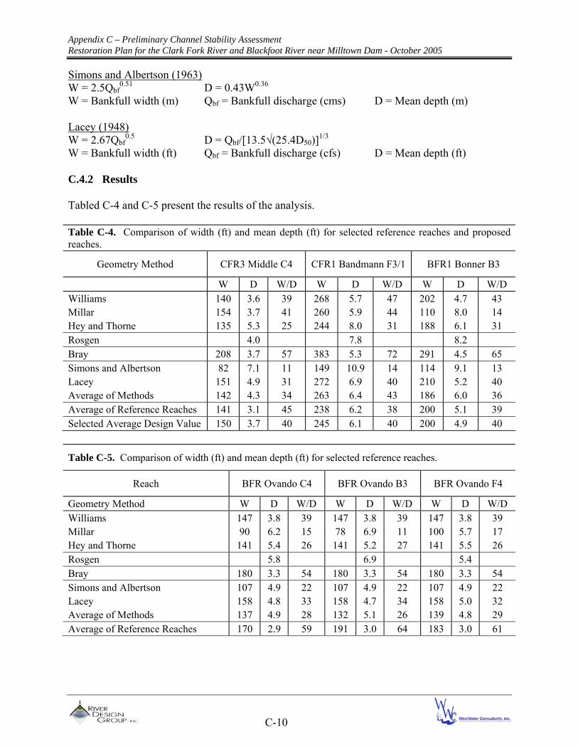
Simons and Albertson (1963) W = 2.5Qbf
0.51 D = 0.43W0.36 W = Bankfull width (m) Qbf = Bankfull discharge (cms) D = Mean depth (m) Lacey (1948) W = 2.67Qbf
0.5 D = Qbf/[13.5√(25.4D50)]1/3 W = Bankfull width (ft) Qbf = Bankfull discharge (cfs) D = Mean depth (ft) C.4.2 Results Tabled C-4 and C-5 present the results of the analysis. Table C-4. Comparison of width (ft) and mean depth (ft) for selected reference reaches and proposed reaches.
Geometry Method CFR3 Middle C4 CFR1 Bandmann F3/1 BFR1 Bonner B3
W D W/D W D W/D W D W/D Williams 140 3.6 39 268 5.7 47 202 4.7 43 Millar 154 3.7 41 260 5.9 44 110 8.0 14 Hey and Thorne 135 5.3 25 244 8.0 31 188 6.1 31 Rosgen 4.0 7.8 8.2 Bray 208 3.7 57 383 5.3 72 291 4.5 65 Simons and Albertson 82 7.1 11 149 10.9 14 114 9.1 13 Lacey 151 4.9 31 272 6.9 40 210 5.2 40 Average of Methods 142 4.3 34 263 6.4 43 186 6.0 36 Average of Reference Reaches 141 3.1 45 238 6.2 38 200 5.1 39 Selected Average Design Value 150 3.7 40 245 6.1 40 200 4.9 40
Table C-5. Comparison of width (ft) and mean depth (ft) for selected reference reaches.
Reach BFR Ovando C4 BFR Ovando B3 BFR Ovando F4
Geometry Method W D W/D W D W/D W D W/D Williams 147 3.8 39 147 3.8 39 147 3.8 39 Millar 90 6.2 15 78 6.9 11 100 5.7 17 Hey and Thorne 141 5.4 26 141 5.2 27 141 5.5 26 Rosgen 5.8 6.9 5.4 Bray 180 3.3 54 180 3.3 54 180 3.3 54 Simons and Albertson 107 4.9 22 107 4.9 22 107 4.9 22 Lacey 158 4.8 33 158 4.7 34 158 5.0 32 Average of Methods 137 4.9 28 132 5.1 26 139 4.8 29 Average of Reference Reaches 170 2.9 59 191 3.0 64 183 3.0 61

Appendix C – Preliminary Channel Stability Assessment Restoration Plan for the Clark Fork River and Blackfoot River near Milltown Dam - October 2005
C-11
C.4.3 Conclusions Results produced a wide range of values. As mentioned previously, differences in experimental conditions under which the equations were developed is a likely cause for the variability. However, the average of all methods when compared to actual reference reach values produced an acceptable range of values. When selecting design values, consideration was given to regime equations however, greater emphasis was placed on observed values from reference reaches. C.5 SHEAR STRESS ANALYSIS The incipient motion for a sediment particle by flowing water is a key concept in estimating shear stress and sediment transport. The movement of a single particle is influenced by a range of factors including hydraulic geometry, slope, bed composition and bed armoring. The force at which point a particular size particle is set in motion is termed the critical shear stress of that particle size. The Shields equation is used to calculate critical shear stress (Shields 1936).
τc = τ
c
*(γ
s-γ)D
where τc
* is the dimensionless Shields parameter for entrainment of a sediment particle of size D,
and γs and γ are the unit weights of sediment and water, respectively, expressed in pounds per
cubic foot. Generally, the parameter D is taken to be D50, the median grain size of the bed sediment, and, dimensionally, must be in units of feet. The Shields critical shear stress equation has been experimentally evaluated in laboratory flumes using uniform size particles. Experimental results suggest a constant value in the range of 0.04 to 0.06 (cited in Reid et al. 1997). Extensive work has been done to evaluate critical shear stress in natural channels characterized by a range of conditions (Montgomery and Buffington 1997). Shear stress assessments typically compare critical shear stress to average total shear stress. Average shear stress is calculated by the equation,
τ = γRs where τ is the shear stress, γ is the specific weight of water, R is the hydraulic radius, and s is the slope of the channel. Concerning channel design methods, the engineered channel is typically designed to generate a critical shear stress capable of initiating motion in a D84 size particle during a bankfull discharge event. This concept is consistent with several studies (Pickup 1976; Jackson and Beschta 1992; Grant 1987; Carling 1988; Sidle 1998; Booth 1990; and Leopold 1992). Significantly increasing or decreasing stream energy by modifying channel dimensions may lead to channel degradation or aggradation, respectively. C.5.1 Methods A critical shear stress analysis was completed for selected reference reaches. Hydraulic models were developed using HEC-RAS (US Army Corps of Engineers 2004) to estimate average total shear stress. As indicated previously, the model was calibrated by using field-surveyed channel geometry, bankfull indicators and bankfull discharges to predict Manning’s roughness values.

Appendix C – Preliminary Channel Stability Assessment Restoration Plan for the Clark Fork River and Blackfoot River near Milltown Dam - October 2005
C-12
Most available methods for calculating critical shear stress use the Shields equation, but differ in their means of calculating critical dimensionless shear stress. There are numerous critical dimensionless shear stress equations that have been developed to predict incipient motion. Equations are generally derived from laboratory flume experiments that used sand bed channels to develop sediment transport relationships. Models based on field data collected in alluvial, gravel-bed rivers are less common. The following two methods were selected for their applicability to pool-riffle bed forms. Parker and Klingeman (1982) τ
c
*= 0.035(Di/D50s)-0.94
Di = Bed particle size for which i% is finer (mm). D84 used. D50s = Bed surface particle size for which 50% is finer (mm) Rosgen (unpublished) τ
c
*= 0.0384(Di/D50)-0.887
Di = Pavement D100 or bar sample D100 (mm) D50 = Bed particle size for which 50% is finer Allowable boundary shear stress can also be calculated from the following equation developed from the Shields diagram (Shields 1936) τ
0= ρV2/[5.75log(12.27R/ks)]2
ρ = Density of waster (slugs/ft3) R = Hydraulic radius (ft) ks = Grain roughness (usually taken as 3.5 D84 (ft)) V = Mean velocity (ft/s) C.5.2 Results Table C-6 presents the results of the analysis. Table C-6. Comparison of critical shear stress and actual shear stress (lbs/ft2) for selected reference reaches and proposed reaches.
Shear Stress Method
CFR3 Middle C4
CFR1 Bandmann F3/1
BFR1 Bonner B3
BFR Ovando
C4
BFR Ovando B3
BFR Ovando F4
Parker and Klingeman 0.63 0.82 1.57 0.77 0.97 0.67
Rosgen 0.50 1.30 0.84 0.80 0.80 1.00
Shields 0.73 1.22 1.25 0.70 0.77 0.73 Average of Methods (Qbf)
0.62 1.12 1.22 0.75 0.85 0.80

Appendix C – Preliminary Channel Stability Assessment Restoration Plan for the Clark Fork River and Blackfoot River near Milltown Dam - October 2005
C-13
Table C-6 (Continued). Comparison of critical shear stress and actual shear stress (lbs/ft2) for selected reference reaches and proposed reaches.
Shear Stress Method
CFR3 Middle C4
CFR1 Bandmann F3/1
BFR1 Bonner B3
BFR Ovando
C4
BFR Ovando B3
BFR Ovando F4
Actual Shear Stress (Qbf)
0.43 0.79 0.95 0.57 0.66 0.62
Actual Shear Stress (Q2)
0.51 0.98 1.16 0.73 0.87 0.79
Actual Shear Stress (Q10)
0.70 1.35 1.57 0.91 1.07 0.96
Actual Shear Stress (Q25)
0.80 1.51 1.73 1.11 1.26 1.13
Actual Shear Stress (Q50)
0.87 1.61 1.84 1.37 1.40 1.32
Actual Shear Stress (Q100)
0.92 1.71 1.94 1.65 1.56 1.48
Actual Shear Stress (Q500)
1.04 1.88 2.14 2.46 1.59 2.02
Design Shear Stress (Qbf)
0.53-0.81 1.19 0.92 N/A N/A N/A
* Calculated critical shear stress values based on D84. C.5.3 Conclusions Results yielded an acceptable range of critical shear stress values for bankfull discharge conditions. When compared with actual shear stress values, average critical shear stress values correspond closely to actual shear stress at Q2 indicating that incipient motion is likely to occur at discharges slightly above bankfull. Assuming that the bankfull discharge is responsible for incipient motion, it could be concluded that the reference reaches are experiencing aggradation. As discussed earlier, significant aggradation was not observed in the reference reaches and variation among the results could indicate that dynamic equilibrium can occur within a range of shear stress values. In fact, the higher critical shear stress could be a result of bed armoring which was observed at all sites. The effects of bed armoring are discussed in more detail in C.7. Assuming similar bed composition for the proposed design reaches, design shear stress values at Qbf lie within the range of values presented in Table C-4 for average critical shear stress. C.6 SEDIMENT TRANSPORT ANALYSIS Sediment transport analysis is generally the most challenging component of a hydraulic analysis due to the difficulty in collecting bedload data during high flows. Sediment transport data are essential for calibrating sediment transport models. Without such data, model calibration may not be possible and modeling results should be treated as suspect. Despite these difficulties, understanding sediment transport and channel resistance to scour and deposition are essential for both understanding existing channel conditions and completing channel designs capable of conveying the available flow and sediment load while minimizing

Appendix C – Preliminary Channel Stability Assessment Restoration Plan for the Clark Fork River and Blackfoot River near Milltown Dam - October 2005
C-14
channel failure risk. As a design parameter, sediment transport analyses focus on providing for sediment continuity, a factor that is necessary for designing a stable channel. In this context, channel stability implies that although the channel configuration may change over time, the channel’s cross-section dimensions remain consistent over time and space. Under the stable channel condition, rates of erosion and deposition are approximately balanced as the channel erodes its outer banks and stores sediment in bars. C.6.1 Methods In the absence of bed load data, sediment transport analyses relied on surface and sub surface sediment sampling from reference reaches. Sediment data and estimated transport rates from upstream and downstream reference reaches formed the boundary conditions for sediment input and output rates for the restoration project area. Due to the variability of results from available methods, objectives of the analysis focused on demonstrating sediment transport continuity rather than predicting actual transport rates. To demonstrate continuity, comparisons were drawn between transport rates for upstream reference reaches, proposed project reaches and a downstream reference reach. For this analysis, it is assumed that bed material within the project reaches will be substantially similar to that found in the respective reference reaches. There are numerous equations that have been developed to predict sediment transport rates. Equations are generally derived from laboratory flume experiments that used sand bed channels to develop sediment transport relationships. Models based on field data collected in alluvial, gravel-bed rivers are less common. The following methods were selected for their applicability to gravel bed rivers. Meyer-Peter and Müller (1948) using D50ss qb = 8[ρs/(ρs-ρ)] √(g/ ρ) [(n’/nt)3/2 ρSD-0.047(ρs-ρ) D50ss]3/2 qb = Bed load transport rate per unit width (kg/s)
ρs = Density of sediment (kg/m3) ρ = Density of water (kg/m3) g = gravitational acceleration (m/s2) S = Slope (m/m) nt = Roughness of bed = S1/2 R2/3/V n’ = particle roughness = D90
1/6/26 R = Hydraulic radius (m) V = Mean velocity (m/s)
D = Average flow depth (m) D90 = Particle size for which 90% is finer (mm)
D50ss = Subsurface Particle size for which 50% is finer (mm) Ackers and White (1973) using Di qb = Ggri fi ρs Di V (V/u*)n 8fi[ρs/(ρs-ρ)] √(g/ ρ) [(n’/nt)3/2 ρSD- τ
ci
* (ρs-ρ) D50ss]3/2
qb = Bed load transport rate per unit width (kg/s) ρs = Density of sediment (kg/m3) Ggri = Dimensionless transport rate for ith class fi = Proportion of subsurface material in ith class (i used = 84) Di = Particle size for which ith % is finer (mm) (i used = 84) V = Mean velocity (m/s) D = Average flow depth (m) u* = Shear velocity = √(gDS) S = Slope (m/m)

Appendix C – Preliminary Channel Stability Assessment Restoration Plan for the Clark Fork River and Blackfoot River near Milltown Dam - October 2005
C-15
C.6.2 Results Figures C-3 through C-8 present sediment transport rates for the proposed channels at various discharges. Each figure displays a plot of sediment transport rate in relation to valley stationing. The intent of this exercise is to evaluate sediment transport continuity between upstream reaches, project area reaches and downstream reaches. In general, sediment transport rate is expected to increase in the downstream direction as discharge and sediment load increase. Station -5000 represents the Bandmann Flats reference reach in the CFR below the confluence. Station 5000 represents the design CFR channel below the confluence. Upstream of station 5000, the BFR and CFR are displayed separately at stations 7500 and 15,000 before entering the confluence. At station 7500, the sum of the transport rates for the CFR and BFR approximates the required transport rate for the CFR below the confluence at station 5000. Station 18000 represents an upstream reference reach in CFR3B.
1,000
10,000
100,000
1,000,000
-5000 0 5000 10000 15000 20000
S tation (Valley Pro fi le )
Ra
te (
tons
/d
ay
)
Ackers & White Meyer-Peter & Muller
Figure C-3. Sediment Transport Rates for Proposed Channels at Bankfull Discharge.
Downstream Reference Reach Upstream Reference Reaches Project Area
BFR
CFR
BFR
CFR

Appendix C – Preliminary Channel Stability Assessment Restoration Plan for the Clark Fork River and Blackfoot River near Milltown Dam - October 2005
C-16
1,000
10,000
100,000
1,000,000
-5000 0 5000 10000 15000 20000
Station (Val ley P rofi le )
Ra
te (
tons
/d
ay
)
Ackers & White Meyer-Peter & Muller
Figure C-4. Sediment Transport Rates for Proposed Channels at Q2 Discharge.
10,000
100,000
1,000,000
10,000,000
-5000 0 5000 10000 15000 20000
Station (Val ley Profi le )
Ra
te (
tons
/d
ay
)
Ackers & White Meyer-Peter & Muller
Figure C-5. Sediment Transport Rates for Proposed Channels at Q10 Discharge.
BFR
CFR
Downstream Reference Reach Upstream Reference Reaches Project Area
Downstream Reference Reach Upstream Reference Reaches Project Area
BFR
CFR
BFR
CFR
BFR
CFR

Appendix C – Preliminary Channel Stability Assessment Restoration Plan for the Clark Fork River and Blackfoot River near Milltown Dam - October 2005
C-17
10,000
100,000
1,000,000
10,000,000
-5000 0 5000 10000 15000 20000
Station (Val ley Profi le )
Ra
te (
tons
/d
ay
)
Ackers & White Meyer-Peter & Muller
Figure C-6. Sediment Transport Rates for Proposed Channels at Q25 Discharge.
10,000
100,000
1,000,000
10,000,000
-5000 0 5000 10000 15000 20000
Station (Val ley P rofi le )
Ra
te (
tons
/d
ay
)
Ackers & White Meyer-Peter & Muller
Figure C-7. Sediment Transport Rates for Proposed Channels at Q50 Discharge.
Downstream Reference Reach Upstream Reference Reaches Project Area
Downstream Reference Reach Upstream Reference Reaches Project Area
BFR
CFR
BFR
CFR
BFR
CFR
BFR
CFR

Appendix C – Preliminary Channel Stability Assessment Restoration Plan for the Clark Fork River and Blackfoot River near Milltown Dam - October 2005
C-18
10,000
100,000
1,000,000
10,000,000
-5000 0 5000 10000 15000 20000
Station (Val ley Pro fi le )
Ra
te (
tons
/d
ay
)
Ackers & White Meyer-Peter & Muller
Figure C-8. Sediment Transport Rates for Proposed Channels at Q100 Discharge. C.6.3 Conclusions As shown in figures C-3 through C-8 results produced a wide range of values for sediment transport rates. As indicated previously, this is common with sediment transport analyses. Results were found to be sensitive to slight changes in input variables. Given this sensitivity and unacceptable range of values, conclusions focus on degree of sediment continuity between upstream and downstream reaches. Results indicate that sediment transport capability increases in the downstream direction, implying that conveyance is adequate and reaches will not experience aggradation. When compared with the upstream reference reach, the proposed CFR3/2 reach appears to be unable to transport the potential sediment input from the upstream CFR3 reference at higher discharges. Although the difference in transport rates may not be significant, it could be attributed to the floodplain constriction that occurs as the CFR3 reach transitions to a more confined valley type in CFR2. More detailed modeling and further review of this transition will occur in the final design phase. Similarly, the potential sediment output from the proposed CFR1 reach appears to be greater than the transport capacity of the downstream CFR1 Bandmann reference reach at higher discharges. This could be due in part to the location of the CFR1 Bandmann reference below the dam. It is likely that the dam has altered the substrate composition and effects of peak discharges on this reach. Again, the difference may be insignificant but it warrants further review of potential effects of downstream deposition.
Downstream Reference Reach Upstream Reference Reaches Project Area
BFR
CFR
BFR
CFR

Appendix C – Preliminary Channel Stability Assessment Restoration Plan for the Clark Fork River and Blackfoot River near Milltown Dam - October 2005
C-19
Figure C-9. Illustration of sediment transport continuity for selected reference reaches and project reaches at bankfull discharge. Values shown are averages values for all methods In summary, a range of 3 to 30 percent difference in average sediment transport capability was observed. Again, this range is attributed to the sensitivity of the methods to slight changes in input variables and transitions in valley morphology. Except for existing conditions, percent difference was observed to increase as discharge increased. Results for Qbf and Q2 produced the lowest range of differences. Given the sensitivity of the methods and range of differences for existing conditions (21 to 23 percent), the analysis appears to provide an adequate demonstration of sediment transport continuity between upstream, restoration project area and downstream reaches. However, further review of effects of sediment transport discontinuity should be evaluated during final design.

Appendix C – Preliminary Channel Stability Assessment Restoration Plan for the Clark Fork River and Blackfoot River near Milltown Dam - October 2005
C-20
C.7 SCOUR ANALYSIS Several types of scour occur in rivers. General scour is a result of unbalanced sediment transport, which may include bed degradation over long periods of time or during extreme flow events. Contraction scour occurs when flow accelerates through an abrupt channel or floodplain constriction. Local scour occurs in the vicinity of an object that causes turbulent flow such as a drop structure, bridge pier, bridge abutment, isolated boulder or fallen tree. Bend scour occurs on the outside of channel meanders and is caused by turbulent flow generated by changes in flow vectors. Scour can occur under live-bed or clear-water conditions. Live-bed conditions exist when the sediment transport rate is at or near the sediment transport capacity. Under live-bed conditions, erosion is offset by deposition. Clear-water conditions exist when the sediment transport rate is significantly less than sediment transport capacity. In such a case, potential exists for erosion without deposition. Accordingly, clear-water conditions typically produce greater scour depths than live-bed conditions. Channel armoring can also affect scour. Armoring is common in gravel bed rivers due to the wide range of particle sizes available for transport. Armoring occurs when shear stress is insufficient to mobilize a portion of the bed material. Under these conditions, smaller particles are entrained and removed from the bed leaving the larger material behind in an armor layer. When the armor layer is disturbed as with channel construction, potential exists for scour in the reconstructed channel until an armor layer re-forms. C.7.1 Methods Most scour analysis methods are empirically derived from experiments or field measurements and can be biased toward site-specific experiment conditions. Moreover, most methods have been calibrated in sand bed channels. Usually, these methods grossly overestimate scour in gravel-bed rivers. Efforts focused on using equations that are applicable to gravel-bed rivers. In addition, a field-based scour analysis was implemented using scour chains. At the time of this report, no scour was recorded due to low peak discharge conditions. A scour analysis was completed for the proposed project reaches to evaluate general scour and bend scour. General scour was analyzed to determine the required scour depth to re-form the armor layer in the new channel. Bend scour was analyzed to validate maximum pool depths. The following equation was used to predict the depth of degradation that would need to occur to re-form an armor layer. U.S. Bureau of Reclamation (1984) Ys = Ya(1/Pc-1) Ys = Depth of scour required to form armor layer (ft) Ya = Thickness of armor layer (ft). Assumed to be twice critical particle size. Pc = Fraction of material coarser than the critical particle size The following equations were used to predict the depth of bend scour in the design meanders.

Appendix C – Preliminary Channel Stability Assessment Restoration Plan for the Clark Fork River and Blackfoot River near Milltown Dam - October 2005
C-21
Thorne (1997) Ymax = Yu[2.07-0.19log(Rc/Wu-2)] Ymax = Maximum water depth in bend (ft) Yu = Maximum water depth in crossing upstream of bend (ft) Rc = Centerline radius of bend (ft) Wu = Water surface width at upstream of bend (ft) Maynord (1996) Ymax = Yu[1.8-0.051(Rc/Wu) + 0.0084(Wu/ Yu)] U.S. Army Corps of Engineers (1994)
Figure C.10. U.S. Army Corps of Engineers momograph for predicting bend scour. Table C-7 summarizes the results of the analysis.

Appendix C – Preliminary Channel Stability Assessment Restoration Plan for the Clark Fork River and Blackfoot River near Milltown Dam - October 2005
C-22
Table C-7. Summary of predicted scour depths (ft) for selected reference reaches and proposed reaches at bankfull discharge.
Shear Stress Method
CFR3 Middle C4
CFR1 Bandmann
F3/1
BFR1 Bonner B3
BFR Ovando
C4
BFR Ovando B3
BFR Ovando F4
Depth of Scour to Form Armor 3.0 2.8 1.3 2.5 1.1 2.3
Depth of Scour to Form Armor Design Reaches
2.2 1.6 1.3
Bend Scour - Thorne 5.9 - 7.9 11.2 - 13.2 7.7 - 8.8 5.9- 8.7 5.3 - 6.6 5.2 - 7.3
Bend Scour - Maynord 6.3 - 7.4 10.3 - 11.2 7.7 -8.3 6.2- 7.2 5.5 - 6.0 5.7 - 7.3
Bend Scour - USACE 7.6 - 9.9 11.9 -13.5 8.8 -9.9 7.9-11.9 5.2 - 6.3 6.1 - 9.3
Range of Values 5.9 - 9.9 10.3 - 13.5 7.7 -9.9 5.9-11.9 5.2 - 6.6 5.2 - 9.3
Avg Bend Scour 7.5 11.5 8.6 7.4 5.6 6.6 Observed Pool Max Depth 7.5 23.8 N/A 7.8 7.9 6.9
Selected Design 8.0 - 11.1 18.2 - 24.3 9.8 - 14.7 N/A N/A N/A
C.7.2 Results Results indicate that a significant amount of scour would occur before the armor layer re-forms in the design channels. Grade control structures will be required to prevent the reconstructed channel bed from significant degradation. Frequency of grade control structures will depend on channel slope and threshold for allowable bed degradation. This is discussed in more detail in 4.5. Bend scour results yielded an acceptable range of values for bankfull discharge. Except for the CFR1 Bandmann reach, average results corresponded closely with observed maximum pool depths in the reference reaches. The observed maximum pool depth in the CFR1 Bandmann reach occurred on the outside of a bend near a bedrock outcrop. A similar bedrock outcrop is present in the proposed CFR1 design reach near the dam. For this reason, the observed value was given greater emphasis when selecting design values. A supplemental check of 100-year scour depths was performed for the CFR1 and BFR1 proposed reaches, yielding values of 24.1 ft and 20.3 ft, respectively. Further consideration will be given to 100-yr scour depths and associated design implications in Phase III final design. C.8 ICE ASSESSMENT In Montana, where rivers can develop thick ice covers during the winter, ice jams can contribute significantly to channel scour and flooding. Although discharges may be relatively low, the

Appendix C – Preliminary Channel Stability Assessment Restoration Plan for the Clark Fork River and Blackfoot River near Milltown Dam - October 2005
C-23
stages of ice jam flooding may be among the highest on record. Ice jams typically occur repeatedly in the same locations and ice jam flooding tends to be localized. In the U.S. Army Cold Regions Research and Engineering Laboratory Technical Note entitled “Methodology for Ice Jam Analysis” (1980), ice jams were classified as freezeup, breakup, floating and grounded jams. Freezeup jams are associated with the formation of frazil ice, which eventually forms a continuous ice cover. Breakup jams occur when ice cover is followed by a rapid increase in runoff and an ice dam forms. Floating jams are not anchored to the channel bed and flow passes beneath the jam. Grounded jams are anchored to the channel bed and flow passes over the jam and onto the floodplain. Ice jams occur at locations where abrupt changes in ice conveyance occur. Common features that contribute to ice jams include transitions from steep to mild slope, confluences, tight meanders and channel obstructions. Nearly all of these features are present in the vicinity of the restoration project area. The history of ice jams occurrences on the BFR and CFR confirms this. Table C.9 presents a summary of historical ice jams in the vicinity of the restoration project area.
Table C-8. Summary of historical ice jams on BFR and CFR near Milltown Dam.*
River Date Location Type Size Ice Stage Discharge Stage
BFR 02-09-96 ¾-mile
upstream from Bonner
Breakup N/A 16 ft
Max. on record
5.2 ft
BFR 02-11-96 Milltown Breakup 8’H
40’ W 4 mi L
N/A 4.3 ft
CFR 01-08-30 Missoula N/A N/A 2.9 ft
CFR 01-11-77 Missoula N/A N/A 4.41 ft Max.
annual 3.0 ft
CFR 11-28-93 Bonner N/A N/A 7.26 ft Max.
annual 2.4 ft
CFR 10-10-95 Bonner N/A N/A 10.24 ft
Max. annual
3.0 ft
CFR 02-08-96 Turah Breakup N/A 9.05 ft Max on record
5.6 ft
* U.S. Army Research and Development Center Cold Regions Research and Engineering Laboratory Ice Jam Database Historically, ice jams have formed upstream of Milltown Dam at Stimson Dam and Turah Bridge. Upon removal of Stimson Dam, the potential increases for ice jams to move or form further downstream. On the BFR, potential areas for ice jam formation include obstructions from bridge piers and abutments on the Highway 200 bridge, Burlington Northern Railroad

Appendix C – Preliminary Channel Stability Assessment Restoration Plan for the Clark Fork River and Blackfoot River near Milltown Dam - October 2005
C-24
bridge and Interstate 90 bridges. In addition, the confluence could be another potential area for ice jam formation. On the CFR, ice jams are likely to reoccur at the Turah bridge. However, ice jams that move past the bridge could become lodged in CFR meander bends or steep-to-mild transition areas between riffles and pools. The confluence also presents another possible ice jam location on the CFR. Records indicate that ice jams on the CFR and BFR account for the maximum stage on record. EPA has commissioned the U.S. Army Corps of Engineers to perform an ice analysis for pre and post dam removal conditions. The results of this analysis are not yet available. During Phase III final design, RDG and WWC will rely on the results of this analysis for potential post dam removal effects on the stability of the proposed design. C.9 HEC-RAS OUTPUT
Reach River Profile Q Total Max Chl Dpth Shear Chan Flow Area Mann Wtd Top W Chnl Hydr Depth C Vel Chnl Power ChanStation (cfs) (ft) (lb/sq ft) (sq ft) Chnl (ft) (ft) (ft/s) (lb/ft s)
Bandmann 660 QBankfull 10400 8.57 0.84 1455.45 0.032 238.21 6.01 7.24 6.06Bandmann 200 QBankfull 10400 9.29 0.81 1645.71 0.037 228.51 7.15 6.36 5.18Bandmann 0 QBankfull 10400 9.21 0.72 1311.25 0.027 217.18 6.04 7.93 5.68
Blackfoot Gage 2228 QBankfull 6200 6.49 1.00 948.33 0.038 194.90 4.86 6.44 6.45Blackfoot Gage 1999 QBankfull 6200 7.93 0.86 999.27 0.038 176.10 5.66 6.12 5.25Blackfoot Gage 1829 QBankfull 6200 7.41 1.28 962.51 0.044 188.70 5.10 6.34 8.11Blackfoot Gage 402 QBankfull 6200 10.01 0.69 1130.37 0.038 195.92 5.66 5.48 3.80Blackfoot Gage 0 QBankfull 6200 6.96 0.90 1000.86 0.038 200.55 4.97 6.12 5.48
Ovando B 550 QBankfull 3500 4.77 0.81 638.49 0.038 162.48 3.87 5.56 4.49Ovando B 0 QBankfull 3500 4.14 0.51 725.28 0.034 217.31 3.33 4.83 2.47
Ovando C 6200 QBankfull 3500 6.97 0.44 712.58 0.032 165.00 4.26 4.97 2.20Ovando C 5340 QBankfull 3500 4.76 0.37 720.64 0.028 187.03 3.66 5.09 1.91Ovando C 250 QBankfull 3500 4.93 0.90 575.70 0.036 167.14 3.44 6.08 5.46Ovando C 0 QBankfull 3500 5.31 0.56 595.42 0.030 154.31 3.85 5.88 3.32
Ovando F 1490 QBankfull 3500 5.73 0.63 609.55 0.032 171.21 3.56 5.74 3.60Ovando F 0 QBankfull 3500 5.33 0.60 720.70 0.038 174.75 4.12 4.86 2.92
Ref CFR 3 1730 QBankfull 3200 4.57 0.28 696.32 0.025 191.94 3.37 4.90 1.39Ref CFR 3 1560 QBankfull 3200 4.26 0.45 660.76 0.030 192.62 3.24 5.10 2.28Ref CFR 3 0 QBankfull 3200 5.14 0.57 502.04 0.027 142.28 3.48 6.46 3.67
CFR 3/CFR 2 14000 QBankfull 3200 4.57 0.5 545.28 0.028 147.88 3.69 5.87 2.91CFR 3/CFR 2 8000 QBankfull 3200 4.48 0.77 532.28 0.034 147.53 3.61 6.01 4.65CFR 3/CFR 2 6000 QBankfull 3200 4.62 0.81 535.67 0.035 146.00 3.65 6.00 4.89
CFR 1 1000 QBankfull 10400 7.70 1.18 1502.56 0.040 243.00 6.18 6.92 8.20CFR 1 700 QBankfull 10400 7.70 1.19 1502.36 0.040 243.00 6.18 6.92 8.21CFR 1 400 QBankfull 10400 7.69 1.19 1501.95 0.040 243.00 6.18 6.92 8.21
BFR 1 1000 QBankfull 6200 6.17 0.92 974.06 0.037 196.00 4.97 6.37 5.87BFR 1 700 QBankfull 6200 6.17 0.92 974.27 0.037 196.00 4.97 6.36 5.87BFR 1 400 QBankfull 6200 6.17 0.92 974.14 0.037 196.00 4.97 6.36 5.87

Appendix C – Preliminary Channel Stability Assessment Restoration Plan for the Clark Fork River and Blackfoot River near Milltown Dam - October 2005
C-25
Reach River Profile Q Total Max Chl Dpth Shear Chan Flow Area Mann Wtd Top Wtd Hydr Depth C Vel Chnl Power ChanStation (cfs) (ft) (lb/sq ft) (sq ft) Chnl (ft) (ft) (ft/s) (lb/ft s)
Bandmann 660 Q2 14900 10.14 0.99 1876.35 0.032 277.17 7.57 8.19 8.12Bandmann 200 Q2 14900 10.85 1.05 2020.97 0.037 243.30 8.71 7.47 7.84Bandmann 0 Q2 14900 10.66 0.89 1633.51 0.027 225.18 7.49 9.15 8.13
Blackfoot Gage 2228 Q2 8700 7.77 1.17 1217.41 0.038 220.32 6.14 7.25 8.52Blackfoot Gage 1999 Q2 8700 9.20 1.09 1235.81 0.038 191.69 6.93 7.11 7.73Blackfoot Gage 1829 Q2 8700 8.71 1.53 1216.97 0.044 201.36 6.24 7.17 10.97Blackfoot Gage 402 Q2 8700 11.23 0.88 1404.76 0.038 228.21 6.85 6.39 5.64Blackfoot Gage 0 Q2 8700 8.13 1.11 1254.19 0.038 221.77 6.13 7.04 7.79
Ovando B 550 Q2 5400 5.79 1.08 888.38 0.038 290.11 4.81 6.68 7.23Ovando B 0 Q2 5400 5.14 0.66 944.95 0.034 223.69 4.33 5.74 3.80
Ovando C 6200 Q2 5400 8.04 0.62 906.63 0.032 186.59 5.33 6.11 3.80Ovando C 5340 Q2 5400 5.75 0.49 1008.88 0.028 294.84 4.62 6.06 2.96Ovando C 250 Q2 5400 6.07 1.09 776.06 0.036 185.84 4.59 7.03 7.68Ovando C 0 Q2 5400 6.47 0.72 789.54 0.030 180.21 4.96 6.95 5.03
Ovando F 1490 Q2 5400 6.85 0.79 808.33 0.032 183.01 4.65 6.73 5.30Ovando F 0 Q2 5400 6.56 0.78 938.99 0.038 180.80 5.35 5.78 4.51
Ref CFR 3 1730 Q2 4600 5.42 0.34 988.22 0.025 402.85 4.22 5.53 1.85Ref CFR 3 1560 Q2 4600 5.15 0.50 930.83 0.030 316.01 4.14 5.61 2.80Ref CFR 3 0 Q2 4600 5.97 0.70 653.13 0.027 201.31 4.31 7.44 5.24
CFR 3/CFR 2 14000 Q2 4600 5.06 0.55 1932.04 0.028 3001.84 4.17 6.29 3.44CFR 3/CFR 2 8000 Q2 4600 5.25 0.91 941.46 0.034 612.93 4.36 6.74 6.14CFR 3/CFR 2 6000 Q2 4600 5.43 0.99 785.27 0.035 316.54 4.46 6.86 6.81
CFR 1 1000 Q2 14900 9.18 1.47 1873.83 0.040 255.67 7.67 7.99 11.74CFR 1 700 Q2 14900 9.18 1.47 1873.80 0.040 255.67 7.67 7.99 11.74CFR 1 400 Q2 14900 9.18 1.47 1873.72 0.040 255.66 7.67 7.99 11.74
BFR 1 1000 Q2 8670 7.28 1.13 1194.93 0.037 203.06 6.08 7.28 8.21BFR 1 700 Q2 8670 7.28 1.13 1195.06 0.037 203.05 6.08 7.28 8.20BFR 1 400 Q2 8670 7.27 1.13 1194.73 0.037 203.04 6.07 7.28 8.21
Reach River Profile Q Total Max Chl Dpth Shear Chan Flow Area Mann Wtd Top Wtd Hydr Depth C Vel Chnl Power ChanStation (cfs) (ft) (lb/sq ft) (sq ft) Chnl (ft) (ft) (ft/s) (lb/ft s)
Bandman 660 Q10 25900 13.31 1.29 2840.89 0.032 326.81 10.74 9.90 12.77Bandman 200 Q10 25900 13.97 1.54 2800.56 0.037 256.48 11.83 9.51 14.65Bandman 0 Q10 25900 13.58 1.23 2354.18 0.027 254.91 10.41 11.40 14.05
Blackfoot Gage 2228 Q10 14600 10.16 1.50 1778.33 0.038 244.36 8.54 8.65 12.97Blackfoot Gage 1999 Q10 14600 11.49 1.55 1699.95 0.038 214.84 9.22 8.92 13.84Blackfoot Gage 1829 Q10 14600 11.04 2.03 1721.56 0.044 225.14 8.57 8.71 17.68Blackfoot Gage 402 Q10 14600 13.50 1.25 1931.93 0.038 236.57 9.12 7.96 9.93Blackfoot Gage 0 Q10 14600 10.32 1.50 1761.29 0.038 240.58 8.33 8.63 12.96
Ovando B 550 Q10 7800 6.85 1.32 1235.20 0.038 351.09 5.87 7.63 10.08Ovando B 0 Q10 7800 6.20 0.82 1191.89 0.034 242.76 5.39 6.65 5.48
Ovando C 6200 Q10 7800 9.13 0.84 1125.11 0.032 222.86 6.42 7.30 6.10Ovando C 5340 Q10 7800 6.82 0.60 1325.05 0.028 294.84 5.69 6.95 4.17Ovando C 250 Q10 7800 7.23 1.33 1006.86 0.036 207.28 5.75 8.06 10.73Ovando C 0 Q10 7800 7.65 0.88 1193.14 0.030 563.14 6.06 7.94 7.02
Ovando F 1490 Q10 7800 8.06 0.95 1039.40 0.032 203.14 5.87 7.69 7.31Ovando F 0 Q10 7800 7.87 0.97 1179.04 0.038 184.48 6.66 6.69 6.51
Ref CFR 3 1730 Q10 9700 7.88 0.42 2113.13 0.025 471.12 6.68 6.71 2.84Ref CFR 3 1560 Q10 9700 7.69 0.61 2012.35 0.030 457.90 6.67 6.71 4.09Ref CFR 3 0 Q10 9700 8.23 1.07 1211.37 0.027 274.53 6.57 9.86 10.58
CFR 3/CFR 2 14000 Q10 9700 5.97 0.65 4658.07 0.028 3005.47 5.08 7.11 4.65CFR 3/CFR 2 8000 Q10 9700 7.14 1.12 2141.19 0.034 650.90 6.26 7.95 8.94CFR 3/CFR 2 6000 Q10 9700 7.54 1.46 1497.53 0.035 358.73 6.57 8.88 12.97
CFR 1 1000 Q10 25900 12.16 2.04 2671.39 0.040 279.51 10.65 9.95 20.31CFR 1 700 Q10 25900 12.16 2.04 2671.07 0.040 279.50 10.65 9.95 20.31CFR 1 400 Q10 25900 12.16 2.04 2670.68 0.040 279.49 10.65 9.95 20.32
BFR 1 1000 Q10 14600 9.49 1.54 1659.37 0.037 216.35 8.29 8.95 13.78BFR 1 700 Q10 14600 9.49 1.54 1659.50 0.037 216.34 8.29 8.95 13.77BFR 1 400 Q10 14600 9.49 1.54 1659.18 0.037 216.33 8.29 8.95 13.78

Appendix C – Preliminary Channel Stability Assessment Restoration Plan for the Clark Fork River and Blackfoot River near Milltown Dam - October 2005
C-26
Reach River Profile Q Total Max Chl Dpth Shear Chan Flow Area Mann Wtd Top Wtd Hydr Depth C Vel Chnl Power ChanStation (cfs) (ft) (lb/sq ft) (sq ft) Chnl (ft) (ft) (ft/s) (lb/ft s)
Bandman 660 Q25 31200 14.63 1.41 3283.44 0.032 343.38 12.06 10.54 14.83Bandman 200 Q25 31200 15.26 1.75 3134.08 0.037 261.92 13.12 10.31 18.02Bandman 0 Q25 31200 14.78 1.38 2662.00 0.027 256.65 11.61 12.27 16.90
Blackfoot Gage 2228 Q25 17300 11.12 1.62 2015.45 0.038 251.46 9.49 9.16 14.88Blackfoot Gage 1999 Q25 17300 12.39 1.74 1897.33 0.038 223.87 10.12 9.59 16.68Blackfoot Gage 1829 Q25 17300 11.95 2.23 1930.16 0.044 230.74 9.49 9.28 20.73Blackfoot Gage 402 Q25 17300 14.40 1.39 2147.16 0.038 239.14 10.03 8.55 11.91Blackfoot Gage 0 Q25 17300 11.20 1.66 1979.42 0.038 256.66 9.21 9.22 15.30
Ovando B 550 Q25 10500 7.88 1.53 1648.57 0.038 460.26 6.91 8.45 12.96Ovando B 0 Q25 10500 7.23 0.98 1454.46 0.034 264.54 6.42 7.48 7.35
Ovando C 6200 Q25 10500 10.21 1.03 1366.82 0.032 224.50 7.50 8.33 8.58Ovando C 5340 Q25 10500 7.99 0.68 1670.41 0.028 294.84 6.86 7.61 5.15Ovando C 250 Q25 10500 8.08 1.72 1188.03 0.036 215.66 6.59 9.39 16.18Ovando C 0 Q25 10500 8.61 1.01 1802.56 0.030 688.56 6.95 8.69 8.80
Ovando F 1490 Q25 10500 9.27 1.10 1297.24 0.032 217.41 7.07 8.53 9.38Ovando F 0 Q25 10500 9.16 1.16 1418.22 0.038 185.71 7.95 7.53 8.74
Ref CFR 3 1730 Q25 12600 8.91 0.48 2600.22 0.025 474.82 7.71 7.32 3.52Ref CFR 3 1560 Q25 12600 8.73 0.68 2490.26 0.030 457.90 7.72 7.26 4.95Ref CFR 3 0 Q25 12600 9.25 1.24 1490.13 0.027 274.53 7.58 10.85 13.44
CFR 3/CFR 2 14000 Q25 12600 6.36 0.7 5837.69 0.028 3007.04 5.47 7.43 5.17CFR 3/CFR 2 8000 Q25 12600 8.02 1.2 2720.48 0.034 668.46 7.14 8.40 10.08CFR 3/CFR 2 6000 Q25 12600 8.48 1.67 1845.99 0.035 377.66 7.52 9.71 16.25
CFR 1 1000 Q25 31200 13.40 2.28 3022.84 0.040 289.40 11.89 10.70 24.37CFR 1 700 Q25 31200 13.40 2.28 3022.73 0.040 289.39 11.89 10.70 24.37CFR 1 400 Q25 31200 13.40 2.28 3022.55 0.040 289.39 11.89 10.70 24.37
BFR 1 1000 Q25 17300 10.37 1.70 1851.66 0.037 221.62 9.17 9.57 16.29BFR 1 700 Q25 17300 10.37 1.70 1851.84 0.037 221.61 9.17 9.57 16.28BFR 1 400 Q25 17300 10.37 1.70 1851.59 0.037 221.61 9.17 9.57 16.29

Appendix C – Preliminary Channel Stability Assessment Restoration Plan for the Clark Fork River and Blackfoot River near Milltown Dam - October 2005
C-27
Reach River Profile Q Total Max Chl Dpth Shear Chan Flow Area Mann Wtd Top Wtd Hydr Depth C Vel Chnl Power ChanStation (cfs) (ft) (lb/sq ft) (sq ft) Chnl (ft) (ft) (ft/s) (lb/ft s)
Bandman 660 Q50 35000 15.53 1.48 3596.83 0.032 354.64 12.96 10.95 16.22Bandman 200 Q50 35000 16.13 1.89 3364.81 0.037 270.56 13.99 10.84 20.48Bandman 0 Q50 35000 15.60 1.47 2872.46 0.027 261.79 12.43 12.83 18.91
Blackfoot Gage 2228 Q50 19200 11.76 1.71 2176.75 0.038 256.17 10.13 9.50 16.20Blackfoot Gage 1999 Q50 19200 12.99 1.86 2032.84 0.038 229.55 10.72 10.02 18.67Blackfoot Gage 1829 Q50 19200 12.56 2.37 2076.44 0.044 258.38 10.09 9.66 22.86Blackfoot Gage 402 Q50 19200 14.99 1.49 2288.32 0.038 240.23 10.61 8.94 13.35Blackfoot Gage 0 Q50 19200 11.78 1.76 2130.50 0.038 265.28 9.78 9.60 16.93
Ovando B 550 Q50 14000 9.09 1.64 2212.71 0.038 484.10 8.12 8.98 14.72Ovando B 0 Q50 14000 8.41 1.16 1770.38 0.034 271.70 7.60 8.36 9.72
Ovando C 6200 Q50 14000 11.49 1.24 1655.54 0.032 226.42 8.78 9.37 11.61Ovando C 5340 Q50 14000 9.42 0.75 2092.36 0.028 294.84 8.29 8.26 6.19Ovando C 250 Q50 14000 8.81 2.36 1347.59 0.036 216.32 7.33 11.17 26.35Ovando C 0 Q50 14000 9.59 1.14 2514.73 0.030 732.82 7.86 9.43 10.77
Ovando F 1490 Q50 14000 10.67 1.26 1603.98 0.032 219.08 8.48 9.40 11.80Ovando F 0 Q50 14000 10.65 1.38 1695.85 0.038 187.12 9.44 8.44 11.62
Ref CFR 3 1730 Q50 14700 9.61 0.52 2929.56 0.025 474.82 8.40 7.70 3.98Ref CFR 3 1560 Q50 14700 9.43 0.73 2812.56 0.030 457.90 8.42 7.61 5.53Ref CFR 3 0 Q50 14700 9.92 1.35 1674.31 0.027 274.53 8.26 11.48 15.48
CFR 3/CFR 2 14000 Q50 14700 6.62 0.72 6629.18 0.028 3008.1 5.74 7.61 5.47CFR 3/CFR 2 8000 Q50 14700 8.61 1.25 3116.12 0.034 680.19 7.72 8.67 10.83CFR 3/CFR 2 6000 Q50 14700 9.11 1.81 2085.05 0.035 390.12 8.14 10.24 18.54
CFR 1 1000 Q50 35000 14.23 2.44 3265.56 0.040 296.03 12.72 11.19 27.26CFR 1 700 Q50 35000 14.23 2.44 3265.53 0.040 296.03 12.72 11.19 27.26CFR 1 400 Q50 35000 14.23 2.44 3265.49 0.040 296.03 12.72 11.19 27.26
Missoula Gage 610 Q50 35000 13.79 1.20 3217.25 0.028 273.93 12.48 11.19 13.45Missoula Gage 0 Q50 35000 10.48 1.86 2658.83 0.028 285.99 9.52 13.27 24.66
BFR 1 1000 Q50 19200 10.95 1.81 1981.94 0.037 225.12 9.75 9.98 18.05BFR 1 700 Q50 19200 10.95 1.81 1982.16 0.037 225.11 9.75 9.97 18.04BFR 1 400 Q50 19200 10.95 1.81 1981.98 0.037 225.11 9.75 9.98 18.05
Reach River Profile Q Total Max Chl Dpth Shear Chan Flow Area Mann Wtd Top Wtd Hydr Depth C Vel Chnl Power ChanStation (cfs) (ft) (lb/sq ft) (sq ft) Chnl (ft) (ft) (ft/s) (lb/ft s)
Bandman 660 Q100 38600 16.37 1.54 3898.67 0.032 363.92 13.80 11.28 17.38Bandman 200 Q100 38600 16.91 2.02 3585.42 0.037 302.49 14.77 11.30 22.79Bandman 0 Q100 38600 16.34 1.56 3070.74 0.027 274.29 13.17 13.33 20.81
Blackfoot Gage 2228 Q100 21000 12.34 1.78 2327.34 0.038 260.49 10.71 9.79 17.41Blackfoot Gage 1999 Q100 21000 13.54 1.97 2161.92 0.038 239.96 11.27 10.39 20.48Blackfoot Gage 1829 Q100 21000 13.11 2.50 2228.80 0.044 284.41 10.65 10.01 25.03Blackfoot Gage 402 Q100 21000 15.51 1.59 2413.79 0.038 241.19 11.14 9.30 14.80Blackfoot Gage 0 Q100 21000 12.29 1.86 2267.41 0.038 266.82 10.30 9.94 18.45
Ovando B 550 Q100 17500 10.20 1.78 2834.42 0.038 682.01 9.23 9.54 16.95Ovando B 0 Q100 17500 9.46 1.33 2055.61 0.034 271.70 8.65 9.12 12.08
Ovando C 6200 Q100 17500 12.69 1.41 1929.64 0.032 228.22 9.99 10.20 14.36Ovando C 5340 Q100 17500 10.78 0.80 2492.74 0.028 294.84 9.65 8.78 7.05Ovando C 250 Q100 17500 9.29 3.15 1451.25 0.036 216.74 7.81 13.05 41.14Ovando C 0 Q100 17500 10.42 1.25 3121.01 0.030 734.30 8.61 10.00 12.50
Ovando F 1490 Q100 17500 11.95 1.39 1884.93 0.032 220.59 9.76 10.13 14.11Ovando F 0 Q100 17500 12.00 1.57 1948.41 0.038 188.40 10.78 9.22 14.51
Ref CFR 3 1730 Q100 16900 10.31 0.55 3265.96 0.025 474.82 9.11 8.04 4.41Ref CFR 3 1560 Q100 16900 10.15 0.76 3141.79 0.030 457.90 9.14 7.92 6.05Ref CFR 3 0 Q100 16900 10.58 1.46 1855.67 0.027 274.53 8.92 12.08 17.59
CFR 3/CFR 2 14000 Q100 16900 6.88 0.74 7411.3 0.028 3009.14 6.00 7.77 5.75CFR 3/CFR 2 8000 Q100 16900 9.19 1.29 3515.38 0.034 691.83 8.30 8.93 11.55CFR 3/CFR 2 6000 Q100 16900 9.71 1.95 2325.35 0.035 402.25 8.74 10.74 20.91
CFR 1 1000 Q100 38600 14.98 2.58 3490.31 0.040 302.04 13.47 11.62 29.97CFR 1 700 Q100 38600 14.98 2.58 3490.54 0.040 302.05 13.47 11.62 29.96CFR 1 400 Q100 38600 14.98 2.58 3490.85 0.040 302.06 13.47 11.62 29.95
BFR 1 1000 Q100 21000 11.48 1.91 2101.77 0.037 227.53 10.28 10.33 19.71BFR 1 700 Q100 21000 11.48 1.91 2101.98 0.037 227.53 10.28 10.33 19.70BFR 1 400 Q100 21000 11.48 1.91 2101.80 0.037 227.52 10.28 10.33 19.71

Appendix C – Preliminary Channel Stability Assessment Restoration Plan for the Clark Fork River and Blackfoot River near Milltown Dam - October 2005
C-28
Reach River Profile Q Total Max Chl Dpth Shear Chan Flow Area Mann Wtd Top Wtd Hydr Depth C Vel Chnl Power ChanStation (cfs) (ft) (lb/sq ft) (sq ft) Chnl (ft) (ft) (ft/s) (lb/ft s)
Bandman 660 Q500 46800 18.19 1.65 4565.26 0.032 366.85 15.62 11.92 19.67Bandman 200 Q500 46800 18.66 2.25 4230.19 0.037 423.44 16.52 12.16 27.40Bandman 0 Q500 46800 17.93 1.75 3532.47 0.027 311.43 14.76 14.38 25.15
Blackfoot Gage 2228 Q500 24900 13.49 1.94 2632.06 0.038 269.03 11.86 10.40 20.22Blackfoot Gage 1999 Q500 24900 14.61 2.21 2426.92 0.038 252.68 12.34 11.17 24.72Blackfoot Gage 1829 Q500 24900 14.24 2.72 2549.07 0.044 285.76 11.77 10.61 28.84Blackfoot Gage 402 Q500 24900 16.58 1.79 2670.98 0.038 243.23 12.20 10.03 17.99Blackfoot Gage 0 Q500 24900 13.35 2.05 2551.08 0.038 269.98 11.35 10.61 21.71
Ovando B 550 Q500 31000 14.38 1.32 6927.39 0.038 1017.83 13.41 8.75 11.54Ovando B 0 Q500 31000 12.88 1.85 2986.30 0.034 271.70 12.07 11.39 21.06
Ovando C 6200 Q500 31000 16.51 2.00 2828.67 0.032 280.72 13.80 12.83 25.61Ovando C 5340 Q500 31000 14.90 1.06 3707.74 0.028 294.84 13.77 10.69 11.30Ovando C 250 Q500 31000 11.62 5.19 1978.37 0.036 233.36 10.14 17.49 90.74Ovando C 0 Q500 31000 12.94 1.60 5048.90 0.030 787.73 11.01 11.78 18.81
Ovando F 1490 Q500 31000 16.20 1.82 2833.95 0.032 226.32 14.01 12.29 22.31Ovando F 0 Q500 31000 16.37 2.21 2782.65 0.038 192.56 15.16 11.57 25.62
Ref CFR 3 1730 Q500 22100 11.93 0.61 4031.29 0.025 474.82 10.72 8.68 5.26Ref CFR 3 1560 Q500 22100 11.79 0.83 3891.24 0.030 457.90 10.78 8.50 7.09Ref CFR 3 0 Q500 22100 12.00 1.69 2247.50 0.027 274.53 10.34 13.35 22.58
CFR 3/CFR 2 14000 Q500 22100 7.46 0.77 9152.91 0.028 3010 6.58 8.08 6.25CFR 3/CFR 2 8000 Q500 22100 10.46 1.39 4411.62 0.034 717.28 9.58 9.47 13.12CFR 3/CFR 2 6000 Q500 22100 11.01 2.24 2863.84 0.035 428.18 10.04 11.78 26.36
CFR 1 1000 Q500 46800 16.57 2.89 3981.69 0.040 314.79 15.06 12.53 36.16CFR 1 700 Q500 46800 16.57 2.89 3981.51 0.040 314.78 15.06 12.53 36.16CFR 1 400 Q500 46800 16.57 2.89 3981.34 0.040 314.78 15.06 12.53 36.17
BFR 1 1000 Q500 24900 12.57 2.11 2351.03 0.037 231.87 11.37 11.05 23.28BFR 1 700 Q500 24900 12.57 2.11 2351.37 0.037 231.87 11.37 11.04 23.27BFR 1 400 Q500 24900 12.57 2.11 2351.33 0.037 231.87 11.37 11.04 23.27
0 100 200 300 400 5001970
1980
1990
2000
2010
2020
2030
millltown bandman Plan: CFR3 Bandman 3/15/2005 RS = 660
Station (ft)
Elev
atio
n (ft
)
Legend
EG Q10
WS Q10
EG Q BF
WS Q BF
Ground
Bank Sta
.075 .032 .075

Appendix C – Preliminary Channel Stability Assessment Restoration Plan for the Clark Fork River and Blackfoot River near Milltown Dam - October 2005
C-29
0 100 200 300 400 5001970
1980
1990
2000
2010
2020
2030
millltown bandman Plan: CFR3 Bandman 3/15/2005 RS = 200
Station (ft)
Elev
atio
n (ft
)Legend
EG Q10
WS Q10
EG Q BF
WS Q BF
Ground
Bank Sta
.075 .037 .075
0 100 200 300 400 5001970
1980
1990
2000
2010
2020
2030
millltown bandman Plan: CFR3 Bandman 3/15/2005 RS = 0
Station (ft)
Elev
atio
n (ft
)
Legend
EG Q10
WS Q10
Crit Q10
EG Q BF
WS Q BF
Crit Q BF
Ground
Bank Sta
.075 .027 .075
0 100 200 300 400 500 600 7001975
1980
1985
1990
1995
2000
millltown bandman Plan: CFR3 Bandman 3/15/2005
Main Channel Distance (ft)
Elev
atio
n (ft
)
Legend
EG Q10
WS Q10
Crit Q10
EG Q BF
WS Q BF
Crit Q BF
Ground
CFR Bandman

Appendix C – Preliminary Channel Stability Assessment Restoration Plan for the Clark Fork River and Blackfoot River near Milltown Dam - October 2005
C-30
0 50 100 150 200 250 300 35020
25
30
35
40
45
50
55
Blackfoot Gage Plan: Plan 02 3/16/2005 RS = 2228
Station (ft)
Elev
atio
n (ft
)Legend
EG Q10
WS Q10
EG Dominant
WS Dominant
Ground
Bank Sta
.075
.038 .075
0 50 100 150 200 250 30020
25
30
35
40
45
50
Blackfoot Gage Plan: Plan 02 3/16/2005 RS = 1999
Station (ft)
Elev
atio
n (ft
)
Legend
EG Q10
WS Q10
EG Dominant
WS Dominant
Ground
Bank Sta
.075 .038 .075
0 50 100 150 200 250 300 35020
25
30
35
40
45
50
Blackfoot Gage Plan: Plan 02 3/16/2005 RS = 1829
Station (ft)
Elev
atio
n (ft
)
Legend
EG Q10
WS Q10
EG Dominant
WS Dominant
Ground
Bank Sta
.075 .044 .075

Appendix C – Preliminary Channel Stability Assessment Restoration Plan for the Clark Fork River and Blackfoot River near Milltown Dam - October 2005
C-31
0 50 100 150 200 250 30010
15
20
25
30
35
40
Blackfoot Gage Plan: Plan 02 3/16/2005 RS = 402
Station (ft)
Elev
atio
n (ft
)Legend
EG Q10
WS Q10
EG Dominant
WS Dominant
Ground
Bank Sta
.075 .038 .075
0 50 100 150 200 250 30015
20
25
30
35
40
Blackfoot Gage Plan: Plan 02 3/16/2005 RS = 0
Station (ft)
Elev
atio
n (ft
)
Legend
EG Q10
WS Q10
EG Dominant
Crit Q10
WS Dominant
Crit Dominant
Ground
Bank Sta
.075 .038 .075
0 500 1000 1500 2000 250010
15
20
25
30
35
Blackfoot Gage Plan: Plan 02 3/16/2005
Main Channel Distance (ft)
Elev
atio
n (ft
)
Legend
EG Q10
WS Q10
EG Dominant
Crit Q10
WS Dominant
Crit Dominant
Ground
BFR Gage

Appendix C – Preliminary Channel Stability Assessment Restoration Plan for the Clark Fork River and Blackfoot River near Milltown Dam - October 2005
C-32
0 200 400 600 800 1000 1200 140045
50
55
60
65
70
Blackfoot Ovando B Plan: blackfoot ovando B 4/4/2005 RS = 550
Station (ft)
Elev
atio
n (ft
)Legend
EG Q10
WS Q10
EG Qbankfull
WS Qbankfull
Ground
Bank Sta
.075 .038 .075
0 50 100 150 200 250 30046
48
50
52
54
56
Blackfoot Ovando B Plan: blackfoot ovando B 4/4/2005 RS = 0
Station (ft)
Elev
atio
n (ft
)
Legend
EG Q10
WS Q10
EG Qbankfull
Crit Q10
WS Qbankfull
Crit Qbankfull
Ground
Bank Sta
.075 .034 .075
0 100 200 300 400 500 600
50
55
60
Blackfoot Ovando B Plan: blackfoot ovando B 4/4/2005
Main Channel Distance (ft)
Elev
atio
n (ft
)
Legend
EG Q10
WS Q10
EG Qbankfull
Crit Q10
WS Qbankfull
Crit Qbankfull
Ground
Blackfoot Ovando

Appendix C – Preliminary Channel Stability Assessment Restoration Plan for the Clark Fork River and Blackfoot River near Milltown Dam - October 2005
C-33
0 50 100 150 200 250 30070
72
74
76
78
80
82
84
86
88
Blackfoot Ovando C Plan: Plan 01 4/4/2005 RS = 6200
Station (ft)
Elev
atio
n (ft
)Legend
EG Q10
WS Q10
EG QBANKFULL
WS QBANKFULL
Ground
Bank Sta
.075 .032 .075
-50 0 50 100 150 200 250 30072
74
76
78
80
Blackfoot Ovando C Plan: Plan 01 4/4/2005 RS = 5340
Station (ft)
Elev
atio
n (ft
)
Legend
EG Q10
WS Q10
EG QBANKFULL
Crit Q10
WS QBANKFULL
Crit QBANKFULL
Ground
Bank Sta
.075 .028 .075
0 50 100 150 200 25058
60
62
64
66
68
70
Blackfoot Ovando C Plan: Plan 01 4/4/2005 RS = 250
Station (ft)
Elev
atio
n (ft
)
Legend
EG Q10
WS Q10
EG QBANKFULL
WS QBANKFULL
Ground
Bank Sta
.075 .036 .075

Appendix C – Preliminary Channel Stability Assessment Restoration Plan for the Clark Fork River and Blackfoot River near Milltown Dam - October 2005
C-34
0 200 400 600 80058
60
62
64
66
68
70
Blackfoot Ovando C Plan: Plan 01 4/4/2005 RS = 0
Station (ft)
Elev
atio
n (ft
)Legend
EG Q10
WS Q10
EG QBANKFULL
Crit Q10
WS QBANKFULL
Crit QBANKFULL
Ground
Bank Sta
.075 .03 .075
0 1000 2000 3000 4000 5000 6000 700055
60
65
70
75
80
85
Blackfoot Ovando C Plan: Plan 01 4/4/2005
Main Channel Distance (ft)
Elev
atio
n (ft
)
Legend
EG Q10
WS Q10
EG QBANKFULL
Crit Q10
WS QBANKFULL
Crit QBANKFULL
Ground
Blackfoot ovando C
0 50 100 150 200 25040
45
50
55
60
65
70
Blackfoot Ovando F Plan: Plan 01 4/4/2005 RS = 1490
Station (ft)
Elev
atio
n (ft
)
Legend
EG Q10
WS Q10
EG QBANKFULL
WS QBANKFULL
Ground
Bank Sta
.075 .032 .075

Appendix C – Preliminary Channel Stability Assessment Restoration Plan for the Clark Fork River and Blackfoot River near Milltown Dam - October 2005
C-35
0 50 100 150 20035
40
45
50
55
60
Blackfoot Ovando F Plan: Plan 01 4/4/2005 RS = 0
Station (ft)
Elev
atio
n (ft
)Legend
EG Q10
WS Q10
EG QBANKFULL
WS QBANKFULL
Crit Q10
Crit QBANKFULL
Ground
Bank Sta
.075
.038 .075
0 200 400 600 800 1000 1200 1400 160038
40
42
44
46
48
50
52
54
Blackfoot Ovando F Plan: Plan 01 4/4/2005
Main Channel Distance (ft)
Elev
atio
n (ft
)
Legend
EG Q10
WS Q10
EG QBANKFULL
WS QBANKFULL
Crit Q10
Crit QBANKFULL
Ground
blackfoot ovando F
0 100 200 300 400 5003278
3280
3282
3284
3286
3288
cfr3 ref Plan: Plan 01 3/23/2005 RS = 1730
Station (ft)
Elev
atio
n (ft
)
Legend
EG Q10
WS Q10
EG Bankfull
WS Bankfull
Ground
Bank Sta
.075
.025 .075

Appendix C – Preliminary Channel Stability Assessment Restoration Plan for the Clark Fork River and Blackfoot River near Milltown Dam - October 2005
C-36
0 100 200 300 400 5003278
3280
3282
3284
3286
3288
cfr3 ref Plan: Plan 01 3/23/2005 RS = 1560
Station (ft)
Elev
atio
n (ft
)Legend
EG Q10
WS Q10
EG Bankfull
WS Bankfull
Ground
Bank Sta
.075 .03 .075
0 50 100 150 200 250 3003272
3274
3276
3278
3280
3282
cfr3 ref Plan: Plan 01 3/23/2005 RS = 0
Station (ft)
Elev
atio
n (ft
)
Legend
EG Q10
WS Q10
Crit Q10
EG Bankfull
WS Bankfull
Crit Bankfull
Ground
Bank Sta
.075 .027 .075
0 200 400 600 8003272
3274
3276
3278
3280
3282
3284
3286
3288
cfr3 ref Plan: Plan 01 3/23/2005
Main Channel Distance (ft)
Elev
atio
n (ft
)
Legend
EG Q10
WS Q10
Crit Q10
EG Bankfull
WS Bankfull
Crit Bankfull
Ground
cfr cfr3

Appendix C – Preliminary Channel Stability Assessment Restoration Plan for the Clark Fork River and Blackfoot River near Milltown Dam - October 2005
C-37
-2000 -1500 -1000 -500 0 500 1000 1500 2000-5
-4
-3
-2
-1
0
1
2
3
CFR C4 Plan: Plan 01 4/4/2005 RS = 14000
Station (ft)
Elev
atio
n (ft
)Legend
EG Q10
WS Q10
Crit Q10
EG QBankfull
WS QBankfull
Crit QBankfull
Ground
Bank Sta
.075 .028
.075
-400 -200 0 200 400-22
-20
-18
-16
-14
-12
-10
-8
-6
CFR C4 Plan: Plan 01 4/4/2005 RS = 8000
Station (ft)
Elev
atio
n (ft
)
Legend
EG Q10
WS Q10
EG QBankfull
WS QBankfull
Crit QBankfull
Ground
Bank Sta
.075 .034 .075
-300 -200 -100 0 100 200 300-28
-26
-24
-22
-20
-18
-16
-14
-12
CFR C4 Plan: Plan 01 4/4/2005 RS = 6000
Station (ft)
Elev
atio
n (ft
)
Legend
EG Q10
WS Q10
Crit Q10
EG QBankfull
WS QBankfull
Crit QBankfull
Ground
Bank Sta
.075 .035 .075

Appendix C – Preliminary Channel Stability Assessment Restoration Plan for the Clark Fork River and Blackfoot River near Milltown Dam - October 2005
C-38
0 2000 4000 6000 8000-30
-25
-20
-15
-10
-5
0
5
CFR C4 Plan: Plan 01 3/23/2005
Main Channel Distance (ft)
Elev
atio
n (ft
)Legend
EG Q10
WS Q10
Crit Q10
EG QBankfull
WS QBankfull
Crit QBankfull
Ground
CFR C4 CFR C4
-200 -150 -100 -50 0 50 100 150 200-10
-5
0
5
10
15
20
CFR F3 Plan: Plan 01 3/22/2005 RS = 1000
Station (ft)
Elev
atio
n (ft
)
Legend
EG Q10
WS Q10
EG QBankfull
WS QBankfull
Ground
Bank Sta
.075 .04 .075

Appendix C – Preliminary Channel Stability Assessment Restoration Plan for the Clark Fork River and Blackfoot River near Milltown Dam - October 2005
C-39
-200 -150 -100 -50 0 50 100 150 200-10
-5
0
5
10
15
20
CFR F3 Plan: Plan 01 3/22/2005 RS = 700
Station (ft)
Elev
atio
n (ft
)Legend
EG Q10
WS Q10
EG QBankfull
WS QBankfull
Ground
Bank Sta
.075 .04 .075
-200 -150 -100 -50 0 50 100 150 200-10
-5
0
5
10
15
20
CFR F3 Plan: Plan 01 3/22/2005 RS = 400
Station (ft)
Elev
atio
n (ft
)
Legend
EG Q10
WS Q10
Crit Q10
EG QBankfull
WS QBankfull
Crit QBankfull
Ground
Bank Sta
.075 .04 .075
0 100 200 300 400 500 600-10
-8
-6
-4
-2
0
2
4
6
8
CFR F3 Plan: Plan 01 3/22/2005
Main Channel Distance (ft)
Elev
atio
n (ft
)
Legend
EG Q10
WS Q10
Crit Q10
EG QBankfull
WS QBankfull
Crit QBankfull
Ground
CFR F3 CFR F3

Appendix C – Preliminary Channel Stability Assessment Restoration Plan for the Clark Fork River and Blackfoot River near Milltown Dam - October 2005
C-40
-150 -100 -50 0 50 100 150-8
-6
-4
-2
0
2
4
6
8
10
BFR F3 Plan: Plan 01 3/23/2005 RS = 1000
Station (ft)
Elev
atio
n (ft
)Legend
EG Q10
WS Q10
EG QBankfull
WS QBankfull
Ground
Bank Sta
.075 .037 .075
-150 -100 -50 0 50 100 150-8
-6
-4
-2
0
2
4
6
8
10
BFR F3 Plan: Plan 01 3/23/2005 RS = 700
Station (ft)
Elev
atio
n (ft
)
Legend
EG Q10
WS Q10
EG QBankfull
WS QBankfull
Ground
Bank Sta
.075 .037 .075
0 100 200 300 400 500 600-8
-6
-4
-2
0
2
4
6
BFR F3 Plan: Plan 01 3/23/2005
Main Channel Distance (ft)
Elev
atio
n (ft
)
Legend
EG Q10
WS Q10
EG QBankfull
Crit Q10
WS QBankfull
Crit QBankfull
Ground
BFR F3 BFR F3

Appendix C – Preliminary Channel Stability Assessment Restoration Plan for the Clark Fork River and Blackfoot River near Milltown Dam - October 2005
C-41
-150 -100 -50 0 50 100 150-8
-6
-4
-2
0
2
4
6
8
10
BFR F3 Plan: Plan 01 3/23/2005 RS = 400
Station (ft)
Elev
atio
n (ft
)Legend
EG Q10
WS Q10
EG QBankfull
Crit Q10
WS QBankfull
Crit QBankfull
Ground
Bank Sta
.075 .037 .075