appendix d district standards - slwsd.com
TRANSCRIPT

APPENDIX D
DISTRICT STANDARDS

DISTRICT STANDARDS
FOR THE CONSTRUCTION OF:
• WATER SYSTEMS • SANITARY SEWER SYSTEMS • SEWAGE LIFT STATIONS
2010

(3/2010)
SILVER LAKE WATER & SEWER DISTRICT
Address: 15205 41st Avenue SE Bothell, Washington 98012 Phone No.: (425) 337-3647 Fax No.: (425) 337-4399
DISTRICT STANDARDS
2010
Commissioners
Bill Anderson Anne Backstrom Rod Keppler
District Manager Patrick Curran
District Engineer Richard Gilmore, P.E.
District Consulting Engineer Gray & Osborne, Inc.
G&O #10438

(3/06) 1
The standards within are presented to inform the Developer/Contractor/Customer of the
general minimum requirements necessary in the construction and acceptance of water and
sewage facilities within the Silver Lake Water & Sewer District service area.
Silver Lake Water & Sewer District does not assume responsibility for keeping this
material current. The District should be consulted in case of doubt on the applicability of
any item(s) within. Some of the information contained within is based on governmental
codes and ordinances, and industry standards and are subject to change in the event that
such governing codes and ordinances are changed.

(3/2010) Page 1 of 1
SILVER LAKE WATER & SEWER DISTRICT DISTRICT STANDARDS
2010
Major Modifications to 2010 Standards Include: GENERAL DRAFTING STANDARDS • Developer will be responsible for an “As-Built Survey” and will provide
electronic files to the District prior to project acceptance. WATER SYSTEMS • Water meters 2 inch and smaller shall be installed by the District. • Locking valve covers may be required in traffic areas. SANITARY SYSTEMS • Individual side sewer connections to exiting sewers in rights-of-way shall require
a Developer Extension Agreement prior to installation.
• C900 PVC is allowed for deep sewer.
• Side sewer tees shall match the main line pipe material. SEWAGE LIFT STATIONS • Field vibration testing of pumps is now required. CROSS-CONNECTION CONTROL • This Section incorporates the District’s cross-connection protection requirements
as its own section. DETAILS • Sewer manhole frames and covers detail added.
• Revised electrical rack design for lift stations added. Additional modifications have been made throughout the 2010 Developer Standards. The Developer shall review the entire document.

(03/2010)
SILVER LAKE WATER & SEWER DISTRICT
DISTRICT STANDARDS
INDEX
DEVELOPER EXTENSION CHECK LIST GENERAL DRAFTING REQUIREMENTS PLANS AND CONSTRUCTION CHECK LIST GENERAL NOTES AND APPROVAL BLOCK PRE-CONSTRUCTION MEETING CHECK LIST SECTION I GENERAL CONDITIONS SECTION II WATER SYSTEMS - GENERAL STANDARDS SECTION III SANITARY SEWER SYSTEMS - GENERAL STANDARDS SECTION IV SEWAGE LIFT STATIONS - GENERAL STANDARDS SECTION V CROSS-CONNECTION CONTROL SECTION VI STANDARD DETAILS APPENDIX DEVELOPER EXTENSION AGREEMENT LATECOMERS AGREEMENT SAMPLE EASEMENT DOCUMENTS PERFORMANCE, PAYMENT AND GUARANTY BOND ASSIGNMENT OF FUND IN LIEU OF PERFORMANCE BOND IRREVOCABLE STANDBY LETTER OF CREDIT MAINTENANCE BOND ASSIGNMENT OF FUNDS IN LIEU OF MAINTENANCE BOND SAMPLES OF BILL OF SALE EASEMENT RESTORATION RELEASE FORM

(03/2010) Page 1 of 2
DEVELOPER EXTENSION CHECK LIST SILVER LAKE WATER & SEWER DISTRICT
NAME OF DEVELOPMENT EXT # DEVELOPER PHONE ADDRESS CONTRACTOR PHONE ENGINEER PHONE DISTRICT PROJECT NO. G&O PROJECT NO. Date Pre Construction Sign Developer Extension Agreement Pre Design Meeting Preliminary Plan Review by District Engineer (Provide 3 Sets of Prints) Approval of Water/Sewer Plans by District Manager Department of Ecology Approval (If required) Site Plan Construction Approval/Snohomish County Snohomish County/City/State Right of Way Use Permit Other Permits, Specify ___________________________ Pre-Construction Meeting Certificate of Insurance (Provided by Contractor) Performance Bond Proposed Construction Schedule Received all Required Recorded Offsite Easements Construction Water Approval of Materials to be Used System Pressure Tested Purification Tested Water Turned On Meter check valves and gaskets received (1") MXU boxes received (1-1/2" and larger) Sewer Approval of Materials to be Used System Pressure Tested Flushed T.V.'d, Mandrel Pulled, Line Plugs Pulled Post Construction As-Built Survey Completed As-Builts Reviewed & Red-Line Sent to Engineer Red Lines Returned to District and 1 Set Blue Lines Mylar, four Sets of prints and electronic file of Plans in District Office Itemized List of Costs Water/Sewer Bill of Sale Water/Sewer Copy of Recorded Plat Received All Developer Fees Paid Final Punch List 2 Year Maintenance Bond Received Compaction Reports

(03/06) Page 2 of 2
Backflow Prevention Assembly Test Report Received Confirmation that on-site wells have been decommissioned Written Easements and Exhibits for water and sewer systems Written easement for access to backflow assemblies Project Accepted as Complete by District Declaration of Construction Sent to Department of Ecology (Sewer Only)

(03/2010) Page 1 of 5
GENERAL DRAFTING REQUIREMENTS Plans for all water and sewer system improvements shall be accurate, legible and properly detailed, and afford the maximum degree of understandability. CONSTRUCTION PLANS Construction Plans for the water and sewer system improvements shall meet the following minimum requirements:
(1) The Plans shall be separate from those plans for plat improvements, storm drainage improvements, road and street improvements and drawings and plans for any other utility. Plans for water system improvements shall be separate from those for sanitary sewer system improvements. Line weights and screening are to be selected to show new work clearly with existing utilities in background.
(2) The Plans shall be prepared in AutoCAD DWG format (Release 2010, Civil 3D, or earlier version) with entities placed on unique layers as listed in “As–Built Drawings and Electronic Files” for incorporation into the District’s GIS unless otherwise pre-approved by the District.
(3) The size of each Plan sheet shall be 22" x 34". (4) The sheet material for the construction plans shall be Mylar, Vellum or equivalent
durable material. Paper diazo reproductions, or photographic reproductions are not acceptable.
(5) The Plans shall include a suitable title block/plate, which states the names and addresses of the property owner/Developer, Engineer, general notes, the scale, the date and the stamp and signature of the Design Engineer. This information should be located on the right side or lower right hand corner of the Plan.
(6) The Plans shall provide a legend of symbols used, to ensure clarity. (7) The Plans shall have a legal description of the developing property and a
location/vicinity or index map that clearly shows the project and its boundaries in relationship to the nearest street intersections.
(8) To the maximum extent possible, the north arrow shall be oriented to the top or to the left of each Plan.
(9) The horizontal scale of the Plans shall be 1-inch = 50 feet. In circumstances where the clarity of the Plans would otherwise be unacceptable due to the complexity of the work, or the number of other simultaneous construction elements within the same Project (such as for a major street/road improvement) are extensive, the District will consider a horizontal scale of 1-inch = 20 feet upon written request with justification provided. The vertical datum plane for the Plans shall be NAVD 88. An elevation benchmark shall be clearly identified. Note: Some District elevation records for existing structures are NGVD 29. When this occurs, elevations should be converted to NAVD 88 wherever shown on the Plans with a parenthetic note stating “(Existing elevation converted from NGVD 29 to NAVD 88)”.
(10) Profile views are required for all sewer system construction Plans. Profile view shall be oriented directly above or below the respective Plan view.

(03/2010) Page 2 of 5
(11) The Plans shall be prepared and stamped by a civil engineer with current registration in the State of Washington.
(12) The Plans shall indicate and identify all property and lot lines, street rights-of-way that have been vacated shall be shown as such on the Plans. The area included in the Plan shall be enough to locate the property from an existing street intersection unless waived by the District. The Plans shall indicate and identify all existing buildings; structures; underground power, electrical, telephone, natural gas, cable television, storm drainage, and appurtenances; street, alley and driveway pavement; stream crossings; trees to be saved, new trees, landscaping, green belt; and other known physical features within the project area which will affect the execution of the system improvement construction. This information should not obscure any water or sewer improvement information.
(13) Where proposed easements are incorporated in the Plans, and they are defined as a constant width on each side of the pipeline/structure, a segment of said easement shall be shown and labeled as “Typical” and shown as Silver Lake Water & Sewer District sewer and/or water easement.
(14) Provide the following additional information when required for clarity: a. Site grading plan b. Plan for other utilities c. Plan of future phases of same project d. Contour maps or street profiles
(15) Upon approval of the construction concept, the original Plans shall be submitted to the District for signature as “approved for construction.” The originals will be returned to the Design Engineer and a minimum of four (4) prints of the signed “approved” Plans shall be provided to the District prior to scheduling a pre-construction conference with the District. Additional copies will be required if right-of-way utility use permit application is necessary for construction of the water or sewer facilities.
(16) The Plans shall have a revision block located in the border frame that will be blank on the initial “approved for construction drawings” when signed by the District and will be used to document significant modifications made and approved by the District during the course of construction.
AS BUILT DRAWINGS AND ELECTRONIC FILES
(1) Upon completion of construction and prior to acceptance, Mylar drawings corrected
to reflect “As-Built” conditions shall be returned to the District. All constructed facilities and easements shall be placed to scale on these drawings. Each drawing shall include a project number provided by the District.
(2) Prior to project acceptance, the Developer shall be responsible for an “As-Built Survey.” This survey may be performed by a licensed surveyor of the Developer’s choosing. If the Developer is unable to perform the survey, the District shall perform the survey at cost to the Developer. The “As-Built Survey” shall be limited to surface water and sewer features, shall be performed in the appropriate datum, shall be incorporated into the record drawings, and shall be submitted to the District electronically prior to project acceptance.

(03/2010) Page 3 of 5
(3) All dimensions shall be corrected to concur with field location. No scratch out of dimensions and notes will be accepted. Remove erroneous and “not applicable” notes and correctly include the new location information and dimensions.
(4) If reprinted, the Mylars shall include a reference block to the prior approved construction drawings that provides the name and date of signature of the design engineer, the name of the District approving personnel and date of approval.
(5) Prior to receiving District acceptance, Developers/Owners of commercial properties, industrial properties and residential/multi-family properties shall submit to the District, drawing files in AutoCAD DWG format (Release 2010, Civil 3D, or earlier version), on CDROM, accompanied by the original mylar record drawings which indicate the water and sewer services. Additionally, electronically scanned copies of the final record drawings in TIF or PDF format (at 200 DPI or best resolution for legibility) are required. The AutoCAD files submitted shall include electronic copies of the project base map containing the water and sewer system as submitted on the mylar record drawings. These files shall include electronic files for the “As-Built Survey.” All AutoCAD files shall be submitted with the mylar record drawings. The Developer shall be responsible for any required changes to the mylar record drawings or electronic AutoCAD files, which are not representative of as-built conditions.
Final record drawings shall incorporate all changes from the original approved plans and shall reflect as-built conditions. If the property has existing water and sewer infrastructure which are not on the District’s G.I.S., the Developer/Owner shall also include the existing facilities. The AutoCAD drawing files shall be supplied in the format listed below:
The entities shall be placed on a unique layer as listed. Any other unique features not listed shall be given a descriptive layer name. A layer list shall be provided with the drawing files to indicate what additional layer names represent. All pertinent text information provided on the drawings shall be placed in a layer called REFTEXT. Associated leaders, dimension lines and arrows can also be placed in this layer. Lines which are intended to remain separate shall be represented by separate polylines. The AutoCAD drawing file shall be drawn with one drawing unit = 1 foot and shall be supplied showing the complete plat on one drawing file. Drawing files shall be tied to the Washington State Plane (North Zone) coordinate system, NAD 83 datum, in U.S. feet.
The following drawing entities shall be developed as single points representing the location of the center of the item they represent. The proper symbols will be allocated to these points by the District once the drawing is translated into the Silver Lake Water & Sewer District’s GIS. The points shall be placed on the proper layers as listed below:

(03/2010) Page 4 of 5
Entity Layer
1. Set monument in Case MON 2. Existing Property Corner PROPCOR 3. Fire hydrant WHYD 4. Sanitary sewer manhole SSMAN 5. Sanitary sewer cleanout SSCO 6. Sanitary sewer force main air-vac assembly SS FM-AV 7. Water valve WVALV(size) 8. Double check valve assembly DCV 9. Water meter WM(size) 10. Blowoff assembly WBLOWOFF 11. Utility vault – water and sewer only VAULT 12. Air vacuum and release assembly WAIRVAC 13. Backflow preventer assembly WBFP 14. Fire department connection WFDC 15. Sewer lift station SLS 16. Master meter WMM 17. Pressure reducing valve vault WPRVA 18. Booster station WBS
The following drawing entities shall be developed as polylines. Each entity shall be placed on the proper layer as listed.
Entity Layer
1. Water Polylines shall run between valves and/or pipe intersection to intersection (8" waterlines) would be located on Layer WL8, and 12" on WL12, etc.)
WL(size)

(03/2010) Page 5 of 5
2. Sanitary sewer lines shall run between manholes as a single polyline. (e.g., 8" sewer lines shall be located on layer SS8).
SSL(size)
3. Sanitary side sewer stub shall run between main line and end of stub.
SSTUB(size)
4. Record drawing information for sanitary side sewer
stubs shall be placed on its own layer.
SSTUB-TXT
5. Water service lines shall run from main line to meter box (e.g., 1" waterlines shall be located on layer WS1)
WLS(size)
6. Centerline polylines shall run from intersection to intersection (one per road).
CL
7. Sewer force mains shall start at lift stations and terminate at discharge point.
SSFM(size)
The AutoCAD files shall be structured so that the following drawing entities are developed using closed polygons.
Entity Layer
1. Parcels (property lines) PROP 2. Water Easements WEASE 3. Sewer Easements SSEASE 4. Right-of-Way ROW 9. Reservoirs RESERVOIR

(03/2010) Page 1 of 2
GENERAL NOTES 1. LOCATIONS SHOWN OF EXISTING UTILITIES AND IMPROVEMENTS
ARE APPROXIMATE ONLY, AND IT SHALL BE THE RESPONSIBILITY OF THE CONTRACTOR TO VERIFY THE EXACT LOCATIONS OF ALL UTILITIES AND IMPROVEMENTS TO AVOID DAMAGE OR DISTURBANCE.
2. ALL WORK AND MATERIALS MUST BE IN ACCORDANCE WITH THE LATEST REVISION, INCLUDING ADDENDA AND UPDATES, OF THE SILVER LAKE WATER & SEWER DISTRICT STANDARDS. CONTRACTOR TO HAVE THESE STANDARDS ON JOBSITE.
3. ROAD RESTORATION SHALL BE PER APPLICABLE CITY OF EVERETT/CITY OF MILL CREEK/SNOHOMISH COUNTY/WSDOT STANDARDS.
4. CONTRACTOR SHALL CALL “DIAL DIG” (1-800-424-5555), 2 FULL WORKING DAYS PRIOR TO CONSTRUCTION, FOR AID IN LOCATING ANY EXISTING UNDERGROUND UTILITIES.
5. THE CONTRACTOR SHALL KEEP TWO SETS OF PLANS ONSITE AT ALL TIMES FOR RECORDING “AS BUILT” INFORMATION. ONE SET SHALL BE SUBMITTED TO SILVER LAKE WATER & SEWER DISTRICT AT COMPLETION OF CONSTRUCTION.
6. PRIOR TO CONSTRUCTION, THE CONTRACTOR SHALL CONTACT THE SILVER LAKE WATER & SEWER DISTRICT FOR A PRECONSTRUCTION MEETING.
7. THE CONTRACTOR SHALL COORDINATE WITH THE DISTRICT FOR A FIELD MEETING PRIOR TO INSTALLATION OF ANY REDUCED PRESSURE BACKFLOW ASSEMBLY OR REDUCED PRESSURE DETECTOR ASSEMBLY.
8. EACH WATER AND SEWER CONSTRUCTION DRAWING SHEET SHALL HAVE THE FOLLOWING DISTRICT SIGNATURE BLOCK.
SILVER LAKE WATER & SEWER DISTRICT
APPROVED FOR CONSTRUCTION
BY:________________________DATE:_______ DISTRICT OFFICIAL
DISTRICT PROJECT NUMBER:

(03/2010) Page 2 of 2
“THESE PLANS ARE APPROVED FOR CONSTRUCTION FOR THE PERIOD NOTED ON THE DEVELOPER EXTENSION AGREEMENT. THE DISTRICTS RESERVES THE RIGHT TO MAKE REVISIONS, MODIFICATIONS, AND CHANGES SHOULD CONSTRUCTION BE DELAYED BEYOND THIS TIME LIMIT.”
(This page is available electronically for Developer use by contacting the District)

(03/2010) Page 1 of 5
PLANS AND CONSTRUCTION CHECK LIST SILVER LAKE WATER & SEWER DISTRICT
YES NO
_____ _____ District Assigned Project No.
_____ _____ Current version of District Standards used in design: July 2010.
_____ _____ Construction Plans signed and dated by a Washington State licensed
engineer.
_____ _____ Construction plans expire 1 year from date of District approval.
_____ _____ Cover sheet showing entire property and location of improvements has been included.
_____ _____ Plans showing Erosion Control, Grading, Street Improvements, StormDrainage, and Landscaping have been included.
_____ _____ Engineering scale and north arrow are shown for each plan view.
_____ _____ Plans sheets are 22" x 34".
_____ _____ Horizontal scale: 1-inch = 50 feet, Vertical Scale: 1 inch = 5 feet (or as otherwise approved by the District).
_____ _____ Vertical datum is NAVD 88 with conversion factor noted to NGVD 29.
_____ _____ District General Notes are included on first water plan sheet and sewerplan sheet.
_____ _____ District Approval Block is included on each water and sewer plan sheet.
_____ _____ Location of streets, right-of-ways, easements, existing utilities and water system facilities have been located and/or called out.
_____ _____ All flood plains, wetlands, steep slope, and/or sensitive areas are clearly identified.
_____ _____ Existing and proposed grades have been shown and labeled.
_____ _____ Stationing has been provided for the site area and on all structures to be constructed.
_____ _____ Match lines and title blocks are shown correctly.
_____ _____ All existing/proposed utilities are shown on Plans.
_____ _____ District system standard details have been referenced.
_____ _____ Road restoration has been performed per County, City, and/or State standards.

(03/2010) Page 2 of 5
_____ _____ All public rights-of-way, front lot corners and a property line stakesare
clearly identified.
_____ _____ Fenced easement areas provided with access gates of matching construction.
WATER
_____ _____ Property lines, water meters, water valves, hydrants, and paving locations are shown.
_____ _____ Mains are located 10 feet northerly or easterly of street centerline (or District approved location).
_____ _____ Water main easements are minimum of 15-feet wide.
_____ _____ A minimum of 3'-6" cover over all 8-inch or less sized water mains except 4'-0" cover in easements. A minimum 4'-0" cover on all water mains 12-inches and larger.
_____ _____ Fire hydrant spacing does not exceed 600 feet and/or located no more than 350 feet from the back of any proposed lot.
_____ _____ Each hydrant shall be marked 1 foot offset from the center line of the street with a Type III blue reflector.
_____ _____ Pipes connecting hydrants to mains are at least 6 inches in diameter and not longer than 50 feet.
_____ _____ Only one fire hydrant is installed on any dead-end 8-inch run.
_____ _____ Valve spacing has not been exceeded (1,000 feet maximum spacing).
_____ _____ Valves are installed on each leg of all tees and crosses, except fire hydrant tees unless required by the District.
_____ _____ Valves are installed at each end of easements.
_____ _____ All valves 14 inches and larger are ductile iron butterfly valves.
_____ _____ All valves 12 inches and smaller are ductile iron resilient seated gate valves.
_____ _____ Approved backflow assemblies is provided for all connections other than single family residential.
_____ _____ All backflow assemblies are located immediately behind and on the property side of the water service box unless internal location in a building receives prior District approval.
_____ _____ District approved air and vacuum assemblies are located at all isolated high point(s) in system.

(03/2010) Page 3 of 5
_____ _____ Blow-off assemblies are located at all isolated low point(s) and dead ends in system. Fire hydrants may be required in lieu of blowoff assemblies at the discretion of the District.
_____ _____ All dead end mains are closed with dead end MJ caps, plugs, thrust blocks, and blowoff assemblies or hydrants.
_____ _____ All pipeline deflections are designed and constructed in accordance with pipe manufacturer's recommendations.
_____ _____ Thrust blocks, anchor blocks or restrained joint pipe have been provided for all fittings and bends.
_____ _____ Minimum size service lines between water main and a single water meter is 1-inch for single-family and 2-inch for commercial and multi-family. Pipes and fittings have been inspected for defects before installation, and are clearly labeled and identified by manufacturer in regards to Class.
_____ _____ Valves have been set with vertical stems.
_____ _____ Operating nut of all valves is within 3'-6" of finished grade, 2-inch standard nut, and 5-inch soil pipe will be used in assembly. Stem extension required if greater in depth than 3'-6".
_____ _____ Valves located in easements or outside of paved areas are set to grade and have concrete collars.
_____ _____ Valve markers have been placed at edge of right-of-way opposite the valve and painted and stenciled appropriately.
_____ _____ Guard posts have been installed and painted for each hydrant, if required by District.
_____ _____ All water services are located within public road rights-of-way or District approved easements.
_____ _____ Meter service, MXU radio unit, and meter boxes have been set to final finished grade elevations and adjusted prior to final pressure test (unless otherwise approved by the District).
_____ _____ Water meters larger than 1-inch have been furnished and installed by the Contractor.
_____ _____ All pipes have been tested and disinfected to District and AWWA standards prior to acceptance.
_____ _____ Service gaskets and dual check valves have been provided to the District.
_____ _____ Backflow assemblies have been tested and installed on all services other than single family residential connections, certified and written test results have been provided to the District.

(03/2010) Page 4 of 5
SEWER
YES
NO
_____ _____ Property lines, sewer main, manholes, side sewer, and paving locations are shown.
_____ _____ Mains are located 5 feet south or west of centerline (or District approved location). Sewer main easements are minimum of 15 feet wide.
_____ _____ All-weather access is provided to manholes in easements suitable for vactor trucks.
_____ _____ All pipelines shall have a minimum cover of 3 feet. (Side sewer laterals in public rights-of-way shall have a minimum of 5-feet cover at right-of-way line).
_____ _____ All sewer main crossings and parallel sewer mains have 10-foot horizontal spacing and 18 inches of vertical separation from the nearest water main.
_____ _____ Pipes between manholes are straight in alignment.
_____ _____ Pipes are designed for no less than the following minimum grade: 8 inch gravity main - 0.5% 6 inch side sewer - 2.0% 8 inch gravity dead end - 1.0%.
_____ _____ Steeper slopes may be required depending on topography and tributary
flows (at the discretion of the District). Other diameter pipe lines must conform to DOE design standards.
_____ _____ Side sewer laterals are located at downstream sewer locations (10 feet from the side lot line and 15 feet (typical) past the street right-of-way line).
_____ _____ Backwater valves provided for all side sewers where potential exists for sewer main to back up into the served facility.
_____ _____ Sewers on 18% slope or greater are anchored securely with concrete anchors or equal:
18 to 35% - 36 feet center to center 35 to 50% - 24 feet center to center 50% and over - 16 feet center to center.
_____ _____ Manhole spacing has not exceeded 400 feet (unless approved by District).
_____ _____ Manholes are a minimum of 8 feet from rim to invert (unless approved by
District).

(03/2010) Page 5 of 5
_____ _____ Manholes are located at all changes in grade, pipe alignment, pipe intersections, and termination points. Clean-outs are not acceptable as a substitute except as approved by the District.
_____ _____ Manholes are not located in low points of vertical curves or curb flow lines (gutter sections).
_____ _____ Manholes are located at the terminus of all sewer mains (unless approved by the District).
_____ _____ Drop connections must be approved by District.
_____ _____ Manholes and cleanouts have locking lids.
_____ _____ Manholes and cleanouts located in easement areas or outside of paved areas have concrete collars and green carsonite markers.
_____ _____ Manholes have a 0.10 foot drop across the channel.
_____ _____ Match crowns of the pipes where a smaller sewer joins a larger one.
_____ _____ Invert and rim elevations are shown on plan and profile for all manholes.
_____ _____ Correct invert elevation at point of connection (field verified) is shown on the plans.
_____ _____ Manhole steps and ladders are polypropylene.
_____ _____ Individual tee connections have been used for side sewer lines (or District approved alternative).
_____ _____ All pipe bedding has been field inspected prior to backfill.
_____ _____ Side sewer stubs have been provided for each lot that requires service (no double side sewer connections).
_____ _____ Inspection of side sewer has been completed prior to backfill of line.
_____ _____ Markers have been provided at the termination of all side sewer stubs and stenciled appropriately.
_____ _____ Side sewer cleanouts have been placed at no more than 100-foot spacing.
_____ _____ Commercial, Industrial, and School food establishments have grease interceptor(s) installed outside of the building (interceptor installed as close as possible to source of grease/fat).
_____ _____ All pipes have been tested prior to acceptance. ADDITIONAL REQUIREMENTS MAY BE MANDATED BY THE DISTRICT, ON A CASE BY CASE BASIS, DUE TO SITE SPECIFIC CONDITIONS.

(03/2010) 1 of 2
SILVER LAKE WATER & SEWER DISTRICT PRE-CONSTRUCTION MEETING CHECK LIST
CONSTRUCTION UNDER 2010 SLWSD DEVELOPER STANDARDS
Date:_________________
PROJECT NAME: G&O NO.: Developer: Phone: Contractor: Phone: Superintendent/Foreman: Phone: Designer: Staking By: Suppliers/Materials: GENERAL Start Date: Performance Bond required. ______Yes ______ No Certificate of Insurance. Submit material list for approval of all items prior to ordering and start of
construction (Sewer & Water). Use construction plans approved and signed by the District. Contractor to maintain a separate set of as-built drawings on site. Control layout staked including lot corners (Sewer & Water). Schedule other agency Inspectors as necessary. Trench safety. Trenches to be compacted per County/City/State Specs. Soils Lab:______________________________________________________.
Provide compaction reports (modified Proctor). Schedule inspections. All field communication to go through the Inspector. Overtime inspection to be requested ( 4 hours min.) in writing by the previous
Wednesday & will be based on availability of Inspectors. All D.I. pipe liner to be checked before installed. Contractor to meet “Offsite County Use Permit Conditions and
Requirements of Endangered Species Act” and the “County’s Best Management Practice” (BMP) requirements or work will be halted by County.
SEWER Lots to be graded to final grades prior to side sewer installation. Inspection required on pipe, bedding, MHs, and existing utilities.

(03/2010) 2 of 2
Provide cut sheets prior to start of pipe laying. Air testing and televised record (narrated DVD) required after utilities
installed. Re-TV’ing may be required if discrepancies discovered (to confirm correction).
Deep construction required ______ D.I. (401 Protecto Lined) pipe _______ or C900 PVC _______.
First MH to be plugged on downstream side. 12-foot 2x4s (wired) to be used for side sewers at 6 feet and 8 feet deep unless
lot grade dictates otherwise. Extend side sewers 15 feet (typical) into each lot. Verify if standing side sewers are needed in easements. WATER Pipe shall be delivered to the site with ends wrapped or with pipe plugs and
shall remain in place until the pipe is installed in the trench. Inspection required on all bends, valves, F.H.s, B.O.s, thrust blocks and
existing utilities. Subgrade to be complete prior to laying water main or provide cut stakes. Provide minimum 3'-6" cover over 8-inch mains (4 feet in easements) and
4'-0" cover over 12-inch mains. Use restrained joint pipe and fittings in fills or if trenches are behind bends.
Use thrust block or restrained joint table. Group water meter boxes. Meter boxes to have coated wire placed between
boxes with minimum 1 foot of coiled wire in each box (District will provide the wire). Use Berg or Mid States Plastics meter boxes. H-20 load rated where required.
All valves and fittings to be ductile iron. F.H.s required to have short bodied 4-inch Storz adapters. May need a temporary air vent where water feed is higher than the new mains. Flush water to be metered. Meters shall be rented from the District. Flush to
on-site erosion control ponds where possible. Dechlorination methods must be approved by the District.
Meters 1-1/2 inches or larger to be provided by developer and to be Sensus or Neptune Meter with Sensus MXU, in Cu.Ft. (Give MXU box to District).
Backflow assemblies are required for all services other than single family residential meters.
Backflow assembly has been approved by the District. Only SLWSD or their representative to operate valves connected to existing
mains. New system will be isolated from existing using protected connection until
final connection is allowed by District. Provide fire hydrant depths.

SECTION I
GENERAL CONDITIONS

GENERAL CONDITIONS
TABLE OF CONTENTS
Page 1. Definitions................................................................................................................1 2. Engineer’s Status .....................................................................................................2 3. Inspection of Work ..................................................................................................2 4. Final Inspection & Acceptance ................................................................................2 5. Materials & Facilities ...............................................................................................3 6. Royalties & Patents ..................................................................................................3 7. Surveys, Permits & Regulations ..............................................................................3 8. Protection of Work & Property ................................................................................3 9. Existing Utilities ......................................................................................................3 10. Replacing Improvements .........................................................................................4 11. Access ......................................................................................................................4 12. Defects & Their Remedies .......................................................................................4 13. Use of Completed Portions ......................................................................................4 14. Insurance Requirements, Summary of Coverage & Indemnity ...............................4 15. Rights of Various Interests .......................................................................................7 16. Sanitation .................................................................................................................7 17. Cleanup ....................................................................................................................7 18. Construction Conformance ......................................................................................8 19. Predesign Meeting ...................................................................................................8 20. Preconstruction Meeting ..........................................................................................8 21. Easements ................................................................................................................8 22. Pollution and Erosion Control .................................................................................9 23. Encasement/Carrier Pipes ......................................................................................10 24. Finishing and Cleanup ...........................................................................................10 25. Record Drawings ...................................................................................................11 26. General Guarantee and Warranty ...........................................................................12 27. Cross Connection Protection..................................................................................12

(03/2010) I-1
I. GENERAL CONDITIONS: 1. DEFINITIONS: To make clear the meaning and intent of the words: District,
District's Engineers, Developer, Contractor, and Contract Documents, as used in these standards, the following definitions are given: District: Silver Lake Water & Sewer District, Snohomish County,
Washington, a Water – Sewer District existing under and by virtue of the laws of the State of Washington.
District's The District Engineer or the engineering firm and that Engineers: firm’s representatives retained and assigned by the District
to act as the Engineer for the work to be performed on the project.
Developer: The person, persons, firm, owner, or corporation entering
into agreement with Silver Lake Water & Sewer District for the installation and/or extension of a water or sewage facility. The term also includes the Developer's agents and employees and Contractor.
Contractor: The person, persons, firm, or corporation employed by the
Developer to perform the work required by project plans and specifications to construct the water or sewage facility within the District's service area. The term also includes the Contractor's agents and employees.
Developer/ Use of either word "Developer" or "Contractor" in this Contractor: document shall be understood to be interchangeable, one
for the other, wherein both are responsible for compliance, and the developer assumes full and final responsibility unless a division of responsibility through the use of a contract, performance bond, insurance, etc., is established.
Contract These shall consist of the following and in case of Documents: conflicting provisions, the text material shall have
precedence:
a) Developer Agreement for Water or Sewer Facility Extensions
b) Plans c) Standard Details d) Specifications-Conditions and Standards of the
Contract to include system testing e) Addenda f) Change Orders

I. GENERAL CONDITIONS - Continued
(03/2010) I-2
g) General Conditions h) "As Built" Documents
These documents shall form the Contract.
2. ENGINEER'S STATUS: The District's Engineer shall serve as an agent of the
District and in conjunction with the District, have the authority to accept or reject the work performed by the Developer for facilities within the District's service area.
3. INSPECTION OF WORK: The Developer shall give the District timely notice that the work, or any part thereof, which has been constructed within the District's service area, is ready for inspection. In no event shall the work, or any portion thereof, be covered up or placed into operation until the District has completed the inspection. If any work should be covered up without prior inspection by the District, it shall be uncovered for examination at the Developer's expense. The District and its representatives shall at all times, have access to the work whenever it is in preparation or progress and the Developer shall provide proper facilities for such access and for such inspection. The Developer shall perform tests of the work, at the Developer's expense. If the specifications, laws, ordinances, or any public authority shall require any work to be specially tested or approved, the Developer shall give the District timely notice of its readiness for inspection and, if the inspection is by other authority than the District, the date fixed for such inspection. All inspections by the District will be made with all reasonable promptness but, in no event, shall the lack of prompt inspections be construed to allow the Developer to cover up the work or any portion of it without inspection. The District’s review of the Contractor’s work plan, safety plan, construction sequence, schedule or performance does not and is not intended to include review or approval of the adequacy of the Contractor’s safety measures in, on or near the construction site. The District does not purport to be a safety expert, is not engaged in that capacity, and has neither the authority nor the responsibility to enforce construction safety laws, rules, regulations, or procedures, or to order the stoppage of work for claimed violations thereof.
4. FINAL INSPECTION & ACCEPTANCE: All materials and completed work shall, before acceptance by the District, be subject to final inspection by the District. The District shall have the right to subject all machinery, equipment and

I. GENERAL CONDITIONS - Continued
(03/2010) I-3
work to all tests necessary to assist in determining whether the contract has been faithfully performed.
5. MATERIALS & FACILITIES: Unless otherwise stipulated, all materials utilized for water or sewage system construction within the District's service area, shall be new and both workmanship and materials shall be of good quality. The Developer shall furnish evidence as to the kind and quality of materials. The Developer shall at all times enforce strict discipline and good order among his employees, and shall not employ on the work any person not skilled in the work assigned to him.
6. ROYALTIES & PATENTS: The Developer shall pay all royalties and license fees. He shall defend all suits and claims for infringement of any patent rights and shall save the District harmless from loss on account thereof.
7. SURVEYS, PERMITS & REGULATIONS: The Developer shall furnish and pay for all surveys, licenses, permits, easements, and rights-of-way. The Developer shall give all notices and comply with all laws, ordinances, rules, and regulations bearing on the conduct of the work. The Developer shall carefully preserve bench marks, reference points and stakes, and in case of destruction, he shall be charged with the resulting expense and shall be responsible for any mistakes that may be caused by their absence or disturbance.
8. PROTECTION OF WORK & PROPERTY: The Developer shall
continuously maintain protection of all his work from damage and shall protect the property of others from injury or loss arising in connection with his work. He shall make good any such damage, injuries, or loss. He shall protect the adjacent property as provided by law and the Contract Documents. He shall provide and maintain all passage ways, guard fences, traffic control, detours, road closures, barricades, signs, flaggers, lights, and other facilities for protection required by public authority or local conditions. The Developer shall bear the risk of loss or damage for all finished or partially finished work until the entire project is completed and accepted by the District.
9. EXISTING UTILITIES: The Developer shall investigate and locate all buried
utilities or obstructions in the construction area prior to construction of new water or sewage facilities. The Developer shall coordinate with the District, power, telephone, cable television, gas companies, and all other affected utilities for field location of the respective existing facilities. The Developer shall call for utility locates (1-800-424-5555) two full working

I. GENERAL CONDITIONS - Continued
(03/2010) I-4
days prior to construction for aid in locating any existing underground utilities as applicable.
10. REPLACING IMPROVEMENTS: Whenever it is necessary in the course of
construction to remove or disturb culverts, driveways, roadways, pipelines or other existing improvements, they shall be replaced to a condition equal or superior to that existing before they were so removed or disturbed. If it is necessary to trench through lawns, the sod shall be removed before trenching and replaced with new sod after backfilling.
11. ACCESS: Bridging shall be provided across private driveways and roadways,
during the period that trenches are open, in such a manner as not to constitute a hazard to the people who use them. All construction operations shall be conducted in such a manner as to interfere as little as possible with the normal procedure of traffic.
12. DEFECTS & THEIR REMEDIES: If the work or any part thereof performed
by the Developer, shall be deemed by the District as not in conformity with the District's Standards, the Developer shall forthwith rebuild or otherwise remedy such defects prior to being accepted by the District. The Developer shall be responsible for correcting all defects in workmanship and material appearing within two years after completion and acceptance of his project. The Developer shall start work to remedy such defects within 7 days of notice of discovery thereof by the District and shall complete such work within a reasonable time. In emergencies, where damage may result from delaying or where loss of service may result, such corrections may be made by the District in which case all costs shall be borne by the Developer. In the event the Developer does not accomplish corrections at the time specified, the work shall be otherwise accomplished and the cost of same shall be paid by the Developer.
13. USE OF COMPLETED PORTIONS: The District shall have the right to take
possession of and use any completed or partially completed portions of the work, notwithstanding that the time may not have expired for completing the entire work or such portions, which will not interfere with the Developer performing the remaining work. Such taking possession and use shall not be deemed an acceptance of any work not completed and inspected in accordance with the Contract Documents or District Standards.
14. INSURANCE REQUIREMENTS, SUMMARY OF COVERAGE &
INDEMNITY: The Developer shall carry liability and property damage insurance covering all work during Project construction, including that done by the Developer's Contractor and the Contractor's subcontractors. This insurance shall also protect the District from any contingent liability prior to Project acceptance.

I. GENERAL CONDITIONS - Continued
(03/2010) I-5
The Developer shall obtain from an insurance company, with have an A.M. Best rating of “AVII” or better approved by the Insurance Commissioner of the State of Washington pursuant to Title 48 RCW, commercial general liability and automobile liability insurance against claims to the Developer, the District and its elected and appointed officials, officers, employees, agents and volunteers for injury to person or property which may arise from any act or omission by anyone directly or indirectly employed by the Developer from or relating to the performance, supervision, or inspection of the work. The insurance policy(s) shall specifically name and include the District and its elected and appointed officials, officers, employees, agents and volunteers as additional insureds under such policy(s) with regards to damages and defense of claims arising from: (a) activities performed by or on behalf of the Developer; (b) products and completed operations of the Developer, or (c) premises owned, leased or used by the Developer for the work proposed under this Developer Extension Agreement. Proof of the existence of such insurance shall be provided to the District in a form acceptable to the District prior to the Pre-Construction Meeting.
The Developer shall not begin work under the agreement or under any special condition until all required insurance has been obtained and until such insurance has been reviewed and accepted by the District. The Developer shall file with the District either a certified copy of all insurance policies or a certificate of insurance with the endorsements in the form included herein as are necessary to comply with these specifications. The minimum limits of coverage shall be as follows:
General Aggregate $2,000,000 Products - Comp/OPS Aggregate $2,000,000 Personal Injury $2,000,000 Each Occurrence $2,000,000 Automobile Liability $2,000,000
Policies shall be kept in force until the project is accepted by the District. The District shall be given at least forty-five (45) days written notice of cancellation, non-renewal, material reduction, or modification of coverage. The District may increase these limits if the scope of the proposed work warrants additional coverage. Failure of the Developer to fully comply with the requirements regarding insurance will be considered a material breach of contract and shall be cause for immediate termination of the developer extension agreement and any and all District obligations, regarding same. The coverage provided by the insurance policies shall be primary to any insurance maintained by the District, except with respect to losses attributable to the sole

I. GENERAL CONDITIONS - Continued
(03/2010) I-6
negligence of the District. Any insurance that might cover this Agreement which is maintained by the District shall be in excess of the Developer’s/Contractor’s insurance and shall not contribute with it. The insurance policy shall protect each insured in the same manner as though a separate policy had been issued to each. The inclusion of more than one insured shall not affect the rights of any insured with respect to any claim, suit or judgment made or brought by or for any other insured or by or for any employee of any other insured. The general aggregate provisions of the insurance policy shall be amended to show that the general aggregate limit of the policies apply separately to this project. The insurance policy shall not contain a deductible or self-insured retention in excess of $10,000 unless approved by the District. Providing coverage in the stated amounts shall not be construed to relieve the Developer from liability in excess of such limits. The Developer shall indemnify, defend and hold the District and its elected and appointed officials, officers, employees, agents and volunteers harmless from and against all losses and all claims, demands, payments, suits, actions, recoveries, and judgments of every nature and description brought or recovered against the District by reason of any act or omission of the Developer, the Developer's agents or employees, in connection with the work performed under this contract, or caused or occasioned in whole or in part by reason of the presence of the Developer, the Developer's Contractor or Sub-contractors, or their property, employees or agents, upon or proximity to any property upon which work is being performed under this contract. For the purpose of applying RCW 4.24.115 to the Developer’s project, the Developer and the District agree that the term "damages" applies only to the finding in a judicial proceeding and is exclusive of third party claims for damages preliminary thereto. The Developer agrees to indemnify, defend and hold harmless the District, and its elected and appointed officials, officers, employees, agents and volunteers from all claims for damages by third parties, including costs and reasonable attorney's fees in the defense of such claims for damages, arising from performance of the work under this contract. Developer waives any right of contribution against the District. It is agreed and mutually negotiated that in any and all claims against Silver Lake Water & Sewer District or any of its agents or employees by any employee of the Developer, anyone directly or indirectly employed by any of them or anyone for

I. GENERAL CONDITIONS - Continued
(03/2010) I-7
whose acts any of them may be liable, the indemnification obligation hereunder constitutes Developer's and its Contractor's and Sub-Contractor's waiver of immunity under Title 51 RCW, solely for the purposes of this indemnity. District and Developer agree that all third party claims for damage against District for which Developer's insurance carrier does not accept defense of District may be tendered by District to the Developer who shall, if so tendered by District, accept and undertake to defend or settle with the Claimant. District retains the right to approve claims investigation and legal counsel assigned to said claim and all investigation and legal work product regarding said claim shall be performed under a fiduciary relationship to Silver Lake Water & Sewer District. In the event that District agrees or a court finds that the claim arises from the sole negligence of District, this indemnification shall be void and District shall be responsible for all damages payable to the third party claimant. In the event that District and Developer agree or a court finds that the claim arises from or includes negligence of both the Developer and District, the Developer shall be responsible for all damages payable by the Developer to the third party claimant under the court finding, and, in addition thereto, the Developer shall hereunder indemnify District for all damages paid or payable by District under the court finding an amount not to exceed the percentage of total fault attributable to the Developer. For example, where the Developer is 25 percent negligent, the Developer shall not be required to indemnify District for any amount in excess of 25 percent of the claimant's total damages. Nothing contained in these insurance requirements is to be construed as limiting the extent of the Developer’s and its contractor’s responsibility for payment of damages resulting from operations under this agreement.
15. RIGHTS OF VARIOUS INTERESTS: Wherever work being done by the District's employees or agents or by other developers is contiguous to work performed by the Developer, the respective rights of the various interests involved shall be established by those involved to secure the completion of the various portions of the work in general harmony.
16. SANITATION: Necessary sanitation conveniences for the use of workmen on
the job, secluded from public observation, shall be provided and maintained by the Developer.
17. CLEAN-UP: The Developer shall keep the construction site reasonably clear
during the progress of the work. The Developer shall backfill the trenches, clean out ditches that may have been filled during the work, replace damaged surfacing, remove surplus materials and trash, dispose of brush, repair all damages, and otherwise leave the job in a neat, orderly and workmanlike condition.

I. GENERAL CONDITIONS - Continued
(03/2010) I-8
18. CONSTRUCTION CONFORMANCE: In addition to meeting the standards and conditions of the Silver Lake Water & Sewer District, all construction shall be in conformance with the requirements of the Cities of Everett and Mill Creek, Departments of Health and Ecology, Snohomish County, Washington State Department of Transportation, American Public Works Association, and American Water Works Association. The Developer shall plan, design, and construct the sewer and/or water extension between the point of connection to the existing utility, to and through the proposed development to provide sewer and/or water service to the Developer’s property and to existing adjacent properties that can be served. This extension include mainlines to the far side of the property where future extension may occur. It also includes installing side sewers, water service, and fire hydrants in areas where water and sewer main improvements from the existing utility to the development are needed, as determined by the District, to serve existing properties along the alignment of the extension. Additional District requirements may be mandated, on a case-by-case basis, due to site specific conditions.
19. PREDESIGN MEETING: A predesign meeting shall be held at the District
offices prior to preliminary design of the proposed improvements. As a minimum, the Developer and the Developer's Engineer shall attend the meeting. This meeting should be used to clarify District Standards, resolve conflicts and to facilitate expeditious review of plan submittals.
20. PRECONSTRUCTION MEETING: A preconstruction meeting shall be held
at the District offices prior to any construction work being performed as part of the Developer Extension. As a minimum, the Developer and/or the Developer's Representative responsible for completion of the work, and the Developer's Contractor and Project Foreman shall attend the meeting. The Developer shall coordinate a meeting time which is convenient with the District's schedule and shall be scheduled a minimum of 5 working days prior to construction.
21. EASEMENTS: The Developer shall obtain all necessary easements without cost to the District, using the District's standard easement form. Wherever a water or sewer main is to be laid other than in a public right-of-way, a permanent easement of not less than 7-1/2 feet on each side of the centerline of the main shall be provided. In addition, the Developer shall provide a temporary construction easement not less than 25 feet in width adjacent to the permanent easement. The Developer shall supply the District with the supporting data necessary to verify the location of the easement. If legal services are required by the District in connection with the easement, the cost of such services shall be reimbursed by the Developer to the District on demand and before acceptance of the extension. The District shall be named as a beneficiary, with respect to both water and sewer

I. GENERAL CONDITIONS - Continued
(03/2010) I-9
facilities, in all general utility easements created in connection with the project. Permanent easements shall also be provided for all water meters, fire hydrants, and backflow assemblies required to protect the public potable water system located outside the public right-of-way. No permanent structures shall be allowed to be constructed within the permanent easement. Landscaping and plantings shall be restricted to non-root intrusive low growing shrubs, grass, and surface coverings. Vehicle access, as approved by the District, shall be provided to all manholes and facilities. Access to any fenced easement shall be provided via a duplex gate (12 foot opening width) of matching construction, to be approved by the District.
All offsite easements shall be obtained by the Developer and reviewed by the District prior to approval of the construction Plans. All other easements shall be provided and reviewed by the District prior to acceptance of the work performed under the Contract. When the form of required easements are approved by District, the Developer shall record the easement with the County Auditor and provide a record easement document to the District as a condition of acceptance.
An easement shall be provided to the District for access to all backflow assemblies required to protect the public potable water supply from possible contamination.
22. POLLUTION AND EROSION CONTROL: The Contractor shall exercise all necessary precautions throughout the life of the project to prevent pollution, erosion, siltation, and damage to property. Erosion and sediment control throughout the project including abutting and downstream properties shall be the responsibility of the Developer.
The Developer shall determine the appropriate temporary erosion and sediment control necessary for the construction time of the year and shall furnish and install the necessary controls as the first order of work. Such erosion control shall be fully maintained during the course of construction, modifying the control when necessary. Temporary erosion and sediment control shall consist of and be installed in accordance with the more stringent conditions of Offsite County Use Permit Conditions, Requirements of Endangered Species Act, City of Mill Creek or Snohomish County Best Management Practice or Department of Ecology’s Storm Management for the Puget Sound Basin Technical Manual for water quality.

I. GENERAL CONDITIONS - Continued
(03/2010) I-10
The Developer shall bear sole responsibility for damage to completed portions of the project and to property located off the project caused by erosion, siltation, run-off, or other related items during construction of the project. The Developer shall also bear sole responsibility for any pollution of rivers, streams, groundwater, or other waters, which may occur as a result of construction operations. Upon failure of the Developer to provide immediately such erosion control, the District shall be at liberty, without further notice to the Developer to provide and/or remove the necessary erosion control. The Developer shall reimburse the District for any costs incurred on account thereof.
23. ENCASEMENT/CARRIER PIPES: All state highway stream crossings, and
other locations determined by the Developer and/or the District shall be encased with steel casing. Steel casing shall be of sufficient diameter, size, and strength to enclose the carrier pipe and to withstand maximum highway loading. Sizing and wall thickness of casing is subject to approval by the District. The carrier pipe shall be ductile iron, Class 52, restrained joint pipes unless otherwise approved by the District. Casing spacers shall be installed at each ten feet of the pipeline. The spacers shall be Uni-Flange Series UFRCS 1300 or approved equal. Sand backfill between the casing and the carrier pipe shall be required. In order to prevent the sand from being washed from the casing, the ends of the casing shall be bricked and cemented after installation, backfill and testing of the pipe are completed.
24. FINISHING AND CLEANUP: After all other work on the project is completed
and before final acceptance, the entire roadway, including the roadbed, planting, sidewalk areas, shoulders, driveways, alley and side street approaches, slopes, ditches, utility trenches, and construction areas shall be neatly finished to the lines, grades and cross sections of a new roadway consistent with the original section, and as hereinafter specified. On construction where all or portions of the construction is in undeveloped areas, the entire area which has been disturbed by the construction shall be shaped so that upon completion the area will present a uniform appearance, blending into the contour of the adjacent properties and hydroseeded. All other requirements outlined previously shall be met. Slopes, sidewalk areas, planting areas and roadway shall be smoothed and finished to the required cross section and grade by means of a grading machine insofar as it is possible to do so without damaging existing improvements, trees, and shrubs. Machine dressing shall be supplemented by handwork to meet requirements outlined herein, to the satisfaction of the District. Upon completion of the cleaning and dressing, the project shall appear uniform in all respects. All graded areas shall be true to line and grade. Where the existing surface is below sidewalk and curb, the area shall be filled and dressed out to the

I. GENERAL CONDITIONS - Continued
(03/2010) I-11
walk. Wherever fill material is required in the planting area, the finished grade shall be elevated to allow for final settlement, but nevertheless, the raised surface shall present a uniform appearance. All rocks in excess of 1 inch diameter shall be removed from the entire construction area and shall be disposed of the same as required for other waste material. In no instance shall the rock be thrown onto private property. Overhang on slopes shall be removed and slopes dressed neatly so as to present a uniform, natural, well-sloped surface. All excavated material at the outer lateral limits of the project shall be removed entirely. Trash of all kinds resulting from clearing and grubbing or grading operations shall be removed and not placed in areas adjacent to the project. Where machine operations have broken down brush and trees beyond the lateral limits of the project, the Developer shall remove and dispose of same and restore said disturbed areas at his own expense. Drainage facilities such as inlets, catch basins, culverts, and open ditches shall be cleaned of all debris that results from the Developer’s operations. All pavements and oil mat surfaces, whether new or old, shall be thoroughly cleaned. Existing improvements such as Portland cement concrete curbs, curb and gutters, walls, sidewalks, and other facilities, which have been sprayed by the asphalt cement, shall be cleaned to the satisfaction of the District. Castings for monuments, water valves, vaults and other similar installations, which have been covered with the asphalt material, shall be cleaned to the satisfaction of the District.
25. RECORD DRAWINGS: Upon completion of construction and prior to
acceptance, the approved construction drawings shall be corrected to reflect “As-Built” conditions, in accordance with the District’s General Drafting Standards, and shall be returned to the District. The record drawing submittal when approved shall include an electronic file on disk of the scanned “As-Built” drawings, and the required signatures. For drawings created in electronic form, the submittal shall also include an AutoCAD file (Release 2010, Civil 3D or earlier version) “As-Built” drawing information in accord with the District GIS provisions on disk, and all related “As-Built Survey” files.
26. GENERAL GUARANTEE AND WARRANTY: The Developer shall be
required, upon completion of the work and prior to acceptance by the District, to furnish the District a construction guarantee covering all material and workmanship for a period of 2 years after the date of final acceptance and shall make all necessary repairs during that period at his own expense, if such repairs are necessitated as the result of furnishing poor materials and/or workmanship. The Developer shall obtain warranties from the contractors, subcontractors, and

I. GENERAL CONDITIONS - Continued
(03/2010) I-12
suppliers of material or equipment where such warranties are required, and shall deliver copies to the District upon completion of the work.
The form of this guarantee shall be mutually agreeable to the District and the Developer. The guarantee shall be an amount not less than 15 percent of the cost of the facility constructed as listed on approved bill of sales documentation and shall be for a duration not less than 2 years from the dated of acceptance of the constructed facilities by the District. A separate warranty to allow for final adjustment of surface features to accommodate final pavement will be allowed. Amount to be based on estimated construction cost to adjust. In no case shall a bond for construction warranty be less than $5,000.
27. CROSS CONNECTION PROTECTION: Backflow assembly tests,
certification and verification of locations, if applicable, shall be completed and reviewed by the District prior to project acceptance. All on-site wells or auxiliary water system shall be disconnected and decommissioned prior to connecting to the District’s water or sewer systems. Confirmation that the on-site wells have been decommissioned in accordance with WAC 173-160-381 shall be provided to the District prior to the District selling a water or sewer connection permit.

SECTION II
WATER SYSTEMS

WATER SYSTEMS
TABLE OF CONTENTS
Page 1. Objective ..................................................................................................................1 2. General .....................................................................................................................1 3. General Requirements ..............................................................................................2 4. Materials ..................................................................................................................5 5. Water Pipe Testing & Disinfecting ........................................................................12

(03/2010) II-1
II. WATER SYSTEMS - GENERAL STANDARDS: 1. OBJECTIVE:
Section II is intended to present information and provide an outline of the minimum general standards required by Silver Lake Water & Sewer District for Developer constructed water main extensions and improvements which are to be acquired and operated by the District.
2. GENERAL:
Detailed plans shall be submitted for the District's review which provide the locations, size, and type of the proposed water system and points of connection. These plans shall be separate from Sewer Plans and shall conform to the District Drafting Standards. Project plans shall have a horizontal scale of 1-inch = 50 feet, unless approved by the District. Plans shall show: • Locations of streets, right-of-ways, existing utilities, and water system
facilities.
• Ground surface, dimensions, pipe type and size, water valves, fittings, hydrants and appurtenances.
• All known existing structures, both above and below ground that might interfere with the proposed construction, particularly sewer lines, gas mains, storm drains, overhead and underground power lines, telephone lines, and television cables.
• All utility easements.
• District Approval Block.
Computations and other data used for design of the water system shall be submitted to the District for approval. The water system facilities shall be constructed in conformance with the current WSDOT Standard Specifications for Road, Bridge, & Municipal Construction and amendments thereto, revised as to form to make reference to Local Governments and as modified by the District's requirements and standards. Material and installation specifications shall contain appropriate requirements that have been established by the industry in its technical publications, such as ASTM, AWWA, WEF, and APWA standards. Requirements shall be set forth in the specifications for the pipe and methods of bedding and backfilling so as not to damage the pipe or its joints.

II. WATER SYSTEMS - GENERAL STANDARDS - Continued
(03/2010) II-2
Except as otherwise noted herein, all work shall be accomplished as recommended in applicable American Water Works Association (AWWA) Standards, and according to the recommendations of the manufacturer of the material or equipment concerned. All piping and plumbing installed to provide water for human consumption that is connected to the District’s water system shall be lead free. The location of the water mains, valves, hydrants, and principal fittings including modifications shall be staked by the Developer. No deviation shall be made from the required line or grade. The Developer shall verify and protect all underground and surface utilities encountered during the progress of this work. All pipelines shall be tested and disinfected to District and AWWA Standards prior to acceptance. Before acceptance of the water system by the District, all pipes, assemblies, and other appurtenances shall be cleaned of all debris and foreign material. After all other work is completed and before final acceptance, the entire roadway, including the roadbed, planting, sidewalk areas, shoulders, driveways, alley and side street approaches, slopes, ditches, utility trenches, and construction areas shall be neatly finished to the lines, grades, and cross sections for a new roadway consistent with the original section.
3. GENERAL REQUIREMENTS:
1. Work shall be performed only by contractors experienced in installing public water mains.
2. Prior to any work being performed, the Developer shall contact the
District's Engineer to set forth his proposed work schedule.
3. All materials shall be new and undamaged.
4. Developer shall obtain approval of materials to be used from the District prior to ordering of materials.
5. Water mains shall be delivered to the site with wrapping to cover the ends of the pipe or with pipe plugs. Either method used shall remain in unbroken condition until the pipe is installed.
6. Water mains shall be laid only in dedicated rights-of-way or in easements
that have been granted to the District. Water mains may be laid within a plat or property identified in the developer extension agreement, subject to dedication of appropriate rights-of-way and recording of appropriate easements at the time the plat and/or warranty bill of sale is filed with the County Auditor.

II. WATER SYSTEMS - GENERAL STANDARDS - Continued
(03/2010) II-3
7. Dead end lines are not permitted except where the District is satisfied that
it would be impractical to extend the line at a future date. Water mains shall extend to the plat line of developable neighboring property for a convenient future connection, and a 2-inch blow off assembly shall be provided on mains 8-inches and smaller. A fire hydrant shall be installed on larger size mains to accommodate flushing velocities.
8. If a service line to a lot is over 200 feet (not including panhandle), the
Developer shall install a 6-inch water main to within 200 feet of the structure being served with a 2-inch blowoff at the end in an easement granted to the District. If multiple lot services are required, the 200-foot distance will include the panhandle distance.
9. All 8-inch and smaller water mains shall have minimum 3'-6" cover from
finished grade except 4'-0" cover in easements. All 12-inch and larger water mains shall have a minimum of 4'-0" cover from finished grade. The maximum shall be 7'-0" cover unless approved by the District. Mains shall generally be located parallel to and ten feet northerly or easterly of street centerline.
10. Valves shall be installed at intervals not to exceed 1,000 feet. Valves shall
be installed on each leg of all tees and crosses, except fire hydrant tees unless required by the District, and at each end of easements.
11. Valve markers shall be installed and marked with the distance to valve
being referenced for all valves in unpaved areas.
12. Fire hydrants are required approximately every 600 feet in residential areas and/or located no more than 350 feet from the back of any proposed lot. Fire hydrants are required every 300 feet in commercial areas, or as required by the Fire Marshal. Distances required herein shall be measured linearly along street or road.
13. Only one fire hydrant shall be installed on any dead-end 8-inch run.
14. Pipes connecting hydrants to mains shall be at least 6 inches in diameter,
restrained and not longer than 50 feet.
15. Provide bends in field to suit construction and in accordance with pipe manufacturer's recommendations so as not to exceed allowable deflection at pipe joints.
16. Provide thrust blocking or restrained joints at all fittings and bends in
accordance with the District standards and conditions. Restrained joint systems required in areas of fill or if installed in previously disturbed soil and where indicated on District Standard Details.

II. WATER SYSTEMS - GENERAL STANDARDS - Continued
(03/2010) II-4
17. Provide anchor blocking at all up-thrust vertical bends in accordance with District standards.
18. Water services shall be Type "K" continuous copper tubing from water
main to meter (no joints) for 1-inch and 2-inch services. Larger service lines shall be the type and style shown in the Standard Details.
19. Minimum size service lines between the water main and the water meter
shall be 1-inch for single family use and 2-inch for commercial and multi-family use. All meters and private service lines shall be the minimum size by the County Plumbing Code in accordance with fixture units, unless otherwise specified.
20. Meter services and meter boxes shall be set to final grade and all
adjustments shall be made prior to final pressure testing of the system, except as approved by the District. Developer shall furnish two (2) neoprene gaskets and one (1) dual check valve for each service installed. Service inlet shall be centered at inlet end of box and faced toward outlet end of box parallel with long sides.
21. All water services shall end within road right-of-way or easements.
22. All 3/4" x 5/8" and 1-inch meters will be installed by the District, and the
property owner shall pay the current meter installation charge. Meters greater than 1 inch and up to 2 inches in size shall be installed by the District and paid by the property owner on a time and material basis. The Developer shall furnish all meters larger than 2 inches in size installed by the Developer and locked off by the District until approved for service.
23. All services other than single family residential shall be provided with Washington State-approved backflow prevention located immediately behind and on the property side of the water service box. Irrigation, residential single-family fire meters, duplex, and multi-family residential connections shall require double check valve assemblies (DCVA). All other connections shall require reduced pressure backflow assemblies (RPBA). Commercial fire sprinkler system, if unmetered shall require reduced pressure detector assemblies (RPDA).
24. All irrigation using chemical feed, or water features, including decorative ponds, pools and fountains requiring make-up water shall be protected from backflow into the public water supply by a minimum of an approved air-gap to be located at the fill point of the pond or water feature. This “air-gap” shall be inspected by the District prior to filling. In all instances, the water supply used for filling purposes shall be protected by a double check valve assembly (DCVA) installed behind the meter for new construction or retrofitted as close as practical on modified systems.

II. WATER SYSTEMS - GENERAL STANDARDS - Continued
(03/2010) II-5
25. All service connections shall comply with the current "Accepted procedure and practice in Cross Connection Control Manual" as published by the Pacific Northwest Section of the American Water Works Committee and the District "Cross Connection Control Manual." A copy of such is available for review at the District office.
26. Developer shall notify the District and obtain approval prior to any water
shut-off or turn-on, affecting the water system, a minimum of 48 hours in advance.
27. Cut in connections and wet taps shall not be made on Fridays, the day
before a holiday, holidays, or weekends (unless approved by the District). Monday connections may be allowed at District sole discretion.
28. Developer shall use only District approved hot tap vendors to perform
work in the District. 29. All tapping sleeves and tapping valves shall be pressure tested prior to
making connection to existing mains.
30. Road restoration shall be per Snohomish County, City and/or State design and construction standards. Developer shall become familiar with all County, City, and State conditions of required permits, and shall adhere to all conditions and requirements.
4. MATERIALS: WATER MAINS & FITTINGS:
Water mains to be installed shall be ductile iron pipe for all sizes, unless specifically noted otherwise. All ductile iron water pipe shall be delivered to the site with wrapping to cover the ends of the pipe or with pipe plugs. Either method used shall remain in unbroken condition until the pipe is installed. The ductile iron pipe shall conform to AWWA C151 and shall be Class 52. Grade of iron shall be a minimum of 60-42-10. The pipe shall be cement lined to a minimum thickness of 1/16" meeting NSF standards for potable water and the exterior shall be coated with an asphaltic coating. Each length shall be plainly marked with the manufacturer's identification, year cast, thickness, class of pipe and weight. The pipe shall be furnished with mechanical joint or push-on type joint, except where plans call for flanged ends. Joints shall conform to AWWA C111. Restrained joint pipe shall be push-on joint pipe with FIELD LOK® or TR FLEX® gaskets as furnished by U.S. Pipe, or approved equal.
II. WATER SYSTEMS - GENERAL STANDARDS - Continued
(03/2010) II-6
All pipe shall be joined by the manufacturer's standard coupling, be all of one manufacturer, and be carefully installed in complete compliance with the manufacturer's recommendations. Joints shall be "made up" in accordance with the manufacturer's recommendations. Standard joint materials, including rubber ring gaskets, shall be furnished with the pipe. Material shall be suitable for the specified pipe size and pressures. All fittings shall be short-bodied, ductile iron complying with AWWA C110 or C153 for 350 psi pressure rated mechanical joint fittings and 250 psi pressure rated flanged fittings. All fittings shall be cement mortar lined per the ductile iron pipe specifications and either mechanical joint or flanged. Fittings in areas requiring restrained joints shall be mechanical joint fittings with a mechanical joint restraint device. The mechanical joint restraint device shall have a working pressure of at least 250 psi with a minimum safety factor of 2:1 and shall be EBAA Iron, Inc., MEGALUG, Star Pipe Products, or approved equal. All couplings shall be ductile iron mechanical joint sleeves. The pipe and fittings shall be inspected for defects before installation. All lumps, blisters and excess coal tar coating shall be removed from the bell and spigot end of each pipe, and the outside of the spigot and the inside of the bell shall be wire-brushed and wiped clean and dry, and free from oil and grease before the pipe is laid. Every precaution shall be taken to prevent foreign material from entering the pipe while it is being placed in the line. After placing a length of pipe in the trench, the spigot end shall be centered in the bell and pipe forced home and brought to correct line and grade. The pipe shall be secured in place with select backfill tamped under it. Precaution shall be taken to prevent dirt from entering the joint space. At times when pipe laying is not in progress, the open ends of pipe shall be closed by a water-tight plug. If water is in the trench when work resumes, the seal shall remain in place until the trench is pumped completely dry. No pipe shall be laid in water or when trench conditions are unsuitable. The cutting of pipe for inserting fittings or closure pieces shall be done in a neat and workmanlike manner, without damage to the pipe or cement lining, and so as to leave a smooth end at right angles to the axis of the pipe. When a pipe length is cut, the outer edge of the cut shall be beveled to prevent damage to the gasket during jointing of the pipes. Pipe shall be laid with bell ends facing in the direction of the laying, unless approved otherwise by the District. Wherever it is necessary to deflect pipe from

II. WATER SYSTEMS - GENERAL STANDARDS - Continued
(03/2010) II-7
a straight line, the amount of deflection allowed shall not exceed pipe manufacturer's recommendations. For connection of mechanical joints, the socket, plain end of each pipe and gasket shall be cleaned of dirt before jointing, and shall be jointed according to manufacturer's directions. Bolts shall be tightened alternately at top, bottom, and sides, so pressure on gasket is even. For connection of push-on type joints, the jointing shall be done according to manufacturer's recommendations, with special care used in cleaning gasket seat to prevent any dirt or sand from getting between the gasket and pipe. Lubricant to be used on the gasket shall be non-toxic and free from contamination. Valves, fittings, plugs, and caps shall be set and jointed to pipe in the manner as required. All dead ends on new mains shall be closed with dead end M.J. caps. Fittings shall be "blocked" with poured-in-place concrete, with a firm minimum bearing against an undisturbed earth wall. Timber blocking will not be permitted. Thrust blocks shall be poured as soon as possible after setting the fittings in place to allow the concrete to "set" before applying the pressure test. The concrete thrust blocks shall be in place before beginning the pressure test. Anchor blocks shall be allowed to set sufficiently to develop the necessary bond strength between the reinforcing rods and the concrete anchor before beginning the pressure test. A visqueen barrier shall be provided to protect glands, bolts and other miscellaneous materials required for this type of connection from the connector. Fittings and adjacent pipe lengths that cannot be blocked against an undisturbed earth wall shall be restrained. Concrete blocking is required and shall be installed as if blocked against undisturbed earth. All of the new piping, valves and blocking shall have been installed, disinfected, and tested up to the point of cutting into existing lines before the crossover is made. The crossover to the existing system shall be in full readiness, including the cut and sized specials. Forty-eight (48) hour notice shall be given the District in advance of the planned "cut-ins.” All sleeves shall be ductile iron. All backfill in roadway sections shall be placed and compacted in accordance with Snohomish County, City and/or State requirements and copies of the compaction results shall be provided to the District. All backfill in easements shall be placed and compacted to a minimum of 90 percent of modified Proctor dry maximum density per ASTM D1557. Copies of compaction results for all water system trenches shall be provided to the District.

II. WATER SYSTEMS - GENERAL STANDARDS - Continued
(03/2010) II-8
VALVES:
All valves 14 inches and larger shall be butterfly valves. All valves 12 inches and smaller shall be resilient seat gate valves.
Resilient-Seated Gate Valves
The gate valves shall be ductile iron body valves, iron disk completely encapsulated with polyurethane rubber and bronze, non-rising stem with "O" ring seals conforming to AWWA C509 or C515. The valves shall open counter-clockwise and be furnished with 2-inch square operating nuts except valves in vaults shall be furnished with handwheels. All surfaces, interior and exterior shall be fusion bonded epoxy coated, acceptable for potable water. For applications with working pressure above 175 psi, a valve rated as 250 psi or higher shall be used. Valves shall be Clow, M&H, Kennedy, U.S. Pipe, Mueller, American Flow Control, or approved equal. Butterfly Valves
Butterfly valves shall be ductile iron body of the tight closing rubber seat type with rubber seat either bonded to the body or mechanically retained in the body with no fasteners or retaining hardware in the flowstream. The valves shall meet the full requirements of AWWA C504, Class 150B except the valves shall be able to withstand 150 psi differential pressure without leakage. The valves may have rubber seats mechanically affixed to the valve vane. Where threaded fasteners are used, the fasteners shall be retained with a locking wire or equivalent provision to prevent loosening. Rubber seats attached to the valve vane shall be equipped with stainless steel seat ring integral with the body, and the body internal surfaces shall be epoxy coated to prevent tuberculations buildup, which might damage the disc-mounted rubber seat. Use of butterfly valves are a special case and shall only be allowed with District approval. No metal-to-metal sealing surfaces shall be permitted. The valves shall be bubble-tight at rated pressures with flow in either direction, and shall be satisfactory for applications involving valve operations after long periods of inactivity. Valve discs shall rotate 90 degrees from the full open position to the tight shut position. Valves shall be Henry Pratt Company "Groundhog,” Dresser "450" or Mueller "Lineseal III.”

II. WATER SYSTEMS - GENERAL STANDARDS - Continued
(03/2010) II-9
Tapping Sleeves & Tapping Valves The tapping sleeves shall be rated for a working pressure of 250 psi minimum and furnished complete with joint accessories. Tapping sleeves shall be constructed in two sections for ease of installation and shall be assembled around the main without interrupting service. Mechanical joint style sleeves shall be ductile iron or fabricated steel style sleeves. Ductile iron mechanical joint style sleeves are required for all size-on-size connections. Mechanical joint sleeves shall be cast by Clow, Dresser, Mueller, Tyler, U.S. Pipe or approved equal. Fabricated steel style sleeves shall be fusion bonded epoxy-coated, acceptable for potable water. Fabricated steel style sleeves will not be allowed for size-on-size connections. Tapping valves shall be provided with a standard mechanical joint outlet for use with ductile iron pipe and shall have oversized seat rings to permit entry of the tapping machine cutters. In all other respects, the tapping valves shall conform to the resilient seat gate valves herein specified with regards to operation and materials. The tapping sleeve and valve shall be tested to 100 psi (air) prior to tapping the main. The installation contractor for the tapping sleeves and valves shall be approved by the District. All Valves The valves shall be set with stems vertical. The axis of the valve box shall be common with the axis projected off the valve stem. The tops of the adjustable valve boxes shall be set to the existing or established grade, whichever is applicable.
All valves with operating nuts located more than 4'-0" below finished grade shall be equipped with extension stems to bring the operating nut to within 18 inches of the finished grade.
At the top of the extension stem, there shall be a 2-inch standard operating nut, complete with a centering flange that closely fits the 5-inch pipe encasement of the extension stem. The valve box shall be set in a telescoping fashion around the 5-inch pipe cut to the correct length to allow future adjustment up or down. Cast iron soil pipe shall be used to extend the top valve box section to grade in deep areas.

II. WATER SYSTEMS - GENERAL STANDARDS - Continued
(03/2010) II-10
Each valve shall be provided with an adjustable two-piece cast iron valve box of 5-inches minimum inside diameter. Valve boxes shall have a top section with an 18-inch minimum length. The valve boxes and covers shall be Olympic Foundry No. 940 or equal. The District may require locking valve covers in traffic areas. Locking covers shall be Olympic Foundary No. 045 DT or equal.
Valves located in easements or outside of paved areas shall have concrete collars with a minimum size of 2'-0" diameter by 4-inches thick.
Valve Markers Provide a blue Carsonite valve marker post for each valve outside of asphalt.
Markers shall be placed at the edge of the right-of-way opposite the valve and set so as to leave 2'-0" of the post exposed above grade. The distance in feet and inches to the valve shall be clearly stenciled on the side facing the valve in black numerals 2-inches in height.
FIRE HYDRANTS:
All fire hydrants shall be approved by the National Board of Fire Underwriters and conform to AWWA C502, break-away type, in which the valve will remain closed if the barrel is broken. The hydrant barrel shall have a diameter of not less than 7-inches, and the valve diameter shall be not less than 5-1/4-inches. Each hydrant shall be equipped with two 2-1/2-inch hose ports (National Standard Thread), and one 4-1/2-inch pumper connection (National Standard Thread). A permanent anodized short profile style Storz hydrant adapter and anodized Storz blind flange shall be installed on the pumper port. The size of the adapter shall be 4 inches. Each hydrant shall be equipped with a suitable positive acting drain valve and 1-1/4 inch pentagonal operating nut (counter-clockwise opening). Fire hydrants shall be Mueller Centurion, Clow Medallion, M&H Style 929 or Waterous Pacer.
The holding spools between the gate valve and fire hydrant shall be made from 6 inch Class 52 ductile iron pipe. The hydrant and gate valve shall be anchored in place using holding spools and mechanical joint restraint device. Holding spools shall be one piece unless the length is in excess of 17 feet or if approved by the District. The joints shall be supplied with a mechanical joint sleeve and mechanical joint restraint device, or with Field Lok gaskets. The fire hydrants shall be painted with two coats of Kelly-Moore 6100-516 yellow enamel paint. Distance to the hydrant valve shall be clearly stenciled in black numerals 2-inches in height on the fire hydrant below the pumper port. Align the stenciled distance on the hydrant to face the hydrant valve. Top of fire hydrant shall be painted as per service level (See Detail V-W2).

II. WATER SYSTEMS - GENERAL STANDARDS - Continued
(03/2010) II-11
Between the time that the fire hydrant is installed and the completed facility is placed in operation, the fire hydrant shall at all times be wrapped in burlap, or covered in some other suitable manner to clearly indicate that the fire hydrant is not in service.
BLOW-OFFS & AIR RELIEF ASSEMBLIES:
A 2 inch blowoff assembly shall be installed at the terminus of all dead end water mains 8 inch diameter and smaller. Water mains greater than 8 inch diameter shall have a fire hydrant assembly installed at the terminus of dead end mains. A 1 inch or 2 inch air and vacuum release valve (as approved by the District) shall be installed at principal high points in the system. The installation of these items shall include connection piping, gate valve, valve box, and all accessories. Valve markers shall be optional with the District.
SERVICE CONNECTIONS Individual services to each property shall be installed and connected to the new
water mains. New service 2 inches and smaller will be installed by the District. New services from existing mains will be installed by the District. The Developer shall be responsible for permitting, traffic control, excavation to expose main, shoring to protect District employees, backfilling trench, and completion of all restoration. Upon completion of the installation of the water main (before testing and disinfection) services shall be installed by connecting to the water main and extending the service line to the property line as shown on the Standard Details or approved equal. Service lines for residential property up to 1-inch meter installation shall be Type “K” 1-inch (minimum size) continuous copper service lines meeting the ASTM Specifications B-88-47. Services up to 2-inch meter installation shall be 2-inch-diameter Type “K” copper. Larger service lines shall be of the type and style as designated in the Standard Details and shown on the Plans. Projects that require meters larger than 1-inch shall be installed per the District Standards and shown on the Standard Details.
All services other than single family residential shall be provided with Washington State-approved backflow prevention located immediately behind and on the property side of the water service box. Irrigation, residential single-family fire meters, duplex, and multi-family residential connections shall require double check valve assemblies (DCVA). All other connections shall require reduced pressure backflow assemblies (RPBA). Commercial fire sprinkler system, if unmetered shall require reduced pressure detector assemblies (RPDA).

II. WATER SYSTEMS - GENERAL STANDARDS - Continued
(03/2010) II-12
All irrigation using chemical feed, or water features, including decorative ponds, pools and fountains requiring make-up water shall be protected from backflow into the public water supply by a minimum of an approved air-gap to be located at the fill point of the pond or water feature. This “air-gap” shall be inspected by the District prior to filling. In all instances, the water supply used for filling purposes shall be protected by a double check valve assembly (DCVA) installed behind the meter for new construction or retrofitted as close as practical on modified systems.
Corporation stops and the single meter shut-off valves shall be Mueller, Ford, or A.Y. McDonald with the type and style noted on the Standard Details or approved equal. Included as a part of the service connection shall be the furnishing and installation of the meter box complete with lid, set flush with the proposed finished grade of the lot in the designated location near the property line, all as shown on the Standard Details. The angle type of shut-off valve and angle type dual check valve shall be set inside the meter box in a proper position for installation of a future meter by the District. Service lines between the main and the property line shall be placed at a trench depth sufficient to maintain a 3'-0" cover over the top of the service line for its full length, taking into consideration the final finished grade of the proposed street and the final finished grade of any storm ditches. Upon completion of each service line as indicated herein, the Developer shall flush the service line to remove the debris that may interfere with the future meter installation, and further verify that the service line has full pressure and flow to the meter box. METERS GREATER THAN 2 INCH If extensions require water meters greater than 2 inches, then such entire meter installation, including valves, piping, vaults or meter boxes, drain lines and meters shall be furnished and installed by the Developer conforming to District standards. Activation of meter is subject to conformance with District requirements and payment of connection fees. PRESSURE REDUCING VALVES If extensions require main line pressure reducing valves as determined by the District, then such entire installation, including strainers, valves, piping, vaults, and drain lines shall be installed by the Developer conforming to District Standards. The pressure reducing installation shall be a prefabricated and plumbed vault and shall include two Cla-Val globe type pressure reducing valves, sized for the area to be served downstream of the installation.

II. WATER SYSTEMS - GENERAL STANDARDS - Continued
(03/2010) II-13
5. WATER PIPE TESTING & DISINFECTING: All pipelines shall be tested and disinfected prior to acceptance of work. A water
hydrant meter shall be required and procured from the District for all water utilized for flushing pipelines. All pumps, gauges, plugs, saddles, corporation stops, miscellaneous hose and piping, and measuring equipment necessary for performing the test shall be furnished, installed and operated by the Developer. The Developer shall provide an oil-filled pressure gauge with a range of 0 to 300 psi. In all instances, the Developer shall utilize a Washington State approved double check valve type backflow prevention device to protect the potable water supply while filling, flushing, and disinfecting the particular water main. The pipeline shall be backfilled sufficiently to prevent movement of the pipe under pressure. All thrust blocks shall be in place and time allowed for the concrete to cure before testing. Where permanent blocking is not required, the Developer shall furnish and install temporary blocking. As soon as pipe is secured against movement under pressure, it may be filled with water. Satisfactory performance of air valves shall be checked while the line is filling. A temporary air vent will be required if the fill point is higher than the line being filled. The Developer shall preflush all water mains after water has remained in the main for 24 hours and before pressure testing the main. After the pipe is filled with water and all air expelled, it shall be charged by a pump to a hydrostatic test pressure of 250 psi, measured at the high point on the pipeline and this pressure shall be maintained for a period of not less than 30 minutes to ensure the integrity of the thrust and anchor blocks. All tests shall be made with the hydrant auxiliary gate valves open and pressure against the hydrant valve. Hydrostatic tests shall be performed on every complete section of water main between two valves, and each valve shall withstand the same test pressure as the pipe with no pressure active in the section of pipe beyond the closed valve. Feed for the pump shall be from a clean container wherein the actual amount of "makeup" water, so that it can be measured periodically during the test period. A separate 250 psi pressure test will be required after all water services are cut to grade with angle stops or setters installed in the meter boxes. In addition to the hydrostatic pressure test, a leakage test shall be conducted on the pipeline. The leakage test shall be conducted at 200 psi for a period of not less than 1 hour. The allowable leakage rate per thousand feet of each size pipeline is as follows:

II. WATER SYSTEMS - GENERAL STANDARDS - Continued
(03/2010) II-14
Pipe Size
Allowable Leakage Gal. per Hour per 1,000 Ft. @ 200 psi
6" 0.32 8" 0.42 10" 0.53 12" 0.63 16" 0.85
Defective materials or workmanship discovered as a result of the tests, shall be replaced by the Developer at the his expense. Whenever it is necessary to replace defective material or correct the workmanship, the tests shall be re-run at the Developer’s expense until a satisfactory test is obtained.
Before pipelines are placed in service, the water mains and appurtenances shall be disinfected in accordance with AWWA C651 and in conformance with the requirements of the State of Washington Department of Health Services. In the process of chlorinating newly laid water pipe, all valves, fire hydrants and other appurtenances shall be operated while the pipeline is filled with the chlorinating agent. Chlorine shall be applied in one of the following manners, listed in order of preference, to secure a concentration in the pipe of at least 50 ppm is maintained for a period of 24 hours. 1) Injection of chlorine-water mixture from chlorinating apparatus through
corporation cock at beginning of section after pipe has been filled, and with water exhausting at end of section at a rate controlled to produce the desired chlorine concentration;
2) Injection similarly of a hypochlorite solution; 3) Placement of dry chlorinated lime throughout pipeline, as constructed, in
proper quantities to produce the desired dosage. Filling of pipeline with this method should be at a very slow rate. Pipeline should be filled within 2 days of placing sterilizing agent.
The Developer shall be responsible for flushing all water mains prior to water samples being acquired under direction and supervision of the District. The water mains shall be flushed at a rate to provide a minimum 2.5 feet per second velocity in the main. Water mains shall be flushed such that a minimum of five exchanges of pipeline volume will occur.
In all disinfection processes, the Developer shall take particular care in flushing and discharging the chlorinated water from the mains to ensure that the flushed and chlorinated water does no physical or environmental damage to property, streams, storm sewers or any waterways. Flushing water must be disposed of in

II. WATER SYSTEMS - GENERAL STANDARDS - Continued
(03/2010) II-15
accordance with Washington State Department of Ecology Standards. Flushing water shall require dechlorination to prevent damage to the affected environment, particularly aquatic and fish life of receiving streams. Discharge of chlorinated flush water to the sanitary sewer system is prohibited, except with District approval.
After the pipeline has been flushed and the system residual chlorine concentration has been obtained throughout the section of line, the water in the line shall again be left standing for a period of 24 hours. Following this, a water sample will be collected and tested. The line shall not be placed in service until a satisfactory bacteriological report has been received. If disinfection of mains by the above methods proves unsatisfactory and the lab report indicates any type of bacteria count, then the Developer shall re-chlorinate using other methods in accordance with AWWA C651, approved by the District. Only District representatives will be allowed to operate existing and new tie-in valves. The Developer's personnel are expressly forbidden to operate any valve on any section of line, which has been accepted by the District.

SECTION III
SANITARY SEWER SYSTEMS

SANITARY SEWER SYSTEMS
TABLE OF CONTENTS
Page 1. Objective ..................................................................................................................1 2. General .....................................................................................................................1 3. General Requirements ..............................................................................................3 4. Materials ..................................................................................................................5 5. Side Sewer Lateral .................................................................................................10 6. Testing Gravity Sewers for Acceptance ................................................................11 7. Televised Inspection ..............................................................................................13 8. Adjustment of New and Existing Utility Structures to Grade ...............................14 9. Final Acceptance ....................................................................................................16 10. Private Side Sewers................................................................................................16

(03/2010) III-1
III. SANITARY SEWER SYSTEMS - GENERAL STANDARDS 1. OBJECTIVE:
Section III is intended to present information and provide an outline of the minimum general standards required by Silver Lake Water & Sewer District for Developer constructed sanitary sewerline facilities and improvements which are to be acquired and operated by the District.
2. GENERAL:
Detailed plans shall be submitted for the District’s review, which provide the location, size, type and direction of flow of the proposed sewers and the connection with existing sewers. These plans shall be separate from Water Plans and shall conform to District Drafting Standards. All sewer system design submittals with drainage basins serving to Alderwood Water and Wastewater District for conveyance to King County facilities requires King County design review and acceptance prior to acceptance by Silver Lake Water & Sewer District.
Project plans should have a horizontal scale of 1-inch = 50 feet and a vertical scale of 1-inch = 5 feet. Plan and profile views for any give section of gravity sewer or force main shall be drawn on the same sheet. Plans and profiles shall show:
• Locations of streets, right-of-ways, existing utilities, and sewers.
• Ground surface, pipe type, class and size, manhole stationing, invert and
surface elevation at each manhole, and grade of sewer between adjacent manholes. Elevations shall be based on the NAVD 88 datum, with a conversion factor to the NGVD 29 datum noted on the plans, as further described in the General Drafting Standards. All manholes shall be numbered on the plans and correspondingly numbered on the profile. Where there is any question of the sewer being sufficiently deep to serve any residence, the elevation and location of the basement floor, if basements are served, shall be plotted on the profile of the sewer that is to serve the house in question. The Developer shall state that all sewers are sufficiently deep to serve adjacent basements, except where otherwise noted on the plans.
• All known existing structures, both above and below ground, which might
interfere with the proposed construction, particularly water mains, gas mains, storm drains, overhead and underground power lines, telephones lines, and television cables.
III. SANITARY SEWER SYSTEMS - GENERAL STANDARDS - Continued
(03/2010) III-2
• All utility easements.
• District Approval Block
• Details in scale drawings, which clearly show special sewer joints and cross-sections, and sewer appurtenances such as manholes and related items.
Construction of new sewer systems or extensions of existing systems will be allowed only if the existing receiving system is capable of supporting the added hydraulic load. Collection and interceptor sewers shall be designed for the ultimate development of the tributary areas. Sewer systems shall be designed and constructed to achieve total containment of sanitary wastes and maximum exclusion of infiltration and inflow. Computations and other data used for design of the sewer system shall be submitted to the District for approval. The sewage facilities shall be constructed in conformance with the current WSDOT Standard Specifications for Road, Bridge, & Municipal Construction, and current amendments thereto, revised as to form to make reference to Local Governments, and as modified by the District’s requirements and standards. Material and installation specifications shall contain appropriate requirements that have been established by the industry in its technical publications, such as ASTM, AWWA, WEF, and APWA standards. Requirements shall be set forth in the specifications for the pipe and methods of bedding and backfilling so as not to damage the pipe or its joints, impede cleaning operations and future tapping, nor create excessive side fill pressure or deformation of the pipe, nor seriously impair flow capacity. All sewers shall be designed to prevent damage from superimposed loads. Proper allowance for loads on the sewer because of the width and depth of trench should be made. When standard-strength sewer pipe is not sufficient, extra-strength pipe shall be used. After all other work is completed and before final acceptance, the entire roadway, including the roadbed, planting, sidewalk areas, shoulders, driveways, alley and side street approaches, slopes, ditches, utility trenches, and construction areas shall be neatly finished to the lines, grades and cross sections for a new roadway consistent with the original section.
III. SANITARY SEWER SYSTEMS - GENERAL STANDARDS - Continued
(03/2010) III-3
3. GENERAL REQUIREMENTS:
1. Prior to construction, the sewer plans shall be reviewed and approved by the Department of Ecology with an affidavit stating such on file at the District’s office, unless the review and approval is waived by Ecology.
2. Work shall be performed only by contractors experienced in laying public
sewer mains. 3. Prior to any work being performed, the Developer shall contact the
District’s Engineer to set forth his proposed schedule. 4. All materials shall be new and undamaged.
5. Developer shall obtain approval of materials to be used from the District
prior to ordering of materials. 6. Sewer mains shall be laid only in dedicated streets or in easements that
have been granted to the District. A street is normally not considered until the plat, which created it, has been filed with the County Auditor.
7. All service connections to the District sewer system shall be a gravity
connection. If service lines to structures or lots to be served are over 200 feet (not including panhandle), the Developer shall install an 8-inch sewer main within 100 feet of the farthest lot with a manhole at the end in an easement granted to the District. Parallel side sewers shall be separated by a minimum of 5 feet horizontally from each sewer service and 10 feet from parallel water services.
8. The sewer mains shall run parallel to and 5 feet southerly or westerly of
street centerline where possible. The sewer main shall maintain a minimum 10 foot horizontal separation from proposed or existing water mains.
9. The minimum slope for 8-inch gravity mains shall be 0.5 percent (except
the minimum slope for dead end runs shall be 1.0 percent for 8-inch gravity mains). The minimum slope for 6-inch side sewer laterals shall be 2.0 percent and the maximum shall be 100 percent (45°).
10. The maximum distance between manholes shall be 400 feet unless
approved by the District. 11. Manholes shall be a minimum of 8 feet deep unless approved by the
District.

III. SANITARY SEWER SYSTEMS - GENERAL STANDARDS - Continued
(03/2010) III-4
12. Manholes greater than 20 feet deep shall be a minimum of 54 inches inside diameter.
13. Manholes greater than 25 feet deep should not be submitted for review
without prior approval of deep design concept by the District. Deep designs will not be approved if alternative service can be provided with shallower gravity service, even if the property developing will have to delay development.
14. Manholes shall be provided with a 0.10 foot drop across the channel.
15. Terminating manholes, where sewer extension may occur, shall be
provided with knock-outs and channeled accordingly. 16. Locking lids shall be provided for all manholes and all manhole lids shall
have the word “sewer” cast integrally onto its surface.
17. All manholes shall be accessible to maintenance vehicles.
18. Manholes in easements shall be provided with a green fiberglass locator marker post with the footage to the manhole stenciled on with 2 inch letters.
19. All side sewer laterals shall be of the same material as the main line unless
approved by the District.
20. Front lot corners and a property line stake shall be staked prior to construction for side sewer tee location.
21. All side sewers shall be extended to the lowest property corner and located
a minimum of 10 feet from the side lot line and extend a minimum of 15 feet past the street right-of-way line (or property line).
22. Side sewer connections allowed directly into manholes shall be
constructed to match the sewer main crown and the manhole channeled accordingly.
23. All commercial, industrial or school food establishments shall be equipped
with an approved grease interceptor located outside the building, as required by the District, prior to discharging to the sewer main. Sizing to be confirmed by a Professional Engineer licensed in the State of Washington.
24. Provide the District a copy of the cut sheets prior to construction.
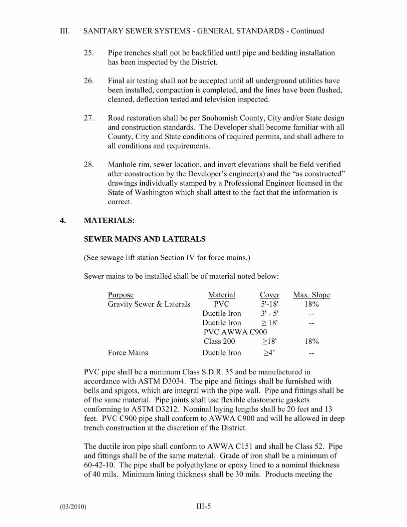
III. SANITARY SEWER SYSTEMS - GENERAL STANDARDS - Continued
(03/2010) III-5
25. Pipe trenches shall not be backfilled until pipe and bedding installation has been inspected by the District.
26. Final air testing shall not be accepted until all underground utilities have
been installed, compaction is completed, and the lines have been flushed, cleaned, deflection tested and television inspected.
27. Road restoration shall be per Snohomish County, City and/or State design
and construction standards. The Developer shall become familiar with all County, City and State conditions of required permits, and shall adhere to all conditions and requirements.
28. Manhole rim, sewer location, and invert elevations shall be field verified
after construction by the Developer’s engineer(s) and the “as constructed” drawings individually stamped by a Professional Engineer licensed in the State of Washington which shall attest to the fact that the information is correct.
4. MATERIALS:
SEWER MAINS AND LATERALS (See sewage lift station Section IV for force mains.) Sewer mains to be installed shall be of material noted below:
Purpose Material Cover Max. Slope Gravity Sewer & Laterals PVC 5'-18' 18% Ductile Iron 3' - 5' -- Ductile Iron ≥ 18' --
PVC AWWA C900 Class 200 ≥18' 18%
Force Mains Ductile Iron ≥4’ --
PVC pipe shall be a minimum Class S.D.R. 35 and be manufactured in accordance with ASTM D3034. The pipe and fittings shall be furnished with bells and spigots, which are integral with the pipe wall. Pipe and fittings shall be of the same material. Pipe joints shall use flexible elastomeric gaskets conforming to ASTM D3212. Nominal laying lengths shall be 20 feet and 13 feet. PVC C900 pipe shall conform to AWWA C900 and will be allowed in deep trench construction at the discretion of the District.
The ductile iron pipe shall conform to AWWA C151 and shall be Class 52. Pipe and fittings shall be of the same material. Grade of iron shall be a minimum of 60-42-10. The pipe shall be polyethylene or epoxy lined to a nominal thickness of 40 mils. Minimum lining thickness shall be 30 mils. Products meeting the

III. SANITARY SEWER SYSTEMS - GENERAL STANDARDS - Continued
(03/2010) III-6
standard are US Pipe “Polylined,” “Protecto 401,” and American Pipe “Polyband,” or equal. The exterior shall be coated with an asphaltic coating.
Each length shall be plainly marked with the manufacturer’s identification, year cast, thickness, class of pipe and weight. The pipe shall be furnished with mechanical joint or push-on type joint, except where plans call for flanged ends. Joints shall conform to AWWA C111. Restrained joint pipe shall be push-on joint pipe with FIELD LOK® or TR FLEX® gaskets as furnished by U.S. Pipe. All pipe shall be jointed by the manufacturer’s standard coupling, be all of one manufacturer, be carefully installed in complete compliance with the manufacturer’s recommendations. All fittings shall be short-bodied, ductile iron complying with AWWA C110 or C153 for 350 psi pressure rated mechanical joint fittings and 250 psi pressure rated flanged fittings. All fittings shall be polyethylene or epoxy lined per the ductile iron pipe specifications and either mechanical joint or flanged, as indicated on the Plans.
Fittings in areas requiring restrained joints shall be mechanical joint fittings with a mechanical joint restraint device. The mechanical joint restraint device shall have a working pressure of at least 250 psi with a minimum safety factor of 2:1 and shall be EBAA Iron, Inc., MEGALUG, Star Pipe Products, or approved equal.
All couplings shall be ductile iron mechanical joint sleeves.
The sewer pipe, unless otherwise approved by the District shall be laid upgrade from point of connection on the existing sewer or from a designated starting point. The sewer pipe shall be installed with the bell end forward or upgrade. When pipe laying is not in progress, the forward end of the pipe shall be kept tightly closed with an approved temporary plug. Wherever movable shoring (steel box) is used in the ditch, pipe shall be restrained by use of a winch mounted in the downstream manhole and a line of sufficient strength threaded through the pipe and set tight before each move. Any indication that joints are not being held shall be sufficient reason for the District to require restraints, whether or not movable shoring is being used.
All gravity pipe shall be laid in straight lines and at uniform rate of grade between manholes. Variance from established line and grade shall not be greater than 1/2-inch, provided that such variation does not result in a level or reverse sloping invert; provided, also, that variation in the invert elevation between adjoining ends of pipe, due to non-concentricity of joining surface and pipe interior surfaces, does not exceed 1/64 of an inch per inch of pipe diameter, or 1/2-inch

III. SANITARY SEWER SYSTEMS - GENERAL STANDARDS - Continued
(03/2010) III-7
maximum. Any corrections required in line and grade shall be reviewed with the District and shall be made at the expense of the Developer.
All extensions, additions and revisions to the sewer system, unless otherwise indicated, shall be made with sewer pipe jointed by means of a flexible gasket, which shall be fabricated and installed in accordance with the manufacturer’s specifications. All joints shall be made up in strict compliance with the manufacturer’s recommendations and all sewer pipe manufacture and handling shall meet or exceed the ASTM recommended specifications. Pipe handling after the gasket has been affixed shall be carefully controlled to avoid disturbing the gasket and knocking it out of position, or loading it with dirt or other foreign material. Any gaskets so disturbed shall be removed, cleaned, relubricated if required, and replaced before the rejoining is attempted. Care shall be taken to properly align the pipe before joints are entirely forced home. During insertion of the tongue or spigot, the pipe shall be partially supported by hand, sling or crane to minimize unequal lateral pressure on the gasket and to maintain concentricity until the gasket is properly positioned. Since most flexible gasketed joints tend to creep apart when the end pipe is deflected and straightened, such movement shall be held to a minimum once the joint is home. Sufficient pressure shall be applied in making the joint to assure that it is home, as described in the installation instructions provided by the pipe manufacturer. Sufficient restraint shall be applied to the line to assure that joints once home are held so, until fill material under and alongside the pipe has been sufficiently compacted. At the end of the work day, the last pipe laid shall be blocked in an effective way to prevent creep during “down time.” For the joining of dissimilar pipes suitable adapter couplings shall be used which have been approved by the District.
All gravity sewer pipe shall be bedded with pea gravel. The PVC pipe shall be bedded from a depth of 4-inches below the pipe to 12-inches above the pipe and ductile iron gravity sewer pipe shall be bedded from a depth of 4-inches below the pipe to the springline of the pipe. The bedding material shall extend across the full width of the trench and shall be compacted under the haunches of the pipe.
Special concrete bedding shall consist of a pipe cradle constructed of Portland cement concrete containing not less than four sacks of cement per cubic yard. Sand, gravel and water proportions are subject to approval by the District. Maximum aggregate size shall be 1-1/2-inches. Maximum slump shall be 4-inches. The bottom of the trench shall be fully compacted before the placement

III. SANITARY SEWER SYSTEMS - GENERAL STANDARDS - Continued
(03/2010) III-8
of pipe cradle. The Developer shall protect pipe against flotation and disturbing the horizontal alignment of the pipe during the pouring of the concrete.
Clay or Bentonite dams shall be installed across the trench and to the full depth of the granular material in all areas of steep slopes, stream crossings and wetland to prevent migration of water along the pipeline.
All backfill in roadway sections shall be placed and compacted in accordance with Snohomish County, City and/or State requirements and copies of the compaction results shall be provided to the District. All backfill in easements shall be placed and compacted to a minimum of 90 percent of the Modified Proctor dry maximum density per ASTM D1557. Copies of compaction results for all sewer system trenches shall be provided to the District. MANHOLES:
Manholes shall be of the offset type and shall be precast concrete sections with either a cast in place base, or a precast base made from a 3,000 psi structural concrete. Joints between precast wall sections shall be confined O-ring or as otherwise specified. The minimum diameter for manholes shall be 48 inches to a depth of 20 feet, and 54-inches for depths of 20 feet and greater. The District may require the diameter to be increased beyond the minimum based on future needs. For connections to existing systems, a concrete coring machine, suitable for this type of work, shall be utilized in making the connection. The existing manhole shall be rechanneled as required. The new pipe connection shall be plugged (water tight) until the new pipe system has been installed and approved. The Developer shall be responsible for any existing defects in the existing manhole unless these defects are witnessed by a representative of the District prior to any work being performed to make the connection. The Contractor shall be required to remove any and all deleterious material in the existing manhole and downstream reaches as a result of this work. Manholes located in easements or outside of paved areas shall have concrete collars with a minimum size of 48 inches diameter by 12 inches thick and marked with a green carsonite marker.
Manhole Sections
Manhole sections shall be placed and aligned so as to provide vertical sides and vertical alignment of the ladder steps. The completed manhole shall be rigid, true to dimension, and be water tight. Rough, uneven surfaces will not be permitted.

III. SANITARY SEWER SYSTEMS - GENERAL STANDARDS - Continued
(03/2010) III-9
Manhole Steps and Ladders Manhole steps shall be polypropylene, Lane International Corp. No. P13938 or equal. Ladders shall be polypropylene Lane International Corp. or equal, and shall be compatible with steps.
Grade Adjustment The manhole shall be set to provide not less than 14-inches or more than 26-inches of adjustment between the top of the cone or slab and the top of the manhole frame.
Masonry units (manhole adjusting rings) shall conform to the ASTM C2, Grade MA. The outside and inside of manhole adjusting rings and the joints of precast concrete sections shall be plastered and troweled smooth with 1/2 inch (minimum) of mortar in order to attain a watertight surface. No wood shall be used for adjustment.
Channels Channels shall be made to conform accurately to the sewer grade and shall be brought together smoothly with well rounded junctions, satisfactory to the District. The channels shall be field poured with concrete, no other fillers are permitted, after the inlet and outlet pipes have been laid and firmly grouted into place at the proper elevation. Allowances shall be made for a 0.1 foot drop in elevation across the manhole in the direction of flow. Channel sides shall be carried up vertically from the invert to three-quarters of the diameter of the various pipes. The concrete shelf shall be warped evenly and sloped 3/8 inch per foot to drain. Rough, uneven surfaces will not be permitted. Channels shall be constructed to allow the installation and use of a mechanical plug or flow meter of the appropriate size.
Drop Manholes Drop manholes require District approval and shall be constructed with outside drop(s). Approval will be limited to future extensions from deep sewers. Where extension from deep sewers is concurrent with deep sewer construction, drop manholes will not be allowed. Drop manholes shall, in all respects, be constructed as a standard manhole with the exception of the drop connection.
Lift Holes and Steel Loops All lift holes shall be completely filled with expanding mortar, smoothed both inside and outside, to insure water tightness. All steel loops shall be removed,

III. SANITARY SEWER SYSTEMS - GENERAL STANDARDS - Continued
(03/2010) III-10
flush with the manhole wall. The stubs shall be covered with mortar and smoothed. Rough, uneven surfaces will not be permitted.
Frames and Covers Frames shall be cast iron and covers shall be ductile iron. Castings shall be free of porosity, shrink cavities, cold shuts or cracks, or any surface defects, which would impair serviceability. Repair of defects by welding, or by the use of “smooth-on” or similar material, will not be permitted. Frames and covers shall be machine finished or ground on seating surfaces so as to assure non-rocking fit in any position and interchangeability of covers. Frames and covers shall be provided with three bolt locking lids. Rings and covers shall be positioned so one of the three locking bolts is located over the manhole steps and shall be adjusted to conform to the final finished surface grade of the street or easement to the satisfaction of the District. Manhole frames and covers shall be as manufactured by East Jordan Iron Works Model 370063, Olympic Foundry Model MH30AD/T, or equal.
Manhole Marker Posts A fiberglass manhole marker post shall be located adjacent to all manholes located in easement areas. The marker post shall be green in color, 3.75 inches wide (flat), 60 inches long and furnished with a 3-inch by 3-inch high intensity white reflector (250 Candle Power) and a flexible anchor barb. Each post shall include the following decal: “Caution Sewer Manhole. Before digging, Call 1-800-424-5555, Utility Underground Location Center.” Manhole markers shall be Carsonite Utility Marker CUM 375. The marker posts shall be set so as to leave 36 inches of the post exposed above grade. Distance from the marker to the manhole shall be stenciled on the marker with 2-inch letters.
5. SIDE SEWER LATERAL:
A side sewer lateral is considered to be that portion of a sewer line that will be constructed between a main sewer line and a property line or easement limit line. All applicable specifications given herein for sewer construction shall be held to apply to side sewer laterals. Side sewers shall be for a single connection only and be a minimum 6-inch diameter pipe. Side sewers shall be connected to the tee, provided in the sewer main where such is available, utilizing approved fittings or adapters. The side

III. SANITARY SEWER SYSTEMS - GENERAL STANDARDS - Continued
(03/2010) III-11
sewer shall rise at a maximum of 45 degrees and a minimum of 2 percent, from the sewer main. Where there are no basements, the minimum side sewer depth shall be 6 feet below existing curb line and 5 feet below ground at the property line, except where existing improvements, proposed improvements or topography may dictate additional depth. The elevations of the side sewer connections shall be of sufficient depth to serve all existing and potential future basements.
Each 6 inch side sewer service shall be provided with a 12 foot long 2 x 4 wooden post, which extends from the invert of the end of the 6 inch pipe to above the existing ground. The exposed area of this post shall be painted white and shall have stenciled thereon in 2 inch letters (black paint) “SEWER” and shall also indicate the total length of the 2 x 4. A 12 gauge (minimum) wire shall be wrapped around and stapled the full length of the 2 x 4. Where no tee or wye is provided or available, connection shall be made by machine-made tap and saddle. Inserta Tee, Fowler Manufacturing Company or approved equal may be utilized on concrete pipe only. Romac Style “CB” Sewer Saddle shall be utilized on PVC pipe. The maximum bend permissible at any one fitting shall not exceed 45 degrees. The maximum bend of any combination of two adjacent fittings shall not exceed 45 degrees (one-eighth bend) unless straight pipe of not less than 3 feet in length is installed between such adjacent fittings, or unless one of the fittings is a wye branch with a cleanout provided on the straight leg. Standing side sewers shall be constructed only with pre-approval of the District. Standing side sewers may be required, or allowed, at the sole discretion of the District. When allowed, standing side sewer tees will be constructed of the same material as the main line sewer.
6. TESTING GRAVITY SEWERS FOR ACCEPTANCE:
The Developer shall furnish all facilities and personnel for conducting tests. Methods other than Low Pressure Air Test shall be subject to the approval of the District.
Preparation for Testing for Leakage The Developer shall be required, prior to testing, to clean and flush all gravity sewer lines with an approved cleaning ball and clean water. The completed gravity sewer, including side sewer stubs, after completion of backfill and cleaning shall be televised. This will be permitted prior to paving. The sewer shall then be tested by the low pressure air test method and/or an infiltration test.

III. SANITARY SEWER SYSTEMS - GENERAL STANDARDS - Continued
(03/2010) III-12
Except, however, that in certain conditions an exfiltration test may be required by the District. The first section of pipe not less than 300 feet in length installed by each crew shall be tested, in order to qualify the crew and/or the material. A successful installation of this first section shall be a prerequisite to further pipe installation by the crew. At the Developer’s option, crew and/or material qualification testing may be performed at any time during the construction process after at least 2-feet of backfill has been placed over the pipe. Low Pressure Air Test The sewer pipe shall be tested for leaks through the use of air (unless exfiltration test is approved) in the following manner: Following the pipe cleaning, utility installation, and paving, the pipe installation shall be tested with low pressure air. Air shall be slowly supplied to the plugged pipe installation until the internal air pressure reaches 4.0 pounds per square inch greater than the average back pressure of any ground water that may submerge the pipe. 0.4 pounds per square inch to be added per 1 foot of water table over the pipe to a max. of 6 psi. At least two minutes shall be allowed for temperature stabilization before proceeding further. The rate of air loss shall then be determined by measuring the time interval required for the internal pressure to decrease from 3.5 to 2.5 pounds per square inch while maintaining the stipulated pressure greater than the pipe section’s average adjacent groundwater back pressure.
The pipeline shall be considered acceptable if the total rate of air loss from any section tested in its entirety between manholes, cleanouts or pipe ends does not exceed the following table:
Length of 6" Pipe (ft)
Leng
th o
f 8"
Pipe
(ft)
0 50 100 150 200 250 300 350 4000 0 0:40 1:20 1:58 2:38 3:18 3:58 4:38 5:16
50 1:10 1:50 2:30 3:10 3:48 4:28 5:08 5:48 5:56100 2:20 3:00 3:40 4:20 5:00 5:38 6:14 6:12 6:08150 3:32 4:10 4:50 5:30 6:10 6:30 6:26 6:22 6:18200 4:42 5:22 6:00 6:40 6:44 6:38 6:34 6:30 6:26250 5:52 6:32 6:48 6:58 6:50 6:44 6:40 6:36 6:32300 7:02 7:20 7:10 7:02 6:56 6:50 6:44 6:40 6:36350 7:34 7:22 7:14 7:06 7:00 6:54 6:50 6:44 6:42400 7:34 7:24 7:16 7:08 7:02 6:58 6:52 6:48 6:44
Test time in minutes and seconds

III. SANITARY SEWER SYSTEMS - GENERAL STANDARDS - Continued
(03/2010) III-13
Test times will be provided by the Engineer for combinations other than 8-inch mains and 6-inch laterals.
If the pipe installation fails to meet these requirements, the Developer shall determine at his own expense the source or sources of leakage, and shall repair (if the extent and type of repairs proposed by the Developer appear reasonable to the District) or replace all defective materials or workmanship. The completed pipe installation shall meet the requirements of this low pressure air test or the alternative water exfiltration test before being considered for acceptance. Plugs used to close the sewer pipe for the air test shall be securely braced to prevent the unintentional release of a plug. Gauges, air piping manifolds and valves shall be located at the top of the ground. No one shall be permitted to enter a manhole where a plugged pipe is under pressure. Air testing apparatus shall be equipped with a pressure release device such as a rupture disk or a pressure relief valve designed to relieve pressure on the pipe under test at 6 psi.
Deflection Test
Deflection tests shall be performed on all ASTM D3034 PVC gravity sewer mains by pulling a mandrel through the pipe. The allowable deflection test limit shall be 5.0 percent of the base inside diameter in accordance with APWA test procedures and the nominal mandrel size shown in the following table.
Nominal Pipe Size (in.)
Base Inside Diameter (in.)
Mandrel Size, Diameter (in.)
6 5.74 5.45 8 7.67 7.28 10 9.56 9.08 12 11.36 10.79
Deflection testing is not required for AWWA C900 PVC or ductile iron pipe. Deflection testing is also not required for pipe diameters 15 inch and greater. The sewer lines shall be thoroughly cleaned prior to the deflection test.
7. TELEVISED INSPECTION:
After the gravity sewer lines have been cleaned, flushed and manhole channeled, the Developer shall provide a complete televised inspection. The Developer shall perform a complete televised inspection of the sewer pipe and appurtenances and shall provide to the District, a narrated DVD color audio-visual recording of the inspections together with a written log of the television inspection. The camera shall be a pan and tilt type equipped with adequate light
III. SANITARY SEWER SYSTEMS - GENERAL STANDARDS - Continued
(03/2010) III-14
and focusing to allow inspection of sewer main, side sewers and full circumference inspection of main line joints and fittings. The District shall determine if the quality of the televising is acceptable. Immediately prior to the televised inspection, the Developer shall run water through each sewer line for 5- to 10-minutes to provide water for detection of any adverse grade sections visible by the presence of ponded water. The camera shall be stopped periodically at the ponded areas and the depth of water shall be measured with a ball of known diameter on the pull line. During the inspection, all tees and other fittings shall be logged as to exact location within 1 percent maximum error in measurement, wherein accuracy is checked with various fittings and the terminating manhole. The District shall be notified 48 hours prior to any television inspection and this work shall be performed on a schedule to allow the District to witness the inspection. Any defects in material or installation identified by the television inspection shall be repaired as required by the District at the Developer’s expense.
8. ADJUSTMENT OF NEW AND EXISTING UTILITY STRUCTURES TO
GRADE:
This work consists of constructing and/or adjusting all new and existing utility structures encountered on the project to finished grade.
Asphalt Concrete Paving On asphalt concrete paving projects, the manholes shall not be adjusted until the final pavement is completed, at which time the center of each manhole lid shall be relocated from references previously established by the Developer. The pavement shall be cut as further described and base material removed to permit removal of the cover. The manhole shall then be brought to proper grade. Prior to commencing adjustment, a plywood and visqueen cover as approved by the District shall be placed over the manhole base and channel to protect them from debris. The asphalt concrete pavement shall be cut and removed to a neat circle, the diameter of which shall not exceed 48 inches or 14 inches from the outside diameter of the ductile iron frame, whichever is smaller. The ductile iron frame shall be brought up to desired grade, which shall conform to surrounding road surface. Adjustment to desired grade shall be made with the use of concrete adjustment rings or bricks. No cast or ductile iron adjustment rings will be allowed. An

III. SANITARY SEWER SYSTEMS - GENERAL STANDARDS - Continued
(03/2010) III-15
approved class of mortar (one part cement to two parts of plaster sand) shall be placed between adjustment rings or bricks and ductile iron frame to completely fill all voids and to provide a watertight seal. No rough or uneven surfaces will be permitted inside or out. Adjustment rings or brick shall be placed and aligned so as to provide vertical sides and vertical alignment of manhole steps and ladder. Adjustments in excess of 26 inches of depth of the 24 inch manhole neck shall require manhole section rings to raise the eccentric cone to within the adjustment ring tolerances. Check manhole specifications for minimum and maximum manhole adjustment and step requirements. Special care shall be exercised in all operations in order not to damage the manhole, frames and lids or other existing facilities. The annular spaces of the manhole frames shall be filled with 5/8-inch minus crushed gravel and compacted with hand tamper to within 2-inches of the top of the frame. Asphalt concrete patching shall not be carried out during wet ground conditions or when air temperature is below 50 degrees F. Asphalt concrete mix shall be at required temperature when placed. Before making the asphalt concrete repair, the edges of the existing asphalt concrete pavement and the outer edge of the casting shall be tack coated with hot asphalt cement. The remaining 2 inches shall then be filled with HMA and compacted with hand tampers and a patching roller.
The completed patch shall match the existing paved surface for texture, density and uniformity of grade. The joint between the patch and the existing pavement shall then be carefully painted with hot asphalt cement or asphalt emulsion and shall be immediately covered with dry paving sand before asphalt cement solidifies. All debris such as asphalt pavement, cement bags, etc., shall be removed and disposed of by Developer. Prior to acceptance of a project, manholes shall be cleaned of all debris and foreign material. All manhole steps and ladders shall be cleaned free of grout. Any damage occurring to the existing facilities due to the Developer’s operations shall be repaired at his own expense.
Adjustment of Manholes in Easements Manholes in easement areas shall be adjusted to ensure drainage away from the manhole frame and cover. Pour a 4'-0" diameter by 12-inch-thick broom finished concrete collar around the manhole frame and cover, and marked with a green carsonite marker.
Adjustment of Monuments Monuments and monument castings shall be adjusted to grade in the same manner as for manholes.

III. SANITARY SEWER SYSTEMS - GENERAL STANDARDS - Continued
(03/2010) III-16
Adjustment of Valve Box Castings Adjustment of valve box castings shall be made in the same manner as for manholes.
9. FINAL ACCEPTANCE:
Prior to final inspection, all pipelines shall be flushed and cleaned and all debris removed. At the District’s discretion, gravity sewer lines shall be inspected for line and grade by checking each section between manholes for alignment. A full circle of light shall be seen by looking through the pipe at a light held in the manhole at the opposite end of the section of sewer line being inspected. Any corrections required in line and grade shall be made at the expense of the Developer. Visual confirmation will require confined space entry compliance and will normally be considered where settlement is suspected.
10. PRIVATE SIDE SEWERS:
Private side sewers are the extension of side sewer laterals located outside of the public rights-of-way or easements granted to the Silver Lake Water & Sewer District.
1. All sewer service connections to District facilities shall be gravity service.
2. The sewer pipe in the street right-of-way and District easements shall be
6-inch diameter, and shall have a 2% minimum grade. Construction in street rights-of-way shall be performed by a licensed side sewer contractor and requires a right-of-way use permit.
3. Private side sewer pipe for residential property shall be 4-inches or larger. Side sewer pipe for duplexes, multi-family, industrial, commercial, etc., shall be 6-inches or larger. Pipe material shall be ductile iron or PVC ASTM D3034, and shall be installed at 2 percent minimum grade (1/4 inch fall per foot). Construction on private property may be performed by owner, but requires a permit.
4. Pipe shall be bedded with pea gravel or clean free draining sand.
5. Side sewer shall be inspected by the District prior to backfilling. Side sewer shall be plugged and tested in the presence of the District Inspector by filling with water. Leakage rate shall not exceed 0.31 gal./hr. for 4 inch pipe and 0.47 gal./hr. for 6 inch pipe, per 100 feet of pipe. Existing homes served by septic systems converting to District sewer service are to

III. SANITARY SEWER SYSTEMS - GENERAL STANDARDS - Continued
(03/2010) III-17
demonstrate proper abandonment of septic tank to Snohomish County Health Department Standards and WAC 246-272A-0300. The Contractor shall provide a copy of documentation regarding sewage pumping to the District.
6. On private property, minimum cover shall be 18-inches over top of pipe
from a point 30-inches out from house and continuing to the connection with the District sewer system.
7. Parallel water and sewer lines shall be 10 feet apart horizontally wherever
possible and have a vertical separation of 18-inches if a vertical crossing is necessary.
8. No more than 100 feet is allowed between cleanouts. Cleanouts are
required for bends equal to or greater than 90 degrees. Cleanout shall be a plugged tee or plugged wye lateral.
9. All pipe joints shall be rubber gasket type. 10. When required, “grease interceptor” to be outside the building and be of a
size and type certified by a professional engineer licensed in the State of Washington and reviewed by the District.
11. Backwater valves are required on all side sewers where potential occurs for flow to back into the private service. These valves shall be installed in a riser pipe, meter box, vault or manhole as necessary to allow access for maintenance.
12. Dwelling units defined by food preparation, bedroom and bathroom areas contained in a structure are primary connections. Secondary connections require preapproval by the District before sewer service can be offered.
a. Auxiliary dwelling units constructed on an existing served
property within an existing structure may be allowed subject to payment of connection charges.
b. Auxiliary dwelling units constructed on an existing served property in separate structures require separate side sewer connections to District mainline facilities.
c. Recreational vehicle dumps are not allowed.
d. Small utility sink and toilet facilities in out buildings may be allowed to connect to existing side sewers.

III. SANITARY SEWER SYSTEMS - GENERAL STANDARDS - Continued
(03/2010) III-18
13. Side sewer installs to existing District mainline facilities in right-of-way are subject to special requirements:
a. Right-of-way permit required. Owner to pay all costs of obtaining
the permit and for any costs associated with full compliance with all permit obligations.
b. Owner to pay all costs of installation of side sewer.
c. The Owner shall enter into a Developer Extension Agreement (DEA) with the District, and will be required to meet the following conditions:
i. All District or District incurred inspection fees are to be
paid prior to and as a condition of connection.
ii. Comply with all District Standards, Conditions, Specifications, and requirements are applicable.
iii. Comply with all state, local and federal requirements apply.
iv. Preconstruction meeting with owner, owner contractor, and District is to be scheduled with the District prior to initiation of construction.
v. No connection to District facilities can be made without District or District Representative on site.

SECTION IV
SEWAGE LIFT STATIONS

SEWAGE LIFT STATIONS
TABLE OF CONTENTS
Page 1. Objective ..................................................................................................................1 2. Design Calculations .................................................................................................1 3. Location ...................................................................................................................2 4. Lift Station ...............................................................................................................3 5. Wet Well ..................................................................................................................6 6. Controls ....................................................................................................................7 7. Electrical Service/Controls & Telemetry System ....................................................8 8. Standby Power System ..........................................................................................13 9. Force Main .............................................................................................................17 10. Testing Force Main ................................................................................................17 11. Lift Station Test Program ......................................................................................19

(03/2010) IV-1
IV. SEWAGE LIFT STATIONS - GENERAL STANDARDS 1. OBJECTIVE:
Section IV is intended to present information and provide an outline of the minimum general standards to be accomplished in planning a sewage lift station installation within the Silver Lake Water & Sewer District service area. The Developer shall submit to the District for review and approval, complete sewage lift station plans and design which provide for the lift station, electrical service, SCADA controls, and auxiliary generator/transfer switch together with all accessories for a complete, automatically operating installation. Design material and drawings shall provide all civil, mechanical and electrical details and align with all applicable codes and regulations, and good engineering practice.
2. DESIGN CALCULATIONS:
The Developer shall perform a study and make the determination to assure that the lift station installation is sized to serve the overall sewage flows generated within the potential service area. The flow study shall include the Developer’s plat boundary area as well as adjacent and future service areas. The service areas shall be the areas within that which could be served by the installation of the lift station(s). The station’s design flow capacity shall be based on an average daily per capita flow with related peaking factors and inflow/infiltration allowances. Documentation of present and future service area flow rates for lift station size and capacity determination shall be provided to the District. The effects of the minimum flow conditions shall be estimated to be sure that retention of the sewage in the wet well will not create a nuisance and that pumping equipment will not operate too infrequently. The wet well shall be sized to limit pump cycles to a maximum of four cycles per hour per pump, with two pumps alternating at pump design capacity. Lift station capacity shall meet the maximum rate of flow expected. At least two (2) pumping units shall be provided at each lift station installation. The pump shall have sufficient capacity and capability to efficiently handle the peak design flow with one (1) pump out of service and to ensure a minimum velocity of 3 feet per second velocity in the force main. The force main shall be sized for a minimum velocity of 3 feet per second and a maximum of 8 feet per second. The minimum diameter of the force main shall be 6 inches.

IV. SEWAGE LIFT STATIONS - GENERAL STANDARDS - Continued
(03/2010) IV-2
The capacity of the receiving sewer shall exceed the flow expected. Three (3) copies of the Design Report shall be submitted to the District for review. As a minimum, the report shall include.
1. Project description 2. Projected flows 3. Connection point with downstream capacity 4. Wet well sizing 5. Run time calculation and cycle time 6. Pump station head calculation 7. Pump selection 8. Force main size, length and material 9. Electrical load study 10. Generator sizing 11. Odor potential calculations 12. Wet well buoyancy calculations 13. Force main surge calculations The Design Report shall be approved by the District prior to starting the design of the lift station.
3. LOCATION:
The Developer shall furnish a site layout for the lift station installation. The lift station shall be located as far as practicable from present or proposed built-up residential areas, and an asphalt concrete access road shall be provided. Sites for sewage lift stations shall be of sufficient size for future expansion or addition, if applicable. The easement for the lift station site shall be submitted to the District for review prior to construction of the lift station. Lift station sites not located within the plat boundary shall be deeded to the Silver Lake Water & Sewer District. The Developer shall coordinate electrical power required to the site with the electrical utility. As a minimum, the site shall provide for the following: 1. Lift station 2. Auxiliary power, including automatic transfer switch 3. Electrical 4. Telemetry
IV. SEWAGE LIFT STATIONS - GENERAL STANDARDS - Continued
(03/2010) IV-3
5. 1-inch water service with reduced pressure backflow preventor and hose bib installed in an above ground hot box enclosure on concrete. Furnish 50 feet of 3/4-inch heavy-duty rubber hose.
6. Odor control, as applicable for location and capacity. 7. Cuts and fills to provide level site for maintenance. 8. Asphalt concrete pavement for access and maintenance areas. 9. Safety system mount. See Detail V-LS7. 10. Single entry to wet well from recessed entry manhole (rock catcher). See
Detail V-LS8. 11. 6 foot high black powder coated frame and posts together with black vinyl
chain link fence with vertical vinyl slats in-laid for screening and three strands of barbed wire on top of the fence, enclosing the site with 3-foot-wide access main gate and separate vehicle access gate 12-foot wide minimum opening. Fence to be located in the asphalt, 6 inches from the edge. A gate button will be used for the center gate post.
4. LIFT STATION:
GENERAL
The sewage lift station shall be Smith & Loveless, custom series buried, dry-well-type or wet-well mounted as approved by the District. Construction shall be in compliance with OSHA, UL, ASTM, NEC, WAC, and other applicable codes and regulations. The station shall be designed, constructed and anchored to comply with current IBC standards. The lift station shall have, as a minimum, two sewage pumps. The pumps shall have sufficient capacity and capability to efficiently handle the peak design flow with one pump and to ensure a minimum velocity of 3 feet per second in the force main. Design calculations and pump curves indicating the same shall be provided with the submittal information. The rotor (motor) assembly shall be dynamically balanced. Add the impeller to the rotor assembly and dynamically rebalance the assembly, all to NEMA specifications for the operating RPM condition and submit documentation to the District. Pump and motor assembly shall meet the vibration tolerances established by the Hydraulic Institute, and shall be certified by the factory prior to shipment. Field vibration testing will be conducted to confirm conformance with vibration standards after installation. Failure to meet vibration standards in the field can be cause for station rejection. The sewage lift station supplier shall check the station during installation to determine if the installation is correct. Written confirmation of each visit and recommendations shall be provided to the District. The sewage lift station supplier shall provide a minimum of 4 hours of training for District personnel at the station site during start-up.

IV. SEWAGE LIFT STATIONS - GENERAL STANDARDS - Continued
(03/2010) IV-4
The sewage lift station supplier shall provide four (4) complete copies of maintenance and operation material to the District. CUSTOM SERIES BURIED STATION (WET WELL/DRY WELL)
The station shall be a Smith & Loveless Custom Series station complying with the latest edition of Smith & Loveless standard specifications and with the District Standards. The station shall be a minimum of 8-feet in diameter and the pump motor assembly and piping shall be District standard dark green in color. The above-ground entrance hatch shall be 44-inches minimum inside diameter with a steel cover, lockable to District standards. In all areas, lighting and ventilation shall be provided to meet the requirements for a confined space entry. The station shall be provided with a minimum of four magnesium anodes. The test box for cathodic protection shall be mounted on the electrical rack. See Detail V-LS3. Each motor starter shall have its own independent phase loss relay wired directly to the starter’s “enable” circuit and to the RTU for alarming. As a minimum, the station shall include the following: 1. Vertical close-coupled, motor driven, non-clog pumps. 2. Resilient seat gate valves. 3. Internal piping. 4. Central control panel with circuit breakers and intrinsically safe circuits. 5. Motor starters. 6. Shelf mounted air compressor (2) 9L25 bubbler system for automatic
pumping level controls. 7. Lighting. 8. Sump pump with dedicated simplex, gray, 20A, non-GFCI receptacle in
cast aluminum weatherproof box with full in-service cover. 9. Ventilating blower. 10. Blower timer. 11. Dehumidifier. 12. All internal wiring. 13. Protection against corrosion. 14. Station flooding alarm. 15. Operator in trouble emergency button. 16. Extended warranty – 24 months from start-up or 30 months from time of
shipment which ever is first. 17. Document certifying the lift station is in compliance with the NEC.

IV. SEWAGE LIFT STATIONS - GENERAL STANDARDS - Continued
(03/2010) IV-5
18. Convenience receptacles, white, duplex, 20A, GFCI, in cast aluminum weatherproof boxes with full in-service covers.
19. Spare parts each pump: • Replacement pump shaft seal – one each for each pump • Filter element for the seal filters – one each for each pump • Volute gaskets – two each for each pump
20. Touch up paint kit. 21. Ductile iron piping between wet well and station. 22. Common reinforced concrete base slab for station and wet well. 23. 316 stainless steel sump pump piping from the sump pump to the wet well
with check valve and unions. Piping to go up dry well entry and discharge through the connection opening in the entry tube.
24. Air bubbler line to go up dry well entry, above ground level, back down and discharge through connection openings in entry tube. Air bubbler line shall be 316 stainless steel tubing in the station and 3/4-inch diameter 316 stainless steel pipe from the entry tube to a wet well mounted tee with 3/8-inch stainless steel pipe extended down from the wet well mounted tee to 6 inches above the inlet of the suction pipes.
25. The wet well shall be a minimum of 8 feet in diameter. The wet well shall provide for the volume of the pumps to be fully submerged.
26. The wet well shall be of precast concrete construction with flat slab cover and 4 x 6 (two door) hatch for access. The flat slab concrete cover shall be provided with a 4-inch vent, which is “hooked and screened.”
WET WELL MOUNTED STATION
The station shall be Smith & Loveless wet well mounted vacuum primed station complying with the latest edition of Smith & Loveless standard specifications and with the District Standards. Each motor starter shall have its own independent phase loss relay wired directly to the starter’s “enable” circuit and to the RTU for alarming. As a minimum, the station shall include the following: 1. Vertical, close-coupled, motor driven, vacuum-primed, non-clog pumps. 2. Resilient seat gate valves. 3. Internal piping. 4. Central control panel with circuit breakers and intrinsically safe circuits. 5. Motor starters. 6. Shelf mounted air compressor (2) bubbler system automatic pump level
controls. Shelf to be mounted at the same level or higher as the top of the station side wall.
7. Heater. 8. Ventilating blower. 9. Priming pumps and appurtenances.

IV. SEWAGE LIFT STATIONS - GENERAL STANDARDS - Continued
(03/2010) IV-6
10. All internal wiring. 11. Discharge pipe welded to the base plate and to be flanged below. 12. Bubbler piping above the base plate, plastic tubing, and below the base
plate to be 3/8 inch diameter 304 SS pipe extended down to 6 inches above the inlet of the suction pipes.
13. Lid to be 2 piece design with hydraulic hood assist. 14. Paint station with dark green epoxy. 15. Shelf mounted vacuum pumps located at the same level or higher as the
top of the station side wall. 16. Extended warranty – 24 months from start-up or 30 months from time of
shipment whichever is first. 17. Document certifying the lift station is in compliance with the NEC. 18. Convenience receptacles, white, duplex, 20A, GFCI, in cast aluminum
weatherproof boxes with full in-service covers. 19. 3/4-inch conduit connection in electric panel for connection to the
telemetry sub panel. 20. Spare parts each pump:
• Replacement pump shaft seal – one for each pump • Volute gaskets – two for each pump
21. Touch up paint kit. 22. AWWA C900 PVC suction pipes. 23. Flexible restrained coupling (Romac Adaptor RFCA) to connect station to
suction pipes. 24. The wet well shall be a minimum of 8 feet in diameter.
MOTORS
The pump and motor shafts shall be the maximum diameter available for these units. Pump motors shall be 3-phase, 60-cycle, 480-voltage inverter rated, TEFC. Motors 40 hp and larger shall be furnished with soft start or variable frequency drives (VFDs). VFDs shall comply with the latest ANSI, IEEE, and NEC codes. VFD load circuits from starter to motor shall be shielded power cables in RGS conduits. The motors shall have 1.15 service factor and be non-overloading for the full range of the curve unless otherwise approved by the District.
5. WET WELL:
GENERAL
The wet well shall be precast concrete manhole sections. Joints between precast wall sections shall be confined O-ring or as otherwise approved. The poured in place slab top shall be designed with the wet well to exceed buoyant forces and

IV. SEWAGE LIFT STATIONS - GENERAL STANDARDS - Continued
(03/2010) IV-7
shall have a cast in place flush mount safety system sleeve per District Standard Detail.
The wet well shall be provided with polypropylene manhole steps as specified for manholes. The wet well shall be checked to ensure all joints are watertight to prevent infiltration and exfiltration of the wet well. The wet well floor, walls and underside of the top shall be coated to comply with the following:
Surface Preparation: Allow a minimum of 28 days cure time for concrete. Sweep blast to provide a surface profile. Surface shall be clean, dry and free of contaminants. Exterior Surfaces: The exterior surface of the wet well shall be coated with 30 mils minimum of coal tar epoxy.
Interior Surfaces: • Filler and Surfacer: Tnemec Series 218 Filler and Surfacer.
Applied as needed. After the application of the prime coat, the bugholes and surface voids shall be filled to ensure that the finish coat is monolithic and pinhole free.
• Finish: Tnemec Series 435 Perma-Glaze Applied in two coats at
15 mils dry film thickness each. Color light gray. • Total System: 30 mils dry film thickness. Comply with all conditions of the manufacturer’s specifications for preparation and application.
6. CONTROLS:
The control panel shall include:
1. Main disconnect. 2. Panel mounted running light for each pump. 3. Panel mounted ammeter for each pump to read percentage of load. 4. Panel mounted running time meter for each pump. 5. Panel mounted Cutler Hammer HOA switches for each pump.
IV. SEWAGE LIFT STATIONS - GENERAL STANDARDS - Continued
(03/2010) IV-8
6. Mounting bracket for telemetry sub panel in station (size: 13-1/2" L x 10" W x 6-1/2" Deep).
7. Local/Remote contact for the following alarms: a) Low Level b) High Level c) Power/Phase Failure (single & 3-phase) d) Pump Failure e) High Water (dry well) f) Pump On g) Intrusion
8. Panel mounted wet well gauge. Minimum 2.5-inch dial and read for depth of wet well in inches (Model Marsh Bellofram No. G 22 687).
9. Phase monitor to protect the pump motors from single-phase reversal and low voltage.
10. Discharge check valve limit switches (each). 11. Pump alternator, each cycle. 12. High water float pump control.
7. ELECTRICAL SERVICE/CONTROLS & TELEMETRY SYSTEM:
GENERAL
Codes and regulations exist at the federal, state, and local level dictating minimum acceptable requirements for electrical systems. The following standards shall be used as a basis for design and review.
1. National Electric Code (NEC) 2. Occupational Safety & Health Act (OSHA) 3. State & Local Building Codes 4. National Electrical Code (NESC) 5. National Electrical Manufacturers Association (NEMA) 6. Underwriters’ Laboratory (UL) 7. Insulated Power Conductor Engineering Association (IPCEA) 8. American National Standards Institute (ANSI) 9. Institute of Electrical & Electronic Engineers (IEEE)
ELECTRICAL SERVICE
The local electric utility will be the primary source of electrical power. The Developer shall ascertain proper coordination between the nominal secondary delivery voltage supplied by Snohomish County PUD No. 1 and the connection to the lift station equipment. The electrical service shall be 480/277V 4-wire, 3-phase, 60 hertz, with a solid neutral terminal at the disconnect or as may otherwise be required by Snohomish County PUD No. 1. This shall be confirmed with the Snohomish County PUD No. 1 and confirmed by the suppliers.

IV. SEWAGE LIFT STATIONS - GENERAL STANDARDS - Continued
(03/2010) IV-9
All installation shall be approved by Snohomish County PUD No. 1 and shall be in conformance with the NEC (current issue) UL, OSHA and County and State electrical codes. The District shall be furnished with a certificate of final inspection by the inspecting agency. All wire shall be stranded copper. All conduit shall be rigid galvanized (RGS). All underground RGS conduits, elbows, and fittings shall be coated with 20 mils (minimum) of PVC coating or a half-lapped wrap of Scotchwrap No. 51. See Detail V-LS4. All underground conduits shall be covered with a strip of yellow polyethylene tape placed 6-inches below finished grade and directly above the conduit. All conduit shall have a minimum of 2'-0" of cover. Instrumentation conduits, elbows and fittings shall be RGS over their entire length. Heating strips shall be provided for outside electrical enclosures. A service entrance shall be provided with a pedestal on which shall be mounted, as a minimum, the following equipment: 1. Meter and meter can (as required by the PUD) 2. Meter C.T.S. (as required by the PUD) 3. Main disconnect SUSE-rated circuit breaker in a NEMA 3R, enclosure,
with padlock to District standards. 4. Service voltage shall be 480/277 volts, 3 phase, 4-wire, except as required
by Snohomish County PUD #1. 5. Single phase services shall be 240/120 volt, 3 wire. Panels shall conform
with NEMA 3R. 6. A 120-volt duplex in NEMA 3R enclosure with padlock to District
standards on the electrical rack. 7. Ground rod and connector wire in conduit to NEC standards. 8. Mount equipment per Detail V-LS3

IV. SEWAGE LIFT STATIONS - GENERAL STANDARDS - Continued
(03/2010) IV-10
9. Provide a complete electrical plan set including the following minimum documents:
a) Electrical plan view showing equipment and interconnecting
conduits b) A cable and conduit schedule c) A one-line diagram d) Motor starter control schematics e) Panelboard schedule f) Main control panel schematics g) PLC I/O tables h) Associated electrical details
10. The District shall be provided with a complete reproducible set of
as-constructed plans and details showing final location of all equipment, conduit and wire.
CONTROLS
Control and instrument system plans shall thoroughly and completely depict system design. The plans, in conjunction with the specifications, shall define the type of control system, the type of components in the system, set points and the interface between the instrumentation and control system and the lift station system. To accomplish this, the control and instrument plan(s) shall include, as a minimum, the following: 1. Control and instrumentation system legend and general notes 2. Control, instrumentation and distribution diagram 3. Plans showing location of all control, instrument, and distribution system
equipment and components, both electrical and pneumatic 4. All equipment and installation details
The power, control and instrumentation systems shall be designed with both operational reliability and maintainability. Use standard products wherever possible. Electrical equipment and devices shall be connected using separate power, control, and instrumentation conduits. Electrical gutters or fabricated raceways shall not be used. All components within the lift station system, including both internally and face-mounted instruments and devices, shall be clearly identified with phenolic nameplates of black background with white letters reverse engraved from the backside (smooth front surface).

IV. SEWAGE LIFT STATIONS - GENERAL STANDARDS - Continued
(03/2010) IV-11
Intrinsically safe electrical circuits shall be installed in the main control panel in compliance with NEC, not in the motor starters. All wiring between cabinet, equipment and components shall be labeled and color coded where applicable. All pump motors shall have an independent lockable circuit breaker located within the lift station and the lift station shall have a lockable main circuit breaker located outside the lift station. Lead and lag pump functionality shall alternate between pumps on each cycle change. The pump controls shall be air bubbler type with two compressors alternating on timer control, and shall provide for both pumps to operate at high water conditions. The control elevations shall be indicated on the plans, i.e., on-off, first pump on, second pump on, and high water alarm. The air compressors shall not be located in electrical cabinets or enclosures. The wet well shall be equipped with a high water redundant float to override the bubbler pump control and start the pumps and send high wet well level alarm. A complete set of spare fuses shall be provided for all fused equipment. TELEMETRY
The District’s telemetry system utilizes Zetron 1716 RTUs for SCADA functions related to the wastewater collection systems. The RTUs report to a master unit at the District Headquarters. The master unit communicates with a personal computer running Wonderware Intouch software to allow Supervisory Control and Data Acquisition functions to take place. The RTUs shall be provided in enclosures with auxiliary equipment to facilitate connection of external signals to the RTU, and to monitor voltage, intrusion, and similar status signals. Communication with the Zetron 1700 MTU shall be via leased telephone lines to the District’s office. For each new lift station, the Developer shall provide a Zetron 1716 RTU (with Modbus option, accumulator/pulse counter access and battery backup) along with an enclosure, power supply, relays, surge protection devices for power and telephone lines, and other auxiliary devices as required for proper operation of the system. Typical discrete inputs for a station include:
1. Utility Power Fail 2. Three Phase Power Fail (phase reversal, phase imbalance, phase loss,
undervoltage, and overvoltage)

IV. SEWAGE LIFT STATIONS - GENERAL STANDARDS - Continued
(03/2010) IV-12
3. Generator Run 4. Generator Fail 5. ATS in Standby 6. Intrusion Alarm 7. Wet Well High Level 8. Wet Well Low Level 9. Pump No. 1 Run 10. Pump No. 2 Run 11. Pump No. 1 Fail 12. Pump No. 2 Fail
(Note: Additional pump run and fail signals are required for each pump when the station has more than two pumps.)
13. Station Flood (Buried Station) 14. Ventilation Fail (Buried Station) 15. Operator in Trouble (Buried Station) 16. Flow Meter Totalizer 17. All exterior transfer switches will be NEMA 3 enclosure with keyed
switch for access to controls.
Typical discrete outputs include:
1. Start Generator (with an interposing relay driven by the RTU in the telemetry subpanel)
Typical analog inputs include:
1. Pump No. 1 Amperes 2. Pump No. 2 Amperes 3. Wet Well Level 4. Flow Rate
Provisions shall also be made for additional I/O signals by providing terminals from each I/O point on the RTU to terminals within the telemetry panel. The telemetry panel and all items contained therein shall be provided by Systems Interface, Inc., (425) 481-1225. The Developer shall also be responsible for correct set-up of the RTU with respect to the existing system configuration. This includes coordinating configuration parameters such as: 1. RTU addressing 2. Master unit configuration 3. RTU configuration, 4. I/O point configuration (enable/disable format) 5. Debounce time 6. NO/NC inputs

IV. SEWAGE LIFT STATIONS - GENERAL STANDARDS - Continued
(03/2010) IV-13
7. Percent change reporting 8. High/low alarm limits 9. Accumulator sampling rates 10. Momentary/latched outputs 11. Signal adjustments (receive gain, transmit gain). 12. Rebalancing of the District’s Verizon dedicated telemetry circuit. The Developer shall coordinate with the telephone utility and the District for obtaining proper telephone service to the site. The Developer shall be responsible for obtaining, installing, and starting up the RTU for the new lift station. The Developer shall coordinate obtaining, installing and starting up the RTU with the District to ensure that the station is properly configured and functions correctly in conjunction with the existing system. All major components, including relays, timers, and power supplies shall be identified using phenolic or vilam engraved labels. Provide a 600 ohm impedance matching transformer for the telephone line, per Zetron’s recommendations. A line (surge) protector unit shall be provided for the telemetry equipment. The unit shall protect the equipment from transient and electrical surges on the telephone line. Protection shall include line fuses and clamps for voltages over 25 volts, gas tubes shall be provided as an integral part of the lighting protection unit.
8. STANDBY POWER SYSTEM:
GENERAL Standby power generation equipment shall be provided at the lift station site, which will operate the lift station in the event of a commercial power outage. The standby system shall be designed with capacity and rating to safely start and operate the entire connected lift station load, including all pumps and ancillary loads unless otherwise approved by the District. All applicable codes shall be followed, including NEC and UPC. The generator set shall be complete in every respect and shall include, but not be limited to the following:
1. Generator, control panel & circuit breaker. 2. Engine, radiator & exhaust system. 3. Fuel tank. (Capacity for 7 days at 25 percent load.) 4. Generator set enclosure providing noise attenuation in compliance with
Washington State Administrative Code, Chapter 173-60, and lockable to District Standards.

IV. SEWAGE LIFT STATIONS - GENERAL STANDARDS - Continued
(03/2010) IV-14
5. Automatic transfer switch – single electric motor style. 6. Block heater. 7. Battery & rack. 8. Battery charger. 9. Conduit, wire and piping. The generator set and transfer switch shall be Cummins/Onan complying with the latest edition of Onan Corporation standard specifications and District Standards or a District approved equal generator set and transfer switch. The generator set shall be spark-ignited, liquid propane; 60 Hertz, 1,800 rpm, 3-phase, 480/277 volt standby power or diesel if approved by the District. Diesel required for generator sets greater than 150 kW. The generator set shall include the following: Engine 1. Single phase, 1500 watt block heater (115 VAC) Generator Set 1. Mainline circuit breaker 2. 5-year basic power warranty Accessories 1. Batteries 2. Battery Charger, 2 amp, 12 VDC, 120 Vac Input 3. Vibration Isolators, Pad Type Control Panel 1. Annunciator relays (12) 2. Run relay package (3) 3. Low coolant level shutdown 4. Anti-condensation space heater, 120 Vac 5. Oil temperature gauge 6. Wattmeter 7. Emergency stop switch Fuel Systems 1. Diesel unless approved by the District. All piping shall be black iron,
except for flexible vibration isolation connections at pipe ends with shut off ball valves.
Alternator 1. Anti-condensation heater, 120 Vac

IV. SEWAGE LIFT STATIONS - GENERAL STANDARDS - Continued
(03/2010) IV-15
Control Features 1. Run-stop-remote switch 2. Remote starting, 12-volt, 2 wire 3. Coolant temperature gauge 4. Field circuit breaker 5. DC voltmeter 6. Running time meter 7. Lamp test switch 8. Oil pressure gauge 9. Fault reset switch 10. Cycle cranking 11. 12-light engine monitor with individual 1/2 amp relay signals and a
common alarm contact for each of the following conditions: • Run (Green Light) • Pre-Warning For Low Oil Pressure (Yellow Light) • Pre-Warning For High Coolant Temp (Yellow Light) • Low Oil Pressure Shutdown (Red Light) • High Coolant Temperature Shutdown (Red Light) • Overcrank Shutdown ( Red Light) • Overspeed Shutdown (Red Light) • Switch Off (Flashing Red Light- Indicates Generator Set Not In
Automatic Start Mode) • Low Coolant Temperature (Yellow Light) • Low Fuel (Yellow Light) • Two Customer Selected Faults (Red Light)
AC Meter Package Order with NFPA 110 monitor to meet code requirements. 1. AC voltmeter (dual range) 2. AC ammeter (dual range) 3. Voltmeter/ammeter phase selector switch with an off position 4. Dual scale frequency meter/tachometer 5. AC Rheostat (panel mounted) for + 5% voltage adjust The transfer switch shall include the following: 1. Sized for full station and auxiliary equipment load plus 25%. Pole Configuration 1. Poles - 3 (Solid Neutral) Frequency 1. 60 Hertz Application 1. Appl - Utility to Genset

IV. SEWAGE LIFT STATIONS - GENERAL STANDARDS - Continued
(03/2010) IV-16
System Options 1. Three phase, 3-wire or 4-wire
Enclosure 1. Generator will be installed in a 12-gauge galvanized welded steel,
insulated, sound attenuated, NEMA 3R weather-protective, walk-in drop over acoustical enclosure. The enclosure will meet the requirements of ASTM A-653 and the current IBC. The sound pressure level will average not more than 45 dBA at 110 feet in a free-field condition, or 53 dBA at 23 feet, or will meet more stringent sound requirements as specified by the District.
Listing 1. Listing - UL 1008
Programmed Transition 1. Program Transition, 1-60 sec.
Applications Modules 1. Monitor - Phase Sequence/Balance
Suitable guards shall be provided on all electrical parts to minimize the personal shock hazard. Generator shall be broken-in sufficiently to permit application of full load immediately upon installation. Generator supplier shall provide all tools for the generator set as recommended and required by the manufacturer. Generator installation shall be checked by the supplier after installation to determine that the installation is correct. Written confirmation shall be provided to the District. Generator supplier shall perform a full load test for 2 hours after installation is complete. Provide resistive load bank for this test. Generator supplier shall provide a minimum of 4 hours of training for District personnel at the station site during start-up. Generator manufacturer shall provide 4 copies of the maintenance and operation manual. These manuals shall be complete and shall include all information necessary to allow District personnel to maintain the generator. Generator mounting pad shall be reinforced concrete to carry the weight of the unit and shall extend a minimum of 3 inches beyond generator housing. All formed edges to be 1/2 round or 3/4 inch chamfer.

IV. SEWAGE LIFT STATIONS - GENERAL STANDARDS - Continued
(03/2010) IV-17
Diesel tanks shall be Convault AST, or approved equal, equipped with external fuel shutoff valve.
9. FORCE MAIN:
The force main shall be a minimum 6-inch diameter ductile iron Class 52 polyethylene or epoxy lined or high-density polyethylene (HDPE) if approved by the District and provided with a continual positive slope. There shall be no intermediate high point between the lift station and the force main discharge point, unless properly protected with sewage air and vacuum release assembly. Minimum cover over the force main shall be 4'-0". All pipes (gravity and pressure) entering and leaving the wet pit or dry pit shall have flexible couplings within 18-inches of the structure. Install force main location boxes as required, shown on Detail V-S4. Discharge of the force main to the gravity sewers shall be made at a manhole with the force main penetration core drilled and the force main aligned to discharge towards the downstream pipe. The invert of the force main shall be 0.1-foot above the invert of the downstream pipe. Channel the manhole as required. A bypass pump connection equipped with a Cam Lock fitting and cap shall be located near the wet well in a location specified by the District. See Detail V-LS2. A surge valve shall be installed on the force main to discharge into a manhole or the wet well if high head conditions will occur as determined by the District.
10. TESTING FORCE MAIN:
Cleaning All force mains shall be cleaned prior to connection of force main to pumping facilities. Contractor to provide cleaning plan for District review and approval. Test Specifications All force mains shall be tested prior to acceptance of work. All pumps, gauges, plugs, saddles, corporation stops, miscellaneous hose and piping, and measuring equipment necessary for performing the test shall be furnished, installed and operated by the Developer. Feed for the pump shall be from a barrel or other container within the actual amount of “makeup” water, so that it can be measured periodically during the test period. The pipeline shall be backfilled sufficiently to prevent movement of the pipe under pressure. All thrust blocks shall be in place and time allowed for the concrete to cure before testing. Where permanent blocking is not required, the Developer shall furnish and install temporary blocking.

IV. SEWAGE LIFT STATIONS - GENERAL STANDARDS - Continued
(03/2010) IV-18
The pipeline shall be subjected to a pressure and leakage test of a minimum of 200 pounds per square inch for a period of not less than 1 hour. The test pressure shall be applied at the low end of the section tested.
Prior to calling for the District to witness the pressure test, the Developer shall first perform a satisfactory pressure test. The allowable leakage rate per thousand feet of each size pipeline is as follows:
Pipe Size Allowable Leakage
Gal. per Hour per 1,000 Ft. @ 200 psi 6" 0.64 8" 0.85 10" 1.06 12" 1.28
Defective materials or workmanship, discovered as a result of the tests, shall be replaced by the Developer at the Developer’s expense. Whenever it is necessary to replace defective material or correct the workmanship, the tests shall be re-run at the Developer’s expense until a satisfactory test is obtained.
Preliminary Tests Developer shall conduct preliminary tests and assure himself that the section to be tested is in an acceptable condition before requesting the District to witness the test. Thrust Blocks & Anchor Blocks Fittings shall be “blocked” with poured-in-place concrete, with a firm minimum bearing against an undisturbed earth wall. Timber blocking will not be permitted. Thrust blocks shall be poured as soon as possible after setting the fittings in place to allow the concrete to “set” before applying the pressure test. The concrete thrust blocks shall be in place before beginning the pressure test. Anchor blocks shall be allowed to set sufficiently to develop the necessary bond strength between the reinforcing rods and the concrete anchor before beginning the pressure test. A visqueen barrier shall be provided to protect glands, bolts and other miscellaneous materials required for this type of connection from the concrete. Fittings that must be blocked against an undisturbed earth wall shall be restrained with restrained joint pipe and fittings.
11. LIFT STATION TEST PROGRAM:
The Developer shall perform, as a minimum, the following tests and provide the District written documentation of the date performed and results obtained. Pump

IV. SEWAGE LIFT STATIONS - GENERAL STANDARDS - Continued
(03/2010) IV-19
tests shall meet or exceed specified capacity. The District shall be informed of the testing schedule 48 hours prior to the test and shall be present during testing. 1. Pump capacity by drawdown test 2. Bubbler/control panel operation 3. Generator load test 4. Automatic transfer reconciled to auxiliary power and back to utility power 5. Telemetry control to terminal strip 6. Telemetry control to SCADA system 7. Pump vibration analysis Fill water for testing shall be obtained in accordance with District cross-connection practices.

SECTION V
CROSS-CONNECTION CONTROL

CROSS-CONNECTION CONTROL
TABLE OF CONTENTS
Page 1. Definitions................................................................................................................1 2. Purpose and Scope ...................................................................................................1 3. Authority ..................................................................................................................2 4. Responsibility ..........................................................................................................2 5. Failure to Comply – Violations – Penalties .............................................................2 6. Requirements ...........................................................................................................3 7. Installation and Testing – Minimum Requirements .................................................6 8. Backflow Assemblies...............................................................................................6 9. Applicability ............................................................................................................7 10. Administrative Procedures .......................................................................................7

(03/2010) V-1
V. CROSS CONNECTION CONTROL: 1. DEFINITIONS:
A. Unless a different meaning plainly is required, the definitions found in WAC 246-290-010 now in effect or as subsequently amended or reenacted are hereby adopted by reference as if set forth in full herein.
B. CCS is defined as the Cross Connection Control Specialist of the Silver Lake Water & Sewer District or delegated representative.
C. Owner is defined as any person or entity with interest in the title to the
property and/or a customer of the District. D. Acronyms for Backflow Assemblies:
AG: Air Gap AVB: Atmospheric Vacuum Breaker DCVA: Double Check Valve Assembly RPBA: Reduced Pressure Backflow Assembly RPDA: Reduced Pressure Detector Assembly (fire systems) SVBA: Spill Resistant Vacuum Breaker Assembly PVBA: Pressure Vacuum Breaker Assembly
E. Other definitions: (the) District: The Silver Lake Water & Sewer District BAT: Backflow Assembly Tester RCW: Revised Code of Washington WAC: Washington Administrative Code WSDOH: Washington State Department of Health USC/FCCCHR: University of Southern California Foundation for Cross Connection Control and Hydraulic Research AHJ: Authority Having Jurisdiction UPC: Uniform Plumbing Code TI: Tenant Improvement
2. PURPOSE AND SCOPE:
A. This Section establishes minimum standards for the District to protect the public potable water supply from possible contamination or pollution due to backflow or backsiphonage from an owner’s private internal system into the public potable water system.
B. This Section establishes minimum cross-connection control operating
policies and requirements for installation, testing, and maintenance of

V. CROSS CONNECTION CONTROL - Continued
(03/2010) V-2
approved backflow assemblies and describes (other) annual inspection requirements for existing and new backflow assemblies.
C. The purpose of this Section is not to create or otherwise establish or
designate any particular class or group of persons who will or should be especially protected or benefited by the terms of this Section. This Section is applicable to all connections to the Silver Lake Water & Sewer District water system.
3. AUTHORITY:
A. This Section is authorized by The Federal Safe Drinking Water Act of 1974 (and Amendments of 1996), the statutes of the State of Washington Title 43 RCW and WAC 246-290-490.
4. RESPONSIBILITY:
A. The District CCS will be responsible for administering the provisions of this Section.
B. Proper installation of required backflow assemblies shall be a condition of
water service from the District’s water supply system to any premises upon which the potential for backflow into the District system exists. Water service may be discontinued or refused until corrective action is taken in accordance with this Section.
C. Upon installation of an approved backflow assembly, the owner shall
contact the District requesting inspection of said assembly or assemblies. D. Upon approval of the installation by the District, the owner shall have the
assembly or assemblies tested by a State of Washington certified BAT and shall submit a copy of the test report to the District in accordance with this Section.
E. The owner shall be subject to all applicable inspection and permitting fees.
All tests and reporting by a certified BAT shall be at owner’s expense. 5. FAILURE TO COMPLY – VIOLATIONS – PENALTIES:
A. Any person, firm, or corporation who willfully violates any provisions or requirements of this Section shall be subject to discontinuance of supply of District water to the service connection to the site where the violation exists and discontinuance of service shall remain in effect until corrective action has been completed in accordance with District standards.
V. CROSS CONNECTION CONTROL - Continued
(03/2010) V-3
6. REQUIREMENTS:
GENERAL
A. Compliance with the provisions of this Section shall be a condition of receiving or to continue receiving the District’s water supply. It is unlawful for any person to allow any contaminants or pollutants to backflow from their facility and/or property into the District distribution system.
B. All domestic connections, except for single family and multi-family
connections shall require the installation of an approved RPBA at the service connection or alternate location as approved by the District. The RPBA shall be installed, inspected and tested in accordance with the provisions of this Section.
C. All multi-family (other than duplexes) connections require at a minimum,
the installation of a DCVA at the service connection or alternate location as approved by the District. The DCVA shall be installed, inspected, and tested in accordance with the provisions of this Section.
D. All fire service connections except for single family residences and
duplexes shall require the installation of an RPDA or RPBA at the service connection or alternate location as approved by the District. The RPDA or RPBA shall be installed, inspected, and tested in accordance with the provisions of this Section. All fire service connections shall be a dedicated and metered connection to the water main. Fire service connections shall be equipped with either an RPDA or RPBA depending upon service size (see II-4 General Standards). A DCVA may be allowed for single-family fire systems if the District CCS determines that a low hazard exists.
E. All irrigation services, other than single family (private) systems shall be a
dedicated and metered connection to the water main. A minimum of a DCVA shall be installed at the service connection. Any irrigation system, including single family, that uses chemical injection of any kind shall be isolated from the District’s water system by an approved RPBA at the service connection (no exceptions). All backflow installations shall be installed, inspected, and tested in accordance with the provisions of this Section.
F. Single Family residences having hard plumbed irrigation systems shall
apply one of the following means of backflow protection to protect the District’s water supply: DCVA, AVB, PVBA, or SVBA. Protection shall be installed, inspected, and tested in accordance with the provisions of this Section.

V. CROSS CONNECTION CONTROL - Continued
(03/2010) V-4
G. The District requires that the public water supply be protected from
contamination from cross connections. The owner shall be responsible for water quality beyond the District service meter. This responsibility includes proper installation, annual testing and maintenance of required backflow assemblies as provided in this Section. Fixture isolation assemblies shall be installed in accordance with the UPC and/or AHJ as a condition of service.
TENANT IMPROVEMENTS H. All TIs that require any modification of the potable water or sewer internal
plumbing shall require upgrade of the water and sewer systems to current District standards at the service connection, or alternate location as approved by the District that shall be installed, inspected, and tested in accordance with the provisions of this Section.
SILVER LAKE WATER AND SEWER DISTRICT I. For premises existing prior to the start of this program, the District will
perform evaluations and inspections of plans and/or premises and inform the owner by letter of any corrective action deemed necessary, the method of achieving the correction and the time allowed for the correction to be made. A maximum of 60 days will be allowed; however, this time period may be adjusted by the District CCS depending upon all reasonable factors including but not limited to the performance history of the backflow assembly and the degree of hazard involved.
J. Premises are subject to inspection on or after the expiration date of
required action to correct a cross-connection. Water service to premises that fail to comply with the District’s request shall receive written notice, via registered mail and regular mail, postage prepaid, that water service to the premise will be terminated within a period not to exceed 30 calendar days. In the event the owner informs the District of extenuating circumstances as to why the correction has not been completed, the District may grant a time extension up to but not exceeding an additional 30 days.
K. If the District determines at any time that a serious threat to the public
health exists; the water service may be terminated immediately, provided, however, that notice will be posted on the premises affected at the time said service is terminated and the proper AHJ is notified of the action.
L. Inspection may be done during the initial installation and during on-site
reviews of existing installations.

V. CROSS CONNECTION CONTROL - Continued
(03/2010) V-5
OWNER M. An easement shall be provided to the District for access to all backflow
assemblies required to protect the public potable water supply from possible contamination.
N. When a test identifies a backflow assembly is not properly functioning, the
owner shall correct the malfunction and have the assembly inspected and re-tested or replaced until proper backflow protection is restored.
O. The owner shall be responsible for the elimination or protection, of all
cross-connection on their premises. P. The owner after notification by the District shall, at their expense, install
any and all required backflow assemblies. Q. The owner shall, at their expense, be responsible for having all backflow
assemblies tested:
1. At the time of installation; 2. Annually after installation or more frequently in cases of repeated
failure to meet test criteria; 3. After an assembly is repaired, reinstalled or relocated; or 4. An air gap is re-plumbed or replaced by a District approved
assembly. The test shall be performed by a Washington State certified BAT. The results of the tests shall be reported within 30 days to the District CCS on a form provided by or approved by the District.
R. The owner shall immediately notify the District CCS of any malfunction
of the approved backflow assembly that is revealed by periodic testing. The required repair or replacement of said assembly(ies) shall be completed within 30 days.
S. The owner shall inform the District of any proposed modifications to their
plumbing that creates a possible cross-connection and also any existing cross-connections of which the owner has actual knowledge but has not been found by the District.
T. The owner shall install only backflow prevention assemblies from the
current list of Washington State approved assemblies (WSDOH Publication # 331-137) as it exists now or as hereinafter changed, modified, amended, reenacted or recodified.

V. CROSS CONNECTION CONTROL - Continued
(03/2010) V-6
U. Any owner having a private well or other private water source desiring to
connect to the Districts’ water supply shall de-commission the well per WAC 173-160-381 as it exists now or as hereinafter changed, modified, amended, reenacted or recodified.
V. The owner shall provide District personnel access to premises for cross
connection inspection at the District’s request. Failure to provide access to inspect facilities shall be grounds for termination of water service and/or installation of appropriate backflow assembly behind the meter by District crews at the owners’ expense.
7. INSTALLATION AND TESTING - MINIMUM REQUIREMENTS:
A. Minimum requirements for the testing of all backflow assemblies shall be in accordance with the Backflow Prevention Assemblies Field Test Procedure Approved for Use in Washington State, published July 1998 including subsequent revisions, adopted by reference herein. A copy is available for viewing at the District Headquarters.
B. Backflow assemblies shall be installed in meter boxes, vaults, or “hot
boxes” if greater than 2-inch diameter unless otherwise approved by the District. Vaults shall have adequate clearances and depths to allow for inspection and testing. Assemblies that cannot be easily and readily inspected shall be relocated and re-plumbed as directed by the District. The owner shall contact the District for applicable installation requirements and standards.
C. All bypass lines parallel to a line on which an approved backflow
assembly is installed shall have an approved backflow assembly installed that offers the same level of protection as the assembly required by the District on the main line.
8. BACKFLOW ASSEMBLIES:
A. Classifications of backflow assemblies include but are not limited to: RPBA, RPDA, DCVA, SVBA, or PVBA of make, model, and size included on the current approved backflow assemblies list approved by WSDOH (Publication # 331-137) as it exists now or as hereinafter changed, modified, amended, reenacted or recodified. Washington State has adopted the USC/FCCCHR list of approved backflow assemblies. CD copies of the approved assemblies are available at the discretion of WSDOH. Call or check WSDOH website for availability. At this writing, this list is only available to members and affiliates of USC/FCCCHR. All major backflow assembly manufacturers display their USC approvals on

V. CROSS CONNECTION CONTROL - Continued
(03/2010) V-7
their respective websites and product literature. Consult manufacturer’s data before purchasing any backflow assemblies.
B. Any existing backflow assembly in use, but not currently listed by the
WSDOH can continue to be used providing all the following conditions are met:
1. The assemblies were included on the WSDOH list of approved
backflow assemblies at the time of installation; 2. The assemblies have been properly maintained; 3. The assemblies are functioning properly based on inspection by the
District and testing by a certified BAT; 4. The degree of protection of the District’s water system is
commensurate with the degree of hazard as determined by the District CCS and the provisions of this Section.
C. When an unlisted assembly does not meet the above conditions, is moved,
or cannot be repaired using spare parts from the original manufacturer, the assembly shall be replaced by an assembly currently listed as approved by the WSDOH.
9. APPLICABILITY:
A. The provisions of this Section are applicable to all connections to the District water supply.
10. ADMINISTRATIVE PROCEDURES:
A. In order to carry out the provisions of the District Cross Connection Control policies, rules and procedures set forth in this Section, the District has an ongoing compliance program based upon but not limited to the following criteria: proper management of system connections; effective customer education; accurate recordkeeping and notification; Development plan review and inspections of new connections; and periodic inspection of existing connections.
B. Minimum Requirements
1. These District requirements are provided for clarification and any disagreement between the requirements listed below and requirements listed elsewhere in this Section, the more restrictive shall govern.

V. CROSS CONNECTION CONTROL - Continued
(03/2010) V-8
2. All non-residential domestic water services shall be isolated from the public water system by an approved RPBA at the domestic service connection or at an alternate location acceptable to the District.
3. Fire services shall be isolated from the Public water system by an
approved RPBA or RPDA at the service connection or at an alternate location acceptable to the District.
4. Premises having an auxiliary water supply (such as an active well(s)) shall be de-commission per WAC 173-160-381 prior to connecting to the District water system.
5. All Multi-family services (other than duplexes) shall have a DCVA
installed at the service connection. 6. Non-residential irrigation services shall be separately metered and
shall have an approved DCVA installed at the service connection. Irrigation systems that use chemical injection shall be isolated from the District’s water system by an approved RPBA at the service connection.
7. Residential irrigation systems where compressed air is introduced
shall have a minimum of an approved DCVA installed at the connection to the irrigation system (AVB systems are not adequate for protection of the public system where compressed air is introduced into the water system).
8. Residential Irrigation systems, which do not fall into the prior
category, may have an approved PVBA installed on the system, or properly installed AVB for each zone. AVB installations are subject to periodic inspection by the District CCS.
9. Premises with water features (ponds) directly or indirectly
connected to the District’s system shall install a District approved AG at the fill point to the water feature, regardless of any upstream backflow protection. AG’s will be annually inspected by the District CCS.
C. Compliance Inspection of Existing Buildings, Structures, and Grounds
1. An ongoing inspection program has been established by the District to locate and address cross connection potential to the District’s system with priority given on the basis of risk to public health and is conducted as outlined below. The District CCS may perform additional inspections as needed.

V. CROSS CONNECTION CONTROL - Continued
(03/2010) V-9
2. The District CCS periodically surveys residential meter routes, looking for irrigation systems, or signs thereof, responds to tips from customers, monitors locate requests, and uses other means with the goal that all connections to the District’s water system be in compliance with State and District regulations. The District relies on plan review and premise isolation procedures established in this Section to properly protect the Public potable water system from other hazards posed by commercial, fire, and multi-family connections. Systems without required cross connection protection when identified, shall be brought into compliance by the owner.
3. The District relies on annual test reports to ensure existing
irrigation installations are in compliance. The District will endeavor to send notices of the deadline of required annual backflow assembly tests. It is the responsibility of the property owner to submit the annual Backflow Assembly Test Report in a timely manner (within 30 days) with or without notice from the District. Property owners who fail to provide annual test results certifying backflow assembly is in compliance with State and District regulations are identified and tracked until satisfactory compliance is achieved or water service is terminated.
4. The District shall respond to customer taste and odor complaints in
a prompt and professional manner, understanding that these complaints may be indicative of possible contamination due to a temporary or continuing cross connection event with the Public water system. Should a cross connection be identified, it will be tracked until satisfactory compliance is achieved or water service is terminated.
D. Residential Education and Awareness
1. The District periodically sends educational pamphlets and/or bill stuffers to all of the water system customers. These include, but are not limited to, the following subjects:
a) Home Irrigation Safety; b) Residential Fire Sprinkler Systems; c) Health hazards associated with hose connections
(chemical sprayers, radiator flush kits, etc.), utility sinks and other household dangers.

V. CROSS CONNECTION CONTROL - Continued
(03/2010) V-10
2. The District also endeavors to provide informational handouts and presentations on cross connections at community events, school programs and with information at District Headquarters.
E. Registering of Certified Backflow Assembly Testers
1. The District maintains a list of Washington certified BATs to provide to customers. Persons or organizations wishing to be added to this list are required to provide the District with copies of the following:
a) Proof of current certification by the State of Washington as
a BAT for each person authorized to perform tests. b) Proof of current annual calibration for all testing
equipment. c) Proof of current liability insurance in an amount not less
than one million dollars. d) Any person providing backflow assembly testing service in
the District service area must possess a current BAT certification, current test instrument calibration and all other licenses, permits or certifications required by law.
F. Record keeping and tracking of assemblies
1. The District meets the record keeping requirements of the State to allow effective monitoring and tracking of customer compliance with the annual backflow assembly testing requirements. The general content of the District’s records include the following information on each backflow assembly includes but is not limited to:
• Service address • Business name (if applicable) • Specific location of each assembly • Initial inspection information for each location • Initial installation date • Water line size • Water pressure • Test results for all check valves • Assembly information (type of assembly, manufacturer,
size, serial #, model, and date of test)

V. CROSS CONNECTION CONTROL - Continued
(03/2010) V-11
• Complete testing history (initial and final test results for each year with: pass/fail, test type, date, tester’s name and certification #)
• Hazard protected (downstream process) • Repair history • Test kit information • Testers contact and certification information

SECTION VI
STANDARD DETAILS
(These details are available electronically for Developer use by contacting the District)

(03/2010) Page 1 of 2
INDEX OF DETAILS
PAGE NO. DESCRIPTION
GENERAL
VI-G1 ...................................................................................... VERTICAL ANCHOR BLOCK VI-G2 .......................................................................................................... THRUST BLOCKS VI-G3 ..................................................... THRUST RESTRAINT FOR DUCTILE IRON PIPE VI-G4 .................................................................................... TYPICAL UTILITY CROSSING VI-G5 .................................................................................. ENCASEMENT/CARRIER PIPES
WATER SYSTEMS
VI-W1 ............................................................................. WATER MAIN TRENCH SECTION VI-W2 ...................................................................................... FIRE HYDRANT ASSEMBLY VI-W3 ......................................................... FIRE HYDRANT LOCATION IN CUT OR FILL VI-W4 ................................................................ RELOCATE FIRE HYDRANT ASSEMBLY VI-W5 ................................................................................................................... VALVE BOX VI-W6 ....................................................................................... VALVE BOX ADJUSTMENT VI-W7 ......................................................................................... VALVE EXTENSION STEM VI-W8 ............................................................................................. WET TAP CONNECTION VI-W9 ................................................................................................. CUT IN CONNECTION VI-W10 .............................................................................TESTING CONNECTION DETAIL VI-W11 ............................................................................................. BLOW OFF ASSEMBLY VI-W12 ....................................................... 1" AIR AND VACUUM RELEASE ASSEMBLY VI-W13 ....................................................... 2" AIR AND VACUUM RELEASE ASSEMBLY VI-W14 ................................................................................................... 1" WATER SERVICE VI-W15 ................................................................................................... 2" WATER SERVICE VI-W16A, V-W16B ................................. METER VAULT ASSEMBLY, 3" THROUGH 10" VI-W17 ............................................. 1" OR 2" DOMESTIC FIRE SERVICE CONNECTION VI-W18 ................................. DOUBLE CHECK VALVE ASSEMBLY, 2" AND SMALLER VI-W19 ............................. REDUCED PRESSURE BACKFLOW ASSEMBLY – 3/4" TO 2" VI-W20 .................. REDUCED PRESSURE BACKFLOW ASSEMBLY, 3" AND LARGER VI-W21 .................... REDUCED PRESSURE DETECTOR ASSEMBLY, 3" AND LARGER VI-W22A, V-W22B .......................................... PRESSURE REDUCING VALVE & VAULT
SANITARY SEWER SYSTEMS
VI-S1 ....................................... SANITARY SEWER TRENCH SECTION (PVC/GRAVITY) VI-S2 ................... SANITARY SEWER TRENCH SECTION (DUCTILE IRON/GRAVITY) VI-S3 ................................................................................ FORCE MAIN TRENCH SECTION VI-S4 .................................................................................... FORCE MAIN LOCATION BOX VI-S5 .................................................................. SANITARY SEWER MANHOLE SECTION VI-S6 ........................................................................ SANITARY SEWER MANHOLE PLAN VI-S7 ................................................................... SANITARY SEWER SADDLE MANHOLE VI-S8 ............................................................... SANITARY SEWER SHALLOW MANHOLE VI-S9 .......................................................................................... OUTSIDE DROP MANHOLE VI-S10 ............................................................................................ INSIDE DROP MANHOLE VI-S11 .................................................................... FORCE MAIN DISCHARGE MANHOLE VI-S12 .......................... SANITARY SEWER AIR AND VACUUM RELEASE ASSEMBLY VI-S13 ........................................................................................... STANDARD SIDE SEWER VI-S14 ................................ SIDE SEWER DETAIL (CONNECTION TO EXISTING MAIN) VI-S15 ............................................................................................. STANDING SIDE SEWER VI-S16 .................................................................. PRIVATE SIDE SEWER INSTALLATION VI-S17 ..................................................................................................... BACKFLOW VALVE VI-S18 .................................................................................................................... CLEANOUT VI-S19 ........................................................ STANDARD MANHOLE FRAME AND COVER

(03/2010) Page 2 of 2
INDEX OF DETAILS (CONT.)
PAGE NO. DESCRIPTION
SEWAGE LIFT STATIONS
VI-LS1 .............................................................LIFT STATION ELECTRICAL SCHEMATIC VI-LS2 ................................................................................... BYPASS PUMP CONNECTION VI-LS3A ........................................ ROOF STRUCTURE FOR ELECTRICAL ENCLOSURE VI-LS3B ......................................... ROOF STRUCTURE FOR ELECTRICAL ENCLOSURE VI-LS4 ....................................................................... UNDERGROUND CONDUIT DETAIL VI-LS5 ......................................................................... 3/4" RPBA BACKFLOW ASSEMBLY VI-LS6 .............................................................................................................. VENT DETAIL VI-LS7 ............................................................................................ FLUSH MOUNT SLEEVE VI-LS8 .......................................................................................... ROCK CATCH MANHOLE
CROSS-CONNECTION CONTROL
CC-W1 .................................................... AUTOMATIC ANTI-SIPHON CONTROL VALVE CC-W2 ........................................................................ ATMOSPHERE VACUUM BREAKER CC-W3 .............................................................................. PRESSURE VACUUM BREAKER

GENERAL


WATER


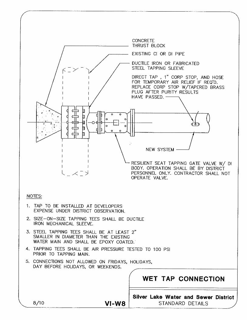


SEWER


LIFT STATIONS


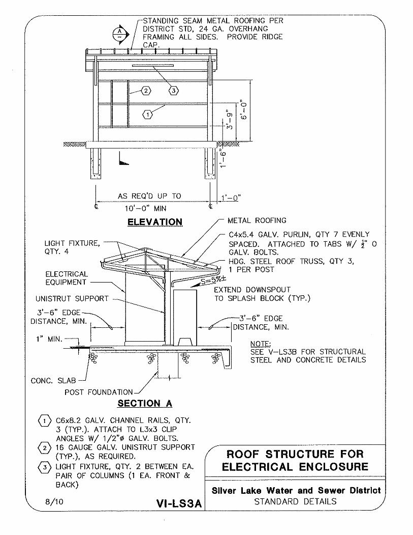


CROSS-CONNECTION CONTROL


APPENDIX

DEVELOPER EXTENSION AGREEMENT


LATECOMERS AGREEMENT


SAMPLE EASEMENT DOCUMENTS


SAMPLES OF BILL OF SALE


PERFORMANCE, PAYMENT AND GUARANTY BOND


MAINTENANCE BOND


ASSIGNMENT OF FUNDS IN LIEU OF MAINTENANCE BOND


EASEMENT RESTORATION RELEASE
