appendix d scenario outline form es-d-1 · simulator scenario review checklist . 1. ... 4 40 cv01a...
TRANSCRIPT
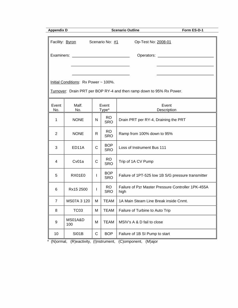
Appendix D Scenario Outline Form ES-D-1
Facility: Byron Scenario No: #1 Op-Test No: 2008-01 Examiners: Operators: Initial Conditions: Rx Power ~ 100%. Turnover: Drain PRT per BOP RY-4 and then ramp down to 95% Rx Power.
Event No.
Malf. No.
Event Type*
Event
Description
1 NONE N RO SRO Drain PRT per RY-4, Draining the PRT
2 NONE R RO SRO Ramp from 100% down to 95%
3 ED11A C BOP SRO Loss of Instrument Bus 111
4 Cv01a C RO SRO Trip of 1A CV Pump
5 RX01E0 I BOP SRO Failure of 1PT-525 low 1B S/G pressure transmitter
6 Rx15 2500 I RO SRO
Failure of Pzr Master Pressure Controller 1PK-455A high
7 MS07A 3 120 M TEAM 1A Main Steam Line Break inside Cnmt.
8 TC03 M TEAM Failure of Turbine to Auto Trip
9 MS01A&D 100 M TEAM MSIV’s A & D fail to close
10 SI01B C BOP Failure of 1B SI Pump to start
* (N)ormal, (R)eactivity, (I)nstrument, (C)omponent, (M)ajor

SCENARIO NUMBER: #1___
TITLE: Respond to a Loss of Instrument Bus followed by a Main Steam Line Fault TURNOVER INFORMATION: The unit is at full power, steady state, equilibrium xenon, MOL. THIS SCENARIO CONTAINS: The following objectives/K/A's: Drain PRT per BOP RY-4 Ramp Down from 100% to
95% Response to Instrument Bus
111 Failure 004000A4.08 (3.8/3.4) IV.D.OA-06/VIII.D.OA-056-C Respond to 1A CV Pump
Trip Respond to a Failed S/G
Press Channel Fails Low Respond to Master Pzr
Press Controller Failing high
000040AA2.04 (4.5/4.7) IV.D.EP-06/VIII.D.EP-001-E Respond to ‘A’ Main Steam Line Break inside Cnmt
/012-B/ VIII.D.EP-007-B Respond to Failure of
Turbine to Trip Respond to Failure of ‘A’ & ‘D’ MSIV to close COMPLETION CRITERIA: Terminate SI injection flow
CRITICAL TASKS: 1. Manually Trip Turbine during immediate action steps of 1BEP-0. 2. Manually aligning 1A SI Pump prior to transitioning out of 1BEP-0. 3. Terminate SI to prevent Pzr overfill and eliminate PTS concern.
Examinees: US RO BOP

Evaluator: Date:

10 CFR 55.45
X 1. Perform pre-startup procedures for the facility, including operation those controls associated with plant equipment that could affect reactivity.
X 2. Manipulate the console controls as required to operate the facility between shutdown and designated power levels.
X 3. Identify annunciators and condition-indicating signals and perform appropriate remedial action where appropriate.
X 4. Identify the instrumentation systems and the significance of facility instrument readings. X 5. Observe and safely control the operating behavior characteristics of the facility. X 6. Perform control manipulations required to obtain desired operating results during normal,
abnormal, and emergency situations. X 7. Safely operate the facility's heat removal systems, including primary coolant, emergency
coolant, and decay heat removal systems and identify the relation of the proper operation of these systems to the operation of the facility.
X 8. Safely operate the facility's auxiliary and emergency systems, including operation of those controls associated with plant equipment that could affect reactivity or the release of radioactive materials to the environment.
X 9. Demonstrate or describe the use and function of the facility's radiation monitoring systems, including fixed radiation monitors and alarms, portable survey instruments, and personnel monitoring equipment.
10. Demonstrate knowledge of significant radiation hazards, including permissible levels in excess of those authorized, and ability to perform other procedures to reduce excessive levels of radiation and to guard against personnel exposure.
X 11. Demonstrate knowledge of the emergency plan for the facility, including, as appropriate, the operator's or senior operator's responsibility to decide whether the plan should be executed and the duties under the plan assigned.
X 12. Demonstrate the knowledge and ability as appropriate to the assigned position to assume the responsibility associated with the safe operation of the facility.
X 13. Demonstrate the applicant's ability to function within the control room team as appropriate to the assigned position, in such a way that the facility licensee's procedures are adhered to and that the limitations in its license and amendments are not violated.
Simulator Scenario Review Checklist

1. The scenario has clearly stated Yes objectives in the scenario summary.
2. The initial conditions are realistic, in Yes that some equipment and/or instrumentation may be out of service, but it does not cue crew into expected events.
3. The scenario consists mostly of Yes related events.
4. Each event description consists of: Yes • the point in the scenario when it is to be initiated • the malfunction(s) that are entered to initiate the event • the symptoms/cues that will be visible to the crew • the expected operator actions (by shift position) • the event termination point
5. No more than one non-mechanistic Yes failure (e.g., pipe break) is incorporated into the scenario without a credible preceding incident such as a seismic event. 6. The events are valid with regard to Yes physics and thermodynamics. 7. Sequencing/timing of events is Yes reasonable, and allows for the examination team to obtain complete evaluation results commensurate
with the scenario objectives.
Operators have sufficient time to Yes carry out expected activities without undue time constraints. Cues are given. If time compression techniques are used, scenario summary clearly indicates. The simulator modeling is not altered. Yes 10. All crew competencies can be Yes
evaluated. 11. The scenario has been validated. Yes 12. The sampling plan indicates that Yes the scenario was not used for training during the requal cycle. Evaluate the need to modify/replace scenario if used. 13. Total malfunctions inserted: 4-8 8 14. Malfunctions that occur after EOP entry: 1-4 3 15. Abnormal Events: 1-2 2 16. Major Transients: 1-2 1 17. EOPs used beyond primary scram response EOP: 1-3 4 18. EOP Contingency Procedures used: 0-3 1 19. Approximate scenario run time: No 45-60 minutes 20. EOP run time: Yes 40-70% of scenario run time 21. Crew Critical Tasks: 2-5 3 22. Technical Specifications are Yes
exercised during the test.

SCENARIO OVERVIEW
The unit is at full power, steady state, equilibrium xenon, MOL. The scenario begins with the PRT High Pressure alarm LIT and the operating crew draining the PRT per BOP RY-4. This action will account for the normal evolution. The reactivity requirement will be fulfilled with a unit ramp from 100% Rx power down to 95% Rx power in preparation for a Main Feedwater Pump swap from 1C to 1A MFP for maintenance work. Once the power change has been completed Instrument Bus 111 will de-energize and 1BOA ELEC-2, Loss of an Instrument Bus will be entered. The instrument bus is damaged & will remain de-energized. Depending on the cause of the failure enter the applicable Tech Spec 3.8.7 & 3.8.9 and 1BOA Inst-1 for a loss of N41. After the actions of 1BOA ELEC-2 are complete, the 1A CV pump trips. The crew should start the 1B CV pump per BAR 1-9-A3 and take actions to stabilize the plant. Technical Specification 3.5.2 and TRM 3.1.d apply. S/G Pressure Channel 1PT-525 fails low. The crew enters BOA INST-2, the BOP needs to take manual control of the 1B Feed Reg Valve and manual control of the Feedwater ∆P controller to restore adequate feedwater flow to all S/G’s. The applicable Tech Spec for this failure is 3.3.2. Master Pressurizer Pressure Controller 1PK-455A output fails high. PORV 1RY455A does not open due to the previous Instrument Bus failure. However, Pressurizer Spray valves fully open and Pzr pressure begins to drop. The RO takes manual control of the Master Pressurizer Pressure controller and restores Pzr Pressure. The applicable Tech Specs are 3.3.1, 3.3.2, & 3.3.4. The 1A Main Steam Line experiences a large break. Containment temperature and pressure increase and Main Steam Line Pressure decreases to the SI setpoint. 1BEP-0, Response to Reactor Trip of Safety Injection is entered. The Reactor automatically trips on the SI signal but the Turbine fails to trip automatically following the Reactor trip. A Manual Turbine trip is required to be actuated. 1B SI pump fails to start on the Safety Injection, and 1A SI pump must be manually started. Due to the Instrument Bus failure all Train A ESF loads fail to start on the SI signal. Train A ESF loads must be manually started. The A & D MSIV’s fail to automatically or manually close causing both S/G’s to blow down. Upon completion of 1BEP-0 the crew transitions to 1BEP-2, Faulted S/G to

isolate the faulted S/G’s then transitions to 1BEP-1 Loss of Reactor or Secondary Coolant, and then to 1BEP ES-1.1, SI Termination, completion criteria is stopping the RH pumps in 1BEP ES-1.1.

SCENARIO SETUP GUIDE
- Initialize IC-22: "full power, steady state, equilibrium xenon, MOL." - Lineup control boards. - Place simulator in run (allow simulator to run during board walkdowns and
turnover). - Open PW to the PRT and fill until the PRT High Pressure alarm is LIT, leave
BAR open to page on desk - Check computer points that are placed in test and removed from scan as part of
this scenario N0049A removed from scan N0041, N0042, U1144 placed in test
- Type bat f:\BY-SIM1\BY-SIM1 and ensure the following insert:
ior zdi1hstg010 norm imf tc03 imf ms01a 100 imf ms01d 100 imf si01b cae f:\BY-SIM1\BY-SIM1.CAE
- Perform TQ-BY-201-0113, Appendix A, “Simulator Exam/ Scenario Reset
Checklist” EVENT TIME MALF NO. DESCRIPTION 1 0 N/A Drain PRT per BOP RY-4 2 10 N/A Ramp Unit from 100% to 95% 3 25 ed11a Trip Instrument Bus 111 4 40 cv01a Trip of 1A CV Pump (SDG CV5) 5 50 rx01e 0 Failure of 1PT-525 low 1B S/G
pressure transmitter 6 65 rx15 2500 Failure of PZR Master Press
controller 1PK-455A High

7 75 ms07a 3 120 1A Main Steam Line Break inside
Cnmt. 8 75 tc03 (in batch) Failure of Turbine to Auto Trip 9 75 ms01a & d 100 (in batch) MSIV’s A & D fail to close 10 75 si01b Failure of 1B SI pump to start
Note 1: Events 7, 8 & 9 should be tied to Main Steam Line Break.

INSTRUCTOR/SIMULATOR RUN AID GUIDE
EVENT ADDITIONAL INFORMATION 3 Report Bus 111 Inverter AC Output Bkr 4CB Open. Report Bus
111 Main Feed Bkr Open. Report Bus 111 is damaged, with smell of burned insulation and paint bubbled. Enters 1BOA ELEC-2, Loss of AC bus, and INST-1, NI malfunction. Need to trip bistables associated with N41. Operator needs to be dispatched to open 1AF005A-D. Allow ten minutes to accomplish this task.
Remote functions per event: RP20 Open/Close Protection Cabinet Door #1
(SDG RX10) RX013 TRIP OTΔT Rx Trip TB411C C1-124
BS-3 (SDG RX4) RX135 TRIP OTΔT Runback TB411D C1-124
BS-4 (SDG RX4) 4 Acknowledge 1A CV pump trip/EP review request when contacted
as SM (as required). When requested to investigate, report a Phase A overcurrent flag at the 1A CV pump breaker bus 141 cub 11. Report results 4 minutes after request.


EVENT 1 BRIEF DESCRIPTION Drain PRT per BOP RY-4
EXPECTED OPERATOR/PLANT RESPONSE SAT UNSAT N/A
Perform the action to lower PRT level per BOP RY-4 (Cue) o Per the initial scenario cue. o Annunciator PRT Press High alarm LIT (Response) • Refer to BOP RY-4 Draining the Pressurizer Relief Tank U-1 • CLOSE 1RY469 PRT to GW isol vlv U-1 • VERIFY approximately 3 psig on 1PI469 (6# indicated) U-1 • VERIFY/OPEN 1AOV-RY8033 N2 Supply to PRT isol vlv U-1 • VERIFY/OPEN 1AOV-RE9170, RCDT Discharge header vlv U-1 • VERIFY/OPEN 1AOV-RE1003, RCDT Discharge header vlv U-1 • OPEN 1AOV-RY8031, PRT Drain vlv U-1 • VERIFY/START 1RE01PA/B, RCDT Pump 1A/B U-1 • CYCLE 1RY8031, PRT Drain vlv to control PRT pressure U-1 • CLOSE 1AOV-RY8031, PRT Drain vlv at desired PRT level U-1 • VERIFY/STOP 1RE01PA/B, RCDT Pump 1A/B U-1 • VERIFY/CLOSE 1AOV-RE1003, RCDT Discharge header vlv U-1
COMMENTS

EVENT 2 BRIEF DESCRIPTION Ramp Unit from 100% to 95%
EXPECTED OPERATOR/PLANT RESPONSE SAT UNSAT N/A
Re-activity manipulation for this scenario. (Cue) o Per the initial scenario cue. (Response) • Refer to BGP 100-4T3, Load Swing Instruction Sheet CREW • Direct actions to lower Rx Pwr US • PROGRAM Turbine Controls to ramp down U-1 AST
- Enter ramp rate (2 MW/min) into LOAD RATE - Enter ~1175 into REF DEMAND
• BORATE per BOP CV-6 to control Tave-Tref U-1 within desired limits
- Enter boration amount into AB totalizer - Select BORATE Mode - Select START on Makeup control switch
• ENERGIZE Second Pressurizer B/U Htr group. U-1 • INSERT Control Rods to maintain ∆I and Tave-Tref U-1 • STOP ramp at 95% Rx Pwr US
COMMENTS


EVENT 3 BRIEF DESCRIPTION Loss of Instrument Bus 111
EXPECTED OPERATOR/PLANT RESPONSE SAT UNSAT N/A
Recognize symptoms and respond to a de-energized Instrument Bus 111 (Cue) • Loss of Control and Instrument Power to: • N31 Source Range Instrument • N35 Intermediate Range Instrument • N41 Power Range Instrument • Annunciator (1-4-A5) "BUS 111 INVERTER TROUBLE" • Annunciator (1-4-A3) "PROCESS I & C CAB PWR SUP FAILURE" • Annunciator (1-4-B3) "SOLID STATE PROT CAB GENERAL WARNING" • Annunciator (1-4-C2) "SEQUENCING CAB PWR FAILURE" • Annunciator (1-13-A2) "RCP BUS UNDERVOLTAGE RX TRIP ALERT" and associated trip status light (Response) Implement 1BOA Elec-2, “Loss of AC Bus” US • Instrument control channels checked for operability: CREW • PZR pressure/level • TAVE/Delta T • PIMP • SG level, steam flow & feed flow • Dispatch operator to investigate status of bus CREW Do NOT attempt to energize Instrument Bus 111 CREW from CVT (bus is damaged) • Dispatch operator to locally fail open 1AF005A-D U-1 AST • Brief crew on effects of loss of inst. bus 111/Train A ESF US equipment manual start requirements per Table A • Inform SM of unit status/loss of inst. bus 111/EP US potential/shutdown required by Tech Specs Implement 1BOA INST-1 "NUCLEAR INSTRUMENT US MALFUNCTION" to establish the following conditions: • Control rods placed in manual U-1 • Plant conditions stabilized CREW • Rod stop bypassed • Tave restored to Tref (+ 1 degree) • SG levels stable

• Bypass associated functions for PR N-41 U-1 AST • Upper current comparator • Lower current comparator • Power mismatch • Rod stop • Channel current comparator • Trip bistables for PR N-41 • Pull control power fuses to trip: U-1 AST • Lo Rx trip • Hi Rx trip • Positive Rate trip • Dispatch operator to locally trip: CREW • OTΔT Trip • OTΔT Runback • Select/verify operable channel to loop ΔT recorder U-1 • Remove Point from Scan Input to PDMS U-1 • Restore automatic rod control U-1 • Inform SM of unit status/potential EP event US • Review Tech Spec 3.8.7, Inverters - Operating & 3.8.9, US Dist. Systems - Operating (Restore power to inst. bus 111 within 2 hours or be in hot standby in next 6 hours.)
COMMENTS

EVENT 4 BRIEF DESCRIPTION 1A CV Pump Trip
EXPECTED OPERATOR/PLANT RESPONSE SAT UNSAT N/A
Recognize symptoms and respond to a tripped CV pump (Cue) o Annunciator (1-7-B2) "RCP SEAL WTR INJ FLOW LOW" o Annunciator (1-9-A3) "CHG PUMP TRIP" o Annunciator (1-9-D3) "CHG LINE FLOW HIGH LOW" o 1A CV pump trip light lit (Response) • Direct actions to restore charging flow US • Refer to BAR 1-9-A3 U-1 AST/U-1 • Isolate Letdown U-1 AST/U-1 • Ensure suction source to standby charging pump U-1 • Place 1CV121 in Manual at 10% Open U-1 • Start the 1B CV pump U-1
EXAMINER’S NOTE: The crew may elect to perform actions for loss of seal injection per 1BOA RCP-2 "LOSS OF SEAL COOLING". Implement 1BOA RCP-2 "LOSS OF SEAL COOLING" to US direct operator actions to: • Check RCP seal cooling U-1 • Start 1B CV pump U-1 • Throttle 1CV182 and 1CV121 to control seal injection flow U-1
EXAMINER’S NOTE: Bus 111 failure prevents auto make-up to VCT. Low VCT level will require manual action to Open make-up isolation valves per applicable BAR.
o Restore Letdown per BOP CV-17 U-1 AST/U-1 • Notify SM of unit status/EP potential US • Refer to TRM 3.1.d, Charging Pumps - US Operating, and Tech Spec 3.5.2, ECCS - Operating (return to operable status within 7 days). • Direct performance of 1BOSR 5.5.1-1 (Reference BOP CV-19) US • Dispatch operators to locally check 1A CV pump/breaker CREW • Notify EM Dept. to investigate 1A CV pump trip US (Feedback) o 1B CV pump running o Charging flow restored

o Seal injection flows normal

EVENT 5
BRIEF DESCRIPTION 1B SG Pressure Transmitter Failure
EXPECTED OPERATOR/PLANT RESPONSE SAT UNSAT N/A
Recognize symptoms and respond to 1B SG Pressure Transmitter failed LOW (Cue) o Annunciator LOW MS PRESSURE o Annunciator 1B SG SF – FF MISMATCH o 1B SG Feed Flow lowering o 1B SG Level lowering o Master Turbine Driven Feed Pump (TDFPSC) DP demand lowering (Response) • Check SG pressure U-1AST • Take manual control to restore SG Feed Flow U-1AST • Place TDFPSC controller in manual U-1AST • Control Feedwater DP U-1AST • Implement 1BOA Inst-2, Failure of Instrument Channel, Att F US Transfer controlling SP channels U-1AST • Locally trip Bistables for failed channel U-1 AST/U-1 • Review Tech Spec 3.3.2 US • Contact SM/maintenance to investigate 1PT-525 failure US (Feedback) o Appropriate annunciators clear o Associated trip status lights and annunciators lit o SG level restored to normal
COMMENTS

EVENT 6
BRIEF DESCRIPTION Master PZR Pressure Controller
EXPECTED OPERATOR/PLANT RESPONSE SAT UNSAT N/A
Recognize symptoms and respond to a Master Pzr Press Controller failure (Cue) o Annunciator (1-12-D2) "PZR PRESS CONT DEV HIGH" o Annunciator (1-12-B2) "PZR PORV OR SAF VLV OPEN" Won’t Open due to Bus 111
failure o PZR spray valves (1RY455B & C) open o Master PZR pressure controller output indication (1PK-455A) at 100% o Actual PZR pressure dropping (Response) • Check PZR pressure U-1 • Take manual control to restore PZR pressure • Place Master PZR pressure controller in manual U-1 • Control PZR pressure • Check PZR PORVs, spray valves and heaters U-1 • PZR PORVs – closed U-1
• PZR spray valves – normal U-1 • PZR heaters – normal U-1
(Pzr Htr’s won’t auto turn on due to Bus 111 failure) • Review Tech Spec 3.4.1, US DNB Limits. • Contact SM/maintenance to investigate 1PK-455A failure US (Feedback) o Appropriate annunciators clear o Associated trip status lights and annunciators lit o PZR pressure restored to normal
COMMENTS


EVENT 7
Brief Description: 1A Main Steam line break inside of Cnmt.
EXPECTED OPERATOR/PLANT RESPONSE SAT UNSAT N/A
Recognize symptoms and respond to main steam line break inside of cnmt. (Cue) o Cnmt temp and pressure increasing o Low S/G & Main Steam Line Pressure o Rx Trip and Safety Injection o Multiple Annunciator Alarms (Response) Automatic Rx Trip CREW Implement 1BEP-0, Reactor Trip or Safety Injection • Inform SM of unit status/potential EP event US • Reactor trip verified U-1 • Rod bottom lights • Reactor trip/Bypass breakers • Neutron flux dropping •* Turbine MANUALLY TRIPPED by fast action GV CLOSED from OWS panel G-5512 U-1 AST * * * • GVs closed • TVs closed • 4 KV ESF busses are energized U-1 AST • Bus 141 energized • Bus 142 energized • SI Status • SI is actuated/required CREW o SI ACTUATED permissive light lit o SI first out annunciator lit o SI equipment automatically actuated • Actuate SI U-1/U-1 AST • Feedwater Status CREW COMMENTS


(NOTE) Loss of Instrument Bus 111 causes failure of Train A ESF load to automatically start on SI signal. Train A SI Pump must be manually aligned to complete critical task. RCP Trip criteria may also be met early during scenario.
•* Verify ECCS Status CREW • Verify 1B CV Pp Running U-1 AST/U-1 •* START 1A SI Pp U-1 AST/U-1 * * * • START 1A RH Pp U-1 AST/U-1 _ _ _ • Verify RCFC’s Running in Accident Mode • Manually align A Train components U-1 AST/U-1 • Verify Cnmt Isolation Phase A • Manually align A Train components U-1 AST/U-1 • Verify Cnmt Ventilation Isolation U-1 AST/U-1 • Verify Aux. Feed System • Manually align A Train components U-1 AST/U-1
• Verify CC Pp’s Running • Manually align A Train component Start 1A CC Pp U-1 AST/U-1 • Verify SX Pp’s Running • Manually align A Train component Start 1A SX Pp U-1 AST/U-1 • Main Steam Line Isolation • Manually attempt to close 1A & 1D MSIV’s U-1 AST/U-1 • Check if Cnmt Spray is Required • Manually align A Train if required U-1 AST/U-1 • Verify Total Aux. Feed System Flow • Manually align A Train components U-1 AST/U-1 • Verify ECCS Valve alignment • Manually align A Train components U-1 AST/U-1 • Verify ECCS Flow U-1 AST/U-1 • Verify one Pzr PORV relief path available U-1 • Verify Main Generator Tripped U-1 AST/U-1

• Verify D/G’s Running • Manually Start 1A D/G U-1 AST/U-1 • Verify Ventilation Equipment aligned for Emergency • Manually align A Train components U-1 AST/U-1 • Verify Pzr Spray Valves Closed U-1 AST/U-1
EXAMINER’S NOTE: Due to steam line break RCS temperature control will not be possible. The crew should stop dumping steam and close all MSIV’s. They should also stop Aux Feed flow to the faulted S/G’s at step 25 to Maintain RCS Temperature.
• Maintain RCS Temperature Control U-1 AST/U-1 • Check RCP Status U-1 AST/U-1 • Check S/G Secondary Pressure boundaries intact U-1 AST/U-1 • Crew determines Secondary Pressure Boundaries not intact and transitions to 1BEP-2, Faulted S/G Isolation
EXAMINER’S NOTE: US directs transition from 1BEP-0 to 1BEP-2, Faulted S/G Isolation. The Critical Task in this procedure is to isolate the Non-Faulted S/G’s from the Faulted S/G’s. This is accomplished by closing the MSIV’s on the Non-Faulted 1B & 1C S/G’s.
Announcement of faulted Steam Generator symptoms US Transition to 1BEP-2 "FAULTED SG ISOLATION" • Order STA function at transition from 1BEP-0 US "RX TRIP OR SI" Perform operator actions to establish the following conditions: • Isolate/close MSIVs and bypass valves U-1 AST • Identify at least 1 non-faulted S/G (1B & 1C) U-1 AST • Faulted SG isolated (1A & 1D S/G’s) US/U-1 AST • AF isolated (1AF013A, D, E & H closed) • Main feedwater isolated • 1A & 1D SG PORV closed (1MS018A&D) • Blowdown isolation valves closed (1SD002A-H) • Blowdown sample valve closed (1SD005A-D)

• Monitor AF pump suction pressure U-1 AST • Check Secondary Radiation • Identify NO ruptured SGs U-1 AST

EXPECTED OPERATOR/PLANT RESPONSE SAT UNSAT N/A
• Transition to 1BEP-1, Loss of Rx or Secondary Coolant US
Transition from 1BEP-2 to 1BEP-1, "LOSS OF US REACTOR OR SECONDARY COOLANT" upon verification that a SGTR does not exist per 1BEP-2 Perform operator actions of 1BEP-1 to establish the following conditions: • Check status of RCPs U-1 • Check SG pressure boundaries intact (1A & D SG faulted)U-1 AST • Check intact SG levels U-1 AST • SG levels > 10% (31%) • Maintain SG NR levels between 10% (31%) - 50% • SG levels not rising in an uncontrolled manner • Check secondary radiation trends normal U-1 AST • Check SJAE/gland steam exhaust and MS line radiation normal for plant conditions • Check PZR PORVs and isolation valves U-1 Transition from 1BEP-1 to ES-1.1 "SI TERMINATION" US when the following conditions are met: • Acceptable RCS subcooling • Secondary heat sink • SG NR levels > 10% (31%) • > 500 gpm total flow • RCS pressure is stable/rising • PZR level > 12% Direct operator actions to US establish the following conditions of ES-1.1: • Reset SI U-1/U-1 AST • Reset Containment Isolation U-1 AST • Phase A
o Phase B • Check SAC run light lit • IA restored to Cnmt • CV system realigned U-1 • 1B CV pump already running • Check RCS pressure stable or rising U-1 •* Terminate high-head ECCS U-1 * * * • CV pump suction aligned to RWST • SI recirc sump/CV miniflows reset

• CV miniflow valves open •* 1SI8801A & B closed
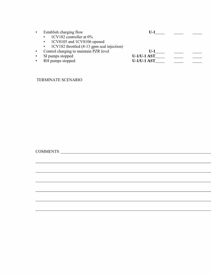
• Establish charging flow U-1 • 1CV182 controller at 0% • 1CV8105 and 1CV8106 opened • 1CV182 throttled (8-13 gpm seal injection) • Control charging to maintain PZR level U-1 • SI pumps stopped U-1/U-1 AST • RH pumps stopped U-1/U-1 AST TERMINATE SCENARIO COMMENTS

Appendix D Scenario Outline Form ES-D-1
Facility: Byron Scenario No: #2 Op-Test No: 2008-01 Examiners: Operators: Initial Conditions: Rx Power ~ 100%. Turnover: Ramp down to 95% Rx Power.
Event No.
Malf. No.
Event Type*
Event
Description
1 msv1ms004a=100 C BOP
SRO 1MS004A Fails Open. Rx Power increases > 100%
1a R RO SRO Ramp from 102% down to 98%
2 Cv16 100 I RO SRO 1LT-112 Failure High
3 Rx18f 650 I BOP SRO 1TE-445 Failure High
4 rm061 C BOP SRO Failure of 0PR031J to actuate VC Emergency Make-Up
5 Eg03 96 C BOP SRO Failure of Main Generator Voltage Regulator High
6 Th04a 50000 M TEAM Sesmic event results in Large Break LOCA
7 Cs05 C TEAM 1B CS Train fails to align, Manual action required
8 Rh01b C TEAM 1B RH Pp Trips on OC at 49% RWST level
9 Ed053p open C TEAM 1SI8811A Fails to open on low RWST level
* (N)ormal, (R)eactivity, (I)nstrument, (C)omponent, (M)ajor
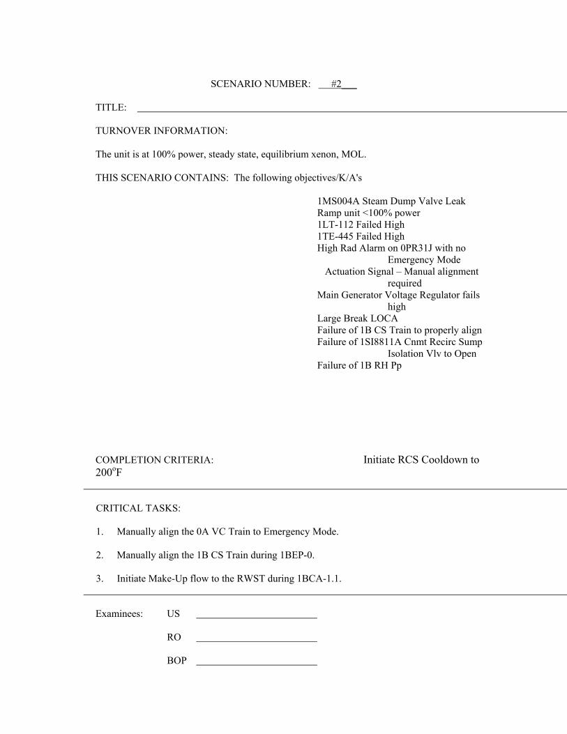
SCENARIO NUMBER: #2___
TITLE: TURNOVER INFORMATION: The unit is at 100% power, steady state, equilibrium xenon, MOL. THIS SCENARIO CONTAINS: The following objectives/K/A's 1MS004A Steam Dump Valve Leak Ramp unit <100% power 1LT-112 Failed High 1TE-445 Failed High High Rad Alarm on 0PR31J with no
Emergency Mode Actuation Signal – Manual alignment
required Main Generator Voltage Regulator fails
high Large Break LOCA Failure of 1B CS Train to properly align Failure of 1SI8811A Cnmt Recirc Sump
Isolation Vlv to Open Failure of 1B RH Pp
COMPLETION CRITERIA: Initiate RCS Cooldown to 200oF
CRITICAL TASKS: 1. Manually align the 0A VC Train to Emergency Mode. 2. Manually align the 1B CS Train during 1BEP-0. 3. Initiate Make-Up flow to the RWST during 1BCA-1.1.
Examinees: US RO BOP

Evaluator: Date:

10 CFR 55.45
X 1. Perform pre-startup procedures for the facility, including operation those controls associated with plant equipment that could affect reactivity.
X 2. Manipulate the console controls as required to operate the facility between shutdown and designated power levels.
X 3. Identify annunciators and condition-indicating signals and perform appropriate remedial action where appropriate.
X 4. Identify the instrumentation systems and the significance of facility instrument readings. X 5. Observe and safely control the operating behavior characteristics of the facility. X 6. Perform control manipulations required to obtain desired operating results during normal,
abnormal, and emergency situations. X 7. Safely operate the facility's heat removal systems, including primary coolant, emergency
coolant, and decay heat removal systems and identify the relation of the proper operation of these systems to the operation of the facility.
X 8. Safely operate the facility's auxiliary and emergency systems, including operation of those controls associated with plant equipment that could affect reactivity or the release of radioactive materials to the environment.
X 9. Demonstrate or describe the use and function of the facility's radiation monitoring systems, including fixed radiation monitors and alarms, portable survey instruments, and personnel monitoring equipment.
10. Demonstrate knowledge of significant radiation hazards, including permissible levels in excess of those authorized, and ability to perform other procedures to reduce excessive levels of radiation and to guard against personnel exposure.
X 11. Demonstrate knowledge of the emergency plan for the facility, including, as appropriate, the operator's or senior operator's responsibility to decide whether the plan should be executed and the duties under the plan assigned.
X 12. Demonstrate the knowledge and ability as appropriate to the assigned position to assume the responsibility associated with the safe operation of the facility.
X 13. Demonstrate the applicant's ability to function within the control room team as appropriate to the assigned position, in such a way that the facility licensee's procedures are adhered to and that the limitations in its license and amendments are not violated.
Simulator Scenario Review Checklist

1. The scenario has clearly stated Yes objectives in the scenario summary.
2. The initial conditions are realistic, in Yes that some equipment and/or instrumentation may be out of service, but it does not cue crew into expected events.
3. The scenario consists mostly of Yes related events.
4. Each event description consists of: Yes • the point in the scenario when it is to be initiated • the malfunction(s) that are entered to initiate the event • the symptoms/cues that will be visible to the crew • the expected operator actions (by shift position) • the event termination point
5. No more than one non-mechanistic Yes failure (e.g., pipe break) is incorporated into the scenario without a credible preceding incident such as a seismic event. 6. The events are valid with regard to Yes physics and thermodynamics. 7. Sequencing/timing of events is Yes reasonable, and allows for the examination team to obtain complete evaluation results commensurate
with the scenario objectives.
Operators have sufficient time to Yes carry out expected activities without undue time constraints. Cues are given. If time compression techniques are used, scenario summary clearly indicates. The simulator modeling is not altered. Yes 10. All crew competencies can be Yes
evaluated. 11. The scenario has been validated. Yes 12. The sampling plan indicates that Yes the scenario was not used for training during the requal cycle. Evaluate the need to modify/replace scenario if used. 13. Total malfunctions inserted: 4-8 8 14. Malfunctions that occur after EOP entry: 1-4 3 15. Abnormal Events: 1-2 3 16. Major Transients: 1-2 1 17. EOPs used beyond primary scram response EOP: 1-3 3-4 18. EOP Contingency Procedures used: 0-3 1 19. Approximate scenario run time: No 45-60 minutes 20. EOP run time: Yes 40-70% of scenario run time 21. Crew Critical Tasks: 2-5 3 22. Technical Specifications are Yes
exercised during the test.

SCENARIO OVERVIEW
The unit is at 100% Rx power, steady state, equilibrium xenon, MOL. The scenario begins when Steam Dump valve 1MS004A fully opens. This pushes Rx Pwr above 100% and requires the unit to be ramped down and the valve isolated. 1LT-112 fails high, bringing in alarm 1-9-A2, VCT LEVEL HIGH-HIGH/LOW, resulting in diverting letdown to the HUT. The crew will respond to the BAR and take manual control of VCT level controller. Manual makeup to the VCT will be required since auto makeup will not work. Loop B Thot Channel will fail High. This failure may require the crew to place the Control Rods into Manual to stop outward rod motion. The crew enters 1BOA INST-2, stablizes the plant and trips the associated bistable. The applicable Tech Spec for this failure is 3.3.1. Following initiation of bistable tripping for the Thot Channel failure 0PR31J will go into High Rad Alarm without actuating the Emergency Make-Up Mode of Operation for the 0A VC Train. The crew will need to recognize the appropriate system response did not occur and will have to manually align the 0A VC Train into the Emergency Make-Up Mode. The next failure to occur will be for the Main Generator Voltage Regulator output to fail high. This will result in increased excitation of the Main Generator which results in increased MVAR output and thus increased current flowing through the generator. The crew should recognize the failure respond to the applicable BAR procedures switch the voltage regulator to OFF and lower generator output to within limits. The major failure for this scenario will be a seismic event that causes a Large Break LOCA. During 1BEP-0 it will be discovered that the 1B CS Train doesn’t align properly. The crew must take manual actions to correctly align the 1B CS Train into operation. When RWST water level reaches 49% the 1B RH Pp will trip due to a φC overcurrent condition. When RWST water level reaches 46% the 1SI8811A Cnmt Sump Isolation Valve will not open. This results in a Loss of Emergency Recirculation capability and thus 1BCA-1.1 needs to be entered from 1BEP ES-1.3.

SCENARIO SETUP GUIDE
- Initialize IC-22: "full power, steady state, equilibrium xenon, MOL." - Lineup control boards. - Place simulator in run (allow simulator to run during board walkdowns and
turnover). - Type bat f:\BY-SIM2\BY-SIM2 and ensure the following insert:
imf ms05a 100 imf rm05e imf cs01a mrf cs05 over trgset 1 "zao1li930.lt.0.49" trg 1 "imf rh01b" trgset 3 "zlo1si8811a(2).gt.0" trg 3 "mrf ed053p open" cae f:\BY-SIM2\BY-SIM2.CAE
- Perform TQ-BY-201-0113, Appendix A, “Simulator Exam/ Scenario Reset
Checklist” EVENT TIME MALF NO. DESCRIPTION 1 0 set msv1ms004a=100 1MS004A Fails Open Ramp Unit to < 100% Rx Pwr 2 5 cv16 100 1LT-112 failure High 3 15 rx18f 650 Failure of 1TE-445 High 4 25 rm061 Failure of 0PR31J to actuate
Emergency Make-Up Mode 5 40 eg03 96 Failure of Main Generator Voltage
Regulator High 6 50 th04a 50000 Seismic event results in Large Break
LOCA 7 70 cs05 1B CS Train fails to align, Manual
action required

8 80 rh01b 1B RH Pp trips on φC overcurrent at
49% RWST level 9 85 ed053p open 1SI8811A fails to open on low
RWST level 46.7%
Note 1: Events 6 &7 can be tied to the seismic event and events 8 & 9 should be tied to RWST Level.

EVENT 1 BRIEF DESCRIPTION 1MS004A Fails Open
EXPECTED OPERATOR/PLANT RESPONSE SAT UNSAT N/A
Perform the action to determine cause of over power condition and take actions to reduce Rx Pwr to < 100%. The crew should also determine cause of the overpower condition and take actions to isolate the failed open Steam Dump valve. Reactivity manipulation for this scenario. (Cue) o Annunicator Bank D Rod Stop C-11 o Noticeable RCS cooldown o Rx Power > 100% o Crew notices 1MS004A Open sugar cube light lit (Response) • Refer to 1BGP 100-4, Power Descension Crew • Direct actions to lower Rx Pwr US • PROGRAM Turbine Controls to ramp down U-1 AST • BORATE per BOP CV-6 to control Tave-Tref U-1 within desired limits • INSERT Control Rods to maintain ∆I and Tave-Tref U-1 • STOP ramp when < 100% Rx Pwr US • Direct NLO to Locally isolate 1MS004A U-1 AST COMMENTS

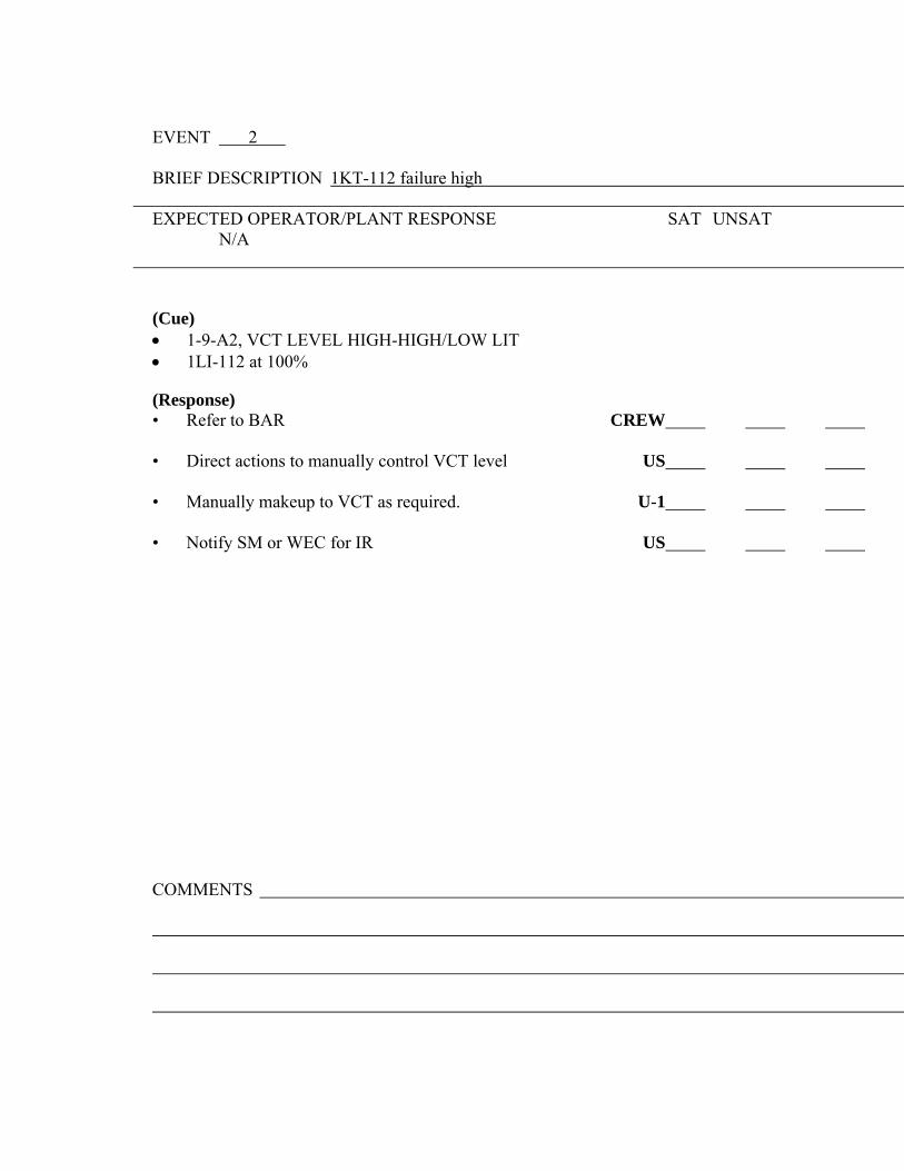
EVENT 2 BRIEF DESCRIPTION 1KT-112 failure high
EXPECTED OPERATOR/PLANT RESPONSE SAT UNSAT N/A
(Cue) • 1-9-A2, VCT LEVEL HIGH-HIGH/LOW LIT • 1LI-112 at 100% (Response) • Refer to BAR CREW • Direct actions to manually control VCT level US • Manually makeup to VCT as required. U-1
• Notify SM or WEC for IR US
COMMENTS


EVENT 3 BRIEF DESCRIPTION 1TE-445 Fails High
EXPECTED OPERATOR/PLANT RESPONSE SAT UNSAT N/A
Recognize symptoms and respond to a Failed High Tave Channel (Cue) o Annunciator Tave CONTROL DEV HIGH o Annunciator Tave CHANNEL DEV HIGH o Annunciator DELTA-T CHANNEL DEV HIGH (Response) • Refer to BAR’s U-1 AST/U-1 • Direct actions to enter 1BOA INST-2 US • PLACE Rod Bank Select Switch in Manual U-1 • Manually Defeat Failed RTD Channel • SELECT failed Tave channel with Tave Defeat Switch U-1 • SELECT failed ΔT channel with ΔT defeat switch U-1 • SELECT an operable RTD channel to the ΔT Recorder U-1 • Check if Rod Control can be placed in Auto • Turbine Low Power Interlock C5 Not Lit U-1 • Tave-Tref deviation Stable and within 1oF U-1 • Place Rod Bank Select Switch in Auto if desired U-1 • Check Pzr Level normal and Stable U-1 • Locally trip Bistables for failed channel U-1 AST/U-1 • Check P12 Interlock in correct state for current RCS temp U-1 • Defeat affected channel input to PDMS (T0422 to Test) U-1 • Enter Tech Spec 3.3.1, 3.3.2 for the failed channel US COMMENTS

EVENT 4 BRIEF DESCRIPTION 0PR31J High Alarm fails to align the 0A VC Train
EXPECTED OPERATOR/PLANT RESPONSE SAT UNSAT N/A
Recognize symptoms and respond to a 0PR31J High Rad Alarm (Cue) o RM-11-2-0PR31J Annunciator (0PB131) "Main Control Room Out Air In OA" (Response) • Direct actions to respond to the RM-11 alarm US • Enter BAR RM-11-2-0PR31J U-1 AST/U-1 • Determines Auto actions have not occurred U-1 AST • STARTS Make-Up Fan 0VC03CA, BOP VC-5 U-1 AST • Aligns recirculation charcoal adsorber U-1 AST • Direct NLO to STOP 0VV01CA & B at 0VV01J U-1 AST • Notify RP to perform BRP 5820-13 US • Enter Tech Spec 3.3.7, spec 3.7.10 not required US
EXAMINER’S NOTE: The crew may elect to perform actions to swap trains of Main Control Room HVAC but this is not required or anticipated. Implement 1BOP-VC-17 "Swapping Control Room Chillers US and HVAC Trains" • Secure electric heaters U-1 AST • Secure chiller U-1 AST • Secure Ventilation system U-1 AST • Start standby Ventilation system U-1 AST • Start standby chiller U-1 AST • Start standby electric heaters U-1 AST
(Feedback) COMMENTS

EVENT 5
BRIEF DESCRIPTION Main Generator Voltage Regulator Output Fails High.
EXPECTED OPERATOR/PLANT RESPONSE SAT UNSAT N/A
Recognize symptoms and respond to the Main Generator Voltage Regulator’s output failing
high. (Cue) o Annunciator (1-19-B6) "Generator Field Forcing"
(Response) Implement BAR 1-19-B8 • PLACE Voltage Regulator Control Switch to OFF U-1 AST • ADJUST Base Adjuster reduce exciter field current to U-1 AST LESS THAN 100 amps • Notify Electric Operations U-1 AST • Check U-2 for adverse Main Generator trends U-1 AST • If Generator field current cannot be reduced to LESS U-1 AST THAN 109 amps THEN trip the Rx if above P-8
COMMENTS


EVENT 6
BRIEF DESCRIPTION Large Break LOCA with failure of the 1B CS Train to
properly align.
EXPECTED OPERATOR/PLANT RESPONSE SAT UNSAT N/A
Recognize symptoms and respond to a Large Break LOCA (Cue) o Annunciator "Rx Trip" o Annunciator "Safety Injection” (Response) Automatic Rx Trip CREW Implement 1BEP-0, Reactor Trip or Safety Injection • Inform SM of unit status/potential EP event US/STA • Reactor trip verified U-1 • Rod bottom lights • Reactor trip/Bypass breakers • Neutron flux dropping • Turbine trip verified by U-1 AST • GVs closed • TVs closed • 4 KV ESF busses are energized U-1 AST • Bus 141 energized • Bus 142 energized • SI Status • SI is actuated/required CREW o SI ACTUATED permissive light lit o SI first out annunciator lit o SI equipment automatically actuated • Actuate SI U-1/U-1 AST • Feedwater Status CREW
• FWI Monitor Lights LIT
COMMENTS


• Verify ECCS Status CREW • Verify CV Pp’s Running U-1 AST/U-1 • Verify SI Pp’s Running U-1 AST/U-1 • verify RH Pp’s Running U-1 AST/U-1 • Verify RCFC’s Running in Accident Mode U-1 AST/U-1 • Verify Cnmt Isolation Phase A U-1 AST/U-1 • Verify Cnmt Ventilation Isolation U-1 AST/U-1 • Verify Aux. Feed System U-1 AST/U-1
• Verify CC Pp’s Running U-1 AST/U-1 • Verify SX Pp’s Running U-1 AST/U-1 • Main Steam Line Isolation U-1 AST/U-1
EXAMINER’S NOTE: RCP trip criteria will be met on both RCS Pressure <1425# with >100 gpm High Head SI flow, and because of Phase B containment isolation
•* Check if Cnmt Spray is Required • Manually align B Train U-1 AST/U-1 * * * Test Switch to ‘Test Position’ OPEN 1CS019B Test Switch to ‘Normal’ Position • Verify Total Aux. Feed System Flow U-1 AST/U-1 • Verify ECCS Valve alignment U-1 AST/U-1 • Verify ECCS Flow U-1 AST/U-1 • Verify one Pzr PORV relief path available U-1 • Verify Main Generator Tripped U-1 AST/U-1 • Verify D/G’s Running U-1 AST/U-1 • Verify Ventilation Equipment aligned U-1 AST/U-1

for Emergency

• Verify Pzr Spray Valves & PORV’s Closed U-1 AST/U-1 • Maintain RCS Temperature Control U-1 AST/U-1 • Check RCP Status U-1 AST/U-1 • Check S/G Secondary Pressure boundaries Intact U-1 AST/U-1 • Check S/G Tubes are Intact U-1 AST/U-1
EXAMINER’S NOTE: US directs transition from 1BEP-0 to 1BEP-1, Loss of Reactor of Secondary Coolant. When RWST Level get to 46% the Crew will transition to 1BEP ES-1.3, Cold Leg Recirculation.
• Check if RCS is Intact U-1 AST/U-1
(Crew will transition to 1BEP-1, Loss of Rx or Secondary Coolant) Transition to 1BEP-1 "Loss of Rx or Secondary Coolant" US • Call for STA function at transition from 1BEP-0 US "RX TRIP OR SI" Operator actions of 1BEP-1 establish the following conditions: • RCPs tripped (RCP should have been tripped earlier) U-1 • Steam Generator boundaries intact U-1 AST • All Steam Generator pressures stable • SG levels maintained between 10%(31%) - 50% U-1 AST • Check secondary radiation normal U-1 AST • All secondary radiation trends normal for plant conditions • Acceptable RCS subcooling U-1 • Secondary heat sink U-1 o SG NR levels > 10%(31%) o > 500 gpm total flow • RCS pressure is stable/rising U-1 • PZR level > 12%(28%) U-1 COMMENTS


• Check if CS should be Stopped U-1 • CS Pumps running • Reset CS signal • Spray Add Tank Lo-2 level lights lit (answer should be no) • Cnmt pressure less than 15 psig (it may be) • Sprays operating time greater than 8 hours (it will not be) • Check if RH Pumps should be Stopped U-1 • Reset SI • Verify SI ACTUATED permissive light NOT LIT • Verify AUTO SI BLOCKED permissive light LIT • Check RCS pressure greater than 325 psig (it won’t be so go to step 10) • Check if DG’s should be stopped U-1 • Check 4 KV ESF busses energized by offsite power • Check 4 KV Non-ESF busses energized by offsite power • Stop any unloaded DG • Initiate evaluation of plant status U-1 • Verify power to a least on RH pump • Verify CNMT sump isol valve position lights LIT • Check Aux Bldg radiation trends NORMAL for PLANT CONDITIONS • Reset CNMT Isol Phase A • Place Hydrogen Monitors in service per BOP PS-9 • Consult TSC for obtaining samples • Evaluate plant equipment • Prepare Hydrogen Recombiners to run per BOP OG-10 • Align SX MDCT for long term cooling per BOP SX-T2 • Shutdown all HD Pumps • Shutdown FW Pumps per BOP FW-2 • Shutdown all unnecessary CD/CB Pumps per BOP CD/CB-2 • Align NDCT for temperature and level control • Shutdown all unnecessary CW Pumps per BOP CW-2 • Shutdown chiller on non-operating VC train • Check if RCS cooldown and depressurization is required U-1 • Check RCS pressure greater than 325 psig • Check if transfer to cold leg recirculation is required U-1 • Check ECCS in INJECTION MODE • Check RWST level less than 46% - WHEN YES go to 1BEP ES-1.3 COMMENTS


EXAMINER’S NOTE: US directs transition from 1BEP-0 or 1BEP-1 when RWST Level get to 46%. The Crew will transition to 1BEP ES-1.3, Cold Leg Recirculation.
Transition to 1BEP ES-1.3 "TRANSFER TO COLD LEG US RECIRCULATION" Direct operator actions of 1BEP ES-1.3 to establish US the following conditions: • Establish CC flow to RH HXs U-1/U-1 AST • Check U-0 CC HX aligned to U-1
• Check 2 CC Pumps running • Open 1CC9412A/B
• Check CC to RH HX flows > 5000 GPM • Check Cnmt floor water level > 8" (13") U-1 AST • Align RH pumps suction to Cnmt sumps U-1 AST
• Place Train A & B SVAG valve control switches to CLOSE • Check RH Pumps both running (1B RH not running)
• 1SI8811A NOT open (GO TO Att. A) • Check if RH Pump 1A needs to be aligned to CNMT Sump U-1 AST
• 1SI8811A closed • Check Train A Recirc flowpath from CNMT Sump available U-1 AST
• 1A RH pump running • 1SI8811A energized (1SI8811A is NOT energized)
• Transfer to cold leg recirculation and establish ECCS U-1 AST/U-1 recirculation flow before RWST level reaches 7%
• Place 1A RH pump in PULL OUT • Close 1SI8812A
o Place 1A CS pump in PULL OUT • Close 1CS001A • Open 1SI8811A (It will not Open) o Reopen 1CS001A
o Restart 1A CS pump (will NOT start) • Check if RH Pump 1B needs to be aligned to CNMT Sump U-1 AST
• 1SI8811B closed (open) • Close 1SI8812B
• Check at least one CNMT Sump Recirc flowpath Established U-1 AST • 1SI8811A Not Open • 1B RH Pp Not Running
• Close 1SI8812B • Close 1SI8812B
• Trip SVAG valve C/S’s and then transition to1BCA-1.1
COMMENTS

EXAMINER’S NOTE: US directs transition to 1BCA-1.1 since neither train of Emergency Coolant Recirculation could be established.
Transition to 1BCA-1.1 "Loss of Emergency Coolant Recirculation” US Direct operator actions of 1BCA-1.1 to establish US the following conditions: • Check Emergency Coolant Recirc Equip Available U-1 AST • At Least One Train Available • 1A RH Pp • 1SI8811A • 1B RH Pp • 1SI8811B • RWST level LO-2 Alarm Lit U-1 AST • CNMT sump isol valves OPEN (Dispatch NLO’s) U-1 AST • CNMT Floor water level at least 8” (13” adverse) U-1 AST • CHECK at least one train of Emergency Recirc U-1 AST Equipment Restored (Answer will be NO) • RESET SI U-1 AST • DEPRESS both SI reset Pushbutton • RESET RWST Auto Swapover U-1 AST • Depress SI recirc sump isol valve reset pushbuttons •* ADD Make-up to RWST as necessary U-1 AST * * * • Initiate BOP SI-13, Filling the RWST • CHECK Intact S/G Levels U-1 AST • Narrow range level > 10% (31% adverse) • Feed flow maintaining BETWEEN 10-50% S/G level • Initiate RCS Cooldown to 200oF U-1 AST TERMINATE SCENARIO
COMMENTS

Appendix D Scenario Outline Form ES-D-1
Facility: Byron Scenario No: #3 Op-Test No: 2008-01 Examiners: Operators: Initial Conditions: Rx Power ~ 100%. Turnover: Continue to operate at 100% Rx Power.
Event No.
Malf. No.
Event Type*
Event
Description
1 NONE C BOP SRO Shutdown the 1A CW Pp
2 NONE R RO SRO
Ramp down 50 MW to account for secondary inefficiencies resulting from CW Pp shutdown
3 MF CV23B 20 C RO
SRO Failure of 1B Letdown Hx
4 MF FW22C C BOP SRO 1C CD/CB Pp Trip with Failure of STBY to Auto Start
5 MF CV10 0 60 I RO
SRO Failure of 1CV121 Controller Low
6 MF FW02A C BOP SRO 1FW012B Fails Open
7 MF RP09B M TEAM Rx Trip switch on 1PM05J Fails
8 MF TC03 C TEAM Turbine Trip Fails requires Manual Turbine Trip
9 MF FW43 C TEAM 1A AF Pp Trips
10 MF FW44 C TEAM 1A AF Pp trips after 1 minute run
* (N)ormal, (R)eactivity, (I)nstrument, (C)omponent, (M)ajor

SCENARIO NUMBER: #3___
TITLE: Loss of Heat Sink requiring Bleed and Feed TURNOVER INFORMATION: The unit is at 100% power, steady state, equilibrium xenon, MOL. THIS SCENARIO CONTAINS: The following objectives/K/A's Shutdown the 1A CW Pp per BOP CW-
2 Load Ramp from 100% down 50 MW Letdown Hx tube leak (Tech. Spec.) 1C CD/CB Pump trips standby fails to
start 1CV121 Controller Fails Low 1B TDFWP Trips, 1A MDFWP and SU
FWP won’t start Rx Fails to trip from 1PM05J Turbine Fails to trip - must use manual
trip pushbutton 1A & 1B AFW Pumps fail to start
COMPLETION CRITERIA: Re-initiate feed flow to the hot dry S/G’s
CRITICAL TASKS: 1. Manually Trip Rx from 1PM06J. 2. Manually Trip Turbine with manual trip pushbutton. 3. Initiate Bleed and Feed during 1BFR - H.1 when required.
Examinees: US RO BOP

Evaluator: Date:

10 CFR 55.45
X 1. Perform pre-startup procedures for the facility, including operation those controls associated with plant equipment that could affect reactivity.
X 2. Manipulate the console controls as required to operate the facility between shutdown and designated power levels.
X 3. Identify annunciators and condition-indicating signals and perform appropriate remedial action where appropriate.
X 4. Identify the instrumentation systems and the significance of facility instrument readings. X 5. Observe and safely control the operating behavior characteristics of the facility. X 6. Perform control manipulations required to obtain desired operating results during normal,
abnormal, and emergency situations. X 7. Safely operate the facility's heat removal systems, including primary coolant, emergency
coolant, and decay heat removal systems and identify the relation of the proper operation of these systems to the operation of the facility.
X 8. Safely operate the facility's auxiliary and emergency systems, including operation of those controls associated with plant equipment that could affect reactivity or the release of radioactive materials to the environment.
X 9. Demonstrate or describe the use and function of the facility's radiation monitoring systems, including fixed radiation monitors and alarms, portable survey instruments, and personnel monitoring equipment.
10. Demonstrate knowledge of significant radiation hazards, including permissible levels in excess of those authorized, and ability to perform other procedures to reduce excessive levels of radiation and to guard against personnel exposure.
X 11. Demonstrate knowledge of the emergency plan for the facility, including, as appropriate, the operator's or senior operator's responsibility to decide whether the plan should be executed and the duties under the plan assigned.
X 12. Demonstrate the knowledge and ability as appropriate to the assigned position to assume the responsibility associated with the safe operation of the facility.
X 13. Demonstrate the applicant's ability to function within the control room team as appropriate to the assigned position, in such a way that the facility licensee's procedures are adhered to and that the limitations in its license and amendments are not violated.
Simulator Scenario Review Checklist

1. The scenario has clearly stated Yes objectives in the scenario summary.
2. The initial conditions are realistic, in Yes that some equipment and/or instrumentation may be out of service, but it does not cue crew into expected events.
3. The scenario consists mostly of Yes related events.
4. Each event description consists of: Yes • the point in the scenario when it is to be initiated • the malfunction(s) that are entered to initiate the event • the symptoms/cues that will be visible to the crew • the expected operator actions (by shift position) • the event termination point
5. No more than one non-mechanistic Yes failure (e.g., pipe break) is incorporated into the scenario without a credible preceding incident such as a seismic event. 6. The events are valid with regard to Yes physics and thermodynamics. 7. Sequencing/timing of events is Yes reasonable, and allows for the examination team to obtain complete evaluation results commensurate
with the scenario objectives.
Operators have sufficient time to Yes carry out expected activities without undue time constraints. Cues are given. If time compression techniques are used, scenario summary clearly indicates. The simulator modeling is not altered. Yes 10. All crew competencies can be Yes
evaluated. 11. The scenario has been validated. Yes 12. The sampling plan indicates that Yes the scenario was not used for training during the requal cycle. Evaluate the need to modify/replace scenario if used. 13. Total malfunctions inserted: 4-8 6 14. Malfunctions that occur after EOP entry: 1-4 3 15. Abnormal Events: 1-2 3 16. Major Transients: 1-2 1 17. EOPs used beyond primary scram response EOP: 1-3 2 18. EOP Contingency Procedures used: 0-3 0 19. Approximate scenario run time: No 45-60 minutes 20. EOP run time: Yes 40-70% of scenario run time 21. Crew Critical Tasks: 2-5 3 22. Technical Specifications are Yes
exercised during the test.

SCENARIO OVERVIEW
The unit is at 100% Rx power, steady state, equilibrium xenon, MOL. The scenario begins with the outside EO reporting the 1A CW pump making a lot of noise and vibrating badly, getting worse. EO recommends immediately shutting down the 1A CW pump. When notified of the 1A CW pump shutdown, the SM will direct a load reduction of 50 MW to maintain <100% reactor power. The crew will reduce turbine load and control reactor parameters during the load reduction. After the actions to ramp down 50 MW have been completed the online Letdown Heat Exchanger will develop a tube leak into the CC system. The crew will be alerted to the failure by the CC surge tank hi rad alarm. The crew will implement BOA PRI-6, CC Malfunction procedure to address the failure. The SRO should realize that the crew needs to enter the RCS Leakage Tech Spec 3.4.13 for excessive (> 10 gpm) RCS leakage. Once the crew identifies the online Letdown Heat Exchanger as the problem the crew will swap to the standby Letdown Heat Exchanger and isolate both the CV and CC sides of the leaking Letdown Heat Exchanger. The next failure to occur will be for the 1C CD/CB pump to trip with a failure of the standby pump to automatically start. The crew will take actions to manually start the standby pump while entering BOA SEC-1, Secondary Pump Trip procedure to address any other plant concerns. Following the CD/CB pump trip the output of the controller for 1CV121 will fail low causing 1CV121 to drift closed reducing charging header flow. The reactor operator will need to take manual control of the controller and restore charging flow so that pressurizer level can be restored. The 1B TDFWP Trips and the 1A MDFWP doesn’t start to provide replacement feedwater flow. The crew will take actions per BOA SEC-1 to runback the Unit to 780 MW however the runback function on the turbine generator will not work so the crew will have to manually reduce turbine load. The crew will not be able to maintain SG water levels and will have to trip the unit. This is the start of the major transient in which the reactor will not trip from the front panel 1PM05J. The reactor operator will have to use the alternate reactor trip switch located on 1PM06J. The turbine will also fail to trip and must be manually tripped using the trip pushbutton.

The reduction in feedwater results in lowering SG levels and a signal to automatically start the Aux. Feedwater Pumps. The 1A AFW pump starts but trips on overcurrent immediately after its start. The 1B AFW will start and run for 1 minute and then trip. With no AFW pumps running once the crew transitions out of 1BEP-0, the crew should enter 1BFR - H.1. The crew will need to initiate an RCS bleed and feed once SG wide range levels fall below 27% (43% adverse). The scenario will be terminated when feedwater flow is re-initiated to a hot dry SG.

SCENARIO SETUP GUIDE
- Initialize IC-22: "full power, steady state, equilibrium xenon, MOL." - Lineup control boards. - Place simulator in run (allow simulator to run during board walkdowns and
turnover). - Type bat f:\BY-SIM3\BY-SIM3 and ensure the following insert: - Perform TQ-BY-201-0113, Appendix A, “Simulator Exam/ Scenario Reset
Checklist” EVENT TIME MALF NO. DESCRIPTION 1 0 N/A Shutdown Standby CW Pp 2 4 N/A Ramp Unit from 100% down 50 MW 3 20 MF CV23B 20 Failure of 1B Letdown Hx 4 35 MF FW22C 1C CD/CB Pp trip with Failure of
STBY to auto start 5 45 MF CV10 0 60 Failure of 1CV121 Controller Low 6 60 MF FW02A 1B TDFWP Trip with 1A MDFWP
failure to start 7 65 MF RP09B Rx Trip switch on 1PM05J failure 8 65 MF TC03 Turbine trip fails requires trip via
manual trip pushbutton 9 70 MF FW43 1A AFW Pp trips on φC overcurrent
immediately after starting 10 71 MF FW44 1B AFW Pp trips after 1 minute run

INSTRUCTOR/SIMULATOR RUN AID GUIDE
EVENT ADDITIONAL INFORMATION 1 After the crew has taken the watch, call as the Outside EO and
report the 1A CW pump is vibrating badly and making a lot of noise, rapidly getting worse. Recommend immediate shutdown of 1A CW pump.
3 As directed by the crew when switching from the 1B LD HX to the
1A LD HX: 1CC9452B OPEN mrf cc40 100 1CC9452A OPEN mrf cc37 100 1CV8467A OPEN mrf cv63 100 1CV9452C CLOSE mrf cc39 0 1CV8467A OPEN mrf cv63 100 1CC9452C CLOSE mrf cc39 0 1CC9452D CLOSE mrf cc43 0 1CV8467B CLOSE mrf cv64 0 to drain CC surge tk mrf cc16 100
4 Report OC trip on 1C CD/CB pump when dispatched to check bus 159 cubicle 3.
6 To pull FWI fuses mrf fw150 removed mrf fw151 removed
to start s/u fw pp l.o. pp mrf fw149 start to start 1B AF pump locally mrf fw196 local mrf fw147 on

mrf fw148 on dmf fw44
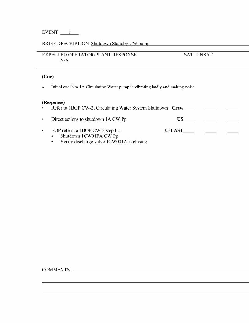
EVENT 1 BRIEF DESCRIPTION Shutdown Standby CW pump
EXPECTED OPERATOR/PLANT RESPONSE SAT UNSAT N/A
(Cue) ● Initial cue is to 1A Circulating Water pump is vibrating badly and making noise. (Response) • Refer to 1BOP CW-2, Circulating Water System Shutdown Crew • Direct actions to shutdown 1A CW Pp US • BOP refers to 1BOP CW-2 step F.1 U-1 AST • Shutdown 1CW01PA CW Pp • Verify discharge valve 1CW001A is closing
COMMENTS


EVENT 2 BRIEF DESCRIPTION Ramp Unit down 50 MW
EXPECTED OPERATOR/PLANT RESPONSE SAT UNSAT N/A
Re-activity manipulation for this scenario. (Cue) o Per SM, lower power 50 MW to maintain Reactor Power
<100%. (Response) • Refer to BGP 100-4, Power Descension CREW • Direct actions to lower Rx Pwr US • PROGRAM Turbine Controls to ramp down U-1 AST • BORATE per BOP CV-6 to control Tave-Tref U-1 within desired limits • INSERT Control Rods to maintain ∆I and Tave-Tref U-1 • STOP ramp after 50 MW ramp is complete. US
COMMENTS


EVENT 3 BRIEF DESCRIPTION Failure of the 1B Letdown Heat Exchanger (Tube Leak)
EXPECTED OPERATOR/PLANT RESPONSE SAT UNSAT N/A
Recognize symptoms and respond to a tube leak in the 1B Letdown Heat Exchanger. (Cue) o Annunciator RM-11 alarm CC Surge Tank Hi-Rad o CC Surge Tank level increasing o Indicated letdown line flow decreases (Response) • Refer to BAR’s U-1 AST/U-1 • Check CC Surge Tank level • Surge tank level > 13% U-1 • Surge tank level stable ( is rising) U-1 • Check for inleakage from RCP Thermal Barrier • RCP Therm Barr CC Wtr Flow alarms Lit OR U-1 • Seal inj flow abnormally Hi (Both will be no - go to step 6) U-1 • Isolate CC System Inleakage • Check inleakage from RCS (cc rad trends rising) U-1 • Notify Chem to sample CC system for activity U-1 • Locate and Isolate inleakage from 1B L/D Hx U-1 • Locally Isolate CV side of 1B L/D Hx U-1 • Locally Isolate CC side of 1B L/D Hx U-1 COMMENTS

EVENT 4 BRIEF DESCRIPTION 1C CD/CB Pp Trips with failure of Standby Pp to auto start
EXPECTED OPERATOR/PLANT RESPONSE SAT UNSAT N/A
Recognize symptoms and respond to a trip of the 1C CD/CB Pp with a failure of the
standby Pp to auto start. (Cue) o Annunciator 1PM03J "CD/CB Pp Trip" (Response) • Direct actions to respond to the tripped CD/CB Pp US • Enter 1BOA SEC-1, Secondary Pump Trip Crew • Check Turbine Load • Check Turbine Load > 700 MW U-1 Ast • Check Standby CD/CB Pp Running (failed to auto start) U-1 Ast • Start Aux Oil Pp for Standby CD/CB Pp U-1 Ast • Start Standby CD/CB Pp U-1 Ast • Check at least 3 CD/CB Pp’s running U-1 Ast • Check FW flow > or = to Steam Flow U-1 Ast • Check FW Pp’s NOT Cavitating • Close recirc valve on tripped CD/CB Pp U-1 Ast • Check FW Pp discharge flows Oscillating (shouldn’t be) U-1 Ast • Check CD/CB Pp Flow Restored • Check Alarm Not Lit CB Pp Dsch Flow Hi (1-17-B11) U-1 Ast • Check Alarm Not Lit FW Pp NPSH Low (1-16-E1) U-1 Ast • Check Plant Status • Check Alarm Not Lit PDMS Inop (1-10-E8) U-1 • Check 1BOL 3.h Pwr Dist Monitoring Sys Not Entered U-1 Ast • Check Alarm Not Lit PDMS Limit Exceeded (1-10-D7) U-1 Ast • Check Delta I near target U-1 Ast • Check Alarm Not Lit Rod Bank Lo Insert Limit (1-10-B6)U-1 Ast • Check Alarm Not Lit Turbine runback U-1 Ast • Check Alarm Not Lit Loss of Turb Load C7 (1-BP-4.6) U-1 Ast • Restore Plant Conditions • Adjust Boron Conc. as necessary U-1 • Verify control in Auto U-1 Ast • Review BOP CD/CB-1 & CD/CB-2 U-1 Ast • Adjust SG blowdown flows and calorimetric inputs U-1 Ast

• Verify DEHC feedback loop In Service U-1 Ast • Notify Chemistry to monitor secondary systems U-1 Ast • Return to Procedure and Step in Effect US

EVENT 5
BRIEF DESCRIPTION The controller for 1CV121 fails low.
EXPECTED OPERATOR/PLANT RESPONSE SAT UNSAT N/A
Recognize symptoms and respond to the 1CV121 control valve controller output failing low. (Cue) • Charging Flow starts lowering. • RCP seal injection low starts lowering. • VCT level starts increasing. (Response) • PLACE Flow Controller 1FK-121 in Manual U-1 • ADJUST Controller Output to re-open 1CV121 U-1
EXAMINER’S NOTE: Depending on how fast the Reactor Operator catches the failure the crew may not enter a procedure to correct the failure. The SRO may direct the RO to place the failed controller to manual and re-establish charging flow. If the crew delays they may enter the BAR for low charging low BAR 1-9-D3, 1BOA PRI-1 Excessive Primary Plant Leakage, or 1BOA RCP-2 Loss of Seal Injection.
COMMENTS


EVENT 6
BRIEF DESCRIPTION 1B TDFWP Trips and the 1A MDFWP does not start.
EXPECTED OPERATOR/PLANT RESPONSE SAT UNSAT N/A
Recognize symptoms and respond Main Feedwater Pump trip. (Cue) • Annunciator (1-16-B1) "FW Pump 1B Trip" • Annunciator (1-15-A4) “SG 1A Flow Mismatch FW Flow Low” • Annunciator (1-15-B4) “SG 1B Flow Mismatch FW Flow Low” • Annunciator (1-15-C4) “SG 1C Flow Mismatch FW Flow Low” • Annunciator (1-15-D4) “SG 1D Flow Mismatch FW Flow Low” (Response) Implement 1BOA SEC-1, Secondary Pump Trip • Inform SM of unit status/potential EP event US/STA • Close FW Pp Recirc Valve • Close 1FW012B U-1 Ast • Check Turbine Load • Check Turbine Load > 700 MW U-1 Ast • Check At Least One FW Pp Running U-1 Ast • Restore Feed Flow • Check FW Pp 1A Available U-1 Ast • Start Aux Oil Pp for 1A FW Pp U-1 Ast • Verify 1FW016 controller in Manual at 20% demand U-1 Ast • Start 1A FW Pp (Pp Trips on OC immediately) U-1 Ast • Reduce Turbine Load • Initiate CD/FW Runback U-1 Ast • Runback Pushbutton (Will not work) U-1 Ast • OWS panel G-5512 U-1 Ast • Check Turbine Load Dropping U-1 Ast • Verify Rod Control in AUTO U-1 • Initiate Boration as necessary U-1
EXAMINER’S NOTE: US directs transition from 1BOA SEC-1 to 1BEP-0, Reactor Trip Response or Safety Injection when he realizes SG levels can not be maintained.

EXPECTED OPERATOR/PLANT RESPONSE SAT UNSAT N/A
Implement 1BEP-0, Reactor Trip Response or Safety Injection • Manually actuate Reactor Trip from 1PM05J U-1 (Trip switch does not work on 1PM05J) *• Manually actuate Reactor Trip from 1PM06J U-1 (Trip switch works on 1PM06J) • Reactor trip verified U-1 • Rod bottom lights • Reactor trip/Bypass breakers • Neutron flux dropping • Turbine trip verified by (Auto trip fails) U-1 AST • GVs closed • TVs closed • Must use Manual trip pushbutton to actuate Turbine trip • 4 KV ESF busses are energized U-1 AST • Bus 141 energized • Bus 142 energized • SI Status • SI is not actuated or required CREW o SI ACTUATED permissive light lit (Not Lit) o SI first out annunciator (Not Lit) o SI equipment automatically actuated (Not running) • Transition to 1BEP ES-0.1, Reactor Trip Response CREW

COMMENTS
=

EXPECTED OPERATOR/PLANT RESPONSE SAT UNSAT N/A
EXAMINER’S NOTE: The 1A AFW Pp trips on Overcurrent after initially starting. The 1B AFW Pp trips after a two minute run. US directs transitions to 1BEP ES-0.1 because SI has not actuated and is not required. The Crew will transition to 1BFR H-1 when all SG narrow range levels are < 10% (31% Adverse).
1BEP ES-0.1, Reactor Trip Response • Verify Generator Trip U-1 AST • Main Transformer Output Breakers Open • Verify GCB 3-4 • Verify OCB 4-5 • Maintain RCS Temperature Control U-1 • RCP Running RCS Temp stable at or trending to 557F • Determine if Boration is Required U-1 AST/U-1
• RCP’s Running • Check FW Status U-1 AST/U-1 • FW isol monitor lights LIT • Trip all HD Pp’s • Total Feed Flow to SG’s > 500 gpm • SG Blowdown isol valves closed 1SD002A-H • Verify all Control Rods Fully Inserted U-1 • Check PZR Level > 17% U-1 • Check Charging and Letdown in Service • PZR Level Trending to Program Level • Check PZR Pressure Control U-1 • PZR Pressure > 1829 psig • PZR Pressure Stable at or Trending to 2235 psig • Check SG Level U-1 • Check Narrow range SG Level > 10% in any SG • Control Feed flow to maintain between 10%-50% SG lvl

• Transition to 1BFR H-1, Loss of Heat Sink when all SG CREW narrow range levels drop below 10% and AF flow is < 500 gpm (AS DIRECTED BY CSF MONITORING).
EXPECTED OPERATOR/PLANT RESPONSE SAT UNSAT N/A
EXAMINER’S NOTE: US will direct transitions to Step 13 and initiate Bleed and Feed when three SG wide range levels are < 27% (43% Adverse).
• Check if Secondary Heat Sink is Required U-1 • RCS Pressure > any Non-Faulted SG Pressure • RCS Temperature > 350F • Check Cent Chg Pp Status U-1 • Cent Chg Pp at least one Running • Check if Bleed and Feed is Required U-1 • SG Wide range level in any three SG’s < 27% (43% adverse) or • PZR pressure > than 2335 psig due to Loss of Heat Sink • Try to Establish AF to at least one SG U-1 • Check SG Blowdown isol Valves Closed 1SD002A-H • Check SG Blowdown sample isol Valves Closed 1SD005A-D • Prior to initiating feed flow review Att B • Check AF Pp SX Suct Vlvs ARMED alarm Not Lit • Check AF Pp’s Both Running (Attempt manual start) • Check AF test valves OPEN 1AF004A&B • Check AF isol Valves OPEN 1AF013A-H • Check AF Throttle Valves OPEN 1AF005A-H • Check Total AF flow > 500 gpm (It won’t be) • Reduce RCP Heat Input Stop all RCP’s U-1 • Prepare FW System for Restoration

• Check at least one CD/CB Pp Running • Place FW Reg valve in Manual at Zero Demand • Place FW Bypass Reg Valve in Manual at Zero Demand • Place Tempering flow control Valve in Manual at Zero Demand
EXPECTED OPERATOR/PLANT RESPONSE SAT UNSAT N/A
• Reset FW Isolation Signal U-1 • Check FW isolation Aux Relay lights Lit • Check SI Not Actuated • Depress both FW Isolation Reset Pushbuttons • Check FW Isol Actd relay lights Not Lit • Dispatch an operator to pull FW Isol Relay Fuses • Try to Establish Main FW flow to at least one SG U-1 • Check Startup FW Pp or 1A MDFWP available • Open FW tempering isol valves 1FW035A-D • Check at least two CD/CB Pp’s running • Check Bus 159 Energized • Verify Startup FW Pp Aux Oil Pp Running • Verify Discharge Valve 1FW059 Open • Open recirc valve 1FW076 and place c/s to Modulate • Close Main FW Pp recirc valves 1FW012A-C • Start Startup FW Pp (Pp won’t start) • Try to establish 1A MDFWP (Unavailable previously) U-1 • Try to establish Condensate Booster Pp flow U-1 • Close FW Pp recirc valves • Start Aux Oil Pp for selected Pp • Open selected FW Pp discharge valve 1FW002A-C, 1FW016, & 1FW059 • Check SI Not Actuated • Check RCS Pressure < 1930 psig P-11 Lit ( It won’t be) • Depressurize RCS to 1880 psig by Opening one PZR PORV to drop SG
pressure

So CB Pp’s can inject into the SG
EXAMINER’S NOTE: US will direct transitions to Step 13 and initiate Bleed and Feed when three SG wide range levels are < 27% (43% Adverse). Step 13 through 16 must be perform without delay to ensure adequate core cooling is maintained.
•* Establish RCS Feed Path U-1 * * * • Stop all RCP’s • Actuate SI •* Verify RCS Feed Path U-1 AST/U-1 * * * • Check Cent Chg Pp’s at least one running or • Check SI Pp’s at least one running • Check ECCS Valve Alignment Group 2 Injection lights Lit •* Establish RCS Bleed Path U-1 AST/U-1 * * * • Verify PZR PORV isol Valves Energized and OPEN • Open PZR PORV’s 1RY455A &1RY456
•* Verify Adequate RCS Bleed Path U-1 AST/U-1 * * * • Verify PZR PORV Both Open • Verify PZR PORV’s isolation valves Both Open
EXAMINER’S NOTE: Once RCS Bleed and Feed has been established the 1B AF Pp will become available. The scenario will end when the crew re-establishes feed flow to a Hot Dry SG per Att B.

Attachment B Feed Flow Limitations:
3 After Initiation of Bleed and Feed with Stable or Dropping Core Exit Temperatures A. Feed any non-dry SG’s as follows:
• If SG feedlines are not voided, then feed non-dry SG at desired rate • If SG feedlines are voided, then feed the non-dry SG between 60-80
gpm for 10 minutes prior to restoring desired feedwater flow. B. If all SG’s are dry, then feed one SG as follows:
• Feed associated SG between 60-80 gpm for 10 minutes • After the 15 minutes, feed at a rate NOT to exceed 100 gpm • When associated SG Wide Range level is > 10% feed flow may be
raised as desired TERMINATE SCENARIO
COMMENTS
Appendix D Scenario Outline Form ES-D-1
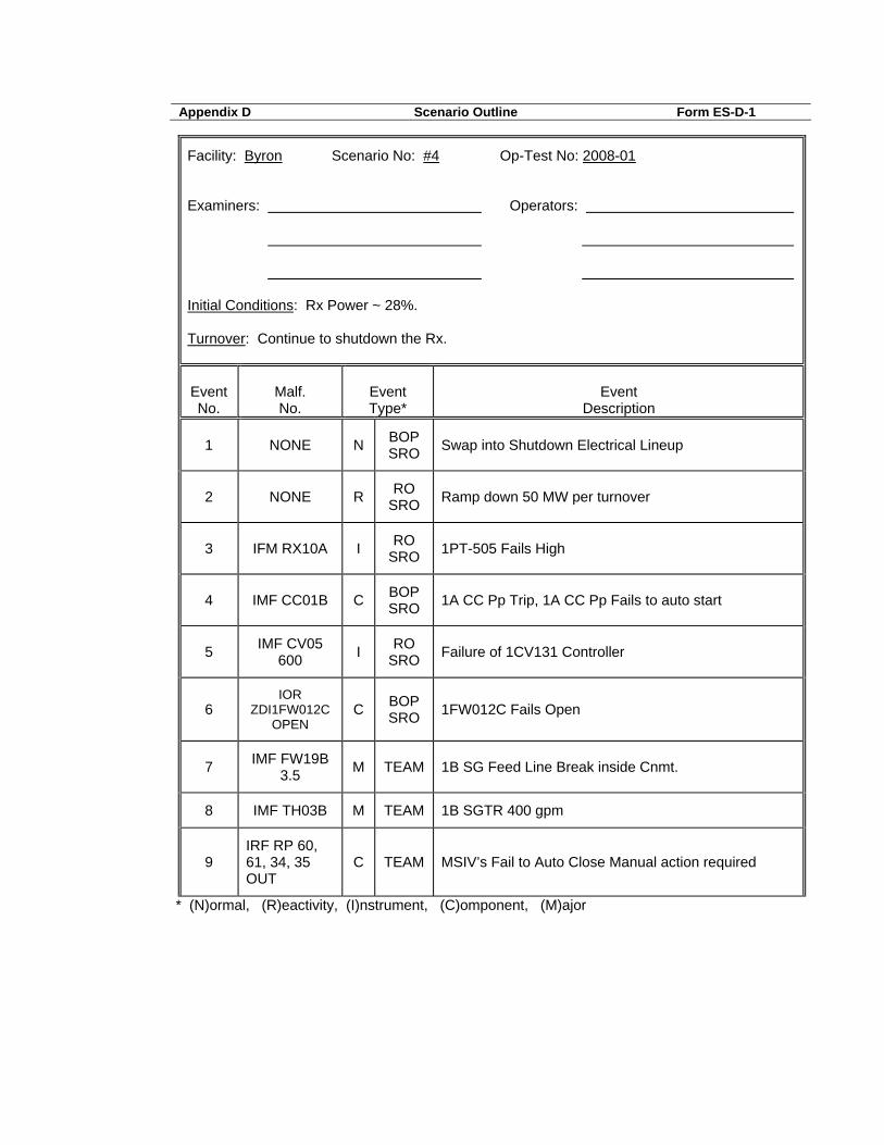
Facility: Byron Scenario No: #4 Op-Test No: 2008-01 Examiners: Operators: Initial Conditions: Rx Power ~ 28%. Turnover: Continue to shutdown the Rx.
Event No.
Malf. No.
Event Type*
Event
Description
1 NONE N BOP SRO Swap into Shutdown Electrical Lineup
2 NONE R RO SRO Ramp down 50 MW per turnover
3 IFM RX10A I RO SRO 1PT-505 Fails High
4 IMF CC01B C BOP SRO 1A CC Pp Trip, 1A CC Pp Fails to auto start
5 IMF CV05 600 I RO
SRO Failure of 1CV131 Controller
6 IOR
ZDI1FW012C OPEN
C BOP SRO 1FW012C Fails Open
7 IMF FW19B 3.5 M TEAM 1B SG Feed Line Break inside Cnmt.
8 IMF TH03B M TEAM 1B SGTR 400 gpm
9 IRF RP 60, 61, 34, 35 OUT
C TEAM MSIV’s Fail to Auto Close Manual action required
* (N)ormal, (R)eactivity, (I)nstrument, (C)omponent, (M)ajor

SCENARIO NUMBER: #4
TITLE: Byron 2008 Scenario #4 TURNOVER INFORMATION: The unit is at 28% power, steady state equilibrium xenon, BOL, 24 EFPH Unit was raising power following a refueling outage when the 1A AFP was found to be INOPERABLEA shutdown is in progress due to 1A AFP inoperability, BOL 7.5 condition A has been in effect for 68 hours, and the repairs will not be completed for 12 hours. Currently at step 14 of 1BGP 100-4 to switch to the shutdown electrical lineup. Continue in 1BGP 100-4 to ramp Unit 1 off line. THIS SCENARIO CONTAINS: The following objectives/K/A's: 004000A4.01 (3.8/3.9) IV.B.GP-04/VIII.B.GP-04-B Perform a Power Descension 008000A2.01 (3.3/3.6) IV.D.OA-10/VIII.D.OA-16-B Respond to a Loss of the CC
System 012000A2.05 (3.1/3.2) IV.D.OA-36/VIII.D.OA-10-B Respond to a 1PT-505
Failure 000040AA2.04 (4.5/4.7) IV.D.EP-06/VIII.D.EP-001-E Respond to a Feedline Break
Inside Cnmt 000038EA2.02 (4.5/4.8) 4D.EP-05/8D.EP-001-E/013-B Respond to a SGTR 000040AA2.01 (4.2/4.7) IV.D.CA-05/VIII.D.CA-007-B Respond to a SGTR with
LOCA-Subcooled Recovery COMPLETION CRITERIA: Completion of the 1BCA-3.1 cooldown determination step.
CRITICAL TASK(S): 1. Isolate 1B Steam Generator before transition out of 1BEP-2. (ERG Critical Task number - E-2--A) (K/A number - 000040AA1.10 importance -
4.1/4.1)
Examinees: US U-1 U-1AST Evaluator: Date:

SCENARIO OVERVIEW
The unit is at 28% power, steady state, equilibrium xenon, BOL. Unit one is ramping down to take the unit offline to comply with a Tech Spec LCO 3.7.5 condition A and B.
The crew will perform actions of 1BGP 100-4 to swap to the shutdown electrical lineup. After electrical lineup is switched, a failure of the turbine impulse pressure transmitter 1PT-505 fails high. The crew will implement 1BOA INST-2 to address the failure. Technical Specification 3.3.1 applies. After the actions of 1BOA Inst-2 are finished, the 1A CC pump trips. The 1B CC pump will fail to auto start on low CC pressure and the crew will manually start the 1B CC pump. After 1B CC pump is started and the failure has been addressed, 1CV131 auto controller fails to 0 demand. The will take control letdown pressure in manual. After actions are finished for 1CV131 failure, 1FW012C, 1C FW pump recirc valve, fails open the crew will perform actions of BAR or 1BOA SEC-1 to restore FW flow, or trip the reactor. After the plant has been stabilized after 1FW012C failure, or if the plant is manually tripped in response to the failure, a FW line break inside CNMT occurs requiring the crew to trip the reactor (if not previously tripped.). The crew should manually initiate a Main Steam Isolation and SI and complete the steps 1BEP-0. If the conditions requiring an SI are not identified before the completion of 1BEP-0 step 4 the crew may transition to 1BEP ES-0.1. When the crew determines that a SI is required they will manually initiate an SI and return to step 1 of 1BEP-0. The MSIVs will not close from an auto signal but will respond to a manual Main Steam Isolation. The crew should identify the 1B SG is faulted and transition to 1BEP-2. 1B DG doesn’t automatically start on the SI signal, but can be manually started. After the 1B SG has blown down to 25#, and RCS pressure is rising, a SGTR will occur on the 1B SG. If conditions for the SGTR are not present while in 1BEP-2 the crew will transition to 1BEP-1. When 1BEP-1 is entered the crew will transition to 1BEP-3 from the OAS. While in 1BEP-3 the crew will determine the need to transition to 1BCA-3.1 to stabilize conditions based on 1B SG pressure <320#. Completion criteria is Completion of the 1BCA-3.1 cooldown determination step (1BCA 3.1 step 10.) .

SCENARIO SETUP GUIDE
- Initialize IC 180, 28% power, steady state, increasing xenon, BOL. - Verify 1A CC pump is in operation - Set Xenon to 0 (zero) on Control Panel Fast Speed box.
- Place C/O tag on 1A AFP control switch, with switch in PTL.
- Place simulator in run (allow simulator to run during board walkdowns and turnover).
- Provide turnover forms and marked up copy of 1BGP 100-4T1 with exceptions marked
to start at step 14.
- Provide ReMa for plant rampdown. - Run batch file f:\by-sim4\by-sim4 and verify the following:
- IRF RP 60 OUT MSI Failure - IRF RP 61 OUT MSI Failure - IRF RP 34 OUT MSI Failure - IRF RP 35 OUT MSI Failure - IMF CC02B 200 1B CC Pump auto start failure - IMF FW43 1A AFP Trip (to prevent start of 1A AFP) - MRF RP73 1B DG auto start failure
- EVENT 1 “YCP0422.LT.25” - Command "IMF TH03B 400 120" EVENT TIME MALF NO. DESCRIPTION A Swap Shutdown Electrical lineup B 2 IFM RX10A 1PT-505 fails high (SDG RX11) C 12 IMF CC01B 1A CC pump trip, 1B CC pump fails to
auto start D 20 IMF CV05 600 1CV131 controller failure E 28 IOR ZDI1FW012C OPEN Fails 1FW012C open F 35 IMF FW19B 3.5 1B SG feed line break inside CNMT Note 1 G Note 2 IMF TH03B 1B SGTR (400 gpm) (SDG TH4)

Note 1: MSIVs fail to auto close inserted in batch file.
Note 2: Inserted by trigger 1 at 120 seconds after the 1B SG pressure drops to 25 psig.

INSTRUCTOR/SIMULATOR RUN AID GUIDE
EVENT ADDITIONAL INFORMATION A Acknowledge power descension when contacted as Electric
Operations/SM (as required). B Acknowledge Turbine Impulse pressure channel failure/EP review
request when contacted as SM (as required). Trip bistables using appropriate RFs when requested (in cae). Procedure is 1BOA Inst-2, Att D for 1PT-505.
C Acknowledge 1A CC pump trip/EP review request when contacted
as SM (as required). When requested to investigate, report a Phase A overcurrent flag at the 1A CC pump breaker. Report results 4 minutes after request.
D Acknowledge report of failed 1CV131 control failure as SM (as
required) E Acknowledge report of failure of 1FW012C as SM (as required) F Acknowledge Rx Trip & SI/EP review request when contacted as the SM
(as required). Acknowledge procedure transitions when contacted as the SM (as
required). REMOTE FUNCTIONS/OVERRIDES PER EVENT B IRF RP20 OPEN/CLOSE Cabinet 1 Door Open/Close
(SDG RX19)
RX143 P13 input to P7 MRF RX143 (TRIP) PB505A; C1-742 BS-1 (SDG RX11)
RX149 AMS MRF RX149 (TRIP) to place Operating
(SDG RX11) Bypass Switch (SW12) in the TIP 1
position.

RP91 AMS MRF RP91 (TEST-TRIP) Operating Bypass (ACTION)
Test Input switch (SW11) to test-trip.

EVENT A BRIEF DESCRIPTION Swap electrical lineup to shutdown lineup per 1BGP 100-4 Step XX
EXPECTED OPERATOR/PLANT RESPONSE SAT UNSAT N/A
Continue with actions to ramp the unit offline. (Cue) o From Turnover: Continue with 1BGP 100-4 Step 14 to
switch to the shutdown electrical lineup.
(Response) Direct U-1 AST to continue with 1BGP 100-4 Step 14 US
Turn on synchroscope for SAT feed to Bus 143 U-1AST Close SAT feed 1432 Open UAT feed 1431
o Turn off synchroscope Turn on synchroscope for SAT feed to Bus 144 U-1AST Close SAT feed 1442 Open UAT feed 1441
o Turn off synchroscope Turn on synchroscope for SAT feed to Bus 157 U-1AST Close SAT feed 1572 Open UAT feed 1571
o Turn off synchroscope Turn on synchroscope for SAT feed to Bus 156 U-1AST Close SAT feed 1562 Open UAT feed 1561
o Turn off synchroscope (Feedback) o Annunciator (1-20-E1) UAT/SAT PARALLEL FEED alarm
whenever both breakers to a bus are shut o All busses aligned to SAT COMMENTS

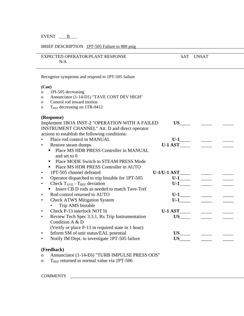
EVENT B BRIEF DESCRIPTION 1PT-505 Failure to 800 psig
EXPECTED OPERATOR/PLANT RESPONSE SAT UNSAT N/A
Recognize symptoms and respond to 1PT-505 failure (Cue) o 1PI-505 decreasing o Annunciator (1-14-D1) "TAVE CONT DEV HIGH" o Control rod inward motion o TREF decreasing on 1TR-0412
(Response) Implement 1BOA INST-2 "OPERATION WITH A FAILED US INSTRUMENT CHANNEL" Att. D and direct operator actions to establish the following conditions: • Place rod control in MANUAL U-1 • Restore steam dumps U-1 AST
Place MS HDR PRESS Controller in MANUAL and set to 0
Place MODE Switch to STEAM PRESS Mode Place MS HDR PRESS Controller in AUTO
• 1PT-505 channel defeated U-1/U-1 AST • Operator dispatched to trip bistable for 1PT-505 U-1 • Check TAVE - TREF deviation U-1
Insert CB D rods as needed to match Tave-Tref • Rod control returned to AUTO U-1 • Check ATWS Mitigation System U-1 • Trip AMS bistable • Check P-13 interlock NOT lit U-1 AST • Review Tech Spec 3.3.1, Rx Trip Instrumentation US
Condition A & D (Verify or place P-13 in required state in 1 hour) • Inform SM of unit status/EAL potential US • Notify IM Dept. to investigate 1PT-505 failure US (Feedback) o Annunciator (1-14-E6) "TURB IMPULSE PRESS OOS" o TREF returned to normal value via 1PT-506 COMMENTS


EVENT C BRIEF DESCRIPTION 1A CC Pump Trip/1B CC Pump Fails to Start
EXPECTED OPERATOR/PLANT RESPONSE SAT UNSAT N/A (Cue) o No CC pump run lights lit o 1A CC pump trip light lit o Annunciator (1-2-A4) "CC PUMP TRIP" o Annunciator (1-2-B5) "CC PUMP DSCH PRESS LOW" (Response) EVALUATOR’S NOTE: Crew may take actions using BAR alone, or enter 1BOA Pri-6. o Respond to BAR 1-2-A4 “CC PUMP TRIP” U-1 AST
Manually start 1B CC Pump U-1 AST Verify adequate CC flow to affected components U-1 AST
o Place 1A CC Pump Switch to Pull To Lock (PTL) U-1 AST
o Implement 1BOA PRI-6 "COMPONENT COOLING US MALFUNCTION" & direct actions to establish the following conditions: • Verify CC surge tank level > 13% and stable U-1 AST • Manually start 1B CC pp U-1 AST • Verify annunciator 1-2-B5 NOT lit U-1 AST • Check CC system/component temperatures normal U-1 AST • CC heat exchanger outlet temp < 105°F • Check RCP cooling • Letdown HX temperature alarms NOT lit : • Check CC system status U-1 AST • Check CC system rad monitors normal • Ensure CC surge tank level between 50% - 65% • Ensure CC system pressure > 85 psig • Dispatch operators to investigate cause of U-1 AST/U-1 CC pump failures • Review Tech Spec 3.7.7, CC System; while only 1CC pump US is available (Restore 1 pump in 7 days) Direct Crew to restore U-0 CC Pump to A/T US Verify U-0 CC pump is mechanically aligned U-1 AST
• Inform SM of unit status/potential EAL event US (Feedback) • 1B CC pump running • CC annunciators clear COMMENTS


EVENT D BRIEF DESCRIPTION 1CV131 auto control failure EXPECTED OPERATOR/PLANT RESPONSE SAT UNSAT N/A
EVALUATOR’S NOTE: Operator may isolate letdown because of relief valve lifting instead of taking manual control of 1CV131.
(Cue) o Annunciator 1-8-B5 LTDN HX OUTLET PRESS HIGH LIT o 1CV131 demand trending to minimum or
MINIMUM demand light LIT o Letdown pressure HIGH • Diagnose failure of 1CV131 Auto control CREW ο Isolate Letdown U-1 ο Take manual control of 1CV131 and restore pressure to approximately 370# U-1 o If letdown is isolated, will be able to restore letdown with U-1
1CV131 in MANUAL. (Problem will resume when 1CV131 is replaced to Automatic.
o Contact WEC or SM for IR US COMMENTS

EVENT E BRIEF DESCRIPTION 1FW012C fails open EXPECTED OPERATOR/PLANT RESPONSE SAT UNSAT N/A
EVALUATOR’S NOTE: Crew may respond to this using either the listed BAR response or 1BOA SEC-1 actions for a tripped FW pump. NOTE that a possible response to 1BOA Sec-1 is to consider NO feed pump running and trip the Reactor.
(Cue) o Annunciators (1-15-A4 thru D4) "S/G 1_ FLOW MISMATCH FW FLOW LOW" o Annunciators (1-15-A9 thru D9) "S/G 1_ LEVEL DEVIATION HIGH LOW" o Steam flow/feed flow mismatch on all SGs o All FRVs opening/open o All SG levels dropping
(Response) o Respond to BAR 1-15-A4-D4 to “Take manual control U-1 AST
of Feed flow and Balance Feed flow with Steam flow to stabilize S/G level.” by adjusting 1C FW pump flow.
OR o Implement 1BOA SEC-1 "SECONDARY PUMP TRIP" US and direct recovery actions: • Attempt to close 1C FW pump recirc valve, 1FW012C U-1 AST • Check NPSH Low Alarm (1-16-E1) not lit U-1 AST • Restore plant conditions CREW • Adjust boron concentration as necessary U-1 AST
o Adjust 1C FW pump flow OR U-1 AST o Start 1A FW pump U-1 AST
• Verify HD, CD, CB, GS valves in auto U-1 AST • Check feed flow restored US/U-1 AST • Operator is dispatched to locally investigate 1FW012C US • Inform SM of unit status/potential EAL event US
OR o Implement 1BOA SEC-1 "SECONDARY PUMP TRIP" US and direct Reactor Trip. COMMENTS

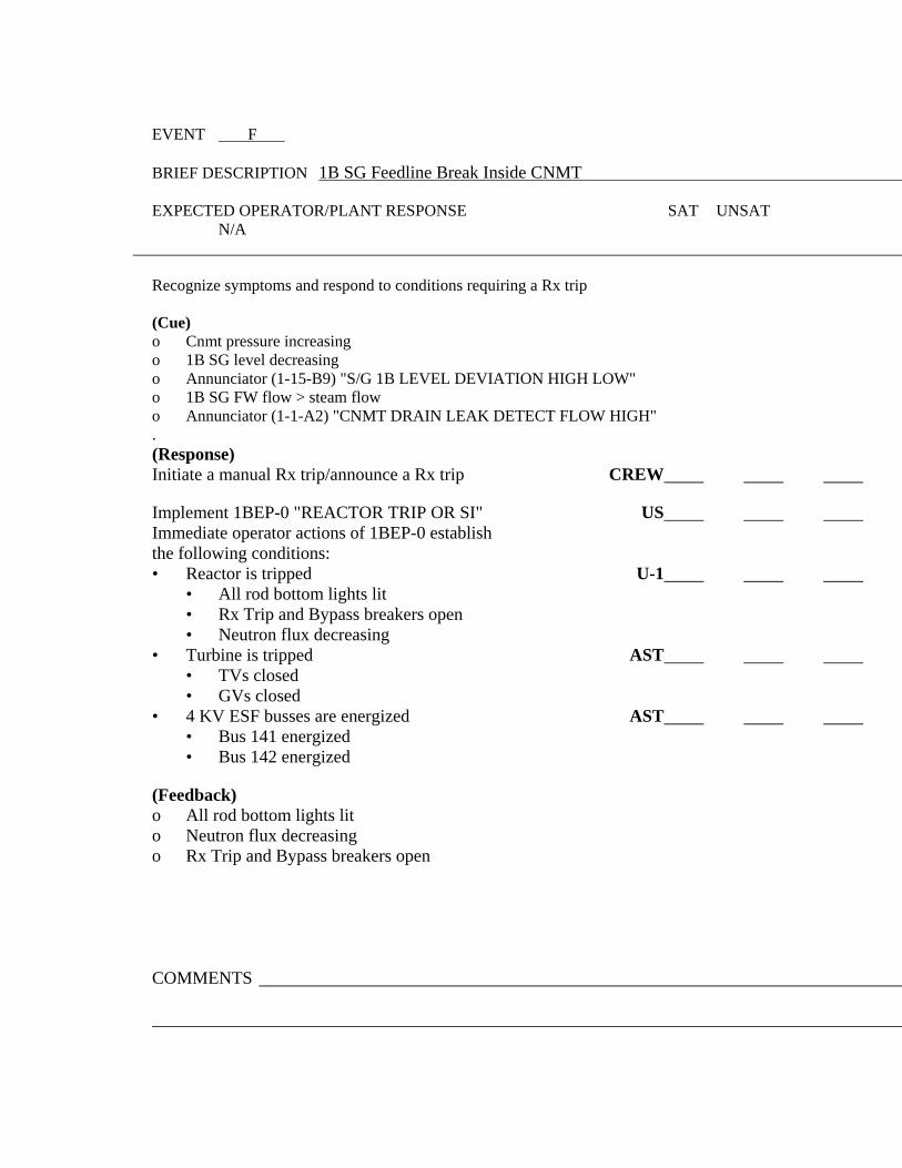
EVENT F BRIEF DESCRIPTION 1B SG Feedline Break Inside CNMT
EXPECTED OPERATOR/PLANT RESPONSE SAT UNSAT N/A
Recognize symptoms and respond to conditions requiring a Rx trip (Cue) o Cnmt pressure increasing o 1B SG level decreasing o Annunciator (1-15-B9) "S/G 1B LEVEL DEVIATION HIGH LOW" o 1B SG FW flow > steam flow o Annunciator (1-1-A2) "CNMT DRAIN LEAK DETECT FLOW HIGH" . (Response) Initiate a manual Rx trip/announce a Rx trip CREW Implement 1BEP-0 "REACTOR TRIP OR SI" US Immediate operator actions of 1BEP-0 establish the following conditions: • Reactor is tripped U-1 • All rod bottom lights lit • Rx Trip and Bypass breakers open • Neutron flux decreasing • Turbine is tripped AST • TVs closed • GVs closed • 4 KV ESF busses are energized AST • Bus 141 energized • Bus 142 energized (Feedback) o All rod bottom lights lit o Neutron flux decreasing o Rx Trip and Bypass breakers open COMMENTS

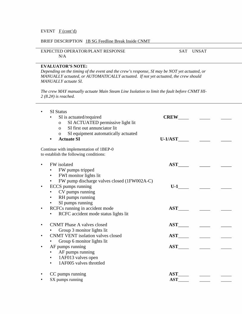
EVENT F (cont’d) BRIEF DESCRIPTION 1B SG Feedline Break Inside CNMT
EXPECTED OPERATOR/PLANT RESPONSE SAT UNSAT N/A
EVALUATOR’S NOTE: Depending on the timing of the event and the crew’s response, SI may be NOT yet actuated, or MANUALLY actuated, or AUTOMATICALLY actuated. If not yet actuated, the crew should MANUALLY actuate SI. The crew MAY manually actuate Main Steam Line Isolation to limit the fault before CNMT HI-2 (8.2#) is reached.
• SI Status • SI is actuated/required CREW o SI ACTUATED permissive light lit o SI first out annunciator lit o SI equipment automatically actuated • Actuate SI U-1/AST
Continue with implementation of 1BEP-0 to establish the following conditions: • FW isolated AST • FW pumps tripped • FWI monitor lights lit • FW pump discharge valves closed (1FW002A-C) • ECCS pumps running U-1 • CV pumps running • RH pumps running • SI pumps running • RCFCs running in accident mode AST • RCFC accident mode status lights lit • CNMT Phase A valves closed AST • Group 3 monitor lights lit • CNMT VENT isolation valves closed AST • Group 6 monitor lights lit • AF pumps running AST • AF pumps running • 1AF013 valves open • 1AF005 valves throttled • CC pumps running AST • SX pumps running AST

COMMENTS

EVENT F (cont’d) BRIEF DESCRIPTION 1B SG Feedline Break Inside CNMT
EXPECTED OPERATOR/PLANT RESPONSE SAT UNSAT N/A
• Main Steamlines are isolated (MSIV do NOT auto close) U-1/AST • Close MSIVs via MSLI switch or individual switches • Containment Spray is not required AST • Cnmt pressure < 20 psig Examiner’s Note: AF to the 1B SG may be throttled to zero or isolated at the next step. • Verify total AF flow AST • > 500 gpm • Control feed flow to maintain SG NR level between 10% (31%) - 50% • No SG level increasing in an uncontrolled manner • ECCS valves aligned with flow U-1 • Group 2 cold leg injection monitor lights lit • > 100 gpm on indicator 1FI-917 • Check at least 1 PZR PORV relief path available U-1 • Generator tripped AST • Switch yard breakers open • PMG breaker open • Diesel Generators running AST • 1A Diesel Generator running • Start 1B Diesel Generator • Verify 1SX169A and B open • Operator dispatched • Ventilation aligned for emergency operation U-2 AST /AST • PZR PORVs and spray valves closed U-1 • RCS temperature < 557°F U-1 • RCPs running U-1 • Inform SM of unit status/potential EP event US COMMENTS


EVENT F (cont’d) BRIEF DESCRIPTION 1B SG Feedline Break Inside CNMT
EXPECTED OPERATOR/PLANT RESPONSE SAT UNSAT N/A
Recognize symptoms and respond to a faulted steam generator in accordance with 1BEP-0 "REACTOR TRIP OR SAFETY INJECTION" (Cue) o 1B SG depressurizing in an uncontrolled manner o 1B SG is completely depressurized. (Response) Announcement of faulted steam generator symptoms CREW Transition to 1BEP-2 "FAULTED SG ISOLATION" US • Request STA function at transition from 1BEP-0 US • Identify at least 1 non-faulted SG U-1 AST * Isolate 1B SG before transition out of 1BEP-2 US/AST (E-2--A) (000040AA1.10 4.1/4.1) • AF valves closed (1AF013B/F) o Main feedwater isolated o 1B SG PORV closed (1MS018B) o Blowdown isolation/sample valves closed (1SD002E/F, 1SD005C) • Monitor AF pump suction pressure U-1 AST • Informs SM of unit status US Examiner’s Note: o If Secondary Radiation is indicated, the crew will transition to 1BEP-3. (Steps continued on page 15.)
• Transition to 1 BEP-1 “LOSS OF REACTOR OR SECONDARY COOLANT”
US (Feedback) • MSIVs closed • 1AF013B and 1AF013F closed COMMENTS


EVENT G BRIEF DESCRIPTION Ruptured - Faulted SG – 1B SG
EXPECTED OPERATOR/PLANT RESPONSE SAT UNSAT N/A
Recognize and diagnose/respond to a SGTR in accordance with 1BEP-1 "LOSS OF REACTOR OR SECONDARY COOLANT" OAS (Cue) o 1B SG radiation monitor trends rising o PZR pressure dropping o PZR level dropping o 1B SG pressure rising (Response) Announce indications of a SGTR US/U-1AST Transition from 1BEP-1 " LOSS OF REACTOR OR US SECONDARY COOLANT " to 1BEP-3 "SGTR" • Inform SM of unit status/potential EP event US COMMENTS


EVENT G (cont’d) BRIEF DESCRIPTION Ruptured - Faulted SG – 1B SG
EXPECTED OPERATOR/PLANT RESPONSE SAT UNSAT N/A
Recognize and diagnose/respond to a SGTR Transition to 1BEP-3 "SGTR" US • Inform SM of unit status/potential EP event US Coordinate/direct operator actions in accordance US with 1BEP-3 "SGTR" to isolate a ruptured SG • RCPs running U-1 • Identify ruptured SG (1B) U-1/U-1AST • Isolate flow from ruptured SG
o 1B SG PORV in auto and closed (1MS018B) U-1AST o 1B SG blowdown isolation valves closed U-1/U-1AST (1SD002E & F) o 1B MSIV and MSIV bypass valves closed U-1AST (1MS001B and 1MS101B) o Check intact SG PORVs available US/U-1AST for RCS cooldown (1MS018A, C, and D) o 1B SG NR level < 10% (do not feed 1B SG) U-1AST • Aux Feedwater isolation valves 1AF013B & F closed U-1AST (may have been previously isolated)
EXAMINER’S NOTE:
o If 1B SG pressure is > 320 psig, go to page 16. o If 1B SG pressure is < 320 psig, go to page 17.
• Check ruptured SG pressure > 320 psig U-1 AST COMMENTS


EVENT G (cont’d) BRIEF DESCRIPTION Ruptured - Faulted SG – 1B SG
EXPECTED OPERATOR/PLANT RESPONSE SAT UNSAT N/A
• Initiate RCS cooldown US/U-1AST • Specify RCS temperature to which the RCS must be cooled down to allow depressurization of the RCS to ruptured SG pressure • Dump steam at maximum rate via: • Intact SG PORVs
• Crew performs steps 7 through 11 of 1BEP-3 to CREW establish the following conditions: • Check intact SG levels > 10%, control 18-50% • Check PZR PORVs and isolation valves • Reset SI • Reset Containment Isolation • Restore IA to Cnmt • Verify AC buses energized by offsite power • Check if RH pumps should be stopped U-1AST • RCS pressure > 325 psig, stop RH pumps • Check if RCS cooldown should be stopped U-1 AST/U-1 • Maintain CETCs < required temperature • Check ruptured SG pressure stable or rising U-1AST • 1B SG pressure within 250 psig of the intact SGs COMMENTS

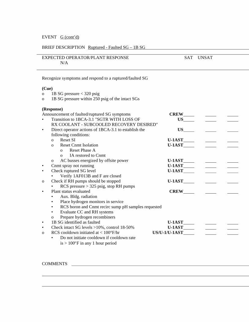
EVENT G (cont’d) BRIEF DESCRIPTION Ruptured - Faulted SG – 1B SG
EXPECTED OPERATOR/PLANT RESPONSE SAT UNSAT N/A
Recognize symptoms and respond to a ruptured/faulted SG (Cue) o 1B SG pressure < 320 psig o 1B SG pressure within 250 psig of the intact SGs (Response) Announcement of faulted/ruptured SG symptoms CREW • Transition to 1BCA-3.1 "SGTR WITH LOSS OF US RX COOLANT - SUBCOOLED RECOVERY DESIRED" • Direct operator actions of 1BCA-3.1 to establish the US following conditions: o Reset SI U-1AST o Reset Cnmt Isolation U-1AST o Reset Phase A o IA restored to Cnmt o AC busses energized by offsite power U-1AST • Cnmt spray not running U-1AST • Check ruptured SG level U-1AST • Verify 1AF013B and F are closed o Check if RH pumps should be stopped U-1AST • RCS pressure > 325 psig, stop RH pumps • Plant status evaluated CREW • Aux. Bldg. radiation • Place hydrogen monitors in service • RCS boron and Cnmt recirc sump pH samples requested • Evaluate CC and RH systems o Prepare hydrogen recombiners • 1B SG identified as faulted U-1AST • Check intact SG levels >10%, control 18-50% U-1AST o RCS cooldown initiated at < 100°F/hr US/U-1/U-1AST • Do not initiate cooldown if cooldown rate is > 100°F in any 1 hour period
COMMENTS
