appendix d technologies for managing point sources of
TRANSCRIPT

APPENDIX D
Technologies for ManagingPoint Sources of Wastewater
IntroductionThis appendix describes the wastewater streams that will be produced in oil shale
facilities, including leachates from solid waste disposal. The physical, chemical, and bio-logical treatment devices and systems are then described, Finally, developer plans are re-viewed to show how water supply, wastewater treatment units and systems, and methodsof disposition might be combined into comprehensivecommercial-scale oil shale facilities.
Oil Shale Waste Streams That Will
water management schemes for
Require TreatmentThe major point source streams that will re-
quire treatment are:
●
●
●
●
●
The
excess mine drainage water—principally forplants near the center of the Piceance basin;retort condensates —especially and perhapsexclusively for in situ operations;gas condensates—for all systems;coker and hydrotreater condensates from allplants that have onsite upgrading or refiningoperations; andstreams from service operations—includingboiler feedwater treatment wastes and cool-ing tower blowdown.
other streams are either relatively small orrelatively clean and consequently require littletreatment. They include boiler blowdown, rainand service water runoff, and sanitary wastes.Sanitary wastes will certainly need treatment,but they should be similar to typical domestic
●
Individual Methods for PointPhysical Methods
Gravity separators are used to treat nearly alloily wastewaters. They are especially commonin refineries and chemical plants. The simplestare impingement-type devices such as APIseparators, corrugated plate interceptor sepa-rators and parallel plate interceptor sepa-rators. These devices are very inexpensive andreliable but they can be used only for first-stage oil removal. Additional treatment is usu-
wastes and can easily be handled in commercially.available biological u-nits.
Leachate from spent or raw shale piles on thesurface is not considered as a separate stream re-quiring treatment during the operating life of theplant. With proper compaction and irrigation,water will be either retained in the pile or lost byevaporation. There should therefore be little ac-cumulation of leachates. 1 There will be storm andsnowmelt runoff, but this will be in limited quan-tities and will have a low salt content.2 The smallquantity of water that may percolate through thepile after intentional leaching can be expected tobe low in both organic and inorganic substances, ]This water can be used for dust control in rawshale crushing operations and will thus find itsway back to the retort, Leachate from spent insitu retorts poses a potential problem of unknownmagnitude, Design concepts for its control are dis-cussed in chapter 8.
Source Wastewater Treatment
●
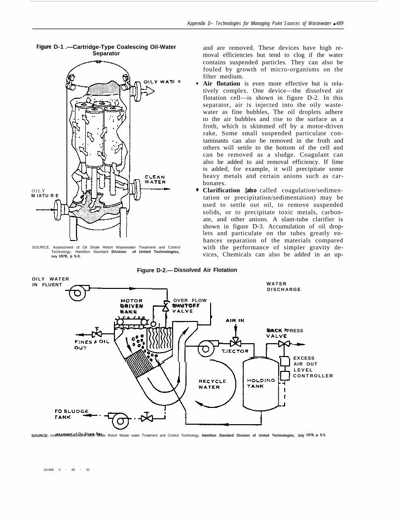
ally needed before the wastewater can be sentto sensitive treatment systems like biologicaloxidizers.Coalescing cartridge separators (figure D-1)are more effective devices that can reduce oilconcentrations to as low as 1 mg/l. In this typeof separator , oi ly wastewater is pumpedthrough a coarse filter medium within the car-tridges, causing oil droplets and some mechan-ically emulsified oil to coagulate into largeglobules which float to the top of the separator
488
Appendix D– Technologies for Managing Point Sources of Wastewater ● 489
Figure D-1 .—Cartridge-Type Coalescing Oil-WaterSeparator
O I L YM IXTU R E
E R
SOURCE. Assessment of Oil Shale Retort Wastewater Treatment and ControlTechnology, Hamilton Standard Division of United Technologies,July 1978, p 5-3.
●
●
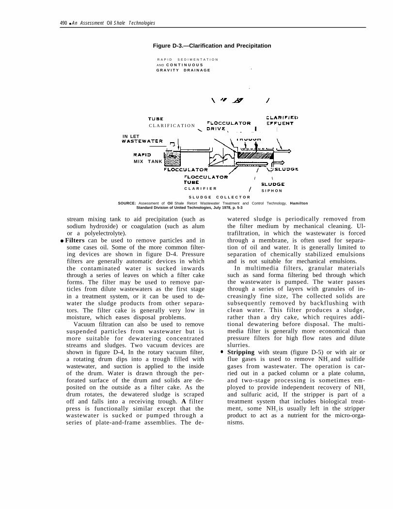
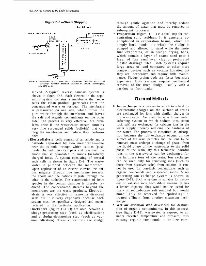
and are removed. These devices have high re-moval efficiencies but tend to clog if the watercontains suspended particles. They can also befouled by growth of micro-organisms on thefilter medium.Air flotation is even more effective but is rela-tively complex. One device—the dissolved airflotation cell—is shown in figure D-2. In thisseparator, air is injected into the oily waste-water as fine bubbles, The oil droplets adhereto the air bubbles and rise to the surface as afroth, which is skimmed off by a motor-drivenrake, Some small suspended particulate con-taminants can also be removed in the froth andothers will settle to the bottom of the cell andcan be removed as a sludge. Coagulant canalso be added to aid removal efficiency. If limeis added, for example, it will precipitate someheavy metals and certain anions such as car-bonates.Clarification [also called coagulation/sedimen-tation or precipitation/sedimentation) may beused to settle out oil, to remove suspendedsolids, or to precipitate toxic metals, carbon-ate, and other anions. A slant-tube clarifier isshown in figure D-3. Accumulation of oil drop-lets and particulate on the tubes greatly en-hances separation of the materials comparedwith the performance of simpler gravity de-vices, Chemicals can also be added in an up-
Figure D-2.— Dissolved Air FlotationOILY WATERIN FLUENT WATER
DISCHARGE
OVER FLOWDRIVEN SHUTOFFR A K E
SOURCE: A
BACK PRESS. . —.
* a * a m I I I
o \EXCESSAIR OUTLEVELCONTROLLER
ssessmentssessrnent ofOil Shale Retort Waste water Treatment and Control Technology, Hamilton Standard Division of United Technologies, July 1978, p. 5-3.
63-898 0 - 80 - 32
490 ● An Assessment Oil Shale Technologies
Figure D-3.—Clarification and Precipitation
R A P I D S E D I M E N T A T I O N
AND C O N T I N U O U SG R A V I T Y D R A I N A G E .
.
C L A R I F I C A T I O NI
IN LET
MIX TANK
// \
C L A R I F I E R S I P H O N
S L U D G E C O L L E C T O R
SOURCE: Assessment of Oil Shale Retort Wastewater Treatment and Control Technology, HamiltonStandard Division of United Technologies, July 1978, p. 5-3
stream mixing tank to aid precipitation (such assodium hydroxide) or coagulation (such as alumor a polyelectrolyte).
● Filters can be used to remove particles and insome cases oil. Some of the more common filter-ing devices are shown in figure D-4. Pressurefilters are generally automatic devices in whichthe contaminated water is sucked inwardsthrough a series of leaves on which a filter cakeforms. The filter may be used to remove par-ticles from dilute wastewaters as the first stagein a treatment system, or it can be used to de-water the sludge products from other separa-tors. The filter cake is generally very low inmoisture, which eases disposal problems.
Vacuum filtration can also be used to removesuspended particles from wastewater but ismore suitable for dewatering concentratedstreams and sludges. Two vacuum devices areshown in figure D-4, In the rotary vacuum filter,a rotating drum dips into a trough filled withwastewater, and suction is applied to the insideof the drum. Water is drawn through the per-forated surface of the drum and solids are de-posited on the outside as a filter cake. As thedrum rotates, the dewatered sludge is scrapedoff and falls into a receiving trough. A filterpress is functionally similar except that thewastewater is sucked or pumped through aseries of plate-and-frame assemblies. The de-
●
watered sludge is periodically removed fromthe filter medium by mechanical cleaning. Ul-trafiltration, in which the wastewater is forcedthrough a membrane, is often used for separa-tion of oil and water. It is generally limited toseparation of chemically stabilized emulsionsand is not suitable for mechanical emulsions.
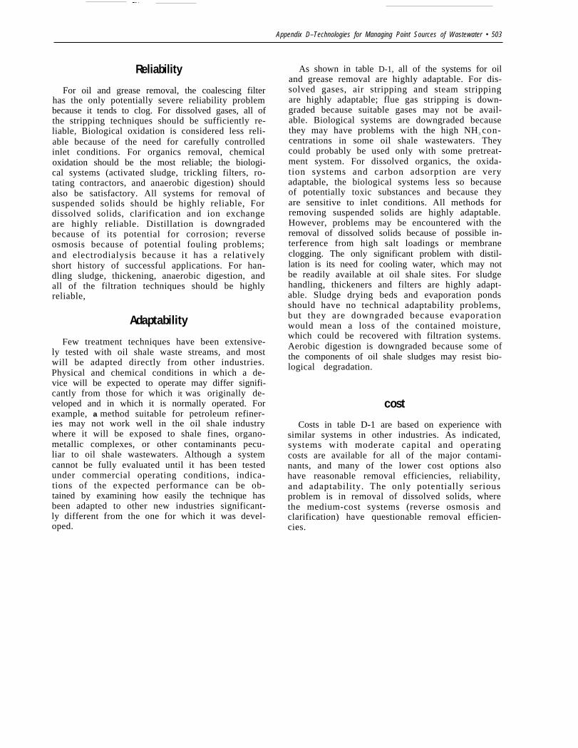
In multimedia filters, granular materialssuch as sand forma filtering bed through whichthe wastewater is pumped. The water passesthrough a series of layers with granules of in-creasingly fine size, The collected solids aresubsequently removed by backflushing withclean water. This filter produces a sludge,rather than a dry cake, which requires addi-tional dewatering before disposal. The multi-media filter is generally more economical thanpressure filters for high flow rates and diluteslurries.Stripping with steam (figure D-5) or with air orflue gases is used to remove NH3 and sulfidegases from wastewater. The operation is car-ried out in a packed column or a plate column,and two-stage processing is sometimes em-ployed to provide independent recovery of NH3
and sulfuric acid, If the stripper is part of atreatment system that includes biological treat-ment, some NH3 is usually left in the stripperproduct to act as a nutrient for the micro-orga-nisms.

Appendix D–Technologies for Managing Point Sources of Wastewater . 491
Figure D-4.— Filters for Wastewater Treatment
I
A. Pressure filter
I
1’ -
I C Y C L E
D. Filter press
B. Rotary vacuum filter
,“.. . “. .“ . . . .
O I L Y
“ . . . -. . , . : . . . . “. . ‘ . ,.. . .. . , . . .
. . . .~: ..,::,:::’ : ,. . . . . . ~,~. . .. , . . ,.
. . Fmcc . . . : , ‘. . . “ “ , .wATCm “ “ . . . .- : ‘ : “
C. Ultrafiltration
I )
- - -
. . ~c O A L
.,
A N
O I L
C O NCm NIRATa
E. Multimedia fi ltration
SOURCE: Assessment of Oil Shale Retort Wastewater Treatment and Control Technology, Hamilton Standard Division of United Technologies, July 1978, PP 5-4, 5-6,5-11, and 5-12
“ .
Adsorption is used to remove dissolved metals, .organic compounds, and many toxic sub-stances. Adsorption with regenerated carbonslurries and with resin particles is shown infigure D-6. Other systems use activated carbonparticles that are contained in a fixed bed, ei-ther without regeneration or with regenerationwithin the column. In all cases, the separationinvolves physical adsorption of the contami- ●
nan t s on t he su r f ace s o f t he pa r t i cu l a t emedium.
Distillation (figure D-7) is a simple process inwhich wastewater is purified by boiling. Theproducts are a very clean steam, which can becondensed with cooling water or in air-cooledcondensers, and a highly contaminated concen-trate. Very pure water can be obtained, but theprocess has large energy requirements. Coolingwater is also needed in most applications.Reverse osmosis can also recover very purewater from concentrated salt solutions. Somedissolved organic materials can also be re-
492 ● An Assessment of Oil Shale Technologies
Figure D-5.—Steam Stripping
H E A TI N T E R -
w ASTE W ATE R
V A PO R S
I
W A T E R
SOURCE: Assessment of Oil Shale Retort Wastewater Treatment and ControlTechnology, Hamilton Standard Division of United Technologies,July 1978, p, 5-4
moved. A typical reverse osmosis system isshown in figure D-8. Each element in the sepa-ration system contains a membrane that sepa-rates the clean product (permeate) from theconcentrated waste or residual. The membraneis pressurized on one side, which forces thepure water through the membrane and leavesthe salt and organic contaminants on the otherside. The process is very effective, but prob-lems arise if the wastewater stream containsvery fine suspended solids (colloids) that canclog the membranes and reduce their perform-ance.
● Electrodialysis cells consist of an anode and acathode separated by two membranes—onenear the cathode through which cations (posi-tively charged ions) can pass and one near theanode that is permeable to anions (negativelycharged ions). A system consisting of severalsuch cells is shown in figure D-9. The waste-water is pumped between the membranes.Upon application of an electric current, the ani-ons migrate through one membrane towardsthe anode and the cations migrate through theother to the cathode. The concentration of ionicspecies in the central chamber is thereby re-duced. The concentrated streams beyond themembranes are the waste products. Electrodi-alysis is very effective in removing dissolvedsalts but it is very expensive because eachsystem must be specifically designed and manu-factured for the particular application.
. Thickeners (figure D-1 O) are used between asludge-generating step (such as clarification)and a sludge-dewatering step (such as vac-uum filtration). These concentrate the sludge
●
●
●
through gentle agitation and thereby reducethe amount of water that must be removed insubsequent processes.Evaporation (figure D-1 1) is a final step for con-centrating solid residues. It is generally ac-complished in evaporation basins, which aresimply lined ponds into which the sludge ispumped and allowed to stand while the mois-ture evaporates, or in sludge drying beds,which contain a layer of coarse sand over alayer of fine sand over clay or perforatedplastic drainage tiles. Both systems requirelarge areas of land compared to other morecompact devices such as vacuum filtration butthey are inexpensive and require little mainte-nance. Sludge drying beds are faster but moreexpensive. Both systems require mechanicalremoval of the dried sludge, usually with abackhoe or front-loader.
Chemical Methods
Ion exchange is a process in which ions held byelectrostatic charges on the surface of resinsare exchanged for ions with similar charges inthe wastewater. An example is a home watersoftening system in which sodium ions (fromrock salt) are exchanged for calcium ions in thewater supply, thereby reducing the hardness ofthe water. The process is classified as adsorp-tion because the ion exchange occurs on thesurface of the resin particles and the ions to beremoved must undergo a change of phase: fromthe liquid phase of the wastewater to the solidphase of the resin. By this technique, harmfulions in the wastewater can be exchanged forthe harmless ions of the resin. Ion exchangecan be used only for removing ions (such asthose from dissolved salts) from solution; it can-not be used for non-ionic contaminants such asorganic compounds and suspended solids. A re-generating ion exchange system is shown infigure D-12. Such a system is suitable for recov-ery of valuable ions from dilute streams. It hasa limited capacity, thus would not be useful forfirst- or second-stage salt removal but wouldmore likely be reserved for “polishing” atreated effluent from another treatment tech-nology.Wet air oxidation was developed for destruc-tion of organic contaminants. In this process(see figure D-13), wastewater is exposed to airunder elevated temperature and pressure, thuscausing organic compounds to oxidize com-

Appendix D–Technologies for Managing Point Sources of Wastewater • 493
Figure D-6.—Adsorption Systems for Wastewater Treatment
A D S O R P T I O N
IN FLUENTW A STEW AT E R
R E G E N E R A T E D CAR BON SLUR RY
I
TR E ATE DE F F L U E N T
FIN ES
‘
REM OVA LSCREEN
i
DEW ATE R I N GSCREEN
R E G E N E R A T I O NS T O R A G E FU RN ACE
R E G E N E R A T E DCAR BONS L U R R Y T A N K S
F I N E S T O -
W A S T E
A. Carbon adsorpt ion wi th external regenerat ion
II T A N K
B. A two-tank adsorption system
SOURCE: Assessment of Oil Shale Retort Wastewater Treatment and Control Technology, Hamilton Standard Division ofUnited Technologies, July 1978, pp. 5-4 and 5-6

494 ● An Assessment of Oil Shale Technologies
Figure D.7.– Distillation Figure D-8.– R e v e r s e O s m o s i s
CON DENsER WASTE WATER . . ●
FEE D
P R E P R O C E S S I N G
F E E D W A T E R T O
D I S C H A R G EO R R E U S E
D R A I N T O W A S T ET A N K
P R O D U C T W A T E R( PE R M E A T E)
SOURCE: Assessment of Oil Shale Retort Wastewater Treatment and Control
SOURCE: Assessment of Oil Shale Retort Wastewater Treatment and ControlTechnology, Hamilton Standard Division of United Technologies,July 1978, p 5-7.
Technology, Hamilton Standard Division of United Technologies,July 1978, p. 5-7
Figure D-9.—Electrodialysis
O U T L E T O F C O N C E N T R A T I O N S T R E A M
OIL.-1 - -
C A T H O D EC O M P A R T M E N T
A N O D E
C O M P A R T M E N TS T R E A M S T R E A M
SOURCE: Assessment of Oil Shale Retort Wastewater Treatment and Control Technology, Hamilton Standard Division of United Technologies, July 1978, p. 5-7.

Appendix D-Technologies for Managing Point Sources Wastewater ● 495
F i g u r e D 1 0 . - M echanical Sludge Thickening
B L A D E
CON D U I T COUNTER F LOWTO MOTOR
DRIVE UNIT\ \
!N FLUE
CON DOVERA L A R
t
P L A N
BASEHAN D R A I L
SOURCE: Assessment of Oil Shale Retort Waste Water Treatment anrd Control Technology, Hamilton Standard Division of United Technologies, July 1978, p. 5-9

496 ● An Assessment of Oil Shale Technologies
Figure D-11 .—Evaporation Systems for Sludge Drying
A. Evaporation pond
(
A
v
1
- -
I
- _ & _ - .- y ~ -
P L A N W A L K
/3-1 N COARSE-SAND
F
A
“OR
B. Sludge drying bed
United Technologies, July 1978, pp. 5-10 and 4-11.

Figure D-12. —A Regenerable Ion Exchange System
U N I T
E J E C T O R
I
O U T L E-,
TO W A S T E S U PP O R T I N G B E D T A N K
SOURCE Assessment of 011 Shale Retort Wastewater Treatment and Control Technology, HamiltonStandard Divlsion of United Technologies. July 1978, p 5-14
Figure D-1 3. — Wet Air Oxidation
R EA C T O R
S E P A R A T O R I
AIR
HOLD I N G F E E D H I G H7A N K
A I R E X P A N S I O NC O M P R E S S O R E N G I N E
E X H A U ST
P U M P
SOURCE. Assessment of 0il Shale Retort Wastewater Treatment and Control Technology, Hamilton Standard Division of United Technologies, July 1978, p 5-14

498 ● An Assessment of Oil Shale Technologies
pletely or at least decomposing them into formsthat are more easily treated. In particular, theprocess can be used to increase the biodegrad-able properties of compounds that are normallyrefractory (resistant) to biological oxidation.The method is very effective but is costly be-cause the highly corrosive environment withinthe equipment requires expensive materialsand construction methods.Photolytic oxidation processes (figure D-14) uselight to oxidize organic contaminants. They canbe used in conjunction with chemical oxidizers.One technique that works well in many indus-trial situations is the combination of ultravioletlight and ozone gas. The process has the disad-vantage of requiring relatively long residencetimes.Electrolytic oxidation is similar to electrodial-ysis except that it can be used to oxidize orreduce dissolved contaminants to their gaseousforms. A typical system is shown in figure D-15.The method is costly to operate, and is general-ly reserved for removing very valuable or veryhazardous substances, It has been used with in-dustrial wastewaters to remove, for example,
chromic acid and cyanide. In oil shale plants, itcould be employed for removing hazardousorganics.Chemical oxidation relies on contacting waste-water with oxidizing chemicals. As mentionedpreviously, chemical oxidation can be com-bined with other oxidizing systems. The exam-ple of ozone combined with ultraviolet light wasmentioned above. The chemical combination ofozone and hydrogen peroxide has been found towork well with refinery wastes, which are simi-lar to the expected wastes from oil shale proc-essing. Potassium permanganate has beentested with oil shale streams.
Biological Methods
Anaerobic and aerobic digestion.-The princi-pal anaerobic system is the anaerobic digester,which is a closed, heated vessel in which themicrobial population is maintained under an at-mosphere of its own waste gases. Such systemshave a long history of application in treatmentof municipal wastes. A typical digester is
Figure D-14.— Photolytic Oxidation
M I X E R
f
F I R S TS T A G E
S E C O N DS T A G E
G A S
T E M P E R A T U R EC O N T R O L
T E M P E R A T U R ECONTROL

Appendix D–Technologies for Managing Point Sources of Wastewater Ž 499
Figure D-15.— Electrolytic Oxidation
CATHODE WATER1
1
sc
C A T H O D E IN F I-U EN TW ASTEWATE R
S E T T L I N GR
SOURCE Assessment of Oil Shale Retort Wastewater Treatment and Control Technology, Hamilton Standard Division of United Technologies. July1978, p 5-15
shown in figure D-16. The illustration shows aflare stack for disposal of the digester gas. It isalso possible to use the gas for many industrial 2.purposes. In municipal systems, the gas is usedas fuel for the compressors that maintain theatmosphere within the unit. Some of the com-mon aerobic biological systems, in which diges-tion takes place in an oxygen-rich atmosphere,are described below,1. Activated s ludge processes t reat waste
streams that contain 1 percent or less of sus-pended solids. In this process, flocculatedbiological growths are continuously circu-lated in contact with organic wastewater inthe presence of oxygen. Organic compoundsthat can be decomposed include polysaccha-rides, proteins, fats, alcohols, aldehydes, fat-ty acids, alkanes, alkenes, cycloalkanes, andaromatics. The process is widely used for in- 3,dustrial wastes and is even more common inmunicipal treatment plants, It is relativelyinexpensive to fabricate and operate, and isusually cost effective for a variety of organiccontaminants. Its major disadvantages arecomplex control procedures and high main-tenance and power requirements. A typical
activated sludge system is shown in figureD-1 7,Trickling filters are also commonly used formunicipal wastewater treatment. One sys-tem is shown in figure D-18. In this process,the microbial population lives on the fixedelements of the filtering medium, and thewastewater trickles past them. Stones werea common medium in the past; plastic ismore common today. Extra nutrients areoften added to the entering waste stream toaccelerate the biodegradation process. Theprocess requires relatively little land areaand can achieve high throughputs with theproper adjustments of acidity, nutrients, andtrace chemicals. It does not work well if thewaste is chemically unstable or if it containssuspended solids.Aerated lagoons are similar to activatedsludge processes except that the micro-orga-nisms are not circulated. The lagoons areessential ly s tabi l izat ion ponds that areequipped with mechanical agitators andaerators to provide the microbial populationwith uniform conditions and with the oxygenthat they need to grow. About 60 to 90 per-

500 ● An Assessment of Oil Shale Technologies
Figure D-16. —An Anaerobic Digestor
F L A R E
I
I
IN FLUENT SLUDGE
H E A TEXCHANGE R
“1
M I X E R S
S U P E R N A T A N T
SLUDGE EFFLUENT
SOURCE: Assessment of Oil Shale Retort Wastewater Treatment and Control Technology, Hamilton Standard Divi-sion of United Technologies, July 1978, pp. 2-12 to 2-24.
Figure D-1 7.—The Activated Sludge Process
IN F
I R E C Y C L E D S L U D G E
the air. Biodegradation occurs very rapidly.A unique advantage of RBCs is that differentstrains of micro-organisms can be estab-lished on each of the disks, One strain couldbe established on an upstream disk to re-move the organic compounds that might beharmful to another strain on a downstreamdisk. This could not be done in other biologi-cal systems in which all micro-organisms areexposed to essentially the same environ-ment.

Appendix D–Technologies for Managing Point Sources of Wastewater ● 501
Figure D-18.— Trickling. Filter Waste Treatment
CHEM IC A L P H A D J U S T M E N T N I T ROG EN& PHOSPHORUS
R A W W A S T E TRICK L 1 N GFI LTE R
PR IM AR Y
C L A R I F I E R
TR E A T E DA I R W A S T EW A T ER
SEC ON D A R YSLU DG E C L A R I F I E R
SOURCE Assessment of Oil Shale Retort Waste water Treatment and Contro/ Technology, Hamilton Standard Division of United Technologies,July 1978 p 5-17
Figure D-19.—Aerated-Lagoon Waste Treatment
N U T R I E N T F E E D
M E C H A N I C A L A E R A T O R S
I N F L U E N T L I Q U I D
\
EARTH CONSTRUCTION )
C LA F? 1 F I E R
EXCESS SLUDGE
SOURCE Assessment of Oil Shale Retort Wastewater Treatment and Control Technology. Hamilton Standard Division of United Technologies, July 1978 p5-17
Figure D-20.— Rotating Biological Contractor
SE CON D A R Y S E T T L I N G
I JSOURCE Assessment of Oil Shale Retort Wastewater Treatment and Control Technology, Hamilton Standard Division of United Technologies. July 1978, P
518

502 ● An Assessment of Oil Shale Technologies
Status of Point Source Water Pollution Control MethodsThe removal efficiencies, reliabilities, adapt-
abilities, and cost features of some point sourcecontrol technologies are summarized in table D-1.
Removal Efficiency
All of the systems could perform adequately forfirst-stage oil and grease removal, and meetingdischarge standards should be possible if a bio-logical oxidation unit is used for final cleaning. Ifnot, single-stage cleaning in a coalescing filterwould be sufficient. For dissolved gases, any ofthe stripping techniques should be adequatealone, and a biological oxidation unit could beused for final removal of any residual NH3. For re-moval of organic compounds, carbon adsorption
would be suitable if used in conjunction with pre-treatment and post-treatment systems. Photolyticmethods should also work, but they are not welldemonstrated. Any filtration method would re-duce suspended solids to acceptable levels. Fordissolved inorganic, clarification would general-ly have low removal efficiency but could be suit-able for removing metals. Distillation would bevery effective for salt removal. Ion exchange orreverse osmosis would also work well, but theirlimited capacities might restrict their use to finalremoval of low-level contaminants. For sludges,sludge drying beds and evaporation basins wouldbe very effective in the semiarid oil shale region.The alternate processes would be much less effec-tive.
Table D-1 .–Relative Ranking of the Water Treatment Methods
Contaminant Technology Removal efficiency, % Relative reliability Relative adaptability Relative cost
Oil and grease Dissolved air flotation 90 Very high Very high MediumCoalescing filter 99 High High MediumClarification 80 Very high Very high High
Dissolved gases Air stripping 80 H i g h - High MediumSteam stripping 95 Very high High MediumFlue gas stripping High Medium MediumBiological oxidation High Medium Medium Low
Dissolved organics Activated sludgeTrickling filterAerated lagoonRotating contactorAnaerobic digestionWet air oxidationPhotolytic oxidationCarbon adsorptionChemical oxidationElectrolytic oxidation
95 BOD/40 COD85 BOD80 BOD
90 BOD/20-50 COD60-95 BOD
64 BOD/74 COD99 BOD99 BOD
90 BOD/90 COD95 BOD/61 COD
HighHighMediumHighHighMediumMediumMediumVery highMedium
MediumMediumMediumMediumMediumHighVery highHighVery high
LowLowLowLowMediumVery highVery highMediumHighHigh
Suspended solids Clarification 50 High High MediumPressure filtration 95 High High MediumMultimedia filtration 95 Very high High Low
Dissolved solids Clarification Low except for metals High Medium MediumDistillation 99 Medium Low Very highReverse osmosis 60-95 Medium Medium MediumIon exchange High High Low HighElectrodialysis 10-40 Medium Medium Very high
Sludges Thickening Product 6-8% solids Very high High MediumAnaerobic digestion Low High Medium MediumVacuum filtration Product 20-35% solids High High HighSludge drying beds Product 90% solids Medium Low MediumEvaporation basins Product 95% solids Very high Low LowFilter press Product 35% solids Very high High HighAerobic digestion Low Low Low High
BOD = biological oxygen demand COD = chemical oxygen demand
Adapted from: Assessment of Oil Shale Retort Wastewater Treatment Control Technology, Hamilton Standard Division of United Technologies, July 1978, pp 2-12 to 2-24
—. —
Appendix D–Technologies for Managing Point Sources of Wastewater • 503
Reliability
For oil and grease removal, the coalescing filterhas the only potentially severe reliability problembecause it tends to clog. For dissolved gases, all ofthe stripping techniques should be sufficiently re-liable, Biological oxidation is considered less reli-able because of the need for carefully controlledinlet conditions. For organics removal, chemicaloxidation should be the most reliable; the biologi-cal systems (activated sludge, trickling filters, ro-tating contractors, and anaerobic digestion) shouldalso be satisfactory. All systems for removal ofsuspended solids should be highly reliable, Fordissolved solids, clarification and ion exchangeare highly reliable. Distillation is downgradedbecause of its potential for corrosion; reverseosmosis because of potential fouling problems;and electrodialysis because it has a relativelyshort history of successful applications. For han-dling sludge, thickening, anaerobic digestion, andall of the filtration techniques should be highlyreliable,
Adaptability
Few treatment techniques have been extensive-ly tested with oil shale waste streams, and mostwill be adapted directly from other industries.Physical and chemical conditions in which a de-vice will be expected to operate may differ signifi-cantly from those for which it was originally de-veloped and in which it is normally operated. Forexample, a method suitable for petroleum refiner-ies may not work well in the oil shale industrywhere it will be exposed to shale fines, organo-metallic complexes, or other contaminants pecu-liar to oil shale wastewaters. Although a systemcannot be fully evaluated until it has been testedunder commercial operating conditions, indica-tions of the expected performance can be ob-tained by examining how easily the technique hasbeen adapted to other new industries significant-ly different from the one for which it was devel-oped.
As shown in table D-1, all of the systems for oiland grease removal are highly adaptable. For dis-solved gases, air stripping and steam strippingare highly adaptable; flue gas stripping is down-graded because suitable gases may not be avail-able. Biological systems are downgraded becausethey may have problems with the high NH3 con-centrations in some oil shale wastewaters. Theycould probably be used only with some pretreat-ment system. For dissolved organics, the oxida-tion systems and carbon adsorption are veryadaptable, the biological systems less so becauseof potentially toxic substances and because theyare sensitive to inlet conditions. All methods forremoving suspended solids are highly adaptable.However, problems may be encountered with theremoval of dissolved solids because of possible in-terference from high salt loadings or membraneclogging. The only significant problem with distil-lation is its need for cooling water, which may notbe readily available at oil shale sites. For sludgehandling, thickeners and filters are highly adapt-able. Sludge drying beds and evaporation pondsshould have no technical adaptability problems,but they are downgraded because evaporationwould mean a loss of the contained moisture,which could be recovered with filtration systems.Aerobic digestion is downgraded because some ofthe components of oil shale sludges may resist bio-logical degradation.
cost
Costs in table D-1 are based on experience withsimilar systems in other industries. As indicated,systems with moderate capital and operatingcosts are available for all of the major contami-nants, and many of the lower cost options alsohave reasonable removal efficiencies, reliability,and adaptability. The only potentially seriousproblem is in removal of dissolved solids, wherethe medium-cost systems (reverse osmosis andclarification) have questionable removal efficien-cies.

504 Ž An Assessment of Oil Shale Technologies
Integrated Wastewater Treatment SystemsGenerally, no one device is able to remove all
the contaminants from a process stream, Further-more, certain process streams may be combinedbefore treatment or at different stages of treat-ment to take advantage of scale economies.
Treatment systems that have been proposed foroil shale wastewater streams are shown in figureD-21 for mine drainage water, figure D-22 for gascondensate, and figure D-23 for retort conden-sate. These systems and their component unitsare discussed below.
Excess Mine Drainage Water
This water can be used without treatment as aslurry medium for backfilling burnt out in situretorts,’ but sufficient ground water may not beavailable over the lifetime of the plant for thiscontrol option. Additional water might have to beimported from other sites. Another disposal op-tion is reinfection, but for this purpose the watershould be free of suspended solids and contain noconstituents that would react adversely with thewater in the receiving strata. 5 6 7 W h i l e m i n edrainage water could easily be treated to meet
these requirements, reinfection is a costly dis-posal option, because deep wells would be re-quired to avoid contamination of aquifers thatdischarge to the surface, and an extensive pipingnetwork would be needed. It has been suggestedthat the reinfection option be used only for veryobjectionable and relatively untreatable wastesand that underground disposal of the relativelyclean mine drainage water would be wasteful in aregion where water is scarce. 17 18
For the option of discharge to a river, dissolvedsolids would have to be reduced to less than 500mg/l, which can easily be achieved by a mem-brane process such as reverse osmosis, as shownin figure D-21. Treatment is not expected to be dif-ficult, but conclusive test data are not yet avail-able. 19 Discharge permits will probably also speci-fy a phenol concentration of no more than 0.001mg/1 and a boron concentration of less than 0.75mg/1. Specific ion absorbents are available forthese substances and can be used, as suggested inoption A of figure D-21. Alternatively, a second-stage reverse osmosis step may prove more eco-nomical, as suggested in option C of figure D-21. Asingle-stage, high-pH reverse osmosis step mayalso prove adequate, particularly if some of the
Figure D-21 .—Possible Treatment Options for Excess Mine Drainage
Option A
(Reference 8)
Option B
(Reference 9)
Spent Shale
MineBackfill to burned
water out MIS retorts
-rMine Pretreatment Reverse
*Phenol Boron
Aeratedholding pond Discharge
osmosis adsorption adsorption
Option C
(Reference 9)
Sodium hydroxide1
Mine Pre- 9Stage 1 reverse Stage 2 Aerated
m pH Dischargem reverseosmosis adjustment
holdingosmosis pond stream
Option D Mine●
Weak acid*
Steam pHm
Reverse●
Aerated Dischargeion exchange stripping Adjustment osmosis holding pond
(1-wk retention) stream
SOURCE R F Probstein, H. Gold, and R. E Hicks, Wafer Requirernents, Pollution Effects and Costs of Water Sq@y and Treafrnerrt for the Oi/ Sha/e /rrdustry, prepared
for OTA by Water Purificatlon Associates, October 1979

Appendix D–Technologies for Managing Point Sources of Wastewater Ž 505
Figure D-22.— Possible Treatment Options for Gas Condensates
Option A(Reference 10)
SteamGas Oil-water stripping Biological Organic Coolingcondensate separation & NH3 oxidation polishing
(if required) Towerrecovery
Option B ●
(Reference 11)● ● .
Filter StreamGas stripping Chemical Biological& oil-water Filtercondensate & NH3 treatmentseparation oxidation
recovery.
Desalinization Carbonsorption
SOURCE R F Probstetn H Gold and R E Hicks, Wafer RequirementsReaufrernenfs, Po//utIorI Effects and Cosfs of Wafer Supp/y and Treatrnenf for the 0// Shale Industry, preparedfor OTA by Water Purification Associates, October ’1979
dissolved salts are first removed by chemical pre-treatment in a weak acid ion exchange degasifieras shown in option D of figure D-21,
An aerated holding pond would be used in anyof the options to dissipate any NH3 and phenolthat are not removed in the treatment units. Thepond would also serve as an equalization basinfor blending in waters that can bypass the treat-ment train. The size of the bypass stream willvary with the quality of the drainage water, theeffectiveness of the aeration pond, and the cri-teria of the discharge permit.
Gas Condensate
This stream requires treatment for removal ofdissolved gases and organics. Dissolved NH3 willlargely be combined with CO2 in the form of am-monium bicarbonate. Both gases can easily be re-moved by steam stripping. Stripping has beentested in the laboratory with both a synthetic am-monium bicarbonate solution and an actual gascondensate. 20 21 I t was found that the smallamount of oil present in the condensate was rap-idly removed in the stripping operation, but evenif an oil-water separator is required before thestripper (as suggested in figure D-22) separationdifficulties due to emulsification are not ex-pected.
Organic control by biological oxidation has notyet been demonstrated on an actual gas conden-sate stream, The organic mix is different from
that of retort condensates and may prove to bemore or less amenable to biodegradation. Otherprocesses such as resin adsorption, carbon ad-sorption, and wet air oxidation are available fororganics control and may prove adequate in com-bination. Preliminary laboratory investigations onretort condensates suggest that no single process(except possibly wet air oxidation) will be capableof controlling all the organics present.
The use of a cooling tower as part of the treat-ment systems (as shown in option A of figure D-22)would have two advantages. First, experiencewith similar wastewaters has shown that somedegradation of organics occurs in a properlyoperated cooling tower circuit. 22 Second, the vol-ume of blowdown water leaving the cooling toweris one-half to one-tenth that of the makeup water,depending on the number of concentration cyclesused. Final organic polishing, if necessary, cantherefore be done on a smaller, more concen-trated stream. Because the wastewater streamwill previously have been subjected to high-tem-perature steam stripping, air pollution by volatili-zation of organics in the cooling tower is not ex-pected to be a problem. This assumes that any or-ganics created in the biological oxidation step willbe either nonvolatile or nontoxic.
Although salts are not a major contaminant inthe gas condensate stream, desalination by re-verse osmosis could be used to remove inorganicand organics. In option B of figure D-22, a desali-nation step is included to provide a very clean dis-charge stream. An effluent stream could also be
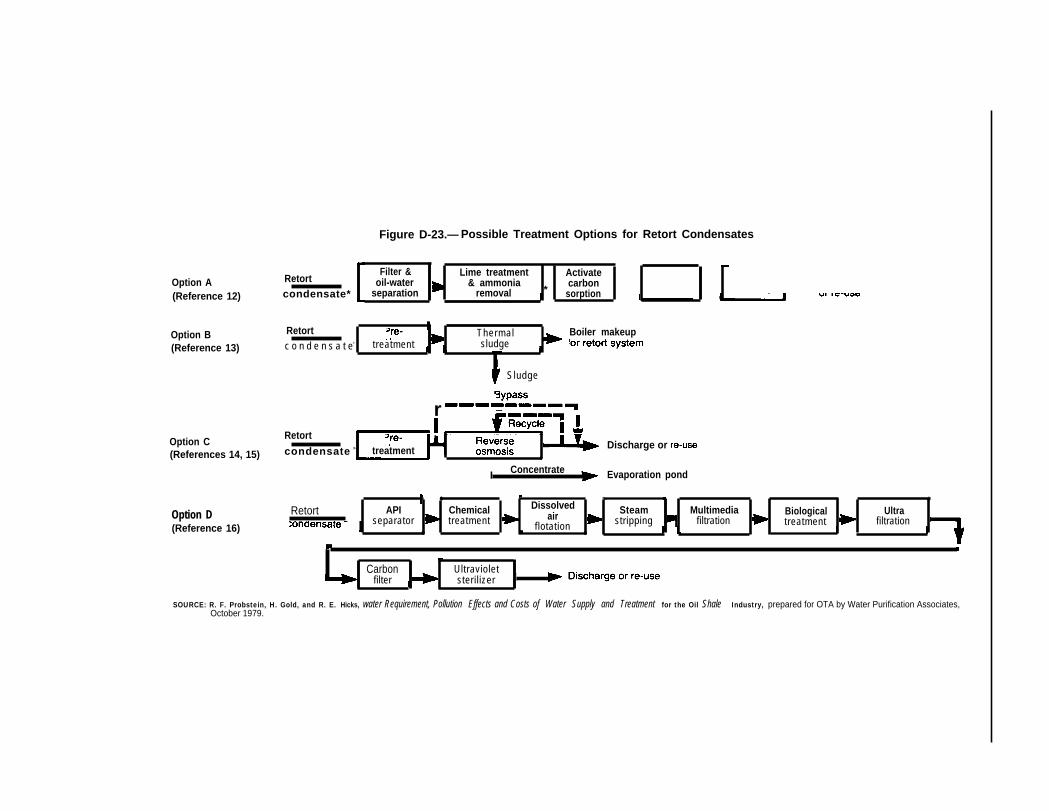
Figure D-23.— Possible Treatment Options for Retort Condensates
Option A(Reference 12)
Option B(Reference 13)
Retortcondensate*
Filter & Lime treatment Activateoil-water & ammonia
*carbon
separation removal sorption
Retort Thermalc o n d e n s a t e> treatment sludge
1
Boiler makeup
Sludge
rOption C
RetortDischarge or re-use
(References 14, 15) condensate > treatment●
I Concentrate Evaporation pond
Option D(Reference 16)
● ✎ ☛ ✌
Retort API Chemical Dissolved Steamair Multimedia Biological Ultraseparator treatment flotation stripping filtration treatment filtration
● ●
Carbon Ultravioletfilter sterilizer I
SOURCE: R. F. Probstein, H. Gold, and R. E. Hicks, water Requirement, Pollution Effects and Costs of Water Supply and Treatment for the Oil Shale Industry, prepared for OTA by Water Purification Associates,October 1979.

Appendix D–Technologies for Managing Point Sources of Wastewater • 507
taken from any intermediate stage of the treat-ment system to provide water for various reuseoptions.
Retort Condensate
The retort condensate stream presents themost formidable treatment challenge. As dis-cussed in chapter 8, this stream is created whenwater and oil vapors condense within in situretorts, and some aboveground retorts if they areoperated at a low top temperature. The conden-sate will be contaminated with oil, dissolvedgases, inorganic salts, and organic substances, allof which will have to be removed.
In the conventional treatment scheme of optionA in figure D-23, oil and suspended solids are firstseparated from the water. Oil-water separationby API units may not be adequate because ofemulsions, and some emulsion-breaking techniquewill probably be required. The techniques thatwould be appropriate for oil shale wastewatershave not yet been determined.
The addition of lime will facilitate NH3 removaland will also remove calcium, magnesium, andcarbonate ions. NH3 is easily removed by steamstripping, but unlike the gas condensate, the re-tort condensate contains strong acid anions thatwill “fix” the NH3 as ammonium ions, which can-not be directly stripped. Lime addition will ele-vate the pH and convert ammonium to NH3.
23 T h epH elevation is also needed to prevent scaling andfouling of the steam stripping column by carbon-ate precipitates.
Removal of organic substances from retort con-densates has not been adequately demonstrated.Activated carbon adsorption (option A in figureD-23) would remove only about half of the organ-ics and would be expensive, given the high organ-ic concentrations found in retort condensates.24 2 5Biological treatment (option D) has been sug-gested for control of organics, but complete re-moval by biological processing may not be achiev-able. The two major problems with biologicaltreatment are the presence of resistant (biore-fractory) and toxic materials. It is expected thatas much as half of the organic matter in retortwater will be biorefractory and that adequate re-moval may not be possible even with novel proc-ess modifications such as the addition of pow-dered activated carbon to the biological unit. Lab-oratory tests have shown that the addition of pow-dered activated carbon to the aeration basin in anair-activated sludge biological system improves
organics removal by only about 10 percent, indi-cating that much of the biorefractory organicmatter is not adsorbed on carbon. Polymeric res-ins have been shown to facilitate removal of or-ganics f rom retor t condensates ,26 but it is notknown whether the ones removed are those thatare resistant to biological and activated carbontreatment.
The inhibition of biological action by toxic sub-stances is also expected to be a problem, The tox-ics may be either organic or inorganic, and can beexpected to be different in the condensates fromdifferent retorts. Their characteristics and con-centrations may even change with time if retort-ing conditions are not constant—a normal situ-ation in MIS processes. Even with all of its poten-tial disadvantages, biological oxidation couldprove more economical and more effective thanother processes (such as wet air oxidation) whencombined with appropriate pretreatment and pol-ishing steps.
Wet air oxidation removes a much wider varie-ty of organics but it is also more expensive. In thisprocess, organic material in water is oxidized byair at about 500° F (260° C). The water is pressur-ized to prevent boiling. The reaction takes about30 minutes and a pressure vessel is required thatis large enough to contain the water for thislength of time. The cost of wet oxidation is notstrongly dependent on the concentration of thewaste, and unlike biological treatment it can becost effective for very concentrated wastes. Wetair oxidation also has several technical advan-tages, Because it relies on chemical oxidation, theorganic material that is to be destroyed does nothave to be biodegradable. In fact, biorefractorymaterials are often converted to biodegradablesubstances, and a biological process could be ef-fectively used as a polishing step. No data havebeen published on the performance of a wet airoxidation process with oil shale retort conden-sates, but an investigation has been initiated.27
Reverse osmosis membranes (option C in figureD-23) are also available for organics control,28 butrecent tests have shown that considerable pre-treatment will be required to provide a feed thatwill not plug or foul the membranes, 29 In fact, apretreatment system similar to the treatmenttrain of option A in figure D-23 may be requiredfor very dirty condensates. If this is done, then itis not clear that a final reverse osmosis step willbe required to provide an effluent suitable forsome of the low-quality reuse options. Neverthe-less, reverse osmosis is of interest because it alsoprovides a means for control for some of the inor-

508 ● An Assessment Oil Shale Technologies
ganic contaminants for which lime softening is notadequate. Ion exchange demineralization afterorganics removal is an alternative to reverseosmosis, but its costs escalate rapidly with in-creasing salt concentrations in the feed.
It is apparent that even if the retort condensateis to be treated to only the low-quality levels re-quired by some re-use options, an elaborate treat-ment system similar to that shown as option D infigure D-23 will be required. Even here additionaltreatment steps may be required. API separatorsmay not be adequate, and an ultrafiltration stepupstream of the steam stripper may be needed toremove emulsified oil and large organic mole-cules. As discussed above, biological oxidationand carbon adsorption will not adequately controlthe remaining organics, and resin adsorption orwet air oxidation steps may be required. An addi-tional processing step to remove inorganic mayalso be required for some re-use options.
In view of the difficulty in treating the retortcondensate (option B in figure D-23) in which thetreated water is used to raise steam for retortingis the most attractive. Volatilized organics will beincinerated in the retort, and other substancescan be removed in a concentrated sludge for dis-position at a hazardous-waste disposal site. Astripping pretreatment step may be needed toavoid accumulating NH 3 and CO2 in the thermalsludge device. No information has been publishedon the feasibility of a thermal-sludge steam rais-ing process fed with retort condensates. Scalingand fouling may be problems unless appropriatepretreatment steps are used.
Other Wastewater Streams
The two other major streams are the coker andhydrotreater condensates from the shale oil up-grading section. Compositions of these streamsare not known, but they should be somewhat simi-lar to the gas condensate. The exception is theconcentration of dissolved gas because, in theabsence of CO2, the NH3 will probably react withH 2S to form ammonium hydrogen sulfide. Differ-ent steam stripping conditions will be required inthat more stages or more steam will be needed toremove H2S. Modifications should not be extremebecause, unlike in the retort condensate, thereshould be no NH3-fixing inorganic anions present.The treatment systems can be expected to be simi-lar to any of the options shown in figure D-22.
Blowdown streams, regenerant streams, con-centrates, and sludge products from water treat-ment processes must also be handled. If a thermalsludge process is included in any water treatmenttrain, it could be used to reduce the reverseosmosis concentrates and ion exchange regener-ant streams to a disposable sludge. If not, vaporcompression evaporators may be used. Thesehave been successfully demonstrated on a com-mercial-scale at, for example, electric power gen-erating stations. Because cooling towers willprobably be operated with few cycles of concen-tration, blowdown streams should not have highsalt concentrations, and should be suitable fordust control and shale disposal operations.
Water Management Plans for Oil Shale FacilitiesComplete water management plans must con-
sider supply, treatment, waste recovery and re-moval, and ultimate disposition. Figures D-24through D-26 are flow sheets that show how wa-ter would be used, treated, and disposed of inthree typical oil shale facilities. The flows into,within, and out of the plants are indicated in gal-lons per minute.
Figure D-24 is a water management plan for anaboveground direct facility that uses Paraho re-torts. The major sources of water are the Colora-do River, contaminated runoff from the facilitysite and its associated disposal area, and gas con-densates from the retorting section. No upgradingfacilities are included, so there are no upgradingcondensates. The total water inflow is 2,357 gal/
rein, of which about 40 percent is lost to the at-mosphere through evaporation within the facility.The rest is eventually used for dust control and inthe solid waste disposal area for spent shalemoistening, compaction, and revegetation. Theprincipal components of this water are treatedriver water, sanitary wastes, blowdowns, runoff,service water, and condensates.
Figure 1)-25 is a plan for an aboveground in-direct plant that uses TOSCO II retorts. Becausethe retorts are indirectly heated, and because up-grading facilities are included, water require-ments are substantially higher than for the Par-aho plant. The total inflow is 7,386 gal/rein fromthe Colorado River, from surface runoff, and fromgas condensates and upgrading condensates.

Appendix D–Technologies for Managing Point Sources of Wastewater ● 509
Figure D-24.— Major Streams in a 50-000-bbl/d Aboveground Direct (Paraho) Oil Shale Plant (gal/rein)
Colorado River water
1883
(7)Domestic
watersystem/ ●
@
16
Biologicaltreatment
663 686Clarification
I
BFW ~ CWtreatment -
treatment
I17
(2)
Steamsystem
BD
Coolingtower
B D
BFW = Boiler Feed WaterCW = Cooling Water( ) = Lossess = SludgeTW = Treater WasteBD = BlowdownGC = Gas Condensate
Revegetation Dust Shalecontrol disposal
(25) 221 791Equalization
43water
system &Oil/water 156
separationb
Runoff and 138Ieachates
(29)
Retorting 336 307gas treatment GC Treatment
— \
SOURCE R F Probsteln, H Gold, and R E Hicks, Water Requlrerrrents, Po//ufIonEflects and Costs of Water SUPP/y and Treatrrrent for the 0// Shale /fldus-try, prepared for OTA by Water Purl flcatlon Associates, October 1979
About 40 percent of the water is lost throughevaporation. The rest is eventually used for dustcontrol, or finds its way to the spent shale pile.
Figure D-26 is a plan for an MIS facility that islocated in a ground water area, Excess minedrainage water is produced, and over 70 percentof it is reinfected. The rest is used in the plant,together with retort condensates, gas conden-sates, and surface runoff, The plant uses a ther-mal sludge system to process the retort conden-sate and to generate steam for injection into the in
situ retorts. The system produces no liquid efflu-ent. The total net inflow is about 5,059 gal/rein, ofwhich 34 percent is lost through evaporation and34 percent is converted to steam for the retorts.The rest is used to control dust and for disposal ofthe mined raw shale.
In summary, the aboveground direct plant willdispose of about 604 gal/min of treated waste-water and treated condensates in the spent shaledisposal pile. An additional 22 I gal/rein of treatedwastewater will be used for dust control. The

510 Ž An Assessment of 0il Shale Technoiogies
Figure D-25.—Major Streams in a 50,000-bbl/d Aboveground Indirect (TOSCO II) Oil Shale Plant (gal/rein)
Colorado River water
2177 2198 3937Clarification
watersystem
Biologicaltreatment
1
BFW ~treatment
(1191)
Steamsystem
2400
Cwtreatment
(1630)
Coolingtower
BD
Revegetation Dust Shalecontrol disposal
w
Retortinggas treatment
upgrading
G C
1072 ~ (53)
Stripping andN H3 recovery (6)
503 Organics 497
(20)removal.
/631
17water .
3 7 system Oil/water 134r separation
\Runoff and 117Ieachates
/ v
BFW = Boiler Feed WaterCW = Cooling Water( ) = LossesS = SludgeTW = Treater WasteBD = BlowdownGC = Gas CondensateRC = Retort Condensate
SOURCE: R. F. Probstein, H. Gold, and R. E. Hicks, Water Requ/refnenrs, Pollutlorr Eflecfs afl~ COS@ of water SUPPIY and Treatment for the 0// Shale hrdustry, preparedfor OTA by Water Purification Associates, October 1979.

Appendix D–Technologies for Managing Point Sources of Wastewater Ž 511
To reinfection
Figure D-26.— Major Streams in a 50,000-bbl/d MIS Oil Shale Plant (gal/rein)
Mine drainage water
7656
treatment
924
14
Biologicaltreatment
14
380
(13)
m
6539 ‘ ‘ 737A A ClarificationY
(5)
treatment treatment
Coolingtower
Steamsystem
882
wL
Revegtation Dust Shalecontrol disposal
(26)Equalization
-42
watersystem \
Oil/water 141separation
\Runoff and 125
4(68)
\
( ) = Lossess = Sludge
SOURCE: R.F. Probstein, H Gold, and R E Hicks, Water Requirements, Pollution Effects and Costs of Water Supply and Treatment for the Oil Shale Industry, preparedfor OTA by Water Purification Associates, October 1979

512 Ž An Assessment of Oil Shale Technologies
aboveground indirect plant will add about 1,827gal/rein of treated wastewater and concentratesto the disposal pile. The MIS plant will use about686 gal/rein of treated wastewater for raw shaledisposal and 210 gal/rein for dust control Anadditional 5,554 gal/rein of treated mine drainage
water will be reinfected into the source aquifer.Thus, the methods for wastewater managementand disposal are recycling after treatment, fol-lowed by disposal through evaporation, in dustcontrol, and in solid waste disposal areas. Excesstreated mine drainage water will be reinfected.
Appendix D References1H, P. Harbart and W. A. Berg, Vegetative Stabiliza-
tion of Spent Oil Shales, EPA-600/7-78-021, IndustrialEnvironmental Research Laboratory, EnvironmentalProtection Agency, Cincinnati, Ohio, February 1978.
21bid.‘T. R. Garland and R. E. Wildung, “Influence of Irri-
gation and Weathering Reactions on the Composition ofPercolates from Retorted Oil Shale in Field Lysim-eters, ” Proceeding of the Twei~th Oil Shale Symposium(J, H. Gary, cd.), Colorado School of Mines, Golden,Colo., August 1979.
4Rio Blanco Oil Shale Project, Revised Detailed DeveLopment Plan; Tract C-a, submitted to Area Oil Shale Su-pervisor, U.S. Geological Survey, Department of the In-terior, May 1977.
‘E. F. Bates and T, L. Thoem (eds.), PoJJution ControlGuidance for Oil Shale Development, revised draft re-port, Environmental Protection Agency, Cincinnati,Ohio, July 1979.
‘B. W. Mercer, et al., “Assessment of Control Tech-nology for Shale Oil Wastewaters, ” paper presented atEnvironmental Control Technology Symposium, Depart-ment of Energy, November 1978.
7N. de Nevers, et al., Analysis of the EnvironmentalControl Technology for Oil Shale Development, Depart-ment of Energy, report No. COO/4043-1, February 1978.
‘Supra No. 4.‘Denver Research Institute, Predicted Costs of Envi-
ronmental Controls for A Oil Shale Industry: VoJume 1—An Engineering Analysis, prepared for the Departmentof Energy under contract No. EP-78-S-O2-51O7, July1979,
‘OIbid.“G. W . Dawson a n d B . W , Mercer, “Analysis,
Screening and Evaluation of Control Technology forWastewater Generated in Shale Oil Development, ”Quarterly Reports, Battelle Pacific Northwest Labora-tory, Richmond, Wash,, January 1977-March 1979.
12A. B. Hubbard, “Method for Reclaiming Waste-water From Oil Shale Processing, ” American ChemicalSociety, Division of Fuel Chemistry Reprints, vol. 15, No.1, March-April 1971, pp. 21-25.
13 Supra No. 9.14A. E. Fry and R. S. Martin, Assessment Of pOllLItiOIl
Control Costs for Emerging Energy Supply Technologies—Subtask 11—Modified In Situ Oil Shale Retorting, De-
partment of Energy, final report, contract No. EE-77-C-02-4534, NOV. 20, 1978.
15A. Brown, et al., Water Management in Oil ShaleMining: Volume 1, NTIS report No. PB-276085, GolderAssociates, Inc., Seattle, Wash., September 1977.
“Supra No. 5.‘7 Supra No, 6.“R. E. Hicks and R. F. Probstein, “Water Manage-
ment in Surface and In Situ Oil Shale Processing, ”paper presented at AIChE 87th National Meeting,Boston, Mass,, Aug. 19-22, 1979.
‘gWater Purification Associates, A Study of ReverseOsmosis for Treating Oil Shale Process Condensatesand Excess Mine Drainage Water, quarterly progressreport, prepared for Laramie Energy TechnologyCenter, Department of Energy, contract No. DE-AC20-79LC1OO89, September 1979,
ZOA, L. Hines, The Role of S p e n t Shale in Oi] SMeProcessing and the Management of Environmental R e s i -dues, Department of Energy, report No. TID-28586,ERDA-Laramie Energy Research Center, Laramie,Wyo., Apr. 1, 1978.
‘lSupra No, 19.“D. J. Goldstein, 1, W. Wei, and R. E. Hicks, “Reuse of
Municipal Wastewater as Makeup to Circulating Cool-ing Systems, ” presented at Water Reuse Symposium,American Water Works Association, Research Foun-dation, Washington, D. C., Mar. 25-30, 1979, pp.371-397. Also: Industrial Water Engineering, vol. 16,No. 4, July 1979, pp. 20-29.
23Water Purification Associates, A Study of AerobicOxidation and AJlied Treatments for Upgrading In SituRetort Waters, contract No, EW-78-C-20-0018 withLaramie Energy Technology Center, Department ofEnergy, quarterly status report, August 1979.
24 Supra No. 19.25B. Harding, et al., “Study Evaluates Treatments for
Oil-Shale Retort Water, ” Industrial Wastes, Septem-ber/October 1978, pp. 28-33.
2bIbid.Z7D. Vernados, I&earch and Development Depart-
ment, Amoco Oil Co., Naperville, Ill., personal com-munication, August 1979.
26 Supra No, 15.2gSupra No. 19.