appendix iii code of practice for earthing of power supply installations for 25kv.pdf
DESCRIPTION
APPENDIX III CODE OF PRACTICE FOR EARTHING OF POWER SUPPLY INSTALLATIONS FOR 25kV.pdfTRANSCRIPT

APPENDIX III
CODE OF PRACTICE
FOR EARTHING OF POWER SUPPLY INSTALLATIONS FOR 25kV, ac, 50Hz, SINGLE PHASETRACTION SYSTEM
(This is a reproduction of RDSO's CODE No. ET1/PSI/120 (2/91) )
1. Scope
1.1 This code of practice caters for general arrangements of system and equipment earthing at 220/ 25
kV or 132/25 kV or 110/25 kV or 66/25 kV traction substations, 25 kV switching stations, boostertransformer stations and auxiliary transformer stations. Low voltage (LT) electrical power distributionsystem, 25 kV overhead equipment system as well as signal and tele-communication equipment do not
come within the purview of this code.
2. Terminology
2.0 The following terms wherever occurring in this code shall, unless excluded or repugnant to thecontext, have the meaning attributed thereto as follows:-
2.1 Combined Earth Resistance : The resistance of an earth electrode (s) with respect to earth, with the
earth electrode (s) connected to the metal work of electrical equipment other than parts which arenormally live or carry current and the masts/structures but without connection with the traction rail(s).
2.2 Earth: The conductive mass of the earth, whose electrical potential at any point is conventionally
taken as zero.
2.3 Earth electrode: A conductor mild steel (MS) pipe, or group of conductors in intimate contact withand providing an electrical connection to earth.
2.4 Earthing grid: A system of a number of interconnected, horizontal bare conductors buried in the
earth, providing a common ground for electrical devices and metallic structures, usually in one specificlocation.
2.5 Equipment earthing: Earthing of all metal work of electrical equipment other than parts which arenormally live or current carrying. This is done to ensure effective operation of the protective gear in
the event of leakage through such metal work, the potential of which with respect to neighbouringobjects may attain a value which would cause danger to life or risk of fire.
2.6 Mesh Voltage (E mesh): The maximum touch voltage to be found within a mesh of an earthing grid.
2.7 Power supply installation: The electrical equipments and associated structures provided at aRailway Traction Substation or Switching Station, or Booster/ Auxiliary transformer Station on the 25
kV over head equipment.
2.8 System earthing: Earthing done to limit the potential of live conductors with respect to earth to
values which the insulation of the system is designed to withstand and thus to ensure the security of
the system.
2.9 Step Voltage (E step): The potential difference between two points on the earth's surface separatedby a distance of one pace, that will be assumed to be one metre in the direction of maximum potential
gradient.
2.10 Traction Rail means a non track circuited rail of a wired track, not required for signalling purposes
and which may be earthed. In non-track circuited sections, both the rails of a wired track are tractionrails and in single rail circuited section, the traction rail is the non-track circuited rail.
2.11 Touch Voltage (E touch): The potential difference between a grounded metallic structure and a
APPENDIX III CODE OF PRACTICE FOR EARTHING OF POWER... http://www.indianrailways.gov.in/railwayboard/uploads/codesmanual...
1 of 15 4/15/2015 1:53 PM

point on the earth's surface separated by a distance equal to the normal maximum horizontal reach of
a person, approximately one metre.
3. Object of Earthing
The object of an earthing system is to provide as nearly as possible a surface under and around astation which shall be at a uniform potential and as nearly zero or absolute earth potential as possible.
The purpose is to ensure that generally all parts of the equipment, other than live parts are at earthpotential and that attending personnel are at earth potential at all times. Also by providing such an
earth surface of uniform potential under and surrounding the station, there can exist no difference ofpotential in a short distance big enough to shock or injure an attendant when short circuits or otherabnormal occurrences take place. The primary requirements of a good earthing system are:
i) It should stabilize circuit potentials with respect to ground and limit the overall potential rise.
ii) It should protect men and materials from injury or damage due to over voltage.
iii) It should provide low impedance path to fault current to ensure prompt and consistent operation of
protective devices during ground faults.
iv) It should keep the maximum voltage gradient along the surface inside and around the substationwithin safe limits during earth faults.
4. Governing Specifications
Assistance has been taken from the following standards/ codes of practices in the preparation of thiscode of practice:
i) IS:3043-1987 - Code of Practice for Earthing (first revision)
ii) Indian Electricity Rules - 1956 (latest edition)
iii) National Electrical Code - 1985 of Bureau of Indian Standards
iv) IEEE Guide for safety in a. c. substation grounding. No. ANSI/IEEE Standard 80-1986.
5. Earth Resistance
At each power supply installation, an earthing system as specified in this code shall be provided. Thecombined resistance of the earthing system shall be not more than the following values: -
S.
No. Name of the station
The limit of combined
earth resistance in ohms
1. Traction substation 0.5
2. Switching station 2.0
3. Booster transformer station 10.0
4. Auxiliary transformer station 10.0
6. Earth Electrodes
6.1 The earth electrode shall normally be of mild steel galvanised perforated pipe of not less than 40mm nominal bore, of about 4 m length provided with a spike at one end and welded lug suitable for
taking directly MS flat of required size at the other end. The pipe shall be embedded as far as possiblevertically into the ground, except when hard rock is encountered, where it may be burled inclined to
the vertical, the inclination being limited to 30 degree from the vertical. The connection of MS flat toeach electrode shall be made through MS links by bolted joints to enable isolation of the electrode for
testing purposes. A sketch for typical arrangement of an earth electrode is shown in Figure 3.01.
6.2 Earth electrodes shall be embedded as far apart as possible from each other. Mutual separationbetween them shall usually be not less than 6.0 m ( which is twice the length of the electrode).
APPENDIX III CODE OF PRACTICE FOR EARTHING OF POWER... http://www.indianrailways.gov.in/railwayboard/uploads/codesmanual...
2 of 15 4/15/2015 1:53 PM
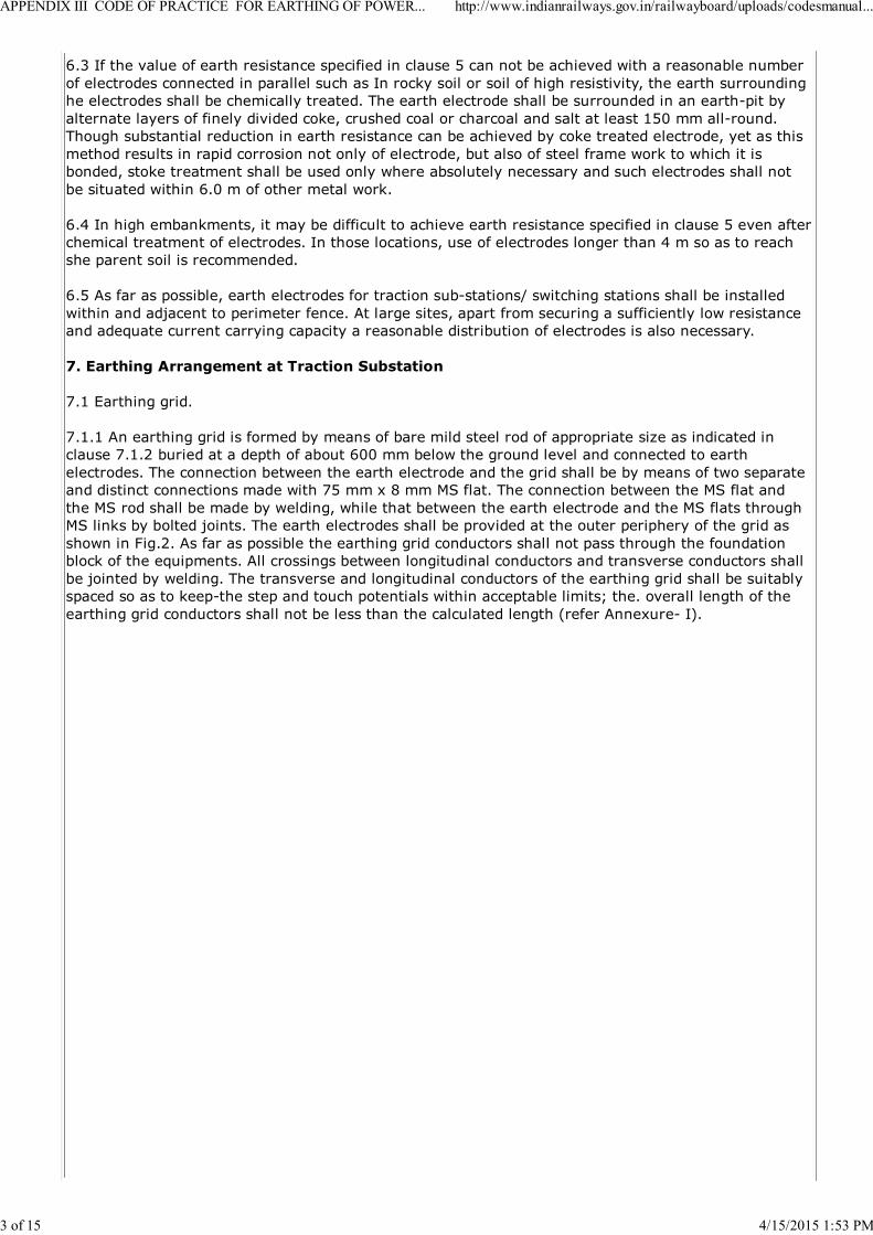
6.3 If the value of earth resistance specified in clause 5 can not be achieved with a reasonable number
of electrodes connected in parallel such as In rocky soil or soil of high resistivity, the earth surroundinghe electrodes shall be chemically treated. The earth electrode shall be surrounded in an earth-pit by
alternate layers of finely divided coke, crushed coal or charcoal and salt at least 150 mm all-round.Though substantial reduction in earth resistance can be achieved by coke treated electrode, yet as this
method results in rapid corrosion not only of electrode, but also of steel frame work to which it isbonded, stoke treatment shall be used only where absolutely necessary and such electrodes shall not
be situated within 6.0 m of other metal work.
6.4 In high embankments, it may be difficult to achieve earth resistance specified in clause 5 even afterchemical treatment of electrodes. In those locations, use of electrodes longer than 4 m so as to reachshe parent soil is recommended.
6.5 As far as possible, earth electrodes for traction sub-stations/ switching stations shall be installed
within and adjacent to perimeter fence. At large sites, apart from securing a sufficiently low resistanceand adequate current carrying capacity a reasonable distribution of electrodes is also necessary.
7. Earthing Arrangement at Traction Substation
7.1 Earthing grid.
7.1.1 An earthing grid is formed by means of bare mild steel rod of appropriate size as indicated inclause 7.1.2 buried at a depth of about 600 mm below the ground level and connected to earth
electrodes. The connection between the earth electrode and the grid shall be by means of two separateand distinct connections made with 75 mm x 8 mm MS flat. The connection between the MS flat and
the MS rod shall be made by welding, while that between the earth electrode and the MS flats throughMS links by bolted joints. The earth electrodes shall be provided at the outer periphery of the grid as
shown in Fig.2. As far as possible the earthing grid conductors shall not pass through the foundationblock of the equipments. All crossings between longitudinal conductors and transverse conductors shall
be jointed by welding. The transverse and longitudinal conductors of the earthing grid shall be suitablyspaced so as to keep-the step and touch potentials within acceptable limits; the. overall length of the
earthing grid conductors shall not be less than the calculated length (refer Annexure- I).
APPENDIX III CODE OF PRACTICE FOR EARTHING OF POWER... http://www.indianrailways.gov.in/railwayboard/uploads/codesmanual...
3 of 15 4/15/2015 1:53 PM

FIG. A 3.01
7.1.2 The size of the earthing grid conductor shall be decided based on the incoming system voltageand fault level (refer Annexure I). The fault level considered shall take into: account the anticipated
increase in fault current during the life span of the station. The size shall be as given below:
S.NoSystem voltage
(kV)Fault level (MVA)
Diameter of the gridconductor (MS rod) in
mm
1. 66
upto 4000 32
above 4000 upto 5000 36
above 5000 upto 6000 40
2. 110
upto 6000 32
above 6000 upto 8000 36
above 8000 upto 10000 40
3. 132upto 7000 32
above 7000 upto 10000 36
4. 220
upto 12000 32
above 12000 upto 16000 36
above 16000 upto 20000 40
APPENDIX III CODE OF PRACTICE FOR EARTHING OF POWER... http://www.indianrailways.gov.in/railwayboard/uploads/codesmanual...
4 of 15 4/15/2015 1:53 PM
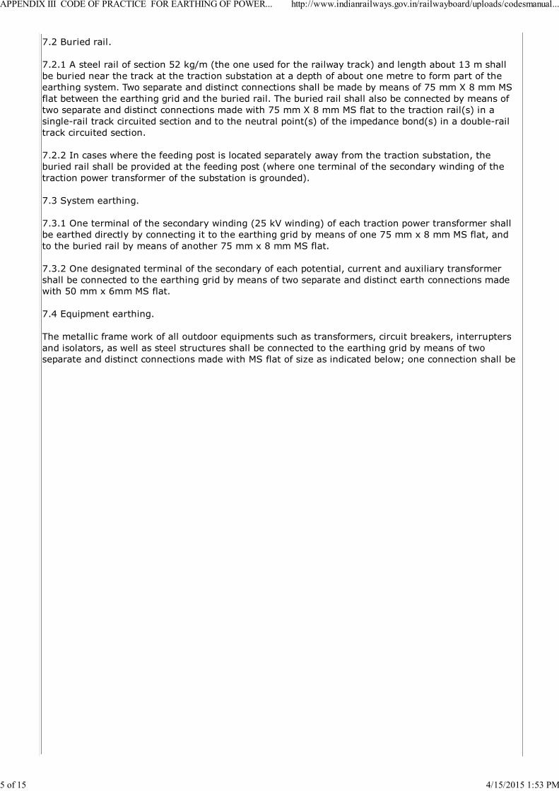
7.2 Buried rail.
7.2.1 A steel rail of section 52 kg/m (the one used for the railway track) and length about 13 m shall
be buried near the track at the traction substation at a depth of about one metre to form part of theearthing system. Two separate and distinct connections shall be made by means of 75 mm X 8 mm MS
flat between the earthing grid and the buried rail. The buried rail shall also be connected by means oftwo separate and distinct connections made with 75 mm X 8 mm MS flat to the traction rail(s) in a
single-rail track circuited section and to the neutral point(s) of the impedance bond(s) in a double-railtrack circuited section.
7.2.2 In cases where the feeding post is located separately away from the traction substation, theburied rail shall be provided at the feeding post (where one terminal of the secondary winding of the
traction power transformer of the substation is grounded).
7.3 System earthing.
7.3.1 One terminal of the secondary winding (25 kV winding) of each traction power transformer shallbe earthed directly by connecting it to the earthing grid by means of one 75 mm x 8 mm MS flat, and
to the buried rail by means of another 75 mm x 8 mm MS flat.
7.3.2 One designated terminal of the secondary of each potential, current and auxiliary transformershall be connected to the earthing grid by means of two separate and distinct earth connections madewith 50 mm x 6mm MS flat.
7.4 Equipment earthing.
The metallic frame work of all outdoor equipments such as transformers, circuit breakers, interrupters
and isolators, as well as steel structures shall be connected to the earthing grid by means of twoseparate and distinct connections made with MS flat of size as indicated below; one connection shall be
APPENDIX III CODE OF PRACTICE FOR EARTHING OF POWER... http://www.indianrailways.gov.in/railwayboard/uploads/codesmanual...
5 of 15 4/15/2015 1:53 PM
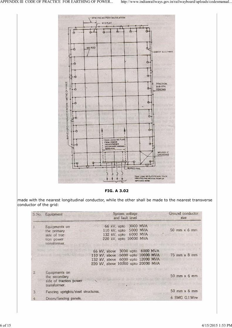
FIG. A 3.02
made with the nearest longitudinal conductor, while the other shall be made to the nearest transverse
conductor of the grid:
APPENDIX III CODE OF PRACTICE FOR EARTHING OF POWER... http://www.indianrailways.gov.in/railwayboard/uploads/codesmanual...
6 of 15 4/15/2015 1:53 PM
7.5 Earthing inside control room.
An earthing ring shall be provided inside the control room by means of 50 mm x 6 mm MS flat whichshall be run along the wall on teak wood blocks fixed to the wall at a height of about 300 mm from the
floor level. The earthing ring shall be connected to the main earthing grid by means of two separateand distinct connections made with 50 mm x 6 mm MS flat. The earthing ring shall also be connected to
an independent earth electrode by means of two separate and distinct connections made with 50 mm x6 mm MS flat. The metallic framework of control and relay panels, LT a.c. and d.c. distribution boards,
battery chargers, remote control equipment cabinets and such other equipments shall be connected tothe earthing ring by means of two separate and distinct connections made with 8 SWG galvanised steelwire. The connections shall be taken along the wall and in recesses in the floor. All recesses shall be
covered with cement plaster after finishing the work. Connections between the MS flats shall be madeby welding.
7.6 Earthing of lightning arrester.
In addition to the earth electrodes provided for the main earthing grid, an independent earth electrode
shall be provided for each lightning arrester. This earth electrode shall be connected to the groundterminal of the lightning arrester as well as to the main earthing grid by means of two separate and
distinct connections made with 50 mm x 6 mm MS flat for the 25 kV side lightning arresters, and with75 mm x 8 mm MS flat for the primary side lightning arresters. The earth electrode shall be providedas close as possible to the lightning arrester and the connections shall be as short and straight as
possible avoiding unnecessary bends. For lightning arresters provided for the traction powertransformers, there shall also be a connection as direct as possible from the ground terminal of the
lightning arrester to the frame of the transformer being protected; this connection shall also be madeby means of two separate and distinct connections made with 50 mm x 6 mm MS flat for 25 kV side
arresters, and with 75 mm x 8 mm MS flat for primary side lightning arrester.
7.7 Earth screen
The area covered by outdoor substation equipments shall be shielded against direct strokes of lightningby an overhead earth screen comprising 19/2.5 mm galvanised steel stranded wire strung across thepinnacles of the metallic structures. The earth screen wires shall be strung at a height as indicated in
the approved traction substation layouts (not less than 2.5 m above the live conductors) and shall besolidly connected to the traction substation earthing grid at each termination by means of 50 mm x 6
mm MS flat.
7. 8 Earthing of fencing uprights and panels.
Each metallic fencing upright shall be connected to the traction substation main earthing grid by meansof two separate and distinct connections made with 50 mm x 6 mm MS flat. In addition, all the metallicfencing panels shall be connected to the uprights by means of two separate and distinct connections
made with 6 SWG G.I. wire. All the metallic door panels shall also be connected to the supportinguprights by means of two separate and distinct connections made with 6 SWG G.I.wire.
7.9 Earthing at the point of 240 V ac 50 Hz supply for oil filtration plant.
The 240 V ac 50 Hz distribution board for power supply to oil filtration plant shall be connected to the
main earthing grid by means of two separate and distinct connections made with 50 mm x 6 mm MSflat.
8. Earthing Arrangement at Switching Station
8.1 A minimum number of three earth electrodes (excluding the one to be provided separately for theremote control cubicle earthing- refer clause 8.4) shall be provided at each switching station, and they
shall be interconnected by means of 50 mm x 6 mm MS flat forming a closed loop main earthing ring.This ring shall be connected by two separate and distinct connections made with 50 mm x 6 mm MS
flat, to the traction rail in a single-rail track circuited section and to the neutral point of the impedancebond in a double-rail track circuited section of the nearest track, so as to limit the potential gradient
developing in the vicinity of the switching station in the event of a fault.
8.2 System earthing.
APPENDIX III CODE OF PRACTICE FOR EARTHING OF POWER... http://www.indianrailways.gov.in/railwayboard/uploads/codesmanual...
7 of 15 4/15/2015 1:53 PM

One designated terminal of the secondary of each potential, current and auxiliary transformer shall beconnected to the main earthing ring by means of two separate and distinct connections made with 50
mm x 6mm MS flat.
8.3 Equipment earthing.
8.3.1 All masts, structures, fencing uprights, and all outdoor equipment pedestals including auxiliarytransformer tank shall be connected to the earthing ring by means of two separate and distinct
connections made with 50 mm x 6 mm MS flat. All fencing panels shall be connected to the supportinguprights by means of two separate and distinct connections made with 6 SWG G.I. wire All the metallicdoor panels shall be connected to the supporting uprights by means of two separate and distinct
connections made with 6 SWG G.I. wire.
8.3.2 The metal casing of potential and current transformers shall be connected to the mast/ structuresby means of two separate and distinct connections made with 50 mm x 6 mm MS flat.
8.3.3 The ground terminal of lightning arrester shall be connected directly to the earth electrode by
means of two separate and distinct connections made with 50 mm x 6 mm MS flat The earth electrodeshall be so placed that the earthing leads from the lightning arrester may be brought to the earth
electrode by as short and straight a path as possible.
8.4 Earthing inside remote control cubicle.
An earthing ring shall be provided inside the remote control cubicle by means of 50 mm x 6 mm MS flat
the earthing ring shall be run along the wall on teak wood blocks fixed to the wall at a height of 300mm from the floor level. The earthing ring shall be connected to the main earthing ring as well as to an
independent earth electrode by means of two separate and distinct connections made with 50 mm x 6mm MS flat. The metal casing of LT a.c. and d.c. distribution board, battery chargers, terminal board,
remote control equipment cabinets and other such equipments shall be connected to the earthing ringby means of two separate and distinct connections made with 8 SWG G.I. wire. The connections shall
be taken along the wall and in recesses in the floor. All recesses shall be covered with cement plasterafter finishing the work. Connections of earth strips to each other shall be made by welding.
9. Earthing of Neutral of Local Power Supply System
At traction substations and switching stations where power supply at 415 V/ 240 V, ac, 50 Hz, is takenfrom the local supply authority and having neutral earth at some distant point in the premises of the
supply authority, the neutral of such supply shall also be earthed by means of two separate and distinctconnections made with 6 SWG G.I. wire by connecting to an independent earth electrode.
10. Earthing Arrangement at Booster Transformer Station
10.1 The combined earth resistancef at a booster transformer station shall be not more than 10 Ohm.Normally one earth electrode shall be sufficient for a booster transformer station. The earth electrode
shall be connected to the lower end of each mast of the supporting gantry by means of two separateand distinct connections made with 50 mm x 6 mm MS flat. In addition each mast of the supporting
gantry shall be connected by means of a 50 mm x 6 mm MS flat to the nearest tractional rail or to theneutral point of the nearest impedance bond in a double rail track circuited section.
10.2 The booster transformer tank shall be connected to the masts of the supporting gantry by means
of two separate and distinct connections made with 50 mm x 6 mm MS flat. These connections shall beas short and as straight as possible without unnecessary bends.
11. Earthing Arrangement at Auxiliary Transformer Station
11.1 The combined earth resistance at an auxiliary transformer station shall be not more than 10 ohm.Normally one earth electrode is sufficient for an auxiliary transformer station. The earth electrode shall
be connected to the mast on which the auxiliary transformer is mounted by means of two separate anddistinct connections made with 50 mm x 6 ram MS flat. In addition the mast shall be connected to the
nearest traction rail or to the neutral point of the nearest impedance bond in a double rail trackcircuited section by means of a 50 mm x 6 mm MS flat.
APPENDIX III CODE OF PRACTICE FOR EARTHING OF POWER... http://www.indianrailways.gov.in/railwayboard/uploads/codesmanual...
8 of 15 4/15/2015 1:53 PM

11.2 The earthing terminal on the transformer tank shall be connected to the mast on which the
transformer is mounted by means of two separate and distinct connections made with 50 mm x 6 mmMS flat One terminal of the secondary winding of the auxiliary transformer shall be connected to the
earthing terminal on the transformer tank and as well as to the mast by means of 50 mm x 6 mm MSflat These connections shall be as short and straight as possible and avoiding unnecessary bends.
12. Method of jointing
All the joints between the MS flats, MS rods or between MS flat and MS rod shall be made by welding
only No soldering shall be permitted. For protection against corrosion, all the welded joints shall betreated with red lead and afterwards thickly coated with bitumen compound.
13. Painting of MS Flats
For protection against corrosion, all the exposed surfaces of earthing connections (MS flats) aboveground level shall be given all around two coats of painting to colour grass green, shade-218 of IS:5.
14. Crushed Rock Surface Layer
At the traction substations and switching stations, a surface layer of crushed rock shall be provided to a
thickness of about 100 mm. If considered necessary from the point of view of containing the step andtouch voltages within the acceptable limits, higher thicknesses may be provided depending oncalculation based on site conditions.
15. Step and Touch Voltages
15.1 The formulae for calculating the tolerable touch and step voltages, estimated mesh and step
voltages, earth resistance, earth potential rise, size of earthing grid conductor and length of buried gridconductor are given in Annexure-I.
15.2 The design for earthing grid shall be done separately for each location depending on the
conditions obtaining and those foreseen.
16. Drawings
The following drawings (latest versions) issued by RDSO in connection with this code may be used for
reference:
i) Typical earthing layout of traction substation. ET1/PSI/224-1
ii)Typical return current connection of buried rail at
traction substation.ETI/PSI/0212-1
iii)Typical earthing layout of subsectioning and
paralleling station.ET1/PSI/201-1
iv)Typical earthing layout of sectioning and paralleling
station.ETI/PSI/202-1
v)Typical earthing layout of booster transformerstation.
ETI/PS:/211-1
vi)Typical arrangement of an earth electrode at atraction substation.
ET1/PSI/222-1
vii)Typical earthing arrangement for an auxiliarytransformer station
ETI/PS1/708
ANNEXURE 1
FORMULAE FOR CALCULATION OF EARTHING GRID BASED ON IEEE
GUIDE FOR SAFETY IN AC SUBSTATION GROUNDING, No. ANSI/IEEEStd 80-1986
APPENDIX III CODE OF PRACTICE FOR EARTHING OF POWER... http://www.indianrailways.gov.in/railwayboard/uploads/codesmanual...
9 of 15 4/15/2015 1:53 PM
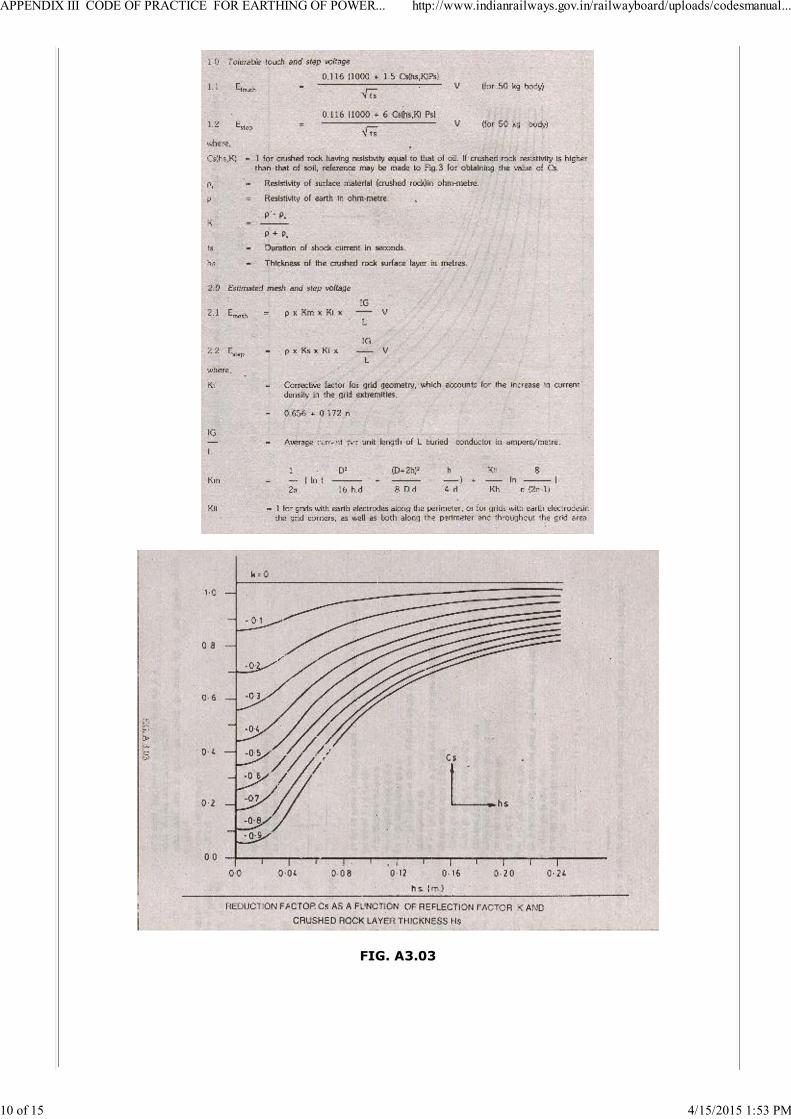
FIG. A3.03
APPENDIX III CODE OF PRACTICE FOR EARTHING OF POWER... http://www.indianrailways.gov.in/railwayboard/uploads/codesmanual...
10 of 15 4/15/2015 1:53 PM
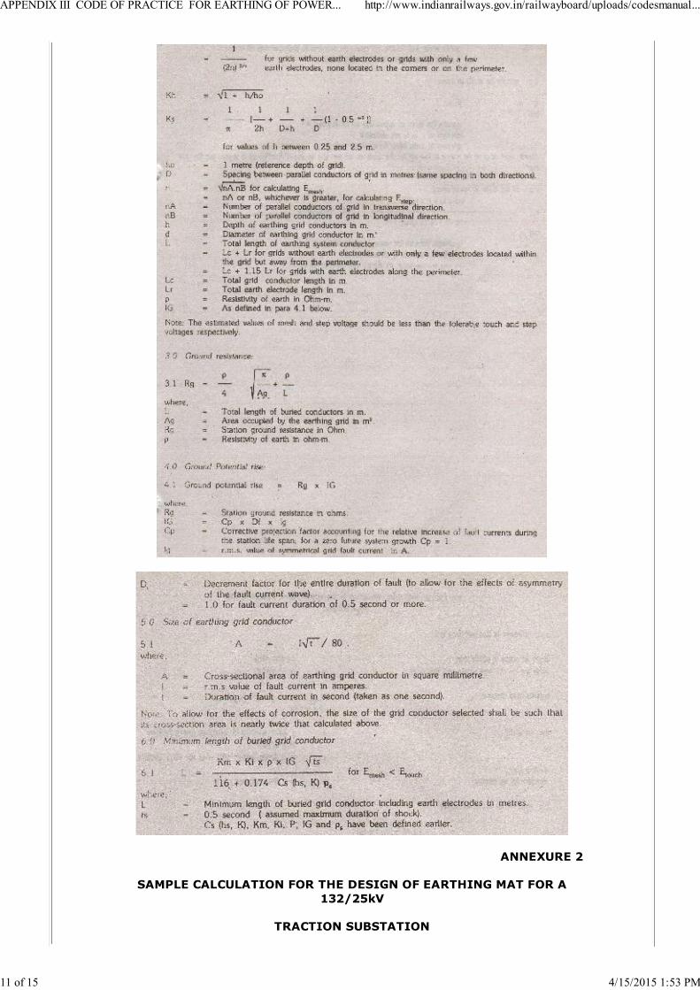
ANNEXURE 2
SAMPLE CALCULATION FOR THE DESIGN OF EARTHING MAT FOR A132/25kV
TRACTION SUBSTATION
APPENDIX III CODE OF PRACTICE FOR EARTHING OF POWER... http://www.indianrailways.gov.in/railwayboard/uploads/codesmanual...
11 of 15 4/15/2015 1:53 PM
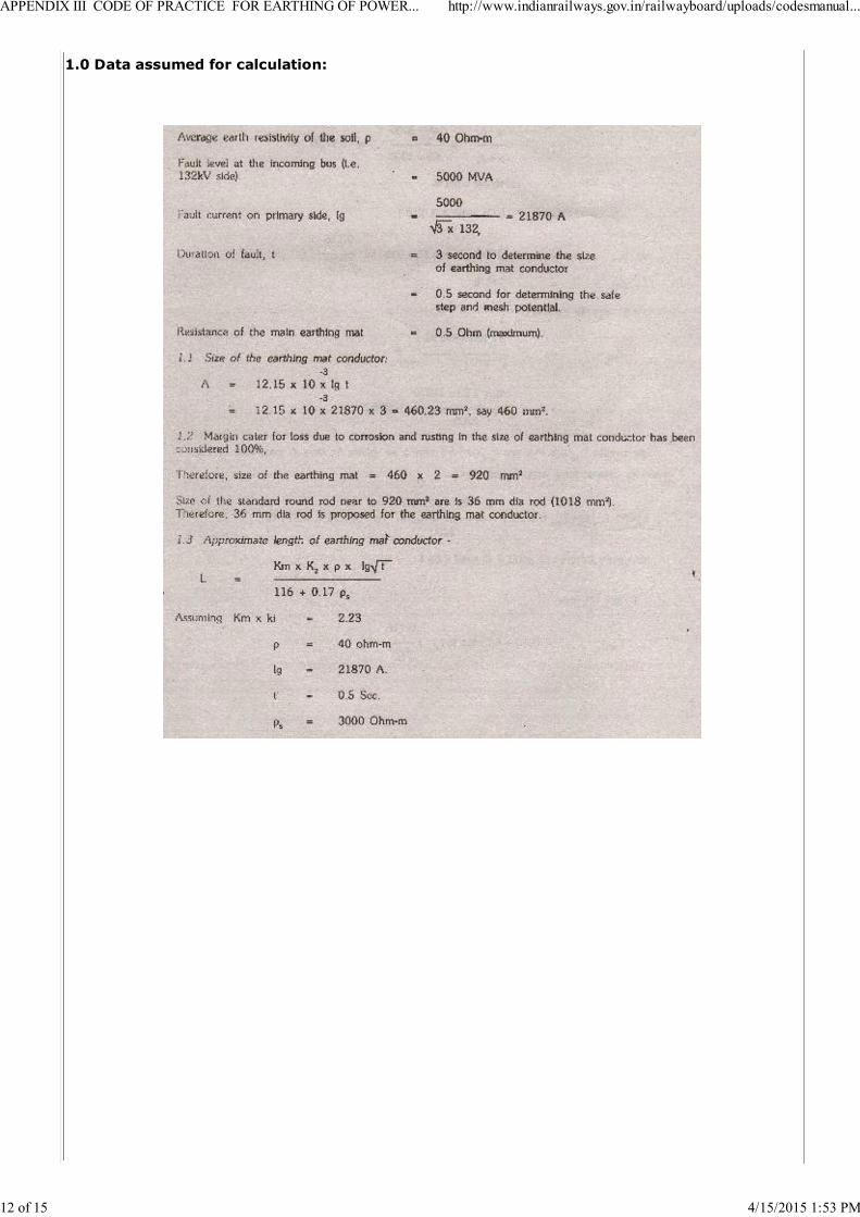
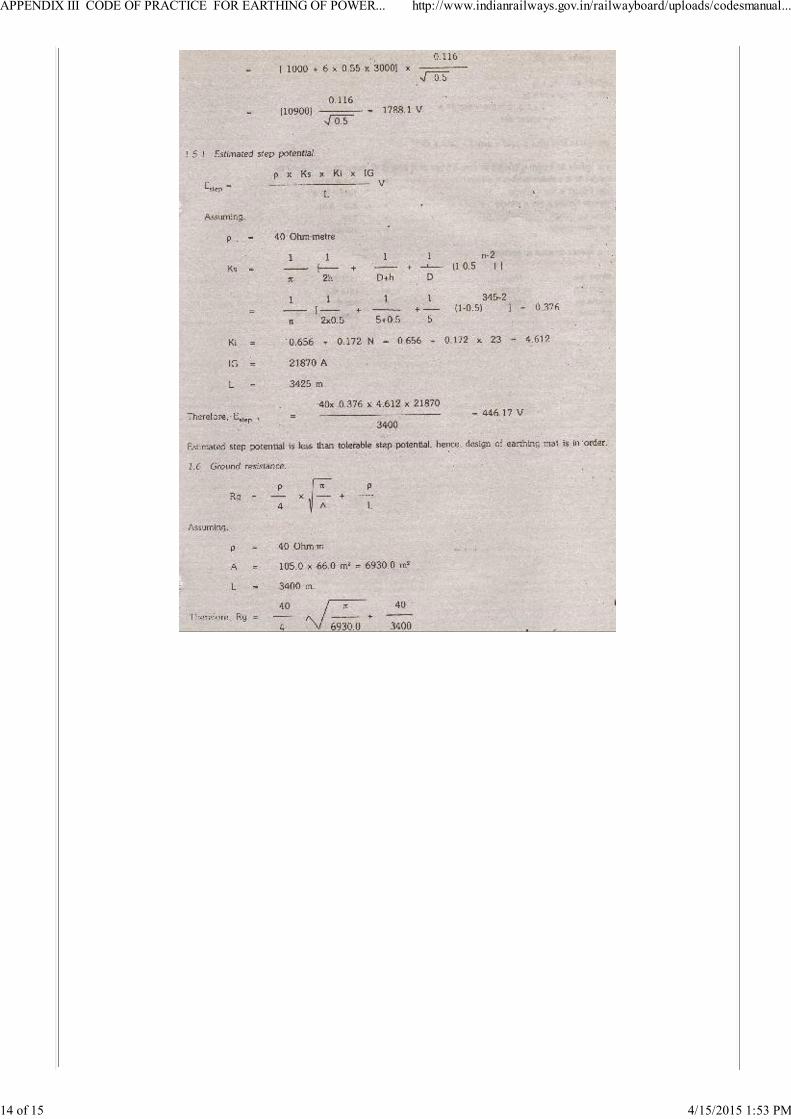
1.0 Data assumed for calculation:
APPENDIX III CODE OF PRACTICE FOR EARTHING OF POWER... http://www.indianrailways.gov.in/railwayboard/uploads/codesmanual...
12 of 15 4/15/2015 1:53 PM

APPENDIX III CODE OF PRACTICE FOR EARTHING OF POWER... http://www.indianrailways.gov.in/railwayboard/uploads/codesmanual...
13 of 15 4/15/2015 1:53 PM
APPENDIX III CODE OF PRACTICE FOR EARTHING OF POWER... http://www.indianrailways.gov.in/railwayboard/uploads/codesmanual...
14 of 15 4/15/2015 1:53 PM

APPENDIX III CODE OF PRACTICE FOR EARTHING OF POWER... http://www.indianrailways.gov.in/railwayboard/uploads/codesmanual...
15 of 15 4/15/2015 1:53 PM