appendix k.7 foundations report - robinson creek
TRANSCRIPT

Appendix K.7 – Foundations Report - Robinson Creek McCowan Road Environmental Assessment between Steeles Avenue and Major Mackenzie Drive

Preliminary Foundation Investigation and Design Report Robinson Creek Crossing McCowan Road, Class Environmental Assessment Study for Improvements to McCowan Road from Steeles Avenue to Major Mackenzie Drive, Markham, Ontario
Submitted to:
HDR Inc. 100 York Boulevard, Suite 300 Richmond Hill, ON L4B 1J8
Submitted by:
Golder Associates Ltd. 6925 Century Avenue, Suite #100 Mississauga, Ontario, L5N 7K2 Canada +1 905 567 4444
Project No. 1662269-1
July 3, 2020

July 3, 2020 Project No. 1662269-1
i
Distribution List 1 eCopy - HDR Inc.
1 eCopy - Golder Associates Ltd.
July 3, 2020 Project No. 1662269-1
ii
Table of Contents PART A - PRELIMINARY FOUNDATION INVESTIGATION REPORT
1.0 INTRODUCTION ............................................................................................................................................. 1
2.0 SITE DESCRIPTION ....................................................................................................................................... 1
3.0 INVESTIGATION PROCEDURES .................................................................................................................. 2
4.0 SITE GEOLOGY AND SUBSURFACE CONDITIONS ................................................................................... 3
4.1 Regional Geology ................................................................................................................................. 3
4.2 Subsurface Conditions ......................................................................................................................... 3
4.2.1 Asphalt ............................................................................................................................................ 3
4.2.2 Fill .................................................................................................................................................... 3
4.2.3 Sandy Clayey Silt to Sandy Silty Clay ........................................................................................... 4
4.2.4 Sandy Silt to Silty Sand and Gravel (Till) ........................................................................................ 4
4.2.5 Sandy Clayey Silt ............................................................................................................................ 5
4.2.6 Gravelly Sand .................................................................................................................................. 5
4.2.7 Groundwater Conditions ................................................................................................................. 5
5.0 CLOSURE ....................................................................................................................................................... 6
6.0 DISCUSSION AND ENGINEERING INVESTIGATION .................................................................................. 7
6.1 General ................................................................................................................................................. 7
6.2 Shallow Foundations ............................................................................................................................ 8
6.2.1 Open Strip Footings and Wing Walls .............................................................................................. 8
6.2.2 Box Culverts .................................................................................................................................... 9
6.2.3 Settlement ..................................................................................................................................... 10
6.2.4 Resistance to Lateral Loads / Sliding Resistance ......................................................................... 10
6.2.5 Culvert Bedding, Backfill and Erosion Protection ......................................................................... 10
6.3 Deep Foundations .............................................................................................................................. 11
6.4 Lateral Earth Pressures for Design of Culvert Walls and Wing Walls ............................................... 12
6.4.1 Static Lateral Earth Pressures for Design ..................................................................................... 12
6.5 Embankments .................................................................................................................................... 13
PART B - PRELIMINARY FOUNDATION DESIGN REPORT

July 3, 2020 Project No. 1662269-1
iii
6.6 Construction Considerations .............................................................................................................. 13
6.6.1 Temporary Excavation .................................................................................................................. 13
6.6.2 Groundwater and Surface Water Control ..................................................................................... 14
6.6.3 Temporary Protection Systems ..................................................................................................... 14
6.6.4 Obstructions During Pile Driving ................................................................................................... 14
6.6.5 Subgrade Protection ..................................................................................................................... 15
6.6.6 Vibration Monitoring During Temporary Protection System or Pile Installation ............................ 15
6.7 Recommendations For Further Investigation Work During Detailed Design ..................................... 15
7.0 CLOSURE ..................................................................................................................................................... 16
REFERENCES
IMPORTANT INFORMATION AND LIMITATIONS OF THIS REPORT
TABLES
Table 1: Borehole Coordinates, Ground Surface Elevation and Depth .................................................................... 2
Table 2: Groundwater Depth and Elevation Reading ............................................................................................... 5
Table 3: Geotechnical Resistances for Shallow Foundations – Strip Footings ........................................................ 8
Table 4: Geotechnical Resistances for Shallow Foundations – Box Culverts .......................................................... 9
Table 5: Geotechnical Axial Resistances for Steel H-Piles .................................................................................... 11
Table 6: Soil Parameters for Lateral Earth Pressure Design – Restrained Walls .................................................. 12
Table 7: Soil Parameters for Lateral Earth Pressure Design – Unrestrained Walls ............................................... 13
FIGURES
Figure 1 Borehole Location Plan – Robinson Creek
APPENDICES
APPENDIX A Drawings Provided by HDR
APPENDIX B Record of Borehole Sheets
Method of Soil Classification Abbreviations and Terms Used on Records of Boreholes and Test Pits List of Symbols Record of Boreholes RC-1 and RC-2

July 3, 2020 Project No. 1662269-1
iv
APPENDIX C Geotechnical Laboratory Test Results
Figure C-1 Plasticity Chart – Fill (CI) Sandy Silty Clay Figure C-2 Grain Size Distribution – (CI) Sandy Silty Clay Figure C-3 Plasticity Chart – (CI) Sandy Silty Clay Figure C-4 Grain Size Distribution – (ML) Sandy Silt to Silty Sand and Gravel (Till) Figure C-5 Grain Size Distribution – (CL-ML) Sandy Clayey Silt Figure C-6 Plasticity Chart – (CL-ML) Sandy Clayey Silt

July 3, 2020 Project No. 1662269-1
PART A PRELIMINARY FOUNDATION INVESTIGATION REPORT ROBINSON CREEK CROSSING IMPROVEMENTS TO MCCOWAN ROAD (Y.R.67) FROM STEELES AVENUE (Y.R. 95) TO MAJOR MACKENZIE DRIVE (Y.R.25) REGIONAL MUNICIPALITY OF YORK

July 3, 2020 Project No. 1662269-1
1
1.0 INTRODUCTION Golder Associates Ltd. (Golder) has been retained by HDR Inc. (HDR) to provide foundation engineering services in support of the Class Environmental Assessment for the proposed improvements to McCowan Road (Y.R. 67) from Steeles Avenue (Y.R. 95) to Major Mackenzie Drive (Y.R. 25), in the City of Markham, Regional Municipality of York (Region), Ontario. As part of this project, a foundation investigation was carried out for multiple structures along McCowan Road, between Steeles Avenue and Major Mackenzie Drive, including the CN Rail, Highway 407, Rouge River, and Robinson Creek crossing structures, as well as the potential grade separation of the current at grade GO Transit railway crossing. This report presents the factual results of the foundation investigation carried out at the Robinson Creek crossing.
The purpose of the investigation was to establish the subsurface soil and groundwater conditions at the Robinson Creek crossing by means of a limited number of boreholes and, based on our interpretation of the data, to provide preliminary foundations engineering recommendations on the geotechnical aspects of design of the project.
The investigation and reporting were carried out in general accordance with the scope of work provided in our Work Plan and Methodology, of the Subconsultant Agreement between Golder and HDR dated May 19, 2017. The scope of work was developed based on the requirements of the Request for Proposal outlined in The Regional Municipality of York ’s Request for Proposal (P-16-155) dated September 27, 2016 and associated addenda.
The factual data, interpretations and preliminary recommendations contained in this report pertain to a specific project as described in the report and are not applicable to any other project or site location. This report should be read in conjunction with “Important Information and Limitations of This Report” following the text of this report. The reader’s attention is specifically drawn to this information, as it is essential for the proper use and interpretation of this report.
2.0 SITE DESCRIPTION The existing structure at Robinson Creek is located about 215 m south of Castlemore Avenue and consists of three corrugated steel pipe (CSP) arch culverts, approximately 3.73 m by 2.29 m, crossing beneath McCowan Road in the City of Markham, in the Regional Municipality of York, Ontario (see key plan on Figure 1). Based on Drawing No P-1051-032, dated May 18, 2001, provided by HDR (see Appendix A), the culvert inverts are at about Elevation 204 m, and the culverts flow from west to east. At the culvert inlets and outlet there is a gabion mat surrounding the circumference of the arch culverts.
Based on a cross-section of the existing ground surface from McCowan Road to the toe of the slope (provided by HDR on September 18, 2018 – see Appendix A), the slopes are oriented at about 5 Horizontal to 1 Vertical (5H:1V). Based on observations of the embankment at the time of the subsurface investigation, the side slopes appear to be performing adequately with no visual evidence of surficial sloughing or slope instability. At the Robinson Creek structure site, the pavement surface of McCowan Road at about Elevation 207.2 m and the ground surface at the toe of the slope is at about Elevation 204 m. Residential and commercial developments are located to the north and south of the crossing.

July 3, 2020 Project No. 1662269-1
2
3.0 INVESTIGATION PROCEDURES Field work for the preliminary investigation was carried out on August 20 and 22, 2018 during which time two boreholes (designated as Boreholes RC-1 and RC-2) were advanced near the culverts to depths of 11.9 m and 15.7 m below ground surface, at the locations are shown on Figure 1.
The investigation was carried out using a truck-mounted CME 75 drill rig, supplied and operated by Tri-Phase Group of Mississauga, Ontario. The boreholes were advanced through the overburden using 210 mm outside diameter (O.D.) hollow-stem augers. Soil samples were obtained at 0.75 m and 1.5 m intervals of depth, using a 50 mm O.D. split-spoon sampler driven by an automatic hammer in accordance with Standard Penetration Test (SPT)procedures (ASTM D1586)1. In-situ field vane testing, using a “N”-sized vanes, was carried out in the cohesivesoils where encountered, to measure the undrained shear strength of the clayey silt to silty clay deposits (ASTMD2573 Standard for Test Method for Field Vane Shear Test).
Groundwater conditions were noted during drilling and immediately following drilling operations. A standpipe piezometer was installed in Borehole RC-1, in accordance with Ontario Regular 903 (as amended), to permit monitoring of the groundwater level at the borehole location. The monitoring well consists of a 50 mm diameter PVC pipe with a slotted screen sealed at depth within the borehole and is equipped with a flush-mount casing. Details of the monitoring well installation and water level readings are presented on the borehole record in Appendix B. Borehole RC-2 was backfilled with bentonite and the ground surface was restored to near original condition as practical, using cold-patch asphalt.
Field work was observed by members of Golder’s engineering and technical staff, who located the boreholes, arranged for the clearance of underground services, observed the drilling, sampling and in situ testing operations, logged the boreholes, and examined and cared for the soil samples. The samples were identified in the field, placed in appropriate containers, labelled and transported to our Whitby laboratory where the samples underwent further visual examination. Geotechnical laboratory testing (water content, grain size distribution, Atterberg limits, and organic content testing) was carried out on selected soil samples, to ASTM Standards.
The borehole locations and ground surface elevations were obtained using a GPS (Trimble XH 3.5G), having accuracy of 0.1 m in the vertical and horizontal directions. The locations provided on the borehole records and shown on Figure 1 relative to UTM NAD 83 (Zone 17) northing and easting coordinates and the ground surface elevations are referenced to a geodetic datum, as detailed in Table 1.
Table 1: Borehole Coordinates, Ground Surface Elevation and Depth
Borehole No. Location (UTM NAD 83) Ground Surface Elevation (m)
Borehole Depth (m)
Northing (m) Easting (m)
RC-1 4,861,850.5 637,195.6 207.16 11.89
RC-2 4,861,805.4 637,212.1 207.19 15.72
1 ASTM D1586-08a – Standard Test Method for Standard Penetration Tests and Split Barrel Sampling of the soil.

July 3, 2020 Project No. 1662269-1
3
4.0 SITE GEOLOGY AND SUBSURFACE CONDITIONS 4.1 Regional Geology The project length along McCowan Road (between Steeles Avenue and Major Mackenzie Drive) is located within the South Slope (southern portion of the site) and the Peel Plain (northern portion of the site) Physiographic Regions, as delineated in The Physiography of Southern Ontario (Chapman and Putnam, 1984)2. The Robinson Creek crossing is located within the Peel Plain region.
The Peel Plain physiographic region covers portions of the Regional Municipalities of York, Peel, and Halton. Shallow, localized deposits of loose silt and sand and/or soft clay can overlie this uppermost till sheet, and these represent relatively recent deposits, formed in small glacial melt water ponds scattered throughout the Peel Plain and concentrated near river valleys. The recent sand, silt and clay and uppermost till deposits in this area overlie and are interbedded with stratified deposits of sand, silt and clay.
The South Slope physiographic region covers portions of the Regional Municipalities of Peel, York and Durham. A surficial till sheet, which generally follows the surface topography, is generally present throughout much of this area. The till is typically comprised of clayey silt to silty clay, with occasional silt to sand zones and is mapped in this area as the Halton Till.
4.2 Subsurface Conditions Subsurface soil and groundwater conditions as encountered in the boreholes advanced for this culvert crossing are presented on the borehole records in Appendix B. The geotechnical laboratory results are presented in Appendix C.
The results of in situ field tests (i.e., SPT “N”-values and shear strength values) as presented on the borehole records and in sub-sections of Section 4.2 are uncorrected. The boundaries between the strata on the borehole records have been inferred from drilling observations and non-continuous sampling. Therefore, these boundaries typically represent transitions between soil types rather than exact planes of geological change. Further, the subsurface conditions will vary between and beyond the borehole locations and across the site and caution should be used when extrapolating subsurface conditions between the boreholes.
In general, the subsurface conditions generally consist of asphalt underlain by fill which is further underlain by sandy silty clay. The cohesive deposit is underlain by a granular till deposit that contains interlayers of sandy clayey silt and gravelly sand. A more detailed description of the subsurface conditions encountered in the boreholes is provided in the following sections.
4.2.1 Asphalt An approximately 145 mm and 250 mm thick layer of asphalt pavement was encountered at ground surface in Boreholes RC-1 and RC-2, respectively.
4.2.2 Fill Fill was encountered in Boreholes RC-1 and RC-2, and it is variable in composition and ranges from non-cohesive to cohesive.
2 Chapman, L.J. and Putnam, D,F. 1984. The Physiography of Southern Ontario, Ontario Geological Survey, Special Volume 2, Third Edition. Accompanied by Map P. 2715, Scale 1:600,000.

July 3, 2020 Project No. 1662269-1
4
Non-cohesive fill, consisting of sand to gravelly sand, was encountered underlying the asphalt in Boreholes RC-1 and RC-2. The non-cohesive fill extends to depths of 2.1 m below ground surface (Elevation 205.0 m) in Boreholes RC-1 and RC-2. Within the non-cohesive fill in Borehole RC-2, a 0.6 m thick layer of fill consisting of sandy clayey silt was encountered at a depth of 0.8 m below ground surface (Elevation 205.7 m).
Cohesive fill, consisting of silty clay was encountered underlying/within the non-cohesive fill in Boreholes RC-1 and RC-2 at a depth of about 2.1 m (Elevation 205.0 m) and extended to depths of about 2.9 m and 4.0 m (Elevations 204.3 m to 203.2 m) in Boreholes RC-1 and RC-2, respectively. The cohesive fill contains trace organics and organic staining.
The SPT “N”-values measured within the non-cohesive fill range from 5 blows to 48 blows per 0.3 m of penetration, indicating a loose to dense compactness condition. The SPT “N”-values measured within the cohesive fill range from 4 blows to 10 blows per 0.3 m of penetration, suggesting a firm to stiff consistency.
Atterberg limit testing was carried out on one sample of the cohesive fill and the results are shown on Figure C-1 in Appendix C. The Atterberg limit test measured a liquid limit of about 32 per cent, a plastic limit of about 17 per cent, and a plasticity index of about 15 per cent, indicating the tested sample of the cohesive fill is a silty clay of medium plasticity. The water contents measured on two samples of the cohesive fill are about 15 per cent and 22 per cent.
4.2.3 Sandy Clayey Silt to Sandy Silty Clay Underlying the cohesive fill in Boreholes RC-1 and RC-2 a 1.6 m and 2.7 m thick deposit of sandy silty clay was encountered at depths of about 2.9 m and 4.0 m below ground surface (Elevations 204.3 m to 203.2 m) and extended to a depth of 5.6 m below ground surface (Elevation 201.6 m), respectively.
The SPT “N”-values measured within the sandy silt clay deposit range are 10 blows and 11 blows per 0.3 m of penetration, suggesting a stiff consistency. A single in situ shear vane test measured within the deposit was greater than 96 kPa, indicating a stiff consistency.
Grain size distribution testing was carried out on one sample of the deposit and the results are shown on Figure C-2 in Appendix C. Atterberg limit testing was carried out on two samples of the deposit and measured liquid limits of about 38 per cent and about 41 per cent, plastic limits of about 17 per cent and about 19 per cent, and plasticity indices of about 20 per cent and about 22 per cent. The Atterberg limit test results are shown on Figure C-3 in Appendix C and indicate the sandy silty clay deposit is of medium plasticity. The water content measured on two samples of the deposit are about 21 per cent and 23 per cent.
4.2.4 Sandy Silt to Silty Sand and Gravel (Till) The sandy silty clay deposit in Boreholes RC-1 and RC-2 is underlain by a till deposit consisting of sandy silt was at a depth of about 5.6 m below ground surface (Elevation 201.6 m) and extended to depths of about 7.1 m and 7.9 m below ground surface (Elevations 199.3 m and 200.1 m), respectively. In Boreholes RC-1 and RC-2, at depths of 8.5 m and 13.2 m below ground surface (Elevation 198.6 m and 194.0 m) a lower till deposit consisting of silt and sand to silty sand and gravel was encountered. Boreholes RC-1 and RC-2 both terminated within this till deposit at depths of 11.9 m and 15.7 m below ground surface (Elevation 195.3 m and 191.5 m).
Two SPT “N”-values measured within the till deposit between Elevations 201.6 m and 199.3 m are 19 blows and 24 blows per 0.3 m of penetration, indicating a compact compactness condition. In the lower till deposit, the SPT “N”-values range from 159 blows per 0.3 m of penetration to 100 per 80 mm of penetration, indicating a very dense compactness condition.

July 3, 2020 Project No. 1662269-1
5
Grain size distribution testing was carried out on three samples of the till deposit and the results are shown on Figure C-4 in Appendix C. Although not encountered when advancing the boreholes, cobbles and boulders are commonly encountered in glacially derived materials and should be expected within this deposit.
Atterberg limit testing was carried out on one sample of the granular till deposit and indicate the sample was non-plastic. The water content measured on four samples of the deposit are between about 8 per cent and about 12 per cent.
4.2.5 Sandy Clayey Silt An interlayer of sandy silty clay within the till deposit was encountered in Boreholes RC-1 and RC-2 at depths of about 7.1 m and 7.9 m below ground surface (Elevations 200.1 m and 199.3 m) and extended to depths of about 8.6 m and 11.7 m (Elevations 198.6 m to 195.5 m), respectively.
The SPT “N”-values measured within the sandy clayey silt deposit are 27 blows, 68 blows and 77 blows per 0.3 m of penetration, suggesting a very stiff to hard consistency.
Grain size distribution testing was carried out on one sample of the sandy clayey silt deposit and the results are shown on Figure C-5 in Appendix C. Atterberg limit testing was carried out on one sample of the deposit and measured a liquid limit of about 22 per cent, a plastic limit of about 15 per cent, and a plasticity index of about 7 per cent. The Atterberg limit test results are shown on Figure C-6 in Appendix C and indicate the sandy clayey silt deposit is of low plasticity. The water content measured on two samples of the deposit are about 14 per cent and about 29 per cent.
4.2.6 Gravelly Sand In Borehole RC-2 underlying the sandy clayey silt deposit a 1.5 m thick layer of gravelly sand was encountered at a depth of about 11.7 m below ground surface (Elevation 195.5 m) and extended to a depth of about 13.2 m (Elevation 194.0 m).
A single SPT “N”-value measured within the gravelly sand deposit is 59 blows per 0.3 m of penetration, indicating a very dense compactness condition.
The water content measured on one sample of the deposit is about 7 per cent.
4.2.7 Groundwater Conditions Details of the water levels observed in the boreholes upon completion of drilling are summarized on the borehole records in Appendix A. The samples were generally moist with the exception of the gravelly sand layer which was saturated during drilling. A standpipe piezometer was installed in Borehole RC-1 to monitor the groundwater level at the borehole location. The stabilized water level in the standpipe piezometer was measured at the depths and elevations shown in Table 2.
Table 2: Groundwater Depth and Elevation Reading
Borehole Number
Screened Stratigraphy Ground Surface Elevation (m)
Water Level Depth (m)
Water Elevation (m)
Date of Piezometer Reading
RC-1 Till - Silty sand / silty sand and gravel
207.2 3.7 203.5 Sept. 13/18

July 3, 2020 Project No. 1662269-1
6
It should be noted that the groundwater level is subject to seasonal fluctuations and precipitation events and should be expected to be higher during wet periods of the year.
5.0 CLOSURE This Foundation Investigation Report was prepared by Ms. Anastasia Poliacik, P.Eng., and was reviewed Mr. Graeme Skinner, PhD., P.Eng., a senior geotechnical engineer and Principal with Golder.
Golder Associates Ltd.
Anastasia Poliacik, P.Eng. Graeme Skinner, PhD., P.Eng. Geotechnical Engineer Principal, Senior Geotechnical Engineer
AP/SMM/GS/ap;mes
Golder and the G logo are trademarks of Golder Associates Corporation
https://golderassociates.sharepoint.com/sites/30079g/deliverables/2. foundation reports/1. robinson creek/4 - final/1662269-001 rep 2020'07'03 fidr mccowan-robinson creek final.docx

July 3, 2020 Project No. 1662269-1
PART B PRELIMNARY FOUNDATION DESIGN REPORT ROBINSON CREEK CROSSING IMPROVEMENTS TO MCCOWAN ROAD (Y.R.67) FROM STEELES AVENUE (Y.R. 95) TO MAJOR MACKENZIE DRIVE (Y.R.25) REGIONAL MUNICIPALITY OF YORK

July 3, 2020 Project No. 1662269-1
7
6.0 DISCUSSION AND ENGINEERING INVESTIGATION This section of the report provides preliminary foundation design recommendations for the preliminary design of the widening of the existing culvert crossing at Robinson Creek associated with the proposed improvements to McCowan Road in the City of Markham, Ontario. The preliminary recommendations are based on interpretation of the factual data obtained from the boreholes advanced during the subsurface investigation. The discussion and recommendations presented are intended to provide the designers with sufficient information to assess the feasible foundation alternatives and to allow for preliminary assessment of stability and settlement of the Robinson Creek culverts, for planning purposes.
Further investigations will be required during detailed design to obtain subsurface information specific to the widened foundation locations and to confirm that the subsurface conditions and the geotechnical parameters and resistance values provided in this preliminary design phase are appropriate for the detailed design of the foundations.
Where comments are made on construction, they are provided to highlight aspects of construction that could affect the design of the project. Those requiring information on aspects of construction must make their own interpretation of the subsurface information provided as it affects their proposed construction methods, costs, equipment selection, scheduling and the like.
6.1 General The following available design drawings for the existing Robinson Creek culvert site were reviewed in preparation of this report are referenced as follows:
The Regional Municipality of York Engineering, drawing titled, “McCowan Road (Y.R. 67) Culvert Crossing at Sta. 11+293, Arch Culvert Details, 16th Ave CN Grade Separation, General Arrangement, Drawing No. P-1051-032, Cont. No. 98-116, Sheet No. 117”, dated May 18, 2001; and,
Profile along the length of the culverts showing the existing ground surface along the embankments and McCowan Road (AutoCAD drawing provided by HDR on September 2018).
As discussed in Section 2.0, the existing structure at Robinson Creek consists of three corrugated steel pipe (CSP) arch culverts, approximately 3.73 m by 2.29 m, crossing beneath McCowan Road. The culvert inverts are at about Elevation 204 m and flow west to east. The pavement surface of McCowan Road is at about Elevation 207.2 m, therefore there is about 3.2 m difference in grade between McCowan Road and the creek.
It is understood that the proposed road widening will be symmetrical and will consist of an additional lane on the east and west sides of McCowan Road. Based on the existing structure geometry and the subsurface conditions at the site, the following foundations recommendations were considered for preliminary design:
Shallow Foundations
Provided the existing structure has sufficient hydraulic capacity, the preferred shallow foundation option is to extend the existing arch culverts.
If consideration is given to full replacement of the structure, shallow foundations consisting of an arch or box culvert(s) or an open footing culvert(s) are considered suitable, although this foundation type will preclude the use of integral abutments. Wingwalls will be required if consideration is given to full replacement and they may be supported on shallow foundations. In Borehole RC-2 there was no soil recovered from the split-spoon
July 3, 2020 Project No. 1662269-1
8
sample taken at about the culvert invert as a cobble entered the split-spoon and prevented entry of the soil sample. The fill in Borehole RC-2 may potentially extend to below the culvert invert(s) and this should be confirmed during detailed design. Depending on the type of shallow foundation adopted, the foundation would have to be founded below the existing fill, on the native soils, which may result in variable excavation depths that may require temporary excavation support and/or dewatering measures.
Deep Foundations
If consideration is given to extending the existing arch culverts, deep foundations are not considered practical or necessary from a foundation perspective as this may create unacceptable differential settlement between the existing and new widened structure elements.
If consideration is given to full replacement of the structure, the deep foundation options may include driven steel H-piles or steel pipe piles. Driven piles would permit design of conventional and semi-integral abutments (for H-piles and tube piles) or integral abutments (generally for H-piles).
The following sections provide preliminary recommendations for the shallow or deep foundation options for extension/replacement of the Robinson Creek culverts to support the proposed widening on both sides of McCowan Road.
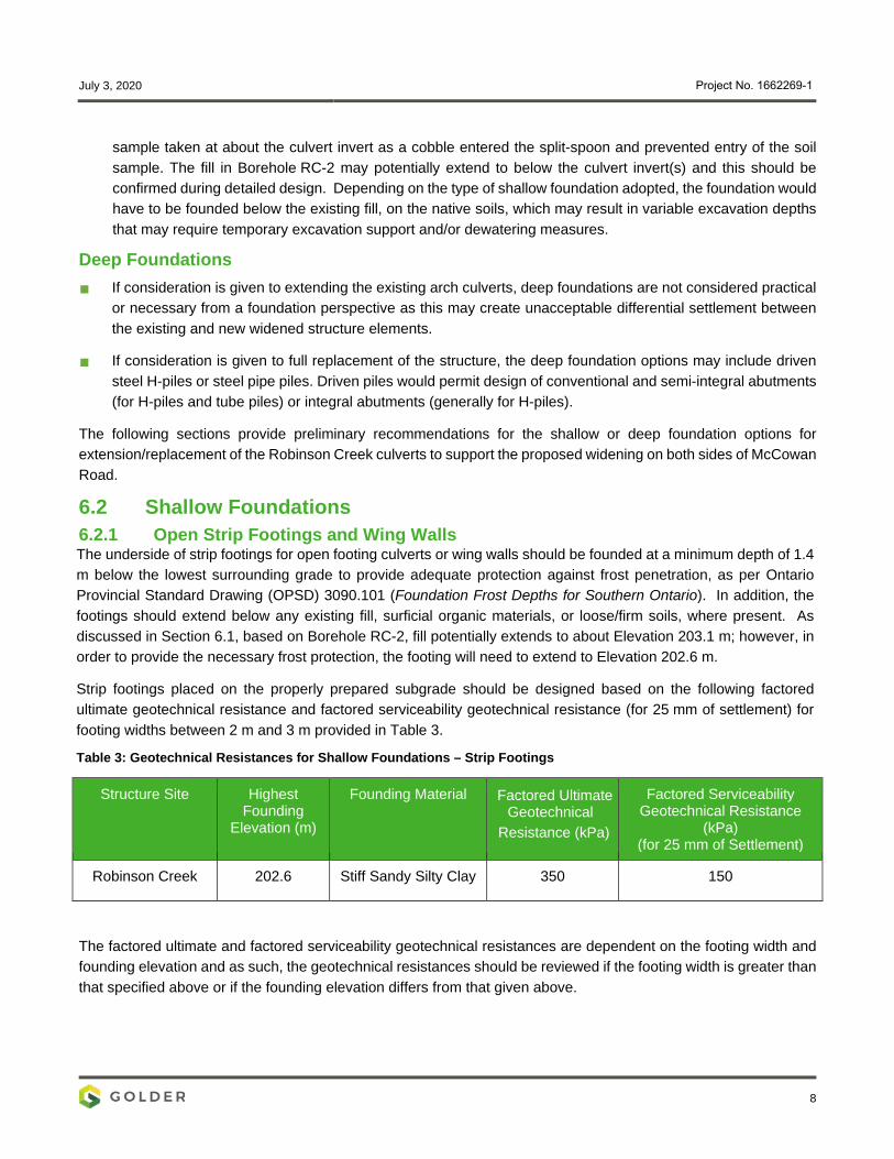
6.2 Shallow Foundations 6.2.1 Open Strip Footings and Wing Walls The underside of strip footings for open footing culverts or wing walls should be founded at a minimum depth of 1.4 m below the lowest surrounding grade to provide adequate protection against frost penetration, as per Ontario Provincial Standard Drawing (OPSD) 3090.101 (Foundation Frost Depths for Southern Ontario). In addition, the footings should extend below any existing fill, surficial organic materials, or loose/firm soils, where present. As discussed in Section 6.1, based on Borehole RC-2, fill potentially extends to about Elevation 203.1 m; however, in order to provide the necessary frost protection, the footing will need to extend to Elevation 202.6 m.
Strip footings placed on the properly prepared subgrade should be designed based on the following factored ultimate geotechnical resistance and factored serviceability geotechnical resistance (for 25 mm of settlement) for footing widths between 2 m and 3 m provided in Table 3.
Table 3: Geotechnical Resistances for Shallow Foundations – Strip Footings
Structure Site Highest Founding
Elevation (m)
Founding Material Factored Ultimate Geotechnical
Resistance (kPa)
Factored Serviceability Geotechnical Resistance
(kPa) (for 25 mm of Settlement)
Robinson Creek 202.6 Stiff Sandy Silty Clay 350 150
The factored ultimate and factored serviceability geotechnical resistances are dependent on the footing width and founding elevation and as such, the geotechnical resistances should be reviewed if the footing width is greater than that specified above or if the founding elevation differs from that given above.

July 3, 2020 Project No. 1662269-1
9
The factored ultimate geotechnical resistance provided is based on loading applied perpendicular to the surface of the footings. Where the load is not applied perpendicular to the surface of the footings, inclination of the load should be taken into account in accordance with Section 6.10.4 of the CHBDC (2014) and its Commentary.
The footing subgrade should be inspected by qualified geotechnical personnel following excavation, in accordance with OPSS 902 (Excavating and Backfilling Structures) to check that all existing fill or other unsuitable material have been removed. Where subexcavation is required, the sub-excavated area should be backfilled with granular material meeting OPSS.MUNI 1010 (Aggregates) Granular ‘A’ or Granular ‘B’ Type II that is placed and compacted in accordance with OPSS.MUNI 501 (Compacting), or the thickness of the footing increased to the full excavation depth.
The sandy silty clay subgrade will be susceptible to disturbance and degradation on exposure to water and construction traffic. It is recommended that a 100 mm thick, 20 MPa concrete working slab be placed within four hours following inspection and approval of the subgrade, to protect the subgrade from softening.
Groundwater and/or surface water control will be required for excavation and construction of an open footing culvert; therefore, the water from the creek will be required to be bypassed in order to construct the footing.
6.2.2 Box Culverts It is not necessary to found box or pipe culverts below the depth for frost protection, as the structures are tolerant of small magnitudes of movement related to freeze-thaw cycles, should these occur. Box or pipe culverts should, however, be founded below any existing fill / softened soils and surficial organic materials, at approximately the founding level recommended in Table 4, following sub-excavation of unstable materials as may be required and backfilling with OPSS.MUNI 1010 (Aggregate) Granular ‘A’ or ‘B’ Type II, based on a box culvert base slab thickness of 250 mm.
Box culverts having a span of about 5 m, placed on the properly prepared subgrade, or on compacted granular fill following sub-excavation, as required, founded at or below the design elevations in Table 4, should be designed based on the factored ultimate geotechnical resistance and factored serviceability geotechnical resistance (for 25 mm of settlement) in Table 4:
Table 4: Geotechnical Resistances for Shallow Foundations – Box Culverts
Structure Site Highest Founding
Elevation (m)
Founding Material Factored Ultimate Geotechnical
Resistance (kPa)
Factored Serviceability Geotechnical Resistance
(kPa) (for 25 mm of Settlement)
Robinson Creek Culvert
203.1 Stiff Sandy Silty Clay 250 150
The geotechnical resistances provided above are based on loading applied perpendicular to the surface of the culvert base slab. Where the load is not applied perpendicular to the surface of the footing, inclination of the load should be taken into account in accordance with Section 6.10.4 of the Canadian Highway Bridge Design Code CHBDC (2014).
The box culvert subgrade should be inspected by qualified geotechnical personnel to ensure that all existing topsoil and fill / softened soils or other unsuitable material have been removed, in accordance with OPSS 902 (Excavating
July 3, 2020 Project No. 1662269-1
10
and Backfilling-Structures) and OPSS 422 (Precast Reinforced Concrete Box Culverts in Open Cut). Following inspection, any sub-excavated area should be backfilled with granular material meeting OPSS.MUNI 1010 (Aggregates) Granular ‘A’ or Granular ‘B’ Type II material that is placed and compacted in accordance with OPSS.MUNI 501 (Compacting).
6.2.3 Settlement It is understood that the existing culverts are to be maintained with up to about 1 m of additional fill placed above the existing culverts. The settlement of the foundation soils under between approximately 1 m to 2 m of additional fill placed on the existing slope is estimated to be less than 25 mm. For these predicted settlements, settlement mitigation measures are not required; however, this should be reassessed at the detailed design stage following completion of additional borehole investigation at that time.
6.2.4 Resistance to Lateral Loads / Sliding Resistance Resistance to lateral forces / sliding resistance between the base slab of the new box culvert extensions and the subgrade should be calculated in accordance with Section 6.10.5 of the CHBDC (2014). A coefficient of friction, tan δ, (unfactored) of 0.45 may be used in the design for the interface between pre-cast concrete box culvert sections and the native stiff sandy silty clay or OPSS.MUNI 1010 (Aggregates) Granular ‘A’ material.
6.2.5 Culvert Bedding, Backfill and Erosion Protection Box culvert replacements and extensions should be provided with at least 150 mm of OPSS.MUNI 1010 (Aggregates) Granular ‘A’ material for bedding purposes. Alternatively, a 100 mm thick, 20 MPa concrete working slab, and 75 mm thick levelling course of OPSS.MUNI 1010 (Aggregates) Granular ‘A’ or OPSS.MUNI 1002 (Aggregates - Concrete) concrete fine aggregate should be placed on top of the concrete working slab to provide a “levelling course” for the pre-cast box culvert segments. Pipe culvert replacement / extension should be provided with at least 300 mm of OPSS.MUNI 1010 (Aggregates) Granular ‘A’ material for bedding purposes in accordance with OPSD 802.020 (Flexible Pipe Arch Embedment and Backfill – Earth Excavation).
Backfill and cover for the culverts should be completed in accordance with OPSD 803.010 (Backfill and Cover for Concrete Culverts) or OPSD 802.020 (Flexible Pipe Arch Embedment and Backfill – Earth Excavation). Backfill to culvert walls should consist of granular fill meeting the requirements of OPSS.PROV 1010 Granular ‘A’ or Granular ‘B’ Type II.
The backfill and bedding should be placed and compacted in accordance with OPSS 501 (Compacting). The fill depth during placement should be maintained equal on both sides of the culvert walls, with one side not exceeding the other by more than 400 mm. The culvert replacements or extensions should be designed for the full overburden and hydrostatic pressures and live load, assuming that the embankment fill above and/or surrounding the culverts has a unit weight of 22 kN/m3 for Granular ‘A’, and 21 kN/m3 for Granular ‘B’ Type II or select earth fill.
To prevent surface water from flowing either beneath the culverts (potentially causing undermining and scouring) or around the culverts (creating seepage through the embankment fill, and potentially causing erosion and loss of fine soil particles), a clay seal should be provided at the upstream end of open footing culverts. Clay seals should also be placed adjacent to the culvert inlet opening. The clay material should meet the requirements of OPSS 1205 (Material Specification for Clay Seal). The clay seal should have a thickness of 1 m, and the seal should extend from a depth of 1 m below the scour level to a minimum horizontal distance of 2 m on either side of the culvert inlet opening. The clay seal should also have a minimum vertical height equivalent to the high-water level including treatment of the adjacent side slopes. Alternatively, a clay blanket may be constructed, extending upstream to a

July 3, 2020 Project No. 1662269-1
11
distance equal to three times the culvert height, and extending along the adjacent side slopes to a height of two times the culvert height or the high-water level, whichever is higher.
If the creek flow velocities are sufficiently high under the base or design storm condition(s), a provision should be made for scour and erosion protection (suitable non-woven geotextiles and/or rip-rap) at the culvert inlets and outlets, including in front of any wing walls/retaining walls adjacent to the creek channel. The requirements for and design of erosion protection measures for the culvert inlets should be assessed by the hydraulic design engineer. As a minimum, rip-rap treatment for the culvert outlets should be consistent with the standard Treatment Type A presented in OPSD 810.010 (Rip-Rap Treatment for Sewer and Culvert Outlets), with rip-rap placed up to the toe of slope level, in combination with the cut-off measures noted above. Similarly, rip-rap should be provided over the full extent of the clay blanket if adopted, including the creek side slopes and embankment fill slope adjacent to the culverts.
6.3 Deep Foundations If consideration was given to a replacement structure, the new structure abutments may be supported on end-bearing steel H-piles or steel pipe piles driven to found within very dense / hard soil (having SPT “N” values of greater than “100 blows” per 0.3 m of penetrate). Based on the two boreholes advanced at the structure site, the elevation of “100-blows” is variable and this should be confirmed during detailed design with additional boreholes. For HP 310x110 piles driven to the recommended tip elevations and based on available subsurface information, the estimated factored ultimate axial geotechnical resistance and factored serviceability geotechnical resistance (for 25 mm of settlement) for design of the foundations is provided in Table 5.
Table 5: Geotechnical Axial Resistances for Steel H-Piles
Structure Site Founding Material Design Pile Tip
Elevation (m)
Factored Axial Ultimate
Geotechnical Resistance (kN)
Factored Serviceability Geotechnical Resistance
(kN) (for 25 mm of Settlement)
Robinson Creek
Very dense Silt and Sand / Silty Sand and
Gravel Till
197.0 (Borehole RC-1) 193.5 (Borehole RC-2) 600 --1
Note 1. The factored serviceability geotechnical resistance at SLS (for 25 mm of settlement) is greater that the factored ultimate geotechnical resistance at ULS, therefore the ULS condition will govern.
The underside of the pile caps should be founded at a minimum depth of 1.4 m below the lowest surrounding grade including measured perpendicular to any sloping ground to provide adequate protection against frost penetration, per OPSD 3090.101 (Foundation Frost Penetration Depths for Southern Ontario).
For the installation of steel H-piles or steel pipe piles, consideration must be given to the potential presence of cobbles and boulders within the soil deposits. In this regard, steel H-piles are preferred over steel pipe piles as pipe piles are considered to pose a slightly higher risk of “hanging up” or being deflected away from their vertical or battered orientation during installation, due to their larger end area. The piles should be reinforced at the tip with driving shoes or flange plates for protection during driving in accordance with OPSS 903 (Deep Foundations) and OPSD 3000.100 (Foundation Piles – Steel H-Pile Driving Shoe). In very dense / hard and / or boulder soils, as may be encountered at this site, driving shoes such as Titus Standard “H” Bearing Pile Points are preferred over flange plates. If steel pipe piles are used, driving shoes should be in accordance with OPSD 3001-100 Type II (Steel Tube Pile Driving Shoe).

July 3, 2020 Project No. 1662269-1
12
6.4 Lateral Earth Pressures for Design of Culvert Walls and Wing Walls The lateral earth pressures acting on the culvert walls and end walls / wingwalls, if applicable, will depend on the type and method of placement of the backfill materials, the nature of the soils behind the backfill, the magnitude of surcharge including construction loadings, the freedom of lateral movement of the structure, and the drainage conditions behind the walls. Seismic (earthquake) loading must also be taken into account in the design and should be addressed at detailed design.
The following recommendations are made concerning the design of the walls.
Free-draining granular fill meeting the specifications of OPSS.MUNI 1010 (Aggregates) Granular ‘A’ or Granular ‘B’ Type II should be used as backfill behind the walls. Longitudinal drains or weep holes should be installed to provide positive drainage of the granular backfill, as applicable. Compaction (including type of equipment, target densities, etc.) should be carried out in accordance with OPSS.MUNI 501 (Compacting). Other aspects of the granular backfill requirements with respect to subdrains and frost taper should be in accordance with OPSD 803.010 (Backfill and Cover for Concrete Culverts) for box culverts, OPSD 803.031 (Frost Treatment Pipe Culverts, Frost Penetration Line Between Top of Pipe and Bedding Grade) for a pipe culvert and OPSD 3121.150 (Walls, Retaining, Backfill, Minimum Granular Requirement), and OPSD 3190.100 (Walls, Retaining and Abutment, Wall Drain) for wingwall / end walls as applicable.
A minimum compaction surcharge of 12 kPa should be included in the lateral earth pressures for the structural design of the walls, in accordance with CHBDC (2014) Section 6.12.3 and Figure 6.6. Care must be taken during the compaction operation not to overstress the wall, with limitations on heavy construction equipment and requirements for the use of hand-operated compaction equipment per OPSS.PROV 501 (Compacting). Other surcharge loadings should be accounted for in the design, as required.
For restrained walls, granular fill should be placed in a zone with the width equal to at least 1.4 m behind the back of the wall in accordance with Figure C6.20(a) of the Commentary to the CHBDC (2014). For unrestrained walls, fill should be placed within the wedge-shaped zone defined by a line drawn at flatter than 1 horizontal to 1 vertical (1H:1V) extending up and back from the rear face of the wall or footing, as applicable, in accordance with Figure C6.20(b) of the Commentary to the CHBDC (2014).
6.4.1 Static Lateral Earth Pressures for Design The following guidelines and recommendations are provided regarding the lateral earth pressures for static (i.e., not earthquake) loading conditions. These design recommendations and parameters assume level backfill and ground surface behind the walls. Where there is sloping ground behind the walls, the coefficient of lateral earth pressure must be adjusted to account for the slope.
For a restrained wall, the pressures are based on the existing or proposed new embankment fill behind the granular backfill zone, and the following parameters (unfactored) in Table 6 may be used assuming the use of earth fill or Select Subgrade Material for the general embankment fill:
Table 6: Soil Parameters for Lateral Earth Pressure Design – Restrained Walls
Fill Type Unit Weight of Material
Coefficients of Static Lateral Earth Pressure
At-Rest, Ko Active, Ka
Earth Fill / Select Subgrade Material 20 kN/m3 0.47 0.31

July 3, 2020 Project No. 1662269-1
13
For an unrestrained wall, the pressures are based on the granular fill in the backfill zone, and the following parameters in Table 7 (unfactored) may be used:
Table 7: Soil Parameters for Lateral Earth Pressure Design – Unrestrained Walls
Fill Type Unit Weight of
Material
Coefficients of Static Lateral Earth Pressure
At-Rest, Ko Active, Ka
Granular ‘A’ 22 kN/m3 0.43 0.27
Granular ‘B’ Type II 21 kN/m3 0.43 0.27
If the wall support and superstructure allow lateral yielding, active earth pressures may be used in the geotechnical design of the structure. The movement required to allow active pressures to develop within the backfill, and thereby assume an unrestrained structure for design, should be calculated in accordance with Section C6.12.1 and Table C6.6 of the Commentary to the CHBDC, 2014.
If the wall does not allow lateral yielding (i.e., restrained structure where the rotational or horizontal movement is not sufficient to mobilize an active earth pressure condition), at-rest earth pressures (plus any compaction surcharge) should be assumed for geotechnical design.
6.5 Embankments The stability of the 3.2 m high embankment slopes should be assessed during the detailed design phase once the configuration (based on structure layout and property restrictions) is available. The CHBDC (2014) requires a Factor of Safety of 1.33 (short-term/temporary) and 1.54 (long-term/permanent) for the stability of embankment slopes. In general, the subsurface conditions at the recommended founding elevations are competent and therefore for widened embankment side slopes inclined at 2 horizontal to 1 vertical, in order to achieve a minimum Factor of Safety of 1.54 (long-term) the widened embankment is required to be constructed of soil meeting the requirements of OPSS.MUNI 1010 (Aggregates) for Select Subgrade Material (SSM). Alternatively, the widened embankments may be constructed of earth fill meeting the requirements of OPSS.MUNI 212 (Borrow); however, the side slopes must be constructed at 3H:1V or flatter in order to achieve a Factor of Safety of 1.54 (long-term).
6.6 Construction Considerations The following subsections identify future construction considerations that should be considered at this stage as they may impact the planning and design.
6.6.1 Temporary Excavation Temporary excavations for the culvert extensions/replacement and/or pile cap construction will be made through the existing cohesive and non-cohesive fill and a sandy silty clay deposit. Excavation works must be carried out in accordance with the guidelines outlined in the Occupational Health and Safety Act (OHSA) and Regulations for Construction Projects. The existing fill and sandy silt clay would be classified as Type 3 soil, according to the OHSA. Temporary excavations above the water table should be made with side slopes no steeper than 1 horizontal to 1 vertical (1H:1V).

July 3, 2020 Project No. 1662269-1
14
6.6.2 Groundwater and Surface Water Control The groundwater level measured in the monitoring well installed in Borehole RC-1 which was screened in the silty sand and gravel till was about 5 m above the deposit, therefore, the groundwater level in the deposit is under hydrostatic pressure. Foundation excavations (culverts and shallow footings) are anticipated to extend to about Elevation 202.6 m, about 4 m above the silty sand and gravel till deposit where the water level in the monitoring well was measured within. Based on this, the Factor of Safety against base instability will be greater than 1.1 and the lower till deposit will not be required to be dewatered prior to excavations for foundations.
Depending on the time of year of construction, perched ground water conditions may be present overlying the sandy silty clay deposit. Considering the relatively low permeability of the sandy silty clay soils at the Robinson Creek culverts, it is anticipated that water inflow from these layers or if perched groundwater conditions are present that they can be handled by pumping from filtered sump pumps placed at the base of the excavation. Surface water seepage into the excavations should be expected and will be heavier during periods of sustained precipitation and all surface water should be directed away from the excavations.
Control of the surface water will be necessary for the construction of the culvert extensions/replacement to allow excavation and foundation construction to be carried out in dry conditions. Depending on the creek flows at the time of construction, the surface water being conveyed by the existing culverts could bypass the culvert construction area by means of a temporary pipe or be diverted by pumping from behind a temporary barrier (cofferdam) placed / constructed inside the existing culverts.
Precipitation runoff in the construction area should be directed away from the excavation areas, to prevent ponding of water that could result in disturbance and weakening of the subgrade or granular backfill / bedding material.
6.6.3 Temporary Protection Systems At this preliminary stage, it is anticipated that temporary protection systems will be required along McCowan Road, in order to facilitate the construction of the widened culverts.
These temporary excavation support systems should be designed and constructed in accordance with OPSS 539 (Temporary Protection Systems). The lateral movement of the temporary protection systems should meet Performance Level 2 as specified in OPSS 539, provided that the existing structures and any adjacent utilities can tolerate this magnitude of deformation. Although the selection and design of the protection systems will be the responsibility of the Contractor, for conceptual purposes, a driven, interlocking sheetpile system or soldier pile and timber lagging system would be suitable for the temporary excavation support at this structure site, based on the anticipated subsurface soil and groundwater conditions.
The selection and design of the temporary protection system will be the responsibility of the contractor. Parameters for lateral earth pressure coefficients should be provided at the detailed design stage.
6.6.4 Obstructions During Pile Driving The glacial till soils at the site should be expected to contain cobbles and boulders, which could affect the installation of deep foundations and/or protection systems. If deep foundations are adopted, it is recommended that driving shoes be used to facilitate pile driving into/through the very dense to hard till deposits to minimize damage to pile tips. Further observation is recommended in the next stage of investigation in support of the detail design.

July 3, 2020 Project No. 1662269-1
15
6.6.5 Subgrade Protection The native soils that will be exposed at the foundation subgrade level will be susceptible to disturbance from construction traffic and/or ponded water. To limit this degradation, it is recommended that a minimum 100 mm thick concrete working slab be placed on the subgrade of foundation excavations within four hours after preparation, inspection and approval of the subgrade.
6.6.6 Vibration Monitoring During Temporary Protection System or Pile Installation A maximum partial peak velocity (PPV) of 100 mm/s is generally considered acceptable for bridge structures in good condition. Based on vibration monitoring experience, it is considered unlikely that vibrations induced by conventional construction activities (such as pile driving) will reach this threshold level.
There are existing residences surrounding the site and while it is expected that vibration levels will not reach these thresholds at this structure, it is considered prudent that pre- and post-construction condition surveys and vibration monitoring at or near the building should be considered to defend against potential damage claims associated with vibration-inducing activities at these sites. A PPV threshold of 25 mm/s is generally considered applicable for residential buildings.
6.7 Recommendations For Further Investigation Work During Detailed Design
An additional borehole investigation is recommended during the detailed design if the Robinson Creek structure is to be modified to accommodate the widening of McCowan Road. The additional boreholes should be advanced within the footprint of the new / widened foundation elements to further assess and/or confirm the subsurface conditions and the preliminary recommendations provided in this report as follows:
Assess the type and depth of fill present;
Assess near surface soil deposits within the footprint of the widened embankments, to allow analysis ofsettlement, where applicable;
Confirm the depth of “100-blow” materials and confirm the tip elevation and bearing resistance for drivensteel H-piles or pipe piles;
Test parameters used to assess the corrosive potential of the soil to concrete and buried steel;
Confirm the groundwater elevation in the silty sand and gravel till deposit; and,
Observe the presence of cobbles and/or boulders within the soil deposits to assess the presence of suchobstructions as they may affect excavations and the installation of driven steel H-pile foundations.

July 3, 2020 Project No. 1662269-1
16
Golder Associates Ltd.
Anastasia Poliacik, P.Eng. Graeme Skinner, PhD., P.Eng. Geotechnical Engineer Principal, Senior Geotechnical Engineer
AP/SMM/GS/ap;mes
Golder and the G logo are trademarks of Golder Associates Corporation
https://golderassociates.sharepoint.com/sites/30079g/deliverables/2. foundation reports/1. robinson creek/4 - final/1662269-001 rep 2020'07'03 fidr mccowan-robinson creek final.docx
7.0 CLOSURE This Preliminary Foundation Design Report was prepared by Ms. Anastasia Poliacik, P.Eng., and Mr. Graeme Skinner, PhD., P.Eng., a senior geotechnical engineer and Principal with Golder.
This Report was authored under a Subconsultant Agreement between HDR and Golder for the Regional Municipality of York’s (“Owner”) projects. The Report is provided to HDR and Regional Municipality of York for their use, utilizing their judgment, in fulfilling a portion of HDR’s particular scope of work. No other party may rely upon this report, or any portion thereof, without Golder’s express written consent and any reliance of the reports by others will be at that user’s sole risk and liability, notwithstanding that they may have received this Report through an appropriate user. In addition, Golder shall not be liable for any use of the Report for any purpose other than that for which the same was originally prepared or provided by Golder, or any improper use of this Report, or to any party other than HDR.

July 3, 2020 Project No. 1662269-1
REFERENCES Bowles, J.E. 1984. Physical and Geotechnical Properties of Soils, Second Edition. McGraw Hill Book Company, New York.
Brennand, T.A.. 1998. Urban Geology Note: Oshawa Ontario. In P.F. Karrow, and O.L. White (Eds.), Geological Association of Canada, Special Papers 42: Urban Geology of Canadian Cities, p. 353-364.
Canadian Geotechnical Society. 2006. Canadian Foundation Engineering Manual (CFEM), 4th Edition. The Canadian Geotechnical Society, BiTech Publisher Ltd., British Columbia.
Canadian Standards Association. 2014. Canadian Highway Bridge Design Code (CHBDC), CAN/CSA-S06-06 and Commentary.
Chapman, L.J. and Putnam, D.F. 1984. The Physiography of Southern Ontario, Ontario Geological Survey, Special Volume 2, Third Edition. Accompanied by Map P.2715, Scale 1:600,000.
Kulhawy, F.H. and Mayne, P.W. 1990. Manual on Estimating Soil Properties for Foundation Design. EL-6800, Research Project 1493-6. Prepared for Electric Power Research Institute, Palo Alto, California, U.S.
Terzaghi, K., 1955. Evaluation of Coefficients of Subgrade Reaction/ Geotechnique, Vol. 5, No. 4, pp. 297-326. Discussion in Vol. 6, No. 2, pp. 94-98.
https://golderassociates.sharepoint.com/sites/30079g/deliverables/2. foundation reports/1. robinson creek/4 - final/1662269-rep 2020'07'03 fidr mccowan-robinson creek final.docx

IMPORTANT INFORMATION AND LIMITATIONS OF THIS REPORT
Standard of Care: Golder Associates Ltd. (Golder) has prepared this report in a manner consistent with that level of care and skill ordinarily exercised by members of the engineering and science professions currently practising under similar conditions in the jurisdiction in which the services are provided, subject to the time limits and physical constraints applicable to this report. No other warranty, expressed or implied is made.
Basis and Use of the Report: This report has been prepared for the specific site, design objective, development and purpose described to Golder by the Client. The factual data, interpretations and recommendations pertain to a specific project as described in this report and are not applicable to any other project or site location. Any change of site conditions, purpose, development plans or if the project is not initiated within eighteen months of the date of the report may alter the validity of the report. Golder cannot be responsible for use of this report, or portions thereof, unless Golder is requested to review and, if necessary, revise the report.
The information, recommendations and opinions expressed in this report are for the sole benefit of the Client. No other party may use or rely on this report or any portion thereof without Golder’s express written consent. If the report was prepared to be included for a specific permit application process, then upon the reasonable request of the client, Golder may authorize in writing the use of this report by the regulatory agency as an Approved User for the specific and identified purpose of the applicable permit review process. Any other use of this report by others is prohibited and is without responsibility to Golder. The report, all plans, data, drawings and other documents as well as all electronic media prepared by Golder are considered its professional work product and shall remain the copyright property of Golder, who authorizes only the Client and Approved Users to make copies of the report, but only in such quantities as are reasonably necessary for the use of the report by those parties. The Client and Approved Users may not give, lend, sell, or otherwise make available the report or any portion thereof to any other party without the express written permission of Golder. The Client acknowledges that electronic media is susceptible to unauthorized modification, deterioration and incompatibility and therefore the Client can not rely upon the electronic media versions of Golder’s report or other work products.
The report is of a summary nature and is not intended to stand alone without reference to the instructions given to Golder by the Client, communications between Golder and the Client, and to any other reports prepared by Golder for the Client relative to the specific site described in the report. In order to properly understand the suggestions, recommendations and opinions expressed in this report, reference must be made to the whole of the report. Golder can not be responsible for use of portions of the report without reference to the entire report.
Unless otherwise stated, the suggestions, recommendations and opinions given in this report are intended only for the guidance of the Client in the design of the specific project. The extent and detail of investigations, including the number of test holes, necessary to determine all of the relevant conditions which may affect construction costs would normally be greater than has been carried out for design purposes. Contractors bidding on, or undertaking the work, should rely on their own investigations, as well as their own interpretations of the factual data presented in the report, as to how subsurface conditions may affect their work, including but not limited to proposed construction techniques, schedule, safety and equipment capabilities.
Soil, Rock and Ground Water Conditions: Classification and identification of soils, rocks, and geologic units have been based on commonly accepted methods employed in the practice of geotechnical engineering and related disciplines. Classification and identification of the type and condition of these materials or units involves judgment, and boundaries between different soil, rock or geologic types or units may be transitional rather than abrupt. Accordingly, Golder does not warrant or guarantee the exactness of the descriptions.
Golder Associates Ltd. 6925 Century Avenue, Suite #100 Mississauga, Ontario, L5N 7K2 Canada T: +1 905 567 4444 | F: +1 905 567 6561
Golder and the G logo are trademarks of Golder Associates Corporation golder.com

2018
Special risks occur whenever engineering or related disciplines are applied to identify subsurface conditions and even a comprehensive investigation, sampling and testing program may fail to detect all or certain subsurface conditions. The environmental, geologic, geotechnical, geochemical and hydrogeologic conditions that Golder interprets to exist between and beyond sampling points may differ from those that actually exist. In addition to soil variability, fill of variable physical and chemical composition can be present over portions of the site or on adjacent properties. The professional services retained for this project include only the geotechnical aspects of the subsurface conditions at the site, unless otherwise specifically stated and identified in the report. The presence or implication(s) of possible surface and/or subsurface contamination resulting from previous activities or uses of the site and/or resulting from the introduction onto the site of materials from off-site sources are outside the terms of reference for this project and have not been investigated or addressed.
Soil and groundwater conditions shown in the factual data and described in the report are the observed conditions at the time of their determination or measurement. Unless otherwise noted, those conditions form the basis of the recommendations in the report. Groundwater conditions may vary between and beyond reported locations and can be affected by annual, seasonal and meteorological conditions. The condition of the soil, rock and groundwater may be significantly altered by construction activities (traffic, excavation, groundwater level lowering, pile driving, blasting, etc.) on the site or on adjacent sites. Excavation may expose the soils to changes due to wetting, drying or frost. Unless otherwise indicated the soil must be protected from these changes during construction.
Sample Disposal: Golder will dispose of all uncontaminated soil and/or rock samples 90 days following issue of this report or, upon written request of the Client, will store uncontaminated samples and materials at the Client’s expense. In the event that actual contaminated soils, fills or groundwater are encountered or are inferred to be present, all contaminated samples shall remain the property and responsibility of the Client for proper disposal.
Follow-Up and Construction Services: All details of the design were not known at the time of submission of Golder’s report. Golder should be retained to review the final design, project plans and documents prior to construction, to confirm that they are consistent with the intent of Golder’s report.
During construction, Golder should be retained to perform sufficient and timely observations of encountered conditions to confirm and document that the subsurface conditions do not materially differ from those interpreted conditions considered in the preparation of Golder’s report and to confirm and document that construction activities do not adversely affect the suggestions, recommendations and opinions contained in Golder’s report. Adequate field review, observation and testing during construction are necessary for Golder to be able to provide letters of assurance, in accordance with the requirements of many regulatory authorities. In cases where this recommendation is not followed, Golder’s responsibility is limited to interpreting accurately the information encountered at the borehole locations, at the time of their initial determination or measurement during the preparation of the Report.
2

2018
Changed Conditions and Drainage: Where conditions encountered at the site differ significantly from those anticipated in this report, either due to natural variability of subsurface conditions or construction activities, it is a condition of this report that Golder be notified of any changes and be provided with an opportunity to review or revise the recommendations within this report. Recognition of changed soil and rock conditions requires experience and it is recommended that Golder be employed to visit the site with sufficient frequency to detect if conditions have changed significantly.
Drainage of subsurface water is commonly required either for temporary or permanent installations for the project. Improper design or construction of drainage or dewatering can have serious consequences. Golder takes no responsibility for the effects of drainage unless specifically involved in the detailed design and construction monitoring of the system.
3

LAMPTON CRESCENT
BEEHIVE LANE
PIN
70010-1442
PA
RT
89
PIN
70010-1443
PA
RT
90
PLAN
65R-
28873
PIN
70010-1444
PA
RT
91
PIN
70010-1445
PA
RT
92
PIN
70010-1446
PA
RT
93
PIN
70010-1447
PA
RT
94
PIN
70010-1448
PA
RT
95
PIN
70010-1449
PA
RT
96
PIN
70010-1450
PA
RT
97
PIN
70010-1451
PA
RT
98
PIN
70010-1452
PA
RT
99
PIN
70010-1453
PA
RT
100
PIN
70010-1454
PA
RT
101
PA
RT
246
PA
RT
247
PA
RT
246
PA
RT
254
PA
RT
253
PA
RT
251
BLOCK 73, PLAN 65M- 3719
BLOCK 74, PLAN 65M-3719
PIN 70010 - 1188
BLO
C
K 78 (0.30 R
ES
ER
VE
)
PLA
N
65M
-3719
PIN
70010-1191
PA
R
T 1, P
LA
N
65R
-22353
PIN
70010-1199
PA
R
T 2
PART 1
PLAN 65R - 29083
PIN 70010 - 1563
PART 3, PLAN 65R-29083
PIN 70010-1562
LOT 19, CONCESSION 6
LOT 18, CONCESSION 6
PART 1, PLAN 64R-6311
PIN 70010 - 0001
PART 2, PLAN 64R-6311
PIN 70010 - 0462
(0.30 RESERVE) PLAN
65M - 3418
PART 4, PLAN 64R-8219
PART 3, PLAN 64R-8219
PART 3, PLAN 65R-28068
PART 4, EXP PLAN R262803
LAMPTON CRESCENT
LOT 40
LOT 41
LOT 42
PL
AN
6
5M
- 3
61
0
PIN 03060-1460
BLOCK 178
LOT 124
LOT 125
LOT 126
LOT 127
LOT 128
LOT 129
PLAN65M -
3610
(BY PLAN 65M-3610)
PIN 03060-1606
PART 13, PLAN 65R-24954
SUBJECT TO AN EASEMENT AS IN
INSTRUMENT No. MA42780
BLOCK 175
BLOCK
174
PLAN 65M - 3610
PART 14, PLAN 65R-24954
SUBJECT TO AN EASEMENT AS IN
INSTRUMENT No. MA42780
PIN
03060
-1594
PIN 03060-1597
BLOCK 177 (0.30 RESERVE) PLAN
65M-3610
PART 15, PLAN 65R-24954
SUBJECT TO AN EASEMENT AS IN
INSTRUMENT No. MA42780
PIN 03060-1595
PART 3, PLAN 65R-22353
SUBJECT TO AN EASEMENT AS IN
INSTRUMENT No. MA42780
PART 2, PLAN 65R-22353
PIN 03060-0164
PART 8, EXP PLAN R262803
PART 1, PLAN 65R-26109
SUBJECT TO AN EASEMENT AS
IN INSTRUMENT No. YR1649643
BLOCK 1, PLAN 65M-3491
L
O
T
1
8
,
C
O
N
C
E
S
S
I
O
N
7
PIN 03060-0439
P
A
R
T
9
,
P
L
A
N
6
5
R
-
2
6
1
0
9
P
A
R
T
8
,
P
L
A
N
6
5
R
-
2
6
1
0
9
P
I
N
0
3
0
6
0
-
2
7
0
3
PA
RT
45
BEEHIVE LANE
PA
RT
48
PA
RT
43
PA
RT
42
PA
RT
39
PA
RT
38
PA
RT
35
PA
RT
34
PA
RT
31
PA
RT
30
PA
RT
27
PA
RT
26
PA
RT
23
PA
RT
22
PIN
03060-6111
PIN
03060-6112
PA
RT
47
PART
46
PART
44
PART
41
PART
40
PART
37
PART
36
PART
33
PART
32
PART
29
PART
28
PART
25
PART
24
PART
21
PIN
03060-6110
PIN
03060-6109
PIN
03060-6108
PIN
03060-6107
PIN
03060-6106
PIN
03060-6105
PIN
03060-6104
PIN
03060-6103
PIN
03060-6102
PIN
03060-6101
PIN
03060-6100
PART 96, PLAN 65R-33209
SUBJECT TO AN EASEMENT AS
IN LT1609991 AND YR1662279
PLAN 65R - 33209
BLOCK 123, PLAN 65M -4193
PIN
03060-6113
PARTS 1 TO 48 (BOTH INCLUSIVE) - SUBJECT TO AN EASEMENT AS IN YR1662279 AND YR1507506
SUBJECT TO AN EASEMENT AS IN YR1662279 AND YR1734942
PIN
0
30
60
-0
44
3
BLO
CK
5
(0
.3
0 R
ES
ER
VE
) P
LA
N
65M
-3491
YORK REGION COMMON ELEMENTS CONDOMINIUM PLAN No. 1197
PIN 29728-0001
PIN 29605-0001
YORK REGION COMMON ELEMENTS CONDOMINIUM PLAN No. 1074
RC-1
RC-2
R
O
B
I
N
S
O
N
C
R
E
E
K
R
O
B
I
N
S
O
N
C
R
E
E
K
R
O
B
I
N
S
O
N
C
R
E
E
K
R
O
B
I
N
S
O
N
C
R
E
E
K
R
O
B
I
N
S
O
N
C
R
E
E
K
R
O
B
I
N
S
O
N
C
R
E
E
K
R
O
B
I
N
S
O
N
C
R
E
E
K
R
O
B
I
N
S
O
N
C
R
E
E
K
R
O
B
I
N
S
O
N
C
R
E
E
K
R
O
B
I
N
S
O
N
C
R
E
E
K
R
O
B
I
N
S
O
N
C
R
E
E
K
R
O
B
I
N
S
O
N
C
R
E
E
K
R
O
B
I
N
S
O
N
C
R
E
E
K
R
O
B
I
N
S
O
N
C
R
E
E
K
R
O
B
I
N
S
O
N
C
R
E
E
K
R
O
B
I
N
S
O
N
C
R
E
E
K
R
O
B
I
N
S
O
N
C
R
E
E
K
SITE LOCATION
MCCOWAN ROAD (Y.R. 67)
STEELES AVENUE (Y.R 95) TO MAJOR MACKENZIE (Y.R. 25),
CITY OF MARKHAM, REGION OF YORK
025 m
m
1662269
CONTROL
0010
FIGURE
1A
2019-03-04
STB
TITLE
BOREHOLE LOCATION PLAN - ROBINSON CREEK
PROJECT NO. REV.
PROJECT
CONSULTANT
PREPARED
DESIGNED
REVIEWED
APPROVED
YYYY-MM-DD
Path: \\golder.gds\gal\m
ississauga\sim
\C
lients\R
egion_of_Y
ork\M
cC
ow
an_R
oad\99_P
RO
J\1662269\40_P
RO
D\0010_H
ydrogeology\ | F
ile N
am
e: 1662269-0010-C
H-0001.dw
g | Last E
dited B
y: sbow
erm
an
D
ate: 2019-03-04
T
im
e:10:43:20 A
M | P
rinted B
y: S
bow
erm
an D
ate: 2019-03-04 T
im
e:10:47:31 A
M
IF
T
HIS
M
EA
SU
RE
ME
NT
D
OE
S N
OT
M
AT
CH
W
HA
T IS
S
HO
WN
, T
HE
S
HE
ET
S
IZ
E H
AS
B
EE
N M
OD
IF
IE
D F
RO
M: A
NS
I B
LEGEND
REFERENCE(S)
BASE DATA PROVIDED BY HDR CORPORATION, THAM SURVEYING LIMITED ONTARIO LAND
SURVEYORS, OBTAINED NOVEMBER 2018
PRODUCED BY GOLDER ASSOCIATES LTD UNDER LICENSE FROM ONTARIO MINISTRY OF
NATURAL RESOURCES, © QUEENS PRINTER 2018
PROJECTION: TRANSVERSE MERCATOR DATUM: NAD 83 COORDINATE SYSTEM: UTM ZONE 17N
CLIENT
HDR CORPORATION
FOUNDATION BOREHOLE LOCATION
1:1,000
500
METRES
25
KEY PLAN SCALE 1:150000 MKEY PLAN SCALE 1:150000 M
KEY PLAN SCALE 1:150000 MKEY PLAN SCALE 1:150000 M
KEY PLAN SCALE 1:150000 MKEY PLAN SCALE 1:150000 MKEY PLAN SCALE 1:150000 MKEY PLAN SCALE 1:150000 MKEY PLAN SCALE 1:150000 MKEY PLAN SCALE 1:150000 M
KEY PLAN SCALE 1:150000 M
KEY PLAN SCALE 1:150000 M
KEY PLAN SCALE 1:150000 M
KEY PLAN SCALE 1:150000 M
KEY PLAN SCALE 1:150000 M
KEY PLAN SCALE 1:150000 M
KEY PLAN SCALE 1:150000 M
GS
AP

July 3, 2020 Project No. 1662269-1
APPENDIX A
Drawings Provided by HDR


July 3, 2020 Project No. 1662269-1
APPENDIX B
Records of Borehole Sheets

June 2018 Revision 5
METHOD OF SOIL CLASSIFICATION
The Golder Associates Ltd. Soil Classification System is based on the Unified Soil Classification System (USCS)
1/3
Organic or Inorganic
Soil Group Type of Soil Gradation
or Plasticity 𝑪𝑪𝑪𝑪 =𝑫𝑫𝟔𝟔𝟔𝟔
𝑫𝑫𝟏𝟏𝟔𝟔𝑪𝑪𝑪𝑪 =
(𝑫𝑫𝟑𝟑𝟔𝟔)𝟐𝟐
𝑫𝑫𝟏𝟏𝟔𝟔𝒙𝒙𝑫𝑫𝟔𝟔𝟔𝟔 Organic
Content USCS Group
Symbol Group Name
INO
RG
ANIC
(O
rgan
ic C
onte
nt ≤
30%
by
mas
s)
CO
ARSE
-GR
AIN
ED S
OIL
S
(˃50
% b
y m
ass
is la
rger
than
0.0
75 m
m)
GR
AVEL
S
(>50
% b
y m
ass
of
coar
se fr
actio
n is
la
rger
than
4.7
5 m
m) Gravels
with ≤12% fines
(by mass)
Poorly Graded <4 ≤1 or ≥3
≤30%
GP GRAVEL
Well Graded ≥4 1 to 3 GW GRAVEL
Gravels with
>12% fines
(by mass)
Below A Line n/a GM SILTY
GRAVEL
Above A Line n/a GC CLAYEY
GRAVEL
SAN
DS
(≥
50%
by
mas
s of
co
arse
frac
tion
is
smal
ler t
han
4.75
mm
) Sands with
≤12% fines
(by mass)
Poorly Graded <6 ≤1 or ≥3 SP SAND
Well Graded ≥6 1 to 3 SW SAND
Sands with
>12% fines
(by mass)
Below A Line n/a SM SILTY SAND
Above A Line n/a SC CLAYEY
SAND
Organic or Inorganic
Soil Group Type of Soil Laboratory
Tests
Field Indicators Organic Content
USCS Group Symbol
Primary Name Dilatancy Dry
Strength Shine Test
Thread Diameter
Toughness (of 3 mm thread)
INO
RG
ANIC
(Org
anic
Con
tent
≤30
% b
y m
ass)
FIN
E-G
RAI
NED
SO
ILS
(≥50
% b
y m
ass
is s
mal
ler t
han
0.07
5 m
m)
SILT
S
(Non
-Pla
stic
or P
I and
LL
plot
be
low
A-L
ine
on
Pla
stic
ity
Cha
rt b
elow
)
Liquid Limit
<50
Rapid None None >6 mm N/A (can’t roll 3 mm thread)
<5% ML SILT
Slow None to Low Dull 3mm to
6 mm None to low <5% ML CLAYEY SILT
Slow to very slow
Low to medium
Dull to slight
3mm to 6 mm Low 5% to
30% OL ORGANIC SILT
Liquid Limit ≥50
Slow to very slow
Low to medium Slight 3mm to
6 mm Low to
medium <5% MH CLAYEY SILT
None Medium to high
Dull to slight
1 mm to 3 mm
Medium to high
5% to 30% OH ORGANIC
SILT
CLA
YS
(PI a
nd L
L pl
ot
abov
e A-
Line
on
Plas
ticity
Cha
rt
belo
w)
Liquid Limit <30 None Low to
medium Slight
to shiny ~ 3 mm Low to medium 0%
to 30%
(see Note 2)
CL SILTY CLAY
Liquid Limit 30 to 50 None Medium
to high Slight
to shiny 1 mm to
3 mm Medium CI SILTY CLAY
Liquid Limit ≥50 None High Shiny <1 mm High CH CLAY
HIG
HLY
O
RG
ANIC
SO
ILS
(Org
anic
C
onte
nt >
30%
by
mas
s) Peat and mineral soil
mixtures
30% to
75% PT
SILTY PEAT, SANDY PEAT
Predominantly peat, may contain some
mineral soil, fibrous or amorphous peat
75% to
100% PEAT
Note 1 – Fine grained materials with PI and LL that plot in this area are named (ML) SILT with slight plasticity. Fine-grained materials which are non-plastic (i.e. a PL cannot be measured) are named SILT. Note 2 – For soils with <5% organic content, include the descriptor “trace organics” for soils with between 5% and 30% organic content include the prefix “organic” before the Primary name.
Dual Symbol — A dual symbol is two symbols separated by a hyphen, for example, GP-GM, SW-SC and CL-ML. For non-cohesive soils, the dual symbols must be used when the soil has between 5% and 12% fines (i.e. to identify transitional material between “clean” and “dirty” sand or gravel. For cohesive soils, the dual symbol must be used when the liquid limit and plasticity index values plot in the CL-ML area of the plasticity chart (see Plasticity Chart at left).
Borderline Symbol — A borderline symbol is two symbols separated by a slash, for example, CL/CI, GM/SM, CL/ML. A borderline symbol should be used to indicate that the soil has been identified as having properties that are on the transition between similar materials. In addition, a borderline symbol may be used to indicate a range of similar soil types within a stratum.

June 2018 Revision 5
ABBREVIATIONS AND TERMS USED ON RECORDS OF BOREHOLES AND TEST PITS
2/3
PARTICLE SIZES OF CONSTITUENTS
Soil Constituent
Particle Size
Description Millimetres Inches
(US Std. Sieve Size)
BOULDERS Not Applicable >300 >12
COBBLES Not Applicable 75 to 300 3 to 12
GRAVEL Coarse Fine
19 to 75 4.75 to 19
0.75 to 3 (4) to 0.75
SAND Coarse Medium
Fine
2.00 to 4.75 0.425 to 2.00
0.075 to 0.425
(10) to (4)(40) to (10)(200) to (40)
SILT/CLAY Classified by plasticity <0.075 < (200)
SAMPLES AS Auger sample BS Block sample CS Chunk sample DD Diamond Drilling
DO or DP Seamless open ended, driven or pushed tube sampler – note size
DS Denison type sample GS Grab Sample MC Modified California Samples MS Modified Shelby (for frozen soil) RC Rock core SC Soil core SS Split spoon sampler – note size ST Slotted tube TO Thin-walled, open – note size (Shelby tube) TP Thin-walled, piston – note size (Shelby tube) WS Wash sample
MODIFIERS FOR SECONDARY AND MINOR CONSTITUENTS Percentage
by Mass Modifier
>35 Use 'and' to combine major constituents (i.e., SAND and GRAVEL)
> 12 to 35 Primary soil name prefixed with "gravelly, sandy, SILTY, CLAYEY" as applicable
> 5 to 12 some
≤ 5 trace
SOIL TESTS w water content PL , wp plastic limit LL , wL liquid limit C consolidation (oedometer) test CHEM chemical analysis (refer to text) CID consolidated isotropically drained triaxial test1
CIU consolidated isotropically undrained triaxial test with porewater pressure measurement1
DR relative density (specific gravity, Gs) DS direct shear test GS specific gravity M sieve analysis for particle size MH combined sieve and hydrometer (H) analysis MPC Modified Proctor compaction test SPC Standard Proctor compaction test OC organic content test SO4 concentration of water-soluble sulphates UC unconfined compression test UU unconsolidated undrained triaxial test V (FV) field vane (LV-laboratory vane test) γ unit weight
1. Tests anisotropically consolidated prior to shear are shown as CAD, CAU.
PENETRATION RESISTANCE Standard Penetration Resistance (SPT), N: The number of blows by a 63.5 kg (140 lb) hammer dropped 760 mm (30 in.) required to drive a 50 mm (2 in.) split-spoon sampler for a distance of 300 mm (12 in.). Values reported are as recorded in the field and are uncorrected.
Cone Penetration Test (CPT) An electronic cone penetrometer with a 60° conical tip and a project end area of 10 cm2 pushed through ground at a penetration rate of 2 cm/s. Measurements of tip resistance (qt), porewater pressure (u) and sleeve frictions are recorded electronically at 25 mm penetration intervals.
Dynamic Cone Penetration Resistance (DCPT); Nd: The number of blows by a 63.5 kg (140 lb) hammer dropped 760 mm (30 in.) to drive uncased a 50 mm (2 in.) diameter, 60° cone attached to "A" size drill rods for a distance of 300 mm (12 in.). PH: Sampler advanced by hydraulic pressure PM: Sampler advanced by manual pressure WH: Sampler advanced by static weight of hammer WR: Sampler advanced by weight of sampler and rod
NON-COHESIVE (COHESIONLESS) SOILS COHESIVE SOILS Compactness2 Consistency
Term SPT ‘N’ (blows/0.3m)1 Very Loose 0 to 4
Loose 4 to 10 Compact 10 to 30 Dense 30 to 50
Very Dense >501. SPT ‘N’ in accordance with ASTM D1586, uncorrected for the effects of
overburden pressure.2. Definition of compactness terms are based on SPT ‘N’ ranges as provided in
Terzaghi, Peck and Mesri (1996). Many factors affect the recorded SPT ‘N’ value, including hammer efficiency (which may be greater than 60% in automatic trip hammers), overburden pressure, groundwater conditions, and grainsize. As such, the recorded SPT ‘N’ value(s) should be considered only an approximate guide to the soil compactness. These factors need to be considered whenevaluating the results, and the stated compactness terms should not be reliedupon for design or construction.
Term Undrained Shear Strength (kPa)
SPT ‘N’1,2 (blows/0.3m)
Very Soft <12 0 to 2 Soft 12 to 25 2 to 4 Firm 25 to 50 4 to 8 Stiff 50 to 100 8 to 15
Very Stiff 100 to 200 15 to 30 Hard >200 >30
1. SPT ‘N’ in accordance with ASTM D1586, uncorrected for overburden pressure effects; approximate only.
2. SPT ‘N’ values should be considered ONLY an approximate guide toconsistency; for sensitive clays (e.g., Champlain Sea clays), the N-value approximation for consistency terms does NOT apply. Rely on directmeasurement of undrained shear strength or other manual observations.
Field Moisture Condition Water Content Term Description
Dry Soil flows freely through fingers.
Moist Soils are darker than in the dry condition and may feel cool.
Wet As moist, but with free water forming on hands when handled.
Term Description
w < PL Material is estimated to be drier than the Plastic Limit.
w ~ PL Material is estimated to be close to the Plastic Limit.
w > PL Material is estimated to be wetter than the Plastic Limit.

June 2018 Revision 5
LIST OF SYMBOLS
3/3
Unless otherwise stated, the symbols employed in the report are as follows:
I. GENERAL (a) Index Properties (continued)w water content
π 3.1416 wl or LL liquid limit ln x natural logarithm of x wp or PL plastic limit log10 x or log x, logarithm of x to base 10 lp or PI plasticity index = (wl – wp) g acceleration due to gravity NP non-plastic t time ws shrinkage limit
IL liquidity index = (w – wp) / Ip IC consistency index = (wl – w) / Ip emax void ratio in loosest state emin void ratio in densest state ID density index = (emax – e) / (emax - emin)
II. STRESS AND STRAIN (formerly relative density)
γ shear strain (b) Hydraulic Properties∆ change in, e.g. in stress: ∆ σ h hydraulic head or potential ε linear strain q rate of flow εv volumetric strain v velocity of flow η coefficient of viscosity i hydraulic gradient υ Poisson’s ratio k hydraulic conductivity σ total stress (coefficient of permeability) σ′ effective stress (σ′ = σ - u) j seepage force per unit volume σ′vo initial effective overburden stress σ1, σ2, σ3 principal stress (major, intermediate,
minor) (c) Consolidation (one-dimensional)Cc compression index
σoct mean stress or octahedral stress (normally consolidated range) = (σ1 + σ2 + σ3)/3 Cr recompression index
τ shear stress (over-consolidated range) u porewater pressure Cs swelling index E modulus of deformation Cα secondary compression index G shear modulus of deformation mv coefficient of volume change K bulk modulus of compressibility cv coefficient of consolidation (vertical
direction) ch coefficient of consolidation (horizontal
direction) Tv time factor (vertical direction)
III. SOIL PROPERTIES U degree of consolidation σ′p pre-consolidation stress
(a) Index Properties OCR over-consolidation ratio = σ′p / σ′vo ρ(γ) bulk density (bulk unit weight)* ρd(γd) dry density (dry unit weight) (d) Shear Strengthρw(γw) density (unit weight) of water τp, τr peak and residual shear strength ρs(γs) density (unit weight) of solid particles φ′ effective angle of internal friction γ′ unit weight of submerged soil δ angle of interface friction
(γ′ = γ - γw) µ coefficient of friction = tan δ DR relative density (specific gravity) of solid c′ effective cohesion
particles (DR = ρs / ρw) (formerly Gs) cu, su undrained shear strength (φ = 0 analysis) e void ratio p mean total stress (σ1 + σ3)/2 n porosity p′ mean effective stress (σ′1 + σ′3)/2 S degree of saturation q (σ1 - σ3)/2 or (σ′1 - σ′3)/2
qu compressive strength (σ1 - σ3) St sensitivity
* Density symbol is ρ. Unit weight symbol is γwhere γ = ρg (i.e. mass density multiplied byacceleration due to gravity)
Notes: 1 2
τ = c′ + σ′ tan φ′ shear strength = (compressive strength)/2

LITHOLOGICAL AND GEOTECHNICAL ROCK DESCRIPTION TERMINOLOGY
3
Version 3 (February 2018)
WEATHERINGS STATE
Fresh: no visible sign of weathering
Faintly weathered: weathering limited to the surface of major
discontinuities.
Slightly weathered: penetrative weathering developed on open
discontinuity surfaces but only slight weathering of rock material.
Moderately weathered: weathering extends throughout the rock
mass but the rock material is not friable.
Highly weathered: weathering extends throughout rock mass and
the rock material is partly friable.
Completely weathered: rock is wholly decomposed and in a friable
condition but the rock and structure are preserved.
BEDDING THICKNESS
Description Bedding Plane Spacing Very thickly bedded Greater than 2 m Thickly bedded 0.6 m to 2 m Medium bedded 0.2 m to 0.6 m Thinly bedded 60 mm to 0.2 m Very thinly bedded 20 mm to 60 mm Laminated 6 mm to 20 mm Thinly laminated Less than 6 mm
JOINT OR FOLIATION SPACING
Description Spacing Very wide Greater than 3 m Wide 1 m to 3 m Moderately close 0.3 m to 1 m Close 50 mm to 300 mm Very close Less than 50 mm
GRAIN SIZE
Term Size* Very Coarse Grained Greater than 60 mm Coarse Grained 2 mm to 60 mm Medium Grained 60 microns to 2 mm Fine Grained 2 microns to 60 microns Very Fine Grained Less than 2 microns
Note: * Grains greater than 60 microns diameter are visible to the
naked eye.
CORE CONDITION
Total Core Recovery (TCR) The percentage of solid drill core recovered regardless of quality or
length, measured relative to the length of the total core run.
Solid Core Recovery (SCR)
The percentage of solid drill core, regardless of length, recovered at
full diameter, measured relative to the length of the total core run.
Rock Quality Designation (RQD)
The percentage of solid drill core, greater than 100 mm length,
recovered at full diameter, measured relative to the length of the total
core run. RQD varied from 0% for completely broken core to 100%
for core in solid sticks.
DISCONTINUITY DATA
Fracture Index A count of the number of discontinuities (physical separations) in the
rock core, including both naturally occurring fractures and
mechanically induced breaks caused by drilling.
Dip with Respect to Core Axis
The angle of the discontinuity relative to the axis (length) of the core.
In a vertical borehole a discontinuity with a 90o angle is horizontal.
Description and Notes An abbreviation description of the discontinuities, whether naturally
occurring separations such as fractures, bedding planes and foliation
planes or mechanically induced features caused by drilling such as
ground or shattered core and mechanically separated bedding or
foliation surfaces. Additional information concerning the nature of
fracture surfaces and infillings are also noted.
Abbreviations JN Joint PL Planar FLT Fault CU Curved SH Shear UN Undulating VN Vein IR Irregular FR Fracture K Slickensided SY Stylolite PO Polished BD Bedding SM Smooth FO Foliation SR Slightly Rough CO Contact RO Rough AXJ Axial Joint VR Very Rough KV Karstic Void MB Mechanical Break

Pow
er A
uger
AS
SS
SS
SS
SS
SS
SS
SS
SS
1A
1B
2
3
4
5
6
7
8A
8B
9A
9B
24
20
6
10
10
19
27
159
OC=2.3%
210
mm
O.D
. Hol
low
Ste
m A
uger
s
ASPHALT (145 mm)FILL - (SP) gravelly SAND, trace fines;brown; non-cohesive, moist
FILL - (SW) SAND, some gravel, tracefines; brown; non-cohesive, moist
FILL - (SM) SILTY SAND, some gravel;brown to dark brown, containing cobblefragments; non-cohesive, moist,compact - Containing clayey silt inclusions below1.5 m depth
FILL - (CL) SILTY CLAY, some sand tosandy, trace gravel, trace organics;black to dark brown, organic staining;cohesive, w>PL, firm
(CI) sandy SILTY CLAY, trace gravel;brown; cohesive, w>PL to w<PL, stiff
- Grey below 4.6 m depth
(ML) sandy SILT, some gravel; grey,(TILL); non-cohesive, moist, compact
(CL-ML) sandy CLAYEY SILT; grey;cohesive, w<PL to w>PL, very stiff
(SM) SILTY SAND to SILTY SAND andGRAVEL; grey, (TILL); non-cohesive,moist, very dense
- Cobble fragments at 9.4 m depth
0.15
0.69
1.00
2.13
2.90
5.56
7.09
8.61
206.47
206.16
205.03
204.26
201.60
200.07
198.55
FlushmountCasing
Soil Cuttings
Bentonite
Silica Sand
PVC Screen
Sept 13/18
TY
PE
BORING DATE: August 22, 2018
NU
MB
ER
Wl
PIEZOMETEROR
STANDPIPEINSTALLATION
HYDRAULIC CONDUCTIVITY, k, cm/s
Wp W
WATER CONTENT PERCENT
BO
RIN
G M
ET
HO
D
ELEV.
AD
DIT
ION
AL
LAB
. TE
ST
ING
SOIL PROFILE
ST
RA
TA
PLO
T
BLO
WS
/0.3
m 10-6 10-5 10-4 10-3
10 20 30 40
SHEET 1 OF 2
SPT/DCPT HAMMER: MASS, 64kg; DROP, 760mm HAMMER TYPE: AUTOMATIC
RECORD OF BOREHOLE: RC-1
SAMPLES
DEPTH(m)
DESCRIPTION
GROUND SURFACE
CONTINUED NEXT PAGE
LOGGED:
CHECKED:
DATUM: Geodetic
PROJECT: 1662269
LOCATION: N 4861850.50; E 637195.60
YS
0.00207.16
DEPTH SCALE
1 : 50
DE
PT
H S
CA
LEM
ET
RE
S
0
1
2
3
4
5
6
7
8
9
10
AMP
GT
A-B
HS
001
\\G
OLD
ER
.GD
S\G
AL\
MIS
SIS
SA
UG
A\S
IM\C
LIE
NT
S\R
EG
ION
_OF
_Y
OR
K\M
CC
OW
AN
_RO
AD
\02_
DA
TA
\GIN
T\M
CC
OW
AN
_RO
AD
.GP
J G
AL-
MIS
.GD
T 6
/30/
20
DYNAMIC PENETRATIONRESISTANCE, BLOWS/0.3m
20 40 60 80
SHEAR STRENGTHCu, kPa
20 40 60 80
Q -U -
nat V.rem V.

Pow
er A
uger
SS10 100/0.08 MH
210
mm
O.D
. Hol
low
Ste
m A
uger
s
(SM) SILTY SAND to SILTY SAND andGRAVEL; grey, (TILL); non-cohesive,moist, very dense - Augers grinding from 9.8 m to 10.7 mdepth
- Augers grinding from 11.3 m to 11.9 mdepth
END OF BOREHOLEDUE TO AUGER REFUSAL
NOTES:
1. Water measured in monitoring well asfollows:
Date Depth(m) Elev. (m)Aug 22/18 8.7 198.46Sept 13/18 3.7 203.46
11.89195.27
PVC Screen
Silica Sand
TY
PE
BORING DATE: August 22, 2018
NU
MB
ER
Wl
PIEZOMETEROR
STANDPIPEINSTALLATION
HYDRAULIC CONDUCTIVITY, k, cm/s
Wp W
WATER CONTENT PERCENT
BO
RIN
G M
ET
HO
D
ELEV.
AD
DIT
ION
AL
LAB
. TE
ST
ING
SOIL PROFILE
ST
RA
TA
PLO
T
BLO
WS
/0.3
m 10-6 10-5 10-4 10-3
10 20 30 40
SHEET 2 OF 2
SPT/DCPT HAMMER: MASS, 64kg; DROP, 760mm HAMMER TYPE: AUTOMATIC
RECORD OF BOREHOLE: RC-1
SAMPLES
DEPTH(m)
DESCRIPTION
LOGGED:
CHECKED:
--- CONTINUED FROM PREVIOUS PAGE ---
DATUM: Geodetic
PROJECT: 1662269
LOCATION: N 4861850.50; E 637195.60
YSDEPTH SCALE
1 : 50
DE
PT
H S
CA
LEM
ET
RE
S
10
11
12
13
14
15
16
17
18
19
20
AMP
GT
A-B
HS
001
\\G
OLD
ER
.GD
S\G
AL\
MIS
SIS
SA
UG
A\S
IM\C
LIE
NT
S\R
EG
ION
_OF
_Y
OR
K\M
CC
OW
AN
_RO
AD
\02_
DA
TA
\GIN
T\M
CC
OW
AN
_RO
AD
.GP
J G
AL-
MIS
.GD
T 6
/30/
20
DYNAMIC PENETRATIONRESISTANCE, BLOWS/0.3m
20 40 60 80
SHEAR STRENGTHCu, kPa
20 40 60 80
Q -U -
nat V.rem V.

Pow
er A
uger
SS
SS
SS
SS
SS
SS
SS
SS
SS
1A
1B
2
3
4
5
6
7
8A
8B
9
48
10
5
4
5
11
24
71
77
MH
NP, MH
MH
210
mm
O.D
. Hol
low
Ste
m A
uger
s
ASPHALT (250 mm)
FILL - (SP) gravelly SAND, trace fines;brown; non-cohesive, moist, dense
FILL - (SP) SAND, some gravel, tracefines; brown; non-cohesive, moist,compact to denseFILL - (ML) sandy CLAYEY SILT, somegravel; dark grey, organic staining;cohesive, w~PL, stiff
FILL - (SM) SILTY SAND, some gravel,trace fines; brown, containing clayey siltinclusions; non-cohesive, moist, loose
FILL - (CI) SILTY CLAY, some sand tosandy, trace gravel, trace organics;black to dark brown, organic staining;cohesive, w>PL, firm
- No sample recovery from sample 5due to cobble fragment in spoon
(CI) sandy SILTY CLAY; grey; cohesive,w~PL, stiff
(ML) sandy SILT, some gravel; grey,(TILL); non-cohesive, moist, compact
(CL-ML) sandy CLAYEY SILT; grey;cohesive, w<PL, hard
- Augers grinding at 9.8 m depth; cobblefragment retrieved from auger cuttings
0.25
0.57
0.82
1.45
2.13
4.04
5.56
7.85
206.94
206.62
206.37
205.74
205.06
203.15
201.63
199.34
Aug 20/18
TY
PE
BORING DATE: August 20, 2018
NU
MB
ER
Wl
PIEZOMETEROR
STANDPIPEINSTALLATION
HYDRAULIC CONDUCTIVITY, k, cm/s
Wp W
WATER CONTENT PERCENT
BO
RIN
G M
ET
HO
D
ELEV.
AD
DIT
ION
AL
LAB
. TE
ST
ING
SOIL PROFILE
ST
RA
TA
PLO
T
BLO
WS
/0.3
m 10-6 10-5 10-4 10-3
10 20 30 40
SHEET 1 OF 2
SPT/DCPT HAMMER: MASS, 64kg; DROP, 760mm HAMMER TYPE: AUTOMATIC
RECORD OF BOREHOLE: RC-2
SAMPLES
DEPTH(m)
DESCRIPTION
GROUND SURFACE
CONTINUED NEXT PAGE
LOGGED:
CHECKED:
DATUM: Geodetic
PROJECT: 1662269
LOCATION: N 4861805.40; E 637212.10
YS
0.00207.19
DEPTH SCALE
1 : 50
DE
PT
H S
CA
LEM
ET
RE
S
0
1
2
3
4
5
6
7
8
9
10
AMP
GT
A-B
HS
001
\\G
OLD
ER
.GD
S\G
AL\
MIS
SIS
SA
UG
A\S
IM\C
LIE
NT
S\R
EG
ION
_OF
_Y
OR
K\M
CC
OW
AN
_RO
AD
\02_
DA
TA
\GIN
T\M
CC
OW
AN
_RO
AD
.GP
J G
AL-
MIS
.GD
T 6
/30/
20
DYNAMIC PENETRATIONRESISTANCE, BLOWS/0.3m
20 40 60 80
SHEAR STRENGTHCu, kPa
20 40 60 80
Q -U -
nat V.rem V.
>96

Pow
er A
uger
SS
SS
SS
SS
10
11
12
13
68
59
100/0.08
100/0.10
MH
210
mm
O.D
. Hol
low
Ste
m A
uger
s
(CL-ML) sandy CLAYEY SILT; grey;cohesive, w<PL, hard
(SW) gravelly SAND, some fines; grey;non-cohesive, wet, very dense
- Augers grinding at 13.1 m depth(ML) SILT and SAND, some gravel;grey, (TILL); non-cohesive, moist, verydense
- Augers grinding from 15.2 m to 15.7 mdepth
END OF BOREHOLE
NOTES:
1. Borehole caved to a depth of 5.9 mbelow ground surface upon removal ofaugers.
2. Water measured in caved borehole ata depth of 5.5 m (Elev. 201.7 m) belowground surface upon removal of augers.
3. NP = Non-plastic
11.66
13.18
15.72
195.53
194.01
191.47
TY
PE
BORING DATE: August 20, 2018
NU
MB
ER
Wl
PIEZOMETEROR
STANDPIPEINSTALLATION
HYDRAULIC CONDUCTIVITY, k, cm/s
Wp W
WATER CONTENT PERCENT
BO
RIN
G M
ET
HO
D
ELEV.
AD
DIT
ION
AL
LAB
. TE
ST
ING
SOIL PROFILE
ST
RA
TA
PLO
T
BLO
WS
/0.3
m 10-6 10-5 10-4 10-3
10 20 30 40
SHEET 2 OF 2
SPT/DCPT HAMMER: MASS, 64kg; DROP, 760mm HAMMER TYPE: AUTOMATIC
RECORD OF BOREHOLE: RC-2
SAMPLES
DEPTH(m)
DESCRIPTION
LOGGED:
CHECKED:
--- CONTINUED FROM PREVIOUS PAGE ---
DATUM: Geodetic
PROJECT: 1662269
LOCATION: N 4861805.40; E 637212.10
YSDEPTH SCALE
1 : 50
DE
PT
H S
CA
LEM
ET
RE
S
10
11
12
13
14
15
16
17
18
19
20
AMP
GT
A-B
HS
001
\\G
OLD
ER
.GD
S\G
AL\
MIS
SIS
SA
UG
A\S
IM\C
LIE
NT
S\R
EG
ION
_OF
_Y
OR
K\M
CC
OW
AN
_RO
AD
\02_
DA
TA
\GIN
T\M
CC
OW
AN
_RO
AD
.GP
J G
AL-
MIS
.GD
T 6
/30/
20
DYNAMIC PENETRATIONRESISTANCE, BLOWS/0.3m
20 40 60 80
SHEAR STRENGTHCu, kPa
20 40 60 80
Q -U -
nat V.rem V.

July 3, 2020 Project No. 1662269-1
APPENDIX C
Geotechnical Laboratory Test Results

LIQUID LIMIT, PLASTIC LIMIT, AND PLASTICITY INDEX OF SOILS (ASTM D4318)
0
10
20
30
40
50
60
0 10 20 30 40 50 60 70 80 90 100
PL
AS
TIC
ITY
IND
EX
%
LIQUID LIMIT %
RC-1 - Sa. 4
Figure No.:
Project No.:
PLASTICITY CHART
FILL-(CI) sandy SILTY CLAY
ML ML OL
CI
MH OH
CH
CL - ML
CLLEGEND
BH - Sample Number
Checked By: AMP
C-1
1662269

GRAIN SIZE DISTRIBUTION(CI) sandy SILTY CLAY FIGURE C-2
Date: 29-Nov-18
Project Number: 1662269
Checked By: AMP Golder Associates
LEGEND
BOREHOLE SAMPLE ELEVATION(m)
RC-2 6 202.4
SYMBOL
0.00010.0010.010.11101000
10
20
30
40
50
60
70
80
90
100
GRAIN SIZE, mm
PE
RC
EN
TF
INE
RT
HA
N
6" 3"4¼" 1½" 1" ¾" ½" 3/8" 3 4 8 10 16 20 30 40 50 60 100 200| | | | | | | | | | | | | | | | | | | |
Size of openings, inches U.S.S Sieve size, meshes/inch
COBBLE
SIZE
COARSE FINE COARSE MEDIUM FINE SILT AND CLAY SIZES
GRAVEL SIZE SAND SIZE FINE GRAINED
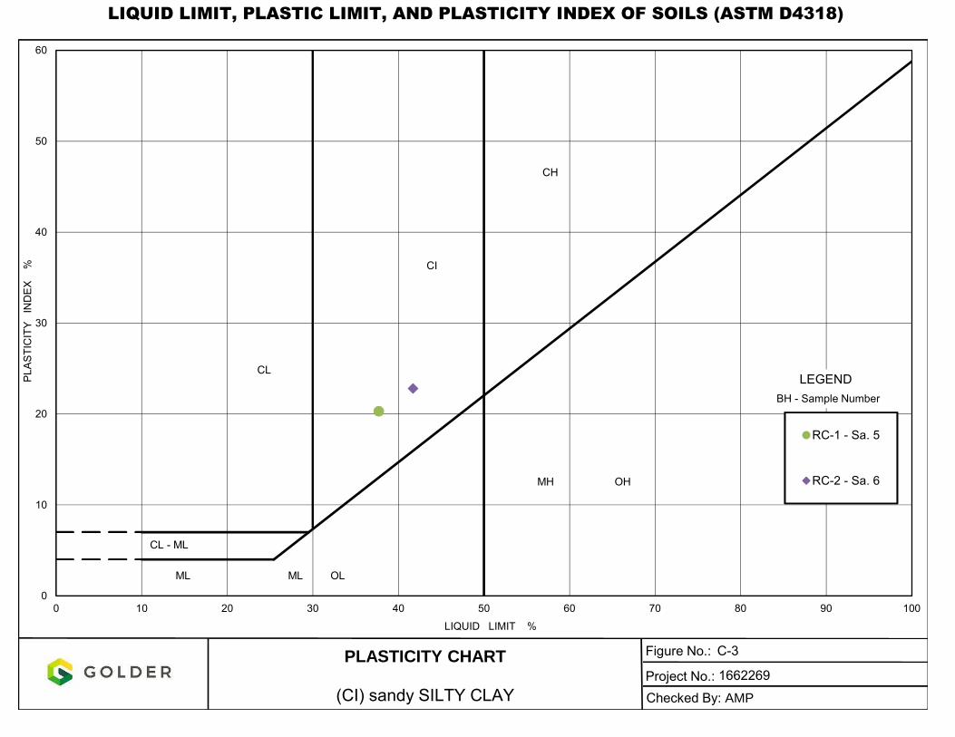
LIQUID LIMIT, PLASTIC LIMIT, AND PLASTICITY INDEX OF SOILS (ASTM D4318)
0
10
20
30
40
50
60
0 10 20 30 40 50 60 70 80 90 100
PL
AS
TIC
ITY
IND
EX
%
LIQUID LIMIT %
RC-1 - Sa. 5
RC-2 - Sa. 6
Figure No.:
Project No.:
PLASTICITY CHART
(CI) sandy SILTY CLAY
ML ML OL
CI
MH OH
CH
CL - ML
CLLEGEND
BH - Sample Number
Checked By: AMP
C-3
1662269

GRAIN SIZE DISTRIBUTION(ML) sandy SILT to SILTY SAND and GRAVEL (TILL) FIGURE C-4
Date: 29-Nov-18
Project Number: 1662269
Checked By: AMP Golder Associates
LEGEND
BOREHOLE SAMPLE ELEVATION(m)
RC-1 10 206.5RC-2 12 193.4RC-2 7 201.9
SYMBOL
0.00010.0010.010.11101000
10
20
30
40
50
60
70
80
90
100
GRAIN SIZE, mm
PE
RC
EN
TF
INE
RT
HA
N
6" 3"4¼" 1½" 1" ¾" ½" 3/8" 3 4 8 10 16 20 30 40 50 60 100 200| | | | | | | | | | | | | | | | | | | |
Size of openings, inches U.S.S Sieve size, meshes/inch
COBBLE
SIZE
COARSE FINE COARSE MEDIUM FINE SILT AND CLAY SIZES
GRAVEL SIZE SAND SIZE FINE GRAINED

GRAIN SIZE DISTRIBUTION(CL-ML) sandy CLAYEY SILT FIGURE C-5
Date: 29-Nov-18
Project Number: 1662269
Checked By: AMP Golder Associates
LEGEND
BOREHOLE SAMPLE ELEVATION(m)
RC-2 8B 199.3
SYMBOL
0.00010.0010.010.11101000
10
20
30
40
50
60
70
80
90
100
GRAIN SIZE, mm
PE
RC
EN
TF
INE
RT
HA
N
6" 3"4¼" 1½" 1" ¾" ½" 3/8" 3 4 8 10 16 20 30 40 50 60 100 200| | | | | | | | | | | | | | | | | | | |
Size of openings, inches U.S.S Sieve size, meshes/inch
COBBLE
SIZE
COARSE FINE COARSE MEDIUM FINE SILT AND CLAY SIZES
GRAVEL SIZE SAND SIZE FINE GRAINED

LIQUID LIMIT, PLASTIC LIMIT, AND PLASTICITY INDEX OF SOILS (ASTM D4318)
0
10
20
30
40
50
60
0 10 20 30 40 50 60 70 80 90 100
PL
AS
TIC
ITY
IND
EX
%
LIQUID LIMIT %
RC-2 - Sa. 8B
Figure No.:
Project No.:
PLASTICITY CHART
(CL-ML) sandy CLAYEY SILT
ML ML OL
CI
MH OH
CH
CL - ML
CLLEGEND
BH - Sample Number
Checked By: AMP
C-6
1662269