appendix r - landcorp · western power feasibility study for the kemerton industrial park . dms#:...
TRANSCRIPT

Appendix R
APPENDIX
Western Power Feasibility Study for the Kemerton Industrial Park

DMS#: 8004467
February 2011
Feasibility Study Report
Project : Kemerton Industrial Area
Developer/Consultant : WGE
Customer Reference : 2276-PER-U WP Reference : SF010041
Lot/Load/Capacity : Heavy Industrial 120-200MVA Related Files NA
Prepared By: - Kurt Franklin (Network Planning) - Vi Nguyen (Land Development)
Queries: For any queries, please contact the Network Planning or Land Development officer mentioned above, via Western Power’s Customer Service Centre on 131087 Alternatively – email: [email protected]
Feas
ibili
ty S
tudy

DMS#: 8004467
CONTENTS
Feasibility Study Report .............................................1
1 Development Proposal............................................3
1.1 Location Details ................................................................ 3
1.2 Development Details......................................................... 3
1.3 Electrical Requirements .................................................... 3
2 Study ........................................................................4
2.1 Electrical Connection........................................................ 4
2.2 Study Model...................................................................... 4
2.3 Study Results .................................................................... 4
3 Conclusion ...............................................................5
3.1 Connection Requirements ................................................. 5
3.2 Reinforcement Requirements............................................ 5
4 General Comments .................................................6

DMS#: 8004467
1 Development Proposal
1.1 Location Details
Vicinity of Marriott, Wellesley and Treasure Roads, Kemerton

DMS#: 8004467
See Figure 1 and
Figure 2

DMS#: 8004467
1.2 Development Details
Number of lots:
Land Use: Heavy Industry
Calculated Area: ~1000 ha (developable area estimated to be ~600 ha)
Staging: Staging and timing indeterminate.
Assumed, for the purposes of transmission planning, to be a load increase of
10 MVA per year for ten years
1.3 Electrical Requirements
The nominal design capacity required is based on an assumed 200 kVA/ha over 100 ha per year
for ten years.
A diversified maximum load, based on the design capacity, the nature of the area and the actual
developable area is considered to determine the requirements for this project.
Given the possible industry that may reside here in the future, a potential horizon load of up to 200
MVA is not unreasonable.

DMS#: 8004467
2 Study
2.1 Electrical Connection The area is adjacent to Marriot Rd substation, Kemerton terminal and contains several major
transmission lines and one three phase “backbone” 22 kV distribution line.
The distribution connections will initially be made to the Marriot Road substation – either directly to
new feeder circuits, or possibly from existing circuits – this will be dependent on timing and loading.
See Figure 1 and Figure 2
2.2 Study Model
Given the nature of this development, no detailed network modelling at the distribution level was
able to be carried out. However, based on the proposed layout and the design capacity, the
number of the 22kV feeders and their probable/preferred spatial arrangements has been proposed
as a conceptual “model”
2.3 Study Results
Details at hand indicate that four “main-line” distribution feeders will be necessary to supply the
basic electrical requirements of this development. As the staging occurs and new zone substations
are constructed, the four feeders will be progressively split up with the creation of new “Normally
Open Points” that should allow a staged and resource efficient method of minimising feeder and
substation investment.
Four feeders will become eight – and will further split to become twelve and sixteen feeders if
necessary.

DMS#: 8004467
3 Conclusion
3.1 Connection Requirements
Connections will be made from new networks constructed through the developments as the
staging occurs.
The general concept to be followed is shown in Figure 2, which is based on the assumption that
each lot will require a 3+1 RMU and direct connection to main-line feeder cables
Details will be provided through the DIP (Design Information Package) process as the stages
develop.
3.2 Reinforcement Requirements
This development area is likely to require significant transmission reinforcement (in the form of new
substations with the requisite transmission line connections) as the load and capacity develops.
The timing for this reinforcement will be driven by the type and timing of the load uptake.
This does not preclude internal or connection issues that will need to be dealt with at the time of
application and during the DIP process.
Applicants need to be aware that the information herein is provided in good faith and is accurate at
the time of issue. However, power systems are dynamic in nature and Western Power's distribution
electricity networks will change over time.

DMS#: 8004467
4 General Comments
Based on the study undertaken for the indicative ultimate load, at least 2 new zone substations and
several new HV feeders are required to supply the Kemerton Industrial area. Please refer to
Figure 2.
Feasibility studies are for the purpose of providing feedback on the distribution HV reinforcements
required to accommodate the proposed development. In this case, no estimate has been provided
as the cable route and distances of HV feeders is dependant on the location of the zone substation
from the development area.
As per the UDS, the developer is to provide Western Power with suitable sites for the future zone
substations having a minimum area of 1.44 hectares (120mx120m), at a location approved by
Western Power. The land for the substation site must be of an estate in fee simple free from all
encumbrances provided by way of gift and for no consideration free of all taxes, duties, charges
and registration. Registration of the transfer is to be negotiated between Western Power and the
developer.
The details in this feasibility study report are only indicative. Further in-depth study and analysis
will be required to determine the exact requirement of the transmission and distribution
reinforcement works once a formal application to Western Power has been lodged.
Western Power can neither reserve capacity nor guarantee supply to this development without a
formal request being lodged. In order to provide a firm connection proposal and cost, a formal
application to Western Power will have to be made, in accordance with our connection policies.

DMS#: 8004467
Figure 1 – Overview of Existing Networks
Approx 5km
330kV 132kV 22kV
Development Area
Single phase line
Marriott Road Substation
Kemerton Terminal

DMS#: 8004467
Figure 2 – Development area and Surrounds Conceptual Distribution and Substation Layout
Marriott Road Substation
Kemerton Terminal

DMS#: 8004467
Figure 3 – Development Area Detail – Plan From Consultant

DMS#: 8004467

Appendix S
APPENDIX
Dampier to Bunbury Natural Gas Pipeline - Main Line Gas Pipeline Plan (DBP)


Appendix T
APPENDIX
Dampier to Bunbury Natural Gas Pipeline - Kemerton Lateral Gas Pipeline Plan (DBP)


Appendix U
APPENDIX
Potential Water, Power & Gas Requirements – Table 5.2 (Parsons Brinckerhoff)

Waste Disposal Management Strategy for Expansion of Kemerton Industrial Park
PARSONS BRINCKERHOFF WASTE DISPOSAL STRATEGY JT D_EDIT Page 15
Table 5.2 Power and water requirements for proposed KIP based on GHD assessment for Oakajee
Industry type GHD classificationKIP industries that fit in
the classification
Total powerrequirements
Total water requirements – Ml/a (ktpa)
Waterdischarge
ML/a (ktpa)
By-products/
waste(ktpa)
Directemployment
(persons)
Power(MW)
Gas(TJ/a)
Domestic TDS (100–200 mg/L)High qualityindustry
TDS (800–1000 mg/L)
Cooling water
INDUSTRIAL FACILITIES
Large non-ferrous mineralprocessing/manufacturing
Covers a range ofpossible mineralgroups.Pyrometallurgic,hydrometallurgicalprocessing, refining,export. Theseprocesses are typicallyhigh energyuse/production, highwater use.
1. Silica sand facility*
2. Aluminium smelter
30 40,000 22 3,500 6,500 8,026 198 800
Medium sizenon-ferrousmineralprocessing/manufacturing
Pyrometallurgic,hydrometallurgical,refining and export.These processes aretypically moderateenergy use/productionand high water use.
1. Synthetic rutile plant
2. vanadium refiningplant
3. Silicon smelter(Simcoa)*
4. Pigment plant (CristalGlobal)*
5. Titanium metal plant
6. Lithium metal facility
45 60,000 33 5,250 5,571 9,750 117 1,200
Organic basedindustrialprocessing plant– agriculturalindustrial
Industrial scaleprocesses that arebased on organicchemicals (e.g.specialised oil refining,
1. Urea plant
2. fertilizer plant,
100 1000 20 2,000 2,000 6,600 1000 500

Waste Disposal Management Strategy for Expansion of Kemerton Industrial Park
PARSONS BRINCKERHOFF WASTE DISPOSAL STRATEGY JT D_EDIT Page 16
Industry type GHD classificationKIP industries that fit in
the classification
Total powerrequirements
Total water requirements – Ml/a (ktpa)
Waterdischarge
ML/a (ktpa)
By-products/
waste(ktpa)
Directemployment
(persons)
Power(MW)
Gas(TJ/a)
Domestic TDS (100–200 mg/L)High qualityindustry
TDS (800–1000 mg/L)
Cooling water
processing (AIP) gas production).3. BOC gases*
4. timber products plant
5. pulp and paper mill(A)
Generalindustries
No description 1. Ammonium nitratestorage
2. Chlor-alkali plant(Nufarm Cooge)*
3. Xanthate plant
4. ammonia plant
5. Hydrogen peroxideplant.
6. Lime hydration plant –Cockburn Cement*
3 144 2.25 120 120 198 300 240
Otherclassification
Fuel storage 1. Fuel terminal 2 11 1 10 25 28 3 50
Subtotal 179.5 102,655 78.25 10,880 15,145 24,600 1,617 2,790
SUPPORTIVE INFRASTRUCTURE
Solid wasteindustrialprocessing(large scale)
A processing facilitythat uses industrialprocesses to convertsolid waste into useful
1. Recycling facilities– Recovery ofgeneral recyclablematerial, industrialwaste, inert waste,
15 2,500 5 700 1,300 1,605 43 200

Waste Disposal Management Strategy for Expansion of Kemerton Industrial Park
PARSONS BRINCKERHOFF WASTE DISPOSAL STRATEGY JT D_EDIT Page 17
Industry type GHD classificationKIP industries that fit in
the classification
Total powerrequirements
Total water requirements – Ml/a (ktpa)
Waterdischarge
ML/a (ktpa)
By-products/
waste(ktpa)
Directemployment
(persons)
Power(MW)
Gas(TJ/a)
Domestic TDS (100–200 mg/L)High qualityindustry
TDS (800–1000 mg/L)
Cooling water
products construction anddemolition waste
Water factory A facility to processmultiple sources ofwater to produce avariety of qualities andvolumes of water.
1. Treatment facilitiesof hazardous andindustrial liquidwaste streams
22 0 0.9 0.2 0 11,300^ 294.2 70
Energy factory Co/tri-generation orcombined cyclefacility, analogous tothe water factory, toreceive natural gas,hot waste process,liquid etc., and supplyelectrical energy,power, steam, hot air,hot water back toindustries.
1. Powerstation/energyfactory
- 20^ 1 0 0 - - 25
Sub total 37 2,500 6.9 700.2 1,300 1,605 337.2 298
Total 216.5 105,155 85.45 14,080 16,445 26,207 1,954 3,088
Notes: *Existing Industry ^indicates water/heat produced/required by the water factory/power factory, respectively, which have therefore not been included as KIP’s output/input.(A) Water demands and discharge not included in this table, given the particular high water demands typical of this industry.

Appendix V
APPENDIX
Preliminary Staging Plan (Wood & Grieve Engineers)

DEVLIN ROAD
WELLESLEY ROAD
WELLIN
GT
ON R
OA
D
TREASURE ROAD
KEMERTON ROAD
OLD
CO
AST
RO
AD
STAGE 4
STAGE 5
STAGE 1B
STAGE 5A
STAGE 3A
STAGE 2A
SCALE 1:20,000
PLAN
MARRIOTT ROAD MARRIOTT ROAD
SO
UT
H W
EST H
WY.
21/10/11ORIGINAL ISSUE GABA
REVISED CADASTRAL GABB
C NJHECADASTRAL UPDATED
STAGE 2
STAGE 3
STAGE 1A
STAGE 4A
-------------
LEGEND
STAGE 1
STAGE 2
STAGE 3
STAGE 4
STAGE 5
PROPOSED STAGE BOUNDARY
D NJHEPROJECT NAME AMENDED
STRATEGIC INDUSTRY ZONE BOUNDARY
ANCILLARY INDUSTRY ZONE BOUNDARY
D
PROPOSED STAGING PLAN
GAB
PSP:\22726\Civil Drawings\Sketches\140722 Sketches new report\c plan staging.dgn
KE
MERT
ON R
OA
D
-
LANDCORP
22726-PER-C
PRELIMINARY
DESIGNED :
SCALE :A1
CONSTRUCTION :APPROVED FOR
FOR TENDER:APPROVED
VERIFIED :
DRAWING No. REVISION
REV. DESCRIPTION
A.H.D.
WAPC :
SECTION:
DRAWN :
PROJECT No.
DATUM :
TITLE:
PROJECT:
CLIENT:
CIVIL SERVICES
VER APPROVEDDRAWN
WOOD & GRIEVE ENGINEERSWOOD & GRIEVE ENGINEERS
CELEBRATING
YE
AR
S
A.C.N. 137 999 609
Level 3, Hyatt Centre
3 Plain Street, East Perth
Western Australia 6004
Phone: +61 8 6222 7000
Fax: +61 8 6222 7100
Email [email protected]
Web www.wge.com.au
PERTH
MELBOURNE
SYDNEY
BRISBANE
ALBANY
BUSSELTON
SHENZHEN
GOLD COAST
Wood & Grieve Engineers Ltd
KEMERTON STRATEGIC INDUSTRIAL AREA - STRUCTURE PLANNING

Appendix W
APPENDIX
Extract from Local Water Management Strategy – Kemerton Strategic Industrial Area
Report, by RPS (RPS ref D1054201 Rev 0, dated December 2014) - Section 5.0 Water
Supply, Section 6.0 Wastewater Treatment and 7.0 Surface Water Management.

Local Water Management Strategy Kemerton Strategic Industrial Area
D1054201, Rev 0, December 2014 Page 21
5.0 WATER SUPPLY
5.1 Existing Potable and Process Water Supply at the KSIA
The existing industries at the KSIA abstract water for process and potable water
requirements from unconfined and confined aquifers. A brief summary (sourced from
Aquaterra 2002) of the abstraction bores for each existing industry is outlined below:
Simcoa Operations Pty Ltd (Kemerton Silica Smelter) operates two production
bores, PB1 and PB2. Bore PB2 extracts water from the Yarragadee Formation and
is the primary source of water. Bore PB1 has been used from time to time as a
back-up and extracts water from the Superficial formation. The site operates a
water treatment plant for water pumped from the production bores. The treated
water is then pumped to a process water tank, which is used to meet potable and
process water requirements. Problems have been encountered with treatment of
groundwater extracted from the Superficial formation due to high TDS, dissolved
organics and hydrogen sulfide. Wastewater is discharged via drainage channels or
pumped to a polyethylene lined settling pond where, after solids have settled out, it
is recycled for on-site use for dust suppression and irrigation purposes.
Kemerton Silica Sands operate two production bores, KW7 and KW14, both
extracting water from the Superficial formation. The process water supply is
primarily made up of return water used in the process and supplemented by water
from the production borefield. Water from the production borefield is also the
source for on-site potable water requirements.
Millennium Inorganic Chemicals (MIC) operates three production bores, KW-1,
KW-3 and KW-4. Bore KW-1 draws water from the Leederville formation and
bores KW-3 and KW-4 from the Cattamarra Coal Measures. This water is treated
prior to use in the process. All wastewaters, excluding stormwater, are directed to
their wastewater treatment plant. The treatment plant currently discharges around
1 GL/yr to the ocean.
Nufarm-Coogee – No production bores. All water requirements for the site are
provided by MIC. All effluent produced from the process, and run-off from the salt
slabs, is pumped to the wastewater treatment plant operated by MIC.
Cockburn Cement – No production bores. All water requirements for the site are
provided by MIC. All effluent produced from the process is pumped to the
wastewater treatment plant operated by MIC.

Local Water Management Strategy Kemerton Strategic Industrial Area
D1054201, Rev 0, December 2014 Page 22
BOC Gases – As for Nufarm, process and potable water requirements for BOC
Gases, located in the southern part of the Estate, is supplied by MIC. The water is
treated on site for potable needs using side stream filters and water softeners
through a cooling tower. The wastewater from the cooling tower is conveyed to a
concrete lined pit, which is then pumped back to MIC to be treated in the
wastewater treatment plant, and discharged to the ocean.
Kemerton Power Station (Transfield Services) commenced operation in November
2005. In June 2008, a 40 MW upgrade was completed on Kemerton Power Station,
increasing its capacity to 300 MW. Transfield Service has an agreement with Harvey
Water to supply up to 5 GL per year of water from the Harvey Irrigation Scheme
to the Transfield Worley power station as and when required. Wastewater
generated at the Power Station is disposed of on site using evaporation ponds.
5.2 Future Potable and Process Water Requirements
5.2.1 Aquaterra Water Study (2002)
An estimate of the type and number of industries that would locate to the KSIA and
estimated future water demand were completed in the Phase 2 Water Study (Aquaterra
2002). It was estimated that the water demand at the KSIA is likely to range between
7 GL/yr and 23 GL/yr. Table 4 below provides an estimate of the predicted water
demand required at the KSIA for various growth scenarios.
Table 4: Future Water Demand for the KSIA
Scenario Demand Comments
Low Growth 7 GL/yr Status quo with demand dictated by the expansion of Cristal and Simcoa operations. Included also is the possibility of titanium sponge production and a few small unspecified industries.
Medium Growth
10 GL/yr Volume required is higher to meet the demands of a synthetic rutile plant, wool processing, iron briquetting plant and a pulp mill.
High Growth
14 to 18 GL/yr
High growth scenario view considering the full development of with a wide range of industries including an aluminium smelter, power station and other industries.
Maximum 23 GL/yr High growth demand plus the introduction of a “high water demand” industry.
Source: Aquaterra 2002 Table 3.2
5.2.2 Marsden Jacob Associates (2011)
Marsden Jacob Associates were commissioned by the South West Development
Commission to undertake an economic analysis of the likely demand for industrial water
supplies and assess the supply options that may be obtained from local sources. A copy
of this document is provided in Appendix 5. Water supply is a key factor in maintaining

Local Water Management Strategy Kemerton Strategic Industrial Area
D1054201, Rev 0, December 2014 Page 23
both existing industrial output and supporting growth in the region. The investigation
was required in order to establish future possible water supply options and the
feasibility for agricultural and industrial uses in the south-west.
The potential water supply and water demand of the KSIA was investigated as part of
this study. Using other industrial parks in Australia as a benchmark, it was calculated that
diversified industrial estates, similar to the KSIA, have a general water demand of
0.025 GL/ha/yr. At full development of the KSIA, the benchmark forecast suggests that
additional water use could be in the order of 18 to 27 GL/year at the KSIA, as indicated
in Figure A below.
(Source: MJA 2011)
Figure A: Existing Supply and Planned Supply/Demand in the Kemerton Strategic
Industrial Area
In assessing possible water supply to the KSIA, the study estimated that 9 GL per year of
water can be provided from sources considered “easily accessible” in the KSIA, including
the Superficial, Leederville and Cattamarra South aquifers (Catammarra north is
relatively deep and has a high salinity) and Harvey Water’s existing pipeline in the area.
Various water supply and demand scenarios were calculated for the KSIA in order to
assess various short and long-term supply and demand options required at the KSIA. A
summary for each scenario is summarised in Table 5 below.

Local Water Management Strategy Kemerton Strategic Industrial Area
D1054201, Rev 0, December 2014 Page 24
Table 5: Summary of Supply and Demand Balance for Each Scenario (Marsden
Jacobs 2010)
Current Supply/ Demand (GL)
Prospective Demand and Supply, 2016 (GL)
High Demand and Supply (GL)
High Demand, Low Supply (GL)
Kemerton Water Supply 19 26 26 19
Kemerton Water Demand 10 17 40 40
Shortfall NA NA 14 21
Excluding the potential conflicting water requirements of other industries located in the
vicinity that may require water, the summary indicates that water demand can be met at
the KSIA under the predicted scenarios until 2016.
In the event that a number of high demand industries locate to the KSIA, such as an
aluminum smelter, the water demand for the KSIA is likely to be 40 GL/year. This will
exceed the 26 GL of supply proposed to be available. The 26 GL of supply is based on
existing groundwater supplies as well as recycled wastewater from the Kemerton Water
Treatment Plant and groundwater from the Cattamarra Coal measures.
In this instance, additional alternate water supplies will be required to meet the water
demands of possible high demand industries that may locate to the KSIA in the long
term. Should capacity be reached however in the long term (which is predicted to be in
20 to 30 years), further water provision options shall be sought from possible sources
such as improved water recycling initiatives on site and from local industries. These two
options mentioned above and additional water sources are discussed in further detail in
Section 5.3.
It is anticipated that growth in irrigated agriculture will be met by existing water
entitlements. Water is currently available for agriculture in the Wellesley groundwater
sub-area and may become available for Harvey Water if salinity in the Wellington Dam
improves or if additional water efficiency projects are funded by government.
The priority in the region is therefore to provide fit for purpose water supplies to
support industrial growth.
5.3 Future Supply Options
The Marsden Jacob study assessed the feasibility of a wide range of possible water
sources and uses. The key water sources available for the KSIA include (MJA 2011):
Integrated Water Supply Scheme (Potable)
Wellington Dam (Potable and Process)

Local Water Management Strategy Kemerton Strategic Industrial Area
D1054201, Rev 0, December 2014 Page 25
Groundwater Abstraction (Potable and Process)
Recycled water from the Verve Pipeline (Process)
Recycled water from the Kemerton Wastewater Treatment Plant (Process)
Recycled water from the Millennium Inorganic Chemicals Treatment Plant
(Process).
An additional water supply option not investigated by the Marsden Jacob study includes
the broad scale application of water recycling within the KSIA at the lot scale and
between industries located within the KSIA.
In the long term, once a sufficient mass of industry is located at the KSIA, the
establishment of an on-site wastewater treatment and recycling plant to allow for the
large scale collection and recycling of water within the KSIA will be investigated.
5.3.1 Integrated Water Supply Scheme
Harvey is supplied by the Integrated Water Supply Scheme that services the Perth
metropolitan area. The Water Corporation presumes the supply to KSIA would be
limited to domestic and low usage industry only with major industrial water use sourced
through other means such as groundwater or recycled water.
5.3.2 Wellington Dam
Wellington Dam has an estimated annual yield of 86.2 GL and a storage capacity of
185 GL, however is under utilised due to high salinity levels. The total allocation
available from the Wellington Dam is currently 85.1 GL, with water currently allocated
or reserved for the following purposes (MJA 2011):
Harvey Water irrigators currently use around 47.5 GL of the 86 GL per year
entitlement (average since 1996–1997). Harvey Water has been in negotiations
with a number of industrial customers to supply water to industry from the
remaining allocation.
To expand the potential for industrial supply, Harvey Water has constructed a
pipeline that can, at present, transfer up to 6 GL of water from the Collie River
catchment. Harvey Water has constructed a pipeline capable of supplying up to
5 GL per year of water to the Transfield Worley power station as and when
required.
The Collie Water River Project has outlined an option to reduce salinity by
diverting high saline flows from the Collie River. Harvey Water has indicated that if
salinity is reduced to the target levels and a Commonwealth funded initiative to

Local Water Management Strategy Kemerton Strategic Industrial Area
D1054201, Rev 0, December 2014 Page 26
pipe the Collie irrigation area is undertaken, Harvey Water would provide 11 GL of
water to the Commonwealth Environmental Water Holder, 11 GL for industrial
use and the remaining 46 GL for irrigation.
5.3.3 Groundwater Abstraction
The remaining groundwater allocation available for abstraction for the groundwater
management areas the KSIA is located in is 11 GL/year, the majority of which is within
the Cattamarra coal measures in the KSIA north and south sub-area.
As discussed in Section 3.4, 2 GL is contained in the Superficial aquifer in a dispersed
nature making extraction of the water for industrial use difficult. In addition, the water
from Cattamarra Coal Measures in Kemerton North is relatively deep with high salinity.
Therefore, only 3 GL of water contained in the Cattamarra Coal Measures in Kemerton
South might be considered readily accessible by industry (MJA 2011).
An application was lodged with the DoW in 2011 to secure a groundwater allocation of
9 GL/year from the Cattamarra Coal Measures aquifer of the Kemerton North and
South groundwater sub-areas for the purpose of industrial processing within the KSIA.
The DoW advised that a staged development plan would be required and that the
maximum permitted licence term for large staged developments with a water
entitlement exceeding 500 ML/yr is five years. In 2011, a staged development plan was
not available and the time frames for development of the KSIA were also uncertain. In
addition the DoW requested that a H3 Hydrogeological Assessment report and
successful drilling of the aquifer be completed prior to the DoW issuing a 5C licence to
take water.
Future applications to secure a groundwater licence for both potable and process water
will be supplied to the DoW following approval of the KSIA Structure Plan and the
required information being available.
5.3.4 Kemerton Domestic Wastewater Treatment Plant
The Water Corporation’s Kemerton Wastewater Treatment Plant treats wastewater
from the nearby towns of Australind and Eaton. The plant is currently capable of
treating 3 ML per day (approximately 1 GL per year) of wastewater. The Water
Corporation is currently examining alternatives to upgrade the plant to treat 7.2 ML per
day (2.6 GL per year at full capacity). Harvey Water understands that the volume
available from recycling could ultimately be increased to 8 GL per year; however, this
could not be confirmed by MJA at the time of reporting. A portion of the treated water
from the plant is recycled and waters nearby tree farms at the KSIA. The Water
Corporation is also in discussions with a potential industrial customer to supply the
remaining capacity of the plant as recycled water (MJA 2011).

Local Water Management Strategy Kemerton Strategic Industrial Area
D1054201, Rev 0, December 2014 Page 27
Correspondence with the Water Corporation has commenced to seek advice as to
whether they would look favorably on diverting treated wastewater to the KSIA for
reuse. The Corporation has supported the proposal to draw some or all of the treated
wastewater from the Kemerton WWTP subject to availability and a commercial
agreement. Refer to Appendix 6 for correspondence with the Water Corporation.
Since early discussions with the Water Corporation occurred regarding the recycling of
wastewater from the Kemerton WWTP, it appears that Harvey Water are in
negotiations to purchase the water from the Water Corporation to shandy with water
from Harvey Water’s dam supplies. The option of reusing water direct from the WWTP
may not be an option; however purchasing the water from Harvey Water is a possibility.
5.3.5 Verve Ocean Outfall
The Verve Ocean outfall pipeline is licensed for approximately 7 ML per day of
discharge. Verve has indicated that the pipeline will be at full capacity if and when
current negotiations with DoW are finalised. The Verve pipeline passes the KSIA and
could potentially be used as a source of recycled water, although the quality of the
wastewater may make recycling an expensive alternative (MJA 2010).
Correspondence with the Water Corporation has commenced to seek advice as to
whether they would look favorably on diverting treated effluent to the KSIA for reuse.
The Water Corporation has responded outlining that discharge of treated wastewater
via the Verve Energy outfall does not preclude commercial reuse alternatives such as the
KSIA. Refer to Appendix 6 for correspondence with the Water Corporation.
5.3.6 MIC Wastewater Treatment Plant
The existing Millennium Inorganic Chemicals wastewater treatment plant discharges
approximately 1 GL/yr to the ocean, with an effluent water quality of around
30,000 mg/L Total Dissolved Solids (TDS). Nutrient concentrations are generally around
0.35 mg/L for nitrate and 0.05 mg/L for phosphorous. This treated water quality is not
suitable for re-use by the existing industries, but it may be suitable for use by future
industries, or for further treatment by any future wastewater treatment plants at
Kemerton (Aquaterra 2002).
5.3.7 KSIA Water Recycling
A potential source of water is the supply of recycled wastewater generated by the
industries located within the KSIA. The strategy in the short term is for sites which
generate industrial wastewater, to treat the water at the lot scale to a standard where it
is suitable for disposal to a nearby facility or reuse on site or by a neighboring industry.

Local Water Management Strategy Kemerton Strategic Industrial Area
D1054201, Rev 0, December 2014 Page 28
In the long term, once a sufficient mass of industry is located at the KSIA, alternate
wastewater disposal options will be investigated, including the establishment of an on-
site wastewater treatment and recycling plant to allow for the large scale collection and
recycling of water within the KSIA.
Further details on this topic can be found in Section 6.1 Industrial Wastewater.

Local Water Management Strategy Kemerton Strategic Industrial Area
D1054201, Rev 0, December 2014 Page 29
6.0 WASTEWATER TREATMENT
6.1 Industrial Wastewater
The Water Corporation does not support reticulated wastewater collection from
industrial sites for treatment in conventional wastewater treatment plants. Industrial
estates by nature of layout, discharge type and potential high flow rates are not readily
compatible with domestic treatment processes. Industrial treatment, reuse and disposal
are often better addressed on site or locally.
The Water Corporation has outlined the preferred options to manage industrial
wastewater at the KSIA:
Industry to treat effluent to predetermined acceptance criteria and recycled on site
or to a neighbouring industry, (this currently occurs on site by some of the existing
industries).
Industrial wastewater to be collected centrally and recycling opportunities sought
or disposal considered.
If a critical mass of industry is reached, a combined application for a common outfall
could be made whereby wastewater is treated to an acceptable standard on site or
centrally within the KSIA prior to disposal (subject to required environmental
approvals).
As the development timetable and occupancy rate of the KSIA is undefined at this stage
in the planning process, the strategy in the short term is for sites which generate
industrial wastewater, to treat the water at the lot scale to a standard where it is
suitable for disposal to a nearby facility or reuse on site or by a neighboring industry.
In the long term, once a sufficient mass of industry is located at the KSIA, alternate
wastewater disposal options will be investigated, including the establishment of an on-
site wastewater treatment and recycling plant.
6.2 Commercial Wastewater
The population of employees expected to work at the KSIA on a daily basis is not
expected to warrant the demand and expense of the infrastructure to install reticulated
wastewater collection sewers provided by the Water Corporation to dispose of
wastewater generated from toilets, bathrooms and kitchens at the lot scale.

Local Water Management Strategy Kemerton Strategic Industrial Area
D1054201, Rev 0, December 2014 Page 30
As an alternative, the KSIA will rely on the use of Aerobic Treatment Units (ATUs)
and/or septic tanks and leach drains to collect, store and treat wastewater from the
Lots. The Shire of Harvey expressed their preference for the use of septic tanks and
leach drains at a brief meeting held between the Shire of Harvey, RPS and Wood and
Grieve Engineers on 11 July 2011. It was agreed at this meeting that the location,
number and type of system would be confirmed in the UWMP, which is to be
completed as a condition of subdivision and development applications submitted to the
SoH for individual lots at time of construction.
6.2.1 Aerobic Treatment Units
Aerobic Treatment Units (ATU) are self-contained electrical wastewater (sewage)
treatment systems for use on properties that are not connected to mains sewerage.
The ATUs shall be designed and located in accordance with the Department of Health’s
(DoH) Code of Practice for the Design, Manufacture, Installation of Aerobic Treatment Units
(DoH 2001) and the Department of Water, Water Quality Protection Note 70 Water
Treatment and Disposal – Domestic Systems (DoW 2010b).
ATUs consist of a series of treatment chambers including an aeration chamber and a
solids settling chamber where the effluent is discharged via an underground soakage
system.
These systems normally reduce degradable organic matter, sediment, suspended solids
and grease to concentrations significantly less than conventional septic tank treatment
systems.
Figure B: Example ATU – DoH Approved Biomax Model C10
Figure B above illustrates that the ATU is divided into five principal chambers:
Stage A – Anaerobic chamber – anaerobic treatment
Stage B – Aerobic chamber – aerobic treatment
Stage C/D –- Clarification chamber – sludge settlement and removal

Local Water Management Strategy Kemerton Strategic Industrial Area
D1054201, Rev 0, December 2014 Page 31
Stage E – Disinfection chamber – contact time with chlorine
Stage F/G – Pumpout chamber – discharge to disposal system.
This system is approved for dripper irrigation. Other units that are DoH approved do
not contain a disinfection chamber and effluent can be discharged to soakage wells or
horizontal leach drains. Soakage through an approved amended soil mix (that retains
phosphate on fine soil particles) in an effluent disposal area can achieve phosphorus
removal. The amended soil has a finite operational life before becoming saturated with
phosphate and will need replacing when phosphate breakthrough occurs
The soil characteristics at the disposal site should allow effective soakage of treated
wastewater in accordance with the Health (Treatment of sewage and disposal of effluent
and liquid waste) Regulations 1974.
Under DoH legislation, ATUs are required to be serviced at least every three months.
Servicing can only be carried out by a person who has approval from the Executive
Director, Public Health to service ATUs
6.2.2 Septic Tanks with Amended Soil Effluent Systems
A possible septic tank system for the KSIA consists of two conventional septic tanks in
series, followed by leach drains surrounded by a permeable amended soil blend that
removes phosphate (Figure C). One approved soil amendment material is a by-product
of alumina processing known as red mud and red sand. This type of system reduces
concentrations of biochemical oxygen demand, suspended solids, micro-organisms and
phosphate in effluent.
(Source: DoW 2010b)
Figure C: Septic Tank System
6.2.3 Buffers to Wastewater Systems with Phosphorus Removal
Table 6 outlines the buffers recommended to wastewater treatment systems with
phosphate removal near sensitive waterways or wetlands.

Local Water Management Strategy Kemerton Strategic Industrial Area
D1054201, Rev 0, December 2014 Page 32
Table 6: Buffers to Wastewater Systems with Phosphate Removal (Source: DoW
2010)
Feature Minimum Buffer Distance Comments
Wetlands 50 m Buffer in accordance with the DER and Environmental Protection Authority policies on the minimum buffer required for any type of development near a wetland.
Waterways and Estuaries
30 m Buffer in accordance with DoW policy on foreshore protection for waterways.
Outside the flooded area resulting from a 10 year (average recurrence interval) storm
Local Water Management Strategy Kemerton Strategic Industrial Area
D1054201, Rev 0, December 2014 Page 33
7.0 SURFACE WATER MANAGEMENT
7.1 Stormwater Management
The site will effectively manage stormwater through the implementation of Water
Sensitive Urban Design (WSUD) principles and Best Management Practices (BMPs) to
control water quality and quantity from both minor and major storm events.
To manage the increased run-off expected from development, the site has been divided
into 10 sub-catchments to allow for a series of stormwater management measures to be
implemented throughout the site, to manage stormwater close to source and to
facilitate the infiltration of stormwater where possible.
In accordance with the Stormwater Management Manual for Western Australia (DoW
2004–2007) and the Department of Waters Water Quality Protection Note 52
“Stormwater Management at Industrial Sites” (May 2010), the drainage system will aim
to achieve the following objectives:
Maintain the existing hydrological regime by allowing the infiltration of
uncontaminated water on site and limiting discharges from the KSIA to pre-
development peak flows and volumes.
Uncontaminated stormwater run-off from roofs for example will not be allowed to
mix with process effluent and stored chemicals to allow for the infiltration of
uncontaminated stormwater and recharge of the Superficial aquifer.
Rainfall up to the 1:10 year ARI event will be retained and infiltrated within lot
boundaries using soakwells. Lot run-off in excess of 1 in 10-year ARI event shall
discharge to roadside swales.
Roadside conveyance swales shall be sized to convey the critical 10-year ARI storm
events from the road reserves wherever possible to minimise the use of a piped
drainage network.
Large rainfall events (>10 year) up to the 1:100 year ARI event will be conveyed
through overland flow and road side swales to drainage detention basins within the
site for storage and/or treatment prior to infiltration.
The proposed drainage strategy adopts a similar approach to the management of
stormwater that is currently being used at the KSIA. The existing industries for example
are primarily located on the main entrance road (Marriott Road) where roadside swales
are used to collect stormwater from the road reserves.

Local Water Management Strategy Kemerton Strategic Industrial Area
D1054201, Rev 0, December 2014 Page 34
As the site is zoned Industrial, fertiliser use is expected to be minimal. Landscaped POS
areas will incorporate native species that will not require irrigation once established.
Native vegetation will also be used in stormwater detention/retention areas to aid
infiltration, control erosion and provide a degree of water quality treatment.
7.1.1 Post-development Drainage Design
Design of the drainage system focuses on maintaining the pre-development hydrological
regime at the site as closely as possible, while concentrating on the protection of
groundwater and surface water resources.
In order to establish the current baseline hydrological conditions at the KSIA, RPS has
developed an XPSWMM surface water model of the site to determine the surface water
catchment boundaries, pre-development surface water flow rates and the required
volumes of stormwater detention needed on site to maintain the pre-development
conditions. Figure 11 provides an assessment of the pre-development drainage flow
paths and catchment boundaries.
Lidar data was received for the KSIA area and was used to create a digital elevation
model for the area, which magnified the surface relief and drainage features for the area.
The preliminary drainage and earthworks designs provided in Figures 12 to 14 and
Appendix 7 will need to be further refined at the subdivision stage. Although
preliminary, the drainage and earthwork concepts demonstrate that the KSIA is capable
of managing stormwater in events up to the 1 in 100 year ARI, while incorporating
suitable best management practices.
7.1.2 Minor Drainage System
Rainfall will be retained on site and infiltrated as close to source as possible using the
following practices:
All rainfall on the permeable surfaces, particularly uncleared land surrounding the
lots will infiltrate as per existing conditions.
The use of rainwater tanks to collect run-off from roof areas will be encouraged as
a potential source of water, and as a means of reducing enhanced run-off from
paved surfaces.
Lots will infiltrate rainfall in events up to the 1:10 year ARI event through the use of
soakwells
Road drainage within the development will incorporate roadside conveyance swales
and limited piped network designed to accommodate the 10-year event.
Local Water Management Strategy Kemerton Strategic Industrial Area
D1054201, Rev 0, December 2014 Page 35
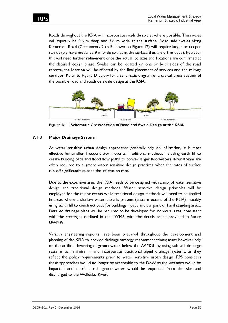
Roads throughout the KSIA will incorporate roadside swales where possible. The swales
will typically be 0.6 m deep and 3.6 m wide at the surface. Road side swales along
Kemerton Road (Catchments 2 to 5 shown on Figure 12) will require larger or deeper
swales (we have modelled 9 m wide swales at the surface that are 0.6 m deep), however
this will need further refinement once the actual lot sizes and locations are confirmed at
the detailed design phase. Swales can be located on one or both sides of the road
reserve, the location will be affected by the final placement of services and the railway
corridor. Refer to Figure D below for a schematic diagram of a typical cross section of
the possible road and roadside swale design at the KSIA.
Figure D: Schematic Cross-section of Road and Swale Design at the KSIA
7.1.3 Major Drainage System
As water sensitive urban design approaches generally rely on infiltration, it is most
effective for smaller, frequent storm events. Traditional methods including earth fill to
create building pads and flood flow paths to convey larger floodwaters downstream are
often required to augment water sensitive design practices when the rates of surface
run-off significantly exceed the infiltration rate.
Due to the expansive area, the KSIA needs to be designed with a mix of water sensitive
design and traditional design methods. Water sensitive design principles will be
employed for the minor events while traditional design methods will need to be applied
in areas where a shallow water table is present (eastern extent of the KSIA), notably
using earth fill to construct pads for buildings, roads and car park or hard standing areas.
Detailed drainage plans will be required to be developed for individual sites, consistent
with the strategies outlined in the LWMS, with the details to be provided in future
UWMPs.
Various engineering reports have been prepared throughout the development and
planning of the KSIA to provide drainage strategy recommendations; many however rely
on the artificial lowering of groundwater below the AAMGL by using sub-soil drainage
systems to minimise fill and incorporate traditional piped drainage systems, as they
reflect the policy requirements prior to water sensitive urban design. RPS considers
these approaches would no longer be acceptable to the DoW as the wetlands would be
impacted and nutrient rich groundwater would be exported from the site and
discharged to the Wellesley River.

Local Water Management Strategy Kemerton Strategic Industrial Area
D1054201, Rev 0, December 2014 Page 36
The refinement of the drainage strategy, incorporating current drainage best practice, is
to maximise the infiltration within the development area of each lot. Broadly, this
strategy relies on the use of undeveloped/uncleared areas on each lot for infiltration,
along with the use of soakwells for run-off from “clean water” sources including roof
areas and pedestrian paved areas surrounding the building pads, to avoid the need for
substantial drainage control structures.
The strategy also relies on the use of the Multiple Use category wetlands as drainage
infiltration basins or existing topographical low points for storage and infiltration of the
larger flood events. It should be noted that the Multiple Use wetlands are “sumplands”
which are seasonally inundated with run-off and groundwater inflows. They typically
occur on the eastern side of the KSIA, and their use as drainage basins is consistent with
their Multiple Use management category, provided that the hydrological functions (e.g.
seasonal inundation) and any remaining ecological functions are preserved. As the basins
are intended for flood storage, the pattern of seasonal inundation will continue. The
roadside swales will provide an important function in the storage of stormwater in
major events also.
The refined drainage strategy and development plan involves filling the developed
portions of Lots with earth fill (preferably sourced from on-site material) to provide
sufficient clearance to groundwater from building foundations. Hence, groundwater
levels under adjacent undeveloped portions of the blocks could be as high as the natural
surface without compromising the developed (earth filled) areas.
With this arrangement, sub-soil drainage beneath the developed areas may not be
required, and only the portion of each block that is developed may require earth fill,
depending on the depth to the water table.
In areas with the groundwater near the surface, earth fill levels for the developed
portions of each block would need to be a minimum of 1.5 m from the AAMGL to guard
against the potential for groundwater contamination and flooding of developed areas.
For larger storms (>10 year ARI), roads and hardstand areas will be designed to convey
the major flood flows towards the road reserve where grassed swales and overland flow
will be used to convey flood flows to retention basins (Multiple Use wetlands or existing
topographical low points) located within individual sub-catchments, as shown on
Figure 12.
Preliminary earthworks plans, completed by the project engineers, Wood and Grieve
Engineering are provided in Figures 13 and 14 and indicate that areas of cut to fill have
been investigated in order to provide a minimum clearance of 1.5 m to AAMGL over a
majority of the site. The engineering plans will be further refined as subdivision
commences and detailed design is completed.

Local Water Management Strategy Kemerton Strategic Industrial Area
D1054201, Rev 0, December 2014 Page 37
In summary, the revised drainage strategy for major events, incorporating current best
practice, involves the following:
filling of land parcels within each lot to provide adequate building envelopes and a
minimum clearance of 1.5 m to AAMGL
lots to infiltrate all events up to the 10 year ARI through the use of soakwells for
“clean” hard standing areas and infiltration in undeveloped portions of lots
events greater than the 10 year ARI from the lots will be directed to the road
reserve and road side swales (designed to have capacity for the 10 year ARI)
roadside swales and overland flow through the road network will convey large
flood flows to detention basins for storage and treatment prior to infiltration. Flow
to Wellesley River shall be maintained at pre-development flow rates to ensure the
hydrological regime and water quality is maintained at pre-development conditions.
7.1.3.1 Stormwater Storage Requirements
The stormwater modelling for the site has been completed by RPS using XPSWMM
software. The stormwater treatment system shown in Figure 12 details the areas and
volumes of stormwater detention for the 1, 10 and 100-year events to maintain pre-
development conditions where possible.
The site has been divided into ten post development catchment areas. Stormwater
storage areas have been sized to accommodate the 1:100 year ARI event within
catchments 1 to 4. Catchments 5 and 6 are sized to cater for the 1:10 year ARI event
with over flow to Wellesley River. The 100-year ARI flows are below predevelopment
1:10 year ARI rates (as lots are infiltrating up to the 1:10 year event). Catchment 7 has
been sized to attenuate the 1:100 year event at predevelopment 1:10 year rates.
Appendix 7 contains a table summarising the stormwater requirements for each of the
10 sub-catchments.
The invert of all drainage structures will be designed to achieve a minimum clearance of
0.3 m to the Maximum Groundwater Level (MGL) across the site to comply with DoW
policy and ensure that the drainage features will be free of standing water except for
short periods of time after heavy rainfall.
The outline drainage design provided in Figure 12 is preliminary and is subject to
variation following confirmation of the staged planning boundaries of the KSIA and lot
boundaries and sizes. A detailed subdivision layout will be confirmed in future UWMP(s)
along with the detailed drainage and earthwork designs. Refer to Appendix 7 for further
details on the stormwater storage requirements and further model assumptions and
detail.

Local Water Management Strategy Kemerton Strategic Industrial Area
D1054201, Rev 0, December 2014 Page 38
7.2 Water Quality Treatment
In addition to the above management measures, the following best management
practices and treatment measures shall be put in place to retain the quality of
stormwater. These measures shall be in accordance with the DoW Water Quality
Protection Note 52 “Stormwater Management at Industrial Sites” (May 2010). Industrial
sites require effective management of stormwater run-off from roofs, pavements,
exterior materials storage and process areas to avoid flooding and contamination of
sensitive water resources.
7.2.1 Structural Treatment Systems
7.2.1.1 Soil Amendment
Soils within the lots will be amended to minimise the risk of soil and groundwater
contamination from the industrial land uses. As a minimum, the soils surrounding the
soakwells within lots will be amended to a depth of 0.3 m beneath the soakwells;
however, the landowners may decide to amend the entire building footprint beneath the
hardstand area for ease of earthworks.
7.2.1.2 Drainage Areas
A combination of using topographical lows points and Multiple Use wetlands for the
attenuation and infiltration of flood flows is proposed for the management of the major
rainfall events. Review of Lidar data and a site visit was completed to assess the
suitability of various Multiple Use wetlands and areas of the site for drainage. The
chosen wetlands are those in existing flood flow paths and are naturally contoured to
hold water, requiring reduced earthworking and disturbance of existing vegetation that
may remain.
Grassed conveyance swales will be used to convey stormwater through the site, in lieu
of a piped drainage network wherever possible, which replicates the approach to
managing stormwater for the developed industries existing at the site. Swales will
incorporate rock pitching and erosion control measures, particularly along the central
main road (Kemerton Road) which provides the main flood flow path through the KSIA.
Vegetation will be included in all suitable stormwater structural controls for amenity to
minimise erosion, maintain soil infiltration, restrict water flows and remove particulate
and soluble pollutants, particularly nitrogen. The plants will mainly be associated with
storage basins and will be appropriately selected based on their intended function using
native vegetation as much as possible. The plant species used within the structural
devices will be identified within the subsequent UWMPs

Local Water Management Strategy Kemerton Strategic Industrial Area
D1054201, Rev 0, December 2014 Page 39
7.2.1.3 Building Control Measures
The DER has responsibility under Part V of the Environmental Protection Act 1986 (EP
Act) for the licensing and registration of prescribed premises, the issuing of works
approvals and administration of a range of regulations. The DER also monitors and
audits compliance with works approvals, licence conditions and regulations and takes
enforcement actions as appropriate.
Certain industrial premises with the potential to cause emissions and discharges to air,
land or water are known as “prescribed premises” and trigger regulation under the EP
Act. The EP Act requires a works approval to be obtained before constructing
prescribed industrial premises and makes it an offence to cause an emission or discharge
unless a licence or registration is held for the premises.
Heavy industry exceeding specified production rates, including for example the
manufacturing or blending of chemicals, food processing, animal feed manufacturing,
scrap metal recovery, liquid waste facility and bulk storage of chemicals, is subject to
licensing. It requires a works approval and monitoring by the DER, which requires the
site to follow strict land-use management practices, and an annual monitoring regime
and reporting program.
Possible building control measures include:
Each premises preparing relevant plans to manage spillages should they occur. The
Plans would include keeping spill response equipment on site, training staff in the
use of equipment and plan for notifying relevant emergency services and
government agencies to seek external assistance if required.
Keep rainfall from directly contacting working areas where stormwater is allowed
to mix with process effluent and chemicals, by installing roofs, placing structures, or
moving industrial operations indoors.
Prevent stormwater, which flows across the industrial area, from contacting
industrial areas, indoors or out, by using properly designed berms or grading and
contained drains.
Storage of chemicals and handling areas should be bunded to allow containment and
recovery of spills.
Paved areas exposed to rainfall where dust, litter or spilt substances accumulate
should be regularly cleaned using methods that prevent drainage or leaching of fluid
into the surrounding environment.
Provide sufficient facilities for rubbish disposal. Discouraging waste dumping in
drains through the use of signage and restricted access.

Local Water Management Strategy Kemerton Strategic Industrial Area
D1054201, Rev 0, December 2014 Page 40
7.2.1.4 In-line Controls
The use of gross pollutant (litter), oil and sand traps at drain/soakwell entry points.
Storm drain inlets that drain the loading areas should be equipped with a shutoff
valve to keep oil, grease or fuel out of the drain in the event of a spill so that they
can be isolated in the event of large fluid spills, until the contaminant is removed.
Sand or membrane filters appear to be particularly effective if used in combination
with detention or retention ponds. These shall be required and shall operate by
diverting the first flush of run-off (often carrying the most pollutants) to the filter
and routing the remainder of the water to the pond.
Oil/water separators shall be installed in the vehicle loading areas to remove oily
constituents from fuel spills.
Appropriate building control measures will be assessed and stipulated by the DER,
where required, for those industries those are required to be regulated by the DER.
7.2.2 Non-structural Treatment Systems
Non-structural controls can be used to provide additional stormwater quality
management and can include establishing operation and maintenance activities and
employee education. The site will use the following non-structural controls to improve
stormwater quality and reduce contamination.
7.2.2.1 Employee Education
Successful storm water pollution and contamination control relies in large part on
appropriate training and education of employees. Industry operators will be responsible
for the training and education of employees, and the preparation of appropriate
Operation and Management Plans specific to their sites and industries.
7.2.2.2 Nutrient Control and Landscaping
An Operation and Management Plan with handover procedures will also be developed
to ensure ongoing compliance with landscaping specifications. It is expected that these
measures will provide improvement of stormwater quality through ensuring:
Appropriate native plant species are continually used.
Basins and swales are maintained.
Recommended fertiliser, pesticide and irrigation regimes are followed.

Local Water Management Strategy Kemerton Strategic Industrial Area
D1054201, Rev 0, December 2014 Page 41
7.2.3 Contingency Measures
Each proposal for commercial and industrial development at the KSIA will be assessed
independently by the Shire of Harvey and DER. The assessment will consider the
individual site conditions such as the type of underlying soil, depth to the water table,
proximity to rivers and wetlands and their significance and potential contamination of
groundwater. The proponents will be required to implement appropriate pollution
control and management measures suitable for the proposed industry.
In an event of a spill or incident leading to possible contamination of stormwater,
contingency measures should be put in place. Possible contingency measures may
include:
Site operators and designated staff should be trained to supervise the response to
spills.
Equipment such as absorbent litter should be available to clean up minor chemical
spills. Hose-down of floor residues into drains should be avoided.
When chemicals have escaped into drains, water sampling should be arranged using
the services of an analytical laboratory accredited by the National Association of
Testing Authorities. Results should be compared against guideline criteria for local
water values and necessary recovery and remedial action taken without delay.
Reintroduce or increase the public awareness program.

Local Water Management Strategy Kemerton Strategic Industrial Area
D1054201, Rev 0, December 2014 Page 42
This page is intentionally blank.

Appendix X
APPENDIX
Extract from Water Supply to Kemerton Industrial Park Report, by Harvey Water.


