appliance administration manual v7 -...
TRANSCRIPT
Appliance Administration Manual
v7.6
rev. 1.2.1
This document covers all required administration information for Loadbalancer.org appliances
Copyright © 2002 – 2015 Loadbalancer.org, Inc.

Table of ContentsChapter 1 – Introduction..................................................................................8
About this Manual........................................................................................................................................ 9About the Appliance..................................................................................................................................... 9
Version 7.6.4........................................................................................................................................... 9Appliance Security..................................................................................................................................... 10Appliance Configuration............................................................................................................................. 10Deployment Guides.................................................................................................................................... 11Additional Information................................................................................................................................ 11
Chapter 2 – Load Balancing Concepts..........................................................12Load Balancing – the Basics......................................................................................................................13
Supported Protocols............................................................................................................................. 13Layer 4 & Layer 7.................................................................................................................................. 13
Load Balancing Algorithms.........................................................................................................................13Weighted Round Robin......................................................................................................................... 13Weighted Least Connection.................................................................................................................. 13Destination Hashing.............................................................................................................................. 13Real Server Agent................................................................................................................................. 13
Layer 4 vs Layer 7...................................................................................................................................... 14Our Recommendation........................................................................................................................... 14
Loadbalancer.org Terminology...................................................................................................................15
Chapter 3 – Load Balancing Methods............................................................16Supported Methods.................................................................................................................................... 17
One-Arm and Two-Arm Configurations.................................................................................................17Direct Routing (DR)............................................................................................................................... 18Network Address Translation (NAT)......................................................................................................19
NAT Mode Packet re-Writing...........................................................................................................20Source Network Address Translation (SNAT) ......................................................................................21
Other Considerations................................................................................................................................. 22Does Your Application Cluster correctly Handle its own State?.............................................................22
Replication Solutions for Shared Data.............................................................................................22Solutions for Session Data...............................................................................................................22Persistence (aka Affinity)................................................................................................................. 22
What do You do if Your Application is not Stateless?............................................................................23Loadbalancer.org Persistence Options............................................................................................23
Which Load Balancing Method should I Use?............................................................................................24Our Recommendation........................................................................................................................... 24
Chapter 4 – Appliance Fundamentals............................................................25The Hardware Appliance – Unpacking and Connecting.............................................................................26The Virtual Appliance – Hypervisor Deployment........................................................................................27
Supported Hypervisors.......................................................................................................................... 27Host Requirements............................................................................................................................... 27Downloading the Appliance................................................................................................................... 27VMware Deployment............................................................................................................................. 28Hyper-V Deployment............................................................................................................................. 28KVM Deployment.................................................................................................................................. 29
Initial Network Interface Configuration.......................................................................................................29Using the Network Setup Wizard..........................................................................................................29Using Linux Commands........................................................................................................................ 30
Appliance Access & Configuration Methods...............................................................................................31Local Methods...................................................................................................................................... 31
Console Access............................................................................................................................... 31Appliance Configuration using Links................................................................................................31Keyboard Layout.............................................................................................................................. 31
Remote Methods.................................................................................................................................. 32Accessing the WUI..........................................................................................................................32Configuring the Appliance using the Wizard.....................................................................................33
Running the Wizard.................................................................................................................... 33Configuration the Appliance using the WUI......................................................................................35
Full Root Access........................................................................................................................................ 37Appliance Configuration Files & Locations............................................................................................37
Chapter 5 – Appliance Management..............................................................38Network Configuration............................................................................................................................... 39
Physical Interfaces................................................................................................................................ 39Configuring IP Addresses..................................................................................................................... 39Configuring Bonding............................................................................................................................. 40
Bonding Configuration Modes..........................................................................................................41Bonding for High-Availability (default mode)...............................................................................41Bonding for Bandwidth................................................................................................................41Bonding for High-Availability & Bandwidth..................................................................................41
Configuring VLANs............................................................................................................................... 42Configuring MTU Settings..................................................................................................................... 43Configuring Default Gateway & Static Routes.......................................................................................43Configuring Hostname & DNS Configuration........................................................................................44
System Date & Time and NTP Server Configuration..................................................................................45Auto Configuration using NTP Servers.................................................................................................45Manual Configuration............................................................................................................................ 46
Appliance Internet Access via Proxy..........................................................................................................46SMTP Relay Configuration......................................................................................................................... 46Syslog Server Configuration......................................................................................................................47SNMP Configuration.................................................................................................................................. 47Appliance Upgrade (Enterprise R16 to Enterprise)....................................................................................48Running OS Level Commands................................................................................................................... 48Restoring Manufacturer's Settings.............................................................................................................49
Using the WUI...................................................................................................................................... 49Using the Console / SSH Session.........................................................................................................49
Restarting Services.................................................................................................................................... 49Appliance Restart & Shutdown................................................................................................................... 51Appliance Software Updates......................................................................................................................51
Checking the Current Software Version & Revision..............................................................................52Online Update....................................................................................................................................... 52Offline Update....................................................................................................................................... 54Updating a Clustered Pair.....................................................................................................................54
Firewall Configuration................................................................................................................................ 55Manual Firewall Configuration...............................................................................................................56Firewall Lock-down Wizard...................................................................................................................57Conntrack Table Size............................................................................................................................ 58
Users & Passwords.................................................................................................................................... 58Appliance Security Lockdown Script..........................................................................................................60
Chapter 6 – Configuring Load Balanced Services.........................................62Layer 4 Services........................................................................................................................................ 63
The Basics............................................................................................................................................ 63Creating Virtual Services (VIPs)............................................................................................................63
Modifying a Virtual Service...............................................................................................................64Creating Real Servers (RIPs)................................................................................................................67Persistence Considerations.................................................................................................................. 69
Persistence State Table Replication.................................................................................................69DR Mode Considerations...................................................................................................................... 70
The ARP Problem............................................................................................................................ 70Detecting the ARP Problem.............................................................................................................70Solving the ARP Problem for Linux..................................................................................................70
Method 1 (using iptables)............................................................................................................70Method 2 (using arp_ignore sysctl values)..................................................................................71
Solving the ARP Problem for Solaris................................................................................................72Solving the ARP Problem for Mac OS X / BSD................................................................................72Solving the ARP Problem for Windows Servers...............................................................................73
Windows Server 2000................................................................................................................. 73Windows Server 2003................................................................................................................. 76Windows server 2008................................................................................................................. 79Windows Server 2012................................................................................................................. 82Verifying netsh Settings for Windows 2008 & 2012.....................................................................85
Configuring IIS to Respond to both the RIP and VIP........................................................................86Windows Firewall Settings...............................................................................................................88

NAT Mode Considerations.................................................................................................................... 90NAT Mode Potential Issues..............................................................................................................90
Enabling Real Server Internet access using Auto-NAT...............................................................90Enabling Access to non Load-Balanced Services.......................................................................90
One-Arm (Single Subnet) NAT Mode...............................................................................................91Route Configuration for Windows Servers..................................................................................91Route Configuration for Linux Servers........................................................................................92
Firewall Marks....................................................................................................................................... 92Firewall Marks – Auto Configuration................................................................................................92Firewall Marks – Manual Configuration............................................................................................93
Layer 4 – Advanced Configuration........................................................................................................98Layer 7 Services...................................................................................................................................... 100
The Basics.......................................................................................................................................... 100Creating Virtual Services (VIPs)..........................................................................................................100
Modifying a Virtual Service.............................................................................................................101Creating Real Servers (RIPs)..............................................................................................................105Persistence Considerations................................................................................................................105
Persistence State Table Replication...............................................................................................105Layer 7 – Custom Configurations........................................................................................................106
Configuring Manual Virtual Services..............................................................................................106Manual Config Ex. 1 – Simple HTTP Redirect..........................................................................106Manual Config Ex. 2 – Load Balancing with URL matching using ACL's...................................108
HAProxy Error Codes.......................................................................................................................... 110Layer 7 – Advanced Configuration.......................................................................................................111
SSL Termination....................................................................................................................................... 114Concepts............................................................................................................................................. 114SSL Termination on the Real Servers (Recommended)......................................................................115SSL Termination on the Load Balancer...............................................................................................115
Creating an STunnel SSL Virtual Service (the Default SSL Terminator).........................................115STunnel Cipher Settings and the BEAST Attack.......................................................................117
Creating a Pound SSL Virtual Service............................................................................................118Modifying a Pound SSL Virtual Service.....................................................................................120Pound Cipher Settings and the BEAST Attack..........................................................................120
Generating a CSR on the Load Balancer.......................................................................................120Using an Existing Certificate..........................................................................................................122
Creating a PEM file...................................................................................................................122Exporting PFX Certificates from Windows Servers...................................................................123Uploading PEM & PFX Certificates...........................................................................................123Converting between certificate formats.....................................................................................123
SSL Re-encryption (aka SSL Bridging)..........................................................................................125SSL – Advanced Configuration...........................................................................................................125
HTTP to HTTPS Redirection....................................................................................................................127SSL Termination on the Real Servers (Recommended)......................................................................127SSL Termination on the Load Balancer...............................................................................................128
Using Transparent Proxy (TProxy)...........................................................................................................129TProxy & HAProxy.............................................................................................................................. 129TProxy, HAProxy & Pound..................................................................................................................130TProxy, HAProxy & STunnel...............................................................................................................131
Floating IPs.............................................................................................................................................. 132Server Feedback Agent........................................................................................................................... 133
Windows Agent................................................................................................................................... 133Linux / Unix Agent............................................................................................................................... 135Custom HTTP Agent........................................................................................................................... 136Configuration...................................................................................................................................... 136
Configuring VIPs & RIPs via Command Line / Script...............................................................................137Layer 4 & 7 using lbcli.........................................................................................................................137Layer 4 using ipvsadm........................................................................................................................139Layer 7 using Socket Commands.......................................................................................................140
Chapter 7 – Real Server Health Monitoring & Control.................................141Configuring Health Checks...................................................................................................................... 142
Heath Checks for Layer 4 Services.....................................................................................................142Health Checks for Layer 7 Services....................................................................................................145Simulating Health-Check Failures.......................................................................................................147Disabling Health-Checks..................................................................................................................... 147
Fallback Server Settings..................................................................................................................... 147Real Server Monitoring & Control using System Overview.......................................................................149
Real Server Monitoring....................................................................................................................... 149Real Server Control............................................................................................................................ 150Ordering of VIPs................................................................................................................................. 151
Sort by Column.............................................................................................................................. 151Drag & Drop................................................................................................................................... 152
Real Server Control using the HAProxy Statistics Page...........................................................................153
Chapter 8 – Appliance Clustering for HA.....................................................154Introduction.............................................................................................................................................. 155Clustered Pair Considerations.................................................................................................................155
Master / Slave Operation.................................................................................................................... 155Heartbeat....................................................................................................................................... 155Master Slave Replication...............................................................................................................155
Settings that are NOT Replicated.............................................................................................155Configuring Heartbeat.............................................................................................................................. 156Adding a Slave Unit after the Master has been Configured – Method 1...................................................158Adding a Slave Unit after the Master has been Configured – Method 2...................................................159Clustered Pair Diagnostics....................................................................................................................... 160
Heartbeat State Diagnostics...............................................................................................................160Split Brain Scenarios........................................................................................................................... 161Forcing Master/Slave Failover & Failback...........................................................................................162Testing & Verifying Master/Slave Replication & Failover.....................................................................163
Chapter 9 – Application Specific Settings....................................................166FTP.......................................................................................................................................................... 167
Layer 4 Virtual Services for FTP.........................................................................................................167FTP Layer 4 Negotiate Health Check.............................................................................................167FTP Recommended Persistence Settings.....................................................................................168
Layer 7 Virtual Services for FTP.........................................................................................................168Active Mode................................................................................................................................... 168
Windows 2008 Example...........................................................................................................169Passive Mode................................................................................................................................ 170
Windows 2008 Example...........................................................................................................171Limiting Passive FTP Ports............................................................................................................172
For Windows 2008.................................................................................................................... 172For Windows 2003.................................................................................................................... 173For Windows 2000.................................................................................................................... 173For Linux................................................................................................................................... 173
Terminal Services / Remote Desktop Services........................................................................................174Layer 4 – IP Persistence................................................................................................................174Layer 7 – Microsoft Connection Broker / Session Directory...........................................................174Layer 7 – RDP Cookies.................................................................................................................175
Other Applications.................................................................................................................................... 175
Chapter 10 – Configuration Examples.........................................................176Introduction.............................................................................................................................................. 177
Initial Network Settings.......................................................................................................................177Example 1 – One-Arm DR Mode (Single Appliance)................................................................................177
Configuration Overview....................................................................................................................... 177Network Settings................................................................................................................................. 177N.B. this step can be skipped if all network settings have already been configured............................177Virtual Service (VIP)............................................................................................................................ 178Real Servers (RIPs)............................................................................................................................ 179Real Server Changes – Solve the ARP Problem.................................................................................179Basic Testing & Verification................................................................................................................. 180
Example 2 – Two-Arm NAT Mode (Clustered Pair)..................................................................................181Configuration Overview....................................................................................................................... 181Master Unit – Network Settings...........................................................................................................181Slave Unit – Network Settings.............................................................................................................182Master Unit – Heartbeat Settings........................................................................................................184Checking the Status............................................................................................................................ 185Virtual Service (VIP)............................................................................................................................ 185Real Servers (RIP).............................................................................................................................. 186Real Server Changes – Set the Default Gateway...............................................................................186

Verify the Slave Configuration.............................................................................................................187Basic Testing & Verification................................................................................................................. 187
Example 3 – One-Arm SNAT Mode & SSL Termination (Single Appliance).............................................188Configuration Overview....................................................................................................................... 188Network Settings................................................................................................................................. 188Virtual Service (VIP)............................................................................................................................ 190Real Servers (RIP).............................................................................................................................. 190SSL Termination.................................................................................................................................. 191Basic Testing & Verification................................................................................................................. 192
Chapter 11 – Testing Load Balanced Services............................................193Testing Load Balanced Services..............................................................................................................194
Diagnosing VIP Connection Problems................................................................................................194Taking Real Servers Offline (Halting)..................................................................................................195Using Log Files................................................................................................................................... 196Using Reports..................................................................................................................................... 196
Chapter 12 – Appliance Monitoring..............................................................197Appliance Log Files.................................................................................................................................. 198
Load Balancer..................................................................................................................................... 198Layer 4................................................................................................................................................ 198Layer 7................................................................................................................................................ 198SSL Termination (Pound).................................................................................................................... 198SSL Termination (STunnel)................................................................................................................. 198Heartbeat............................................................................................................................................ 198
Appliance Reports.................................................................................................................................... 199Layer 4 Status..................................................................................................................................... 199Layer 4 Traffic Rate............................................................................................................................. 200Layer 4 traffic Counters....................................................................................................................... 201Layer 4 Current Connections..............................................................................................................202Layer 4 Current Connections (resolve hostnames).............................................................................202Layer 7 Status..................................................................................................................................... 202Layer 7 Stick Table.............................................................................................................................. 203
Graphing.................................................................................................................................................. 203Graphs – Load Balanced Services......................................................................................................203Graphs – Appliance Specific...............................................................................................................206Graph Options.................................................................................................................................... 207
SNMP Reporting...................................................................................................................................... 209SNMP for Layer 4 Based Services......................................................................................................209
Monitoring Layer 4 RIPs using SNMP............................................................................................209SNMP for Layer 7 Based Services......................................................................................................210
Monitoring Layer 7 RIPs using SNMP............................................................................................210Configuring Email Alerts........................................................................................................................... 211
Global Alerts........................................................................................................................................ 211VIP Level Alerts................................................................................................................................... 212
Chapter 13 – Useful Tools & Utilities............................................................213Useful Diagnostics Tools..........................................................................................................................214
Netstat................................................................................................................................................ 214Telnet.................................................................................................................................................. 214Tcpdump............................................................................................................................................. 215Ethtool................................................................................................................................................. 215Wireshark........................................................................................................................................... 216
Windows Specific Tools........................................................................................................................... 216WinSCP.............................................................................................................................................. 216PuTTy................................................................................................................................................. 216
Remote Support Tools............................................................................................................................. 216
Chapter 14 – Backup & Restore and Disaster Recovery.............................217Introduction.............................................................................................................................................. 218Backup & Restore.................................................................................................................................... 218
Restoring XML Files............................................................................................................................ 219Disaster Recovery.................................................................................................................................... 220
Being Prepared................................................................................................................................... 220Backing Up to a Remote Location..................................................................................................220Using wget to Copy the Files.........................................................................................................220

Backing up locally on the Load Balancer.......................................................................................221Appliance Recovery using a USB Memory Stick.................................................................................221Disaster Recovery After Master Failure...............................................................................................224Disaster Recovery After Slave Failure.................................................................................................226
Option 1 – Using the XML Backup.................................................................................................226Option 2 – Synchronizing From the Master....................................................................................227
Chapter 15 – Technical Support...................................................................228Introduction.............................................................................................................................................. 229WUI Support Options............................................................................................................................... 229
Contact Us.......................................................................................................................................... 229Technical Support Download...............................................................................................................230
Appendix......................................................................................................231Front & Rear Panel Layouts.....................................................................................................................232IPMI (Remote Management for Supermicro) Configuration.....................................................................233iDRAC (Remote Management for DELL) Configuration...........................................................................237Appliance IPv4 Address Format...............................................................................................................238Company Contact Information................................................................................................................. 239

Chapter 1 – Introduction
8
About this ManualThis document covers all required administration information for v7.6.x Loadbalancer.org appliances.
About the ApplianceThe Loadbalancer.org appliance is an Intel based server running the GNU/Linux operating system with a custom kernel configured for load balancing.
The core software is based on customized versions of Centos 6 / RHEL 6, Linux 3.10.x, LVS, HA-Linux, HAProxy, Pound, STunnel & Ldirectord. Full root access is provided which enables complete control of all settings.
Appliances can be deployed as single units or in HA pairs, although Loadbalancer.org always recommend that HA pairs should be used for high availability and resilience.
Version 7.6.4The latest version of the appliance (v7.6.4) includes the following new features, updates and bug fixes:
Layer 4
• Ldirectord updated to send emails on server being marked down
• When draining then halting a real server the weight no longer incorrectly gets set to 1
• OPS/UDP graphs are now available at layer 4
• IPVSADM updated to version 1.27
Layer 7
• Setting the weight of a real server to zero no longer puts it into an inescapable drain state
• Caught error reported when adding a port 443 Layer7 service with a currently active SSL offloading service
• HAProxy Virtual Service is marked as down if failing health-check and feedback agent enabled
• Reloading HAProxy incorrectly disconnected current connections
• MySQL healthcheck now available
System Overview
• Click To Edit VIPs and RIPs from system overview
• Show Last state when Halting or Draining
• Display number of active connections
• Real servers with the same IP under different virtual services can now be drained automatically
• Taking multiple real servers offline rapidly no longer causes incorrect states
• IPV6 services show as down/up correctly
9

• Agent drain state reported incorrectly
• Display ordering of Virtual Services is now available
STunnel
• Ability to disable the Nagle algorithm
• IPV6 address wrapping improvement
Other
• It's now possible to search for Virtual/Real services from the edit page
• The Loadbalancer status bar now auto refreshes
• You cannot set a floating IP for heartbeat communication
• SSH No longer allows server CBC mode and weak MAC algorithm ciphers
• Running lbsecure on a single appliance is now possible
• Improved help item selector
• Setup user prompts to change default root password
• Support for tertiary DNS server
Routing
• It's now possible to use IPV6 link local addresses for default gateway
• It's now possible to select default gateway interface for IPV4 and IPV6
Appliance SecurityThe appliance includes a security lockdown command (lbsecure) that enables passwords to set, network access to be locked down and SSH key regeneration in one simple step. This command can be run on a single appliance or an HA pair. For more details please refer to page 60.
Appliance ConfigurationInitial network configuration can be carried out on the console by using the Network Setup Wizard, using standard Linux network setup commands, or by connecting to the default IP address:port in a browser (192.168.2.21:9080) and making changes using the WUI.
Once the network is configured, the appliance can be configured manually or by using the Setup Wizard. TheWUI is accessible using HTTP on port 9080 and HTTPS on port 9443. It's also possible to configure the load balancer at the console using the text based Links browser, although using the WUI is the recommended method.
For a clustered pair the slave device must be defined on the master. All configuration must be carried out on the master unit, the slave is then automatically kept in-sync as changes are made on the master.
10
Deployment GuidesDeployment guides have also been written that focus on load balancing specific applications. An up to date listing is available on the solutions page of our website: http://www.loadbalancer.org/solutions.php.
At the time of writing, the following deployment & quick-reference guides are available:
• Load Balancing Microsoft IIS Web Servers
• Load Balancing Microsoft Terminal Services
• Load Balancing Microsoft Remote Desktop Services
• Load Balancing Microsoft Exchange 2013
• Load Balancing Microsoft Exchange 2010
• Load Balancing Microsoft Sharepoint 2010
• Load Balancing Microsoft AD FS
• Load Balancing VMware View
• Load Balancing Microsoft Lync 2010
• Load Balancing Microsoft OCS 2007 R2
• Load Balancing Web Proxies / Filters
• Load Balancing RSA Authentication Manager
• Load Balancing Oracle Application Server
Additional InformationThis manual should provide you with enough information to be very productive with your Loadbalancer.org appliance. However, if there are aspects of the appliance that have not been covered, or if you have any questions, please contact our support team : [email protected].
11

Chapter 2 – Load Balancing Concepts
12
Load Balancing – the BasicsLoadbalancer.org appliances enable two or more servers to be combined into a cluster. This enables inboundrequests to be distributed across multiple servers which provides improved performance, reliability and resilience. Appliances can also be deployed as a clustered pair (our recommended solution) which creates a highly-available configuration.
Supported ProtocolsLoadbalancer.org appliances support virtually any TCP or UDP based protocol including HTTP, HTTPS, FTP, SMTP, RDP, SIP, IMAP, POP, DNS etc. etc.
Layer 4 & Layer 7Load balancing at layer 4 and layer 7 is supported. LVS (Linux Virtual Server) is utilized at layer 4 whilst HAProxy is used at layer 7.
Load Balancing AlgorithmsThe Loadbalancer.org appliance supports several different load balancing algorithms. Each one has its advantages and disadvantages and it depends on the specific application which is the most appropriate to use. Usually the default method Weighted Least Connection is a good solution which works well in most situations. The following sections summarize each method supported.
Weighted Round RobinWith this method incoming requests are distributed to Real Servers proportionally to the Real Servers weight.Servers with higher weights receive new jobs first and get more jobs than servers with lower weights. Serverswith equal weights get an equal distribution of new jobs. This method addresses the weakness of the simple round robin method. Weightings are relative, so it makes no difference if Real Server #1 and #2 have weightings of 50 and 100 respectively or 5 and 10 respectively.
Weighted Least ConnectionThis method distributes incoming requests based on the number of current connections and also the weighting of each server. Again, weightings are relative, so it makes no difference if Real Server #1 and #2 have weightings of 50 and 100 respectively or 5 and 10 respectively.
This is the default method for new VIPs.
Destination HashingThis algorithm assign jobs to servers through looking up a statically assigned hash table by their destination IP addresses.
Real Server AgentTo compliment the methods above, Loadbalancer.org appliances also support Real Server (i.e back-end server) agents. This permits the load balancing algorithm to be dynamically modified based on each Real Servers running characteristics. For example, one Real Server could have a run-away process that is consuming excessive CPU resources or RAM. Without the agent, the load balancer has no way of knowing
13

this and would continue to send requests to the overloaded server based on the algorithm selected. With the agent installed on the Real Server, feedback is provided to the load balancer and the algorithm is then adjusted to reduce requests that are sent to that server. For more details on using the agent please refer to page 133.
Layer 4 vs Layer 7A fundamental choice when setting up the load balancer is whether to configure the services at layer 4 or layer 7.
The Basics
At layer 4 the primary protocols used are TCP and UDP. These protocols are not aware of upper level protocols such as FTP, HTTP, HTTPS, DNS, RDP etc. Therefore the load balancer can only make load balancing decisions based on details available at layers 4 and below such as port numbers and IP addresses.At layer 7, the load balancer has more information to make load balancing related decisions since more information about upper levels protocols is available.
Layer 7 load balancing uses a proxy at the application layer (HAProxy). HTTP requests are terminated on the load balancer, and the proxy generates a new request which is passed to the chosen Real Server.
Performance
Due to the increased amount of information at layer 7, performance is not as fast as at layer 4. If raw throughput is a primary concern, then layer 4 is probably the better choice.
Persistence
Persistence (aka affinity or sticky connections) is the ability to ensure that a specific client connects back to the same server within a specific time limit. It is normally required when the session state is stored locally on the web server rather than in a separate database. At Layer 4, Source IP persistence is the only option. At layer 7, additional methods are available such as HTTP cookie persistence where the load balancer sets a cookie to identify the session and Microsoft Connection Broker where the load balancer is able to utilize the redirection token for reconnecting users to existing sessions.
Real Server Changes
At Layer 4, either the ARP problem (please refer to page 70 for more details) has to be solved (required whenusing Layer4 DR mode) or the default gateway on the Real Servers must be set to point at the load balancer (required when using Layer 4 NAT mode). At Layer 7, the connection is fully proxied and therefore the Real Servers do not need to be changed.
Transparency
Transparency refers to the ability to see the originating IP address of the client. Connections at Layer 4 are always transparent where as at layer 7 the IP address of the load balancer is recorded as the source addressunless additional configuration steps are taken (such as using TProxy or utilizing the X-Forwarded-For headers, please see pages 129 and 104 respectively).
Our RecommendationWhere possible we recommend that Layer 4 Direct Routing (DR) mode is used. This offers the best possible performance since replies go direct from the Real Servers to the client, not via the load balancer. It's also relatively simple to implement.
Ultimately, the final choice depends on your specific requirements and infrastructure.
14
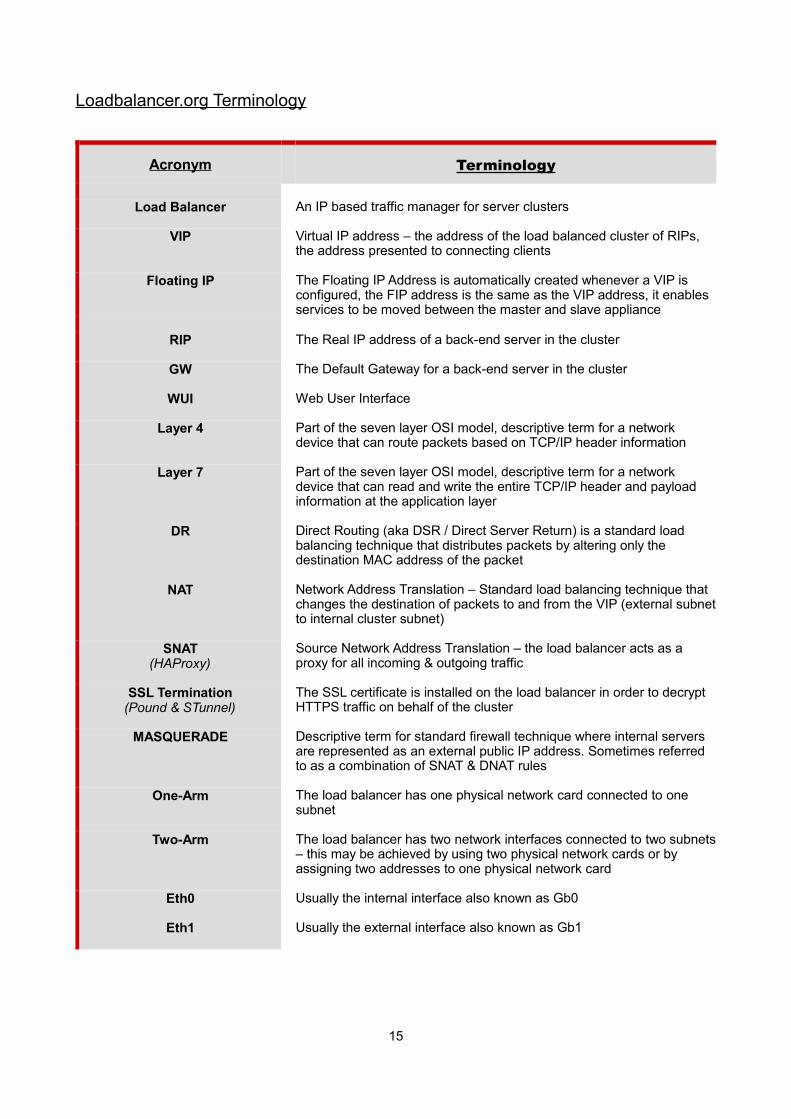
Loadbalancer.org Terminology
Acronym Terminology
Load Balancer An IP based traffic manager for server clusters
VIP Virtual IP address – the address of the load balanced cluster of RIPs, the address presented to connecting clients
Floating IP The Floating IP Address is automatically created whenever a VIP is configured, the FIP address is the same as the VIP address, it enables services to be moved between the master and slave appliance
RIP The Real IP address of a back-end server in the cluster
GW The Default Gateway for a back-end server in the cluster
WUI Web User Interface
Layer 4 Part of the seven layer OSI model, descriptive term for a network device that can route packets based on TCP/IP header information
Layer 7 Part of the seven layer OSI model, descriptive term for a network device that can read and write the entire TCP/IP header and payload information at the application layer
DR Direct Routing (aka DSR / Direct Server Return) is a standard load balancing technique that distributes packets by altering only the destination MAC address of the packet
NAT Network Address Translation – Standard load balancing technique that changes the destination of packets to and from the VIP (external subnetto internal cluster subnet)
SNAT(HAProxy)
Source Network Address Translation – the load balancer acts as a proxy for all incoming & outgoing traffic
SSL Termination(Pound & STunnel)
The SSL certificate is installed on the load balancer in order to decrypt HTTPS traffic on behalf of the cluster
MASQUERADE Descriptive term for standard firewall technique where internal servers are represented as an external public IP address. Sometimes referred to as a combination of SNAT & DNAT rules
One-Arm The load balancer has one physical network card connected to one subnet
Two-Arm The load balancer has two network interfaces connected to two subnets– this may be achieved by using two physical network cards or by assigning two addresses to one physical network card
Eth0 Usually the internal interface also known as Gb0
Eth1 Usually the external interface also known as Gb1
15

Chapter 3 – Load Balancing Methods
16

Supported MethodsThe Loadbalancer.org appliance is one of the most flexible load balancers on the market. The design allows different load balancing modules to utilize the core high availability framework of the appliance.
Multiple load balancing methods can be used at the same time or in combination with each other.
Layer 4 DR (Direct Routing)
Ultra-fast local server based load balancingRequires solving the 'ARP problem' on the Real
Servers
One-Arm
Layer 4 NAT(Network Address
Translation)
Fast Layer 4 load balancing, the appliance becomes thedefault gateway for the Real Servers
Two-Arm
Layer 4 TUN Similar to DR but works across IP encapsulated tunnels One-Arm
Layer 7 SSL Termination(Pound & STunnel)
Usually required in order to process cookie persistencein HTTPS streams on the load balancer
Processor intensive
One or Two-Arm
Layer 7 SNAT(Source Network
Address Translation:HAProxy)
Layer 7 allows great flexibility including full SNAT andWAN load balancing, cookie insertion and URL
switching Not as fast as Layer 4
One or Two-Arm
Key:
Recommended for high performance fully transparent and scalable solutions
Recommended if HTTP cookie persistence is required, also used for several Microsoft applications such as Exchange, Sharepoint & Remote Desktop Services and for overall deployment simplicity since real servers can be on any accessible subnet and noReal-Server changes are required
Only required for Direct Routing implementation across routed networks (rarely used)
One-Arm and Two-Arm ConfigurationsThe number of 'arms' is normally a descriptive term for how many physical connections (Ethernet interfaces) are used to connect a device to a network. It's very common for a load balancer that uses a routing method (NAT) to have a two-arm configuration. Proxy based load balancers (SNAT) commonly use a one-arm configuration.
One-Arm The load balancer has one physical network card connected to one subnet
Two-ArmThe load balancer has two network interfaces connected to two subnets – this can be achieved by using two physical network cards or by assigning two addresses to one physical network card
17
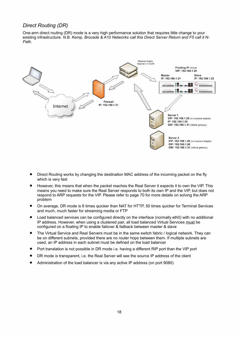
Direct Routing (DR)One-arm direct routing (DR) mode is a very high performance solution that requires little change to your existing infrastructure. N.B. Kemp, Brocade & A10 Networks call this Direct Server Return and F5 call it N-Path.
Direct Routing works by changing the destination MAC address of the incoming packet on the fly which is very fast
However, this means that when the packet reaches the Real Server it expects it to own the VIP. This means you need to make sure the Real Server responds to both its own IP and the VIP, but does not respond to ARP requests for the VIP. Please refer to page 70 for more details on solving the ARP problem
On average, DR mode is 8 times quicker than NAT for HTTP, 50 times quicker for Terminal Services and much, much faster for streaming media or FTP
Load balanced services can be configured directly on the interface (normally eth0) with no additional IP address. However, when using a clustered pair, all load balanced Virtual Services must be configured on a floating IP to enable failover & failback between master & slave
The Virtual Service and Real Servers must be in the same switch fabric / logical network. They can be on different subnets, provided there are no router hops between them. If multiple subnets are used, an IP address in each subnet must be defined on the load balancer
Port translation is not possible in DR mode i.e. having a different RIP port than the VIP port
DR mode is transparent, i.e. the Real Server will see the source IP address of the client
Administration of the load balancer is via any active IP address (on port 9080)
18
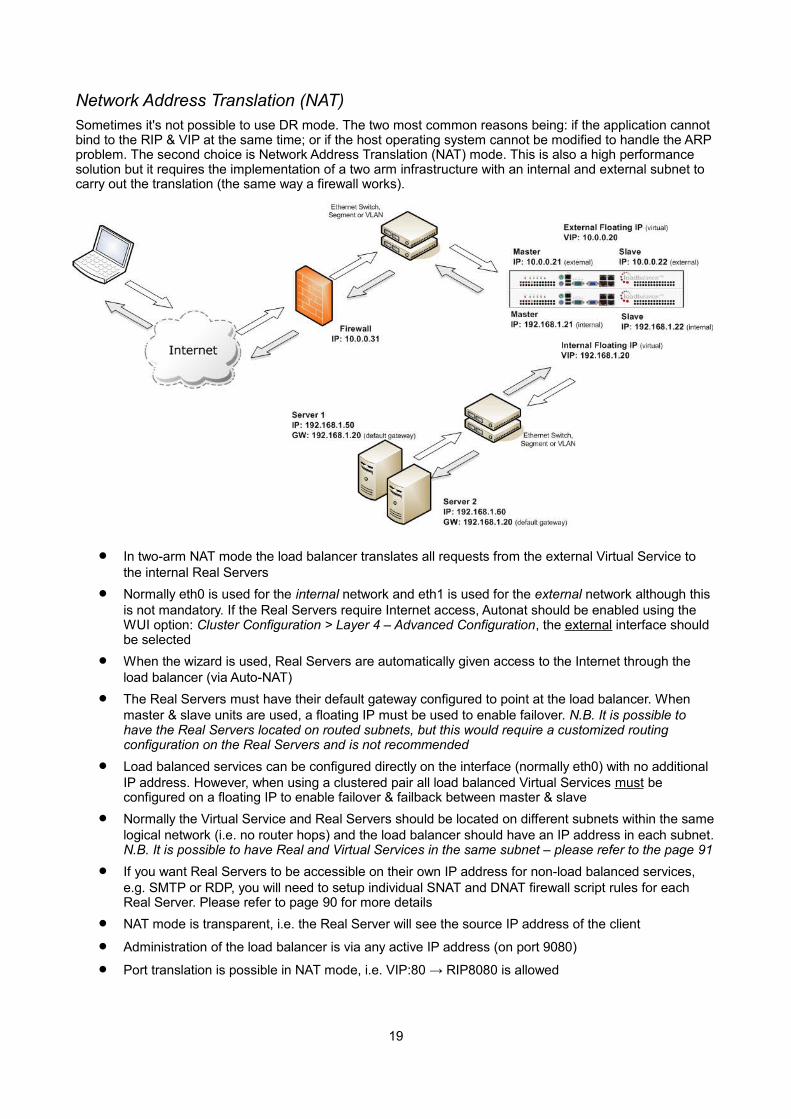
Network Address Translation (NAT)Sometimes it's not possible to use DR mode. The two most common reasons being: if the application cannot bind to the RIP & VIP at the same time; or if the host operating system cannot be modified to handle the ARP problem. The second choice is Network Address Translation (NAT) mode. This is also a high performance solution but it requires the implementation of a two arm infrastructure with an internal and external subnet to carry out the translation (the same way a firewall works).
In two-arm NAT mode the load balancer translates all requests from the external Virtual Service to the internal Real Servers
Normally eth0 is used for the internal network and eth1 is used for the external network although this is not mandatory. If the Real Servers require Internet access, Autonat should be enabled using the WUI option: Cluster Configuration > Layer 4 – Advanced Configuration, the external interface should be selected
When the wizard is used, Real Servers are automatically given access to the Internet through the load balancer (via Auto-NAT)
The Real Servers must have their default gateway configured to point at the load balancer. When master & slave units are used, a floating IP must be used to enable failover. N.B. It is possible to have the Real Servers located on routed subnets, but this would require a customized routing configuration on the Real Servers and is not recommended
Load balanced services can be configured directly on the interface (normally eth0) with no additional IP address. However, when using a clustered pair all load balanced Virtual Services must be configured on a floating IP to enable failover & failback between master & slave
Normally the Virtual Service and Real Servers should be located on different subnets within the samelogical network (i.e. no router hops) and the load balancer should have an IP address in each subnet.N.B. It is possible to have Real and Virtual Services in the same subnet – please refer to the page 91
If you want Real Servers to be accessible on their own IP address for non-load balanced services, e.g. SMTP or RDP, you will need to setup individual SNAT and DNAT firewall script rules for each Real Server. Please refer to page 90 for more details
NAT mode is transparent, i.e. the Real Server will see the source IP address of the client
Administration of the load balancer is via any active IP address (on port 9080)
Port translation is possible in NAT mode, i.e. VIP:80 → RIP8080 is allowed
19

NAT Mode Packet re-Writing
In NAT mode, the inbound destination IP address is changed by the load balancer from the Virtual Service IP address (VIP) to the Real Server. For outbound replies the load balancer changes the source IP address of the Real Server to be the Virtual Services IP address.
The following table shows an example NAT mode setup:
Protocol VIP Port RIP Port
TCP 10.0.0.20 80 192.168.1.50 80
In this simple example all traffic destined for IP address 10.0.0.20 on port 80 is load-balanced to the real IP address 192.168.1.50 on port 80.
Packet rewriting works as follows:
1) The incoming packet for the web server has source and destination addresses as:
SOURCE x.x.x.x:3456 DEST 10.0.0.20:80
2) The packet is rewritten and forwarded to the back-end server as:
SOURCE x.x.x.x:3456 DEST 192.168.1.50:80
3) Replies return to the load balancer as:
SOURCE 192.168.1.50:80 DEST x.x.x.x:3456
4) The packet is written back to the VIP address and returned to the client as:
SOURCE 10.0.0.20:80 DEST x.x.x.x:3456
20
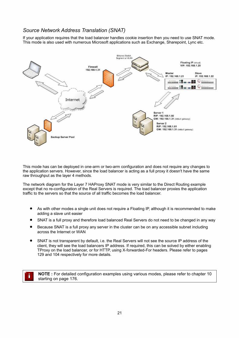
Source Network Address Translation (SNAT) If your application requires that the load balancer handles cookie insertion then you need to use SNAT mode. This mode is also used with numerous Microsoft applications such as Exchange, Sharepoint, Lync etc.
This mode has can be deployed in one-arm or two-arm configuration and does not require any changes to the application servers. However, since the load balancer is acting as a full proxy it doesn't have the same raw throughput as the layer 4 methods.
The network diagram for the Layer 7 HAProxy SNAT mode is very similar to the Direct Routing example except that no re-configuration of the Real Servers is required. The load balancer proxies the application traffic to the servers so that the source of all traffic becomes the load balancer.
As with other modes a single unit does not require a Floating IP, although it is recommended to makeadding a slave unit easier
SNAT is a full proxy and therefore load balanced Real Servers do not need to be changed in any way
Because SNAT is a full proxy any server in the cluster can be on any accessible subnet including across the Internet or WAN
SNAT is not transparent by default, i.e. the Real Servers will not see the source IP address of the client, they will see the load balancers IP address. If required, this can be solved by either enabling TProxy on the load balancer, or for HTTP, using X-forwarded-For headers. Please refer to pages129 and 104 respectively for more details.
NOTE : For detailed configuration examples using various modes, please refer to chapter 10 starting on page 176.
21
Other Considerations
Does Your Application Cluster correctly Handle its own State?
NOTE : Load balancers work most effectively if the application servers are completely stateless. This means that if a web server fails and is automatically taken out of the cluster; then all the current user sessions will be transferred to other servers in the cluster without the users needing to re login to the application again. If your application doesn't have a persistent data store then you can't have seamless fail over for your back-end servers.
Do your web servers store persistent information on local drives?
Images (jpeg, png, gif etc.)
Files (html, php, asp etc.)
If so, these files either need to be on shared storage such as an NFS/CIFS mount, or they need to be replicated to all of the nodes in the cluster.
Replication Solutions for Shared Data
On UNIX you can use the RSYNC command to replicate files, on Windows Server you can use RSYNC as well but you may prefer ROBOCOPY that's included by default in newer versions of Windows Server or in theresource kit for older versions. Usually you will upload your content to one master server and then replicate it to the other servers in the cluster.
Solutions for Session Data
Standard ASP and PHP session data is stored locally by default, leaving your session data in a local store willprevent you from implementing seamless application server fail-over in your cluster. If an application server fails, all of the local session data will be lost and your user will need to re-log in and possibly lose shopping baskets etc.
This problem is easily resolvable by implementing a shared persistent data store for the cluster. This is usually either done with a shared back-end database or a shared memory solution.
Persistence (aka Affinity)
Persistence is a feature that is required by many web applications. Once a user has interacted with a particular server all subsequent requests are sent to the same server thus persisting to that particular server. It is normally required when the session state is stored locally to the web server as opposed to a database.
22

What do You do if Your Application is not Stateless?Some applications require state to be maintained such as:
Terminal Services / Remote Desktop Services
SSH
FTP (upload)
SMTP (incoming)
You may also find that you are unable to modify your HTTP/HTTPS based application to handle shared session data.
For these cases, you can use persistence based on source IP address. You lose the ability to have transparent fail-over, but you do still get increased capacity and manageability. This persistence problem occurs with all load balancers and all vendors use standard methods and technologies to mitigate the issue.
Loadbalancer.org Persistence Options
Source IP (subnet)
Cookie (Active or Passive)
SSL session ID
Microsoft Connection Broker / Session Broker Integration
The standard Layer 4 persistence method is source IP persistence, you can handle millions of persistent connections at Layer 4. Just modify your Virtual Service to be persistent if you require source IP persistence.
Cookies are a Layer 7 based persistence method that can offer more even traffic distribution and also handle any clients where the source IP address may change during the session (e.g. mega proxies).
SSL session ID based persistence is useful in certain circumstances, although due to the way some browsersoperate – notably older versions of Internet Explorer, the session ID can be renegotiated frequently (every fewseconds) which effectively breaks the persistence.
23

Which Load Balancing Method should I Use?
Layer 4 DR Mode offers the best performance and requires limited Real Server changes. The server application must be able to bind to the both the RIP & VIP at the same time.
Layer 4 NAT Mode is also a high performance solution but not as fast as DR mode. It requires the implementation of a two-arm infrastructure with an internal and external subnet to carry out the translation (the same way a firewall works). Also each Real Server must use the load balancer as the default gateway.
Layer 7 SNAT Mode offers greater flexibility but at lower performance levels. It supports HTTP cookie insertion, RDP cookies, Connection Broker integration and works very well with either Pound or STunnel when SSL termination is required. It does not require any changes to the application servers and can be deployed in one-arm or two-arm mode and. HAProxy is a high performance solution, but since it operates as a full proxy, it cannot perform as fast as the layer 4 solutions.
Our RecommendationWhere possible we recommend that Layer 4 Direct Routing (DR) mode is used. This offers the best possible performance since replies go directly from the Real Servers to the client, not via the load balancer. It's also relatively simple to implement.
Ultimately, the final choice does depend on your specific requirements and infrastructure.
IMPORTANT NOTE : If you are using Microsoft Windows Real Servers (i.e. back-end servers) make sure that Windows NLB (Network Load Balancing) is completely disabled to ensure that this does not interfere with the operation of the load balancer.
24

Chapter 4 – Appliance Fundamentals
25
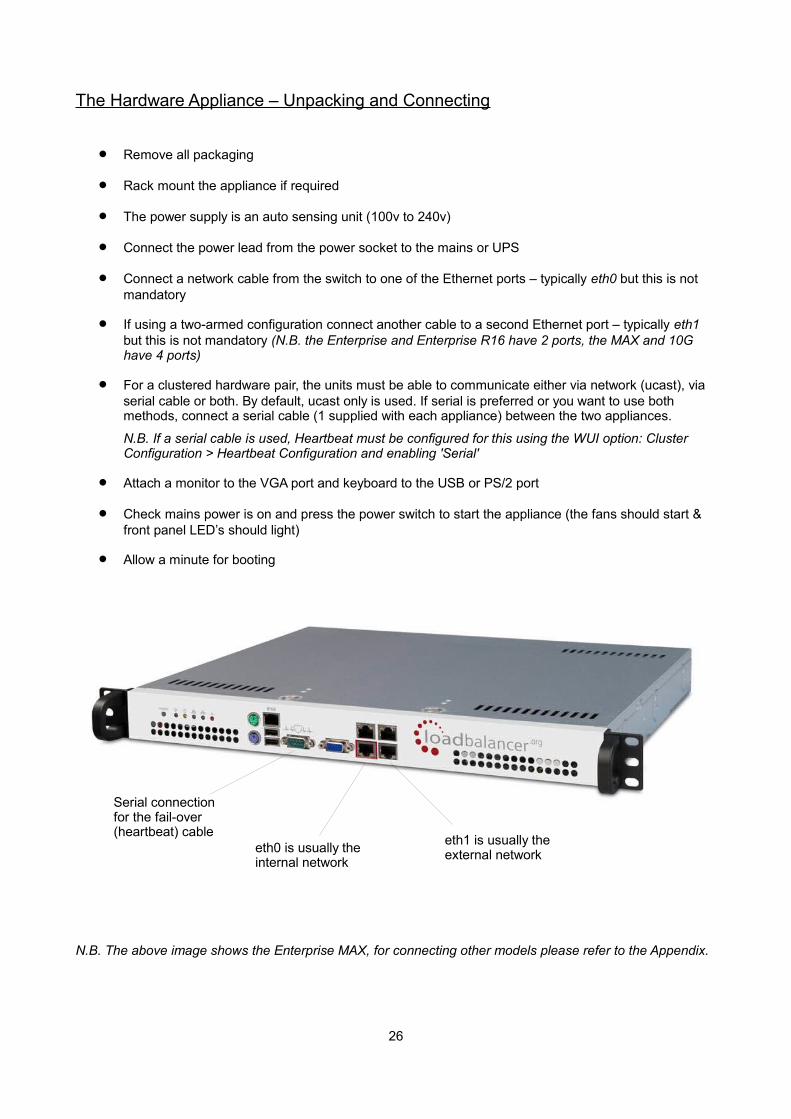
The Hardware Appliance – Unpacking and Connecting
Remove all packaging
Rack mount the appliance if required
The power supply is an auto sensing unit (100v to 240v)
Connect the power lead from the power socket to the mains or UPS
Connect a network cable from the switch to one of the Ethernet ports – typically eth0 but this is not mandatory
If using a two-armed configuration connect another cable to a second Ethernet port – typically eth1 but this is not mandatory (N.B. the Enterprise and Enterprise R16 have 2 ports, the MAX and 10G have 4 ports)
For a clustered hardware pair, the units must be able to communicate either via network (ucast), via serial cable or both. By default, ucast only is used. If serial is preferred or you want to use both methods, connect a serial cable (1 supplied with each appliance) between the two appliances.
N.B. If a serial cable is used, Heartbeat must be configured for this using the WUI option: Cluster Configuration > Heartbeat Configuration and enabling 'Serial'
Attach a monitor to the VGA port and keyboard to the USB or PS/2 port
Check mains power is on and press the power switch to start the appliance (the fans should start & front panel LED’s should light)
Allow a minute for booting
N.B. The above image shows the Enterprise MAX, for connecting other models please refer to the Appendix.
26
eth1 is usually the external networketh0 is usually the
internal network
Serial connection for the fail-over (heartbeat) cable
The Virtual Appliance – Hypervisor Deployment
Supported HypervisorsCurrently, the Virtual Appliance is available for the following hypervisors:
• VMware (Player/Workstation/Server & vSphere ESX/ESXi)
• Microsoft Hyper-V
• KVM
Host RequirementsTo run the Loadbalancer.org Enterprise VA (irrespective of which Hypervisor is being used) the following basicserver specifications must be met:
• 64bit CPU
• Virtual Technology hardware support – either Intel-VT or AMD-V compliant CPU's
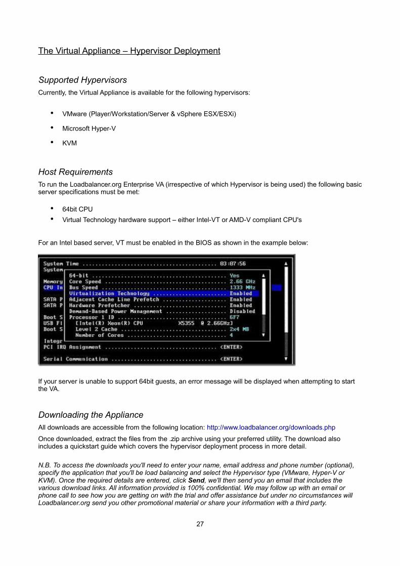
For an Intel based server, VT must be enabled in the BIOS as shown in the example below:
If your server is unable to support 64bit guests, an error message will be displayed when attempting to start the VA.
Downloading the ApplianceAll downloads are accessible from the following location: http://www.loadbalancer.org/downloads.php
Once downloaded, extract the files from the .zip archive using your preferred utility. The download also includes a quickstart guide which covers the hypervisor deployment process in more detail.
N.B. To access the downloads you'll need to enter your name, email address and phone number (optional), specify the application that you'll be load balancing and select the Hypervisor type (VMware, Hyper-V or KVM). Once the required details are entered, click Send, we'll then send you an email that includes the various download links. All information provided is 100% confidential. We may follow up with an email or phone call to see how you are getting on with the trial and offer assistance but under no circumstances will Loadbalancer.org send you other promotional material or share your information with a third party.
27
VMware DeploymentThe exact steps depend on which VMware environment is in use. The following list provides a basic guideline:
• For vSphere Client use: File > Deploy ovf Template
• For Virtual Infrastructure Client use: File > Virtual Appliance > Import
• For VMware Server use: Virtual Machine > Add VM to Inventory
Hyper-V Deployment
Windows 2008 R2
1. Start Hyper-V Manager, then using the right-click menu or the Actions pane select Import Virtual Machine and then click Next
2. Browse to the location of the extracted download and select the folder LBVMHYPER-Vv7
3. Select the option "Copy the virtual machine (create a new unique ID)" and also select the "Duplicate all files so the same virtual machine can be imported again" check-box, click Import
4. The import will start, once complete the new appliance will appear in the Virtual Machine list
5. The appliance has 4 NIC cards, to connect these right-click the appliance and select Settings then foreach Network Adapter select the required network
6. Right-click and select Start to power up the appliance, allow a minute to boot
7. If you're deploying a clustered pair, you'll first need to do one of the following steps before importing the second virtual machine. If this is not done, the second virtual machine cannot be deployed because the disk from the first import already exists, and there will therefore be a conflict:
i) Shutdown the first VM and modify the name of the disk
or
ii) Change the default file location using the Hyper-V Settings option in the Actions pane
Once one of the above is done, repeat steps 1-6 to create the second virtual machine.
Windows 2012
1. Start Hyper-V Manager, then using the right-click menu or the Actions pane select Import Virtual Machine then click Next
2. Browse to the location of the extracted download and select the folder LBVMHYPER-Vv7
3. Click Next until prompted for the Import Type, make sure that 'Copy the virtual machine (create a new unique ID)' is selected and click Next
4. Tick the check-box 'Store the Virtual Machine in different location', then define a suitable location for the virtual machines files and click Next
5. Define a location for the virtual hard disk files
6. Click Next, then click Finish to complete the import process. Once complete, the load balancer will appear in the Virtual Machines list
7. The appliance has 4 NIC cards, to connect these right-click the appliance and select Settings then foreach Network Adapter select the required network
8. Highlight the new load balancer and start it either by using the right-click menu or the Actions pane
If you're deploying a clustered pair, repeat steps 2-8 for the slave unit, making sure that a different folder location is selected in steps 4 & 5.
28
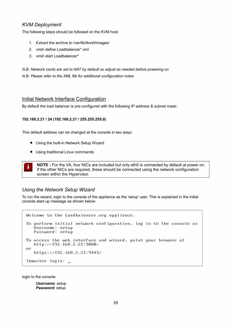
KVM DeploymentThe following steps should be followed on the KVM host:
1. Extract the archive to /var/lib/libvirt/images/
2. virsh define Loadbalancer*.xml
3. virsh start Loadbalancer*
N.B. Network cards are set to NAT by default so adjust as needed before powering on
N.B. Please refer to the XML file for additional configuration notes
Initial Network Interface ConfigurationBy default the load balancer is pre-configured with the following IP address & subnet mask:
192.168.2.21 / 24 (192.168.2.21 / 255.255.255.0)
This default address can be changed at the console in two ways:
Using the built-in Network Setup Wizard
Using traditional Linux commands
NOTE : For the VA, four NICs are included but only eth0 is connected by default at power on. If the other NICs are required, these should be connected using the network configuration screen within the Hypervisor.
Using the Network Setup WizardTo run the wizard, login to the console of the appliance as the 'setup' user. This is explained in the initial console start-up message as shown below:
login to the console:
Username: setupPassword: setup
29
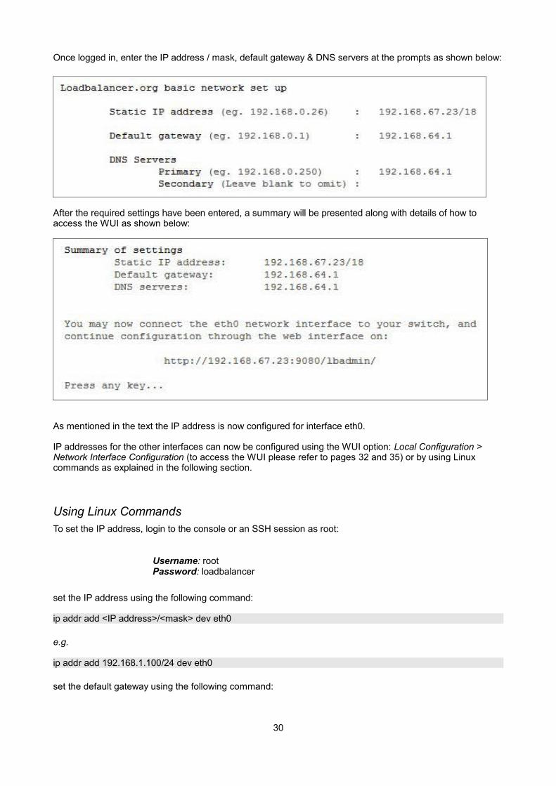
Once logged in, enter the IP address / mask, default gateway & DNS servers at the prompts as shown below:
After the required settings have been entered, a summary will be presented along with details of how to access the WUI as shown below:
As mentioned in the text the IP address is now configured for interface eth0.
IP addresses for the other interfaces can now be configured using the WUI option: Local Configuration > Network Interface Configuration (to access the WUI please refer to pages 32 and 35) or by using Linux commands as explained in the following section.
Using Linux CommandsTo set the IP address, login to the console or an SSH session as root:
Username: rootPassword: loadbalancer
set the IP address using the following command:
ip addr add <IP address>/<mask> dev eth0
e.g.
ip addr add 192.168.1.100/24 dev eth0
set the default gateway using the following command:
30

route add default gw <IP address> <interface>
e.g.
route add default gw 192.168.1.254 eth0
N.B. Setting the IP address in this way is temporary, the IP address MUST be set via the WUI to make this permanent otherwise settings will be lost after a reboot
Appliance Access & Configuration MethodsThe appliance can be accessed & configured both locally and remotely.
Local Methods
Console Access
To access the console, simply connect a monitor and keyboard to the load balancer, power up and you'll be presented with a login prompt. The console can also be accessed via the serial port if the default heartbeat configuration is used - i.e. heartbeat is configured to communicate over the network only.
Log in to the console:
Username: root Password: loadbalancer
Appliance Configuration using Links
Once logged into the console, the Links browser can be used to configure the appliance. To start Links and bring up the text based administration interface use the following command:
links 127.0.0.1:9080/lbadmin
Log in to Links:
Username: loadbalancer Password: loadbalancer
Use the Up, Down & Enter keys to move between and select the various menu options.
N.B. The preferred configuration method is the WUI which can be accessed via a browser as detailed on page 32.
Keyboard Layout
To change the keyboard locale edit the file: /etc/sysconfig/keyboard, e.g. to change from a UK to a US layout:
1. edit /etc/sysconfig/keyboard using a browser such as 'vi' or 'vim' for Linux or WinSCP under Windows
2. replace KEYTABLE="uk" with KEYTABLE="us"
3. re-boot the appliance
31
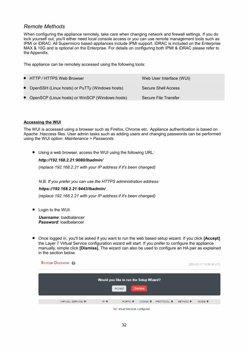
Remote MethodsWhen configuring the appliance remotely, take care when changing network and firewall settings. If you do lock yourself out, you'll either need local console access or you can use remote management tools such as IPMI or iDRAC. All Supermicro based appliances include IPMI support, iDRAC is included on the Enterprise MAX & 10G and is optional on the Enterprise. For details on configuring both IPMI & iDRAC please refer to the Appendix.
The appliance can be remotely accessed using the following tools:
HTTP / HTTPS Web Browser Web User Interface (WUI)
OpenSSH (Linux hosts) or PuTTy (Windows hosts) Secure Shell Access
OpenSCP (Linux hosts) or WinSCP (Windows hosts) Secure File Transfer
Accessing the WUI
The WUI is accessed using a browser such as Firefox, Chrome etc. Appliance authentication is based on Apache .htaccess files. User admin tasks such as adding users and changing passwords can be performed using the WUI option: Maintenance > Passwords.
Using a web browser, access the WUI using the following URL:
http://192.168.2.21:9080/lbadmin/
(replace 192.168.2.21 with your IP address if it's been changed)
N.B. If you prefer you can use the HTTPS administration address:
https://192.168.2.21:9443/lbadmin/
(replace 192.168.2.21 with your IP address if it's been changed)
Login to the WUI:
Username: loadbalancerPassword: loadbalancer
Once logged in, you'll be asked if you want to run the web based setup wizard. If you click [Accept] the Layer 7 Virtual Service configuration wizard will start. If you prefer to configure the appliance manually, simple click [Dismiss]. The wizard can also be used to configure an HA pair as explained in the section below.
32
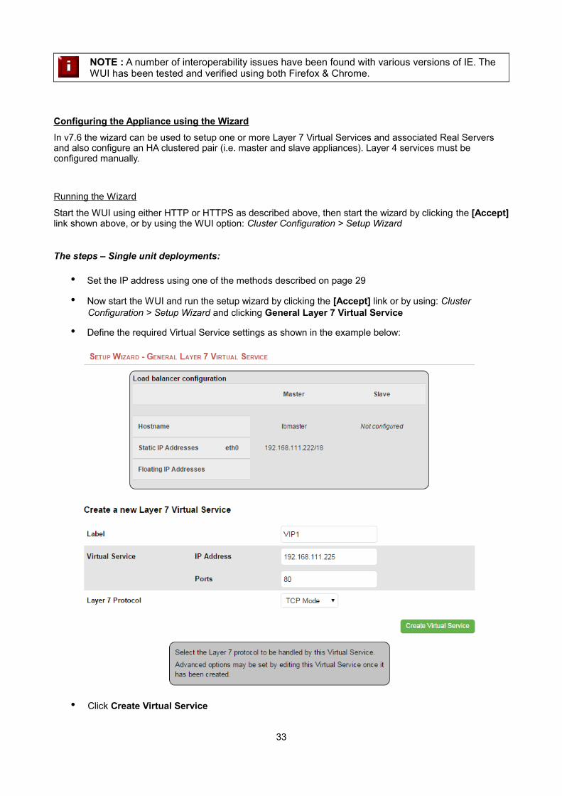
NOTE : A number of interoperability issues have been found with various versions of IE. The WUI has been tested and verified using both Firefox & Chrome.
Configuring the Appliance using the Wizard
In v7.6 the wizard can be used to setup one or more Layer 7 Virtual Services and associated Real Servers and also configure an HA clustered pair (i.e. master and slave appliances). Layer 4 services must be configured manually.
Running the Wizard
Start the WUI using either HTTP or HTTPS as described above, then start the wizard by clicking the [Accept]link shown above, or by using the WUI option: Cluster Configuration > Setup Wizard
The steps – Single unit deployments:
• Set the IP address using one of the methods described on page 29
• Now start the WUI and run the setup wizard by clicking the [Accept] link or by using: Cluster Configuration > Setup Wizard and clicking General Layer 7 Virtual Service
• Define the required Virtual Service settings as shown in the example below:
• Click Create Virtual Service
33
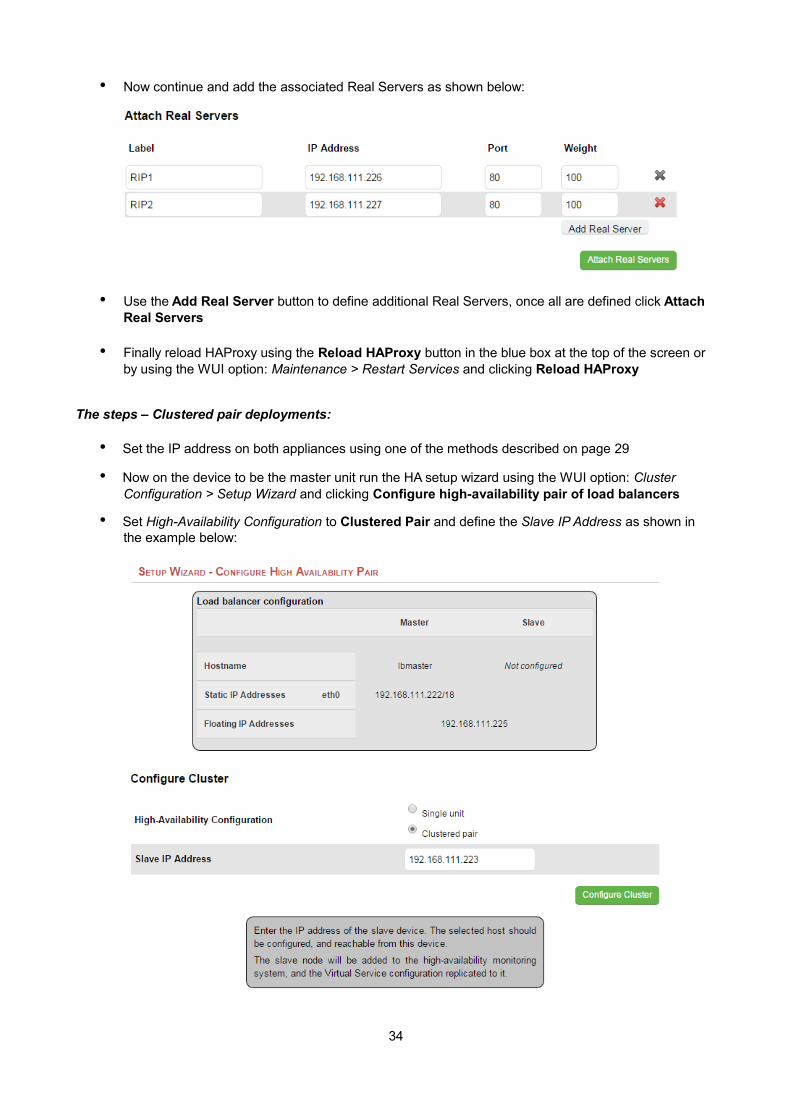
• Now continue and add the associated Real Servers as shown below:
• Use the Add Real Server button to define additional Real Servers, once all are defined click Attach Real Servers
• Finally reload HAProxy using the Reload HAProxy button in the blue box at the top of the screen or by using the WUI option: Maintenance > Restart Services and clicking Reload HAProxy
The steps – Clustered pair deployments:
• Set the IP address on both appliances using one of the methods described on page 29
• Now on the device to be the master unit run the HA setup wizard using the WUI option: Cluster Configuration > Setup Wizard and clicking Configure high-availability pair of load balancers
• Set High-Availability Configuration to Clustered Pair and define the Slave IP Address as shown in the example below:
34
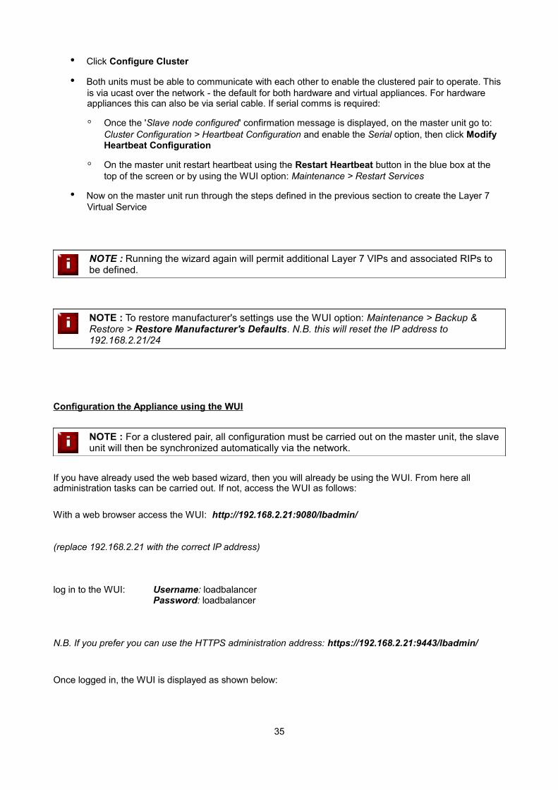
• Click Configure Cluster
• Both units must be able to communicate with each other to enable the clustered pair to operate. This is via ucast over the network - the default for both hardware and virtual appliances. For hardware appliances this can also be via serial cable. If serial comms is required:
◦ Once the 'Slave node configured' confirmation message is displayed, on the master unit go to: Cluster Configuration > Heartbeat Configuration and enable the Serial option, then click Modify Heartbeat Configuration
◦ On the master unit restart heartbeat using the Restart Heartbeat button in the blue box at the top of the screen or by using the WUI option: Maintenance > Restart Services
• Now on the master unit run through the steps defined in the previous section to create the Layer 7 Virtual Service
NOTE : Running the wizard again will permit additional Layer 7 VIPs and associated RIPs to be defined.
NOTE : To restore manufacturer's settings use the WUI option: Maintenance > Backup & Restore > Restore Manufacturer's Defaults. N.B. this will reset the IP address to 192.168.2.21/24
Configuration the Appliance using the WUI
NOTE : For a clustered pair, all configuration must be carried out on the master unit, the slave unit will then be synchronized automatically via the network.
If you have already used the web based wizard, then you will already be using the WUI. From here all administration tasks can be carried out. If not, access the WUI as follows:
With a web browser access the WUI: http://192.168.2.21:9080/lbadmin/
(replace 192.168.2.21 with the correct IP address)
log in to the WUI: Username: loadbalancerPassword: loadbalancer
N.B. If you prefer you can use the HTTPS administration address: https://192.168.2.21:9443/lbadmin/
Once logged in, the WUI is displayed as shown below:
35

Main Menu Options:
System Overview – Displays a graphical summary of all VIPs, RIPs and key appliance statistics
Local Configuration – Configure local host settings such as IP address, DNS, system time etc.
Cluster Configuration – Configure load balanced services such as VIPs & RIPs
Maintenance – Perform maintenance tasks such as service restarts and taking backups
View Configuration – Display the saved appliance configuration settings
Reports – View various appliance reports & graphs
Logs – View various appliance logs
Support – Create a support download, contact the support team & access useful links
36
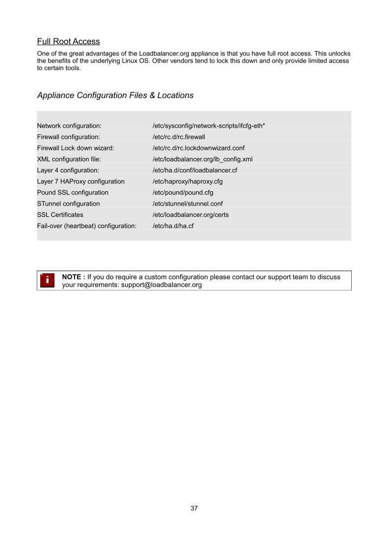
Full Root AccessOne of the great advantages of the Loadbalancer.org appliance is that you have full root access. This unlocksthe benefits of the underlying Linux OS. Other vendors tend to lock this down and only provide limited access to certain tools.
Appliance Configuration Files & Locations
Network configuration: /etc/sysconfig/network-scripts/ifcfg-eth*
Firewall configuration: /etc/rc.d/rc.firewall
Firewall Lock down wizard: /etc/rc.d/rc.lockdownwizard.conf
XML configuration file: /etc/loadbalancer.org/lb_config.xml
Layer 4 configuration: /etc/ha.d/conf/loadbalancer.cf
Layer 7 HAProxy configuration /etc/haproxy/haproxy.cfg
Pound SSL configuration /etc/pound/pound.cfg
STunnel configuration /etc/stunnel/stunnel.conf
SSL Certificates /etc/loadbalancer.org/certs
Fail-over (heartbeat) configuration: /etc/ha.d/ha.cf
NOTE : If you do require a custom configuration please contact our support team to discuss your requirements: [email protected]
37

Chapter 5 – Appliance Management
38
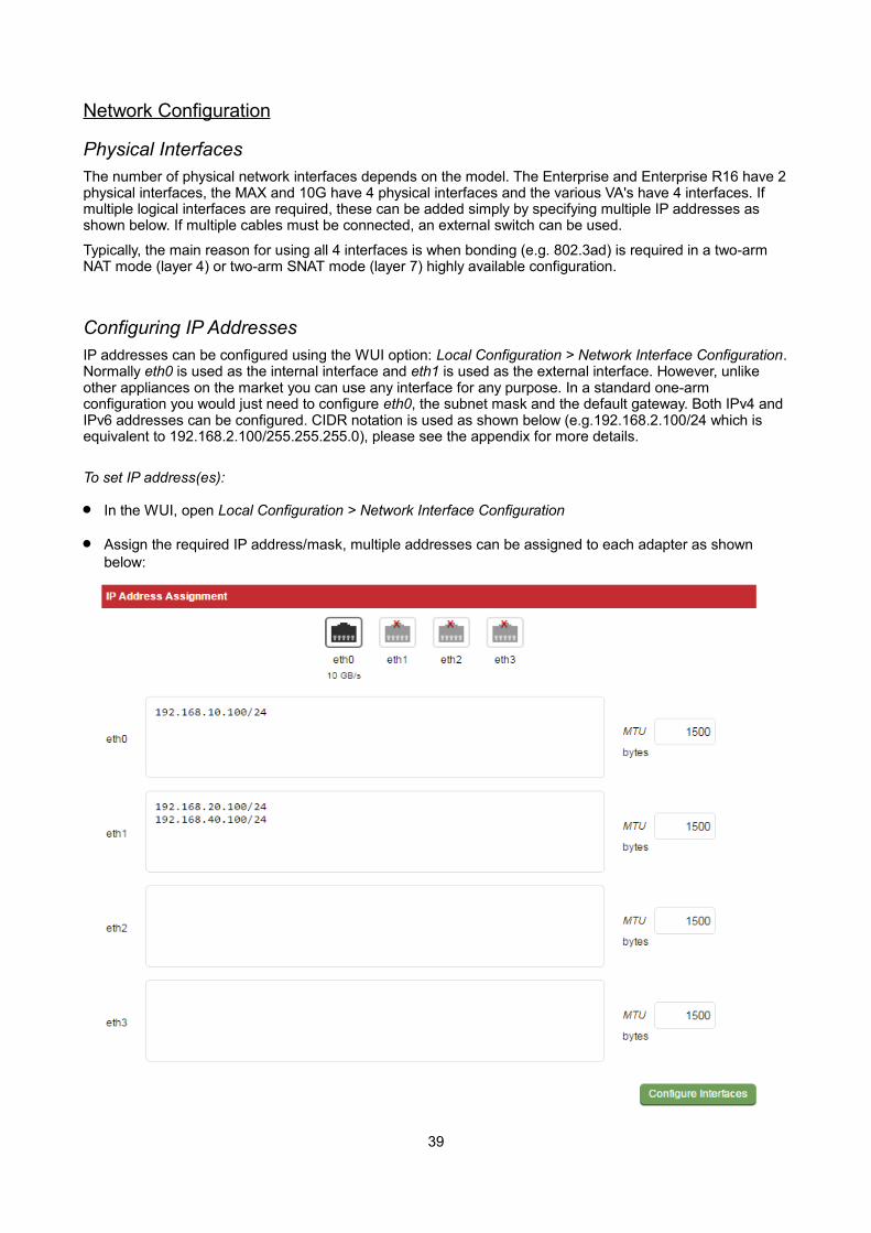
Network Configuration
Physical InterfacesThe number of physical network interfaces depends on the model. The Enterprise and Enterprise R16 have 2physical interfaces, the MAX and 10G have 4 physical interfaces and the various VA's have 4 interfaces. If multiple logical interfaces are required, these can be added simply by specifying multiple IP addresses as shown below. If multiple cables must be connected, an external switch can be used.
Typically, the main reason for using all 4 interfaces is when bonding (e.g. 802.3ad) is required in a two-arm NAT mode (layer 4) or two-arm SNAT mode (layer 7) highly available configuration.
Configuring IP AddressesIP addresses can be configured using the WUI option: Local Configuration > Network Interface Configuration.Normally eth0 is used as the internal interface and eth1 is used as the external interface. However, unlike other appliances on the market you can use any interface for any purpose. In a standard one-arm configuration you would just need to configure eth0, the subnet mask and the default gateway. Both IPv4 and IPv6 addresses can be configured. CIDR notation is used as shown below (e.g.192.168.2.100/24 which is equivalent to 192.168.2.100/255.255.255.0), please see the appendix for more details.
To set IP address(es):
In the WUI, open Local Configuration > Network Interface Configuration
Assign the required IP address/mask, multiple addresses can be assigned to each adapter as shown below:
39
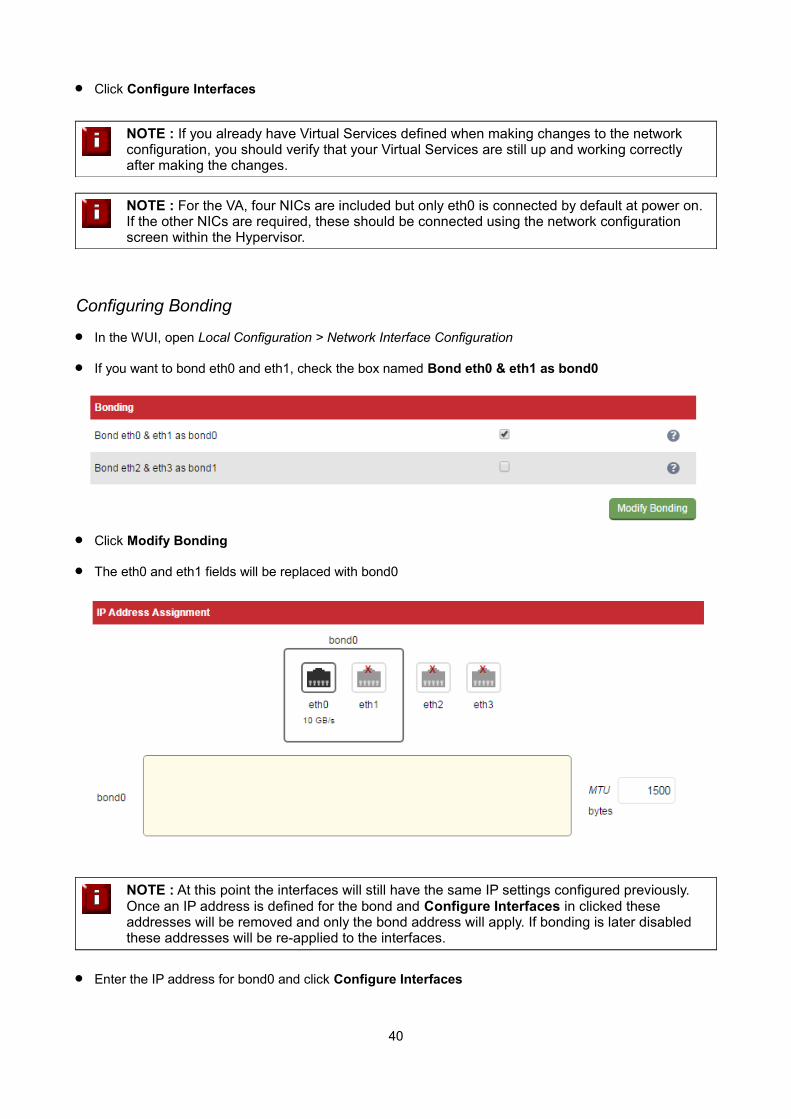
Click Configure Interfaces
NOTE : If you already have Virtual Services defined when making changes to the network configuration, you should verify that your Virtual Services are still up and working correctly after making the changes.
NOTE : For the VA, four NICs are included but only eth0 is connected by default at power on. If the other NICs are required, these should be connected using the network configuration screen within the Hypervisor.
Configuring Bonding
In the WUI, open Local Configuration > Network Interface Configuration
If you want to bond eth0 and eth1, check the box named Bond eth0 & eth1 as bond0
Click Modify Bonding
The eth0 and eth1 fields will be replaced with bond0
NOTE : At this point the interfaces will still have the same IP settings configured previously. Once an IP address is defined for the bond and Configure Interfaces in clicked these addresses will be removed and only the bond address will apply. If bonding is later disabled these addresses will be re-applied to the interfaces.
Enter the IP address for bond0 and click Configure Interfaces
40
NOTE : If you have a master and slave configured as an HA pair, make sure you configure bonding in the same way on both units. Failure to do this will result in heartbeat related issues.
Bonding Configuration Modes
Ideally all single points of failure should be eliminated from a network. To help achieve this a cross-wired switch environment can be used. Every server including the load balancers is cross wired into two switch stacks. Then, if a network switch fails the servers & load balancers will activate the connection to the second switch.
Loadbalancer.org appliances support this using the standard Linux bonding driver. Once you have setup the appliance using a single network card and are happy with the configuration you can set up bonding using Local Configuration > Network Interface Configuration.
If required you can change the bonding mode in the file: /etc/modprobe.d/loadbalancer.conf. By default mode 1 is used which configures the bond for high availability. Simply edit the file and set the mode setting as needed.
Supported Modes:
Bonding for High-Availability (default mode)
mode=1
alias bond0 bonding
options bond0 miimon=100 mode=1
Bonding for Bandwidth
Change to mode 0
alias bond0 bonding
options bond0 miimon=100 mode=0
Bonding for High-Availability & Bandwidth
Change to mode 4
alias bond0 bonding
options bond0 miimon=100 mode=4
This option requires the ports on the switch to be configured as a TRUNK with 802.3ad support.
NOTE : If your Real Servers, ESX hosts etc. support network bonding using Broadcom's SLB (Smart Load Balancing), this can cause issues in Layer 4 DR mode if older drivers are used. We have successfully tested SLB (Auto Fallback Disable) with driver version 15.2.0.5. Therefore at least this version is recommended.
41
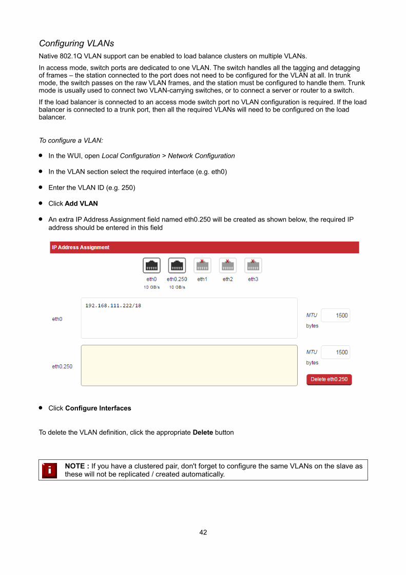
Configuring VLANsNative 802.1Q VLAN support can be enabled to load balance clusters on multiple VLANs.
In access mode, switch ports are dedicated to one VLAN. The switch handles all the tagging and detagging of frames – the station connected to the port does not need to be configured for the VLAN at all. In trunk mode, the switch passes on the raw VLAN frames, and the station must be configured to handle them. Trunk mode is usually used to connect two VLAN-carrying switches, or to connect a server or router to a switch.
If the load balancer is connected to an access mode switch port no VLAN configuration is required. If the loadbalancer is connected to a trunk port, then all the required VLANs will need to be configured on the load balancer.
To configure a VLAN:
In the WUI, open Local Configuration > Network Configuration
In the VLAN section select the required interface (e.g. eth0)
Enter the VLAN ID (e.g. 250)
Click Add VLAN
An extra IP Address Assignment field named eth0.250 will be created as shown below, the required IP address should be entered in this field
Click Configure Interfaces
To delete the VLAN definition, click the appropriate Delete button
NOTE : If you have a clustered pair, don't forget to configure the same VLANs on the slave as these will not be replicated / created automatically.
42
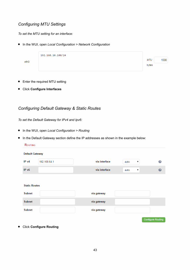
Configuring MTU Settings
To set the MTU setting for an interface:
In the WUI, open Local Configuration > Network Configuration
Enter the required MTU setting
Click Configure Interfaces
Configuring Default Gateway & Static Routes
To set the Default Gateway for IPv4 and Ipv6:
In the WUI, open Local Configuration > Routing
In the Default Gateway section define the IP addresses as shown in the example below:
Click Configure Routing
43
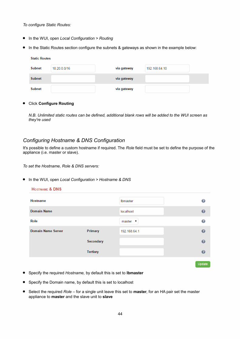
To configure Static Routes:
In the WUI, open Local Configuration > Routing
In the Static Routes section configure the subnets & gateways as shown in the example below:
Click Configure Routing
N.B. Unlimited static routes can be defined, additional blank rows will be added to the WUI screen as they're used
Configuring Hostname & DNS ConfigurationIt's possible to define a custom hostname if required. The Role field must be set to define the purpose of the appliance (i.e. master or slave).
To set the Hostname, Role & DNS servers:
In the WUI, open Local Configuration > Hostname & DNS
Specify the required Hostname, by default this is set to lbmaster
Specify the Domain name, by default this is set to localhost
Select the required Role – for a single unit leave this set to master, for an HA pair set the master appliance to master and the slave unit to slave
44

N.B. If Hostname is left at its default value of lbmaster, when Role is changed to slave, Hostname will be automatically set to lbslave, if a custom hostname has been specified this will remain unchanged irrespective of which role is selected
Specify the required DNS servers
Click Update
System Date & Time and NTP Server Configuration
Auto Configuration using NTP Servers
To configure NTP:
In the WUI, open Local Configuration > System Date & Time
Select the required System Timezone
Define your NTP servers using the NTP Servers fields
Click Set Timezone & NTP
45
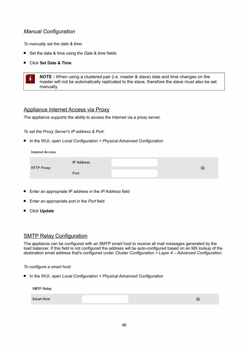
Manual Configuration
To manually set the date & time:
Set the data & time using the Date & time fields
Click Set Date & Time
NOTE : When using a clustered pair (i.e. master & slave) date and time changes on the master will not be automatically replicated to the slave, therefore the slave must also be set manually.
Appliance Internet Access via ProxyThe appliance supports the ability to access the Internet via a proxy server.
To set the Proxy Server's IP address & Port:
In the WUI, open Local Configuration > Physical Advanced Configuration
Enter an appropriate IP address in the IP Address field
Enter an appropriate port in the Port field
Click Update
SMTP Relay ConfigurationThe appliance can be configured with an SMTP smart host to receive all mail messages generated by the load balancer. If this field is not configured the address will be auto-configured based on an MX lookup of the destination email address that's configured under Cluster Configuration > Layer 4 – Advanced Configuration.
To configure a smart host:
In the WUI, open Local Configuration > Physical Advanced Configuration
46
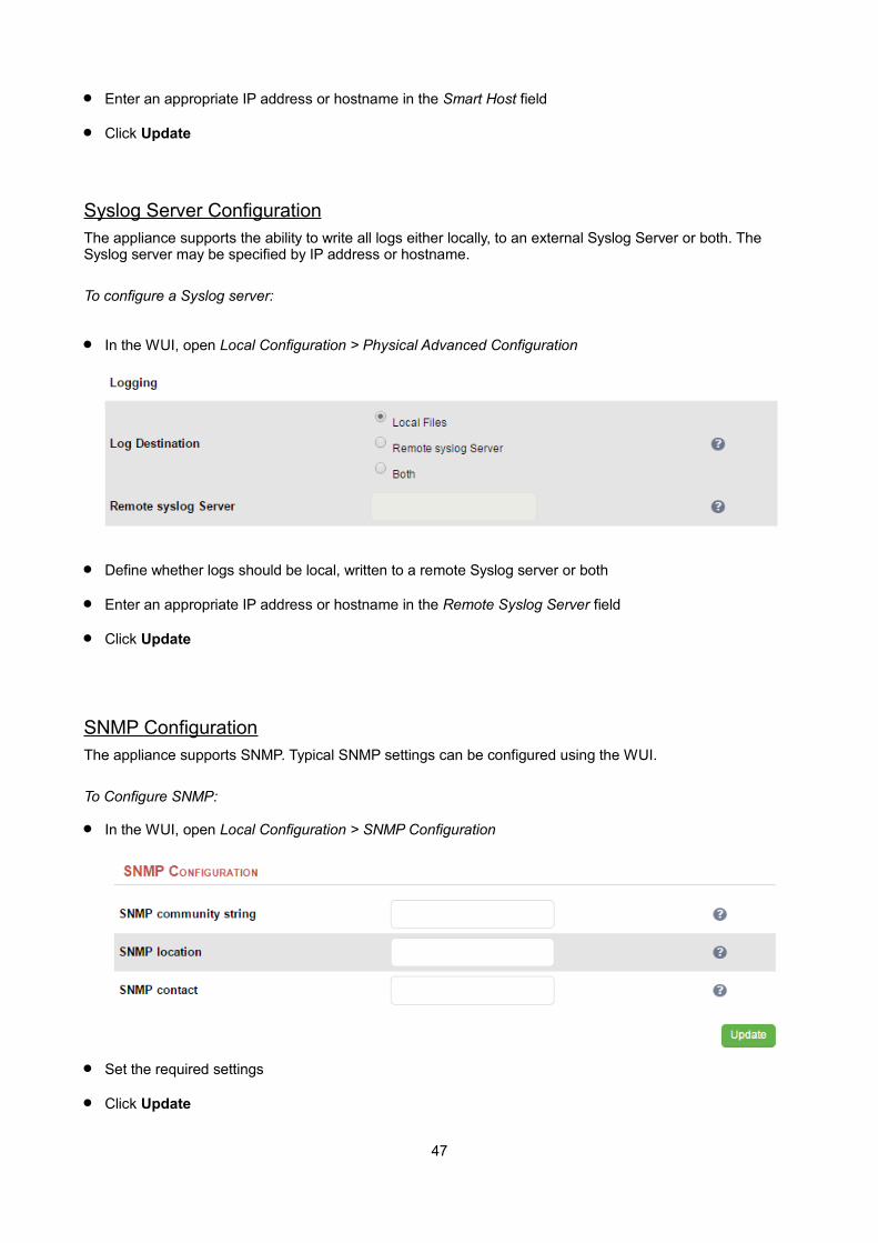
Enter an appropriate IP address or hostname in the Smart Host field
Click Update
Syslog Server ConfigurationThe appliance supports the ability to write all logs either locally, to an external Syslog Server or both. The Syslog server may be specified by IP address or hostname.
To configure a Syslog server:
In the WUI, open Local Configuration > Physical Advanced Configuration
Define whether logs should be local, written to a remote Syslog server or both
Enter an appropriate IP address or hostname in the Remote Syslog Server field
Click Update
SNMP ConfigurationThe appliance supports SNMP. Typical SNMP settings can be configured using the WUI.
To Configure SNMP:
In the WUI, open Local Configuration > SNMP Configuration
Set the required settings
Click Update
47
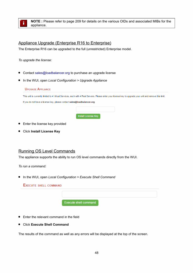
NOTE : Please refer to page 209 for details on the various OIDs and associated MIBs for the appliance.
Appliance Upgrade (Enterprise R16 to Enterprise)The Enterprise R16 can be upgraded to the full (unrestricted) Enterprise model.
To upgrade the license:
Contact [email protected] to purchase an upgrade license
In the WUI, open Local Configuration > Upgrade Appliance
Enter the license key provided
Click Install License Key
Running OS Level CommandsThe appliance supports the ability to run OS level commands directly from the WUI.
To run a command:
In the WUI, open Local Configuration > Execute Shell Command
Enter the relevant command in the field
Click Execute Shell Command
The results of the command as well as any errors will be displayed at the top of the screen.
48

Restoring Manufacturer's SettingsThe load balancers settings can be reset to factory default values in two ways. In both cases this will remove all custom configuration from the load balancer. All VIPs and RIPs will be removed and the IP address configured for eth0 will be set to 192.168.2.21.
Using the WUI
To restore settings:
In the WUI, open Maintenance > Backup & Restore > Restore Tab
Click Restore Manufacturer's Defaults
Once restored, restart the appliance to complete the process.
Using the Console / SSH Session
Run the following command:
lbrestore
Once restored, restart the appliance to complete the process.
Restarting ServicesThe various services running on the appliance can be manually reloaded or restarted if required. This is normally only required for HAProxy, Pound, STunnel and Heartbeat when configuration changes are made.
49

Restart Ldirectord
Restart Layer 4 Services. Restarting Ldirectord will result in a loss of layer 4 services during the restart. This causes the related process to be stopped and a new instance started. Generally only needed if Ldirectord hasfailed for some reason and needs to be started again from scratch.
Reload Ldirectord
Reload Layer 4 Services. The Ldirectord configuration is re-read and re-applied. Note that a reload occurs automatically whenever a layer 4 VIP or RIP and added, deleted or modified.
Restart HAProxy
Restart Layer 7 Services. Restarting HAProxy will result in a loss of layer 7 services during the restart Restarting HAProxy will cause any persistence tables to be dropped and all connections to be closed, it's a complete restart and reload of the HAProxy configuration.
Reload HAProxy
Reload Layer 7 Services. HAProxy will start a new process (leaving the old one) with the new configuration. New connections will be passed onto this process, the old process will maintain existing connections and eventually terminate when there are no more connections accessing it. If you are using stick tables for persistence the entries will be copied between processes. N.B. If you have long lasting tcp connections it cantake quite some time for the old process to terminate, leaving those users running the old configuration. If thisis taking too long – See Restart HAProxy.
Clear HAProxy Stick Table
Clears All HAProxy persistence tables. If you are using a Layer 7 persistence mode that relies on stick-tables (IP persistence or RDP cookie persistence), this option will clear all entries from these tables. Once cleared, clients may be directed to a different server upon re-connection.
Restart Pound
Restart Pound SSL Termination Service. Restarting Pound will result in a loss of SSL termination services during the restart.
Restart STunnel
Restart STunnel SSL Termination Service. Restarting STunnel will result in a loss of SSL termination servicesduring the restart.
Restart Heartbeat
Restart Heartbeat Services. Restarting Heartbeat will result in a loss of service during the restart. Restarting heartbeat will cause a temporary loss of all layer 4, layer 7 and SSL services.
Reload Heartbeat
From v7.6 this option forces heartbeat to stop (for the active member of an HA pair the floating IP's will also be taken down, for a single unit they will be left up) then after an appropriate delay heartbeat is reloaded. Thisoption is useful with a clustered pair when a device needs to be re-introduced without disrupting running services (see page 159).
Restart Firewall
Restarts iptables. This will clear then re-read and re-apply the firewall rules.
50
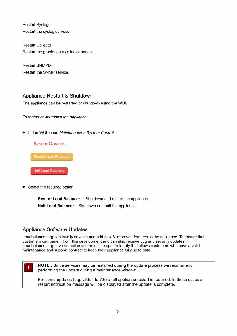
Restart Syslogd
Restart the syslog service.
Restart Collectd
Restart the graphs data collector service.
Restart SNMPD
Restart the SNMP service.
Appliance Restart & ShutdownThe appliance can be restarted or shutdown using the WUI.
To restart or shutdown the appliance:
In the WUI, open Maintenance > System Control
Select the required option:
Restart Load Balancer – Shutdown and restart the appliance
Halt Load Balancer – Shutdown and halt the appliance
Appliance Software UpdatesLoadbalancer.org continually develop and add new & improved features to the appliance. To ensure that customers can benefit from this development and can also receive bug and security updates, Loadbalancer.org have an online and an offline update facility that allows customers who have a valid maintenance and support contract to keep their appliance fully up to date.
NOTE : Since services may be restarted during the update process we recommend performing the update during a maintenance window.
For some updates (e.g. v7.5.4 to 7.6) a full appliance restart is required. In these cases a restart notification message will be displayed after the update is complete.
51
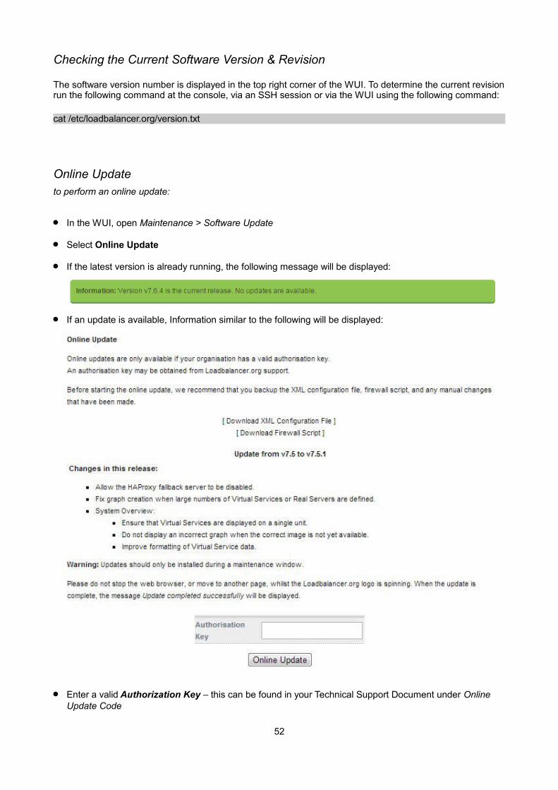
Checking the Current Software Version & Revision
The software version number is displayed in the top right corner of the WUI. To determine the current revisionrun the following command at the console, via an SSH session or via the WUI using the following command:
cat /etc/loadbalancer.org/version.txt
Online Updateto perform an online update:
In the WUI, open Maintenance > Software Update
Select Online Update
If the latest version is already running, the following message will be displayed:
If an update is available, Information similar to the following will be displayed:
Enter a valid Authorization Key – this can be found in your Technical Support Document under Online Update Code
52
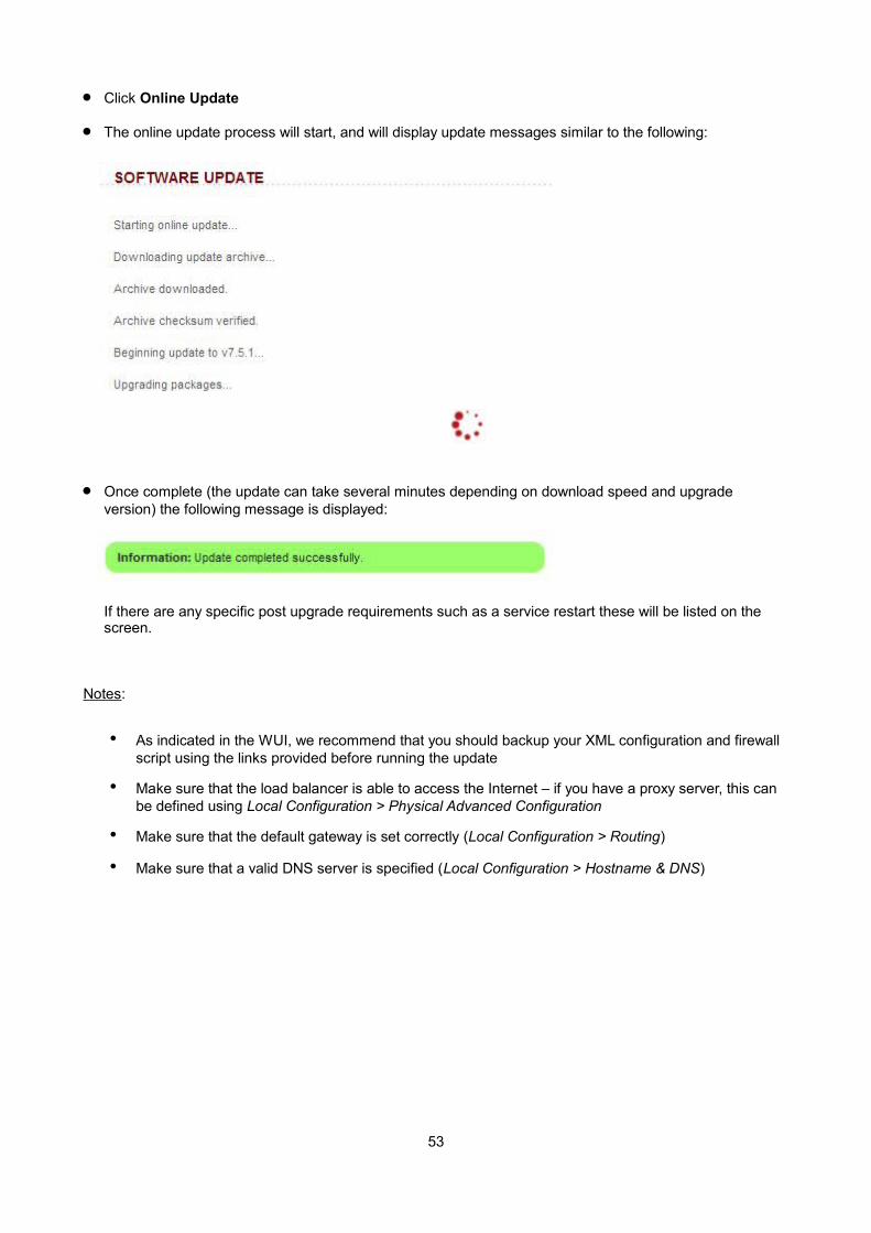
Click Online Update
The online update process will start, and will display update messages similar to the following:
Once complete (the update can take several minutes depending on download speed and upgrade version) the following message is displayed:
If there are any specific post upgrade requirements such as a service restart these will be listed on the screen.
Notes:
• As indicated in the WUI, we recommend that you should backup your XML configuration and firewall script using the links provided before running the update
• Make sure that the load balancer is able to access the Internet – if you have a proxy server, this can be defined using Local Configuration > Physical Advanced Configuration
• Make sure that the default gateway is set correctly (Local Configuration > Routing)
• Make sure that a valid DNS server is specified (Local Configuration > Hostname & DNS)
53
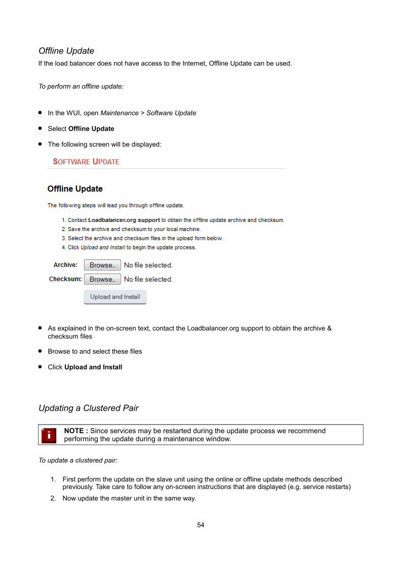
Offline UpdateIf the load balancer does not have access to the Internet, Offline Update can be used.
To perform an offline update:
In the WUI, open Maintenance > Software Update
Select Offline Update
The following screen will be displayed:
As explained in the on-screen text, contact the Loadbalancer.org support to obtain the archive & checksum files
Browse to and select these files
Click Upload and Install
Updating a Clustered Pair
NOTE : Since services may be restarted during the update process we recommend performing the update during a maintenance window.
To update a clustered pair:
1. First perform the update on the slave unit using the online or offline update methods described previously. Take care to follow any on-screen instructions that are displayed (e.g. service restarts)
2. Now update the master unit in the same way.
54
IMPORTANT NOTE : For a clustered pair, we strongly recommend fully testing & validating the master / slave failover process before going live. If testing was not carried out before go-live, we recommend scheduling a maintenance window to do this. For detailed steps, please refer to page 163.
Firewall Configuration
NOTE : Whilst the load balancer is capable of supporting complex firewall rules, we do not recommend using the load balancer as your main bastion host. We recommend that the load balancer is deployed behind your external firewall.
If you want to configure firewall rules, some points to consider are:
1. All Virtual Service connections are dealt with on the INPUT chain not the FORWARD chain
2. The WUI runs on HTTP port 9080 and HTTPS port 9443
3. SSH on the load balancer listens on the standard port (22)
4. SNAT & DNAT is handled automatically for all layer 4 NAT mode (LVS) and layer 7 (HAProxy) based Virtual/Real load balanced services
5. You can use the standard Linux filters against spoofing attacks and syn floods
6. LVS has built in DOS attack filters that can be implemented
7. Plenty of extra information is available on the Internet relating to Linux Netfilter and LVS, if you need any assistance please email our support team : [email protected]
55
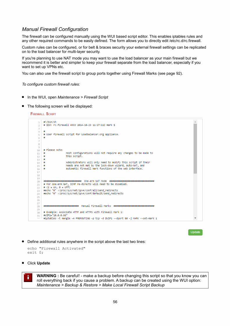
Manual Firewall ConfigurationThe firewall can be configured manually using the WUI based script editor. This enables iptables rules and any other required commands to be easily defined. The form allows you to directly edit /etc/rc.d/rc.firewall.
Custom rules can be configured, or for belt & braces security your external firewall settings can be replicated on to the load balancer for multi-layer security.
If you're planning to use NAT mode you may want to use the load balancer as your main firewall but we recommend it is better and simpler to keep your firewall separate from the load balancer, especially if you want to set up VPNs etc.
You can also use the firewall script to group ports together using Firewall Marks (see page 92).
To configure custom firewall rules:
In the WUI, open Maintenance > Firewall Script
The following screen will be displayed:
Define additional rules anywhere in the script above the last two lines:
echo "Firewall Activated"exit 0;
Click Update
WARNING : Be careful! - make a backup before changing this script so that you know you canroll everything back if you cause a problem. A backup can be created using the WUI option: Maintenance > Backup & Restore > Make Local Firewall Script Backup
56
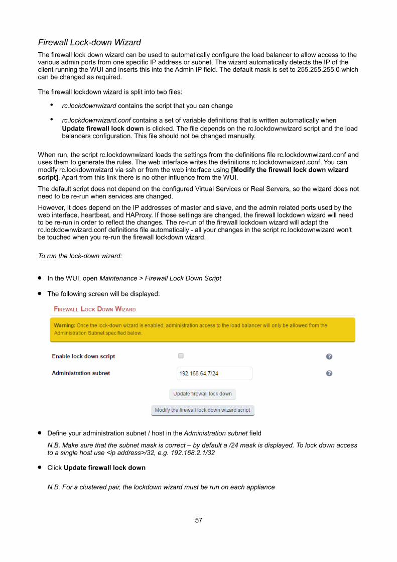
Firewall Lock-down WizardThe firewall lock down wizard can be used to automatically configure the load balancer to allow access to the various admin ports from one specific IP address or subnet. The wizard automatically detects the IP of the client running the WUI and inserts this into the Admin IP field. The default mask is set to 255.255.255.0 whichcan be changed as required.
The firewall lockdown wizard is split into two files:
• rc.lockdownwizard contains the script that you can change
• rc.lockdownwizard.conf contains a set of variable definitions that is written automatically when Update firewall lock down is clicked. The file depends on the rc.lockdownwizard script and the loadbalancers configuration. This file should not be changed manually.
When run, the script rc.lockdownwizard loads the settings from the definitions file rc.lockdownwizard.conf anduses them to generate the rules. The web interface writes the definitions rc.lockdownwizard.conf. You can modify rc.lockdownwizard via ssh or from the web interface using [Modify the firewall lock down wizard script]. Apart from this link there is no other influence from the WUI.
The default script does not depend on the configured Virtual Services or Real Servers, so the wizard does notneed to be re-run when services are changed.
However, it does depend on the IP addresses of master and slave, and the admin related ports used by the web interface, heartbeat, and HAProxy. If those settings are changed, the firewall lockdown wizard will need to be re-run in order to reflect the changes. The re-run of the firewall lockdown wizard will adapt the rc.lockdownwizard.conf definitions file automatically - all your changes in the script rc.lockdownwizard won't be touched when you re-run the firewall lockdown wizard.
To run the lock-down wizard:
In the WUI, open Maintenance > Firewall Lock Down Script
The following screen will be displayed:
Define your administration subnet / host in the Administration subnet field
N.B. Make sure that the subnet mask is correct – by default a /24 mask is displayed. To lock down accessto a single host use <ip address>/32, e.g. 192.168.2.1/32
Click Update firewall lock down
N.B. For a clustered pair, the lockdown wizard must be run on each appliance
57

Disabling the lock-down script
To disable the lock-down script un-check the Enable lock down script check-box and click the Update Firewall lock down button.
N.B. If you accidentally block your own access to the appliance you will need to clear the current firewall rules and try again. to clear the firewall tables completely use the following command at the console:
/etc/rc.d/rc.flush-iptables
Conntrack Table SizeBy default the connection tracking table size is set to 524288 and is fine in most cases. For high traffic deployment using NAT mode, or when using connection tracking in the firewall script, this value may need to be increased. If the connection tracking table fills up, the following error will be reported in the log:
ip_conntrack: table full, dropping packet.
To increase the setting:
In the WUI, open Local Configuration > Physical – Advanced Configuration
Use the following section:
Set the required value using the Connection Tracking table size field
Click Update
Users & PasswordsBy default the appliance includes three pre-defined user accounts. The default usernames, passwords, groupmembership and their primary use are:
Username Default Password
Default Group
Permissions (see also the group table below)
loadbalancer loadbalancer config * appliance administration account
reportuser reportuser report viewing the appliance configuration, reports & logs
maintuser maintuser maintsame as reportuser, can also take servers on/off line & create the support download archive file
* It's not possible to change the default group for user 'loadbalancer'
N.B. These are Apache .htaccess style accounts and are not related to the local Linux OS level accounts.
58

The permissions for each group are shown below:
Menu / Permissions
GroupSystem
OverviewLocal
configurationCluster
ConfigurationMaintenance View
ConfigurationReports Logs Support
config Full Full Full Full View Full View Full
report View None none None View Full View View
maint Full None None None View Full View Full
Modifying User Passwords
to modify a user's password:
In the WUI, open Maintenance > Passwords
In the following section, click the [Modify] link next to the relevant user
Now change the password for the selected user:
Click Edit User
59

Adding New Users
to add new users:
In the WUI, open Maintenance > Passwords
Use the following section:
Enter the required Username & Password and click Add New User
By default, new users will be added to the report group (least privilege). To change this, click [Modify] next to the user, select the required group and click Edit User
Resetting forgotten Passwords
It's possible to reset passwords via the command line if required. To do this you'll need to login as root to the console / SSH session. The htpasswd command can then be used as shown below:
htpasswd -b /etc/loadbalancer.org/passwords loadbalancer <new password>
e.g. htpasswd -b /etc/loadbalancer.org/passwords loadbalancer loadbalancer
This example sets the password for user 'loadbalancer' to 'loadbalancer'
Appliance Security Lockdown ScriptTo ensure that the appliance is secure it's recommended that a number of steps should be carried out. Thesesteps have been incorporated into a lockdown script which can be run at the console (recommended) or via aterminal session. The script helps to lock down the following:
the password for the 'loadbalancer' Web User Interface account
the password for the Linux 'root' account
which subnet / host is permitted access to the load balancer
It also regenerates the SSH keys that are used to secure communicating between the master and slave appliance. To start the script, at the console or via an SSH terminal session run the following command:
lbsecure
The image below illustrates how the script works for a single appliance:
60

Once the script has finished, the “Security enhancement complete” message is displayed as shown above.
NOTE : If lbsecure is run on the master of a correctly configured HA pair, the passwords, firewall rules and SSH keys will also be updated on the slave appliance.
61

Chapter 6 – Configuring Load Balanced Services
62
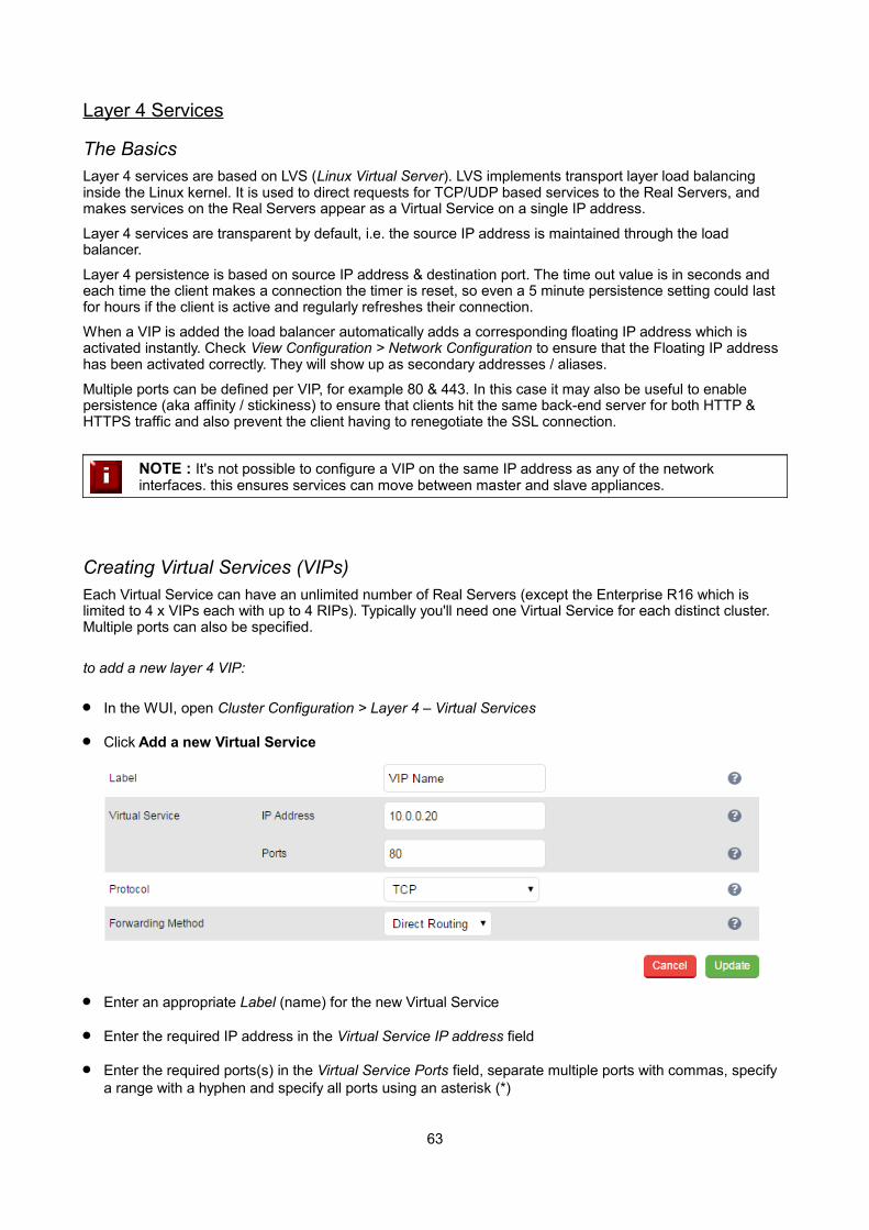
Layer 4 Services
The BasicsLayer 4 services are based on LVS (Linux Virtual Server). LVS implements transport layer load balancing inside the Linux kernel. It is used to direct requests for TCP/UDP based services to the Real Servers, and makes services on the Real Servers appear as a Virtual Service on a single IP address.
Layer 4 services are transparent by default, i.e. the source IP address is maintained through the load balancer.
Layer 4 persistence is based on source IP address & destination port. The time out value is in seconds and each time the client makes a connection the timer is reset, so even a 5 minute persistence setting could last for hours if the client is active and regularly refreshes their connection.
When a VIP is added the load balancer automatically adds a corresponding floating IP address which is activated instantly. Check View Configuration > Network Configuration to ensure that the Floating IP address has been activated correctly. They will show up as secondary addresses / aliases.
Multiple ports can be defined per VIP, for example 80 & 443. In this case it may also be useful to enable persistence (aka affinity / stickiness) to ensure that clients hit the same back-end server for both HTTP & HTTPS traffic and also prevent the client having to renegotiate the SSL connection.
NOTE : It's not possible to configure a VIP on the same IP address as any of the network interfaces. this ensures services can move between master and slave appliances.
Creating Virtual Services (VIPs)Each Virtual Service can have an unlimited number of Real Servers (except the Enterprise R16 which is limited to 4 x VIPs each with up to 4 RIPs). Typically you'll need one Virtual Service for each distinct cluster. Multiple ports can also be specified.
to add a new layer 4 VIP:
In the WUI, open Cluster Configuration > Layer 4 – Virtual Services
Click Add a new Virtual Service
Enter an appropriate Label (name) for the new Virtual Service
Enter the required IP address in the Virtual Service IP address field
Enter the required ports(s) in the Virtual Service Ports field, separate multiple ports with commas, specify a range with a hyphen and specify all ports using an asterisk (*)
63

NOTE : The following ports are used by the appliance and therefore cannot be used for VirtualServices: 22 (SSH), 9080 (WUI – HTTP), 9443 (WUI – HTTPS), 7777 (HAProxy statistics page), 7778 (HAProxy persistence table replication and 9081 (nginx fallback page).
Set the Protocol as required
TCP – Transmission Control Protocol is the default and most common option
UDP – User Datagram Protocol – used for DNS, SIP, etc.
One Packet Scheduling - used for UDP SIP connections
Firewall Marks – For use when traffic has been tagged in the firewall script using the MARK target
Select the required Forwarding Method
Direct Routing (DR) - This is the default one-arm mode. Direct Routing is recommended as it's easy to understand and implement with two load balancers in failover mode (our recommended configuration). It only requires one external Floating IP address on the same subnet as your web server cluster and only one network card.
NAT – This is the default two-arm mode (Network Address Translation). This has the advantage that you can load balance any device without having to deal with the ARP problem. The Real Servers need their default gateway changed to be the internal floating VIP of the load balancer. Because the load balancer handles the return packet you will get more detailed statistics but slower speed than DR or TUN. NAT can also be implemented with a single NIC – just use the firewall script to set up an alias on the eth0 interface.
Tunneling – This is for WAN links (Tunneling). Tunneling has somewhat limited use as it requires an ip tunnel between the load balancer and the Real Server as the VIP is the target address many routers will drop the packet assuming that it has been spoofed. However it is useful for private networks with Real Servers on multiple subnets.
Click Update
Now proceed to define the RIPs (Real Servers) as detailed on page 67
Modifying a Virtual Service
When first adding a Virtual Service, only certain values can be configured, others are set at their default setting. These values can be changed after the Virtual Service has been created by clicking [Modify] next to the relevant Virtual Service. Additional settings that can be changed are:
Option Sub-Option Description
Balance Mode Weighted Least-Connection – assign more jobs to servers with fewer jobs, relative to the Real Servers' weight (the default).
Weighted Round Robin – assign jobs to Real Servers proportionally to the Real Servers' weight. Servers with higher weights receive new jobs first andget more jobs than servers with lower weights. Servers with equal weights get an equal distribution ofnew jobs.
Destination Hash – assign jobs to servers through looking up a statically assigned hash table by their destination IP addresses.
Persistent Enable persistence for this Virtual Service, by Source IP or SIP call-ID. Sticky or persistent connections are required for some protocols such as FTP and SIP. It
64
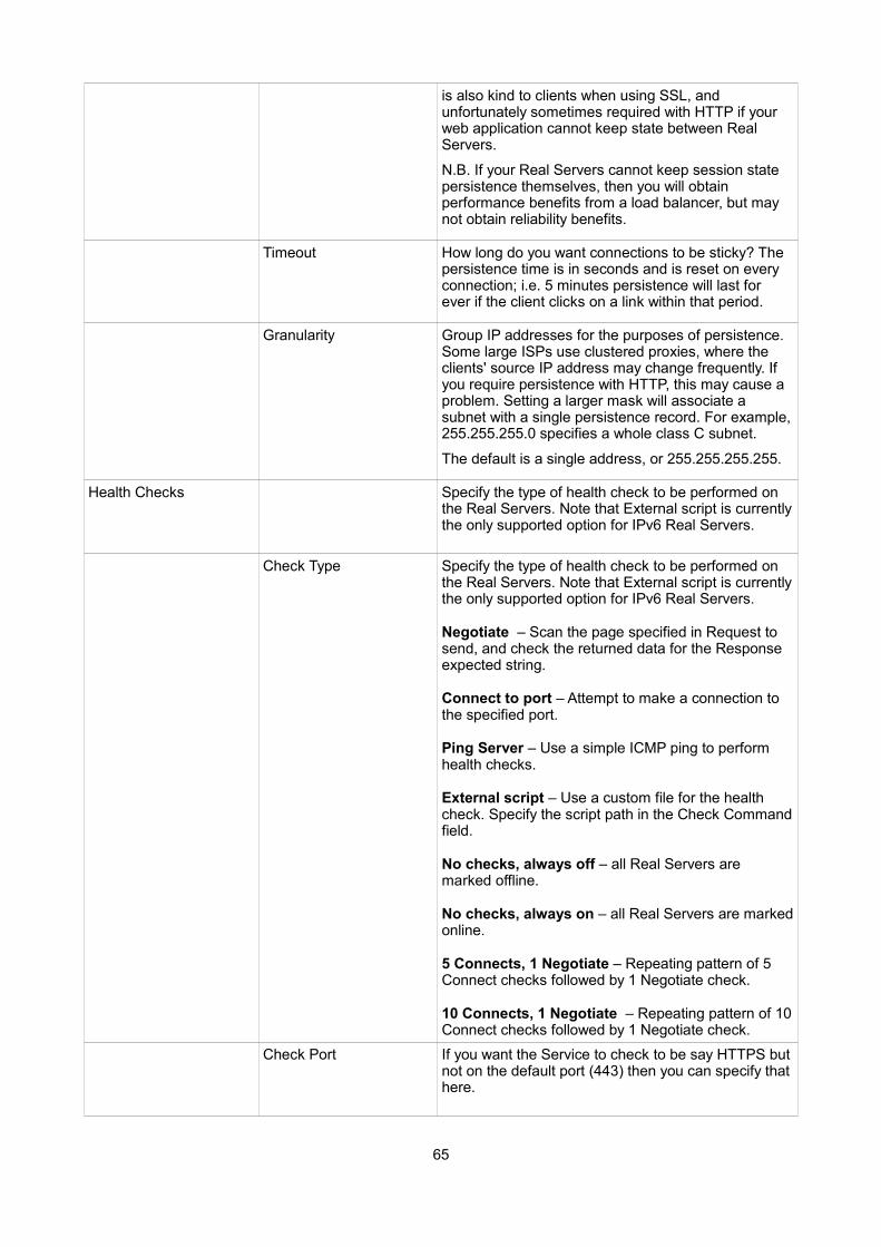
is also kind to clients when using SSL, and unfortunately sometimes required with HTTP if your web application cannot keep state between Real Servers.
N.B. If your Real Servers cannot keep session state persistence themselves, then you will obtain performance benefits from a load balancer, but may not obtain reliability benefits.
Timeout How long do you want connections to be sticky? The persistence time is in seconds and is reset on every connection; i.e. 5 minutes persistence will last for ever if the client clicks on a link within that period.
Granularity Group IP addresses for the purposes of persistence. Some large ISPs use clustered proxies, where the clients' source IP address may change frequently. If you require persistence with HTTP, this may cause a problem. Setting a larger mask will associate a subnet with a single persistence record. For example,255.255.255.0 specifies a whole class C subnet.
The default is a single address, or 255.255.255.255.
Health Checks Specify the type of health check to be performed on the Real Servers. Note that External script is currentlythe only supported option for IPv6 Real Servers.
Check Type Specify the type of health check to be performed on the Real Servers. Note that External script is currentlythe only supported option for IPv6 Real Servers.
Negotiate – Scan the page specified in Request to send, and check the returned data for the Response expected string.
Connect to port – Attempt to make a connection to the specified port.
Ping Server – Use a simple ICMP ping to perform health checks.
External script – Use a custom file for the health check. Specify the script path in the Check Commandfield.
No checks, always off – all Real Servers are marked offline.
No checks, always on – all Real Servers are markedonline.
5 Connects, 1 Negotiate – Repeating pattern of 5 Connect checks followed by 1 Negotiate check.
10 Connects, 1 Negotiate – Repeating pattern of 10Connect checks followed by 1 Negotiate check.
Check Port If you want the Service to check to be say HTTPS butnot on the default port (443) then you can specify thathere.
65
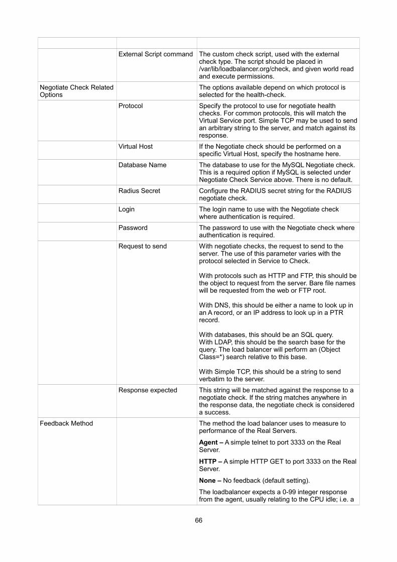
External Script command The custom check script, used with the external check type. The script should be placed in /var/lib/loadbalancer.org/check, and given world read and execute permissions.
Negotiate Check RelatedOptions
The options available depend on which protocol is selected for the health-check.
Protocol Specify the protocol to use for negotiate health checks. For common protocols, this will match the Virtual Service port. Simple TCP may be used to sendan arbitrary string to the server, and match against its response.
Virtual Host If the Negotiate check should be performed on a specific Virtual Host, specify the hostname here.
Database Name The database to use for the MySQL Negotiate check.This is a required option if MySQL is selected under Negotiate Check Service above. There is no default.
Radius Secret Configure the RADIUS secret string for the RADIUS negotiate check.
Login The login name to use with the Negotiate check where authentication is required.
Password The password to use with the Negotiate check where authentication is required.
Request to send With negotiate checks, the request to send to the server. The use of this parameter varies with the protocol selected in Service to Check.
With protocols such as HTTP and FTP, this should bethe object to request from the server. Bare file names will be requested from the web or FTP root.
With DNS, this should be either a name to look up in an A record, or an IP address to look up in a PTR record.
With databases, this should be an SQL query.With LDAP, this should be the search base for the query. The load balancer will perform an (Object Class=*) search relative to this base.
With Simple TCP, this should be a string to send verbatim to the server.
Response expected This string will be matched against the response to a negotiate check. If the string matches anywhere in the response data, the negotiate check is considered a success.
Feedback Method The method the load balancer uses to measure to performance of the Real Servers.
Agent – A simple telnet to port 3333 on the Real Server.
HTTP – A simple HTTP GET to port 3333 on the RealServer.
None – No feedback (default setting).
The loadbalancer expects a 0-99 integer response from the agent, usually relating to the CPU idle; i.e. a
66
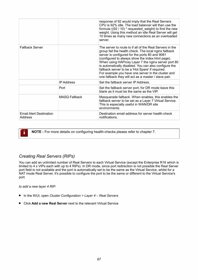
response of 92 would imply that the Real Servers CPU is 92% idle. The load balancer will then use the formula ((92 / 10) * requested_weight) to find the newweight. Using this method an idle Real Server will get 10 times as many new connections as an overloaded server.
Fallback Server The server to route to if all of the Real Servers in the group fail the health check. The local nginx fallback server is configured for the ports 80 and 9081 (configured to always show the index.html page).When using HAProxy Layer 7 the nginx server port 80is automatically disabled. You can also configure the fallback server to be a 'Hot Spare' if required. For example you have one server in the cluster and one fallback they will act as a master / slave pair.
IP Address Set the fallback server IP Address.
Port Set the fallback server port, for DR mode leave this blank as it must be the same as the VIP.
MASQ Fallback Masquerade fallback. When enables, this enables thefallback server to be set as a Layer 7 Virtual Service. This is especially useful in WAN/DR site environments.
Email Alert Destination Address
Destination email address for server health-check notifications.
NOTE : For more details on configuring health-checks please refer to chapter 7.
Creating Real Servers (RIPs)You can add an unlimited number of Real Servers to each Virtual Service (except the Enterprise R16 which islimited to 4 x VIPs each with up to 4 RIPs). In DR mode, since port redirection is not possible the Real Serverport field is not available and the port is automatically set to be the same as the Virtual Service, whilst for a NAT mode Real Server, it's possible to configure the port to be the same or different to the Virtual Service's port.
to add a new layer 4 RIP:
In the WUI, open Cluster Configuration > Layer 4 – Real Servers
Click Add a new Real Server next to the relevant Virtual Service
67
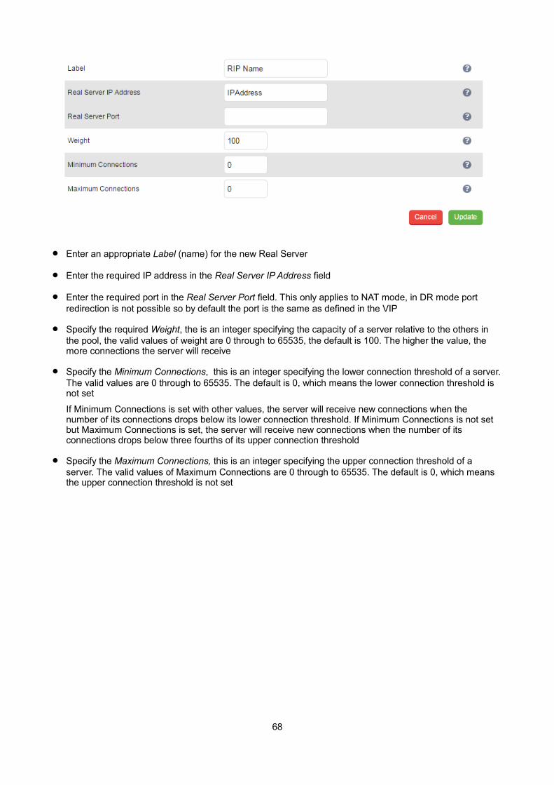
Enter an appropriate Label (name) for the new Real Server
Enter the required IP address in the Real Server IP Address field
Enter the required port in the Real Server Port field. This only applies to NAT mode, in DR mode port redirection is not possible so by default the port is the same as defined in the VIP
Specify the required Weight, the is an integer specifying the capacity of a server relative to the others in the pool, the valid values of weight are 0 through to 65535, the default is 100. The higher the value, the more connections the server will receive
Specify the Minimum Connections, this is an integer specifying the lower connection threshold of a server.The valid values are 0 through to 65535. The default is 0, which means the lower connection threshold is not set
If Minimum Connections is set with other values, the server will receive new connections when the number of its connections drops below its lower connection threshold. If Minimum Connections is not set but Maximum Connections is set, the server will receive new connections when the number of its connections drops below three fourths of its upper connection threshold
Specify the Maximum Connections, this is an integer specifying the upper connection threshold of a server. The valid values of Maximum Connections are 0 through to 65535. The default is 0, which means the upper connection threshold is not set
68

Persistence Considerations
Persistence State Table Replication
If you want the current persistent connection table to work when the master load balancer swaps over to the slave then you can start the synchronization daemons on each load balancer to replicate the data in real time.
First login to the master appliance using SSH or the console, then as root run the following commands:
ipvsadm --start-daemon masteripvsadm --start-daemon backup
Then login to the slave appliance using SSH or the console, then as root run the following commands:
ipvsadm --start-daemon masteripvsadm --start-daemon backup
N.B. To ensure that these sync daemons are started on each reboot put these commands in the rc.firewall. This can be done via the WUI using Maintenance > Firewall Script. Make sure that the full path is specified in the firewall script, i.e.
/usr/local/sbin/ipvsadm --start-daemon master/usr/local/sbin/ipvsadm --start-daemon backup
After a few seconds you can confirm that it is working by seeing the output from:
ipvsadm -Lc
N.B. This is the same command that the 'Layer 4 Current Connections' report is based on.
When run on the active device the output will show all connections including those in state 'NONE' i.e. the persistence entries. When run on the passive device, the output will only include connections in state 'NONE'since only these are being replicated.
NOTE : Setting this option can generate a high level of connection state synchronization data between the master and slave load balancers.
69
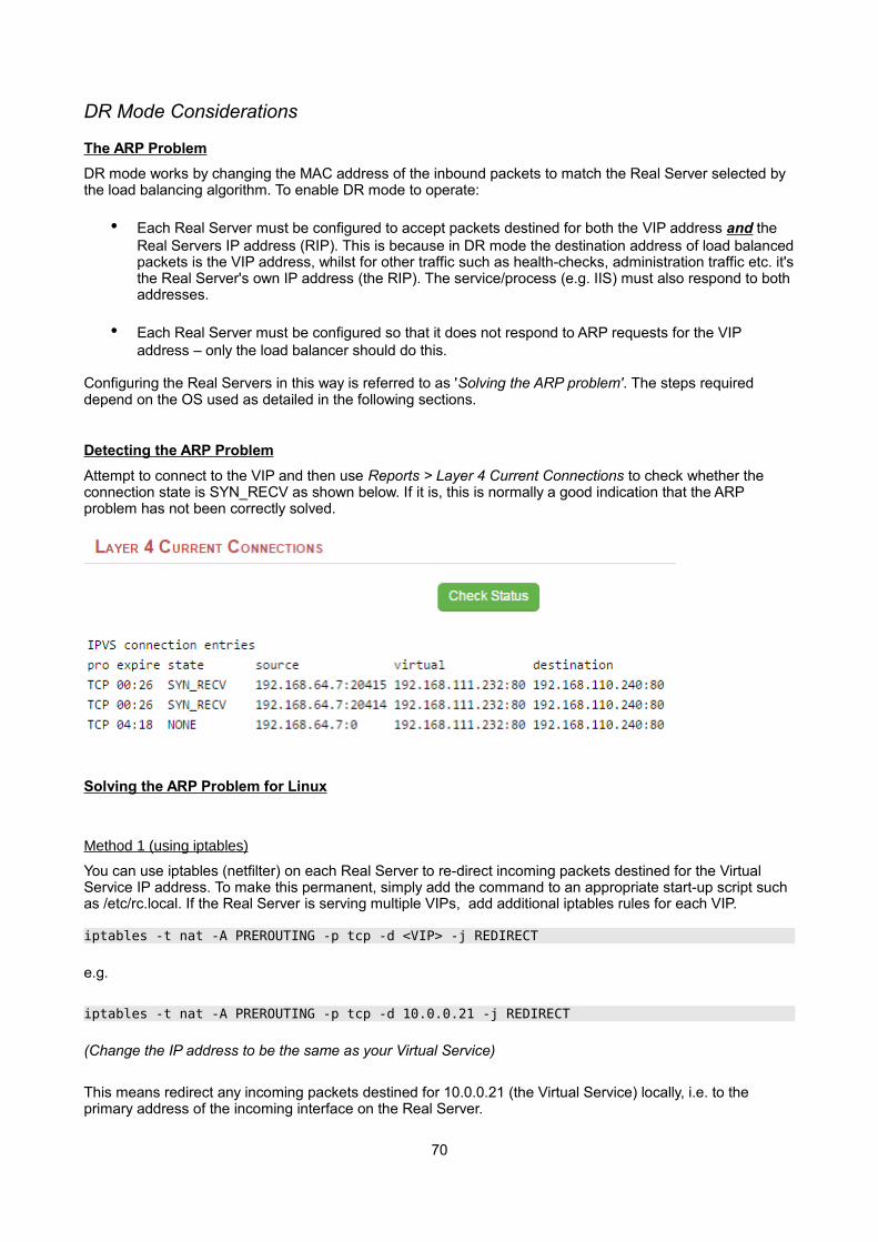
DR Mode Considerations
The ARP Problem
DR mode works by changing the MAC address of the inbound packets to match the Real Server selected by the load balancing algorithm. To enable DR mode to operate:
• Each Real Server must be configured to accept packets destined for both the VIP address and the Real Servers IP address (RIP). This is because in DR mode the destination address of load balancedpackets is the VIP address, whilst for other traffic such as health-checks, administration traffic etc. it'sthe Real Server's own IP address (the RIP). The service/process (e.g. IIS) must also respond to both addresses.
• Each Real Server must be configured so that it does not respond to ARP requests for the VIP address – only the load balancer should do this.
Configuring the Real Servers in this way is referred to as 'Solving the ARP problem'. The steps required depend on the OS used as detailed in the following sections.
Detecting the ARP Problem
Attempt to connect to the VIP and then use Reports > Layer 4 Current Connections to check whether the connection state is SYN_RECV as shown below. If it is, this is normally a good indication that the ARP problem has not been correctly solved.
Solving the ARP Problem for Linux
Method 1 (using iptables)
You can use iptables (netfilter) on each Real Server to re-direct incoming packets destined for the Virtual Service IP address. To make this permanent, simply add the command to an appropriate start-up script such as /etc/rc.local. If the Real Server is serving multiple VIPs, add additional iptables rules for each VIP.
iptables -t nat -A PREROUTING -p tcp -d <VIP> -j REDIRECT
e.g.
iptables -t nat -A PREROUTING -p tcp -d 10.0.0.21 -j REDIRECT
(Change the IP address to be the same as your Virtual Service)
This means redirect any incoming packets destined for 10.0.0.21 (the Virtual Service) locally, i.e. to the primary address of the incoming interface on the Real Server.
70
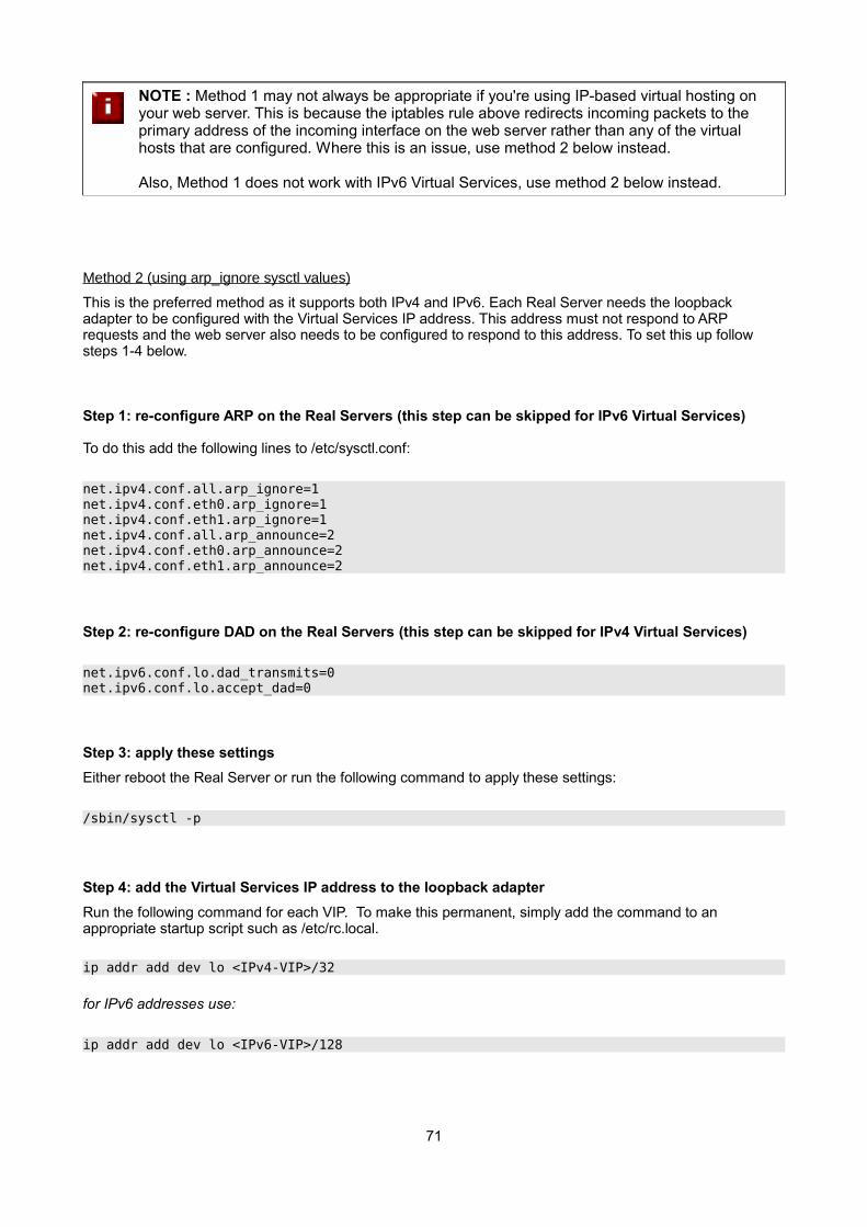
NOTE : Method 1 may not always be appropriate if you're using IP-based virtual hosting on your web server. This is because the iptables rule above redirects incoming packets to the primary address of the incoming interface on the web server rather than any of the virtual hosts that are configured. Where this is an issue, use method 2 below instead.
Also, Method 1 does not work with IPv6 Virtual Services, use method 2 below instead.
Method 2 (using arp_ignore sysctl values)
This is the preferred method as it supports both IPv4 and IPv6. Each Real Server needs the loopback adapter to be configured with the Virtual Services IP address. This address must not respond to ARP requests and the web server also needs to be configured to respond to this address. To set this up follow steps 1-4 below.
Step 1: re-configure ARP on the Real Servers (this step can be skipped for IPv6 Virtual Services)
To do this add the following lines to /etc/sysctl.conf:
net.ipv4.conf.all.arp_ignore=1 net.ipv4.conf.eth0.arp_ignore=1 net.ipv4.conf.eth1.arp_ignore=1 net.ipv4.conf.all.arp_announce=2 net.ipv4.conf.eth0.arp_announce=2 net.ipv4.conf.eth1.arp_announce=2
Step 2: re-configure DAD on the Real Servers (this step can be skipped for IPv4 Virtual Services)
net.ipv6.conf.lo.dad_transmits=0net.ipv6.conf.lo.accept_dad=0
Step 3: apply these settings
Either reboot the Real Server or run the following command to apply these settings:
/sbin/sysctl -p
Step 4: add the Virtual Services IP address to the loopback adapter
Run the following command for each VIP. To make this permanent, simply add the command to an appropriate startup script such as /etc/rc.local.
ip addr add dev lo <IPv4-VIP>/32
for IPv6 addresses use:
ip addr add dev lo <IPv6-VIP>/128
71
N.B. Steps 1, 2 & 3 can be replaced by writing directly to the required files using the following commands:
(temporary until the next reboot)
echo 1 > /proc/sys/net/ipv4/conf/all/arp_ignoreecho 1 > /proc/sys/net/ipv4/conf/eth0/arp_ignoreecho 1 > /proc/sys/net/ipv4/conf/eth1/arp_ignoreecho 2 > /proc/sys/net/ipv4/conf/all/arp_announceecho 2 > /proc/sys/net/ipv4/conf/eth0/arp_announceecho 2 > /proc/sys/net/ipv4/conf/eth1/arp_announce
echo 0 > /proc/sys/net/ipv6/conf/lo/dad_transmitsecho 0 > /proc/sys/net/ipv6/conf/lo/accept_dad
Solving the ARP Problem for Solaris
With Solaris the loopback interface does not respond to ARP requests so you just add your VIPs to it.
ifconfig lo0:1 plumbifconfig lo0:1 VIP netmask 255.255.255.255 up
You will need to add this to the startup scripts for your server.
Solving the ARP Problem for Mac OS X / BSD
OS X is BSDish, so you need to use BSDish syntax:
ifconfig lo0 alias VIP netmask 255.255.255.255 -arp up
You will need to add this to the startup scripts for your server.
NOTE : Don't forget that the service on the Real Servers needs to listen on both the RIP address and VIP address as mentioned previously.
NOTE : Failure to correctly configure the Real Servers to handle the ARP problem is the most common mistake in DR mode configurations.
72
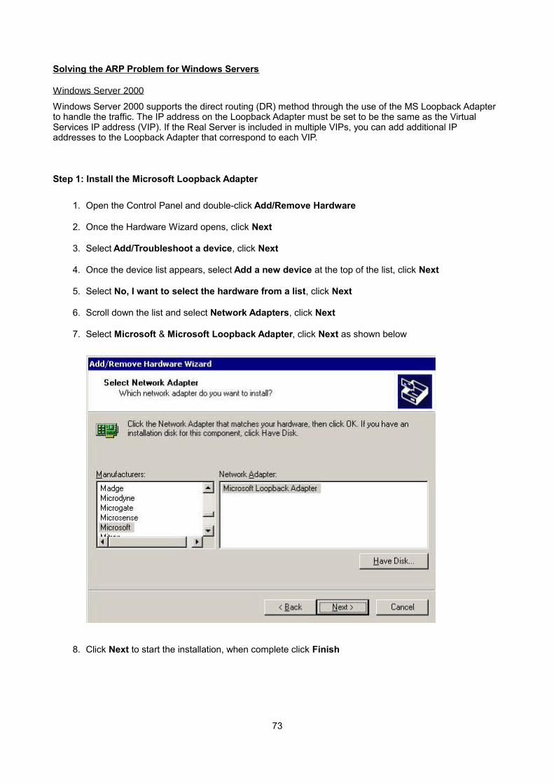
Solving the ARP Problem for Windows Servers
Windows Server 2000
Windows Server 2000 supports the direct routing (DR) method through the use of the MS Loopback Adapter to handle the traffic. The IP address on the Loopback Adapter must be set to be the same as the Virtual Services IP address (VIP). If the Real Server is included in multiple VIPs, you can add additional IP addresses to the Loopback Adapter that correspond to each VIP.
Step 1: Install the Microsoft Loopback Adapter
1. Open the Control Panel and double-click Add/Remove Hardware
2. Once the Hardware Wizard opens, click Next
3. Select Add/Troubleshoot a device, click Next
4. Once the device list appears, select Add a new device at the top of the list, click Next
5. Select No, I want to select the hardware from a list, click Next
6. Scroll down the list and select Network Adapters, click Next
7. Select Microsoft & Microsoft Loopback Adapter, click Next as shown below
8. Click Next to start the installation, when complete click Finish
73

Step 2: Configure the Loopback Adapter
1. Open the Control Panel and double-click Network and Dial-up Connections
2. Right-click the new Loopback Adapter and select Properties
3. Un-check all items except Internet Protocol (TCP/IP) as shown below
4. Select Internet Protocol (TCP/IP), click Properties and configure the IP address and mask to be the same as the Virtual Service IP address (VIP), e.g. 192.168.2.20/24 as shown below
74
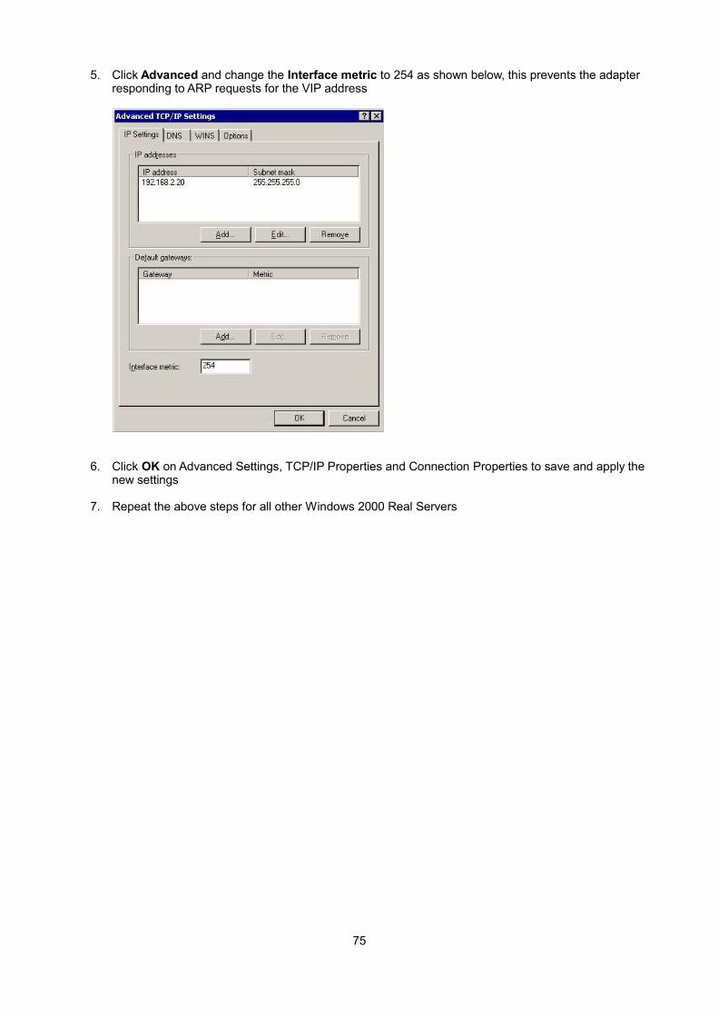
5. Click Advanced and change the Interface metric to 254 as shown below, this prevents the adapter responding to ARP requests for the VIP address
6. Click OK on Advanced Settings, TCP/IP Properties and Connection Properties to save and apply the new settings
7. Repeat the above steps for all other Windows 2000 Real Servers
75

Windows Server 2003
Windows server 2003 supports the direct routing (DR) method through the use of the MS Loopback Adapter to handle the traffic. The IP address on the Loopback Adapter must be set to be the same as the Virtual Services IP address (VIP). If the Real Server is included in multiple VIPs, you can add additional IP addresses to the Loopback Adapter that correspond to each VIP.
Step 1: Install the Microsoft Loopback Adapter
1. Open the Control Panel and double-click Add Hardware
2. Once the Hardware Wizard opens, click Next
3. Select Yes, I have already connected the hardware, click Next
4. Scroll to the bottom of the list, select Add a new hardware device, click Next
5. Select Install the hardware that I manually select from a list (Advanced), click Next
6. Select Network adapters, click Next
7. Select Microsoft & Microsoft Loopback Adapter, click Next as shown below
8. Click Next to start the installation, when complete click Finish
76
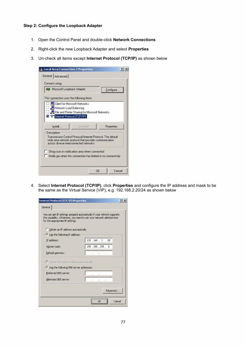
Step 2: Configure the Loopback Adapter
1. Open the Control Panel and double-click Network Connections
2. Right-click the new Loopback Adapter and select Properties
3. Un-check all items except Internet Protocol (TCP/IP) as shown below
4. Select Internet Protocol (TCP/IP), click Properties and configure the IP address and mask to be the same as the Virtual Service (VIP), e.g. 192.168.2.20/24 as shown below
77
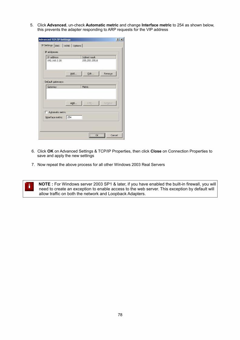
5. Click Advanced, un-check Automatic metric and change Interface metric to 254 as shown below, this prevents the adapter responding to ARP requests for the VIP address
6. Click OK on Advanced Settings & TCP/IP Properties, then click Close on Connection Properties to save and apply the new settings
7. Now repeat the above process for all other Windows 2003 Real Servers
NOTE : For Windows server 2003 SP1 & later, if you have enabled the built-in firewall, you willneed to create an exception to enable access to the web server. This exception by default will allow traffic on both the network and Loopback Adapters.
78
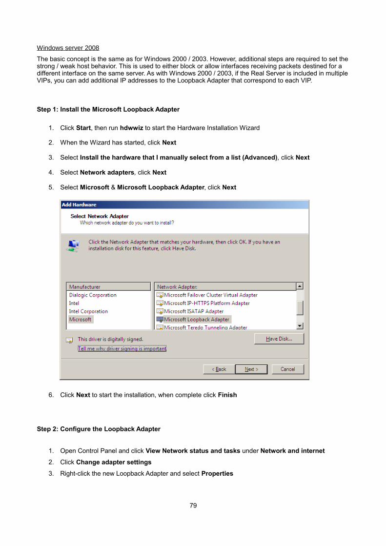
Windows server 2008
The basic concept is the same as for Windows 2000 / 2003. However, additional steps are required to set thestrong / weak host behavior. This is used to either block or allow interfaces receiving packets destined for a different interface on the same server. As with Windows 2000 / 2003, if the Real Server is included in multipleVIPs, you can add additional IP addresses to the Loopback Adapter that correspond to each VIP.
Step 1: Install the Microsoft Loopback Adapter
1. Click Start, then run hdwwiz to start the Hardware Installation Wizard
2. When the Wizard has started, click Next
3. Select Install the hardware that I manually select from a list (Advanced), click Next
4. Select Network adapters, click Next
5. Select Microsoft & Microsoft Loopback Adapter, click Next
6. Click Next to start the installation, when complete click Finish
Step 2: Configure the Loopback Adapter
1. Open Control Panel and click View Network status and tasks under Network and internet
2. Click Change adapter settings
3. Right-click the new Loopback Adapter and select Properties
79
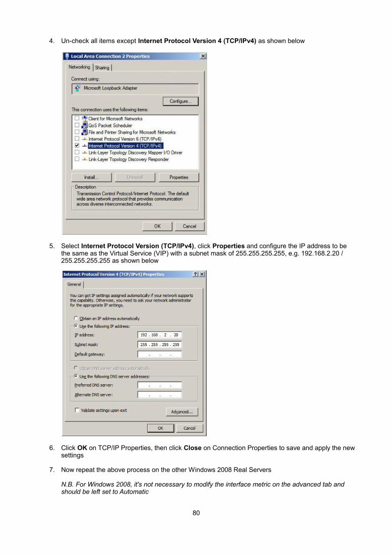
4. Un-check all items except Internet Protocol Version 4 (TCP/IPv4) as shown below
5. Select Internet Protocol Version (TCP/IPv4), click Properties and configure the IP address to be the same as the Virtual Service (VIP) with a subnet mask of 255.255.255.255, e.g. 192.168.2.20 / 255.255.255.255 as shown below
6. Click OK on TCP/IP Properties, then click Close on Connection Properties to save and apply the newsettings
7. Now repeat the above process on the other Windows 2008 Real Servers
N.B. For Windows 2008, it's not necessary to modify the interface metric on the advanced tab and should be left set to Automatic
80
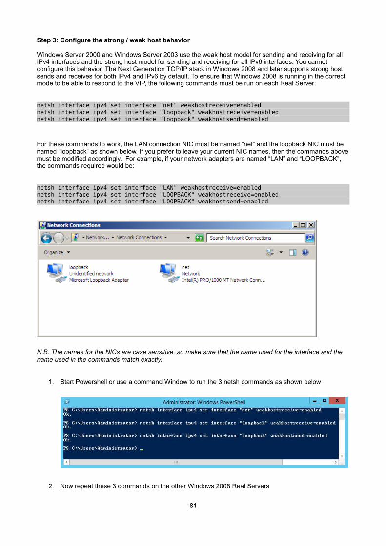
Step 3: Configure the strong / weak host behavior
Windows Server 2000 and Windows Server 2003 use the weak host model for sending and receiving for all IPv4 interfaces and the strong host model for sending and receiving for all IPv6 interfaces. You cannot configure this behavior. The Next Generation TCP/IP stack in Windows 2008 and later supports strong host sends and receives for both IPv4 and IPv6 by default. To ensure that Windows 2008 is running in the correct mode to be able to respond to the VIP, the following commands must be run on each Real Server:
netsh interface ipv4 set interface "net" weakhostreceive=enabled netsh interface ipv4 set interface "loopback" weakhostreceive=enabled netsh interface ipv4 set interface "loopback" weakhostsend=enabled
For these commands to work, the LAN connection NIC must be named “net” and the loopback NIC must be named “loopback” as shown below. If you prefer to leave your current NIC names, then the commands abovemust be modified accordingly. For example, if your network adapters are named “LAN” and “LOOPBACK”, the commands required would be:
netsh interface ipv4 set interface "LAN" weakhostreceive=enabled netsh interface ipv4 set interface "LOOPBACK" weakhostreceive=enabled netsh interface ipv4 set interface "LOOPBACK" weakhostsend=enabled
N.B. The names for the NICs are case sensitive, so make sure that the name used for the interface and the name used in the commands match exactly.
1. Start Powershell or use a command Window to run the 3 netsh commands as shown below
2. Now repeat these 3 commands on the other Windows 2008 Real Servers
81
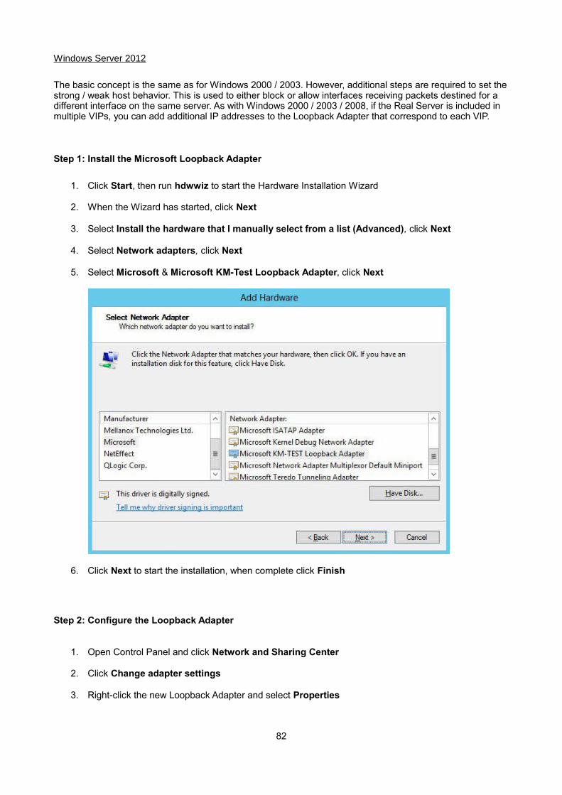
Windows Server 2012
The basic concept is the same as for Windows 2000 / 2003. However, additional steps are required to set thestrong / weak host behavior. This is used to either block or allow interfaces receiving packets destined for a different interface on the same server. As with Windows 2000 / 2003 / 2008, if the Real Server is included in multiple VIPs, you can add additional IP addresses to the Loopback Adapter that correspond to each VIP.
Step 1: Install the Microsoft Loopback Adapter
1. Click Start, then run hdwwiz to start the Hardware Installation Wizard
2. When the Wizard has started, click Next
3. Select Install the hardware that I manually select from a list (Advanced), click Next
4. Select Network adapters, click Next
5. Select Microsoft & Microsoft KM-Test Loopback Adapter, click Next
6. Click Next to start the installation, when complete click Finish
Step 2: Configure the Loopback Adapter
1. Open Control Panel and click Network and Sharing Center
2. Click Change adapter settings
3. Right-click the new Loopback Adapter and select Properties
82
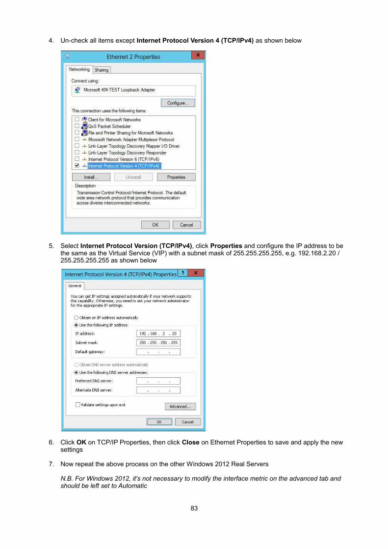
4. Un-check all items except Internet Protocol Version 4 (TCP/IPv4) as shown below
5. Select Internet Protocol Version (TCP/IPv4), click Properties and configure the IP address to be the same as the Virtual Service (VIP) with a subnet mask of 255.255.255.255, e.g. 192.168.2.20 / 255.255.255.255 as shown below
6. Click OK on TCP/IP Properties, then click Close on Ethernet Properties to save and apply the new settings
7. Now repeat the above process on the other Windows 2012 Real Servers
N.B. For Windows 2012, it's not necessary to modify the interface metric on the advanced tab and should be left set to Automatic
83
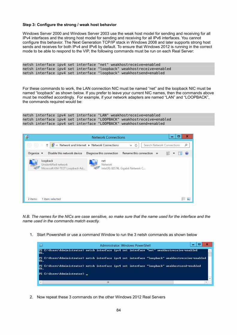
Step 3: Configure the strong / weak host behavior
Windows Server 2000 and Windows Server 2003 use the weak host model for sending and receiving for all IPv4 interfaces and the strong host model for sending and receiving for all IPv6 interfaces. You cannot configure this behavior. The Next Generation TCP/IP stack in Windows 2008 and later supports strong host sends and receives for both IPv4 and IPv6 by default. To ensure that Windows 2012 is running in the correct mode to be able to respond to the VIP, the following commands must be run on each Real Server:
netsh interface ipv4 set interface "net" weakhostreceive=enabled netsh interface ipv4 set interface "loopback" weakhostreceive=enabled netsh interface ipv4 set interface "loopback" weakhostsend=enabled
For these commands to work, the LAN connection NIC must be named “net” and the loopback NIC must be named “loopback” as shown below. If you prefer to leave your current NIC names, then the commands abovemust be modified accordingly. For example, if your network adapters are named “LAN” and “LOOPBACK”, the commands required would be:
netsh interface ipv4 set interface "LAN" weakhostreceive=enabled netsh interface ipv4 set interface "LOOPBACK" weakhostreceive=enabled netsh interface ipv4 set interface "LOOPBACK" weakhostsend=enabled
N.B. The names for the NICs are case sensitive, so make sure that the name used for the interface and the name used in the commands match exactly.
1. Start Powershell or use a command Window to run the 3 netsh commands as shown below
2. Now repeat these 3 commands on the other Windows 2012 Real Servers
84
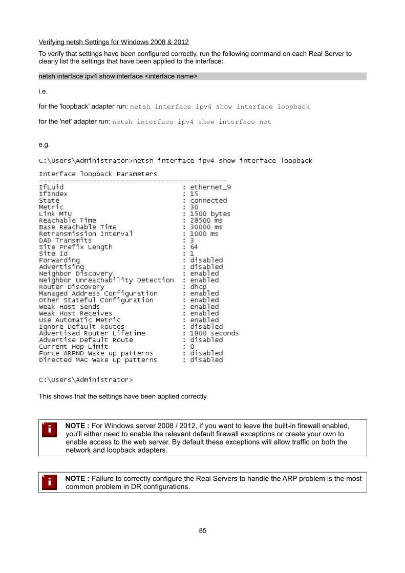
Verifying netsh Settings for Windows 2008 & 2012
To verify that settings have been configured correctly, run the following command on each Real Server to clearly list the settings that have been applied to the interface:
netsh interface ipv4 show interface <interface name>
i.e.
for the 'loopback' adapter run: netsh interface ipv4 show interface loopback
for the 'net' adapter run: netsh interface ipv4 show interface net
e.g.
This shows that the settings have been applied correctly.
NOTE : For Windows server 2008 / 2012, if you want to leave the built-in firewall enabled, you'll either need to enable the relevant default firewall exceptions or create your own to enable access to the web server. By default these exceptions will allow traffic on both the network and loopback adapters.
NOTE : Failure to correctly configure the Real Servers to handle the ARP problem is the most common problem in DR configurations.
85

Configuring IIS to Respond to both the RIP and VIP
For DR & TUN modes, it's also important to make sure that your application (IIS in this case) responds to both the VIP and RIP.
Windows 2000 / 2003
By default, IIS listens on all configured IP addresses, this is shown in the example below (shows Windows 2003 example). As can be seen the IP address field is set to 'All Unassigned'.
If the default configuration is left, no further IIS configuration is required. If you do change the IP address in the bindings from 'All Unassigned' to a specific IP address, then you need to make sure that you also add a binding for the Virtual Service IP address (VIP) as shown in the example below:
86
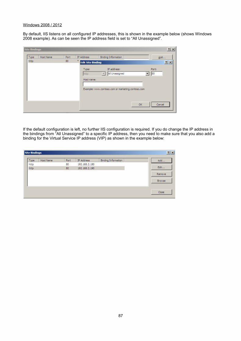
Windows 2008 / 2012
By default, IIS listens on all configured IP addresses, this is shown in the example below (shows Windows 2008 example). As can be seen the IP address field is set to “All Unassigned”.
If the default configuration is left, no further IIS configuration is required. If you do change the IP address in the bindings from “All Unassigned” to a specific IP address, then you need to make sure that you also add a binding for the Virtual Service IP address (VIP) as shown in the example below:
87

Windows Firewall Settings
Windows 2003 SP1+
For Windows Server 2003 SP1 & later, if you have enabled the built-in firewall, you will need to enable the Web Server (HTTP) exception to permit access to the web server. This exception is created automatically when IIS is installed and when enabled allows traffic on both the network and Loopback Adapters.
Windows 2008 R1 Firewall Settings
For Windows 2008 R1 the firewall configuration is very similar to windows 2003 R2. Again, an exception is created automatically that must be enabled to permit port 80 HTTP traffic. You just need to enablethe firewall for both interfaces then ensure that the WWW service check-box is ticked as shown below:
88
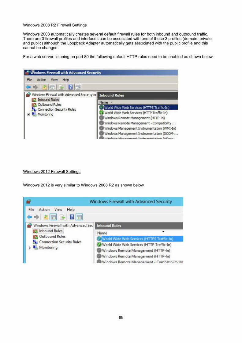
Windows 2008 R2 Firewall Settings
Windows 2008 automatically creates several default firewall rules for both inbound and outbound traffic.There are 3 firewall profiles and interfaces can be associated with one of these 3 profiles (domain, private and public) although the Loopback Adapter automatically gets associated with the public profile and this cannot be changed.
For a web server listening on port 80 the following default HTTP rules need to be enabled as shown below:
Windows 2012 Firewall Settings
Windows 2012 is very similar to Windows 2008 R2 as shown below.
89
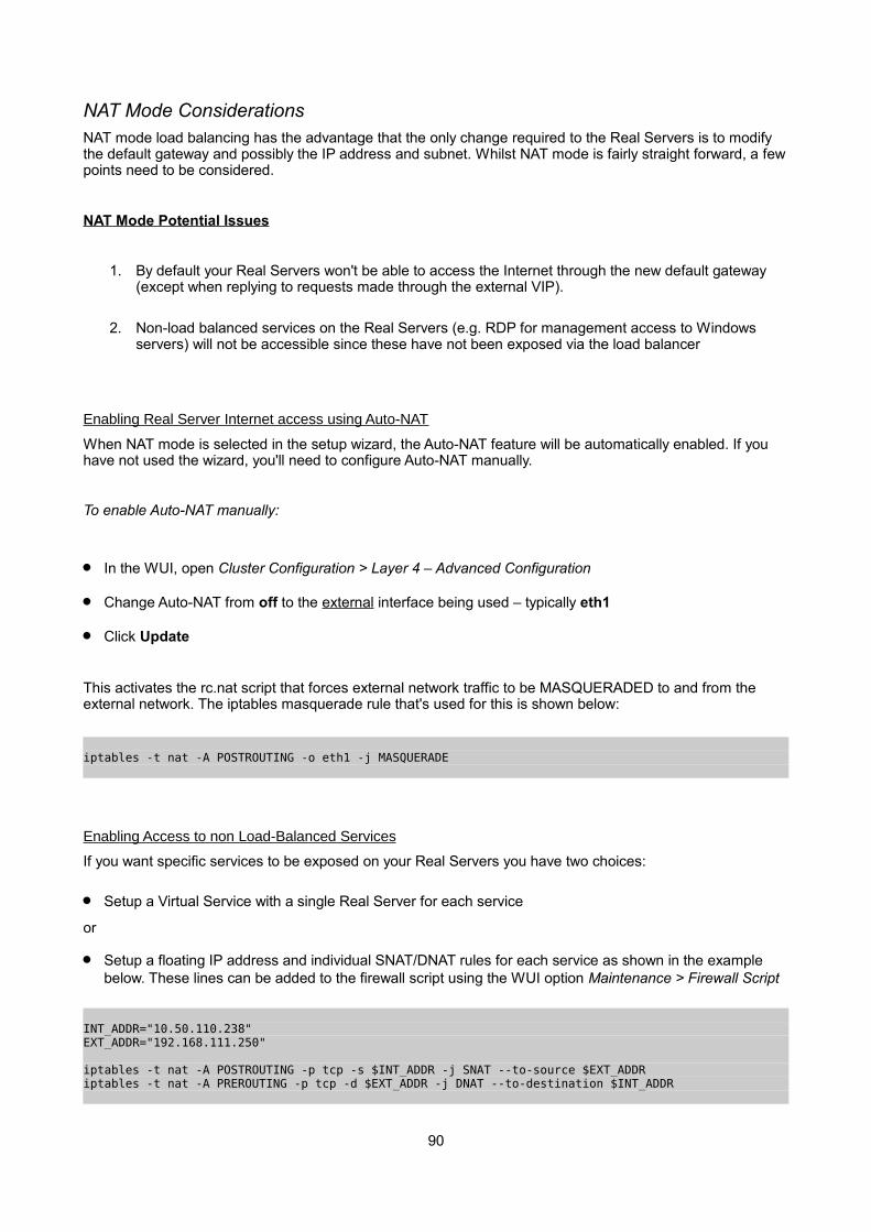
NAT Mode ConsiderationsNAT mode load balancing has the advantage that the only change required to the Real Servers is to modify the default gateway and possibly the IP address and subnet. Whilst NAT mode is fairly straight forward, a fewpoints need to be considered.
NAT Mode Potential Issues
1. By default your Real Servers won't be able to access the Internet through the new default gateway (except when replying to requests made through the external VIP).
2. Non-load balanced services on the Real Servers (e.g. RDP for management access to Windows servers) will not be accessible since these have not been exposed via the load balancer
Enabling Real Server Internet access using Auto-NAT
When NAT mode is selected in the setup wizard, the Auto-NAT feature will be automatically enabled. If you have not used the wizard, you'll need to configure Auto-NAT manually.
To enable Auto-NAT manually:
In the WUI, open Cluster Configuration > Layer 4 – Advanced Configuration
Change Auto-NAT from off to the external interface being used – typically eth1
Click Update
This activates the rc.nat script that forces external network traffic to be MASQUERADED to and from the external network. The iptables masquerade rule that's used for this is shown below:
iptables -t nat -A POSTROUTING -o eth1 -j MASQUERADE
Enabling Access to non Load-Balanced Services
If you want specific services to be exposed on your Real Servers you have two choices:
Setup a Virtual Service with a single Real Server for each service
or
Setup a floating IP address and individual SNAT/DNAT rules for each service as shown in the example below. These lines can be added to the firewall script using the WUI option Maintenance > Firewall Script
INT_ADDR="10.50.110.238"EXT_ADDR="192.168.111.250"
iptables -t nat -A POSTROUTING -p tcp -s $INT_ADDR -j SNAT --to-source $EXT_ADDRiptables -t nat -A PREROUTING -p tcp -d $EXT_ADDR -j DNAT --to-destination $INT_ADDR
90
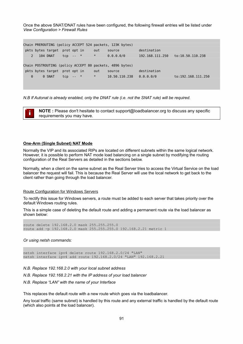
Once the above SNAT/DNAT rules have been configured, the following firewall entries will be listed under View Configuration > Firewall Rules
Chain PREROUTING (policy ACCEPT 524 packets, 123K bytes)
pkts bytes target prot opt in out source destination
2 104 DNAT tcp -- * * 0.0.0.0/0 192.168.111.250 to:10.50.110.238
Chain POSTROUTING (policy ACCEPT 80 packets, 4896 bytes)
pkts bytes target prot opt in out source destination
0 0 SNAT tcp -- * * 10.50.110.238 0.0.0.0/0 to:192.168.111.250
N.B If Autonat is already enabled, only the DNAT rule (i.e. not the SNAT rule) will be required.
NOTE : Please don't hesitate to contact [email protected] to discuss any specific requirements you may have.
One-Arm (Single Subnet) NAT Mode
Normally the VIP and its associated RIPs are located on different subnets within the same logical network. However, it is possible to perform NAT mode load balancing on a single subnet by modifying the routing configuration of the Real Servers as detailed in the sections below.
Normally, when a client on the same subnet as the Real Server tries to access the Virtual Service on the load balancer the request will fail. This is because the Real Server will use the local network to get back to the client rather than going through the load balancer.
Route Configuration for Windows Servers
To rectify this issue for Windows servers, a route must be added to each server that takes priority over the default Windows routing rules.
This is a simple case of deleting the default route and adding a permanent route via the load balancer as shown below:
route delete 192.168.2.0 mask 255.255.255.0route add -p 192.168.2.0 mask 255.255.255.0 192.168.2.21 metric 1
Or using netsh commands:
netsh interface ipv4 delete route 192.168.2.0/24 "LAN"netsh interface ipv4 add route 192.168.2.0/24 "LAN" 192.168.2.21
N.B. Replace 192.168.2.0 with your local subnet address
N.B. Replace 192.168.2.21 with the IP address of your load balancer
N.B. Replace “LAN” with the name of your Interface
This replaces the default route with a new route which goes via the loadbalancer.
Any local traffic (same subnet) is handled by this route and any external traffic is handled by the default route (which also points at the load balancer).
91
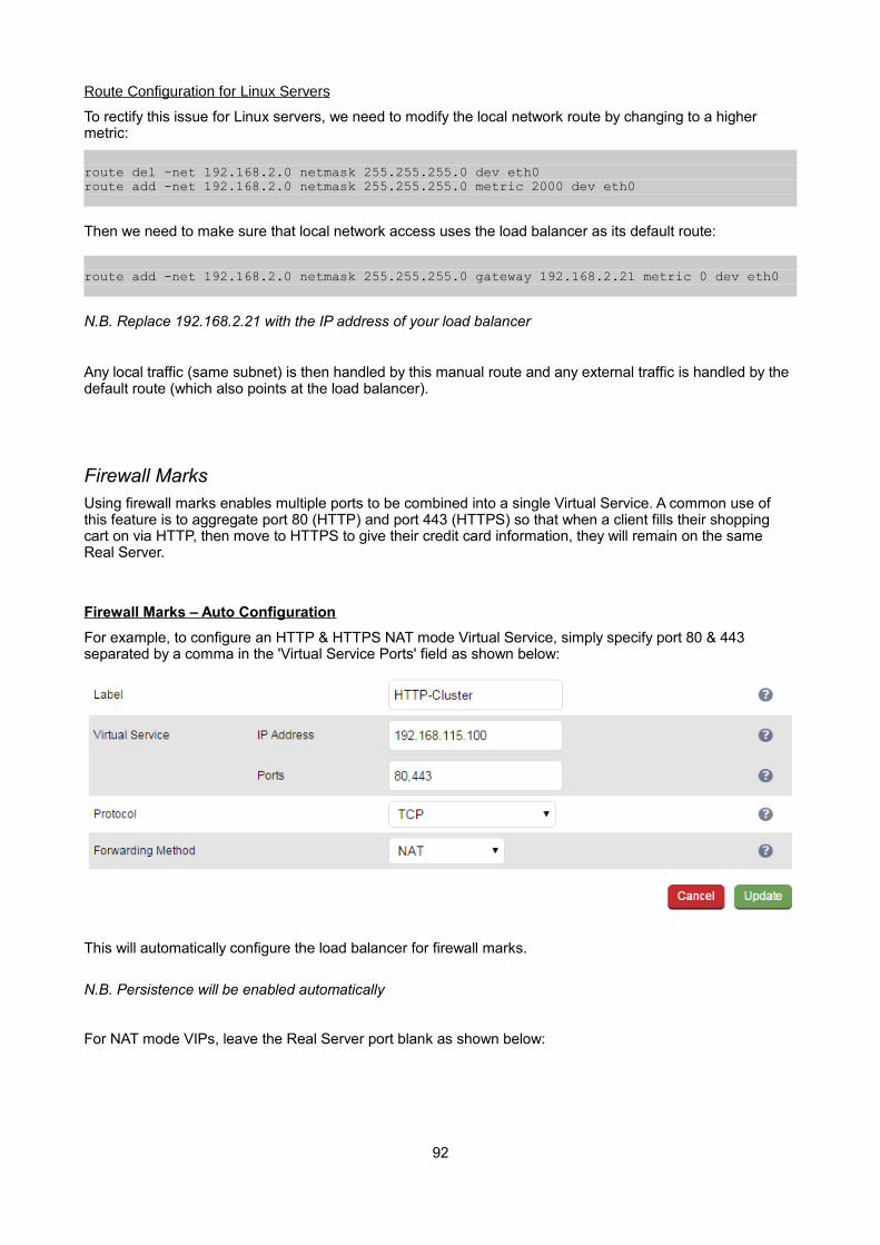
Route Configuration for Linux Servers
To rectify this issue for Linux servers, we need to modify the local network route by changing to a higher metric:
route del -net 192.168.2.0 netmask 255.255.255.0 dev eth0 route add -net 192.168.2.0 netmask 255.255.255.0 metric 2000 dev eth0
Then we need to make sure that local network access uses the load balancer as its default route:
route add -net 192.168.2.0 netmask 255.255.255.0 gateway 192.168.2.21 metric 0 dev eth0
N.B. Replace 192.168.2.21 with the IP address of your load balancer
Any local traffic (same subnet) is then handled by this manual route and any external traffic is handled by the default route (which also points at the load balancer).
Firewall MarksUsing firewall marks enables multiple ports to be combined into a single Virtual Service. A common use of this feature is to aggregate port 80 (HTTP) and port 443 (HTTPS) so that when a client fills their shopping cart on via HTTP, then move to HTTPS to give their credit card information, they will remain on the same Real Server.
Firewall Marks – Auto Configuration
For example, to configure an HTTP & HTTPS NAT mode Virtual Service, simply specify port 80 & 443 separated by a comma in the 'Virtual Service Ports' field as shown below:
This will automatically configure the load balancer for firewall marks.
N.B. Persistence will be enabled automatically
For NAT mode VIPs, leave the Real Server port blank as shown below:
92
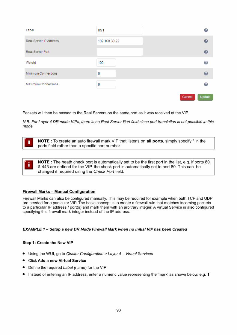
Packets will then be passed to the Real Servers on the same port as it was received at the VIP.
N.B. For Layer 4 DR mode VIPs, there is no Real Server Port field since port translation is not possible in thismode.
NOTE : To create an auto firewall mark VIP that listens on all ports, simply specify * in the ports field rather than a specific port number.
NOTE : The heath check port is automatically set to be the first port in the list, e.g. if ports 80 & 443 are defined for the VIP, the check port is automatically set to port 80. This can be changed if required using the Check Port field.
Firewall Marks – Manual Configuration
Firewall Marks can also be configured manually. This may be required for example when both TCP and UDP are needed for a particular VIP. The basic concept is to create a firewall rule that matches incoming packets to a particular IP address / port(s) and mark them with an arbitrary integer. A Virtual Service is also configuredspecifying this firewall mark integer instead of the IP address.
EXAMPLE 1 – Setup a new DR Mode Firewall Mark when no Initial VIP has been Created
Step 1: Create the New VIP
Using the WUI, go to Cluster Configuration > Layer 4 – Virtual Services
Click Add a new Virtual Service
Define the required Label (name) for the VIP
Instead of entering an IP address, enter a numeric value representing the 'mark' as shown below, e.g. 1
93
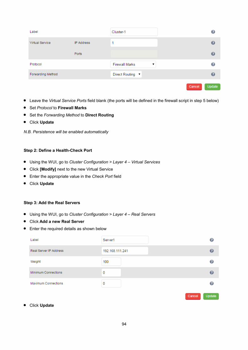
Leave the Virtual Service Ports field blank (the ports will be defined in the firewall script in step 5 below)
Set Protocol to Firewall Marks
Set the Forwarding Method to Direct Routing
Click Update
N.B. Persistence will be enabled automatically
Step 2: Define a Health-Check Port
Using the WUI, go to Cluster Configuration > Layer 4 – Virtual Services
Click [Modify] next to the new Virtual Service
Enter the appropriate value in the Check Port field
Click Update
Step 3: Add the Real Servers
Using the WUI, go to Cluster Configuration > Layer 4 – Real Servers
Click Add a new Real Server
Enter the required details as shown below
Click Update
94
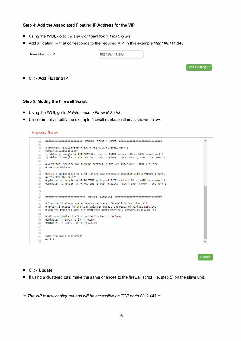
Step 4: Add the Associated Floating IP Address for the VIP
Using the WUI, go to Cluster Configuration > Floating IPs
Add a floating IP that corresponds to the required VIP, in this example 192.168.111.240
Click Add Floating IP
Step 5: Modify the Firewall Script
Using the WUI, go to Maintenance > Firewall Script
Un-comment / modify the example firewall marks section as shown below:
Click Update
If using a clustered pair, make the same changes to the firewall script (i.e. step 5) on the slave unit.
** The VIP is now configured and will be accessible on TCP ports 80 & 443 **
95

EXAMPLE 2 – Setup a Firewall Mark by Modifying an Existing VIP
In this case, the VIP and the associated floating IP address will already exist so does not need to be created manually.
Step 1: Modify the Existing Virtual Service
Using the WUI, go to Cluster Configuration > Layer 4 – Virtual Services
Click [Modify] next to the relevant VIP
Change the IP address to the chosen 'mark' value as shown above
Clear the Virtual Service Ports field
Set the Protocol field to Firewall Marks
Click Update
Step 2: Define a Health-Check Port
Using the WUI, go to Cluster Configuration > Layer 4 – Virtual Services
Click [Modify] next to the new Virtual Service
Enter the appropriate value in the Check Port field
Click Update
Step 3: Modify the Firewall Script
Using the WUI, go to Maintenance > Firewall Script
Un-comment / modify the example firewall marks section as shown in the following example. Additional ports can be added as required by adding additional iptables entries and specifying the appropriate port / protocol.
96
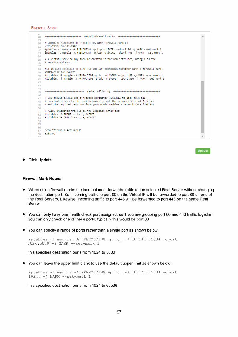
Click Update
Firewall Mark Notes:
When using firewall marks the load balancer forwards traffic to the selected Real Server without changing the destination port. So, incoming traffic to port 80 on the Virtual IP will be forwarded to port 80 on one of the Real Servers. Likewise, incoming traffic to port 443 will be forwarded to port 443 on the same Real Server
You can only have one health check port assigned, so if you are grouping port 80 and 443 traffic together you can only check one of these ports, typically this would be port 80
You can specify a range of ports rather than a single port as shown below:
iptables -t mangle -A PREROUTING -p tcp -d 10.141.12.34 –dport 1024:5000 -j MARK -–set-mark 1
this specifies destination ports from 1024 to 5000
You can leave the upper limit blank to use the default upper limit as shown below:
iptables -t mangle -A PREROUTING -p tcp -d 10.141.12.34 –dport1024: -j MARK -–set-mark 1
this specifies destination ports from 1024 to 65536
97
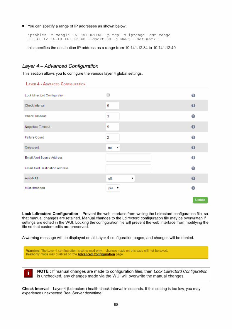
You can specify a range of IP addresses as shown below:
iptables -t mangle -A PREROUTING -p tcp -m iprange –dst-range 10.141.12.34-10.141.12.40 --dport 80 -j MARK --set-mark 1
this specifies the destination IP address as a range from 10.141.12.34 to 10.141.12.40
Layer 4 – Advanced ConfigurationThis section allows you to configure the various layer 4 global settings.
Lock Ldirectord Configuration – Prevent the web interface from writing the Ldirectord configuration file, so that manual changes are retained. Manual changes to the Ldirectord configuration file may be overwritten if settings are edited in the WUI. Locking the configuration file will prevent the web interface from modifying the file so that custom edits are preserved.
A warning message will be displayed on all Layer 4 configuration pages, and changes will be denied.
NOTE : If manual changes are made to configuration files, then Lock Ldirectord Configuration is unchecked, any changes made via the WUI will overwrite the manual changes.
Check Interval – Layer 4 (Ldirectord) health check interval in seconds. If this setting is too low, you may experience unexpected Real Server downtime.
98

Check Timeout – Layer 4 (Ldirectord) health check timeout in seconds. If this setting is too low, you may induce unexpected Real Server downtime.
Negotiate Timeout – Layer 4 (Ldirectord) negotiate health check timeout in seconds. The negotiate checks may take longer to process as they involve more server side processing than a simple TCP socket connect check. If this setting is too low, you may induce unexpected Real Server downtime.
Failure Count – Layer 4 (Ldirectord) number of times a check has to fail before taking server offline. The time to detect a failure and take down a server will be (check interval + check timeout) * failure count.
Quiescent – When a Real Server fails a health check, do we kill all connections?
When Quiescent is set to yes, on a health check failure the Real Server is not removed from the load balancing table, but the weight is set to 0. Persistent connections will continue to be routed to the failed server, but no new connections will be accepted.
When Quiescent is set to no, the server is completely removed from the load balancing table on a health check failure. Persistent connections will be broken and sent to a different Real Server.
N.B. Quiescent only applies to health checks – it has no effect on taking Real Servers offline in System Overview. To manually force a Real Server to be removed from the table, set Quiescent to no and arrange forthe server to fail its health check. This may be done, for example, by shutting down the daemon or service, changing the negotiate check value, or shutting down the server.
Email Alert Source Address – Specify the global source address of the email alerts. When an email alert is sent, the system will use this address as the 'From' field.
Email Alert Destination Address – Specify the global destination email alert address. This address is used to send notifications of Real Server health check failures. This can also be configured on a Virtual Service level.
Auto NAT – Automatically NAT outbound network connections from internal servers. By default servers behind the load balancer in a NAT configuration will not have access to the outside network. However clients on the outside will be able to access load balanced services. By enabling Auto NAT the internal servers will have their requests automatically mapped to the load balancers external IP address. The default configuration is to map all requests originating from internal network eth0 to the external IP on eth1. If you areusing a different interface for external traffic you can select it here. Manual SNAT and DNAT configurations for individual servers can also be configured in the firewall script.
Multi-threaded – Perform health checks with multiple threads. Using multiple-threads for health checks will increase performance when you have a large number of Virtual Services.
99
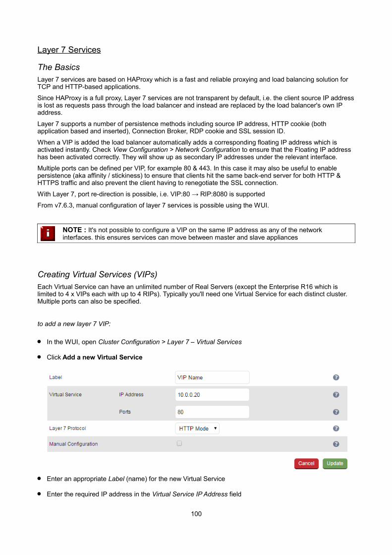
Layer 7 Services
The BasicsLayer 7 services are based on HAProxy which is a fast and reliable proxying and load balancing solution for TCP and HTTP-based applications.
Since HAProxy is a full proxy, Layer 7 services are not transparent by default, i.e. the client source IP addressis lost as requests pass through the load balancer and instead are replaced by the load balancer's own IP address.
Layer 7 supports a number of persistence methods including source IP address, HTTP cookie (both application based and inserted), Connection Broker, RDP cookie and SSL session ID.
When a VIP is added the load balancer automatically adds a corresponding floating IP address which is activated instantly. Check View Configuration > Network Configuration to ensure that the Floating IP address has been activated correctly. They will show up as secondary IP addresses under the relevant interface.
Multiple ports can be defined per VIP, for example 80 & 443. In this case it may also be useful to enable persistence (aka affinity / stickiness) to ensure that clients hit the same back-end server for both HTTP & HTTPS traffic and also prevent the client having to renegotiate the SSL connection.
With Layer 7, port re-direction is possible, i.e. VIP:80 → RIP:8080 is supported
From v7.6.3, manual configuration of layer 7 services is possible using the WUI.
NOTE : It's not possible to configure a VIP on the same IP address as any of the network interfaces. this ensures services can move between master and slave appliances
Creating Virtual Services (VIPs)Each Virtual Service can have an unlimited number of Real Servers (except the Enterprise R16 which is limited to 4 x VIPs each with up to 4 RIPs). Typically you'll need one Virtual Service for each distinct cluster. Multiple ports can also be specified.
to add a new layer 7 VIP:
In the WUI, open Cluster Configuration > Layer 7 – Virtual Services
Click Add a new Virtual Service
Enter an appropriate Label (name) for the new Virtual Service
Enter the required IP address in the Virtual Service IP Address field
100
Enter the required ports(s) in the Virtual Service Ports field, separate multiple ports with commas, specify a range with a hyphen and specify all ports using an asterisk
NOTE : the following ports are used by the appliance and therefore cannot be used for Virtual Services: 22 (SSH), 9080 (WUI – HTTP), 9443 (WUI – HTTPS), 7777 (HAProxy statistics page), 7778 (HAProxy persistence table replication and 9081 (nginx fallback page).
Select the Layer 7 protocol to be handled by this Virtual Service, either HTTP or TCP
HTTP Mode – Selected if the Virtual Service will handle only HTTP traffic. Allows more flexibility in the processing of connections. The HTTP Cookie and HTTP application cookie modes, and the X-Forwarded-For header all require HTTP to be selected. In addition, HAProxy logs will show more information on the client requests and Real Server responses.
TCP Mode – Required for non HTTP traffic such as HTTPS, RPC, RDP, FTP etc.
If the VIP will be configured manually, check (enable) the Manual Configuration check-box
N.B. Please refer to page 106 for more information on manually configuring layer 7 services
Click Update
Now proceed to define the RIPs (Real Servers) as detailed on page 105
Modifying a Virtual Service
When first adding a Virtual Service, only certain values can be configured, others are set at their default setting. These values can be changed after the Virtual Service has been created by clicking [Modify] next to the relevant Virtual Service. Additional settings that can be changed are:
Option Description
HTTP Pipeline Mode Select how HAProxy should handle HTTP pipelining to client and server
No change - Act as a transparent tunnel, allowing the client and server to negotiate pipelining.
Close both client and server - Disable pipelining, always closing connections to both client and server using HTTP.
Keep-alive client, close server - Allow client to negotiate pipelining, whilst closing the server connection using HTTP.
Close client, force close server - Close the server connection at the TCP layer, as well as sending the Connection: close header. Also close the client connection using HTTP.
Work around broken Connection: close
Work around Real Servers that do not correctly implement the HTTP Connection:close option. This does not take effect when HTTP pipeline mode is set to No change.
Balance Mode The scheduler used to specify server rotation. Specify the scheduler to utilize when deciding the back-end server to use for the next new connection.
Persistence Mode Select how the load balancer should track clients so as to direct each request to the same server.
HTTP Cookie - The load balancer will set an HTTP Cookie to track each client.
101

Application Cookie - Where an existing HTTP Cookie is set by the web application on the Real Servers, use this to track each client.
SSL Session ID - Read the Session ID from the SSL connection and use this to track each client.
MS Session Broker - Use the server-set msts RDP Cookie to track clients connecting to a Microsoft Terminal Server. The Session Broker service must be enabled on the real servers.
RDP Client Cookie - Use the client-set mstshash RDP Cookie to track clients connecting to a Microsoft Terminal Server. If the cookie is missing, source IP persistence will be used instead.
Source IP - Make sure the same source IP always hits the same server.
HTTP Cookie and Source IP - As HTTP Cookie, falling back to Source IP ifthe cookie is missing from the HTTP request.
None - No persistence. The allocation of clients to Real Servers will be determined solely by the Balance Mode.
Persistence Options The persistence options depend on which mode is selected. The following list details all available options.
HTTP Cookie name – set the name of the HTTP cookie
Application Cookie name - The name of a cookie used by the application running on the Real Servers. If set, this enables connection persistence based on an existing application cookie, ensuring that a client is always directed to the same Real Server. Note that this option requires the selection of HTTP Application Cookie persistence mode.
Application Cookie Length – The number of characters of the application cookie value to match. When storing and matching an Application Cookie value, the loadbalancer will use only the number of characters given here. Ifthe cookie value is shorter than this maximum, only the actual length will be stored.
Application Cookie hold time - The time-out period before an idle application cookie is removed from memory. The application cookie will be removed from memory when it has been idle for longer than the Hold Time period. The default units are milliseconds.
Persistence timeout - The time-out period before an idle connection is removed from the connection table. The source IP address will be removed from memory when it has been idle for longer than the persistence timeout. The default units are minutes.
Persistence table size - The size of the table of connections in KB. The size of the table of connections (approx 50 bytes per entry) where connection information is stored to allow a session to return to the same server within the timeout period. The default units are in KB.
Feedback Method Select whether HAProxy should query each Real Server for its load level.
Agent - The Real Server is queried every health check interval for the real server's percent CPU idle. This is used to set each Real Server's weight to a value proportional to its initial weight. For example, if the initial weight is 100 and the percentage cpu idle is 34, the weight will be set to 34. Remember lower numbers mean lower priority for traffic, when compared with other real servers in the pool.None - HAProxy will not modify the Real Server's weight.
102
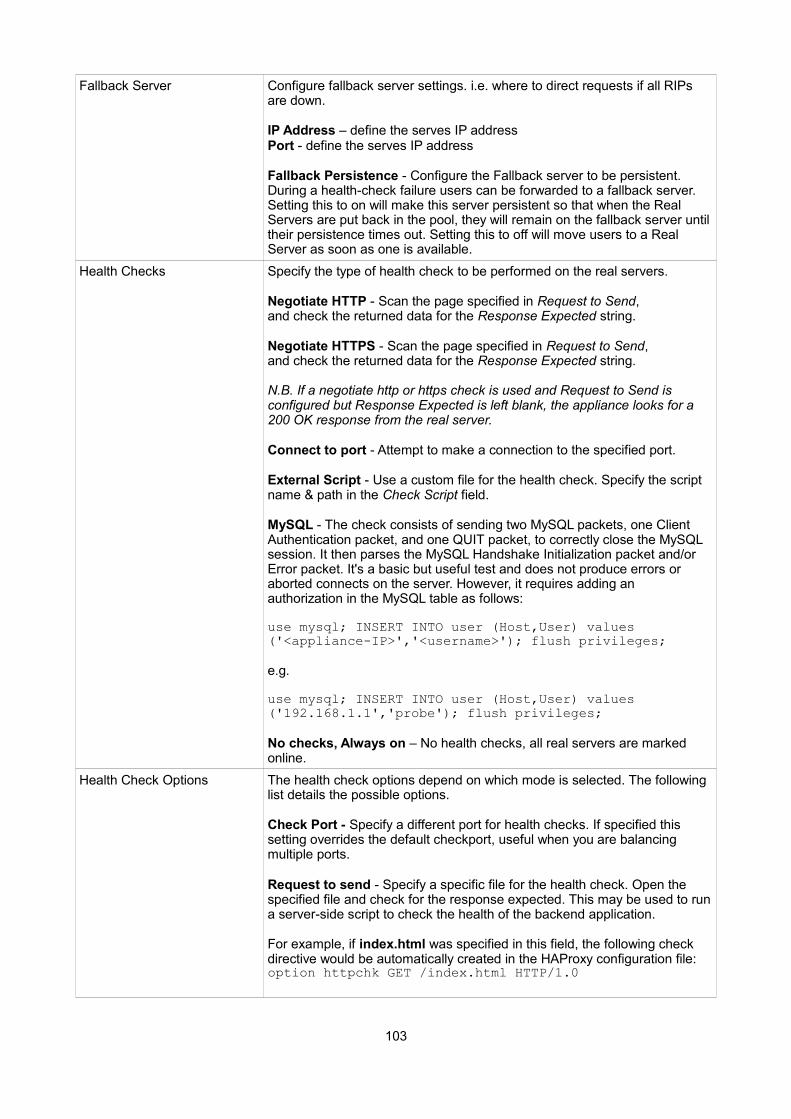
Fallback Server Configure fallback server settings. i.e. where to direct requests if all RIPs are down.
IP Address – define the serves IP addressPort - define the serves IP address
Fallback Persistence - Configure the Fallback server to be persistent. During a health-check failure users can be forwarded to a fallback server. Setting this to on will make this server persistent so that when the Real Servers are put back in the pool, they will remain on the fallback server untiltheir persistence times out. Setting this to off will move users to a Real Server as soon as one is available.
Health Checks Specify the type of health check to be performed on the real servers.
Negotiate HTTP - Scan the page specified in Request to Send, and check the returned data for the Response Expected string.
Negotiate HTTPS - Scan the page specified in Request to Send, and check the returned data for the Response Expected string.
N.B. If a negotiate http or https check is used and Request to Send is configured but Response Expected is left blank, the appliance looks for a 200 OK response from the real server.
Connect to port - Attempt to make a connection to the specified port.
External Script - Use a custom file for the health check. Specify the script name & path in the Check Script field.
MySQL - The check consists of sending two MySQL packets, one Client Authentication packet, and one QUIT packet, to correctly close the MySQL session. It then parses the MySQL Handshake Initialization packet and/or Error packet. It's a basic but useful test and does not produce errors or aborted connects on the server. However, it requires adding an authorization in the MySQL table as follows:
use mysql; INSERT INTO user (Host,User) values ('<appliance-IP>','<username>'); flush privileges;
e.g.
use mysql; INSERT INTO user (Host,User) values ('192.168.1.1','probe'); flush privileges;
No checks, Always on – No health checks, all real servers are marked online.
Health Check Options The health check options depend on which mode is selected. The following list details the possible options.
Check Port - Specify a different port for health checks. If specified this setting overrides the default checkport, useful when you are balancing multiple ports.
Request to send - Specify a specific file for the health check. Open the specified file and check for the response expected. This may be used to runa server-side script to check the health of the backend application.
For example, if index.html was specified in this field, the following check directive would be automatically created in the HAProxy configuration file:option httpchk GET /index.html HTTP/1.0
103
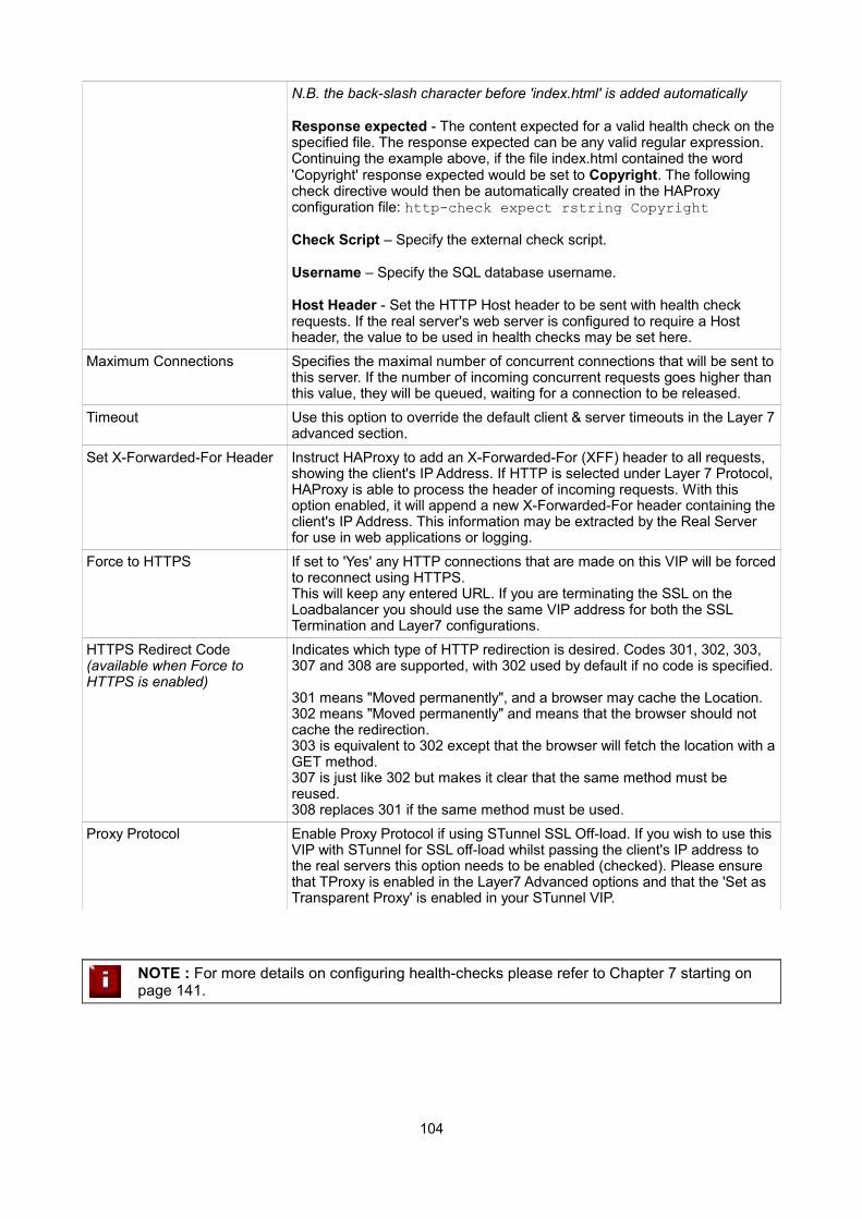
N.B. the back-slash character before 'index.html' is added automatically
Response expected - The content expected for a valid health check on thespecified file. The response expected can be any valid regular expression.Continuing the example above, if the file index.html contained the word 'Copyright' response expected would be set to Copyright. The following check directive would then be automatically created in the HAProxy configuration file: http-check expect rstring Copyright
Check Script – Specify the external check script.
Username – Specify the SQL database username.
Host Header - Set the HTTP Host header to be sent with health check requests. If the real server's web server is configured to require a Host header, the value to be used in health checks may be set here.
Maximum Connections Specifies the maximal number of concurrent connections that will be sent tothis server. If the number of incoming concurrent requests goes higher than this value, they will be queued, waiting for a connection to be released.
Timeout Use this option to override the default client & server timeouts in the Layer 7advanced section.
Set X-Forwarded-For Header Instruct HAProxy to add an X-Forwarded-For (XFF) header to all requests, showing the client's IP Address. If HTTP is selected under Layer 7 Protocol,HAProxy is able to process the header of incoming requests. With this option enabled, it will append a new X-Forwarded-For header containing theclient's IP Address. This information may be extracted by the Real Server for use in web applications or logging.
Force to HTTPS If set to 'Yes' any HTTP connections that are made on this VIP will be forcedto reconnect using HTTPS.This will keep any entered URL. If you are terminating the SSL on the Loadbalancer you should use the same VIP address for both the SSL Termination and Layer7 configurations.
HTTPS Redirect Code(available when Force to HTTPS is enabled)
Indicates which type of HTTP redirection is desired. Codes 301, 302, 303, 307 and 308 are supported, with 302 used by default if no code is specified.
301 means "Moved permanently", and a browser may cache the Location.302 means "Moved permanently" and means that the browser should not cache the redirection.303 is equivalent to 302 except that the browser will fetch the location with aGET method.307 is just like 302 but makes it clear that the same method must be reused.308 replaces 301 if the same method must be used.
Proxy Protocol Enable Proxy Protocol if using STunnel SSL Off-load. If you wish to use this VIP with STunnel for SSL off-load whilst passing the client's IP address to the real servers this option needs to be enabled (checked). Please ensure that TProxy is enabled in the Layer7 Advanced options and that the 'Set as Transparent Proxy' is enabled in your STunnel VIP.
NOTE : For more details on configuring health-checks please refer to Chapter 7 starting on page 141.
104
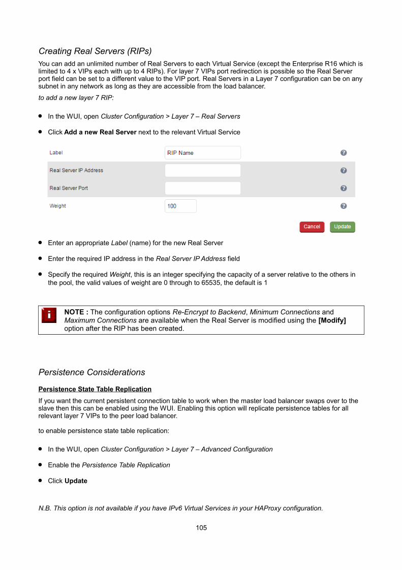
Creating Real Servers (RIPs)You can add an unlimited number of Real Servers to each Virtual Service (except the Enterprise R16 which islimited to 4 x VIPs each with up to 4 RIPs). For layer 7 VIPs port redirection is possible so the Real Server port field can be set to a different value to the VIP port. Real Servers in a Layer 7 configuration can be on anysubnet in any network as long as they are accessible from the load balancer.
to add a new layer 7 RIP:
In the WUI, open Cluster Configuration > Layer 7 – Real Servers
Click Add a new Real Server next to the relevant Virtual Service
Enter an appropriate Label (name) for the new Real Server
Enter the required IP address in the Real Server IP Address field
Specify the required Weight, this is an integer specifying the capacity of a server relative to the others in the pool, the valid values of weight are 0 through to 65535, the default is 1
NOTE : The configuration options Re-Encrypt to Backend, Minimum Connections and Maximum Connections are available when the Real Server is modified using the [Modify] option after the RIP has been created.
Persistence Considerations
Persistence State Table Replication
If you want the current persistent connection table to work when the master load balancer swaps over to the slave then this can be enabled using the WUI. Enabling this option will replicate persistence tables for all relevant layer 7 VIPs to the peer load balancer.
to enable persistence state table replication:
In the WUI, open Cluster Configuration > Layer 7 – Advanced Configuration
Enable the Persistence Table Replication
Click Update
N.B. This option is not available if you have IPv6 Virtual Services in your HAProxy configuration.
105
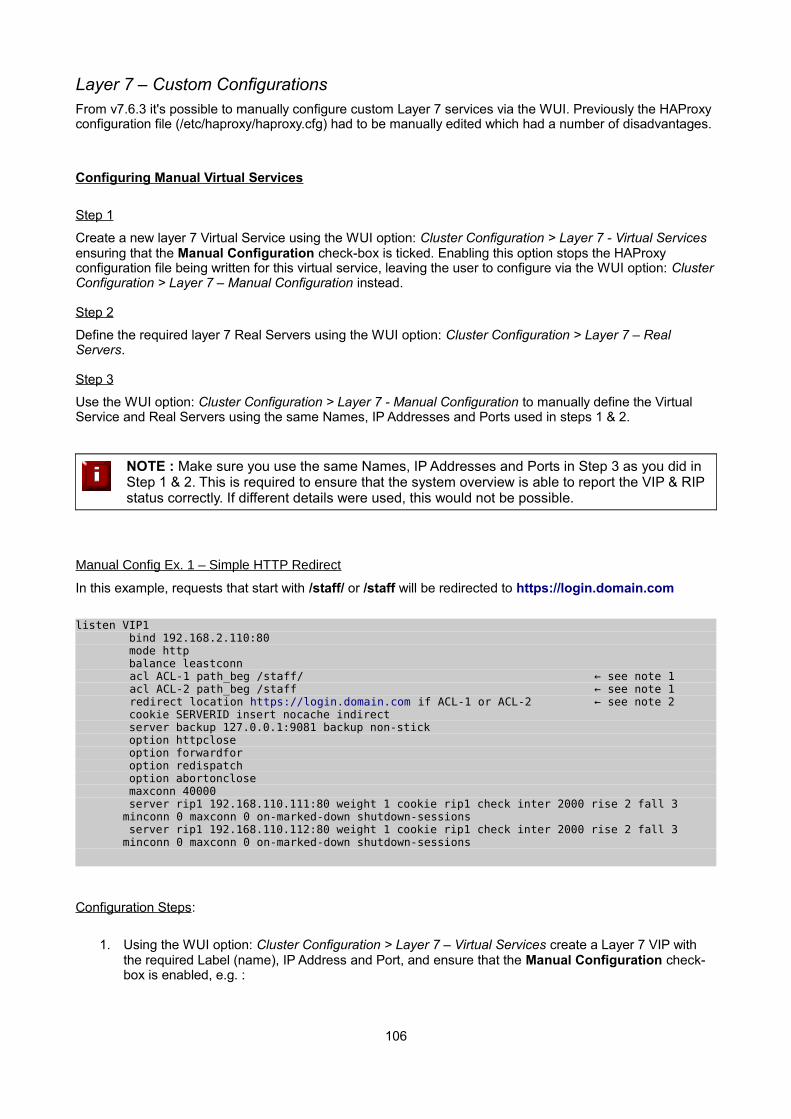
Layer 7 – Custom ConfigurationsFrom v7.6.3 it's possible to manually configure custom Layer 7 services via the WUI. Previously the HAProxy configuration file (/etc/haproxy/haproxy.cfg) had to be manually edited which had a number of disadvantages.
Configuring Manual Virtual Services
Step 1
Create a new layer 7 Virtual Service using the WUI option: Cluster Configuration > Layer 7 - Virtual Services ensuring that the Manual Configuration check-box is ticked. Enabling this option stops the HAProxy configuration file being written for this virtual service, leaving the user to configure via the WUI option: ClusterConfiguration > Layer 7 – Manual Configuration instead.
Step 2
Define the required layer 7 Real Servers using the WUI option: Cluster Configuration > Layer 7 – Real Servers.
Step 3
Use the WUI option: Cluster Configuration > Layer 7 - Manual Configuration to manually define the Virtual Service and Real Servers using the same Names, IP Addresses and Ports used in steps 1 & 2.
NOTE : Make sure you use the same Names, IP Addresses and Ports in Step 3 as you did in Step 1 & 2. This is required to ensure that the system overview is able to report the VIP & RIP status correctly. If different details were used, this would not be possible.
Manual Config Ex. 1 – Simple HTTP Redirect
In this example, requests that start with /staff/ or /staff will be redirected to https://login.domain.com
listen VIP1 bind 192.168.2.110:80 mode http balance leastconn acl ACL-1 path_beg /staff/ ← see note 1
acl ACL-2 path_beg /staff ← see note 1 redirect location https://login.domain.com if ACL-1 or ACL-2 ← see note 2
cookie SERVERID insert nocache indirect server backup 127.0.0.1:9081 backup non-stick option httpclose option forwardfor option redispatch option abortonclose maxconn 40000 server rip1 192.168.110.111:80 weight 1 cookie rip1 check inter 2000 rise 2 fall 3
minconn 0 maxconn 0 on-marked-down shutdown-sessions server rip1 192.168.110.112:80 weight 1 cookie rip1 check inter 2000 rise 2 fall 3
minconn 0 maxconn 0 on-marked-down shutdown-sessions
Configuration Steps:
1. Using the WUI option: Cluster Configuration > Layer 7 – Virtual Services create a Layer 7 VIP with the required Label (name), IP Address and Port, and ensure that the Manual Configuration check-box is enabled, e.g. :
106
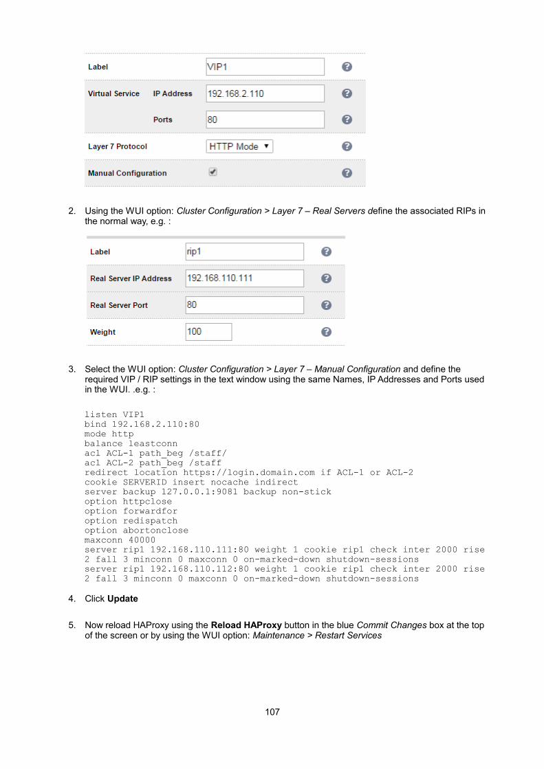
2. Using the WUI option: Cluster Configuration > Layer 7 – Real Servers define the associated RIPs in the normal way, e.g. :
3. Select the WUI option: Cluster Configuration > Layer 7 – Manual Configuration and define the required VIP / RIP settings in the text window using the same Names, IP Addresses and Ports used in the WUI. .e.g. :
listen VIP1bind 192.168.2.110:80mode httpbalance leastconnacl ACL-1 path_beg /staff/acl ACL-2 path_beg /staffredirect location https://login.domain.com if ACL-1 or ACL-2cookie SERVERID insert nocache indirectserver backup 127.0.0.1:9081 backup non-stickoption httpcloseoption forwardforoption redispatchoption abortonclosemaxconn 40000server rip1 192.168.110.111:80 weight 1 cookie rip1 check inter 2000 rise 2 fall 3 minconn 0 maxconn 0 on-marked-down shutdown-sessionsserver rip1 192.168.110.112:80 weight 1 cookie rip1 check inter 2000 rise 2 fall 3 minconn 0 maxconn 0 on-marked-down shutdown-sessions
4. Click Update
5. Now reload HAProxy using the Reload HAProxy button in the blue Commit Changes box at the top of the screen or by using the WUI option: Maintenance > Restart Services
107

Notes:
1. These lines configure 2 ACL's named ACL-1 & ACL-2 where the criteria for a match is that the URL starts with either /staff/ or /staff
2. This line causes a redirect to https://login.domain.com to occur when either acl is matched
Manual Config Ex. 2 – Load Balancing with URL matching using ACL's
To support URL matched load balancing the structure of the HAProxy configuration file must be changed to use the front-end / back-end model as shown in the example below:
frontend f1 bind 192.168.2.110:80 acl ACL-1 path_beg /test1 acl ACL-2 path_beg /test2 use_backend b1 if ACL-1 use_backend b2 if ACL-2 default_backend b2 option httpclose
backend b1 cookie SERVERID insert nocache indirect server s1 192.168.2.111:80 weight 1 cookie s1 check server s2 192.168.2.112:80 weight 1 cookie s2 check
backend b2 cookie SERVERID insert nocache indirect server s3 192.168.2.113:80 weight 1 cookie s3 check server s4 192.168.2.114:80 weight 1 cookie s4 check
Configuration Steps:
1. Using the WUI option: Cluster Configuration > Floating IPs , add a floating IP for the new VIP, in this example 192.168.2.110 is added to match the IP address required:
2. Click Add Floating IP
3. Select the WUI option: Cluster Configuration > Layer 7 – Manual Configuration and define the required VIP / RIP settings in the text window. .e.g. :
108

frontend F1 bind 192.168.2.110:80
acl ACL-1 path_beg /test1 acl ACL-2 path_beg /test2 use_backend B1 if ACL-1 use_backend B2 if ACL-2 default_backend B2 option httpclose
backend B1 cookie SERVERID insert nocache indirect
server s1 192.168.2.111:80 weight 1 cookie s1 check server s2 192.168.2.112:80 weight 1 cookie s2 check
backend B2 cookie SERVERID insert nocache indirect
server s3 192.168.2.113:80 weight 1 cookie s3 check server s3 192.168.2.114:80 weight 1 cookie s3 check
4. Click Update
5. Now reload HAProxy using the Reload HAProxy button in the blue Commit Changes box at the top of the screen or by using the WUI option: Maintenance > Restart Services
Notes:
1. ACL-1 & ACL-2 are the names of the ACLs
2. path_beg matches the beginning of the path to a certain value, in this case /test1 & /test2 and then directs requests to the appropriate back-end, either backend B1 or B2
IMPORTANT : This example uses the Frontend/Backend structure to define the Layer 7 Virtual Service. When using this structure, the related Virtual Service cannot be displayed in the System Overview so there is no need to define a matching VIP in this case.
These are fairly simple examples to show the principle of using ACLs. For much more information please refer to the HAProxy manual at the following link:
http://www.haproxy.org/download/1.6/doc/configuration.txt
(Search that page for ''Using ACLs”)
NOTE : Don't hesitate to contact [email protected] to discuss any specific ACL or other custom configuration requirements you may have.
109
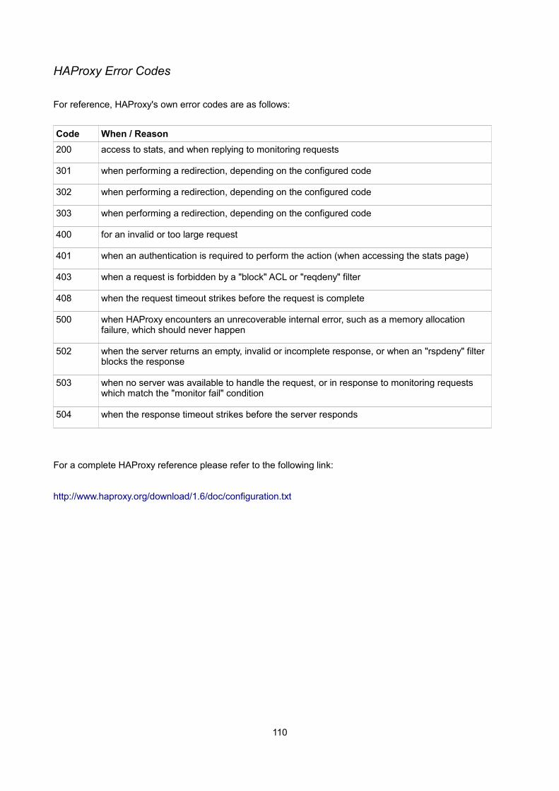
HAProxy Error Codes
For reference, HAProxy's own error codes are as follows:
Code When / Reason
200 access to stats, and when replying to monitoring requests
301 when performing a redirection, depending on the configured code
302 when performing a redirection, depending on the configured code
303 when performing a redirection, depending on the configured code
400 for an invalid or too large request
401 when an authentication is required to perform the action (when accessing the stats page)
403 when a request is forbidden by a "block" ACL or "reqdeny" filter
408 when the request timeout strikes before the request is complete
500 when HAProxy encounters an unrecoverable internal error, such as a memory allocation failure, which should never happen
502 when the server returns an empty, invalid or incomplete response, or when an "rspdeny" filter blocks the response
503 when no server was available to handle the request, or in response to monitoring requests which match the "monitor fail" condition
504 when the response timeout strikes before the server responds
For a complete HAProxy reference please refer to the following link:
http://www.haproxy.org/download/1.6/doc/configuration.txt
110
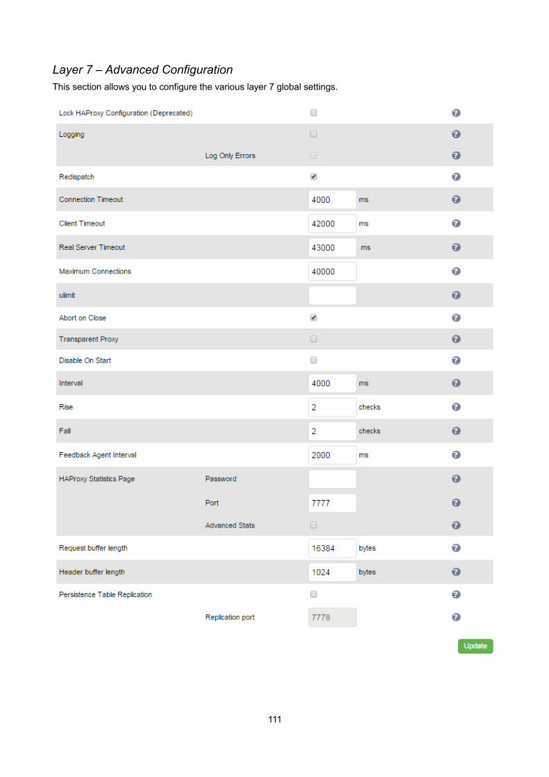
Layer 7 – Advanced ConfigurationThis section allows you to configure the various layer 7 global settings.
111

Lock HAProxy Configuration – Prevent the WUI writing to the HAProxy configuration file. Manual changes to the HAProxy configuration file may be overwritten if settings are edited in the web interface. Locking the configuration file will prevent the web interface from modifying the file, so that custom edits are preserved. A warning message will be displayed on all Layer 7 configuration pages, and changes will be denied.
NOTE : This Feature is now deprecated. It's now possible to configure each virtual service as read-only. The manual configuration can then be created using the WUI option: Layer 7 - Manual Configuration
Logging – Activate detailed logging of the Layer 7 HAProxy service. When activated the HAProxy log is written to /var/log/haproxy.log.
Log Only Errors – Do not log operational connection details, only log errors.
Redispatch – Allows HAProxy to break persistence and redistribute to working servers should failure occur. Normally this setting should not require changing.
Connection Timeout – HAProxy connection timeout in milliseconds. This setting should normally not requirechanging.
Client Timeout – HAProxy client timeout in milliseconds. This setting should normally not require changing.
Real Server Timeout – HAProxy Real Server timeout in milliseconds. This setting should not require changing.
Maximum Connections – HAProxy maximum concurrent connections. This setting should not require changing, unless you are running a high volume site. See also Maximum Connections for a Virtual Service (HAProxy).
Ulimit – The maximum number of file descriptors used for layer 7 load balancing.
N.B. From v7.6.3 this value is now auto-configured internally based on other system parameters and does not need to be set here.
Abort on Close – Abort connections when users close their connection. Recommended as the probability fora closed input channel to represent a user hitting the 'STOP' button is close to 100%
Transparent Proxy – Enable TProxy support for Layer 7 HAProxy. TProxy support is required in order for theReal Servers behind a layer 7 HAProxy configuration to see the client source IP address. The load balancer must be in a NAT configuration (internal and external subnets) with the Real Servers using an IP address on the load balancer (preferably a floating IP) as their default gateway.
N.B. all Layer 4 methods are transparent by default
NOTE : For more details on using TProxy, refer to page 129.
N.B. Since the load balancer must be in a NAT configuration (i.e. VIPs & RIPs in different subnets) to utilize TProxy, it is not always an appropriate solution. In situations such as this, it's also possible to use the X-forwarded-for header with layer 7 Virtual Services. Most web servers can then be configured to record the X-Forwarded-For IP address in the log files.
112
For details on how to enable X-Forwarded-For support, please refer to page 104. For details on how to enable X-Forwarded-For support with Apache and IIS, please refer to the following Loadbalancer.org blog links:
Apache - http://blog.loadbalancer.org/apache-and-x-forwarded-for-headers/
IIS - http://blog.loadbalancer.org/iis-and-x-forwarded-for-header/
Interval – Interval between health checks. This is the time interval between Real Server health checks in milliseconds.
Rise – Number of health checks to Rise. The number of positive health checks required before re-activating a Real Server.
Fall – Number of health checks to Fall. The number of negative health checks required before de-activating aReal Server.
Feedback Agent Interval - The time in milliseconds between each feedback agent check from HAProxy to the feedback agent.
HAProxy Statistics Page Password – Set the password used to access Reports > Layer 7 Status.
HAProxy Statistics Page Port – Change the listening port for the HAProxy web based statistics report from the default of TCP 7777.
Advanced Stats - Enable/disable additional actions available on the HAProxy stats page.
Request Buffer Length – Set the health check buffer length in bytes.
N.B. Changing this value will effect the performance of HAProxy. Do not make changes unless you know exactly what you are doing.
Lower values allow more sessions to coexist in the same amount of RAM, and higher values allow some applications with very large cookies to work. The default value is 16384 bytes. It is strongly recommended notto change this from the default value, as very low values will break some services such as statistics, and values larger than the default size will increase memory usage, possibly causing the system to run out of memory. Administrators should consider reducing the Maximum Connections parameter if the request buffer is increased.
Header Buffer Length – Set the header buffer length, in bytes The header buffer is a section of the request buffer, reserved for the addition and rewriting of request headers. The default value is 1024 bytes. Most applications will only require a small header buffer, as few headers are added or rewritten.
Persistence Table Replication – When enabled, HAProxy's persistence tables are replicated to the slave device.
Persistence Table Replication Port – Set the TCP port to use for persistence table replication. The default port is TCP 7778.
113
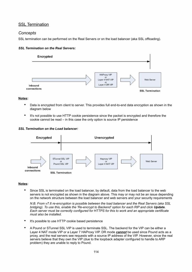
SSL Termination
ConceptsSSL termination can be performed on the Real Servers or on the load balancer (aka SSL offloading).
SSL Termination on the Real Servers:
Notes:
• Data is encrypted from client to server. This provides full end-to-end data encryption as shown in the diagram below
• It's not possible to use HTTP cookie persistence since the packet is encrypted and therefore the cookie cannot be read – in this case the only option is source IP persistence
SSL Termination on the Load balancer:
Notes:
• Since SSL is terminated on the load balancer, by default, data from the load balancer to the web servers is not encrypted as shown in the diagram above. This may or may not be an issue dependingon the network structure between the load balancer and web servers and your security requirements
N.B. From v7.6 re-encryption is possible between the load balancer and the Real Servers (aka SSL bridging). To use this, enable the 'Re-encrypt to Backend' option for each RIP and click Update. Each server must be correctly configured for HTTPS for this to work and an appropriate certificate must also be installed.
• It's possible to use HTTP cookie based persistence
• A Pound or STunnel SSL VIP is used to terminate SSL. The backend for the VIP can be either a Layer 4 NAT mode VIP or a Layer 7 HAProxy VIP. DR mode cannot be used since Pound acts as a proxy, and the real servers see requests with a source IP address of the VIP. However, since the real servers believe that they own the VIP (due to the loopback adapter configured to handle to ARP problem) they are unable to reply to Pound.
114

NOTE : SSL termination on the load balancer can be very CPU intensive. In most cases, for a scalable solution, terminating SSL on the Real Servers is the best option.
SSL Termination on the Real Servers (Recommended)In this case SSL certificates are installed on each Real Server in the normal way. The load balancer is then configured with a VIP that listens on HTTPS port 443 and distributes inbound requests to the Real Servers again on port 443 as shown in the layer 4 DR mode example below:
A fairly common configuration is to include port 80 in the VIPs definition and also enable persistence. This ensures that both HTTP and HTTPS requests from a particular client are always sent to the same Real Server as shown below:
SSL Termination on the Load BalancerIn this case SSL certificate(s) must be installed on the load balancer. The appliance supports the use of both STunnel (default) and Pound for SSL termination.
To configure SSL termination on the appliance an SSL Virtual Service must be defined that specifies an IP address and port to listen for inbound HTTPS connections and a back-end IP address / port where to forwardthe corresponding unencrypted HTTP connection.
By default a self-signed certificate is used for the new VIP which is ideal for testing but needs to be replaced for production deployments.
Creating an STunnel SSL Virtual Service (the Default SSL Terminator)
to add an STunnel SSL VIP:
In the WUI, open Cluster Configuration > SSL Termination
Click Add a new Virtual Service
115

Enter an appropriate Label (name) for the new Virtual Service
Enter the required IP address in the Virtual Service IP address field
Enter the required port in the Virtual Service Port field – typically 443
Enter the required IP address in the Back-end Virtual Service IP Address field
This is normally the same IP address as the Virtual Service IP address but can be any valid IP. The IP address specified must correspond to a Layer 7 HAProxy VIP or a Layer 4 NAT mode VIP. Unencrypted traffic will be sent here for load balancing.
N.B. DR mode cannot be used since STunnel acts as a proxy, and the Real Servers see requests with a source IP address of the Virtual Service. However since the Real Servers believe that they own the VirtualIP (due to the Loopback Adapter configured to handle to ARP problem) they are unable to reply to STunnel
Enter the required port in the Back-end Virtual Service Port field
Define the list of accepted ciphers using the Ciphers to use field
By default the cipher is set to: ECDHE-RSA-AES128-GCM-SHA256:ECDHE-RSA-RC4-SHA:ECDHE-RSA-AES128-SHA:RC4:HIGH:!MD5:!aNULL:!EDH
This can be modified as required, or the field can be cleared (blank) to allow all available ciphers (not recommended)
116

Configure Do not Insert Empty Fragments
Disables a countermeasure against a SSL 3.0/TLS 1.0 protocol vulnerability affecting CBC ciphers. This option needs to be enabled (checked) to ensure mitigation of both the BEAST and CRIME MITM attacks. It is also required for PCI Testing.
Ensure SSL Terminator is set to STunnel
Configure Delay DNS Lookup
Delay DNS lookup for 'connect' option. This option is useful for dynamic DNS, or when DNS is not available during STunnel startup (road warrior VPN, dial-up configurations).
Configure Disable SSLv2 Ciphers
When ticked this option disables all SSLv2 Ciphers by using the OpenSSL 'SSL_OP_NO_SSLv2' option.
Configure Disable SSLv3 Ciphers
When ticked this option disables all SSLv3 Ciphers by using the OpenSSL 'SSL_OP_NO_SSLv3' option. Please note that entering '!SSLv3' into a Cipher list can have an adverse effect and we recommend using this option and not entering '!SSLv3'.
Configure Allow Client Renegotiation
Sets whether the client is allowed to renegotiate the cipher order. This option should be enabled (checked)to mitigate the BEAST attack.
Configure Disable SSL Renegotiation
Applications of the SSL renegotiation include some authentication scenarios, or re-keying long lasting connections. On the other hand this feature can facilitate a trivial CPU-exhaustion DoS attack. This option should be enabled (checked) to mitigate the BEAST Attack.
Configure Time to Close
Configure the global client response timeout in seconds. This setting should not require changing.
Configure Set as Transparent Proxy
If you wish to use HAProxy and TProxy this option needs to be enabled (checked) to allow SSL termination on the load balancer whilst passing the client's IP address to the Real Servers. This option only enables TProxy on a Single STunnel VIP – if you're using HAProxy with this VIP you will also need to enable TProxy for your HAProxy VIP (please refer to the examples on page 129)
Click Update to create the SSL VIP
STunnel Cipher Settings and the BEAST Attack
The following STunnel options should be set to mitigate the BEAST attack:
Ciphers to use – a minimum cipher list of 'RC4:HIGH:!MD5:!aNULL' is required
Allow Client Renegotiation – this option should be disabled (un-checked)
Do Not Insert Empty Fragments – this option should be enabled (checked)
Disable SSL Renegotiation – this option should be enabled (checked)
If these options are set, this should prevent the BEAST attack, and should also help to mitigate DoS attacks and MITM Attacks.
117
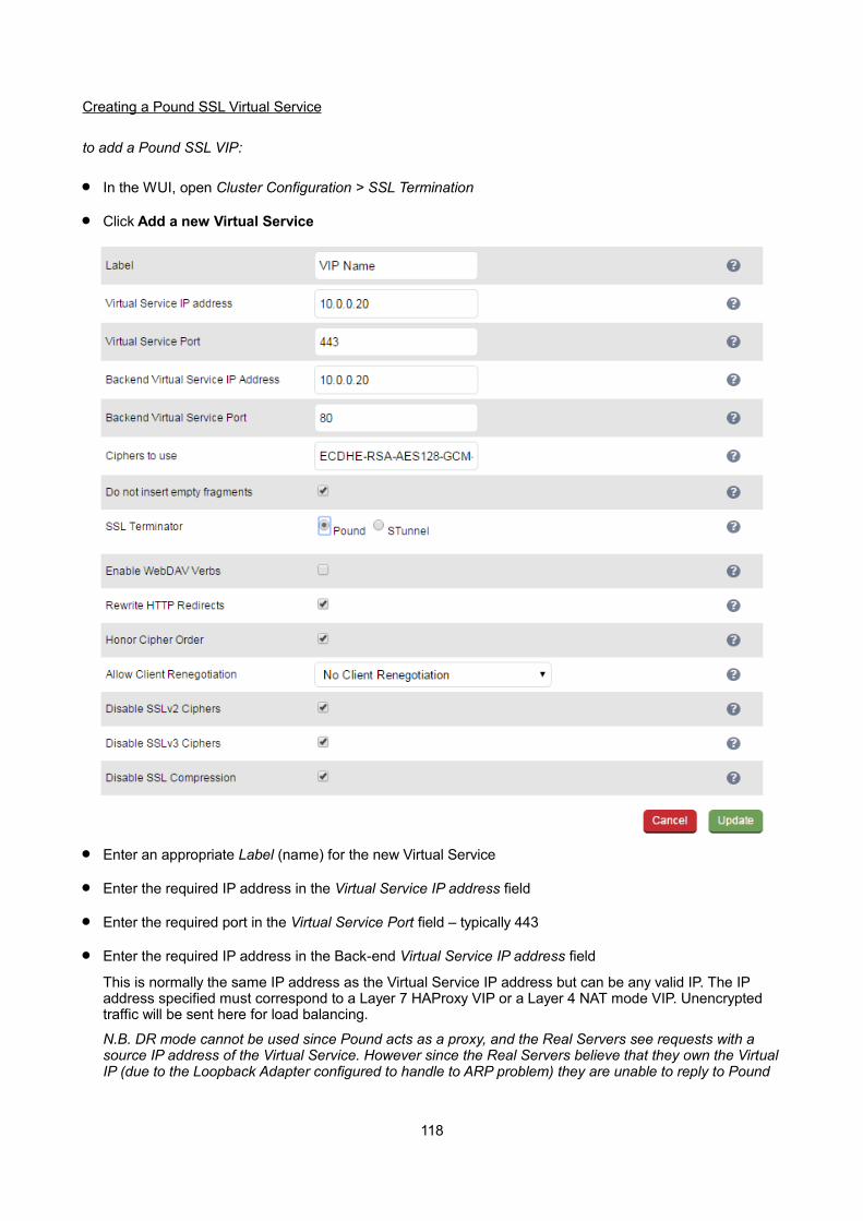
Creating a Pound SSL Virtual Service
to add a Pound SSL VIP:
In the WUI, open Cluster Configuration > SSL Termination
Click Add a new Virtual Service
Enter an appropriate Label (name) for the new Virtual Service
Enter the required IP address in the Virtual Service IP address field
Enter the required port in the Virtual Service Port field – typically 443
Enter the required IP address in the Back-end Virtual Service IP address field
This is normally the same IP address as the Virtual Service IP address but can be any valid IP. The IP address specified must correspond to a Layer 7 HAProxy VIP or a Layer 4 NAT mode VIP. Unencrypted traffic will be sent here for load balancing.
N.B. DR mode cannot be used since Pound acts as a proxy, and the Real Servers see requests with a source IP address of the Virtual Service. However since the Real Servers believe that they own the VirtualIP (due to the Loopback Adapter configured to handle to ARP problem) they are unable to reply to Pound
118

Enter the required port in the Back-end Virtual Service Port field
Define the list of accepted ciphers using the Ciphers to use field
By default the cipher is set to: ECDHE-RSA-AES128-GCM-SHA256:ECDHE-RSA-RC4-SHA:ECDHE-RSA-AES128-SHA:RC4:HIGH:!MD5:!aNULL:!EDH
This can be modified as required, or the field can be cleared (blank) to allow all available ciphers (not recommended)
Configure Do Not Insert Empty Fragments
Disables a countermeasure against a SSL 3.0/TLS 1.0 protocol vulnerability affecting CBC ciphers. This option needs to be enabled (checked) to ensure mitigation of both the BEAST and CRIME MITM attacks. It is also required for PCI Testing.
Ensure SSL Terminator is set to Pound
Configure Enable WebDAV Verbs
When enabled extends which HTTP / WebDAV verbs are accepted.
Configure Rewrite HTTP Redirects
Pound to change the Location: and Content-location: headers in responses If they point to the back-end itself or to the listener (but with the wrong protocol) the response will be changed to show the virtual host in the request. NOTE: If you do not know what this means leave this as the default (enabled).
Configure Honor Cipher Order
When choosing a cipher during a handshake, normally the client's preference is used. If this directive is enabled, the server's preference will be used instead. When choosing a cipher during a SSLv3 or TLSv1 handshake, normally the client's preference is used. If this directive is enabled, the server's preference willbe used instead.
This option should be enabled to mitigate the BEAST attack.
Configure Allow Client Renegotiation
Sets whether the client is allowed to renegotiate the cipher order. In Pound when set to either:
- No Client Renegotiation, no client renegotiation will be honored- Secure Renegotiation, secure renegotiation will be honored- Insecure Renegotiation, insecure renegotiation will be honored
This option should be set to 'No Client Renegotiation' to mitigate the BEAST attack.
Configure Disable SSLv2 Ciphers
Allow the option to Disable all SSLv2 Ciphers. When ticked this option disables all SSLv2 Ciphers by usingthe OpenSSL 'SSL_OP_NO_SSLv2' option.
Configure Disable SSLv3 Ciphers
When ticked this option disables all SSLv3 Ciphers by using the OpenSSL 'SSL_OP_NO_SSLv3' option. Please note that entering '!SSLv3' into a Cipher list can have an adverse effect and we recommend using this option and not entering '!SSLv3'.
Configure Disable SSL Compression
Disable DEFLATE compression even if both server and client supports it. If this option is enabled (checked), the server will disable DEFLATE compression even if both server and client supports it. In casecompression is enabled an attacker with access to encrypted network traffic can conduct a "CRIME" attack by making client issue requests with specific character sequences and observing whether they got compressed or not, indicating their presence in part of the request that is not under his control (e.g. cookieheaders).
119

Click Update to create the SSL VIP
Modifying a Pound SSL Virtual Service
When first adding a Pound SSL Virtual Service, only certain values can be configured, others are set at their default setting. These values can be changed after the Virtual Service has been created by clicking [Modify] next to the relevant Virtual Service. Additional settings that can be changed are:
Option Sub-Option Description
Headers Header Field Name Add your own header to be passed on by Pound. Set Field Name allows the name part of the header to be specified: [field-name]: [field-value]
Header Field Value Add your own header to be passed on by Pound. Set Field Value allows the value part of the header to be specified: [field-name]: [field-value]
Pound Cipher Settings and the BEAST Attack
The following Pound options should be set to mitigate the BEAST attack:
Ciphers to use – a minimum cipher list of 'RC4:HIGH:!MD5:!aNULL' is required
Honor Cipher Order – this option should be enabled (checked)
Allow Client Renegotiation – this option should be set to 'No Client Renegotiation'
Do not Insert Empty Fragments – this option should be enabled (checked)
If these options are set, this should prevent the BEAST attack, and should also help to mitigate DoS attacks and MITM Attacks.
Generating a CSR on the Load Balancer
By default, when creating an SSL Virtual Service a self-signed certificate is used. This is ideal for testing but needs to be replaced for production deployments.
In order to obtain a valid signed certificate from a certificate authority such as Verisign or Thawte you'll need to generate a certificate request (CSR).
to generate a CSR:
In the WUI, open Cluster Configuration > SSL Termination
Click [Certificate] next to the relevant Virtual Service
Compete the fields as shown in the example below:
120
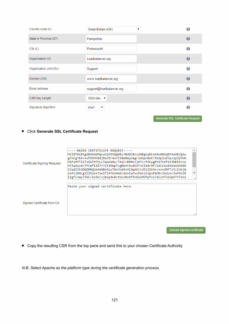
Click Generate SSL Certificate Request
Copy the resulting CSR from the top pane and send this to your chosen Certificate Authority
N.B. Select Apache as the platform type during the certificate generation process.
121

Once you receive your signed certificate from the CA, copy/paste this into the lower pane
If you need to add an intermediate certificate, paste it after the signed certificate in the lower pane.
Click Upload signed certificate
Using an Existing Certificate
It's possible to upload both PEM and PFX format certificates. PEM files should contain the private key (without a password), the signed certificate issued by a Certificate Authority (CA) and also any additional validation / intermediate certificates that may be required by the CA.
Creating a PEM file
Using a text editor such as vi or vim under Linux or Notepad under Windows create an empty file called pem.txt for example. Then copy/paste the Certificate, the Private Key and any additional Intermediate Certificates into the file as follows (truncated versions are shown):
-----BEGIN CERTIFICATE-----
MIICsDCCAhmgAwIBAgIJAL98jhEiUm3iMA0GCSqGSIb3DQEBBQUAMEUxCzAJBgN
2bShC2AVC+ZDMNu6bvCdvfySi6EypUcIvEwao7ZbyaAEbcSVympQJdgs6W6ajiLSf£
-----END CERTIFICATE-----
-----BEGIN RSA PRIVATE KEY-----
MIICXAIBAAKBgQCcPYkYHm8gYwIm3HyoVxjrymusOeIFgZlWyuaebIrreCpIo+iydRf
YwC2ZCE0HwquomN/q4ctnhgeN+kugDxlgCTVYd3eo/Dv/KZ16p4HUlrTqwES4Lunff
-----END RSA PRIVATE KEY-----
-----BEGIN CERTIFICATE-----
MIICsDCCAhmgAwIBAgIJAL98jhEiUm3iMA0GCSqGSIb3DQEBBQUAMEUxCzAJBgN
E89UJCG2nMW5JVBNkyHYbQTvU8MeR3iIhe2fw+qVE2pgxWYWaGm8QwTsxQKgbx
2bShC2AVC+ZDMNu6bvCdvfySi6EypUcIvEwao7ZbyaAEbcSVympQJdgs6W6ajiLSf£
-----END CERTIFICATE-----
Save the file
122

Exporting PFX Certificates from Windows Servers
When exporting certificates from Windows servers, make sure that Yes, export the private key is selected, this will enable the output format to be PFX. Also make sure that Include all certificates in the certificationpath if possible is selected.
Uploading PEM & PFX Certificates
Using the WUI open Cluster Configuration > SSL Termination
Click [Certificate] next to the relevant Virtual Service
Navigate to the bottom of the screen, the using the browse option select the relevant certificate file (either PEM or PFX format)
Click Open to upload the certificate
Once uploaded, restart Pound / STunnel using the restart link at the top of the page or via the WUI option:Maintenance > Restart Services
NOTE : If your master & slave are correctly configured as a clustered pair, when you upload the certificate file to the master, the file will be automatically copied over to the slave unit.
NOTE : It's important to backup all of these files. This can be done via the WUI from Maintenance > Backup & Restore > Download SSL Certificates.
Converting between certificate formats
PFX file upload is a new feature available in v7.6 and later which has virtually eliminated the need to manuallyconvert certificates between formats. However, this may still be be required in certain circumstances. In thesecases OpenSSL can be used. This is usually included by default in Linux distributions. For Windows, it can befreely downloaded from the following location:
http://slproweb.com/products/Win32OpenSSL.html
At this URL you'll need to download and install the Visual C++ 2008 Redistributable, then download either the light or full version of OpenSSL. Once installed, you'll have an OpenSSL directory located on your filesystem (default location c:\OpenSSL)
To use the program, open a command window, navigate to the location where it was installed (by default c:\OpenSSL\bin) then run the required command as detailed below.
123

Converting PFX certificates to PEM format
Using OpenSSL under Windows:
openssl pkcs12 -in drive:\path\filename.pfx -nodes -out drive:\path\filename.pem
e.g.
openssl pkcs12 -in c:\cert.pfx -nodes -out c:\cert.pem
Using the Appliance / Linux:
openssl pkcs12 -in /path/filename.pfx -nodes -out /path/filename.pem
e.g
openssl pkcs12 -in /root/cert.pfx -nodes -out /root/cert.pem
Converting .cer certificates to PEM format
Using OpenSSL under Windows:
openssl x509 -in drive:\path\filename.cer -inform DER -out drive:\path\filename.pem -outform PEM
e.g
openssl x509 -in c:\cert.cer -inform DER -out c:\cert.pem -outform PEM
Using the Appliance / Linux:
openssl x509 -in /path/filename.cer -inform DER -out /path/filename.pem -outform PEM
e.g
openssl x509 -in /root/cert.cer -inform DER -out /root/cert.pem -outform PEM
Converting an Encrypted Private Key to an Unencrypted Key
If a password has been included in the private key, this should be removed before it is used with your PEM file. This can be done using the following OpenSSL command either on the load balancer or another machinewith openssl installed:
openssl rsa -in encrypted-server.key -out unencrypted-server.key
124
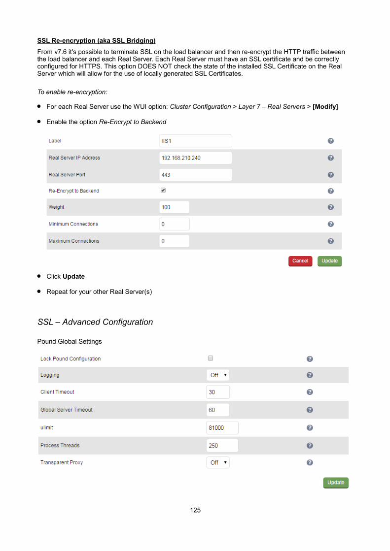
SSL Re-encryption (aka SSL Bridging)
From v7.6 it's possible to terminate SSL on the load balancer and then re-encrypt the HTTP traffic between the load balancer and each Real Server. Each Real Server must have an SSL certificate and be correctly configured for HTTPS. This option DOES NOT check the state of the installed SSL Certificate on the Real Server which will allow for the use of locally generated SSL Certificates.
To enable re-encryption:
For each Real Server use the WUI option: Cluster Configuration > Layer 7 – Real Servers > [Modify]
Enable the option Re-Encrypt to Backend
Click Update
Repeat for your other Real Server(s)
SSL – Advanced Configuration
Pound Global Settings
125
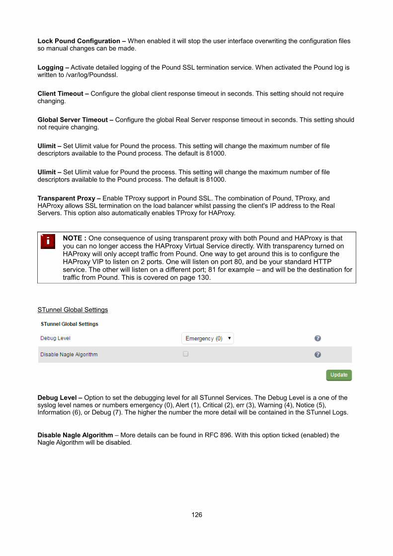
Lock Pound Configuration – When enabled it will stop the user interface overwriting the configuration files so manual changes can be made.
Logging – Activate detailed logging of the Pound SSL termination service. When activated the Pound log is written to /var/log/Poundssl.
Client Timeout – Configure the global client response timeout in seconds. This setting should not require changing.
Global Server Timeout – Configure the global Real Server response timeout in seconds. This setting shouldnot require changing.
Ulimit – Set Ulimit value for Pound the process. This setting will change the maximum number of file descriptors available to the Pound process. The default is 81000.
Ulimit – Set Ulimit value for Pound the process. This setting will change the maximum number of file descriptors available to the Pound process. The default is 81000.
Transparent Proxy – Enable TProxy support in Pound SSL. The combination of Pound, TProxy, and HAProxy allows SSL termination on the load balancer whilst passing the client's IP address to the Real Servers. This option also automatically enables TProxy for HAProxy.
NOTE : One consequence of using transparent proxy with both Pound and HAProxy is that you can no longer access the HAProxy Virtual Service directly. With transparency turned on HAProxy will only accept traffic from Pound. One way to get around this is to configure the HAProxy VIP to listen on 2 ports. One will listen on port 80, and be your standard HTTP service. The other will listen on a different port; 81 for example – and will be the destination fortraffic from Pound. This is covered on page 130.
STunnel Global Settings
Debug Level – Option to set the debugging level for all STunnel Services. The Debug Level is a one of the syslog level names or numbers emergency (0), Alert (1), Critical (2), err (3), Warning (4), Notice (5), Information (6), or Debug (7). The higher the number the more detail will be contained in the STunnel Logs.
Disable Nagle Algorithm – More details can be found in RFC 896. With this option ticked (enabled) the Nagle Algorithm will be disabled.
126
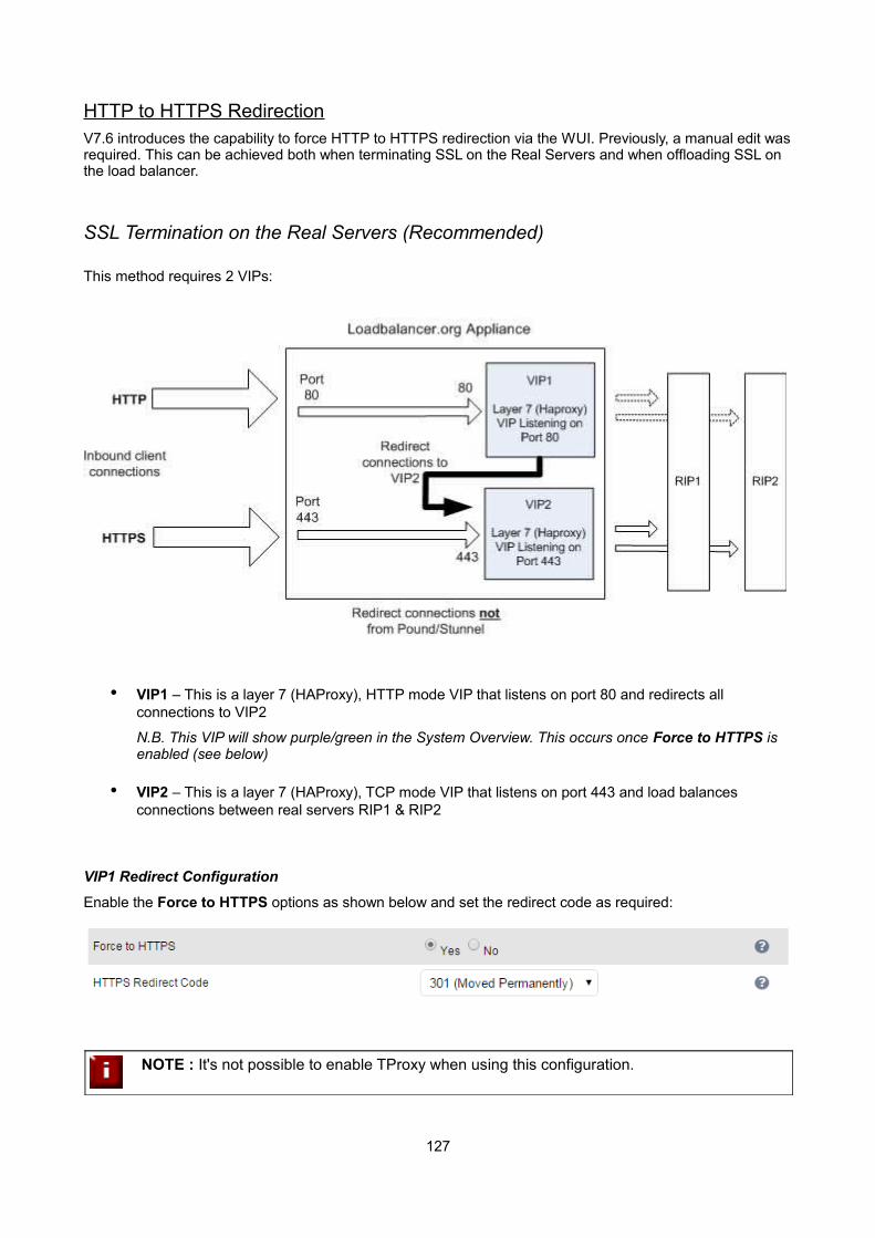
HTTP to HTTPS RedirectionV7.6 introduces the capability to force HTTP to HTTPS redirection via the WUI. Previously, a manual edit wasrequired. This can be achieved both when terminating SSL on the Real Servers and when offloading SSL on the load balancer.
SSL Termination on the Real Servers (Recommended)
This method requires 2 VIPs:
• VIP1 – This is a layer 7 (HAProxy), HTTP mode VIP that listens on port 80 and redirects all connections to VIP2
N.B. This VIP will show purple/green in the System Overview. This occurs once Force to HTTPS is enabled (see below)
• VIP2 – This is a layer 7 (HAProxy), TCP mode VIP that listens on port 443 and load balances connections between real servers RIP1 & RIP2
VIP1 Redirect Configuration
Enable the Force to HTTPS options as shown below and set the redirect code as required:
NOTE : It's not possible to enable TProxy when using this configuration.
127

SSL Termination on the Load Balancer
This method requires 2 VIPs:
• VIP1 – This is a Pound or STunnel VIP that listens on port 443, terminates the SSL connection and then forwards the decrypted HTTP connections to VIP2 on port 80
• VIP2 – This is a layer 7 (HAProxy), HTTP mode VIP that listens on port 80 and load balances connections between real servers RIP1 and RIP2. It also redirects connections that have NOT come from Pound or STunnel, i.e. client connections directly on port 80
VIP2 Redirect Configuration
Enable the Force to HTTPS options as shown below and set the redirect code as required:
NOTE : It's not possible to enable TProxy when using this configuration.
NOTE : If you require to re-encrypt the data from the load balancer to the Real Server, enable the Re-encrypt to Backend option for the each real server. See page 125 for more details.
128
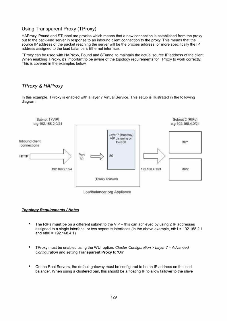
Using Transparent Proxy (TProxy)HAProxy, Pound and STunnel are proxies which means that a new connection is established from the proxy out to the back-end server in response to an inbound client connection to the proxy. This means that the source IP address of the packet reaching the server will be the proxies address, or more specifically the IP address assigned to the load balancers Ethernet interface.
TProxy can be used with HAProxy, Pound and STunnel to maintain the actual source IP address of the client.When enabling TProxy, it's important to be aware of the topology requirements for TProxy to work correctly. This is covered in the examples below.
TProxy & HAProxy
In this example, TProxy is enabled with a layer 7 Virtual Service. This setup is illustrated in the following diagram.
Topology Requirements / Notes
• The RIPs must be on a different subnet to the VIP – this can achieved by using 2 IP addresses assigned to a single interface, or two separate interfaces (in the above example, eth1 = 192.168.2.1 and eth0 = 192.168.4.1)
• TProxy must be enabled using the WUI option: Cluster Configuration > Layer 7 – Advanced Configuration and setting Transparent Proxy to 'On'
• On the Real Servers, the default gateway must be configured to be an IP address on the load balancer. When using a clustered pair, this should be a floating IP to allow failover to the slave
129
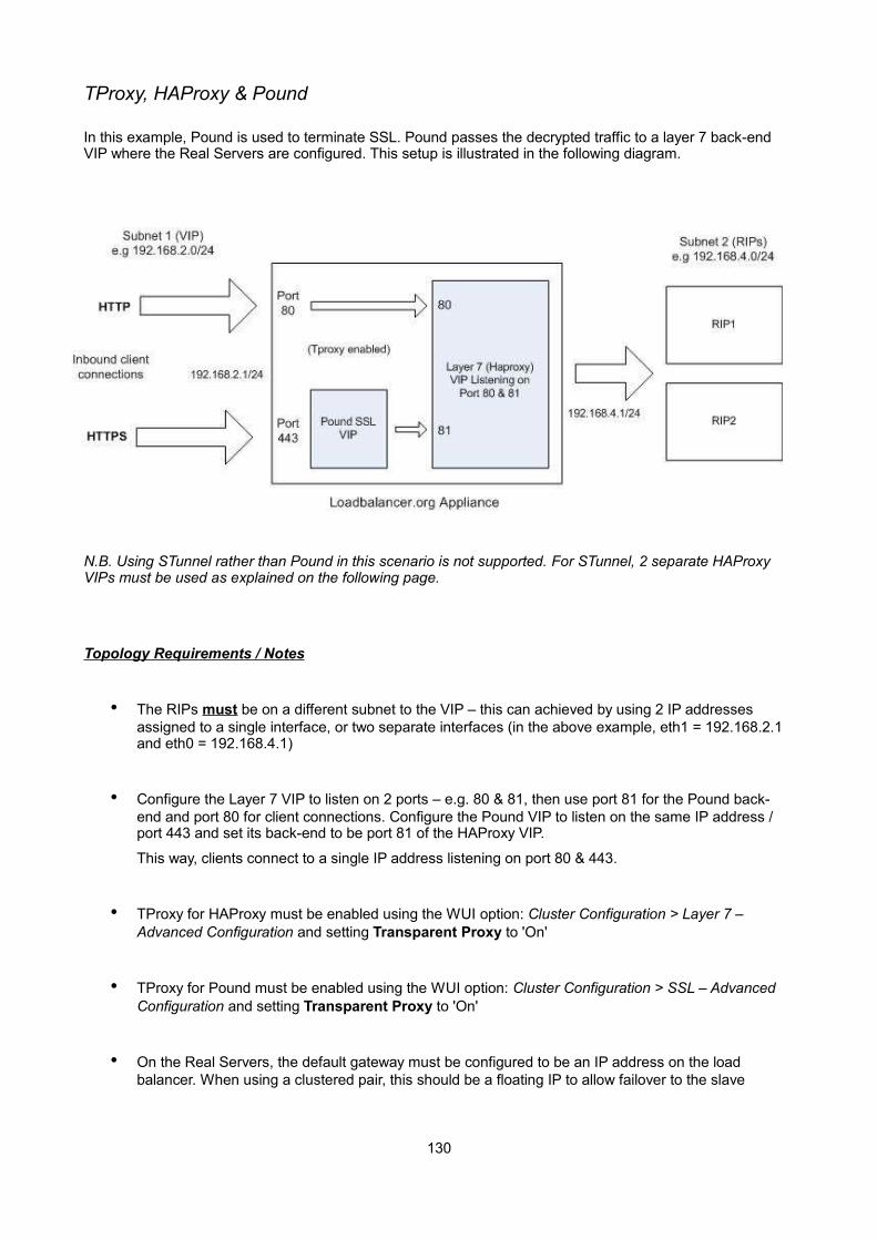
TProxy, HAProxy & Pound
In this example, Pound is used to terminate SSL. Pound passes the decrypted traffic to a layer 7 back-end VIP where the Real Servers are configured. This setup is illustrated in the following diagram.
N.B. Using STunnel rather than Pound in this scenario is not supported. For STunnel, 2 separate HAProxy VIPs must be used as explained on the following page.
Topology Requirements / Notes
• The RIPs must be on a different subnet to the VIP – this can achieved by using 2 IP addresses assigned to a single interface, or two separate interfaces (in the above example, eth1 = 192.168.2.1 and eth0 = 192.168.4.1)
• Configure the Layer 7 VIP to listen on 2 ports – e.g. 80 & 81, then use port 81 for the Pound back-end and port 80 for client connections. Configure the Pound VIP to listen on the same IP address / port 443 and set its back-end to be port 81 of the HAProxy VIP.
This way, clients connect to a single IP address listening on port 80 & 443.
• TProxy for HAProxy must be enabled using the WUI option: Cluster Configuration > Layer 7 – Advanced Configuration and setting Transparent Proxy to 'On'
• TProxy for Pound must be enabled using the WUI option: Cluster Configuration > SSL – Advanced Configuration and setting Transparent Proxy to 'On'
• On the Real Servers, the default gateway must be configured to be an IP address on the load balancer. When using a clustered pair, this should be a floating IP to allow failover to the slave
130
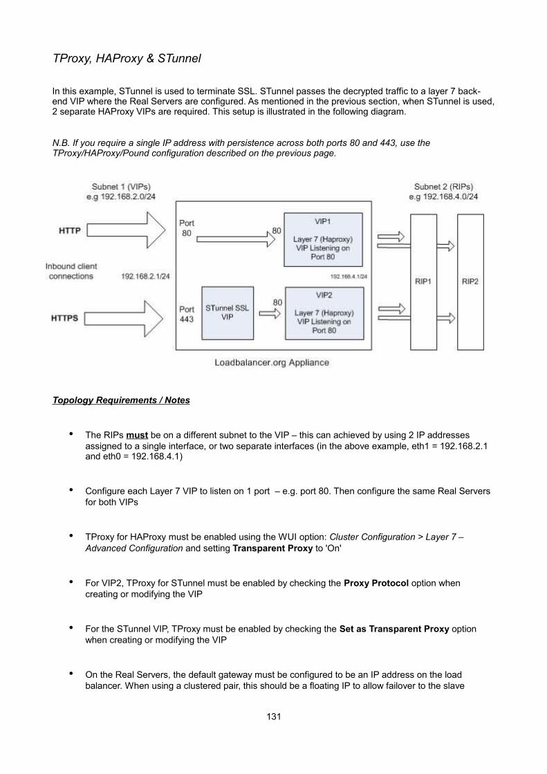
TProxy, HAProxy & STunnel
In this example, STunnel is used to terminate SSL. STunnel passes the decrypted traffic to a layer 7 back-end VIP where the Real Servers are configured. As mentioned in the previous section, when STunnel is used,2 separate HAProxy VIPs are required. This setup is illustrated in the following diagram.
N.B. If you require a single IP address with persistence across both ports 80 and 443, use the TProxy/HAProxy/Pound configuration described on the previous page.
Topology Requirements / Notes
• The RIPs must be on a different subnet to the VIP – this can achieved by using 2 IP addresses assigned to a single interface, or two separate interfaces (in the above example, eth1 = 192.168.2.1 and eth0 = 192.168.4.1)
• Configure each Layer 7 VIP to listen on 1 port – e.g. port 80. Then configure the same Real Servers for both VIPs
• TProxy for HAProxy must be enabled using the WUI option: Cluster Configuration > Layer 7 – Advanced Configuration and setting Transparent Proxy to 'On'
• For VIP2, TProxy for STunnel must be enabled by checking the Proxy Protocol option when creating or modifying the VIP
• For the STunnel VIP, TProxy must be enabled by checking the Set as Transparent Proxy option when creating or modifying the VIP
• On the Real Servers, the default gateway must be configured to be an IP address on the load balancer. When using a clustered pair, this should be a floating IP to allow failover to the slave
131
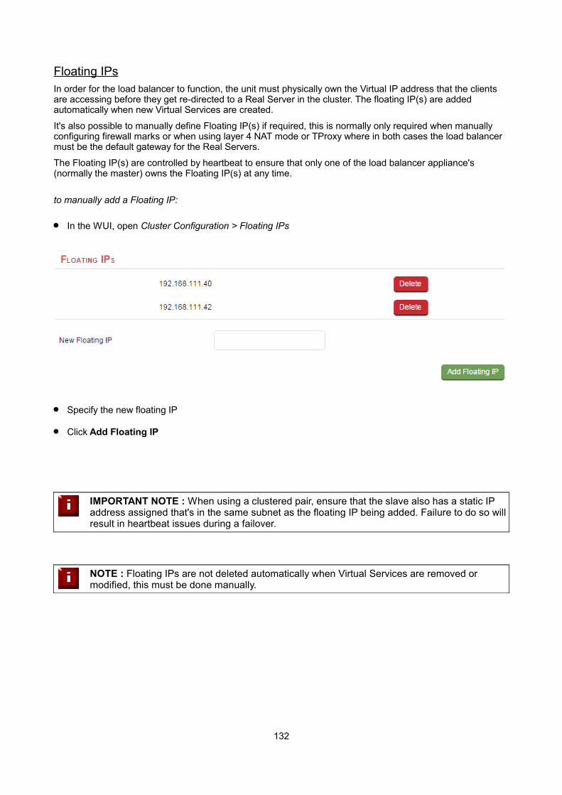
Floating IPsIn order for the load balancer to function, the unit must physically own the Virtual IP address that the clients are accessing before they get re-directed to a Real Server in the cluster. The floating IP(s) are added automatically when new Virtual Services are created.
It's also possible to manually define Floating IP(s) if required, this is normally only required when manually configuring firewall marks or when using layer 4 NAT mode or TProxy where in both cases the load balancer must be the default gateway for the Real Servers.
The Floating IP(s) are controlled by heartbeat to ensure that only one of the load balancer appliance's (normally the master) owns the Floating IP(s) at any time.
to manually add a Floating IP:
In the WUI, open Cluster Configuration > Floating IPs
Specify the new floating IP
Click Add Floating IP
IMPORTANT NOTE : When using a clustered pair, ensure that the slave also has a static IP address assigned that's in the same subnet as the floating IP being added. Failure to do so willresult in heartbeat issues during a failover.
NOTE : Floating IPs are not deleted automatically when Virtual Services are removed or modified, this must be done manually.
132
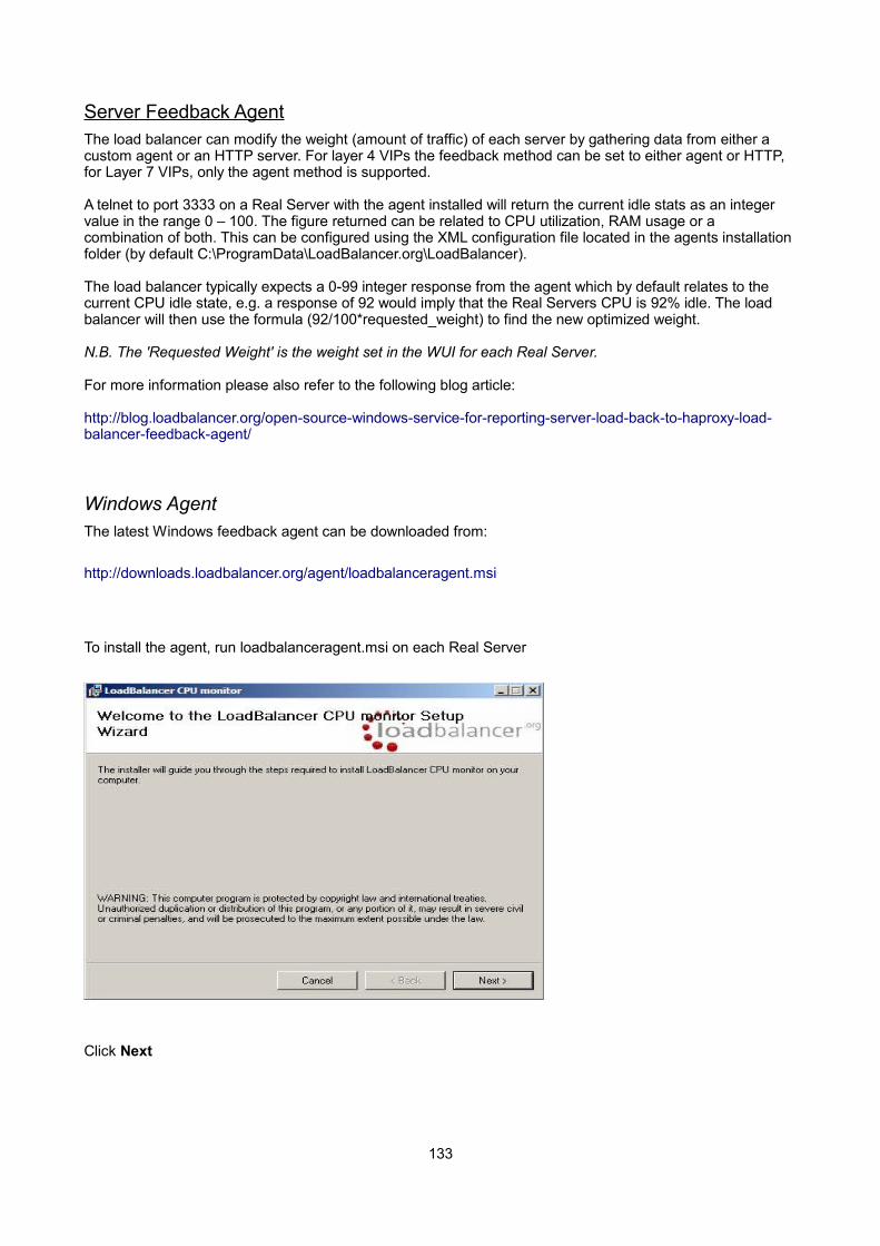
Server Feedback AgentThe load balancer can modify the weight (amount of traffic) of each server by gathering data from either a custom agent or an HTTP server. For layer 4 VIPs the feedback method can be set to either agent or HTTP, for Layer 7 VIPs, only the agent method is supported.
A telnet to port 3333 on a Real Server with the agent installed will return the current idle stats as an integer value in the range 0 – 100. The figure returned can be related to CPU utilization, RAM usage or a combination of both. This can be configured using the XML configuration file located in the agents installation folder (by default C:\ProgramData\LoadBalancer.org\LoadBalancer).
The load balancer typically expects a 0-99 integer response from the agent which by default relates to the current CPU idle state, e.g. a response of 92 would imply that the Real Servers CPU is 92% idle. The load balancer will then use the formula (92/100*requested_weight) to find the new optimized weight.
N.B. The 'Requested Weight' is the weight set in the WUI for each Real Server.
For more information please also refer to the following blog article:
http://blog.loadbalancer.org/open-source-windows-service-for-reporting-server-load-back-to-haproxy-load-balancer-feedback-agent/
Windows AgentThe latest Windows feedback agent can be downloaded from:
http://downloads.loadbalancer.org/agent/loadbalanceragent.msi
To install the agent, run loadbalanceragent.msi on each Real Server
Click Next
133
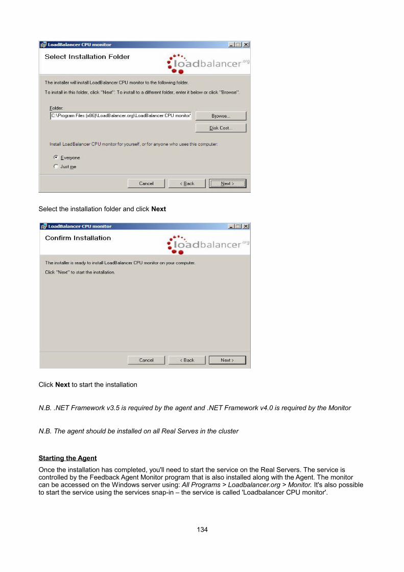
Select the installation folder and click Next
Click Next to start the installation
N.B. .NET Framework v3.5 is required by the agent and .NET Framework v4.0 is required by the Monitor
N.B. The agent should be installed on all Real Serves in the cluster
Starting the Agent
Once the installation has completed, you'll need to start the service on the Real Servers. The service is controlled by the Feedback Agent Monitor program that is also installed along with the Agent. The monitor can be accessed on the Windows server using: All Programs > Loadbalancer.org > Monitor. It's also possible to start the service using the services snap-in – the service is called 'Loadbalancer CPU monitor'.
134
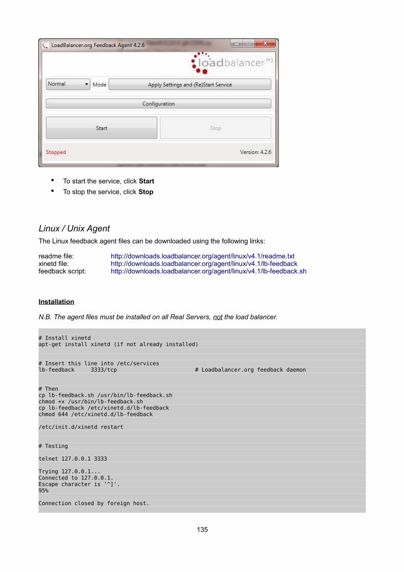
• To start the service, click Start
• To stop the service, click Stop
Linux / Unix AgentThe Linux feedback agent files can be downloaded using the following links:
readme file: http://downloads.loadbalancer.org/agent/linux/v4.1/readme.txtxinetd file: http://downloads.loadbalancer.org/agent/linux/v4.1/lb-feedbackfeedback script: http://downloads.loadbalancer.org/agent/linux/v4.1/lb-feedback.sh
Installation
N.B. The agent files must be installed on all Real Servers, not the load balancer.
# Install xinetdapt-get install xinetd (if not already installed)
# Insert this line into /etc/serviceslb-feedback 3333/tcp # Loadbalancer.org feedback daemon
# Thencp lb-feedback.sh /usr/bin/lb-feedback.shchmod +x /usr/bin/lb-feedback.shcp lb-feedback /etc/xinetd.d/lb-feedbackchmod 644 /etc/xinetd.d/lb-feedback
/etc/init.d/xinetd restart
# Testing
telnet 127.0.0.1 3333
Trying 127.0.0.1...Connected to 127.0.0.1.Escape character is '^]'.95%
Connection closed by foreign host.
135
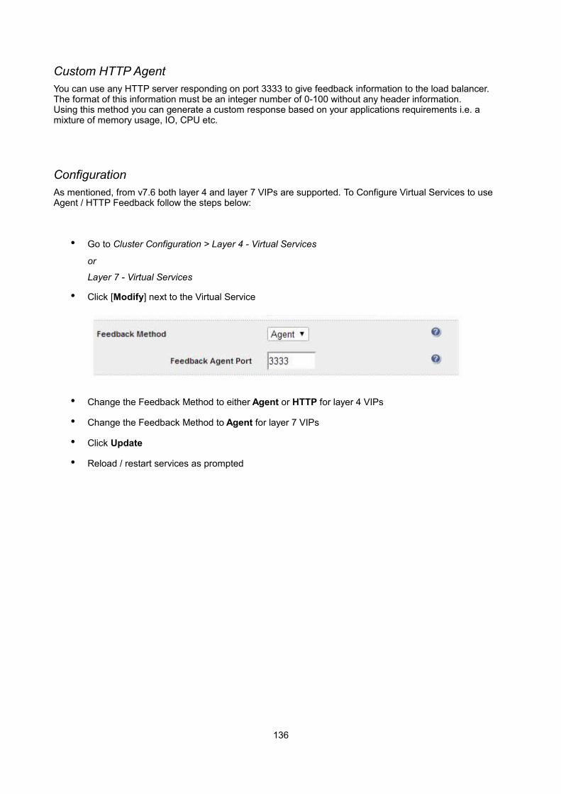
Custom HTTP AgentYou can use any HTTP server responding on port 3333 to give feedback information to the load balancer.The format of this information must be an integer number of 0-100 without any header information. Using this method you can generate a custom response based on your applications requirements i.e. a mixture of memory usage, IO, CPU etc.
ConfigurationAs mentioned, from v7.6 both layer 4 and layer 7 VIPs are supported. To Configure Virtual Services to use Agent / HTTP Feedback follow the steps below:
• Go to Cluster Configuration > Layer 4 - Virtual Services
or
Layer 7 - Virtual Services
• Click [Modify] next to the Virtual Service
• Change the Feedback Method to either Agent or HTTP for layer 4 VIPs
• Change the Feedback Method to Agent for layer 7 VIPs
• Click Update
• Reload / restart services as prompted
136
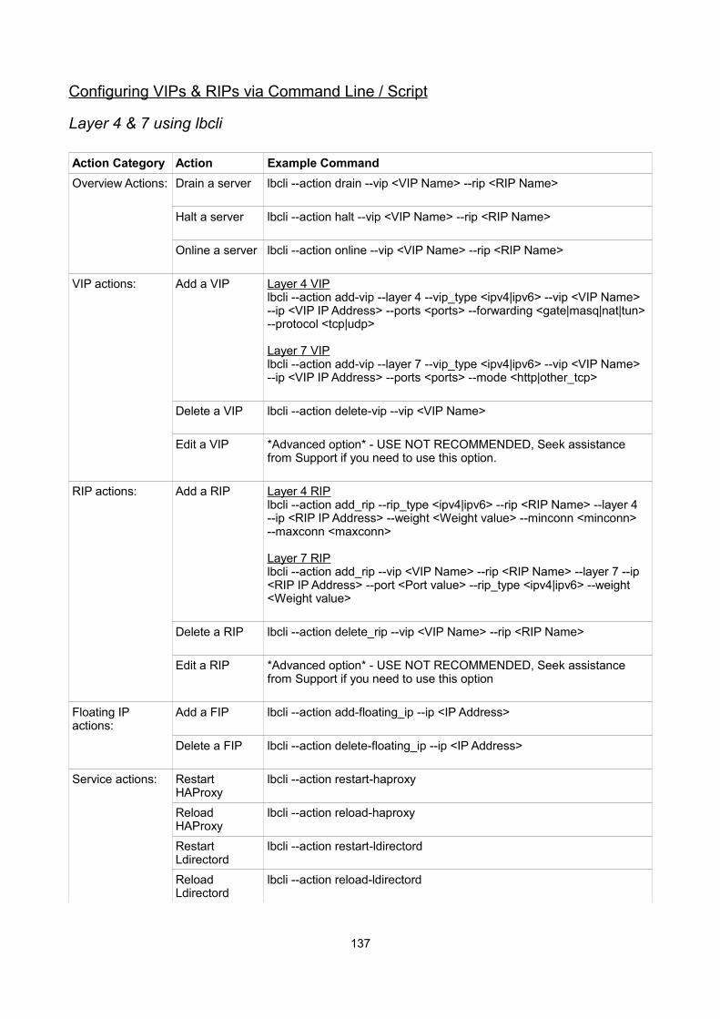
Configuring VIPs & RIPs via Command Line / Script
Layer 4 & 7 using lbcli
Action Category Action Example Command
Overview Actions: Drain a server lbcli --action drain --vip <VIP Name> --rip <RIP Name>
Halt a server lbcli --action halt --vip <VIP Name> --rip <RIP Name>
Online a server lbcli --action online --vip <VIP Name> --rip <RIP Name>
VIP actions: Add a VIP Layer 4 VIPlbcli --action add-vip --layer 4 --vip_type <ipv4|ipv6> --vip <VIP Name> --ip <VIP IP Address> --ports <ports> --forwarding <gate|masq|nat|tun> --protocol <tcp|udp>
Layer 7 VIPlbcli --action add-vip --layer 7 --vip_type <ipv4|ipv6> --vip <VIP Name> --ip <VIP IP Address> --ports <ports> --mode <http|other_tcp>
Delete a VIP lbcli --action delete-vip --vip <VIP Name>
Edit a VIP *Advanced option* - USE NOT RECOMMENDED, Seek assistance from Support if you need to use this option.
RIP actions: Add a RIP Layer 4 RIPlbcli --action add_rip --rip_type <ipv4|ipv6> --rip <RIP Name> --layer 4 --ip <RIP IP Address> --weight <Weight value> --minconn <minconn> --maxconn <maxconn>
Layer 7 RIPlbcli --action add_rip --vip <VIP Name> --rip <RIP Name> --layer 7 --ip <RIP IP Address> --port <Port value> --rip_type <ipv4|ipv6> --weight <Weight value>
Delete a RIP lbcli --action delete_rip --vip <VIP Name> --rip <RIP Name>
Edit a RIP *Advanced option* - USE NOT RECOMMENDED, Seek assistance from Support if you need to use this option
Floating IP actions:
Add a FIP lbcli --action add-floating_ip --ip <IP Address>
Delete a FIP lbcli --action delete-floating_ip --ip <IP Address>
Service actions: Restart HAProxy
lbcli --action restart-haproxy
Reload HAProxy
lbcli --action reload-haproxy
Restart Ldirectord
lbcli --action restart-ldirectord
Reload Ldirectord
lbcli --action reload-ldirectord
137
N.B. The above information is also displayed when typing the following command:
lbcli ––action help
Running from a remote Linux Host
These commands can be run from a remote Linux host. This example halts VIP1 / RIP1 :
ssh [email protected] "lbcli --action halt --vip L72 --rip RIP_Name"
Running from a remote Windows Host
These commands can be run from a remote Windows host. This example halts VIP1 / RIP1 :
plink -pw loadbalancer [email protected] "lbcli --action halt --vip VIP1 --rip RIP1"
Notes:
1. PuTTy must be installed to use the plink command
(see: http://www.chiark.greenend.org.uk/~sgtatham/putty/download.html)
2. 'loadbalancer' is the password for the root user
3. 192.168.111.42 is the IP address of the load balancer
138

Layer 4 using ipvsadmFor layer 4, the ipvsadm command can be used. Several examples are provided below.
Add a TCP based Virtual Service & use weighted round robin scheduling:
ipvsadm -A -t 192.168.65.192:80 -s wrr
Add a TCP based Real Server in DR mode:
ipvsadm -a -t 192.168.65.192:80 -g -r 192.168.70.196:80
Add a TCP based Real Server in NAT mode:
ipvsadm -a -t 192.168.65.192:80 -m -r 192.168.70.196:80
Add a UDP based Virtual Service & use weighted least connection scheduling:
ipvsadm -A -u 192.168.65.192:80 -s wlc
Add a UDP based Real Server in DR mode:
ipvsadm -a -u 192.168.65.192:80 -g -r 192.168.70.196:80
Delete a TCP based Virtual Service:
ipvsadm -D -t 192.168.65.180:80
Delete a TCP based Real Server:
ipvsadm -d -t 192.168.65.122:80 -r 192.168.70.134:80
View the current running config:
ipvsadm -ln
IP Virtual Service version 1.2.1 (size=4096)
Prot LocalAddress:Port Scheduler Flags
-> RemoteAddress:Port Forward Weight ActiveConn InActConn
TCP 192.168.65.120:80 rr
-> 192.168.70.130:80 Route 1 0 0
-> 192.168.70.131:80 Route 1 0 0
TCP 192.168.65.122:80 rr
-> 192.168.70.132:80 Mass 1 0 0
-> 192.168.70.133:80 Mass 1 0 0
139
Layer 7 using Socket CommandsFor layer 7 HAProxy VIPs, the socat socket command can be used as shown in the examples below.
To take a server offline:
echo "disable server VIP_Name/RIP_Name" | socat unix-connect:/var/run/haproxy.stat stdio
To bring a server online:
echo "enable server VIP_Name/RIP_Name" | socat unix-connect:/var/run/haproxy.stat stdio
To set the weight of a Real Server:
echo "set weight VIP_Name/RIP_Name 0" | socat unix-connect:/var/run/haproxy.stat stdio
To view HAProxy's running configuration:
echo "show info" | socat unix-connect:/var/run/haproxy.stat stdio
To clear HAProxy's statistics:
echo "clear counters all" | socat unix-connect:/var/run/haproxy.stat stdio
N.B. Other examples can be found by searching for “Unix Socket Commands” at the following link:
http://haproxy.1wt.eu/download/1.6/doc/configuration.txt
IMPORTANT NOTE : Please note that since these changes are being made directly to the running configuration, the services that are displayed in the System Overview will no longer match the running configuration when ipvsadm / socat commands are used.
Using the lbcli command does not have this disadvantage and the System Overview will showthe correct VIP and RIP status.
NOTE : For additional assistance don't hesitate to contact: [email protected].
140

Chapter 7 – Real Server Health Monitoring & Control
141

Configuring Health ChecksThe appliance supports a range of health-check options to check and verify the health of Real Servers. These range from simple ping checks to more complex negotiate options to determine that the underlying daemon / service is running. The specific options available depend on whether services are deployed at Layer 4 or Layer 7, details of both are covered in the following sections.
Heath Checks for Layer 4 ServicesAt layer 4, Real Server health checking is provided by Ldirectord. This is integrated into Loadbalancer.org appliances and allows a full range of options to check that Real Servers are operational.
To configure health checks use the WUI option: Cluster Configuration > Layer 4 - Virtual Services > Modify
The exact options available depend on the check type selected. For the default (Connect to port), one field is required:
As the drop-down is changed, the field list changes as shown in the Negotiate option shown below:
Default Health Check
By default, a TCP connect health check is used for newly created layer 4 Virtual Services.
Check Types
Negotiate – Sends a request and looks for a specific response (see Negotiate Check Service below)
Connect to port – Just do a simple connect to the specified port/service & verify that it's able to accept a connection
Ping server – Sends an ICMP echo request packet to the Real Server
External check – Use a custom file for the health check. Specify the file path in the 'Check Command' field.
No checks, always Off – All Real Servers are off
142

No checks, always On – All Real Servers are on (no checking)
5 Connects, 1 Negotiate – Do 5 connect checks and then 1 negotiate check
10 Connects, 1 Negotiate – Do 10 connect checks and then 1 negotiate check
Check Port
This can be used if the port to check is non standard, e.g., the service to check is HTTPS, but the port used is 4443 instead of the standard 443. Leaving the field blank will cause the health-check to occur on the port specified for the Real Server (note that in DR mode there is no Real Server port field since port re-mapping isnot possible, the port specified for the Virtual Service is used).
External Script Command
The custom check script, used with the external check type. The script should be placed in /var/lib/loadbalancer.org/check, and given world read and execute permissions.
The following example illustrates how scripts can be constructed. This script uses the Linux command 'wget' to connect to the Real Server, then uses the Linux command 'grep' to look for the text 'OK' in the file 'check.txt'. The variable 'EXIT_CODE' which indicates a pass or fail is then returned to Ldirectord to control whether the server should be left online or removed.
#!/bin/bash# VariablesREALIP="$3"PORT="$2"REQUEST="check.txt"RESPONSE="OK"
# Get the Page/Filewget q -O -header="Host: host.domain.co.uk" http://$REALIP:$PORT/$REQUEST |grep -e $RESPONSEif [ "$?" -eq "0" ]; thenEXIT_CODE="0"elseEXIT_CODE="1"fi
exit $EXIT_CODE
Notes:
$2 and $3 are Ldirectord variables that are passed to the script. The following Ldirectord variables are available and can be used as required:$1 – the VIP address$2 – the VIP port$3 – the RIP address$4 – the RIP port
Negotiate Check Service
If negotiate is selected as the check type, the following methods are valid:
HTTP – use HTTP as the negotiate protocol (also requires filename, path + text expected)
HTTPS – use HTTPS as the negotiate protocol (also requires filename, path + text expected)
143
HTTP Proxy – Use an HTTP proxy check
FTP – use FTP as the negotiate protocol (also requires login/password, filename in the default folder)
IMAP (IPv4 only) – use IMAP as the negotiate protocol (requires login/password)
IMAPS (IPv4 only) - use IMAPS as the negotiate protocol (requires login/password)
POP – use POP as the negotiate protocol (also requires login/password)
POPS – use POPS as the negotiate protocol (also requires login/password)
LDAP (IPv4 only) – use LDAP as the negotiate protocol (also requires username/password)
SMTP – use SMTP as the negotiate protocol
NNTP (IPv4 only) – use NNTP as the negotiate protocol
DNS – use DNS as the negotiate protocol
MySQL (IPv4 only) – use MySQL as the negotiate protocol (also requires username/password)
SIP – use SIP as the negotiate protocol (also requires username/password)
Simple TCP – Sends a request string to the server and checks the response
RADIUS (IPv4 only) – use RADIUS as the negotiate protocol (also requires username/password)
none -
Virtual Host
If the Real Server will only respond to a URL or 'virtualhost' rather than an ip address, you can specify the virtual host to request here.
Database Name
The database to use for the MySQL Negotiate check. This is a required option if MySQL is selected under Negotiate Check Service above.
Radius Secret
The secret to use with Radius servers.
Login
The login name to use with negotiate checks where authentication is required.
Password
The password to use with negotiate checks where authentication is required.
Request to Send
This is used with negotiate checks and specifies the request to send to the server. The use of this parameter varies with the protocol selected in Negotiate Check Service. With protocols such as HTTP and FTP, this should be the object to request from the server. Bare filenames will be requested from the web or FTP root. With DNS, this should be either a name to look up in an A record, or an IP address to look up in a PTR record. With databases, this should be an SQL SELECT query (N.B. the response expected field in not used by the SQL health check since the data returned in not read, the answer must simply be 1 or more rows). With LDAP, this should be the search base for the query. The load balancer will perform an (ObjectClass=*) search relative to this base. With Simple TCP, this should be a string to send verbatim to the server.
144
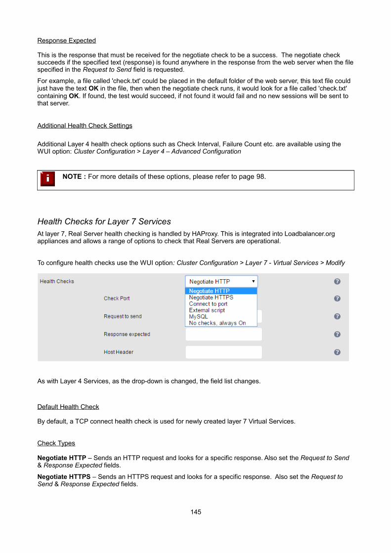
Response Expected
This is the response that must be received for the negotiate check to be a success. The negotiate check succeeds if the specified text (response) is found anywhere in the response from the web server when the filespecified in the Request to Send field is requested.
For example, a file called 'check.txt' could be placed in the default folder of the web server, this text file could just have the text OK in the file, then when the negotiate check runs, it would look for a file called 'check.txt' containing OK. If found, the test would succeed, if not found it would fail and no new sessions will be sent to that server.
Additional Health Check Settings
Additional Layer 4 health check options such as Check Interval, Failure Count etc. are available using the WUI option: Cluster Configuration > Layer 4 – Advanced Configuration
NOTE : For more details of these options, please refer to page 98.
Health Checks for Layer 7 ServicesAt layer 7, Real Server health checking is handled by HAProxy. This is integrated into Loadbalancer.org appliances and allows a range of options to check that Real Servers are operational.
To configure health checks use the WUI option: Cluster Configuration > Layer 7 - Virtual Services > Modify
As with Layer 4 Services, as the drop-down is changed, the field list changes.
Default Health Check
By default, a TCP connect health check is used for newly created layer 7 Virtual Services.
Check Types
Negotiate HTTP – Sends an HTTP request and looks for a specific response. Also set the Request to Send & Response Expected fields.
Negotiate HTTPS – Sends an HTTPS request and looks for a specific response. Also set the Request to Send & Response Expected fields.
145
N.B. If a negotiate HTTP or HTTPS check is used and Request to Send is configured but Response Expected is left blank, the appliance looks for a 200 OK response from the real server.
Connect to port – Just do a simple TCP connect to the specified port/service & verify that it's able to accept a connection
External Script – use a custom file for the health check. Specify the script path in the Check Script field.
MySQL - The check consists of sending two MySQL packets, one Client Authentication packet, and one QUIT packet, to correctly close the MySQL session. It then parses the MySQL Handshake Initialization packet and/or Error packet. It is a basic but useful test and does not produce error nor aborted connect on the server. However, it does require adding an authorization in the MySQL table as follows:
use mysql; INSERT INTO user (Host,User) values ('<appliance-IP>','<username>'); flush privileges;
e.g.
use mysql; INSERT INTO user (Host,User) values ('192.168.1.1','probe'); flush privileges;
No checks, always On – All Real Servers are on (i.e. no checking)
Check Port
Specify a different port for health checks. If this field is left blank, health checks occur or the port specified foreach Real Server. If the VIP includes multiple ports (e.g. 80 & 443) by default the check occurs on the first port listed. If a different port must be checked, it can be specified here.
Request to Send
Specify a specific file for the health check. Open the specified file and check for the response expected. useful for checking a server sided script to check the health of the back-end application.
Response Expected
The content expected for a valid health check on the specified file. The response expected can be any valid regular expression statement.
Request to Send / Response Expected Example:
If the server has a virtual directory called /customers, with a default page that contains the word 'welcome' therequired setup would be as follows:
Request to send: customersResponse expected: welcome
These settings would configure the following check directives in the HAProxy configuration file:
option httpchk GET /customers HTTP/1.0http-check expect rstring welcome
N.B. the forward-slash character before 'customers' is added automatically
In this example, provided that the load balancer can access the page and see the text 'welcome', the health-check would pass.
146
Additional Health Check Settings
Additional Layer 7 health check options such as the check interval and failure count are available using the WUI option: Cluster Configuration > Layer 7 – Advanced Configuration
NOTE : For more details of these options, please refer to page 111.
Simulating Health-Check FailuresIt may not always be possible to take a server offline to check that health-checks are working correctly. In these cases, firewall rules can be used. The following rules can be configured at the console, using SSH or via the WUI under Local Configuration > Execute a Shell Command
To block access to a particular Real Server port:
iptables -A OUTPUT -p tcp --dport <Check Port> -d <REAL-SERVER-IP> -j DROP
e.g. iptables -A OUTPUT -p tcp --dport 80 -d 192.168.65.60 -j DROP
To re-enable access to a particular Real Server port:
iptables -D OUTPUT -p tcp --dport <Check Port> -d <REAL-SERVER-IP> -j DROP
e.g. iptables -D OUTPUT -p tcp --dport 80 -d 192.168.65.60 -j DROP
N.B. Make sure these rule are cleared after testing & verification is complete!
Disabling Health-ChecksIn some cases it may be desirable to completely disable health checking and simply assume that the real servers are up and working correctly. The can be configured simply by setting the health-check option to No Checks, Always On – this applies to both layer 4 and layer 7 services.
Fallback Server SettingsThe appliance uses NGINX for the local fallback server. The fallback server is activated under the following conditions for Layer 4 & Layer 7 Virtual Services:
Layer 4
From v7.6 the fallback page is displayed when all Real Servers are unavailable AND when all servers are taken offline via the WUI. The page can be hosted on the load balancer or on an external server. From v7.6.3 it can also be configured to be a Layer 7 VIP. Set the Fallback Server option of the VIP accordingly.
Layer 7
For layer 7 VIPs the fallback page is displayed when all Real Servers are unavailable and when all servers are taken offline via the WUI. The page can be hosted on the load balancer or on an external server. Set the Fallback Server option of the VIP accordingly.
147

The local fallback page can be modified using the WUI option: Maintenance > Fallback Page
Notes:
• The local fallback server is an NGINX instance that by default listens on port 9081
• If a layer 4 VIP is added that listens on port 80, NGINX is automatically configured to listen on ports 9081 & 80
• You can use any valid HTML for the default page, simply copy and paste the required HTML into the Fallback Page using the Maintenance menu
Additional Fallback Server Notes:
Using the load balancers built-in Fallback Server:
• If you are using the load balancer for your holding page and your web servers are offline then the local NGINX server is exposed to hacking attempts, if you are concerned about this you can change the fallback server to be one of your internal servers.
Using an External, Dedicated Server:
• For DR mode the fallback server must be listening on the same port as the VIP (port re-mapping is not possible with DR mode). Also, don't forget to solve the ARP problem for the dedicated fallback server (see page 70)
• For NAT mode don't forget to set the default gateway of the fallback server to the internal IP of the load balancer or when you have 2 appliances in a cluster, to a floating IP.
Using a Layer 7 VIP as the fallback server for Layer 4 VIPs:
• From v7.6.3 it's possible to set the fallback server for a layer 4 VIP to be a layer 7 VIP. This is especially useful in WAN/DR site environments.
It also enables an external fallback server to be easily configured for Layer 4 VIPs – simply create a fallback VIP and configure the fallback server as an associated RIP, then enable the MASQ option forthe Layer 4 VIP and set the fallback VIP as its fallback server. If all servers are down, requests will then be routed via the Layer 7 VIP to the external server.
148
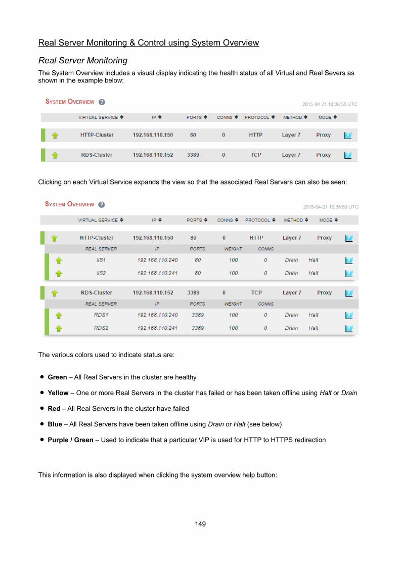
Real Server Monitoring & Control using System Overview
Real Server MonitoringThe System Overview includes a visual display indicating the health status of all Virtual and Real Severs as shown in the example below:
Clicking on each Virtual Service expands the view so that the associated Real Servers can also be seen:
The various colors used to indicate status are:
Green – All Real Servers in the cluster are healthy
Yellow – One or more Real Servers in the cluster has failed or has been taken offline using Halt or Drain
Red – All Real Servers in the cluster have failed
Blue – All Real Servers have been taken offline using Drain or Halt (see below)
Purple / Green – Used to indicate that a particular VIP is used for HTTP to HTTPS redirection
This information is also displayed when clicking the system overview help button:
149

Real Server ControlThe System Overview also enables the state of each Real Server to be controlled. Real Servers can be put inthe following modes:
Drain – This option allows existing connections to close gracefully and prevents new connections
Halt – This options prevents new connections and drops all existing connections immediately without waiting
The screen shot below shows that RDS2 has been put into drain mode:
To bring RDS2 back online, click the Online (drain) link. If the server had been halted rather than drained, the the link would be displayed as Online (Halt).
NOTE : If a particular Real Server is used in multiple VIPs you can choose to apply the offline/ online action to all relevant VIPs or only a single VIP. This simplifies taking Real Servers offline for maintenance purposes.
NOTE : From v7.6, halting or draining all Real Servers in a cluster at layer 7 and layer 4 activates the fallback server.
150

Ordering of VIPsThe display order of configured VIPs can be changed either by clicking on the column heading, or by drag and drop.
Sort by Column
If VIPs are ordered by a particular column, this is indicated using arrows next to the column heading as shown below:
In this example, the VIPs are ordered alpha-numerically by Virtual Service name. To change the order, click on the required column heading then click save. If you want to reverse the order for a particular column, click that column heading again.
e.g. Clicking on the IP column heading shows the following:
Clicking on the IP column heading again changes the order to:
Once you've set the required order, click Save.
151

Drag & Drop
To re-order VIPs by drag and drop, simply click the mouse on any part of the VIP:
Then drag it to the required position:
And release it.
Once you've set the required order, click Save.
152
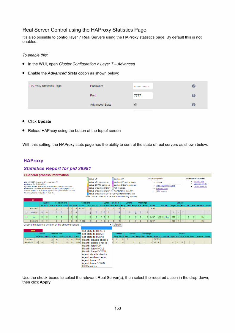
Real Server Control using the HAProxy Statistics PageIt's also possible to control layer 7 Real Servers using the HAProxy statistics page. By default this is not enabled.
To enable this:
In the WUI, open Cluster Configuration > Layer 7 – Advanced
Enable the Advanced Stats option as shown below:
Click Update
Reload HAProxy using the button at the top of screen
With this setting, the HAProxy stats page has the ability to control the state of real servers as shown below:
Use the check-boxes to select the relevant Real Server(s), then select the required action in the drop-down, then click Apply
153

Chapter 8 – Appliance Clustering for HA
154

IntroductionAppliances can be deployed as single units or as a clustered pair. We always recommend a clustered pair to avoid introducing a single point of failure.
Clustered Pair ConsiderationsWhen configured as a clustered pair, the appliances work in Active-Passive mode. In this mode the active unit (normally the master) handles all traffic under normal circumstances. If the active unit fails, the passive unit (normally the slave) becomes active and handles all traffic.
Master / Slave Operation
Heartbeat
By default, heartbeat uses ucast over UDP port 6694 to communicate between the master and slave appliances. The link enables the state of each to be monitored by the other and permits a failover to the passive unit if the active unit should fail. For hardware appliances, it's also possible to configure ucast and serial communication if required.
NOTE : For hardware appliances we recommend that heartbeat is configured to use both ucast and serial when possible for added resilience. Once the serial cable is connected between the appliances, the serial option must be enabled under: Cluster Configuration > Heartbeat Configuration
Ping checks to a common node such as the default gateway can also be configured. If the active node loses access to the ping node, the system will fail-over to the peer. However, if both nodes lose access, no fail-overwill occur.
Master Slave Replication
Once the clustered pair is correctly configured, all settings related to the layer 4 and layer 7 load balanced services are automatically replicated from master to slave. This ensures that should the master unit fail, the slave is already configured to run the same services. Note that replication of the configured load balanced services from the master to the slave appliance occurs over the network via SSH/SCP.
Settings that are NOT Replicated
Appliance specific settings that are not replicated (and therefore must be manually configured on the slave unit) are listed below:
• Hostname & DNS settings
• Network settings including IP addresses, bonding configuration and VLANs
• Routing configuration including default gateways and static routes
• Date & time settings
• Physical – Advanced Configuration settings including Internet Proxy IP address & port, Firewall table size, SMTP relay and Syslog server
• SNMP settings
• Graphing settings
• Firewall Script & Firewall Lockdown Script settings
• Software updates
155
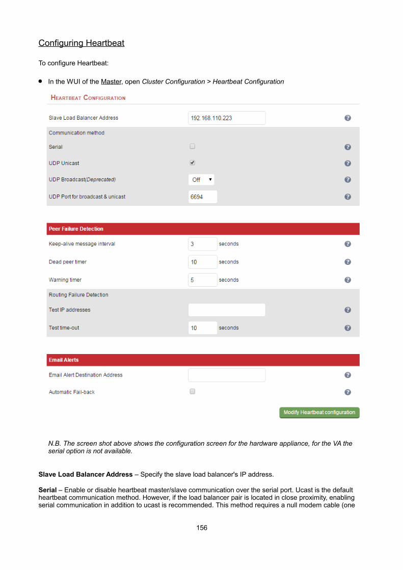
Configuring Heartbeat
To configure Heartbeat:
In the WUI of the Master, open Cluster Configuration > Heartbeat Configuration
N.B. The screen shot above shows the configuration screen for the hardware appliance, for the VA the serial option is not available.
Slave Load Balancer Address – Specify the slave load balancer's IP address.
Serial – Enable or disable heartbeat master/slave communication over the serial port. Ucast is the default heartbeat communication method. However, if the load balancer pair is located in close proximity, enabling serial communication in addition to ucast is recommended. This method requires a null modem cable (one
156
cable is supplied with each appliance) to be connected between the two load balancers in the cluster. This enables heartbeat checks to utilize the serial port. When serial communication is disabled, console access via the serial port is activated.
UDP Unicast – Enable or disable unicast heartbeat master/slave communication. This is the default method of heartbeat communication and uses unicast UDP between master and slave, with a destination port specified by the UDP Port for broadcast & unicast parameter. When unicast is enabled, the load balancer determines the correct interface and IP addresses to use based upon the configured slave IP address.
UDP Broadcast (Deprecated) – Enable or disable broadcast heartbeat master/slave communication, and choose the interface. This option is deprecated - please migrate to Unicast. This method of heartbeat communication uses broadcast UDP between master and slave, with a destination port specified by the UDP Port for broadcast & unicast parameter. Care must be taken when using broadcast on multiple pairs of load balancers in the same network. Each high-availability pair must operate on a different UDP port if they are not to interfere with each other. If heartbeat communication over the network is required, it is recommended that unicast be used in preference to broadcast.
UDP Port for unicast & broadcast – The UDP port number used by heartbeat for network communication over unicast or broadcast. By default, heartbeat uses UDP port 6694 for unicast or broadcast communication.If you have multiple load balancer pairs on the same subnet, and wish to use broadcast, you will need to set each pair to a different UDP port.
Keepalive – Specify the number of seconds between keepalive pings. The Keepalive setting must be less than the warntime and deadtime.
Deadtime – The number of seconds communication can fail before a fail over is performed. A very low setting of deadtime could cause unexpected failovers.
Warntime – If communication fails for this length of time write a warning to the logs. This is useful for tuning your deadtime without causing failovers in production.
Test IP address – Specify one or more mutually accessible IP address to test network availability. A good ping node to specify is the IP address of a router that both the master and slave node can access. If the active node loses access to the ping node, the system will fail-over to the peer. However, if both nodes lose access, no fail-over will occur. Multiple IP addresses may be given, separated by spaces or commas. In this case, if any one address is reachable the routing test will pass.
Test time-out - Specify the time-out, in seconds, for the routing test. If a response is not received from the test address within the time-out period, the route to that host will be considered dead.
Email Alert Destination Address – Specify the Email address to send heartbeat alerts. In the event of failover the email address specified will receive an alert.
Automatic Fail-back – Enable/disable auto-failback. When the master returns to service after a failure, should it become active again? This option controls the cluster behavior when the master returns to service after a failure. With Automatic Fail-back enabled, the master will automatically return to active status, taking back the floating IP addresses from the slave. With Automatic Fail-back disabled, the slave will remain active and will retain the floating IP addresses. Fail-over back to the master must then be controlled manually.
NOTE : Automatic Fail-back is disabled by default. Manual intervention is required to force the repaired master to become active and the slave unit to return to passive mode. For more details refer to page 162. Auto fail-back can be enabled if required using the WUI option: Cluster Configuration > Heartbeat Configuration and enabling Automatic Fail-Back
157
Adding a Slave Unit after the Master has been Configured – Method 1
NOTE : This method uses this Wizard to simplify adding the slave. Load balanced services may be disrupted momentarily.
To add a slave unit to an existing master unit to create a highly available clustered pair, follow the steps below:
STEP 1 - Slave Appliance:
• Power up the additional appliance that will be used as the slave
• Set the appliance's network settings using one of the methods described on page 29
STEP 2 - Master Appliance:
• Select the WUI option: Cluster Configuration > setup Wizard
• Click Configure high-availability pair of load balancers
• Set High Availability Configuration to Clustered Pair
• Enter the IP address of the slave appliance in the Slave IP Address field
• Click Configure Cluster
• Wait till the peer synchronization is complete (a message will be displayed)
• Once configuration is complete & stable, verify that the master displays: Master | Active | Link
STEP 3 – Slave Appliance:
• Once configuration is complete & stable, verify that the slave displays: Slave | Passive | Link
NOTE : It's highly recommended that the clustered pair is fully tested to ensure that failover to the slave works as expected. For more details on this, please refer to page 163.
158

Adding a Slave Unit after the Master has been Configured – Method 2
NOTE : This procedure enables a slave to be added without disrupting running services.
To add a slave unit to an existing master unit to create a highly available clustered pair, follow the steps below:
STEP 1 - Slave Appliance:
• Power up the additional appliance that will be used as the Slave
• Set the appliance's network settings using one of the methods described on page 29
• Once the network is configured, connect to the WUI using a browser: http://<IP address>:9080
• Using the WUI option: Local Configuration > Hostname & DNS change the Role to slave
• Using the WUI option: Local Configuration > System date & time set the same as the existing master
• Click Update to apply these settings
STEP 2 - Master Appliance:
• Using the WUI option: Cluster Configuration > Heartbeat Configuration enter the slave units IP address in the field Slave Load Balancer Address
• By default, both the VA and the hardware appliance use ucast over the network for heartbeat communication. For a hardware clustered pair, heartbeat can also be configured to use the serial link(in addition to ucast). If this is done, ensure a null modem cable is connected between master & slave
• Once the required heartbeat options are set, click Modify Heartbeat Configuration to apply the settings and replicate these settings to the slave unit
• Open the WUI option: Maintenance > Backup & Restore, select the Synchronization tab and click Synchronize Configuration with peer – this will copy all configured load balanced services from the master to the slave unit
• Wait till the peer synchronization is complete (a message will be displayed)
STEP 3 - Slave Appliance:
• Now reload heartbeat on the slave using the WUI option: Maintenance > Restart Services and clicking Reload Heartbeat
IMPORTANT! - Using reload rather than restart ensures services are not disrupted
• Once configuration is complete & stable, verify that the slave displays: Slave | Passive | Link
STEP 4 – Master Appliance:
• Once configuration is complete & stable, verify that the master displays: Master | Active | Link
159
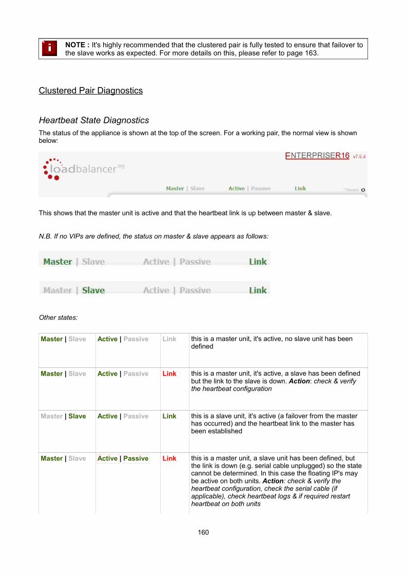
NOTE : It's highly recommended that the clustered pair is fully tested to ensure that failover to the slave works as expected. For more details on this, please refer to page 163.
Clustered Pair Diagnostics
Heartbeat State DiagnosticsThe status of the appliance is shown at the top of the screen. For a working pair, the normal view is shown below:
This shows that the master unit is active and that the heartbeat link is up between master & slave.
N.B. If no VIPs are defined, the status on master & slave appears as follows:
Other states:
Master | Slave Active | Passive Link this is a master unit, it's active, no slave unit has been defined
Master | Slave Active | Passive Link this is a master unit, it's active, a slave has been defined but the link to the slave is down. Action: check & verify the heartbeat configuration
Master | Slave Active | Passive Link this is a slave unit, it's active (a failover from the master has occurred) and the heartbeat link to the master has been established
Master | Slave Active | Passive Link this is a master unit, a slave unit has been defined, but the link is down (e.g. serial cable unplugged) so the state cannot be determined. In this case the floating IP's may be active on both units. Action: check & verify the heartbeat configuration, check the serial cable (if applicable), check heartbeat logs & if required restart heartbeat on both units
160
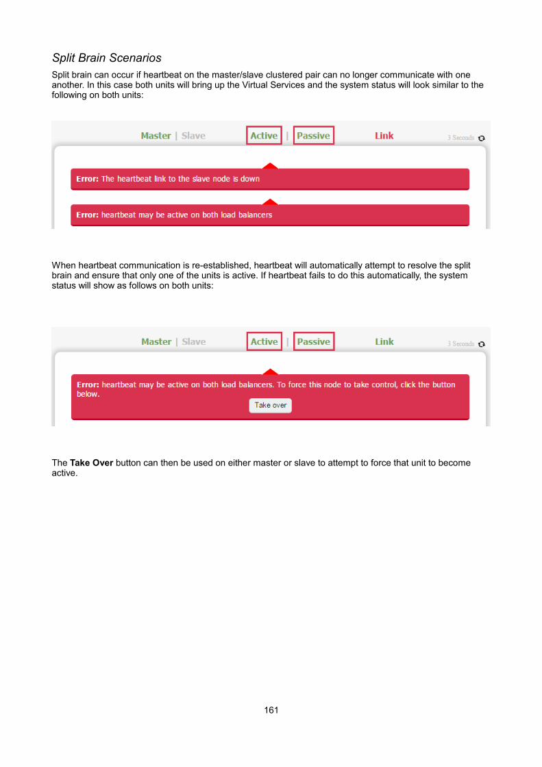
Split Brain ScenariosSplit brain can occur if heartbeat on the master/slave clustered pair can no longer communicate with one another. In this case both units will bring up the Virtual Services and the system status will look similar to the following on both units:
When heartbeat communication is re-established, heartbeat will automatically attempt to resolve the split brain and ensure that only one of the units is active. If heartbeat fails to do this automatically, the system status will show as follows on both units:
The Take Over button can then be used on either master or slave to attempt to force that unit to become active.
161

Forcing Master/Slave Failover & Failback
To force the slave to become active & the master to become passive:
Either use the Take over button in the slave's system overview:
N.B. Click the [Advanced] link to show this button.
Or run the following command on the slave:
/usr/local/sbin/hb_takeover.php all
To force the master to become active & the slave to become passive:
Either use the Take over button on the master as explained above, or run the following command on the master:
/usr/local/sbin/hb_takeover.php all
N.B. these commands can either be run on the console, via an SSH session or via the WUI using: Local Configuration > Execute Shell Command
162
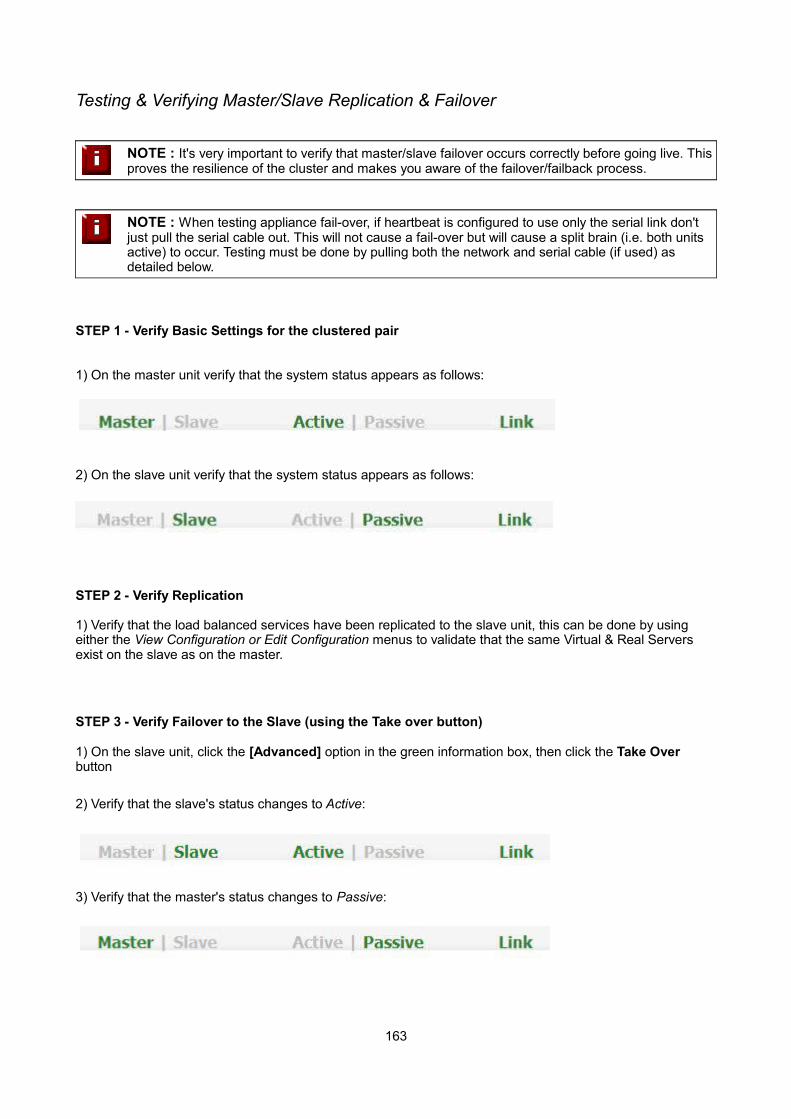
Testing & Verifying Master/Slave Replication & Failover
NOTE : It's very important to verify that master/slave failover occurs correctly before going live. Thisproves the resilience of the cluster and makes you aware of the failover/failback process.
NOTE : When testing appliance fail-over, if heartbeat is configured to use only the serial link don't just pull the serial cable out. This will not cause a fail-over but will cause a split brain (i.e. both units active) to occur. Testing must be done by pulling both the network and serial cable (if used) as detailed below.
STEP 1 - Verify Basic Settings for the clustered pair
1) On the master unit verify that the system status appears as follows:
2) On the slave unit verify that the system status appears as follows:
STEP 2 - Verify Replication
1) Verify that the load balanced services have been replicated to the slave unit, this can be done by using either the View Configuration or Edit Configuration menus to validate that the same Virtual & Real Servers exist on the slave as on the master.
STEP 3 - Verify Failover to the Slave (using the Take over button)
1) On the slave unit, click the [Advanced] option in the green information box, then click the Take Over button
2) Verify that the slave's status changes to Active:
3) Verify that the master's status changes to Passive:
163
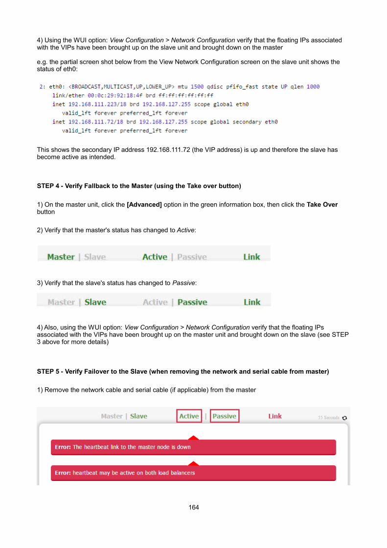
4) Using the WUI option: View Configuration > Network Configuration verify that the floating IPs associated with the VIPs have been brought up on the slave unit and brought down on the master
e.g. the partial screen shot below from the View Network Configuration screen on the slave unit shows the status of eth0:
This shows the secondary IP address 192.168.111.72 (the VIP address) is up and therefore the slave has become active as intended.
STEP 4 - Verify Fallback to the Master (using the Take over button)
1) On the master unit, click the [Advanced] option in the green information box, then click the Take Over button
2) Verify that the master's status has changed to Active:
3) Verify that the slave's status has changed to Passive:
4) Also, using the WUI option: View Configuration > Network Configuration verify that the floating IPs associated with the VIPs have been brought up on the master unit and brought down on the slave (see STEP3 above for more details)
STEP 5 - Verify Failover to the Slave (when removing the network and serial cable from master)
1) Remove the network cable and serial cable (if applicable) from the master
164
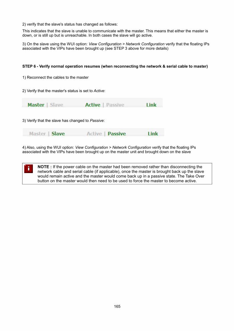
2) verify that the slave's status has changed as follows:
This indicates that the slave is unable to communicate with the master. This means that either the master is down, or is still up but is unreachable. In both cases the slave will go active.
3) On the slave using the WUI option: View Configuration > Network Configuration verify that the floating IPs associated with the VIPs have been brought up (see STEP 3 above for more details)
STEP 6 - Verify normal operation resumes (when reconnecting the network & serial cable to master)
1) Reconnect the cables to the master
2) Verify that the master's status is set to Active:
3) Verify that the slave has changed to Passive:
4) Also, using the WUI option: View Configuration > Network Configuration verify that the floating IPs associated with the VIPs have been brought up on the master unit and brought down on the slave
NOTE : If the power cable on the master had been removed rather than disconnecting the network cable and serial cable (if applicable), once the master is brought back up the slave would remain active and the master would come back up in a passive state. The Take Over button on the master would then need to be used to force the master to become active.
165

Chapter 9 – Application Specific Settings
166
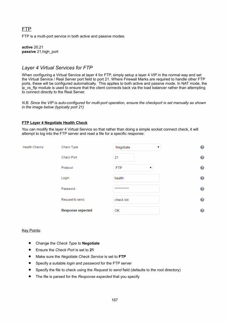
FTPFTP is a multi-port service in both active and passive modes:
active 20,21passive 21,high_port
Layer 4 Virtual Services for FTPWhen configuring a Virtual Service at layer 4 for FTP, simply setup a layer 4 VIP in the normal way and set the Virtual Service / Real Server port field to port 21. Where Firewall Marks are required to handle other FTP ports, these will be configured automatically. This applies to both active and passive mode. In NAT mode, theip_vs_ftp module is used to ensure that the client connects back via the load balancer rather than attempting to connect directly to the Real Server.
N.B. Since the VIP is auto-configured for multi-port operation, ensure the checkport is set manually as shownin the image below (typically port 21)
FTP Layer 4 Negotiate Health Check
You can modify the layer 4 Virtual Service so that rather than doing a simple socket connect check, it will attempt to log into the FTP server and read a file for a specific response:
Key Points:
Change the Check Type to Negotiate
Ensure the Check Port is set to 21
Make sure the Negotiate Check Service is set to FTP
Specify a suitable login and password for the FTP server
Specify the file to check using the Request to send field (defaults to the root directory)
The file is parsed for the Response expected that you specify
167
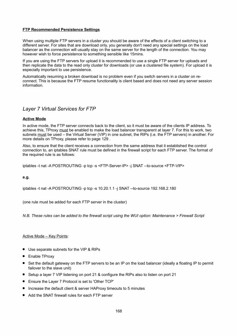
FTP Recommended Persistence Settings
When using multiple FTP servers in a cluster you should be aware of the effects of a client switching to a different server. For sites that are download only, you generally don't need any special settings on the load balancer as the connection will usually stay on the same server for the length of the connection. You may however wish to force persistence to something sensible like 15mins.
If you are using the FTP servers for upload it is recommended to use a single FTP server for uploads and then replicate the data to the read only cluster for downloads (or use a clustered file system). For upload it is especially important to use persistence.
Automatically resuming a broken download is no problem even if you switch servers in a cluster on re-connect. This is because the FTP resume functionality is client based and does not need any server session information.
Layer 7 Virtual Services for FTP
Active Mode
In active mode, the FTP server connects back to the client, so it must be aware of the clients IP address. To achieve this, TProxy must be enabled to make the load balancer transparent at layer 7. For this to work, two subnets must be used – the Virtual Server (VIP) in one subnet, the RIPs (i.e. the FTP servers) in another. Formore details on TProxy, please refer to page 129 .
Also, to ensure that the client receives a connection from the same address that it established the control connection to, an iptables SNAT rule must be defined in the firewall script for each FTP server. The format of the required rule is as follows:
iptables -t nat -A POSTROUTING -p tcp -s <FTP-Server-IP> -j SNAT --to-source <FTP-VIP>
e.g.
iptables -t nat -A POSTROUTING -p tcp -s 10.20.1.1 -j SNAT --to-source 192.168.2.180
(one rule must be added for each FTP server in the cluster)
N.B. These rules can be added to the firewall script using the WUI option: Maintenance > Firewall Script
Active Mode – Key Points:
Use separate subnets for the VIP & RIPs
Enable TProxy
Set the default gateway on the FTP servers to be an IP on the load balancer (ideally a floating IP to permit failover to the slave unit)
Setup a layer 7 VIP listening on port 21 & configure the RIPs also to listen on port 21
Ensure the Layer 7 Protocol is set to 'Other TCP'
Increase the default client & server HAProxy timeouts to 5 minutes
Add the SNAT firewall rules for each FTP server
168
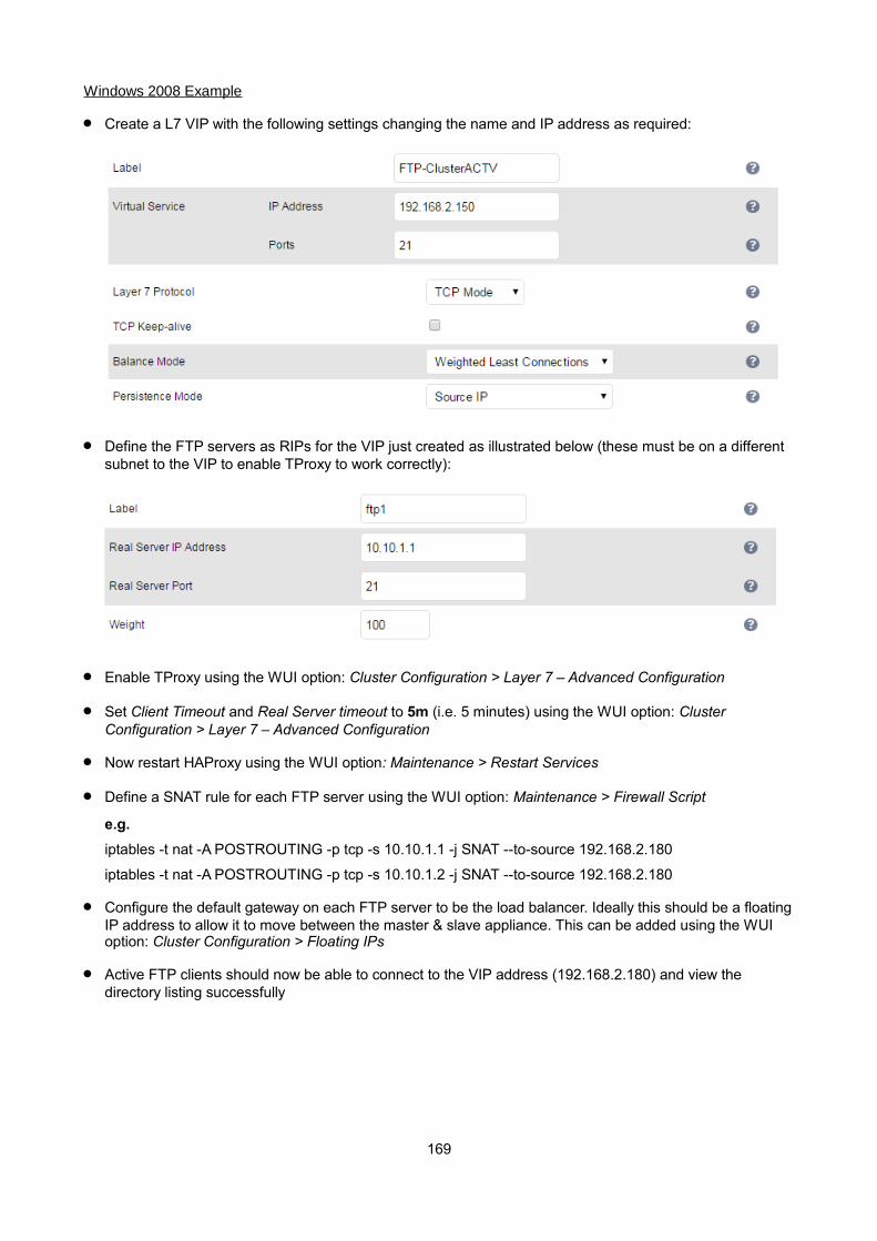
Windows 2008 Example
Create a L7 VIP with the following settings changing the name and IP address as required:
Define the FTP servers as RIPs for the VIP just created as illustrated below (these must be on a different subnet to the VIP to enable TProxy to work correctly):
Enable TProxy using the WUI option: Cluster Configuration > Layer 7 – Advanced Configuration
Set Client Timeout and Real Server timeout to 5m (i.e. 5 minutes) using the WUI option: Cluster Configuration > Layer 7 – Advanced Configuration
Now restart HAProxy using the WUI option: Maintenance > Restart Services
Define a SNAT rule for each FTP server using the WUI option: Maintenance > Firewall Script
e.g.
iptables -t nat -A POSTROUTING -p tcp -s 10.10.1.1 -j SNAT --to-source 192.168.2.180
iptables -t nat -A POSTROUTING -p tcp -s 10.10.1.2 -j SNAT --to-source 192.168.2.180
Configure the default gateway on each FTP server to be the load balancer. Ideally this should be a floatingIP address to allow it to move between the master & slave appliance. This can be added using the WUI option: Cluster Configuration > Floating IPs
Active FTP clients should now be able to connect to the VIP address (192.168.2.180) and view the directory listing successfully
169

Passive Mode
In passive mode all connections are initiated by the client. The server passes the client a port to use for the inbound data connection. By default, FTP serves can use a wide range of ports for the inbound connection and it's often useful to limit this range. The following section “Limiting Passive FTP ports” on page 172 coversthis for a range of OS's & FTP servers.
N.B. This method configures HAProxy to listen on port 21 (control channel) and all passive ports (data channel)
Passive Mode – Key Points:
It's sensible to use a controlled passive port range, this can be configured on the FTP server
Configure the VIP to listen on port 21 and also the passive range selected, e.g. 50000-50100
Configure the RIPs without specifying a port
Ensure the Layer 7 Protocol is set to 'TCP Mode'
If transparency is required (for passive mode this is optional), enable TProxy using the WUI option: Cluster Configuration > Layer 7 – Advanced Configuration
N.B. If TProxy is enabled, make sure that the RIPs (i.e. the FTP servers) are located in a different subnet to the Virtual Server (VIP). The default gateway on each FTP server must also be set to be an IP on the load balancer – preferably a floating IP which then allows failover to the slave unit (see page 129 for more details on using TProxy)
Using the WUI option: Cluster Configuration > Layer 7 – Advanced Configuration increase the default Client timeout & Real Server Timeout to 5m (i.e. 5 minutes)
To ensure the correct address is passed back to the client, on each FTP server specify the external address to be the VIP address.
e.g.
- for Windows 2008 use the External IP address of Firewall field
- for Linux vsftpd use the directive: pasv_address=xxx.xxx.xxx.xxx
- for Linux ProFTPd use the directive: MasqueradeAddress=xxx.xxx.xxx.xxx
170
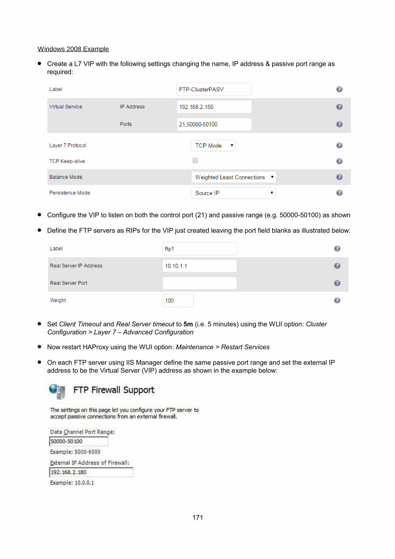
Windows 2008 Example
Create a L7 VIP with the following settings changing the name, IP address & passive port range as required:
Configure the VIP to listen on both the control port (21) and passive range (e.g. 50000-50100) as shown
Define the FTP servers as RIPs for the VIP just created leaving the port field blanks as illustrated below:
Set Client Timeout and Real Server timeout to 5m (i.e. 5 minutes) using the WUI option: Cluster Configuration > Layer 7 – Advanced Configuration
Now restart HAProxy using the WUI option: Maintenance > Restart Services
On each FTP server using IIS Manager define the same passive port range and set the external IP address to be the Virtual Server (VIP) address as shown in the example below:
171

N.B. The external IP address must be set to be the VIP address, this ensure that this IP address is passedback to the client to use for the subsequent inbound connection
If TProxy is enabled, make sure the gateway of each FTP sever is set to be an IP on the load balancer (preferably a floating IP to allow failover to the slave unit)
Now restart both IIS and the Microsoft FTP Service on each FTP server
Passive FTP clients should now be able to connect to the VIP address (192.168.2.180) and view the directory listing successfully
Limiting Passive FTP Ports
Limiting passive ports allows your firewall to be more tightly locked down. The following sections show how this is achieved for a range of Operating Systems / FTP servers.
For Windows 2008
Open the IIS Management console, highlight the server node, then double-click the FTP Firewall Support icon.
The following screen will be displayed:
172

Specify a suitable range, in the example above this is 50000-50100
IMPORTANT! - Make sure you restart IIS and the Microsoft FTP Service to apply these settings.
For Windows 2003
a) Enable Direct Metabase Edit
1. Open the IIS Management Console2. Right-click on the Local Computer node3. Select Properties4. Make sure the Enable Direct Metabase Edit check-box is checked
b) Configure PassivePortRange via ADSUTIL script
1. Click Start, click Run, type cmd, and then click OK2. Type cd Inetpub\AdminScripts and then press ENTER3. Type the following command from a command prompt adsutil.vbs set /MSFTPSVC/PassivePortRange "50000-50100"4. Restart the FTP service
For Windows 2000
Configure PassivePortRange via the Registry Editor
1. Start Registry Editor (Regedt32.exe)2. Locate the following registry key: HKEY_LOCAL_MACHINE\System\CurrentControlSet\Services\Msftpsvc\Parameters\3. Add a value named "PassivePortRange" (without the quotation marks) of type REG_SZ4. Close Registry Editor5. Restart the FTP service
(SP4 or higher must be installed for this to work)
N.B. The range that FTP will validate is from 5001 to 65535
For Linux
For vsftpd, the following line can be added to the vsftpd.conf file to limit the port range:
pasv_max_port – max is 65535pasv_min_port – min is 1024
For proftpd, the following line can be added to the proftpd.conf file to limit the port range:
PassivePorts 50000 – 50100
For pureftpd, the following startup switch can be used:
-p --passiveportrange <min port:max port>
173
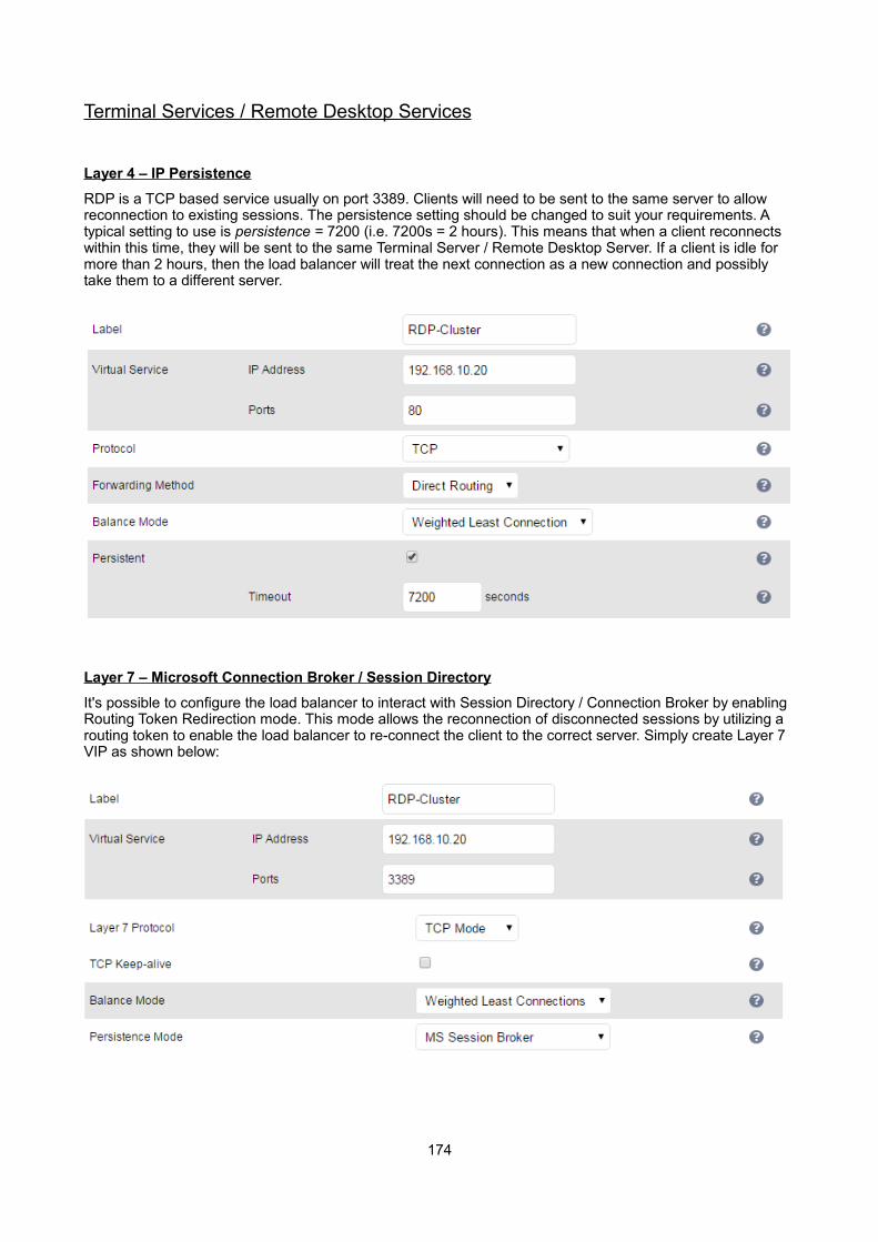
Terminal Services / Remote Desktop Services
Layer 4 – IP Persistence
RDP is a TCP based service usually on port 3389. Clients will need to be sent to the same server to allow reconnection to existing sessions. The persistence setting should be changed to suit your requirements. A typical setting to use is persistence = 7200 (i.e. 7200s = 2 hours). This means that when a client reconnects within this time, they will be sent to the same Terminal Server / Remote Desktop Server. If a client is idle for more than 2 hours, then the load balancer will treat the next connection as a new connection and possibly take them to a different server.
Layer 7 – Microsoft Connection Broker / Session Directory
It's possible to configure the load balancer to interact with Session Directory / Connection Broker by enabling Routing Token Redirection mode. This mode allows the reconnection of disconnected sessions by utilizing a routing token to enable the load balancer to re-connect the client to the correct server. Simply create Layer 7 VIP as shown below:
174
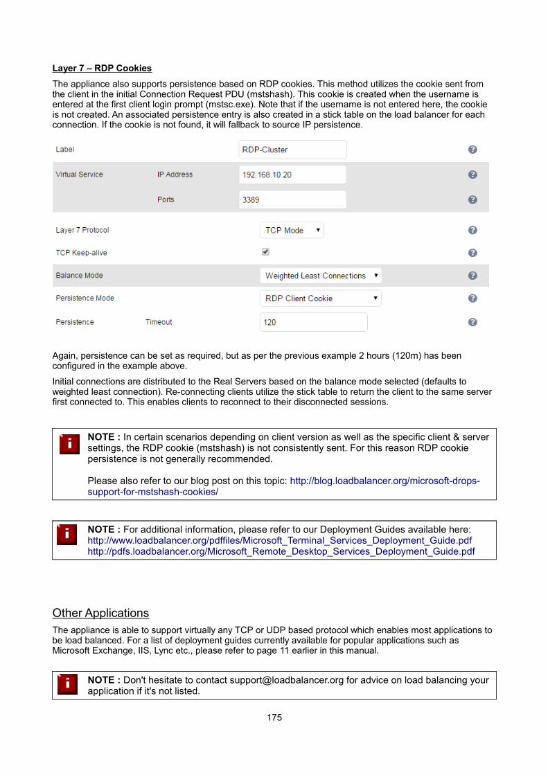
Layer 7 – RDP Cookies
The appliance also supports persistence based on RDP cookies. This method utilizes the cookie sent from the client in the initial Connection Request PDU (mstshash). This cookie is created when the username is entered at the first client login prompt (mstsc.exe). Note that if the username is not entered here, the cookie is not created. An associated persistence entry is also created in a stick table on the load balancer for each connection. If the cookie is not found, it will fallback to source IP persistence.
Again, persistence can be set as required, but as per the previous example 2 hours (120m) has been configured in the example above.
Initial connections are distributed to the Real Servers based on the balance mode selected (defaults to weighted least connection). Re-connecting clients utilize the stick table to return the client to the same server first connected to. This enables clients to reconnect to their disconnected sessions.
NOTE : In certain scenarios depending on client version as well as the specific client & server settings, the RDP cookie (mstshash) is not consistently sent. For this reason RDP cookie persistence is not generally recommended.
Please also refer to our blog post on this topic: http://blog.loadbalancer.org/microsoft-drops-support-for-mstshash-cookies/
NOTE : For additional information, please refer to our Deployment Guides available here:http://www.loadbalancer.org/pdffiles/Microsoft_Terminal_Services_Deployment_Guide.pdfhttp://pdfs.loadbalancer.org/Microsoft_Remote_Desktop_Services_Deployment_Guide.pdf
Other ApplicationsThe appliance is able to support virtually any TCP or UDP based protocol which enables most applications to be load balanced. For a list of deployment guides currently available for popular applications such as Microsoft Exchange, IIS, Lync etc., please refer to page 11 earlier in this manual.
NOTE : Don't hesitate to contact [email protected] for advice on load balancing your application if it's not listed.
175

Chapter 10 – Configuration Examples
176
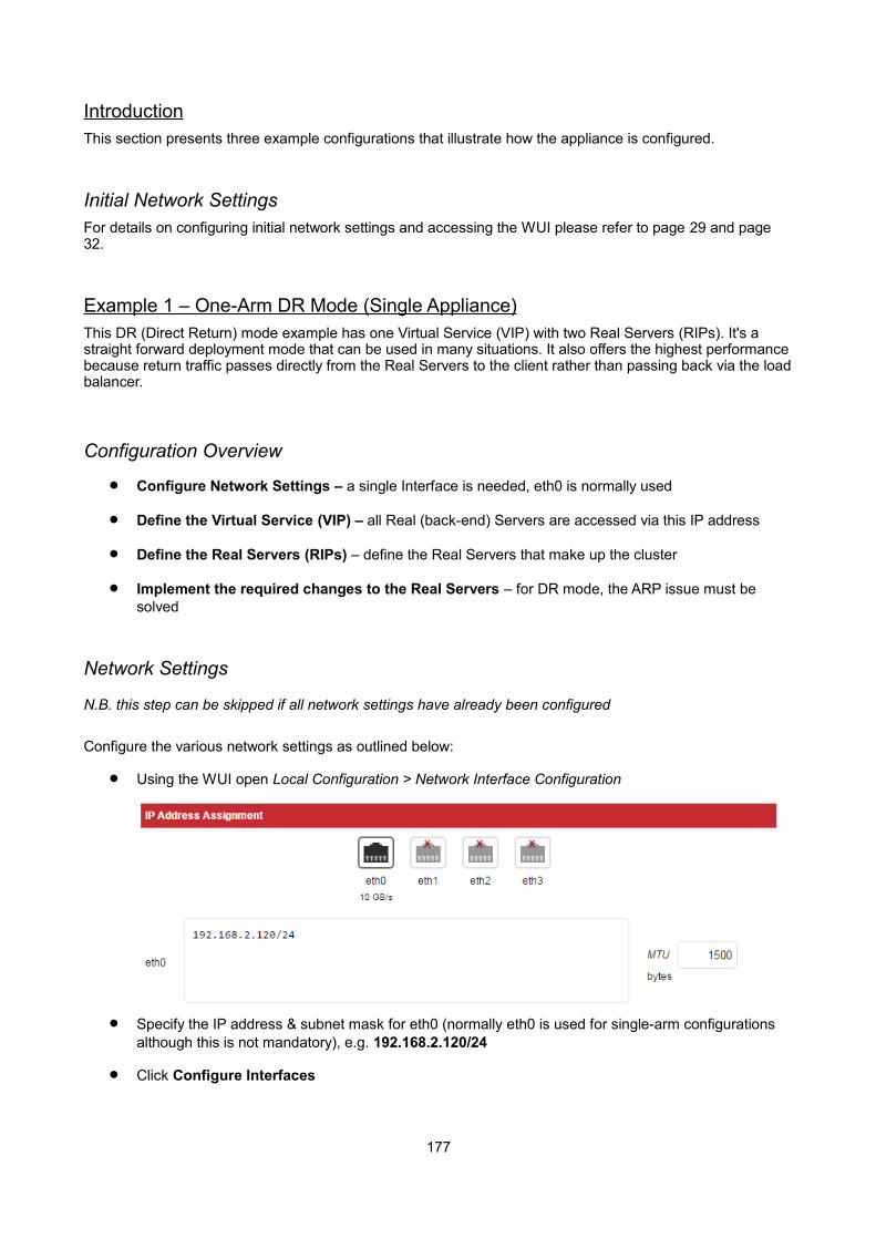
IntroductionThis section presents three example configurations that illustrate how the appliance is configured.
Initial Network SettingsFor details on configuring initial network settings and accessing the WUI please refer to page 29 and page32.
Example 1 – One-Arm DR Mode (Single Appliance)This DR (Direct Return) mode example has one Virtual Service (VIP) with two Real Servers (RIPs). It's a straight forward deployment mode that can be used in many situations. It also offers the highest performancebecause return traffic passes directly from the Real Servers to the client rather than passing back via the loadbalancer.
Configuration Overview
Configure Network Settings – a single Interface is needed, eth0 is normally used
Define the Virtual Service (VIP) – all Real (back-end) Servers are accessed via this IP address
Define the Real Servers (RIPs) – define the Real Servers that make up the cluster
Implement the required changes to the Real Servers – for DR mode, the ARP issue must be solved
Network Settings
N.B. this step can be skipped if all network settings have already been configured
Configure the various network settings as outlined below:
Using the WUI open Local Configuration > Network Interface Configuration
Specify the IP address & subnet mask for eth0 (normally eth0 is used for single-arm configurations although this is not mandatory), e.g. 192.168.2.120/24
Click Configure Interfaces
177

Using the WUI open Local Configuration > Hostname & DNS
Specify the DNS server(s)
Click Update
Using the WUI open Local Configuration > Routing
Specify the Default Gateway
Click Configure Routing
Virtual Service (VIP)Next, configure the Virtual Service. This is the IP address that is presented to clients. Any packet arriving at the load balancer with that IP address and port number will be forwarded to the the Real Servers associated with the Virtual Service.
Using the WUI open Cluster Configuration > Layer 4 – Virtual Services and click Add a new Virtual Service
Enter a suitable Label (name) for the VIP, e.g. ExVIP1
Enter a valid IP address, e.g. 192.168.2.150
Enter a valid port, e.g. 80
Ensure that Forwarding Method is set to Direct Routing (N.B. this is the default)
178
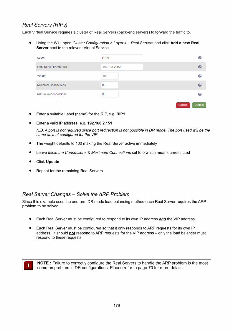
Real Servers (RIPs)Each Virtual Service requires a cluster of Real Servers (back-end servers) to forward the traffic to.
Using the WUI open Cluster Configuration > Layer 4 – Real Servers and click Add a new Real Server next to the relevant Virtual Service
Enter a suitable Label (name) for the RIP, e.g. RIP1
Enter a valid IP address, e.g. 192.168.2.151
N.B. A port is not required since port redirection is not possible in DR mode. The port used will be thesame as that configured for the VIP
The weight defaults to 100 making the Real Server active immediately
Leave Minimum Connections & Maximum Connections set to 0 which means unrestricted
Click Update
Repeat for the remaining Real Servers
Real Server Changes – Solve the ARP ProblemSince this example uses the one-arm DR mode load balancing method each Real Server requires the ARP problem to be solved:
Each Real Server must be configured to respond to its own IP address and the VIP address
Each Real Server must be configured so that it only responds to ARP requests for its own IP address, it should not respond to ARP requests for the VIP address – only the load balancer must respond to these requests
NOTE : Failure to correctly configure the Real Servers to handle the ARP problem is the most common problem in DR configurations. Please refer to page 70 for more details.
179

Basic Testing & Verification
Once configured, a few quick checks can be performed to verify the setup:
Using System Overview check that the VIP & RIPs are shown as active (green)
Using a browser, navigate to the VIP address, i.e. http://192.168.2.150 to verify that you can reach the Real Servers via the Virtual Service
Check Reports > Layer 4 Current Connections to ensure that client connections are reported in state 'ESTABLISHED'. If connections are in state 'SYN_RECV', this normally indicates that the ARP problem on the Real Servers has not been correctly solved
180
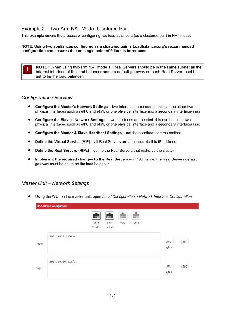
Example 2 – Two-Arm NAT Mode (Clustered Pair)This example covers the process of configuring two load balancers (as a clustered pair) in NAT mode.
NOTE: Using two appliances configured as a clustered pair is Loadbalancer.org's recommended configuration and ensures that no single point of failure is introduced
NOTE : When using two-arm NAT mode all Real Servers should be in the same subnet as the internal interface of the load balancer and the default gateway on each Real Server must be set to be the load balancer.
Configuration Overview
Configure the Master's Network Settings – two Interfaces are needed, this can be either two physical interfaces such as eth0 and eth1, or one physical interface and a secondary interface/alias
Configure the Slave's Network Settings – two Interfaces are needed, this can be either two physical interfaces such as eth0 and eth1, or one physical interface and a secondary interface/alias
Configure the Master & Slave Heartbeat Settings – set the heartbeat comms method
Define the Virtual Service (VIP) – all Real Servers are accessed via this IP address
Define the Real Servers (RIPs) – define the Real Servers that make up the cluster
Implement the required changes to the Real Servers – in NAT mode, the Real Servers default gateway must be set to be the load balancer
Master Unit – Network Settings
Using the WUI on the master unit, open Local Configuration > Network Interface Configuration
181

Specify the IP address & mask for eth0 – normally eth0 is configured as the internal interface although this is not mandatory, e.g. 192.168.2.120/24
Specify the IP address & mask for eth1 – normally eth1 is configured as the external interface although this is not mandatory, e.g. 192.168.20.120/24
N.B. For a VA make sure that the virtual NIC associated with eth1 is connected to the virtual switch. By default only the first NIC is connected.
Click Configure Interfaces
Using the WUI open Local Configuration > Hostname & DNS
Ensure that Role is set to master
Ensure that the DNS server(s) are set correctly
Click Update
Using the WUI open Local Configuration > Routing
Specify the Default Gateway, e.g. 192.168.254
Click Configure Routing
Slave Unit – Network Settings
Configure the various network settings as outlined below:
Using the WUI on the slave unit open Local Configuration > Network Interface Configuration
182
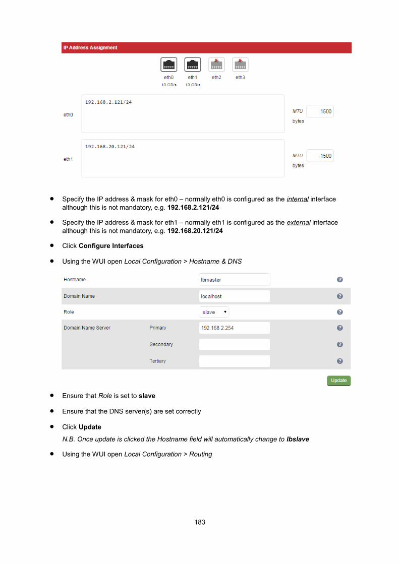
Specify the IP address & mask for eth0 – normally eth0 is configured as the internal interface although this is not mandatory, e.g. 192.168.2.121/24
Specify the IP address & mask for eth1 – normally eth1 is configured as the external interface although this is not mandatory, e.g. 192.168.20.121/24
Click Configure Interfaces
Using the WUI open Local Configuration > Hostname & DNS
Ensure that Role is set to slave
Ensure that the DNS server(s) are set correctly
Click Update
N.B. Once update is clicked the Hostname field will automatically change to lbslave
Using the WUI open Local Configuration > Routing
183

Specify the default gateway, e.g. 192.168.2.254
Click Configure Routing
Master Unit – Heartbeat Settings
Using the WUI on the master unit open Cluster Configuration > Heartbeat Configuration
Define the slave load balancers IP address in the Slave Load Balancer Address field, e.g. 192.168.2.121
Set the heartbeat communications method as required. The default is UDP unicast.
184
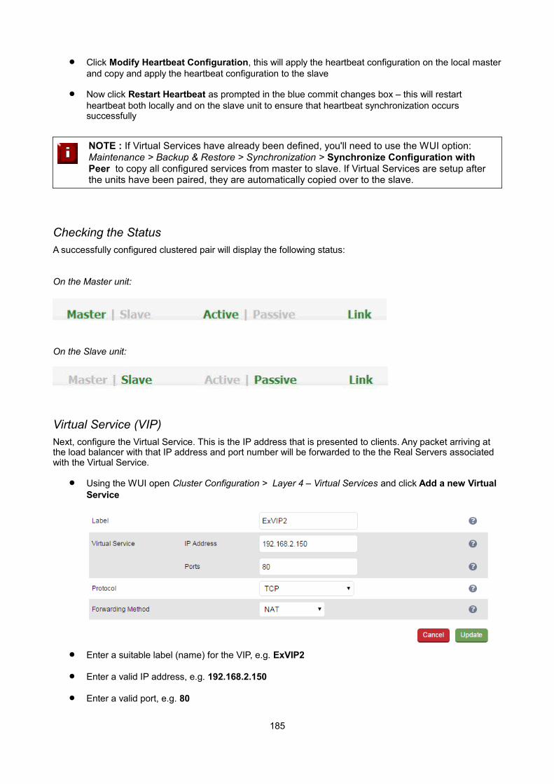
Click Modify Heartbeat Configuration, this will apply the heartbeat configuration on the local masterand copy and apply the heartbeat configuration to the slave
Now click Restart Heartbeat as prompted in the blue commit changes box – this will restart heartbeat both locally and on the slave unit to ensure that heartbeat synchronization occurs successfully
NOTE : If Virtual Services have already been defined, you'll need to use the WUI option: Maintenance > Backup & Restore > Synchronization > Synchronize Configuration withPeer to copy all configured services from master to slave. If Virtual Services are setup after the units have been paired, they are automatically copied over to the slave.
Checking the StatusA successfully configured clustered pair will display the following status:
On the Master unit:
On the Slave unit:
Virtual Service (VIP)Next, configure the Virtual Service. This is the IP address that is presented to clients. Any packet arriving at the load balancer with that IP address and port number will be forwarded to the the Real Servers associated with the Virtual Service.
Using the WUI open Cluster Configuration > Layer 4 – Virtual Services and click Add a new Virtual Service
Enter a suitable label (name) for the VIP, e.g. ExVIP2
Enter a valid IP address, e.g. 192.168.2.150
Enter a valid port, e.g. 80
185
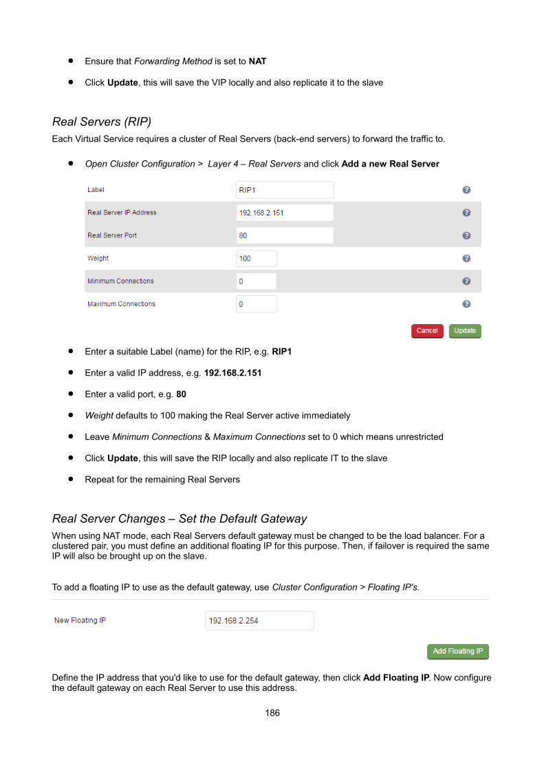
Ensure that Forwarding Method is set to NAT
Click Update, this will save the VIP locally and also replicate it to the slave
Real Servers (RIP)Each Virtual Service requires a cluster of Real Servers (back-end servers) to forward the traffic to.
Open Cluster Configuration > Layer 4 – Real Servers and click Add a new Real Server
Enter a suitable Label (name) for the RIP, e.g. RIP1
Enter a valid IP address, e.g. 192.168.2.151
Enter a valid port, e.g. 80
Weight defaults to 100 making the Real Server active immediately
Leave Minimum Connections & Maximum Connections set to 0 which means unrestricted
Click Update, this will save the RIP locally and also replicate IT to the slave
Repeat for the remaining Real Servers
Real Server Changes – Set the Default GatewayWhen using NAT mode, each Real Servers default gateway must be changed to be the load balancer. For a clustered pair, you must define an additional floating IP for this purpose. Then, if failover is required the same IP will also be brought up on the slave.
To add a floating IP to use as the default gateway, use Cluster Configuration > Floating IP's.
Define the IP address that you'd like to use for the default gateway, then click Add Floating IP. Now configurethe default gateway on each Real Server to use this address.
186
Verify the Slave ConfigurationTo verify that the new VIP & RIP have been replicated correctly, open the WUI on the slave and open Cluster Configuration > Layer 4 – Virtual Services and Cluster Configuration > Layer 4 – Real Servers and check thatyour configuration appears there also. For a correctly configured pair, the VIPs and RIPs are automatically replicated to the slave as they are defined on the master.
If not, double check that both units are configured correctly and that the IP address for the slave defined on the master is correct. Then on the master open Maintenance > Backup & Restore and click Synchronize Configuration with peer. This will force the VIPs & RIPs to be copied from the master to the slave, then check again.
Basic Testing & Verification
A few quick checks can be performed to verify the configuration:
On the master, use System Overview to check that the VIP & RIPs are shown as active (green)
Using a browser, navigate to the VIP address, i.e. http://192.168.2.150 to verify that you can reach the Real Servers via the Virtual Service
On the master, check Reports > Layer 4 Current Connections to ensure that client connections are reported in state 'ESTABLISHED'. If not, double-check that you have set the default gateway on all Real Servers to be an IP address on the load balancer.
187
Example 3 – One-Arm SNAT Mode & SSL Termination (Single Appliance )This example uses HAProxy and STunnel at layer 7. STunnel is used to terminate SSL on the load balancer. STunnel then passes un-encrypted HTTP traffic to the HAProxy VIP / RIP cluster.
HAProxy does not offer the raw throughput of layer 4, but is still a high performance solution that is appropriate in many situations.
N.B. Pound can also be used for SSL termination, although STunnel is the preferred and default method
In this example it's assumed that the Real Server application has not been designed to track & share session details between Real Servers. Therefore, cookie based persistence will be enabled on the load balancer to ensure that clients connect to the same Real Server on each subsequent connection (within the persistence timeout window). If persistence is not configured then new connections may get distributed to a different RealServer which may result in failure of the application.
NOTE : Because HAProxy is a full proxy, any server in the cluster can be on any accessible subnet including across the Internet or WAN.
NOTE : In this mode, no changes are required to the Real Servers.
NOTE : We generally recommend that SSL is terminated on the real serves rather than on the load balancer. This ensures that the SSL load is distributed and also ensures scalability.
Configuration Overview
Configure Network Settings – A single Interface is needed, eth0 is normally used
Define the Virtual Service (VIP) – All Real Servers are accessed via this IP address
Define the Real Servers (RIPs) – Define the Real Servers that make up the cluster
Configure SSL Termination – Configure STunnel for SSL termination
Network Settings
Configure the various network settings as outlined below:
Using the WUI open Local Configuration > Network Interface Configuration
188
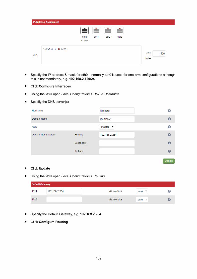
Specify the IP address & mask for eth0 – normally eth0 is used for one-arm configurations although this is not mandatory, e.g. 192.168.2.120/24
Click Configure Interfaces
Using the WUI open Local Configuration > DNS & Hostname
Specify the DNS server(s)
Click Update
Using the WUI open Local Configuration > Routing
Specify the Default Gateway, e.g. 192.168.2.254
Click Configure Routing
189
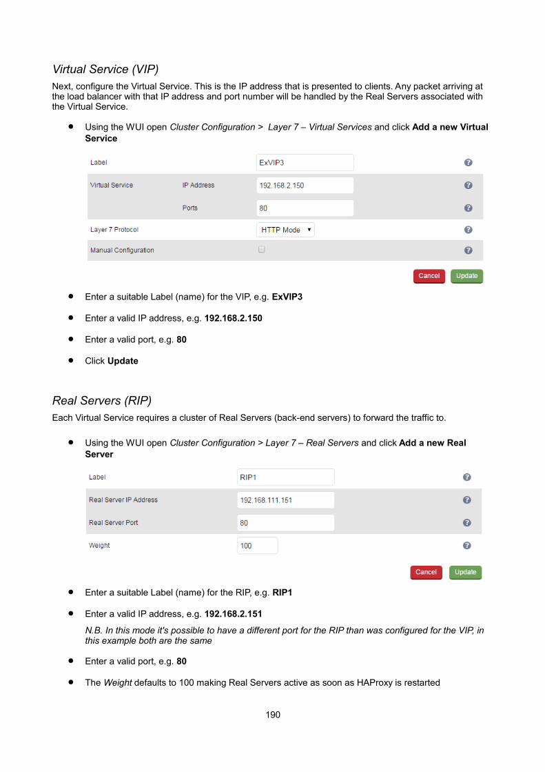
Virtual Service (VIP)Next, configure the Virtual Service. This is the IP address that is presented to clients. Any packet arriving at the load balancer with that IP address and port number will be handled by the Real Servers associated with the Virtual Service.
Using the WUI open Cluster Configuration > Layer 7 – Virtual Services and click Add a new Virtual Service
Enter a suitable Label (name) for the VIP, e.g. ExVIP3
Enter a valid IP address, e.g. 192.168.2.150
Enter a valid port, e.g. 80
Click Update
Real Servers (RIP)Each Virtual Service requires a cluster of Real Servers (back-end servers) to forward the traffic to.
Using the WUI open Cluster Configuration > Layer 7 – Real Servers and click Add a new Real Server
Enter a suitable Label (name) for the RIP, e.g. RIP1
Enter a valid IP address, e.g. 192.168.2.151
N.B. In this mode it's possible to have a different port for the RIP than was configured for the VIP, in this example both are the same
Enter a valid port, e.g. 80
The Weight defaults to 100 making Real Servers active as soon as HAProxy is restarted
190
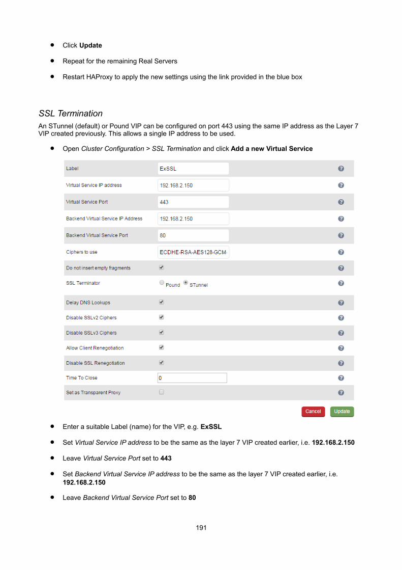
Click Update
Repeat for the remaining Real Servers
Restart HAProxy to apply the new settings using the link provided in the blue box
SSL TerminationAn STunnel (default) or Pound VIP can be configured on port 443 using the same IP address as the Layer 7 VIP created previously. This allows a single IP address to be used.
Open Cluster Configuration > SSL Termination and click Add a new Virtual Service
Enter a suitable Label (name) for the VIP, e.g. ExSSL
Set Virtual Service IP address to be the same as the layer 7 VIP created earlier, i.e. 192.168.2.150
Leave Virtual Service Port set to 443
Set Backend Virtual Service IP address to be the same as the layer 7 VIP created earlier, i.e. 192.168.2.150
Leave Backend Virtual Service Port set to 80
191
Leave the other settings at their default values
Click Update
Restart STunnel to apply the new settings using the link provided in the blue box
When creating the SSL Virtual Service, by default a self-signed certificate is used. This is ideal for testing but needs to be replaced for live deployments.
NOTE : For more detailed information on SSL termination please refer to page 114.
Basic Testing & Verification
A few quick checks can be performed to verify the configuration:
Using System Overview, verify that the VIP & RIP are shown as active (green)
Using a browser, navigate to the VIP address, i.e. http://192.168.2.150 to verify that you can reach the Real Servers via the Virtual Service using HTTP
Using a browser, navigate to the STunnel SSL VIP address, i.e. https://192.168.2.150 to verify that you can reach the Real Servers via the Virtual Service using HTTPS
Check / verify the certificate details
192
Chapter 11 – Testing Load Balanced Services
193

Testing Load Balanced ServicesFor example, to test a web server based configuration, add a page to each web servers root directory e.g. test.html and put the server name on this page for easy identification during the tests.
Use two or more clients to do the testing. Open up a web browser on each test clients and enter the URL for the VIP e.g. http://192.168.110.150
Each client should see a different server name because of the load balancing algorithm in use i.e. they are being load balanced across the cluster.
Why test using two clients? If you use a single client it will most likely keep on hitting the same server for multiple requests. This is to do with the way that the load balancing algorithms are optimized.
Diagnosing VIP Connection Problems
1. Make sure that the device is active - this can be checked in the WUI. For a single appliance, the status bar should report Master & Active as shown below:
2. Check that the VIP/floating IP is up - Using View Configuration > Network Configuration verify that the VIP is active on the load balancer, if not check Logs > Heartbeat for errors.
The above example shows that the interface address (192.168.110.85) and the VIP address (192.168.110.90) are both up.
3. Check that the Real Servers are up - Using System Overview make sure that none of your VIPs are colored red. If they are, the entire cluster is down (i.e. all Real Servers). Green indicates a healthy cluster, yellow indicates that your cluster may need attention (one or more of the Real Servers may be down), and blue indicates all Real Server have been deliberately taken offline (by using either Halt or Drain).
194
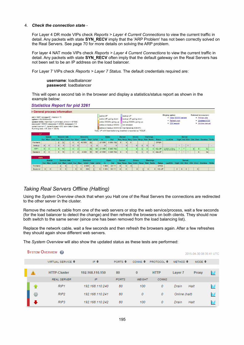
4. Check the connection state -
For Layer 4 DR mode VIPs check Reports > Layer 4 Current Connections to view the current traffic in detail. Any packets with state SYN_RECV imply that the 'ARP Problem' has not been correctly solved on the Real Servers. See page 70 for more details on solving the ARP problem.
For layer 4 NAT mode VIPs check Reports > Layer 4 Current Connections to view the current traffic in detail. Any packets with state SYN_RECV often imply that the default gateway on the Real Servers has not been set to be an IP address on the load balancer.
For Layer 7 VIPs check Reports > Layer 7 Status. The default credentials required are:
username: loadbalancerpassword: loadbalancer
This will open a second tab in the browser and display a statistics/status report as shown in theexample below:
Taking Real Servers Offline (Halting)Using the System Overview check that when you Halt one of the Real Servers the connections are redirectedto the other server in the cluster.
Remove the network cable from one of the web servers or stop the web service/process, wait a few seconds (for the load balancer to detect the change) and then refresh the browsers on both clients. They should now both switch to the same server (since one has been removed from the load balancing list).
Replace the network cable, wait a few seconds and then refresh the browsers again. After a few refreshes they should again show different web servers.
The System Overview will also show the updated status as these tests are performed:
195

In this example:
'rip1' is green, this indicates that it's operating normally.
'rip2' is blue, this indicates that it has been either Halted or Drained. in this example Halt has been used as indicated by Online (Halt) being displayed. If it had been drained it would show as Online (Drain).
'rip3' is red, this indicates that it has failed a health check.
NOTE : From v7.6.4 the System Overview supports sorting of VIPs. This can be done by clicking on the column headings or by drag & drop. For more details please refer to page 151.
Using Log FilesThe appliance includes several log files that are very useful when diagnosing issues. Please refer to the next chapter (chapter 12) for more details on the logs available.
Using ReportsThe appliance includes several reports that are very useful when diagnosing issues. Please refer to the next chapter (chapter 12) for more details on the reports available.
NOTE : When testing a clustered pair, also make sure that failover to the slave appliance and failback to the master appliance is working correctly. For more details please refer to page163.
196

Chapter 12 – Appliance Monitoring
197
Appliance Log FilesAll logs can be accessed using the Logs option in the WUI.
N.B. all logs are located in /var/log on the appliance
Load BalancerFile: /var/log/lbadmin.log
The lbadmin log shows all changes made to the appliances configuration. This is very useful for tracking changes made to the configuration.
Layer 4File: /var/log/ldirectord.log
The Ldirectord log shows the output from the health checking daemon. This is useful for checking the health your Real Servers or pinning down any configuration errors. The logging here can be quite verbose but it clearly shows exactly what the health checking process is doing.
Layer 7File: /var/log/haproxy.log
If activated via Cluster Configuration > Layer 7 – Advanced Configuration, this will show the contents of the HAProxy log. This is a very detailed log of all HAProxy transactions. It's also possible to configure HAProxy tolog errors only.
SSL Termination (Pound)File: /var/log/poundssl.log
If activated via Cluster Configuration > SSL – Advanced Configuration, this will show the contents of the Pound log. This is a very detailed log of all Pound SSL transactions.
SSL Termination (STunnel)File: /var/log/stunnel.log
If activated via Edit Configuration > SSL – Advanced Configuration, this will show the contents of the STunnellog. The required debug level can also be set.
HeartbeatFile: /var/log/ha.log
The heartbeat log shows the status of the heartbeat daemons. Heartbeat is used whether configured as a single device or as a clustered pair. The log provides a detailed real-time status of heartbeat.
198

Appliance ReportsAll reports can be accessed using the Reports option in the WUI.
Layer 4 StatusThis report shows the current weight and number of active & inactive connections for each Real Server. If a Real Server has failed a health check, it will not be listed. Use the Logs > Layer 4 option to view the Ldirectord log file if expected servers are not listed.
In the example above, the details for RIP3 are not displayed because it's failing its health checks.
199
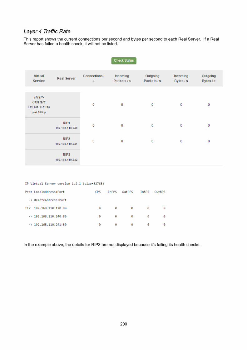
Layer 4 Traffic RateThis report shows the current connections per second and bytes per second to each Real Server. If a Real Server has failed a health check, it will not be listed.
In the example above, the details for RIP3 are not displayed because it's failing its health checks.
200
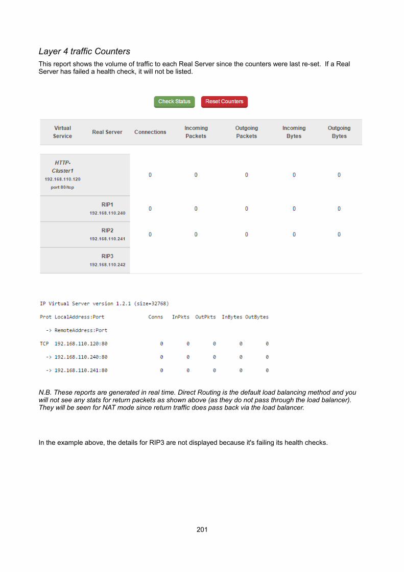
Layer 4 traffic CountersThis report shows the volume of traffic to each Real Server since the counters were last re-set. If a Real Server has failed a health check, it will not be listed.
N.B. These reports are generated in real time. Direct Routing is the default load balancing method and you will not see any stats for return packets as shown above (as they do not pass through the load balancer). They will be seen for NAT mode since return traffic does pass back via the load balancer.
In the example above, the details for RIP3 are not displayed because it's failing its health checks.
201

Layer 4 Current ConnectionsThe current connections report is very useful for diagnosing issues with routing or ARP related problems. In the example below, the state is shown as SYN_RECV, this is normally a good indication that the ARP problem has not been solved. In NAT mode, this is a good indication that the Real Servers default gateway has not been configured to be the load balancer and therefore return traffic is not routed correctly.
N.B. The IPVS connection entries in state NONE represent the persistence related entries for client connections, and are not actual client connections. These only appear when persistence is enabled.
Layer 4 Current Connections (resolve hostnames)This is the same as the current connections report but is slower as it looks up the DNS name of each IP address.
Layer 7 StatusThis report is provided by the stats instance of HAProxy. This web page contains the current live status of all of the configured layer 7 HAProxy virtual and Real Servers.
Log in using: Username: loadbalancerPassword: loadbalancer
N.B. This password can be changed using the 'statistics password' field available under Cluster Configuration> Layer 7 – Advanced Configuration
202
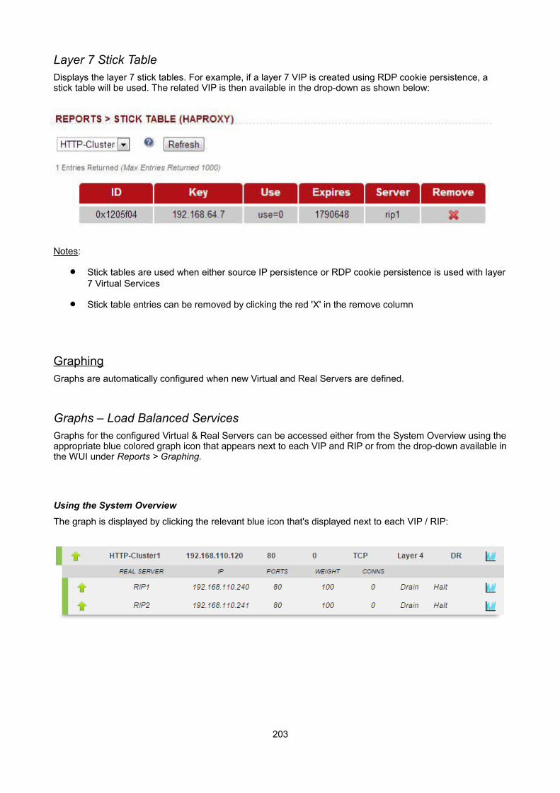
Layer 7 Stick TableDisplays the layer 7 stick tables. For example, if a layer 7 VIP is created using RDP cookie persistence, a stick table will be used. The related VIP is then available in the drop-down as shown below:
Notes:
Stick tables are used when either source IP persistence or RDP cookie persistence is used with layer7 Virtual Services
Stick table entries can be removed by clicking the red 'X' in the remove column
GraphingGraphs are automatically configured when new Virtual and Real Servers are defined.
Graphs – Load Balanced ServicesGraphs for the configured Virtual & Real Servers can be accessed either from the System Overview using theappropriate blue colored graph icon that appears next to each VIP and RIP or from the drop-down available inthe WUI under Reports > Graphing.
Using the System Overview
The graph is displayed by clicking the relevant blue icon that's displayed next to each VIP / RIP:
203

When this method is used, the daily Service Connections Graph (i.e. the last 24 hrs) is displayed for the particular VIP or RIP:
Clicking anywhere within this graph opens the complete list of graphs for the VIP / RIP in question. This is thesame as selecting the VIP/RIP in the Reports > Graphing menu options as explained below.
Using the WUI Option: Reports > Graphing
When selected, a drop-down similar to the following is displayed:
When selected in this way, a complete list of graphs is displayed for the VIP / RIP selected as shown below:
N.B. As VIPs & RIPs are added or removed, these are automatically added / removed from the drop-down list
204
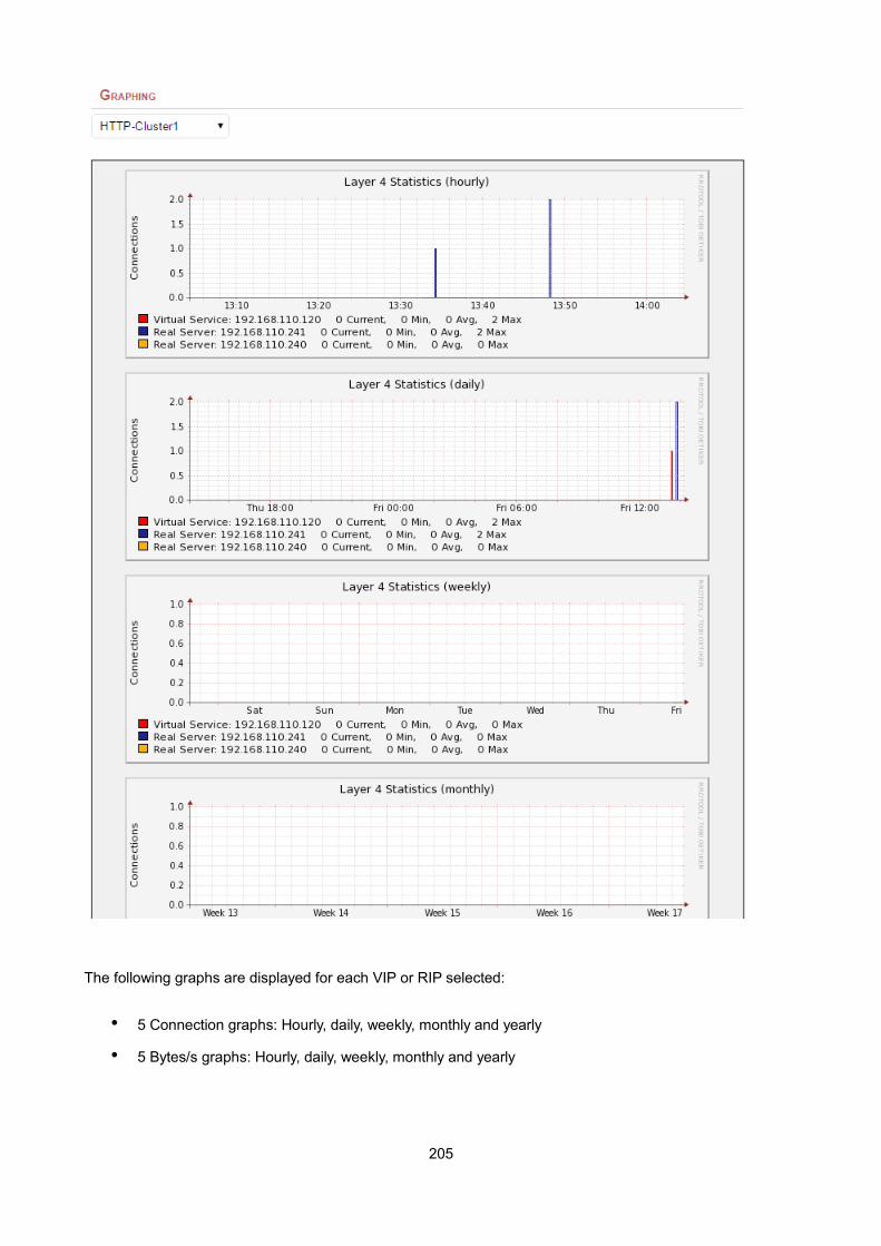
The following graphs are displayed for each VIP or RIP selected:
• 5 Connection graphs: Hourly, daily, weekly, monthly and yearly
• 5 Bytes/s graphs: Hourly, daily, weekly, monthly and yearly
205
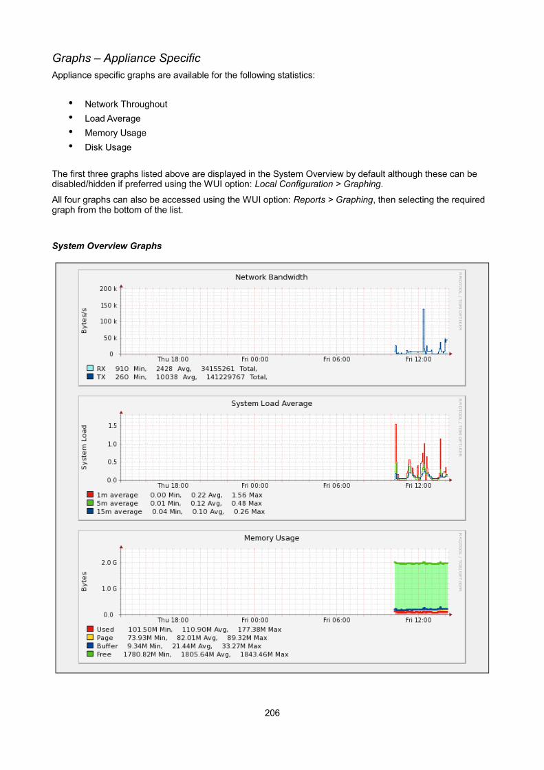
Graphs – Appliance SpecificAppliance specific graphs are available for the following statistics:
• Network Throughout
• Load Average
• Memory Usage
• Disk Usage
The first three graphs listed above are displayed in the System Overview by default although these can be disabled/hidden if preferred using the WUI option: Local Configuration > Graphing.
All four graphs can also be accessed using the WUI option: Reports > Graphing, then selecting the required graph from the bottom of the list.
System Overview Graphs
206
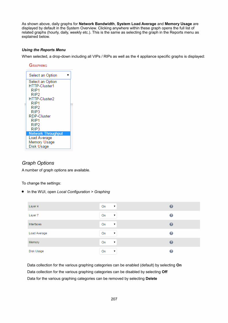
As shown above, daily graphs for Network Bandwidth, System Load Average and Memory Usage are displayed by default in the System Overview. Clicking anywhere within these graph opens the full list of related graphs (hourly, daily, weekly etc.). This is the same as selecting the graph in the Reports menu as explained below.
Using the Reports Menu
When selected, a drop-down including all VIPs / RIPs as well as the 4 appliance specific graphs is displayed:
Graph OptionsA number of graph options are available.
To change the settings:
In the WUI, open Local Configuration > Graphing
Data collection for the various graphing categories can be enabled (default) by selecting On
Data collection for the various graphing categories can be disabled by selecting Off
Data for the various graphing categories can be removed by selecting Delete
207
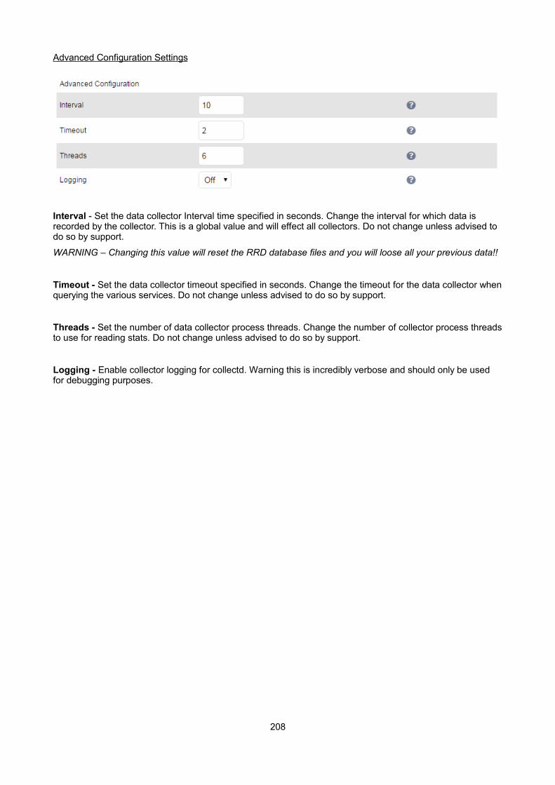
Advanced Configuration Settings
Interval - Set the data collector Interval time specified in seconds. Change the interval for which data is recorded by the collector. This is a global value and will effect all collectors. Do not change unless advised to do so by support.
WARNING – Changing this value will reset the RRD database files and you will loose all your previous data!!
Timeout - Set the data collector timeout specified in seconds. Change the timeout for the data collector whenquerying the various services. Do not change unless advised to do so by support.
Threads - Set the number of data collector process threads. Change the number of collector process threadsto use for reading stats. Do not change unless advised to do so by support.
Logging - Enable collector logging for collectd. Warning this is incredibly verbose and should only be used for debugging purposes.
208

SNMP ReportingBy default, SNMP is disabled on the appliance. Once the SNMP settings are configured using the WUI option: Local Configuration > SNMP Configuration , the SNMP service is set to auto start at boot.
SNMP for Layer 4 Based ServicesThe root OID for Layer 4 based services is: 1.3.6.1.4.1.8225.4711
You can test if everything works by running the command shown below:
[root@lbmaster ~]# snmpwalk -c public -v 2c -m LVS-MIB localhost 1.3.6.1.4.1.8225.4711
LVS-MIB::lvsVersion.0 = STRING: "1.2.0" LVS-MIB::lvsNumServices.0 = INTEGER: 2 LVS-MIB::lvsHashTableSize.0 = INTEGER: 4096 LVS-MIB::lvsTcpTimeOut.0 = INTEGER: 900 LVS-MIB::lvsTcpFinTimeOut.0 = INTEGER: 120 LVS-MIB::lvsUdpTimeOut.0 = INTEGER: 300 LVS-MIB::lvsDaemonState.0 = INTEGER: none(0) …etc.
N.B. LVS-MIB.txt and other MIB files are available on the appliance in /usr/share/snmp/mibs/
You can also use all the usual MIB II counters and gauges such as network and CPU etc.
Monitoring Layer 4 RIPs using SNMP
To list the Virtual Services use the command shown below:
[root@lbmaster ~]# snmpwalk -c public -v 2c -m LVS-MIB localhost 1.3.6.1.4.1.8225.4711.17.1.4
LVS-MIB::lvsServiceAddr.1 = IpAddress: 192.168.110.194
To list the Real Servers use the command shown below:
[root@lbmaster ~]# snmpwalk -c public -v 2c -m LVS-MIB localhost 1.3.6.1.4.1.8225.4711.18.1.3
LVS-MIB::lvsRealServerAddr.2.1 = IpAddress: 10.0.0.101LVS-MIB::lvsRealServerAddr.2.2 = IpAddress: 10.0.0.100
This indicates that all servers are passing their health-check. If the check fails, that server will be omitted from the list as shown below:
[root@lbmaster ~]# snmpwalk -c public -v 2c -m LVS-MIB localhost 1.3.6.1.4.1.8225.4711.18.1.3
LVS-MIB::lvsRealServerAddr.2.1 = IpAddress: 10.0.0.100
In this case, 10.0.0.101 is now failing its health-check so has been omitted from the list.
209
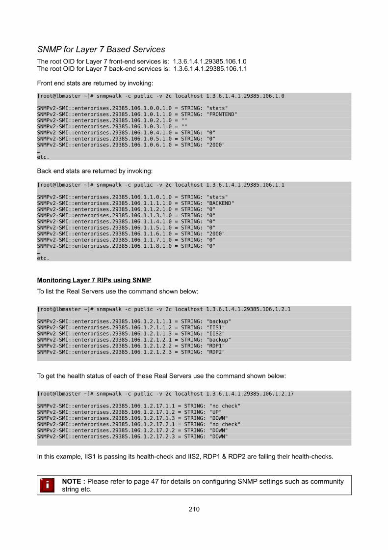
SNMP for Layer 7 Based ServicesThe root OID for Layer 7 front-end services is: 1.3.6.1.4.1.29385.106.1.0The root OID for Layer 7 back-end services is: 1.3.6.1.4.1.29385.106.1.1
Front end stats are returned by invoking:
[root@lbmaster ~]# snmpwalk -c public -v 2c localhost 1.3.6.1.4.1.29385.106.1.0
SNMPv2-SMI::enterprises.29385.106.1.0.0.1.0 = STRING: "stats" SNMPv2-SMI::enterprises.29385.106.1.0.1.1.0 = STRING: "FRONTEND" SNMPv2-SMI::enterprises.29385.106.1.0.2.1.0 = "" SNMPv2-SMI::enterprises.29385.106.1.0.3.1.0 = "" SNMPv2-SMI::enterprises.29385.106.1.0.4.1.0 = STRING: "0" SNMPv2-SMI::enterprises.29385.106.1.0.5.1.0 = STRING: "0" SNMPv2-SMI::enterprises.29385.106.1.0.6.1.0 = STRING: "2000" …etc.
Back end stats are returned by invoking:
[root@lbmaster ~]# snmpwalk -c public -v 2c localhost 1.3.6.1.4.1.29385.106.1.1
SNMPv2-SMI::enterprises.29385.106.1.1.0.1.0 = STRING: "stats" SNMPv2-SMI::enterprises.29385.106.1.1.1.1.0 = STRING: "BACKEND" SNMPv2-SMI::enterprises.29385.106.1.1.2.1.0 = STRING: "0" SNMPv2-SMI::enterprises.29385.106.1.1.3.1.0 = STRING: "0" SNMPv2-SMI::enterprises.29385.106.1.1.4.1.0 = STRING: "0" SNMPv2-SMI::enterprises.29385.106.1.1.5.1.0 = STRING: "0" SNMPv2-SMI::enterprises.29385.106.1.1.6.1.0 = STRING: "2000" SNMPv2-SMI::enterprises.29385.106.1.1.7.1.0 = STRING: "0" SNMPv2-SMI::enterprises.29385.106.1.1.8.1.0 = STRING: "0" …etc.
Monitoring Layer 7 RIPs using SNMP
To list the Real Servers use the command shown below:
[root@lbmaster ~]# snmpwalk -c public -v 2c localhost 1.3.6.1.4.1.29385.106.1.2.1
SNMPv2-SMI::enterprises.29385.106.1.2.1.1.1 = STRING: "backup"SNMPv2-SMI::enterprises.29385.106.1.2.1.1.2 = STRING: "IIS1"SNMPv2-SMI::enterprises.29385.106.1.2.1.1.3 = STRING: "IIS2"SNMPv2-SMI::enterprises.29385.106.1.2.1.2.1 = STRING: "backup"SNMPv2-SMI::enterprises.29385.106.1.2.1.2.2 = STRING: "RDP1"SNMPv2-SMI::enterprises.29385.106.1.2.1.2.3 = STRING: "RDP2"
To get the health status of each of these Real Servers use the command shown below:
[root@lbmaster ~]# snmpwalk -c public -v 2c localhost 1.3.6.1.4.1.29385.106.1.2.17
SNMPv2-SMI::enterprises.29385.106.1.2.17.1.1 = STRING: "no check"SNMPv2-SMI::enterprises.29385.106.1.2.17.1.2 = STRING: "UP"SNMPv2-SMI::enterprises.29385.106.1.2.17.1.3 = STRING: "DOWN"SNMPv2-SMI::enterprises.29385.106.1.2.17.2.1 = STRING: "no check"SNMPv2-SMI::enterprises.29385.106.1.2.17.2.2 = STRING: "DOWN"SNMPv2-SMI::enterprises.29385.106.1.2.17.2.3 = STRING: "DOWN"
In this example, IIS1 is passing its health-check and IIS2, RDP1 & RDP2 are failing their health-checks.
NOTE : Please refer to page 47 for details on configuring SNMP settings such as community string etc.
210
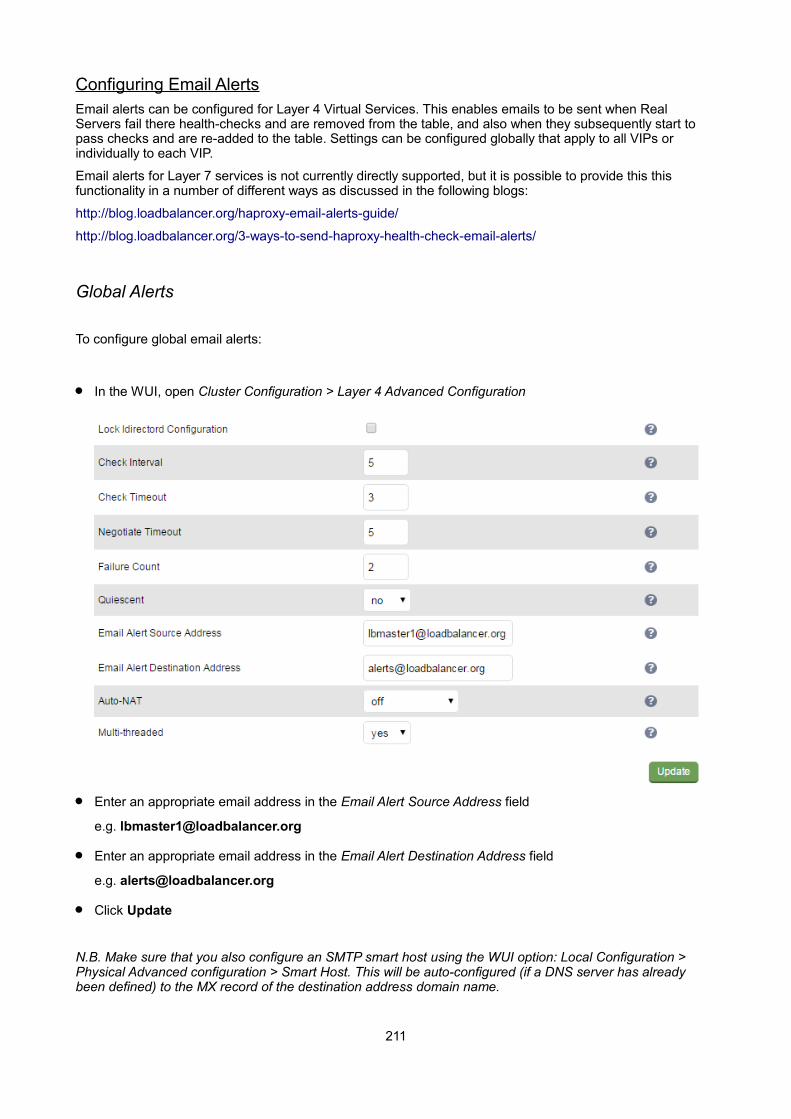
Configuring Email AlertsEmail alerts can be configured for Layer 4 Virtual Services. This enables emails to be sent when Real Servers fail there health-checks and are removed from the table, and also when they subsequently start to pass checks and are re-added to the table. Settings can be configured globally that apply to all VIPs or individually to each VIP.
Email alerts for Layer 7 services is not currently directly supported, but it is possible to provide this this functionality in a number of different ways as discussed in the following blogs:
http://blog.loadbalancer.org/haproxy-email-alerts-guide/
http://blog.loadbalancer.org/3-ways-to-send-haproxy-health-check-email-alerts/
Global Alerts
To configure global email alerts:
In the WUI, open Cluster Configuration > Layer 4 Advanced Configuration
Enter an appropriate email address in the Email Alert Source Address field
e.g. [email protected]
Enter an appropriate email address in the Email Alert Destination Address field
e.g. [email protected]
Click Update
N.B. Make sure that you also configure an SMTP smart host using the WUI option: Local Configuration > Physical Advanced configuration > Smart Host. This will be auto-configured (if a DNS server has already been defined) to the MX record of the destination address domain name.
211
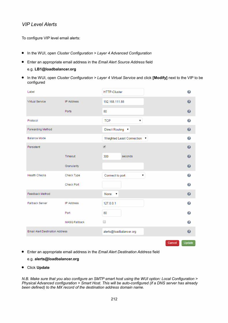
VIP Level Alerts
To configure VIP level email alerts:
In the WUI, open Cluster Configuration > Layer 4 Advanced Configuration
Enter an appropriate email address in the Email Alert Source Address field
e.g. [email protected]
In the WUI, open Cluster Configuration > Layer 4 Virtual Service and click [Modify] next to the VIP to be configured
Enter an appropriate email address in the Email Alert Destination Address field
e.g. [email protected]
Click Update
N.B. Make sure that you also configure an SMTP smart host using the WUI option: Local Configuration > Physical Advanced configuration > Smart Host. This will be auto-configured (if a DNS server has already been defined) to the MX record of the destination address domain name.
212

Chapter 13 – Useful Tools & Utilities
213

Useful Diagnostics ToolsFull root access to the appliance is supported which enables many useful commands to be run directly at the console or via an SSH session. Many commands can also be run using the WUI option: Local Configuration > Execute Shell Command. Several commonly used examples are listed below.
NetstatPrint network connections, routing tables, interface statistics, masquerade connections, and multicast memberships. Useful to check that services are listening on the correct IP / port.
e.g. netstat -anp
Output:
Active Internet connections (servers and established)
Proto Recv-Q Send-Q Local Address Foreign Address State PID/Program name
tcp 0 0 0.0.0.0:7777 0.0.0.0:* LISTEN 17784/haproxy
tcp 0 0 127.0.0.1:7778 0.0.0.0:* LISTEN 17784/haproxy
tcp 0 0 127.0.0.1:199 0.0.0.0:* LISTEN 24881/snmpd
tcp 0 0 192.168.111.129:82 0.0.0.0:* LISTEN 17784/haproxy
tcp 0 0 192.168.111.128:82 0.0.0.0:* LISTEN 17784/haproxy
tcp 0 0 0.0.0.0:22 0.0.0.0:* LISTEN 1789/sshd
tcp 0 0 0.0.0.0:9081 0.0.0.0:* LISTEN 12863/nginx
tcp 0 0 192.168.110.232:443 0.0.0.0:* LISTEN 10199/Pound
tcp 0 0 192.168.110.230:443 0.0.0.0:* LISTEN 10113/STunnel
tcp 0 0 192.168.67.22:22 192.168.64.7:3424 ESTABLISHED 24798/sshd
tcp 0 1 192.168.67.22:49118 192.168.110.238:3389 SYN_SENT 17784/haproxy
tcp 0 1 192.168.67.22:50915 192.168.110.237:3389 SYN_SENT 17784/haproxy
tcp 0 0 :::9443 :::* LISTEN 1946/httpd
tcp 0 0 :::22 :::* LISTEN 1789/sshd
tcp 0 0 :::9080 :::* LISTEN 1946/httpd
tcp 0 0 ::ffff:192.168.67.22:9080 ::ffff:192.168.64.7:11322 ESTABLISHED 19953/httpd
etc.
TelnetThe telnet command is used to communicate with another host using the TELNET protocol. Useful for testingthat a connection to a specific port can be made. Note that this command should be run from the console or a terminal session rather than via the WUI.
e.g. telnet 192.168.100.10 80
In this example, 192.168.100.10 is a Real Server, the command is useful to ensure that the load balancer is able to successfully connect to this server on port 80.
[root@lbmaster ~]# telnet 192.168.100.10 80
Trying 192.168.100.10...
Connected to 192.168.100.10.
Escape character is '^]'.
214
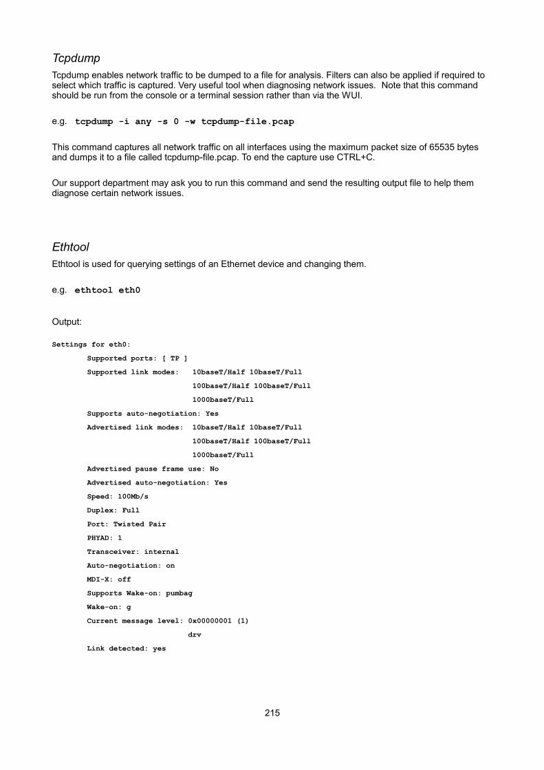
TcpdumpTcpdump enables network traffic to be dumped to a file for analysis. Filters can also be applied if required to select which traffic is captured. Very useful tool when diagnosing network issues. Note that this command should be run from the console or a terminal session rather than via the WUI.
e.g. tcpdump -i any -s 0 -w tcpdump-file.pcap
This command captures all network traffic on all interfaces using the maximum packet size of 65535 bytes and dumps it to a file called tcpdump-file.pcap. To end the capture use CTRL+C.
Our support department may ask you to run this command and send the resulting output file to help them diagnose certain network issues.
EthtoolEthtool is used for querying settings of an Ethernet device and changing them.
e.g. ethtool eth0
Output:
Settings for eth0:
Supported ports: [ TP ]
Supported link modes: 10baseT/Half 10baseT/Full
100baseT/Half 100baseT/Full
1000baseT/Full
Supports auto-negotiation: Yes
Advertised link modes: 10baseT/Half 10baseT/Full
100baseT/Half 100baseT/Full
1000baseT/Full
Advertised pause frame use: No
Advertised auto-negotiation: Yes
Speed: 100Mb/s
Duplex: Full
Port: Twisted Pair
PHYAD: 1
Transceiver: internal
Auto-negotiation: on
MDI-X: off
Supports Wake-on: pumbag
Wake-on: g
Current message level: 0x00000001 (1)
drv
Link detected: yes
215
WiresharkWireshark is an open source application that can be used to analyze tcpdump output files. It can be downloaded from the following location:
http://www.wireshark.org/download.html
Windows Specific Tools
WinSCPWinSCP is an open source application that allows files to be uploaded/downloaded to/from the load balancer using Windows. It can be downloaded from the following location:
http://winscp.net/eng/download.php
PuTTyPuTTy is an open source SSH client for Windows. It can be downloaded from the following location:
http://www.chiark.greenend.org.uk/~sgtatham/putty/download.html
Remote Support ToolsThe Loadbalancer.org Support Department uses Teamviewer for remote desktop support. The client-side software is available at the following links:
Windows clients: http://downloads.loadbalancer.org/support/quicksupport/WindowsQS.exe
Mac clients: http://downloads.loadbalancer.org/support/quicksupport/MacQS.zip
Linux clients: http://downloads.loadbalancer.org/support/quicksupport/LinuxQS.tar.gz
Once downloaded, the client should be installed on a local machine that has access to the load balancer's WUI and also to the load balancer via SSH (Putty, WinSCP for Windows). Our Support Engineers will provide guidance as required.
NOTE : The download links mentioned above can be accessed using the WUI option: Support> Useful Links
216

Chapter 14 – Backup & Restore and Disaster Recovery
217

IntroductionThe appliance uses various configuration files to store all settings. Files that must be backed up to enable a full restore are as follows:
XML configuration file – The is the main file for the appliance. All configuration details including local settings and load balanced services settings are stored here. This file can be backed up using the WUI.
Firewall Script – If manual changes such as manual firewall marks have been made, this file is also important. This file can be backed up using the WUI.
SSL Certificate PEM files – If SSL is terminated on the appliance, these files are also important. These files can be backed up using the WUI.
Backup & RestoreThe WUI can be used for to perform backup and restore functions. To access these options:
In the WUI, open Maintenance > Backup & Restore
Backup Options
Download XML configuration file – download and save the load balancer's XML configuration file
Download Firewall script – download and save load balancer's firewall script
Download SSL Certificates – download and save the load balancer's SSL certificates
Download HAProxy manual configuration – download and save the load balancer's layer 7 manual configuration file
Make local XML backup – creates a local backup of the current XML file in /etc/loadbalancer.org/userbkup
Make local Firewall Script backup – creates a local backup of the current rc.firewall in /etc/loadbalancer.org/userbkup
Restore Options
Upload XML file and Restore – upload an XML file and restore load balancer settings
218

Restore from the last local XML backup – Restore the last local backup created with the 'Make local XML Backup' option
Restore Manufacturer's defaults – Restore system settings to default values
N.B. The xml restore feature is not backward compatible with previous major versions of the software, e.g. it's not possible to restore a V7.6.4 xml file to a v7.5 appliance.
Synchronization Options
Synchronize Configuration with peer – replicate the load balanced services configuration to the slave device.
NOTE : For details of which settings are NOT replicated from master to slave when using this option, please refer to page 155.
Separate HA Pair – reconfigure the local appliance as a non paired unit
Restoring XML FilesThe screen shot below shows an ongoing restore from a local XML file backup:
Once complete, you'll need to either restart or reload heartbeat to complete the restore process as explained in the yellow message box:
219

Disaster Recovery
Being Prepared
To be able to quickly recover your appliance when a disaster occurs it's important that you create a backup ofthe XML file as well as other relevant configuration files and keep them stored in a secure location off the load balancer. Ideally you should keep a backup of both the master and slave configurations. This can easily be done by following the steps below:
Backing Up to a Remote Location
Login to the Web User Interface:
Username: loadbalancerPassword: loadbalancer
Backup the XML configuration file:
• Select Maintenance > Backup & Restore and click Download XML configuration file
• Select an appropriate location to store the file
• Update the filename if required then save the file
If manual firewall marks have been configured or any other manual firewall script changes have been made, backup the firewall configuration:
• Select Maintenance > Backup & Restore and click Download Firewall Script
• Select an appropriate location to store the file
• Update the filename if required then save the file
If you're terminating SSL on the load balancer, backup your certificates as well:
• Select Maintenance > Backup & Restore and click Download SSL Certificates
• Select an appropriate location to store the file
• Update the filename if required then save the file
Using wget to Copy the Files
It's also possible to use wget from a remote Linux host to pull the XML configuration file and firewall script from the appliance:
wget --user=loadbalancer --password=loadbalancer http://<IP >:9080/lbadmin/config/getxmlconfig.php -O lb_config.xml
wget --user=loadbalancer --password=loadbalancer http://<IP>:9080/lbadmin/config/getfirewall.php -Orc.firewall
N.B. Replace the password 'loadbalancer' with your password if it's been changed.
220

Backing up locally on the Load Balancer
To create local backups of the various configuration files, follow these steps:
Log in to the web interface:
Username: loadbalancerPassword: loadbalancer
• Select Maintenance > Backup & Restore and click Make local XML backup
• Select Maintenance > Backup & Restore > and click Make local Firewall Script backup
A copy of these files will be stored in /etc/loadbalancer.org/userbkup
Appliance Recovery using a USB Memory Stick
NOTE : This will only work on 64Bit hardware. From v6.x onwards, all appliances are 64Bit. If you're running an older version, this may or may not be possible depending on the hardware.
Checking older hardware for Compatibility
If you are running v5.x and wish to determine whether your appliance is 64Bit and can be upgraded to the latest version, use the following command:
grep flags /proc/cpuinfo
This can be run from the WUI using Local Configuration > Execute Shell command, at the console or via a terminal session.
If lm (long mode) is present in the output then the CPU is 64Bit and you can proceed. If not then your appliance is 32Bit and you are limited to the latest v5 software.
The latest images require a standard disk (Dell hardware) or a high speed IDE DOM / SATA SSD (Supermicro hardware) of at least 4GB in size. If you're already running v6.x or later then you will already have this and should be able to simply re-image your current drive, disk module or SSD.
If you're upgrading from v5 you may need to upgrade the storage device and possibly the hardware.
Obtaining the latest disk image
The latest disk image can be downloaded from our website – please contact [email protected] for more details.
Extracting the image from the compressed archive
Extract the image using tar under Linux or something like WinRar or 7-Zip under Windows (not the built-in Windows extractor).
221

Preparing the USB stick
Under Linux:
after formatting the USB stick run the command:
dd if=/imagefilename.img of=/dev/nameofusbdisk
e.g.
dd if=/tmp/v7.5.0_r3368.img of=/dev/sda
Do not use /dev/sdax where 'x' is a number, for example – /dev/sda1 as this will install to a partition on your usb stick. Use the whole disk /dev/sda Instead.
NOTE: Be careful using this command – make sure you specify the correct disk !
Under Windows:
For Windows, a third party image writer must be used. Several free ones are available, the example below uses Win32 Disk Imager which can be downloaded here: http://sourceforge.net/projects/win32diskimager/
First extract the archive, then run the executable
Select the image file and set the appropriate output Device as shown above
Click Write
NOTE: Be careful using this utility – make sure you specify the correct disk !
Using the USB Stick to restore the Appliance
• Change the appliance's BIOS settings to boot from USB first (on some models the stick must be plugged in to allow it to be selected as a boot device)
• Boot the appliance, after the initial boot messages the following prompt will appear:
DO YOU WISH TO CONTINUE?
222
Please enter yes or no
• Type yes and press <Enter>
• The installation will take around 2-3 minutes, once complete the following message will be displayed:
Installation Finished
• As directed, press any key to shutdown the load balancer
• Once shutdown, remove the USB stick
• Power up the appliance
• Login at the console:
Username: rootPassword: loadbalancer
• Run the following command:
lbrestore <Enter>
• Reboot the appliance once again
*** The restore process is now complete ***
NOTE : If your appliance is either an Enterprise, MAX or 10G please contact [email protected] for information on completing the licensing process.
The Enterprise R16 will be licensed automatically.
223
Disaster Recovery After Master FailureFor a correctly configured clustered pair, if the master fails, the slave will take over automatically. To restore the master load balancer's configuration, a backup copy of the lb_config.xml file is used. This backup should be created using the steps on page 220.
NOTE : If a backup copy from the master is not available, It's also possible to use the XML file from the slave instead. If there is no current backup of this, then use the WUI option: Maintenance > Backup & Restore > Download XML Configuration file to create the file. A couple of changes need to be made so the file represents the master unit rather than the slaveas detailed below.
Steps (with example IP addresses) to modify a copy of the slaves XML file for use on the master:
find & Change:
<physical><network>
<role>slave</role><hostname>lbslave</hostname><master>192.168.67.23</master><slave></slave>
To:
<physical><network>
<role>master</role> (i.e. change the role to master)<hostname>lbmaster</hostname> (i.e. change the hostname to lbmaster)<master>192.168.67.22</master> (i.e. change to the masters IP address)<slave>192.168.67.23</slave> (i.e. add the slaves IP address)
Find & Change:
<rip><eth0>10.0.0.23/16</eth0><eth1>192.168.67.23/18</eth1>
</rip>
To:
<rip><eth0>10.0.0.22/16</eth0> (i.e. change to the masters IP address)<eth1>192.168.67.22/18</eth1> (i.e. change to the masters IP address)
</rip>
N.B. for the MAX & 10G you may also need to change eth2 & eth3 in the same way if these interfaces are also used.
224
To Perform the Recovery
Locate your copy of lb_config.xml (either the backup from the master, or the modified slave copy)
If the failed master is still on, power it down
Disconnect all cables
Repair the problems you're having with the master
Connect the power lead, mouse, monitor and keyboard
Power up the repaired master appliance
If the SSD / HD failed and has been replaced, follow the steps on page 221 to restore the image from USB stick
Login to the console as:
Username: setupPassword: setup
now run through the network setup wizard to configure the initial network setting
Open the WUI of the appliance (replace with your IP address) using: http://192.168.2.21:9080
Login to the WUI as:
Username: loadbalancerPassword: loadbalancer
In the WUI go to: Maintenance > Backup & Restore
At the Upload XML file & Restore: option, browse to and select your backup XML file
Click Upload and confirm this is what you want to do at the check prompt, the file will now be restored
Once complete, reload heartbeat on the master unit. This can be done using the WUI option: Maintenance > Restart Services and clicking Reload Heartbeat
N.B. Using reload rather than restart ensures services are not disrupted
Once heartbeat has reloaded, the master and slave will be automatically re-synchronized, the master will be passive and the slave will remain active
Verify that the master displays: Master | Passive | Link and the slave displays: Slave | Active | Link
To force the master to go active and the slave passive, during a maintenance window click the [Advanced] option in the green Information box and click the Take over button
Verify that the master now displays: Master | Active | Link and the slave displays: Slave | Passive | Link
225
Disaster Recovery After Slave FailureIf the slave unit has failed, the master will continue to provide load balancing services as normal. However it'simportant to recover the slave unit as soon as possible to restore the clustered pair to normal. To restore the slave there are two options:
OPTION 1 – Repair the unit, then restore the slave's XML backup file
or
OPTION 2 – Repair the unit, then use the 'Synchronize Configuration with peer' option on the master to re-synchronize the slave
Option 1 – Using the XML Backup
Locate your backup copy of the slave's configuration file (lb_config.xml)
If the failed slave is still on, power it down
Disconnect all cables
Repair the problems you're having with the slave
Connect the power lead, mouse, monitor and keyboard
Power up the repaired slave appliance
If the SSD / HD failed and has been replaced, follow the steps on page 221 to restore the image from USB stick
Login to the console as:
Username: setupPassword: setup
now run through the network setup wizard to configure the initial network setting
Open the WUI of the appliance (replace with your IP address) using: http://192.168.2.21:9080
Login to the WUI as:
Username: loadbalancerPassword: loadbalancer
In the WUI go to: Maintenance > Backup & Restore
At the Upload XML file & Restore: option, browse to and select your backup XML file
Click Upload and confirm this is what you want to do at the check prompt, the file will now be restored
Once complete, reload heartbeat on the slave unit. This can be done using the WUI option: Maintenance > Restart Services and clicking Reload Heartbeat
N.B. Using reload rather than restart ensures services are not disrupted
226
Once heartbeat has reloaded, the master and slave will be automatically re-synchronized, the master will remain active and the slave will be passive
Verify that the master displays: Master | Active | Link and the slave displays: Slave | Passive | Link
Option 2 – Synchronizing From the Master
If the failed slave is still on, power it down
Disconnect all cables
Repair the problems you're having with the slave
Connect the power lead, mouse, monitor and keyboard
Power up the repaired slave appliance
If the SSD / HD failed and has been replaced, follow the steps on page 221 to restore the image from USB stick
login to the console as:
Username: setupPassword: setup
now run through the network setup wizard to configure the initial network setting
Now follow the steps in the section 'Adding a Slave Unit after the master has been configured' on page 158.
227

Chapter 15 – Technical Support
228

IntroductionLoadbalancer.org have a team of very experienced support Engineers who are available to assist with your load balancer deployment.
Unlimited support is available as follows:
During the complimentary 90 day installation support period included with the product when no other support package is purchased
During the cover period of any active support package
(to purchase a support package, please contact: [email protected]
During the 30 day Virtual Appliance trial period
(to download the trial please go to: www.loadbalancer.org/downloads.php)
WUI Support Options
Contact UsThis option provides details on how to contact Loadbalancer.org, how to report any issues and what information we'll need to resolve issues as quickly as we can. As mentioned here, the Loadbalancer.org support team can be contacted using the email address: [email protected]
Sending an email to this address creates a ticket in our help desk system and enables all technical support staff to view the case. This is the most efficient way to contact support and guarantees that any reported issues will be acted upon and addressed as quickly and efficiently as possible.
229
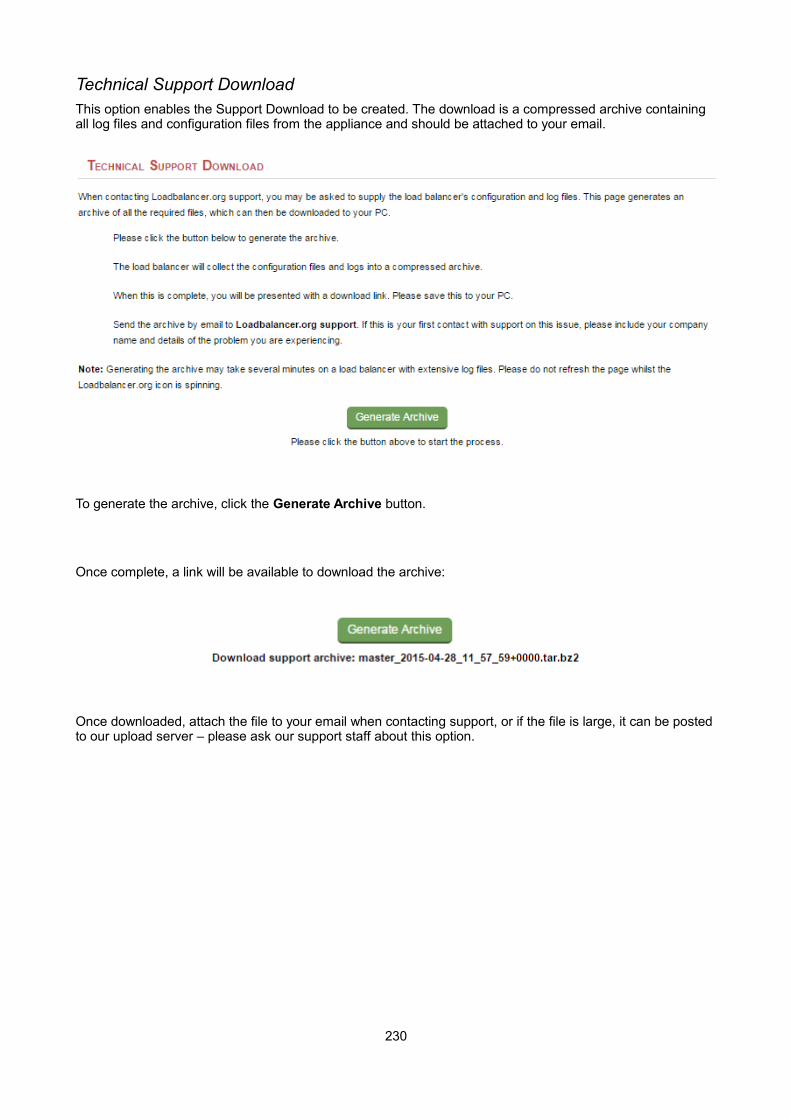
Technical Support DownloadThis option enables the Support Download to be created. The download is a compressed archive containing all log files and configuration files from the appliance and should be attached to your email.
To generate the archive, click the Generate Archive button.
Once complete, a link will be available to download the archive:
Once downloaded, attach the file to your email when contacting support, or if the file is large, it can be postedto our upload server – please ask our support staff about this option.
230

Appendix
231

Front & Rear Panel Layouts
Enterprise / Enterprise R16 – Supermicro
Enterprise – Dell
Enterprise Max – Supermicro
Enterprise Max / 10G – Dell
232
Eth0 Eth1
Eth2 Eth3
Eth2 Eth3 Eth0 Eth1
Eth0
Eth0
Eth1
Eth0 Eth1
Eth1
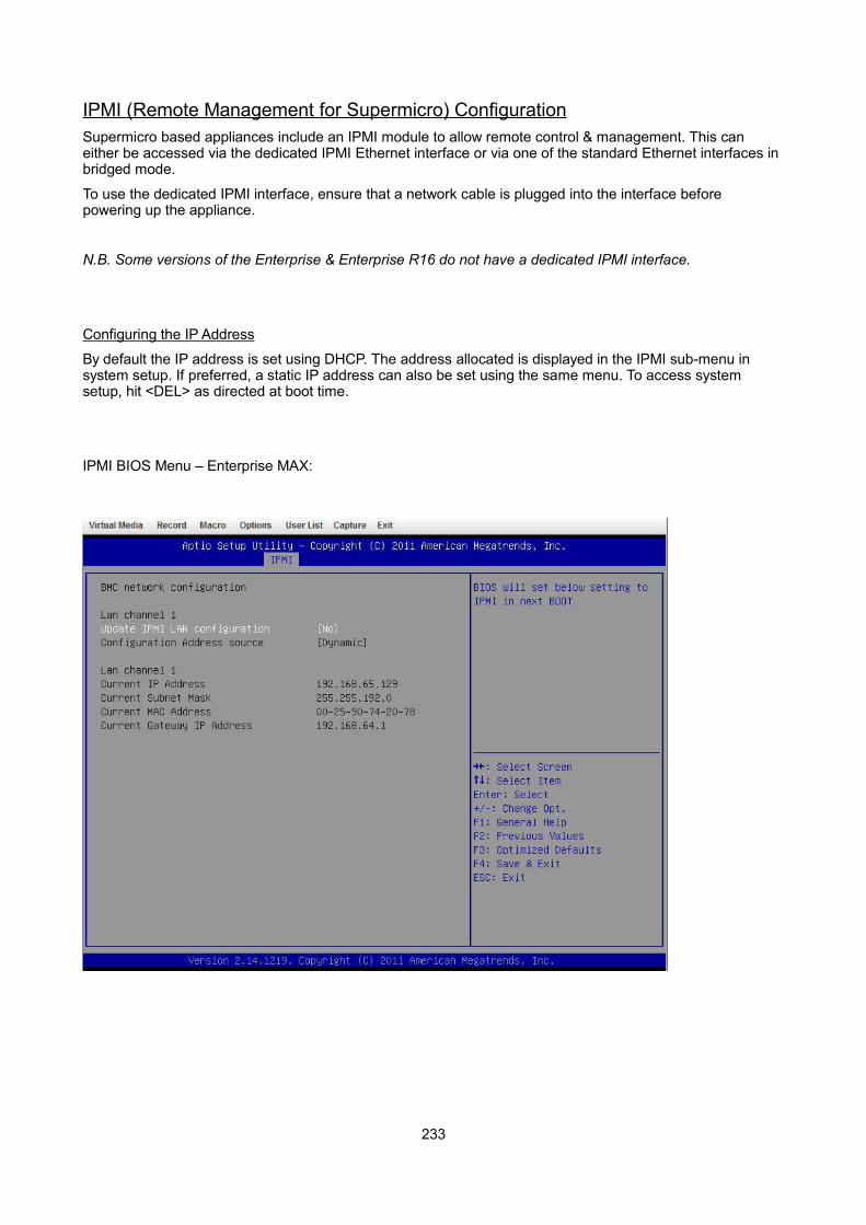
IPMI (Remote Management for Supermicro ) ConfigurationSupermicro based appliances include an IPMI module to allow remote control & management. This can either be accessed via the dedicated IPMI Ethernet interface or via one of the standard Ethernet interfaces in bridged mode.
To use the dedicated IPMI interface, ensure that a network cable is plugged into the interface before powering up the appliance.
N.B. Some versions of the Enterprise & Enterprise R16 do not have a dedicated IPMI interface.
Configuring the IP Address
By default the IP address is set using DHCP. The address allocated is displayed in the IPMI sub-menu in system setup. If preferred, a static IP address can also be set using the same menu. To access system setup, hit <DEL> as directed at boot time.
IPMI BIOS Menu – Enterprise MAX:
233
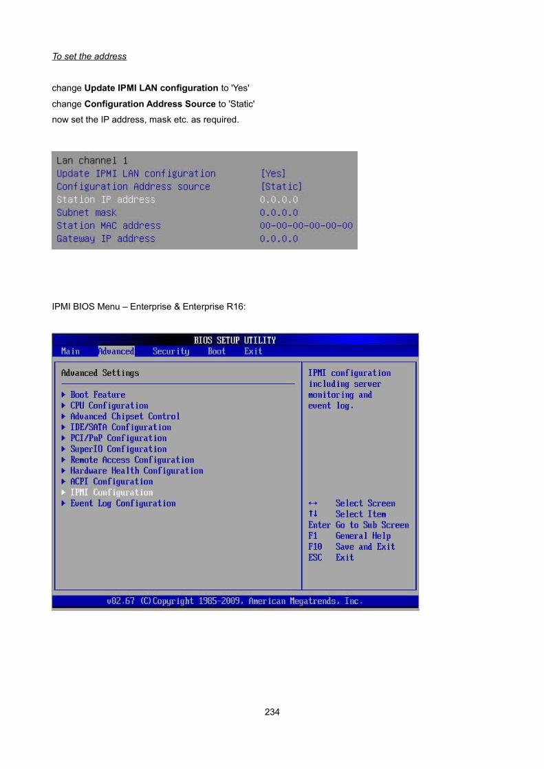
To set the address
change Update IPMI LAN configuration to 'Yes'
change Configuration Address Source to 'Static'
now set the IP address, mask etc. as required.
IPMI BIOS Menu – Enterprise & Enterprise R16:
234
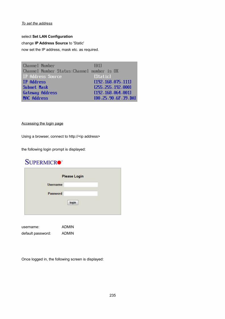
To set the address
select Set LAN Configuration
change IP Address Source to 'Static'
now set the IP address, mask etc. as required.
Accessing the login page
Using a browser, connect to http://<ip address>
the following login prompt is displayed:
username: ADMIN
default password: ADMIN
Once logged in, the following screen is displayed:
235
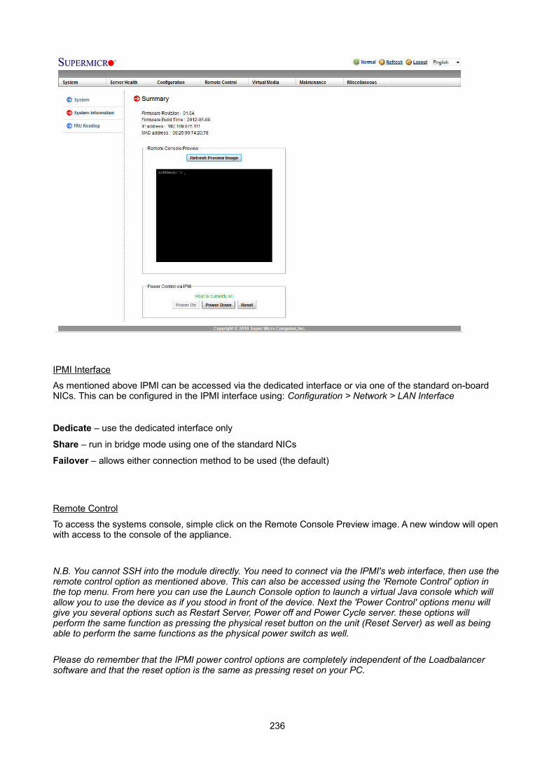
IPMI Interface
As mentioned above IPMI can be accessed via the dedicated interface or via one of the standard on-board NICs. This can be configured in the IPMI interface using: Configuration > Network > LAN Interface
Dedicate – use the dedicated interface only
Share – run in bridge mode using one of the standard NICs
Failover – allows either connection method to be used (the default)
Remote Control
To access the systems console, simple click on the Remote Console Preview image. A new window will open with access to the console of the appliance.
N.B. You cannot SSH into the module directly. You need to connect via the IPMI's web interface, then use theremote control option as mentioned above. This can also be accessed using the 'Remote Control' option in the top menu. From here you can use the Launch Console option to launch a virtual Java console which will allow you to use the device as if you stood in front of the device. Next the 'Power Control' options menu will give you several options such as Restart Server, Power off and Power Cycle server. these options will perform the same function as pressing the physical reset button on the unit (Reset Server) as well as being able to perform the same functions as the physical power switch as well.
Please do remember that the IPMI power control options are completely independent of the Loadbalancer software and that the reset option is the same as pressing reset on your PC.
236
iDRAC (Remote Management for DELL) ConfigurationiDRAC enables remote management of DELL based appliances. The following models include iDRAC by default:
• Enterprise MAX
• Enterprise 10G
• Enterprise R320
N.B. IDRAC is also available on the Enterprise as an optional extra – please contact sales for pricing.
Default IP Address
By default the following static IP address & mask is assigned to the iDRAC interface:
IP address: 192.168.0.120
Mask: 255.255.255.0
This can be changed using the iDRAC management interface accessible at boot-up.
Default Username & Password
The default username & password is:
username: root
password: calvin
237

Appliance IPv4 Address FormatWhen specifying IP addresses on the appliance, CIDR format is used. The following table shows the various masks and the corresponding IPv4 IP/CIDR equivalents:
Mask IP/CIDR
255.255.255.255 a.b.c.d/32
255.255.255.254 a.b.c.d/31
255.255.255.252 a.b.c.d/30
255.255.255.248 a.b.c.d/29
255.255.255.240 a.b.c.d/28
255.255.255.224 a.b.c.d/27
255.255.255.192 a.b.c.d/26
255.255.255.128 a.b.c.d/25
255.255.255.000 a.b.c.d/24
255.255.254.000 a.b.c.d/23
255.255.252.000 a.b.c.d/22
255.255.248.000 a.b.c.d/21
255.255.240.000 a.b.c.d/20
255.255.224.000 a.b.c.d/19
255.255.192.000 a.b.c.d/18
255.255.128.000 a.b.c.d/17
255.255.000.000 a.b.c.d/16
255.254.000.000 a.b.c.d/15
255.252.000.000 a.b.c.d/14
255.248.000.000 a.b.c.d/13
255.240.000.000 a.b.c.d/12
255.224.000.000 a.b.c.d/11
255.192.000.000 a.b.c.d/10
255.128.000.000 a.b.c.d/9
255.000.000.000 a.b.c.d/8
254.000.000.000 a.b.c.d/7
252.000.000.000 a.b.c.d/6
248.000.000.000 a.b.c.d/5
240.000.000.000 a.b.c.d/4
224.000.000.000 a.b.c.d/3
192.000.000.000 a.b.c.d/2
128.000.000.000 a.b.c.d/1
238
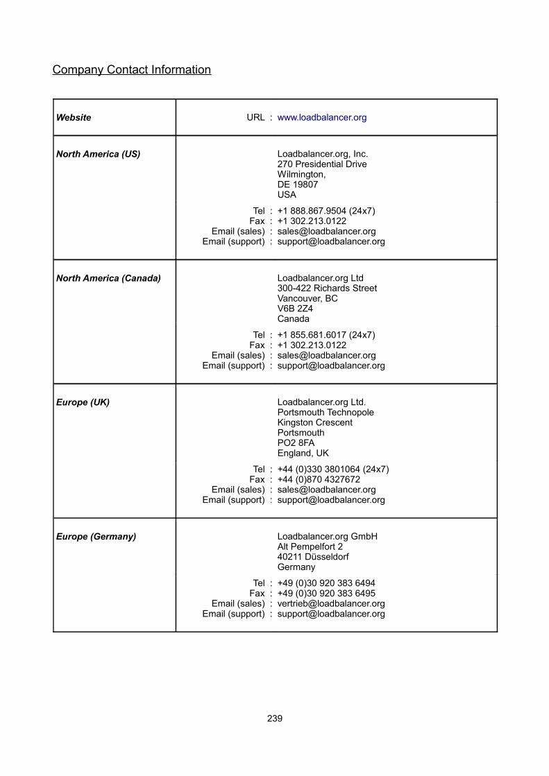
Company Contact Information
Website URL : www.loadbalancer.org
North America (US) Loadbalancer.org, Inc.270 Presidential DriveWilmington,DE 19807USA
Tel :Fax :
Email (sales) :Email (support) :
+1 888.867.9504 (24x7) +1 [email protected]@loadbalancer.org
North America (Canada) Loadbalancer.org Ltd300-422 Richards StreetVancouver, BCV6B 2Z4Canada
Tel :Fax :
Email (sales) :Email (support) :
+1 855.681.6017 (24x7)+1 [email protected]@loadbalancer.org
Europe (UK) Loadbalancer.org Ltd.Portsmouth TechnopoleKingston CrescentPortsmouthPO2 8FAEngland, UK
Tel :Fax :
Email (sales) :Email (support) :
+44 (0)330 3801064 (24x7)+44 (0)870 [email protected]@loadbalancer.org
Europe (Germany) Loadbalancer.org GmbHAlt Pempelfort 240211 DüsseldorfGermany
Tel :Fax :
Email (sales) :Email (support) :
+49 (0)30 920 383 6494+49 (0)30 920 383 [email protected]@loadbalancer.org
239