applicatin ntes for trug-le leds - kingbright usa led ... · applicatin ntes for trug-le leds ......
TRANSCRIPT

2/9/18 1Page
APPLICATION NOTES for THROUGH-HOLE LEDs
STORAGE CONDITIONS1. Avoid continued exposure to the condensing moisture environment and keep the product away from rapid
transitions in ambient temperature.2. LEDs should be stored with temperature ≤ 30°C and relative humidity < 60%.3. Product in the original sealed package is recommended to be assembled within 72 hours of opening.
Product in opened package for more than a week should be baked for 30 (+10/-0) hours at 85 ~ 100°C.4. The LED leadframe surface is plated with silver. When the leadframe is stored under high-humidity
environments, or exposed to certain chemical elements or gases, the surface may become discolored. Please maintain the cleanliness of the storage environment.
5. If the storage conditions do not meet specification standards, the component pins may become oxidized requiring re-plating and re-sorting before use. Suggest customers consume LEDs as soon as possible, and avoid long-term storage of large inventories.
LED MOUNTING METHOD1. The lead pitch of the LED must match the pitch of the mounting holes on the PCB during component
placement. Lead-forming may be required to insure the lead pitch matches the hole pitch. Refer to the figure below for proper lead forming procedures. “○” Correct mounting method “X” Incorrect mounting method Note: Do not route PCB trace in the contact area between the leadframe and the PCB to prevent short-circuits.
2. When soldering wires to the LED, each wire joint should be separately insulated with heat-shrink tube to prevent short-circuit contact. Do not bundle both wires in one heat shrink tube to avoid pinching the LED
2/9/18 2Page
APPLICATION NOTES for THROUGH-HOLE LEDs
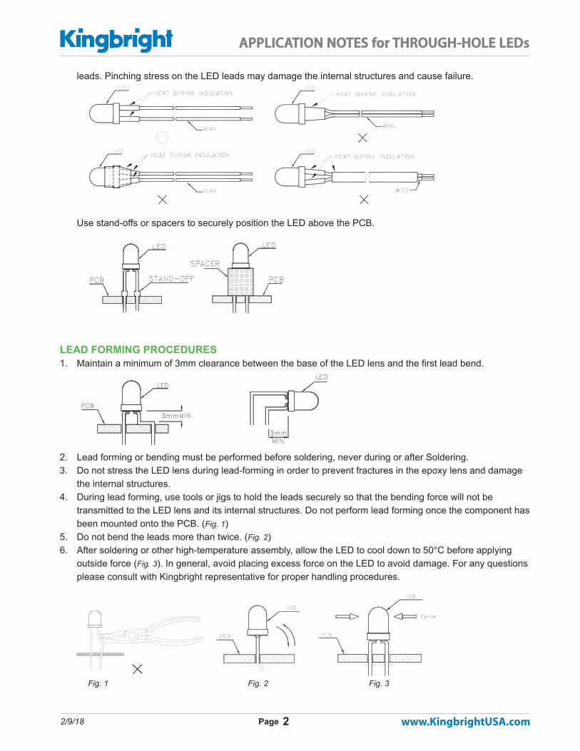
leads. Pinching stress on the LED leads may damage the internal structures and cause failure.
Use stand-offs or spacers to securely position the LED above the PCB.
LEAD FORMING PROCEDURES1. Maintain a minimum of 3mm clearance between the base of the LED lens and the first lead bend.
2. Lead forming or bending must be performed before soldering, never during or after Soldering.3. Do not stress the LED lens during lead-forming in order to prevent fractures in the epoxy lens and damage
the internal structures.4. During lead forming, use tools or jigs to hold the leads securely so that the bending force will not be
transmitted to the LED lens and its internal structures. Do not perform lead forming once the component has been mounted onto the PCB. (Fig. 1)
5. Do not bend the leads more than twice. (Fig. 2)6. After soldering or other high-temperature assembly, allow the LED to cool down to 50°C before applying
outside force (Fig. 3). In general, avoid placing excess force on the LED to avoid damage. For any questions please consult with Kingbright representative for proper handling procedures. Fig. 1 Fig. 2 Fig. 3

2/9/18 3Page
APPLICATION NOTES for THROUGH-HOLE LEDs
7. When bending the leads, the LED lamp should be secured by the upper part of the lead. Do not grip the epoxy lens during lead-forming bending the lead.
8. During soldering, component covers and holders should leave clearance to avoid placing damaging stress on the LED during soldering.
SOLDERING GENERAL NOTES1. We recommend manual soldering operations only for repair and rework purposes. The soldering iron should
not exceed 30W in power. The maximum soldering temperature is 300°C for Pb-Sn solder and 350°C for lead-free solder for normal lamps and displays. For blue (typical λd 465 nm), green (typical λd 525 nm), and all white LEDs, the maximum soldering iron temperature is 280°C. Do not place the soldering iron on the component for more than 3 seconds.
2. The tip of the soldering iron should never touch the lens epoxy.3. Do not apply stress to the leads when the component is heated above 85°C, otherwise internal wire bonds
may be damaged.
LED
Epoxy
LED
Epoxy
ForceForce
Contact areaContact area
2/9/18 4Page
APPLICATION NOTES for THROUGH-HOLE LEDs
4. After soldering, allow at least three minutes for the component to cool down to room temperature before further operations.
5. Through-hole LEDs are incompatible with reflow soldering.6. If the LED will undergo multiple soldering passes or face other processes where the part may be subjected
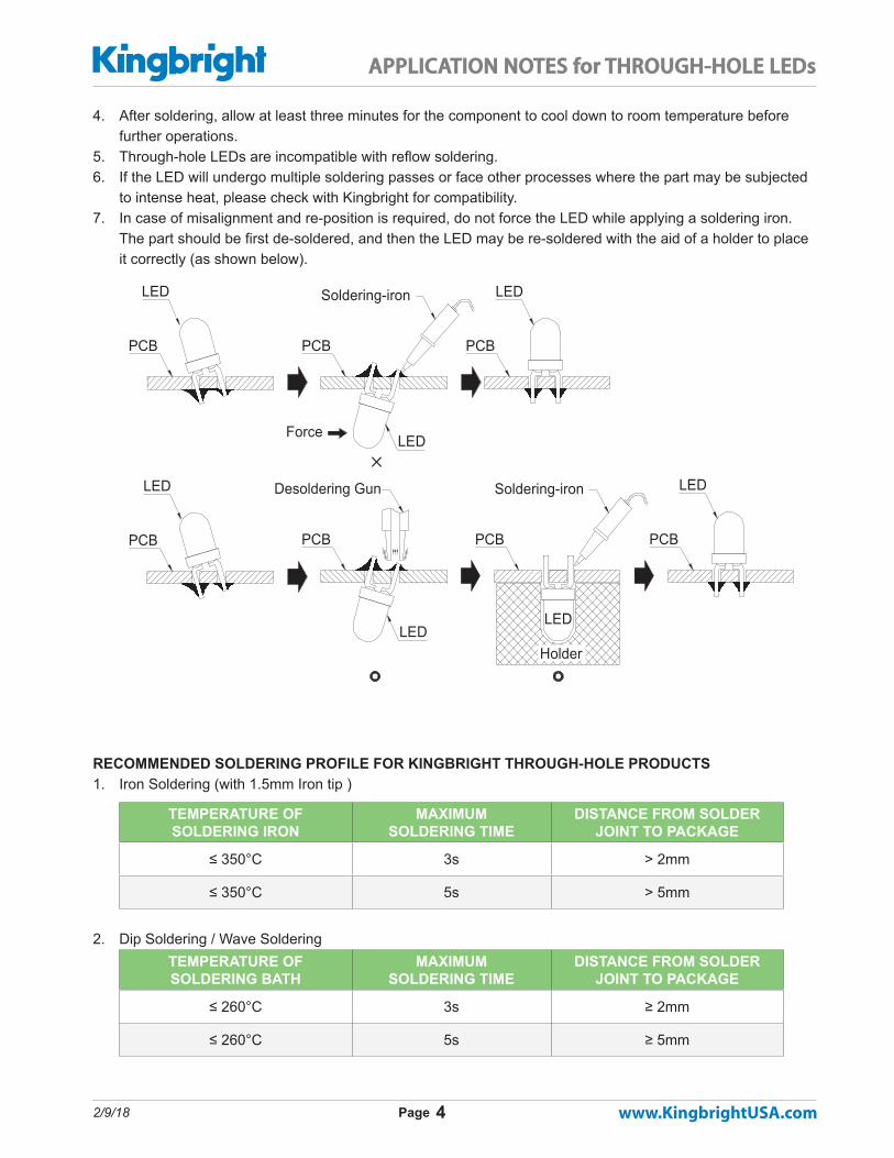
to intense heat, please check with Kingbright for compatibility. 7. In case of misalignment and re-position is required, do not force the LED while applying a soldering iron.
The part should be first de-soldered, and then the LED may be re-soldered with the aid of a holder to place it correctly (as shown below).
RECOMMENDED SOLDERING PROFILE FOR KINGBRIGHT THROUGH-HOLE PRODUCTS1. Iron Soldering (with 1.5mm Iron tip )
TEMPERATURE OF SOLDERING IRON
MAXIMUM SOLDERING TIME
DISTANCE FROM SOLDER JOINT TO PACKAGE
≤ 350°C 3s > 2mm
≤ 350°C 5s > 5mm
2. Dip Soldering / Wave Soldering TEMPERATURE OF SOLDERING BATH
MAXIMUM SOLDERING TIME
DISTANCE FROM SOLDER JOINT TO PACKAGE
≤ 260°C 3s ≥ 2mm
≤ 260°C 5s ≥ 5mm
Desoldering Gun
Force
LED
PCB
PCBPCB PCB
Soldering-iron
PCB PCB
LED
Holder
LED
LEDLED Soldering-iron
PCB
LED
LED

2/9/18 5Page
APPLICATION NOTES for THROUGH-HOLE LEDs
3. Lead-Free Wave Soldering Profile
Note:
• Recommend pre-heat temperature of 105° C or less (as measured with a thermocouple attached to the LED pins) prior to immersion in the solder wave with a maximum solder bath temperature of 260° C.
• Peak wave soldering temperature between 245° C ~ 255°C for 3 sec (5 sec max).• Do not apply stress to the epoxy resin while the temperature is above 85°C.• Fixtures should not incur stress on the component when mounting and during soldering process.• SAC 305 solder alloy is recommended.• No more than one wave soldering pass.
4. Wave Soldering Profile With Pb-Sn Solder
Preheat time: 60 sec max.
3. Do not apply stress to the epoxy body while the temperature is above 85°C.The maximum soldering temperature should not exceed 260°C.
2. Recommend the solder wave peak temperature kept between 245~260°C,
Notes:
<30°C.
4°C/s max
Time(sec)
0
50
100
150
200
250
300
(85°C)Tem
pera
ture
1. During the wave soldering process, the preheat temperature must not exceed 105°C.
255°C/5 sec max.
(100°C)
(°C)
4. Fixtures should not place stress on the component when mounted.5. No more than one soldering pass.
2. waveLimit curves
Standard curve3~6s
235°C...260°C
1. wave
300
250
200
Wave Soldering Profile With Pb-Sn Solder
2°C/s
250
Time(sec)200150
2°C/s
150
100
50
85°C...100°C
500
0
forced cooling
100
5°C/s
Tem
pera
ture
(°C
)

2/9/18 6Page
APPLICATION NOTES for THROUGH-HOLE LEDs
RECOMMENDED REFLOW SOLDERING PROFILES FOR SMD HOUSING LEDSLead-Free Reflow Soldering Profile
Note:1. We recommend the reflow temperature 245°C (± 5°C). The maximum soldering temperature should be limited to 260°C2. Don’t cause stress to the epoxy resin while it is exposed to high temperature. 3. No more than once. For “AA3528AVU/1 & AAA3528AVU/1” Series
Note:1. Don’t cause stress to the LEDs while it is exposed to high temperature. 2. The maximum number of reflow soldering passes is 2 times.3. Reflow soldering is recommended. Other soldering methods are not recommended as they might casuse damage to the product.

2/9/18 7Page
APPLICATION NOTES for THROUGH-HOLE LEDs
DESIGN PRECAUTIONS Products using InGaN/GaN components must incorporate protection circuitry to prevent ESD and voltage spikes from reaching the vulnerable component. STATIC ELECTRICITY AND VOLTAGE SPIKES IN InGaN / GaN PRODUCTSInGaN/GaN products are sensitive to electrostatic discharge (ESD) and other transient voltage spikes. ESD and voltage spikes can affect the component’s reliability, increase reverse current, and decrease forward voltage. This may result in reduced light intensity or cause component failure. Kingbright InGaN/GaN products are stored in anti-static packaging for protection during transport and storage. Please note the anti-static measures below when handling Kingbright InGaN/GaN products.
ESD PROTECTION DURING PRODUCTIONStatic discharge can result when static–sensitive products come in contact with the operator or other conduc-tors. The following procedures may decrease the possibility of ESD damage:1. Minimize friction between the product and surroundings to avoid static buildup.2. All manufacturing and testing equipment should be grounded.3. All personnel in an ESD protected area should wear antistatic garments and wrist straps.4. Set up ESD protection areas using grounded metal plating for component handling.5. All workstations that handle IC and ESD-sensitive components must maintain an electrostatic potential of
150V or less.6. Relative humidity levels maintained between 40% and 60% in production area are recommended to avoid
the build-up of static electricity – Ref JEDEC/JESD625-A and JEDEC/J-STD-033.7. Use anti-static packaging for transport and storage.8. All anti-static equipment and procedures should be periodically inspected and evaluated for proper function-
ality.
CLEANING1. Isopropyl alcohol or deionizer water are recommended for cleaning. Do not use acidic solvents or unknown
chemicals, as they might cause corrosion or damage to the component.2. Lightly wipe away any surface contaminants, and allow the component to dry under room temperature be-
fore further usage. Do not soak the component in solution.
CIRCUIT DESIGN NOTES1. Protective current-limiting resistors may be necessary to operate the LEDs within the specified range.2. LEDs mounted in parallel should each be placed in series with its own current-limiting resistor.

2/9/18 8Page
APPLICATION NOTES for THROUGH-HOLE LEDs
3. The driving circuit should be designed to avoid reverse voltages and transient voltage spikes when the circuit is powered up or shut down.
4. The operating current shall not exceed the rated maximum current for the environmental temperature. Please refer to the Current vs. Temperature graph on the datasheet for the current limit at each temperature.
5. Please contact Kingbright representative first if LEDs are to be driven by AC current.
RESTRICTIONS ON PRODUCT USE1. The information contained within this document is subject to change without notice. Before referencing this
document, please confirm that it is the most current version available.2. Not all devices and product families are available in every country.3. The light output from UV, blue, white, and other high-power LEDs may cause injury to the human eye when
viewed directly.4. LED devices may contain gallium arsenide (GaAs) material. GaAs is harmful if ingested. GaAs dust and
fumes are toxic. Do not break, cut, or pulverize LED devices. Do not dissolve LEDs in chemical solvents.5. Semiconductor devices can fail or malfunction due to their sensitivity to electrical fluctuation and physical
stress. It is the responsibility of the user to observe all safety standards when using Kingbright products, in order to avoid situations in which the malfunction or failure of a Kingbright product could cause injury, property damage, or the loss of human life. In developing designs, please insure that Kingbright products are used within specified operating conditions as set forth in the most recent product specification datasheet.
6. The LEDs should not be exposed to an environment where high level of moisture or corrosive gases are present.
7. Prolonged reverse bias should be avoided, as it could cause metal migration, leading to an increase in leakage current or causing a short circuit.
8. Excess driving current and/or operating temperature higher than recommended conditions may result in severe light degradation or premature failure.
9. It is not recommended to assemble LEDs of different color or intensity bins together, as there may be perceivable color or intensity variation. Each bag contains parts from the same bin code. The bin code is printed on the bag’s label as shown left.
TERMS AND CONDITIONS FOR THE USAGE OF THIS DOCUMENT1. The information included in this document reflects representative usage scenarios and is intended for
technical reference only.2. The part number, type, and specifications mentioned in this document are subject to future change and
improvement without notice. Before production usage customer should refer to the latest datasheet for the updated specifications.
3. When using the products referenced in this document, please make sure the product is being operated within the environmental and electrical limits specified in the datasheet. If customer usage exceeds the specified limits, Kingbright will not be responsible for any subsequent issues.
4. The information in this document applies to typical usage in consumer electronics applications. If customer’s application has special reliability requirements or have life-threatening liabilities, such as

2/9/18 9Page
APPLICATION NOTES for THROUGH-HOLE LEDs
automotive or medical usage, please consult with Kingbright representative for further assistance.5. The contents and information of this document may not be reproduced or re-transmitted without permission
by Kingbright. 6. All design applications should refer to Kingbright application notes available at
http://www.kingbrightusa.com/ApplicationNotes/
Disclaimer: Kingbright site and its contents are delivered on an “as-is” and “as-available” basis. All information provided on the site is subject to change without notice including, but not limited to corrections, modifications, enhancements, and improvements. Kingbright disclaims all warranties, express or implied, including any warranties of accuracy and assumes no liability to customer’s product design using the information provided. Customer shall assume total responsibility for the use of site’s information for its products and applications. Kingbright, in no event, will be liable for any direct or indirect, consequential, exemplary, incidental or punitive damages incurred from the use of its products. It is customer’s responsibility to obtain the latest documents, specifications, application notes, and verify that the information is current.