application and installation guide for sunwarm140 ahu ... · 2.0 installation of the sunwarm 140...
TRANSCRIPT

Application and Installation Guidefor sunwarm140 AHU system(excluding Solar Air Collectors)
Manual Number 671334 November 2008


Nuaire Limited Western Industrial Estate Caerphilly United Kingdom CF83 1NATelephone: 029 2085 8441 Facsimile: 029 2085 8442Email: [email protected] www.sunwarm.comEmail: [email protected] www.nuaire.co.uk
Application and Installation Guide
for 140 AHU system(excluding Solar Air Collectors)
The EMC Directive 2004/108/EC The Low Voltage directive 2006/95/EC

Supply to rooms
Supply to rooms Control
To Solar Air Collector
To Solar Air Collector
Coil connections to solar water heating circuit
Coil connections to boiler circuit for air heating
Damper motor inside box
COIL BOX
200 ù 150ù Unit Inlets
200 ù Return from Solar Collector
Air heating coil
100mmù
MASTER
SLAVE
150mmù
1.1 Introduction
This manual covers the installation and maintenance of
the Sunwarm 140 air handling unit only.
For Collector installation instructions refer to manual
number 671274, which can be downloaded from the
Sunwarm Website.
The air handling unit consists of three main sections;
master unit, coil box and slave unit.
An installation kit containing various sensors and duct
fittings are supplied within the overall package.
1.2 Prior to Installation
The unit is intended for installation in the loft space. The
installation must be planned carefully due to the large
number of components involved and the ducting needed to
produce a complete system. The designer/installer of the
system must ensure adequate airflow is delivered into each
room and there are provisions for system commissioning;
e.g. dampers and adjustable grilles.
Please take note of the dimensions and weight of the unit;
especially regarding the access and manual handling of the
unit on site.
The unit must be able to pass through the loft access
(minimum dimensions required are 555 x 370 mm).
The designer must ensure the system complies with all
current building regulation that applies; e.g. Part F and L of
the building regulations in UK.
1.3 General Arrangement
The general arrangement of the unit is shown in figure 1.
Please note that the orientation is important as the master
and the slave units are not identical. If absolutely necessary,
it is possible to reverse this to suit site conditions but the
setting of the damper must be changed (see figure 2) to
ensure correct operation.
4
1.0 Introduction
Figure
1
Method of joining sections together.
M5 screwsinto thecase
M8setscrewswith nuts and washers
200mmø
200mm ø
200mm ø

2.1 Installation of the air handling unitThe work must be carried by competent persons with the
relevant skills. The installation must comply with all
relevant regulations that apply, including but not limited
to the wiring and CDM regulations.
2.2 Positioning the unitPlace a piece of 25mm thick chipboard or blockboard on
the floor of the loft in a convenient position. Place a piece
of 25mm foam on top of the board. Position the three
sections of the air handling unit on the board (see fig 1 for
their arrangement).
Feed the damper control cable protruding from the master
unit through the grommet hole in the coil box. Connect the
wires into the actuator motor (see fig. 11 on page 12).
Ensure that access for further installation work and future
maintenance is maintained.
The filters are accessed via the top panel of each fan section
and a clearance of 500mm is required above the unit.
2.3 Connecting the sectionsCheck that the foam strips on the mating faces of the
sections are in good condition. Replace these foam strips if
necessary.
Fix the connecting brackets onto the unit using M5 screws.
Bolt the sections together using the M8 setscrews and
nuts provided. See figure 1.
If the handing of the unit is changed, please ensure the
setting of the damper motor is adjusted to suit. See figure 2.
This must be carried out with the mains switched off.
2.4 Spigot connections
Master Unit
A selection of spigot holes are available:
200mm (1 off)
150mm (3 off)
100mm (4 off)
Use the correct size to suit the airflow. Cut out the blanking
plate with a pair of cutters and cut through the foam back-
ing with a sharp knife. Attach the spigot to the hole using
the self tapping screws provided.
Slave Unit
Three 200mm holes are provided, two with spigots
already attached. Leave the spare hole blanked off unless it
is required.
Coil box
Two inlets (200mm and 150mm) holes are available.
Select the most appropriate one to suit the inlet duct. Cut
out the blanking plate with a pair of cutters and cut
through the foam backing with a sharp knife. Attach the
spigot to the hole using the self tapping screws provided.
Leave the spare hole blanked off.
Three 200mm inlet holes are provided, for the return air
from the solar air collectors. Two at the end of the coil box
(200mm with spigot fitted) and one on the lid (200mm
but blanked off).
Only use the hole in the lid if this becomes necessary,
otherwise leave it blanked off.
Air return from solar panels
Air to solar panels
SLAVE UNIT
COIL BOXMASTER UNIT
Supply to house
Air return from solar panels
Air to solar panels
MASTER UNIT
COIL BOXSLAVE UNIT
Supply to house
2.0 Installation of the Sunwarm 140 Air Handling Unitand Associated Components
5
Damper actuator in Sunwarm 140−Coilbo x
Dir
Service/off
Rev
Dir
Service/off
Rev
Master fan on the LHS (see 2a)
Master fan on the RHS (see 2b)
Figure
2
Figure
2a
Figure
2b

B
A
Duct section A is notsupplied with unit.Must be 200mm øinsulated.
DDuct section D is not supplied with unit. Must be 200mm øinsulated.
E
These ducts are notsupplied with unit. Must be 200mm øinsulated.
Pull duct over Tpieces as far as possible and use tiewrap to secure.
F
F
SLAVE
MASTER
Figure
3
Soffit grille (Part No. 518920) fixes over rectangular ducting which has been pulled through rectangular hole (220mm X 80mm) cut in soffit and folded flat up against the surface of the soffit. Note that a minimum soffit width of 130mm is required.
222mm x 90mm flexible PVC Rectangular ducting (Part No. PVC933WH) Note: this duct should be left as short as possible.
Circular duct connector (Part No. FDC200).
200mm dia. insulated ducting connected to unit spigot using dynotie connector.
Form end of rectangular ducting to fit connector and secure using dynotie connector.
Via the soffit through a grille and ductingsupplied by the installer
200mm dia. insulated ducting connected to unit spigot using dynotie connector.
150mm dia. pipe (Part No. SAVD6-WALL).
Insulated duct formed over pipe and sealed with dynotie connector.
199 x 215 x 20mm white plastic wall grille (Part No. SAVD6-EG).
Via a wall grille and ductingsupplied by the installer
Main inlet duct mustbe 200mm øinsulated.
See 2.6 for diffuser fitting details.
Duct section B is notsupplied with unit.Must be 200mm øinsulated.
2.5 Ductwork connectionsInstall the spigots supplied with the solar collector onto the
inlet and outlet holes using the self-tapping screws provided.
It is advisable to seal the joint between the spigot and the
collector using a proprietary sealant. Make sure the solar
collector outlet sensor is fitted inside one of the outlet spigots
at the top of the collector.
Thermally insulated ductwork must be used. Ensure the
ducting is securely fixed using “Dynotie” zip ties and the cut
edges are sealed with 40 micron aluminium adhesive tape.
Make sure all the sensors are fitted before connecting
securely.
2.0 Installation of the Sunwarm 140 Air Handling Unitand Associated Components
6
A typical ductwork layout.
Only two solar panels are shown for clarity.
Auxillary Unit.

2.0 Installation of the Sunwarm 140 Air Handling Unitand Associated Components
7
2.6 Supply Air Diffuser The diffuser has a unique air throw pattern and it must be
located correctly in the central hallway in single storey
properties or in the ceiling of the top floor landing on 2
or more storey dwellings.
As can be seen (Figure 4) the diffuser discharges air from
all four sides along the underside of the ceiling.
Note: Obstructions The diffuser must not be allowed to
discharge air if there is an obstruction such as a wall
within 1 metre of the diffuser sides, otherwise unacceptable
draughts may be experienced.
If the diffuser cannot be repositioned, up to two sides of
the diffuser may be closed off using the two foam strips
supplied. (see figure 5).
2.7 Fitting the DiffuserPlastic Type
Cut a circular hole 225mm diameter in the ceiling between
two convenient joists. Position the diffuser frame and
secure it to the underside of the ceiling with the 1 1/2“ x 8
csk. hd. screws and plugs provided.
Attach the diffuser plate to the frame using the four built in
press on clips provided. Foam strips should also be used as
required when this method of installing the diffuser is used.
Painted aluminium type c/w intumescent fireblock
Cut a 200mm hole in ceiling and align the top portion of
unit (A) above the ceiling over the hole.
Position the central ceiling plate (B) on the ceiling in the
room ensuring the the central hole is aligned with the hole
in the ceiling. Use the 4 MS X 35mm screws to fix (B)
to (A) through the 4 studs positioned on the upper side
of (B).
Screw bottom part of the unit (C) to the the ceiling plate
(B) through the plastic spacers and into the 2 studs
positioned on the upper side of (A).
Airflow from four sides
Figure
4
Note: Smoke Detectors
It is important that any open side of the diffuser is
not positioned within 1.5m of a smoke detector.
If the diffuser cannot be repositioned, two sides of
the diffuser must be closed off using the foam strips
supplied so that the open sides face a minimum 1.5m
unobstructed path away from the detector.
As an alternative to the aforementioned, a smoke
detector maybe fitted directly onto the underside of
the diffuser.
4 Diffuser frame fixing screws
Press on bottom Diffuser plate
2 Foam strips (supplied) fit on any of the diffuser sides to guide airflow away from a smoke detector and/or obstructions as required.
Airflow from two sides
Figure
5
Figure
6
Note: Due to the higher air resistance of the fireblock, the
speed of the unit should be increased by one increment for
the particular property (see 4.3 speed setting).
Spacers
CeilingHole in ceiling200mm dia.
(C)
(B)
(A)
4 x MS X 35mm screws
Studs
Fixing (C) to (B)

2.8 Temperature Sensor LocationsCorrect location of the sensors is essential for the correct
operation of the system. Follow the instructions in figure 7
exactly. These connections are low voltage. All sensors
must be connected to their respective marked terminal on
the air handling units. Failure to do so will prevent the
system from working correctly.
Rockwool
Trusses
Solar Collector
SENSOR
Tso - Solar Out Sensor (A)
Ceiling
Joists
Sensor Housing
Th - House temperatureSensor
Twr - Return temperatureSensor 15mm Pipe Clampconnects to bottom pipe oncylinder’s solar coil.
Sensor Connectors are located on the Air Handling Unit (See figure 8).
Pipe
SENSOR
Foam
Clamp (provided)
Twf - Flow temperatureSensor 15mm Pipe Clampconnects to top pipe oncylinder’s solar coil.
Pipe
SENSOR
Foam
Clamp (provided)
Figure
7
Ti - Inlet temperature sensor located at the inlet for the AHU.
Sensor cable plug locates into Sensor Connector.
2.0 Installation of the Sunwarm 140 Air Handling Unitand Associated Components
8
Ta - auxillary unit. Only fit this sensor if anauxillary unit is fitted.
To unit inlet.Inlet of auxillary unit.
2.0 Installation of the Sunwarm 140 Air Handling Unitand Associated Components
9
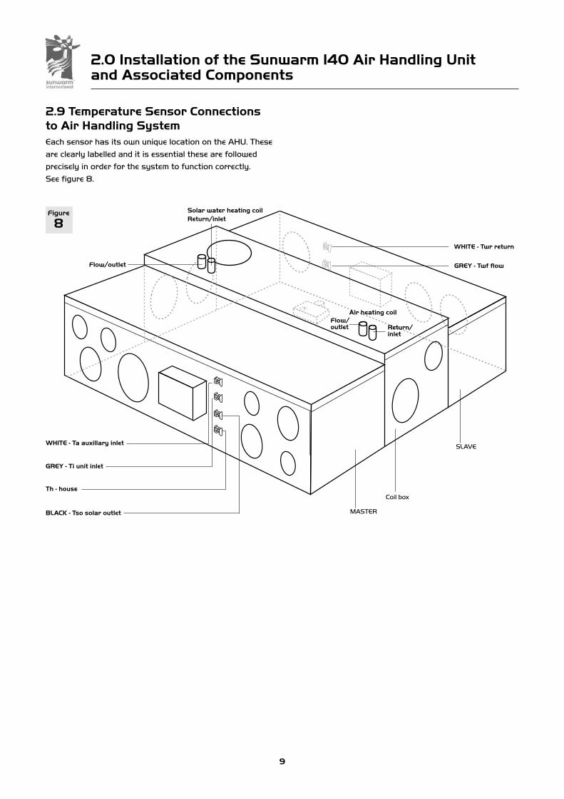
2.9 Temperature Sensor Connections to Air Handling SystemEach sensor has its own unique location on the AHU. These
are clearly labelled and it is essential these are followed
precisely in order for the system to function correctly.
See figure 8.
SLAVE
MASTER
Coil box
BLACK - Tso solar outlet
WHITE - Ta auxillary inlet
GREY - Ti unit inlet
WHITE - Twr return
Figure
8
Th - house
GREY - Twf flow
Solar water heating coilReturn/inlet
Flow/outlet
Air heating coilFlow/outlet Return/
inlet

3.0 Installation of the Solar Hot Water Storage Systemand Associated Components
10
Sunwarm can be integrated with a wide range of solar hot
water storage systems. These devices can be purchased
through Nuaire or be supplied by others.
For best energy gain we would recommend a well insulated
hot water cylinder with a high efficiency solar coil at the
lowest part of the cylinder.
Number Description
1 3 bar pressure relief valve
2 Air eliminator with Shut off valve
3 2 x 22 x 1/2 inch x 22 compression tee fittings
4 3/4 BSP X 15mm addaptor
5 Expansion vessel 8 1itres
6 Expansion vessel bracket
7 2 x No. 12 rawl plugs
8 Combi filling loop
9 3.5 bar pressure gauge
10 15 x 15 x 1/2 inch comp. tee
11 Grundfos 25 - 15 circulator pump
12 2 x 22mm pump isolating valves
13 15mm non return valve
14 4 x 22 x 15 reducer sets
15 Drain cock
16 1/2 inch x 1/4 inch BSP reducing bush
17 PTFE tape (Use only on threaded parts)
18 2 x 15 x 15 x 15 T piece
19 2 No. 10 Posi screws
For Solar Hot Water Connections refer to figure 9 and the
key to components below. Please note all the items listed
below form the Solar Loop Kit supplied as an option.
(Flow) Hot water pipes
(Return) Cold water pipes
1 23
1414
13
15
12
14
11
14
18
18
16
10
9
8
5
19
6
74
Figure
9
Air to water heatexchanger, part ofthe Air HandlingUnits.
Typical pipework connections.
12
IMPORTANT
Note: the optional air heating coil must be connected to an auxiliary source and controlled separately,
please refer to system designers instructions for connecting this coil.
Solar water heating circuit

IMPORTANT
For good EMC engineering practice, any sensor cables or switched live cables should not be
placed within 50mm of other cables or on the same metal cable tray as other cables.
IMPORTANT
Turn power supply off before making any connections.Failure to do so will damage the unit and render
the warranty void.
8 7 6 5 4 3 2 1
ON PUMP−VFBOX
N/C N/O COM
L N E
PUMP
LNE
Supply 240V 50Hz
Net cableto unit
Power Status
sunwarm
4.0 Electrical Connections
User control LV connection
Pump-VF control LV
Connection required LV
LNE Mains supply 240V 50Hz 1 Phvia suitable isolatoror fused spur
Wiring of circulator pump to PUMP-VF control box
Optional DATASTORE
This connectionmay be to theslave unit ifrequired.
MASTER
Figure
10
Mains loop
Pump Consumptions:3A fuse 60W (max)
AHU Electrical details:-
Voltage: 230V 1phase 50Hz
Consumption: 130W (max)
Fuse rating: 3 Amp
NOTE This unit must be earthed.
The three core cable from the mains power supply
should be connected to a fixed wiring installation, via
a fused isolator, in accordance with current IEE wiring
regulations.
LV = Low Voltage Net cable supplied.
4.1 WiringPlease note: the electrical connection of the unit must be
carried out by a qualified electrician.
SLAVE
11

4.1 Wiring cont.Other conditions could be identified by changing the DIL
switch settings of the PUMP-VF unit. Note the PUMP-VF
must have software version 1.5 or above to indicate the
following:
The relay will operate when the Sunwarm 140 is running at
the maximum boost speed.
The relay will operate when the target temperature setting
of the user control is higher than the house temperature
and the target is higher than 19oC.
The relay will operate when the target temperature setting
of the user control is less than the house temperature and
the target is also less than 19oC.
8 7 6 5 4 3 2 1
OFF
ON
8 7 6 5 4 3 2 1
OFF
ON
8 7 6 5 4 3 2 1
OFF
ON
Wiring to the actuat or motor
1 2 3
Brown Blue Red
Loom from the master fan
4.0 Electrical Connections
12
Figure
11

4.0 Electrical Connections
13
4.2 User ControlThe user control should be fitted to an appropriate wall
(fixings supplied). Position the control so that the user can
gain easy access. Instructions for fixing are supplied with
the control.
Screw the backplate to the wall. Connect the cable
(supplied) and clip the control into place. Route the cable to
the loft and connect to the control module.
Secure the cable to prevent accidental dislocation.
User Control Test
Ensure the power light is on green and the status light is
either green or amber.
If the power light is not on check the wiring and connections
between the fan unit and the user control.
Sunwarm User Control
The user control as shown in figure 11 above, has a target
temperature setting dial and two press buttons (under the
cover) which enable the fan to be switched off or the
airflow to be boosted to its maximum duty.
Master Control Box (cover removed).
4.3 Airflow Adjustment on Master Unit
The unit has six air volume (speed) settings. The setting
switch is located on the main control box on the fan case.
Figure 13 shows the LED’s that, when illuminated, indicate
the corresponding air volume for the unit.
Default setting on middle LED
4.4 Trouble ShootingIf there are any red lights flashing on either the Master
Unit or the Slave Unit consult the following table to
determine the cause.
On Master Unit :
House sensor not connected
Collector outlet sensor
not connected
Inlet sensor not connected
Fan failure
On Slave Unit:
Water return sensor not connected
Return flow sensor not connected
Fan failure
Note: the status LED of the user control will stay on red
if there is a fault with the unit.
4.5 Speed indicationPress the speed selection button located on the top of the
Ventilation Fan Unit to achieve the required speed setting.
Also see figure 13.
Power Status
Power Status
User controlcover closed
User controlcover open
Speed selectionbutt on
LED's indicatespeed (air volume)
L N
Key to speedsettings
230V 1ph 50Hz supply
NET 1 NET 2 NET 3
Low voltage (LV) connection terminals
Figure
12
Figure
13Speed 1
Speed 2
Speed 3
Speed 4
Speed 6
Button Led Led Led
Speed 5

5.0 Miscellaneous
14
5.1 Airflow AdjustmentThe unit has six speed settings and these settings
are selectable using the push-button on the side of
the control on the ventilation fan. The chart below
shows the performance of the unit at different speeds.
However; it should be noted that the pressure losses
through flexible ducting and other obstructions (e.g.
grilles) are difficult to predict. Therefore a proper
commissioning procedure should be followed to
ensure the correct air delivery into the rooms.
Figure
14
0
75
100
125
150
175
200
0 20 40 60 80 100 120
Air Volum e Flow rate (l/s)
Sta
tic
Pre
ss
ure
(Pa
)
AIR PERFORMANCE (Supply Fan)
50
25
Total weight of the unit:
73kg excluding any ducting.
Dimensions for the sunwarm 140 Air Handling Unit (mm).Figure
15
5.2 Dimensions and Weight
Slave Unit
Mast er Unit
Coilbox
1300
300
505
300
400
440
Coil box 1320. 1405 Including handle and spigots on one side

IMPORTANT
Isolate the mains supply before carrying out any maintenance procedure.
6.0 Maintenance
15
6.1 Maintenance NotesThe air handling unit only requires general cleaning toensure it function at its optimum. Remove any dust and dirton the internal parts using a soft brush and a low powervacuum cleaner.
Apart from the filter; there is no user serviceable part.
6.2 Filter ChangeAfter a period of 5 years, the status light on the user
control will flash red to indicate the filters require changing.
However; local conditions may dictate a shorter period
between filter changes.
To change the filters, isolate the power supply and remove
the screws securing the top cover of the fan units.
Slide the filter out of the box and replace with new filters
(part number 630027). Re-assemble the cover and the
screws.
Make sure that the filters are installed in the correct
orientation. Filters have an arrow on the side indicating the
direction of the air flow. These arrows should be pointing
towards the coil box in the middle of the AHU’s.
To reset the filter timer:
Switch on the mains power to the unit and ensure it is
operating. Press and hold button on the ventilation fan unit
for 10sec to reset the timer. The control will confirm this
by flashing all 3 LED 5 times.
7.0 WarrantyThe 5 year warranty starts from the day of delivery and
includes parts and labour for the first year. The remaining
4 years covers parts only. This warranty is conditional on
planned maintenance being undertaken.
8.0 DisclosureA value for solar energy gained may be given by Nuaire;this is a theoretical figure based on historical weather dataand test results. However, the actual amount of solar energy collected is affected by a number of factors. These include the local micro-climate, the unit’s interactionwith other equipment (e.g. boiler) in the building, and theoperational setting chosen by the occupants. Therefore anyenergy figures given are indicative of potential energy gainavailable and do not form part of our contract of sales.
9.0 Service EnquiriesService issues can be handled by your installer or Nuaire.
Our service department will be happy to provide any
assistance required, initially by telephone and if necessary
arrange for an engineer to call.
Telephone 02920 858 255
Technical or commercial considerations may, from time to time, make it necessary to alter the design, performance and dimensions of equipment and the right is reserved to make such changes without prior notice.

10.0 Commissioning the System, checklist
16
Doc 1) Documentation left with building occupier
Doc 2) Solar system commissioning certificate completed and signed
Doc 3) Cylinder/store commissioning certificate completed and signed (if store replaced)
Doc 4) DHW drain location and DHW isolation points pointed out
Doc 5) System schematic drawing (mechanical and electric)
Doc 6) Specialist maintenance tasks, schedule and parts list
Doc 7) Manual DHW drain-off method to prevent over-heating isprescribed and safe (if required)
Doc 8) User actions to prevent freeze damage to be stated
Doc 9) De-commissioning method including any hazardoussubstances to be stated
Doc 10) All end-user and manufacturer’s instructions for all installed solar water heating equipment shown and explained to end-user. Document storage location to be explained
Doc 11) Where required by PED (pressure has potential to exceed 0.5 bar and temperature over 110oC), evidence left on site of compliance with essential safety requirements with CE mark
Doc 12) Manufacturer’s written installation requirement’s to be lefton-site for any fitted electrical and mechanical equipment.
Doc 13) Hot water store listed as approved by Clear Skies Labelling and type of replacement store to building regulations
Doc 14) System Registration documented on page 20
Ref Item Yes No N/A Notes
code Documentation
1) User manual2) Installation &
maintenance
Pointed out
FilterPressure

10.0 Commissioning the System, checklist
17
Elec 1) Check all electrical connections per figure 10
Elec 2) 240V isolation switch and fuse protection fitted
Elec 3) Class 1 equipment such as pumps etc is earthed
Elec 4) All wiring supported and routed reasonably and ofcorrect length
Elec 5) Cable to pump is heat resisting flex
Elec 6) All cabling correct current rating, type and suitable for purpose
Elec 7) Cable sheaths taken into enclosures and glands
Elec 8) All connections are enclosed
Elec 9) Check all sensor connections per figure 8
Elec 10) Check solar flow sensor to be close to tank
Elec 11) Check solar return sensor to be close to tank
Elec 12) LV and 240V wires are min 5cm apart
Roof 1) Collector appearance OK
Roof 2) No significant shading across collector
Roof 3) Collector orientation checked with that on application
Roof 4) Auto air vent not obstructed
Roof 5) Roof fixings robust and weather tight. Roof penetrations i.e. sarking felt made good
Roof 6) Collector mountings solid
Oper 1) LED’S on user control are correct pattern
Oper 2) Electrical controls and sensors are operating
Oper 3) Reverse flow protection identifiable from schematic
Oper 4) If a hot water store does not have an open vent then acombination of thermostatic control device, energy cut-offdevice and heat dissipation method should be present. (i.e. unvented stores and sealed thermal stores)
Oper 5) If a hot water store has an open vent it must have at least a thermostatic control or a temperature relief valve
Oper 6) All safety devices to operate correctly
Oper 7) Check for excessive pump noise
Oper 8) Check ventilation units, correct set up (Master/Slave)
Oper 9) Sufficient expansion capability in cisterns and vessels
Oper 10) Check all ductwork, connections and type
Oper 11) Check for fan noise
Oper 12) Check diffuser location
Ref Item Yes No N/A Notes
code Electrical
Ref Item Yes No N/A Notes
code Roof
Ref Item Yes No N/A Notes
code Operation

10.0 Commissioning the System, checklist
18
Gen 1) Prevention of water backflow into potable rising main by check valve. Filling loop is disconnected
Gen 2) Sufficient drain points - to enable all pipes to be drained
Gen 3) Materials are rated and WRAS listed at stagnation temperature and pressure
Gen 4) Open vent termination over correct cistern
Gen 5) No obstruction before safety valves or vents. Vents anddischarge pipes to be correctly graded and exhaust locations are safe - no scald risk to people
Gen 6) Sound engineering practice to be used or evidence left on site of higher conformity according to PED. All pressure componentsto be labelled and identifiable
Gen 7) Pipe clips and insulation to be sufficient for stagnationtemperatures
Gen 8) All indoor components in unheated areas to be sufficiently protected from freeze damage
Gen 9) Anti scald measures are in place e.g. controller can be set or auto blend valve is fitted
Gen 10) Pressure relief measures will operate before failure risk of most vulnerable component
Gen 11) If replaced, DHW back-up heat source to have time switch
Gen 12) If replaced, DHW back-up heat source to have correctly located thermostat and interlock
Gen 13) On replacement cylinders, all connected pipes to be insulated where practicable
Gen 14) Hot water store sufficient and dedicated pre-heat volume for user requirements
Gen 15) Hot water store sensor pockets or digital readout
Gen 16) Check auxiliary heat source is capable of heating store to at least 55oC to prevent leg ionella
Gen 17) All unions, and glands are free from leaks; no leaking evident elsewhere e.g from pipework joints etc.
Gen 18) All pipework is adequately clipped, insulated and components are adequately supported
Gen 19) Pipe insulation to be firmly in place and secured at junctions and corners
Gen 20) Penetrations in building made good. Debris removed
Gen 21) Check solar loop preesure is 1 to 1.5 bar
Gen 22) Increase solar loop preesure to test relief valve
Gen 23) Check plumbing components per figure 9
Ref Item Yes No N/A Notes
code General
Notes: to turn the pump on manually, on the ES-VF (Pump) box turn switch 8 on. Make sure you return it to offwhen testing is finished.

19
We declare that the machinery named below is intended to be assembled with other components to constitute a system of machinery. The machinery shall not be put into service until the system has been declared to be in conformity with the provisions of theEC Machinery Directive.
Designation of machinery: SUNWARM 140
Machinery Types: SUNWARM 140
Relevant EC Council Directives: 98/37/EC as amended by 98/79/EC (Machinery Directive)
Applied Harmonised Standards: BS EN ISO 12100-1, BS EN ISO 12100-2, EN294, EN60204-1, BS EN ISO 9001
Applied National Standards: BS848 Parts One, Two and Five
Signature of manufacture representatives:Name: Position: Date:
1) C. Biggs Technical Director 20. 07. 07
2) W. Glover Manufacturing Director 20. 07. 07
DECLARATION OF INCORPORATION AND INFORMATION FOR SAFE INSTALLATION, OPERATION AND MAINTENANCE
DECLARATION OF CONFORMITY
We declare that the machine named below conforms to the requirements of EC Council Directives relating to ElectromagneticCompatibility and Safety of Electrical Equipment.
Designation of machinery: SUNWARM 140
Machinery Types: SUNWARM 140
Relevant EC Council Directives: 2004/108/EC (EMC)2006/95/EC (Low Voltage Directive)
Applied Harmonised Standards: EN55014-1, EN55014-2, EN60335-2-80
Basis of Self Attestation: Quality Assurance to BS EN ISO 9001BSI Registered FirmCertificate No. FM 149
Signature of manufacture representatives:Name: Position: Date:
1) C. Biggs Technical Director 20. 07. 07
2) W. Glover Manufacturing Director 20. 07. 07
INFORMATION FOR SAFE INSTALLATION, OPERATION AND MAINTENANCE OF NUAIRE VENTILATION EQUIPMENTTo comply with EC Council Directives 98/37/EC Machinery Directive and2004/108/EC (EMC).
To be read in conjunction with the relevant Product Documentation (see 2.1)
1.0 GENERAL
1.1 The equipment referred to in this Declaration of Incorporation is supplied by Nuaire to be assembled into a ventilation system which may or may not include additional components.
The entire system must be considered for safety purposes and it is the responsibilityof the installer to ensure that all of the equipment is installed in compliance with the manufacturers recommendations and with due regard to current legislation and
codes of practice.
2.0 INFORMATION SUPPLIED WITH THE EQUIPMENT
2.1 Each item of equipment is supplied with a set of documentation which provides the information required for the safe installation and maintenance of the equipment. This may be in the form of a Data sheet and/or Installation and Maintenance instruction.
2.2 Each unit has a rating plate attached to its outer casing. The rating plate provides essential data relating to the equipment such as serial number, unit code and electrical data. Any further data that may be required will be found in the documentation. If any item is unclear or more information is required, contact Nuaire.
2.3 Where warning labels or notices are attached to the unit the instructions given must be adhered to.
3.0 TRANSPORTATION, HANDLING AND STORAGE
3.1 Care must be taken at all times to prevent damage to the equipment. Note that shock to the unit may result in the balance of the impeller being affected.
3.2 When handling the equipment, care should be taken with corners and edges and thatthe weight distribution within the unit is considered. Lifting gear such as slings or ropes must be arranged so as not to bear on the casing.
3.3 Equipment stored on site prior to installation should be protected from the weather and steps taken to prevent ingress of contaminants.
4.0 OPERATIONAL LIMITS
4.1 It is important that the specified operational limits for the equipment are adhered to e.g. operational air temperature, air borne contaminants and unit orientation.
4.2 Where installation accessories are supplied with the specified equipment eg. wall mounting brackets. They are to be used to support the equipment only. Other system components must have separate provision for support.
4.3 Flanges and connection spigots are provided for the purpose of joining to ductworksystems. They must not be used to support the ductwork.
4.4 In the event of RF interference the fan may change speed. This is normal and will have no adverse effect on the fan. The speed will return to normal once the interference has subsided.
5.0 INSTALLATION REQUIREMENTS
In addition to the particular requirements given for the individual product, the
following general requirements should be noted.
5.1 Where access to any part of equipment which moves, or can become electrically live
are not prevented by the equipment panels or by fixed installation detail
(eg ducting), then guarding to the appropriate standard must be fitted.
5.2 The electrical installation of the equipment must comply with the requirements of the
relevant local electrical safety regulations.
5.3 For EMC all control and sensor cables should not be placed within 50mm or on the
same metal cable tray as 230V switched live, lighting or power cables and any
cables not intended for use with this product.
6.0 COMMISSIONING REQUIREMENTS
6.1 General pre-commissioning checks relevant to safe operation consist of the following:
Ensure that no foreign bodies are present within the fan or casing.
Check electrical safety. e.g. Insulation and earthing.
Check guarding of system.
Check operation of Isolators/Controls.
Check fastenings for security.
6.2 Other commissioning requirements are given in the relevant product documentation.
7.0 OPERATIONAL REQUIREMENTS
7.1 Equipment access panels must be in place at all times during operation of the unit,
and must be secured with the original fastenings.
7.2 If failure of the equipment occurs or is suspected then it should be taken out of
service until a competent person can effect repair or examination. (Note that certain
ranges of equipment are designed to detect and compensate for fan failure).
8.0 MAINTENANCE REQUIREMENTS
8.1 Specific maintenance requirements are given in the relevant product documentation.
8.2 It is important that the correct tools are used for the various tasks required.
8.3 If the access panels are to be removed for any reason the electrical supply to the
unit must be isolated.
8.4 A minium period of two minutes should be allowed after electrical disconnection
before access panels are removed. This will allow the impeller to come to rest.
NB: Care should still be taken however since airflow generated at some other
point in the system can cause the impeller to “windmill” even when power is not
present.
8.5 Care should be taken when removing and storing access panels in windy conditions.

20

Man
ual N
umbe
r 67
1334
Nov
embe
r 20
08
Nuaire Limited Western Industrial Estate Caerphilly United Kingdom CF83 1NATelephone: 029 2085 8441 Facsimile: 029 2085 8442Email: [email protected] www.sunwarm.comEmail: [email protected] www.nuaire.co.uk