application example: quality control online … example: quality control online calibration and...
TRANSCRIPT
Copyright © 2008 GOM mbH All rights reserved! Rev. A (en) 17112008 www.gom.com 1
Application Example: Quality Control
Online Calibration and Validation of Fixtures, Jigs and Gauges
GOM mbHMittelweg 7-838106 BraunschweigGermanyPhone +49 531 390 29 0Fax +49 531 390 29 [email protected]
GOM Branch BeneluxInterleuvenlaan 15 E3001 LeuvenBelgiumPhone +32 16 408 034Fax +32 16 408 [email protected]
GOM International AGBremgarterstrasse 89B8967 WidenSwitzerlandPhone +41 5 66 31 04 04Fax +41 5 66 31 04 [email protected]
GOM France SAS10 Quai de la Borde - Bât A291130 Ris OrangisFrancePhone +33 1 60 47 90 50Fax +33 1 69 06 63 [email protected]
GOM UK LtdBusiness Innovation CentreCoventry, CV3 2TXGreat BritainPhone +44 2476 430 230Fax +44 2476 430 [email protected]
Measuring Systems: ATOS, GOM Touch Probe
Keywords: Quality Control, Assembly, Jigs, Fixture & Gauge Calibration, Optical 3D Surface measurement, Additive Manufacturing, Rapid Fit Prototyping, Touch Probing, Flexible Parts, Plastic Components, Sheet Metal
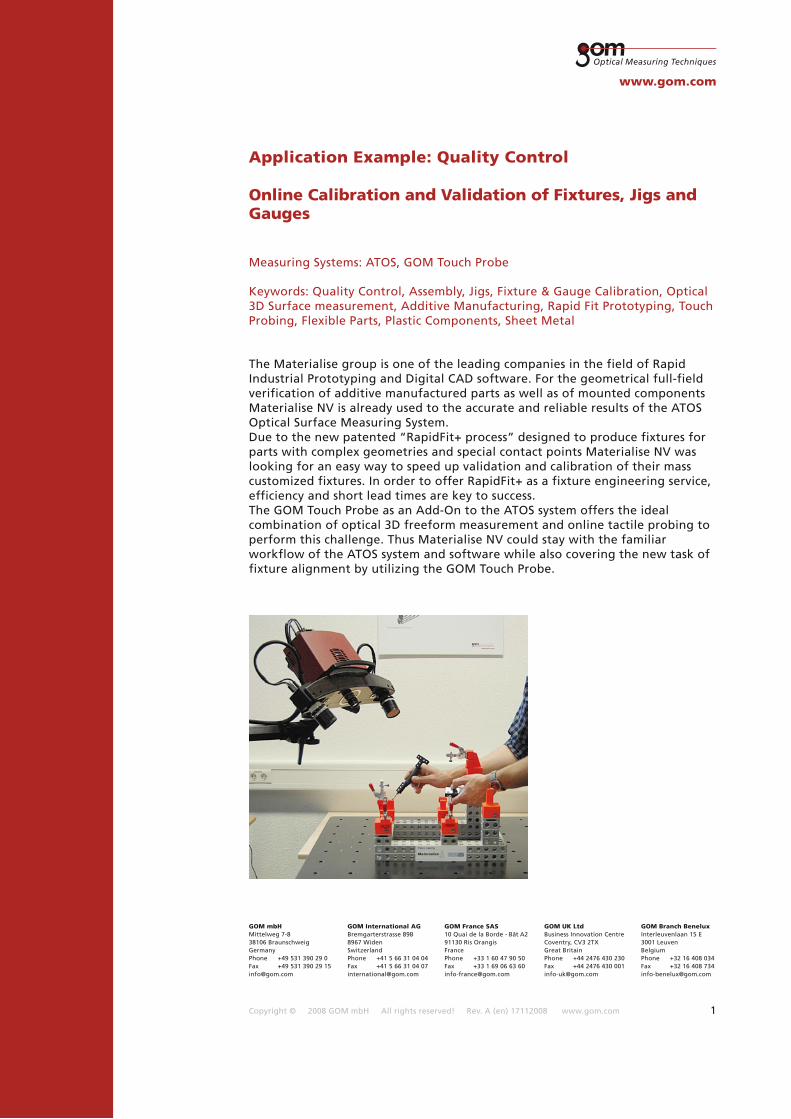
The Materialise group is one of the leading companies in the field of Rapid Industrial Prototyping and Digital CAD software. For the geometrical full-field verification of additive manufactured parts as well as of mounted components Materialise NV is already used to the accurate and reliable results of the ATOS Optical Surface Measuring System. Due to the new patented “RapidFit+ process” designed to produce fixtures for parts with complex geometries and special contact points Materialise NV was looking for an easy way to speed up validation and calibration of their mass customized fixtures. In order to offer RapidFit+ as a fixture engineering service, efficiency and short lead times are key to success. The GOM Touch Probe as an Add-On to the ATOS system offers the ideal combination of optical 3D freeform measurement and online tactile probing to perform this challenge. Thus Materialise NV could stay with the familiar workflow of the ATOS system and software while also covering the new task of fixture alignment by utilizing the GOM Touch Probe.
Copyright © 2008 GOM mbH All rights reserved! Rev. A (en) 17112008 www.gom.com 2
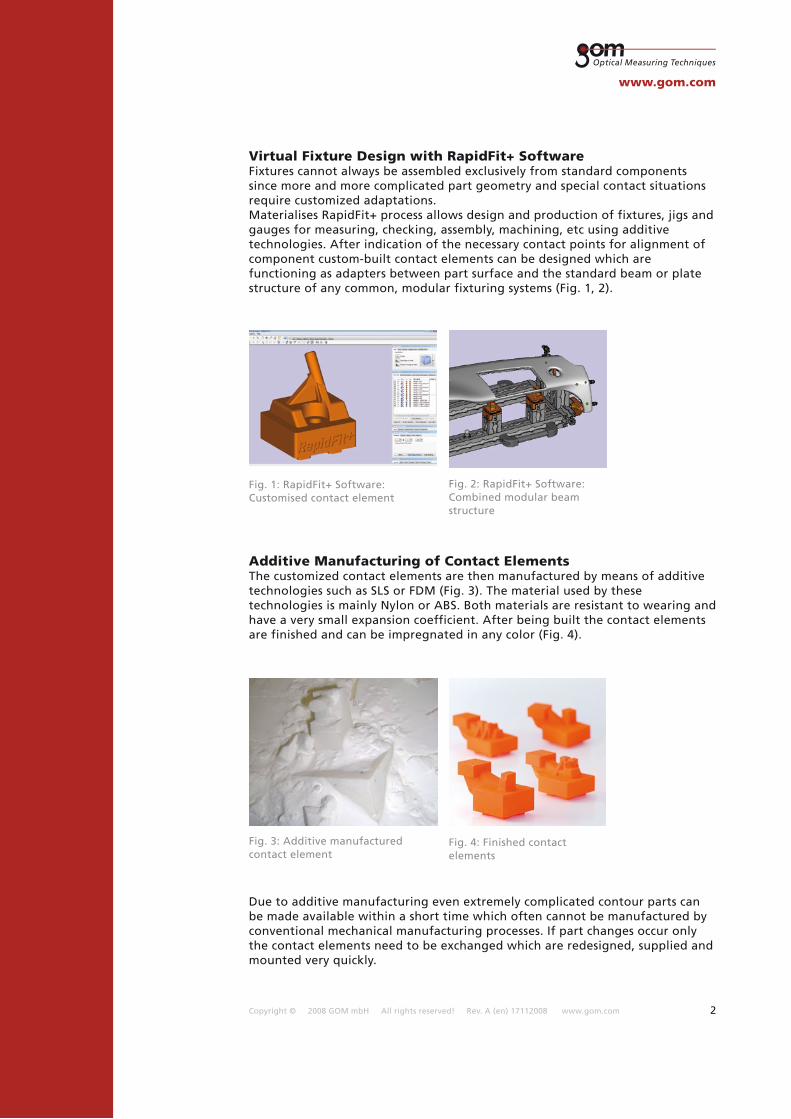
Virtual Fixture Design with RapidFit+ SoftwareFixtures cannot always be assembled exclusively from standard components since more and more complicated part geometry and special contact situations require customized adaptations.Materialises RapidFit+ process allows design and production of fixtures, jigs and gauges for measuring, checking, assembly, machining, etc using additive technologies. After indication of the necessary contact points for alignment of component custom-built contact elements can be designed which are functioning as adapters between part surface and the standard beam or plate structure of any common, modular fixturing systems (Fig. 1, 2).
Fig. 1: RapidFit+ Software: Customised contact element
Fig. 2: RapidFit+ Software: Combined modular beam structure
Additive Manufacturing of Contact ElementsThe customized contact elements are then manufactured by means of additive technologies such as SLS or FDM (Fig. 3). The material used by these technologies is mainly Nylon or ABS. Both materials are resistant to wearing and have a very small expansion coefficient. After being built the contact elements are finished and can be impregnated in any color (Fig. 4).
Fig. 3: Additive manufactured contact element
Fig. 4: Finished contact elements
Due to additive manufacturing even extremely complicated contour parts can be made available within a short time which often cannot be manufactured by conventional mechanical manufacturing processes. If part changes occur only the contact elements need to be exchanged which are redesigned, supplied and mounted very quickly.

Copyright © 2008 GOM mbH All rights reserved! Rev. A (en) 17112008 www.gom.com 3
Dimensional & Geometrical Control Contact ElementsEach RapidFit+ contact element manufactured by Materialise NV is certified with a 3D measurement report of the contact surface using the ATOS 3D Digitizing System (Fig. 5). The ATOS system is a white light optical scanner which measures the complete surfaces of three-dimensional objects (Fig. 6). With 1 second measuring time for a single measurement 3D objects can be captured from various views in very short time resulting in a high density point cloud or polygon mesh. Each individual measurement is automatically transferred into the objects coordinate system by means of easy applicable reference markers. The mobile ATOS system can simply be adapted to measure objects of various sizes, from filigree components up to a complete aircraft. The stereo camera set-up guarantees constant self-monitoring of the ATOS system throughout the whole measuring process. This makes it possible to verify the calibration of the system, detect movements and ambient light changes during the measurement and also to survey the matching accuracy of the individual scans into the objects coordinate system. Turntables and robots can be employed to automate the measuring process in order to save man power (Fig. 6, Fig. 26).
Fig. 5: ATOS Inspection Software: Measuring report for contact element
Fig. 6: Measuring of contact element with ATOS 3D Digitizing System
Fig. 7: ATOS Inspection Software: Complete 3D surface deviation, defined inspection points
GOM is a one source provider developing and delivering hardware, software, PCs, training and support from one hand. Thus the ATOS system comes along with a powerful software package so that no second party software for evaluation is necessary.The ATOS inspection software allows direct comparison of measuring data to CAD data including various CAD-Import formats such as CATIA, Pro/Engineer, UG, IGES, STEP, etc.. Any deviation can be immediately visualized by a 3D color-map of the entire component surface which can be easily and quickly interpreted (Fig. 7).
Positions of standard defined CMM points can also be imported and evaluated.Utilisation of the ATOS 3D optical scanning devices gives Materialise NV the advantage to ensure perfect quality of each contact element. Beneficially the 3D colour map shows even the smallest deviation of the whole contact surface in order to check the complete mating surface and not just a couple of specific points.
Copyright © 2008 GOM mbH All rights reserved! Rev. A (en) 17112008 www.gom.com 4
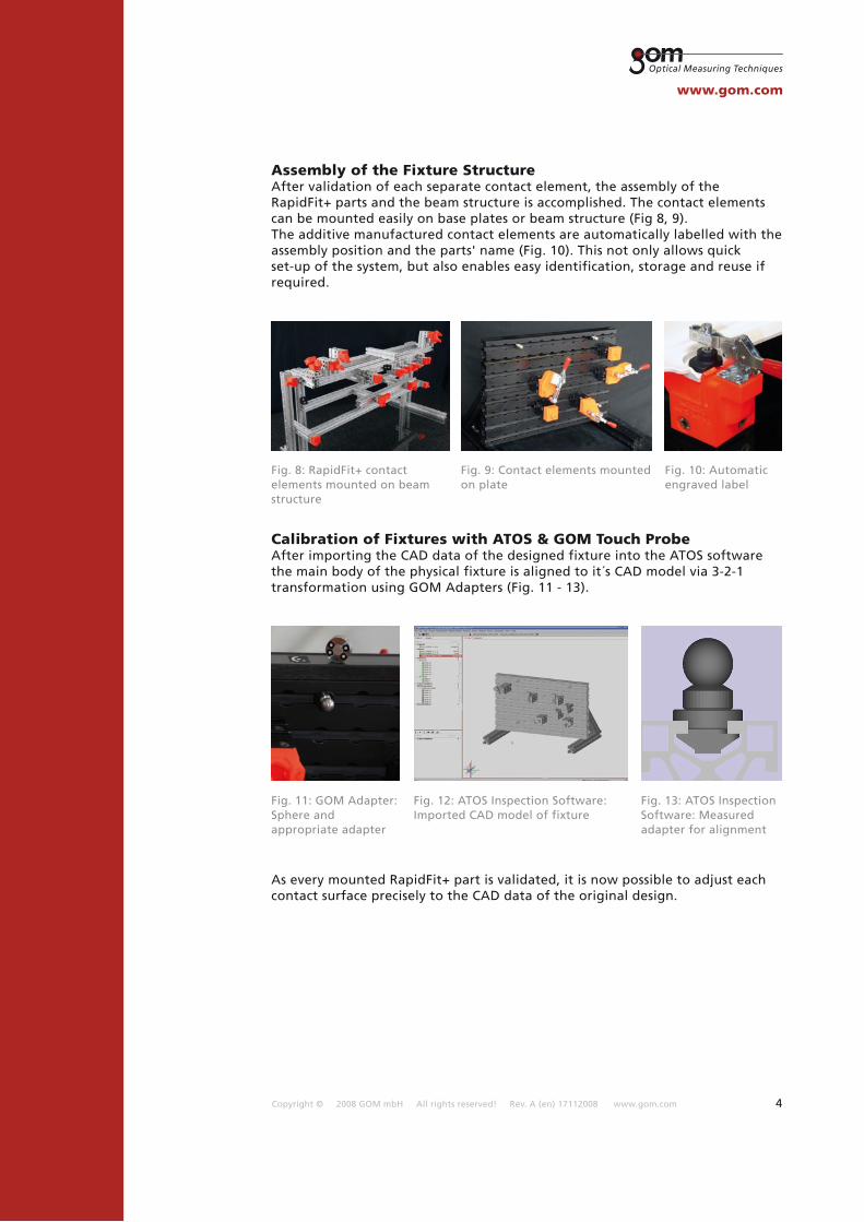
Assembly of the Fixture StructureAfter validation of each separate contact element, the assembly of the RapidFit+ parts and the beam structure is accomplished. The contact elements can be mounted easily on base plates or beam structure (Fig 8, 9). The additive manufactured contact elements are automatically labelled with the assembly position and the parts' name (Fig. 10). This not only allows quick set-up of the system, but also enables easy identification, storage and reuse if required.
Fig. 8: RapidFit+ contact elements mounted on beam structure
Fig. 9: Contact elements mounted on plate
Fig. 10: Automatic engraved label
Calibration of Fixtures with ATOS & GOM Touch ProbeAfter importing the CAD data of the designed fixture into the ATOS software the main body of the physical fixture is aligned to it´s CAD model via 3-2-1 transformation using GOM Adapters (Fig. 11 - 13).
Fig. 11: GOM Adapter: Sphere and appropriate adapter
Fig. 12: ATOS Inspection Software: Imported CAD model of fixture
Fig. 13: ATOS Inspection Software: Measured adapter for alignment
As every mounted RapidFit+ part is validated, it is now possible to adjust each contact surface precisely to the CAD data of the original design.
Copyright © 2008 GOM mbH All rights reserved! Rev. A (en) 17112008 www.gom.com 5
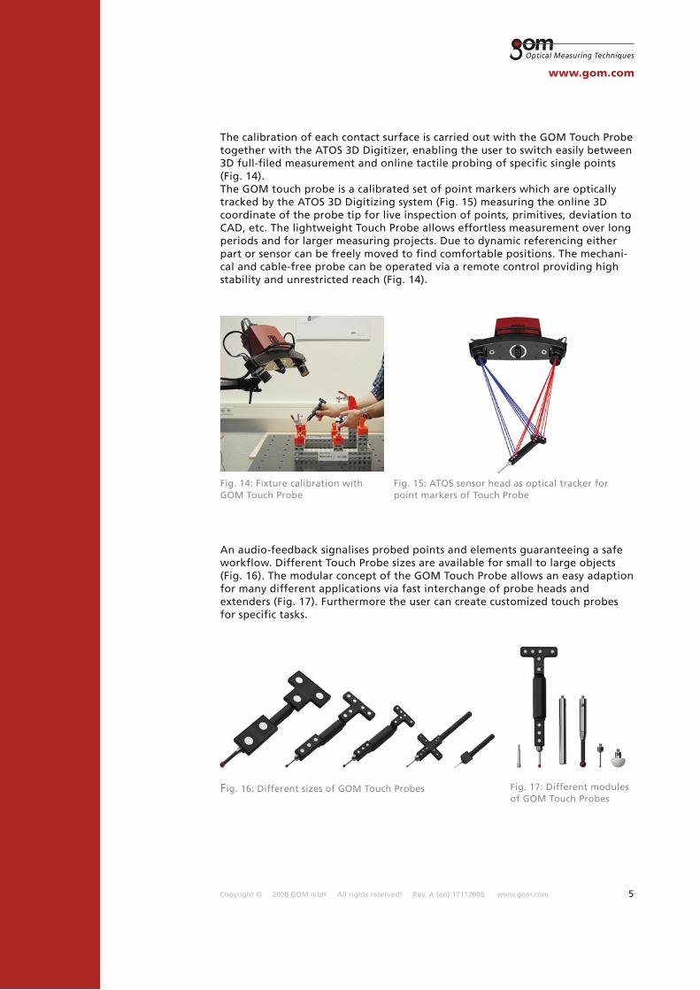
The calibration of each contact surface is carried out with the GOM Touch Probe together with the ATOS 3D Digitizer, enabling the user to switch easily between 3D full-filed measurement and online tactile probing of specific single points (Fig. 14).The GOM touch probe is a calibrated set of point markers which are optically tracked by the ATOS 3D Digitizing system (Fig. 15) measuring the online 3D coordinate of the probe tip for live inspection of points, primitives, deviation to CAD, etc. The lightweight Touch Probe allows effortless measurement over long periods and for larger measuring projects. Due to dynamic referencing either part or sensor can be freely moved to find comfortable positions. The mechani-cal and cable-free probe can be operated via a remote control providing high stability and unrestricted reach (Fig. 14).
An audio-feedback signalises probed points and elements guaranteeing a safe workflow. Different Touch Probe sizes are available for small to large objects (Fig. 16). The modular concept of the GOM Touch Probe allows an easy adaption for many different applications via fast interchange of probe heads and extenders (Fig. 17). Furthermore the user can create customized touch probes for specific tasks.
Fig. 14: Fixture calibration with GOM Touch Probe
Fig. 15: ATOS sensor head as optical tracker for point markers of Touch Probe
Fig. 16: Different sizes of GOM Touch Probes Fig. 17: Different modules of GOM Touch Probes
Copyright © 2008 GOM mbH All rights reserved! Rev. A (en) 17112008 www.gom.com 6
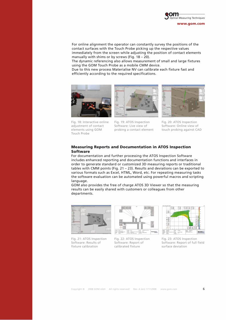
Fig. 18: Interactive online adjustment of contact elements using GOM Touch Probe
Fig. 19: ATOS Inspection Software: Live view of probing a contact element
Fig. 20: ATOS Inspection Software: Online view of touch probing against CAD
Measuring Reports and Documentation in ATOS Inspection SoftwareFor documentation and further processing the ATOS Inspection Software includes enhanced reporting and documentation functions and interfaces in order to generate standard or customized 3D measuring reports or traditional tables with CMM points (Fig. 21 – 23). Results and deviations can be exported to various formats such as Excel, HTML, Word, etc. For repeating measuring tasks the software evaluation can be automated using powerful macros and scripting language.GOM also provides the free of charge ATOS 3D Viewer so that the measuring results can be easily shared with customers or colleagues from other departments.
Fig. 21: ATOS Inspection Software: Results of fixture calibration
Fig. 22: ATOS Inspection Software: Report of calibrated fixture
Fig. 23: ATOS Inspection Software: Report of full field surface deviation
For online alignment the operator can constantly survey the positions of the contact surfaces with the Touch Probe picking up the respective values immediately from the screen while adjusting the position of contact elements manually with shims or by screws (Fig. 18 – 20).The dynamic referencing also allows measurement of small and large fixtures using the GOM Touch Probe as a mobile CMM device.Due to this new process Materialise NV can calibrate each fixture fast and efficiently according to the required specifications.
Copyright © 2008 GOM mbH All rights reserved! Rev. A (en) 17112008 www.gom.com 7
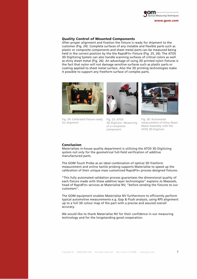
Quality Control of Mounted ComponentsAfter proper alignment and fixation the fixture is ready for shipment to the customer (Fig. 24). Complete surfaces of any instable and flexible parts such as plastic or composite components and sheet metal parts can be measured being held in the correct position by the the RapidFit+ Fixture (Fig. 25, 26). The ATOS 3D Digitizing System can also handle scanning surfaces of critical colors as well as shiny sheet metal (Fig. 26). An advantage of using 3D printed nylon fixtures is the fact that nylon will not damage sensitive surfaces such as plastic parts or coating applied to sheet metal surface. Also the 3D printing technologies make it possible to support any freeform surface of complex parts.
ConclusionMaterialises in-house quality department is utilizing the ATOS 3D Digitizing system not only for the geometrical full-field verification of additive manufactured parts.
The GOM Touch Probe as an ideal combination of optical 3D freeform measurement and online tactile probing supports Materialise to speed up the calibration of their unique mass customized RapidFit+ process designed fixtures.
“This fully automated validation process guarantees the dimensional quality of each fixture made with these additive layer technologies” explains Jo Massoels, head of RapidFit+ services at Materialise NV, “before sending the fixtures to our customers”.
The GOM equipment enables Materialise NV furthermore to efficiently perform typical automotive measurements e.g. Gap & Flush analysis, using RPS alignment up to a full 3D colour map of the part with a precise and assured overall accuracy.
We would like to thank Materialise NV for their confidence in our measuring technology and for the longstanding good cooperation.
Fig. 24: Calibrated fixture ready for shipment
Fig. 25: ATOS 3D-Digitizer: Measuring of a composite component
Fig. 26: Automated measurement of shiny Sheet Metal Assembly with the ATOS 3D-Digitizer