application for process automation · push the button "next" to start the wizard. 3....
TRANSCRIPT

Application for Process Automation
Integration of SIMATIC PCS 7 Asset Management into existing projects
Engineering example

Warranty, liability and support
Asset Management Integration 27833758
1.0 14.02.08 2/42
Cop
yrig
ht ©
Sie
men
s A
G 2
008
All
right
s re
serv
ed
Note The application examples are not binding and do not claim to be com-plete regarding the configuration and equipment and any eventuality. The application examples do not represent customer-specific solutions. They are only intended to provide support for typical applications. You are re-sponsible in ensuring that the described products are correctly used. These application examples do not relieve you of the responsibility in safely using, installing, operating and servicing equipment. By using these application examples you recognize that Siemens cannot be made liable for any damage beyond the specified liability clause. We reserve the right to make changes to these application examples at any time without prior notice. If there are any deviations between the recommen-dations provided in this application example and other Siemens publica-tions - e.g. catalogs - then the contents of the other documents have pri-ority.
Warranty, liability and support
We do not accept any liability for the information contained in this docu-ment.
Any claims against us - based on whatever legal reason - resulting from the use of the examples, information, programs, engineering and performance data, etc., described in this application example shall be excluded. Such an exclusion shall not apply in the case of mandatory liability, e.g. under the German Product Liability Act ("Produkthaftungsgesetz"), in case of intent, gross negligence, or injury of life, body or health, guarantee for the quality of a product, fraudulent concealment of a deficiency or breach of a condi-tion which goes to the root of the contract ("wesentliche Vertragspflichten"). However, claims arising from a breach of a condition which goes to the root of the contract shall be limited to the foreseeable damage which is intrinsic to the contract, unless caused by intent or gross negligence or based on mandatory liability for injury of life, body or health. The above provision does not imply a change in the burden of proof to your detriment.
Copyright © 2008 Siemens A&D. Distribution or reproduction of these application examples or excerpts of them without first having prior authorization from Siemens A&D in writing are not allowed. For questions about this document please use the following e-mail address:
mailto:[email protected]

Preface
Asset Management Integration 27833758
1.0 14.02.08 3/42
Cop
yrig
ht ©
Sie
men
s A
G 2
008
All
right
s re
serv
ed
Preface
Purpose of this document The purpose of this application is to set up the integrated Asset Manage-ment based on PCS 7 V7.0 SP1 into an existing PCS 7 project.
The document describes the conditions and the actions required to prepare PCS 7 projects mainly of the versions V5.x and V6.0 for the integration of Asset Management. The procedures for this are explained step by step.
Note For the basic system description of SIMATIC PCS 7 Asset Management refer to the "PCS 7 - Configuration Manual Operator Station" chapter "Using PCS 7 Maintenance Station".
Main contents The main focus for the integration of the integrated Asset Management into an existing project rests on the following key tasks:
• Preparatory activities
• Engineering and configuring Asset Management
Reference to Automation and Drives Service & Support This document is taken from the Internet application portal of Automation and Drives Service & Support. The following link takes you directly to the download page of this document.
http://support.automation.siemens.com/WW/view/de/27833758

Table of Contents
Asset Management Integration 27833758
1.0 14.02.08 4/42
Cop
yrig
ht ©
Sie
men
s A
G 2
008
All
right
s re
serv
ed
Table of Contents
Table of Contents ......................................................................................................... 4
1 Prerequisites ................................................................................................... 5 1.1 Plant structure................................................................................................... 5 1.2 Required software and licenses........................................................................ 6
2 Preparatory activities ..................................................................................... 7 2.1 PC and communication settings ....................................................................... 7 2.2 Necessary default settings in the SIMATIC Manager ..................................... 15 2.3 Preparation of non PCS 7 conform projects ................................................... 22
3 Configuration ................................................................................................ 27 3.1 Creation of the PC stations in the multiproject................................................ 27 3.2 Network object and PC monitoring by SNMP ................................................. 32 3.3 Configuring and creating the diagnostics structure......................................... 37
4 Final activities ............................................................................................... 40 4.1 Compiling and downloading............................................................................ 40 4.2 Assigning the server data ............................................................................... 41 4.3 Activating detailed diagnostics........................................................................ 42

Prerequisites
Asset Management Integration 27833758
1.0 14.02.08 5/42
Cop
yrig
ht ©
Sie
men
s A
G 2
008
All
right
s re
serv
ed
1 Prerequisites
1.1 Plant structure
This description is based on a server-client architecture where the Mainte-nance Server (MS Server) is configured on a separate PC station and the Maintenance Client (MS Client) is configured on the Engineering Station.
MS Server and MS Client are connected both to the terminal bus and to the plant bus here.
Figure 1-1
Note A PCS 7 OS Server BCE must be used for the application case of a separate MS Server described here. It is connected to the plant bus and terminal bus via two standard network cards.
With few exceptions, which are the result of client-server settings, this document can also be used for an ES/OS single-user architecture.

Prerequisites
Asset Management Integration 27833758
1.0 14.02.08 6/42
Cop
yrig
ht ©
Sie
men
s A
G 2
008
All
right
s re
serv
ed
1.2 Required software and licenses
The following table lists the installations and licenses for the ES/MS Client and the OS Server.
Table 1-1
SIMATIC Station Required software Required licenses
ES/MS Client Package installation ES with PDM (for use of intelligent field devices or ASSETMON functionality)
PCS 7 Engineering V7.0 PCS 7 ASSET Engineering V7.0 PCS 7 OS Client V7.0 PDM PCS 7 V6.0 (optional)
OS Server Package installation OS Server PCS 7 OS Software V7.0 OS Client Package installation OS Client PCS 7 OS Client V7.0 MS Server Package installation MS Server PCS 7 OS Software V7.0
PCS 7 Asset Runtime Basic Pack-age V7.0 PCS 7 Asset Runtime V7.0 (tags)
More information on software and licenses is given in the manual "PCS 7 - PC Configuration and Authorizations".

Preparatory activities
Asset Management Integration 27833758
1.0 14.02.08 7/42
Cop
yrig
ht ©
Sie
men
s A
G 2
008
All
right
s re
serv
ed
2 Preparatory activities
2.1 PC and communication settings
If you monitor the network components at the plant bus with a Maintenance Station and if you use a CP 1613 for access, the following steps are re-quired:
• Install SIMATIC CP 1613 NDIS Adapter
• Configure SIMATIC CP 1613 NDIS Adapter
Perform these steps as described for every CP 1613 of the MS Server in the following table.
Install NDIS adapter The following table describes the installation of the SIMATIC CP 1613 NDIS adapter which has to be carried out on the MS Server.
Table 2-1
Activity Screenshot
1. Open the hardware wizard via "Start > "Settings > Control Panel > Add Hardware".

Preparatory activities
Asset Management Integration 27833758
1.0 14.02.08 8/42
Cop
yrig
ht ©
Sie
men
s A
G 2
008
All
right
s re
serv
ed
2. Push the button "Next" to start the wizard.
3. Select the option "Yes, I have already connected the hardware" and push the button "Next".
4. Select the entry "Add a new hardware device" in the list and proceed with "Next".
5. Select the option "Install the hard-ware that I manually select from a list (Advanced)" and push "Next".

Preparatory activities
Asset Management Integration 27833758
1.0 14.02.08 9/42
Cop
yrig
ht ©
Sie
men
s A
G 2
008
All
right
s re
serv
ed
6. Select the entry "Network adapters" in the list and confirm your selection with "Next".
7. Under "Manufacturer" select the entry "SIEMENS AG" and under "Network Adapter:" select the entry "SIMATIC CP 1613 NDIS Adapter". Click "Next" then.
8. Start the installation by pushing "Next".
9. If you get a Windows Logo Test warning during the installation, proceed by pushing the button "Continue Anyway".

Preparatory activities
Asset Management Integration 27833758
1.0 14.02.08 10/42
Cop
yrig
ht ©
Sie
men
s A
G 2
008
All
right
s re
serv
ed
10. Complete the installation by pushing "Fin-ish". Restart the computer now.
Configure NDIS adapter In the following you configure the SIMATIC CP 1613 NDIS adapter on the MS Server.
Table 2-2
Activity Screenshot
1. Open the network connections via "Start > Settings > Network Connections".

Preparatory activities
Asset Management Integration 27833758
1.0 14.02.08 11/42
Cop
yrig
ht ©
Sie
men
s A
G 2
008
All
right
s re
serv
ed
2. Open the advanced settings of the Network Connections via the menu „Advanced > Advanced Settings…“.
3. The Terminalbus adapter must always be listed in the order as first like shown in the picture.
4. Go to the detail view via the menu "View > Details".
5. Select the NDIS adapter "SIMATIC CP 1613 NDIS Adapter", open its context menu and select "Rename". Assign a mnemonic name such as "Anla-genbus_NDIS".

Preparatory activities
Asset Management Integration 27833758
1.0 14.02.08 12/42
Cop
yrig
ht ©
Sie
men
s A
G 2
008
All
right
s re
serv
ed
6. In the context menu select the properties menu command. Select the NDIS adapter "SIMATIC CP 1613 NDIS Adapter" once again, open its context menu and select "Properties".
7. In the list select "Internet Protocol (TCP/IP)" and open the corresponding properties with the button "Properties".
8. Select the option "Use the following IP address" and enter the desired IP ad-dress and subnet mask. Note that the NDIS adapter and the actual plant bus belong to different networks. Confirm your settings with "OK".
9. Close the window "Properties of (the network connection)".

Preparatory activities
Asset Management Integration 27833758
1.0 14.02.08 13/42
Cop
yrig
ht ©
Sie
men
s A
G 2
008
All
right
s re
serv
ed
Assignment of IP bands Configure the network of the plant bus, terminal bus and NDIS adapter so that they are located in different IP bands.
The procedure is analogous to the configuration of the NDIS adapter (see previous section).
Setting up the SNMP service Set up the SNMP service on the PCs to be monitored as described in the following.
Table 2-3
Activity Screenshot
1. Select "Start > "Settings > Control Panel > Add or Remove Programs".
2. On the left side select "Add/Remove Win-dows Components".

Preparatory activities
Asset Management Integration 27833758
1.0 14.02.08 14/42
Cop
yrig
ht ©
Sie
men
s A
G 2
008
All
right
s re
serv
ed
Activity Screenshot
3. In the list mark "Management and Moni-toring Tools" and push the button "De-tails".
4. Tick "Simple Network Management Protocol". Confirm your selection with "OK".
Install the DiagMonitor The DiagMonitor software monitors, signals, alarms and visualizes applica-tion-specifically the operating states of SIMATIC PCs.
Install the SIMATIC DiagMonitor software on all PCs which have to be monitored. This software is included in the delivery scope of PCS 7 Bundle PCs (see also FAQ 25203736).
More information is given in the manual "PCS 7 - PC Configuration and Au-thorization" in the chapter DiagMonitor.

Preparatory activities
Asset Management Integration 27833758
1.0 14.02.08 15/42
Cop
yrig
ht ©
Sie
men
s A
G 2
008
All
right
s re
serv
ed
2.2 Necessary default settings in the SIMATIC Manager
Default settings and checks are required in SIMATIC Manager for Asset Management both in the Component View and in the Process Device Plant View (PDM specific view).
The following settings must be checked in the Component View of SIMATIC Manager:
Message number assignment Check whether all projects of the multiproject have the same message con-cept.
For this purpose mark the CPU and call the corresponding context menu with the right mouse button. Select "Special Object Properties > Message Numbers...". Check here whether the projects are the same. Figure 2-1
Version of the block library used Make sure that only such driver blocks are used in your multiproject which were taken from the PCS 7 Library V6.1 SP1 or a more recent version. They are required for the utilization of Asset Management.
Note If you have used older blocks and you update them with the required ver-sions, an AS download in stop will be necessary due to the interface changes of the driver blocks.

Preparatory activities
Asset Management Integration 27833758
1.0 14.02.08 16/42
Cop
yrig
ht ©
Sie
men
s A
G 2
008
All
right
s re
serv
ed
Module drivers Check whether the module drivers were created faultlessly (see protocol).
Compilation mode Check whether the OS compilation modes have been set to "area-oriented" for all subprojects of the multiproject which contain an OS. This is a prereq-uisite for the utilization of Asset Management.
For this purpose select a subproject and in the menu bar select "Options > "Compile Multiple OSs" Wizard > Compilation Mode...".
Note The prerequisite for this is that at least one hierarchy folder exists in the plant hierarchy for the selected project.
Figure 2-2

Preparatory activities
Asset Management Integration 27833758
1.0 14.02.08 17/42
Cop
yrig
ht ©
Sie
men
s A
G 2
008
All
right
s re
serv
ed
Figure 2-3
Maintenance Station settings Mark the multiproject and select via the menu option "Options > SIMATIC PDM > Settings...". Figure 2-4

Preparatory activities
Asset Management Integration 27833758
1.0 14.02.08 18/42
Cop
yrig
ht ©
Sie
men
s A
G 2
008
All
right
s re
serv
ed
In the window which opens now go to the "Maintenance Station" tab and check whether the specified path is the path of your multiproject. Figure 2-5
If this is not the case, correct it via the buttons "Current Multipro-ject" or "Search...".
Field device assignment The following settings must be checked in the Process Device Plant View of SIMATIC Manager.
Table 2-4
Activity Screenshot
1. Open the Process Device Plant View and check whether all devices have been as-signed. Unassigned devices are greyed out.

Preparatory activities
Asset Management Integration 27833758
1.0 14.02.08 19/42
Cop
yrig
ht ©
Sie
men
s A
G 2
008
All
right
s re
serv
ed
Activity Screenshot
2. Assign a sensor type to the unspecified de-vices. For this purpose open PDM via the device context menu "Open Object".
3. Log in as a "Specialist".
4. By pushing the button "Device identi-fication" perform an automatic detection.
5. If the device cannot be accessed online, you can execute the assignment manually. For this purpose select the connected sensor from the list.

Preparatory activities
Asset Management Integration 27833758
1.0 14.02.08 20/42
Cop
yrig
ht ©
Sie
men
s A
G 2
008
All
right
s re
serv
ed
Activity Screenshot
6. For devices which have already been con-figured upload the current configuration from the device using the button "Upload to PG/PC".
Plant hierarchy The plant hierarchies must have the same settings in all projects of the mul-tiproject. You can check this in SIMATIC Manager via "Options > Plant Hierarchy > Settings...". All projects must have the 6 PH levels which are required for Asset Management. Figure 2-6
Consistency check The check of the consistency between projects should be completed suc-cessfully (e.g. the names of the S7 programs are unique throughout the whole multiproject, S7 program names should not contain any blanks).

Preparatory activities
Asset Management Integration 27833758
1.0 14.02.08 21/42
Cop
yrig
ht ©
Sie
men
s A
G 2
008
All
right
s re
serv
ed
OS compilation The option "Picture Tree" must be activated during the OS compilation (see screenshot). Figure 2-7
Naming of components in Hardware Configuration It is advised to give proper names to all components. The names of all components (stations, modules, etc.) should not be longer than 14 charac-ters. The function “Generate module drivers” cuts the name after 14 char-acters, adds “_1” and puts this name to the driver block in the system charts. A block instance in CFC can have a maximum of 16 characters.
Same applies for SIMATIC Station name (AS) in the component view of SIMATIC Manager.
Longer descriptions can be done in the comment of each component. The comment will be displayed in the Asset Faceplate in an additional field.

Preparatory activities
Asset Management Integration 27833758
1.0 14.02.08 22/42
Cop
yrig
ht ©
Sie
men
s A
G 2
008
All
right
s re
serv
ed
2.3 Preparation of non PCS 7 conform projects
With a configuration which is PCS 7 conform in the present view the proc-ess tags are put in the plant hierarchy of the AS projects according to the picture hierarchy. Projects which have not derived the picture hierarchy from the plant hierarchy so far must take into account the following addi-tional points.
If your project is PCS 7 conform in this context you can skip this chapter. Table 2-5
Activity Screenshot
1. In SIMATIC Manager open the context menu of the multiproject folder and select "Plant Hierarchy > Settings...". Tick "Derive picture hierarchy from the plant hierarchy".
Preparatory activities
Asset Management Integration 27833758
1.0 14.02.08 23/42
Cop
yrig
ht ©
Sie
men
s A
G 2
008
All
right
s re
serv
ed
Activity Screenshot
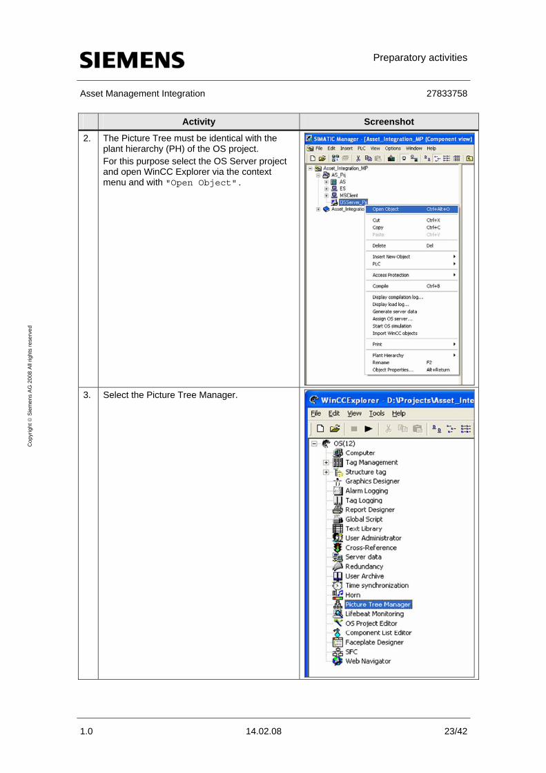
2. The Picture Tree must be identical with the plant hierarchy (PH) of the OS project. For this purpose select the OS Server project and open WinCC Explorer via the context menu and with "Open Object".
3. Select the Picture Tree Manager.

Preparatory activities
Asset Management Integration 27833758
1.0 14.02.08 24/42
Cop
yrig
ht ©
Sie
men
s A
G 2
008
All
right
s re
serv
ed
Activity Screenshot
4. Recreate the Picture Tree in the Plant View of the OS project now by creating the respective PH folders.
5. In the Component View of SIMATIC Manager
select the OS project of the OS Server and open its context menu. Select "Import WinCC Objects". Note For the import of the WinCC objects it is impor-tant that the names both of the pictures and of the reports have only up to 24 characters.

Preparatory activities
Asset Management Integration 27833758
1.0 14.02.08 25/42
Cop
yrig
ht ©
Sie
men
s A
G 2
008
All
right
s re
serv
ed
Activity Screenshot
6. Assign the pictures to the PH folders by cutting the pictures from the Component View and pasting them into the Plant View in the hierar-chy.
7. Go to the Plant View of SIMATIC Manager. For the area-oriented compilation the PH struc-ture of the AS projects must be recreated in the PH structure of the OS project now (see upper picture on the right). No pictures must be pasted here. The recreation is required only up to the set OS area level. If subordinate hierarchy folders exist in the AS project, they need not be recreated in the OS project (see lower picture on the right).

Preparatory activities
Asset Management Integration 27833758
1.0 14.02.08 26/42
Cop
yrig
ht ©
Sie
men
s A
G 2
008
All
right
s re
serv
ed
Activity Screenshot
8. In the OS project select an area and open its "Properties" via the context menu. In the window which opens now go to the "AS-OS Assignment" tab. Under "Assigned OS:" assign the OS to the area.
9. During the OS compilation warnings will be given due to the non-existing pictures in the AS PH structure but they can be ignored.
Note Despite the selected PH settings of the project the automatic generation of the block icons is still impossible even with PCS 7 V7.0 SP1. The CFCs and SFCs are still not located in PH folders with the same name as the pictures which would be a requirement.

Configuration
Asset Management Integration 27833758
1.0 14.02.08 27/42
Cop
yrig
ht ©
Sie
men
s A
G 2
008
All
right
s re
serv
ed
3 Configuration
3.1 Creation of the PC stations in the multiproject
Below you will find step-by-step instructions for the creation of the required PC stations.
For detailed information about the individual configuration steps refer to the "Configuration Manual Operator Station" (chapter 14.6).
Creation of the PC station for ES The PC station created here serves as Engineering Station.
Table 3-1
Activity Screenshot
1. In the Component View open the con-text menu of the project and insert a new PC station via "Insert New Object > SIMATIC PC Sta-tion". The OS must not be deleted.

Configuration
Asset Management Integration 27833758
1.0 14.02.08 28/42
Cop
yrig
ht ©
Sie
men
s A
G 2
008
All
right
s re
serv
ed
Activity Screenshot
2. Open HW Config of the PC station via its context menu and execute "Open Object".
3. Insert a "WinCC Application" and a "CP 1613". Configure the "CP 1613" like you do with common PCS 7 projects (see "PCS 7 - Engineering System").
4. Open "Object Properties..."
via the context menu of the PC sta-tion. In the "General" tab enter the sta-tion name of the component configu-rator under "Name:". The icon of the PC station contains a yellow arrow then. Note Do not enter a name in the field "Computer name:" for this PC sta-tion.

Configuration
Asset Management Integration 27833758
1.0 14.02.08 29/42
Cop
yrig
ht ©
Sie
men
s A
G 2
008
All
right
s re
serv
ed
Creation of the PC station for the MS Client In the following you create the MS Client. The MS Client is an OS Client which is operated on the Engineering Station.
Table 3-2
Activity Screenshot
1. Create a PC station for the MS Client analogously to "Creation of the PC station for ES" (Table 3-1) and add to it a "WinCC application cli-ent".
2. Open "Object Properties..."
via the context menu of the PC sta-tion. In the "General" tab you can enter a freely selectable name in "Name:". It is important that you enter the name of the master ES for "Computer name:".

Configuration
Asset Management Integration 27833758
1.0 14.02.08 30/42
Cop
yrig
ht ©
Sie
men
s A
G 2
008
All
right
s re
serv
ed
Creation of the PC station for the MS Server In the following you create the MS Server. Depending on the plant architec-ture it can be designed as a stand-alone or redundant server.
Table 3-3
Activity Screenshot
1. Create a PC station for the MS Server analogously to "Creation of the PC station for ES" (Table 3-1) and add to it a "WinCC application".
2. Open "Object Properties..."
via the context menu of the PC sta-tion. In the "General" tab you can enter a freely selectable name in "Name:". Enter the Windows computer name of the destination computer for "Com-puter name:".

Configuration
Asset Management Integration 27833758
1.0 14.02.08 31/42
Cop
yrig
ht ©
Sie
men
s A
G 2
008
All
right
s re
serv
ed
Activity Screenshot
3.
Optional: If the MS server is designed redun-dant, create an additional PC station for the MS Server Stby and add a "WinCC Application (Stby)" to it.
4. Open "Object Properties..."
via the context menu of the PC station In the "General" tab you can enter a freely selectable name in "Name:". Enter the Windows computer name of the destination computer for "Com-puter name:".

Configuration
Asset Management Integration 27833758
1.0 14.02.08 32/42
Cop
yrig
ht ©
Sie
men
s A
G 2
008
All
right
s re
serv
ed
3.2 Network object and PC monitoring by SNMP
In the following you create the OPC Server in the component configurator on the MS Server. It allows processing of the information of the PC stations and switches via SNMP.
Profile and community of the components The following table shows various components with their profile and their community. This information is required for the following step-by-step in-struction.
Table 3-4
Component Profile Community
SCALANCE class X200 Profil_SCALANCE_X200_V11.txt public SCALANCE class X200IRT Profil_SCALANCE_X200_V11.txt public SCALANCE class X300X400 V30 Profile SCALANCE
X300X400_V30.txt public
SCALANCE class X400 Profil_SCALANCE_X400_V11.txt public SCALANCE class X408 Profil_SCALANCE_X400_V22.txt public ESM/OSM Profil_OSM_V10.txt public IPC Profil_IPC_V13.txt SOL Communication processor CP1613 MIB-II_V10.txt private Other devices e.g. network cards; switches
MIB-II_V10.txt Determine the community config-ured in the device
All devices which have been added by import but which are not to be dis-played
No SNMP

Configuration
Asset Management Integration 27833758
1.0 14.02.08 33/42
Cop
yrig
ht ©
Sie
men
s A
G 2
008
All
right
s re
serv
ed
Configuration of the SIMATIC NET OPC Server Proceed as follows:
Table 3-5
Activity Screenshot
1. Open HW Config of the PC Server Station via its context menu and execute "Open Ob-ject". In the hardware catalog find the OPC Server (path: "SIMATIC PC Station > User Ap-plication > OPC Server") and use drag & drop to add it to the hardware configuration.
2. Open the properties of the OPC Server via the context menu "Object Properties...". Go to the "SNMP" tab and enter 2000 ms for "Cycle time:". Push "Edit Plant Configuration...".

Configuration
Asset Management Integration 27833758
1.0 14.02.08 34/42
Cop
yrig
ht ©
Sie
men
s A
G 2
008
All
right
s re
serv
ed
Activity Screenshot
3. In the window which opens now you can con-figure your SNMP components via the button "Add...". The following fields must be filled in for every SIEMENS component such as PC, switch, etc.: • „Name:“ (for PCs the name must be the
same as the computer name of the PC sta-tion)
• „IP address:“ • "Device profile:" (see Table 3-4) • "Community:" (see Table 3-4) • "Timeout:" 9000 (default) • Tick "SNMP Optimization". Optionally you can add to the SNMP compo-nent a description under "Comment:". After having entered all components, exit the configuration window with "OK".
4. In the properties window of the OPC Server you transfer the SNMP tags now by pushing the button "Export Tags for WinCC".

Configuration
Asset Management Integration 27833758
1.0 14.02.08 35/42
Cop
yrig
ht ©
Sie
men
s A
G 2
008
All
right
s re
serv
ed
Activity Screenshot
5. In the HW Config Editor of the MS Master Server select the OPC Server and copy it via its context menu and the option "Copy".

Configuration
Asset Management Integration 27833758
1.0 14.02.08 36/42
Cop
yrig
ht ©
Sie
men
s A
G 2
008
All
right
s re
serv
ed
Activity Screenshot
6. Now open the hardware configuration of the MS Standby Server. Select an empty line and add the copied OPC Server of the configuration via the context menu and the option "Paste". With this procedure you need not enter the SNMP components anew.

Configuration
Asset Management Integration 27833758
1.0 14.02.08 37/42
Cop
yrig
ht ©
Sie
men
s A
G 2
008
All
right
s re
serv
ed
3.3 Configuring and creating the diagnostics structure
The diagnostics structure is configured and created as described below. When you create it PCS 7 creates several extra subfolders and diagnostic screens and automatically assigns the names to these folders/diagnostic screens.
Note When the diagnostics structure has been created the names of the hier-archy folders in the plant hierarchy which are relevant for the Mainte-nance Station must not be changed anymore.
Table 3-6
Procedure Explanation/screen
1. In SIMATIC Manager select the multiproject folder, open its context menu and select "Plant Hierarchy > Settings...". In the window you tick "Derive diagnostic screens from the plant hierarchy".
2. Select the Maintenance Server as Maintenance Station and confirm your selection with "OK".

Configuration
Asset Management Integration 27833758
1.0 14.02.08 38/42
Cop
yrig
ht ©
Sie
men
s A
G 2
008
All
right
s re
serv
ed
Procedure Explanation/screen
3. Optionally you can change the OS area ID of the diagnostics folder for the display in the OS. For this purpose select in the PH the diagnos-tics folder "Diagnostics", open the context menu and select "Object Properties...". In the window which appears now you go to the "Control and Monitoring Attributes" tab. In "OS area ID:" you can assign a mnemonic name for the OS visualization. Note Note that this change of the OS area ID is re-quired for all projects of the multiproject, you have to assign the same name and there is no automatic function for this.
4. In SIMATIC Manager select the context menu of the multiproject folder and execute "Op-tions > Plant Hierarchy > Cre-ate/Update Diagnostic Screen". Note With this selection the function "Create Module Driver" is called and the "Control and Monitor-ing" functionality of the driver blocks which are required for the visualization is activated (the ticks are set automatically). Further the diag-nostics hierarchy, pictures and objects are cre-ated.

Configuration
Asset Management Integration 27833758
1.0 14.02.08 39/42
Cop
yrig
ht ©
Sie
men
s A
G 2
008
All
right
s re
serv
ed
Procedure Explanation/screen

Final activities
Asset Management Integration 27833758
1.0 14.02.08 40/42
Cop
yrig
ht ©
Sie
men
s A
G 2
008
All
right
s re
serv
ed
4 Final activities
When you have performed the required configuration steps you can start the following final activities.
4.1 Compiling and downloading
• Download and compile the S7 programs of all AS stations.
Note If you used older blocks in the CFC charts and you updated them with the required versions, an AS download in stop will be necessary due to the interface changes of the driver blocks.
• Compile and download all OS Servers and the Maintenance Server.
Note Because the diagnostic screens are derived from the Plant Hierarchy a complete OS download will be necessary.
• Download the PC station of the Maintenance Server.

Final activities
Asset Management Integration 27833758
1.0 14.02.08 41/42
Cop
yrig
ht ©
Sie
men
s A
G 2
008
All
right
s re
serv
ed
4.2 Assigning the server data
Check in the MS Client project whether the server data of all required OS Servers and of the MS Server have been assigned.
Table 4-1
Activity Screenshot
1. For this purpose select in SIMATIC Manager in MS Client the OS Client Application, open its context menu and select "Assign OS server...".
2. Select the required server data and confirm with "OK".

Final activities
Asset Management Integration 27833758
1.0 14.02.08 42/42
Cop
yrig
ht ©
Sie
men
s A
G 2
008
All
right
s re
serv
ed
4.3 Activating detailed diagnostics
Activate the detailed diagnostics in the object properties of the MS Client.
Note Activation of the detailed diagnostics is possible only from the version PCS 7 V7.0.
Table 4-2
Activity Screenshot
1. For this purpose mark in SIMATIC Manager the context menu of the MS Client and select "Object Properties".
2. Go to the "Target OS” and tick "Detailed diagnostics".