application guide splitsystemairconditioners ... - hvac-talk
TRANSCRIPT

SSAAFFEETTYY WWAARRNNIINNGGOnly qualified personnel should install and service the equipment. The installation, starting up, and servicing of heating, ventilating, and air-conditioningequipment can be hazardous and requires specific knowledge and training. Improperly installed, adjusted or altered equipment by an unqualified personcould result in death or serious injury. When working on the equipment, observe all precautions in the literature and on the tags, stickers, and labels thatare attached to the equipment.
April 2020 SSSS--AAPPGG000099GG--EENN
Application Guide
Split System Air ConditionersOdyssey™Tube Size and Component SelectionTTA and TWA (6-25 Tons)
(TTA Models)TTA0724*A/DTTA0904*A/DTTA1204*A/C/DTTA1504*DTTA1804*C/DTTA2404*C/DTTA3004*C
(TWAModels)TWA0724*A/DTWA0904*A/DTWA1204*A/DTWA1804*DTWA2404*D
©2020 American Standard SS-APG009G-EN
IntroductionRead this manual thoroughly before operating orservicing this unit.
Warnings, Cautions, and NoticesSafety advisories appear throughout this manual asrequired. Your personal safety and the properoperation of this machine depend upon the strictobservance of these precautions.
The three types of advisories are defined as follows:
WARNINGIndicates a potentially hazardous situationwhich, if not avoided, could result in death orserious injury.
CAUTIONIndicates a potentially hazardous situationwhich, if not avoided, could result in minor ormoderate injury. It could also be used to alertagainst unsafe practices.
NOTICEIndicates a situation that could result inequipment or property-damage onlyaccidents.
Important Environmental ConcernsScientific research has shown that certain man-madechemicals can affect the earth’s naturally occurringstratospheric ozone layer when released to theatmosphere. In particular, several of the identifiedchemicals that may affect the ozone layer arerefrigerants that contain Chlorine, Fluorine and Carbon(CFCs) and those containing Hydrogen, Chlorine,Fluorine and Carbon (HCFCs). Not all refrigerantscontaining these compounds have the same potentialimpact to the environment. Trane advocates theresponsible handling of all refrigerants-includingindustry replacements for CFCs and HCFCs such assaturated or unsaturated HFCs and HCFCs.
Important Responsible RefrigerantPracticesTrane believes that responsible refrigerant practicesare important to the environment, our customers, andthe air conditioning industry. All technicians whohandle refrigerants must be certified according to localrules. For the USA, the Federal Clean Air Act (Section608) sets forth the requirements for handling,reclaiming, recovering and recycling of certainrefrigerants and the equipment that is used in theseservice procedures. In addition, some states ormunicipalities may have additional requirements thatmust also be adhered to for responsible managementof refrigerants. Know the applicable laws and followthem.
WWAARRNNIINNGGPPrrooppeerr FFiieelldd WWiirriinngg aanndd GGrroouunnddiinnggRReeqquuiirreedd!!FFaaiilluurree ttoo ffoollllooww ccooddee ccoouulldd rreessuulltt iinn ddeeaatthh oorrsseerriioouuss iinnjjuurryy..AAllll ffiieelldd wwiirriinngg MMUUSSTT bbee ppeerrffoorrmmeedd bbyy qquuaalliiffiieeddppeerrssoonnnneell.. IImmpprrooppeerrllyy iinnssttaalllleedd aanndd ggrroouunnddeeddffiieelldd wwiirriinngg ppoosseess FFIIRREE aanndd EELLEECCTTRROOCCUUTTIIOONNhhaazzaarrddss.. TToo aavvooiidd tthheessee hhaazzaarrddss,, yyoouu MMUUSSTT ffoolllloowwrreeqquuiirreemmeennttss ffoorr ffiieelldd wwiirriinngg iinnssttaallllaattiioonn aannddggrroouunnddiinngg aass ddeessccrriibbeedd iinn NNEECC aanndd yyoouurr llooccaall//ssttaattee//nnaattiioonnaall eelleeccttrriiccaall ccooddeess..
WWAARRNNIINNGGPPeerrssoonnaall PPrrootteeccttiivvee EEqquuiippmmeenntt ((PPPPEE))RReeqquuiirreedd!!FFaaiilluurree ttoo wweeaarr pprrooppeerr PPPPEE ffoorr tthhee jjoobb bbeeiinngguunnddeerrttaakkeenn ccoouulldd rreessuulltt iinn ddeeaatthh oorr sseerriioouuss iinnjjuurryy..TTeecchhnniicciiaannss,, iinn oorrddeerr ttoo pprrootteecctt tthheemmsseellvveess ffrroommppootteennttiiaall eelleeccttrriiccaall,, mmeecchhaanniiccaall,, aanndd cchheemmiiccaallhhaazzaarrddss,, MMUUSSTT ffoollllooww pprreeccaauuttiioonnss iinn tthhiiss mmaannuuaallaanndd oonn tthhee ttaaggss,, ssttiicckkeerrss,, aanndd llaabbeellss,, aass wweellll aass tthheeiinnssttrruuccttiioonnss bbeellooww::
•• BBeeffoorree iinnssttaalllliinngg//sseerrvviicciinngg tthhiiss uunniitt,,tteecchhnniicciiaannss MMUUSSTT ppuutt oonn aallll PPPPEE rreeqquuiirreedd ffoorrtthhee wwoorrkk bbeeiinngg uunnddeerrttaakkeenn ((EExxaammpplleess;; ccuuttrreessiissttaanntt gglloovveess//sslleeeevveess,, bbuuttyyll gglloovveess,, ssaaffeettyyggllaasssseess,, hhaarrdd hhaatt//bbuummpp ccaapp,, ffaallll pprrootteeccttiioonn,,eelleeccttrriiccaall PPPPEE aanndd aarrcc ffllaasshh ccllootthhiinngg))..AALLWWAAYYSS rreeffeerr ttoo aapppprroopprriiaattee SSaaffeettyy DDaattaaSShheeeettss ((SSDDSS)) aanndd OOSSHHAA gguuiiddeelliinneess ffoorrpprrooppeerr PPPPEE..
•• WWhheenn wwoorrkkiinngg wwiitthh oorr aarroouunndd hhaazzaarrddoouusscchheemmiiccaallss,, AALLWWAAYYSS rreeffeerr ttoo tthhee aapppprroopprriiaatteeSSDDSS aanndd OOSSHHAA//GGHHSS ((GGlloobbaall HHaarrmmoonniizzeeddSSyysstteemm ooff CCllaassssiiffiiccaattiioonn aanndd LLaabbeelllliinngg ooffCChheemmiiccaallss)) gguuiiddeelliinneess ffoorr iinnffoorrmmaattiioonn oonnaalllloowwaabbllee ppeerrssoonnaall eexxppoossuurree lleevveellss,, pprrooppeerrrreessppiirraattoorryy pprrootteeccttiioonn aanndd hhaannddlliinnggiinnssttrruuccttiioonnss..
•• IIff tthheerree iiss aa rriisskk ooff eenneerrggiizzeedd eelleeccttrriiccaallccoonnttaacctt,, aarrcc,, oorr ffllaasshh,, tteecchhnniicciiaannss MMUUSSTT ppuuttoonn aallll PPPPEE iinn aaccccoorrddaannccee wwiitthh OOSSHHAA,, NNFFPPAA7700EE,, oorr ootthheerr ccoouunnttrryy--ssppeecciiffiicc rreeqquuiirreemmeennttssffoorr aarrcc ffllaasshh pprrootteeccttiioonn,, PPRRIIOORR ttoo sseerrvviicciinnggtthhee uunniitt.. NNEEVVEERR PPEERRFFOORRMM AANNYY SSWWIITTCCHHIINNGG,,DDIISSCCOONNNNEECCTTIINNGG,, OORR VVOOLLTTAAGGEE TTEESSTTIINNGGWWIITTHHOOUUTT PPRROOPPEERR EELLEECCTTRRIICCAALL PPPPEE AANNDDAARRCC FFLLAASSHH CCLLOOTTHHIINNGG.. EENNSSUURREEEELLEECCTTRRIICCAALL MMEETTEERRSS AANNDD EEQQUUIIPPMMEENNTT AARREEPPRROOPPEERRLLYY RRAATTEEDD FFOORR IINNTTEENNDDEEDDVVOOLLTTAAGGEE..
SS-APG009G-EN 3
WWAARRNNIINNGGFFoollllooww EEHHSS PPoolliicciieess!!FFaaiilluurree ttoo ffoollllooww iinnssttrruuccttiioonnss bbeellooww ccoouulldd rreessuulltt iinnddeeaatthh oorr sseerriioouuss iinnjjuurryy..
•• AAllll TTrraannee ppeerrssoonnnneell mmuusstt ffoollllooww tthheeccoommppaannyy’’ss EEnnvviirroonnmmeennttaall,, HHeeaalltthh aanndd SSaaffeettyy((EEHHSS)) ppoolliicciieess wwhheenn ppeerrffoorrmmiinngg wwoorrkk ssuucchh aasshhoott wwoorrkk,, eelleeccttrriiccaall,, ffaallll pprrootteeccttiioonn,, lloocckkoouutt//ttaaggoouutt,, rreeffrriiggeerraanntt hhaannddlliinngg,, eettcc.. WWhheerree llooccaallrreegguullaattiioonnss aarree mmoorree ssttrriinnggeenntt tthhaann tthheesseeppoolliicciieess,, tthhoossee rreegguullaattiioonnss ssuuppeerrsseeddee tthheesseeppoolliicciieess..
•• NNoonn--TTrraannee ppeerrssoonnnneell sshhoouulldd aallwwaayyss ffoolllloowwllooccaall rreegguullaattiioonnss..
WWAARRNNIINNGGRReeffrriiggeerraanntt uunnddeerr HHiigghh PPrreessssuurree!!FFaaiilluurree ttoo ffoollllooww iinnssttrruuccttiioonnss bbeellooww ccoouulldd rreessuulltt iinnaann eexxpplloossiioonn wwhhiicchh ccoouulldd rreessuulltt iinn ddeeaatthh oorrsseerriioouuss iinnjjuurryy oorr eeqquuiippmmeenntt ddaammaaggee..SSyysstteemm ccoonnttaaiinnss rreeffrriiggeerraanntt uunnddeerr hhiigghh pprreessssuurree..RReeccoovveerr rreeffrriiggeerraanntt ttoo rreelliieevvee pprreessssuurree bbeeffoorreeooppeenniinngg tthhee ssyysstteemm.. SSeeee uunniitt nnaammeeppllaattee ffoorrrreeffrriiggeerraanntt ttyyppee.. DDoo nnoott uussee nnoonn--aapppprroovveeddrreeffrriiggeerraannttss,, rreeffrriiggeerraanntt ssuubbssttiittuutteess,, oorr rreeffrriiggeerraannttaaddddiittiivveess..
WWAARRNNIINNGGEExxpplloossiioonn HHaazzaarrdd!!FFaaiilluurree ttoo ffoollllooww iinnssttrruuccttiioonnss bbeellooww ccoouulldd rreessuulltt iinnaann eexxpplloossiioonn wwhhiicchh ccoouulldd rreessuulltt iinn ddeeaatthh oorrsseerriioouuss iinnjjuurryy,, aanndd eeqquuiippmmeenntt ddaammaaggee..NNEEVVEERR bbyyppaassss ssyysstteemm ssaaffeettiieess iinn oorrddeerr ttoo ppuummppddoowwnn tthhee uunniitt ccoommppoonneenntt''ss rreeffrriiggeerraanntt iinnttoo tthheemmiiccrroocchhaannnneell hheeaatt eexxcchhaannggeerr ((MMCCHHEE)) ccooiill.. DDooNNOOTT ddeepprreessss tthhee ccoommpprreessssoorr ccoonnttaaccttoorr ssiinnccee iitteeffffeeccttiivveellyy bbyyppaasssseess tthhee hhiigghh--pprreessssuurree ccoonnttrrooll..
CopyrightThis document and the information in it are theproperty of Trane, and may not be used or reproducedin whole or in part without written permission. Tranereserves the right to revise this publication at any time,and to make changes to its content without obligationto notify any person of such revision or change.
TrademarksAll trademarks referenced in this document are thetrademarks of their respective owners.
Revision History• Update to refrigerant piping - shutoff valves are
field installed only.
• Running changes included.
IInnttrroodduuccttiioonn

4 SS-APG009G-EN
Overview . . . . . . . . . . . . . . . . . . . . . . . . . . . . . . . . . . . 5Background . . . . . . . . . . . . . . . . . . . . . . . . . . . . . . 5
Updated Guidelines. . . . . . . . . . . . . . . . . . . . . . . 5Liquid Lines . . . . . . . . . . . . . . . . . . . . . . . . . . 5Suction Lines . . . . . . . . . . . . . . . . . . . . . . . . . 6Equipment Placement . . . . . . . . . . . . . . . . . 6Refrigerant Piping Guidelines . . . . . . . . . . 7
Line Sizing, Routing, and ComponentSelection . . . . . . . . . . . . . . . . . . . . . . . . . . . . . . . . . . . 8
Liquid Lines . . . . . . . . . . . . . . . . . . . . . . . . . . . . . . 8Line Sizing . . . . . . . . . . . . . . . . . . . . . . . . . . . 8Routing . . . . . . . . . . . . . . . . . . . . . . . . . . . . . . 8Insulation . . . . . . . . . . . . . . . . . . . . . . . . . . . . 8Components. . . . . . . . . . . . . . . . . . . . . . . . . . 8
Gas Line . . . . . . . . . . . . . . . . . . . . . . . . . . . . . . . . . 9
Line Sizing . . . . . . . . . . . . . . . . . . . . . . . . . . . 9Routing . . . . . . . . . . . . . . . . . . . . . . . . . . . . . . 9Insulation . . . . . . . . . . . . . . . . . . . . . . . . . . . 10Components. . . . . . . . . . . . . . . . . . . . . . . . . 10
Expansion Valves. . . . . . . . . . . . . . . . . . . . . . . . . . 11
Controls . . . . . . . . . . . . . . . . . . . . . . . . . . . . . . . . . . . 12
Hot Gas Bypass. . . . . . . . . . . . . . . . . . . . . . . . . . . . 13
Remodel, Retrofit, or Replacement . . . . . . . . 14
Microchannel Heat ExchangerCondensers (MCHE) . . . . . . . . . . . . . . . . . . . . . . . 15
Refrigerant Piping Examples . . . . . . . . . . . . . . 16
Parts. . . . . . . . . . . . . . . . . . . . . . . . . . . . . . . . . . . . . . . 24
Table of Contents
SS-APG009G-EN 5
OverviewThe TTA and TWA, 6 – 25 ton condensing unit productline (specific model numbers are listed on the cover)has been designed for use only with R-410A and POEoil. R-410A is a higher pressure refrigerant that requiresthe other components of the system to be rated for thehigher pressures. For compressor lubrication, therefrigerant requires POE oil.
Traditionally, refrigerant piping practices were guidedby four principles:
• Return the oil to the compressor.
• Maintain a column of liquid at the expansion valve.
• Minimize the loss of capacity.
• Minimize the refrigerant charge in the system.
These piping practices remain the same. However,because of the different mass flows and pressures, theline diameter required to carry the oil and refrigerantmay not be the same as a similar tonnage R-22 unit.Also, the allowable pressure drop may be greater for R-410A than R-22.
Evidence accumulated over years of observationdemonstrates that the lower the refrigerant charge, themore reliably a split air-conditioning system performs.Any amount of refrigerant in excess of the minimumdesign charge becomes difficult to manage. The excessrefrigerant tends to collect in areas that can interferewith proper operation and eventually shortens theservice life of the system. To successfully minimize thesystem refrigerant charge, the correct line size shouldbe used and the line length must be kept to aminimum.
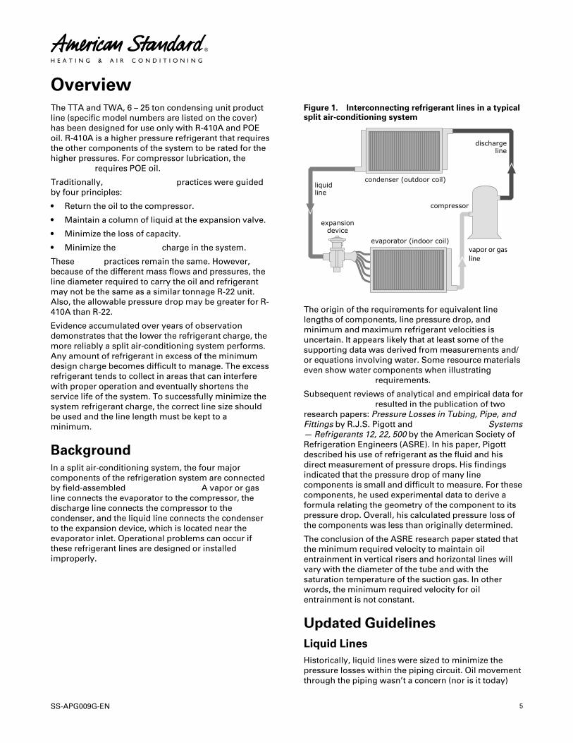
BackgroundIn a split air-conditioning system, the four majorcomponents of the refrigeration system are connectedby field-assembled refrigerant piping. A vapor or gasline connects the evaporator to the compressor, thedischarge line connects the compressor to thecondenser, and the liquid line connects the condenserto the expansion device, which is located near theevaporator inlet. Operational problems can occur ifthese refrigerant lines are designed or installedimproperly.
Figure 1. Interconnecting refrigerant lines in a typicalsplit air-conditioning system
vapor or gasline
The origin of the requirements for equivalent linelengths of components, line pressure drop, andminimum and maximum refrigerant velocities isuncertain. It appears likely that at least some of thesupporting data was derived from measurements and/or equations involving water. Some resource materialseven show water components when illustratingrefrigerant piping requirements.
Subsequent reviews of analytical and empirical data forrefrigerant piping resulted in the publication of tworesearch papers: Pressure Losses in Tubing, Pipe, andFittings by R.J.S. Pigott and Refrigerant Piping Systems— Refrigerants 12, 22, 500 by the American Society ofRefrigeration Engineers (ASRE). In his paper, Pigottdescribed his use of refrigerant as the fluid and hisdirect measurement of pressure drops. His findingsindicated that the pressure drop of many linecomponents is small and difficult to measure. For thesecomponents, he used experimental data to derive aformula relating the geometry of the component to itspressure drop. Overall, his calculated pressure loss ofthe components was less than originally determined.
The conclusion of the ASRE research paper stated thatthe minimum required velocity to maintain oilentrainment in vertical risers and horizontal lines willvary with the diameter of the tube and with thesaturation temperature of the suction gas. In otherwords, the minimum required velocity for oilentrainment is not constant.
Updated GuidelinesLiquid LinesHistorically, liquid lines were sized to minimize thepressure losses within the piping circuit. Oil movementthrough the piping wasn’t a concern (nor is it today)
6 SS-APG009G-EN
because oil is miscible in liquid refrigerant at normalliquid-line temperatures. The historic and traditional 6psid liquid line pressure drop had the unintendedconsequence of requiring line sizes with large internalrefrigerant volumes. Since our objective is also tominimize the refrigerant charge to make the mostreliable systems, we increased the allowable liquidpressure drop to 35 psid (R-22), which allows for theselection of a smaller liquid line while still maintainingrefrigeration operation. With R-410A refrigerant andPOE oil, this pressure drop can be as high as 50 psid.Within these guidelines, refrigeration operation ismaintained while minimizing the refrigerant charge. Itis still required to limit the liquid line velocity to 600 ft/min to help avoid issues with water hammer.
Suction LinesR-410A is a high-pressure refrigerant and allowshigher-pressure drops in the suction lines. With R-22, a2°F loss in the suction line means a pressure drop of 3psi. With R-410A refrigerant, that same 2°F loss is a 5psi drop. Additional pressure drop may be tolerated incertain applications.
R-410A refrigerant suction lines must be sized tomaintain oil-entrainment velocities in both thehorizontal lines and vertical risers. Oil entrainment forR-410A is based on suction temperature as well as tubediameter. At the time of this writing, no known directoil-entrainment tests have been published. Trane hasused ASHRAE data to create equation-based formulasto predict the entrainment velocities of R-410A
refrigerant and POE oil. These minimum velocities arereflected in the line sizes listed in the componentselection summary tables, see Parts chapter.
Equipment PlacementMMiinniimmiizzee DDiissttaannccee BBeettwweeeenn CCoommppoonneennttss
For a split air-conditioning system to perform asreliably and inexpensively as possible, the refrigerantcharge must be kept to a minimum. To help accomplishthis design goal:
• Site the outdoor unit (cooling-only condensing unitor heat pump) as close to the indoor unit aspossible.
• Route each interconnecting refrigerant line by theshortest and most direct path so that line lengthsand riser heights are no longer than absolutelynecessary.
• Use only horizontal and vertical pipingconfigurations.
• Determine whether the total length of eachrefrigerant line requires Trane review. Be sure toaccount for the difference in elevations of theindoor and outdoor units when calculating the totalline length.
Interconnecting lines of 150 lineal ft (45.7 m) or less donot require Trane review, but only a limited amountmay be in a riser, see allowable elevation differencefigures in the following Refrigerant Piping Guidelines.
OOvveerrvviieeww
SS-APG009G-EN 7
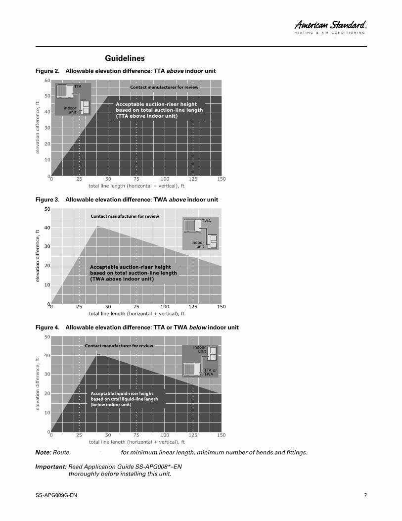
Refrigerant Piping Guidelines
Figure 2. Allowable elevation difference: TTA above indoor unit
Contact manufacturer for review
Figure 3. Allowable elevation difference: TWA above indoor unit
Contact manufacturer for review
Figure 4. Allowable elevation difference: TTA or TWA below indoor unit
Acceptable liquid-riser height based on total liquid-line length(below indoor unit)
Contact manufacturer for review
NNoottee:: Route refrigerant piping for minimum linear length, minimum number of bends and fittings.
IImmppoorrttaanntt:: Read Application Guide SS-APG008*–ENthoroughly before installing this unit.
OOvveerrvviieeww
8 SS-APG009G-EN
Line Sizing, Routing, and Component Selection“Refrigerant Piping Examples,” p. 16 providesillustrations of TTA/TWA split system componentarrangement. Use them to determine the proper,relative sequence of the components in the refrigerantlines that connect the TTA/TWA outdoor unit to anevaporator coil. The TTA/TWA units are R-410Amachines and all the selected components installed inthe field must also be rated for use with R-410A.
Liquid LinesLine SizingProperly sizing the liquid line is critical to a reliable splitsystem application. The Component Selection tables,found in “Parts,” p. 24, show the recommended liquid-line sizing for each TTA/TWA model based on itsnominal capacity. Using the preselected tube diameterto uniformly size the liquid line will maintain operatingrequirements and is the line size around which the TTA/TWA installation literature charging charts weregenerated (see IOM). Increasing the line size will notincrease the allowable line length.
RoutingInstall the liquid line with a slight slope in the directionof flow so that it can be routed with the suction line. Aheight limitation exists for liquid lines that include aliquid riser because of the loss of subcooling thataccompanies the pressure loss in the height of theliquid column. Figure 3, p. 7 and Figure 4, p. 7 depictthe permissible rise in the liquid line (without excessiveloss of subcooling). Again, system designs outside theapplication envelope of the TTA/TWA unit requireTrane review.
InsulationThe liquid line is generally warmer than thesurrounding air, so it does not require insulation. Infact, heat loss from the liquid line improves systemcapacity because it provides additional subcooling. Ifthe liquid line is routed through a high temperaturearea, such as an attic or mechanical room, insulationwould be required.
ComponentsLiquid-line refrigerant components necessary for asuccessful job include a filter drier, access port,moisture-indicating sight glass, and expansion valve(s). The examples in “Refrigerant Piping Examples,” p.16, illustrate the proper sequence for positioning thecomponents in the liquid line. Position the componentsas close to the indoor unit as possible. The ComponentSelection tables, found in “Parts,” p. 24, identifysuitable components, by part number, of each TTA/TWA model. Note there are two access ports: one
located at the TTA/TWA and one located at theevaporator. , lists suitable expansion valves.
Liquid Filter DrierThere is no substitute for cleanliness during systeminstallation. The liquid filter drier prevents residualcontaminants, introduced during installation, fromentering the expansion valve. The TTA/TWA outdoorunits have a filter drier pre-installed. However, if therefrigerant line length exceeds 80 ft, this filter shouldbe removed and a new one selected from theComponent Selection tables found in “Parts,” p. 24,and should be installed close to the indoor unit. Ifchoosing a filter other than the one listed in thesetables, make sure its volume, filtering, and moisture-absorbing characteristics are equivalent.
NNoottee:: Due to the reverse flow nature of a heat pump, ifthe liquid line exceeds 80 ft, the heat pump willrequire a bi-flow filter drier (see Figure 9, p. 17and Figure 10, p. 18).
Access PortThe access port located at the TTA/TWA allows the unitto be charged with liquid refrigerant and is used todetermine charge level. This port is usually a Schraedervalve with a core.
Solenoid ValveIn TTA split systems, solenoid valves may be used toisolate the refrigerant from the evaporator during theoff cycles. This is only done when the indoor unit iswell below the outdoor unit. The solenoid valve on theTTA unit is a drop solenoid—open when thecompressor is on, and off when the compressor is off.If used, the solenoid requires code compliant wiring tothe TTA condensing unit. (The solenoid is not shownon the unit wiring diagram.)
NNootteess::
• Solenoids should not be used in the TWAheat pumps due to the reverse flow of theliquid.
• Solenoids are seldom used and not includedin the Component Selection tables found in“Parts,” p. 24.
SS-APG009G-EN 9
WWAARRNNIINNGGRRiisskk ooff EExxpplloossiioonn wwiitthh RReeffrriiggeerraannttLLiinnee!!FFaaiilluurree ttoo ffoollllooww iinnssttrruuccttiioonnss ccoouulldd ccaauussee aarreeffrriiggeerraanntt lliinnee ttoo eexxppllooddee uunnddeerr pprreessssuurree wwhhiicchhccoouulldd rreessuulltt iinn ddeeaatthh oorr sseerriioouuss iinnjjuurryy..LLiiqquuiidd rreeffrriiggeerraanntt ttrraappppeedd bbeettwweeeenn ttwwoo vvaallvveess ccaannbbeeccoommee hhiigghhllyy pprreessssuurriizzeedd iiff tthhee aammbbiieenntttteemmppeerraattuurree iinnccrreeaasseess.. DDOO NNOOTT aadddd aa lliiqquuiidd lliinneessoolleennooiidd vvaallvvee iinn aa ccoooolliinngg--oonnllyy ssyysstteemm tthhaatt iissaallrreeaaddyy eeqquuiippppeedd wwiitthh aa cchheecckk vvaallvvee..
Moisture-Indicating SightglassBe sure to install one moisture-indicating sight glass inthe main liquid line.
NNoottee:: The sole value of the glass is its moisture-indicating ability. Use the Installation manualcharging curves—not the sightglass—todetermine proper charge levels.
Expansion ValveThe expansion valve is the throttling device that metersthe refrigerant into the evaporator coil. Metering toomuch refrigerant floods the compressor; metering toolittle elevates the compressor temperature. Choosingthe correct size and type of expansion valve is critical toensure that it will correctly meter refrigerant into theevaporator coil throughout the entire operatingenvelope of the system. CCoorrrreecctt rreeffrriiggeerraannttddiissttrriibbuuttiioonn iinnttoo tthhee ccooiill rreeqquuiirreess aann eexxppaannssiioonnvvaallvvee ffoorr eeaacchh ddiissttrriibbuuttoorr..
For improved modulation, choose expansion valveswith balanced port construction and externalequalization. , identifies the part number of the valverecommended for TTA/TWA systems. The tonnage ofthe valve should represent the tonnage of the portionof coil that the TXV/ distributor will feed.
Some expansion valve models have built-in checkvalves for heat pump operation and do not requireadditional external check valves for reverse flowoperation. These valves are identified in .
The expansion valve and heat pump check valve areinclusive when the indoor unit is a TWE.
The Microchannel condenser cooling-only units do notrequire a bleed TXV valve as required on some otherproduct types. TXV for TTA microchannel units canalso be selected from .
Check Valves
WWAARRNNIINNGGRRiisskk ooff EExxpplloossiioonn wwiitthh RReeffrriiggeerraannttLLiinnee!!FFaaiilluurree ttoo ffoollllooww iinnssttrruuccttiioonnss ccoouulldd ccaauussee aarreeffrriiggeerraanntt lliinnee ttoo eexxppllooddee uunnddeerr pprreessssuurree wwhhiicchhccoouulldd rreessuulltt iinn ddeeaatthh oorr sseerriioouuss iinnjjuurryy..LLiiqquuiidd rreeffrriiggeerraanntt ttrraappppeedd bbeettwweeeenn ttwwoo vvaallvveess ccaannbbeeccoommee hhiigghhllyy pprreessssuurriizzeedd iiff tthhee aammbbiieenntttteemmppeerraattuurree iinnccrreeaasseess.. DDOO NNOOTT aadddd aa lliiqquuiidd lliinneessoolleennooiidd vvaallvvee iinn aa ccoooolliinngg--oonnllyy ssyysstteemm tthhaatt iissaallrreeaaddyy eeqquuiippppeedd wwiitthh aa cchheecckk vvaallvvee..
TWA: Due to the reverse cycle of the TWA heat pump, acheck valve is required to bypass refrigerant aroundthe TXV while the unit is in heating mode. If the airhandler is a TWE, it includes both the TXV and checkvalve.
TTA: Because of the limited holding capacity of themicrochannel heat exchanger, if more than 50 ft ofliquid line is above a TTA unit, a check valve should beinstalled in the liquid line at the TTA unit to preventbackflow during the off condition. The check valveshould be one size larger than the liquid line to reducepressure drop and should be located at the TTA unit. Asolenoid valve should never be used in the liquid linewhen using this check valve.
Gas LineLine SizingProper line sizing is required to guarantee that the oilreturns to the compressor throughout the system’soperating envelope. At the same time, the line must besized so that the pressure drop does not excessivelyaffect capacity or efficiency. To accomplish bothobjectives, it may be necessary to use two different linediameters: one for the horizontal run and for thevertical drops, and another for the vertical lifts (risers).
NNoottee:: Preselected suction-line diameters shown in theComponent Selection tables found in “Parts,” p.24, are independent of total line length forproperly charged 6 – 25 ton TTA/TWA in normalair-conditioning applications.
RoutingRoute the line as straight (horizontally and vertically) aspossible. Avoid unnecessary changes of direction. Toprevent residual or condensed refrigerant from “free-flowing” toward the compressor, install the gas line sothat it slopes by ¼ to 1 inch per 10 feet of run (1 cm per3 m) toward the indoor coil.
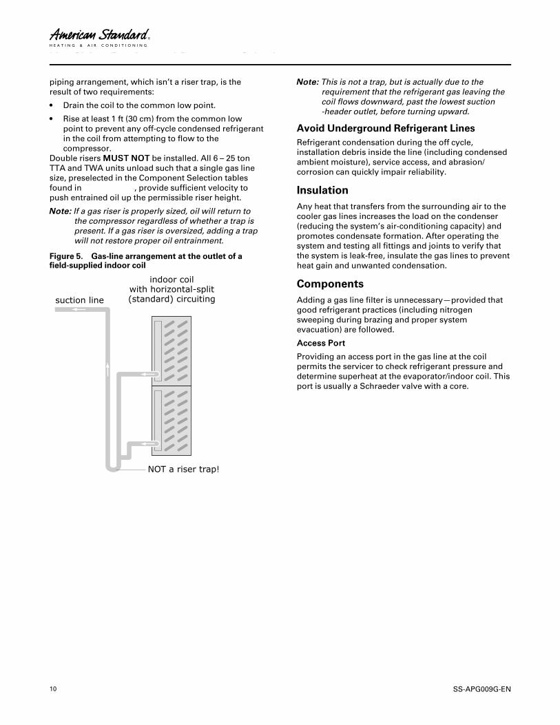
Do not install riser traps. With field-supplied air-handlercoils, what appears to be a riser trap is located at thecoil outlet; see Figure 5, p. 10 for an example. This
LLiinnee SSiizziinngg,, RRoouuttiinngg,, aanndd CCoommppoonneenntt SSeelleeccttiioonn
10 SS-APG009G-EN
piping arrangement, which isn’t a riser trap, is theresult of two requirements:
• Drain the coil to the common low point.
• Rise at least 1 ft (30 cm) from the common lowpoint to prevent any off-cycle condensed refrigerantin the coil from attempting to flow to thecompressor.
Double risers MMUUSSTT NNOOTT be installed. All 6 – 25 tonTTA and TWA units unload such that a single gas linesize, preselected in the Component Selection tablesfound in“Parts,” p. 24, provide sufficient velocity topush entrained oil up the permissible riser height.
NNoottee:: If a gas riser is properly sized, oil will return tothe compressor regardless of whether a trap ispresent. If a gas riser is oversized, adding a trapwill not restore proper oil entrainment.
Figure 5. Gas-line arrangement at the outlet of afield-supplied indoor coil
NNoottee:: This is not a trap, but is actually due to therequirement that the refrigerant gas leaving thecoil flows downward, past the lowest suction-header outlet, before turning upward.
Avoid Underground Refrigerant LinesRefrigerant condensation during the off cycle,installation debris inside the line (including condensedambient moisture), service access, and abrasion/corrosion can quickly impair reliability.
InsulationAny heat that transfers from the surrounding air to thecooler gas lines increases the load on the condenser(reducing the system’s air-conditioning capacity) andpromotes condensate formation. After operating thesystem and testing all fittings and joints to verify thatthe system is leak-free, insulate the gas lines to preventheat gain and unwanted condensation.
ComponentsAdding a gas line filter is unnecessary—provided thatgood refrigerant practices (including nitrogensweeping during brazing and proper systemevacuation) are followed.
AAcccceessss PPoorrtt
Providing an access port in the gas line at the coilpermits the servicer to check refrigerant pressure anddetermine superheat at the evaporator/indoor coil. Thisport is usually a Schraeder valve with a core.
LLiinnee SSiizziinngg,, RRoouuttiinngg,, aanndd CCoommppoonneenntt SSeelleeccttiioonn
SS-APG009G-EN 11
Expansion Valves
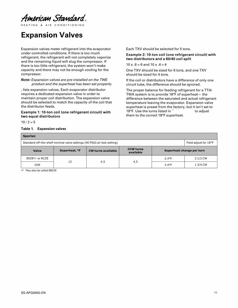
Expansion valves meter refrigerant into the evaporatorunder controlled conditions. If there is too muchrefrigerant, the refrigerant will not completely vaporizeand the remaining liquid will slug the compressor. Ifthere is too little refrigerant, the system won’t makecapacity and there may not be enough cooling for thecompressor.
NNoottee:: Expansion valves are pre-installed on the TWEproduct and the superheat has been set properly.
, lists expansion valves. Each evaporator distributorrequires a dedicated expansion valve in order tomaintain proper coil distribution. The expansion valveshould be selected to match the capacity of the coil thatthe distributor feeds.
EExxaammppllee 11:: 1100--ttoonn ccooiill ((oonnee rreeffrriiggeerraanntt cciirrccuuiitt)) wwiitthhttwwoo eeqquuaall ddiissttrriibbuuttoorrss
10 / 2 = 5
Each TXV should be selected for 5 tons.
EExxaammppllee 22:: 1100--ttoonn ccooiill ((oonnee rreeffrriiggeerraanntt cciirrccuuiitt)) wwiitthhttwwoo ddiissttrriibbuuttoorrss aanndd aa 6600//4400 ccooiill sspplliitt
10 x .6 = 6 and 10 x .4 = 4
One TXV should be sized for 6 tons, and one TXVshould be sized for 4 tons.
If the coil or distributors have a difference of only onecircuit tube, the difference should be ignored.
The proper balance for feeding refrigerant for a TTA/TWA system is to provide 18°F of superheat— thedifference between the saturated and actual refrigeranttemperature leaving the evaporator. Expansion valvesuperheat is preset from the factory, but it isn’t set to18°F. Use the turns listed in Table 1, p. 11 to adjustthem to the correct 18°F superheat.
Table 1. Expansion valves
Sporlan
Standard off-the-shelf nominal valve settings (90 PSIG air test setting) Field adjust for 18°F
Valve Superheat, °F CW turns available CCW turnsavailable
Superheat change per turn
ERZE(a) or RCZE12 4.5 4.5
2.4°F 2 1/2 CW
OZE 3.4°F 1 3/4 CW
(a) May also be called BBIZE
12 SS-APG009G-EN
Controls
The TTA/TWA unit is available with either ReliaTel™ orthermostat control. It is important to understand that ifthe staging of compressors is turned over to a thirdparty, the compressor protection, provided throughsystem stability, is also turned over to the third party.Simply stated, this means that when a compressorturns on, it shouldn’t turn off until the expansion valvecomes under control. And, once the compressor turns
off, it should be allowed to stay off until the crank caseheater has warmed up.
System stability must be programmed in the thirdparty system control. To accomplish this, the systemcontrols must incorporate a 55--mmiinnuuttee--oonn, a 55--mmiinnuuttee--ooffff, and a 55--mmiinnuuttee--iinntteerrssttaaggee differential on eachcompressor stage.

SS-APG009G-EN 13
Hot Gas Bypass
Many years ago, hot gas bypass (HGBP) wassuccessfully added to HVAC systems to correct anumber of operational problems. Hoping to avoid suchproblems altogether, it eventually became commonpractice for designers to specify hot gas bypass insystems. Unfortunately, the practice often degradedrather than improved reliability.
Hot gas bypass increases the minimum refrigerantcharge; it also inflates the first cost of the system.Besides adding more paths for potential refrigerantleaks, hot gas bypass increases the likelihood ofrefrigerant distribution problems. Finally, hot gasbypass uses excessive amounts of energy bypreventing the compressors from cycling withfluctuating loads.
Trane now has several years of successful experiencewith Evaporator Defrost Control (EDC). Like hot gas
bypass, the EDC system protects the coil from freezing,but it does so by turning off compressors when asensor detects the formation of frost on the evaporatorcoil. The compressor is released to operate when thecoil temperature rises a few degrees above the frostthreshold. The EDC control strategy may reduce theoverall energy consumption of the system whilemaintaining system control.
Systems should be designed to avoid HGBP wheneverpossible. But, if HGBP is necessary for the application -like 100% OA - then the system must be designed tosupport HGBP. As an example, the line lengths will belimited more than is shown in Figure 2, p. 7, Figure 3,p. 7 and Figure 4, p. 7.
For more information, refer to the EngineersNewsletter, “Hot Gas Bypass – Blessing or a Curse?”(ADM-APM007-EN).

14 SS-APG009G-EN
Remodel, Retrofit, or Replacement
Inevitably, older condensing unit/evaporator systemsthat are designed for use with a refrigerant other thanR-410A will need to be upgraded. Due to the phase-outof many of these older refrigerants, the majorcomponents for those older condensing unit/evaporator systems may no longer be available. Theonly option will be to convert the system to R-410A,POE oil, and R-410A components.
When upgrading an existing refrigerant split systemdue to remodel, retrofit, or replacement, the entiresystem must be reviewed for compatibility with R-410Aand POE oil. Each and every part of the split HVACsystem MUST be compatible with the properties of R-410A refrigerant and POE oil. In addition, ensure theexisting electrical service and protection are correct forthe product being installed.
WWAARRNNIINNGGRR--441100AA RReeffrriiggeerraanntt uunnddeerr HHiigghheerrPPrreessssuurree tthhaann RR--2222!!FFaaiilluurree ttoo uussee pprrooppeerr eeqquuiippmmeenntt oorr ccoommppoonneennttss aassddeessccrriibbeedd bbeellooww,, ccoouulldd rreessuulltt iinn eeqquuiippmmeenntt ffaaiilliinnggaanndd ppoossssiibbllyy eexxppllooddiinngg,, wwhhiicchh ccoouulldd rreessuulltt iinnddeeaatthh,, sseerriioouuss iinnjjuurryy,, oorr eeqquuiippmmeenntt ddaammaaggee..TThhee uunniittss ddeessccrriibbeedd iinn tthhiiss mmaannuuaall uussee RR--441100AArreeffrriiggeerraanntt wwhhiicchh ooppeerraatteess aatt hhiigghheerr pprreessssuurreesstthhaann RR--2222.. UUssee OONNLLYY RR--441100AA rraatteedd sseerrvviicceeeeqquuiippmmeenntt oorr ccoommppoonneennttss wwiitthh tthheessee uunniittss.. FFoorrssppeecciiffiicc hhaannddlliinngg ccoonncceerrnnss wwiitthh RR--441100AA,, pplleeaasseeccoonnttaacctt yyoouurr llooccaall TTrraannee rreepprreesseennttaattiivvee..
Every part of an existing split system needs to beanalyzed to determine if it can be reused in an R-410Aand POE oil system:
• R-22 condensing units will not work with R-410A.
• Most older evaporator coils were not pressure andcycle rated for R-410A pressures. If they weren’t,they will need to be replaced. Check with themanufacturer.
• Suction lines 2-5/8 OD and smaller of type L copperare suitable for use with R-410A. Suction lines 3-1/8OD must use type K or thicker wall.
• Discharge lines, liquid lines, heat pump vapor lines,and hot gas bypass lines 1-3/8 OD and smaller oftype L copper are suitable for use with R-410A.
These same lines sized at 1-5/8 OD or 2-1/8 OD mustuse type K or thicker wall.
• R-410A refrigerant line sizes may be different thanthe existing line sizes. The lines need to be re-sizedand compared to existing lines for reusability.
• Expansion valves need to be reselected. Expansionvalves are refrigerant specific.
• Any gasket or o-ring should be replaced. Shrinkageof the original seal may occur after an HFCconversion, potentially causing a refrigerant leak.Components commonly affected are Schraedercores, solenoid valves, ball valves, and flange seals.But all external seals in contact with refrigerantshould be viewed as potential leak sources after aretrofit.
• All other valves, filters, valve packing, pressurecontrols, and refrigeration accessories must beresearched through their manufacturer forcompatibility with the pressures of an R-410Asystem, and for their compatibility with the newerPOE oil.
• For the best performance and operation, theoriginal mineral oil should be removed from thecomponents of the system that are not beingreplaced. Any component of the system that issuspected of trapping oil (piping, traps, and coil),should be dismantled, drained, and reassembled.After all components have been drained, theamount of residual mineral oil will have a negligibleeffect on performance and reliability.
IImmppoorrttaanntt:: The system should not be open forlonger than necessary, dry nitrogenshould flow in the system whilebrazing, and only new containers of oilshould be used for service andmaintenance.
NNOOTTIICCEEEEqquuiippmmeenntt DDaammaaggee!!TThhiiss iiss PPOOEE ooiill,, wwhhiicchh rreeaaddiillyy aabbssoorrbbss mmooiissttuurree..AAllwwaayyss uussee nneeww ooiill aanndd nneevveerr lleeaavvee ccoonnttaaiinneerrssooppeenn ttoo aattmmoosspphheerree wwhhiillee nnoott iinn uussee..
All Codes take precedence over anything written here.
SS-APG009G-EN 15
Microchannel Heat Exchanger Condensers (MCHE)
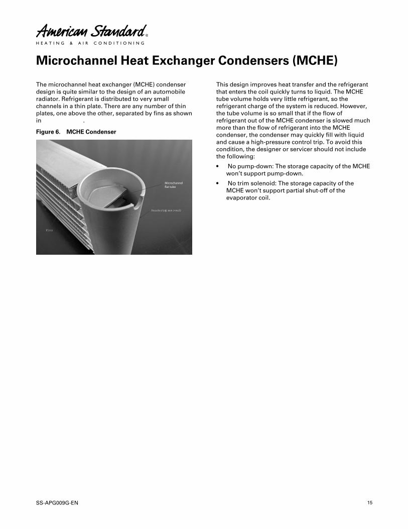
The microchannel heat exchanger (MCHE) condenserdesign is quite similar to the design of an automobileradiator. Refrigerant is distributed to very smallchannels in a thin plate. There are any number of thinplates, one above the other, separated by fins as shownin Figure 6, p. 15.
Figure 6. MCHE Condenser
Fins
Header (top removed)
This design improves heat transfer and the refrigerantthat enters the coil quickly turns to liquid. The MCHEtube volume holds very little refrigerant, so therefrigerant charge of the system is reduced. However,the tube volume is so small that if the flow ofrefrigerant out of the MCHE condenser is slowed muchmore than the flow of refrigerant into the MCHEcondenser, the condenser may quickly fill with liquidand cause a high-pressure control trip. To avoid thiscondition, the designer or servicer should not includethe following:
• No pump-down: The storage capacity of the MCHEwon’t support pump-down.
• No trim solenoid: The storage capacity of theMCHE won’t support partial shut-off of theevaporator coil.
16 SS-APG009G-EN
Refrigerant Piping Examples
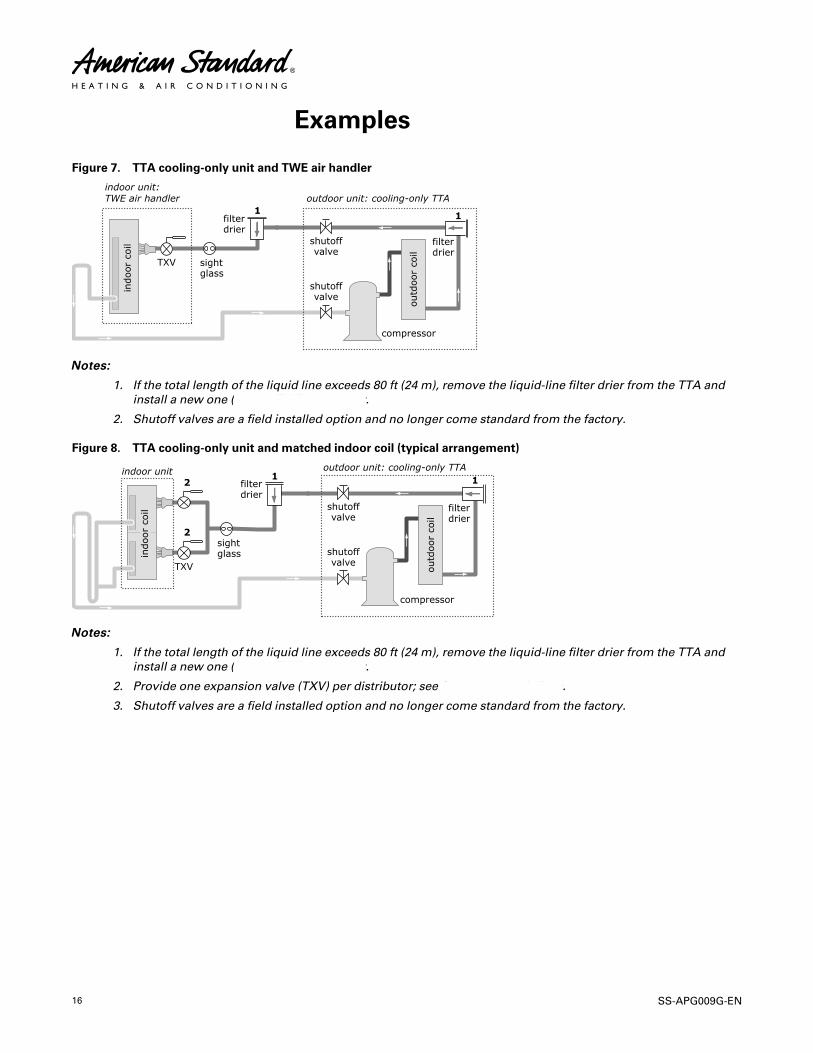
Figure 7. TTA cooling-only unit and TWE air handler
NNootteess::
1. If the total length of the liquid line exceeds 80 ft (24 m), remove the liquid-line filter drier from the TTA andinstall a new one () at the TWE air handler.
2. Shutoff valves are a field installed option and no longer come standard from the factory.
Figure 8. TTA cooling-only unit and matched indoor coil (typical arrangement)
NNootteess::
1. If the total length of the liquid line exceeds 80 ft (24 m), remove the liquid-line filter drier from the TTA andinstall a new one () at the TWE air handler.
2. Provide one expansion valve (TXV) per distributor; see for recommendations.
3. Shutoff valves are a field installed option and no longer come standard from the factory.
SS-APG009G-EN 17
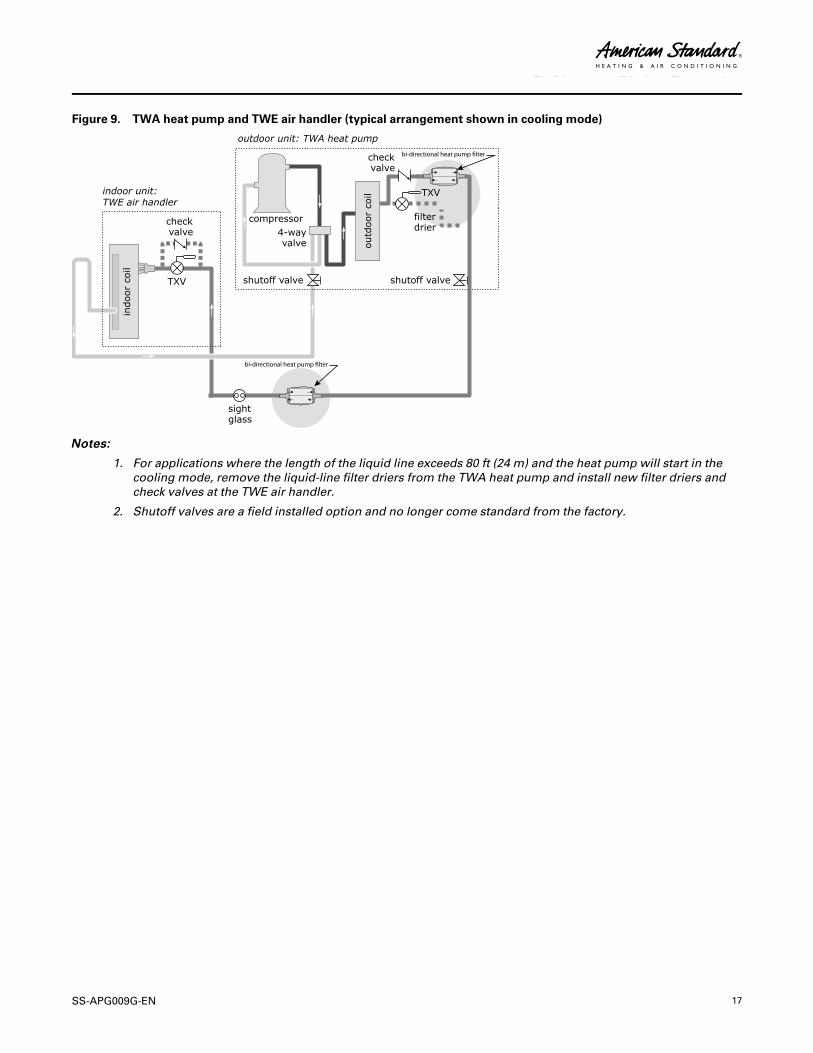
Figure 9. TWA heat pump and TWE air handler (typical arrangement shown in cooling mode)
bi-directional heat pump �lter
bi-directional heat pump �lter
NNootteess::
1. For applications where the length of the liquid line exceeds 80 ft (24 m) and the heat pump will start in thecooling mode, remove the liquid-line filter driers from the TWA heat pump and install new filter driers andcheck valves at the TWE air handler.
2. Shutoff valves are a field installed option and no longer come standard from the factory.
RReeffrriiggeerraanntt PPiippiinngg EExxaammpplleess
18 SS-APG009G-EN
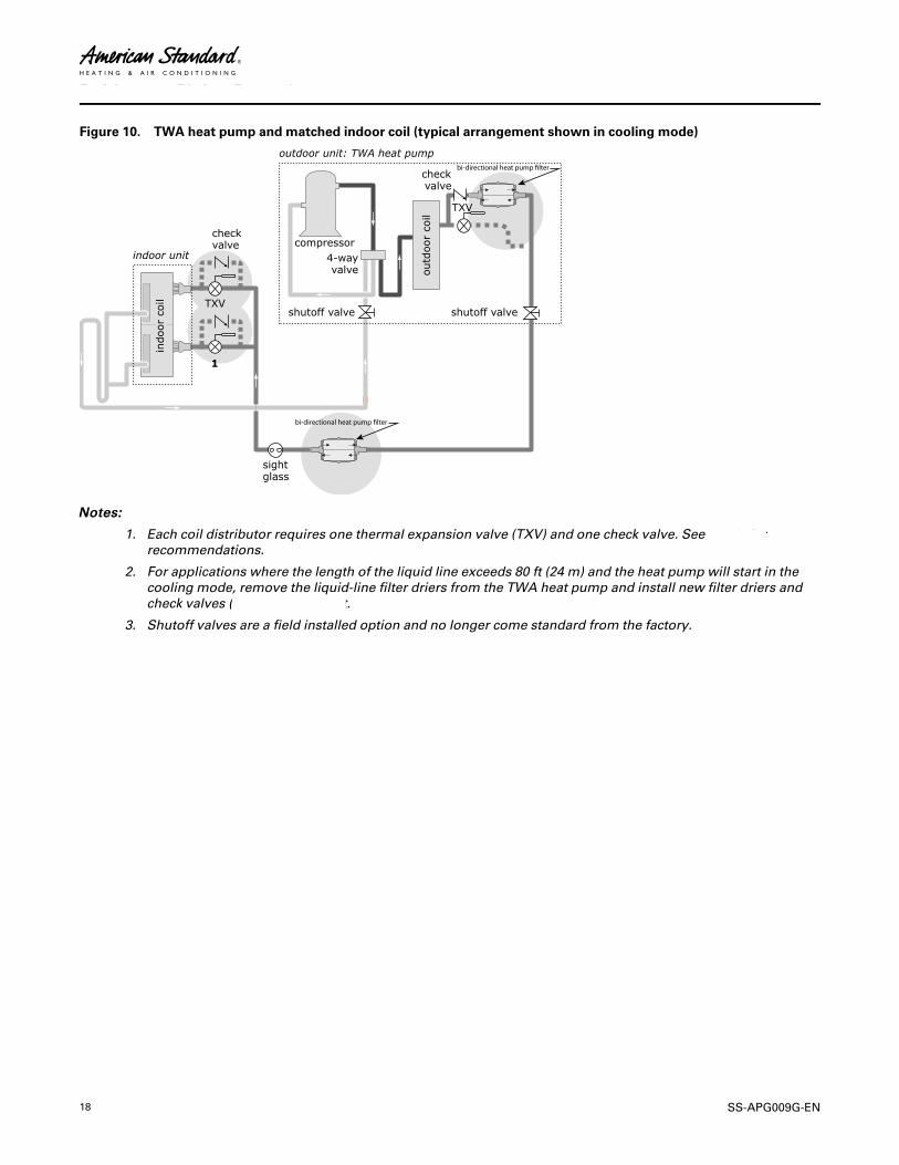
Figure 10. TWA heat pump and matched indoor coil (typical arrangement shown in cooling mode)
bi-directional heat pump �lter
bi-directional heat pump �lter
NNootteess::
1. Each coil distributor requires one thermal expansion valve (TXV) and one check valve. See , and , forrecommendations.
2. For applications where the length of the liquid line exceeds 80 ft (24 m) and the heat pump will start in thecooling mode, remove the liquid-line filter driers from the TWA heat pump and install new filter driers andcheck valves () at the indoor unit.
3. Shutoff valves are a field installed option and no longer come standard from the factory.
RReeffrriiggeerraanntt PPiippiinngg EExxaammpplleess

SS-APG009G-EN 19
Figure 11. Indoor coil (non-TWE) with one distributor (single-circuit TTA/TWA units)
NNootteess::
1. Pitch the liquid line 1 inch per 10 feet (1 cm per 3 m) so that the liquid refrigerant drains toward the indoorcoil. Use the liquid-line size recommended in or .
2. Provide one expansion valve (TXV) per distributor.
TTWWAA hheeaatt ppuummppss oonnllyy: Provide one check valve for each expansion valve.
3. Pitch the gas line leaving the coil so that it slopes away from the coil by 1 inch per 10 feet (1 cm per 3 m).
4. For vertical risers, use the tube diameter recommended in or . Ensure that the top of the riser is at least 1 foot(30 cm) above the lowest point.
5. Pitch the gas line 1 inch per 10 feet (1 cm per 3 m) toward the indoor coil.
6. Insulate the gas line.
RReeffrriiggeerraanntt PPiippiinngg EExxaammpplleess
20 SS-APG009G-EN
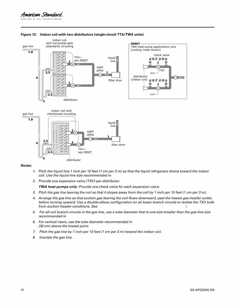
Figure 12. Indoor coil with two distributors (single-circuit TTA/TWA units)
NNootteess::
1. Pitch the liquid line 1 inch per 10 feet (1 cm per 3 m) so that the liquid refrigerant drains toward the indoorcoil. Use the liquid-line size recommended in , or .
2. Provide one expansion valve (TXV) per distributor.
TTWWAA hheeaatt ppuummppss oonnllyy: Provide one check valve for each expansion valve.
3. Pitch the gas line leaving the coil so that it slopes away from the coil by 1 inch per 10 feet (1 cm per 3 m).
4. Arrange the gas line so that suction gas leaving the coil flows downward, past the lowest gas-header outlet,before turning upward. Use a double-elbow configuration on all lower branch circuits to isolate the TXV bulbfrom suction-header conditions. See “Line Sizing, Routing, and Component Selection,” p. 8.
5. For all coil branch circuits in the gas line, use a tube diameter that is one size smaller than the gas-line sizerecommended in or .
6. For vertical risers, use the tube diameter recommended in or . Ensure that the top of the riser is at least 1 foot(30 cm) above the lowest point.
7. Pitch the gas line by 1 inch per 10 feet (1 cm per 3 m) toward the indoor coil.
8. Insulate the gas line.
RReeffrriiggeerraanntt PPiippiinngg EExxaammpplleess

SS-APG009G-EN 21
Figure 13. Indoor coil with two distributors (dual-circuit TTA/TWA units)
liquid line(circuit 1)
liquid line(circuit 2)
sightglass
sightglass
distributor
TXV —see INSET
TXV —see INSET
filterdrier
filterdrier
gas line(circuit 1)
gas line(circuit 2)
distributor
Indoor coil with Intertwined circuiting
NNootteess::
1. Pitch the liquid line 1 inch per 10 feet (1 cm per 3 m) so that the liquid refrigerant drains toward the indoorcoil. Use the liquid-line size recommended in the Component selection tables, found in “Parts,” p. 24.
2. Provide one expansion valve (TXV) per distributor.
TTWWAA hheeaatt ppuummppss oonnllyy: Provide one check valve for each expansion valve.
3. Pitch the gas line leaving the coil so that it slopes away from the coil by 1 inch per 10 feet (1 cm per 3 m).
4. For vertical risers, use the tube diameter recommended in the Component selection tables, found in“Parts,” p. 24. Ensure that the top of the riser is at least 1 foot (30 cm) above the lowest point.
5. Pitch the gas line 1 inch per 10 feet (1 cm per 3 m) toward the indoor coil.
6. Insulate the gas line.
RReeffrriiggeerraanntt PPiippiinngg EExxaammpplleess
22 SS-APG009G-EN
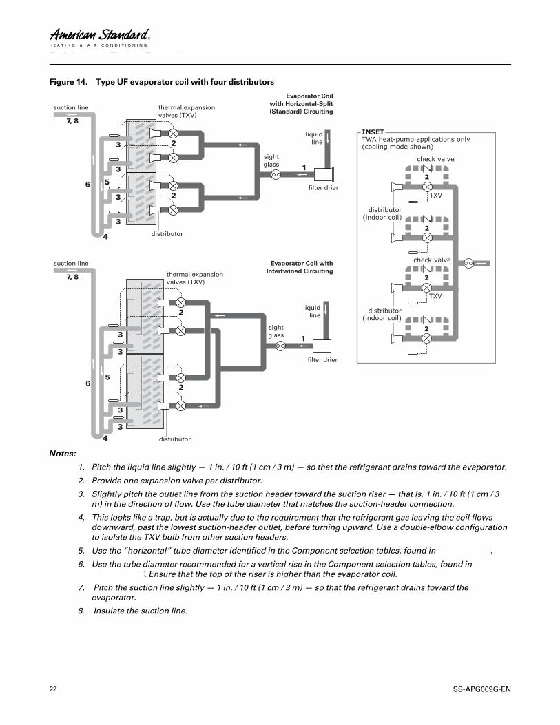
Figure 14. Type UF evaporator coil with four distributors
thermal expansionvalves (TXV)
liquidline
filter drier
sightglass
distributor
suction line
Evaporator Coilwith Horizontal-Split(Standard) Circuiting
thermal expansionvalves (TXV)
liquidline
filter drier
sightglass
distributor
suction line Evaporator Coil withIntertwined Circuiting
NNootteess::
1. Pitch the liquid line slightly — 1 in. / 10 ft (1 cm / 3 m) — so that the refrigerant drains toward the evaporator.
2. Provide one expansion valve per distributor.
3. Slightly pitch the outlet line from the suction header toward the suction riser — that is, 1 in. / 10 ft (1 cm / 3m) in the direction of flow. Use the tube diameter that matches the suction-header connection.
4. This looks like a trap, but is actually due to the requirement that the refrigerant gas leaving the coil flowsdownward, past the lowest suction-header outlet, before turning upward. Use a double-elbow configurationto isolate the TXV bulb from other suction headers.
5. Use the “horizontal” tube diameter identified in the Component selection tables, found in “Parts,” p. 24.
6. Use the tube diameter recommended for a vertical rise in the Component selection tables, found in“Parts,” p. 24. Ensure that the top of the riser is higher than the evaporator coil.
7. Pitch the suction line slightly — 1 in. / 10 ft (1 cm / 3 m) — so that the refrigerant drains toward theevaporator.
8. Insulate the suction line.
RReeffrriiggeerraanntt PPiippiinngg EExxaammpplleess
SS-APG009G-EN 23
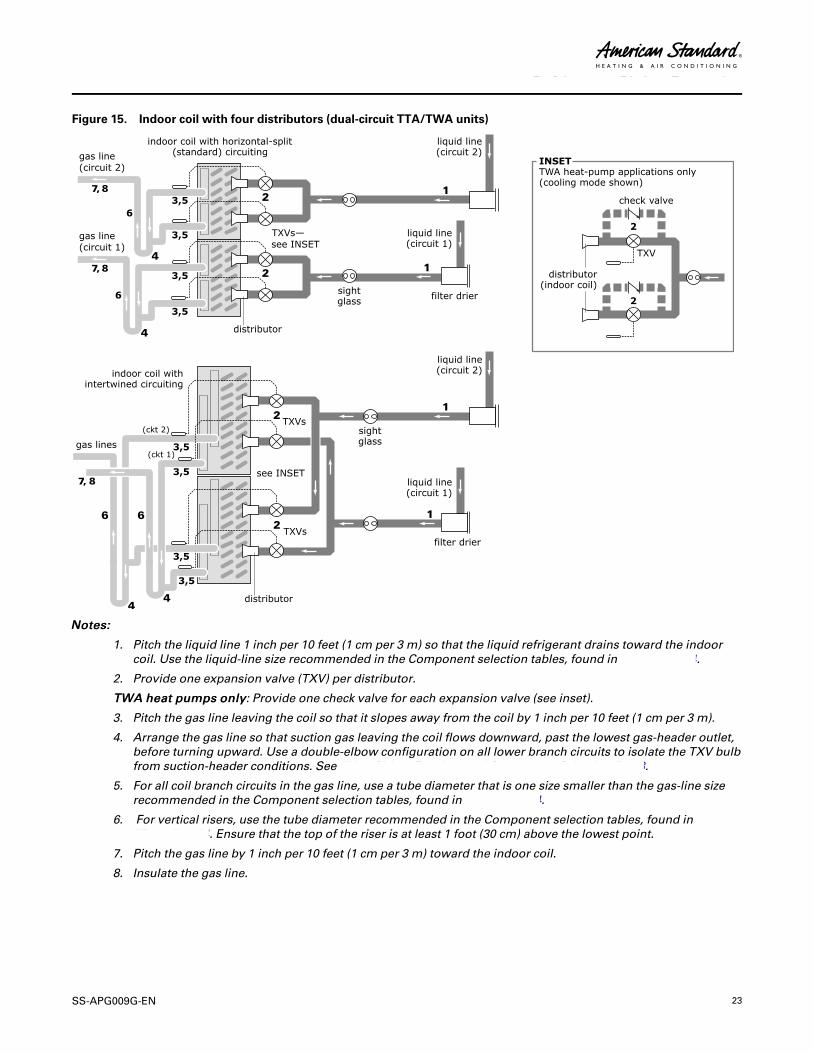
Figure 15. Indoor coil with four distributors (dual-circuit TTA/TWA units)
NNootteess::
1. Pitch the liquid line 1 inch per 10 feet (1 cm per 3 m) so that the liquid refrigerant drains toward the indoorcoil. Use the liquid-line size recommended in the Component selection tables, found in “Parts,” p. 24.
2. Provide one expansion valve (TXV) per distributor.
TTWWAA hheeaatt ppuummppss oonnllyy: Provide one check valve for each expansion valve (see inset).
3. Pitch the gas line leaving the coil so that it slopes away from the coil by 1 inch per 10 feet (1 cm per 3 m).
4. Arrange the gas line so that suction gas leaving the coil flows downward, past the lowest gas-header outlet,before turning upward. Use a double-elbow configuration on all lower branch circuits to isolate the TXV bulbfrom suction-header conditions. See “Line Sizing, Routing, and Component Selection,” p. 8.
5. For all coil branch circuits in the gas line, use a tube diameter that is one size smaller than the gas-line sizerecommended in the Component selection tables, found in “Parts,” p. 24.
6. For vertical risers, use the tube diameter recommended in the Component selection tables, found in“Parts,” p. 24. Ensure that the top of the riser is at least 1 foot (30 cm) above the lowest point.
7. Pitch the gas line by 1 inch per 10 feet (1 cm per 3 m) toward the indoor coil.
8. Insulate the gas line.
RReeffrriiggeerraanntt PPiippiinngg EExxaammpplleess
24 SS-APG009G-EN
Parts
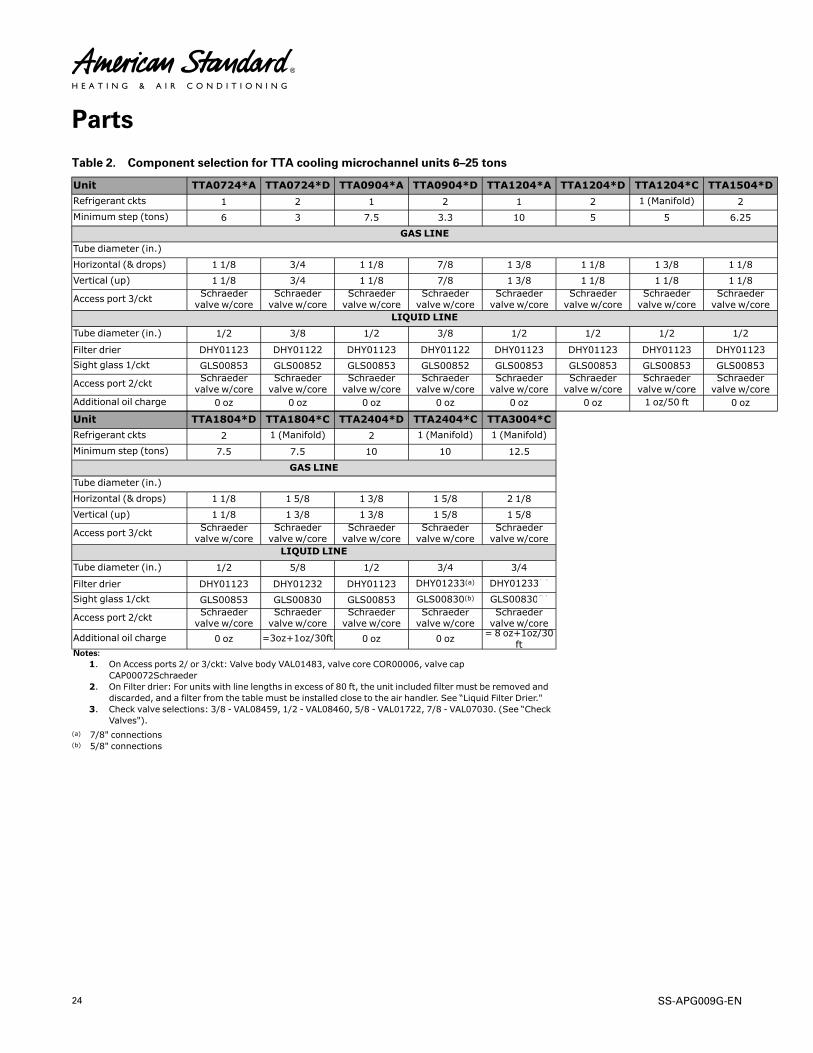
Table 2. Component selection for TTA cooling microchannel units 6–25 tons
Unit TTA0724*A TTA0724*D TTA0904*A TTA0904*D TTA1204*A TTA1204*D TTA1204*C TTA1504*DRefrigerant ckts 1 2 1 2 1 2 1 (Manifold) 2Minimum step (tons) 6 3 7.5 3.3 10 5 5 6.25
GAS LINETube diameter (in.)
Horizontal (& drops) 1 1/8 3/4 1 1/8 7/8 1 3/8 1 1/8 1 3/8 1 1/8Vertical (up) 1 1/8 3/4 1 1/8 7/8 1 3/8 1 1/8 1 1/8 1 1/8
Access port 3/ckt Schraedervalve w/core
Schraedervalve w/core
Schraedervalve w/core
Schraedervalve w/core
Schraedervalve w/core
Schraedervalve w/core
Schraedervalve w/core
Schraedervalve w/core
LIQUID LINE
Tube diameter (in.) 1/2 3/8 1/2 3/8 1/2 1/2 1/2 1/2
Filter drier DHY01123 DHY01122 DHY01123 DHY01122 DHY01123 DHY01123 DHY01123 DHY01123Sight glass 1/ckt GLS00853 GLS00852 GLS00853 GLS00852 GLS00853 GLS00853 GLS00853 GLS00853
Access port 2/ckt Schraedervalve w/core
Schraedervalve w/core
Schraedervalve w/core
Schraedervalve w/core
Schraedervalve w/core
Schraedervalve w/core
Schraedervalve w/core
Schraedervalve w/core
Additional oil charge 0 oz 0 oz 0 oz 0 oz 0 oz 0 oz 1 oz/50 ft 0 oz
Unit TTA1804*D TTA1804*C TTA2404*D TTA2404*C TTA3004*CRefrigerant ckts 2 1 (Manifold) 2 1 (Manifold) 1 (Manifold)
Minimum step (tons) 7.5 7.5 10 10 12.5
GAS LINETube diameter (in.)
Horizontal (& drops) 1 1/8 1 5/8 1 3/8 1 5/8 2 1/8Vertical (up) 1 1/8 1 3/8 1 3/8 1 5/8 1 5/8
Access port 3/ckt Schraedervalve w/core
Schraedervalve w/core
Schraedervalve w/core
Schraedervalve w/core
Schraedervalve w/core
LIQUID LINE
Tube diameter (in.) 1/2 5/8 1/2 3/4 3/4
Filter drier DHY01123 DHY01232 DHY01123 DHY01233(a) DHY01233(a)
Sight glass 1/ckt GLS00853 GLS00830 GLS00853 GLS00830(b) GLS00830(b)
Access port 2/ckt Schraedervalve w/core
Schraedervalve w/core
Schraedervalve w/core
Schraedervalve w/core
Schraedervalve w/core
Additional oil charge 0 oz =3oz+1oz/30ft 0 oz 0 oz = 8 oz+1oz/30ft
Notes:1. On Access ports 2/ or 3/ckt: Valve body VAL01483, valve core COR00006, valve cap
CAP00072Schraeder2. On Filter drier: For units with line lengths in excess of 80 ft, the unit included filter must be removed and
discarded, and a filter from the table must be installed close to the air handler. See “Liquid Filter Drier."3. Check valve selections: 3/8 - VAL08459, 1/2 - VAL08460, 5/8 - VAL01722, 7/8 - VAL07030. (See “Check
Valves").(a) 7/8" connections(b) 5/8" connections
SS-APG009G-EN 25
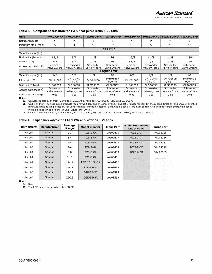
Table 3. Component selection for TWA heat pump units 6–20 tons
Unit TWA0724*A TWA0724*D TWA0904*A TWA0904*D TWA1204*A TWA1204*D TWA1804*D TWA2404*DRefrigerant ckts 1 2 1 2 1 2 2 2Minimum step (tons) 6 3 7.5 3.75 10 5 7.5 10
GAS LINETube diameter (in.)
Horizontal (& drops) 1 1/8 3/4 1 1/8 7/8 1-3/8 1 1/8 1 1/8 1 3/8Vertical (up) 7/8 3/4 1 1/8 7/8 1 1/8 7/8 1 1/8 1 1/8
Access port 3/ckt(a) Schraedervalve w/core
Schraedervalve w/core
Schraedervalve w/core
Schraedervalve w/core
Schraedervalve w/core
Schraedervalve w/core
Schraedervalve w/core
Schraedervalve w/core
LIQUID LINE
Tube diameter (in.) 1/2 3/8 1/2 3/8 1/2 1/2 1/2 1/2
Filter drier(b) DHY01608DHY01467(Qty 2) DHY01608
DHY01467(Qty 2) DHY01608
DHY01467(Qty 2)
DHY01608(Qty 2)
DHY01608(Qty 2)
Sight glass 1/ckt GLS00853 GLS00852 GLS00853 GLS00852 GLS00853 GLS00853 GLS00853 GLS00853
Access port 2/ckt(a) Schraedervalve w/core
Schraedervalve w/core
Schraedervalve w/core
Schraedervalve w/core
Schraedervalve w/core
Schraedervalve w/core
Schraedervalve w/core
Schraedervalve w/core
Additional oil charge 0 oz 0 oz 0 oz 0 oz 0 oz 0 oz 0 oz 0 ozNotes:
1. On Access ports 2/ or 3/ckt: Valve body VAL01483, valve core COR00006, valve cap CAP000722. On Filter drier: The heat pump products require two filters and two check valves: one set-oriented for liquid in the cooling direction, and one set-oriented
for liquid in the heating direction. For units with line lengths in excess of 80 ft, the included filters must be removed and filters from the table must beinstalled close to the air handler. See “Liquid Filter Drier.".
3. Check valve selections: 3/8 - VAL08459, 1/2 - VAL08460, 5/8 - VAL01722, 7/8 - VAL07030. (see “Check Valves”)
Table 4. Expansion valves for TTA/TWA applications 6–20 tons
Refrigerant ManufacturerTonnageRange Model Number Trane Part Model Number w/
Check Valve Trane Part
R-410A Sporlan 2-3 RZE-2-GA VAL09476 RCZE-2-GA VAL08085
R-410A Sporlan 3-4 RZE-3-GA VAL09477 RCZE-3-GA VAL08086
R-410A Sporlan 4-5 RZE-4-GA VAL09478 RCZE-4-GA VAL08087
R-410A Sporlan 5-6 RZE-5-GA VAL09479 RCZE-5-GA VAL08088
R-410A Sporlan 6-8 RZE-6-GA VAL09480 RCZE-6-GA VAL08089
R-410A Sporlan 8-11 RZE-8-GA VAL09481 ——————————-———
————————-—————
R-410A Sporlan 11-14 RZE-12-1/2-GA VAL09482 ——————————-———
————————-—————
R-410A Sporlan 14-17 RZE-15-GA VAL09483 ——————————-———
————————-—————
R-410A Sporlan 17-23 OZE-20-GA VAL09585 ——————————-———
————————-—————
R-410A Sporlan 23-28 OZE-25-GA VAL09583 ——————————-———
————————-—————
Notes:1. See “Expansion Valves,” p. 11.2. The RZE valves may also be called BBIZE.
PPaarrttss

26 SS-APG009G-EN
Table 5. R-410A lbs charge per 100 ft
OD Suction Liquid Discharge
1/4 0.04 1.25 0.18
5/16 0.07 2.15 0.31
3/8 0.12 3.45 0.51
1/2 0.22 6.43 0.94
5/8 0.36 10.33 1.51
3/4 0.53 15.42 2.26
7/8 0.74 21.42 3.14
1 1/8 1.26 36.52 5.36
1 3/8 1.93 55.63 8.16
1 5/8 2.73 78.74 11.55
2 1/8 4.74 136.97 20.08
2 5/8 7.32 211.22 30.97
Note: Type L or ACR tube. Suction: Saturated at 40°F, Liquid: Saturated at 90°F, Discharge: Saturated at 125°F
PPaarrttss
SS-APG009G-EN 27
NNootteess
American Standard has been creating comfortable and affordable living environments for more than acentury. For more information, please visit americanstandardair.com.
American Standard has a policy of continuous product and product data improvement and reserves the right to change design andspecifications without notice. We are committed to using environmentally conscious print practices.
SS-APG009G-EN 30 Apr 2020
Supersedes SS-APG009F-EN (July 2018) ©2020 American Standard