application limits for continuously welded rails on...
TRANSCRIPT

Jef Pauwels
temporary bridge decksApplication limits for continuously welded rails on
Academic year 2014-2015Faculty of Engineering and ArchitectureChairman: Prof. dr. ir. Peter TrochDepartment of Civil Engineering
Master of Science in Civil EngineeringMaster's dissertation submitted in order to obtain the academic degree of
Counsellor: Ir. Ken SchotteSupervisors: Prof. Jan Mys, Prof. dr. ir. Hans De Backer

i
PREFACE
During the first of two master years of my education for Civil Engineer: Construction, a course of choice
had to be followed. I chose to follow the course ‘Railroads’ taught by Prof. Jan Mys, and thanks to this
course my interests in railroads increased. Additionally, during my education of Civil Engineering
Technology at Kaho Sint-Lieven Ghent, I had the privilege to be allowed to follow an internship at Victor
Buyck Steel Construction. During this internship my interest in bridge structures was triggered and
therefore I started to look for a dissertation topic in this field. When I subsequently stumbled on the
title “Application limits for continuously welded rails on temporary bridge decks”, combining two
subjects which had my interest in one dissertation, it was a logic choice to apply for this topic.
ACKNOWLEDGEMENTS
Throughout my studies and my Master’s dissertation in particular, I acquired more appreciation for
several people. All of these people helped me in one way or another and I therefore would like to
mention them.
First of all I would like to thank prof. dr. ir. Hans De Backer and prof. ir. Jan Mys for giving me the
opportunity to work on this subject. It was a pleasure working with them and I am grateful for the
feedback, ideas and help they both offered me.
Furthermore, I extensively want to thank ir. Ken Schotte. Whenever I had questions or encountered a
complication regarding the implementation of the model into the Samcef Software, he was available
and ready to help me.
Finally, I would also like to thank ir. Ben Ferdinande, ir Didier van de Velde and ir. Alex Lefevre of
INFRABEL. They have put a lot of time and work in assisting me during various meetings. Moreover
they enriched me with their insights and ideas to complement my thesis. I really enjoyed assisting in
the research they are performing on the application of temporary bridge decks.
ii
PERMISSION FOR USAGE
The author gives permission to make this master dissertation available for consultation and to copy
parts of this master dissertation for personal use. In the case of any other use, the limitations of the
copyright have to be respected, in particular with regard to the obligation to state expressly the source
when quoting results from this master dissertation.
22th of May Jef Pauwels

iii
ABSTRACT
This study investigates the possibility of omitting rail expansion devices from the track configuration
when CWR is continued over temporary bridge decks. This is done by analysing the arising track/bridge
interaction phenomena. In a first parametric analysis the additional rail stresses due to moving train
loads and temperature variations are assessed using a computer model based on stipulations provided
in the UIC code 774-3R. Subsequently the model is expanded to a more complex model which is able
to simulate the buckling behaviour of the rail track. Using this model a second parametric study is
performed in which the model is only loaded with thermal loads. In this way the parameters which are
predominant in determining the critical buckling temperature of the rails are determined and an
assessment is made on the magnitude of the margin of safety with respect to thermal buckling.
It is found that depending on the magnitude of two main factors, the lateral ballast resistance and the
amplitude of the initial misalignment a large reduction of the track stability might arise. Therefore a
minimal characteristic lateral ballast resistance of 4 kN is recommended along with a maximal
allowable misalignment amplitude of 7 mm for the case of thermal track buckling.
In order to be able to make a good founded conclusion on the allowance of train passage over a
temporary bridge deck without expansion devices it will be necessary to perform further research by
expanding the 3D model assembled in this dissertation in order to be able to correctly take into account
the influence of both the moving train loads and thermal loads.
Author
Jef Pauwels
Academic year
2014 - 2015
Supervisors
Prof. dr. ir. Hans De Backer
Prof. ir. Jan Mys
Counsellor
Ir. Ken Schotte
Title
Application limits for continuously welded rails on temporary
bridge decks
Department, faculty and chairman
Department of Civil Engineering
Chairman: Prof. dr. ir. Peter Troch
Faculty of Engineering and Architecture, University of Ghent
Keywords:
Track-bridge interaction, temporary bridge decks, application limits, parametric study

iv
Application limits for continuously welded rails on
temporary bridge decks
Jef Pauwels
Supervisors: Prof. dr. ir. Hans De Backer, Prof. Jan Mys
Counsellor: Ir. Ken Schotte
Abstract This study investigates the possibility of omitting
rail expansion devices from the track configuration when CWR is
continued over temporary bridge decks. This is done by analysing
the arising track/bridge interaction phenomena. In a first
parametric analysis the additional rail stresses due to moving
train loads and temperature variations are assessed using a
computer model based on stipulations provided in the UIC code
774-3R [1]. Subsequently the model is expanded to a more
complex model which is able to simulate the buckling behaviour
of the rail track. Using this model a second parametric study is
performed in which the model is only loaded with thermal loads.
In this way the parameters which are predominant in
determining the critical buckling temperature of the rails are
determined and an assessment can is made on the magnitude of
the margin of safety with respect to thermal buckling.
It is found that depending on the magnitude of two main
factors, the lateral ballast resistance and the amplitude of the
initial misalignment a large reduction of the track stability might
arise. Therefore a minimal characteristic lateral ballast resistance
of 4 kN is recommended along with a maximal allowable
misalignment amplitude of 7 mm for the case of thermal track
buckling.
In order to be able to make a good founded conclusion on the
allowance of train passage over a temporary bridge deck without
expansion devices it will be necessary to perform further research
by expanding the 3D model assembled in this dissertation in
order to be able to correctly take into account the influence of
both the moving train loads and thermal loads.
Keywords Track/bridge interaction, temporary bridge decks,
applications limits, parametric study
I. INTRODUCTION
In situations where maintenance works on the track bed
cannot be done while assuring stability of the tracks temporary
bridge decks are used. An example of such a configuration is
given in Figure 1. In such situations, the ballast layers are
entirely replaced by temporary bridge decks. For safety
reasons and in the absence of clear application criteria, the
continuous welded rails are systematically interrupted before
and after these temporary constructions. However, this method
causes high costs since the need to install expansion joints also
requires permanent maintenance works.
The aim of this dissertation is to study this problem in depth
and to determine in which circumstances the use of continuous
welded rails without expansion joints could be allowed when
using such temporary bridges. Although these temporary
bridge decks are in many ways different from actual bridges,
J. Pauwels is a student at the, Ghent University (UGent), Gent, Belgium.
E-mail: [email protected] .
they also show a lot of interesting similarities which can be
used for the evaluation of the interaction between temporary
bridge decks and tracks.
In order to determine all the conditions that are strictly
necessary for the use of continuously welded rails and what
condition are advantageous but not necessary, a parametric
study will be performed using the infinite elements program
Samcef Field. Based on the results of this analysis, eventually
specific proposals will be developed to allow the use of
continuously welded rails in specific circumstances
determined by clear criteria.
Figure 1: Example of a twin girder temporary bridge deck [2]
II. TRACK/BRIDGE INTERACTION
If continuous welded rails are continued over bridges the
track and bridge are interlinked to each other, regardless of
whether the track is directly fastened or laid on a ballasted
bed. This interlinking affects the behaviour of one on the
other, which can be termed as the interaction between the
bridge and the track. Movement of either one of them will
result in forces on the other.
During the past decennia a lot of research has been
performed on the subject of interaction. The ERRI (the
European Rail Research Institute) Committee D 213 carried
out an extensive study to analyse and asses these interactive
forces. The results of these studies were subsequently
summarized in the form of a report which is named UIC code
774-3R[1]. This report contains the actions to be considered,
the configuration of test models and the design requirements
needed in order to prevent damage due to these interaction
effects. This leaflet has been accepted as the general guideline
for all interaction analyses and will therefore also play an
important role in this dissertation.
The forces causing the interaction between track and bridge
are those that cause relative- displacements between track and

v
the bridge Three different loading cases should be regarded
according to the UIC code 774-3R [1] for each direction of the
moving train. These are:
- Vertical forces of 80 kN/m situated on left
respectively right embankment and bridge fully
loaded.
- Braking forces of 20 kN/m situated on left
respectively right embankment and bridge fully
loaded
- Influence of temperature variation in bridge due
to respectively a temperature increase of +35°C and a
temperature decrease of -35°C
Due to these forces, additional rail stresses arise in the track
and these might, in some cases, become too large resulting in
track buckling for the case of large compressive forces or rail
breaks for the case of large tensile forces. It should therefore
be verified whether these additional rail stresses remain within
acceptable limits, which are imposed by the UIC code 774-3R.
In order to do so a computer model will be assembled by
which these additional rail stresses can be computed.
III. ASSESSMENT OF ADDITIONAL RAIL STRESSES IN FIRST
PARAMETRIC STUDY ON 2D MODEL
Using the model configuration shown in Figure 2 a first
parametric analysis is performed in which multiple parameters
of both the temporary bridge deck and surroundings are
analysed. Their influence on the arising stresses in the rails
due the different interaction loading cases are investigated. At
the same time it is also verified whether the arising rail
stresses and rail/bridge displacements comply with the
limitations given in the UIC leaflet 774-3R.
A. General composition
The track is represented by one single Wire-type element to
which a flexible beam behaviour is assigned which
corresponds to two UIC 60 rails. The position of the track
coincides with the upper face of the bridge deck. The bridge
deck is modelled horizontal flexible beam-type elements
which have the same properties (bending stiffness, material
properties,…) as the actual bridge. These elements are located
at the centre of gravity of the bridge and are depicted in Figure
2 as (5). Additionally vertical rigid beam-type elements which
have an infinite stiffness connect the horizontal elements to the
bearings or to the track. These and are depicted in Figure 2 as
(6) respectively (4).The connection between track and
embankment/bridge deck is modelled using bilinear
longitudinal spring elements. In case of a temporary bridge
deck usually neoprene bearings are used for which one bearing
is fixed and the other one is movable.
In order to ensure the model yields the correct interaction
behavior first the assembly was validated by checking multiple
test-cases provided in the UIC code 774-3R[1]. Subsequently,
the validated model was then adjusted and expanded to the
case of a temporary bridge deck.
B. Model properties
Table 1 shows the model properties and reference values of
the parameters investigated in this study. Each parameter is
varied in a practical range while the other parameters are kept
constant. Only the properties of the track were not altered. The
properties of the temporary bridge deck used are those
corresponding to a temporary bridge deck used by
INFRABEL for a span of 12 metres. [2]
Figure 2: Schematic overview of the temporary bridge deck model in Samcef Field
Table 1: Properties of 2D model Table 2 : Characteristic long. ballast resistance [kN/m]
Table 3: Characteristic long. fastener resistance [kN/m]

vi
Figure 3: Sensitivity of rail stresses with respect to bridge span
length
Figure 4: Sensitivity of rail stresses with respect to bearing stiffness
C. Results
In Figure 3 to Figure 7 the results of the parametric analysis
are shown. It was found that the span length and bridge
bending stiffness are the most determining parameters with
respect to the arising additional rail stresses. It will thus be
compulsory to impose certain application limits to these
parameters for the allowance of continuing CWR track over a
temporary bridge deck. The other parameters examined also
had an influence on the arising stresses but this influence was
less decisive.
The standard configuration used in this parametric analysis
corresponds to the case of a temporary bridge deck with a
span length of 20 metres. The bending stiffness of the
temporary bridge deck is chosen equal to the stiffness of an
actual temporary bridge deck used by INFRABEL for a span
length of 12 metres. The characteristics for the longitudinal
track resistance and the loads applied to the model are both
based on the values imposed by the UIC code 774-3R.
Therefore, if this configuration complies with the limitations
given by the UIC code 774-3R (maximum additional
compressive rail stress 72 N/mm² and maximum additional
tensile rail stress is 92 N/mm²) , one can assume that for this
span length and temporary bridge deck configuration it is
allowed to continue CWR track over the bridge structure
without providing an expansion device.
When considering the graphs shown above, it is found that,
not only for the standard configuration but also for all other
test-cases examined (except for the one with a span length of
30 metres), the limitations imposed by the UIC code 774-3R
are met. As a result one can state that for these configurations
it is allowed to omit the expansion device from the structural
configuration of the track.
Furthermore, it could even be concluded that, if the
temporary bridge decks used by INFRABEL are applied
Figure 5: Sensitivity of rail stresses with respect to ballast quality
Figure 6: Sensitivity of rail stresses with respect to fastener long.
resistance on temporary bridge deck
Figure 7: Sensitivity of rail stresses with respect to bending stiffness
of temporary bridge deck
corresponding to their practical applied span range, there is
still a large safety margin with respect to the additional rail
stresses and displacements.
IV. PARAMETRIC STUDY ON 3D TEMPORARY BRIDGE DECK
MODEL
In the previous section use has been made of a 2D model in
which only the influence of the longitudinal and vertical
displacements of track and bridge were taken into account. In
these models the lateral component has been neglected. This
simplification was acceptable as long as the arising additional
rail stresses and relative and absolute displacements due to the
interaction effect remained within certain limits provided by
the UIC Code 774-3R. If this was the case then one could state
that the design provided sufficient safety against track
buckling and rail break.
However, in an attempt to find the more exact boundaries
concerning track buckling due to interaction the model
assembled in section III will now be further expanded to a 3D
model. This 3D model will take into account the lateral
deflections of the rail and the elastoplastic behaviour of the
rail. In this way it will become possible to simulate the actual
buckling behaviour of the track.

vii
A. Modifications with respect to 2D model
The following modifications with respect to the 2D model
were made: The track is modelled using two separate
elastoplastic beam elements representing each one UIC 60
rail. Every 0.5 metres the lateral distance between a pair of
opposing mesh nodes of the rail elements is fixed in order to
simulate the presence of a sleeper. The centre line of the
bridge deck is now situated in between both rails at equal
distances, additional lateral beams are required to provide the
connection between rails and bridge deck. In order to model
the lateral ballast resistance bilinear spring elements are
applied to both rails each 0.5 metres. An overview of this new
configuration is given in Figure 8.
B. Loads
Since the Samcef model assembled in this dissertation does
not allow to perform a complete analysis (applying the
temperature loads first on an unloaded track and afterwards
adding the moving train loads) it does not seem too suitable to
perform a sensitivity analysis with respect to the buckling of a
rail track loaded by both the moving train loads and the
temperature loads. As a result it is opted to only check the
buckling behaviour for an unloaded track charged with
temperature loads (rail expansion and bridge expansion).
It is opted to make a distinction between the temperature
increase of the bridge deck and the one of the rail track. For
the temperature increase of the bridge deck an upper limit of
35°C is chosen, in accordance with the UIC code 774-3R.The
temperature of the bridge deck can never exceed this limit. In
this way it is possible to investigate the critical temperature
increase of the rail for which buckling occurs. This allowable
temperature increase of the rail can then be regarded as a
measure in order to express the level of safety against thermal
track buckling.
C. Model properties
All test cases are assembled starting from the same standard
case. Subsequently, in an attempt to investigate the influence
of each parameter, all parameters are kept constant except for
the one being investigated. In this way it is possible to check
the influence of the regarded parameter on the arising critical
buckling temperature. The properties of the standard case are
provided in Table 4. As found in Table 4 a lateral
misalignment with a wavelength of 4 meters and an amplitude
of 3 millimetres is standardly incorporated in each model. This
is done in order to destabilize the model. If no lateral
misalignment would be applied to the configuration the model
would not yield any solutions due to the perfect straightness of
the beams used. There are however two exceptions with
respect to the standard properties used. For the tests in which
the position of the amplitude is analysed a misalignment
amplitude of 17mm is used. For the tests in which the
wavelength of the misalignment is analysed both an amplitude
of 17mm is used and the position of the maximal deflection is
situated 6 metres away from the temporary bridge deck.
Table 4: Properties of 3D model
D. Results
Based on previous studies and the results obtained in the
parametric analysis using the 2D model it was opted to
examine the influence of the following parameters: span
length, longitudinal resistance of fasteners on temporary
bridge deck, longitudinal ballast resistance, lateral ballast
resistance, wavelength of initial misalignment, amplitude of
initial misalignment and position of initial misalignment. The
results are given in Figure 9 to Figure 15.
Figure 9: Sensitivity of critical temperature increase with respect to
the position of the misalignment
Figure 8: Overview of configuration of 3D model
viii
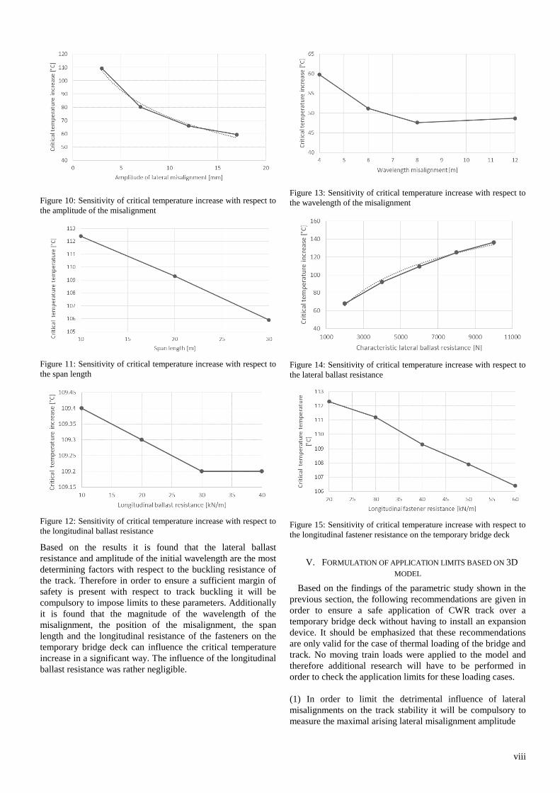
Figure 10: Sensitivity of critical temperature increase with respect to
the amplitude of the misalignment
Figure 11: Sensitivity of critical temperature increase with respect to
the span length
Figure 12: Sensitivity of critical temperature increase with respect to
the longitudinal ballast resistance
Based on the results it is found that the lateral ballast
resistance and amplitude of the initial wavelength are the most
determining factors with respect to the buckling resistance of
the track. Therefore in order to ensure a sufficient margin of
safety is present with respect to track buckling it will be
compulsory to impose limits to these parameters. Additionally
it is found that the magnitude of the wavelength of the
misalignment, the position of the misalignment, the span
length and the longitudinal resistance of the fasteners on the
temporary bridge deck can influence the critical temperature
increase in a significant way. The influence of the longitudinal
ballast resistance was rather negligible.
Figure 13: Sensitivity of critical temperature increase with respect to
the wavelength of the misalignment
Figure 14: Sensitivity of critical temperature increase with respect to
the lateral ballast resistance
Figure 15: Sensitivity of critical temperature increase with respect to
the longitudinal fastener resistance on the temporary bridge deck
V. FORMULATION OF APPLICATION LIMITS BASED ON 3D
MODEL
Based on the findings of the parametric study shown in the
previous section, the following recommendations are given in
order to ensure a safe application of CWR track over a
temporary bridge deck without having to install an expansion
device. It should be emphasized that these recommendations
are only valid for the case of thermal loading of the bridge and
track. No moving train loads were applied to the model and
therefore additional research will have to be performed in
order to check the application limits for these loading cases.
(1) In order to limit the detrimental influence of lateral
misalignments on the track stability it will be compulsory to
measure the maximal arising lateral misalignment amplitude

ix
during the execution of the maintenance works. As can be
derived from Figure 10 the major decrease of the critical rail
buckling temperature arises in the interval of 3 to 12
millimetres for the track misalignment amplitude. Therefore it
might be advisable to monitor the lateral misalignments during
the maintenance works and try to restrict the arising
misalignment amplitudes to a maximum of approximately 7
millimetres.
(2) Due to the incorporation of the temporary bridge deck in
the track configuration and the presence of heavy machinery
on the construction site locally a reduced compaction and thus
reduced lateral ballast resistance might arise. As proven in the
parametric study this can be very detrimental with respect to
the stability of the track and therefore limitations should be
imposed with respect to the minimum required lateral ballast
resistance. Based on in situ measurements performed by the
Technical University of Munich and the track measurement
department of DB a mean value of 6 kN was found for the
characteristic resistance of timber sleepers in a consolidated
condition[3].For this condition very high safety margins are
found with respect to the critical temperature increase.
Therefore a slightly lower lateral ballast resistance of 4 kN can
still be allowed. Additionally it is also advised in order to
make sure that a sufficient high lateral ballast resistance is
preserved that the track is compacted after implementation of
the temporary bridge deck.
(3) As found in the parametric study the most critical position
of a track defect is situated in the immediate surroundings of
the movable support. Still, the deviation between the different
critical temperature increases up to a position of 20 metres
away from the movable support remains rather small. From
this one could conclude that the part of the track beyond the
movable support, with a length of a factor 1 or 1.5 times the
bridge span length, should be monitored more strictly for the
presence of misalignments.
(4) When analysing the influence of the longitudinal resistance
of the fasteners on the temporary bridge deck it can be seen in
Figure 15 that a reduced clamping force results in a higher
buckling resistance of the track. Therefore the usage of such
fasteners might be advantageous with respect to the track
stability. However the influence of this parameter is not that
decisive in determining the critical temperature increase of the
rails.
(5) For the wavelength of the initial misalignment it was found
that the most critical wavelength is dependent on the
magnitude of the lateral ballast resistance. For lateral ballast
resistances equal to 4 or 6 kN the most critical wavelengths for
the initial misalignment were found in the range of 8 to 12
metres. For smaller initial misalignment wavelengths slightly
higher critical temperature increases were found. However the
relative deviation is not that high. For misalignment
wavelengths longer than 12 metres no tests were performed.
Further research for these misalignment wavelengths might be
advisable.
VI. GENERAL CONCLUSION
If one would rely on the model assembled according to the
UIC code 774-3R in section III one could conclude that it is
allowed to continue CWR track over a temporary bridge deck
without providing expansion devices in front and after the
temporary bridge. However if one considers the results
obtained in the parametric analysis using the 3D model, in
which the track is loaded with temperature loads only, it is
found that the conclusion is not that straightforward. It is
acquired that depending on the magnitude of two main factors,
the lateral ballast resistance and the amplitude of the initial
misalignment (which are not incorporated in the 2D model of
section III), a large reduction of the track stability might arise.
It is found that, for a situation in which very bad track
conditions are present, this reduction may even lead to a
critical buckling temperature increase of only 29°C, being
smaller than the imposed temperature increase (35°C for a
bridge deck and 50°C for the track) by the UIC code 774-3R.
Therefore it is compulsory to impose strict limits to the
magnitude of these parameters in order to ensure an adequate
track stability with respect to thermal buckling. A minimal
characteristic lateral ballast resistance of 4 kN is
recommended along with a maximal allowable misalignment
amplitude of 7 mm.
It should be noted that these limitations are only valid with
respect to the stability of the track loaded with temperature
loads only. It is not possible to make a conclusion on the fact
whether it is allowed to allow train passage over the temporary
bridge decks since no vertical and braking loads due to a
moving train have been incorporated in the models of section
IV. In order to be able to make a good founded conclusion on
the allowance of train passage over a temporary bridge deck
without expansion devices it will be necessary to perform
further research by expanding the 3D model of section IV.
ACKNOWLEDGEMENTS
The author would like to thank prof. dr. ir. Hans De Backer
and prof. ir. Jan Mys for giving me the opportunity to work on
this subject. It was a pleasure working with them and I am
grateful for the feedback, ideas and help they both offered me.
Furthermore, I extensively want to thank ir. Ken Schotte.
Whenever I had questions or encountered a complication
regarding the implementation of the model into the Samcef
Software, he was available and ready to help me.
Finally, I would also like to thank ir. Ben Ferdinande, ir
Didier van de Velde and ir. Alex Lefevre of INFRABEL.
They have put a lot of time and work in assisting me during
various meetings. Moreover they enriched me with their
insights and ideas to complement my thesis. I really enjoyed
assisting in the research they are performing on the application
of temporary bridge decks
REFERENCES
[1] Union Internationale de Chemins Fer, “UIC Code 774-3 :
Track/bridge interaction,” 2001.
[2] A. (INFRABEL) Lefevre, “Bundel 34.6: Spoorversterkingen,
voorlopige brugdekken en stalen boogbekisting,” 2015.
[3] M. Zacher, “Calculation of the critical temperature for track
buckling in a switch P3550 – XAM 1 / 46 on the line Liège -
Brussels Document : Date : 10-P-4926 - ICE3 MS Belgien
Fahrzeug / Fahrbahn-Wechselwirkung Völckerstraße 5 80939
München,” 2011.

x
TABLE OF CONTENTS
Preface………………………………………………………………………………………………………………………………………………..i
Acknowledgements……………………………………………………………………………………………………………………………..i
Permission for usage….……………………………………………………………………………………………………………………….ii
Abstract………………………………………………………………………………………………………………………………………….….iii
Extended Abstract………………………….......................................................................................................iv
Table of Contents ..................................................................................................................................... x
List of abbreviations and symbols ......................................................................................................... xiv
Introduction ....................................................................................................................... I-1
Literature study ............................................................................................................ II-2
1 Introduction .............................................................................................................................. II-2
2 Concept of continuous welded rail on an embankment .......................................................... II-2
3 Track-bridge interaction ........................................................................................................... II-3
4 ZLR Fastenings .......................................................................................................................... II-5
5 Track Stability ........................................................................................................................... II-7
5.1 Introduction ...................................................................................................................... II-7
5.2 Buckling theory ................................................................................................................. II-9
5.3 Safety Concept ................................................................................................................ II-11
5.4 Buckling parameters for cwr on an embankment .......................................................... II-13
6 Temporary bridge decks ......................................................................................................... II-17
6.1 Introduction .................................................................................................................... II-17
6.2 Temporary bridge deck configuration ............................................................................ II-18
Design and validation of preliminary 2D model ........................................................ III-20
1 Introduction ........................................................................................................................... III-20
2 Assembly of classical bridge model ....................................................................................... III-20
2.1 Modeler ......................................................................................................................... III-20
2.2 Analysis Data ................................................................................................................. III-21

xi
2.3 Mesh .............................................................................................................................. III-24
2.4 Solver Settings ............................................................................................................... III-24
3 loading cases ......................................................................................................................... III-25
4 Validation of the model ......................................................................................................... III-28
4.1 Data ............................................................................................................................... III-28
4.2 Loads .............................................................................................................................. III-29
4.3 Results ........................................................................................................................... III-30
4.4 Overview results ............................................................................................................ III-33
5 Conclusion ............................................................................................................................. III-34
Design of 2D temporary bridge deck model and execution of a first parametric study
IV-35
1 Introduction ........................................................................................................................... IV-35
2 Assembly of temporary bridge deck model .......................................................................... IV-35
2.1 Modeler ......................................................................................................................... IV-35
2.2 Analysis Data ................................................................................................................. IV-36
2.3 Loads .............................................................................................................................. IV-40
2.4 Mesh .............................................................................................................................. IV-40
2.5 Solver Settings ............................................................................................................... IV-41
3 Parametric study ................................................................................................................... IV-41
3.1 Imposed limitations for track-bridge interaction effects .............................................. IV-41
3.2 Data ............................................................................................................................... IV-42
3.3 Results ........................................................................................................................... IV-43
4 General conclusions .............................................................................................................. IV-53
Design and validation of 3D model for the case of a temporary bridge deck ............ V-56
1 introduction ............................................................................................................................ V-56
2 Assembly of 3D temporary bridge model .............................................................................. V-56
2.1 Modeler .......................................................................................................................... V-56
2.2 Analysis Data .................................................................................................................. V-57
xii
2.3 Mesh ............................................................................................................................... V-61
2.4 Solver Settings ................................................................................................................ V-62
3 Validation of the model .......................................................................................................... V-62
3.1 Data ................................................................................................................................ V-62
3.2 Loads ............................................................................................................................... V-63
3.3 Results ............................................................................................................................ V-63
Parametric study on 3D temporary bridge deck model ............................................ VI-68
1 Introduction ........................................................................................................................... VI-68
2 Clarifications regarding the procedure of the parametric study .......................................... VI-68
2.1 Analysis type .................................................................................................................. VI-68
2.2 Loads .............................................................................................................................. VI-68
2.3 Definition of critical temperature increase ................................................................... VI-69
2.4 Obtained results ............................................................................................................ VI-70
2.5 Standard case ................................................................................................................ VI-71
3 Parameters to be examined .................................................................................................. VI-72
3.1 Presence of lateral misalignment in rail configuration ................................................. VI-73
3.2 Lateral ballast resistance ............................................................................................... VI-76
3.3 Torsional resistance fasteners ....................................................................................... VI-76
3.4 Bending stiffness temporary bridge deck ...................................................................... VI-76
3.5 Stiffness of fixed bearing ............................................................................................... VI-76
3.6 Longitudinal track resistance embankments ................................................................ VI-77
3.7 Longitudinal track resistance fasteners on temporary bridge deck .............................. VI-77
3.8 Span length .................................................................................................................... VI-77
4 Results ................................................................................................................................... VI-78
4.1 Presence of lateral misalignment in rail configuration ................................................. VI-78
4.2 Longitudinal ballast resistance embankments .............................................................. VI-80
4.3 Longitudinal track resistance fasteners on temporary bridge deck .............................. VI-81
4.4 Lateral ballast resistance ............................................................................................... VI-82
xiii
4.5 Span length .................................................................................................................... VI-82
5 Discussion of results .............................................................................................................. VI-83
5.1 Position of lateral misalignment.................................................................................... VI-83
5.2 Amplitude of lateral misalignment ................................................................................ VI-84
5.3 Wavelength of lateral misalignment ............................................................................. VI-84
5.4 Longitudinal ballast resistance embankments .............................................................. VI-85
5.5 Longitudinal resistance fasteners on temporary bridge deck ....................................... VI-86
5.6 Lateral ballast resistance ............................................................................................... VI-86
5.7 Span length .................................................................................................................... VI-87
6 Quantification of safety margin............................................................................................. VI-88
7 Important remarks regarding the obtained results .............................................................. VI-89
General conclusions and formulation of application limits...................................... VII-90
1 Conclusions and application limits based on 2D interaction model assembled in Chapter IV VII-
90
1.1 conclusions ................................................................................................................... VII-90
1.2 Formulation of application limits ................................................................................. VII-91
2 Conclusions and application limits based on 3D model simulating thermal buckling ......... VII-93
2.1 conclusions ................................................................................................................... VII-93
2.2 Formulation of application limits ................................................................................. VII-94
3 General conclusion ............................................................................................................... VII-96
Further research suggestions .............................................................................. VIII-97
References ............................................................................................................................................. 98
List of figures ......................................................................................................................................... 99
List of tables ........................................................................................................................................ 102
Annexes………………………………………………………………………………………………………………………………………….104

xiv
LIST OF ABBREVIATIONS AND SYMBOLS
Roman upper case letters
CWR Continuous Welded Rail
E Modulus of elasticity; Young’s modulus
ZLR Zero Longitudinal Restraint
Tall The allowable temperature increase of the rail above the rail neutral temperature in
order to ensure adequate rail buckling safety
Tmax Temperature increase above rail stress-free temperature for which the track will
buckle without any addition of external energy
Tmin Minimal temperature increase above rail stress-free temperature for which track
buckling can still occur if sufficient external energy is supplied
Ksupport Longitudinal resistance of fixed support
Usupport Elastic-plastic boundary of longitudinal support spring
S Area of cross section of bridge deck
Vi Distance of neutral axis bridge deck to position of bridge bearing
Wi Distance of neutral axis bridge deck to upper face deck
Roman lower case letters
α Coefficient of thermal expansion
kn Longitudinal stiffness of neoprene bearing pad
k Characteristic longitudinal track resistance
u0 Elastic-plastic boundary for longitudinal track resistance

Chapter I Introduction
Application limits for continuously welded rail on temporary bridge decks I-1
INTRODUCTION
These days most modern railways use continuously welded rails (CWR) for their track configuration.
Continuously welded rails are composed of multiple smaller rails which are welded together forming
one continuous rail which may extend over several kilometres. The use of this technique offers a lot
of advantages, such as an enhanced riding quality, better maintainability of the track and reduced
costs of maintenance resulting in a high economic benefit. But at the same time it also poses new
challenges to the railway engineers.
In situations where maintenance works on the track bed cannot be done while assuring stability of
the tracks temporary bridge decks are used. In such situations, the ballast layers are removed and
entirely replaced by temporary bridge decks. For safety reasons and in the absence of clear
application criteria, the continuous welded rails are systematically interrupted before and after these
temporary constructions. This causes high costs because the need to install expansion joints also
necessitates permanent maintenance works.
The aim of this dissertation is to study this problem in depth and to determine in which
circumstances the use of continuous welded rails without expansion joints could be allowed when
using such temporary bridges. During the past few decennia a lot of research has been done on the
subject of track-bridge interaction. The UIC Leaflet 774-3R and Euro-code 1991-2:2003 include the
basic methodology for analysis of track-bridge interaction and describe the actions to be considered
and the limit values to be complied with as regard to both the stresses and the displacements of rails.
Although these temporary bridge decks are in many ways different from actual bridges, they also
show a lot of interesting similarities which can be used for the evaluation of the interaction between
temporary bridge decks and tracks.
In order to determine all the conditions that are strictly necessary for the use of continuously welded
rails and what condition are advantageous but not necessary, a parametric study is performed using
the infinite elements program Samcef Field. Based on the results of this analysis, eventually specific
proposals are developed to allow the use of continuously welded rails in specific circumstances
determined by clear criteria.

Chapter II Literature study
Application limits for continuously welded rail on temporary bridge decks II-2
LITERATURE STUDY
1 INTRODUCTION
During this chapter existing papers and guidelines are condensed to an extensive introduction
regarding the analysis of continuing continuous welded rails over temporary bridge decks. First of all,
a short introduction on the general behaviour of continuous welded rail track situated on
embankments and on bridges is given. Secondly, the applicability of ZLR fastenings for temporary
bridge decks is examined in order to reduce the track-bridge interaction phenomena. Subsequently
the general stability of a train track is discussed, with the emphasis on the track buckling behaviour.
The different influencing factors are regarded and a first assessment is made on which factors will
prove to be important for the parametric analysis performed further in this dissertation. Finally, also
a short description on the use and composition of temporary bridge decks is given.
2 CONCEPT OF CONTINUOUS WELDED RAIL ON AN EMBANKMENT
In recent years continuous welded rails (CWR) have become an essential part of the modern railway
track structures due to their higher maintainability, safety and better riding quality compared to the
former fish plated track. Because of these advantages trains can travel at higher speeds and with less
friction. Therefore, this type of track is especially used for high-speed trains.
For the general case of a continuous welded rail on an embankment, the displacement of the rails is
prevented through the track fastening elements. These fasteners exert a clamping force onto the rail
in a way that all the longitudinal movement of the rail is transmitted to the sleepers, since the
resistance to rail/sleeper sliding is greater than the resistance to sleeper/ballast sliding. A typical
configuration of a ballasted track on an embankment is depicted in Fig. II-1. If consequently, a
thermal or traffic force is exerted onto the rail, longitudinal forces will arise in the tracks as a result of
the prohibited movement of the rails.
Fig. II-1: Typical cross section of ballasted track [1]
Chapter II Literature study
Application limits for continuously welded rail on temporary bridge decks II-3
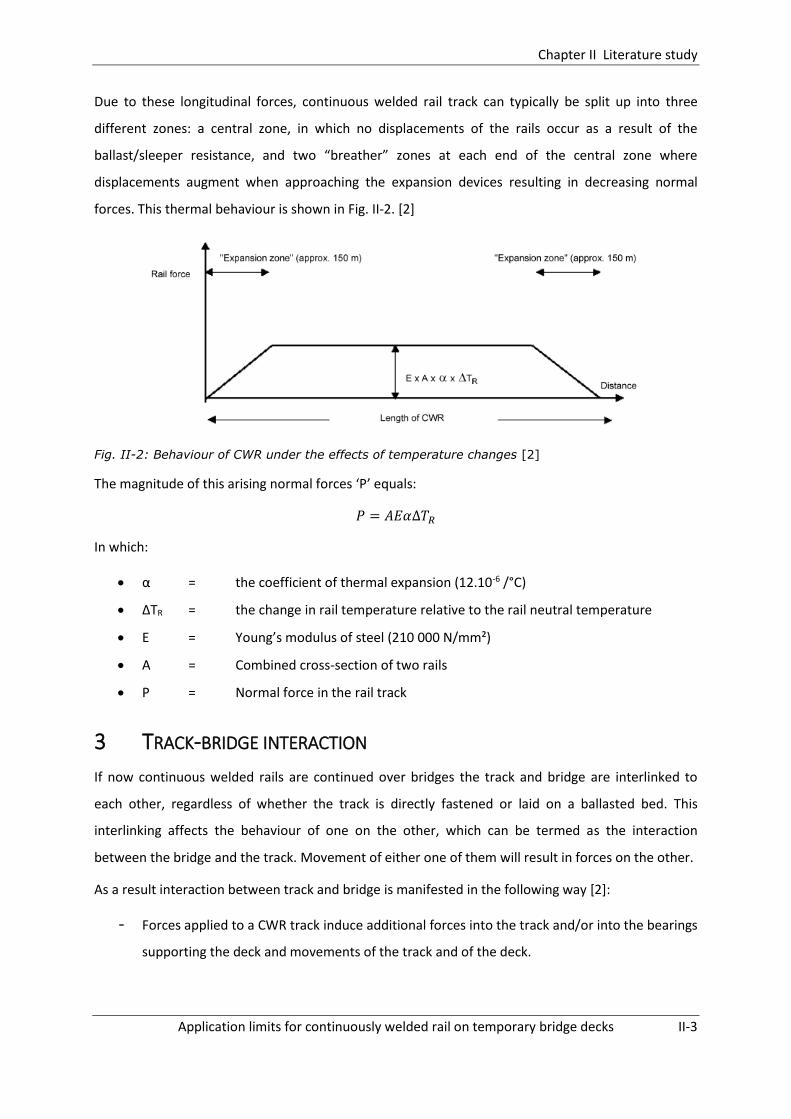
Due to these longitudinal forces, continuous welded rail track can typically be split up into three
different zones: a central zone, in which no displacements of the rails occur as a result of the
ballast/sleeper resistance, and two “breather” zones at each end of the central zone where
displacements augment when approaching the expansion devices resulting in decreasing normal
forces. This thermal behaviour is shown in Fig. II-2. [2]
Fig. II-2: Behaviour of CWR under the effects of temperature changes [2]
The magnitude of this arising normal forces ‘P’ equals:
𝑃 = 𝐴𝐸𝛼∆𝑇𝑅
In which:
α = the coefficient of thermal expansion (12.10-6 /°C)
ΔTR = the change in rail temperature relative to the rail neutral temperature
E = Young’s modulus of steel (210 000 N/mm²)
A = Combined cross-section of two rails
P = Normal force in the rail track
3 TRACK-BRIDGE INTERACTION
If now continuous welded rails are continued over bridges the track and bridge are interlinked to
each other, regardless of whether the track is directly fastened or laid on a ballasted bed. This
interlinking affects the behaviour of one on the other, which can be termed as the interaction
between the bridge and the track. Movement of either one of them will result in forces on the other.
As a result interaction between track and bridge is manifested in the following way [2]:
- Forces applied to a CWR track induce additional forces into the track and/or into the bearings
supporting the deck and movements of the track and of the deck.

Chapter II Literature study
Application limits for continuously welded rail on temporary bridge decks II-4
- Any movement of the deck induces a movement of the track and an additional force in the
track and, indirectly, in the bridge bearings.
Fig. II-3: Example of a curve showing rail stresses due to a temperature variation in the bridge
deck [2]
During the past decennia a lot of research has been performed on the subject of interaction. The
ERRI (the European Rail Research Institute) Committee D 213 carried out an extensive study to
analyse and asses these interactive forces. The results of these studies were subsequently
summarized in the form of a report which was given the name ‘UIC code 774-3R’ [2]. This report
contains the actions to be considered, the configuration of test models and the design requirements
needed in order to prevent damage due to these interaction effects. This leaflet has been accepted
as the general guideline for all interaction analyses and will therefore also play an important role in
this dissertation.
The forces causing the interaction between track and bridge are those that cause relative-
displacements between track and the bridge. These are [2]:
1. The thermal expansion of the deck only, in the case of CWR, or the thermal expansion of the
deck and of the rail, whenever a rail expansion device is present
2. Horizontal braking and acceleration forces
3. Rotation of the deck on its supports as a result of the deck bending under vertical traffic
loads
4. Deformation of the concrete structure due to creep and shrinkage
5. Longitudinal displacement of the supports under the influence of the thermal gradient
6. Deformation of the structure due to the vertical temperature gradient
In most cases, the first three effects are the most important in bridge design. More information
concerning these first three effects is given in §3 Chapter III.
The additional forces, which arise in the track due to the interaction between track and bridge might,
in some cases, become too large resulting in track buckling for the case of large compressive forces
or rail breaks for the case of large tensile forces.

Chapter II Literature study
Application limits for continuously welded rail on temporary bridge decks II-5
In order to solve this problem rail expansion devices might be used. However, this is not a very
attractive solution since these devices generate high impact loads and may accelerate bridge
degradation. Also, they are expensive to install and require a lot of maintenance. Therefore, during
this dissertation, it is tried to find an alternative in which expansion devices are not used.
An alternative to these rail expansion devices in CWR for example, is to allow the rail to be
unanchored in longitudinal direction over a certain length. For this, zero longitudinal restraint (ZLR)
fastenings could be used [3]. This alternative is briefly discussed in §4.
Another alternative, and the one which is examined in this dissertation, is to simply eliminate the
expansion device from the track configuration and continue the CWR track over the bridge without
making any alterations to the track design. This solution will however result in larger rail stresses and
it will therefore be compulsory to verify whether the arising stresses remain within acceptable limits.
This verification is performed in Chapter IV.
4 ZLR FASTENINGS
In order to prevent the need for rail expansion devices in CWR track when continuing CWR over
bridges zero longitudinal restraint (ZLR) fasteners might be useful.[3] These zero longitudinal
restraint fasteners do not prevent any longitudinal displacement of the rails and therefore no
(longitudinal) forces will be transferred to the bridge.
This type of fastening consists of a special steel baseplate which is fastened to the sleeper by means
of a Pandrol railclip, as depicted in Fig. II-5. Typically, a small opening is present which permits the
rails to move longitudinally with temperature changes, while holding the rail vertically in place. When
large lateral forces are present, the baseplate provides lateral restraint and prevents turning-over of
the rail. The rail pad under the rail is made of a low friction material such as Teflon and provides
almost no longitudinal restraint against movement of the rails with respect to the sleepers when
train loading is absent.[3]

Chapter II Literature study
Application limits for continuously welded rail on temporary bridge decks II-6
Fig. II-4: Pandrol® ZLR System Fig. II-5: Principle sketch Pandrol® ZLR System [3]
However, a first disadvantage of this technique is that, if a rail fracture would occur, the gap at
fracture could enlarge as a result of the absence of longitudinal anchoring and movement of trains
passing over it, resulting eventually in a possible derailment. Also, when train loading is present, the
longitudinal restraint will increase, reducing the favourable effect of these fastenings.
Despite these disadvantages, this method has already been successfully applied several times.
Examples can be found at the ‘Olifants River Bridge’ in South Africa, the high-speed line Brussels-Lille
[3], the Mission Valley West light rail extension in San Diego[4], etc…
Also ‘The Manual of Instructions on Long Welded Rails’[5], which contains instructions for the
installation of Long Welded Rails and Continuous Welded Rails on Indian Railways, has incorporated a
section with regard to the application of ZLR fastenings on bridges. This manual states that bridges of
which the overall length does not exceed 30 metres can be provided with rail-free fastenings if the
following requirements are fulfilled:
1) The approach track up to 50 metres on both sides shall be well anchored by providing any
one of the following:
a. ST sleepers with elastic fastenings
b. PRC sleepers with elastic rail clips with fair ‘T’ or similar type creep anchors.
2) The ballast section of the approach track up to 50 metres shall be heaped up to the foot of
the rail on the shoulders and kept in well compacted and consolidated condition during the
months of extreme summer and winter.
Conclusion
Based on the information given above one could assume that the application of ZLR fastenings on
temporary bridge decks could form a valid solution in order to solve the problem of track-bridge

Chapter II Literature study
Application limits for continuously welded rail on temporary bridge decks II-7
interaction when continuing CWR over a temporary bridge deck. Still, further research will be
required in order to verify their applicability, but this is not further examined during this dissertation.
5 TRACK STABILITY
5.1 INTRODUCTION
In order to obtain a better insight in the stability of continuous welded track on a temporary bridge
deck first the stability of a track on an embankment is analysed. Many different factors play a role in
this phenomenon. One tries to obtain a complete overview of the different influencing factors as a
first step towards determining the most important factors for the parametric study which is executed
further in this dissertation.
5.1.1 TRACK BUCKLING
A first instability phenomenon which might arise in a rail track is the formation of a large lateral
misalignment. This phenomenon is called track buckling and can have disastrous consequences such
as derailments. The amplitudes of the buckling deflections can range up to 1 metre and the length of
the deformed track can measure up to 25 metres long. The origin of this instability problem can be
the result of three different factors, these are large compressive forces in the rail, weakened track
conditions and vehicle induced loads.
Fig. II-6: Examples of track buckling in CWR
The compressive forces are the result of the constrained movement of the rail by the sleepers,
fasteners and ballast, in case the rail is loaded with a temperature above its ‘stress-free
temperature’. Also, compressive forces might occur as a result of braking and accelerating of a
moving train. This ‘stress-free’ temperature which is mentioned, is the temperature in the rail at
which the rail experiences zero longitudinal force. In Belgium, values for the stress-free temperature

Chapter II Literature study
Application limits for continuously welded rail on temporary bridge decks II-8
are situated in the range of 20 to 30 °C. When the temperature in the rail increases above this
temperature, the rail experiences a compression force. When the temperature in the rail drops
below this ‘stress-free temperature’ tensile forces are developed. In order to prevent buckling of the
track it is essential to maintain a stable and high stress-free temperature.
Another major factor which influences the track buckling behaviour are weakened track conditions.
Examples of these weakened conditions are reduced longitudinal and lateral track resistance, lateral
alignment defects and lowered rail neutral temperature. These are factors which will prove to be
very important in delineating the required circumstances in which continuous welded rails are
allowed on temporary bridge decks. They will be discussed more thoroughly in §5.4.
A third and final critical issue on the subject of continuous welded track stability is the influence of
vehicle loads. Track buckling usually starts from an initial small alignment error. However, due to
train passage over this section this alignment error might aggravate and trigger buckling of the track.
This aggravation of the misalignment is caused by lateral wheel forces which arise in curved track or
in tangent track due to line or surface deviations. The type of track instability which is caused by
thermal and vehicle loads is called dynamic buckling. However, in the early theories of buckling, only
thermal loads were taken into account and vehicle loads were not accounted for. These theories are
designated as static theories.
5.1.2 RAIL BREAKS
The previous instability problem occurred due to an increase of the rail temperature above the
‘stress-free temperature’. When adversely the temperature is decreased below the ‘stress-free
temperature’ tensile forces will arise in the rail. When these forces become too large, rail cracks and
eventually rail breaks might occur at locations where internal defects are present or at weak welds.
This phenomenon is denoted with the term ‘rail pull apart’. Initial small cracks do not form any large
problems to the rails. The problems start when the cracks start to grow in size under the influence of
cyclic loading due to vehicle and thermal loads. This increase of the crack gap might eventually result
into disastrous derailments. In order to counter the increase of the crack sizes good anchoring of the
rails is essential. In most cases the initial gap size is rather small and the breaks are detected by the
use of a standard signalling system. Therefore rail breaks are considered to be less dangerous from a
safety point of view than track buckling. Hence the stress-free temperature of rails is often chosen
higher so lower compressive forces in the rails are obtained to the cost of higher tensile forces in
winter conditions.

Chapter II Literature study
Application limits for continuously welded rail on temporary bridge decks II-9
5.2 BUCKLING THEORY
5.2.1 BUCKLING MECHANISM
As discussed above, track buckling can be initiated by a small initial misalignment 0. Subsequently
due to thermal compressive forces this misalignment may increase up to a lateral displacement wB,
which represents the boundary for a stable equilibrium. This maximum lateral displacement is
obtained at a temperature increase ΔTBmax above the tracks neutral temperature. At higher
temperatures the compressive forces will become too large and the track will become unstable,
resulting into buckling of the track. As a result a new equilibrium position is obtained corresponding
to a lateral displacement wC. This mechanism is depicted in Fig. II-7. From a thermal point of view the
track’s behaviour is shown in the buckling response curves in Fig. II-8.
Fig. II-7: Pre- and postbuckled track configurations [6]
Fig. II-8: Buckling response curves [6]
Fig. II-8 shows the behaviour of a track subjected to thermal forces only, as described above. In this
case buckling will occur at a temperature increase ΔTBmax above the neutral temperature. However,
buckling can also occur at a temperature increase ΔT smaller than ΔTBmax. This can take place if
sufficient extra energy is supplied, for example by means of vehicle induced forces. In this
mechanism, the track will jump from a stable pre-buckling equilibrium (1) to a stable post-buckling
equilibrium (3) through an unstable configuration (2) as shown in Fig. II-8. The lowest temperature
increase ΔT for which this alternative mechanism might occur is designated with the term ΔTBmin.
During this dissertation the influence of different track and bridge parameters on the upper buckling
temperature ΔTBmax will be investigated. The influence on the lower buckling temperature ΔTBmin will

Chapter II Literature study
Application limits for continuously welded rail on temporary bridge decks II-10
not be investigated since it is not possible to calculate this value using the model assembled in this
dissertation.
5.2.2 STATIC VERSUS DYNAMIC BUCKLING MODEL
As mentioned before a distinction is made between static buckling and dynamic buckling. In the
static buckling theory vehicle induced forces are not taken into account. Therefore, their influence on
the lateral stability of the tracks is not regarded. As a result, computational models based on the
static theory cannot be used in order to explain buckling occurring in conjunction with train
movements.
Fig. II-9: Definition of uplift waves [6]
Dynamic buckling models on the other hand, do take into account vehicle induced forces and their
influences on the lateral stability of the track. As a train moves along a track, it exerts vertical forces
onto the track at the position of its axles. Due to these axle loads the lateral resistance of the track
increases at these positions. However, in between the axles an uplift wave is generated, depicted in
Fig. II-9 as ‘central wave’, which results in a decrease of the lateral stability of the track. Also in front
and behind a moving train two smaller uplift waves are generated; the latter is denoted with the
term ‘recession wave’ and the former with ‘precession wave’. Usually, the central wave results in the
largest decrease of lateral stability and therefore track buckling under the train is a frequent
occurring phenomenon. So, in order to obtain a model which reflects the actual behaviour of a track
subjected to train passage in a realistic way, account has to be taken of this dynamic uplift wave.
However, in order to take into account these dynamic effects due to vertical traffic loads a quite
complex model should be assembled. Therefore during this dissertation, it is opted to make use of a
more simplified static buckling model.

Chapter II Literature study
Application limits for continuously welded rail on temporary bridge decks II-11
5.2.3 TANGENT VERSUS CURVED TRACK
A distinction should be made between tangent and curved track since they have a different buckling
behaviour. For curved track, the post-buckling shape I, which reflects a symmetric half sine wave, is
obtained most often. This is due to the fact that the energy required to bend the track inwards, as in
shape III, is too high.
Tangent track, the type of track which is discussed in this dissertation, buckles out in a rather
explosive way, to the left or the right side. The direction of the lateral displacement depends on the
track characteristics such as lateral resistance of the track at the right and left side, or on the
direction of the initial misalignment. The post-buckling shape which is obtained most often here is
the symmetric shape III, given in Fig. II-10. However, an asymmetric shape II given by a complete sine
wave can also occur.
Fig. II-10: Possible buckling shapes [6]
5.3 SAFETY CONCEPT
The safety concept with regard to buckling defined in the UIC code 720 [7] is based on the parameter
Tall, which represents the allowable temperature increase above the stress-free temperature of the
rail. Tall can also be considered as the required buckling strength of the track. It forms a buffer against
all sorts of phenomena which increase the rails temperature such as air temperature, sunlight, eddy
current brakes and interaction with other structures such as bridges.
The allowable value for the temperature Tall is determined by the components ΔTb,max and ΔTb,min (Fig.
II-11), which were already discussed in §5.2.1. As mentioned, ΔTb,max is the temperature increase
above its stress-free temperature, for which the track will buckle without any addition of external
energy. ΔTb,min on the other hand, is the minimal increase of the rail temperature for which buckling
Chapter II Literature study
Application limits for continuously welded rail on temporary bridge decks II-12
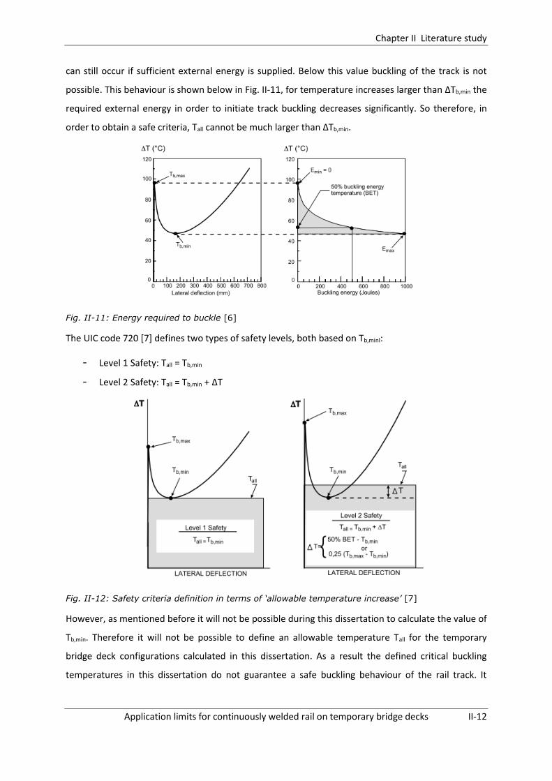
can still occur if sufficient external energy is supplied. Below this value buckling of the track is not
possible. This behaviour is shown below in Fig. II-11, for temperature increases larger than ΔTb,min the
required external energy in order to initiate track buckling decreases significantly. So therefore, in
order to obtain a safe criteria, Tall cannot be much larger than ΔTb,min.
Fig. II-11: Energy required to buckle [6]
The UIC code 720 [7] defines two types of safety levels, both based on Tb,minl:
- Level 1 Safety: Tall = Tb,min
- Level 2 Safety: Tall = Tb,min + ΔT
Fig. II-12: Safety criteria definition in terms of ‘allowable temperature increase’ [7]
However, as mentioned before it will not be possible during this dissertation to calculate the value of
Tb,min. Therefore it will not be possible to define an allowable temperature Tall for the temporary
bridge deck configurations calculated in this dissertation. As a result the defined critical buckling
temperatures in this dissertation do not guarantee a safe buckling behaviour of the rail track. It
Chapter II Literature study
Application limits for continuously welded rail on temporary bridge decks II-13
should always be kept in mind that, when adding extra energy to the rail, track buckling can still
occur for a rail temperature below Tb,max but still above Tb,min.
5.4 BUCKLING PARAMETERS FOR CWR ON AN EMBANKMENT
This section tries to provide an overview of all factors which might play a role in the buckling
behaviour for the general case of continuous welded rails on an embankment. Afterwards, when the
different parametric studies are performed, a selection will be made joining the most determining
parameters for the case of CWR over a temporary bridge deck. Below an overview of the discussed
parameters is given:
- Longitudinal track resistance
- Lateral track resistance
- Track defect (Lateral misalignment)
- Span length
- Support stiffness
- Bending behaviour of the bridge
- Torsional resistance of the rail fastenings
- Cross sectional area of the rail
- Curvature
- Rail stress-free temperature
5.4.1 LONGITUDINAL TRACK RESISTANCE
The longitudinal track resistance ‘k’ is the resistance of the track to longitudinal movement, per unit
of length, provided by ties and ballast. The longitudinal resistance varies with the longitudinal
displacement of the rail relative to its support. At first the resistance increases linearly until a certain
limit, beyond this limit the resistance remains rather constant. This behaviour is simplified to a
bilinear behaviour in the UIC code 774-3R as depicted in Fig. II-13 below.

Chapter II Literature study
Application limits for continuously welded rail on temporary bridge decks II-14
Fig. II-13: Resistance ‘k’ of the track per unit length as a function of the longitudinal displacements of the rail
The magnitude of the longitudinal resistance ‘k’ depends on different factors such as loaded or
unloaded situation, degree of maintenance, ballasted or unballasted track,… An overview of the
different values proposed by the UIC Code 774-3R is given below:
Ballasted track
- Displacement u0 between elastic and plastic zones:
o U0 = 0.5mm for the resistance of the rail to sliding relative to the
sleeper
o U0 = 2 mm for the resistance of the sleeper in the ballast
- Resistance k in the plastic zone
o K = 12 kN/m resistance of sleeper in ballast (unloaded track), moderate
maintenance
o K = 20 kN/m resistance of sleeper in ballast (unloaded track), good
maintenance
o K = 60 kN/m resistance of loaded track or track with frozen ballast
Unballasted track
- Displacement u0 between elastic and plastic zones:
o U0 = 0.5mm
- Resistance k in plastic zone
o K = 40 kN/m Unloaded track
o K = 60 kN/m Loaded track
Chapter II Literature study
Application limits for continuously welded rail on temporary bridge decks II-15
Previous studies by for example D. Choi et al. (2010) [8] and Samavedam et al. (1993) [9] have shown
that the influence of the longitudinal track resistance on the upper buckling temperature Tmax is
practically negligible, whereas the lower buckling temperature shows a slight increase with
increasing longitudinal stiffness.
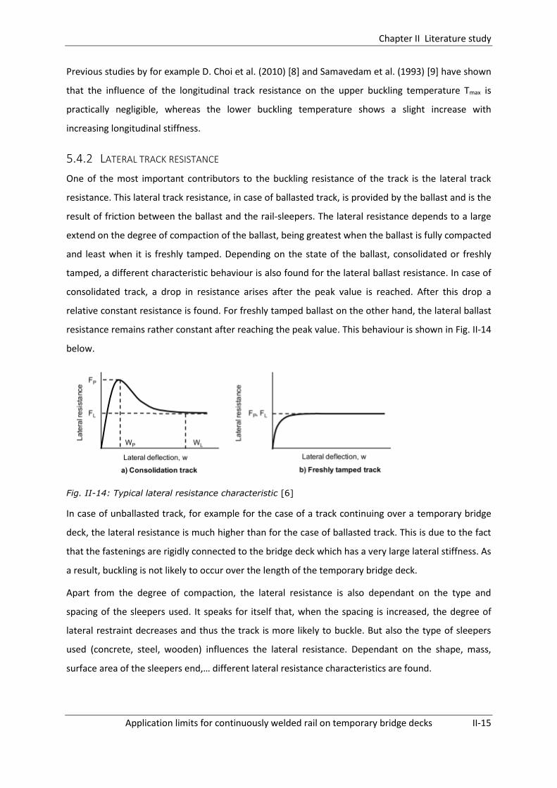
5.4.2 LATERAL TRACK RESISTANCE
One of the most important contributors to the buckling resistance of the track is the lateral track
resistance. This lateral track resistance, in case of ballasted track, is provided by the ballast and is the
result of friction between the ballast and the rail-sleepers. The lateral resistance depends to a large
extend on the degree of compaction of the ballast, being greatest when the ballast is fully compacted
and least when it is freshly tamped. Depending on the state of the ballast, consolidated or freshly
tamped, a different characteristic behaviour is also found for the lateral ballast resistance. In case of
consolidated track, a drop in resistance arises after the peak value is reached. After this drop a
relative constant resistance is found. For freshly tamped ballast on the other hand, the lateral ballast
resistance remains rather constant after reaching the peak value. This behaviour is shown in Fig. II-14
below.
Fig. II-14: Typical lateral resistance characteristic [6]
In case of unballasted track, for example for the case of a track continuing over a temporary bridge
deck, the lateral resistance is much higher than for the case of ballasted track. This is due to the fact
that the fastenings are rigidly connected to the bridge deck which has a very large lateral stiffness. As
a result, buckling is not likely to occur over the length of the temporary bridge deck.
Apart from the degree of compaction, the lateral resistance is also dependant on the type and
spacing of the sleepers used. It speaks for itself that, when the spacing is increased, the degree of
lateral restraint decreases and thus the track is more likely to buckle. But also the type of sleepers
used (concrete, steel, wooden) influences the lateral resistance. Dependant on the shape, mass,
surface area of the sleepers end,… different lateral resistance characteristics are found.

Chapter II Literature study
Application limits for continuously welded rail on temporary bridge decks II-16
5.4.3 LATERAL MISALIGNMENT
Another very important factor which influences the buckling behaviour of a continuous welded track
is the presence of lateral misalignments in the track geometry. These lateral misalignments tend to
increase under loading conditions and can ultimately lead to track buckling. Parametric studies by
among others Samavedam et al. (1993) and C. Esveld (1997) [10] have shown that both the
amplitude and wavelength of these anomalies strongly influence the buckling resistance of the CWR
track. As mentioned in §5.2.3 the shape of the buckled track is strongly influenced by the shape of
the initial misalignment. The different possible types of misalignment shapes are depicted in Fig.
II-10.
5.4.4 SPAN LENGTH
Given the fact that an increase in span length results in an increase in rail stresses, the span length of
the bridge will surely influence the buckling behaviour of the continuous welded rail on top of it.
Different bridge deck lengths will have to be checked when performing the parametric analysis.
5.4.5 SUPPORT STIFFNESS
The stiffness of the supports on which the bridge is constructed also has an influence on the stresses
arising in the rail track and thus influences the buckling behaviour of the rails. This overall stiffness
which is described, is dependent on contributions of different structural arrangements. A first
example of such a contribution is the type of bearings which is used. For example, when elastomeric
bearings are used, a certain degree of resistance to longitudinal movement of the bridge is provided
by these bearings and this will affect the stresses arising in the rail. However when movable bearings
are used generally no contribution to the stiffness is taken into account. Another contributor to the
overall stiffness of the bridge supports is the stiffness of the support itself, for example the stiffness
of a bridge pier and its foundation.
5.4.6 BENDING BEHAVIOUR OF THE BRIDGE DECK
When loads are exerted onto the bridge deck, the bridge will deform and bend about its lateral axis.
As a result, the bridge deck will in turn exert forces onto the rails which are situated on top of it. The
interaction effects are predominantly influenced by the bending stiffness of the bridge deck, but also
by the position of the neutral axis with respect to the position of the rails and bearings.

Chapter II Literature study
Application limits for continuously welded rail on temporary bridge decks II-17
5.4.7 TORSIONAL RESISTANCE OF THE RAIL FASTENINGS
The rail fasteners also provide, apart from longitudinal and lateral support, some restraint against
rotation about the vertical axis. It has been proven in several studies by for example D. Choi et al.
(2010) or Samavedam et al. (1993) that the lower buckling temperature significantly increases when
increasing the torsional resistance. The upper buckling temperature however, which is more relevant
to our models, does not change significantly.
5.4.8 CROSS SECTIONAL AREA OF THE RAIL
Various parametric studies by for example D. Choi et al. (2010) or Samavedam et al. (1993) have
proven that an increase in rail size results in a decrease of the critical buckling temperature of the rail
track. This due to the fact that an increase in rail size also results in an increase of the thermal force
which counteracts the positive effect of an increased bending stiffness of the rail.
5.4.9 CURVATURE
It has been proven (D. Choi et al., 2010) that curved tracks are more prone to buckle than
corresponding straight tracks. Especially for high curved tracks the critical buckling temperature is
drastically reduced compared to low curved tracks.
5.4.10 RAIL NEUTRAL TEMPERATURE
During the parametric study performed in Chapter VI it should be verified for which deviation of the
rail neutral temperature the track starts to buckle. Dependant on the degree of safety subsequently
an appropriate rail neutral temperature can be defined. If the rail neutral temperature is too low, rail
buckling in hot summers becomes an actual threat. On the other hand, when this temperature is too
high, then the danger of rail breaks in cold winters increases.
6 TEMPORARY BRIDGE DECKS
6.1 INTRODUCTION
In order to be able to perform maintenance works on the track bed (for example when constructing a
tunnel underneath the train tracks) without having to stop train passage, INFRABEL uses a certain
technique in which they entirely replace the existing track bed by a temporary bridge deck. This
technique is used for spans ranging up to a maximum of about 25 metres. In the following part a
short introduction to how these temporary bridge decks are configured and how they are adopted
into the track configuration is provided. However for further details reference is made to the report
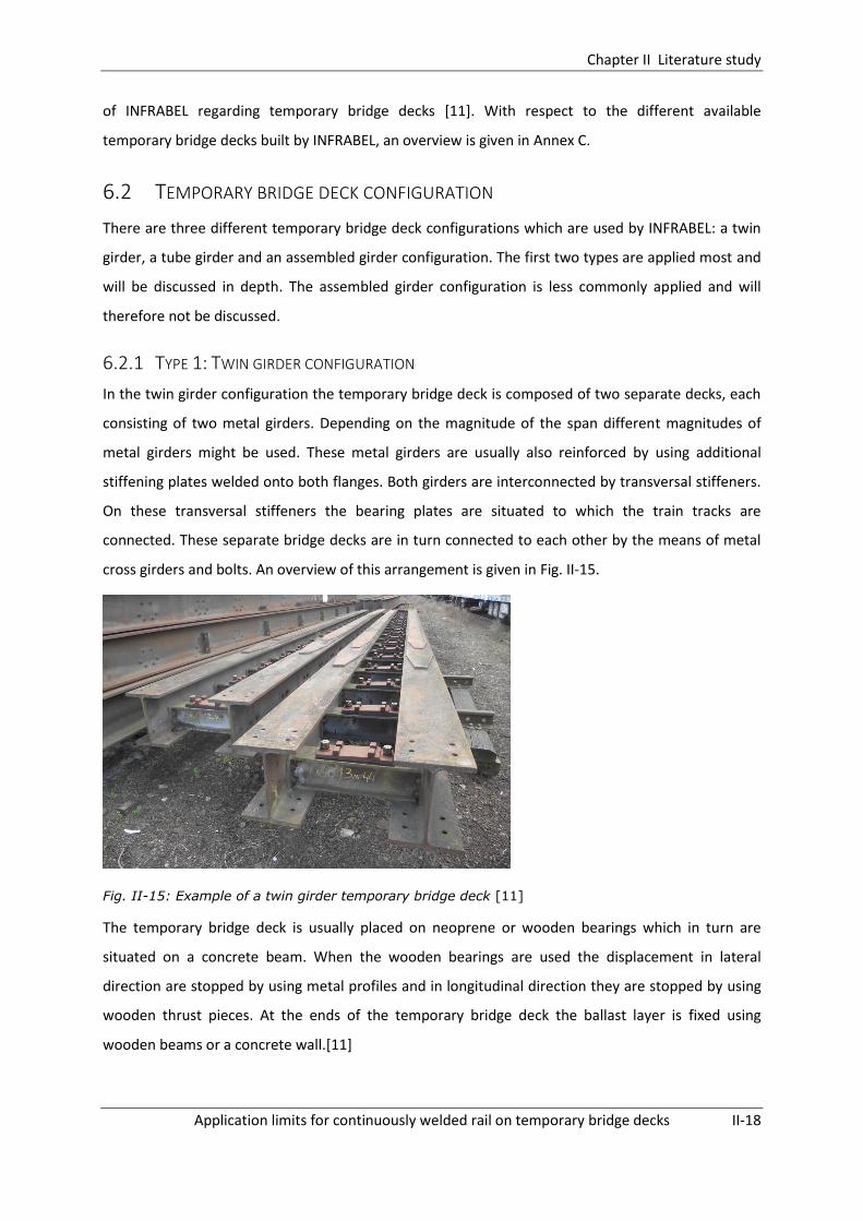
Chapter II Literature study
Application limits for continuously welded rail on temporary bridge decks II-18
of INFRABEL regarding temporary bridge decks [11]. With respect to the different available
temporary bridge decks built by INFRABEL, an overview is given in Annex C.
6.2 TEMPORARY BRIDGE DECK CONFIGURATION
There are three different temporary bridge deck configurations which are used by INFRABEL: a twin
girder, a tube girder and an assembled girder configuration. The first two types are applied most and
will be discussed in depth. The assembled girder configuration is less commonly applied and will
therefore not be discussed.
6.2.1 TYPE 1: TWIN GIRDER CONFIGURATION
In the twin girder configuration the temporary bridge deck is composed of two separate decks, each
consisting of two metal girders. Depending on the magnitude of the span different magnitudes of
metal girders might be used. These metal girders are usually also reinforced by using additional
stiffening plates welded onto both flanges. Both girders are interconnected by transversal stiffeners.
On these transversal stiffeners the bearing plates are situated to which the train tracks are
connected. These separate bridge decks are in turn connected to each other by the means of metal
cross girders and bolts. An overview of this arrangement is given in Fig. II-15.
Fig. II-15: Example of a twin girder temporary bridge deck [11]
The temporary bridge deck is usually placed on neoprene or wooden bearings which in turn are
situated on a concrete beam. When the wooden bearings are used the displacement in lateral
direction are stopped by using metal profiles and in longitudinal direction they are stopped by using
wooden thrust pieces. At the ends of the temporary bridge deck the ballast layer is fixed using
wooden beams or a concrete wall.[11]
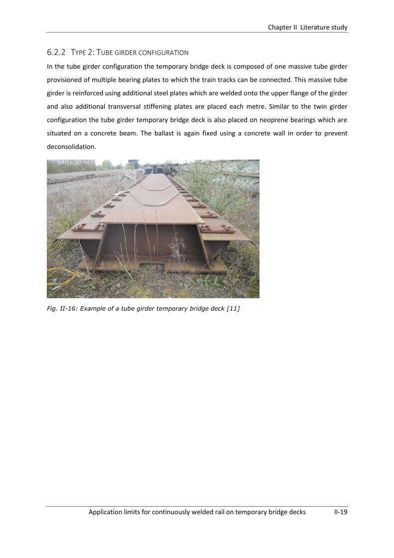
Chapter II Literature study
Application limits for continuously welded rail on temporary bridge decks II-19
6.2.2 TYPE 2: TUBE GIRDER CONFIGURATION
In the tube girder configuration the temporary bridge deck is composed of one massive tube girder
provisioned of multiple bearing plates to which the train tracks can be connected. This massive tube
girder is reinforced using additional steel plates which are welded onto the upper flange of the girder
and also additional transversal stiffening plates are placed each metre. Similar to the twin girder
configuration the tube girder temporary bridge deck is also placed on neoprene bearings which are
situated on a concrete beam. The ballast is again fixed using a concrete wall in order to prevent
deconsolidation.
Fig. II-16: Example of a tube girder temporary bridge deck [11]

Chapter III Design and validation of preliminary 2D model
Application limits for continuously welded rail on temporary bridge decks III-20
DESIGN AND VALIDATION OF PRELIMINARY 2D
MODEL
1 INTRODUCTION
In this chapter it is tried to build a computer model for the case of a track passing over a classic
bridge deck first. For this situation the UIC provides test-cases in the UIC code 774-3R by which a
track-bridge interaction model can be validated. In this way one can ensure that the obtained results
using the computer model are correct. Subsequently, the validated model will be adjusted and
expanded to the case of a temporary bridge deck.
2 ASSEMBLY OF CLASSICAL BRIDGE MODEL
As mentioned above, it is opted to start by creating a model for the general case of a track running
over a classical bridge. This is done using the software Samcef Field. The assembly of the model is
based upon the descriptions given in the UIC leaflet 774-3R. A schematic overview of the model is
given in Fig. III-1 and will be discussed more thoroughly in the following sections.
In order to create and calculate a model in Samcef Field each time the same 4 steps have to be
followed. First the geometry of the model is entered in the “Modeler” tab, next the behaviour,
material, constraints and loads are applied to the different model elements in the “Analysis Data”
tab. Subsequently a mesh has to be created in the “Mesh” tab and finally the solver settings have to
be entered in the “Solver” tab after which the calculations can be launched. These different design
steps will be partially adopted as intermediate section titles in order to maintain a clear overview of
the design of the models created in this dissertation.
2.1 MODELER
In general the model can be subdivided into two main parts: a track situated on a bridge deck and a
track situated on an embankment on both sides of the bridge. The length of the track situated on the
embankments amounts 100 meters, which is the minimum allowable length according to the UIC
code 774-3R to be modelled. The length of the track on the bridge deck is variable depending on
which bridge span is considered.

Chapter III Design and validation of preliminary 2D model
Application limits for continuously welded rail on temporary bridge decks III-21
All elements entered in this model, for modelling both the bridge and track structure, are made up
using ‘Wire’-type elements. These are line-elements to which a certain behaviour (beam, volume,…),
material,… can be appointed in the ‘Analysis Data’-tab.
Fig. III-1: Schematic overview of the finite elements model in Samcef Field
2.2 ANALYSIS DATA
As mentioned above, in the ‘Analysis Data’-tab it is possible to apply a certain behaviour, material,
constraints and loadings to the ‘Wire-type’ elements. Which settings are used to reproduce the
actual behaviour of the track-bridge interaction is discussed below.
2.2.1 TRACK
2.2.1.1. BEHAVIOUR
In Belgium the majority of the rail tracks are constructed using UIC 60 rails. As a results all models will
be designed assuming this rail type is present. The properties of a single UIC 60 rail are given in Table
III-1.
Cross-sectional area 76.70 cm²
Moment of inertia about lateral axis 3038.3 cm4
Table III-1: Properties of single UIC60 rail
For the ease of modelling however the track is represented by one single Wire-type element to which
a flexible beam behaviour is assigned which corresponds to two UIC 60 rails. This is done by making
use of an ‘undefined cross-section’ for which the following properties are entered:
Cross-sectional area 153.4 cm²
Moment of inertia about lateral axis 6076.6 cm4
Table III-2: Properties of beam corresponding to two UIC 60 rail

Chapter III Design and validation of preliminary 2D model
Application limits for continuously welded rail on temporary bridge decks III-22
Note: The position of the track coincides with the upper face of the bridge deck. This is not the actual
position of the track but this simplification is allowed according to the UIC 774-3R leaflet.
2.2.1.2. MATERIAL
The track is made of steel and thus has an E-modulus of 210.109 N/m² and is given an elastic material
behaviour, as imposed by the UIC Code 774-3R.
2.2.1.3. CONSTRAINTS
In order to discuss the constraints applied to the track, a distinction should be made between the
track situated on the embankments and the track situated on the bridge deck. The part of track
situated on the bridge has 6 degrees of freedom. For the part of the track situated on the
embankments the displacements in vertical direction are prohibited. All other displacements and
rotations are free.
2.2.2 BRIDGE DECK
2.2.2.1. BEHAVIOUR
The bridge deck is modelled using two types of elements:
1) Horizontal flexible beam-type elements which have the same properties (bending stiffness,
material properties,…) as the actual bridge. These elements are located at the centre of
gravity of the bridge and are depicted in Fig. III-1 as (5).
2) Vertical rigid beam-type elements which have an infinite stiffness. These elements connect
the horizontal elements to the bearings or to the track and are depicted in Fig. III-1 as (6)
respectively (4).
2.2.2.2. MATERIAL
It is assumed the bridge deck is entirely made of steel and thus has an E-modulus of 210.109 N/m².
Similar to the track, the bridge deck is also given an elastic material behaviour, as imposed by the UIC
Code 774-3R.
2.2.2.3. CONSTRAINTS
All elements have six degrees of freedom. Except for the modelling of the bearings no constraints are
applied to the beams representing the bridge structure.
2.2.3 CONNECTION BETWEEN TRACK AND BALLAST
For the test-cases in the UIC leaflet it is assumed that the bridges have a ballasted deck. As a result
the longitudinal track resistance for the part of the track on the bridge deck is identical to the

Chapter III Design and validation of preliminary 2D model
Application limits for continuously welded rail on temporary bridge decks III-23
resistance on the embankments. However, when advancing to a temporary bridge deck in a further
stage this will no longer be the case and thus will have to be adjusted.
As discussed in Chapter II §5.4.1 the connection between track and ballast should follow a bilinear
behaviour characterized by a threshold displacement u0 and a maximum longitudinal resistance ‘k’.
This resistance depends on whether the track is loaded or unloaded and the corresponding values
are repeated below:
- K = 20 kN per unit length of track, for unloaded track with good maintenance level
- K = 60 kN per unit length of track, for loaded track
- u0 = 2 mm
In order for the spring to provide resistance in both longitudinal directions this bilinear behaviour
should be defined point-symmetrical with respect to the origin of the coordinate system, as shown in
Fig. III-2 below.
Fig. III-2: Entry of bilinear behaviour for longitudinal springs in Samcef Field
Unidirectional ground bushings
For the connection between track and embankment unidirectional (in the longitudinal rail direction)
‘ground-bushings’ are used. These ground bushings are applied to the track every metre and are
given the characteristic spring behaviour as described above. The position of these ground bushings
is shown in Fig. III-1, in which they are designated as (2).
Bidirectional bushings
For the part of the track running over the bridge bidirectional (longitudinal and vertical direction)
bushings are used. For the longitudinal direction the same bilinear behaviour is applied as for the
unidirectional ground bushings on the embankments. However, now an additional stiffness is
entered for the vertical direction in order to allow the bushings to transfer the vertical forces from

Chapter III Design and validation of preliminary 2D model
Application limits for continuously welded rail on temporary bridge decks III-24
the rail to the bridge. For the vertical stiffness of the bushings a value of 1015 N/mm is entered in
order to simulate a quasi-rigid vertical connection of the track with the bridge deck.
2.2.4 DECK BEARINGS
Two types of deck bearings are considered in these test-cases:
- A fixed bearing at the left side of the bridge. This bearing is situated at its actual position and
is connected using a rigid beam to the centre of gravity of the beam. The bearings are
modelled by restricting vertical displacements and by adding a bilinear spring in horizontal
direction. The threshold displacement Usupport and longitudinal resistance ‘Ksupport’ of the fixed
bearing are different for each model and will be defined in §4 - Validation of the model.
- A sliding bearing at the right side of the bridge. This bearing is modelled by again restricting
vertical displacement but now allowing horizontal displacement. In these test-cases friction is
not taken into account.
The actual position of the bearings is clarified in Fig. III-1.
2.3 MESH
The UIC Code 774-3R imposes a maximum limit for the spacing of the mesh nodes of 2 meters. In
order to ensure an adequate dense mesh a spacing of 5 centimetres is used for all models
throughout this dissertation.
2.4 SOLVER SETTINGS
In order to be able to increase the load over a certain interval of time an implicit nonlinear
calculation has to be performed. Also use is made of a static computation in which the inertia and
velocity dependent phenomena are not taken into account.
Chapter III Design and validation of preliminary 2D model
Application limits for continuously welded rail on temporary bridge decks III-25
3 LOADING CASES
In order to validate the interaction model different loading cases have to be considered in which
interaction between track and bridge might occur. The cases which result into interaction effects are
those in which relative displacements between track and deck arise, these actions were already
summed up in Chapter II §3. In the test-cases only the three most important interaction loads are
regarded: braking forces, vertical forces and temperature loading. More specifications concerning
their way of application and magnitude, as described in UIC leaflet 774-3R, are given below.
However first a decision will have to be made concerning the type of analysis. How will the different
loading cases be combined? According to the UIC leaflet 774-3R two different methods can be used
in order to evaluate the stresses and displacements resulting from the different loading cases.
Depending on the degree of accuracy which has to be obtained and the capabilities of the computer
program a choice has to be made between:
1) A simplified separate analysis for the different loading cases
2) A complete analysis of the joint effects of the different loads being applied simultaneously
It should be noted that for the loading cases (braking and vertical loading) simulating the presence of
a moving train as many analyses should be performed as there are different positions of the moving
train on the bridge. However, in most cases it is sufficient to only check the case in which the bridge
deck is fully loaded since this often gives the most critical values. Due to the limitations of the model
assembled in this dissertation, no intermediate positions of the train on the bridge structure are
investigated. Only the case for which the train is situated over the full length of the bridge span is
looked into.
Additionally, in order to find the maximal stresses arising in the rail, both directions of travel should
be examined: thus both for a train moving from the fixed support to the movable support and the
other way around.
3.1.1 SIMPLIFIED SEPARATE ANALYSIS
In this type of analysis the loads are applied separately and the obtained results are simply added to
each other. In other words, a linear combination is made using the results of the separate analyses.
This will obviously lead to an overestimation of the actual stresses given the fact that the model itself
has a nonlinear character due to the bilinear connection between rail and track.
When simplified separate analyses are carried out, the temperature effects should be assessed
assuming non-loaded track conditions. However, for the vertical and braking loading cases, the

Chapter III Design and validation of preliminary 2D model
Application limits for continuously welded rail on temporary bridge decks III-26
stiffness of the track-connection springs should be adjusted in accordance with the fact whether the
track is loaded or not.
3.1.1.1. VERTICAL LOADS (CASE 1/4)
When a train passes over a bridge, the bridge will experience a vertical loading due to the weight of
the train. This vertical loading will result into bending of the bridge deck and thus also into bending of
the upper face of the bridge to which the rails are connected. As a result this bending will in turn
cause additional stresses in the rail track. The magnitude of the vertical forces which are applied are
conform the standards described in the UIC 774-3R leaflet. They suggest this vertical train loading
can be modelled using a line load of 80 kN/m over a length of maximum 300 metres. As mentioned,
both train moving directions should be evaluated. The case for which the vertical loads move from
fixed to movable support is designated as case 1. The case for which the vertical loads move in the
opposite direction is designated as case 4.
Fig. III-3: Representation of loading cases regarded for train moving direction 1
3.1.1.2. BRAKING OR ACCELERATION FORCES (CASE 2/5)
As a result of braking or accelerating of a train, horizontal forces will be exerted onto the track. These
horizontal forces will result into relative displacements of the rail with respect to the bridge deck and
will thus result into interaction effects. In case of acceleration of a train a line load of 33 kN/m per
track should be applied over a maximal distance of 30 meters. In case of braking a line load of 20
kN/m per track should be applied over a maximal distance of 300m.
In the test cases it is assumed the train has a length of 100 meters and applies braking forces of 20
kN/m over its entire length. Again, both train running directions are examined. Case 2 corresponds to
a train running from fixed to movable support and case 4 corresponds to the opposite direction. Also,
when performing a simplified separate analysis the deck was assumed to be rigid in order to evaluate
the effects of braking alone and to prevent interaction by bending of the deck.
3.1.1.3. TEMPERATURE LOADING (CASE 3/6)
Depending on the presence of an expansion device in the track configuration, a different
temperature loading should be applied. For the case of a normal continuous welded rail, expansion
of the rail will not result in any differential movement of the rail with respect to the bridge and
Chapter III Design and validation of preliminary 2D model
Application limits for continuously welded rail on temporary bridge decks III-27
therefore should not be checked. Therefore it is sufficient to only check the interaction effects due to
a temperature variation of the bridge deck.
However, for the case in which an expansion device is present in the track configuration, there will
be differential displacements between track and bridge structure in case of a temperature variation
in the track. As a result in this case interaction effects should be checked for both a temperature
increase of the bridge deck and a temperature increase of the track. In this dissertation however no
expansion devices are incorporated in the model and therefore only the interaction due to a
temperature variation of the bridge deck will be regarded.
According to the UIC leaflet 774-3R the temperature of the bridge does not deviate from the
reference temperature (temperature of the deck at which the rail was fixed) by more than ± 35°C.
For the rail track this deviation is limited at ± 50°C. However for the validation of the model
performed in §4 only positive temperature deviations are regarded.
When applying a temperature loading onto the track the stiffness of the springs should correspond
to an unloaded situation. As a result for this loading situation case 3 and 6 are identical.
3.1.2 COMPLETE ANALYSIS
When a complete analysis is performed, first the temperature loads are applied and then the moving
train loads (horizontal and vertical loads) are added. In this way more realistic results are found.
Again the longitudinal stiffness of the rail-ballast connection should vary depending on whether the
rail is loaded or not.
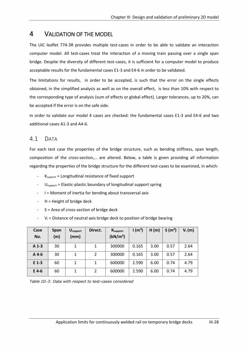
Chapter III Design and validation of preliminary 2D model
Application limits for continuously welded rail on temporary bridge decks III-28
4 VALIDATION OF THE MODEL
The UIC leaflet 774-3R provides multiple test-cases in order to be able to validate an interaction
computer model. All test-cases treat the interaction of a moving train passing over a single span
bridge. Despite the diversity of different test-cases, it is sufficient for a computer model to produce
acceptable results for the fundamental cases E1-3 and E4-6 in order to be validated.
The limitations for results, in order to be accepted, is such that the error on the single effects
obtained, in the simplified analysis as well as on the overall effect, is less than 10% with respect to
the corresponding type of analysis (sum of effects or global effect). Larger tolerances, up to 20%, can
be accepted if the error is on the safe side.
In order to validate our model 4 cases are checked: the fundamental cases E1-3 and E4-6 and two
additional cases A1-3 and A4-6.
4.1 DATA
For each test case the properties of the bridge structure, such as bending stiffness, span length,
composition of the cross-section,… are altered. Below, a table is given providing all information
regarding the properties of the bridge structure for the different test-cases to be examined, in which:
- Ksupoort = Longitudinal resistance of fixed support
- Usupport = Elastic-plastic boundary of longitudinal support spring
- I = Moment of inertia for bending about transversal axis
- H = Height of bridge deck
- S = Area of cross-section of bridge deck
- Vi = Distance of neutral axis bridge deck to position of bridge bearing
Case
No.
Span
(m)
Usupport
(mm)
Direct. Ksupport
(kN/m²)
I (m4) H (m) S (m²) Vi (m)
A 1-3 30 1 1 300000 0.165 3.00 0.57 2.64
A 4-6 30 1 2 300000 0.165 3.00 0.57 2.64
E 1-3 60 1 1 600000 2.590 6.00 0.74 4.79
E 4-6 60 1 2 600000 2.590 6.00 0.74 4.79
Table III-3: Data with respect to test-cases considered

Chapter III Design and validation of preliminary 2D model
Application limits for continuously welded rail on temporary bridge decks III-29
For the entire length of the track, both on the embankment and on the bridge structure, ballasted
track is assumed with the following characteristic resistance per unit track length:
- k = 20 kN/m for unloaded track
- k = 60 kN/m for loaded track
4.2 LOADS
The loads which are applied are the ones discussed in §3.1.1. Below a small summary is given. In total
4 different types of analyses are carried out:
Case 1 and 4 : vertical forces of 80 kN/m situated on left respectively right embankment and
bridge fully loaded
Case 2 and 5: deck assumed rigid, braking forces of 20 kN/m situated on left respectively
right embankment and bridge fully loaded
Case 3 and 6: influence of temperature variation in bridge (+35°C) or rail (+50°C)
Complete analysis: the three effects are evaluated simultaneously, applying the temperature
variation first and then the moving train loads.
All loads are applied in the same manner over a time interval of 10 seconds. Initially at t = 0 s already
a small load is present on the structure in order to prevent the calculation from diverging.
Subsequently the load is increased linearly reaching its maximum design value at 10 seconds. An
example of such a load progress is shown in Fig. III-4.
Fig. III-4: Progress of braking load over period of 10s

Chapter III Design and validation of preliminary 2D model
Application limits for continuously welded rail on temporary bridge decks III-30
4.3 RESULTS
In the figures below the different normal stress progresses found with Samcef Field for the multiple
loading cases discussed in §3.1.1 are given. From these figures the maximum arising rail stresses can
be derived and these are summarized in the tables of §4.4.
Note: With regard to the sign of the stresses shown in the figures below and throughout this
dissertation, Samcef Field follows the following convention: negative stresses indicate compressive
forces are present in the track while positive stresses correspond to tensile stresses.
4.3.1 CASE E1: VERTICAL FORCES – DIR 1
Fig. III-5: Rail normal stress data due to vertical forces for train moving direction 1
4.3.2 CASE E2: BRAKING FORCES (DECK ASSUMED RIGID) – DIR 1
Fig. III-6: Rail normal stress data due to braking forces for train moving direction 1
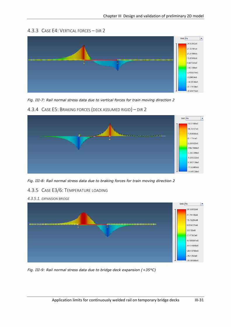
Chapter III Design and validation of preliminary 2D model
Application limits for continuously welded rail on temporary bridge decks III-31
4.3.3 CASE E4: VERTICAL FORCES – DIR 2
Fig. III-7: Rail normal stress data due to vertical forces for train moving direction 2
4.3.4 CASE E5: BRAKING FORCES (DECK ASSUMED RIGID) – DIR 2
Fig. III-8: Rail normal stress data due to braking forces for train moving direction 2
4.3.5 CASE E3/6: TEMPERATURE LOADING
4.3.5.1. EXPANSION BRIDGE
Fig. III-9: Rail normal stress data due to bridge deck expansion (+35°C)

Chapter III Design and validation of preliminary 2D model
Application limits for continuously welded rail on temporary bridge decks III-32
4.3.5.2. EXPANSION RAIL
Fig. III-10: Rail normal stress data due to rail expansion (+50°C)
4.3.6 COMPLETE ANALYSIS: ALL LOADS APPLIED
Fig. III-11: Rail normal stress data due moving train loads and bridge deck expansion (35°C) for
train moving direction 2

Chapter III Design and validation of preliminary 2D model
Application limits for continuously welded rail on temporary bridge decks III-33
4.4 OVERVIEW RESULTS
In the tables below the maximal arising compressive rail stresses for the different loading cases are
summarized. Subsequently it is possible to compare these rail stresses with the stresses specified by
the UIC code 774-3R. In this way one can subsequently derive whether the assembled model
provides acceptable results regarding the interaction analysis.
Separate simplified analysis Complete analysis
T rail T deck Braking End rot Sum
E1-3 UIC [MPa] -126 -30.7 -16.4 -17.0 -64.07 -56.4
Model [MPa] -126 -31.5 -19.3 -17.6 -68.4 -84.4
Error [%] 0 2.6 18 4 6.8 49.6
Table III-4: Additional rail stresses for test-case E1-3
Separate simplified analysis Complete analysis
T rail T deck Braking End rot Sum
E4-6 UIC [MPa] -126 -30.7 -15.9 -28.2 -74.84 -36.06
Model [MPa] -126 -31.5 -14.5 -25.7 -71.7 -71.4
Error [%] 0 3 -9 -9 -4 98
Table III-5: Additional rail stresses for test-case E4-6
The calculations for test cases A1 to A6 are carried out analogously to case E. The results are given
below.
Separate simplified analysis Complete analysis
T rail T deck Braking End rot Sum
A1-3 UIC [MPa] -126 -13.22 -12.7 -14.98 -40.96 -38.89
Model [MPa] -126 -12.6 -11.5 -15.4 -38.1 -48
Error [%] 0 -5 -10 3 -7 23
Table III-6: Additional rail stresses for test-case A1-3
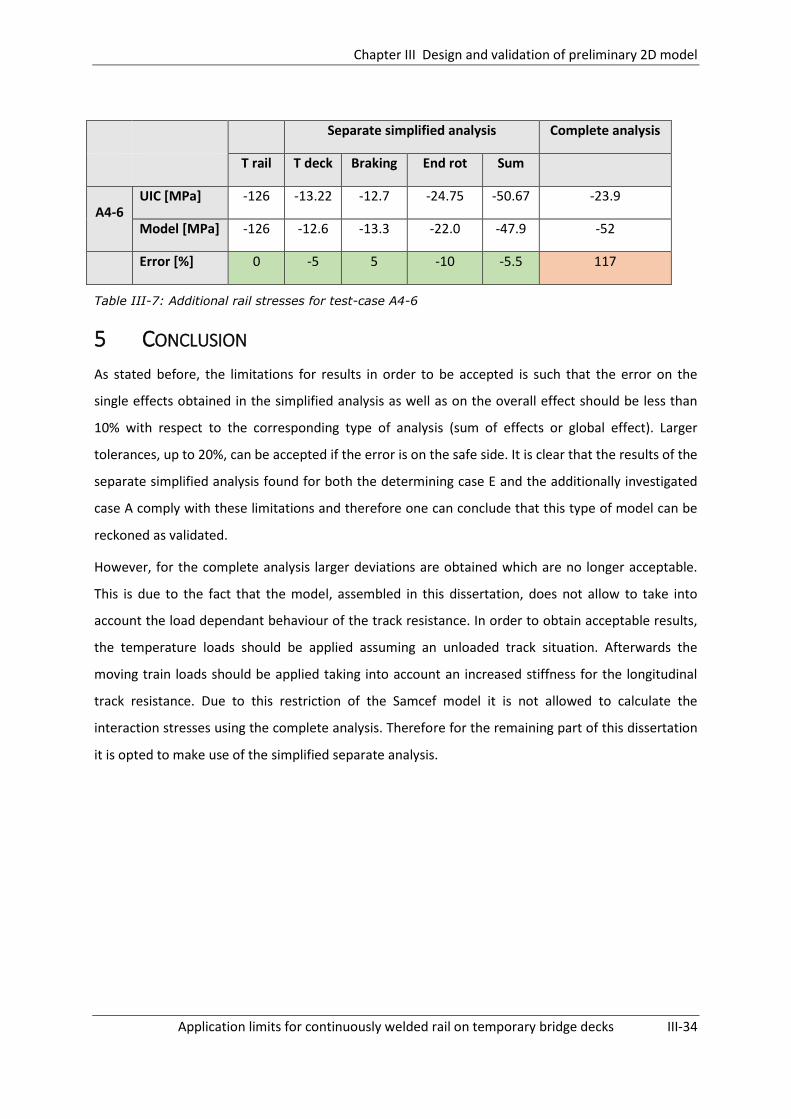
Chapter III Design and validation of preliminary 2D model
Application limits for continuously welded rail on temporary bridge decks III-34
Separate simplified analysis Complete analysis
T rail T deck Braking End rot Sum
A4-6 UIC [MPa] -126 -13.22 -12.7 -24.75 -50.67 -23.9
Model [MPa] -126 -12.6 -13.3 -22.0 -47.9 -52
Error [%] 0 -5 5 -10 -5.5 117
Table III-7: Additional rail stresses for test-case A4-6
5 CONCLUSION
As stated before, the limitations for results in order to be accepted is such that the error on the
single effects obtained in the simplified analysis as well as on the overall effect should be less than
10% with respect to the corresponding type of analysis (sum of effects or global effect). Larger
tolerances, up to 20%, can be accepted if the error is on the safe side. It is clear that the results of the
separate simplified analysis found for both the determining case E and the additionally investigated
case A comply with these limitations and therefore one can conclude that this type of model can be
reckoned as validated.
However, for the complete analysis larger deviations are obtained which are no longer acceptable.
This is due to the fact that the model, assembled in this dissertation, does not allow to take into
account the load dependant behaviour of the track resistance. In order to obtain acceptable results,
the temperature loads should be applied assuming an unloaded track situation. Afterwards the
moving train loads should be applied taking into account an increased stiffness for the longitudinal
track resistance. Due to this restriction of the Samcef model it is not allowed to calculate the
interaction stresses using the complete analysis. Therefore for the remaining part of this dissertation
it is opted to make use of the simplified separate analysis.

Chapter IV Design of 2D temporary bridge deck model and execution of a first parametric study
Application limits for continuously welded rail on temporary bridge decks IV-35
DESIGN OF 2D TEMPORARY BRIDGE DECK
MODEL AND EXECUTION OF A FIRST PARAMETRIC STUDY
1 INTRODUCTION
In this chapter the model assembled in Chapter III (see Fig. IV-1) is further adjusted to the case of a
temporary bridge deck. Subsequently a parametric study is performed in order to be able to make a
first selection regarding the parameters to be analysed in the parametric study of Chapter VI. Also, it
is possible to verify, for these several cases, whether the arising additional rail stresses, absolute and
relative displacements resulting from the interaction between track and temporary bridge deck are
conform the limitations given in the UIC code 774-3R. In this way a first conclusion regarding the use
of continuous welded rails on temporary bridge decks might be defined.
Fig. IV-1: Schematic overview of the finite elements model in Samcef Field
2 ASSEMBLY OF TEMPORARY BRIDGE DECK MODEL
2.1 MODELER
It is again opted to model the embankments over a length of 100 meters, which is the minimum
allowable length according to the UIC code 774-3R. For the temporary bridge deck a length of 20
meters is chosen.
The model is built up in the same way as described in Chapter III. The composing elements of this
model are depicted in Fig. IV-1.

Chapter IV Design of 2D temporary bridge deck model and execution of a first parametric study
Application limits for continuously welded rail on temporary bridge decks IV-36
2.2 ANALYSIS DATA
2.2.1 TRACK
The track is represented in the same way as described in Chapter III §2.2.1. No additional
modifications are made.
2.2.2 TEMPORARY BRIDGE DECK
2.2.2.1. BEHAVIOUR
The bridge deck is modelled in the same way as described in Chapter III §2.2.2 using vertical rigid
beam elements and a horizontal flexible beam element at the centre line which has the same
properties as the temporary bridge deck.
As discussed in Chapter II §6 there are two main configurations for a temporary bridge deck which
are applied in most cases: a tube girder configuration (Fig. IV-2) and a twin girder configuration (Fig.
IV-3). Both temporary bridge deck configurations have their own specific characteristics and
therefore need a separate model. In order to make a valid comparison between both types it is opted
to model two actual built temporary bridge decks by INFRABEL used for an equal span. According to
table C-1 of Annex C INFRABEL has only built one actual tube girder temporary bridge deck for a span
length of 12 metres. Therefore this configuration will be compared to a twin girder configuration for
an equal span length.
Tube girder
In order to determine the required properties (surface area, moment of inertia about lateral axis,
position of neutral axis) of the tube girder for the SAMCEF analysis use has been made of the cross-
section editor of SCIA Engineer.
Fig. IV-2: Cross-section of tube girder temporary bridge deck by INFRABEL for a span length of 12
metres [11]
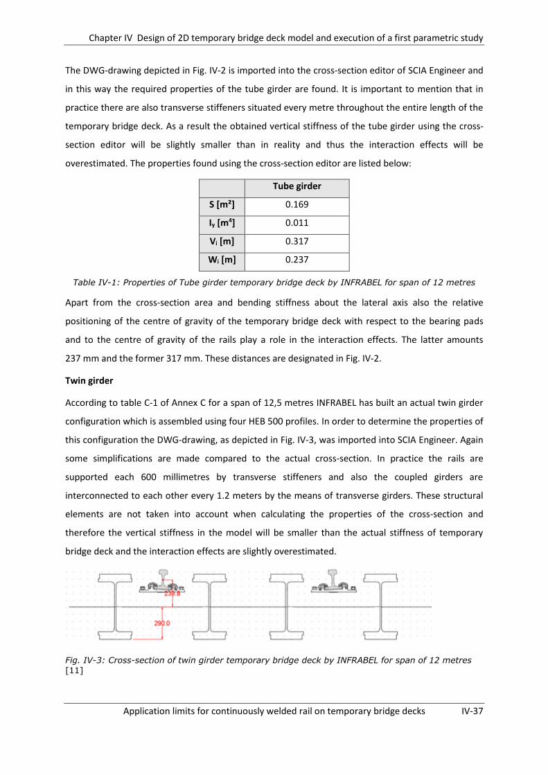
Chapter IV Design of 2D temporary bridge deck model and execution of a first parametric study
Application limits for continuously welded rail on temporary bridge decks IV-37
The DWG-drawing depicted in Fig. IV-2 is imported into the cross-section editor of SCIA Engineer and
in this way the required properties of the tube girder are found. It is important to mention that in
practice there are also transverse stiffeners situated every metre throughout the entire length of the
temporary bridge deck. As a result the obtained vertical stiffness of the tube girder using the cross-
section editor will be slightly smaller than in reality and thus the interaction effects will be
overestimated. The properties found using the cross-section editor are listed below:
Tube girder
S [m²] 0.169
Iy [m4] 0.011
Vi [m] 0.317
Wi [m] 0.237
Table IV-1: Properties of Tube girder temporary bridge deck by INFRABEL for span of 12 metres
Apart from the cross-section area and bending stiffness about the lateral axis also the relative
positioning of the centre of gravity of the temporary bridge deck with respect to the bearing pads
and to the centre of gravity of the rails play a role in the interaction effects. The latter amounts
237 mm and the former 317 mm. These distances are designated in Fig. IV-2.
Twin girder
According to table C-1 of Annex C for a span of 12,5 metres INFRABEL has built an actual twin girder
configuration which is assembled using four HEB 500 profiles. In order to determine the properties of
this configuration the DWG-drawing, as depicted in Fig. IV-3, was imported into SCIA Engineer. Again
some simplifications are made compared to the actual cross-section. In practice the rails are
supported each 600 millimetres by transverse stiffeners and also the coupled girders are
interconnected to each other every 1.2 meters by the means of transverse girders. These structural
elements are not taken into account when calculating the properties of the cross-section and
therefore the vertical stiffness in the model will be smaller than the actual stiffness of temporary
bridge deck and the interaction effects are slightly overestimated.
Fig. IV-3: Cross-section of twin girder temporary bridge deck by INFRABEL for span of 12 metres
[11]

Chapter IV Design of 2D temporary bridge deck model and execution of a first parametric study
Application limits for continuously welded rail on temporary bridge decks IV-38
The properties found for the twin girder configuration are the following:
Twin girder
S [m²] 0.185
Iy [m4] 0.011
Vi [m] 0.290
Wi [m] 0.240
Table IV-2: Properties of twin girder temporary bridge deck by INFRABEL for a span length of 12 metres [11]
Again, the relative positioning of the centre of gravity of the temporary bridge deck with respect to
the bearing pads and to the centre of gravity of the rails was determined. The latter amounts
240 mm and the former 290 mm. These distances are also depicted in Fig. IV-3.
Comparing of tube girder to twin girder
An overview of the determining characteristics of the two temporary bridge deck types is given in
Table IV-3. As one can see the characteristics of both temporary bridge decks are almost identical.
Therefore no significant difference in interaction behaviour will occur and it should be sufficient to
check only one of both temporary bridge deck types.
Tube girder Twin girder
S [m²] 0.169 0.185
Iy [m4] 0.011 0.011
Vi [m] 0.317 0.290
Wi [m] 0.237 0.240
Table IV-3: Comparison of properties of both temporary bridge deck types
Note: It should be noted that only one tube girder configuration has been built in practice by
INFRABEL. Therefore it is not possible to check the difference in behaviour between a tube girder and
twin girder configuration for other span lengths.
2.2.2.2. MATERIAL
It is assumed the bridge deck is entirely made of steel and thus has an E-modulus of 210.109 N/m².
Similar to the track, the bridge deck is also given an elastic material behaviour, as imposed by the UIC
Code 774-3R [2].
Chapter IV Design of 2D temporary bridge deck model and execution of a first parametric study
Application limits for continuously welded rail on temporary bridge decks IV-39
2.2.3 CONNECTION BETWEEN TRACK AND EMBANKMENTS
For the part of the track situated on the embankments ballasted track is assumed. As a result the
longitudinal ballast resistance is modelled in the same way as described in Chapter III §2.2.3.
2.2.4 CONNECTION BETWEEN TRACK AND TEMPORARY BRIDGE DECK
For the part of the track situated on the temporary bridge deck the track is directly fastened to the
bridge and no ballast is present. Therefore a different characteristic behaviour for the longitudinal
resistance is applied in the model. The behaviour is characterised by the following values suggested
by the UIC code 774-3R:
- k = 40 kN per unit length of track, for unloaded track
- k = 60 kN per unit length of track, for loaded track
- u0 = 0.5 mm
In order to model this longitudinal restraint again bidirectional bushings are used as described in
Chapter III §2.2.3 and depicted in Fig. IV-1 as (2).
2.2.5 DECK BEARINGS
In case of a temporary bridge deck usually neoprene bearings are used for which one bearing is fixed
and the other one is movable:
- The fixed bearing is situated at the left side of the bridge. This bearing is situated at its actual
position and is connected using a rigid beam to the centre of gravity of the beam. The
bearing is modelled by restricting vertical displacements and by adding a linear spring in
horizontal direction. The stiffness of the spring has been estimated as the stiffness of the
compressed neoprene interfacing deck and abutment and assuming an abutment with
infinite stiffness[12]:
𝑘𝑛 =𝐸𝑛𝐴𝑛
𝑒𝑛≈ 6,000,000 𝑘𝑁/𝑚
In which:
o kn = stiffness of neoprene anchoring
o En = Young’s modulus of neoprene = 420 MPa
o An = total cross-section of neoprene = 2 x 0.50 x 0.30 = 0.30 m²
o en = net thickness of neoprene = 0.021 m

Chapter IV Design of 2D temporary bridge deck model and execution of a first parametric study
Application limits for continuously welded rail on temporary bridge decks IV-40
- The sliding bearing is situated at the right side of the bridge. This bearing is modelled by
again restricting vertical displacements but now allowing horizontal displacement. As a
simplification it is assumed no friction is present.
2.3 LOADS
As mentioned in Chapter III §5 the model does not allow to perform a complete analysis in which the
temperature loads are applied first on the unloaded track and then the moving train loads. Therefore
it is opted to use the simplified separate analysis and make a linear combination of the results.
However since the model itself has non-linear characteristics this method will lead to an
overestimation of the interaction effects. So if one can show that the results obtained using the
simplified separate analysis comply with the limitations given by the UIC code 774-3R then one can
assume that the interaction effects will not result in any unsafe situations.
Again three different loading cases will be regarded for each direction of the moving train: vertical
loading, horizontal loading and temperature loading. These loading cases are identical to the ones
described in Chapter III §3. Below a small summary is given. In total 3 different types of analyses are
carried out:
Case 1 and 4 : Vertical forces of 80 kN/m situated on left respectively right embankment and
bridge fully loaded
Case 2 and 5: Deck assumed rigid, braking forces of 20 kN/m situated on left respectively
right embankment and bridge fully loaded
Case 3 and 6: Influence of temperature variation in bridge due to a temperature increase of
+35°C and a temperature decrease of -35°C
Again it should be noted that for both loading cases (braking and vertical loading) as many analyses
should be performed as there are different positions of the moving train on the bridge. However in
most cases it is sufficient to only check the case in which the train is positioned on one of both
embankments and on the entire length of the bridge deck since this often gives the most critical
values. Due to the limitations of the model no intermediate positions of the train on the bridge
structure will be investigated.
2.4 MESH
The UIC Code 774-3R imposes a maximum limit for the spacing of the mesh nodes of 2 meters. In
order to ensure an adequate dense mesh a spacing of 5 centimetres is used for all models.

Chapter IV Design of 2D temporary bridge deck model and execution of a first parametric study
Application limits for continuously welded rail on temporary bridge decks IV-41
2.5 SOLVER SETTINGS
In order to be able to increase the load over a certain interval of time it is opted to make use of an
implicit nonlinear calculation. Also use has been made of a static computation in which the inertia
and velocity dependent phenomena are not taken into account.
3 PARAMETRIC STUDY
In the following section a parametric analysis will be performed in which multiple parameters of both
the temporary bridge deck and surroundings will be analysed. Their influence on the arising rail
stresses due to interaction will be investigated. As mentioned the UIC code 774-3R also provides
multiple criteria for the track-bridge interaction effects in order to prevent damage to track and
bridge. At the same time it will also be verified for these multiple test cases whether the arising rail
stresses and rail/bridge displacements comply with these limitations given in the UIC leaflet.
3.1 IMPOSED LIMITATIONS FOR TRACK-BRIDGE INTERACTION EFFECTS
First of all the permissible additional stresses due to the track-bridge interaction in continuous
welded rails on bridges are to be limited. For a UIC 60 rail the following limitations are given:
The maximum permissible additional compressive rail stress is 72 N/mm²
The maximum permissible additional tensile rail stress is 92 N/mm²
Also, limitations are given for the displacement of the deck and track in order to prevent excessive
deconsolidation of the ballast. The displacement limits also play a role in limiting indirectly the
additional longitudinal stress in the rails. These limits are:
The maximum permissible displacement between rail and deck or embankment under
braking and/or acceleration forces is 4 mm
The maximum permissible absolute horizontal displacement of the deck for the same
braking/acceleration forces is ± 5 mm if the rails run across one or both ends of the
bridge/embankment transition
Finally, the end rotation of a bridge deck due to traffic loads is an important factor to determine
satisfactory track-bridge interaction behaviour. Under vertical loads, the displacements of the upper
edge of the deck end must be limited in order to maintain ballast stability. However, since in the case
of a temporary bridge deck no ballasted deck is present, this criteria should not be checked.

Chapter IV Design of 2D temporary bridge deck model and execution of a first parametric study
Application limits for continuously welded rail on temporary bridge decks IV-42
3.2 DATA
As mentioned, a parametric analysis will be performed in which varying parameters are altered. An
overview of the parameters to be examined is given below:
- Span length
- Stiffness of fixed bearing
- Deck bending stiffness
- Longitudinal ballast resistance on embankments
- Longitudinal fastener resistance on temporary bridge deck
All models are created starting from the same standard configuration. In turn each parameter is
altered in a practical range while the other parameters are kept constant. The properties of the
standard configuration are given below in Table IV-4:
Span length 20 metres
Longitudinal ballast resistance on
embankments
Characteristic resistance (unloaded): 20 kN/m
Characteristic resistance (loaded): 60 kN/m
Elastic limit: 2 mm
Longitudinal fastener resistance on
temporary bridge deck
Characteristic resistance (unloaded): 40 kN/m
Characteristic resistance (loaded): 60 kN/m
Elastic limit: 0.5 mm
Stiffness fixed bearing 6,000,000 kN/m
Temporary bridge deck (Tube girder) S = 0.169 m²
Iy =0.011 m4
Vi = 0.317 m
Wi = 0.237 m
Table IV-4: Properties of the standard configuration used for the parametric study
For each case to be examined both the maximum arising compressive stress and tensile stress will be
regarded. Also both moving train directions have to be regarded which are designated in the
following way:
o Direction 1 = moving from fixed to movable support
o Direction 2 = moving from movable to fixed support
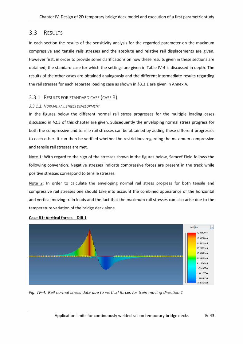
Chapter IV Design of 2D temporary bridge deck model and execution of a first parametric study
Application limits for continuously welded rail on temporary bridge decks IV-43
3.3 RESULTS
In each section the results of the sensitivity analysis for the regarded parameter on the maximum
compressive and tensile rails stresses and the absolute and relative rail displacements are given.
However first, in order to provide some clarifications on how these results given in these sections are
obtained, the standard case for which the settings are given in Table IV-4 is discussed in depth. The
results of the other cases are obtained analogously and the different intermediate results regarding
the rail stresses for each separate loading case as shown in §3.3.1 are given in Annex A.
3.3.1 RESULTS FOR STANDARD CASE (CASE B)
3.3.1.1. NORMAL RAIL STRESS DEVELOPMENT
In the figures below the different normal rail stress progresses for the multiple loading cases
discussed in §2.3 of this chapter are given. Subsequently the enveloping normal stress progress for
both the compressive and tensile rail stresses can be obtained by adding these different progresses
to each other. It can then be verified whether the restrictions regarding the maximum compressive
and tensile rail stresses are met.
Note 1: With regard to the sign of the stresses shown in the figures below, Samcef Field follows the
following convention. Negative stresses indicate compressive forces are present in the track while
positive stresses correspond to tensile stresses.
Note 2: In order to calculate the enveloping normal rail stress progress for both tensile and
compressive rail stresses one should take into account the combined appearance of the horizontal
and vertical moving train loads and the fact that the maximum rail stresses can also arise due to the
temperature variation of the bridge deck alone.
Case B1: Vertical forces – DIR 1
Fig. IV-4: Rail normal stress data due to vertical forces for train moving direction 1
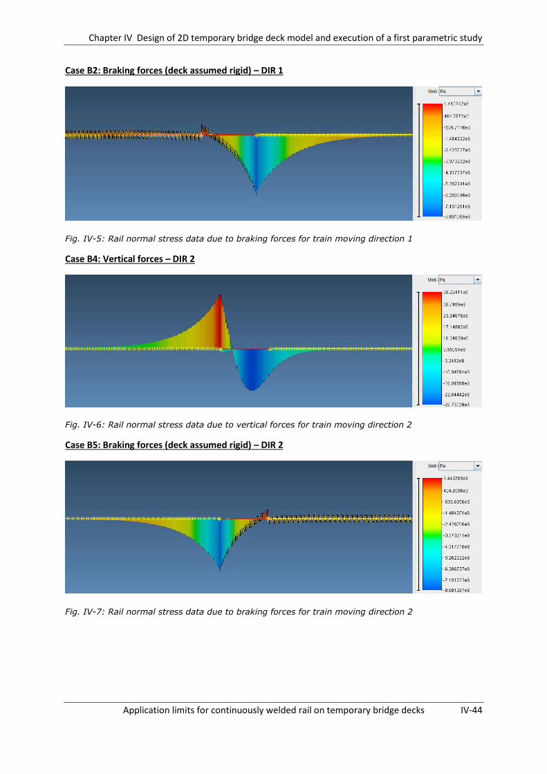
Chapter IV Design of 2D temporary bridge deck model and execution of a first parametric study
Application limits for continuously welded rail on temporary bridge decks IV-44
Case B2: Braking forces (deck assumed rigid) – DIR 1
Fig. IV-5: Rail normal stress data due to braking forces for train moving direction 1
Case B4: Vertical forces – DIR 2
Fig. IV-6: Rail normal stress data due to vertical forces for train moving direction 2
Case B5: Braking forces (deck assumed rigid) – DIR 2
Fig. IV-7: Rail normal stress data due to braking forces for train moving direction 2

Chapter IV Design of 2D temporary bridge deck model and execution of a first parametric study
Application limits for continuously welded rail on temporary bridge decks IV-45
Case B3: Expansion bridge deck (+35°C)
Fig. IV-8: Rail normal stress data due to deck expansion (+35°C)
Case B6: Contraction bridge deck (-35°C)
Fig. IV-9: Rail normal stress data due to deck contraction (-35°C)
As mentioned in §3.1 the additional rail stresses due to interaction should comply with the following
limitations:
The maximum permissible additional compressive rail stress is 72 N/mm²
The maximum permissible additional tensile rail stress is 92 N/mm²
In Fig. IV-10 & Fig. IV-11 the envelope of the maximum arising additional tensile and compressive rail
stresses due to interaction effects are depicted. These maxima are either the result of a combined
loading of both the moving train loads (horizontal and vertical loading) and the expansion of the
bridge deck, or of the moving train loads or the temperature variation alone.

Chapter IV Design of 2D temporary bridge deck model and execution of a first parametric study
Application limits for continuously welded rail on temporary bridge decks IV-46
Fig. IV-10: Envelope of additional stresses in rail on bridge for train moving direction 1
Fig. IV-11: Envelope of additional stresses in rail on bridge for train moving direction 2
Conclusion
When these graphs are regarded, it is clear that all additional rail stresses remain within the given
boundaries of §3.1. As a result, the first demand with respect to an acceptable interaction behaviour
is met.
-60.00
-40.00
-20.00
0.00
20.00
40.00
60.00
80.00
0 5 10 15 20
Ad
dit
ion
al r
ail s
tres
ses
[MP
a]
Position on bridge deck [m]
Enveloping compressive stresses Enveloping tensile stresses
-60.00
-40.00
-20.00
0.00
20.00
40.00
60.00
0 5 10 15 20
Ad
dit
ion
al r
ail s
tres
ses
[MP
a]
Position on bridge deck[m]
Enveloping compressive stresses Enveloping tensile stresses

Chapter IV Design of 2D temporary bridge deck model and execution of a first parametric study
Application limits for continuously welded rail on temporary bridge decks IV-47
3.3.1.2. LONGITUDINAL RAIL/DECK DISPLACEMENTS
As mentioned in §3.1 also limitations are given for the displacement of the deck and track:
The maximum permissible relative longitudinal displacement between rail and deck or
embankment under braking forces is 4mm
Below the relative longitudinal displacement of the rail with respect to the bridge deck is given for
both train movement directions. It is clear that for both cases the relative longitudinal displacements
remain within the boundaries given by the UIC.
Fig. IV-12: Progress of relative displacement of rail with respect to bridge deck – dir 1
Fig. IV-13: Progress of relative displacement of rail with respect to bridge deck – dir 2
The maximum permissible absolute horizontal displacement of the deck for the same
braking/acceleration forces is ± 5 mm if the rails run across one or both ends of the
bridge/embankment transition
0
0.1
0.2
0.3
0.4
0.5
0.6
0 5 10 15 20
Rel
ativ
e d
isp
lace
men
t ra
il/d
eck
[mm
]
Position on bridge deck [m]
-0.6
-0.5
-0.4
-0.3
-0.2
-0.1
0
0 5 10 15 20
Rel
ativ
e d
isp
lace
men
t ra
il/d
eck
[mm
]
Position on bridge deck [m]

Chapter IV Design of 2D temporary bridge deck model and execution of a first parametric study
Application limits for continuously welded rail on temporary bridge decks IV-48
The absolute horizontal displacement of the deck when loaded with braking forces amounts
0.457 mm and is therefore acceptable.
3.3.1.3. GENERAL CONCLUSION
It is clear that the additional rail stresses, absolute and relative rail displacements found for this test
case comply with the limitations given by the UIC code 774-3R. Therefore one can assume that the
interaction effects remain within acceptable limits for this configuration.
3.3.2 SPAN LENGTH
The first influencing factor which is regarded is the span length of the temporary bridge deck. Three
different span lengths are regarded: 10m, 20m and 30m. The results are obtained analogously to
§3.3.1. The Cases 1-3 denote the results for the moving train loads going from the fixed support
towards the movable support while the cases 4-6 denote the inverse direction.
Additional rail stresses
[MPa]
Long. relative
displacements
Long. displacement
deck
Case Compression Tension [mm] [mm]
A1-3 / 10m 22.9 16.7 0.57 0.03
B1-3 / 20m 52.6 67.0 0.61 0.06
C1-3 / 30m 53.9 125.3 0.63 0.09
A4-6 / 10m 18.1 14.3 -0.57 -0.03
B4-6 / 20m 49.7 48.5 -0.61 -0.06
C4-6 / 30m 60.0 93.6 -0.63 -0.09
Table IV-5: Results of parametric study with regard to changing span length
Fig. IV-14: Sensitivity of rail stresses with respect to bridge span length
0
20
40
60
80
100
120
140
10 15 20 25 30
Ab
solu
te r
ail s
tre
ss [
MP
a]
Bridge span length [m]
Compression - dir 1
Tension - dir 1
Compression - dir 2
Tension - dir 2

Chapter IV Design of 2D temporary bridge deck model and execution of a first parametric study
Application limits for continuously welded rail on temporary bridge decks IV-49
3.3.3 LONGITUDINAL BALLAST RESISTANCE EMBANKMENTS
As mentioned in Chapter II, depending on the degree of maintenance and compaction of the ballast,
a different longitudinal ballast resistance may occur. In the following section therefore the influence
of the longitudinal resistance of the ballast on the rail stresses is investigated. Since no ballast is
present on the temporary bridge deck only the longitudinal resistance of the part of the track
situated on the embankments is altered. The following situations are investigated:
Moderate maintenance:
o Unloaded situation: characteristic resistance = 10 kN/m
o Loaded situation: characteristic resistance = 50 kN/m
Good maintenance:
o Unloaded situation: characteristic resistance = 20 kN/m
o Loaded situation: characteristic resistance = 60 kN/m
Excellent maintenance:
o Unloaded situation: characteristic resistance = 30 kN/m
o Loaded situation: characteristic resistance = 70 kN/m
Additional rail stresses
[MPa]
Long. relative
displacements
Long. displacement
deck
Case Compression Tension [mm] [mm]
D1-3 / Moderate 45.4 65.3 0.66 0.06
B1-3 / Good 52.6 67 0.61 0.06
E1-3 / Excellent 57.8 73.7 0.58 0.05
D4-6 / Moderate 48.5 42.5 -0.66 -0.06
B4-6 / Good 49.7 48.5 -0.61 -0.06
E4-6 / Excellent 51.9 55.8 -0.58 -0.05
Table IV-6: Results of parametric study with regard to long. ballast resistance on embankments
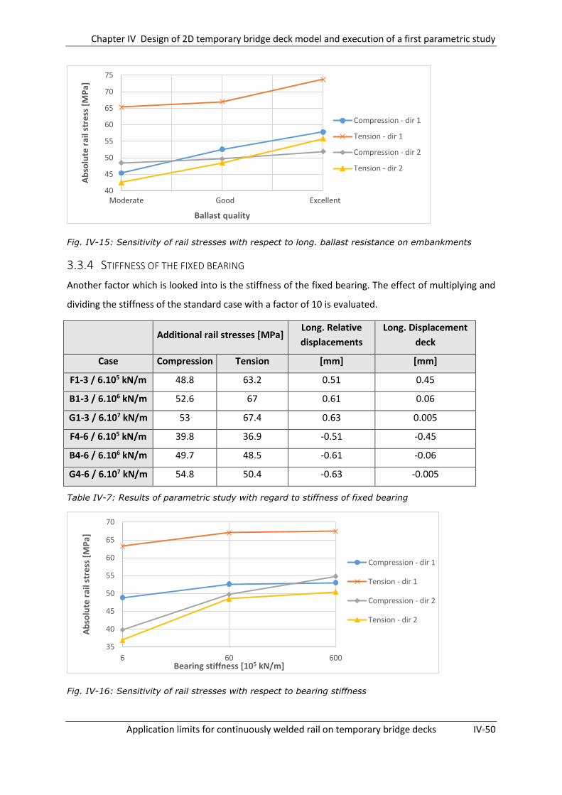
Chapter IV Design of 2D temporary bridge deck model and execution of a first parametric study
Application limits for continuously welded rail on temporary bridge decks IV-50
Fig. IV-15: Sensitivity of rail stresses with respect to long. ballast resistance on embankments
3.3.4 STIFFNESS OF THE FIXED BEARING
Another factor which is looked into is the stiffness of the fixed bearing. The effect of multiplying and
dividing the stiffness of the standard case with a factor of 10 is evaluated.
Additional rail stresses [MPa]
Long. Relative
displacements
Long. Displacement
deck
Case Compression Tension [mm] [mm]
F1-3 / 6.105 kN/m 48.8 63.2 0.51 0.45
B1-3 / 6.106 kN/m 52.6 67 0.61 0.06
G1-3 / 6.107 kN/m 53 67.4 0.63 0.005
F4-6 / 6.105 kN/m 39.8 36.9 -0.51 -0.45
B4-6 / 6.106 kN/m 49.7 48.5 -0.61 -0.06
G4-6 / 6.107 kN/m 54.8 50.4 -0.63 -0.005
Table IV-7: Results of parametric study with regard to stiffness of fixed bearing
Fig. IV-16: Sensitivity of rail stresses with respect to bearing stiffness
Moderate Good Excellent40
45
50
55
60
65
70
75A
bso
lute
rai
l str
ess
[M
Pa]
Ballast quality
Compression - dir 1
Tension - dir 1
Compression - dir 2
Tension - dir 2
35
40
45
50
55
60
65
70
6 60 600
Ab
solu
te r
ail s
tre
ss [
MP
a]
Bearing stiffness [105 kN/m]
Compression - dir 1
Tension - dir 1
Compression - dir 2
Tension - dir 2

Chapter IV Design of 2D temporary bridge deck model and execution of a first parametric study
Application limits for continuously welded rail on temporary bridge decks IV-51
3.3.5 DECK BENDING STIFFNESS
As indicated in the UIC code 774-3R the bending stiffness of the bridge deck is also a determining
factor with regard to the magnitude of the interaction effects. As a results its influence should
certainly be investigated.
Additional rail stresses [MPa]
Long. Relative
displacement
Long deck
displacement
Case Compression Tension [mm] [mm]
H1-3 / 0,005 m4 53.5 81.7 0.61 0.06
B1-3 / 0,01 m4 52.6 67 0.61 0.06
I1-3 / 0,02 m4 48.1 50 0.61 0.06
H4-6 / 0,005 m4 53.8 51.1 -0.61 -0.06
B4-6 / 0,01 m4 49.7 48.5 -0.61 -0.06
I4-6 / 0,02 m4 44.6 34 -0.61 -0.06
Table IV-8: Results of parametric study with regard to deck bending stiffness
Fig. IV-17: Sensitivity of rail stresses with respect to bridge bending stiffness
3.3.6 LONGITUDINAL FASTENER RESISTANCE ON TEMPORARY BRIDGE DECK
In this section the influence of a reduced/enhanced clamping action of the fasteners situated on the
temporary bridge deck are investigated. The following situations are regarded:
Moderate clamping force:
o Unloaded situation: characteristic resistance = 30 kN/m
o Loaded situation: characteristic resistance = 50 kN/m
30
40
50
60
70
80
0.005 0.01 0.015 0.02
Ab
solu
te r
ail s
tre
ss [
MP
a]
Bridge bending stiffness [m4]
Compression - dir 1
Tension - dir 1
Compression - dir 2
Tension - dir 2

Chapter IV Design of 2D temporary bridge deck model and execution of a first parametric study
Application limits for continuously welded rail on temporary bridge decks IV-52
Good clamping force:
o Unloaded situation: characteristic resistance = 40 kN/m
o Loaded situation: characteristic resistance = 60 kN/m
Excellent clamping force:
o Unloaded situation: characteristic resistance = 50 kN/m
o Loaded situation: characteristic resistance = 70 kN/m
Additional rail stresses
[MPa]
Long. relative
displacements
Long. displacement
deck
Case Compression Tension [mm] [mm]
J1-3 / Moderate 47.8 62.2 0.69 0.05
B1-3 / Good 52.6 67 0.61 0.06
K1-3 / Excellent 56.7 71.7 0.61 0.06
J4-6 / Moderate 42.6 42.9 -0.69 -0.05
B4-6 / Good 49.7 48.5 -0.61 -0.06
K4-6 / Excellent 56.6 52.9 -0.61 0.06
Table IV-9: Sensitivity of rail stresses with regard to long. fastener resistance on bridge deck
Fig. IV-18: Sensitivity of rail stresses with regard to fastener longitudinal resistance on bridge deck
Moderate Good Excellent
40
45
50
55
60
65
70
75
Ab
solu
te r
ail s
tre
ss [
MP
a]
Quality of clamping force
Compression - dir 1
Tension - dir 1
Compression - dir 2
Tension - dir 2
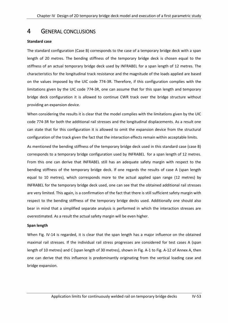
Chapter IV Design of 2D temporary bridge deck model and execution of a first parametric study
Application limits for continuously welded rail on temporary bridge decks IV-53
4 GENERAL CONCLUSIONS
Standard case
The standard configuration (Case B) corresponds to the case of a temporary bridge deck with a span
length of 20 metres. The bending stiffness of the temporary bridge deck is chosen equal to the
stiffness of an actual temporary bridge deck used by INFRABEL for a span length of 12 metres. The
characteristics for the longitudinal track resistance and the magnitude of the loads applied are based
on the values imposed by the UIC code 774-3R. Therefore, if this configuration complies with the
limitations given by the UIC code 774-3R, one can assume that for this span length and temporary
bridge deck configuration it is allowed to continue CWR track over the bridge structure without
providing an expansion device.
When considering the results it is clear that the model complies with the limitations given by the UIC
code 774-3R for both the additional rail stresses and the longitudinal displacements. As a result one
can state that for this configuration it is allowed to omit the expansion device from the structural
configuration of the track given the fact that the interaction effects remain within acceptable limits.
As mentioned the bending stiffness of the temporary bridge deck used in this standard case (case B)
corresponds to a temporary bridge configuration used by INFRABEL for a span length of 12 metres.
From this one can derive that INFRABEL still has an adequate safety margin with respect to the
bending stiffness of the temporary bridge deck. If one regards the results of case A (span length
equal to 10 metres), which corresponds more to the actual applied span range (12 metres) by
INFRABEL for the temporary bridge deck used, one can see that the obtained additional rail stresses
are very limited. This again, is a confirmation of the fact that there is still sufficient safety margin with
respect to the bending stiffness of the temporary bridge decks used. Additionally one should also
bear in mind that a simplified separate analysis is performed in which the interaction stresses are
overestimated. As a result the actual safety margin will be even higher.
Span length
When Fig. IV-14 is regarded, it is clear that the span length has a major influence on the obtained
maximal rail stresses. If the individual rail stress progresses are considered for test cases A (span
length of 10 metres) and C (span length of 30 metres), shown in Fig. A-1 to Fig. A-12 of Annex A, then
one can derive that this influence is predominantly originating from the vertical loading case and
bridge expansion.

Chapter IV Design of 2D temporary bridge deck model and execution of a first parametric study
Application limits for continuously welded rail on temporary bridge decks IV-54
For the tension stresses a clear approximate linear relationship is found between span length and
maximal arising tensile rail stress for both train moving directions. When the compressive rail
stresses are regarded a similar increase of the rail stresses is found, going from 10 to 20 metres of
span. However for the branch going from 20 to 30 metres a much smaller increase of compressive
rail stresses is found. This is due to the fact that for the case of a span length of 30 metres a different
load combination becomes determining. For both a span length of 10 and 20 metres the maximal
compressive rail stresses were found for the combination in which both the train moving loads and
the bridge deck expansion were applied to the model. However for the case of a span length of 30
metres the maximal arising rail stresses are found for the case in which the expansion of the bridge
deck was applied alone. An explanation for this change of determining load combination can be
found when comparing the normal rail stress evolution for the vertical loading situation of both case
B (Fig. IV-4) and case C (Fig. A-7 of Annex A). At the side of the bridge at which the maximal
compressive rail stress is found a tensile contribution is found for the vertical loading case for a span
of 30 metres. This tensile contribution is larger than the compressive contribution due to the
horizontal braking force of the moving train (shown in Fig A-8 of Annex A) and therefore a smaller
maximal compressive rail stress is found for the loading combination which contains all loads
compared to the loading combination which only contains the temperature variation of the deck.
When considering Table IV-5 it can be seen that the span length influences the arising rail stresses
even in such a way that for the case of a span length of 30 metres the limitations given by the UIC are
no longer met. However it should be noted that for this case (Case C) the same temporary bridge
deck is used as INFRABEL uses for a span length of 12 metres. In reality for a span length of 30 metres
a much stiffer bridge deck will be used and therefore the arising rail stresses will be lower compared
to the ones calculated in this section. This influence of the bridge bending stiffness is demonstrated
in §3.3.5 of this chapter.
Still, an increased bending stiffness of the bridge deck will not influence the arising additional rail
stresses due to bridge deck expansion in a significant manner, as proven in §3.3.5. Therefore the
increase of the additional rail stresses for an increased span length due to bridge deck expansion
might result in considerable problems. As can be seen in Fig. A-11 of Annex A for a span length of 30
metres the additional compressive rail stress at movable support due to bridge deck expansion
amounts 50 MPa. Given the fact that the upper limit for the compressive rail stresses imposed by the
UIC code 774-3R equals 72 MPa one can thus understand that this behaviour will limit the application
range of the temporary bridge decks.
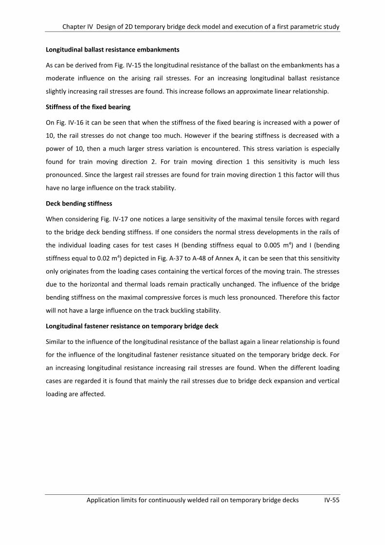
Chapter IV Design of 2D temporary bridge deck model and execution of a first parametric study
Application limits for continuously welded rail on temporary bridge decks IV-55
Longitudinal ballast resistance embankments
As can be derived from Fig. IV-15 the longitudinal resistance of the ballast on the embankments has a
moderate influence on the arising rail stresses. For an increasing longitudinal ballast resistance
slightly increasing rail stresses are found. This increase follows an approximate linear relationship.
Stiffness of the fixed bearing
On Fig. IV-16 it can be seen that when the stiffness of the fixed bearing is increased with a power of
10, the rail stresses do not change too much. However if the bearing stiffness is decreased with a
power of 10, then a much larger stress variation is encountered. This stress variation is especially
found for train moving direction 2. For train moving direction 1 this sensitivity is much less
pronounced. Since the largest rail stresses are found for train moving direction 1 this factor will thus
have no large influence on the track stability.
Deck bending stiffness
When considering Fig. IV-17 one notices a large sensitivity of the maximal tensile forces with regard
to the bridge deck bending stiffness. If one considers the normal stress developments in the rails of
the individual loading cases for test cases H (bending stiffness equal to 0.005 m4) and I (bending
stiffness equal to 0.02 m4) depicted in Fig. A-37 to A-48 of Annex A, it can be seen that this sensitivity
only originates from the loading cases containing the vertical forces of the moving train. The stresses
due to the horizontal and thermal loads remain practically unchanged. The influence of the bridge
bending stiffness on the maximal compressive forces is much less pronounced. Therefore this factor
will not have a large influence on the track buckling stability.
Longitudinal fastener resistance on temporary bridge deck
Similar to the influence of the longitudinal resistance of the ballast again a linear relationship is found
for the influence of the longitudinal fastener resistance situated on the temporary bridge deck. For
an increasing longitudinal resistance increasing rail stresses are found. When the different loading
cases are regarded it is found that mainly the rail stresses due to bridge deck expansion and vertical
loading are affected.

Chapter V Design and validation of 3D model for the case of a temporary bridge deck
Application limits for continuously welded rail on temporary bridge decks V-56
DESIGN AND VALIDATION OF 3D MODEL FOR
THE CASE OF A TEMPORARY BRIDGE DECK
1 INTRODUCTION
In the previous chapters use has been made of a 2D model in which only the influence of the
longitudinal and vertical displacements of track and bridge was taken into account. In these models
the lateral component has been neglected.
This simplification was acceptable as long as the arising additional rail stresses and relative and
absolute displacements due to the interaction effect remained within certain limits provided by the
UIC Code 774-3R. If this was the case then one could state that the design provided sufficient safety
against track buckling and rail break.
In an attempt to find the more exact boundaries concerning track buckling due to interaction the
model assembled in Chapter III and IV will now be expanded to a 3D model. This 3D model will take
into account the lateral deflections of the rail and the elastoplastic behaviour of the rail. In this way it
will become possible to simulate the actual buckling behaviour of the track.
However before performing a sensitivity analysis regarding the buckling behaviour of the track it
should first be checked whether the modified model assembled in this chapter still provides the
correct rail stresses.
2 ASSEMBLY OF 3D TEMPORARY BRIDGE MODEL
2.1 MODELER
A first major adjustment made, is the deduplication of the train track. In this new configuration each
rail is represented individually using again ‘wire-type’ elements. As a result of this deduplication the
model of the bridge deck also needed some adjustments. The centre line of the bridge deck is now
situated in between both rails at equal distances. The relative position in vertical direction remains
the same. Given the fact that the rails are now no longer situated immediately above the centre line
of the bridge deck, additional lateral beams are required to provide the connection between rails and
bridge deck. An overview of the configuration is given in Fig. V-1 .

Chapter V Design and validation of 3D model for the case of a temporary bridge deck
Application limits for continuously welded rail on temporary bridge decks V-57
With respect to the dimensions of the modelled track parts no changes are made. Again, the
embankments are modelled over a length of 100 metres at both sides of the bridge. The span length
of the bridge is dependent on the type of case regarded.
Fig. V-1: Overview of configuration of the model
2.2 ANALYSIS DATA
Due to this new configuration of the model, with the implementation of the lateral rigid beams, it
should first be checked whether the model still yields the correct normal rail stresses. This check is
done assuming the same settings (elastic rail behaviour, static computation,…) as for the 2D
temporary bridge deck model described in Chapter IV and is performed in §3 of this chapter. After
performing this validation, the model is further adjusted in order to be able to simulate the buckling
behaviour of the rails, which is covered in Chapter VI.
Since the settings for both the model used for the validation of the new configuration (§3) and the
simulation of the rail buckling behaviour (Chapter VI) do not differ too much both will be described in
this section. Whenever necessary a clear distinction will be made between both models.
2.2.1 TRACK
2.2.1.1. BEHAVIOUR
Given the fact it is not possible to apply an elastoplastic behaviour to an ‘undefined cross-section’ in
Samcef Field it is necessary to deduplicate the rails from one beam element to two single beam
elements. These beam elements are entered as I-profiles due to the afore mentioned problem of the
application of the elastoplastic behaviour.
In order to make sure the I-profiles behave in the same way as an UIC 60 rail the I-profiles are
dimensioned in such a way that their relevant characteristics are approximately equal to those of an
UIC 60 rail. The dimensions used and the characteristics obtained are depicted below:

Chapter V Design and validation of 3D model for the case of a temporary bridge deck
Application limits for continuously welded rail on temporary bridge decks V-58
Fig. V-2: Relevant dimensions for design of rail
Table V-1: Comparison of actual UIC 60 properties to approximated rail in Samcef Field
Table V-2: Dimensions used for I-profile in order to approximate UIC 60 rail
2.2.1.2. MATERIAL
Validation of the model (Chapter V §3)
For the validation of the model in §3 still an elastic behaviour should be applied to the rails in order
to rule out any lateral displacements and to be able to compare the model of Chapter IV to the one
described in this chapter.
Simulation of buckling behaviour (Chapter VI)
In order to be able to simulate the buckling behaviour of the track it is necessary to adjust the
material behaviour of the rails from an elastic behaviour, used in the previous models, to an
elastoplastic behaviour. It is still assumed the rails are made of steel with an E-modulus of 210.109
N/m², however in this case a yield stress is also entered. This yield stress amounts about 900 N/mm²
for a typical UIC 60 rail.
2.2.1.3. CONSTRAINTS
Regarding the degrees of freedom of the track structure no modifications are made with respect to
the models of Chapter III and IV.
Since in this new configuration both rails are modelled separately, attention has to be paid to their
relative behaviour. In practice both rails do not move with respect to each other in transversal
direction due to the connection of the rails to the sleepers. In order to simulate this behaviour use
has been made of the assembly type ‘connection between mesh nodes’. This assembly type allows
one to prevent any differential movement in a direction of choice for two selected mesh nodes.
UIC 60 Samcef rail Deviation
Iy 3038,3 m4 3117 m4 2,6 %
Iz 512,3 m4 515,9 m4 0,7 %
A 7670 m2 7671 m2 0,01 %
H [mm] 176 B1 [mm] 135
TW [mm] 20 B2 [mm] 63
R1 [mm] 10.75 TF1 [mm] 21
R2 [mm] 10.75 TF2 [mm] 35

Chapter V Design and validation of 3D model for the case of a temporary bridge deck
Application limits for continuously welded rail on temporary bridge decks V-59
Assuming a sleeper spacing of 500 mm this assembly was applied to an opposing couple of mesh
nodes every 500 mm.
2.2.2 BRIDGE DECK
2.2.2.1. BEHAVIOUR
In this new configuration the bridge deck is modelled using three types of elements:
1) Vertical rigid beam-type elements which have an infinite stiffness. These elements connect
the rails to the lateral rigid beams and connect the bearings to the deck centre line. They are
depicted in Fig. V-1 as (1) respectively (2).
2) Lateral rigid beam-type elements which have and infinite stiffness. These elements connect
the vertical rigid beams to the deck centre line and are depicted in Fig. V-1 as (3).
3) Horizontal flexible beam-type elements which have the same properties (bending stiffness,
longitudinal stiffness , …) as the temporary bridge deck. These elements are located at the
centre of gravity of the bridge and are depicted in Fig. V-1 as (4).
The basic model for the sensitivity analysis will be based on a twin girder configuration for a bridge
span of 20 meters. According to Table C-1 of Annex C INFRABEL has built an actual twin girder
configuration for a span of 21,7 metres which is assembled using 4 HEM650 profiles reinforced with
additional steel plates connected to the flanges. In order to determine the properties of this
configuration the DWG-drawing of the cross-section was imported into SCIA Engineer. This cross-
section has the following characteristics:
Twin girder
S [m²] 0.239
Iy [m4] 0.0225
vi [m] 0.424
wi [m] 0.317
Table V-3 : Properties of twin girder temporary bridge deck built by INFRABEL for a span of 21.7m
2.2.2.2. MATERIAL
It is assumed the bridge deck is entirely made of steel and thus has an E-modulus of 210.109 N/m².
Similar to the track the bridge deck is also given an elastic material behaviour as imposed by the UIC
Code 774-3R.
2.2.2.3. CONSTRAINTS
As a manner of simplification it is assumed the temporary bridge deck cannot move in lateral
direction. Therefore the displacements in lateral direction of the bridge-elements are restricted.

Chapter V Design and validation of 3D model for the case of a temporary bridge deck
Application limits for continuously welded rail on temporary bridge decks V-60
2.2.3 CONNECTION BETWEEN TRACK AND EMBANKMENTS
2.2.3.1. LONGITUDINAL TRACK RESISTANCE
The longitudinal track resistance is modelled in the same way is described in Chapter III and Chapter
IV.
2.2.3.2. LATERAL TRACK RESISTANCE (ONLY VALID FOR CHAPTER VI MODEL)
As mentioned, the model of Chapter VI should also take into account the influence of the lateral
displacement component. Therefore it is necessary to implement the lateral track resistance of the
ballast on the sleepers into the model. In order to do so the ground bushings used to model the
longitudinal track resistance are now given an additional lateral spring stiffness following the bilinear
behaviour as described in the section below. These bushings are applied to the track each 0.5 metres
in order to simulate a corresponding sleeper spacing.
Depending on the degree of compaction (consolidated or freshly tamped track), the lateral resistance
can follow a different characteristic behaviour (as described in Chapter II §5.4.2). Since for situations
in which a temporary bridge deck is applied the compaction of the ballast might be affected. It is
chosen to assume a freshly tamped track characteristic behaviour. This behaviour can be
approximated by a bilinear behaviour characterized by a limit resistance Fl. In order for the spring to
provide resistance in both lateral directions this bilinear behaviour should be defined point-
symmetrical with respect to the origin of the coordinate system, as shown in Fig. V-3 below. Based
on in situ measurements performed by the Technical University of Munich and the track
measurement department of DB a mean value1 of 6000 kN is assumed for this limit resistance at a
displacement of 2mm [13]. Since there are two lateral springs applied to the track to represent the
support of each sleeper, this limit resistance Fl should be halved when entering the bilinear
behaviour of the springs.
1 The mean value is derived from 251 measurements on timber sleepers in a consolidated condition [13]

Chapter V Design and validation of 3D model for the case of a temporary bridge deck
Application limits for continuously welded rail on temporary bridge decks V-61
Fig. V-3 : Entry of bilinear behaviour for lateral springs in Samcef Field [6]
2.2.4 CONNECTION BETWEEN TRACK AND TEMPORARY BRIDGE DECK
2.2.4.1. LONGITUDINAL TRACK RESISTANCE
The connection between track and temporary bridge deck is modelled in the same way as described
in Chapter IV §2.2.4, no additional modifications are made.
2.2.4.2. LATERAL TRACK RESISTANCE (ONLY FOR CHAPTER VI MODEL)
The temporary bridge deck configuration is of the non-ballasted track type. As a result, the lateral
track resistance is only dependant on the lateral resistance of the fastenings and is therefore much
larger than the lateral resistance of the ballasted track. It is assumed the lateral stiffness of the rail
fastenings amounts at about 500 kN/mm [13]. In order to incorporate this lateral resistance into the
model similar as for the track on the embankment this lateral stiffness is entered using the bushings
used to model the longitudinal resistance.
2.2.5 DECK BEARINGS
The deck bearings are modelled in the same way as described in Chapter IV §2.2.5, with the
exception that now also the displacement in lateral direction is prohibited.
2.3 MESH
The UIC Code 774-3R imposes a maximum limit for the spacing of the mesh nodes of 2 meters. In
order to ensure an adequate dense mesh a spacing of 5 centimetres is used for all models.

Chapter V Design and validation of 3D model for the case of a temporary bridge deck
Application limits for continuously welded rail on temporary bridge decks V-62
2.4 SOLVER SETTINGS
Validation of the model
In order to be able to increase the load over a certain interval of time, it is opted to make use of an
implicit non-linear calculation. Also use has been made of a static computation in which the inertia
and velocity dependent phenomena are not taken into account.
Simulation of buckling behaviour
For the simulation of the rail buckling behaviour still use is made of an implicit non-linear calculation.
However, for this case, a switch is made from a static computation to a dynamic computation in
which the inertia and velocity dependent phenomena are also taken into account.
3 VALIDATION OF THE MODEL
As mentioned, it should be checked whether the new 2-rail-configuration for the 3D temporary
bridge deck model yields the same results with respect to arising rail stresses as for the 2D temporary
bridge deck configuration assembled in Chapter IV. In order to do so one configuration representing
a temporary bridge deck spanning a length of 20 metres is calculated. The relevant data, analysed
loading cases and results are given below.
3.1 DATA
In Table V-4 a small overview of all relevant data is given:
Span length 20 metres
Longitudinal ballast resistance on
embankments
Characteristic resistance (unloaded): 20 kN/m
Characteristic resistance (loaded): 60 kN/m
Elastic limit: 2mm
Longitudinal fastener resistance on
temporary bridge deck
Characteristic resistance (unloaded): 40 kN/m
Characteristic resistance (loaded): 60 kN/m
Elastic limit: 0.5 mm
Stiffness fixed bearing 6,000,000 kN/m
Temporary bridge deck (Tube girder) S = 0.239 m²
Iy =0.023 m4
vi = 0.424 m
wi = 0.317 m
Table V-4: Properties of the model regarded

Chapter V Design and validation of 3D model for the case of a temporary bridge deck
Application limits for continuously welded rail on temporary bridge decks V-63
3.2 LOADS
The same 4 loading cases are regarded as in the previous chapters. These are listed below. However,
now only train moving direction 1 is considered. The other train moving direction is disregarded.
Case 1: Vertical forces of 80 kN/m situated on left embankment and bridge fully loaded
Case 2: Deck assumed rigid. Braking forces of 20 kN/m situated on left embankment and
bridge fully loaded
Case 3: influence of temperature variation in bridge (+35°C) and rail (+50°C)
3.3 RESULTS
Below the progress of the normal stresses/forces in the track and rail are given for respectively the
2D model assembled according to Chapter IV and the 2-rail-configuration described in this chapter.
3.3.1 CASE 1: VERTICAL FORCES – DIR 1
3.3.1.1. 2D MODEL
Fig. V-4: Rail normal stress data for 2D model due to vertical forces for train moving direction 1
Maximal tensile stress : 27.8 MPa
Maximal compressive stress : 13.9 MPa

Chapter V Design and validation of 3D model for the case of a temporary bridge deck
Application limits for continuously welded rail on temporary bridge decks V-64
3.3.1.2. 2-RAIL-CONFIGURATION
Fig. V-5: Rail normal force data for 2-rail-configuration model due to vertical forces for train
moving direction 1
Maximal tensile force : 210.3 kN
o Maximal tensile stress : 210.3 kN / 7670 mm² = 27.4 MPa
Maximal compressive force : 103.6 kN
o Maximal compressive stress : 103.6 kN / 7670 mm² = 13.5 MPa
3.3.2 CASE 2: BRAKING FORCES; BRIDGE FULLY LOADED – DIR 1
3.3.2.1. 2D MODEL
Fig. V-6: Rail normal stress data for 2D-model due to horizontal forces for train moving direction 1
Maximal tensile stress : 1.4 MPa
Maximal compressive stress : 6.2 MPa
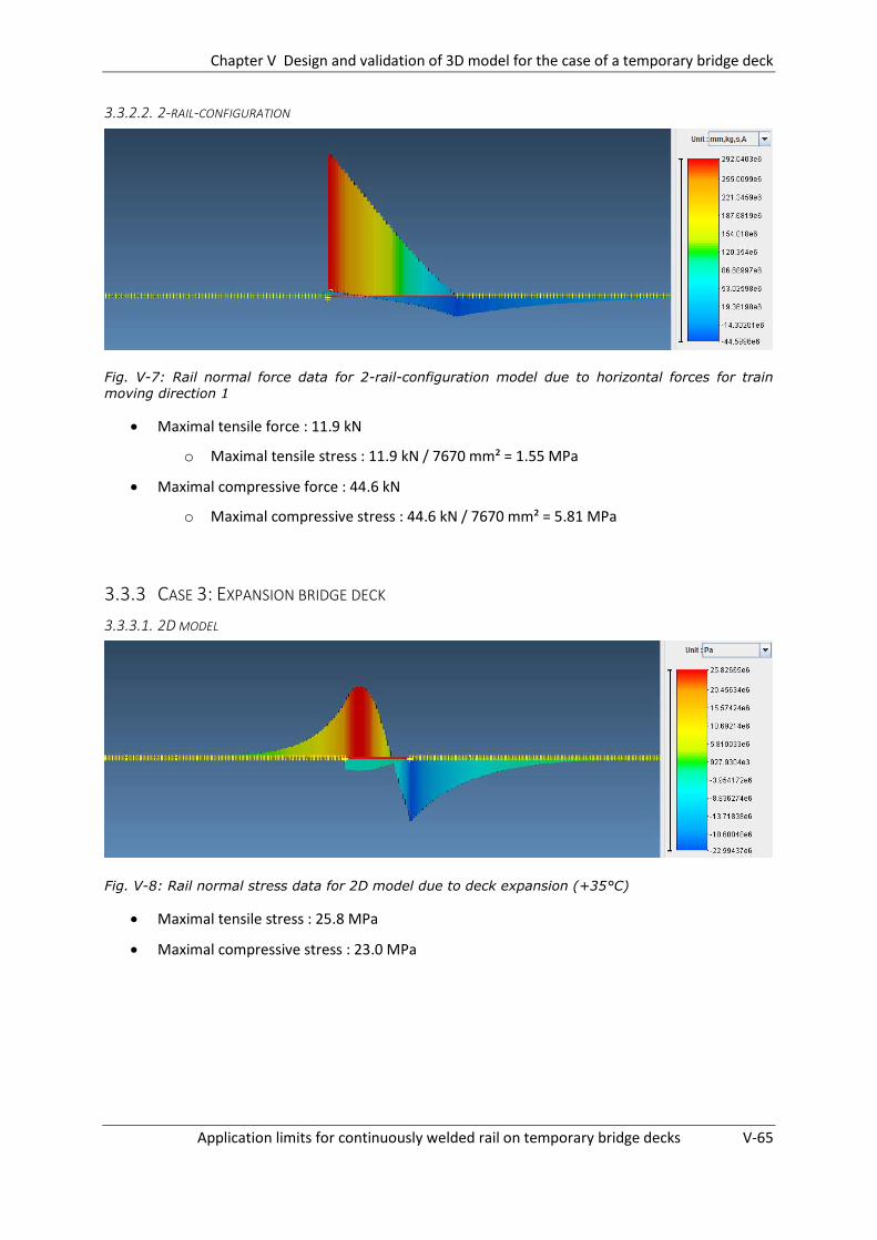
Chapter V Design and validation of 3D model for the case of a temporary bridge deck
Application limits for continuously welded rail on temporary bridge decks V-65
3.3.2.2. 2-RAIL-CONFIGURATION
Fig. V-7: Rail normal force data for 2-rail-configuration model due to horizontal forces for train
moving direction 1
Maximal tensile force : 11.9 kN
o Maximal tensile stress : 11.9 kN / 7670 mm² = 1.55 MPa
Maximal compressive force : 44.6 kN
o Maximal compressive stress : 44.6 kN / 7670 mm² = 5.81 MPa
3.3.3 CASE 3: EXPANSION BRIDGE DECK
3.3.3.1. 2D MODEL
Fig. V-8: Rail normal stress data for 2D model due to deck expansion (+35°C)
Maximal tensile stress : 25.8 MPa
Maximal compressive stress : 23.0 MPa
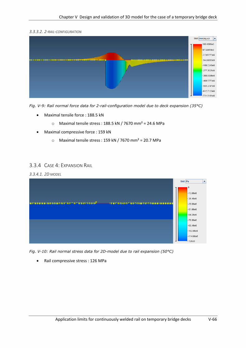
Chapter V Design and validation of 3D model for the case of a temporary bridge deck
Application limits for continuously welded rail on temporary bridge decks V-66
3.3.3.2. 2-RAIL-CONFIGURATION
Fig. V-9: Rail normal force data for 2-rail-configuration model due to deck expansion (35°C)
Maximal tensile force : 188.5 kN
o Maximal tensile stress : 188.5 kN / 7670 mm² = 24.6 MPa
Maximal compressive force : 159 kN
o Maximal tensile stress : 159 kN / 7670 mm² = 20.7 MPa
3.3.4 CASE 4: EXPANSION RAIL
3.3.4.1. 2D MODEL
Fig. V-10: Rail normal stress data for 2D-model due to rail expansion (50°C)
Rail compressive stress : 126 MPa

Chapter V Design and validation of 3D model for the case of a temporary bridge deck
Application limits for continuously welded rail on temporary bridge decks V-67
3.3.4.2. 2-RAIL-CONFIGURATION
Fig. V-11: Rail normal stress data for 2-rail-configuration model due to rail expansion (50°C)
Rail compressive stress : 126 MPa
3.3.5 RESULT OVERVIEW
Braking loads Vertical loads Deck expansion Rail expansion
Compr. Tension Compr. Tension Compr. Tension Compression
2D model
[MPa] 6.2 1.4 13.9 27.8 25.8 23.0 126
2-rail-config.
[MPa] 5.81 1.55 13.5 27.4 24.6 20.7 126
Deviation [%] -6.3 10.7 -2.9 -1.4 -4.7 -10.0 0
Table V-5: Overview of results with regard to arising rail stresses for both configuration types
3.3.6 CONCLUSION
As can be derived from Table V-5 the adjustments made to the model assembled in Chapter IV and
described in this chapter only result in small changes of the obtained rail stresses. All deviations
remain within acceptable limits. There are no deviations larger than 10% with respect to values
obtained using the model assembled according to Chapter IV. Therefore one can assume that the
model described in this chapter can be applied successfully in Chapter VI in order to simulate the
buckling behaviour of the CWR track.
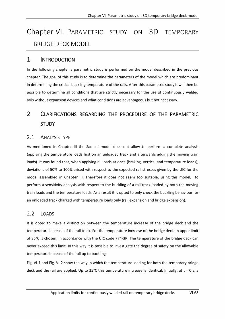
Chapter VI Parametric study on 3D temporary bridge deck model
Application limits for continuously welded rail on temporary bridge decks VI-68
PARAMETRIC STUDY ON 3D TEMPORARY
BRIDGE DECK MODEL
1 INTRODUCTION
In the following chapter a parametric study is performed on the model described in the previous
chapter. The goal of this study is to determine the parameters of the model which are predominant
in determining the critical buckling temperature of the rails. After this parametric study it will then be
possible to determine all conditions that are strictly necessary for the use of continuously welded
rails without expansion devices and what conditions are advantageous but not necessary.
2 CLARIFICATIONS REGARDING THE PROCEDURE OF THE PARAMETRIC
STUDY
2.1 ANALYSIS TYPE
As mentioned in Chapter III the Samcef model does not allow to perform a complete analysis
(applying the temperature loads first on an unloaded track and afterwards adding the moving train
loads). It was found that, when applying all loads at once (braking, vertical and temperature loads),
deviations of 50% to 100% arised with respect to the expected rail stresses given by the UIC for the
model assembled in Chapter III. Therefore it does not seem too suitable, using this model, to
perform a sensitivity analysis with respect to the buckling of a rail track loaded by both the moving
train loads and the temperature loads. As a result it is opted to only check the buckling behaviour for
an unloaded track charged with temperature loads only (rail expansion and bridge expansion).
2.2 LOADS
It is opted to make a distinction between the temperature increase of the bridge deck and the
temperature increase of the rail track. For the temperature increase of the bridge deck an upper limit
of 35°C is chosen, in accordance with the UIC code 774-3R. The temperature of the bridge deck can
never exceed this limit. In this way it is possible to investigate the degree of safety on the allowable
temperature increase of the rail up to buckling.
Fig. VI-1 and Fig. VI-2 show the way in which the temperature loading for both the temporary bridge
deck and the rail are applied. Up to 35°C this temperature increase is identical: Initially, at t = 0 s, a

Chapter VI Parametric study on 3D temporary bridge deck model
Application limits for continuously welded rail on temporary bridge decks VI-69
small temperature load (0.1°C) is present on both the rail and the bridge deck in order to prevent the
calculation from diverging. This situation corresponds to the case in which the rail’s temperature is
(approximately) equal to its neutral temperature, since there are no stresses present in the track.
Subsequently the temperature of both the bridge and rail is increased linearly with a speed of 10°C/s
to a temperature of 20°C. When reaching this value the temperature is then kept constant for a short
period of 1s allowing the structure to stabilize and after this short period the temperature is
increased further with the same rate to 35°C. After reaching this temperature the temperature of the
temporary bridge deck is kept constant for the remainder of the test and only the temperature of the
rail is increased further at the same rate of 10°C/s.
Fig. VI-1: Temp increase of bridge deck Fig. VI-2: Temp increase of rails
2.3 DEFINITION OF CRITICAL TEMPERATURE INCREASE
At a certain temperature the compressive forces in the rails will become too large and buckling will
occur. However initially this buckling temperature is unknown. Therefore a large temperature
increase is applied to the rail (for example 120°C at t = 13 s as shown in Fig. VI-2) such that buckling
will surely occur. Afterwards the displacements of the different mesh nodes as a function of time can
be plotted and from this plot the time and thus also the critical temperature increase at which
buckling initiates can be derived. An example of such a plot for the mesh node at the top of the
misalignment is given in Fig. VI-3.
As can be seen, the development of the lateral deflection takes place over a certain temperature
interval. It is thus quite difficult to quantify a specific buckling temperature. In order to do so, a
simplified definition is used. Since it is found in multiple test cases that the interval in which the
lateral deflections grow is relatively small (approximately 3°C) and the position of the maximum

Chapter VI Parametric study on 3D temporary bridge deck model
Application limits for continuously welded rail on temporary bridge decks VI-70
deflection due to buckling does not differ too much from the initial position with the maximal
misalignment amplitude it is opted to define the critical buckling temperature as the temperature
corresponding to the peak value in the lateral displacement – temperature plot.
In Fig. VI-3 given below the progress of the lateral displacement as a function of time (and thus also
temperature) is given for the mesh node with the initial maximal misalignment amlitude. The
boundary for which the critical buckling temperature will be defined is designated with the red line.
Fig. VI-3: Progress of lateral displacement as a function of time for mesh node at top of the
misalignment
Inevitably there will be a certain margin of error on the obtained critical temperature increase but
still the obtained values will provide a good insight on the sensitivity of the buckling temperature
with respect to the different parameters examined. Additionally one will also gain a good
understanding on the order of magnitude of the arising critical temperature increases.
Note: The temperature increase at which buckling initiates is not equal to the rail’s physical
temperature at that moment. If one would want to calculate the physical temperature at which
buckling initiates the obtained critical temperature increase should be added to the rail’s neutral
temperature.
2.4 OBTAINED RESULTS
It is possible to retrieve the deformed track geometry of the buckled track. In this way it is possible to
obtain information regarding the shape and wavelength of the buckle. An example of such a buckled
track geometry obtained using the Samcef Field model is shown in Fig. VI-4.
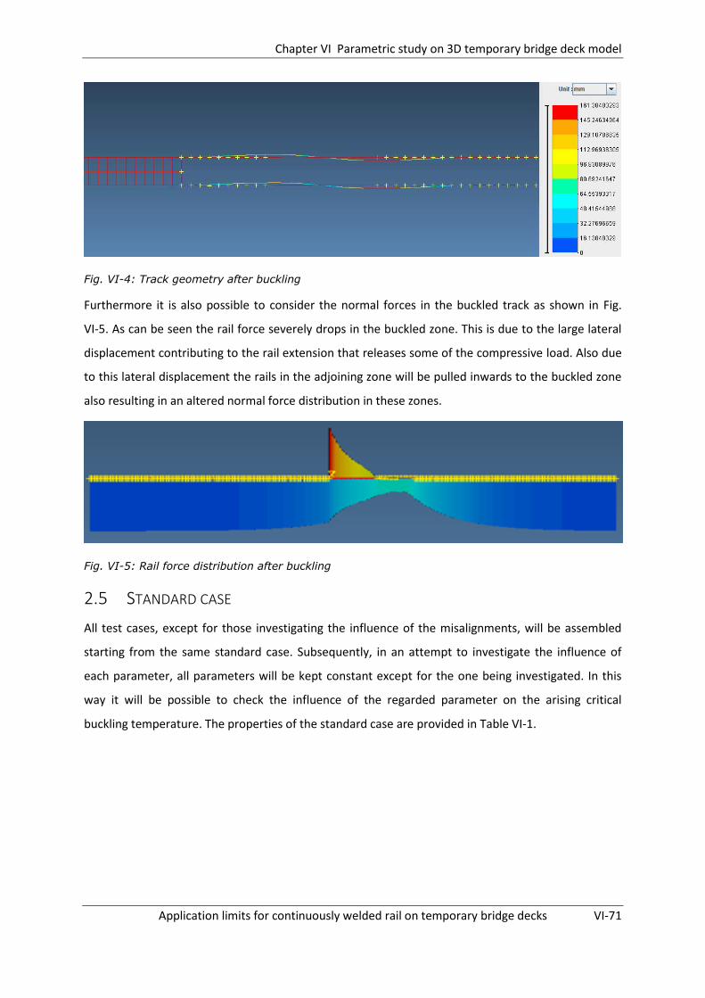
Chapter VI Parametric study on 3D temporary bridge deck model
Application limits for continuously welded rail on temporary bridge decks VI-71
Fig. VI-4: Track geometry after buckling
Furthermore it is also possible to consider the normal forces in the buckled track as shown in Fig.
VI-5. As can be seen the rail force severely drops in the buckled zone. This is due to the large lateral
displacement contributing to the rail extension that releases some of the compressive load. Also due
to this lateral displacement the rails in the adjoining zone will be pulled inwards to the buckled zone
also resulting in an altered normal force distribution in these zones.
Fig. VI-5: Rail force distribution after buckling
2.5 STANDARD CASE
All test cases, except for those investigating the influence of the misalignments, will be assembled
starting from the same standard case. Subsequently, in an attempt to investigate the influence of
each parameter, all parameters will be kept constant except for the one being investigated. In this
way it will be possible to check the influence of the regarded parameter on the arising critical
buckling temperature. The properties of the standard case are provided in Table VI-1.

Chapter VI Parametric study on 3D temporary bridge deck model
Application limits for continuously welded rail on temporary bridge decks VI-72
Span length 20 metres
Longitudinal track resistance Characteristic resistance (unloaded): 20 kN/m
Characteristic resistance (loaded): 60 kN/m
Elastic limit: 2mm
Lateral track resistance Characteristic resistance: 6000 N
Elastic limit: 2mm
Lateral misalignment Amplitude : 3mm
Wavelength: 4m
Position: Max deflection situated 3m right of
temporary bridge deck
Stiffness fixed bearing 6,000,000 kN/m
Temporary bridge deck S = 0.239 m²
Iy = 0.0225 m4
vi = 0.424 m
wi = 0.317 m
Table VI-1: Properties of standard case forming basis for parametric study
Note: As depicted in Table VI-1 a lateral misalignment with a wavelength of 4 meters and an
amplitude of 3 millimetres is standardly incorporated in each model. This is done in order to
destabilize the model. If no lateral misalignment would be applied to the configuration the model
would not yield any solutions due to the perfect straightness of the beams used. The magnitude of
the amplitude of 3 millimetres is chosen according to the target values for construction imposed by
INFRABEL, shown in Table D-1 of Annex D.
3 PARAMETERS TO BE EXAMINED
In order to determine the parameters which should be examined in this parametric study each
possible parameter is discussed based on the information provided in the literature study of Chapter
II §5 and on the results of the preliminary parametric study of Chapter IV. The different parameters
which are discussed are listed below:
- Presence of lateral misalignment in rail configuration
o Position of lateral misalignment
o Amplitude of lateral misalignment
o Wavelength of lateral misalignment

Chapter VI Parametric study on 3D temporary bridge deck model
Application limits for continuously welded rail on temporary bridge decks VI-73
- Lateral track resistance
- Torsional resistance fasteners
- Span length
- Bending stiffness temporary bridge deck
- Longitudinal stiffness of fixed bearing
- Longitudinal track resistance embankments
- Longitudinal track resistance fasteners on temporary bridge deck
3.1 PRESENCE OF LATERAL MISALIGNMENT IN RAIL CONFIGURATION
It has been proven in several studies that the presence of a lateral misalignment in the track
configuration severely influences the critical track buckling temperature. Therefore the influence of
this parameter should absolutely be checked in the parametric analysis. As mentioned in Chapter II
§5 and depicted in Fig. VI-6 multiple types of initial misalignment shapes might occur. For this
dissertation it is opted to assume the misalignments have a shape corresponding to the anti-
symmetric mode shape. The other misalignment shapes are not regarded in this dissertation.
However, it should be mentioned that they could have an influence on the critical buckling
temperature. In a future further elaboration of this dissertation it might be interesting to examine
this influence.
Fig. VI-6: Possible buckling shapes
As mentioned the models examining the influence of the presence of a lateral misalignment on the
critical buckling temperature use a slightly different configuration with respect to the standard
configuration described in Table VI-1. All properties given in this table also apply for the models
examined in this section except for the properties describing the small misalignment. In order to

Chapter VI Parametric study on 3D temporary bridge deck model
Application limits for continuously welded rail on temporary bridge decks VI-74
better examine the influence of the presence of a misalignment in the track configuration slightly
different properties with respect to the misalignment will be applied. In the following sections it will
be mentioned clearly which properties do apply for the misalignments.
3.1.1 POSITION OF LATERAL MISALIGNMENT
Due to the presence of the temporary bridge deck locally larger compressive forces will arise in the
track, situated at the side of the movable bridge bearing, when expansion of the bridge deck takes
place. This behaviour is depicted in Fig. VI-7 where the normal rail stress evolution due to a
temperature increase of 35°C for the temporary bridge deck and 50°C for the rails is depicted.
Fig. VI-7: Normal stress evolution for deck expansion (35°C) and rail expansion (50°C)
As a result the most critical position for a track misalignment to occur will also be situated at that
part of the track. At which exact location (variable for each different considered case) the track is
most sensitive to the presence of a track misalignment is mainly dependent on two factors. First of
all the magnitude of the stabilizing effect of the stiff fasteners situated on the temporary bridge deck.
And secondly the magnitude of the destabilizing additional compressive stresses resulting from the
interaction due to the bridge deck expansion.
In order to now check this critical position different positions for the misalignment are applied in the
Samcef model. The properties of the models checked are discussed below:
Wavelength : 4 metres
Amplitude : 17 millimetres
o This magnitude is chosen corresponding to the ‘DAN’-value of the amplitude for
which INFRABEL suggests actions are required. (as shown in Table D-1 of Annex D)
Position: the position of the misalignments is characterized by the distance of the point with
the maximal initial amplitude closest to the movable support of the temporary bridge deck.

Chapter VI Parametric study on 3D temporary bridge deck model
Application limits for continuously welded rail on temporary bridge decks VI-75
In order to clarify this position an example is given in Fig. VI-8. The following distances will be
checked: 3m, 7m, 11m, 15m, 19m, 25m, 50m
The resulting properties of the models are depicted in Table VI-1 (the properties regarding
the misalignment given in this table should be neglected)
Fig. VI-8: definition of position of misalignment
3.1.2 AMPLITUDE OF LATERAL MISALIGNMENT
Multiple studies by for example Samavedam (1993) have shown that the magnitude of the
misalignment present in the track has an important impact on the critical buckling temperature.
Therefore the magnitude of this parameter will also be investigated in the parametric study. The
properties of the models checked are listed below:
Wavelength : 4 metres
Position: point with maximal amplitude closest to the temporary bridge deck situated at a
distance of 3 metres to the movable support
Amplitude: The following magnitudes will be checked: 3mm, 7mm, 12mm, 17mm
The resulting properties are depicted in Table VI-1 (the properties regarding the
misalignment given in this table should be neglected).
3.1.3 WAVELENGTH OF LATERAL MISALIGNMENT
Samavedam (1993) and others also proved that apart from the amplitude of the misalignment also
the wavelength (equal to a distance of 2 times L for shape II in Fig. VI-6) plays an important role in
determining the critical buckling temperature of the track. The properties of the models used to
verify this influence are given below:
Position: point with maximal amplitude closest to the temporary bridge deck situated at a
distance of 6 metres to the movable support
Amplitude : 17 millimetres
Wavelength: the following magnitudes are regarded: 4 m, 6 m, 8 m, 12 m

Chapter VI Parametric study on 3D temporary bridge deck model
Application limits for continuously welded rail on temporary bridge decks VI-76
The resulting properties are depicted in Table VI-1 (the properties regarding the
misalignment given in this table should be neglected).
3.2 LATERAL BALLAST RESISTANCE
Multiple studies by for example Choi (2010) and Samavedam et al. (1993) have shown that the
magnitude of the lateral track resistance severely influences the critical track buckling temperature.
Therefore the influence of this track parameter will be examined in the parametric analysis. As
mentioned in Table VI-1, for the standard case a bilinear behaviour is assumed characterized by a
maximum resistance value of 6 kN combined with an elastic limit of 2 mm2. In the parametric study
this maximum characteristic resistance will be varied over the following values:
2000 N, 4000 N, 6000 N, 8000 N, 10000 N
3.3 TORSIONAL RESISTANCE FASTENERS
As proven in multiple studies by for example Samavedam et al. (1993) the torsional resistance of the
fasteners has a negligible influence on the critical buckling temperature of the track. It is thus safe to
assume the fasteners do not exert any resisting moment to the track. The influence of this parameter
will not be regarded in the parametric analysis.
3.4 BENDING STIFFNESS TEMPORARY BRIDGE DECK
As mentioned for the parametric study performed in this chapter only thermal expansion of both the
rail and bridge deck are regarded. Therefore, in order to make a decision on which parameters
should be examined one can base itself on the results obtained in Chapter IV for loading case 3. As
concluded in Chapter IV the additional rail stresses due to bridge deck expansion remain unchanged
for varying bridge deck bending stiffnesses. Therefore this factor will not have a significant influence
on the arising critical buckling temperature of the rail and can thus be disregarded.
3.5 STIFFNESS OF FIXED BEARING
As can be seen in Fig. A-29 and Fig. A-35 of annex A and concluded in Chapter IV the influence of the
stiffness of the fixed bearing on the arising compressive rail stress at the movable bearing is rather
small. Therefore it is opted to not examine the influence of this parameter in the parametric study.
2 Value corresponding to timber sleepers with a length of 2.6 metres[13]

Chapter VI Parametric study on 3D temporary bridge deck model
Application limits for continuously welded rail on temporary bridge decks VI-77
3.6 LONGITUDINAL TRACK RESISTANCE EMBANKMENTS
When comparing Fig. A-17 and Fig. A-23 of Annex A a change of the compressive rail stress at the
movable support can be distinguished. In order to check the influence of this variation on the critical
rail buckling temperature the characteristic longitudinal resistance will by varied. The following
characteristic resistance values will be evaluated:
10 kN/m, 20 kN/m, 30 kN/m, 40 kN/m
3.7 LONGITUDINAL TRACK RESISTANCE FASTENERS ON TEMPORARY BRIDGE DECK
Looking at the arising compressive rail stress at the movable support for both Fig. A-53 and Fig. A-59
of Annex A, a variation of the compressive rail stress at the movable support is found. Therefore it is
opted to evaluate the influence of this factor on the critical rail buckling temperature. In order to do
so the following characteristic resistance values are checked:
30 kN/m, 40 kN/m, 50 kN/m, 60 kN/m
3.8 SPAN LENGTH
In Chapter IV it is proven that the span length can have a significant influence on the arising
additional rail stresses for the different interaction loading cases. Especially the rail stresses resulting
from the vertical loading case and deck expansion showed a severe increase in rail stresses.
Therefore it is advised to also check the influence of the span length on the critical rail buckling
temperature. The following span lengths will be checked:
10 m, 20 m, 30 m
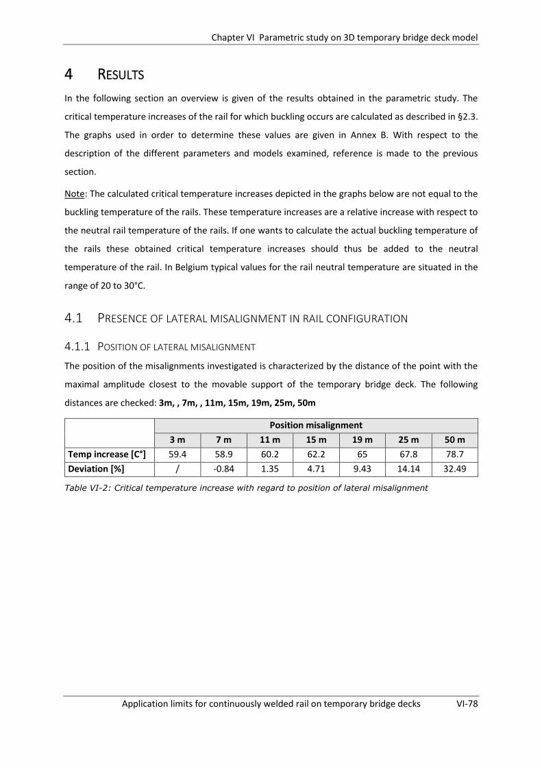
Chapter VI Parametric study on 3D temporary bridge deck model
Application limits for continuously welded rail on temporary bridge decks VI-78
4 RESULTS
In the following section an overview is given of the results obtained in the parametric study. The
critical temperature increases of the rail for which buckling occurs are calculated as described in §2.3.
The graphs used in order to determine these values are given in Annex B. With respect to the
description of the different parameters and models examined, reference is made to the previous
section.
Note: The calculated critical temperature increases depicted in the graphs below are not equal to the
buckling temperature of the rails. These temperature increases are a relative increase with respect to
the neutral rail temperature of the rails. If one wants to calculate the actual buckling temperature of
the rails these obtained critical temperature increases should thus be added to the neutral
temperature of the rail. In Belgium typical values for the rail neutral temperature are situated in the
range of 20 to 30°C.
4.1 PRESENCE OF LATERAL MISALIGNMENT IN RAIL CONFIGURATION
4.1.1 POSITION OF LATERAL MISALIGNMENT
The position of the misalignments investigated is characterized by the distance of the point with the
maximal amplitude closest to the movable support of the temporary bridge deck. The following
distances are checked: 3m, , 7m, , 11m, 15m, 19m, 25m, 50m
Position misalignment
3 m 7 m 11 m 15 m 19 m 25 m 50 m
Temp increase [C°] 59.4 58.9 60.2 62.2 65 67.8 78.7
Deviation [%] / -0.84 1.35 4.71 9.43 14.14 32.49
Table VI-2: Critical temperature increase with regard to position of lateral misalignment

Chapter VI Parametric study on 3D temporary bridge deck model
Application limits for continuously welded rail on temporary bridge decks VI-79
Fig. VI-9: Representation of influence of position misalignment on critical temperature increase
4.1.2 AMPLITUDE OF LATERAL MISALIGNMENT
The following magnitudes of the lateral misalignment are checked: 3mm, 7mm, 12mm, 17mm
Amplitude misalignment
3 mm 7 mm 12 mm 17 mm
Temp increase [C°] 109 80.2 65.9 59.4
Deviation [%] 83.5 35.0 10.9 /
Table VI-3: Critical temperature increase with regard to amplitude of lateral misalignment
Fig. VI-10: Representation of influence of amplitude of misalignment on critical temperature increase
50
55
60
65
70
75
80
85
0 10 20 30 40 50
Cri
tica
l tem
per
atu
re in
crea
se [
°C]
Distance point of maximal amplitude to movable support [m]
40
50
60
70
80
90
100
110
120
0 5 10 15 20
Cri
tica
l tem
per
atu
re in
crea
se [
°C]
Amplitude of lateral misalignment [mm]

Chapter VI Parametric study on 3D temporary bridge deck model
Application limits for continuously welded rail on temporary bridge decks VI-80
4.1.3 WAVELENGTH OF LATERAL MISALIGNMENT
The following magnitudes for the lateral misalignment wavelength are regarded:
4 m, 6 m, 8 m, 12 m
Wavelength misalignment
4 m 6 m 8 m 12 m
Temp increase [C°] 59.8 51.2 47.6 48.7
Deviation [%] / -14.38 -20.4 -18.6
Table VI-4: Critical temperature increase with regard to wavelength of lateral misalignment
Fig. VI-11: Representation of influence of wavelength of misalignment on critical temperature
increase
4.2 LONGITUDINAL BALLAST RESISTANCE EMBANKMENTS
As mentioned, the progress of the critical buckling temperature is investigated for the following
values of the characteristic resistance assessed at a displacement of 2mm:
10 kN/m, 20 kN/m, 30 kN/m, 40 kN/m
Longitudinal ballast resistance on embankments
10 kN/m 20 kN/m 30 kN/m 40 kN/m
Temp increase [C°] 109.4 109.3 109.2 109.2
Deviation [%] 0.09 / -0.09 -0.09
Table VI-5: Critical temperature increase with regard to longitudinal ballast resistance on embankments
40
45
50
55
60
65
4 5 6 7 8 9 10 11 12
Cri
tica
l tem
per
atu
re in
crea
se [
°C]
Wavelength misalignment [m]

Chapter VI Parametric study on 3D temporary bridge deck model
Application limits for continuously welded rail on temporary bridge decks VI-81
Fig. VI-12: Representation of influence of longitudinal ballast resistance of track situation on
embankment on the critical temperature increase
4.3 LONGITUDINAL TRACK RESISTANCE FASTENERS ON TEMPORARY BRIDGE DECK
The progress of the critical buckling temperature is investigated for the following values of the
characteristic resistance assessed at a displacement of 0.5 mm:
30 kN/m, 40 kN/m, 50 kN/m, 60 kN/m
Longitudinal fastener resistance temporary bridge deck
30 kN/m 40 kN/m 50 kN/m 60 kN/m
Temp increase [C°] 111.2 109.3 107.9 106.4
Deviation [%] 1.74 / -1.28 -2.65
Table VI-6: Critical temperature increase with regard to longitudinal fastener resistance on temporary bridge deck
Fig. VI-13: Representation of influence of longitudinal resistance of fasteners on temporary bridge
deck on the critical temperature increase
109.15
109.2
109.25
109.3
109.35
109.4
109.45
10 15 20 25 30 35 40
Cri
tica
l te
mp
erat
ure
incr
ease
[°C
]
Longitudinal ballast resistance [kN/m]
106
107
108
109
110
111
112
113
20 25 30 35 40 45 50 55 60
Cri
tica
l te
mp
erat
ure
tem
per
atu
re
[°C
]
Longitudinal fastener resistance [kN/m]

Chapter VI Parametric study on 3D temporary bridge deck model
Application limits for continuously welded rail on temporary bridge decks VI-82
4.4 LATERAL BALLAST RESISTANCE
As mentioned, the progress of the critical buckling temperature is investigated for the following
values of the characteristic resistance assessed at a displacement of 2mm:
2000 N, 4000 N, 6000 N, 8000 N, 10000 N
Lateral ballast resistance
2000 N 4000 N 6000 N 8000 N 10000 N
Temp increase [C°] 67.9 92 109.3 125.2 136.5
Deviation [%] -37.9 -15.8 / 14.6 24.9
Table VI-7: Critical temperature increase with regard to lateral ballast resistance
Fig. VI-14: Representation of influence of lateral ballast resistance on critical temperature increase
4.5 SPAN LENGTH
The progress of the critical buckling temperature is investigated for the following span lengths:
10 m, 20 m, 30 m
Span length
10 m 20 m 30 m
Temp increase [C°] 112.4 109.3 105.9
Deviation [%] 2.84 0.00 -3.11
Table VI-8: Critical temperature increase with regard to span length
40
60
80
100
120
140
160
1000 3000 5000 7000 9000 11000
Cri
tica
l tem
per
atu
re in
crea
se [
°C]
Characteristic lateral ballast resistance [N]

Chapter VI Parametric study on 3D temporary bridge deck model
Application limits for continuously welded rail on temporary bridge decks VI-83
Fig. VI-15: Representation of influence of span length on critical temperature increase
5 DISCUSSION OF RESULTS
5.1 POSITION OF LATERAL MISALIGNMENT
It is found that the most critical position for a track defect is situated in the immediate surroundings
of the movable support. For a track misalignment position moving away from the temporary bridge
deck the obtained allowable temperature increase augments and eventually will become constant.
This increased sensitivity at the movable support is off course the result of the local increased
compressive rail stresses due to the expansion of the temporary bridge deck, as shown in Fig. VI-16.
Fig. VI-16: Normal stress evolution for deck expansion (35°C) and rail expansion (50°C)
Still, the deviation between the different critical temperature increases remains rather small. For a
misalignment situated up to 25 metres away from the movable support the relative increase, with
respect to the critical temperature increase found for a misalignment situated 3 metres away from
the movable support, amounts only approximately 14%. For a misalignment position situated 50
105
106
107
108
109
110
111
112
113
10 15 20 25 30Cri
tica
l te
mp
erat
ure
tem
per
atu
re [
°C]
Span length [m]
Chapter VI Parametric study on 3D temporary bridge deck model
Application limits for continuously welded rail on temporary bridge decks VI-84
metres away from the movable support this relative deviation has grown to 32%. From this one could
conclude that the part of the track beyond the movable support, with a length of a factor 1 or 1.5
times the bridge span length, should be monitored more strictly for the presence of misalignments.
5.2 AMPLITUDE OF LATERAL MISALIGNMENT
When considering Fig. VI-10 it is clear that the amplitude of the lateral misalignment will be one of
the determining factors with respect to the critical buckling temperature of the track. For decreasing
amplitude magnitudes, an exponential relationship is found with respect to the critical rail
temperature increase. In order to preserve sufficient safety margin against track buckling it will thus
be compulsory to limit the arising lateral misalignment amplitudes in the track. Since an inverse
exponential relationship is found for increasing misalignment amplitudes and the critical
temperature increase it will be very important to limit the arising misalignment amplitudes in an
early stage, since in this range the maximal decrease of the buckling temperature is found.
5.3 WAVELENGTH OF LATERAL MISALIGNMENT
When considering Fig. VI-11 it can be derived that the wavelength of the track misalignment also has
a considerable influence on the obtained critical buckling temperature of the track. It appears that
the buckling behaviour of the track is most critical for a misalignment wavelength situated in the
range of 8 to 12 metres. For wavelengths smaller than 8 metres the required temperature increase of
the track for buckling grows. For wavelengths longer than 12 metres no tests have been performed.
Further research might be needed.
In order to find an explanation for this phenomenon the geometry of the buckled track is regarded.
This is done for the different cases examined in §3.1.3. An example of such a deformed track is given
in Fig. VI-17 for the case of an initial wavelength of 4 metres and in Fig. VI-18 for an initial wavelength
of 8 metres. As can be derived from both figures the obtained final wavelength of the buckled track
measures respectively 8 and 12 metres. In the same way, for an initial misalignment wavelength of 6
metres, a buckled track wavelength of 11 metres was found.
It appears thus that, dependant on the magnitude of the initial misalignment, postbuckled track
wavelengths of 9 to 12 metres are found. Due to the tendency of the track to buckle with a
wavelength situated in this range, the track will thus be more prone to buckle for initial misalignment
wavelengths situated in the same range. This might explain the obtained minimum in Fig. VI-11 for an
initial misalignment wavelength situated in the range of 8 to 12 metres.

Chapter VI Parametric study on 3D temporary bridge deck model
Application limits for continuously welded rail on temporary bridge decks VI-85
Fig. VI-17: Geometry of buckled track for an initial misalignment length of 4 metres
Fig. VI-18: Geometry of buckled track for an initial misalignment length of 8 metres
It should however be noted that the wavelength for which the track is most prone to buckle is
dependent on the magnitude of the lateral resistance, as shown in § 5.6. It appears that for
increasing lateral resistances the obtained wavelength of the buckled track decreases. Therefore it is
difficult to define a general wavelength of the initial misalignment for which the track is most prone
to buckle. As shown in §5.6 for a lateral resistance of 4 kN the obtained wavelength of the buckled
track amounts approximately 13 metres. However for a lateral resistance of 6 kN this wavelength has
decreased to 11 metres.
5.4 LONGITUDINAL BALLAST RESISTANCE EMBANKMENTS
When considering Fig. VI-12 it can be derived that the magnitude of the longitudinal track resistance,
for the part of the track situated on the embankments, does not influence the rail buckling
temperature in a considerable way. Its influence is negligible.

Chapter VI Parametric study on 3D temporary bridge deck model
Application limits for continuously welded rail on temporary bridge decks VI-86
5.5 LONGITUDINAL RESISTANCE FASTENERS ON TEMPORARY BRIDGE DECK
It is found that an increased characteristic longitudinal resistance of the fasteners situated on the
temporary bridge deck results in a slight decrease of the critical buckling temperature. The influence
is more pronounced than for the longitudinal resistance of the track on the embankments, but still
remains quite small. These results also show that, if one would apply ZLR fastenings along the entire
bridge length, the critical buckling temperature would increase. Still, this increase would be rather
limited and therefore the benefits of the application of ZLR fastenings might not outweigh the
increased risk for rail breaks.
5.6 LATERAL BALLAST RESISTANCE
As expected the lateral ballast resistance also plays a major role in the buckling behaviour of the
track. First of all it is found that for increasing characteristic ballast resistances the critical buckling
temperature also severely increases. The rate at which the critical buckling temperature rises
however slightly decreases for growing resistances. Furthermore, when analysing the buckled state
of the track, a second influence of the lateral ballast resistance on the buckling behaviour of the track
is found. It appears that for decreasing lateral ballast resistances the obtained wavelength of the
buckled track increases. This effect can clearly be seen when analysing both Fig. VI-19 and Fig. VI-20 .
Fig. VI-19: Buckled track for characteristic lateral ballast resistance of 4kN

Chapter VI Parametric study on 3D temporary bridge deck model
Application limits for continuously welded rail on temporary bridge decks VI-87
Fig. VI-20: Post-buckled track for characteristic lateral ballast resistance of 6 kN
For a characteristic ballast resistance of 6 kN and an initial wavelength of the track misalignment of 6
metres a post-buckling wavelength of approximately 11 metres is found. For, the case of a
characteristic ballast resistance of 4 kN this post-buckling wavelength amounts approximately 13
metres. A reasonable explanation for this behaviour could be that depending on the magnitude of
the lateral restraint a different representative buckling length of the track is valid: the larger the
lateral ballast resistance the smaller the relevant track buckling length.
As a result the increased critical buckling temperature is the result of both an increased restraint
against the lateral deformation of the track and a smaller representative track buckling length
resulting in a higher required normal force for buckling.
5.7 SPAN LENGTH
As shown in Fig. VI-14 the increase of the span length results in a decrease of the critical temperature
increase. This influence however, is not that determining as would be expected based on the results
obtained in Chapter IV. An explanation for this can be found in the fact that the applied amplitude of
the track misalignment in the standard case is rather small (3mm). Therefore the required
temperature increase of the track (≈ 110°C) in order to initiate buckling is very high compared to the
temperature increase of the bridge deck (35°C). Thus also the share of the normal forces present in
the track due to bridge deck expansion is very small compared to the normal forces originating from
the rail expansion. However if the misalignment amplitude would increase then the required rail
temperature will decrease and thus the relative share of the normal forces due to bridge deck
expansion will increase and will become more determining. This explanation is also valid for the
influence of the longitudinal resistance of the fasteners situated on the temporary bridge deck.
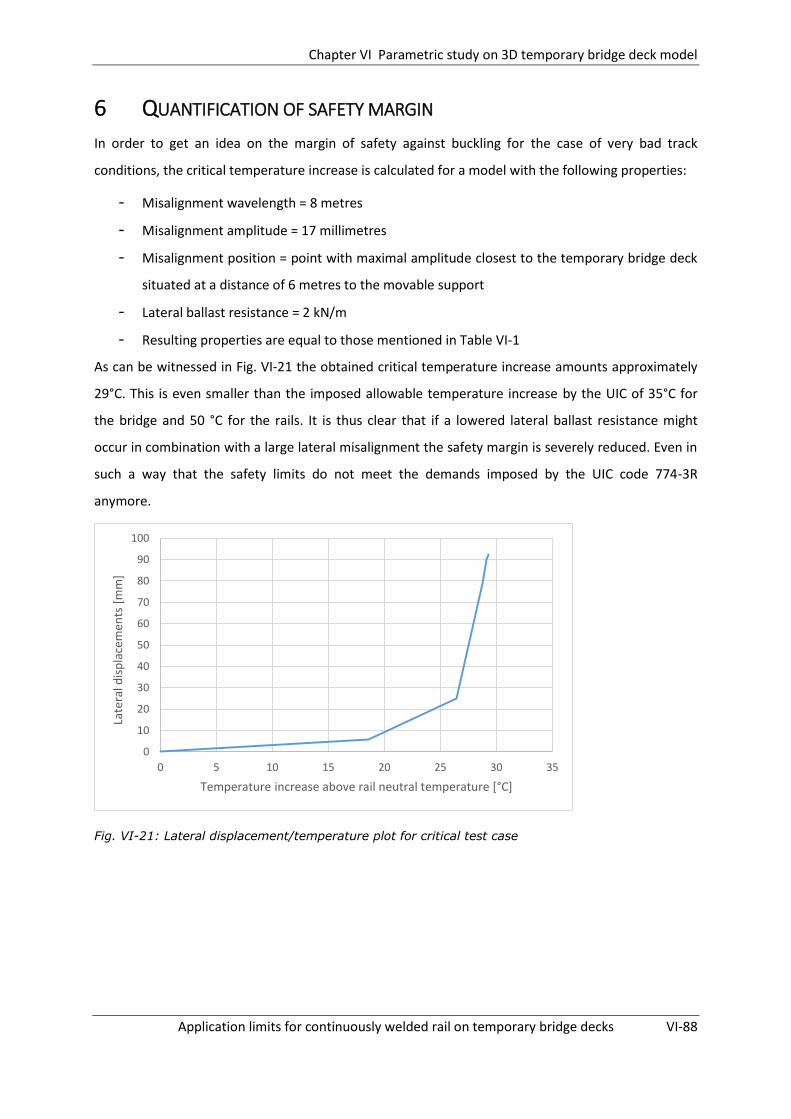
Chapter VI Parametric study on 3D temporary bridge deck model
Application limits for continuously welded rail on temporary bridge decks VI-88
6 QUANTIFICATION OF SAFETY MARGIN
In order to get an idea on the margin of safety against buckling for the case of very bad track
conditions, the critical temperature increase is calculated for a model with the following properties:
- Misalignment wavelength = 8 metres
- Misalignment amplitude = 17 millimetres
- Misalignment position = point with maximal amplitude closest to the temporary bridge deck
situated at a distance of 6 metres to the movable support
- Lateral ballast resistance = 2 kN/m
- Resulting properties are equal to those mentioned in Table VI-1
As can be witnessed in Fig. VI-21 the obtained critical temperature increase amounts approximately
29°C. This is even smaller than the imposed allowable temperature increase by the UIC of 35°C for
the bridge and 50 °C for the rails. It is thus clear that if a lowered lateral ballast resistance might
occur in combination with a large lateral misalignment the safety margin is severely reduced. Even in
such a way that the safety limits do not meet the demands imposed by the UIC code 774-3R
anymore.
Fig. VI-21: Lateral displacement/temperature plot for critical test case
0
10
20
30
40
50
60
70
80
90
100
0 5 10 15 20 25 30 35
Late
ral d
isp
lace
men
ts [
mm
]
Temperature increase above rail neutral temperature [°C]

Chapter VI Parametric study on 3D temporary bridge deck model
Application limits for continuously welded rail on temporary bridge decks VI-89
7 IMPORTANT REMARKS REGARDING THE OBTAINED RESULTS
Some important additional remarks should be made regarding the results obtained in the parametric
study. First of all it should be noted that the obtained critical temperature increases are equal to the
component ΔTb,max which was defined in the literature study of Chapter II. This component equals the
temperature increase above the rail’s stress-free temperature, for which the track will buckle
without any addition of external energy. However as discussed, the track may also buckle for a
temperature increase lower than ΔTb,max if sufficient external energy is supplied. The safety levels
defined by the UIC code 720 [7] are all based on this lower temperature increase ΔTb,min. Therefore it
should always be kept in mind that, when adding extra energy to the rail, track buckling can still
occur for a rail temperature under Tb,max but still above Tb,min.
Additionally, it was also mentioned that there is a certain margin of error on the defined critical
temperature increases. The interval in which the lateral displacements grow has a magnitude of
approximately 5°C. In this dissertation the critical temperature was taken equal to the temperature
corresponding to the peak value of the lateral displacement/temperature plot shown in Fig. VI-3.
However the critical temperature increase at which the maximal arising lateral displacement in the
track exceeds the limit value imposed by INFRABEL for which immediate action is required (22
millimetres) will be slightly smaller. In the parametric study therefore a slight overestimation of the
safety margin is obtained.

Chapter VII General conclusions and formulation of application limits
Application limits for continuously welded rail on temporary bridge decks VII-90
GENERAL CONCLUSIONS AND FORMULATION
OF APPLICATION LIMITS
1 CONCLUSIONS AND APPLICATION LIMITS BASED ON 2D INTERACTION
MODEL ASSEMBLED IN CHAPTER IV
1.1 CONCLUSIONS
In Chapter IV multiple test cases have been examined in the parametric analysis with respect to their
interaction effects. For this parametric analysis a 2D temporary bridge deck model was assembled
based on the prescriptions of the UIC code 774-3R. This model only takes into account the stresses
arising in the rails due longitudinal and vertical (for the part of the track situated on the temporary
bridge deck) displacements of the rails. The lateral component is disregarded in these models. In
order to be able to verify whether CWR can be continued over the temporary bridge deck without
providing expansion devices all interaction loads imposed by the UIC code 774-3R were applied to
the structure. These loads consisted of braking and vertical loads due to a moving train and
temperature variations in the bridge (±35°C) and track (+50°C) expansion.
The following parameters have been examined: span length, longitudinal ballast resistance,
longitudinal resistance of fasteners situated on the temporary bridge deck, bending stiffness of the
temporary bridge deck, and stiffness of the fixed bearing. It was found that the span length and
bridge bending stiffness are the most determining parameters with respect to the arising additional
rail stresses. It will thus be compulsory to impose certain application limits to these parameters for
the allowance of continuing CWR track over a temporary bridge deck. The other parameters
examined also had an influence on the arising stresses but this influence was less decisive.
The standard configuration used in this parametric analysis corresponds to the case of a temporary
bridge deck with a span length of 20 metres. The bending stiffness of the temporary bridge deck is
chosen equal to the stiffness of an actual temporary bridge deck used by INFRABEL for a span length
of 12 metres. The characteristics for the longitudinal track resistance and the loads imposed to the
model are based on the values imposed by the UIC code 774-3R. Therefore, if this configuration
complies with the limitations given by the UIC code 774-3R, one can assume that for this span length
and temporary bridge deck configuration it is allowed to continue CWR track over the bridge
structure without providing an expansion device.

Chapter VII General conclusions and formulation of application limits
Application limits for continuously welded rail on temporary bridge decks VII-91
It is found that, not only for this configuration but also for all other test-cases examined (except for
the one with a span length of 30 metres), the limitations imposed by the UIC code 774-3R are met. As
a result one can state that for these configurations it is allowed to omit the expansion device from
the structural configuration of the track.
Furthermore, it could even be concluded that, if the temporary bridge decks used by INFRABEL are
applied corresponding to their practical applied span range, there is still a large safety margin with
respect to the additional rail stresses and displacements.
1.2 FORMULATION OF APPLICATION LIMITS
Based on the parametric study performed in Chapter IV the following recommendations are given in
order to ensure a safe application of CWR track over a temporary bridge deck without having to
install an expansion device:
One of the most determining factors in reducing the interaction stresses is the choice of an
appropriate bending stiffness for the temporary bridge deck with respect to the span to be
covered. As found in the parametric analysis of Chapter IV the increase of the interaction
stresses for an increasing span length is predominantly originating from the vertical and
thermal loading cases. If thus a temporary bridge deck with a sufficient bending stiffness is
chosen then, as proven in §3.3.5 of Chapter IV, the arising additional rail stresses for the
vertical loading case can be severely reduced.
Still, an increased bending stiffness of the bridge deck will not influence the arising additional
rail stresses due to bridge deck expansion in a significant manner, as proven in §3.3.5 of
Chapter IV. Therefore the increase of the additional rail stresses for an increased span length
due to bridge deck expansion might result in considerable problems. As can be seen in Fig. A-
11 of Annex A, for a span length of 30 metres the additional compressive rail stress at the
movable support due to bridge deck expansion amounts 50 MPa. Given the fact that the
upper limit for the compressive rail stresses imposed by the UIC code 774-3R equals 72 MPa
one can thus understand that this behaviour will limit the application range of the temporary
bridge decks. If a sufficient bending stiff temporary bridge deck is chosen the additional rail
stresses due to the vertical loading case can be limited and in this way the imposed limit of
72 MPa might still be obtained for a span length of 30 metres. However for larger spans this
will not be possible anymore.

Chapter VII General conclusions and formulation of application limits
Application limits for continuously welded rail on temporary bridge decks VII-92
As mentioned in the literature study of Chapter II, the implementation of zero longitudinal
rail fastenings would result in much smaller interaction forces since no longitudinal rail forces
would be transferred to the lower bridge structure. This beneficial behaviour is
demonstrated in the parametric study performed in Chapter IV. Nevertheless one should still
take into account the risk of rail breaks and therefore at any time a small longitudinal
resistance should be present on the bridge. Therefore, with respect to the rail fasteners
situated onto the bridge, a reduced clamping force would be beneficial but is not
compulsory. Conversely, an increased clamping force with respect to the one assumed in the
UIC code (40 kN/m in unloaded state and 60 kN/m in loaded state) has a negative influence
on the arising rail stresses but this increase remains rather small and will therefore not be
determining.
Similar to the longitudinal fastener resistance on the temporary bridge deck, limited
decreases of rail stresses are found for decreasing characteristic ballast resistance values. As
a result a reduced longitudinal ballast resistance is beneficial but not determining with
regard to the arising interaction stresses.
Finally it was also found that by choosing a sufficient flexible fixed bearing the arising rail
stresses can be reduced. This stress decrease is predominantly present for train moving
direction 2. For train moving direction 1 however this sensitivity is less pronounced. Since the
largest rail stresses are found for train moving direction 1 this factor will thus have no
significant influence on the overall track stability but it can prove to be helpful in order to
reduce the rail stresses for train moving direction 2.
Chapter VII General conclusions and formulation of application limits
Application limits for continuously welded rail on temporary bridge decks VII-93
2 CONCLUSIONS AND APPLICATION LIMITS BASED ON 3D MODEL
SIMULATING THERMAL BUCKLING
2.1 CONCLUSIONS
In Chapter VI a parametric analysis was performed in order to find the parameters which are decisive
in determining the track stability on and in the surroundings of the temporary bridge deck. In order
to do so the 2D model assembled in Chapter IV was expanded to a 3D model which is able to take
into account the elastoplastic behaviour and lateral displacements of the rails. In this way it was
possible to simulate the actual buckling behaviour of the rails. Since it was not possible to perform a
complete analysis using the model assembled in this dissertation it was opted to only apply
temperature loads to the models. First of all a temperature load of 35°C was applied to the
temporary bridge deck. Subsequently the temperature of the rails was increased until buckling
occurred. In this way it was possible to define a critical temperature increase of the track with
respect to thermal track buckling.
Multiple parameters have been examined, these are: position of the initial misalignment, amplitude
of the initial misalignment, wavelength of the initial misalignment, lateral ballast resistance,
longitudinal ballast resistance, longitudinal resistance of fasteners on the temporary bridge deck and
span length. The lateral ballast resistance and amplitude of the initial wavelength proved to be the
most determining factors with respect to the buckling resistance of the track. Therefore in order to
ensure a sufficient margin of safety is present with respect to track buckling it will be compulsory to
impose limits to these parameters. Additionally it was found that the magnitude of the wavelength of
the misalignment, the position of the misalignment, the span length and the longitudinal resistance
of the fasteners on the temporary bridge deck can influence the critical temperature increase in a
significant way. The influence of the longitudinal ballast resistance was rather negligible.
Based on these findings it was also tried to quantify the margin of safety with respect to track
buckling for a more critical case in which both a reduced lateral track resistance of 2 kN was assumed
and a large lateral misalignment amplitude of 17 millimetres situated 6 metres from the movable
support. For this case only an allowable temperature increase of 29°C for both the bridge deck and
rails was found. It is thus clear that if a lowered lateral ballast resistance might occur in combination
with a large lateral misalignment the safety margin is severely reduced. Even in such a way that the
safety limits do not meet the demands imposed by the UIC code 774-3R anymore (temperature
increase of 35°C for the bridge deck and 50°C for the track).

Chapter VII General conclusions and formulation of application limits
Application limits for continuously welded rail on temporary bridge decks VII-94
Additionally it should also be mentioned that there is a certain margin of error on the defined critical
temperature increases obtained in the parametric study. The interval in which the lateral
displacements grow has a magnitude of approximately 5°C. In this dissertation the critical
temperature was taken equal to the temperature corresponding to the peak value of the lateral
displacement/temperature plot shown in Fig. VI-3. However the critical temperature increase at
which the maximal arising lateral displacement in the track exceeds the limit value imposed by
INFRABEL for which immediate action is required (22 millimetres) will be slightly smaller. Also the
obtained critical temperature increases correspond to the temperature increase ΔTb,max for which the
track will buckle without any addition of external energy. However as discussed, the track may also
buckle for a temperature increase lower than ΔTb,max if sufficient external energy is supplied.
Therefore the margin of safety of for example 29°C defined in the paragraph above will be even
smaller.
2.2 FORMULATION OF APPLICATION LIMITS
Based on the findings of the parametric study performed in Chapter VI in the following section
recommendations are given in order to ensure a safe application of CWR track over a temporary
bridge deck without having to install an expansion device. It should be emphasized that these
recommendations are only valid for the case of thermal loading of the bridge and track. No moving
train loads were applied to the model and therefore additional research will have to be performed in
order to check the application limits for these loading cases.
In order to limit the detrimental influence of lateral misalignments on the track stability it
will be compulsory to measure the maximal arising lateral misalignment amplitude during
the execution of the maintenance works. INFRABEL has the following policy on the maximum
misalignment amplitude which is allowed to be present for a limited track speed of 40 km/h:
- Values for which an intervention is necessary ‘DAN’: 17mm
- Values for which immediate intervention is necessary: 22mm
These values were defined for the situation of a traditional track on an embankment.
However, for the case of a track situated immediately next to a temporary bridge deck the
increased compressive rail stresses will result in an increased buckling risk and therefore it
might be advisable to change these limits. As can be derived from Fig. VI-10 the major
decrease of the critical rail buckling temperature arises in the interval of 3 to 12 millimetres
for the track misalignment amplitude. Therefore it might be advisable to monitor the lateral

Chapter VII General conclusions and formulation of application limits
Application limits for continuously welded rail on temporary bridge decks VII-95
misalignments during the maintenance works and try to restrict the arising misalignment
amplitudes to a maximum of approximately 7 millimetres.
Due to the incorporation of the temporary bridge deck in the track configuration and the
presence of heavy machinery on the construction site locally a reduced compaction and thus
reduced lateral ballast resistance might arise. As proven in the parametric study this can be
very detrimental with respect to the stability of the track and therefore limitations should be
imposed with respect to the minimum required lateral ballast resistance. Based on in situ
measurements performed by the Technical University of Munich and the track measurement
department of DB a mean value of 6 kN was found for the characteristic resistance of timber
sleepers in a consolidated condition [13]. For this condition very high safety margins are
found with respect to the critical temperature increase. Therefore a slightly lower lateral
ballast resistance of 4 kN can still be allowed. Additionally it is also advised in order to make
sure that a sufficient high lateral ballast resistance is preserved that the track is compacted
after implementation of the temporary bridge deck.
As found in the parametric study the most critical position of a track defect is situated in the
immediate surroundings of the movable support. Still, the deviation of the different critical
temperature increases obtained remains rather small. For a misalignment situated up to 25
metres away from the movable support the relative increase, with respect to the critical
temperature increase found for a misalignment situated 3 metres away from the movable
support, amounts only approximately 14%. For a misalignment position situated 50 metres
away from the movable support this relative deviation has grown to 32%. From this one
could conclude that the part of the track beyond the movable support, with a length of a
factor 1 or 1.5 times the bridge span length, should be monitored more strictly for the
presence of misalignments.
For the wavelength of the initial misalignment it was found that the most critical wavelength
is dependent on the magnitude of the lateral ballast resistance. For lateral ballast resistances
equal to 4 or 6 kN the most critical wavelength of the initial misalignment was found in the
range of 8 to 12 metres. However no tests were performed for misalignment lengths longer
than 12 metres so no conclusion can be made for this situation. Further research for these
misalignment wavelengths might advisable.
With respect to the influence of the longitudinal resistance of the fasteners on the
temporary bridge deck the same conclusion can be made as found in Chapter IV. A reduced
clamping force would be beneficial but is not compulsory. Conversely, an increased clamping

Chapter VII General conclusions and formulation of application limits
Application limits for continuously welded rail on temporary bridge decks VII-96
force with respect to the one assumed in the UIC code (40 kN/m in unloaded state) has a
negative influence on the critical temperature increase but this influence remains rather
small and will therefore not be determining.
Finally, It should be noted that it is not possible to make a conclusion on the fact whether it is
allowed to allow train passage over the temporary bridge decks since no vertical and braking loads
due to a moving train have been incorporated in the model. However it is found that when the
expansion device is omitted from the track configuration the additional rail stresses due to thermal
expansion of both the temporary bridge deck and rails can be kept within acceptable limits as long as
certain demands with respect to the track quality are met.
3 GENERAL CONCLUSION
If one would rely on the model assembled according to the UIC code 774-3R of Chapter IV one could
conclude that it is allowed to continue CWR track over a temporary bridge deck without providing
expansion devices in front and after the temporary bridge. However if one considers the results
obtained in the parametric analysis of Chapter VI, in which the track is loaded with temperature
loads only, it is found that the conclusion is not that straightforward. It is found that depending on
the magnitude of two main factors, the lateral ballast resistance and the amplitude of the initial
misalignment (which are not incorporated in the 2D model of Chapter IV), a large reduction of the
track stability might arise. It is found that, for a situation in which very bad track conditions are
present, this reduction may even lead to a critical buckling temperature increase of only 29°C, being
smaller than the imposed temperature increase (35°C for a bridge deck and 50°C for the track) by the
UIC code 774-3R. Therefore it is compulsory to impose strict limits to the magnitude of these
parameters in order to ensure an adequate track stability with respect to thermal buckling. A
minimal characteristic lateral ballast resistance of 4 kN is recommended along with a maximal
allowable misalignment amplitude of 7 mm.
It should be noted that these limitations are only valid with respect to the stability of the track
loaded with temperature loads only. It is not possible to make a conclusion on the fact whether it is
allowed to allow train passage over the temporary bridge decks since no vertical and braking loads
due to a moving train have been incorporated in the model of Chapter VI. In order to be able to make
a good founded conclusion on the allowance of train passage over a temporary bridge deck without
expansion devices it will be necessary to perform further research by expanding the 3D model of
Chapter VI.

Chapter VIII Further research suggestions
Application limits for continuously welded rail on temporary bridge decks VIII-97
FURTHER RESEARCH SUGGESTIONS
During this dissertation a first step towards modelling the correct interaction behaviour of a CWR
track which is continued over a temporary bridge deck is provided. However in order to do so
multiple simplifications were made. In order to be able to approach the exact interaction behaviour
more accurately the following suggestions are made for further research:
First of all the model should be expanded in such a way that it becomes possible to execute a
complete analysis in which temperature loads should be applied first assuming an unloaded
track situation. Afterwards the moving train loads should be applied taking into account an
increased stiffness for the longitudinal track resistance.
Additionally the model can be further expanded to a dynamic buckling model which does
take into account the vehicle induced forces (dynamic uplift wave) and their influences on
the lateral stability of the track as discussed in Chapter II §5.2.2.
Application limits for continuously welded rail on temporary bridge decks 98
REFERENCES
[1] C. Esveld, Modern railway track. MRT-Productions, 2001.
[2] Union Internationale de Chemins Fer, “UIC Code 774-3 : Track/bridge interaction,” 2001.
[3] C. Esveld, “Avoidance of expansion joints in high speed tracks on bridges.pdf,” Rail Eng. Int. Ed., no. 3, pp. 7–9, 1995.
[4] K. R. Chaudhary and A. N. Sinha, “A study of various methods adopted by world railways to continue LWR over bridges.”
[5] IRICEN, Manual of Instructions on Long Welded Rails, no. 2. Indian Railways Institute of Civil Engineering, 2005.
[6] A. Kish and G. Samavedam, “Track Buckling Prevention : Theory , Safety Concepts , and Applications,” 2013.
[7] Union Internationale de Chemins Fer, “UIC Code 720,” 2005.
[8] D. Choi and H. Na, “Parametric Study of Thermal Stability on Continuous Welded Rail,” IJR Int. J. Railw., vol. 3, no. 4, pp. 126–133, 2010.
[9] G. Samavedam, A. Kish, and J. Schoengart, “Parametric Analysis and Safety Concepts of CWR Track Buckling,” 1993.
[10] C. Esveld, “Improved knowledge of CWR track,” 1992.
[11] A. (INFRABEL) Lefevre, “Bundel 34.6: Spoorversterkingen, voorlopige brugdekken en stalen boogbekisting,” 2015.
[12] M. C. Sanguino and P. G. Requejo, “Chapter 9: Numerical methods for the analysis of longitudinal interaction between track and structure,” in Track bridge interaction on high speed railways, 2009, pp. 95–108.
[13] M. Zacher, “Calculation of the critical temperature for track buckling in a switch P3550 – XAM 1 / 46 on the line Liège - Brussels Document : Date : 10-P-4926 - ICE3 MS Belgien Fahrzeug / Fahrbahn-Wechselwirkung Völckerstraße 5 80939 München,” 2011.

Application limits for continuously welded rail on temporary bridge decks 99
LIST OF FIGURES
Fig. II-1: Typical cross section of ballasted track [1] ............................................................................. II-2
Fig. II-2: Behaviour of CWR under the effects of temperature changes [2] ......................................... II-3
Fig. II-3: Example of a curve showing rail stresses due to a temperature variation in the bridge deck
[2] ......................................................................................................................................................... II-4
Fig. II-4: Pandrol® ZLR System .............................................................................................................. II-6
Fig. II-5: Principle sketch Pandrol® ZLR System [3] ............................................................................... II-6
Fig. II-6: Examples of track buckling in CWR......................................................................................... II-7
Fig. II-7: Pre- and postbuckled track configurations [6] ....................................................................... II-9
Fig. II-8: Buckling response curves [6] .................................................................................................. II-9
Fig. II-9: Definition of uplift waves [6] ................................................................................................ II-10
Fig. II-10: Possible buckling shapes [6] ............................................................................................... II-11
Fig. II-11: Energy required to buckle [6] ............................................................................................. II-12
Fig. II-12: Safety criteria definition in terms of ‘allowable temperature increase’ [7] ....................... II-12
Fig. II-13: Resistance ‘k’ of the track per unit length as a function of the longitudinal displacements of
the rail ................................................................................................................................................ II-14
Fig. II-14: Typical lateral resistance characteristic [6] ........................................................................ II-15
Fig. II-15: Example of a twin girder temporary bridge deck [11] ....................................................... II-18
Fig. II-16: Example of a tube girder temporary bridge deck [11] ....................................................... II-19
Fig. III-1: Schematic overview of the finite elements model in Samcef Field ................................... III-21
Fig. III-2: Entry of bilinear behaviour for longitudinal springs in Samcef Field.................................. III-23
Fig. III-3: Representation of loading cases regarded for train moving direction 1 ............................ III-26
Fig. III-4: Progress of braking load over period of 10s ....................................................................... III-29
Fig. III-5: Rail normal stress data due to vertical forces for train moving direction 1 ....................... III-30
Fig. III-6: Rail normal stress data due to braking forces for train moving direction 1 ....................... III-30
Fig. III-7: Rail normal stress data due to vertical forces for train moving direction 2 ....................... III-31
Fig. III-8: Rail normal stress data due to braking forces for train moving direction 2 ....................... III-31
Fig. III-9: Rail normal stress data due to bridge deck expansion (+35°C) .......................................... III-31
Fig. III-10: Rail normal stress data due to rail expansion (+50°C) ...................................................... III-32
Fig. III-11: Rail normal stress data due moving train loads and bridge deck expansion (35°C) for train
moving direction 2 ............................................................................................................................. III-32
Fig. IV-1: Schematic overview of the finite elements model in Samcef Field ................................... IV-35

Application limits for continuously welded rail on temporary bridge decks 100
Fig. IV-2: Cross-section of tube girder temporary bridge deck by INFRABEL for a span length of 12
metres [11] ........................................................................................................................................ IV-36
Fig. IV-3: Cross-section of twin girder temporary bridge deck by INFRABEL for span of 12 metres [11]
........................................................................................................................................................... IV-37
Fig. IV-4: Rail normal stress data due to vertical forces for train moving direction 1 ....................... IV-43
Fig. IV-5: Rail normal stress data due to braking forces for train moving direction 1 ...................... IV-44
Fig. IV-6: Rail normal stress data due to vertical forces for train moving direction 2 ....................... IV-44
Fig. IV-7: Rail normal stress data due to braking forces for train moving direction 2 ...................... IV-44
Fig. IV-8: Rail normal stress data due to deck expansion (+35°C) ..................................................... IV-45
Fig. IV-9: Rail normal stress data due to deck contraction (-35°C).................................................... IV-45
Fig. IV-10: Envelope of additional stresses in rail on bridge for train moving direction 1 ................ IV-46
Fig. IV-11: Envelope of additional stresses in rail on bridge for train moving direction 2 ................ IV-46
Fig. IV-12: Progress of relative displacement of rail with respect to bridge deck – dir 1 ................. IV-47
Fig. IV-13: Progress of relative displacement of rail with respect to bridge deck – dir 2 ................. IV-47
Fig. IV-14: Sensitivity of rail stresses with respect to bridge span length ......................................... IV-48
Fig. IV-15: Sensitivity of rail stresses with respect to long. ballast resistance on embankments ..... IV-50
Fig. IV-16: Sensitivity of rail stresses with respect to bearing stiffness ............................................ IV-50
Fig. IV-17: Sensitivity of rail stresses with respect to bridge bending stiffness ................................ IV-51
Fig. IV-18: Sensitivity of rail stresses with regard to fastener longitudinal resistance on bridge deck . IV-
52
Fig. V-1: Overview of configuration of the model .............................................................................. V-57
Fig. V-2: Relevant dimensions for design of rail ................................................................................. V-58
Fig. V-3 : Entry of bilinear behaviour for lateral springs in Samcef Field [6] ...................................... V-61
Fig. V-4: Rail normal stress data for 2D model due to vertical forces for train moving direction 1 .. V-63
Fig. V-5: Rail normal force data for 2-rail-configuration model due to vertical forces for train moving
direction 1 .......................................................................................................................................... V-64
Fig. V-6: Rail normal stress data for 2D-model due to horizontal forces for train moving direction 1 .. V-
64
Fig. V-7: Rail normal force data for 2-rail-configuration model due to horizontal forces for train
moving direction 1 .............................................................................................................................. V-65
Fig. V-8: Rail normal stress data for 2D model due to deck expansion (+35°C) ................................. V-65
Fig. V-9: Rail normal force data for 2-rail-configuration model due to deck expansion (35°C) ......... V-66
Fig. V-10: Rail normal stress data for 2D-model due to rail expansion (50°C) ................................... V-66

Application limits for continuously welded rail on temporary bridge decks 101
Fig. V-11: Rail normal stress data for 2-rail-configuration model due to rail expansion (50°C) ........ V-67
Fig. VI-1: Temp increase of bridge deck ............................................................................................ VI-69
Fig. VI-2: Temp increase of rails ........................................................................................................ VI-69
Fig. VI-3: Progress of lateral displacement as a function of time for mesh node at top of the
misalignment ..................................................................................................................................... VI-70
Fig. VI-4: Track geometry after buckling ........................................................................................... VI-71
Fig. VI-5: Rail force distribution after buckling .................................................................................. VI-71
Fig. VI-6: Possible buckling shapes .................................................................................................... VI-73
Fig. VI-7: Normal stress evolution for deck expansion (35°C) and rail expansion (50°C) .................. VI-74
Fig. VI-8: definition of position of misalignment ............................................................................... VI-75
Fig. VI-9: Representation of influence of position misalignment on critical temperature increase . VI-79
Fig. VI-10: Representation of influence of amplitude of misalignment on critical temperature increase
........................................................................................................................................................... VI-79
Fig. VI-11: Representation of influence of wavelength of misalignment on critical temperature
increase ............................................................................................................................................. VI-80
Fig. VI-12: Representation of influence of longitudinal ballast resistance of track situation on
embankment on the critical temperature increase .......................................................................... VI-81
Fig. VI-13: Representation of influence of longitudinal resistance of fasteners on temporary bridge
deck on the critical temperature increase ........................................................................................ VI-81
Fig. VI-14: Representation of influence of lateral ballast resistance on critical temperature increase VI-
82
Fig. VI-15: Representation of influence of span length on critical temperature increase ................ VI-83
Fig. VI-16: Normal stress evolution for deck expansion (35°C) and rail expansion (50°C) ................ VI-83
Fig. VI-17: Geometry of buckled track for an initial misalignment length of 4 metres ..................... VI-85
Fig. VI-18: Geometry of buckled track for an initial misalignment length of 8 metres ..................... VI-85
Fig. VI-19: Buckled track for characteristic lateral ballast resistance of 4kN ................................... VI-86
Fig. VI-20: Post-buckled track for characteristic lateral ballast resistance of 6 kN ........................... VI-87
Fig. VI-21: Lateral displacement/temperature plot for critical test case .......................................... VI-88
Application limits for continuously welded rail on temporary bridge decks 102
LIST OF TABLES
Table III-1: Properties of single UIC60 rail ......................................................................................... III-21
Table III-2: Properties of beam corresponding to two UIC 60 rail .................................................... III-21
Table III-3: Data with respect to test-cases considered .................................................................... III-28
Table III-4: Additional rail stresses for test-case E1-3 ....................................................................... III-33
Table III-5: Additional rail stresses for test-case E4-6 ....................................................................... III-33
Table III-6: Additional rail stresses for test-case A1-3 ....................................................................... III-33
Table III-7: Additional rail stresses for test-case A4-6 ....................................................................... III-34
Table IV-1: Properties of Tube girder temporary bridge deck by INFRABEL for span of 12 metres . IV-37
Table IV-2: Properties of twin girder temporary bridge deck by INFRABEL for a span length of 12
metres [11] ........................................................................................................................................ IV-38
Table IV-3: Comparison of properties of both temporary bridge deck types ................................... IV-38
Table IV-4: Properties of the standard configuration used for the parametric study ...................... IV-42
Table IV-5: Results of parametric study with regard to changing span length ................................. IV-48
Table IV-6: Results of parametric study with regard to long. ballast resistance on embankments . IV-49
Table IV-7: Results of parametric study with regard to stiffness of fixed bearing ............................ IV-50
Table IV-8: Results of parametric study with regard to deck bending stiffness ............................... IV-51
Table IV-9: Sensitivity of rail stresses with regard to long. fastener resistance on bridge deck ....... IV-52
Table V-1: Comparison of actual UIC 60 properties to approximated rail in Samcef Field ................ V-58
Table V-2: Dimensions used for I-profile in order to approximate UIC 60 rail ................................... V-58
Table V-3 : Properties of twin girder temporary bridge deck built by INFRABEL for a span of 21.7m .. V-
59
Table V-4: Properties of the model regarded..................................................................................... V-62
Table V-5: Overview of results with regard to arising rail stresses for both configuration types...... V-67
Table VI-1: Properties of standard case forming basis for parametric study .................................... VI-72
Table VI-2: Critical temperature increase with regard to position of lateral misalignment ............. VI-78
Table VI-3: Critical temperature increase with regard to amplitude of lateral misalignment .......... VI-79
Table VI-4: Critical temperature increase with regard to wavelength of lateral misalignment ....... VI-80
Table VI-5: Critical temperature increase with regard to longitudinal ballast resistance on
embankments .................................................................................................................................... VI-80
Table VI-6: Critical temperature increase with regard to longitudinal fastener resistance on
temporary bridge deck ...................................................................................................................... VI-81

Application limits for continuously welded rail on temporary bridge decks 103
Table VI-7: Critical temperature increase with regard to lateral ballast resistance ......................... VI-82
Table VI-8: Critical temperature increase with regard to span length .............................................. VI-82

Application limits for continuously welded rail on temporary bridge decks A-104
Annex A. RESULTS CHAPTER IV
1 CASE A – SPAN LENGTH – 10 METRES
Fig. A-1: Case A1 - Normal rail stress progress – Vertical forces dir 1
Fig. A-2: Case A2 - Normal rail stress progress – Braking forces dir 1
Fig. A-3: Case A4 - Normal rail stress progress – Vertical forces dir 2

Application limits for continuously welded rail on temporary bridge decks A-105
Fig. A-4: Case A5 - Normal rail stress progress – Braking forces dir 2
Fig. A-5: Case A3/6 - Normal rail stress progress – Bridge expansion (+35°C)
Fig. A-6: Case A3/6 - Normal rail stress progress – Bridge contraction (-35°C)

Application limits for continuously welded rail on temporary bridge decks A-106
2 CASE C – SPAN LENGTH – 30 METRES
Fig. A-7: Case C1 - Normal rail stress progress – Vertical forces dir 1
Fig. A-8: Case C2 - Normal rail stress progress – Braking forces dir 1
Fig. A-9: Case C4 - Normal rail stress progress – Vertical forces dir 2

Application limits for continuously welded rail on temporary bridge decks A-107
Fig. A-10: Case C5 - Normal rail stress progress – Braking forces dir 2
Fig. A-11 Case C3/6 - Normal rail stress progress – Bridge expansion (+35°C)
Fig. A-12: Case C3/6 - Normal rail stress progress – Bridge contraction (-35°C)

Application limits for continuously welded rail on temporary bridge decks A-108
3 CASE D – BALLAST QUALITY – MODERATE
Fig. A-13: Case D1 - Normal rail stress progress – Vertical forces dir 1
Fig. A-14: Case D2 - Normal rail stress progress – Braking forces dir 1
Fig. A-15: Case D4 - Normal rail stress progress – Vertical forces dir 2

Application limits for continuously welded rail on temporary bridge decks A-109
Fig. A-16: Case D5 - Normal rail stress progress – Braking forces dir 2
Fig. A-17 Case D3/6 - Normal rail stress progress – Bridge expansion (+35°C)
Fig. A-18: Case D3/6 - Normal rail stress progress – Bridge contraction (-35°C)

Application limits for continuously welded rail on temporary bridge decks A-110
4 CASE E – BALLAST QUALITY – EXCELLENT
Fig. A-19: Case E1 - Normal rail stress progress – Vertical forces dir 1
Fig. A-20: Case E2 - Normal rail stress progress – Braking forces dir 1
Fig. A-21: Case E4 - Normal rail stress progress – Vertical forces dir 2

Application limits for continuously welded rail on temporary bridge decks A-111
Fig. A-22: Case E5 - Normal rail stress progress – Braking forces dir 2
Fig. A-23: Case E3/6 - Normal rail stress progress – Bridge expansion (+35°C)
Fig. A-24: Case E3/6 - Normal rail stress progress – Bridge contraction (-35°C)

Application limits for continuously welded rail on temporary bridge decks A-112
5 CASE F – BRIDGE BEARING STIFFNESS – 6.105 KN/M
Fig. A-25: Case F1 - Normal rail stress progress – Vertical forces dir 1
Fig. A-26: Case F2 - Normal rail stress progress – Braking forces dir 1
Fig. A-27: Case F4 - Normal rail stress progress – Vertical forces dir 2

Application limits for continuously welded rail on temporary bridge decks A-113
Fig. A-28: Case F5 - Normal rail stress progress – Braking forces dir 2
Fig. A-29: Case F3/6 - Normal rail stress progress – Bridge expansion (+35°C)
Fig. A-30: Case F3/6 - Normal rail stress progress – Bridge contraction (-35°C)

Application limits for continuously welded rail on temporary bridge decks A-114
6 CASE G – BRIDGE BEARING STIFFNESS – 6.107 KN/M
Fig. A-31: Case G1 - Normal rail stress progress – Vertical forces dir 1
Fig. A-32: Case G2 - Normal rail stress progress – Braking forces dir 1
Fig. A-33: Case G4 - Normal rail stress progress – Vertical forces dir 2

Application limits for continuously welded rail on temporary bridge decks A-115
Fig. A-34: Case G5 - Normal rail stress progress – Braking forces dir 2
Fig. A-35: Case G3/6 - Normal rail stress progress – Bridge expansion (+35°C)
Fig. A-36: Case G3/6 - Normal rail stress progress – Bridge contraction (-35°C)

Application limits for continuously welded rail on temporary bridge decks A-116
7 CASE H – BRIDGE BENDING STIFFNESS – 0.005 M4
Fig. A-37: Case H1 - Normal rail stress progress – Vertical forces dir 1
Fig. A-38: Case H2 - Normal rail stress progress – Braking forces dir 1
Fig. A-39: Case H4 - Normal rail stress progress – Vertical forces dir 2
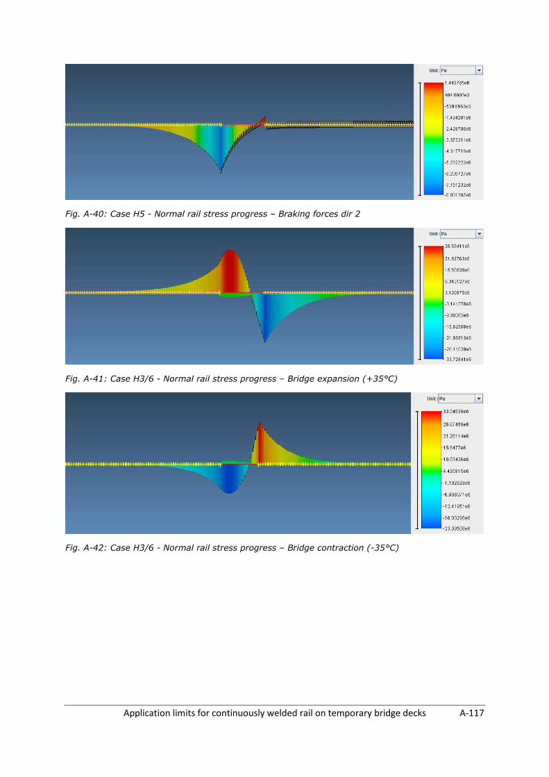
Application limits for continuously welded rail on temporary bridge decks A-117
Fig. A-40: Case H5 - Normal rail stress progress – Braking forces dir 2
Fig. A-41: Case H3/6 - Normal rail stress progress – Bridge expansion (+35°C)
Fig. A-42: Case H3/6 - Normal rail stress progress – Bridge contraction (-35°C)

Application limits for continuously welded rail on temporary bridge decks A-118
8 CASE I – BRIDGE BENDING STIFFNESS – 0.02 M4
Fig. A-43: Case I1 - Normal rail stress progress – Vertical forces dir 1
Fig. A-44: Case I2 - Normal rail stress progress – Braking forces dir 1
Fig. A-45: Case I4 - Normal rail stress progress – Vertical forces dir 2
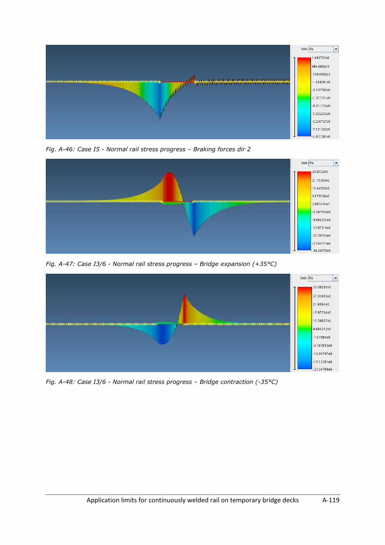
Application limits for continuously welded rail on temporary bridge decks A-119
Fig. A-46: Case I5 - Normal rail stress progress – Braking forces dir 2
Fig. A-47: Case I3/6 - Normal rail stress progress – Bridge expansion (+35°C)
Fig. A-48: Case I3/6 - Normal rail stress progress – Bridge contraction (-35°C)

Application limits for continuously welded rail on temporary bridge decks A-120
9 CASE J – LONG RESISTANCE FASTENER – MODERATE CLAMPING
Fig. A-49: Case J1 - Normal rail stress progress – Vertical forces dir 1
Fig. A-50: Case J2 - Normal rail stress progress – Braking forces dir 1
Fig. A-51: Case J4 - Normal rail stress progress – Vertical forces dir 2

Application limits for continuously welded rail on temporary bridge decks A-121
Fig. A-52: Case J5 - Normal rail stress progress – Braking forces dir 2
Fig. A-53: Case J3/6 - Normal rail stress progress – Bridge expansion (+35°C)
Fig. A-54: Case J3/6 - Normal rail stress progress – Bridge contraction (-35°C)

Application limits for continuously welded rail on temporary bridge decks A-122
10 CASE K – LONG RESISTANCE FASTENER – EXCELLENT CLAMPING
Fig. A-55: Case K1 - Normal rail stress progress – Vertical forces dir 1
Fig. A-56: Case K2 - Normal rail stress progress – Braking forces dir 1
Fig. A-57: Case K4 - Normal rail stress progress – Vertical forces dir 2

Application limits for continuously welded rail on temporary bridge decks A-123
Fig. A-58: Case K5 - Normal rail stress progress – Braking forces dir 2
Fig. A-59: Case K3/6 - Normal rail stress progress – Bridge expansion (+35°C)
Fig. A-60: Case K3/6 - Normal rail stress progress – Bridge contraction (-35°C)
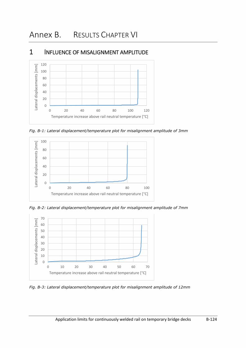
Application limits for continuously welded rail on temporary bridge decks B-124
Annex B. RESULTS CHAPTER VI
1 INFLUENCE OF MISALIGNMENT AMPLITUDE
Fig. B-1: Lateral displacement/temperature plot for misalignment amplitude of 3mm
Fig. B-2: Lateral displacement/temperature plot for misalignment amplitude of 7mm
Fig. B-3: Lateral displacement/temperature plot for misalignment amplitude of 12mm
0
20
40
60
80
100
120
0 20 40 60 80 100 120Late
ral d
isp
lace
men
ts [
mm
]
Temperature increase above rail neutral temperature [°C]
0
20
40
60
80
100
0 20 40 60 80 100Late
ral d
isp
lace
men
ts [
mm
]
Temperature increase above rail neutral temperature [°C]
0
10
20
30
40
50
60
70
0 10 20 30 40 50 60 70
Late
ral d
isp
lace
men
ts [
mm
]
Temperature increase above rail neutral temperature [°C]
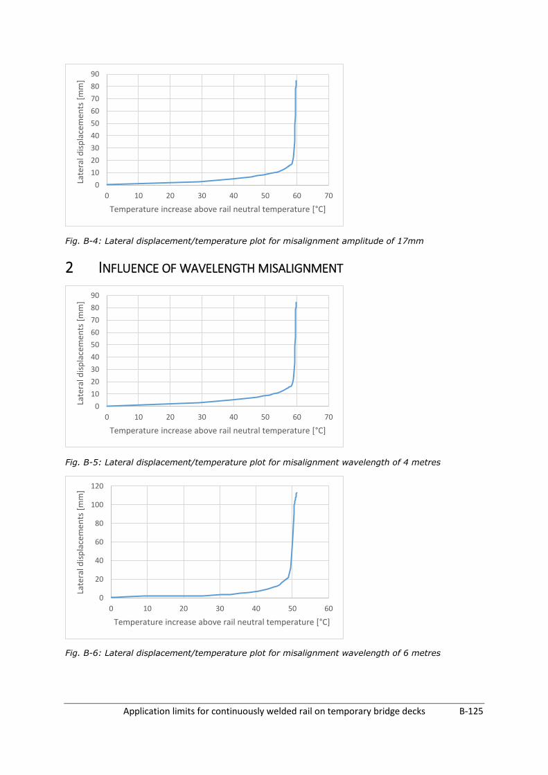
Application limits for continuously welded rail on temporary bridge decks B-125
Fig. B-4: Lateral displacement/temperature plot for misalignment amplitude of 17mm
2 INFLUENCE OF WAVELENGTH MISALIGNMENT
Fig. B-5: Lateral displacement/temperature plot for misalignment wavelength of 4 metres
Fig. B-6: Lateral displacement/temperature plot for misalignment wavelength of 6 metres
0
10
20
30
40
50
60
70
80
90
0 10 20 30 40 50 60 70
Late
ral d
isp
lace
men
ts [
mm
]
Temperature increase above rail neutral temperature [°C]
0
10
20
30
40
50
60
70
80
90
0 10 20 30 40 50 60 70
Late
ral d
isp
lace
men
ts [
mm
]
Temperature increase above rail neutral temperature [°C]
0
20
40
60
80
100
120
0 10 20 30 40 50 60
Late
ral d
isp
lace
men
ts [
mm
]
Temperature increase above rail neutral temperature [°C]
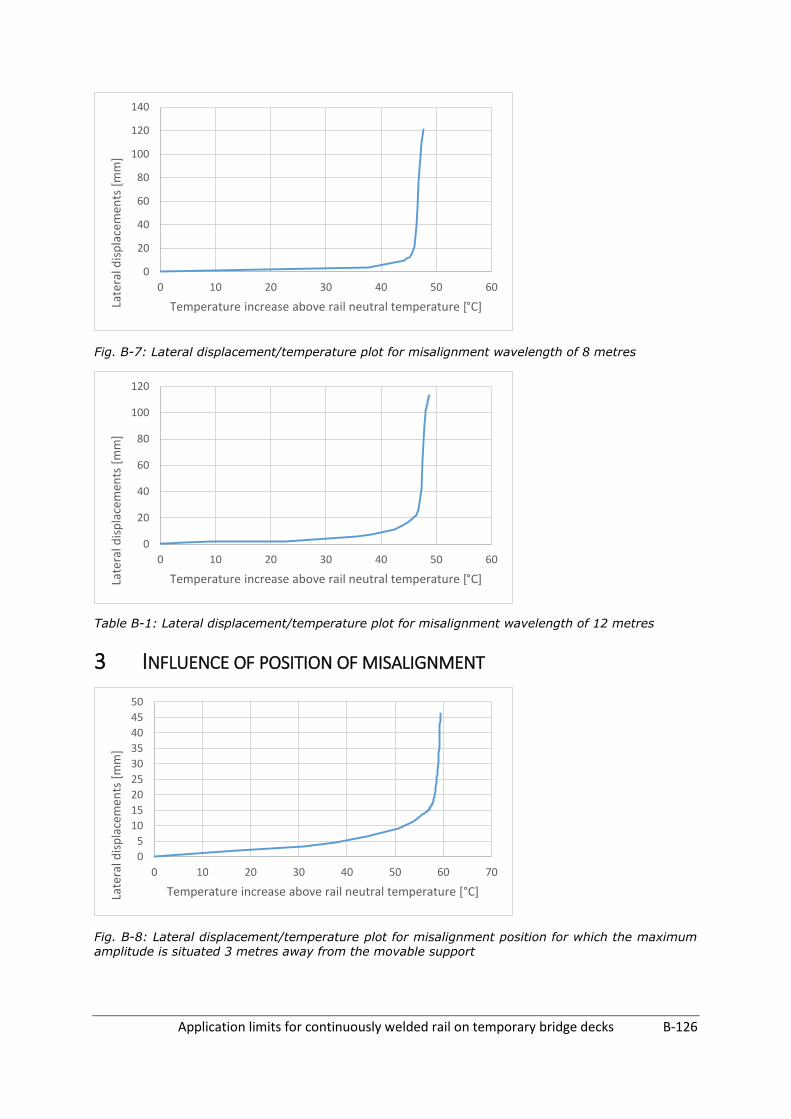
Application limits for continuously welded rail on temporary bridge decks B-126
Fig. B-7: Lateral displacement/temperature plot for misalignment wavelength of 8 metres
Table B-1: Lateral displacement/temperature plot for misalignment wavelength of 12 metres
3 INFLUENCE OF POSITION OF MISALIGNMENT
Fig. B-8: Lateral displacement/temperature plot for misalignment position for which the maximum amplitude is situated 3 metres away from the movable support
0
20
40
60
80
100
120
140
0 10 20 30 40 50 60
Late
ral d
isp
lace
men
ts [
mm
]
Temperature increase above rail neutral temperature [°C]
0
20
40
60
80
100
120
0 10 20 30 40 50 60
Late
ral d
isp
lace
men
ts [
mm
]
Temperature increase above rail neutral temperature [°C]
0
5
10
15
20
25
30
35
40
45
50
0 10 20 30 40 50 60 70
Late
ral d
isp
lace
men
ts [
mm
]
Temperature increase above rail neutral temperature [°C]

Application limits for continuously welded rail on temporary bridge decks B-127
Fig. B-9: Lateral displacement/temperature plot for misalignment position for which the maximum amplitude is situated 7 metres away from the movable support
Fig. B-10: Lateral displacement/temperature plot for misalignment position for which the maximum amplitude is situated 11 metres away from the movable support
Fig. B-11: Lateral displacement/temperature plot for misalignment position for which the maximum amplitude is situated 15 metres away from the movable support
0
10
20
30
40
50
60
70
80
90
100
0 10 20 30 40 50 60 70
Late
ral d
isp
lace
men
ts [
mm
]
Temperature increase above rail neutral temperature [°C]
0
10
20
30
40
50
60
70
80
90
100
0 10 20 30 40 50 60 70
Late
ral d
isp
lace
men
ts [
mm
]
Temperature increase above rail neutral temperature [°C]
0
10
20
30
40
50
60
70
80
90
100
0 10 20 30 40 50 60 70
Late
ral d
isp
lace
men
ts [
mm
]
Temperature increase above rail neutral temperature [°C]
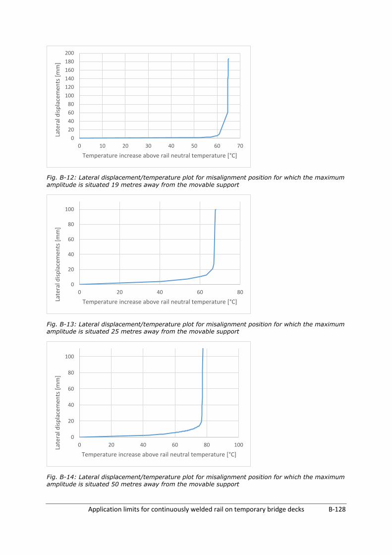
Application limits for continuously welded rail on temporary bridge decks B-128
Fig. B-12: Lateral displacement/temperature plot for misalignment position for which the maximum
amplitude is situated 19 metres away from the movable support
Fig. B-13: Lateral displacement/temperature plot for misalignment position for which the maximum amplitude is situated 25 metres away from the movable support
Fig. B-14: Lateral displacement/temperature plot for misalignment position for which the maximum amplitude is situated 50 metres away from the movable support
0
20
40
60
80
100
120
140
160
180
200
0 10 20 30 40 50 60 70
Late
ral d
isp
lace
men
ts [
mm
]
Temperature increase above rail neutral temperature [°C]
0
20
40
60
80
100
0 20 40 60 80
Late
ral d
isp
lace
men
ts [
mm
]
Temperature increase above rail neutral temperature [°C]
0
20
40
60
80
100
0 20 40 60 80 100Late
ral d
isp
lace
men
ts [
mm
]
Temperature increase above rail neutral temperature [°C]

Application limits for continuously welded rail on temporary bridge decks B-129
4 INFLUENCE OF LATERAL BALLAST RESISTANCE
Fig. B-15: Lateral displacement/temperature plot for lateral ballast resistance of 2 kN
Fig. B-16: Lateral displacement/temperature plot for lateral ballast resistance of 4 kN
Fig. B-17: Lateral displacement/temperature plot for lateral ballast resistance of 6 kN
0
5
10
15
20
25
30
35
0 20 40 60 80
Late
ral d
isp
lace
men
ts [
mm
]
Temperature increase above rail neutral temperature [°C]
0
10
20
30
40
50
60
70
80
90
0 20 40 60 80 100
Late
ral d
isp
lace
men
ts [
mm
]
Temperature increase above rail neutral temperature [°C]
0
20
40
60
80
100
120
0 20 40 60 80 100 120
Late
ral d
isp
lace
men
ts [
mm
]
Temperature increase above rail neutral temperature [°C]

Application limits for continuously welded rail on temporary bridge decks B-130
Fig. B-18: Lateral displacement/temperature plot for lateral ballast resistance of 8 kN
Fig. B-19: Lateral displacement/temperature plot for lateral ballast resistance of 10 kN
5 INFLUENCE OF LONGITUDINAL BALLAST RESISTANCE ON EMBANKMENTS
Fig. B-20: Lateral displacement/temperature plot for longitudinal ballast resistance of 10 kN
0
20
40
60
80
100
120
140
0 20 40 60 80 100 120 140
Late
ral d
isp
lace
men
ts [
mm
]
Temperature increase above rail neutral temperature [°C]
0
20
40
60
80
100
120
140
0 50 100 150
Late
ral d
isp
lace
men
ts [
mm
]
Temperature increase above rail neutral temperature [°C]
0
20
40
60
80
100
120
0 20 40 60 80 100 120
Late
ral d
isp
lace
men
ts [
mm
]
Temperature increase above rail neutral temperature [°C]

Application limits for continuously welded rail on temporary bridge decks B-131
Fig. B-21: Lateral displacement/temperature plot for longitudinal ballast resistance of 30 kN
Fig. B-22: Lateral displacement/temperature plot for longitudinal ballast resistance of 40 kN
6 INFLUENCE OF LONGITUDINAL RESISTANCE OF FASTENERS ON
TEMPORARY BRIDGE DECK
Fig. B-23: Lateral displacement/temperature plot for longitudinal fastener resistance on temporary bridge deck of 30 kN
0
20
40
60
80
100
120
0 20 40 60 80 100 120
Late
ral d
isp
lace
men
ts [
mm
]
Temperature increase above rail neutral temperature [°C]
0
20
40
60
80
100
120
0 20 40 60 80 100 120
Late
ral d
isp
lace
men
ts [
mm
]
Temperature increase above rail neutral temperature [°C]
0
20
40
60
80
100
120
140
0 20 40 60 80 100 120
Late
ral d
isp
lace
men
ts [
mm
]
Temperature increase above rail neutral temperature [°C]

Application limits for continuously welded rail on temporary bridge decks B-132
Fig. B-24: Lateral displacement/temperature plot for longitudinal fastener resistance on temporary
bridge deck of 50 kN
Fig. B-25: Lateral displacement/temperature plot for longitudinal fastener resistance on temporary bridge deck of 60 kN
7 SPAN LENGTH
Fig. B-26: Lateral displacement/temperature plot for span length of 10 metres
0
20
40
60
80
100
120
140
0 20 40 60 80 100 120
Late
ral d
isp
lace
men
ts [
mm
]
Temperature increase above rail neutral temperature [°C]
0
20
40
60
80
100
120
140
0 20 40 60 80 100 120
Late
ral d
isp
lace
men
ts [
mm
]
Temperature increase above rail neutral temperature [°C]
0
20
40
60
80
100
120
0 20 40 60 80 100 120
Late
ral d
isp
lace
men
ts [
mm
]
Temperature increase above rail neutral temperature [°C]
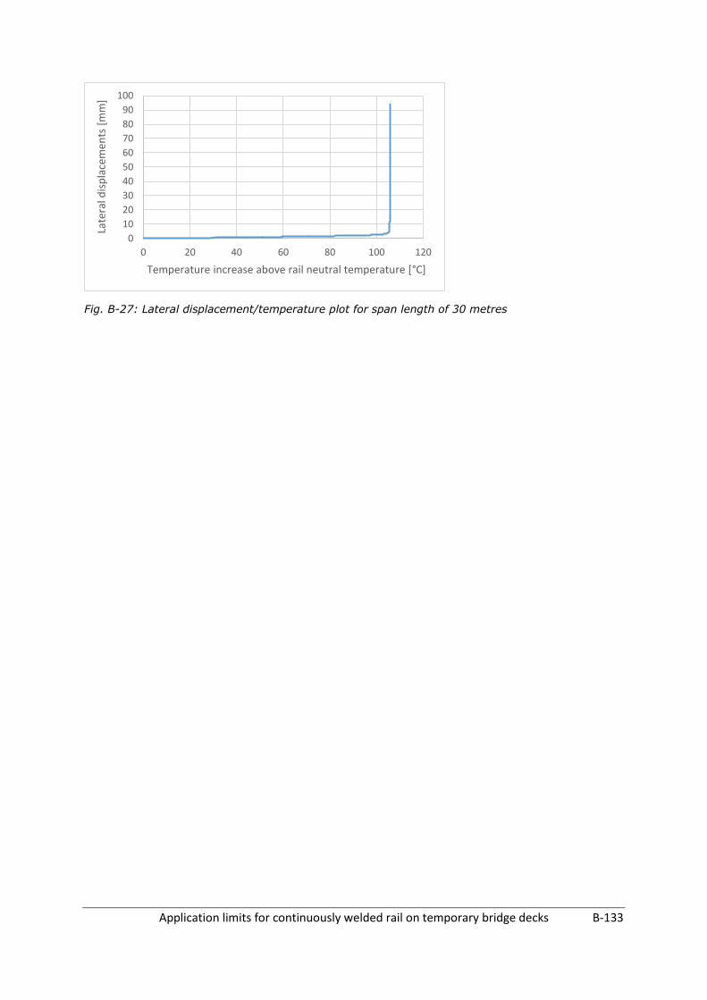
Application limits for continuously welded rail on temporary bridge decks B-133
Fig. B-27: Lateral displacement/temperature plot for span length of 30 metres
0
10
20
30
40
50
60
70
80
90
100
0 20 40 60 80 100 120
Late
ral d
isp
lace
men
ts [
mm
]
Temperature increase above rail neutral temperature [°C]

Application limits for continuously welded rail on temporary bridge decks C-134
Annex C. Table C-1: Overview of available temporary bridge decks used by INFRABEL
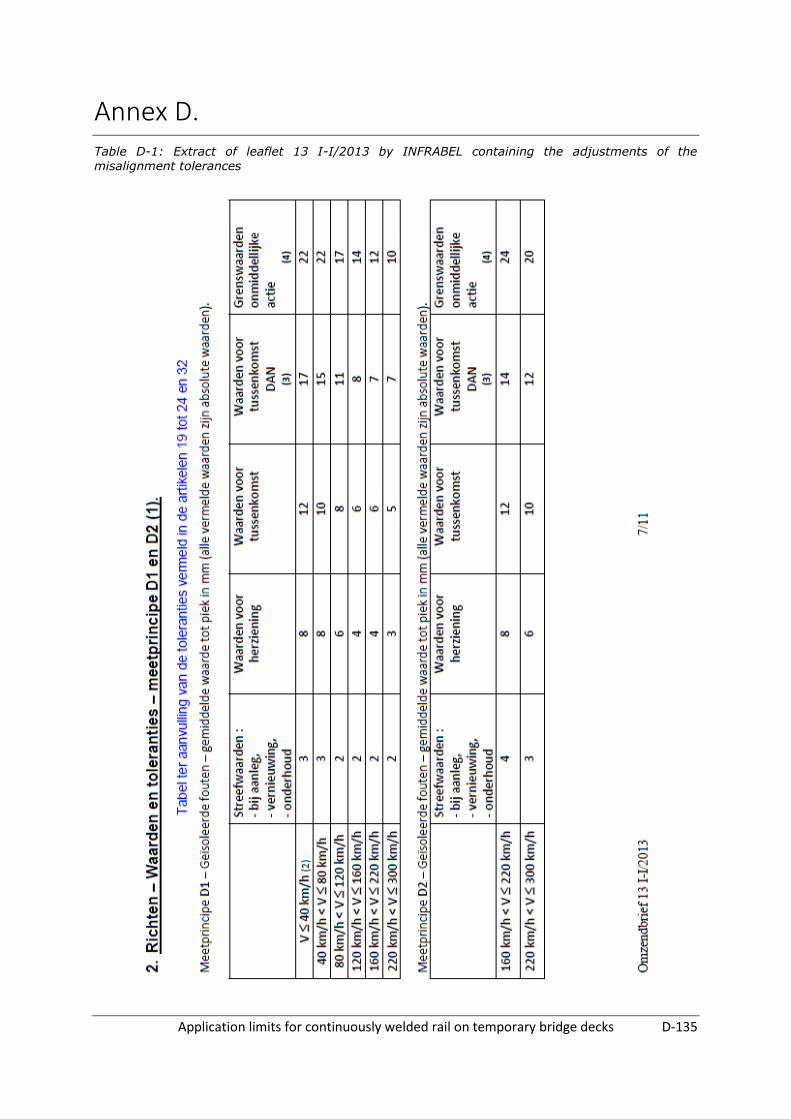
Application limits for continuously welded rail on temporary bridge decks D-135
Annex D. Table D-1: Extract of leaflet 13 I-I/2013 by INFRABEL containing the adjustments of the misalignment tolerances