application manual ref630 feeder protection and control€¦ · the function can be enabled and...
TRANSCRIPT

—RELION® 630 SERIES
Feeder Protection and ControlREF630Application Manual


Document ID: 1MRS756510Issued: 2019-02-25
Revision: FProduct version: 1.3
© Copyright 2019 ABB. All rights reserved

Copyright
This document and parts thereof must not be reproduced or copied without writtenpermission from ABB, and the contents thereof must not be imparted to a third party,nor used for any unauthorized purpose.
The software or hardware described in this document is furnished under a license andmay be used, copied, or disclosed only in accordance with the terms of such license.
TrademarksABB and Relion are registered trademarks of the ABB Group. All other brand orproduct names mentioned in this document may be trademarks or registeredtrademarks of their respective holders.
WarrantyPlease inquire about the terms of warranty from your nearest ABB representative.
www.abb.com/relion

Disclaimer
The data, examples and diagrams in this manual are included solely for the concept orproduct description and are not to be deemed as a statement of guaranteed properties.All persons responsible for applying the equipment addressed in this manual mustsatisfy themselves that each intended application is suitable and acceptable, includingthat any applicable safety or other operational requirements are complied with. Inparticular, any risks in applications where a system failure and/or product failurewould create a risk for harm to property or persons (including but not limited topersonal injuries or death) shall be the sole responsibility of the person or entityapplying the equipment, and those so responsible are hereby requested to ensure thatall measures are taken to exclude or mitigate such risks.
This product has been designed to be connected and communicate data andinformation via a network interface which should be connected to a secure network.It is the sole responsibility of the person or entity responsible for networkadministration to ensure a secure connection to the network and to take the necessarymeasures (such as, but not limited to, installation of firewalls, application ofauthentication measures, encryption of data, installation of anti virus programs, etc.)to protect the product and the network, its system and interface included, against anykind of security breaches, unauthorized access, interference, intrusion, leakage and/ortheft of data or information. ABB is not liable for any such damages and/or losses.
This document has been carefully checked by ABB but deviations cannot becompletely ruled out. In case any errors are detected, the reader is kindly requested tonotify the manufacturer. Other than under explicit contractual commitments, in noevent shall ABB be responsible or liable for any loss or damage resulting from the useof this manual or the application of the equipment.

Conformity
This product complies with the directive of the Council of the European Communitieson the approximation of the laws of the Member States relating to electromagneticcompatibility (EMC Directive 2004/108/EC) and concerning electrical equipment foruse within specified voltage limits (Low-voltage directive 2006/95/EC). Thisconformity is the result of tests conducted by ABB in accordance with the productstandards EN 50263 and EN 60255-26 for the EMC directive, and with the productstandards EN 60255-1 and EN 60255-27 for the low voltage directive. The product isdesigned in accordance with the international standards of the IEC 60255 series.

Table of contents
Section 1 Introduction.......................................................................5This manual........................................................................................ 5Intended audience.............................................................................. 5Product documentation.......................................................................6
Product documentation set............................................................6Document revision history............................................................. 6Related documentation..................................................................7
Symbols and conventions...................................................................7Symbols.........................................................................................7Document conventions..................................................................8Functions, codes and symbols...................................................... 8
Section 2 REF630 overview...........................................................13Overview...........................................................................................13
Product version history................................................................13PCM600 and IED connectivity package version..........................13
Operation functionality......................................................................14Product variants...........................................................................14Optional functions........................................................................14
Physical hardware............................................................................ 15Local HMI......................................................................................... 16
Display.........................................................................................16LEDs............................................................................................19Keypad........................................................................................ 19
Web HMI...........................................................................................19Authorization.....................................................................................21Communication.................................................................................21
Section 3 REF630 variants.............................................................23Presentation of preconfigurations.....................................................23
Preconfigurations.........................................................................24Preconfiguration A for open/closed ring feeder................................ 27
Application...................................................................................27Functions.....................................................................................28Input/output signal interfaces.......................................................29Preprocessing blocks and fixed signals ......................................30Control functions..........................................................................31
Bay control QCCBAY............................................................. 31Apparatus control SCILO, GNRLCSWI, DAXCBR, DAXSWI.31Autoreclosing DARREC......................................................... 33
Table of contents
REF630 1Application Manual
Protection functions.....................................................................34Three-phase current inrush detection INRPHAR................... 34Non-directional overcurrent protection PHxPTOC................. 34Directional overcurrent protection DPHxPDOC......................35Negative-sequence overcurrent protection NSPTOC............ 36Phase discontinuity protection PDNSPTOC...........................37Non-directional earth-fault protection EFxPTOC....................37Intermittent earth-fault protection INTRPTEF.........................37Directional earth-fault protection DEFxPDEF.........................38Thermal overload protection T1PTTR.................................... 39Circuit-breaker failure protection CCBRBRF..........................39Tripping logic TRPPTRC........................................................ 39Combined operate and start alarm signal.............................. 40Other output and alarm signals.............................................. 41
Supervision functions.................................................................. 41Trip circuit supervision TCSSCBR......................................... 41Fuse failure and current circuit supervision SEQRFUF,CCRDIF..................................................................................41Circuit-breaker condition monitoring SSCBR......................... 41
Measurement and analog recording functions............................ 42Binary recording and LED configuration......................................44
Preconfiguration B for radial overhead/mixed line feeder.................46Application...................................................................................46Functions.....................................................................................47Input/output signal interfaces.......................................................48Preprocessing blocks and fixed signals ......................................49Control functions..........................................................................50
Bay control QCCBAY............................................................. 50Apparatus control SCILO, GNRLCSWI, DAXCBR, DAXSWI.50Autoreclosing DARREC......................................................... 52
Protection functions.....................................................................53Three-phase current inrush detection INRPHAR................... 53Non-directional overcurrent protection PHxPTOC................. 53Negative-sequence overcurrent protection NSPTOC............ 54Phase discontinuity protection PDNSPTOC...........................55Non-directional earth-fault protection EFxPTOC....................55Directional earth-fault protection DEFxPDEF ........................55Thermal overload protection T1PTTR.................................... 56Circuit-breaker failure protection CCBRBRF..........................57Tripping logic TRPPTRC........................................................ 57Combined operate and start alarm signal.............................. 58Other output and alarm signals.............................................. 58
Supervision functions.................................................................. 58
Table of contents
2 REF630Application Manual

Trip circuit supervision TCSSCBR......................................... 58Fuse failure and current circuit supervision SEQRFUF,CCRDIF..................................................................................58Circuit-breaker condition monitoring SSCBR......................... 59
Measurement and analog recording functions............................ 59Binary recording and LED configuration......................................61
Preconfiguration C for ring/meshed feeder.......................................63Application...................................................................................63Functions.....................................................................................65Input/output signal interfaces.......................................................66Preprocessing blocks and fixed signals ......................................67Control functions..........................................................................68
Bay control QCCBAY............................................................. 68Apparatus control SCILO, GNRLCSWI, DAXCBR, DAXSWI.68Autoreclosing DARREC......................................................... 70
Protection functions.....................................................................72Three-phase current inrush detection INRPHAR................... 72Non-directional overcurrent protection PHxPTOC................. 72Negative-sequence overcurrent protection NSPTOC............ 73Phase discontinuity protection PDNSPTOC...........................74Non-directional earth-fault protection EFxPTOC....................74Directional earth-fault protection DEFxPDEF.........................75Three-phase overvoltage protection PHPTOV.......................76Three-phase undervoltage protection PHPTUV.....................77Three-phase residual overvoltage protection ROVPTOV...... 78Distance protection DSTPDIS................................................ 78Automatic switch onto fault logic CVRSOF............................ 79Local acceleration logic DSTPLAL......................................... 79Scheme communication logic for distance protectionDSOCPSCH........................................................................... 80Current reversal and weak-end infeed logic for distanceprotection CRWPSCH............................................................ 81Scheme communication logic for residual overcurrentprotection RESCPSCH...........................................................82Current reversal and scheme communication logic forresidual overcurrent RCRWPSCH......................................... 83Thermal overload protection T1PTTR.................................... 84Circuit-breaker failure protection CCBRBRF..........................85Tripping logic TRPPTRC........................................................ 85Combined operate and start alarm signal.............................. 86Other output and alarm signals.............................................. 86
Supervision functions.................................................................. 87Trip circuit supervision TCSSCBR......................................... 87
Table of contents
REF630 3Application Manual
Fuse failure and current circuit supervision SEQRFUF,CCRDIF..................................................................................87Circuit-breaker condition monitoring SSCBR......................... 87
Measurement and analog recording functions............................ 88Binary recording and LED configuration......................................90
Preconfiguration D for bus sectionalizer ..........................................93Application...................................................................................93Functions.....................................................................................94Input/output signal interfaces.......................................................95Preprocessing blocks and fixed signals ......................................96Control functions..........................................................................96
Bay control QCCBAY............................................................. 96Apparatus control................................................................... 97
Protection functions.....................................................................98Three-phase current inrush detection INRPHAR................... 98Non-directional overcurrent protection PHxPTOC................. 98Negative-sequence overcurrent protection NSPTOC............ 98Non-directional earth-fault protection EFxPTOC....................99Circuit-breaker failure protection CCBRBRF........................100Tripping logic TRPPTRC...................................................... 100Combined operate and start alarm signal............................ 101Other output and alarm signals............................................ 101
Supervision functions................................................................ 102Trip circuit supervision TCSSCBR....................................... 102Circuit-breaker condition monitoring SSCBR....................... 102
Measurement and analog recording functions.......................... 103Binary recording and LED configurations..................................104
Section 4 Requirements for measurement transformers..............107Current transformers...................................................................... 107
Current transformer requirements for overcurrent protection.... 107Current transformer accuracy class and accuracy limitfactor.................................................................................... 107Non-directional overcurrent protection................................. 108Example for non-directional overcurrent protection..............109
Section 5 Glossary....................................................................... 111
Table of contents
4 REF630Application Manual

Section 1 Introduction
1.1 This manual
The application manual contains descriptions of preconfigurations. The manual canbe used as a reference for configuring control, protection, measurement, recording andLED functions. The manual can also be used when creating configurations accordingto specific application requirements.
1.2 Intended audience
This manual addresses the protection and control engineer responsible for planning,pre-engineering and engineering.
The protection and control engineer must be experienced in electrical powerengineering and have knowledge of related technology, such as protection schemesand principles.
1MRS756510 F Section 1Introduction
REF630 5Application Manual

1.3 Product documentation
1.3.1 Product documentation set
Pla
nnin
g &
pu
rcha
se
Eng
inee
ring
Inst
alla
tion
Com
mis
sion
ing
Ope
ratio
n
Mai
nten
ance
Dec
omm
issi
onin
g,
dein
stal
latio
n &
dis
posa
l
Quick start guide
Quick installation guide
Brochure
Product guide
Operation manual
Installation manual
Engineering manual
Technical manual
Application manual
Communication protocol manual
Point list manual
Commissioning manual
GUID-C8721A2B-EEB9-4880-A812-849E1A42B02C V1 EN
Figure 1: The intended use of documents during the product life cycle
Product series- and product-specific manuals can be downloadedfrom the ABB Web site http://www.abb.com/relion.
1.3.2 Document revision historyDocument revision/date Product version HistoryA/2009-09-15 1.0 First release
B/2011-02-23 1.1 Content updated to correspond to theproduct version
C/2011–05-18 1.1 Content updated
D/2012-08-29 1.2 Content updated to correspond to theproduct version
E/2014-11-28 1.3 Content updated to correspond to theproduct version
F/2019-02-25 1.3 Content updated
Section 1 1MRS756510 FIntroduction
6 REF630Application Manual

Download the latest documents from the ABB Web sitehttp://www.abb.com/substationautomation.
1.3.3 Related documentationName of the document Document IDDNP3 Communication Protocol Manual 1MRS756789
IEC 61850 Communication Protocol Manual 1MRS756793
IEC 60870-5-103 Communication Protocol Manual 1MRS757203
Installation Manual 1MRS755958
Operation Manual 1MRS756509
Technical Manual 1MRS756508
Engineering Manual 1MRS756800
Commissioning Manual 1MRS756801
1.4 Symbols and conventions
1.4.1 Symbols
The electrical warning icon indicates the presence of a hazard whichcould result in electrical shock.
The warning icon indicates the presence of a hazard which couldresult in personal injury.
The caution icon indicates important information or warning relatedto the concept discussed in the text. It might indicate the presence ofa hazard which could result in corruption of software or damage toequipment or property.
The information icon alerts the reader of important facts andconditions.
The tip icon indicates advice on, for example, how to design yourproject or how to use a certain function.
1MRS756510 F Section 1Introduction
REF630 7Application Manual
Although warning hazards are related to personal injury, it is necessary to understandthat under certain operational conditions, operation of damaged equipment may resultin degraded process performance leading to personal injury or death. Therefore,comply fully with all warning and caution notices.
1.4.2 Document conventions
A particular convention may not be used in this manual.
• Abbreviations and acronyms are spelled out in the glossary. The glossary alsocontains definitions of important terms.
• Push button navigation in the LHMI menu structure is presented by using thepush button icons.To navigate between the options, use and .
• Menu paths are presented in bold.Select Main menu/Settings.
• WHMI menu names are presented in bold.Click Information in the WHMI menu structure.
• LHMI messages are shown in Courier font.To save the changes in nonvolatile memory, select Yes and press .
• Parameter names are shown in italics.The function can be enabled and disabled with the Operation setting.
• The ^ character in front of an input or output signal name in the function blocksymbol given for a function, indicates that the user can set an own signal name inPCM600.
• The * character after an input or output signal name in the function block symbolgiven for a function, indicates that the signal must be connected to anotherfunction block in the application configuration to achieve a valid applicationconfiguration.
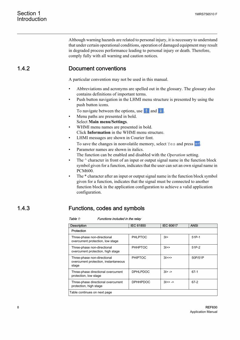
1.4.3 Functions, codes and symbolsTable 1: Functions included in the relay
Description IEC 61850 IEC 60617 ANSIProtection
Three-phase non-directionalovercurrent protection, low stage
PHLPTOC 3I> 51P-1
Three-phase non-directionalovercurrent protection, high stage
PHHPTOC 3I>> 51P-2
Three-phase non-directionalovercurrent protection, instantaneousstage
PHIPTOC 3I>>> 50P/51P
Three-phase directional overcurrentprotection, low stage
DPHLPDOC 3I> -> 67-1
Three-phase directional overcurrentprotection, high stage
DPHHPDOC 3I>> -> 67-2
Table continues on next page
Section 1 1MRS756510 FIntroduction
8 REF630Application Manual

Description IEC 61850 IEC 60617 ANSIDistance protection DSTPDIS Z< 21, 21P, 21N
Automatic switch-onto-fault logic CVRSOF SOTF SOTF
Fault locator SCEFRFLO FLOC 21FL
Autoreclosing DARREC O -> I 79
Non-directional earth-fault protection,low stage
EFLPTOC I0> 51N-1
Non-directional earth-fault protection,high stage
EFHPTOC I0>> 51N-2
Non-directional earth-fault protection,instantaneous stage
EFIPTOC I0>>> 50N/51N
Directional earth-fault protection, lowstage
DEFLPDEF I0> -> 67N-1
Directional earth-fault protection, highstage
DEFHPDEF I0>> -> 67N-2
Harmonics based earth-fault protection HAEFPTOC Io>HA 51NHA
Transient/intermittent earth-faultprotection
INTRPTEF I0> -> IEF 67NIEF
Admittance-based earth-fault protection EFPADM Yo>-> 21YN
Multi-frequency admittance-basedearth-fault protection
MFADPSDE I0> ->Y 67YN
Wattmetric earth-fault protection WPWDE Po>-> 32N
Phase discontinuity protection PDNSPTOC I2/I1> 46PD
Negative-sequence overcurrentprotection
NSPTOC I2> 46
Three-phase thermal overloadprotection for feeder
T1PTTR 3Ith>F 49F
Three-phase current inrush detection INRPHAR 3I2f> 68
Three-phase overvoltage protection PHPTOV 3U> 59
Three-phase undervoltage protection PHPTUV 3U< 27
Positive-sequence overvoltageprotection
PSPTOV U1> 47O+
Positive-sequence undervoltageprotection
PSPTUV U1< 47U+
Negative-sequence overvoltageprotection
NSPTOV U2> 47O-
Residual overvoltage protection ROVPTOV U0> 59G
Directional reactive power undervoltageprotection
DQPTUV Q>-->,3U< 32Q,27
Reverse power/directional overpowerprotection
DOPPDPR P> 32R/32O
Frequency gradient protection DAPFRC df/dt> 81R
Overfrequency protection DAPTOF f> 81O
Underfrequency protection DAPTUF f< 81U
Load shedding LSHDPFRQ UFLS/R 81LSH
Circuit breaker failure protection CCBRBRF 3I>/I0>BF 51BF/51NBF
Table continues on next page
1MRS756510 F Section 1Introduction
REF630 9Application Manual
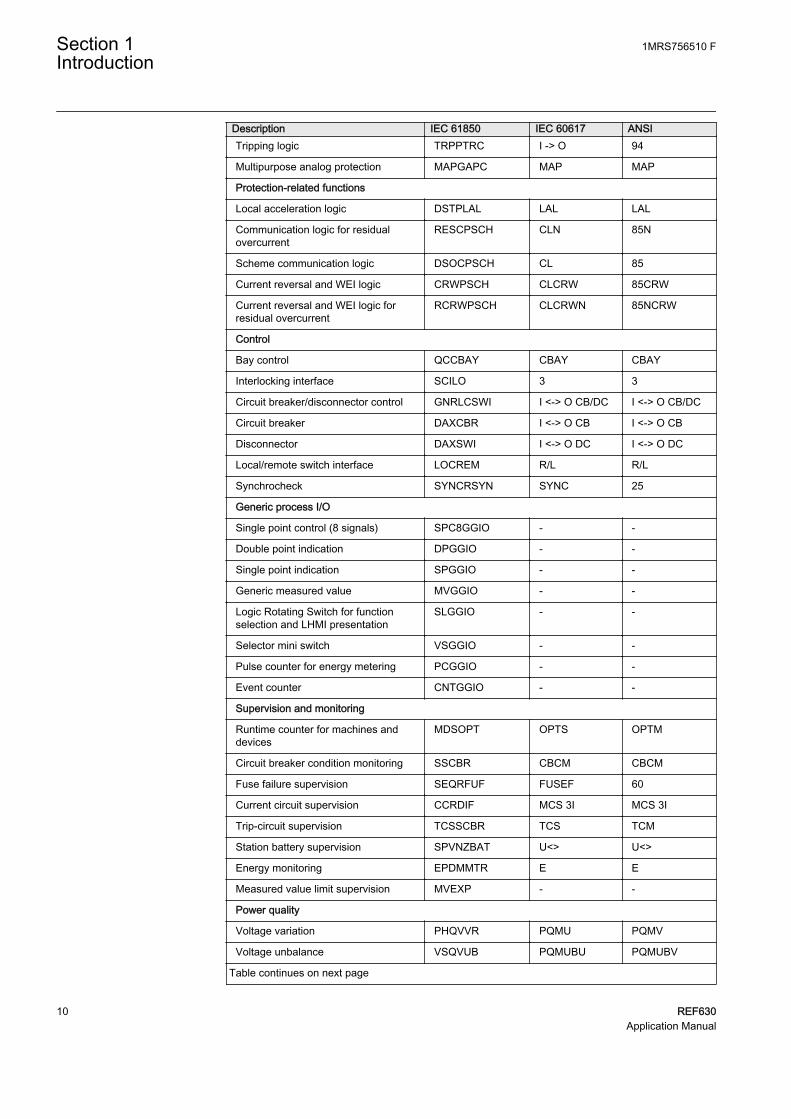
Description IEC 61850 IEC 60617 ANSITripping logic TRPPTRC I -> O 94
Multipurpose analog protection MAPGAPC MAP MAP
Protection-related functions
Local acceleration logic DSTPLAL LAL LAL
Communication logic for residualovercurrent
RESCPSCH CLN 85N
Scheme communication logic DSOCPSCH CL 85
Current reversal and WEI logic CRWPSCH CLCRW 85CRW
Current reversal and WEI logic forresidual overcurrent
RCRWPSCH CLCRWN 85NCRW
Control
Bay control QCCBAY CBAY CBAY
Interlocking interface SCILO 3 3
Circuit breaker/disconnector control GNRLCSWI I <-> O CB/DC I <-> O CB/DC
Circuit breaker DAXCBR I <-> O CB I <-> O CB
Disconnector DAXSWI I <-> O DC I <-> O DC
Local/remote switch interface LOCREM R/L R/L
Synchrocheck SYNCRSYN SYNC 25
Generic process I/O
Single point control (8 signals) SPC8GGIO - -
Double point indication DPGGIO - -
Single point indication SPGGIO - -
Generic measured value MVGGIO - -
Logic Rotating Switch for functionselection and LHMI presentation
SLGGIO - -
Selector mini switch VSGGIO - -
Pulse counter for energy metering PCGGIO - -
Event counter CNTGGIO - -
Supervision and monitoring
Runtime counter for machines anddevices
MDSOPT OPTS OPTM
Circuit breaker condition monitoring SSCBR CBCM CBCM
Fuse failure supervision SEQRFUF FUSEF 60
Current circuit supervision CCRDIF MCS 3I MCS 3I
Trip-circuit supervision TCSSCBR TCS TCM
Station battery supervision SPVNZBAT U<> U<>
Energy monitoring EPDMMTR E E
Measured value limit supervision MVEXP - -
Power quality
Voltage variation PHQVVR PQMU PQMV
Voltage unbalance VSQVUB PQMUBU PQMUBV
Table continues on next page
Section 1 1MRS756510 FIntroduction
10 REF630Application Manual

Description IEC 61850 IEC 60617 ANSICurrent harmonics CMHAI PQM3I PQM3I
Voltage harmonics (phase-to-phase) VPPMHAI PQM3Upp PQM3Vpp
Voltage harmonics (phase-to-earth) VPHMHAI PQM3Upe PQM3Vpg
Measurement
Three-phase current measurement CMMXU 3I 3I
Three-phase voltage measurement(phase-to-earth)
VPHMMXU 3Upe 3Upe
Three-phase voltage measurement(phase-to-phase)
VPPMMXU 3Upp 3Upp
Residual current measurement RESCMMXU I0 I0
Residual voltage measurement RESVMMXU U0 U0
Power monitoring with P, Q, S, powerfactor, frequency
PWRMMXU PQf PQf
Sequence current measurement CSMSQI I1, I2 I1, I2
Sequence voltage measurement VSMSQI U1, U2 V1, V2
Analog channels 1-10 (samples) A1RADR ACH1 ACH1
Analog channels 11-20 (samples) A2RADR ACH2 ACH2
Analog channels 21-30 (calc. val.) A3RADR ACH3 ACH3
Analog channels 31-40 (calc. val.) A4RADR ACH4 ACH4
Binary channels 1-16 B1RBDR BCH1 BCH1
Binary channels 17 -32 B2RBDR BCH2 BCH2
Binary channels 33 -48 B3RBDR BCH3 BCH3
Binary channels 49 -64 B4RBDR BCH4 BCH4
Station communication (GOOSE)
Binary receive GOOSEBINRCV - -
Double point receive GOOSEDPRCV - -
Interlock receive GOOSEINTLKRCV
- -
Integer receive GOOSEINTRCV - -
Measured value receive GOOSEMVRCV - -
Single point receive GOOSESPRCV - -
1MRS756510 F Section 1Introduction
REF630 11Application Manual

12
Section 2 REF630 overview
2.1 Overview
REF630 is a comprehensive feeder management relay for protection, control,measuring and supervision of utility and industrial distribution substations. REF630is a member of ABB’s Relion® product family and a part of its 630 series characterizedby functional scalability and flexible configurability. REF630 also features necessarycontrol functions constituting an ideal solution for feeder bay control.
The supported communication protocols including IEC 61850 offer seamlessconnectivity to industrial automation systems.
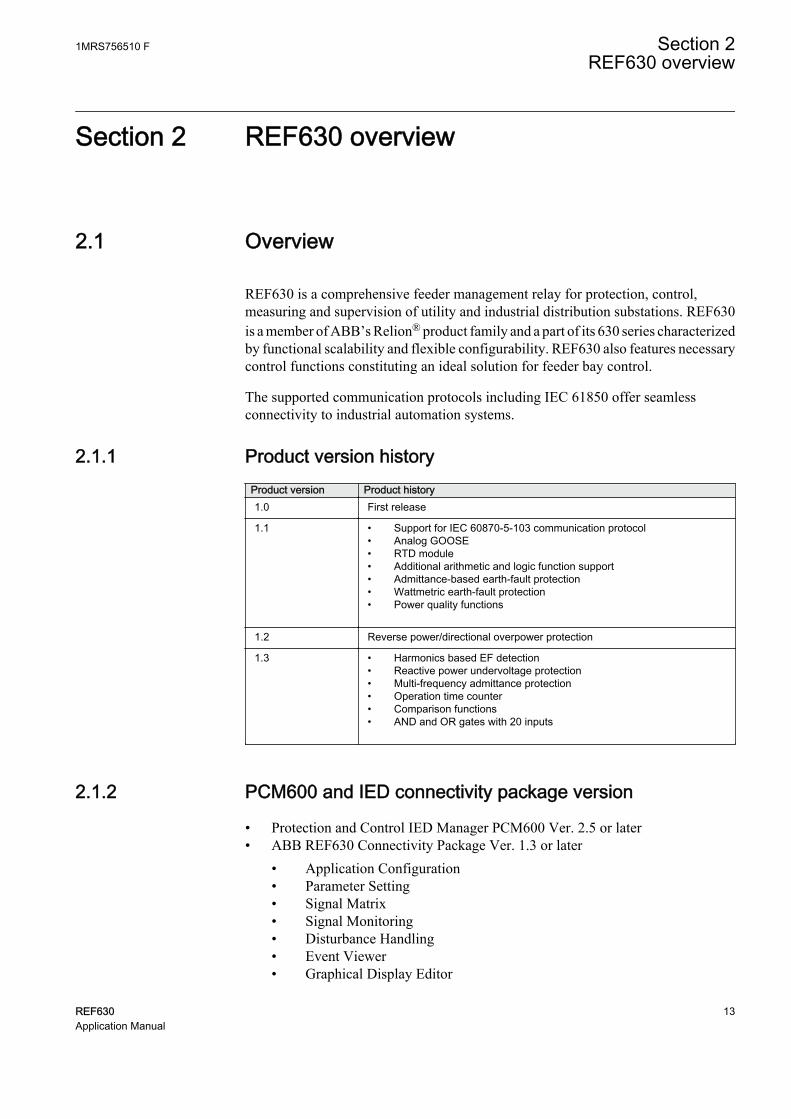
2.1.1 Product version historyProduct version Product history1.0 First release
1.1 • Support for IEC 60870-5-103 communication protocol• Analog GOOSE• RTD module• Additional arithmetic and logic function support• Admittance-based earth-fault protection• Wattmetric earth-fault protection• Power quality functions
1.2 Reverse power/directional overpower protection
1.3 • Harmonics based EF detection• Reactive power undervoltage protection• Multi-frequency admittance protection• Operation time counter• Comparison functions• AND and OR gates with 20 inputs
2.1.2 PCM600 and IED connectivity package version
• Protection and Control IED Manager PCM600 Ver. 2.5 or later• ABB REF630 Connectivity Package Ver. 1.3 or later
• Application Configuration• Parameter Setting• Signal Matrix• Signal Monitoring• Disturbance Handling• Event Viewer• Graphical Display Editor
1MRS756510 F Section 2REF630 overview
REF630 13Application Manual
• Hardware Configuration• IED Users• IED Compare• Communication Management• Configuration Migration
Download connectivity packages from the ABB Web sitehttp://www.abb.com/substationautomation or directly with UpdateManager in PCM600.
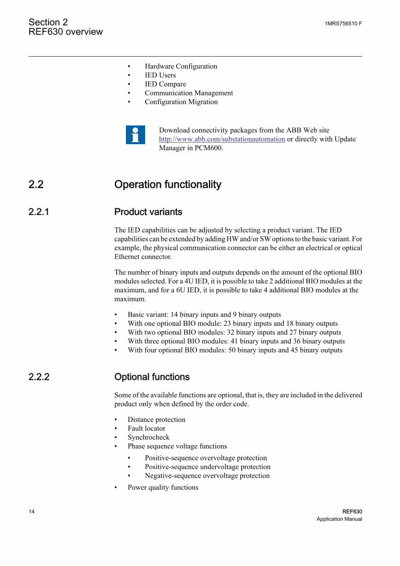
2.2 Operation functionality
2.2.1 Product variants
The IED capabilities can be adjusted by selecting a product variant. The IEDcapabilities can be extended by adding HW and/or SW options to the basic variant. Forexample, the physical communication connector can be either an electrical or opticalEthernet connector.
The number of binary inputs and outputs depends on the amount of the optional BIOmodules selected. For a 4U IED, it is possible to take 2 additional BIO modules at themaximum, and for a 6U IED, it is possible to take 4 additional BIO modules at themaximum.
• Basic variant: 14 binary inputs and 9 binary outputs• With one optional BIO module: 23 binary inputs and 18 binary outputs• With two optional BIO modules: 32 binary inputs and 27 binary outputs• With three optional BIO modules: 41 binary inputs and 36 binary outputs• With four optional BIO modules: 50 binary inputs and 45 binary outputs
2.2.2 Optional functions
Some of the available functions are optional, that is, they are included in the deliveredproduct only when defined by the order code.
• Distance protection• Fault locator• Synchrocheck• Phase sequence voltage functions
• Positive-sequence overvoltage protection• Positive-sequence undervoltage protection• Negative-sequence overvoltage protection
• Power quality functions
Section 2 1MRS756510 FREF630 overview
14 REF630Application Manual

• Voltage harmonics• Current harmonics• Voltage sags and swells• Voltage unbalance
2.3 Physical hardware
The mechanical design of the IED is based on a robust mechanical rack. The HWdesign is based on the possibility to adapt the HW module configuration to differentcustomer applications.
Table 2: IED contents
Content optionsLHMI
Communication andCPU module
1 electrical Ethernet connector for the detached LHMI module (the connectormust not be used for any other purpose)
1 Ethernet connector for communication (selectable electrical or opticalconnector)
IRIG-B (external time synchronization) connector
1 fibre-optic connector pair for serial communication (selectable plastic orglass fibre)
14 binary control inputs
Auxiliary power/binaryoutput module
48-125 V DC or 100-240 V AC/110-250 V DC
Input contacts for the supervision of the auxiliary supply battery level
3 normally open power output contacts with TCS
3 normally open power output contacts
1 change-over signalling contact
3 additional signalling contacts
1 dedicated internal fault output contact
Analog input module 3 or 4 current inputs (1/5 A)
4 or 5 voltage inputs (100/110/115/120 V)
Max. 1 accurate current input for sensitive earth-fault protection (0.1/0.5 A)
Binary input andoutput module
3 normally open power output contacts
1 change-over signalling contact
5 additional signalling contacts
9 binary control inputs
RTD input and mAoutput module 8 RTD-inputs (sensor/R/V/mA)
4 outputs (mA)
All external wiring, that is CT and VT connectors, BI/O connectors, power supplyconnector and communication connections, can be disconnected from the IED
1MRS756510 F Section 2REF630 overview
REF630 15Application Manual

modules with wiring, for example, in service situations. The CT connectors have abuild-in mechanism which automatically short-circuits CT secondaries when theconnector is disconnected from the IED.
2.4 Local HMI
The LHMI is used for setting, monitoring and controlling the protection relay. TheLHMI comprises the display, buttons, LED indicators and communication port.
A071260 V3 EN
Figure 2: Example of the LHMI
2.4.1 Display
The LHMI includes a graphical monochrome display with a resolution of 320 x 240pixels. The character size can vary. The amount of characters and rows fitting the viewdepends on the character size and the view that is shown.
The display view is divided into four basic areas.
Section 2 1MRS756510 FREF630 overview
16 REF630Application Manual

A071258 V2 EN
Figure 3: Display layout
1 Path
2 Content
3 Status
4 Scroll bar (appears when needed)
The function button panel shows on request what actions are possible with thefunction buttons. Each function button has a LED indication that can be used as afeedback signal for the function button control action. The LED is connected to therequired signal with PCM600.
1MRS756510 F Section 2REF630 overview
REF630 17Application Manual
GUID-6828CE38-2B88-4BB5-8F29-27D2AC27CC18 V1 EN
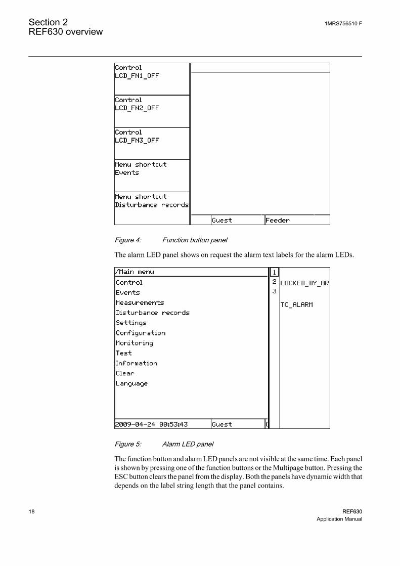
Figure 4: Function button panel
The alarm LED panel shows on request the alarm text labels for the alarm LEDs.
GUID-3CBCBC36-EFCE-43A0-9D62-8D88AD6B6287 V1 EN
Figure 5: Alarm LED panel
The function button and alarm LED panels are not visible at the same time. Each panelis shown by pressing one of the function buttons or the Multipage button. Pressing theESC button clears the panel from the display. Both the panels have dynamic width thatdepends on the label string length that the panel contains.
Section 2 1MRS756510 FREF630 overview
18 REF630Application Manual

2.4.2 LEDs
The LHMI includes three protection status LEDs above the display: Ready, Start andTrip.
There are 15 programmable alarm LEDs on the front of the LHMI. Each LED canindicate three states with the colors: green, yellow and red. The alarm texts related toeach three-color LED are divided into three pages. Altogether, the 15 physical three-color LEDs can indicate 45 different alarms. The LEDs can be configured withPCM600 and the operation mode can be selected with the LHMI, WHMI or PCM600.
2.4.3 Keypad
The LHMI keypad contains push-buttons which are used to navigate in differentviews or menus. With the push-buttons you can control objects in the single-linediagram, for example, circuit breakers or disconnectors The push-buttons are alsoused to acknowledge alarms, reset indications, provide help and switch between localand remote control mode.
The keypad also contains programmable push-buttons that can be configured either asmenu shortcut or control buttons.
GUID-FE571EAC-D3AF-4E26-8C01-197F21AA96CA V1 EN
Figure 6: LHMI keypad with object control, navigation and command push-buttons and RJ-45 communication port
2.5 Web HMI
The WHMI enables the user to access the IED via a web browser. The supported Webbrowser versions are Internet Explorer 8.0, 9.0 and 10.0.
1MRS756510 F Section 2REF630 overview
REF630 19Application Manual

WHMI is disabled by default. To enable the WHMI, select Mainmenu/Configuration/HMI/Web HMI/Operation via the LHMI.
WHMI offers several functions.
• Alarm indications and event lists• System supervision• Parameter settings• Measurement display• Disturbance records• Phasor diagram
Viewing phasor diagram with WHMI requires downloading a SVGViewer plugin.
The menu tree structure on the WHMI is almost identical to the one on the LHMI.
A071242 V3 EN
Figure 7: Example view of the WHMI
The WHMI can be accessed locally and remotely.
• Locally by connecting the user's computer to the IED via the frontcommunication port.
• Remotely over LAN/WAN.
Section 2 1MRS756510 FREF630 overview
20 REF630Application Manual
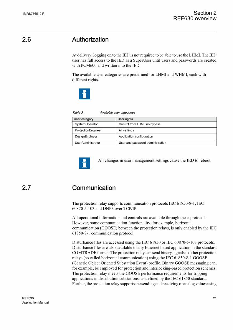
2.6 Authorization
At delivery, logging on to the IED is not required to be able to use the LHMI. The IEDuser has full access to the IED as a SuperUser until users and passwords are createdwith PCM600 and written into the IED.
The available user categories are predefined for LHMI and WHMI, each withdifferent rights.
Table 3: Available user categories
User category User rightsSystemOperator Control from LHMI, no bypass
ProtectionEngineer All settings
DesignEngineer Application configuration
UserAdministrator User and password administration
All changes in user management settings cause the IED to reboot.
2.7 Communication
The protection relay supports communication protocols IEC 61850-8-1, IEC60870-5-103 and DNP3 over TCP/IP.
All operational information and controls are available through these protocols.However, some communication functionality, for example, horizontalcommunication (GOOSE) between the protection relays, is only enabled by the IEC61850-8-1 communication protocol.
Disturbance files are accessed using the IEC 61850 or IEC 60870-5-103 protocols.Disturbance files are also available to any Ethernet based application in the standardCOMTRADE format. The protection relay can send binary signals to other protectionrelays (so called horizontal communication) using the IEC 61850-8-1 GOOSE(Generic Object Oriented Substation Event) profile. Binary GOOSE messaging can,for example, be employed for protection and interlocking-based protection schemes.The protection relay meets the GOOSE performance requirements for trippingapplications in distribution substations, as defined by the IEC 61850 standard.Further, the protection relay supports the sending and receiving of analog values using
1MRS756510 F Section 2REF630 overview
REF630 21Application Manual
GOOSE messaging. Analog GOOSE messaging enables fast transfer of analogmeasurement values over the station bus, thus facilitating for example sharing of RTDinput values, such as surrounding temperature values, to other relay applications.Analog GOOSE messages can also be used in load shedding applications. Theprotection relay interoperates with other IEC 61850 compliant devices, tools andsystems and simultaneously reports events to five different clients on the IEC 61850station bus. For a system using DNP3 over TCP/IP, events can be sent to four differentmasters. For systems using IEC 60870-5-103, the protection relay can be connected toone master in a station bus with star-topology.
All communication connectors, except for the front port connector, are placed onintegrated communication modules. The protection relay is connected to Ethernet-based communication systems via the RJ-45 connector (10/100BASE-TX) or thefibre-optic multimode LC connector (100BASE-FX).
IEC 60870-5-103 is available from optical serial port where it is possible to use serialglass fibre (ST connector) or serial plastic fibre (snap-in connector).
The protection relay supports the following time synchronization methods with atimestamping resolution of 1 ms.
Ethernet communication based
• SNTP (simple network time protocol)• DNP3
With special time synchronization wiring
• IRIG-B
IEC 60870-5-103 serial communication has a time-stamping resolution of 10 ms.
Section 2 1MRS756510 FREF630 overview
22 REF630Application Manual

Section 3 REF630 variants
3.1 Presentation of preconfigurations
The 630 series protection relays are offered with optional factory-madepreconfigurations for various applications. The preconfigurations contribute to fastercommissioning and less engineering of the protection relay. The preconfigurationsinclude default functionality typically needed for a specific application. Eachpreconfiguration is adaptable using the Protection and Control IED ManagerPCM600. By adapting the preconfiguration the protection relay can be configured tosuit the particular application.
The adaptation of the preconfiguration may include adding or removing of protection,control and other functions according to the specific application, changing of thedefault parameter settings, configuration of the default alarms and event recordersettings including the texts shown in the HMI, configuration of the LEDs and functionbuttons, and adaptation of the default single-line diagram.
In addition, the adaptation of the preconfiguration always includes communicationengineering to configure the communication according to the functionality of theprotection relay. The communication engineering is done using the communicationconfiguration function of PCM600.
If none of the offered preconfigurations fulfill the needs of the intended area ofapplication, 630 series protection relays can also be ordered without anypreconfiguration. In this case the protection relay needs to be configured from theground up.
The functional diagrams describe the IED's functionality from the protection,measuring, condition monitoring, disturbance recording, control and interlockingperspective. Diagrams show the default functionality with simple symbol logicsforming principle diagrams. The external connections to primary devices are alsoshown, stating the default connections to measuring transformers. The positivemeasuring direction of directional protection functions is towards the outgoing feeder.
The functional diagrams are divided into sections which each constitute onefunctional entity. The external connections are also divided into sections. Only therelevant connections for a particular functional entity are presented in each section.
Protection function blocks are part of the functional diagram. They are identifiedbased on their IEC 61850 name but the IEC based symbol and the ANSI functionnumber are also included. Some function blocks, such as PHHPTOC, are used severaltimes in the configuration. To separate the blocks from each other, the IEC 61850name, IEC symbol and ANSI function number are appended with a running number,an instance number, from one onwards.
1MRS756510 F Section 3REF630 variants
REF630 23Application Manual
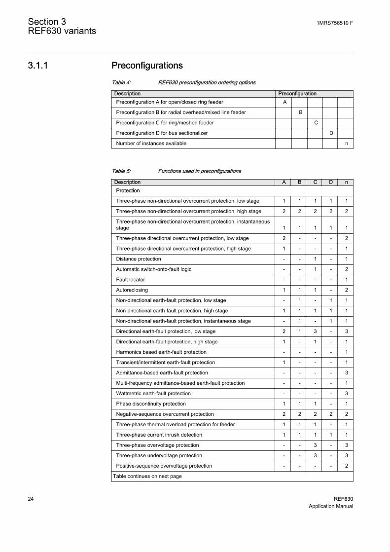
3.1.1 PreconfigurationsTable 4: REF630 preconfiguration ordering options
Description PreconfigurationPreconfiguration A for open/closed ring feeder A
Preconfiguration B for radial overhead/mixed line feeder B
Preconfiguration C for ring/meshed feeder C
Preconfiguration D for bus sectionalizer D
Number of instances available n
Table 5: Functions used in preconfigurations
Description A B C D nProtection
Three-phase non-directional overcurrent protection, low stage 1 1 1 1 1
Three-phase non-directional overcurrent protection, high stage 2 2 2 2 2
Three-phase non-directional overcurrent protection, instantaneousstage 1 1 1 1 1
Three-phase directional overcurrent protection, low stage 2 - - - 2
Three-phase directional overcurrent protection, high stage 1 - - - 1
Distance protection - - 1 - 1
Automatic switch-onto-fault logic - - 1 - 2
Fault locator - - - - 1
Autoreclosing 1 1 1 - 2
Non-directional earth-fault protection, low stage - 1 - 1 1
Non-directional earth-fault protection, high stage 1 1 1 1 1
Non-directional earth-fault protection, instantaneous stage - 1 - 1 1
Directional earth-fault protection, low stage 2 1 3 - 3
Directional earth-fault protection, high stage 1 - 1 - 1
Harmonics based earth-fault protection - - - - 1
Transient/intermittent earth-fault protection 1 - - - 1
Admittance-based earth-fault protection - - - - 3
Multi-frequency admittance-based earth-fault protection - - - - 1
Wattmetric earth-fault protection - - - - 3
Phase discontinuity protection 1 1 1 - 1
Negative-sequence overcurrent protection 2 2 2 2 2
Three-phase thermal overload protection for feeder 1 1 1 - 1
Three-phase current inrush detection 1 1 1 1 1
Three-phase overvoltage protection - - 3 - 3
Three-phase undervoltage protection - - 3 - 3
Positive-sequence overvoltage protection - - - - 2
Table continues on next page
Section 3 1MRS756510 FREF630 variants
24 REF630Application Manual

Description A B C D nPositive-sequence undervoltage protection - - - - 2
Negative-sequence overvoltage protection - - - - 2
Residual overvoltage protection - - 3 - 3
Directional reactive power undervoltage protection - - - - 2
Reverse power/directional overpower protection - - - - 3
Frequency gradient protection - - - - 5
Overfrequency protection - - - - 5
Underfrequency protection - - - - 5
Load shedding - - - - 6
Circuit breaker failure protection 1 1 1 1 2
Tripping logic 1 1 1 1 2
Multipurpose analog protection - - - - 16
Protection-related functions
Local acceleration logic - - 1 - 1
Communication logic for residual overcurrent - - 1 - 1
Scheme communication logic - - 1 - 1
Current reversal and WEI logic - - 1 - 1
Current reversal and WEI logic for residual overcurrent - - 1 - 1
Control
Bay control 1 1 1 1 1
Interlocking interface 4 4 4 1 10
Circuit breaker/disconnector control 4 4 4 1 10
Circuit breaker 1 1 1 1 2
Disconnector 3 3 3 - 8
Local/remote switch interface - - - - 1
Synchrocheck - - - - 1
Generic process I/O
Single point control (8 signals) - - - - 5
Double point indication - - - - 15
Single point indication - - - - 64
Generic measured value - - - - 15
Logic Rotating Switch for function selection and LHMI presentation - - - - 10
Selector mini switch - - - - 10
Pulse counter for energy metering - - - - 4
Event counter - - - - 1
Supervision and monitoring
Runtime counter for machines and devices - - - - 1
Circuit breaker condition monitoring 1 1 1 1 2
Fuse failure supervision 1 1 1 - 2
Table continues on next page
1MRS756510 F Section 3REF630 variants
REF630 25Application Manual

Description A B C D nCurrent circuit supervision 1 1 1 - 2
Trip-circuit supervision 3 3 3 3 3
Station battery supervision - - - - 1
Energy monitoring - - - - 1
Measured value limit supervision - - - - 40
Power quality
Voltage variation - - - - 1
Voltage unbalance - - - - 1
Current harmonics - - - - 1
Voltage harmonics (phase-to-phase) - - - - 1
Voltage harmonics (phase-to-earth) - - - - 1
Measurement
Three-phase current measurement 1 1 1 1 1
Three-phase voltage measurement (phase-to-earth) 1 1 1 1 2
Three-phase voltage measurement (phase-to-phase) - - - - 2
Residual current measurement 1 1 1 1 1
Residual voltage measurement 1 1 1 - 1
Power monitoring with P, Q, S, power factor, frequency 1 1 1 1 1
Sequence current measurement 1 1 1 1 1
Sequence voltage measurement 1 1 1 1 1
Disturbance recorder function
Analog channels 1-10 (samples) 1 1 1 1 1
Analog channels 11-20 (samples) - - - - 1
Analog channels 21-30 (calc. val.) - - - - 1
Analog channels 31-40 (calc. val.) - - - - 1
Binary channels 1-16 1 1 1 1 1
Binary channels 17-32 1 1 1 1 1
Binary channels 33-48 1 1 1 1 1
Binary channels 49-64 1 - 1 - 1
Station communication (GOOSE)
Binary receive - - - - 10
Double point receive - - - - 32
Interlock receive - - - - 59
Integer receive - - - - 32
Measured value receive - - - - 60
Single point receive - - - - 64
n = total number of available function instances regardless of the preconfiguration selected1, 2, ... = number of included instances
Section 3 1MRS756510 FREF630 variants
26 REF630Application Manual
3.2 Preconfiguration A for open/closed ring feeder
3.2.1 Application
The functionality of the IED is designed to be used for selective short-circuit,overcurrent and earth-fault protection of radial outgoing feeders on double busbarsystems with one circuit breaker. The configuration can be used in isolated neutralnetworks, resistant-earthed networks and compensated networks.
The objects controlled by the IED are the circuit breaker and the disconnector. Theearth switch is considered to be operated manually. The open, close and undefinedstates of the circuit breaker, disconnectors and the earth switch are indicated on theLHMI.
Required interlocking is configured in the IED.
The preconfiguration includes:
• Control functions• Current protection functions• Supervision functions• Disturbance recorders• LEDs' configuration• Measurement functions
1MRS756510 F Section 3REF630 variants
REF630 27Application Manual

3.2.2 Functions
CONDITION MONITORING AND SUPERVISION
1 0 1 0 0 0 1 1 0 0 1 1 0 01 0 1 1 0 0 1 0 1 1 1 0 0 1 01 1 0 0 1 1 1 0 1 1 0 1 01 0 1 1 0 1 1 0 1 1 0 1 0 01 0 1 0 0 0 1 1 0 0 1 1 0 0 1 0 1 0 0 0 1 1 0 0 1 1 0 01 0 1 1 0 0 1 0 1 1 1 0 0 1 01 1 0 0 1 1 1 0 1 1 0 1 01 0 1 1 0 1 1 0 1 1 0 1 0 0
ORAND
CONTROL AND INDICATION 1) MEASUREMENT
PRE- CONFIGURATION
PROTECTION LOCAL HMI *)
REF630
REMARKS
Optionalfunction
Function(s) not enabled by default in preconfiguration, can be enabled afterwards
No. of instances enabled by default
2×
No. of instances not enabled by default in preconfiguration, can be enabled afterwards
1×
COMMUNICATION
Protocols: IEC 61850-8-1 IEC 60870-5-103 DNP3
Interfaces: Ethernet: TX (RJ45), FX (LC) Serial: Serial glass fiber (ST), Serial plastic fiber (snap-in connector)
ALSO AVAILABLE
- 5 × prog. push buttons on LHMI- Disturbance and fault recorders- IED self-supervision - Local/Remote push button on LHMI- Sequence event recorder- User management- WebHMI
A
- I, U, Io, Uo, P, Q, E, pf, f- Symmetrical components- Limit value supervision
Analog interface types B
Current transformer 51)
Voltage transformer 4
1) One of available current transformer inputs is sensitive (0.1 / 0.5 A)
*) Fixed or detached LHMI is available.
Object Ctrl 2)
CB 2
DC8
ES1) Check availability of binary inputs/outputs
from technical documentation2) Control and indication function for
primary object
3I>/Io>BF51BF/51NBF
Io>→67N-1
df/dt>81R
I→O94
1×1×
TCSTCM
U<>U<>
O→I79
1×1×SYNC
25Io>HA51NHA
Z<21, 21P, 21N
CBCMCBCM
MCS 3IMCS 3I
FUSEF60
FLOC21FL
Io>51N-1
Io>>>50N/51N
Io>>51N-2
Io>→67N-2
Io>→IEF67NIEF
Po>→32N
1× 1×3I>>
51P-2
3I>>>50P/51P
3I>→67-1
3I>>→67-2
3I>51P-1
I2/I1>46PD
I2>46
3Ith>F49F
3I2f>68
3U>59
U1>47O+
U1<47U+
U2>47O-
Uo>59G
P>32R/32O
f>81O
f<81U
UFLS/R81LSH
Yo>→21YN
3U<27
SOTFSOTF
EE
PQMUPQMV
PQMUBUPQMUBV
PQM3IPQM3I
PQM3UppPQM3Vpp
PQM3UpePQM3Vpg
2× 1×
3×
3× 3×
3×
5×6×3×
5×5×
2×2×2×
2×MAPMAP
16×
2×
2×
2× 1×1× 1×1×
1×1× 3×
Q>→, 3U<32Q, 27
Io>→Y67YN
3I
Io
UL1
UL2
UL3
UL1UL2UL3
Uo
Uo
3×
FEEDER PROTECTION AND CONTROL IEDPreconfiguration A for open/closed ring feeder
OPTSOPTM
GUID-973EE09F-BEFA-40C3-AAEE-FB97B84EAA52 V1 EN
Figure 8: Functionality overview for preconfiguration A
Section 3 1MRS756510 FREF630 variants
28 REF630Application Manual
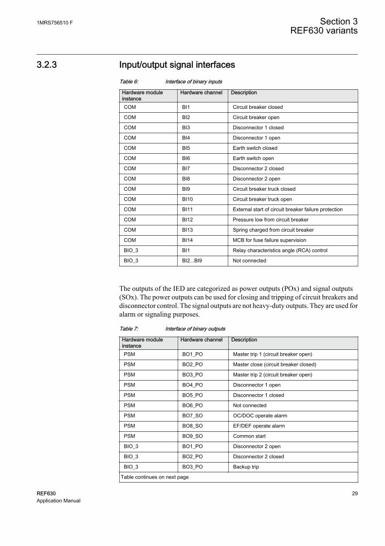
3.2.3 Input/output signal interfacesTable 6: Interface of binary inputs
Hardware moduleinstance
Hardware channel Description
COM BI1 Circuit breaker closed
COM BI2 Circuit breaker open
COM BI3 Disconnector 1 closed
COM BI4 Disconnector 1 open
COM BI5 Earth switch closed
COM BI6 Earth switch open
COM BI7 Disconnector 2 closed
COM BI8 Disconnector 2 open
COM BI9 Circuit breaker truck closed
COM BI10 Circuit breaker truck open
COM BI11 External start of circuit breaker failure protection
COM BI12 Pressure low from circuit breaker
COM BI13 Spring charged from circuit breaker
COM BI14 MCB for fuse failure supervision
BIO_3 BI1 Relay characteristics angle (RCA) control
BIO_3 BI2...BI9 Not connected
The outputs of the IED are categorized as power outputs (POx) and signal outputs(SOx). The power outputs can be used for closing and tripping of circuit breakers anddisconnector control. The signal outputs are not heavy-duty outputs. They are used foralarm or signaling purposes.
Table 7: Interface of binary outputs
Hardware moduleinstance
Hardware channel Description
PSM BO1_PO Master trip 1 (circuit breaker open)
PSM BO2_PO Master close (circuit breaker closed)
PSM BO3_PO Master trip 2 (circuit breaker open)
PSM BO4_PO Disconnector 1 open
PSM BO5_PO Disconnector 1 closed
PSM BO6_PO Not connected
PSM BO7_SO OC/DOC operate alarm
PSM BO8_SO EF/DEF operate alarm
PSM BO9_SO Common start
BIO_3 BO1_PO Disconnector 2 open
BIO_3 BO2_PO Disconnector 2 closed
BIO_3 BO3_PO Backup trip
Table continues on next page
1MRS756510 F Section 3REF630 variants
REF630 29Application Manual

Hardware moduleinstance
Hardware channel Description
BIO_3 BO4_SO Upstream OC/DOC block
BIO_3 BO5_SO Common operate
BIO_3 BO6_SO Not connected
BIO_3 BO7_SO Circuit breaker monitoring alarm
BIO_3 BO8_SO Supervision circuit alarm
BIO_3 BO9_SO Not connected
The IED measures the analog signals needed for protection and measuring functionsvia galvanically isolated matching transformers. The matching transformer inputchannels 1…4 are intended for current measuring and channels 7...10 for voltagemeasuring.
Table 8: Interface of analog inputs
Hardware moduleinstance
Hardware channel Description
AIM_2 CH1 Phase current IL1
AIM_2 CH2 Phase current IL2
AIM_2 CH3 Phase current IL3
AIM_2 CH4 Neutral current I0
AIM_2 CH5 Not connected
AIM_2 CH6 Not available
AIM_2 CH7 Phase voltage UL1
AIM_2 CH8 Phase voltage UL2
AIM_2 CH9 Phase voltage UL3
AIM_2 CH10 Neutral voltage U0
3.2.4 Preprocessing blocks and fixed signals
The analog current and voltage signals coming to the IED are processed bypreprocessing blocks. There are two types of preprocessing blocks based on 20samples per cycle and 80 samples per cycle. All function blocks functioning at 5 mstask time need 80 samples per cycle whereas all the rest need 20 samples per cycle.
A fixed signal block providing a logical TRUE and a logical FALSE output has beenused. Outputs are connected internally to other functional blocks when needed.
Even if the AnalogInputType setting of a SMAI block is set to“Current”, the MinValFreqMeas setting is still visible. This meansthat the minimum level for current amplitude is based on UBase. Asan example, if UBase is 20 kV, the minimum amplitude for current is20000 × 10% = 2000 A.
Section 3 1MRS756510 FREF630 variants
30 REF630Application Manual

3.2.5 Control functions
3.2.5.1 Bay control QCCBAY
Bay control is used to handle the selection of the operator place per bay. It providesblocking functions that can be distributed to different apparatuses within the bay. Baycontrol sends information about the permitted source to operate (PSTO) and blockingconditions to other functions within the bay, for example switch control functions.
3.2.5.2 Apparatus control SCILO, GNRLCSWI, DAXCBR, DAXSWI
Apparatus control initializes and supervises proper selection and switches on primaryapparatus. Each apparatus requires interlocking function, switch control function andapparatus functions.
Circuit-breaker control functionThe circuit breaker is controlled by a combination of switch interlocking (SCILO),switch controller (GNRLCSWI) and circuit breaker controller (DAXCBR) functions.
The position information of the circuit breaker and the truck are connected toDAXCBR. The interlocking logics for the circuit breaker have been programmed toopen at any time, provided that the gas pressure inside the circuit breaker is above thelockout limit. Closing of the circuit breaker is always prevented if the gas pressureinside the circuit breaker is below the lockout limit or the truck is open or springcharge time is above the set limit. In case the earth switch is closed, check that bothdisconnectors are open while closing the circuit breaker.
SCILO function checks for the interlocking conditions and provides closing andopening enable signals. The enable signal is used by GNRLCSWI function blockwhich checks for operator place selector before providing the final open or closesignal to DAXCBR function.
The open, closed and undefined states of the circuit breaker are indicated on theLHMI.
Disconnector 1, disconnector 2 and earth switch control functionDisconnector 1, disconnector 2, and earth switch are controlled by a combination ofSCILO, GNRLCSWI and DAXSWI functions. Each apparatus requires one set ofthese functions.
The position information of the disconnectors and the earth switch are connected torespective DAXSWI functions via binary inputs. The interlocking logics for thedisconnector have been programmed so that it can be opened or closed only if otherthree apparatuses, that is circuit breaker, earth switch and one of the disconnectors, areopen. Interlocking for the earth switch depends on the circuit-breaker condition. If thecircuit breaker is open, it is possible to open or close the earth switch at any time. If thecircuit breaker is in closed, it is required that the other two disconnectors are open.
1MRS756510 F Section 3REF630 variants
REF630 31Application Manual

SCILO function checks for these conditions and provides closing and opening enablesignals. The enable signal is used by GNRLCSWI function blocks which check foroperator place selector before providing the final open or close signal to DAXCBRfunction.
The open, closed and undefined states of the disconnector 1, disconnector 2 and earthswitch are indicated on the LHMI.
The interlocking condition for the disconnector can be different incase a bus sectionalizer is available in the system.
GUID-3FEC4A93-BFE0-4386-8091-0D83339E19EE V1 EN
Figure 9: Apparatus control
Section 3 1MRS756510 FREF630 variants
32 REF630Application Manual
3.2.5.3 Autoreclosing DARREC
Majority of medium voltage overhead line faults are transient and automaticallycleared by momentarily de-energizing the line, whereas the rest of the faults, 15 to 20percent, are cleared by longer interruptions. The de-energization of the fault place fora wanted period of time is implemented by autoreclosing relays or functions.Automatic reclosing is capable of clearing most of the faults. At a permanent fault,autoreclosing is followed by the final tripping. A permanent fault has to be located andcleared before the fault location can be re-energized.
The function block provides five programmable autoreclose shots for creatingautoreclosings of wanted type and duration, such as one high-speed and one delayedautoreclosing. The function consists of six individual initiation lines INIT_1... INIT 6from which lines INIT_1...3 are used in the preconfiguration. It is possible to create anindividual autoreclosing sequence for each input.
In this preconfiguration the autoreclosing function is initiated (lines INIT_1..3) fromthe operation of protection functions. The autoreclosing function allows also initiationfrom the start of the protection function, then opening the circuit breaker (OPEN CB)and performing a fast final trip.
The autoreclosing function can be inhibited with the INHIBIT_RECL input. Operatesignals of negative sequence overcurrent, phase discontinuity, intermittent earth faultand circuit-breaker gas pressure lock are connected to INHIBIT_RECL input. Springcharged input available from the circuit breaker at binary input COM_101 BI13 isused to check the ready status of circuit breaker before autoreclosing. Inhibitautoreclose signal from the thermal overload protection is connected toBLK_THERM input.
The outputs describing closing command (reclose) to a circuit breaker, unsuccessfulautoreclosing and autoreclosing locked-out (CLOSE CB, UNSUC_AR, andLOCKED) are connected to binary recorders. Whereas autoreclosing ready,autoreclosing in progress and autoreclosing locked-out (READY, INPRO andLOCKED) outputs are connected to LED indication on the LHMI.
Status indicating that circuit breaker in open state is connected to the CB_POS inputs.With this connection the setting is CB closed Pos status = FALSE.
CLOSE CB output is used for closing the circuit breaker. Before any autoreclosingsignal is activated the function block checks for the circuit breaker ready status.
If an industrial feeder employs cables it may not be advisable to useautoreclosing, as cable faults are not transient but permanent.
1MRS756510 F Section 3REF630 variants
REF630 33Application Manual

GUID-C341207A-5B43-415A-93E3-30FFBC16B9C7 V1 EN
Figure 10: Autoreclosing
3.2.6 Protection functions
3.2.6.1 Three-phase current inrush detection INRPHAR
The configuration includes a three-phase current inrush detection function. Thefunction can be used for increasing, typically double, the set start value of thedirectional overcurrent (DOC) as well as non-directional overcurrent stage (OC)during inrush condition. This is done by the ENA_MULT input and the Start valuemult setting in the corresponding function blocks. The default multiplier setting is 1.0.
3.2.6.2 Non-directional overcurrent protection PHxPTOC
The three-phase non-directional overcurrent functions are used for non-directionalone-phase, two-phase and three-phase overcurrent and short-circuit protection withdefinite time or various inverse definite minimum time (IDMT) characteristic. Theoperation of a stage is based on three measuring principles: DFT, RMS or peak-to-peak values.
Section 3 1MRS756510 FREF630 variants
34 REF630Application Manual
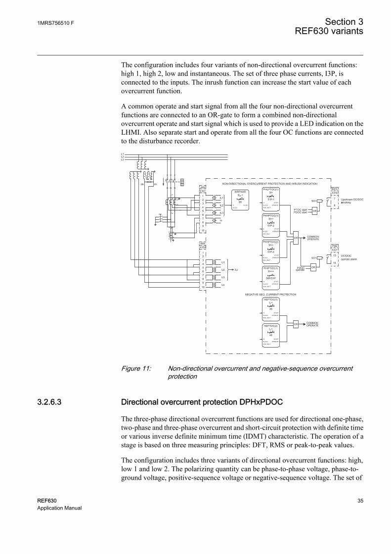
The configuration includes four variants of non-directional overcurrent functions:high 1, high 2, low and instantaneous. The set of three phase currents, I3P, isconnected to the inputs. The inrush function can increase the start value of eachovercurrent function.
A common operate and start signal from all the four non-directional overcurrentfunctions are connected to an OR-gate to form a combined non-directionalovercurrent operate and start signal which is used to provide a LED indication on theLHMI. Also separate start and operate from all the four OC functions are connectedto the disturbance recorder.
GUID-35BF2B0F-6AD8-4062-93CE-BDA860891522 V1 EN
Figure 11: Non-directional overcurrent and negative-sequence overcurrentprotection
3.2.6.3 Directional overcurrent protection DPHxPDOC
The three-phase directional overcurrent functions are used for directional one-phase,two-phase and three-phase overcurrent and short-circuit protection with definite timeor various inverse definite minimum time (IDMT) characteristic. The operation of astage is based on three measuring principles: DFT, RMS or peak-to-peak values.
The configuration includes three variants of directional overcurrent functions: high,low 1 and low 2. The polarizing quantity can be phase-to-phase voltage, phase-to-ground voltage, positive-sequence voltage or negative-sequence voltage. The set of
1MRS756510 F Section 3REF630 variants
REF630 35Application Manual

three phase currents and voltages, I3P and U3P, is connected to the inputs. The inrushfunction can increase the start value of each overcurrent function.
A common operate and start signal from all the three overcurrent functions areconnected to an OR-gate to form a combined directional overcurrent operate and startsignal which is used to provide a LED indication on the LHMI. Also separate start andoperate signals from all the three DOC functions are connected to a disturbancerecorder.
GUID-80FF66BF-1F0E-4EDA-9CEC-F218D38B3963 V1 EN
Figure 12: Directional overcurrent, phase discontinuity and thermal overloadprotection
3.2.6.4 Negative-sequence overcurrent protection NSPTOC
Two instances of negative-sequence overcurrent detection are provided, forprotection against single-phasing, unbalanced load or asymmetrical feeder voltage.The set of three phase currents, I3P, is connected to the inputs.
Section 3 1MRS756510 FREF630 variants
36 REF630Application Manual

A common operate and start signal from both NSPTOC functions are connected to anOR-gate to form a combined negative-sequence overcurrent operate and start signalwhich is used to provide a LED indication on the LHMI. Also separate start andoperate signals from the NSPTOC function is connected to the disturbance recorder.
3.2.6.5 Phase discontinuity protection PDNSPTOC
The phase discontinuity protection functions are used for protection against brokenphase conductors in distribution networks. Definite-time (DT) characteristic is alwaysused. Operation of the stage is based on ratio of 2nd harmonic and fundamentalfrequency of phase currents.
The set of three phase currents, I3P, is connected to the inputs. Operate and startsignals are used to trigger the disturbance recorder and to provide a LED indication onthe LHMI.
3.2.6.6 Non-directional earth-fault protection EFxPTOC
The non-directional earth-fault protection functions are used for protection underearth-fault conditions with definite-time (DT) or with inverse definite minimum time(IDMT) characteristic when appropriate.
The operation of the stage is based on three measuring principles: DFT, RMS or peak-to-peak values. The configuration includes high-stage non-directional currentfunctions. The set of three phase currents, I3P, is connected to the inputs.
The start and operate signals from the high-stage non-directional current function isconnected to the disturbance recorder.
3.2.6.7 Intermittent earth-fault protection INTRPTEF
Intermittent earth-fault function is a dedicated earth-fault protection function inintermittent and transient earth faults occurring in distribution networks. Definite time(DT) characteristic is always used. In the configuration, the intermittent function isused in parallel with directional earth-fault protection. Directional earth-fault functionis blocked by an intermittent earth-fault function to prevent erroneous trips when thefunction is set to operate with “Intermittent EF" mode.
The start and operate signals from INTRPTEF is connected to the disturbancerecorder. Also a common operate and start signal from the high-stage earth-faultprotection and intermittent earth-fault functions are connected to an OR-gate to forma combined non-directional earth-fault operate and start signal which is used toprovide a LED indication on the LHMI.
1MRS756510 F Section 3REF630 variants
REF630 37Application Manual
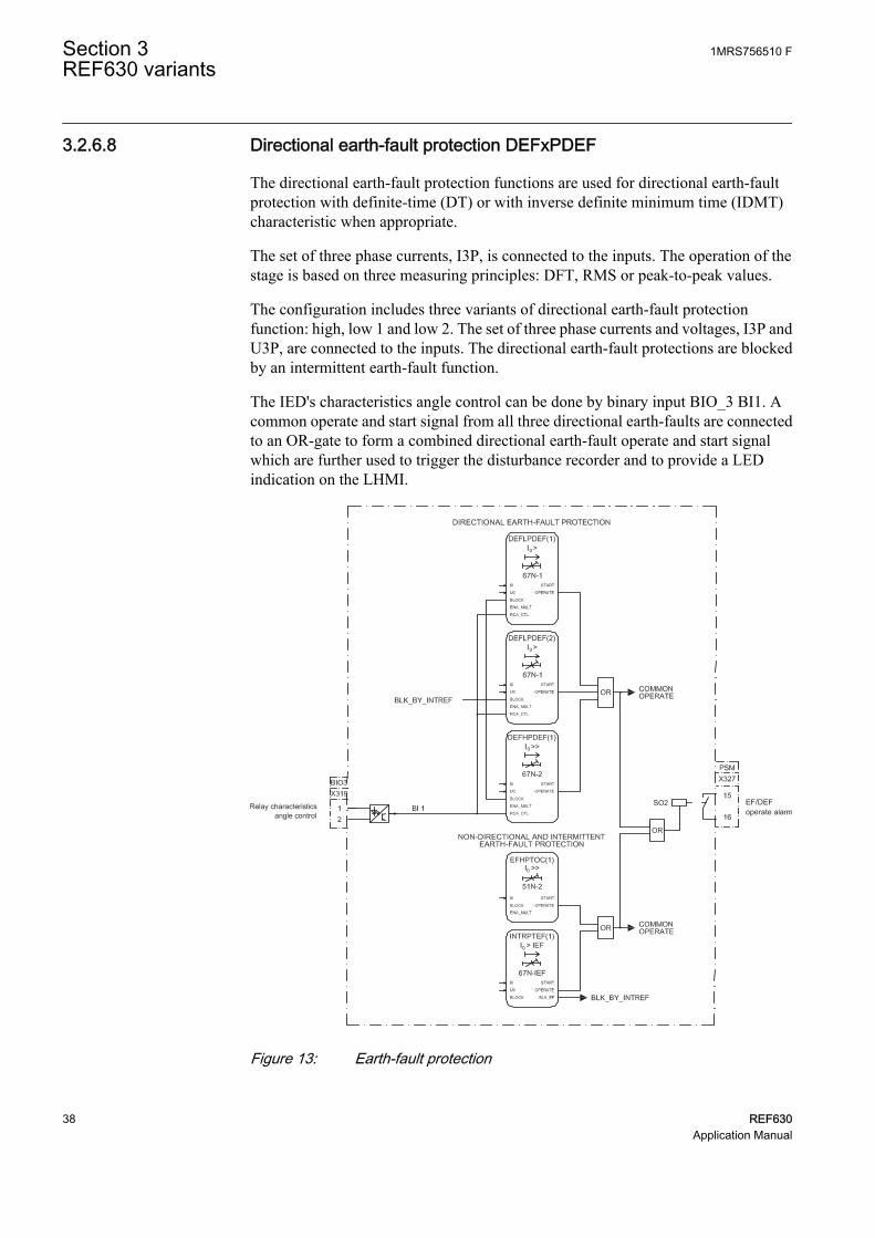
3.2.6.8 Directional earth-fault protection DEFxPDEF
The directional earth-fault protection functions are used for directional earth-faultprotection with definite-time (DT) or with inverse definite minimum time (IDMT)characteristic when appropriate.
The set of three phase currents, I3P, is connected to the inputs. The operation of thestage is based on three measuring principles: DFT, RMS or peak-to-peak values.
The configuration includes three variants of directional earth-fault protectionfunction: high, low 1 and low 2. The set of three phase currents and voltages, I3P andU3P, are connected to the inputs. The directional earth-fault protections are blockedby an intermittent earth-fault function.
The IED's characteristics angle control can be done by binary input BIO_3 BI1. Acommon operate and start signal from all three directional earth-faults are connectedto an OR-gate to form a combined directional earth-fault operate and start signalwhich are further used to trigger the disturbance recorder and to provide a LEDindication on the LHMI.
GUID-B2D2869A-F1F7-48A5-9A77-812B8C63F500 V1 EN
Figure 13: Earth-fault protection
Section 3 1MRS756510 FREF630 variants
38 REF630Application Manual
3.2.6.9 Thermal overload protection T1PTTR
The three-phase thermal overload protection function is used for thermal protection ofthe three-phase power cables and overhead lines. It has adjustable temperature limitsfor tripping, alarm and reclose inhibit. The thermal model applied uses one timeconstant and the true RMS current measuring principle.
The operate signal from the thermal overload protection is further used to trigger thedisturbance recorder. Both the operate and alarm signals provide a LED indication onthe LHMI.
3.2.6.10 Circuit-breaker failure protection CCBRBRF
The function is activated by the common operate command from the protectionfunctions. The breaker failure function issues a backup trip command to adjacentcircuit breakers in case the main circuit breaker fails to trip for the protectedcomponent. The backup trip is connected at binary output BIO_3 PO3.
A failure of a circuit breaker is detected by measuring the current or by detecting theremaining trip signal. Function also provides retrip. Retrip is used along with the maintrip, and is activated before the backup trip signal is generated in case the main breakerfails to open. Retrip is used to increase the operational reliability of the circuit breaker.
3.2.6.11 Tripping logic TRPPTRC
Tripping logic has been configured to provide tripping signal of required duration.The tripping circuit opens the circuit breaker on
• Receipt of operate signal from the protection function or• Retrip signal from the circuit-breaker failure protection.
Two master tripping signals are available at binary output PSM PO1 and PSM PO3.
1MRS756510 F Section 3REF630 variants
REF630 39Application Manual

GUID-9C15DB69-98E5-49EB-836A-CF0B247D2DF4 V1 EN
Figure 14: Tripping logic and breaker failure protection
3.2.6.12 Combined operate and start alarm signal
The operate outputs of all protection functions are combined in an OR-gate to get acommon Operate output. This common operate signal is connected to a tripping logic.It is also available as an alarm binary output, BIO_3_SO2, with a settable minimumalarm delay of 80 ms. Also, a common Start output is derived from the start outputs ofprotection functions combined in an OR-gate. The output is available as an alarmbinary output PSM SO3 with a settable minimum alarm delay of 80 ms.
Section 3 1MRS756510 FREF630 variants
40 REF630Application Manual

3.2.6.13 Other output and alarm signals
• Combined directional and non-directional overcurrent (OC/DOC) operate signalavailable at binary output PSM SO1
• Combined directional and non-directional earth-fault (EF/DEF) operate signalavailable at binary output PSM SO2
• Combined alarm signal from circuit-breaker monitoring function available atbinary output BIO_3 SO4
• Combined alarm signal from various supervision functions available at binaryoutput BIO_3 SO5
• Upstream directional and non-directional overcurrent (OC/DOC) blockingsignal available at binary output BIO_3 SO1
3.2.7 Supervision functions
3.2.7.1 Trip circuit supervision TCSSCBR
Two instances of trip circuit supervision function are used for supervising Master trip1 and Master trip 2. Function continuously supervises trip circuit and an alarm isissued in case of a failure of a trip circuit. The function does not perform thesupervision itself but it is used as an aid for configuration.
Function gives an indication via a LED on the LHMI on detection of any of the tripcircuit failure. To prevent unwanted alarms, the function is blocked when the circuitbreaker is open, one of the protection function operate signals is active.
An instance of trip circuit supervision is used to check the proper functioning ofclosing circuit of the circuit breaker. This function is blocked when the circuit breakeris in closed position to prevent unwanted alarms.
3.2.7.2 Fuse failure and current circuit supervision SEQRFUF, CCRDIF
The fuse failure and current circuit supervision functions give an alarm in case of afailure in the secondary circuits between the voltage transformer or currenttransformer and the IED respectively. The set of three phase currents and voltages, I3Pand U3P, are connected to the inputs.
An alarm is available on failure of the secondary circuits. Alarms are recorded by adisturbance recorder.
3.2.7.3 Circuit-breaker condition monitoring SSCBR
The circuit-breaker condition monitoring function checks for the health of the circuitbreaker. The circuit breaker status is connected to the function via binary inputs.Function requires also pressure lockout input and spring charged input connected viabinary input COM_101.BI12 and COM_101.BI13 respectively. Various alarm
1MRS756510 F Section 3REF630 variants
REF630 41Application Manual

outputs from the function are combined in an OR-gate to create a master circuit-breaker monitoring alarm, which is available at binary output BIO_3 SO4.
All of the alarms are separately connected to the binary recorder and a combined alarmis available as an indication via a LED on the LHMI.
GUID-F364F9E6-D33D-4ADD-82DA-5CFFE1960055 V2 EN
Figure 15: Circuit-breaker condition monitoring and trip-circuit, fuse failure andcurrent measuring circuit supervision
3.2.8 Measurement and analog recording functions
The measured quantities in this configuration are:
• Sequence current• Sequence voltage• Residual voltage• Residual current• Energy• Phase current• Phase voltage• Line voltage• Power with frequency
Section 3 1MRS756510 FREF630 variants
42 REF630Application Manual

The measured quantities can be viewed in the measurement menu on the LHMI.
All analog input channels are connected to the analog disturbance recorder. When anyof these analog values violate the upper or lower threshold limits, the recorder unit istriggered which in turn will record all the signals connected to the recorder.
Table 9: Signals connected to the analog recorder
Channel ID DescriptionChannel 1 Phase A current
Channel 2 Phase B current
Channel 3 Phase C current
Channel 4 Neutral current
Channel 5 Phase A voltage
Channel 6 Phase B voltage
Channel 7 Phase C voltage
Channel 8 Neutral voltage
Data connected to analog channels contain 20 samples per cycle.
GUID-AC75BF4F-D96B-4B06-B990-4FD23C4CE452 V1 EN
Figure 16: Measurement and analog recording functions
1MRS756510 F Section 3REF630 variants
REF630 43Application Manual
3.2.9 Binary recording and LED configuration
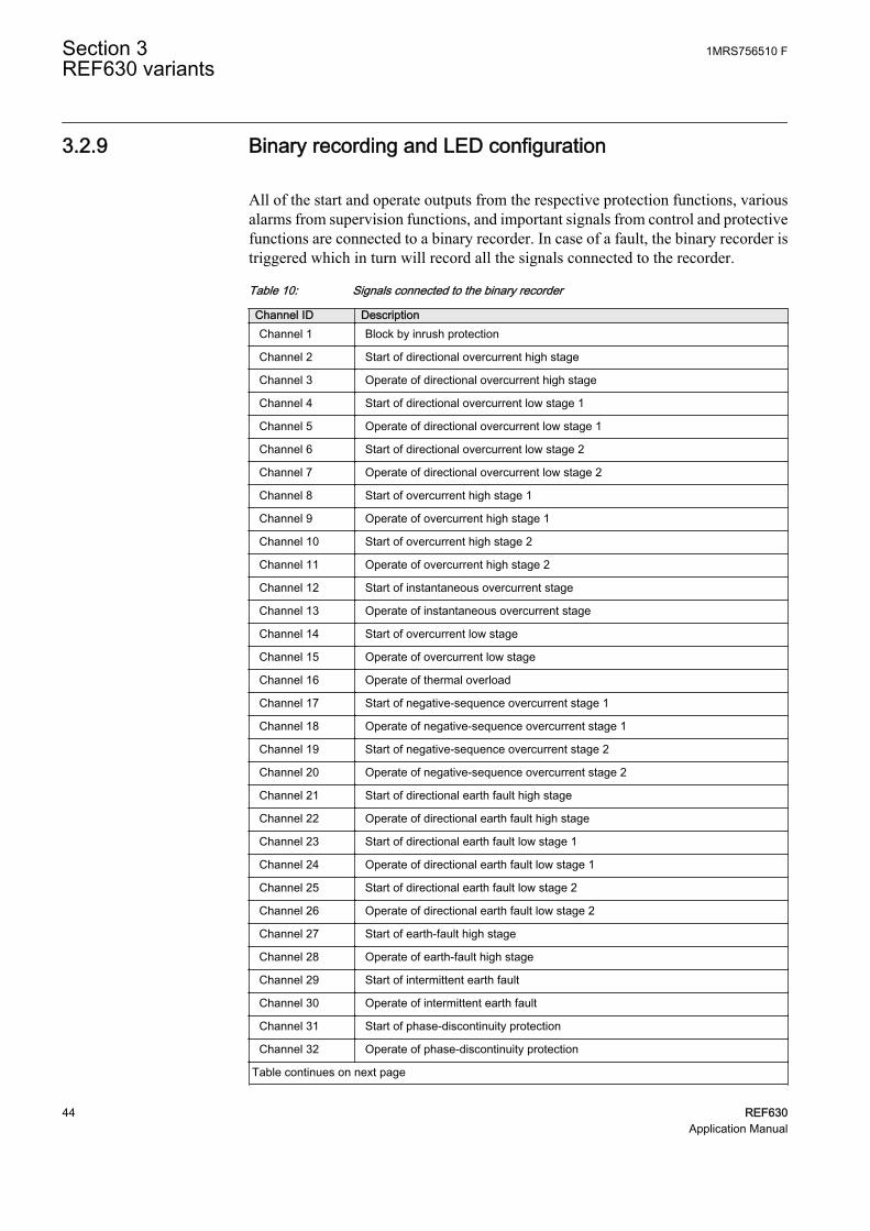
All of the start and operate outputs from the respective protection functions, variousalarms from supervision functions, and important signals from control and protectivefunctions are connected to a binary recorder. In case of a fault, the binary recorder istriggered which in turn will record all the signals connected to the recorder.
Table 10: Signals connected to the binary recorder
Channel ID DescriptionChannel 1 Block by inrush protection
Channel 2 Start of directional overcurrent high stage
Channel 3 Operate of directional overcurrent high stage
Channel 4 Start of directional overcurrent low stage 1
Channel 5 Operate of directional overcurrent low stage 1
Channel 6 Start of directional overcurrent low stage 2
Channel 7 Operate of directional overcurrent low stage 2
Channel 8 Start of overcurrent high stage 1
Channel 9 Operate of overcurrent high stage 1
Channel 10 Start of overcurrent high stage 2
Channel 11 Operate of overcurrent high stage 2
Channel 12 Start of instantaneous overcurrent stage
Channel 13 Operate of instantaneous overcurrent stage
Channel 14 Start of overcurrent low stage
Channel 15 Operate of overcurrent low stage
Channel 16 Operate of thermal overload
Channel 17 Start of negative-sequence overcurrent stage 1
Channel 18 Operate of negative-sequence overcurrent stage 1
Channel 19 Start of negative-sequence overcurrent stage 2
Channel 20 Operate of negative-sequence overcurrent stage 2
Channel 21 Start of directional earth fault high stage
Channel 22 Operate of directional earth fault high stage
Channel 23 Start of directional earth fault low stage 1
Channel 24 Operate of directional earth fault low stage 1
Channel 25 Start of directional earth fault low stage 2
Channel 26 Operate of directional earth fault low stage 2
Channel 27 Start of earth-fault high stage
Channel 28 Operate of earth-fault high stage
Channel 29 Start of intermittent earth fault
Channel 30 Operate of intermittent earth fault
Channel 31 Start of phase-discontinuity protection
Channel 32 Operate of phase-discontinuity protection
Table continues on next page
Section 3 1MRS756510 FREF630 variants
44 REF630Application Manual

Channel ID DescriptionChannel 33 Circuit breaker closed
Channel 34 Circuit breaker is open
Channel 35 Unsuccessful autoreclosing
Channel 36 Autoreclosing function locked out
Channel 37 Reclose by autoreclosing
Channel 38 Backup trip from circuit-breaker failure protection
Channel 39 Retrip from circuit-breaker failure protection
Channel 40 Trip circuit alarm 1 (supervising master trip 1)
Channel 41 Trip circuit alarm 2 (supervising master trip 2)
Channel 42 Trip circuit alarm 3 (supervising closing circuit)
Channel 43 Current circuit supervision alarm
Channel 44 Fuse failure
Channel 45 Closing time of circuit breaker exceeded the limit
Channel 46 Opening time of circuit breaker exceeded the limit
Channel 47 Spring charge time of circuit breaker exceeded the limit
Channel 48 Number of circuit breaker operation exceeded the set limit
Channel 49 Pressure in circuit breaker below lockout limit
Channel 50 Circuit breaker maintenance alarm: number of operations exceeds the set limit
Channel 51 Circuit breaker maintenance alarm: accumulated energy exceeds the set limit
Channel 52 Circuit breaker not operated since long
The LEDs are configured for alarm indications.
Table 11: LEDs configured on LHMI alarm page 1
LED No LED color DescriptionLED 1 Yellow Combine start from DOC
LED 1 Red Combine operate from DOC
LED 2 Yellow Combine start from OC
LED 2 Red Combine operate from OC
LED 3 Yellow Combine start from NSOC
LED 3 Red Combine operate from NSOC
LED 4 Yellow Combine start from EF
LED 4 Red Combine operate from EF
LED 5 Yellow Combine start from DEF
LED 5 Red Combine operate from DEF
LED 6 Yellow Start from phase discontinuity
LED 6 Red Operate from phase discontinuity
LED 7 Yellow Operate from thermal overload
LED 7 Red Alarm from thermal overload
Table continues on next page
1MRS756510 F Section 3REF630 variants
REF630 45Application Manual

LED No LED color DescriptionLED 8 Green Autoreclosing ready
LED 8 Yellow Autoreclosing in progress
LED 8 Red Autoreclosing function locked out
LED 9 Red Combine trip circuit supervision alarm
LED 10 Red Backup trip from circuit-breakerprotection function
LED 11 Red Retrip from circuit-breaker protectionfunction
LED 12 Red Alarm from circuit-breaker monitoringfunction
LED 13 Red Fuse failure supervision
LED 14 Red Current circuit supervision alarm
3.3 Preconfiguration B for radial overhead/mixed linefeeder
3.3.1 Application
The functionality of the IED is designed to be used for selective short-circuit,overcurrent and earth-fault protection of impedance grounded population feeders ondouble busbar systems with one circuit breaker.
The objects controlled by the IED are the circuit breaker and the disconnector. Theearth switch is considered to be operated manually. The open, close and undefinedstates of the circuit breaker, disconnectors and the earth switch are indicated on theLHMI.
Required interlocking is configured in the IED.
The preconfiguration includes:
• Control functions• Current protection functions• Supervision functions• Disturbance recorders• LEDs' configuration• Measurement functions
Section 3 1MRS756510 FREF630 variants
46 REF630Application Manual
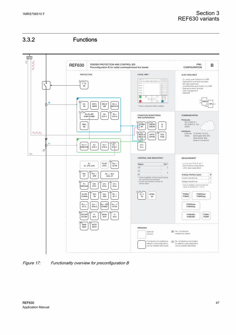
3.3.2 Functions
Io>→Y67YN
CBCMCBCM
MCS 3IMCS 3I
FUSEF60
Io>HA51NHA
Z<21, 21P, 21N
FLOC21FL
Po>→32N
3U>59
U1>47O+
U1<47U+
U2>47O-
P>32R/32O
Yo>→21YN
3U<27
3×
3× 3×
3×
f>81O
5×
Uo>59G
3×
f<81U
5×df/dt>81R
5×
2×2×2×
SOTFSOTF
2×MAPMAP
16×
Q>→, 3U<32Q, 27
3×
CONDITION MONITORING AND SUPERVISION
1 0 1 0 0 0 1 1 0 0 1 1 0 01 0 1 1 0 0 1 0 1 1 1 0 0 1 01 1 0 0 1 1 1 0 1 1 0 1 01 0 1 1 0 1 1 0 1 1 0 1 0 01 0 1 0 0 0 1 1 0 0 1 1 0 0 1 0 1 0 0 0 1 1 0 0 1 1 0 01 0 1 1 0 0 1 0 1 1 1 0 0 1 01 1 0 0 1 1 1 0 1 1 0 1 01 0 1 1 0 1 1 0 1 1 0 1 0 0
ORAND
CONTROL AND INDICATION 1) MEASUREMENT
PRE- CONFIGURATION
PROTECTION LOCAL HMI *)
REF630
REMARKS
Optionalfunction
Function(s) not enabled by default in preconfiguration, can be enabled afterwards
No. of instances enabled by default
2×
No. of instances not enabled by default in preconfiguration, can be enabled afterwards
1×
COMMUNICATION
Protocols: IEC 61850-8-1 IEC 60870-5-103 DNP3
Interfaces: Ethernet: TX (RJ45), FX (LC) Serial: Serial glass fiber (ST), Serial plastic fiber (snap-in connector)
ALSO AVAILABLE
- 5 × prog. push buttons on LHMI- Disturbance and fault recorders- IED self-supervision - Local/Remote push button on LHMI- Sequence event recorder- User management- WebHMI
B
- I, U, Io, Uo, P, Q, E, pf, f- Symmetrical components- Limit value supervision
Analog interface types B
Current transformer 51)
Voltage transformer 4
1) One of available current transformer inputs is sensitive (0.1 / 0.5 A)
*) Fixed or detached LHMI is available.
Object Ctrl 2)
CB 2
DC8
ES1) Check availability of binary inputs/outputs
from technical documentation2) Control and indication function for
primary object
3I>/Io>BF51BF/51NBF
Io>→67N-1
I→O94
1×1×
U<>U<>
O→I79
1×1×SYNC
25
Io>51N-1
Io>>>50N/51N
Io>>51N-2
Io>→67N-2
Io>→IEF67NIEF
1× 1×3I>>
51P-2
3I>>>50P/51P
3I>>→67-2
3I>51P-1
I2/I1>46PD
I2>46
3Ith>F49F
3I2f>68
EE
PQMUPQMV
PQMUBUPQMUBV
PQM3IPQM3I
PQM3UppPQM3Vpp
PQM3UpePQM3Vpg
2×1×
2×
2×
3I>→67-1
2×
1×1× 1×1×
1×1×TCSTCM
3×
3I
Io
UL1
UL2
UL3
UL1UL2UL3
Uo
Uo
FEEDER PROTECTION AND CONTROL IEDPreconfiguration B for radial overhead/mixed line feeder
UFLS/R81LSH
6×
OPTSOPTM
GUID-041037E1-4C3F-4F83-BFFB-995BA916B55B V1 EN
Figure 17: Functionality overview for preconfiguration B
1MRS756510 F Section 3REF630 variants
REF630 47Application Manual

3.3.3 Input/output signal interfacesTable 12: Interface of binary inputs
Hardware moduleinstance
Hardware channel Description
COM BI1 Circuit breaker closed
COM BI2 Circuit breaker open
COM BI3 Disconnector 1 closed
COM BI4 Disconnector 1 open
COM BI5 Earth switch closed
COM BI6 Earth switch open
COM BI7 Disconnector 2 closed
COM BI8 Disconnector 2 open
COM BI9 Circuit breaker truck closed
COM BI10 Circuit breaker truck open
COM BI11 External start of circuit-breaker failure protection
COM BI12 Pressure low from circuit breaker
COM BI13 Spring charged from circuit breaker
COM BI14 MCB for fuse failure supervision
The outputs of the IED are categorized as power outputs (POx) and signal outputs(SOx). The power outputs can be used for closing and tripping of circuit breakers anddisconnector control. The signal outputs are not heavy-duty outputs. They are used foralarm or signaling purposes.
Table 13: Interface of binary outputs
Hardware moduleinstance
Hardware channel Description
PSM BO1_PO Master trip 1 (circuit breaker open)
PSM BO2_PO Master close (circuit breaker closed)
PSM BO3_PO Master trip 2 (circuit breaker open)
PSM BO4_PO Disconnector 1 open
PSM BO5_PO Disconnector 1 closed
PSM BO6_PO Not connected
PSM BO7_SO OC operate alarm
PSM BO8_SO EF/DEF operate alarm
PSM BO9_SO Common start
BIO_3 BO1_PO Disconnector 2 open
BIO_3 BO2_PO Disconnector 2 closed
BIO_3 BO3_PO Backup trip
BIO_3 BO4_SO Upstream OC block
BIO_3 BO5_SO Common operate
Table continues on next page
Section 3 1MRS756510 FREF630 variants
48 REF630Application Manual

Hardware moduleinstance
Hardware channel Description
BIO_3 BO6_SO Not connected
BIO_3 BO7_SO Circuit-breaker monitoring alarm
BIO_3 BO8_SO Supervision circuit alarm
BIO_3 BO9_SO Not connected
The IED measures the analog signals needed for protection and measuring functionsvia galvanically isolated matching transformers. The matching transformer inputchannels 1…4 are intended for current measuring and channels 7...10 for voltagemeasuring.
Table 14: Interface of analog inputs
Hardware moduleinstance
Hardware channel Description
AIM_2 CH1 Phase current IL1
AIM_2 CH2 Phase current IL2
AIM_2 CH3 Phase current IL3
AIM_2 CH4 Neutral current I0
AIM_2 CH5 Current I0 from CBCT
AIM_2 CH6 Not available
AIM_2 CH7 Phase voltage UL1
AIM_2 CH8 Phase voltage UL2
AIM_2 CH9 Phase voltage UL3
AIM_2 CH10 Neutral voltage U0
3.3.4 Preprocessing blocks and fixed signals
The analog current and voltage signals coming to the IED are processed bypreprocessing blocks. There are two types of preprocessing blocks based on 20samples per cycle and 80 samples per cycle. All function blocks functioning at 5 mstask time need 80 samples per cycle whereas all the rest need 20 samples per cycle.
A fixed signal block providing a logical TRUE and a logical FALSE output has beenused. Outputs are connected internally to other functional blocks when needed.
Even if the AnalogInputType setting of a SMAI block is set to“Current”, the MinValFreqMeas setting is still visible. This meansthat the minimum level for current amplitude is based on UBase. Asan example, if UBase is 20 kV, the minimum amplitude for current is20000 × 10% = 2000 A.
1MRS756510 F Section 3REF630 variants
REF630 49Application Manual
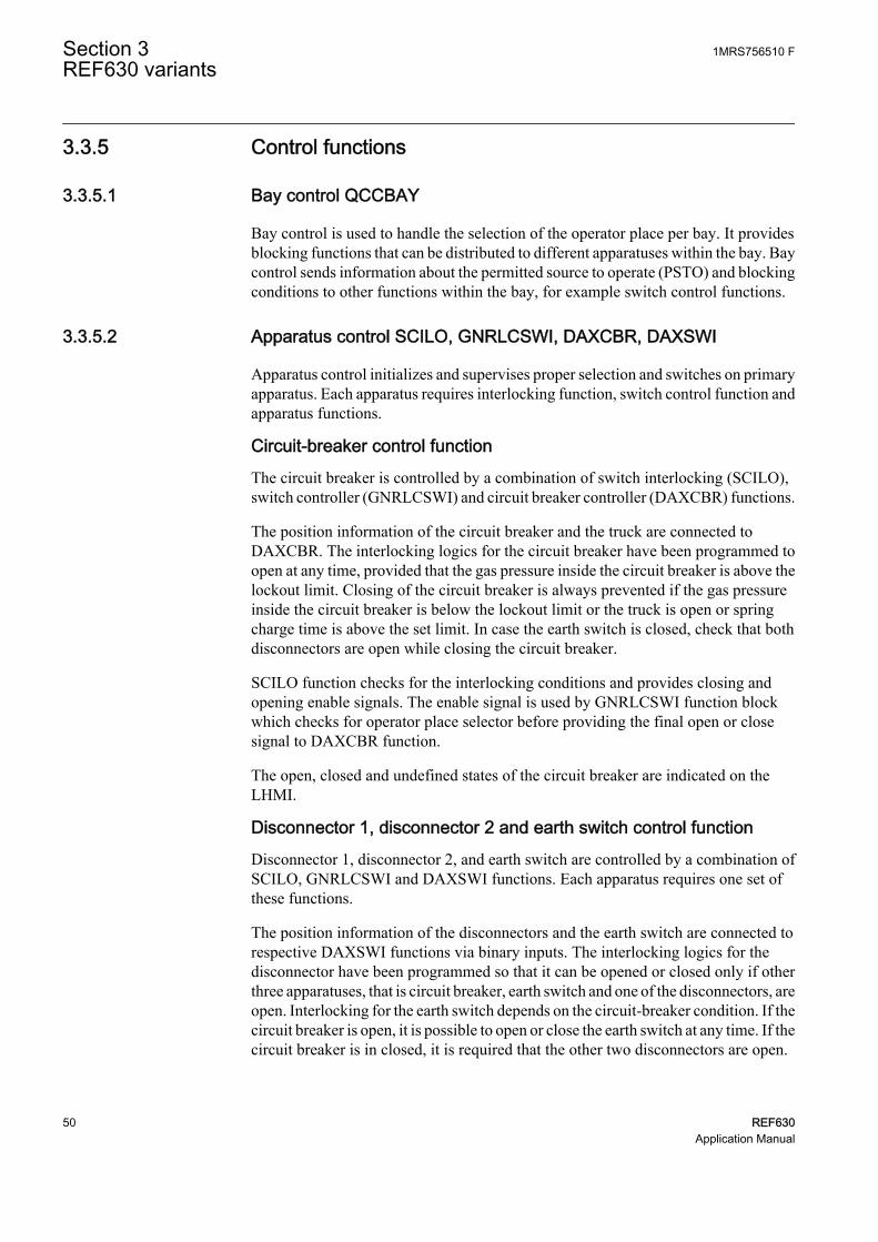
3.3.5 Control functions
3.3.5.1 Bay control QCCBAY
Bay control is used to handle the selection of the operator place per bay. It providesblocking functions that can be distributed to different apparatuses within the bay. Baycontrol sends information about the permitted source to operate (PSTO) and blockingconditions to other functions within the bay, for example switch control functions.
3.3.5.2 Apparatus control SCILO, GNRLCSWI, DAXCBR, DAXSWI
Apparatus control initializes and supervises proper selection and switches on primaryapparatus. Each apparatus requires interlocking function, switch control function andapparatus functions.
Circuit-breaker control functionThe circuit breaker is controlled by a combination of switch interlocking (SCILO),switch controller (GNRLCSWI) and circuit breaker controller (DAXCBR) functions.
The position information of the circuit breaker and the truck are connected toDAXCBR. The interlocking logics for the circuit breaker have been programmed toopen at any time, provided that the gas pressure inside the circuit breaker is above thelockout limit. Closing of the circuit breaker is always prevented if the gas pressureinside the circuit breaker is below the lockout limit or the truck is open or springcharge time is above the set limit. In case the earth switch is closed, check that bothdisconnectors are open while closing the circuit breaker.
SCILO function checks for the interlocking conditions and provides closing andopening enable signals. The enable signal is used by GNRLCSWI function blockwhich checks for operator place selector before providing the final open or closesignal to DAXCBR function.
The open, closed and undefined states of the circuit breaker are indicated on theLHMI.
Disconnector 1, disconnector 2 and earth switch control functionDisconnector 1, disconnector 2, and earth switch are controlled by a combination ofSCILO, GNRLCSWI and DAXSWI functions. Each apparatus requires one set ofthese functions.
The position information of the disconnectors and the earth switch are connected torespective DAXSWI functions via binary inputs. The interlocking logics for thedisconnector have been programmed so that it can be opened or closed only if otherthree apparatuses, that is circuit breaker, earth switch and one of the disconnectors, areopen. Interlocking for the earth switch depends on the circuit-breaker condition. If thecircuit breaker is open, it is possible to open or close the earth switch at any time. If thecircuit breaker is in closed, it is required that the other two disconnectors are open.
Section 3 1MRS756510 FREF630 variants
50 REF630Application Manual

SCILO function checks for these conditions and provides closing and opening enablesignals. The enable signal is used by GNRLCSWI function blocks which check foroperator place selector before providing the final open or close signal to DAXCBRfunction.
The open, closed and undefined states of the disconnector 1, disconnector 2 and earthswitch are indicated on the LHMI.
The interlocking condition for the disconnector can be different incase a bus sectionalizer is available in the system.
GUID-3FEC4A93-BFE0-4386-8091-0D83339E19EE V1 EN
Figure 18: Apparatus control
1MRS756510 F Section 3REF630 variants
REF630 51Application Manual

3.3.5.3 Autoreclosing DARREC
Majority of medium voltage overhead line faults are transient and automaticallycleared by momentarily de-energizing the line, whereas the rest of the faults, 15 to 20percent, are cleared by longer interruptions. The de-energization of the fault place fora wanted period of time is implemented by autoreclosing relays or functions.Automatic reclosing is capable of clearing most of the faults. At a permanent fault,autoreclosing is followed by the final tripping. A permanent fault has to be located andcleared before the fault location can be re-energized.
The function block provides five programmable autoreclose shots for creatingautoreclosings of wanted type and duration, such as one high-speed and one delayedautoreclosing. The function consists of six individual initiation lines INIT_1... INIT 6from which lines INIT_1...3 are used in the preconfiguration. It is possible to create anindividual autoreclosing sequence for each input.
In this preconfiguration the autoreclosing function is initiated (lines INIT_1..3) fromthe operation of protection functions. The autoreclosing function allows also initiationfrom the start of the protection function, then opening the circuit breaker (OPEN CB)and performing a fast final trip.
The autoreclosing function can be inhibited with the INHIBIT_RECL input. Operatesignals of negative sequence overcurrent, phase discontinuity, intermittent earth faultand circuit-breaker gas pressure lock are connected to INHIBIT_RECL input. Springcharged input available from the circuit breaker at binary input COM_101 BI13 isused to check the ready status of circuit breaker before autoreclosing. Inhibitautoreclose signal from the thermal overload protection is connected toBLK_THERM input.
The outputs describing closing command (reclose) to a circuit breaker, unsuccessfulautoreclosing and autoreclosing locked-out (CLOSE CB, UNSUC_AR, andLOCKED) are connected to binary recorders. Whereas autoreclosing ready,autoreclosing in progress and autoreclosing locked-out (READY, INPRO andLOCKED) outputs are connected to LED indication on the LHMI.
Status indicating that circuit breaker in open state is connected to the CB_POS inputs.With this connection the setting is CB closed Pos status = FALSE.
CLOSE CB output is used for closing the circuit breaker. Before any autoreclosingsignal is activated the function block checks for the circuit breaker ready status.
If an industrial feeder employs cables it may not be advisable to useautoreclosing, as cable faults are not transient but permanent.
Section 3 1MRS756510 FREF630 variants
52 REF630Application Manual

GUID-C341207A-5B43-415A-93E3-30FFBC16B9C7 V1 EN
Figure 19: Autoreclosing
3.3.6 Protection functions
3.3.6.1 Three-phase current inrush detection INRPHAR
The configuration includes a three-phase current inrush detection function. Thefunction can be used for increasing, typically double, the set start value of the non-directional overcurrent stage (OC) during inrush condition. This is done by theENA_MULT input and the Start value mult setting in the corresponding functionblocks. The default multiplier setting is 1.0.
3.3.6.2 Non-directional overcurrent protection PHxPTOC
The three-phase non-directional overcurrent functions are used for non-directionalone-phase, two-phase and three-phase overcurrent and short-circuit protection withdefinite time or various inverse definite minimum time (IDMT) characteristic. Theoperation of a stage is based on three measuring principles: DFT, RMS or peak-to-peak values.
1MRS756510 F Section 3REF630 variants
REF630 53Application Manual

The configuration includes four variants of non-directional overcurrent functions:high 1, high 2, low and instantaneous. The set of three phase currents, I3P, isconnected to the inputs. The inrush function can increase the start value of eachovercurrent function.
A common operate and start signal from all the four non-directional overcurrentfunctions are connected to an OR-gate to form a combined non-directionalovercurrent operate and start signal which is used to provide a LED indication on theLHMI. Also separate start and operate from all the four OC functions are connectedto the disturbance recorder.
3.3.6.3 Negative-sequence overcurrent protection NSPTOC
Two instances of negative-sequence overcurrent detection are provided, forprotection against single-phasing, unbalanced load or asymmetrical feeder voltage.The set of three phase currents, I3P, is connected to the inputs.
A common operate and start signal from both NSPTOC functions are connected to anOR-gate to form a combined negative-sequence overcurrent operate and start signalwhich is used to provide a LED indication on the LHMI. Also separate start andoperate signals from the NSPTOC function is connected to the disturbance recorder.
GUID-1378C047-42E7-4016-80B7-3482BA186092 V1 EN
Figure 20: Non-directional overcurrent and negative-sequence overcurrentprotection
Section 3 1MRS756510 FREF630 variants
54 REF630Application Manual

3.3.6.4 Phase discontinuity protection PDNSPTOC
The phase discontinuity protection functions are used for protection against brokenphase conductors in distribution networks. Definite-time (DT) characteristic is alwaysused. Operation of the stage is based on ratio of 2nd harmonic and fundamentalfrequency of phase currents.
The set of three phase currents, I3P, is connected to the inputs. Operate and startsignals are used to trigger the disturbance recorder and to provide a LED indication onthe LHMI.
3.3.6.5 Non-directional earth-fault protection EFxPTOC
The non-directional earth-fault protection functions are used for protection underearth fault conditions with definite-time (DT) or with inverse definite minimum time(IDMT) characteristic when appropriate.
The operation of the stage is based on three measuring principles: DFT, RMS or peak-to-peak values. The configuration includes three variants of non-directional earth-fault functions: high, low and instantaneous. The set of three phase currents, I3P, isconnected to the inputs.
A common operate and start signal from all the three non-directional earth-faultfunctions are connected to an OR-block to form a combined non-directional earth-fault operate and start signal which is used to provide a LED indication on the LHMI.Also separate start and operate signals from all the three EF functions are connectedto the disturbance recorder.
3.3.6.6 Directional earth-fault protection DEFxPDEF
The directional earth-fault protection function block is set to operate as non-directional earth-fault protection, with definite-time (DT) or with inverse definiteminimum time (IDMT) characteristic when appropriate.
The set of three phase currents and voltages, I3P and U3P, are connected to the inputs.The operation of the stage can be based on three measuring principles: DFT, RMS orpeak-to-peak values.
The configuration includes low-stage directional earth-fault protection. The residualcurrent inputs are obtained through residual connection of three numbers of singlephase current transformers or a core-balanced current transformer or through a singlecurrent transformer connected to neutral of a star-connected transformer. To achievethe highest sensitivity and accuracy, use a separate neutral current transformerconnection to sensitive dedicated current channel 5 of the IED.
A directional earth-fault operate and start signal is used to trigger the disturbancerecorder and to provide a LED indication on the LHMI.
1MRS756510 F Section 3REF630 variants
REF630 55Application Manual
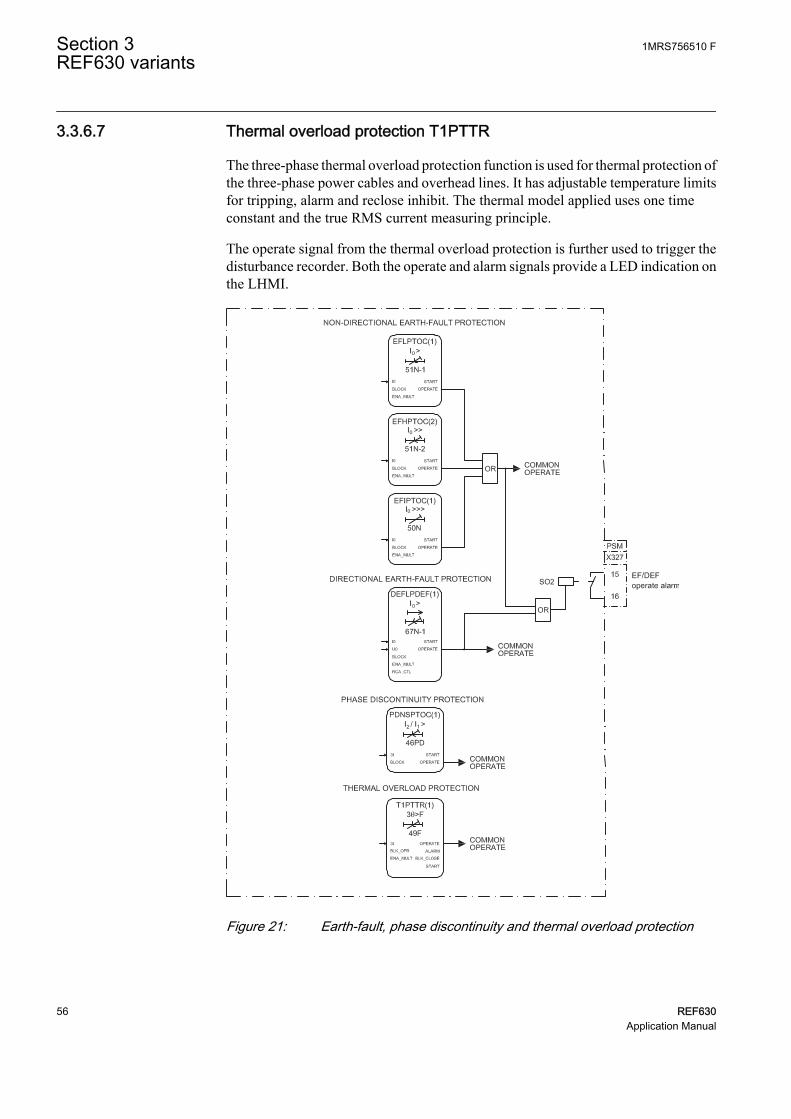
3.3.6.7 Thermal overload protection T1PTTR
The three-phase thermal overload protection function is used for thermal protection ofthe three-phase power cables and overhead lines. It has adjustable temperature limitsfor tripping, alarm and reclose inhibit. The thermal model applied uses one timeconstant and the true RMS current measuring principle.
The operate signal from the thermal overload protection is further used to trigger thedisturbance recorder. Both the operate and alarm signals provide a LED indication onthe LHMI.
GUID-0AFD2863-36F7-4C77-84BE-F060DF1E64CD V1 EN
Figure 21: Earth-fault, phase discontinuity and thermal overload protection
Section 3 1MRS756510 FREF630 variants
56 REF630Application Manual
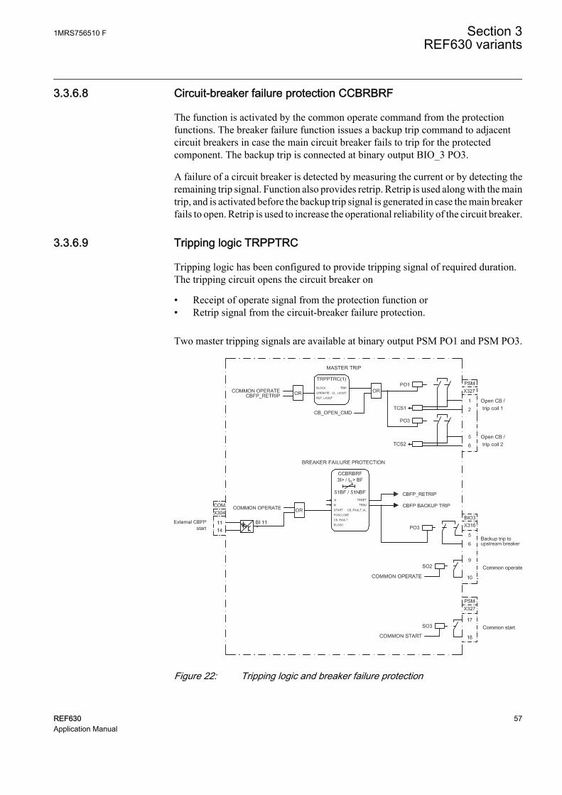
3.3.6.8 Circuit-breaker failure protection CCBRBRF
The function is activated by the common operate command from the protectionfunctions. The breaker failure function issues a backup trip command to adjacentcircuit breakers in case the main circuit breaker fails to trip for the protectedcomponent. The backup trip is connected at binary output BIO_3 PO3.
A failure of a circuit breaker is detected by measuring the current or by detecting theremaining trip signal. Function also provides retrip. Retrip is used along with the maintrip, and is activated before the backup trip signal is generated in case the main breakerfails to open. Retrip is used to increase the operational reliability of the circuit breaker.
3.3.6.9 Tripping logic TRPPTRC
Tripping logic has been configured to provide tripping signal of required duration.The tripping circuit opens the circuit breaker on
• Receipt of operate signal from the protection function or• Retrip signal from the circuit-breaker failure protection.
Two master tripping signals are available at binary output PSM PO1 and PSM PO3.
GUID-9C15DB69-98E5-49EB-836A-CF0B247D2DF4 V1 EN
Figure 22: Tripping logic and breaker failure protection
1MRS756510 F Section 3REF630 variants
REF630 57Application Manual

3.3.6.10 Combined operate and start alarm signal
The operate outputs of all protection functions are combined in an OR-gate to get acommon Operate output. This common operate signal is connected to a tripping logic.It is also available as an alarm binary output, BIO_3_SO2, with a settable minimumalarm delay of 80 ms. Also, a common Start output is derived from the start outputs ofprotection functions combined in an OR-gate. The output is available as an alarmbinary output PSM SO3 with a settable minimum alarm delay of 80 ms.
3.3.6.11 Other output and alarm signals
• Combined overcurrent (OC) operate signal available at binary output PSM SO1• Combined earth fault and sensitive earth-fault (EF/DEF) operate signal available
at binary output PSM SO2• Combined alarm signal from circuit-breaker monitoring function available at
binary output BIO_3 SO4• Combined alarm signal from various supervision functions available at binary
output BIO_3 SO5• Upstream overcurrent (OC) blocking signal available at binary output BIO_3
SO1
3.3.7 Supervision functions
3.3.7.1 Trip circuit supervision TCSSCBR
Two instances of trip circuit supervision function are used for supervising Master trip1 and Master trip 2. Function continuously supervises trip circuit and an alarm isissued in case of a failure of a trip circuit. The function does not perform thesupervision itself but it is used as an aid for configuration.
Function gives an indication via a LED on the LHMI on detection of any of the tripcircuit failure. To prevent unwanted alarms, the function is blocked when the circuitbreaker is open, one of the protection function operate signals is active.
An instance of trip circuit supervision is used to check the proper functioning ofclosing circuit of the circuit breaker. This function is blocked when the circuit breakeris in closed position to prevent unwanted alarms.
3.3.7.2 Fuse failure and current circuit supervision SEQRFUF, CCRDIF
The fuse failure and current circuit supervision functions give an alarm in case of afailure in the secondary circuits between the voltage transformer or currenttransformer and the IED respectively. The set of three phase currents and voltages, I3Pand U3P, are connected to the inputs.
An alarm is available on failure of the secondary circuits. Alarms are recorded by adisturbance recorder.
Section 3 1MRS756510 FREF630 variants
58 REF630Application Manual

3.3.7.3 Circuit-breaker condition monitoring SSCBR
The circuit-breaker condition monitoring function checks for the health of the circuitbreaker. The circuit breaker status is connected to the function via binary inputs.Function requires also pressure lockout input and spring charged input connected viabinary input COM_101.BI12 and COM_101.BI13 respectively. Various alarmoutputs from the function are combined in an OR-gate to create a master circuit-breaker monitoring alarm, which is available at binary output BIO_3 SO4.
All of the alarms are separately connected to the binary recorder and a combined alarmis available as an indication via a LED on the LHMI.
GUID-F364F9E6-D33D-4ADD-82DA-5CFFE1960055 V2 EN
Figure 23: Circuit-breaker condition monitoring and trip-circuit, fuse failure andcurrent measuring circuit supervision
3.3.8 Measurement and analog recording functions
The measured quantities in this configuration are:
• Sequence current• Sequence voltage• Residual voltage• Residual current
1MRS756510 F Section 3REF630 variants
REF630 59Application Manual

• Energy• Phase current• Phase voltage• Line voltage• Power with frequency
The measured quantities can be viewed in the measurement menu on the LHMI.
All analog input channels are connected to the analog disturbance recorder. When anyof these analog values violate the upper or lower threshold limits, the recorder unit istriggered which in turn will record all the signals connected to the recorder.
Table 15: Signals connected to the analog recorder
Channel ID DescriptionChannel 1 Phase A current
Channel 2 Phase B current
Channel 3 Phase C current
Channel 4 Neutral current
Channel 5 Neutral current from CBCT
Channel 6 Phase A voltage
Channel 7 Phase B voltage
Channel 8 Phase C voltage
Channel 9 Neutral voltage
Data connected to analog channels contain 20 samples per cycle.
Section 3 1MRS756510 FREF630 variants
60 REF630Application Manual
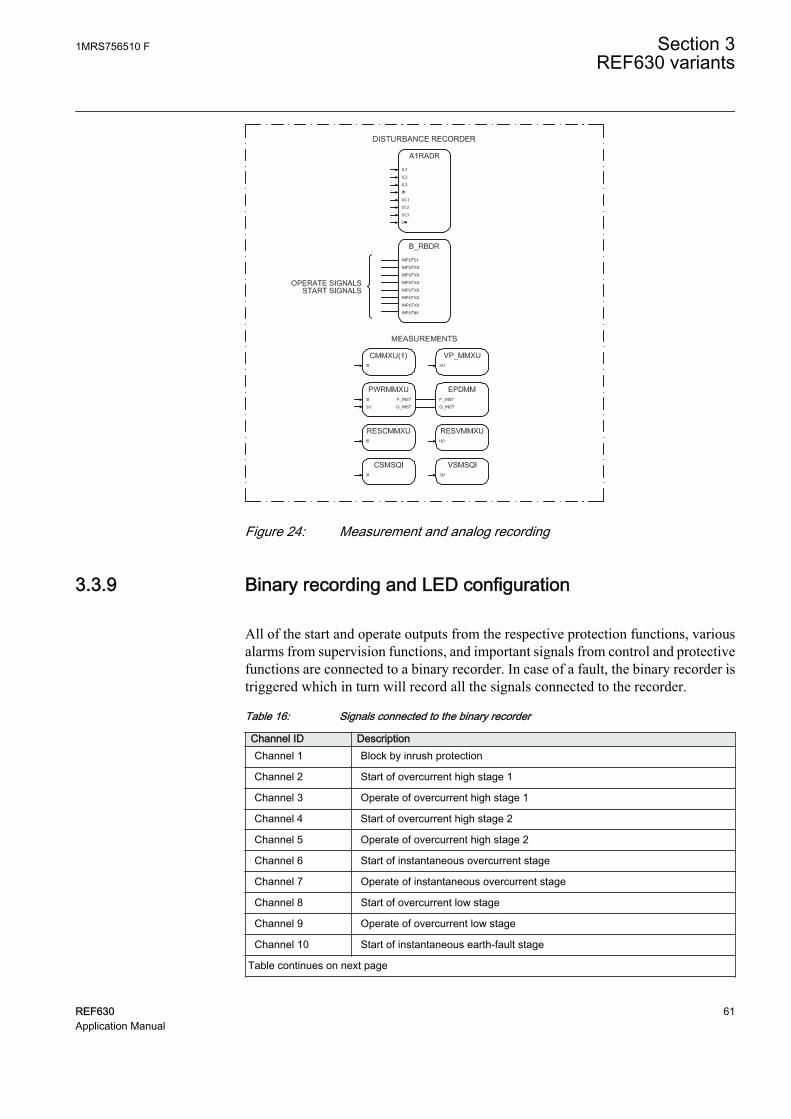
GUID-7BE6A942-DDC2-4D39-AB42-87C984C2015B V1 EN
Figure 24: Measurement and analog recording
3.3.9 Binary recording and LED configuration
All of the start and operate outputs from the respective protection functions, variousalarms from supervision functions, and important signals from control and protectivefunctions are connected to a binary recorder. In case of a fault, the binary recorder istriggered which in turn will record all the signals connected to the recorder.
Table 16: Signals connected to the binary recorder
Channel ID DescriptionChannel 1 Block by inrush protection
Channel 2 Start of overcurrent high stage 1
Channel 3 Operate of overcurrent high stage 1
Channel 4 Start of overcurrent high stage 2
Channel 5 Operate of overcurrent high stage 2
Channel 6 Start of instantaneous overcurrent stage
Channel 7 Operate of instantaneous overcurrent stage
Channel 8 Start of overcurrent low stage
Channel 9 Operate of overcurrent low stage
Channel 10 Start of instantaneous earth-fault stage
Table continues on next page
1MRS756510 F Section 3REF630 variants
REF630 61Application Manual

Channel ID DescriptionChannel 11 Operate of instantaneous earth-fault stage
Channel 12 Start of earth-fault high stage
Channel 13 Operate of earth-fault high stage
Channel 14 Start of earth-fault low stage
Channel 15 Operate of earth-fault low stage
Channel 16 Operate of thermal overload
Channel 17 Start of negative-sequence overcurrent stage 1
Channel 18 Operate of negative-sequence overcurrent stage 1
Channel 19 Start of negative-sequence overcurrent stage 2
Channel 20 Operate of negative-sequence overcurrent stage 2
Channel 21 Start of directional earth-fault, low stage
Channel 22 Operate of directional earth-fault, low stage
Channel 23 Start of phase discontinuity protection
Channel 24 Operate of phase discontinuity protection
Channel 25 Circuit breaker closed
Channel 26 Circuit breaker is open
Channel 27 Unsuccessful autoreclosing
Channel 28 Autoreclosing function locked out
Channel 29 Reclose by autoreclosing
Channel 30 Backup trip from circuit-breaker failure protection
Channel 31 Retrip from circuit-breaker failure protection
Channel 32 Trip circuit alarm 1 (supervising master trip 1)
Channel 33 Trip circuit alarm 2 (supervising master trip 2)
Channel 34 Trip circuit alarm 3 (supervising closing circuit )
Channel 35 Current circuit supervision alarm
Channel 36 Fuse failure
Channel 37 Closing time of circuit breaker exceeded the limit
Channel 38 Opening time of circuit breaker exceeded the limit
Channel 39 Spring charge time of circuit breaker exceeded the limit
Channel 40 Number of circuit breaker operation exceeded the set limit
Channel 41 Pressure in circuit breaker below lockout limit
Channel 42 Circuit breaker maintenance alarm: number of operations exceeds the set limit
Channel 43 Circuit breaker maintenance alarm: accumulated energy exceeds the set limit
Channel 44 Circuit breaker not operated since long
The LEDs are configured for alarm indications.
Section 3 1MRS756510 FREF630 variants
62 REF630Application Manual

Table 17: LEDs configured on LHMI alarm page 1
LED No LED color DescriptionLED 1 Yellow Combine start from OC
LED 1 Red Combine operate from OC
LED 2 Yellow Combine start from NSOC
LED 2 Red Combine operate from NSOC
LED 3 Yellow Combine start from EF
LED 3 Red Combine operate from EF
LED 4 Yellow Start from DEF
LED 4 Red Operate from DEF
LED 5 Yellow Start from phase discontinuity
LED 5 Red Operate from phase discontinuity
LED 6 Yellow Operate from thermal overload
LED 6 Red Alarm from thermal overload
LED 7 Green Autoreclosing ready
LED 7 Yellow Autoreclosing in progress
LED 7 Red Autoreclosing function locked out
LED 8 Red Combine trip circuit supervision alarm
LED 9 Red Backup trip from circuit-breaker protection function
LED 10 Red Retrip from circuit-breaker protection function
LED 11 Red Alarm from circuit-breaker monitoring function
LED 12 Red Fuse failure supervision
LED 13 Red Current circuit supervision
3.4 Preconfiguration C for ring/meshed feeder
3.4.1 Application
The functionality of the IED is designed to provide selective, fast and reliableprotection to be used for overhead lines and power cables in interconnected systems,where distance protection is generally applied. These systems are typically operatedin ring or meshed type of configurations, where the switching state can be changedfrequently due to daily operation and load flow considerations making it impossibleto apply simple overcurrent-based protection. The configuration can also be appliedfor radial feeders to increase the sensitivity of the protection especially if the short-circuit power of the source is low or it is changing due to network operation. Inaddition to the comprehensive distance protection, the configuration includes a multi-stage non-directional overcurrent protection as a back-up protection in cases wheredistance protection is unavailable, for example, due to failure in voltage measuringcircuits.
1MRS756510 F Section 3REF630 variants
REF630 63Application Manual

To enchance the selectivity and operating speed even more, the configuration enablesthe application of scheme communication logic for distance protection and fordirectional residual overcurrent protection. The application of the schemecommunication logic requires a communication link between the line ends, for whicha simple auxiliary voltage based arrangement, or a third-party communication bus--based solutions capable of transmitting binary signals to both directions, can beapplied. If there is a risk of losing the synchronism between the bus and line-sidesources, for example, during the dead time of the autoreclosing due to effects of localgeneration, the configuration can be completed with the synchrocheck/voltagecheckfunctionality.
In solidly or low-impedance-earthed networks, the phase-to-earth measuringelements provide selective and fast protection against earth faults. However, thesensitivity of this protection may not be adequate due to the possibility of faultresistance. Therefore, the configuration includes a multi-stage non-directional anddirectional residual overcurrent protection to ensure adequate sensitivity of theprotection. This protection also operates as a back-up earth-fault protection for thedistance protection, and the low-set stage of these functions can be used to provide adedicated sensitive earth-fault protection.
In high-impedance-earthed networks, it is typical that the phase-to-earth elements ofthe distance protection become blocked by the internal logic of the function when asingle-phase-to-earth fault is detected. Otherwise, a correct and adequate operation ofthe distance protection during single-phase-to-earth faults cannot be ensured.Therefore, if the configuration is used in case of unearthed or compensated neutralpoint networks, sensitive and selective protection against earth faults can be achievedby the multi-stage directional residual overcurrent protection completed with possiblescheme communication logic to fulfill the set sensitivity and operating speedrequirements. In addition, the configuration can further be completed with transientbased earth-fault protection function, which also detects so called intermittent or re-striking earth faults.
The objects controlled by the IED are the circuit breaker and the disconnector. Theearth switch is considered to be operated manually. The open, close and undefinedstates of the circuit breaker, disconnectors and the earth switch are indicated on theLHMI.
Required interlocking is configured in the IED.
The preconfiguration includes:
• Control functions• Current protection functions• Supervision functions• Disturbance recorders• LEDs' configuration• Measurement functions
Section 3 1MRS756510 FREF630 variants
64 REF630Application Manual

3.4.2 Functions
Io>→67N-1
Io>>51N-2
Io>→67N-2
3×
CBCMCBCM
MCS 3IMCS 3I
FUSEF60
CONDITION MONITORING AND SUPERVISION
1 0 1 0 0 0 1 1 0 0 1 1 0 01 0 1 1 0 0 1 0 1 1 1 0 0 1 01 1 0 0 1 1 1 0 1 1 0 1 01 0 1 1 0 1 1 0 1 1 0 1 0 01 0 1 0 0 0 1 1 0 0 1 1 0 0 1 0 1 0 0 0 1 1 0 0 1 1 0 01 0 1 1 0 0 1 0 1 1 1 0 0 1 01 1 0 0 1 1 1 0 1 1 0 1 01 0 1 1 0 1 1 0 1 1 0 1 0 0
ORAND
CONTROL AND INDICATION 1) MEASUREMENT
PRE- CONFIGURATION
PROTECTION LOCAL HMI *)
REF630
REMARKS
Optionalfunction
Function(s) not enabled by default in preconfiguration, can be enabled afterwards
No. of instances enabled by default
2×
No. of instances not enabled by default in preconfiguration, can be enabled afterwards
1×
COMMUNICATION
Protocols: IEC 61850-8-1 IEC 60870-5-103 DNP3
Interfaces: Ethernet: TX (RJ45), FX (LC) Serial: Serial glass fiber (ST), Serial plastic fiber (snap-in connector)
ALSO AVAILABLE
- 5 × prog. push buttons on LHMI- Disturbance and fault recorders- IED self-supervision - Local/Remote push button on LHMI- Sequence event recorder- User management- WebHMI
C
- I, U, Io, Uo, P, Q, E, pf, f- Symmetrical components- Limit value supervision
Analog interface types B
Current transformer 51)
Voltage transformer 4
1) One of available current transformer inputs is sensitive (0.1 / 0.5 A)
*) Fixed or detached LHMI is available.
Object Ctrl 2)
CB 2
DC8
ES1) Check availability of binary inputs/outputs
from technical documentation2) Control and indication function for
primary object
3I>/Io>BF51BF/51NBF
I→O94
1×1×
U<>U<>
O→I79
1×1×SYNC
25
1× 1×
3I>>51P-2
3I>>>50P/51P
3I>51P-1
I2/I1>46PD
I2>46
3Ith>F49F
3I2f>68
EE
PQMUPQMV
PQMUBUPQMUBV
PQM3IPQM3I
PQM3UppPQM3Vpp
PQM3UpePQM3Vpg
2×
2× 1×1× 1×1×
1×1×TCSTCM
3×
3I
Io
UL1
UL2
UL3
UL1UL2UL3
Uo
Uo
FEEDER PROTECTION AND CONTROL IEDPreconfiguration C for ring/meshed feeder
Uo>59G
3×3U<27
3×3U>59
3×
Z<21, 21P, 21N
SOTFSOTF
1×
Io>→IEF67NIEF
3I>→67-1
3I>>→67-2
2×
df/dt>81R
Io>HA51NHA
FLOC21FL
Io>51N-1
Io>>>50N/51N
Po>→32N
U1>47O+
U1<47U+
U2>47O-
P>32R/32O
f>81O
f<81U
UFLS/R81LSH
Yo>→21YN
3×
3×
5×6×
5×
5×
2×2×
2×
MAPMAP
16×
Q>→, 3U<32Q, 27
3×
1×
OPTSOPTM
Io>→Y67YN
GUID-A5805D15-8663-4995-B76C-A21248C18FBF V1 EN
Figure 25: Functionality overview for preconfiguration C
1MRS756510 F Section 3REF630 variants
REF630 65Application Manual

3.4.3 Input/output signal interfacesTable 18: Interface of binary inputs
Hardware moduleinstance
Hardware channel Description
COM BI1 Circuit breaker closed
COM BI2 Circuit breaker open
COM BI3 Disconnector 1 closed
COM BI4 Disconnector 1 open
COM BI5 Earth switch closed
COM BI6 Earth switch open
COM BI7 Disconnector 2 closed
COM BI8 Disconnector 2 open
COM BI9 Circuit breaker truck closed
COM BI10 Circuit breaker truck open
COM BI11 External start of circuit-breaker failure protection
COM BI12 Pressure low from circuit breaker
COM BI13 Spring charged from circuit breaker
COM BI14 MCB (for fuse failure supervision)
BIO_3 BI1 Relay characteristics angle (RCA) control
BIO_3 BI2 Carrier received - RESCPSCH
BIO_3 BI3 Carrier guard received
BIO_3 BI4 Carrier received - DSOCPSCH
BIO_3 BI5...BI9 Not connected
The outputs of the IED are categorized as power outputs (POx) and signal outputs(SOx). The power outputs can be used for closing and tripping of circuit breakers anddisconnector control. The signal outputs are not heavy-duty outputs. They are used foralarm or signaling purposes.
Table 19: Interface of binary outputs
Hardware moduleinstance
Hardware channel Description
PSM BO1_PO Master Trip 1 (circuit breaker open)
PSM BO2_PO Master Close (circuit breaker closed)
PSM BO3_PO Master Trip 2 (circuit breaker open)
PSM BO4_PO Disconnector 1 open
PSM BO5_PO Disconnector 1 closed
PSM BO6_PO Not connected
PSM BO7_SO Not connected
PSM BO8_SO Not connected
PSM BO9_SO Common start
Table continues on next page
Section 3 1MRS756510 FREF630 variants
66 REF630Application Manual

Hardware moduleinstance
Hardware channel Description
BIO_3 BO1_PO Disconnector 2 open
BIO_3 BO2_PO Disconnector 2 closed
BIO_3 BO3_PO Backup trip
BIO_3 BO4_SO Carrier send - RESCPSCH
BIO_3 BO5_SO Common operate
BIO_3 BO6_SO Carrier send - DSOCPSCH
BIO_3 BO7_SO Circuit breaker monitoring alarm
BIO_3 BO8_SO Supervision circuit alarm
BIO_3 BO9_SO Carrier guard send
The IED measures the analog signals needed for protection and measuring functionsvia galvanically isolated matching transformers. The matching transformer inputchannels 1…4 are intended for current measuring and channels 7...10 for voltagemeasuring.
Table 20: Interface of analog inputs
Hardware moduleinstance
Hardware channel Description
AIM_2 CH1 Phase current IL1
AIM_2 CH2 Phase current IL2
AIM_2 CH3 Phase current IL3
AIM_2 CH4 Neutral current I0
AIM_2 CH5 Not connected
AIM_2 CH6 Not available
AIM_2 CH7 Phase voltage UL1
AIM_2 CH8 Phase voltage UL2
AIM_2 CH9 Phase voltage UL3
AIM_2 CH10 Neutral voltage U0
3.4.4 Preprocessing blocks and fixed signals
The analog current and voltage signals coming to the IED are processed bypreprocessing blocks. There are two types of preprocessing blocks based on 20samples per cycle and 80 samples per cycle. All function blocks functioning at 5 mstask time need 80 samples per cycle whereas all the rest need 20 samples per cycle.
A fixed signal block providing a logical TRUE and a logical FALSE output has beenused. Outputs are connected internally to other functional blocks when needed.
Even if the AnalogInputType setting of a SMAI block is set to“Current”, the MinValFreqMeas setting is still visible. This meansthat the minimum level for current amplitude is based on UBase. As
1MRS756510 F Section 3REF630 variants
REF630 67Application Manual
an example, if UBase is 20 kV, the minimum amplitude for current is20000 × 10% = 2000 A.
3.4.5 Control functions
3.4.5.1 Bay control QCCBAY
Bay control is used to handle the selection of the operator place per bay. It providesblocking functions that can be distributed to different apparatuses within the bay. Baycontrol sends information about the permitted source to operate (PSTO) and blockingconditions to other functions within the bay, for example switch control functions.
3.4.5.2 Apparatus control SCILO, GNRLCSWI, DAXCBR, DAXSWI
Apparatus control initializes and supervises proper selection and switches on primaryapparatus. Each apparatus requires interlocking function, switch control function andapparatus functions.
Circuit-breaker control functionThe circuit breaker is controlled by a combination of switch interlocking (SCILO),switch controller (GNRLCSWI) and circuit breaker controller (DAXCBR) functions.
The position information of the circuit breaker and the truck are connected toDAXCBR. The interlocking logics for the circuit breaker have been programmed toopen at any time, provided that the gas pressure inside the circuit breaker is above thelockout limit. Closing of the circuit breaker is always prevented if the gas pressureinside the circuit breaker is below the lockout limit or the truck is open or springcharge time is above the set limit. In case the earth switch is closed, check that bothdisconnectors are open while closing the circuit breaker.
SCILO function checks for the interlocking conditions and provides closing andopening enable signals. The enable signal is used by GNRLCSWI function blockwhich checks for operator place selector before providing the final open or closesignal to DAXCBR function.
The open, closed and undefined states of the circuit breaker are indicated on theLHMI.
Disconnector 1, disconnector 2 and earth switch control functionDisconnector 1, disconnector 2, and earth switch are controlled by a combination ofSCILO, GNRLCSWI and DAXSWI functions. Each apparatus requires one set ofthese functions.
The position information of the disconnectors and the earth switch are connected torespective DAXSWI functions via binary inputs. The interlocking logics for thedisconnector have been programmed so that it can be opened or closed only if other
Section 3 1MRS756510 FREF630 variants
68 REF630Application Manual
three apparatuses, that is circuit breaker, earth switch and one of the disconnectors, areopen. Interlocking for the earth switch depends on the circuit-breaker condition. If thecircuit breaker is open, it is possible to open or close the earth switch at any time. If thecircuit breaker is in closed, it is required that the other two disconnectors are open.
SCILO function checks for these conditions and provides closing and opening enablesignals. The enable signal is used by GNRLCSWI function blocks which check foroperator place selector before providing the final open or close signal to DAXCBRfunction.
The open, closed and undefined states of the disconnector 1, disconnector 2 and earthswitch are indicated on the LHMI.
The interlocking condition for the disconnector can be different incase a bus sectionalizer is available in the system.
1MRS756510 F Section 3REF630 variants
REF630 69Application Manual

GUID-3FEC4A93-BFE0-4386-8091-0D83339E19EE V1 EN
Figure 26: Apparatus control
3.4.5.3 Autoreclosing DARREC
Majority of medium voltage overhead line faults are transient and automaticallycleared by momentarily de-energizing the line, whereas the rest of the faults, 15 to 20percent, are cleared by longer interruptions. The de-energization of the fault place fora wanted period of time is implemented by autoreclosing relays or functions.Automatic reclosing is capable of clearing most of the faults. In the event of apermanent fault, autoreclosing is followed by the final tripping. A permanent fault hasto be located and cleared before the fault location can be re-energized.
Section 3 1MRS756510 FREF630 variants
70 REF630Application Manual

The function block provides five programmable autoreclose shots for creatingautoreclosings of wanted type and duration, such as one high-speed and one delayedautoreclosing. The function consists of six individual initiation lines INIT_1... INIT 6from which lines lines INIT_1...4 are used in the preconfiguration. It is possible tocreate an individual autoreclosing sequence for each input.
In this preconfiguration the autoreclosing function is initiated (lines INIT_1..4) fromthe operation of protection functions. The autoreclosing function allows also initiationfrom the start of the protection function, then opening the circuit breaker (OPEN CB)and performing a fast final trip.
The autoreclosing function can be inhibited with the INHIBIT_RECL input. Operatesignals of negative sequence overcurrent, phase discontinuity, intermittent earth faultand circuit-breaker gas pressure lock are connected to INHIBIT_RECL input. Springcharged input available from the circuit breaker at binary input COM_101 BI13 isused to check the ready status of circuit breaker before autoreclosing. Inhibitautoreclosing signal from the thermal overload protection is connected toBLK_THERM input.
The outputs describing closing command (reclose) to a circuit breaker, unsuccessfulautoreclosing and autoreclosing locked-out (CLOSE CB, UNSUC_AR, andLOCKED) are connected to binary recorders. Where as autoreclosing ready,autoreclosing in progress and autoreclosing locked-out (READY, INPRO andLOCKED) outputs are connected to LED indication on the LHMI.
Status indicating that circuit breaker in open state is connected to the CB_POS inputs.With this connection the setting is CB closed Pos status = FALSE.
CLOSE CB output is used for closing the circuit breaker. Before any autoreclosingsignal is activated the function block checks for the circuit breaker ready status.
If an industrial feeder employs cables it may not be advisable to useautoreclosing, as cable faults are not transient but permanent.
1MRS756510 F Section 3REF630 variants
REF630 71Application Manual

GUID-757E04BC-4814-41E3-AD7A-A401978F692D V1 EN
Figure 27: Autoreclosing
3.4.6 Protection functions
3.4.6.1 Three-phase current inrush detection INRPHAR
The configuration includes a three-phase current inrush detection function. Thefunction can be used for increasing, typically double, the set start value of the non-directional overcurrent stage (OC) during inrush condition. This is done by theENA_MULT input and the Start value mult setting in the corresponding functionblocks. The default multiplier setting is 1.0.
3.4.6.2 Non-directional overcurrent protection PHxPTOC
The three-phase non-directional overcurrent functions are used for non-directionalone-phase, two-phase and three-phase overcurrent and short-circuit protection withdefinite time or various inverse definite minimum time (IDMT) characteristic. Theoperation of a stage is based on three measuring principles: DFT, RMS or peak-to-peak values.
Section 3 1MRS756510 FREF630 variants
72 REF630Application Manual

The configuration includes four variants of non-directional overcurrent functions:high 1, high 2, low and instantaneous. The set of three phase currents, I3P, isconnected to the inputs. The inrush function can increase the start value of eachovercurrent function.
A common operate and start signal from all the four non-directional overcurrentfunctions are connected to an OR-gate to form a combined non-directionalovercurrent operate and start signal which is used to provide a LED indication on theLHMI. Also separate start and operate from all the four OC functions are connectedto the disturbance recorder.
3.4.6.3 Negative-sequence overcurrent protection NSPTOC
Two instances of negative-sequence overcurrent detection are provided, forprotection against single-phasing, unbalanced load or asymmetrical feeder voltage.The set of three phase currents, I3P, is connected to the inputs.
A common operate and start signal from both NSPTOC functions are connected to anOR-gate to form a combined negative-sequence overcurrent operate and start signalwhich is used to provide a LED indication on the LHMI. Also separate start andoperate signals from the NSPTOC function is connected to the disturbance recorder.
1MRS756510 F Section 3REF630 variants
REF630 73Application Manual

GUID-9B29C6CC-AC89-434C-A190-224D080CA774 V2 EN
Figure 28: Non-directional overcurrent and negative-sequence overcurrentprotection
3.4.6.4 Phase discontinuity protection PDNSPTOC
The phase discontinuity protection functions are used for protection against brokenphase conductors in distribution networks. Definite-time (DT) characteristic is alwaysused. Operation of the stage is based on ratio of 2nd harmonic and fundamentalfrequency of phase currents.
The set of three phase currents, I3P, is connected to the inputs. Operate and startsignals are used to trigger the disturbance recorder and to provide a LED indication onthe LHMI.
3.4.6.5 Non-directional earth-fault protection EFxPTOC
The non-directional earth-fault protection functions are used for protection underearth-fault conditions with definite-time (DT) or with inverse definite minimum time(IDMT) characteristic when appropriate.
Section 3 1MRS756510 FREF630 variants
74 REF630Application Manual
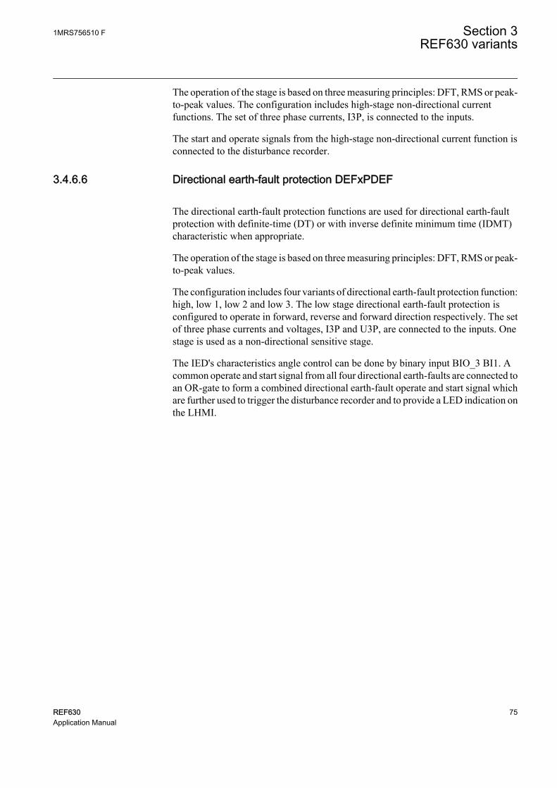
The operation of the stage is based on three measuring principles: DFT, RMS or peak-to-peak values. The configuration includes high-stage non-directional currentfunctions. The set of three phase currents, I3P, is connected to the inputs.
The start and operate signals from the high-stage non-directional current function isconnected to the disturbance recorder.
3.4.6.6 Directional earth-fault protection DEFxPDEF
The directional earth-fault protection functions are used for directional earth-faultprotection with definite-time (DT) or with inverse definite minimum time (IDMT)characteristic when appropriate.
The operation of the stage is based on three measuring principles: DFT, RMS or peak-to-peak values.
The configuration includes four variants of directional earth-fault protection function:high, low 1, low 2 and low 3. The low stage directional earth-fault protection isconfigured to operate in forward, reverse and forward direction respectively. The setof three phase currents and voltages, I3P and U3P, are connected to the inputs. Onestage is used as a non-directional sensitive stage.
The IED's characteristics angle control can be done by binary input BIO_3 BI1. Acommon operate and start signal from all four directional earth-faults are connected toan OR-gate to form a combined directional earth-fault operate and start signal whichare further used to trigger the disturbance recorder and to provide a LED indication onthe LHMI.
1MRS756510 F Section 3REF630 variants
REF630 75Application Manual
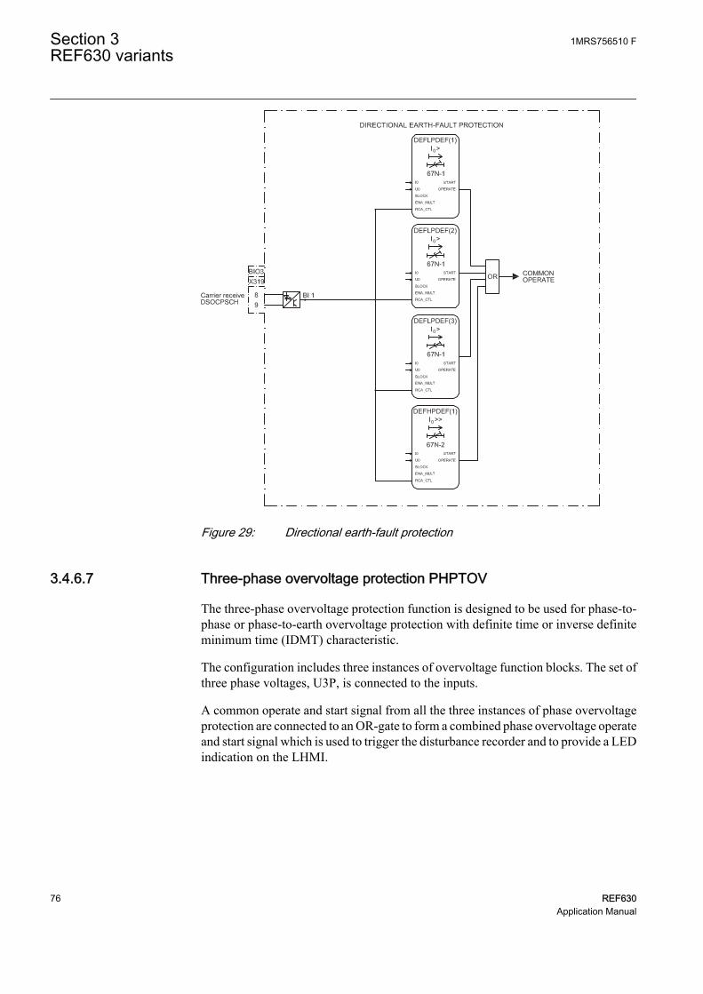
GUID-A96B2BE5-4A13-4FF3-9BF5-F750B494DC63 V1 EN
Figure 29: Directional earth-fault protection
3.4.6.7 Three-phase overvoltage protection PHPTOV
The three-phase overvoltage protection function is designed to be used for phase-to-phase or phase-to-earth overvoltage protection with definite time or inverse definiteminimum time (IDMT) characteristic.
The configuration includes three instances of overvoltage function blocks. The set ofthree phase voltages, U3P, is connected to the inputs.
A common operate and start signal from all the three instances of phase overvoltageprotection are connected to an OR-gate to form a combined phase overvoltage operateand start signal which is used to trigger the disturbance recorder and to provide a LEDindication on the LHMI.
Section 3 1MRS756510 FREF630 variants
76 REF630Application Manual

3.4.6.8 Three-phase undervoltage protection PHPTUV
The three-phase undervoltage protection function is designed to be used for phase-to-phase or phase-to-earth overvoltage protection with definite time or inverse definiteminimum time (IDMT) characteristic.
The configuration includes three instances of undervoltage protection functionblocks. The set of three phase voltages, U3P, is connected to the inputs. Theundervoltage protection is blocked in case of detection of fuse failure.
A common operate and start signal from all the three instances of undervoltageprotection are connected to an OR-gate to form a combined phase undervoltageoperate and start signal which is used to trigger the disturbance recorder and to providea LED indication on the LHMI.
GUID-9154CC42-7BAC-4E2F-82C2-1CFD2163BBDC V1 EN
Figure 30: Under- and overvoltage protection
1MRS756510 F Section 3REF630 variants
REF630 77Application Manual
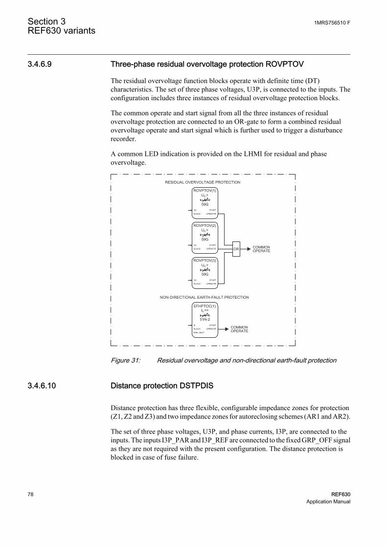
3.4.6.9 Three-phase residual overvoltage protection ROVPTOV
The residual overvoltage function blocks operate with definite time (DT)characteristics. The set of three phase voltages, U3P, is connected to the inputs. Theconfiguration includes three instances of residual overvoltage protection blocks.
The common operate and start signal from all the three instances of residualovervoltage protection are connected to an OR-gate to form a combined residualovervoltage operate and start signal which is further used to trigger a disturbancerecorder.
A common LED indication is provided on the LHMI for residual and phaseovervoltage.
GUID-DFD12114-1F1F-4FF6-AC2F-AC08A75A6B64 V1 EN
Figure 31: Residual overvoltage and non-directional earth-fault protection
3.4.6.10 Distance protection DSTPDIS
Distance protection has three flexible, configurable impedance zones for protection(Z1, Z2 and Z3) and two impedance zones for autoreclosing schemes (AR1 and AR2).
The set of three phase voltages, U3P, and phase currents, I3P, are connected to theinputs. The inputs I3P_PAR and I3P_REF are connected to the fixed GRP_OFF signalas they are not required with the present configuration. The distance protection isblocked in case of fuse failure.
Section 3 1MRS756510 FREF630 variants
78 REF630Application Manual
The AR zones are activated only if AR_ZONES is connected toAR_ZONES from autoreclosing function and the autoreclosing isON.
The operate and start signals from all five zones along with GFC are connected to anOR-gate to form a distance protection operate and start signal which is used to providea common LED indication on the LHMI. Separate operate and start signals from allfive zones along with GFC are used to trigger the disturbance recorder.
The real and imaginary part of fault impedance value for zone Z1 is connected to thedisturbance recorder.
3.4.6.11 Automatic switch onto fault logic CVRSOF
CVRSOF is used as a complement to distance protection to accelerate the operation ofthe protection, ensuring a fast trip when the breaker is closed during a fault. Thefunction has been configured to start its operation on receipt of start from GFC ofdistance protection.
The set of three phase voltages, U3P and I3P, is connected to the inputs. The functionis blocked when autoreclosing is in progress.
The operate signal from CVRSOF is connected to a LED indication on the LHMI andalso to trigger the disturbance recorder.
3.4.6.12 Local acceleration logic DSTPLAL
DSTPLAL is a complementary function to the distance protection function. It is notintended for stand-alone use. DSTPLAL enables fast fault clearing independent of thefault location on the protected feeder when no communication channel is availablebetween the local and remote terminals. DSTPLAL cannot fully replacecommunication scheme logic. DSTPLAL can be controlled either by the autorecloser(zone extension logic) or by monitoring the loss of load currents (loss of load logic).Both operation modes can be enabled independently.
The set of three phase currents, I3P, is connected to the inputs. Overreaching zone,which is used for acceleration, is connected to zone extension and loss of load inputsEX_ACC and LOSSLOAD_ACC respectively. The start signal from the non-directional zone is connected to the NONDIR_ST input. In case the set reclaim timeof the autoreclose function expires before the fault has been cleared, the NONDIR_STsignal blocks the activation of the zone acceleration. This ensures that the acceleratedtrip followed by the AR initiation is not repeated for the same fault regardless of thereclaim time setting and the reach of the overreaching zone connected to EX_ACC.Otherwise this could lead to pumping of the circuit breaker, that is, repetition of thefirst shot without being able to complete the wanted AR sequence.
The operate signals, OP_LOSSLOAD and OP_Z_EXTN, are connected to thedisturbance recorder. These outputs along with other operate signals from distance
1MRS756510 F Section 3REF630 variants
REF630 79Application Manual

support functions are connected to an OR-block to from a combined operate signalfrom distance support functions.
3.4.6.13 Scheme communication logic for distance protection DSOCPSCH
To achieve instantaneous fault clearing independent of the fault location on theprotected feeder, a scheme communication logic DSOCPSCH is provided.
There are different types of communication schemes available.
• Direct intertrip (DUTT)• Permissive underreach (PUTT)• Permissive overreach (POTT)• Directional comparison blocking (DCB)
The directional comparison unblocking scheme (DCUB) can also be provided bycomplementing the permissive schemes by an additional logic called the unblockingfunction, which is also included in DSOCPSCH.
If the permissive overreaching scheme is used, some power system conditions requireadditional special logic circuits, like current reversal logic and weak-end infeed logic(WEI) for distance protection CRWPSCH.
The BLK_CS input connected to the operate signal from current reversal logic is usedto block the carrier send signal from overreaching zone. It is applicable in directionalcomparison blocking scheme (DCB) and in the permissive overreach schemes(POTT).
The CSBLK input connected to the START signal from a reverse looking zone Z3 isused in the directional comparison blocking scheme (DCB) in order to create a carriersend signal CS.
The CACC input connected to the START signal from an overreaching zone Z2 isused in the permissive underreach scheme (PUTT) and in the directional comparisonblocking scheme (DCB).
The CSOR input connected to the START signal from an overreaching zone Z2 isused in the permissive overreach scheme (POTT).
The CSUR input connected to the START signal from an underreaching zone Z1 isused in the direct intertrip scheme (DUTT) and in the permissive underreach scheme(PUTT). It can also be used in the permissive overreach scheme (POTT).
The CR input is a carrier received signal from the IED available at the opposite end ofthe feeder via binary input BI0_3 BI4. Similarly, the CRG input is a carrier guardsignal used in the directional comparison unblocking scheme (DCUB) available fromthe IED at the opposite end of the feeder via binary input BI0_3 BI3.
The CS output is the carrier send signal, send to the IED available at the opposite endof the feeder and send via binary output BI0_3 SO3.
Section 3 1MRS756510 FREF630 variants
80 REF630Application Manual

The operate signal OPERATE along with carrier guard received, DSOCPSCH carrierreceived and DSOCPSCH carrier send signals available at binary input BI0_3 BI3,BI0_3 BI4 and binary output BI0_3 SO3 are connected to the disturbance recorder.
The OPERATE output along with other operate signals from the distance supportfunctions are connected to an OR-block to form a combined operate signal from thedistance support functions.
3.4.6.14 Current reversal and weak-end infeed logic for distance protectionCRWPSCH
Scheme communication logic for distance protection (DSOCPSCH) may requireadditional logics in order to operate correctly in all possible power system conditions.These logics include for example current reversal logic and weak-end infeed logicwhich are combined to the function block CRWPSCH.
The main purpose of the current reversal logic is to prevent unwanted operation of thedistance protection. In parallel feeder applications, the direction of fault current on ahealthy feeder can change when the circuit breaker on the faulty feeder opens to clearthe fault. This can lead to unwanted operation of the distance protection on the healthyparallel feeder when scheme communication logic (DSOCPSCH) with permissiveoverreach scheme is used.
Permissive communication schemes can operate only when the protection function inthe remote terminal can detect the fault. Detection requires a sufficient minimum faultcurrent. If such current is not available due to too weak remote-end source, the weak-end infeed logic can be used to overcome the situation and to trip the remote-endbreaker.
The set of three phase voltages, U3P, is connected to the inputs.
The BLK_IRV input connected to START signals from a forward directional zonesZ1 and Z2 is used to block the activation of the OPR_IRV output. The BLK_WEI1input connected to START signals from the non-directional start signal from GFC isused to block the operate signal from WEI logic. The IRV input is connected to thereverse looking zone Z3 to recognize that the fault is in the reverse direction, that is,in the parallel feeder. Input CR is connected to carrier received signal. This is obtainedfrom scheme communication logic from distance protection (DSOCPSCH). TheCB_OPEN input is connected to binary input COM_101 BI2.
The OPR_IRV output indicates current reversal detection and it is used in schemecommunication logic from distance protection (DSOCPSCH) in order to block thesending of the carrier send signal (CS) and block the activation of the OPERATEoutput of the communication logic.
OPR_WEI is connected to the disturbance recorder and also to an OR-block to froma combined operate signal from distance support functions.
1MRS756510 F Section 3REF630 variants
REF630 81Application Manual

GUID-A74805F2-6711-41F0-8D0C-22C6AA86CE72 V1 EN
Figure 32: Distance protection
3.4.6.15 Scheme communication logic for residual overcurrent protectionRESCPSCH
To achieve instantaneous fault clearing independent of the fault location on theprotected feeder, a scheme communication logic RESCPSCH is provided.
There are different types of communication schemes available.
• Direct intertrip (DUTT)• Permissive underreach (PUTT)• Permissive overreach (POTT)• Directional comparison blocking (DCB)
The directional comparison unblocking scheme (DCUB) can also be provided bycomplementing the permissive schemes by an additional logic called the unblockingfunction, which is also included in RESCPSCH.
Section 3 1MRS756510 FREF630 variants
82 REF630Application Manual

If the permissive overreaching scheme is used, some power system conditions requireadditional special logic circuits, like current reversal logic and weak-end infeed logic(WEI) for residual overcurrent protection RCRWPSCH.
The BLK_CS input connected to the operate signal from current reversal logic is usedto block the carrier send signal from the overreaching function. It is applicable indirectional comparison blocking scheme (DCB) and in the permissive overreachschemes (POTT).
The CSBLK input connected to the START signal from a reverse looking residualovercurrent function is used in the directional comparison blocking scheme (DCB) inorder to create a carrier send signal CS.
The CACC input connected to the START signal from an overreaching residualovercurrent function is used in the permissive underreach scheme (PUTT) and in thedirectional comparison blocking scheme (DCB).
The CSOR input connected to the START signal from an overreaching residualovercurrent function, is used in the permissive overreach scheme (POTT).
The CSUR input connected to the START signal from an underreaching residualovercurrent function, is used in the direct intertrip scheme (DUTT) and in thepermissive underreach scheme (PUTT). It can also be used in the permissiveoverreach scheme (POTT).
The CR input is a carrier received signal from the IED available at the opposite end ofthe feeder via binary input BI0_3 BI2. Similarly, the CRG input is a carrier guardsignal used in the directional comparison unblocking scheme (DCUB) is from IEDavailable at opposite end of the feeder via binary input BI0_3 BI3.
The CS output is the carrier send signal, send to the IED available at the opposite endof the feeder and send via binary output BI0_3 SO1.
The operate signal, OPERATE along with carrier guard received, RESCPSCH carrierreceived and RESCPSCH carrier send signal available at binary input BI0_3 BI3,BI0_3 BI4 and binary output BI0_3 SO3 are connected to disturbance recorder.
The OPERATE output along with other operate signals from the distance supportfunctions are connected to an OR-block to form a combined operate signal from thedistance support functions.
3.4.6.16 Current reversal and scheme communication logic for residualovercurrent RCRWPSCH
Scheme communication logic for residual overcurrent protection (RESCPSCH) mayrequire additional logics in order to operate correctly in all possible power systemconditions. Such special logics include for example current reversal logic and weak-end infeed logic which are combined to the function block CRWPSCH.
1MRS756510 F Section 3REF630 variants
REF630 83Application Manual

The main purpose of the current reversal logic is to prevent unwanted operation of thedistance protection. In parallel feeder applications, the direction of fault current on thehealthy feeder can change when the circuit breaker on the faulty feeder opens to clearthe fault. This can lead to unwanted operation of the distance protection on the healthyparallel feeder when scheme communication logic (RESCPSCH) with permissiveoverreach scheme is used.
Permissive communication schemes can operate only when the protection in theremote terminal can detect the fault. Detection requires a sufficient minimum faultcurrent. If such current is not available due to too weak remote-end source, the weak-end infeed logic can be used to overcome the situation and to trip the remote-endbreaker.
The set of three phase voltages, U3P, is connected to the inputs.
The BLK_IRV input connected to the START signal from a forward directionalresidual overcurrent function, is used to block the activation of the OPR_IRV output.The BLK_WEI1 input connected to the START signal from non-directional residualovercurrent function is used to block the operate signal from WEI logic. The IRVinput is connected to the reverse looking residual overcurrent function to recognizethat the fault is in the reverse direction, that is, in the parallel feeder. The CR input isconnected to the carrier received signal. This is obtained from scheme communicationlogic from residual overcurrent protection (RESCPSCH). The CB_OPEN input isconnected to the binary input COM_101 BI2.
The OPR_IRV output indicates current reversal detection and it is used in schemecommunication logic from residual overcurrent protection (RESCPSCH) in order toblock the sending of the carrier send signal (CS) and to block the activation of theOPERATE output of the communication logic.
OPR_WEI is connected to disturbance recorder and also connected to OR block tofrom a combine operate signal from distance support functions.
The output ECHO from CRWPSCH and RCRWPSCH are connectedto an OR-block to form a carrier guard signal for the IED available atthe opposite end of the feeder and send via binary output BI0_3 SO6.
3.4.6.17 Thermal overload protection T1PTTR
The three-phase thermal overload protection function is used for thermal protection ofthe three-phase power cables and overhead lines. It has adjustable temperature limitsfor tripping, alarm and reclose inhibit. The thermal model applied uses one timeconstant and the true RMS current measuring principle.
The operate signal from the thermal overload protection is further used to trigger thedisturbance recorder. Both the operate and alarm signals provide a LED indication onthe LHMI.
Section 3 1MRS756510 FREF630 variants
84 REF630Application Manual
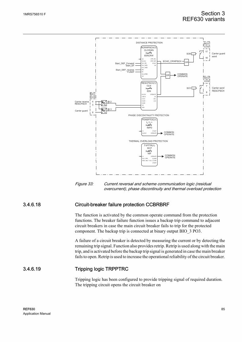
GUID-8B094D7E-1A5C-4F77-8213-CB135B8DFC1D V2 EN
Figure 33: Current reversal and scheme communication logic (residualovercurrent), phase discontinuity and thermal overload protection
3.4.6.18 Circuit-breaker failure protection CCBRBRF
The function is activated by the common operate command from the protectionfunctions. The breaker failure function issues a backup trip command to adjacentcircuit breakers in case the main circuit breaker fails to trip for the protectedcomponent. The backup trip is connected at binary output BIO_3 PO3.
A failure of a circuit breaker is detected by measuring the current or by detecting theremaining trip signal. Function also provides retrip. Retrip is used along with the maintrip, and is activated before the backup trip signal is generated in case the main breakerfails to open. Retrip is used to increase the operational reliability of the circuit breaker.
3.4.6.19 Tripping logic TRPPTRC
Tripping logic has been configured to provide tripping signal of required duration.The tripping circuit opens the circuit breaker on
1MRS756510 F Section 3REF630 variants
REF630 85Application Manual
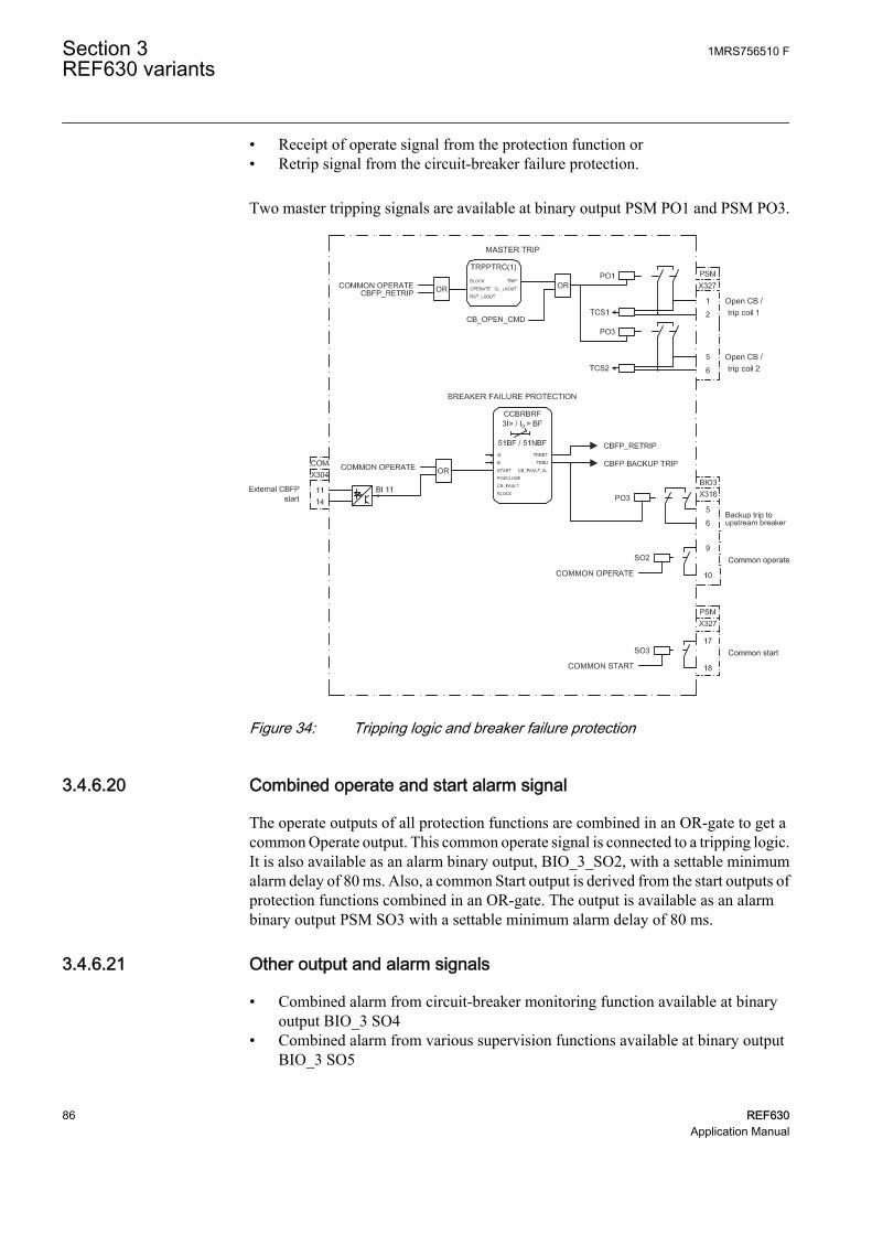
• Receipt of operate signal from the protection function or• Retrip signal from the circuit-breaker failure protection.
Two master tripping signals are available at binary output PSM PO1 and PSM PO3.
GUID-9C15DB69-98E5-49EB-836A-CF0B247D2DF4 V1 EN
Figure 34: Tripping logic and breaker failure protection
3.4.6.20 Combined operate and start alarm signal
The operate outputs of all protection functions are combined in an OR-gate to get acommon Operate output. This common operate signal is connected to a tripping logic.It is also available as an alarm binary output, BIO_3_SO2, with a settable minimumalarm delay of 80 ms. Also, a common Start output is derived from the start outputs ofprotection functions combined in an OR-gate. The output is available as an alarmbinary output PSM SO3 with a settable minimum alarm delay of 80 ms.
3.4.6.21 Other output and alarm signals
• Combined alarm from circuit-breaker monitoring function available at binaryoutput BIO_3 SO4
• Combined alarm from various supervision functions available at binary outputBIO_3 SO5
Section 3 1MRS756510 FREF630 variants
86 REF630Application Manual

3.4.7 Supervision functions
3.4.7.1 Trip circuit supervision TCSSCBR
Two instances of trip circuit supervision function are used for supervising Master trip1 and Master trip 2. Function continuously supervises trip circuit and an alarm isissued in case of a failure of a trip circuit. The function does not perform thesupervision itself but it is used as an aid for configuration.
Function gives an indication via a LED on the LHMI on detection of any of the tripcircuit failure. To prevent unwanted alarms, the function is blocked when the circuitbreaker is open, one of the protection function operate signals is active.
Apart from the previous two instances, another instance of trip circuit supervision isused to check the proper functioning of closing circuit of the circuit breaker. Thisfunction is blocked when the circuit breaker is in closed. A common trip alarm fromall three instances of the trip circuit supervision is connected to an OR-gate to form acombined trip circuit supervision alarm which is used to trigger the disturbancerecorder and to provide a LED indication on the LHMI.
3.4.7.2 Fuse failure and current circuit supervision SEQRFUF, CCRDIF
The fuse failure and current circuit supervision functions give an alarm in case of afailure in the secondary circuits between the voltage transformer or currenttransformer and the IED respectively. The set of three phase currents and voltages, I3Pand U3P, are connected to the inputs.
An alarm is available on failure of the secondary circuits. Alarms are recorded by adisturbance recorder.
3.4.7.3 Circuit-breaker condition monitoring SSCBR
The circuit-breaker condition monitoring function checks for the health of the circuitbreaker. The circuit breaker status is connected to the function via binary inputs.Function requires also pressure lockout input and spring charged input connected viabinary input COM_101.BI12 and COM_101.BI13 respectively. Various alarmoutputs from the function are combined in an OR-gate to create a master circuit-breaker monitoring alarm, which is available at binary output BIO_3 SO4.
All of the alarms are separately connected to the binary recorder and a combined alarmis available as an indication via a LED on the LHMI.
1MRS756510 F Section 3REF630 variants
REF630 87Application Manual

GUID-93753FF5-0E73-45D1-8698-8836383D3F1D V2 EN
Figure 35: Circuit-breaker condition monitoring and trip-circuit, fuse failure andcurrent measuring circuit supervision
3.4.8 Measurement and analog recording functions
The measured quantities in this configuration are:
• Sequence current• Sequence voltage• Residual voltage• Residual current• Energy• Phase current• Phase voltage• Line voltage• Power with frequency
The measured quantities can be viewed in the measurement menu on the LHMI.
All analog input channels are connected to the analog disturbance recorder. When anyof these analog values violate the upper or lower threshold limits, the recorder unit istriggered which in turn will record all the signals connected to the recorder.
Section 3 1MRS756510 FREF630 variants
88 REF630Application Manual

Table 21: Signals connected to the analog recorder A1RADR
Channel ID DescriptionChannel 1 Phase A current
Channel 2 Phase B current
Channel 3 Phase C current
Channel 4 Neutral current
Channel 5 Phase A voltage
Channel 6 Phase B voltage
Channel 7 Phase C voltage
Channel 8 Neutral voltage
Data connected to analog channels contain 20 samples per cycle.
Table 22: Signals connected to the analog recorder A4RADR
Channel ID DescriptionChannel 31 Real part of p-p/3p impedance from zone 1
Channel 32 Imaginary part of p-p/3p impedance from zone 1
Channel 33 Real part of first p-e loop impedance from zone 1
Channel 34 Imaginary part of first p-e loop impedance from zone 1
Channel 35 Real part of second p-e loop impedance from zone 1
Channel 36 Imaginary part of second p-e loop impedance from zone 1
1MRS756510 F Section 3REF630 variants
REF630 89Application Manual
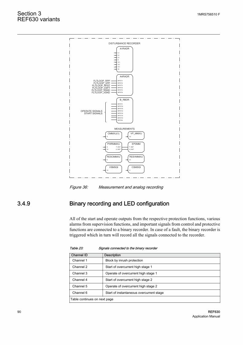
GUID-ACACC65B-2662-45F0-8FA6-DFEBF1A9DB5F V1 EN
Figure 36: Measurement and analog recording
3.4.9 Binary recording and LED configuration
All of the start and operate outputs from the respective protection functions, variousalarms from supervision functions, and important signals from control and protectivefunctions are connected to a binary recorder. In case of a fault, the binary recorder istriggered which in turn will record all the signals connected to the recorder.
Table 23: Signals connected to the binary recorder
Channel ID DescriptionChannel 1 Block by inrush protection
Channel 2 Start of overcurrent high stage 1
Channel 3 Operate of overcurrent high stage 1
Channel 4 Start of overcurrent high stage 2
Channel 5 Operate of overcurrent high stage 2
Channel 6 Start of instantaneous overcurrent stage
Table continues on next page
Section 3 1MRS756510 FREF630 variants
90 REF630Application Manual

Channel ID DescriptionChannel 7 Operate of instantaneous overcurrent stage
Channel 8 Start of overcurrent low stage
Channel 9 Operate of overcurrent low stage
Channel 10 Start of directional earth fault high stage
Channel 11 Operate of directional earth fault high stage
Channel 12 Start of directional earth fault low stage 1
Channel 13 Operate of directional earth fault low stage 1
Channel 14 Start of directional earth fault low stage 2
Channel 15 Operate of directional earth fault low stage 2
Channel 16 Operate of thermal overload
Channel 17 Start of negative-sequence overcurrent stage 1
Channel 18 Operate of negative-sequence overcurrent stage 1
Channel 19 Start of negative-sequence overcurrent stage 2
Channel 20 Operate of negative-sequence overcurrent stage 2
Channel 21 Start of earth fault high stage
Channel 22 Operate of earth fault high stage
Channel 23 Start of directional earth fault low stage 3
Channel 24 Operate of directional earth fault low stage 3
Channel 25 Start of phase discontinuity protection
Channel 26 Operate of phase discontinuity protection
Channel 27 Combined start of phase overvoltage protection
Channel 28 Combined operate of phase overvoltage protection
Channel 29 Combined start of phase undervoltage protection
Channel 30 Combined operate of phase undervoltage protection
Channel 31 Combined start of residual overvoltage protection
Channel 32 Combined operate of residual overvoltage protection
Channel 33 Circuit breaker closed
Channel 34 Circuit breaker is open
Channel 35 Unsuccessful autoreclosing
Channel 36 Autoreclosing function locked out
Channel 37 Reclose by autoreclosing
Channel 38 Backup trip from circuit-breaker failure protection
Channel 39 Retrip from circuit-breaker failure protection
Channel 40 Combined trip circuit alarm
Channel 41 Current circuit failure
Channel 42 Fuse failure
Channel 43 Start from zone 1 of distance protection
Channel 44 Operate from zone 1 of distance protection
Channel 45 Start from zone 2 of distance protection
Table continues on next page
1MRS756510 F Section 3REF630 variants
REF630 91Application Manual

Channel ID DescriptionChannel 46 Operate from zone 2 of distance protection
Channel 47 Start from zone 3 of distance protection
Channel 48 Operate from zone 3 of distance protection
Channel 49 Start from AR zone 1 of distance protection
Channel 50 Operate from AR zone 1 of distance protection
Channel 51 Start from AR zone 2 of distance protection
Channel 52 Operate from AR zone 2 of distance protection
Channel 53 Start from GFC of distance protection
Channel 54 Operate from GFC of distance protection
Channel 55 Operate from switch on to fault protection
Channel 56 Operate by zone extension
Channel 57 Operate from DSOCPSCH
Channel 58 Operate from RESCPSCH
Channel 59 Operate from WEI logic of CRWPSCH
Channel 60 Operate from WEI logic of RCRWPSCH
Channel 61 Operate by loss of load
Channel 62 Carrier receive from remote IED - RESCPSCH
Channel 63 Carrier guard receive from remote IED
Channel 64 Carrier receive from remote IED – DSOCPSCH
The LEDs are configured for alarm indications.
Table 24: LEDs configured on LHMI alarm page 1
LED No LED color DescriptionLED 1 Yellow Combined start from distance protection
LED 1 Red Combined operate from distance protection
LED 2 Yellow Combined start from OC
LED 2 Red Combined operate from OC
LED 3 Yellow Combined start from NSOC
LED 3 Red Combined operate from NSOC
LED 4 Yellow Combined start from DEF
LED 4 Red Combined operate from DEF
LED 5 Yellow Combined start from EF
LED 5 Red Combined operate from EF
LED 6 Yellow Start from phase discontinuity
LED 6 Red Operate from phase discontinuity
LED 7 Yellow Alarm from thermal overload
LED 7 Red Operate from thermal overload
LED 8 Green Autoreclosing ready
Table continues on next page
Section 3 1MRS756510 FREF630 variants
92 REF630Application Manual

LED No LED color DescriptionLED 8 Yellow Autoreclosing in progress
LED 8 Red Autoreclosing function locked out
LED 9 Red Operate from switch on to fault logic
LED 10 Red Operate from distance support function
LED 11 Yellow Combined start from overvoltage
LED 11 Red Combined operate from overvoltage
LED 12 Yellow Combined start from undervoltage
LED 12 Red Combined operate from undervoltage
LED 13 Yellow Backup trip from circuit-breaker protection function
LED 13 Red Retrip from circuit-breaker protection function
LED 14 Yellow Fuse failure supervision
LED 14 Red Current circuit failure
LED 15 Red Combined supervision alarm
3.5 Preconfiguration D for bus sectionalizer
3.5.1 Application
The functionality of the IED is designed to be used for selective short-circuit,overcurrent and earth-fault protection in a bus sectionalizer on double busbar systemswith a truck circuit breaker.
The object controlled by the IED is the circuit breaker with truck. The open, close andundefined states of the circuit breaker are indicated on the LHMI.
Required interlocking is configured in the IED.
The preconfiguration includes:
• Control functions• Current protection functions• Supervision functions• Disturbance recorders• LEDs' configuration• Measurement functions
1MRS756510 F Section 3REF630 variants
REF630 93Application Manual
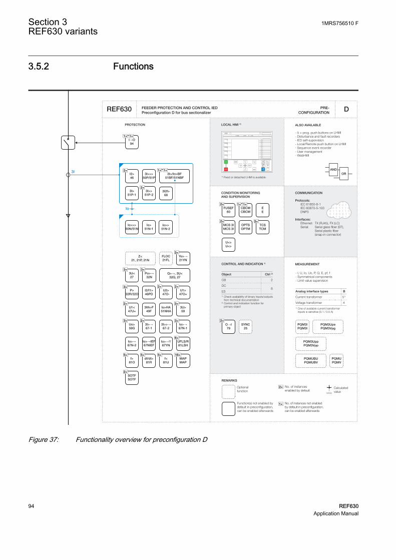
3.5.2 Functions
CBCMCBCM
MCS 3IMCS 3I
REMARKS
Optionalfunction
Function(s) not enabled by default in preconfiguration, can be enabled afterwards
No. of instances enabled by default
CalculatedvalueIo/Uo
2×
No. of instances not enabled by default in preconfiguration, can be enabled afterwards
1×
CONDITION MONITORING AND SUPERVISION
1 0 1 0 0 0 1 1 0 0 1 1 0 01 0 1 1 0 0 1 0 1 1 1 0 0 1 01 1 0 0 1 1 1 0 1 1 0 1 01 0 1 1 0 1 1 0 1 1 0 1 0 01 0 1 0 0 0 1 1 0 0 1 1 0 0 1 0 1 0 0 0 1 1 0 0 1 1 0 01 0 1 1 0 0 1 0 1 1 1 0 0 1 01 1 0 0 1 1 1 0 1 1 0 1 01 0 1 1 0 1 1 0 1 1 0 1 0 0
ORAND
CONTROL AND INDICATION 1) MEASUREMENT
PRE- CONFIGURATION
PROTECTION LOCAL HMI *)
REF630
COMMUNICATION
Protocols: IEC 61850-8-1 IEC 60870-5-103 DNP3
Interfaces: Ethernet: TX (RJ45), FX (LC) Serial: Serial glass fiber (ST), Serial plastic fiber (snap-in connector)
ALSO AVAILABLE
- 5 × prog. push buttons on LHMI- Disturbance and fault recorders- IED self-supervision - Local/Remote push button on LHMI- Sequence event recorder- User management- WebHMI
D
- I, U, Io, Uo, P, Q, E, pf, f- Symmetrical components- Limit value supervision
Analog interface types B
Current transformer 51)
Voltage transformer 4
1) One of available current transformer inputs is sensitive (0.1 / 0.5 A)
*) Fixed or detached LHMI is available.
Object Ctrl 2)
CB 2
DC8
ES1) Check availability of binary inputs/outputs
from technical documentation2) Control and indication function for
primary object
3I>/Io>BF51BF/51NBF
Io>→67N-1
df/dt>81R
I→O94
1×1×
U<>U<>
O→I79
SYNC25
Io>HA51NHA
Z<21, 21P, 21N
FLOC21FL
Io>51N-1
Io>>>50N/51N
Io>>51N-2
Io>→67N-2
Io>→IEF67NIEF
Po>→32N
1× 1×
3I>>51P-2
3I>>>50P/51P
3I>→67-1
3I>>→67-2
3I>51P-1
I2/I1>46PD
I2>46
3Ith>F49F
3I2f>68
3U>59
U1>47O+
U1<47U+
U2>47O-
Uo>59G
P>32R/32O
f>81O
f<81U
UFLS/R81LSH
Yo>→21YN
3U<27
SOTFSOTF
EE
PQMUPQMV
PQMUBUPQMUBV
PQM3IPQM3I
PQM3UppPQM3Vpp
PQM3UpePQM3Vpg
3×
3× 3×
3×
5×
6×
3×
5×5×
2×
2×2×
2×
MAPMAP
16×
2×
2×
1×1×
TCSTCM
3×
Q>→, 3U<32Q, 27
3I
3×
FEEDER PROTECTION AND CONTROL IEDPreconfiguration D for bus sectionalizer
FUSEF60
2×
2×
2×3×
Io
OPTSOPTM
Io>→Y67YN
2×
GUID-46E0483B-5329-418D-944B-5F75F073A12E V1 EN
Figure 37: Functionality overview for preconfiguration D
Section 3 1MRS756510 FREF630 variants
94 REF630Application Manual

3.5.3 Input/output signal interfacesTable 25: Interface of binary inputs
Hardware moduleinstance
Hardwarechannel
Description
COM BI1 Circuit breaker closed
COM BI2 Circuit breaker open
COM BI3...BI8 Not connected
COM BI9 Circuit breaker truck closed
COM BI10 Circuit breaker truck open
COM BI11 External start of circuit-breaker failure protection
COM BI12 Pressure low from circuit breaker
COM BI13 Spring charged from circuit breaker
COM BI14 Not connected
The outputs of the IED are categorized as power outputs (POx) and signal outputs(SOx). The power outputs can be used for closing and tripping of circuit breakers anddisconnector control. The signal outputs are not heavy-duty outputs. They are used foralarm or signaling purposes.
Table 26: Interface of binary outputs
Hardware moduleinstance
Hardwarechannel
Description
PSM BO1_PO Master trip 1 (circuit breaker open)
PSM BO2_PO Master close (circuit breaker closed)
PSM BO3_PO Master trip 2 (circuit breaker open)
PSM BO4_PO Not connected
PSM BO5_PO Not connected
PSM BO6_PO Not connected
PSM BO7_SO OC operate alarm
PSM BO8_SO EF operate alarm
PSM BO9_SO Common start
BIO_3 BO1_PO Not connected
BIO_3 BO2_PO Not connected
BIO_3 BO3_PO Backup trip
BIO_3 BO4_SO Upstream OC block
BIO_3 BO5_SO Common operate
BIO_3 BO6_SO Not connected
BIO_3 BO7_SO Circuit-breaker monitoring alarm
BIO_3 BO8_SO Supervision circuit alarm
BIO_3 BO9_SO Not connected
1MRS756510 F Section 3REF630 variants
REF630 95Application Manual
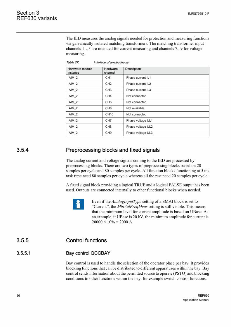
The IED measures the analog signals needed for protection and measuring functionsvia galvanically isolated matching transformers. The matching transformer inputchannels 1…3 are intended for current measuring and channels 7...9 for voltagemeasuring.
Table 27: Interface of analog inputs
Hardware moduleinstance
Hardwarechannel
Description
AIM_2 CH1 Phase current IL1
AIM_2 CH2 Phase current IL2
AIM_2 CH3 Phase current IL3
AIM_2 CH4 Not connected
AIM_2 CH5 Not connected
AIM_2 CH6 Not available
AIM_2 CH10 Not connected
AIM_2 CH7 Phase voltage UL1
AIM_2 CH8 Phase voltage UL2
AIM_2 CH9 Phase voltage UL3
3.5.4 Preprocessing blocks and fixed signals
The analog current and voltage signals coming to the IED are processed bypreprocessing blocks. There are two types of preprocessing blocks based on 20samples per cycle and 80 samples per cycle. All function blocks functioning at 5 mstask time need 80 samples per cycle whereas all the rest need 20 samples per cycle.
A fixed signal block providing a logical TRUE and a logical FALSE output has beenused. Outputs are connected internally to other functional blocks when needed.
Even if the AnalogInputType setting of a SMAI block is set to“Current”, the MinValFreqMeas setting is still visible. This meansthat the minimum level for current amplitude is based on UBase. Asan example, if UBase is 20 kV, the minimum amplitude for current is20000 × 10% = 2000 A.
3.5.5 Control functions
3.5.5.1 Bay control QCCBAY
Bay control is used to handle the selection of the operator place per bay. It providesblocking functions that can be distributed to different apparatuses within the bay. Baycontrol sends information about the permitted source to operate (PSTO) and blockingconditions to other functions within the bay, for example switch control functions.
Section 3 1MRS756510 FREF630 variants
96 REF630Application Manual

3.5.5.2 Apparatus control
Apparatus control initializes and supervises proper selection and switches on circuitbreaker. The circuit breaker requires interlocking function, switch control functionand apparatus functions.
Circuit-breaker control functionThe circuit breaker is controlled by a combination of switch interlocking (SCILO),switch controller (GNRLCSWI) and circuit breaker controller (DAXCBR) functions.
The position information of the circuit breaker and the truck are connected toDAXCBR. The interlocking logics for the circuit breaker have been programmed toopen at any time, provided that the gas pressure inside the circuit breaker is above thelockout limit. Closing of the circuit breaker is always prevented if the gas pressureinside the circuit breaker is below the lockout limit or the truck is open or springcharge time is above the set limit.
SCILO function checks for the interlocking conditions and provides closing andopening enable signals. The enable signal is used by GNRLCSWI function blockwhich checks for operator place selector before providing the final open or closesignal to DAXCBR function.
The open, closed and undefined states of the circuit breaker are indicated on theLHMI.
GUID-1384EA10-3BAC-4DC6-899C-D73E93A9A52F V1 EN
Figure 38: Apparatus control
1MRS756510 F Section 3REF630 variants
REF630 97Application Manual

3.5.6 Protection functions
3.5.6.1 Three-phase current inrush detection INRPHAR
The configuration includes a three-phase current inrush detection function. Thefunction can be used for increasing, typically double, the set start value of the non-directional overcurrent stage (OC) during inrush condition. This is done by theENA_MULT input and the Start value mult setting in the corresponding functionblocks. The default multiplier setting is 1.0.
3.5.6.2 Non-directional overcurrent protection PHxPTOC
The three-phase non-directional overcurrent functions are used for non-directionalone-phase, two-phase and three-phase overcurrent and short-circuit protection withdefinite time or various inverse definite minimum time (IDMT) characteristic. Theoperation of a stage is based on three measuring principles: DFT, RMS or peak-to-peak values.
The configuration includes four variants of non-directional overcurrent functions:high 1, high 2, low and instantaneous. The set of three phase currents, I3P, isconnected to the inputs. The inrush function can increase the start value of eachovercurrent function.
A common operate and start signal from all the four non-directional overcurrentfunctions are connected to an OR-gate to form a combined non-directionalovercurrent operate and start signal which is used to provide a LED indication on theLHMI. Also separate start and operate from all the four OC functions are connectedto the disturbance recorder.
3.5.6.3 Negative-sequence overcurrent protection NSPTOC
Two instances of negative-sequence overcurrent detection are provided, forprotection against single-phasing, unbalanced load or asymmetrical feeder voltage.The set of three phase currents, I3P, is connected to the inputs.
A common operate and start signal from both NSPTOC functions are connected to anOR-gate to form a combined negative-sequence overcurrent operate and start signalwhich is used to provide a LED indication on the LHMI. Also separate start andoperate signals from the NSPTOC function is connected to the disturbance recorder.
Section 3 1MRS756510 FREF630 variants
98 REF630Application Manual

GUID-051E6536-AF92-49F9-92E5-1C7BC995AF41 V1 EN
Figure 39: Non-directional overcurrent and negative-sequence overcurrentprotection
3.5.6.4 Non-directional earth-fault protection EFxPTOC
The non-directional earth-fault protection functions are used for protection underearth fault conditions with definite-time (DT) or with inverse definite minimum time(IDMT) characteristic when appropriate.
The operation of the stage is based on three measuring principles: DFT, RMS or peak-to-peak values. The configuration includes three variants of non-directional earth-fault functions: high, low and instantaneous. The set of three phase currents, I3P, isconnected to the inputs.
A common operate and start signal from all the three non-directional earth-faultfunctions are connected to an OR-block to form a combined non-directional earth-fault operate and start signal which is used to provide a LED indication on the LHMI.Also separate start and operate signals from all the three EF functions are connectedto the disturbance recorder.
1MRS756510 F Section 3REF630 variants
REF630 99Application Manual

GUID-86F11D26-74A6-4387-9A0C-3D6B9D52F288 V1 EN
Figure 40: Non-directional earth-fault protection
3.5.6.5 Circuit-breaker failure protection CCBRBRF
The function is activated by the common operate command from the protectionfunctions. The breaker failure function issues a backup trip command to adjacentcircuit breakers in case the main circuit breaker fails to trip for the protectedcomponent. The backup trip is connected at binary output BIO_3 PO3.
A failure of a circuit breaker is detected by measuring the current or by detecting theremaining trip signal. Function also provides retrip. Retrip is used along with the maintrip, and is activated before the backup trip signal is generated in case the main breakerfails to open. Retrip is used to increase the operational reliability of the circuit breaker.
3.5.6.6 Tripping logic TRPPTRC
Tripping logic has been configured to provide tripping signal of required duration.The tripping circuit opens the circuit breaker on
• Receipt of operate signal from the protection function or• Retrip signal from the circuit-breaker failure protection.
Two master tripping signals are available at binary output PSM PO1 and PSM PO3.
Section 3 1MRS756510 FREF630 variants
100 REF630Application Manual

GUID-9C15DB69-98E5-49EB-836A-CF0B247D2DF4 V1 EN
Figure 41: Tripping logic and breaker failure protection
3.5.6.7 Combined operate and start alarm signal
The operate outputs of all protection functions are combined in an OR-gate to get acommon Operate output. This common operate signal is connected to a tripping logic.It is also available as an alarm binary output, BIO_3_SO2, with a settable minimumalarm delay of 80 ms. Also, a common Start output is derived from the start outputs ofprotection functions combined in an OR-gate. The output is available as an alarmbinary output PSM SO3 with a settable minimum alarm delay of 80 ms.
3.5.6.8 Other output and alarm signals
• Combined overcurrent (OC) operate signal available at binary output PSM SO1• Combined earth fault (EF) operate signal available at binary output PSM SO2• Combined alarm signal from circuit-breaker monitoring function available at
binary output BIO_3 SO4• Combined alarm signal from various supervision functions available at binary
output BIO_3 SO5• Upstream overcurrent (OC) blocking signal available at binary output BIO_3
SO1
1MRS756510 F Section 3REF630 variants
REF630 101Application Manual

3.5.7 Supervision functions
3.5.7.1 Trip circuit supervision TCSSCBR
Two instances of trip circuit supervision function are used for supervising Master trip1 and Master trip 2. Function continuously supervises the trip circuit and an alarm isissued in case of a failure of a trip circuit. The function does not perform thesupervision itself but it is used as an aid for configuration. An additional instance isused to check the proper functioning of the closing circuit of the circuit breaker.
Function gives an indication via a LED on the LHMI on detection of any of the tripcircuit failure. To prevent unwanted alarms, the function is blocked when the circuitbreaker is open, one of the protection function operate signals is active.
An instance of trip circuit supervision is used to check the proper functioning ofclosing circuit of the circuit breaker. This function is blocked when the circuit breakeris in closed position to prevent unwanted alarms.
3.5.7.2 Circuit-breaker condition monitoring SSCBR
The circuit-breaker condition monitoring function checks for the health of the circuitbreaker. The circuit breaker status is connected to the function via binary inputs.Function requires also pressure lockout input and spring charged input connected viabinary input COM_101.BI12 and COM_101.BI13 respectively. Various alarmoutputs from the function are combined in an OR-gate to create a master circuit-breaker monitoring alarm, which is available at binary output BIO_3 SO4.
All of the alarms are separately connected to the binary recorder and a combined alarmis available as an indication via a LED on the LHMI.
GUID-10B6F218-EE98-4DB4-9C6F-E14E5E2582FA V1 EN
Figure 42: Circuit-breaker condition monitoring and trip circuit supervision
Section 3 1MRS756510 FREF630 variants
102 REF630Application Manual

3.5.8 Measurement and analog recording functions
The measured quantities in this configuration are:
• Sequence current• Sequence voltage• Residual voltage• Residual current• Energy• Phase current• Phase voltage• Line voltage• Power with frequency
The measured quantities can be viewed in the measurement menu on the LHMI.
All analog input channels are connected to the analog disturbance recorder. When anyof these analog values violate the upper or lower threshold limits, the recorder unit istriggered which in turn will record all the signals connected to the recorder.
Table 28: Signals connected to the analog recorder
Channel ID DescriptionChannel 1 Phase A current
Channel 2 Phase B current
Channel 3 Phase C current
Channel 4 Calculated neutral current
Channel 5 Phase A voltage
Channel 6 Phase B voltage
Channel 7 Phase C voltage
Channel 8 Calculated neutral voltage
Data connected to analog channels contain 20 samples per cycle.
1MRS756510 F Section 3REF630 variants
REF630 103Application Manual

GUID-3794F9A5-CE29-4CF9-A289-DEAC0947A64E V1 EN
Figure 43: Measurement and analog recording
3.5.9 Binary recording and LED configurations
All of the start and operate outputs from the respective protection functions, variousalarms from supervision functions, and important signals from control and protectivefunctions are connected to a binary recorder. In case of a fault, the binary recorder istriggered which in turn will record all the signals connected to the recorder.
Table 29: Signals connected to the binary recorder
Channel ID DescriptionChannel 1 Block by inrush protection
Channel 2 Start of overcurrent high stage 1
Channel 3 Operate of overcurrent high stage 1
Channel 4 Start of overcurrent high stage 2
Channel 5 Operate of overcurrent high stage 2
Channel 6 Start of instantaneous overcurrent stage
Channel 7 Operate of instantaneous overcurrent stage
Channel 8 Start of overcurrent low stage
Channel 9 Operate of overcurrent low stage
Channel 10 Start of instantaneous earth fault
Table continues on next page
Section 3 1MRS756510 FREF630 variants
104 REF630Application Manual

Channel ID DescriptionChannel 11 Operate of instantaneous earth fault stage
Channel 12 Start of earth fault high stage
Channel 13 Operate of earth fault high stage
Channel 14 Start of earth fault low stage
Channel 15 Operate of earth fault low stage
Channel 16 Pressure in circuit breaker below lockout limit
Channel 17 Start of negative sequence overcurrent stage 1
Channel 18 Operate of negative-sequence overcurrent stage 1
Channel 19 Start of negative-sequence overcurrent stage 2
Channel 20 Operate of negative-sequence overcurrent stage 2
Channel 21 Backup trip from circuit-breaker failure protection
Channel 22 Retrip from circuit-breaker failure protection
Channel 23 Circuit breaker closed
Channel 24 Circuit breaker is open
Channel 25 Trip circuit alarm 1 (supervising master trip 1)
Channel 26 Trip circuit alarm 2 (supervising master trip 2)
Channel 27 Trip circuit alarm 3 (supervising closing circuit )
Channel 28 Closing time of circuit breaker exceeded the limit
Channel 29 Opening time of circuit breaker exceeded the limit
Channel 30 Spring charge time of circuit breaker exceeded the limit
Channel 31 Number of circuit breaker operation exceeded the set limit
Channel 32 Circuit breaker maintenance alarm: number of operations exceeds the set limit
Channel 33 Circuit breaker maintenance alarm: accumulated energy exceeds the set limit
Channel 34 Circuit breaker not operated since long
The LEDs are configured for alarm indications.
Table 30: LEDs configured on LHMI alarm page 1
LED No LED color DescriptionLED 1 Yellow Combine start from OC
LED 1 Red Combine operate from OC
LED 2 Yellow Combine start from NSOC
LED 2 Red Combine operate from NSOC
LED 3 Yellow Combine start from EF
LED 3 Red Combine operate from EF
LED 4 Red Backup trip from circuit-breaker protection function
LED 5 Red Retrip from circuit-breaker protection function
LED 6 Red Alarm from circuit-breaker monitoring function
Table continues on next page
1MRS756510 F Section 3REF630 variants
REF630 105Application Manual

LED No LED color DescriptionLED 7 Red Trip circuit supervision alarm 1
LED 8 Red Trip circuit supervision alarm 2
LED 9 Red Closing circuit supervision alarm
Section 3 1MRS756510 FREF630 variants
106 REF630Application Manual
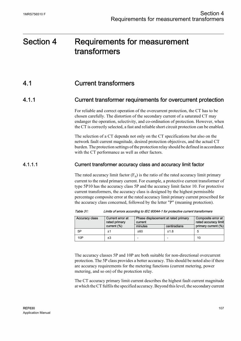
Section 4 Requirements for measurementtransformers
4.1 Current transformers
4.1.1 Current transformer requirements for overcurrent protection
For reliable and correct operation of the overcurrent protection, the CT has to bechosen carefully. The distortion of the secondary current of a saturated CT mayendanger the operation, selectivity, and co-ordination of protection. However, whenthe CT is correctly selected, a fast and reliable short circuit protection can be enabled.
The selection of a CT depends not only on the CT specifications but also on thenetwork fault current magnitude, desired protection objectives, and the actual CTburden. The protection settings of the protection relay should be defined in accordancewith the CT performance as well as other factors.
4.1.1.1 Current transformer accuracy class and accuracy limit factor
The rated accuracy limit factor (Fn) is the ratio of the rated accuracy limit primarycurrent to the rated primary current. For example, a protective current transformer oftype 5P10 has the accuracy class 5P and the accuracy limit factor 10. For protectivecurrent transformers, the accuracy class is designed by the highest permissiblepercentage composite error at the rated accuracy limit primary current prescribed forthe accuracy class concerned, followed by the letter "P" (meaning protection).
Table 31: Limits of errors according to IEC 60044-1 for protective current transformers
Accuracy class Current error atrated primarycurrent (%)
Phase displacement at rated primarycurrent
Composite error atrated accuracy limitprimary current (%)minutes centiradians
5P ±1 ±60 ±1.8 5
10P ±3 - - 10
The accuracy classes 5P and 10P are both suitable for non-directional overcurrentprotection. The 5P class provides a better accuracy. This should be noted also if thereare accuracy requirements for the metering functions (current metering, powermetering, and so on) of the protection relay.
The CT accuracy primary limit current describes the highest fault current magnitudeat which the CT fulfils the specified accuracy. Beyond this level, the secondary current
1MRS756510 F Section 4Requirements for measurement transformers
REF630 107Application Manual

of the CT is distorted and it might have severe effects on the performance of theprotection relay.
In practise, the actual accuracy limit factor (Fa) differs from the rated accuracy limitfactor (Fn) and is proportional to the ratio of the rated CT burden and the actual CTburden.
The actual accuracy limit factor is calculated using the formula:
F FS S
S Sa n
in n
in
≈ ×
+
+
A071141 V1 EN
Fn the accuracy limit factor with the nominal external burden Sn
Sin the internal secondary burden of the CT
S the actual external burden
4.1.1.2 Non-directional overcurrent protection
The current transformer selectionNon-directional overcurrent protection does not set high requirements on the accuracyclass or on the actual accuracy limit factor (Fa) of the CTs. It is, however,recommended to select a CT with Fa of at least 20.
The nominal primary current I1n should be chosen in such a way that the thermal anddynamic strength of the current measuring input of the protection relay is notexceeded. This is always fulfilled when
I1n > Ikmax / 100,
Ikmax is the highest fault current.
The saturation of the CT protects the measuring circuit and the current input of theprotection relay. For that reason, in practice, even a few times smaller nominalprimary current can be used than given by the formula.
Recommended start current settingsIf Ikmin is the lowest primary current at which the highest set overcurrent stage is tooperate, the start current should be set using the formula:
Current start value < 0.7 × (Ikmin / I1n)
I1n is the nominal primary current of the CT.
The factor 0.7 takes into account the protection relay inaccuracy, current transformererrors, and imperfections of the short circuit calculations.
Section 4 1MRS756510 FRequirements for measurement transformers
108 REF630Application Manual

The adequate performance of the CT should be checked when the setting of the highset stage overcurrent protection is defined. The operate time delay caused by the CTsaturation is typically small enough when the overcurrent setting is noticeably lowerthan Fa.
When defining the setting values for the low set stages, the saturation of the CT doesnot need to be taken into account and the start current setting is simply according to theformula.
Delay in operation caused by saturation of current transformersThe saturation of CT may cause a delayed protection relay operation. To ensure thetime selectivity, the delay must be taken into account when setting the operate timesof successive protection relays.
With definite time mode of operation, the saturation of CT may cause a delay that isas long as the time constant of the DC component of the fault current, when the currentis only slightly higher than the starting current. This depends on the accuracy limitfactor of the CT, on the remanence flux of the core of the CT, and on the operate timesetting.
With inverse time mode of operation, the delay should always be considered as beingas long as the time constant of the DC component.
With inverse time mode of operation and when the high-set stages are not used, the ACcomponent of the fault current should not saturate the CT less than 20 times thestarting current. Otherwise, the inverse operation time can be further prolonged.Therefore, the accuracy limit factor Fa should be chosen using the formula:
Fa > 20 × Current start value / I1n
The Current start value is the primary start current setting of the protection relay.
4.1.1.3 Example for non-directional overcurrent protection
The following figure describes a typical medium voltage feeder. The protection isimplemented as three-stage definite time non-directional overcurrent protection.
1MRS756510 F Section 4Requirements for measurement transformers
REF630 109Application Manual

A071142 V1 EN
Figure 44: Example of three-stage overcurrent protection
The maximum three-phase fault current is 41.7 kA and the minimum three-phase shortcircuit current is 22.8 kA. The actual accuracy limit factor of the CT is calculated tobe 59.
The start current setting for low-set stage (3I>) is selected to be about twice thenominal current of the cable. The operate time is selected so that it is selective with thenext protection relay (not visible in Figure 44). The settings for the high-set stage andinstantaneous stage are defined also so that grading is ensured with the downstreamprotection. In addition, the start current settings have to be defined so that theprotection relay operates with the minimum fault current and it does not operate withthe maximum load current. The settings for all three stages are as in Figure 44.
For the application point of view, the suitable setting for instantaneous stage (I>>>) inthis example is 3 500 A (5.83 × I2n). I2n is the 1.2 multiple with nominal primarycurrent of the CT. For the CT characteristics point of view, the criteria given by thecurrent transformer selection formula is fulfilled and also the protection relay settingis considerably below the Fa. In this application, the CT rated burden could have beenselected much lower than 10 VA for economical reasons.
Section 4 1MRS756510 FRequirements for measurement transformers
110 REF630Application Manual

Section 5 Glossary
100BASE-FX A physical medium defined in the IEEE 802.3 Ethernetstandard for local area networks (LANs) that uses fiberoptic cabling
ANSI American National Standards InstituteAR AutoreclosingBI/O Binary input/outputBIO Binary input and outputCOMTRADE Common format for transient data exchange for power
systems. Defined by the IEEE Standard.Connectivitypackage
A collection of software and information related to aspecific protection and control IED, providing systemproducts and tools to connect and interact with the IED
CPU Central processing unitCT Current transformerDCB Directional comparison blocking schemeDCUB Directional comparison unblocking schemeDNP3 A distributed network protocol originally developed by
Westronic. The DNP3 Users Group has the ownershipof the protocol and assumes responsibility for itsevolution.
DT Definite timeDUTT Direct underreach transfer tripEF Earth fault
EMC Electromagnetic compatibilityEthernet A standard for connecting a family of frame-based
computer networking technologies into a LANGFC General fault criteriaGOOSE Generic Object-Oriented Substation EventHMI Human-machine interfaceHW HardwareIDMT Inverse definite minimum timeIEC International Electrotechnical Commission
1MRS756510 F Section 5Glossary
REF630 111Application Manual

IEC 60870-5-103 1. Communication standard for protective equipment2. A serial master/slave protocol for point-to-pointcommunication
IEC 61850 International standard for substation communicationand modeling
IEC 61850-8-1 A communication protocol based on the IEC 61850standard series
IED Intelligent electronic deviceLAN Local area networkLC Connector type for glass fiber cable, IEC 61754-20LED Light-emitting diodeLHMI Local human-machine interfaceOC OvercurrentPCM600 Protection and Control IED ManagerPOTT Permissive overreach transfer tripPUTT Permissive underreach transfer tripREF630 Feeder protection and control relayRJ-45 Galvanic connector typeRMS Root-mean-square (value)RTD Resistance temperature detectorSW SoftwareTCP/IP Transmission Control Protocol/Internet ProtocolVT Voltage transformerWAN Wide area networkWEI Weak-end infeed logicWHMI Web human-machine interface
Section 5 1MRS756510 FGlossary
112 REF630Application Manual

113

ABB Distribution SolutionsDistribution AutomationP.O. Box 699FI-65101 VAASA, FinlandPhone +358 10 22 11
www.abb.com/mediumvoltagewww.abb.com/relion
—
© Copyright 2019 ABB. All rights reserved. 1MR
S75
6510
F