application manual rel 501-c1*2.3 line distance protection … · 2018-05-09 · tionality...
TRANSCRIPT

© ABB Automation Products AB 2001Substation Automation Division
Application manualREL 501-C1*2.3
Line distance protection terminal
About this manualDocID: 1MRK 506 114-UEN
Issue date: July 2001Status: NewVersion: 2.3Revision: 00

COPYRIGHT
WE RESERVE ALL RIGHTS TO THIS DOCUMENT, EVEN IN THE EVENT THAT A PATENT IS ISSUED AND A DIFFERENT COMMERCIAL PROPRIETARY RIGHT IS REGISTERED. IMPROPER USE, IN PARTICULAR REPRODUCTION AND DIS-SEMINATION TO THIRD PARTIES, IS NOT PERMITTED.
THIS DOCUMENT HAS BEEN CAREFULLY CHECKED. IF THE USER NEVERTHELESS DETECTS ANY ERRORS, HE IS ASKED TO NOTIFY US AS SOON AS POSSIBLE.
THE DATA CONTAINED IN THIS MANUAL IS INTENDED SOLELY FOR THE PRODUCT DESCRIPTION AND IS NOT TO BE DEEMED TO BE A STATEMENT OF GUARANTEED PROPERTIES. IN THE INTERESTS OF OUR CUSTOMERS, WE CON-STANTLY SEEK TO ENSURE THAT OUR PRODUCTS ARE DEVELOPED TO THE LATEST TECHNOLOGICAL STAN-DARDS. AS A RESULT, IT IS POSSIBLE THAT THERE MAY BE SOME DIFFERENCES BETWEEN THE HW/SW PRODUCT AND THIS INFORMATION PRODUCT.
Manufacturer:
ABB Automation Products ABSubstation Automation DivisionSE-721 59 VästeråsSwedenTel: +46 (0) 21 34 20 00Fax: +46 (0) 21 14 69 18Internet: http://www.abb.se
Contents
PageChapter
Chapter 1 Introduction ..................................................................... 1
Introduction to the application manual ................................................. 2About the complete set of manuals to a terminal............................ 2Intended audience .......................................................................... 3Related documents......................................................................... 3Revision notes ................................................................................ 3
Chapter 2 General............................................................................. 5
Features............................................................................................... 6Application ........................................................................................... 7Design.................................................................................................. 8Requirements ...................................................................................... 9Terminal identification........................................................................ 17
Application .................................................................................... 17Calculations .................................................................................. 17
Chapter 3 Common functions ....................................................... 19
Time synchronisation (TIME)............................................................. 20Application .................................................................................... 20Functionality ................................................................................. 20Calculations .................................................................................. 20
Setting group selector (GRP)............................................................. 22Application .................................................................................... 22Functionality ................................................................................. 22Design .......................................................................................... 23
Setting lockout (HMI) ......................................................................... 24Application .................................................................................... 24Functionality ................................................................................. 24
I/O system configurator (IOP) ............................................................ 26Application .................................................................................... 26Functionality ................................................................................. 26
Logic function blocks ......................................................................... 30Application .................................................................................... 30Functionality ................................................................................. 30Calculations .................................................................................. 42
Self supervision (INT) ........................................................................ 44Application .................................................................................... 44Functionality ................................................................................. 45
Blocking of signals during test ........................................................... 48Functionality ................................................................................. 48

Contents
Chapter 4 Line impedance ............................................................. 51
Distance protection (ZM1-5) .............................................................. 52Application .................................................................................... 52Functionality.................................................................................. 59Design........................................................................................... 66Calculations .................................................................................. 71Configuration ................................................................................ 91
Automatic switch onto fault logic (SOTF)........................................... 94Application .................................................................................... 94Functionality.................................................................................. 94Calculations .................................................................................. 95
Local acceleration logic (ZCLC)......................................................... 96Application .................................................................................... 96Functionality.................................................................................. 96Calculations .................................................................................. 97
General fault criteria (GFC)................................................................ 99Application .................................................................................... 99Functionality................................................................................ 102Design......................................................................................... 107Calculations ................................................................................ 112
Power swing detection (PSD) .......................................................... 117Application .................................................................................. 117Functionality................................................................................ 118Design......................................................................................... 120Calculations ................................................................................ 123
Scheme communication logic for distance protection (ZCOM) ....... 128Application .................................................................................. 128Functionality................................................................................ 128Calculations ................................................................................ 131
Current reversal and WEI logic for distance protection (ZCAL) ....... 132Application .................................................................................. 132Functionality................................................................................ 133Design......................................................................................... 134Calculations ................................................................................ 136
Chapter 5 Current ......................................................................... 139
Instantaneous overcurrent protection (IOC)..................................... 140Application .................................................................................. 140Functionality................................................................................ 141Design......................................................................................... 141Calculations ................................................................................ 145
Time delayed overcurrent protection (TOC) .................................... 155Application .................................................................................. 155Functionality................................................................................ 155Design......................................................................................... 156Calculations ................................................................................ 159
Definite and inverse time-delayed residual overcurrent protection (TEF) ........................................................... 163
Application .................................................................................. 163

Contents
Functionality ............................................................................... 164Calculations ................................................................................ 168
Scheme communication logic for residual overcurrent protection (EFC) ......................................................... 172
Application .................................................................................. 172Functionality ............................................................................... 172Design ........................................................................................ 175Calculations ................................................................................ 175
Current reversal and weak end infeed logic for residual overcurrent protection (EFCA) ........................................... 177
Application .................................................................................. 177Functionality ............................................................................... 178Design ........................................................................................ 181Calculations ................................................................................ 182
Chapter 6 Voltage ......................................................................... 185
Time delayed undervoltage protection (TUV) .................................. 186Application .................................................................................. 186Design ........................................................................................ 186Calculations ................................................................................ 186
Time delayed overvoltage protection (TOV) .................................... 187Application .................................................................................. 187Functionality ............................................................................... 187Design ........................................................................................ 187Calculations ................................................................................ 190
Chapter 7 Secondary system supervision ................................. 191
Fuse failure supervision (FUSE)...................................................... 192Application .................................................................................. 192Functionality ............................................................................... 192Calculations ................................................................................ 196
Chapter 8 Control ......................................................................... 199
Automatic reclosing function (AR) ................................................... 200Application .................................................................................. 200Functionality ............................................................................... 202
Chapter 9 Logic............................................................................. 209
Trip logic (TR) .................................................................................. 210Application .................................................................................. 210Functionality ............................................................................... 210
High speed binary output logic (HSBO)........................................... 211Application .................................................................................. 211

Contents
Functionality................................................................................ 211Design......................................................................................... 215
Event function (EV) .......................................................................... 218Application .................................................................................. 218Functionality................................................................................ 218Design......................................................................................... 218Calculations ................................................................................ 220
Chapter 10 Monitoring.................................................................... 223
Disturbance report (DRP) ................................................................ 224Application .................................................................................. 224Functionality................................................................................ 224Calculations ................................................................................ 229
Event recorder ................................................................................. 236Application .................................................................................. 236Functionality................................................................................ 236Calculations ................................................................................ 236
Trip value recorder........................................................................... 238Application .................................................................................. 238Design......................................................................................... 238Calculations ................................................................................ 239
Monitoring of AC analog measurements.......................................... 240Application .................................................................................. 240Functionality................................................................................ 240Design......................................................................................... 250Calculations ................................................................................ 251
Monitoring of DC analog measurements ......................................... 256Application .................................................................................. 256Functionality................................................................................ 256Design......................................................................................... 265Calculations ................................................................................ 267
Chapter 11 Data communication ................................................... 271
Serial communication....................................................................... 272Application .................................................................................. 272
Serial communication, SPA ............................................................. 273Application .................................................................................. 273Functionality................................................................................ 273Design......................................................................................... 273Calculations ................................................................................ 274
Serial communiction, IEC................................................................. 276Application .................................................................................. 276Functionality................................................................................ 276Design......................................................................................... 276Calculations ................................................................................ 277
Serial communication, LON ............................................................. 282Application .................................................................................. 282Functionality................................................................................ 282
Contents
Design ........................................................................................ 282Calculations ................................................................................ 283
Serial communication modules (SCM) ............................................ 285SPA/IEC ..................................................................................... 285LON ............................................................................................ 285
Chapter 12 Hardware modules ...................................................... 287
Platform ........................................................................................... 288General ....................................................................................... 288Platform configuration................................................................. 2891/2x19" platform.......................................................................... 293
Transformer input module (TRM) .................................................... 294A/D-conversion module (ADM) ........................................................ 297Main processing module (MPM) ...................................................... 299Signal processing module (SPM) .................................................... 301Input/Output modules ...................................................................... 302
Binary input module (BIM) .......................................................... 302Binary output module (BOM) ...................................................... 303
Power supply module (PSM) ........................................................... 305Human-machine interface (HMI)...................................................... 306

Contents

About this chapter Chapter 1Introduction
Chapter 1 Introduction
About this chapter
This chapter introduces you to the manual as such.
1

Introduction to the application manual Chapter 1Introduction
es or on of
refer-l and
nfig-ters n
1 Introduction to the application manual
1.1 About the complete set of manuals to a terminal
The complete package of manuals to a terminal is named users manual (UM). The Us-ers manual consists of four different manuals:
The Application Manual (AM) contains descriptions, such as application and func-tionality descriptions as well as setting calculation examples sorted per function. The application manual should be used when designing and engineering the protection ter-minal to find out when and for what a typical protection function could be used. The manual should also be used when calculating settings and creating configurations.
The Technical Reference Manual (TRM) contains technical descriptions, such as function blocks, logic diagrams, input and output signals, setting parameter tables and technical data sorted per function. The technical reference manual should be used as a technical reference during the engineering phase, installation and commissioning phase and during the normal service phase.
The Operator´s Manual (OM) contains instructions on how to operate the protection terminal during normal service (after commissioning and before periodic maintenance tests). The operator´s manual could be used to find out how to handle disturbanchow to view calculated and measured network data in order to determine the reasa fault.
The Installation and Commissioning Manual (ICM) contains instructions on how toinstall and commission the protection terminal. The manual can also be used as aence if a periodic test is performed. The manual covers procedures for mechanicaelectrical installation, energising and checking of external circuitry, setting and couration as well as verifying settings and performing a directionality test. The chapand sections are organised in the chronological order (indicated by chapter/sectionumbers) the protection terminal should be installed and commissioned.
Applicationmanual
Technicalreference
manual
Installation andcommissioning
manual
Operator´smanual
en01000044.vsd
2

Introduction to the application manual Chapter 1Introduction
1.2 Intended audience
1.2.1 General
The application manual is addressing the system engineer/technical responsible who is responsible for specifying the application of the terminal.
1.2.2 Requirements
The system engineer/technical responsible must have a good knowledge about protec-tion systems, protection equipment, protection functions and the configured functional logics in the protection.
1.3 Related documents
1.4 Revision notes
Documents related to REL 501-C1*2.3 Identity number
Operator’s manual 1MRK 506 088-UEN
Installation and commissioning manual 1MRK 506 090-UEN
Technical reference manual 1MRK 506 089-UEN
Application manual 1MRK 506 114-UEN
Technical overview brochure 1MRK 506 087-BEN
Revision Description
2.3-00 First revision
3

Introduction to the application manual Chapter 1Introduction
4

About this chapter Chapter 2General
Chapter 2 General
About this chapter
This chapter describes the terminal in general.
5

Features Chapter 2General
ion-
1 Features
• Versatile local human-machine interface (HMI)
• Simultaneous dual protocol serial communication facilities
• Extensive self-supervision with internal event recorder
• Time synchronization with 1 ms resolution
• Four independent groups of complete setting parameters
• Powerful software ‘tool-box’ for monitoring, evaluation and user configuration
• Pre-configured protection terminal for cost-effective engineering and commissing
• Compact half 19" case size
6

Application Chapter 2General
2 Application
The main purpose of the REL 501-C1 terminal is the protection, control and monitoring of overhead lines and cables in distribution and sub-transmission networks. It can also be used in transmission networks up to the highest voltage levels. The terminal is in-tended for three-pole tripping applications, and is suitable for the protection of heavily loaded lines and multi-circuit lines. It may be used for applications with or without a communications channel(s) installed, as well as for applications which must provide re-mote backup protection, and for applications which require directional earth fault pro-tection.
The REL 501-C1 terminal may be used as the main protection terminal in single main protection system applications, or as the second main protection terminal in dual main protection system applications up to the highest voltage levels.
7

Design Chapter 2General
BB´s high
strin-
t dis-
n, d to ission the
3 Design
Type tested software and hardware that comply with international standards and Ainternal design rules together with extensive self monitoring functionality, ensure reliability of the complete terminal.
The terminal’s closed and partly welded steel case makes it possible to fulfill the gent EMC requirements.
All serial data communcation is via optical connections to ensure immunity againsturbances.
A fully functional terminal comprising a compact hardware, pre-selected protectiocontrol and monitoring functions that were carefully chosen, configured and testemeet a broad range of application requirements. This ready to connect and commfeature makes this product a cost effective solution for both new installations andrefurbishment of existing installations.
8

Requirements Chapter 2General
4 Requirements
4.0.1 General
The operation of a protection measuring function is influenced by distortion, and mea-sures need to be taken in the protection to handle this phenomenon. One source of dis-tortion is current transformer saturation. In this protection terminal, measures are taken to allow for a certain amount of CT saturation with maintained correct operation. This protection terminal can allow relatively heavy current transformer saturation.
Protection functions are also affected by transients caused by capacitive voltage trans-formers (CVTs) but as this protection terminal has a very effective filter for these tran-sients, the operation is hardly affected at all.
4.0.2 Voltage transformers
Magnetic or capacitive voltage transformers can be used.
Capacitive voltage transformers (CVTs) should fulfil the requirements according to IEC 186A, Section 20, regarding transients. According to the standard, at a primary voltage drop down to zero, the secondary voltage should drop to less than 10% of the peak pre-fault value before the short circuit within one cycle.
The protection terminal has an effective filter for this transient, which gives secure and correct operation with CVTs.
4.0.3 Current transformers
Classification
The performance of the REx 5xx terminal depends on the conditions and the quality of the current signals fed to it. The terminal REx 5xx has been designed to permit relative-ly heavy current transformer saturation with maintained correct operation. To guarantee correct operation, the CTs must be able to correctly reproduce the current for a mini-mum time before the CT will begin to saturate. To fulfil the requirement on a specified time to saturation the CTs must fulfil the requirements of a minimum secondary e.m.f. that is specified below.
There are several different ways to specify CTs. Conventional magnetic core CTs are usually specified and manufactured according to some international or national stan-dards, which specify different protection classes as well. However, generally there are three different types of current transformers:
• high remanence type CT
• low remanence type CT
• non remanence type CT
9

Requirements Chapter 2General
The high remanence type has no limit for the remanence flux. This CT has a magnetic core without any airgap and a remanence flux might remain for almost infinite time. In this type of transformers the remanence flux can be up to 70-80% of the saturation flux. Typical examples of high remanence type CT are class P, TPS, TPX according to IEC, class P, X according to BS (British Standard) and nongapped class C, K according to ANSI/IEEE.
The low remanence type has a specified limit for the remanence flux. This CT is made with a small airgap to reduce the remanence flux to a level that does not exceed 10% of the saturation flux. The small airgap has only very limited influence on the other prop-erties of the CT. Class TPY according to IEC is a low remanence type CT.
The non remanence type CT has practically negligible level of remanence flux. This type of CT has relatively big airgaps in order to reduce the remanence flux to practically zero level. At the same time, these airgaps minimize the influence of the DC-component from the primary fault current. The airgaps will also reduce the measuring accuracy in the non-saturated region of operation. Class TPZ according to IEC is a non remanence type CT.
The rated equivalent limiting secondary e.m.f. Eal according to the IEC 60044-6 stan-dard is used to specify the CT requirements for REx 5xx. The requirements are also specified according to other standards.
Conditions
The requirements are a result of investigations performed in our network simulator. The tests have been carried out with an analogue current transformer model with a settable core area, core length, air gap and number of primary and secondary turns. The setting of the current transformer model was representative for current transformers of high re-manence and low remanence type. The results are not valid for non remanence type CTs (TPZ).
The performance of the distance protection was checked at both symmetrical and fully asymmetrical fault currents. A source with a time constant of about 120 ms was used at the tests. The current requirements below are thus applicable both for symmetrical and asymmetrical fault currents.
Both phase-to-earth, phase-to-phase and three-phase faults were tested in fault locations backward, close up forward and at the zone 1 reach. The protection was checked with regard to directionality, dependable tripping, and overreach.
All testing was made without any remanence flux in the current transformer core. The requirements below are therefore fully valid for a core with no remanence flux. It is dif-ficult to give general recommendations for additional margins for remanence flux. They depend on the reliability and economy requirements.
10

Requirements Chapter 2General
ccur
faults gle- cur-oop is
ould
t loop ts, the to be
d the
tion is min-
re-t racter-angle ducts
When current transformers of low remanence type (TPY) are used, practically no addi-tional margin is needed.
For current transformers of high remanence type (e.g. TPX), the small probability of a fully asymmetrical fault, together with maximum remanence flux in the same direction as the flux generated by the fault, has to be kept in mind at the decision of an additional margin. Fully asymmetrical fault current will be achieved when the fault occurs at zero voltage (0°). Investigations have proved that 95% of the faults in the network will owhen the voltage is between 40° and 90°.
Fault current
The current transformer requirements are based on the maximum fault current for in different positions. Maximum fault current will occur for three-phase faults or sinphase-to-earth faults. The current for a single phase-to-earth fault will exceed therent for a three-phase fault when the zero sequence impedance in the total fault lless than the positive sequence impedance.
When calculating the current transformer requirements, maximum fault current shbe used and therefore both fault types have to be considered.
Cable resistance and additional load
The current transformer saturation is directly affected by the voltage at the currentransformer secondary terminals. This voltage, for an earth fault, is developed in acontaining the phase and neutral conductor, and relay load. For three-phase faulneutral current is zero, and only the phase conductor and relay phase load have considered.
In the calculation, the loop resistance should be used for phase-to-earth faults anphase resistance for three-phase faults.
Current transformer requirements for CTs according to the IEC 60044-6 standard
The current transformer ratio should be selected so that the current to the protechigher than the minimum operating value for all faults that are to be detected. Theimum operating current is 10-30% of the nominal current.
All current transformers of high remanence and low remanence type that fulfil thequirements on the rated equivalent secondary e.m.f. Eal below can be used. The currentransformers should have an accuracy class comparable to 5P or better. The chaistic of the non remanence type CT (TPZ) is not well defined as far as the phase error is concerned, and we therefore recommend contacting ABB Automation ProAB to confirm that the type in question can be used.
The current transformers must have a rated equivalent secondary e.m.f. Eal that is larger than the maximum of the required secondary e.m.f. Ealreq below:
11

Requirements Chapter 2General
(Equation 1)
(Equation 2)
where
Ikmax Maximum primary fundamental frequency current for close-in forward and reverse faults (A)
Ikzone1 Maximum primary fundamental frequency current for faults at the end of zone 1 reach (A)
Ipn The rated primary CT current (A)
Isn The rated secondary CT current (A)
IR The protection terminal rated current (A)
RCT The secondary resistance of the CT (Ω)
RL The resistance of the secondary cable and additional load (Ω). The loop resistance should be used for phase-to-earth faults and the phase resistance for three-phase faults.
a This factor is a function of the network frequency and the primary time constant for the dc component in the fault current, see figure 1.
k A factor of the network frequency and the primary time constant for the dc compo-
nent in the fault current for a three-phase fault at the set reach of zone 1, see figure2. The time constant is normally less than 50 ms.
Eal Ealreq>Ikmax Isn⋅
Ipn------------------------ a RCT RL
0.25
I2R
-----------+ + ⋅ ⋅=
Eal Ealreq>Ikzone1 Isn⋅
Ipn---------------------------- k RCT RL
0.25
I2R
-----------+ + ⋅ ⋅=
12

Requirements Chapter 2General
Figure 1: Factor a as a function of the frequency and the time constant
Figure 2: Factor k as a function of the frequency and the time constant
60 Hz
50 Hz
60 Hz
50 Hz
13

Requirements Chapter 2General
Current transformer requirements for CTs according to other standards
All kinds of conventional magnetic core CTs are possible to be used with REx 5xx ter-minals if they fulfil the requirements that correspond to the above specified according to the IEC 60044-6 standard. From the different standards and available data for relay-ing applications it is possible to approximately calculate a secondary e.m.f. of the CT. It is then possible to compare this to the required secondary e.m.f. Ealreq and judge if the CT fulfils the requirements. The requirements according to some other standards are specified below.
Current transformer according to IEC 60044-1
A CT according to IEC 60044-1 is specified by the secondary limiting e.m.f. E2max. The value of the E2max is approximately equal to Eal according to IEC 60044-6.
(Equation 3)
The current transformers must have a secondary limiting e.m.f. E2max that fulfills the following:
(Equation 4)
Current transformer according to British Standard (BS)
A CT according to BS is often specified by the rated knee-point e.m.f. EkneeBS. The val-ue of the EkneeBS is lower than Eal according to IEC 60044-6. It is not possible to give a general relation between the EkneeBS and the Eal but normally the EkneeBS is 80 to 85% of the Eal value. Therefore, the rated equivalent limiting secondary e.m.f. EalBS for a CT specified according to BS can be estimated to:
(Equation 5)
The current transformers must have a rated knee-point e.m.f. EkneeBS that fulfills the following:
Eal E2max≈
E2max maximum of Ealreq>
E alBS 1.2 E kneeBS⋅≈
14

Requirements Chapter 2General
(Equation 6)
Current transformer according to ANSI/IEEE
A CT according to ANSI/IEEE is specified in a little different way. For example a CT of class C has a specified secondary terminal voltage UANSI. There is a few standard-ized value of UANSI (e.g. for a C400 the UANSI is 400 V). The rated equivalent limiting secondary e.m.f. EalANSI for a CT specified according to ANSI/IEEE can be estimated as follows:
(Equation 7)
The CT requirements are fulfilled if:
(Equation 8)
Often an ANSI/IEEE CT also has a specified knee-point voltage UkneeANSI. This is graphically defined from the excitation curve. The knee-point according to ANSI/IEEE has normally a lower value than the knee-point according to BS. The rated equivalent limiting secondary e.m.f. EalANSI for a CT specified according to ANSI/IEEE can be estimated to:
(Equation 9)
The current transformers must have a knee-point voltage UkneeANSI that fulfills the fol-lowing:
where
ZbANSI The impedance (i.e. complex quantity) of the standard ANSI burden for the specific C class (Ω)
UANSI The secondary terminal voltage for the specific C class (V)
1.2 EkneeBS maximum of Ealreq>⋅
EalANSI 20 Isn R CT U ANSI+⋅ ⋅ 20 Isn R CT 20 Isn ZbANSI⋅ ⋅+⋅ ⋅= =
EalANSI maximum of Ealreq>
EalANSI 1.3 UkneeANSI⋅≈
15

Requirements Chapter 2General
1.3 UkneeANSI maximum of Ealreq>⋅
16

Terminal identification Chapter 2General
ed ut the
trans- the calcu-base al for
5 Terminal identification
5.1 Application
Serial number, software version and the identification names and numbers for the sta-tion, the object and the terminal (unit) itself can be stored in the REx 5xx terminal. Also the serial numbers of included modules are stored in the terminal. This information can be read on the local HMI or when communicating with the terminal through a PC or with SMS/SCS.
The base currents, voltages and rated frequency must be set since the values affect many functions. The input transformers ratio must be set as well. The ratio for the current and the voltage transformer automatically affects the measuring functions in the terminal.
The internal clock is used for time tagging of:
• Internal events
• Disturbance reports
• Events in a disturbance report
• Events transmitted to the SCS substation control system
This implies that the internal clock is very important. The clock can be synchroniz(see Time synchronization) to achieve higher accuracy of the time tagging. Withosynchronization, the internal clock is useful for comparisons among events withinREx 5xx terminal.
5.2 Calculations
Uxr and Ixr (x = 1-5) are the rated voltage and current values for the analog input formers within the REx 5xx terminal. UxScale and IxScale are the actual ratio formain protection transformer at the protected object. These values will be used to late the present voltage and current in the protected object. Uxb and Ixb defines voltage and current values, used to define the per-unit system used in the termincalculation of setting values.
The current transformer secondary current (IsSEC) is:
(Equation 10)
IsSEC
ISEC
IPRIM------------- Is⋅=
17

Terminal identification Chapter 2General
The relay setting value IP>> is given in percentage of the secondary base current value, Ixb, associated to the current transformer input Ix:
(Equation 11)
The value of Ixb can be calculated as:
(Equation 12)
where:
ISEC = secondary rated current of the main CT
IPRIM = primary rated current of the main CT
Is = primary setting value of the current
IP>>IsSEC
Ixb-------------- 100⋅=
Ixb Rated primary currentCT ratio
----------------------------------------------------------=
18

About this chapter Chapter 3Common functions
Chapter 3 Common functions
About this chapter
This chapter presents the common functions in the terminal.
19

Time synchronisation (TIME) Chapter 3Common functions
1 Time synchronisation (TIME)
1.1 Application
Use time synchronisation to achieve a common time base for the terminals in a protec-tion and control system. This makes comparision of events and disturbance data be-tween all terminals in the system possible.
Time-tagging of internal events and disturbances is an excellent help when evaluating faults. Without time synchronisation, only the events within the terminal can be com-pared to one another. With time synchronisation, events and disturbances within the en-tire station, and even between line ends, can be compared during an evaluation.
1.2 Functionality
Two main alternatives of external time synchronisation is available. Either the synchro-nisation message is applied via any of the communication ports of the terminal as a tele-gram message including date and time, or as a minute pulse, connected to a binary input. The minute pulse is used to fine tune already existing time in the terminals.
The REx 5xx terminal has its own internal clock with date, hour, minute, second and millisecond. It has a resolution of 1 ms.
The clock has a built-in calendar for 30 years that handles leap years. Any change be-tween summer and winter time must be handled manually or through external time syn-chronisation. The clock is powered by a capacitor, to bridge interruptions in power supply without malfunction.
The internal clock is used for time-tagging disturbances, events in Substation monitor-ing system (SMS) and Substation control system (SCS), and internal events.
1.3 Calculations
The internal time can be set on the local human-machine interface (HMI) at:
Settings
Time
The time is set with year, month, day and time.
The source of the time synchronisation is set on the local HMI at:
20

Time synchronisation (TIME) Chapter 3Common functions
N-
HMI ock set
Configuration
Time
When the setting is performed on the local HMI, the parameter is called TimeSync-Source. The time synchronisation source can also be set from the CAP 531 tool. The setting parameter is then called SYNCSCR. The setting alternatives are:
• None (no synchronisation)
• LON
• SPA
• IEC
• Minute pulse positive flank
• Minute pulse negative flank
The function input to be used for minute-pulse synchronisation is called TIME-MISYNC.
The internal time can be set manually down to the minute level, either via the local or via any of the communication ports. The time synchronisation fine tunes the cl(seconds and milliseconds). If no clock synchronisation is active, the time can bedown to milliseconds.
21

Setting group selector (GRP) Chapter 3Common functions
2 Setting group selector (GRP)
2.1 Application
Different conditions in networks of different voltage levels require high adaptability of the used protection and control units to best provide for dependability, security and se-lectivity requirements. Protection units operate with higher degree of availability, espe-cially, if the setting values of their parameters are continuously optimised regarding the conditions in power system.
The operational departments can plan different operating conditions for the primary equipment. The protection engineer can prepare in advance for the necessary optimised and pre-tested settings for different protection functions. Four different groups of set-ting parameters are available in the REx 5xx terminals. Any of them can be activated automatically through up to four different programmable binary inputs by means of ex-ternal control signals.
2.2 Functionality
Select a setting group by using the local HMI, from a front connected personal comput-er, remotely from the station control or station monitoring system or by activating the corresponding input to the GRP function block.
Each input of the function block is configurable to any of the binary inputs in the ter-minal. Configuration must be performed under the menu:
Configuration
Functions
Active Group
FuncInputs
Use external control signals to activate a suitable setting group when adaptive function-ality is necessary. Input signals that should activate setting groups must be either per-manent or a pulse longer than 200 ms.
More than one input may be activated simultaneously. In such cases the lower order set-ting group has priority. This means that if for example both group four and group two are set to activate, group two will be the one activated.
22

Setting group selector (GRP) Chapter 3Common functions
2.3 Design
The GRP function block has four functional inputs, each corresponding to one of the setting groups stored within the terminal. Activation of any of these inputs changes the active setting group. Four functional output signals are available for configuration pur-poses, so that continuous information on active setting group is available.
GRP--ACTGRP1
GRP--ACTGRP2
GRP--ACTGRP3
GRP--ACTGRP4
IOx-Bly1
IOx-Bly2
IOx-Bly3
IOx-Bly4
+RL2
∅
∅
∅
∅
en01000144.vsd
ACTIVATE GROUP 4ACTIVATE GROUP 3
ACTIVATE GROUP 2
ACTIVATE GROUP 1
23

Setting lockout (HMI) Chapter 3Common functions
3 Setting lockout (HMI)
3.1 Application
Unpermitted or uncoordinated changes by unauthorized personnel may cause severe damage to primary and secondary power circuits. Use the setting lockout function to prevent unauthorized setting changes and to control when setting changes are allowed.
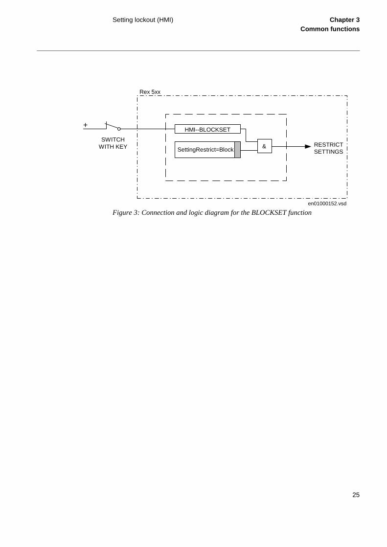
By adding a key switch connected to a binary input a simple setting change control cir-cuit can be built simply allowing only authorized keyholders to make setting changes. Security can be increased by adding SA/SMS overrides that prevents changes even by keyholders.
3.2 Functionality
Activating the setting restriction prevents unauthorized personell to purposely or by mistake change terminal settings.
The HMI--BLOCKSET functional input is configurable only to one of the available bi-nary inputs of a REx 5xx terminal. For this reason, the terminal is delivered with the default configuration, where the HMI--BLOCKSET signal is connected to NONE-NOSIGNAL.
The function permits remote changes of settings and reconfiguration through the serial communication ports. The setting restrictions can be activated only from the local HMI.
All other functions of the local human-machine communication remain intact. This means that an operator can read all disturbance reports and other information and set-ting values for different protection parameters and the configuration of different logic circuits.
24
Setting lockout (HMI) Chapter 3Common functions
Figure 3: Connection and logic diagram for the BLOCKSET function
SettingRestrict=BlockRESTRICTSETTINGS
HMI--BLOCKSET
&SWITCH
WITH KEY
+
Rex 5xx
en01000152.vsd
25

I/O system configurator (IOP) Chapter 3Common functions
-
size
put/. The
r put
e mA
the
tion. g.
4 I/O system configurator (IOP)
4.1 Application
The I/O system configurator must be used in order to recognize added modules and to create internal adress mappings between modules and protections and other functions.
4.2 Functionality
The I/O system configurator is used to add, remove or move I/O modules in the REx 5xx terminals. To configure means to connect the function blocks that represent each I/O module (BIM, BOM, IOM, IOPSM, DCM and MIM) to a function block for the I/O positions (IOP1) that represent the physical slot in the rack.
Available I/O modules are:
• BIM, Binary Input Module with 16 binary input channels.
• BOM, Binary Output Module with 24 binary output channels.
• IOM, Input/Output Module with 8 binary input and 12 binary output channels.
• MIM, mA Input Module with six analog input channels.
• IOPSM, Input Output Power Supply Module with four inputs and four outputs.
• DCM, Data Communication Module. The only software configuration for this module is the I/O Position input.
An REx 5xx terminal houses different numbers of modules depending of the casingand which kind of modules chosen.
• The 1/1 of 19-inch size casing houses a maximum of 13 modules. But when InOutput- or Output modules are included, the maximum of these modules are sixmaximum number of mA Input modules are also limited to six.
• The 3/4-size casing houses a maximum of eight modules. The limitation is foumodules for Input/Output- or Output modules. The maximum number of mA Inmodules are three.
• The 1/2-size casing houses a maximum of three binary modules or one analoguInput module.
It is possible to fit modules of different types in any combination in a terminal, buttotal maximum numbers of modules must be considered.
Each I/O-module can be placed in any CAN-I/O slot in the casing with one excepThe DCM-module has a fixed slot position which depends on the size of the casin
26

I/O system configurator (IOP) Chapter 3Common functions
To add, remove or move modules in the terminal, the reconfiguration of the terminal must be done from the graphical configuration tool CAP 531.
Users refer to the CAN-I/O slots by the physical slot numbers of the CAN-I/O slots, which also appear in the terminal drawings.
If the user-entered configuration does not match the actual configuration in the termi-nal, an error output is activated on the function block, which can be treated as an event or alarm.
The BIM, BOM, IOM, IOPSM and DCM share the same communication addresses for parameters and configuration. So they must share I/O module 1-13 (IOxx), which are the same function block. A user-configurable function selector per I/O module function block determines which type of module it is.
All names for inputs and outputs are inputs on the function blocks and must be set from the graphical tool CAP 531.
I/O position
The IOP1 (I/O position) function block is the same for the different casings, indepen-dent of the number of slots available. Anyway, it looks different depending of actual configuration. All necessary configuration is done in the CAP 531 configuration tool.
The Sxx outputs are connected to the POSITION inputs of the I/O Modules and MIMs.
27

I/O system configurator (IOP) Chapter 3Common functions
ule
t of
Figure 4: Function block of the I/O position block (IOP1-).
Configuration
The I/O-configuration can only be performed from CAP 531, the graphical configura-tion tool.
To configure from the graphical tool:
• First, set the function selector for the logical I/O module to the type of I/O modthat is used, BIM, BOM, IOM, IOPSM or DCM.
• Secondly, connect the POSITION input of the logical I/O module to a slot outputhe IOP function block.
xx00000238.vsd
IOP1-I/OPOSITION
S11S12S13S14S15S16S17S18S19S20S21S22S23S24S25S26S27S28S29S30S31S32S33S34S35S36
28

I/O system configurator (IOP) Chapter 3Common functions
Figure 5: Example of an I/O-configuration in the graphical tool CAP 531 for a REx 5xx with two BIMs.
I/O-MODULEIO01-
POSITION ERRORBI1
. .
.BI16
I/O-MODULEIO02-
POSITION ERRORBI1
. .
.BI16
IOP1-I/OPOSITION
S11S13S15S17S19
en01000142.vsd
29

Logic function blocks Chapter 3Common functions
5 Logic function blocks
5.1 Application
5.1.1 Application
Different protection, control, and monitoring functions within the REx 5xx terminals are quite independent as far as their configuration in the terminal is concerned. The user cannot enter and change the basic algorithms for different functions, because they are located in the digital signal processors and extensively type tested. The user can config-ure different functions in the terminals to suit special requirements for different appli-cations.
For this purpose, additional logic circuits are needed to configure the terminals to meet user needs and also to build in some special logic circuits, which use different logic gates and timers.
5.2 Functionality
Inverter (INV)
The INV function block is used to invert the input boolean variable. The function block (figure 6) has one input designated IVnn-INPUT where nn presents the serial number of the block. Each INV circuit has one output IVnn-OUT.
Figure 6: Function block diagram of the inverter (INV) function
Table 1: Truth table for the INV function block
INPUT OUT
1 0
0 1
1INPUT OUT
IVnn
99000021.vsd
30

Logic function blocks Chapter 3Common functions
Controllable gate (GT)
The GT function block is used for controlling if a signal should be able to pass or not depending on a setting. The function block (figure 7) has one input, designated GTnn-INPUT, where nn presents the serial number of the block. Each GT circuit has one out-put, GTnn-OUT. Each gate further has a Operation On/Off which controls if the INPUT is passed to the OUT or not.
Figure 7: Function block diagram of the controllable gate (GT) function
The output signal from the GT function block is set to 1 if the input signal is 1 and Op-eration = On elsewhere it is set to 0. See truth table below.
Table 2: Truth table for the GT function block
OR
OR function blocks are used to form general combinatory expressions with boolean variables. The function block (figure 8) has six inputs, designated Onnn-INPUTm, where nnn presents the serial number of the block, and m presents the serial number of the inputs in the block. Each OR circuit has two outputs, Onnn-OUT and Onnn-NOUT (inverted).
INPUT Operation OUT
0 Off 0
1 Off 0
0 On 0
1 On 1
&Operation = On
INPUTOUT
GTnn
xx00000530.vsd
31

Logic function blocks Chapter 3Common functions
Figure 8: Function block diagram of the OR function
The output signal (OUT) is set to 1 if any of the inputs (INPUT1-6) is 1. See truth table below.
Table 3: Truth table for the OR function block
AND
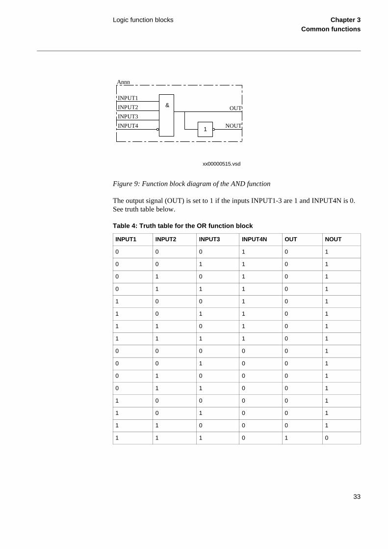
AND function blocks are used to form general combinatory expressions with boolean variables. The function block (figure 9) has four inputs (one of them inverted), desig-nated Annn-INPUTm (Annn-INPUT4N is inverted), where nnn presents the serial number of the block, and m presents the serial number of the inputs in the block. Each AND circuit has two outputs, Annn-OUT and Annn-NOUT (inverted).
≥1
INPUT6
INPUT1
INPUT2
INPUT3
INPUT4
INPUT5
OUT
1NOUT
Onnn
xx00000514.vsd
INPUT1 INPUT2 INPUT3 INPUT4 INPUT5 INPUT6 OUT NOUT
0 0 0 0 0 0 0 1
0 0 0 0 0 1 1 0
0 0 0 0 1 0 1 0
... ... ... ... ... ... 1 0
1 1 1 1 1 0 1 0
1 1 1 1 1 1 1 0
32
Logic function blocks Chapter 3Common functions
Figure 9: Function block diagram of the AND function
The output signal (OUT) is set to 1 if the inputs INPUT1-3 are 1 and INPUT4N is 0. See truth table below.
Table 4: Truth table for the OR function block
INPUT1 INPUT2 INPUT3 INPUT4N OUT NOUT
0 0 0 1 0 1
0 0 1 1 0 1
0 1 0 1 0 1
0 1 1 1 0 1
1 0 0 1 0 1
1 0 1 1 0 1
1 1 0 1 0 1
1 1 1 1 0 1
0 0 0 0 0 1
0 0 1 0 0 1
0 1 0 0 0 1
0 1 1 0 0 1
1 0 0 0 0 1
1 0 1 0 0 1
1 1 0 0 0 1
1 1 1 0 1 0
xx00000515.vsd
&INPUT1
INPUT2
INPUT3
INPUT4
OUT
1NOUT
Annn
33

Logic function blocks Chapter 3Common functions
Timer
The function block TM timer has outputs for delayed input signal at drop-out and at pick-up. The timer (figure 10) has a settable time delay TMnn-T between 0.00 and 60.00 s in steps of 0.01 s. The input signal for each time delay block has the designation TMnn-INPUT, where nn presents the serial number of the logic block. The output sig-nals of each time delay block are TMnn-ON and TMnn-OFF. The first one belongs to the timer delayed on pick-up and the second one to the timer delayed on drop-out. Both timers within one block always have the same setting.
Figure 10: Function block diagram of the Timer function
The function block TL timer (figure 11) with extended maximum time delay at pick-up and at drop-out, is identical with the TM timer. The difference is the longer time delay TLnn-T, settable between 0.0 and 90000.0 s in steps of 0.1 s.
xx00000523.vsd
OFFINPUT
ON
TTime delay 0.00-60.00s
TMnn
t
t
34

Logic function blocks Chapter 3Common functions
Figure 11: Function block diagram of the TimerLong function
The input variable to INPUT is obtained delayed a settable time T at output OFF when the input variable changes from 1 to 0 in accordance with the time pulse diagram, figure 12. The output OFF signal is set to 1 immediately when the input variable changes from 0 to 1.
Figure 12: Example of time diagram for a timer delayed on drop-out with preset time T = 3 s
xx00000526.vsd
OFFINPUT
ON
TTime delay 0.0-90000.0s
TLnn
t
t
xx00000528.vsd
INPUT
OFF
T=3s
1
0
1
0
0 11 2 3 4 5 6 7 8 9 10
35

Logic function blocks Chapter 3Common functions
The input variable to INPUT is obtained delayed a settable time T at output ON when the input variable changes from 0 to 1 in accordance with the time pulse diagram, figure 13. The output ON signal returns immediately when the input variable changes from 1 to 0.
Figure 13: Example of time diagram for a timer delayed on pick-up with preset time T = 3 s
If more timers than available in the terminal are needed, it is possible to use pulse timers with AND or OR logics. Figure 14 shows an application example of how to realize a timer delayed on pick-up. Figure 15 shows the realization of a timer delayed on drop-out. Note that the resolution of the set time must be 0.2 s, if the connected logic has a cycle time of 200 ms.
Figure 14: Realization example of a timer delayed on pick-up
INPUT
ON
T=3s
1
0
1
0
0 11 2 3 4 5 6 7 8 9 10
xx00000529.vsd
AND
INPUT1INPUT2INPUT3INPUT4N
OUTNOUT
Pulse
INPUTT
OUTNOUT
FIXED-ON
0.00-60.00s
xx00000533.vsd
36

Logic function blocks Chapter 3Common functions
Figure 15: Realization example of a timer delayed on drop-out
Timer settable through HMI/SMS/PST
The function block TS timer has outputs for delayed input signal at drop-out and at pick-up. The timer (figure 16) has a settable time delay TSnn-T between 0.00 and 60.00 s in steps of 0.01 s. It also has an Operation setting On, Off which controls the operation of the timer.The input signal for each time delay block has the designation TSnn-IN-PUT, where nn presents the serial number of the logic block. The output signals of each time delay block are TSnn-ON and TSnn-OFF. The first one belongs to the timer de-layed on pick-up and the second one to the timer delayed on drop-out. Both timers with-in one block always have the same setting.
Figure 16: Function block diagram of the Settable timer function
INV
INPUT OUT
ORINPUT1INPUT2
OUTNOUT
INPUT3INPUT4INPUT5INPUT6
FIXED-OFF
Pulse
INPUT
T
OUT
0.00-60.00s
xx00000534.vsd
&Operation = On
INPUT
TSnn
t OFF
t ON
Time delay T=0.00-60.00s
xx00000531.vsd
37

Logic function blocks Chapter 3Common functions
For details about the function see the description of TM Timer.
Pulse
The pulse function can be used, for example, for pulse extensions or limiting of opera-tion of outputs. The pulse timer TP (figure 17) has a settable length of a pulse between 0.00 s and 60.00 s in steps of 0.01 s. The input signal for each pulse timer has the des-ignation TPnn-INPUT, where nn presents the serial number of the logic block. Each pulse timer has one output, designated by TPnn-OUT. The pulse timer is not retrigga-ble, that is, it can be restarted first after that the time T has elapsed.
Figure 17: Function block diagram of the Pulse function
The function block TQ pulse timer (figure 18) with extended maximum pulse length, is identical with the TP pulse timer. The difference is the longer pulse length TQnn-T, set-table between 0.0 and 90000.0 s in steps of 0.1 s.
Figure 18: Function block diagram of the PulseLong function, TQ
OUTINPUT
T Time delay 0.00-60.00s
TPnn
xx00000524.vsd
OUTINPUT
T Time delay 0.0-90000.0s
TQnn
xx00000525.vsd
38

Logic function blocks Chapter 3Common functions
A memory is set when the input INPUT is set to 1. The output OUT then goes to 1. When the time set T has elapsed, the memory is cleared and the output OUT goes to 0. If a new pulse is obtained at the input INPUT before the time set T has elapsed, it does not affect the timer. Only when the time set has elapsed and the output OUT is set to 0, the pulse function can be restarted by the input INPUT going from 0 to 1. See time pulse diagram, figure 19.
Figure 19: Example of time diagram for the pulse function with preset pulse length T = 3 s
Exclusive OR (XOR)
The function block exclusive OR (XOR) is used to generate combinatory expressions with boolean variables. XOR (figure 20) has two inputs, designated XOnn-INPUTm, where nn presents the serial number of the block, and m presents the serial number of the inputs in the block. Each XOR circuit has two outputs, XOnn-OUT and XOnn-NOUT (inverted). The output signal (OUT) is 1 if the input signals are different and 0 if they are equal.
T=3s
1
0
1
0
0 11 2 3 4 5 6 7 8 9 10
INPUT
OUT
xx00000571.vsd
39

Logic function blocks Chapter 3Common functions
Figure 20: Function block diagram of the XOR function
The output signal (OUT) is set to 1 if the input signals are different and to 0 if they are equal. See truth table below.
Table 5: Truth table for the XOR function block
Set-Reset (SR)
The function block Set-Reset (SR) (figure 21) has two inputs, designated SRnn-SET and SRnn-RESET, where nn presents the serial number of the block. Each SR circuit has two outputs, SRnn-OUT and SRnn-NOUT (inverted). The output (OUT) is set to 1 if the input (SET) is set to 1 and if the input (RESET) is 0. If the reset input is set to 1, the output is unconditionally reset to 0.
INPUT1 INPUT2 OUT NOUT
0 0 0 1
0 1 1 0
1 0 1 0
1 1 0 1
=1OUT
1NOUT
INPUT1
INPUT2
XOnn
xx00000517.vsd
40

Logic function blocks Chapter 3Common functions
Figure 21: Function block diagram of the Set-Reset function
Set-Reset with/without memory (SM)
The function block Set-Reset (SM) (figure 22) with/without memory has two inputs, designated SMnn-SET and SMnn-RESET, where nn presents the serial number of the block. Each SM circuit has two outputs, SMnn-OUT and SMnn-NOUT (inverted). The output (OUT) is set to 1 if the input (SET) is set to 1 and if the input (RESET) is 0. If the reset input is set to 1, the output is unconditionally reset to 0. The memory setting controls if the flip-flop after a power interruption will return to the state it had before or if it will be reset.
OUTSET
RESET
&≥1
1NOUT
SRnn
xx00000519.vsd
41

Logic function blocks Chapter 3Common functions
Figure 22: Function block diagram of the Set-Reset with/without memory function
5.3 Calculations
For the AND gates, OR gates, inverters, normal SR (Set-Reset) flip-flops, XOR gates and MOVE elements no settings exist.
For the normal On/Off delay timers and pulse timers the time delays and pulse lengths are set from the CAP 531 configuration tool.
Both timers in the same logic block (the one delayed on pick-up and the one delayed on drop-out) always have a common setting value. Setting values of the pulse length are independent of one another for all pulse circuits.
For the controllable gates, settable timers, SR flip-flops with/without memory the set-ting parameters are accessible through the HMI and SMS.
Configuration
The configuration of the logics is performed from the CAP 531 configuration tool.
Execution of functions as defined by the configurable logic blocks runs in a fixed se-quence in two different cycle times, typical 6 ms and 200 ms.
xx00000520.vsd
OUTSET
RESET
&≥1
1NOUT
SMnn
Memory=On,Off
42

Logic function blocks Chapter 3Common functions
For each cycle time, the function block is given an execution serial number. This is shown when using the CAP 531 configuration tool with the designation of the function block and the cycle time, for example, TMnn-(1044, 6). TMnn is the designation of the function block, 1044 is the execution serial number and 6 is the cycle time.
Execution of different function blocks within the same cycle time should follow the same order as their execution serial numbers to get an optimal solution. Always remem-ber this when connecting in series two or more logical function blocks. When connect-ing function blocks with different cycle times, the MOVE function blocks can be used. These function blocks synchronize boolean signals sent between logics with slow exe-cution time and logics with fast execution time. The MOVE functions are available as additional configurable logic circuits.
Note!
Be always careful when connecting function blocks with a fast cycle time to functionblocks with a slow cycle time.
So design the logic circuits carefully and check always the execution sequence for dif-ferent functions. In other cases, additional time delays must be introduced into the logicschemes to prevent errors, for example, race between functions.
43

Self supervision (INT) Chapter 3Common functions
The n it is ot be
g
nect-
6 Self supervision (INT)
6.1 Application
The REx 5xx protection and control terminals have a complex design with many includ-ed functions. The included self-supervision function and the INTernal signals function block provide good supervision of the terminal. The different safety measures and fault signals makes it easier to analyze and locate a fault.
Both hardware and software supervision is included and it is also possible to indicate possible faults through a hardware contact and/or through the software communication.
Internal events are generated by the built-in supervisory functions. The supervisory functions supervise the status of the various modules in the terminal and, in case of fail-ure, a corresponding event is generated. Similarly, when the failure is corrected, a cor-responding event is generated.
Apart from the built-in supervision of the various modules, events are also generated when the status changes for the:
• built-in real time clock (in operation/out of order).
• external time synchronization (in operation/out of order).
Events are also generated:
• whenever any setting in the terminal is changed.
• when the content of the Disturbance report is erased.
The internal events are time tagged with a resolution of 1 ms and stored in a list.list can store up to 40 events. The list is based on the FIFO principle, that is, whefull, the oldest event is overwritten. The list cannot be cleared and its content cannmodified.
The list of internal events provides valuable information, which can be used durincommissioning and fault tracing.
The information can only be retrieved with the aid of the SMS. The PC can be coned either to the port at the front or at the rear of the terminal.
44

Self supervision (INT) Chapter 3Common functions
e list t - In-
con-R-ults
23. , trol sys-tputs tions
6.2 Functionality
The self-supervision status can be monitored from the local HMI or via the PST Param-eter Setting Tool or a SMS/SCS system.
Under the Terminal Report menu in the local HMI the present information from the self-supervision function can be viewed. A detailed list of supervision signals that can be generated and displayed in the local HMI is found in the Installation and Commis-sioning Manual.
In the PST under Terminal Report these summary signals are available:
• InternalStatus
• CPU-Status
When an internal fault has occurred, extensive information about the fault from thof internal events can be retrieved from the PST under the menu Terminal Reporternal Events.
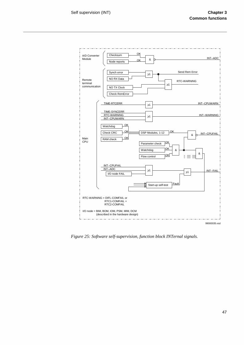
A self-supervision summary can be obtained by means of the potential free alarmtact located on the power supply module. The function of this output relay is an Ofunction between the INT--FAIL signal (figure 25) and a couple of more severe fathat can happen in the terminal (figure 24).
Some signals are available from the function block InternSignals (INT), see figureThe signals from this function block can be connected to an Event function blockwhich generates and sends these signals as events to the station level of the contem. The signals from the INT-function block can also be connected to binary oufor signalization via output relays or they can be used as conditions for other funcif required/desired.
Figure 23: Function block INTernal signals.
xx00000169.vsd
INT--INTERNSIGNALS
FAILWARNING
CPUFAILCPUWARN
ADCSETCHGD
45

Self supervision (INT) Chapter 3Common functions
Individual error signals from I/O modules and time synchronization can be obtained from respective function block of IOM-, BIM-, BOM-, MIM-, IOPSM-modules and from the time synchronization block TIME.
Figure 24: Hardware self-supervision, potential-free alarm contact.
Power supply fault
WatchdogTX overflowMaster resp.Supply fault
ReBoot I/O
Checksum fault
Sending reports
DSP faultSupply faultParameter check
Power supplymodule
I/O nodes
A/D conv.module
Main CPU
&
Fault
Fault
Fault
Fault
INTERNALFAIL
I/O nodes = BIM, BOM, IOM PSM, MIM or DCMDSP = Digital Signal Processorxxxx = Inverted signal
99000034.vsd
46
Self supervision (INT) Chapter 3Common functions
Figure 25: Software self-supervision, function block INTernal signals.
Checksum
Node reports
Synch error
NO RX Data
NO TX Clock
Check RemError
&
>1
>1
INT--ADC
Send Rem Error
OK
OK
>1TIME-RTCERR INT--CPUWARN
>1
TIME-SYNCERRRTC-WARNINGINT--CPUWARN
INT--WARNING
Watchdog
Check CRC
RAM check
DSP Modules, 1-12
OK
OK
OK&
OKINT--CPUFAIL
Parameter check
Watchdog
Flow control
&
OK
OK
OK&
>1
INT--CPUFAILINT--ADC
I/O node FAILINT--FAIL
Start-up self-test Fault
MainCPU
Remoteterminalcommunication
A/D ConverterModule
RTC-WARNING = DIFL-COMFAIL or RTC1-COMFAIL + RTC2-COMFAIL
I/O node = BIM, BOM, IOM, PSM, MIM, DCM (described in the hardware design)
99000035.vsd
>1
RTC-WARNING
47

Blocking of signals during test Chapter 3Common functions
7 Blocking of signals during test
7.1 Functionality
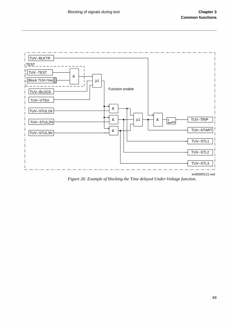
This blocking function is only active during operation in the test mode, see example in Figure 26. When exiting the test mode, entering normal mode, this blocking is disabled and everything is set to normal operation. All testing will be done with actually set and configured values within the terminal. No settings etc. will be changed. Thus no mis-takes are possible.
The blocked functions will still be blocked next time entering the test mode, if the blockings were not reset.
The blocking of a function concerns all output signals from the actual function, so no outputs will be activated.
Each of the terminal related functions is described in detail in the documentation for the actual unit. The description of each function follows the same structure (where appli-cable).
48
Blocking of signals during test Chapter 3Common functions
Figure 26: Example of blocking the Time delayed Under-Voltage function.
TUV--BLKTR
TUV--BLOCK
TUV--TEST
Block TUV=Yes
TUV--STUL1N
TUV--STUL2N
TUV--STUL3N
&
>1 & TUV--TRIP
TUV--START
TUV--STL1
TUV--STL2
TUV--STL3
TEST
TUV--VTSU
>1
&
&
&
en00000121.vsd
Function enable
t
49

Blocking of signals during test Chapter 3Common functions
50

About this chapter Chapter 4Line impedance
Chapter 4 Line impedance
About this chapter
This chapter describes the line impedance functions in the terminal.
51

Distance protection (ZM1-5) Chapter 4Line impedance
its op-
pro-emote
selec- erate
tech-
and
es-on
ation tect akes t
1 Distance protection (ZM1-5)
1.1 Application
General
The distance protection function is the most widely spread protection function in trans-mission and subtransmission networks. It is also becoming increasingly important in distribution networks. The main reasons for this are:
• Its independence on communication links between the line ends, because for eration, it uses information about the locally available currents and voltages.
• The distance protection forms a relatively selective protection system (non-unittection system) in the power network. This means that it can also operate as a rback-up protection for other primary elements in the network.
The basic requirements for modern line protection, such as speed, sensitivity andtivity, with their strict requirements for dependability and security (availability), aregetting more stringent. In addition, modern distance protections must be able to opin networks with existing distance relays, which are mostly designed in a different nology (static or even electromechanical relays).
Older distance relays protect in many cases power lines only at phase-to-phase three-phase faults. Some other protection is used for phase-to-earth faults.
The flexibility of modern distance protection is for this reason very important. Thispecially applies when it is used in a complex network configuration, for example, parallel operating multicircuit lines and on multiterminal lines.
The selective operation of the distance protection does not depend on communicfacilities between two line ends. At the same time, the distance protection can defaults beyond the current transformers at the remote terminal. This functionality mit an ideal complement to the line differential protection function that cannot detecfaults beyond the current transformer at the opposite terminal.
52

Distance protection (ZM1-5) Chapter 4Line impedance
Distance protection zones
The distance protection function in REx 5xx line protection, control, and monitoring terminals consists of three to five independent distance protection zones, each of them comprising three measuring elements for phase-to-earth (Ph-E) faults and/or three mea-suring elements for phase-to-phase (Ph-PH) faults. Different terminals suit different re-quirements in different networks on various voltage levels. For this reason, some characteristic parameters of the distance protection function differ from terminal to ter-minal. For detailed information, please refer to ordering particulars for each line pro-tection terminal REx 5xx separately.
Distance protection zone five differs from other zones with respect to its speed of oper-ation. It starts faster than other distance protection zones and might have for this reason higher overreaching for different system transients. It is for this reason suggested to use it only for the applications, which permit higher overreaching, (i.e. switch-onto-fault function) or as a time delayed distance protection zone with time delay longer than 100 ms.
Complement to the line differential protection
The distance protection function can become optional protection in some line differen-tial protection terminals (REL 561, for example). At the same time it represents the pri-mary protection for faults beyond the current transformers at the opposite terminal. This functionality is achieved by the time delayed overreaching zone (generally zone 2), which covers at least the adjacent busbar and thus forms a primary or back-up protec-tion for the busbar. So the overreaching zone should be continuously in operation.
An underreaching zone (generally zone 1) can form a back-up to the line differential protection. There is no need for this function as long as the differential protection is in operation. To minimize the risk of unwanted operation from zone 1, this function can be activated only when the differential function is out of operation. The most likely cause to lose the differential protection is a failure within the communication system.
The communication scheme used with the distance protection should for this reason use another communication channel than the one used by the line differential protection.
Set of simplified setting parameters
Each distance protection zone comprises basically completely independent setting pa-rameters for phase-to-earth, and for phase-to-phase measurement. This is an application advantage in complex network configurations and in networks, where it is required to adjust the newly applied distance protection functions to the existing other types of re-lays (overcurrent earth fault, for example).
A set of simplified optional parameters is available optionally for applications, where equal zone reaches for all kinds of faults are a standard practice. See the table of setting parameters and the setting instructions.
53

Distance protection (ZM1-5) Chapter 4Line impedance
part e 27 stics.
Basic characteristics
The distance protection function, as built into the REx 5xx line protection terminals, is a full-scheme distance protection. This means that it has individual measuring elements for different types of faults within different zones.
Depending on the type of terminal, it consists of up to five (for details see the corre-sponding ordering details) independent, impedance-measuring zones, each has a quad-rilateral characteristic, as symbolically illustrated in figure 27. RL and XL represent line resistance and reactance and RF represents the resistive reach of a protective zone.
Figure 27: Typical characteristic of a distance protection zone.
The static characteristic in reactive direction is a straight line, parallel with the R-axis. The measuring algorithm used for the reactance part of the characteristic for phase-to-earth faults compensates for the influence of the load current on the impedance mea-surement for distance zone 1. So the static characteristic has no declination against the R-axis. Setting of the reach in a reactive direction is independent for each separate zone. It can also differ for ph-ph and for ph-E measuring elements.
A straight line limits the reach of the distance protection zone in resistive direction. It is generally parallel with ZL, the line-impedance characteristic. This means that it forms, with the R-axis, a ϕL line-characteristic angle. Setting of the reach in resistive direction is independent for each separate zone. Different setting values are also possi-ble for phase-to-earth faults (RFPE) and for phase-to-phase faults (RFPP).
With the X-axis, the directional characteristic in the second quadrant forms an ArgNegRes settable angle (default value 25°). With the R-axis, the correspondingforms a settable ArgDir angle in the fourth quadrant (default value -15°), as in figurand figure 28. All distance protection zones have the same directional characteri
R
jX
en00000376.vsd
ZL=R
L+ jX
L
RF
ArgDirA
rgNegR
es
ϕL
54

Distance protection (ZM1-5) Chapter 4Line impedance
The characteristics of the distance zones are independent of one another as far as their directionality and reach in different directions are concerned. One can program the di-rectionality of each distance zone. Figure 28 shows a typical example of the character-istics of an impedance-measuring zone when directed into forward or reverse directions. A polygon, completed with dashed lines, represents the characteristic of a non-directional zone.
Figure 28: Nondirectional and directional (forward and reverse) operating character-istic
The set value of a reach in resistive direction determines whether the directional line in the second quadrant meets, as first, the reactive or the resistive characteristic. Compare the characteristics in figure 27 and 28.
The values of the reaches in reactive and resistive direction for a particular zone are the same for forward and reverse impedance-measuring elements and for the non-direction-al mode of operation.
R
jX
en00000377.vsd
RF
Forward
Reverse
ArgN
egRes
XL
RF RF
XL
ArgDir
55
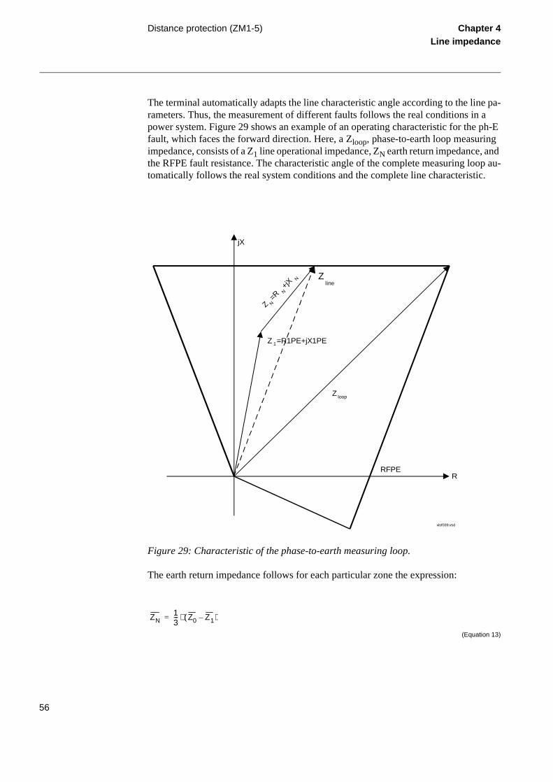
Distance protection (ZM1-5) Chapter 4Line impedance
The terminal automatically adapts the line characteristic angle according to the line pa-rameters. Thus, the measurement of different faults follows the real conditions in a power system. Figure 29 shows an example of an operating characteristic for the ph-E fault, which faces the forward direction. Here, a Zloop, phase-to-earth loop measuring impedance, consists of a Z1 line operational impedance, ZN earth return impedance, and the RFPE fault resistance. The characteristic angle of the complete measuring loop au-tomatically follows the real system conditions and the complete line characteristic.
Figure 29: Characteristic of the phase-to-earth measuring loop.
The earth return impedance follows for each particular zone the expression:
(Equation 13)
R
jX
visf039.vsd
Z 1=R1PE+jX1PE
Z loop
RFPE
Z N=R
N+jX
N Zline
ZN13--- Z0 Z1–( )⋅=
56

Distance protection (ZM1-5) Chapter 4Line impedance
is en
e dis-
with:
(Equation 14)
and
(Equation 15)
Where R1PE, X1PE, R0PE and X0PE are the reach setting parameters.
It is possible to make the characteristic independent of line angle by setting the corre-sponding line resistances R1PE and R0PE to their minimum possible values. For more details see setting instructions.
The possibility to cover a sufficient fault resistance is a major consideration in short-line applications. Load encroachment problems are not so common. The independent setting option of the reach in reactive and resistive direction is a function that greatly improves the flexibility of distance protection. For these short line applications, an op-tional overreaching scheme communication logic, also improves, the resistive cover-age. The optimum solution in some applications is to add the optional, directional-comparison, earth-fault, overcurrent protection to the distance protection scheme.
In long line applications, the margin to the load impedance (to avoid load encroach-ment) is usually a major consideration. Quadrilateral characteristics with independent settings of the reach in reactive (to cover sufficient length of a line) and resistive (to avoid load encroachment) direction greatly diminish the conflict that is very character-istic for circular characteristics.
A wide setting range of the reach in a reactive direction, which one set independently for each zone with good current sensitivity — down to 10% of the rated current —an important factor that improves the performances of the distance protection whused on long transmission lines.
High-voltage power cables have two main characteristics that make them, from thtance protection perspective, different from overhead lines:
Z1 R1PE j X1PE⋅+=
Z0 R0PE j X0PE⋅+=
57

Distance protection (ZM1-5) Chapter 4Line impedance
wer harac-
fol-and re- line-
inde-epen-
allel pro-o op-ssible
of mpen-ent of
f the nce
low- that is
infor-ase
flex-tion tec-g sys-h the erent pli-
• They are relatively short, compared to overhead lines.
• The value of their zero-sequence reactance is very low, in many cases even lothan the positive-sequence reactance. This results in a negative value of the cteristic angle for the earth-return impedance.
Without approximation, the value of the earth-return compensation automaticallylows the parameters of a power cable for positive and zero sequence reactance sistance. This makes the impedance measuring function, as built into the REx 5xxprotection terminals, suitable for the protection of short, EHV power cables. The pendent setting of the reach (in reactive and resistive direction, separately and inddently for each distance zone) improves these basic performances.
Zero-sequence, mutual impedance between different circuits of the multicircuit paroperating lines is a factor that particularly influences the performance of distancetection during single-phase-to-earth fault conditions. Distance protection must alserate selectively for intersystem faults and simultaneous faults to the greatest poextent.
The separate and independent setting of the parameters that determine the valueearth-return compensation for different distance-protection zones, enables the cosation of the influence of the zero-sequence, mutual impedance on the measuremthe impedance-measuring elements for single-phase-to-earth faults.
Separate, optional, phase selectors usage, with their reach setting independent oreach of the zone measuring elements, greatly improves the performance of distaprotection on the multicircuit parallel operating lines. At the same time and to the est possible level, these selectors reduce the influence of the heavy load current,present during a fault, on the phase selection function within the terminals.
Additional phase-segregated, scheme communication logic (refer to the ordering mation for its availability within the different types of terminals) enables absolute phselectivity of the distance protection of multi-circuit, parallel operating lines.
For the selective operation of distance protection on tied and multiterminal lines, ibility in scheme communication logic associated with the distance protection funcis a great advantage. Scheme communication logic built into the REx 5xx line protion terminals enables the adaptation of any communication scheme to the existintem conditions. The free selection of overreaching and underreaching zones, witfree selection of a conditional zone, and independent settings of the reach for diffzones, makes the REx 5xx line protection terminals extremely flexible for such apcations.
58

Distance protection (ZM1-5) Chapter 4Line impedance
1.2 Functionality
1.2.1 Measuring principle
Fault loop equations use the complex values of voltage, current, and changes in the cur-rent. Apparent impedances are calculated and compared with the set limits. The calcu-lation of the apparent impedances at ph-ph faults follows the equation (example for a phase L1 to phase L2 fault):
(Equation 16)
Here represent U and I the corresponding voltage and current phasors in the respective phase Ln (n = 1, 2, 3)
The earth return compensation applies in a conventional manner for ph-E faults (exam-ple for a phase L1 to earth fault):
(Equation 17)
Here IN is a phasor of the residual current in relay point. This results in the same reach along the line for all types of faults.
The apparent impedance is considered as an impedance loop with resistance R and re-actance X, as presented in figure 30.
The measuring elements receive information about currents and voltages from the A/D converter. The check sums are calculated and compared, and the information is distrib-uted into memory locations. For each of the six supervised fault loops, sampled values of voltage (U), current (I), and changes in current between samples (∆I) are brought from the input memory and fed to a recursive Fourier filter.
ZapUL1 UL2–
IL1 IL2–-------------------------=
Zap
UL1
IL1 KN IN⋅+------------------------------=
59

Distance protection (ZM1-5) Chapter 4Line impedance
Figure 30: Apparent impedance with resistance and reactance connected in series
The filter provides two orthogonal values for each input. These values are related to the loop impedance according to the formula:
(Equation 18)
in complex notation, or:
(Equation 19)
(Equation 20)
with
(Equation 21)
R X
U
I
en00000379
U R I⋅ Xω0------+
∆I∆t-----⋅=
Re U( ) R Re I( )⋅ Xω0------+ ∆Re I( )
∆t------------------⋅=
Im U( ) R Im I( )⋅ Xω0------+
∆Im I( )∆t
-----------------⋅=
ω0 2 π f0⋅ ⋅=
60

Distance protection (ZM1-5) Chapter 4Line impedance
The algorithm calculates Rm measured resistance from the equation for the real value of the voltage and substitute it in the equation for the imaginary part. The equation for the Xm measured reactance can then be solved. The final result is equal to:
(Equation 22)
(Equation 23)
The calculated Rm and Xm values are updated each millisecond and compared with the set zone reach. The adaptive tripping counter counts the number of permissive tripping results. This effectively removes any influence of errors introduced by the capacitive voltage transformers or by other causes. The algorithm is insensitive to changes in fre-quency, transient dc components, and harmonics because a true replica of the protected line is implemented in the algorithm.
The directional evaluations are simultaneously performed in forward and reverse direc-tions, and in all six fault loops. Positive sequence voltage and a phase locked positive sequence memory voltage are used as a reference. This ensures unlimited directional sensitivity for faults close to the relay point.
Measured impedance
Phase-to-earth measurement
The impedance measurement for the phase-to-earth faults is performed on the loop ba-sis by comparing the calculated Rm resistance and Xm reactance with the set values of the reach in the resistive and reactive direction:
Where:
Re designates the real component,
Im designates the imaginary component of current and voltage and
f0 designates the rated system frequency
RmIm U( ) ∆Re I( )⋅ Re U( )– ∆ Im I( )⋅∆Re I( ) Im I( )⋅ ∆ Im I( )– Re I( )⋅
------------------------------------------------------------------------------------=
Xm ω0 ∆t Re U( ) Im I( )⋅ Im U( )– Re I( )⋅∆Re I( ) Im I( )⋅ ∆Im I( )– Re I( )⋅-------------------------------------------------------------------------------⋅ ⋅=
61

Distance protection (ZM1-5) Chapter 4Line impedance
(Equation 24)
(Equation 25)
(Equation 26)
(Equation 27)
The p factor represents the relative fault position (-1≤p≤1) within the reactive operating limits in forward and reverse direction.
Equations for resistive measurement represent in the impedance plane non-directional operating limits in resistive direction (see figure 31). For the faults on radial lines equa-tion 24 represents a straight line (left side operating characteristic in loop domain), which passes the R axis at point D = - RFPE + j0 and forms with it an angle of:
(Equation 28)
Equation 25 represents for the same conditions a straight line (right side operating limit) passing the R axis in set point B = RFPE + j0 and is parallel to the left side operating characteristic. Equations 26 and 27 represent in the impedance plane the operating lim-its in reactive direction (see figure 31). For faults on radial lines equation 26 represents in impedance plane (loop domain) a straight line, which is parallel with the R axis and passes the point
Rm R1PE 13---+ R0PE R1PE–( )⋅ p⋅ RFPE–≥
Rm R1PE 13---+ R0PE R1PE–( )⋅ p RFPE+⋅≤
Xm X1PE– 13---– X0PE X1PE–( )⋅≥
Xm X1PE 13---+ X0PE X1PE–( )⋅≤
α atanX1PE 1
3---+ X0PE X1PE–( )⋅
R1PE 13---+ R0PE R1PE–( )⋅
------------------------------------------------------------------------=
62

Distance protection (ZM1-5) Chapter 4Line impedance
(Equation 29)
Similarly represents equation 27 a straight line, which is also parallel with the R axis and passes the point
(Equation 30)
Figure 31: General operating characteristic of impedance measuring elements
Phase-to-phase measurement
The impedance measurement for the phase-to-phase faults is performed on a phase ba-sis by comparing the calculated Rm resistance and Xm reactance with the set values of the reach in the resistive and reactive direction:
C 0 j– X1PE 13---+ X0PE X1PE–( )⋅=
A 0 j+ X1PE 13---+ X0PE X1PE–( )⋅=
R
jX
Forward
Reverse
A
B
C
Dα
en00000383.vsd
ArgN
egRes
ArgDir
63

Distance protection (ZM1-5) Chapter 4Line impedance
(Equation 31)
(Equation 32)
(Equation 33)
(Equation 34)
Here represents p factor the relative fault position (- 1 < p < 1) within the reactive zone reach. Parameters R1PP, X1PP and RFPP are the reach setting parameters for the ph-ph and three-phase faults. The first two equations represent the left and right side oper-ating boundaries, see figure 31. For the faults on radial feeders represent these two equations straight lines in impedance plain, which cross the R axis in points:
(Equation 35)
and
(Equation 36)
respectively.
Both operating limits are parallel and form with the R axis an angle of:
Rm R1PP p⋅ 12---– RFPP⋅≥
Rm R1PP p⋅ 12---+ RFPP⋅≤
Xm X1PP–≥
Xm X1PP≤
D 12---– RFPP⋅ j0+=
B 12--- RFPP⋅ j0+=
64

Distance protection (ZM1-5) Chapter 4Line impedance
he di-ction
for the
d by
(Equation 37)
The third and the fourth equations represent the reactive operating boundaries in for-ward and reverse direction, see figure 31. They cross in impedance plain the X axis in operating points: A = X1PP and C = -X1PP respectively. For the faults on radial feeders this two boundaries are straight lines, parallel with the R axis.
Directional lines
The results of impedance measurement are combined in “and” combination with trectional measurement, to obtain the desired directionality for each distance protezone separately, see figure in “Phase-to-earth measurement”.
The directional measurement is based on the use of a positive-sequence voltage respective fault loop. For the L1-N element, the equation for forward direction is:
(Equation 38)
For the L1-L2 element, the equation in forward direction is:
The reverse directional characteristic is equal to the forward characteristic rotate180 degrees.
Where:
ArgDir is the setting for the lower boundary of the forward directional character-
istic, by default set to 15 (= -15 degrees) and
ArgNegRes is the setting for the upper boundary of the forward directional character-istic, by default set to 115 (degrees)
α atanX1PPR1PP---------------
=
-ArgDir arg0.8 U1L1 0.2+ U1L1M⋅ ⋅
IL1------------------------------------------------------------ ArgNegRes< <
-ArgDir arg0.8 U1L1L2 0.2+ U1L1L2M⋅ ⋅
IL1L2----------------------------------------------------------------------- ArgNegRes< <
65

Distance protection (ZM1-5) Chapter 4Line impedance
een
re-
until
dis-inal. ped-
luded
sin-d re-
forms ms the The d the
each
The polarizing voltage is available as long as the positive-sequence voltage exceeds 4% of the rated voltage Ur. So the directional element can use it for all unsymmetrical faults including close-in faults.
For close-in three-phase faults, the U1L1M memory voltage, based on the same positive sequence voltage, ensures correct directional discrimination.
The memory voltage is used for 100 ms or until the positive sequence voltage is re-stored. After 100 ms, the following occurs:
• If the current is still above the set value of the minimum operating current (betw10 and 30% of the terminal rated current Ir), the condition seals in.
• If the fault has caused tripping, the trip endures.
• If the fault was detected in the reverse direction, the measuring element in theverse direction remains in operation.
• If the current decreases below the minimum operating value, the memory resetsthe positive sequence voltage exceeds 10% of its rated value.
1.3 Design
Full-scheme measurement
Up to three digital signal processors execute algorithms for up to five, full-schemetance protection zones, depending on the type of the REx 5xx line protection termFigure 32 presents an outline of the different measuring loops for the basic five, imance-measuring zones when both, ph-E and ph-ph fault measuring loops are incinto the terminal.
The first digital-signal processor (DSP) measures different fault loops for differentgle-phase-to-earth faults and for different zones. This way, it forms the resistive anactive part of a characteristic for single-phase-to-earth faults. The second DSP perthe same task for the phase-to-phase fault loops. The third DSP separately perfordirectional measurement for all types of faults in forward and reverse directions. presence of the first or the second DSP within the terminal depends on its type anfault type, for which the distance protection is ordered (see ordering particulars forREx 5xx terminal separately).
66

Distance protection (ZM1-5) Chapter 4Line impedance
Figure 32: Location of different measuring loops within the three digital signal proces-sors
The parallel execution of measurements in up to three different DSPs permits the sep-arate evaluation of each impedance measuring loop for each zone every millisecond. This gives the distance protection function the same features as those known for the full-scheme design of conventional distance relays (REZ 1, RAZFE). So each distance protection zone performs like one independent distance protection relay with six mea-suring elements.
Distance protection zone one
The design of distance protection zone 1 is presented for all measuring loops: phase-to-earth as well as phase-to-phase. Different terminals REx 5xx have built-in different measuring circuits, dependent on ordering details. In the following description consider only the phase-to-earth related signals, if only phase-to-earth measurement is included in terminal. Similarly consider only the phase-to-phase related signals, if only phase-to-phase measurement is included in terminal.
The phase-to-earth related signals are designated by LnE, where represents n the corre-sponding phase number (L1E, L2E, and L3E). The phase-to-phase signals are designat-ed by LnLm, where n and m represent the corresponding phase numbers (L1L2, L2L3, and L3L1).
Fulfillment of two different measuring conditions is necessary to obtain the logical one signal for each separate measuring loop:
L1-N L2-N L3-N
L1-N L2-N L3-N
L1-N L2-N L3-N
L1-N L2-N L3-N
L1-L2 L2-L3 L3-L1
L1-L2 L2-L3 L3-L1
L1-L2 L2-L3 L3-L1
L1-L2 L2-L3 L3-L1
L1-N L2-N L3-N L1-L2 L2-L3 L3-L1
L1-N L2-N L3-N L1-L2 L2-L3 L3-L1
L1-N L2-N L3-N L1-L2 L2-L3 L3-L1
Zone 1
Zone 2
Zone 3
Zone 4
Zone 5
Forward
Reverse
en00000487.vsd
67

Distance protection (ZM1-5) Chapter 4Line impedance
bove.
lues e ion
a non-
• Zone measuring condition, which follows the operating equations described a
• Group functional input signal (ZM1--STCND), as presented in figure 33.
The ZM1--STCND input signal represents a connection of six different integer vafrom other measuring functions within the terminal, which are converted within thzone measuring function into corresponding boolean expressions for each conditseparately (see “ZMn--STCND functional input” in “Basic configuration”).
Figure 33: Conditioning by a group functional input signal ZM1--STCND
Composition of the phase starting signals for a case, when the zone operates in directional mode, is presented in figure 34.
99000557.vsd
ZM1L1L2
ZM1L2L3
ZM1L3L1
&
&
&
&
&
&
ZM1L1N
ZM1L2N
ZM1L3N
ZM1--STCND
STNDL1L2-cont.
STNDL2L3-cont.
STNDL3L1-cont.
STNDL1N-cont.
STNDL2N-cont.
STNDL3N-cont.
STZMPP-cont.
STNDPE-cont.
&ZM1--BLOCK
ZM1--VTSZ ZM1--STND
BLK-cont.
>1
>1
>1
>1
68

Distance protection (ZM1-5) Chapter 4Line impedance
Figure 34: Composition of starting signals in non-directional operating mode
Results of the directional measurement enter the logic circuits, when the zone operates in directional (forward or reverse) mode, see figure 35.
en00000488.vsd
STNDL1N-cont.
STNDL2N-cont.
STNDL3N-cont.
STNDL1L2-cont.
STNDL2L3-cont.
STNDL3L1-cont.
>1
>1
>1
>1
&
&
&
&
BLK-cont.
t15 ms
t15 ms
t15 ms
t15 ms
ZM1--START
ZM1--STL3
ZM1--STL2
ZM1--STL1
69

Distance protection (ZM1-5) Chapter 4Line impedance
Figure 35: Composition of starting signals in directional operating mode
Tripping conditions for the distance protection zone one are symbolically presented on figure 36.
en00000489.vsd
STNDL1N-cont.
DIRL1N&
&STNDL2N-cont.
DIRL2N
&STNDL3N-cont.
DIRL3N
&STNDL1L2-cont.
DIRL1L2
&STNDL2L3-cont.
DIRL2L3
&STNDL3L1-cont.
DIRL3L1
>1
>1
>1
>1
>1
>1
&
&
&
&
&
&
BLK-cont.
t15 ms
t15 ms
t15 ms
t15 ms
STZMPE-cont.
ZM1--STL1
ZM1--STL2
ZM1--STL3
ZM1--START
STZMPP-cont.
70

Distance protection (ZM1-5) Chapter 4Line impedance
Figure 36: Tripping logic for the distance protection zone one
Phase related starting and tripping signals are available only in case, when the 1/2/3 phase tripping unit is ordered within the terminal. Please, refer to ordering particulars for each REx 5xx terminal separately.
Remaining distance protection zones
Distance protection zones two and three have the same composition as distance protec-tion zone 1. All descriptions for the distance protection zone 1 are for this reason valid also for the distance protection zones two and three. It is only necessary to replace the ZM1- designation with corresponding designations ZM2- for zone two and ZM3- for zone three respectively.
Distance protection zones four (ZM4-) and five (ZM5-) are based on the same princi-ples as the other distance protection zones. The only difference is in the presentation of phase selective signals, belonging to these two zones. The phase selective signals are not available with distance protection zones four and five.
1.4 Calculations
1.4.1 Setting instructions
The setting values of all parameters that belong to distance protection within the REx 5xx line-protection terminals, must correspond to the parameters of the protected line and to the selectivity plan for the network.
en00000490.vsd
Timer t1PP=On
STZMPP-cont.&
Timer t1PE=On
STZMPE-cont.&
tt1PP
tt1PE
>1
ZM1-BLKTR t
15ms
&
&
&
ZM1--STL1-cont.
ZM1--STL2-cont.
ZM1--STL3-cont.
ZM1--TRIP
ZM1--TRL1
ZM1--TRL2
ZM1--TRL3
&
71

Distance protection (ZM1-5) Chapter 4Line impedance
Reach setting recommendations
Before starting the setting activities for the distance protection function, check that the setting values of the secondary rated current within the terminal correspond to the cur-rent transformers used for the same purposes for a specific REx 5xx terminal.
Conversion to secondary impedances
Convert the primary line impedances to the secondary sides of the current and voltage instrument transformers. The following relation applies to these purposes:
(Equation 39)
Basic zone setting recommendations
An impedance seen by the distance protection might differ from the calculated values due to:
Where:
Abbreviation: Is a set value of:
Iprim Rated primary current of the used current instrument transformers
Isec Rated secondary current of the used current instrument transformers
Uprim Rated primary voltage of the used voltage instrument transformers
Usec Rated secondary voltage of the used voltage instrument transformers
Zprim Primary impedance
Zsec Calculated secondary impedance
ZsecUsec
Uprim--------------
Iprim
Isec------------ Zprim⋅ ⋅=
72

Distance protection (ZM1-5) Chapter 4Line impedance
nder
calcu-
nce
The large
the
e 1) e reach — to ch can nces:
f the
max-d of
short-t least
ent re-rotec-overs n pur-
nce t line, ust in-
ust not ll con-
• Errors introduced by current and voltage instrument transformers, particularly utransient conditions.
• Inaccuracies in the line zero-sequence impedance data, and their effect on thelated value of the earth-return compensation factor.
• The effect of infeed between the relay and the fault location, including the influeof different Z0/Z1 ratios of the various sources.
• The phase impedance of untransposed lines is not identical for all fault loops.difference between the impedances for different phase-to-earth loops can be asas 5-10% of the total line impedance.
• The effect of a load transfer between the terminals of the protected line. Whenfault resistance is considerable, the effect must be recognized.
• Zero-sequence mutual coupling from parallel lines.
Usually, these errors require a limitation of the underreaching zone (normally zonto 85-90% of the protected line. For the same reason, it is necessary to increase thof the overreaching zone (normally zone 2) to at least 120% of the protected line ensure that the overreaching zone always covers a complete line. The zone 2 reabe even higher, but in general it should never exceed 80% of the following impeda
• The impedance corresponding to the protected line, plus the first zone reach oshortest adjacent line.
• The impedance corresponding to the protected line, plus the impedance of theimum number of transformers operating in parallel on the bus at the remote enthe protected line.
The back-up overreaching zone (normally zone 3) must never exceed 90% of theest zone 2 reach of any of the lines connected to the remote end bus. It must be a2 times the zone 1 reach.
The reverse zone is applicable for purposes of scheme communication logic, currversal logic, weak-end-infeed logic, and so on. The same applies to the back-up ption of the busbar or power transformers. It is necessary to secure, that it always cthe overreaching zone, used at the remote line terminal for the telecommunicatioposes.
In the case of a long line followed by a short line, or by a large bank of low impedatransformers, the mandatory 120% setting might overreach zone 1 of the adjacenor reach through the transformer bank at the other line end. In such cases, one mcrease the zone 2 time delay and thus secure the selectivity. The zone 2 reach mbe reduced below 120% of the protected line section. It must be covered under aditions.
73

Distance protection (ZM1-5) Chapter 4Line impedance
In networks with lines tied at an intermediate location, consider an increase in the mea-sured impedance due to the fault current fed into the system at the teed point.
If a fault occurs at point F (see figure 37 also for the explanation of all abbreviations used), the relay at point A senses the impedance:
(Equation 40)
IA and IB are fault currents from sources A and B respectively.
Assume that the reach of zone 1 of the relay in C covers 85% of ZCD, and the reach of zone 2 of the relay in A covers 80% of (ZAC + 85% of ZCD).
The impedance from station A up to the reach limit of the first zone at C corresponds to:
(Equation 41)
The reach of zone 2 can not be longer than 80% of the apparent impedance at the limit of the first zone at C, which means that:
(Equation 42)
Zm ZAC
IA IB+
IA---------------- ZCF⋅+ ZAC 1
IBIA-----+
ZCF⋅+= =
ZAC 0.85+ 1IB
IA
-----+
ZCD⋅ ⋅
Z2 0.8 ZAC 0.85+ 1IBIA-----+
ZCD⋅ ⋅⋅=
74
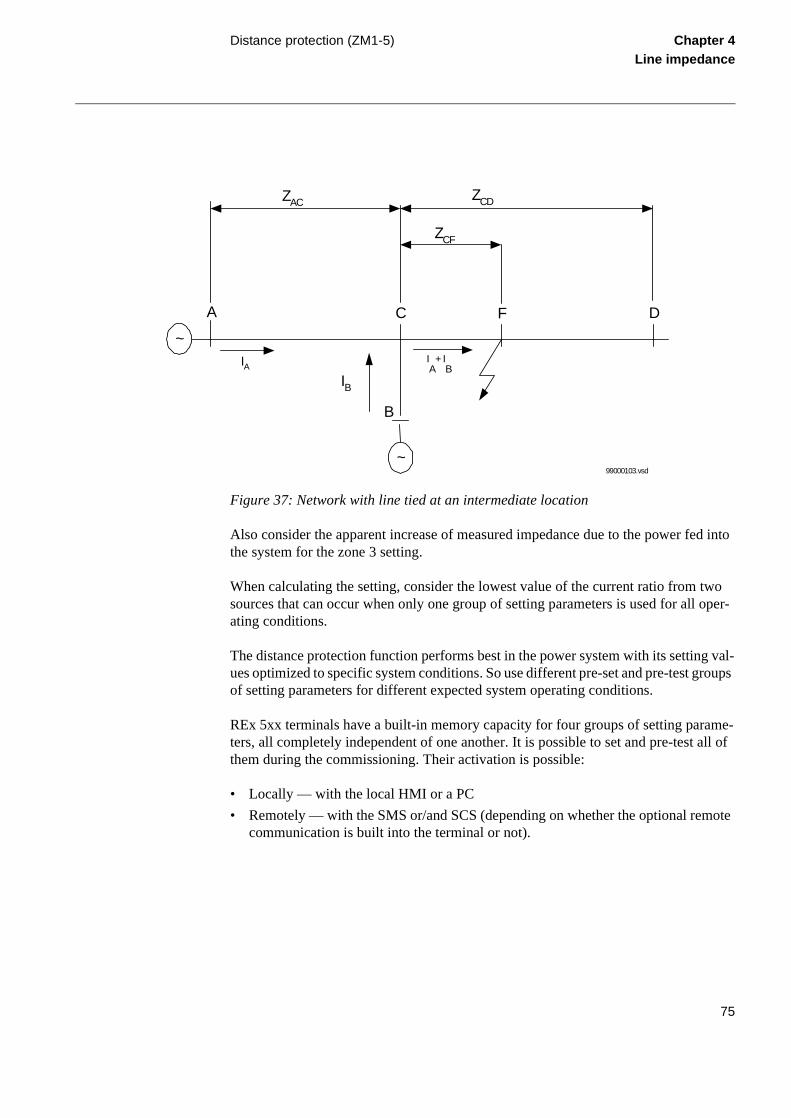
Distance protection (ZM1-5) Chapter 4Line impedance
ote
Figure 37: Network with line tied at an intermediate location
Also consider the apparent increase of measured impedance due to the power fed into the system for the zone 3 setting.
When calculating the setting, consider the lowest value of the current ratio from two sources that can occur when only one group of setting parameters is used for all oper-ating conditions.
The distance protection function performs best in the power system with its setting val-ues optimized to specific system conditions. So use different pre-set and pre-test groups of setting parameters for different expected system operating conditions.
REx 5xx terminals have a built-in memory capacity for four groups of setting parame-ters, all completely independent of one another. It is possible to set and pre-test all of them during the commissioning. Their activation is possible:
• Locally — with the local HMI or a PC
• Remotely — with the SMS or/and SCS (depending on whether the optional remcommunication is built into the terminal or not).
C
ZAC ZCD
F
ZCF
IA
A
IA
+ IB
B
IB
D
~
~99000103.vsd
75

Distance protection (ZM1-5) Chapter 4Line impedance
Earth return compensation
A simplified measuring loop at the single-phase-to-earth faults consists of three imped-ances, as shown in figure 38:.
The earth return impedance is equal to:
(Equation 43)
Figure 38: Equivalent circuits for measurement at single-phase-to-earth faults.
The complete measuring impedance, according to Figure 38 is equal to:
(Equation 44)
Where:
Abbreviation: Is a set value of:
Z1 Positive sequence impedance of the line
Rf Fault resistance
ZN Earth-return impedance
Z0 Zero sequence impedance of the line
ZN13--- Z0 Z1–( )⋅=
I
U
L1L2L3F
Irsd
a)I
U
Z1
NfZ
R
b)
99000036.vsd
Zloop Z1 ZN Rf+ +13--- 2 Z1⋅ Z0+( )⋅ Rf+= =
76

Distance protection (ZM1-5) Chapter 4Line impedance
por-gle-
istance
The reach of distance protection zone is related to the positive sequence line impedance. So an earth-return compensation factor has been introduced into the measuring algo-rithm. Its value is equal to:
(Equation 45)
(Equation 46)
The impedance measuring algorithm within the REL 5xx terminals calculates automat-ically the complex value of the earth-return compensation factor KN on the basis of the set values for the
• Positive sequence reactance of protected line section X1PE
• Positive sequence resistance of protected line section R1PE
• Zero-sequence reactance of protected line section X0PE
• Zero-sequence resistance of protected line section R0PE
Fault resistance
The performance of distance protection for single-phase-to-earth faults is very imtant, because normally more than 70% of the faults on transmission lines are sinphase-to-earth faults.
At these faults, the fault resistance is composed of three parts: arc resistance, resof a tower construction, and tower-footing resistance.
The arc resistance can be calculated according to Warrington’s formula:
(Equation 47)
Rarc28707 L⋅
I1.4
-------------------------------=
77

Distance protection (ZM1-5) Chapter 4Line impedance
for
tect-
he e for s. a-udy
een
Calculate or measure the tower-footing resistance for the specific case, because the variation of this parameter is very large.
The distance protection cannot detect very high-resistive earth faults, because the load impedance and load transfer limit its reach. For faults with resistance higher than those that can be detected by the impedance measurement, an optional earth-fault overcurrent protection can be included in the REx 5xx terminals.
Zero-sequence mutual coupling on multicircuit lines
When calculating the settings for distance-protection ph-E fault measuring elements, one must consider zero-sequence mutual coupling between the circuits of the multicir-cuit lines. The positive and the negative-sequence mutual coupling generally have no significant influence on the operation of the impedance-measuring protection schemes.
The distance protection within the REx 5xx terminals can compensate for the influence of a zero-sequence mutual coupling on the measurement at single-phase-to-earth faults in the following ways, by using:
• The possibility of different values that influence the earth-return compensationdifferent distance zones within the same group of setting parameters.
• Different groups of setting parameters for different operating conditions of a proed multicircuit line.
Most multicircuit lines have two parallel operating circuits, as shown in figure 39. Tapplication guide mentioned below recommends in more detail the setting practicthis particular type of line. The basic principles also apply to other multicircuit lineThe Application Guide on Protection of Complex Transmission Network Configurtions describes the problems in more detail. The CIGRE Working Group 04 of StCommittee 34 (Protection), published the guide in November 1991.
Zm0 in figure 39 represents the zero-sequence mutual-coupling impedance betwcircuits of a double-circuit, parallel operating line.
Where:
L represents the length of the arc (in meters). This equation applies for the distance
protection zone 1. Consider approximately three-times arc foot spacing for the zone 2 with time delay of 0.7 seconds and wind speed of approximately 50 km/h.
I is the actual fault current in A.
78

Distance protection (ZM1-5) Chapter 4Line impedance
Figure 39: Double-circuit parallel operating line
The parallel circuit disconnected and earthed at both ends
Figure 40 represents an equivalent zero-sequence impedance circuit for the double-cir-cuit parallel operating line. Input terminals A and B are related to the input terminals of each circuit close to the busbar A in figure 39. Terminal C is related to the F fault point, moved towards the B busbar.
Figure 40: Equivalent zero sequence impedance circuit of the double-circuit, parallel, operating line with a single phase-to-earth fault at the remote busbar
The distance protection overreaches for single-phase-to-earth faults on the protected line when the parallel circuit is disconnected and earthed on both ends. The equivalent zero-sequence impedance circuit gets the configuration as in figure 41.
ZSZm0
IB
REL 5xx
IA F
99000037.vsd
Z Z0 m0
Z Z0 m0
Zm0
A
B
C
99000038.vsd
79

Distance protection (ZM1-5) Chapter 4Line impedance
Figure 41: Equivalent zero-sequence impedance circuit for the double-circuit line that operates with one circuit disconnected and earthed at both ends
Here the equivalent zero-sequence impedance is equal to:
(Equation 48)
This influences the value of the total loop impedance as measured by the distance-pro-tection function, thus causing it to overreach. It is necessary to compensate for this over-reaching by setting the compensated zero-sequence impedance for the particular underreaching zone.
All expressions below are proposed for practical use. They assume the value of zero-sequence, mutual resistance Rm0 equals to zero. They consider only the zero-sequence, mutual reactance Xm0.
Calculate the equivalent X0E and R0E zero-sequence parameters according to the equa-tions below for each particular line section and set them for the particular underreaching zone of distance protection function.
(Equation 49)
Z Z0 m0
Z Z0 m0
Zm0
A
B
C
99000039.vsd
I0
I0
Z0EZ0
2Zm0
2–
Z0-----------------------=
R0E R0 1Xm0
2
R02 X0
2+
--------------------------+
⋅=
80

Distance protection (ZM1-5) Chapter 4Line impedance
(Equation 50)
The parallel circuit out of service and not earthed
When the parallel circuit is out of service and not earthed, it has the equivalent zero-sequence impedance circuit for faults at the remote busbar as shown in figure 42. The line zero-sequence mutual impedance does not influence the measurement of the dis-tance protection in a faulty circuit. This means that the reach of the underreaching dis-tance-protection zone is reduced if, due to operating conditions, the equivalent zero-sequence impedance is set according to the conditions when the parallel system is out of operation and earthed at both ends.
Figure 42: Equivalent zero-sequence impedance circuit for a double-circuit line with one circuit disconnected and not earthed
The reduction of the reach is equal to:
(Equation 51)
This means that the reach is reduced in reactive and resistive directions. If the real and imaginary components of the constant A are equal to:
X0E X0 1Xm0
2
R02 X0
2+--------------------------–
⋅=
Z Z0 m0
Z Z0 m0
Zm0
A
B
C
99000040.vsd
I0
I0
KU
13--- 2 Z1⋅ Z0E+( )⋅ Rf+
13--- 2 Z1⋅ Z0+( )⋅ Rf+
------------------------------------------------------- 1Zm0
2
Z0 2 Z1⋅ Z0 3Rf+ +( )⋅----------------------------------------------------------–= =
81

Distance protection (ZM1-5) Chapter 4Line impedance
(Equation 52)
(Equation 53)
The real component of the KU factor is equal to:
(Equation 54)
The imaginary component of the same factor is equal to:
(Equation 55)
Ensure that the underreaching zones from both line ends will overlap a sufficient amount (at least 10%) in the middle of the protected circuit.
Parallel circuit in service
The zero-sequence mutual coupling can reduce the reach of distance protection on the protected circuit when the parallel circuit is in normal operation. The reduction of the reach is most pronounced with no infeed in the line terminal closest to the fault. This reach reduction is normally less than 15%. But when the reach is reduced at one line end, it is proportionally increased at the opposite line end. So this 15% reach reduction does not significantly affect the operation of a permissive underreach scheme.
Setting of the overreaching zones
Overreaching zones (in general, zones 2 and 3) must overreach the protected circuit in all cases. The greatest reduction of a reach occurs in cases when both parallel circuits are in service with a single-phase-to-earth fault located at the end of a protected line. The equivalent zero-sequence impedance circuit for this case is equal to the one in fig-ure 40.
Re A( ) R0 2 R1⋅ R0 3 Rf⋅+ +( )⋅ X0– 2 X1⋅ X0+( )⋅=
Im A( ) X0 2 R1⋅ R0 3 R1⋅+ +( ) R0 2 X1⋅ X0+( )⋅+⋅=
Re KU( ) 1Re A( ) Xm0
2⋅
Re A( )[ ]2
Im A( )[ ]2
+------------------------------------------------------+=
Im KU( )Im A( ) Xm0
2⋅
Re A( )[ ]2
Im A( )[ ]2
+------------------------------------------------------=
82

Distance protection (ZM1-5) Chapter 4Line impedance
The components of the zero-sequence impedance for the overreaching zones must be equal to at least:
(Equation 56)
(Equation 57)
Check the reduction of a reach for the overreaching zones due to the effect of the zero-sequence mutual coupling. The reach is reduced for a factor:
(Equation 58)
If the real and imaginary components of the B constant are equal to:
(Equation 59)
(Equation 60)
The real and the imaginary value of the reach reduction factor for the overreaching zones are equal to:
(Equation 61)
R0E R0 Rm0+=
X0E X0 Xm0+=
K0 1Zm0
2 Z1⋅ Z0 Zm0 3Rf+ + +-----------------------------------------------------------–=
Re B( ) 2 R1⋅ R0 Rm0 3 Rf⋅+ + +=
Im B( ) 2 X1⋅ X0 Xm0+ +=
Re K0( ) 1Xm0 Im B( )⋅
Re B( )[ ]2
Im B( )[ ]2
+------------------------------------------------------–=
83

Distance protection (ZM1-5) Chapter 4Line impedance
(Equation 62)
Use of different setting groups on double circuit lines
Each of the REx 5xx line-protection terminals has a built-in possibility for setting and activating four different groups of setting parameters according to the system condi-tions. Different setting groups can also suit different operating conditions of a multicir-cuit, parallel operating line.
The advantage of such an approach is a better coverage of the line during normal and abnormal operating conditions.
The parallel circuit out of operation with both ends earthed
Apply the same measures as in the case with a single set of setting parameters. This means that an underreaching zone must not overreach the end of a protected circuit for the single-phase-to-earth faults. Set the values of the corresponding zone (zero-se-quence resistance and reactance) equal to:
(Equation 63)
(Equation 64)
Double-circuit parallel line in normal operation
Normally, the underreaching zone of distance protection underreaches for the single-phase-to-earth faults located closer to the opposite end of the circuit. To overcome this underreaching and trip without a sequential tripping for the faults along the greatest possible percentage of a line, increase the value of the equivalent zero-sequence imped-ance to the one also recommended for the overreaching zones. This means that the val-ues of the equivalent zero-sequence resistance and reactance are equal to:
Im K0( )X– m0 Re B( )⋅
Re B( )[ ]2
Im B( )[ ]2
+------------------------------------------------------=
R0E R0 1Xm0
2
R02 X0
2+--------------------------+
⋅=
X0E X0 1Xm0
2
R02 X0
2+
--------------------------–
⋅=
84

Distance protection (ZM1-5) Chapter 4Line impedance
(Equation 65)
(Equation 66)
Overreaching distance protection zones
The same rules apply to the overreaching zones as in cases with a single set of setting parameters. Ensure that they will always overreach. So increase the setting of the zero-sequence resistance and reactance to the values that correspond to at least:
(Equation 67)
(Equation 68)
In many cases, it is sufficient if the influence of the zero-sequence mutual impedance is compensated only in the first overreaching zone (generally, zone 2). The setting of the back-up overreaching zones (zone 3 and higher) is usually so high that no such com-pensation is necessary.
Instructions for overreaching zones are applicable for normal network configurations. Always reconsider their settings if any special lines or other elements (cables, power transformers, etc.) follow the double-circuit, parallel operating line.
Pay special attention to the distance protection of double-circuit, parallel operating mul-titerminal or tapped lines.
Setting of the reach in resistive direction
Set the resistive reach independently for each zone, and separately for phase-to-phase, and phase-to-earth loop measurement.
Set separately the expected fault resistance for phase-to-phase faults (RFPP) and for the phase-to-earth faults (RFPE) for each zone. Set all remaining reach setting parameters independently of each other for each distance zone.
R0E R0 Rm0+=
X0E X0 Xm0+=
R0E R0 Rm0+=
X0E X0 Xm0+=
85

Distance protection (ZM1-5) Chapter 4Line impedance
The final reach in resistive direction for phase-to-earth fault loop measurement auto-matically follows the values of the line-positive and zero-sequence resistance, and at the end of the protected zone is equal to:
(Equation 69)
The blinder in the resistive direction forms an angle with the R-axis equal to:
(Equation 70)
Setting of the resistive reach for the underreaching zone 1 should follow the condition:
(Equation 71)
The fault resistance for phase-to-phase faults is normally quite low, compared to the fault resistance for phase-to-earth faults. Limit the setting of the zone 1 reach in resis-tive direction for phase-to-phase loop measurement to:
(Equation 72)
Load impedance limitation
Check the maximum permissible resistive reach for any zone to ensure that there is a sufficient setting margin between the relay boundary and the minimum load impedance.
The minimum load impedance [Ω/phase] is calculated as:
(Equation 73)
R 13--- 2 R1Zn⋅ R0Zn+( ) RFNZn+=
ϕ loop arctan2 X1⋅ X0+
2 R1⋅ R0+----------------------------=
RFPE 4.5 X1PE⋅≤
RFZ1 3 X1Z1⋅≤
ZloadminU2
S-------=
86

Distance protection (ZM1-5) Chapter 4Line impedance
The load impedance [Ω/phase] is a function of the minimum operation voltage and the maximum load current:
(Equation 74)
Minimum voltage Umin and maximum current Imax are related to the same operating conditions. Minimum load impedance occurs normally under emergency conditions.
To avoid load encroachment for the phase-to-earth measuring elements, the set resistive reach of any distance protection zone must be less than 80% of the minimum load im-pedance.
(Equation 75)
This equation is applicable only when the loop characteristic angle for the single-phase-to-earth faults is more than three times as large as the maximum expected load-imped-ance angle. More accurate calculations are necessary according to the equation below:
(Equation 76)
Where:
U is the minimum phase-to-phase voltage in kV
S is the maximum apparent power in MVA
Zload
Umin
3 Imax⋅----------------------=
Note!
Because a safety margin is required to avoid load encroachment under three-phaseconditions and to guarantee correct healthy phase relay operation under combinedheavy three-phase load and earth faults, consider both: phase-to-phase and phase-to-earth fault operating characteristics.
RFPE 0.8 Zload⋅≤
RFPE 0.8 Zloadmin cosϑ 2 R1PE⋅ R0PE+2 X1PE⋅ X0PE+---------------------------------------------– sinϑ⋅⋅ ⋅≤
87

Distance protection (ZM1-5) Chapter 4Line impedance
g de-
tec-inal
erat-es,
rans-
lue, .
To avoid load encroachment for the phase-to-phase measuring elements, the set resis-tive reach of any distance protection zone must be less than 160% of the minimum load impedance.
(Equation 77)
This equation is applicable only when the loop characteristic angle for the phase-to-phase faults is more than three times as large as the maximum expected load-impedance angle. More accurate calculations are necessary according to the equation below:
(Equation 78)
All this is applicable for all measuring zones when no power swing detection element is in the protection scheme. Use an additional safety margin in cases when a power-swing detection element is in the protection scheme; see document “Power swintection”.
Setting of minimum operating current
Minimum operating fault current IMinOp defines the sensitivity of the distance protion as built in REx 5xx terminals. Default setting value, which is 20% of basic termcurrent, proved in practice as the optimum value for the most of applications.
Sometimes it is necessary to increase the sensitivity by reducing the minimum oping current down to 10% of terminal basic current. This happens especially in caswhen the terminal serves as a remote back-up protection on series of very long tmission lines.
The minimum operating fault current is automatically reduced to 75% of its set vaif the distance protection zone has been set for the operation in reverse direction
Where
ϑ is a maximum load-impedance angle, related to the minimumload impedance conditions.
RFPP 1.6 Zloadr⋅≤
RFPP 1.6 Zloadmin cosϑ R1PPX1PP---------------– sinϑ⋅⋅ ⋅≤
88

Distance protection (ZM1-5) Chapter 4Line impedance
ly and g and
Setting of timers for the distance protection zones
The required time delays for different distance-protection zones are independent of each other. Distance protection zone 1 can also have a time delay, if so required for selectivity reasons. One can set the time delays for all zones (basic and optional) in a range of 0 to 60 seconds. The tripping function of each particular zone can be inhibited by setting the corresponding Operation parameter to Off. Different time delays are pos-sible for the ph-E (tnPE, n = 1...5) and for the ph-ph (tnPP, n = 1...5) measuring loops in each distance protection zone separately, to further increase the total flexibility of a distance protection.
Setting the directional lines
ArgDir and ArgNegRes setting parameters define the position of the directional lines in impedance plane (see figure 43). Their default values are 15° and 25° respectiveshould not be changed unless the simulation studies for the application on very lonheavilly loaded transmission lines show the need to change them accordingly.
Figure 43: Directional lines define the forward and reverse operating area for each distance protection zone
ArgN
egRes
Reverse
R
jX
Foward
ArgDir
en01000130.vsd
89

Distance protection (ZM1-5) Chapter 4Line impedance
Simplified operating characteristic
Distance protection operating characteristic follows with its reach in resisitive direction automatically the line charcateristic angle. The R1PP setting parameters influences the line characateristic angle for the phase-to-phase measurement while R1PE and R0PE influence the characteristics for the phase-to-earth faults.
The operating charatceristic for phase-to-phase faults becomes independent on line characteristic angle when RFPP is set to its minimum possible value (0.1 ohm for ter-minals with rated current Ir = 1A and 0.02 ohm for terminals with rated current Ir = 5A). Similarly becomes independent the operating characteristic for phase-to-earth faults, when R1PE and R0PE are set to their minimum values. In such case it is necessary to consider the reduction of a fault resistance coverage for the faults at the end of the pro-tection zone. The simplified operating characteristic is schematically presented on
Figure 44: Simplified operating characteristic with R1PP or (R1PE and R0PE) or (R1 and R0 with simplified setting parameters) are set to their minimum values
Set of simplified setting parameters
All statements presented under this subject apply also in case when the set of simplified setting parameters has been ordered instead of a complete set. It is only necessary to consider the fact, that in this case the reactive reach setting is equal for the phase-to-phase as well as for the phase-to-earth measuring elements. This way the setting param-eter X1 replaces the parameters X1PP and X1PE. Similarly replaces X0 the X0PE pa-rameter.
R
xx00000713.vsd
jX
RFPERFPP
X
Zline
90

Distance protection (ZM1-5) Chapter 4Line impedance
1.5 Configuration
1.5.1 Basic configuration
Each distance protection zone comprises different functional inputs, which influence its operation in different ways.
ZMn--BLOCK functional input
Logical one on ZMn--BLOCK functional input blocks completely the operation of the distance protection zone. The input should be connected to the functional outputs of those protection and logic functions, which are supposed to block instantaneously and completely the operation of the zone. Functional output PSD--START of the power swing detection function is a typical example.
ZMn--VTSZ functional input
The operation of the distance protection function must be blocked in cases of different faults within the secondary voltage measuring circuits. The ZMn-VTSZ functional in-put should be configured to the functional output FUSE-VTSZ of the fuse-failure su-pervision function or to the binary inputs of a terminal, connected to the output contacts of external fuse-failure relays and MCBs.
ZMn--BLKTR functional input
The ZMn--BLKTR functional input blocks only the tripping function of each particular distance protection zone, but it does not block its measurement and starting output sig-nals. It is possible to use it in different cases together with internal logic circuits for dif-ferent application purposes.
ZMn--STCND functional input
The ZMn--STCND functional input brings into each distance protection zone informa-tion on external measuring conditions, which influence the zone operation. It is neces-sary to configure it to one of the following functional outputs within the terminal:
91

Distance protection (ZM1-5) Chapter 4Line impedance
of tions, Phase
n of e se-ction ction
ion tected Gen-
s-or im-ly on
ea-d. It s a
ail-nal-late
ular ble to hibit
nc-ys
• PHS--STCNDI functional output of the phase selection function. The operationthe distance protection zone depends in this case only on the fault current condias used for the operation of the phase selection elements (see the document “selection for distance protection”).
• PHS--STCNDZ functional output of the phase selection function. The operatiothe distance protection depends in this case on the operation of different phaslection elements for a particular fault. The fault must be seen by the phase seleimpedance measuring elements, to release the operation of the distance protezone (see the document “Phase selection for distance protection”).
• GFC--STCND functional output of the general fault criteria (GFC). The operatof a particular distance protection zone is released only, if the fault has been dealso within the operating characteristic of a GFC element (see the document “eral fault criteria”).
• FIXD-INTONE functional integer output signal. The operation of a particular ditance protection function does not depend in this case on any external current pedance measuring condition. All measuring loops are permitted to operate onthe basis of the measured impedance for a particular fault conditions.
ZMn--START functional output
The ZMn--START functional output becomes logical one at any detection of the msured impedance within a particular distance protection zone. It is not time delayeis possible to configure it as an input signal to the scheme communication logic (acarrier send signal) or for a signalling purposes.
Phase selective starting signals (ZMn--STL1, ZMn--STL2, and ZMn--STL3) are avable in units with built-in single pole tripping function. They have the same functioity as the general starting signal ZMn--START with the addition, that they always reto a specific faulty phase.
ZMn--TRIP functional output
The ZMn--TRIP functional output represents a time delayed operation of a particdistance protection zone. It is generally used for tripping purposes. It is also possiconfigure the trip output signals of time-delayed distance protection zones to the inconditions of the autoreclosing function, when used within the terminal.
Phase selective tripping signals (ZMn--TRL1, ZMn--TRL2, and ZMn--TRL3) are available in units with built-in single pole tripping function. They have the same futionality as the general tripping signal ZMn--TRIP with the addition, that they alwarelate to a specific faulty phase.
92

Distance protection (ZM1-5) Chapter 4Line impedance
al
ZMn--STND functional output
Informs about the non-directional start of the distance protection zone (see figure in “Basic characteristics”). It is possible, among others, to configure it to the functioninput SOTF-NDACC functional input of the switch-onto-fault function.
93

Automatic switch onto fault logic (SOTF) Chapter 4Line impedance
2 Automatic switch onto fault logic (SOTF)
2.1 Application
The switch-onto-fault function is a complementary function to the distance protection function (ZMn--) and to the high-speed protection function (HS---).
With the switch-onto-fault (SOTF-) function, a fast trip is achieved for a fault on the whole line, when the line is being energized. The SOTF tripping is generally non-direc-tional in order to secure a trip at a nearby three-phase fault when a line potential trans-former is used.
Automatic activation can be used only when the potential transformer is situated on the line side of a circuit breaker.
2.2 Functionality
The switch-onto-fault function can be activated either externally or automatically, in-ternally, by using the information from a dead-line-detection (DLD) function (see fig-ure 45).
Figure 45: SOTF function - simplified logic diagram
After activation, a distance protection zone (usually its non-directional starting signal) is allowed to give an instantaneous trip. The functional output signal ZMn--STND (n represents the corresponding zone number) should be connected to the SOTF-NDACC functional input of the SOTF function, see figure 45. The distance protection zone used together with the switch-onto-fault function shall be set to cover the entire protected line. Always use distance protection zone 5 as a criteria for the SOTF function, if the high-speed protection function is used in the REx 5xx line protection terminal. It is also suggested to use the distance protection zone 5, when faster operation of SOTF function is required. The non-directional instantaneous condition is maintained for 1 s after clos-ing the line circuit breaker.
SO TF-BC
SO TF-DLCND&
SO TF-ND ACC t
200 m s > 1
&SO TF-BLO CK
t1000 m s
& t15 m s
SO TF-TR IP
en00000492.vsd
94

Automatic switch onto fault logic (SOTF) Chapter 4Line impedance
The external activation is achieved by an input (SOTF-BC), which should be set high for activation, and low when the breaker has closed. This is carried out by an NC aux-illiary contact of the circuit breaker or by the closing order to the breaker.
The internal automatic activation is controlled by the DLD function and its functional output DLD--START. The DLD--START functional output is activated when all three phase voltages and phase currents have been below their set operate values. The DLD--START functional output is usually configured to the SOTF-DLCND functional input. It activates the operation of the SOTF function, if present for more than 200 ms without the presence of a non-directional impedance starting signal SOTF-NDACC.
Operation of a SOTF function can be blocked by the activation of a SOTF-BLOCK functional input.
2.3 Calculations
2.3.1 Setting instructions
The operation of a switch-onto-fault function is set in the menu tree:
Settings
Functions
Group n (n=1-4)
Impedance
SwitchOntoFlt
The low voltage and low current criteria for automatic activation is settable under the DLD-- function under the menu tree:
Settings
Functions
Group n (n=1-4)
DeadLineDet
This setting is not critical as long as it is lower then the lowest operation voltage during normal and emergency conditions.
The distance protection zone used for a switch-onto-fault criterion (SOTF zone) have to be set to cover the entire protected line with a safety margin of minimum 20%.
95

Local acceleration logic (ZCLC) Chapter 4Line impedance
C-see
ted
ate, each-ction sed. neous s”.
3 Local acceleration logic (ZCLC)
3.1 Application
To achieve fast clearing of faults on the whole line, also in cases where no communica-tion channel is available, local acceleration logic is used. This logic enables fast fault clearing during certain conditions, but naturally, it can not fully replace a communica-tion channel.
The logic can be controlled either by the auto-recloser (zone extension) or by the loss of load current (loss-of-load acceleration).
3.2 Functionality
Zone extension
When the auto-recloser controls the function, a signal “auto-recloser ready” (ZCLARREADY) allows an overreaching zone (ZCLC-EXACC) to trip instantaneously (figure 46). For this reason, configure the ZCLC-ARREADY functional input to a AR0n-READY functional output of a used auto-reclosing function or via the selecbinary input to an external autoreclosing device.
Figure 46: Simplified logic diagram for the local acceleration logic
After the auto-recloser initiates the close command and remains in the reclaim stthere will be no ZCLC-ARREADY signal, and the protection will trip normally withstep distance time functions. In case of a fault on the adjacent line within the overring zone range, an unwanted auto-reclosing cycle will occur. The step distance funat the reclosing attempt will prevent an unwanted retrip when the breaker is recloOn the other hand, at a persistent line fault on line section not covered by instantazone (normally zone 1) or on adjacent line, only the first trip will be “instantaneou
99000452.vsd
ZCLC-BLOCK
ZCLC-ARREADY 1
≥1
ZCLC-NDST &
&TRIP1 - cont.
ZCLC-EXACC
96

Local acceleration logic (ZCLC) Chapter 4Line impedance
d for al r for ring hree-ormed mes in this will be low
Loss-of-load acceleration
When the “acceleration” is controlled by a loss of load, the overreaching zone use“acceleration” (ZCLC-LLACC) is not allowed to trip “instantaneously” during normnon-fault system conditions. When all three-phase currents have been >10% of Imore than 35 ms, an overreaching zone will be allowed to trip “instantaneously” dua fault condition when one or two of the phase currents will become low due to a tphase trip at the opposite terminal, see figure 47. The current measurement is perfinternally in one of the built-in digital signal processors and the STILL signal becological one under the described conditions. The load current in a healthy phase is way used to indicate the tripping at the opposite terminal. Note that this function not operate in case of three-phase faults, because none of the phase currents willwhen the opposite terminal is tripped.
Figure 47: Loss-of-load acceleration - simplified logic diagram
3.3 Calculations
3.3.1 Setting instructions
The operation of the local acceleration functions is set in the menu under:
ZCLC-BLOCK
ZCLC-BC
ZCLC-LLACC
>1
STILL t
15 ms
&TRIP2 - cont.
99000453.vsd
97

Local acceleration logic (ZCLC) Chapter 4Line impedance
the hase earth-than
Setting
Functions
Group n (n=1-4)
Impedance
ComLocal
To allow the “overreaching” trip controlled by the auto-recloser at earth-faults only,zone used for this function can be set with a normal reach of 85% for phase-to-pfaults, but with an increased X1PE and X0PE setting that gives an overreach for faults. This setting generally excludes the use of this zone for any purpose other local acceleration logic.
98

General fault criteria (GFC) Chapter 4Line impedance
high re-
asuring e mea-
re pre-tion only
4 General fault criteria (GFC)
4.1 Application
General fault criterion is a basic function in line protection terminals REL 501 and REL 511 as well as in their C-series variants. The following description is relevant for all of them, with the exception of all functionality for the earth-faults related to REL 501 and its C-series variants. It is also possible to apply it to different other, cus-tomer specific REx 5xx terminals. Please, check the ordering details for each specific terminal.
The distance protection function remains the most widely used protection function in all networks. It is a common practice to have two line protection units installed on the transmission, and in many cases also on the subtransmission lines, to achieve a suffi-cient degree of availability for the selected protection system. The remote back-up pro-tection systems play an important, but not essential role.
A different type of practice is applied in distribution and in certain subtransmission net-works. Here, the economical reasons dictate the use of a single line protection at each line end. If it is a line differential protection, which depends very much on the availabil-ity of a communication link, it is necessary to add a relative selective protection scheme (distance protection), either locally as a local backup, or also on all the adjacent lines, as a remote back-up.
Therefore, the security of the used protection schemes is very important. Many utilities require that two different measuring elements - which must operate for the same fault - are built into the existing distance relays.
• The first one is generally an overall impedance measuring element with a veryreach and a long time delay for its tripping function. Since many older distancelays used for these purposes are switched scheme relays and these overall meelements are used for the course detection of a fault type and starting the zonsurement and related timers, they are called starting elements.
• The second measuring element must measure impedance in the fault loop mocisely, according to the selectivity planning in the network. In the existing protecschemes, these measuring relays are called measuring elements, and usuallyone of them is built into each of the conventional distance relays.
99

General fault criteria (GFC) Chapter 4Line impedance
that it respec-g ele-n the igger ria”
as pre-epa-th the dering s.
h other everse rent
he zero-an dif-pen-
The distance protection, as built into the REx 5xx line protection terminals, is a full scheme distance protection (see the document “Distance protection”. This meanshas separate and independent measurement for each separate fault loop in eachtive distance protection zone. Besides the full scheme design, separate measurinments can be added to perform the functions of the overall measuring elements iexisting protection schemes. They determine only whether there is a fault in the bpart of a network around the terminal. They are therefore called “General fault criteelements (GFC).
The underimpedance based GFC function has an advanced operate characteristicsented principally in figure 48. The overcurrent based GFC function has built-in srate phase and residual current measuring elements. It is also possible to use bounderimpedance and overcurrent criteria at the same time. Please, refer to the orparticulars for each terminal separately for more details about the included option
Settings of the reach for impedance based GFC elements are independent of eacto the greatest possible extent. It is therefore possible to set the reactive reach in rdirection independent of the one in forward direction. It is also possible to set differeactive reach for the phase-to-phase and for the phase-to-earth measurement. Tsequence reactance for the setting of the reach in forward and reverse direction cfer from one another. The algorithm calculates automatically the earth return comsation according to the set values.
100

General fault criteria (GFC) Chapter 4Line impedance
Figure 48: Operating characteristics of the GFC (impedance measuring principle) and zone measuring elements
Figure 48 presents principally a shaped operate characteristic for an impedance based GFC function. Different designations have the following meaning:
• XFW: reactive reach in forward direction
• XRV: reactive reach in reverse direction
• RF: resistive reach within the unlimited area
• RLoad: resistive reach restricted by the minimum load impedance
• LA: expected load impedance angle
ZONE 3
ZONE 2
ZONE 1
ZONE 4
R
jX
99000189.vsd
XFW
RLoad
XRV
RFLA
101

General fault criteria (GFC) Chapter 4Line impedance
The mea-
ollow-
The setting of the resistive reaches is independent of that of the reactive reaches. It is possible to have the resistive reach different for phase-to-earth (ph - E) and phase-to-phase (ph-ph) or three-phase faults. To make the GFC function as sensitive as possible to faults with higher fault resistances, a separate setting of the reach in resistive direc-tion in the possible load impedance area has been introduced. In addition to this, a char-acteristic is also adaptable to the possible load impedance with a settable load impedance angle.
4.2 Functionality
Impedance measuring elements
The basic algorithm for the operation of the impedance based GFC is the same as that for the distance protection measuring function (see section “Distance protection”.)difference, compared to the zone-measuring elements, is in the combination of thesuring quantities (currents and voltages) for different types of faults.
Measuring elements for the ph-E faults
The GFC elements for the ph-E faults measure the impedance according to the fing equation:
(Equation 79)
(Equation 80)
Where:
ULN is a phasor of measured voltage in phase Ln
ILN is a phasor of measured current in phase Ln
KNF is an earth return compensation factor, calculated automatically according to the equation:
ZMLnULn
ILn 1 K NF+( )⋅----------------------------------=
KNFX0FwPE X1FwPE–
3 X1FwPE⋅--------------------------------------------------------=
102

General fault criteria (GFC) Chapter 4Line impedance
A separate earth return compensation is calculated according to similar formula with the reactive reach setting parameters for reverse direction, X1RvPE and X0FwRv re-spectively.
The operation of the corresponding measuring loop occurs, when the following condi-tions are satisfied.
(Equation 81)
and
(Equation 82)
as well as:
(Equation 83)
The resistive reach is limited within the load impedance area, which is defined by the load angle ARGLd. The resistive reach conditional equation changes in this case to:
(Equation 84)
Where:
X1FwPE and
X0FwPE
are the reactive reach setting parameters for forward direction.
Im ZMLn( ) X1FwPE<
X1RvPE Im ZMLn( )<
Re ZMLmLn( ) RFPE<1+KNF
Re ZMLn( ) RLd1 KN F+--------------------<
103

General fault criteria (GFC) Chapter 4Line impedance
Besides this, the relation between the measured currents must correspond to the follow-ing conditions:
(Equation 85)
and
(Equation 86)
and
(Equation 87)
Measuring elements for ph-ph and three-phase faults
The GFC elements for the ph-ph faults measure the impedance according to the equa-tion
Where:
RLd is a set resistive reach within the load impedance area.
Where:
IMinOp is the set value of a minimum operating current for the distance protection
Iphmax is a maximum current among all three phase currents.
INReleasePE is the setting for the minimum residual current needed to enable operation in the ph-E fault loops (in %)
IN1 is a corresponding logic signal.
Iph 0.5 IMinOp⋅>
3 I0 0.5 IMinOp⋅>⋅
3 I0⋅ INReleasePE100
------------------------------------ Iphmax⋅ IN1⇒>
104
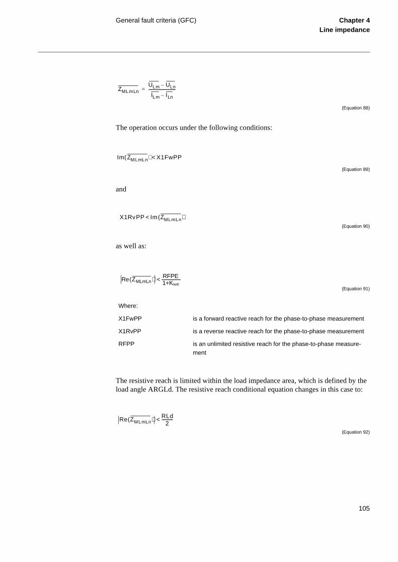
General fault criteria (GFC) Chapter 4Line impedance
(Equation 88)
The operation occurs under the following conditions:
(Equation 89)
and
(Equation 90)
as well as:
(Equation 91)
The resistive reach is limited within the load impedance area, which is defined by the load angle ARGLd. The resistive reach conditional equation changes in this case to:
(Equation 92)
Where:
X1FwPP is a forward reactive reach for the phase-to-phase measurement
X1RvPP is a reverse reactive reach for the phase-to-phase measurement
RFPP is an unlimited resistive reach for the phase-to-phase measure-
ment
ZMLmLnULm ULn–
ILm ILn–---------------------------=
Im ZMLmLn( ) X1FwPP<
X1RvPP Im ZMLmLn( )<
Re ZMLmLn( ) RFPE<1+KNF
Re ZMLmLn( ) RLd2
-----------<
105

General fault criteria (GFC) Chapter 4Line impedance
Besides this, the relation between the measured currents must correspond to the follow-ing conditions:
(Equation 93)
and
(Equation 94)
or
(Equation 95)
Ir is the rated current of the terminal and IN2 is a corresponding logic signal. Iphmaxis the maximum current of all three phase currents. INBlockPP is the setting for the resid-ual current level below which operation of the ph-ph fault loops is allowed. Iph-ph is a difference of phase currents in observed faulty phases.
Current-based GFC elements
The current-based GFC measuring elements measure continuously three phase currents and the residual current, comparing them with the set values. Fourier’s recursive filter filters the current signals, and a separate trip counter prevents too high overreaching of the measuring elements.
If Ilim is a set value of the operating current for the phase measuring elements (desig-nated by I> in the terminal), and INlim for the measuring element that measures the re-sidual current (designated by IN> in the terminal), the operating conditions are as follows:
(Equation 96)
for the phase L1 current measuring element
Iph ph– IMinOp>
3 I0 0 2 Ir⋅,( )<⋅
3 I0⋅ INBlockPP100
---------------------------- Iphmax⋅ IN2⇒<
IL1 Ilim IL1⇒>
106
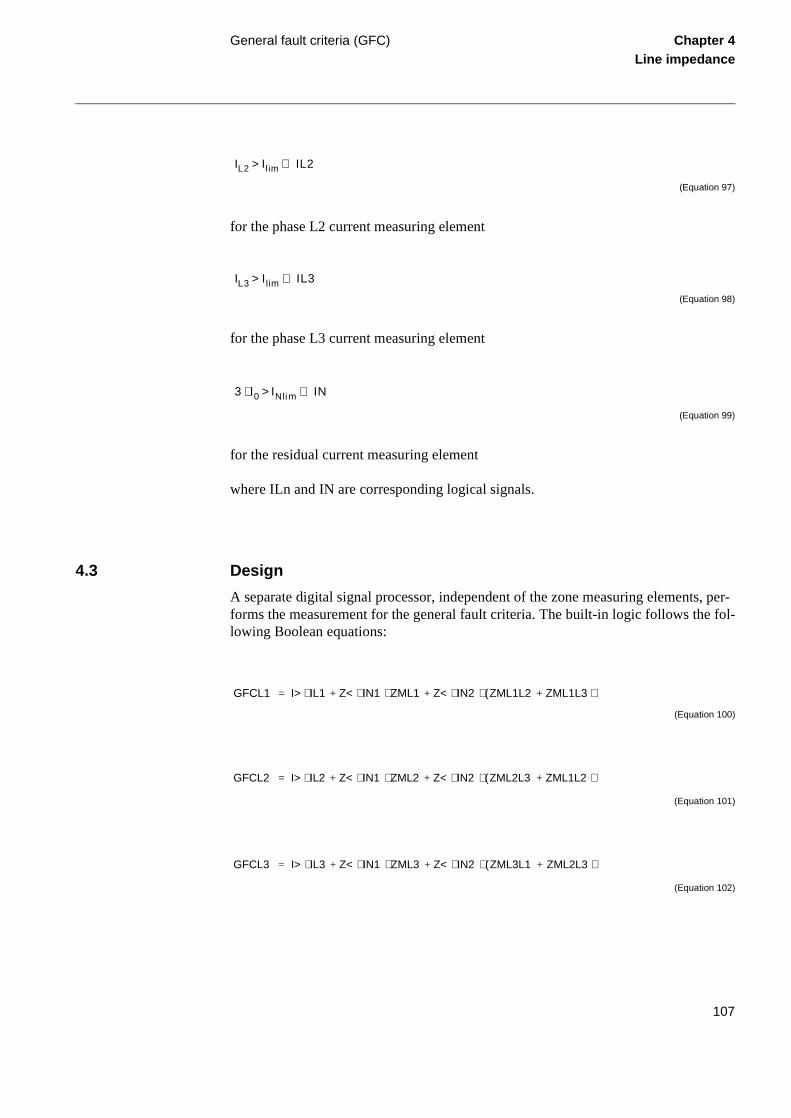
General fault criteria (GFC) Chapter 4Line impedance
(Equation 97)
for the phase L2 current measuring element
(Equation 98)
for the phase L3 current measuring element
(Equation 99)
for the residual current measuring element
where ILn and IN are corresponding logical signals.
4.3 Design
A separate digital signal processor, independent of the zone measuring elements, per-forms the measurement for the general fault criteria. The built-in logic follows the fol-lowing Boolean equations:
(Equation 100)
(Equation 101)
(Equation 102)
IL2 Ilim IL2⇒>
IL3 Ilim IL3⇒>
3 I0 INli m IN⇒>⋅
GFCL1 I> IL1 Z< IN1 ZML1⋅ Z< IN2 ZML1L2 ZML1L3+( )⋅ ⋅+⋅+⋅=
GFCL2 I> IL2 Z< IN1 ZML2⋅ Z< IN2 ZML2L3 ZML1L2+( )⋅ ⋅+⋅+⋅=
GFCL3 I> IL3 Z< IN1 ZML3⋅ Z< IN2 ZML3L1 ZML2L3+( )⋅ ⋅+⋅+⋅=
107

General fault criteria (GFC) Chapter 4Line impedance
tion o the
(Equation 103)
Later on, the signals produced by the GFC measuring elements serve for different parts of the distance protection. These are:
• indication of the faulty phases
• phase selection for the zone measuring elements
• general criteria for the operation of the trip logic
• time delayed trip as a backup function to the zone measuring elements
• phase preference logic, when included in a terminal
Figure 49 presents basic logic circuits dealing with current conditions for the detecof ph-E and ph-ph faults (consider only the parts and signals, which correspond tactual functionality of a used terminal)
Figure 49: Detection of ph-E and ph-ph fault conditions
Where:
Z< represents active underimpedance mode of operation (setting)
I> represents active overcurrent mode of operation (setting)
GFCN I> IN Z< IN1 ZML1 ZML2 ZML3+ +⋅ ⋅+⋅=
GFC--BLOCK
&
& t
10 ms
t
20 ms & t
15 ms
t
15 ms GFC--STPE
GFC--STPP
IRELPE - cont.
IRELPP - cont.
3 ⋅ I0 ≥ 0.5 ⋅ IMinOp
&
3⋅I0 ≥ (INRelease PE/100) ⋅ Iph max
3 ⋅ I0 ≤ 0.2 ⋅ Ir
or
3⋅I0 ≤ (INBlockPP/100) ⋅ Iph max
en01000048.vsd
108

General fault criteria (GFC) Chapter 4Line impedance
Figure 50: Composition of non-directional GFC signals
Figure 50 presents schematically the composition of non-directional general criteria signals GFC--STNDLn, where n presents the corresponding phase number. Signals GF-CLnN and GFCLmLn (m and n change between 1 and 3 according to the phase number) represent the fulfilled operating criteria for each separate loop measuring element.
INDL1N - cont.INDL2N - cont.INDL3N - cont.
INDL3L1 - cont.INDL2L3 - cont.INDL1L2 - cont.
GFC--STNDPE
GFC--STNDL1
GFC--STNDL2
GFC--STNDL3
99000546.vsd
&
&
&
&
&
& ≥1
t15 ms
t15 ms
t15 ms
t15 ms
&
&
STUL1&
&
&ST3U0
NO FILTER ACTIVE = 1
STUL2
STUL3
IRELPE-cont.
GFCL1N
GFCN
GFCL2N
GFCL3N
GFCL1L2
GFCL2L3
GFCL3L1IRELPP-cont.
≥1
≥1≥1
≥1
≥1
≥1
≥1≥1
109

General fault criteria (GFC) Chapter 4Line impedance
Figure 51: Composition of forward directed GFC signals.
Composition of the directional (forward and reverse) phase selective signals is present-ed schematically in figure 51 and figure 52. The directional criteria appears as a condi-tion for the correct phase selection in order to secure a high phase selectivity for simultaneous and evolving faults on lines within the complex network configurations.
Signals DFWLn and DFWLnLm present the corresponding directional signals for mea-suring loops with phases Ln and Lm (m and n are running between 1 and 3). Designa-tion FW (figure 51) represents the forward direction as well as the designation RV (figure 52) represents the reverse direction. All directional signals are derived within the corresponding digital signal processor.
INDL1N - cont.
DFWL1N&
&
INDL1L2 - cont.
DFWL1L2
&
INDL3L1 - cont.
DFWL3L1
&
INDL2N - cont.
DFWL2N
&
INDL1L2 - cont.
DFWL2L3&
INDL2L3 - cont.
&
INDL3N - cont.
DFWL3N
&
INDL2L3 - cont.
&
INDL3L1 - cont.
>1
>1
>1
>1
t
15 ms
t
15 ms
t
15 ms
t
15 ms
&
&
&
&
&
&
&
>1
>1
t
15 ms
t
15 ms
t
15 ms
t
15 ms
t
15 ms
GFC--STFW1PH
GFC--STFWL1
GFC--STFWPE
GFC--STFWL2
GFC--STFW2PH
GFC--STFWL3
GFC--STFW3PH
en00000483.vsd
110

General fault criteria (GFC) Chapter 4Line impedance
Figure 52: Composition of reverse directed GFC signals and measured impedance re-lated zone starting conditions
Figure 53 presents a composition of a GFC tripping signal, which consists of two dif-ferent conditions: earth fault and phase-to-phase fault operating conditions. Each path has its own timer (tPE and tPP), to further increase the flexibility of a complete function
INDL1N - cont.
DRVL1N&
&
INDL1L2 - cont.
DRVL1L2
&
INDL3L1 - cont.
DRVL3L1
&
INDL2N - cont.
DRVL2N
&
INDL1L2 - cont.
DRVL2L3&
INDL2L3 - cont.
&
INDL3N - cont.
DRVL3N
&
INDL2L3 - cont.
&
INDL3L1 - cont.
>1
>1
>1
>1
t
15 ms
t
15 ms
t
15 ms
t
15 ms
GFC--STRVL1
GFC--STRVPE
GFC--STRVL2
GFC--STRVL3
en00000484.vsd
INDL1N -cont.
INDL2N - cont.
INDL3N - cont.
INDL1L2 - cont.
INDL2L3 - cont.
INDL3L1 - cont.
Bool tointeger
GFC--STCND
111

General fault criteria (GFC) Chapter 4Line impedance
Figure 53: Composition of time-delayed tripping signal
Figure 54 presents a composition of a starting condition integer signal, which is sup-posed to be configured to the distance protection zones and their starting condition in-puts (ZMn--STCND). The signal controls the operation of different measuring loops in each distance protection separately.
Figure 54: GFC start condition with phase preference
4.4 Calculations
4.4.1 Setting instructions
All the setting parameters for the GFC are available in the menu tree of the local HMI unit under the menu:
en000000485.vsd
Timer tPE=On
INDL1N-cont.INDL2N-cont.INDL3N-cont.
Timer tPP=On
INDL1L2-cont.INDL2L3-cont.INDL3L1-cont.
≥1&
&
t
tPE
ttPP
t15ms
GFC--TRIP
≥1
≥1
2/3ENABLE - cont.
99000541.vsd
INDL1L2 - cont.
GFC - STCND
INDL2L3 - cont.
INDL3L1 - cont.
&
&
&PPINDL3N - cont.
PPINDL2N - cont.
PPINDL1N - cont.
1
2
4
8
16
32
IN:
Bool tointeger
Σ IN
112

General fault criteria (GFC) Chapter 4Line impedance
Settings
Functions
Group n
Impedance
GenFltCriteria
For the remote setting facilities and local HMI via a personal computer, please refer to the corresponding SMS or SCS documents.
The first parameter under the GFC is the operating mode, which is selectable among two different possibilities:
It is also possible to have active both operating modes at the same time. The available operating mode depends on the functions available within the terminal. Only one of two or both operating modes are available depending on ordering. Please, refer to ordering particulars for each terminal separately.
General setting parameters
Operation of the GFC measurement is enabled or disabled by setting the Operation = On or Off respectively. Setting the parameters Timer tPP and Timer tPE On or Off en-ables or disables the time delayed tripping, caused by the GFC measurement for the ph-ph and ph-E faults respectively.
If not the 2 out of 3 logic is active it is recommend to set Timer tPP and Timer tPE to Off in isolated or high-impedance earthed networks, if the distance protection is not in-tended or permitted to operate at single-phase-to-earth faults.
Setting of tPP and tPE timers define the tripping time delay of the GFC function, if ac-tivated.
Setting parameters for the I> mode of operation
The setting of the operating value for the overcurrent GFC phase measuring elements IP> must be higher than the maximum expected load current in the protected feeder. It is necessary to consider an additional margin of at least 10% to the declared inaccuracy of the current instrument transformers and measuring elements.
Operation Z< = On the GFC will operate on an underimpedance basis
Operation I> = On the GFC will operate on an over current basis
113

General fault criteria (GFC) Chapter 4Line impedance
n-egard-
ance
ach of
ach of ).
the EL
ch of ving lose
ch of ing lose
of the REL der
ld be
There will always be a certain low value of measured residual current 3I0 in the mea-suring circuits due to the differences in the current instrument transformers. Higher val-ues can be expected on longer lines with a higher operating voltage. The presence of the close untransposed lines, where the zero-sequence mutual coupling effect is significant, will additionally increase the apparent residual current measured by the terminal.
Therefore, it is usually necessary to set the operating value of the earth-fault current measuring element IN> at a minimum of 10% of the line nominal current. The setting value must be increased on the longer, untransposed lines and in cases where the zero-sequence mutual coupling effect is significant.
Setting parameters for the Z< mode of operation
The setting instructions refer to the operating characteristic of the GFC elements as shown principally in a figure in “Application”. The GFC characteristic should, in geeral, cover all the impedance measuring zones used for the distance protection, rless of their directionality.
The following parameters should be set for the GFC, operating in the underimpedmode:
• X1FwPP is a positive-sequence reactance that corresponds to the reactive rethe GFC elements in forward direction for ph-ph faults.
• X1FwPE is a positive-sequence reactance that corresponds to the reactive rethe GFC elements in forward direction for ph-E fault (not available in REL 501
• X0FwPE is a zero-sequence reactance that defines the total reactive reach ofGFC earth-fault loop measuring elements in forward direction (not available in R501) for the ph-E faults.
• X1RvPP is a positive-sequence reactance that corresponds to the reactive reathe GFC elements in reverse direction for the ph-ph faults. We recommend haX1RvPP > =10% of X1FwPP in order to guaranty a correct measurement for cup faults.
• X1RvPE is a positive-sequence reactance that corresponds to the reactive reathe GFC elements in reverse direction for the ph-E faults. We recommend havX1RvPE > = 10% of X1FwPE in order to guaranty a correct measurement for cup faults.
• X0RvPE is a zero-sequence reactance that defines the complete reactive reachGFC earth-fault loop measuring elements in reverse direction (not available in 501) for ph-E faults. We recommend having X0RvPE > =10% of X0FwPE in orto guaranty a correct measurement for close up faults.
• RFPP is the resistive reach of the GFC elements for multi-phase faults. It shouset as a loop value of the measured resistances, according to the formula:
114

General fault criteria (GFC) Chapter 4Line impedance
(not nces,
struc-ion e-
(Equation 104)
• RFPE is the resistive reach of the GFC elements for the phase-to-earth-faultsavailable in REL 501). It should be set as a loop value of the measured resistaaccording to the formula:
(Equation 105)
• RLd is the resistive reach in the load impedance area. For the corresponding intions, please refer to the “Setting instructions” for the distance protection funct(document Distance protection). Observe the loop character of this setting paramter. It should be set generally to:
(Equation 106)
Where:
R1PP is a corresponding line positive sequence resistance
RF is the expected fault resistance between two faulty phases.
Where:
R1PE is a corresponding line positive-sequence resistance
R0PE is a corresponding line zero-sequence resistance
RF is a fault resistance as expected for the single-phase-to-earth-faults.
RFPP 2 R1PP⋅ RF+>
RFPE 13--- 2 R1PE⋅ R0PE+( ) RF+⋅>
RLd 1.6 RLmin⋅<
115

General fault criteria (GFC) Chapter 4Line impedance
mum d for
age of e ult val-udies d posi-ce im-t these
• ARGLd is the maximum expected load angle that could appear under the maxiload conditions on a protected line. One of the following expressions can be useits calculation:
(Equation 107)
• Setting parameters INReleasePE and INBlockPP (both are settable in percentthe terminal rated current Ir) control the operation of the phase-to-earth and thphase-to-phase measuring elements. They should in general be set to the defaues, which are INReleasePE = 20%, and INBlockPP = 40%. Special system stand calculations of fault currents are necessary in cases, when the remote entive sequence source impedance is much higher than the zero sequence sourpedance. The results of these studies may require in some special cases to separameters different from their default values.
Where:
RLmin represents the minimum expected load resistance
Where:
S is the apparent power
P is the active power
Q is the reactive power
ARGLd PS----acos Q
S----asin Q
P----atan= = =
116

Power swing detection (PSD) Chapter 4Line impedance
5 Power swing detection (PSD)
5.1 Application
General
Various changes in power system may cause oscillations of rotating units. The most typical reasons for these oscillations are big changes in load or changes in power system configuration caused by different faults and their clearance. As the rotating masses strive to find a stable operate condition, they oscillate with damped oscillations until they reach the final stability.
The extent of the oscillations depends on the extent of the disturbances and on the nat-ural stability of the system. The oscillation rate depends also on the inertia of the system and on the impedance between different generating units.
These oscillations cause changes in phase and amplitude of the voltage difference be-tween the oscillating parts of the power system. This causes changes in power flow be-tween two oscillating parts of the system - the power swings from one part to another - and vice-versa.
Figure 55: Impedance plane with the locus of the measured impedance and operate characteristics of the zone measuring elements.
R
jX
Impedance locus at power swing
99000158.vsd
117

Power swing detection (PSD) Chapter 4Line impedance
Distance relays see these power swings as the swinging of the measured impedance in relay points. The measured impedance varies with time along a locus in an impedance plane (see figure 55). This locus can enter the operate characteristic of a distance pro-tection and causes, if no preventive measures have been considered, its unwanted oper-ation.
Basic characteristics
The power swing detection function (PSD) is optionally available in most of the REx 5xx terminals, which include also the line distance protection function. Please, refer to the ordering information for each terminal separately.
The PSD function detects reliably power swings with periodic time of swinging as low as 200 ms (i.e. slip frequency as high as 10% of the rated frequency on the 50 Hz basis). It detects the swings under normal system operate conditions as well as during dead-time of a single-pole reclosing cycle.
The function is able to secure selective operation for internal faults during power swings, when used together with optional power swing logic (PSL) and some additional functions, available within the REx 5xx terminals. The operation of the distance protec-tion function remains stable for external faults during the power swing condition, even with the swing (electrical) centre on the protected line.
5.2 Functionality
5.2.1 Theory of operation
The operation of the PSD function is based on the measurement of the transition time needed for the transient impedance to pass the area between the outer and the inner im-pedance characteristic of the PSD function, see figure 56.
118

Power swing detection (PSD) Chapter 4Line impedance
e fol-
Figure 56: Operating principle and characteristic of the PSD function.
The impedance measuring principle is based on the same impedance measuring algo-rithm as used by the distance protection zone measuring elements (see the document “Distance protection”).
The impedance measurement within the PSD function is performed by solving thlowing equations (n = 1, 2, 3 for each corresponding phase):
(Equation 108)
and
jX
R
tP1
Impedance locus at power swing
99000159.vsd
− ⋅KX X IN1
− X IN1
X IN1
KX X IN⋅ 1
− ⋅KR R IN1
KR R IN⋅ 1
−R IN1
−R IN1
ReUL1
IL1
----------
Rset≤
ImUL1
IL1
----------
Xset≤
119

Power swing detection (PSD) Chapter 4Line impedance
ree this al in
wo
the resents e cor-
tial rs be-ance
r. All
5.3 Design
Basic detection logic
The PSD function can operate in two operating modes:
• The “1-of-3” operating mode is based on detection of power swing in any of thphases. Figure 57 presents a composition of a detection signal PSD-DET-L1 inparticular phase. The internal signal PSD-CONS.-int. is related to the same signfigure
• The “2-of-3” operating mode is based on detection of power swing in at least tout of three phases. Figure 58 presents a composition of the detection signalsDET1of3 and DET2of3.
Signals ZOUTLn (external boundary) and ZINLn (internal boundary) are related tooperation of the impedance measuring elements in each phase separately (Ln repthe corresponding phase L1, L2, and L3) They are internal signals, produced by thresponding digital signal processors (DSPs).
All tP1 timers in figure 57 have the same settings. They serve the detection of inipower swings, which are usually not as fast as the later swings are. The tP2 timecome activated for the detection of the consecutive swings if the measured impedexits the operate area and returns within the time delay, set on the tW waiting timetP2 timers in figure 57 have the same setting.
Where:
Xset corresponds to the reactive reach setting values X1IN for the internal and
(KX . X1IN) for the external operate characteristic of the PSD function and
Rset corresponds to the resistive reach setting values R1IN for the internal and
(KR . R1IN) for the external operate characteristic.
120

Power swing detection (PSD) Chapter 4Line impedance
Figure 57: Detection of power-swing in phase L1.
Figure 58: Detection of power-swing for 1-of-3 and 2-of-3 operating mode.
Operating and inhibit conditions
Figure 59 presents a simplified logic diagram for a PSD function. The internal signals DET1of3 and DET2of3 relate to the detailed logic diagrams in figure 57 and figure 58 respectively.
Selection of the operating mode is possible by the proper configuration of the functional input signals PSD--REL1PH, PSD--BLK1PH, PSD--REL2PH, and PSD--BLK2PH (see the signal list in the appendix to this document).
en01000056.vsd
ZOUTL1&
ZINL1ttP1
ttP2
&PSD-DET-L1
PSD-CONS.-int.
≥1
&
en01000057.vsd
PSD-DET-L1PSD-DET-L2PSD-DET-L3
DET1of3 - int.
DET2of3 - int.
&
&
&
≥1
≥1
121

Power swing detection (PSD) Chapter 4Line impedance
Figure 59: PSD function - simplified block diagram.
There are four different ways to form the internal INHIBIT signal:
en01000060.vsd
PSD--TRSPt
tEF
PSD--I0CHECK
&PSD--START
PSD--BLKI02t
10 ms
&PSD--BLKI01
PSD--BLOCK
INHIBIT
ZOUTL3
ZOUTL2
ZOUTL1
DET1of3 - int.PSD--REL1PHPSD--BLK1PH
&
DET2of3 - int.PSD--REL2PHPSD--BLK2PH
&
PSD--EXTERNAL&
PSD--START
PSD--ZOUT
ZINL1
ZINL2
ZINL3
PSD--ZIN
PSD - CONS. - int.
& ttR1
ttR2
ttH
≥1
&
&
≥1
≥1
≥1
≥1
≥1
122
Power swing detection (PSD) Chapter 4Line impedance
al
tect-he ble in-
er, ical e
has l three n the clos-cuit
nu:
60) om-y the rgin.
• Logical 1 on functional input PSD--BLOCK inhibits the output PSD--START signinstantaneously.
• The INHIBIT internal signal becomes logical 1, if the power swing has been deed and the measured impedance remains within its operate characteristic for ttime, which is longer than the time delay set on tR2 timer. It is possible to disathis condition by connecting the logical 1 signal to the PSD--BLKI01 functionalput.
• The INHIBIT internal signal becomes logical 1 after the time delay, set on tR1 timif the power swing appears before the functional PSD--I0CHECK becomes log1. It is possible to disable this condition by connecting the logical 1 signal to thBLKI02 functional input.
• The INHIBIT logical signals becomes logical 1, if the functional input PSD--I0CHECK appears within the time delay, set on tEF timer and the impedance been seen within the outer characteristic of the PSD operate characteristic in alphases. This function prevents the operation of the PSD function in cases, whecircuit breaker closes on persistent single-phase fault after single-pole auto-reing dead time, if the initial single-phase fault and single-pole opening of the cirbreaker causes the power swing in the remaining two phases.
5.4 Calculations
5.4.1 Setting instructions
The operation and the reach of the PSD function can locally be set under the me
Settings
Functions
Group n
Impedance
PowerSwingDet
Setting the reach of the inner characteristic
Set the reach of the inner characteristic R1IN in the resistive direction (see figureas well as X1IN in the reactive direction, so that the inner operate characteristic cpletely covers all distance protection zones, which are supposed to be blocked bPSD function. It is recommended to consider at least 10% of additional safety ma
123

Power swing detection (PSD) Chapter 4Line impedance
Figure 60: Operating characteristic of the PSD function
Setting the reach of the outer characteristic
Set the reach of the outer characteristic as a multiple of a reach for the inner character-istic. KR and KX are the setting parameters, expressed in percentages of the set reaches in resistive (R1IN) and reactive (X1IN) direction for the inner operate characteristic.
(Equation 109)
and
en01000058.vsd
jX
R
KX · X1IN
X1IN
- R1IN
KR · R1IN
-X1IN
- R1IN
-KR · R1IN
-KX · X1IN
KR 100 R1OUTR1IN
---------------------⋅=
124

Power swing detection (PSD) Chapter 4Line impedance
(Equation 110)
R1OUT and X1OUT are the calculated values of the reach for the outer characteristic. Also observe the fact, that the minimum values for KR and KX are equal to 120%.
Limitation of the resistive reach
The reach in the resistive direction should not exceed more than 80% of the minimum load resistance RLmin. This stands for both the reach of the inner as well as for the reach of the outer characteristic.
(Equation 111)
and
(Equation 112)
Determination of the impedance difference and speed
The resistive transition area, which is equal to:
(Equation 113)
should be set as wide as possible, considering the limitations for covering the desired distance protection zones and not entering the load impedance area. At the same time, it depends on the maximum required initial speed of the impedance, which should still be recognised as a power swing and not as a fault. The initial speed of impedance must be determined by the system studies. It is recommended to try the first iteration with the default time delay for the tP1 timer, which is 45 ms, and calculate, if the set speed of the transition impedance corresponds to the condition:
(Equation 114)
KX 100 X1OUTX1IN
---------------------⋅=
R1IN 0.8 R⋅ Lmin≤
KR 80RLmi nR1IN---------------⋅≤
∆R R1OUT R1IN–=
R1OUT R1IN–tP1
------------------------------------------ ∆Z∆t-------
req
>
125

Power swing detection (PSD) Chapter 4Line impedance
The expression:
(Equation 115)
represents the maximum required speed of impedance, which should still be recognised as an initial power swing. Reduce the setting of the tP1 time delay only, if the upper condition can not be satisfied with the resistance settings on their specified minimum and maximum possible values.
System studies also determine the maximum possible speed of the transition imped-ance. Set the tP2 timer so, that the maximum detectable speed of the transition imped-ance satisfies the condition:
(Equation 116)
The expression :
(Equation 117)
represents the maximum required speed of impedance, which should still be recognised as a power swing within the developed stage.
Reactive reach
The reactive transition area should generally be equal to the resistive transition area. If supposed, that the reactive reach of the inner characteristic is determined by the distance protection zone reach and equal to X1IN, then the reactive multiplication factor must be equal to:
(Equation 118)
Set the KX to 120%, if the calculation requires a value less than 120%.
∆Z ∆t⁄( )req
R1OUT R1IN–tP2
------------------------------------------ ∆Z∆t-------
max
>
∆Z ∆t⁄( )max
KX 100 R1INX1IN-------------- KR
100---------- 1–
⋅ 1+⋅=
126

Power swing detection (PSD) Chapter 4Line impedance
al-D D op-us sys-
hibit ts in
ion, r than older
f a he
tH hold timer
System studies should determine the settings for the hold timer tH (see “Functionity”). The purpose of this timer is, to secure continuous output signal from the PSfunction during the power swing, even after the transient impedance leaves the PSerate characteristic and is expected to return within a certain time due to continuoswinging. Consider the minimum possible speed of power swinging in a particulartem.
tR1 inhibit timer
The tR1 inhibit timer delays the influence of the detected residual current on the incriteria for the PSD function. It prevents operation of the function for short transienthe residual current measured by the terminal.
tR2 inhibit timer
The tR2 inhibit timer disables the output PSD--START signal from the PSD functif the measured impedance remains within the PSD operate area for a time, longethe set tR2 value. This time delay was usually set to approximately two seconds inpower-swing devices.
tEF timer for reclosing on persistent single-phase faults
The setting of the tEF timer must cover, with sufficient margin, the opening time ocircuit breaker and the dead-time of a single-phase auto-reclosing together with tbreaker closing time.
127

Scheme communication logic for distance protection (ZCOM)
Chapter 4Line impedance
6 Scheme communication logic for distance protection (ZCOM)
6.1 Application
To achieve fast fault clearing for a fault on the part of the line not covered by the instan-taneous zone 1, the stepped distance protection function can be supported with logic, that uses communication channels.
One communication channel in each direction, which can transmit an on/off signal is required. The performance and security of this function is directly related to the trans-mission channel speed, and security against false or lost signals. For this reason special channels are used for this purpose. When power line carrier is used for communication, these special channels are strongly recommended due to the communication distur-bance caused by the primary fault.
The logic supports the following communications schemes; blocking scheme, permis-sive schemes (overreach and underreach) and direct intertrip.
6.2 Functionality
6.2.1 Theory of operation
Depending on whether a reverse or forward directed impedance zone is used to issue the send signal (ZCOM-CS), the communication schemes are divided into Blocking and Permissive schemes, respectively.
Blocking communication scheme
In a blocking scheme, the received signal (ZCOM-CR) carries information about the fault position, which specifies that it is outside the protected line, on the bus or on ad-jacent lines. Do not prolong the sent signal, so set tSendMin to zero. The sending might be interrupted by operation of a forward zone if it is connected to ZCOM-CSNBLK.
An overreaching zone is allowed to trip after a co-ordination time (tCoord), when no signal is received from the remote terminal. The tCoord time must allow for the trans-mission of the blocking signal with a certain margin.
In case of external faults, the blocking signal (ZCOM-CR) must be received before the tCoord elapses, to prevent a false trip.
128
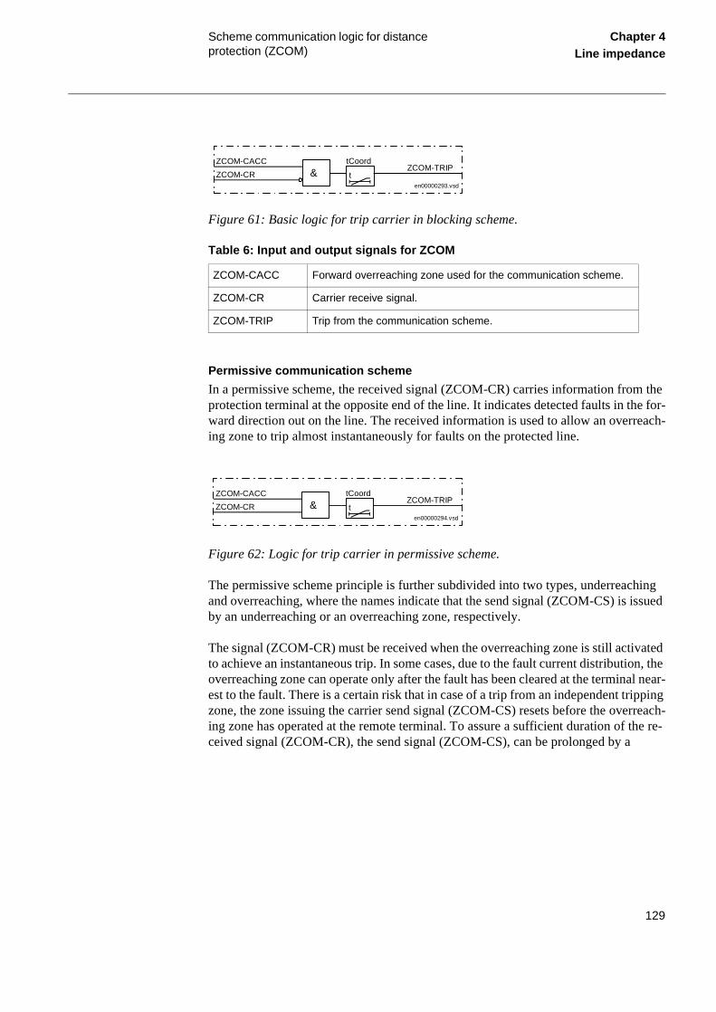
Scheme communication logic for distance protection (ZCOM)
Chapter 4Line impedance
Figure 61: Basic logic for trip carrier in blocking scheme.
Table 6: Input and output signals for ZCOM
Permissive communication scheme
In a permissive scheme, the received signal (ZCOM-CR) carries information from the protection terminal at the opposite end of the line. It indicates detected faults in the for-ward direction out on the line. The received information is used to allow an overreach-ing zone to trip almost instantaneously for faults on the protected line.
Figure 62: Logic for trip carrier in permissive scheme.
The permissive scheme principle is further subdivided into two types, underreaching and overreaching, where the names indicate that the send signal (ZCOM-CS) is issued by an underreaching or an overreaching zone, respectively.
The signal (ZCOM-CR) must be received when the overreaching zone is still activated to achieve an instantaneous trip. In some cases, due to the fault current distribution, the overreaching zone can operate only after the fault has been cleared at the terminal near-est to the fault. There is a certain risk that in case of a trip from an independent tripping zone, the zone issuing the carrier send signal (ZCOM-CS) resets before the overreach-ing zone has operated at the remote terminal. To assure a sufficient duration of the re-ceived signal (ZCOM-CR), the send signal (ZCOM-CS), can be prolonged by a
ZCOM-CACC Forward overreaching zone used for the communication scheme.
ZCOM-CR Carrier receive signal.
ZCOM-TRIP Trip from the communication scheme.
ZCOM-CACC
ZCOM-CR & t
tCoordZCOM-TRIP
en00000293.vsd
ZCOM-CACC
ZCOM-CR t
tCoordZCOM-TRIP
en00000294.vsd
&
129

Scheme communication logic for distance protection (ZCOM)
Chapter 4Line impedance
tSendMin reset timer. The recommended setting of tSendMin is 100 ms. A ZCOM-CS signal from an underreaching zone can be prolonged during all circumstances without drawbacks, but a ZCOM-CS signal from an overreaching zone must never be prolonged in case of paralllel lines, to secure correct operation of current reversal logic, when ap-plied.
At the permissive overreaching scheme, the carrier send signal (ZCOM-CS) might be issued in parallel both from an overreaching zone and an underreaching, independent tripping zone. The ZCOM-CS signal from the overreaching zone must not be prolonged while the ZCOM-CS signal from zone 1 can be prolonged.
There is no race between the ZCOM-CR signal and the operation of the zone in a per-missive scheme. So set the tCoord to zero. A permissive scheme is inherently faster and has better security against false tripping than a blocking scheme. On the other hand, a permissive scheme depends on a received ZCOM-CR signal for a fast trip, so its de-pendability is lower than that of a blocking scheme.
To overcome this lower dependability in permissive schemes, an Unblocking function can be used. Use this function at power-line carrier (PLC) communication, where the signal has to be sent through the primary fault. The unblocking function uses a carrier guard signal (ZCOM-CRG), which must always be present, even when no ZCOM-CR signal is received. The absence of the ZCOM-CRG signal during the security time is used as a CR signal. See figure 63. This also enables a permissive scheme to operate when the line fault blocks the signal transmission. Set the tSecurity at 35 ms.
Figure 63: Carrier guard logic with unblock logic.
The ZCOM-CR signals are always transferred directly to ZCOM-CRL without any de-lay.
Z C O M -C R G
t2 00 m s
&
1 ttS e cu rity
> 1 t15 0 m s
&
> 1
Z C O M -C R
Z C O M -C R L
Z C O M -L C G
e n 0 0 00 0 4 9 1 .vs d
130

Scheme communication logic for distance protection (ZCOM)
Chapter 4Line impedance
Table 7: Input and output signals for carrier guard
Direct inter-trip scheme
In the direct inter-trip scheme, the carrier send signal (ZCOM-CS) is sent from an un-derreaching zone that is tripping the line.
The received signal (ZCOM-CR) is directly transferred to a ZCOM-TRIP for tripping without local criteria. The signal is further processed in the tripping logic. In case of sin-gle-pole tripping, a phase selection is performed.
6.3 Calculations
6.3.1 Settings
The scheme type and the timers are set under:
Settings
Functions
Group n (n=1-4)
Impedance
ZCommunication
SchemeType
Configure the zones used for the ZCOM-CS carrier send and for scheme communica-tion tripping under:
Configuration
Functions
Impedance
ZCom
ZCOM-CR Received signal from the communication equipment
ZCOM-CRG Carrier guard signal from the communication equipment.
ZCOM-CRL Signal to the communication scheme.
ZCOM-LCG Alarm signal line-check guard
131
Current reversal and WEI logic for distance protection (ZCAL)
Chapter 4Line impedance
heme n log-
ts, able L).
ds of
ermis-un-his
gic)
ion in um
eak
ere, equen-rip-ilable,
7 Current reversal and WEI logic for distance protection (ZCAL)
7.1 Application
To achieve fast fault clearing for a fault on the part of the line not covered by the instan-taneous zone 1, the stepped distance protection function can be supported with logic, that uses communication channels. REx 5xx line distance protection terminals have for this reason available a scheme communication logic (ZCOM - see the document “Scheme communication logic for distance protection”) and a phase segregated sccommunication logic (ZC1P - see the document “Phase segregated communicatioic for distance protection”).
Different system conditions, in many cases, require additional special logic circuilike current reversal logic and WEI, weak end infeed logic. Both functions are availwithin the additional communication logic for the distance protection function (ZCA
The contents of the additional communication logic is always adjusted to the neeeach communication logic, ZCOM or ZC1P respectively, whichever included in REx 5xx terminal.
Current reversal logic
If parallel lines are connected to common buses at both terminals, overreaching psive communication schemes can trip unselectively due to current reversal. This wanted tripping affects the healthy line when a fault is cleared on the other line. Tlack of security results in a total loss of inter-connection between the two buses.
To avoid this kind of disturbance, a fault current reversal logic (transient blocking locan be used.
Weak end infeed (WEI) logic
Permissive communication schemes can basically operate only when the protectthe remote terminal can detect the fault. The detection requires a sufficient minimfault current, normally >20% of Ir . The fault current can be too low due to an open breaker or low short-circuit power of the source. To overcome these conditions, wend infeed echo logic is used.
The fault current can also be initially too low due to the fault current distribution. Hthe fault current increases when the breaker opens in the strong terminal, and a stial tripping is achieved. This requires a detection of the fault by an independent-tping zone 1. To avoid sequential tripping as described, and when zone 1 is not avaweak end infeed tripping logic is used.
132

Current reversal and WEI logic for distance protection (ZCAL)
Chapter 4Line impedance
7.2 Functionality
Current reversal logic
Figure 64 and figure 65 show a typical system condition, which can result in a fault cur-rent reversal. Note that the fault current is reversed in line L2 after the breaker opening.
In terminal A:2, where the forward zone was initially activated, this zone must reset be-fore the carrier signal ZCOM-CRLn, initiated from B:2, arrives. The carrier send ZCOM-CS or ZC1P-CSLn from B:2 is therefore held back until the reverse zone ZCAL-IRVLn has reset and the tDelay time has elapsed; see figure in Design, Current reversal logic .
Figure 64: Initial system condition.
Figure 65: Current distribution after the breaker B:1 is opened.
Weak end infeed logic
The WEI function sends back (echoes) the received carrier signal under the condition that no fault has been detected on the weak end by different fault detection elements (distance protection in forward and reverse direction).
Strongsource
L1
L2
A:1
A:2
B:1
B:2
A B
Weaksource
99000043.vsd
Strongsource
L1
L2
A:1
A:2
B:1
B:2
A B
Weaksource
99000044.vsd
133

Current reversal and WEI logic for distance protection (ZCAL)
Chapter 4Line impedance
e. It mote tion lete
WEI T
on-EI
sed the
VLn in he al. n of con-
The weak end infeed logic function can be extended to trip also the breaker in the weak terminal. The trip is achieved when one or more phase voltages are low during an echo function. In case of single-pole tripping, the phase voltages are used as phase selectors.
Weak end infeed logic is generally used in permissive schemes only. It is also possible to use it together with the blocking teleprotection scheme. Some limitations apply in this case:
• Only the trip part of the function can be used together with the blocking schemis not possible to use the echo function to send the echo carrier signal to the reline terminal. The echo signal would block the operation of the distance protecat the remote line end and in this way prevent the correct operation of a compprotection scheme.
• It is not possible to use the carrier receive signal from the remote end to start thefunction. Start the operation of the WEI function by connecting the TUV--STARoutput signal of the time delayed undervoltage function to the ZCAL-CRL functial input. In this way, the operation of the undervoltage protection will start the Wlogic.
• Configure the carrier receive signal from the remote end to the ZCAL-WEIBLKfunctional input together with an OR combination of all fault detection signals, uwithin the terminal to detect the fault in forward or reverse direction. Do not useundervoltage protection signals for this purpose.
7.3 Design
Current reversal logic
The current reversal logic (IREV) uses a reverse zone (connected to the ZCAL-IRinput signal), which in terminal B:2 recognises the fault on the L1 line (see figure Functionality, Current reversal logic. When the reverse zone is activated during ttPickUp time (see figure 66), the logic is ready to issue a ZCAL-IRVLLn output signThis signal prevents sending of a ZCOM-CS (or ZC1P-CSLn) signal and activatiothe ZCOM-TRIP (or ZC1P-TRLn) signal for a time as set on a tDelay timer, when nected to the ZCOM-BLOCK (or ZC1P-BLOCK) functional input of the ZCOM (orZC1P) function.
134

Current reversal and WEI logic for distance protection (ZCAL)
Chapter 4Line impedance
the
u-.
n olt-
Figure 66: Current reversal logic.
The tDelay timer makes it possible for the carrier receive signal, connected to the ZCOM-CR (or ZC1P-CRLn) functional input, to reset before the ZCOM-TRIP (or the ZC1P-TRLn) signal is activated due to the current reversal by the forward directed zone, connected to the ZCOM-CACC (or the ZC1P-CACCLn) functional input.
Weak end infeed logic
The WEI function returns the received carrier signal (see figure 67), when:
• The functional input ZCAL-CRLLn is active. This input is usually connected to ZCOM-CRL or to the ZC1P-CRLLn functional output.
• The WEI function is not blocked by the active signal connected to the ZCAL-BLOCK functional input or to the ZCAL-VTSZ functional input. The latest is usally configured to the FUSE-VTSZ functional output of the fuse-failure function
• No active signal has been present for at least 200 ms on the ZCAL-WEIBLKLfunctional input. An OR combination of all fault detection functions (not undervage) as present within the terminal is usually used for this purpose.
Figure 67: Echo of a received carrier signal by the WEI function.
99000193.vsd
ZCAL-IRVLn
ZCAL-IRVBLKLnZCAL-IRVLLnt
tDelay&
ttPickUp
t10 ms
ttPickUp
ZCAL-BLOCK
ZCAL-CRLLn
ZCAL-WEIBLKLn
ZCAL-ECHOLn
ECHOLn - cont.
99000194.vsd
ZCAL-VTSZ
>1
ttWEI
t200 ms
& t50 ms
t200 ms
&
135

Current reversal and WEI logic for distance protection (ZCAL)
Chapter 4Line impedance
Figure 68: Tripping part of the WEI logic - simplified logic diagram.
When an echo function is used in both terminals, a spurious signal can be looped round by the echo logics. To avoid a continuous lock-up of the system, the duration of the ech-oed signal is limited to 200 ms.
An undervoltage criteria is used as an additional tripping criteria, when the tripping of the local breaker is selected together with the WEI function and ECHO signal has been issued by the echo logic, see figure 68.
7.4 Calculations
7.4.1 Setting
The current reversal logic and the WEI function are set in the menu under:
WEI = Trip
ZCAL-CBOPEN
STUL1N
STUL2N
STUL3N
& t100 ms
>1
&
&
&
ECHOLn - cont.
t15 ms
t15 ms
t15 ms
>1ZCAL-TRWEI
ZCAL-TRWEIL1
ZCAL-TRWEIL2
ZCAL-TRWEIL3
en00000551.vsd
136

Current reversal and WEI logic for distance protection (ZCAL)
Chapter 4Line impedance
Setting
Functions
Group n (n=1-4)
Impedance
ComIRevWei
Current reversal logic
Set the tDelay time in relation to the reset time in the communication equipment for the ZCOM-CR (ZC1P-CRLn) signal. Set the tDelay at the maximum carrier reset time plus 30 ms. A minimum tDelay setting of 40 ms is recommended. A long tDelay setting in-creases security against unwanted tripping, but delay the fault clearing in case of a fault developing from one line to involve the other one. The probability of this type of fault is small. So set the tDelay with a good margin.
Set the pick-up delay tPickUp to <80% of the breaker operate time, but with a minimum of 20 ms.
Weak end infeed logic
Set WEI = Echo to activate the weak end infeed function. Set WEI = Trip to obtain echo with trip.
Set the voltage criterion for the weak end trip to 90% of the minimum operation voltage and consider also the emergency conditions.
137

Current reversal and WEI logic for distance protection (ZCAL)
Chapter 4Line impedance
138

About this chapter Chapter 5Current
Chapter 5 Current
About this chapter
This chapter describes the current protection functions.
139

Instantaneous overcurrent protection (IOC)
Chapter 5Current
power
ase
rators ts if the
and tion , for
otec-lts efer
lts in he se are
1 Instantaneous overcurrent protection (IOC)
1.1 Application
unbalanceLong transmission lines often transfer great quantities of electrical power from production to consumption areas. The unbalance of the produced and consumed electrical power at each end of the transmission line is very large. This means that a fault on the line can easily endanger the stability of a complete system.
The transient stability of a power system depends mostly on three parameters (at con-stant amount of transmitted electrical power):
• The type of the fault. Three-phase faults are the most dangerous, because no can be transmitted through the fault point during fault conditions.
• The magnitude of the fault current. A high fault current indicates that the decreof transmitted power is high.
• The total fault clearing time. The phase angles between the EMFs of the geneon both sides of the transmission line increase over the permitted stability limithe total fault clearing time, which consists of the protection operating time andbreaker opening time, is too long.
The fault current on long transmission lines depends mostly on the fault position decreases with the distance from the generation point. For this reason the protecmust operate very quickly for faults very close to the generation (and relay) pointwhich very high fault currents are characteristic.
For this reason instantaneous, non-directional, phase-segregated, overcurrent prtion (IOC), which can operate in 15 ms (50 Hz nominal system frequency) for faucharacterized by very high currents, is included in some of the REx 5xx terminals. Rto the ordering information for more details.
The conventional distance protection can manage the fault clearance of earth-faumost of the cases. In some applications, especially applications with long lines, tclearance can be improved by use of an instantaneous earth-fault protection. Thofor instance:
140

Instantaneous overcurrent protection (IOC)
Chapter 5Current
ight instan-
t the in a ce.
ng fault
ction clear-
can ry
in-
con-> set
ignal ase
the
con-alue.
vents e out-se-
own
• In the case of high infeed of fault current from the opposite end of the line, this mincrease the fault resistance seen by the distance relay to such a value that thetaneous step of the distance protection will not operate.
• In applications with series compensated lines, where the capacitor is located aend of the line and very strong infeed of fault current from that end, will result difficult problem for the distance protection to perform a selective fault clearanThis due to the voltage reversal that might occur.
The use of instantaneous overcurrent earth-fault protection is most suitable for lolines in meshed transmission systems. It can also be used for radial lines with lowcurrent infeed from the opposite end of the line.
The instantaneous residual overcurrent function is very suitable as back-up protefor phase to earth faults close to the terminal. This enables a short back-up faultsance time for the phase to earth faults with high fault current.
The instantaneous, non-directional, earth-fault overcurrent protection (IOC), whichoperate in 15 ms (50 Hz nominal system frequency) for faults characterized by vehigh currents, is included in some of the REx 5xx terminals. Refer to the orderingformation for more details.
1.2 Functionality
The current-measuring elements within one of the built-in digital signal processorstinuously measure the current in all three phases, and compare them with the IP>value. The logical value of each phase current signal on the output of the digital sprocessor (STIL1, STIL2 and STIL3 respectively) is equal to 1 if the measured phcurrent exceeds the preset value.
The measuring technic is based on measuring of the incoming residual current toterminal.
The current-measuring elements within one of the built-in digital signal processorstinuously measure the zero sequence current, and compare it with the IN>> set vA recursive Fourier filter filters the current signals, and a separate trip counter prehigh overreaching of the measuring elements. The logical value of the signal on thput of the digital signal processor (IOC--STIN) is equal to 1 if the measured zero quence current exceeds the pre-set value.
1.3 Design
The simplified logic diagram of the instantaneous phase overcurrent function is shin figure 69.
141

Instantaneous overcurrent protection (IOC)
Chapter 5Current
en
ent lock nc-ns.
out-func-
g sig-. ut sig-
to h sin-
The overcurrent function is disabled if:
• The terminal is in TEST mode (TEST-ACTIVE is high) and the function has beblocked from the HMI (BlockIOC=Yes)
• The input signal IOC--BLOCK is high.
The IOC--BLOCK signal is a blocking signal of the instantaneous phase overcurrfunction. It can be connected to a binary input of the terminal in order to receive a bcommand from external devices or can be software connected to other internal futions of the terminal itself in order to receive a block command from internal functioThrough OR gate it can be connected to both binary inputs and internal function puts. The IOC--BLOCK signal blocks also the instantaneous residual overcurrent tion, if this is installed in the terminal.
When the instantaneous phase overcurrent function is enabled, the output trippinnals IOC--TRL1, IOC--TRL2, IOC--TRL3, IOC--TRP and IOC--TRIP can operateThe duration of each output signal is at least 15 ms. This enables continuous outpnals for currents, which go just a little above the set operating value.
The single phase trip signals IOC--TRL1, IOC--TRL2, and IOC--TRL3 are relatedL1, L2, and L3 phases and therefore also suitable for the single phase tripping witgle-phase auto-reclosing.
142

Instantaneous overcurrent protection (IOC)
Chapter 5Current
Figure 69: Simplified logic diagram of instantaneous overcurrent protection
The signal IOC--TRP is the logic OR of the three single phase trips. It can be used to trip the circuit breaker if only three phase operation is desired.
The IOC--TRIP output signal behaves as general instantaneous overcurrent trip when in the REx 5xx terminal also the instantaneous residual overcurrent function is imple-mented; i.e. this signal will be activated in case of any single phase overcurrent or re-sidual overcurrent detection. If only the instantaneous phase overcurrent function is installed in the terminal, then this signal behaves exactly as the signal IOC--TRP and can be used for signalization.
The simplified logic diagram of the instantaneous phase overcurrent function is shown in figure 70.
The overcurrent function is disabled if:
IOC--BLOCK
IOC--TRIP
en01000077.vsd
&
Function Enable
IOC - INSTANTANEOUS PHASE OVERCURRENT FUNCTION
>1
STIL1
&
&
&
&
STIL2
STIL3
IOC--TRP
IOC--TRL1
IOC--TRL2
IOC--TRL3
>1
TEST-ACTIVE&
TEST
BlockIOC = Yes
143

Instantaneous overcurrent protection (IOC)
Chapter 5Current
een
on-es or rmi-R
nd en-g val-
when le-or in -he d for
• The terminal is in TEST status (TEST-ACTIVE is high) and the function has bblocked from the HMI (BlockIOC=Yes)
• The input signal IOC--BLOCK is high.
The IOC--BLOCK signal is a blocking signal of the overcurrent function. It can be cnected to a binary input in order to receive a block command from external devicit can be configured (software connection) to other internal functions within the tenal itself, in order to receive a block command from internal functions. Through Ogates it can be connected to both binary inputs and internal function outputs.
When the overcurrent function is enabled, the output tripping signals IOC--TRN aIOC--TRIP can operate. The duration of each output signal is at least 15 ms. Thisables continuous output signals for currents, which go just beyond the set operatinue.
The IOC--TRN signal is related to the residual overcurrent trip.
The IOC--TRIP output signal behaves as general instantaneous overcurrent trip in the REx 5xx terminal also the instantaneous phase overcurrent function is impmented. I.e. this signal will be activated in case of residual overcurrent detection case of any single-phase overcurrent detection (IOC--STIL_: IOC--STIL1 or IOC-STIL2 or IOC--STIL3). If only the residual overcurrent function is implemented in tterminal, then this signal behaves exactly as the signal IOC--TRN and can be usesignalising.
144

Instantaneous overcurrent protection (IOC)
Chapter 5Current
Figure 70: Simplified logic diagram of instantaneous residual overcurrent protection.
1.4 Calculations
1.4.1 Setting instructions
This protection function must operate only in a selective way. So check all system and transient conditions that could cause its unwanted operation.
Only detailed network studies can determine the operating conditions under which the highest possible fault current is expected on the line. In most cases, this current appears during three-phase fault conditions. But also examine single-phase-to-earth and two-phase-to-earth conditions.
Also study transients that could cause a high increase of the line current for short times. A typical example is a transmission line with a power transformer at the remote end, which can cause high inrush current when connected to the network and can thus also cause the operation of the built-in, instantaneous, overcurrent protection.
IOC--BLOCK
en01000078.vsd
IOC - INSTANTANEOUS RESIDUAL OVERCURRENT FUNCTION
TEST-ACTIVE&
TEST
BlockIOC = Yes
>1
&
&
IOC--STIN
IOC--TRN
IOC--TRIP
145

Instantaneous overcurrent protection (IOC)
Chapter 5Current
Meshed network without parallel line
The following fault calculations have to be done for three-phase, single-phase-to-earth and two-phase-to-earth faults. With reference to figure 71, apply a fault in B and then calculate the relay through fault phase current IfB. The calculation should be done using the minimum source impedance values for ZA and the maximum source impedance val-ues for ZB in order to get the maximum through fault current from A to B.
Figure 71: Through fault current from A to B: IfB
Then a fault in A has to be applied and the through fault current IfA has to be calculated (Figure 72). In order to get the maximum through fault current, the minimum value for ZB and the maximum value for ZA have to be considered.
Figure 72: Through fault current from B to A: IfA
The relay must not trip for any of the two trough fault currents. Hence the minimum theoretical current setting (Imin) will be:
99000474.vsd
~ ~ZA ZBZ L
A B
Relay
I fB
Fault
99000475.vsd
~ ~ZA ZBZ L
A B
Relay
I fA
Fault
146
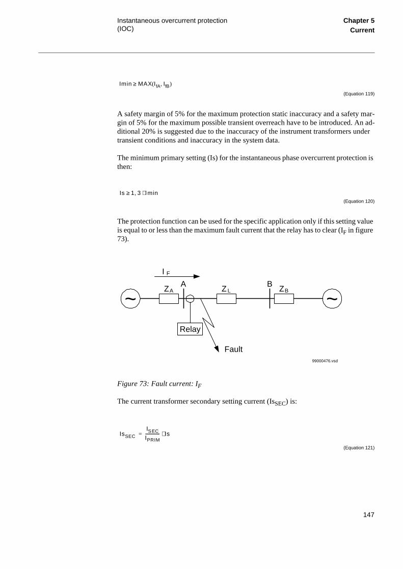
Instantaneous overcurrent protection (IOC)
Chapter 5Current
(Equation 119)
A safety margin of 5% for the maximum protection static inaccuracy and a safety mar-gin of 5% for the maximum possible transient overreach have to be introduced. An ad-ditional 20% is suggested due to the inaccuracy of the instrument transformers under transient conditions and inaccuracy in the system data.
The minimum primary setting (Is) for the instantaneous phase overcurrent protection is then:
(Equation 120)
The protection function can be used for the specific application only if this setting value is equal to or less than the maximum fault current that the relay has to clear (IF in figure 73).
Figure 73: Fault current: IF
The current transformer secondary setting current (IsSEC) is:
(Equation 121)
Imin MAX IfA IfB,( )≥
Is 1 3, Imin⋅≥
99000476.vsd
~ ~ZA ZBZ L
A B
Relay
I F
Fault
IsSEC
ISEC
IPRIM-------------- Is⋅=
147

Instantaneous overcurrent protection (IOC)
Chapter 5Current
Where ISEC is the secondary rated current of the main CT and IPRIM is the primary rated current of the main CT.
The relay setting value IP>> is given in percentage of the secondary base current value, I1b, associated to the current transformer input I1. The value for IP>> is given from this formula:
(Equation 122)
This is the value that has to be set in the terminal.
Set this value under the setting menu:
Settings
Functions
Group n
InstantOC
Meshed network with parallel line
In case of parallel lines, the influence of the induced current from the parallel line to the protected line has to be considered. One example is given in figure 74 where the two lines are connected to the same busbars. In this case the influence of the induced fault current from the faulty line (line 1) to the healthy line (line 2) is considered together with the two through fault currents IfA and IfB mentioned previously. The maximal in-fluence from the parallel line for the relay in figure 74 will be with a fault at the C point with the C breaker open.
A fault in C has to be applied, and then the maximum current seen from the relay (IM ) on the healthy line (this applies for single-phase-to-earth and two-phase-to-earth faults) is calculated.
IP>>IsSEC
I1b--------------- 100⋅=
148

Instantaneous overcurrent protection (IOC)
Chapter 5Current
Figure 74: Two parallel lines. Influence from parallel line to the through fault current: IM
The minimum theoretical current setting for the overcurrent protection function (Imin) will be:
(Equation 123)
Where IfA and IfB have been described in the previous paragraph. Considering the safe-ty margins mentioned previously, the minimum setting (Is) for the instantaneous phase overcurrent protection is then:
(Equation 124)
The protection function can be used for the specific application only if this setting value is equal or less than the maximum phase fault current that the relay has to clear.
The current transformer secondary setting current (IsSEC) is:
99000477.vsd
~ ~ZA ZB
ZL1A B
I M
Fault
Relay
ZL2
M
CLine 1
Line 2
Imin MAX IfA IfB IM, ,( )≥
Is 1 3, Imin⋅≥
149
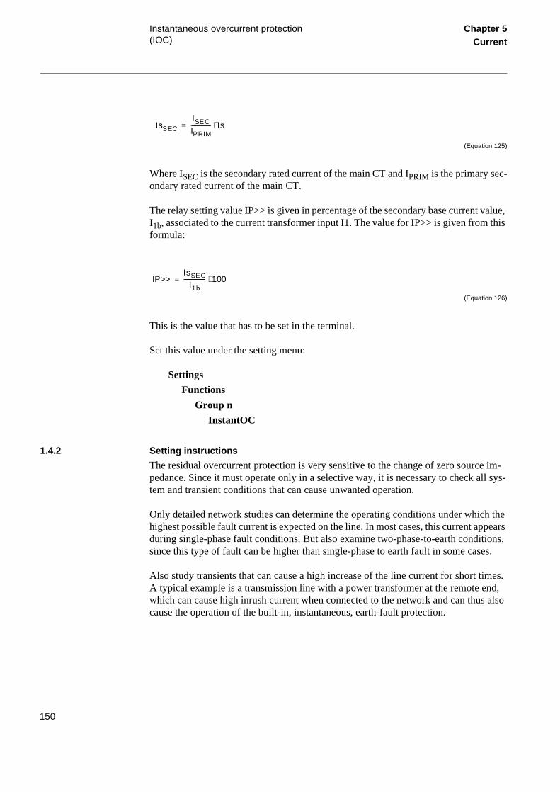
Instantaneous overcurrent protection (IOC)
Chapter 5Current
(Equation 125)
Where ISEC is the secondary rated current of the main CT and IPRIM is the primary sec-ondary rated current of the main CT.
The relay setting value IP>> is given in percentage of the secondary base current value, I1b, associated to the current transformer input I1. The value for IP>> is given from this formula:
(Equation 126)
This is the value that has to be set in the terminal.
Set this value under the setting menu:
Settings
Functions
Group n
InstantOC
1.4.2 Setting instructions
The residual overcurrent protection is very sensitive to the change of zero source im-pedance. Since it must operate only in a selective way, it is necessary to check all sys-tem and transient conditions that can cause unwanted operation.
Only detailed network studies can determine the operating conditions under which the highest possible fault current is expected on the line. In most cases, this current appears during single-phase fault conditions. But also examine two-phase-to-earth conditions, since this type of fault can be higher than single-phase to earth fault in some cases.
Also study transients that can cause a high increase of the line current for short times. A typical example is a transmission line with a power transformer at the remote end, which can cause high inrush current when connected to the network and can thus also cause the operation of the built-in, instantaneous, earth-fault protection.
IsSEC
ISEC
IPRIM-------------- Is⋅=
IP>>IsSEC
I1b--------------- 100⋅=
150

Instantaneous overcurrent protection (IOC)
Chapter 5Current
Meshed network without parallel line
The following fault calculations have to be done for single-phase-to-earth and two-phase-to-earth faults. With reference to figure 75, apply a fault in B and then calculate the relay through fault residual current IfB. The calculation should be done using the minimum source impedance values for ZA and the maximum source impedance values for ZB in order to get the maximum through fault current from A to B. The zero se-quence source impedances are of great importance.
Figure 75: Through fault current from A to B: IfB
Then a fault in A has to be applied and the through fault residual current IfA has to be calculated (Figure 76). In order to get the maximum through fault current, the minimum value for ZB and the maximum value for ZA have to be considered.
Figure 76: Through fault current from B to A: IfA
99000474.vsd
~ ~ZA ZBZ L
A B
Relay
I fB
Fault
99000475.vsd
~ ~ZA ZBZ L
A B
Relay
I fA
Fault
151

Instantaneous overcurrent protection (IOC)
Chapter 5Current
The relay must not trip for any of the two trough fault currents. Hence the minimum theoretical current setting (Imin) will be:
(Equation 127)
A safety margin of 5% for the maximum protection static inaccuracy and a safety mar-gin of 5% for the maximum possible transient overreach have to be introduced. An ad-ditional 20% is suggested due to the inaccuracy of the instrument transformers under transient conditions and inaccuracy in the system data.
The minimum setting (Is) for the instantaneous residual overcurrent protection is then:
(Equation 128)
The protection function can be used for the specific application only if this setting value is equal or less than the maximum fault current that the relay has to clear (IF in Figure 77).
Figure 77: Fault current: IF
The current transformer secondary setting current (IsSEC) is:
(Equation 129)
Imin MAX IfA IfA,( )≥
Is 1 3, Imin⋅≥
99000476.vsd
~ ~ZA ZBZ L
A B
Relay
I F
Fault
IsSECISEC
IPRIM-------------- Is⋅=
152

Instantaneous overcurrent protection (IOC)
Chapter 5Current
Set this value under the setting menu:
Settings
Functions
Groupn
InstantOC
Note: n=1,2,3 or 4, depending on which group to set.
Meshed network with parallel line
In case of parallel lines, the influence of the induced current from the parallel line to the protected line has to be considered. One example is given in figure 78, where the two lines are connected to the same busbar. In this case the influence of the induced residual fault current from the faulty line (line 1) to the healthy line (line 2) is considered togeth-er with the two through fault currents IfA and IfB mentioned previously. The maximal influence from the parallel line for the relay in Figure 78 will be with a fault at the C point with the C breaker open.
A fault in C has to be applied, and then the maximum current seen from the relay (IM) on the healthy line (this applies for single-phase-to-earth and two-phase-to-earth faults) is calculated.
Figure 78: Two parallel lines. Influence from parallel line to the through fault current: IM.
The minimum theoretical current setting for the residual overcurrent protection func-tion (Imin) will be:
99000477.vsd
~ ~ZA ZB
ZL1A B
I M
Fault
Relay
ZL2
M
CLine 1
Line 2
153

Instantaneous overcurrent protection (IOC)
Chapter 5Current
(Equation 130)
Where IfA and IfB have been described in the previous paragraph. Considering the safe-ty margins mentioned previously, the minimum setting (Is) for the instantaneous phase overcurrent protection is then:
(Equation 131)
The protection function can be used for the specific application only if this setting value is equal or less than the maximum residual fault current that the relay has to clear.
The current transformer secondary setting current (IsSEC) is:
(Equation 132)
Set this value under the setting menu:
Settings
Functions
Groupn
InstantOC
Note: n=1,2,3 or 4, depending on which group to set.
I m in M AX IfA I fB IM, ,( )≥
Is 1 3, Imin⋅≥
IsSECISEC
IPRIM-------------- Is⋅=
154

Time delayed overcurrent protection (TOC)
Chapter 5Current
2 Time delayed overcurrent protection (TOC)
2.1 Application
The time delayed phase overcurrent protection can be used as independent overcurrent protection, particularly for radially fed systems, or as back-up protection to the main distance or line differential protection functions. In the first case the protected zone of the time delayed overcurrent protection reaches upto the next overcurrent protection and works in its zone as back-up protection. The programmable time delay (definite time) of the function allows the time selectivity through an appropriate time grading among the overcurrent relays protecting the system.
Where the function acts as back-up for the main line protection, the trip from the over-current protection can be activated when the main protection function is blocked (e.g. by the fuse failure protection) or it can be active all the time.
In some cases, where it could be difficult to achieve a selective trip, the function can be used as a helpful overcurrent signallization for the post-fault analysis.
The time delayed residual overcurrent protection (TOC) which is an earth-fault protec-tion, serves as a built-in local back-up function to the main protection function. In most cases, it is used as a back-up for the earth-fault measuring in distance protection.
The function is intended to be used in solidly earthed systems.
The time delay makes it possible to set the relay to detect high resistance faults and still perform selective trip.
The protection, which is non-directional, is included in some of the REx 5xx terminals. Refer to the ordering information for more details.
2.2 Functionality
The current-measuring elements within one of the built-in digital signal processors con-tinuously measure the current in all three phases, and compare them with the IP> set value. A recursive Fourier filter filters the current signals, and a separate trip counter prevents high overreaching of the measuring elements. The logical value of each phase current signal on the output of the digital processor (STIL1, STIL2 and STIL3 respec-tively) is equal to 1 if the measured phase current exceeds the set value. These signals will instantaneously set their respective output starting signals (TOC--STL1, TOC--STL2, TOC--STL3), if the function is not blocked.
155

Time delayed overcurrent protection (TOC)
Chapter 5Current
, then
own
en
nt n-
ex-inal
te it
is
nly, with e
If any of the three phase currents exceeds the set value for a period longer than the set time tP, then a three phase trip is generated from the output signal TOC--TRP.
The current-measuring element within one of the built-in digital signal processors con-tinuously measures the residual current (3I0), and compares it with the IN> set value. A recursive Fourier filter filters the current signal, and a separate trip counter prevents high overreaching of the measuring element. The logical value of the signal on the out-put of the digital signal processor (TOC--STIN) is equal to 1 if the measured residual current exceeds the pre-set value. This signal will instantaneously set the output start signal (TOC--STN), unless the function is blocked (see “Design”).
The function trip signal (TOC--TRN) can be delayed 0-60 s.
If the residual current exceeds the set value for a period longer than the set valuea three phase trip is generated from the output signal TOC--TRN.
2.3 Design
The simplified logic diagram of the time delayed phase overcurrent function is shin figure 79.
The function is disabled (blocked) if:
• The terminal is in TEST mode (TEST-ACTIVE is high) and the function has beblocked from the HMI (BlockTOC=Yes).
• The input signal TOC--BLOCK is high.
The TOC--BLOCK signal is a blocking signal of the time delayed phase overcurrefunction. It prevents the activation of any trip or starting output signal. It can be conected to a binary input of the terminal in order to receive a block command fromternal devices or can be software connected to other internal functions of the termitself in order to receive a block command from internal functions. Through OR gacan be connected to both binary inputs and internal function outputs. The TOC--BLOCK signal blocks also the time delayed residual overcurrent protection, if thisinstalled in the same REx 5xx terminal.
When the function is enabled, there is still the possibility to block the output trips owithout affecting the start signals, that will always be active. This can be obtained the function input TOC--BLKTR. Similarly to the TOC--BLOCK signal, also the timdelayed residual overcurrent protection, if present in the terminal, is blocked fromTOC-BLKTR.
156

Time delayed overcurrent protection (TOC)
Chapter 5Current
een
The duration of each output signal is at least 15 ms. This enables continuous output sig-nals for currents, which go just a little above the set operating value.
The output trip signal TOC--TRP is a three phase trip. Single phase information is avail-able from the starting signals, that are phase segregated.
The TOC--TRIP output signal behaves as general time delayed overcurrent trip when in the REx 5xx terminal also the time delayed residual overcurrent function is imple-mented; i.e. this signal will be activated in case of any time delayed overcurrent or time delayed residual overcurrent trip. If only the time delayed phase overcurrent function is installed in the terminal, then this signal behaves exactly as the signal TOC--TRP and can be used for signallization.
Figure 79: Simplified logic diagram of time delayed phase overcurrent protection
The simplified logic diagram of the time delayed earth-fault protection is shown in fig-ure 80.
The time delayed residual function is disabled if:
• The terminal is in TEST status (TEST-ACTIVE is high) and the function has bblocked from the HMI (BlockTOC=Yes).
• The input signal TOC--BLOCK is high.
TOC--BLOCK
en01000075.vsd
TOC - TIME DELAYED PHASE OVERCURRENT FUNCTION
TEST-ACTIVE
&
TEST
BlockTOC= Yes
>1
STIL1
STIL2
STIL3
TOC--TRIP
TOC--TRP
&
&
TOC--BLKTR
&
t
tP&
>1 STP
STL1
STL2
STL3
157
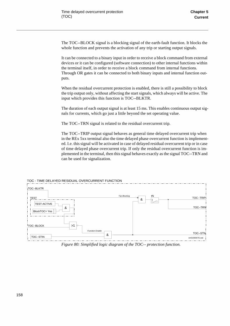
Time delayed overcurrent protection (TOC)
Chapter 5Current
The TOC--BLOCK signal is a blocking signal of the earth-fault function. It blocks the whole function and prevents the activation of any trip or starting output signals.
It can be connected to a binary input in order to receive a block command from external devices or it can be configured (software connection) to other internal functions within the terminal itself, in order to receive a block command from internal functions. Through OR gates it can be connected to both binary inputs and internal function out-puts.
When the residual overcurrent protection is enabled, there is still a possibility to block the trip output only, without affecting the start signals, which always will be active. The input which provides this function is TOC--BLKTR.
The duration of each output signal is at least 15 ms. This enables continuous output sig-nals for currents, which go just a little beyond the set operating value.
The TOC--TRN signal is related to the residual overcurrent trip.
The TOC--TRIP output signal behaves as general time delayed overcurrent trip when in the REx 5xx terminal also the time delayed phase overcurrent function is implement-ed. I.e. this signal will be activated in case of delayed residual overcurrent trip or in case of time delayed phase overcurrent trip. If only the residual overcurrent function is im-plemented in the terminal, then this signal behaves exactly as the signal TOC--TRN and can be used for signalization.
Figure 80: Simplified logic diagram of the TOC-- protection function.
TOC--BLOCK
en01000076.vsd
TOC - TIME DELAYED RESIDUAL OVERCURRENT FUNCTION
TEST-ACTIVE
&
TEST
BlockTOC= Yes
>1
TOC--STIN
TOC--TRIP
TOC--TRN
&
TOC--BLKTR
t
tN&
TOC--STNFunction Enable
Trip Blocking
158

Time delayed overcurrent protection (TOC)
Chapter 5Current
2.4 Calculations
2.4.1 Setting instructions
The current setting value must be selected to permit the detection of the lowest short circuit current without having any unwanted tripping or starting of the function under normal load conditions. The following relation has to be considered for the setting of the primary operating current (Is) of the function:
(Equation 133)
The settable time delay tP allows the time selectivity of the overcurrent function, ac-cording to the time grading plan of all the other overcurrent protections in the system. The time setting value should also consider transients that could cause a high increase of the line current for short times. A typical example is a transmission line with a power transformer at the remote end, which can cause high inrush current when energized.
Where the time delayed overcurrent function is used as back-up of impedance protec-tion, normally the time delay is set higher than the time delay of distance zone 2 (or 3) in order to avoid interferences with the impedance measuring system.
Setting of operating current IP>
If Is is the primary setting operating value of the function, than the secondary setting current (IsSEC) is:
(Equation 134)
Where:
ILmax is the maximum permissible load current of the protected unit,
IFmin is the minimum fault current that the relay has to
clear. The values 1.2 and 0.7 are safety factors and
K is the reset ratio of the overcurrent function:
0.95.
1.2 ILmaxK
-----------------⋅ Is 0.7 IFmin⋅< <
IsSEC
ISEC
IPRIM-------------- Is⋅=
159

Time delayed overcurrent protection (TOC)
Chapter 5Current
The relay setting value IP> is given in percentage of the secondary base current value, I1b, associated to the current transformer input I1. The value for IP> is given from this formula:
(Equation 135)
This is the value that has to be set in the terminal.
Set this value under the setting menu:
Settings
Functions
Group n
TimeDelayOC
On the value IP>.
Setting of time delay tP
Set the time delay of the function, tP, under the setting menu:
Settings
Functions
Group n
TimeDelayOC
on the value tP.
Where:
ISEC is the secondary rated current of the main CT
and
IPRIM is the primary rated current of the main CT.
IP>IsSEC
I1b--------------- 100⋅=
160

Time delayed overcurrent protection (TOC)
Chapter 5Current
2.4.2 Setting instructions
The residual overcurrent protection is very sensitive to the change of zero source im-pedance. Since it must operate only in a selective way, it is necessary to check all sys-tem and transient conditions that can cause unwanted operation.
The settings should be chosen in such a way that it can detect high resistance faults on the protected line and still be selective to other residual time delayed protections in both forward and reverse directions. The time setting value should also consider transients that can cause a high increase of the residual line current for short times.
A typical example is a transmission line with a power transformer at the remote end, which can cause high inrush current when being energised.
In well transposed system, the false earth-fault current is normally lower than 5% of the line current. For non transposed lines a considerably higher false residual current may be found.
In case of extremely short or not fully transposed parallel lines, the false residual current must be measured or calculated when maximum sensitivity is desired. Generally, 80 A is recommended as a minimum primary operation value for the residual overcurrent protection.
General criteria for the primary current setting value of the time delayed residual over-current protection is given in the formula below:
(Equation 136)
Where:
IRmax is the maximum permissive residual current flowing in the protection unit during normal service conditions and
IFmin is the minimum residual fault current that the relay has to clear.
1.3 and
are safety factor values. 0.7
1.3 IRmax⋅ Is 0.7 IFmin⋅< <
161

Time delayed overcurrent protection (TOC)
Chapter 5Current
Setting of operating current IN>
If Is is the primary setting operating value of the function, then the secondary setting current (IsSEC) is:
(Equation 137)
where ISEC is the secondary rated current of the main CT and IPRIM is the primary rated current of the main CT.
The relay setting value IN> is given in percentage of the secondary base current value, I4b, associated to the current transformer on input I4. The value for IN> is given from the formula:
(Equation 138)
and this is the value that has to be set in the relay.
Set the value under the setting menu:
Settings
Functions
Group n (n=1-4)
TimeDelayOC
For the parameter IN>.
Setting of time delay tN
Set the time delay of the function, tN, under the setting menu:
Settings
Functions
Group n (n=1-4)
TimeDelayOC
IsSEC
ISEC
IPRIM-------------- Is⋅=
IN>IsSE C
I4b--------------- 100⋅=
162

Definite and inverse time-delayed residual overcurrent protection (TEF)
Chapter 5Current
rans-r-
3 Definite and inverse time-delayed residual overcurrent protection (TEF)
3.1 Application
This earth-fault overcurrent protection is intended for solidly earthed networks.
Earth-fault overcurrent protection
In case of single-phase earth-faults, the primary fault resistance varies with the network conditions, the type of fault and location of the fault. In many cases, the fault resistance is much higher than the resistance that can be covered by an impedance-measuring dis-tance protections. This can be the case with a phase to earth fault to a tower with large tower footing resistance.
Earth-faults with high fault resistances can be detected by measuring the residual cur-rent (3I0).
The inrush current can cause unwanted tripping of the earth-fault overcurrent relay when energizing a directly earthed power transformer. The earth-fault overcurrent pro-tection is therefore provided with second harmonic restraint, which blocks the operation if the residual current (3I0) contains 20% or more of the second harmonic component.
In some cases, it is possible to improve the selectivity by adding a settable minimum operate current (IMin) and a minimum operate time (tMin) to the inverse characteristic. These functions are included in the earth-fault protection modules.
To minimize the operate time, in case of closing the circuit breaker to a fault, the resid-ual overcurrent protection module is provided with a switch-onto-fault logic, which can be activated at breaker closure. The tripping time will temporarily be reduced to 300 ms.
Directional earth-fault protection is obtained by measuring the residual current and the angle between this current and the zero-sequence voltage (3U0).
It is possible to obtain the polarizing voltage (-3U0) from an open delta winding in the voltage transformer or via summation of the three phase voltages supplied to the termi-nal.
The 3I0 current lags the polarizing voltage (-3U0) by a phase angle equal to the angle of the zero-sequence source impedance. In solidly earthed networks, this angle is in the range of 40° to nearly 90°. The high value refers to stations with directly earthed tformers with delta winding. To obtain maximum sensitivity at all conditions, the foward measuring element should have a characteristic angle of 65°.
163

Definite and inverse time-delayed residual overcurrent protection (TEF)
Chapter 5Current
As a general rule, it is easier to obtain selectivity by using directional instead of non-directional earth-fault overcurrent protection, but sufficient polarizing voltage must be available.
It is not possible to measure the distance to the fault by using the zero-sequence com-ponents of the current and voltage, because the zero-sequence voltage is a product of the zero-sequence components of current and source impedance. It is possible to obtain selectivity by the use of a directional comparison scheme, which uses communication between the line ends.
If a communication scheme can not be used, the best selectivity is generally obtained by using inverse time delay. All relays, in the network, must have the same type of in-verse characteristic. An earth-fault on a line is selectively tripped if the difference be-tween the residual current (3I0) out on the faulted line and the residual current (3I0) out on the other lines gives a time difference of 0.3-0.4 seconds. A logarithmic characteris-tic is generally the most suitable for this purpose, because the time difference is constant for a given ratio between the currents.
Directional comparison logic function
In the directional comparison scheme, information of the fault current direction must be transmitted to the other line end. A short operate time enables auto-reclosing after the fault. During a single-phase reclosing cycle, the auto-reclosing device must block the directional comparison earth-fault scheme.
A communication logic block for residual overcurrent protection can be included in the REx 5xx terminal to provide this feature. The function contains circuits for blocking overreach and permissive overreach schemes. See the section “Communication logic for residual overcurrent protection”.
Also an additional communication logic block for the communication can be included. It contains logic for the weak-end-infeed and current-reversal functions, which are used only in the permissive overreach scheme. See the section “Current reversal and weak end infeed logic for residual overcurrent protection.
3.2 Functionality
3.2.1 Theory of operation
Directional earth-fault overcurrent protection
This protection measures the residual current (3I0) and the residual voltage (3U0). Fig-ure 81 shows the current measuring, time delay and logic circuits (both with and with-out directional check) of this protection function.
164

Definite and inverse time-delayed residual overcurrent protection (TEF)
Chapter 5Current
Figure 81: Simplified logic diagram for the residual overcurrent protection
Activate the independent time-delay function by setting Characteristic= Def (or inverse time delay according to the setting table). The t1 timer starts when both the definite/in-verse time characteristic and the tMin timer operate. The tMin timer starts when the 3I0 current to the relay is equal to or higher than the set operate value for IMin and the con-tent of the second harmonic in 3I0 is less than 20%.
The inverse time calculation starts when 3I0 is equal to or higher than the set operate value for IMin and the content of the second harmonic in 3I0 is less than 20%. The in-verse time delay is determined by the selection of the characteristic (NI, VI etc.) in the Characteristic setting and the setting of the characteristic IN> current.
99000204.vsd
Operation = ON
Def/NI/VI/EI/LOG
&
&
>1
EFCh
k
IN>
±Σ
300mst
1000mst
3Io>
ttMin
&
tt1
&
IMin
20%
50mst
TEF--TRIP
= Directional
100% FORWARD
60% REVERSE
3Ioxcos (φ-65)
EF3IoSTD
0.01Un
2fn
2fn
Direction
Option: Directional check
3Uo
TEF--BLOCK
&
&
&
&
&
TEF--TRSOTF
TEF--STFW
TEF--STRV
TEF--START
TEF--BC
TEF--BLKTR
3Io
>1
&
&
165

Definite and inverse time-delayed residual overcurrent protection (TEF)
Chapter 5Current
The t1 timer is normally set to zero. Use it to add a constant time to the inverse time delay. Figure 82 shows the effect of the IMin and tMin settings on the inverse charac-teristic.
Figure 82: Normal inverse and logarithmic inverse time characteristics.
The switch-onto-fault function is used to minimise the operate time in case of pole dis-crepancy at breaker closing and in cased of closing on to a fault. The function is released by activating the TEF--BC binary input. The function is activated for 1 second after the reset of the TEF--BC binary input.
The function is blocked by activating the TEF--BLOCK binary input.
Activating the TEF--BLKTR blocks the definite/inverse delay trip outputs TEF--TRIP and the switch-on-to-fault trip TEF-TRSOTF.
The 3I0 current lags the polarising voltage (3U0) by a phase angle equal to the angle of the zero-sequence source impedance. The forward measuring element operates when:
(Equation 139)
1
2
3
4
5
1 2 3 5 7 10 20 30 50
LogaritmicInverse
NormalInverse(k=0,4)
x IN>
t (s)
99000105.vsd
tMIN
IMIN
3I0 ϕ 65°–( ) IN>Dir≥cos⋅
166

Definite and inverse time-delayed residual overcurrent protection (TEF)
Chapter 5Current
Ts, n the rect f the uen-
Figure 83: Measuring characteristic of the directional element
The change in operate value is small when the phase angle deviates moderately from 65°. A deviation of 20° increases the operate value by only 6.5%.
The polarising voltage, normally obtained from the broken delta windings of the Vcan have a high content of harmonics relative to the fundamental frequency wheoutput voltage is low, particularly when capacitive VTs are used. To secure a cormeasurement, the directional function must have an effective bandpass filtering ovoltage. In the module, the filtering secures a correct function for fundamental freqcy polarising voltages down to 1% of the rated voltage.
Where:
ϕ is the angle between 3I0 and 3U0 (positive if 3I0 lags 3U0)
IN>Dir is the set operate value
IN>Dir
IN Operation
Upol = -3U0
99000052.vsd
65°
ϕ
167

Definite and inverse time-delayed residual overcurrent protection (TEF)
Chapter 5Current
In case of an external fault, the capacitive current generated on the line decreases the current to the earth-fault relay situated at the line end towards the fault. So the reverse direction comparator must have an increased sensitivity to secure reliable blocking in case of external faults when a directional comparison or a blocking communication scheme is used. The operate current of the reverse direction measuring element in the module is, as a fixed ratio, set at 0.6 IN> Dir.
3.3 Calculations
3.3.1 Setting instructions
To detect high resistive earth-faults, a low operate current is required. On the other hand, a low setting increases the risk for unwanted operation due to imbalance in the network and the current transformer circuits. Set the minimum operate current (IN> *IMin) of the earth-fault overcurrent protection higher than the maximum false earth-fault current. If the directional function is chosen, set the start level of the directional function (IN> Dir) higher than the maximum false earth-fault current.
The imbalance in the network that causes false earth-fault currents is caused mainly by untransposed or not fully transposed parallel lines with strong zero-sequence mutual coupling. There might also be high imbalance currents for non-transposed single circuit lines if the zero sequence source impedance is low at both line ends. This false earth-fault current is directly proportional to the load current.
In a well-transposed system, the false earth-fault current is normally lower than 5% of the line current.
In case of not fully transposed parallel lines, measure or calculate the false earth-fault current at maximum load.
The choice of time delay characteristics - definite time, normal inverse, very inverse, extremely inverse or logarithmic inverse - depends on the network. To achieve opti-mum selectivity, use the same type of characteristic for all earth-fault overcurrent pro-tections in the network. This means that in networks already equipped with earth-fault overcurrent relays, the best selectivity is normally achieved by using the same type of characteristic as in the existing relays.
The following formulas for the operate time (in seconds) apply to the characteristic used within the REx 5xx terminal with line protection, see table 8.
168
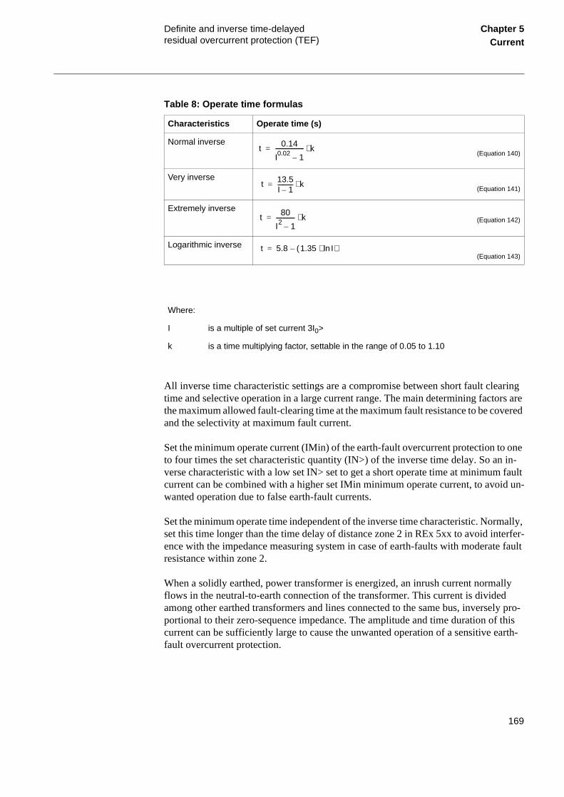
Definite and inverse time-delayed residual overcurrent protection (TEF)
Chapter 5Current
Table 8: Operate time formulas
All inverse time characteristic settings are a compromise between short fault clearing time and selective operation in a large current range. The main determining factors are the maximum allowed fault-clearing time at the maximum fault resistance to be covered and the selectivity at maximum fault current.
Set the minimum operate current (IMin) of the earth-fault overcurrent protection to one to four times the set characteristic quantity (IN>) of the inverse time delay. So an in-verse characteristic with a low set IN> set to get a short operate time at minimum fault current can be combined with a higher set IMin minimum operate current, to avoid un-wanted operation due to false earth-fault currents.
Set the minimum operate time independent of the inverse time characteristic. Normally, set this time longer than the time delay of distance zone 2 in REx 5xx to avoid interfer-ence with the impedance measuring system in case of earth-faults with moderate fault resistance within zone 2.
When a solidly earthed, power transformer is energized, an inrush current normally flows in the neutral-to-earth connection of the transformer. This current is divided among other earthed transformers and lines connected to the same bus, inversely pro-portional to their zero-sequence impedance. The amplitude and time duration of this current can be sufficiently large to cause the unwanted operation of a sensitive earth-fault overcurrent protection.
Characteristics Operate time (s)
Normal inverse(Equation 140)
Very inverse(Equation 141)
Extremely inverse(Equation 142)
Logarithmic inverse(Equation 143)
Where:
I is a multiple of set current 3I0>
k is a time multiplying factor, settable in the range of 0.05 to 1.10
t 0.14
I0.02 1–-------------------- k⋅=
t 13.5I 1–----------- k⋅=
t 80
I2 1–------------- k⋅=
t 5.8 1.35 Iln⋅( )–=
169

Definite and inverse time-delayed residual overcurrent protection (TEF)
Chapter 5Current
The earth-fault overcurrent protection has a built-in second harmonic current stabiliza-tion, which prevents unwanted operation if the inrush current has a second harmonic content of 20% or more. This is normally the case. On rare occasions, it may be neces-sary to increase the setting of the operate value for the residual earth-fault overcurrent protection to avoid unwanted operation due to transformer inrush current.
When single-phase auto-reclosing is used, the minimum time of the inverse time de-layed residual overcurrent protection (tMin) should be set to be longer than the time from the occurrence of the fault to the reclosing of the breaker at both line terminals. An alternative method is to block the earth fault protection by the autorecloser during the dead time. This avoids unwanted three-phase tripping during a single-phase auto-reclosing cycle controlled by the distance protection.
The polarizing voltage for directional earth-fault overcurrent protection is normally ob-tained from the broken delta windings of instrument voltage transformers or by internal calculation. The voltage contains a certain amount of harmonics, especially when the protection is connected to CVTs.
Due to the bandpass filtering a polarizing voltage down to 1 percent of the rated voltage will provide correct directional functionality. This is also valid when the protection is connected to CVTs.
The minimum polarizing voltage to the protection (Umin) is calculated from the formu-la:
(Equation 144)
Observe that when a blocking scheme or a permissive scheme with current reversal or weak-end-infeed logic is used, IFmin represents the primary operate current of the re-verse-looking directional element which is 60% of the forward element.
Where:
IFmin is the minimum primary operate fault current
Z0min is the minimum zero-sequence impedance seen from the relay
Usec, Uprim are the rated phase voltages of the broken delta connected CVTs (VTs)
Umin IF min Z0 min
Usec
Uprim--------------⋅ ⋅=
170

Definite and inverse time-delayed residual overcurrent protection (TEF)
Chapter 5Current
To even secure operation in unfavorable cases, Umin must be equal to at least 1 volt plus the maximum network frequency false voltage, due to measuring errors in the VT circuits.
If not blocked, the directional comparator operates during the dead time in case of a sin-gle-phase auto-reclosure. So the TEF--BLOCK blocking input must be activated during the single-phase auto-reclosing cycle.
171

Scheme communication logic for residual overcurrent protection (EFC)
Chapter 5Current
4 Scheme communication logic for residual overcurrent protection (EFC)
4.1 Application
This communication logic is intended for residual overcurrent protections.
To achieve fast fault clearing for a fault on the part of the line not covered by the instan-taneous zone 1, the directional residual overcurrent protection function can be support-ed with logic, that uses communication channels.
One communication channel in each direction, which can transmit an on/off signal is required. The performance and security of this function is directly related to the trans-mission channel speed and security against false or lost signals. So special channels are used for this purpose. When power line carrier is used for communication, these special channels are strongly recommended due to the communication disturbance caused by the primary fault.
In the directional comparison scheme, information of the fault current direction must be transmitted to the other line end.
With directional comparison, an operate time of 50-60 ms, including a channel trans-mission time of 20 ms, can be achieved. This short operate time enables rapid automatic reclosing function after the fault.
During a single-phase reclosing cycle, the auto-reclosing device must block the direc-tional comparison earth-fault scheme.
The communication logic module for the REx 5xx terminal contains circuits for block-ing overreach and permissive overreach schemes. The module also contains logic for the weak-end-infeed and current-reversal functions, which are used only in the permis-sive overreach scheme.
4.2 Functionality
4.2.1 Theory of operation
Directional comparison logic function
The directional comparison function contains logic for blocking overreach and permis-sive overreach schemes.
172

Scheme communication logic for residual overcurrent protection (EFC)
Chapter 5Current
The circuits for the permissive overreach scheme contain logic for current reversal and weak-end-infeed functions. These functions are not required for the blocking overreach scheme.
Use the independent or inverse time functions in the directional earth-fault protection module to get back-up tripping in case the communication equipment malfunctions and prevents operation of the directional comparison logic.
Connect the necessary signal from the auto-recloser for blocking of the directional com-parison scheme, during a single-phase auto-reclosing cycle, to the EFC--BLOCK input of the directional comparison module.
Blocking scheme
In the blocking overreach scheme, a signal is sent to the other line end if the directional element detects a fault in the reverse direction. When the forward directional element operates, it trips the line after a short time delay if no blocking signal is received from the other line end. The time delay, normally 30-40 ms, depends on the communication transmission time and the chosen safety margin.
One advantage of the blocking scheme is that only one channel (carrier frequency) is needed and the channel can be shared with the impedance-measuring system, if that also works in the blocking mode. The communication signal is also transmitted on a healthy line and no signal attenuation will occur due to the fault.
Blocking schemes are particularly favourable for three-terminal applications if there is no zero-sequence current outfeed from the tapping. The blocking scheme is immune to current reversals because the received carrier signal is maintained long enough to avoid unwanted operation due to current reversal. There is neither any need for weak-end-in-feed logic, because the strong end trips for an internal fault when no blocking signal is received from the weak end. But the fault clearing time is generally longer for a block-ing scheme than for a permissive one.
If the fault is on the line, the forward direction measuring element operates. If no block-ing signal comes from the other line end via the EFC--CR binary input (carrier receive) the EFC--TRIP output is activated after the tCoord set time delay.
173

Scheme communication logic for residual overcurrent protection (EFC)
Chapter 5Current
Figure 84: Simplified logic diagram, Scheme type = blocking
Permissive overreach scheme
In the permissive scheme, the forward directed measuring element sends a permissive signal to the other line end if a fault is detected in the forward direction. The directional element at the other line end must wait for a permissive signal before giving a trip sig-nal. Independent channels (frequencies) must be available for the communication in each direction.
An impedance-measuring relay which works in an underreach permissive mode with one channel in each direction can share the channels with the earth-fault overcurrent protection. If the impedance measuring relay works in the permissive overreach mode, common channels can be used in single-line applications. In case of double lines con-nected to a common bus at both ends, use common channels only if the ratio Z1S / Z0S (positive through zero-sequence source impedance) is about equal at both line ends. If the ratio is different, the impedance measuring and the directional earth-fault current system of the healthy line may detect a fault in different directions, which could result in unwanted tripping.
Common channels can not be used when the weak-end-infeed function is used in the distance or earth-fault protection.
In case of an internal fault, the forward directed measuring element operates and sends a permissive signal to the remote end via the EFC--CS output (carrier send). Local trip-ping is permitted when the forward direction measuring element operates and a permis-sive signal is received via the EFC--CR binary input (carrier receive).
&
&
&
t 50 ms
t
0-60 s
t Coord
t25 ms
EFC-CSBLK
EFC-BLOCK
EFC-CACC
EFC-CR
EFC-CS
EFC-TRIP
EFC-CRL
99000107.vsd
174

Scheme communication logic for residual overcurrent protection (EFC)
Chapter 5Current
The total operate-time for the system is the sum of the Pick-up time (of the measuring element) and the Transmission time (of the permissive signal)
Figure 85: Simplified logic diagram, Scheme type = permissive
4.3 Design
Blocking scheme
In the blocking scheme, a signal is sent to the other line end if the directional element in TEF function, connected to the EFC--CSBLK input signal, detects a fault in the re-verse direction. When the forward directional element operates, it trips the line after a short time delay if no blocking signal is received from the other line end. The time de-lay, normally 30-40 ms, depends on the communication transmission time and the cho-sen safety margin.
Permissive overreaching scheme
In the permissive scheme, the forward direction measuring element in TEF function, connected to the EFC--CSPRM input, sends a permissive signal to the other line end if a fault is detected in the forward direction. The directional element at the other line end must wait for a permissive signal before giving a trip signal. Independent channels (fre-quencies) must be available for the communication in each direction.
4.4 Calculations
4.4.1 Setting
The settings are done from the local HMI under the menu:
&
&
&
&
&
t
0-60 s t
25 ms
>1
t
50 mst Coord
EFC-CRL
EFC-TRIP
EFC-CS
EFC-BLOCK
EFC-CR
EFC-CACC
EFC-CSBLK
EFC-CSPRM
99000108.vsd
175

Scheme communication logic for residual overcurrent protection (EFC)
Chapter 5Current
Settings
Functions
Group n (n = 1.4)
Earth Fault
EFCom
Blocking scheme
In the blocking scheme, set the tCoord timer to the channel transmission time during disturbance conditions. Add a margin of 20-30 ms. Two times the nominal value of the channel transmission time is recommended when a power line carrier is used.
Permissive communication scheme
In the permissive communication scheme, the security against unwanted operation caused by spurious carrier receive signals can be increased by delaying the tripping out-put with the tCoord timer. Set the timer in the range of 0.000 to 60.000 s. In most cases, a time delay of 30 ms is sufficient.
176

Current reversal and weak end infeed logic for residual overcurrent protection (EFCA)
Chapter 5Current
5 Current reversal and weak end infeed logic for residual overcurrent protection (EFCA)
5.1 Application
This additional communication logic is intended for the Communication logic for resid-ual overcurrent protections.
To achieve fast fault clearing for a fault on the part of the line not covered by the instan-taneous zone 1, the earth-fault protection functions can be supported with logic, that uses communication channels. REx 5xx terminals have for this reason available a scheme communication logic. Different system conditions require in many cases addi-tional special logic circuits, like current reversal logic and weak-end-infeed logic. Both functions are available within the additional communication logic for earth-fault pro-tection.
Current reversal logic
If parallel lines are connected to common buses at both terminals, overreaching permis-sive communication schemes can trip unselectively due to fault current reversal. This unwanted tripping affects the healthy line when a fault is cleared on the other line. This lack of security can result in a total loss of interconnection between the two buses.
To avoid this type of disturbance, a fault current-reversal logic (transient blocking log-ic) can be used.
Weak end infeed logic
Permissive communication schemes can basically operate only when the protection in the remote terminal can detect the fault. The detection requires a sufficient minimum fault current. The fault current can be too low due to an opened breaker or low short-circuit power of the source. To overcome these conditions, weak end infeed (WEI) echo logic is used.
The fault current can also be initially too low due to the fault current distribution. Here, the fault current increases when the breaker opens in the strong terminal and a sequen-tial tripping is achieved. This requires a detection of the fault by an independent-trip-ping zone 1. To avoid sequential tripping as described and when zone 1 is not available, weak end infeed tripping logic is used.
177

Current reversal and weak end infeed logic for residual overcurrent protection (EFCA)
Chapter 5Current
5.2 Functionality
5.2.1 Theory of operation
Directional comparison logic function
The directional comparison function contains logic for blocking overreach and permis-sive overreach schemes.
The circuits for the permissive overreach scheme contain logic for current reversal and weak end infeed functions. These functions are not required for the blocking overreach scheme.
Use the independent or inverse time functions in the directional earth-fault protection module to get back-up tripping in case the communication equipment malfunctions and prevents operation of the directional comparison logic.
Figures 88, 89 and 90 shows the logic circuits.
Connect the necessary signal from the auto-recloser for blocking of the directional com-parison scheme, during a single-phase auto-reclosing cycle, to the EFCA-BLOCK input of the directional comparison module.
Fault current reversal logic
Figures 86 and 87 show a typical system condition, which can result in a fault current reversal; note that the fault current is reversed in line L2 after the breaker opening. This can cause an unselectiv trip on line L2 if the current reversal logic does not block the permissive overreach scheme in the terminal at B:2.
Figure 86: Initial condition
Strongsource
L1
L2
A:1
A:2
B:1
B:2
A B
Weaksource
99000043.vsd
178

Current reversal and weak end infeed logic for residual overcurrent protection (EFCA)
Chapter 5Current
Figure 87: Current distribution after the breaker at B:1 is opened
The fault current reversal logic uses a reverse directed element, connected to EFCA-IRV, which in terminal at B:2 recognises the fault on the L1 line. See Figure 86. When the reverse direction element is activated during the tPickUp time, the EFCA-IRVL sig-nal is activated, see figure 88. The logic is now ready to handle a current reversal with-out tripping. EFCA-IRVL will be connected to the block input on the permissive overreach scheme.
When breaker in B:1 operate, the fault current is reversed in line L2. The terminal at B:2 recognises now the fault in forward direction. Together with the remaining carrier received signal it will trip the breaker in B:2. To ensure that this does not occur, the per-missive overreach function need to be blocked by EFCA-IRVL, until the carrier receive signal is reset.
When the fault current is reversed in line L2, EFCA-IRV is deactived and EFCA-IRVBLK is actived. The reset of EFCA-IRVL is delayed by the tDelay time, see figure 88. This ensures the reset of the carrier receive EFCA-CR signal in terminal B:2.
In terminal A:2, where the forward direction element was initially activated. This direc-tion element must reset before the carrier send signal is initiated from B:2. The delayed reset of EFCA-IRVL also ensures the carrier send signal from terminal B:2 is held back until the forward direction element is reset in terminal A:2.
Figure 88: Simplified logic diagram, current reversal
Strongsource
L1
L2
A:1
A:2
B:1
B:2
A B
Weaksource
99000044.vsd
t t10 ms0-60 s
t0-60 s
tPickUp tPickUp
&0-60 s
t
tDelay
EFCA-BLOCK
EFCA-IRV
EFCA-IRVBLK
EFCA-IRVL
99000053.vsd
179

Current reversal and weak end infeed logic for residual overcurrent protection (EFCA)
Chapter 5Current
Weak and infeed logic
Figure 89 shows a typical system condition, which can result in a missing operation; note that there is no fault current from node B. This cause that terminal at B cannot de-tect the fault and trip the breaker in B. To cope with this situation, a selectable weak end infeed logic is provided for the permissive overreach scheme.
The weak end infeed function can be set to send only an echo signal (WEI=Echo) or an echo signal and a trip signal (WEI=Trip). See figures 90 and 91.
Figure 89: Initial condition
The weak end infeed logic uses normally a reverse and a forward direction element, connected to EFCA-WEIBLK via an OR-gate. See figure 90. If neither the forward nor the reverse directional measuring element is activated during the last 200 ms. The weak-end-infeed logic echoes back the received permissive signal. See figure 90.
If the forward or the reverse directional measuring element is activated during the last 200 ms, the fault current is sufficient for the terminal in B to detect the fault with the earth-fault function that is in operation.
Figure 90: Simplified logic diagram, weak end infeed - echo.
With the Trip setting, the logic sends an echo according to above. Further, it activates the EFCA-TRWEI signal to trip the breaker if the echo conditions are fulfilled and the neutral point voltage is above the set operate value for 3U0.
L1A B
Strongsource
Weaksource
99000054.vsd
t
200 mst
50 mst
200 ms&&
EFCA-CRL
EFCA-WEIBLK
EFCA-BLOCK
EFCA-ECHO
WEI = Echo
99000055.vsd
180
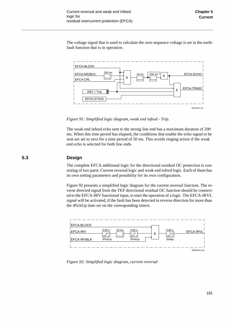
Current reversal and weak end infeed logic for residual overcurrent protection (EFCA)
Chapter 5Current
The voltage signal that is used to calculate the zero sequence voltage is set in the earth-fault function that is in operation.
Figure 91: Simplified logic diagram, weak end infeed - Trip.
The weak end infeed echo sent to the strong line end has a maximum duration of 200 ms. When this time period has elapsed, the conditions that enable the echo signal to be sent are set to zero for a time period of 50 ms. This avoids ringing action if the weak end echo is selected for both line ends.
5.3 Design
The complete EFCA additional logic for the directional residual OC protection is con-sisting of two parts: Current reversal logic and weak end infeed logic. Each of them has its own setting parameters and possibility for its own configuration.
Figure 92 presents a simplified logic diagram for the current reversal function. The re-verse directed signal from the TEF directional residual OC function should be connect-ed to the EFCA-IRV functional input, to start the operation of a logic. The EFCA-IRVL signal will be activated, if the fault has been detected in reverse direction for more than the tPickUp time set on the corresponding timers.
Figure 92: Simplified logic diagram, current reversal
t
200 mst
50 mst
200 ms&&
EFCA-CRL
EFCA-WEIBLK
EFCA-BLOCK
EFCA-ECHO
WEI = Trip
99000056.vsd
&
EFCA-ST3U0
EFCA-TRWEI
t t10 ms0-60 s
t0-60 s
tPickUp tPickUp
&0-60 s
t
tDelay
EFCA-BLOCK
EFCA-IRV
EFCA-IRVBLK
EFCA-IRVL
99000053.vsd
181

Current reversal and weak end infeed logic for residual overcurrent protection (EFCA)
Chapter 5Current
The tDelay timer delays the reset of the output signal, when the current reversal occurs and the fault is detected in the forward direction. This prevents the TEF function to op-erates unnecessarily during the current reversal conditions.
The weak end infeed function can be set to send only an echo signal (WEI=Echo) or an echo signal and a trip signal (WEI=Trip). The function is released with either of the WEI=Echo or WEI=Trip settings in the menu.
The weak end infeed logic uses normally a reverse and a forward directional element, connected to EFCA-WEIBLK via an OR-gate. The weak-end-infeed logic echoes back the received permissive signal, if neither the forward nor the reverse directional mea-suring element is activated during the last 200 ms.
With the Trip setting, the logic sends an echo according to above. Further, it activates the EFCA-TRWEI signal to trip the breaker if the echo conditions are fulfilled and the residual voltage is above the set operate value for 3U0>.
5.4 Calculations
5.4.1 Setting
The settings are done from the local HMI under the menu:
Settings
Functions
Group n (n = 1..4)
Earth Fault
ComIRevWeiEF
Current reversal
The Current-reversal function is set on and off by setting the parameter CurrRev = On/Off. Time delays shall be set for the timers tPickUp and tDelay.
tPickUp is chosen shorter (<80%) than the breaker opening time, but minimum 20 ms.
tDelay is chosen at a minimum to the sum of protection reset time and the communica-tion reset time. A minimum tDelay setting of 40 ms is recommended.
Weak end infeed
The weak end infeed can either be set off or to echo or trip by setting the parameter WEI = Off/Echo/Trip. (Echo = Echo, Trip = Echo + Trip). Operate zero sequence voltage for WEI trip is set with Ugr = xx % of Ub.
182

Current reversal and weak end infeed logic for residual overcurrent protection (EFCA)
Chapter 5Current
The zero sequence voltage for a fault at the remote line end and appropriate fault resis-tance is calculated.
To avoid unwanted trip from the weak end infeed logic (if spurious carrier signals should occur), set the operate value of the broken delta voltage level detector (3U0) higher than the maximum false network frequency residual voltage that can occur dur-ing normal service conditions. The recommended minimum setting is two times the false zero-sequence voltage during normal service conditions.
183

Current reversal and weak end infeed logic for residual overcurrent protection (EFCA)
Chapter 5Current
184

About this chapter Chapter 6Voltage
Chapter 6 Voltage
About this chapter
This chapter describes the voltage protection functions.
185

Time delayed undervoltage protection (TUV)
Chapter 6Voltage
1 Time delayed undervoltage protection (TUV)
1.1 Application
Undervoltage protection prevents the sensitive elements from running under conditions that could cause their overheating and thus shorten their life expectancy below the eco-nomical limits. In many cases, it is a useful tool in circuits for local or remote automa-tion processes in the power system.
1.2 Design
The voltage measuring elements within one of the built-in digital signal processors con-tinuously measure the phase-to-neutral voltages in all three phases. Recursive Fourier filter filters the input voltage signals and a separate trip counter prevents high over-reaching or underreaching of the measuring elements.
1.3 Calculations
The parameters for the undervoltage protection are set on the local HMI under the menu:
Settings
Functions
Group n (n = 1...4)
TimeDelayUV
All the voltage conditions in the system where the undervoltage protection performs its functions should be considered. The same also applies to the associated equipment, its voltage and time characteristic.
186

Time delayed overvoltage protection (TOV)
Chapter 6Voltage
2 Time delayed overvoltage protection (TOV)
2.1 Application
The application areas of the overvoltage protection functions are different in distribu-tion and transmission networks.
The overvoltage protection is used to protect the equipment and its insulation against overvoltage. In this way it prevents damage to the equipment in the power system and shortening of their life time.
2.2 Functionality
The phase overvoltage protection function continuously measures the three phase volt-ages and initiates the corresponding output signals if the measured phase voltages ex-ceed the preset value (starting) and remain high longer than the time delay setting on the timers (trip). This function also detects the phases which caused the operation.
2.3 Design
Figure 93 shows a simplified logic diagram of the overvoltage protection function. The time delayed residual overvoltage protection and the time delayed overvoltage protec-tion share some input signals and logical elements. For this reason and for the sake of better overview both the protections are shown in the figure.
187

Time delayed overvoltage protection (TOV)
Chapter 6Voltage
Figure 93: Time delayed overvoltage protection - simplified logic diagramen01000187.vsd
TOV--BLKTR
TOV--BLOCK
TOV--TEST
Block TOV=Yes
TOV--STUL1N
TOV--STUL2N
TOV--STUL3N
&
&
TOV--TRIP
TOV--TRPE
TOV--STPE
TOV--STL1
TOV--STL2
TOV--STL3
TEST
&
&
&
TOV--ST3UO & &
TOV--STN
TOV--TRN
≥1
t
t
≥1
≥1
188

Time delayed overvoltage protection (TOV)
Chapter 6Voltage
Figure 94: Logic diagram, time delayed overvoltage protection, phase wise
The TOV--TRIP and TOV--TRPE output signals changes from logical 0 to logical 1 if at least one of the logical signals TOV--STUL1N, TOV--STUL2N, TOV--STUL3N re-mains equal to logical 1 for a time longer than the set value on the corresponding timer. The signal TOV--TRPE will be high, to indicate that the overvoltage protection caused the trip
Any signal connected to the TOV--BLOCK input blocks the operation of the time de-layed overvoltage protection. Similarly any signal connected to TOV--BLKTR will block the trip output from the time delayed overvoltage protection.
en01000088.vsd
TOV--BLKTR
TOV--BLOCK
TOV--TEST
Block TOV=Yes
TOV--STUL1N
TOV--STUL2N
TOV--STUL3N
&
&
TOV--TRIP
TOV--TRPE
TOV--STPE
TOV--STL1
TOV--STL2
TOV--STL3
TEST
&
&
&
t≥1
≥1
189

Time delayed overvoltage protection (TOV)
Chapter 6Voltage
2.4 Calculations
2.4.1 Setting
The time delayed overvoltage protection parameters can be set on the local HMI under the menu:
Settings
Functions
Group n (n = 1...4)
TimeDelayOV
All the voltage conditions in the system where the overvoltage protection performs its functions must be considered. The same also applies to the associated equipment, its voltage-time characteristic.
The overvoltage protection should be set higher than the expected maximum system op-erate voltage that is in a particular part of a network. A safety margin of at least 10% should also be considered due to the inaccuracies in the instrument transformers, calcu-lation methods, and the inaccuracy of the measuring elements in the terminal.
190

About this chapter Chapter 7Secondary system supervision
Chapter 7 Secondary system supervision
About this chapter
This chapter describes the secondary system supervision functions.
191

Fuse failure supervision (FUSE) Chapter 7Secondary system supervision
l pro-calcu-
1 Fuse failure supervision (FUSE)
1.1 Application
Different protection functions within the REx 5xx protection, control and monitoring terminals operate on the basis of the measured voltage in the relay point. Examples are: distance protection function, undervoltage measuring function and voltage check for the weak infeed logic.
These functions can operate unnecessarily if a fault occurs in the secondary circuits be-tween the voltage instrument transformers and the terminal.
It is possible to use different measures to prevent such unwanted operations. Miniature circuit breakers in the voltage measuring circuits, located as close as possible to the voltage instrument transformers, are one of them. Separate fuse-failure monitoring re-lays or elements within the protection and monitoring devices are another possibilities. These solutions are combined to get the best possible effect in the fuse failure supervi-sion function (FUSE) of REx 5xx terminals.
The fuse-failure supervision function as built into the REx 5xx terminals can operate on the basis of external binary signals from the miniature circuit breaker or from the line disconnector. The first case influences the operation of all voltage-dependent functions while the second one does not affect the impedance measuring functions.
The zero sequence detection algorithm, based on the zero sequence measuring quanti-ties, a high value of voltage 3·U0 without the presence of the residual current 3·I0, is recommended for terminals used in directly or low impedance earthed networks.
1.2 Functionality
Zero sequence
The current and voltage measuring elements within one of the built-in digital signacessors continuously measure the currents and voltages in all three phases and late:
• The zero-sequence current 3·I0
• The zero-sequence voltage 3·U0
comparing them with their respective set values 3I0< and 3U0>.
192

Fuse failure supervision (FUSE) Chapter 7Secondary system supervision
RO is he zero
Fourier’s recursive filter filters the current and voltage signals, and a separate tripcounter prevents high overreaching of the measuring elements. The signal STZEset to 1, if the zero sequence measured voltage exceeds its set value 3U0> and if tsequence measured current does not exceed its pre-set value 3I0<.
193
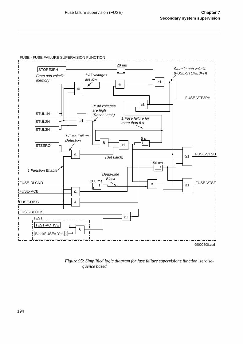
Fuse failure supervision (FUSE) Chapter 7Secondary system supervision
Figure 95: Simplified logic diagram for fuse failure supervisione function, zero se-quence based
Store in non volatile(FUSE-STORE3PH)
FUSE-BLOCK
FUSE-VTSU
99000500.vsd
FUSE - FUSE FAILURE SUPERVISION FUNCTION
TEST-ACTIVE&
TEST
BlockFUSE= Yes
STZERO
&
FUSE-VTSZ
FUSE-VTF3PH
FUSE-MCB
FUSE-DISC
&
&
t150 ms
FUSE-DLCNDt
200 ms
t5 s
&
STUL3N
STUL2N
STUL1N
&&
STORE3PH20 ms
1:All voltagesare low
From non volatilememory
0: All voltagesare high(Reset Latch)
1:Fuse failure formore than 5 s
Dead-LineBlock
(Set Latch)
1:Function Enable
1:Fuse FailureDetection
≥1
≥1
&
≥1
≥1
≥1
≥1
≥1
194

Fuse failure supervision (FUSE) Chapter 7Secondary system supervision
een
su- re-
ther ter-rnal
the cir-
the
asur-nce
func-
rder rop-ant-
main
tage unc-
Logic
Signals STUL1N, STUL2N and STUL3N are related to phase to earth voltages and be-come 1 when the respective phase voltage is lower than the set value. The set value (U<) is chosen in the dead line detection function, that is always present in the terminal when the fuse failure supervision is present.
The fuse failure supervision function is disabled (blocked) if:
• The terminal is in TEST status (TEST-ACTIVE is high) and the function has bblocked from the HMI (BlockFUSE=Yes)
• The input signal FUSE-BLOCK is high
The FUSE-BLOCK signal is a general purpose blocking signal of the fuse failurepervision function. It can be connected to a binary input of the terminal in order toceive a block command from external devices or can be software connected to ointernal functions of the terminal itself in order to receive a block command from innal functions. Through OR gate it can be connected to both binary inputs and intefunction outputs.
Function input signal FUSE-MCB is to be connected via a terminal binary input toN.C. auxiliary contact of the miniature circuit breaker protecting the VT secondarycuit.
Function input signal FUSE-DISC is to be connected via a terminal binary input toN.C. auxiliary contact of the line disconnector.
The function output FUSE-VTSU can be used for blocking the voltage related meing functions (undervoltage protection, synchrocheck etc.) except for the impedaprotection.
Function output FUSE-VTSZ can be used for blocking the impedance protection tion.
The FUSE-MCB signal sets the output signals FUSE-VTSU and FUSE-VTSZ in oto block all the voltage related functions when the MCB is open. The additional doff timer of 150 ms prolongs the presence of FUSE-MCB signal to prevent the unwed operation of voltage dependent function due to non simultaneous closing of thecontacts of the miniature circuit breaker.
The FUSE-DISC signal sets the output signal FUSE-VTSU in order to block the volrelated functions when the line disconnector is open. The impedance protection ftion is not affected by the position of the line disconnector.
195

Fuse failure supervision (FUSE) Chapter 7Secondary system supervision
The function input signal FUSE-DLCND is related to the dead line condition detection. It has to be connected to the output signal of the dead line condition function DLD-STPH (dead phase condition detected). This signal is activated from the dead line con-dition function when the voltage and the current in at least one phase are below their respective setting values. It prevents the blocking of the impedance protection by a fuse failure detection during dead line condition (that occurs also during single pole auto-reclosing). The 200 ms drop-off timer prolongs the dead line condition after the line-energization in order to prevent the blocking of the impedance protection for unequal pole closing.
If a fuse failure condition is detected, the signal FUSE-VTSU is turned high, and if there is no dead line condition also FUSE-VTSZ is high. If the fuse failure condition remains for more then five seconds and at least one of the phases has a low phase to earth volt-age, then the fuse failure condition is latched.
The output signal FUSE-VTF3PH is high if the fuse failure condition is detected for 5 seconds and all the three measured voltages are low (STUL1N = STUL2N = STUL3N = 1).
Fuse failure condition is unlatched when the normal voltage conditions are restored (STUL1N = STUL2N = STUL3N = 0).
Fuse failure condition is stored in the non volatile memory of the terminal. In the new start-up procedure the terminal checks the VTF3PH (STORE3PH) value in its non vol-atile memory and establishes the corresponding starting conditions.
1.3 Calculations
The operating value for the voltage check function (signals STUL1N, STUL2N, STUL3N) is the same as the operating value of the dead line detection function. The setting of the voltage minimum operating value U< occurs under the submenu:
196

Fuse failure supervision (FUSE) Chapter 7Secondary system supervision
Settings
Functions
Group n
DeadLineDet
Zero sequence function
The zero sequence voltages and currents always exist due to different non-symmetries in the primary system and differences in the current and voltage instrument transform-ers. The minimum value for the operation of the current and voltage measuring ele-ments must always be set with a safety margin of 10 to 15%, depending on the system operating conditions.
Pay special attention to the dissymmetry of the measuring quantities when the function is used on longer untransposed lines, on multi circuit lines and so on.
Setting of zero sequence voltage 3U0>
The relay setting value 3U0> is given in percentage of the secondary base voltage value, U1b, associated to the voltage transformer input U1. If UsSEC is the secondary setting value of the relay, then the value for 3U0> is given from equation 145.
(Equation 145)
Set this value under the setting menu:
Settings
Functions
Group n
FuseFailure
on the value 3U0>.
Setting of zero sequence current 3I0<
The relay setting value 3I0< is given in percentage of the secondary base current value, I1b, associated to the current transformer input I1. If IsSEC is the secondary setting val-ue of the relay, then the value for 3I0< is given from equation 146.
3U0>UsSEC
U1b------------------ 100⋅=
197

Fuse failure supervision (FUSE) Chapter 7Secondary system supervision
(Equation 146)
Set this value under the setting menu:
Settings
Functions
Group n
FuseFailure
on the value 3I0<.
3I0<IsSEC
I1b--------------- 100⋅=
198

About this chapter Chapter 8Control
Chapter 8 Control
About this chapter
This chapter describes the control functions.
199

Automatic reclosing function (AR) Chapter 8Control
1 Automatic reclosing function (AR)
1.1 Application
Automatic reclosing (AR) is a well-established method to restore the service of a power line after a transient line fault. The majority of line faults are flashover arcs, which are transient by nature. When the power line is switched off by operation of line protection and line breakers, the arc de-ionises and recovers voltage withstand at a somewhat vari-able rate. So a certain line dead time is needed. But then line service can resume by the auto-reclosing of the line breakers. Select the length of the dead time to enable good probability of fault arc de-ionisation and successful reclosing.
For the individual line breakers and auto-reclosing equipment, the Auto-reclose open time (AR open time) expression is used. At simultaneous tripping and reclosing at the two line ends, Auto-reclose open time equals approximaltely the dead time of the line. Otherwise these two times may differ.
In case of a permanent fault, the line protection trips again at reclosing to clear the fault.
200

Automatic reclosing function (AR) Chapter 8Control
Figure 96: Single-shot auto-reclosing at a permanent fault
In a bay with one circuit breaker only one terminal is normally provided with one AR function.
Single-phase tripping and single-phase reclosing is a way to limit the effect of a single-phase line fault to system operation. Especially at higher voltages, the majority of line faults are of the single-phase type. The method is of particular value to maintain system stability in systems with limited meshing or parallel routing. It requires individual op-eration of each phase of the breakers, which is common at the higher transmission volt-ages.
A somewhat longer dead time may be required at single-phase reclosing compared to high-speed three-phase reclosing, due to influence on the fault arc from voltage and cur-rent of the non-tripped phases.
Open
Closed
Operate time
Lineprotection
Circuitbreaker
Break time
Trip
com
man
d
Con
tact
s se
para
ted
Are
ext
ingu
ishe
rs
Fault duration AR open time for breaker Fault duration
Res
ets
Inst
at o
f fau
lt
Ope
rate
s
Break timeClosing time
Operate time
Fau
lt
Ope
rate
s
Res
ets
Clo
se c
omm
and
Con
tact
clo
sed
Set AR open time Reclaim timeAuto-reclosing
function
Sta
rt A
R
Rec
losi
ngco
mm
and
AR
res
et
99000118.vsd
201

Automatic reclosing function (AR) Chapter 8Control
tem. idual clos-
three-ee-
auto-eed
on-ose input ns).
ction
eter ON
There is also a possibility to trip and reclose two of the circuit breaker poles, in case of faults when two out of the three phases are involved and parallel lines are in service. This type of faults is less common compared to single phase to earth faults, but more common than three phase faults.
In order to maximize the availability of the power system there is a possibility to chose single pole tripping and auto-reclosing at single phase faults, two pole tripping and auto-reclosing at faults involving two phases and three pole tripping and auto-reclosing at three phase faults.
During the single pole open time there will be an equivalent “series”-fault in the sysAs a consequence there will be a flow of zero sequence current. Therefor the rescurrent protections must be co-ordinated with the single pole tripping and auto-reing.
The reclosing function can be selected to perform single-phase, two-phase and/orphase reclosing from six single-shot to multiple-shot reclosing programs. The thrphase auto-reclose open time can be set to give either high-speed auto-reclosing(HSAR) or delayed auto-reclosing (DAR). In the reclosing programs the delayed reclosing (DAR) is always a three pole trip and reclosing, even if the first high-spreclosing is a single pole action.
1.2 Functionality
The AR function is a logical function built up from logical elements. It operates in cjunction with the trip output signals from the line protection functions, the OK to cloutput signals from the synchrocheck and energizing check function, and binary signals (for circuit breaker position/status, or from other external protection functio
In the AR logic a number of parameters can be set to adjust the auto-reclosing funto the desired requirements. Examples are:
• Number of AR attempts
• AR programs
• Open times for different AR attempts
Start and control of the auto-reclosing
The automatic operation of the auto-reclosing function is controlled by the paramOperation and the input signals as described above. When it is on, the AR01-SEToutput is high (active). See Function block diagrams.
202

Automatic reclosing function (AR) Chapter 8Control
The auto-reclosing function is activated at a protection trip by the AR01-START input signal. At repeated trips, this signal is activated again to make the reclosing program continue.
There are a number of conditions for the start to be accepted and a new cycle started. After these checks, the start signal is latched in and the Started state signal is activated. It can be interrupted by certain events.
Extended AR open time, shot 1
The purpose of this function is to adapt the length of the AR Open time to the possibility of non-simultaneous tripping at the two line ends. If a permissive communication scheme is used and the permissive communication channel (for example, PLC, power-line carrier) is out of service at the fault, there is a risk of sequential non-simultaneous tripping. To ensure a sufficient line dead time, the AR open time is extended by 0.4 s. The input signal AR01-PLCLOST is checked at tripping. See Function block diagrams. Select this function (or not) by setting the Extended t1 parameter to On (or Off).
Long trip signal
During normal circumstances, the trip command resets quickly due to fault clearing. The user can set a maximum trip pulse duration by tTrip. At a longer trip signal, the AR open dead time is extended by Extend_t1. If the Extended t1 = Off, a long trip signal interrupts the reclosing sequence in the same way as AR01-INHIBIT.
Reclosing programs
The reclosing programs can be performed with up to maximum four reclosing attempts (shots), selectable with the NoOfReclosing parameter. The first program is used at pure 3-phase trips of breakers and the other programs are used at 1-, 2- or 3-phase trips of breakers.
3ph
3-phase reclosing, one to four attempts (NoOfReclosing parameter). The output AR01-P3P is always high (=1).
A trip operation is made as a three-phase trip at all types of fault. The reclosing is as a three-phase reclosing in program 1/2/3ph, described below.
1/2/3ph
1-phase, 2-phase or 3-phase reclosing in the first shot.
For the example, one-shot reclosing for 1-phase, 2-phase or 3-phase, see Figures in Function block diagrams. Here, the AR function is assumed to be On and Ready. The breaker is closed and the operation gear ready (manoeuvre spring charged etc.). Only the 1-phase and 3-phase cases are described.
203

Automatic reclosing function (AR) Chapter 8Control
AR01-START is received and sealed-in at operation of the line protection. The AR01-READY output is reset (Ready for a new AR cycle).
If AR01-TR2P (2-phase trip) is low and AR01-TR3P (3-phase trip) is:
Immediately after the start-up of the reclosing and tripping of the breaker, the input (see Function block diagrams) AR01-CBCLOSED is low (possibly also AR01-CBREADY at type OCO). The AR Open-time timer, t1 1Ph or t1, keeps on running.
At the end of the set AR open time, t1 1Ph or t1, the respective SPTO or TPTO (single-phase or three-phase AR time-out, see Function block diagrams) is activated and goes on to the output module for further checks and to give a closing command to the circuit breaker.
At any kind of trip, the operation is as already described, program 1/2/3ph. If the first reclosing attempt fails, a 3-phase trip will be issued and 3-phase reclosings can follow, if selected. Maximum three additional attempts can be done (according to the NoOfRe-closing parameter).
1/2ph
1-phase or 2-phase reclosing in the first shot.
At 1-phase or 2-phase trip, the operation is as in above described example, program 1/2/3ph. If the first reclosing attempt fails, a 3-phase trip will be issued and 3-phase re-closings can follow, if selected. Maximum three additional attempts can be done (ac-cording to the NoOfReclosing parameter).
At 3-phase trip, TR2P low and TR3P high, the AR will be blocked and no reclosing takes place.
1ph + 1*2ph
1-phase or 2-phase reclosing in the first shot.
low, the timer for 1-phase reclosing open time t1 1Ph is started and the AR01-1PT1 output (auto-reclosing 1-phase, shot 1, in progress) is activated. It can be used to suppress Pole disagreement and Earth-fault protection during the 1-phase open interval.
high, the timer for 3-phase AR open time, t1, is started (instead of t1 1Ph) and AR01-T1 is set (auto-reclosing 3-phase, shot 1, in progress). While either t1 1Ph or t1 is running, the output AR01-INPROGR is activated.
204

Automatic reclosing function (AR) Chapter 8Control
At 1-phase trip (TR2P low and TR3P low), the operation is as in above described ex-ample, program 1/2/3ph. If the first reclosing attempt fails, a 3-phase trip will be issued and 3-phase reclosings can follow, if selected. Maximum three additional attempts can be done (according to the NoOfReclosing parameter).
At 2-phase trip (TR2P high and TR3P low), the operation is similar as above. But, if the first reclosing attempt fails, a 3-phase trip will be issued and the AR will be blocked. No more attempts take place!
At 3-phase trip, TR2P low and TR3P high, the AR will be blocked and no reclosing takes place.
1/2ph + 1*3ph
1-phase, 2-phase or 3-phase reclosing in the first shot.
At 1-phase or 2-phase trip, the operation is as described above. If the first reclosing at-tempt fails, a 3-phase trip will be issued and 3-phase reclosings can follow, if selected. Maximum three additional attempts can be done (according to the NoOfReclosing pa-rameter).
At 3-phase trip, the operation is similar as above. But, if the first reclosing attempt fails, a 3-phase trip will be issued and the AR will be blocked. No more attempts take place!
1ph + 1*2/3ph
1-phase, 2-phase or 3-phase reclosing in the first shot.
At 1-phase trip, the operation is as described above. If the first reclosing attempt fails, a 3-phase trip will be issued and 3-phase reclosings can follow, if selected. Maximum three additional attempts can be done (according to the NoOfReclosing parameter).
At 2-phase or 3-phase trip, the operation is similar as above. But, if the first reclosing attempt fails, a 3-phase trip will be issued and the AR will be blocked. No more attempts take place!
Table 9: Type of reclosing for different programs
Program 1st attempt 2-4th attempt
3ph 3ph 3ph
1/2/3ph 1ph 3ph
2ph 3ph
3ph 3ph
1/2ph 1ph 3ph
205
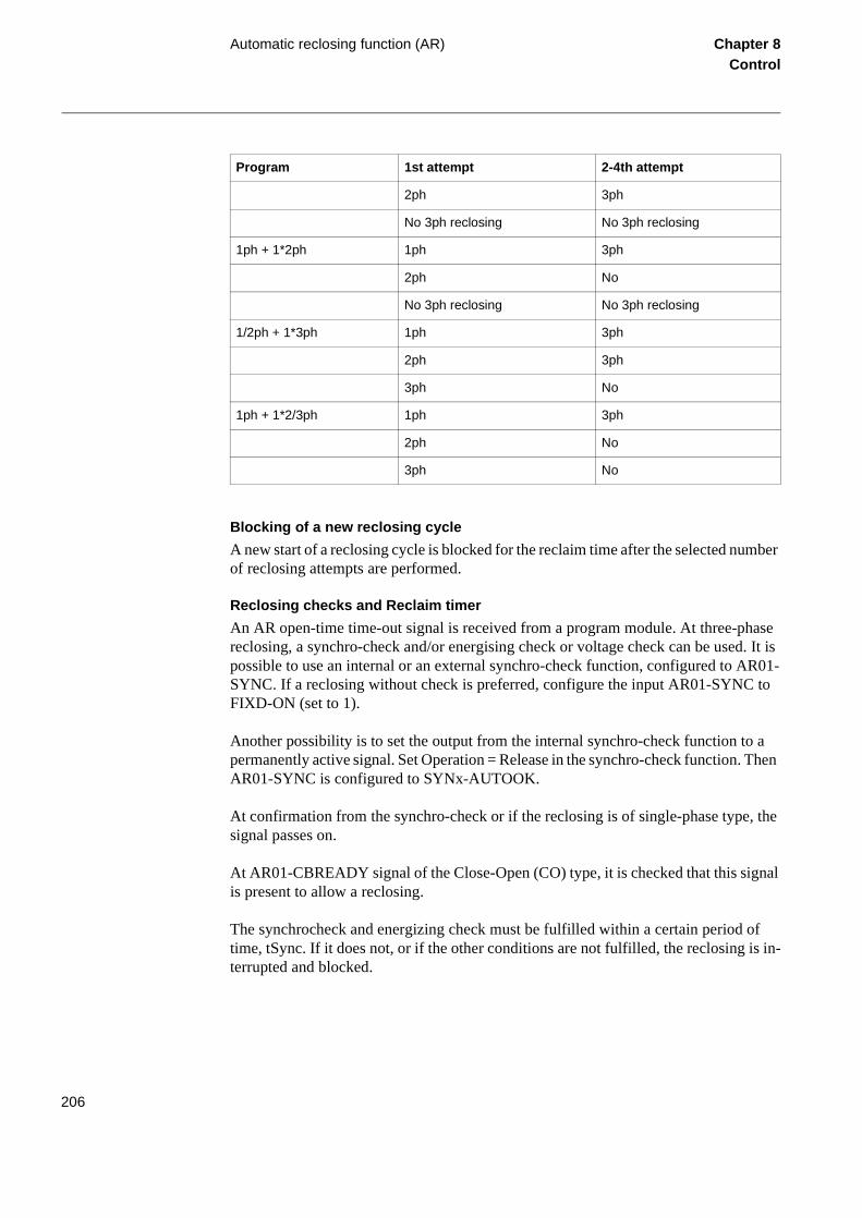
Automatic reclosing function (AR) Chapter 8Control
Blocking of a new reclosing cycle
A new start of a reclosing cycle is blocked for the reclaim time after the selected number of reclosing attempts are performed.
Reclosing checks and Reclaim timer
An AR open-time time-out signal is received from a program module. At three-phase reclosing, a synchro-check and/or energising check or voltage check can be used. It is possible to use an internal or an external synchro-check function, configured to AR01-SYNC. If a reclosing without check is preferred, configure the input AR01-SYNC to FIXD-ON (set to 1).
Another possibility is to set the output from the internal synchro-check function to a permanently active signal. Set Operation = Release in the synchro-check function. Then AR01-SYNC is configured to SYNx-AUTOOK.
At confirmation from the synchro-check or if the reclosing is of single-phase type, the signal passes on.
At AR01-CBREADY signal of the Close-Open (CO) type, it is checked that this signal is present to allow a reclosing.
The synchrocheck and energizing check must be fulfilled within a certain period of time, tSync. If it does not, or if the other conditions are not fulfilled, the reclosing is in-terrupted and blocked.
2ph 3ph
No 3ph reclosing No 3ph reclosing
1ph + 1*2ph 1ph 3ph
2ph No
No 3ph reclosing No 3ph reclosing
1/2ph + 1*3ph 1ph 3ph
2ph 3ph
3ph No
1ph + 1*2/3ph 1ph 3ph
2ph No
3ph No
Program 1st attempt 2-4th attempt
206

Automatic reclosing function (AR) Chapter 8Control
The Reclaim-timer defines a period from the issue of a reclosing command, after which the reclosing function is reset. Should a new trip occur within this time, it is treated as a continuation of the first fault. When a closing command is given (Pulse AR), the re-claim timer is started.
There is an AR State Control, see Function block diagrams, to track the actual state in the reclosing sequence.
Pulsing of CB closing command
The circuit breaker closing command, AR01-CLOSECB, is made as a pulse with a du-ration, set by the tPulse parameter. For circuit breakers without an anti-pumping func-tion, the closing-pulse-cutting described below can be used. It is selected by means of the CutPulse parameter (set to On). In case of a new trip pulse, the closing pulse will be cut (interrupted). But the minimum length of the closing pulse is always 50 ms.
At the issue of a reclosing command, the associated reclosing operation counter is also incremented. There is a counter for each type of reclosing and one for the total number of reclosings. See Function block diagrams.
Transient fault
After the reclosing command, the reclaim timer keeps running for the set time. If no tripping occurs within this time, tReclaim, the auto-reclosing function will be reset. The circuit breaker remains closed and the operating gear ready (manoeuvre spring is re-charged). AR01-CBCLOSED = 1 and AR01-CBREADY = 1.
After the reclaim time, the AR state control resets to original rest state, with AR01-SE-TON = 1, AR01-READY = 1 and AR01-P1P = 1 (depending on the selected program). The other AR01 outputs = 0.
Unsuccessful signal
Normally the signal AR01-UNSUC appears when a new start is received after the last reclosing attempt has been made. See Function block diagrams. It can be programmed to appear at any stage of a reclosing sequence by setting the parameter UnsucMode = On. The UNSUC signal is attained after the time tUnsuc.
Permanent fault
If a new trip takes place after a reclosing attempt and a new AR01-START or AR01-TRSOTF signal appears, the AR01-UNSUC (Reclosing unsuccessful) is activated. The timers for the first reclosing attempt (t1 1Ph, t1 2Ph and t1) cannot be started.
Depending on the PulseCut parameter setting, the closing command may be shortened at the second trip command.
207

Automatic reclosing function (AR) Chapter 8Control
After time-out of the reclaim timer, the auto reclosing function resets, but the circuit breaker remains open (AR01-CBCLOSED = 0, AR01-CBREADY = 1). Thus the re-closing function is not ready for a new reclosing cycle. See Function block diagrams and Sequence examples.
Automatic confirmation of programmed reclosing attempts
The auto-recloser can be programmed to continue with reclosing attempts two to four (if selected) even if the start signals are not received from the protection functions, but the breaker is still not closed. See figure in Function block diagrams. This is done by setting the parameter AutoCont = On and the wait time tAutoWait to desired length.
208

About this chapter Chapter 9Logic
Chapter 9 Logic
About this chapter
This chapter describes the logic functions.
209

Trip logic (TR) Chapter 9Logic
for tions
h auto-
1 Trip logic (TR)
1.1 Application
All trip signals from the different protection functions shall be routed through the trip logic. In its most simple alternative the logic will only link the trip signal and assure a sufficient duration of the trip signal.
To meet the different single, double, 1 and 1/2 or other multiple circuit breaker arrange-ments, one or more identical TR function blocks may be provided within a single ter-minal. The actual number of these TR function blocks that may be included within any given terminal depends on the type of terminal. Therefore, the specific circuit breaker arrangements that can be catered for, or the number of bays of a specific arrangement that can be catered for, depends on the type of terminal.
One TR function block should be used for each breaker, if the line is connected to the substation via more than one breaker. Assume that single pole tripping and auto-reclos-ing is used for the line. The breaker chosen as master must in that case have single pole tripping, while the slave breaker could have three pole tripping and auto-reclosing. In case of a permanent fault only one of the breakers has to be operated at the second en-ergising of the fault. In case of a transient fault the slave breaker reclosing is made as a three pole reclosing onto the non-faulted line.
The same philosophy can be used for two-pole tripping and auto-reclosing.
1.2 Functionality
The minimum duration of a trip output signal from the TR function is 150ms. This is to secure the fault clearance.
The three-pole TR function has a single input through which all trip output signals from the protection functions within the terminal, or from external protection functions via one or more of the terminal’s binary inputs, are routed. It has a single trip output connection to one or more of the terminal’s binary outputs, as well as to other funcwithin the terminal requiring this signal.
In case of multi-breaker arrangement, one TR function block can be used for eacbreaker, if the breaker functions differ. This can be the case if single pole trip andreclosing is used.
210

High speed binary output logic (HSBO) Chapter 9Logic
trip on
ith-t re- of is ard ed by
nals are ed). In
ion.
rrect cor-nsfer ular ra-
sive
2 High speed binary output logic (HSBO)
2.1 Application
The high-speed binary out logic (HSBO--) is included as basic and is used as a supple-ment to the high-speed protection function (HS--) and the distance protection zone 1 function (ZM1--) in the REx 5xx terminals.
Depending on the terminal type (actually the set of included functions) the following description will be valid entirely or partly.
Together with the high-speed binary out logic, the high-speed (distance) protection and the (main) distance protection zone 1 obtain even shorter operate times since the critical connections to/from binary output/input are established in a more straightforward way than in the case of using the regular I/O-modules.
The high-speed binary out logic also includes trip scheme logic employing the same ‘fast’ connections. The HSBO trip scheme logic will run in parallel with the regular scheme logic configured within the terminal (ZC1P and ZCOM). In fact, informatifrom these two functions will be used in the HSBO function.
2.2 Functionality
The operation of the high-speed binary out logic overruns all other logical circuits win the terminal and activates, with minimum time delay, the binary outputs (outpulays). The same relays should also be activated by the normal functional outputscorresponding built-in functions (TRIP function, for example). The reason for thisthat the ‘fast’ (phase segregated) outputs of the HSBO function should bring forwan earlier activation of trip and carrier send signals that are supposed to be continuthe regular functions (TRIP, ZC1P and ZCOM function). For example, the trip sigthat are issued by the high-speed protection function through the HSBO function presented as short pulses (20ms) and therefore they need to be extended (continuthe general case, this would be provided for by the intervention of the TRIP funct
The operation is dependent upon other functions within the terminal. To achieve cofunctionality, it is absolutely necessary that all depending functions are configuredrectly, set on and not blocked. With respect to the employed distance protection tratrip scheme the HSBO function will retrieve the necessary information from the regcommunication functions (ZC1P or ZCOM) in order to determine the mode of opetion. The HSBO function will support intertrip, permissive under-reach and permis
211

High speed binary output logic (HSBO) Chapter 9Logic
overreach scheme. There is, however, one exception to the possible use of these schemes. A delayed operation within the communication functions (ZCOM or ZC1P) (i.e. tCoord > 0) is not allowed. In this case the trip scheme logic within the HSBO func-tion should be blocked through activating input HSBO-BLKZCTR. Do not use the de-fault value for tCoord of 50ms.
The main configuration for the function is shown in figure 97 below.
This configuration is made internally and cannot be altered.
212

High speed binary output logic (HSBO) Chapter 9Logic
Figure 97: Simplified diagram of the high-speed binary out logic function together with depending functions
en01000181.vsd
ZC1P-CRLn
ZC1P-CRMPH
ZCOM-CR
BIx
BIy
BIz
....
....
IOxx
HSBO-ZC1PCACCLn
HSBO-CRLn
HSBO-CRMPH
HSBO-BLKZCTR
HSBO-CR
HSBO-ZCOMCACC
HSBO-TRIPPSLn
HSBO-TRLn
HSBO-HSTRLn
HSBO-BLKHSTR
HSBO-HSCSLn
HSBO-HSCSMPH
HSBO-CSLn
HSBO-CSMPH
HSBO
ZC1PZC1P-CACCLn
ZCOM-CACC
TRIP-PSLn
TRIP
ZCOM
HS-TRLn
HS-CSLn
HS-CSMPH
HS
HSBO-BLKHSCS
HSBO-ERROR
BIx
BIy
BIz BOx
BOx
BOy
BOz....
IOxx
BOy
BOz
Binary output contacts
Binary inputs
Regular functionblock in/out
’Internal’ in/out
Fast Trip/CS outputsconfigured through
settings:IOMOD
TRmLnOUTCSLnOUT
CSMPHOUT
&TEST/BLOCK
TEST/BLOCK&
TEST/BLOCK&
HSBO-ZM1TRLnZM1-TRLn
ZM1
213

High speed binary output logic (HSBO) Chapter 9Logic
e
nput on-r the ust
that
the
n-
-,
y out-ing nd
om and eters
r-AP
ast’ t
According to the presented ‘internal’ configuration input will be brought in from thHS, ZM1, ZC1P, ZCOM and TRIP functions.
In the case of carrier receive signals, the input will be attained directly from binary ioverriding the binary I/O-modules. This is obtained by means of looking up and cnecting to the input contacts used for the carrier receive inputs of the ZC1P and/oZCOM function. This calls for that the carrier receive inputs of the latter functions mbe connected directly to a binary I/O-module, with nothing in between. In figure 97this is illustrated with ZC1P-CRLn and ZCOM-CR connected to arbitrary binary in(BIx, BIy,...).
The input signals (HSBO-ZC1PCACCLn, HSBO-ZCOMCACC and HSBO-TRIPPSLn) are connected to the inputs on respective function block. This meansthe high-speed binary out logic runs in parallel with those functions. But it is important that the functions are set on so the signals are received with true values. Otherwise, logic can malfunction. Note that these signals can be blocked in the function fromwhere they originate.
Similarly, input signals HSBO-HSTRLn, HSBO-CSLn and HSBO-HSCSMPH areconnected to the output of the HS function. Input signals HSBO-ZM1TRLn are conected to the output of the ZM1 function.
Shown connections to in and outputs of the other function blocks (ZC1P-, ZCOMTRIP-, HS- and ZM1-) can not be reconfigured. They are so called hard connections in the software and done during manufacturing.
The output signals (trip and carrier send) must be configured to appropriate binarput contacts during engineering. This is done through configuring the correspondparameters of the HSBO-function in CAP 531 (IOMOD, TRmLnOUT, CSLnOUT aCSMPHOUT).
It should be noted that trip output from the HSBO-function can be issued either frthe HS-function or the ZM1-function, or both in parallel, dependin on terminal type setting. As specified above the common trip outputs are configured through paramTRmLnOUT.
The blocking input signals (HSBO-BLKZCTR, -BLKHSTR and -BLK-HSCS) are nomal function input signals. The configuration is done with the configuration tool C531 as usual.
The error output signal (HSBO-ERROR) indicates if the present configuration of ‘ftrip and carrier send output does not correspond to actual hardware (binary outpucards). The signal can be used for indication or as wanted.
214
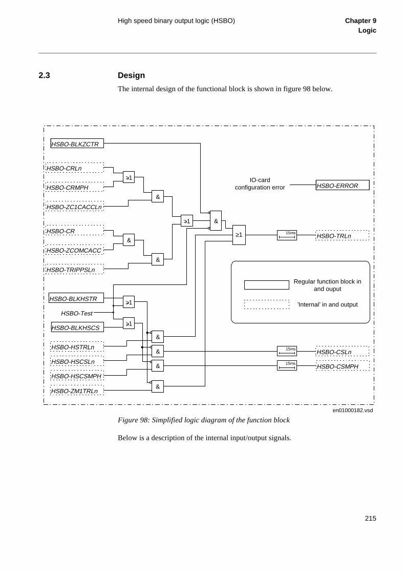
High speed binary output logic (HSBO) Chapter 9Logic
2.3 Design
The internal design of the functional block is shown in figure 98 below.
Figure 98: Simplified logic diagram of the function block
Below is a description of the internal input/output signals.
en01000182.vsd
IO-cardconfiguration error
HSBO-Test
Regular function block inand ouput
’Internal’ in and output
&
HSBO-HSCSMPH
HSBO-HSCSLn
HSBO-HSTRLn&
&
HSBO-BLKHSCS
HSBO-BLKHSTR
HSBO-CR
HSBO-ZCOMCACC
HSBO-TRIPPSLn
&
&
>1
&
>1
HSBO-ZC1CACCLn
HSBO-CRMPH
HSBO-CRLn
HSBO-BLKZCTR
HSBO-TRLn
HSBO-ERROR
HSBO-CSLn
HSBO-CSMPH
15ms
15ms
15ms
>1
>1
&
HSBO-ZM1TRLn&
≥1
215

High speed binary output logic (HSBO) Chapter 9Logic
Configuration parameters
Input signals:
HSBO-CRLn Carrier receive signal, for phase n (n=1..3), connected to the binary input.
These inputs use the same signals as the inputs to the communication logic ZC1P-.
HSBO-CRMPH A carrier receive signal, multi-phase, connected to a binary input. It uses
the same signal as the input to the communication logic ZC1P-.
HSBO-ZC1PCACCLn
Carrier acceleration signals, for phase n (n=1..3). They are connected internally to the input of the communication logic ZC1P- and cannot be
redirected.
HSBO-CR A carrier receive signal connected to a binary input, already connected to the corresponding input of the communication logic ZCOM-.
HSBO-ZCOM-CACC
A carrier acceleration signal. Is a hard connection to the input of the com-munication logic ZCOM-.
HSBO-TRIPPSLn Phase selection signal, selected phase n (n=1..3). Is a hard connection to
the input of the trip function block TRIP-.
HSBO-ZM1TRLn Trip signal, of phase n (n=1..3). Is a hard connection to the output of the distance protection zone 1 function block ZM1-.
HSBO-HSTRLn Trip signal, of phase n (n=1..3). Is a hard connection to the output of the high-speed function block HS---.
HSBO-HSCSLn Carrier send signals, of phase n (n=1..3). Is a hard connection to the out-
put of the high-speed function block HS---.
HSBO-HSCSMPH A carrier send signal, multi-phase. Is a hard connection to the output of the high-speed function block HS---.
216

High speed binary output logic (HSBO) Chapter 9Logic
Status of the output signals can be viewed on the local HMI under menu:
ServiceReport
Functions
Impedance
HighSpeedBO
FuncOutputs
Here, the signals are designated:
Output signals:
IOMOD Parameter for selecting the binary out card supposed to transfer the ‘fast’
outputs of the HSBO function.
TRmLnOUT Parameter for selecting the specific binary output contact intended for trip signal m of phase n. m is either 1 or 2. Both the ‘TR1LnOUT-output’ and
‘TR2LnOUT-output’ carry the same signal, for a possible double-breaker arrangement. It is recommended that these trip outputs are configured to the same contacts as the corresponding regular trip outputs (of the TRIP
function). If three-pole trip is required all three trip outputs should be con-figured to the same contact (i.e. TRxL1OUT=TRxL2OUT=TRxL3OUT). Consider that the trip signals can be issued from the HS function and/or
the ZM1 function.
CSLnOUT Parameter for selecting the specific binary output contact intended for carrier send signal of phase n. Like in the trip output case above, it is rec-
ommended that these carrier send outputs are configured to the same contacts as the corresponding regular carrier send outputs (of the ZC1P or ZCOM function).
CSMPHOUT Parameter for selecting the specific binary output contact intended for the multi-phase carrier send signal. If it is applicable, connect it to the same contact as the regular multi-phase carrier send signal (of the ZC1P func-
tion).
HSBO-TRLn
HSBO-CSLn
HSBO-CSMPH
217

Event function (EV) Chapter 9Logic
3 Event function (EV)
3.1 Application
When using a Substation Automation system, events can be spontaneously sent or polled from the terminal to the station level. These events are created from any available signal in the terminal that is connected to the event function block. The event function block can also handle double indication, that is normally used to indicate positions of high-voltage apparatuses. With this event function block, data also can be sent to other terminals over the interbay bus.
3.2 Functionality
The events can be created from both internal logical signals and binary input channels. The internal signals are time tagged in the main processing module, while the binary input channels are time tagged directly on each I/O module. The events are produced according to the set event masks. The event masks are treated commonly for both the LON and SPA channels. All events according to the event mask are stored in a buffer, which contains up to 1000 events. If new events appear before the oldest event in the buffer is read, the oldest event is overwritten and an overflow alarm appears.
The outputs from the event function block are formed by the reading of status and events by the station HMI on either every single input or double input. The user-defined name for each input is intended to be used by the station HMI.
Twelve of the event function blocks are executed with fast cyclicity. That means that the time-tagging resolution on the events that are emerging from internal logical sig-nals, created from configurable logic, is the same as the cyclicity of this logic. The time tagging resolution on the events that are emerging from binary input signals have a res-olution of 1 ms.
Two special signals for event registration purposes are available in the terminal, Termi-nal restarted and Event buffer overflow.
3.3 Design
General
As basic, 12 event function blocks EV01-EV12 running with a fast cyclicity, are avail-able in REx 5xx. When the function Apparatus control is included in the terminal, ad-ditional 32 event function blocks EV13-EV44, running with a slower cyclicity, are available.
218

Event function (EV) Chapter 9Logic
ich
unc-ndard
xam-scon-n the e the tes.
nder
on the
Each event function block has 16 connectables corresponding to 16 inputs INPUT1 to INPUT16. Every input can be given a name with up to 19 characters from the CAP 531 configuration tool.
The inputs can be used as individual events or can be defined as double indication events.
The inputs can be set individually from the Parameter Setting Tool (PST) under the Mask-Event function as:
• No events
• OnSet, at pick-up of the signal
• OnReset, at drop-out of the signal
• OnChange, at both pick-up and drop-out of the signal
Also an input PrColxx (xx=01-44) is available on the function block to define on whprotocol the events shall be sent.
The event function blocks EV01-EV06 have inputs for information numbers and ftion type, which are used to define the events according to the communication staIEC 60870-5-103.
Double indication
Double indications are used to handle a combination of two inputs at a time, for eple, one input for the open and one for the close position of a circuit breaker or dinector. The double indication consists of an odd and an even input number. Wheodd input is defined as a double indication, the next even input is considered to bother input. The odd inputs has a suppression timer to suppress events at 00 sta
To be used as double indications the odd inputs are individually set from the SMS uthe Mask-Event function as:
• Double indication
• Double indication with midposition suppression
Here, the settings of the corresponding even inputs have no meaning.
These states of the inputs generate events. The status is read by the station HMIstatus indication for the odd input:
219

Event function (EV) Chapter 9Logic
d to send nsfer nt sed
r-
- via ckup ta, e N the .
d as
e set-
the
• 00 generates an intermediate event with the read status 0
• 01 generates a close event with the read status 1
• 10 generates an open event with the read status 2
• 11 generates an undefined event with the read status 3
Communication between terminals
The BOUND and INTERVAL inputs are available on the event function block.
The BOUND input set to 1 means that the output value of the event block is bounanother control terminal on the LON bus. The event function block is then used to data over the LON bus to other REx 5xx terminals. The most common use is to trainterlocking information between different bays. That can be performed by an evefunction block used as a send block and with a Multiple Command function block uas a receive block. The document Apparatus Control describes how to transfer the in-terlocking information. The configuration of the communication between control teminals is made by the LON Network Tool.
The INTERVAL input is applicable only when the BOUND input is set to 1. The INTERVAL is intended to be used for cyclic sending of data to other control terminalsthe LON bus with the interval time as set. This cyclic sending of data is used as a baof the event-driven sending, which always is performed. With cyclic sending of dathe communication can be supervised by a corresponding INTERVAL input on thMultiple Command function block in another control terminal connected to the LObus. This INTERVAL input time is set a little bit longer than the interval time set on event function block. With INTERVAL=0, only event-driven sending is performed
3.4 Calculations
The event reporting can be set from the PST as:
• Use event masks
• Report no events
• Report all events
Use of event masks is the normal reporting of events, that is, the events are reportedefined in the database.
An event mask can be set individually for each available signal in the terminal. Thting of the event mask can only be performed from the PST.
All event mask settings are treated commonly for all communication channels of terminal.
220

Event function (EV) Chapter 9Logic
bus.
C
d-
D pa-
Report no events means blocking of all events in the terminal.
Report all events means that all events, that are set to OnSet/OnReset/OnChange are re-ported as OnChange, that is, both at set and reset of the signal. For double indications when the suppression time is set, the event ignores the timer and is reported directly. Masked events are still masked.
Parameters to be set for the event function block are:
• T_SUPRyy including the suppression time for double indications.
• NAMEyy including the name for each input.
• PrColxx including the type of protocol for sending the events.
• INTERVAL used for the cyclic sending of data.
• BOUND telling that the block has connections to other terminals over the LON
• FuncTEVx (for EV01-EV06) including the function type for sending events via IE60870-5-103.
• InfoNoyy (for EV01-EV06) including the information number for the events sening via IEC 60870-5-103.
These parameters are set from the CAP 531 configuration tool. When the BOUNrameter is set, the settings of the event masks have no meaning.
221

Event function (EV) Chapter 9Logic
222

About this chapter Chapter 10Monitoring
Chapter 10 Monitoring
About this chapter
This chapter describes the monitoring functions.
223

Disturbance report (DRP) Chapter 10Monitoring
ach ns in-
o-
1 Disturbance report (DRP)
1.1 Application
Use the disturbance report to provide the network operator with proper information about disturbances in the primary network. Continuous collection of system data and, at occurrence of a fault, storing of a certain amount of pre-fault, fault and post-fault da-ta, contributes to the highest possible quality of electrical supply. The stored data can be used for analysis and decision making to find and eliminate possible system and equipment weaknesses.
The function comprises several sub functions enabling different users to access relevant information in a structured way.
1.2 Functionality
The disturbance report is a common name for several facilities to supply the operator with more information about the disturbances in the system. Some of the facilities are basic and some are optional in the different products. For some products not all facilities are available.
The facilities included in the disturbance report are:
• General disturbance information
• Indications
• Event recorder
• Fault locator
• Trip values (phase values)
• Disturbance recorder
The whole disturbance report can contain information for up to 10 disturbances, ewith the data coming from all the parts mentioned above, depending on the optiostalled. All information in the disturbance report is stored in non-volatile flash memries. This implies that no information is lost in case of loss-of-power supply
224
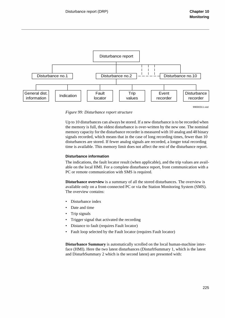
Disturbance report (DRP) Chapter 10Monitoring
-est
Figure 99: Disturbance report structure
Up to 10 disturbances can always be stored. If a new disturbance is to be recorded when the memory is full, the oldest disturbance is over-written by the new one. The nominal memory capacity for the disturbance recorder is measured with 10 analog and 48 binary signals recorded, which means that in the case of long recording times, fewer than 10 disturbances are stored. If fewer analog signals are recorded, a longer total recording time is available. This memory limit does not affect the rest of the disturbance report.
Disturbance information
The indications, the fault locator result (when applicable), and the trip values are avail-able on the local HMI. For a complete disturbance report, front communication with a PC or remote communication with SMS is required.
Disturbance overview is a summary of all the stored disturbances. The overview is available only on a front-connected PC or via the Station Monitoring System (SMS). The overview contains:
• Disturbance index
• Date and time
• Trip signals
• Trigger signal that activated the recording
• Distance to fault (requires Fault locator)
• Fault loop selected by the Fault locator (requires Fault locator)
Disturbance Summary is automatically scrolled on the local human-machine interface (HMI). Here the two latest disturbances (DisturbSummary 1, which is the latand DisturbSummary 2 which is the second latest) are presented with:
Disturbance report
Disturbance no.1 Disturbance no.2 Disturbance no.10
General dist.information
IndicationFault
locatorTrip
valuesEvent
recorderDisturbance
recorder
99000311.vsd
225

Disturbance report (DRP) Chapter 10Monitoring
cator are
r-after
Mon-
mea-eters
ection
the
d after
time-ance
• Date and time
• Selected indications (set with the Indication mask)
• Distance to fault and fault loop selected by the Fault locator
Disturbance data on the HMI is presented at:
DisturbReport/Disturbances/Disturbance n (n=1 - 10)
The date and time of the disturbance, the trigger signal, the indications, the fault loresult and the trip values are available, provided that the corresponding functionsinstalled.
Indications
Indications is a list of signals that were activated during the fault time of the distubance. A part (or all) of these signals are automatically scrolled on the local HMI a disturbance.
Event recorder
The event recorder contains an event list with time-tagged events. In the Station itoring System, this list is directly connected to a disturbance.
Fault locator
The fault locator contains information about the distance to the fault and about thesuring loop that was selected for the calculation. After changing the system paramin the terminal, a recalculation of the distance to the fault can be made in the prot
Trip values
Trip values includes phasors of currents and voltages before the fault and duringfault
Disturbance recorder
The disturbance recorder records analog and binary signal data before, during anthe fault.
Recording times
The disturbance report records information about a disturbance during a settableframe. The recording times are valid for the whole disturbance report. The disturbrecorder and the event recorder register disturbance data and events during tRecording, the total recording time. Indications are only registered during the fault time.
The total recording time, tRecording, of a recorded disturbance is:
226

Disturbance report (DRP) Chapter 10Monitoring
Table 10: Definitions
Figure 100: The recording times definition
Analog signals
Up to 10 analog signals (five voltages and five currents from the transformer module) can be selected for recording and triggering if the disturbance recorder function is in-stalled. If fewer than 10 signals are selected, the maximum storing capacity in the flash memories, regarding total recording time are increased.
A user-defined name for each of the signals can be programmed in the terminal.
tRecording = tPre + tFault + tPost or tPre + tLim, depending on which criterion stops the current disturbance recording
1 Pre-fault or pre-trigger recording time. The time before the fault including the operate time of the trigger. Use the setting tPre to set this time.
2 Fault time of the recording. The fault time cannot be set. It continues as
long as any valid trigger condition, binary or analog, persists (unless limited by tLim the limit time).
3 Post fault recording time. The time the disturbance recording continues
after all activated triggers are reset. Use the setting tPost to set this time.
tLim Limit time. The maximum allowed recording time after the disturbance recording was triggered. The limit time is used to eliminate the conse-
quences of a trigger that does not reset within a reasonable time interval. It limits the maximum recording time of a recording and prevents subsequent overwriting of already stored disturbances.Use the setting tLim to set this
time.
tPre
tLim
tPost
xx00000316.vsd
1 2 3
227

Disturbance report (DRP) Chapter 10Monitoring
For each of the 10 analog signals, Operation = On means that it is recorded by the dis-turbance recorder. The trigger is independent of the setting of Operation, and triggers even if operation is set to Off. Both undervoltage and overvoltage can be used as trigger condition. The same applies for the current signals.
The check of the trigger condition is based on peak-to-peak values. When this is found, the absolute average value of these two peak values is calculated. If the average value is above the threshold level for an overvoltage or overcurrent trigger, this trigger is in-dicated with a greater than (>) sign with the user-defined name.
If the average value is below the set threshold level for an undervoltage or undercurrent trigger, this trigger is indicated with a less than (<) sign with its name. The procedure is separately performed for each channel.
This method of checking the analog start conditions gives a function which is insensi-tive to DC offset in the signal. The operate time for this start is typically in the range of one cycle, 20 ms for a 50 Hz network.
The analog signals are presented only in the disturbance recording, but they affect the entire disturbance report when being used as triggers.
Binary signals
Up to 48 binary signals can be selected from the signal list, where all available signals are grouped under each function. The 48 signals can be selected from internal logical signals and binary input signals. Each of the 48 signals can be selected as a trigger of the disturbance report. It is also possible to set if the trigger should be activated on a logic 1 or a logic 0. A binary signal can be selected to activate the red LED on the local HMI.
A user-defined name for each of the signals can be programmed in the terminal.
The selected 48 signals are presented in the event list and the disturbance recording. But they affect the whole disturbance report when they are used as triggers.
The indications, that are to be automatically scrolled on the HMI when a disturbance has been recorded are also selected from these 48 signals with the HMI Indication Mask.
Trigger signals
The trigger conditions affect the entire disturbance report. As soon as a trigger condition is fulfilled, a complete disturbance report is recorded. On the other hand, if no trigger condition is fulfilled, there is no disturbance report, no calculation of distance to fault, no indications, and so on. This implies the importance of choosing the right signals as trigger conditions.
228

Disturbance report (DRP) Chapter 10Monitoring
cted . This
igger.
ed sig-
d in talled
re-ture
an-
A trigger can be of type:
• Manual trigger
• Binary-signal trigger
• Analog-signal trigger (over/under function)
Manual trigger
A disturbance report can be manually triggered from the local HMI, a front-connePC, or SMS. When the trigger is activated, the manual trigger signal is generatedfeature is especially useful for testing.
Manual trigger from the local HMI is found at:
DisturbReport
ManualTrig
Binary trigger
Any binary signal state (logic one or a logic zero) can be selected to generate a trThe binary signal must remain in a steady state for at least 15 ms to be valid.
When a binary signal is selected to generate a trigger from a logic zero, the selectnal will not be listed in the indications list of the disturbance report.
Analog trigger
All analog signals are available for trigger purposes, no matter if they are recordethe disturbance recorder or not. But the disturbance recorder function must be insin the terminal.
Retrigger
Under certain circumstances the fault condition may reoccur during the postfault cording, for instance by automatic reclosing to a still faulty network. In order to capthe new fault it is possible to allow retriggering during the PostFault recording.
1.3 Calculations
The main part of the settings for the Disturbance Report is found on the local hummachine interface (HMI) at:
229

Disturbance report (DRP) Chapter 10Monitoring
Settings
DisturbReport
The settings include:
User-defined names of analog signals can be set at:
Configuration
AnalogInputs
The user-defined names of binary signals can be set at:
Configuration
DisturbReport
Input n (n=1-48)
The analog and binary signals appear with their user-defined names.
Operation Disturbance Report (On/Off)
ReTrig Re-trigger during post-fault state (On/Off)
SequenceNo Sequence number (0-255) (normally not necessary to set)
RecordingTimes Recording times for the Disturbance Report and the event/indication logging, including pre-fault time, post-fault time, and limit time for the
entire disturbance
BinarySignals Selection of binary signals, trigger conditions, HMI indication mask and HMI red LED option
AnalogSignals Recording mask and trigger conditions
FaultLocator Distance measurement unit (km/miles/%)
km or miles selected under line reference
230
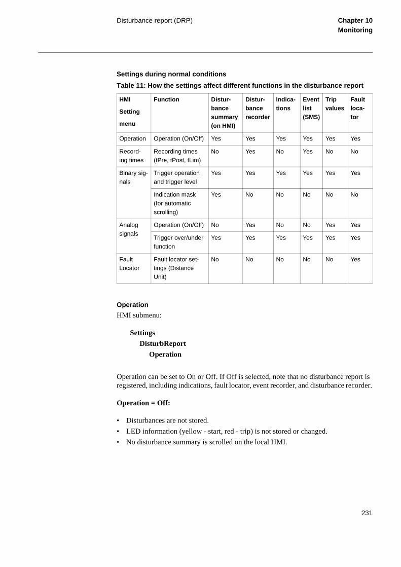
Disturbance report (DRP) Chapter 10Monitoring
Settings during normal conditions
Table 11: How the settings affect different functions in the disturbance report
Operation
HMI submenu:
Settings
DisturbReport
Operation
Operation can be set to On or Off. If Off is selected, note that no disturbance report is registered, including indications, fault locator, event recorder, and disturbance recorder.
Operation = Off:
• Disturbances are not stored.
• LED information (yellow - start, red - trip) is not stored or changed.
• No disturbance summary is scrolled on the local HMI.
HMI
Setting
menu
Function Distur-bance summary (on HMI)
Distur-bance recorder
Indica-tions
Event list (SMS)
Trip values
Fault loca-tor
Operation Operation (On/Off) Yes Yes Yes Yes Yes Yes
Record-ing times
Recording times (tPre, tPost, tLim)
No Yes No Yes No No
Binary sig-
nals
Trigger operation
and trigger level
Yes Yes Yes Yes Yes Yes
Indication mask (for automatic
scrolling)
Yes No No No No No
Analog signals
Operation (On/Off) No Yes No No Yes Yes
Trigger over/under
function
Yes Yes Yes Yes Yes Yes
Fault Locator
Fault locator set-tings (Distance
Unit)
No No No No No Yes
231

Disturbance report (DRP) Chapter 10Monitoring
from
lat-
ber in
will
e until
Operation = On:
• Disturbances are stored, disturbance data can be read from the local HMI anda front-connected PC or Station Monitoring System (SMS).
• LED information (yellow - start, red - trip) is stored.
• The disturbance summary is automatically scrolled on the local HMI for the twoest registered disturbances, until cleared.
Post re-trigger can be set to On or Off
Postretrig = On:
Re-trigger during the set post-fault time is enabled.
Postretrig = Off:
Re-trigger during the set post fault time is not accepted.
Sequence number
HMI submenu:
Settings
DisturbReport
SequenceNo
Normally, this setting option is seldom used. Each disturbance is assigned a numthe disturbance report. The first disturbance each day normally receives SequenceNo = 0. The value of SequenceNo that can be read in the service report is the number that be assigned to the next disturbance registered during that day.
In normal use, the sequence number is increased by one for each new disturbancit is reset to zero each midnight.
Recording times
HMI submenu:
232

Disturbance report (DRP) Chapter 10Monitoring
Settings
DisturbReport
RecordingTimes
Under this submenu, the different recording times for the disturbance report are set (the pre-fault time, post-fault time, and limit time). These recording times affect the distur-bance recorder and event recorder functions. The total recording time, tRecording, of a recorded disturbance is:
Binary signals
HMI submenu:
Configuration
DisturbReport
Input n (n=1-48)
Up to 48 binary signals can be selected from the signal list, where all available signals are grouped function by function. The 48 signals can be selected among internal logical signals and binary input signals. Each selected signal is registered by the disturbance recorder, event recorder, and indication functions during a recording.
A user-defined name for each of the signals can be entered. This name can comprise up to 13 characters.
HMI submenu:
Settings
DisturbReport
BinarySignals
For each of the 48 signals, it is also possible to select if the signal is to be used as a trig-ger for the start of the disturbance report (TrigOperation), and if the trigger should be activated at a logical 1 or 0 level (TrigLevel).
tRecording = tPre + tFault + tPost, or tPre + tLim, depending on which criterion stops the
current disturbance recording.
233

Disturbance report (DRP) Chapter 10Monitoring
The indications in the disturbance summary, that are automatically scrolled on the HMI when a disturbance is registered, are also selected from these 48 signals using the indi-cation mask.
Analog signals
HMI submenu:
Settings
DisturbReport
AnalogSignals
This HMI submenu is only available when the disturbance recorder option is installed. For each of the 10 analog signals (five voltages and five currents), Operation = On means that it is recorded by the disturbance recorder. If fewer than 10 signals are select-ed, the maximum storing capacity in the flash memories for total recording time be-comes longer.
Both undervoltage and overvoltage can be used as trigger condition. The same applies for the current signals. The trigger is independent of the setting of Operation and trig-gers even if Operation = Off.
A user-defined name for each of the signals can be entered. It can consist of up to 13 characters. It is found at:
Configuration
AnalogInputs
Behaviour during test mode
When the terminal is set to test mode, the behaviour of the disturbance report can be controlled by the test mode disturbance report settings Operation and DisturbSumma-ry available on the local HMI under:
Test/Testmode/DisturbReport
The impact of the settings are according to the following table:
234

Disturbance report (DRP) Chapter 10Monitoring
Table 12: Disturbance report settings
Operation Disturb-Summary
Then the results are...
Off Off • Disturbances are not stored.
• LED information is not displayed on the HMI and not stored.
• No disturbance summary is scrolled on the HMI.
Off On • Disturbances are not stored.
• LED information (yellow - start, red - trip) are displayed on the local HMI but not stored in the terminal.
• Disturbance summary is scrolled automatically on the local HMI for the two latest recorded disturbances, until cleared.
• The information is not stored in the terminal.
On On or Off • The disturbance report works as in normal mode.
• Disturbances are stored. Data can be read from the local HMI, a front-connected PC, or SMS.- LED information (yellow - start, red - trip) is stored.
• The disturbance summary is scrolled automatically on the local HMI for the two latest recorded disturbances, until cleared.
• All disturbance data that is stored during test mode remains in the terminal when changing back to normal mode.
235
Event recorder Chapter 10Monitoring
2 Event recorder
2.1 Application
When using a front-connected PC or Station Monitoring System (SMS), an event list can be available for each of the recorded disturbances in the disturbance report. Each list can contain up to 150 time-tagged events. These events are logged during the total recording time, which depends on the set recording times (pre-fault, post-fault and limit time) and the actual fault time. During this time, the first 150 events for all the 48 se-lected binary signals are logged and time tagged. This list is a useful instrument for evaluating a fault and is a complement to the disturbance recorder.
To obtain this event list, the event recorder function (basic in some terminals and op-tional in others) must be installed.
2.2 Functionality
When one of the trig conditions for the disturbance report is activated, the events are collected by the main processing unit, from the 48 selected binary signals. The events can come from both internal logical signals and binary input channels. The internal sig-nals are time tagged in the main processing module, while the binary input channels are time tagged directly on each I/O module. The events are collected during the total re-cording time, tRecording, and they are stored in the disturbance report memory at the end of each recording.
The name of the binary input signal that appears in the event list is the user-defined name that can be programmed in the terminal.
The time tagging of events emerging from internal logical signals and binary input channels has a resolution of 1 ms.
2.3 Calculations
The settings of the event recorder consist of the signal selection and the recording times. It is possible to select up to 48 binary signals, either internal signals or signals coming from binary input channels. These signals coincide with the binary signals recorded by the disturbance recorder. The disturbance summary indications that are to scroll auto-matically on the local human-machine interface (HMI), can only be selected from these 48 event channels.
The signal selection is found at:
236

Event recorder Chapter 10Monitoring
Settings
DisturbReport
BinarySignals
Input n (n=1-48)
Each of the up to 48 event channels can be selected from the signal list, consisting of all available internal logical signals and all binary input channels.
For each of the binary input and output signals, a user-defined name can be pro-grammed at:
Configuration
I/O
Slotnn-XXXX (ex. Slot15-BOM3)
237

Trip value recorder Chapter 10Monitoring
3 Trip value recorder
3.1 Application
The main objective of line protection and monitoring terminals is fast, selective and re-liable operation for faults on a protected object. Besides this, information on the values of the currents and voltages before and during the fault is valuable to understand the se-verity of the fault.
The trip value recorder in the REx 5xx series of terminals provides this information on the HMI and via SCS/SMS. The function is an optional software module in the terminal.
The function calculates the pre-fault and fault values of currents and voltages and pre-sents them as phasors with amplitude and argument.
3.2 Design
Pre-fault and fault phasors of currents and voltages are filtered from disturbance data stored in digital sample buffers.
When the disturbance report function is triggered, the trip value recorder function starts to calculate the frequency of the analogue channel U1. If the calculation fails, a default frequency is read from database to ensure further execution of the function.
Then the sample for the fault interception is looked for by checking the non-periodic changes. The channel search order is U1, U2, U3, I1, I2, I3, I4, I5 and U5.
If no error sample is found, the trig sample is used as the start sample for the Fourier estimation of the complex values of currents and voltages. The estimation uses samples during one period before the trig sample. In this case the calculated values are used both as pre-fault and fault values.
If an error sample is found the Fourier estimation of the prefault values starts 1.5 period before the fault sample. The estimation uses samples during one period. The postfault values are calculated using the Recursive Least Squares (RLS) method. The calculation starts a few samples after the fault sample and uses samples during 1/2 - 2 periods de-pending on the shape of the signals.
The pre-fault time (tPre) should be at least 0.1 s to ensure enough samples for the esti-mation of pre-fault trip values.
238

Trip value recorder Chapter 10Monitoring
3.3 Calculations
Customer specific names for all the ten analogue inputs (five currents and five voltages) can be entered. Each name can have up to 13 alphanumeric characters. These names are common for all functions within the disturbance report functionality.
The user-defined names for the analogue inputs are set under the menu:
Configuration
AnalogInputs
U1 (U2..U5, I1..I5)
239

Monitoring of AC analog measurements Chapter 10Monitoring
ltage ts and nd tective
nd ower
tion- five
on the
els.
nels.
e mea-
age
tage
4 Monitoring of AC analog measurements
4.1 Application
Fast, reliable supervision of different analogue quantities is of vital importance during the normal operation of a power system.
Operators in the control centres can, for example:
• Continuously follow active and reactive power flow in the network
• Supervise the busbar voltage and frequency
Different measuring methods are available for different quantities. Current and voinstrument transformers provide the basic information on measured phase currenvoltages in different points within the power system. At the same time, currents avoltages serve as the input measuring quantities to power and energy meters, prodevices and so on.
Further processing of this information occurs within different control, protection, amonitoring terminals and within the higher hierarchical systems in the secondary psystem.
4.2 Functionality
The REx 5xx protection, control, and monitoring terminals have as basic the funcality to measure and further process information about up to five input currents andinput voltages. The number of processed alternate measuring quantities dependstype of terminal and built-in options. Additional information is also available:
• Mean values of measured currents I in the first three current measuring chann
• Mean values of measured voltages U in the first three voltage measuring chan
• Three-phase active power P as measured by the first three current and voltagsuring channels.
• Three-phase reactive power Q as measured by the first three current and voltmeasuring channels.
• Three-phase apparent power S as measured by the first three current and volmeasuring channels.
• Frequency f.
240

Monitoring of AC analog measurements Chapter 10Monitoring
his al-uantity the
f four of
-set
Low-
The accuracy of measurement depends on the requirements. Basic accuracy satisfies the operating (information) needs. An additional calibration of measuring channels is nec-essary and must be ordered separately when the requirements on accuracy of the mea-surement are higher. Refer to the technical data and ordering particulars for the particular terminal.
The information on measured quantities is then available for the user at different loca-tions:
• Locally by means of the local human-machine interface (HMI) unit.
• Locally by means of a front-connected personal computer (PC).
• Remotely over the LON bus to the station control system (SCS)
• Remotely over the SPA port to the station monitoring system (SMS).
User-defined measuring ranges
Each measuring channel has an independent measuring range from the others. Tlows the users to select the most suitable measuring range for each measuring qon each monitored object of the power system. This gives a possibility to optimizefunctionality of the power system.
Continuous monitoring of the measured quantity
Users can continuously monitor the measured quantity in each channel by means obuilt-in operating thresholds (figure 101). The monitoring has two different modesoperating:
• Overfunction, when the measured current exceeds the HiWarn or HiAlarm prevalues.
• Underfunction, when the measured current decreases under the LowWarn or Alarm pre-set values.
241

Monitoring of AC analog measurements Chapter 10Monitoring
1.
erating el sep-
mea- to the ting
Figure 101: Presentation of the operating limits.
Each operating level has its corresponding functional output signal:
• HIWARN
• HIALARM
• LOWWARN
• LOWALARM
The logical value of the functional output signals changes according to Figure 10
The user can set the hysteresis, which determines the difference between the opand reset value at each operating point, in wide range for each measuring channarately. The hysteresis is common for all operating values within one channel.
Continuous supervision of the measured quantity
The actual value of the measured quantity is available locally and remotely. The surement is continuous for each channel separately, but the reporting of the valuehigher levels depends on the selected reporting mode. The following basic repormodes are available:
99000507.vsd
HIWARN = 1
HIALARM = 1
HIWARN = 0
HIALARM = 0
Hysteresis
HiAlarm
HiWarn
LowWarn
LowAlarm
LOWWARN = 1
LOWALARM = 1
LOWALARM = 0
LOWWARN = 0
Y
t
242

Monitoring of AC analog measurements Chapter 10Monitoring
nge is nnel mple.
ple pli-al of
than
• Periodic reporting.
• Periodic reporting with dead-band supervision in parallel.
• Periodic reporting with dead-band supervision in series.
• Dead-band reporting.
Users can select between two types of dead-band supervision:
• Amplitude dead-band supervision (ADBS).
• Integrating dead-band supervision (IDBS).
Amplitude dead-band supervision
If a measuring value is changed, compared to the last reported value, and the chalarger than the +/- ∆Y predefined limits that are set by user, then the measuring chareports the new value to a higher level, if this is detected by a new measuring saThis limits the information flow to a minimum necessary. Figure 102 shows an examof periodic reporting with the amplitude dead-band supervision. The picture is simfied: the process is not continuous but the values are evaluated with a time intervone second from each others.
Figure 102: Amplitude dead-band supervision reporting
After the new value is reported, the +/- ∆Y limits for dead-band are automatically setaround it. The new value is reported only if the measured quantity changes moredefined by the +/- ∆Y set limits.
99000529.vsd
Y
t
Value Reported(1st)
Value ReportedValue Reported
Y1
Y2
Y3
∆Y∆Y
∆Y∆Y
∆Y∆Y
Value Reported
243

Monitoring of AC analog measurements Chapter 10Monitoring
Integrating dead-band supervision
The measured value is reported if the time integral of all changes exceeds the pre-set limit (figure 103), where an example of reporting with integrating dead-band supervi-sion is shown. The picture is simplified: the process is not continuous but the values are evaluated with a time interval of one second from each other.
The last value reported (Y1 in figure 103) serves as a basic value for further measure-ment. A difference is calculated between the last reported and the newly measured value during new sample and is multiplied by the time increment (discrete integral). The ab-solute values of these products are added until the pre-set value is exceeded. This occurs with the value Y2 that is reported and set as a new base for the following measurements (as well as for the values Y3, Y4 and Y5).
The integrating dead-band supervision is particularly suitable for monitoring signals with small variations that can last for relatively long periods.
Figure 103: Reporting with integrating dead-band supervision.
Periodic reporting
The user can select the periodic reporting of measured value in time intervals between 1 and 3600 s. The measuring channel reports the value even if it has not changed for more than the set limits of amplitude or integrating dead-band supervision. To disable periodic reporting, set the reporting time interval to 0 s (figure 104).
99000530.vsd
Y
t
Value Reported(1st)
Y1
ValueReported
A1Y2
ValueReported
Y3
Y4
AValueReported
A2
Y5A3
A4A5 A7
A6
ValueReported
A2 >=pre-set value
A1 >=pre-set valueA >=
pre-set value
A3 + A4 + A5 + A6 + A7 >=pre-set value
244

Monitoring of AC analog measurements Chapter 10Monitoring
riodic
Figure 104: Periodic reporting.
Periodic reporting with parallel dead-band supervision
The newly measured value is reported:
• After each time interval for the periodic reporting expired or
• When the new value is detected by the dead-band supervision function.
The amplitude dead-band and the integrating dead-band can be selected. The pereporting can be set in time intervals between 1 and 3600 seconds.
99000528.vsd
Val
ue 1
Y
t
Val
ue 2
Val
ue 3
Val
ue 4
Value Reported(1st)
Value Reported
Val
ue 5
Value Reported
Y1
Y2
Y5
Value Reported Value Reported
Y3Y4
(*)Set value for t: RepInt
t (*) t (*) t (*) t (*)
245

Monitoring of AC analog measurements Chapter 10Monitoring
Figure 105: Periodic reporting with amplitude dead-band supervision in parallel.
Periodic reporting with serial dead-band supervision
Periodic reporting can operate serially with the dead-band supervision. This means that the new value is reported only if the set time period expired and if the dead-band limit was exceeded during the observed time (figures 106 and 107). The amplitude dead-band and the integrating dead-band can be selected. The periodic reporting can be set in time intervals between 1 and 3600 seconds.
99000531.vsdVal
ue 1
Y
tV
alue
2
Val
ue 3
Val
ue 4
Value Reported(1st)
Value ReportedValueReported
Val
ue 5
Value Reported
Y1
∆Y∆Y
ValueReported
t (*) t (*) t (*) t (*)
(*)Set value for t: RepInt
Value Reported
∆Y∆Y
Value Reported
∆Y∆Y
ValueReported
∆Y∆Y
246

Monitoring of AC analog measurements Chapter 10Monitoring
Figure 106: Periodic reporting with amplitude dead-band supervision in series.
99000508.vsdVal
ue 1
Y
t
Val
ue 2
Val
ue 3
Val
ue 4
Value Reported(1st)
Value Reported
∆Y∆Y
Value notReported
Val
ue 5
Value Reported
Y1
Y2
Y3
∆Y∆Y
Value notReported
t (*) t (*) t (*) t (*)
(*)Set value for t: RepInt
247

Monitoring of AC analog measurements Chapter 10Monitoring
Figure 107: Periodic reporting with integrating dead-band supervision in series
Combination of periodic reportings
The reporting of the new value depends on setting parameters for the dead-band and for the periodic reporting. Table 13 presents the dependence between different settings and the type of reporting for the new value of a measured quantity.
99000509.vsd
Y
t
Val
ue 1
Val
ue 2
Val
ue 3
Value Reported(1st)
Value notReported
Y1
ValueReported
A1 A2
Y2
t (*) t (*)
(*)Set value for t: RepInt
A1 <pre-set value
A1 + A2 >= pre-set value
248

Monitoring of AC analog measurements Chapter 10Monitoring
Table 13: Dependence of reporting on different setting parameters:
EnDeadB* EnIDeadB* EnDeadBP* RepInt* Reporting of the new value
Off Off Off 0 No measured values is reported.
Off On On t>0 The new measured value is reported only if the time t period expired and if, during
this time, the integrating dead-band limits were exceeded (periodic reporting with integrating dead-band supervision in
series).
On Off On t>0 The new measured value is reported only if the time t period has expired and if, dur-
ing this time, the amplitude dead-band limits were exceeded (periodic reporting with amplitude dead-band supervision in
series).
On On On t>0 The new measured value is reported only if the time t period expired and if at least
one of the dead-band limits were exceeded (periodic reporting with dead-band supervision in series).
Off On Off 0 The new measured value is reported only when the integrated dead-band limits are exceeded.
On Off Off 0 The new measured value is reported only when the amplitude dead-band limits were exceeded.
On On Off 0 The new measured value is reported only if one of the dead-band limits was exceeded.
x x Off t>0 The new measured value is updated at least after the time t period expired. If the dead-band supervision is additionally
selected, the updating also occurs when the corresponding dead-band limit was exceeded (periodic reporting with paral-
lel dead-band supervision).
* Please see the setting parameters in the Technical reference manual for further explanation
249

Monitoring of AC analog measurements Chapter 10Monitoring
first
voltag-
d volt-
d volt-
4.3 Design
The design of the alternating quantities measuring function follows the design of all REx 5xx-series protection, control, and monitoring terminals that have distributed func-tionality, where the decision levels are placed as closely as possible to the process.
The measuring function uses the same input current and voltage signals as other protec-tion and monitoring functions within the terminals. The number of input current and voltage transformers depends on the type of terminal and options included. The maxi-mum possible configuration comprises five current and five voltage input channels.
Measured input currents and voltages are first filtered in analogue filters and then con-verted to numerical information by an A/D converter, which operates with a sampling frequency of 2 kHz.
The numerical information on measured currents and voltages continues over a serial link to one of the built-in digital signal processors (DSP). An additional Fourier filter numerically filters the received information, and the DSP calculates the corresponding values for the following quantities:
• Five input measured voltages (U1, U2, U3, U4, U5), RMS values
• Five input measured currents (I1, I2, I3, I4, I5), RMS Values
• Mean RMS value, U, of the three phase-to-phase voltages calculated from thethree phase-to-earth voltages U1, U2 and U3
• Mean RMS value, I, of the first three measured RMS values I1, I2, and I3
• Three-phase active power, P, related to the first three measured currents and es (I1, U1, I2, U2, I3, U3)
• Three-phase, reactive power, Q, related to the first three measured currents anages (I1, U1, I2, U2, I3, U3)
• Three-phase apparent power, S, related to the first three measured currents anages (I1, U1, I2, U2, I3, U3)
• Mean value of frequencies, f, as measured with voltages U1, U2, and U3
250

Monitoring of AC analog measurements Chapter 10Monitoring
ther
t under
d the
Figure 108: Simplified diagram for the function
This information is available to the user for operational purposes.
4.4 Calculations
The basic terminal parameters can be set from the HMI under the submenu:
Configuration
AnalogInputs
General
fr,CTEarth
So users can determine the rated parameters for the terminal:
• Rated frequency fr
• Position of the earthing point of the main CTs (CTEarth), which determines whethe CT earthing point is towards the protected object or the busbar
The other basic terminal parameters, related to any single analog input, can be sethe submenu:
Configuration
AnalogInputs
U1, U2, U3, U4, U5, I1, I2, I3, I4, I5, U, I, P, Q, S, f
So the users can determine the base values, the primary CTs and VTs ratios, anuser-defined names for the analog inputs of the terminal.
99000510.vsd
AD DSP
5I
5U
PROCESSING
CALIBRATION
SCS
HMI
SMS
LOGIC
251

Monitoring of AC analog measurements Chapter 10Monitoring
ale
ale
ale
ale
ale
Under U1:
• ac voltage base value for analog input U1: U1b
• voltage transformer input U1 nominal primary to secondary scale value: U1Sc
• Name (of up to 13 characters) of the analog input U1: Name
Under U2:
• ac voltage base value for analog input U2: U2b
• voltage transformer input U2 nominal primary to secondary scale value: U2Sc
• Name (of up to 13 characters) of the analog input U2: Name
Under U3:
• ac voltage base value for analog input U3: U3b
• voltage transformer input U3 nominal primary to secondary scale value: U3Sc
• Name (of up to 13 characters) of the analog input U3: Name
Under U4:
• ac voltage base value for analog input U4: U4b
• voltage transformer input U4 nominal primary to secondary scale value: U4Sc
• Name (of up to 13 characters) of the analog input U4: Name
Under U5:
• ac voltage base value for analog input U5: U5b
• voltage transformer input U5 nominal primary to secondary scale value: U5Sc
• Name (of up to 13 characters) of the analog input U5: Name
Under I1:
• ac current base value for analog input I1: I1b
• current transformer input I1 nominal primary to secondary scale value: I1Scale
• Name (of up to 13 characters) of the analog input I1: Name
Under I2:
252

Monitoring of AC analog measurements Chapter 10Monitoring
• ac current base value for analog input I2: I2b
• current transformer input I2 nominal primary to secondary scale value: I2Scale
• Name (of up to 13 characters) of the analog input I2: Name
Under I3:
• ac current base value for analog input I3: I3b
• current transformer input I3 nominal primary to secondary scale value: I3Scale
• Name (of up to 13 characters) of the analog input I3: Name
Under I4:
• ac current base value for analog input I4: I4b
• current transformer input I4 nominal primary to secondary scale value: I4Scale
• Name (of up to 13 characters) of the analog input I4: Name
Under I5:
• ac current base value for analog input I5: I5b
• current transformer input I5 nominal primary to secondary scale value: I5Scale
• Name (of up to 13 characters) of the analog input I5: Name
Under U:
• Name (of up to 13 characters) of the average voltage U: Name
Under I:
• Name (of up to 13 characters) of the average current I: Name
Under P:
• Name (of up to 13 characters) of the active power P: Name
Under Q:
• Name (of up to 13 characters) of the reactive power Q: Name
253

Monitoring of AC analog measurements Chapter 10Monitoring
on
eters
yster-r each
ed
Under S:
• Name (of up to 13 characters) of the apparent power S: Name
Under f:
• Name (of up to 13 characters) of the frequency value f: Name
The names of the first 10 quantities automatically appears in the REVAL evaluatiprogram for each reported disturbance.
The PST Parameter Setting Tool has to be used in order to set all remaining paramthat are related to different alternating measuring quantities.
In the settings menu it is possible to set all monitoring operating values and the hesis directly in the basic units of the measured quantities for each channel and foquantity:
Settings
DisturbReport
AnalogSignals
The dead-band limits can be set directly in the corresponding units of the observquantity for the:
• Amplitude dead-band supervision (ADBS)
• Integrating dead-band supervision (IDBS)
The IDBS area is defined by the following formula:
(Equation 147)
Where:
IDBS IDeadBReadFreq----------------------------- IDeadB ts⋅= =
254

Monitoring of AC analog measurements Chapter 10Monitoring
The setting value for IDBS is IDeadB, and is expressed in the measuring unit of the monitored quantity (kV, A, MW, Mvar, MVA or Hz). The value is reported if the time integral area is greater than the value IDBS.
If a 0.1 Hz variation in the frequency for 10 minutes (600 s) is the event that should cause the reporting of the frequency monitored value, than the set value for IDeadB is 60 Hz.
The hysteresis can be set under the setting Hysteres.
Alarm and warning thresholds have to be set respectively under the settings HiAlarm (LowAlarm) and HiWarn (LowWarn).
See the Technical reference manual for a list of all the setting parameters.
IDeadB is a set operating value for IDBS in corresponding unit.
ReadFreq is the reading frequency. It has a constant value of 1Hz.
ts = 1/ReadFreq is the time between two samples (fixed to 1s).
Note!
It is important to set the time for periodic reporting and deadband in an optimized wayto minimize the load on the station bus.
255

Monitoring of DC analog measurements Chapter 10Monitoring
ltage ts and nd
cal t cases, direct rtion
uring d
ea-tion cated one tech-
nt lo-
5 Monitoring of DC analog measurements
5.1 Application
Fast, reliable supervision of different analogue quantities is of vital importance during the normal operation of a power system. Operators in the control centres can, for exam-ple:
• Continuously follow active and reactive power flow in the network
• Supervise the busbar voltages
• Check the temperature of power transformers, shunt reactors
• Monitor the gas pressure in circuit breakers
Different measuring methods are available for different quantities. Current and voinstrument transformers provide the basic information on measured phase currenvoltages in different points within the power system. At the same time, currents avoltages serve as the input measuring quantities to power and energy meters.
Different measuring transducers provide information on electrical and non-electrimeasuring quantities such as voltage, current, temperature, and pressure. In mosthe measuring transducers change the values of the measured quantities into thecurrent. The current value usually changes within the specified mA range in propoto the value of the measured quantity.
Further processing of the direct currents obtained on the outputs of different measconverters occurs within different control, protection, and monitoring terminals anwithin the higher hierarchical systems in the secondary power system.
5.2 Functionality
The REx 5xx control, protection and monitoring terminal have a built-in option to msure and further process information from 6 up to 36 different direct current informafrom different measuring transducers. Six independent measuring channels are loon each independent mA input module and the REx 5xx terminals can accept fromup to six independent mA input modules, depending on the case size. Refer to thenical data and ordering particulars for the particular terminal.
Information about the measured quantities is then available to the user on differecations:
256

Monitoring of DC analog measurements Chapter 10Monitoring
y the steps han
bove oc-ll oc-
f a te
ans of ther
-set
Low-
• Locally by means of the local human-machine-interface (HMI)
• Locally by means of a front-connected personal computer (PC)
• Remotely over the LON bus to the station control system (SCS)
• Remotely over the SPA port to the station monitoring system (SMS)
User-defined measuring ranges
The measuring range of different direct current measuring channels is settable buser independent on each other within the range between -25 mA and +25 mA inof 0.01 mA. It is only necessary to select the upper operating limit I_Max higher tthe lower one I_Min.
The measuring channel can have a value of 2 of the whole range I_Max - I_Min athe upper limit I_Max or below the lower limit I_Min, before an out-of-range error curs. This means that with a nominal range of 0-10 mA, no out-of-range event wicur with a value between -0.2 mA and 10.2 mA.
User can this way select for each measuring quantity on each monitored object opower system the most suitable measuring range and this way optimize a complefunctionality together with the characteristics of the used measuring transducer.
Continuous monitoring of the measured quantity
The user can continuously monitor the measured quantity in each channel by mesix built-in operating limits (figure 109). Two of them are defined by the operatingrange selection: I_Max as the upper and I_Min as the lower operating limit. The ofour operating limits operate in two different modes:
• Overfunction, when the measured current exceeds the HiWarn or HiAlarm prevalues
• Underfunction, when the measured current decreases under the LowWarn or Alarm pre-set values
257

Monitoring of DC analog measurements Chapter 10Monitoring
.
erating el sep-
mea- to the ed re-
Figure 109: Presentation of the operating limits
Each operating level has its corresponding functional output signal:
• RMAXAL
• HIWARN
• HIALARM
• LOWWARN
• LOWALARM
• RMINAL
The logical value of the functional output signals changes according to figure 109
The user can set the hysteresis, which determines the difference between the opand reset value at each operating point, in wide range for each measuring channarately. The hysteresis is common for all operating values within one channel.
Continuous supervision of the measured quantity
The actual value of the measured quantity is available locally and remotely. The surement is continuous for each channel separately, but the reporting of the valuehigher levels (control processor in the unit, HMI and SCS) depends on the selectporting mode. The following basic reporting modes are available:
99000532.vsd
HIWARN = 1
HIALARM = 1
HIWARN = 0
HIALARM = 0
Hysteresis
HiAlarm
HiWarn
LowWarn
LowAlarm
LOWWARN = 1
LOWALARM = 1
LOWALARM = 0
LOWWARN = 0
Y
t
I_MaxRMAXAL = 1
RMAXAL = 0
I_MinRMINAL = 1
RMINAL = 0
258

Monitoring of DC analog measurements Chapter 10Monitoring
/- mple,
e in-c re-
ed at te set-
ore
• Periodic reporting
• Periodic reporting with dead-band supervision in parallel
• Periodic reporting with dead-band supervision in series
• Dead-band reporting
Users can select between two types of dead-band supervision:
• Amplitude dead-band supervision (ADBS).
• Integrating dead-band supervision (IDBS).
Amplitude dead-band supervision
If the changed value —compared to the last reported value— is larger than the +∆Y predefined limits that are set by users, and if this is detected by a new measuring sathen the measuring channel reports the new value to a higher level. This limits thformation flow to a minimum necessary. Figure 110 shows an example of periodiporting with the amplitude dead-band supervision.
The picture is simplified: the process is not continuous but the values are evaluattime intervals depending on the sampling frequency chosen by the user (SampRating).
After the new value is reported, the new +/- ∆Y limits for dead-band are automaticallyset around it. The new value is reported only if the measured quantity changes mthan defined by the new +/- ∆Y set limits.
259

Monitoring of DC analog measurements Chapter 10Monitoring
Figure 110: Amplitude dead-band supervision reporting
Integrating dead-band supervision
The measured value is updated if the time integral of all changes exceeds the pre-set limit (figure 111), where an example of reporting with integrating dead-band supervi-sion is shown. The picture is simplified: the process is not continuous but the values are evaluated at time intervals depending on the sampling frequency chosen by the user (SampRate setting).
The last value reported (Y1 in figure 111) serves as a basic value for further measure-ment. A difference is calculated between the last reported and the newly measured value during new sample and is multiplied by the time increment (discrete integral). The ab-solute values of these products are added until the pre-set value is exceeded. This occurs with the value Y2 that is reported and set as a new base for the following measurements (as well as for the values Y3, Y4 and Y5).
The integrating dead-band supervision is particularly suitable for monitoring signals with low variations that can last for relatively long periods.
99000529.vsd
Y
t
Value Reported(1st)
Value ReportedValue Reported
Y1
Y2
Y3
∆Y∆Y
∆Y∆Y
∆Y∆Y
Value Reported
260

Monitoring of DC analog measurements Chapter 10Monitoring
Figure 111: Reporting with integrating dead-band supervision
Periodic reporting
The user can select the periodic reporting of measured value in time intervals between 1 and 3600 s (setting RepInt). The measuring channel reports the value even if it has not changed for more than the set limits of amplitude or integrating dead-band supervision (figure 112). To disable periodic reporting, set the reporting time interval to 0 s.
Figure 112: Periodic reporting
99000530.vsd
Y
t
Value Reported(1st)
Y1
ValueReported
A1Y2
ValueReported
Y3
Y4
AValueReported
A2
Y5A3
A4A5 A7
A6
ValueReported
A2 >=pre-set value
A1 >=pre-set valueA >=
pre-set value
A3 + A4 + A5 + A6 + A7 >=pre-set value
99000528.vsd
Val
ue 1
Y
t
Val
ue 2
Val
ue 3
Val
ue 4
Value Reported(1st)
Value Reported
Val
ue 5
Value Reported
Y1
Y2
Y5
Value Reported Value Reported
Y3Y4
(*)Set value for t: RepInt
t (*) t (*) t (*) t (*)
261

Monitoring of DC analog measurements Chapter 10Monitoring
riodic
s that
ad-be set
Periodic reporting with parallel dead-band supervision
The newly measured value is reported:
• After each time interval for the periodic reporting expired, OR;
• When the new value is detected by the dead-band supervision function.
The amplitude dead-band and the integrating dead-band can be selected. The pereporting can be set in time intervals between 1 and 3600 seconds.
Figure 113: Periodic reporting with amplitude dead-band supervision in parallel.
Periodic reporting with serial dead-band supervision
Periodic reporting can operate serially with the dead-band supervision. This meanthe new value is reported only if the set time period expired AND if the dead-band limit was exceeded during the observed time (figures 114 and 115). The amplitude deband and the integrating dead-band can be selected. The periodic reporting can in time intervals between 1 and 3600 seconds.
99000531.vsdVal
ue 1
Y
t
Val
ue 2
Val
ue 3
Val
ue 4
Value Reported(1st)
Value ReportedValueReported
Val
ue 5
Value Reported
Y1
∆Y∆Y
ValueReported
t (*) t (*) t (*) t (*)
(*)Set value for t: RepInt
Value Reported
∆Y∆Y
Value Reported
∆Y∆Y
ValueReported
∆Y∆Y
262

Monitoring of DC analog measurements Chapter 10Monitoring
Figure 114: Periodic reporting with amplitude dead-band supervision in series
Figure 115: Periodic reporting with integrating dead-band supervision in series
99000508.vsdVal
ue 1
Y
t
Val
ue 2
Val
ue 3
Val
ue 4
Value Reported(1st)
Value Reported
∆Y∆Y
Value notReported
Val
ue 5
Value Reported
Y1
Y2
Y3
∆Y∆Y
Value notReported
t (*) t (*) t (*) t (*)
(*)Set value for t: RepInt
99000509.vsd
Y
t
Val
ue 1
Val
ue 2
Val
ue 3
Value Reported(1st)
Value notReported
Y1
ValueReported
A1 A2
Y2
t (*) t (*)
(*)Set value for t: RepInt
A1 <pre-set value
A1 + A2 >= pre-set value
263

Monitoring of DC analog measurements Chapter 10Monitoring
Combination of periodic reportings
The reporting of the new value depends on setting parameters for the dead-band and for the periodic reporting. Table 1 presents the dependence between different settings and the type of reporting for the new value of a measured quantity.
Table 14: Dependence of reporting on different setting parameters:
EnDeadB * EnIDeadB * EnDeadBP * RepInt * Reporting of the new value
Off Off Off 0 No measured values is reported
Off On On t>0 The new measured value is reported
only if the time t period expired and if, during this time, the integrating dead-band limits were exceeded (periodic
reporting with integrating dead-band supervision in series)
On Off On t>0 The new measured value is reported
only if the time t period has expired and if, during this time, the amplitude dead-band limits were exceeded (periodic
reporting with amplitude dead-band supervision in series)
On On On t>0 The new measured value is reported
only if the time t period expired and if at least one of the dead-band limits were exceeded (periodic reporting with
dead-band supervision in series)
Off On Off 0 The new measured value is reported only when the integrated dead-band
limits are exceeded
On Off Off 0 The new measured value is reported only when the amplitude dead-band
limits were exceeded
264

Monitoring of DC analog measurements Chapter 10Monitoring
5.3 Design
The design of the mA input modules follows the design of all REx 5xx-series protec-tion, control, and monitoring terminals that have distributed functionality, where the de-cision levels are placed as closely as possible to the process.
Each independent measuring module contains all necessary circuitry and functionality for measurement of six independent measuring quantities related to the corresponding measured direct currents.
On the accurate input shunt resistor (R), the direct input current (from the measuring converter) is converted into a proportional voltage signal (the voltage drop across the shunt resistor is in proportion to the measured current). Later, the voltage signal is pro-cessed within one differential type of measuring channel (figure 116).
On On Off 0 The new measured value is reported
only if one of the dead-band limits was exceeded
x x Off t>0 The new measured value is updated at least after the time t period expired. If the dead-band supervision is addition-
ally selected, the updating also occurs when the corresponding dead-band limit was exceeded (periodic reporting
with parallel dead-band supervision)
* Please see the setting parameters in the Technical reference manual for further explanation
EnDeadB * EnIDeadB * EnDeadBP * RepInt * Reporting of the new value
265

Monitoring of DC analog measurements Chapter 10Monitoring
The ule
Figure 116: Simplified diagram for the function
The measured voltage is filtered by the low-pass analogue filter before entering the an-alogue to digital converter (A/D). Users can set the sampling frequency of the A/D con-verter between 5 Hz and 255 Hz to adapt to different application requirements as best as possible.
The digital information is filtered by the digital low-pass filter with the (sinx/x)3 re-sponse. The filter notch frequency automatically follows the selected sampling frequen-cy. The relation between the frequency corresponding to the suppression of -3 dB and the filter notch frequency corresponds to the equation:
(Equation 148)
Using optocouplers and DC/DC conversion elements that are used separately for each measuring channel, the input circuitry of each measuring channel is galvanically sepa-rated from:
• The internal measuring circuits
• The control microprocessor on the board
A microprocessor collects the digitized information from each measuring channel.microprocessor serves as a communication interface to the main processing mod(MPM).
99000533.vsd
I R UA
D
DC
DCUdc
MeasuringConverter
REx 5xx Terminal
f 3dB– 0 262, fnotch⋅=
266

Monitoring of DC analog measurements Chapter 10Monitoring
o
ess. era-
parts
ts the value
quan-
ly the rs, e
errors
hat are
A of
e cor-sers
range
All processing of the measured signal is performed on the module so that only the min-imum amount of information is necessary to be transmitted to and from the MPM. The measuring module receives information from the MPM on setting and the command pa-rameters; it reports the measured values and additional information—according tneeds and values of different parameters.
Each measuring channel is calibrated very accurately during the production procThe continuous internal zero offset and full-scale calibration during the normal option is performed by the A/D converter. The calibration covers almost all analogue of the A/D conversion, but neglects the shunt resistance.
Each measuring channel has built in a zero-value supervision, which greatly rejecnoise generated by the measuring transducers and other external equipment. Theof the measured input current is reported equal to zero (0) if the measured primarytity does not exceed +/-0.5% of the maximum measuring range.
The complete measuring module is equipped with advanced self-supervision. Onoutermost analogue circuits cannot be monitored. The A/D converter, optocoupledigital circuitry, and DC/DC converters, are all supervised on the module. Over thCAN bus, the measuring module sends a message to the MPM for any detectedon the supervised circuitry.
5.4 Calculations
The PST Parameter Setting Tool has to be used in order to set all the parameters trelated to different DC analogue quantities.
Users can set the 13 character name for each measuring channel.
All the monitoring operating values and the hysteresis can be set directly in the mthe measured input currents from the measuring transducers.
The measured quantities can be displayed locally and/or remotely according to thresponding modules that are separately set for each measuring channel by the u(five characters).
The relation between the measured quantity in the power system and the settingof the direct current measuring channel corresponds to this equation:
(Equation 149)
Value ValueMin I IMin–( ) ValueMax ValueMin–IMax IMin–
--------------------------------------------------------------⋅+=
267

Monitoring of DC analog measurements Chapter 10Monitoring
Where:
Figure 117 shows the relationship between the direct mA current I and the actual value of the primary measured quantity, Value.
I_Min is the set value for the minimum operating current of a channel in mA.
I_Max is the set value for the maximum operating current of a channel in mA.
ValueMin is the value of the primary measuring quantity corresponding to the set value of
minimum operating current of a channel, I_Min.
ValueMax is the value of the primary measuring quantity corresponding to the set value of maximum operating current of a channel, I_Max.
Value is the actual value of the primary measured quantity.
268
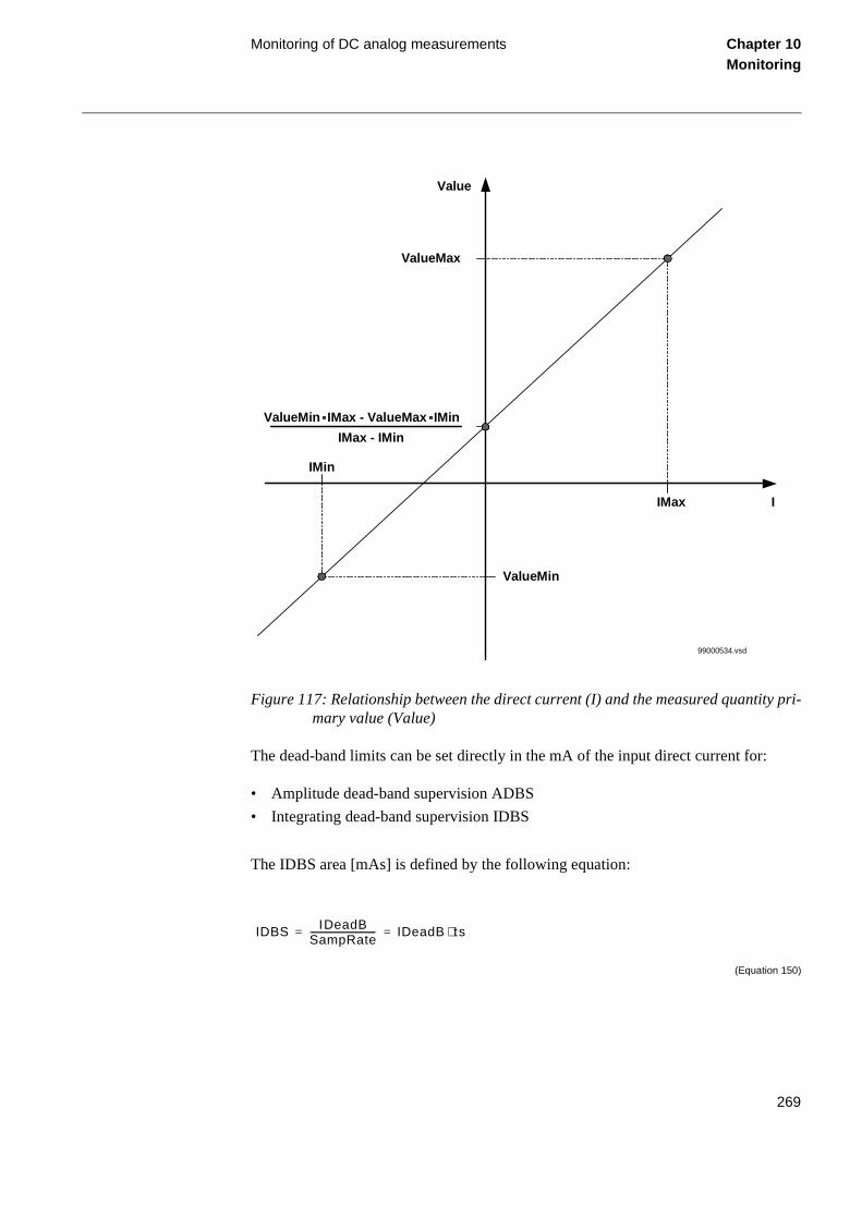
Monitoring of DC analog measurements Chapter 10Monitoring
Figure 117: Relationship between the direct current (I) and the measured quantity pri-mary value (Value)
The dead-band limits can be set directly in the mA of the input direct current for:
• Amplitude dead-band supervision ADBS
• Integrating dead-band supervision IDBS
The IDBS area [mAs] is defined by the following equation:
(Equation 150)
Value
IMin
ValueMin
ValueMin IMax - ValueMax IMin
IMax - IMin
IMax
ValueMax
I
99000534.vsd
IDBS IDeadBSampRate------------------------------ IDeadB ts⋅= =
269

Monitoring of DC analog measurements Chapter 10Monitoring
If a 0.1 mA variation in the monitored quantity for 10 minutes (600 s) is the event that should cause the trigger of the IDBS monitoring (reporting of the value because of IDBS threshold operation) and the sampling frequency (SampRate) of the monitored quantity is 5 Hz, than the set value for IDBS (IDeadB) will be 300 mA:
(Equation 151)
(Equation 152)
The polarity of connected direct current input signal can be changed by setting the ChSign to On or Off. This way it is possible to compensate by setting the possible wrong connection of the direct current leads between the measuring converter and the input terminals of the REx 5xx series unit.
The setting table lists all setting parameters with additional explanation.
where:
IDeadB is the set value of the current level for IDBS in mA.
SampRate is the sampling rate (frequency) set value, in Hz.
ts = 1/SampRate is the time between two samples in s.
IDBS 0.1 600⋅ 60 mA s ][= =
IDeadB IDBS SampRate⋅ 60 5⋅ 300 mA ][= = =
Note:
It is important to set the time for periodic reporting and deadband in an optimized wayto minimize the load on the station bus.
270

About this chapter Chapter 11Data communication
Chapter 11 Data communication
About this chapter
This chapter describes the data communication and the associated hardware.
271

Serial communication Chapter 11Data communication
1 Serial communication
1.1 Application
The serial communication can be used for different purposes, which enable better ac-cess to the information stored in the terminals. The serial communication is also used for communication directly between terminals (bay-to-bay communication).
The serial communication can be used with a station monitoring system (SMS) or with a substation control system (SCS). Normally, SPA communication is used for SMS and SCS; LON communication is used for SCS. Additionally, LON communication can also be used for SMS 510. SPA communication is also applied when using the front communication port, but for this purpose, no special serial communication function is required in the terminal. Only the software in the PC and a special cable for front con-nection is needed.
The rear SPA-port can alternatively be set up for IEC 60870-5-103 communication. IEC 60870-5-103 is a standard protocol for protection functions.
272

Serial communication, SPA Chapter 11Data communication
2 Serial communication, SPA
2.1 Application
The SPA communication is mainly used for SMS. It can include different numerical re-lays/terminals with remote communication possibilities. Connection to a personal com-puter (PC) can be made directly (if the PC is located in the substation) or by telephone modem through a telephone network with CCITT characteristics.
Figure 118: Example of SPA communication structure for a station monitoring system
2.2 Functionality
The SPA protocol V2.5 is an ASCII-based protocol for serial communication. The com-munication is based on a master-slave principle, where the terminal is a slave and the PC is the master. Only one master can be applied on each optic fibre loop. A program is needed in the master computer for interpretation of the SPA-bus codes and for trans-lation of the settings sent to the terminal.
2.3 Design
When communicating locally with a Personal Computer (PC) in the station, using the rear SPA port, the only hardware needed for a station monitoring system is:
• Optical fibres
• Opto/electrical converter fo the PC
• PC
REL 5xx*2.3
REB 551*2.3
REC 561*2.3
(Minute pulsefrom station clock)
Telephonemodem
Telephonemodem
SMS 510CAP 535REVAL
Opto/electricalconverter
SPA busOptical fibreloop
en01000080.vsd
273

Serial communication, SPA Chapter 11Data communication
ce to
spe-
ce to
n of
col to
s to
num-l for all
n at:
When communicating remotely with a PC using the rear SPA port, the same hardware is needed plus telephone modems.
The software needed in the PC, either local or remote, is:
• CAP 535 (Ver. 1.0 or higher) for configuration and parameter setting
• SMS 510 (Ver 1.0 or higher) for reading of disturbance records, events, distanfault and trip value settings
• REVAL (Ver 2.0 or higher) for evaluation of the disturbance recorder data
When communicating to a front-connected PC, the only hardware required is thecial front-connection cable. The software needed in a front connected PC is:
• CAP 535 (Ver. 1.0 or higher) for configuration and parameter setting
• SMS 510 (Ver 1.0 or higher) for reading of disturbance records, events, distanfault and trip value settings
• REVAL (Ver 2.0 or higher) is also required if the same PC is used for evaluatiothe disturbance recorder data.
2.4 Calculations
The SPA and the IEC use the same rear communication port. To define the protobe used, a setting is done on the local HMI under the menu:
Configuration
TerminalCom
SPA-IECPort
When the type of communication protocol is defined, the power to the terminal habe switched off and on.
The most important settings in the terminal for SPA communication are the slave ber and baud rate (communication speed). These settings are absolutely essentiacommunication contact to the terminal.
These settings can only be done on the local HMI for rear channel communicatio
274

Serial communication, SPA Chapter 11Data communication
Configuration
TerminalCom
SPACOMM
Rear
and for front connection at:
Configuration
TerminalCom
SPACOMM
Front
The slave number can be set to any value from 1 to 899, as long as the slave number is unique within the used SPA loop.
The baud rate, which is the communication speed, can be set to between 300 and 38400 bits/s. The baud rate should be the same for the whole station, although different baud rates in a loop are possible. If different baud rates in the same fibre optical loop are used, consider this when making the communication setup in the communication master, the PC. The maximum baud rate of the front connection is limited to 9600 bit/s.
For local communication, 19200 or 38400 bit/s is the normal setting. If telephone com-munication is used, the communication speed depends on the quality of the connection and on the type of modem used. But remember that the terminal does not adapt its speed to the actual communication conditions, because the speed is set on the HMI of the ter-minal.
275

Serial communiction, IEC Chapter 11Data communication
al
3 Serial communiction, IEC
3.1 Application
The IEC 60870-5-103 communication protocol is mainly used when a protection termi-nal communicates with a third party control or monitoring system. This system must have a software that can interpret the IEC 60870-5-103 communication messages.
3.2 Functionality
The IEC 60870-5-103 is an unbalanced (master-slave) protocol for coded-bit serial communication exchanging information with a control system. In IEC terminology a primary station is a master and a secondary station is a slave. The communication is based on a point to point principle. The master must have a software that can interpret the IEC 60870-5-103 communication messages. For detailed information about IEC 60870-5-103, refer to the IEC60870 standard part 5: Transmission protocols, and to the section 103: Companion standard for the informative interface of protection equipment.
3.3 Design
General
The protocol implementation in REx 5xx consists of the following functions:
• Event handling
• Report of analog service values (measurands)
• Fault location
• Command handling
- Autorecloser ON/OFF
- Teleprotection ON/OFF
- Protection ON/OFF
- LED reset
- Characteristics 1 - 4 (Setting groups)
• File transfer (disturbance files)
• Time synchronization
Hardware
When communicating locally with a Personal Computer (PC) or a Remote TerminUnit (RTU) in the station, using the SPA/IEC port, the only hardware needed is:
276

Serial communiction, IEC Chapter 11Data communication
ased tion IEC-
to the
ctive ted
icated ble
alog nces, ferred
ance the
eport.
t four
col to
• Optical fibres, glass/plastic
• Opto/electrical converter for the PC/RTU
• PC/RTU
Events
The events created in the terminal available for the IEC 60870-5-103 protocol are bon the event function blocks EV01 - EV06. These function blocks include the functype and the information number for each event input, which can be found in the document. See also the description of the Event function.
Measurands
The measurands can be included as type 3.1, 3.2, 3.3, 3.4 and type 9 according standard.
Fault location
The fault location is expressed in reactive ohms. In relation to the line length in reaohms, it gives the distance to the fault in percent. The data is available and reporwhen the fault locator function is included in the terminal.
Commands
The commands defined in the IEC 60870-5-103 protocol are represented in a dedfunction block. This block has output signals according to the protocol for all availacommands.
File transfer
The file transfer functionality is based on the Disturbance recorder function. The anand binary signals recorded will be reported to the master. The eight last disturbathat are recorded, are available for transfer to the master. A file that has been transand acknowledged by the master it cannot be transferred again.
The binary signals, that are reported, are those that are connected to the disturbfunction blocks DRP1 - DRP3. These function blocks include the function type andinformation number for each signal. See also the description of the Disturbance r
The analog channels, that are reported, are the first four current inputs and the firsvoltage inputs.
3.4 Calculations
Settings from the local HMI
The SPA and the IEC use the same rear communication port. To define the protobe used, a setting is done on the local HMI under the menu:
277

Serial communiction, IEC Chapter 11Data communication
I at:
. The te.
3.2,
The d on
Configuration
TerminalCom
SPA-IECPort
When the type of communication protocol is defined, the power to the terminal has to be switched off and on.
The settings for IEC 60870-5-103 communication are the following:
• Individually blocking of commands
• Setting of measurand type
• Setting of main function type and activation of main function type
• Settings for slave number and baud rate (communication speed)
• Command for giving Block of information command
The settings for individually blocking of commands can be found on the local HM
Configuration
TerminalCom
IECCom
Commands
Each command has its own blocking setting and the state can be set to OFF or ONOFF state corresponds to non-blocked state and ON corresponds to blocked sta
The settings for type of measurand can be found on the local HMI at:
Configuration
TerminalCom
IECCom
Measurands
The type of measurands can be set to report standardised types, Type 3.1, TypeType 3.3, Type 3.4 or Type 9.
The use of main function type is to facilitate the engineering work of the terminal. settings for main function type and the activation of main function type can be founthe local HMI at:
278

Serial communiction, IEC Chapter 11Data communication
Configuration
TerminalCom
IECCom
FunctionType
The main function type can be set to values according to the standard, this is, between 1 and 255. The value zero is used as default and corresponds to not used.
The setting for activation of main function type can be set to OFF or ON. The OFF state corresponds to non-activated state and ON corresponds to activated state. Upon activat-ed the main function type overrides all other settings for function type within the termi-nal, that is, function type settings for event function and disturbance recorder function. When set to OFF, function type settings for event function and disturbance recorder function use their own function type settings made on the function blocks for the event function and disturbance recorder respectively. Though for all other functions they use the main function type even when set to OFF.
The settings for communication parameters slave number and baud rate can be found on the local HMI at:
Configuration
TerminalCom
IECCom
Communication
The slave number can be set to any value between 0 to 255.
The baud rate, the communication speed, can be set either to 9600 bits/s or 19200 bits/s.
The settings for issuing a block-of-information command can be found on the local HMI at:
Configuration
TerminalCom
IECCom
BlockOfInfo
Information command with the value one (1) blocks all information sent to the master and abort any GI procedure or any file transfer in process. Thus issuing the command with the value set to zero (0) will allow information to be polled by the master.
279

Serial communiction, IEC Chapter 11Data communication
down
f the d 255. event sk
tion
ith 531
I, ted r 20
The dialogue to operate the output from the BlockOfInformation command function is performed from different state as follows:
1. Selection active; select the:
• C button, and then the No box activates.
• Up arrow, and then New: 0 changes to New: 1. The up arrow changes to the arrow.
• E button, and then the Yes box activates.
2. Yes box active; select the:
• C button to cancel the action and return to the BlockOfInfo window.
• E button to confirm the action and return to the BlockOfInfo window.
• Right arrow to activate the No box.
3. No box active; select the:
• C button to cancel the action and return to the BlockOfInfo window.
• E button to confirm the action and return to the BlockOfInfo window.
• Left arrow to activate the Yes box.
Settings from the CAP 535 tool
Event
For each input of the Event function there is a setting for the information number oconnected signal. The information number can be set to any value between 0 anIn order to get proper operation of the sequence of events the event masks in thefunction shall be set to ON_CHANGE. For single-command signals, the event mashall be set to ON_SET.
In addition there is a setting on each event block for function type. Refer to descripof the Main Function type set on the local HMI.
Commands
As for the commands defined in the protocol there is a dedicated function block weight output signals. The configuration of these signals are made by using the CAPtool.
To realise the BlockOfInformation command, which is operated from the local HMthe output BLKINFO on the IEC command function block ICOM has to be connecto an input on an event function block. This input shall have the information numbe(monitor direction blocked) according to the standard.
280

Serial communiction, IEC Chapter 11Data communication
File transfer
For each input of the Disturbance recorder function there is a setting for the information number of the connected signal. The information number can be set to any value be-tween 0 and 255.
Furthermore there is a setting on each input of the Disturbance recorder function for the function type. Refer to description of Main Function type set on the local HMI.
281

Serial communication, LON Chapter 11Data communication
ce,
rks com-ica-
on, cting CA-
20 ith-
4 Serial communication, LON
4.1 Application
An optical network can be used within the Substation Automation system. This enables communication with the terminal through the LON bus from the operator’s workplafrom the control center and also from other terminals.
Figure 119: Example of LON communication structure for substation automation
4.2 Functionality
The LON protocol is specified in the LonTalkProtocol Specification Version 3 fromEchelon Corporation. This protocol is designed for communication in control netwoand is a peer-to-peer protocol where all the devices connected to the network canmunicate with each other directly. For more information of the bay-to-bay communtion, refer to the documents Event function and Multiple command function.
4.3 Design
The hardware needed for applying LON communication depends on the applicatibut one very central unit needed is the LON Star Coupler and optical fibres connethe star coupler to the terminals. To communicate with the terminals from MicroSDA, the application library LIB 520 is needed.
The HV/Control and the HV/REx 500 software modules are included in the LIB 5high-voltage process package, which is a part of the Application Software Library win MicroSCADA applications.
Control Center
en01000081.vsd
REL 5xx*2.3
REB 551*2.3
REC 561*2.3
Micro SCADALIB 520
Gateway
LON-bus
282

Serial communication, LON Chapter 11Data communication
The HV/Control software module is intended to be used for control functions in REx 5xx terminals. This module contains the process picture, dialogues and process data-base for the control application in the MicroSCADA.
The HV/REx 500 software module is used for setting and monitoring of the terminal via the MicroSCADA screen. At use of this function the PST Parameter Setting Tool (of v1.1 or higher) is required.
4.4 Calculations
Use the LNT, LON Network Tool to set the LON communication. This is a software tool applied as one node on the LON bus. In order to communicate via LON, the termi-nals need to know which node addresses the other connected terminals have, and which network variable selectors should be used. This is organised by the LNT.
The node address is transferred to the LNT via the local HMI at:
Configuration
TerminalCom
LONComm
ServicePinMsg
By setting YES, the node address is sent to the LNT via the LON bus. Or, the LNT can scan the network for new nodes.
The speed of the LON bus is set to the default of 1.25 MHz. This can be changed by the LNT.
If the LON communication from the terminal stops, caused by setting of illegal com-munication parameters (outside the setting range) or by another disturbance, it is possi-ble to reset the LON port of the terminal. This is performed at the local HMI at:
Configuration
TerminalCom
LONComm
LONDefault
By setting YES, the LON communication is reset in the terminal, and the addressing procedure can start from the beginning again.
283

Serial communication, LON Chapter 11Data communication
There are a number of session timers which can be set via the local HMI. These settings are only for advanced use and should only be changed after recommendation from ABB Automation Products AB. The time values below are the default settings. The settings can be found at:
Configuration
TerminalCom
LONComm
SessionTimers
284

Serial communication modules (SCM) Chapter 11Data communication
5 Serial communication modules (SCM)
5.1 SPA/IEC
The serial communication module for SPA/IEC is placed in a slot at the rear part of the main processing module. The serial communication module can have connectors for two plastic fibre cables or two glass fibre cables. The incoming optical fibre is connect-ed to the RX receiver input and the outgoing optical fibre to the TX transmitter output. Pay special attention to the instructions concerning the handling, connection, etc. of the optical fibres.
5.2 LON
The serial communication module for LON is placed in a slot at the rear part of the Main processing module. The serial communication module can have connectors for two plastic fibre cables or two glass fibre cables. The incoming optical fibre is connected to the RX receiver input and the outgoing optical fibre to the TX transmitter output. Pay special attention to the instructions concerning the handling, connection, etc. of the op-tical fibres.
285

Serial communication modules (SCM) Chapter 11Data communication
286

About this chapter Chapter 12Hardware modules
Chapter 12 Hardware modules
About this chapter
This chapter describes the different hardware modules.
287

Platform Chapter 12Hardware modules
r the flush all
nal made net
od-
ion, tion
1 Platform
1.1 General
The REx 5xx platform consists of a case, hardware modules and a set of basic functions.
The closed and partly welded steel case makes it possible to fulfill stringent EMC re-quirements. Three different sizes of the case are available to fulfill the space require-ments of different terminals. The degree of protection is IP 40 according to IEC 529 for cases with the widths 1/2x19” and 3/4x19”. For case size 1/1x19” IP 30 applies fotop and bottom part. IP 54 can be obtained for the front area with accessories forand semiflush mounting. Mounting kits are available for rack, flush, semiflush or wmounting.
All connections are made on the rear of the case. Screw compression type termiblocks are used for electrical connections. Serial communication connections are by optical fibre connectors type Hewlett Packard (HFBR) for plastic fibres or bayotype ST for glass fibres
A set of hardware modules are always included in a terminal. Application specific mules are added to create a specific terminal type or family.
The basic functions provide a terminal with basic functionality such as self supervisI/O-system configurator, real time clock and other functions to support the protecand control system of a terminal.
288

Platform Chapter 12Hardware modules
1.2 Platform configuration
Table 15: Basic, always included, modules
Module Description
Combined backplane module (CBM) Carries all internal signals between modules in
a terminal. The size of the module depends on the size of the case.
1/1x19”: 13 slots available for I/O.
3/4x19”: 8 slots available for I/O.
1/2x19”: 3 slots available for I/O.
Power supply module (PSM) Available in two different versions, each includ-
ing a regulated DC/DC converter that supplies auxiliary voltage to all static circuits.
• For case size 1/2x19” and 3/4x19” a version with four binary inputs and four binary outputs are used. An internal fail alarm output is also available. PSM out-put power 20W.
• For case size 1/1x19” a version without binary I/O:s and increased output power is used. An internal fail alarm output is available. PSM output power 30W.
Main processing module (MPM) Module for overall application control. All infor-
mation is processed or passed through this module, such as configuration, settings and communication.
Human machine interface (LCD-HMI) The module consist of LED:s, a LCD, push but-tons and an optical connector for a front con-nected PC
289

Platform Chapter 12Hardware modules
Table 16: Application specific modules
Module Description
Signal processing module (SPM) Module for protection algorithm processing. Carries up to 12 digital signal processors, per-forming all measuring functions.
Milliampere input module (MIM) Analog input module with 6 independent, gal-vanically separated channels.
Binary input module (BIM) Module with 16 optically isolated binary inputs
Binary output module (BOM) Module with 24 single outputs or 12 double-pole command outputs including supervision function
Binary I/O module (IOM) Module with 8 optically isolated binary inputs,
10 outputs and 2 fast signalling outputs.
Data communication modules (DCMs) Modules used for digital communication to remote terminal.
Transformer input module (TRM) Used for galvanic separation of voltage and/or current process signals and the internal cir-cuitry.
A/D conversion module (ADM) Used for analog to digital conversion of analog process signals galvanically separated by the TRM.
Optical receiver module (ORM) Used to interface process signals from optical instrument transformers.
Serial communication module (SCM) Used for SPA/LON/IEC communication
LED module (LED-HMI) Module with 18 user configurable LEDs for indi-cation purposes
290

Platform Chapter 12Hardware modules
Figure 120: Basic block diagram
HMI unitU
IA/D
SP1
SP2
SP3
SP4
SP5
SP6
SP7
SP8
SP9
SP10
SP11
SP12
TRM
In
Out
In
Out
32-b
it co
ntro
ller
Com
mun
icat
ion
SCS
ADM SPM MPM BIO
SMS
99000522.vsd
291

Platform Chapter 12Hardware modules
Figure 121: Internal hardware structure showing a full width case configuration
SA
PC/SMS
SPM
C
E
ShieldShield
Shield
TRMS2
ADMS8
MPMS10
BIM, BOM, IOM, MIMnumbers depending on
the rack sizeDCMS38
PSMS40
...............
CAN-bus (1 Mbit/s)
Analogbus
Serialbus
HDLC-bus
HMI
HMI serial communication links
99000526.vsd
292

Platform Chapter 12Hardware modules
1.3 1/2x19" platform
Figure 122: Hardware structure of the 1/2x19” case
REx 5xxS1 S7 S9 S11 S13 S15 S17 S19
C
E
99000525.vsd
293

Transformer input module (TRM) Chapter 12Hardware modules
the l cur-n
pro-
func-
2 Transformer input module (TRM)
Current and voltage input transformers form an insulating barrier between the external wiring and internal circuits of the terminal. They adapt the values of the measuring quantities to the static circuitry and prevent the disturbances to enter the terminal. Max-imum 10 analog input quantities can be connected to the transformer module (TRM). A TRM with maximum number of transformers has:
• Five voltage transformers. The rated voltage is selected at order.
• Five current transformers. The rated currents are selected at order.
The input quantities are the following:
• Three phase currents
• Residual current of the protected line
• Residual current of the parallel circuit (if any) for compensation of the effect ofzero sequence mutual impedance on the fault locator measurement or residuarent of the protected line but from a parallell core used for CT circuit supervisiofunction or independent earthfault function.
• Three phase voltages
• Open delta voltage for the protected line (for an optional directional earth-faulttection)
• Phase voltage for an optional synchronism and energizing check.
The actual configuration of the TRM depends on the type of terminal and included tions. See figure 123 and figure 124.
294

Transformer input module (TRM) Chapter 12Hardware modules
Figure 123: Block diagram of the TRM for REL 551, Line differential protection
Bac
kpla
ne c
onne
ctor
Cur
rent
Inpu
t con
nect
or CT CT
CT
CT
CT
99000560.vsd
295

Transformer input module (TRM) Chapter 12Hardware modules
Figure 124: Block diagram of the TRM with maximum number of transformers used in most REx 5xx.
Bac
kpla
ne c
onne
ctor
Vol
tage
Inpu
t con
nect
orC
urre
nt In
put c
onne
ctor CT CT
CT
CT
CT
VT
VT
VT
VT
VT
990000511.vsd
296

A/D-conversion module (ADM) Chapter 12Hardware modules
3 A/D-conversion module (ADM)
The incoming signals from the intermediate current transformers are adapted to the electronic voltage level with shunts. To gain dynamic range for the current inputs, two shunts with separate A/D channels are used for each input current. By that a 16-bit dy-namic range is obtained with a 12 bits A/D converter.
The next step in the signal flow is the analogue filter of the first order, with a cut-off frequency of 500 Hz. This filter is used to avoid aliasing problems.
The A/D converter has a 12-bit resolution. It samples each input signal (5 voltages and 2x5 currents) with a sampling frequency of 2 kHz.
Before the A/D-converted signals are transmitted to the signal processing module, the signals are band-pass filtered and down-sampled to 1 kHz in a digital signal processor (DSP).
The filter in the DSP is a numerical filter with a cut-off frequency of 250 Hz.
The transmission of data between the A/D-conversion module and the signal processing module is done on a supervised serial link of RS485 type. This transmission is per-formed once every millisecond and contains information about all incoming analog sig-nals.
297

A/D-conversion module (ADM) Chapter 12Hardware modules
Figure 125: Block diagram for the ADM
Bac
kpla
ne c
onne
ctor
Analog filters ¤t shunts
PLD
DS
P
A/D
-co
nver
ter
Ana
log
MU
X
Controllogic &buffers
1-5 Voltageinputs
1-5 Currentinputs
99000512.vsd
298

Main processing module (MPM) Chapter 12Hardware modules
ine
4 Main processing module (MPM)
The terminal is based on a pipelined multi-processor design. The 32-bit main controller receives the result from the Signal processing module every millisecond.
All memory management are also handled by the main controller. The module has 8MB of disc memory and 1MB of code memory. It also has 8MB of dynamic memory.
The controller also serves four serial links: one high-speed CAN bus for Input/Output modules and three serial links for different types of HMI communication.
The main controller makes all decisions, based on the information from the Signal pro-cessing module and from the binary inputs. The decisions are sent to the different output modules and to these communication ports:
• Local HMI module including a front-connected PC, if any, for local human-machcommunication.
• LON communication port at the rear (option).
• SPA/IEC communication port at the rear (option)
299

Main processing module (MPM) Chapter 12Hardware modules
Figure 126: Block diagram for the MPM
To allow easy upgrading of software in the field a special connector is used, the Down-load connector.
Bac
kpla
ne c
onne
ctor
SP
M c
onne
ctor
Dow
nloa
dco
nnec
tor
Maincontroller
LON
CAN
DRAM (SIMM)
SP
A/IE
CLO
N
Disc Flash (8MB)
Code Flash (1MB)
8-bit Data bus
32-b
it D
ata
bus
CAN bus
SCM
SCM
99000513.vsd
300

Signal processing module (SPM) Chapter 12Hardware modules
5 Signal processing module (SPM)
All numerical data is received in all of the up to 12 (16 bits) digital signal processors (DSP). In these DSPs, the main part of the filtering and the calculations take place. The result from the calculations in the DSPs is sent every millisecond on a parallel bus to the (32 bit) main controller on the Main processing module.
Figure 127: Block diagram of the SPM
DSP12
DSP11
DSP10 DSP8
DSP9
DSP6 DSP4 DSP1
DSP2
DSP3DSP5DSP7
MP
M-c
onne
ctor
99000514.vsd
301

Input/Output modules Chapter 12Hardware modules
6 Input/Output modules
6.1 Binary input module (BIM)
The binary input module contains 16 optically isolated binary inputs. The binary inputs are freely programmable and can be used for the input logical signals to any of the func-tions. They can also be included in the disturbance recording and event recording func-tions. This enables the extensive monitoring and evaluation of operation for the terminal and for all associated electrical circuits. The voltage level of the binary input modules can be selected at order.
Figure 128: Block diagram of the binary input module
Bac
kpla
ne c
onne
ctor
Pro
cess
con
nect
orP
roce
ss c
onne
ctor
Micro-controller
Memory
CA
N
Opto isolated input
Opto isolated input
Opto isolated input
Opto isolated input
Opto isolated input
Opto isolated input
Opto isolated input
Opto isolated input
Opto isolated input
Opto isolated input
Opto isolated input
Opto isolated input
Opto isolated input
Opto isolated input
Opto isolated input
Opto isolated input
99000503.vsd
302

Input/Output modules Chapter 12Hardware modules
6.2 Binary output module (BOM)
The Binary output module has 24 single-output relays or 12 command-output relays. They are grouped together as can be seen in figure 129 and 130. All the output relays have contacts with a high switching capacity (trip and signal relays).
Figure 129: Block diagram of the binary output module
Two single output relay contacts can be connected in series (which gives a command output) in order to get a high security at operation of high voltage apparatuses.
Bac
kpla
ne c
onne
ctor
Pro
cess
con
nect
orP
roce
ss c
onne
ctor
Micro-controller
Memory
CA
N
Rel
ayRelay
Relay
Relay
Relay
Relay
Relay
Relay
Relay
Relay
Relay
Relay
Relay
Relay
Relay
Relay
Relay
Relay
Relay
Relay
Relay
Rel
ay
Rel
ay
Rel
ay
99000505.vsd
303

Input/Output modules Chapter 12Hardware modules
Figure 130: One of twelve binary output groups
The output relays are provided with a supervision function to ensure a high degree of security against unwanted operation. The status of the output circuits is continuously read back and compared with the expected status. If any discrepancy occurs, an error is reported. This function covers:
• interrupt or short circuit in an output relay coil
• failure of an output relay driver.
xx00000299.vsd
5
5
2
1
3
304

Power supply module (PSM) Chapter 12Hardware modules
ur r in-
7 Power supply module (PSM)
The power supply module (PSM) contains a built-in, self-regulated DC/DC converter that provides full isolation between the terminal and the external battery system. The wide input voltage range of the DC/DC converter converts an input voltage range from 48 to 250V, including a +/-20% tolerance on the EL voltage. The output voltages are +5, +12 and -12 Volt.
The PSM, used in the 1/2x19” and 3/4x19” platforms, has built-in binary I/O with fooptically isolated inputs and five outputs. One of the binary outputs is dedicated foternal fail. The PSM can provide power up to 20W.
Figure 131: Block diagram for the PSM used in 1/2x19” and 3/4x19” cases.
Bac
kpla
ne c
onne
ctor
Pro
cess
con
nect
orC
AN
&de
bug
Opto isolatedinput
Opto isolatedinput
Opto isolatedinput
Opto isolatedinput
RelayRelayRelayRelayRelay
Power supply
Micro-controller
Memory
PWM
CAN
99000515.vsd
305
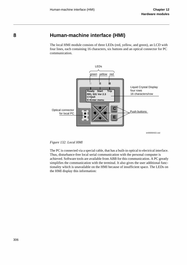
Human-machine interface (HMI) Chapter 12Hardware modules
8 Human-machine interface (HMI)
The local HMI module consists of three LEDs (red, yellow, and green), an LCD with four lines, each containing 16 characters, six buttons and an optical connector for PC communication.
Figure 132: Local HMI
The PC is connected via a special cable, that has a built-in optical to electrical interface. Thus, disturbance-free local serial communication with the personal computer is achieved. Software tools are available from ABB for this communication. A PC greatly simplifies the communication with the terminal. It also gives the user additional func-tionality which is unavailable on the HMI because of insufficient space. The LEDs on the HMI display this information:
en00000422.vsd
E
C
ReadyREL 531 Ver 2.3C=QuitE=Enter menu
Start Trip
Push buttons
green yellow red
LEDs
Liquid Crystal Displayfour rows16 characters/row
Optical connectorfor local PC
306

Human-machine interface (HMI) Chapter 12Hardware modules
Table 17: The local HMI LED display
LED indication Information
Green:
Steady
Flashing
Dark
Yellow:
Steady
Flashing
Red:
Steady
Flashing
In service
Internal failure
No power supply
Disturbance Report triggered
Terminal in test mode
Trip command issued from a protection function or disturbance recorder started
Blocked
307

Human-machine interface (HMI) Chapter 12Hardware modules
308