application note 1985 lm3429 buck-boost evaluation board...
TRANSCRIPT

LM3420,LM3429
Application Note 1985 LM3429 Buck-Boost Evaluation Board
Literature Number: SNVA403B

LM3429 Buck-BoostEvaluation Board
National SemiconductorApplication Note 1985James PattersonAugust 3, 2009
IntroductionThis wide range evaluation board showcases the LM3429NFET controller used with a buck-boost current regulator. Itis designed to drive 4 to 8 LEDs at a maximum average LEDcurrent of 1A from a DC input voltage of 10 to 70V.
The evaluation board showcases most features of theLM3429 including PWM dimming, overvoltage protection andinput under-voltage lockout. It also has a right angle connec-tor (J7) which can mate with an external LED load boardallowing for the LEDs to be mounted close to the driver. Al-ternatively, the LED+ and LED- banana jacks can be used toconnect the LED load.
The buck-boost circuit can be easily redesigned for differentspecifications by changing only a few components (see theAlternate Designs section found at the end of this applicationnote). Note that design modifications can change the systemefficiency for better or worse. See the LM3429 datasheet fora comprehensive explanation of the device and applicationinformation.
EFFICIENCY WITH 6 SERIES LEDS AT 1A
30100801
Schematic
30100802
© 2009 National Semiconductor Corporation 301008 www.national.com
LM
3429 B
uck-B
oo
st E
valu
atio
n B
oard
AN
-1985

Pin Descriptions
Pin Name Description Application Information
1 VIN Input VoltageBypass with 100 nF capacitor to AGND as close to the device as possible in
the circuit board layout.
2 COMP Compensation Connect a capacitor to AGND.
3 CSH Current Sense High
Connect a resistor to AGND to set the signal current. For analog dimming,
connect a controlled current source or a potentiometer to AGND as detailed in
the Analog Dimming section.
4 RCT Resistor Capacitor TimingConnect a resistor from the switch node and a capacitor to AGND to set the
switching frequency.
5 AGND Analog GroundConnect to PGND through the DAP copper circuit board pad to provide proper
ground return for CSH, COMP, and RCT.
6 OVP Over-Voltage Protection
Connect to a resistor divider from VO to program output over-voltage lockout
(OVLO). Turn-off threshold is 1.24V and hysteresis for turn-on is provided by
20 µA current source.
7 nDIM Not DIM input
Connect a PWM signal for dimming as detailed in the PWM Dimming section
and/or a resistor divider from VIN to program input under-voltage lockout
(UVLO). Turn-on threshold is 1.24V and hysteresis for turn-off is provided by
20 µA current source.
8 NC No Connection Leave open.
9 PGND Power GroundConnect to AGND through the DAP copper circuit board pad to provide proper
ground return for GATE.
10 GATE Gate Drive Output Connect to the gate of the external NFET.
11 VCC Internal Regulator Output Bypass with a 2.2 µF–3.3 µF, ceramic capacitor to PGND.
12 IS Main Switch Current SenseConnect to the drain of the main N-channel MosFET switch for RDS-ON sensing
or to a sense resistor installed in the source of the same device.
13 HSPHigh-Side LED Current Sense
Positive
Connect through a series resistor to the positive side of the LED current sense
resistor.
14 HSNHigh-Side LED Current Sense
Negative
Connect through a series resistor to the negative side of the LED current sense
resistor.
DAP
(15)DAP Thermal pad on bottom of IC
Star ground, connecting AGND and PGND.
www.national.com 2
AN
-1985

Bill of Materials
Qty Part ID Part Value Manufacturer Part Number
2 C1, C4 0.1 µF X7R 10% 100V TDK C2012X7R2A104K
4 C2, C3, C16, C18 4.7 µF X7R 10% 100V MURATA GRM55ER72A475KA01L
3 C6, C17, C19 2.2 µF X7R 10% 100V TDK C4532X7R2A225K
1 C7 1000 pF COG/NPO 5% 50V MURATA GRM2165C1H102JA01D
1 C8 1 µF X7R 10% 16V MURATA GRM21BR71C105KA01L
1 C9 2.2 µF X7R 10% 16V MURATA GRM21BR71C225KA12L
1 C12 0.1 µF X7R 10% 25V MURATA GRM21BR71E104KA01L
1 D1 Schottky 100V 12A VISHAY 12CWQ10FNPBF
4 J1, J2, J4, J5 banana jack KEYSTONE 575-8
1 J7 2 x 7 shrouded header SAMTEC TSSH-107-01-SDRA
1 L1 33 µH 20% 6.3A COILCRAFT MSS1278-333MLB
1 Q1 NMOS 100V 40A VISHAY SUD40N10-25
1 Q3 NMOS 60V 260 mA ON-SEMI 2N7002ET1G
1 Q5 PNP 150V 600 mA FAIRCHILD MMBT5401
1 R1 12.4 kΩ 1% VISHAY CRCW080512k4FKEA
1 R2 0Ω 1% VISHAY CRCW08050000Z0EA
2 R3, R20 10Ω 1% VISHAY CRCW080510R0FKEA
1 R4 16.9 kΩ 1% VISHAY CRCW080516k9FKEA
1 R5 1.43 kΩ 1% VISHAY CRCW08051k43FKEA
1 R6 0.05Ω 1% 1W VISHAY WSL2512R0500FEA
2 R7, R8 1.0 kΩ 1% VISHAY CRCW08051k00FKEA
1 R9 0.1Ω 1% 1W VISHAY WSL2512R1000FEA
1 R10 35.7 kΩ 1% VISHAY CRCW080535k7FKEA
1 R11 15.8 kΩ 1% VISHAY CRCW080515k8FKEA
2 R12, R13 10.0 kΩ 1% VISHAY CRCW080510k0FKEA
1 R18 750 kΩ 1% VISHAY CRCW0805750kFKEA
7 TP1, TP2, TP3,
TP7, TP10, TP11,
TP12
turret KEYSTONE 1502-2
1 U1 Buck-boost controller NSC LM3429MH
3 www.national.com
AN
-1985

PCB Layout
30100803
Top Layer
30100804
Bottom Layer
www.national.com 4
AN
-1985

Design ProcedureRefer to LM3429 datasheet for design considerations.
SPECIFICATIONS
N = 6
VLED = 3.5V
rLED = 325 mΩVIN = 24V
VIN-MIN = 10V; VIN-MAX = 70V
fSW = 700 kHz
VSNS = 100 mV
ILED = 1A
ΔiL-PP = 500 mA
ΔiLED-PP = 50 mA
ΔvIN-PP = 100 mV
ILIM = 5A
VTURN-ON = 10V; VHYS = 3V
VTURN-OFF = 60V; VHYSO = 15V
1. OPERATING POINT
Solve for VO and rD:
Solve for D, D', DMAX, and DMIN:
2. SWITCHING FREQUENCY
Assume C7 = 1 nF and solve for R10:
The closest standard resistor is actually 35.7 kΩ therefore thefSW is:
The chosen components from step 2 are:
3. AVERAGE LED CURRENT
Solve for R9:
Assume R1 = 12.4 kΩ and solve for R8:
The closest standard resistor for R9 is 0.1Ω and the closestfor R8 (and R7) is actually 1 kΩ therefore ILED is:
The chosen components from step 3 are:
4. INDUCTOR RIPPLE CURRENT
Solve for L1:
The closest standard inductor is 33 µH therefore the actualΔiL-PP is:
Determine minimum allowable RMS current rating:
The chosen component from step 4 is:
5 www.national.com
AN
-1985

5. OUTPUT CAPACITANCE
Solve for CO:
A total value of 6.6 µF (using 3 2.2 µF X7R ceramic capaci-tors) is chosen therefore the actual ΔiLED-PP is:
Determine minimum allowable RMS current rating:
The chosen components from step 5 are:
6. PEAK CURRENT LIMIT
Solve for R6:
The closest standard resistor is 0.05 Ω therefore ILIM is:
The chosen component from step 6 is:
7. LOOP COMPENSATION
ωP1 is approximated:
ωZ1 is approximated:
TU0 is approximated:
To ensure stability, calculate ωP2:
Solve for C8:
Since PWM dimming can be evaluated with this board, amuch larger compensation capacitor C8 = 1.0 µF is chosen.
To attenuate switching noise, calculate ωP3:
Assume R20 = 10Ω and solve for C12:
The chosen components from step 7 are:
8. INPUT CAPACITANCE
Solve for the minimum CIN:
To minimize power supply interaction a 3x larger capacitanceof approximately 20 µF is used, therefore the actual ΔvIN-PPis much lower. Since high voltage ceramic capacitor selectionis limited, four 4.7 µF X7R capacitors are chosen.
Determine minimum allowable RMS current rating:
The chosen components from step 8 are:
www.national.com 6
AN
-1985
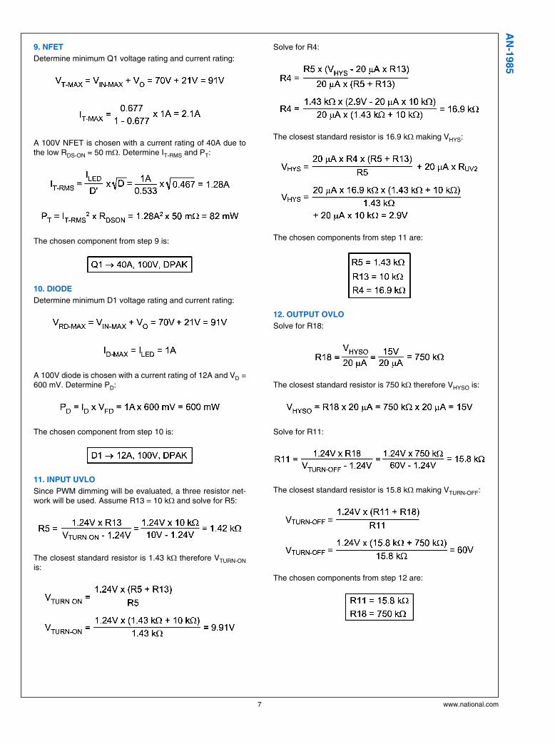
9. NFET
Determine minimum Q1 voltage rating and current rating:
A 100V NFET is chosen with a current rating of 40A due tothe low RDS-ON = 50 mΩ. Determine IT-RMS and PT:
The chosen component from step 9 is:
10. DIODE
Determine minimum D1 voltage rating and current rating:
A 100V diode is chosen with a current rating of 12A and VD =600 mV. Determine PD:
The chosen component from step 10 is:
11. INPUT UVLO
Since PWM dimming will be evaluated, a three resistor net-work will be used. Assume R13 = 10 kΩ and solve for R5:
The closest standard resistor is 1.43 kΩ therefore VTURN-ONis:
Solve for R4:
The closest standard resistor is 16.9 kΩ making VHYS:
The chosen components from step 11 are:
12. OUTPUT OVLO
Solve for R18:
The closest standard resistor is 750 kΩ therefore VHYSO is:
Solve for R11:
The closest standard resistor is 15.8 kΩ making VTURN-OFF:
The chosen components from step 12 are:
7 www.national.com
AN
-1985

Typical Waveforms
TA = +25°C, VIN = 24V and VO = 21V.
30100859
STANDARD OPERATIONTP1 switch node voltage (VSW)
LED current (ILED)
30100860
200Hz 50% PWM DIMMINGTP11 dim voltage (VDIM)
LED current (ILED)
Alternate DesignsAlternate designs with the LM3429 evaluation board are pos-sible with very few changes to the existing hardware. Theevaluation board FETs and diodes are already rated higherthan necessary for design flexibility. The input UVLO, outputOVP, input and output capacitance can remain the same for
the designs shown below. These alternate designs can beevaluated by changing only R9, R10, and L1.
The table below gives the main specifications for four differentdesigns and the corresponding values for R9, R10, and L1.PWM dimming can be evaluated with any of these designs.
Specification /
Component
Design 1 Design 2 Design 3 Design 4
VIN 10V - 45V 15V - 50V 20V - 55V 25V - 60V
VO 14V 21V 28V 35V
fSW 600kHz 700kHz 500kHz 700kHz
ILED 2A 500mA 2.5A 1.25A
R9 0.05Ω 0.2Ω 0.04Ω 0.08ΩR10 41.2 kΩ 35.7 kΩ 49.9 kΩ 35.7 kΩL1 22µH 68µH 15µH 33µH
www.national.com 8
AN
-1985

9 www.national.com
AN
-1985
NotesA
N-1
985
LM
3429 B
uck-B
oo
st
Evalu
ati
on
Bo
ard
For more National Semiconductor product information and proven design tools, visit the following Web sites at:
Products Design Support
Amplifiers www.national.com/amplifiers WEBENCH® Tools www.national.com/webench
Audio www.national.com/audio App Notes www.national.com/appnotes
Clock and Timing www.national.com/timing Reference Designs www.national.com/refdesigns
Data Converters www.national.com/adc Samples www.national.com/samples
Interface www.national.com/interface Eval Boards www.national.com/evalboards
LVDS www.national.com/lvds Packaging www.national.com/packaging
Power Management www.national.com/power Green Compliance www.national.com/quality/green
Switching Regulators www.national.com/switchers Distributors www.national.com/contacts
LDOs www.national.com/ldo Quality and Reliability www.national.com/quality
LED Lighting www.national.com/led Feedback/Support www.national.com/feedback
Voltage Reference www.national.com/vref Design Made Easy www.national.com/easy
PowerWise® Solutions www.national.com/powerwise Solutions www.national.com/solutions
Serial Digital Interface (SDI) www.national.com/sdi Mil/Aero www.national.com/milaero
Temperature Sensors www.national.com/tempsensors SolarMagic™ www.national.com/solarmagic
Wireless (PLL/VCO) www.national.com/wireless PowerWise® DesignUniversity
www.national.com/training
THE CONTENTS OF THIS DOCUMENT ARE PROVIDED IN CONNECTION WITH NATIONAL SEMICONDUCTOR CORPORATION(“NATIONAL”) PRODUCTS. NATIONAL MAKES NO REPRESENTATIONS OR WARRANTIES WITH RESPECT TO THE ACCURACYOR COMPLETENESS OF THE CONTENTS OF THIS PUBLICATION AND RESERVES THE RIGHT TO MAKE CHANGES TOSPECIFICATIONS AND PRODUCT DESCRIPTIONS AT ANY TIME WITHOUT NOTICE. NO LICENSE, WHETHER EXPRESS,IMPLIED, ARISING BY ESTOPPEL OR OTHERWISE, TO ANY INTELLECTUAL PROPERTY RIGHTS IS GRANTED BY THISDOCUMENT.
TESTING AND OTHER QUALITY CONTROLS ARE USED TO THE EXTENT NATIONAL DEEMS NECESSARY TO SUPPORTNATIONAL’S PRODUCT WARRANTY. EXCEPT WHERE MANDATED BY GOVERNMENT REQUIREMENTS, TESTING OF ALLPARAMETERS OF EACH PRODUCT IS NOT NECESSARILY PERFORMED. NATIONAL ASSUMES NO LIABILITY FORAPPLICATIONS ASSISTANCE OR BUYER PRODUCT DESIGN. BUYERS ARE RESPONSIBLE FOR THEIR PRODUCTS ANDAPPLICATIONS USING NATIONAL COMPONENTS. PRIOR TO USING OR DISTRIBUTING ANY PRODUCTS THAT INCLUDENATIONAL COMPONENTS, BUYERS SHOULD PROVIDE ADEQUATE DESIGN, TESTING AND OPERATING SAFEGUARDS.
EXCEPT AS PROVIDED IN NATIONAL’S TERMS AND CONDITIONS OF SALE FOR SUCH PRODUCTS, NATIONAL ASSUMES NOLIABILITY WHATSOEVER, AND NATIONAL DISCLAIMS ANY EXPRESS OR IMPLIED WARRANTY RELATING TO THE SALEAND/OR USE OF NATIONAL PRODUCTS INCLUDING LIABILITY OR WARRANTIES RELATING TO FITNESS FOR A PARTICULARPURPOSE, MERCHANTABILITY, OR INFRINGEMENT OF ANY PATENT, COPYRIGHT OR OTHER INTELLECTUAL PROPERTYRIGHT.
LIFE SUPPORT POLICY
NATIONAL’S PRODUCTS ARE NOT AUTHORIZED FOR USE AS CRITICAL COMPONENTS IN LIFE SUPPORT DEVICES ORSYSTEMS WITHOUT THE EXPRESS PRIOR WRITTEN APPROVAL OF THE CHIEF EXECUTIVE OFFICER AND GENERALCOUNSEL OF NATIONAL SEMICONDUCTOR CORPORATION. As used herein:
Life support devices or systems are devices which (a) are intended for surgical implant into the body, or (b) support or sustain life andwhose failure to perform when properly used in accordance with instructions for use provided in the labeling can be reasonably expectedto result in a significant injury to the user. A critical component is any component in a life support device or system whose failure to performcan be reasonably expected to cause the failure of the life support device or system or to affect its safety or effectiveness.
National Semiconductor and the National Semiconductor logo are registered trademarks of National Semiconductor Corporation. All otherbrand or product names may be trademarks or registered trademarks of their respective holders.
Copyright© 2009 National Semiconductor Corporation
For the most current product information visit us at www.national.com
National SemiconductorAmericas TechnicalSupport CenterEmail: [email protected]: 1-800-272-9959
National Semiconductor EuropeTechnical Support CenterEmail: [email protected]
National Semiconductor AsiaPacific Technical Support CenterEmail: [email protected]
National Semiconductor JapanTechnical Support CenterEmail: [email protected]
www.national.com

IMPORTANT NOTICE
Texas Instruments Incorporated and its subsidiaries (TI) reserve the right to make corrections, modifications, enhancements, improvements,and other changes to its products and services at any time and to discontinue any product or service without notice. Customers shouldobtain the latest relevant information before placing orders and should verify that such information is current and complete. All products aresold subject to TI’s terms and conditions of sale supplied at the time of order acknowledgment.
TI warrants performance of its hardware products to the specifications applicable at the time of sale in accordance with TI’s standardwarranty. Testing and other quality control techniques are used to the extent TI deems necessary to support this warranty. Except wheremandated by government requirements, testing of all parameters of each product is not necessarily performed.
TI assumes no liability for applications assistance or customer product design. Customers are responsible for their products andapplications using TI components. To minimize the risks associated with customer products and applications, customers should provideadequate design and operating safeguards.
TI does not warrant or represent that any license, either express or implied, is granted under any TI patent right, copyright, mask work right,or other TI intellectual property right relating to any combination, machine, or process in which TI products or services are used. Informationpublished by TI regarding third-party products or services does not constitute a license from TI to use such products or services or awarranty or endorsement thereof. Use of such information may require a license from a third party under the patents or other intellectualproperty of the third party, or a license from TI under the patents or other intellectual property of TI.
Reproduction of TI information in TI data books or data sheets is permissible only if reproduction is without alteration and is accompaniedby all associated warranties, conditions, limitations, and notices. Reproduction of this information with alteration is an unfair and deceptivebusiness practice. TI is not responsible or liable for such altered documentation. Information of third parties may be subject to additionalrestrictions.
Resale of TI products or services with statements different from or beyond the parameters stated by TI for that product or service voids allexpress and any implied warranties for the associated TI product or service and is an unfair and deceptive business practice. TI is notresponsible or liable for any such statements.
TI products are not authorized for use in safety-critical applications (such as life support) where a failure of the TI product would reasonablybe expected to cause severe personal injury or death, unless officers of the parties have executed an agreement specifically governingsuch use. Buyers represent that they have all necessary expertise in the safety and regulatory ramifications of their applications, andacknowledge and agree that they are solely responsible for all legal, regulatory and safety-related requirements concerning their productsand any use of TI products in such safety-critical applications, notwithstanding any applications-related information or support that may beprovided by TI. Further, Buyers must fully indemnify TI and its representatives against any damages arising out of the use of TI products insuch safety-critical applications.
TI products are neither designed nor intended for use in military/aerospace applications or environments unless the TI products arespecifically designated by TI as military-grade or "enhanced plastic." Only products designated by TI as military-grade meet militaryspecifications. Buyers acknowledge and agree that any such use of TI products which TI has not designated as military-grade is solely atthe Buyer's risk, and that they are solely responsible for compliance with all legal and regulatory requirements in connection with such use.
TI products are neither designed nor intended for use in automotive applications or environments unless the specific TI products aredesignated by TI as compliant with ISO/TS 16949 requirements. Buyers acknowledge and agree that, if they use any non-designatedproducts in automotive applications, TI will not be responsible for any failure to meet such requirements.
Following are URLs where you can obtain information on other Texas Instruments products and application solutions:
Products Applications
Audio www.ti.com/audio Communications and Telecom www.ti.com/communications
Amplifiers amplifier.ti.com Computers and Peripherals www.ti.com/computers
Data Converters dataconverter.ti.com Consumer Electronics www.ti.com/consumer-apps
DLP® Products www.dlp.com Energy and Lighting www.ti.com/energy
DSP dsp.ti.com Industrial www.ti.com/industrial
Clocks and Timers www.ti.com/clocks Medical www.ti.com/medical
Interface interface.ti.com Security www.ti.com/security
Logic logic.ti.com Space, Avionics and Defense www.ti.com/space-avionics-defense
Power Mgmt power.ti.com Transportation and Automotive www.ti.com/automotive
Microcontrollers microcontroller.ti.com Video and Imaging www.ti.com/video
RFID www.ti-rfid.com
OMAP Mobile Processors www.ti.com/omap
Wireless Connectivity www.ti.com/wirelessconnectivity
TI E2E Community Home Page e2e.ti.com
Mailing Address: Texas Instruments, Post Office Box 655303, Dallas, Texas 75265Copyright © 2011, Texas Instruments Incorporated