application note 25 - digi internationalftp1.digi.com/support/documentation/an_025... · 1...
TRANSCRIPT

1
Application Note 25 Configure an IPsec VPN tunnel between a Digi
Transport router and a Cisco router using Certificates and SCEP
UK Support
November 2015

2
Contents
1 Introduction ......................................................................................................................................... 4
1.1 Outline ......................................................................................................................................... 4
1.2 Digi Transport and Cisco VPN Terminology ..................................................................................5
2 Assumptions ........................................................................................................................................ 6
2.1 Corrections .................................................................................................................................. 6
2.2 Version ......................................................................................................................................... 6
2.3 Corrections .................................................................................................................................. 6
3 The Public Key Infrastructure ................................................................................................................ 7
3.1 Public Key Infrastructure terminology ........................................................................................... 7
3.2 Identity authentication using the PKI ............................................................................................ 7
3.3 IPsec – Secure Data Transfer ........................................................................................................ 8
4 Microsoft® Windows Server 2008 Configuration ................................................................................. 10
4.1 Requirements ............................................................................................................................. 10
4.2 Configure the Microsoft® Windows Server 2008 as a Certificate Authority ................................. 10
4.3 Automatic Enrolment ................................................................................................................ 20
5 Transport VPN Server - Certificates ................................................................................................... 22
5.1 LAN Interface Configuration ...................................................................................................... 22
5.2 Date and Time ........................................................................................................................... 22
5.3 Hostname ................................................................................................................................... 23
5.4 WAN Interface Configuration ...................................................................................................... 23
5.5 Configure the Default Route ...................................................................................................... 24
5.6 Certificate Enrolment ................................................................................................................. 24
5.7 Reviewing certificates on Transport routers ................................................................................ 30
6 CISCO® VPN initiator - Certificates .................................................................................................... 32
6.1 General Setup ............................................................................................................................. 32
6.2 Ethernet Configuration ............................................................................................................... 32
6.3 Generate the RSA Key Pair ......................................................................................................... 34
6.4 Configure the CA......................................................................................................................... 34
6.5 Using SCEP to retrieve the CA certificates .................................................................................. 35
6.6 Using SCEP to Enrol the Certificate Request ............................................................................... 35
6.7 Obtain a Challenge Password for the Certificate Request. .......................................................... 36
6.8 Issuing a Signed Certificate on Microsoft® Windows Server 2008. .............................................. 37
Configure IKE and IPsec – VPN Server ........................................................................................................ 38

3
6.9 Configure IKE (Internet Key Exchange) ....................................................................................... 38
6.10 Configure IPsec ........................................................................................................................... 39
7 Configure IKE and IPsec – CISCO® ...................................................................................................... 41
7.1 Configure IKE (Internet Key Exchange) ....................................................................................... 41
7.2 Configure IPsec Transform-Set .................................................................................................. 42
7.3 Configure the Crypto Map .......................................................................................................... 42
7.4 Create the IPsec Access List ........................................................................................................ 43
7.5 Saving the Configuration ........................................................................................................... 44
8 Testing – Cisco® vpn Initiator ............................................................................................................. 45
8.1 Display IKE Information .............................................................................................................. 45
8.2 Display Transform Set Configuration ......................................................................................... 46
8.3 Display List of All RSA Public Keys On the Cisco Router ............................................................. 46
8.4 Display the Cisco Routers RSA Public Keys ................................................................................ 46
8.5 Display Information about the Router, CA and RA Certificates ................................................... 47
8.6 Display Information About the IPsec SAs ................................................................................... 48
9 Checking status of VPN on the transport router ................................................................................. 50
9.1 Check the WAN Link is Active ..................................................................................................... 50
9.2 Check the IPsec Tunnel is Active ................................................................................................. 50
9.3 Test the IPsec Routing ................................................................................................................ 51
10 Troublshooting VPN negotiations ................................................................................................... 58
10.1 Debugging the Transport router ................................................................................................. 58
11 Configuration Files ......................................................................................................................... 62
11.1 Transport Configuration ............................................................................................................ 62
11.2 Cisco® Configuration ................................................................................................................. 64
11.3 Transport Firmware Versions ...................................................................................................... 67
11.4 Cisco® Firmware Version ........................................................................................................... 69
12 Alternate Configuration .................................................................................................................. 70
12.1 Cisco® Responder Configuration. ............................................................................................... 70
12.2 Transport Initiator Configuration - IKE ........................................................................................ 71
12.3 Transport Initiator Configuration – IPsec..................................................................................... 72

4
1 INTRODUCTION
1.1 Outline
This application note is intended to explain how to create RSA key files, certificate requests, and how to
use SCEP to retrieve a signed certificate from a Microsoft® Windows 2008 server for use with IPsec.
This document is a worked example of how to configure a Digi Transport and a Cisco® IOS based router to
establish an IPsec tunnel between each other using signed certificates, RSA key files and Certificate
Authority (CA) certificates. This will allow full secure connectivity between two private networks
connected together via the Internet.
The Cisco is the VPN initiator.
The Transport is the VPN server/responder.
In this working example all addresses used are private non routable addresses. The WAN network is
configured to use a 10.x.x.x network range and is used to simulate the Internet.
Note: At the end of this document there is a brief description of the changes required in order to reverse
the rolls of these routers
The advantages of using RSA certificates over pre-shared keys are;
Scalable - pre-shared keys become unmanageable on large schemes
Provides increased security over pre-shared keys

5
1.2 Digi Transport and Cisco VPN Terminology
There are differences in the terminology commonly used when dealing with Digi Transport and Cisco
devices. In order to help understand the terms used when referring to the configuration of the different
devices these will be discussed briefly.
The terms ‘Phase 1’, Internet Key Exchange (IKE) and ISAKMP are largely interchangeable in use. All are
used to refer to, the settings used for and/or the actual process of the first stage of a VPN tunnel
negotiation where during which the identity of the remote host is verified and a unique encryption key is
generated in order to facilitate the next stage of the negotiation. Terms used to refer to the second stage
of negotiations vary can vary a little more. Digi users will commonly use the terms Phase 2, IPsec and
Eroute (a contraction of ‘encrypted route’), Cisco users tend to use the term ‘crypto map’ to refer to the
settings used or negotiating the second stage.

6
2 ASSUMPTIONS
This guide has been written for use by technically competent personnel with a good understanding of the
communications technologies used in the product, and of the requirements for their specific application.
This application note applies only to;
Router Model: Any Digi Transport or Sarian branded router
Firmware versions: 5123 or later.
Configuration: This Application Note assumes that the Digi Transport product is set to its factory
default. Most configuration commands are only shown if they differ from the factory default.
Cisco® Model: For the purpose of this application note a Cisco 1720.
Cisco® IOS: For the purpose of this application note the following was used;
C1700 Software (C1700-K9SY7-M), Version 12.2(15)T
When choosing a Cisco IOS ensure the feature set is compatible for IPsec and SCEP.
Microsoft® Operating System: Microsoft® Windows 2008 Server with IIS (Internet Information
Services) and Active Directory Certificate Services installed
2.1 Corrections
Requests for corrections or amendments to this application note are welcome and should be addressed to:
Requests for new application notes can be sent to the same address.
2.2 Version
Version Number
Status
1.0 Published
1.1 Revised for new Transport web UI, Windows 2008 server, VPN negotiation debugging added.
2.3 Corrections
Requests for corrections or amendments to this application note are welcome and should be addressed to:
Requests for new application notes can be sent to the same address.

7
3 THE PUBLIC KEY INFRASTRUCTURE
3.1 Public Key Infrastructure terminology
The following terms are used frequently when referring to the Public Key Infrastructure (PKI), these
explained, detailing their respective roles in security provision through the PKI.
3.1.1 Private Key
Each device creates its own private key. The private key is the basis for all the security for this method of
IKE authentication and as such it is important that it is kept safe. Any user/device who gains access to the
private key can then authenticate themselves as the owner of the certificate. Therefore if at any point
there is suspicion that the privacy of a private key may have been compromised any certificates generated
from this should be immediately revoked. A new private key should then be generated and this used to
create new versions of any required public certificates.
Private Key files installed on a Transport router should be in the format of “priv*.pem” (e.g. privxxxx.pem).
Private Key files of this format cannot be copied, renamed, or have their contents read, they can only be
deleted. It should be noted that at the time of publication the Transport routers only support short (AKA
8.3) filenames so any files uploaded or generated on the router need to adhere to this.
3.1.2 Certificate Request
In order to receive a signed public key certificate from a CA, a certificate request is generated from the
private key and sent to the CA for signing.
3.1.3 Public Key Certificate
The Certificate request is sent to a trusted CA. The CA digitally signs the certificate request thus creating a
public key certificate. The digital signature provided can be thought of an electronic watermark.
The public key certificate is used to identify Router ‘A’ with the opposite router ‘B’ and vice versa.
3.1.4 Certificate Authority Certificate
The CA Certificate contains the public portion of the CA’s public/private key pair which signed the
certificate request.
3.2 Identity authentication using the PKI
Before the routers can begin to send and receive confidential data, they need to verify that the remote
host is who it appears to be. When building a VPN this verification of identity is carried out through the
use of the Internet Key Exchange (IKE) protocol in order to establish trust between the two devices
involved in the negotiation.
To provide a simplified explanation of the use of the PKI for authentication we will consider the
negotiation between two routers (A and B). In this example that both routers in this already trust the CAs
that have signed the public certificates involved. In the example configuration later in this document both
routers use certificates signed by the same CA. Therefore the signed signatures automatically trusted as
each router uses the same CA to provide proof of identity. When using a single CA server for the purposes
of signing certificates this is often referred to as a centralised CA. The use of multiple servers to act a CAs
creates a hierarchical CA topology.
8
3.2.1 Certificate validation
Initially, each router will send its own signed Public Key Certificate to the other if it is available on the
FLASH filing system. If it is not available, the remote unit must be able to access the file by some other
means (e.g. previously uploaded manually). The router is able to verify that the received certificate is
correct by hashing a value using information taken from the CA certificate and also carrying out a similar
action using the remote host certificate, the results of the two processes are compared and if they are the
same then the signature on the remote host certificate is considered valid. Once the validity of the public
certificate has been checked then the next stage is to verify the remote host identity matches with the
public certificate.
3.2.2 Remote host identity validation
The public/private key pair relies upon asymmetric encryption. This means that a different key is used to
encrypt data than is used to decrypt data. If a public key is used to encrypt a message it can only be
successfully decrypted using the private key that was used to generate the public key used.
Router A then needs to verify that it was router B that provided the certificate. It uses its own Private Key
to sign (encrypt) a HASH which is created from other data unique to the negotiation. The signature is sent
to Router ‘B’ which uses Router ‘A’s public key to verify the signature.
The certificates are used for authentication purposes only. A unique set of keys, applicable only to that IKE
session are created for the secure transfer of data.
It is worth noting that on a transport router and CA certificate that is manually uploaded to the FFLASH
will be treated as a trusted CA. Therefore if both routers public certificates have been signed by the same
CA then the digital signature from the CA will be automatically trusted.
3.3 IPsec – Secure Data Transfer
Once the Identities of each router have been proved the transfer of secure data can begin. Dynamically
generated Public and Private Keys are used to secure data, only this time the Private Key is used to de-
crypt data and the Public Key is used to encrypt data.
Example (see diagram on page 3)
Router ‘A’ receives a confidential text document from computer ‘A’. The text document should be sent in
a secure manner over the Internet to Router ‘B’ then forwarded to Server ‘B’.
Using the Public Key received from Router ‘B’, Router ‘A’ encrypts the IP packets containing the text file
and sends them to Router ‘B’ over the Internet connection via the VPN tunnel. Router ‘B’ uses its secure
Private Key to decrypt the IP packets containing the text document and forwards them to Server ‘B’.
This is highly secure because only the owner of the Private Key can de-crypt the data. So if the data is
intercepted by a third party it is rendered useless without possession of the correct Private Key.

9

10
4 MICROSOFT® WINDOWS SERVER 2008 CONFIGURATION
4.1 Requirements
For a Microsoft® Windows server2008 to act as a CA the following services must be installed;
1. Web Server (IIS) (Internet Information Services)
2. Active Directory Certificate Services, including Certification Authority and Network Device
Enrollment Service (AKA SCEP service).
Please note: The steps taken below are to configure a newly installed Windows 2008 server as a
standalone CA server with no attachment to any Domain which simplifies the configuration process
somewhat. If using a server in an already existing Domain then the steps required may differ. If there is a
problem getting a working CA as part of an existing network then there are several Microsoft TechNet
blog articles based around implementing various aspects of the PKI.
4.2 Configure the Microsoft® Windows Server 2008 as a Certificate Authority
4.2.1 Install SCEP Add-on for certificates
Login to the server with an appropriate System Administrator account
Start the Microsoft management console.
Select ‘Roles’ then click the ‘Add Roles’ link
If the ‘before you begin’ window appears in the roles wizard, click next.
11
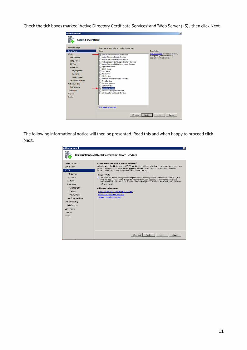
Check the tick boxes marked ‘Active Directory Certificate Services’ and ‘Web Server (IIS)’, then click Next.
The following informational notice will then be presented. Read this and when happy to proceed click
Next.

12
On the next screen, check the ‘Certification Authority’ box and click Next.
Please note; while we do also need to install the Network Device Enrolment Service that it’s not possible
to install this feature at the same time as the Certification Authority service. This service will need to be
installed later.
At the next screen select the Standalone option. This will be the only option available if the server is not
part of a Domain. Click Next.
On the next screen select the Root CA option as this is the only CA that will be in use. Click Next

13
Select the option to use a new private key as we are not restoring a previously configured CA. Click Next.
Select a suitable cryptographic service provider, key size and hashing algorithm. Click Next.
Enter the desired Common Name and any require suffix for the CA. Click Next.

14
Choose a suitable length of time for the CA certificate to be valid. A certificate issued using this CA can in
turn only be valid up to eh expired date of the CA itself. Click Next.
Choose a location for the certificate database and log files to be located. Click Next.
The next screen will provide information on installing the IIS service. Read this then click Next.
For this application the default options are sufficient. Click Next.

15
Review the options chosen, then click install to begin the installation process.
The installation of the CA and IIS services will begin. After the installation is complete the server will
present a summary window that details what has been installed and if any error occurred. Review this and
click close.
To install the Remote Device Enrollment Service In the Microsoft Management console browse to Active
Directory Certificate services, then click the ‘Add Role Services’ link.

16
This will start the relevant wizard. Check the box to add the Network Device Enrollment Service.
The server will then present a notification of the other dependencies that will also need to be installed.
Click the button to add these to the installation.

17
Then Click next on the wizard screen. Then select the option to use a network service account. Click Next.
Enter registration authority information. Enter appropriate company information and click Next.
Select suitable cryptography settings for the registration authority. Click Next.

18
The next screen details the update to the IIs installed again. Click next on this, the next screen highlights
the dependencies that are required for the SCEP service installation. Click Next.
Then review the chosen options and click install to proceed with the installation of the updated roles.
There will then be a summary screen of features that have been installed.
Finally a dialogue box will appear containing a URL to use for SCEP enrolment.
IMPORTANT: Make a permanent note of this URL. This will be needed every time when creating
certificates with this CA; http://<hostname>/certsrv/mscep/mscep.dll where <hostname> is the hostname
or IP address of the CA server.

19
4.2.2 Check the CA Certificate service is running
To check the CA Certificate service is running, check the server manger MMC. There should be a green
circle with a tick in it next to the CA, as per the picture below.
If the service is not running there will be a white circle with a black dot inside it. To start the service right
click on the CA object , highlight ‘all tasks’, then select ‘start service’.
4.2.3 Check IIS and SCEP service status
To check that both IIS and SCEP are running OK using the server management console browsr to web
server (IIS) heading in the roles section. This shows the status and if IIS services is running.

20
To check that the SCEP service has started OK, click on the ‘Internet Information Service (IIS) Manager’
section. Then in main window click on Application Pools. This will display the ‘Application Pools’ where the
status of the SCEP service can be checked.
4.3 Automatic Enrolment
This is an optional stage, without configuring this feature the initial certificate request will be left in a
pending state. At this point the CA administrator will need to manually either approve or reject the
certificate request. A 2nd request will need to be made after this has been done in order to automatically
download the router certificate. Not using automatic Enrolment increases the security of the CA service
but also increases the amount of administration time required.
To enable this feature open the Certificate Authority console, right click on the CA and select Properties.

21
In the Properties window select the Policy Module tab.
Whilst in the Policy Module tab click the Properties button.
Select Follow the settings in the certificate template, if applicable. Otherwise, automatically issue the
certificate.
Click OK and again OK on the Policy Module tab.
Note: A warning dialogue box like the one below should be displayed stating that for the configuration
change to take effect, Active Directory Certificate Services must be stopped and started again.
Despite stopping and starting the service, during the process of creating this document the only reliable
method of ensuring the configuration change took effect, to allowed automated enrolling, was to restart
the Windows server.

22
5 TRANSPORT VPN SERVER - CERTIFICATES
5.1 LAN Interface Configuration
The following configures the Ethernet local area network IP address for the VPN server.
Browse to Configuration – Network > Interfaces > Ethernet > Eth 0
Parameter Setting Description
IP Address: 172.16.0.254 Configures the IP address for the LAN
Mask: 255.255.0.0 Configures the subnet mask for the LAN
5.2 Date and Time
Any certificates stored on the router flash will have a validity period. Therefore it is important that the
Transport is configured with the correct time and date as the incorrect date/time set on the router is one of
the most common issues encountered when attempting to use certificates when
Browse to; Configuration – System > Date and Time.
Amend the time and date as appropriate and click the Set button.

23
5.3 Hostname
Configure the hostname of the router.
Browse to Configuration - System > Device Identity and enter the router hostname and click Apply.
Please note: The hostname should be a unique identifier for the router; The hostname is only for
identification and system management and does not take any part in the certificate process.
5.4 WAN Interface Configuration
Enter the details of the IP Address, subnet mask and gateway and also enable IPsec on this interface.
Browse to Configuration - Network > Interfaces > Ethernet > ETH 3

24
Parameter Setting Description
Description WAN Interface A free text field to provide a friendly name.
IP Address 10.1.65.10 Configures the IP Address of the interface
Subnet Mask 255.255.0.0 Sets the subnet mask for the IP address
assigned
Gateway 10.1.255.254 Sets the gateway for the network on this
interface
DNS Server 10.1.255.254 Sets the DNS Server for the interface
Enable IPsec on this interface
checked Enables IPsec on ETH 3*
*This option is found under the advanced section of the Ethernet interface configuration.
5.5 Configure the Default Route
To ensure that Eth 3 is configured as the default route.
Browse to Configuration - Network > IP Routing/Forwarding > Static Routes > Default Route 0
Parameter Setting Description
Interface Entity type Ethernet Sets the WAN interface entity type
Interface Instance number
3 Sets the instance number of the entity
type chosen.
Please Note: As the gateway was configured on the WAN interface setting a gateway on this page is not
required or advised.
5.6 Certificate Enrolment
5.6.1 Download CA certificates.
The router must first have access to the server CA certificate(s). Some servers require the use of more than
one CA certificate. In this case the Microsoft® Windows 2008 server requires 3 CA certificates before SCEP
will work. For other servers, just one certificate may be used for all three tasks. Check the server vendor
for details.
The tasks these certificates are used for are:

25
CA certificate. This is the certificate that will contain the public key portion of the key used to sign
the certificate request.
CA encryption certificate. This certificate is used to encrypt the data the client will send to the
server.
CA signature certificate. This is attached to the reply from the CA which is validated by the client.
The public key from this certificate is used to verify the signature.
Browse to Administration – X.509 certificate management > Certificate Authorities (CAs)
To receive the CA certificates fill in the fields marked and press Get CA Certificates.
Parameter Setting Description
SCEP server IP Adderss
CA server IP address CA server IP address
Port 0
MS SCEP uses HTTP to carry the requests, If this parameter is non-zero, the unit will use
this value as the destination port rather than the default of 80
Path certsrv/mscep/mscep.dll Select Microsoft SCEP from drop down list and the path will be entered automatically
Application pkiclient.exe This represents the SCEP application on the
server
CA Identifier ACP CA identifier
After clicking ‘Get CA Certificates’, the process starts and output detailing the progress of CA certificate
collection is shown bellow.

26
Please note: If a hierarchical CA is used the router will download more than one CA certificate (one for
each CA that is involved in the chain). On firmware releases prior to 5132 multiple CA certificates will be
downloaded but may not all be saved correctly with the ‘ca’ prefix to indicate a CA certificate. Therefore
the need to rename CA certificates from the ‘cert’ prefix to the ‘ca’ prefix to ensure that the certificates are
used correctly during the SCEP process. Carefully reading the certificate collection results will indicate
what each certificate was saved as. These can then be renamed by the ‘execute a command’ web page
using the <ren> command.
5.6.2 Obtain a Challenge Password for the Certificate Request.
This password is generally obtained from the SCEP CA server by way of WEB server, or a phone call to the
CA Server Administrator. For the SCEP server, browse to a web interface. If the server requires a challenge
password, it will be displayed on the page along with the CA certificate fingerprint.
This challenge password is usually only valid once and for a short period of time, in this case 60 minutes,
meaning that a certificate request must be created within the 60 minutes after retrieving the challenge
password.
From a PC browse to the following Microsoft® CA server web page using URL changing the host name of
the CA server http://<hostname>/mscep/mscep.dll, click the link to browse to the URL that will provide the
challenge password. The server will ask for a suitable username/password to view the page.
5.6.3 Configure the Certificate Request page
Browse to Administration – X.509 certificate management > IPsec/SSH/HTTPS certificates
Enter the above challenge password and configure all other fields as appropriate. These details will form
part of the certificate request and thus form part of the signed public key certificate. Note that there is the
option to use an already existing private key. If automatic enrolment process is not being used ensure to
use this option on the second SCEP request.
Note: If the router has only a single CA certificate it will automatically choose this in the following page.
IF the router has multiple CA certificates ensure that the certificate of the server that is being requested
has been selected.

27
NOTE: * The Common Name (case sensitive) field is important as this will be used as the ID for the device
for the IKE negotiations.
Click the Enrol button. Some indication of the progress as the router generates the Private Key file (if
applicable) and certificate request as follows;
Parameter Setting Description
Challenge Password:
D0B9A7D053B044F5 Enter the Challenge Password issued by the
SCEP server
Country: UK Enter a two character representation of the
country
Common Name: DR_Router Enter a Common Name for the router’s ID*
Locality: Ilkley The Location of the unit
Organisation: Digi International An appropriate Company name
Organisational Unit:
Support An appropriate organisational unit
State: West Yorkshire State or County or Province
Email Address: [email protected] An appropriate email Address
Unstructured Name:
Optional descriptive text
Digest Algorithm: MD5 Choose either MD5 or SHA1. This is used
when signing the certificate request
New Key Size: 1024 Size of the private key in bits
Private Key filename:
privkey.pem Enter a name for the private key (must be
prefixed with “priv” and have a .pem extension).

28
The above example shows the SCEP response as success, There are three possible responses;
Failure - The request failed. Check that the correct CA certificates have been used. Check that the
challenge password is correct. Check that the correct certificate request has been specified, and that the
correct private key has been used. Check the server logs to see what the problem is.
Pending - The server has the request, but hasn’t signed it yet. It may require some input by the System
Administrator. The unit should poll the server occasionally until the certificate is returned. However, if
certificate request has been allowed having contacted the System Administrator simply press the Enroll
button again rather than wait for the Transport to re-poll.
Success - The response should contain the signed certificate.

29
5.6.4 Administrator approved enrolment
If automatic enrolment has been configured correctly then this section is not required. An example
certificate request output below shows the SCEP certificate request is left in the pending state. In this case
then the SCEP server administrator needs to manually enrol the device prior to the router being able to
obtain its certificate.
Log in to the SCEP Server with an appropriate System Administrator account. Start the server a
management console and browse to the pending folder of the CA.
Right-click the pending certificate and highlight the ‘All Tasks’ option which will reveal another menu.
From the new menu select the ‘Issue’ option to sign the certificate request. If there is more than one
certificate request pending, then check the request is for the correct device by scrolling sideway and
checking the common name that is listed in the certificate request.
Once the certificate request has been signed the router will automatically re-poll the CA server over time
or re-poll manually by again clicking on the Enroll button as before.
There should now be a success message indicating that the certificate request has been signed and
returned by the CA as shown below. This router now has a public key.

30
5.7 Reviewing certificates on Transport routers
If during the VPN configuration process there are problems with the VPN negotiation and a certificate
error is suspected it may be useful to manually check the contents of any certificates that are located on a
router, or alternatively delete incorrect/unused certificates. This can be done by clicking the relevant
“View” button that is visible for each of the certificates that are on the router. The screen print below
shows all the downloaded certificates
Clicking on the view button opens the certificate so this can be review. Below is a portion of the output of a
just issued DR64 router certificate. Highlights on the portions that are most commonly needed to be
checked.

31

32
6 CISCO® VPN INITIATOR - CERTIFICATES
The following Cisco® configuration is denoted as follows;
General description is shown using the “Arial” font with points of interest in bold.
The command prompt is shown using the “courier new” font.
User input is shown using the “courier new” font in bold text.
Any dialogue returned by the Cisco® is shown using the “courier new” font
in italic text.
6.1 General Setup
6.1.1 Set the Real Time Clock
Any certificates stored in the Cisco® private NVRAM will have a validity period. Therefore it is important
that the Cisco® is configured with the correct time and date.
Router#clock set 10:10:50 6 july 2011
6.1.2 Enter Global Configuration Mode
Router#conf t
Enter configuration commands, one per line. End with CNTL/Z.
6.1.3 Configure a Password for Privileged Mode
Router(config)#enable secret xxxxxxxxxxx
6.1.4 Configure a Hostname and Domain name
In this example the fully qualified domain name will be cisco.scepmatic5000.com
Router(config)#hostname Cisco
Cisco(config)# ip domain-name scepomatic5000.com
Note: Notice that the command prompt has now changed to the hostname
6.1.5 Configure the IP Address of a DNS Server
Cisco(config)#ip name-server 217.34.133.20
6.2 Ethernet Configuration
Select FastEthernet0 as the Ethernet interface to configure. This command will put router into configure
interface (config-if) mode.
Cisco(config)#interface FastEthernet0

33
6.2.1 Configure the internal LAN address of the router
Cisco(config-if)#ip address 192.168.0.254 255.255.255.0
Configure the speed of the Ethernet interface
Cisco(config-if)#speed 100
Cisco(config-if)#full-duplex
6.2.2 Activate the Fast Ethernet Interface
By default the FastEthernet0 interface will be in a shutdown or inactive state. Therefore the Ethernet
interface should be made active as follows;
Cisco(config-if)#no shutdown
After the no shutdown command is issued there should be some indication that the interface is active
(assuming that eh Ethernet cable is connected);
Jul 6 10:51:36.259: %LINEPROTO-5-UPDOWN: Line protocol on Interface
FastEthernet0, changed state to up
6.2.3 Configure the outside WAN address of the router
Cisco(config-if)#interface Ethernet 0
Cisco(config-if)#ip address 10.1.65.12 255.255.0.0
Cisco(config-if)#full-duplex
Cisco(config-if)#no shutdown
After the no shutdown command is issued there should be some indication that the interface is active
(assuming that eh Ethernet cable is connected);
Jul 6 10:51:19.563: %LINEPROTO-5-UPDOWN: Line protocol on Interface
Ethernet0, changed state to up
6.2.4 Exit config-if mode
Cisco(config-if)#exit
6.2.5 Configure the Default Gateway
Cisco(config)#ip default-gateway 10.1.255.254
6.2.6 Enable classless routing (CIDR) behaviour
Cisco(config)#ip classless
6.2.7 Configure the Default Route IP route
Cisco(config)#ip route 0.0.0.0 0.0.0.0 10.1.255.254

34
6.3 Generate the RSA Key Pair
The Cisco® RSA key pairs are used to sign and encrypt IKE messages. The RSA key pair must be generated
before the router can request a certificate from the CA.
Use the following command whilst in global configuration mode.
Cisco(config)#crypto key generate rsa
The name for the keys will be: Cisco.scepomatic5000.com
Choose the size of the key modulus in the range of 360 to 2048 for your
General Purpose Keys. Choosing a key modulus greater than 512 may take
a few minutes.
6.3.1 Specify the Key Length in Bits
How many bits in the modulus [512]: 1024
% Generating 1024 bit RSA keys ...[OK]
Jul 6 11:05:16.871: %SSH-5-ENABLED: SSH 1.5 has been enabled
6.4 Configure the CA
6.4.1 Certificate Authority Server Declaration
Before the router can obtain a signed certificate, a valid CA must be declare. The following command
declares the CA that will be used, if a domain name is used ensure it will resolve to an IP address that the
Cisco® can connect to .
This command puts the router into ca-identity configuration mode.
Cisco(config)# crypto ca identity 10.1.65.200
6.4.2 Configure the SCEP URL
Enter the url presented at the end of installing the SCEP add-on facility on the CA server. The format is
http://<server>:80/certsrv/mscep/mscep.dll , where <server> is the FQDN or IP address of the CA server, if
the hostname is used, the previously configured DNS sevrer must be able to resolve the configured
hostname and the router must be able to connect to it.
Cisco(ca-trustpoint)#enrollment url http://10.1.65.200/certsrv/mscep/mscep.dll
If a host name for the CA server is to been used the router should provide output similar to that used
below.
Translating "server.domain.com"...domain server (217.34.133.20) [OK]

35
6.4.3 Registration Authority (RA) Mode
The Microsoft® CA Server provides a Registration Authority (RA), therefore the Cisco® needs to be put
into RA mode as follows.
Cisco(ca-trustpoint)#enrollment mode ra
6.4.4 Set Certificate Revocation List to Optional
The following command enables the router to accept the other Peer’s certificates even if the CRL
(Certificate Revocation List) is not accessible to the router.
Cisco(ca-trustpoint)#crl optional
6.4.5 Exit ca-trustpoint mode.
Cisco(ca-trustpoint)#exit
6.5 Using SCEP to retrieve the CA certificates
6.5.1 Authenticate the CA
The router is required to authenticate the CA by retrieving the CA’s self signed certificate which contains
the CA’s public key.
Cisco(config)#crypto ca authenticate 10.1.65.200
Certificate has the following attributes:
Fingerprint: 1D91BC43 C27BBF63 BD91DD64 BF61F1E7
6.5.2 Accept the CA Certificate
At this point it is required to accept or decline the CA’s certificate.
% Do you accept this certificate? [yes/no]: yes
Trustpoint CA certificate accepted.
6.6 Using SCEP to Enrol the Certificate Request
Cisco(config)#crypto ca enroll 10.1.65.200
% Start certificate enrollment ..
% Create a challenge password. You will need to verbally provide this
password to the CA Administrator in order to revoke your certificate.
For security reasons your password will not be saved in the
configuration.
Please make a note of it.

36
6.7 Obtain a Challenge Password for the Certificate Request.
The router will now prompted for a challenge password from the CA Server. This password is generally
obtained from the SCEP CA server by way of WEB server, or a phone call to the CA Server Administrator.
For the Microsoft® SCEP server, browse to a web interface. If the server requires a challenges password, it
will be displayed on the page along with the CA certificate fingerprint.
This challenge password is usually only valid once and for a short period of time, in this case 60 minutes,
meaning that a certificate request must be created within the 60 minutes after retrieving the challenge
password.
From a PC browse to the following Microsoft® CA server web page using URL
http://<hostname>/mscep/mscep.dll (as detailed in “Microsoft® 2008 server Configuration) and make a
note of the challenge password.
6.7.1 Enter the Challenge Password
Note: The router does not echo back the password as it is type, but for the purpose of this application note
I have entered plain text.
Password: C35B1FCFAA5A13C2
Re-enter password: C35B1FCFAA5A13C2
% The fully-qualified domain name in the certificate will be:
Cisco.scepomatic5000.com
% The subject name in the certificate will be: Cisco.scepomatic5000.com
Type NO when prompted to include the router’s serial number in the certificate request
% Include the router serial number in the subject name? [yes/no]: no
Type NO when prompted to include the router IP address in the certificate request

37
% Include an IP address in the subject name? [no]: no
Type YES to request a certificate from the CA.
Request certificate from CA? [yes/no]: yes
% Certificate request sent to Certificate Authority
% The certificate request fingerprint will be displayed.
% The 'show crypto ca certificate' command will also show the
fingerprint.
Cisco(config)# Fingerprint: 67948EB0 ADA7C83C 4DD505CB DB5415D7
6.8 Issuing a Signed Certificate on Microsoft® Windows Server 2008.
If the Microsoft® CA server is not configured for automatic enrolment then it will return a pending
message to the router
Jul 6 12:10:25.849: CRYPTO_PKI: status = 102: certificate request pending
Jul 6 12:10:42.849: CRYPTO_PKI: status = 102: certificate request pending
Login to the SCEP server and issue the certificate as detailed in Section 6.4.4. Once the certificate request
has been signed then wait for the router to automatically re-poll the CA server according to the retry
counters set in the Cisco® configuration.
There should now be a success message indicating that the certificate request has been signed and
returned by the CA as shown below. This is the routers public key.
Jul 6 12:13:42.723: %CRYPTO-6-CERTRET: Certificate received from Certificate
Authority

38
CONFIGURE IKE AND IPSEC – VPN SERVER
6.9 Configure IKE (Internet Key Exchange)
IKE is the first stage in establishing a secure link between two endpoints. The VPN Server will act as
the IKE ‘responder’ and as such will not initiate VPN tunnels. By default the DR64 responder setup is
configured to accept the full range of authentication and encryption algorithms available.
Browse to Configuration - Network > Virtual Private Networking (VPN) > IPsec > IKE > IKE
Responder
Set the IKE lifetime to 24hrs (86400s), drop down the Advanced options, un-tick send initial contact
notifications and enter the file name of the private key file and click Apply.
Parameter Setting Description
Renegotiate after 24hrs Sets the IKE lifetime
Send ININTIAL-CONTACT
notifications Un-checked
Prevents initial contact notification option being used
RSA private key file:
privkey.pem Enter the name of the private key file

39
6.10 Configure IPsec
The IPsec itself is configured in the IPsec Tunnels section (also often referred to as an Eroute or encrypted
route). The IPsec instances define the characteristics of the encrypted routes i.e. local and remote
subnets, authentication and encryption methods etc.
Browse to Configuration - Network > Virtual Private Networking (VPN) > IPsec > IPsec Tunnels > IPsec
0 - 9 > IPsec 0

40
Parameter Setting Description
Description Tunnel to Cisco A friendly name
Local LAN IP address: 172.16.0.0 Enter the local subnet IP address
Local LAN subnet mask: 255.255.0.0 Enter the local subnet mask
Remote LAN subnet IP address:
192.168.0.0 Enter the remote subnet IP address
Remote LAN subnet mask: 255.255.255.0 Enter the remote subnet mask
Authentication method RSA Signatures Select RSA signatures for the authentication
method
Our ID: DR_Router Common name specified in our public key *
Peer ID: Cisco.scepomatic5000.com Enter the Cisco® fully qualified domain name
(FQDN).
Encryption Method AES (128 bit) Select AES 128 as the encryption algorithm **
Authentication Method SHA1 Select SHA1 as the authentication algorithm
**
Diffie Hellman group 2 Sets ESP the Diffie Hellman group (AKA PFS
group)**
* To check the common name used in the public key
Browse to Administration – X.509 certificate management > IPsec/SSH/HTTPS certificates
click view. Now be able to view the certificate and see the entry in the common name field.
** The authentication and encryption algorithms must match exactly the settings in the peer IPsec
router.
41
7 CONFIGURE IKE AND IPSEC – CISCO®
7.1 Configure IKE (Internet Key Exchange)
IKE is the first stage in establishing a secure link between two endpoints. The VPN client will act as
the IKE ‘initiator’ and as such will make first contact with the VPN server. This allows the Cisco® to
have a dynamic IP address on its WAN interface and therefore there is no requirement for the VPN
server to know the Cisco® IP address. The Cisco® current IP address will be included each time IKE is
negotiated.
Whilst in global configuration mode define the IKE policy to use. Policies are uniquely identified by
the policy number define and can create multiple IKE policies each with an entirely different set of IKE
parameters.
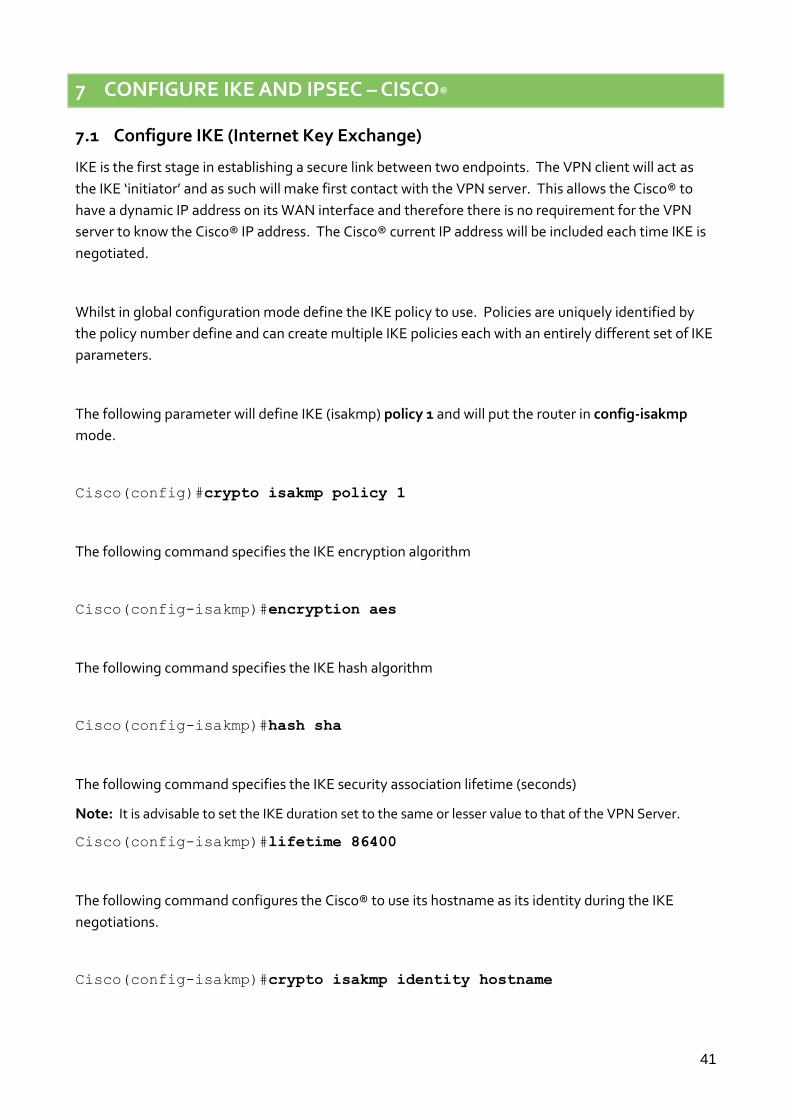
The following parameter will define IKE (isakmp) policy 1 and will put the router in config-isakmp
mode.
Cisco(config)#crypto isakmp policy 1
The following command specifies the IKE encryption algorithm
Cisco(config-isakmp)#encryption aes
The following command specifies the IKE hash algorithm
Cisco(config-isakmp)#hash sha
The following command specifies the IKE security association lifetime (seconds)
Note: It is advisable to set the IKE duration set to the same or lesser value to that of the VPN Server.
Cisco(config-isakmp)#lifetime 86400
The following command configures the Cisco® to use its hostname as its identity during the IKE
negotiations.
Cisco(config-isakmp)#crypto isakmp identity hostname
42
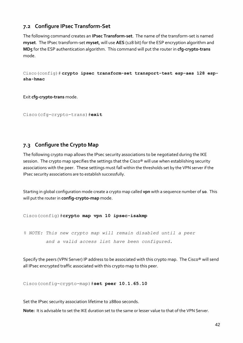
7.2 Configure IPsec Transform-Set
The following command creates an IPsec Transform-set. The name of the transform-set is named
myset. The IPsec transform-set myset, will use AES (128 bit) for the ESP encryption algorithm and
MD5 for the ESP authentication algorithm. This command will put the router in cfg-crypto-trans
mode.
Cisco(config)# crypto ipsec transform-set transport-test esp-aes 128 esp-
sha-hmac
Exit cfg-crypto-trans mode.
Cisco(cfg-crypto-trans)#exit
7.3 Configure the Crypto Map
The following crypto map allows the IPsec security associations to be negotiated during the IKE
session. The crypto map specifies the settings that the Cisco® will use when establishing security
associations with the peer. These settings must fall within the thresholds set by the VPN server if the
IPsec security associations are to establish successfully.
Starting in global configuration mode create a crypto map called vpn with a sequence number of 10. This
will put the router in config-crypto-map mode.
Cisco(config)#crypto map vpn 10 ipsec-isakmp
% NOTE: This new crypto map will remain disabled until a peer
and a valid access list have been configured.
Specify the peers (VPN Server) IP address to be associated with this crypto map. The Cisco® will send
all IPsec encrypted traffic associated with this crypto map to this peer.
Cisco(config-crypto-map)#set peer 10.1.65.10
Set the IPsec security association lifetime to 28800 seconds.
Note: It is advisable to set the IKE duration set to the same or lesser value to that of the VPN Server.

43
Cisco(config-crypto-map)# set security-association lifetime seconds 28800
The following command specifies which transform-set is to be associated with the crypto map.
Specify that transform-set myset to be associated with this crypto map vpn.
Cisco(config-crypto-map)#set transform-set transport-test
The following command names the extended access list which is to be associated with this crypto
map. The access list specify will determine what traffic is to be passed through the IPsec tunnel.
Specify access-list 101 (access list 101 will be created later).
Cisco(config-crypto-map)#match address 101
Exit config-crypto-map mode.
Cisco(config-crypto-map)#exit
7.4 Create the IPsec Access List
Create an extended access list. An extended access list will allows to filter on both the source and
destination IP address rather than just the source IP address as with a standard access list. This is
important as the router needs to allow encrypted IPsec traffic to be initiated from both directions.
This command will put the router in config-ext-nacl mode for access list “101”.
Cisco(config)# ip access-list extended 101
Create access list with an ID of 101* as specified in crypto map vpn. The access list will allow traffic from
the IP subnet 192.168.0.0/24 to 172.16.0.0/16 (and vice versa) to pass freely through the IPsec tunnel.
*For extended access lists the access list ID must be within the range of 101 to 199 inclusive.
Cisco(config-ext-nacl)# permit ip 192.168.0.0 0.0.0.255 172.16.0.0
0.0.255.255
Associate Crypto Map to the WAN Interface.
Enter config-if mode for interface Fast Ethernet 0

44
Cisco(config)#interface Ethernet0
Associate crypto map test-vpn with Ethernet 0
Cisco(config-if)#crypto map test-vpn
Type crtl z to return to global mode.
Cisco(config-if)#
7.5 Saving the Configuration
Important: The following command is very important as it includes saving the RSA keys to private NV
RAM. RSA keys are NOT saved with certain other methods of saving.
Cisco#copy system:running-config nvram:startup-config
Destination filename [startup-config]?
Building configuration...
[OK]

45
8 TESTING – CISCO® VPN INITIATOR
8.1 Display IKE Information
First generate some traffic from the Cisco LAN to the Transport LAN.
Cisco#show crypto isakmp policy
Protection suite of priority 1
encryption algorithm: AES - Advanced Encryption Standard (128
bit keys).
hash algorithm: Secure Hash Standard
authentication method: Rivest-Shamir-Adleman Signature
Diffie-Hellman group: #1 (768 bit)
lifetime: 86400 seconds, no volume limit
Default protection suite
encryption algorithm: DES - Data Encryption Standard (56 bit
keys).
hash algorithm: Secure Hash Standard
authentication method: Rivest-Shamir-Adleman Signature
Diffie-Hellman group: #1 (768 bit)
lifetime: 86400 seconds, no volume limit
Display Crypto Map Configuration
Cisco#show crypto map tag test-vpn
Cisco#show crypto map tag test-vpn
Crypto Map "test-vpn" 10 ipsec-isakmp
Peer = 10.1.65.10
Extended IP access list 101
access-list 101 permit ip 192.168.0.0 0.0.0.255 172.16.0.0
0.0.255.255
Current peer: 10.1.65.10
Security association lifetime: 4608000 kilobytes/28800 seconds
PFS (Y/N): N
Transform sets={
transport-test,
}
Interfaces using crypto map test-vpn:
Ethernet0

46
8.2 Display Transform Set Configuration
Cisco#show crypto ipsec transform-set
Transform set transport-test: { esp-aes esp-sha-hmac }
will negotiate = { Tunnel, },
8.3 Display List of All RSA Public Keys On the Cisco Router
Cisco#show crypto key pubkey-chain rsa
Codes: M - Manually configured, C - Extracted from certificate
Code Usage IP-Address/VRF Keyring Name
C Signing default X.500 DN name:
CN = SCEPOTRON-CA
C General default DR_Router
Cisco#
8.4 Display the Cisco Routers RSA Public Keys
Cisco#show crypto key mypubkey rsa
% Key pair was generated at: 12:09:53 UTC Jul 6 2011
Key name: Cisco.scepomatic5000.com
Usage: General Purpose Key
Key is not exportable.
Key Data:
30819F30 0D06092A 864886F7 0D010101 05000381 8D003081 89028181 00A65BE4
E63ABC86 FE941136 11BA199E 83A42489 CA1F4BA4 46AD07EB 65658052 5EAD4212
AE700126 BB8D7F4A 3D708CA7 80F38A70 A3679F02 E0AC75F2 375D4235 35D4D53D
12D90BAE 01484C8D 7F73676E 37564852 96EC3A93 470648DB 5D8D54AF CA7053CE
A1122040 35F68692 28E9827D 57BAB9B5 77D58CCB F69F366F 9540C9B7 45020301 0001
% Key pair was generated at: 05:18:44 UTC Jul 7 2011
Key name: Cisco.scepomatic5000.com.server
Usage: Encryption Key
Key is not exportable.
Key Data:

47
307C300D 06092A86 4886F70D 01010105 00036B00 30680261 00AE796D A63C6F8A
913E06EE 34C76C07 1EFBBA92 1B5F3599 3FC0673F 10737F16 F66F6EAE D6E30071
8F314768 FEAAB24A FAAF5728 11DA31AC 541BED97 8CBB198B 1AC7AE3F 0581039F
799CFC4E FAC50E1F A018BFD0 C8133EB1 E6EDB4B8 EBA80950 6B020301 0001
Cisco#
8.5 Display Information about the Router, CA and RA Certificates
Cisco#show crypto ca certificates
Certificate
Status: Available
Certificate Serial Number: 6120A901000000000008
Certificate Usage: General Purpose
Issuer:
CN = SCEPOTRON-CA
Subject:
Name: Cisco.scepomatic5000.com
OID.1.2.840.113549.1.9.2 = Cisco.scepomatic5000.com
CRL Distribution Point:
http://scepotron/CertEnroll/SCEPOTRON-CA.crl
Validity Date:
start date: 11:02:23 UTC Jul 6 2011
end date: 11:12:23 UTC Jul 6 2012
renew date: 00:00:00 UTC Jan 1 1970
Associated Trustpoints: 10.1.65.200
CA Certificate
Status: Available
Certificate Serial Number: 67E5E20F8B7B799140B561AE0C4DA469
Certificate Usage: Signature
Issuer:
CN = SCEPOTRON-CA
Subject:
CN = SCEPOTRON-CA
Validity Date:
start date: 14:14:48 UTC Jul 1 2011
end date: 14:24:39 UTC Jul 1 2026
Associated Trustpoints: 10.1.65.200

48
8.6 Display Information About the IPsec SAs
Cisco#show crypto ipsec sa
interface: Ethernet0
Crypto map tag: test-vpn, local addr. 10.1.65.12
protected vrf:
local ident (addr/mask/prot/port): (192.168.0.0/255.255.255.0/0/0)
remote ident (addr/mask/prot/port): (172.16.0.0/255.255.0.0/0/0)
current_peer: 10.1.65.10:500
PERMIT, flags={origin_is_acl,}
#pkts encaps: 2, #pkts encrypt: 2, #pkts digest 2
#pkts decaps: 2, #pkts decrypt: 2, #pkts verify 2
#pkts compressed: 0, #pkts decompressed: 0
#pkts not compressed: 0, #pkts compr. failed: 0
#pkts not decompressed: 0, #pkts decompress failed: 0
#send errors 1, #recv errors 0
local crypto endpt.: 10.1.65.12, remote crypto endpt.: 10.1.65.10
path mtu 1500, media mtu 1500
current outbound spi: BC507856
inbound esp sas:
spi: 0xFFC4C117(4291084567)
transform: esp-aes esp-sha-hmac ,
in use settings ={Tunnel, }
slot: 0, conn id: 2000, flow_id: 1, crypto map: test-vpn
sa timing: remaining key lifetime (k/sec): (4401498/27655)
IV size: 16 bytes
replay detection support: Y
inbound ah sas:
inbound pcp sas:
outbound esp sas:

49
spi: 0xBC507856(3159390294)
transform: esp-aes esp-sha-hmac ,
in use settings ={Tunnel, }
slot: 0, conn id: 2001, flow_id: 2, crypto map: test-vpn
sa timing: remaining key lifetime (k/sec): (4401498/27655)
IV size: 16 bytes
replay detection support: Y
outbound ah sas:
outbound pcp sas:
Cisco#

50
9 CHECKING STATUS OF VPN ON THE TRANSPORT ROUTER
9.1 Check the WAN Link is Active
When browsing the Transport web interface, view the status of any interface. The following screen shot
shows the status of the exit interface interface. The presence of an IP address in the IP Address filed
shows status and statistics.
Browse to Management - Network Status > Interfaces > Ethernet > ETH 3
9.2 Check the IPsec Tunnel is Active
In the Management - Connections > Virtual Private Networking (VPN) section it is possible to check the
status of the IPsec VPN tunnel
9.2.1 IPsec PEERS
The IPSec Peers shows the WAN address or hostnames of all the VPN Clients/Hosts that are currently
connected to the transport router.
Browse to Management - Connections > Virtual Private Networking (VPN) > IPsec > IPsec Tunnels

51
9.2.2 IKE SAs
The IKE SAs status page shows the current active IKE security associations.
Browse to Management - Connections > Virtual Private Networking (VPN) > IPsec > IKE SAs
9.2.3 IPsec SAs
The IPSec SAs status page shows the current active IPsec security associations. Each IPsec VPN tunnel has
IPsec security associations for both inbound and outbound traffic.
Browse to Management - Connections > Virtual Private Networking (VPN) > IPsec > IPsec Tunnels >
IPsec Tunnels 0 - 9 > IPsec Tunnel 0
9.3 Test the IPsec Routing
When an IP packet is received by a VPN router it must meet certain criteria for it to be passed through the
VPN tunnel. On the transport router the source and destination IP address MUST match that of one of the
configured Eroutes and IPsec SAs. In the case of the Cisco® the addresses need to match that of the access
list(s) configured for the tunnel group, the Cisco router will accept all inbound traffic by default, the access
list applies to traffic outbound on the interface.
In brief, the VPN tunnel in this application note will pass data from network on subnet 192.168.0.0/24 to
network on subnet 172.16.0.0/16 and vice versa (see diagram on page 3).
Using the Transport analyser trace we will see evidence of data being routed through the IPsec VPN
Tunnel. In this example computer A (192.168.0.10) will ping Server B (172.16.0.1).
To view the Transport analyser trace browse to Management - Analyser > Trace.
Items of particular interest have been highlighted in red in the decoded IP packets.
The Transport router receives an ICMP PING (echo request) on interface Eth 0 from Server B
(172.16.0.10) to be routed via the VPN tunnel to Computer A (192.168.0.10).

52
----- 11-7-2011 10:42:10.600 ------
45 00 00 26 00 06 00 00 F9 01 55 0D AC 10 00 0A E.......ù.U.....
C0 A8 00 01 08 00 39 7B 18 F8 00 06 01 78 00 00 ......9..ø...x..
00 01 58 01 4C 0C 00 00 00 00 00 00 00 00 00 00 ..X.L...........
00 00 ..
IP (In) From REM TO LOC IFACE: ETH 0
45 IP Ver: 4
Hdr Len: 20
00 TOS: Routine
Delay: Normal
Throughput: Normal
Reliability: Normal
00 26 Length: 38
00 06 ID: 6
00 00 Frag Offset: 0
Congestion: Normal
May Fragment
Last Fragment
F9 TTL: 249
01 Proto: ICMP
55 0D Checksum: 21773
AC 10 00 0A Src IP: 172.16.0.10
C0 A8 00 01 Dst IP: 192.168.0.10
ICMP:
08 Type: ECHO REQ
00 Code: 0
39 7B Checksum: 31545
----------
The PING is passed to the Eth 3 interface for routing over the WAN connection.
----- 11-7-2011 10:42:10.600 ------
45 00 00 26 00 06 00 00 F8 01 56 0D AC 10 00 0A E.......ø.V.....
C0 A8 00 01 08 00 39 7B 18 F8 00 06 01 78 00 00 ......9..ø...x..
00 01 58 01 4C 0C ..X.L.
ER 0-Cisco.scepomatic5000.com From LOC TO REMIFACE: ETH 3
45 IP Ver: 4
Hdr Len: 20
00 TOS: Routine
Delay: Normal
Throughput: Normal
Reliability: Normal

53
00 26 Length: 38
00 06 ID: 6
00 00 Frag Offset: 0
Congestion: Normal
May Fragment
Last Fragment
F8 TTL: 248
01 Proto: ICMP
56 0D Checksum: 22029
AC 10 00 0A Src IP: 172.16.0.10
C0 A8 00 01 Dst IP: 192.168.0.10
ICMP:
08 Type: ECHO REQ
00 Code: 0
39 7B Checksum: 31545
----------
The PING is then encapsulated in an ESP Packet.
Note: the source IP addresses is now that of the WAN interface of Transport router (10.1.65.10) and the
destination IP address is that of the WAN Interface of the Cisco® Router (10.1.65.12).
----- 11-7-2011 10:42:10.600 ------
45 00 00 68 00 12 00 00 FA 32 2A 3A 0A 01 41 0A E..h.....2....A.
0A 01 41 0C 21 96 68 93 00 00 00 06 05 A8 BC 5C ..A..–h“........
B8 EB C9 48 17 C0 05 1A E8 77 CC C2 CA 1D 13 4D .ë.H....èw.....M
90 5A 3E BA 13 8E 9F A4 44 FA F5 FD 26 C3 99 8A �Z...Ž..D..ý..™Š
AB 00 ED 5E 49 38 36 F0 BD 56 3D 33 2E 60 69 3D ..í.I86..V.3..i.
7E 4D 64 05 51 89 0C F9 78 1F 1C C3 FB 82 40 26 .Md.Q‰.ùx...û...
7E 8E DB CE F6 9C 13 60 .ŽÛÎöœ..
IP (Final) From LOC TO REM IFACE: ETH 3
45 IP Ver: 4
Hdr Len: 20
00 TOS: Routine
Delay: Normal
Throughput: Normal
Reliability: Normal
00 68 Length: 104
00 12 ID: 18
00 00 Frag Offset: 0
Congestion: Normal
May Fragment
Last Fragment

54
FA TTL: 250
32 Proto: ESP
2A 3A Checksum: 10810
0A 01 41 0A Src IP: 10.1.65.10
0A 01 41 0C Dst IP: 10.1.65.12
----------

55
The Transport router receives an ESP packet on the WAN interface (ETH 3) from the Cisco® router
(10.1.65.12). The ESP packet contains the Ping (echo) reply from Computer A.
----- 11-7-2011 10:42:10.610 ------
45 00 00 68 00 18 00 00 FF 32 25 34 0A 01 41 0C E..h.....2.4..A.
0A 01 41 0A BC 50 78 58 00 00 00 06 A4 B1 1E B0 ..A..PxX.....±.°
A6 74 13 08 C1 F8 F2 87 DC F2 DC 2E 16 4C 75 0A .t...øò‡ÜòÜ..Lu.
C3 41 D4 18 D2 40 FE D2 12 20 56 95 87 7C F0 E5 .AÔ.Ò.þÒ..V•‡..å
EC C7 D8 E2 52 93 8C 83 D8 ED 59 39 7C B8 C1 EC ..ØâR“ŒƒØíY9....
4C E2 4B 5A 4F CC 9E 14 9F F3 AC A8 A2 C3 FB D0 LâKZO.ž..ó....ûÐ
80 73 90 8E 94 F5 E1 06 €s�Ž”.á.
IP (In) From REM TO LOC IFACE: ETH 3
45 IP Ver: 4
Hdr Len: 20
00 TOS: Routine
Delay: Normal
Throughput: Normal
Reliability: Normal
00 68 Length: 104
00 18 ID: 24
00 00 Frag Offset: 0
Congestion: Normal
May Fragment
Last Fragment
FF TTL: 255
32 Proto: ESP
25 34 Checksum: 9524
0A 01 41 0C Src IP: 10.1.65.12
0A 01 41 0A Dst IP: 10.1.65.10
----------
The Transport router decrypts the ESP packet, this is now visible as an echo reply packet destined for
the server on ETH 0.
NOTE: The source IP address is now that of Computer A (192.168.0.10) and the destination IP address is
that of Server B (172.16.0.10). At this point the packet is still seen as an incoming packet on the WAN
interface.
----- 11-7-2011 10:42:10.610 ------
45 00 00 26 00 08 00 00 F9 01 55 0B C0 A8 00 01 E.......ù.U.....
AC 10 00 0A 00 00 41 7B 18 F8 00 06 01 78 00 00 ......A..ø...x..
00 01 58 01 4C 0C ..X.L.

56
IP (Cont) From REM TO LOC IFACE: ETH 3
45 IP Ver: 4
Hdr Len: 20
00 TOS: Routine
Delay: Normal
Throughput: Normal
Reliability: Normal
00 26 Length: 38
00 08 ID: 8
00 00 Frag Offset: 0
Congestion: Normal
May Fragment
Last Fragment
F9 TTL: 249
01 Proto: ICMP
55 0B Checksum: 21771
C0 A8 00 01 Src IP: 192.168.0.10
AC 10 00 0A Dst IP: 172.16.0.10
ICMP:
00 Type: ECHO REPLY
00 Code: 0
41 7B Checksum: 31553
----------
The PING REPLY is routed out of interface Ethernet 0 to Server B (172.16.0.10).
----- 11-7-2011 10:42:10.610 ------
45 00 00 26 00 08 00 00 F8 01 56 0B C0 A8 00 01 E.......ø.V.....
AC 10 00 0A 00 00 41 7B 18 F8 00 06 01 78 00 00 ......A..ø...x..
00 01 58 01 4C 0C ..X.L.
IP (Final) From LOC TO REM IFACE: ETH 0
45 IP Ver: 4
Hdr Len: 20
00 TOS: Routine
Delay: Normal
Throughput: Normal
Reliability: Normal

57
00 26 Length: 38
00 08 ID: 8
00 00 Frag Offset: 0
Congestion: Normal
May Fragment
Last Fragment
F8 TTL: 248
01 Proto: ICMP
56 0B Checksum: 22027
C0 A8 00 01 Src IP: 192.168.0.10
AC 10 00 0A Dst IP: 172.16.0.10
ICMP:
00 Type: ECHO REPLY
00 Code: 0
41 7B Checksum: 31553
----------

58
10 TROUBLSHOOTING VPN NEGOTIATIONS
If problems are encountered while configuring the VPN it is possible to collect debug from both devices in
order to determine the cause of the VPN negotiation failure. Usually when debugging VPN issues the
device acting as the responder for the negotiation will be the device that provides the most useful debug.
10.1 Debugging the Transport router
10.1.1 Check the event log
The first stage in tracing a problem with a VPN is to check the event log. The information stated in this is
valuable in providing insight as to what to check initially. If in the event log there are no messages that
10.1.2 Collect the IKE/IPsec debug
Initially we need to enable the IKE entity to collect the debug information.
Browse to Configuration - Network > Virtual Private Networking (VPN) > IPsec > IKE > IKE Debug
Tick the ‘Enable IKE Debug’ option and select the level of debug to be collected. Click Apply.
Parameter Setting Description
Enable IKE Debug checked Enable the IKE debug
Debug Level Very High Sets the level of detail of information
The option to add a ‘Debug IP Address Filter’ is not going to be used in this instance as we only have a
single tunnel configured. This free text field can be used to filter in/out specific IP addresses to make
reading easier. The use of this field is similar to the other filters that found in the main analyser trace. See
Reference Manual for more detail.
Next browse to Configuration - Network > Virtual Private Networking (VPN) > IPsec > IPsec Tunnels >
IPsec 0 - 9 > IPsec 0
In the tunnel negotiation drop down list tick the ‘Enable IKE tracing’ box. Click Apply.
Parameter Setting Description

59
Enable IKE tracing checked Enable the IPsec debug
Now need to configure the analyser to collect the debugging information. When doing this it is also useful
to configure the analyser to trace IKE/NAT-T packets that are being sent and received, not only does this
help break the IKE debug in easier to read segments it can also highlight issues, or instance if only
outbound packets are observed in a trace this would indicate that the remote device is not reachable or
responding.
Browse to Management - Analyser > Settings
Ensure that the highlighted options are selected and that all other ticked boxes are un-ticked. Click Apply.

60
* Ethernet 3 is being traced in this instance as it is being used as the WAN interface that is being used for
the VPN negotiation. If using a different interface, ensure that the trace is set to the correct IP source.
Additionally it is a common error when using the analyser to trace a PPP interface that the PPP source is
traced accidentally.
** The tilde character ‘~’ instructs the analyser to include the values that follow. When using this character
it means that any port number not listed is excluded from the analyser trace. Port 500 is IKE traffic, port
4500 is used for NAT-T traffic.
Reading the analyser trace
Parameter Setting Description
Enable Analyser Ticked Enables the Analyser
Log size 180 Set the file size of the analyser trace (180 is
the maximum)
Protocol Layer – Layer 1 Ticked Enables tracing on layer 1
Protocol Layer – Layer 2 Ticked Enables tracing on layer 2
Protocol Layer – Layer 3 Ticked Enables tracing on layer 3
Enable IKE Debug Ticked Collects the generated IKE/IPsec debug
information
IP source – Eth 3 Ticked Traces the IP source of the Ethernet 3
interface*
IP Packet filters –TCP/UDP ports
~500,4500 Include packets with a source or destination
port number of either 500 or 4500**

61
Validate certificates
Cert Validate <filename>

62
11 CONFIGURATION FILES
11.1 Transport Configuration
This is the configuration file from the Transport router used in this application note.
eth 0 descr "LAN 0" eth 0 IPaddr "172.16.0.254" eth 0 mask "255.255.0.0" eth 0 ipanon ON eth 1 descr "LAN 1" eth 2 descr "LAN 2" eth 3 descr "LAN 3" eth 3 IPaddr "10.1.65.10" eth 3 mask "255.255.0.0" eth 3 DNSserver "10.1.255.254" eth 3 gateway "10.1.255.254" eth 3 ipsec 1 eth 3 ipanon ON eth 4 descr "ATM PVC 0" eth 4 do_nat 2 eth 5 descr "ATM PVC 1" eth 5 do_nat 2 eth 6 descr "ATM PVC 2" eth 6 do_nat 2 eth 7 descr "ATM PVC 3" eth 7 do_nat 2 eth 8 descr "ATM PVC 4" eth 8 do_nat 2 eth 9 descr "ATM PVC 5" eth 9 do_nat 2 eth 10 descr "ATM PVC 6" eth 10 do_nat 2 eth 11 descr "ATM PVC 7" eth 11 do_nat 2 eth 12 descr "Logical" eth 13 descr "Logical" eth 14 descr "Logical" eth 15 descr "Logical" eth 16 descr "Logical" lapb 0 ans OFF lapb 0 tinact 120 lapb 1 tinact 120 lapb 3 dtemode 0 lapb 4 dtemode 0 lapb 5 dtemode 0 lapb 6 dtemode 0 ip 0 cidr ON def_route 0 ll_ent "eth" def_route 0 ll_add 3 eroute 0 descr "Tunnel to Cisco" eroute 0 peerid "Cisco.scepomatic5000.com" eroute 0 ourid "DR_Router" eroute 0 locip "172.16.0.0" eroute 0 locmsk "255.255.0.0" eroute 0 remip "192.168.0.0" eroute 0 remmsk "255.255.255.0" eroute 0 ESPauth "SHA1" eroute 0 ESPenc "AES" eroute 0 authmeth "RSA"

63
eroute 0 dhgroup 2 eroute 0 enckeybits 128 eroute 0 debug ON dhcp 0 respdelms 500 dhcp 0 mask "255.255.255.0" dhcp 0 gateway "192.168.1.1" dhcp 0 DNS "192.168.1.1" ppp 0 timeout 300 ppp 1 name "ADSL" ppp 1 l1iface "AAL" ppp 1 username "Enter ADSL Username" ppp 1 IPaddr "0.0.0.0" ppp 1 timeout 0 ppp 1 immoos ON ppp 1 echo 10 ppp 1 echodropcnt 5 ppp 3 defpak 16 ppp 4 defpak 16 ike 0 ltime 86400 ike 0 initialcontact OFF ike 0 privrsakey "privkey.pem" ike 0 deblevel 4 ana 0 anon ON ana 0 l1on ON ana 0 lapdon 0 ana 0 lapbon 0 ana 0 ipfilt "~500,4500" ana 0 ikeon ON ana 0 logsize 45 cmd 0 unitid "ss%s>" cmd 0 cmdnua "99" cmd 0 hostname "DR_Router" cmd 0 tremto 1200 cmd 0 web_suffix ".wb2" user 1 name "username" user 1 epassword "KD5lSVJDVVg=" user 1 access 0 user 2 access 0 user 3 access 0 user 4 access 0 user 5 access 0 user 6 access 0 user 7 access 0 user 8 access 0 user 9 access 0 local 0 transaccess 2 sslsvr 0 certfile "cert01.pem" sslsvr 0 keyfile "privrsa.pem" ssh 0 hostkey1 "privSSH.pem" ssh 0 nb_listen 5 ssh 0 v1 OFF creq 0 challenge_pwd "318308B716A1892B" creq 0 country "UK" creq 0 commonname "DR_Router" creq 0 locality "Ilkley" creq 0 orgname "Digi International" creq 0 org_unit "Support" creq 0 state "West Yorkshire" creq 0 email "[email protected]" creq 0 digest "MD5" scep 0 host "10.1.65.200" scep 0 path "certsrv/mscep/mscep.dll"

64
scep 0 caident "SCEPOTRON-CA" scep 0 keyfile "privkey.pem" scep 0 reqfile "creq.tmp" scep 0 cafile "ca0.pem" scep 0 caencfile "cert1.pem" scep 0 casigfile "cert0.pem"
11.2 Cisco® Configuration
This is the configuration file from the Cisco® client VPN initiator used in this application note.
Cisco#show run Building configuration... Current configuration : 5741 bytes ! ! No configuration change since last restart ! version 12.2 service timestamps debug datetime msec service timestamps log datetime msec no service password-encryption ! hostname Cisco ! logging queue-limit 100 ! memory-size iomem 15 ip subnet-zero ! ! ip domain name scepomatic5000.com ip name-server 10.1.65.1 ! ! ! crypto ca trustpoint 10.1.65.200 enrollment mode ra enrollment url http://10.1.65.200:80/certsrv/mscep/mscep.dll crl optional ! crypto ca certificate chain 10.1.65.200 certificate 6120A901000000000008 30820404 308202EC A0030201 02020A61 20A90100 00000000 08300D06 092A8648 86F70D01 01050500 30173115 30130603 55040313 0C534345 504F5452 4F4E2D43 41301E17 0D313130 37303631 31303232 335A170D 31323037 30363131 31323233 5A302931 27302506 092A8648 86F70D01 09021318 43697363 6F2E7363 65706F6D 61746963 35303030 2E636F6D 30819F30 0D06092A 864886F7 0D010101 05000381 8D003081 89028181 00A65BE4 E63ABC86 FE941136 11BA199E 83A42489 CA1F4BA4 46AD07EB 65658052 5EAD4212 AE700126 BB8D7F4A 3D708CA7 80F38A70 A3679F02 E0AC75F2 375D4235 35D4D53D 12D90BAE 01484C8D 7F73676E 37564852 96EC3A93 470648DB 5D8D54AF CA7053CE A1122040 35F68692 28E9827D 57BAB9B5 77D58CCB F69F366F 9540C9B7 45020301 0001A382 01C23082 01BE300B 0603551D 0F040403 0205A030 1D060355 1D0E0416 0414615A DF4FDD4A 6B3CC32F DD343487 1FB44544 D2A2301F 0603551D 23041830 16801468 3E05FC70 2A129028 333F6669 355DF00B EBB2D330 6B060355 1D1F0464 30623060 A05EA05C 862C6874 74703A2F 2F736365 706F7472 6F6E2F43 65727445 6E726F6C 6C2F5343 45504F54 524F4E2D 43412E63 726C862C 66696C65 3A2F2F53 4345506F 74726F6E 2F436572 74456E72 6F6C6C2F

65
53434550 4F54524F 4E2D4341 2E63726C 30819806 082B0601 05050701 0104818B 30818830 4206082B 06010505 07300286 36687474 703A2F2F 73636570 6F74726F 6E2F4365 7274456E 726F6C6C 2F534345 506F7472 6F6E5F53 4345504F 54524F4E 2D43412E 63727430 4206082B 06010505 07300286 3666696C 653A2F2F 53434550 6F74726F 6E2F4365 7274456E 726F6C6C 2F534345 506F7472 6F6E5F53 4345504F 54524F4E 2D43412E 63727430 26060355 1D110101 FF041C30 1A821843 6973636F 2E736365 706F6D61 74696335 3030302E 636F6D30 3F06092B 06010401 82371402 04321E30 00490050 00530045 00430049 006E0074 00650072 006D0065 00640069 00610074 0065004F 00660066 006C0069 006E0065 300D0609 2A864886 F70D0101 05050003 82010100 4F673F24 BCBC91C3 9EDD49A4 9E7A600C 14B5098F AB2A157B D46134B6 FB01B9CF 539F5780 86783339 0E11F966 B7588739 83614CDA B8B9306D 150BC850 1FFB184B 9F7EC42D C961608E D82A935F B94C7EE2 DDCE84B6 94B91A06 8575A9A7 E46FAFD5 CD689A41 0A0134CC ABEF1FFD 5E33976A DE24A830 F196D27E 0097A112 77F5F81F B0ACD3DE 382A2D33 0B7E79FC 9CB3EAB2 EF70B769 489969D1 1C0C04C7 B1EE0E11 8054F176 48D4267A B8B2C679 15A72661 D780C624 F1FB2B8A FF4FC2D9 F55414EE 87D32712 FFA46C04 B8BBFAE3 07717E64 692163F1 537C4E13 E7E2ABC1 50410783 C081E926 00F5CFF6 BE3EC2FF 0FAB925E 2F67E925 87E912DE 1E0B1822 C15A0B04 quit certificate ca 67E5E20F8B7B799140B561AE0C4DA469 30820309 308201F1 A0030201 02021067 E5E20F8B 7B799140 B561AE0C 4DA46930 0D06092A 864886F7 0D010105 05003017 31153013 06035504 03130C53 4345504F 54524F4E 2D434130 1E170D31 31303730 31313431 3434385A 170D3236 30373031 31343234 33395A30 17311530 13060355 0403130C 53434550 4F54524F 4E2D4341 30820122 300D0609 2A864886 F70D0101 01050003 82010F00 3082010A 02820101 00A54564 99A2B9E8 3321B8A8 AD71AD40 6F880603 9E38A1A3 12F2329A 64EE944F 00358A24 2806100B C783CF4C 6F0D318E 6DCA1682 36ECD7DF EED0B3AD FCE874A4 BE13F143 6B10D242 6D73FC77 4BB9E75F CB2EF600 12E7AA60 61F03A7D 43CCAD0A 8DA74881 6940FF95 82B6E6E5 0838BD42 213B1884 40279223 9887FF37 062BC840 28469B0A F9489048 3576F120 25EEE57C 7F2F5DFC A1148C6B 70D948C6 636B35E8 95DBED50 318BE4D5 90A3D256 9DEB5650 24DB09D3 AD9996C9 4FC9D5EA A6559442 69389674 A724C46E 108410C7 E860655D 08C26D6E BAA169FF 689353E3 CE35ABB5 9235A0F7 8199947A A23672B7 2E91FCA6 171677AB 165EFBCF F8FD7113 0FF5F0C7 89020301 0001A351 304F300B 0603551D 0F040403 02018630 0F060355 1D130101 FF040530 030101FF 301D0603 551D0E04 16041468 3E05FC70 2A129028 333F6669 355DF00B EBB2D330 1006092B 06010401 82371501 04030201 00300D06 092A8648 86F70D01 01050500 03820101 00370678 17862FCE 41EE9DD2 266066DD 0E71A07C EAB324E5 8DAAA87D 7F2460CF D2F685B4 DAB0DAE2 D65AA7E3 FDBA2139 6568324E 8F2789FF A2D33DEE CF56D10F AE4373F6 5F3B2F79 3E22CCEE F76DDB0D 2D114877 20356E77 DB1CD1E1 401994B3 C4D9E69A DD331B0B 8738C055 F6B133E4 AAFB7E86 FE58D3DB 4072E736 91B53B22 B486F470 CFD0E0A8 0492F220 7400FCFC 0A6870A5 C9AA8FFE 8E59A553 9C190625 9B0D34BB A0C43FAF BD54ACF4 6D7C3BCE 908D1E68 CEB20553 2019CD9B 700200DD A9B7A92C 2E703923 B2A4C55A 52859E5E A4D4B4BF 56B6E47D 36863E3F E062B79D 0F619206 F3F21169 9907B118 C43F346E 50F76F54 3B91AEF7 9B3E70A0 09613083 05 quit ! ! crypto isakmp policy 1 encr aes crypto isakmp identity hostname crypto isakmp keepalive 120 ! crypto isakmp peer address 10.1.65.10 ! ! crypto ipsec transform-set transport-test esp-aes esp-sha-hmac ! crypto map test-vpn 10 ipsec-isakmp set peer 10.1.65.10 set security-association lifetime seconds 28800 set transform-set transport-test

66
match address 101 ! ! ! ! interface BRI0 no ip address shutdown ! interface Ethernet0 ip address 10.1.65.12 255.255.0.0 full-duplex crypto map test-vpn ! interface FastEthernet0 ip address 192.168.0.254 255.255.255.0 speed 100 full-duplex ! ip default-gateway 10.1.255.254 ip classless ip route 0.0.0.0 0.0.0.0 10.1.255.254 no ip http server no ip http secure-server ! ! ! ip access-list extended access-list ! access-list 101 permit ip 192.168.0.0 0.0.0.255 172.16.0.0 0.0.255.255 ! ! line con 0 speed 115200 line aux 0 line vty 0 4 login ! end Cisco#

67
11.3 Transport Firmware Versions
This is the firmware \ hardware information from the Transport Router used in this application note
Ss81319>ati5 Digi TransPort DR64-00A2-DE2-XX(MkII) Ser#:81319 HW Revision: Software Build Ver5131. Jun 16 2011 02:25:03 9W ARM Bios Ver 6.07 v35 197MHz B128-M128-F300-O8001,0 MAC:00042d013da7 Power Up Profile: 0 Async Driver Revision: 1.19 Int clk Ethernet Hub Driver Revision: 1.11 Firewall Revision: 1.0 EventEdit Revision: 1.0 Timer Module Revision: 1.1 AAL Revision: 1.0 ADSL Revision: 1.0 (B)USBHOST Revision: 1.0 L2TP Revision: 1.10 PPTP Revision: 1.00 TACPLUS Revision: 1.00 MySQL Revision: 0.01 LAPB Revision: 1.12 X25 Layer Revision: 1.19 MACRO Revision: 1.0 PAD Revision: 1.4 X25 Switch Revision: 1.7 V120 Revision: 1.16 TPAD Interface Revision: 1.12 SCRIBATSK Revision: 1.0 BASTSK Revision: 1.0 ARM Sync Driver Revision: 1.18 TCP (HASH mode) Revision: 1.14 TCP Utils Revision: 1.13 PPP Revision: 1.19 WEB Revision: 1.5 SMTP Revision: 1.1 FTP Client Revision: 1.5 FTP Revision: 1.4 IKE Revision: 1.0 PollANS Revision: 1.2 PPPOE Revision: 1.0 BRIDGE Revision: 1.1 MODEM CC (NO MODULE) Revision: 1.4 FLASH Write Revision: 1.2 Command Interpreter Revision: 1.38 SSLCLI Revision: 1.0 OSPF Revision: 1.0 BGP Revision: 1.0 QOS Revision: 1.0 RADIUS Client Revision: 1.0 SSH Server Revision: 1.0 SCP Revision: 1.0 CERT Revision: 1.0 LowPrio Revision: 1.0 Tunnel Revision: 1.2 OVPN Revision: 1.2 TEMPLOG Revision: 1.0 Wi-Fi Revision: 2.0 iDigi Revision: 2.0 OK

68

69
11.4 Cisco® Firmware Version
This is the firmware \ hardware information from the Cisco® client VPN initiator used in this application
note
Cisco#show ver Cisco Internetwork Operating System Software IOS (tm) C1700 Software (C1700-K9SY7-M), Version 12.2(15)T, RELEASE SOFTWARE (fc1) TAC Support: http://www.cisco.com/tac Copyright (c) 1986-2003 by cisco Systems, Inc. Compiled Tue 11-Mar-03 13:48 by ccai Image text-base: 0x80008120, data-base: 0x80F66160 ROM: System Bootstrap, Version 12.0(3)T, RELEASE SOFTWARE (fc1) Cisco uptime is 3 hours, 19 minutes System returned to ROM by power-on System restarted at 11:27:47 UTC Sat Jul 9 2011 System image file is "flash:c1700-k9sy7-mz.122-15.T.bin" This product contains cryptographic features and is subject to United States and local country laws governing import, export, transfer and use. Delivery of Cisco cryptographic products does not imply third-party authority to import, export, distribute or use encryption. Importers, exporters, distributors and users are responsible for compliance with U.S. and local country laws. By using this product you agree to comply with applicable laws and regulations. If you are unable to comply with U.S. and local laws, return this product immediately. A summary of U.S. laws governing Cisco cryptographic products may be found at: http://www.cisco.com/wwl/export/crypto/tool/stqrg.html If you require further assistance please contact us by sending email to [email protected]. cisco 1720 (MPC860T) processor (revision 0x501) with 41780K/7372K bytes of memory. Processor board ID JAD04120D5Y (4124128204), with hardware revision 0000 MPC860T processor: part number 0, mask 32 Bridging software. X.25 software, Version 3.0.0. Basic Rate ISDN software, Version 1.1. 1 Ethernet/IEEE 802.3 interface(s) 1 FastEthernet/IEEE 802.3 interface(s) 1 ISDN Basic Rate interface(s) 32K bytes of non-volatile configuration memory. 16384K bytes of processor board System flash (Read/Write) Configuration register is 0x3922 Cisco#

70
12 ALTERNATE CONFIGURATION
Up to now this application note has discussed configuring the Transport router as a head end VPN
server/responder and the Cisco® router as the Client VPN initiator.
With only a few amendments to the above configurations can configure the Transport to be the VPN
initiator and the Cisco® to be the VPN responder. This is particularly useful to create an IPsec tunnel to a
Cisco® using say, a Transport router that is using GPRS/EDGE/3G/HSDPA as the WAN interface where it is
common that the router is issued with a dynamic IP address from the GPRS provider. In such a case the
Cisco® has no way of knowing the WAN address of the remote unit and therefore is unable to initiate a
VPN connection.
12.1 Cisco® Responder Configuration.
In addition to the configuration specified in this application note the creation if a dynamic map is needed.
This allows the Cisco® to negotiate a VPN connection from an unknown dynamic IP address.
In global configuration mode, create a dynamic map named test-dynmap with a sequence number of 1.
The following command will put the router in config-crypto-map mode.
cisco(config)#crypto dynamic-map test-dynmap 1
The following command specifies which transform-set is to be associated with the crypto dynamic
map. Specify that transform-set transport-test to be associated with this crypto dynamic map test-
dynmap.
cisco(config-crypto-map)#set transform-set transport-test
The following command names the extended access list which is to be associated with this crypto
dynamic map. The access list that specified will determine what traffic is to be passed through the
IPsec tunnel.
cisco(config-crypto-map)#match address 101
Type “exit” to go back into global configuration mode.
cisco(config-crypto-map)#exit
cisco(config)#
Next create a new crypto map and associate the new dynamic map.
First remove the crypto map in the previous configuration by entering the same commands used to create
it but proceed each command with the word no.
Create the new crypto map named dynamic-vpn and configure it to use the new dynamic map transport-
dynmap.
cisco(config)#crypto map dynamic-vpn 20 ipsec-isakmp dynamic transport-
dynmap

71
12.2 Transport Initiator Configuration - IKE
Instead of configuring the IKE responder parameters as detailed in item 7.1 configure an IKE initiator
session as follows;
Browse to CONFIGURE IPsec IKE IKE 0
Parameter Setting Description
Encryption Algorithm: 3DES Select 3DES for the IKE encryption algorithm *
Authentication algorithm:
MD5 Select MD5 for the IKE Authentication algorithm *
Duration (s): 1200 Enter 1200 seconds for the IKE lifetime **
NAT traversal enabled: YES Enable NAT traversal
RSA private key file: privdem1.pem Enter the name of the private key file
* The encryption/authentication algorithms must be within the threshold set by the Cisco® VPN
server/responder.
** It is advisable to set the IKE duration set to the same or lesser value to that of the Cisco® VPN
Server/responder.

72
12.3 Transport Initiator Configuration – IPsec
Browse to CONFIGURE IPsec IPsec EROUTES EROUTE 0

73
Parameter Setting Description
Peer IP/hostname: cisco.sarians.co.uk Enter the Cisco® public IP address or fully
qualified domain name
Peer ID: cisco.sarians.co.uk Enter the Cisco® fully qualified domain name
Our ID: Sn27272 Common name specified in our public key *
Local subnet IP address: 192.168.0.0 Enter the local subnet IP address
Local subnet mask: 255.255.255.0 Enter the local subnet mask
Remote subnet IP address: 172.16.0.0 Enter the remote subnet IP address
Remote subnet mask: 255.255.0.0 Enter the remote subnet mask
ESP authentication algorithm:
MD5 Select MD5 as the authentication algorithm
**
ESP encryption algorithm: AES Select AES as the encryption algorithm **
ESP encrypt key length (bits):
128 Set the ESP key length to 128 bits **
Duration (s): 1200 Enter 1200 seconds for the IPsec lifetime
No SA action Use IKE If no SA action then Use IKE
Create SAs automatically Yes Create Security Associations automatically
Authentication method: RSA Signatures Select RSA signatures for the authentication
method
* To check the common name used in the public key
Browse to Administration – X.509 certificate management > IPsec/SSH/HTTPS certificates
click view. This will open the certificate and see the entry in the common name field.
** The authentication and encryption algorithms must be within the threshold set by the Cisco VPN
responder.

74
12.3.1 Identifying the CA certificates
To complete the previous task normally need to determine which certificate is used for what task. For the
purpose of this application note these have already been determined but for future reference the following
information will be useful
If only one CA certificate is returned, it is a trivial task. When three are returned, to display the certificates
using the ‘view’ button having selected a CA certificate from the drop down list and investigate the
attributes of the certificate.
Identifying the CA certificate:
This certificate will have matching Issuer and Subject fields. It may have a V3 extension which shows
something like…
X509v3 Basic Constraints: critical
CA: TRUE
Identifying the encryption certificate:
This certificate will have an Issuer which matches the CA certificate. It will probably have a V3 extension
something like…
X509v3 Key Usage: critical
Key Encipherment, Data Encipherment
Identifying the signature certificate:
This certificate will have an Issuer which matches the CA certificate. It will probably have a V3 extension
something like…
X509v3 Key Usage: critical
Digital Signature, Non Repudiation
Here is an example screen shot of the same page after clicking a ‘view’ button to determine which of the
CA certificates is the encryption certificate.

75
Cisco#show crypto isakmp sa
f_vrf/i_vrf dst src state conn-id slot
/ 10.1.65.10 10.1.65.12 QM_IDLE 1 0

76
Cisco#show crypto ipsec sa
interface: Ethernet0
Crypto map tag: test-vpn, local addr. 10.1.65.12
protected vrf:
local ident (addr/mask/prot/port): (192.168.0.0/255.255.255.0/0/0)
remote ident (addr/mask/prot/port): (172.16.0.0/255.255.0.0/0/0)
current_peer: 10.1.65.10:500
PERMIT, flags={origin_is_acl,}
#pkts encaps: 4, #pkts encrypt: 4, #pkts digest 4
#pkts decaps: 4, #pkts decrypt: 4, #pkts verify 4
#pkts compressed: 0, #pkts decompressed: 0
#pkts not compressed: 0, #pkts compr. failed: 0
#pkts not decompressed: 0, #pkts decompress failed: 0
#send errors 5, #recv errors 0
local crypto endpt.: 10.1.65.12, remote crypto endpt.: 10.1.65.10
path mtu 1500, media mtu 1500
current outbound spi: BC507854
inbound esp sas:
spi: 0x23CFA195(600809877)
transform: esp-aes esp-sha-hmac ,
in use settings ={Tunnel, }
slot: 0, conn id: 2000, flow_id: 1, crypto map: test-vpn
sa timing: remaining key lifetime (k/sec): (4596288/23208)
IV size: 16 bytes
replay detection support: Y
inbound ah sas:
inbound pcp sas:

77
outbound esp sas:
spi: 0xBC507854(3159390292)
transform: esp-aes esp-sha-hmac ,
in use settings ={Tunnel, }
slot: 0, conn id: 2001, flow_id: 2, crypto map: test-vpn
sa timing: remaining key lifetime (k/sec): (4596288/23208)
IV size: 16 bytes
replay detection support: Y
outbound ah sas:
outbound pcp sas:
Cisco#debug ip packet 101
IP packet debugging is on for access list 101
Cisco#
Jul 6 14:57:25.727: IP: s=192.168.0.1 (FastEthernet0), d=172.16.0.254 (Ethernet0), g=10.1.65.1, len 34,
forward
Event log;
15:29:45, 12 Jul 2011,DTR Down ASY 0 15:29:37, 12 Jul 2011,DTR Up ASY 0 12:30:19, 12 Jul 2011,Eventlog Counters Reset 12:17:56, 12 Jul 2011,CMD 26 Error Result: basver 10:17:31, 12 Jul 2011,(2544) IKE SA Removed. Peer: Cisco.scepomatic5000.com,Successful Negotiation 02:07:28, 12 Jul 2011,Eroute 0 VPN down peer: Cisco.scepomatic5000.com 02:07:28, 12 Jul 2011,IPSec SA Deleted ID Cisco.scepomatic5000.com,Timed Out 18:17:34, 11 Jul 2011,IPSec SA Deleted ID Cisco.scepomatic5000.com,Timed Out 18:07:31, 11 Jul 2011,(3003) IKE SA Removed. Peer: Cisco.scepomatic5000.com,Successful Negotiation 18:07:28, 11 Jul 2011,New IPSec SA created by Cisco.scepomatic5000.com 18:07:28, 11 Jul 2011,(3003) New Phase 2 IKE Session 10.1.65.12,Responder 12:30:19, 11 Jul 2011,Eventlog Counters Reset 11:56:44, 11 Jul 2011,Par change by dunno, eth 3 gateway to 10.1.255.254 11:56:44, 11 Jul 2011,Par change by dunno, eth 3 DNSserver to 10.1.255.254 11:56:44, 11 Jul 2011,Par change by dunno, eth 3 descr to WAN Interface 10:42:04, 11 Jul 2011,Par change by WEB 24, eth 3 ethanon to OFF 10:42:04, 11 Jul 2011,Par change by WEB 24, eth 0 ethanon to OFF 10:41:37, 11 Jul 2011,Par change by dunno, ana 0 ipfilt to 80 10:40:16, 11 Jul 2011,Par change by WEB 24, eth 3 ethanon to ON 10:40:16, 11 Jul 2011,Par change by WEB 24, eth 0 ethanon to ON 10:38:45, 11 Jul 2011,Par change by dunno, ana 0 ikeon to 0 10:38:44, 11 Jul 2011,Par change by dunno, ana 0 xoton to 0 10:38:44, 11 Jul 2011,Par change by dunno, ana 0 ipaddfilt to ~192.168.1.10, 172.16.0.10,10.1.65

78
10:38:44, 11 Jul 2011,Par change by dunno, ana 0 ipfilt to 10:32:41, 11 Jul 2011,DTR Down ASY 0 10:32:32, 11 Jul 2011,CMD 0 Error Result: ti5 10:32:30, 11 Jul 2011,CMD 0 Error Result: ti5 10:32:29, 11 Jul 2011,CMD 0 Error Result: Ti5 10:31:40, 11 Jul 2011,DTR Up ASY 0 10:17:06, 11 Jul 2011,(2545) IKE SA Removed. Peer: Cisco.scepomatic5000.com,Successful Negotiation 10:17:03, 11 Jul 2011,Eroute 0 VPN up peer: Cisco.scepomatic5000.com 10:17:03, 11 Jul 2011,New IPSec SA created by Cisco.scepomatic5000.com 10:17:03, 11 Jul 2011,(2545) New Phase 2 IKE Session 10.1.65.12,Responder 10:17:01, 11 Jul 2011,(2544) IKE Keys Negotiated. Peer: 10:17:00, 11 Jul 2011,(2544) New Phase 1 IKE Session 10.1.65.12,Responder 12:29:48, 10 Jul 2011,Eventlog Counters Reset 16:42:12, 09 Jul 2011,(1509) IKE SA Removed. Peer: Cisco.scepomatic5000.com,Successful Negotiation 12:29:48, 09 Jul 2011,Eventlog Counters Reset 08:40:06, 09 Jul 2011,Eroute 0 VPN down peer: Cisco.scepomatic5000.com 08:40:06, 09 Jul 2011,IPSec SA Deleted ID Cisco.scepomatic5000.com,Timed Out 00:42:15, 09 Jul 2011,IPSec SA Deleted ID Cisco.scepomatic5000.com,Timed Out 00:40:09, 09 Jul 2011,(1977) IKE SA Removed. Peer: Cisco.scepomatic5000.com,Successful Negotiation 00:40:07, 09 Jul 2011,New IPSec SA created by Cisco.scepomatic5000.com 00:40:07, 09 Jul 2011,(1977) New Phase 2 IKE Session 10.1.65.12,Responder 16:42:18, 08 Jul 2011,(1510) IKE SA Removed. Peer: Cisco.scepomatic5000.com,Successful Negotiation 16:42:15, 08 Jul 2011,Eroute 0 VPN up peer: Cisco.scepomatic5000.com 16:42:15, 08 Jul 2011,New IPSec SA created by Cisco.scepomatic5000.com 16:42:15, 08 Jul 2011,(1510) New Phase 2 IKE Session 10.1.65.12,Responder 16:42:13, 08 Jul 2011,(1509) IKE Keys Negotiated. Peer: 16:42:13, 08 Jul 2011,(1509) New Phase 1 IKE Session 10.1.65.12,Responder 13:54:56, 08 Jul 2011,(321) IKE SA Removed. Peer: Cisco.scepomatic5000.com,Successful Negotiation 12:29:48, 08 Jul 2011,Eventlog Counters Reset 05:31:41, 08 Jul 2011,Eroute 0 VPN down peer: Cisco.scepomatic5000.com 05:31:41, 08 Jul 2011,IPSec SA Deleted ID Cisco.scepomatic5000.com,Timed Out 21:54:59, 07 Jul 2011,IPSec SA Deleted ID Cisco.scepomatic5000.com,Timed Out 21:31:44, 07 Jul 2011,(769) IKE SA Removed. Peer: Cisco.scepomatic5000.com,Successful Negotiation 21:31:41, 07 Jul 2011,New IPSec SA created by Cisco.scepomatic5000.com 21:31:41, 07 Jul 2011,(769) New Phase 2 IKE Session 10.1.65.12,Responder 14:00:46, 07 Jul 2011,Par change by dunno, ike 0 initialcontact to Off 13:55:02, 07 Jul 2011,(323) IKE SA Removed. Peer: Cisco.scepomatic5000.com,Successful Negotiation 13:54:59, 07 Jul 2011,Eroute 0 VPN up peer: Cisco.scepomatic5000.com 13:54:59, 07 Jul 2011,New IPSec SA created by Cisco.scepomatic5000.com 13:54:59, 07 Jul 2011,(323) New Phase 2 IKE Session 10.1.65.12,Responder 13:54:58, 07 Jul 2011,(320) IKE SA Removed. Peer: Cisco.scepomatic5000.com,Duplicate SA 13:54:57, 07 Jul 2011,(321) IKE Keys Negotiated. Peer: 13:54:56, 07 Jul 2011,(321) New Phase 1 IKE Session 10.1.65.12,Responder 12:29:48, 07 Jul 2011,Eventlog Counters Reset 12:08:00, 07 Jul 2011,(320) IKE Keys Negotiated. Peer: 12:08:00, 07 Jul 2011,(320) New Phase 1 IKE Session 10.1.65.12,Responder 12:07:56, 07 Jul 2011,(317) IKE SA Removed. Peer: Cisco.scepomatic5000.com,WEB 12:06:22, 07 Jul 2011,(315) IKE SA Removed. Peer: Cisco.scepomatic5000.com,Duplicate SA 12:06:21, 07 Jul 2011,(317) IKE Keys Negotiated. Peer: 12:06:21, 07 Jul 2011,(317) New Phase 1 IKE Session 10.1.65.12,Responder 09:38:28, 07 Jul 2011,(313) IKE SA Removed. Peer: Cisco.scepomatic5000.com,Duplicate SA 09:38:27, 07 Jul 2011,(315) IKE Keys Negotiated. Peer: 09:38:27, 07 Jul 2011,(315) New Phase 1 IKE Session 10.1.65.12,Responder 09:37:05, 07 Jul 2011,(10) IKE SA Removed. Peer: Cisco.scepomatic5000.com,Duplicate SA 09:37:04, 07 Jul 2011,(313) IKE Keys Negotiated. Peer:

79
09:37:03, 07 Jul 2011,(313) New Phase 1 IKE Session 10.1.65.12,Responder 21:19:31, 06 Jul 2011,Eroute 0 VPN down peer: Cisco.scepomatic5000.com 21:19:31, 06 Jul 2011,IPSec SA Deleted ID Cisco.scepomatic5000.com,Dead Peer Detected 16:14:14, 06 Jul 2011,(12) IKE SA Removed. Peer: Cisco.scepomatic5000.com,Successful Negotiation 16:14:12, 06 Jul 2011,Eroute 0 VPN up peer: Cisco.scepomatic5000.com 16:14:12, 06 Jul 2011,New IPSec SA created by Cisco.scepomatic5000.com 16:14:12, 06 Jul 2011,(12) New Phase 2 IKE Session 10.1.65.12,Responder 16:14:10, 06 Jul 2011,(8) IKE SA Removed. Peer: Cisco.scepomatic5000.com,Duplicate SA 16:14:09, 06 Jul 2011,(10) IKE Keys Negotiated. Peer: 16:14:09, 06 Jul 2011,(10) New Phase 1 IKE Session 10.1.65.12,Responder 16:09:04, 06 Jul 2011,(6) IKE SA Removed. Peer: Cisco.scepomatic5000.com,Duplicate SA 16:09:02, 06 Jul 2011,(8) IKE Keys Negotiated. Peer: 16:09:02, 06 Jul 2011,(8) New Phase 1 IKE Session 10.1.65.12,Responder 16:07:16, 06 Jul 2011,Par change by dunno, ana 0 ipfilt to ~500,4500 16:06:58, 06 Jul 2011,Par change by dunno, ana 0 ipfilt to 80 16:06:40, 06 Jul 2011,(4) IKE SA Removed. Peer: Cisco.scepomatic5000.com,Duplicate SA 16:06:39, 06 Jul 2011,(6) IKE Keys Negotiated. Peer: 16:06:39, 06 Jul 2011,(6) New Phase 1 IKE Session 10.1.65.12,Responder 16:06:30, 06 Jul 2011,Par change by dunno, eroute 0 debug to On 16:06:09, 06 Jul 2011,Par change by dunno, ike 0 deblevel to 4 16:05:45, 06 Jul 2011,Par change by WEB 24, eth 3 ipanon to ON 16:05:45, 06 Jul 2011,Par change by WEB 24, eth 0 ipanon to ON 16:04:37, 06 Jul 2011,(2) IKE SA Removed. Peer: Cisco.scepomatic5000.com,Duplicate SA 16:04:36, 06 Jul 2011,(4) IKE Keys Negotiated. Peer: 16:04:36, 06 Jul 2011,(4) New Phase 1 IKE Session 10.1.65.12,Responder 15:57:53, 06 Jul 2011,(1) IKE SA Removed. Peer: Cisco.scepomatic5000.com,Duplicate SA 15:57:52, 06 Jul 2011,(2) IKE Keys Negotiated. Peer: 15:57:51, 06 Jul 2011,(2) New Phase 1 IKE Session 10.1.65.12,Responder 15:53:04, 06 Jul 2011,(1) IKE Keys Negotiated. Peer: 15:53:04, 06 Jul 2011,(1) New Phase 1 IKE Session 10.1.65.12,Responder 15:52:02, 06 Jul 2011,Par change by WEB 23, eth 3 ipsec to 1 15:48:15, 06 Jul 2011,Par change by dunno, ana 0 asyon to 0 15:48:15, 06 Jul 2011,Par change by dunno, ana 0 ikeon to 1 15:27:23, 06 Jul 2011,DTR Down ASY 0 13:22:46, 06 Jul 2011,Par change by dunno, eroute 0 remmsk to 255.255.255.0 13:22:46, 06 Jul 2011,Par change by dunno, eroute 0 remip to 192.168.0.0 13:22:26, 06 Jul 2011,Par change by dunno, eroute 0 enckeybits to 128 13:22:26, 06 Jul 2011,Par change by dunno, eroute 0 dhgroup to 2 13:22:26, 06 Jul 2011,Par change by dunno, eroute 0 authmeth to RSA 13:22:26, 06 Jul 2011,Par change by dunno, eroute 0 ESPenc to AES 13:22:26, 06 Jul 2011,Par change by dunno, eroute 0 ESPauth to SHA1 13:22:26, 06 Jul 2011,Par change by dunno, eroute 0 locmsk to 255.255.0.0 13:22:26, 06 Jul 2011,Par change by dunno, eroute 0 locip to 172.16.0.0 13:22:26, 06 Jul 2011,Par change by dunno, eroute 0 ourid to DR_Router 13:22:26, 06 Jul 2011,Par change by dunno, eroute 0 peerid to Cisco.scepomatic5000.com 13:22:26, 06 Jul 2011,Par change by dunno, eroute 0 peerip to 13:00:27, 06 Jul 2011,Par change by dunno, ike 0 ltime to 86400 12:58:13, 06 Jul 2011,GP socket connected: 10.1.65.10:1581 -> 10.1.65.200:80 12:58:13, 06 Jul 2011,TCP Req: 0.0.0.0:1581 -> 10.1.65.200:80 12:58:04, 06 Jul 2011,Par change by dunno, scep 0 challenge_pwd to 318308B716A1892B 12:54:55, 06 Jul 2011,Par change by ASY 0, eth 0 gateway to ! 12:54:39, 06 Jul 2011,Par change by ASY 0, eth 0 ipaddr to 172.16.0.254 12:53:46, 06 Jul 2011,DTR Up ASY 0 12:52:47, 06 Jul 2011,Par change by dunno, eroute 0 authmeth to Off 12:52:47, 06 Jul 2011,Par change by dunno, eroute 0 proto to Off 12:52:47, 06 Jul 2011,Par change by dunno, eroute 0 IPCOMPalg to Off 12:52:47, 06 Jul 2011,Par change by dunno, eroute 0 ESPauth to Off 12:52:47, 06 Jul 2011,Par change by dunno, eroute 0 AHauth to Off 12:52:47, 06 Jul 2011,Par change by dunno, eroute 0 mode to Tunnel 12:52:47, 06 Jul 2011,Par change by dunno, eroute 0 peerip to cisco.scepomatic5000.com 12:52:47, 06 Jul 2011,Par change by dunno, eroute 0 descr to Tunnel to Cisco

80
12:42:51, 06 Jul 2011,Par change by dunno, ike 0 privrsakey to privkey.pem 12:29:40, 06 Jul 2011,Eventlog Counters Reset 09:59:52, 06 Jul 2011,DTR Down ASY 0 09:59:44, 06 Jul 2011,DTR Up ASY 0 09:54:54, 06 Jul 2011,DTR Down ASY 0 09:48:48, 06 Jul 2011,GP socket connected: 10.1.65.10:4000 -> 10.1.3.14:49615 09:48:13, 06 Jul 2011,Par change by dunno, ana 0 lapbon to 0 09:47:46, 06 Jul 2011,DTR Up ASY 0 16:33:39, 05 Jul 2011,DTR Down ASY 0 16:33:34, 05 Jul 2011,CMD 0 Error Result: en 16:33:32, 05 Jul 2011,CMD 0 Error Result: ``````````````````en 16:32:54, 05 Jul 2011,DTR Up ASY 0 16:13:11, 05 Jul 2011,GP socket connected: 10.1.65.10:1580 -> 10.1.65.200:80 16:13:11, 05 Jul 2011,TCP Req: 0.0.0.0:1580 -> 10.1.65.200:80 16:13:02, 05 Jul 2011,Par change by dunno, scep 0 challenge_pwd to E4315ED8D44C0A56 16:11:26, 05 Jul 2011,DTR Down ASY 0 15:59:51, 05 Jul 2011,GP socket connected: 10.1.65.10:1579 -> 10.1.65.200:80 15:59:51, 05 Jul 2011,TCP Req: 0.0.0.0:1579 -> 10.1.65.200:80 15:59:42, 05 Jul 2011,Par change by dunno, scep 0 challenge_pwd to 0AC0A21A821DE4DC 15:43:10, 05 Jul 2011,GP socket connected: 10.1.65.10:1578 -> 10.1.65.200:80 15:43:10, 05 Jul 2011,TCP Req: 0.0.0.0:1578 -> 10.1.65.200:80 15:42:47, 05 Jul 2011,Par change by dunno, scep 0 challenge_pwd to 9F5728C8AF0F2A93 15:36:05, 05 Jul 2011,GP socket connected: 10.1.65.10:1577 -> 10.1.65.200:80 15:36:05, 05 Jul 2011,TCP Req: 0.0.0.0:1577 -> 10.1.65.200:80 15:35:46, 05 Jul 2011,Par change by dunno, scep 0 challenge_pwd to E3C87C5ADABE999A 15:32:13, 05 Jul 2011,GP socket connected: 10.1.65.10:1576 -> 10.1.65.200:80 15:32:13, 05 Jul 2011,TCP Req: 0.0.0.0:1576 -> 10.1.65.200:80 15:32:04, 05 Jul 2011,Par change by dunno, scep 0 challenge_pwd to A9AB390322518CCC 15:30:49, 05 Jul 2011,GP socket connected: 10.1.65.10:1575 -> 10.1.65.200:80 15:30:49, 05 Jul 2011,TCP Req: 0.0.0.0:1575 -> 10.1.65.200:80 15:30:40, 05 Jul 2011,Par change by dunno, scep 0 challenge_pwd to 974A907253992A2B 15:30:16, 05 Jul 2011,GP socket connected: 10.1.65.10:1574 -> 10.1.65.200:80 15:30:16, 05 Jul 2011,TCP Req: 0.0.0.0:1574 -> 10.1.65.200:80 15:29:44, 05 Jul 2011,GP socket connected: 10.1.65.10:1573 -> 10.1.65.200:80 15:29:44, 05 Jul 2011,TCP Req: 0.0.0.0:1573 -> 10.1.65.200:80 15:29:35, 05 Jul 2011,Par change by dunno, scep 0 challenge_pwd to 04187E904D3B5FDF 15:28:59, 05 Jul 2011,GP socket connected: 10.1.65.10:1572 -> 10.1.65.200:80 15:28:59, 05 Jul 2011,TCP Req: 0.0.0.0:1572 -> 10.1.65.200:80 14:59:31, 05 Jul 2011,GP socket connected: 10.1.65.10:1571 -> 10.1.65.200:80 14:59:31, 05 Jul 2011,TCP Req: 0.0.0.0:1571 -> 10.1.65.200:80 14:58:48, 05 Jul 2011,GP socket connected: 10.1.65.10:1570 -> 10.1.65.200:80 14:58:48, 05 Jul 2011,TCP Req: 0.0.0.0:1570 -> 10.1.65.200:80 14:54:16, 05 Jul 2011,GP socket connected: 10.1.65.10:1569 -> 10.1.65.200:80 14:54:16, 05 Jul 2011,TCP Req: 0.0.0.0:1569 -> 10.1.65.200:80 14:54:07, 05 Jul 2011,Par change by dunno, scep 0 challenge_pwd to 5EC8FF0DFDFD13BA 14:53:08, 05 Jul 2011,GP socket connected: 10.1.65.10:1568 -> 10.1.65.200:80 14:53:08, 05 Jul 2011,TCP Req: 0.0.0.0:1568 -> 10.1.65.200:80 14:38:31, 05 Jul 2011,GP socket connected: 10.1.65.10:1567 -> 10.1.65.200:80 14:38:31, 05 Jul 2011,TCP Req: 0.0.0.0:1567 -> 10.1.65.200:80 14:38:22, 05 Jul 2011,Par change by dunno, scep 0 challenge_pwd to 97DBF7317A6F6D46 12:29:35, 05 Jul 2011,USB-2 device 1 connected: OHCI root hub 12:29:35, 05 Jul 2011,USB-1 device 1 connected: OHCI root hub 12:29:34, 05 Jul 2011,ETH 17 up 12:29:34, 05 Jul 2011,ETH 16 up 12:29:34, 05 Jul 2011,ETH 15 up 12:29:34, 05 Jul 2011,ETH 14 up 12:29:34, 05 Jul 2011,ETH 13 up 12:29:34, 05 Jul 2011,ETH 12 up 12:29:34, 05 Jul 2011,ETH 0 up 12:29:32, 05 Jul 2011,Power-up[],Reboot command 12:29:32, 05 Jul 2011,GPRS using SIM 1 (not present) 12:29:32, 05 Jul 2011,Eventlog Counters Reset

81
12:29:15, 05 Jul 2011,Reboot 12:27:08, 05 Jul 2011,Sustained high CPU usage,ike:81036B68,Q,M:0,IKE not running 12:26:47, 05 Jul 2011,Par change by WEB 24, def_route 0 ll_add to 3 12:26:27, 05 Jul 2011,Par change by dunno, eth 3 gateway to 10.1.2.100 12:26:27, 05 Jul 2011,Par change by dunno, eth 3 DNSserver to 10.1.2.100 12:26:27, 05 Jul 2011,Par change by dunno, eth 3 mask to 255.255.0.0 12:26:27, 05 Jul 2011,Par change by dunno, eth 3 IPaddr to 10.1.65.10 12:20:47, 05 Jul 2011,GP socket connected: 10.1.65.10:1566 -> 10.1.65.200:80 12:20:47, 05 Jul 2011,TCP Req: 0.0.0.0:1566 -> 10.1.65.200:80 12:20:22, 05 Jul 2011,Par change by dunno, scep 0 challenge_pwd to 11388563D6798BA9 12:19:23, 05 Jul 2011,GP socket connected: 10.1.65.10:1565 -> 10.1.65.200:80 12:19:23, 05 Jul 2011,TCP Req: 0.0.0.0:1565 -> 10.1.65.200:80 12:18:58, 05 Jul 2011,Par change by dunno, scep 0 challenge_pwd to 2D37A3E05BD080B8 12:16:51, 05 Jul 2011,GP socket connected: 10.1.65.10:1564 -> 10.1.65.200:80 12:16:51, 05 Jul 2011,TCP Req: 0.0.0.0:1564 -> 10.1.65.200:80 12:16:28, 05 Jul 2011,Par change by dunno, scep 0 casigfile to cert0.pem 12:16:28, 05 Jul 2011,Par change by dunno, scep 0 caencfile to cert1.pem 12:15:06, 05 Jul 2011,GP socket connected: 10.1.65.10:1563 -> 10.1.65.200:80 12:15:06, 05 Jul 2011,TCP Req: 0.0.0.0:1563 -> 10.1.65.200:80 12:14:58, 05 Jul 2011,Par change by dunno, scep 0 challenge_pwd to 36AFA50B5CEA12AC 12:14:58, 05 Jul 2011,Par change by dunno, scep 0 casigfile to 12:14:58, 05 Jul 2011,Par change by dunno, scep 0 caencfile to 12:01:22, 05 Jul 2011,USB-2 device 1 connected: OHCI root hub 12:01:21, 05 Jul 2011,USB-1 device 1 connected: OHCI root hub 12:01:21, 05 Jul 2011,ETH 17 up 12:01:21, 05 Jul 2011,ETH 16 up 12:01:21, 05 Jul 2011,ETH 15 up 12:01:21, 05 Jul 2011,ETH 14 up 12:01:21, 05 Jul 2011,ETH 13 up 12:01:21, 05 Jul 2011,ETH 12 up 12:01:21, 05 Jul 2011,ETH 0 up 12:01:20, 05 Jul 2011,Power-up[],Reboot command 12:01:20, 05 Jul 2011,GPRS using SIM 1 (not present) 12:01:20, 05 Jul 2011,Eventlog Counters Reset 12:00:57, 05 Jul 2011,Reboot 11:58:53, 05 Jul 2011,DTR Up ASY 0 08:49:38, 05 Jul 2011,DTR Down ASY 0 08:49:38, 05 Jul 2011,DTR Up ASY 0 08:49:37, 05 Jul 2011,DTR Down ASY 0 08:49:37, 05 Jul 2011,DTR Up ASY 0 08:49:37, 05 Jul 2011,DTR Down ASY 0 08:49:36, 05 Jul 2011,DTR Up ASY 0 08:49:36, 05 Jul 2011,DTR Down ASY 0 08:49:36, 05 Jul 2011,DTR Up ASY 0 08:49:35, 05 Jul 2011,DTR Down ASY 0 08:49:35, 05 Jul 2011,DTR Up ASY 0 08:49:35, 05 Jul 2011,DTR Down ASY 0 08:49:34, 05 Jul 2011,DTR Up ASY 0 08:49:34, 05 Jul 2011,DTR Down ASY 0