application note 1326materias.fi.uba.ar/6644/info/anlogicos/basico/an1326... · ·...
TRANSCRIPT

Application Note 1326
8 Hints For Solving CommonDebugging ProblemsWith Your Logic Analyzer

2
Table of ContentsHint 1: Acquiring Data From a Multiplexed Address/Data Bus 3Hint 2: What to do When Your Target System is Functioning Normally,
but the Data You Capture Does Not Appear to be Valid 4Hint 3: Using a "Golden Trace" to Troubleshoot Unexpected System Changes 6Hint 4: Using Offsets to Avoid False Triggers 7Hint 5: Reducing Security Risks on Networked Logic Analyzers 8Hint 6: How to Capture Data Before a System Crash 9Hint 7: Analyzing Serial Data with a Logic Analyzer 11Hint 8: Generating Files for a Pattern Generator Using Third-Party EDA Tools 13
Reducing the Complexityin Your Job
Logic analyzers are complex instru-
ments. They have to be in order to
handle the capabilities of today’s
advanced electronic devices.
Unfortunately, the complexity of logic
analyzers can cause you headaches
when you need critical information
about your digital designs.
Yet using a logic analyzer is frequently
the best way, and sometimes the only
way, to understand how your device is
working, or why it’s not. So, if you need
to look at your logic in state mode, for
example, or examine timing relation-
ships on a large number of channels,
you might reluctantly pull out your logic
analyzer. Sound familiar?
We’d like to help you overcome your
reluctance by helping you build the
measurement expertise you need to do
your job. That’s why we’ve gathered and
published these hints. They are not
intended to be comprehensive tutorials.
They are suggestions intended to help
you understand how you can use logic
analyzers most effectively and how they
can help you save time in getting your
job done.

3
Many engineers whodesign with modernmicroprocessors andmicro-controllers usemultiplexed buses inorder to conserve pinsand reduce cost.Engineers used this
technique in early processors such asthe Intel 8088, and they’re using it incurrent processors such as custom-cored ASICs. In order to effectivelycapture the information you need in thiscomplex design arena, you need a logicanalyzer with specialized features.
Today’s logic analyzers offer specificclocking capabilities to handle the acqui-sition of address and data from multi-plexed buses. You can capture infor-mation on two different clock events,one when the address is valid and
another when the data is valid. Becausethe bus is multiplexed, you only needone set of logic analyzer probes.You can connect the logic analyzerprobes to the multiplexed address/databus either with individual probes orthrough a probing adapter.
Since the sample clocks are comingfrom the device under test, set the analyzer to "State" or "Synchronous" mode.
The key to making this measurement isto determine the clock or clock combi-nation for the address phase and for thedata phase. If these are not different,the bus is not really multiplexed.
An example of a multiplexed bus:
address clock specification:CLK rising AND ADS# = low (true)data clock specification:CLK rising AND DS# = low (true)
As an example, in the AgilentTechnologies 16700B Series logicanalyzers, you can go to the LogicAnalysis System window and click onthe Logic Analysis card. From the pop-up menu, select ‘Setup’, then click onthe Sampling tab. On this screen, youcan set your logic analyzer to"Demultiplex" clocking mode, as shownin Figure 1.1. This screen also allowsyou to specify the logic for the masterand slave clocks. Then go to theFormat tab, shown in Figure 1.2, andassign the pins for your logic analyzer probe.
Note that your logic analyzer’s setupand hold requirements in demultiplexclocking mode may be different fromthose in normal clocking mode. Checkyour logic analyzer's specifications for details.
Acquiring Data From a Multiplexed Address/Data Bus
HINT
11HINT HINT HINT
HINT HINT HINT HINT
CLK
ADS
DS
BUSADDR DATA
Figure 1.1 Sampling Clocking Mode
SelectDemultiplexmode
Figure 1.2 Formatting Clock Mode
Read address here
Readdata here
Assignpinshere
4
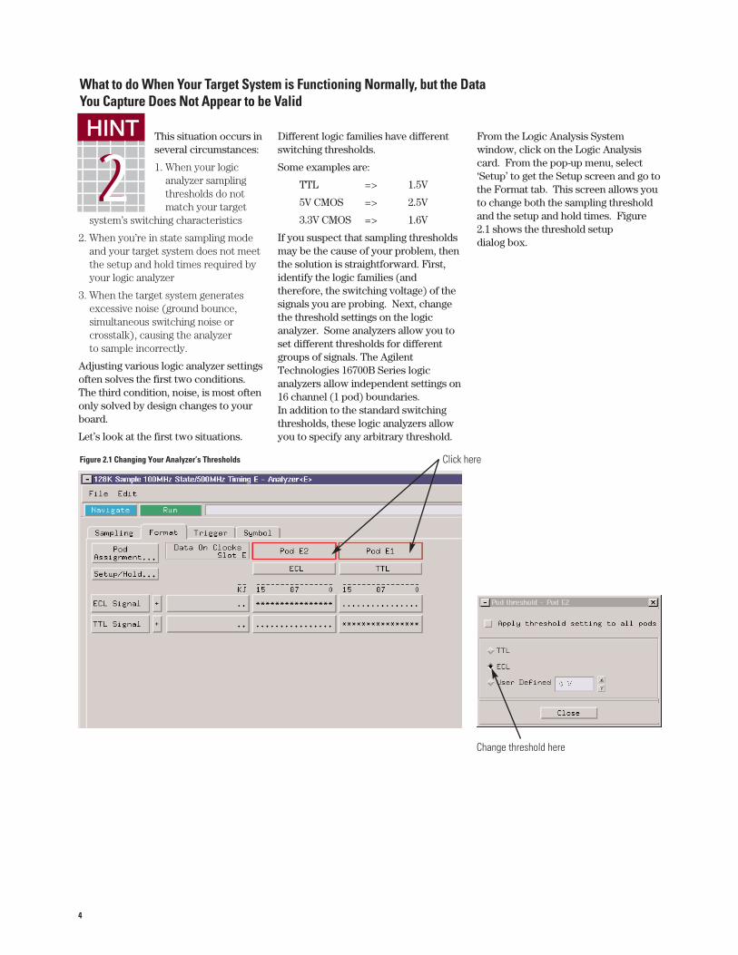
This situation occurs inseveral circumstances:
1. When your logicanalyzer samplingthresholds do notmatch your target
system’s switching characteristics
2. When you’re in state sampling modeand your target system does not meetthe setup and hold times required byyour logic analyzer
3. When the target system generatesexcessive noise (ground bounce,simultaneous switching noise orcrosstalk), causing the analyzerto sample incorrectly.
Adjusting various logic analyzer settingsoften solves the first two conditions.The third condition, noise, is most oftenonly solved by design changes to yourboard.
Let’s look at the first two situations.
Different logic families have differentswitching thresholds.
Some examples are:
TTL => 1.5V
5V CMOS => 2.5V
3.3V CMOS => 1.6V
If you suspect that sampling thresholdsmay be the cause of your problem, thenthe solution is straightforward. First,identify the logic families (andtherefore, the switching voltage) of thesignals you are probing. Next, changethe threshold settings on the logicanalyzer. Some analyzers allow you toset different thresholds for differentgroups of signals. The AgilentTechnologies 16700B Series logicanalyzers allow independent settings on16 channel (1 pod) boundaries.In addition to the standard switchingthresholds, these logic analyzers allowyou to specify any arbitrary threshold.
From the Logic Analysis Systemwindow, click on the Logic Analysiscard. From the pop-up menu, select‘Setup’ to get the Setup screen and go tothe Format tab. This screen allows youto change both the sampling thresholdand the setup and hold times. Figure2.1 shows the threshold setup dialog box.
What to do When Your Target System is Functioning Normally, but the DataYou Capture Does Not Appear to be Valid
HINT HINT
22HINT HINT
HINT HINT HINT HINT
Figure 2.1 Changing Your Analyzer’s Thresholds
Change threshold here
Click here

5
The second situation involves setup andhold times and only occurs when yousample based on the clock supplied bythe target system.
The solution here is also relativelystraightforward. First, determine thesetup and hold requirements of thelogic you are probing. Hopefully, youconsidered this in your design becausethe interconnected IC’s must satisfyeach other’s setup and hold require-ments. Next, determine the setup andhold time requirements for your logicanalyzer. Does your target meet thelogic analyzer’s required time? If the"window" (setup+hold) supplied issmaller than that required by the logicanalyzer, you may need to upgrade yourlogic analyzer. If the window is larger,
but either the setup or hold time isviolated, you may be in luck. Somelogic analyzers allow you to adjust thewindow as needed.
The example given shows that you canadjust from 4.0 ns setup and 0.0 ns holdtime all the way to 0.0 ns setup and 4.0ns hold time, in 0.5 ns increments.It also allows you to set differentchannel groups differently. Figure 2.2demonstrates this.
The techniques mentioned aboveof adjusting your thresholds andsetup/hold windows can be valuableways to squeeze more mileage out ofyour analyzer, especially if your targetsystem is heavily taxing the capabilitiesof your current analyzer.
If your logic analyzer meets the specifi-cations required by your target system,and neither of these techniques solveyour problems, you most likely have anoise problem. That means it’s time toget your oscilloscope back out and puton your analog designer hat.
Figure 2.2 Adjusting Setup and Hold Times
Select the setup/hold time fromthe popup window

6
When you are devel-oping your targetsystem and it isworking properly, life isgood. This is the timeyou should connectyour target to a logic
analyzer and capture a ‘golden trace’ ofthe signals. Performing this small taskmight save the day if your target systemstarts behaving unexpectedly.
If you have saved a ‘golden trace,’ youcan use your logic analyzer’s Comparetool to zero in on the problem. TheCompare tool takes data from a stored‘golden trace’ file and compares it to areal-time trace so that you can find thedifferences. You can set up theCompare tool to perform thecomparison on specific signals orbuses, or on all signals or buses that arepresent in both data sources. You canalso set it up in a repetitive run mode inwhich each new run is compared to a
data file. The analyzer will stopcapturing and comparing data when itfinds a difference.
In the example shown in Figure 3.1, theCompare tool has an analyzer as onedata source and a data file as the other.The data file represents your stored‘golden trace.’ You can displaythe results of the comparison using aListing tool.
Right click on the Compare icon andselect Setup from the pop-up menu. Inthe Setup dialog, right click on the Runbutton and select ‘Repetitive’ from thepop-up menu. Then click on the Runbutton to run the Compare tool repeti-tively. When the measurements stop,use the listing window to examine theexact state on which the differenceoccurred.
In the listing window, you can searchon the "DiffFlag" label to find the exactstate on which the comparison failed, as
shown in Figure 3.2. The data that isdifferent in each source is highlighted.
This technique shows you whatchanged between your ‘golden trace’and the current trace and helps youquickly identify what caused the problem.
Often, simulators are used to testsoftware when hardware is not yetavailable. When the first versions of thehardware become available, thesoftware that was tested and workingon the simulation system may not workon the actual system hardware. You canuse the Compare tool to comparesimulation data (that has been runthrough a conversion program so that itcan be read by the analyzer) with realacquired data. This helps you withhardware/software integration byletting you quickly find signals that arenot behaving as they did in the simulations.
Using a "Golden Trace" to Troubleshoot Unexpected System Changes
HINT HINT HINT
33HINT
HINT HINT HINT HINT
Figure 3.1 Using the Compare Tool on Signals or Buses
Your stored "golden trace" file
Figure 3.2 Using the DiffFlag Function to Identify Changes
Where differences occur, data is shown in a different color

7
Because today’sprocessors havevery complex and deeppipelines and prefetchqueues, many instruc-tions can be fetchedand brought across the
bus and yet never be executed. Thismakes it difficult to accurately set thetrigger on your logic analyzer. Whenthe logic analyzer triggers on one ofthese unexecuted fetches a false trigger results.
This problem typically occurs whenyou’re trying to trigger on a line of codethat is directly after a function call orthe end of a loop. Setting a trigger onlines 25 or 57 in the following examplecode may result in false triggers (seeFigure 4.1).
One way to avoid false triggers in thesesituations is to use a trigger offset. Atrigger offset indicates that the logicanalyzer should trigger on a given
address only if the address value itselfis captured and the address value that isthe trigger address plus the offset valueis also captured. This tells the analyzerto trigger only if the address of interestis captured AND an address that issome number of bytes away is also captured.
Typically, the offset value should be thenumber of bytes that the prefetch queueand pipeline can hold. For example, theprocessor being used has a four-instruction queue and each instruction is32 bits (or 4 bytes). The processor alsohas a one-instruction prefetch queue(another 4 bytes). The offset for thisprocessor should be 20 bytes (5 instruc-tions total).
Note that this is not a foolproof schemefor avoiding these types of falsetriggers. Using an offset of the fullprefetch queue depth and pipeliningqueue depth could result in a missedtrigger if a branch takes place between
the base address and the offset address.In this case, the queue depth is too largeof an offset. Reduce the offset to avoidcompletely missing the trigger.
Using Offsets to Avoid False Triggers
HINT HINT HINT HINT
44HINT HINT HINT HINT
Line # C source code
11 for(int i=0;i<MAX_LOOP;i++)
12 {
.....
24 }
25 count++;
.. ...
56 storeCount(count);
57 count++;
Figure 4.1 C Source Code

8
Without specialprecautions, havingyour logic analyzer onthe network mightpose a security risk.People using theanalyzer might haveaccess to files on other
networked machines that they are notsupposed to access. And, can inversely,people on the network might haveaccess to data on the logic analyzer thatthey are not supposed to see. Theoverall responsibility for security is onthe shoulders of your network adminis-trators, but if the logic analyzer does notprovide some basic security features,such as user accounts (logins),passwords, file permissions, etc., youmay be out of luck.
Most modern logic analyzers providethe features needed to make themselves"good network citizens." Theseanalyzers allow you to set up useraccounts and passwords to control whocan use the analyzer. In addition, theyallow you to specify file permissions forindividual users so that you can controlaccess to the data on the logic analyzer.They also allow you to share files on anetwork in a controlled fashion.
The screen shot in Figure 5.1 shows the"Secure Mode" setup dialog, andindicates how the various featuresprovided are set up. You can accessthis dialog box through the MainWindow "System Admin" dialog, andthen select the "Security" tab. Click on"User Accounts" to manage userinformation.
Reducing Security Risks on Networked Logic Analyzers
HINT HINT HINT HINT
HINT
55HINT HINT HINT
Figure 5.1 Secure Mode Setup
Click here to assign permissions.
Figure 5.2 Assigning Passwords

9
How to Capture Data Before a System Crash
Capturing the cause ofa system crash can betricky with a logicanalyzer. This is truebecause you have toget the instrument totrigger when nothing
happens. How do you describe"nothing" to a logic analyzer's triggermenu? One tried-and-true technique isto set up the logic analyzer to store onlythe data of interest and never trigger.Then you can stop the instrumentmanually when the system under testcrashes. When this technique works,the logic analyzer has a history stored inits pretrigger trace buffer. But thistechnique only works if you can set upyour logic analyzer to capturemeaningful information, then stop whenthe system under test crashes.
Here’s one way around the problem:use a timer in the logic analyzer to get atrigger soon after the system crashes.To use a timer in the trigger, first figureout what event should happen regularlyin order for you to consider your systemunder test alive and working fine. Let’scall this event the system's "heartbeat".
This could be an address-strobe, aperiodic interrupt, or anything thatoccurs consistently at some minimumfrequency. Then set a timer equal to thelongest period between successiveheartbeats that you would expect to seebefore you would consider the systemnonfunctional. In the trigger sequence,if you start the timer when a heartbeatoccurs, and restart the timer wheneveranother heartbeat occurs, you can thentest if the timer reaches the maximumvalue that you set. If the timer reachesthe maximum value, then the logicanalyzer should trigger, since the"heartbeat" isn't occurring as often as itshould. You can also experiment withthe timer value to determine just howlong a period between "heartbeats" is normal.
Here’s an example of this trigger timeridea using an Agilent Technologies1670G, a benchtop logic analyzer and anoptional integrated oscilloscope. Set upthe logic analyzer trigger like you see inFigure 6.1.
HINT HINT HINT HINT
HINT HINT
66HINT HINT
Figure 6.1 Configuring a "Heartbeat" Trigger

10
The "heartbeat" in this example is asignal that consistently occurs at 8 µsintervals. This trigger setup will force atrigger 10 µs after the last "heartbeat".With the Agilent Technologies 1670G,you can send the trigger to the oscillo-scope, which is also probing the deviceunder test, to get a better understandingof the cause of the crash. Figure 6.2shows what the oscilloscope caught 10 µs prior to the trigger that it receivedfrom the logic analyzer.
In this case, the oscilloscope can helpget to the cause of the system crash.Without an actual trigger event, therewould be no trigger signal to send to theoscilloscope. Using timers in a logicanalyzer's trigger system can allow youto trigger on "nothing" since you candescribe the condition as too much timebetween successive "heartbeats".
Figure 6.2 Oscilloscope Display of Results

Analyzing Serial Data with a Logic Analyzer
While logic analyzersare commonly used toanalyze parallel data(e.g. microprocessoraddress and data),some modern logicanalyzers also allowyou to analyze serial
data. This feature comes in handywhen you are trying to debug simpleserial protocols such as RS-232C, CAN,LAN, USB or your proprietary bus. Alogic analyzer is not a tool foranalyzing higher-level protocols suchas TCP-IP. You will need a protocolanalyzer for that task.
Here’s an example of how to use an Agilent Technologies 16700B Serieslogic analyzer to analyzeand troubleshoot data from an RS-232Coutput port. Once you have connectedthe serial port on your target system tothe logic analyzer through one of itsdata pods, you will need to put the logicanalyzer in the "Timing" or"Asynchronous" mode because thesampling clock is being supplied by thelogic analyzer. Even though you are intiming analysis mode, you will be ableto view the data as parallel informationin a listing form. Next you will need toassign a label (Serial) to the input databit. The RS-232C protocol has a dataformat with 1 start bit, 8 data bits, and1.5 stop bits, as shown in Figure 7.1.
To capture the data, you can set thetrigger on any data value. Here we haveset the trigger on the start bit. Once youhave done this, you will need to createthe Serial Analysis tool from theAnalysis tab on the Listing displaywindow. This will bring up the SerialAnalysis window, as shown in Figure 7.2.
Select the Serial input label and createan output Parallel label with a wordwidth of 8 bits, with the LSB as the firstbit. This box will also allow you toinvert the input data so that it becomeseasy to analyze. Now comes the reallyneat part! You will have to specify to thelogic analyzer how you would like theinput frame to be processed. Select thebox for frame processing on this dialogbox and click on the define button.
11
HINT HINT HINT HINT
HINT HINT HINT
77HINT
LSB
104.17 µs
MSB
StartBit 1.5 Stop Bits
8 Data Bits
Make sure this box is selected.Then click on the Define button to bring up the FrameParameters dialog boxes.
Figure 7.2 Serial Analysis Window
Figure 7.1 Timing for RS-232C Before it is Inverted.

12
In the dialog box for specifyingthe frame parameters, you can specifythe start of the frame to have the label“Start”, as shown in Figure 7.3. It isbinary and has a width of 1 bit. Underthe Data Block tab, uncheck the box forstuffed 0s because the RS-232C protocoldoes not do any bit stuffing. Since youdo not need to perform any patternmanipulation, pass the entire data blockthrough. In a similar fashion, under theEnd of Frame tab you will need tospecify that the frame ends after 8 bits,as shown in Figure 7.5. Having done allthis work, you are now ready to look atthe serial data. Figure 7.6 shows a listingof the data, looking at just the Parallellabels. It shows the serial data comingdown the output port.
As you can see, the Serial Analysis toolin the logic analyzer gives you the versa-tility to analyze and debug serialprotocols.
Figure 7.3 Start of Frame Tab
Figure 7.4 Data Block Tab
Figure 7.5 End of Frame Tab
Figure 7.6 Data Listing

13
Electronic DesignAutomation (EDA)tools have becomean integral part ofmost engineers’ toolsets. You can useEDA tools for
drawing, analyzing, simulating anddocumenting the circuits that you areworking on. Wouldn’t it be nice if youcould leverage the work that you did inyour EDA environment while debuggingyour prototype? The pattern generatorsthat are integrated into the AgilentTechnologies logic analyzers allow you todo this without much trouble.
With shrinking times-to-market, youtypically cannot wait for your prototypeto be complete before you start testing.Suppose your circuit board is ready butyour third-party partner has not yetdelivered your ASIC. The pattern gener-ators available in the AgilentTechnologies logic analyzers allow youto debug your circuit by replacing themissing components. All you need to dois program the pattern generator andhook it to the circuit where the ASICbelongs. The integrated patterngenerator will stimulate your circuitwhile you analyze it using the logicanalyzer.
SynaptiCAD, the creators ofWaveFormer Pro, an EDA tool used fordrawing, analyzing, simulating, anddocumenting timing diagrams, hasworked closely with AgilentTechnologies to make it easy for you toexport your timing diagrams to Agilent’spattern generators. Once you havecreated your timing diagram usingWaveFormer Pro, make sure that itincludes a sampling clock and user-created signals because the signals aresampled using the first clock in thetiming diagram. In addition, the diagramshould include at least one documen-tation marker. The first documentationmarker found in the timing diagramdenotes the beginning of the mainsequence (separating the initializationfrom the main section). If no documen-tation marker is present, only mainsequences will appear (i.e., no initialsequences).
As shown in Figure 8.1, in order toexport a timing diagram to a patterngenerator, simply go the Export menuin WaveFormer Pro and select ‘ExportSignals As’. This will bring up a dialogbox that will allow you to save your fileeither as HP pattern generator diskformat (disk *.hpd) or HP patterngenerator bus format (bus *.hpb). The
*.hpd format is used for file transfer vianetwork or diskette. The *.hpb formatuses the GP-IB bus for file transfer.
It’s also possible to generate input filesfor the pattern generator without usingan EDA tool. You can either programthe pattern generator using the systeminterface or you can type the patterngenerator commands in an ASCII fileand import them into the patterngenerator.
Here is an example of a file that you canload into the pattern generator.
HINT HINT HINT HINT
HINT HINT HINT HINT
88
Figure 8.1 Exporting a File From WaveFormer Pro
ASCII 000000ASCDOWNFORM: MODE FULLLABEL 'LAB1',8LABEL 'DATA',8LABEL 'TEST',9LABEL 'CLK',3VECT #80000009212 34 56 70 22 7 0A0 33 00 1*M92 6F 00 1CA CA 00 100 10 11 0
Generating Files for Agilent Technologies Pattern Generator Using Third-Party EDA Tools

14
In the Agilent Technologies 1670G logicanalyzer, go to the System screen andselect the file that you created above.As shown in Figure 8.2, select the Loadbutton, then select the PatternGenerator button and click on theExecute button.
That is all you have to do. The data inthe input file has been imported intoyour pattern generator! Figure 8.3shows the pin assignments in thepattern generator and Figure 8.4 showsthe pattern generator sequence that willresult from your actions.
Figure 8.2 Selecting the File to Load Into the Pattern Generator
Figure 8.3 Pattern Generator Pin Assignments
Figure 8.4 Pattern Generator Sequence
The combination of WaveFormer Proand an Agilent Technologies logicanalyzer makes a very powerfuldesign and debugging tool. The abovehint shows how to get data fromWaveFormer Pro into Agilent’spattern generators. In addition, datacaptured by your logic analyzer canbe imported into WaveFormer Pro.The circuit operations captured bythe logic analyzers can be translatedby WaveFormer Pro into stimulusfiles for driving the simulations to testyour circuit design. For more infor-mation, see your logic analyzer usermanual or go to www.syncad.com.
21
3

15
Agilent Technologies 16700B SeriesLogic Analysis Systems
With the power of the latest technologyand the familiarity of windows, theAgilent Technologies 16700BSeries logic analysis systems offer asingle solution for hardware, softwareand system debugging.
Hardware designers get measurementpower plus processor executioncontrol, register access and other toolsto explore software-dependenthardware problems such as interrupthandling.
Software designers get debugging andanalysis tools that overcome thedrawbacks of traditional emulation,while providing an easier way to solvehardware-dependent software problemsthat only a logic analyzer can uncover.
System designers get time-correlatedviews showing system activity fromanalog signals all the way to sourcecode. The Agilent Technologies logicanalysis systems’ cross-domain displaysminimize the mysteries of hardware-software interaction, helping your teamtrack symptoms back to root causesquickly and confidently.
The 16700B and 16702B are high-perfor-mance platforms for applications thatuse 32- or 64-bit microprocessors inmultiprocessor systems; core-basedASICs; or systems on silicon.
For more information on AgilentTechnologies logic analysis systems,visithttp://www.agilent.com/find/LAsystems
Cost-Effective Solutions That Match YourSpecific Application Needs
The Agilent Technologies 1670 Seriesbenchtop analyzers offer cost-effective150 MHz state analysis and 500 MHztiming analysis, and a color, flat-paneldisplay with built-in VGA resolution.Oscilloscope, pattern generator, anddeep memory features in the 1670Series give you the capability toconfigure a solution that meets yourdemanding troubleshooting challenges.
Navigating through the user interface ismade simple via your choice of eithermouse or front-panel operation. Anoptional keyboard is also available.
Graphical trigger macros assist inmaking powerful measurements.Trigger set-ups can be selected from acategorized list of trigger macros. Eachmacro is shown in graphical form andhas a written description. Macros canbe chained together to create a customtrigger sequence.
For more information on Agilentbenchtop logic analyzers, visithttp://www.agilent.com/find/LAbenchtop
Logic Analyzer Families to Help You Get Your Job Done
Figure 8.5 Agilent Technologies 1670G Series Benchtop Logic Analyzers

www.agilent.comAgilent Technologies’Test and Measurement Support, Services, and AssistanceAgilent Technologies aims to maximize the value youreceive, while minimizing your risk and problems. Westrive to ensure that you get the test andmeasurement capabilities you paid for and obtain thesupport you need. Our extensive support resourcesand services can help you choose the right Agilentproducts for your applications and apply themsuccessfully. Every instrument and system we sellhas a global warranty. Support is available for atleast five years beyond the production life of theproduct. Two concepts underlay Agilent's overallsupport policy: "Our Promise" and "Your Advantage."
Our PromiseOur Promise means your Agilent test andmeasurement equipment will meet its advertisedperformance and functionality. When you arechoosing new equipment, we will help you withproduct information, including realistic performancespecifications and practical recommendations fromexperienced test engineers. When you use Agilentequipment, we can verify that it works properly, helpwith product operation, and provide basicmeasurement assistance for the use of specifiedcapabilities, at no extra cost upon request. Manyself-help tools are available.
Your Advantage
Your Advantage means that Agilent offers a widerange of additional expert test and measurementservices, which you can purchase according to yourunique technical and business needs. Solveproblems efficiently and gain a competitive edge bycontracting with us for calibration, extra-costupgrades, out-of-warranty repairs, and on-siteeducation and training, as well as design, systemintegration, project management, and other profes-sional services. Experienced Agilent engineers andtechnicians worldwide can help you maximize yourproductivity, optimize the return on investment ofyour Agilent instruments and systems, and obtaindependable measurement accuracy for the life ofthose products.
By internet, phone, or fax, get assistance with allyour test & measurement needs
Online assistance:www.agilent.com/find/assist
Phone or FaxUnited States:(tel) 1 800 452 4844
Canada:(tel) 1 877 894 4414(fax) (905) 206 4120
Europe:(tel) (31 20) 547 2000
Japan:(tel) (81) 426 56 7832(fax) (81) 426 56 7840
Latin America:(tel) (305) 267 4245(fax) (305) 267 4286
Australia:(tel) 1 800 629 485 (fax) (61 3) 9272 0749
New Zealand:(tel) 0 800 738 378 (fax) 64 4 495 8950
Asia Pacific:(tel) (852) 3197 7777(fax) (852) 2506 9284
Product specifications and descriptions in thisdocument subject to change without notice.
Copyright © 1999, 2000 Agilent TechnologiesPrinted in USA May, 20005968-5700E