application notes for configuring 911 enable emergency
TRANSCRIPT
KJA; Reviewed:
SPOC 9/21/2014
Solution & Interoperability Test Lab Application Notes
©2014 Avaya Inc. All Rights Reserved.
1 of 39
911EnEGW-CM62
Avaya Solution & Interoperability Test Lab
Application Notes for Configuring 911 Enable Emergency
Gateway and Emergency Routing Service with Avaya Aura®
Communication Manager R6.2, Avaya one-X® Desk Phones
and Avaya one-X® Communicator– Issue 1.2
Abstract
These Application Notes describe the procedures for configuring the 911 Enable Emergency
Gateway and Emergency Routing Service with Avaya Aura® Communication Manager R6.2
and Avaya one-X® Desk Phones.
The 911 Enable Emergency Gateway and Emergency Routing Service offer E911 call routing
and location provisioning solution for enterprises using both legacy and IP phone
deployments. Avaya Aura® Communication Manager connects to the Emergency Gateway via
an H.323 trunk and the Emergency Gateway connects to the public Internet to access the
Emergency Routing Service. The compliance testing focused on placing 911 calls from Avaya
one-X® Desk Phones connected to different network equipment to verify that their location
and callback number could be properly determined.
Information in these Application Notes has been obtained through DevConnect compliance
testing and additional technical discussions. Testing was conducted via the DevConnect
Program at the Avaya Solution and Interoperability Test Lab.

KJA; Reviewed:
SPOC 9/21/2014
Solution & Interoperability Test Lab Application Notes
©2014 Avaya Inc. All Rights Reserved.
2 of 39
911EnEGW-CM62
1. Introduction These Application Notes describe the procedures for configuring the 911 Enable Emergency
Gateway (EGW) and Emergency Routing Service (ERS) with Avaya Aura® Communication
Manager and Avaya one-X® Desk Phones.
The 911 Enable Emergency Gateway and Emergency Routing Service offers an E911 call routing
and location provisioning solution for enterprises using both legacy and IP phone deployments.
Avaya Aura® Communication Manager connects to the Emergency Gateway via an H.323 trunk and
the Emergency Gateway connects to the public Internet to access the Emergency Routing Service.
The compliance testing focused on placing 911 calls from various endpoint types connected to
different network equipment to verify that their location and callback number could be properly
determined.
2. General Test Approach and Test Results This section describes the compliance testing used to verify the interoperability of the EGW and
ERS with Communication Manager. This section covers the general test approach and the test
results.
DevConnect Compliance Testing is conducted jointly by Avaya and DevConnect members. The
jointly-defined test plan focuses on exercising APIs and/or standards-based interfaces pertinent to
the interoperability of the tested products and their functionalities. DevConnect Compliance Testing
is not intended to substitute full product performance or feature testing performed by DevConnect
members, nor is it to be construed as an endorsement by Avaya of the suitability or completeness of
a DevConnect member’s solution.
2.1. Interoperability Compliance Testing
The following features and functionality of the EGW were tested.
Layer 2 discovery from supported layer 2 switches.
Layer 3 discovery of Avaya one-X® Desk Phones that support the PUSH API.
Layer 3 discovery of Avaya one-X® Communicator when used with 911 Enable E911
Softphone Locator (ESL) Software.
Emergency calls from all endpoint types were routed to the ERS via the EGW.
Proper location information provided for all “known” locations.
Calls from “unknown” locations were routed to the 911 Enable Emergency Call Response
Center (ECRC).
Callback numbers were assigned using the EGW Extension-Bind feature.
Calls placed using the provided callback number were routed to the proper extension.
Failover to the secondary EGW, if the primary EGW was not available.
If neither EGW was available, Communication Manager routed emergency calls to the
ECRC via the PSTN.
If the ERS was not available, the EGW routed emergency calls to the ECRC via
Communication Manager.
Note: Please note that EGW supports only G711MU audio codec and does not support IP-IP
media shuffling.
KJA; Reviewed:
SPOC 9/21/2014
Solution & Interoperability Test Lab Application Notes
©2014 Avaya Inc. All Rights Reserved.
3 of 39
911EnEGW-CM62
2.2. Test Results
The features described in Section 2.1 were tested. All test cases passed successfully
2.3. Support
For technical support on the EGW, contact 911 Enable at www.911enable.com.
3. Reference Configuration
WAN
5049
25 27 29 31 33 35
32 34 3626 28 30
37 39 41 43 45 47
44 46 4838 40 42
Down/51
Base
Status
1 3 5 7 9 11 13 15 17 19 21 23
8 10 122 4 6 20 22 2414 16 18
Up/52
PWR
SpeedLink/Act
2550T
Simulated PSAP
Simulated ECRC
W A N
1 LAN 10/3SERVICESCCA 10/12
USB
10/2LAN10/4
MDM
A LM
CPU
P W R
RST A SB
V1
SY
ST
EM
COMPACT FLASH
CARDIN US E
V2
V3
A UDIO
G430
Avaya one-X® Communicator
Avaya Aura® Communication Manager
Avaya G450 Media Gateway
911 Enable
Emergency Gateway
911 Enable
Emergency Routing Service
OK
PHONEMESSAGE
CONTACTS MENU CALL LOG
VOLUME
ABC DEF
JKL MNOGHI
1 2 3
4 5 6
TUV WXYZPQRS
7 8 9
*
[
0 #
.,@
MUTESPEAKER
HEADSET
FORWARD
Avaya one-X
OK
PHONEMESSAGE
CONTACTS MENU CALL LOG
VOLUME
ABC DEF
JKL MNOGHI
1 2 3
4 5 6
TUV WXYZPQRS
7 8 9
*
[
0 #
.,@
MUTESPEAKER
HEADSET
FORWARD
Avaya one-X
OK
PHONEMESSAGE
CONTACTS MENU CALL LOG
VOLUME
ABC DEF
JKL MNOGHI
1 2 3
4 5 6
TUV WXYZPQRS
7 8 9
*
[
0 #
.,@
MUTESPEAKER
HEADSET
FORWARD
Avaya 96xx Series IP Phones
Avaya 5520-24T-PWR
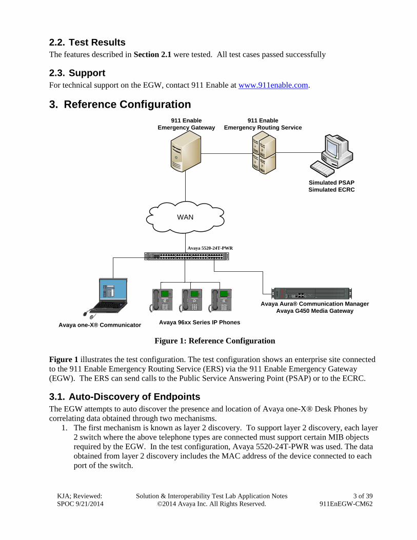
Figure 1: Reference Configuration
Figure 1 illustrates the test configuration. The test configuration shows an enterprise site connected
to the 911 Enable Emergency Routing Service (ERS) via the 911 Enable Emergency Gateway
(EGW). The ERS can send calls to the Public Service Answering Point (PSAP) or to the ECRC.
3.1. Auto-Discovery of Endpoints
The EGW attempts to auto discover the presence and location of Avaya one-X® Desk Phones by
correlating data obtained through two mechanisms.
1. The first mechanism is known as layer 2 discovery. To support layer 2 discovery, each layer
2 switch where the above telephone types are connected must support certain MIB objects
required by the EGW. In the test configuration, Avaya 5520-24T-PWR was used. The data
obtained from layer 2 discovery includes the MAC address of the device connected to each
port of the switch.
KJA; Reviewed:
SPOC 9/21/2014
Solution & Interoperability Test Lab Application Notes
©2014 Avaya Inc. All Rights Reserved.
4 of 39
911EnEGW-CM62
2. The second mechanism required for auto-discovery is known as layer 3 discovery. To
support layer 3 discovery, each listed telephone type uses an application downloaded to it
during initialization to report information to the EGW. Thus, the Avaya one-X® Desk Phone
must support the PUSH API. The information collected includes the MAC address, IP
address and extension of the phone. Correlating the information from layer 2 and 3, the
EGW learns what extensions are physically connected to which layer 2 switch.
The location of Avaya one-X® Communicator is gathered in a similar manner. Layer 2 discovery is
dependent upon which layer 2 switch the Windows PC running Avaya one-X® Communicator is
connected. Layer 3 discovery is done by installing the 911 Enable ESL software on the same PC, to
report the necessary information for these endpoints.
All digital and analog endpoints also must be manually provisioned.
3.2. Callback Numbers
A callback number (CBN) is assigned to each extension for use by the 911 operator to reach the
caller if the emergency call is dropped. The callback number for each extension would be its Direct
Inward Dial (DID) number if it has one assigned. However, all internal extensions may not have a
DID assigned. In this case, where an extension does not have a DID assigned, the EGW will
temporarily map a DID number to that extension for the duration of the emergency call. This is
known as the EGW Extension-Bind feature. The pool of DIDs used by the EGW is assigned to the
EGW from the DIDs owned by the enterprise. In the case of the compliance test, none of the
extensions were assigned an individual DID number, instead all extensions were assigned a
temporary DID from the EGW during an emergency call. In addition, a single DID number was
allocated to the EGW for this purpose.
3.3. Emergency Call Flows
Emergency calls are routed differently depending on whether all components are operational and
what information is available about the caller.
1. Typical “Sunny Day” Scenario: If all components and user information are available then
the call flow is as follows: User Extension Communication Manager EGW ERS
PSAP. If a callback call is needed and a temporary DID number is used from the EGW
Extension-Bind pool, then the callback call flow is PSAP PSTN Communication
Manager EGW Communication Manager User Extension. If the user extension has
its own DID number, then the callback call would not need to be routed through the EGW
but would flow from PSAP PSTN Communication Manager User Extension.
2. Missing User Information: If all components are operational, but the emergency call does
not have the proper location or callback information, then the call is routed to the ECRC
where a trained 911 operator collects the correct information before forwarding the call to the
PSAP. This call can reach the ECRC in two different ways based on the provisioning of the
EGW. The EGW can be provisioned to reject the call if all necessary information is not
present, so that Communication Manager reroutes the call out the PSTN. This was done for
the compliance test. The call flows from User Extension Communication Manager
EGW (rejects the call), then the call is rerouted as Communication Manager PSTN
ECRC PSAP. Alternatively, the EGW can be provisioned to accept the call and send it to
the ERS. The ERS will determine that all information is not present and send the call to the
KJA; Reviewed:
SPOC 9/21/2014
Solution & Interoperability Test Lab Application Notes
©2014 Avaya Inc. All Rights Reserved.
5 of 39
911EnEGW-CM62
ECRC. The call flow would be User Extension Communication Manager EGW
ERS ECRC PSAP. Either the ECRC or the PSAP can initiate a callback if necessary.
If the callback is made from the PSAP, the callback call flow would be the same as described
in scenario 1 above. If the ECRC places the callback, the call flow is the same as described
in scenario 1 with the exception that the ECRC replaces the PSAP in the call flow.
3. ERS Unavailable: If the EGW is operational but the ERS is unavailable, then when the
EGW receives an emergency call, it will originate a new call leg to the ECRC (using the 10
digit ECRC number) through Communication Manager and bridge the emergency call. The
call flows from User Extension Communication Manager EGW, then EGW
Communication Manager PSTN ECRC PSAP. The callback call flows would be
the same as the callback call flows described in scenario 2 above.
4. EGW Failover: If the primary EGW fails, Communication Manager will reroute the call to
the secondary EGW. The call flow would be the same as scenario 1 above.
5. Both EGWs Fail: If both EGWs are unreachable, Communication Manager will timeout on
its call requests to EGWs and reroute the call to the ECRC. The call flow is User Extension
Communication Manager EGW (no response), then the call is rerouted as
Communication Manager PSTN ECRC PSAP. The callback call flows would be
the same as the callback call flows described in scenario 2 above.

KJA; Reviewed:
SPOC 9/21/2014
Solution & Interoperability Test Lab Application Notes
©2014 Avaya Inc. All Rights Reserved.
6 of 39
911EnEGW-CM62
4. Equipment and Software Validated The following equipment and software/firmware were used for the sample configuration provided:
Equipment Software/Firmware
Avaya Aura® Communication Manager
6.2 SP3
Avaya G450 Media Gateway 31.20.1
Avaya Aura® Session Manager 6.2 SP3
Avaya 9630 IP Phone
Avaya 9608 IP Phone
Avaya 9641 IP Phone
SIP 2.6.7
H.323 3.1.5
Avaya one-X® Communicator 6.1
Avaya 6408D Digital Telephone -
Avaya 6210 Analog Telephone -
911 Enable Emergency Gateway 4.1
911 Enable E911 Softphone Locator
Software
1.5
911 Enable Emergency Routing Service 2.12
KJA; Reviewed:
SPOC 9/21/2014
Solution & Interoperability Test Lab Application Notes
©2014 Avaya Inc. All Rights Reserved.
7 of 39
911EnEGW-CM62
5. Configure Avaya Aura® Communication Manager This section describes the Communication Manager configuration to support connectivity to the
EGWs and related functionality. It assumes all other components of Figure 1 have already been
configured. For more detailed information on any other Communication Manager configuration
shown in Figure 1, see [1].
The configuration of Communication Manager was performed using the System Access Terminal
(SAT). After the completion of the configuration, perform a save translation command to make the
changes permanent.
5.1. H.323 Trunk Related Configuration
This section summarizes the configuration of the H.323 trunks that connects the Communication
Manager to each EGW.
Step Description
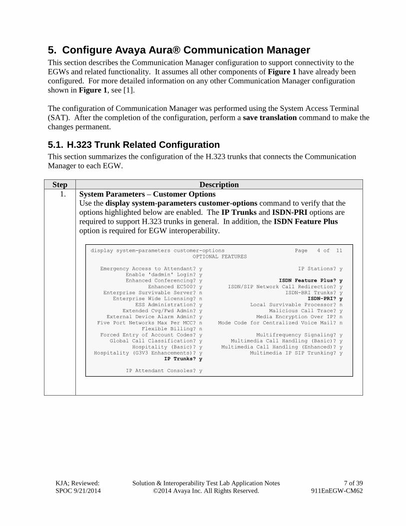
1. System Parameters – Customer Options
Use the display system-parameters customer-options command to verify that the
options highlighted below are enabled. The IP Trunks and ISDN-PRI options are
required to support H.323 trunks in general. In addition, the ISDN Feature Plus
option is required for EGW interoperability.
display system-parameters customer-options Page 4 of 11
OPTIONAL FEATURES
Emergency Access to Attendant? y IP Stations? y
Enable 'dadmin' Login? y
Enhanced Conferencing? y ISDN Feature Plus? y
Enhanced EC500? y ISDN/SIP Network Call Redirection? y
Enterprise Survivable Server? n ISDN-BRI Trunks? y
Enterprise Wide Licensing? n ISDN-PRI? y
ESS Administration? y Local Survivable Processor? n
Extended Cvg/Fwd Admin? y Malicious Call Trace? y
External Device Alarm Admin? y Media Encryption Over IP? n
Five Port Networks Max Per MCC? n Mode Code for Centralized Voice Mail? n
Flexible Billing? n
Forced Entry of Account Codes? y Multifrequency Signaling? y
Global Call Classification? y Multimedia Call Handling (Basic)? y
Hospitality (Basic)? y Multimedia Call Handling (Enhanced)? y
Hospitality (G3V3 Enhancements)? y Multimedia IP SIP Trunking? y
IP Trunks? y
IP Attendant Consoles? y
KJA; Reviewed:
SPOC 9/21/2014
Solution & Interoperability Test Lab Application Notes
©2014 Avaya Inc. All Rights Reserved.
8 of 39
911EnEGW-CM62
Step Description
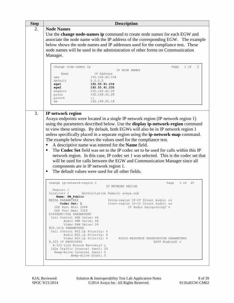
2. Node Names
Use the change node-names ip command to create node names for each EGW and
associate the node name with the IP address of the corresponding EGW. The example
below shows the node names and IP addresses used for the compliance test. These
node names will be used in the administration of other forms on Communication
Manager.
3. IP network region
Avaya endpoints were located in a single IP network region (IP network region 1)
using the parameters described below. Use the display ip-network-region command
to view these settings. By default, both EGWs will also be in IP network region 1
unless specifically placed in a separate region using the ip-network-map command.
The example below shows the values used for the compliance test.
A descriptive name was entered for the Name field.
The Codec Set field was set to the IP codec set to be used for calls within this IP
network region. In this case, IP codec set 1 was selected. This is the codec set that
will be used for calls between the EGW and Communication Manager since all
components are in IP network region 1.
The default values were used for all other fields.
change ip-network-region 1 Page 1 of 20
IP NETWORK REGION
Region: 1
Location: 1 Authoritative Domain: avaya.com
Name: SM_Public
MEDIA PARAMETERS Intra-region IP-IP Direct Audio: no
Codec Set: 1 Inter-region IP-IP Direct Audio: no
UDP Port Min: 2048 IP Audio Hairpinning? n
UDP Port Max: 3329
DIFFSERV/TOS PARAMETERS
Call Control PHB Value: 46
Audio PHB Value: 46
Video PHB Value: 26
802.1P/Q PARAMETERS
Call Control 802.1p Priority: 6
Audio 802.1p Priority: 6
Video 802.1p Priority: 5 AUDIO RESOURCE RESERVATION PARAMETERS
H.323 IP ENDPOINTS RSVP Enabled? n
H.323 Link Bounce Recovery? y
Idle Traffic Interval (sec): 20
Keep-Alive Interval (sec): 5
Keep-Alive Count: 5
change node-names ip Page 1 of 2
IP NODE NAMES
Name IP Address
aes 192.168.62.108
default 0.0.0.0
egw1 192.55.91.234
egw2 192.55.91.235
msgsrvr 192.168.62.28
procr 192.168.62.28
procr6 ::
sm 192.168.62.18
KJA; Reviewed:
SPOC 9/21/2014
Solution & Interoperability Test Lab Application Notes
©2014 Avaya Inc. All Rights Reserved.
9 of 39
911EnEGW-CM62
Step Description
4. Codecs
Use the change ip-codec-set 1 command to define the codecs used by IP codec set 1.
The EGW only supports the G.711MU codec. Thus for the compliance test, only
G.711MU was set in the codec list.

KJA; Reviewed:
SPOC 9/21/2014
Solution & Interoperability Test Lab Application Notes
©2014 Avaya Inc. All Rights Reserved.
10 of 39
911EnEGW-CM62
Step Description
5. Signaling Group
Use the add signaling-group n command, where n is an unused signaling group, to
create a new signaling group for each H.323 trunk to each of the EGWs. For the
compliance test, signaling group 4 was created for the trunk to the primary EGW and
signaling group 5 was created for the trunk to the secondary EGW. Signaling group 4
was configured using the parameters highlighted below. Signaling group 5 was
configured in the same way except where noted below. Default values were used for
all other fields.
Set the Group Type to h.323.
Set the Trunk Group for Channel Selection field to the trunk group created in the
next step. This cannot be done until the trunk group is created. Thus, initially this
field is left blank and later changed to the correct value after the trunk group is
created. A separate trunk group will be created for each signaling-group.
Set the Near-end Node Name to procr. This node name maps to the IP address of
the Avaya Server. Node names are defined using the change node-names ip
command (Step 2).
Set the Far-end Node Name to egw1. This node name maps to the IP address of
the primary EGW as defined using the change node-names ip command (Step 2).
For signaling-group 32, set this field to egw2.
Set the Near-end Listen Port and Far-end Listen Port to 1720.
Set the Far-end Network Region to 1. This is the IP network region which
contains the EGW.
Set the Direct IP-IP Audio Connections field to n. The EGW does not support
media shuffling so this field must be set to n.
The default values were used for all other fields.
add signaling-group 4 Page 1 of 6
SIGNALING GROUP
Group Number: 4 Group Type: h.323
SBS? n Remote Office? n Max number of NCA TSC: 0
Q-SIP? n Max number of CA TSC: 0
IP Video? n Trunk Group for NCA TSC:
Trunk Group for Channel Selection: 4 X-Mobility/Wireless Type:
NONE
TSC Supplementary Service Protocol: a Network Call Transfer? n
T303 Timer(sec): 10
H.245 DTMF Signal Tone Duration(msec):
Near-end Node Name: procr Far-end Node Name: egw1
Near-end Listen Port: 1720 Far-end Listen Port: 1720
Far-end Network Region: 1
LRQ Required? n Calls Share IP Signaling Connection? n
RRQ Required? n
Bypass If IP Threshold Exceeded? n
H.235 Annex H Required? n
DTMF over IP: out-of-band Direct IP-IP Audio Connections? n
Link Loss Delay Timer(sec): 90 IP Audio Hairpinning? n
Enable Layer 3 Test? n Interworking Message: PROGress
DCP/Analog Bearer Capability: 3.1kHz

KJA; Reviewed:
SPOC 9/21/2014
Solution & Interoperability Test Lab Application Notes
©2014 Avaya Inc. All Rights Reserved.
11 of 39
911EnEGW-CM62
Step Description
6. Trunk Group
Use the add trunk-group n command, where n is an unused trunk group, to create a
new trunk group for each H.323 trunk to each of the EGWs. For the compliance test,
trunk group 4 was created for the trunk to the primary EGW and trunk group 5 was
created for the trunk to the secondary EGW. Trunk group 4 was configured using the
parameters highlighted below. Trunk group 5 was configured in the same way except
where noted below. Default values were used for all other fields.
On Page 1:
Set the Group Type to isdn.
Enter a descriptive name for the Group Name.
Enter an available trunk access code (TAC) that is consistent with the existing dial
plan in the TAC field.
Set the Carrier Medium to H.323.
Set the Service Type to public-ntwrk.
Set the Member Assignment Method to auto.
Set the Signaling Group to the signaling group shown in the previous step.
Set the Number of Members field to the number of channels available in this
trunk. For an H.323 trunk, the number of members also represents the number of
simultaneous calls that can be supported by the trunk. For the compliance test, the
number of members was chosen to be 10.
The default values were used for all other fields.
add trunk-group 4 Page 1 of 21
TRUNK GROUP
Group Number: 4 Group Type: isdn CDR Reports: y
Group Name: EGW1-911Enable COR: 1 TN: 1 TAC: *004
Direction: two-way Outgoing Display? n Carrier Medium: H.323
Dial Access? n Busy Threshold: 255 Night Service:
Queue Length: 0
Service Type: public-ntwrk Auth Code? n
Member Assignment Method: auto
Signaling Group: 4
Number of Members: 10

KJA; Reviewed:
SPOC 9/21/2014
Solution & Interoperability Test Lab Application Notes
©2014 Avaya Inc. All Rights Reserved.
12 of 39
911EnEGW-CM62
Step Description
7. Trunk Group – continued
On Page 3:
It is required that the Send Name field is set to y and the Send Calling Number
field is set to y.
Set the Format field to pub-unk. This field specifies the format of the calling
party number sent to the far-end.
The default values were used for all other fields.
8. Public Unknown Numbering
Public unknown numbering defines the calling party number to be sent to the far-end.
An entry was created that will be used by the trunk groups defined in Step 6. In the
example shown below, all calls originating from a 5-digit extension beginning with 5
and routed across trunk group 4 or 5 will be sent as a 5-digit calling number.
change public-unknown-numbering 0 Page 1 of 2
NUMBERING - PUBLIC/UNKNOWN FORMAT
Total
Ext Ext Trk CPN CPN
Len Code Grp(s) Prefix Len
Total Administered: 2
5 4 5 Maximum Entries: 240
5 7 5
5 5 4 5 Note: If an entry applies to
5 5 5 5 a SIP connection to Avaya
Aura(R) Session Manager,
the resulting number must
be a complete E.164 number.
add trunk-group 4 Page 3 of 21
TRUNK FEATURES
ACA Assignment? n Measured: none
Maintenance Tests? y
Data Restriction? n NCA-TSC Trunk Member:
Send Name: y Send Calling Number: y
Used for DCS? n Send EMU Visitor CPN? n
Suppress # Outpulsing? n Format: pub-unk
UUI IE Treatment: service-provider
Replace Restricted Numbers? n
Replace Unavailable Numbers? n
Send Connected Number: n
Network Call Redirection: none Hold/Unhold Notifications? n
Send UUI IE? y Modify Tandem Calling Number: no
Send UCID? n
Send Codeset 6/7 LAI IE? y
Show ANSWERED BY on Display? y
KJA; Reviewed:
SPOC 9/21/2014
Solution & Interoperability Test Lab Application Notes
©2014 Avaya Inc. All Rights Reserved.
13 of 39
911EnEGW-CM62
Step Description
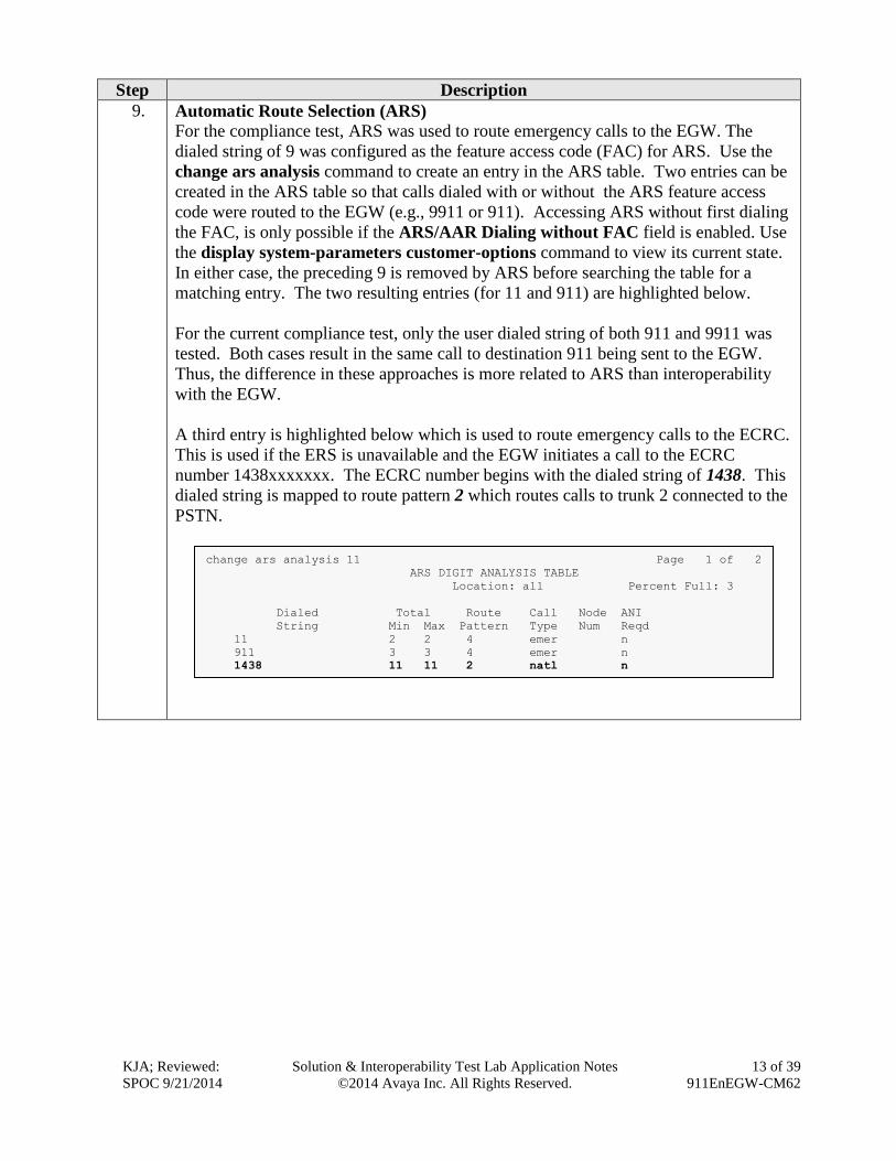
9. Automatic Route Selection (ARS)
For the compliance test, ARS was used to route emergency calls to the EGW. The
dialed string of 9 was configured as the feature access code (FAC) for ARS. Use the
change ars analysis command to create an entry in the ARS table. Two entries can be
created in the ARS table so that calls dialed with or without the ARS feature access
code were routed to the EGW (e.g., 9911 or 911). Accessing ARS without first dialing
the FAC, is only possible if the ARS/AAR Dialing without FAC field is enabled. Use
the display system-parameters customer-options command to view its current state.
In either case, the preceding 9 is removed by ARS before searching the table for a
matching entry. The two resulting entries (for 11 and 911) are highlighted below.
For the current compliance test, only the user dialed string of both 911 and 9911 was
tested. Both cases result in the same call to destination 911 being sent to the EGW.
Thus, the difference in these approaches is more related to ARS than interoperability
with the EGW.
A third entry is highlighted below which is used to route emergency calls to the ECRC.
This is used if the ERS is unavailable and the EGW initiates a call to the ECRC
number 1438xxxxxxx. The ECRC number begins with the dialed string of 1438. This
dialed string is mapped to route pattern 2 which routes calls to trunk 2 connected to the
PSTN.
change ars analysis 11 Page 1 of 2
ARS DIGIT ANALYSIS TABLE
Location: all Percent Full: 3
Dialed Total Route Call Node ANI
String Min Max Pattern Type Num Reqd
11 2 2 4 emer n
911 3 3 4 emer n
1438 11 11 2 natl n
KJA; Reviewed:
SPOC 9/21/2014
Solution & Interoperability Test Lab Application Notes
©2014 Avaya Inc. All Rights Reserved.
14 of 39
911EnEGW-CM62
Step Description
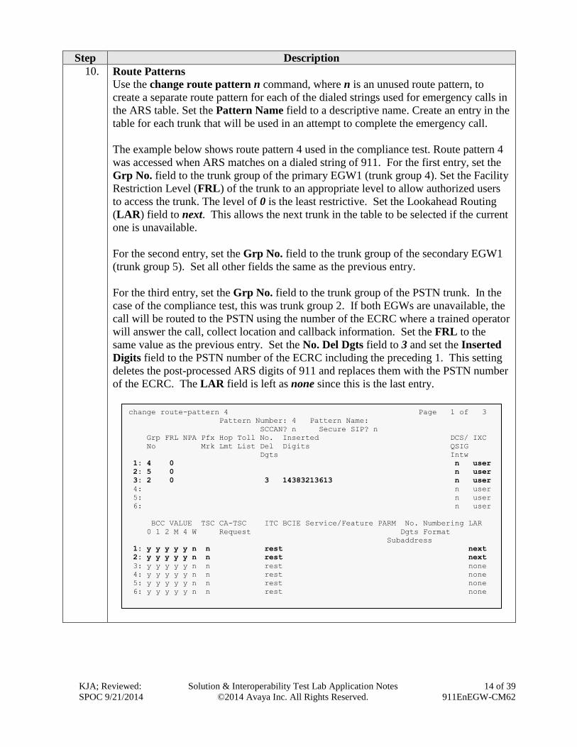
10. Route Patterns
Use the change route pattern n command, where n is an unused route pattern, to
create a separate route pattern for each of the dialed strings used for emergency calls in
the ARS table. Set the Pattern Name field to a descriptive name. Create an entry in the
table for each trunk that will be used in an attempt to complete the emergency call.
The example below shows route pattern 4 used in the compliance test. Route pattern 4
was accessed when ARS matches on a dialed string of 911. For the first entry, set the
Grp No. field to the trunk group of the primary EGW1 (trunk group 4). Set the Facility
Restriction Level (FRL) of the trunk to an appropriate level to allow authorized users
to access the trunk. The level of 0 is the least restrictive. Set the Lookahead Routing
(LAR) field to next. This allows the next trunk in the table to be selected if the current
one is unavailable.
For the second entry, set the Grp No. field to the trunk group of the secondary EGW1
(trunk group 5). Set all other fields the same as the previous entry.
For the third entry, set the Grp No. field to the trunk group of the PSTN trunk. In the
case of the compliance test, this was trunk group 2. If both EGWs are unavailable, the
call will be routed to the PSTN using the number of the ECRC where a trained operator
will answer the call, collect location and callback information. Set the FRL to the
same value as the previous entry. Set the No. Del Dgts field to 3 and set the Inserted
Digits field to the PSTN number of the ECRC including the preceding 1. This setting
deletes the post-processed ARS digits of 911 and replaces them with the PSTN number
of the ECRC. The LAR field is left as none since this is the last entry.
change route-pattern 4 Page 1 of 3
Pattern Number: 4 Pattern Name:
SCCAN? n Secure SIP? n
Grp FRL NPA Pfx Hop Toll No. Inserted DCS/ IXC
No Mrk Lmt List Del Digits QSIG
Dgts Intw
1: 4 0 n user
2: 5 0 n user
3: 2 0 3 14383213613 n user
4: n user
5: n user
6: n user
BCC VALUE TSC CA-TSC ITC BCIE Service/Feature PARM No. Numbering LAR
0 1 2 M 4 W Request Dgts Format
Subaddress
1: y y y y y n n rest next
2: y y y y y n n rest next
3: y y y y y n n rest none
4: y y y y y n n rest none
5: y y y y y n n rest none
6: y y y y y n n rest none
KJA; Reviewed:
SPOC 9/21/2014
Solution & Interoperability Test Lab Application Notes
©2014 Avaya Inc. All Rights Reserved.
15 of 39
911EnEGW-CM62
Step Description
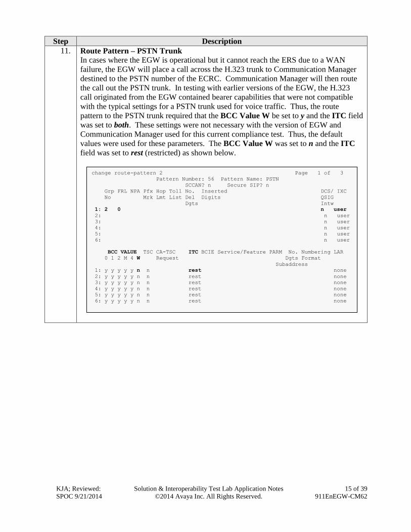
11. Route Pattern – PSTN Trunk
In cases where the EGW is operational but it cannot reach the ERS due to a WAN
failure, the EGW will place a call across the H.323 trunk to Communication Manager
destined to the PSTN number of the ECRC. Communication Manager will then route
the call out the PSTN trunk. In testing with earlier versions of the EGW, the H.323
call originated from the EGW contained bearer capabilities that were not compatible
with the typical settings for a PSTN trunk used for voice traffic. Thus, the route
pattern to the PSTN trunk required that the BCC Value W be set to y and the ITC field
was set to both. These settings were not necessary with the version of EGW and
Communication Manager used for this current compliance test. Thus, the default
values were used for these parameters. The BCC Value W was set to n and the ITC
field was set to rest (restricted) as shown below.
change route-pattern 2 Page 1 of 3
Pattern Number: 56 Pattern Name: PSTN
SCCAN? n Secure SIP? n
Grp FRL NPA Pfx Hop Toll No. Inserted DCS/ IXC
No Mrk Lmt List Del Digits QSIG
Dgts Intw
1: 2 0 n user
2: n user
3: n user
4: n user
5: n user
6: n user
BCC VALUE TSC CA-TSC ITC BCIE Service/Feature PARM No. Numbering LAR
0 1 2 M 4 W Request Dgts Format
Subaddress
1: y y y y y n n rest none
2: y y y y y n n rest none
3: y y y y y n n rest none
4: y y y y y n n rest none
5: y y y y y n n rest none
6: y y y y y n n rest none

KJA; Reviewed:
SPOC 9/21/2014
Solution & Interoperability Test Lab Application Notes
©2014 Avaya Inc. All Rights Reserved.
16 of 39
911EnEGW-CM62
Step Description
12. Inbound Call Routing – Temporary Callback Numbers
When the PSAP uses the callback number, it must be routed to the correct destination.
If the callback number is a DID number temporarily assigned by the EGW as a
callback number, then the call must get routed to the EGW to determine the associated
internal extension. Use the change inc-call-handling-trmt trunk-group n command,
where n is the trunk group to the PSTN, to insert a 9 in front of all the DID numbers
used by the EGW as temporary DIDs. The preceding 9 (which is the ARS feature
access code) will instruct Communication Manager to process the digits using ARS to
determine the route. The xxxx in the example below is simply to mask the DID number
for security reasons.
13. Routing Callback Calls to the EGW
Use the change ars analysis command to add an entry in the ARS table for each DID
used by the EGW. Each entry will match on the inbound DID number and map it to a
route pattern that will route the call to the EGW. The example below was used for the
compliance test. The dialed string is the actual DID number (the xxxx in the example
below is simply to mask the DID number for security reasons). This dialed string is
mapped to route pattern 6 defined in the next step.
change ars analysis 11 Page 1 of 2
ARS DIGIT ANALYSIS TABLE
Location: all Percent Full: 3
Dialed Total Route Call Node ANI
String Min Max Pattern Type Num Reqd
11 2 2 4 emer n
1514 11 11 2 natl n
303538xxxx 10 10 6 natl n
911 3 3 5 emer n
change inc-call-handling-trmt trunk-group 2 Page 1 of 3
INCOMING CALL HANDLING TREATMENT
Service/ Number Number Del Insert Per Call Night
Feature Len Digits CPN/BN Serv
tie 10 3035368xxxx 9

KJA; Reviewed:
SPOC 9/21/2014
Solution & Interoperability Test Lab Application Notes
©2014 Avaya Inc. All Rights Reserved.
17 of 39
911EnEGW-CM62
Step Description
14. Callback Route Pattern
Use the change route pattern command to create a route for the callback calls using
the EGW assigned DID numbers. These calls must be directed to the EGW. Thus, the
route pattern is created the same as the route pattern 4 in Step 10 with the following
exceptions:
Use a unique name for the Pattern Name.
Remove the third trunk choice shown in route pattern 4. If the callback call
fails to reach the EGW, it should not be routed out the PSTN trunk 2 as was
done in Step 10.
By removing the third trunk from the route pattern, the LAR value for the
second trunk should be set to none.
change route-pattern 6 Page 1 of 3
Pattern Number: 33 Pattern Name: Callback calls
SCCAN? n Secure SIP? n
Grp FRL NPA Pfx Hop Toll No. Inserted DCS/ IXC
No Mrk Lmt List Del Digits QSIG
Dgts Intw
1: 4 0 n user
2: 5 0 n user
3: n user
4: n user
5: n user
6: n user
BCC VALUE TSC CA-TSC ITC BCIE Service/Feature PARM No. Numbering LAR
0 1 2 M 4 W Request Dgts Format
Subaddress
1: y y y y y n n rest next
2: y y y y y n n rest none
3: y y y y y n n rest none
4: y y y y y n n rest none
5: y y y y y n n rest none
6: y y y y y n n rest none
KJA; Reviewed:
SPOC 9/21/2014
Solution & Interoperability Test Lab Application Notes
©2014 Avaya Inc. All Rights Reserved.
18 of 39
911EnEGW-CM62
5.2. Station Configuration
This section will describe the settings required of each of the different station types to support the
EGW functionality. Each station is required to have an Emergency Location Extension configured.
Step Description
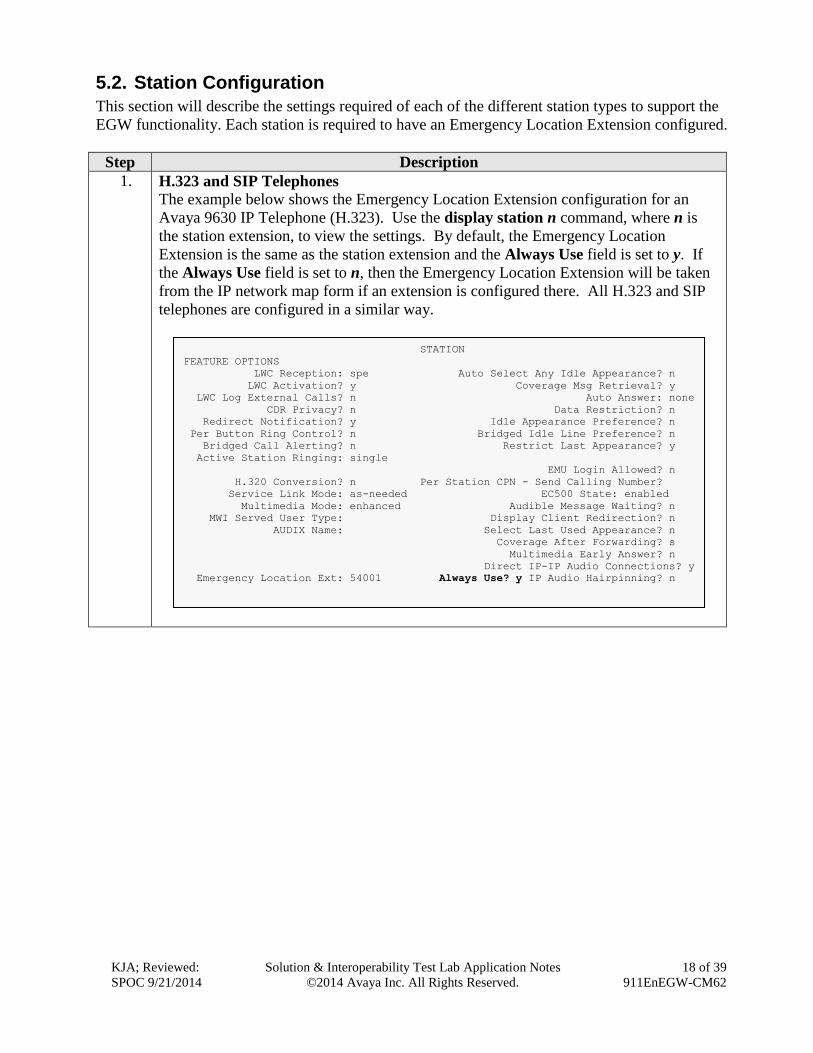
1. H.323 and SIP Telephones
The example below shows the Emergency Location Extension configuration for an
Avaya 9630 IP Telephone (H.323). Use the display station n command, where n is
the station extension, to view the settings. By default, the Emergency Location
Extension is the same as the station extension and the Always Use field is set to y. If
the Always Use field is set to n, then the Emergency Location Extension will be taken
from the IP network map form if an extension is configured there. All H.323 and SIP
telephones are configured in a similar way.
STATION
FEATURE OPTIONS
LWC Reception: spe Auto Select Any Idle Appearance? n
LWC Activation? y Coverage Msg Retrieval? y
LWC Log External Calls? n Auto Answer: none
CDR Privacy? n Data Restriction? n
Redirect Notification? y Idle Appearance Preference? n
Per Button Ring Control? n Bridged Idle Line Preference? n
Bridged Call Alerting? n Restrict Last Appearance? y
Active Station Ringing: single
EMU Login Allowed? n
H.320 Conversion? n Per Station CPN - Send Calling Number?
Service Link Mode: as-needed EC500 State: enabled
Multimedia Mode: enhanced Audible Message Waiting? n
MWI Served User Type: Display Client Redirection? n
AUDIX Name: Select Last Used Appearance? n
Coverage After Forwarding? s
Multimedia Early Answer? n
Direct IP-IP Audio Connections? y
Emergency Location Ext: 54001 Always Use? y IP Audio Hairpinning? n
KJA; Reviewed:
SPOC 9/21/2014
Solution & Interoperability Test Lab Application Notes
©2014 Avaya Inc. All Rights Reserved.
19 of 39
911EnEGW-CM62
Step Description
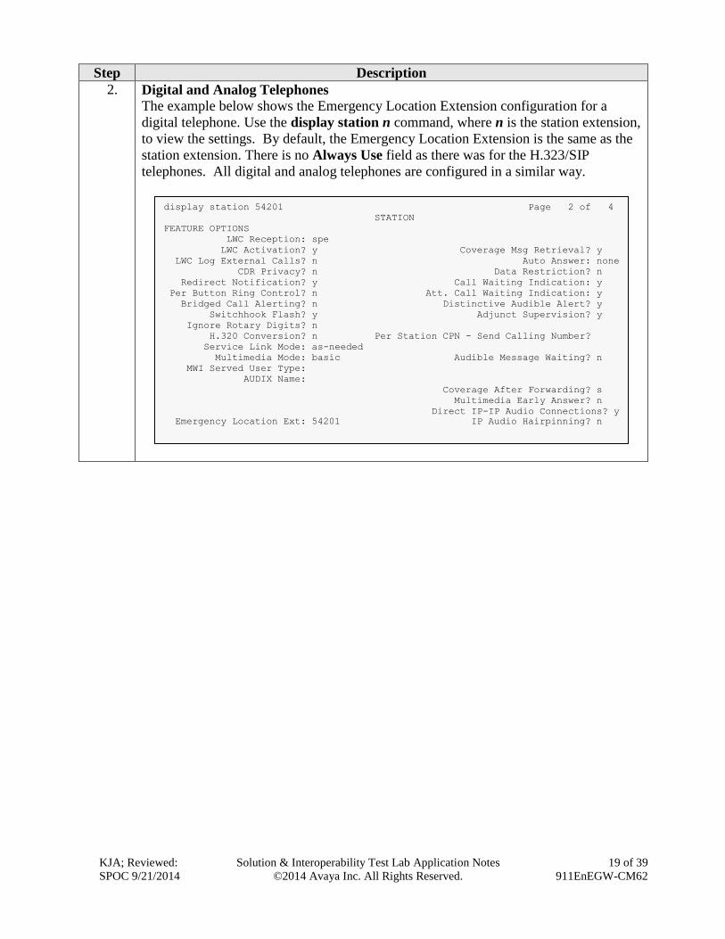
2. Digital and Analog Telephones
The example below shows the Emergency Location Extension configuration for a
digital telephone. Use the display station n command, where n is the station extension,
to view the settings. By default, the Emergency Location Extension is the same as the
station extension. There is no Always Use field as there was for the H.323/SIP
telephones. All digital and analog telephones are configured in a similar way.
display station 54201 Page 2 of 4
STATION
FEATURE OPTIONS
LWC Reception: spe
LWC Activation? y Coverage Msg Retrieval? y
LWC Log External Calls? n Auto Answer: none
CDR Privacy? n Data Restriction? n
Redirect Notification? y Call Waiting Indication: y
Per Button Ring Control? n Att. Call Waiting Indication: y
Bridged Call Alerting? n Distinctive Audible Alert? y
Switchhook Flash? y Adjunct Supervision? y
Ignore Rotary Digits? n
H.320 Conversion? n Per Station CPN - Send Calling Number?
Service Link Mode: as-needed
Multimedia Mode: basic Audible Message Waiting? n
MWI Served User Type:
AUDIX Name:
Coverage After Forwarding? s
Multimedia Early Answer? n
Direct IP-IP Audio Connections? y
Emergency Location Ext: 54201 IP Audio Hairpinning? n

KJA; Reviewed:
SPOC 9/21/2014
Solution & Interoperability Test Lab Application Notes
©2014 Avaya Inc. All Rights Reserved.
20 of 39
911EnEGW-CM62
Step Description
3. Avaya one-X® Communicators (H.323)
The example shows the settings for an Avaya one-X® Communicator (H.323). Use the
display station n command, where n is the station extension, to view the settings. It
contains an additional field named Remote Softphone Emergency Calls. In the case
of the compliance test, the Avaya one-X® Communicator was treated the same as any
other H.323 telephone on the enterprise, so the Remote Softphone Emergency Calls
field was left with the default value of as-on-local. This setting instructs the
Communication Manager to use the value in the Emergency Location Ext. field as the
Emergency Location Extension. This value can still be overwritten by the value on the
IP network map form if permitted by the setting of the Always Use field.
display station 54002 Page 2 of 5
STATION
FEATURE OPTIONS
LWC Reception: spe Auto Select Any Idle Appearance? n
LWC Activation? y Coverage Msg Retrieval? y
LWC Log External Calls? n Auto Answer: none
CDR Privacy? n Data Restriction? n
Redirect Notification? y Idle Appearance Preference? n
Per Button Ring Control? n Bridged Idle Line Preference? n
Bridged Call Alerting? n Restrict Last Appearance? y
Active Station Ringing: single
EMU Login Allowed? n
H.320 Conversion? n Per Station CPN - Send Calling Number?
Service Link Mode: as-needed EC500 State: enabled
Multimedia Mode: enhanced Audible Message Waiting? n
MWI Served User Type: Display Client Redirection? n
AUDIX Name: Select Last Used Appearance? n
Coverage After Forwarding? s
Multimedia Early Answer? n
Remote Softphone Emergency Calls: as-on-local Direct IP-IP Audio Connections? n
Emergency Location Ext: 54002 Always Use? n IP Audio Hairpinning? n

KJA; Reviewed:
SPOC 9/21/2014
Solution & Interoperability Test Lab Application Notes
©2014 Avaya Inc. All Rights Reserved.
21 of 39
911EnEGW-CM62
6. Configure Avaya Endpoints This section describes the configuration required of Avaya endpoints to support the EGW
functionality. Avaya H.323 and SIP telephones require additions to the 46xxsettings.txt file to
support layer 3 discovery. The Avaya one-X® Communicator requires installation of the ESL
software on the same PC running the Avaya one-X® Communicator. No special configuration is
required of analog or digital telephones.
Step Description
1. Avaya H.323 and SIP Telephone Configuration File
In order to support layer 3 discovery, the following lines need to be added to the
46xxsettings.txt configuration file for Avaya H.323 and SIP telephones. The two
highlighted parameters in the SUBSCRIBELIST and WMLHOME URLs must be
modified for a specific installation. The first parameter (192.168.0.118) represents the
IP address of the private side of the primary EGW. The second parameter (19) is the
IP-PBX ID number that is created while configuring EGW.
## 911 Enable Settings
SET TPSLIST /
SET SUBSCRIBELIST http://192.168.0.118/19/r
SET PUSHPORT 80
SET PUSHCAP 2
SET WMLHOME http://192.168.0.118/wml/19/service.html

KJA; Reviewed:
SPOC 9/21/2014
Solution & Interoperability Test Lab Application Notes
©2014 Avaya Inc. All Rights Reserved.
22 of 39
911EnEGW-CM62
Step Description
2. Avaya one-X® Communicator (H.323) – ESL software installation
On the PC running the Avaya one-X® Communicator, launch the ESL setup
application. A welcome screen will appear. Click Next to proceed.

KJA; Reviewed:
SPOC 9/21/2014
Solution & Interoperability Test Lab Application Notes
©2014 Avaya Inc. All Rights Reserved.
23 of 39
911EnEGW-CM62
Step Description
3. ESL Installation – Select Protocol
Select the desired protocol. HTTP was used for the compliance test. Click Next.
KJA; Reviewed:
SPOC 9/21/2014
Solution & Interoperability Test Lab Application Notes
©2014 Avaya Inc. All Rights Reserved.
24 of 39
911EnEGW-CM62
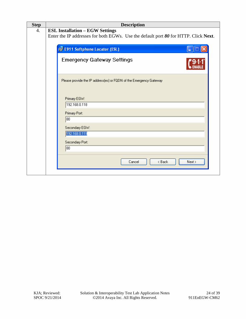
Step Description
4. ESL Installation – EGW Settings
Enter the IP addresses for both EGWs. Use the default port 80 for HTTP. Click Next.
KJA; Reviewed:
SPOC 9/21/2014
Solution & Interoperability Test Lab Application Notes
©2014 Avaya Inc. All Rights Reserved.
25 of 39
911EnEGW-CM62
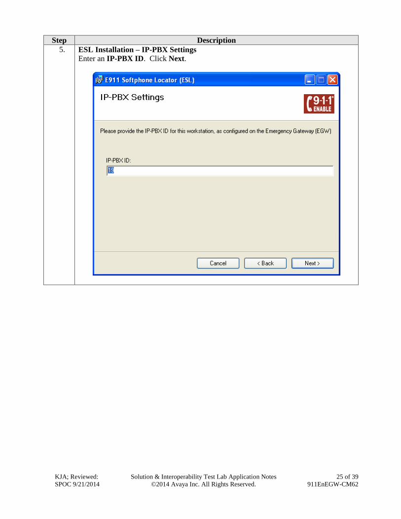
Step Description
5. ESL Installation – IP-PBX Settings
Enter an IP-PBX ID. Click Next.
KJA; Reviewed:
SPOC 9/21/2014
Solution & Interoperability Test Lab Application Notes
©2014 Avaya Inc. All Rights Reserved.
26 of 39
911EnEGW-CM62
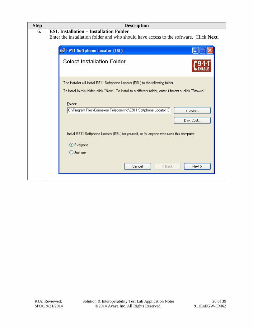
Step Description
6. ESL Installation – Installation Folder
Enter the installation folder and who should have access to the software. Click Next.

KJA; Reviewed:
SPOC 9/21/2014
Solution & Interoperability Test Lab Application Notes
©2014 Avaya Inc. All Rights Reserved.
27 of 39
911EnEGW-CM62
Step Description
7. ESL Installation – Confirm
Confirm the installation by clicking Next.
KJA; Reviewed:
SPOC 9/21/2014
Solution & Interoperability Test Lab Application Notes
©2014 Avaya Inc. All Rights Reserved.
28 of 39
911EnEGW-CM62
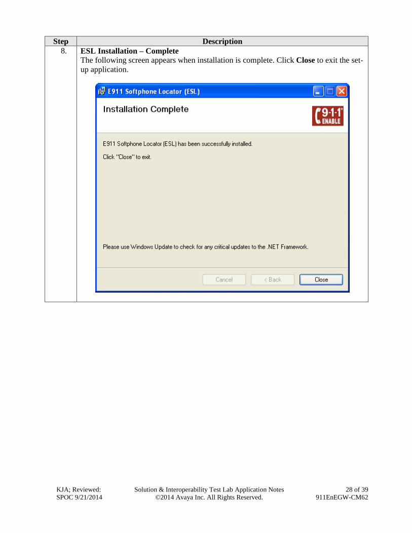
Step Description
8. ESL Installation – Complete
The following screen appears when installation is complete. Click Close to exit the set-
up application.
KJA; Reviewed:
SPOC 9/21/2014
Solution & Interoperability Test Lab Application Notes
©2014 Avaya Inc. All Rights Reserved.
29 of 39
911EnEGW-CM62
7. Configure 911 Enable Emergency Gateway (EGW) The configuration of the EGW is performed by 911 Enable for the customer when the customer
subscribes to 911 Enable’s Emergency Routing Service. The information in this section is included
simply as a reference.
Step Description
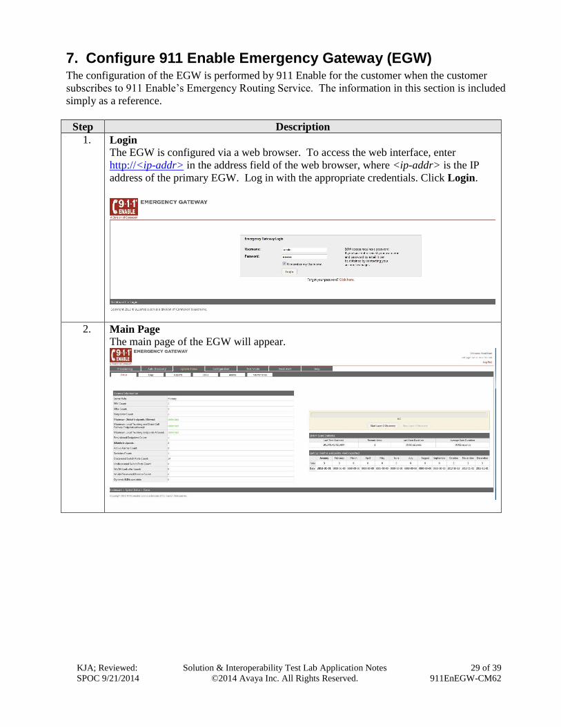
1. Login
The EGW is configured via a web browser. To access the web interface, enter
http://<ip-addr> in the address field of the web browser, where <ip-addr> is the IP
address of the primary EGW. Log in with the appropriate credentials. Click Login.
2. Main Page
The main page of the EGW will appear.

KJA; Reviewed:
SPOC 9/21/2014
Solution & Interoperability Test Lab Application Notes
©2014 Avaya Inc. All Rights Reserved.
30 of 39
911EnEGW-CM62
Step Description
3. ERS Account
The ERS account defines the parameters used to connect to the Emergency Routing
Service. Navigate to the Configuration Advanced ERS Account tab to
configure these settings. The example below shows the settings used for the
compliance test. The necessary values for each field shown for the 911 Account
Settings and the ECRC List are provided by 911 Enable for connection to the ERS.
For security reasons, the public IP addresses of the ERS are not shown but some digits
are replaced by an x. The ECRC list shows the phone number of the ECRC. This
number is dialed through Communication Manager so it contains the preceding 9 (ARS
feature access code) followed by the 11-digit number. For security reasons, the full
PSTN number is not shown..
4. Extension-Bind Numbers
The Extension-Bind numbers are the pool of DID numbers owned by the enterprise
that the EGW can use as callback numbers for active 911 calls. Navigate to the
Configuration Advanced Callback tab to configure these Extension-Bind
numbers. For the compliance test, a single number was used in the Extension-Bind
Numbers list. To add a number to the list, click the Add a number button. Enter the
number in the subsequent window (not shown). Each number is represented by 10-
digits. For security reasons, the full PSTN number is not shown.
KJA; Reviewed:
SPOC 9/21/2014
Solution & Interoperability Test Lab Application Notes
©2014 Avaya Inc. All Rights Reserved.
31 of 39
911EnEGW-CM62
Step Description
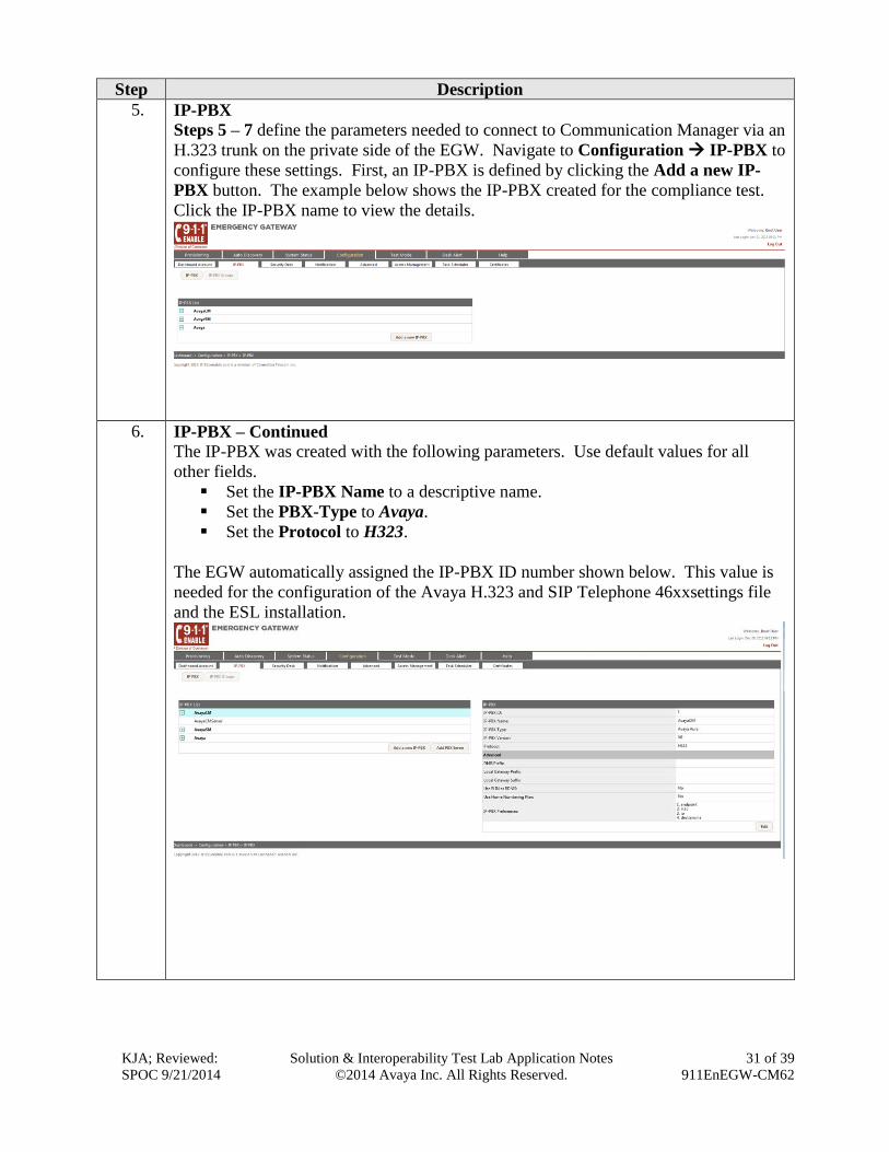
5. IP-PBX
Steps 5 – 7 define the parameters needed to connect to Communication Manager via an
H.323 trunk on the private side of the EGW. Navigate to Configuration IP-PBX to
configure these settings. First, an IP-PBX is defined by clicking the Add a new IP-
PBX button. The example below shows the IP-PBX created for the compliance test.
Click the IP-PBX name to view the details.
6. IP-PBX – Continued
The IP-PBX was created with the following parameters. Use default values for all
other fields.
Set the IP-PBX Name to a descriptive name.
Set the PBX-Type to Avaya.
Set the Protocol to H323.
The EGW automatically assigned the IP-PBX ID number shown below. This value is
needed for the configuration of the Avaya H.323 and SIP Telephone 46xxsettings file
and the ESL installation.
KJA; Reviewed:
SPOC 9/21/2014
Solution & Interoperability Test Lab Application Notes
©2014 Avaya Inc. All Rights Reserved.
32 of 39
911EnEGW-CM62
Step Description
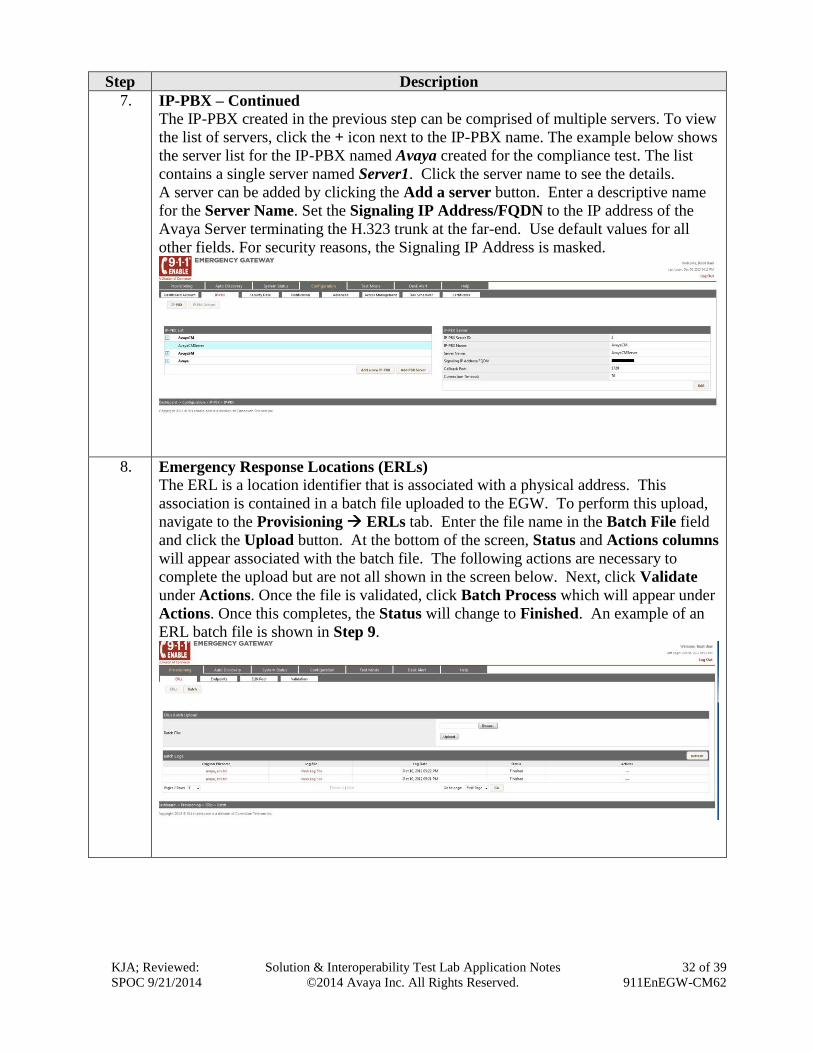
7. IP-PBX – Continued
The IP-PBX created in the previous step can be comprised of multiple servers. To view
the list of servers, click the + icon next to the IP-PBX name. The example below shows
the server list for the IP-PBX named Avaya created for the compliance test. The list
contains a single server named Server1. Click the server name to see the details.
A server can be added by clicking the Add a server button. Enter a descriptive name
for the Server Name. Set the Signaling IP Address/FQDN to the IP address of the
Avaya Server terminating the H.323 trunk at the far-end. Use default values for all
other fields. For security reasons, the Signaling IP Address is masked.
8. Emergency Response Locations (ERLs)
The ERL is a location identifier that is associated with a physical address. This
association is contained in a batch file uploaded to the EGW. To perform this upload,
navigate to the Provisioning ERLs tab. Enter the file name in the Batch File field
and click the Upload button. At the bottom of the screen, Status and Actions columns
will appear associated with the batch file. The following actions are necessary to
complete the upload but are not all shown in the screen below. Next, click Validate
under Actions. Once the file is validated, click Batch Process which will appear under
Actions. Once this completes, the Status will change to Finished. An example of an
ERL batch file is shown in Step 9.
KJA; Reviewed:
SPOC 9/21/2014
Solution & Interoperability Test Lab Application Notes
©2014 Avaya Inc. All Rights Reserved.
33 of 39
911EnEGW-CM62
Step Description
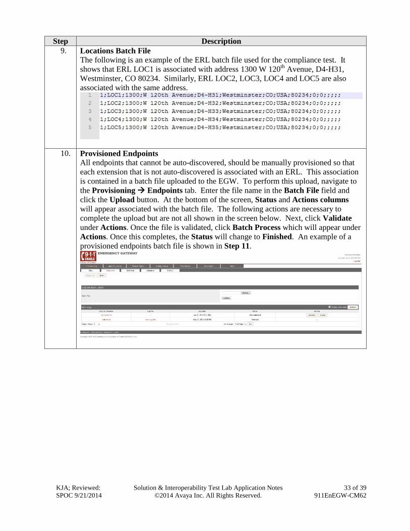
9. Locations Batch File
The following is an example of the ERL batch file used for the compliance test. It
shows that ERL LOC1 is associated with address 1300 W 120th
Avenue, D4-H31,
Westminster, CO 80234. Similarly, ERL LOC2, LOC3, LOC4 and LOC5 are also
associated with the same address.
10. Provisioned Endpoints
All endpoints that cannot be auto-discovered, should be manually provisioned so that
each extension that is not auto-discovered is associated with an ERL. This association
is contained in a batch file uploaded to the EGW. To perform this upload, navigate to
the Provisioning Endpoints tab. Enter the file name in the Batch File field and
click the Upload button. At the bottom of the screen, Status and Actions columns
will appear associated with the batch file. The following actions are necessary to
complete the upload but are not all shown in the screen below. Next, click Validate
under Actions. Once the file is validated, click Batch Process which will appear under
Actions. Once this completes, the Status will change to Finished. An example of a
provisioned endpoints batch file is shown in Step 11.

KJA; Reviewed:
SPOC 9/21/2014
Solution & Interoperability Test Lab Application Notes
©2014 Avaya Inc. All Rights Reserved.
34 of 39
911EnEGW-CM62
Step Description
11. Provisioned Endpoints Batch File
The following is an example of the provisioned endpoints batch file used for the
compliance test. It contains the extensions associated with the digital and analog
endpoints since these endpoints cannotcannot be auto-discovered. In the case of the
compliance test, the Avaya IP Telephone with extension 50023 also could not be auto-
discovered due to the type of layer 2 switch to which it was connected. Thus, this
extension should also be manually provisioned. However, for the purposes of the
compliance test, this extension was not provisioned in order to test the EGW operation
when the location of an extension is unknown. In this case, emergency calls from
extension 50023 would get routed to an ECRC operator to collect location and callback
information. The batch file shows that all the provisioned endpoints (extensions
52000, and 52003) are associated with the same ERL – LOC3. For Security reasons, IP
addresses are masked.
12. Layer 2 Discovery
Each enterprise layer 2 switch that has Avaya H.323 or SIP telephones connected to it
must be configured on the EGW so that it can be queried as part of layer 2 discovery.
Navigate to the Auto Discovery Layer 2 Discovery tab to display the list of layer 2
switches. The example below shows the list used for the compliance test. The IP
address of switch shown in Figure 1 was entered. Click the Add a switch button to
enter the switch parameters. Enter the management IP address of the switch in the
Switch IP field and enter the appropriate string in the SNMP Community String
field. Enter the ERL where the switch resides in the Default ERL ID field. Default
values may be used for all other fields. For security reasons, IP address is masked.
KJA; Reviewed:
SPOC 9/21/2014
Solution & Interoperability Test Lab Application Notes
©2014 Avaya Inc. All Rights Reserved.
35 of 39
911EnEGW-CM62
Step Description
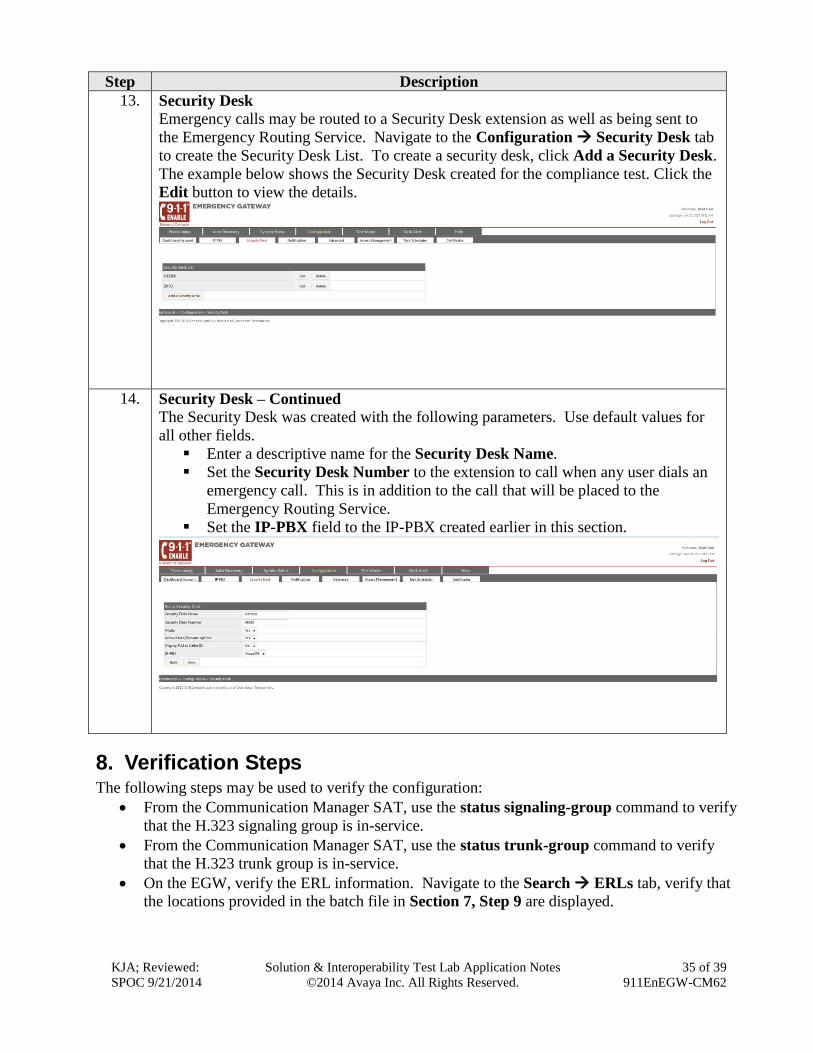
13. Security Desk
Emergency calls may be routed to a Security Desk extension as well as being sent to
the Emergency Routing Service. Navigate to the Configuration Security Desk tab
to create the Security Desk List. To create a security desk, click Add a Security Desk.
The example below shows the Security Desk created for the compliance test. Click the
Edit button to view the details.
14. Security Desk – Continued
The Security Desk was created with the following parameters. Use default values for
all other fields.
Enter a descriptive name for the Security Desk Name.
Set the Security Desk Number to the extension to call when any user dials an
emergency call. This is in addition to the call that will be placed to the
Emergency Routing Service.
Set the IP-PBX field to the IP-PBX created earlier in this section.
8. Verification Steps The following steps may be used to verify the configuration:
From the Communication Manager SAT, use the status signaling-group command to verify
that the H.323 signaling group is in-service.
From the Communication Manager SAT, use the status trunk-group command to verify
that the H.323 trunk group is in-service.
On the EGW, verify the ERL information. Navigate to the Search ERLs tab, verify that
the locations provided in the batch file in Section 7, Step 9 are displayed.

KJA; Reviewed:
SPOC 9/21/2014
Solution & Interoperability Test Lab Application Notes
©2014 Avaya Inc. All Rights Reserved.
36 of 39
911EnEGW-CM62

KJA; Reviewed:
SPOC 9/21/2014
Solution & Interoperability Test Lab Application Notes
©2014 Avaya Inc. All Rights Reserved.
37 of 39
911EnEGW-CM62
On the EGW, verify the endpoints. Navigate to the Search Endpoints tab, verify that all
endpoints are displayed.
Verify that 911 calls can be placed from different endpoints types from different locations.
Verify from the EGW Call Detail Records (CDR), that the correct location and callback
number is being passed to 911 Enable. Navigate to the System Status CDRs tab to
display this information. The example below shows two emergency 911 calls as represented
by the value ERS in the Call Destination field. The example also shows three callback calls
which show the local extension being called back in the Call Destination field. Each of the
911 calls shows the correct location and callback information for that endpoint.
9. Conclusion 911 Enable Emergency Gateway and Emergency Routing Service passed compliance testing. These
Application Notes describe the procedures required to configure the connectivity between Avaya
Aura® Communication Manager and the 911 Enable equipment and service as shown in Figure 1.
10. Additional References This section references the documentation relevant to these Application Notes. Avaya product
documentation is available at http://support.avaya.com. Product documentation for the EGW can be
obtained from 911 Enable.
[1] Administering Avaya Aura® Communication Manager, Release 6.2, Document 03-3005089,
Issue 7.0, December 2012

KJA; Reviewed:
SPOC 9/21/2014
Solution & Interoperability Test Lab Application Notes
©2014 Avaya Inc. All Rights Reserved.
38 of 39
911EnEGW-CM62
[2] 911Enable Emergency Gateway System Guide 2.6.
[3] ESL Configuration Guide Rev. A, February 15, 2010.
KJA; Reviewed:
SPOC 9/21/2014
Solution & Interoperability Test Lab Application Notes
©2014 Avaya Inc. All Rights Reserved.
39 of 39
911EnEGW-CM62
©2014 Avaya Inc. All Rights Reserved.
Avaya and the Avaya Logo are trademarks of Avaya Inc. All trademarks identified by ® and ™
are registered trademarks or trademarks, respectively, of Avaya Inc. All other trademarks are the
property of their respective owners. The information provided in these Application Notes is
subject to change without notice. The configurations, technical data, and recommendations
provided in these Application Notes are believed to be accurate and dependable, but are
presented without express or implied warranty. Users are responsible for their application of any
products specified in these Application Notes.
Please e-mail any questions or comments pertaining to these Application Notes along with the
full title name and filename, located in the lower right corner, directly to the Avaya DevConnect
Program at [email protected].