application of artificial neural network for the prediction of laser cladding process...
TRANSCRIPT

ORIGINAL ARTICLE
Application of artificial neural network for the predictionof laser cladding process characteristics at Taguchi-basedoptimized condition
Subrata Mondal & Asish Bandyopadhyay &
Pradip Kumar Pal
Received: 11 July 2011 /Accepted: 2 October 2013 /Published online: 14 November 2013# Springer-Verlag London 2013
Abstract This paper presents an investigation on the optimi-zation of multiple performance characteristics during CO2
laser cladding process considering clad width and clad depthas performance characteristics. This optimization for multiplequality characteristics has been done using Taguchi’s qualityloss function. The process model for laser cladding operationusing various techniques like artificial neural network (ANN)has rarely been found in the literature review. In the presentwork, a number of experiments have been performed to es-tablish the interrelationship between process variables andresponse variables using the back propagation method ofANN. The essential input process parameters are identifiedas laser power, scan speed of work table, and powder feed rate.Moreover, the analysis of variance is also employed to deter-mine the contribution of each control parameter on clad beadquality. In order to validate the predicted result, an experimentas confirmatory test is carried out at the optimized claddingcondition. It is observed that the confirmatory experimentalresult is showing a good agreement with the predicted one.However, it has been found that the optimum condition of thecladding parameters for multi-performance characteristicsvaries with the different combinations of weighting factors.
Keywords Laser cladding . Taguchi method . Optimization .
ANOVA .ANN
1 Introduction
Advanced laser surface cladding finds wide applications inmechanical industries. This is because of the superior surfacecharacteristics of the coat in which the surface with resistanceto wear, corrosion, and hardness can be resulted. In the presentday, the surface cladding is one of the most active and growingareas in research. From the application point of view, thecoating on any component produced by laser is highly com-parable to other coating processes such as plasma coating andspray coating. Laser cladding is one of the thermal typetechniques in which laser is used as heat source to deposit athin layer of a desired metal (by melting) on the substratesurface. Laser cladding using powder can be performed in twodistinct ways. In the first process, powder is pasted on thesurface by some adhesive and then the clad is formed by laserbeam. In the second process, powder is pneumatically fed intothe melt pool on a substrate surface so that powder jet andlaser beam are focused on the same area and the clad is formedon the surface; the second process is called “blown powdermethod” [1]. Some of the important process parameters arelaser power, scan speed of work table, stand-off distance, andpowder mass flow rate. Generally, the effect of laser claddingprocess performance is evaluated on the basis of clad beaddimension such as clad height and clad width and depth ofpenetration [2, 3]. It is well known that AISI 1040 steel has apotential application in automobile and mechanical industriesbut it gets corroded in open atmosphere, in order to minimizethe corrosion rate, an anticorrosive powder material of Ni–Cr–Momixture has been coated on the surface of AISI 1040 steelby using CO2 laser in the present work.
S. Mondal (*)School of Laser Science and Engineering, Jadavpur University,Kolkata 700032, Indiae-mail: [email protected]
A. Bandyopadhyay : P. K. PalMechanical Engineering Department, Jadavpur University,Kolkata 700032, India
A. Bandyopadhyaye-mail: [email protected]
P. K. Pale-mail: [email protected]
Int J Adv Manuf Technol (2014) 70:2151–2158DOI 10.1007/s00170-013-5393-z

A number of experimental investigations have been foundin the literature review to analyze the effect of process param-eters on clad bead geometry and clad quality by varying onefactor at a time [4–6]. In the present work, an experimentalstudy was carried out to get the data on clad bead geometrywith the variations of process parameters namely laser power,scan speed of work table, and powder feed rate. Many re-searchers [7–10] applied design of experiments technique toanalyze their experimental data and optimize the processparameters for desired response(s). In recent years, theTaguchi method has become a powerful tool for improvingthe productivity during research and development state so thata quality product can be obtained in an economical way. Thetraditional Taguchi method was applied to optimize a singlequality characteristic. However, multi-objective optimizationtechnique is more difficult than single-objective optimization.
It is well known that artificial neural networks (ANNs) arepowerful tools for analysis, modeling, and control of suchapplications. In the recent decade, ANNs have gained prom-inence in the field of material science and manufacturingtechnology. Acherjee et al. [11] developed an ANN model topredict the weld quality characteristics in laser welding ofthermoplastics. In addition to that, the results of the ANNmodels were compared with the multiple regression analyses(MRA) models which showed that the prediction rate of ANNmodels were superior to MRAmodels. Erzurumlu and Oktem[12] developed an ANN model to predict the surface rough-ness values error on mold surfaces and that model was com-pared with response surface (RS) model. They observed thatthe ANN model lead to a slightly accurate surface roughnessprediction than RS model. Ravi Sankar et al. [13] developedan ANN model for drill bit-guided abrasive flow finishing(DBGAFF) process to conduct parametric analysis and tounderstand, in depth, the DBGAFF process; also, the resultswere compared with multi-variable regression analysis(MVRA). They observed that for all responses, experimentalresults are very well matched with the theoretical resultsevaluated using ANN and MVRA. Application of ANN tolaser cladding process has rarely been found in literaturesurvey and thereafter, the present work has been taken up.The result of ANN has been validated by a confirmation testand seen that there is a good agreement between experimentalresult and ANN predicted result.
In the present investigation, multi-objective optimizationhas been applied for two quality characteristics such as clad
width (W ) and clad depth (D ) during CO2 laser cladding forAISI steel surface using Taguchi methodology. In the presentwork, to minimize the machining time, a minimum number ofpass of laser beam over the substrate surface and a short depthof clad bead have been required. Therefore, the nature of cladwidth is “higher-the-better” and “lower-the better” for claddepth. After finding the optimum condition, the optimumresults are predicted by developing the ANN model andcompared with confirmation test. Application of ANN to lasercladding process has rarely been found in literature survey andthereafter, the present work has been taken up. The result ofANN has been validated by a confirmation test and seen thatthere is a good agreement between experimental result andANN predicted result. However, the developed ANN modelin MATLAB® 7.0 can be used for the prediction of any othercombination of process parameters within the experimentaldomain and one can use the model for further investigation.
2 Experimental details
2.1 Selection of materials
The experiments are performed on Φ 3×0.5 in.-thick speci-mens of commercial mild steel (S235). The surfaces of the
Table 1 Composition of feeding powder
Elements Chromium Molybdenum Nickel
Percentage in weight 20 % 5 % Balance
Table 2 Control factors and their levels
Control factor Levels
1 2 3
A. Feed rate (gm/min) 5 8 11
B. Scan speed (m/min) 0.3 0.5 0.8
C. Laser power (kW) 1 1.25 1.5
Table 3 Experimental layout using an L9 orthogonal array
Trial Runs Process parameter’s level
A B CLaser power Scan speed Powder feed rate
1 1 1 1
2 1 2 2
3 1 3 3
4 2 1 3
5 2 2 1
6 2 3 2
7 3 1 2
8 3 2 3
9 3 3 1
2152 Int J Adv Manuf Technol (2014) 70:2151–2158

substrate are sand blasted prior to laser cladding. The powder(feedingmaterial) used in laser cladding is a mixture of nickel,chromium, and molybdenum powder. The powder particlesare of globe-shaped with a size of 45–106 μm. The chemicalcomposition of the powder is shown in Table 1. In order toimprove the surface characteristics of this substrate, an anti-corrosive powder material is used as the clad material. It is anon-magnetic, corrosion, and oxidation resistant. Nickel andchromium provide resistance to oxidizing environment, whilenickel and molybdenum to non-oxidizing environment.Pitting and crevice corrosion are prevented by molybdenum[14].
2.2 Taguchi-based experimental design
The design of experiment is a statistical tool which helps tominimize the number of experiments so that appropriate datawill be collected; the minimum number of experiments will beperformed to acquire the necessary technical information andsuitable statistical methods will be used to analyze the collect-ed data. Taguchi’s method for experimental design is straight-forward and easy to apply to many engineering situations,making it a powerful, yet, simple tool [15, 16]. The initial taskof this stage is to find out the key process control parameterswith their ranges and performance evaluation parameter(output) that is to be measured. The levels of each variablerepresent the range for which the effect of that variable isdesired to be known. The selected ranges of process parame-ters employed in the present work are shown in Table 2.
In order to minimize the number of experiments, the ex-periments are planned against a three-level Taguchi’s orthog-onal array that required nine runs in total to be carried out. Theprocess parameters of laser power, scan speed of the table, andpowder feed rate have been varied to investigate the processresponses of clad quality. The selected L9 orthogonal array inthe present analysis is presented in Table 3.
2.3 Experimental set-up
The equipment used for laser cladding is a 3.5-kW continuouswave CO2 laser rapid manufacturing (LRM) system. The
POWDER FEEDER
Ar GAS
PM
PM
CM
LASER BEAM
X-Y WORK STATION
Fig. 1 The schematic arrangement of experimental LRM set-up
Fig. 2 A photographic view of laser-clad beads of Ni–Cr–Mo powder onAISI1040 steel substrate using 3.5-kW CO2 laser
Fig. 3 A sketch of cross-section of a single bead clad
Table 4 Experimental observations using L9 OA
Trial Runs Clad width (W) mm Clad depth (D) mm
1 3.11 0.41
2 2.72 0.2
3 3.39 0.3
4 2.57 0.25
5 4.25 0.55
6 3.69 0.25
7 4.19 0.25
8 4.64 0.38
9 4.74 0.53
Int J Adv Manuf Technol (2014) 70:2151–2158 2153
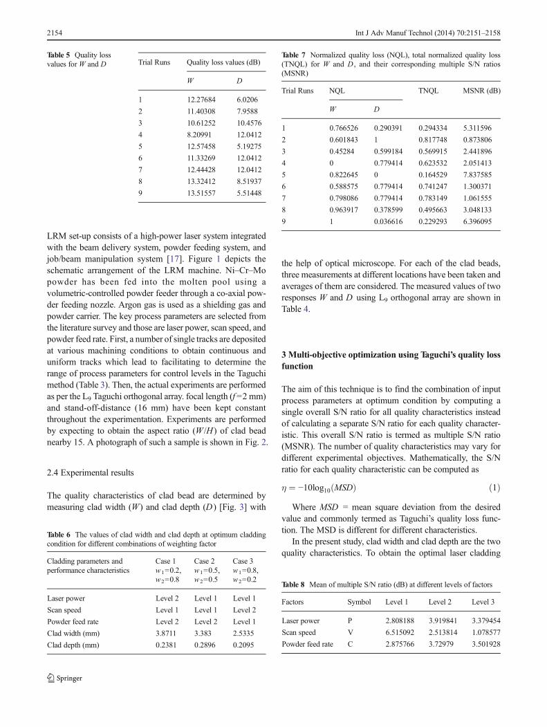
LRM set-up consists of a high-power laser system integratedwith the beam delivery system, powder feeding system, andjob/beam manipulation system [17]. Figure 1 depicts theschematic arrangement of the LRM machine. Ni–Cr–Mopowder has been fed into the molten pool using avolumetric-controlled powder feeder through a co-axial pow-der feeding nozzle. Argon gas is used as a shielding gas andpowder carrier. The key process parameters are selected fromthe literature survey and those are laser power, scan speed, andpowder feed rate. First, a number of single tracks are depositedat various machining conditions to obtain continuous anduniform tracks which lead to facilitating to determine therange of process parameters for control levels in the Taguchimethod (Table 3). Then, the actual experiments are performedas per the L9 Taguchi orthogonal array. focal length (f =2 mm)and stand-off-distance (16 mm) have been kept constantthroughout the experimentation. Experiments are performedby expecting to obtain the aspect ratio (W /H) of clad beadnearby 15. A photograph of such a sample is shown in Fig. 2.
2.4 Experimental results
The quality characteristics of clad bead are determined bymeasuring clad width (W) and clad depth (D ) [Fig. 3] with
the help of optical microscope. For each of the clad beads,three measurements at different locations have been taken andaverages of them are considered. The measured values of tworesponses W and D using L9 orthogonal array are shown inTable 4.
3 Multi-objective optimization using Taguchi’s quality lossfunction
The aim of this technique is to find the combination of inputprocess parameters at optimum condition by computing asingle overall S/N ratio for all quality characteristics insteadof calculating a separate S/N ratio for each quality character-istic. This overall S/N ratio is termed as multiple S/N ratio(MSNR). The number of quality characteristics may vary fordifferent experimental objectives. Mathematically, the S/Nratio for each quality characteristic can be computed as
η ¼ −10log10 MSDð Þ ð1ÞWhere MSD = mean square deviation from the desired
value and commonly termed as Taguchi’s quality loss func-tion. The MSD is different for different characteristics.
In the present study, clad width and clad depth are the twoquality characteristics. To obtain the optimal laser cladding
Table 5 Quality lossvalues for W and D Trial Runs Quality loss values (dB)
W D
1 12.27684 6.0206
2 11.40308 7.9588
3 10.61252 10.4576
4 8.20991 12.0412
5 12.57458 5.19275
6 11.33269 12.0412
7 12.44428 12.0412
8 13.32412 8.51937
9 13.51557 5.51448
Table 6 The values of clad width and clad depth at optimum claddingcondition for different combinations of weighting factor
Cladding parameters andperformance characteristics
Case 1 Case 2 Case 3w1=0.2,w2=0.8
w1=0.5,w2=0.5
w1=0.8,w2=0.2
Laser power Level 2 Level 1 Level 1
Scan speed Level 1 Level 1 Level 2
Powder feed rate Level 2 Level 2 Level 1
Clad width (mm) 3.8711 3.383 2.5335
Clad depth (mm) 0.2381 0.2896 0.2095
Table 7 Normalized quality loss (NQL), total normalized quality loss(TNQL) for W and D , and their corresponding multiple S/N ratios(MSNR)
Trial Runs NQL TNQL MSNR (dB)
W D
1 0.766526 0.290391 0.294334 5.311596
2 0.601843 1 0.817748 0.873806
3 0.45284 0.599184 0.569915 2.441896
4 0 0.779414 0.623532 2.051413
5 0.822645 0 0.164529 7.837585
6 0.588575 0.779414 0.741247 1.300371
7 0.798086 0.779414 0.783149 1.061555
8 0.963917 0.378599 0.495663 3.048133
9 1 0.036616 0.229293 6.396095
Table 8 Mean of multiple S/N ratio (dB) at different levels of factors
Factors Symbol Level 1 Level 2 Level 3
Laser power P 2.808188 3.919841 3.379454
Scan speed V 6.515092 2.513814 1.078577
Powder feed rate C 2.875766 3.72979 3.501928
2154 Int J Adv Manuf Technol (2014) 70:2151–2158

performance, higher-the-better quality characteristic for cladwidth should be taken. The MSD for higher-the-better qualitycharacteristic can be computed as
MSD ¼ 1
n
X
i¼1
n 1
W 2i
ð2Þ
Where n is the number of experiments andWi is the valueof clad width at i th test.
On the other hand, lower-the-better quality characteristicfor clad depth is chosen for obtaining optimal cladding per-formance. TheMSD for lower-the-better quality characteristiccan be computed as
MSD ¼ 1
n
X
i¼1
n
D2i ð3Þ
Where Di is the value of clad depth for the i th test. Thequality loss values forW andD are presented in Table 5 usingEqs. (2) and (3).
Before calculating the MSNR, it is important to normalizethe quality loss of each quality characteristic so that qualityloss value varies from minimum of 0 to maximum of 1. The
normalized quality loss can be computed using:
yij ¼Lij− Lið Þmin
Lið Þmax− Lið Þmin
ð4Þ
Where, y ij = normalized quality loss associated with the i thquality characteristic at the j th experimental run; (L i)min and(L i)max= minimum and maximum quality loss respectively fori th quality characteristic among all the experimental runs.
For computing the total normalized quality loss (Y j) corre-sponding to each run, a weighting factor is assigned to estab-lish multi-objective optimization process. If w i represents theweighting factor for the i th quality characteristic then Y j canbe computed as follows.
Y j ¼X
i¼1
m
wiyij ð5Þ
Where, m = number of quality characteristicsAfter calculating the total normalized quality loss, the next
step is to find the MSNR (ξ j) at each experimental run using:
ξ j ¼ −10Log10 Y j
� � ð6Þ
4 Analysis of experimental results
The values of weighting factor (w i) is chosen with engineeringjudgment. In order to obtain the desired outcome severalcombinations of weighting factor for clad width and clad
1 2 3
1
2
3
4
5
6
7M
ean
of M
ultip
le S
/N r
atio
s (d
B)
Factor Levels
Laser Power Scan Speed Powder Feedrate
Fig. 4 Effect of input parameters in multiple S/N ratio
Table 9 Analysis of variance for clad width
Source DF SS MS F Contribution (%)
Laser power 2 0.5022 0.2511 1.52 13.97
Scan speed 2 1.0567 0.5283 3.20 29.41
Powder feed rate 2 1.7032 0.8516 5.15 47.40
Error 2 0.3307 0.1653
Total 8 3.5928
Table 10 Analysis of variance for clad depth
Source DF SS MS F Contribution (%)
Laser power 2 0.019117 0.009558 17.12 15.50
Scan speed 2 0.099117 0.049558 88.76 80.38
Powder feed rate 2 0.003950 0.001975 3.54 3.20
Error 2 0.001117 0.000558
Total 8 0.123300
Target
Input Output
AdjustWeights
Neural network including
connections (called weights)
Between neurons
Compare
Fig. 5 The flow diagram for ANN system
Int J Adv Manuf Technol (2014) 70:2151–2158 2155

depth are considered and their results are shown in Table 6.The normalized quality loss, total normalized quality loss(TNQL) for both quality characteristics and MSNR for mul-tiple quality characteristics are calculated using Eqs. (4), (5),and (6), respectively and presented in Table 7. From Table 6, itis clear that the optimum cladding condition for higherW andlower D has been obtained in case 1 in which, very low w1
was used. The cladding condition for mediumW and mediumD is obtained in case 2 where equal weighting factor has beenused (w1=w2=0.5). The cladding condition for lower W andlower D is found in case 3 in which very high w1 have beenused. In this study, w1=0.2 and w2=0.8, i.e., case 1 is accept-ed since the higher W is more important for laser claddingapplication.
The mean of MSNR at different levels for the three inputprocess parameters is shown in Table 8. The effect of inputprocess parameters on the mean of MSNR is shown graphi-cally in Fig. 4. From this figure, it is observed that theoptimum levels of different input process parameters for max-imum clad width with minimum clad depth obtained are: laserpower at level 2 (1.25 kW), scan speed at level 1 (0.3 m/min)and powder feed rate at level 2 (8 g/min).
4.1 ANOVA for the responses
A better feel for the relative effect of the different factors canbe obtained by decomposition of variance, which is common-ly called analysis of variance (ANOVA). The parameters suchas sum of square, mean square, degree of freedom, and Fish-er’s ratio (F) are calculated using Minitab software of version13. A value of F less than 1 means the factor effect is smallerthan the error of the additive model. Avalue of F larger than 2means the factor effect is not quite small, whereas larger than 4means the factor effect is quite large [18]. The percentageprocess contribution of each factor on the responses is alsocalculated in this Table. The result of ANOVA for clad widthis shown in Table 9 and for clad depth is shown in Table 10.
5 Process prediction through ANN during optimization
Neural networks are composed of simple elements operatingin parallel. These elements are inspired by biological nervoussystems [19]. As in nature, the network function is determinedlargely by the connections between elements. One can train aneural network to perform a particular function by adjustingthe values of the connections (weights) between elements.Commonly, neural networks are adjusted or trained, so that aparticular input leads to a specific target output. There, thenetwork is adjusted, based on a comparison of the output andthe target, until the network output matches the target. Typi-cally, many such input/target pairs are used in this supervisedlearning, to train a network [20]. The flow diagram for ANNsystem is shown in Fig. 5.
There are various algorithms in the ANN. In the presentstudy, the back propagation training algorithm is used. Theaim of the ANNmodeling is to establish a correlation of inputprocess variables such as laser power, scan speed, and powderfeed rate, with output parameters namely clad width and claddepth. The back propagation neural networks are usuallyreferred to as feed forwarded and multi layered perceptronwith number of hidden layers. The error back-propagationprocess consists of two passes through the different layer ofthe network: a forward pass and a backward pass. In theforward pass, an activity pattern (input vector) is applied to
P = Laser powerV = Scan velocityC = Powder mass flow rateW = Clad widthD = Clad depth
Hidden Layers
Fig. 6 Structure of 4-layeredANN model for clad width
Fig. 7 Variation of total error with number of epochs in 3-4-9-1 networkfor clad width
2156 Int J Adv Manuf Technol (2014) 70:2151–2158

the sensory nodes of the network and its effect propagatesthrough the network layer by layer. Finally, a set of output isproduced as the actual response of the network. During thebackward pass, all synaptic weights are adjusted in accor-dance with the error correction rule with the following formu-la.
ΔΩ tð Þ ¼ βδiOi þ αΔwij t−1ð Þ ð7Þ
Where β = learning rate, α = momentum coefficient, and δ= local error gradient, O i = output of the i th unit, w ij =weighting factor connecting the i th neuron of the input vectorto the j th neuron of the output vector. The configuration of thepresent neural network structure is shown in Fig. 6.
5.1 Training and testing of neural network
To increase the accuracy and speed of the network, the nor-malized data set obtained from Eq. (4) is used in the trainingand testing phase. Out of a total available data set, 70 % dataset was used for training the network and the remaining wasused for testing the network. There are two responses consid-ered in the present process, one model for clad width (W ) andanother model for clad depth (D) formed separately. There-fore, the number of neurons in the input and output layer hasbeen set to three and one, respectively, in the present neuralnetwork architecture. Several network structures are formedby keeping on changing the number of neurons in the hiddenlayers and finally 3-4-9-1 configuration is selected for cladwidth as well as clad depth. The training period is around10 min for each run. The error plot for clad width is shown inFig. 7 and same kind of trend is also obtained in case of claddepth. The selected values of model parameters for cladwidth/clad depth are shown in Table 11.
6 Confirmation test
The optimum levels of design parameters are used for theprediction of laser cladding response variables and therebycomparison with the experimental results. The estimated S/Nratio γ at the optimal level of the design parameters can becalculated as
γ ¼ γm þX
i¼1
n
γi−γmð Þ
Where, γm is the total mean S/N ratio, γ i is the mean S/Nratio at the optimal level, and n is the number of main designparameters that affect the quality characteristics. For valida-tion of the predicted results at optimum condition, experi-ments are conducted as per the optimum condition and theaverage results are fairly close to the predicted results. Theabsolute prediction error (APE) has been calculated using thefollowing formula.
Absolute Prediction Error APEð Þ ¼ Experimental−PredictedExperimental
����
����� 100%
7 Conclusion
In the context of laser cladding process performance for AISI1040 steel substrate using nickel, chromium, and molybde-num powder as cladding material, an attempt is made todetermine the optimum combination of laser power, scanspeed, and powder feed rate to maximize clad width as wellas to minimize clad depth at a time using Taguchi’s experi-mental design method. During the optimization, it is observedthat the deviation of quality from its optimum conditiondepends mainly on the weight assigned to it. Therefore, theselection of weighting factor is more important. The weightassigned in the present work is verified by the confirmationtest which gives the idea about the weighting factor that lowerweight is recommended for clad width to achieve its highervalue. Based on multi-objective optimization using Taguchimethod, the optimum values for W and D are 3.773 and0.258 mm, respectively, which are showing great improve-ment in performance characteristics. From ANOVA test, it isfound that the increasing order of contribution for W is laserpower, scan speed, and powder feed rate and that for D ispowder feed rate, laser power, and scan speed.
Table 11 Selected train-ing parameters of ANNfor clad width
No. of epochs 20,000
Goal 0.0001
Learning rate 0.05
Max_fail 5
Mu_max 1010
Transfer function Log sigmoid
Table 12 Validation of the ANNpredicted results Responses Optimum condition Experimental value Predicted value APE (in %)
Clad width (W) A2B1C2 3.773 mm 3.595 mm 4.72
Clad depth (D) A2B1C2 0.258 mm 0.266 mm 3.10
Int J Adv Manuf Technol (2014) 70:2151–2158 2157

The artificial neural network model has been developedspecially for predicting the clad bead characteristics at opti-mum cladding condition (Table 12). This model also helps tofind the responses at other combinations of process variables.The developed ANN model may be applied to other optimi-zation process like genetic algorithm, particle swarm optimi-zation, etc. It is seen that the developed ANN model shows agood agreement with the experimental outcomes.
References
1. Gedda H (2000) Laser surface cladding a literature survey. 2000:07.ISSN: 1402–1536. ISRN: LTU-TR—00/07—SE
2. Paulo Davim J, Oliveira C, Cardoso A (2008) Predicting the geo-metric form of clad in laser cladding by powder using multipleregression analysis (MRA). Mater Des 29:554–557
3. Oliveira U, Ocelik V, De Hosson J (2005) Analysis of coaxial lasercladding processing conditions. Surf Coat Technol 197:127–136
4. Onwubolu GC, Paulo Davim J, Oliveria C, Cardoso A (2007) Predictionof clad angle in laser cladding by powder using response surface meth-odology and scatter search. Opt Laser Technol 39:1130–1134
5. Kathuria YP (1997) Laser-cladding process: a study using stationaryand scanning CO2 laser beams. Surf Coat Technol 97:442–447
6. Shepeleva L, Medres B, Kaplan WD, Bamberger M, Weisheit A(2000) Laser cladding of turbine blades. Surf Coat Technol 125:45–48
7. Karazi SM, Issa A, Brabazon D (2009) Comparison of ANN andDoE for the prediction of laser-machined micro-channel dimensions.Opt Lasers Eng 47:956–964
8. Benyounis KY, Olabi AG (2008) Optimization of different weldingprocesses using statistical and numerical approaches—a referenceguide. Adv Eng Softw 39:483–496
9. Aggarwal A, Singh H, Kumar P, Singh M (2008) Optimizing powerconsumption for CNC turned parts using response surface method-ology and Taguchi’s technique—a comparative analysis. J MaterProcess Technol 200:373–384
10. Rao R, Yadav V (2009) Multi-objective optimization of Nd:YAGlaser cutting of thin superalloy sheet using grey relational analysiswith entropy measurement. Opt Laser Technol 41:922–930
11. Acherjee B, Mondal S, Tudu B, Misra D (2011) Application ofartificial neural network for predicting weld quality in laser transmis-sion welding of thermoplastics. Appl Soft Comput 11:2548–2555
12. Erzurumlu T, Oktem H (2007) Comparison of response surfacemodel with neural network in determining the surface quality ofmoulded parts. Mater Des 28:459–465
13. Sankar MR, Mondal S, Ramkumar J, Jain VK (2008) Experimentalinvestigations and modeling of drill bit-guided abrasive flowfinishing (DBG-AFF) process. Int J Adv Manuf Technol. doi:10.1007/s00170-008-1642-y
14. Paul CP, Ganesh P, Mishra SK, Bhargavaa P, Negib J, Nath AK(2007) Investigating laser rapid manufacturing for Inconel-625 com-ponents. Opt Laser Technol 39:800–805
15. Hsieh K-L, Tong L-I, Chiu H-P, Yeh H-Y (2005) Optimization of amulti-response problem in Taguchi’s dynamic system. Comput IndEng 49:556–571
16. Tan O, Sahin Zaimoglu A, Hinislioglu S, Altun S (2005) Taguchiapproach for optimization of the bleeding on cement-based grouts.Tunn Undergr Space Technol 20:167–173
17. Paul CP, Jain A, Ganesh P, Negi J, Nath AK (2006) Laser rapidmanufacturing of Colmonoy-6 components. Opt Lasers Eng 44:1096–1109
18. Phadke MS (2008) Quality engineering using robust design. PearsonEducation, New Jersey
19. Okuyucu H, Kurt A, Arcaklioglu E (2007) Artificial neural networkapplication to the friction stir welding of aluminum plates. Mater Des28:78–84
20. El Kadi H (2006) Modeling the mechanical behavior of fiber-reinforced polymeric composite materials using artificial neural net-works—a review. Compos Struct 73:1–23
2158 Int J Adv Manuf Technol (2014) 70:2151–2158