application of cognitive radios in centralized and in … of cognitive radios ... software radio,...
TRANSCRIPT

KIT – University of the State of Baden-Wuerttemberg and National Research Center of the Helmholtz Association
COMMUNICATIONS ENGINEERING LAB (CEL)
www.kit.edu
Application of Cognitive Radios in Centralized and in Ad-hoc Overlay SystemsFriedrich Jondral
VirginiaTech, May 30, 2012

Communications Engineering Lab (CEL)2 09.05.2012
0. Introduction
Prof. Dr.rer.nat. Friedrich Jondral

Communications Engineering Lab (CEL)3 09.05.2012 3
Karlsruhe
Karlsruhe
● 8° 24’ 18” E, 49° 00’ 54” N
●114.9 m above sea level
● founded: 1715
● 173.49 km2
● 285 000 inhabitants
● German Federal Constitutional Court
Communications Engineering Lab (CEL)4 09.05.2012
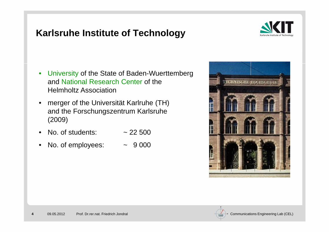
Karlsruhe Institute of Technology
Prof. Dr.rer.nat. Friedrich Jondral
• University of the State of Baden-Wuerttembergand National Research Center of theHelmholtz Association
• merger of the Universität Karlruhe (TH) and the Forschungszentrum Karlsruhe(2009)
• No. of students: ~ 22 500
• No. of employees: ~ 9 000
Communications Engineering Lab (CEL)5 09.05.2012
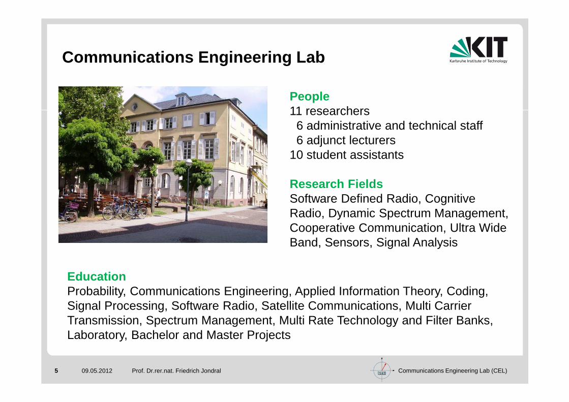
Communications Engineering Lab
Prof. Dr.rer.nat. Friedrich Jondral
People11 researchers6 administrative and technical staff6 adjunct lecturers
10 student assistants
Research FieldsSoftware Defined Radio, CognitiveRadio, Dynamic Spectrum Management, Cooperative Communication, Ultra Wide Band, Sensors, Signal Analysis
EducationProbability, Communications Engineering, Applied Information Theory, Coding, Signal Processing, Software Radio, Satellite Communications, Multi Carrier Transmission, Spectrum Management, Multi Rate Technology and Filter Banks,Laboratory, Bachelor and Master Projects

Communications Engineering Lab (CEL)6 09.05.2012
Friedrich K. Jondral1970-79 Technische Universität Braunschweig
Education in Mathematics and Physics
1975 Diploma in Mathematics
Research Associate at the Applied Mathematics Lab
WS 77/78 Visiting Researcher to Nagoya University, Nagoya (Japan)
1979 Doctorate in Natural Sciences (Dr.rer.nat.)
1979-92 AEG-Telefunken (and Successor Companies) Ulm
Various Positions in Research, Development and Systems Engineering
1984 Habilitation (State Doctorate) in Applied Mathematics (Universität Ulm)
1991 Adjunct Professor (Universität Ulm)
1993- Karlsruhe Institute of Technology
Full Professor,
Director Communications Engineering Lab
SS 2004 Visiting Faculty to the Virginia Polytechnical
Institute and State University,
Blacksburg (Virginia)
Prof. Dr.rer.nat. Friedrich Jondral
Communications Engineering Lab (CEL)7 09.05.2012
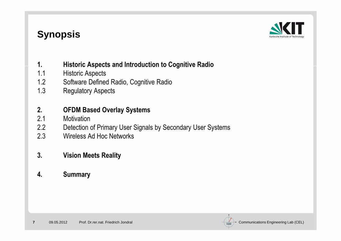
Synopsis
1. Historic Aspects and Introduction to Cognitive Radio
1.1 Historic Aspects
1.2 Software Defined Radio, Cognitive Radio
1.3 Regulatory Aspects
2. OFDM Based Overlay Systems
2.1 Motivation
2.2 Detection of Primary User Signals by Secondary User Systems
2.3 Wireless Ad Hoc Networks
3. Vision Meets Reality
4. Summary
Prof. Dr.rer.nat. Friedrich Jondral

Communications Engineering Lab (CEL)8 09.05.2012 Prof. Dr.rer.nat. Friedrich Jondral
1. Historic Aspects and Introduction to Cognitive R adio

Communications Engineering Lab (CEL)9 09.05.2012 Prof. Dr.rer.nat. Friedrich Jondral
1.1 Historic Aspects
Communications Engineering Lab (CEL)10 09.05.2012 Prof. Dr.rer.nat. Friedrich Jondral
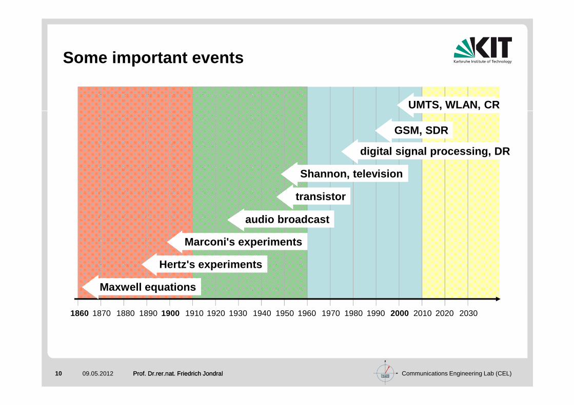
Some important events
GSM, SDR
digital signal processing, DR
audio broadcast
Marconi's experiments
Hertz's experiments
Maxwell equations
1860 1870 1880 1890 1900 1910 1920 1930 1940 1950 1960 1970 1980 1990 2000 2010 2020 2030
Shannon, television
transistor
UMTS, WLAN, CR
Prof. Dr.rer.nat. Friedrich Jondral
Communications Engineering Lab (CEL)11 09.05.2012
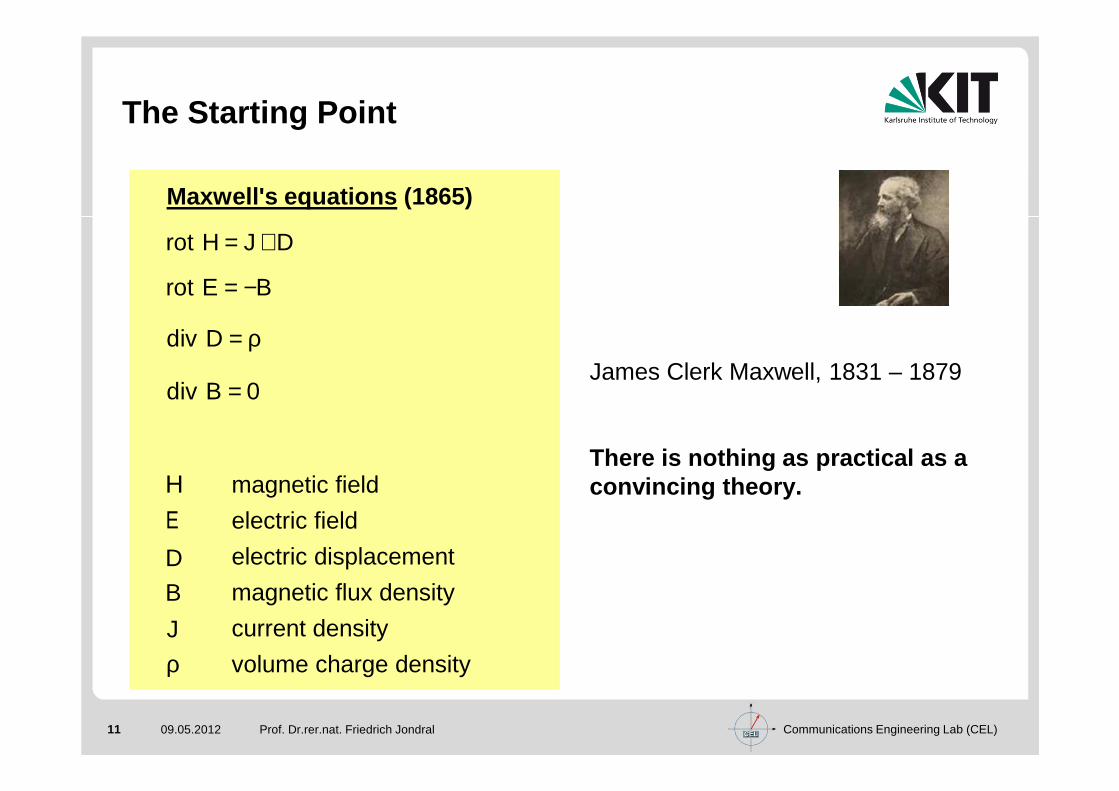
The Starting Point
Prof. Dr.rer.nat. Friedrich Jondral
James Clerk Maxwell, 1831 – 1879
There is nothing as practical as a convincing theory.
Maxwell's equations (1865)
magnetic field
electric field
electric displacement
magnetic flux density
current density
volume charge density
rot H J D= +
rot E B= −
div D = ρ
div B 0=
H
E
D
B
ρJ

Communications Engineering Lab (CEL)12 09.05.2012
Generation of Electromagnetic Waves
Prof. Dr.rer.nat. Friedrich Jondral
Heinrich Hertz, 1857 – 1894
Karlsruhe 1887:
Electromagnetic wavespropagate through freespace
Metallic walls reflectelectromagnetic waves
Electromagnetic wavesexhibit the properities oflight waves (reflection, diffraction, refraction, polarization, interference, ...)
Hertzian dipole
z
x
θ r
Communications Engineering Lab (CEL)13 09.05.2012
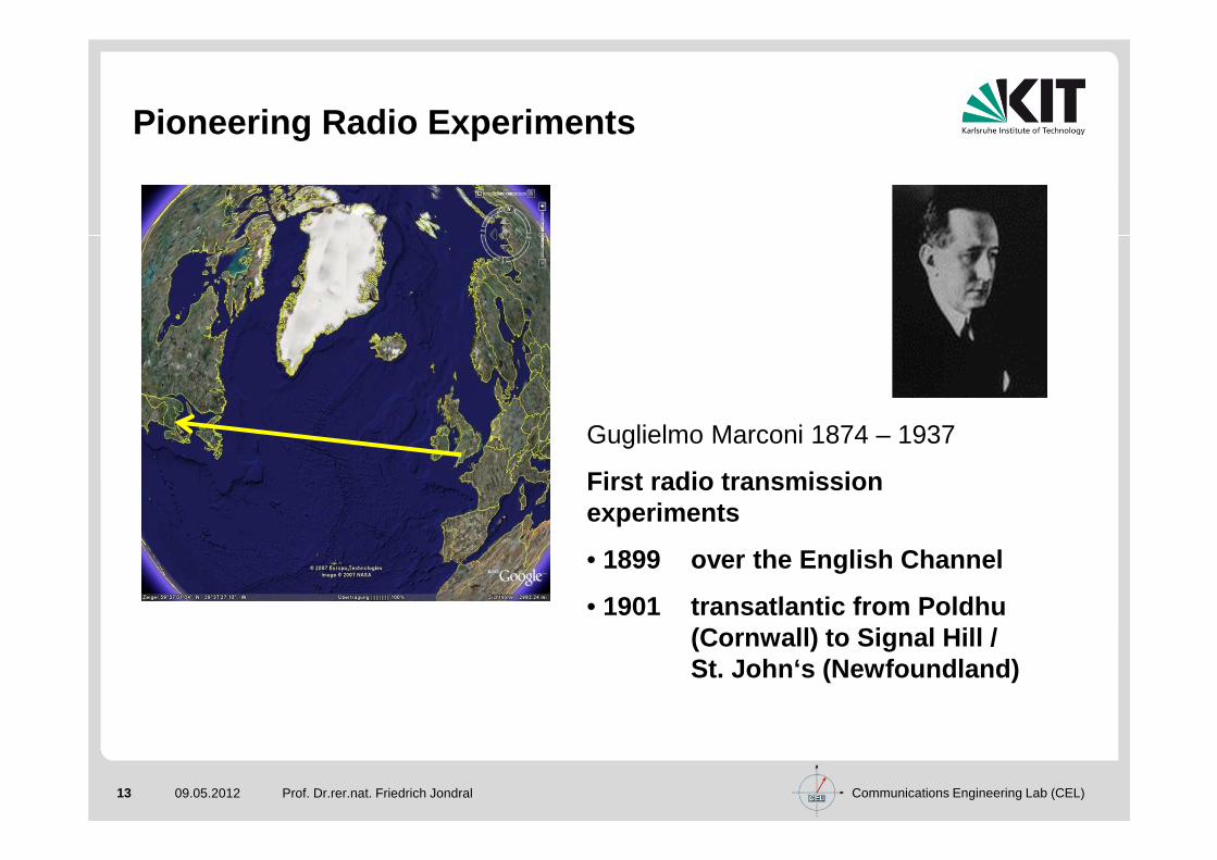
Pioneering Radio Experiments
Prof. Dr.rer.nat. Friedrich Jondral
Guglielmo Marconi 1874 – 1937
First radio transmissionexperiments
• 1899 over the English Channel
• 1901 transatlantic from Poldhu(Cornwall) to Signal Hill / St. John‘s (Newfoundland)

Communications Engineering Lab (CEL)14 09.05.2012
Modulation
Prof. Dr.rer.nat. Friedrich Jondral
a amplitude, fc carrier frequency
ϕ phase, fi information frequency
( ) ( ) ( ) ( ){ } c is t a t cos 2 f f t t t= π + + ϕ
analog digital multi carrier spread spectrum
� AM� SSB� RSB� FM
� ASK� FSK� PSK� QAM
� FFT based- OFDM- DMT
� Filter Bank
� DS� FH� TH

Communications Engineering Lab (CEL)15 09.05.2012
Digitalization / Coding
Prof. Dr.rer.nat. Friedrich Jondral
Claude E. Shannon, 1916 – 2001
Source coding
Channel coding (FEC)
Cryptographic coding
Sampling theorem, 1949
If the real signal s(t) is
• integrable over the whole real axis
• band limited by B, i.e.
then
s(t) is determined by its values s(k∆t ),
k ∈ Ζ, periodically taken at the time
difference
( ) ( ) ( ) s t S f : S f 0 f B• = ∀ ≥
( ) ( ) ( )( )k
sin2 B t k ts t s k t
2 B t k t
∞
=−∞
π − ∆= ∆
π − ∆∑
:1
t2B
∆ =

Communications Engineering Lab (CEL)16 09.05.2012
Networking
Radios are normally integrated into networks→ Cognitive Radio is a networking subject
In many cases radio networks serve as access networ ks to fiber optic backbones
We have distinguish commercial, security, and milit ary networks
Autarky is of special interest for military and sec urity networks
Military applications may call for low probability of intercept and for advanced crypto requirements
Prof. Dr.rer.nat. Friedrich Jondral

Communications Engineering Lab (CEL)17 09.05.2012
Radios in Past and Present
Prof. Dr.rer.nat. Friedrich Jondral
Apple i-Phone, 2007
TELEFUNKENTFK801, ca. 1935

Communications Engineering Lab (CEL)18 09.05.2012
Software Defined Radio / Cognitive Radio
Prof. Dr.rer.nat. Friedrich Jondral
Joseph Mitola III
Communications Engineering Lab (CEL)19 09.05.2012 Prof. Dr.rer.nat. Friedrich Jondral
1.2 Software Defined Radio, Cognitive Radio

Communications Engineering Lab (CEL)20 09.05.2012
Hierarchical Cells
Prof. Dr.rer.nat. Friedrich Jondral
Source: UMTS Task Force Report

Communications Engineering Lab (CEL)21 09.05.2012
Mobile Standards
Prof. Dr.rer.nat. Friedrich Jondral
user data rate
mobility/range
high velocity
long distance traffic
urban traffic
walking
nomadic
fixed
inhouse
personal environment
0.1 1 10 100 Mbit/s
vehi
cle
stat
iona
ry
EDGE
HSPA
3G/UMTS
GSM/GPRS
DECT
Bluetooth
flashOFDM
WLAN(IEEE 802.11x)
WiMAXIEEE
802.16-2004
IEEE802.16e
3Gsuccessorsystems
>2014
pede
stria
n
Source:Klaus-D. Kohrt: 3G und WIMAX –Konkurrenten oder Partner?ntz, Heft 1, 2007, S. 12-15
Communications Engineering Lab (CEL)22 09.05.2012
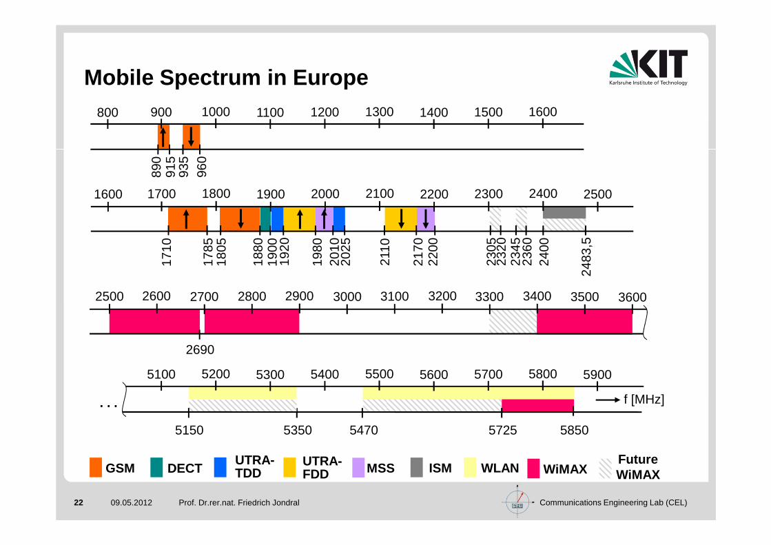
Mobile Spectrum in Europe
Prof. Dr.rer.nat. Friedrich Jondral
890
915
935
960
. . . f [MHz]
GSM DECTUTRA-TDD
UTRA-FDD MSS ISM WLAN WiMAX
FutureWiMAX
1600 1700 1800 1900 2000 2100 2200 2300 2400 2500
800 900 1000 1100 1200 1300 1400 1500 1600
2500 2600 2700 2800 2900 3000 3100 3200 3300 3400 3500 3600
2690
1710
1785
1805
1880
1900
1920
1980
2010
2025
2110
2170
2200
2400
2483
,5
2305
2320
2345
2360
5100 5200 5300 5400 5500 5600 5700 5800 5900
5150 5350 5470 5725 5850

Communications Engineering Lab (CEL)23 09.05.2012
The Key Question
Prof. Dr.rer.nat. Friedrich Jondral
What does a subscriber need?One specific device for each and every situation
or one device that serves all situations?
Personal Area Networks Pico Cells Voice
Wireless Local Area Networks Micro Cells Data
Cordless Phones Macro Cells Video
Cellular Networks Global Cells Multimedia
Broadcast NetworksLocation & Navigation
Satellite Networks Infotainment

Communications Engineering Lab (CEL)24 09.05.2012
Standards
Prof. Dr.rer.nat. Friedrich Jondral
Definition :A communications standard is a set of documents that describesthe functions of a communication system in such a way tha t a manufacturer can develop terminals or infrastructure equi pmenton this basis.
Remarks:(i) Standardization is one necessary condition for making a com-
municationsystem successful on the market.
(ii) Today, standardization encompasses all kinds of comm uni-cation networks.
Will standards continue to play an outstanding role in future communication systems ?

Communications Engineering Lab (CEL)25 09.05.2012
Standards Summary
Prof. Dr.rer.nat. Friedrich Jondral
Radio communication standards define transmission s ystemsw.r.t. specific services like voice, video, data, m ultimedia, broadcast, location, navigation etc.
The accompanying transmission modes and protocols d epend on data rate bandwidth, velocity, type of service etc.
Mobile radio communication starts with the channel properties.

Communications Engineering Lab (CEL)26 09.05.2012
Definitions 1)
Prof. Dr.rer.nat. Friedrich Jondral
Software Radio (SR): An ideal SR directly samples the antenna output.
1) According to J. Mitola, 2000
Digital Radio (DR): The baseband signal processing is invariably implemented on a DSP.
Software Defined Radio (SDR): An SDR is a realizable version of an SR: Signals are sampled after a suitable band selection filter.
radio frontend
radio
frequency
RF
baseband
processing
analog-to-digital
conversion
A/D
data
processing
control(parametrization )
tran
smit
rece
ive
from
user
tous
er

Communications Engineering Lab (CEL)27 09.05.2012
Radio Types since 1980
Time Frame
Radio TypeSignal
ProceedingHardware
AdaptivityFeatures
Services
1980µP-controlledAnalog Radio
Analog circuits, µP
AGC, AFC Voice
1990Digital Radio
(DR)DBP
ALE with ACA, adaptive filters,
equalizersVoice, data, SMS
2000Software Defined
Radio (SDR)FGPA
Adaptive coding and modulation,
multiband, multistandard,
multirole
Multimedia
2010Cognitive Radio
(CR)GPP
Location, spectral
environment, velocity
Location based applications, sensor networks, internet of
things
Prof. Dr.rer.nat. Friedrich Jondral
Communications Engineering Lab (CEL)28 09.05.2012
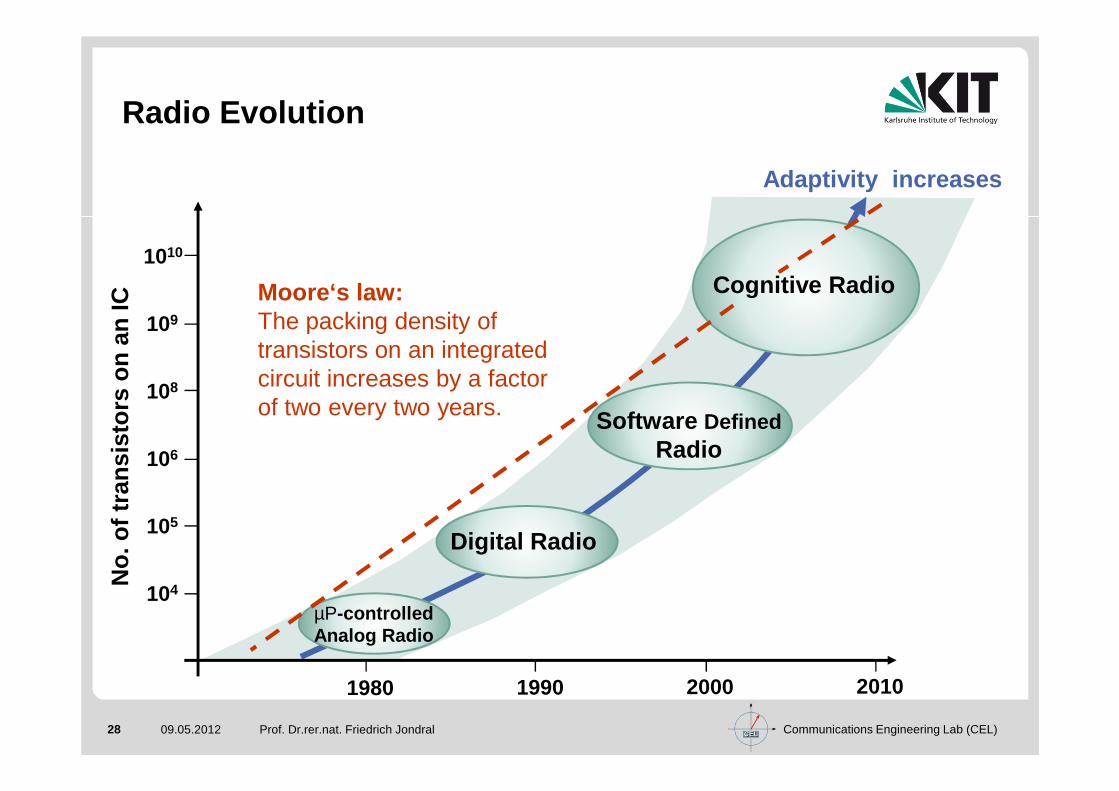
Radio Evolution
Prof. Dr.rer.nat. Friedrich Jondral
1980 1990 2000 2010
104
105
106
108
109
1010
Adaptivity increases
No.
of t
rans
isto
rs o
n an
IC
Moore‘s law:The packing density of transistors on an integrated circuit increases by a factor of two every two years.
Digital Radio
µP-controlledAnalog Radio
Software DefinedRadio
Cognitive Radio

Communications Engineering Lab (CEL)29 09.05.2012
Multi Standard Terminal
Prof. Dr.rer.nat. Friedrich Jondral
ZigBee
Bluetooth
UWB
NFC
GPSGSM, GPRS,
EDGE, UMTS,HSPA, S3G, LTE
WiMax
DVB-H
WLAN

Communications Engineering Lab (CEL)30 09.05.2012
Multi Band, Multi Standard Approach
Prof. Dr.rer.nat. Friedrich Jondral
� Integration
• Use technology development (Moore’s law) to miniatu rize current solution
• Examples:- On-chip VCOs- Integration of passive components in RF ICs- WCDMA and GSM on general baseband IC
� Architecture
• Facilitate multi-band multi-standard
• Examples:- Use homodyne instead of heterodyne receivers- SDR- Modular and expandable software architecture
The rightarchitecture
is key

Communications Engineering Lab (CEL)31 09.05.2012
Reuseable Radio Architecture
Prof. Dr.rer.nat. Friedrich Jondral
� General radio architecture
� All platforms use the same open and stable APIs
� Hardware depends on product configuration (WCDMA, E DGE, GPRS, ... )
Customer Applications
Product specific Hardware
NetworkAccessService
DataCommunication
Services
MMI andMultimedia
Services
ApplicationPlatformServices
OperationServices
Hardware Abstraction Layer (HAL)
Middleware Service Platform

Communications Engineering Lab (CEL)32 09.05.2012
Cognitive Radio: Definitions
Joseph Mitola / Gerald Maguire, 1991 ( IEEE Pers. Comm., vol. 6, no. 4, 1999):“Radio etiquette is the set of RF bands, air interfaces, protocols, and spatial and temporal patterns that moderate the use of radio spectrum. Cognitive radio extends the software radio with radio-domain model-based reasoning about such etiquettes.” Simon Haykin, 2005 ( IEEE J. Select. Areas in Comm., vol. 23, no. 2, 2005):“Cognitive radio is an intelligent wireless communication system that is aware of its surroundingenvironment (i.e. its outside world), and uses the methodology of understanding-by-building to learn from the environment and adapt its internal states to statistical variations in the incoming RF stimuli by making corresponding changes in certain operating parameters (e.g. transmit power, carrier-frequency and modulation strategy) in real-time, with two primary objectives in mind:
- highly reliable communications whenever and wherever needed;- efficient utilization of the radio spectrum.”
Friedrich K. Jondral, 2005 ( EURASIP J. on Wireless Comm. and Networking, 2005, no. 3):“A cognitive radio (CR) is an SDR that additionally senses its environment, tracks changes, and reactsupon its findings. A CR is an autonomous unit in a communications environment that frequently exchanges information with the networks it is able to access as well as with other CRs.”BNetzA, 2006 :Cognitive radio is a radio or system that senses and is aware of its operational environment and can dynamically and autonomously adjust its radio operating parameters.Note: Cognitive radio may benefit from SDR implementation techniques.
Prof. Dr.rer.nat. Friedrich Jondral

Communications Engineering Lab (CEL)33 09.05.2012
Cognitive Radio: Tasks
Evaluate the actual transmission request: Data rate , BER, delay, …, own location, partner’s location, time
Choose the suitable transmission mode: Modulation, coding, MIMO, transmit power, …, w.r.t. the hardware available, the interfe rence temperature limit
Look for a transmission resource: Spectrum holes
Get in touch with the communications partner: Negot iate about the resource to be used, agree upon possible alternatives and upon the transmission mode for the reverse link, exchange channel state information (C SI)
Choose the suitable receiver adjustment
Prof. Dr.rer.nat. Friedrich Jondral

Communications Engineering Lab (CEL)34 09.05.2012
Cognitive Characteristics
Awareness (with respect to the transmitted waveform, RF spectrum, communication network, localization and geography, available services, user needs, language, situation, security policy, …)
Intelligence
Learning
Adaptivity
Reliability
Efficiency
Prof. Dr.rer.nat. Friedrich Jondral

Communications Engineering Lab (CEL)35 09.05.2012
Mitola's Cognitive Cycle
Prof. Dr.rer.nat. Friedrich Jondral
A necessary condition for highest flexibility in mobile communications is a general rethinking in spectrum allocation: Open access
In order to make open access feasible Cognitive Radios are necessary.
Immediate Urgent Normal
NewStates
PriorStates
GenerateAlternatives
EvaluateAlternatives
Receive a MessageRead Buttons
Send a Message
Register toCurrent Time
Save Global States
Set Display Source:Joseph Mitola III: Cognitive Radio – An Integrated Agent Architecture for Software Defined Radio. KTH Stockholm, 2000
Pre-ProcessParse
Infer on ContextHierarchie
Initiate Process(es)
Allocate Resources
ORIENTEstablish Priority
ACT
LEARN PLAN
DECIDE
OutsideWorld
OBSERVE

Communications Engineering Lab (CEL)36 09.05.2012
CR Properties
Prof. Dr.rer.nat. Friedrich Jondral
Mitola's cognition cycle is very general. The proper ties of cognitive radios may be divided into two groups
user centric properties (support functions like finding an appropriate restaurant, recommendation of a travel route, supervision of apointments, . . .)
technology centric properties− spectrum monitoring− localization− awareness of processing capabilities (partitioning and scheduling of
processes)− information and knowledge processing− time− …
Communications Engineering Lab (CEL)37 09.05.2012
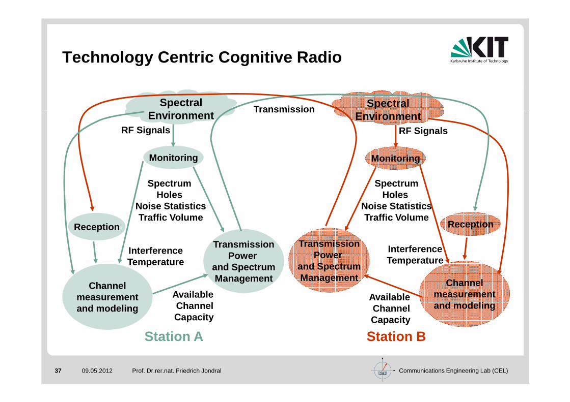
Technology Centric Cognitive Radio
Prof. Dr.rer.nat. Friedrich Jondral
Station BStation A
Transmission
Channel measurement and modeling
Reception
Monitoring
SpectralEnvironment
AvailableChannelCapacity
TransmissionPower
and SpectrumManagement
InterferenceTemperature
SpectrumHoles
Noise StatisticsTraffic Volume
RF Signals
Monitoring
SpectralEnvironment
AvailableChannelCapacity
TransmissionPower
and SpectrumManagement
InterferenceTemperature
RF Signals
SpectrumHoles
Noise StatisticsTraffic Volume
Reception
Channel measurement and modeling
Communications Engineering Lab (CEL)38 09.05.2012 Prof. Dr.rer.nat. Friedrich Jondral
1.3 Regulatory Aspects
Communications Engineering Lab (CEL)39 09.05.2012
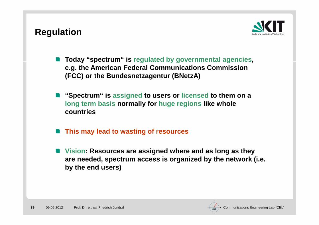
Regulation
Prof. Dr.rer.nat. Friedrich Jondral
Today “spectrum“ is regulated by governmental agencies , e.g. the American Federal Communications Commission (FCC) or the Bundesnetzagentur (BNetzA)
“Spectrum“ is assigned to users or licensed to them on a long term basis normally for huge regions like whole countries
This may lead to wasting of resources
Vision : Resources are assigned where and as long as they are needed, spectrum access is organized by the netw ork (i.e. by the end users)
Communications Engineering Lab (CEL)40 09.05.2012 40
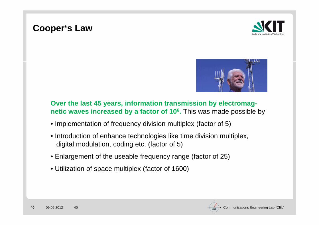
Cooper‘s Law
Over the last 45 years, information transmission by electromag-netic waves increased by a factor of 10 6. This was made possible by
• Implementation of frequency division multiplex (factor of 5)
• Introduction of enhance technologies like time division multiplex, digital modulation, coding etc. (factor of 5)
• Enlargement of the useable frequency range (factor of 25)
• Utilization of space multiplex (factor of 1600)

Communications Engineering Lab (CEL)41 09.05.2012 41
Spectrum Utilization 30 MHz – 10 GHz
2% 8%4%
19%
1%
13%19%
5%
5%
24%Radar
Other Aeronautical
Broadcasting
PMR
Defence Systems
Fixed AccessRadio Relay and Fixed Satellite
Satellite Mobile
Land Mobile
(GSM, UMTS, DECT)
Source: Dr. Klaus-D. Kohrt,CROWNCOM 2009

Communications Engineering Lab (CEL)42 09.05.2012
Spectrum Utilization Measurements
Prof. Dr.rer.nat. Friedrich Jondral
density of thetime between
arrivalsdBs-1
electricfield strength
dBmV/m
Lichtenau (Germany), September 2001

Communications Engineering Lab (CEL)43 09.05.2012
Self Regulation
Prof. Dr.rer.nat. Friedrich Jondral
Wireless LANs (IEEE 802.11x)ISM band: 2400 – 2483.5 MHzWLAN band: 5150 – 5350 MHz and 5470 – 5725 MHz
Ultra Wide Band
UW
B E
IRP
Em
issi
on L
evel
in d
Bm
Frequency in GHz
Part 15 Limit
fc greater than3.1 GHz
−40
−45
−50
−55
−60
−65
−70100 101
fc less than960 GHz
Communications Engineering Lab (CEL)44 09.05.2012
Advanced Spectrum Management
Prof. Dr.rer.nat. Friedrich Jondral
Spectrum reallocation : The reallocation of bandwidth from government or other long-standing users to new serv ices such as mobile communications, broadband internet access, a nd video distribution.Spectrum leases : The relaxation of the technical and commercial limitations on existing licensees to use their spec trum for new or hybrid (for example, satellite and terrestrial) ser vices and granting most mobile radio licensees the right to lease thei r spectrum to third parties.Spectrum sharing : The allocation of an unprecedented amount of spectrum that could be used for unlicensed or share d services.
Source:G. Staple, K. Werbach: The End of Spectrum Scarcity. IEEE Spectrum, March 2004, pp. 41-44

Communications Engineering Lab (CEL)45 09.05.2012
Cognitive Radio: Spectral Efficiency *)
Prof. Dr.rer.nat. Friedrich Jondral
CR technology is perfectly suited to opportunistically employ the wireless spectrumFlexible spectrum utilization is allowed by
• frequency agility• dynamic frequency selection• adaptive modulation• transmit power control• location awareness• negotiated use
CRs could skillfully navigate their way through interference and greatly improve spectral efficiencyFCC and other regulators are altering their rules i n order to allow for more flexible use of the licensed wireless spectrum
*) from N. Devroye, P. Mitran, V. Tarokh: Limits on Communications in a Cognitive Radio Channel.IEEE Communications Magazine, June 2006, pp. 44-49

Communications Engineering Lab (CEL)46 09.05.2012
Secondary Frequency Markets *)
Prof. Dr.rer.nat. Friedrich Jondral
Spectrum leasing: Allowing unlicensed users to lease any part or all of the spectrum of a licensed user
Dynamic spectrum leasing: Temporary and opportunistic usage of spectrum rather than a longer-term sublease
Private commons: A licensee could allow unlicensed users access to his spectrum without a contract, optionally with an access fee
Interruptible spectrum leasing: Suitable for a lessor that wants a high level of assurance that any spectrum temporarily in use, or leased, to an incumbent CR could be efficiently reclaimed if needed**)
*) from N. Devroye, P. Mitran, V. Tarokh: Limits on Communications in a Cognitive Radio Channel.IEEE Communications Magazine, June 2006, pp. 44-49**) e.g. T. A. Weiss, F.K. Jondral: Spectrum Pooling: An Innovative Strategy for the enhancement ofSpectrum Efficiency. IEEE Communications Magazine, Radio Communications Supplement, March 2004, pp. S8-S14

Communications Engineering Lab (CEL)47 09.05.2012 Prof. Dr.rer.nat. Friedrich Jondral
2. OFDM Based Overlay Systems

Communications Engineering Lab (CEL)48 09.05.2012 Prof. Dr.rer.nat. Friedrich Jondral
2.1 Motivation

Communications Engineering Lab (CEL)49 09.05.2012
Motivation
Prof. Dr.rer.nat. Friedrich Jondral
Situation:
• resource ‘frequency’ is limited
• large amount of spectrum unused
⇒ increasing efficiency in spectrum use is desirable
Approaches:
• cooperative systems (e.g. GPRS)
• underlay systems (e.g. ultra wideband)
• overlay systems m
easu
rem
ent t
ime
1810 MHz frequency 1880 MHz
signal strength (dBm)

Communications Engineering Lab (CEL)50 09.05.2012
OFDM Overlay Systems
Prof. Dr.rer.nat. Friedrich Jondral
Coexistence of two independent systems in the same frequency band
Licensed / primary user (PU) system:
• TDMA / FDMA
• no CSMA
• has priority
• allocation is time and location dependent
⇒⇒⇒⇒ OFDM is a flexible and efficient technology for ove rlay systems
Overlay / secondary user (SU) system:
• OFDM
• has to continuously monitor the PU system’s allocation

Communications Engineering Lab (CEL)51 09.05.2012
OFDM Overlay Systems
Prof. Dr.rer.nat. Friedrich Jondral
PU system: Busy and idle subbandsSU system: Allocation vector
PU system: Resource exploitation in the time frequency-plane
SU system: Detection period andupdate interval

Communications Engineering Lab (CEL)52 09.05.2012
Radio Access Networks
Prof. Dr.rer.nat. Friedrich Jondral
Radio access networks connectmobile users to a communicationinfrastructure (backbone).
Only the last hop is wirelessUsually the networking protocol is TCP/IP (mobile IP)
Examples:Cellular systems of second and third generationWireless local area networksWiMax
Backbone
Backbone
Cell
Communications Engineering Lab (CEL)53 09.05.2012 Prof. Dr.rer.nat. Friedrich Jondral
2.2 Detection of Primary User Signals by secondary User SystemsMotivation
Communications Engineering Lab (CEL)54 09.05.2012
SU Detection of PU Signals
Reliable detection of PU signals by the SU system is of paramount importance
Only if this reliability is satisfactory, the PUs will tolerate the SU system sharing their spectrum
Consequence : The SUs‘ probability of detection PD for PU signals must be high (e.g. 99.9%)
The SU system‘s efficiency decreases with increasing false alarm probability PF
PD and PF cannot be independently optimized
According to its importance, first PD is specified and then PF is minimized
Prof. Dr.rer.nat. Friedrich Jondral

Communications Engineering Lab (CEL)55 09.05.2012
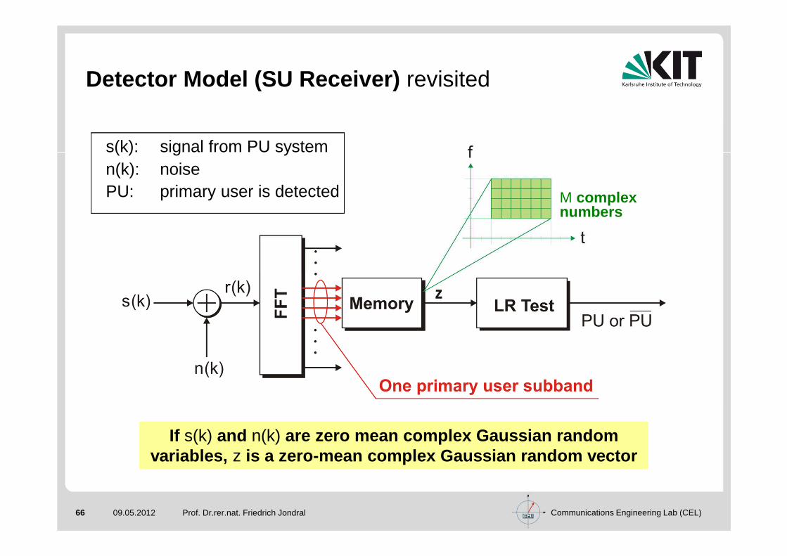
Detector Model (SU Receiver)
Prof. Dr.rer.nat. Friedrich Jondral
If s(k) and n(k) are zero mean complex Gaussian randomvariables, z is a zero-mean complex Gaussian random vector
s(k) signal from PU systemn(k) noisePU primary user is detected
M complexnumbers

Communications Engineering Lab (CEL)56 09.05.2012
Receiver Operating Characteristics
Prof. Dr.rer.nat. Friedrich Jondral
Numerically calculatedreceiver operatingcharacteristics ( ROCs),λ0 threshold of LR test ,M = 8
( ) ( )( ) ( )
− −− − −
= =
−λ = σ λ + σ λ − σ σ −∑ ∏
mM 1 m 12 M 1 2 M m 10F N 0 N 02M2 m 1 l 1N
N
1P exp 2 2 M l
22 M 1 !
( ) ( ) ( ) ( ) ( )( ) ( )− −− − −
= =
−λ = σ + σ λ + σ + σ λ − σ + σ σ + σ − ∑ ∏
mM 1 m 10 2 2 M 1 2 2 M m 12 2D S N 0 S N 0MM 2 2 S N m 1 l 1
S N
1P exp 2 2 M l
22 M 1 !
Communications Engineering Lab (CEL)57 09.05.2012
Distributed Detection
Prof. Dr.rer.nat. Friedrich Jondral
Tolerating a SU overlay system is attractive for PUs only if the detection probability PD of PU signals by the SU system is sufficiently high (e.g., 99.9%).
According to the ROCs, our detector cannot achieve this PD at an acceptable false alarm probability PF.
Increasing M will not really help, because larger numbers of FFT cycles cause a larger detection duration.
Distributed detection by all SU stations mayhelp to solve the problem.

Communications Engineering Lab (CEL)58 09.05.2012
Distributed Detection - SU Access Network
Prof. Dr.rer.nat. Friedrich Jondral
SU system's detection probability
SU system's false alarm probability
number of stations involved in thedetection process
( ) ( )= − − LSF FP L 1 1 P
( ) ( ) ( )= − − ⇒ = − −LS SLD D D DP L 1 1 P P 1 1 P L
( ) ( )( ) = − − − −
S SLF F DP L 1 1 P 1 1 P L
( )SFP L
( )SDP L
L
SU System'sfalse alarmprobability PS (L)
(M = 8, SNR = 2dB,
PS (L) = 0.999)
F
D
Communications Engineering Lab (CEL)59 09.05.2012 Prof. Dr.rer.nat. Friedrich Jondral
2.3 Wireless Ad Hoc Networks

Communications Engineering Lab (CEL)60 09.05.2012
Wireless Ad Hoc Network
Prof. Dr.rer.nat. Friedrich Jondral
Gupta, Kumar (2000): " ... the throughput furnished to each user diminishes to zero as the number of users is increased, ..."*)
In ad hoc networks all links are wireless.
Network layer: Routing (time-varying network topology, power constraints, mobile radio channel)
Radio access: TDMA is complex (no centralized control), FDMA is inefficient, CDMA is difficult to implement (user mobility, time-varying neighborhood) ⇒ random access,but "hidden stations" and "exposed stations" (CTS/RTS) exist
Physical layer: Power control
*) P. Gupta, P.R. Kumar: The Capacity of Wireless Networks. IEEE Transactions on Information Theory, Vol.46, No.2, March 2000, pp. 388-404
Communications Engineering Lab (CEL)61 09.05.2012
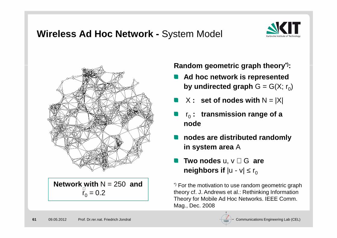
Wireless Ad Hoc Network - System Model
Prof. Dr.rer.nat. Friedrich Jondral
Random geometric graph theory *):
Ad hoc network is represented by undirected graph G = G(X; r0)
X : set of nodes with N = |X|
r0 : transmission range of a node
nodes are distributed randomly in system area A
Two nodes u, v ∈ G areneighbors if |u - v| ≤ r0
*) For the motivation to use random geometric graphtheory cf. J. Andrews et al.: Rethinking Information Theory for Mobile Ad Hoc Networks. IEEE Comm. Mag., Dec. 2008
Network with N = 250 andr0 = 0.2∧

Communications Engineering Lab (CEL)62 09.05.2012
Number of Neighbors: Borderless Scenario
Prof. Dr.rer.nat. Friedrich Jondral
Assumption: Infinite system area, i.e. , with constant as
1. Number of nodes in every finite subarea follows a Poissondistribution
2. Numbers of nodes in disjoint subareas are indepe ndent random variables���� the number of nodes forms a homogeneous Poisson poi nt
process
With 1. also the number of neighbors D follows a Poisson distribution:
with the location independent expectation
( ) ( ) −ν∞ ∞
ν= = ν =d
P D d P ;d ed!
ρ = NA
{ } = ν = ρπ 20E D r
→ ∞N→ ∞A

Communications Engineering Lab (CEL)63 09.05.2012
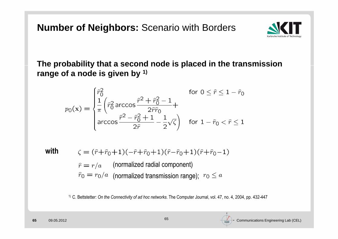
Numbers of Neighbors: Scenario with Borders
Prof. Dr.rer.nat. Friedrich Jondral
The location independent probability is derived by integration
Assumption: The system area is a disk with radius a
The probability that a second node is placed in the transmission range of a given node x depends on its location and is given by p0(x).
( ) ( ) ( )( )N d 1d
0 0
N 1P D d | x p x 1 p x
d
− −− = = −
( ) ( ) ( ) ( )= = = =∫∫ XP D d P d P D d | x f x dx

Communications Engineering Lab (CEL)64 09.05.2012
Number of Neighbors: Scenario with Borders
Prof. Dr.rer.nat. Friedrich Jondral
With a uniform node distribution in the system area
and using polar coordinates, the location independent probability of having d neighbors is
Area A
x
a
xr0
( ) X
1for x A
f x A0 otherwise.
∈=
( ) ( ) ( )( )1
N d 1d
0 00
N 1ˆ ˆ ˆ ˆP d 2r p r 1 p r drd
− −− = ⋅ −
∫
Communications Engineering Lab (CEL)65 09.05.2012 65
Number of Neighbors: Scenario with Borders
The probability that a second node is placed in the transmission range of a node is given by 1)
with
(normalized radial component)
(normalized transmission range);
1) C. Bettstetter: On the Connectivity of ad hoc networks. The Computer Journal, vol. 47, no. 4, 2004, pp. 432-447
Communications Engineering Lab (CEL)66 09.05.2012
Detector Model (SU Receiver) revisited
Prof. Dr.rer.nat. Friedrich Jondral
If s(k) and n(k) are zero mean complex Gaussian randomvariables, z is a zero-mean complex Gaussian random vector
M complex numbers
s(k): signal from PU systemn(k): noisePU: primary user is detected M complex
numbers

Communications Engineering Lab (CEL)67 09.05.2012
Receiver Operating Characteristics SU accessnetwork, revisted
Prof. Dr.rer.nat. Friedrich Jondral
Numerically calculatedreceiver operating
characteristics (ROCs),λ0 threshold of LR test,
M = 8
( ) ( ) ( ) ( ) ( )( ) ( )mM 1 m 1
2 2 M 1 2 2 M m 10D S N 0 S N 0M 2 2M 2 2 m 1 l 1N NS N
1P exp 2 2 M l
22 M 1 !
− −− − −
= =
−λ = σ + σ λ + σ + σ λ − σ + σ σ + σ − ∑ ∏
( ) ( )( ) ( )
mM 1 m 12 M 1 2 M m 10F N 0 N 0M 22 m 1 l 1NN
1P exp 2 2 M l
22 M 1 !
− −− − −
= =
−λ = σ λ + σ λ − σ σ −∑ ∏

Communications Engineering Lab (CEL)68 09.05.2012
Distributed Detection Wireless Ad Hoc Networks
Prof. Dr.rer.nat. Friedrich Jondral
The detection probability can be increased by combi ning the detection probabilities of several nodes in a cluster (L: number of contributing nodes):
The network false alarm probability is defined in a similar way.
( ) ( )LcellD DP L 1 1 P= − −
( ) ( )LcellF FP L 1 1 P= − −
Application of distributed detection to ad hoc netw orks leads to the definition of the network detection probability :
Borderless scenario: ( ) ( ) ( )net cellD D
d 0
P P ;d P d 1∞
∞
∞=
ν = ν ⋅ +∑
Scenario with borders: ( ) ( ) ( )N 1
net cellD 0 0 D
d 0
P N;r P r ;d P d 1−
=
= ⋅ +∑

Communications Engineering Lab (CEL)69 09.05.2012
Borderless Scenario
Prof. Dr.rer.nat. Friedrich Jondral
0 2 4 6 8 10
1
0.99
0.98
0.97
0.96
0.951 3 5 7 9
simulationtheory: PD = 0.9
PD = 0.8PD = 0.7PD = 0.6
PDnet∞
ν
( ) ( )( ) d
d 1netD D
d 0
P e 1 1 Pd!
∞
∞+−ν
=
νν = ⋅ − −∑
( ) ( )( ) d
d 1netF F
d 0
P e 1 1 Pd!
∞
∞+−ν
=
νν = ⋅ − −∑

Communications Engineering Lab (CEL)70 09.05.2012
Borderless Scenario
Prof. Dr.rer.nat. Friedrich Jondral
Network false alarm probability depending on ν for a required network detection probability of 0.999
ν should be greater than 9 for a good performance (e.g., ρ = 2.9 km-2
if r0 = 1 km)

Communications Engineering Lab (CEL)71 09.05.2012
Scenario with Border Effects
Prof. Dr.rer.nat. Friedrich Jondral
simulationtheory: PD = 0.9
PD = 0.8PD = 0.7PD = 0.6
r0
0 0.2 0.4 0.6 0.8 1
1.0
0.99
0.98
0.97
0.96
0.950.1 0.3 0.5 0.7 0.9
PDnet
Network detection probability depending on the norm alizedtransmission range with N = 40.
( ) ( ) ( )( ) ( )( ) 1N 1 N d 1d d 1net
D 0 0 0 Dd 0 0
N 1ˆ ˆ ˆ ˆP N;r 2r p r 1 p r dr 1 1 Pd
− − − +
=
− = ⋅ ⋅ − ⋅ − −
∑ ∫

Communications Engineering Lab (CEL)72 09.05.2012
Scenario with Border Effects
Prof. Dr.rer.nat. Friedrich Jondral
r0
N = 150N = 80N = 40N = 20N = 10
0 0.2 0.4 0.6 0.8 1
1.0
0.99
0.98
0.97
0.96
0.1 0.3 0.5 0.7 0.9
PDnet
0.95
Network detection probability depending on the norm alizedtransmission range with PD = 0.8.
Communications Engineering Lab (CEL)73 09.05.2012
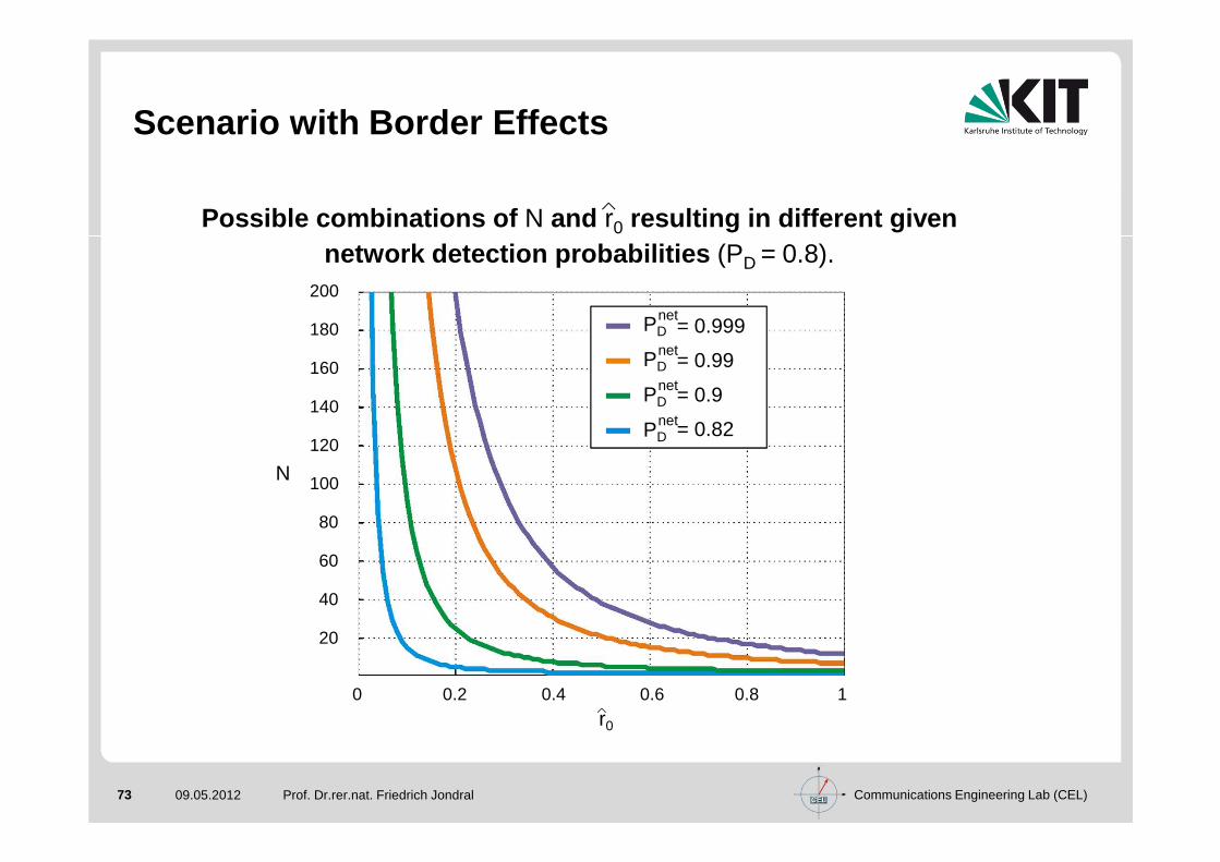
Scenario with Border Effects
Prof. Dr.rer.nat. Friedrich Jondral
Possible combinations of N and r0 resulting in different givennetwork detection probabilities (PD = 0.8).
0 0.2 0.4 0.6 0.8 1
200
180
160
140
120
100
80
60
40
20
= 0.999
= 0.99
= 0.9
= 0.82
N
r0
PDnet
PDnet
PDnet
PDnet

Communications Engineering Lab (CEL)74 09.05.2012
Receiver Operating Characteristic
Prof. Dr.rer.nat. Friedrich Jondral
Receiver operating characteristics for M = 4, SNR = 0 dB, r0 = 0.2 and different numbers of nodes in the network.
PFnet
00 0.2 0.4 0.6 0.8 1
1
0.8
0.6
0.5
0.3
0.1
single detectionN = 40
PDnet
N = 80N = 150
0.2
0.4
0.7
0.9

Communications Engineering Lab (CEL)75 09.05.2012
Overlay Frame
Prof. Dr.rer.nat. Friedrich Jondral
Coordination of detection periods in ad hoc SU systems:
What is the present allocation in the PU system?
Are there any other SUs with whom a communicationslink may be established?
Block 1 Block 2 Block 3
Overlay frame
Detection Beaconing ACK Data

Communications Engineering Lab (CEL)76 09.05.2012
SU Entering an Ad Hoc Network
Prof. Dr.rer.nat. Friedrich Jondral
Association
Find an idle slot
Send RTS
RTStransmissionsuccessful?
Receive CTS
Send
yesno
First estimate of the AV
Listen for beacons
Beacon received?
Send beacon
Synchronize frameto other SU's frame
SU associated
noyes
Communication

Communications Engineering Lab (CEL)77 09.05.2012
Boosting and Collection
Prof. Dr.rer.nat. Friedrich Jondral
Key fact in ad hoc networks :No central node, no central knowledge, all SUs are equal
PU signal detection and informationcollection
Slot A: Every SU performs detectionof PU signals
Slot B: Boosting or collection inthe SUs' system. Each SUdecides randomly ( w.p. 0.5) whether to boost or to collect
Slot C: Each SU performs theoperation he did not duringslot B.
A B C
SU1
boosting
collectionSU2
A BC
. . .
. . .
. . .
. . .
B C
Detection Beaconing ACK Data
A

Communications Engineering Lab (CEL)78 09.05.2012
Boosting and Collection
Prof. Dr.rer.nat. Friedrich Jondral
Key fact in ad hoc networks :No central node, no central knowledge, all SUs are equal
PU signal detection and information collectionSlot A: Every SU performs detection
of PU signals
Slot B: Boosting or collection in theSUs' system. Each SU decidesrandomly ( w.p. 0.5) whetherto boost or to collect
Slot C: Each SU performs the operationhe did not during slot B.

Communications Engineering Lab (CEL)79 09.05.2012
Summary
Prof. Dr.rer.nat. Friedrich Jondral
The introduction of cognitive radio systems is not a revolution but an evolution
The scarce resource “spectrum“ is underutilized
New (self) regulation strategies are necessary
OFDM overlay systems may help to achieve higher efficiency in spectrum usage
Distributed detection of PU signals in SU systems
Radio access networks and wireless ad hoc networks must be distinguished: Different signaling strategies are t o be employed
Advanced spectrum utilization (and regulation) is a hot topic
but should be handled with care!

Communications Engineering Lab (CEL)80 09.05.2012
3. Vision Meets Reality
Prof. Dr.rer.nat. Friedrich Jondral
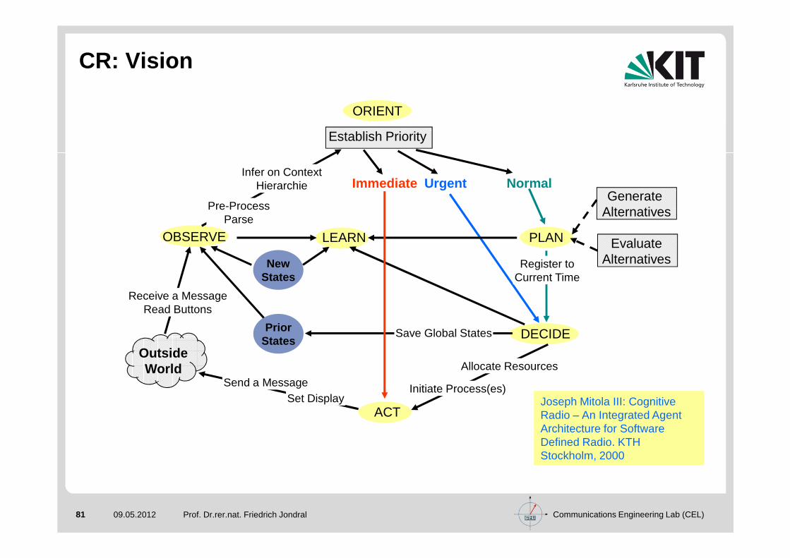
Communications Engineering Lab (CEL)81 09.05.2012 Prof. Dr.rer.nat. Friedrich Jondral
Immediate Urgent Normal
ACT
OutsideWorld
NewStates
PriorStates
Generate Alternatives
EvaluateAlternatives
ORIENT
Establish Priority
Receive a MessageRead Buttons
Send a Message Initiate Process(es)
Register toCurrent Time
Pre-ProcessParse
Save Global States
Allocate Resources
Set Display
Infer on ContextHierarchie
Joseph Mitola III: Cognitive Radio – An Integrated Agent Architecture for Software Defined Radio. KTH Stockholm, 2000
CR: Vision
OBSERVE
DECIDE
LEARN PLAN

Communications Engineering Lab (CEL)82 09.05.2012 Prof. Dr.rer.nat. Friedrich Jondral
CR: Definition
“Cognitive Radio is an intelligent wireless communication system that is aware of its surrounding environment (i.e. its outside world), and uses the methodology of understanding-by-building to learn from the environment and adapt its internal states to statistical variations in the incoming RF stimuli by making corresponding changes in certain operating parameters (e.g. transmit power, carrier-frequency and modulation strategy) in real-time, with two primary objectives in mind:
- highly reliable communications whenever and wherever needed;- efficient utilization of the radio spectrum.”
Simon Haykin: Cognitive Radio: Brain-Empowered Wireless Communications. IEEE J. Select. Areas in Comm., vol. 23, no. 2, 2005, pp. 201-220
Communications Engineering Lab (CEL)83 09.05.2012
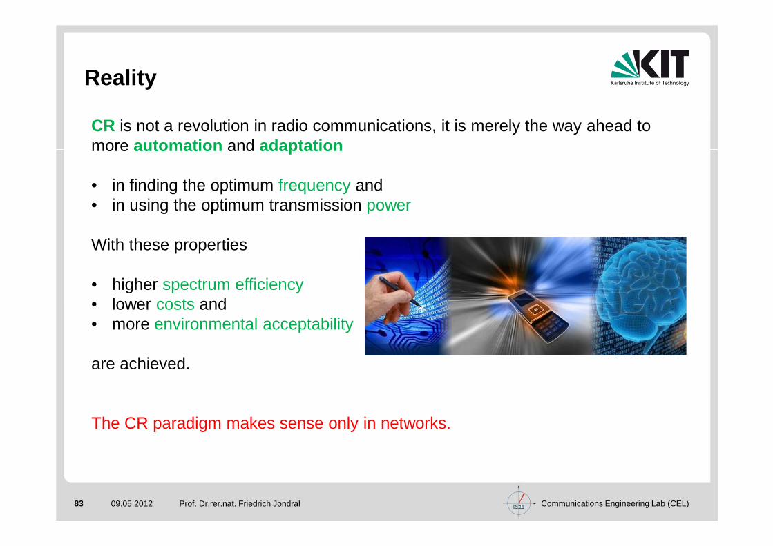
Reality
Prof. Dr.rer.nat. Friedrich Jondral
CR is not a revolution in radio communications, it is merely the way ahead to more automation and adaptation
• in finding the optimum frequency and• in using the optimum transmission power
With these properties
• higher spectrum efficiency• lower costs and• more environmental acceptability
are achieved.
The CR paradigm makes sense only in networks.

Communications Engineering Lab (CEL)84 09.05.2012 Prof. Dr.rer.nat. Friedrich Jondral
Meaning of "Spectrum"
A material quantity that may be partitioned
or an immaterial mediumthat may be accessedwithout regulation?

Communications Engineering Lab (CEL)85 09.05.2012 Prof. Dr.rer.nat. Friedrich Jondral
Spectrum Utilization
M. McHenry: NSF Spectrum Occupancy Measurements. The Shared Spectrum Company, Tech. Rep., 2005, http://sharedspectrum.com/?sectio=nsf_measurementsFundamental Statement:Even in crowded frequency regions not more then 15 percent of the (theoretical) capacity is actually used.
However:A hundred percent usage of the transmission resourceis utopistic (interferences)But: Struggling is promising.
Photo: The Shared Spectrum Company

Communications Engineering Lab (CEL)86 09.05.2012 Prof. Dr.rer.nat. Friedrich Jondral
Dynamic Spectrum Access (DAS)
Dynamic Spectrum AccessDynamic Spectrum Access
DynamicExclusiv Use Model
DynamicExclusiv Use Model
HierarchicalAccess ModelHierarchical
Access Model
Open Sharing Model(Spectrum
Commons Model)
Open Sharing Model(Spectrum
Commons Model)
SpectrumPropertyRights
SpectrumPropertyRights
DynamicSpectrum Allocation
DynamicSpectrum Allocation
SpectrumUnderlay
(Ultra WideBand)
SpectrumUnderlay
(Ultra WideBand)
Spectrum Overlay
(OpportunisticSpectrumAccess)
Spectrum Overlay
(OpportunisticSpectrumAccess)
from: Qing Zhao, Brian M. Sadler: A Survey of Dynamic Spectrum Access.IEEE Signal Processing Magazine, May 2007, pp. 79 - 89

Communications Engineering Lab (CEL)87 09.05.2012 Prof. Dr.rer.nat. Friedrich Jondral
DSA: Questions
What is the meaning of “Spectrum Access”?To enhance the efficiency in the usage of spectrum (briefly: spectral efficiency) in a specific geographic region, CRs access spectrum holes left by the licensed users’ system (primary users) as secondary users.
I.e.: Spectrum Access happens in time, frequency, and space.
What is the meaning of “Dynamic”?Nobody knows …On which scale is DSA based upon? Milliseconds, seconds, minutes, …? Change in primary users’ behavior?
Communications Engineering Lab (CEL)88 09.05.2012 Prof. Dr.rer.nat. Friedrich Jondral
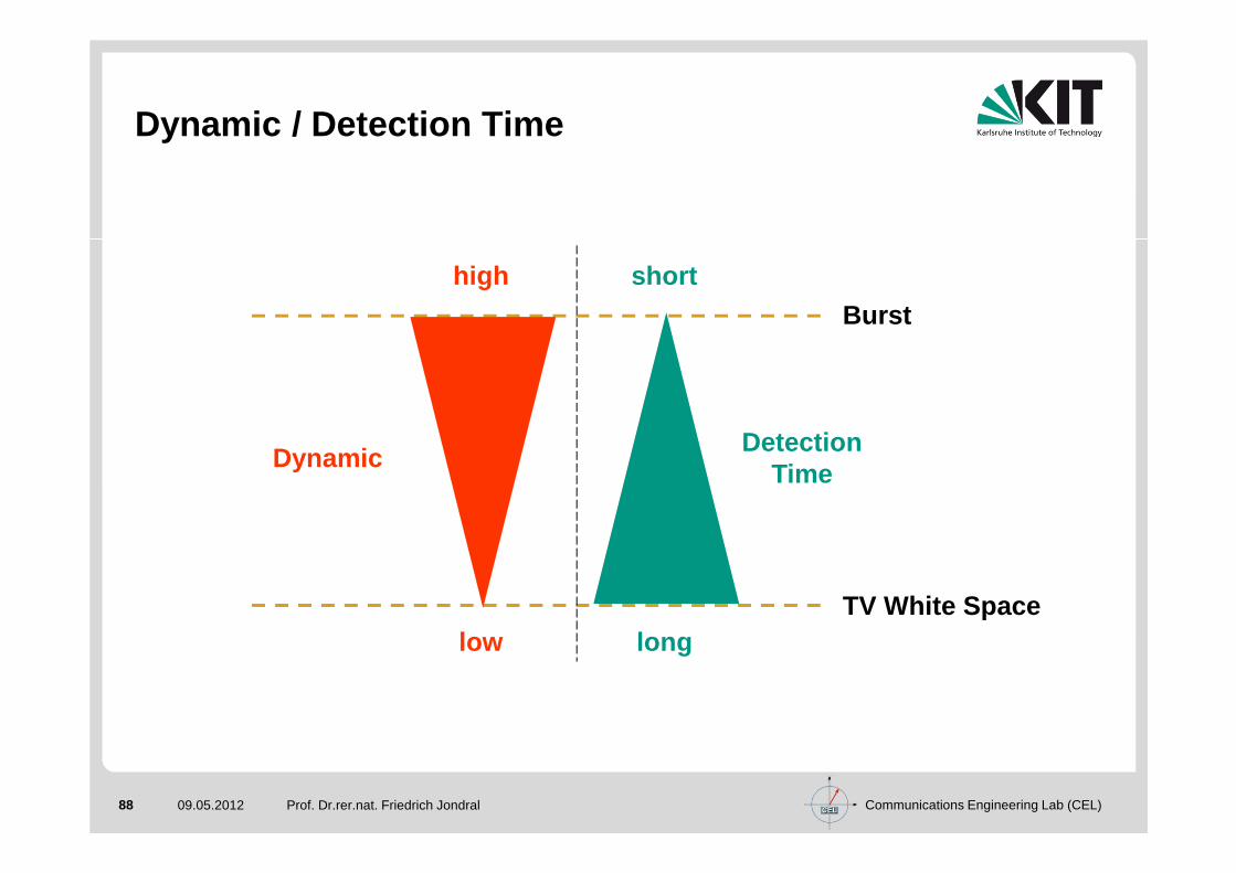
Dynamic / Detection Time
DynamicDetection
Time
Burst
TV White Space
high short
low long

Communications Engineering Lab (CEL)89 09.05.2012 Prof. Dr.rer.nat. Friedrich Jondral
Time/Frequency Plane
GSM 1800No. of Channels: 374Bandwidth: ≈270 kHzDistance: 200 kHzBurst Duration: 0.577 ms
Communications Engineering Lab (CEL)90 09.05.2012 Prof. Dr.rer.nat. Friedrich Jondral
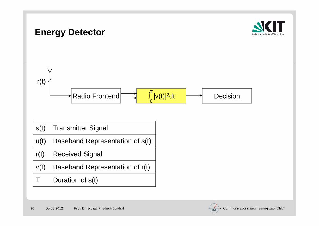
Energy Detector
s(t) Transmitter Signal
u(t) Baseband Representation of s(t)
r(t) Received Signal
v(t) Baseband Representation of r(t)
T Duration of s(t)
Radio Frontend Decision∫ |v(t)|2dtT
0
r(t)

Communications Engineering Lab (CEL)91 09.05.2012 Prof. Dr.rer.nat. Friedrich Jondral
Matched Filter Detector
s(t) Transmitter Signal
u(t) Baseband Representation of s(t)
r(t) Received Signal
v(t) Baseband Representation of r(t)
T Duration of s(t)
Radio Frontend Decision∫ v(t)u(T−t) dtT
0
r(t)
u(t)

Communications Engineering Lab (CEL)92 09.05.2012 Prof. Dr.rer.nat. Friedrich Jondral
Pattern Recognition Detector
s(t) Transmitter Signal
u(t) Baseband Representation of s(t)
r(t) Received Signal
v(t) Baseband Representation of r(t)
T Duration of s(t)
Radio Frontend DecisionFeature
Extraction
r(t)
u(t)
PatternRecognition
FeatureExtraction
. . .
. . .

Communications Engineering Lab (CEL)93 09.05.2012
Signal Detection
Prof. Dr.rer.nat. Friedrich Jondral
DetectorA Priori
Knowledge
Detection Time/ Computational
ComplexityApplicability Robustness
Energy Nothing low universal high
MatchedFilter
Signal medium specific medium
Pattern Recognition
Signal Features
high highly specific low

Communications Engineering Lab (CEL)94 09.05.2012 Prof. Dr.rer.nat. Friedrich Jondral
Energy Detector
Detection Time: AWGNFalse Alarm Rate: 10-4
Detection Probability: β(σ2: normalized noise variance)
β = 0.9999n
β = 0.999 β = 0.99 σ2SNR[dB]
111 93 74 2 -356 47 37 1 028 24 19 1/2 314 12 10 1/4 67 6 5 1/8 94 3 3 1/16 122 2 2 1/32 152 2 2 1/32 15
1 1/37 15.71 1/47 16.7
1 1/56 17.5
Communications Engineering Lab (CEL)95 09.05.2012 Prof. Dr.rer.nat. Friedrich Jondral
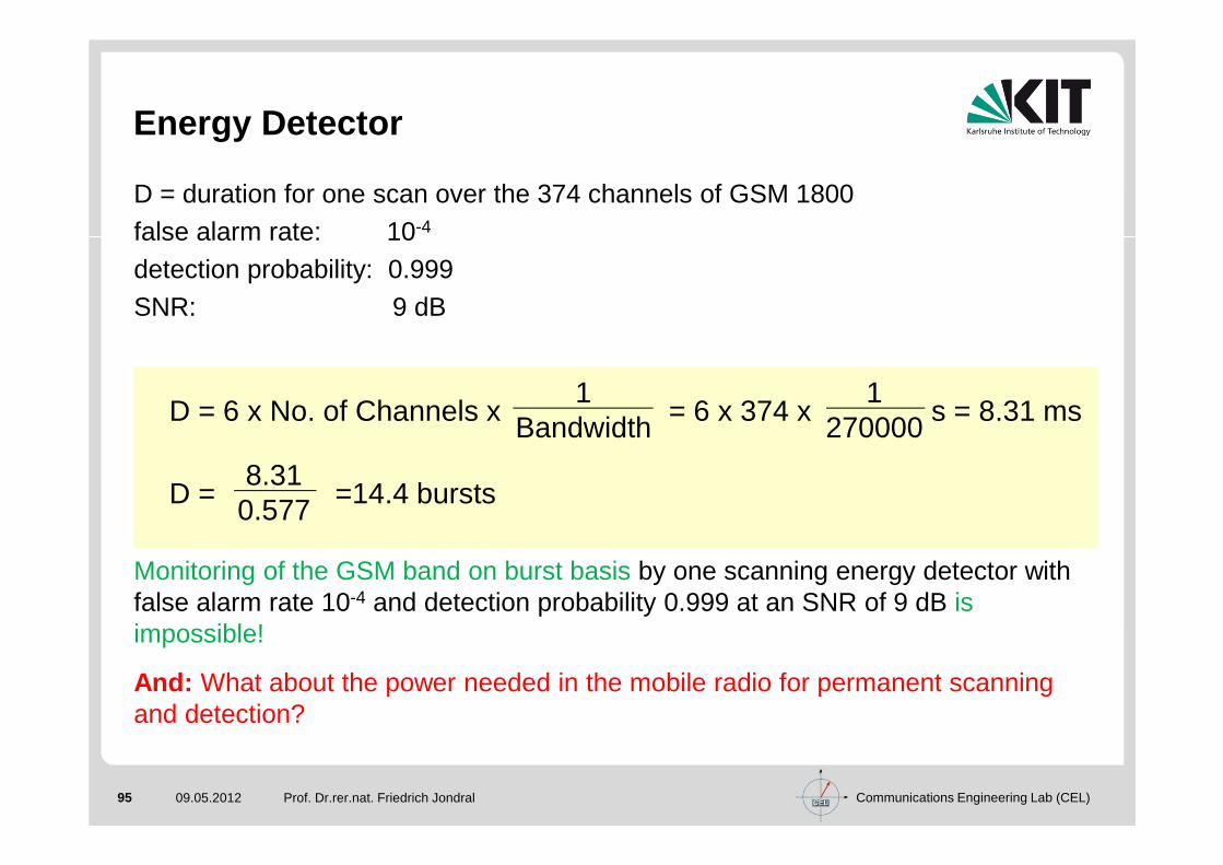
Energy Detector
D = duration for one scan over the 374 channels of GSM 1800false alarm rate: 10-4
detection probability: 0.999SNR: 9 dB
Monitoring of the GSM band on burst basis by one scanning energy detector withfalse alarm rate 10-4 and detection probability 0.999 at an SNR of 9 dB isimpossible!
And: What about the power needed in the mobile radio for permanent scanningand detection?
D = 6 x No. of Channels x = 6 x 374 x s = 8.31 ms1
Bandwidth1
270000
D = =14.4 bursts8.310.577

Communications Engineering Lab (CEL)96 09.05.2012
Proposed Solution 1
Prof. Dr.rer.nat. Friedrich Jondral
Distributed DetectionFor networks with access point :Timo Weiß: OFDM-basiertes Spectrum Pooling. Dissertation, Forschungsberichte aus dem Institut für Nachrichtentechnik der Universität Karlsruhe (TH), Band 13, Karlsruhe 2004
For ad hoc networks:Ulrich Berhold: Dynamic Spectrum Access Using OFDM-based Overlay Systems. Dissertation, Forschungsberichte aus dem Institut für Nachrichtentechnik der Universität Karlsruhe (TH), Band 21, Karlsruhe 2009
MAC frame MAC frame MAC frame
detectionphase
boostingphase
broadcastphaseP P
2 ms

Communications Engineering Lab (CEL)97 09.05.2012
Distributed Detection and Boosting
Prof. Dr.rer.nat. Friedrich Jondral
With Access Point Ad Hoc
b) Boosting and Collection

Communications Engineering Lab (CEL)98 09.05.2012
Proposed Solution 2
Prof. Dr.rer.nat. Friedrich Jondral
Off-line Sensing, Data Base Query, and Instantaneou s Measurement
During idle times• The radio senses all potential transmission channels1)
• The sensing results for each channel, together with the time of the day when the sensing took place, are stored in a data base in order to establish channel utilization statistics depending on time and frequency
When a communications request occurs1. The radio queries the data base for a channel that is idle with highest
probability at the current time of the day and that has not been sensed yet2. The radio instantaneously senses the chosen channel3. If the channel is idle, the radio starts operation.
If not, it goes back to 1.
1) The power problem for this remains unsolved.

Communications Engineering Lab (CEL)99 09.05.2012 Prof. Dr.rer.nat. Friedrich Jondral
Data Base Query
16:05
16:10
16:15
16:20
Time Channel Utilization Statistics
16:17
Channel No. Priority
1 2
2 5
3 4
4 5
5 1
6 3
1 2 3 5 64
1 2 3 5 64
1 2 3 5 64
1 2 3 5 64
. . .
. . .

Communications Engineering Lab (CEL)100 09.05.2012
Don‘t forget
Prof. Dr.rer.nat. Friedrich Jondral
CoordinationA channel idle at station A must not be idle at station B (agreement necessary).
Continuous SensingAs long as a SU station is active, it must permanently sense it‘s channel (look through).
Automated Frequency Change If a PU signal is detected on the currently used channel, communication partners must identify a new usable frequency and jointly switch to it.
Hidden Stations
Multicast / Broadcast

Communications Engineering Lab (CEL)101 09.05.2012
Summary
Prof. Dr.rer.nat. Friedrich Jondral
As of January 31, 2012 there are • 8 079 papers on Cognitive Radio,• 7 777 papers on Spectrum Sensing, and• 2 519 papers on Dynamic Spectrum Accesslisted in the IEEE Xplore Digital Library. Many of them do not observe any constraints imposed by physics.
All notions that we use in communications need to be well defined.
Detection time depends on SNR, false alarm rate, detection probability, and further conditions imposed by wave propagation.
CR and DSA bear high potential for theoretical and practical research work.

Communications Engineering Lab (CEL)102 09.05.2012
References
Prof. Dr.rer.nat. Friedrich Jondral
Linda E. Doyle: Essentials of Cognitive Radio. Cambridge University Press, Cambridge (U.K.), 2009
Bruce Fette (Ed.): Cognitive Radio Technology, 2nd Edition. Academic Press, Burlington (MA), 2009
Ekram Hossain, Vijay K. Bhargava (Ed.): Cognitive Wireless Communication Networks. Springer, New York, 2007
Preston Marshall: Quantitative Analysis of Cognitive Radio and Network Performance. Artech House, Norwood (MA), 2010
Joseph Mitola III: Cognitive Radio – An Integrated Agent Architecture for Software Defined Radio. Ph.D. Dissertation, Department of Teleinformatics, KTH Stockholm (Sweden), 2000
Alexander M. Wyglinski, Maziar Nekovee, Thomas Hou ( Ed.): Cognitive Radio Communications and Networks: Principles and Practice. Academic Press, Burlington (MA), 2010

Communications Engineering Lab (CEL)103 09.05.2012
References
Prof. Dr.rer.nat. Friedrich Jondral
Timo A. Weiss, Friedrich K. Jondral: Spectrum Pooling: An Innovative Strategy for the Enhancement of Spectrum Efficiency. IEEE Communications Magazine, March 2004, Radio Communications Supplement, pp. S8 - S14
Jörg Hillenbrand, Timo A. Weiss, Friedrich K. Jondral: Calculation of Detection and False Alarm Probabilities in Spectrum Pooling Systems. IEEE Communications Letters, April 2005, Vol. 9, No. 4, pp. 349 - 351
Friedrich K. Jondral: Software Defined-Radio – Basics and Evolution to Cognitive Radio. Invited paper,EURASIP Journal on Wireless Communications and Networking, 2005, No. 3, pp. 275 - 283
Friedrich K. Jondral: Cognitive Radio: A Communications Engineering View. IEEE Wireless Communications, August 2007, pp. 28-33
Ulrich Berthold, Sinja Brandes, Michael Schnell and Friedrich K. Jondral: OFDM-Based Overlay Systems: A Promising Approach for Enhancing Spectral Efficiency. IEEE Communications Magazine, Vol. 45 No. 12, December 2007, pp. 52-58
Ulrich Berthold, Friedrich K. Jondral: Distributed Detection in OFDM based Ad Hoc Overlay Systems. Proceedings of the IEEE Vehicular Technology Conference VTC2008-Spring, Singapore, May 11-14, 2008, CD-ROM

Communications Engineering Lab (CEL)104 09.05.2012 104
Thank you!