application of composite fracture mechanics to bone - meditech
TRANSCRIPT
APPLICATION OF COMPOSITE FRACTURE MECHANICS
TO BONE FRACTURE ANALYSIS USING ABAQUS XFEM
Presenter: David Reid
Dassault Systemes UK Ltd – SIMULIA
[email protected] – 01925 885971 – 07825 308031
Work by: Xiaoliang Qin; Xiangyi (Cheryl) Liu; Zhenzhong Du
Dassault Systemes Simulia Corp, Providence/Rhode Island, USA
Presented originally at the World Congress for Biomechanics Aug 2010 in Singapore
Introduction
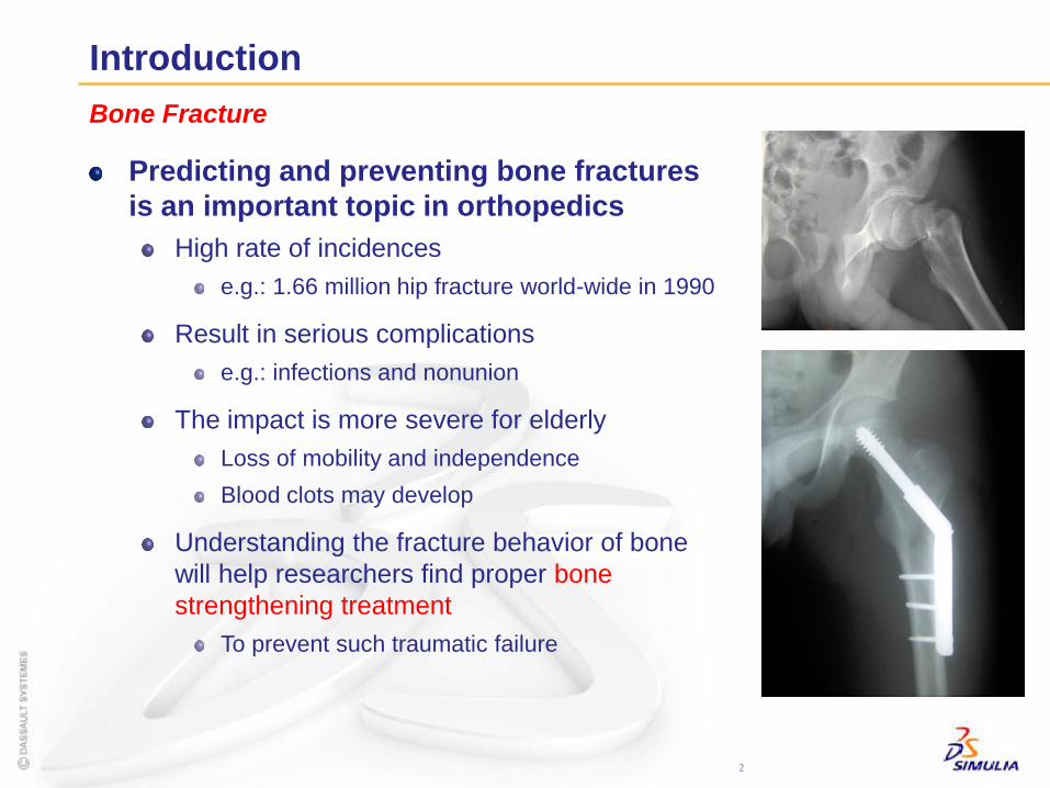
Predicting and preventing bone fractures
is an important topic in orthopedics
High rate of incidences
e.g.: 1.66 million hip fracture world-wide in 1990
Result in serious complications
e.g.: infections and nonunion
The impact is more severe for elderly
Loss of mobility and independence
Blood clots may develop
Understanding the fracture behavior of bone
will help researchers find proper bone
strengthening treatment
To prevent such traumatic failure
2
Bone Fracture
Introduction
Finite element analysis has been instrumental in
understanding various aspects of bone mechanics
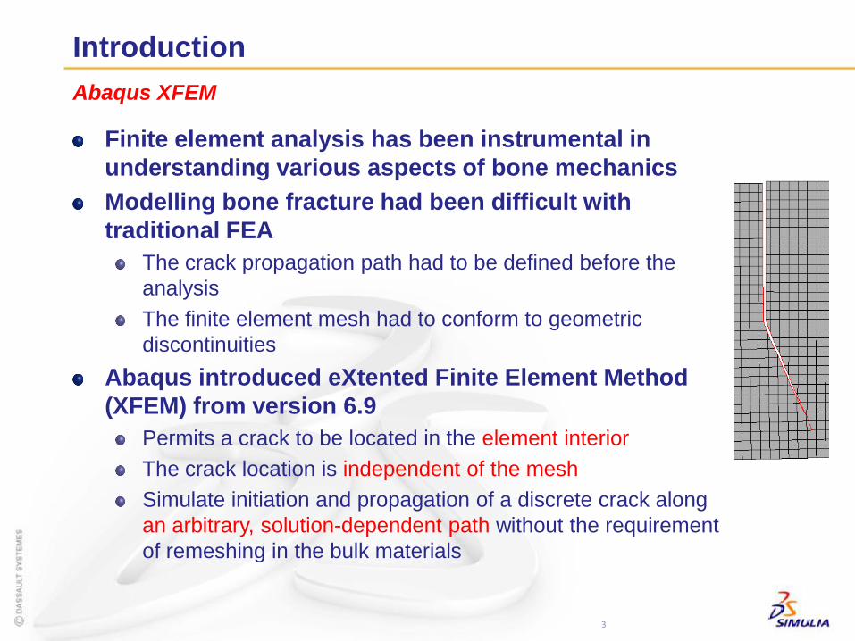
Modelling bone fracture had been difficult with
traditional FEA
The crack propagation path had to be defined before the
analysis
The finite element mesh had to conform to geometric
discontinuities
Abaqus introduced eXtented Finite Element Method
(XFEM) from version 6.9
Permits a crack to be located in the element interior
The crack location is independent of the mesh
Simulate initiation and propagation of a discrete crack along
an arbitrary, solution-dependent path without the requirement
of remeshing in the bulk materials
3
Abaqus XFEM
Introduction
Damage initiation criteria
Built-in criteria
Maximum principal stress
Maximum principal strain
Maximum nominal stress
Maximum nominal strain
Quadratic nominal stress
Quadratic nominal strain
User-defined damage initiation criterion (available in 6.10EF)
Provides users with access to the damage initiation criterion and the
direction of the crack propagation
Allows the specification of competing failure mechanisms
– Multiple crack initiation mechanisms in composite material
Great tool to study bone fracture properties
– Which failure criterion best predicts when a crack will initiate
4
Abaqus XFEM
5
Methods
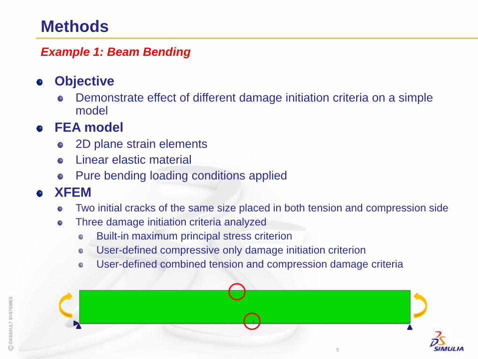
Example 1: Beam Bending
Objective
Demonstrate effect of different damage initiation criteria on a simple model
FEA model
2D plane strain elements
Linear elastic material
Pure bending loading conditions applied
XFEMTwo initial cracks of the same size placed in both tension and compression side
Three damage initiation criteria analyzed
Built-in maximum principal stress criterion
User-defined compressive only damage initiation criterion
User-defined combined tension and compression damage criteria
Methods
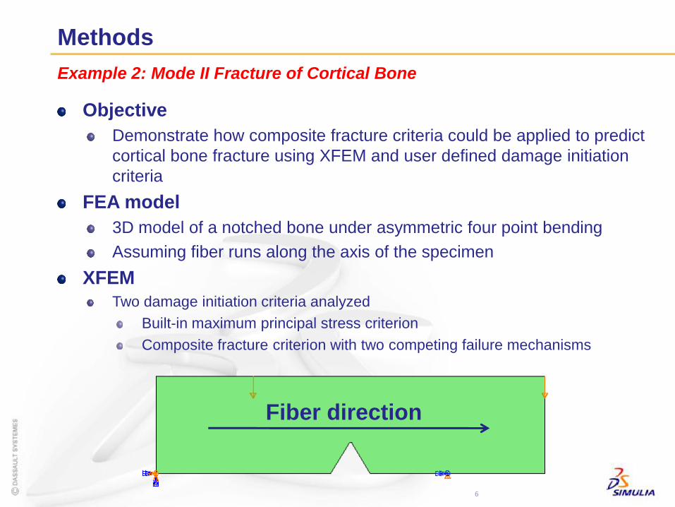
Objective
Demonstrate how composite fracture criteria could be applied to predict
cortical bone fracture using XFEM and user defined damage initiation
criteria
FEA model
3D model of a notched bone under asymmetric four point bending
Assuming fiber runs along the axis of the specimen
XFEM
Two damage initiation criteria analyzed
Built-in maximum principal stress criterion
Composite fracture criterion with two competing failure mechanisms
6
Example 2: Mode II Fracture of Cortical Bone
Fiber direction
Crack surface
Methods
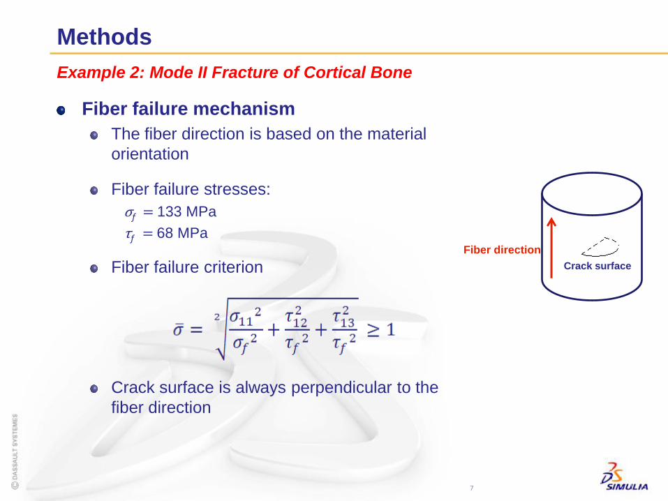
Fiber failure mechanism
The fiber direction is based on the material
orientation
Fiber failure stresses:
σf = 133 MPa
τf = 68 MPa
Fiber failure criterion
Crack surface is always perpendicular to the
fiber direction
7
Example 2: Mode II Fracture of Cortical Bone
Fiber direction
Methods
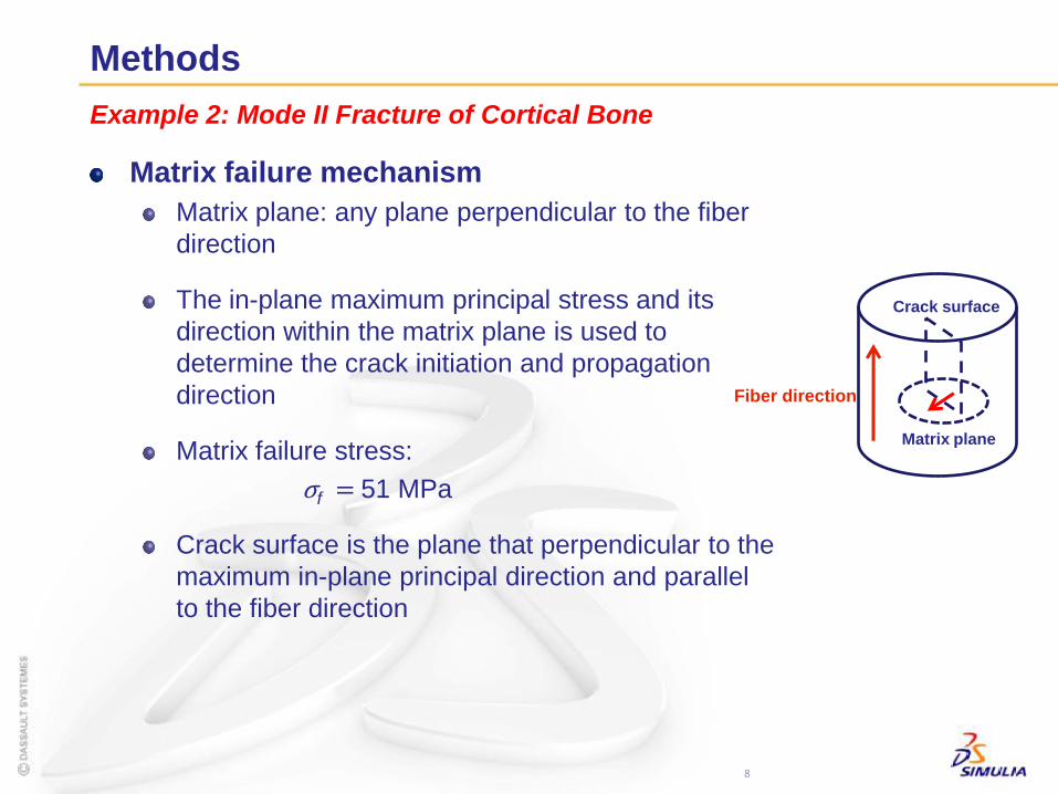
Matrix failure mechanism
Matrix plane: any plane perpendicular to the fiber
direction
The in-plane maximum principal stress and its
direction within the matrix plane is used to
determine the crack initiation and propagation
direction
Matrix failure stress:
σf = 51 MPa
Crack surface is the plane that perpendicular to the
maximum in-plane principal direction and parallel
to the fiber direction
8
Example 2: Mode II Fracture of Cortical Bone
Fiber direction
Matrix plane
Crack surface
9
Methods
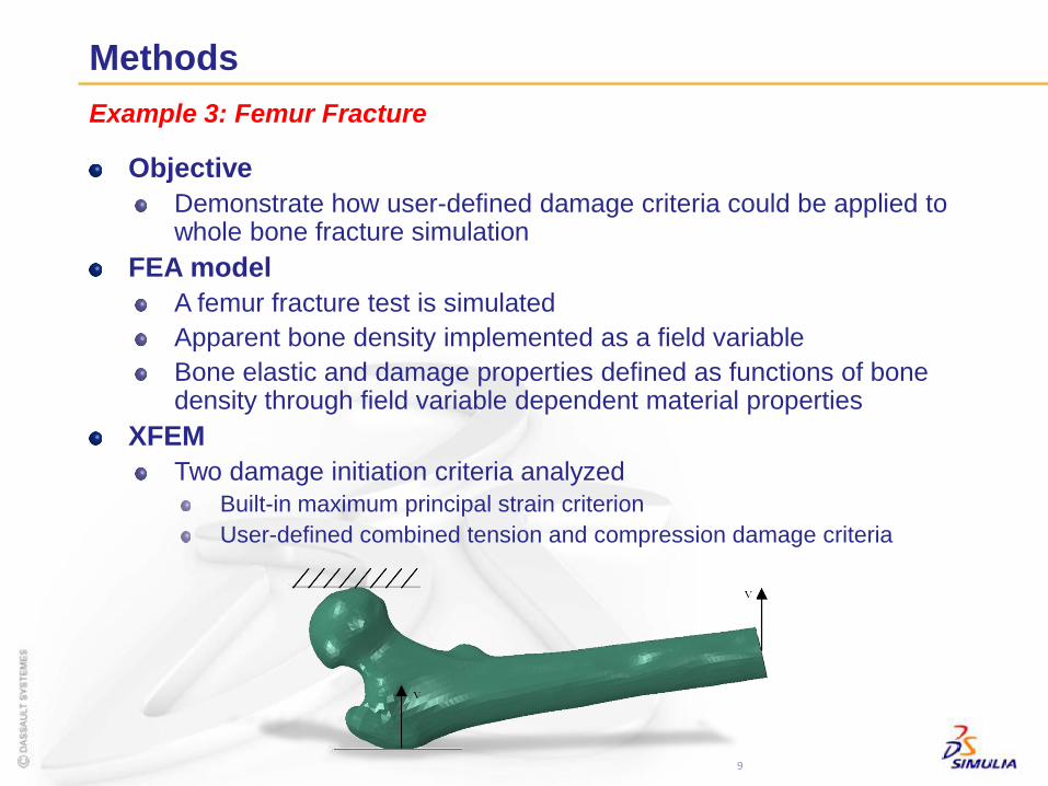
Example 3: Femur Fracture
Objective
Demonstrate how user-defined damage criteria could be applied to whole bone fracture simulation
FEA model
A femur fracture test is simulated
Apparent bone density implemented as a field variable
Bone elastic and damage properties defined as functions of bone density through field variable dependent material properties
XFEM
Two damage initiation criteria analyzed
Built-in maximum principal strain criterion
User-defined combined tension and compression damage criteria
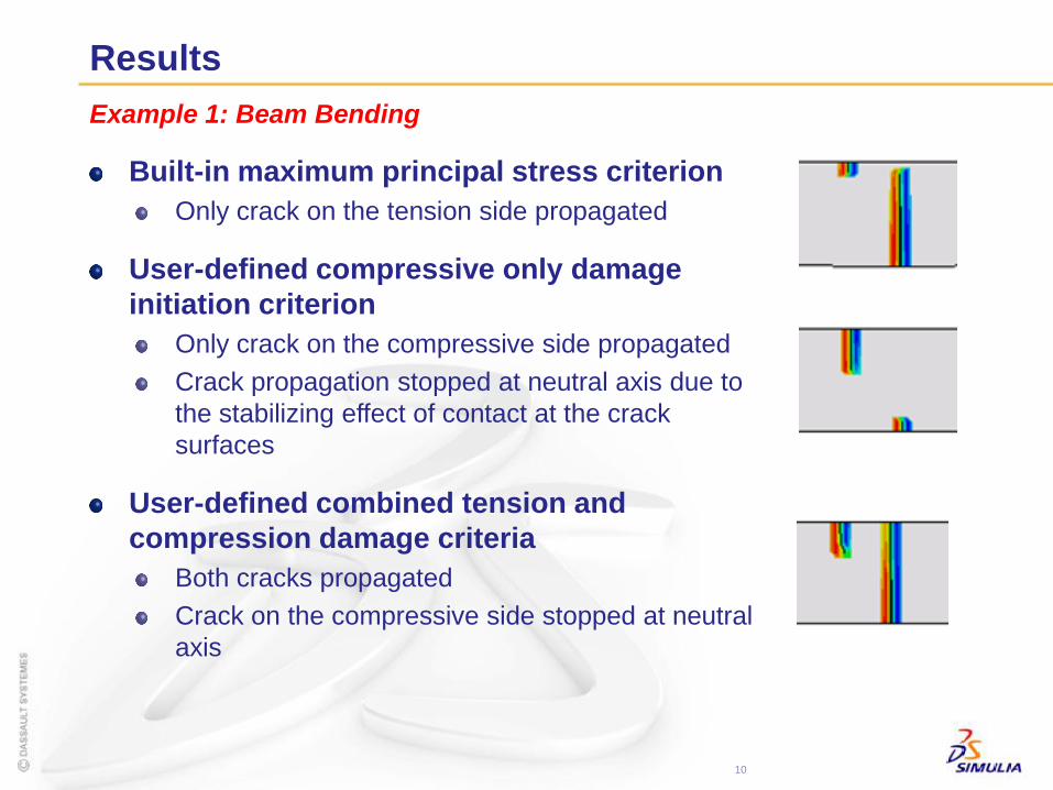
Results
Built-in maximum principal stress criterion
Only crack on the tension side propagated
User-defined compressive only damage
initiation criterion
Only crack on the compressive side propagated
Crack propagation stopped at neutral axis due to
the stabilizing effect of contact at the crack
surfaces
User-defined combined tension and
compression damage criteria
Both cracks propagated
Crack on the compressive side stopped at neutral
axis
10
Example 1: Beam Bending
Results
11
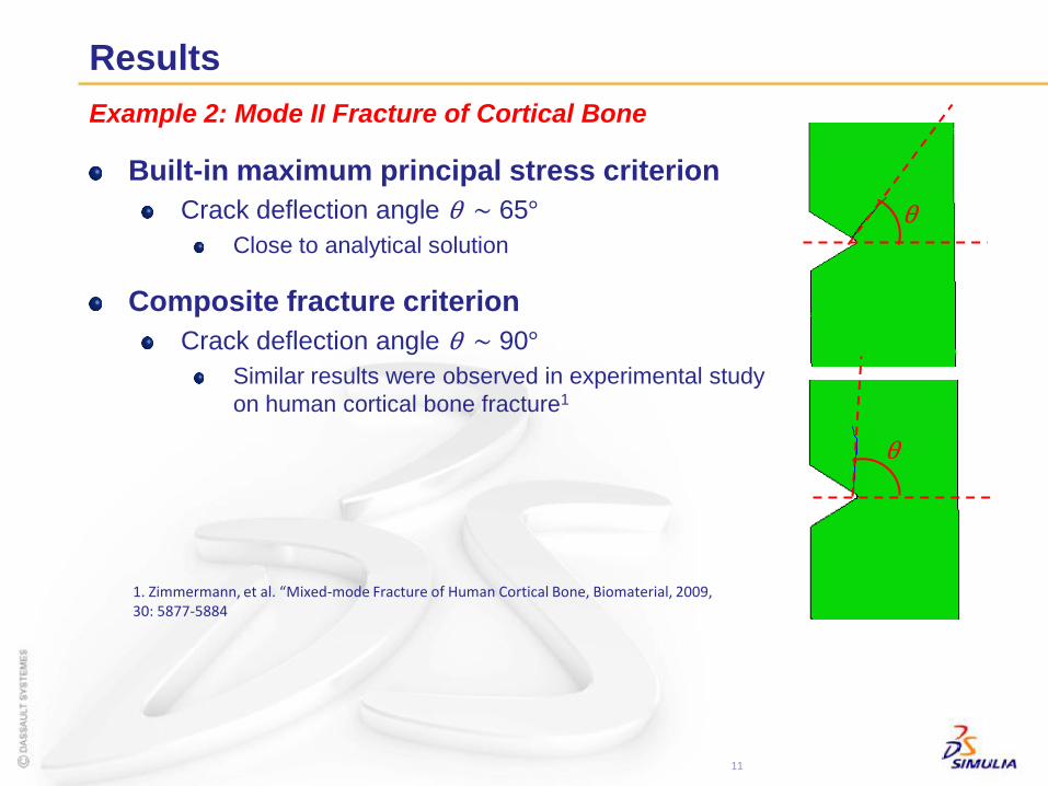
Example 2: Mode II Fracture of Cortical Bone
1. Zimmermann, et al. “Mixed-mode Fracture of Human Cortical Bone, Biomaterial, 2009, 30: 5877-5884
Built-in maximum principal stress criterion
Crack deflection angle θ ~ 65°
Close to analytical solution
Composite fracture criterion
Crack deflection angle θ ~ 90°
Similar results were observed in experimental study
on human cortical bone fracture1
θ
θ
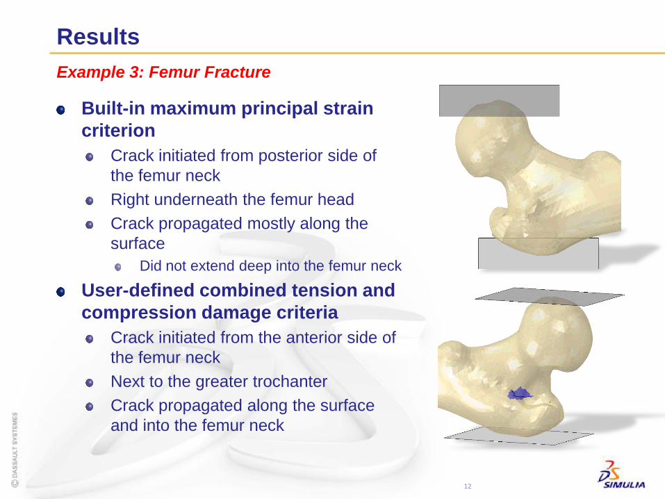
Results
Built-in maximum principal strain
criterion
Crack initiated from posterior side of
the femur neck
Right underneath the femur head
Crack propagated mostly along the
surface
Did not extend deep into the femur neck
User-defined combined tension and
compression damage criteria
Crack initiated from the anterior side of
the femur neck
Next to the greater trochanter
Crack propagated along the surface
and into the femur neck
12
Example 3: Femur Fracture
Summary
Bone is a very complex material
Hierarchical: multilevel structure complexity
Inhomogeneous: material property varies spatially
Orthotropic: stronger in the load carrying direction
Asymmetric: stronger in compression than in tension and shear
Living tissue that is capable of repairing and remodelling itself
Fracture mechanics property is one of the most important
aspects of bone that concerns millions of people’s wellbeing
It is not yet fully understood
Abaqus XFEM is another unique powerful tool for researchers to:
Better understand bone fracture and failure behavior
Develop strengthening treatment
Abaqus XFEM for Bone Fracture Study