application of data matrix identification … · application of data matrix identification symbols...
TRANSCRIPT

National Aeronautics and Space Administration
NASA-HDBK-6003 JULY 2, 2001
APPLICATION OF DATA MATRIX IDENTIFICATION SYMBOLS TO AEROSPACE
PARTS USING DIRECT PART MARKING METHODS/TECHNIQUES
NASA TECHNICAL HANDBOOK
NOT MEASUREMENT SENSITIVE
Approved for Public Release – Distribution is Unlimited


NASA-HDBK-6003 July 2, 2001
i
FOREWORD
This handbook is approved for use by NASA Headquarters and all NASA Centers and is intended to provide a common framework for consistent practices across NASA programs. Recognizing that manual data collection and keyed data entry were inefficient and error-prone, NASA adopted bar code in the mid 1980’s to upgrade its operations. It soon became apparent that collecting the identity of the part from a symbol marked directly on it would be optimal. Bar codes were determined to not be suitable for direct part marking (DPM). NASA established a team to work with industry to develop and test machine-readable two-dimensional (2-D) symbols designed to be applied to non-paper substrates. This 5-year effort resulted in selecting the Data Matrix symbol for use in NASA applications and provided proof that 2-D symbols are reliable and can be applied to most aerospace materials without impacting performance. NASA findings spurred additional testing by the Department of Defense (DOD) and private industry that resulted in selecting the Data Matrix symbol for parts marking by the Automated Identification Manufacturers (AIM) and the American National Standards Institute (ANSI). Additional part marking standards quickly followed as the automotive, electronics, pharmaceutical, and aircraft industries adopted the symbol. These industries, including NASA, have relied heavily on the use of cast, forge or mold, engraving; electrical arc pencil; electrical-chemical etch; embossing; hot stamp; rubber ink stamp; stencil and silk screen; vibration-etch; and add-on tags for part identification marking. These marking methods, originally designed to apply human-readable markings, do not provide the fidelity required to successfully apply micro-size (1/32-inch to 15/64-inch square), high-density machine-readable symbols. Their manual operations also added to the large number of data transposition errors associated with paper-based manufacturing systems. Understanding these weaknesses, the parts identification industry began to refine existing marking methods so they could be utilized to apply 2-D symbols. The manual metal stamp and embossing technique methods were replaced by dot peen machines. Automated micro-profilers were designed to replace the manual cutting wheel used to produce paint stencils. Photo stencils and thermal printing materials were developed to replace the direct impact electro-chemical marking stencil materials. Desktop publishing systems were developed for the production of stencils. Ink jet machines were built to replace rubber stamps. Laser marking systems were designed to replace the electric-arc etch and hot stamp processes. This Handbook and its related Standard, NASA-STD-6002, Applying Data Matrix Identification Symbols on Aerospace Parts, were developed to provide NASA and its contractors with instructions to safely apply Data Matrix identification symbols to aerospace parts using these new DPM methods and techniques. Both the Standard and the Handbook were created by representatives from major automatic identification and data capture (AI/DC) manufacturers, Government and aerospace user groups under a collaborative agreement with NASA.

NASA-HDBK-6003 July 2, 2001
ii
Requests for information, corrections or additions to this handbook should be directed to Materials, Processes, and Manufacturing Department, ED30, MSFC, AL, 35812. Requests for general information concerning standards should be sent to the NASA Technical Standards Program Office, ED41, MSFC, AL 35812 (telephone 256-544-2448). This and other NASA standards/handbooks may be viewed and downloaded, free-of-charge, from our NASA Standards Homepage: http://standards.nasa.gov/ . W. Brian Keegan Chief Engineer

NASA-HDBK-6003 July 2, 2001
iii
TABLE OF CONTENTS
PARAGRAPH PAGE FORWARD .............................................................................................................. i TABLE OF CONTENTS ........................................................................................... iii FIGURES AND TABLES.......................................................................................... iv 1. SCOPE .................................................................................................................. 1 1.1 Scope.............................................................................................................. 1 1.2 Purpose........................................................................................................... 1 1.3 Applicability ..................................................................................................... 1 1.4 Environmental Stewardship ............................................................................. 1 2. APPLICABLE DOCUMENTS. .. ............................................................................... 1 2.1 General ........................................................................................................ .... 1 2.2 Government documents ............................................................................... .... 2 2.2.1 Specifications, standards and handbooks...................................................... 2 2.2.2 Other Government documents, drawings, and publications ....................... 2 2.2.3 Non-Government publications…………........................................................ 2 2.3 Order of precedence..................................................................................... .... 4 3. DEFINITIONS AND ACRONYMS ........................................................................ ..... 4 3.1 Definitions used in this handbook .................................................................... 4 3.2 Acronyms used in this handbook..................................................................... 8 4. GENERAL REQUIREMENTS .................................................................................. 9 4.1 Part Tracking Systems Advancements ............................................................ 9 5. DETAILED REQUIREMENTS.................................................................................. 10 5.1 Marking Methods............................................................................................. 10 5.1.1 Non-intrusive Marking Methods ................................................................. 10 5,1.2 Automated Adhesive Dispensing ............................................................... 10 5.1.2.1 Description ................................................................................................ 10 5.1.2.2 Limitations ................................................................................................. 11 5.1.3 Cast, Forge, or Mold .................................................................................. 11 5.1.3.1 Description ................................................................................................ 11 5.1.3.2 Limitations ................................................................................................. 14 5.1.4 Ink Jet........................................................................................................ 14 5.1.4.1 Description ................................................................................................ 14 5.1.4.2 Limitations ................................................................................................. 14 5.1.5 Laser Bonding ........................................................................................... 15 5.1.5.1 Description ................................................................................................ 15 5.1.5.2 Limitations ................................................................................................. 17 5.1.6 Laser Engineered Net Shaping (LENS) ..................................................... 18 5.1.6.1 Description ................................................................................................ 18 5.1.6.2 Limitations ................................................................................................. 19

NASA-HDBK-6003 July 2, 2001
iv
TABLE OF CONTENTS (CONT’D) PARAGRAPH PAGE 5.1.7 Liquid Metal Jet ......................................................................................... 19 5.1.7.1 Description ................................................................................................ 19 5.1.7.2 Limitations ................................................................................................. 20 5.1.8 Silk Screen ................................................................................................ 20 5.1.8.1 Description ................................................................................................ 20 5.1.8.2 Limitations ................................................................................................. 20 5.1.9 Stencil........................................................................................................ 20 5.1.9.1 Description ................................................................................................ 21 5.1.9.2 Limitations ................................................................................................. 21 5.2 Intrusive Marking Methods ....................................................................................... 22 5.2.1 Abrasive Blast............................................................................................ 22 5.2.1.1 Description ................................................................................................ 22 5.2.1.2 Limitations ................................................................................................. 23 5.2.2 Dot Peen (Stamp Impression).................................................................... 23 5.2.2.1 Description ................................................................................................ 23 5.2.2.2 Limitations ................................................................................................. 29 5.2.3 Electro-Chemical Marking.......................................................................... 29 5.2.3.1 Electro-Chemical Etching........................................................................... 31 5.2.3.2 Electro-Chemical Coloring ......................................................................... 31 5.2.3.3 Limitations ................................................................................................. 31 5.2.4 Engraving/Milling ....................................................................................... 31 5.2.4.1 Description ................................................................................................ 31 5.2.4.2 Limitations ................................................................................................. 32 5.2.5 Fabric Embroidery/Weaving....................................................................... 32 5.2.5.1 Description ................................................................................................ 32 5.2.5.2 Limitations ................................................................................................. 32 5.2.6 Direct Laser Marking.................................................................................. 32 5.2.6.1 Light Amplification by Stimulated Emission of Radiation (Laser)................ 32 5.2.6.2 Short Wave Length Lasers ........................................................................ 33 5.2.6.3 Visible Wave Length Lasers ...................................................................... 34 5.2.6.4 Long Wavelength Lasers ........................................................................... 34 5.2.7 Laser Marking Methods ............................................................................. 34 5.2.7.1 Laser Coloring ........................................................................................... 34 5.2.7.1.1 Description ................................................................................................ 34 5.2.7.1.2 Limitations ................................................................................................. 35 5.2.7.2 Laser Etching............................................................................................. 35 5.2.7.2.1 Description ................................................................................................ 35 5.2.7.2.2 Limitations ................................................................................................. 36 5.2.7.3 Laser Engraving ........................................................................................ 36 5.2.7.3.1 Description ................................................................................................ 36 5.2.7.3.2 Limitations ................................................................................................. 37 5.2.8 Laser Shotpeening .................................................................................... 37 5.2.8.1 Description ................................................................................................ 37 5.2.8.2 Limitations ................................................................................................. 38 5.2.9 Laser Inducted Surface Improvement (LISI) .............................................. 38 5.2.9.1 Description ................................................................................................ 38

NASA-HDBK-6003 July 2, 2001
v
TABLE OF CONTENTS (CONT’D) PARAGRAPH PAGE 5.2.9.2 Limitations ................................................................................................. 39 5.2.10 Gas Assisted Laser Etch (GALE)............................................................... 40 5.2.10.1 Description ................................................................................................ 40 5.2.10.2 Limitations ................................................................................................. 40 5.2.11 Laser Induced Vapor Deposition (LIVD)..................................................... 41 5.2.11.1 Description ................................................................................................ 41 5.2.11.2 Limitations ................................................................................................. 41 6. NOTES ............................................................................................................... 42 6.1 Intended Use................................................................................................... 42 6.2 Key Word Listing ............................................................................................. 42
LIST OF FIGURES FIGURE PAGE 1. Preferred Mold Profile .............................................................................................. 14 2. Spherical Mold Profile .............................................................................................. 14 3. Camera Image of Spherical Profile........................................................................... 14 4. Unacceptable Ink Jet Markings ................................................................................ 12 5. Material Fused To A Surface Using The Laser Bonding Process ............................. 15 6. Unacceptable Laser Bonding Markings.................................................................... 16 7. Schematic Illustration of the LENS process.............................................................. 8. Direct part marking using LENS. A Molybdenum disk was marked with stainless steel raised lettering .................................................................................. 9. High Speed Photograph of LMJ Spray Pattern......................................................... 17 10. LMJ Surface Marking Patterns Under Magnification................................................. 17 11. Data Matrix System Stencil Structure....................................................................... 19 12. Dot Peen Patterns Used To Create Individual Data Cells......................................... 20 13. Preferred Stylus to Target Configuration .................................................................. 21 14. Preferred Dot Peen Stylus Configuration.................................................................. 22 15. Acceptable Dot Size Range Using 120 Degrees Stylus with .005-Inch Radius......... 22 16. Acceptable Dot Size Range Using 120 Degree Stylus with .010-Inch Radius........... 23 17. Dot Size Tolerances................................................................................................. 23 18. Proper Dot Peen Spacing......................................................................................... 24 19. Row and Column Misalignment................................................................................ 24 20. Improper Dot Marking Conditions............................................................................. 25 21. Dot Peen Marking with and without Proper Illumination............................................ 26 22. Cloth Label Produced Using Fabric Weaving Technique.......................................... 29 23. Laser Light Wavelengths.......................................................................................... 30 24. 2-D Markings Applied to the Head of a Straight Pin Using an Ar-F Excimer Laser ......................................................................................................... 30 25. Marking Applied to a Surface Using the Laser Coloration Process........................... 32 26. Laser Etching Applied Directly To a Surface ............................................................ 33 27. Laser Etching Applied To A Surface Coating............................................................ 33 28. Laser Engraving Applied Directly to a Surface ......................................................... 34 29. Laser Engraving Applied Directly to a Surface Coating ............................................ 34

NASA-HDBK-6003 July 2, 2001
vi
LIST OF FIGURES FIGURE PAGE 30. Magnified Image of LaserShot Peen Marking........................................................... 35 31. LISI Marking Applied Directly To a Part Surface....................................................... 36 32. Laser Etched Marking Applied To a LISI Patch ........................................................ 36 33. Scanning Electron Microscope View of The LISI ...................................................... 36 34. View of Gas Assisted Laser Etch Coating Under Magnification................................ 37 35. Stainless Steel Marking Applied To Glass Slide Using LIVD Process....................... 38
TABLES
TABLE PAGE I. Laser Marking Process Comparison Table......................................................... 39

NASA-HDBK-6003 July 2, 2001
1
APPLICATION OF DATA MATRIX IDENTIFICATION SYMBOLS TO AEROSPACE PARTS USING DIRECT PART MARKING METHODS/TECHNIQUES
1. SCOPE 1.1 Scope. This handbook provides requirements for applying Data Matrix identification symbols to parts used on NASA programs/projects using direct part marking (DPM) methods and techniques. While it is anticipated that this handbook will be used on new programs as well as those that are currently in the design phase, retrofit marking for hardware on existing programs is encouraged where feasible. The portions of this document addressing the application of human readable identification (HRI) markings does not apply to retrofit marking programs. Materials degradation and hazard analysis studies conducted on existing NASA programs were made under the assumption that a single HRI marking would be applied to each product. Consequently, the application of an additional Data Matrix marking to these parts will require the review of the applicable and engineering and program/project offices to ensure that product integrity is not compromised. 1.2 Purpose. This handbook is intended to provide detailed requirements for applying Data Matrix identification symbols safely onto products using permanent direct part marking (DPM) methods and techniques. The handbook addresses symbol structure only as it relates to marking and reading limitations. Technical specifications related to the Data Matrix symbol are found in AIM International Incorporated technical specification titled “International Symbology Specification – Data Matrix.” Overall program/project requirements related to the use of the Data Matrix symbol including: symbol criteria, marking method selection, marking surface preparation, marking locations, protective coatings, and reading standards are contained in NASA STD-6002, Applying Data Matrix Identification Symbols on Aerospace Parts. 1.3 Applicability. This handbook recommends engineering practices for NASA programs and projects. It may be cited in contracts and program documents as a technical requirement or as a reference for guidance. Determining the suitability of this handbook and its provisions is the responsibility of program/project management and the performing organization. Individual provisions of this Handbook may be tailored (i.e., modified or deleted) by contract or program specifications to meet specific program/project needs and constraints. 1.4 Environmental Stewardship. Environmental, health and safety impacts in processes and materials should be considered when employing identification marking methods and techniques. Alternative, "environmentally friendly", materials, which contain low/no volatile organic compounds (VOCs), should be considered when determining the appropriate method/technique for each marking application. Many types of ink contain VOCs, such as methyl ethyl ketone, xylene, and toluene, which are principal components in atmospheric reactions that form ozone and other photochemical oxidants. Exposures to VOC containing materials have health impacts, which include eye and respiratory irritation, headache, dizziness, memory impairment, neurotoxicity, cancer. 2. APPLICABLE DOCUMENTS 2.1 General. The applicable documents cited in this handbook are listed in this section for reference only. The specified technical requirements listed in the body of this document must be met whether or not the source document is listed in this section.

NASA-HDBK-6003 July 2, 2001
2
2.2 Government documents. 2.2.1 Specifications, standards and handbooks. The following specifications, standards and handbooks form a part of this document to the extent specified herein. Unless otherwise specified, the issuance in effect on date of invitation for bids or request for proposals shall apply. DEPARTMENT OF DEFENSE
MIL-STD-10A - Surface Roughness Waviness & Lay MIL-STD-130J - Identification Marking of U.S. Military Property available from HQ AFLC, ATTN: MMTIB, Wright-Patterson Air Force Base, OH 45433 MIL-A-8625E - Anodic Coatings For Aluminum And Aluminum Alloys MIL-M-13231 - Marking of Electronic Items
FEDERAL STANDARDS
FED-STD-182 - Continuous Identification Marking of Nickel and Nickel Base Alloys FED-STD-183 - Continuous Identification Marking of Iron and Steel Products FED-STD-184 - Identification Marking of Aluminum, Magnesium, and Titanium FED-STD-185 - Identification Marking of Copper and Copper Base Alloy Mill Products FED-STD-595 - Colors Used In Government Procurement (Fan Deck)
NATIONAL AERONAUTICS AND SPACE ADMINISTRATION (NASA) None identified.
2.2.2 Other Government documents, drawings, and publications. Title 14 of the code of Federal Regulations
2.2.3. Non-Government publications. The following documents form a part of this document to the extent specified herein. Unless otherwise specified, the issuance in effect on the date of invitation for bids or request for proposal shall apply.
A-A-208, Ink Marking, Stencil, Opaque (Porous and Nonporous Surfaces) A-A-56032, Ink, Marking, Epoxy Base AIAG B-4, Component Marking Standard (Data Matrix) – Pending AIM USA Uniform Symbology Specification for Data Matrix

NASA-HDBK-6003 July 2, 2001
3
American National Standard X3.182 Bar Code Print Quality Guidelines – available from the American National Standards Institute (ANSI), 11 West 42nd Street, New York, NY 10036. Telephone (212) 642-4900 The two-dimensional Standard for Unit Loads and Transport Packages (formerly known as ANSI MH10.8.3M-1996), 2D Symbol data encodation ASM Handbook, Surface Engineering, Volume 5; available from ASM International, Materials Park, OH 44073-0002. ATA Spec-2000, Chapter 9, Bar Coding EIA-624, Product Packaging Marking EIA-706, Component Marking Standard (Data Matrix) EIA-802, Product Marking Standard EIA SP-3497, Component Product Marking Standard (Data Matrix) ISO 15415, Two-dimensional symbol print quality – Pending ISO 16022, Information Technology International Symbology Specification Data Matrix SEMI T2-95, Specification for Marking of Wafers with Two-Dimensional Matrix Code Symbol SEMI T7-0997E, Specification for the Back Surface of Double-Sided Polished Wafers with a Two-Dimensional Matrix Code Symbol SEMI T8-0698, Specification for Marking of Glass Flat Panel Display Substrates with A Two-Dimensional Matrix Code Symbol SEMI Draft Document #2999, Test Method for the Assessment of 2D Data Matrix Direct Mark Quality SEMI Draft Document #2999, Specification for the Assessment of 2D Data Matrix Direct Mark Quality TT-L-50, Lacquer, Nitrocellulose, Acrylic And Acrylic Butyrate Aerosol (In Pressurized Dispensers) Uniform Code Council (UCC) Standards. To apply for UCC Manufacturer Identification (Company Prefix) Codes contact Uniform Code Council, 8163 Old Yankee Road, Suite J, Dayton, OH 45458. Telephone (513) 435-3870. Telefax: (513) 435-4749 Uniform Symbology Specification for Data Matrix available from AIM USA, 634 Alpha Drive, Pittsburgh, PA 15238-2802. Telephone (412) 963-8588 UPS S28-1, Identification/Codification Standards (Data Matrix and PDF417) – Pending

NASA-HDBK-6003 July 2, 2001
4
2.3. Order of precedence. Where this document is adopted or imposed by contract on a program or project, the technical guidelines of this document take precedence, in case of conflict, over the technical guidelines cited in other referenced documents. 3. DEFINITIONS AND ACRONYMS 3.1 Definitions used in this handbook 3.1.1 Bar Code. A patterned series of vertical bars of varying widths used by a computerized scanner for inventory, pricing, etc.
3.1.2 Binary Value. A dot in the substrate surface indicates the binary of one. The absence of a dot, or a smooth surface surrounding a cell center point, indicates the binary value of zero. 3.1.3 Bit (Binary Digit) – The basic unit of information in a binary numbering system. 1’s and 0’s are used in a binary system. 3.1.4 Border Column – The outermost column of a data matrix code symbol. The column is a portion of the finder pattern. 3.1.5 Border Row – The outermost row of a data matrix code symbol. This row is a portion of the finder pattern. 3.1.6 Cell, of a data matrix symbol – The area within which a marking may be placed to indicate a binary value. The cell is the smallest element of a two-dimensional matrix symbol. 3.1.7 Cell center point, of an array – The point at which the centerline of a row intersects the centerline of a column. 3.1.8 Cell spacing, of an array – The (equal) vertical or horizontal distance between the cell center points of contiguous cells. 3.1.9 Centerline, of a row or column – The line positioned parallel to, and spaced equally between, the boundary lines of the row or column. 3.1.10 Central area, of a cell – The area enclosed by a circle centered at the center point: used by code readers to sense the binary value of the cell. 3.1.11 Character (Data character) – A letter, digit or other member of the ASCII character set. 3.1.12 Character Set – that character available for encodation in a particular automated identification technology. 3.1.13 Components – For the purposes of this document, the term component relates to parts used in the manufacturer of launch vehicles, satellites, aircraft and their support hardware (e.g., facilities, ground support equipment, mission kits, test devices and other related hardware).

NASA-HDBK-6003 July 2, 2001
5
3.1.14 Contrast – This can be thought of as the grayscale difference between two areas of color. 3.1.15 Data Matrix Code Symbol – A two-dimensional array of square cells arranged in contiguous rows and columns. In certain ECC200 symbols, data regions are separated by alignment patterns. The data region is surrounded by a finder pattern (AIM – Data Matrix).
3.1.16 Data Redundancy – Data repeated in a code to correct any possible errors caused by damage, poor print quality, or erasures. 3.1.17 Density (Matrix Density) – The number of rows and columns in a scanned matrix symbol.
3.1.18 Depth of Etch – The distance from the surface of the substrate to the bottom of the recess created by an etching process. 3.1.19 Depth of Field – An optical term (typically applied to cameras) which describes the minimum and maximum range (distance) an object will stay in focus without adjusting the focus of the lens. 3.1.20 Dot – A localized region with a reflectance which differs from that of the surrounding surface.
3.1.21 Dot misalignment, within a cell – The distance between the physical center point of a dot and the cell center point.
3.1.22 Edge – This is seen as a dramatic change in pixel brightness values between regions. It is the point(s) that has the greatest amount of contrast difference (change in intensity values) between pixels.
3.1.23 Electrolyte – The solution formed by water and a selected salt(s) and used as the conductor between an object and the electrode in an electro-chemical marking process. Selected electrolytes also have the ability to “color” the mark due to the chemical reaction that takes place between the metal and the electrolyte. 3.1.24 Error Correction – Mathematical techniques, which reconstruct the original information, based upon the remaining data in a damaged or poorly printed code. Reed Solomon and convolution are two such techniques. 3.1.25 Fatigue. The cumulative irreversible damage incurred in materials caused by cyclic application of stresses and environments resulting in degradation of load carrying capability. 3.1.26 Field of View – The maximum area that can be viewed through the camera lens or viewed on the monitor. 3.1.27 Finder pattern, of a data matrix code symbol – A perimeter to the data region. Two adjacent sides contain dots in every cell: these are used primarily to define physical size, orientation and symbol distortion. The two opposite sides are made up of cells containing dots in alternate cells (AIM – Data Matrix).

NASA-HDBK-6003 July 2, 2001
6
3.1.28 Focal Length – The focal length is the distance from the main lens to the back focal point projected on the CCD array. 3.1.29 Grayscale – The assignment of a digital value to a degree of light intensity. The shades of gray are used by the computer to reconstruct an image. A common scale is 256 shades of gray, with 0 being black and 255 being white. 3.1.30 Hardness – A measure of the resistance of a material to surface indentation or abrasion; may be thought of as a function of the stress required to produce some specified type of surface deformation. There is no absolute scale for hardness; therefore, to express hardness quantitatively, each type of test has its own scale of arbitrarily defined hardness. Indentation hardness can be measured by Brinell, Rockwell, Vickers, Knoop, and Scleroscope hardness tests. 3.1.31 Human-Readable Interpretation – The letters, digits or other characters associated with specific symbol characters and printed incorporated into the linear bar code or two-dimensional symbol. 3.1.32 Intensity – Intensity is the average of the sum total of grayscale values.
3.1.33 Intrusive Marking – Any device designed to alter a material surface to form a human or machine-readable symbol. This marking category includes, but is not limited to, devices that abrade, burn, corrode, cut, deform, dissolve, etch, melt, oxidize, or vaporize a material surface.
3.1.34 Laser – Short Wave Length – Lasers operating in the 1 to 399nm range.
3.1.35 Laser – Visible Spectrum – Lasers operating in the 400 to 749nm range.
3.1.36 Laser – Long Wave Length – Lasers operating in the 750- 10,000nm range. 3.1.37 License tag number – The information contained with the symbol character set to
uniquely identify the component. As a minimum the information shall contain the manufacturer’s CAGE code followed by an asterisk (ASCII separator) and trace code (lot, member or serial number).
3.1.38 Manufacturer – Actual producer of fabricator of component or the supplier in a transaction if the supplier is the warrantor of the component. 3.1.39 Mark – Refers to a Data Matrix symbol that has been applied to a material surface using a permanent marking method. 3.1.40 Matrix – A set of numbers, terms, or things arranged in rows and columns. 3.1.41 Matrix Density – The number of rows and columns in a matrix. 3.1.42 Non-intrusive Marking – A method of forming markings by adding material to a surface. Non-intrusive marking methods include ink jet, laser bonding, liquid metal jet, silk screen, stencil and thin film deposition.

NASA-HDBK-6003 July 2, 2001
7
3.1.43 Overhead (OVHD) Characters – Those characters included within a symbol that are not data characters, e.g., start, stop, error checking, concatenation, and field identifier characters. 3.1.44 Permanent Marking – Markings designed to remain legible throughout the normal service life of an item.
3.1.45 Pixels – Picture elements. In a camera array, pixels are photoelectric elements capable of converting light into an electrical charge.
3.1.46 Photo-Stencil – A silk-screen type fabric coated with a photo-resist compound which can be fixed by UV radiation and easily washed from the fabric where unexposed. The patterns opened in the fabric are the images to be marked (stenciled, etched, or colored) on the substrate.
3.1.47 Quiet Zone – Areas of high reflectance (spaces) surrounding the machine-readable symbol. Quiet zone requirements may be found in application and symbology specifications. Sometimes called “Clear Area” or “Margin” 3.1.48 Reader – Another name for a CCD or CMOS camera configured to read symbols. 3.1.49 Redundant Data – Data that is repeated in a code. The redundant data is randomly placed or encoded inside the data storage area to increase a symbol’s ability to recover from damage. NOTE: The reference point is a fixed location on the object; different cells may be chosen as the reference point depending on the desired orientation of the symbol. The particular cell to be used as the reference point must be specified for each application. 3.1.50 Reference point, of a data matrix symbol – The physical center point of a cell common to a designated row and column, used to identify the physical location of the symbol on the object being marked with the symbol. 3.1.51 Resolution – The measure of how small a feature the camera can distinguish in its field of view. Camera resolution is determined in its field of view. The number of pixels within the CCD array determines camera resolution. The more pixels used to capture the image, the higher the resolution or quality of the image. Since the number of pixels is fixed, the smaller the field of view, the higher the image resolution will be. For example, a 1-inch field of view photographed by a 640 x 480 camera will have a resolution of .0015-inch per pixel; a ½-inch field of view would yield a resolution of .00078-inch per pixel. 3.1.52 Scaleable Code – A matrix code where the presence or absence of an individual cell is all that is required to be known. It can be made any size since non-measurements are being made, unlike a bar code, which is decoded by measuring the width of each element. 3.1.53 Structure – The order of data elements in a message.
3.1.54 Substrate – The material (paper, plastic, metal, etc.) upon which a symbol is marked.
3.1.55 Supplier – The trading partner in a transaction that provides the component (e.g., manufacturer, distributor, reseller, etc.).

NASA-HDBK-6003 July 2, 2001
8
3.1.56 Symbology – A machine-readable pattern comprised of a quiet zone, finder pattern, symbol characters (which include special functions and error detection and/or correction characters) required by a particular symbology.
3.1.57 Thermal Stencil – Similar to the photo-stencil. In this case, the fabric is coated with
a compound, which can be opened by a thermal printer to form the desired images.
3.1.58 Weld Cleaner – A device to remove oxidation marks using electro-chemical processes. 3.2 Acronyms used in this handbook.
3.2.1 AIM – Automatic Identification Manufacturers 3.2.2 ANSI - The American National Standards Institute. A non-government organization responsible for the coordination of voluntary national (United States) standards. ANSI, 11 West 42nd Street, New York, NY 10036, Telephone: 212.642.4900, Telefax: 212.302.1286
3.2.3. ASTM. American Society for Testing and Materials 3.2.4 ATA – Aircraft Transportation Association 3.2.5 CCD – Charged Coupled Device. A type of sensor array used in some 2D cameras to capture the light reflected from a marked surface to produce an image 3.2.6 CMOS – Complementary Metal Oxide Semiconductor 3.2.7 CO2 – Type of laser using carbon dioxide gas as the lasing medium 3.2.8 DOD – Department of Defense 3.2.9 DPM – Direct Part Marking 3.2.10 ECE – Electro-Chemical Etching 3.2.11 ECM – Electro-Chemical Marking 3.2.12 ECC – Error Correction Codes or Error Check and Correction: the Data Matrix code can be printed in 15 error correction levels 3.2.13 ECG – Error Correction Codes or Error Check and Correction: the Data Matrix code can be printed in 15 error correction levels 3.2.14 Excimer – Excited dimmer 3.2.15 FAA – Federal Aviation Administration 3.2.16 GALE – Gas Assisted Laser Etch 3.2.17 ISO – International Standards Organization

NASA-HDBK-6003 July 2, 2001
9
3.2.18 KHz – Kilohertz(1000 cycles of oscillation per second)
3.2.19 LASER – Light Amplification by Stimulated Emission of Radiation
3.2.20 LENS – Laser Engineered Net Shaping 3.2.21 LISI – Laser Induced Surface Improvement
3.2.22 LIVD – Laser Induced Vapor Deposition
3.2.23 LMJ – Liquid Metal Jet
3.2.24 NASA - National Aeronautics and Space Administration
3.2.25 Nd:YAG – Type of laser using a Neodymium Yttrium Aluminum Garnet crystal as
the lasing medium
3.2.26 Nd: YAP - Type of laser using a Neodymium doped Yttrium Aluminum Perovskite crystal as the lasing medium
3.2.27 Nd:YLF - Type of laser using a Neodymium doped: Yttrium Lithium Fluoride crystal as the lasing medium
3.2.28 Nd:YVO4 – Type of laser using a Neodymium-doped yttrium vanadate
orthovanadate crystal as the lasing medium
3.2.29 WAD – Work Authorization Document 4. GENERAL REQUIREMENTS 4.1 Part Tracking Systems Advancements. Parts, components, assemblies, and contract end items utilized on NASA programs/projects are marked with identification numbers that are used to relate them to their respective manufacturing and operational histories. Program officials continuously review this data to ensure that products are properly configured and ready to support mission objectives. The successful operation of NASA’s part tracking systems is critical to mission safety. In the past, these systems utilized hard copy Work Authorization Documents (WAD’s) that were routed, after closure and inspection buy-off, to computer input stations. Personnel located at these stations reviewed the WAD's for completion and then manually transposed product status information into the appropriate configuration management and quality assurance database(s). Due to the nature of this process, product status information contained in the database(s) could be expected to be days or even longer behind actual conditions. Data variances detected by the computer programs were investigated and corrected after the fact. The variances tied up resources and added to overall program costs. These conditions, inherent in paper based systems, were tolerated by program officials, who often made critical decisions based on incomplete and incorrect data. Part identification technology has now matured to a point where accurate product information can be electronically moved between the shop floor and the program computer databases. This has been made possible by the development of a machine-readable code, known as the Data Matrix symbol.

NASA-HDBK-6003 July 2, 2001
10
The Data Matrix symbol was designed to be applied directly to, and read from parts made from a wide range of different materials. The following sections of this handbook were developed to provide users with the methods and information necessary to safely apply these symbols to NASA hardware. 5. DETAILED REQUIREMENTS 5.1 Marking Methods. Direct part marking (DPM) is generally suggested in applications where:
• Traceability is required after the product is separated from its temporary identification • The part is too small to be marked with bar code labels or tags • The part is subjected to environmental conditions that preclude the use of add-on
identification means • Identification is required beyond the expended life of the part to preclude further use
DPM can be broken down into two primary categories: non-intrusive and intrusive. Non-intrusive Marking Methods. Non-intrusive markings, also known as additive markings, are produced as part of the manufacturing process or by adding a layer of media to the surface using methods that have no adverse effect on material properties. These methods include:
• Automated Adhesive dispensing • Cast, forge, and mold • Ink jet • Laser bonding • Laser engineered net shaping (LENS) • Liquid metal jet • Silk screen • Stencil
5.1.1 Automated Adhesive Dispensing: 5.1.2 Description: Automated Adhesive Dispensing Systems are designed to deposit
precise amounts of adhesive on a repeatable basis. The preferred system employs an overhead gantry which allows for accurate positioning of the dispensing heads while the work piece remains stationary. Any fluid application is possible, including full contoured beads, dot dispensing, gasketing, potting, and spraying of both one and two part materials. For maximum accuracy and repeatability, specified systems should allow for three-axis movement driven by Teflon-coated hardened stainless steel lead screws and controlled by 5-phase stepper motors and precision servomotors. These drive systems assure a resolution of +/- .001”. The system specified should be supported by a Windows-based programming platform incorporating Windows graphical and icon-driven concepts to provide an intuitive and user-friendly environment. Pull-down menus should allow operators to quickly input their specific dispensing parameters, while on-screen positioning displays should allow for real-time monitoring and control of the dispensing sequence. Software should allow for circular path

NASA-HDBK-6003 July 2, 2001
11
motion in XY, XZ and YZ combinations, which provides continuous dispensing at different levels and shapes including vertical peaks and valleys (contouring). The system specified should be designed to incorporate a full spectrum of dispensing heads, from syringes to fully integrated valves and controllers. Special consideration should be given to dispensing heads that are field repairable with a minimum of downtime. Such systems contain disposable material path inserts that allow the valve to be replaced on-line and with no cleaning.
5.1.2.2 Limitations:
• Marking surfaces must be cleaned prior to marking
5.1.1 Cast, Forge, or Mold
5.1.1.1 Description: Cast metal marking of the 2-D Data Matrix identification symbol can be achieved by printing a pattern of the Data Matrix symbol in physical or 3-dimensional form on a 3-dimensional printer such as the ThermoJet Solid Object Printer by 3-D Systems. These 3-dimensional printing devices produce physical objects by using an ink jet print head that uses a wax based thermoplastic instead of ink, and prints layer upon layer to build up the “ink” thickness into a 3-dimensional object. For the cast metal marking application the 3-dimensional printed pattern of the Data Matrix symbol is incorporated into a coupon made from the wax-based thermoplastic material. Once printed this coupon can be turned into a cast metal equivalent by putting the wax coupon pattern through the investment casting process. For direct part marking of investment cast parts, these wax coupons would be directly attached to the wax pattern of the part to be marked before being put through the investment casting process. For parts that are fabricated using sand casting the wax coupons containing the Data Matrix symbology would be placed into a recess in the mold pattern before the sand mold is compacted and formed. For parts produced by the molding or forged fabrication processes the wax coupons containing the Data Matrix symbology would be investment cast first to produce a cast metal coupon which would be inserted into a recess in the mold before the end use part is fabricated in the mold. The maximum size of a 3-dimensional printed Data Matrix symbol is primarily limited by the maximum readable size of the scanning device (typically 2” to 3”) and to a lesser extent by the build platform size (typically 8” by 10”) of the 3-D printing device. The individual cells of the Data Matrix symbol are either raised above the surface or recessed into the coupon and when side lighted produce the contrast pattern necessary to be read by a Data Matrix scanner. Practically speaking individual cell X, Y dimensions are typically held above “0.015” to 0.020” for good acuity and readability after the investment casting process. Any geometry may be used for the profile of an individual cell within the limits of the printing resolution of the 3-dimensional printing device, typically 300-400 dpi. The most preferred cell profiles are cubical, semi-spherical, conical, or pyramidal in shape. The conical or pyramidal profile can also be truncated to help eliminate sharp corners and corresponding stress risers. The depth or height of an individual cell recess or protrusion can be as little as 0.0015”, and is primarily limited by scanning constraints. This 0.0015” dimension is a typical single layer thickness for the 3-D printing process. The maximum height or depth of a cell profile is only limited by the practical constraints of reproducing high aspect ratio features in the investment casting process, and by the coupon or part thickness itself. Typically aspect ratios (depth/dimension) of less than 1 are most preferred for the investment casting process.

NASA-HDBK-6003 July 2, 2001
12
A preferred pyramid profile used to produce an individual raised cell is shown in cross section in Figure 1. The protruding profile is most preferrable as it is less likely to trap or attach fluid within or around the individual cell features during the face coating step of the investment casting process. The sloped faces of this profile is also preferred for scanning as it reflects the scanning light away from the scanner receptor decreasing the contrast for this cell area and enables the scanning device to uniquely distinguish the contrast level of this individual cell from the neighboring cell areas on the exposed surface of the coupon.
FIGURE 1. Preferred Mold Profile Cell profiles similar to the spherical or cubical geometry result in an individual raised or recessed cell that is difficult to distinguish from the surrounding exposed top surface of the coupon corresponding to neighboring cells. These profile types require a frame or border around the raised/recessed profile within the area of an individual cell to enable the scanner to distinguish areas of differing contrast corresponding to individual cells of the Data Matrix. Figure 2 graphically displays the geometry of a raised spherical data cell.
FIGURE 2. Spherical Mold Profile The scanned image of this profile results in the contrast map as shown below in Figure 3.
Protruding data cell of wax coupon
Wax coupon
Wax coupon exposed surface
Neighboring data cell
Reflected light scattered due to curvature of profile
Direct incident light
Raised data cell
Reflected light at apex of spherical profile
Scanner light source and detector
Neighboring Cell

NASA-HDBK-6003 July 2, 2001
13
FIGURE 3. Camera Image of Spherical Profile
Figure 3 demonstrates the overall contrast value for such an individual cell is reduced as a result of the bright spot in the center caused by the surface area of the spherical profile near the center having relative flat slope. This effect is more pronounced for the cubical cell profiles. In cases where a spherical or cubical profile is used, the frame or border dimension must be at least 0.0035” in width completely surrounding an individual cell profile. This requirement reduces the cell profile feature size by this same dimension. As an example, for a minimum cell size of 0.025” this reduces the cell profile feature size to a dimension of 0.018”. 5.1.3.2 Limitations:
• Raised cell profiles preferred for end use parts subjected to high stresses • Raised cell profiles preferred for accurate reproduction in the investment casting
process, due to less likely to trap fluid bubbles. • Raised cell profiles with truncated vertices most preferred for end use parts subjected
to high stresses. • Raised markings should not be used if interference with manufacturing operations or
other mating parts in the end use application are anticipated • Markings should be used on non-machined surfaces only • Coupon overall thickness less than 0.020” may be difficult to handle in later
manufacturing operations, such as attachment to wax pattern. • Cell profiles with aspect ratios substantially greater than 1 may be difficult to produce
using the investment casting process. 5.1.4 Ink Jet. 5.1.4.1 Description: Ink Jet markers propel ink globules from the printing head to the part surface. The permanence of the mark is dependent on the chemical interaction between the ink, the surface of the part, and other materials to which the part may be exposed, i.e., “cleaning solvents. Care must be taken to ensure the chemical properties of the ink being used are compatible with the material being marked, and with the processes through which the part being marked will be exposed. When applied to metal parts, ink jet markings should be coated with a clear lacquer in accordance with TT-L-50 before oiling.
Extents of individual cell
Area of dark contrast
Areas of light contrast

NASA-HDBK-6003 July 2, 2001
14
Operators should evaluate test marking to identify and correct adverse marking conditions such as: 1. symbol distortion, 2. a condition known in the industry as “doughnuting”, 3. ink splatter, and 4. smearing. These conditions can be corrected by adjusting the gap between the print head and the target, the shaft encoder input (speed sensor), system air pressure, and the ink formulation. Figure 4 illustrates some examples of ink jet marking conditions that adversely affect reading. 5.1.4.2 Limitations: Should not be applied to parts subjected to:
• Immersion in liquids • Prolonged exposure to liquid splash or spray • High temperatures • Abrasion, rubbing or sliding wear
FIGURE 4. Unacceptable Ink Jet Markings
The practical minimum size of the Data Matrix is limited to 3/8-inch square, with a density (number of rows and columns) of 16x16 cells, representing 16 alphanumeric characters. Ultraviolet (UV) ink can be used for security or aesthetic reasons.

NASA-HDBK-6003 July 2, 2001
15
5.1.5 Laser Bonding. 5.1.5.1 Description: Laser bonding is an additive process that involves the bonding of a material to the substrate surface using the heat generated by a Nd:YAG, YVO4, or CO2 laser. The materials used in this process are commercially available and generally consist of a glass frit powder or ground metal, oxides mixed with inorganic pigment, and a liquid carrier (usually water). The pigment can be painted or sprayed directly onto the surface to be marked, or transferred via pad printer, screen printer, or coating roller. Adhesive backed tapes coated with an additive are also used in this process. The process also can also be performed using a CO2 laser and ink foils for use in less harsh environments. Laser bonding is accomplished using heat levels that have no noticeable affect on metal or glass substrates and are safe for use in safety critical applications. The markings produced using this technique (dependant upon the material used), are resistant to high heat, are unaffected by salt fog/spray and are extremely durable (see Figure 5).
FIGURE 5. Material Fused To A Surface Using The Laser Bonding Process Laser bonding parameters shall be established using scrap material or test coupons made of the same as the product marked. Coating materials must be stirred or agitated vigorously to ensure that the bonding materials are in suspension. Coatings shall be applied in a manner that ensures even distribution of the coating across the marking surface. The settings established for laser bonding must be tested on bare metal to ensure that the heat levels applied produced no visible affect on the part surface. Figure 6 illustrates some of the more common laser bonding marking conditions that adversely affect reading.
NASA-HDBK-6003 July 2, 2001
16
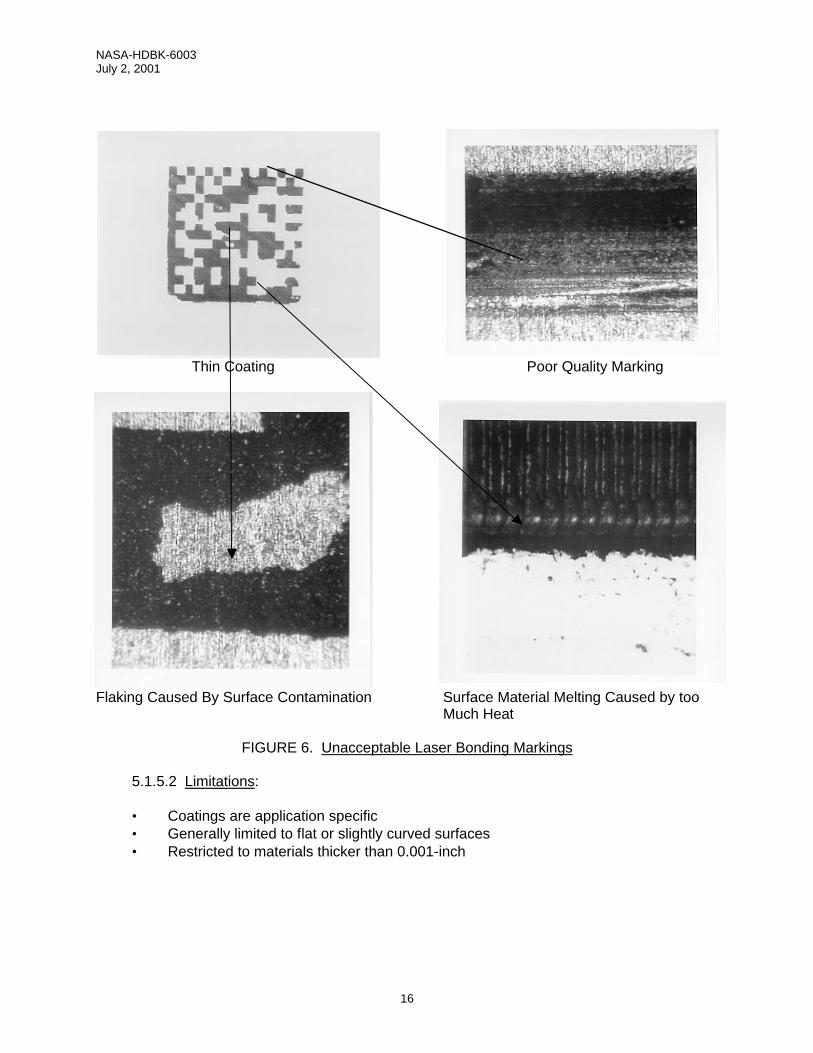
Thin Coating Poor Quality Marking
Flaking Caused By Surface Contamination Surface Material Melting Caused by too Much Heat
FIGURE 6. Unacceptable Laser Bonding Markings
5.1.5.2 Limitations:
• Coatings are application specific • Generally limited to flat or slightly curved surfaces • Restricted to materials thicker than 0.001-inch

NASA-HDBK-6003 July 2, 2001
17
5.1.6 Laser-Engineered-Net-Shaping (LENS) 5.1.6.1 Description: Laser-Engineered-Net-Shaping (LENS) utilizes the heat from an Nd-YAG
laser to form a small weld-pool on the surface of the part to be marked. Simultaneously, metallic powder is injected into the molten pool, building up a feature (see Figure 7). 3-D CAD software is used to manipulate the head or the part to deposit the data matrix identification symbol. The injected metallic material does not have to be of the same material as the part, and can be chosen to be corrosion resistant, wear-resistant, or with any other desirable characteristic. LENS-deposited materials offer a rough surface finish, providing good light reflection. LENS is compatible with all common steels, titanium, aluminum, nickel, and copper alloys. LENS gives a small heat-affected-zone in the part. LENS markings can be resistant to abrasion and chemical reactions. LENS marking will protrude above a surface since this process adds material to an existing substrate (see Figure 8).
FIGURE 7. Schematic Illustration of the LENS process

NASA-HDBK-6003 July 2, 2001
18
FIGURE 8. Direct Part Marking Using LENS. A Molybdenum Disk Was Marked With Stainless
Steel Raised Lettering. 5.1.6.2 Limitations
• Limited to metallic alloys
5.1.7 Liquid Metal Jet. 5.1.7.1 Description: The Liquid Metal Jet (LMJ) marking is similar in nature to ink jet printing but differs in that it dispenses extremely small droplets (0.0005 – 500 picoliter), (1-100 micro-inch diameter) of liquid metal in lieu of ink. The LMJ technology is being developed for the electronics industry to produce aluminum (AL) based printed wiring (circuit) boards (PWB’s). It will also be suitable for use in permanent part marking. Figures 9 and 10 depict photographs of typical LMJ spray and surface marking patterns.
FIGURE 9. High Speed Photograph of LMJ Spray Pattern
2mm

NASA-HDBK-6003 July 2, 2001
19
Straight Line Pattern Dot Pattern
FIGURE 10. LMJ Surface Marking Patterns Under Magnification
5.1.7.2 Limitations:
• Marking device still under development
5.1.8 Silk-Screen. 5.1.8.1 Description: Silk-screen markings are applied by pressing a pigmented marking media (usually ink or paint) through openings in a mask. In the past silk-screen marking masks were made from woven silk or nylon fabrics coated with a photo-sensitive resist. The symbol is created by placing a photo-negative over the stencil and exposing it to an ultra violet light source. The unexposed areas of the stencil are then dissolved using a chemical cutter, exposing openings in the mask that provide a representation of a symbol for marking. The most common problem experienced using this silk-screen generation method is poor marking edge definition caused by improper light exposure times and marking voids caused by incomplete chemical cleaning of the stencil mask. The silk-screen stencil process was recently automated so that Data Matrix symbols can be printed in a manner very similar to that used to produce printed labels. The new method involves the use of a special laminated masking material that is passed through a desk top printing device which perforates a thermoplastic resin coating using a thermal print head to form opening for silk screening and electro-chemical etching. 5.1.8.2 Limitations: Should not be used on:
• Items exposed to liquid spray or splash • Items exposed to high temperatures (over 300° F) • Items exposed to rubbing wear or abrasion

NASA-HDBK-6003 July 2, 2001
20
5.1.9 Stencil. 5.1.9.1 Description: Stencil markings are applied by depositing a marking agent onto a surface using a mask that has openings corresponding to the shape of the desired marking. Stencils are generated using photo-process, laser etching, or mechanical micro-cutting processes. Laser etch and mechanically cut stencils require the use of a symbol pattern that provides spacing between the individual data cells to hold the pattern together. The spacing provides a grid work of interconnecting stencil material that typically occupy approximately 36 percent of the individual data cell marking area as illustrated on Figure 11. Interconnecting data cell elements that occupy less than 26 percent of the allotted data cell marking space can be damaged during stencil generation and handling. Interconnecting data cell elements exceeding 46 percent of the allotted data cell area can adversely affect symbol readability. Stencils can be created out of a wide range of application dependent materials including paper, vinyl, zinc, aluminum, polypropylene or magnetic rubber. Adhesive backed stencils are used with marking agents that bleed under the stencil surface. Marking agents are applied to the part surface by spraying, rolling, or dabbing the marking agent through the openings in the mask. The marking agents most commonly used in conjunction with stencil marking include:
• Abrasive Blast • Acid Etch • Chemical Coloring Agents • Dip, Barrier, And Chemical Conversion Coatings • Plating And Electro-Plating • Ink (A-A-208 and A-A-56032) • Vacuum And Controlled Atmosphere Coatings And Surface Modification Processes
5.1.9.2 Limitations:
• Stencil marking processes are not practical for use with irregular shaped surfaces (compound curves)
• Some marking agents are susceptible to damage caused by abrasion, rubbing wear, and exposure to high temperatures
• Some marking agents may also be susceptible to damage caused by immersion in liquids or prolonged exposure to liquid splash or spray

NASA-HDBK-6003 July 2, 2001
21
FIGURE 11. Data Matrix System Stencil Structure
5.1.6 Intrusive Marking Methods. Intrusive markings alter a parts surface (abrade, cut, burn, vaporize, etc.) and are considered to be controlled defects. If not done properly, they can degrade material properties beyond a point of acceptability. Consequently, some intrusive markings, especially laser, are generally not used in safety critical applications without appropriate metallurgical testing. Typical intrusive marking methods include:
• Abrasive blast • Dot peen • Electro-chemical marking • Engraving/milling • Fabric embroidery/weaving • Direct laser marking.
Typical data cell marking area
Marking media applied through opening in mast
Opening cut in mask to produce data cell Interconnecting
elements used to hold stencil pattern together
Connecting elements will typically occupy 36 percent of data cell marking area

NASA-HDBK-6003 July 2, 2001
22
5.2.1 Abrasive Blast. 5.2.1.1 Description: The micro-abrasive blast marking system operates by directing a mixture of dry air and abrasive (silica, baking soda, etc.) through a small tungsten carbide nozzle at high velocity. Software automatically controls the direction and speed of the nozzle, the length of the stop-and-go pulses, and the flow pressure to provide the requested mark. Marking quality is controlled by abrasive type, air pressure, nozzle speed, and gap (nozzle to target distance). Abrasive blasting is commonly utilized to texture surfaces prior to marking to reduce glare. 5.2.1.2 Limitations:
• Cannot be used in humid conditions • Cannot be used to mark irregular shaped surfaces • Should not be used where particle contamination is an issue • Should ensure that there are no corrosion or compatibility issues between the grit and
the marking surface 5.2.2 Dot Peen (Stamp Impression). 5.2.2.1 Description: Dot peening is achieved by striking a carbide or diamond tipped marker stylus against the surface of the material being marked. Symbol size is controlled by the size and tip angle of the stylus, dot spacing or by altering the number of strikes per data cell. Single strikes are used to create small symbols. Multiple strikes may be used to create larger symbols. An odd number of strikes is recommended to create data cells to ensure that a recess is located in the center of each data cell (e.g., 3x3, 5x5, 7x7, etc.) as illustrated in Figure 12.
FIGURE 12. Dot Peen Patterns Used To Create Individual Data Cells The depth requirement for stamp impression marking is typically 0.003-inch ± 0.001-inch (application dependent). Exact depths can be precisely controlled by adjusting system air pressure or force and the gap between the stylus and the target. Dot peen markings less than .002-inches deep can present a difficult reading challenge when applied to surfaces with an average peak-to-valley roughness greater then 32 micro-inches. Single pin markers are preferred for use in the aerospace industry. Hand-held markers are acceptable but must be clamped to the surface to prevent unwanted movement during the marking operations.
1 3X3 5X5 7X7
Odd number data pattern recommended for improved readability

NASA-HDBK-6003 July 2, 2001
23
Machine setup operations must be checked to ensure that the stylus (pin) is positioned at a 90-degree angle (perpendicular) to the marking surface. Pin projection from the stylus nose guide should not exceed 0.5-inches in the retracted state to prevent deflection upon impact and it’s resulting oscillations. Dot depth is dependent on the distance between the tip of the retracted stylus and the target surface. This distance is variable and ranges from 0.05" to 0.5". The greater this distance, the deeper the dot. Refer to Figure 13 for proper pin adjustments. Prior to marking, operators shall check the pin/nose guide for visual damage or contamination that can interfere with the pin stroke. Checks shall also be made to ensure that no play exists between the nose guide and the stylus or in any of the joints in robotic marking head arms. Dot peen stylus used to mark safety critical and/or flight hardware must be modified to reduce the compressive stresses that can emanate from the point of stylus impact. This is accomplished by rounding the point of the stylus to provide a .005 to .010-inch spherical radius. Tests have concluded that a polished 30-degree (120-degree included) stylus provides the best light reflectivity angle for decoding using fixed station readers and proper illumination. Since the verification of proper stylus angle and radius requires the use of special measuring equipment, it is recommended that users standardize on the stylus configuration noted in Figure 14 and remove other configurations from the shop floor to prevent there inadvertent use. Quality assurance checks shall be incorporated into program/project procedures to provide for the periodically inspection of marking styluses to ensure proper condition and to verify that worn/damaged styluses are properly machined to specification.
Nose Guide
Marking Stylus
Marking Surface
FIGURE 13. Preferred Stylus to Target Configuration
Nose guide to Stylus Distance 0.05-inch to 0.5-inch in the retracted state
Stylus to Target Distance 0.050-inch to 0.5-inch

NASA-HDBK-6003 July 2, 2001
24
FIGURE 14. Preferred Dot Peen Stylus Configuration Utilizing the preferred dot peen stylus configuration illustrated above, depth can be calculated by measuring the average dot diameter as illustrated in Figures 15 and 16. The acceptable dot size range for NASA Projects/Programs is 0.00960-inch to 0.0192-inch unless otherwise specified by engineering.
120-Degree Included Angle
30-Degree Angle
.005 to .010-inch Spherical Radius applied to stylus point to reduce stress risers in marked material.
FIGURE 15. Acceptable Dot Size Range Using 120 Degree Stylus With .005-Inch Radius
0.0040” Penetration
R0.0050-Inch
0.0096” Dot
0.0113” Dot
0.0131” Dot
0.0165” Dot
0.0020” Penetration
0.0030” Penetration
0.0035” Penetration
0.125 Dia. Pin Illustrated

NASA-HDBK-6003 July 2, 2001
25
The part to be marked must be securely gripped in an approved fixture to prevent movement during the marking operation. The nominal shape of a dot peened data cell is circular. Dot spacing is the horizontal or vertical distance between center points of contiguous cells. Dot spacing should be equal to the cell size of a printed Data Matrix symbol (see Figure 17). Dot diameter shall be 80 percent of the dot spacing to allow for a dot size tolerance of ±10 percent.
0.125-inch ia. Pin Illustrated
FIGURE 16. Acceptable Dot Size Range Using 120 Degree Stylus With .010-Inch Radius
R0.010-Inch
0.0123” Dot
0.0140” Dot
0.0158” Dot
0.0192” Dot
0.0020” Penetration
0.0030” Penetration
0.0035” Penetration
0.0040” Penetration
FIGURE 17. Dot Size Tolerance
+ 10 Percent Dot Growth
Nominal (80 Percent of Data Cell Area)
10 Percent Dot Reduction
Dot Spacing = Cell Size
Cell Size

NASA-HDBK-6003 July 2, 2001
26
Dot spacing (machine adjustment) should be adjusted to ensure that the individual data cells touch or are in close proximity to each other. Gaps that exceed 50 percent of the dot size will adversely effect symbol readability. Data cells should not overlap (See Figure 18 for proper dot spacing). Precise dot alignment along the horizontal and vertical alignment bars is preferred. Part slippage in the holding fixture, however, can result in a symbol being skewed as illustrated in Figure 19. The decoding software used to decipher the data contained within the symbol is designed to overcome up to 7.18 degrees of skew beyond perpendicular reliably. Skew angles beyond this value are prohibited on NASA programs/projects.
No Gap Between Data Cells Cell spacing must not exceed ½ the diameter of the dot
FIGURE 18. Proper Dot Peen Spacing
Acceptable Dot Space Range
Data Cells Overlapping
Unacceptable Dot Spacing
90 Degree Angle
Preferred Symbol Rows and Columns at 90 Degree Angle
Maximum Columns Skew 1-½ Dot Widths or 7.18 Degrees Off Perpendicular
97.18 Degree Angle
FIGURE 19. Row and Column Misalignment

NASA-HDBK-6003 July 2, 2001
27
Off center dots resulting from fluctuations in throw force, stylus deflections, or similar conditions, are tolerated by the decoding software if they are not placed more than 30 percent off normal cell center position. Dots exceeding this tolerance force the software to seek out and utilize redundant data (error correction) embedded in other portions of the symbol. If cells over 30 percent strike both the primary and redundant data elements encoded into the symbol, the symbol cannot be read. Since the position of the off center cells in relation to the redundant data cannot be predetermined, limits on the maximum number of off center cells cannot be defined. Over/under printed cells also have no affect on decoding until the their tolerances exceed 30 percent in either direction (up or down) as illustrated in Figure 20. Information related to off center and over/under printed cells and used overhead can be obtained by symbol verification software Because dot peening produces a no contrast mark, successful reading is depended the application of colored backfill media or by utilizing a lighting solution that produces artificial contrast. Projecting light at an angle perpendicular to sidewalls of the dot to reflect light directly to the reader lens (dark field) creates a data cell that looks bright white to the imager. By lowering the lighting angle further, shadows can be cast into the dots (bright field) to produce data cells that appear black to the imager. Both of these lighting configurations, as well as lighting to illuminate symbols placed in recesses or adjacent to protruding surfaces, is easily accomplished under static conditions where fixed station readers are utilized in conjunction with moveable light sources. Hand-held readers, which are typically manufactured with fixed position lighting, can have difficulty reading symbols that are placed near obstructions that can block illumination. Consequently, if field site reading is anticipated, an engineering evaluation must be conducted prior to placing symbols within recesses or adjacent to structures that protrude above the marking surfaces. For further information refer to NASA-STD-6002, paragraph 5.4 (marking location) NOTE: To assure reading efficiency, a minimum contrast of 20% is required between the reflectance value of the dot and the surrounding substrate. Various densitometers can provide such measurements nondestructively
Normal Cell Center
FIGURE 20. Improper Dot Marking Conditions
Under Sized Dots
Over sized Dots
Misplaced Dots

NASA-HDBK-6003 July 2, 2001
28
Figure 21 illustrates a properly applied and illuminated dot peen marking. The lighting setup used with the fixed station reader will have to be adjusted to compensate for differences in surface roughness and stylus wear.
FIGURE 21. Dot Peen Marking With and Without Proper Illumination.
Dot peen marking is generally limited to parts exposed to harsh manufacturing, operational, and/or refurbishment conditions. Since many of these conditions change surface properties and/or color, it may be necessary to modify the surface to restore readability. This can be accomplished using a weld cleaner to remove oxides from the surface or by back filling the dot recesses with a removable media of contrasting color, usually dry erase ink or chalk. 5.2.2.2 Limitations: Should not be used on:
• Materials less than 0.020-inch thick (reference Paragraph 5.1.10 of Standard) • EDM, grit blasted, machined, and shot peened surfaces between 8-250-microinches
using a single dot per cell • Cast surfaces between 8 and 120-microinches using a single dot per data cell • Multi-layer fabric reinforced laminates • Non-metallic materials that chip, shatter, or regain shape after impact. • Within a distance of four times the material depth from any edge, weld, or forming
radius • High pressure system components • Metals hardened above 54 on the Rockwell Hardness C Scale without engineering
approval. • Highly stressed parts without engineering approval

NASA-HDBK-6003 July 2, 2001
29
5.2.3 Electro-Chemical Marking. Electro-Chemical Marking (ECM) can be used on all conductive metallic parts. This marking technology has undergone many drastic changes since its inception in the aircraft industry of the 1940’s. At the outset, marks lacked resolution, the process was not repeatable, and neutralizing to remove the corrosive agents was a necessity. But all this has changed. No longer are fixed voltage power supplies, typewriter or stylus cut stencils, and corrosive electrolytes characteristic of the methodology. Today, ECM is one of the processes of choice for critical parts because it does not weaken, deform, or fracture the substrate beyond the marking depth. All metals can be marked. Today’s ECM system is characterized by processor controlled power units, computer generated stencils, and benign electrolytes. Resolution meets/exceeds DPM requirements, the process is repeatable (controllable), and neutralizing after marking is no longer required. Modern power units are a key element in this revolutionized marking system. Low voltage (≤ 40 V) processor-controlled SCR units provide precise control of power application including AC/DC, AC frequency, time, voltage, and power profile. The result is precise, repeatable control of the mark. Thermal and photo-sensitive silk-screen materials are now used to make the marking stencils. A thermo-stencil fabricating system consists of computer, symbol creation software, stencil material, and a special thermal printer. In this method, the pattern to be marked is computer generated. Then, thermo-sensitive material is passed through a special desktop printer, which uses a thermal print head to deposit non-conductive ink onto the silk-screen material in the non-image area to form the pattern for the mark. This process is fast: The stencil is ready to use as it emerges from the printer. For better resolution and stencil durability, photo-stencils are used. A desktop photo-stencil fabricating system is available. It consists of a computer, symbol creation software, laser printer, photo-sensitive silk-screen stencil material, exposure unit, and washer/dryer unit. In this process, the pattern to be marked is laser printed on a transparent medium to form a “negative”. The negative is placed over the photo-sensitive stencil material in the exposure unit and exposed to UV light. The stencil material is then placed in the washer (or an open tray) where the unexposed photo-resist is washed away. The finished stencil is then dried in the dryer (or open air). This proven technology is inexpensive and eliminates the need for stencil preparation by outside vendors. Modern electrolytic chemistry has developed electrolytes that are safe to handle, and corrosion free; marked objects do not require neutralization following the marking process. With some metal/electrolyte combinations, colored marks (black, white, blue, etc.) can be obtained. ECM is applied to metallic surfaces prior to the application of protective coatings. ECM may be accomplished by either of two processes: Electro-Chemical Etching, or Electro-Chemical Coloring. The first uses electrolysis to remove metal from the surface of the object being marked. The second marks by discoloring the surface of the object without removing, melting, or vaporizing the material. The first method uses a DC power source while the second uses AC. In both methods, the voltages are low to ensure operator safety.

NASA-HDBK-6003 July 2, 2001
30
Marking System Features:
• Low acquisition cost • Ease of operation, minimal operator training • Outside vendors are not required to make marking stencils • Applicable to short runs: Jigs/fixtures usually not required • Flat surfaces as well as simple curved surfaces can be marked easily. • Portable: Carry the system to the (large) partHigh resolution: The 14 x 14 data matrix
symbol can be marked onto a 3/16 x 3/16-inch square 5.2.3.1 Electro-Chemical Etching. Description: Electro-Chemical Etching (ECE) removes
metal from a metal object by electrolysis. The mark resulting from this process is the least likely, of all the intrusive marking methods, to weaken, deform, or fracture the metal beyond the marking depth. Only the molecular structure involved in the mark itself is altered (removed). Marking is accomplished by including the part to be marked in an electric circuit, and applying a DC potential across an electrolyte separating the part and the applicator electrode (essentially a sponge soaked in electrolyte). Metal is removed from the part and transferred to the applicator pad. The shape/pattern of the mark is determined by a pre-made stencil. All conductive metal parts can be marked by this process. (Anodized parts, normally considered insulated by the anodized coating, can also be marked.) Etching depths can be precisely controlled and range from 0.0001 to 0.01 – inch. Materials as thin as 0.001 can be etched. Following etching, the part may be anodized and/or protected with clear coatings. Etching may also be followed by electro-chemical coloring (see below) to enhance the contrast of the mark. 5.2.3.2 Electro-Chemical Coloring. Description: Electro-Chemical Coloring is one of the least intrusive of the marking methods currently in use. Electro-chemical coloring is a process, which marks metallic materials without burning, melting, vaporizing, or otherwise deforming the material. This process is setup, and proceeds in a manner similar to electro-chemical etching described above. However, in this case, an AC potential is used instead of DC. In this case, metal is not removed, it is colored (oxidized). No pigments are added in this process. This process produces a high quality mark that does not disrupt the surface of the part although the chemical reaction which produces the coloration may alter the surface properties of the material. The penetration of the coloration into the metal is controlled by the amplitude and frequency of the AC potential. The color obtained is determined by the chemical properties of the metal and the electrolyte used. 5.2.3.3 Limitations. ECM is not an appropriate marking method for:
• Non-metallic objects • Objects characterized by compound curves of small radius (Simple curves, cylinders,
are easily marked consistent with this DPM standard.)

NASA-HDBK-6003 July 2, 2001
31
5.2.4 Engraving/Milling. 5.2.4.1 Description: Engraved and milled markings are applied by removing material from the parts surface using a computer guided carbide tipped cutter or diamond drag. The quality of the marking is controlled by adjusting cutter depth, air pressure, rotation, and dwell time. Marking readability can be improved by backfilling the marking recesses with a material of contrasting color. Engraved markings can be applied to glass, plastic, phenolic, ferrous and non-ferrous metals.
5.2.4.2 Limitations: Should not be applied to:
• Materials less than .060-inch thick • High pressure system components • Components subjected to severe loads • Multi-layer or fabric reinforced laminates • Alloys or other metals hardened above 32 Rockwell C. • Must be located a minimum distance of twice the base material thickness from any
edge, including holes 5.2.5 Fabric Embroidery/ Weaving. 5.2.5.1 Description: Fabric marking can be incorporated into the cloth during manufacture (fabric weaving) or after manufacture using embroidery methods. Both processes are computer controlled. The fabric weaving process is generally utilized to create identification labels that are sewn onto clothing or similar articles. Fabric embroidery involves the stitching representations of part identification markings onto knits, cotton, canvas, leather and many other materials after their manufacturer using a wide range of different thread sizes and materials. Figure 22 illustrates a Data Matrix symbol created using fabric weaving.
FIGURE 22. Cloth Label Produced Using Fabric Weaving Technique 5.2.5.2 Limitations:
• Generally restricted to tight weave fabrics • Can not be used with threads made of Nomex or impregnated with additives to
support use in high temperature applications.

NASA-HDBK-6003 July 2, 2001
32
5.2.6 Direct Laser Marking. 5.2.6.1 Light Amplification by Stimulated Emission of Radiation (Laser) is a marking method that utilizes amplified light to mark products. The heart of the laser-marking device is the lasing medium, which contains atoms that store photon energy and can be stimulated to release this energy in a concentrated pulse. The medium may be a gas mixture (CO2, Helium-neon, etc.), a semiconductor substrate (laser diode), a liquid (dye laser), or a solid crystal (Nd:YAG, Nd:YLF, etc.). Dependent upon the medium used, different light wavelengths are produced. For purposes of marking, these wavelengths can be broken into three major categories: short wave lengths, visible wave lengths, and long wavelengths as illustrated in Figure 23.
5.2.6.2 Short wave length lasers, also known as ultra-violet lasers, utilize light in the lower end of the light spectrum and mark using a cold marking process. Lasers included within this category include excited dimmer (excimer) lasers. Short wave length lasers mark by ablation and are preferred for use in safety critical applications. Excimer lasers are used to mark extremely thin materials, wire insulation and very small parts (see Figure 24).
FIGURE 23. Laser Light Wavelengths
Violet Indigo Blue Green Yellow Orange Red Ultra-Violet Infrared
400nm 600nm 500nm 700nm
750-3000nm 1-380nm
Visible Spectrum 400-750nm
Cooler Marking & Smaller Spot Size
Hotter marking & Larger Spot Size

NASA-HDBK-6003 July 2, 2001
33
Photograph Magnified 25 Times Photograph Magnified 200 Times
FIGURE 24. 2-D Markings Applied To The Head Of A Straight Pin Using An Ar-F Excimer Laser
5.2.6.3 Visible wave length lasers utilize light in the visible light spectrum and produce
marks using heat action or pressure. Lasers included in this category include, Ruby – Neodymium doped: Yttrium Lithium Fluoride (Nd:YLF), Neodymium doped: Yttrium Aluminum Garnet (Nd:YAG), Neodymium doped: Yttrium Aluminium Perovskite (Nd:YAP), Neodymium doped: Yttrium Vanadate Orthovanadate (Nd:YVO4). Visible wave length lasers are generally used to mark metal substrates.
5.2.6.4 Long wavelength lasers, also known as infrared lasers, utilize light in the infrared spectrum and Carbon Dioxide (CO2) lasers are included in this category. CO2 lasers are effective for marking organic materials such as wood, leather and some plastics. The laser marks by directing a concentrated beam of coherent light onto a part surface. The marking beam is controlled via a high-speed computer that moves the beam by reflecting it off galvanometer-controlled mirrors. The movement of the laser can reach speeds of 2000 mm/sec with an accuracy of 0.01mm. Laser peening can be done with a single laser pulse, eliminating the need for high speed motion. Six different types of markings can be made:
• Changing metal color by tempering (annealing) • Changing plastic color through heat action on pigments embedded in the material • Changing metal color by surface melting (laser etching) • Changing surface texture by material vaporizing (laser engraving) • Removing coatings to expose an underlying substrate of contrasting color (coat &
remove) • Generating a shockwave that indents a pattern (peening)
Marking quality is controlled by adjusting the machine settings: lamp current (power in amps), pulse rate (frequency in kHz), beam velocity (mm per second) and line/dot spacing.

NASA-HDBK-6003 July 2, 2001
34
CAUTION: Laser beams emitted in the visible spectrum will penetrate clear surfaces with out effect. Consequently, if these devices are used to mark products with clear protective finishes, a build-up of hot gases will occur between the part surface and the coating. This condition can result in bubbling and/or breakage of the finish seal. Therefore, the use of this category of laser for marking clear-coated parts is not permitted. 5.2.7 Laser Marking Methods: The various direct laser-marking methods authorized for use in the aerospace industry are listed as follows: 5.2.7.1 Laser Coloring. 5.2.7.1.1 Description: Laser coloration is a process used to discolor metallic substrate material without burning, melting, or vaporizing the substrate material. This is done by passing a low power laser beam across a surface at slow speed to discolor the area of the mark (see Figure 25). This laser marking method produces a high-quality, high-contrast marking that does not disrupt the surface. Laser colored markings will penetrate into deep surface imperfections, allowing the marking of surfaces with roughness levels up to 500 micro-inches. Laser coloring causes fewer surfaces disruption than the intrusive marking methods currently used to mark aerospace parts. The process, however, can have an adverse affect on materials that have been previously heat-treated. It can also reduce the corrosion resistant properties of some stainless steel alloys. These affects can be minimized or eliminated by using carefully selected laser marking parameters.
FIGURE 25. Marking Applied to a Surface Using the Laser Coloration Process. Properly applied laser coloration markings applied to smooth surfaces cannot be felt when rubbed with the finger and appear smooth when viewed under low (10X) magnification.
5.2.7.1.2 Limitations: • The laser coloring process is not recommended for parts thinner than 0.10-inch. • Carbon and stainless steel alloys
Metal Substrate
Area of Metal Discoloration

NASA-HDBK-6003 July 2, 2001
35
5.2.7.2 Laser Etching. 5.2.7.2.1 Description: Laser etching is similar to laser coloring except that the heat applied to the surface is increased to a level that causes substrate surface melting. The advantage to using this technique on metal over laser coloring is increased marking speed. Excellent results can be routinely obtained at penetration depths of less than 0.001-inch. This technique, however, should not be used on some metals used in safety critical parts because cracks produced in the molten metal during cooling can propagate into the underlying surface material. These cracks can expand downward if the part is stressed and/or after repeated hot and cold cycles. These conditions can led to part failures. Laser etching is frequently used to mark plastics that contain pigmented materials that are discolored by the laser beam to produce striking color contrast (see Figure 26). Additives can be added to plastics that do not mark well to enhance contrast. Laser etched marking can generally be felt when rubbed with a finger and have a corn row (swipe mode) or cratered (dot mode) appearance when viewed under low (10X) magnification. Laser etching is not recommended for parts thinner than 0.050-inches. Laser etching can be safely used in safety critical applications to mark coatings applied to substrates as illustrated in Figure 27. The process, known in the industry as Coat and Mark, has been successfully demonstrated on materials used to coat aircraft aluminum surfaces and external aircraft engine components subjected to temperatures up to 2000 degrees Fahrenheit. FIGURE 26. Laser Etching Applied Directly to a Surface
FIGURE 27. Laser Etching Applied to a Surface Coating
5.2.7.2.2 Limitations:
• Laser etched markings shall not be applied directly to uncoated parts used in safety
critical applications without engineering approval.
Etched Surfaces
Surface Coating

NASA-HDBK-6003 July 2, 2001
36
5.2.7.3 Laser Engraving.
5.2.7.3.1 Description: Laser engraving involves more heat than laser etching and results in the removal of substrate material through vaporization. This technique produces a deep light marking similar to a deep electro-chemical etch marking. The major advantage of this laser marking technique is speed, because it is the quickest laser marking that can be produced. The high contrast obtained by laser coloring or etching cannot be obtained by laser engraving because the discolored material is vaporized and ejected during the marking process. Although this method appears to be the most vigorous laser marking technique, it generally produces less damage to the substrate than laser etching. However, because it can produce micro cracking in some materials, its use in safety critical applications should be studied by a metallurgist prior to use. Like laser etching, direct laser engraving (Figure 28), can be easily determined by touch and low power microscope (10X) magnification. Laser engraving is not recommended for use on parts less than 0.10-inches in thickness. Laser engraving is acceptable for use in safety critical applications when used in conjunction with a Coat and Remove process. The Coat and Remove process involves the coating of a part with a media of contrasting color that is subsequently removed to expose the underlying material (see Figure 29). The marking is as resilient as the surface coating used in the process. FIGURE 28. Laser Engraving Applied Directly FIGURE 29. Laser Engraving Applied to to a Surface a Surface Coating
5.2.7.3.2 Limitations:
• Laser etched markings shall not be applied directly to uncoated parts used in
safety critical applications without engineering approval. 5.2.8 Laser Shotpeening. 5.2.8.1 Description: Lasershot peen marking is a marking process for metal components that imprints an identification coding and leaves the surface in residual compressive stress. The technique involves the use of a laser peening system that impresses an image generated in the near field spatial profile of the laser beam onto the metal in the form of a relief pattern. The creation of a compressive stress is highly advantageous for safety critical parts as it leaves the component resistant to fatigue failure and stress corrosion cracking. In the laser peening process a thin layer of absorptive material is placed over the area to be peened and a thin, approximately 1 mm thick layer of fluid is flowed over the absorption layer. A high intensity laser with fluence of approximately 100 J/cm2 and pulse duration of 15 ns, illuminates and ablates material from the absorption layer, creating an intense pressure pulse
Area of material vaporization

NASA-HDBK-6003 July 2, 2001
37
inertially confined by the water layer. This pressure creates a shock wave that strains the metal surface in a two-dimensional pattern directly correlated to the laser intensity profile at the metal surface. By creating a desired pattern upstream in the light field and imaging this pattern onto the metal surface, the entire desired pattern can be pressure printed with a single laser pulse. By employing spatial light modulation of the near field beam and subsequent imaging of this pattern onto the metal, a completely new data matrix can be created with each laser pulse. Essentially any two or three-dimensional pattern can be printed including the data matrix standard (Figure 30) as well as bar codes and alpha-numerics. A breakthrough in laser technology employing a Nd:glass laser and a wavefront correction technology called phase conjugation now enables the building of a laser system that can operate a 6 pulses per second with output energy of up to 100J. This represents a fundamental capability of peen marking 6 complete data matrices per second. Lasershot peen marking can be used on any non-brittle material that undergoes plastic strain upon reaching its stress yield point. It will not work well on materials that fracture such as glass. The process can be combined with an overall shot peening or lasershot peening of the surface to provide excellent protection against fatigue failure and stress corrosion cracking.
5.2.8.2 Limitations: • Materials less than 0.020-inch thick (reference Paragraph 5.1.10 of Standard) • EDM, grit blasted, machined, and shot peened surfaces between 8-63 micro-inches
using a single dot per cell • Cast surfaces between 8 and 63-microinches using a single dot per data cell • Multi-layer fabric reinforced laminates • Non-metallic materials that chip, shatter, or regain shape after impact. • Within a distance of four times the material depth from any edge, weld, or forming
radius • High pressure system components • Metals hardened above 54 on the Rockwell Hardness C Scale without engineering
approval.

NASA-HDBK-6003 July 2, 2001
38
FIGURE 30. Magnified Image of LaserShot Peen Marking
5.2.9 Laser Inducted Surface Improvement (LISI).
5.2.9.1 Description: Laser induced surface improvement (LISI) is similar to laser bonding except that the additive material is melted into the metallic host substrate to form an improved alloy with high corrosion resistance and wear properties. LISI is generally used as a surface coating but can be applied directly to parts to form a representation of a symbol (Figure 31). Where required, a LISI patch can be applied that is subsequently marked using another intrusive or non-intrusive marking method (See Figure 32). The process is generally used to mark steel parts that rust when exposed to their normal operating environment. Figure 33 illustrates a cross section of a LISI mark as seen by a Scanning Electron Microscope. 5.2.9.2 Limitations:
• Limited to metallic alloys.

NASA-HDBK-6003 July 2, 2001
39
FIGURE 31. LISI Marking Applied Directly FIGURE 32. Laser Etched Marking Applied to a Part Surface to a LISI Patch
FIGURE 33. Scanning Electron Microscope View Of The LISI
5.2.10 Gas Assisted Laser Etch (GALE). 5.2.10.1 Description: Ambient environment laser marking often results in a limited degree of contrast between the engraved mark and the background on which it is placed. This can limit the speed of the mark and the number of different materials that can be marked. The gas-assisted laser etch (GALE) technique can be used to mark an object in the presence of a selected gaseous environment, thus enhancing contrast and increasing readability. The mark is made using low power settings, enabling the mark to be made with minimal laser interaction with the target material. GALE accomplishes this by the use of an assist gas that reacts with the material under the influence of the laser energy to produce a reactant that is a different reflective color from the background (see Figure 34). The assist gases might be reducing, oxidizing or even inert, their selection being dependent upon the target material. A contrasting
Improved LISI Area Marking applied to LISI Patch
Substrate Metal

NASA-HDBK-6003 July 2, 2001
40
surface results at the coincident point of the laser, the gas and the material, producing a high contrast, readable mark created in a controlled environment. Tests performed at the University of Tennessee Space Institute have demonstrated that the process should be safe for use in most aerospace marking applications.
FIGURE 34. View Of Gas Assisted Laser Etch Coating Under Magnification
(Note That Surface Protrusions Are Left Intact After Marking)
5.2.10.2 Limitations:
• Limited to metallic alloys. 5.2.11 Laser Induced Vapor Deposition (LIVD). 5.2.11.1 Description: Laser induced vapor deposition is used to apply part identification markings, heating and defrosting strips, antennas, circuitry, and sun shields to transparent materials. This is accomplished by vaporizing material from a marking media trapped under a transparent part using heat generated from a visible spectrum laser. The gaseous vapors and droplets resulting from the heat build up condense on the cooler transparent surface to form a hard uniform coating that is applied in a prescribed pattern (Figure 35). The process is accomplished under normal office conditions without the need for high heat or seal gas/vacuum chambers. The marking materials (most metals) used to produce machine-readable symbols

NASA-HDBK-6003 July 2, 2001
41
can be formulated to be read using both optical readers and sensing devices like X-ray, thermal imaging, ultrasound, magneto-optic, radar, capacitance, or other similar sensing means.
FIGURE 35. Stainless Steel Marking Applied To Glass Slide Using LIVD Process
5.2.11.2 Limitations:
• Limited to transparent materials only • Process limited to lasers operating in the visible spectrum
Table I provides a listing of attributes associate with the various laser marking processes described in this Handbook.

NASA-HDBK-6003 July 2, 2001
42
TABLE I. Laser Marking Process Comparison Table
Laser Marking Process Comparison
Attributes Marking Process Laser Type Mark
Power Marking Speed
Marking Quality
Mark Durability
Removes Part Material
Laser Bonding CO2, LVO4 & Nd:YAG Low Slow Excellent Good No
Laser Coloration Nd:YAG Low Slow Excellent Excellent No
LENS Nd:YAG No Laser Etching –Direct Nd:YAG Medium Fast Very
Good Excellent Yes
Laser Etching – Coat and Mark
CO2, LVO4 & Nd:YAG Low Two-step
process Excellent As durable as coating No
Laser Engraving – Direct
Nd:YAG Medium Fast Good Excellent Yes
Laser Engraving – Coat and Mark
Nd:YAG Low Two-step process Excellent
As durable as coating No
LISI Nd:YAG High Slow Good Excellent No*
Gas Assisted Laser Etch
LVO4 & Nd:YAG Low Slow Very
Good Good Minimal
LIVD LVO4 & Nd:YAG Low Slow Excellent Good No
LaserShot Peening Nd:glass High Fast Good Excellent No
* Marked surface area has improved properties 6. NOTES 6.1. Intended Use: 6.2 Key Word Listing: Configuration management Data matrix Direct mart marking License tag number Machine-readable code Part cleaning Part finish Part identification Part marking Part tracking Protective coating