application of different process chains for polymer ... · pdf fileapplication of different...
TRANSCRIPT
4M – Multi Material Micro Manufacturing Network of ExcellencePolymer Processing Technology Division
GT – 4M 2007
Application of different process chains for polymer microfluidics
fabrication including hybrid tooling technologies, standardization and
replication: a benchmark investigation within 4M Polymer Division
G. Tosello1, B. Fillon2, S. Azcarate3, A. Schoth4, L. Mattsson5, C. Griffiths6, L. Staemmler7, P.J. Bolt8
1 Dept. of Manufacturing Eng. and Management (IPL), Technical Univ. of Denmark (DTU), 2800 Kgs. Lyngby, Denmark2 Laboratory of Innovation for New Energy Technologies and Nanomaterials, (LITEN),
French Atomic Energy Commission (CEA), 38054 Grenoble, France3 Tekniker Technological Center, 20600 Eibar, Spain
4 Institute of Microsystem Technology (IMTEK), University of Freiburg, 79110 Freiburg, Germany5 School of Industrial Engineering and Management (ITM), Royal Institute of Technology (KTH), 100 44 Stockholm, Sweden
6 Manufacturing Engineering Center (MEC), Cardiff University, Cardiff CF 24 3AA, United Kingdom7 Hahn-Schickard-Gesellschaft – Institute for Micro Assembly Technology (HSG-IMAT), 70174 Stuttgart, Germany
8 TNO Science & Industry, 5600 HE Eindhoven, The Nederlands
Borovets (Bulgaria), October 4th 2007

4M – Multi Material Micro Manufacturing Network of ExcellencePolymer Processing Technology Division
GT – 4M 2007
Outline
• Hybrid manufacturing technology project
• Micro tooling manufacturing technologies
• Application of hybrid tooling• Micro fluidic system
• Different process chains
• Metrology benchmark
• Conclusion

4M – Multi Material Micro Manufacturing Network of ExcellencePolymer Processing Technology Division
GT – 4M 2007
Outline
• Hybrid manufacturing technology project
• Micro tooling manufacturing technologies
• Application of hybrid tooling• Micro fluidic systems
• Different process chains
• Metrology benchmark
• Conclusion

4M – Multi Material Micro Manufacturing Network of ExcellencePolymer Processing Technology Division
GT – 4M 2007
◙ Hybrid tooling technology Cross Divisional Project (CDP)
4M – Multi Material Micro Manufacturing Network of ExcellencePolymer Processing Technology Division
GT – 4M 2007
Project motivation
• To overpass limitations of the current existing micro tooling capabilities• To develop a new generation of micro hybrid tooling technologies for micro replication • A metrological approach was applied for standardization
Azcarate, S., Uriarte, L, Bigot, Bolt, P., Staemmler, L., Tosello, G., Roth, S. and Schoth, A., Hybrid tooling: a review of process chains for tooling microfabrication within 4M, Proceedings of the 2nd International Conference 4M, 305-308 (2006).

4M – Multi Material Micro Manufacturing Network of ExcellencePolymer Processing Technology Division
GT – 4M 2007
Project structure
• µ-tooling � investigation, standardization and integration (hybrid approach) of different tooling processes:
• Micro milling
• µ-Electro Discharge Machining
• Electrochemical µ-milling
• µ-replication � tests of micro tools using:• Different polymers
• Different machines
• Comparison of these technologies concerning obtainable feature sizes, surface finishing, and aspect ratios of:
• Micro tools• Micro molded parts
4M – Multi Material Micro Manufacturing Network of ExcellencePolymer Processing Technology Division
GT – 4M 2007
Outline
• Hybrid manufacturing technology project
• Micro tooling manufacturing technologies
• Application of hybrid tooling• Micro fluidic systems
• Different process chains
• Metrology benchmark
• Conclusion
4M – Multi Material Micro Manufacturing Network of ExcellencePolymer Processing Technology Division
GT – 4M 2007
Micro tooling technology ���� Micro milling
• Tools (micro mills ) � issues• Wide spread of dimensions with µ-mill diameter below 100µm
• Material homogeneity
• Stability of cutting edge geometry• Tools down to 40µm are also available but are limited to aspect ratio = 1
• Machining of features with sizes below 50µm are not possible
• Minimum µ-mill diameter• Cutting forces acting on the micro features
• Databases of cutting forces for a wide range of materials for micro milling not available
• 4M CDP is currently being carried out during 2007
4M – Multi Material Micro Manufacturing Network of ExcellencePolymer Processing Technology Division
GT – 4M 2007
Micro tooling technology ���� Micro Electro Discharge Machining (µEDM)
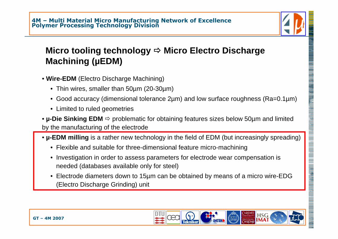
• Wire-EDM (Electro Discharge Machining)
• Thin wires, smaller than 50µm (20-30µm)
• Good accuracy (dimensional tolerance 2µm) and low surface roughness (Ra=0.1µm)
• Limited to ruled geometries
• µ-Die Sinking EDM � problematic for obtaining features sizes below 50µm and limited by the manufacturing of the electrode
• µ-EDM milling is a rather new technology in the field of EDM (but increasingly spreading)
• Flexible and suitable for three-dimensional feature micro-machining
• Investigation in order to assess parameters for electrode wear compensation is needed (databases available only for steel)
• Electrode diameters down to 15µm can be obtained by means of a micro wire-EDG (Electro Discharge Grinding) unit
4M – Multi Material Micro Manufacturing Network of ExcellencePolymer Processing Technology Division
GT – 4M 2007
Micro tooling technology ���� Micro Electrochemical milling (ECF)
• New technology � Electrochemical micro milling• ECF, where F is the German acronym for milling
• Suitable for machining of materials such as:
• Hard materials like stainless steel• Electrochemical active materials
• Feature dimensions below 50µm can be machined
• Very small removal rate (6x10⁻⁶mm3/min)• High resolution in machining
• Suitable to manufacture the finest details in a pre-machined structure

4M – Multi Material Micro Manufacturing Network of ExcellencePolymer Processing Technology Division
GT – 4M 2007
Outline
• Hybrid manufacturing technology project
• Micro tooling manufacturing technologies
• Application of hybrid tooling• Micro fluidic system
• Different process chains
• Metrology benchmark
• Conclusion
4M – Multi Material Micro Manufacturing Network of ExcellencePolymer Processing Technology Division
GT – 4M 2007
Hybrid tooling concept
• Increasing of miniaturization and integration of different micro features � Combination of processes can lead to an accurate manufacturing of micro moulds
• Hybrid tooling ���� “the capability of producing a mould insert combining two or more processes in sequence”• � On the same process chain for tooling

4M – Multi Material Micro Manufacturing Network of ExcellencePolymer Processing Technology Division
GT – 4M 2007
Application of hybrid tooling
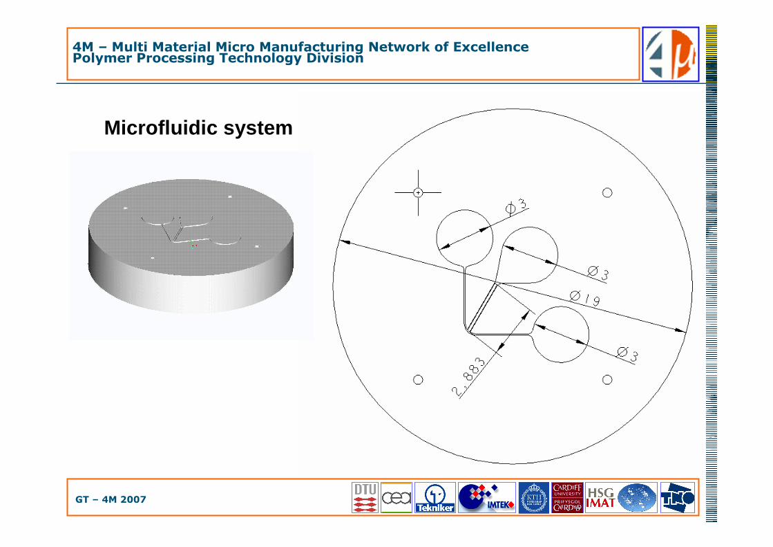
• Choice of design � micro fluidic device• Functionality � blood cells and plasma separation due to the micro channel bend structure
• A. Schoth et al., Separation of blood cells and plasma in microchannel bend structures, Proceedings of SPIE (2004) Vol.5591, pp 143-151
• Critical dimensions and tolerances• Channels 20, 50, 75 µm wide (tolerance ±5 µm)• Radius down to 25 µm (tolerance ±5 µm)
• Depth of 100 µm (tolerance ±5 µm)• Sub-micrometer roughness
• Suitable for micro fluidic applications
• Ra≤100nm
4M – Multi Material Micro Manufacturing Network of ExcellencePolymer Processing Technology Division
GT – 4M 2007
W1 W2
H2H1
D bw 1,2
W bw 1,2
Pos B
Pos A
Pos C
Microfluidic system

4M – Multi Material Micro Manufacturing Network of ExcellencePolymer Processing Technology Division
GT – 4M 2007
Microfluidic system
4M – Multi Material Micro Manufacturing Network of ExcellencePolymer Processing Technology Division
GT – 4M 2007
Outline
• Hybrid manufacturing technology project
• Micro tooling manufacturing technologies
• Application of hybrid tooling• Micro fluidic system
• Different process chains
• Metrology benchmark
• Conclusion

4M – Multi Material Micro Manufacturing Network of ExcellencePolymer Processing Technology Division
GT – 4M 2007
Different hybrid tooling process chains
• µTool_1 = direct tooling with 4 steps micro milling operation
• insert material: Stainless Steel AISI 304
• µTool_2 = direct tooling with 4 steps micro milling operation
• insert material: tool steel EN30B
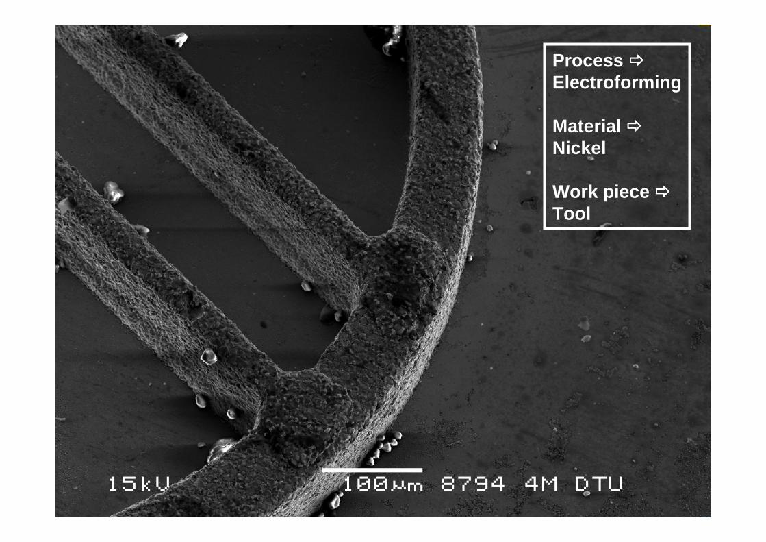
• µTool_3 = indirect hybrid tooling with µEDM milling of silicon, deposition of
nickel-copper by electroforming , selective silicon substrate etching• insert material: nickel with copper substrate
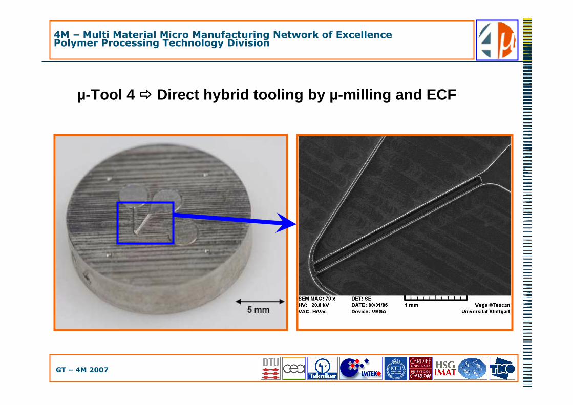
• µTool_4 = direct hybrid tooling with µ-milling and µECF• insert material: Stainless Steel 1.4441
• µTool_5 = direct tooling with 4 steps micro milling operation
• insert material: tool steel EN30B
4M – Multi Material Micro Manufacturing Network of ExcellencePolymer Processing Technology Division
GT – 4M 2007
µ-Tool 1, 2 and 5 ���� Direct tool by micro milling
• Smallest micro mill diameter = 100µm• � Minimum radius = 50µm • Thin wall micro milling strategy had to be applied to:
• Manufacture long (2.88mm) and thin (20µm) ribs• Avoid bending due to cutting forces
4M – Multi Material Micro Manufacturing Network of ExcellencePolymer Processing Technology Division
GT – 4M 2007
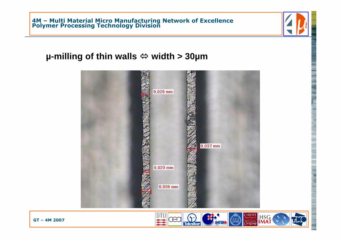
µ-milling of thin walls ���� width > 30µm

4M – Multi Material Micro Manufacturing Network of ExcellencePolymer Processing Technology Division
GT – 4M 2007
µ-milling of thin walls ���� width < 25µm

4M – Multi Material Micro Manufacturing Network of ExcellencePolymer Processing Technology Division
GT – 4M 2007
Micro mould fully conventional milled
1.4301
Milling not possible:
- Radius still too large- Microbars bent due to
cutting forces- burr on top of the structure

Nominal r=25µmµ-milling r=50µm

4M – Multi Material Micro Manufacturing Network of ExcellencePolymer Processing Technology Division
GT – 4M 2007
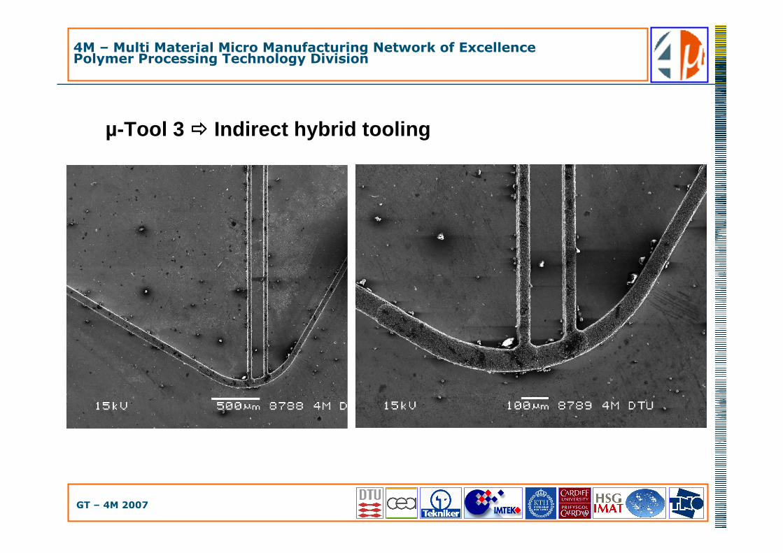
µ-Tool 3 ���� Indirect hybrid tooling
Micro EDM of silicon substrate (master)
Pre-treatments including cleaning and deposition of a thin layer of Ti/Cu by PVD
coating
Electroforming of nickel and copper for the insert fabrication
Selective etching of silicon in a warm alkaline solution
Mechanical machining of the back of the insert and of the external shape
Final cleaning and selective etching of the Ti/Cu layer
3
4
5
6
2
1
4M – Multi Material Micro Manufacturing Network of ExcellencePolymer Processing Technology Division
GT – 4M 2007
µ-Tool 3 ���� Indirect hybrid tooling
4M – Multi Material Micro Manufacturing Network of ExcellencePolymer Processing Technology Division
GT – 4M 2007
Process ����Electroforming
Material ����Nickel
Work piece ����Tool
4M – Multi Material Micro Manufacturing Network of ExcellencePolymer Processing Technology Division
GT – 4M 2007
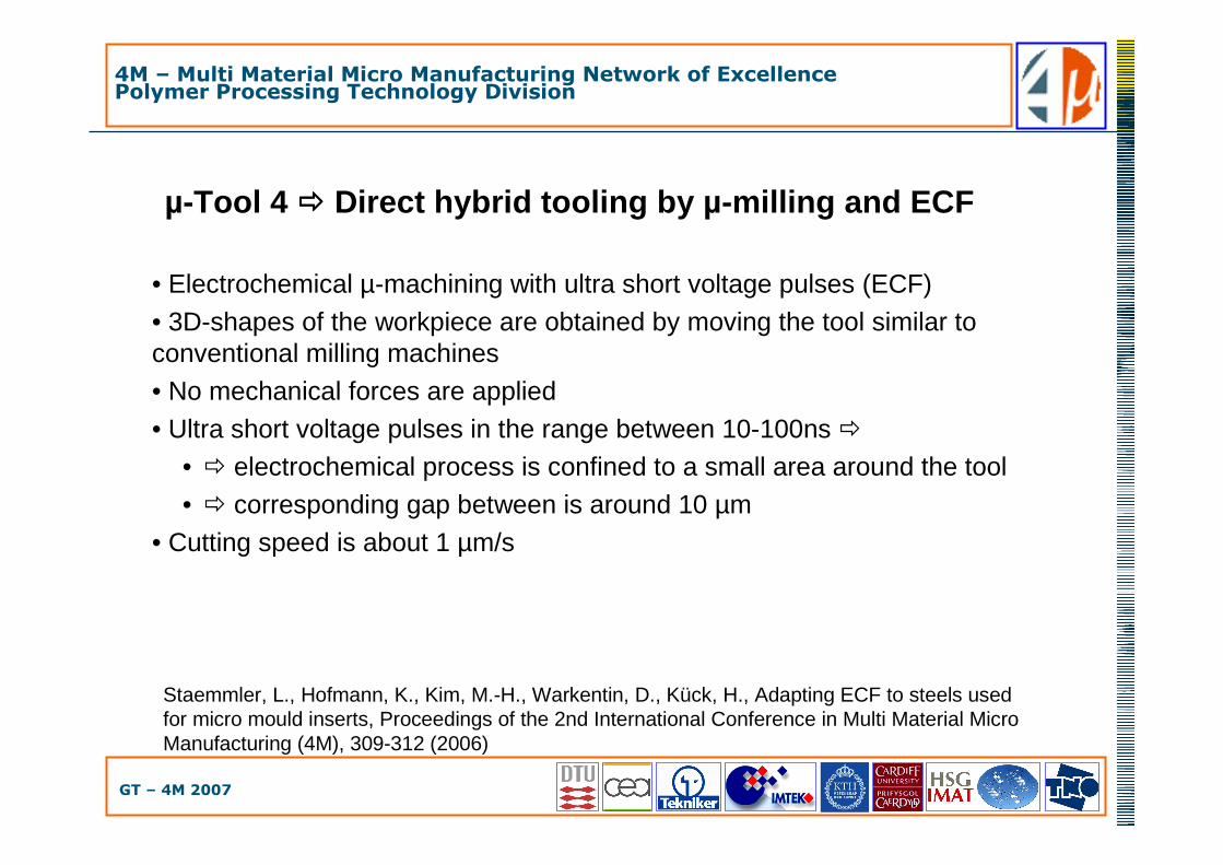
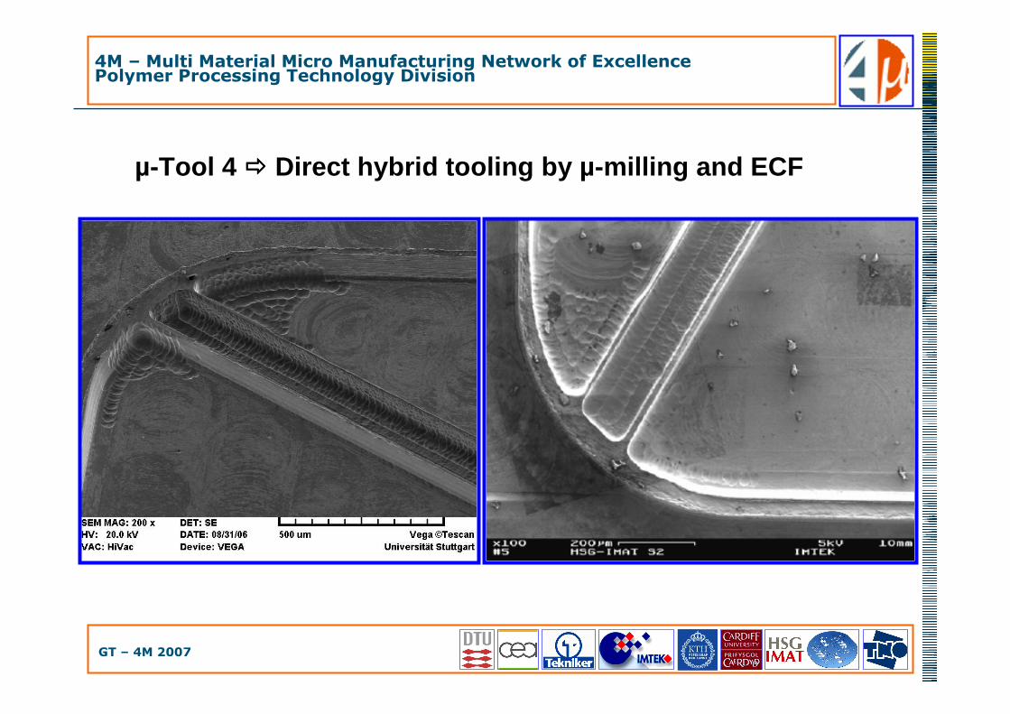
µ-Tool 4 ���� Direct hybrid tooling by µ-milling and ECF
• Electrochemical µ-machining with ultra short voltage pulses (ECF)
• 3D-shapes of the workpiece are obtained by moving the tool similar to conventional milling machines
• No mechanical forces are applied
• Ultra short voltage pulses in the range between 10-100ns �• � electrochemical process is confined to a small area around the tool
• � corresponding gap between is around 10 µm
• Cutting speed is about 1 µm/s
Staemmler, L., Hofmann, K., Kim, M.-H., Warkentin, D., Kück, H., Adapting ECF to steels used for micro mould inserts, Proceedings of the 2nd International Conference in Multi Material Micro Manufacturing (4M), 309-312 (2006)
4M – Multi Material Micro Manufacturing Network of ExcellencePolymer Processing Technology Division
GT – 4M 2007
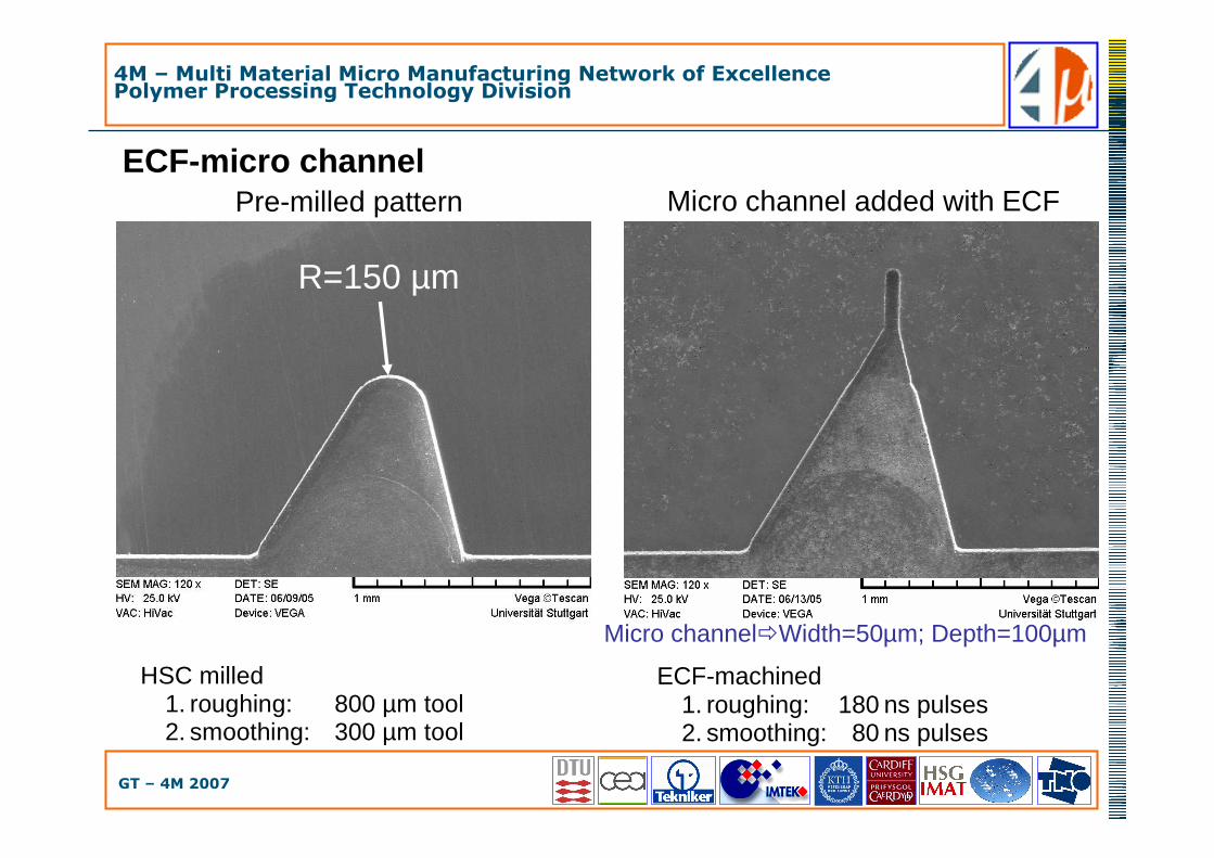
ECF-micro channel
HSC milled 1. roughing: 800 µm tool 2. smoothing: 300 µm tool
R=150 µm
ECF-machined 1. roughing: 180 ns pulses 2. smoothing: 80 ns pulses
Pre-milled pattern Micro channel added with ECF
Micro channel�Width=50µm; Depth=100µm

4M – Multi Material Micro Manufacturing Network of ExcellencePolymer Processing Technology Division
GT – 4M 2007
Micro mould after conventional milling
Pre-milled mould:- Microbars not separated- Radius still large
4M – Multi Material Micro Manufacturing Network of ExcellencePolymer Processing Technology Division
GT – 4M 2007
µ-Tool 4 ���� Direct hybrid tooling by µ-milling and ECF
4M – Multi Material Micro Manufacturing Network of ExcellencePolymer Processing Technology Division
GT – 4M 2007
µ-Tool 4 ���� Direct hybrid tooling by µ-milling and ECF
4M – Multi Material Micro Manufacturing Network of ExcellencePolymer Processing Technology Division
GT – 4M 2007
Outline
• Hybrid manufacturing technology project
• Micro tooling manufacturing technologies
• Application of hybrid tooling• Micro fluidic system
• Different process chains
• Metrology benchmark
• Conclusion

4M – Multi Material Micro Manufacturing Network of ExcellencePolymer Processing Technology Division
GT – 4M 2007
Metrology benchmark
• � Performance evaluation of the different micro tooling technologies
• � Measuring capabilities of the available measuring technologies
• Measuring tasks � DIMENSIONS• Width of the two 20µm ribs (W1, W2)
• Distance between the two 20µm ribs (W bw 1,2)
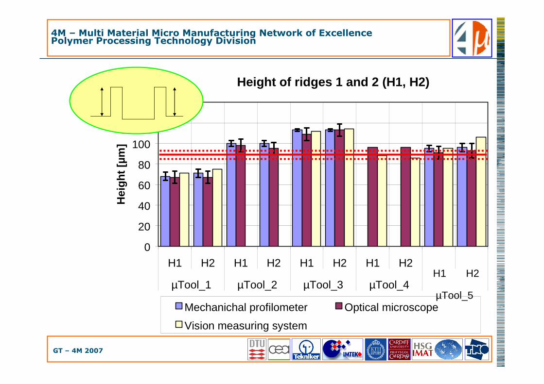
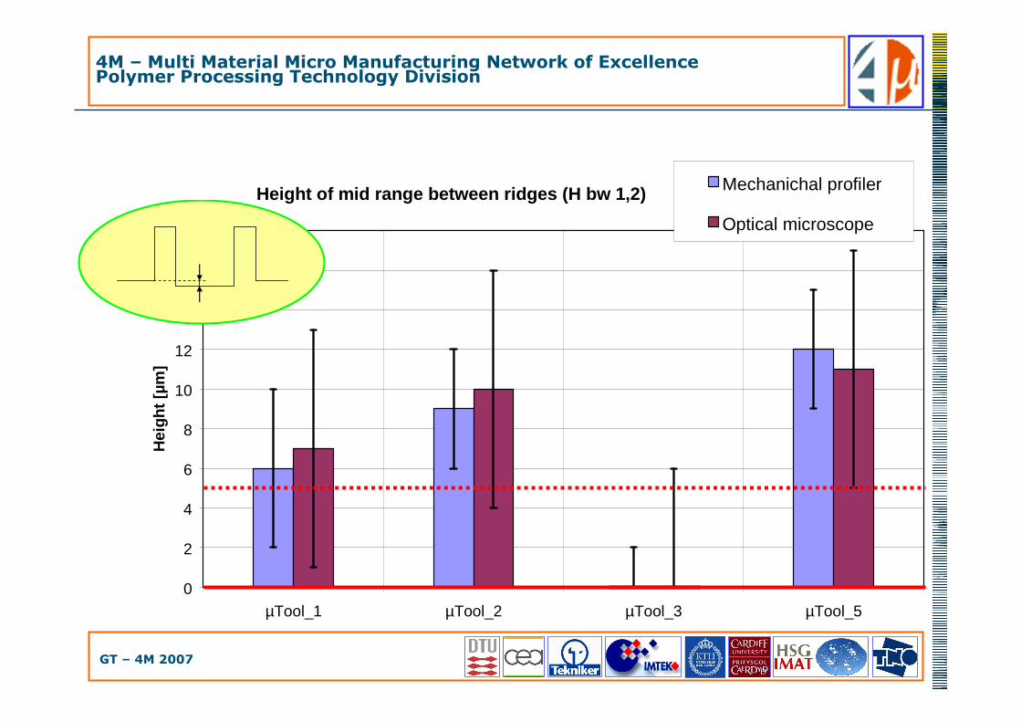
• Height of the two 20µm ribs (H1, H2)• Difference on depth of the middle area between the two 20µm ribs (D bw 1,2)
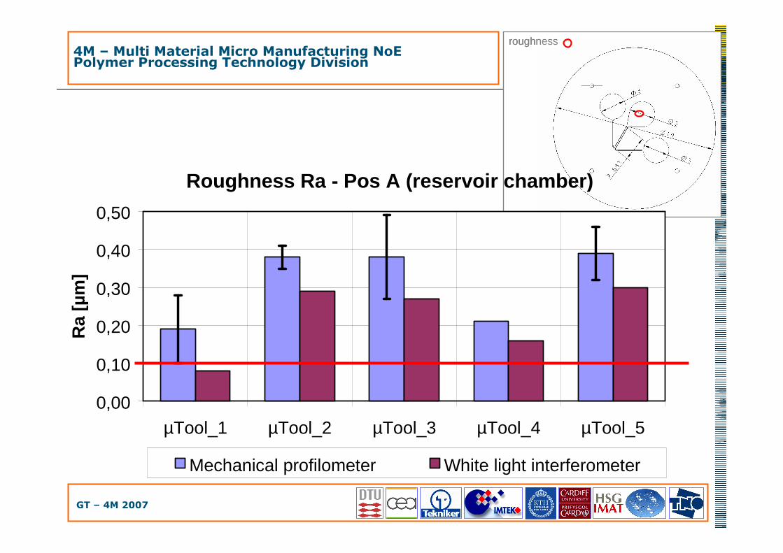
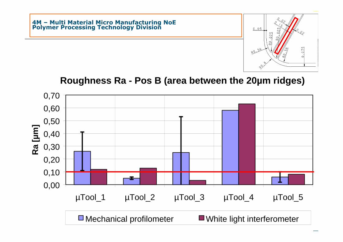
• Measuring tasks � SURFACES• Roughness of the bottom part of reservoir chamber (Ra Pos A)• Roughness of the area between the two 20µm ribs (Ra Pos B)
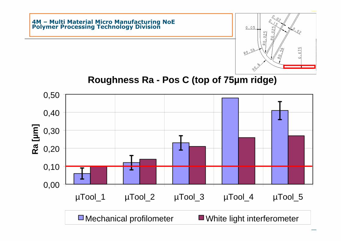
• Roughness of the 75µm wide rib (Ra Pos C)

4M – Multi Material Micro Manufacturing Network of ExcellencePolymer Processing Technology Division
GT – 4M 2007
Width of ridges 1 and 2 (W1, W2)
0
10
20
30
40
50
W1 W2 W1 W2 W1 W2 W1 W2 W1 W2
µTool_1 µTool_2 µTool_3 µTool_4 µTool_5
Wid
th [µ
m]
Mechanichal profilometer Optical microscope 1
Optical microscope 2

4M – Multi Material Micro Manufacturing Network of ExcellencePolymer Processing Technology Division
GT – 4M 2007
Width between ridges (W bw rid1,2)
0
20
40
60
80
100
120
140
160
180
µTool_1 µTool_2 µTool_3 µTool_4 µTool_5
Wid
th [µ
m]
Mechanichal profilometer
Optical microscope
Vision measuring system
4M – Multi Material Micro Manufacturing Network of ExcellencePolymer Processing Technology Division
GT – 4M 2007
Height of ridges 1 and 2 (H1, H2)
0
20
40
60
80
100
120
140
H1 H2 H1 H2 H1 H2 H1 H2
µTool_1 µTool_2 µTool_3 µTool_4
Hei
ght [
µm]
Mechanichal profilometer Optical microscope
Vision measuring system
H1 H2
µTool_5
4M – Multi Material Micro Manufacturing Network of ExcellencePolymer Processing Technology Division
GT – 4M 2007
Height of mid range between ridges (H bw 1,2)
0
2
4
6
8
10
12
14
16
18
µTool_1 µTool_2 µTool_3 µTool_5
Hei
ght [
µm]
Mechanichal profiler
Optical microscope
4M – Multi Material Micro Manufacturing Network of ExcellencePolymer Processing Technology Division
GT – 4M 2007
roughnessroughness
Roughness Ra - Pos A (reservoir chamber)
0,00
0,10
0,20
0,30
0,40
0,50
µTool_1 µTool_2 µTool_3 µTool_4 µTool_5
Ra
[µm
]
Mechanical profilometer White light interferometer
4M – Multi Material Micro Manufacturing NoEPolymer Processing Technology Division
4M – Multi Material Micro Manufacturing Network of ExcellencePolymer Processing Technology Division
GT – 4M 2007
Roughness Ra - Pos B (area between the 20µm ridges)
0,00
0,10
0,20
0,30
0,40
0,50
0,60
0,70
µTool_1 µTool_2 µTool_3 µTool_4 µTool_5
Ra
[µm
]
Mechanical profilometer White light interferometer
4M – Multi Material Micro Manufacturing NoEPolymer Processing Technology Division
4M – Multi Material Micro Manufacturing Network of ExcellencePolymer Processing Technology Division
GT – 4M 2007
Roughness Ra - Pos C (top of 75µm ridge)
0,00
0,10
0,20
0,30
0,40
0,50
µTool_1 µTool_2 µTool_3 µTool_4 µTool_5
Ra
[µm
]
Mechanical profilometer White light interferometer
4M – Multi Material Micro Manufacturing NoEPolymer Processing Technology Division

4M – Multi Material Micro Manufacturing Network of ExcellencePolymer Processing Technology Division
GT – 4M 2007
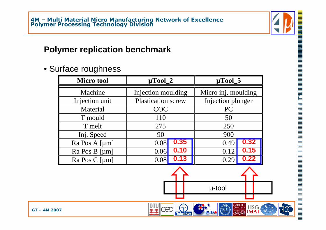
Polymer replication benchmark
• DimensionsMicro tool µTool_2 µTool_3
Machine Injection moulding Injection moulding Injection unit Plastication screw Plastication screw
Material PP+nano filler PP T mould 60 55 T melt 190 220
Inj. Speed 100 150 W1 [µm] 27 34 W2 [µm] 35 34
W bw 1,2 [µm] 135 136
2833138
3433138
µ-tool
4M – Multi Material Micro Manufacturing Network of ExcellencePolymer Processing Technology Division
GT – 4M 2007
Micro tool µTool_2 µTool_5
Machine Injection moulding Micro inj. moulding Injection unit Plastication screw Injection plunger
Material COC PC T mould 110 50 T melt 275 250
Inj. Speed 90 900 Ra Pos A [µm] 0.08 0.49 Ra Pos B [µm] 0.06 0.12 Ra Pos C [µm] 0.08 0.29
0.350.100.13
0.320.150.22
µ-tool
Polymer replication benchmark
• Surface roughness

4M – Multi Material Micro Manufacturing Network of ExcellencePolymer Processing Technology Division
GT – 4M 2007
µ-tool manufactured by direct tooling (µ-milling)
µ-tool manufactured by indirect hybrid tooling (µEDM and electroforming)
Comparison of replicas

4M – Multi Material Micro Manufacturing Network of ExcellencePolymer Processing Technology Division
GT – 4M 2007
Outline
• Hybrid manufacturing technology project
• Micro tooling manufacturing technologies
• Application of hybrid tooling• Micro fluidic system
• Different process chains
• Metrology benchmark
• Conclusion
4M – Multi Material Micro Manufacturing Network of ExcellencePolymer Processing Technology Division
GT – 4M 2007
Conclusion ���� micro tooling
• Direct tooling and hybrid tooling process chains for micro mold manufacturing have been presented• µ-milling
• Conventional and established technology
• Issues regarding minimum obtainable feature size
• Hybrid tooling• Optimization still needed
• Opens to smaller feature sizes

4M – Multi Material Micro Manufacturing Network of ExcellencePolymer Processing Technology Division
GT – 4M 2007
Conclusion ���� metrology
• DIMENSIONAL MEASUREMENTS• Good agreement between measurements with different instruments• key point � uncertainty budget• Issue � still poor rate between tolerance and measurement
uncertainty• � golden rule of metrology = uncertainty/tolerance = 1/10 ÷ 1/20
• Good agreement between tool and replicated parts
• SURFACE ROUGHNESS MEASUREMENTS• Qualitatively valid• Quantitatively not reliable, especially regarding comparison between
different instruments, critical when using optical instruments• Uncertainty budget not standardized yet for micro part and 3D
roughness
4M – Multi Material Micro Manufacturing Network of ExcellencePolymer Processing Technology Division
GT – 4M 2007
Outlook
• Micro tooling �
• Process optimization for higher correspondence to specificationsrequirements, accuracy and repeatability
• Metrology �
• Uncertainty when compared to tolerances
• Standardization (uncertainty assessment, measuring strategy)• On-line quality control of polymer micro parts

4M – Multi Material Micro Manufacturing Network of ExcellencePolymer Processing Technology Division
GT – 4M 2007
Acknowledgments
• Dr. B. Fillon – CEA, France• Dr. S. Azcarate – TEKNIKER, Spain• Dr. A. Schoth – IMTEK, Germany• Prof. L. Mattsson – KTH, Sweden• PhD candidate C. Griffiths – MEC, UK• Dr. L. Staemmler – HSG-IMAT, Germany• Dr. P.J. Bolt – TNO, The Nederlands• All the colleagues from the Polymer Division of 4M

4M – Multi Material Micro Manufacturing Network of ExcellencePolymer Processing Technology Division
GT – 4M 2007
Thank you for your kind attention
http://www.4m-net.org