application of hpc-cfd for industrial problems on the k
TRANSCRIPT
RIKEN CENTER FOR COMPUTATIONAL SCIENCE 1
Makoto TSUBOKURA
Team Leader of the Complex Phenomena Unified Simulation, RIKEN Center for Computational Science
Professor, Kobe University
The 2nd R-CCS International Symposium
February 17th, 2020
Application of HPC-CFD for Industrial Problems on the K Computer and toward Fugaku

Backgrounds and Motivations
How HPC can change the industrial CFD?
High-resolution turbulence simulation
Higher time resolution realizing the unsteady simulation, capturing the transient phenomena.
Higher spatial resolution realizing the highly accurate simulation, independent on turbulence modeling.
Coupled analysis realizing real-world simulation
Application of CFD to what conventional experiments are difficult to treat.
Coupling simulation of fluid motion with other physics such as structure deformation/vibration, heat and mass transfer, or aero-acoustics.
Big data analysis
Optimization, Machine/Deep learning based on AI technique.
RANS LES
2
Backgrounds and Motivations
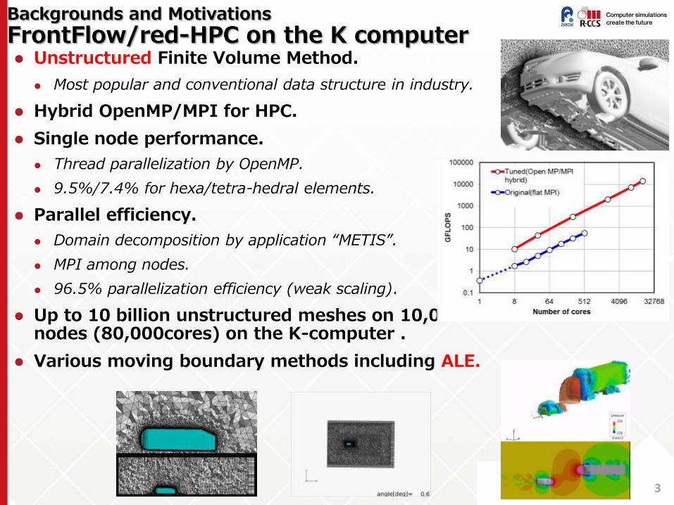
FrontFlow/red-HPC on the K computer Unstructured Finite Volume Method.
Most popular and conventional data structure in industry.
Hybrid OpenMP/MPI for HPC.
Single node performance.
Thread parallelization by OpenMP.
9.5%/7.4% for hexa/tetra-hedral elements.
Parallel efficiency.
Domain decomposition by application “METIS”.
MPI among nodes.
96.5% parallelization efficiency (weak scaling).
Up to 10 billion unstructured meshes on 10,000 nodes (80,000cores) on the K-computer .
Various moving boundary methods including ALE.
3
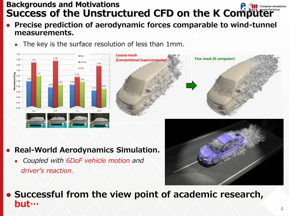
Precise prediction of aerodynamic forces comparable to wind-tunnel measurements.
The key is the surface resolution of less than 1mm.
Real-World Aerodynamics Simulation.
Coupled with 6DoF vehicle motion and
driver’s reaction.
Successful from the view point of academic research, but…
Backgrounds and Motivations
Success of the Unstructured CFD on the K Computer
4
Coarse mesh (Conventional Supercomputer) Fine mesh (K computer)
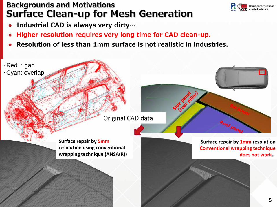
Industrial CAD is always very dirty…
Higher resolution requires very long time for CAD clean-up.
Resolution of less than 1mm surface is not realistic in industries.
Backgrounds and Motivations
Surface Clean-up for Mesh Generation
Surface repair by 5mm resolution using conventional wrapping technique (ANSA(R))
Original CAD data
Surface repair by 1mm resolution Conventional wrapping technique
does not work…
5
・Red : gap
・Cyan: overlap

Numerical Methods
CUBE: Building Cube Method for Unified Simulation
Hierarchically structured Finite Volume Method
A solver for coupled phenomena: fluid/structure/acoustics/chemical reaction…
Building Cube Method for the unified data structure (Nakahashi et al., 2003)
Easy tune for both single node and parallel performance
Immersed Boundary Method (Fadlun et al., 2002)
(1) Dirty CAD treatment (Onishi et al., 2013)
(2) Moving Boundary Method (Bale et al., 2016)
(3) Unified Compressible/Incompressible analysis (Li)
(4) Unified Fluid/Structure analysis (Nishiguchi)
Cube Cell
Unstructured SAE 2014-01-0621
Structured(Cartesian) SAE 2014-01-0580 Domain decomposition by different size of cubes
Allocation of meshes for each cube
6
Numerical Methods
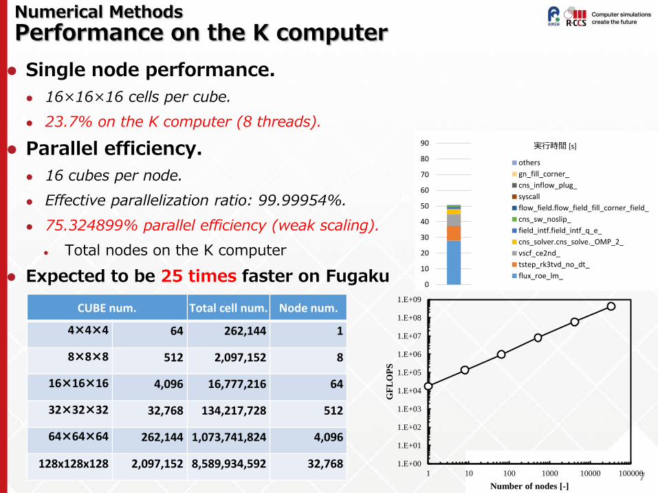
Performance on the K computer
Single node performance.
16×16×16 cells per cube.
23.7% on the K computer (8 threads).
Parallel efficiency.
16 cubes per node.
Effective parallelization ratio: 99.99954%.
75.324899% parallel efficiency (weak scaling).
Total nodes on the K computer
Expected to be 25 times faster on Fugaku
7
CUBE num. Total cell num. Node num.
4×4×4 64 262,144 1
8×8×8 512 2,097,152 8
16×16×16 4,096 16,777,216 64
32×32×32 32,768 134,217,728 512
64×64×64 262,144 1,073,741,824 4,096
128x128x128 2,097,152 8,589,934,592 32,768 1.E+00
1.E+01
1.E+02
1.E+03
1.E+04
1.E+05
1.E+06
1.E+07
1.E+08
1.E+09
1 10 100 1000 10000 100000
GF
LO
PS
Number of nodes [-]
0
10
20
30
40
50
60
70
80
90 実行時間 [s]
others
gn_fill_corner_
cns_inflow_plug_
syscall
flow_field.flow_field_fill_corner_field_
cns_sw_noslip_
field_intf.field_intf_q_e_
cns_solver.cns_solve._OMP_2_
vscf_ce2nd_
tstep_rk3tvd_no_dt_
flux_roe_lm_
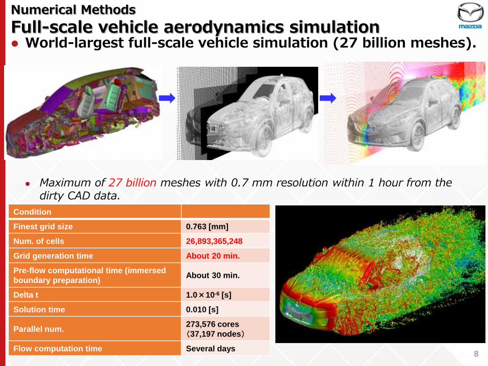
World-largest full-scale vehicle simulation (27 billion meshes).
Maximum of 27 billion meshes with 0.7 mm resolution within 1 hour from the
dirty CAD data.
Numerical Methods
Full-scale vehicle aerodynamics simulation
Condition
Finest grid size 0.763 [mm]
Num. of cells 26,893,365,248
Grid generation time About 20 min.
Pre-flow computational time (immersed
boundary preparation) About 30 min.
Delta t 1.0×10⁻⁶ [s]
Solution time 0.010 [s]
Parallel num. 273,576 cores
(37,197 nodes)
Flow computation time Several days 8

Capacity Computing for Shape Optimization
Multi-Objective Shape Optimization
10
4 objectives (0° and -3° yaws) Drag and Lift at 0 yaw Delta Drag (difference bet. 0 and -3) Delta Lift (difference bet. 0 and -3) Smaller is better for all four variables
8 design parameters Multi-objective Genetic Algorithm
18 models for each generation
Shape parameters (Design variables)
Text
Geometry STL format
Aerodynamic characteristics (Objective function) Text

Capacity Computing for Shape Optimization
Results of multi-objective shape optimization
10
• Genetic Optimization until 12th generations. • Tradeoff between some objective functions
such as Cd and DCd.
CD
ΔCD
CL
ΔCD
CL
ΔCL

Grid size 0.2 mm/1.6mm
Cube num. 471,059
Cell num. 1,929,457,664
Core num. 13086x8 / 50 hrs Cell
Real-World Simulation
Narrow band noise from a full-scale vehicle
11
Acoustic feedback noise generated at a small gap.
Very peaky and uncomfortable… For the prediction, full coupling
simulation of flow and acoustics is needed.

Real-World Simulation
Coupled Aerodynamics, Vehicle Motion and Driver’s Reaction Simulation
• HPC-CFD for flow around a vehicle (Aerodynamics)
• Multi-Body vehicle motion analysis (6DoF body motion with suspension and steering)
• Autonomous Vehicle Motion by a Driver’s steering wheel, accelerator/braking actions
• Lane changing motion at 100km/h

Toward FUGAKU
Coupling Data Science and HPC-CFD for Innovative CAE
Innovative Industrial CAE Solution by a Fusion of Data Science and High-Performance Computing Simulation
Machine/Deep Learning, Data Assimilation, Multi-Objective Optimization…
Surrogate Model: Realizing real time evaluation of aerodynamic performance such as drag and lift force.
Reduction Model: Realizing complicated real world simulation and reproducing flow field at lower cost.
Neural Network
Co-operation design Multi-objective optimization
Virtual on-road test Training AI for automatic driving
Real Time Performance Prediction
Surrogate Model Reduction Model by Proper-Orthogonal Decomposition
Digital Twin Physical Space Cyber Space
0
1
2
3
4
5
空気抵抗 操縦安定性 横風安定性
14
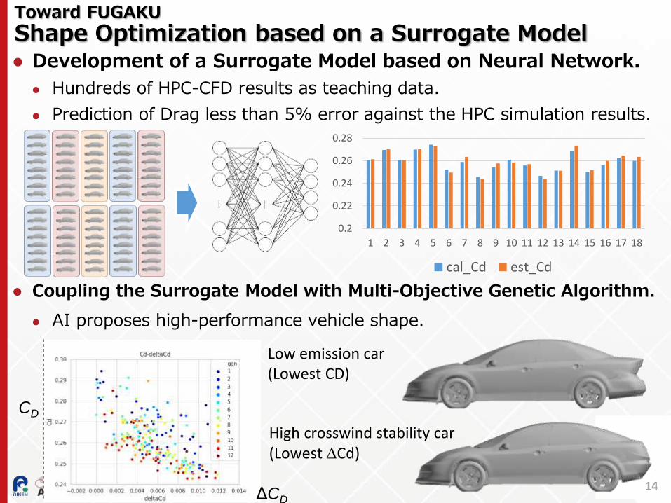
Development of a Surrogate Model based on Neural Network.
Hundreds of HPC-CFD results as teaching data.
Prediction of Drag less than 5% error against the HPC simulation results.
Coupling the Surrogate Model with Multi-Objective Genetic Algorithm.
AI proposes high-performance vehicle shape.
Toward FUGAKU
Shape Optimization based on a Surrogate Model
CD
ΔCD
Low emission car (Lowest CD)
High crosswind stability car (Lowest DCd)
0.2
0.22
0.24
0.26
0.28
1 2 3 4 5 6 7 8 9 10 11 12 13 14 15 16 17 18
cal_Cd est_Cd

15
Reduced order model by Proper-Orthogonal Decomposition. Full flow simulation results are projected on
the reduced base functions.
The base functions are obtained by Neural Network(Murata).
Toward FUGAKU
Reduction Model of the Navier-Stokes Simulation
10,000 samples 2,000 epochs
L2 Norm (Time averaged) Full-NS simulation
𝑎1 𝑡 𝝋1(𝒙)
𝑎2(𝑡)𝝋2(𝒙)
𝑎3(𝑡)𝝋3(𝒙)
𝑎5(𝑡)𝝋5(𝒙)
𝑎0 𝑡 𝝋0(𝒙)
Reduction by MD-CNN-AE
ℱ𝑑𝑒𝑐1 𝑥 = 𝝋1𝑥
ℱ𝑑𝑒𝑐2 𝑥 = 𝝋2𝑥 𝑷𝒙 = 𝝋𝑘𝝋𝑘𝑇𝒙
2
𝑘=1 ℱ𝑒𝑛𝑐 𝒙 =
𝝋1𝑇𝒙
𝝋2𝑇𝒙
Inner product Scaling Summation

Concluding Remarks CFD use in industries are conservative, which is just an
alternative to conventional experiments, so far…
HPC expands the possibility of CFD by exceeding their accuracy and applying to real-world problems, while data structure is the key to massively utilize HPC environment.
Hierarchically structured data realized very fast and real-world aerodynamics simulation on the K computer.
Coupling data science and HPC simulation will create next-generation Computer-Aided Engineering on FUGAKU.
Surrogate model for real time evaluation.
Reduction model for real world simulation.
16
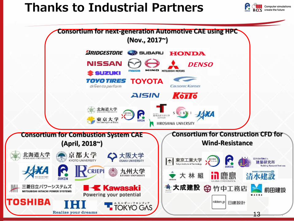
Consortium for Construction CFD for Wind-Resistance
Consortium for next-generation Automotive CAE using HPC
(Nov., 2017~)
Thanks to Industrial Partners
Consortium for Combustion System CAE
(April, 2018~)
13