application of ltspice modeling to vishay temperature sensors · vishay bccomponents non-linear...
TRANSCRIPT

V I S H A Y B C C O M P O N E N T S
Non-Linear Resistors Application Note
Application of LTSpice Modeling to Vishay Temperature Sensors
www.vishay.com
AP
PL
ICA
TIO
N N
OT
E
Revision: 10-Aug-16 1 Document Number: 29170For technical questions, contact: [email protected]
THIS DOCUMENT IS SUBJECT TO CHANGE WITHOUT NOTICE. THE PRODUCTS DESCRIBED HEREIN AND THIS DOCUMENTARE SUBJECT TO SPECIFIC DISCLAIMERS, SET FORTH AT www.vishay.com/doc?91000
By Alain Stas
1. INTRODUCTIONNTC thermistors and thin film PTC RTDs have temperature-dependent characteristics that are in essence not linear, even if the level of linearity is higher for RTDs than for NTC thermistors. The simple SPICE resistor model cannot be applied to those devices; even the PSpice resistor model with the possibility of defining two intrinsic temperature coefficients is not sufficient.With SPICE modeling of electronic circuits becoming preponderant in the industry, it is necessary to have accurate models of temperature sensors in order to allow such simulation. PSpice models for NTC thermistors have been widely available from several suppliers, and for some time now these models have been available as downloads from Vishay’s website. Even if these PSpice models simulate the components with great accuracy, however, there is still one important limitation: the lack of compatibility between a temperature sweep on a continuous range and a statistical Monte Carlo analysis. This is very important, for example, at the final testing level in automotive applications.In LTSpice modeling, it is possible to simulate the Monte Carlo statistical response of a potential thermistor divider as a function of the embedded TEMP variable (see Fig. 1).
2. THE LTSPICE MODELSLTSpice modeling is based principally on the netlists derived from PSpice modeling, with some important practical changes:• The initial condition .IC of the capacitor simulating the
thermal mass of the thermistors is now adapted specifically to LTSpice syntax
• The LT Monte Carlo of random probability distribution (LTSpice MC) has been introduced explicitly in the models
• For experienced users, it will be possible to modify the flexible netlists in order to adopt other statistical distribution than random (Gauss or else)
• For each type of component included in a circuit, the particular P/N can be changed by right clicking on it and modifying “Value” in the component attribute editor
Note• The models can be downloaded at www.vishay.com/doc?29171
Fig. 1
The new models for Vishay thermistors and RTDs adapted to the free LTSpice IV simulator are thus useful complements to present modeling. This is the subject of this application note.

Application of LTSpice Modeling to Vishay Temperature Sensors
Application Notewww.vishay.com Vishay BCcomponents
AP
PL
ICA
TIO
N N
OT
E
Revision: 10-Aug-16 2 Document Number: 29170For technical questions, contact: [email protected]
THIS DOCUMENT IS SUBJECT TO CHANGE WITHOUT NOTICE. THE PRODUCTS DESCRIBED HEREIN AND THIS DOCUMENTARE SUBJECT TO SPECIFIC DISCLAIMERS, SET FORTH AT www.vishay.com/doc?91000
Symbol for an NTC Thermistor
“TR” (tolerance on R25 in %) and “TB” (tolerance on B25/85 in %)
Symbol for a TFPT RTD
“TOL25” (tolerance on R25 in %) and “TOLslope” (normally 1)
Symbol for a PTS
Identical to TFPT, with two parameters: “tol0” (tolerance in °C at 0 °C) and “TolS” (tolerance on the slope in °C / °C)

Application of LTSpice Modeling to Vishay Temperature Sensors
Application Notewww.vishay.com Vishay BCcomponents
AP
PL
ICA
TIO
N N
OT
E
Revision: 10-Aug-16 3 Document Number: 29170For technical questions, contact: [email protected]
THIS DOCUMENT IS SUBJECT TO CHANGE WITHOUT NOTICE. THE PRODUCTS DESCRIBED HEREIN AND THIS DOCUMENTARE SUBJECT TO SPECIFIC DISCLAIMERS, SET FORTH AT www.vishay.com/doc?91000
3. RESISTANCE TEMPERATURE OF AN NTC THERMISTOR (MONTE CARLO ANALYSIS)
Fig. 2
The simulation pane in Fig. 3 represents the electrical resistance vs temperature for two 10 k models - an SMD NTCS0805 (red) and a leaded NTCLE203 (blue) - with two different B values (Fig. 2). The tolerances on R25 and B25/85 are “TR” and “TB,” respectively. 300 runs have been performed. Note the different percent tolerances on “TR” and “TB” (wide for the red NTCS0805 curve, and small for the blue NTCLE203).
Fig. 3

Application of LTSpice Modeling to Vishay Temperature Sensors
Application Notewww.vishay.com Vishay BCcomponents
AP
PL
ICA
TIO
N N
OT
E
Revision: 10-Aug-16 4 Document Number: 29170For technical questions, contact: [email protected]
THIS DOCUMENT IS SUBJECT TO CHANGE WITHOUT NOTICE. THE PRODUCTS DESCRIBED HEREIN AND THIS DOCUMENTARE SUBJECT TO SPECIFIC DISCLAIMERS, SET FORTH AT www.vishay.com/doc?91000
4. VOLTAGE-CURRENT RELATION FOR AN NTCWe can also compute the voltage-current relation at different ambient temperatures with the following SPICE directive (Fig. 4). Three components of the NTCS0805 type are tested with R25 = 10 k, but different B values (low B in red, medium B in green, and high B in blue).
Fig. 4
The simulation result is reprinted in Fig. 4 (low B in blue, medium B in red, and high B in green).
Fig. 5

Application of LTSpice Modeling to Vishay Temperature Sensors
Application Notewww.vishay.com Vishay BCcomponents
AP
PL
ICA
TIO
N N
OT
E
Revision: 10-Aug-16 5 Document Number: 29170For technical questions, contact: [email protected]
THIS DOCUMENT IS SUBJECT TO CHANGE WITHOUT NOTICE. THE PRODUCTS DESCRIBED HEREIN AND THIS DOCUMENTARE SUBJECT TO SPECIFIC DISCLAIMERS, SET FORTH AT www.vishay.com/doc?91000
5. ACCURACY SIMULATION OF RTDs (MONTE CARLO)
5.1. TFPT Thin Film PTC Resistors
Fig. 6 uses the same type of simulation as previously used, and provides the R-T characteristics of a 1 k TFPT1206L1002 with two parameters: TOL R25 = 1 % and TOLSLOPE, which can be tuned between 0 (no tolerance on slope / ratio) and 1 (100 % of the tolerance on slope / ratio of ratio tolerances table is covered). In this simulation, TOLSLOPE is set at 1).
Fig. 6
Extracting these results in Excel and measuring the shift with respect to the nominal curve, we get the graph shown in Fig. 6 (only 100 curves are presented). We have also reprinted the maximum and minimum curves derived from the specification table below (ratio tolerances). We see that the simulation results cover the range between the minimum and maximum specifications. At 25 °C all the computed values are more or less equally distributed within the 1 % range, and at lower or higher percentages we see the limited effect of the combination of two random distributions.

Application of LTSpice Modeling to Vishay Temperature Sensors
Application Notewww.vishay.com Vishay BCcomponents
AP
PL
ICA
TIO
N N
OT
E
Revision: 10-Aug-16 6 Document Number: 29170For technical questions, contact: [email protected]
THIS DOCUMENT IS SUBJECT TO CHANGE WITHOUT NOTICE. THE PRODUCTS DESCRIBED HEREIN AND THIS DOCUMENTARE SUBJECT TO SPECIFIC DISCLAIMERS, SET FORTH AT www.vishay.com/doc?91000
Fig. 7 - Monte Carlo Analysis for TFPT R/R vs. Temperature
RATIO TOLERANCE EXAMPLESAt 40 °C, ratio = 1.063 ± 0.5 % (0.005)so, ratio = 1.058 to 1.068
At 125 °C, ratio = 1.460 ± 3 % (0.044)so, ratio = 1.416 to 1.504
5.2. PTS Platinum Thin Film Resistors
Connecting a 1 k PTS1206 to a voltage source of +0.1 V (Fig. 8), we compute 100 runs and represent the resistance as a function of the temperature, letting the electrical parameters randomly cover their tolerances. These tolerances are defined with the parameters “TOL0” (the temperature tolerance at 0 °C, here 0.6 °C) and “TOLS” (the tolerance on the slope, here 0.01 °C / °C).
-6
-5
-4
-3
-2
-1
0
1
2
3
4
5
6
-75 -50 -25 0 25 50 75 100 125 150 175
ΔR/R
(%)
Temperature (°C)
Maximum specification
Minimum specification
RATIO TOLERANCESLOW TEMP. HIGH TEMP. TOL.
-65 °C +150 °C ± 4 %
-40 °C +125 °C ± 3 %
-20 °C +85 °C ± 2 %
0 °C +55 °C ± 1 %
+12 °C +40 °C ± 0.5 %

Application of LTSpice Modeling to Vishay Temperature Sensors
Application Notewww.vishay.com Vishay BCcomponents
AP
PL
ICA
TIO
N N
OT
E
Revision: 10-Aug-16 7 Document Number: 29170For technical questions, contact: [email protected]
THIS DOCUMENT IS SUBJECT TO CHANGE WITHOUT NOTICE. THE PRODUCTS DESCRIBED HEREIN AND THIS DOCUMENTARE SUBJECT TO SPECIFIC DISCLAIMERS, SET FORTH AT www.vishay.com/doc?91000
Fig. 8
Extracting the results in Excel and computing the delta T corresponding to the R-T curves, we obtain the graphs in Fig. 9. With the Monte Carlo analysis, we well cover the whole specification of this PTS F0.6 with a maximum / minimum T = (0.6 + 0.01 abs (T)).
Fig. 9 - Temperature Accuracy of PTS F0.6
-3
-2
-1
0
1
2
3
-60 -40 -20 0 20 40 60 80 100 120 140 160 180
ΔT (K
)
Temperature (°C)
Maximumspecification
Minimumspecification

Application of LTSpice Modeling to Vishay Temperature Sensors
Application Notewww.vishay.com Vishay BCcomponents
AP
PL
ICA
TIO
N N
OT
E
Revision: 10-Aug-16 8 Document Number: 29170For technical questions, contact: [email protected]
THIS DOCUMENT IS SUBJECT TO CHANGE WITHOUT NOTICE. THE PRODUCTS DESCRIBED HEREIN AND THIS DOCUMENTARE SUBJECT TO SPECIFIC DISCLAIMERS, SET FORTH AT www.vishay.com/doc?91000
6. POSSIBLE MODIFICATION OF PROBABILITY DISTRIBUTIONSThe available Monte Carlo function MC(x, tolx) sweeps the x variable into the range x(1 - tolx) until x(1 + tolx) in a random way.It is possible to replace this function by a user-defined function of another type.
For example MCG(x, tolx) = if (run = 1, x, x * (1 + gauss (tolx/4))).
The first run will simulate the nominal case; the remaining runs will simulate a Gaussian normal distribution around the nominal with a standard deviation of a fourth of the tolerance.
We have applied this modification to the TFPT (cf point 5.1). In the netlist of the TFPT model, the function MC(x, tolx) must be replaced by MCG(x,tolx). The MCG function must be defined as a SPICE directive as shown below.
We now measure the electrical resistance distribution at 155 °C with the LTSpice directive .MEAS. The comparison of the distributions (random and Gaussian) can be seen in Fig. 10.
Fig. 10
A second trial can be done (this time on NTCs) building a probability distribution R25, assuming that an initial random distribution between -5 % and +5 % has been truncated between -1 % and +1 %, leaving two distributions: random between -5 % and -1 %, thus -3 % ± 2 %, and another between +1 % and +5 %, thus +3 % ± 2 %). For the tolerance on B, we hold a MCG function of the Gaussian type.
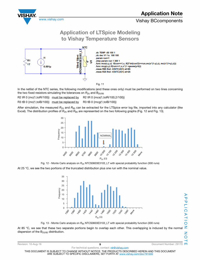
The SPICE directive presented in Fig. 11 introduces
• A new MCS(x, y, z) function. For the first run, the value is nominal. If the simulation run is even, the density will be centered on -3 %, and for an uneven simulation run, centered on +3 %
• MCG: Monte Carlo Gaussian
• A measurement R25 and R85
0102030405060708090
100
Freq
uenc
y
R155 (Ω)
Comparison of Histogram MC (Orange) and MCG (Blue)
15 3
0015
450
15 6
0015
750
15 9
0016
050
16 2
0016
350
16 5
0016
650
16 8
0016
950
17 1
00M
ore
Application of LTSpice Modeling to Vishay Temperature Sensors
Application Notewww.vishay.com Vishay BCcomponents
AP
PL
ICA
TIO
N N
OT
E
Revision: 10-Aug-16 9 Document Number: 29170For technical questions, contact: [email protected]
THIS DOCUMENT IS SUBJECT TO CHANGE WITHOUT NOTICE. THE PRODUCTS DESCRIBED HEREIN AND THIS DOCUMENTARE SUBJECT TO SPECIFIC DISCLAIMERS, SET FORTH AT www.vishay.com/doc?91000
Fig. 11
In the netlist of the NTC series, the following modifications (and these ones only) must be performed on two lines concerning the two fixed resistors simulating the tolerances on R25 and B25/85
R2 tR 0 {mc(1,tolR/100)} must be replaced by R2 tR 0 {mcs(1,tolR/100,2/100)}
R3 tB 0 {mc(1,tolB/100)} must be replaced by R3 tB 0 {mcg(1,tolB/100)}
After simulation, the measured R25 and R85 can be extracted for the LTSpice error log file, imported into any calculator (like Excel). The distribution profiles of R25 and R85 are represented on the two following graphs (Fig. 12 and Fig. 13).
Fig. 12 - Monte Carlo analysis on R25 NTCS0603E3103_LT with special probability function (300 runs)
At 25 °C, we see the two portions of the truncated distribution plus one run with the nominal value.
Fig. 13 - Monte Carlo analysis on R85 NTCS0603E3103_LT with special probability function (300 runs)
At 85 °C, we see that these two separate portions begin to overlap each other. This overlapping is induced by the normal dispersion of the B25/85 distribution.
0
5
10
15
20
25
30
Freq
uenc
y
NOMINAL
R25 (Ω)
9400
9500
9600
9700
9800
9900
10 0
0010
100
10 2
0010
300
10 4
0010
500
Mor
e
0
5
10
15
20
25
30
35
Freq
uenc
y
R85 (Ω)
1360
1380
1400
1420
1440
1460
1480
1500
1520
1560
Mor
e
1540

Application of LTSpice Modeling to Vishay Temperature Sensors
Application Notewww.vishay.com Vishay BCcomponents
AP
PL
ICA
TIO
N N
OT
E
Revision: 10-Aug-16 10 Document Number: 29170For technical questions, contact: [email protected]
THIS DOCUMENT IS SUBJECT TO CHANGE WITHOUT NOTICE. THE PRODUCTS DESCRIBED HEREIN AND THIS DOCUMENTARE SUBJECT TO SPECIFIC DISCLAIMERS, SET FORTH AT www.vishay.com/doc?91000
7. SIMPLE VOLTAGE DIVIDER WITH AN NTC THERMISTORWith new modeling, it is now possible to perform a statistical analysis of the voltage response of a thermistor in a circuit where all the elements have a tolerance: the voltage source, the fixed resistors, and of course the thermistor (here the standard models with random MC function have been used). The thermal voltage provided by the thermistor is reprinted in Fig. 14 (1000 runs).
Fig. 14
The statistical measurement of the temperature at which the voltage reaches 0.675 V (recorded on LTSpice error log file for the 1000 runs) is plotted in Fig. 15, with values going from 97.3 °C to 105 °C.

Application of LTSpice Modeling to Vishay Temperature Sensors
Application Notewww.vishay.com Vishay BCcomponents
AP
PL
ICA
TIO
N N
OT
E
Revision: 10-Aug-16 11 Document Number: 29170For technical questions, contact: [email protected]
THIS DOCUMENT IS SUBJECT TO CHANGE WITHOUT NOTICE. THE PRODUCTS DESCRIBED HEREIN AND THIS DOCUMENTARE SUBJECT TO SPECIFIC DISCLAIMERS, SET FORTH AT www.vishay.com/doc?91000
Fig. 15
8. CONCLUSIONS• The new LTSpice models for NTC thermistors reproduce the same accurate modeling as the previous PSpice models. The
specifications are once again reproduced.
• Thanks to the flexibility of the LT IV simulator, Monte Carlo analyses can be done in TEMP range sweep.
• Doing this allows for the reproduction of the sensor tolerances in a very accurate way.
• The statistical distributions can be changed at will in order to simulate different figure cases (random cases, Gaussian cases, and multimodal distribution with two peaks). A two peak case is very useful, for example, when testing a device with 5 % tolerance, where the 1 % has been previously sorted out.