application of potenciometric method of …advancesmst.prz.edu.pl/pdfy/04-derbas-czan-inni.pdf ·...
TRANSCRIPT
ADVANCES IN MANUFACTURING SCIENCE AND TECHNOLOGY Vol. 36, No. 2, 2012
Address: M. DERBAS, Eng., A. CZÁN, prof. Eng. PhD., J. ŠEMCER, Eng. PhD., T. KURŇA-VA, Eng., Department of Machining and Manufacturing Technology, Faculty of Mechanical Engineering, University of Žilina, Univerzitná 8215/1, 010 26 Žilina, Slovakia, e-mail: [email protected],
APPLICATION OF POTENCIOMETRIC METHOD OF DETECTION OF CRACKS IN THE RENOVATION
OF FORGING TOOLS
M. Derbas, A. Czán, J. Šemcer, T. Kurňava
S u m m a r y
This article deals with renovation of tools for volume forming. It analyzes the current state of the solved problems of renovation of tools for volume forming and possibilities of rationalizations and cost reduction by using non-destructive detection technologies for examination of inside defects.
Keywords: non-destructive, forging, repair, tools, fracture, forming
Zastosowanie potencjometrycznej metody wykrywania pęknięć w procesie renowacji narzędzi kuźniczych
S t r e s z c z e n i e
Praca dotyczy renowacji narzędzi do obróbki objętościowej. Prowadzono analizę metod i zagadnień związanych z renowacją narzędzi do kształtowania objętościowego oraz moŜliwości ich racjonalizacji. Uwzględniono zmniejszenie kosztów przez zastosowanie metod nieniszczących do oceny wad wewnętrznych narzędzi.
Słowa kluczowe: metody nieniszczące, kucie, naprawa, narzędzia, pęknięcie, przeróbka plastyczna
1. Introduction
Tools made of special hardened materials processed is highly cost-intensive, and therefore already in the design consider the possibility of its manufacture, renovation or repair. The biggest problem is to choose the right technology, which returns tool as soon as possible mechanical and physical properties, of course, a profitable price. In most cases, the repaired tools represents the forging block, which is heat treated to a hardness about 50 HRC with a thickness of nitriding layer from 800 to 900 drawnings, it is further processed powdered steel into hardness about 64 HRC used as shaping tool and materials in excess of the hardness over 65 HRC from sintered materials as
44 M. Derbas, A. Czán, J. Šemcer, T. Kurňava
carbides non-ferrous metals and the like. The mentioned tools are difficult tested elements in the process exposed to temperatures around 1300°C and more. This, together with mechanical stress causes on the surface the microcracks, that by the time growing into uncontrollable fractures or occur to brittle fracture. Tools to be worn by the mechanical load lose its function and therefore must be replaced.
2. Current status of solved issue
Renovating is a special case of repair, where the repaired object is machine component. It is a work in renewing when are damaged machine parts to their functional properties. Renovation is a set of activities carried out in order to restore operational status of components and their life. It is a reparation in which we return of wear parts its geometric shape, the original size, functional and mechanical properties in accordance with drawings and technical specifications. Renovation may be seen as a repair sub-sector, which contributes to reducing the cost of restoration and operation of machinery, but it will be seen as a special case of recycling materials, which, moreover, reduces the demand for raw materials and energy sources [1].
Management of the renovation process usually develops spontaneously, where lacks a systemical approach in terms of an objective decision about the effectiveness of organization´s renovation. These problems remain in the literature and in practice need to solve and increases proportionally with the possibilities of current computer and communication technology [2].
3. Block forging
It is shaping process, in which is forging formed from the initial forging blank, either in single cavity swage, or to more cavities, while the flow of metal is regulated or restricted of cavities. Block is a tool used for forging applications. It is essentially a steel block, which has a section adapted to fit in the ram, the second part is mounted on the table. In the block is formed on active surface of block cavity, it has a shape, which will have block forging divided into two parts. Block forging has many advantages to free forging. Labour productivity is several times higher than in the free forging. Precision of forgings is much greater than in the free forging. With block forging we can produce the products already done. This favorably affects not only the total consumption of material required to manufacture parts, but it also reduces the labor of intensity required for production parts.
Some negative aspect of block forging is complexivity of tool. Block forging, it can be formed complicated forgings, which should not be done by
Application of potenciometric method ... 45
free forging. Block forging is used on the production of more quantity of equal forgings. Nature of nitriding is two-staged, where in the first period of time - in the first instance is surface intensively nurtured by nitrogen at high partial pressure of NH3. In the second stage occurs to diffusion layer growth at zero partial pressure of NH3, where is absorbed nitrogen from the atmosphere into the metal and nitrogen diffusion takes place from the ε-phase to α-phase. This is achieved by block a high resistance to sudden temperature changes, increase resistance to abrasion and cavitation wear of block [3].
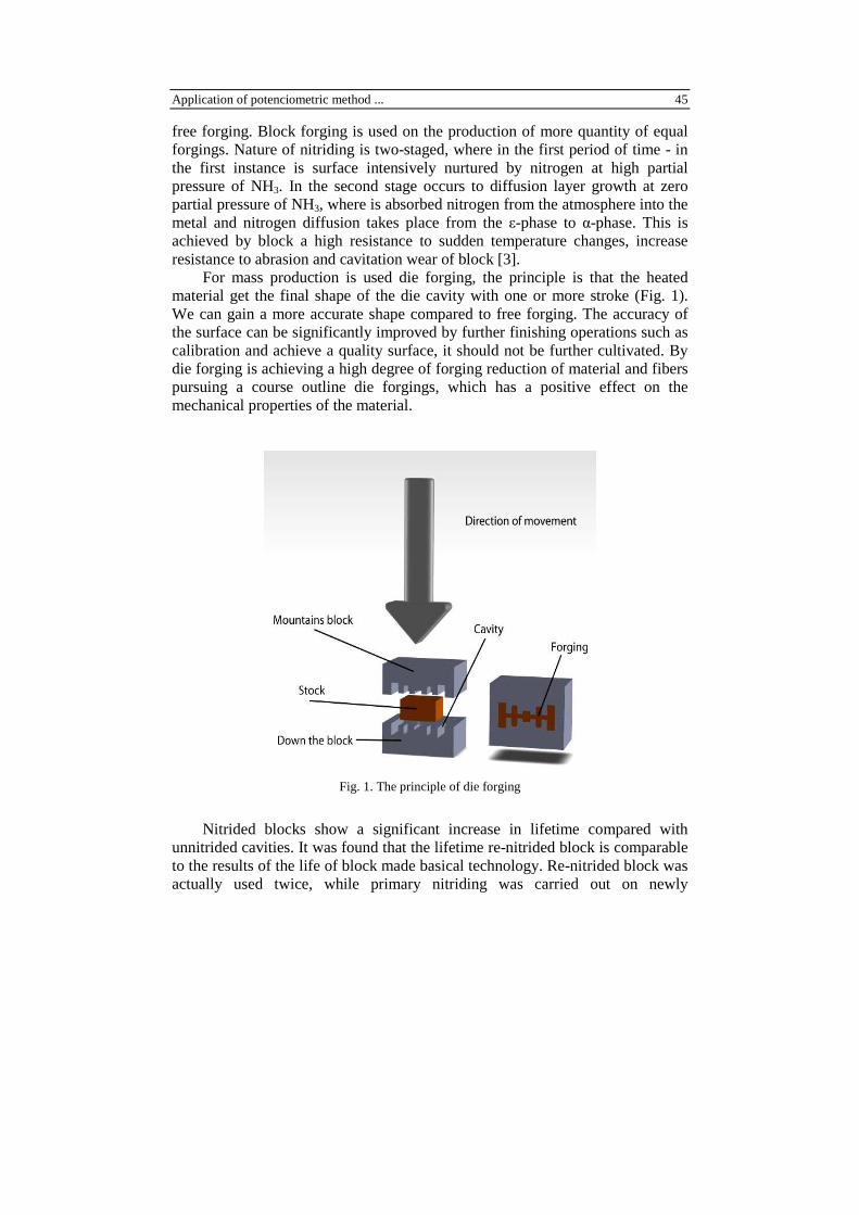
For mass production is used die forging, the principle is that the heated material get the final shape of the die cavity with one or more stroke (Fig. 1). We can gain a more accurate shape compared to free forging. The accuracy of the surface can be significantly improved by further finishing operations such as calibration and achieve a quality surface, it should not be further cultivated. By die forging is achieving a high degree of forging reduction of material and fibers pursuing a course outline die forgings, which has a positive effect on the mechanical properties of the material.
Fig. 1. The principle of die forging
Nitrided blocks show a significant increase in lifetime compared with unnitrided cavities. It was found that the lifetime re-nitrided block is comparable to the results of the life of block made basical technology. Re-nitrided block was actually used twice, while primary nitriding was carried out on newly
46 M. Derbas, A. Czán, J. Šemcer, T. Kurňava
manufactured block, which after completing its life in production was enhanced mechanical process for base metal and after obtaining drawing was again nitrided [3].
4. Experimental test of fitness for use non-destructive methods by examination of quarries
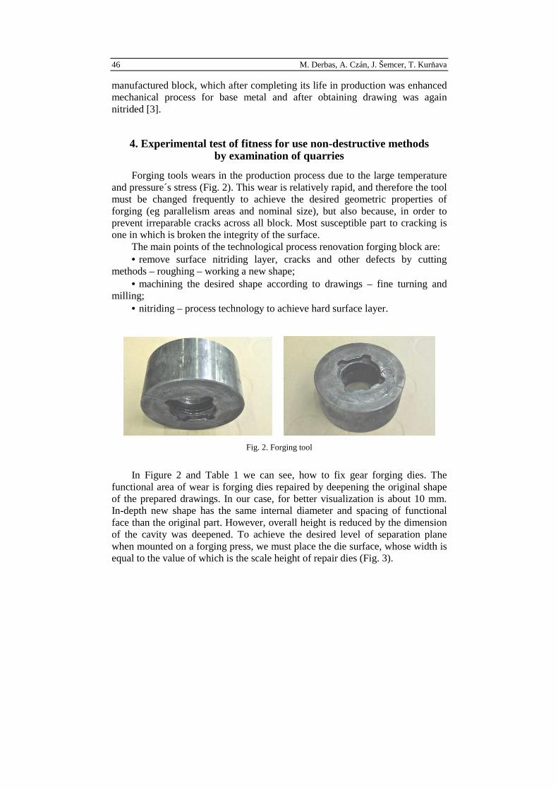
Forging tools wears in the production process due to the large temperature and pressure´s stress (Fig. 2). This wear is relatively rapid, and therefore the tool must be changed frequently to achieve the desired geometric properties of forging (eg parallelism areas and nominal size), but also because, in order to prevent irreparable cracks across all block. Most susceptible part to cracking is one in which is broken the integrity of the surface.
The main points of the technological process renovation forging block are: • remove surface nitriding layer, cracks and other defects by cutting
methods – roughing – working a new shape; • machining the desired shape according to drawings – fine turning and
milling; • nitriding – process technology to achieve hard surface layer.
Fig. 2. Forging tool
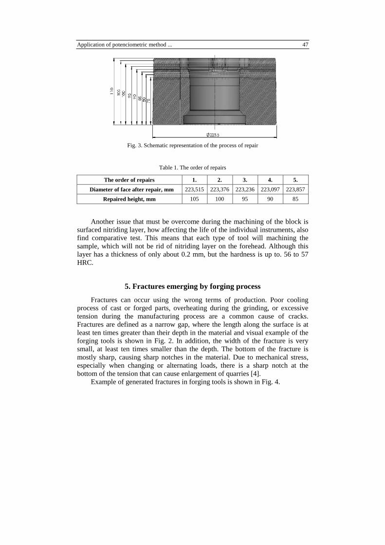
In Figure 2 and Table 1 we can see, how to fix gear forging dies. The functional area of wear is forging dies repaired by deepening the original shape of the prepared drawings. In our case, for better visualization is about 10 mm. In-depth new shape has the same internal diameter and spacing of functional face than the original part. However, overall height is reduced by the dimension of the cavity was deepened. To achieve the desired level of separation plane when mounted on a forging press, we must place the die surface, whose width is equal to the value of which is the scale height of repair dies (Fig. 3).
Application of potenciometric method ... 47
Fig. 3. Schematic representation of the process of repair
Table 1. The order of repairs
The order of repairs 1. 2. 3. 4. 5.
Diameter of face after repair, mm 223,515 223,376 223,236 223,097 223,857
Repaired height, mm 105 100 95 90 85 Another issue that must be overcome during the machining of the block is
surfaced nitriding layer, how affecting the life of the individual instruments, also find comparative test. This means that each type of tool will machining the sample, which will not be rid of nitriding layer on the forehead. Although this layer has a thickness of only about 0.2 mm, but the hardness is up to. 56 to 57 HRC.
5. Fractures emerging by forging process
Fractures can occur using the wrong terms of production. Poor cooling process of cast or forged parts, overheating during the grinding, or excessive tension during the manufacturing process are a common cause of cracks. Fractures are defined as a narrow gap, where the length along the surface is at least ten times greater than their depth in the material and visual example of the forging tools is shown in Fig. 2. In addition, the width of the fracture is very small, at least ten times smaller than the depth. The bottom of the fracture is mostly sharp, causing sharp notches in the material. Due to mechanical stress, especially when changing or alternating loads, there is a sharp notch at the bottom of the tension that can cause enlargement of quarries [4].
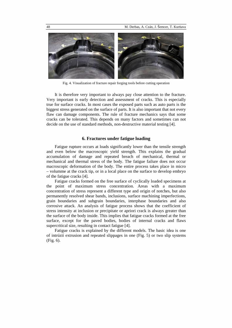
Example of generated fractures in forging tools is shown in Fig. 4.
48 M. Derbas, A. Czán, J. Šemcer, T. Kurňava
Fig. 4. Visualization of fracture repair forging tools before cutting operation
It is therefore very important to always pay close attention to the fracture. Very important is early detection and assessment of cracks. This is especially true for surface cracks. In most cases the exposed parts such as auto parts is the biggest stress generated on the surface of parts. It is also important that not every flaw can damage components. The rule of fracture mechanics says that some cracks can be tolerated. This depends on many factors and sometimes can not decide on the use of standard methods, non-destructive material testing [4].
6. Fractures under fatigue loading
Fatigue rupture occurs at loads significantly lower than the tensile strength and even below the macroscopic yield strength. This explains the gradual accumulation of damage and repeated breach of mechanical, thermal or mechanical and thermal stress of the body. The fatigue failure does not occur macroscopic deformation of the body. The entire process takes place in micro – volumme at the crack tip, or in a local place on the surface to develop embryo of the fatigue cracks [4].
Fatigue cracks formed on the free surface of cyclically loaded specimens at the point of maximum stress concentration. Areas with a maximum concentration of stress represent a different type and origin of notches, but also permanently resolved shear bands, inclusions, surface machining imperfections, grain boundaries and subgrain boundaries, interphase boundaries and also corrosive attack. An analysis of fatigue process shows that the coefficient of stress intensity at inclusion or precipitate or apriori crack is always greater than the surface of the body inside. This implies that fatigue cracks formed at the free surface, except for the paved bodies, bodies of internal cracks and flaws supercritical size, resulting in contact fatigue [4].
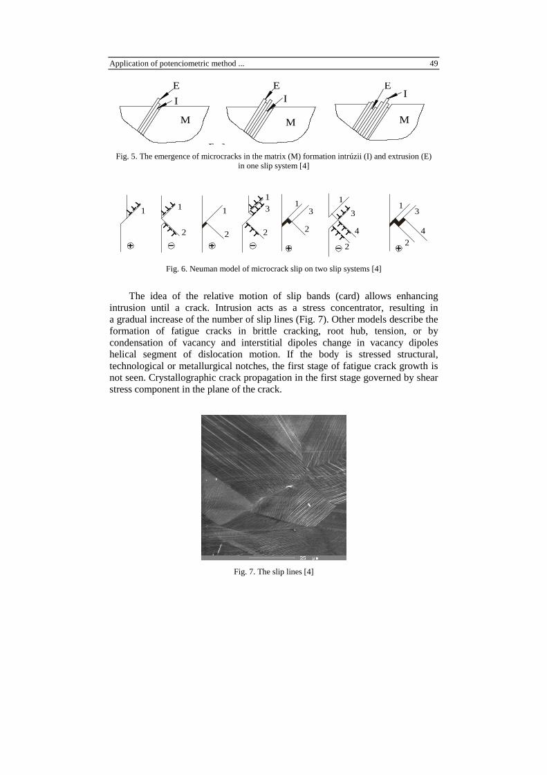
Fatigue cracks is explained by the different models. The basic idea is one of intrúzií extrusion and repeated slippages in one (Fig. 5) or two slip systems (Fig. 6).
Application of potenciometric method ... 49 E M
M
E
E
I
M
M
E
E
I
M
EI
Fig. 5. The emergence of microcracks in the matrix (M) formation intrúzii (I) and extrusion (E) in one slip system [4]
1 1 1
1
2 2 2
3
1 11
2
2 2
3 3 3
4 4
Fig. 6. Neuman model of microcrack slip on two slip systems [4]
The idea of the relative motion of slip bands (card) allows enhancing intrusion until a crack. Intrusion acts as a stress concentrator, resulting in a gradual increase of the number of slip lines (Fig. 7). Other models describe the formation of fatigue cracks in brittle cracking, root hub, tension, or by condensation of vacancy and interstitial dipoles change in vacancy dipoles helical segment of dislocation motion. If the body is stressed structural, technological or metallurgical notches, the first stage of fatigue crack growth is not seen. Crystallographic crack propagation in the first stage governed by shear stress component in the plane of the crack.
Fig. 7. The slip lines [4]
50 M. Derbas, A. Czán, J. Šemcer, T. Kurňava
4
3
2
1
3
aF
aF
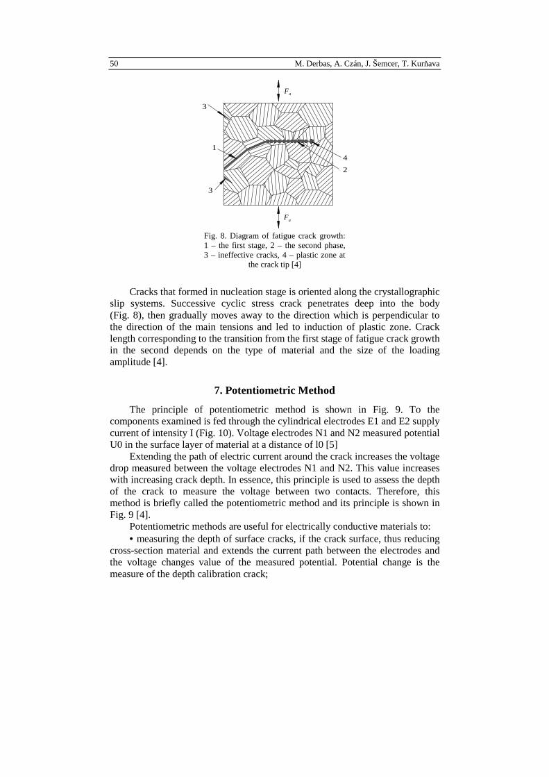
Fig. 8. Diagram of fatigue crack growth: 1 – the first stage, 2 – the second phase, 3 – ineffective cracks, 4 – plastic zone at the crack tip [4]
Cracks that formed in nucleation stage is oriented along the crystallographic slip systems. Successive cyclic stress crack penetrates deep into the body (Fig. 8), then gradually moves away to the direction which is perpendicular to the direction of the main tensions and led to induction of plastic zone. Crack length corresponding to the transition from the first stage of fatigue crack growth in the second depends on the type of material and the size of the loading amplitude [4].
7. Potentiometric Method
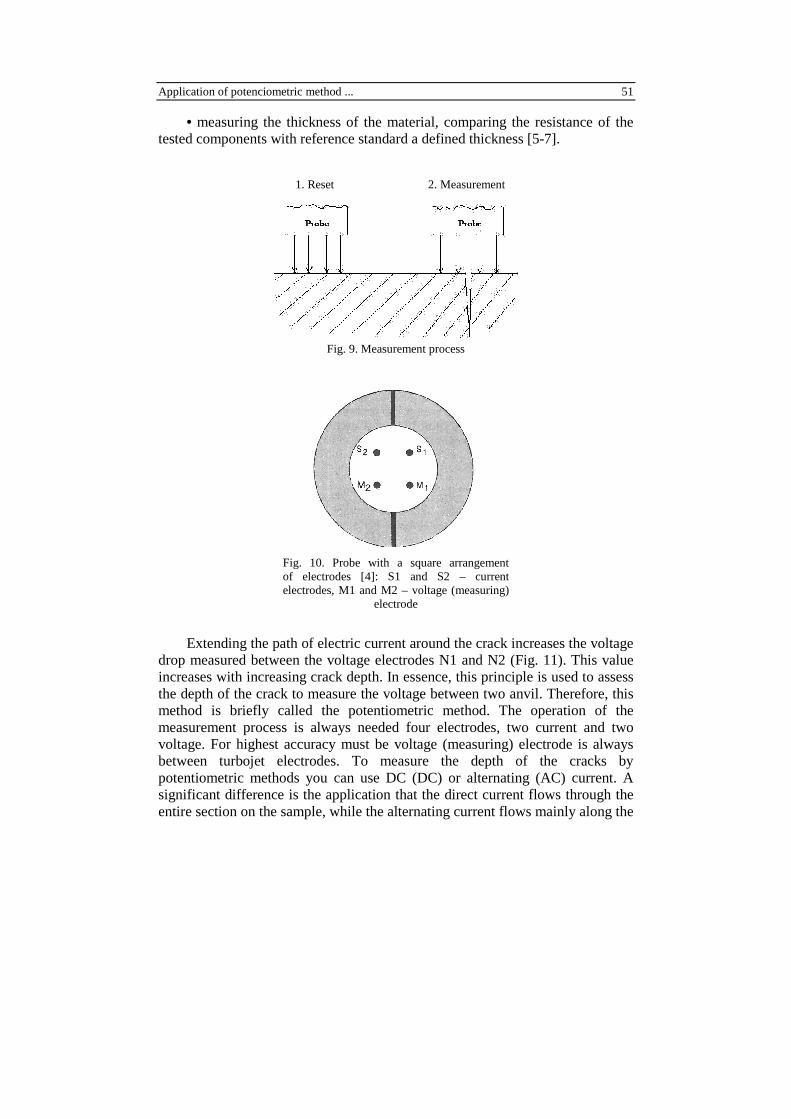
The principle of potentiometric method is shown in Fig. 9. To the components examined is fed through the cylindrical electrodes E1 and E2 supply current of intensity I (Fig. 10). Voltage electrodes N1 and N2 measured potential U0 in the surface layer of material at a distance of l0 [5]
Extending the path of electric current around the crack increases the voltage drop measured between the voltage electrodes N1 and N2. This value increases with increasing crack depth. In essence, this principle is used to assess the depth of the crack to measure the voltage between two contacts. Therefore, this method is briefly called the potentiometric method and its principle is shown in Fig. 9 [4].
Potentiometric methods are useful for electrically conductive materials to: • measuring the depth of surface cracks, if the crack surface, thus reducing
cross-section material and extends the current path between the electrodes and the voltage changes value of the measured potential. Potential change is the measure of the depth calibration crack;
Application of potenciometric method ... 51
• measuring the thickness of the material, comparing the resistance of the tested components with reference standard a defined thickness [5-7].
Fig. 9. Measurement process
Fig. 10. Probe with a square arrangement of electrodes [4]: S1 and S2 – current electrodes, M1 and M2 – voltage (measuring) electrode
Extending the path of electric current around the crack increases the voltage drop measured between the voltage electrodes N1 and N2 (Fig. 11). This value increases with increasing crack depth. In essence, this principle is used to assess the depth of the crack to measure the voltage between two anvil. Therefore, this method is briefly called the potentiometric method. The operation of the measurement process is always needed four electrodes, two current and two voltage. For highest accuracy must be voltage (measuring) electrode is always between turbojet electrodes. To measure the depth of the cracks by potentiometric methods you can use DC (DC) or alternating (AC) current. A significant difference is the application that the direct current flows through the entire section on the sample, while the alternating current flows mainly along the
1. Reset 2. Measurement
52 M. Derbas, A. Czán, J. Šemcer, T. Kurňava
surface. This physical phenomenon is caused by the so-called surface effects. The area of flowing current is reduced to the subsurface region of the measured components. Resistance R for alternating current increases with increasing frequency. Therefore, the small streams I show a significantly higher voltage drop compared to DC [4].
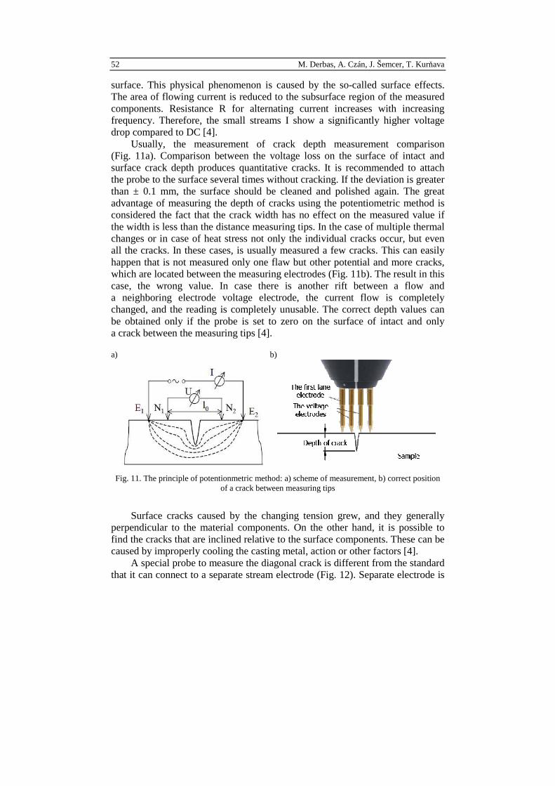
Usually, the measurement of crack depth measurement comparison (Fig. 11a). Comparison between the voltage loss on the surface of intact and surface crack depth produces quantitative cracks. It is recommended to attach the probe to the surface several times without cracking. If the deviation is greater than ± 0.1 mm, the surface should be cleaned and polished again. The great advantage of measuring the depth of cracks using the potentiometric method is considered the fact that the crack width has no effect on the measured value if the width is less than the distance measuring tips. In the case of multiple thermal changes or in case of heat stress not only the individual cracks occur, but even all the cracks. In these cases, is usually measured a few cracks. This can easily happen that is not measured only one flaw but other potential and more cracks, which are located between the measuring electrodes (Fig. 11b). The result in this case, the wrong value. In case there is another rift between a flow and a neighboring electrode voltage electrode, the current flow is completely changed, and the reading is completely unusable. The correct depth values can be obtained only if the probe is set to zero on the surface of intact and only a crack between the measuring tips [4].
a) b)
Fig. 11. The principle of potentionmetric method: a) scheme of measurement, b) correct position of a crack between measuring tips
Surface cracks caused by the changing tension grew, and they generally perpendicular to the material components. On the other hand, it is possible to find the cracks that are inclined relative to the surface components. These can be caused by improperly cooling the casting metal, action or other factors [4].
A special probe to measure the diagonal crack is different from the standard that it can connect to a separate stream electrode (Fig. 12). Separate electrode is
Application of potenciometric method ... 53
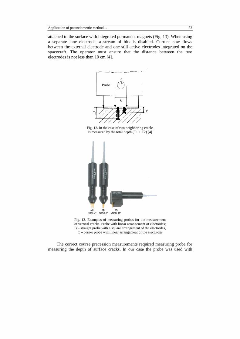
attached to the surface with integrated permanent magnets (Fig. 13). When using a separate lane electrode, a stream of bits is disabled. Current now flows between the external electrode and one still active electrodes integrated on the spacecraft. The operator must ensure that the distance between the two electrodes is not less than 10 cm [4].
Fig. 12. In the case of two neighboring cracks is measured by the total depth (T1 + T2) [4]
Fig. 13. Examples of measuring probes for the measurement of vertical cracks. Probe with linear arrangement of electrodes; B – straight probe with a square arrangement of the electrodes, C – corner probe with linear arrangement of the electrodes
The correct course precession measurements required measuring probe for measuring the depth of surface cracks. In our case the probe was used with
Probe
54 M. Derbas, A. Czán, J. Šemcer, T. Kurňava
a square arrangement of electrodes for measuring vertical to ensure reliable contact to curved surfaces.
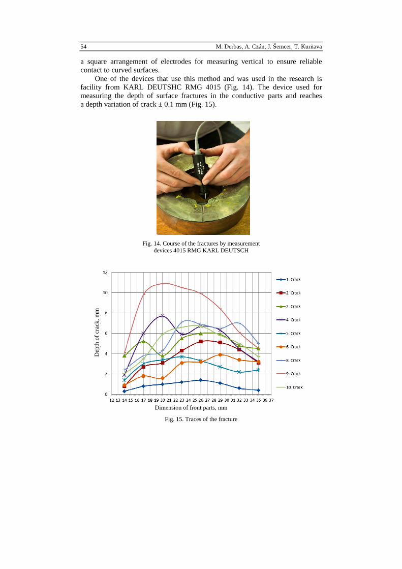
One of the devices that use this method and was used in the research is facility from KARL DEUTSHC RMG 4015 (Fig. 14). The device used for measuring the depth of surface fractures in the conductive parts and reaches a depth variation of crack ± 0.1 mm (Fig. 15).
Fig. 14. Course of the fractures by measurement devices 4015 RMG KARL DEUTSCH
Fig. 15. Traces of the fracture
Dep
th o
f cra
ck,
mm
Dimension of front parts, mm
Application of potenciometric method ... 55
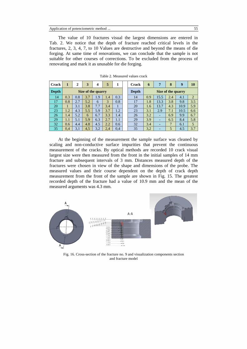
The value of 10 fractures visual the largest dimensions are entered in Tab. 2. We notice that the depth of fracture reached critical levels in the fractures, 2, 3, 4, 7, to 10 Values are destructive and beyond the means of die forging. At same time of renovations, we can conclude that the sample is not suitable for other courses of corrections. To be excluded from the process of renovating and mark it as unusable for die forging.
Table 2. Measured values crack
Crack 1 2 3 4 5 1 Crack 6 7 8 9 10
Depth Size of the quarry Depth Size of the quarry
14 0.3 0.8 3.7 1.9 1.4 0.3 14 0.9 15.5 2.4 4.1 2 17 0.8 2.7 5.2 6 3 0.8 17 1.8 13.3 3.8 9.8 3.5 20 1 3.1 3.8 7.7 3.4 1 20 1.6 13.7 4.3 10.9 5.9 23 1.2 4.3 5.5 5.9 3.7 1.2 23 3.1 2.9 7.1 10.5 6.6 26 1.4 5.2 6 6.7 3.3 1.4 26 3.2 - 6.9 9.9 6.7 29 1.1 5.1 5.9 6.3 2.7 1.1 29 3.9 - 6.5 8.4 5.8 32 0.6 4.4 4.8 4.5 2.2 0.6 32 3.4 - 7 6.1 5 35 0,4 3,1 4,5 3,2 2,4 0,4 35 3,2 - 5 4.5 3.7
At the beginning of the measurement the sample surface was cleaned by scaling and non-conductive surface impurities that prevent the continuous measurement of the cracks. By optical methods are recorded 10 crack visual largest size were then measured from the front in the initial samples of 14 mm fracture and subsequent intervals of 3 mm. Distances measured depth of the fractures were chosen in view of the shape and dimensions of the probe. The measured values and their course dependent on the depth of crack depth measurement from the front of the sample are shown in Fig. 15. The greatest recorded depth of the fracture had a value of 10.9 mm and the mean of the measured arguments was 4.3 mm.
Fig. 16. Cross-section of the fracture no. 9 and visualization components section and fracture model
56 M. Derbas, A. Czán, J. Šemcer, T. Kurňava
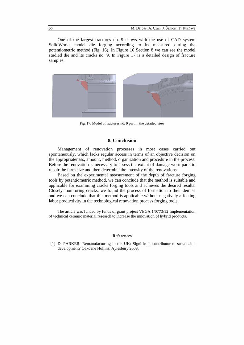
One of the largest fractures no. 9 shows with the use of CAD system SolidWorks model die forging according to its measured during the potentiometric method (Fig. 16). In Figure 16 Section 8 we can see the model studied die and its cracks no. 9. In Figure 17 is a detailed design of fracture samples.
Fig. 17. Model of fractures no. 9 part in the detailed view
8. Conclusion
Management of renovation processes in most cases carried out spontaneously, which lacks regular access in terms of an objective decision on the appropriateness, amount, method, organization and procedure in the process. Before the renovation is necessary to assess the extent of damage worn parts to repair the farm size and then determine the intensity of the renovations.
Based on the experimental measurement of the depth of fracture forging tools by potentiometric method, we can conclude that the method is suitable and applicable for examining cracks forging tools and achieves the desired results. Closely monitoring cracks, we found the process of formation to their demise and we can conclude that this method is applicable without negatively affecting labor productivity in the technological renovation process forging tools.
The article was funded by funds of grant project VEGA 1/0773/12 Implementation of technical ceramic material research to increase the innovation of hybrid products.
References
[1] D. PARKER: Remanufacturing in the UK: Significant contributor to sustainable development? Oakdene Hollins, Aylesbury 2003.

Application of potenciometric method ... 57
[2] E. SPROW: The mechanics of remanufacturin. Manufacturing Engineering, (1992).
[3] O. HÍREŠ, R. PERNIS, J. KASALA: Increasing life ram dies. Proc. of the Conference Functional Surfaces – FŠT TnU, Trenčín 2001.
[4] V. DEUTSCH, M. PLATTE: Crack depth gauging with the potential probe method. Wuppertal. Castell Publication Inc., 34(2003).
[5] J. BALOG, A. CHOVANEC, M. KIANICOVÁ: Technical diagnostics, 115(2002). [6] K. ELISSA: Title of paper if known, unpublished. [7] J. MORAVEC, M. JANČUŠOVÁ, J. KUBA, R. STROKA: Forming technology
engineering materials. Žilinská Univerzita, Žilina 2010.
Received in April 2012