application of quality assurance - louisiana · manual was edited and prepared for publication by...
TRANSCRIPT

APPLICATION OF QUALITY ASSURANCE SPECIFICATIONS
FOR PORTLAND CEMENT CONCRETE PAVEMENT AND STRUCTURES
TECHNOLOGY TRANSFER AND TRAINING Louisiana Transportation Research Center
for Louisiana Department of Transportation and Development
2006

ii

iii
CREDITS
This manual was prepared by Mr. John Eggers, LTRC Senior Concrete Research Engineer with the assistance of the technical review committee listed below. The manual was edited and prepared for publication by Ms. Cindy Twiner, Construction and Materials Training Program Manager. The material contained herein was approved for publication by the department’s Construction Division and the DOTD Chief Engineer.
Technical Review Committee
Joe Bond District 61 Training Coordinator
Bert Wintz
Field Quality Assurance Administrator
Matt Ziecker District 08 Laboratory Engineer
Sadi Torres
Concrete Research Engineer
Michael Boudreaux District 03 Laboratory Engineer
William Killian
DOTD Engineer Program Manager
Gary Keel LTRC Senior Pavement Technician
Johnathan Lachney
District 08 Project Engineer
Chris Lissard District 03 Project Engineer
Ray Mumphrey
Assistant Bridge Engineer
Mike Ricca Systems Construction Engineer

iv

v
PREFACE This manual is designed to standardize department policies and procedures with reference to applicable areas (Part VI, Part VIII, Sections 805, 806, 813, Part IX and Part X) of the Standard Specifications. It is specifically written for routine DOTD cast-in-place portland cement concrete construction operations. It is not designed for application in areas requiring specialized techniques, such as concrete overlays, pavement rehabilitation, concrete recycling, etc. The manual details the responsibilities of the contractor and the department with reference to the areas of certification, design, production, transportation, placement, quality control, inspection and acceptance of pavements and structures built of portland cement concrete. It is to be used in conjunction with the Standard Specifications, the contract, the Materials Sampling Manual, Test Procedures Manual, MATT System Field Handbook, and all applicable Special Provisions, EDSM's and department memoranda to ensure that portland cement concrete operations are performed in complete accordance with all DOTD specifications, policies and procedures. For precast-prestressed plant operations, refer to the DOTD Application of Quality Assurance Specifications for Precast-Prestressed Concrete Plants manual.
For the purposes of this manual the term "certified technician" is intended to mean the authorized representative of the contractor. The term "certified inspector" is intended to mean the department's authorized representative.
Examples of forms and specification requirements in this booklet are based on the 2006 Standard Specifications. These specifications, tables, forms, etc., are subject to change.
Hence, the contract for a particular project should always be checked for the applicable specification requirements.
Bold type has been used within the text of this manual to emphasize certain statements which the department considers to be of significant importance or which delineate a substantial departure from previous department policies or procedures. The user should pay special attention to all phrases or sentences which are printed in bold typeface.
SPECIFICATION CHANGES
This manual is referenced in those areas of the Standard Specifications which are concerned with cast-in-place portland cement concrete; therefore, it must be consulted for elaboration of areas of specification change and DOTD construction techniques and procedures which are presented in more detail than is possible in the Standard Specifications. This version has both English and SI Metric System units of measure.
The primary changes regarding portland cement concrete pavement and structural concrete construction are:
References to the Authorized Concrete Batcher have been removed throughout Part IX because the Department no longer has requirements for it
Reduction in the minimum cement content for all classes and types of concrete
The addition of Class P(X) concrete

vi
Gradation requirements for pavement types B & D concrete
Deletion of Type C concrete for pavement mixes
Volume of coarse aggregate is specified in new Table 901-1 (excluding mixes for concrete pipe, Types B & D pavements and minor structures)
Trial mixes are no longer required for HRWR (superplasticizers) but are now required for heavyweight concrete and flexural strength (if required)
Trial mixes may be waived by the District Laboratory Engineer for previously accepted mix designs
Types I(B) and I(C) cements are no longer allowed
Mass concrete is designated on the plans or by special provision as being mass concrete
Both grades 100 and 120 slag may be used as a partial substitution for cement up to 50% replacement by weight
The amount of each material used in the mix is required to be recorded by the contractor and if the automated ticket printer system fails or is not used quantities and batching information shall be recorded and certified by the contractor
Only standard full bags of cement (when used) will be allowed in a mix
Over-Design to Meet Compressive Strength Requirements are required as per new Table 901-4
Revision for metric values in Acceptance and Payment Schedules Tables 901-4 and 901-5
For Longitudinal Surface Tolerance Requirements an approved profilograph shall be furnished, calibrated and operated by the contractor for pavement quality control
Clarification of Sealing Joints that when poured or extruded sealants are used the concrete must be at least 7 days old prior to sealing
A low shrinkage cementitious concrete is required for dowel bar slots in Dowel Bar Retrofit projects
Payment for removal of existing shoulder underdrain systems will include plugging and backfilling of outfalls.
The payment adjustment schedules were not developed for the benefit of the contractor, but as a mechanism by which the department can accept the product and pay the contractor on those rare occasions when the portland cement concrete product does not meet all department requirements. The payment adjustment schedules included in the Standard Specifications are to be considered as a method of payment to the contractor for a substandard product. Under these specifications, the production of portland cement concrete at less than 100 percent payment will not be allowed on a continuous basis. If test results demonstrate that payment adjustments are necessary, or other specification requirements are not being met, satisfactory control adjustments shall be made or production shall be discontinued.

vii
TABLE OF CONTENTS
TOPIC PAGE
CHAPTER 1 - QUALITY ASSURANCE .................................................................................... 1
Contractor's Responsibilities - Quality Control (QC) ....................................................... 2 Personnel ............................................................................................................ 3 Dimensional Control ............................................................................................ 4 Material Quality ................................................................................................... 4 Sampling and Testing.......................................................................................... 4 Construction Layout ............................................................................................ 5 Traffic Control ..................................................................................................... 6
Responsibilities of the Project Engineer .......................................................................... 6 Monitoring Quality Control (QC) .......................................................................... 7 Inspection............................................................................................................ 7 Personnel ..................................................................................................... 7 Construction Layout ...................................................................................... 8 Equipment ..................................................................................................... 8 Acceptance ......................................................................................................... 8 Visual Inspection ........................................................................................... 8 Sampling and Testing .................................................................................... 9 Traffic Control ................................................................................................ 9
Responsibilities of the District Laboratory ..................................................................... 10 Responsibilities of the Materials and Testing Section ................................................... 11 Dedicated Stockpiles .................................................................................................... 11 Non-dedicated Stockpiles ............................................................................................. 12
CHAPTER 2 - CERTIFICATION .............................................................................................. 13
Plant ............................................................................................................................. 13 Scale and Meter Calibration .............................................................................. 14
Trucks ........................................................................................................................... 14 Performance Inspection .................................................................................... 15 Revocation of Plant or Truck Certification .................................................... 15
Personnel ..................................................................................................................... 15 DOTD Personnel ............................................................................................... 15 Non-department Personnel ............................................................................... 16
CHAPTER 3 - LOT ESTABLISHMENT .................................................................................... 19
Pavement and Shoulders.............................................................................................. 19 Lot Layout of Pavement and Shoulders ............................................................. 19 Projects Totaling Less Than 2,000 Square Yards .............................................. 20
Structural ...................................................................................................................... 20 Minor Structure Concrete .............................................................................................. 21

viii
TABLE OF CONTENTS – Continued TOPIC PAGE CHAPTER 4 - MIX DESIGN ..................................................................................................... 23
Submittal Procedures ................................................................................................... 23 Pavement or Structural, Including Minor Structure ............................................ 23 Mix Design for Specific DOTD Project ............................................................... 24 Trial Mixtures .................................................................................................... 24
Sampling and Testing for Mix Design Purposes ............................................................ 24 Design Methodology ..................................................................................................... 25
Necessary Beginning Data ........................................................................................... 25 Specific Gravity and Absorption of Each Component ............................. 26 Dry-rodded Unit Weight ......................................................................... 26 Maximum Size of Aggregate .................................................................. 27 Fineness Modulus of Fine Aggregate .................................................... 27
Cement Content ................................................................................................ 28 Water-Cement Ratio ......................................................................................... 28 Air Content for the Mixture ................................................................................ 28
Mix Proportion Calculations .......................................................................................... 29 Determination of Mix Proportions of Coarse Aggregate ..................................... 29 Volume of Coarse Aggregate Per Unit Volume of
Concrete - Chart .................................................................................... 30 Determining the Absolute Volume of Other Components .................................. 31 Moisture Adjustments ........................................................................................ 34 Fly Ash as Partial Replacement of Portland Cement ......................................... 35 Determination of Mix Proportions of Coarse Aggregate ..................................... 35 Determination of Mix Proportions for Cement and Fly Ash ................................ 37 Determination of Mix Proportions for Fine Aggregate ........................................ 37
GGBFS as Partial Replacement of Portland Cement ............................. 40 Determination of Mix Proportions of Cement and GGBFS ................................. 41 Determination of Mix Proportions of Fine Aggregate ......................................... 41
Plain Portland Cement Type B Mix ........................................................ 43 Determination of Volume Percentages of Aggregate Portion ............................. 44
Determination of Batch Weights for Mixture ..................................................... 48 Calculation of Oven-Dry Weight of Materials ..................................................... 51
CHAPTER 5 - PLANT OPERATIONS...................................................................................... 53
Responsibilities of Contractor's Certified Technician ..................................................... 53 Responsibilities of Contractor's Authorized Field Tester ............................................... 54 Sampling, Testing and Documentation ......................................................................... 54
Cement ............................................................................................................. 54 Fly Ash, GGBFSlag & Blended Cements (1P & 1s) ........................................... 55 Admixtures ........................................................................................................ 55 Aggregates ........................................................................................................ 56 Gradation .............................................................................................. 56 Fine Aggregate ...................................................................................... 56 Coarse Aggregate ................................................................................. 56 Aggregate Test Report: DOTD 03-22-0745 .......................................... 57

ix
TABLE OF CONTENTS – Continued TOPIC PAGE CHAPTER 5 – PLANT OPERATIONS - continued
Concrete Aggregate Control Charts: DOTD 03-22-5004 ....................... 58 Moisture Content of Fine and Coarse Aggregates ................................. 58 Concrete ........................................................................................................... 59 Portland Cement Concrete Plant Report: DOTD 03-22-4040 ................. 59 Calculating Batch Weights From Mix Design Proportions - English ........ 59 Hot Weather Adjustments ....................................................................... 64 Cold Weather Adjustments ..................................................................... 65 Batch Certification for PC Concrete: DOTD 03-22-4028 ......................... 65 Control Charts for Slump and Air of Concrete: DOTD 03-22-5003 ......... 66
Responsibilities of DOTD'S Certified Inspector ............................................................. 66 Mix Design Review ............................................................................................ 66 Preliminary Plant Inspection For Project ............................................................ 67 Materials Inspection .......................................................................................... 68
Aggregate Sampling and Testing ........................................................... 68 Dedicated or Non-dedicated Stockpiles ................................................. 68 Paving Concrete .................................................................................... 69 Structural Concrete ................................................................................ 69 Disposition of Failing Material ................................................................ 70
Dedicated Stockpiles............................................................................. 70 Non-dedicated Stockpiles ..................................................................... 71
Acceptance Sampling and Testing .................................................................... 71 Inspection Documentation ................................................................................. 71 Daily Plant Inspections ...................................................................................... 72
CHAPTER 6 - PAVING OPERATIONS .................................................................................... 75
Responsibilities of Contractor's Personnel .................................................................... 75 Base Course, Forms, Load Transfer Devices and Reinforcement ..................... 75 Paving Equipment ............................................................................................. 75 Materials, Personnel and Testing Equipment .................................................... 76 Cold Weather Limitations .................................................................................. 76 Hot Weather Limitations .................................................................................... 77 Pre-pour Conference ......................................................................................... 77 Slump and Air Tests .......................................................................................... 77
Placement Operations .................................................................................................. 79 Sawing - Longitudinal and Transverse Joints ......................................... 81
Daily Monitoring for Project Control ................................................................... 81 Responsibilities of DOTD Personnel ........................................................................................ 82
Base Course, Forms, Load Transfer Devices and Reinforcement ..................... 82 Paving Equipment......................................................................................................... 83 Materials ....................................................................................................................... 83 Placement Operations .................................................................................................. 83 Tine Finish .................................................................................................................... 84

x
TABLE OF CONTENTS – Continued TOPIC PAGE CHAPTER 6 – PAVING OPERATIONS - continued
Joint Sawing and Sealing.............................................................................................. 84 Daily Inspection ............................................................................................................ 84 Acceptance Tests ......................................................................................................... 85
Slump and Air Content ...................................................................................... 85 Thickness and Compressive Strength ............................................................... 86 Pavements and Shoulders ................................................................................ 86 Compressive Strength Cylinders for Early Opening of
Concrete Pavement ............................................................................... 87 Longitudinal Surface Tolerance ......................................................................... 87 Portland Cement Concrete Pavement Report ................................................... 87
CHAPTER 7 - STRUCTURAL OPERATIONS ......................................................................... 91
Responsibilities of Contractor's Personnel .................................................................... 91 Forms and Reinforcement ................................................................................. 91 Placement and Finishing Equipment ................................................................. 91 Materials, Personnel and Testing Equipment .................................................... 91 Pre-pour Conference ......................................................................................... 92 Pre-pour Inspection ........................................................................................... 92 Hot Weather Limitations .................................................................................... 93 Cold Weather Limitations .................................................................................. 93 Pouring Operations ........................................................................................... 94 Slump and Air Tests .......................................................................................... 98 Unit Weight ....................................................................................................... 98 Strength Determination for Form Removal ........................................................ 98 Cylinder Protection ............................................................................................ 99 Documentation and Verification ......................................................................... 99
Responsibilities of DOTD Personnel ............................................................................100 Materials ..........................................................................................................100 Production, Placement and Finishing Equipment .............................................100
Pre-pour Conference ...................................................................................................101 Pre-pour Inspection ..........................................................................................102 Pouring Operations ..........................................................................................102 Hot Weather Limitations ...................................................................................103 Cold Weather Limitations .................................................................................103 Personnel and Testing Equipment....................................................................104 Acceptance Tests .............................................................................................104
Slump and Air Content .......................................................................... 104 Compressive Strength ..........................................................................105 Compressive Strength Cylinders for Form Removal .............................107
CHAPTER 8 - SURFACE TOLERANCE TESTING ................................................................109
Pavement ....................................................................................................................109

xi
TABLE OF CONTENTS – Continued TOPIC PAGE
CHAPTER 8 – SURFACE TOLERANCE TESTING - continued
Approval of Profilographs.............................................................................................109 Approval of Personnel .................................................................................................111
Responsibilities of Authorized Profilograph Operator or Evaluator...................112 Authorized Profilograph Operator .....................................................................112 Contractor's Authorized Profilograph Evaluator ................................................112 Project Engineer's Authorized Profilograph Evaluator ......................................113 District Laboratory Authorized Profilograph Evaluator ......................................113
Quality Control Surface Finish Testing .........................................................................114 Travel Lanes ....................................................................................................114 Associated Pavements .....................................................................................116 Shoulders, Turnouts and Crossovers ...............................................................116
Acceptance Surface Finish Testing and Payment Determination .................................117 Travel Lanes ....................................................................................................117
Payment Determination ...............................................................................................119 Example ...............................................................................................119
Associated Pavements .....................................................................................120 Shoulders, Turnouts, and Crossovers ..............................................................120 Documentation: PCC Pavement Report (DOTD Form No. 03-22-4035) ...........120
Min. 3.0 Meter (Ten Foot), Metal, Static Straightedge ..................................................121 Profilograph: Travel Lanes ...........................................................................................121 Profilograph: Associated Pavements ...........................................................................121 Final Documentation: MATT System............................................................................122
CHAPTER 9 - PAYMENT CALCULATIONS...........................................................................123
Pavement ....................................................................................................................123 Compressive Strength, Thickness and Longitudinal Surface Tolerance ...........124 Payment Adjustments to Lot Segments Based on
Compressive Strength or Thickness .....................................................125 Compressive Strength ..........................................................................125 Thickness .............................................................................................127
CHAPTER 10 - APPROACH SLABS......................................................................................131
CHAPTER 11 - MINOR STRUCTURE CONCRETE ...............................................................133
Certification..................................................................................................................133 Contractor's Quality Control .........................................................................................133 Acceptance and Documentation ..................................................................................133

xii
TABLE OF CONTENTS – Continued TOPIC PAGE APPENDIX
Sample Identification ................................................................................................... A-1 Portland Cement Concrete Plant Certification Report .................................................. A-3 Certification Report for Scales and Meters ................................................................. A-13 Portland Cement Concrete Truck Certification Report................................................ A-15 Portland Cement Concrete Mix Design – Class AA – English .................................... A-19 Portland Cement Concrete Mix Design – Class AA – Metric ...................................... A-20 Portland Cement Concrete Mix Design – Type B – English ....................................... A-21 Portland Cement Concrete Mix Design – Type B – Metric ......................................... A-22 Specific Gravity and Water Absorption Factors for Sand and Gravel ......................... A-23 Portland Cement Concrete Plant Report .................................................................... A-25 Batch Certification for Portland Cement Concrete ...................................................... A-29 Certificate of Delivery for Fly Ash ............................................................................... A-33 Certificate of Delivery for Ground Granulated Blast Furnace Slag .............................. A-34 Certificate of Delivery for Portland Cement, Portland-Pozzolan Cement and ................... Portland Blast Furnace Slag Cement ......................................................................... A-35 Certificate of Delivery for Concrete Admixtures .......................................................... A-36 Aggregate Test Report .............................................................................................. A-37 Concrete Aggregate Control Charts ........................................................................... A-39 Control Charts for Slump and Air ............................................................................... A-41 Portland Cement Concrete Pavement Report – 2000 Specs ..................................... A-43 Certificate of Delivery for Joint Sealants .................................................................... A-45 Drilled Paving Concrete Cores ................................................................................... A-47 Check List of major Items to be Discussed At Bridge Deck Pre-Pour Conference...... A-49 Structural Concrete Tests .......................................................................................... A-55

APPLICATION OF QUALITY ASSURANCE SPECIFICATIONS
FOR PORTLAND CEMENT CONCRETE PAVEMENT AND STRUCTURES


Chapter 1 – Quality Assurance 1
CHAPTER 1 - QUALITY ASSURANCE
The concept of quality assurance refers to the combined efforts of quality control and acceptance processes to assure that a project will provide the public with a durable product exhibiting a high level of performance. Quality control is the process used by the contractor to monitor, assess, and adjust material selection, production, and project construction to control the level of quality so that the product continuously and uniformly conforms to specification. Acceptance is the process of sampling, testing, and inspection to determine the degree of compliance with specifications for acceptance of materials and/or contractor’s work. To this end, a system of inspection by qualified personnel (both department and contractor) and statistically based sampling and testing has been established. To ensure that the quality assurance concept functions properly, it is critical that the contractor's quality control and the department's inspection and acceptance process be a cooperative, coordinated effort. When any part of the process fails, the contractor's risk for payment adjustments and the department's risk of accepting substandard work increase. The increase of these risks caused by a failure on the part of either the contractor or the department is unacceptable.
The obvious concept behind statistically based testing is the determination of project quality in terms of a specific parameter by a randomly distributed number of tests. Some element of risk exists for both the department and the contractor; however, historical data has established that this risk is minimal and evenly distributed. Additional tests are not to be performed unless it is clear that the initial, statistically-based, test is in a location that is not representative of the lot or the selected test location is obviously deficient and must be replaced.
The performance of random quality control and acceptance testing in no way relieves the contractor of the duty to produce a consistently uniform project meeting all specification criteria; nor does the performance of random acceptance testing relieve the department from requiring the correction of any deficiencies identified during the inspection process which fall outside a test location. Both contractor and department personnel are duty bound to visually inspect all aspects and areas of the project for uniformity and to ensure that the project is free of defects. The testing program is designed to support, not replace, visual inspection.
Quality assurance specifications are not "end result." It is not the intent of quality
assurance specifications to allow the contractor to use construction practices or materials that may lead to a less than quality product. If the contractor attempts to achieve only the minimum criteria for which the department will allow 100% payment, the risk of the discontinuance of operations and/or payment adjustments will be significantly increased due to the nature of statistically based acceptance parameters. The department will not allow continued operations when tests result in less than 100% payment or show less than minimum specification requirements when no payment adjustment is applicable.

Chapter 1 – Quality Assurance 2
CONTRACTOR'S RESPONSIBILITIES - QUALITY CONTROL (QC)
The contractor is responsible for meeting all specification requirements. The contractor shall employ competent trained personnel and provide equipment that is in good condition and appropriate for the tasks for which it is used. When no minimum QC sampling and testing program is specified, the minimum acceptable schedule of QC sampling and testing shall be the same as performed by the department for acceptance.
The contractor shall locate, select, process and place uniform materials meeting specification requirements. The contractor shall sample and test the materials and final product to ensure that no failures will be identified by the department during inspection or acceptance testing. Prior to the preconstruction conference the contractor is to provide the project engineer with a list of quality control personnel, their assigned responsibilities, and their prior experience in their areas of responsibility, the types of equipment proposed for the various construction activities, and a proposed quality control program, including a basic schedule of sampling and testing and the testing equipment to be used. If the contractor is
unable to provide details at the preconstruction conference, these topics are to be thoroughly discussed. The contractor will not be permitted to begin construction until this information is approved by the project engineer. If changes to personnel or any other aspect of the QC program must be made, the contractor shall notify the project engineer immediately.
The contractor shall obtain copies of appropriate department documents, manuals and forms needed for the work. Such documents and manuals may include specifications, plans, contract, Materials Sampling Manual, Testing Procedures Manual, MATT System Field Handbook, Quality Assurance Manual, etc., for the field representatives on the
project and are defined below. The contractor is to ask the project engineer for information on how to obtain these documents or order the documents directly from LA DOTD's General Files Unit, Post Office Box 94245, Baton Rouge, LA 70804-9245. Many of these documents, manuals and forms can be found on the department’s website - www.dotd.la.gov.
CONTRACT DOCUMENTS – the legally binding written agreement between the DOTD
and the Contractor setting forth obligations for the performance of work for a specific project. MATERIALS SAMPLING MANUAL – arranged by Contract Item #, this includes the purpose, method of sampling, minimum frequency of sampling, sample quantity (size), and sampling procedures, certificate requirements, and distribution of documentation. MATT SYSTEM FIELD HANDBOOK – essential for completing and submitting the required documentation to accompany samples. This manual includes:
Sample Identification forms
Worksheets with examples
Material Codes
QPL Source Codes

Chapter 1 – Quality Assurance 3
Plant Codes
Submitter Codes TEST PROCEDURES MANUAL – all standardized DOTD test procedures (TR’s).
ENGINEERING DIRECTIVES AND STANDARDS MANUAL – establishes policies and procedures for DOTD Design, Construction, and Maintenance. QUALIFIED PRODUCTS LIST – a listing of materials which have been prequalified by
DOTD. This does not necessarily eliminate the requirement for testing. DOTD CONSTRUCTION MEMORANDA – The DOTD’s inter-office documentation to
explain various construction issues. CONTRACT ADMINISTRATION MANUAL – Instructions for DOTD Project Engineers
and their representatives that include procedures for change orders, estimates, diaries and field book entries. AASHTO TEST PROCEDURES – a set of nationally recognized test procedures and
specifications published by the American Association of State Highway Transportation Officials. ASTM TEST PROCEDURES – a set of nationally recognized test procedures published by the American Standards for Testing and Materials. DOTD ADMINISTRATIVE MANUAL for INSPECTOR/TECHNICIAN TRAINING and CERTIFICATION - identifies certification policy for PCC Technicians
and the departments certified inspectors.
PERSONNEL
DOTD specifications require that the contractor provide a Certified Concrete Technician who is to be at the plant or job site whenever a plant supplying concrete for DOTD projects is in operation. An Authorized Concrete Field Tester will be allowed to take samples and perform certain tests under the direction of the Certified Concrete Technician.
It is recommended that the project QC personnel complete the department's training materials in their areas of responsibility. QC technicians shall be approved by the project engineer or district laboratory engineer. QC technicians may be required to successfully complete LA DOTD training manuals in their area of responsibility. It is imperative that QC technicians be thoroughly familiar with department specifications, policy and procedural documents, and sampling and testing procedures. The contractor shall require that personal safety equipment be used as appropriate, including the wearing of film badges by nuclear device operators, should they be employed by the QC technician.

Chapter 1 – Quality Assurance 4
Each equipment operator shall be fully knowledgeable of the safety features, limitations, and uses of the machine. Personnel employed by the contractor to operate equipment shall be properly trained in its operation and be capable of using the equipment to ensure compliance with plans and specification requirements. For example, operators of placement and finishing equipment shall know how to adjust the equipment to obtain proper grade and alignment of the pavement surface and proper frequency and position of internal vibrators.
It is critical to the rideability of portland cement concrete pavements and structures that placement and finishing equipment be properly operated. Failure to operate placement or finishing equipment properly may cause the structure or pavement surface not to meet specification requirements for thickness, strength or rideability, resulting in additional work and expense for the contractor and the department.
DIMENSIONAL CONTROL
The contractor shall routinely check alignment and grade (when applicable), thickness and cross section to ensure that layout matches the plans. These checks shall be in accordance with standard survey practices or published DOTD procedures. Such checks shall be made at intervals of adequate frequency to ensure that alignment, thickness and grade do not deviate from specification tolerances.
MATERIAL QUALITY
It is the contractor's responsibility to locate and furnish materials which meet specifications. It is also the responsibility of the contractor to ensure that those materials, after being processed, placed, and consolidated, will meet department acceptance criteria. The contractor is required to select materials from sources listed as approved for portland cement concrete on the Qualified Products List. The contractor is responsible for coordinating the arrangements for materials acceptance testing and approval and the planned work schedule with the project engineer and the district laboratory engineer. The contractor is to schedule work so that the laboratory or project engineer can arrange the sampling and testing of materials prior to their planned incorporation into the project. Failure to do so will result in a delay of the contractor's proposed schedule, since no material can be placed on a project without approval. When scheduling work, the contractor must consider the additional time required for the approval of materials which must be tested by the Materials and Testing Section in Baton Rouge.
SAMPLING AND TESTING
The contractor shall conduct tests during the progress of the work to ensure continuous compliance with specifications. The contractor is to take as many samples and perform as many tests as necessary to ensure that materials and processes are producing a uniform product within the specification limits. When test results are near the borderline

Chapter 1 – Quality Assurance 5
of specifications, the contractor may be advised to adjust operations and/or materials sources to ensure that no failure to meet specifications occurs and that borderline conditions do not continue. Materials and operations at the borderline of specification requirements often result in failing acceptance tests, which can result in payment adjustments, loss of production time, and significant alterations to the QC program. When borderline materials or operations result in failing acceptance tests, immediate adjustments will be required. The contractor shall use test procedures and methods which correspond with the department's quality assurance program. These procedures are designated in the specifications, Testing Procedures Manual, and Materials Sampling Manual. The project engineer will provide the contractor with appropriate EDSM or other directives. Testing equipment shall be appropriately calibrated and in good working condition. The contractor shall contact the district laboratory engineer for policies and procedures to be followed for each piece of testing equipment.
The contractor is not to wait until a change in materials or a test result from DOTD indicates a deficiency, but is to stay continually abreast of construction progress and activity. When the contractor identifies failing materials or processes, the
contractor shall take whatever measures are necessary to correct the deficiency and prevent its recurrence. These measures shall include, but not be limited to the following:
removal of personnel or equipment not performing in an acceptable manner
removing and replacing materials
locating and selecting other material sources
reprocessing the deficient area
additional testing both to establish the total limits of the deficient area and to ensure that corrective action has been successful
The contractor is to complete QC testing and make any needed corrections prior to requesting acceptance testing by the department. The contractor is not to rely on the department's acceptance program and acceptance test results to prevent the application of payment adjustments or delays caused by suspensions of operations due to failures or deficiencies.
The contractor is to document all QC testing and provide copies to the department as directed. All QC documents shall be stamped "QC" with red ink, in minimum one-inch high letters by the contractor.
CONSTRUCTION LAYOUT
Unless otherwise stipulated in the contract, the department will be responsible for construction layout. When any construction stakes or marks are carelessly or willfully destroyed or disturbed by the contractor, the cost of replacement will be deducted from
Chapter 1 – Quality Assurance 6
payments to the contractor. Such deductions will be coordinated through the Chief, Construction Division.
When the contract requires the contractor to provide layout, the engineer will inspect the contractor's staking, elevations, station numbers, etc. The project engineer has the authority to require additional stakes and markers. The contractor shall correct any deficiencies prior to continuing operations. The project engineer's inspection of construction layout by the contractor in no way implies that the department accepts liability for layout errors by the contractor. In accordance with Specification Subsection 105.08, the contractor shall be responsible for the preservation of all stakes and markers.
TRAFFIC CONTROL
It is the responsibility of the contractor to control traffic, to install signs and other warnings and traffic control devices which meet MUTCD and DOTD requirements, in accordance with the plans. The project engineer is authorized to require additional traffic control, as needed, in accordance with the MUTCD. It is also the responsibility of the contractor to maintain all control devices in good condition. If traffic control is not adequate or if signs or devices lean, become damaged, misplaced, dirty, inoperative or lose reflectivity, the contractor shall correct the deficiency immediately. Operations will not be allowed to proceed if traffic control is not effective. Corrections are not to be delayed, since the safety of the traveling public is of prime importance.
RESPONSIBILITIES OF THE PROJECT ENGINEER
The project engineer is the legal representative of DOTD for the administration of the contract and represents the department directly as well as through the inspection staff. The department is responsible for inspecting, sampling, and testing for acceptance. The process of inspection and acceptance is continuous. The department evaluates the contractor's construction process, materials, personnel, equipment, and quality control program to determine if specifications are being uniformly met. Additionally, the department takes samples and conducts tests to ensure that the contractor's QC test results are accurate and reflect the actual quality of the product. The department's results are used to determine the acceptability of the product and take precedence over any other test results. Any deficiency identified by the department through
inspection, sampling or testing shall be corrected by the contractor at no direct pay. Consistent or repeated failures identified by test results or repeated deficiencies identified by inspection will result in the suspension of operations until the cause is identified and corrected and the QC program is reviewed and modified to eliminate such repeated or consistent failures.

Chapter 1 – Quality Assurance 7
MONITORING QUALITY CONTROL (QC)
At the preconstruction conference, the project engineer is to review the contractor's proposed QC program and provide a copy to the district laboratory engineer. The project engineer may require the contractor to modify the proposed program either at the preconstruction conference, before construction begins, or during construction. During construction, based on good construction processes and no failing acceptance test results, at the request of the contractor, the project engineer may allow a reduction in the number of tests required in the approved QC program, but not less than the minimum frequency or quantity required by specifications directly or through the Materials Sampling Manual. When acceptance inspection or tests indicate that the contractor's
QC program is not effective, modifications to the program will be required. The project engineer has the right to reject personnel, equipment, construction methods, testing methods or frequencies that are not resulting in an acceptable project. The contractor will not be allowed to proceed with construction operations without an effective, approved QC program.
The project engineer will be certain that the contractor's representative on the project has the appropriate department documents and manuals, such as the specifications, plans, contract, Materials Sampling Manual, Testing Procedures Manual, MATT System Field Handbook, and the latest edition of the "Quality Assurance Manual" as well as the
appropriate DOTD forms. Any required document can be obtained from the department at a published price through General Files. The project engineer will provide information on the appropriate procedure for obtaining published documents.
Evaluations of the QC effort to ensure that additional failing acceptance tests do not occur may include, but not be limited to, the following:
Observation of the contractor's sampling and testing procedures for conformance to department procedures and proper testing techniques
Evaluation of the contractor's testing equipment for proper working condition and conformance to the requirements of the appropriate test procedure
Observation of construction procedures for uniformity of effort and results
INSPECTION
Personnel
The project engineer is responsible for providing qualified inspectors on the project. Each inspector will successfully complete the department's training materials for the level of responsibility assigned. The chief inspector at the project site will be certified in Portland Cement Concrete Paving Inspection or Structural Concrete Inspection, as applicable, and it is recommended to visit the plant daily.

Chapter 1 – Quality Assurance 8
The project engineer is responsible for checking that QC technicians are trained and/or certified as required.
Construction Layout
Unless otherwise stipulated in the contract, the engineer will be responsible for construction layout. In accordance with Specification Subsection 105.08, the contractor shall be responsible for the preservation of all stakes and marks. When any construction stakes or marks are carelessly or willfully destroyed or disturbed by the contractor, the cost of replacement will be deducted from payments to the contractor. Such deduction will be coordinated through the Chief, Construction Division.
If the contract requires the contractor to provide layout, the engineer will inspect the contractor's staking, elevations, alignment, station numbers, etc. The project engineer's inspection of construction layout by the contractor in no way implies that the department accepts liability for layout errors by the contractor.
Equipment
Prior to construction, the project engineer will inspect the equipment to be used on the project to ensure that it is in good condition and appropriate for the activity for which it is to be used. Equipment required by specifications or weight laws to be certified must be properly identified and certified. The project engineer is to require that equipment which leaks or is damaged be repaired or replaced before it operates on the project. The project engineer is to require the replacement of equipment that is not appropriate for the project prior to its being used.
During the progress of construction, construction personnel are to inspect equipment daily to ensure that it has been maintained in good condition and that no damage which would affect its operation has occurred. Damaged equipment shall be repaired prior to its continued use. Project personnel will evaluate the effectiveness of equipment. Equipment which does not perform properly or which does not produce a quality product meeting specifications is to be replaced with acceptable equipment.
ACCEPTANCE
Visual Inspection
Although the random, statistically-based sampling and testing performed by the department represents the entire area being tested, this methodology does not replace visual inspection. Department personnel will observe the contractor's operations and inspect the project throughout its construction. When nonuniform materials or

Chapter 1 – Quality Assurance 9
nonuniform processes result in areas which do not appear to be acceptable or which are obviously not in conformance with the quality of construction expected, the department will require the contractor to correct these deficient areas. Such deficiencies for portland cement concrete paving or structure concrete construction may include segregation, contamination, excess laitance or bleeding, lack of consolidation, or elevation and alignment problems.
It has never been the intent of the department to accept a project solely on the basis of the statistically-based sampling and testing program. It is always necessary for the project engineer and inspector to be aware of the quality of construction and performance of the project during construction and acceptance phases before final acceptance.
Visual inspection includes base preparation, forms, steel placement, all concrete placement, consolidation, finishing and curing, and other aspects of the project to ensure conformance to plans and specifications.
Sampling and Testing
Sampling and testing is a support for visual inspection. Project personnel will sample and test material for acceptance in accordance with the Project Sampling Plan, based on the schedules published in the Materials Sampling Manual. It is to be noted that the Materials Sampling Manual establishes the minimum frequency and quantities of sampling and testing at the required level. The engineer has the authority to require additional tests to ensure uniformity, acceptability, and quality of the work. When samples or tests yield failing results the contractor will be required to correct the area represented by the sample or test, unless the specifications allow the application of payment adjustments. Materials are to be sampled, tested and approved prior to incorporation into the project. Materials which do not meet specifications are not to be placed.
A copy of the department’s Sample Identification (03-22-0800) is reprinted in the Appendix on pages A-1 and A-2.
Acceptance sampling and testing is to be performed by department personnel independently of the contractor's QC program. Under no circumstances is the inspector to use the results of the contractor's QC tests for independent acceptance results.
TRAFFIC CONTROL
Project personnel will inspect traffic control daily and will monitor its effectiveness continually. Nighttime effectiveness of traffic control arrangements and their continued reflectivity and operation will be regularly inspected after dark. Inspections will be

Chapter 1 – Quality Assurance 10
documented on the Project Diary (DOTD Form 03-40-3093). Any deficiencies noted
during inspections or during operations are to be documented along with instructions to the contractor regarding corrections. Follow-up inspections of the contractor's corrections are also to be documented. If the deficiency creates a dangerous traffic situation or is detrimental to the course being constructed, the engineer will require immediate correction or the discontinuance of operations until the deficiency is corrected. Damage by traffic shall be repaired by the contractor.
RESPONSIBILITIES OF THE DISTRICT LABORATORY
The district laboratory engineer is the coordinating authority of the district's quality assurance program and is the legal representative of the department in the area of material’s quality. The district laboratory is responsible for assuring that the quality assurance program is applied uniformly. This coordination of the QA program is performed in conjunction with the DOTD Materials Engineer Administrator. The district laboratory has specific and implied responsibilities, including but not limited to the following:
Administer the district Quality Assurance Program
Certification of and inspection of portland cement concrete plants
Certification or approval of testing equipment
Evaluation of the qualifications of DOTD employees and personnel associated with DOTD construction
Assisting and providing expertise for construction processes and problem solving
Establishing the Project Sampling Plan
Identifying the appropriate test to be performed
Identification of proper sampling and testing techniques
Interpretation of test results
Sampling and approving project material sources
Acceptance testing for selected parameters
Coordination of application of Project Sampling Plan
Project Materials Certification (2059 Review)
FHWA mandated Independent Assurance Sampling and Testing
Mix Design Approval
Portland Cement Concrete Paving Lot Layout (in conjunction with the Project Engineer)
Portland Cement Concrete Paving Thickness and Strength Testing (Determination of percent Pay)

Chapter 1 – Quality Assurance 11
Acceptance of Surface Tolerance Testing
RESPONSIBILITIES OF THE MATERIALS AND TESTING SECTION
The Materials and Testing Section is responsible for updating sampling and testing procedures, providing lists of approved materials sources, performing acceptance testing on materials not tested by the district laboratories or project engineers, testing materials for inclusion on approved source lists, and distributing the Materials Sampling Manual, Testing Procedures Manual, Qualified Products List, and MATT System documentation.
For PCC paving, the Materials and Testing Section/District Laboratory Engineer is responsible for sampling and testing for thickness and strength requirements, including the determination of percent pay. When no specific sampling or testing is referenced, the Materials Engineer Administrator will determine the appropriate sampling frequency, methods, and tests to be used. The Materials and Testing
Section also provides technical support to district construction and materials forces.
DEDICATED STOCKPILES
A dedicated stockpile is defined as a stockpile built for a specific project. It is sampled, tested and approved during its construction. Dedicated stockpiles are to be constructed in final position. If the engineer allows the contractor to move material from a dedicated stockpile, except for placement in the project, such disturbance shall be at the contractor's risk. The disturbed material will be subject to additional approval sampling and testing. If the disturbed material has become contaminated, segregated or fails specification requirements when retested, it shall not be placed in the project.
The contractor may attempt to correct any deficiency in a disturbed stockpile which has failed subsequent approval testing at no direct pay. If the contractor is unable to correct the deficiency, the material will not be used on the project.
Material in dedicated stockpiles may be used only on the project for which it has been dedicated, unless otherwise approved in writing by the project engineer. Once a dedicated stockpile has been approved by the department, no material can be removed or added without the approval of the project engineer. The project engineer will not approve the addition of material to a dedicated stockpile until such material has been sampled, tested and approved to be placed in the stockpile. Material which is
approved for addition to a dedicated stockpile will be sampled and tested under the same conditions as the dedicated stockpile. To avoid the risk of the department rejecting a disturbed dedicated stockpile, in lieu of requesting that material be added to an existing dedicated stockpile, the contractor is expected to make every effort to create a new stockpile.
Chapter 1 – Quality Assurance 12
During the construction of a dedicated stockpile, the engineer will sample the stockpile in accordance with the Materials Sampling Manual and submit the samples to the district laboratory for testing. It shall be the responsibility of the contractor to notify the project engineer and request sampling and testing during stockpile construction and to keep the project engineer and district laboratory engineer apprised of the building schedule of stockpiles to be dedicated. Failure to do so can result in the rejection of the stockpile, disallowance of or substantial delay in advance payment for the materials, or substantial delay in the construction process.
NONDEDICATED STOCKPILES
Stockpiles which are not dedicated for use on a specific project are nondedicated. Advance payment will not be made for materials in nondedicated stockpiles. In general, nondedicated stockpiles are those to which material is randomly added or removed, or which will subsequently be moved to another location. Nondedicated stockpiles remain in the control of the contractor. Material from nondedicated stockpiles is sampled and tested as it is used in accordance with the Materials Sampling Manual.

Chapter 2 - Certification 13
CHAPTER 2 - CERTIFICATION
PLANT
All plants supplying portland cement concrete paving and structural mixtures to DOTD projects must be certified by the district laboratory except Pre-cast and Prestress Plants which produce portland cement concrete strictly for there own use will be certified by the Structural Fabrication Engineer.. Plant certification requires an in-depth inspection by district laboratory personnel or Structural Fabrication Engineer personnel to ensure that the plant's equipment, stockpiles, storage bins, plant laboratory, etc., are in conformance with department specifications and standards. It is advisable that engineering staff involved with construction projects receiving material from the plant being inspected participate in the certification process to ensure that the requirements of both the specifications and individual contracts are met. This inspection is a preliminary to the actual granting of certification. Certification by the district laboratory signifies that the plant is capable of producing portland cement concrete mixtures that meet department standards of quality. Therefore, in order to receive final certification, a plant must be in a production mode and able to demonstrate its performance. As a part of this inspection, routine sampling and testing by contractor and department personnel will be observed to determine if inconsistencies or other problems are a direct result of plant, equipment, or batching operations. The plant owner must notify the district laboratory or the Structural Fabrication Engineer so that arrangements for certification can be made.
Certification inspections are documented on the Portland Cement Concrete Plant Certification Report: 03-22-4030. The completed form will be filed at the district
laboratory or Structural Fabrication Engineer’s office. A copy of this form is reprinted in the Appendix on pages A-3 through A-12.
After initial certification, the plant must continue to conform to the requirements for certification during all subsequent inspections. Certification is valid for a two year period, provided that the plant is maintained in accordance with the conditions under which certification was issued. District laboratory personnel will review the
plant for conformance to certification requirements every ninety calendar days, or more frequently if equipment or processes are modified. It is the responsibility of both contractor and department personnel to notify the district laboratory or Structural Fabrication Engineer when modifications are made to either equipment or processes.
The revocation of certification shall be at the discretion of the certifying district laboratory engineer.
Plants producing only minor structure class concrete must meet all certification requirements except the approved laboratory and certified technician. The quality control program must keep the mixture within specification requirements. The plant

Chapter 2 - Certification 14
certification sticker will identify the plant as certified to produce minor structure concrete only. Classes M, R and Y are Minor Structure Concrete.
SCALE AND METER CALIBRATION
In accordance with EDSM III.1.1.16 and the Standard Specifications, the contractor shall
have all scales and metering devices calibrated every ninety days and certified by the Weights and Measures Division of the LA Department of Agriculture and Forestry or an independent scale service approved by the department's certifying laboratory engineer. This certification, stating that the equipment meets all department requirements for accuracy, must be submitted to the district laboratory engineer on the Certification Report for Scales and Meters: 03-22-3065. A copy of this report is reprinted in the Appendix on page A-13. Scales shall be checked in a conventional manner using known weights of sufficient size to check the scale system in its upper ranges with a minimum number of loadings to the satisfaction of the department.
When a calibration service/technician located outside of Louisiana must be used to calibrate a scale or metering device, the service/technician shall be licensed by the state where the service\technician is located under standards similar to those required by Louisiana and approved by the DOTD Materials Engineer Administrator. When a calibration service/technician located within the geographic borders of Louisiana is used to calibrate a scale or metering device, the service/technician must be licensed by Louisiana in order to calibrate scales and metering devices for the department.
All scales must be accurate to 0.5 percent throughout the range of use. Additionally, the maximum graduation on scales shall be 0.1 percent of rated scale capacity. If a scale is used to weigh water for batching, the scale must be accurate to 1 percent at 1/2 the maximum allowable water per batch. If a meter is used to measure water for batching, the meter must be accurate to 1 percent at 1/2 the maximum allowable water per batch.
TRUCKS
All trucks delivering portland cement concrete, including minor structure class concrete, to DOTD projects shall be certified by the district laboratory. Truck certification requires an in-depth inspection by district laboratory personnel to ensure that the truck meets specification requirements documented on the Portland Cement Concrete Truck Certification Report: 03-22-4045. The completed form will be filed at the district laboratory. A copy of this form is printed in the Appendix on pages A-15 through A -18. It is advisable that engineering staff involved with construction projects to which the truck is delivering concrete participate in the certification process to ensure that the requirements of both the specifications and individual contracts are met.
Truck certification, once granted, is valid for a two year period, provided the truck is maintained in accordance with the conditions under which certification was issued.

Chapter 2 - Certification 15
District laboratory personnel will review the truck for conformance to certification requirements every ninety calendar days, or more frequently if equipment or processes are modified. It is the responsibility of both contractor and department personnel to notify the district laboratory when modifications are made to either equipment or processes. Additionally, all trucks must be certified in accordance with EDSM III.1.1.12 to establish each truck's legal load. All trucks must display a sticker for both DOTD certification and weight limitations.
PERFORMANCE INSPECTION
Official certification and performance evaluation inspections do not release the inspector from the responsibility of monitoring performance on a daily basis during production for DOTD projects. If equipment fails to perform satisfactorily or is not maintained in acceptable condition, the inspector is to notify the project engineer and the district laboratory engineer. Furthermore, the certified inspector has the authority to temporarily revoke the certification of any plant or truck which fails to meet certification standards. In such a circumstance, the certifying district laboratory engineer shall be notified immediately. Only the certifying district laboratory engineer can remove a certification sticker from a certified plant or truck. Certification will be reinstated by the district laboratory engineer after corrections have been made and all certification requirements met. In the event of a serious malfunction of equipment, the certified inspector has the authority to refuse to accept material produced or delivered by the defective equipment.
Revocation of Plant or Truck Certification
If a plant or truck fails to conform to department standards under which certification was issued, the certification will be revoked. Certification can be revoked by the certifying district laboratory engineer. Once certification has been revoked, the plant or truck shall be prohibited from supplying or transporting mix for any department project until all deficiencies are corrected and certification is reinstated by the district laboratory engineer. If the plant is supplying concrete across district lines and is failing to produce a satisfactory mixture or is no longer in conformance with department certification standards, the project engineer or district laboratory engineer in the district to which concrete is being delivered shall immediately notify the certifying district laboratory engineer, so that certification can be revoked. The certified inspector will not accept concrete that is deficient or that is being delivered from a plant or by a truck that is not in conformance with department certification standards.
PERSONNEL
DOTD PERSONNEL
A DOTD Certified Inspector shall be present at the job site during construction activities using portland cement concrete produced under Section 901. The inspector shall be
Chapter 2 - Certification 16
certified in the specific construction area (structural or paving inspection). The certified inspector is also responsible for reviewing the contractor's coordination of plant production with on-site construction activities to ensure conformance to the specifications and department policies.
Certification is awarded by the department upon satisfactory completion of examinations and evaluation. Six months on-the-job training under the direction of a certified inspector, in all phases of structural or paving operations with portland cement concrete, is required before an applicant is considered eligible for certification testing. Arrangements for certification testing should be made through the respective District Training Office.
The Materials Engineer Administrator is the certifying authority for the department. The Materials Engineer Administrator has full authority to grant or to revoke certification.
If for any reason a DOTD Certified Inspector is performing substandard work, proceedings to revoke certification can be initiated by the district training specialist, district laboratory engineer, project engineer or district construction engineer. The request that certification be revoked must be directed to the Materials Engineer Administrator and be accompanied by documentation of the unsatisfactory performance. The request will be evaluated by the Certification Committee. When revocation is due to substandard work performance, the applicant must present the Certification Committee with evidence that the unsatisfactory performance has been corrected and will not be repeated before recertification can be attempted. When certification is revoked, complete requalification and retesting will be required before recertification will be granted.
NONDEPARTMENT PERSONNEL
Nondepartment personnel are certified and authorized by DOTD. A Certified Concrete Technician must be present at the plant or job site when the plant is in operation. The terms "certified" and "authorized" means that the technician is experienced in this field, has successfully completed the department's testing requirements and is capable of performing all tasks required by Subsection 901.06, Standard Specifications, in a manner acceptable to the department. If a Certified Concrete Technician or an Authorized Concrete Field Tester does not satisfactorily demonstrate the ability to perform the duties as stipulated in Subsection 901.06, the Technician or Tester will not be allowed to be involved in the production or placement of concrete mixtures for the department.
A certified technician is not required for the production of minor structure class concrete; however, mix designs, even for minor structure concrete, must be prepared by a certified technician.

Chapter 2 - Certification 17
If a Certified Concrete Technician is not available at the job site, an Authorized Concrete Field Tester will be allowed to perform control tests for temperature, slump and air content; to mold cylinders for compressive strength testing; to add water to the concrete mixture at the job site; and report the results to the Certified Concrete Technician. An Authorized Concrete Field Tester is defined as a person who has demonstrated the ability to perform the preceding tasks in accordance with the department's standard procedures for the concrete being placed to the satisfaction of the department. The use of an Authorized Concrete Field Tester will not relieve the Certified Concrete Technician from performing the remaining duties outlined in Section 901, Standard Specifications.
If for any reason a Certified Concrete Technician or Authorized Field Tester is performing substandard work, proceedings to revoke certification can be initiated by the district training specialist, district laboratory engineer, project engineer or district construction engineer. The request that certification be revoked must be directed to the Materials Engineer Administrator and be accompanied by documentation of the unsatisfactory performance. The request will be evaluated by the Certification Committee. When revocation is due to substandard work performance, the applicant must present the Certification Committee with evidence that the unsatisfactory performance has been corrected and will not be repeated before recertification can be attempted. When certification is revoked, complete requalification and retesting will be required before certification will be reissued.

Chapter 2 - Certification 18

Chapter 3 – Lot Establishment 19
LOT ESTABLISHMENT
Lots are used for the purposes of acceptance testing for surface tolerance, thickness and compressive strength.
PAVEMENT AND SHOULDERS
A lot of portland cement concrete pavement or shoulders is an identifiable area of approximately 4,000 yd2 (m2) paid under the same item number. The final area of pavement placed will be considered as a lot if it is at least 2,000 yd2 (m2); otherwise, it will be included in the previous lot. A lot may consist of either a single day's operation, a portion of a day's operation or a combination of several days' operations.
Small, irregular areas with the same plan thickness and item number, including intersections, entrances, crossovers, etc., will be grouped together to form lots. Each lot will be approximately 4,000 yd2 (m2).
It is the intent of this specification that lots be as close as possible to 4,000 yd2 (m2). It is not the intent of this specification that lot sizes be artificially manipulated for the consideration of payment adjustments. The word "approximately" in this specification is intended to provide the engineer with the flexibility needed to establish lot limits that are easily identifiable and reflect the actual construction methods of the project.
When concrete is poured monolithically in areas which must be paid under more than one item number, as in portland cement concrete pavement and shoulders, the boundaries of the lots must be based on each item number. For example, separate lots must be established for pavement and shoulders. They would not be grouped together, although placed at the same time. Shoulders and travel lanes have different requirements for thickness and surface tolerance and have different item numbers. In addition, surface tolerance requirements should be considered in the determination of lot boundaries. Associated pavement, such as continuous turn lanes, should be separated from roadway travel lanes, for example, even though under the same item number.
LOT LAYOUT FOR PAVEMENT AND SHOULDERS
Lots for surface tolerance must be the same (station location to station location) as the lots for obtaining pavement cores. The lot divisions are to be established prior to the beginning of paving operations whenever possible. The Project Engineer and the District Laboratory Engineer will jointly establish these divisions based on the plans and the construction method to be utilized by the contractor. These divisions are to be delineated by station numbers and sketches. Lot limits are also to be clearly identified
on the project, so that coring locations can be accurately determined.

Chapter 3 – Lot Establishment 20
A concrete pavement lot should be as continuous as possible; however, exceptions that occur shall be subtracted from the total area, so that the actual lot quantity will reflect the requirements of the specifications. When continuous lot sequences are interrupted by structures, ramps, or other areas that may be considered exceptions, the lot will be interrupted and an exception noted for the affected area. Pavement areas with different plan thicknesses shall not be grouped together in the same lot.
PROJECTS TOTALING LESS THAN 2,000 yd2 (m2)
The Materials Sampling Manual allows the application of the small quantities rule to
portland cement concrete pavement when the total contract quantity of pavement, shoulders, ramps and irregular areas is less than 2,000 yd2 (m2) for the entire project. A project requiring less than 2,000 yd2 (m2) of portland cement concrete may be accepted on cylinders or cored and tested. If the project engineer chooses to make cylinders in order to test for compressive strength, three cylinders shall be made per 100 yd3 (m3) of concrete and tested. Cylinders shall be made in accordance with DOTD Designation: TR 226 and tested in accordance with DOTD Designation: TR 230. When concrete cylinders are used to determine the compressive strength of the lot, thickness measurements shall be based on standard inspection or survey practice. If there is any question about thickness or problems with the cylinders, the project can also be cored. The project engineer shall notify the Materials Engineer Administrator, in writing, if cylinders are to be used in lieu of pavement cores for the determination of payment. If the project engineer plans to use cores for the determination of payment, the same procedures outlined for a standard sized lot shall be followed.
STRUCTURAL
A concrete lot for structural activities is an identifiable pour of the same class of concrete which must not exceed 200 yd3 (m3). An identifiable pour is to be delineated in such a way that if the concrete must be removed, the limits of each lot of concrete represented by the failing tests can be readily identified. For sampling and testing purposes, pours exceeding 200 yd3 (m3) of concrete, but not exceeding 400 yd3 (m3) will be divided into two lots of approximately equal size, while maintaining the identity of each lot. A pour exceeding 400 yd3 (m3) will be represented by three lots of approximately equal size, while maintaining the identity of each lot.
It should be noted that for structural concrete activities, the lot size controls the schedule for sampling and testing.

Chapter 3 – Lot Establishment 21
MINOR STRUCTURE CONCRETE
A lot of minor structure concrete is considered to be any combination of pours equal to fifty yd3 (m3) or less, per class per plant. The amount of mixture produced to
equal a lot of minor structure class concrete may be placed in different locations, used in different items of the contract, and may be produced on more than one day. The location(s) of each lot of minor structure concrete shall also be readily identifiable, so that in the event of nonconformance to specifications requiring that the concrete be removed or a payment adjustment applied, the affected areas or items can be isolated.

Chapter 3 – Lot Establishment 22

Chapter 4 – Mix Design 23
CHAPTER 4 - MIX DESIGN
SUBMITTAL PROCEDURES
PAVEMENT OR STRUCTURAL, INCLUDING MINOR STRUCTURE
A mix design will be required when a plant produces portland cement concrete for DOTD. Mix designs will be required for each different type or class of concrete produced for each project for each plant. (Pavement concrete is designated by type and structural concrete and minor structure concrete is designated by class.) Mixture
designs should be in accordance with Section 901.06(a) of the Standard Specifications. Mix designs must be resubmitted whenever a plant produces a mixture with significant changes to Section 901.06(c) of the Standard Specifications.
It is the responsibility of the contractor to submit the mix design to the district laboratory engineer. Approval of the mix design by the district laboratory is required before any mixture can be produced for the department. The proposed mix design must be submitted on a properly completed Portland Cement Concrete Mix Design: 03-22-0735.
An example of a properly completed mix design form for a Class AA structural concrete, with admixtures, is shown in the Appendix on pages A-19 and A-20. A properly completed mix design form for Type B pavement mixture, with admixtures, is shown in the Appendix on pages A-21 and A-22.
The laboratory will accept the general mix design and assign a sequence number. The accepted mix design will be returned to the submitter for future use on specific projects. Rejected mix designs will be marked "rejected" and returned to the submitter without a sequence number. Rejected mix designs shall not be used on DOTD projects.
Acceptance of the mix design by the district laboratory is based on the following criteria:
Absolute Volume not over 27.00 ft3 (1.000 m3)
Water-Cement Ratio
Cement Content
Fly Ash Type and Percentage
Ground Granulated Blast Furnace Slag Grade and Percentage
All Materials from Approved Sources (QPL)
Cement Type
Cement Alkalinity
Admixture Type(s)

Chapter 4 – Mix Design 24
MATT Codes
Results of Trial Batches (when applicable)
Combined aggregate gradation for Types B and D
The mixture must still demonstrate its workability and ability to consolidate under field conditions and be satisfactory to the engineer. The mixture must meet the specification requirements for slump, air, compressive strength, and when applicable, flexural strength and permeability. Failure of the mixture in any of these areas can result in cessation of production and rejection of the mix design.
MIX DESIGN FOR SPECIFIC DOTD PROJECT
When the concrete producer is to supply a mix for a specific project, the contractor or producer is to submit a pre-accepted mix design to the project engineer. The project engineer will check the mix design for conformance to specific contract requirements of correct class or type. If the mix design is appropriate for use on the project, the project engineer is to initial and date the form in the space below the "Date Received" field. The project engineer is to submit the initialed mix design to the district laboratory engineer. The district laboratory engineer will review the form and have it entered into the MATT System for that project. Mix designs for metric projects must be submitted in SI units. Mix design for English projects must be submitted in English units.
TRIAL MIXTURES
Trial mixtures are required to demonstrate the mix performance and material compatibility as required in Section 901.06(a) of the Standard Specifications. The contractor shall conduct trial mixes and submit test results for slump, air content, and compressive (flexural if required) strength at 3, 7 and 28 days and if required permeability. The contractor shall furnish materials to DOTD for verification of trial mixes
when requested.
SAMPLING AND TESTING FOR MIX DESIGN PURPOSES
All sampling and testing for the purposes of mix design are the responsibility of the contractor. However, at the contractor's request, certain tests (gradation, unit weight, specific gravity and absorption factor of aggregate) will be performed by the Department. A chart providing specific gravities and absorption factors for naturally occurring Louisiana siliceous sands and siliceous gravel deposits is printed in the Appendix on page A-23. The Qualified Products List provides specific gravities and absorption
factors for approved aggregate sources. Specific gravities and absorption factors for coarse and fine aggregates other than those listed in the chart must be determined by the department.

Chapter 4 – Mix Design 25
DESIGN METHODOLOGY
The Absolute Volume Method of Mix Proportioning is the standard design method for DOTD projects and will be used to check the mix design for acceptance. The absolute volume is the volume of solid materials in the mixture, and it is computed from the material’s mass and specific gravity. The summation of the absolute volume of all the components must add to one cubic yard (27.00 cubic feet) of concrete, or in the case of SI units, one cubic meter (1.000). The components used for this calculation may include cement and other cementitious materials such as fly ash, silica fume or ground granulated blast furnace slag, aggregates, water (not including the amounts absorbed by the aggregates), air, and any admixtures added to the mixture. The data required for the proportions calculation is listed in the next section.
NECESSARY BEGINNING DATA
To utilize this method of design, certain values must be known before the calculations can be completed.
Specific Gravity at SSD condition or Oven-Dry condition and Absorption of Each Component
Dry-rodded Unit Mass of Coarse Aggregate
Maximum Size of Aggregate
Fineness Modulus of the Fine Aggregate
Specification Requirements for:
Minimum Cement Content
Maximum Water-Cement Ratio
Air Content
Complete gradations for aggregates to be used in Type B and D pavements.
Chapter 4 – Mix Design 26
Specific Gravity and Absorption of each Component
The bulk specific gravity (SSD) of the aggregates is used to convert the calculated volumes of the components into batch weights. The specific gravity is the ratio of the weight of a substance relative to the weight of water. The bulk specific gravities are determined from AASHTO test methods T84 and T85 for fine and coarse aggregate respectively. These values have been determined for the approved aggregate sources and are provided in the Qualified Products List. However, it is recommended that the
values are verified prior the calculation of mixture proportions. The specific gravity values are unit less, and the same number can be used in either U.S. or SI units.
The specific gravity of portland cement ranges from 3.10 to 3.25. Usually a value of 3.15 is assumed for volumetric calculations of portland cement concrete mixtures. This means that a cubic foot of cement weighs 3.15 times more that a cubic foot of water. Portland cements blends such as portland blast-furnace slag and portland-pozzolan cements have specific gravity values ranging from 2.90 to 3.15. The specific gravity values for approved sources of fly ash and ground granulated blast-furnace slag are shown in QPL 50 and QPL 70 respectively. The value for the specific gravity of water is 1.00.
The aggregates are made up of solid matter and voids. These voids may absorb water and vary the mass of an aggregate depending on its moisture condition. The absorption values are used to calculate the change in mass of an aggregate due to the water it absorbs. AASHTO test methods T84 and T85 are used to determine the absorption values of fine and coarse aggregate respectively. QPL 2 provides absorption values for approved aggregate sources. Note A-4 in the QPL 2 presents a relationship between the specific gravity at SSD condition and the water absorption factors for Louisiana silica sands and chert gravels. This table is also presented in Appendix A-23 in this manual. The absorption values are usually expressed as a percentage.
Any mix components which require sampling and testing for specific gravity or absorption must be submitted to the Materials and Testing Section. Under normal conditions, the department requires approximately ten days to complete testing and to transmit the results to the contractor.
Dry-Rodded Unit Mass or Weight
This value will be calculated in accordance with AASHTO Designation: T 19 and it can be supplied by the district laboratory upon request by the contractor.

Chapter 4 – Mix Design 27
Maximum Size of Aggregate
Maximum size of aggregate is defined as the largest size of aggregate determined by gradation analysis. It will be determined by the contractor's personnel from the gradation of the actual stockpile of materials by the Testing Procedure DOTD Designation: TR 113.
Fineness Modulus of Fine Aggregate
The fineness modulus is an index of the fineness or coarseness of an aggregate. A higher fineness modulus indicates a coarser aggregate, for example, a fine sand can have a fineness modulus of about 2.50 and a coarse sand can be around 2.90. The fineness modulus is useful in estimating proportions of fine and coarse aggregate in a concrete mix. The fineness modulus will be the same in both U.S. and SI units.
The fineness modulus is calculated by the sum of the cumulative percentages retained on specific sieves and dividing it by 100. The specified sieves for the calculation of the fineness modulus of a fine aggregate are: No. 4 (4.75 mm), No. 8 (2.36 mm), No. 16 (1.18 mm), No. 30 (0.600 mm), No. 50 (0.300 mm), and No. 100 (0.150 mm). The complete set of sieves used to calculate the fineness modulus of coarser aggregate is specified in AASHTO Test Method T27. The following example illustrates the calculation process.
EXAMPLE
The first step will be to determine the gradation of the fine aggregate using test method DOTD TR 113. The cumulative percent retained is calculated for each sieve, but only the sieves listed above are used to calculate the fineness modulus (FM) of the fine aggregate.
100
Retained sPercentage Cumulative Modulus Fineness
Sieve Size Percent
Retained Cumulative
Percent Retained Percent Passing
3/8” 9.50mm 0 0 100 No. 4 4.75 mm 2.99 2.99 97 No. 8 2.36 mm 6.00 8.99 91
No. 16 1.18 mm 13.99 22.98 77 No. 30 0.600 mm 19.02 42.00 58 No. 50 0.300 mm 51.05 93.05 7
No. 100 0.150 mm 5.98 99.03 1 Mass Matl. In Pan .09 - 0

Chapter 4 – Mix Design 28
EXAMPLE:
Sieve Size 100 -% Passing = % Cumulative Retained #4 (4.75mm) 100 - 97 = 3 #8 (2.36mm) 100 - 91 = 9 #16 (1.18mm) 100 - 77 = 23 #30 (0.600mm) 100 - 58 = 42 #50 (0.300mm) 100 - 7 = 93 #100 (1.150mm) 100 - 1 = 99 Total 269 100 Fineness Modulus = 2.69
CEMENT CONTENT
Cement content values for DOTD concrete mixtures are provided in the Master Proportion Table (Table 901-3 of the Standard Specifications). These values are the minimum mass of cement required in the mixture for compliance with DOTD specifications. Additional cement can be used at the contractor/suppliers discretion.
WATER-CEMENT RATIO
The water-cement ratio is the ratio of mass of water to mass of cement used in the concrete mixture. The maximum water-cement ratios allowed by DOTD are listed in the Standard Specifications in Table 901-3 Master Proportion Table. Less water than the maximum allowed can be used as long as the mixture is acceptable to the Department.
The Master Proportion Table specifies reductions in water content due to the use of water-reducing or air-entraining admixtures in all concrete classes and types except Class AA and AA(M).
AIR CONTENT FOR THE MIXTURE For mix design approval, design each submitted concrete mix design at 5% air content.

Chapter 4 – Mix Design 29
MIX PROPORTION CALCULATION EXAMPLES
EXAMPLE 1. Plain Portland Cement
The following is an example design of a Class AA mix using the required air entrainment and water reducing admixture. This example utilizes the absolute volume method for proportioning concrete mixtures. The calculations are presented in both U.S. customary units and international system (SI) units.
Given:
minimum cement content 560 lb 332 kg maximum water-cement ratio 0.44 air content 5.0 % maximum size of aggregate 3/4 in. 19.0 mm dry-rodded unit weight of coarse aggregate 100 lb/ft3 1,602.0 kg/m3 specific gravity of coarse aggregate (SSD) 2.55 absorption factor of coarse aggregate 1.5 % fineness modulus of fine aggregate 2.69 specific gravity of fine aggregate (SSD) 2.62 absorption factor of fine aggregate 0.5 % specific gravity of cement 3.15 admixtures:
water reducer 38.50 oz* 1517 mL* air entrainment 2.92 oz* 116 mL*
* These quantities are already included in the maximum allowed water.
The minimum cement content, maximum water-cement ratio and the total air are determined from the Master Proportion Table. The maximum aggregate size was determined by a gradation analysis from the stockpile. Note that the quantities for all of the components to be included in the mix are listed with the exception of the coarse and fine aggregate. These quantities must be determined to complete the design of the mixture.
Determination of mix proportion of coarse aggregate
The following table may be used to determine the volume of dry-rodded coarse aggregate required for one cubic yard of concrete. This is Table 901.1 in the Standard Specifications. The values for the fineness modulus of the fine aggregate and the maximum coarse aggregate size must be known in order to use this table. Interpolation might be necessary when the fineness modulus of the fine aggregate falls between the values of the table.

Chapter 4 – Mix Design 30
Table 1 Volume of Coarse Aggregate Per Unit of Volume of Concrete
Maximum Size of Aggregate, in. (mm)
Volume of Dry-rodded Coarse Aggregate Per Unit Volume of Concrete for Different Fineness Modulus of Fine Aggregate
2.20 2.40 2.60 2.80 3.00 3/8 (9.5) 0.52 0.50 0.48 0.46 0.44 1/2 (12.5) 0.61 0.59 0.57 0.55 0.53 3/4 (19.0) 0.68 0.66 0.64 0.62 0.60
1 (25.0) 0.73 0.71 0.69 0.67 0.65 1 1/2 (37.5) 0.77 0.75 0.73 0.71 0.69
2 (50.0) 0.80 0.78 0.76 0.74 0.72 3 (75.0) 0.84 0.82 0.8 0.78 0.76
Volumes are based on aggregates in dry-rodded condition as described in AASHTO T19, Unit Weight of Aggregate. These volumes are selected from empirical relationships to produce concrete with a degree of workability suitable for usual reinforced construction. For less workable concrete such as required for concrete pavement construction, they may be increased up to 10%. For more workable concrete, such as may sometimes be required when placing is to be by pumping, they may be reduced up to 10%.
In this example, the fine aggregate has a fineness modulus of 2.69 and the maximum size aggregate is 3/4 inch (19.0 mm). For this aggregate size the table provides a value of 0.64 for a fineness modulus of 2.60 and 0.62 for a fineness modulus of 2.80. Interpolation is required to determine the volume of coarse aggregate for this mix. The following equation can be used to interpolate the required value from the table:
112
12
1 VVVFMFM
FMFMV R
R
Where: VR = percent volume of coarse aggregate required for mix FMR = fineness modulus provided for mix V1 = percent volume of coarse aggregate required for lower fineness modulus V2 = percent volume of coarse aggregate required for higher fineness modulus FM1 = lower fineness modulus FM2 = higher fineness modulus Substituting the corresponding values into the equation,

Chapter 4 – Mix Design 31
631.064.064.062.060.280.2
60.269.2RV
The weight of dry-rodded coarse aggregate required for one cubic yard (27.00 ft3) of concrete is calculated in the following step,
3333 lb/yd 1,704 lb/ft 100 /ydft 27 0.631 (dry)Weight Aggregate Coarse
If the weight of dry-rodded coarse aggregate is needed in kilograms per cubic meter, a similar calculation is used,
3333 kg/m 1,011 kg/m 1,602.0 /mm 1 0.631 (SI) (dry)Weight Aggregate Coarse
Therefore, 1,704 pounds of dry coarse aggregate will be required for one cubic yard, or 1,011.0 kilograms for one cubic meter of this mix. This weight needs to be converted to saturated surface dry condition (SSD) using the Absorption Factor taken from the Qualified Products List 2
33 lb/yd 1,730 100
5.11 lb/yd 1,704
100
Factor Absorption 1 (dry) Weight Aggregate Coarse (SSD) Weight Aggregate Coarse
The coarse aggregate SSD weight required for a cubic meter of concrete is,
33 kg/m 1,026 100
5.11 kg/m 1,011 (SI) (SSD) Weight Aggregate Coarse
Determining the Absolute Volume of other components
The following formula can be used to calculate the absolute volume of cement, water, and coarse aggregate for one cubic yard (27 ft3) or one cubic meter of concrete:
WaterofWeightUnitGravitySpecific
ComponentofWeightVolumeAbsolute
33
3
3
/ydft 85.2lb/ft 4.6215.3
lb/yd 560 Volume AbsoluteCement

Chapter 4 – Mix Design 32
33
3
3
/mm 105.0kg/m 000,115.3
kg/m 233 (SI) Volume AbsoluteCement
To calculate the absolute volume of the water required it is first necessary to find the maximum weight of water using the water-cement ratio that is provided by the specifications.
33 lb/yd 40246440lb/yd560 Water ofWeight ..
gal5.2934.8
lb/yd 40.246 Water of Gallons
3
33 kg/m 146440kg/m 332 (SI) Water ofWeight .
Liters 146440kg/m 332 (SI) Water of Liters 3 .
33
3
3
/ydft 95.3lb/ft 4.6200.1
lb/yd 40.246 Volume AbsoluteWater
33
3
3
/mm 146.0kg/m 000,100.1
kg/m 146(SI) Volume AbsoluteWater
To calculate the absolute volume of coarse aggregate in SSD condition, take the SSD weight of coarse aggregate previously calculated and the specific gravity for the aggregate in SSD condition and substitute in the absolute volume formula,
33
3
3
/ydft 87.10lb/ft 4.6255.2
lb/yd 730,1 (SSD) Volume Absolute Aggregate Coarse
33
3
3
/mm 402.0kg/m 000,155.2
kg/m 026,1 (SSD)(SI) Volume Absolute Aggregate Coarse
To calculate the absolute volume of air, multiply the total volume (27.00 ft3 or 1.000 m3) times the percent of air required per design, in this case 5.0%,
3333 /ydft 35.1/ydft 00.2705.0 Volume AbsoluteAir
3333 /mm 050.0/mm 000.105.0 (SI) Volume AbsoluteAir

Chapter 4 – Mix Design 33
The absolute volume of fine aggregate is obtained by subtracting the sum of all the components from the absolute volume of a cubic yard (27.00 ft3) or a cubic meter in SI units,
33
33
/ydft 98.7
ft )35.187.1095.385.2(ft 00.27 (SSD) Volume Absolute Aggregate Fine
33
33
/mm 297.0
m )050.0402.0146.0105.0(m 000.1 (SI) (SSD) Volume Absolute Aggregate Fine
Once the absolute volume of fine aggregate is known, the absolute volume formula can be used to determine the weight of fine aggregate in SSD condition,
3333 lb/yd 1305lb/ft 4.6262.2/ydft 98.7 (SSD) Weight Aggregate Fine
3333 kg/m 0.778kg/m 000,162.2/mm 297.0 (SI) (SSD) Weight Aggregate Fine
The batch weights, based on the saturated surface dry conditions of the aggregate, for one cubic yard of concrete mixture for this design are transferred to the Portland Cement Concrete Mix Design: 03-22-0735 presented below:
English:
Mix Proportions for one Cubic Yard (Cubic Meter) of Concrete
Cement 5 6 0 lb (kg)
Fly Ash lb (kg)
Slag lb (kg)
Fine Aggregate (SSD) 1 3 0 5 lb (kg)
Course Aggregate 1 (SSD) 1 7 3 0 lb (kg)
Course Aggregate 2 (SSD) lb (kg)
Water 2 9 . 5 gal (L)
Water Reducer 3 8 . 5 0 oz (ml)
Air Entrainer 2 . 9 2 oz (ml)

Chapter 4 – Mix Design 34
Metric:
Mix Proportions for one Cubic Yard (Cubic Meter) of Concrete
Cement 3 3 2 (kg)
Fly Ash (kg)
Slag (kg)
Fine Aggregate (SSD) 7 7 8 (kg)
Course Aggregate 1 (SSD) 1 0 2 6 (kg)
Course Aggregate 2 (SSD) (kg)
Water 1 4 6 (L)
Water Reducer 1 5 1 7 (ml)
Air Entrainer 1 1 6 (ml)
These proportions will require adjustment to take into consideration the moisture present on the aggregates and batch size. Adjustments may be necessary based on field experience with the mixture.
Moisture Adjustments
More than likely the aggregates will not be at SSD condition at the time of preparing the mixture. If the previously calculated batch weights are used with aggregated at any condition other than SSD, the mixture proportions will not be maintained. In addition if the aggregates are too dry there will not be sufficient water to react with the cement. On the other hand, if the aggregates are too wet there will be additional water not required by the specifications that might introduce other problems such as reduced compressive strength and shrinkage cracking on the concrete. Moisture adjustments using the Portland Cement Concrete Plant Report: DOTD 03-22-4040 are illustrated in the
proceeding section on Plant Operations. This form is shown on pages A-25 through A-27.

Chapter 4 – Mix Design 35
EXAMPLE: Fly Ash as Partial Replacement of Portland Cement
The following is an example of the design of a Class AA mix using an air entrainment and water reducing admixture. The specification for this mixture allows the use of fly ash as pound for pound substitution of cement up to 15% fly ash by weight of cement. This example utilizes the absolute volume method for proportioning concrete mixtures. The calculations are presented in both U.S. customary units and international system (SI) units.
Given: minimum cementitious material content 560 lb (332 kg) fly ash substitution by weight 15% maximum water-cement ratio 0.44 air content 5.0 % maximum size of aggregate 3/4 in. (19.0 mm) dry-rodded unit weight of coarse aggregate 100 lb/ft3 (1,602.0 kg/m3) specific gravity of coarse aggregate (SSD) 2.55 absorption factor of coarse aggregate 1.5 % fineness modulus of fine aggregate 2.69 specific gravity of fine aggregate (SSD) 2.62 absorption factor of fine aggregate 0.5 % specific gravity of cement 3.15 specific gravity of fly ash 2.58 admixtures:
water reducer 38.50 oz* (1517 mL)* air entrainment 2.92 oz* (116 mL)*
* These quantities are already included in the maximum allowed water.
The minimum cementitious material content, maximum water-cement ratio and the total air are determined from the Master Proportion Table in the Standard Specifications. The maximum aggregate size was determined by a gradation analysis from the stockpile. Note that the quantities for all of the components to be included in the mix are listed with the exception of the coarse and fine aggregate. These quantities must be determined to complete the design of the mixture.
Determination of mix proportion of coarse aggregate
The following table may be used to determine the volume of dry-rodded coarse aggregate required for one cubic yard of concrete. The values for the fineness modulus of the fine aggregate and the maximum coarse aggregate size must be known in order to use this table. Interpolation might be necessary when the fineness modulus of the fine aggregate falls between the values of the table.

Chapter 4 – Mix Design 36
In this example, the fine aggregate has a fineness modulus of 2.69 and the maximum size aggregate is 3/4 inch (19.0 mm). For this aggregate size the table provides a value of 0.64 for a fineness modulus of 2.60 and 0.62 for a fineness modulus of 2.80. Interpolation is required to determine the volume of coarse aggregate for this mix.
The following equation can be used to interpolate the required value from Table 1 in Example 1:
112
12
1 VVVFMFM
FMFMV R
R
Where: VR = percent volume of coarse aggregate required for mix FMR = fineness modulus provided for mix V1 = percent volume of coarse aggregate required for lower fineness modulus V2 = percent volume of coarse aggregate required for higher fineness modulus FM1 = lower fineness modulus FM2 = higher fineness modulus
Substituting the corresponding values into the equation,
631.064.064.062.060.280.2
60.269.2RV
The weight of dry coarse aggregate that is required for this mix can be calculated as follows,
3333 lb/yd 1,704 lb/ft 100 /ydft 27.00 0.631 (dry)Weight Aggregate Coarse
3333 kg/m 1,011.0 kg/m 1,602.0 /mm 1.000 0.631 (SI) (dry)Weight Aggregate Coarse
Therefore, 1,704 pounds of dry coarse aggregate will be required for one cubic yard, or 1,011 kilograms for one cubic meter of this mix. This weight needs to be converted to saturated surface dry condition (SSD),
33 lb/yd 1,730 100
5.11 lb/yd 1,704
100
Factor Absorption 1 (dry) Weight Aggregate Coarse (SSD) Weight aggregate Coarse

Chapter 4 – Mix Design 37
33 kg/m 1,026 100
5.11 kg/m 1,011 (SI) (SSD) Weight Aggregate Coarse
Determination of mix proportions for cement and fly ash
The weight of fly ash is a percentage of the cement weight. In this case it is 15% and it can be calculated as follows,
33 lb/yd 84100
%15lb/yd 605
Percenton SubstitutiAsh Fly ght Cement Wei Ash WeightFly
33 kg/m50100
%15kg/m 332 (SI) Ash WeightFly
To determine the proportion of cement for this mixture it is necessary to calculate the weight of cement with the adjustment for the fly ash substitution.
333 lb/yd 476lb/yd84lb/yd 560
Ash WeightFly ght Cement Wei ght Cement Wei Adjusted
333 kg/m 282kg/m 50kg/m 332 (SI)ght Cement Wei Adjusted
Determination of mix proportions for fine aggregate To determine the proportion of fine aggregate to be used in one cubic yard of concrete, it is necessary to calculate the absolute volumes of the other components. The sum of these absolute volumes subtracted from the total 27 ft3/yd, or one cubic meter, will provide the absolute volume of fine aggregate. Once the absolute volumes of the components have been determined they can be converted to weight. The following formula can be used to calculate the absolute volume of the components,
WaterofWeightUnitGravitySpecific
ComponentofWeightVolumeAbsolute
33
3
3
/ydft 42.2lb/ft 4.6215.3
lb/yd 476 Volume AbsoluteCement
33
3
3
/mm 090.0kg/m 000,115.3
kg/m 282 (SI) Volume AbsoluteCement
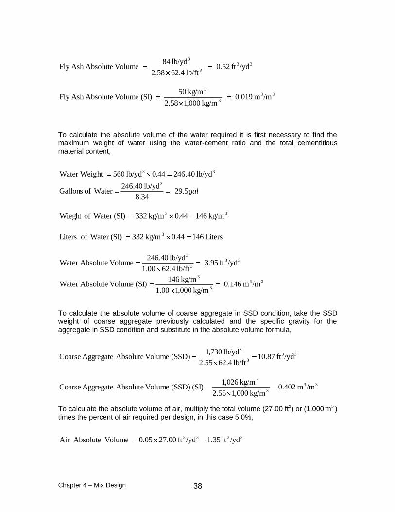
Chapter 4 – Mix Design 38
33
3
3
/ydft 52.0lb/ft 4.6258.2
lb/yd 84 Volume AbsoluteAsh Fly
33
3
3
/mm 019.0kg/m 000,158.2
kg/m 50 (SI) Volume AbsoluteAsh Fly
To calculate the absolute volume of the water required it is first necessary to find the maximum weight of water using the water-cement ratio and the total cementitious material content,
33 lb/yd 40.246440lb/yd 560ht Water Weig .
gal5.2934.8
lb/yd 40.246 Water of Gallons
3
33 kg/m 146440kg/m 332 (SI) Water ofWieght .
Liters 146440kg/m 332 (SI) Water of Liters 3 .
33
3
3
/ydft 95.3lb/ft 4.6200.1
lb/yd 40.246 Volume AbsoluteWater
33
3
3
/mm 146.0kg/m 000,100.1
kg/m 146(SI) Volume AbsoluteWater
To calculate the absolute volume of coarse aggregate in SSD condition, take the SSD weight of coarse aggregate previously calculated and the specific gravity for the aggregate in SSD condition and substitute in the absolute volume formula,
33
3
3
/ydft 87.10lb/ft 4.6255.2
lb/yd 730,1 (SSD) Volume Absolute Aggregate Coarse
33
3
3
/mm 402.0kg/m 000,155.2
kg/m 026,1 (SI) (SSD) Volume Absolute Aggregate Coarse
To calculate the absolute volume of air, multiply the total volume (27.00 ft3) or (1.0003m )
times the percent of air required per design, in this case 5.0%,
3333 /ydft 35.1/ydft 00.2705.0 Volume AbsoluteAir

Chapter 4 – Mix Design 39
3333 /mm 050.0/m.000m 105.0 (SI) Volume AbsoluteAir
The absolute volume of fine aggregate is obtained by subtracting the sum of all the components from the absolute volume of a cubic yard (27.00 ft3), or from one cubic
meter (1.0003m ).
33
33
/ydft 89.7
ft )35.187.1095.352.042.2(.00ft 27 (SSD) Volume Absolute Aggregate Fine
33
33
/mm 293.0
m )050.0402.0146.0019.0090.0(m 000.1 (SI) (SSD) Volume Absolute Aggregate Fine
Once the absolute volume of fine aggregate is known, the absolute volume formula can be used to determine the weight of fine aggregate in SSD condition,
3333 lb/yd 290,1lb/ft 4.6262.2/ydft 89.7 (SSD) Weight Aggregate Fine
3333 kg/m 768kg/m 000,162.2/mm 293.0 (SI) (SSD) Weight Aggregate Fine
The batch weights for one cubic yard of concrete mixture for this design are the following:
English:
Mix Proportions for one Cubic Yard (Cubic Meter) of Concrete
Cement 4 7 6 lb (kg)
Fly Ash 8 4 lb (kg)
Slag lb (kg)
Fine Aggregate (SSD) 1 2 9 0 lb (kg)
Course Aggregate 1 (SSD) 1 7 3 0 lb (kg)
Course Aggregate 2 (SSD) lb (kg)
Water 2 9 . 5 gal (L)
Water Reducer 3 8 . 5 0 oz (ml)
Air Entrainer 2 . 9 2 oz (ml)

Chapter 4 – Mix Design 40
Metric:
Mix Proportions for one Cubic Yard (Cubic Meter) of Concrete
Cement 2 8 2 (kg)
Fly Ash 5 0 (kg)
Slag (kg)
Fine Aggregate (SSD) 7 6 8 (kg)
Course Aggregate 1 (SSD) 1 0 2 6 (kg)
Course Aggregate 2 (SSD) (kg)
Water 1 4 6 (L)
Water Reducer 1 5 1 7 (ml)
Air Entrainer 1 1 6 (ml)
These proportions will require adjustment to take into consideration the moisture present on the aggregates and batch size. Adjustments may be necessary based on field experience with the mixture. Moisture adjustment calculations are presented in Example 1.
EXAMPLE GGBFS as Partial Replacement of Portland Cement
The following is an example of the design of a Class AA mix using an air entrainment and water reducing admixture. The specification for this mixture allows the use of ground granulated blast-furnace slag (GGBFS) as pound for pound substitution of cement up to 50% GGBFS by weight of cement. This example utilizes the absolute volume method for proportioning concrete mixtures. The calculations are presented in both U.S. customary units and international system (SI) units.
Given:
minimum cementitious material content 560 lb 332 kg GGBFS substitution by weight 50% maximum water-cement ratio 0.44 air content 5.0 % maximum size of aggregate 3/4 in. 19.0 mm dry-rodded unit weight of coarse aggregate 100 lb/ft3 1,602.0 kg/m3 specific gravity of coarse aggregate (SSD) 2.55 absorption factor of coarse aggregate 1.5 % fineness modulus of fine aggregate 2.69 specific gravity of fine aggregate (SSD) 2.62 absorption factor of fine aggregate 0.5 % specific gravity of cement 3.15 specific gravity of GGBFS 2.88 admixtures:
water reducer 38.50 oz* 1517 mL* air entrainment 2.92 oz* 116 mL*
* These quantities are already included in the maximum allowed water.

Chapter 4 – Mix Design 41
Since this example differs from Example 2 only in the use of GGBFS instead of fly ash, the only proportions that need to be recalculated are for the cement, GGBFS and fine aggregate.
Determination of mix proportions of cement and GGBFS
Calculate the weights of GGBFS and cement in the same way as Example 2.
33 lb/yd 280100
50lb/yd 605
onSubstituti GGBFS Content usCementitio WeightGGBFS
33 kg/m 166100
50kg/m 332 (SI) Weight GGBFS
333 lb/yd 280lb/yd 280lb/yd 560
WeightGGBFS Content usCementitio ght Cement Wei
333 kg/m 166lb/yd 166kg/m332 (SI)ght Cement Wei
WaterofWeightUnitGravitySpecific
componentofWeightVolumeAbsolute
33
3
3
/ydft 42.1lb/ft 4.6215.3
lb/yd 280 Volume AbsoluteCement
33
3
3
/mm 053.0kg/m 000,115.3
kg/m 166 (SI) Volume AbsoluteCement
33
3
3
/ydft 56.1lb/ft 4.6288.2
lb/yd 280 Volume Absolute GGBFS
33
3
3
/mm 058.0kg/m 000,188.2
kg/m 166 (SI) Volume Absolute GGBFS
Determination of mix proportions of fine aggregate
The absolute volume of fine aggregate is obtained by subtracting the sum of all the components from the absolute volume of a cubic yard (27.00 ft3), or a cubic meter (1.000) for SI units.

Chapter 4 – Mix Design 42
33
33
/ydft 85.7
ft )35.187.1095.356.142.1(ft 00.27 (SSD) Volume Absolute Aggregate Fine
33
33
/mm 291.0
m )050.0402.0146.0058.0053.0(m 000.1 (SI) (SSD) Volume Absolute Aggregate Fine
Once the absolute volume of fine aggregate is known, the absolute volume formula can be used to determine the weight of fine aggregate in SSD condition,
3333 lb/yd 283,1lb/ft 4.6262.2/ydft 85.7 (SSD) Weight Aggregate Fine
3333 kg/m 762kg/m 000,162.2/mm291.0 (SSD) Weight Aggregate Fine
The batch weights for one cubic yard and one cubic meter of concrete for this design are the following:
English:
Metric:
Mix Proportions for one Cubic Yard (Cubic Meter) of Concrete
Cement 1 8 1 (kg)
Fly Ash (kg)
Slag 1 8 1 (kg)
Fine Aggregate (SSD) 7 6 2 (kg)
Course Aggregate 1 (SSD) 1 0 2 6 (kg)
Course Aggregate 2 (SSD) (kg)
Water 1 4 6 (L)
Water Reducer 1 5 1 7 (ml)
Air Entrainer 1 1 6 (ml)
Mix Proportions for one Cubic Yard (Cubic Meter) of Concrete
Cement 2 8 0 lb (kg)
Fly Ash lb (kg)
Slag 2 8 0 lb (kg)
Fine Aggregate (SSD) 1 2 8 3 lb (kg)
Course Aggregate 1 (SSD) 1 7 3 0 lb (kg)
Course Aggregate 2 (SSD) lb (kg)
Water 2 9 . 5 gal (L)
Water Reducer 3 8 . 5 0 oz (ml)
Air Entrainer 2 . 9 2 oz (ml)
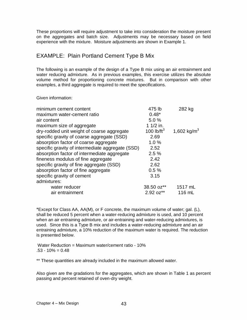
Chapter 4 – Mix Design 43
These proportions will require adjustment to take into consideration the moisture present on the aggregates and batch size. Adjustments may be necessary based on field experience with the mixture. Moisture adjustments are shown in Example 1.
EXAMPLE: Plain Portland Cement Type B Mix
The following is an example of the design of a Type B mix using an air entrainment and water reducing admixture. As in previous examples, this exercise utilizes the absolute volume method for proportioning concrete mixtures. But in comparison with other examples, a third aggregate is required to meet the specifications.
Given information:
minimum cement content 475 lb 282 kg maximum water-cement ratio 0.48* air content 5.0 % maximum size of aggregate 1 1/2 in. dry-rodded unit weight of coarse aggregate 100 lb/ft3 1,602 kg/m3 specific gravity of coarse aggregate (SSD) 2.69 absorption factor of coarse aggregate 1.0 % specific gravity of intermediate aggregate (SSD) 2.52 absorption factor of intermediate aggregate 2.5 % fineness modulus of fine aggregate 2.42 specific gravity of fine aggregate (SSD) 2.62 absorption factor of fine aggregate 0.5 % specific gravity of cement 3.15 admixtures:
water reducer 38.50 oz** 1517 mL air entrainment 2.92 oz** 116 mL
*Except for Class AA, AA(M), or F concrete, the maximum volume of water; gal. (L), shall be reduced 5 percent when a water-reducing admixture is used, and 10 percent when an air entraining admixture, or air-entraining and water-reducing admixtures, is used. Since this is a Type B mix and includes a water-reducing admixture and an air entraining admixture, a 10% reduction of the maximum water is required. The reduction is presented below. Water Reduction = Maximum water/cement ratio - 10% .53 - 10% = 0.48 ** These quantities are already included in the maximum allowed water.
Also given are the gradations for the aggregates, which are shown in Table 1 as percent passing and percent retained of oven-dry weight.
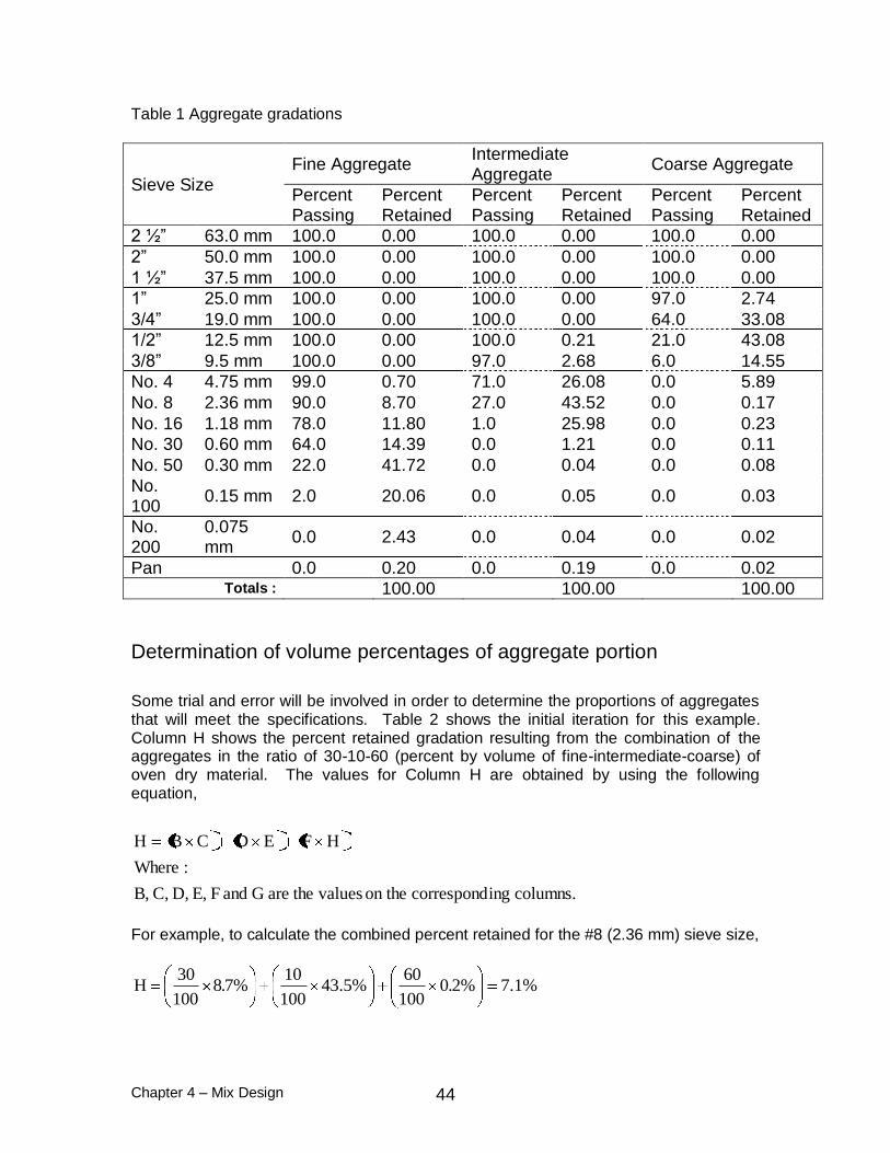
Chapter 4 – Mix Design 44
Table 1 Aggregate gradations
Sieve Size
Fine Aggregate Intermediate Aggregate
Coarse Aggregate
Percent Passing
Percent Retained
Percent Passing
Percent Retained
Percent Passing
Percent Retained
2 ½” 63.0 mm 100.0 0.00 100.0 0.00 100.0 0.00
2” 50.0 mm 100.0 0.00 100.0 0.00 100.0 0.00
1 ½” 37.5 mm 100.0 0.00 100.0 0.00 100.0 0.00
1” 25.0 mm 100.0 0.00 100.0 0.00 97.0 2.74
3/4” 19.0 mm 100.0 0.00 100.0 0.00 64.0 33.08
1/2” 12.5 mm 100.0 0.00 100.0 0.21 21.0 43.08
3/8” 9.5 mm 100.0 0.00 97.0 2.68 6.0 14.55
No. 4 4.75 mm 99.0 0.70 71.0 26.08 0.0 5.89
No. 8 2.36 mm 90.0 8.70 27.0 43.52 0.0 0.17
No. 16 1.18 mm 78.0 11.80 1.0 25.98 0.0 0.23
No. 30 0.60 mm 64.0 14.39 0.0 1.21 0.0 0.11
No. 50 0.30 mm 22.0 41.72 0.0 0.04 0.0 0.08
No. 100
0.15 mm 2.0 20.06 0.0 0.05 0.0 0.03
No. 200
0.075 mm
0.0 2.43 0.0 0.04 0.0 0.02
Pan 0.0 0.20 0.0 0.19 0.0 0.02 Totals : 100.00 100.00 100.00
Determination of volume percentages of aggregate portion
Some trial and error will be involved in order to determine the proportions of aggregates that will meet the specifications. Table 2 shows the initial iteration for this example. Column H shows the percent retained gradation resulting from the combination of the aggregates in the ratio of 30-10-60 (percent by volume of fine-intermediate-coarse) of oven dry material. The values for Column H are obtained by using the following equation,
columns. ingcorrespond on the values theareG and F E, D, C, B,
:Where
HFEDCBH
For example, to calculate the combined percent retained for the #8 (2.36 mm) sieve size,
%1.7%20100
60%5.43
100
10%78
100
30H ..

Chapter 4 – Mix Design 45
Table 2 Initial iteration for pavement mix design
A B C D E F G H I
Sieve Size
Sieve Size (mm)
Fine Aggregate Intermediate Aggregate
Coarse Aggregate Combined
Percent Retained
Sum of Consecutive
Sieves Percent
by Volume
Percent Retained
Percent by
Volume
Percent Retained
Percent by
Volume
Percent Retained
2 ½” 63.0 30.0%
0.00 10.0%
0.00 60.0%
0.00 0
2” 50.0 0.00 0.00 0.00 0
1 ½” 37.5 0.00 0.00 0.00 0
1” 25.0 0.00 0.00 2.74 2
3/4” 19.0 0.00 0.00 33.08 20
1/2” 12.5 0.00 0.21 43.08 26 46
3/8” 9.5 0.00 2.68 14.55 9 35
No. 4 4.75 0.70 26.08 5.89 6 15
No. 8 2.36 8.70 43.52 0.17 7 13
No. 16 1.18 11.80 25.98 0.23 6 13
No. 30 0.60 14.39 1.21 0.11 5 11
No. 50 0.30 41.72 0.04 0.08 13
No. 100 0.15 20.06 0.05 0.03 6
No. 200 0.075 2.43 0.04 0.02 1
Pan 0.20 0.19 0.02 0 Totals : 100.0 100.0 100.0 100
From examination of Column H in Table 2 or by looking at Figure 1, it can be determined that this combination of aggregates do not meet the specification for a Type B concrete pavement mixture.
The specification for this pavement mixture requires the combined percent retained curve to be between a 5% and a 20% low and upper limits. Also the sum of two consecutive sieve sizes needs to be equal to or greater than 13%.
There is an excess of material retained on the 1/2” sieve, not enough material retained on the #30 sieve and the sum of material retained on sieves #16 and #30 is less than 13%. Additional iterations are required to find a combination that meets the specifications. Based on this data the adjustments to be done in the next iterations could be reducing the coarse aggregate proportion, and increasing the fine and intermediate aggregate proportions.
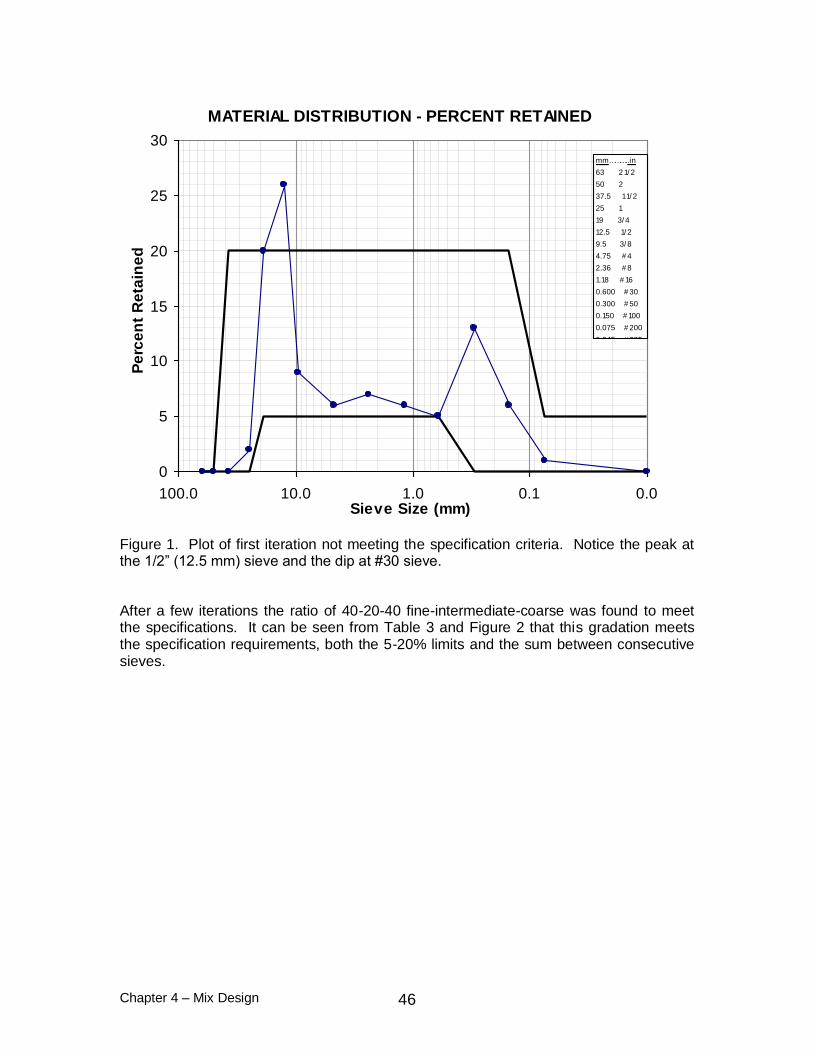
Chapter 4 – Mix Design 46
MATERIAL DISTRIBUTION - PERCENT RETAINED
0
5
10
15
20
25
30
0.00.11.010.0100.0Sieve Size (mm)
Pe
rce
nt
Re
tain
ed
mm………..in
63 2 1/ 2
50 2
37.5 1 1/ 2
25 1
19 3/ 4
12.5 1/ 2
9.5 3/ 8
4.75 # 4
2.36 # 8
1.18 # 16
0.600 # 30
0.300 # 50
0.150 # 100
0.075 # 200
0.045 # 325
Figure 1. Plot of first iteration not meeting the specification criteria. Notice the peak at the 1/2” (12.5 mm) sieve and the dip at #30 sieve.
After a few iterations the ratio of 40-20-40 fine-intermediate-coarse was found to meet the specifications. It can be seen from Table 3 and Figure 2 that this gradation meets the specification requirements, both the 5-20% limits and the sum between consecutive sieves.

Chapter 4 – Mix Design 47
Table 3. Final iteration of aggregate combination meeting the specification requirements.
A B C D E F G H I
Sieve Size
Sieve Size (mm)
Fine Aggregate Intermediate Aggregate
Coarse Aggregate Combined
Percent Retained
Sum of Consecutive
Sieves Percent
by Volume
Percent Retained
Percent by
Volume
Percent Retained
Percent by
Volume
Percent Retained
2 ½” 63.0 40.0%
0.00 20.0%
0.00 40.0%
0.00 0
2” 50.0 0.00 0.00 0.00 0
1 ½” 37.5 0.00 0.00 0.00 0
1” 25.0 0.00 0.00 2.74 1
3/4” 19.0 0.00 0.00 33.08 13
1/2” 12.5 0.00 0.21 43.08 17 30
3/8” 9.5 0.00 2.68 14.55 6 23
No. 4 4.75 0.70 26.08 5.89 8 14
No. 8 2.36 8.70 43.52 0.17 12 20
No. 16 1.18 11.80 25.98 0.23 10 22
No. 30 0.60 14.39 1.21 0.11 6 16
No. 50 0.30 41.72 0.04 0.08 17
No. 100 0.15 20.06 0.05 0.03 8
No. 200 0.075 2.43 0.04 0.02 1
Pan 0.20 0.19 0.02 0 Totals : 100.0 100.0 100.0 100
MATERIAL DISTRIBUTION - PERCENT RETAINED
0
5
10
15
20
25
0.00.11.010.0100.0Sieve Size (mm)
Pe
rce
nt
Re
tain
ed
mm………..in
63 2 1/ 2
50 2
37.5 1 1/ 2
25 1
19 3/ 4
12.5 1/ 2
9.5 3/ 8
4.75 # 4
2.36 # 8
1.18 # 16
0.600 # 30
0.300 # 50
0.150 # 100
0.075 # 200
0.045 # 325
Figure 2. Plot of final iteration of combined aggregate gradation meeting the specification requirements.
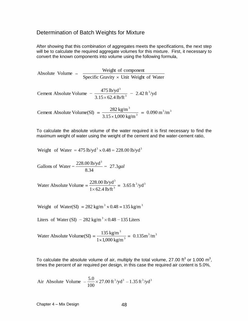
Chapter 4 – Mix Design 48
Determination of Batch Weights for Mixture
After showing that this combination of aggregates meets the specifications, the next step will be to calculate the required aggregate volumes for this mixture. First, it necessary to convert the known components into volume using the following formula,
WaterofWeightUnitGravitySpecific
componentofWeightVolumeAbsolute
/ydft 42.2lb/ft 4.6215.3
lb/yd 475 Volume AbsoluteCement 3
3
3
33
3
3
/mm 090.0kg/m 000,115.3
kg/m 822 Volume(SI) AbsoluteCement
To calculate the absolute volume of the water required it is first necessary to find the maximum weight of water using the weight of the cement and the water-cement ratio,
33 lb/yd 00.228480lb/yd 475 Water ofWeight .
gal3.2734.8
lb/yd 00.228 Water of Gallons
3
33
3
3
/ydft 65.3lb/ft 4.621
lb/yd 00.228 Volume AbsoluteWater
33 kg/m 135480kg/m 282 Water(SI)ofWeight .
Liters 135480kg/m 282 (SI) Water of Liters 3 .
33
3
3
/mm135.0kg/m 000,11
kg/m 135 Volume(SI) AbsoluteWater
To calculate the absolute volume of air, multiply the total volume, 27.00 ft3 or 1.000 m3, times the percent of air required per design, in this case the required air content is 5.0%,
3333 /ydft 35.1/ydft 00.27100
0.5 Volume AbsoluteAir

Chapter 4 – Mix Design 49
3333 /mm 05.0/mm 000.1100
0.5 Volume(SI) AbsoluteAir
The absolute volume of the aggregate component is obtained by subtracting the sum of all the components from the absolute volume of a cubic yard (27.00 ft3),
3333 /ydft 58.19ft )35.165.342.2(ft 00.27 Volume AbsoluteComponent Aggregate
3333 /mm 725.0m )050.0135.0090.0(m 000.1 Volume(SI) AbsoluteComponent Aggregate
Now the volumes for the individual aggregates can be calculated,
3333 /ydft 83.7100
%0.40/ydft58.19 Volume Absolute Aggregate Coarse
3333 /ydft 92.3100
%0.20/ydft58.19 Volume Absolute Aggregate teIntermedia
3333 /ydft 83.7100
%0.40/ydft58.19 Volume Absolute Aggregate Fine
3333 /mm 290.0100
%0.40/mm725.0 Volume(SI) Absolute Aggregate Coarse
3333 /mm 145.0100
%0.20/mm725.0 Volume(SI) Absolute Aggregate teIntermedia
3333 /mm 290.0100
%0.40/mm725.0 Volume(SI) Absolute Aggregate Fine
To calculate the aggregate batch weights in Saturated Surface Dry condition (SSD), using the SSD specific gravity, the absolute volume equation can be rearranged in the following form,
Wateroft Unit WeighGravity Specific Volume Absolute Component ofWeight
3333 lb/yd314,1lb/ft4.6269.2/ydft83.7 (SSD) Weight Aggregate Coarse

Chapter 4 – Mix Design 50
3333 lb/yd616lb/ft4.6252.2/ydft92.3 (SSD) Weight Aggregate teIntermedia
3333 lb/yd280,1lb/ft4.6262.2/ydft83.7 (SSD) Weight Aggregate Fine
3333 kg/m780kg/m000,169.2/mm0.290 (SI) (SSD) Weight Aggregate Coarse
3333 kg/m365kg/m000,152.2/mm0.145 (SI) (SSD) Weight Aggregate teIntermedia
3333 kg/m760kg/m000,162.2/mm0.290 (SI) (SSD) Weight Aggregate Fine
The following are the batch weights at SSD condition required for one cubic yard or one cubic meter of concrete:
English:
Metric:
Mix Proportions for one Cubic Yard (Cubic Meter) of Concrete
Cement 2 8 2 (kg)
Fly Ash (kg)
Slag (kg)
Fine Aggregate (SSD) 7 6 0 (kg)
Course Aggregate 1 (SSD) 7 8 0 (kg)
Course Aggregate 2 (SSD) 3 6 5 (kg)
Water 1 3 5 (L)
Water Reducer 1 5 1 7 (ml)
Air Entrainer 1 1 6 (ml)
These proportions will require adjustment to take into consideration the moisture present on the aggregates and batch size. Adjustments may also be necessary based on field experience with the mixture.
Mix Proportions for one Cubic Yard (Cubic Meter) of Concrete
Cement 4 7 5 lb (kg)
Fly Ash lb (kg)
Slag lb (kg)
Fine Aggregate (SSD) 1 2 8 0 lb (kg)
Course Aggregate 1 (SSD) 1 3 1 4 lb (kg)
Course Aggregate 2 (SSD) 6 1 6 lb (kg)
Water 2 7 . 3 gal (L)
Water Reducer 3 8 . 5 0 oz (ml)
Air Entrainer 2 . 9 2 oz (ml)

Chapter 4 – Mix Design 51
Calculation of Oven-Dry Weight of Materials
If the oven-dry weight of the aggregates is desired then the following equation can be used to convert SSD weight into oven-dry weight,
100
Factor Absorption 1
(SSD) Weight Aggregate (dry) Weight Aggregate
33
lb/yd3011
100
011
lb/yd3141 (dry) Weight Aggregate Coarse ,
.
,
33
lb/yd601
100
5.21
lb/yd616 (dry) Weight Aggregate teIntermedia
33
lb/yd2741
100
5.01
lb/yd2801 (dry) Weight Aggregate Fine ,
,
33
kg/m772
100
011
kg/m780 (SI) (dry) Weight Aggregate Coarse
.
33
kg/m356
100
5.21
kg/m365 (SI) (dry) Weight Aggregate teIntermedia
33
kg/m756
100
5.01
kg/m760 (SI) (dry) Weight Aggregate Fine

Chapter 4 – Mix Design 52

Chapter 5 – Plant Operations 53
CHAPTER 5 - PLANT OPERATIONS
RESPONSIBILITIES OF CONTRACTOR'S CERTIFIED TECHNICIAN
The portland cement concrete specifications place the responsibility for the purchase of materials, the design and production of the mixture, and the transportation and final placement of the mixture on the contractor within the guidelines of the specifications and the direction of the engineer. Therefore, the contractor's certified concrete technician is responsible for quality control. Quality control is defined as the
constant monitoring of equipment, materials and processes to ensure that portland cement concrete mixtures produced and placed are uniform, are within control limits, and meet all requirements of Table 1 of Section 901, as well as all other requirements of the Standard Specifications. The details of the certified concrete technician's
responsibilities for quality control are covered under SAMPLING, TESTING AND DOCUMENTATION.
The contractor's certified concrete technician must be at the plant or project site whenever the plant is in operation. (When only minor structure concrete class concrete is being produced, the certified technician is not required.) Prior to beginning daily plant operations, the certified concrete technician must ensure that all materials to be incorporated into the mixture have been approved; that all certifications, test reports and other required documentation are available; and must run gradation and moisture content tests of the aggregate stockpiles. The technician is responsible for sampling and testing for control, including determining moisture contents and adjusting batch weights, setting all metering devices and scales, and ensuring that the plant is operating satisfactorily. Furthermore, the technician shall monitor the reception of materials and mix production in such a manner that all criteria established by the mix design and the Standard Specifications are met. To eliminate problems in the area of transport and
mixing, the technician must also observe the trucks, their condition, and the loading operation. The contractor's certified technician must also be certain, prior to beginning any concrete operations for DOTD, that all scales and metering devices are functioning properly and have been properly calibrated and certified, in accordance with department policies. For department policies regarding the certification of scales and metering devices, refer to page 14.
The contractor's certified technician must check all scales prior to beginning batching operations and frequently during construction activity to ensure that scales zero. The technician must be certain that the batch weights for all components are clearly marked on the scales (dial) or as otherwise indicated (digital).
The certified technician shall determine the number of revolutions at mixing speed that the concrete will be mixed at the plant. The number must be chosen so that the specification limits of 70-130 revolutions will not be exceeded. The number of revolutions at the plant shall be documented on the Batch Certification for Portland

Chapter 5 – Plant Operations 54
Cement Concrete: 03-22-4028 and verified by the Authorized Concrete Batcher. An
example of this form properly completed by contractor is shown on pages A-29 - A-31 in the Appendix.
When complete mixing (minimum 50 seconds) is accomplished at a central mix plant, additional mixing at mixing speed will not be required during transport. If the concrete is partially mixed at a central mix plant, the mixture must be mixed a minimum of thirty seconds at the stationary mixer. It shall then be mixed between 20-30 revolutions at mixing speed in the truck transport.
RESPONSIBILITIES OF CONTRACTOR'S AUTHORIZED FIELD TESTER
An Authorized Concrete Field Tester will be allowed to perform the following QC testing:
slump
make cylinders
air content
take temperature
water at the job site
SAMPLING, TESTING AND DOCUMENTATION
The Materials Sampling Manual establishes minimum acceptable sampling and testing
frequencies for projects using portland cement concrete. Additional tests or samples may be obtained to verify that the corrections adjust the mixture to specification requirements when test results require that adjustments be made to the equipment, mixture or process.
CEMENT
The contractor's certified technician is responsible for ensuring that every transport of cement is from an approved source and is accompanied by a Cement Certificate of Delivery. Approved sources of portland cement and portland-pozzolan cement are listed on the department's Qualified Products List, No. 7. In accordance with EDSM
No.V.1.1.2, the manufacturer's (or terminal's) seal shall be placed on the discharge end of each truck transport. These seals shall be intact and in place upon arrival at the concrete plant.
If cement is unloaded during non-working hours or delivered to a commercial concrete plant, it will be the responsibility of the designated plant representative to verify that all conveyances were properly sealed. Retention of seals will not be required. Should any conveyance arrive on the job without being properly sealed, the material contained therein shall not be accepted.

Chapter 5 – Plant Operations 55
The certified technician shall also ensure that the right type of cement is being used in the mixture and that cements of different types or sources are not mixed. The certified technician shall check the alkali content of the cement on the Cement Certification of Delivery. Reactive aggregate shall not be used with cement which has an alkali content
greater than 0.60 percent.
FLY ASH, GROUND GRANULATED BLAST FURNACE SLAG (SLAG) & BLENDED CEMENTS (1P & 1S)
When fly ash or slag is to be incorporated into the mixture, the contractor is responsible for ensuring that every transport of fly ash or slag is from an approved source and is accompanied by a Fly Ash or Slag Certificate of Delivery. A copy of the department's Fly Ash Certificate of Delivery: 03-22-0023, Ground Granulated Blast Furnace Slag Certificate of Delivery: 03-22-0032 is reprinted in the Appendix on page A-33 and A-34. If blended cement is used, see a copy of Certificate of Delivery for Portland Cement, Portland-Pozzolan Cement and Portland Blast-Furnace Slag Cement on page A-35. Approved sources for these materials are listed in the department's Qualified Products List. In accordance with EDSM No. V.1.1.2, the manufacturer's (or terminal's) seal shall
be placed on the discharge end of each truck transport. These seals shall be intact and in place upon arrival at the concrete plant. If any of these materials are unloaded during non-working hours or delivered to a commercial concrete plant, it will be the responsibility of the designated plant representative to verify that all conveyances were properly sealed. Retention of seals will not be necessary.
Should any conveyance arrive on the job without being properly sealed, the material contained therein shall not be accepted.
The certified technician shall also ensure that the right type of fly ash (C or F) and grade of slag (100 or 120) is being used as specified in the contract. Fly ash or slag of different types or sources shall not be mixed. The certified technician shall check the alkali content of the fly ash on the Fly Ash Certificate of Delivery. Reactive aggregate
shall not be used with fly ash which has an alkali content greater than 1.5%. No tertiary cement blends (cement, fly ash and slag together) are allowed.
ADMIXTURES
When an admixture is incorporated into the mixture, the contractor is responsible for ensuring that every shipment of the admixture is from an approved source and is accompanied by an Admixture Certificate of Delivery. A copy of the department's Admixture Certificate of Delivery is reprinted in the appendix on page A-36. Approved sources of admixture are listed in the department's Qualified Products List No. 58. If the shipment does not have a Certificate of Delivery, the certified technician shall notify the

Chapter 5 – Plant Operations 56
project engineer and request that a sample be taken and submitted for testing. It will take approximately 10 days to receive test results. No admixture that has not been approved is to be used in concrete for DOTD projects.
If ambient air temperatures are such that an admixture may have been exposed to freezing temperatures, the material must be remixed, resampled, retested and approved prior to use.
AGGREGATES
GRADATION
As a requirement of the Standard Specifications, the certified concrete technician shall
test both fine and coarse aggregates to determine gradation, which includes the amount of material passing the No. 200 (75 µm) sieve by wash, according to the following schedule. These tests shall be documented on an Aggregate Test Report form (DOTD
03-22-0745). This form shall be made available to the department on a daily basis. A copy of this form is shown on pages A-37 and A-38.
FINE AGGREGATE
The gradation of fine aggregate shall be routinely determined by dry sieving (DOTD Designation: TR 113) except when:
The percent passing the No. 200 (75 µm) sieve by dry sieving technique exceeds two percent.
The district laboratory acceptance sample indicates excessive minus No. 200 (75 µm) material. Should this situation occur, the samples shall be washed until the problem has been resolved.
When excessive minus No. 200 (75 µm) material is encountered and gradation samples must be tested by washing, a minimum of one sample per day shall be run in order to monitor and control stockpile conditions.
COARSE AGGREGATE
The gradation of coarse aggregate shall be routinely determined by dry sieving (DOTD Designation: TR 113) except when:
For Dedicated Stockpiles*

Chapter 5 – Plant Operations 57
If visual inspection indicates that contamination is occurring in a dedicated stockpile, the certified technician shall be required to determine the percent of material passing the No. 200 (75 µm) sieve by wash on each sample until the problem has been resolved to the satisfaction of the engineer.
For Nondedicated Stockpiles*
a. Structural Operations
The minus No. 200 (75 µm) wash shall not be run during routine gradation tests conducted by the certified technician, unless required by the engineer from visual inspection of the stockpile or the failure of the percentage of minus No. 200 (75 µm) material during testing of the independent fifth lot sample by the district laboratory.
b. Paving Operations
Every fifth pour the certified technician shall include the minus No. 200 (75 µm) wash in the daily gradation analysis performed for quality control. Additionally, the aggregates shall be checked visually each day for contamination and clay coating. If any samples tested by the district laboratory indicate failure of the minus No. 200 (75 µm) material, the certified technician will be required to run the minus No. 200 (75 µm) wash until the problem is resolved to the satisfaction of the engineer. The engineer may require that additional minus No. 200 (75 µm) wash testing be performed.
AGGREGATE TEST REPORT: DOTD 03-22-0745
Each aggregate gradation for fine and coarse aggregates shall be documented on the Aggregate Test Report. It is the responsibility of the contractor to complete this form. A copy of the complete Aggregate Test Report shall be sent to the district laboratory with
the acceptance sample.
Examples of Aggregate Test Reports for coarse and fine aggregates, properly
completed, are shown in the Appendix on pages A-37 and A-38.

Chapter 5 – Plant Operations 58
CONCRETE AGGREGATE CONTROL CHARTS: DOTD 03-22-5004
The information from the Aggregate Test Report: 03-22-0745 will be used to complete the Concrete Aggregate Control Charts. These charts shall be completed each day by
the contractor and shall be available at the plant for review by the department's certified inspector or other department personnel. The original of these charts will be provided to the project engineer for project records. The contractor may keep copies of these charts for his own records.
Test results shall be entered on the control charts after the completion of the tests. These results shall be analyzed to ensure that the results are within specification tolerances and to ascertain whether or not any trends in gradation are developed which might prove detrimental to the mixture. If test results show the gradation to be outside of specification limits, no material shall be produced for DOTD projects using these materials.
A trend toward the outer limits of the specifications may be caused by a change in material source, stockpile segregation, poor handling techniques, and a naturally occurring change in gradation in the material from the supplier, etc. If the control charts show a trend toward the outside limits of the specifications, the contractor shall take action to ensure that materials used on DOTD projects will meet specifications on a continuous basis and in a uniform manner.
Examples of properly completed Concrete Aggregate Control Charts for coarse and fine aggregates are shown in the Appendix on pages A-39 and A-40.
MOISTURE CONTENT OF FINE AND COARSE AGGREGATES
Moisture content of fine and coarse aggregates to be used in concrete shall be determined at the beginning of each day's operation from samples obtained from the stockpile material to be incorporated in that day's production. Additionally, moisture contents must be determined whenever a change in moisture content occurs in stockpiled materials. These changes may be the result of weather conditions, length of storage, vertical location within the stockpile, or other conditions which lead to nonuniform moisture content. Changes in moisture content can lead to slump control problems. Moisture contents of fine and coarse aggregate shall be determined in accordance with DOTD Designation: TR 106.

Chapter 5 – Plant Operations 59
CONCRETE
PORTLAND CEMENT CONCRETE PLANT REPORT: DOTD 03-22-4040
The Portland Cement Concrete Plant Report is to be completed and signed by the contractor. A copy of a properly completed Portland Cement Concrete Plant Report is
reprinted in the Appendix on pages A-25 through A-27. This form, in conjunction with the Batch Certification for Portland Cement Concrete: 03-22-4028, is designed to document portland cement concrete batching operations. A copy of the form shall be completed at least once per day and when there are changes to the mix design or when batch weights must be adjusted to compensate for changes in the moisture content of the aggregate.
Design (SSD) batch weights and total batch weights for each size batch used for the project shall be calculated and shown on the Portland Cement Concrete Plant Report. Actual batch weights will be documented on the Batch Certification: 03-22-4028 for
each individual batch. This form is shown in the Appendix on pages A-29 through A-31
The original of the Portland Cement Concrete Plant Report shall be provided to the
DOTD certified inspector for inclusion in project records. The contractor may keep as many copies as needed for records.
CALCULATING BATCH WEIGHTS FROM MIX DESIGN PROPORTIONS - ENGLISH
The proportions calculated for design purposes (example Chapter 4) must be modified, for actual production, into batch weights based on the amount of total water in the fine and coarse aggregate determined by DOTD Designation: TR 106. These adjustments must be performed at least once per day prior to starting operations to account for changes in free moisture in the aggregate stockpiles. The Portland Cement Concrete Plant Report: 03-22-4040 is provided by the department for the certified technician to
use for these computations. The completed form should be kept with the daily control charts for review by the department's certified inspector.
The maximum allowable water for design purposes is the amount of water that may be used, not the amount of water that must be used. Only enough water to
produce concrete within the correct slump range should actually be used; however, in this example, for convenience, calculations will be based on using maximum allowable water.

Chapter 5 – Plant Operations 60
Cement used in making concrete is dry; therefore, no moisture corrections need to be made for cement. However, the sand and gravel will normally contain a different amount of moisture than the moisture content of the saturated surface dry condition (SSD). Therefore, the wet weight of each (sand and gravel), must be adjusted so that the quantity charged into the mixer will be the equivalent of the saturated surface dry quantity.
The mix design shall be adjusted to compensate for these conditions and are documented on the Portland Cement Concrete Plant Report: 03-22-4040. For this
example, the moisture contents of the stockpiled aggregates for a Class AA mix as determined by DOTD Designation: TR 403 are 4.4% for the fine aggregate and 0.3% for the course aggregate. The Absorption Factors are taken from the Qualified Products List 2. The Metric values are shown in parentheses.
Aggregate Tests Test 1
Fine Coarse
Time of Test 6:30AM 6:30AM
A: tare mass, g (lb) 300.0 2.12
B: Wet mass (A+sample), g(lb) 863.0 12.90
C: Dry mass (A+ sample), g (lb) 839.3 12.87
D: Mass of Water (B-C), g (lb) 23.7 0.03
E: Dry mass of sample 539.3 10.75
F: Percent total moisture (D/E)% 4.4 0.3
G: Absorption factor, % 0.5 1.5
H: Percent free moisture (F-G), % 3.9 -1.2
I: Aggr. (SSD) from mix design, kg/m3 (lb/Cu yd) 1305 (778) 1730 (1026)
J: Corrected mass (1+(H/100)) I, kg(lb) 1356 (808) 1709 (1014)
The following equation can be used to determine the free moisture or additional water on the aggregates:
%%.%.
%.%.%.
2.15130 (%) Moisture Free Agg. Coarse
935044 (%) Moisture Free Agg. Fine
Aggregate ofFactor Absorption - Moisture Aggregate (%) Moisture Free Aggregate
It can be seen that the fine aggregate contains 3.9% of water above the SSD condition (free water for mixing), while the coarse aggregate needs 1.2% of water to get to SSD condition (water that will be absorbed from the mixing water). These percentages are now converted into weights. The aggregate weights corrected for moisture content are determined by the following equation:

Chapter 5 – Plant Operations 61
lb709,1100
%2.11lb7301 Weight Agg. Coarse Corrected
lb356,1100
%9.31lb3051 Weight Agg. Fine Corrected
100
Agg.in % Moisture Free1 Weight SSD Agg. Weight Agg. Corrected
,
,
kg014,1100
%2.11kg0261 (SI) Weight Agg. Coarse Corrected
kg808100
%9.31kg 778 (SI) Weight Agg. Fine Corrected
,
The free water in the aggregates can be found by subtracting the SSD weight from the corrected weight:
I: Aggr. (SSD) from mix design, kg/m3 (lb/Cu yd) 1305 (778) 1730 (1026)
J: Corrected mass (1+(H/100))1, kg(lb) 1356 (808) 1709 (1014)
K: Free Water (J-I), kg (lb) 51 (30) -21 (-12)
L: Free Water (1kg=1L), L[(K/8.34) gal] 6.1 (30) -2.5 (-12)
gals. 2.5- 8.34
lbs. 21- Agg Coursein Gallonson Water Free
gals. 6.1 8.34
lbs. 51 Agg. Finein Gallonsin Water Free
lb21lb7301lb7091 Agg. Coarsein Water Free
lb51lb3051lb3561 Agg. Finein Water Free
WeightSSD Agg.- WeightAgg. Corrected Water Free
,,
,,
Liters 12-or kg12kg 0261kg 0141 (SI) Agg. Coarsein Water Free
Liters 30or kg 30kg 787kg808 (SI) Agg. Finein Water Free
,,

Chapter 5 – Plant Operations 62
The correction for the mixing water is then done by subtracting the free water and the total admixtures in gallons (Liters) from the water calculated for the SSD condition mix design:
M: total admixture from mix design, (mL/1000)[(oz/128)gal] 0.3 (2)
N: Total free water (L for fine and coarse aggr. +M), L (gal) 3.8 (20)
O: Maximum allowable water (from mix design), L (gal) 29.5 (146)
P: Maximum allowable water to be added (O-N), L (gal) 25.6 (126)
Q: Minimum allowable water to be added (.75P), L (gal) 19.2 (94)
0.3gal128oz/gal
oz92.238.50oz Admixtures Total
L 2116ml/1000 1517ml (SI) Admixtures Total
gal9.3..3gal0 2.5gal- gal .16 Water Free Total
L20 L2 L 12- L 30 (SI) Water Free Total
gal6.52 3.9gal - 29.5gal Water Adjusted
L 126 L 20 - L 146 (SI) Water Adjusted
gals. 19.2 .75 x gals. 25.6 *Added be Water toAllowable Minimum
L 94 .75 x L 126 (SI)* Added be Water toAllowable Minimum
*Specifications require that a minimum of 75% of the maximum allowable mixing water must be added at the plant during batching. The batch weights, based on the adjustments made above for the corrected weights of aggregates and the total free water, the actual quantities of the components to be batched for one cubic yard (cubic meter) are below:
Cement 560 lb (332 kg) Minimum Water to Be Added 19.2 gal (94 L) Fine Aggregate (Corrected Mass) 1,356 lb (808 kg) Coarse Aggregate (Corrected Mass) 1,709 lb (1,014 kg) Water Reducing Admixture 38.50 oz (1,517 mL) Air Entrainment Admixture 2.92 oz (116 mL)

Chapter 5 – Plant Operations 63
It is seldom that exactly one cubic yard or one cubic meter batches are used in the field. To adjust the quantities above (adjusted batch weights, stockpile condition) for the field to any size batch, multiply the values for one cubic yard by the number of cubic yards in one batch. For example, if an 8 cubic yard batch is desired, multiply each component by 8. The metric values are shown in parentheses:
Total Batch Calculations
R: Batch Size, m3 (cu yd) 8 (6)
S: Cement (R x mix design mass ), kg (lb) 4480 (1992)
T: Fly Ash (or) Slag (R x mix design mass), kg (lb) -
U: Fine Aggregate (R x J), kg (lb) 10848 (4848)
V: Coarse aggregate (R x J), kg (lb) 13672 (8112)
W: Maximum water to be added (R x P), L (gal) 204.8 (756)
X: Minumum water to be added (R x Q), L (gal) 153.6 (564)
Y: Water Reducing admixture (R x mix design mass), mL (oz) 308.00 (12136)
Z: Air entraining admixture (r x mix design mass), mL (oz) 23.36 (928)
Cement 560 x 8 = 4,480 lb
Cement 332 x 6 = 1,992 kg
Sand 1,356 x 8 = 10,848 lb
Sand 808 x 6 = 4,848 kg
Coarse Aggregate 1,709 x 8 = 13,672 lb
Coarse Aggregate 1,014 x 6 = 8,112 kg
Max. Water 25.6 x 8 = 204.8 gal
Max. Water 126 x 6 = 756 L
*Min. Water 19.2 x 8 = 153.6 gal
*Min. Water 94 x 6 = 752 L
Water Reducer 38.50 x 8 = 308.00 oz
Water Reducer 1,517 x 6 = 9,102 ml
Air Entertainer 2.92 x 8 = 23.36 oz
Air Entertainer 16 x 6 = 696 ml
*Specifications require that a minimum of 75% of the maximum allowable mixing water must be added at the plant during batching.

Chapter 5 – Plant Operations 64
HOT WEATHER ADJUSTMENTS
Whenever the ambient air temperature at the job site reaches 80 F (27 C) and the
internal temperature of the concrete reaches 85 F (30 C), hot weather concreting practices are required for bridge deck construction and mass concrete by Subsection 901.11, Standard Specifications. Concrete production shall be controlled to ensure that
the internal temperature of the plastic concrete does not exceed 90 F (32 C). The addition of ice to the batch is one method of controlling the temperature of the concrete. Whenever ice is added to a batch of concrete, the amount of mixing water must be reduced by a comparable quantity of ice converted to liters or gallons. The following rule can be used to determine the amount of ice to be added per cubic yard in order to lower the temperature. For each degree F (C) reduction, add approximately 5.4 kilograms per
cubic meter or 5 pounds of ice per cubic yard of concrete. (Note: 1 C is approximately
equal to 2 F)
For paving operations, the internal temperature of the plastic concrete shall not exceed
95 F (35 C) at time of placement.
EXAMPLE
To reduce a cubic yard (m3) batch from 85 F (30 C) to 83 F (29 C), approximately 10 pounds of ice (5 kilograms) would be necessary. These values are converted to gallons or liters and then multiplied by the batch size. Additionally, the maximum and minimum water to be must be adjusted so that maximum water/cement ratio is not exceeded.
85 - 83 = 2 F (30 - 29 = 1 C)
2 x 5 lb = 10 lb ice/cu yd (1 C x 5 kg = 5 kg ice/m3 concrete)
gal.6.934.8
8x lb/yd 10 Water of Gallons
3
Liters of water = 5 L/ m3 x 6 = 30 L
Adjusted Maximum Water to be Added 204.8 gal - 9.6 gal = 195.2 gal
756 L - 30 L = 726 L
Adjusted Minimum Water to be Added 153.6 gal - 9.6 gal = 144.0 gal
564 L - 564 L = 534 L
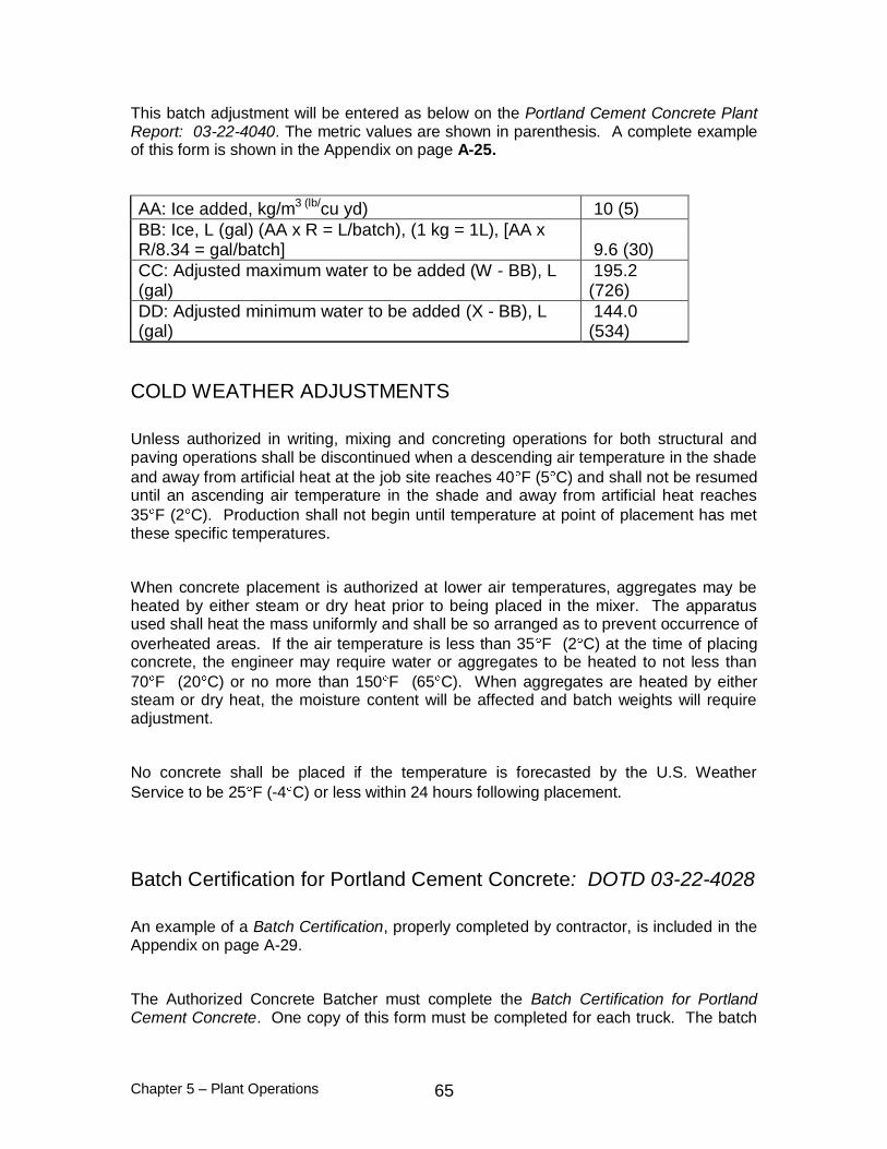
Chapter 5 – Plant Operations 65
This batch adjustment will be entered as below on the Portland Cement Concrete Plant Report: 03-22-4040. The metric values are shown in parenthesis. A complete example of this form is shown in the Appendix on page A-25.
AA: Ice added, kg/m3 (lb/cu yd) 10 (5)
BB: Ice, L (gal) (AA x R = L/batch), (1 kg = 1L), [AA x R/8.34 = gal/batch] 9.6 (30)
CC: Adjusted maximum water to be added (W - BB), L (gal)
195.2 (726)
DD: Adjusted minimum water to be added (X - BB), L (gal)
144.0 (534)
COLD WEATHER ADJUSTMENTS
Unless authorized in writing, mixing and concreting operations for both structural and paving operations shall be discontinued when a descending air temperature in the shade
and away from artificial heat at the job site reaches 40 F (5 C) and shall not be resumed until an ascending air temperature in the shade and away from artificial heat reaches
35 F (2 C). Production shall not begin until temperature at point of placement has met these specific temperatures.
When concrete placement is authorized at lower air temperatures, aggregates may be heated by either steam or dry heat prior to being placed in the mixer. The apparatus used shall heat the mass uniformly and shall be so arranged as to prevent occurrence of
overheated areas. If the air temperature is less than 35 F (2 C) at the time of placing concrete, the engineer may require water or aggregates to be heated to not less than
70 F (20 C) or no more than 150 F (65 C). When aggregates are heated by either steam or dry heat, the moisture content will be affected and batch weights will require adjustment.
No concrete shall be placed if the temperature is forecasted by the U.S. Weather
Service to be 25 F (-4 C) or less within 24 hours following placement.
Batch Certification for Portland Cement Concrete: DOTD 03-22-4028
An example of a Batch Certification, properly completed by contractor, is included in the Appendix on page A-29.
The Authorized Concrete Batcher must complete the Batch Certification for Portland Cement Concrete. One copy of this form must be completed for each truck. The batch

Chapter 5 – Plant Operations 66
information required by the specifications can be provided by an automatic printer system can be entered manually on the form, or by a combination of the two methods. If the information, or any part thereof, required by the batch certification form is supplied by an automatic printer system, the print-out generated by that system shall be attached to Form 03-22-4028 for documentation purposes and for the convenience of the
department's certified inspector.
Control Charts for Slump and Air of Concrete: DOTD 03-22-5003
The results of the contractor's control tests for slump and air during concrete placement will be recorded on this form. ( Appendix page A-41.) The form may be completed by the concrete field tester, but it must be signed by the certified technician. Refer to page 77, PAVING OPERATIONS, and page 98, STRUCTURAL OPERATIONS.
Adjustments to the slump can be made prior to placement or in successive batches in order to meet specification requirements, or for workability within the specification ranges. A “Rule of thumb” of ± one gallon per cubic yard or ±3 Liters per cubic meter will increase or reduce the slump by one inch or 25 mm. Examples are presented below. Increase in slump of 2 inches for a 8 cubic yard batch: 1 gal. × 2 in. × 8 yards = 16 gallons added to the batch Increase in slump of 50 mm for a 6 cubic meter batch: 3L x (50/25) x 6 cubic meters = 36 Liters added to batch For adjustments to the slump, water may be added to a batch at the jobsite at a maximum of two increments. A range of 20-30 revolutions at mixing speed is allowed for each increment. Specifications allow a minimum of 70 revolutions at mixing speed and a maximum of 130 revolutions at mixing speed for a batch.
RESPONSIBILITIES OF DOTD'S CERTIFIED INSPECTOR
DOTD's inspector in charge of concrete operations must be certified in the area of construction activity (structural or pavement). For information on the certification process, refer to page 15-17.
MIX DESIGN REVIEW
When the contractor submits an accepted mix design for project use, the project engineer shall review the mix design for applicability to the project. The purpose of this review is to ascertain that the design is for the type or class mix specified by the plans or contract. The project engineer may designate the DOTD Certified Inspector to sign and approve this form.

Chapter 5 – Plant Operations 67
PRELIMINARY PLANT INSPECTION FOR PROJECT
Prior to the beginning of construction operations using portland cement concrete, the inspector must check the plans and contract for class(es) or type(s) of concrete to be used on the project and any special conditions or requirements of the mixture (e.g., high density concrete, slip form operations, special designs). The certified inspector shall determine the source of concrete from the contractor and shall coordinate the proposals made by the contractor with the conditions and requirements of the contract and plans. The inspector shall then arrange a preliminary inspection of the plant from which the contractor intends to supply concrete. In order to allow adequate time for any deficiencies to be corrected, this preliminary inspection should take place as far in advance of concreting operations as possible.
During this preliminary inspection, the certified inspector shall ascertain that the plant has a valid DOTD certification and that it has been maintained in accordance with the conditions under which certification was granted. If the plant is not certified, the certified inspector must notify the district laboratory engineer. Certification must be obtained before any concrete will be accepted from the plant. The certified inspector must be certain that all scales and metering devices have valid calibration stickers, that scales zero and are operating properly, that the production required by the specifications can be met, and that the plant has access to an adequate number of certified trucks. The trucks must also be inspected to be certain they have been
maintained in accordance with the conditions under which certification was granted. When inspecting trucks, special attention should be paid on the revolution counter, the water measurement scale and concrete build up on blades.
The Portland Cement Concrete Plant Certification Report: 03-22-4030, and the Portland Cement Concrete Truck Certification Report: 03-22-4045 will be a valuable guide to the
inspector during the preliminary inspection of a certified plant or truck to ensure that the plant or truck still meets all requirements of certification. The inspector should check the plant or truck for each area of the form. The Portland Cement Concrete Plant Certification Report is reprinted in the Appendix on pages A-3 through A-12 and the Portland Cement Concrete Truck Certification Report on pages A-15 through A-18.
Prior to the beginning of concrete operations, the certified inspector shall ascertain that the contractor has all documents required by the department available at the plant and that the technician is capable of properly completing the forms.
03-22-5003 Control Charts for Air and Slump of Concrete
03-22-5004 Concrete Aggregate Control Charts
03-22-4040 Portland Cement Concrete Plant Report
03-22-4028 Batch Certification for Portland Cement Concrete
03-22-0745 Aggregate Test Report
03-22-0735 Portland Cement Concrete Mix Design

Chapter 5 – Plant Operations 68
Examples of each form are shown in the Appendix.
Furthermore, prior to beginning concrete operations, or as soon as possible thereafter, the certified inspector shall observe the performance of the technician and batcher during actual production to ascertain that they are capable of performing all tasks associated with these positions in a manner acceptable to the department.
MATERIALS INSPECTION
As part of the preliminary plant inspection, the inspector must determine the types and sources of all components to be used in project mixtures. All materials must come from approved sources. If it is determined from the plans or contract that unusual material conditions exist, the inspector must arrange with the contractor to obtain independent department samples at least forty-five days prior to the planned commencement of concrete operations. These samples must be submitted to the appropriate laboratory at least forty-five days prior to planned use. If an admixture is to be used, the inspector shall obtain a sample and submit it to the Materials and Testing Section for testing at least ten days prior to the planned commencement of concrete operations.
Aggregate Sampling and Testing
Independent stockpile samples will be obtained by department personnel and will be tested for gradation and foreign matter by the district laboratory for acceptance. Portions of the contractor's samples for control testing shall not be submitted to the district laboratory. The contractor shall be completely responsible for the quality control program of the plant. Acceptance sampling and testing for coarse and fine aggregates will be performed by the department, in accordance with the Materials Sampling Manual.
Dedicated or Nondedicated Stockpiles
The inspector shall determine if the contractor is planning to use dedicated stockpiles. The use of dedicated or nondedicated stockpiles will govern the schedule of gradation testing during routine operations. A dedicated stockpile is defined as a stockpile built for a specific project contract. In common construction practice, structural concrete is obtained from a ready-mix plant without dedicated stockpiles and paving concrete is obtained from a central mix plant using dedicated stockpiles.
The building of a dedicated stockpile must be approved by the project engineer. As the stockpile is being built, construction personnel will sample the material and submit the samples to the district laboratory for material acceptance testing. No additional sampling by the department will be required for dedicated stockpiles, unless visual inspection indicates contamination, segregation or other problems. This procedure allows the

Chapter 5 – Plant Operations 69
project engineer to authorize advance payments for the stockpiled materials in accordance with Subsection 109.07, Standard Specifications. The district laboratory will run a complete gradation on each sample, including the minus No. 200 (75 µm) material by wash.
If the stockpiles used for concrete mixtures are not dedicated, department personnel shall sample the stockpiles every fifth lot and submit these samples to the district laboratory for gradation testing, including the minus No. 200 (75 µm) wash.
Paving Concrete
For paving concrete produced from nondedicated stockpiles, one full sample sack from
each stockpile will be submitted for acceptance testing for each pavement lot. Project personnel shall obtain these samples during their daily plant visit and shall submit them to the district laboratory for testing. The samples taken shall be representative of the material incorporated into the mixture delivered for that project lot. These samples shall be delivered to the district laboratory in a timely manner. Test results shall be reported by the district laboratory to the project engineer as soon as possible after samples are submitted.
For paving concrete produced from dedicated stockpiles, one full sample sack will be
obtained by department personnel from each stockpile for each 1000 yd3 (1000 m3) of material delivered.
Samples shall be obtained and tested during stockpile construction. Acceptance of this material during stockpile construction does not prohibit the department from performing additional acceptance tests on the material during construction operations. The department reserves the right to take additional samples and conduct additional tests to ensure that stockpile quality has not deteriorated due to contamination, improper handling, etc. If subsequent testing is necessary and previously accepted material is no longer acceptable for use in DOTD projects, the guidelines provided under Disposition of Failing Materials shall apply.
Structural Concrete
For structural concrete mixed from nondedicated stockpiles, one full sample sack from each stockpile will be submitted to the district laboratory for testing for gradation and foreign matter for each five lots of concrete. The samples taken by department personnel shall be representative of the material incorporated into the mixture delivered for those project lots. These samples shall be delivered to the district laboratory in a timely manner. Test results shall be reported by the district laboratory to the project engineer as soon as possible after samples are submitted.

Chapter 5 – Plant Operations 70
For structural concrete produced from dedicated stockpiles, one full sample sack will be
obtained by project personnel from each stockpile for each 1000 yd3 (1000 m3) of material delivered. Samples shall be obtained and tested during stockpile construction. Materials shall meet department acceptance requirements prior to the issuance of authorization for partial payment. The contractor is responsible for maintaining the quality of the stockpiles in conformance with DOTD requirements after he has received payment. Acceptance of this material during stockpile construction does not prohibit the department from performing additional acceptance tests on the material during construction operations. The department reserves the right to take additional samples and conduct additional tests to ensure that stockpile quality has not deteriorated due to contamination, improper handling, etc. If subsequent testing is necessary and previously accepted material is no longer acceptable for use in DOTD projects, the guidelines provided under Disposition of Failing Materials shall apply.
Disposition of Failing Material
DEDICATED STOCKPILES
Material represented by a failing sample shall not be added to a dedicated stockpile. All material shall be sampled, tested, and approved prior to being placed in a dedicated stockpile.
If a dedicated stockpile appears to have deteriorated in quality since initial acceptance, the department will take additional samples to determine the current suitability of the material for use in DOTD projects and to establish the source of the deterioration. If tests indicate that the material no longer meets DOTD standards, the contractor shall be required to adjust his quality control operation (mixing, testing, handling, etc.) in order to correct the deficiencies prior to delivering additional concrete to DOTD.
If material represented by a failing sample has already been incorporated into a project, the department will investigate the quality of the concrete in-place in order to determine its acceptability. The contractor may be required to remove any concrete produced and placed which incorporated unsatisfactory material. The department will also investigate the contractor's quality control program, including testing equipment, sampling and testing methods used by the contractor and the credentials and capabilities of the certified technician. The contractor will be required to modify his program to correct all deficiencies and to ensure that unsatisfactory material will not be incorporated into subsequent lots. If the contractor's quality control program does not ensure that materials produced will meet DOTD requirements, the plant's certification will be revoked.

Chapter 5 – Plant Operations 71
NONDEDICATED STOCKPILES
If an acceptance sample from a nondedicated stockpile fails to meet department specifications, the concrete plant shall be required to cease operations for DOTD projects immediately. The stockpile shall be corrected, if possible, or all material represented by the failing sample removed. Following the correction of the stockpile or the removal of the material represented by the failing test result, the remaining stockpile material shall be resampled and tested at a frequency determined by the district laboratory engineer. Sufficient samples shall be taken to ensure that all material remaining in the stockpile meets DOTD standards. Operations shall not recommence for DOTD projects until stockpile materials test satisfactorily.
If material represented by a failing test result has already been incorporated into a DOTD project, the department will investigate the concrete in-place in order to determine its acceptability. The contractor may be required to remove any concrete produced and placed which incorporated unsatisfactory material. The department will also investigate the contractor's quality control program. The contractor will be required to modify his program to correct all deficiencies and to ensure that unsatisfactory material will not be incorporated into subsequent lots. If the department is not satisfied with the contractor's quality control process, the department reserves the right to require the contractor to construct dedicated stockpiles for DOTD projects. If the contractor's quality control program does not ensure that materials produced will meet DOTD requirements, the plant's certification will be revoked.
The Aggregate Test Report (DOTD Form No. 03-22-0745) shall be made available by the contractor to the department on a daily basis, with the control charts for slump, air and gradation and the Portland Cement Concrete Plant Report. These documents shall
be provided to the department by the end of the project for inclusion in the plant records.
ACCEPTANCE SAMPLING AND TESTING
All acceptance samples will be taken by department personnel and delivered to the district laboratory. Test results will be reported by the district laboratory engineer to the project engineer as soon as possible after samples are received. Upon receipt of failing test results, the project engineer shall immediately report the disposition of that failing material to the district laboratory engineer. This disposition will be entered into the MATT system for subsequent inclusion in the 2059 Review.
INSPECTION DOCUMENTATION
The inspector shall note and document any deficiencies observed during these early inspections. The project engineer shall be notified immediately of the inspector's findings. All deficiencies must be corrected prior to the beginning of concrete activities.

Chapter 5 – Plant Operations 72
DAILY PLANT INSPECTIONS
The certified inspector should make every effort to visit the plant at least once each day when concrete operations are in progress. During this daily plant visit, the
inspector shall check the plant equipment to be certain that no malfunctions have occurred that would cause the plant's certification to be invalid or that might have a detrimental effect on the mixture. If any equipment failures have occurred, the certified inspector must require that they be repaired immediately. If the problem is serious enough to place the plant outside of certification standards, the inspector shall immediately notify the project engineer and the district laboratory engineer. As a part of this equipment inspection, the inspector shall ascertain that scales are returning to zero when empty, that they are weighing batches properly, that admixture metering systems are functioning properly, and that the batch weights marked on each scale are the correct ones for the mix design under production.
During working hours, the department's authorized representative shall whenever possible observe the removal of seals from transports of cement or fly ash and verify that the seal numbers are the same as those listed on the certifications which accompany the shipment. Retention of seals will not be required.
The certified inspector must also examine mix materials on a daily basis. The inspector should check material sources and types and inspect stockpiles for segregation, contamination, drainage, etc. If new materials are delivered, the inspector must obtain samples and submit them to the appropriate laboratory for approval testing. These materials must be sampled, tested, and approved prior to use. The inspector must obtain independent samples of non-dedicated stockpiles every fifth lot and submit them to the district laboratory for acceptance testing. Any Cement, Fly Ash or Admixture Certificates of Delivery for shipments arriving during operations must be checked and
placed in project files. The certified inspector must also be certain that the contractor is performing all sampling and testing in accordance with department requirements. The inspector should check the calculations correcting mix design for proportion requirements. The inspector must be certain that the plant is producing concrete in accordance with the correct project mix design for the item being constructed. This is especially important when more than one design is approved for a specific project or when a plant is producing mixtures for more than one project. The
inspector shall examine the control charts for aggregate, slump and air. If any trends are developing in the mixture that may cause the mixture to move outside of specification ranges or the concrete to develop low strengths, the inspector must be certain that the contractor is aware of these trends and that proper adjustments are made to prevent the mix from moving outside of specification limits. If the mix exceeds specification limits, the certified inspector will reject the concrete and require that adjustments which bring the mix within the requirements of Section 901, Standard Specifications, be made prior to accepting additional concrete. Finally, it is the responsibility of the certified inspector to coordinate the resolution of any problems encountered in construction activities or acceptance testing with the contractor.

Chapter 5 – Plant Operations 73
The department's certified inspector will sign the Portland Cement Concrete Plant Report: 03-22-4028, the Concrete Aggregate Control Charts: 03-22-5004 and the Control Charts for Slump and Air of Concrete: 03-22-5003 after review. The inspector's
signature indicates that the inspector has reviewed the information. If the inspector does not accept the information on the forms as completed, he or she shall explain any reservations (remarks field of PCC Plant Report); however, the inspector will still sign the forms.

Chapter 5 – Plant Operations 74

Chapter 6 – Paving Operations 75
CHAPTER 6 - PAVING OPERATIONS
RESPONSIBILITIES OF CONTRACTOR'S PERSONNEL
In general, these requirements are applicable to both roadway and shoulder paving. It is the responsibility of all personnel to check the contract and plans for specific requirements.
BASE COURSE, FORMS, LOAD TRANSFER DEVICES AND REINFORCEMENT
Prior to beginning a concrete pour, the contractor must be certain that all formwork is in place and set to grade in conformance with Section 601, Standard Specifications. The
alignment and elevations of forms shall be checked by the contractor. Forms shall be well oiled or coated with form release agent to the vertical face and free of grout or foreign matter. If any form movement or misalignment is observed, the third pin shall be added to forms placed on stabilized base. The finished grade of the base course shall be checked by the contractor. All load transfer devices and reinforcement must be in place within the form (except tie bars for split slab construction) in time for the certified pavement inspector's final inspection. Load transfer devices and reinforcement placed prior to pouring must be properly supported and spaced according to plans. When load transfer devices are placed mechanically, the devices and the placing equipment shall be inspected before and during placement to ensure proper alignment, grade and spacing in accordance with the plans and specifications. Dowel bars must be spaced across the roadway according to plans, at the right elevation, and at the proper station location. The finished grade of the base course shall be according to plan and shall be in a smooth and compacted condition. All corrections must be completed before final approval will be given by the department's representative.
PAVING EQUIPMENT
The contractor shall submit to the project engineer for review the type of equipment to be used and the proposed method of construction at least 7 days prior to paving. This information is to be sufficiently detailed to permit a complete evaluation as to suitability and adequacy. This information is to be reviewed by the project engineer. If the project engineer has any concerns about the proposed equipment, he is to contact the headquarters construction section.
All equipment to be used in the paving operation must be available at the job site for inspection by department personnel. The equipment must be inspected by the project engineer at least 24 hours in advance of the beginning of paving operations. Any
Chapter 6 – Paving Operations 76
deficiencies in the equipment must be corrected to the satisfaction of the engineer prior to the beginning of paving operations.
MATERIALS, PERSONNEL AND TESTING EQUIPMENT
Materials to be used in paving operations, such as joint forming devices, joint fillers and seals, load transfer devices, curing materials, reinforcing steel, etc., shall be made available for sampling sufficiently in advance of paving to allow sampling, testing and approval prior to use. Only materials which have been approved by the department shall be used on the project. Under normal conditions, the department takes
approximately ten days for sampling, testing and approving materials.
The contractor must be certain that adequate, experienced personnel will be available to ensure a smooth and efficient paving operation.
It shall be the responsibility of the contractor to provide a certified technician and all quality control testing equipment. The contractor must provide adequate equipment in satisfactory condition for the performance of all tests which may be required by the department. The department will inspect all testing equipment prior to its use. No concrete shall be batched until the certified technician is present and all testing equipment has been approved. When quality control testing is to be provided by an
independent testing laboratory, it shall be the responsibility of the contractor to assure the department that all the requirements discussed above will be met at any time that pouring operations are scheduled.
COLD WEATHER LIMITATIONS
Unless authorized in writing, mixing and concreting operations shall be discontinued when a descending air temperature in the shade and away from artificial heat reaches 40ºF (5ºC) and shall not be resumed until an ascending air temperature in the shade and away from artificial heat reaches 35ºF (2ºC). The respective temperature requirements for Type IS or ground granulated blast-furnace slag cement mixtures shall be 55ºF (13ºC) and 50ºF (10ºC), with the forecasted high temperature by the U.S. Weather Service being above 55ºF (13ºC). Concrete shall not be placed if the U.S. Weather Service forecasts the temperature to be less than 35ºF (2ºC) within the 24-hour period following placement unless authorized in writing.
When concrete placement is authorized at lower air temperatures, aggregates may be heated by either steam or dry heat prior to being placed in the mixer. The apparatus used shall heat the mass uniformly and shall be so arranged as to prevent occurrence of overheated areas. If the air temperature is less than 35ºF (2ºC) at the time of placing concrete, the engineer may require water or aggregates to be heated to not less than 70ºF (20ºC) nor more than 150ºF (65ºC). No concrete shall be placed on a frozen subgrade nor shall frozen aggregates be used in concrete.

Chapter 6 – Paving Operations 77
When concrete is being placed and the air temperature is expected to drop below 35ºF (2ºC), a sufficient supply of straw, hay, grass, approved curing paper or other approved blanketing material shall be provided along the work. Any time the temperature is expected to reach the freezing point during the day or night, the material shall be spread over the pavement to a sufficient depth to prevent freezing of concrete. Any concrete damaged by frost action shall be removed and replaced at no direct pay.
HOT WEATHER LIMITATIONS
Internal temperature of the plastic concrete shall not exceed 95°F (35°C) at the time of placement.
PRE-POUR CONFERENCE
The contractor or a representative shall be required to attend any pre-pour conferences established by the project engineer. The contractor shall assure the department that the certified technician, concrete supplier, and any contracting parties involved with the pour will attend pre-pour conferences as necessary.
SLUMP AND AIR TESTS
To establish control and to verify batch proportions, the contractor's certified technician shall test the first concrete out of the first truckload every day for slump and, if air entrainment is used, for air content. Slump and air must meet
specification requirements prior to the placement of concrete in the forms. This procedure will provide the contractor with the opportunity to make any necessary adjustments without excessive waste of material. The results of these tests shall be recorded on the Batch Certification form for that truck load. For an example of a
properly completed form, refer to the Appendix, page A-29. If the slump or air tests indicate that adjustments to the mixture are necessary, these adjustments shall be performed at the plant as soon as possible. The adjustments shall be recorded on the Batch Certification form for the appropriate batches. Additional tests for slump and air
must be made on subsequent adjusted batches.
If the slump test on the first truckload indicates that the batch is out of specification requirements, on the low side, and it is possible to adjust the batch to bring it into specification range, such adjustments will be allowed. However, under no circumstances will the maximum water-cement ratio or number of allowable revolutions at mixing speed or the applicable specification time limit be exceeded. If such adjustments are not possible, the batch shall be rejected and no concrete shall be accepted until appropriate plant adjustments are made.
Chapter 6 – Paving Operations 78
Allowable adjustments do not include excessive rotation, the addition of dry materials or other adjustments which may be detrimental to the quality of the mixture. If the mix is obviously deficient by visual observation, it shall be rejected prior to placing the mixture in the forms.
The Standard Specifications allow water to be added to truck mixers at the job site only in a maximum of two increments. Water added to a partial load can cause the water-cement ratio to be exceeded, causing low strengths and poor pavement performance.
In addition to the tests which shall be performed on the first truckload of mix, the certified technician shall perform a minimum of two slump and two air (when air entrainment is used) tests per each half day of operations. These tests shall be performed in accordance with DOTD Designations: TR 207 and TR 202. Samples for these tests shall be obtained in accordance with DOTD Designation: S 301.
If test results for slump or air indicate that a batch is already outside of specification limits, the same guidelines and procedures as are applicable to the first truck shall be followed.
The results of these tests shall be entered on the Batch Certification and plotted on the Control Charts for Slump and Air of Concrete: 03-22-5003. For an example of properly completed control charts, refer to the Appendix, page A-41. The certified technician shall review these charts to determine any trends developing in the mixture. If it appears that the mixture is moving toward the outer limits of the specifications, the technician shall make appropriate adjustments at the plant to ensure that the mixture will not move outside of specification limits. If the mixture does move outside of specification limits, the batch will be rejected and no material accepted until adequate adjustments have been made.
These control charts must be maintained on a daily basis and be available for review by department personnel. The original control charts must be provide to department personnel for project files and be included in the 2059 Review. The contractor may keep copies for his own files.
If the control tests for slump or air are performed by an authorized concrete field tester, the tester may enter the results on the Batch Certification form and the control charts;
however, both documents must still be signed by the contractor’s certified technician who is ultimately responsible for quality control of the project.

Chapter 6 – Paving Operations 79
PLACEMENT OPERATIONS
Once the base course, forms, load transfer devices, reinforcement, materials, and equipment have met department requirements, the contractor can schedule placement operations.
The surface on which the concrete is to be placed shall be uniformly moistened by sprinkling immediately prior to concrete placement. The method of sprinkling shall not be such as to form mud or pools of water.
Concrete shall be deposited on the grade so that as little rehandling as possible is required. Equipment shall be so designed and operated as to assure placing and spreading of concrete without segregation. Placing shall be continuous between transverse joints without the use of intermediate bulkheads. Necessary hand spreading shall be done with shovels or other approved tools, excluding toothed rakes. Special untoothed concrete rakes may be used. When concrete must be placed by shovel, the shovel should be used to drag the concrete into place. Lifting the concrete or tossing it with a shovel can cause segregation. Workmen shall not be allowed to walk in freshly mixed concrete with boots or shoes coated with earth or foreign substances.
After the concrete has been placed, it shall be struck off to conform to the specified cross section and to an elevation such that when the concrete is properly consolidated and finished the pavement surface will be at plan elevation.
The placement of joint forming devices shall not cause excessive displacement of concrete. Only a minimum amount of handwork should be done around joints. The placement of excessive amounts of mortar to correct displaced concrete around joints will cause spalls and pavement failure. Joints must be straight, vertical, and correctly spaced. The longitudinal joint must be continuous. All reinforcing at joints must be clean and properly aligned, spaced, and placed at the proper depth. Bars must be of the correct diameter and length.
After the surface of the concrete has been floated in accordance with Subsection 601.08, Standard Specifications, and any excess bleed water or laitance has been
removed, the surface of the plastic concrete shall be tested for trueness with a ten-foot static straightedge, furnished and operated by contractor personnel, in accordance with Subsection 601.08.
Water shall not be added to concrete which has attained its initial set, in order to retemper the mixture. Concrete which attains its initial set prior to finishing operations shall be discarded. Initial set is the early strengthening of concrete due to chemical reaction between the water and the cement. Initial set is generally recognized by the department as occurring when the penetration resistance measured by a penetrometer reaches 500 psi (3440 kPa).

Chapter 6 – Paving Operations 80
Final finish and texture shall be obtained in accordance with Subsection 601.08, Standard Specifications, using a carpet drag and an approved metal tine texturing device, except as otherwise noted in Subsection 601.08. The testing of plastic concrete in accordance with DOTD Designation: TR 229 is a control and shall be performed by contractor personnel. The texturing operation shall meet the satisfaction of the engineer. Problems in achieving the desired texture depth stem primarily from two sources: poor control of concrete consistency or texturing the pavement at the wrong time as a result of negligence or poor judgment.
Immediately after completion of finishing operations, the entire surface of newly placed concrete shall be cured by covering it with a white pigmented impervious membrane. The rate of application shall be in accordance with the manufacturer's recommendations. It shall be a minimum of one gallon per 100 square feet (4 liters per 10 square meters). Concrete shall not be left exposed for more than one-half hour before the curing membrane is applied. Curing shall be maintained continuously for 72 hours.
The contractor shall have available at the job site sufficient covering material to properly protect any concrete which has not reached initial set from the effects of rain. Covering material may be burlap mats, waterproof paper or combined burlap and white polyethylene sheeting. Failure to provide sufficient cover material or adequately take care of curing shall be cause for immediate suspension of concreting operations.
It shall be the responsibility of the contractor to maintain control of yield. Unit weight tests and calculations shall be performed by the certified technician, as needed, in accordance with DOTD Designation: TR 201.
The contractor is responsible for ensuring that the finished pavement, including shoulders, will meet the surface finish requirements of Subsection 601.18, Standard Specifications. The contractor shall furnish an approved profilograph for pavement testing and an approved ten-foot static straightedge for shoulder testing, in accordance with Subsection 601.11. The contractor shall maintain the straightedge in acceptable condition during use.
The sealing of joints in portland cement concrete pavement is the responsibility of the contractor. Each joint will be subject to inspection and approval by department personnel before sealing is allowed. Joints must be of proper width, depth, alignment and be properly prepared for sealing. For requirements of specific types of joint sealants, refer to Subsection 601.13, Standard Specifications.
The contractor shall protect the pavement and its appurtenances against both public traffic and traffic caused by his own employees and agents. This shall include providing watchmen to direct traffic and the erection and maintenance of warning signs, lights, pavement bridges or crossovers, etc., as necessary. Any damage to pavement which occurs prior to final acceptance shall be repaired or the pavement replaced.

Chapter 6 – Paving Operations 81
It is the intent of the specifications that the contractor identifies any deficiencies in operations and makes corrections. It is not the intent that the department discovers continuing deficiencies during acceptance testing.
Sawing - Longitudinal and Transverse Joints
It is critical that joints be sawed to the proper depth and width and at the proper time. Sawing shall not be delayed. Weather conditions and admixtures and additives (e.g. fly ash & slag), as well as many other factors, can affect the curing of the concrete and must be considered in determining the time to saw. Joints shall be formed in accordance with Subsection 601.09, of the Standard Specifications.
DAILY MONITORING FOR PROJECT CONTROL
Daily operations shall be monitored by the contractor for conformance to the specifications in all aspects except compressive strength and thickness obtained from cores. The quality of the product shall be checked behind the paver and shall include the following:
thickness, grade and surface tolerance of plastic concrete
joint placement (longitudinal and transverse)
surface finish
tine texture
curing compound
longitudinal surface tolerance
joint sawing
placement of joint sealers
mixture temperature during hot weather
These evaluations shall be used by the contractor for the purpose of control in order to ensure that continuing operations will meet all requirements of the specification. Additionally, the contractor is responsible for maintaining records of all batching operations conducted for DOTD projects.

Chapter 6 – Paving Operations 82
Portland Cement Concrete Plant Report: DOTD 03-22-4040
Batch Certification for Portland Cement Concrete: DOTD 03-22-4028
Aggregate Test Report: DOTD 03-22-0745
Concrete Aggregate Control Charts: DOTD 03-22-5004
Control Charts for Air and Slump of Concrete: DOTD 03-22-5003
Certificate(s) of Delivery for Cement, Fly Ash, Admixtures, and Curing Compound
The project engineer shall be provided with a signed copy of all batch records represented by the forms listed above, plus the Certificate(s) of Delivery for each shipment delivered to the plant. Sampling and testing for moisture content and gradation of aggregates and the calculation of batch weight adjustments shall be completed by the certified technician as outlined in the Materials Sampling Manual which includes prior to beginning batching operations. Additional sampling and testing for gradation, moisture content and calculations for batch weight adjustments are required when there are significant changes in the moisture contents of the stockpiles.
RESPONSIBILITIES OF DOTD PERSONNEL
BASE COURSE, FORMS, LOAD TRANSFER DEVICES AND REINFORCEMENT
The department's certified inspector must check the forms and the surface of the base course to be certain they meet all specification requirements and that they conform to the grade and alignment requirements of the plans. Forms shall be checked for rigidity, cleanliness, and proper application of the form release agent. The inspector shall check the staking pockets, key pin arrangement, and joint locking device on each form. Reinforcement and dowel bars shall be checked for alignment, proper station location, proper spacing across pavement, and correct elevation. Dowel bars must be properly plastic coated. Dowel bars with slightly damaged coatings may be used with the approval of the engineer provided the bars are lightly oiled or greased prior to placement. Dowel racks must have appropriate restraining wires removed prior to placement of concrete. When concrete is placed, tie bars must be free of oil, rust, mud or any other substance which will interfere with the bond. If deficiencies are discovered, the inspector must notify the contractor. All deficiencies must be corrected before any concrete can be placed. When PCCP is to be placed directly on unstabilized base, geotextile fabric must be placed on the base beneath the joint.
Chapter 6 – Paving Operations 83
PAVING EQUIPMENT
The certified inspector should coordinate the inspection of paving equipment and process to be used on the project with the contractor. Trucks to be used for mixing or transporting concrete must be certified and must be in acceptable condition. Inspection of the equipment is the responsibility of the project engineer and the certified inspector. All equipment must meet the requirements of the Standard Specifications and must be
capable of providing a finished product that is acceptable to the department. Any equipment that does not pass inspection must be replaced or repaired before concrete operations can begin.
Equipment must be inspected continually during operation. If any equipment develops a malfunction that would be detrimental to the final product, the certified inspector shall require the contractor to discontinue paving operations until the equipment can be repaired or replaced.
MATERIALS
All materials to be used on the project, including such items as joint forming devices, joint fillers and seals, load transfer devices, curing materials, and reinforcing steel must be sampled and approved prior to the beginning of operations or use. The certified inspector must coordinate with the contractor so that independent samples can be obtained, tested, and approved prior to the planned beginning of operations. Materials which have not been tested and approved shall not be utilized in the construction of DOTD projects.
PLACEMENT OPERATIONS
The certified inspector shall observe the contractor's placement operation and ensure that the contractor complies with all requirements of the Standard Specifications. For details regarding placement, handling and finishing of concrete pavement, refer to PLACEMENT OPERATIONS.
The department's certified inspector shall be certain that the contractor's certified technician performs slump and air tests on the first truckload of mixture delivered to the job site, prior to allowing the placement of mixture into the forms. If the mixture is not in accordance with the requirements of Table 901-2, Section 901, Standard Specifications, no mixture is to be placed in the forms until appropriate adjustments have been made in plant operations. If the mixture is obviously deficient
by visual observation, the certified inspector shall reject the batch.

Chapter 6 – Paving Operations 84
TINE FINISH
The tine finish of the hardened concrete shall be checked daily by the department's inspector in accordance with DOTD Designation: TR 229. The depth of the grooves shall be checked at five randomly selected locations spaced across the roadway. These five depth checks and their average shall be recorded twice per lot on the Portland Cement Concrete Pavement Report: 03-22-4035. (See Appendix pages A-43 and A-44)
JOINT SAWING AND SEALING
The DOTD certified inspector shall inspect and approve each joint prior to allowing the contractor to seal the joints. Joints shall be checked for proper width, depth, alignment, cleaning and preparation. Particular attention should be paid to the end of the cut on sawed joints, because the saw tends to ride up in this area. Joints must be reasonably free of spalls, fractures, breaks or voids. Areas which must be repaired shall be chipped back to sound concrete and repaired with an approved nonshrinking patching system used in accordance with the manufacturer's recommendation.
Joints shall be thoroughly cleaned and dried immediately prior to sealing. When poured sealants are used, the joint faces shall be sandblasted immediately prior to sealing. Sandblasting is not required for preformed elastomeric compression seal except when the joint insert is sawed.
Sealant shall be placed as soon as possible after curing of concrete. Traffic shall not be permitted while sealing and until after the sealant has cured. When a liquid poured sealant meeting the requirements of Subsection 1005.02 is used, the pavement shall be closed to all traffic for at least one day after sealing. When elastomeric compression seal is used, the pavement may be opened to traffic immediately following completion of sealing.
Joint sealant shall be installed in accordance with specifications and the manufacturer's recommendations. Sealant shall be installed to a depth of 1/4 to 3/8 in. (7mm to 10mm) below the pavement surface. The overstretching (greater than 5%) of elastomeric compression seals shall not be permitted. The certified inspector shall check each installation to be sure that these requirements are met. A copy of the department’s Certificate of Delivery for Joint Sealants (03-33-0025) is reprinted in the Appendix on
page A-45.
DAILY INSPECTION
Daily operations will be evaluated by the certified inspector for conformance to the specifications in all aspects except compressive strength and thickness obtained from cores. The quality of the product shall be checked behind the paver and shall include the following:

Chapter 6 – Paving Operations 85
thickness, grade and surface tolerance of plastic concrete
joint placement (longitudinal and transverse)
surface finish (carpet drag)
tine finish
curing compound (proper rate and uniformity)
Theoretical and Actual yield comparison
longitudinal surface tolerance
joint sawing
placement of joint sealants
The originals of all required department forms must be obtained from the contractor for inclusion in the 2059 Review.
ACCEPTANCE TESTS Slump and Air Content
The Materials Sampling Manual requires a minimum of one acceptance test per half day for slump and for air (when air entrainment is used) during concrete paving operations. These tests are to be performed in accordance with TR 202 and TR 207. They must be performed under the direction of the department's certified inspector from samples of material obtained independently in accordance with DOTD Designation: S 301. The observance and documentation of the contractor's control testing operation shall not be substituted for acceptance testing.
The results of the inspector's acceptance tests shall be recorded on the Portland Cement Concrete Pavement Report: 03-22-4035. An example of a properly completed PCC Pavement Report is printed in the Appendix on pages A-43 and A-44.
If acceptance test results are not within specification ranges, the batch of concrete represented by these tests shall be rejected. The contractor must be notified. The certified inspector shall require that adjustments be made to the mixture to bring future batches into specification ranges. When a mixture fails acceptance testing, additional tests shall be performed on subsequent batches. Material which does not meet specification requirements shall not be incorporated into the project.
The department's inspectors on the project shall be responsible for completing the section of the Batch Certification form labeled "For Department Use Only." If the

Chapter 6 – Paving Operations 86
information is entered by a qualified inspector who is not certified in the applicable construction activity, it must be reviewed by the certified inspector who must also sign the form. An example of a Batch Certification for Portland Cement Concrete completed
with department information is shown in the Appendix on page A-29.
THICKNESS AND COMPRESSIVE STRENGTH PAVEMENTS AND SHOULDERS
Concrete pavement and shoulders are accepted based on the results of tests for thickness and compressive strength made on cores taken directly from the hardened concrete in place. These cores will be obtained by the contractor under the direction and in the presence of a DOTD District Laboratory Representative. The contractor shall cut these cores, and the DOTD Representative shall take immediate possession of the cores. The cores will be tested by the Materials and Testing Section or District Laboratory. The Laboratory performing the testing will also determine the applicability of any payment adjustment in terms of thickness and compressive strength based on Table 601-1E or 601-1M (Payment Adjustment Schedule), Section 601, Standard Specifications. It will be the responsibility of the project engineer to determine the final
payment adjustment for the entire lot, based on thickness, compressive strength and surface tolerance. This report from the Materials and Testing Section shall be included in the 2059 Review.
The contractor shall notify the District Laboratory Engineer at least five (5) days prior to the start of coring operations. Concrete must be at least fourteen days old or attained a 3000 psi compressive strength before coring operations will be allowed. All surface tolerance requirements must be met before the coring operation is begun; thickness measurements would be affected by any grinding operations which took place subsequent to coring. Lots, as identified on the approved Lot Layout for the project, must be clearly marked on the pavement surface prior to requesting that cores be taken. This request is to be sent to the Materials Engineer Administrator prior to the majority of the concrete pavement on the project being fourteen days old.
The Materials and Testing Section/District Laboratory will divide each lot of concrete pavement and shoulders into five segments of approximately equal size; one core will be obtained from each segment in accordance with DOTD Designation: TR 225. Core locations will be determined by application of the Random Number Tables: DOTD Designation: S 605. A copy of the department’s Drilled Paving Concrete Cores (03-22-0736) is reprinted in the Appendix on page A- 47.
Each core is measured at the time of coring by the District Laboratory representative. This measurement will be recorded as a field measurement. Areas of pavement found deficient in thickness by more than one inch from specifications will be investigated for possible removal or 50% payment. The official thickness of each core will be determined at the Materials and Testing Section or District Laboratory in accordance with DOTD Designation: TR 225 (AASHTO T 148).

Chapter 6 – Paving Operations 87
COMPRESSIVE STRENGTH CYLINDERS FOR EARLY OPENING OF CONCRETE PAVEMENT
If a roadway is to be opened to traffic before fourteen days have elapsed after placement, compressive strength cylinders shall be made when the concrete is placed. A sufficient number of cylinders shall be made, so that successive sets of three cylinders can be broken until such time as the cylinder breaks indicate that the concrete has reached the required 3,000 psi (20.7 MPa) compressive strength. Concrete for such cylinders shall be furnished by the contractor at his expense. Cylinders will be made and cured in accordance with DOTD Designation: TR 226. They will be made by department personnel under the direction of the department's certified inspector and tested by the district laboratory.
The molding of early break concrete cylinders shall be recorded in a field book. The ID shall be coordinated with the Batch Certification form for the truck from which the cylinder concrete was obtained.
Longitudinal Surface Tolerance
The longitudinal surface tolerance of portland cement concrete pavement travel lanes, associated pavements, shoulders, turnouts and crossovers shall conform to the requirements of Section 601.11 of the Standard Specifications.
Pavement travel lanes and associated pavements shall be tested for acceptance with an approved 25-foot (7.5m) profilograph. Areas not meeting the minimum requirements shall be corrected by the contractor in accordance with Section 601.11 of the Standard Specifications.
The longitudinal surface tolerance of the surface of shoulders, turnouts and crossovers shall be tested for acceptance with an approved minimum 10-foot (3.0m), metal, static straightedge. Areas not meeting the minimum requirements shall be corrected by the contractor in accordance with Section 601.11 of the Standard Specifications.
Refer to SURFACE TOLERANCE TESTING for detailed information on longitudinal
surface tolerance testing for acceptance.
Portland Cement Concrete Pavement Report
The Portland Cement Concrete Pavement Report: 03-22-4035 (A-44) shall be
completed by the certified pavement inspector and signed by the project engineer for each lot of pavement on the project. This report shall be included in the 2059 Review.

Chapter 6 – Paving Operations 88
Information regarding the location of miscellaneous type pours (intersections, turnouts, crossovers, etc.) will be difficult to enter on the form. The inspector is expected to exercise engineering judgment as to the pertinent information to be entered in such circumstances. The Remarks field should be used when additional clarification is necessary. In cases of multiple pour lots, the data from each pour will be entered on the Portland Cement Concrete Pavement Report and an interim logging report will be generated from this computer entry. Additional pours made on the lot will necessitate that project engineer's personnel accumulate data and update the computer file for the lot. Once the lot is complete, the computer will generate a final logging report. An alternate method of record keeping for multiple pour lots will be to maintain all records in field books, then complete and enter a PCC Pavement Report only when the lot has
been completed. Additionally, the theoretical and actual yield of the concrete expressed as square yards per cubic yard or square meters per cubic meter are completed and entered on the report. The theoretical yield determines how much area a cubic yard or cubic meter of concrete should cover on a roadway based on plan width, plan thickness
and the length of the section to be paved. The actual yield tells you much area was actually covered with the quantity of cubic yards or cubic meters of concrete used. If the actual yield is less than the theoretical yield, it may take more concrete than anticipated to complete the entire project if it continues consistently. If the actual yield is greater than theoretical yield, less concrete will be needed to complete the project if it continues
consistently. Over or under runs greater than 5% will require a Change Order in accordance with the DOTD Construction Contract Administration Manual. Some factors that affect the actual yield are under and over thicknesses or widths, insufficient or excessive cross slope, deficiencies in the base course that affect grade and variations in the composition of the concrete during batching operations.
Below are examples of the calculations for theoretical and actual yield:
English
Theoretical yield (sq yd/cu yd) = Area in square yards to be paved (Volume in cubic yards using Plan Thickness) Plan Width = 24’ Length to be poured= 500’ Plan Thickness= 10” [(24 x 500)/9] [(24 x 500) x (10/12) /27] [(12000.0000)/9] [(12000.0000) x (.8333) /27] [1333.3333] [370.3555] 3.6001 = 3.60 Square Yards/Cubic Yards Actual yield (sq yd/cu yd) = Area in Square Yards covered Actual total Cubic Yards used based on Batch Tickets

Chapter 6 – Paving Operations 89
Width Paved= 24’ Length Paved= 500’ Total Cubic Yards Used= 376 = [(24 x 500)/9]
376 = [(12000.0000)/9] 376 = [1333.3333] 376 = 3.5460 = 3.55 Square Yards/Cubic Yards
Metric
Theoretical yield (sq m/cu m) = (Area in cubic meters to be paved) (Volume in Cubic Yards using Plan Thickness) Plan Width = 7.3 m Length = 152.4 m Plan Thickness= 254 mm (7.5 m x 152.4 m) (7.5 x 152.4 x .254) (1143.0000 sq m) (290.3220 cu m) 3.9370 = 3.94 sq m/cu m
Actual yield (sq m/cu m) = Area in square meters covered Actual total cubic meters used based on Batch Tickets Width Paved= 7.5 m Length Paved= 152.4 m Total Cubic Meters Used=285 (7.5 m x 152.4 m) 285 cu m (1143.0000 sq m) 285 cu m 4.0105 = 4.01 sq m/cu m
Results of surface tolerance and percent pay for surface tolerance are determined and entered by the district laboratory.

Chapter 6 – Paving Operations 90
The computer will generate pay for surface tolerance for the lot upon receiving instructions from the project engineer that the lot has been completed. The percent pay will not be calculated or reported for the lot for any interim report.
Refer to the MATT System Field Handbook for examples of latest edition of some of the
forms used in concreting operations.
Acceptance testing will be in accordance with standard operations and should be completed prior to opening the road to traffic.

Chapter 7 – Structural Operations 91
CHAPTER 7 - STRUCTURAL OPERATIONS
RESPONSIBILITIES OF CONTRACTOR'S PERSONNEL
FORMS AND REINFORCEMENT
Prior to the beginning of a concrete pour, the contractor must be certain that all falsework, formwork and reinforcement are in place and meet the requirements of Sections 805 and 806 Standard Specifications. The contractor shall check the alignment
and grade of all forms and be certain that any planned deflection under load (camber) has been taken into consideration in form placement. Forms must be cleared of all deleterious material prior to any concrete operations. Forms must be coated with an approved form release agent prior to the placement of reinforcing steel; no form release agent is to contact reinforcing steel. Reinforcing steel must be correctly aligned, spaced, tied and supported in accordance with the dimensions and elevations indicated on the plans. Reinforcing steel must be clean and of the proper size, length and configuration. Splices must be staggered and lapped to meet the requirements of Subsection 806.07, Standard Specifications. On deck pours, a dry run with the screed will be required as a part of this inspection. The contractor will be required to correct any deficiencies that are discovered during this inspection. All corrections must be completed before final approval will be given by the certified inspector.
PLACEMENT AND FINISHING EQUIPMENT
The contractor must have all equipment (including back-up equipment) to be used during pouring operations on site prior to the beginning of any concrete pour. When concrete is to be placed by pumping, a back-up pump or an alternate system for concrete placement shall be available. All equipment must be available for inspection by department personnel at or prior to the prepour conference. Any deficiencies that are noted during this inspection shall be corrected by the contractor or the equipment replaced with approved equipment prior to the beginning of pouring operations. Equipment which has not been approved by the department shall not be used in concrete operations.
MATERIALS, PERSONNEL AND TESTING EQUIPMENT
Materials used in structural concrete construction must be approved by the department prior to use. If sampling is necessary for approval testing (e.g., curing materials, reinforcing supports, joint materials, reinforcing steel, etc.) the materials must be made available for sampling sufficiently in advance of planned use to allow sampling, testing, and approval prior to use. Under normal conditions, the department takes approximately ten days for sampling, testing and approving materials. Admixtures not accompanied by a Certificate of Delivery must be sampled, tested and approved prior to incorporation into
Chapter 7 – Structural Operations 92
the concrete mixture. A copy of the department’s Certificate of Delivery for Concrete Admixtures (03-220-0030) is reprinted in the Appendix on page A-36.
The contractor must be certain that adequate experienced personnel will be available to ensure a smooth and efficient concrete operation. The performance of the crew is subject to department approval; if contractor personnel exhibit substandard performance which threatens to result in an inferior product, the department may require their removal from the project.
It shall be the responsibility of the contractor to provide a certified technician and all quality control testing equipment. The contractor must provide adequate equipment in satisfactory condition for the performance of all tests required by the department. The department will inspect all testing equipment prior to its use. No concrete shall be batched until the certified technician is present and all testing equipment has been approved. When quality control testing is to be provided by an independent
testing laboratory, it shall be the responsibility of the contractor to assure the department that all the requirements discussed above will be met at any time pouring operations are scheduled.
PRE-POUR CONFERENCE
The contractor or a representative shall be required to attend the pre-pour conferences as established by the project engineer. The contractor shall assure the department that the certified technician, concrete supplier, and any contracting parties involved with the pour will attend the pre-pour conferences, as needed.
A checklist of major items to be discussed at a bridge deck pre-pour conference is reprinted in the Appendix on pages A-49 through A-53.
PRE-POUR INSPECTION
The contractor shall notify the DOTD certified inspector when a pour unit is ready for final inspection prior to concrete placement. The certified inspector will then perform the pre-pour inspection. At the time of this inspection all areas of the pour unit, including forms, reinforcing steel and strike off equipment, are to be ready for concrete placement. All foreign objects and deleterious materials shall be cleaned off and removed from the pour unit prior to pouring. The contractor shall accord the certified inspector adequate time to complete this inspection prior to scheduling concrete placement.
The certified inspector will notify the contractor of any deficiencies discovered during this inspection. The contractor shall correct all deficiencies to the satisfaction of the engineer. No concrete is to be placed until the pre-pour inspection has been completed and the correction of all deficiencies approved.

Chapter 7 – Structural Operations 93
HOT WEATHER LIMITATIONS
Hot weather concreting practices are required by Subsection 901.11, Standard Specifications, for concrete for bridge decks and mass concrete.
Hot weather concrete practices will be required when the job site temperature in the shade and away from artificial heat is 80ºF (27ºC), and rising. When the internal temperature of plastic concrete reaches 85ºF (30ºC), the contractor shall use approved methods to prevent the temperature of succeeding batches from going beyond 90ºF (32ºC). The addition of ice to the batch is one method of controlling the temperature of the concrete. Whenever ice is added to a batch of concrete, the amount of mixing water must be reduced by a comparable weight of ice converted to pounds (kilograms). The following rule can be used to determine the amount of ice to be added per cubic yard (cubic meter) in order to lower the temperature. For each degree Fahrenheit reduction, add five pounds of ice per cubic yard (3 kilograms of ice per cubic meter) of concrete.
The contractor shall control the temperature of the concrete mixture so that all requirements of Subsection 901.11, Standard Specifications are met.
COLD WEATHER LIMITATIONS
Unless authorized in writing, mixing and concreting operations shall be discontinued when a descending air temperature in the shade and away from artificial heat at the job site reaches 40ºF (5ºC), and shall not be resumed until an ascending air temperature in the shade and away from artificial heat reaches 35ºF (2ºC) provided the high temperature forecasted by the U.S. Weather Service is above 40ºF (5ºC). Furthermore, Concrete shall not be placed if the U.S. Weather Service forecasts the temperature is forecasted by the U.S. Weather Service to be less than 35°F (2°C) within the 24 hour period following placement unless authorized in writing.
For concrete mixes containing ground granulated blast-furnace slag or Type IS cement, operations shall be discontinued at a descending air temperature in the shade and away from artificial heat of 55°F (13°C) and can resume at a temperature of 50°F (10°C) and rising provided the high temperature forecasted by the U.S. Weather Service is above 55°F (13°C).
No concrete shall be placed on a frozen surface nor shall frozen aggregates be used in concrete.
When concrete is placed during cold weather, adequate protection must be provided to ensure that the concrete does not freeze for at least 72 hours after placement. Concrete which becomes frozen before it has cured sufficiently must be removed and replaced. The certified inspector shall check that the concrete is adequately protected.

Chapter 7 – Structural Operations 94
During continued cold weather, when artificial heat is not provided, the engineer may permit removal of forms and falsework at the end of a period of calendar days equal to 2 times the number of curing days. The term "curing day" is a calendar day on which the temperature is above 50ºF (10ºC) for at least 19 hours. Colder days may be counted if satisfactory provision is made to maintain air temperature adjacent to concrete above 50ºF (10ºC) throughout the day.
In determining the time for removal of forms and falsework and discontinuance of heating, consideration will be given to location and character of the structure, weather and other conditions influencing setting of concrete.
POURING OPERATIONS
When falsework, forms, reinforcement, materials, equipment, and personnel have met department requirements, the contractor can schedule pouring operations. Nonagitator trucks are prohibited for structural and mass concrete, including minor structures.
Forms shall be thoroughly moistened prior to concrete placement. To establish control and to verify batch proportions, the contractor's certified technician shall test the first concrete out of the first truckload each day for slump and if air entrainment is used, for air content. Slump and air must meet specification requirements prior to the
placement of concrete in the forms. When concrete is placed by pumping, concrete must meet all specifications requirements at pump discharge. This procedure will provide the contractor with the opportunity to make any necessary adjustments without excessive waste of material. The results of these tests shall be recorded on the Batch Certification form for that truckload. If the slump and air tests indicate that adjustments
to the mixture are necessary, these adjustments shall be performed at the plant as soon as possible. The adjustments shall be recorded on the Batch Certification form for the
appropriate batches. Additional tests for slump and air must be made on subsequent adjusted batches.
If the slump test on the first truckload indicates that the batch is out of specification requirements, on the low side, and it is possible to adjust the batch to bring it into specification range, such adjustments will be allowed.
However, under no circumstances will the maximum water-cement ratio or number of allowable revolutions at mixing speed or applicable specification time limit be exceeded. If such adjustments are not possible, the batch shall be rejected and no concrete shall be accepted until appropriate plant adjustments are made. The Batch Certification for a rejected truckload of mix shall be voided by the department's certified
inspector.
Allowable adjustments do not include excessive rotation, the addition of dry materials, or any other adjustments which may be detrimental to the quality of the mixture. If the mix

Chapter 7 – Structural Operations 95
is obviously deficient by visual observation, it shall be rejected prior to placing the mixture in the forms.
The Standard Specifications allow water to be added for truck mixers only in a maximum of two increments at the job site. Water added to a partial load can cause the water-cement ratio to be exceeded, causing low strengths and poor performance.
Concrete shall be placed in the forms avoiding segregation of materials or displacement of reinforcement or forms. Concrete during and immediately after depositing shall be thoroughly consolidated in accordance with the requirements of Subsection 805.03, Standard Specifications. Concrete shall be struck off, finished, cured and protected in
accordance with the Standard Specifications.
When placing concrete in bridge decks, the contractor shall provide sufficient supervision, manpower, equipment, tools and materials to assure proper production, placement and finishing of concrete for each pour in accordance with the minimum placement rates specified in Subsection 805.03, Standard Specifications. If the contractor fails to meet the minimum placement rate, the engineer may reject the pour, and further placement of concrete will not be permitted until corrective measures have been taken to assure the engineer that the minimum placement rate can be met.
ENGLISH
Pour Size, yd3 Minimum Placement Rate, yd3/hr
0 - 50 20
51 – 75 25
76 – 125 30
Over 125 40

Chapter 7 – Structural Operations 96
METRIC
Pour Size, m3 Minimum Placement Rate, m3/hr
0 - 40 15
41-60 20
60-100 25
Over 100 30
For bridge decks and approach slabs, after the concrete has been struck off, the entire surface shall be checked by the contractor with an approved minimum 10-foot (3.0m) metal straightedge operated parallel to the centerline of bridge and shall show no deviation in excess of 1/8 inch (3mm) from the testing edge of the straightedge. Deviations in excess of this requirement shall be corrected before final finishing. The checking operation shall progress by overlapping the straightedge at least 1/2 the length of the preceding pass. Major deviations shall be corrected by the strike-off, with the straightedge being used to correct minor deviations and as a checking device.
Water shall not be added to concrete which has attained its initial set, in order to retemper the mixture. Concrete which attains its initial set prior to finishing operations shall be discarded. Initial set is the early strengthening of concrete due to chemical reaction between the water and the cement. Initial set is generally recognized by the department as occurring when the penetration resistance measured by a penetrometer reaches 500 psi (3450 MPa).
On bridge decks and approach slabs, final finish and texture shall be obtained in accordance with Subsection 805.13, Standard Specifications, using a metal tine
texturing device, except as otherwise noted in Subsection 805.13. The testing of plastic concrete in accordance with DOTD Designation: TR 229 is a control and shall be performed by contractor personnel. The texturing operation shall meet the satisfaction of the engineer. Problems in achieving the desired texture depth stem primarily from poor control of concrete consistency or texturing the pavement at the wrong time.
Curing shall be in accordance with Subsection 805.10, Standard Specifications. A Type 1-D curing compound conforming to Subsection 1011.01, Standard Specifications may be used for curing concrete in minor drainage structures and bridge substructures and diaphragms when surfaces do not require a Class 2A finish. Construction joint surfaces

Chapter 7 – Structural Operations 97
shall be wet cured by approved methods. All curing shall begin as soon as possible after concrete placement. Liquid curing membranes (curing compounds) shall be applied as soon as surface moisture has evaporated. The method and application rate of curing compound shall be in accordance with the manufacturer's recommendations, but in no case shall the application rate be less than one gallon per 100 square feet (4 liters per 10 square meters) of surface area. Curing compound may be applied in either one or two increments. If it is applied in two increments, the second application shall follow within thirty minutes of the first. At no time shall curing compound be allowed to come into contact with reinforcing steel or construction joint surfaces.
In bridge deck construction, the exposed surface of decks shall be sprayed uniformly with a Type II curing compound immediately after final texturing as an interim curing measure in accordance with Subsection 601.10(a), Standard Specifications. Exposed
reinforcing steel and joints shall be covered or shielded to prevent contact with curing compound. The moist curing methods conforming to Subsection 805.10, Standard Specifications shall then be used on the deck.
If rain falls on concrete freshly coated with curing compound before the film has dried sufficiently to resist damage, or if the film is damaged, a new coat of compound shall be applied to affected portions.
When curing with burlap, the exposed concrete shall be covered with two thicknesses of wet burlap immediately after finishing. Burlap shall be kept continuously and thoroughly wet for at least five curing days after concrete is placed, as defined in Subsection 805.11, Standard Specifications.
Forms and falsework shall be removed in accordance with Subsection 805.11, Standard Specifications.
Every attempt shall be made by the contractor, with the cooperation of the department's inspection force, to ensure that all mixtures incorporated into the structure meet the requirements of the specifications. To meet this goal, careful attention must be exercised at both plant and job site to ensure that such things as the incorporation of laitance rolls into the deck slab, inclusion of wash water in batches of concrete, adding water to a partially discharged batch, and other practices which affect the uniformity of the materials or compliance with specification requirements do not occur.

Chapter 7 – Structural Operations 98
SLUMP AND AIR TESTS
In addition to the tests which shall be run on the first truckload of concrete, the contractor's certified concrete technician shall perform a minimum of two slump and two air tests per lot. These tests shall be performed in accordance with DOTD Designations: TR 207 and TR 202. Samples for these tests shall be obtained in accordance with DOTD Designation: S 301.
The results of these tests shall be entered on the Batch Certification and plotted on the Control Charts for Slump and Air: DOTD 03-22-5003. The certified technician will
review these charts to determine any trends developing in the mixture. If the mixture is moving toward the outer limits of the specifications, the technician shall make appropriate adjustments at the plant in order to ensure that the mixture will not move outside of specification limits. If the mixture does move outside of specification limits, the batch will be rejected and no material accepted until adequate adjustments have been made.
These control charts must be maintained on a daily basis and be available for review by department personnel. The original control charts must be kept by department personnel for project files and be included in the 2059 Review. The contractor may keep copies for his files.
If the test results for slump or air indicate that a batch is outside of specification limits, the same guidelines and procedures used on the first truck are applicable and shall be followed.
UNIT WEIGHT
The contractor shall maintain control of yield. Unit weight tests and calculations shall be performed by the certified technician as needed, in accordance with DOTD Designation: TR 201. Unit weight is an excellent means to judge consistency and uniformity of concrete from batch to batch. Variation in unit weight of 3 to 4 pounds per cubic foot may indicate a problem in the concrete and warrant further investigation.
STRENGTH DETERMINATION FOR FORM REMOVAL
When the contractor requires compressive strength cylinders to be made and broken in order to determine if the concrete is ready for forms or falsework to be removed, he shall notify the certified inspector. Compressive strength cylinders shall be molded in accordance with DOTD Designation: TR 226 and tested in accordance with DOTD Designation: TR 230. Forms and falsework shall be removed in accordance with Subsection 805.11.

Chapter 7 – Structural Operations 99
CYLINDER PROTECTION
Portland cement concrete used in structural items will be accepted and paid for based on the results of compressive strength determined by testing hardened cylinders which are molded from concrete delivered to the job site. The contractor may observe the cylinder molding operation. If any discrepancies are noted or if the inspector deviates from the department's accepted test procedure (DOTD Designation: TR 226), the contractor may protest at that time.
Should unusual circumstances cause the contractor to feel that protective systems in addition to normal procedures are necessary, it will be his responsibility to furnish them. The department will utilize such systems if they are in conformance with DOTD Designation: TR 226.
DOCUMENTATION AND VERIFICATION
The contractor's certified technician is responsible for maintaining records of all batching operations conducted for DOTD projects. The technician must complete and sign all or part of the following forms:
Portland Cement Concrete Plant Report: DOTD 03-22-4040
Batch Certification for Portland Cement Concrete: DOTD 03-22-4028
Aggregate Test Report: DOTD 03-22-0745
Concrete Aggregate Control Charts: DOTD 03-22-5004
Control Charts for Air and Slump of Concrete: DOTD 03-22-5003
Certificate(s) of Delivery for Cement, Fly Ash, Slag Admixtures and Curing Compound
The project engineer shall be provided with a signed copy of all batch records represented by the forms listed above, plus a copy of the Certificate(s) of Delivery for
each shipment delivered to the plant. Sampling and testing for moisture content and gradation of aggregates and the calculation of batch weight adjustments shall be completed by the certified technician prior to beginning batching operations. Admixtures not accompanied by a Certificate of Delivery must be accompanied by a passing test.

Chapter 7 – Structural Operations 100
RESPONSIBILITIES OF DOTD PERSONNEL
It shall be the responsibility of the department to provide daily inspection of construction operations. As materials are delivered to the job site, the inspector shall ascertain that they meet all requirements of the plans, contract and Standard Specifications, and that all materials are accompanied by proper documentation and are sampled, tested and approved prior to incorporation in the structure. All precast concrete or timber bridge members shall be checked for the DOTD inspector's stamp of acceptance and inspected for shipping damage. The inspector shall require that all materials at the job site be properly handled and stored.
The inspector shall continually check grade, alignment, and dimensions during the erection of the structure to be certain that all elevations and dimensions are in accordance with the plans. If an Item for Contractor layout is included in the contract the inspector should review the requirements with the responsible party, assist in answering any questions, do spot checks to help verify accuracy and bring any noted discrepancies to the attention of the contractor. As forms, falsework, reinforcing steel, etc., are placed; the inspector shall check that all materials are in acceptable condition and that they are placed in accordance with the elevations, dimensions, etc., shown on the plans or shop drawings. Reinforcing steel shall be supported and tied, so that it will not deform when concrete is placed. Forms shall also be checked for tightness and application of form release agent.
MATERIALS
The project engineer shall ascertain that all materials to be incorporated into a project or a concrete mixture have been sampled, tested, and approved in accordance with department regulations prior to actual use. The project engineer shall also be certain that a mix design has been submitted and approved prior to the beginning of concrete operations. The project engineer shall check the mix
design to be certain that it is for the correct class of concrete for its specific use. Materials which have not been approved shall not be used on a project. Concrete for which a mix design has not been approved shall not be placed on a project.
PRODUCTION, PLACEMENT AND FINISHING OPERATIONS
The certified inspector shall examine all of the contractor's equipment to ensure that it meets the specifications and will perform in a satisfactory manner. In accordance with EDSM No. III.2.5.4, it shall be the responsibility of the project engineer to forward all information provided by the contractor regarding forms, equipment, concrete placement, etc. to the Headquarters Construction Section for approval. Furthermore, in accordance with EDSM No. III.2.5.4, the Headquarters Construction Section is to be notified at least three days in advance of any pouring of concrete bridge decks in order that the department's inspection team can review the contractor's personnel, equipment,

Chapter 7 – Structural Operations 101
methods, preparation and controls being utilized when constructing the bridge deck. This inspection shall be performed prior to finalizing preparations for pouring operations. Equipment being used in the production, delivery, and testing of the concrete shall be inspected during production to ensure continuing compliance with department requirements. Any equipment which fails to perform in a manner satisfactory to the engineer shall be rejected and replaced with equipment which will perform in accordance with department standards. No concrete shall be batched until all equipment has been approved.
The Portland Cement Concrete Plant Certification Report: 03-22-4040 and the Portland Cement Concrete Truck Certification Report: 03-22-4045 shall be used as guides during these inspections
PRE-POUR CONFERENCE
Prior to the initial bridge deck pour on any project; the project engineer shall hold a pre-pour conference. The contractor or a representative, the certified technician, the DOTD certified inspector, the project engineer, and the concrete supplier shall be required to attend this conference, as needed. The project engineer shall coordinate the scheduling of pre-pour conferences with the contractor to ensure that all affected parties will be present. Other personnel with major responsibilities in pouring operations shall also be required to attend, as necessary.
Topics to be discussed at the pre-pour conference shall include: plant operations; material requirements; mix design approval; rate of pour; concrete delivery (trucks); method of placement; type of equipment and its inspection; stand-by equipment; finishing; curing; personnel; minimum quality control and acceptance testing; the pre-pour inspection. Special conditions which would affect either construction operations or testing (e.g., early opening to traffic or early form removal) and any additional requirements or special problems of the specific pour shall also be discussed.
The contractor and the department shall agree to actual construction procedures designed to achieve a product that will be in accordance with all plans and specification requirements. If any of these agreed-upon procedures fail to operate properly during actual construction operations, the affected parties shall coordinate and agree to all efforts taken to correct the problems.
In accordance with DOTD Construction Memorandum No. 130, the checklist reprinted on pages 49-53 of the Appendix shall be completed and signed by the project engineer, attesting that all areas covered by the checklist have been discussed. The checklist shall then be placed in project files.
The project engineer has both the authority and the responsibility to call a pre-pour conference at his discretion prior to any concrete pour when conditions warrant.

Chapter 7 – Structural Operations 102
PRE-POUR INSPECTION
The certified inspector shall make an in-depth pre-pour inspection prior to every concrete pour. The intent of this pre-pour inspection is to assure that the entire pour unit is in compliance with specifications and plans, to reinforce routine inspections, and to ensure that previously inspected areas have not been damaged or allowed to deteriorate. The pre-pour inspection is not to be used to replace day-to-day inspections of individual components of the pour unit which are to be checked as placed.
This inspection will include checks of form dimensions and elevations, including measuring for allowance for camber (deflection under load); application of form release agent; alignment and tightness of forms; damage to forms, re-steel or supports; spot checks of re-steel placement using actual measurements; and re-steel support, alignment, ties and splices. Steel must be supported so that the mat does not deform during concrete placement. On bridge decks a dry run of the screed shall be performed over the entire pour unit with spot checks for elevations taken using actual measurements. The entire pour unit is to be in compliance with the accords reached at the pre-pour conference.
Communications with the contractor shall be such that the inspector will have adequate time to complete the pre-pour inspection prior to the beginning of concrete placement. The inspector shall inform the contractor of any deficiencies which are discovered during the pre-pour inspection. These deficiencies shall be corrected to the satisfaction of the engineer prior to the ordering of any concrete. If the inspector does not have adequate time to complete this inspection, including the approval of any corrections, the project engineer and the contractor shall be notified so that the pour schedule can be modified.
POURING OPERATIONS
The certified inspector shall observe the contractor's pouring operation and ensure that the contractor compiles with all requirements of the Standard Specifications.
The department's certified inspector shall be certain that the contractor's certified technician performs slump and air tests on the first truckload of mixture delivered to the job site, prior to allowing placement of mixture. If the mixture is not in accordance with the requirements of the Special Provisions, Plans or Section 901, Standard Specifications, no mixture is to be placed in the forms until appropriate adjustments have been made in the operations. If the mixture is obviously deficient
by visual observations, the certified inspector shall reject the batch. The certified inspector shall void the Batch Certification of any truckload of mix which is rejected.
Chapter 7 – Structural Operations 103
HOT WEATHER LIMITATIONS
During bridge deck and mass concrete pours, the inspector shall be certain that the temperature of the concrete is controlled and does not exceed specification requirements of not over 90º F (32 º C). Additionally, all concrete must be in place before any part of the concrete being placed attains initial set. Should any portion of a deck pour reach initial set before the pour is completed or should a cold joint become apparent, the certified inspector shall immediately notify the project engineer. An investigation by the department will then be necessary to determine if the deck or portion thereof shall remain in place.
Hot weather concreting practices will be required when the job site temperature in the shade and away from artificial heat is 80º F (27º C), and rising. When the internal temperature of plastic concrete reaches 85º F (30º C), the contractor shall use approved methods to prevent the temperature of succeeding batches from going beyond 90º F (32º C) by approved methods. The addition of ice to the batch is one method of controlling the temperature of the concrete. Whenever ice is added to a batch of concrete, mixing water must be reduced by a comparable weight of ice converted to pounds (kilograms). The following rule can be used to determine the amount of ice to be added per cubic yard (cubic meter) in order to lower the temperature. For each degree Fahrenheit reduction, add five pounds of ice per cubic yard (3.0 kilograms of ice per cubic meter) of concrete.
The temperature of the concrete mixture shall be controlled so that all requirements of Subsection 901.11, Standard Specifications are met.
COLD WEATHER LIMITATIONS
Unless authorized in writing, mixing and concreting operations shall be discontinued when a descending air temperature in the shade and away from artificial heat at the job site reaches 40º F (5º C) and shall not be resumed until an ascending air temperature in the shade and away from artificial heat reaches 35º F (2º C) provided the high temperature forecasted by the U.S. Weather Service is above 40º F (5º C). Furthermore, Concrete shall not be placed if the U.S. Weather Service forecasts the temperature is forecasted by the U.S. Weather Service to be less than 35°F (2°C) within the 24 hour period following placement unless authorized in writing.
For concrete mixes containing ground granulated blast-furnace slag or Type IS cement, operations shall be discontinued at a descending air temperature in the shade and away from artificial heat of 55°F (13°C) and can resume at a temperature of 50°F (10°C) and rising provided the high temperature forecasted by the U.S. Weather Service is above 55°F (13°C).

Chapter 7 – Structural Operations 104
No concrete shall be placed on a frozen surface nor shall frozen aggregates be used in concrete.
When concrete is placed during cold weather, adequate protection must be provided to ensure that the concrete does not freeze for at least 72 hours after placement. Concrete which freezes before it has cured sufficiently must be removed and replaced. The certified inspector shall check that the concrete is adequately protected.
During continued cold weather, when artificial heat is not provided, the engineer may permit removal of forms and falsework at the end of a period of calendar days equal to 2 times the number of curing days. The term "curing day" is a calendar day on which the temperature is above 50º F (10º C) for at least 19 hours. Colder days may be counted if satisfactory provision is made to maintain air temperature adjacent to concrete above 50º F (10º C) throughout the day.
In determining the time for removal of forms and falsework and discontinuance of heating, consideration will be given to location and character of the structure, weather and other conditions influencing setting of concrete.
PERSONNEL AND TESTING EQUIPMENT
The project engineer's representative on the project shall be certified in the area of Structural Concrete Inspection. All equipment used by department personnel to perform acceptance tests shall be furnished by the department and shall conform to the standards established by the appropriate approved department test procedures.
ACCEPTANCE TESTS
SLUMP AND AIR CONTENT
The Materials Sampling Manual requires a minimum of one acceptance test per lot for
slump and for air (when air entrainment is used) during structural concrete operations. These tests are to be performed in accordance with TR 202 and TR 207. They must be performed by the department's certified inspector from samples of material obtained independently in accordance with DOTD Designation: S 301. The observance and documentation of the contractor's quality control testing operation shall not be substituted for acceptance testing.
The results of the inspector's acceptance tests shall be recorded on the Structural Concrete Tests Form: DOTD 03-22-0740. An example of a properly completed Structural Concrete Tests Form is printed in the Appendix on page A-55.

Chapter 7 – Structural Operations 105
When concrete is being placed by pumping, samples for acceptance tests for slump and air for the operation shall be taken from the discharge end of the pump. The purpose of sampling the concrete at this point is to ensure that the concrete being placed in the forms meets specification requirements and that the pumping operation is not causing a significant change in the quality of the concrete.
If concrete sampled at pump discharge is outside of specification limits, placement operations shall be halted until the problem can be corrected. If acceptance test results are not within specification ranges, the material represented by these tests shall be rejected and the contractor's certified technician must be notified. The certified inspector shall require that adjustments be made to the mixture to bring future batches into specification ranges. When a mixture fails acceptance testing, additional tests shall be performed on subsequent batches to be certain that material which does not meet specifications will not be incorporated into the project.
COMPRESSIVE STRENGTH
Portland cement concrete used in structural items is accepted and paid for based on the results of compressive strength determined by testing hardened cylinders which are molded from concrete delivered to the job site. These cylinders shall be molded by DOTD personnel under the direction of the department's certified inspector in accordance with DOTD Designation: TR 226 from concrete sampled in accordance with DOTD Designation: S 301. The cylinders will be cured and tested for compressive strength by the district laboratory in accordance with DOTD Designation: TR 230. Two batches will be sampled for cylinders per lot; three cylinders will be molded per batch. Thus, six cylinders normally represent a lot. However, if operations are halted before six cylinders can be molded, a lot shall be represented by a minimum of three cylinders.
Concrete will be accepted on a lot basis in accordance with Table 901-3, (Master Proportion Table for Portland Cement Concrete) Section 901, Standard Specifications.
The contractor may observe the cylinder molding operation. If any discrepancies are noted or if the inspector deviates from the department's accepted test procedure, the contractor may request that the cylinder in question be discarded and another prepared.
All three cylinders in a set shall be prepared from the same batch of concrete. Therefore, if replacements are necessary and there was not enough material taken at the time of sampling to mold a complete set of three cylinders, any cylinders already molded shall be disposed of, and another batch sampled for the preparation of a set of three cylinders.

Chapter 7 – Structural Operations 106
The protection, curing and transporting of the cylinders is the department's responsibility. The inspector must take all reasonable measures to prevent cylinder damage. Field curing of cylinders shall be done in accordance with DOTD Designation: TR 226.
The cylinders, still in molds, will be delivered to the district laboratory as soon as practical after 20 hours have elapsed. Cylinders will be protected in transit by being transported in padded, partitioned containers and immobilized to prevent movement.
When computing the average compressive strength for a lot under the Standard Specifications, both high and low critical strengths for a set of cylinders must be
identified. The critical strengths are defined as those values greater than fifteen percent above and below the average for the three cylinders. When the compressive strength of an individual cylinder is outside of the range of the critical strengths, that cylinder is considered as an Outlier. Outliers are not to be used in the batch average. Should this be the case, the batch average shall be recalculated using the remaining cylinders. If two cylinders are outside of the critical strengths, the compressive strength of the one remaining cylinder shall be used to determine the average strength of the lot. If all three cylinders are outside of the critical strength, an investigation should be made. Below are example calculations.
EXAMPLE
Class AA - Structural Concrete - Lot 001
Batch #1
Sample No. Strength (PSI)
001-A 3950
001-B 4180
001-C 4210
Batch Average _4113__ = 3950+4180+4210 / 3 = 4113
Critical Strength Low _3496__ = 4113 x 0.85 = 3496
Critical Strength High _4730 _ = 4113 x 1.15 = 4730
No individual cylinders are outliers; therefore, the batch average for this set is 4113 psi.
Batch #8
Sample No. Strength (PSI)
001-D 4520

Chapter 7 – Structural Operations 107
001-E 4780
001-F 3430
Batch Average _4243 _ = 4520+4780+3430 / 3 = 4243
Critical Strength Low _3607__ = 4243 x 0.85 = 3607
Critical Strength High _4879 _ = 4243 x 1.15 = 4879
Sample 28-2F, 3430 is an outlier and outside of the low critical strength value of 3607. Therefore, a new batch average must be calculated for the set using the two valid remaining cylinders. The outlier shall be indicated in the "Remarks" field.
The new batch average = 4520+4780 / 2 = 4650
Batch Average 4650
The average strength for the lot is then calculated using the batch average from the first set and the new batch average for the second set.
Average Strength for Lot = 4113 + 4650 / 2 = 4328
The percent pay for lot 28 would be 100% based on Table 901-3E
NOTE: See TR 230m/230 for a metric example
Compressive Strength Cylinders for Form Removal
When the contractor requests compressive strength cylinders for form removal determination, they shall be made by department personnel under the direction of the certified inspector. Cylinders shall be made and cured in accordance with DOTD Designation: TR 226. A sufficient number of cylinders shall be made, so that successive sets of three cylinders can be broken until such time as the cylinder breaks indicate that the concrete has attained the required compressive strength. Form removal shall be determined in accordance with Table 805-3 or Table 805-4 of the standard specifications.

Chapter 7 – Structural Operations 108

Chapter 8 – Surface Tolerance Testing
109
CHAPTER 8 - SURFACE TOLERANCE TESTING
PAVEMENT
The rideability of pavement travel lanes and associated pavements will be tested using the California Type Profilograph. This rideability will be judged in terms of longitudinal surface tolerance expressed in inches per mile and deviations in excess of specification requirements (bumps). Profilographs will be used by both the contractor for quality control and by the department for acceptance. The contractor shall furnish a profilograph for quality control testing; the department will furnish a profilograph for acceptance. In some cases, as explained in TR641M/641- Determining Pavement Profile By Use of a California Type Profilograph, a contractor’s profilograph may be used
to produce the trace that is interpreted by DOTD for acceptance.
Portland cement concrete shoulders, turnouts and crossovers will be tested by the contractor for quality control with an approved ten-foot (3 meter), metal, static straightedge. They will be tested for acceptance by the department using an approved ten-foot (3 meter), metal, static straightedge furnished by the contractor.
APPROVAL OF PROFIL0GRAPHS
All profilographs used for testing on DOTD projects must be evaluated and approved by the DOTD Materials Engineer Administrator. For approval evaluation, the profilograph must be brought to the Materials and Testing Section at 5080 Florida Blvd., Baton Rouge, Louisiana. All auxiliary equipment (i.e., bump template, blanking band template, engineering scale, profile paper, calibration plates, 100-foot (30 meter) measuring tape, bound record book) must meet DOTD requirements and must accompany the profilograph. The profilograph must be transported to the Materials and Testing Section mounted on the transport vehicle which is to be routinely used to transport the profilograph. This vehicle must be equipped with an approved, notched rack and tiedowns and be capable of transporting the device without damage. Additionally, the vehicle must have space to transport the recording box without exposing it to the weather.
NOTE
To prevent delay in the inspection or calibration of any profilograph, advance scheduling with the Materials and Testing Section is required.
Testing for approval is conducted on a pavement calibration section maintained by the Materials and Testing Section. The profilograph must be completely assembled prior to inspection and testing. Testing involves horizontal distance calibration, vertical calibration, and evaluation of the profile trace for repeatability and conformance to a

Chapter 8 – Surface Tolerance Testing
110
standard trace. All profilographs must produce a profile trace which matches the standard trace of the calibration section when viewed on a light table. Additionally, they must all demonstrate the ability to repeatedly duplicate the test trace.
The horizontal distance calibration consists of pushing the profilograph over the premeasured 100 ft (30 m) calibration section and determining the length of the profile trace in inches. The total profile trace length shall be 4.00 ±0.04 inches (100 mm ± 1.0 mm). If the profile trace is not within this tolerance, the drive mechanism for the profile trace paper and/or air pressure of the bicycle tire will be adjusted until this measurement meets specifications. If minor adjustments cannot correct the device's deviation from specification tolerance, the profilograph will not be approved for use on DOTD projects.
For vertical calibration, the profilograph is kept stationary. A vertical trace is produced on the profile paper by placing a 0.2 inch (5.08 mm) and then a 0.5 inch (12.70 mm) calibration plate under the profile wheel. The record on the profile paper must indicate the actual height of the calibration plates within ±0.02 inch (±0.5 mm). There is no procedure by which the DOTD Materials and Testing Section staff can correct the vertical calibration of a profilograph. If the vertical calibration is not within specification tolerances, the device will not be approved for use on DOTD projects.
An approval sticker (Figure 1) will be affixed to the recorder box of each profilograph which meets approval requirements. This DOTD approval will be valid for two years unless the profilograph must be repaired during this period. If repairs are required, the device must be returned to the Materials and Testing Section for reevaluation.
NOTE: See TR 641m/641 for metric projects.
A bound book must be used to maintain official records of profilograph use. All calibration checks, daily use and maintenance performed on the device are to be entered into the book. The book is to be kept with the profilograph at all times and must be presented with the profilograph when it is delivered to the Materials and Testing Section for approval testing. For profilographs owned by DOTD, the Materials and Testing Section will record the initial approval evaluation in a numbered field book and place the book in the recorder box. This field book will become the official record of all calibration checks, daily use, and maintenance performed on this device. This field book will become an official department record and once completed, is to be kept on file at the district laboratory. Nondepartment owners of profilographs must supply a bound book for keeping this permanent record of the equipment's calibration checks, maintenance, and daily use. A copy of the approval form is given to the owner of the device or to the district to which the DOTD device is assigned. The Materials and Testing Section will keep the original on file.
Chapter 8 – Surface Tolerance Testing
111
APPROVAL OF PERSONNEL
Both DOTD and nondepartment personnel who are responsible for operating the profilograph and/or interpreting the profile trace must have successfully completed the department's appropriate training examination and performance evaluation. Nondepartment personnel must make arrangements for evaluation with district training. In accordance with standard procedures, a fee will be assessed to nondepartment personnel for training materials and evaluation.
There will be two levels of authorization issued by the department: Authorized Profilograph Operator and Authorized Profilograph Evaluator. These authorizations will be approved by the DOTD Materials Engineer Administrator. Each Authorized Profilograph Operator or Evaluator will be issued a card which is to be maintained in his possession as proof of qualification. Authorized Profilograph Operators will be required to successfully complete a single written examination and performance evaluation. Authorized Evaluators will be required to complete the written examinations and performance evaluations for operator and evaluator levels.
The written examination and performance evaluation, Use and Care of the Profilograph, is required for Authorized Profilograph Operators and Authorized Evaluators. It is designed to verify that the operator of the profilograph is capable of performing longitudinal surface tolerance testing (including the transport, assembly, calibration checks [both horizontal and vertical], pavement profile testing and documentation, disassembly, and performance of routine care and maintenance of the device). This examination must be successfully completed by any individual who operates a profilograph on a DOTD project or who interprets the profile trace of a DOTD project, as well as all DOTD Certified PCC Paving Inspectors.
The examination and performance evaluation, The Interpretation of the Profile Trace, is required of Authorized Evaluators. It is designed to verify that the interpreter of the profile trace is capable of correctly evaluating the trace, identifying high points in excess of specification limits, determining the average profile index, determining the acceptability of the section, identifying areas to be corrected, and applying any applicable payment adjustments per lot based on the results of longitudinal surface finish testing.
These examinations and performance evaluations must be successfully completed by any individual who interprets a profile trace of a DOTD project.

Chapter 8 – Surface Tolerance Testing
112
RESPONSIBILITIES OF AUTHORIZED PROFILOGRAPH OPERATOR OR EVALUATOR
AUTHORIZED PROFILOGRAPH OPERATOR
The Authorized Profilograph Operator will be responsible for the proper operation and care of the profilograph, performing rideability testing in accordance with standard DOTD testing procedures and policies, and obtaining an accurate profile trace.
CONTRACTOR'S AUTHORIZED PROFILOGRAPH EVALUATOR
The contractor's Authorized Evaluator shall be responsible for the following tasks:
Quality Control testing with the profilograph and interpretation of the profile trace
Determining the average profile index and identifying and locating bumps in excess of specification limits on a daily production basis
Locating areas of deficiency to be corrected
Reevaluating the entire daily production area following any corrections to ensure that corrections have brought the pavement into conformance with contract specifications
Formulating reports of all quality control testing results for transmittal to the project engineer prior to acceptance testing. The report shall include a copy of the profile trace, the average profile index, the location of bumps, and all calculations. Results of all interim quality control testing shall be available to DOTD personnel upon request.

Chapter 8 – Surface Tolerance Testing
113
PROJECT ENGINEER'S AUTHORIZED PROFILOGRAPH EVALUATOR
The project engineer's authorized evaluator will be responsible for the following tasks.
Transmitting information regarding lot limits to the contractor and ensuring that the lot limits are clearly marked on the project
Observing the contractor's profilograph testing operation
Reviewing the contractor's interpreted trace to ensure that the contractor's daily production meets specification requirements for deviations in excess of specification limits (bumps) and average profile index. This review will routinely be for production on a daily basis not a lot basis.
Maintaining a file of profile trace copies provided by the contractor to be incorporated into final project documentation
Ensuring that all deficiencies identified by the contractor's quality control testing operation are corrected to meet specification requirements
After all corrections have been made by the contractor and quality control testing has been completed, notifying the project engineer when each lot is completed in order to arrange for acceptance testing by the district laboratory
If acceptance testing indicates deficiencies in excess of specification limits, ensuring that all such deficiencies are corrected by the contractor and that all quality control testing of corrected lots is completed by the contractor prior to notifying the project engineer to arrange for retesting by the district laboratory
DISTRICT LABORATORY AUTHORIZED PROFILOGRAPH EVALUATOR
The Authorized Evaluator for the district laboratory will be responsible for the following tasks:
Establishing lots before placement operations begin and transmitting this information to the project engineer and the DOTD Materials Engineer Administrator
Scheduling acceptance testing following notification from the project engineer
Supervising profilograph testing by the district laboratory
Interpreting and evaluating the profile trace
Determining the average profile index and formulating a report to the project engineer and contractor of corrective action required on PCCP pavement. This report will include the average profile index, location of bumps and descriptions of deficiencies to be corrected.

Chapter 8 – Surface Tolerance Testing
114
If no correction is needed, the district laboratory authorized evaluator will determine and document the average profile index.
Repeating the acceptance testing operation for lots with corrected deficiencies before making a final report and documentation
Calculating and determining the final percent pay, applying a payment adjustment, if appropriate
Completing documentation, signing the PCC Pavement Report, and transmitting it to the district laboratory engineer for approval
QUALITY CONTROL SURFACE FINISH TESTING
TRAVEL LANES
During initial paving operations, the pavement surface of travel lanes shall be tested by the contractor with the profilograph as soon as the concrete has cured sufficiently to allow the use of the profilograph without damage to the concrete surface. These tests shall be conducted by the contractor's Authorized Profilograph Operator or Authorized Profilograph Evaluator. The purpose of this initial testing is to aid the contractor and the department in the evaluation of the entire paving operation. Once the initial pavement smoothness and paving operation are acceptable to the department, the contractor shall proceed with paving operations. Initial paving operations shall be limited to a single day's work. Prior to beginning a second day's work, the averaged profile trace shall be interpreted by the contractor's Authorized Profilograph Evaluator and approved by the project engineer. The averaged profile trace must indicate that the paving operation and equipment are producing a surface which conforms to
the specification requirements for 100% payment.
If the averaged profile trace indicates that the paving operation or equipment is not producing a pavement which meets surface finish requirements for 100% payment, adjustments shall be made to the paving operation by the contractor and approved by the department before the second day's operation can begin. Initial testing and evaluation must then be repeated for the second day's work. This procedure shall be followed until paving operations result in a surface meeting requirements for 100% payment. The contractor may then proceed with paving operations. Once it has been established that the paving operation will yield a pavement that meets specification requirements for 100% payment, the contractor may begin each day's operation without waiting for the profilograph test results of the previous day's operation. However, should test results indicate that the paving operation is no longer providing a pavement meeting specification requirements for 100% payment, the paving operation shall be discontinued and adjustments made to the paving operation to ensure that the surface finish will meet specification requirements. Testing and evaluation procedures for the first day's operation shall then be repeated until it is demonstrated that the paving operation has been satisfactorily adjusted.
Chapter 8 – Surface Tolerance Testing
115
The contractor shall test each day's paving with the California Type Profilograph no later than the first work day following the placement of the pavement. The pavement area shall be tested in each wheel path per pavement lane. For the purpose of rideability testing, a wheel path is defined as a strip two feet (0.6 meter) wide, beginning two feet (0.6 meter) from the edge of the pavement lane, longitudinal joint or edge line marking.
The profile trace shall be marked while still in the recorder box with the direction of travel during testing and which direction is up. The up position (top of the profile trace) is to the left when the operator is pushing the profilograph. The averaged profile trace shall be evaluated by the Authorized Profilograph Evaluator immediately following testing in accordance with DOTD Designation: TR 641m/641. The report, including the evaluated profile trace, shall be supplied to the project engineer immediately after completion of the evaluation, so that any necessary adjustments can be made prior to additional pavement being placed.
Any areas identified as deficient by quality control testing shall be corrected by the contractor using approved methods in accordance with specification requirements. Additional profiles shall be taken by the contractor to define the limits of all areas which are out of tolerance and will require correction. Pavement sections in which corrections are made shall be retested in accordance with TR 641M/641 and the averaged profile trace evaluated immediately. If corrections have not brought the pavement within the specification requirements for 100% payment for longitudinal surface finish, additional corrections shall be made and the pavement retested and reevaluated until specification requirements are met. A copy of all evaluated profile traces shall be furnished to the project engineer.
NOTE
It is the intent of these specifications that the contractor constructs an initial pavement that meets the standards for 100% payment with no bumps. It is not the intent of these specifications that the contractor be allowed to repeatedly pave to lesser quality and then rely on corrections in order to attain 100% payment. Corrections to attain smoothness will always result in a
pavement which is not visually pleasing to the traveling public, reflect a lack of acceptable quality and workmanship in the paving operation, and result in a removal of surface microtexture.
The 25-foot (7.5 m) area of new pavements adjacent to tie-ins with existing pavements or approach slabs which is not tested with the profilograph shall be tested in each wheel path for its entire length with an approved, ten-foot, metal, static straightedge. The joint between the new and existing pavement or approach slab will also be tested with the approved, ten-foot (3.0 meter), metal, static straightedge, placed longitudinally across the joint in each wheel path. Surface deviations in excess of specification limits shall be corrected. The performance of this testing shall be conducted in the presence of department personnel. The juncture of associated pavements and travel lanes is not considered a tie-in and will be tested with the profilograph.

Chapter 8 – Surface Tolerance Testing
116
ASSOCIATED PAVEMENTS
Associated pavements are acceleration lanes, deceleration lanes, turn lanes, and ramps. Following initial paving operations, these associated pavements shall be tested for quality control with the California Type Profilograph in a manner similar to that described for travel lanes and after completion. Quality control testing for associated pavements shall be performed at the approximate centerline of each lane of associated pavements. Ramps which have a longitudinal joint shall be tested with the profilograph at the centerline of each lane. For these ramps, a lane is defined as the pavement on each side of the longitudinal joint. The profile trace shall be marked while still in the recorder box with the direction of travel during testing and which direction is up. The up position (top of the profile trace) is to the left when the operator is pushing the profilograph. All high points having deviations in excess of specification limits as determined by the contractor's Authorized Profilograph Evaluator shall be isolated and corrected by the contractor for the full longitudinal and transverse extent of their occurrence in accordance with specification requirements. The contractor shall then retest and reevaluate the corrected pavement. A copy of all evaluated profile traces shall be furnished to the project engineer. Tie-ins of associated pavement shall meet the same requirements as travel lanes. The juncture of associated pavement and a travel lane is not considered a tie-in. The entire area shall be tested as part of the lot with the profilograph.
SHOULDERS, TURNOUTS AND CROSSOVERS
The surface of each paved shoulder, turnout or crossover will be tested following initial paving operations using an approved, minimum ten-foot (3.0 meter), metal, static straightedge, as soon as the concrete has hardened sufficiently and upon completion. If this initial testing indicates surface deviations in excess of 1/2-in (15 mm) (excluding corrugations), the contractor shall stop and alter paving operations to produce shoulder surfacing with surface deviations of 1/2-in (15 mm) or less. Once the initial shoulder surface smoothness and paving operations are acceptable, the contractor shall proceed with shoulder paving operations. The straightedge is to be placed at random locations once in each 300 linear feet (90 meter) of shoulder, turnout or crossover, or as necessary to ensure that the area will meet specifications requirements when tested for acceptance by the department. The performance of this testing shall be conducted in the presence of department personnel.
NOTE
Quality control testing of daily production may not coincide with lot limits established by the department; therefore, the results of acceptance testing by lots may vary from values obtained by quality control testing. If a contractor is concerned with the conformance of the pavement on a lot basis, the contractor may perform additional quality control testing or evaluation per lot. All quality control testing results shall be provided to the project engineer.

Chapter 8 – Surface Tolerance Testing
117
ACCEPTANCE SURFACE FINISH TESTING AND PAYMENT DETERMINATION
At the time a portland cement concrete paving project is awarded and the sampling plan is developed, the district laboratory engineer will establish lot limits. The district laboratory engineer will submit a copy of the lot limits to the project engineer and the Materials Engineer Administrator so that the same lot limits can be used for the coring operation for the determination of pavement thickness and compressive strength, as well as other acceptance tests conducted by the department personnel. It will be the responsibility of the project engineer to provide lot limit information to the contractor and to mark the lots clearly on the project.
The results of quality control testing performed by the contractor for each day's operation will be reviewed by the department. If all corrections have been made satisfactorily by the contractor, the project engineer will request acceptance testing by the district laboratory. Acceptance testing for longitudinal surface finish on travel lanes, associated pavements shoulders, turnouts and crossovers will be performed only on completed lots. Pavement lots may include one day's operation or multiple days' operations, which may or may not be consecutive. The results of acceptance testing will be made available to the project engineer and the contractor as soon as testing and evaluation of the results are complete.
TRAVEL LANES
Each pavement lot will be tested in each wheel path per pavement lane. For the purpose of rideability testing, a wheel path is defined as a strip two feet (0.6 meter) wide, beginning two feet (0.6 meter) from the edge of the pavement lane, longitudinal joint or edge line marking. The profile trace shall be marked while still in the recorder box with the direction of travel during testing and which direction is up. The up position (top of profile trace) is to the left when the operator is pushing the profilograph.
For travel lanes, the report of acceptance testing made by the district laboratory to the project engineer will include the average profile index and the locations and number of high points (bumps) in excess of specification limits.
If the acceptance testing identifies surface deviations in excess of specification limits (bumps), the contractor will be required to locate and isolate the extent of these deviations (bumps) and make satisfactory corrections. All such deviations (bumps) shall be brought into conformance with specification requirements. The department will retest and reevaluate the lot for acceptance and payment determination. It is expected that the contractor will correct all deviations in excess of specification limits before requesting that the department retest the lot for acceptance. The contractor shall provide the
Chapter 8 – Surface Tolerance Testing
118
project engineer's authorized evaluator with the profile traces of his retesting of the corrected area indicating that the lot now meets specification requirements. No lots which have bumps in excess of specification limits will be accepted.
If the lot does not meet specification requirements for 100% payment in terms of the average profile index in inches per mile (millimeters/kilometers), but does not fall within specification requirements for possible removal and replacement, the contractor will be allowed to locate the areas requiring correction and make corrections. The contractor may bring the lot into conformance with department requirements for 100% payment before requesting that the department retest the lot for acceptance. The contractor shall provide the project engineer's authorized evaluator with the profile traces of his retesting of the corrected area indicating that the lot now meets specification requirements. The department will retest and reevaluate the lot for acceptance and payment determination one additional time. If the lot is still not within specification requirements for 100% payment, a payment adjustment will be applied. No additional testing will be performed by the department.
If the lot does not meet the requirements for 100% payment for surface finish testing in terms of the average profile index in inches per mile (millimeters/kilometers) and falls within specification requirements for possible removal and replacement, the contractor shall make corrections to bring the pavement into conformance with the requirements for 100% payment. The type of corrective action required by the contractor (including removal and replacement) will be at the option of the department. It is expected that the contractor will complete all corrections before requesting that the department retest the lot for acceptance. The contractor shall provide the project engineer's authorized evaluator with the profile traces of his retesting of the corrected area indicating that the lot now meets specification requirements. The department will retest and reevaluate the lot for acceptance and payment determination one additional time. No additional testing will be performed by the department. Any applicable payment adjustments will be applied. If the contractor is unable to correct the pavement to the department's satisfaction and the lot still falls within specification requirements for removal and replacement, the department will require the removal and replacement of the pavement. If the pavement must be removed and replaced, the replacement pavement shall be tested in accordance with the same quality control and acceptance testing procedures used for original pavement.
All corrections shall be made using an approved profiling device or removed and replaced as directed by the engineer. The use of bush-hammers or other impact devices will not be permitted. In cases where corrections are made using an approved profiling device, the contractor shall reestablish transverse grooving by sawing to provide a uniform texture conforming to specification requirements, when tested in accordance with DOTD Designation: TR 229. Whenever corrections are made, regrooving to meet specification requirements shall be completed prior to acceptance testing. All corrective work will be at the contractor's expense with no additional payment from the department. All corrective work shall be satisfactorily completed by the contractor prior to coring for the determination of pavement thickness measurements.

Chapter 8 – Surface Tolerance Testing
119
The surface of the 25-foot (7.5 m) area of new pavements adjacent to tie-ins with existing pavements or approach slabs which is not tested with the profilograph will be tested by construction personnel in each wheel path for its entire length with an approved, ten-foot (3.0 meter), metal, static straightedge furnished by the contractor. The joint between the new and existing pavement or approach slab will also be tested with the approved, ten-foot, metal, static straightedge. To test for surface tolerance with the ten-foot (3.0 meter), static straightedge, the inspector will attempt to push a l/4-inch (5 mm) shim beneath the straightedge. If the shim can be pushed beneath the straightedge at any point, the surface is out of specification tolerance. Surface deviations in excess of 1/4-inch (5 mm) will be isolated by the engineer and shall be corrected in accordance with Subsection 601.11. This area will not be subject to payment adjustments for surface tolerance, but will be contained in the lot for thickness and compressive strength. All deviations in excess of 1/4-inch (5 mm) shall be corrected prior to acceptance of the lot. The juncture of associated pavements and travel lanes is not considered a tie-in and will be tested with the profilograph for the entire lot.
NOTE
The APPARE Computer Software is primary method for evaluating the profile trace for acceptance and the determination of any payment adjustments. DOTD TR 641M/641- Determining Pavement Profile By Use of a California Type Profilograph utilizes the APPARE software.
PAYMENT DETERMINATION
Payment determination for longitudinal surface finish on travel lanes will be determined by the district laboratory engineer. These results will be documented on the Portland Cement Concrete Pavement Report (DOTD Form No. 03-22-4035). Payment
adjustments will be determined in accordance with Table 901-5 and 901-6 of the specifications.
EXAMPLE
Lot 75 of a roadway has a design speed of 65 mph (100 km/hr). Six thousand linear feet (eighteen hundred meters) have been tested. All deviations in excess of 0.3 inch in 25 feet (7.5 mm in 7.5 m) or less have been satisfactorily corrected; however, the contractor chose not to correct the Average Profile Index to less than 6.0 inches per mile (94 mm/km). Acceptance testing by the district laboratory determined an Average Profile Index of 6.2 inches per mile (97 mm/km). The percent payment for Lot 75 will be 98% of the contract unit price for longitudinal surface tolerance.

Chapter 8 – Surface Tolerance Testing
120
ASSOCIATED PAVEMENTS
Completed lots of associated pavements will be tested for acceptance by the district laboratory with the California Type Profilograph, in accordance with TR 641M/641. Acceptance testing will not be performed until all corrective work and retesting and evaluation have been completed by the contractor. The district laboratory will test the approximate centerline of each lane of associated pavements for longitudinal surface finish. Ramps which have a longitudinal joint will be tested with the profilograph at the centerline of each lane. For these ramps, a lane is defined as the pavement on each side of the longitudinal joint. The department will determine if there are any high points in excess of specification limits. If any high points are found in excess of specification limits, the contractor shall make satisfactory corrections in accordance with specification requirements. The department will then retest and reevaluate the associated pavement. For associated pavements, the report of acceptance testing made by the district laboratory to the project engineer will include the locations and number of high points (bumps) in excess of specification limits. There are no payment adjustments for longitudinal surface tolerance for PCC associated pavements. The junction of associated pavement and travel lanes is not considered a tie-in and will be tested with the profilograph for the entire lot. All deviations shall be corrected before acceptance of the lot.
SHOULDERS, TURNOUTS, AND CROSSOVERS
Longitudinal surface finish for shoulders, turnouts or crossovers will not be tested with a California Type Profilograph. The hardened surface of each paved shoulder, turnout or crossover will be tested longitudinally by project engineer's personnel at one randomly selected location in each 300 linear feet (90 meters), using an approved, minimum 10-foot (3.0 meter), metal, static straightedge furnished by the contractor. Areas with surface deviations in excess of 1/2 inch in 10 feet (15 mm in 3.0 meters) (excluding corrugated areas for shoulders) will be isolated by the engineer and shall be corrected by the contractor in accordance with the specifications at no direct pay to within 1/2 in (15 mm) deviation. There are no payment adjustments for longitudinal surface finish for PCC shoulders, turnouts, or crossovers. All deviations shall be corrected before final acceptance of the lot.
DOCUMENTATION: PCC Pavement Report (DOTD Form No. 03-22-4035)
The Portland Cement Concrete Pavement Report reflects profilograph use for surface
finish testing.

Chapter 8 – Surface Tolerance Testing
121
MINIMUM TEN-FOOT (3.0 METER), METAL, STATIC STRAIGHTEDGE
For areas on which acceptance testing is performed using the minimum ten-foot (3.0 meter), metal, static straightedge (shoulders, turnouts, crossovers and the 25-foot (7.5 meter) areas of new travel lanes in tie-in areas), the project engineer's certified inspector will complete the PCC Paving Report as previously. The only change will be the requirement of identifying the method of test as the ten-foot (3.0 meter), metal, static straightedge by entering a "3" in the Test Method field, completing the field for linear feet (meters) measured and percent payment, and entering a "8" in the field for "Pavements." Tie-ins will be documented on the Project Diary, DOTD form number 03-40-3093, or in a field book. The PCC Pavement Report will then be transmitted to the district laboratory
for review by the district laboratory profilograph evaluator and signature by the district laboratory engineer.
PROFILOGRAPH: TRAVEL LANES
For lots consisting of travel lanes, when each lot is completed and the contractor's quality control testing indicates that the area is ready for acceptance testing, the project engineer's certified paving inspector will complete the areas of the PCC Pavement Report above "Surface Tolerance," enter a "2" in the "Test Method" field, and a "5", “6",
or "7" in the "Pavements" field, as appropriate, sign and transmit the form to the project engineer for review and signature. The project engineer will then transmit the original report to the district laboratory. The district laboratory will perform acceptance testing for surface tolerance and complete the PCC Pavement Report after the lot is accepted. The
district laboratory authorized evaluator will enter the linear feet (meters) measured, the average profile index, and determine and enter the percent pay. He will sign the report on the appropriate blank and submit it to the district laboratory engineer for final approval.
PROFILOGRAPH: ASSOCIATED PAVEMENTS
For lots consisting of associated pavements, the project engineer's certified paving inspector will complete the PCC Paving Report above the "Surface Tolerance," enter a
"2" in the field for "Test Method," and a "3" in the field for "Pavements," sign and transmit the form to the project engineer for review and signature. The project engineer will then transmit the original report to the district laboratory. The district laboratory will perform acceptance testing for surface tolerance and complete the PCC Pavement Report after the lot is accepted. The district laboratory evaluator will enter the linear feet measured and the percent pay. The evaluator will sign the report on the appropriate blank and submit it to the district laboratory engineer for final approval.

Chapter 8 – Surface Tolerance Testing
122
FINAL DOCUMENTATION: MATT SYSTEM
The entire PCC Pavement Report, regardless of the method of surface finish testing used, will be entered into the MATT System by the district laboratory. Two copies will be
sent to the project engineer. The original will be filed at the district laboratory on a project basis, along with the profile traces. One of the project engineer's copies will be included in final project documentation. .

Chapter 9 – Payment Calculations
123
CHAPTER 9 - PAYMENT CALCULATIONS
PAVEMENT
Payment for PCC pavement will be on a lot basis at the contract unit price per square yard. When payment adjustments are made for more than one deficiency, they shall be cumulative.
If any section of pavement does not meet specifications requirements, an adjustment in unit price for the lot will be made in accordance with the Payment Adjustment Schedule, Table 601-1, Section 601 of the department's specifications.
Table 601-1E Payment Adjustment Schedule
Payment (Percent Of Contract Unit Price/Lot)1
100 98 95 80 50 or remove and replace
2
Correct or remove and
replace2
Deficiency in Average Thickness of 5 cores per lot, inches
0 to 0.10 ----- 0.11 to 0.25 0.26 to 0.50 Over 0.50 -----
Average Compressive Strength, psi Without Air Entrainment With Air Entrainment
4000 & over
3600 &
over
-----
-----
3500 to 3999
3150 to 3599
3000 to 3499
3000 to 3149
Below 3000
Below 3000
-----
-----
Category I Average Profile Index (inches/mile/lot) for pavement travel lanes with design speed greater than 45 mph
3
6.0 or less
6.1 to 7.0 7.1 to 8.0 ----- ----- over 8.0
Category II Average Profile Index (inches/mile/lot) for Urban Areas using
continuous paving operations with design speeds 45 mph or less
3
12.0 or
less
12.1 to
13.0 13.1 to 14.0 ----- ----- over 14.0
Category III Average Profile Index (inches/mile/lot) for Urban Areas not using continuous paving operations with design speeds 45 mph or less
3
20.0 or less
20.1 to 22.0
22.1 to 24.0 24.1 to 26.0 ----- over 26.0
1Payment adjustments shall be cumulative.
2At the option of the Department after investigation.
3As defined in Subsection 601.11 using an approved profilograph.
TABLE 601-1, PAYMENT ADJUSTMENT SCHEDULE EXCERPTED FROM THE STANDARD SPECIFICATIONS
ENGLISH VERSION
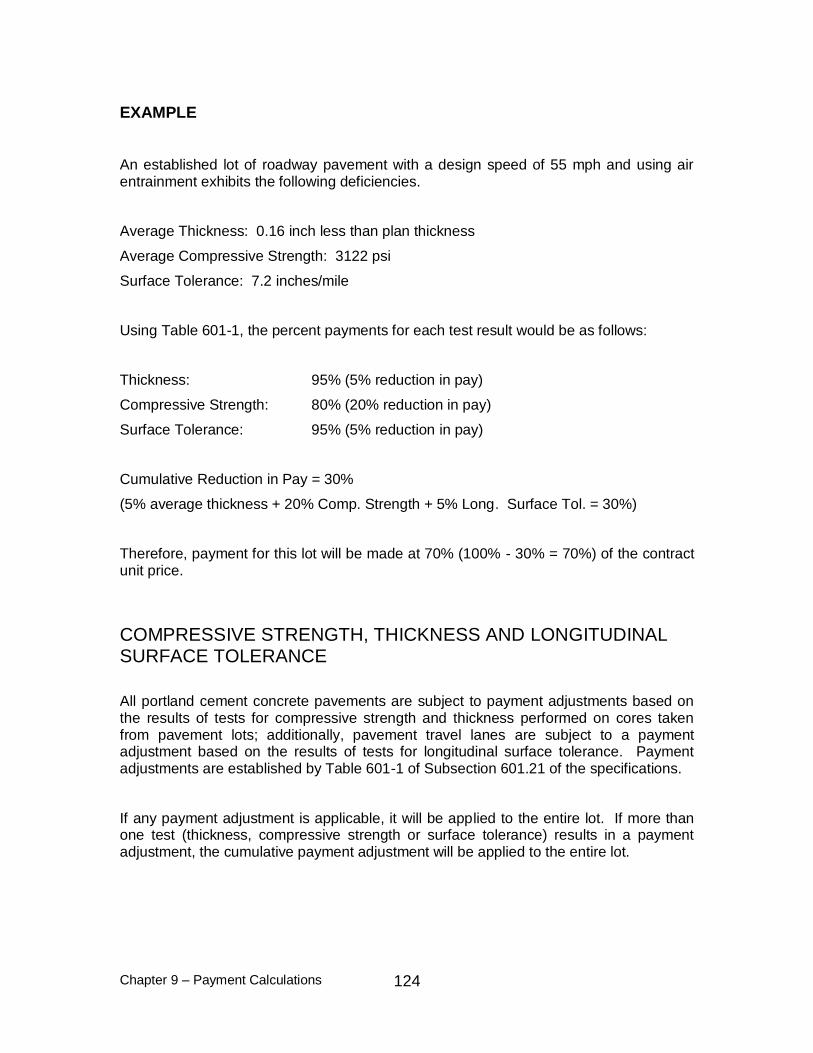
Chapter 9 – Payment Calculations
124
EXAMPLE
An established lot of roadway pavement with a design speed of 55 mph and using air entrainment exhibits the following deficiencies.
Average Thickness: 0.16 inch less than plan thickness
Average Compressive Strength: 3122 psi
Surface Tolerance: 7.2 inches/mile
Using Table 601-1, the percent payments for each test result would be as follows:
Thickness: 95% (5% reduction in pay)
Compressive Strength: 80% (20% reduction in pay)
Surface Tolerance: 95% (5% reduction in pay)
Cumulative Reduction in Pay = 30%
(5% average thickness + 20% Comp. Strength + 5% Long. Surface Tol. = 30%)
Therefore, payment for this lot will be made at 70% (100% - 30% = 70%) of the contract unit price.
COMPRESSIVE STRENGTH, THICKNESS AND LONGITUDINAL SURFACE TOLERANCE
All portland cement concrete pavements are subject to payment adjustments based on the results of tests for compressive strength and thickness performed on cores taken from pavement lots; additionally, pavement travel lanes are subject to a payment adjustment based on the results of tests for longitudinal surface tolerance. Payment adjustments are established by Table 601-1 of Subsection 601.21 of the specifications.
If any payment adjustment is applicable, it will be applied to the entire lot. If more than one test (thickness, compressive strength or surface tolerance) results in a payment adjustment, the cumulative payment adjustment will be applied to the entire lot.
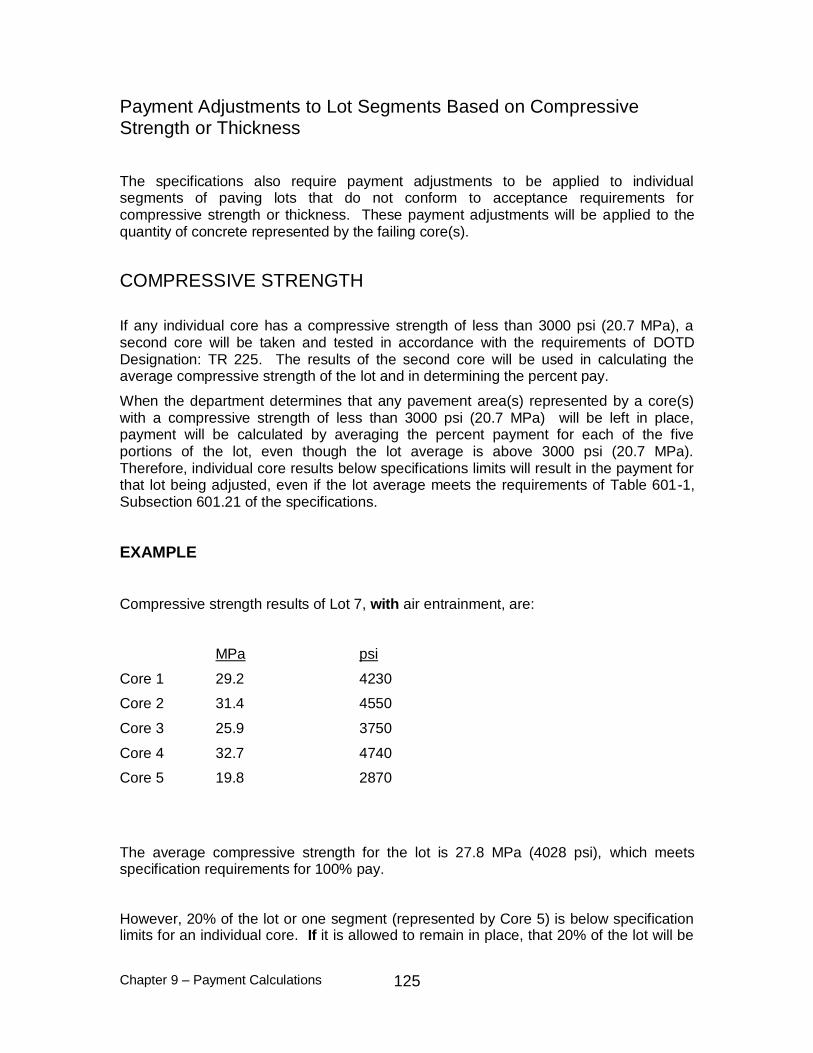
Chapter 9 – Payment Calculations
125
Payment Adjustments to Lot Segments Based on Compressive Strength or Thickness
The specifications also require payment adjustments to be applied to individual segments of paving lots that do not conform to acceptance requirements for compressive strength or thickness. These payment adjustments will be applied to the quantity of concrete represented by the failing core(s).
COMPRESSIVE STRENGTH
If any individual core has a compressive strength of less than 3000 psi (20.7 MPa), a second core will be taken and tested in accordance with the requirements of DOTD Designation: TR 225. The results of the second core will be used in calculating the average compressive strength of the lot and in determining the percent pay.
When the department determines that any pavement area(s) represented by a core(s) with a compressive strength of less than 3000 psi (20.7 MPa) will be left in place, payment will be calculated by averaging the percent payment for each of the five portions of the lot, even though the lot average is above 3000 psi (20.7 MPa). Therefore, individual core results below specifications limits will result in the payment for that lot being adjusted, even if the lot average meets the requirements of Table 601-1, Subsection 601.21 of the specifications.
EXAMPLE
Compressive strength results of Lot 7, with air entrainment, are:
MPa psi
Core 1 29.2 4230
Core 2 31.4 4550
Core 3 25.9 3750
Core 4 32.7 4740
Core 5 19.8 2870
The average compressive strength for the lot is 27.8 MPa (4028 psi), which meets specification requirements for 100% pay.
However, 20% of the lot or one segment (represented by Core 5) is below specification limits for an individual core. If it is allowed to remain in place, that 20% of the lot will be

Chapter 9 – Payment Calculations
126
paid at 50% of the contract unit price. Payment for Lot 7 for compressive strength will be calculated as follows:
MPa psi
Core 1 29.2 4230
Core 2 31.4 4550
Core 3 25.9 3750
Core 4 32.7 4740
The average compressive strength is recalculated for Cores 1,2, 3 and 4 which is 4317 psi (29.8 MPa), which according to Table 601-1, makes them eligible for 100% pay although they account for only 80% of the lot.
Hence,
%905
%50%100%100%100%100
Payment for Lot 7 for compressive strength will be made at 90% of the contract unit price.
If two cores for a lot are below 3000 psi (20.7 MPa), and average compressive strength for the lot meets the requirements for 100% payment, the lot will be paid at 80%.
EXAMPLE
Compressive strength results for Lot 8, without air entrainment, are:
MPa psi
Core 1 31.0 4500
Core 2 30.0 4350
Core 3 25.7 3720
Core 4 20.6 2980
Core 5 20.1 2920
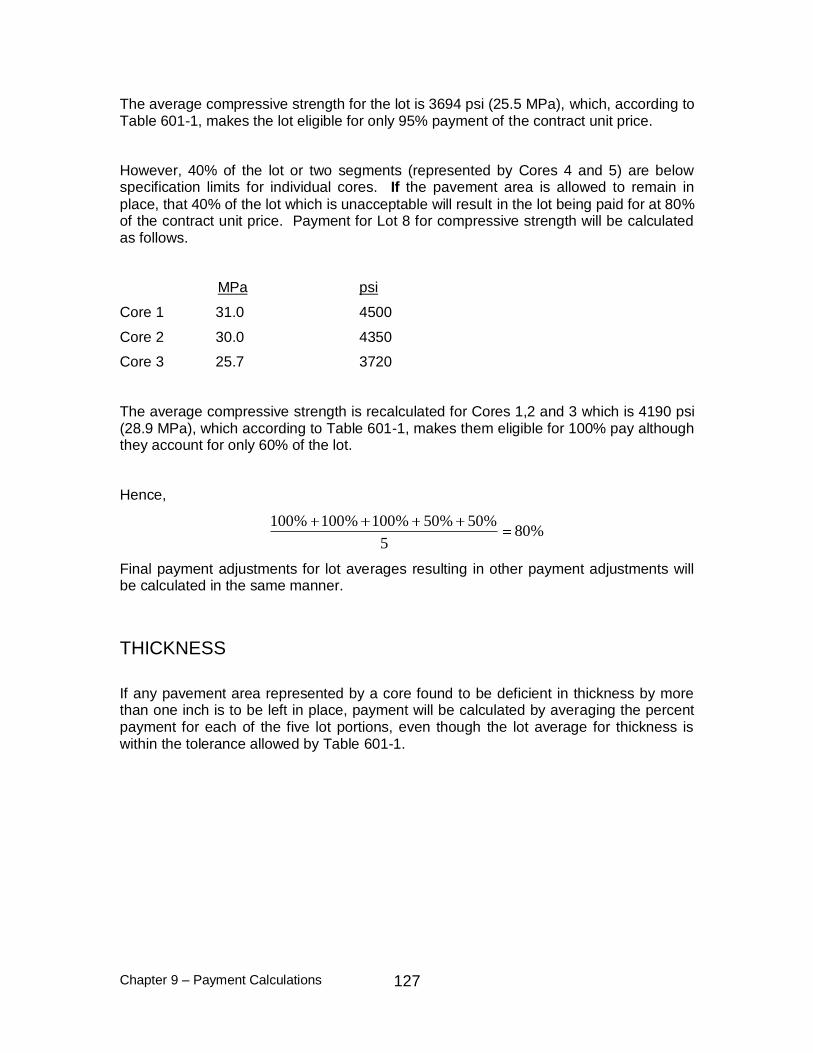
Chapter 9 – Payment Calculations
127
The average compressive strength for the lot is 3694 psi (25.5 MPa), which, according to Table 601-1, makes the lot eligible for only 95% payment of the contract unit price.
However, 40% of the lot or two segments (represented by Cores 4 and 5) are below specification limits for individual cores. If the pavement area is allowed to remain in
place, that 40% of the lot which is unacceptable will result in the lot being paid for at 80% of the contract unit price. Payment for Lot 8 for compressive strength will be calculated as follows.
MPa psi
Core 1 31.0 4500
Core 2 30.0 4350
Core 3 25.7 3720
The average compressive strength is recalculated for Cores 1,2 and 3 which is 4190 psi (28.9 MPa), which according to Table 601-1, makes them eligible for 100% pay although they account for only 60% of the lot.
Hence,
%805
%50%50%100%100%100
Final payment adjustments for lot averages resulting in other payment adjustments will be calculated in the same manner.
THICKNESS
If any pavement area represented by a core found to be deficient in thickness by more than one inch is to be left in place, payment will be calculated by averaging the percent payment for each of the five lot portions, even though the lot average for thickness is within the tolerance allowed by Table 601-1.

Chapter 9 – Payment Calculations
128
EXAMPLE
Plan thickness is 9 inches (230 mm). Thickness measurement results for Lot 10 are:
Core 1 9.40 inches 239 mm
Core 2 9.20 inches 234 mm
Core 3 9.15 inches 232 mm
Core 4 7.85 inches 199 mm
Core 5 9.20 inches 234 mm
The lot average is 8.93 inches (227 mm). To calculate the lot average, the thickness of Core 1 (9.40 inches) (239 mm) is reduced to 9.25 inches (235 mm), because for averaging computations, a core is allowed excess thickness of only 0.25 inches (6 mm).
The lot average is only 0.07 inch (3 mm) deficient, which meets the requirements of Table 601-1 for 100% payment. However, Core 4 is more than 1 inch (25 mm) deficient in thickness. If the segment of Lot 10 represented by Core 4 is allowed to remain in place, a 50% payment adjustment will be assessed for the 20% of the lot that is not satisfactory. Payment for Lot 10 will be calculated as follows:
%905
%100%50%100%100%100
Payment for Lot 10 for average thickness will be made at 90% of the contract unit price.
Lots for which a payment adjustment is applicable based on the lot average of thickness results and which also have a core(s) with a thickness deficiency greater than 1.00 inch (25 mm) will be assessed an additional payment adjustment for the unsatisfactory thickness represented by the failing cores, if that segment of the lot is allowed to remain in place. Calculations for this payment adjustment will be the same as for lots which qualify for 100% payment based on lot average.

Chapter 9 – Payment Calculations
129
EXAMPLE
Plan thickness is 9.00 inches (230 mm). Thickness results for Lot 12 are:
Core 1 9.00 inch 230 mm
Core 2 7.90 inch 201 mm
Core 3 8.60 inch 218 mm
Core 4 7.80 inch 198 mm
Core 5 9.25 inch 236 mm
The average thickness of the lot is 8.51 inches (217 mm), a deficiency of 0.49 inch (13 mm), which, according to Table 601-1, is eligible for only 80% payment of the contract unit price. However, Core 2 and Core 4 show a deficiency of more than 1.00 inch (25 mm). If these segments are allowed to remain in place, that 40% of the lot which is below the specification limits for an individual core will result in the lot being paid at 80% of the contract unit price. Payment for Lot 12 will be calculated as follows:
Core 1 9.00 inch 230 mm
Core 3 8.60 inch 218 mm
Core 5 9.25 inch 236 mm
The average thickness is recalculated for Cores 1, 3 and 5 which is 8.95 inches (228 mm), which according to Table 601-1, makes them eligible for 100% pay although they account for only 60% of the lot.

Chapter 9 – Payment Calculations
130
Hence,
%805
%100%50%100%50%100
Final payment adjustments for lot averages resulting in other payment adjustments will be calculated in the same manner.
Chapter 10 – Approach Slabs
131
CHAPTER 10 - APPROACH SLABS
The approach slab shall be constructed by placing structural (class AA) concrete on a prepared subgrade. The inspection procedures for the prepared subgrade shall be as discussed for portland cement concrete pavement. The documentation, inspection of forms, reinforcement, concrete placement, sampling, testing, etc., shall be as discussed for structural concrete operations. Aggregate material shall be sampled and approved prior to placement. Surface tolerance requirements shall be in accordance with Subsection 805.13, Standard Specifications. Acceptance and payment for concrete
approach slabs will be made on a lot basis. A lot will be considered as a complete approach slab or an identifiable pour that is completed in one day. Two random batches will be sampled for each lot, and 3 cylinders molded for each batch. The six cylinders per lot will be tested for compressive strength in 28 to 31 days. In the event of sudden cessation of operations, a minimum of three cylinders will constitute a lot. Acceptance and payment for each lot will be made in accordance with Table 5, Section 901.
For pile supported approach slabs, inspection procedures for pile driving, forms, embankment, reinforcement, etc., shall be the same as for structural operations.
Concrete for bolster blocks shall be structural (Class AA or A) or paving (Type B or D) and accepted under the requirements of Section 901.

Chapter 10 – Approach Slabs
132

Chapter 11 – Minor Structure Concrete 133
CHAPTER 11 - MINOR STRUCTURE CONCRETE
The essential difference between structural classes of concrete and minor structure concrete is the compressive strength requirements for payment.
CERTIFICATION
All plant certification requirements, with the exception of a plant laboratory, a specified quality control program and a Certified Concrete Technician, must be met by a plant supplying minor structure concrete to the department. Scales must meet all requirements of Section 901, Standard Specifications. The Certification Report for Scales and Meters (03-22-3065) must be completed and on file at the district laboratory.
All trucks used to deliver minor structure concrete must be certified and must meet all other requirements of Section 901, Standard Specifications.
CONTRACTOR'S QUALITY CONTROL
For minor structure concrete, the contractor is responsible for establishing a quality control program to meet the requirements of the specifications. This policy is different from that established for structural concrete produced under Section 901, wherein the department specifies the quality assurance program which the contractor must follow and monitors the contractor's adherence to it on a continual basis. For minor structure concrete only, the contractor will not be required to have a Certified Concrete Technician or Authorized Concrete Field Tester, but shall implement a quality control testing program which shall ensure that the concrete produced meets the requirements of the specifications.
The requirements for all materials and mixing of the concrete shall be in accordance with Table 2 (Portland Cement Concrete Mixture Substitutions), Section 901, Standard Specifications. Control tests shall be in accordance with the Materials Sampling Manual.
ACCEPTANCE AND DOCUMENTATION
An accepted mix design is required for all concrete. Adequate documentation of mix components must be available at the plant for the review of department personnel at all times. All trucks must present a properly completed Batch Certification for Portland Cement Concrete: 03-22-4028 to the department's inspector. Sampling and testing by the department shall be in accordance with the Materials Sampling Manual. The project
engineer's representative shall be certified in the area of Structural Concrete and shall direct all inspection, sampling and testing. Acceptance tests by the department shall be entered on the Structural Concrete Tests: 03-22-0740. A set of three cylinders for

Chapter 11 – Minor Structure Concrete 134
compressive strength testing shall be made for each lot of 50 cubic yards (fifty m3) of the same class of concrete on the project. This set of cylinders may represent more than one day's pour.
The Acceptance and Payment Schedules, Table 6, for Cast-in-Place Minor Structure Concrete in Section 901 of the department's specifications allow only 100 percent payment or fifty percent payment or removal at the department's discretion.

Chapter 11 – Minor Structure Concrete 135
APPENDIX