application of reliability centred maintenance to optimize ... · reliability centered maintenance...
TRANSCRIPT
IAEA-TECDOC-1590
Application of Reliability Centred Maintenance to
Optimize Operation andMaintenance in
Nuclear Power Plants
May 2007
IAEA-TECDOC-1590
Application of Reliability Centred Maintenance to
Optimize Operation andMaintenance in
Nuclear Power Plants
May 2007

The originating Section of this publication in the IAEA was:
Nuclear Power Engineering Section International Atomic Energy Agency
Wagramer Strasse 5 P.O. Box 100
A-1400 Vienna, Austria
APPLICATION OF RELIABILITY CENTRED MAINTENANCE TO OPTIMIZE OPERATION AND MAINTENANCE IN NUCLEAR POWER PLANTS
IAEA, VIENNA, 2008 IAEA-TECDOC-1590
ISBN 978–92–0–105008–3 ISSN 1011–4289
© IAEA, 2008
Printed by the IAEA in Austria May 2008
FOREWORD
In order to increase Member States capabilities in utilizing good engineering and management practices the Agency has developed a series of Technical Documents (TECDOCs) to describe best practices and members experience in the application of them.
This TECDOC describes the concept of Reliability Centred Maintenance (RCM) which is the term used to describe a systematic approach to the evaluation, design and development of cost effective maintenance programmes for plant and equipment. The concept has been in existence for over 25 years originating in the civil aviation sector. This TECDOC supplements previous IAEA publications on the subject and seeks to reflect members experience in the application of the principles involved
The process focuses on the functionality of the plant and equipment and the critical failure mechanisms that could result in the loss of functionality. When employed effectively the process can result in the elimination of unnecessary maintenance activities and the identification and introduction of measures to address deficiencies in the maintenance programme. Overall the process can result in higher levels of reliability for the plant and equipment at reduced cost and demands on finite maintenance resources.
The application of the process requires interaction between the operators and the maintenance practitioners which is often lacking in traditional maintenance programmes. The imposition of this discipline produces the added benefit of improved information flows between the key players in plant and equipment management with the result that maintenance activities and operational practices are better informed.
This publication was produced within IAEA programme on nuclear power plants operating performance and life cycle management.
The IAEA wishes to express its gratitude to all experts who provided contributions and to all the reviewers listed at the end of this publication. The IAEA officer responsible for this publication is F. Hezoucky of the Division of Nuclear Power.

EDITORIAL NOTE
The use of particular designations of countries or territories does not imply any judgement by the publisher, the IAEA, as to the legal status of such countries or territories, of their authorities and institutions or of the delimitation of their boundaries.
The mention of names of specific companies or products (whether or not indicated as registered) does not imply any intention to infringe proprietary rights, nor should it be construed as an endorsement or recommendation on the part of the IAEA.
CONTENTS
1. INTRODUCTION ............................................................................................................ 1
1.1. Background......................................................................................................... 1 1.2. Description.......................................................................................................... 1 1.3. Structure.............................................................................................................. 2
2. RELIABILITY CENTRED MAINTENANCE................................................................ 2
2.1. Maintenance and Reliability Centred Maintenance (RCM) ............................... 2 2.2. RCM as a tool for Optimization of Operations and Maintenance activities ...... 3 2.3. The Principles of RCM....................................................................................... 3 2.4. The RCM Process – Basic Steps ........................................................................ 3
2.4.1. Preparation .............................................................................................. 3 2.4.2. Analysis .................................................................................................. 4 2.4.3. Task Selection......................................................................................... 4 2.4.4. Task Comparison .................................................................................... 5 2.4.5. Task Comparison Review....................................................................... 5 2.4.6. Records ................................................................................................... 5
3. PRACTICAL APPLICATIONS....................................................................................... 5
3.1. System Selection................................................................................................. 5 3.2. System Boundaries ............................................................................................. 5 3.3. Required Materials and Documentation ............................................................. 6 3.4. Plant Personnel Interviews ................................................................................. 6 3.5. Functional Failure Modes Effects and Criticality Analysis (FMECA) .............. 7
3.5.1. System Functions.................................................................................... 7 3.5.2. System Functional Failure ...................................................................... 7 3.5.3. Identification of Equipment .................................................................... 7 3.5.4. Identification of Failure Modes .............................................................. 7 3.5.5. Identification of Failure Effects .............................................................. 8 3.5.6. Criticality ................................................................................................ 8 3.5.7. Maintenance criteria for Non-Critical components ................................ 9 3.5.8. Reliability and Performance Data collection and processing ................. 9
3.6. Use of PSA to support RCM analysis ................................................................ 9 3.6.1. Systems selection.................................................................................. 10 3.6.2. Identification of critical components .................................................... 11 3.6.3. The impact of the maintenance activity changes on Plant Risk ........... 12 3.6.4. The Increased Allowed Outage Time (AOT) ....................................... 13 3.6.5. PSA Capability and Insights ................................................................. 13
3.7. Task Selection................................................................................................... 13 3.7.1. Task Selection Guidance ...................................................................... 13 3.7.2. Maintenance Templates ........................................................................ 15 3.7.3. Task Selection Hierarchy...................................................................... 15 3.7.4. Task Options ......................................................................................... 16 3.7.5. Non Critical Components ..................................................................... 17 3.7.6. Task Selection Review.......................................................................... 17 3.7.7. Final Phase of Analysis......................................................................... 17 3.7.8. Perform Task Comparison .................................................................... 18
4. DEVELOPMENT AND DEPLOYMENT ..................................................................... 18
4.1. Management Involvement ................................................................................ 18 4.2. Project Management ......................................................................................... 18 4.3. Analytical and Software Tools ......................................................................... 19 4.4. Databases .......................................................................................................... 19 4.5. Use of Contractors ............................................................................................ 21 4.6. Conditions Monitoring Programme.................................................................. 21 4.7. Skills and Competences.................................................................................... 21
4.7.1. Project Management Skills ................................................................... 22 4.7.2. Training................................................................................................. 22
4.8. Performance Indicators..................................................................................... 22 4.9. Integration into O&M Process.......................................................................... 22 4.10. Implementing recommendations ...................................................................... 24 4.11. Living RCM...................................................................................................... 24 4.12. Factors for consideration in RCM implementation .......................................... 24
5. BENEFITS...................................................................................................................... 24
5.1. Primary Goals of RCM - Reliability................................................................. 24 5.2. Cost Benefits..................................................................................................... 25 5.3. Contribution to Long Term Operation.............................................................. 25 5.4. Soft.................................................................................................................... 25
5.4.1. Operations and Maintenance interaction .............................................. 25 5.4.2. Justification of maintenance tasks ........................................................ 25 5.4.3. Feed back quality improved.................................................................. 25 5.4.4. A culture of economic performance ..................................................... 26 5.4.5. Questioning Attitude............................................................................. 26
REFERENCES......................................................................................................................... 27
GLOSSARY............................................................................................................................. 29
ABBREVIATIONS.................................................................................................................. 31
ANNEX I STREAMLINED RCM .................................................................................... 33
ANNEX II EXPERIENCE OF RCM IN EDF .................................................................... 34
ANNEX III RCM AT NPP DUKOVANY, CZECH REPUBLIC ....................................... 44
ANNEX IV RCM EXPERIENCE IN ASCO/VANDELLOS, SPAIN ............................... 55
ANNEX V THE APPLICATION OF RCM TECHNIQUES WITHIN BRITISH ENERGY ........................................................................................ 60
ANNEX VI THE APPLICATION OF RCM TECHNIQUES IN THE UNITED STATES OF AMERICA .................................................................. 69
ANNEX VII RCM AT KOZLODUY NPP, BULGARIA..................................................... 77
CONTRIBUTORS TO DRAFTING AND REVIEW ............................................................. 87
1. INTRODUCTION
1.1. Background
The power industry worldwide has been the subject of major reviews and reforms in recent years, which have resulted in changing demands in respect of enhanced safety, reliability, environmental safeguards and commercial competition. In such an environment it is essential that the personnel and the plant and equipment involved, perform to their optimum levels of capability. Reliability Centred Maintenance is a maintenance Optimization tool which has a role in providing an effective response to such demands on the industry, by enhancing the effectiveness of operations and maintenance programmes.
This TECDOC supplements other IAEA publications by both describing the principles and basic steps in the Reliability Centered Maintenance concept, its relationship with established maintenance programmes and by providing insights into the practical application of the concept in Nuclear Power Plants (NPPs) based on international experience.
This document may be used by maintenance practitioners seeking to optimize the use of maintenance resources and enhance the safety and reliability of Nuclear Power Plants.
1.2. Description
Reliability centered maintenance (RCM) is a technique initially developed by the airline industry that focuses on preventing failures whose consequences are most likely to be serious. RCM was developed in the late 1960s when wide-body jets were being introduced into service. Because of the increased size and complexity of these aircraft, airlines were concerned that the continuing use of traditional maintenance methods would make the new aircraft uneconomical.
Previously, preventive maintenance was primarily time-based (e.g., overhauling equipment after a certain number of hours of flying time). In contrast RCM is condition-based, with maintenance intervals based on actual equipment criticality and performance data. After adopting this approach, airlines found that maintenance costs remained about constant, but that the availability and reliability of their aircraft improved because effort was spent on maintenance of equipment most likely to cause serious problems. As a result, RCM is now used by most of the world's airlines.
In 1984 the Electric Power Research Institute (EPRI) introduced RCM to the nuclear power industry. Part of the motivation was that the preventive maintenance programmes at many nuclear power plants were based on vendors' overly conservative recommendations, without sufficient consideration of actual duty cycles or overall system functions. In other cases, too little preventive maintenance was performed on key components that had not been identified as critical, leading to failures that increased corrective maintenance costs and reduced plant availability.
The utilities which comprise the EPRI RCM Users Group have accepted the following definition for their use:
"Reliability centered maintenance (RCM) analysis is a systematic evaluation approach for developing or optimizing a maintenance programme. RCM utilizes a decision logic tree to identify the maintenance requirements of equipment according to the safety and operational consequences of each failure and the degradation mechanism responsible for the failures. "
1
1.3. Structure
This TECDOC describes the principles of RCM, some practical examples for its application in NPPs, key requirements for its implementation, experience in its application and examples of the practical benefits.
2. RELIABILITY CENTRED MAINTENANCE
2.1. Maintenance and Reliability Centred Maintenance (RCM)
The relationship between RCM and traditional maintenance practices can best be summarised as follows:
“Plant and equipment are installed and employed to do what the users want them to do. Maintenance is undertaken in a variety of forms, to ensure that the plant and equipment continues to do what the users want it to do. Reliability Centred Maintenance determines what maintenance needs to be performed and what testing and inspection needs to be performed to support the maintenance strategy”.
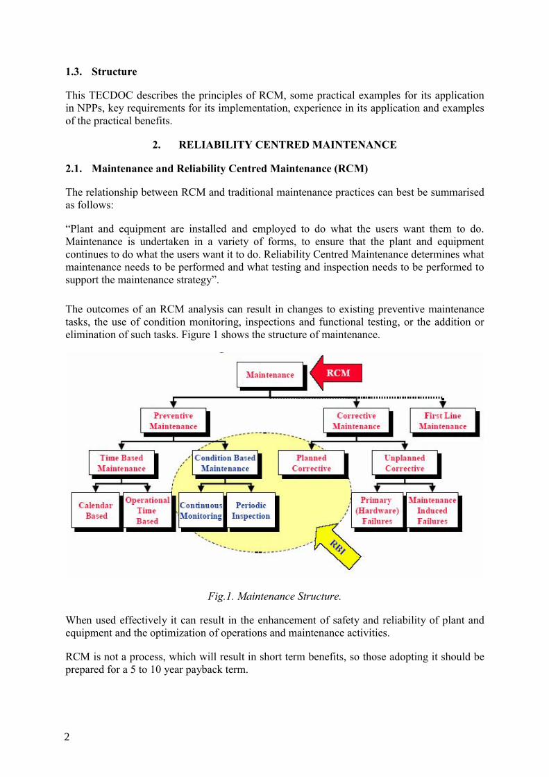
The outcomes of an RCM analysis can result in changes to existing preventive maintenance tasks, the use of condition monitoring, inspections and functional testing, or the addition or elimination of such tasks. Figure 1 shows the structure of maintenance.
Fig.1. Maintenance Structure.
When used effectively it can result in the enhancement of safety and reliability of plant and equipment and the optimization of operations and maintenance activities.
RCM is not a process, which will result in short term benefits, so those adopting it should be prepared for a 5 to 10 year payback term.
2
2.2. RCM as a tool for Optimization of Operations and Maintenance activities
RCM is a decision making tool. Operations and maintenance programmes can benefit both the processes involved in the decision-making, “soft“ benefits and the outcomes, that result in the changes to maintenance and operations programmes. The following are some examples:
⎯ The act of performing the RCM decision-making process provides a benefit in promoting better co-operation among all of those involved in the process.
⎯ The process demands that all established tasks are challenged with the objective of justifying continued use or removing/replacing them with other tasks, in doing so it promotes a healthy questioning attitude.
⎯ The process raises awareness of the functions of the systems involved, the consequences of failure of those functions and the economics of operating and maintaining them.
The clear aims of RCM are to improve reliability and optimise the cost effectiveness of maintenance activities. When performed effectively it will result in the elimination of unnecessary maintenance tasks and the introduction of measures to address omissions and deficiencies in maintenance programmes.
2.3. The Principles of RCM
The RCM analysis process centres on the functions of plant and equipment, the consequences of failure and measures to prevent or cope with functional failure. The process must establish answers to the following questions and an effective response to them:-
⎯ What are the functions and performance standards of the plant? ⎯ In what ways does it fail to fulfil its functions? ⎯ What causes each functional failure? ⎯ What happens when each failure occurs? ⎯ In what way does each failure matter? ⎯ What can be done to predict or prevent each failure? ⎯ What should be done if a suitable proactive task cannot be found? 2.4. The RCM Process – Basic Steps
RCM is not a stand-alone process, it must be an integral part of the Operations and Maintenance programmes. The introduction of the RCM process will involve changes to established working processes. For the successful introduction of such changes it will be important that management demonstrate their commitment to the changes, possibly in the form of a policy statement and personal involvement and that measures are taken to establish the engagement of those who will be involved or affected by the changes. RCM works best when employed as a bottom up process, involving those working directly in the operation and maintenance of the plant and equipment.
2.4.1. Preparation
The preparatory phase has a number of steps which basically involve the selection of the systems to be analysed, gathering the necessary data for the analysis. In addition the ground rules or criteria to be used in the selection and analysis process must be established. For
3
example; Key Assumptions, Critical Evaluation Criteria, Non Critical Evaluation Criteria and Establishment of a review process. The stages can be summarised as follows:
⎯ System Selection ⎯ Definition of the system boundaries ⎯ Acquisition of Documentation and Materials ⎯ Interviews with Plant Personnel These stages will be discussed in more detail later in the document
2.4.2. Analysis
Once the systems have been selected for analysis and the preparations have been completed the analysis can commence. Experience in the analysis process is important for effective decision-making. Such experience may exist in the utility or it may be bought in from specialist service providers in this area.
The data contained in formal systems is usually very comprehensive but knowledge management is not so well developed in NPPs that all experience is captured in data basis. For this reason it is important that personnel with local experience in the operation and maintenance of the plant are involved in the analysis process.
The first stage of the analysis process therefore is the assembly of a team with a suitable range of qualifications and experience for the task. The analysis involves the following stages.
⎯ Identification of System Functions ⎯ System Functional failure analysis ⎯ Equipment identification ⎯ Reliability and Performance Data collection ⎯ Identification of failure modes ⎯ Identification of failure effects ⎯ Determination of Component Criticality 2.4.3. Task Selection
When the analysis has been completed the next part of the process is to allocate suitable maintenance tasks to the systems and equipment identified in the analysis process, in accordance with the significance ascribed to them, be they critical or non-critical. This part of the process will seek to establish the most cost effective means of delivering the maintenance strategy in respect of achieving safety, reliability, environmental and economic goals.
The task selection process uses various forms of logical decision making to arrive at conclusions in a systematic manner. The outcomes can include:
⎯ Preventive maintenance ⎯ Condition monitoring ⎯ Inspection and functional testing ⎯ Run to Failure
4
2.4.4. Task Comparison
When the task selection has been completed and reviewed, the recommendations arising from the task selection process will be compared against the current maintenance practices. The purpose of this comparison is to identify the changes needed to the maintenance programme and the impact on resources and other commitments.
2.4.5. Task Comparison Review
The outputs of the analysis will result in a change to the maintenance programme. It is important that such changes are consistent with the maintenance philosophy of the plant and with regulatory and social obligations. For this reason it is important that the process and its outcomes be subjected to a final review.
2.4.6. Records
RCM should form part of a living programme. The outcomes of the analysis process and the implementation of the recommendations will have an impact on the effectiveness of the operations and maintenance programmes. It is important therefore, that all decisions, the basis for them and those involved in making them are effectively recorded, so that the information is available to those carrying out subsequent reviews of the maintenance strategy.
3. PRACTICAL APPLICATIONS
3.1. System Selection
The preparation phase of the RCM process involves the collection of data, drawings and experienced personnel that will be an integral part of the analysis and decision making process. In addition selection and review criteria must be established to ensure that the efforts of specialist plant personnel are well focussed and used productively in the process. One approach is to use PSA in the system selection process. (See Section 2.6), Using the criteria it should be evident to the analysts at the outset, that there will be some added value in applying the process to the system, either as a result of defining measures that will result in enhanced reliability or through optimised use of finite resources. If that is not the case the effort would be better placed on other systems.
3.2. System Boundaries
In order to further focus the analysis, it is necessary to define system boundaries. Usually plant coding systems can be used but these are often incomplete, so some form of review process will be required to ensure that all necessary plant and equipment has been included in the selected system.
In addition, plant and equipment functionally related to, but which is not part of, the system as described in the plant coding, must be included. The analysis team should use all the latest drawings and databases and consider plant walk downs to verify completeness and accuracy where that is feasible.
System boundaries are often delineated as:
⎯ Mechanical: includes all static and rotating plant equipment.
5
⎯ Electrical: must include not only the plant equipment such as motors and transformers but also power sources, control supplies and circuit breakers associated with them.
⎯ Control and instrumentation: in addition to those components within the system, components outside the system which could impact the functionality of the system must be included. For example, electrical control and instrument air or control air supplies. By considering only the instruments within the system or pressure switches and control valves, the analysts could make the vital error of assuming that the control supplies will always be available.
The analysis process will require the analysts to make decisions about what components to include or omit from the process. There is no infallible methodology, process or analytical tools to do this, so the experience and judgement of the analysts will be important for an effective outcome to the process.
3.3. Required Materials and Documentation
⎯ The system or process description (operations manuals) ⎯ Plant, Piping and Instrument Drawings ⎯ Schematic Drawings of electrical and I&C systems ⎯ Plant and equipment list for mechanical, electrical and I&C ⎯ Lists of Preventive Maintenance and Technical Specification Testing and Inspection
programmes. ⎯ Plant vendor drawings and manuals ⎯ Plant maintenance history (including corrective maintenance) ⎯ Regulatory and insurance obligations, operating instructions, alarm response procedures
and operator records. ⎯ PSA analysis for the system where that is available. 3.4. Plant Personnel Interviews
In the absence of comprehensive documentation and records of systems, it can be of use to conduct interviews with experienced plant personnel to obtain their perspective of the history of the plant. Very often, station personnel such as Electrical, Mechanical and Instrumentation Engineers/Foremen/Supervisors or Senior Craft Personnel, as well as Operations Engineers or Senior Operators can provide valuable input to the analysis.
Time constraints, schedules, personnel availability and station operating conditions are all to be considered when deciding upon a format for the interviews. Typically, the analysis will involve interviewing an individual or group, expert in a particular discipline: e.g. Mechanical, Electrical, I&C, Operations, Engineering. It is important for the analysts to be knowledgeable (though not expert) on the system and components under analysis, and to be capable of drawing “difficult to obtain information” out from the interviewees.
Such interviews will be a standard feature of the RCM process. When station personnel participate in the analysis there will be accompanying benefits derived from the interaction among plant personnel which can be in the form of improved team working, cross functional co-operation and enhanced knowledge of system functionality.
6
3.5. Functional Failure Modes Effects and Criticality Analysis (FMECA)
Classical RCM focuses on the functional failures of systems and components. A systematic process is employed to determine the functions of physical assets, failure modes, consequences of failure, their significance and hence their criticality.
In its most comprehensive form this process is described as a failure modes effects and criticality analysis or FMECA. The electricity, gas and the automotive industry have typically used a simplified form of the process which is FMEA.
Some utilities have developed checklists that are designed to follow the logical steps of the process without explicitly defining each of the steps. Checklists are used to assist the assessment of the consequences of equipment failure. The checklists implicitly assume that the failure modes of the equipment and the impact of systems functions are understood.
3.5.1. System Functions
Every physical asset has one or more functions to perform. The objective of maintenance is to ensure that those assets continue to perform their functions. In the RCM process the first step of the analysis requires that the functions of the selected system be defined. Simple schematic diagrams illustrating the system components, flow paths and interactions are useful.
Physical assets usually have a primary function which is often defined by the name of the asset, e.g. condensate extraction pump. Secondary functions are not so easy to identify but are critical to the successful outcome of the RCM process.
For example an auxiliary boiler might supply steam to a key production process as its primary function and provide factory heating as its secondary function.
3.5.2. System Functional Failure
For each function described, there must be at least one functional failure mode/mechanism. The functional failure statement documents the mechanism of failure for the function and its consequences.
3.5.3. Identification of Equipment
For the analysis, the process requires the identification of all equipment, whose failure could result in the functional failure. This can be accomplished by tracing the flow paths in the function. All mechanical (rotating and stationary) equipment, valves, pumps, filters, heat exchangers and vessels etc must be included. Similarly electrical equipment such as motors, circuit breakers and relays, together with all associated I&C equipment must be identified.
It is important to identify the equipment in terms of equipment type as well as its unique application within the system under review. This treatment potentially enables the analysts to access a broader equipment reliability database for relevant data.
3.5.4. Identification of Failure Modes
The failure of a component such as a valve to open or close or the failure of a pump to start or stop are termed “failure modes” by analysts, in that they describe the nature of the failures
7
rather than the causes of the failure. This simple definition of failure mode is typically used in reliability and PSA (probabilistic safety analysis).
Maintenance practitioners would normally go further and define why the failure occurred, e.g. valve spindle wear, actuator defects, or in the case of pumps, related switchgear defects. The latter comes closer to the safety analyst definition of failure causes
In the RCM process definitions of failure mode typically align with those of the safety analysts. “Failure mode” is used to describe plant conditions such as, fails to open or fails to close, while the term “failure causes” typically describes the degradation mechanism that gives rise to a failure mode.
3.5.5. Identification of Failure Effects
The analysts will need to identify the effects of functional failures on safety, the environment, personnel safety and plant performance. The list produced will need to contain all the information the analysts will require to enable them to devise suitable countermeasures to mitigate the consequences. For example, how will failure be identified, what are the consequences of failure, what remedial options and countermeasures are available.
3.5.6. Criticality
A component is defined as critical if its failure effects are intolerable to the facility. As an example, in a Nuclear Power Plant a component could be regarded as critical if a failure results in any one of the following:
⎯ The failure results in a reactor trip or shut down necessity before regularly planned outages,
⎯ The failure results in a reduction in power or efficiency; ⎯ The failure results in exceeding a technical specification limit; ⎯ The failure results in an increased personnel safety hazard; ⎯ The failure results in significant damage; ⎯ The failure results in a violation of environmental release limits; ⎯ The failure results in a radiation release to the public; ⎯ The failure results in a fire. When assessing criticality, the evaluator should take credit for redundancy in a system, where it exists. For example, in an application in which there are two 100% capacity pumps (which may be used interchangeably) neither pump would be considered critical since the logical assumption is that if the operating pump failed the other pump would be available and used. It is important to note here that the analyst evaluates for only a single failure, hence the assumption that the second pump would be available. In such a situation the pressure or flow switch that is designed to ensure the standby pump cut in on failure of the duty pump would be considered critical.
In addition it may be possible to provide a component function by some other components, not specifically a second train of the same thing. For example, another valve in the system may provide the ability to provide the “function” of the first valve, even though it is not technically a “redundant” valve in the design.
8
Probabilistic Safety Analysis (PSA) can be used as part of the criticality determination for safety related issues, see section 2.6. 3.5.7. Maintenance criteria for Non-Critical components
Non-Critical (i.e., failure of this component can be tolerated). Once a component is deemed Non-Critical, the component is evaluated to identify if there is a Preventive Maintenance task that should be performed or to determine whether the item should be considered for Run to Failure. Examples of criteria are used to determine run to failure:
⎯ Is there a high repair or replacement cost if the component is run to failure? ⎯ Will the component’s failure induce failures in other critical components? ⎯ Is there a simple PM task that will prevent severe degradation of the component’s
inherent reliability (e.g. bearing lubrication, filter cleaning)? ⎯ Will the component’s failure cause a potential personnel hazard if the component is run
to failure (i.e. hazard from a PM task may be less than the hazard from a corrective action upon failure or the actual failure itself)?
⎯ Is the component needed to support the performance of a recommended critical component maintenance activity, or is it significant to the operators?
⎯ Is there excessive Corrective Maintenance (CM) performed on this component that should be eliminated (i.e. does the CM history imply that a PM task may be less costly in terms of manpower and materials than the current maintenance regime).
An affirmative answer to any of these questions implies that a PM task should be selected for the component. If there are no affirmative answers to any of these criteria, then the best option is for the component to be Run to Failure.
3.5.8. Reliability and Performance Data collection and processing
Existing manufacturing data and plant history databases are the primary sources of data on which RCM analysis will be based. Ongoing data derived from plant inspections, condition monitoring and maintenance activities will provide future data. One of the tasks of the analyst is to assess the adequacy and completeness of the data available and to prescribe the information that must be gathered from future activities. Databases can be supplemented with information derived through interviews with experienced operations and maintenance practitioners.
3.6. Use of PSA to support RCM analysis
The PSA can be used in combination with deterministic approaches, for optimization of plant maintenance program whilst maintaining safety level at the same time. PSA can be used in the following three activities:
⎯ Systems selection based of the systems/components safety significance. ⎯ Maintenance assessment and alternate strategies based on identification of the system
critical components. ⎯ Assessment of the impact of the proposed changes to Maintenance activities to the plant
risk.
9
Regulatory Guide 1.174 discusses the overall approach for using PSA in risk-informed decisions on plant-specific changes [14].
3.6.1. Systems selection
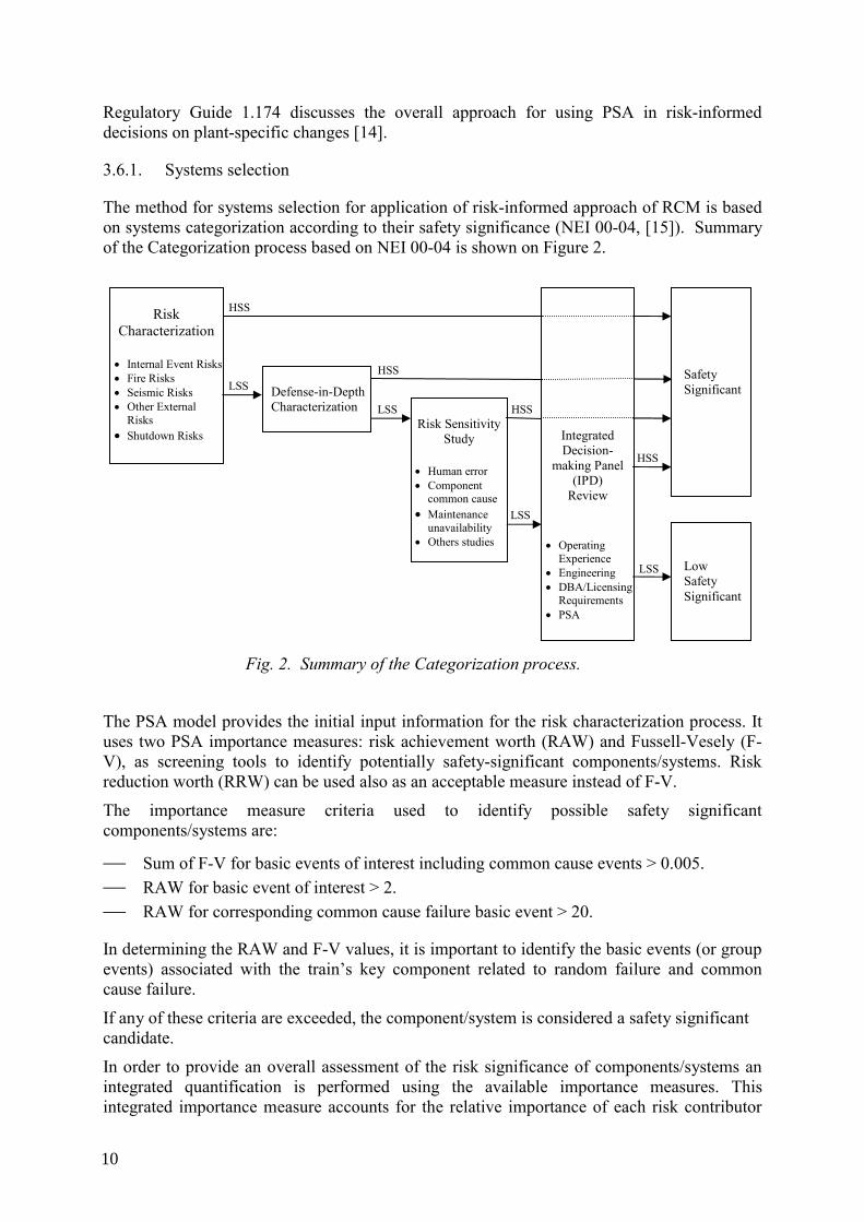
The method for systems selection for application of risk-informed approach of RCM is based on systems categorization according to their safety significance (NEI 00-04, [15]). Summary of the Categorization process based on NEI 00-04 is shown on Figure 2.
Fig. 2. Summary of the Categorization process.
The PSA model provides the initial input information for the risk characterization process. It uses two PSA importance measures: risk achievement worth (RAW) and Fussell-Vesely (F-V), as screening tools to identify potentially safety-significant components/systems. Risk reduction worth (RRW) can be used also as an acceptable measure instead of F-V.
The importance measure criteria used to identify possible safety significant components/systems are:
⎯ Sum of F-V for basic events of interest including common cause events > 0.005. ⎯ RAW for basic event of interest > 2. ⎯ RAW for corresponding common cause failure basic event > 20.
In determining the RAW and F-V values, it is important to identify the basic events (or group events) associated with the train’s key component related to random failure and common cause failure.
If any of these criteria are exceeded, the component/system is considered a safety significant candidate.
In order to provide an overall assessment of the risk significance of components/systems an integrated quantification is performed using the available importance measures. This integrated importance measure accounts for the relative importance of each risk contributor
Defense-in-Depth Characterization
Risk Characterization
• Internal Event Risks • Fire Risks • Seismic Risks • Other External
Risks • Shutdown Risks
Risk Sensitivity Study
• Human error • Component
common cause • Maintenance
unavailability • Others studies
Integrated Decision-
making Panel (IPD)
Review
• Operating Experience
• Engineering • DBA/Licensing
Requirements • PSA
Safety Significant
Low Safety Significant
HSS
HSS
HSS
LSS
HSSLSS
LSS
LSS
10
(internal events, fire, seismic) to the overall core damage frequency. The integrated importance assessment will determine if component/system that is categorized as potentially HSS based on a hazard with a low contribution to CDF should remain with a potentially HSS categorization.
The systems that have low impact on the risk (LSS), and accordingly on plant safety are of primary interest. The systems, defined as HSS, are also of interest, but the potential changes to the Maintenance should be directed to keeping of the current level of availability and reliability of the system.
3.6.2. Identification of critical components
A reliability centred maintenance (RCM) approach requires identification of the critical components of the systems. The critical components are those whose failures can lead to the failure of the system/train. Identification of those components on the quantitative basis is based on reliability (or unavailability) models developed using fault trees for each system function.
In the RCM process, the PSA can be used as a souarce of information for:
⎯ System functions and functional failures. ⎯ Component failure modes. ⎯ Component failure probability. ⎯ System reliability model.
The system functions of interest are those that directly support the objective of the RCM program. Identification of functional failures is required for each system function of interest. The functional failures identify how the system can fail and how that will affect the function of interest.
The component failure modes present information on how the component failure results in system (or train) functional failure. Identification of component failure modes relates directly to system functioning and to the way the component supports this function.
The component failure probabilities used in the PSA model are determined using the information for components failure. The specific individual failures that are used as input to the failure probability need to be re-examined in terms of the RCM process. The PSA model may use different component boundaries than those of interest in the RCM program. The basic events for the components of interest should be expanded to sub-components with their associated failure probabilities, were it is possible. This will allow identifying the Maintenance activities currently performed on the level of sub-component failure mode.
In accordance with the RCM program objectives some changes in the systems reliability models should be done. These changes are addressed to:
⎯ Component (and system) unavailability due to test activities and Maintenance activities or repair.
⎯ Common cause failures. ⎯ Applicability of the human errors. ⎯ Support systems (power supply, service water and the system actuation signals).
11
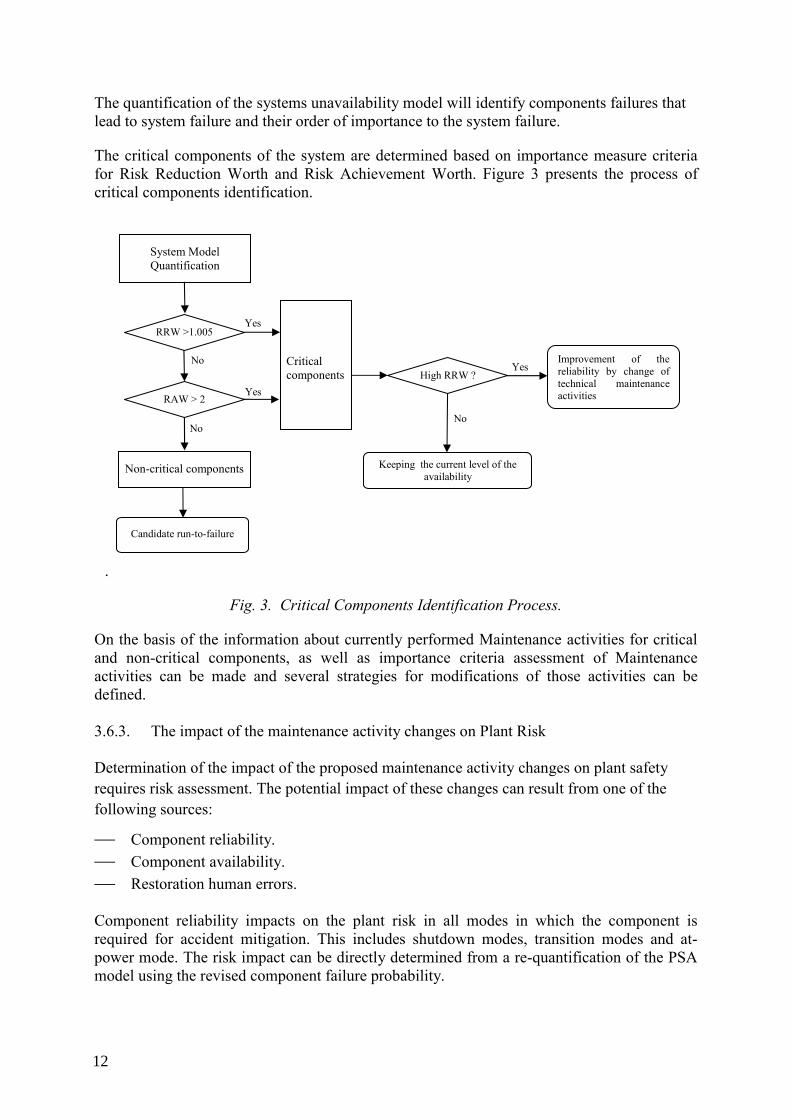
The quantification of the systems unavailability model will identify components failures that lead to system failure and their order of importance to the system failure.
The critical components of the system are determined based on importance measure criteria for Risk Reduction Worth and Risk Аchievement Worth. Figure 3 presents the process of critical components identification.
.
Fig. 3. Critical Components Identification Process.
On the basis of the information about currently performed Maintenance activities for critical and non-critical components, as well as importance criteria assessment of Maintenance activities can be made and several strategies for modifications of those activities can be defined. 3.6.3. The impact of the maintenance activity changes on Plant Risk
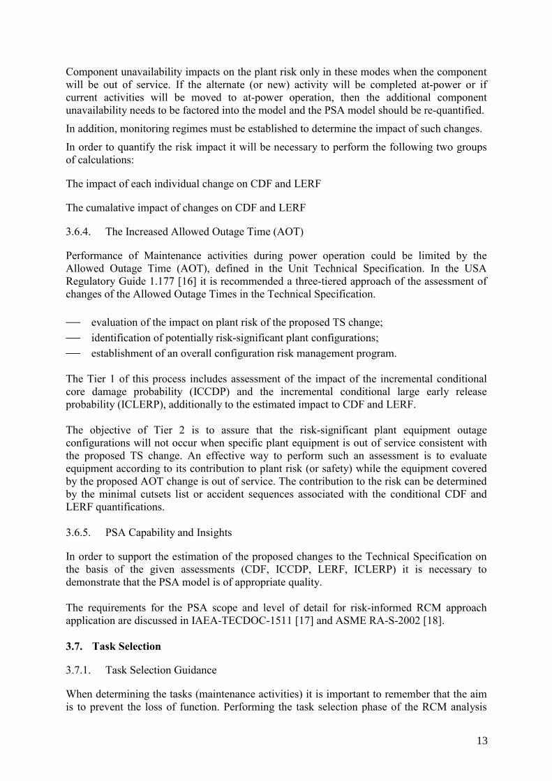
Determination of the impact of the proposed maintenance activity changes on plant safety requires risk assessment. The potential impact of these changes can result from one of the following sources:
⎯ Component reliability. ⎯ Component availability. ⎯ Restoration human errors. Component reliability impacts on the plant risk in all modes in which the component is required for accident mitigation. This includes shutdown modes, transition modes and at-power mode. The risk impact can be directly determined from a re-quantification of the PSA model using the revised component failure probability.
Candidate run-to-failure
RRW >1.005
Critical components
Keeping the current level of the availability
Improvement of the reliability by change of technical maintenance activities
Yes
Yes
Yes
No
No
No
Non-critical components
RAW > 2
System Model Quantification
High RRW ?
12
Component unavailability impacts on the plant risk only in these modes when the component will be out of service. If the alternate (or new) activity will be completed at-power or if current activities will be moved to at-power operation, then the additional component unavailability needs to be factored into the model and the PSA model should be re-quantified.
In addition, monitoring regimes must be established to determine the impact of such changes.
In order to quantify the risk impact it will be necessary to perform the following two groups of calculations:
The impact of each individual change on CDF and LERF
The cumalative impact of changes on CDF and LERF
3.6.4. The Increased Allowed Outage Time (AOT)
Performance of Maintenance activities during power operation could be limited by the Allowed Outage Time (AOT), defined in the Unit Technical Specification. In the USA Regulatory Guide 1.177 [16] it is recommended a three-tiered approach of the assessment of changes of the Allowed Outage Times in the Technical Specification. ⎯ evaluation of the impact on plant risk of the proposed TS change; ⎯ identification of potentially risk-significant plant configurations; ⎯ establishment of an overall configuration risk management program. The Tier 1 of this process includes assessment of the impact of the incremental conditional core damage probability (ICCDP) and the incremental conditional large early release probability (ICLERP), additionally to the estimated impact to CDF and LERF. The objective of Tier 2 is to assure that the risk-significant plant equipment outage configurations will not occur when specific plant equipment is out of service consistent with the proposed TS change. An effective way to perform such an assessment is to evaluate equipment according to its contribution to plant risk (or safety) while the equipment covered by the proposed AOT change is out of service. The contribution to the risk can be determined by the minimal cutsets list or accident sequences associated with the conditional CDF and LERF quantifications. 3.6.5. PSA Capability and Insights
In order to support the estimation of the proposed changes to the Technical Specification on the basis of the given assessments (CDF, ICCDP, LERF, ICLERP) it is necessary to demonstrate that the PSA model is of appropriate quality. The requirements for the PSA scope and level of detail for risk-informed RCM approach application are discussed in IAEA-TECDOC-1511 [17] and ASME RA-S-2002 [18]. 3.7. Task Selection
3.7.1. Task Selection Guidance
When determining the tasks (maintenance activities) it is important to remember that the aim is to prevent the loss of function. Performing the task selection phase of the RCM analysis
13
within the guidelines listed below will ensure that the PM program will be based on maintaining reliability.
⎯ Identify tasks that specifically address the dominant failure mechanisms; ⎯ Identify existing reliability issues; ⎯ Identify approaches to resolve existing reliability issues and intolerable failure
mechanisms; ⎯ Do not use task selection to justify the existing maintenance program; ⎯ Do not assume that the frequencies of current maintenance tasks are correct/optimum
because few failures have been experienced; ⎯ Identify tasks to prevent the effects of failure consequences rather than to prevent the
equipment failure. (Predictive Maintenance); ⎯ Do not recommend tasks that will not prevent the effects of equipment failure, extend
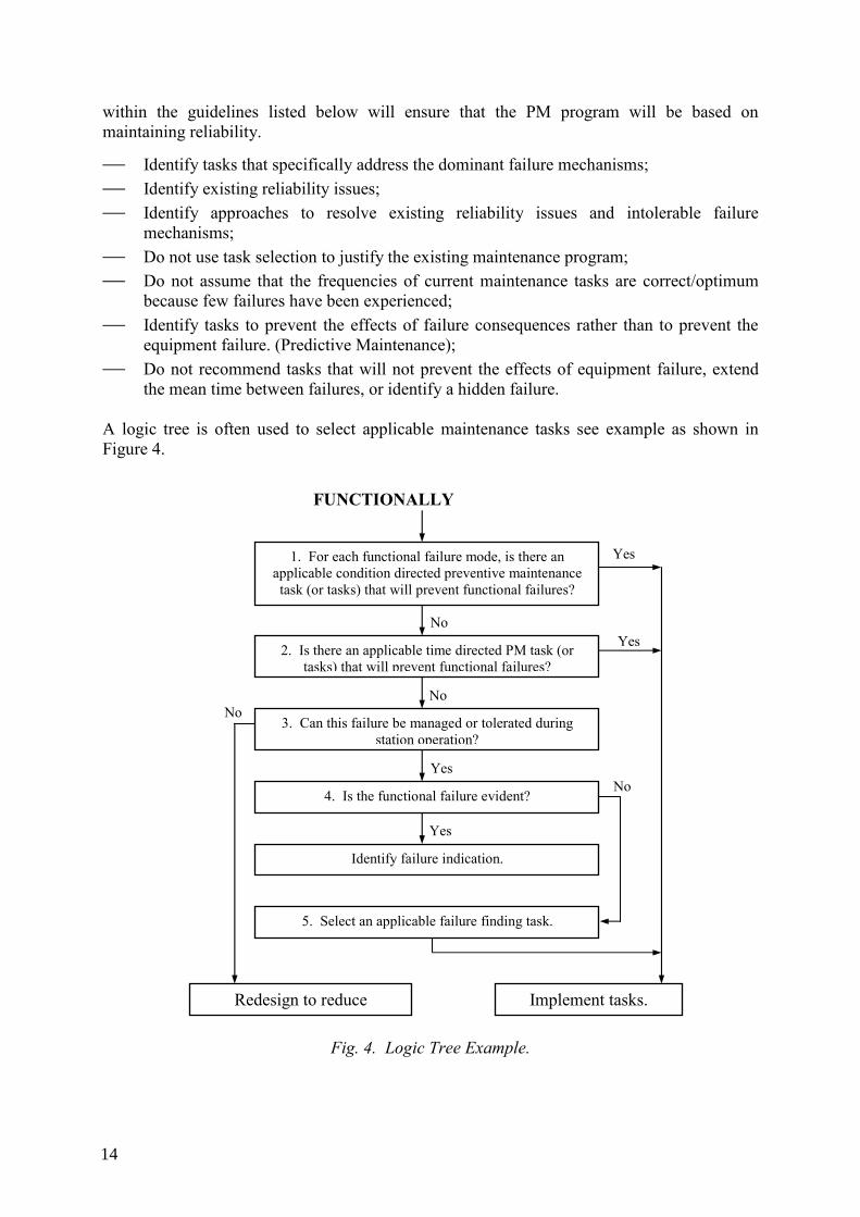
the mean time between failures, or identify a hidden failure. A logic tree is often used to select applicable maintenance tasks see example as shown in Figure 4.
Fig. 4. Logic Tree Example.
FUNCTIONALLY
1. For each functional failure mode, is there an applicable condition directed preventive maintenance task (or tasks) that will prevent functional failures?
2. Is there an applicable time directed PM task (or tasks) that will prevent functional failures?
3. Can this failure be managed or tolerated during station operation?
4. Is the functional failure evident?
Identify failure indication.
5. Select an applicable failure finding task.
Redesign to reduce Implement tasks.
Yes
Yes No
No No
No
Yes
Yes
14
3.7.2. Maintenance Templates
The Logic Tree Analysis (LTA) process is the step used to determine the most applicable, cost-effective Preventive Maintenance tasks for a component. These recommended tasks are typically a function of component importance, design, usage and service environment. With no common guidance provided to different analysts, use of the LTA can result in different PM recommendations for similar components with the same characteristics of criticality, environment and component usage. Variations in an RCM analyst’s experience will also contribute to the length of time required to research appropriate PM tasks for a specific component type.
To achieve greater efficiency and consistency between analysts in the determination of the ideal PM program for a specific component type, the PM Review can use templates as much as practical. Each template is designed to maintain the LTA process of emphasising condition-directed tasks versus time-directed tasks for each component type, and identifies the most applicable and effective preventive maintenance tasks and associated task frequencies considering several component characteristics, such as component failure importance, component usage and service environment.
Below is a summary of the format of a typical Maintenance Template.
Each maintenance template has tasks divided into four categories:
⎯ Condition monitoring tasks, such as thermography, ferrography, vibration, eddy current and acoustic monitoring;
⎯ Time-directed tasks, such as clean and inspect, lubricate, overhaul and calibration check;
⎯ Surveillance (failure finding) tasks, such as functional tests; ⎯ Economic run-to-failure considerations. Not all of the tasks in the template need to be performed. The tasks selected to be performed on a component will be influenced by the failure causes that the analyst determines to be dominant and worthy of prevention/identification in the PM program. This is combined with the maintenance philosophy of the station in the cost-effective application of various predictive maintenance technologies (condition monitoring).
3.7.3. Task Selection Hierarchy
When selecting tasks, there is a hierarchy of task types and that should be followed. This hierarchy is based on minimizing overall maintenance costs while maintaining plant reliability and availability. Task types should be selected from the following, listed in order of preference:
(1) Performance Monitoring (e.g., visual inspections, monitored process parameters such as temperature, pressure, flow)
(2) Predictive Maintenance (e.g.,vibration monitoring, thermography, lube oil analysis) (3) Non-Intrusive Maintenance (e.g., oil change, grease) (4) Intrusive Maintenance (e.g., internal inspection) (5) Renewal (e.g., bearing replacement, complete overhaul)
15

Responsible personnel-based tasks should be selected from the following, also listed in order of preference:
(1) Actions operators may perform as part of normal rounds (visual inspection) (2) Actions operators may perform that are not a part of normal rounds (functional test) (3) Actions requiring minimal craft skill (simple lubrication) (4) Actions requiring skilled craft work (detailed inspection) (5) Time-based intrusive maintenance (complete rebuild by craft / contractor) Both of the above hierarchical lists are founded on the same principle of selecting tasks preferentially from least intrusive to most intrusive, from least manpower intensive to most manpower intensive and from least to most costly.
A cost effective maintenance program should utilise existing activities when possible. For example an operator that is quite familiar with the equipment operation performs task such as monitoring temperatures and pressures and functionally testing equipment as part of their routine. Developing a maintenance task for a craftsperson to specifically perform these activities is often not the best utilisation of manpower. To be successful, both departments must take responsibility to rely on each other in knowing the monitoring or testing will be done, and that if abnormalities are found, quick response will be provided.
By minimizing intrusive inspections and rebuilds/overhauls, there is less chance of introducing failures due to human error and infant mortality of new parts. In addition general maintenance costs are reduced (rebuilds and overhauls are costly in terms of labour, materials and down-time).
3.7.4. Task Options
There are some criteria to be considered prior to deciding the type of task to select for a piece of equipment (condition directed, time based, failure finding).
3.7.4.1. Condition Directed Tasks
For condition directed tasks to be applicable it must be possible to detect reduced failure resistance for a specific failure mechanism. The task must be able to detect the potential failure condition and there must be a reasonable, consistent amount of time between the first indication of potential failure and the actual failure.
More specifically, however, when determining the frequency for condition monitoring tasks, the frequency should be consistent with the time interval between the first indication of potential failure (a “threshold value”) and the actual time of failure to allow a condition directed task to be carried out.
3.7.4.2. Time Based Tasks
For time based overhaul tasks to be applicable there must be an identifiable age at which the component displays a rapid increase in the conditional probability of failure. A large proportion of the same equipment type must survive to that age, and it must be possible to restore the original failure resistance to the component through rebuild or overhaul (or else the component must be replaced periodically). In determining frequency for time-based tasks, past failure history and maintenance experience should be consulted, as should vendor recommendations if the equipment is operated in a manner consistent with vendor
16
assumptions. Normally, the frequency will be based on the expected mean time between failures and the time between incidences of unacceptable degradation.
3.7.4.3. Failure Finding Tasks
For failure finding tasks to be applicable, the component must be subject to a failure mechanism that is not evident to personnel during normal operation of the equipment and there is no other applicable and effective type of task to prevent the failure from occurring. Functional tests are useful failure finding tasks for protective features and interlocks. However, it must be assured that the test fully verifies the feature. If a device is supposed to block operation of a valve or pump start, make sure this function is tested, not just that the input works properly.
When determining frequency for failure finding tasks, consideration should be given to the expected frequency of demand, failure rate and tolerability of failure. Also, it must be remembered that performing the failure finding task may increase the amount of wear or degradation in the component, and/or may place the system in an unsafe or abnormal condition
3.7.5. Non Critical Components
For non-critical components, maintenance tasks should only be selected if they are cost effective to perform. If no cost effective maintenance can be defined the components should be run-to-failure. This does not mean that the component is to be run to destruction or other significant effect – the component would have had routine maintenance recommended to prevent that. It means that there is no applicable, cost-effective maintenance that should be done to it, the consequences of run-to-failure are tolerable, and the failure is obvious to operators or maintenance personnel. Note that run-to-failure may imply that spare parts should be on hand, or easily obtainable, to repair or replace the component upon “failure.”
In summary, for all equipment in the RCM analysis, both critical and non critical, it is recommended that a logic tree is used to determine the most applicable and effective planned maintenance tasks and periodicity. This approach will ensure that the Preventive Maintenance program developed is complete and effective while being firmly reliability-based.
3.7.6. Task Selection Review
The Task Selection results need to be reviewed with appropriate facility personnel. This is to assure that plant personnel agree that the selected tasks are reasonable and capable of being implemented. The analysts should provide tasks that are a challenge to the present program to foster new thinking, more in line with the functional nature of the analysis. The intent is to maintain system functions, not just the components.
3.7.7. Final Phase of Analysis
Task Selection has been completed and reviewed, the analyst is ready to begin the final phase of the RCM analysis, the comparison of the selected or recommended tasks developed in the analysis with the facility’s current planned maintenance program. The purpose of this comparison is to identify needed changes in the existing program, and thereby optimise the facility’s Preventive Maintenance program. The comparison also provides another check of the analysis to assure validity of assumptions and completeness and gaps derived between RCM analysis and existing Preventive Maintenance program.
17
3.7.8. Perform Task Comparison
To properly perform the Task Comparison, all of the relevant system planned maintenance information must be gathered for each component: actual PM tasks, surveillance or functional tests, performance tests and operator rounds activities. It is also important that the information obtained in any plant personnel interviews be incorporated, especially in the case of undocumented maintenance activities that are routinely performed. This assures the thoroughness of the analysis and provides the most accurate portrayal of the Preventive Maintenance program in its current state.
The task comparison is performed by the analyst on a component basis, and is a comparison of the RCM derived PM tasks with the plant’s existing PM tasks, surveillance tests and operator rounds activities with results that are in the following action categories:
⎯ RETAIN: Existing tasks for the components that have RCM recommended tasks that exactly match the existing PM tasks (content and frequency).
⎯ MODIFY: Existing tasks for the components that have RCM recommended tasks that differ slightly in context or frequency from the existing PM tasks and will make these tasks more applicable and effective.
⎯ DELETE: Existing tasks for the components that may be replaced by more applicable and effective RCM recommended tasks.
⎯ DELETE may apply to existing tasks that are redundant. ⎯ DELETE may also apply to existing tasks where RCM recommended the component be
run-to-failure. ⎯ ADD: New PM tasks intended to prevent or mitigate identified failures for the
components whose existing tasks do not provide this appropriately. Add new tasks would also apply to all of those components for which there are no existing PM tasks but RCM has identified applicable and effective tasks. Note: Most new, or add, tasks are usually condition monitoring which should replace existing time-directed overhauls and inspections.
4. DEVELOPMENT AND DEPLOYMENT
4.1. Management Involvement
The introduction of the RCM concept into the work environment requires many functions to work together in new ways. The process of introducing the concept will, initially place a significant demand on finite resources. Traditional methods and relationship will be challenged; new tools and techniques will need to be developed to support the process. In summary the adoption of the RCM approach to maintenance will involve the need for a culture change within the organisations involved. For such an exercise in change management the involvement of the leadership is vital. That commitment should include a policy statement, personal demonstration of involvement, and commitment of resources. For effective engagement of the workforce measures must be taken to ensure effective training is provided and that the benefits of the change for those involved is demonstrated.
4.2. Project Management
The overall approach to implementation will involve substantial commitment of resources. To optimise the use of those resources and to deliver benefits in the shortest possible timescale a
18
project management approach should be adopted. Implementation can be undertaken on a global basis, i.e. all systems are included from the outset, or a phased introduction can be employed. The EdF programme and the TACIS sponsored programme at Dukovany (See attachments 1 and 3) are examples where a phased approach has been adopted, this has allowed the benefit of the scheme to be evaluated before the full commitment to other plant areas is undertaken.
Typical criteria for selecting systems of a pilot scheme:
⎯ high maintenance burden ⎯ low operability ⎯ safety related ⎯ personnel safety importance ⎯ high failure related cost ⎯ data available ⎯ evident and transparent gain from RCM Project preparations include:
⎯ The appointment of a project manager, who could be a contractor. ⎯ The establishment of a project team that could also be made up of contractors ⎯ RCM training for the participants, both in the project and the implementation of RCM
measures. ⎯ Site communication and briefing regarding the RCM project. ⎯ Software – to support the project and monitoring tools. 4.3. Analytical and Software Tools
4.3.1 Software based analytical tools exist for use in the RCM process. An example based on the experience in the Dukovany NPP is described in Attachment 2.
4.3.2 Software based tools need an operating platform that may or may not be compatible with work management systems that already exist in the NPPs. The tools themselves can be a significant additional expense, not only in the purchase of such things as a dedicated workstation but also in the development of interfaces with pre-existing databases. Where such interfaces cannot be developed the transfer and entry of data from existing databases to the analytical platform can be very time consuming.
4.4. Databases
The analysts will require plant performance data for analysis. Such data is often incorporated in work management databases or other plant and equipment databases. There are workstation based software packages that can be used to undertake some of the data processing and analysis involved in RCM and there are interface tools to assist the migration of plant data into the analytical programme.
The effort needed to collect the data in a format sufficient for analysis can be significant and should not be under estimated. Central data collection and sharing of reliability and performance data across the utilities and internationally could be beneficial in the RCM process.
19
The source information recorded and elaborated at plants may differ regarding quality and completeness. The scope of component categories should be taken into consideration. In the initial phase a reasonable alternative could be to cover the most safety important components only, but to the level of detail corresponding to RCM needs.
There are some Member States that already operate a functional component reliability database, while there are other states with few NPPs resulting in an insufficient statistical population. It is also a fact, that such small operators cumulatively operate a significant number of NPPs. It is therefore useful for the functioning databases to enrich themselves with the experience of these small operators. On the other hand the small operators are in a definite need of access to larger databases and participation therein. Outputs from the component reliability database and data sharing could improve capability of Member States to use reliability data in the Reliability Centred Maintenance (RCM).
There have been differences with respect to component boundaries and failure modes therefore development of a common framework would be beneficial. It may be possible to standardize failure modes but the problem is that different countries collect data according to their own needs. Some countries have a large list of failure modes for any given component (e.g. France, Canada) whereas other countries have a shorter list of failure modes. Therefore, any standardization of failure modes would mean additional work by Member States as they will have to re-categorise the failures according to the standardized failure modes.
Keeping in mind the considerations above it is desirable to give the operators a possibility of benefiting from the experience in reliability of others by agreeing on common good practices for the collection and analysis of the necessary information to obtain reliability data from their plants. If a common and consistent approach is developed it will bring opportunities for interchanging reliability information with the highest assurance of quality and applicability for the end users.
The difficulties of sharing information between plants have been preventing countries from benefiting from external experience for many years. However, successfully collaboration of different plants or operator groups, e.g. KWU-Siemens plants, EDF plants, Swedish plants, has shown the relevance of sharing good quality reliability information. The benefit relies in broadening the operating experience while using reliable information from plants that have similar design and equipment and being analysed consistently.
Reliability data sharing could be established at the level of plants with the same or very similar design and constructed by the same suppliers. Collaboration can be established at corporate level within units of the same company, at national level within plants across the country or internationally. Obviously at plant owner level there is an opportunity for full and open sharing of information. At national level, the sharing of information is still possible but still possible and can promote the development of a national reliability data bank. At international level, the exchange of information is more difficult, but at the same time it broadens significantly the amount of information available.
A number of reasons restrain operators from sharing detailed reliability information with other organizations. Therefore, plant records and sensible information sources are in many cases not made available to others. However, if a common framework for gathering and analysing information is established, each plant participating in such a project can easily in the first instance pass elaborated reliability information to others, and received similar information from the others. Plants could use the information received for its own purpose on
20
the confidence that is based on the operational experience of the same type of equipment and analysed in a manner consistent with the own plant practices
4.5. Use of Contractors
The application of the RCM analysis process requires certain process skills and experience that may or may not be available in the NPP organisation. Where such skills are not available one solution is to draft in contractors with the necessary experience. It is unlikely that such contractors will have the local knowledge necessary for the process therefore, it is important that effective working relationships are established between the contractors and the local plant personnel. In the longer term it will be of benefit for the plant personnel to become proficient in the application of the RCM process, so measures should be established to develop that capability.
4.6. Conditions Monitoring Programme
Many NPPs are instituting a programmatic approach to maintenance activities. Included are items such as guidelines, procedures, training and more, that control and provide direction. Condition monitoring offers the opportunity to reduce the amount and costs of corrective maintenance, to extend or eliminate time based preventive tasks by substituting lower cost condition monitoring. Other large gains are the reduction of intrusive maintenance tasks provide longer horizons for scheduling and planning to make repairs if necessary.
Examples of condition monitoring activities are vibration monitoring, oil analysis, infrared surveys performance testing and non destructive tests.
4.7. Skills and Competences
The application of the principles of RCM requires the practitioners to have a good working knowledge and experience of the process. Such skills may be possessed by personnel within the NPP, if not then measures to contract those skills into the organisation will be needed.
RCM is a living process; therefore the maintenance practices will need to be continuously reviewed and the RCM process continuously applied. Personnel will need to be developed that have practical experience of RCM and the associated analytical skills that are needed for the review process.
The process requires continuous feedback to evaluate the effectiveness of the measures undertaken. Condition monitoring programmes, the skills and knowledge to devise appropriate programmes, data collection and analysis skills are required.
The process requires detailed knowledge of plant performance and its design and maintenance practices. Personnel with such knowledge and experience are a vital part of an RCM programme.
The RCM practitioners must be skilled in bringing together the workers in a NPP who have the knowledge and experience of the plant, into a programme which utilises their collective experience effectively.
RCM will involve the change of some working practices, their integration with existing practices and the adoption of new skills and behaviours. The RCM practitioners must be effective change agents and change managers.
21
The process requires the use of IT platforms for data collection and analysis. These skills must be incorporated into the team.
4.7.1. Project Management Skills
⎯ The Project Manager identifies the required technical skills needed to execute the project and negotiates with the appropriate organizations to obtain assignment of appropriately skilled team members.
⎯ Management and leadership skills are systematically developed, practiced, evaluated, and reinforced.
⎯ Effective listening ⎯ Critical decision making ⎯ Planning and organization skills ⎯ Conflict management ⎯ Acts with integrity ⎯ Business commercial skills ⎯ Coaching ⎯ Performance management ⎯ Strategic thinking ⎯ Change agents and change managers ⎯ Confront reality and articulate a compelling need to change ⎯ Demonstrate faith that the company has a viable future and the leadership to get there ⎯ Provide a roadmap to guide behaviors and decision-making ⎯ Socialize, Model, and Reward the Behaviors that meet your cultural expectations 4.7.2. Training
The introduction of RCM will require plant personnel t acquire new skills both for the process itself and to address some of the maintenance practices arising from the application of the process. The NPP must have the necessary facilities, tutors and capacity for the training that will have to be undertaken to support RCM
4.8. Performance Indicators
The investment of time and financial resources in RCM are considerable and the impact of the measures taken can be very significant. It is important therefore that effective monitoring of the outcomes is established at the outset. Ongoing condition monitoring will give an indication of the impact of revised maintenance strategies on components over time but and Key Performance Indicators relating to reliability and performance of plant and equipment will be essential monitoring tools.
4.9. Integration into O&M Process
Integration of the new RCM process and successful implementation are about sustaining the investment made. The following activities should be considered:
⎯ Setting Expectations ⎯ Engaging the Organisation - Understanding and Commitment are required
22
• Appropriate Project Priority • Steadfast Management Support • Empower Change Agents • Clear Goals and Objectives • Metrics that measure the Goals and objectives
⎯ Planning for Success - Transition Planning, supported by: • Communication Planning should include:
− what's happening? − why? − what is the anticipated impact of the change? − wiifm – what’s in it for me?
• Training Planning - In order to e • Ensure that planned changes affecting business processes are successful, a
Training Plan should be developed. This plan should identify: − Which groups or individuals require training − What are the training requirements − How, where and when it will be delivered − Who will deliver the training.
• Maintenance Planning - Requires Process Changes − Procedure Changes − Data Management − Data Analysis − Ongoing Skills Development − Ensure Continuous Improvement
• Performance Measurement - The Project Business Plan and ultimately the Company Business/Strategic Plan should detail the target outcomes: − Performance Indicators − Performance Measures to be used − Baseline data − Target levels − Target dates − Accountability
⎯ Transitional planning should include consideration of the following: • Organizational culture including business processes and how these will be
changed • Physical environment • Job design/responsibilities • Skills and knowledge required • Policies and procedures, which need revising or developing
⎯ Monitoring to the Plan ⎯ Measure (Process and People) ⎯ Managing Expectations ⎯ Check, Adjust and Celebrate
23
4.10. Implementing recommendations
The measures arising from the analysis will both involve the change of maintenance practices and working relationships between functions involved in the activities. They will also be implemented over a protracted period and so it is important that the measures are formalised to ensure consistent implementation. Typical measures include:
⎯ The recommendations are formally approved ⎯ The tasks to be performed are precisely described ⎯ Changes to plant equipment, operating procedures and maintenance practices are
subject to formal approval processes, these must be effectively identified and controlled ⎯ Work packages issued to maintenance practitioners contain the revisions ⎯ All personnel involved are effectively trained in the revised activities. ⎯ Communication 4.11. Living RCM
RCM should not be considered as a singular event, it is part of a continuous improvement process. Mechanisms to monitor and evaluate the effectiveness of measures taken must be established as part of the exercise together with the means to review and revise maintenance programmes based on the data gathered.
4.12. Factors for consideration in RCM implementation
(1) RCM benefits are often derived over a medium to long term period therefore, plant personnel should not expect to experience gains in cost or performance right away. Such expectations should be discouraged.
(2) The use of contractors in the RCM process is often an expedient way of making progress when no experience of the process exists in an organisation. RCM however it should form part of the normal business process. Over the longer term it is important to develop in house capability to avoid dependence on contractors.
(3) The RCM process will involve both significant changes to the work practices and the inter relationships between the maintenance practitioners and the operators. These changes will prove to be beneficial but as with all change management programmes they will require the engagement of the participants for them to succeed. Measures must be taken to secure that engagement, failure to do will result in costly delays.
(4) Think hard about which RCM methodology will best meet your objectives. Classical RCM can be extremely demanding in the form of time and resources. Whereas streamlined versions of RCM can deliver many of the benefits without the level of resource commitment required with classical RCM.
5. BENEFITS
5.1. Primary Goals of RCM - Reliability
The overall aim of the RCM process is not necessarily to reduce the cost of the maintenance programmes but to improve the functional performance of the plant equipment. Enhanced reliability and efficiency will in turn contribute to improved economic and safety performance of the plant equipment.
24
5.2. Cost Benefits
Cost reduction benefits are not the primary goal of the RCM process however, EdF estimate that the application of RCM to their maintenance programmes will produce a maintenance cost reduction of 7 Million Euros over a period of 2004-2007 when applied to a large standardised fleet.
Conversely, the experience in the Czech Republic where RCM was applied to a small number of systems at the Dukovany NPP the experience proved to be maintenance cost neutral.
The experience of cost savings through the application of RCM in France, Spain, UK and Czech Republic are detailed in the Attachments to this TECDOC. Many are quoted in the form of task and man-hour reductions.
5.3. Contribution to Long Term Operation
RCM is a systematic approach to the identification and execution of maintenance activities designed to support plant performance. The associated condition monitoring programmes and analytical techniques ensure excellent knowledge of plant condition and can provide early warning of plant aging and obsolescence issues which are vital for asset management. The data collected and the maintenance practices developed are conducive to long term asset management strategies. 5.4. Soft
5.4.1. Operations and Maintenance interaction
The application of RCM principles requires significant co-operation between all those involved in maintenance, work planning and operation of the plant. The interactions involved promote greater understanding between the participants that is a vital requirement for a successful programme. This results in greater alignment between maintenance activities and the production processes.
EdF place great value on the soft benefits derived from the use of RCM that have resulted in improved working relationships between operations and maintenance and an improvement in the questioning attitude/commercial awareness of the workforce in respect of maintenance.
5.4.2. Justification of maintenance tasks
Most maintenance activities are initially based on manufacturer’s recommendations, experience of the personnel involved and traditional thinking. The RCM process requires that all maintenance activities are critically examined to determine their relevance to the functional performance of the plant. The disciplines involved result in the eradication of unnecessary or inappropriate maintenance activities and the introduction of new activities where the circumstances demand.
5.4.3. Feed back quality improved
RCM should form part of a living programme; to be successful it will require careful monitoring of the impact of decisions taken in the process and the ability to respond to inappropriate actions or omissions. The disciplines involved require the practitioners to use
25

operating experience in a very focussed and systematic manner that enhances the effectiveness of the feedback process.
5.4.4. A culture of economic performance
In the RCM process all actions must be justified on the basis of their impact on the functionality of the plant equipment. The disciplines imposed in the decision-making processes can serve to heighten awareness among the practitioners of the relevance and the cost of their activities. EdF found that this resulted in a greater commercial awareness among those involved.
5.4.5. Questioning Attitude
The RCM process fosters the development of a questioning attitude among the practitioners in both those phases where the concept is introduced and through the continuous monitoring and evaluation phases following the introduction of the measures arising from the process.
26
REFERENCES
[1] MOUBRAY, J., “RCM – Reliability-centered Maintenance”, Second Edition, Industrial Press Inc. (1997).
[2] INTERNATIONAL ATOMIC ENERGY AGENCY, Guidance for optimizing nuclear power plant maintenance program, IAEA-TECDOC-1383, IAEA, Vienna (2003).
[3] INTERNATIONAL ATOMIC ENERGY AGENCY, Advances in Safety Related Maintenance, IAEA-TECDOC-1138, IAEA, Vienna (2000).
[4] INTERNATIONAL ATOMIC ENERGY AGENCY, Good Practices for Cost Effective Maintenance of Nuclear Power Plants, IAEA-TECDOC-928, IAEA, Vienna (1997).
[5] INTERNATIONAL ATOMIC ENERGY AGENCY, Practices for Cost Effective Maintenance of Nuclear Power Plants, IAEA-TECDOC-658, IAEA, Vienna (1992).
[6] INTERNATIONAL ATOMIC ENERGY AGENCY, Good practices for outage management in nuclear power plants, IAEA-TECDOC-621, IAEA, Vienna (1991).
[7] INTERNATIONAL ATOMIC ENERGY AGENCY, Nuclear power plant outage optimization strategy, IAEA-TECDOC-1315, IAEA, Vienna (2002).
[8] INTERNATIONAL ATOMIC ENERGY AGENCY, International outage coding system for Nuclear power plants, IAEA-TECDOC-1393, IAEA, Vienna (2004).
[9] INTERNATIONAL ATOMIC ENERGY AGENCY, Surveillance of Safety Related Maintenance at Nuclear Power Plants, IAEA-TECDOC-960, IAEA, Vienna (1997).
[10] INTERNATIONAL ATOMIC ENERGY AGENCY, Manual on Maintenance of Systems and Components Important to Safety, IAEA-Technical Report Series No. 268, IAEA, Vienna (1986).
[11] INTERNATIONAL ATOMIC ENERGY AGENCY, Technologies for Improving Current and Future Light Water Reactor Operation and Maintenance: Development on the Basis of Experience, IAEA-TECDOC-1175, IAEA, Vienna (2000).
[12] INTERNATIONAL ATOMIC ENERGY AGENCY, Designing Nuclear Power Plants for Improved Operation and Maintenance, IAEA-TECDOC-906, IAEA, Vienna (1996).
[13] INTERNATIONAL ATOMIC ENERGY AGENCY, Computerization of Operation and Maintenance for Nuclear Power Plants, IAEA-TECDOC-808, IAEA, Vienna (1995).
[14] US NRC, “An Approach for Using Probabilistic Risk Assessment in Risk-Informed Decisions on Plant-Specific Changes to the Licensing Basis”, Regulatory Guide 1.174, Revision 1, November 2002.
[15] NEI 00-04 (Prepublication Rev. 0), “10 CFR 50.69 SSC Categorization Guideline”, January 2005.
[16] US NRC, “An Approach for Plant-Specific, Risk-Informed Decision making: Technical Specifications”, Regulatory Guide 1.177, August 1998.
[17] INTERNATIONAL ATOMIC ENERGY AGENCY, Determining the quality of probabilistic safety assessment (PSA) for applications in nuclear power plants, IAEA-TECDOC-1511, Vienna, 2006.
27

[18] THE AMERICAN SOCIETY OF MECHANICAL ENGINEERS, Standard for Probabilistic Risk Assessment for Nuclear Power Plants Applications, ASME RA-S-2002, ASME New York (2002).
[19] NASA RCM Guidance for Collateral facilities. [20] Optimising Maintenance and Reliability WH Closer EPRI Solutions.
28
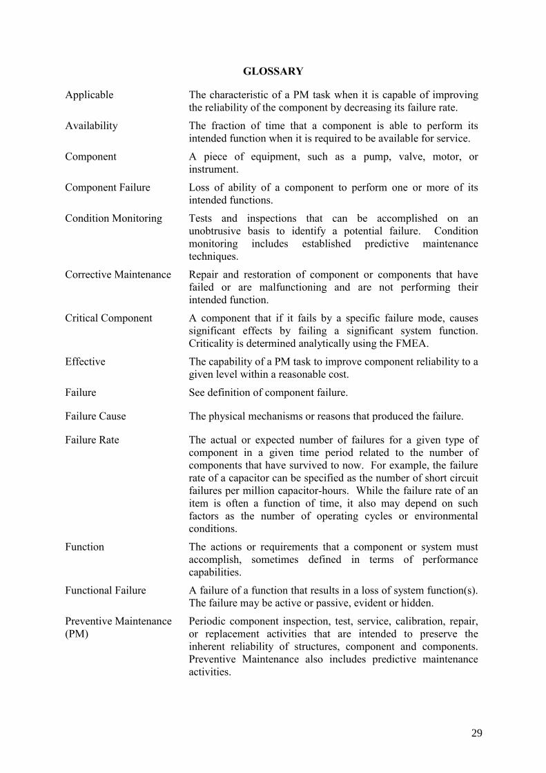
GLOSSARY
Applicable The characteristic of a PM task when it is capable of improving the reliability of the component by decreasing its failure rate.
Availability The fraction of time that a component is able to perform its intended function when it is required to be available for service.
Component A piece of equipment, such as a pump, valve, motor, or instrument.
Component Failure Loss of ability of a component to perform one or more of its intended functions.
Condition Monitoring Tests and inspections that can be accomplished on an unobtrusive basis to identify a potential failure. Condition monitoring includes established predictive maintenance techniques.
Corrective Maintenance Repair and restoration of component or components that have failed or are malfunctioning and are not performing their intended function.
Critical Component A component that if it fails by a specific failure mode, causes significant effects by failing a significant system function. Criticality is determined analytically using the FMEA.
Effective The capability of a PM task to improve component reliability to a given level within a reasonable cost.
Failure See definition of component failure.
Failure Cause The physical mechanisms or reasons that produced the failure.
Failure Rate The actual or expected number of failures for a given type of component in a given time period related to the number of components that have survived to now. For example, the failure rate of a capacitor can be specified as the number of short circuit failures per million capacitor-hours. While the failure rate of an item is often a function of time, it also may depend on such factors as the number of operating cycles or environmental conditions.
Function The actions or requirements that a component or system must accomplish, sometimes defined in terms of performance capabilities.
Functional Failure A failure of a function that results in a loss of system function(s). The failure may be active or passive, evident or hidden.
Preventive Maintenance (PM)
Periodic component inspection, test, service, calibration, repair, or replacement activities that are intended to preserve the inherent reliability of structures, component and components. Preventive Maintenance also includes predictive maintenance activities.
29

ABBREVIATIONS
AOT Allowed Outage Time
CDF Core Damage Frequency
CM Corrective Maintenance
EDF Electricite de France
FMEA Functional failure Modes Effects Analysis
FMECS Functional failure Modes Effects and Criticality Analysis
F-V Fussel-Vesely
HSS High Safety Significant
I&C Instrumentation and Control
ICCDP Incremental Conditional Core Damage Probability
ICLERP Incremental Conditional Large Release Probability
LERF Large Release Frequency
LSS Low safety Significant
NPP Nuclear Power Plant
O&M Operation and Maintenance
PM Planned Maintenance
PRA Probabilistic Risk Assessment (Analysis)
PSA Probabilistic Safety Analysis
RAW Risk Achievement Worth
RBI Risk Based Inspection
RCA Root Cause Analysis
RCM Reliability Centred Maintenance
RRW Risk Reduction Worth
TECDOC Technical Document
TS Technical Specification
31

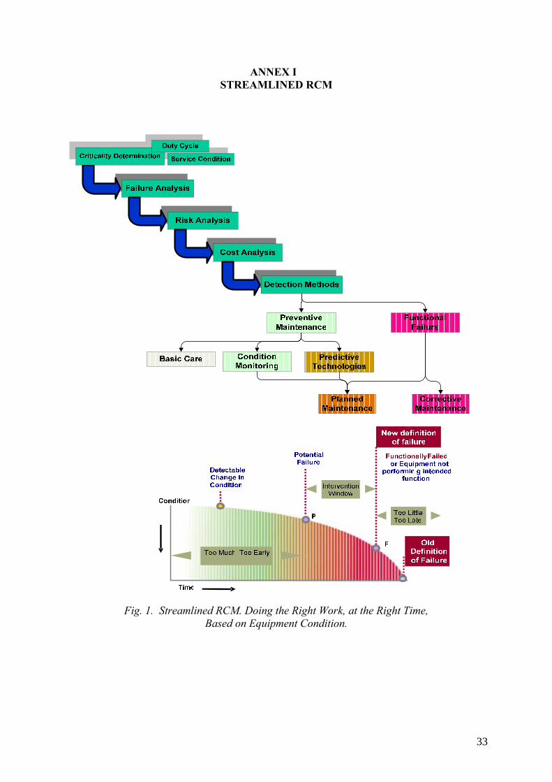
ANNEX I STREAMLINED RCM
Fig. 1. Streamlined RCM. Doing the Right Work, at the Right Time, Based on Equipment Condition.
33
ANNEX II EXPERIENCE OF RCM IN EDF
1. STRUCTURE OF EDF NUCLEAR GENERATION DIVISION
The Generation and Engineering Direction of the EDF Group gathers the means for generation, engineering and related services in the six following Divisions:
⎯ Nuclear Generation Division, ⎯ Nuclear Engineering Division, ⎯ Fuel Division, ⎯ Renewable, Thermal and Hydraulic Generation Division, ⎯ Renewable, Thermal and Hydraulic Generation Engineering and Projects Division, ⎯ Services Division.
The Nuclear Generation Division includes a fleet of 19 nuclear power stations and 3 national Units in charge of the fleet Operating Engineering, the fleet Operating Support and the fleet Maintenance Support.
In the 19 power stations are 58 nuclear PWR units: 34 of 900 MW, 20 of 1300 MW, 4 of 1400 MW. Their design is quite similar, which allows to have standardised policies, procedures and equipments of the fleet.
2. MAINTENANCE POLICY
The aim of the maintenance policy of EDF Nuclear Operator is to guaranty that the operations of its units will be in accordance with the nuclear safety requirements, at the best production conditions of a safe, clean and competitive kWh for its customers.
This policy has three components
⎯ maintain safety in operations at the required level during all the phases of the operation of the reactor,
⎯ increase the nuclear kWh competitiveness, ⎯ prepare the future, by ensuring the maintenance of the production tool, to consider a life
length of at least 40 years for the fleet.
Reliability-centred maintenance is a rigorous methodology internally developed by EDF, which allows to define the maintenance activities of some components, by integrating the probabilistic safety analyses, the functional analysis of the systems, the analysis of the causes and consequences of each failure, and the operational experience.
3. LOCATION OF RCM IN THE PROJECTS OF MAINTENANCE OPTIMIZATION IN EDF NUCLEAR GENERATION DIVISION
The Optimization of the volume of maintenance is an important part of the competitiveness of the kWh generated, and in particular of the control of the length, resources and quality of outages.
34
Four initiatives aim at the Optimization of the maintenance programs:
⎯ Improvement of the Preventive Maintenance programs, ⎯ Use of Reliability-Centred Maintenance, ⎯ Generalisation of the Condition-Based maintenance activities, developed on numerous
stations, but in a scattered way, ⎯ Development of Sample-Based Maintenance, used for numerous static components and
to be extended to electrical or rotating machines.
4. PRESENT STATUS OF THE USE OF RCM
From 1989 to 1992, EDF has tested and developed a RCM method applicable to its Nuclear Power Stations, with the participation of EDF R&D, Corporate Operations Support engineers and some stations’ maintenance specialists. From the method developed in other industry sectors or by other nuclear operators, EDF has built its own maintenance Optimization method in order to:
⎯ Identify equipments requiring preventive maintenance ⎯ Define the just necessary preventive maintenance tasks ⎯ Take into account their impact on nuclear safety, environment, availability, costs and
dose rate.
From 1992 to 1995, EDF has progressively applied the RCM method to elaborate maintenance programs optimised regarding the stakes the Nuclear Division had to face. From 1995, the implementation of these maintenance programs by the stations are compulsory, as they are the first means for the Optimization of the economies of scale and scope that can be drawn out of the standardised plant series.
A project team has been in charge of defining the procedures of use of the method and of implementing them on 50 elementary systems classified as “high stake systems” on the 900MW standardised plant series (28 units) and on the 1300MW standardised plant series (20 units) in order to elaborate the RC preventive maintenance programs which will have then to be applied on the related plants.
In 2001, an internal audit has stated that the RC preventive maintenance programs were applied by the stations in a heterogeneous way, due to the absence of corporate coordination.
In consequence, the Nuclear Division Direction decided in September 2001 to entrust to the corporate Operations support Centre the supervision of this implementation, and confirmed the continuation of the use of RCM method with an objective of 100% for the complete integration of the 50 “high stake systems” in 2003 on the 900 and 1300MW plant series. Finally, it was decided that the so-called “Second generation RCM method” was the only method to use for any definition of a RC preventive maintenance program, for all the plant series of the fleet.
35

5. THE “SECOND GENERATION” RCM METHOD
Principle
It consists in the identification of the only failures that have to be faced considering the stakes identified by the Nuclear Division, and in the definition of the best adapted maintenance program regarding the causes and effects of these failures on the functioning of the studied system.
It is a five steps method:
(1) Analysis of the input data (2) Functional analysis (3) Analysis of the failure modes and of their effects (4). Selection of a maintenance orientation (5) Selection of the maintenance tasks of the program
These steps are detailed underneath, because this method is different from the one presented in the publication IAEA-TECDOC-658 “Safety related maintenance in the framework of the reliability centred maintenance concept”, which was used in the first phase of the project.
A – Analysis of the input data
Do a review of the input data to make an inventory of the documents required for the study.
Determine on which plant series this study is applicable.
B – Functional analysis
Determine:
⎯ the elementary systems which provide the inputs (fluids, energy, data…) to the system to be studied, and the elementary systems which receive them from this system
⎯ the missions that the system has to fulfil ⎯ the boundaries of the system, defined on diagrams, drawings or lists of equipments ⎯ the grouping of these equipments into Functional groups (FG) including all what is
necessary for the achievement of an Elementary Technical Function (ETF). The FGs cans be broken down into Technological Sets (TS) or even in Technological sub-sets. Lists of Failure Modes (FM) that can occur on every ETF, FG and TS are available, and are used to list the FMs which can affect this system.
C – Analysis of the failure modes and of their effects
C1 – Select, in the above-defined list of FMs, the FMs which are possible regarding the missions of the system. This choice is based on the knowledge and experience of the specialists who perform the analysis.
C2 – Determine the gravity (heavy or none) of the consequences of these selected FMs, facing five skates in the following domains: nuclear safety, industrial safety, environment, availability of the station, maintenance costs.
36
If a FM is deemed ‘heavy’ for only one of these five domains (or for one of their sub-domains), the FM is classified as significant for the rest of the study.
C21 – The gravity regarding Nuclear safety is measured according three criteria:
⎯ the compliance with Technical Specifications for Operations. If the FM induces the application of a group 1 specification (i.e. events implying the design hypotheses to comply with during normal operations, the shutdown systems or the safeguard systems) or a group 2 specification (events on equipments or systems necessary for the monitoring, the diagnosis or the rules to follow in case of abnormal condition), then the FM is ranked as ‘heavy’.
⎯ the contribution of the FM to the risk of serious accidents : ⎯ two data are calculated : the contribution of the FM to the increase of the risk of core
melting in case of the complete unavailability of the equipment considered, and the contribution of the FM to the reduction of the risk of core melting if this equipment is perfectly reliable. If one of these two parameters is higher than its pre-defined threshold, the gravity of this FM will be heavy. This is applicable to ‘classified’ equipments, which have a mission in incidental or accidental situations, for which a PSA has been done.
⎯ the contribution to failures of the missions that have to be ensured in incidental or accidental situations with effects not studied in a PSA.
⎯ the effect on safety related classified mechanical, electrical or structural functions and equipments.
C22 – A FM is ‘heavy” for industrial safety if this FM can lead to personnel injury.
C23 – A FM is “heavy” for environment if it can lead to a pollution or a contamination.
C24 – A FM is “heavy” for availability if it can lead to a reduction of power production, an loss of the unit efficiency or an increase in the shutdown duration.
C25 – A FM is “heavy” for maintenance costs if it induces costly maintenance works.
The ranking of the level of this three last gravities depends on the qualitative assessment of the persons involved in the study.
C3 – Definition of the “visible” or hidden” aspect of a FM
A “visible” FM can be detected form the control room when it occurs.
The gravity of a “hidden” FM is determined in a specific study, considering the case where this FM is cumulated with a FM of another equipment.
D – Selection of a maintenance orientation
A performance orientation defines the areas that an analyst has to investigate in order to define the maintenance tasks of the program. It requires an evaluation of the performance of a FG :
37
If the FG has at least a “heavy” FM, then the performance analysis will be based on past events occurred on this FG and on the calculation of the related maintenance costs. The information necessary for these analyses are available in an historical event data base, but require some re treatment.
If the GF has no “heavy” FM, only the maintenance costs will be calculated and analysed.
Then, the maintenance orientation is defined according to five criteria, i.e. the gravity of the FM, the existence or not of a previous preventive maintenance program, the (high or low) importance of the numbers of failures and degradations, and to the maintenance cost. A table provides a list of 16 orientations for the different cases.
E – Selection of the maintenance tasks of the program
This selection is done with maintenance experts.
The various possibilities are: light maintenance, surveillance during normal operations, tests, intrusive controls, systematic (partial or total) replacement.
All the material of this study is gathers into a synthesis document for traceability and updating. This document, in addition of the conclusions and justifications of the above steps, will include an impact survey of the evolutions brought by the preventive maintenance program created or updated, on:
⎯ the common mode risks for safety related equipments ⎯ the consumption of spare parts ⎯ the outage schedules ⎯ the dose rates.
Some characteristics of this method
⎯ This method is exhaustive; it relies on predefined lists of FTEs, GFs, FMs and Measurable Effects.
⎯ This method is simplified; there is no Analysis of the Critical Failure Modes ad their Effects; the gravity is ranked after selection of the FM deemed as relevant for the analysis.
⎯ No failure tree is used. ⎯ Both qualitative and quantitative criteria are used. ⎯ A methodological guide book provides tables for helping to determine the orientations
and the tasks of maintenance; this to make easier the work of elaboration of the preventive maintenance program and to guaranty the consistency of the use of the method and the homogeneity of the outcomes.
⎯ The process uses historical data of the events occurred on the equipments; the quality of the analysis depends obviously on the quality of these primary data..
⎯ It relies on a common work between the various experts participating in the construction of the program and the future users (e.g. planners) who give their opinion before the decision of implementation of the program. Once the program is validated, it is considered as a prescriptive document, to be applied by all the stations within six
38
months. This to ensure consistency and standardisation for a multi-reactor company such as EDF.
However, limited dispensations are possible; upon justification, after agreement of the corporate responsible for the implementation of the preventive maintenance programs , a station is allowed not to completely apply a program, to allow for local particularities.
6. PROGRESS STATUS OF THE DEFINITION OF THE MAINTENANCE PROGRAMS
The permanent search for Optimization of the preventive maintenance programs is monitored by a team of experts of the corporate level who lead a network of correspondents on the various stations.
Today, around 450 preventive maintenance programs are defined by EDF:
50 for the primary circuit (mostly with regulatory conditions)
200 RCM preventive maintenance programs
200 preventive maintenance programs elaborated without the RCM method, on the basis of doctrines written by experts of the Corporate Operating Support Unit, on the basis of the rules set by the vendors and of the operating experience.
7. PROGRESS STATUS OF THE IMPLEMENTATION OF THE RC PREVENTIVE MAINTENANCE PROGRAMS
The RC preventive maintenance programs of the “high stake” systems have been written. The present step is the end of the translation of these new programs into the station maintenance systems, or the updating of these RCM preventive maintenance programs due to a new operational feedback or due to modifications in policies, equipments or systems.
For a station, the implementation of such a program consists in the change in the type of its maintenance activities, the periodicities, the methods used in its maintenance management system, i.e.:
⎯ the procedures for work, tests, which describe the tasks on a general way, ⎯ the maintenance procedure which precisely describe the maintenance tasks, ⎯ the schedules of the activities during outages or normal operation, ⎯ the technical specifications of outsourced activities, ⎯ the documents attached to the work order : risk analysis, quality plan…
In consequence, each station must implement an organisation able to monitor this task, forecast and allocate resources to achieve these changes and respect the 6 month-delay afforded for the actual implementation of the programs in the maintenance system of the station.
39
8. EFFECTS OF THE RCM
RCM method implies to make an EFMA before the definition of any maintenance program; this enables to justify each decided maintenance task by a risk analysis based on the stakes and the missions of the equipments. This method leads to choose the maintenance orientation which offers the best economic benefit regarding the experience feedback, the analysis of the causes and of the consequences of failures.
8.1. The ‘soft’ benefits
The main beneficial changes generated by the use of RCM for the definition of preventive maintenance programs are:
⎯ Operations and maintenance personnel work together during this exercise ⎯ Maintenance is aligned with the objectives of the production process ⎯ The maintenance tasks and programs are justified on a formal basis ⎯ The quality of the experience feedback data is improved (those who collect them use
them). ⎯ A culture of economic performance is developed in the maintenance personnel. ⎯ A sustainable process is implemented for continuous re-questioning of the validity of
the maintenance decisions ⎯ Non-intrusive maintenance is enhanced. ⎯ Corporate monitoring of the maintenance function and networking between stations are
reinforced on the occasion of the implementation of the process of definition, validation, updating of maintenance program supervised by corporate experts.
Even if the cause-effect link cannot be directly showed, it seems obvious that all this « soft » effects contribute to the reduction of maintenance costs.
Contribution of RCM to insurance of LTO:
⎯ the RCM method does not provide the predictive analysis of the degradations that can affect the various components. However, RCM contributes to sustain the operating conditions necessary for a LTO, by two means:
⎯ by the elimination of maintenance tasks regarded as useless when ranked according to skates and criteria validated by the top management of the company,
⎯ by a continuous re-questioning of the relevance of preventive maintenance activities.
9. DIRECT EFFECTS OF RCM ON COSTS
9.1. Method of calculation of the cost reduction generated by the RCM maintenance programs
For each elementary system analysed, a estimated calculation of the expected cost reduction due to the change in the maintenance program, is done during the technical analysis.
This reduction is the yearly average difference between:
40
⎯ the actual costs of the preventive maintenance programs before the use of the RCM method
⎯ the estimated cost of the RCM program once implemented.
This difference is calculated on a ten-year basis (which allows to take into account the increase in the periodicities, and of the reduction of the maintenance volume between two ten-year heavy outages).
The gains are caused by the reduction or even the deletion of the quantity or the frequency of the systematic maintenance, by the replacement of systematic maintenance by inspections, or by the use of condition or sample-based maintenance. There are some cases when the analysis has led to an increase in maintenance volumes, hence to extra costs.
The consolidated amount of all these expected gains is: 7 M Euros for the period 2004- 2007.
In 2005, on the period 2004-2007, the gains obtained and expected from the use of RCM are 21% of the whole gains obtained and expected in the maintenance expenses of the nuclear fleet (condition-based maintenance 17%, sample-based maintenance 17%, reduction of maintenance on big components (SG) 37%, standardisation of effective practices 7%)
9.2. Difficulties met in the calculation of gains; performance indicators
During the 2001 audit, it had been stated that the audited stations had not implemented the indicators aiming at measuring the gains creates by RCM, because:
⎯ The station cost controllers had not been involved at the beginning of the project ⎯ The information system had not been designed to measure these gains easily ⎯ The cost control of the stations was not connected with the initiatives of cost reduction
implemented by technicians.
Today, the difficulties encountered in the calculation of these costs are:
⎯ The cost control and indicator system has not been implemented from the beginning of the RCM project.
⎯ Some gains are expected in the next ten years according to the periods retained in the maintenance programs
⎯ Other initiatives for optimising maintenance are implemented at the same time ⎯ The regulatory rules steadily evolve. ⎯ The development of global contracts with contractors for a bunch of activities makes
difficult to know the cost of each elementary activity. ⎯ An ERP system implemented in 2004 has brought about the following issues:
• a change in the cost breakdown scheme and the withdrawal of some analytical cost centres
• a difficulty to link directly and easily the costs to the maintenance activities at the level of the work orders.
• This makes difficult to compare forecasted and actual costs and to compare costs between different years.
41
However, besides the indicators of follow-up of the gains of the RCM project, a system of 19 indicators has been implemented to assess the performance of the maintenance function, through its effects on the “high skate” domains, i.e.: Nuclear Safety, Availability, Costs, Regulation, Industrial safety, Environment, Radio protection.
The figures are calculated for the whole Nuclear Division and for the stations for benchmarking and continuous improvement purpose, on a one-year or on a four-year period.
These indicators are:
⎯ Number of group 1 operating specifications applied due to maintenance issues ⎯ Duration of group 1 operating specifications due to maintenance issues compared with
the allowed accrued duration (%) ⎯ Loss of electricity generation due to maintenance issues over 4 years (%) ⎯ Outage extension unavailability rate over 4 years (%) ⎯ Average cost of maintenance and average cost of lost production due to maintenance
issues (€/Mwh) ⎯ Average maintenance costs for one year per unit (€/Mwh) ⎯ Average maintenance costs over 4 years per unit (€/Mwh) ⎯ Average maintenance costs during outage over 4 years per unit (€/Mwh) ⎯ Average maintenance costs during normal operations over 4 years per unit (€/Mwh) ⎯ Sundry maintenance costs per unit (M€) ⎯ Part of the sundry maintenance costs in the total maintenance costs over 4 years (%) ⎯ Cost reductions achieved due to the Maintenance Volume Reduction project* ⎯ Delays necessary for the implementation of the internal regulatory inspectors ⎯ Implementation of the regulatory rules related to primary and secondary circuit
surveillance ⎯ Average Dose rate per outage over 4 years (H.mSv) ⎯ Number of radio protection detections at the exit of the station, per unit ⎯ Industrial safety accident rate ⎯ Volume of nuclear waste conditioned per year
* Note on the indicator: Cost reductions achieved due to the Maintenance Volume Reduction project
This indicator gives per station and per year the gains achieved thanks to the three components of this project: systematic maintenance program written with RCM method, condition-based maintenance implementation and sample-based maintenance implementation.
Robustness: The quality of the indicator value depends on the quality of the figures given by the various stations, and cannot consider the gains achieved by the plants before 2003.
Before 2003, it was possible to calculate another indicator:
Average trend per unit of the maintenance costs on the “high skate” systems, over 4 years.
This indicator gives the average yearly trend per unit of the maintenance costs of preventive and corrective maintenance during outage and normal operations ( calculated from the data
42
collected on work orders), for the 50 ‘high skate’ systems (except primary circuit) selected by the RCM project.
From 2000 to 2003, these maintenance costs per unit represent 53% of the total costs of maintenance (preventive and corrective, during outage and normal operations) per unit. The trend of the yearly maintenance costs on these systems for the 900 MW and 1300 MW plant series indicates a significant reduction of maintenance costs on this period.
These examples show the necessity to have a technical and accounting information system adapted, stable and interrelated, in order to:
⎯ Avoid the difficulties linked to the separation of the technical and economic data ⎯ Have access to work hours spent, orders placed, spare parts consumed for each
equipment, all these data being generally collected at the end of a work order.
43
ANNEX III RCM AT NPP DUKOVANY, CZECH REPUBLIC
1. PHARE PROJECT FOR NPP DUKOVANY, BOHUNICE, PAKS Project components:
⎯ RCM course for beneficiaries of the Project - participants from NPP Dukovany, NPP Bohunice, NPP Paks - and local Project subcontractors from the Czech Republic (NRI Rez), Slovakia (Relko), and Hungary (Veiki)
⎯ software - EPRI RCM Workstation 2.5 ⎯ pilot RCM projects at NPP Dukovany and NPP Bohunice
Pilot RCM project at NPP Dukovany Note: The RCM analysis was performed by the local subcontractor under supervision by the Project contractor. Coordinating plant engineers participated at most of the activities and provided necessary relevant electronic data and contacts to other plant expert departments. Reference system selection
(Selection condition input - mechanical system for NPP Dukovany) System selection criteria: ⎯ high maintenance burden ⎯ low operability ⎯ safety related ⎯ personnel safety importance ⎯ high failure related cost ⎯ data available ⎯ evident and transparent gain from RCM For the system selection, following data were used – numbers of preventive maintenance (PM) and corrective maintenance (CM) work orders per one system component, PM/CM ratio, maintenance cost, numbers of events, PSA data (initiating events, important items). Based on the criteria, Feed Water System was selected. The selected reference system was then divided into the following subsystems and components were assigned to the individual subsystems. For each component, following data were collected — ID, name, type/model, supplier, current PM tasks (task description, frequency, man-hours), maintenance history (dates, repair time, failure detection and description, job description).
44
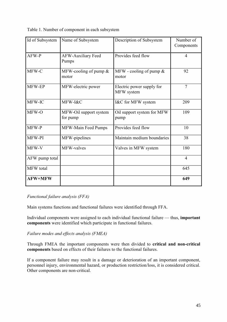
Table 1. Number of component in each subsystem
Id of Subsystem Name of Subsystem Description of Subsystem Number of Components
AFW-P AFW-Auxiliary Feed Pumps
Provides feed flow 4
MFW-C MFW-cooling of pump & motor
MFW - cooling of pump & motor
92
MFW-EP MFW-electric power Electric power supply for MFW system
7
MFW-IC MFW-I&C I&C for MFW system 209
MFW-O MFW-Oil support system for pump
Oil support system for MFW pump
109
MFW-P MFW-Main Feed Pumps Provides feed flow 10
MFW-PI MFW-pipelines Maintain medium boundaries 38
MFW-V MFW-valves Valves in MFW system 180
AFW pump total 4
MFW total 645
AFW+MFW 649
Functional failure analysis (FFA) Main systems functions and functional failures were identified through FFA. Individual components were assigned to each individual functional failure — thus, important components were identified which participate in functional failures. Failure modes and effects analysis (FMEA) Through FMEA the important components were then divided to critical and non-critical components based on effects of their failures to the functional failures. If a component failure may result in a damage or deterioration of an important component, personnel injury, environmental hazard, or production restriction/loss, it is considered critical. Other components are non-critical.
45
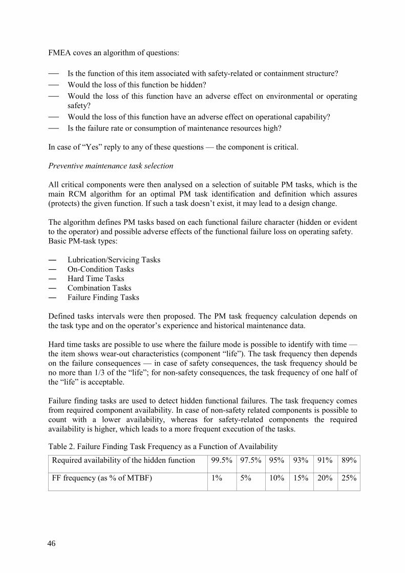
FMEA coves an algorithm of questions: ⎯ Is the function of this item associated with safety-related or containment structure? ⎯ Would the loss of this function be hidden? ⎯ Would the loss of this function have an adverse effect on environmental or operating
safety? ⎯ Would the loss of this function have an adverse effect on operational capability? ⎯ Is the failure rate or consumption of maintenance resources high? In case of “Yes” reply to any of these questions — the component is critical. Preventive maintenance task selection All critical components were then analysed on a selection of suitable PM tasks, which is the main RCM algorithm for an optimal PM task identification and definition which assures (protects) the given function. If such a task doesn’t exist, it may lead to a design change. The algorithm defines PM tasks based on each functional failure character (hidden or evident to the operator) and possible adverse effects of the functional failure loss on operating safety. Basic PM-task types: ― Lubrication/Servicing Tasks ― On-Condition Tasks ― Hard Time Tasks ― Combination Tasks ― Failure Finding Tasks Defined tasks intervals were then proposed. The PM task frequency calculation depends on the task type and on the operator’s experience and historical maintenance data. Hard time tasks are possible to use where the failure mode is possible to identify with time — the item shows wear-out characteristics (component “life”). The task frequency then depends on the failure consequences — in case of safety consequences, the task frequency should be no more than 1/3 of the “life”; for non-safety consequences, the task frequency of one half of the “life” is acceptable. Failure finding tasks are used to detect hidden functional failures. The task frequency comes from required component availability. In case of non-safety related components is possible to count with a lower availability, whereas for safety-related components the required availability is higher, which leads to a more frequent execution of the tasks.
Table 2. Failure Finding Task Frequency as a Function of Availability
Required availability of the hidden function 99.5% 97.5% 95% 93% 91% 89%
FF frequency (as % of MTBF) 1% 5% 10% 15% 20% 25%
46
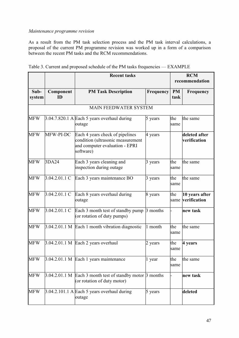
Maintenance programme revision As a result from the PM task selection process and the PM task interval calculations, a proposal of the current PM programme revision was worked up in a form of a comparison between the recent PM tasks and the RCM recommendations.
Table 3. Current and proposed schedule of the PM tasks frequencies — EXAMPLE
Recent tasks RCM recommendation
Sub-system
Component ID
PM Task Description Frequency PM task
Frequency
MAIN FEEDWATER SYSTEM
MFW 3.04.7.820.1 A Each 5 years overhaul during outage
5 years the same
the same
MFW MFW-PI-DC Each 4 years check of pipelines condition (ultrasonic measurement and computer evaluation - EPRI software)
4 years deleted after verification
MFW 3DA24 Each 3 years cleaning and inspection during outage
3 years the same
the same
MFW 3.04.2.01.1 C Each 3 years maintenance BO 3 years the same
the same
MFW 3.04.2.01.1 C Each 8 years overhaul during outage
8 years the same
10 years after verification
MFW 3.04.2.01.1 C Each 3 month test of standby pump (or rotation of duty pumps)
3 months - new task
MFW 3.04.2.01.1 M Each 1 month vibration diagnostic 1 month the same
the same
MFW 3.04.2.01.1 M Each 2 years overhaul 2 years the same
4 years
MFW 3.04.2.01.1 M Each 1 years maintenance 1 year the same
the same
MFW 3.04.2.01.1 M Each 3 month test of standby motor (or rotation of duty motor)
3 months - new task
MFW 3.04.2.101.1 A Each 5 years overhaul during outage
5 years deleted
47
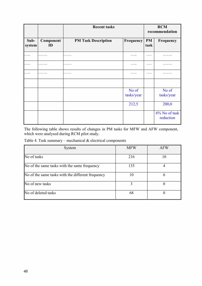
Recent tasks RCM recommendation
Sub-system
Component ID
PM Task Description Frequency PM task
Frequency
….. ……. …… ….. …. …….
….. ……. …… ….. …. …….
….. ……. …… ….. …. …….
No of tasks/year
No of tasks/year
212,5 200,0
6% No of task reduction
The following table shows results of changes in PM tasks for MFW and AFW component, which were analysed during RCM pilot study.
Table 4. Task summary – mechanical & electrical components
System MFW AFW
No of tasks 216 10
No of the same tasks with the same frequency 135 4
No of the same tasks with the different frequency 10 6
No of new tasks 3 0
No of deleted tasks 68 0
48
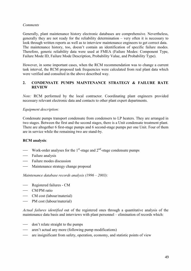
Comments Generally, plant maintenance history electronic databases are comprehensive. Nevertheless, generally they are not ready for the reliability determination – very often it is necessary to look through written reports as well as to interview maintenance engineers to get correct data. The maintenance history, too, doesn’t contain an identification of specific failure modes. Therefore, generic reliability data were used at FMEA (Failure Modes: Component Type, Failure Mode ID, Failure Mode Description, Probability Value, and Probability Type). However, in some important cases, when the RCM recommendation was to change a current task interval, the RCM proposed task frequencies were calculated from real plant data which were verified and consulted in the above described way. 2. CONDENSATE PUMPS MAINTENANCE STRATEGY & FAILURE RATE
REVIEW Note: RCM performed by the local contractor. Coordinating plant engineers provided necessary relevant electronic data and contacts to other plant expert departments. Equipment description: Condensate pumps transport condensate from condensers to LP heaters. They are arranged in two stages. Between the first and the second stages, there is a Unit condensate treatment plant. There are altogether 6 first-stage pumps and 6 second-stage pumps per one Unit. Four of them are in service while the remaining two are stand-by. RCM analysis: ⎯ Work-order analyses for the 1st-stage and 2nd-stage condensate pumps ⎯ Failure analysis ⎯ Failure modes discussion ⎯ Maintenance strategy change proposal Maintenance database records analysis (1996 – 2003): ⎯ Registered failures - CM ⎯ CM/PM ratio ⎯ CM cost (labour/material) ⎯ PM cost (labour/material) Actual failures identified out of the registered ones through a quantitative analysis of the maintenance data basis and interviews with plant personnel – elimination of records which: ⎯ don’t relate straight to the pumps ⎯ aren’t actual any more (following pump modifications) ⎯ are insignificant from safety, operation, economy, and statistic points of view
49
The failures were then sorted and analyzed – defined: ⎯ failure modes ⎯ failure causes ⎯ failure effects ⎯ failure finding methods ⎯ mean time between failures (MTBF)/failure intensity ⎯ failure distribution pursuant to individual Units Failure distribution pursuant to individual Units – it may indicate a possibly uneven approach of individual responsible maintenance engineers. The analysis took into account modifications performed recently at the pumps. The main goal of the analysis was to find out if the current PM were performed effectively and if cost savings are possible. Failure modes discussion: For most important problems, proposals were made to change the PM approach, or to implement other measures to improve maintainability etc. 1st-stage condensate pumps Significant failure modes occur rarely. The pumps are backed up. There is no danger of a significant damage of the equipment, negligible threats to the personnel. RCM recommendation – extend the pump overhaul interval from 4 to 6 years. 2nd-stage condensate pumps The most dominant failures are related to oil: ⎯ minor oil leakages (which are not tolerated according to plant’s current approach) ⎯ forced early replacements of lubrication oil due to its blackening Oil leakages Characteristics: they are even, minor (drop-sized), constant, and seemingly insignificant from the repair-cost point of view, nevertheless there is: ⎯ unfavourable trend of costs of all the activities related to remove the failures (work
request issue – work order – pump shut-down and isolation – call for a contractor – repair – pump start-up, post-maintenance test), and
⎯ associated pump availability decrease – such a repair takes ca 2 – 3 day
50
RCM recommendation Based on the above characteristics — to revise the apparently “ambitious” culture of the plant operation and look on the minor oil leakages more reasonably. (It is possible to collect the leaking oil drops easily to avoid the costly CM.) Forced oil replacements The replacements of lubrication oil are due to its blackening, while the origin of the effect is generally unclear. As it is impossible to replace the oil under working conditions (a risk of bearing seizure), it is necessary to come through the entire costly work-management process (work request, work order …), and thus decrease the associated pump availability (see the previous case). RCM recommendation ⎯ perform a thorough oil analysis to find out the nature of contamination (is the forced oil
replacement necessary?) as well as the cause of oil blackening ⎯ take measures / go on the operation provided the oil contamination doesn’t influence oil
characteristics Pump-motor vibration There are 3 basic effects of the vibration: ⎯ bearing wear/failure ⎯ pump-motor misalignment ⎯ pump-motor bed loosening ⎯ pump internal failure Imperfect design of the pump discharge pipeline is the most probable common cause of the problem. The design isn’t perfect enough to eliminate thermal-expansion tensions. The high tensions result in high static load to the equipment — limited maintainability under working conditions due to tensions in connecting elements. RCM recommendation ⎯ Discharge pipeline reconstruction incl. heat compensators. ⎯ Following the above mentioned improvement of maintainability, it will be possible to
extend the pump overhaul intervals from 4 to 6 or 8 years. Diagnostics of 1st-stage & 2nd-stage condensate pumps Current situation ⎯ Vibration measurement at both pumps and motors once every 2 weeks. ⎯ Impossible measurement of the 2nd-stage pumps’ characteristics.
51
RCM recommendation ⎯ Based on experience, extend the vibration measurement interval to 1 – 2 moths; perform
the measurement before outages and after repairs. This will reduce the diagnostics labour consumption/cost by 50%.
⎯ Consider existing possibilities of the pump characteristics measurement. A success would be another possible supporting argument to extend the pump overhaul intervals.
3. RCM APPLICATION TO SELECTED ELECTRIC SYSTEMS Note: RCM performed by the local contractor. Coordinating plant engineers provided necessary relevant electronic data and contacts to other plant expert departments. 3.1. Accumulators maintenance strategy & failure rate review Equipment description: Accumulators are autonomous backup power supply sources which function is to supply power to plant safety & other systems in case of the operating power systems’ power failure. Operation modes: Under normal conditions, the accumulators are charged up by a minimal preservative current covering a spontaneous discharge. In case of the operating power systems loss, the accumulators take over the load without the power supply interruption. Following the operating power systems recovery, rectifiers automatically start up and charge the accumulators. RCM analysis In this case, a plant specific RCM was performed: ⎯ the analysed system was modelled in PSA – it was possible to use PSA to quantify the
analysed equipment failures’ impacts ⎯ no FMEA was performed (demanding, time consuming) ⎯ data available:
• current maintenance strategy • maintenance history – inspection protocols include well arranged PM & CM
relevant information, and give a credible picture of the equipment performance • interviews with maintenance and system engineers • manufacturers’ recommendations, MTBF for individual accumulator 2V-cells,
4V-monoblocks, and 6V-monoblocks; most likely failure modes ⎯ no RCM software was used to do the analysis
52
Equipment importance assessment according to PSA To determine individual system components’ importance, EPRI and IAEA risk important component criteria were used. Those criteria are based on an assessment of each component’s influence to the core-melt probability. EPRI approach uses “Risk Increase Factor” (RIF) which indicates an increase of the resulting core-melt probability in case the given component is out of service (due to a failure, or maintenance). IAEA approach uses a “sensitivity (10)“ criterion — sensitivity of a system to a change of the component’s reliability parameters. With the use of the above criteria, risk-important accumulators were identified. In order to support a maintenance strategy with extended inspection intervals, accumulator unavailability calculations were performed in PSA (a simple fault-tree modelled in Risk Spectrum programme, MTBF values from the manufacturer, MTTR values from maintenance engineers). At the calculations, common cause failures (CCF) resulting in a simultaneous putting out of service of all accumulators were considered (same failure may occur at all accumulators as all of them were made by the same manufacturer, and are inspected by the same technicians using the same procedures). Result: Unavailability of 1 accumulator is <10-7, which is equivalent to a very short inoperability time throughout the year. As the accumulators have 200% back-up, the cumulated unavailability as well as inoperability time are insignificant. Recommendations and conclusions Based on the above calculations, maintenance programme was modified: ⎯ carry on 3 current activities ⎯ extend inspection intervals of 3 activities ⎯ cancel 1 activity This will result in a reduction of: ⎯ number of work-order tasks from 12264 to 4772 within a period of 8 years ⎯ number of man-hours from 14464 to 4772 within a period of 8 years 3.2. CT transformers maintenance strategy and failure rate review Equipment description: CT transformers’ (HV/LV) function is to supply power to the in-plant service-load section switchboards.
53

Operation modes: Full-load operation and no-load operation (back-up). RCM analysis A similar approach was adopted as in case of C1). With the use of the above mentioned EPRI and IAEA criteria, risk-important CT transformers were identified. Based on the results, even the identified risk-important transformers had a potential to extend maintenance intervals. Based on the maintenance historical records as well as good operational experience with the equipment, responsible maintenance engineers also supported the idea of extending the maintenance intervals. Recommendations and conclusions Based on the above calculations and operational experience, maintenance programme was modified: ⎯ double all maintenance intervals This will result in a reduction of: ⎯ number of work-order tasks from 250 to 125 within a period of 8 years ⎯ number of man-hours from 4250 to 2125 within a period of 8 years
54
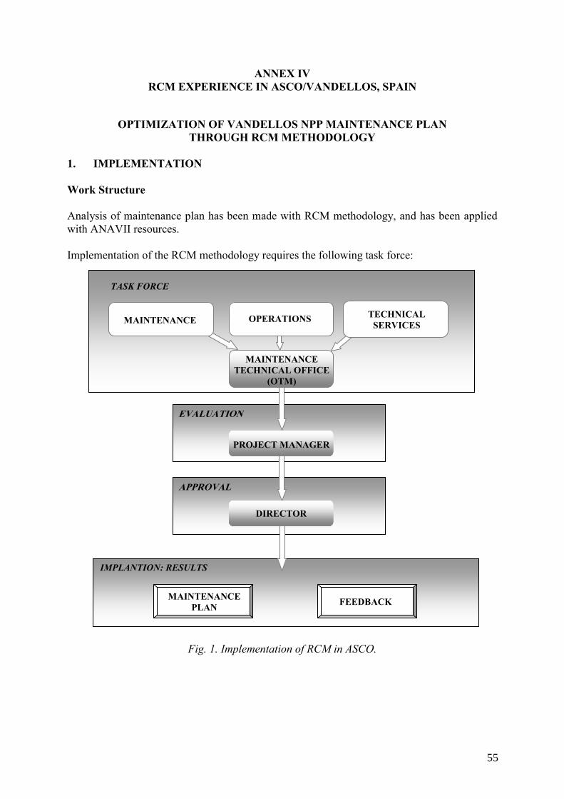
ANNEX IV RCM EXPERIENCE IN ASCO/VANDELLOS, SPAIN
OPTIMIZATION OF VANDELLOS NPP MAINTENANCE PLAN THROUGH RCM METHODOLOGY
1. IMPLEMENTATION Work Structure Analysis of maintenance plan has been made with RCM methodology, and has been applied with ANAVII resources. Implementation of the RCM methodology requires the following task force:
Fig. 1. Implementation of RCM in ASCO.
TASK FORCE
EVALUATION
APPROVAL
IMPLANTION: RESULTS
MAINTENANCE OPERATIONS TECHNICAL SERVICES
MAINTENANCE TECHNICAL OFFICE
(OTM)
PROJECT MANAGER
DIRECTOR
MAINTENANCE PLAN FEEDBACK
55
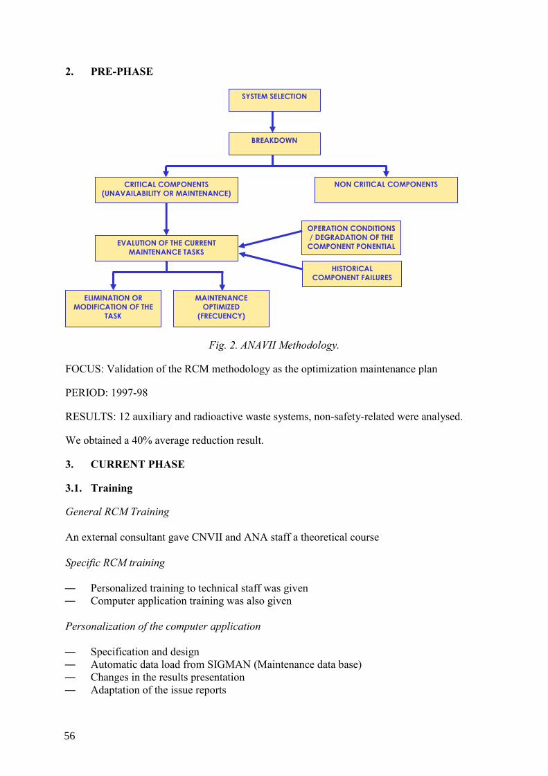
2. PRE-PHASE
Fig. 2. ANAVII Methodology.
FOCUS: Validation of the RCM methodology as the optimization maintenance plan
PERIOD: 1997-98
RESULTS: 12 auxiliary and radioactive waste systems, non-safety-related were analysed.
We obtained a 40% average reduction result.
3. CURRENT PHASE
3.1. Training
General RCM Training An external consultant gave CNVII and ANA staff a theoretical course Specific RCM training ― Personalized training to technical staff was given ― Computer application training was also given
Personalization of the computer application ― Specification and design ― Automatic data load from SIGMAN (Maintenance data base) ― Changes in the results presentation ― Adaptation of the issue reports
SYSTEM SELECTION
BREAKDOWN
CRITICAL COMPONENTS (UNAVAILABILITY OR MAINTENANCE)
NON CRITICAL COMPONENTS
EVALUTION OF THE CURRENT MAINTENANCE TASKS
MAINTENANCE OPTIMIZED
(FRECUENCY)
HISTORICAL COMPONENT FAILURES
OPERATION CONDITIONS / DEGRADATION OF THE
COMPONENT PONENTIAL
ELIMINATION OR MODIFICATION OF THE
TASK
56
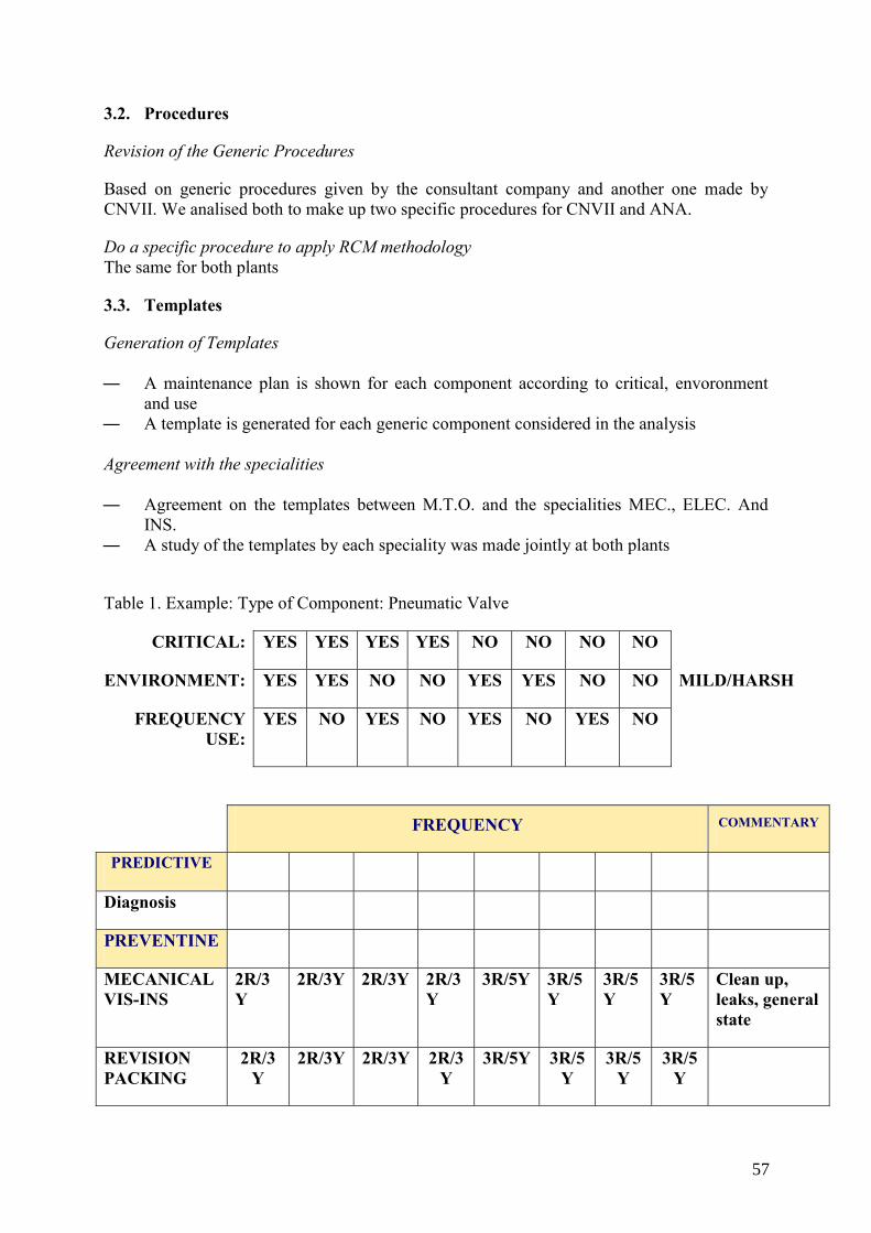
3.2. Procedures
Revision of the Generic Procedures
Based on generic procedures given by the consultant company and another one made by CNVII. We analised both to make up two specific procedures for CNVII and ANA.
Do a specific procedure to apply RCM methodology The same for both plants
3.3. Templates
Generation of Templates ― A maintenance plan is shown for each component according to critical, envoronment
and use ― A template is generated for each generic component considered in the analysis Agreement with the specialities ― Agreement on the templates between M.T.O. and the specialities MEC., ELEC. And
INS. ― A study of the templates by each speciality was made jointly at both plants
Table 1. Example: Type of Component: Pneumatic Valve
CRITICAL: YES YES YES YES NO NO NO NO
ENVIRONMENT: YES YES NO NO YES YES NO NO MILD/HARSH
FREQUENCY USE:
YES NO YES NO YES NO YES NO
FREQUENCY COMMENTARY
PREDICTIVE
Diagnosis
PREVENTINE
MECANICAL VIS-INS
2R/3Y
2R/3Y 2R/3Y 2R/3Y
3R/5Y 3R/5Y
3R/5Y
3R/5Y
Clean up, leaks, general state
REVISION PACKING
2R/3Y
2R/3Y 2R/3Y 2R/3Y
3R/5Y 3R/5Y
3R/5Y
3R/5Y
57
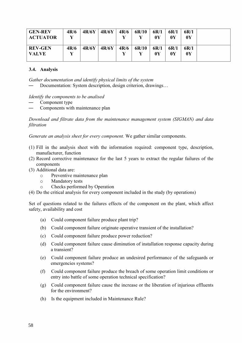
GEN-REV ACTUATOR
4R/6Y
4R/6Y 4R/6Y 4R/6Y
6R/10Y
6R/10Y
6R/10Y
6R/10Y
REV-GEN VALVE
4R/6Y
4R/6Y 4R/6Y 4R/6Y
6R/10Y
6R/10Y
6R/10Y
6R/10Y
3.4. Analysis
Gather documentation and identify physical limits of the system ― Documentation: System description, design criterion, drawings… Identify the components to be analised ― Component type ― Components with maintenance plan Download and filtrate data from the maintenance management system (SIGMAN) and data filtration Generate an analysis sheet for every component. We gather similar components. (1) Fill in the analysis sheet with the information required: component type, description,
manufacturer, function (2) Record corrective maintenance for the last 5 years to extract the regular failures of the
components (3) Additional data are:
o Preventive maintenance plan o Mandatory tests o Checks performed by Operation
(4) Do the critical analysis for every component included in the study (by operations) Set of questions related to the failures effects of the component on the plant, which affect safety, availability and cost
(a) Could component failure produce plant trip?
(b) Could component failure originate operative transient of the installation?
(c) Could component failure produce power reduction?
(d) Could component failure cause diminution of installation response capacity during a transient?
(e) Could component failure produce an undesired performance of the safeguards or emergencies systems?
(f) Could component failure produce the breach of some operation limit conditions or entry into battle of some operation technical specification?
(g) Could component failure cause the increase or the liberation of injurious effluents for the environment?
(h) Is the equipment included in Maintenance Rule?
58
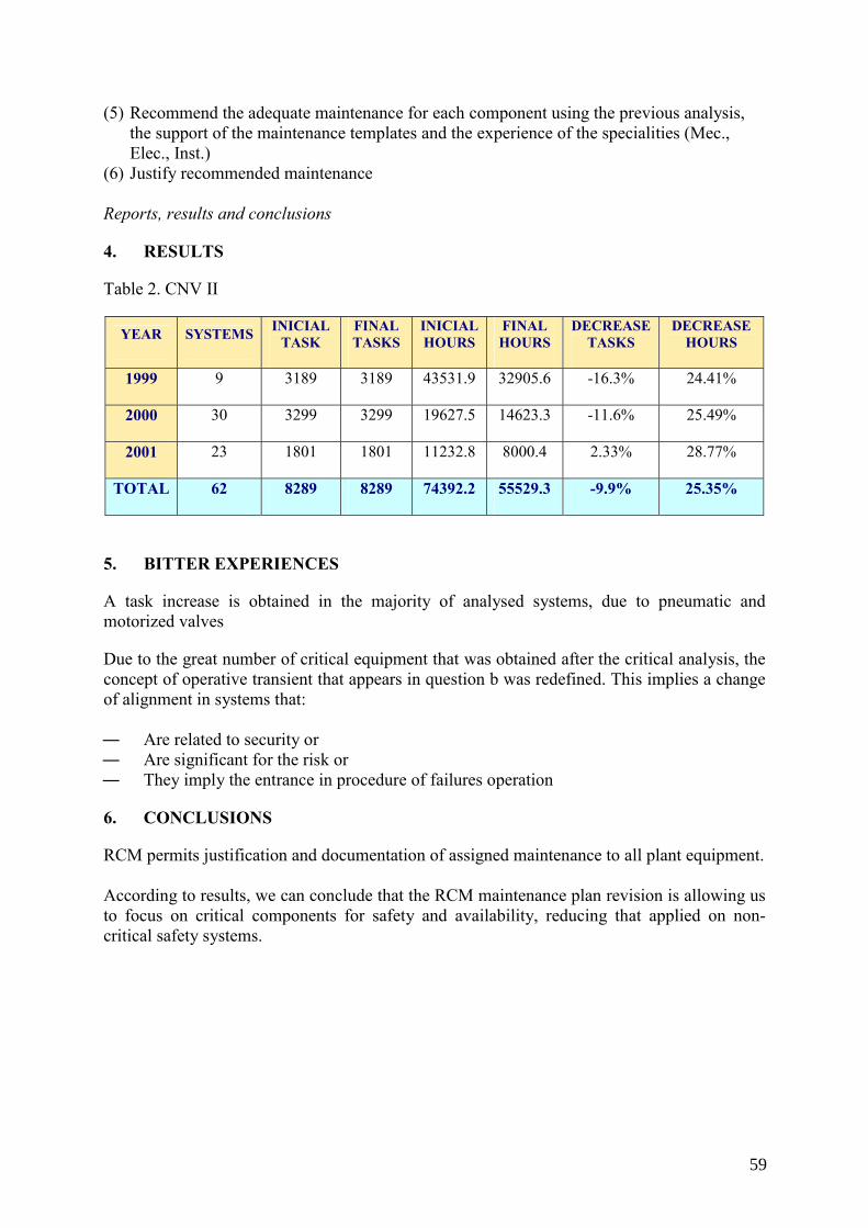
(5) Recommend the adequate maintenance for each component using the previous analysis, the support of the maintenance templates and the experience of the specialities (Mec., Elec., Inst.)
(6) Justify recommended maintenance Reports, results and conclusions
4. RESULTS
Table 2. CNV II
YEAR SYSTEMS INICIAL TASK
FINAL TASKS
INICIAL HOURS
FINAL HOURS
DECREASE TASKS
DECREASE HOURS
1999 9 3189 3189 43531.9 32905.6 -16.3% 24.41%
2000 30 3299 3299 19627.5 14623.3 -11.6% 25.49%
2001 23 1801 1801 11232.8 8000.4 2.33% 28.77%
TOTAL 62 8289 8289 74392.2 55529.3 -9.9% 25.35%
5. BITTER EXPERIENCES
A task increase is obtained in the majority of analysed systems, due to pneumatic and motorized valves
Due to the great number of critical equipment that was obtained after the critical analysis, the concept of operative transient that appears in question b was redefined. This implies a change of alignment in systems that: ― Are related to security or ― Are significant for the risk or ― They imply the entrance in procedure of failures operation
6. CONCLUSIONS
RCM permits justification and documentation of assigned maintenance to all plant equipment. According to results, we can conclude that the RCM maintenance plan revision is allowing us to focus on critical components for safety and availability, reducing that applied on non-critical safety systems.
59
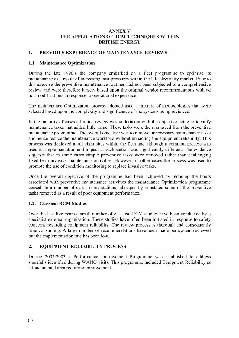
ANNEX V THE APPLICATION OF RCM TECHNIQUES WITHIN
BRITISH ENERGY
1. PREVIOUS EXPERIENCE OF MAINTENANCE REVIEWS
1.1. Maintenance Optimization
During the late 1990’s the company embarked on a fleet programme to optimise its maintenance as a result of increasing cost pressures within the UK electricity market. Prior to this exercise the preventive maintenance routines had not been subjected to a comprehensive review and were therefore largely based upon the original vendor recommendations with ad hoc modifications in response to operational experience.
The maintenance Optimization process adopted used a mixture of methodologies that were selected based upon the complexity and significance of the systems being reviewed.
In the majority of cases a limited review was undertaken with the objective being to identify maintenance tasks that added little value. These tasks were then removed from the preventive maintenance programme. The overall objective was to remove unnecessary maintenance tasks and hence reduce the maintenance workload without impacting the equipment reliability. This process was deployed at all eight sites within the fleet and although a common process was used its implementation and impact at each station was significantly different. The evidence suggests that in some cases simple preventive tasks were removed rather than challenging fixed term invasive maintenance activities. However, in other cases the process was used to promote the use of condition monitoring to replace invasive tasks.
Once the overall objective of the programme had been achieved by reducing the hours associated with preventive maintenance activities the maintenance Optimization programme ceased. In a number of cases, some stations subsequently reinstated some of the preventive tasks removed as a result of poor equipment performance.
1.2. Classical RCM Studies
Over the last five years a small number of classical RCM studies have been conducted by a specialist external organisation. These studies have often been initiated in response to safety concerns regarding equipment reliability. The review process is thorough and consequently time consuming. A large number of recommendations have been made per system reviewed but the implementation rate has been low.
2. EQUIPMENT RELIABILITY PROCESS
During 2002/2003 a Performance Improvement Programme was established to address shortfalls identified during WANO visits. This programme included Equipment Reliability as a fundamental area requiring improvement.
60
An Equipment Reliability (ER) process was developed based upon the INPO AP913 model, fig 1. The ER Process represents the integration and co-ordination of a broad range of equipment reliability activities into one process. This process enables plant personnel to evaluate important station equipment, develop and implement long-term equipment health plans, monitor equipment performance and condition, and make continuing adjustments to preventive maintenance tasks and frequencies based on equipment operating experience.
Fig. 1. BE Approach Interfaces.
The ER Process groups these activities in to six areas, which are: Scoping and Identification of Critical Components This area of the ER Process includes: (i) Common scope criteria (ii) Identification of important functions (iii) Critical component identification (iv) Run To Failure component determinations This area of the ER Process concerns the identification of components that truly effect safety, reliability and generation. Therefore this is an integral part of the Maintenance Strategy and in terms of the development of a PM Programme the criticality plays a key role in determining what maintenance will be applicable and effective for a component.
Continuing Equipment Reliability Improvement
PM
Implementation
Life-Cycle Management
Scoping and Identification of
Critical
Performance Monitoring
Corrective Action
61
Performance Monitoring This part of the ER Process incorporates:
(i) System performance monitoring and trending (ii) Component performance monitoring and trending (iii) Predictive Maintenance trending (iv) Operations Rounds monitoring (v) Monitor testing and inspection results The data that is collected and analysed is used to identify systems that are performing poorly and to recover the system health the causes are determined and an Action Plan is created. Determining the cause and creating an Action Plan is conducted within the ER Process as part of Corrective Action and may identify a need for the Maintenance Strategy to be reviewed. Continuing Equipment Reliability Improvement This aspect of the ER Process includes: (i) Development and use of PM templates (ii) Continuing adjustment to PM task and frequency based on station and industry
experience (iii) Documentation of PM technical bases (iv) Consideration of alternative maintenance strategies to ensure reliable equipment (v) Initiation of design change requests This area of the ER Process is at the heart of the maintenance strategy, as it provides the tools to review maintenance in order to identify applicable and effective task for components. The Maintenance Strategy uses Reliability Centred Maintenance (RCM), specifically Streamlined RCM (SRCM), to adjust and review PM tasks and frequencies on a continual basis. This methodology is supported by the use of Maintenance Templates to help promote consistency for like items and provides a documented basis for the changes being made. In addition, as part of the PM Review process the methodology used will identify deficiencies in design, such as single points of vulnerability, which would potentially require design changes. As a consequence of this there is a link from Continuing Equipment Reliability Improvement in to the Life Cycle Management area of the ER Process. Corrective Action This area of the ER Process incorporates: (i) Corrective Maintenance (ii) Cause determination and corrective action (iii) Prioritisation of equipment problems This area of the ER Process is largely dealt with via the Corrective Action Programme (CAP), which includes determining the cause of adverse conditions and generating appropriate actions to correct the problem.
62
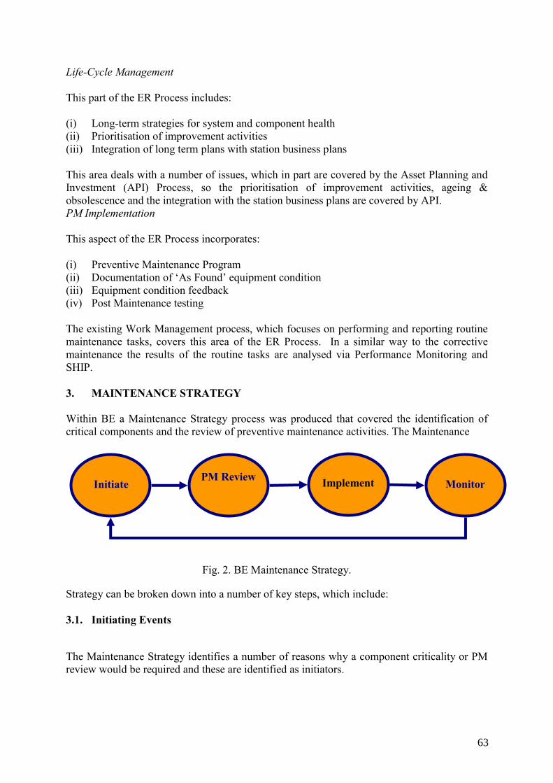
Life-Cycle Management This part of the ER Process includes: (i) Long-term strategies for system and component health (ii) Prioritisation of improvement activities (iii) Integration of long term plans with station business plans This area deals with a number of issues, which in part are covered by the Asset Planning and Investment (API) Process, so the prioritisation of improvement activities, ageing & obsolescence and the integration with the station business plans are covered by API. PM Implementation This aspect of the ER Process incorporates: (i) Preventive Maintenance Program (ii) Documentation of ‘As Found’ equipment condition (iii) Equipment condition feedback (iv) Post Maintenance testing The existing Work Management process, which focuses on performing and reporting routine maintenance tasks, covers this area of the ER Process. In a similar way to the corrective maintenance the results of the routine tasks are analysed via Performance Monitoring and SHIP. 3. MAINTENANCE STRATEGY Within BE a Maintenance Strategy process was produced that covered the identification of critical components and the review of preventive maintenance activities. The Maintenance
Fig. 2. BE Maintenance Strategy.
Strategy can be broken down into a number of key steps, which include: 3.1. Initiating Events
The Maintenance Strategy identifies a number of reasons why a component criticality or PM review would be required and these are identified as initiators.
Initiate PM Review Implement Monitor
63
These initiators include: (i) Performance Monitoring (predominantly the SHIP) (ii) Corrective Action Programme (CAP) Reports (CRs) (iii) Engineering Changes (ECs) (iv) Operational Experience Feedback (OEF) (v) Changes to Operating Procedures (vi) Plus others reasons such as changes to Condition Monitoring (Con Mon or PdM)
techniques or technology, updates to manufacturers technical manuals and changes to Code or Insurance requirements.
3.2. Review Process
Component Criticality is a method for identifying plant items or components that have a significant impact on the station and uses common scoping criteria for identification. Knowing which items are critical facilitates the appropriate targeting of limited plant resources to those components that truly affect safety, reliability and generation. Components are categorized as: (i) ‘Critical’: the failure of the equipment will result in situation that can not be tolerated. (ii) ‘Non-Critical’: the failure of the equipment can be tolerated but preventive maintenance
tasks are applicable. (iii) ‘Run To Failure’: the failure of the equipment can be tolerated and preventive
maintenance tasks are not applicable. (iv) ‘Not Assessed’: the equipment is a passive component and inherently reliable and is
omitted from the analysis. The criticality assigned to an item or component it will affect the way items are managed, so that the focus is placed on those items where failure is considered intolerable to the facility. The PM Review Process is made up of a number of fundamental steps: (i) Define the review boundaries: ⎯ Identifying the start and end points of the PM Review. ⎯ Record some of the assumptions in the analysis. ⎯ Review required documentation. (ii) Functional Failure Analysis (FFA): ⎯ Identifying the important functions of the system. ⎯ Recording the functional failures. ⎯ Identifying the functionally significant components. (iii) Failure Modes and Effects Analysis (FMEA) / Criticality Analysis: ⎯ Record the failure modes for items assessed. ⎯ Identify the significant failure effects. ⎯ Determine the Critical, Non-Critical items.
64
(iv) Task Selection and Comparison: ⎯ Identifying applicable and effective maintenance tasks. ⎯ Compare current maintenance with selected tasks to identify a complete list of
recommendations. For Significant Component Types a Maintenance Template may be available to identify tasks. The templates allow easy assessment of like components to determine the appropriate tasks and frequencies. Also, it permits a consistent approach to determining PM Tasks for like components. 3.3. Implementation
The implementation of the recommendations arising from the PM Review that change the existing equipment maintenance regime. To assist implementation the results of the review should be analysed, considering 3 main areas: (i) Resources The resources available for adding, modifying or deleting tasks (ii) Capability The identification of the programmes required to support the tasks and a review of the current programmes in place to determine their capability. (iii) Priority The identification of tasks on critical equipment or tasks currently carried out that requires deletion. 3.4. Effectiveness Review
The process for reviewing the effectiveness of the maintenance strategy. The effectiveness review should address: (i) The effectiveness of the operation of the maintenance strategy process. The following indicators should be used for to assess the effectiveness of the operation of the maintenance strategy process: ⎯ Evaluation request forms raised. The number and status of forms to identify the number
of requests that have been initiated completed or cancelled in the period of review. ⎯ The status of the recommended tasks recorded by implementation tracking for
outstanding evaluation requests.
65
⎯ The number of components that have an assigned criticality on the high priority systems as determined by the SHIP process.
(ii) The effectiveness of the maintenance strategy in improving the system performance. The following indicators should be used for to assess the effectiveness of the maintenance strategy in improving system performance: ⎯ CM/PM ratio. For systems that have recently been reviewed the ratio of planned to
corrective work on the system should be trended. ⎯ Corrective Work Order Cards. The number of defects reported on critical equipment by
system should be trended. ⎯ The number of failures of critical equipment in systems that have been reviewed.
Through the Corrective Action Programme (CAP) failures the result in losses will be assessed and when the root cause of the failure is against a component then this should be recorded for further analysis.
⎯ The cancellation rate for routines on critical and non-critical equipment by system. 4. DEPLOYMENT OF THE ER PROCESS 4.1. Organizational Issues To promote the use of the ER process the station organisation has been modified. At each station a System Health Department has been formed with engineers managing either systems or component groups and programs. The role of the system health engineers is to focus on long term issues effecting the health of the systems. This model has also required the reallocation of some traditional engineering duties to other groups to allow System Health Engineers to focus on their primary role. The duties reallocated typically include contractor management, materials procurement, minor projects management and maintenance technical support. A ‘swim lane’ chart has been produced to illustrate which groups will now be responsible for these activities. The formation of the System Health Department and the reallocation of engineering responsibilities have resulted in a net increase in the station headcount. 4.2. Training Two phases of training have been completed for the System Health engineers. Phase 1 provided an overview of the ER process and highlighted the areas where the engineers had a key role. Phase 2 covered the maintenance strategy in more detail with an emphasis on the evaluation of component criticality and the methodology for conducting an SRCM review. Further training is envisaged to ensure other groups have a good understanding of Equipment Reliability and their role in the operation of the process. 4.3. Maintenance Review Programme As a precursor to the deployment of the Maintenance Strategy a trial was conducted at for one system at three stations. The results of this trial were used to develop a company specification
66
for The Maintenance Strategy which encompassed. The Selection of Critical Components and The Preventive Review Process. In the short term it was recognised that there would insufficient experienced resource to carry out a significant number of PM reviews. It was therefore decided that the use of an external consultant to facilitate system reviews would be an expedient method of reviewing the high priority systems. Across the fleet 20 systems were selected by the stations for review, the selection was based upon lead indicators that suggested that a system had issues that could be addressed by a review of the maintenance activities. In the longer term it is envisaged that the system health engineers will conduct maintenance reviews of sub-systems or component groups as initiating events were identified. The PM review process will therefore become a living programme whereby maintenance is optimised in a continuous manner. 4.4. Preventive Maintenance Capability The SRCM process selects applicable and effective maintenance tasks using a logic tree. This approach prioritises condition based tasks over complex invasive tasks where practicable. Experience has shown that this approach leads to an increased dependence on a number of key condition monitoring programmes. However, it is essential that these condition monitoring programmes are sufficiently robust to support the maintenance strategy especially if they are being relied upon in lieu of invasive inspect/replace tasks. The following condition monitoring programmes have been identified as essential: ⎯ Equipment performance monitoring ⎯ Vibration analysis ⎯ Oil analysis ⎯ Thermography 4.5. Implementation of Recommendations Experience from a limited number classical RCM studies that have previously been completed has indicated that implementing the RCM recommendations within the maintenance management system is often a process bottleneck. Historically this has resulted in many recommendations not being implemented. For sub-system reviews conducted by System Health Engineers the implementation can be managed by the responsible engineer using the local station resources. This is considered to be practicable for the reviews where there are a limited number of recommendations. For externally facilitated reviews specialist resource at a fleet level will be required to manage the implementation of the recommendations. It is considered that this supplementary resource will be required for complete systems reviews that may produce a large number of recommendations. As the implementation phase is time consuming and can be protracted it is necessary to prioritise the recommendations to ensure that the maximum benefit is derived as soon as
67
possible. The exact order of prioritisation will depend on the objectives of the study but the following criteria should be considered: Criticality
Critical items are those that can effect safety, reliability and generation. Implementing recommendations on these items will therefore provide the maximum benefit to equipment reliability. Conversely if resource intensive tasks are being carried out on Run to Fail items then the deletion of these activities will remove a drain on resources. Capability The capability of the maintenance staff to carry out the maintenance task must be considered. This is particularly important where routine maintenance activities are being replaced by condition monitoring tasks. 4.6. Conclusions (I) The application of a loosely defined maintenance Optimization process for cost
reduction can result in deterioration of equipment reliability (II) To be effective in the longer term a continuous programme of PM reviews (living
programme) needs to be established (III) To create a living PM review programme it needs to be established within the context
of equipment reliability process that will provide feedback on performance and ensure other aspects of equipment reliability are addressed.
(IV) The application of classical RCM using external expertise is time consuming and is not efficient for use in a living programme.
(V) Streamlined RCM provides a cost effective method of determining ‘the right task on the right equipment’ and can be used as the basis for a living programme
(VI) The determination of equipment criticality is an essential element in determining applicable and cost effective maintenance tasks
(VII) The PM review process preferentially selects condition monitoring tasks over invasive tasks and typically results in a larger number of less resource intensive activities. The net impact is a reduction in maintenance hours when applied to a system subject to tasks derived from traditional vendor recommendations.
(VIII) A number of key condition monitoring programmes are required if the recommendations arising from the PM review process are to be implemented.
(IX) The implementation of the PM recommendations is often the process bottleneck.
68
ANNEX VI THE APPLICATION OF RCM TECHNIQUES IN THE
UNITED STATES OF AMERICA
During the beginning stages of Nuclear power in the US, much attention was given to making the plants “Run and run safely”. This was appropriate but tended to distract the plants attention away from maintenance, longer term maintenance, the functionality of each component, its criticality, and more.
One approach to alleviate these issues was to perform RCM (Reliability Centred Maintenance). It has been applied for over 25 years at many but not all of the 100 plus nuclear sites in the United States. It involves an in-depth look at each System and all of the parts that make up each System. This helps with developing maintenance practices to keep the equipment operating reliably and managing the consequences of failures.
The RCM process systematically identifies all of the asset’s functions and functional failures and identifies all of its reasonably likely failure modes (or failure causes). It then proceeds to identify the effects of these likely failure modes and to identify in what way those effects matter. Once it has gathered this information, the RCM process then selects the most appropriate asset management policy.
A rigorous RCM analysis is based on a detailed Failure Modes and Effects Analysis (FMEA) and includes probabilities of failure and system reliability calculations
The analysis is used to determine appropriate maintenance tasks to address each of the identified failure modes and their consequences.
Over the 25 plus year period, an area of concern for performing RCM was the US lacked a standardized methodology. Other drawback examples were the lack of good plant participation and follow through to implementation. In some RCM cases, history proved that the in-depth review along with deriving the best maintenance to perform was a lot to ask from one project.
1. MAINTENANCE RULE
In 1991, the NRC (Nuclear Regulatory Commission) published to all nuclear plants, the Maintenance Rule, 10 CFR 50. 65 - Requirements for Monitoring the Effectiveness of Maintenance of Nuclear Power Plants. It became effective in 1996 to ensure equipment within the scope of the Maintenance Rule criteria were capable of fulfilling their intended functions.
The rationale is that good maintenance is important in providing assurance that safety systems are reliable, and that failures of some other than safety-related SSCs (systems, structures, components) that could initiate or adversely affect a transient or accident are minimized. Maintenance is also important to ensure that design assumptions and margins in the original design basis are maintained and are not unacceptably degraded. It also ensures they are required to be monitored for overall continuing effectiveness of maintenance programs.
69
2. PSA / PRA
Applying PSA / PRA attributes to RCM provides an objective assessment of risk.
It is done with deterministic and probabilistic risk assessment. The Nuclear Regulatory Commission (NRC) is risk informing (10CFR50.69, 10CFR53) and INPOs classifications schemes are deterministic. Early on, applying PSA / PRA data during RCM was a means of getting failure rates of critical equipment. This was then used to help define maintenance activity and intervals.
U.S. nuclear plants had been implementing preventive maintenance (PM) tasks with little documented basis beyond fundamental vendor information to support the tasks or their intervals. Many tasks were performed on equipment that had very little fundamental value.
In 1999, a group began working on building an RCM Standard to define the process. There were many different processes already in use so developing a standard was difficult. What evolved was a set of criteria that if the process you were using met the criteria, then it could be called an RCM process. (SAE JA1011 called Evaluation Criteria for Reliability-Centred Maintenance (RCM) Processes.) This helped companies decide if their process should be called RCM or not. Today, RCM has evolved enough so that every process could be called at least a form of RCM (classic or streamlined RCM).
3. DOWNSIDES
Many utilities and other industries have implemented various forms of an RCM program only to find that they continued to have fundamental reliability issues that were not addressed by their analysis. Some people believe the primary reason was the lack of a full understanding of the principles governing the analysis.
Historically RCM has been cumbersome, expensive, and very difficult to implement. Implementing an RCM program has for the most part been shrouded in confusion and unfortunately, its image has taken on an aura of perceived complexity.
It has been conservatively estimated that over 60% of all RCM programs initiated are never successfully implemented. There are many reasons for this. Most of the existing information on RCM is very difficult to understand and assimilate, and even more difficult to use as a tool for implementation by the layperson. RCM is a very powerful reliability tool but as long as it remains mostly non-user friendly, its full potential is limited.
United States Nuclear Plant designs are typically different from plant to plant and often different between each sites own reactors. (Very few have the same exact designs) Applying RCM at one unit typically has not proven to be directly applicable to other units or other NPPs.
When RCM may be a very useful tool ⎯ When designing, selecting, and installing new systems in a plant. ⎯ When setting up Preventive Maintenance for complex equipment and systems we are
not clear on how they work ⎯ When teaching people the basics of reliability it helps to explain the matters in a
detailed fashion using RCM
70
⎯ Some components functional failures have the potential to result in large losses of life, and / or extreme environmental impact.
Reliability Centred Maintenance (RCM) has its definite place in the specification and design phase of new equipment and systems and for existing critical and complicated systems. The thought process used to analyze existing preventive maintenance programs is good but can easily be made overcomplicated to serve the purpose.
For example, in analyzing the results of RCM implementations and after a very lengthy criticality and failure mode analysis, the end results have not changed the fact that a V-belt drive needs to be inspected for a critical belt conveyor! What is often missing is a document describing how to inspect it while the equipment is operating.
In some cases, belts, couplings, heat exchangers, control valves, and other common components are, even after the RCM analyses, inspected during shutdowns and don’t take advantage of inspections while operating.
Another example may be that some inspections have been deleted because equipment was not critical. You might have saved an inspection that only takes a few minutes for an operator who will inspect that area every shift anyway!
Recognizing hidden failure modes, understanding when a single-failure analysis is not acceptable, and knowing when run to failure is acceptable are the real cornerstones of RCM. Additionally, the understated, but powerfully important, distinction between true redundancy and redundant components fulfilling a standby or backup function is a key to reliability success.
When RCM is less useful ⎯ Rigorous RCM has been previously performed (reduces the gains from another full
RCM project) ⎯ When defining Preventive Maintenance for typical plant equipment such as pumps,
motors, couplings, cylinders, hydraulics etc. It is too tedious. We know this equipment and failure modes.
4. DATABASES
Component information has not always been complete or fully accurate for fields such as Manufacturer, Model, etc. Plant data management systems are not always easy to use as many sites used stand-alone computer management systems.
Many plants in the last few years have been updating to better systems.
Previous plant data systems were not all user friendly at in-put and controlling costs associated with maintenance. Cost accounting at times, is incomplete and not reliable enough to obtain accurate results or for building baselines after a project is completed.
At times, critical plant data has been stored in multiple locations, not only the main computer system. Engineering functions often utilize separate programs for certain calculations which has led to data being stored away from the main system.
71
Maintenance history seldom is easily retrievable or kept in a form that gives large projects the ability to combine and utilize the information. An example is that it hasn’t been entered into an electronic system or requires the analyst to read each full write-up by the mechanic in order to interpret the information.
Many component numberings systems are different from other sites. These unlike numbering systems have kept RCM data from one project from being directly applicable to other sites.
5. CONSIDERATIONS FROM THE HISTORY OF PERFORMING FULL RCM
⎯ Time to perform RCM (some 2 unit sites - 6 years or more) ⎯ Costs – More time and people involved, more cost. Initial goal savings are to save 25-
40% for performing RCM. At the start of RCM, costs typically increase. This increase is relatively short-lived. The cost of repair decreases as failures are prevented and preventive maintenance tasks are replaced by condition monitoring. The net effect is a reduction of both repair and a reduction in total maintenance cost.
⎯ Personnel utilized was large; contractors (typically) supported by site personnel ⎯ Many files and work performed for RCM have been completed and stored on paper (not
electronic.) Experience has shown that many sites have all but abandoned trying to keep the changes updated in these papers. Hence the living program necessity for RCM had to be handled other ways or sometimes, not updated.
Some NPPs in the US continue to perform RCM in a variety of forms. It could be safely stated that every plant performing maintenance program review is using some sort of RCM since it has evolved greatly from past methodologies. Also, there are very few if any plants presently performing full RCM across their entire plant.
Engineers and others at NPPs typically do not desire simplified forms of accomplishing results. They often analyze things so deeply that the term “analysis paralysis” has become common, which has been a stumbling block for completing projects in the US. Contracted companies try to sort this out, incorporate enhancements, changes, and methods to alleviate some of the drawbacks found over time.
6. POSSIBLE ALTERNATIVE APPROACH
Is full RCM for you or is an alternative approach?
There is a streamlined approach that uses many of the same principles of rigorous RCM, but does not intend to analyze all of the failure modes. Some US sites have used this new approach without having had RCM performed, for re-assessing their maintenance programs a few years after RCM was completed, or in combination with parts of full RCM.
One approach is to use what has been called PMO, (Preventive Maintenance Optimization), Component Type review or Streamlined RCM. It utilizes many if not all of the same inputs as RCM uses, but with less in-depth review. Component Type review is not as concerned with which System the component is in. It relies on determinations of criticality, duty cycles and service conditions in developing maintenance practices with justifications “across” systems for the components standardized maintenance tasks.
In the US, the RCM process has evolved by incorporating pieces of other methodologies.
72
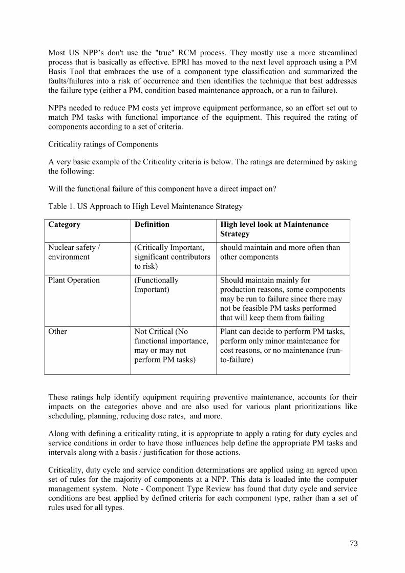
Most US NPP’s don't use the "true" RCM process. They mostly use a more streamlined process that is basically as effective. EPRI has moved to the next level approach using a PM Basis Tool that embraces the use of a component type classification and summarized the faults/failures into a risk of occurrence and then identifies the technique that best addresses the failure type (either a PM, condition based maintenance approach, or a run to failure).
NPPs needed to reduce PM costs yet improve equipment performance, so an effort set out to match PM tasks with functional importance of the equipment. This required the rating of components according to a set of criteria.
Criticality ratings of Components
A very basic example of the Criticality criteria is below. The ratings are determined by asking the following:
Will the functional failure of this component have a direct impact on?
Table 1. US Approach to High Level Maintenance Strategy
Category Definition High level look at Maintenance Strategy
Nuclear safety / environment
(Critically Important, significant contributors to risk)
should maintain and more often than other components
Plant Operation (Functionally Important)
Should maintain mainly for production reasons, some components may be run to failure since there may not be feasible PM tasks performed that will keep them from failing
Other Not Critical (No functional importance, may or may not perform PM tasks)
Plant can decide to perform PM tasks, perform only minor maintenance for cost reasons, or no maintenance (run-to-failure)
These ratings help identify equipment requiring preventive maintenance, accounts for their impacts on the categories above and are also used for various plant prioritizations like scheduling, planning, reducing dose rates, and more.
Along with defining a criticality rating, it is appropriate to apply a rating for duty cycles and service conditions in order to have those influences help define the appropriate PM tasks and intervals along with a basis / justification for those actions.
Criticality, duty cycle and service condition determinations are applied using an agreed upon set of rules for the majority of components at a NPP. This data is loaded into the computer management system. Note - Component Type Review has found that duty cycle and service conditions are best applied by defined criteria for each component type, rather than a set of rules used for all types.
73
To help provide technical basis for tasks, EPRI (Electric Power Research Institute) chose about 40 major equipment component types initially so that better focus could be applied to a large portion of the plants, which also covers the majority of the main components.
Preventive Maintenance (PM) - PM Basis templates for each component type are built and developed by component Experts and used to derive the best practices and frequencies for that specific type.
PM Optimization looks early on at existing maintenance tasks, reviews, optimizes them, and forms justifications for performing them. These optimized tasks are also applied to other like components that presently don’t have maintenance but should have according to their criticality ratings.
A shortened version of FMEA (Failure Modes and Effects Analysis) is included in this review that ensures the typical failure mechanisms are known and addressed when possible. Life expectancy is reviewed, maintenance history assessed, Operating experience and more are all incorporated to help increase equipment reliability.
Utilizing the guidance set forth by the Maintenance Rule, applying PSA / PRA during Streamlined RCM typically involves merely reviewing the proposed changes to the maintenance programs for the safety significant components. Since US plants are mandated to maintain and also prove it by monitoring, adherence keeps most programs from major distractions.
7. TRAINING
Training is provided prior to and during equipment criticality review meetings as well as prior to and during Component Type Review meetings. The process is simple enough for rapid comprehension and the personnel in the reviews grasp it quickly. They realize they are going to be the owners of the new program moving forward and feel comfortable knowing enough to keep it “living.”
8. A SIMPLIFIED VIEW OF COMPONENT TYPE REVIEW MIGHT BE
Gather all of the appropriate inputs per a component type, have component experts review and incorporate the best data and newest available tasks, implement them directly into the plant computer system, and use a good feedback program to keep them as updated and “best” moving forward by being easily updated. This applies to all like components due to them being electronically grouped. All of which is under the guidelines of AP-913.
This type of review typically takes much less time than full RCM takes.
For comparison, an estimate of time required for using Component Type review over past RCM projects with the deeper review would be about one-fourth the amount of time. (Remember, this isn’t an exact match since far more study is provided by full RCM and the streamlined results may not be everything a NPP wants to achieve)
Some benefits of this much shorter time duration:
⎯ Has shown quicker results in Equipment Reliability (more focus) ⎯ Site personnel remain enthusiastic about maintenance review (see progress sooner)
74
⎯ Costs are typically less ⎯ Plant personnel (if deeply involved) can return to their old positions in a shorter period
of time
Quantifiable results of savings have been difficult to obtain. Many U.S. sites have not been persistent in keeping accurate maintenance man-hours, costs, etc. to provide good baselines. Their data management systems were not consistently updated or the system was not good at accepting the data in prior years.
Also, some PMO projects have been completed in less than a year (for a given set of Component Types), which at times is not enough time to see results due to refuelling cycles typically being 18 months or 2 years. It has been left up to the NPP to keep up with building a baseline and keeping it updated for capturing cost benefits, which has not always been successful.
9. TO FURTHER ASSIST IN DECIDING IF FULL RCM OR STREAMLINED APPROACH IS WHAT YOU NEED, CONSIDER THE FOLLOWING:
Full RCM will take time, money, plant participation and a good software tool able to hold and update the data.
It has proven that a major portion of RCM should be performed using Contract personnel. NPPs attempting to perform this with site help typically have not produced good standard results.
10. COMPONENT TYPE REVIEW
Component Type review has shown to produce quick results, NPPs can move on to other projects quicker, and the results are easy to control and update. A software tool is good but not essential to do the analysis. Data must be able to be extracted from the NPP maintenance management system.
The results of this review could also be used to perform RCM later if needed.
11. UNDECIDED?
Possibly the most economical and efficient approach is to use a combination of rigorous RCM and Component Type analysis. Divisions could rely on system criticality and failure impacts. Candidates for rigorous analysis may include support systems where single points of failure exist.
12. ADDITIONAL THOUGHTS REGARDING MAINTENANCE PROGRAM REVIEW
The business process Like any business process, the reliability process requires a disciplined approach. When supported by reliability software and practices, reliability- focused maintenance processes will help to enhance and sustain a proactive work culture. The stages of plan, assess, improve and control can be applied to the maintenance process.
75
Over the next two to five years, emerging reliability software will further boost the move to greater efficiency. Because maintenance is typically the largest cost center in a utility, power providers are expected to take increasing advantage of it.
Benefits of incorporating Change management with the RCM or Maintenance Review
⎯ Provides the path to a new culture (everyone is responsible for Equip. Reliability ⎯ Ensures results reside in a Living Program ⎯ Ensures people needs are addressed ⎯ Starts with an assessment to map key business processes ⎯ Develops performance improvement action plan – to process centred organization ⎯ Integrates other improvement initiatives, such as Work Management ⎯ Participation by nearly every Plant organization
13. RETAINING KNOWLEDGE
According to a recent Hudson Institute study of the workforce in North America, 30% to 40% of maintenance trades people will be retiring over the next five years. This problem is particularly acute in the power industry where estimates are as high as 50%. During their 20 to 40 years on the job, trades people collect a wealth of knowledge that is rarely documented or transferred to others. Well-seasoned maintenance veterans are intimate with their equipment and can quickly repair equipment to avoid downtime.
This knowledge includes asset-prioritization, asset-indicator targets, inspection knowledge and general know-how pertaining to the maintenance of the assets. This critical information is often just memorized by the employee or manually recorded in handbooks. As employees retire, this knowledge is lost in companies that do not systematically collect it as the employee performs his or her job. At the same time, fewer people are entering the trades. The impact of the personnel shortage in the nuclear power industry has been significant.
In addition, educating non-engineers to analyze condition data to reduce the reliance on licensed engineers is critical in the power industry where equipment failure can be catastrophic. Recall the Three-Mile Island reactor accident, the worst nuclear power plant accident in the U.S. The Nuclear Energy Institute said the cause of this accident was a combination of equipment failure, inadequately designed instrumentation and the inability of the plant operators to understand the reactor's condition.
In the nuclear power industry, the Maintenance Rule dictates that companies monitor its structures, systems and components (SSC) against established goals to provide assurance they are fulfilling their intended functions. Failure to comply with this regulation could result in loss of an operating license. Nuclear sites expend significant engineering resources to comply.
Condition monitoring alone is diminished in value if the data is not analyzed and is not utilized to trigger the right work at the right time.
76
ANNEX VII RCM AT KOZLODUY NPP, BULGARIA
Use of PSA for system/components risk ranking with regard to their safety significance for the purposes of system selection for maintenance optimization for Kozloduy NPP, Units 5&6
1. INTRODUCTION
RCM methodology is applied within the task for Maintenance and Repair Optimization which is part of a big project started in 2005 for Optimization of maintenance using risk-informed PSA applications for Units 5&6 (VVER 1000/320) of Kozloduy NPP. The project is still under development. It has several different tasks among which are:
⎯ Risk informed ISI ⎯ Risk informed Maintenanceand repair – RCM is performed as part of the activities
related to this task for selection and evaluation of critical components ⎯ Risk informed testing ⎯ Risk monitoring The annual refuelling outages at Kozloduy NPP Units 5&6 are performed at the end of the fuel campaign of the corresponding unit and include activities for refuelling, an overall inspection of the equipment condition and pipelines and complex of maintenance activities to assure the safe operation of the equipment over the next fuel campaign. The planned outages of Kozloduy NPP Units 5&6 over the past 5 years have taken average of 110 calendar days (from the beginning of power reduction and planned cooldown time via refuelling to the unit start up). The capacity factor – CF – varies within 0.55÷0.65 and usually closer to the lower value. The units were under big modernization program which had also a significant contribution to the increased outage duration.
The Kozloduy NPP management commitment was to take measures and implement actions in order to increase the capacity factor up to 0.85-0.90 and implementation of the results of this project is one of these actions.
The risk-informed applications are performed by Bulgarian local contractor Risk Engineering Ltd with Westinghouse Energy Systems as a subcontractor.
The ultimate objective of the plant management is to reduce the length of refuelling outages at Kozloduy Nuclear Power Plant. Outages can be shortened using RI approaches, in addition to other approaches performing one or more of the following:
⎯ Moving Maintenance, repair, inspection, and testing activities completed during the refuelling outage to at power.
⎯ Increasing the interval of Maintenance, inspection, and test activities. ⎯ Reducing the number of Maintenance, inspection, and test activities that occur during
the refuelling outage. ⎯ Changing the type of Maintenance, inspection, and test activities that occur during the
refuelling outage.
77
In addition to the potential impact on refuelling outage time, changes in Maintenance, inspection, and test activities can impact plant operation and plant risk. These impacts need to be assessed and understood prior to making changes.
At the time of project commencement Kozloduy NPP Unit 5&6 had only PSA level 1 [18] completed and PSA level 2 under the development. For that reason simplified LERF model was developed as part of the work. Only level 1 for the “At power” was used because the shutdown model was not available at that time.
2. PRELIMINARY PREPARATORY WORKS
The system safety significance categorization and assessment of outage activities provide input data for selection of the systems which will be used later for the applications.
System selection was done based on two independent assessments: system/component risk ranking and deterministic assessment of outage activities, which are briefly described below.
3. ASSESSMENT OF IMPACT OF OUTAGE ACTIVITIES ON OUTAGE LENGTH
This task was performed for the purpose of the identification of the Maintenance, repair, inspection, and testing outage activities that have the largest impact on the outage duration. This is necessary to ensure that the program will provide the largest benefits of shortening the outage. Usually there is a large number of outage activities that do not impact the outage duration and although thy can also be the subject of interest, they were excluded from consideration.
The task comprised of the following:
(1) Review typical Refuelling Outage - A typical refuelling outage schedule for Kozloduy NPP was reviewed in detail to identify the activities that have the largest impact on the outage duration.
(2) Rank and Identify Key Outage Activities - The outage activities were ranked according to their potential impact on the outage duration and whether or not they are critical path items. The ranking gives information on what systems/components have to be selected for further analysis.
4. SYSTEM/COMPONENT RISK RANKING
The purpose of this task was to identify the components/systems that are most important to at-power plant risk. This information can then be used to identify and propose changes to the activities on components/systems that have the smallest impact on plant risk [14]. An expert panel session was used to review the component/system risk rankings.
The flow-chart showing the process is presented in Fig 1 [19]. It is necessary to understand the importance of the equipment to plant safety in order to select systems that are not safety significant and do not have a significant impact on plant safety.
78
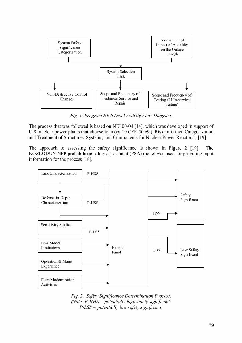
Fig. 1. Program High Level Activity Flow Diagram.
The process that was followed is based on NEI 00-04 [14], which was developed in support of U.S. nuclear power plants that choose to adopt 10 CFR 50.69 (“Risk-Informed Categorization and Treatment of Structures, Systems, and Components for Nuclear Power Reactors”, [19].
The approach to assessing the safety significance is shown in Figure 2 [19]. The KOZLODUY NPP probabilistic safety assessment (PSA) model was used for providing input information for the process [18].
Fig. 2. Safety Significance Determination Process. (Note: P-HHS = potentially high safety significant;
P-LSS = potentially low safety significant)
Non-Destructive Control Changes
Scope and Frequency of Technical Service and
Repair
Scope and Frequency of Testing (RI In-service
Testing)
System Safety Significance
Categorization
Assessment of Impact of Activities
on the Outage Length
System Selection Task
Sensitivity Studies
PSA Model Limitations
Operation & Maint. Experience
Safety Significant
Low Safety Significant
P-HSS
P-HSS
HSS
LSS
Plant Modernization Activities
P-LSS
Risk Characterization
Defense-in-Depth Characterization
Expert Panel
79
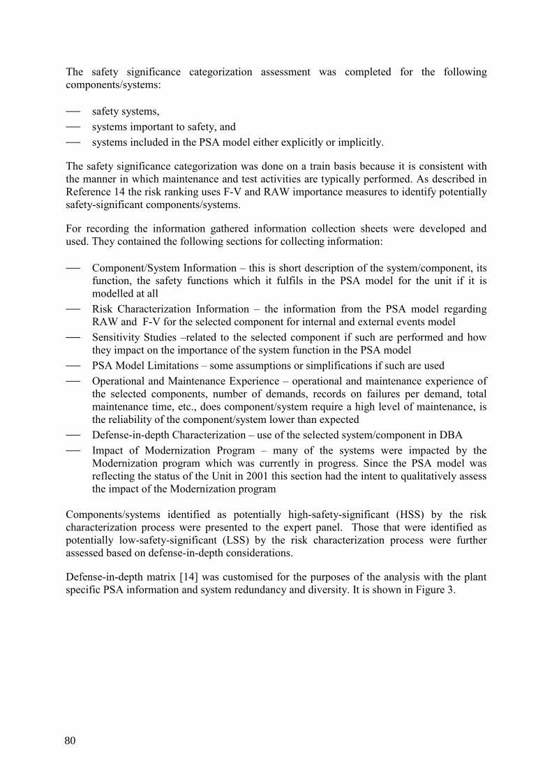
The safety significance categorization assessment was completed for the following components/systems:
⎯ safety systems, ⎯ systems important to safety, and ⎯ systems included in the PSA model either explicitly or implicitly.
The safety significance categorization was done on a train basis because it is consistent with the manner in which maintenance and test activities are typically performed. As described in Reference 14 the risk ranking uses F-V and RAW importance measures to identify potentially safety-significant components/systems.
For recording the information gathered information collection sheets were developed and used. They contained the following sections for collecting information:
⎯ Component/System Information – this is short description of the system/component, its function, the safety functions which it fulfils in the PSA model for the unit if it is modelled at all
⎯ Risk Characterization Information – the information from the PSA model regarding RAW and F-V for the selected component for internal and external events model
⎯ Sensitivity Studies –related to the selected component if such are performed and how they impact on the importance of the system function in the PSA model
⎯ PSA Model Limitations – some assumptions or simplifications if such are used ⎯ Operational and Maintenance Experience – operational and maintenance experience of
the selected components, number of demands, records on failures per demand, total maintenance time, etc., does component/system require a high level of maintenance, is the reliability of the component/system lower than expected
⎯ Defense-in-depth Characterization – use of the selected system/component in DBA ⎯ Impact of Modernization Program – many of the systems were impacted by the
Modernization program which was currently in progress. Since the PSA model was reflecting the status of the Unit in 2001 this section had the intent to qualitatively assess the impact of the Modernization program
Components/systems identified as potentially high-safety-significant (HSS) by the risk characterization process were presented to the expert panel. Those that were identified as potentially low-safety-significant (LSS) by the risk characterization process were further assessed based on defense-in-depth considerations.
Defense-in-depth matrix [14] was customised for the purposes of the analysis with the plant specific PSA information and system redundancy and diversity. It is shown in Figure 3.
80
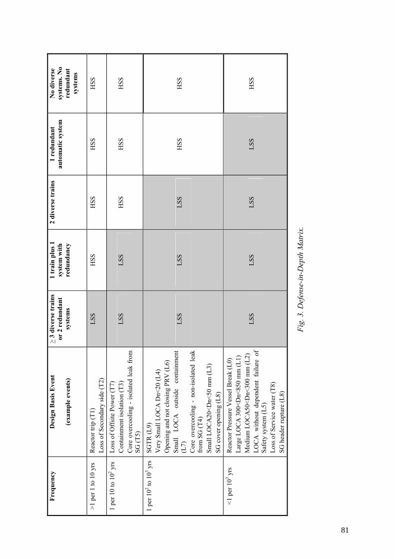
Freq
uenc
y D
esig
n B
asis
Eve
nt
(exa
mpl
e ev
ents
)
> 3
dive
rse
trai
ns
or 2
red
unda
nt
syst
ems
1 tr
ain
plus
1
syst
em w
ith
redu
ndan
cy
2 di
vers
e tr
ains
1
redu
ndan
t au
tom
atic
syst
em
No
dive
rse
syst
ems.
No
redu
ndan
t sy
stem
s
>1 p
er 1
to 1
0 yr
s R
eact
or tr
ip (T
1)
Loss
of S
econ
dary
side
(T2)
LS
S H
SS
HSS
H
SS
HSS
1 pe
r 10
to 1
02 yrs
Lo
ss o
f Off
site
Pow
er (T
7)
Con
tain
men
t iso
latio
n (T
3)
Cor
e ov
erco
olin
g -
isol
ated
leak
fro
m
SG (T
5)
LSS
LSS
HSS
H
SS
HSS
1 pe
r 102 to
103 y
rs
SGTR
(L9)
V
ery
Smal
l LO
CA
Dn<
20 (L
4)
Ope
ning
and
not
clo
sing
PR
V (L
6)
Smal
l LO
CA
ou
tsid
e co
ntai
nmen
t (L
7)
Cor
e ov
erco
olin
g -
non-
isol
ated
lea
k fr
om S
G (T
4)
Smal
l LO
CA
20<D
n<50
mm
(L3)
SG
cov
er o
peni
ng (L
8)
LSS
LSS
LSS
HSS
H
SS
<1 p
er 1
03 yrs
R
eact
or P
ress
ure
Ves
sel B
reak
(L0)
La
rge
LOC
A 3
00<D
n<85
0 m
m (L
1)
Med
ium
LO
CA
50<D
n<30
0 m
m (L
2)
LOC
A w
ithou
t de
pend
ent
failu
re o
f Sa
fety
syst
em (L
5)
Loss
of S
ervi
ce w
ater
(T8)
SG
hea
der r
uptu
re (L
8)
LSS
LSS
LSS
LSS
HSS
Fig.
3. D
efen
se-in
-Dep
th M
atri
x.
81
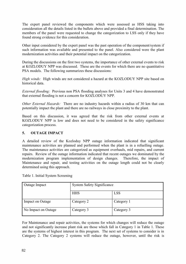
The expert panel reviewed the components which were assessed as HSS taking into consideration all the details listed in the bullets above and provided a final determination. The members of the panel were requested to change the categorization to LSS only if they have found strong evidence for this consideration.
Other input considered by the expert panel was the past operation of the component/system if such information was available and presented to the panel. Also considered were the plant modernization activities and their potential impact on the categorization.
During the discussions on the first two systems, the importance of other external events to risk at KOZLODUY NPP was discussed. These are the events for which there are no quantitative PSA models. The following summarizes these discussions:
High winds: High winds are not considered a hazard at the KOZLODUY NPP site based on historical data.
External flooding: Previous non PSA flooding analyses for Units 3 and 4 have demonstrated that external flooding is not a concern for KOZLODUY NPP.
Other External Hazards: There are no industry hazards within a radius of 30 km that can potentially impact the plant and there are no railways in close proximity to the plant.
Based on this discussion, it was agreed that the risk from other external events at KOZLODUY NPP is low and does not need to be considered in the safety significance categorization process.
5. OUTAGE IMPACT
A detailed review of the Kozloduy NPP outage information indicated that significant maintenance activities are planned and performed when the plant is in a refuelling outage. The maintenance activities are categorized as equipment overhauls, mid repairs, and current repairs. Review of the outage information indicated that recent outages we dominated by the modernization program implementation of design changes. Therefore, the impact of Maintenance and repair, and testing activities on the outage length could not be clearly determined using this approach. Table 1. Initial System Screening
System Safety Significance Outage Impact
HHS LSS
Impact on Outage Category 2 Category 1
No Impact on Outage Category 3 Category 3
For Maintenance and repair activities, the systems for which changes will reduce the outage and not significantly increase plant risk are those which fall in Category 1 in Table 1. These are the systems of highest interest in this program. The next set of systems to consider is in Category 2. The Category 2 systems will reduce the outage, however, until the risk is
82
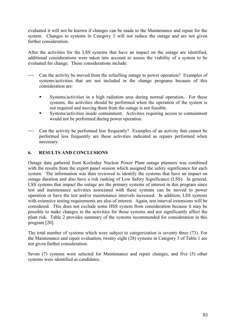
evaluated it will not be known if changes can be made to the Maintenance and repair for the system. Changes to systems in Category 3 will not reduce the outage and are not given further consideration. After the activities for the LSS systems that have an impact on the outage are identified, additional considerations were taken into account to assess the viability of a system to be evaluated for change. These considerations include: ⎯ Can the activity be moved from the refuelling outage to power operation? Examples of
systems/activities that are not included in the change programs because of this consideration are:
Systems/activities in a high radiation area during normal operation. For these
systems, the activities should be performed when the operation of the system is not required and moving them from the outage is not feasible.
Systems/activities inside containment. Activities requiring access to containment would not be performed during power operation.
⎯ Can the activity be performed less frequently? Examples of an activity that cannot be
performed less frequently are those activities indicated as repairs performed when necessary.
6. RESULTS AND CONCLUSIONS
Outage data gathered from Kozloduy Nuclear Power Plant outage planners was combined with the results from the expert panel session which assigned the safety significance for each system. The information was then reviewed to identify the systems that have an impact on outage duration and also have a risk ranking of Low Safety Significance (LSS). In general, LSS systems that impact the outage are the primary systems of interest in this program since test and maintenance activities associated with these systems can be moved to power operation or have the test and/or maintenance intervals increased. In addition, LSS systems with extensive testing requirements are also of interest. Again, test interval extensions will be considered. This does not exclude some HSS system from consideration because it may be possible to make changes to the activities for those systems and not significantly affect the plant risk. Table 2 provides summary of the systems recommended for consideration in this program [20].
The total number of systems which were subject to categorization is seventy three (73). For the Maintenance and repair evaluation, twenty eight (28) systems in Category 3 of Table 1 are not given further consideration.
Seven (7) systems were selected for Maintenance and repair changes, and five (5) other systems were identified as candidates.
83
Tabl
e 2.
Sys
tem
s for
Mod
ifyin
g th
e M
aint
enan
ce a
nd R
epai
r Act
iviti
es
Cod
e
Des
crip
tion
Ris
k
Ran
king
PS
A
Mod
ellin
g B
asis
for
Rec
omm
enda
tion
TQ4
Hig
h-pr
essu
re sy
stem
for e
mer
genc
y bo
ron
inje
ctio
n in
to th
e co
re
LSS
Expl
icitl
y Sy
stem
is
LSS
and
Mai
nten
ance
and
re
pair
activ
ities
hav
e an
impa
ct o
n th
e ou
tage
. TL
02
Post
-acc
iden
t con
tain
men
t dec
onta
min
atio
n sy
stem
LS
S N
ot
Mod
elle
d Sy
stem
not
mod
elle
d in
PSA
so
ther
e is
neg
ligib
le ri
sk im
pact
. Mai
nten
ance
an
d re
pair
activ
ities
hav
e an
impa
ct o
n th
e ou
tage
.
Poss
ible
to
m
ove
activ
ities
to a
t-pow
er.
TL, U
V
Syst
ems f
or v
entil
atio
n an
d co
olin
g of
safe
ty sy
stem
s:
• TL
10 -
ECC
S pu
mp
cool
-dow
n •
TL13
- va
lve
cham
ber a
nd p
enet
ratio
n co
olin
g •
TL50
- R
Y sy
stem
pen
etra
tion
cool
ing
• U
V05
- TX
pum
p co
olin
g •
UV
07 -
cool
ing
of Y
KTS
safe
ty sy
stem
s •
UV
09, U
V21
,22,
23, U
V41
,42,
43 –
coo
ling
of P
YC
H –
I-st
, II-n
d, II
I-rd
safe
ty sy
stem
•
UV
03, U
V08
, UV
10 -
air-c
ondi
tioni
ng sy
stem
s of A
MN
F, e
mer
genc
y pr
otec
tion,
pre
vent
ive
prot
ectio
n •
UV
40 -
pene
tratio
n co
olin
g
LSS
Expl
icitl
y Sy
stem
is
LSS
and
Mai
nten
ance
and
re
pair
activ
ities
hav
e an
impa
ct o
n th
e ou
tage
.
UV
05,
UV
40,
and
TL50
do
no
t im
pact
the
outa
ge le
ngth
. N
ote:
Mor
e in
form
atio
n is
need
ed o
n th
e sc
ope
of e
ach
syst
em to
det
erm
ine
if al
l or s
ome
of th
e sy
stem
s w
ould
be
incl
uded
in
th
e M
aint
enan
ce
and
Rep
air c
hang
e pr
ogra
m.
TQ2
Low
pre
ssur
e sy
stem
for e
mer
genc
y an
d pl
anne
d co
olin
g of
reac
tor
HSS
1 Ex
plic
itly
Pum
p ov
erha
ul
activ
ities
ha
ve
an
impa
ct o
n ou
tage
. TQ
3 H
igh
pres
sure
syst
em fo
r em
erge
ncy
and
plan
ned
cool
ing
of re
acto
r H
SS1
Expl
icitl
y Sy
stem
pu
mp
activ
ities
ha
ve
an
impa
ct o
n ou
tage
. D
G
Syst
em fo
r rel
iabl
e po
wer
supp
ly to
safe
ty sy
stem
mec
hani
sms –
seco
nd
cate
gory
H
SS
Expl
icitl
y A
ctiv
ities
hav
e im
pact
on
outa
ge a
nd
prog
ram
s pe
rfor
med
in
the
US
have
be
en su
cces
sful
. TX
St
eam
gen
erat
or e
mer
genc
y fe
edw
ater
syst
em P
umps
TX
10(2
0,30
)D01
H
SS1
Expl
icitl
y Pu
mp
over
haul
ac
tiviti
es
have
an
im
pact
on
outa
ge.
1 . Sy
stem
is L
SS fo
r PSA
inte
rnal
eve
nts.
84
The candidate systems that could be considered if needed are: ⎯ QF,VF- System for service water supply to group A consumers in reactor building.
Maintenance and repair have significant impact on the outage. ⎯ SVRK (In-core monitoring system) and SUZ (Reactor power control systems (PZ,
ROM, SGUI, URB)). These systems have comments that they are controlled by codes and standards and the regulator.
⎯ SD - Turbine condensate system. Maintenance activities have impact on the outage. ⎯ YR- System for emergency gas removal from the primary circuit. MOV’s preventive
maintenance schedule impacts the outage. After the expert panel decision was taken, when the work on the implementation began with gathering input data for the selected systems it was decided that TL02 system will be replaced by QF/VF system, because TL02 equipment is in the containment and its Maintenance can not be moved to at-power.
85

CONTRIBUTORS TO DRAFTING AND REVIEW
Capponi, A. Electricite de France, France
DeReu, T. The Commerce Foundation, LLC, United States of America
Ilieva, M. Risk Engineering Ltd., Bulgaria
Hezoucky, F. International Atomic Energy Agency
Kouzmina, I. International Atomic Energy Agency
Liszka, E. International Atomic Energy Agency
Mandula, J. International Atomic Energy Agency
Mirallas Moreno, F. Central Nuclear Vandellós II (ANACNV), Spain
Moares, J. Consultant, United Kingdom
Vladimirova, V. Risk Engineering Ltd., Bulgaria
Vlcek, P. CEZ, NPP Dukovany, Czech Republic
Vance, R. British Energy, United Kingdom
Yllera, J. International Atomic Energy Agency
Consultants Meetings
Vienna, Austria: 4–7 April 2006, 21–23 March 2007
87