application of scada for controlling electrical power ... · pdf fileapplication of scada for...
TRANSCRIPT
UITS Journal Volume: 1 Issue: 2 ISSN: 2226-3128
85
Application of SCADA for Controlling Electrical
Power System Network
Rajib Baran Roy1
Abstract : Due to the rapid development in automation system, the remote operation, control and monitoring are necessary for any modern system. The SCADA (Supervisory Control and Data Acquisition) facilitates this remote operation, control and monitoring for industrial automation. The SCADA is also widely used for overall operation of modern power system. This paper is about the application of SCADA in overall operation, control and monitoring of transmission and distribution system of electrical network of Dhaka city, Bangladesh. The paper justifies the suitability of utilization of SCADA for remote controlling of electrical power system network of Dhaka city which can be implemented for controlling the overall power system network of Bangladesh. The 132 and 33KV circuit breakers of power system network of Dhaka city are generally controlled by SCADA. The daily operation, load management and system faults are monitored by the SCADA for managing the overall system with minimum supervision and manpower. The SCADA system comprises RTU (Remote Telemetry Unit), microwave communication network and RCS (Remote Control Server). The SPIDER software, which is a open platform for horizontal and vertical integration of power control center uses UNIX based operating system is used for SCADA of DPDC.
Introduction
The SCADA stands for Supervisory Control and Data Acquisition. In this study the application of the SCADA system in controlling the overall electrical network of Dhaka city, Bangladesh is discussed. The SCADA system becomes popular in the 1960’s in order to monitor and control remote equipment. The early SCADA systems used mainframe technology and required human operators to make actions, decisions and maintain the information systems. Because of the increased human labor cost, early SCADA systems were very expensive. Today, SCADA is much more automated and consequently more cost-efficient. The SCADA is the foundation for the distributed automation system. The use of the SCADA system in electrical utility companies started in early sixties for smooth monitor and control of the overall power system. For remote operation of large power system network by SCADA started first in the USA in 1962[1]. The interconnection of large power grids in the Midwestern and the Southern U.S.A was the largest synchronized system in the world. The blackout of 1965 prompted the U.S. Federal Power Commission to recommend closer coordination between regional coordination groups and gave impetus to the subsequent formation of the National Electric Reliability Council which is formed in 1970. From that time the electrical utility company of the USA gave emphasis on reliable operation, control and monitor of the power system. However, the importance and urgency of closer monitoring and coordination of overall electrical network was emphasized in the USA after the blackout of the northeast grid network of 2003.
1. Assistant Professor, Department of Electrical and Electronics Engineering,
University of Information Technology and Sciences, Dhaka, Bangladesh, email:
Application of SCADA for Controlling Electrical Power System Network
86
The application of SCADA for industrial automation system in Bangladesh
stared in late 80s and now it is widely used for remote operation, control and
monitoring of industrial automation system. Whereas the use of SCADA in
power system of Bangladesh started in late 90’s and still its application is limited
in controlling the transmission network of power system. Nowadays almost all
critical industrial infrastructures and processes are managed remotely from
central control rooms by using SCADA. The flow of gas and oil through pipes,
the processing and distribution of water, the management of the electricity
network, the operation of chemical plants and the signaling network for railways
are some applications of SCADA [3].
The RTU, microwave communication network and RCS are the backbone of
the SCADA system. The RTU of each substation gathers operational information
of switchgears of the substation and transfers that to the central database through
microwave linkage. Basically the RTU collects all information related to remote
and manual operation. The SCADA master or control station is comprised of
Local Area Network (LAN) of RCS (Remote Communication Server) and
workstations. The RCS stores and processes data according to the system
requirement and generates necessary commands for remote operation of the
substation switchgear. Initially the SCADA software was based on VAX (Virtual
Address Extension) and VMS (Virtual Memory System) and OpenVMS (Alpha)
platforms. However UNIX and Windows platforms are now used for most
SCADA software. Initially SCADA were used for large utility networks having
100,000 to 250,000 service points. However SCADA is now used for large
automation system having many service points. The system is resided on LANs
with communication front end (CFE) processors and user interface (UI) attached
locally either on the same LAN or across a WAN (Wide Area Network) [2].
Basically 132 and 33 kV circuit breakers of substations of Dhaka city are
operated by SCADA system. The SPAIDER, an open source software which is
provided by the vendor, ABB, Switzerland is used as the main operational
software for the SCADA system of electricity network of Dhaka city. This
software is basically based on different programming languages such as C++,
FORTRAN, and Pascal. The UNIX operating system is used for this software.
1. Scada System and its Functions
SCADA is a means of controlling from remote location by using
communication technology. It is used to collect data and control processes at
the supervisory level. The SCADA monitored system could be just about an oil
refinery plant, a power generation system, a communication network or even a
simple switch. To monitor and control the automation system, the SCADA
collects data from the system and issue commands accordingly. By using sensors
(discrete or analog) and control relays, the SCADA collects information about
processes and control individual equipment. The system is supervised by a
SCADA master station which collects data from monitoring devices and issues
controls accordingly (either automatically or at the request of human operators)
[4]. The SCADA system comprises of,
UITS Journal Volume: 1 Issue: 2 ISSN: 2226-3128
87
1. Sensors (either digital or analog): Sensors control relays that directly
interface with the managed system.
2. Remote telemetry units (RTU): These are small computerized units
deployed in the field at specific sites and locations. It serves as local
collection points for gathering information from sensors and delivering
commands to control relays.
3. Communications network: It connects the SCADA master station to the
RTU.
4. SCADA master units: These are larger computer consoles that serve as the
central processor for the SCADA system. Master units provide a human
interface to the system and automatically regulate the managed system in
response to sensor inputs.
5. Remote communication server (RCS): The RCS communicates with the
RTU and collect information which is also called master station. The master
station, an HMI (Human Machine Interface) or an HCI (Human Computer
Interface) performs data processing on information gathered from sensors
[6]. The functions of SCADA are discussed below.
A. Data Acquisition
Since SCADA system monitors a large processing unit or network having
various equipments therefore it collects information hundreds or thousands of
sensors. Some of those sensors measure simple events that can be detected by
on-off switch, called a discrete or digital input. Discrete inputs are used to
measure simple states like whether the equipment is on or off, alarm for
shutdown or tripping of any device or power failure at a critical facility. Some
sensors measure more complex situations where exact measurement is
important. These are analog sensors, which can detect continuous changes in a
voltage or current input. Analog sensors are used to track fluid levels in tanks,
voltage levels in batteries, temperature and other factors that can be measured in
a continuous range of input [1].
A. Data Communication
In supervisory control, it is required to monitor multiple systems from a central
location, so a communication network is required to transport all the data
collected from sensors. In earlier SCADA systems had radio, modem or
dedicated serial lines based communication network. Today the trend is to put
SCADA data on Ethernet and IP (Internet Protocol) over SONET (Synchronous
Optical Networking). For security reasons, SCADA data should be kept on
closed LAN (Local Area Network) or WAN (Wide Area Network) without
exposing sensitive data to the open internet. For data security, data protocol is
maintained. Sensors and control relays can't generate or interpret protocol
communication on their own. Therefore the RTU is needed to provide an
interface between the sensors and the SCADA network. The RTU encodes sensor
inputs into protocol format and forwards them to the SCADA master or central
station. Again the RTU receives control commands in protocol format from the
master station and transmits electrical signals to the appropriate control relays [2,5].
Application of SCADA for Controlling Electrical Power System Network
88
A. Data Presentation
The data presentation or display in SCADA system is mostly in visual or audio
form. A SCADA system interacts with human operators through work station
computers which are commended by RCS. The master station continuously
monitors all sensors and alerts the operator by visual display or sound. The
master station presents a comprehensive view of the entire managed system and
also provides details operation of the system according to the requests of user. It
maintains report logs and summarizes historical trends of daily operation of any
system [5].
A. Data Presentation
The SCADA system automatically controls the overall system with minimum
human interference. In case of sophisticated master station, these controls can
run completely automatically without the need of human intervention. For
example, if too much pressure is building up in a gas pipeline, the SCADA
system can automatically open a release valve. In modern power system
network, the overall control is performed by SCADA without the human
intervention [5].
2. Electrical Network Operation by Using SCADA
All 132/33 kV and 33/11 kV substations of the electricity network of Dhaka city
are controlled by the SCADA system. The SCADA central control room
manages the electricity network by coordinating with the central load dispatch
center and other related electricity authorities of Bangladesh. The SCADA
manages the load demand of Dhaka city according to the power generation of
Bangladesh. It also keeps proper coordination within the system and the
regulating authority during any emergency situation in order to avoid overall
system failure. The power flow status within the overall system, daily and
monthly power supply report and overall system operation are main functions of
the SCADA system [6].
A. Functional Steps of SCADA
The functional steps for managing the overall power system network of Dhaka
city are briefly described below.
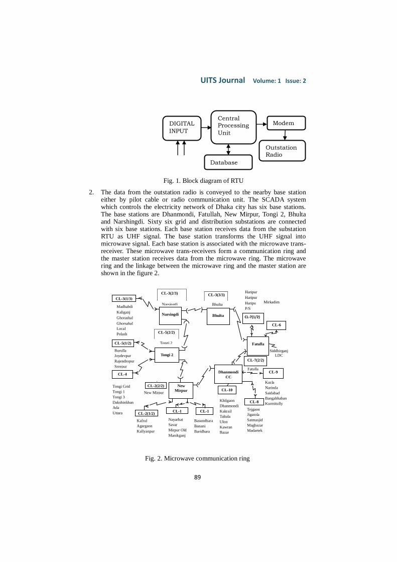
1. All data points at the substation equipment are connected with the RTU card
by using wire. The figure 1 shows the block diagram of RTU. When any
substation is remote or manually operated, the RTU gathers operational
information in the central database through microwave linkage which is
transferred to the RCS later. This RTU is installed at every 132/33 kV and
33/11 kV substation of Dhaka city. For collecting information circuit
breaker and other switchgears of any substation are connected to the RTU
card at a specific point. The installed data in the database of the RTU is
transferred to outstation radio through modem.
UITS Journal Volume: 1 Issue: 2 ISSN: 2226-3128
89
Fig. 1. Block diagram of RTU
2. The data from the outstation radio is conveyed to the nearby base station either by pilot cable or radio communication unit. The SCADA system which controls the electricity network of Dhaka city has six base stations. The base stations are Dhanmondi, Fatullah, New Mirpur, Tongi 2, Bhulta and Narshingdi. Sixty six grid and distribution substations are connected with six base stations. Each base station receives data from the substation RTU as UHF signal. The base station transforms the UHF signal into microwave signal. Each base station is associated with the microwave trans-receiver. These microwave trans-receivers form a communication ring and the master station receives data from the microwave ring. The microwave ring and the linkage between the microwave ring and the master station are shown in the figure 2.
Fig. 2. Microwave communication ring
CL-3(1/3)
Narsingdi
Bhulta CL-7(1/2)
CL-6
Fatulla
Bhulta
CL-3(2/3)
Narsingdi Madhabdi
Kaliganj
Ghorashal
Ghorsahal
Local
Polash
Kanchan
Tongi 2
CL-5(2/2)
Tongi 2 CL-5(1/2)
Burulla
Joydevpur
Rajendropur
Sreepur
Kabirpur CL-4
Tongi Grid
Tongi 1
Tongi 3
Dakshinkhan
Ada
Uttara
New
Mirpur
CL-2(1/2)
Kafrul
Agargaon
Kallyanpur
CL-1
CL-2(2/2)
New Mirpur
CL-1
Basundhara
Banani
Baridhara
Haripur
Haripur
Haripu
P/S
Demra
Siddhirg
anj
Dhanmondi
CC
CL-7(2/2)
Fatulla
CL-10
Khilgaon
Dhanmondi
Kakrail
Taltala
Ulon
Kawran
Bazar
Ramna
CL-8
Tejgaon
Jigatola
Satmasjid
Magbazar
Madartek
Lalgah
Fort
Zinzira
CL-9
Kazla
Narinda
Saidabad
Bangabhaban
Kurmitully
Gulshan
Naubganj
Siddhirganj LDC
CL-3(3/3)
Nayarhat
Savar
Mirpur Old
Manikganj
Old
Manikganj
Mirkadim
Narayangnaj
Madanganj
Shuampur
Hasnabad
Postogola
Srinagar
DATABASE REMOTE TERMINAL UNIT
ON
OFF
L1-S POWER
SYSTEM
(Process)
SERVER COMMUNICATION MODEM
DIGITAL
INPUT
CENTRAL PROCESSING
UNIT
COMMUNICATION MODEM
L1 – S
CONTROL SYSTEM
DATABASE
DIGITAL
INPUT
Central
Processing
Unit
Database
Modem
Outstation
Radio
Application of SCADA for Controlling Electrical Power System Network
90
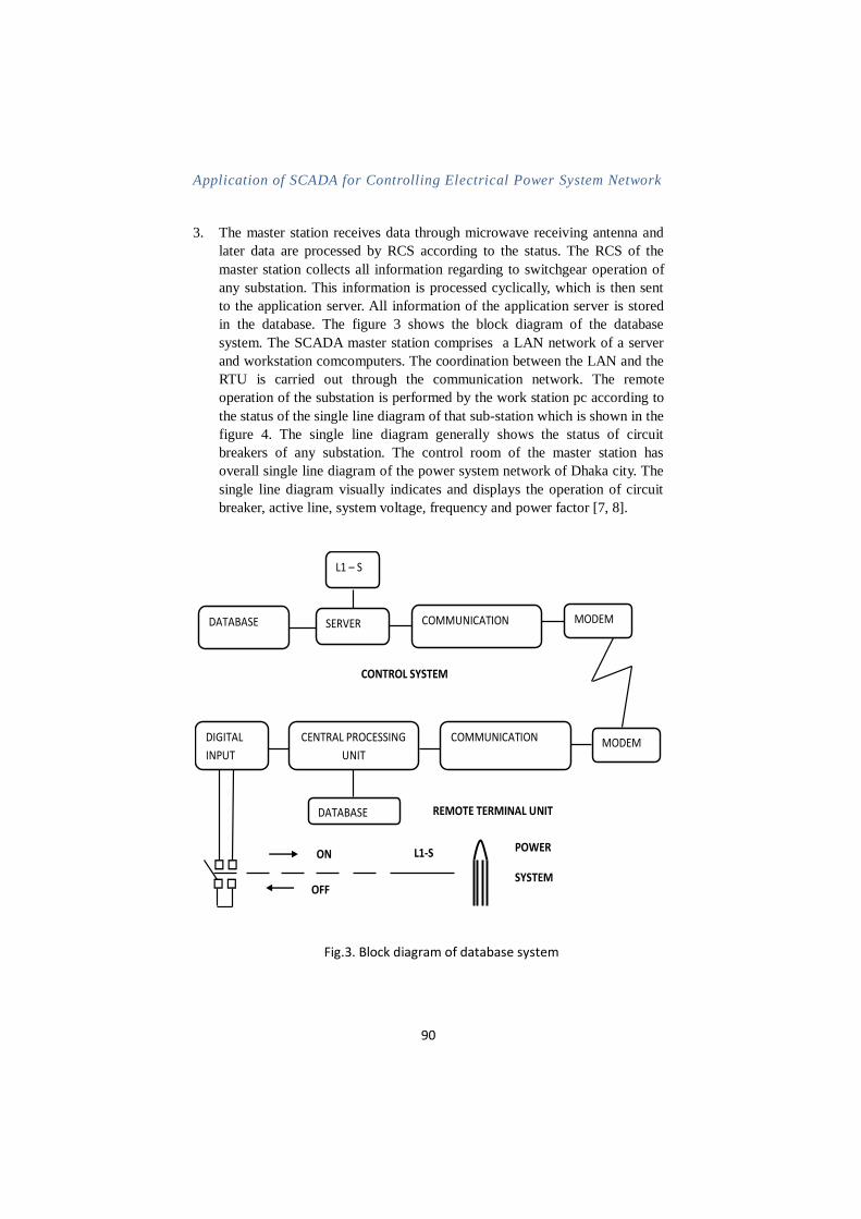
3. The master station receives data through microwave receiving antenna and
later data are processed by RCS according to the status. The RCS of the
master station collects all information regarding to switchgear operation of
any substation. This information is processed cyclically, which is then sent
to the application server. All information of the application server is stored
in the database. The figure 3 shows the block diagram of the database
system. The SCADA master station comprises a LAN network of a server
and workstation comcomputers. The coordination between the LAN and the
RTU is carried out through the communication network. The remote
operation of the substation is performed by the work station pc according to
the status of the single line diagram of that sub-station which is shown in the
figure 4. The single line diagram generally shows the status of circuit
breakers of any substation. The control room of the master station has
overall single line diagram of the power system network of Dhaka city. The
single line diagram visually indicates and displays the operation of circuit
breaker, active line, system voltage, frequency and power factor [7, 8].
Fig.3. Block diagram of database system
DATABASE REMOTE TERMINAL UNIT
ON
OFF
L1-S POWER
SYSTEM
(Process)
SERVER COMMUNICATION MODEM
DIGITAL
INPUT
CENTRAL PROCESSING
UNIT
COMMUNICATION MODEM
L1 – S
CONTROL SYSTEM
DATABASE
UITS Journal Volume: 1 Issue: 2 ISSN: 2226-3128
91
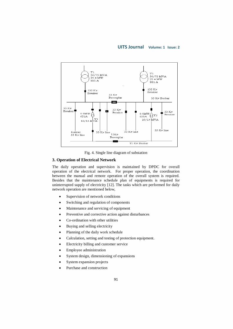
Fig. 4. Single line diagram of substation
3. Operation of Electrical Network
The daily operation and supervision is maintained by DPDC for overall
operation of the electrical network. For proper operation, the coordination
between the manual and remote operation of the overall system is required.
Besides that the maintenance schedule plan of equipments is required for
uninterrupted supply of electricity [12]. The tasks which are performed for daily
network operation are mentioned below,
Supervision of network conditions
Switching and regulation of components
Maintenance and servicing of equipment
Preventive and corrective action against disturbances
Co-ordination with other utilities
Buying and selling electricity
Planning of the daily work schedule
Calculation, setting and testing of protection equipment.
Electricity billing and customer service
Employee administration
System design, dimensioning of expansions
System expansion projects
Purchase and construction
Application of SCADA for Controlling Electrical Power System Network
92
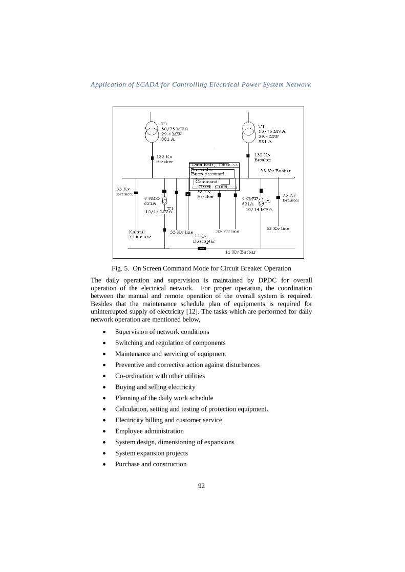
Fig. 5. On Screen Command Mode for Circuit Breaker Operation
The daily operation and supervision is maintained by DPDC for overall
operation of the electrical network. For proper operation, the coordination
between the manual and remote operation of the overall system is required.
Besides that the maintenance schedule plan of equipments is required for
uninterrupted supply of electricity [12]. The tasks which are performed for daily
network operation are mentioned below,
Supervision of network conditions
Switching and regulation of components
Maintenance and servicing of equipment
Preventive and corrective action against disturbances
Co-ordination with other utilities
Buying and selling electricity
Planning of the daily work schedule
Calculation, setting and testing of protection equipment.
Electricity billing and customer service
Employee administration
System design, dimensioning of expansions
System expansion projects
Purchase and construction
UITS Journal Volume: 1 Issue: 2 ISSN: 2226-3128
93
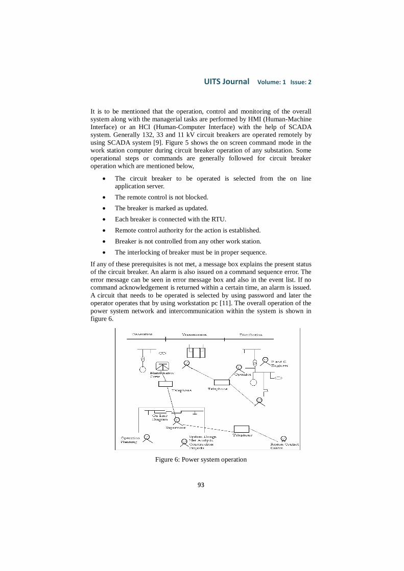
It is to be mentioned that the operation, control and monitoring of the overall
system along with the managerial tasks are performed by HMI (Human-Machine
Interface) or an HCI (Human-Computer Interface) with the help of SCADA
system. Generally 132, 33 and 11 kV circuit breakers are operated remotely by
using SCADA system [9]. Figure 5 shows the on screen command mode in the
work station computer during circuit breaker operation of any substation. Some
operational steps or commands are generally followed for circuit breaker
operation which are mentioned below,
The circuit breaker to be operated is selected from the on line
application server.
The remote control is not blocked.
The breaker is marked as updated.
Each breaker is connected with the RTU.
Remote control authority for the action is established.
Breaker is not controlled from any other work station.
The interlocking of breaker must be in proper sequence.
If any of these prerequisites is not met, a message box explains the present status
of the circuit breaker. An alarm is also issued on a command sequence error. The
error message can be seen in error message box and also in the event list. If no
command acknowledgement is returned within a certain time, an alarm is issued.
A circuit that needs to be operated is selected by using password and later the
operator operates that by using workstation pc [11]. The overall operation of the
power system network and intercommunication within the system is shown in
figure 6.
Figure 6: Power system operation
Application of SCADA for Controlling Electrical Power System Network
94
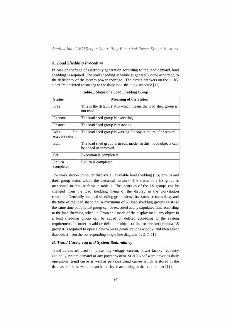
A. Load Shedding Procedure
In case of shortage of electricity generation according to the load demand, load
shedding is required. The load shedding schedule is generally done according to
the deficiency of the system power shortage. The circuit breakers on the 11 kV
sides are operated according to the daily load shedding schedule [11].
Table1. Status of a Load Shedding Group
Status Meaning of the Status
Free This is the default status which means the load shed group is
not used
Execute The load shed group is executing
Restore The load shed group is restoring
Wait for
execute return
The load shed group is waiting for object return after restore
Edit The load shed group is in edit mode. In this mode objects can
be added or removed
Set Execution is completed
Return
completed
Return is completed
The work station computer displays all available load shedding (LS) groups and
their group status within the electrical network. The status of a LS group is
mentioned in tabular form in table 1. The identities of the LS groups can be
changed from the load shedding menu of the display in the workstation
computer. Generally one load shedding group shows its status, restores delay and
the time of the load shedding. A maximum of 50 load shedding groups exists at
the same time but one LS group can be executed at any stipulated time according
to the load shedding schedule. From edit mode of the display menu any object in
a load shedding group can be added or deleted according to the system
requirement. In order to add or delete an object (a line or breaker) from a LS
group it is required to open a new WS400 (work station) window and then select
that object from the corresponding single line diagram [1, 2, 7, 11].
B. Trend Curve, Tag and System Redundancy
Trend curves are used for presenting voltage, current, power factor, frequency
and daily system demand of any power system. SCADA software provides daily
operational trend curve as well as pervious trend curves which is stored in the
database of the server and can be retrieved according to the requirement [11].
UITS Journal Volume: 1 Issue: 2 ISSN: 2226-3128
95
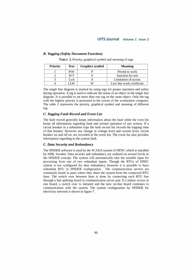
B. Tagging (Safety Document Function)
TABLE 2. Priority, graphical symbol and meaning of tags
The single line diagram is marked by using tags for proper operation and safety
during operation. A tag is used to indicate the status of an object in the single line
diagram. It is possible to set more than one tag on the same object. Only the tag
with the highest priority is presented in the screen of the workstation computer.
The table 2 represents the priority, graphical symbol and meaning of different
tag.
C. Tagging Fault Record and Event List
The fault record generally keeps information about the fault while the even list
keeps all information regarding fault and normal operation of any system. If a
circuit breaker in a substation trips the fault record list records the tripping time
of that breaker. However any change in voltage level and current level, circuit
breaker on and off etc are recorded in the event list. The event list also provides
information regarding to the system fault.
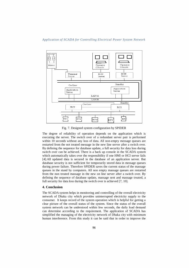
C. Data Security and Redundancy
The SPIDER software is used by the SCADA system of DPDC which is installed
by ABB, Sweden. Data security and redundancy are realized on several levels in
the SPIDER concept. The system will automatically take the suitable input for
processing from one of two redundant inputs. Though the RTUs of DPDC
system is not configured for data redundancy however it is possible to have
redundant RTU in SPIDER configuration. The communication servers are
commonly found in pairs where they share the system from the connected RTU
lines. The switch over between lines is done by connecting each RTU line
through a line splitting board in communication server pair. If a failure occurs in
one board, a switch over is initiated and the new on-line board continues to
communication with the system. The system configuration by SPIDER for
electricity network is shown in figure 7.
Priority Text Graphics symbol Meaning
1 PtW P Permit to work
2 Sf T S Sanction for test
3 LoA A Limitation of access
4 LLW W Live line work certificate
Application of SCADA for Controlling Electrical Power System Network
96
Fig. 7. Designed system configuration by SPIDER
The degree of reliability of operation depends on the application which is
executing the server. The switch over of a redundant server pair is performed
within 10 seconds without any loss of data. All non-empty message queues are
restarted from the not treated message in the new line server after a switch over.
By defining the sequence for database update, a full security for data loss during
switch over can be achieved. There is a back up console in the SCADA system
which automatically takes over the responsibility if one HMI or HCI server fails
[4].All updated data is secured in the database of an application server. But
database security is not sufficient for temporarily stored data in message queues
during power failure. Therefore SPIDER saves the current status of the massage
queues in the stand by computers. All non empty massage queues are restarted
from the non treated massage in the new on line server after a switch over. By
defining the sequence of database update, massage sent and massage treated, a
full security for data loss during the switch over is achieved [7, 10].
4. Conclusion
The SCADA system helps in monitoring and controlling of the overall electricity
network of Dhaka city which provides uninterrupted electricity supply to the
consumer. It keeps record of the system operation which is helpful for getting a
clear picture of the overall status of the system. Since the status of the overall
system network can be understood within few seconds, the daily load demand
can determine according to the requirement. The application of SCADA has
simplified the managing of the electricity network of Dhaka city with minimum
human interference. From this study it can be said that in order to improve the
UITS Journal Volume: 1 Issue: 2 ISSN: 2226-3128
97
overall system performance, reliability and stability it is necessary to implement
the SCADA system for controlling the whole electricity network of Bangladesh.
The manual operation of power system in Bangladesh requires huge manpower
which increases the overall system cost. Moreover quick decision making
becomes difficult in manual system during system failure or unbalanced
situation. For proper operation, control and monitoring of the overall power
system of Bangladesh it is necessary to implement the SCADA system.
References
[1] D. Baiely and E. Wright, Practical SCADA for Industry, Third Edition, 2003. G and GM Publishing Co., USA, pp. 51-65, 120-130
[2] W. T. Shaw, Cyber Security for SCADA Systems, Second Edition, 2006, McGraw-
Hill Publishing Company Limited, USA, pp. 35-50, 66-80, 100-105
[3] Hadi Saadat., Power System Analysis, 1999, Tada McGraw-Hill Publishing
Company Limited, p.p. 78-85, 212-250
[4] I. McKenzie Smith. Hughes, Electrical Technology, Seventh Edition, 1993, Tada
McGraw-Hill Publishing Company Limited, pp. 65-80, 95-105
[5] Salivahanan, S.Suresh, N., and Vallavaraj, A., Electronic Devices and Circuit, Fourth
Edition, Tada Seventh Edition, 2000, McGraw-Hill Publishing Company Limited,
USA, pp. 70-90, 187, 200-300
[6] Floyed, T., Electronic Devices, Fourth Edition, 1996, Prentice Hall International, Inc,
pp. 40-85, 95-150
[7] J. D. Glover, M.S. Sharma and T.J. Overbye, Power System Analaysis and Design,
Fourth Edition, 2008, Thomson Learning, Thomson Corporation, USA, pp. 60- 85,
120-150, 210-300
[8] J. J. Grainger and W. D. Stevenson, Power System Analysis, International Edition,
1994,McGraw-Hill Book Co., Singapore, pp. 105-180, 350-400, 512-516
[9] W. D. Stevenson, Elements of Power System Analysis, International Edition, 1994,
MacGraw Hill Book Co., Singapore, pp. 45-60, 90-120, 220-250
[10] R. H. Miller, Power System Operation, Sixth Edition, 1994 Prentice-Hall Inc, India,
pp. 50-80, 95-120
[11] Operational manual of SCADA system, ABB network partner, 1998, ABB, Sweden, pp. 22-50, 60-85
[12] Official Website of Dhaka Power Distribution Company Limited, Dhaka,
Bangladesh, http://www.dpdc.org.bd.