application of single-use equipment for buffer storage and ... · and a virus filtration step after...
TRANSCRIPT
1PHARMACEUTICAL ENGINEERING JANUARY/FEBRUARY 2014
facilities and equipmentBuffer Distribution and Storage Systems
Application of Single-Use Equipment for Buffer Storage and Distribution in Medium Size mAb
Production Facilityby Wilfried Kappel, Bhimasen Vadavi, Sanjay Lodha, and
Daniel Karrer
This article presents a hybrid system approach in which stainless steel equipment and single-use equipment have been combined in the best possible manner for buffer preparation and buffer storage systems at a
2,000 L mammalian cell culture CMO production facility.
B iopharmaceutical processes are oper-ated in aqueous systems using large quantities of WFI or Purified Water (PW). In the upstream process (USP), WFI is required for media preparation and feed solutions. In the downstream process (DSP), large quantities of PW or WFI are required for buffers, with buffer preparation, buffer storage, and
distribution systems representing a significant portion of the process equipment used for the downstream purification in monoclonal antibody (mAb) production facilities. However, the overall required volumes for buffer storage as well as the complexity for buffer distribution are often underestimated. This is especially the case for multi product facilities, which need a high degree of flexibility and short time intervals for product changeover. In large scale production facilities of 10,000 L and more working volume, stainless steel systems have been installed traditionally using large buffer tank farms for buffer storage and complex transfer line configurations for buffer distribution. In small scale production facilities, single-use systems with bags for buffer storage and flexible hoses for buffer
distribution are widely used; however, size limitations and a higher degree of manual operations in regulated cGMP production environments must be taken into consideration. This article describes an intelligent hybrid system ap-proach in which both technologies – stainless steel systems and single-use systems – have been combined in the best possible manner in consideration of the pros and cons of each individual technology. The system described for buffer storage and buffer distribution has been realized for a 2,000 L mammalian cell culture production facility at Kemwell Biopharma Pvt. Ltd., India (a Contract Manufacturing Orga-nization (CMO)). The article will discuss the basic concepts and the selec-tion criteria for utilizing single-use or stainless steel sys-tems. Furthermore, practical examples will be provided for novel process designs as well as for novel equipment design details, such as interfacing flexible hoses with stainless steel piping that need SIP/CIP capabilities. Finally, the level of flexibility achieved by still keeping the systems simple and safe will be highlighted.
Buffer DemandsIn most cases, current production strategies for manufactur-
Reprinted fromPHARMACEUTICAL ENGINEERINGTHE OFFICIAL TECHNICAL MAGAZINE OF ISPE
JANUARY/FEBRUARY 2014, VOL 34, NO 1
©Copyright ISPE 2014
www.PharmaceuticalEngineering.org

2 JANUARY/FEBRUARY 2014 PHARMACEUTICAL ENGINEERING
facilities and equipmentBuffer Distribution and Storage Systems
ing of protein therapeutics, such as monoclonal antibodies (mAbs), are based on platform processes1 that need to allow easy adaption for multiple products in CMO facilities, if different product titers in upstream can be handled with the available buffer volumes in downstream. As a consequence, for flexibility the downstream process has to be designed for the expected titer range in the upstream process such as a cell culture titer of 3 to 5 g/L. Figure 1 shows the downstream unit operations for the process steps of a typical mAb platform technology. After harvesting the bioreactor by disc stack centrifuge, further clarification is carried out by using depth and membrane filters. The first purification step usually is a Protein A affinity chromatography (Chromo 1), in which the monoclonal anti-body is selectively captured and purified from other host cell proteins and media components with a purity of up to 95%.
Two additional chromatography polishing steps are typically used for further purifications, most commonly a cation exchange chromatography (Chromo 2) for removal of aggregates and an anion exchange chromatography (Chromo 3) for removal of DNA. In order to achieve sufficient viral clearance, a low pH virus inactivation step after the Protein A chromatography and a virus filtration step after the anion exchange chroma-tography step is foreseen in the purification process. Additional dead-end filtration steps for removal of im-purities and ultrafiltration/diafiltration steps (UF/DF 1) for product concentration and buffer exchange may be required for mAb processes. Lastly, a final ultrafiltration/diafiltration step (UF/DF 2) is used for concentration and formulation before the bulk drug substance is frozen for storage. Each individual purification step as described above
Figure 1. Process flow diagram for downstream process steps of a mAb platform process.
Table A. Typical buffer volumes for a 2,000 L mAb downstream process with a product titer of 5 g/L.
Process Step WFI Buffer A Buffer B Buffer C Buffer D Buffer E Buffer F Buffer G Buffer H Total
Depth Filtration 800 L 800 L
Chromatography 1 700 L 2,000 L 2,000 L 1,300 L 1,500 L 1,300 L 200 L 300 L 100 L 9,400 L
Virus Inactivation 100 L 100 L 50 L 250 L
Chromatography 2 800 L 1,000 L 600 L 600 L 1,100 L 600 L 300 L 500 L 5,500 L
UF/DF 1 1,400 L 100 L 200 L 200 L 1,900 L
Chromatography 3 800 L 1,000 L 1,000 L 1,600 L 1,000 L 600 L 300 L 300 L 6,600 L
Nanofiltration 500 L 200 L 700 L
UF/DF 2 1,600 L 100 L 200 L 200 L 2,100 L
3PHARMACEUTICAL ENGINEERING JANUARY/FEBRUARY 2014
facilities and equipmentBuffer Distribution and Storage Systems
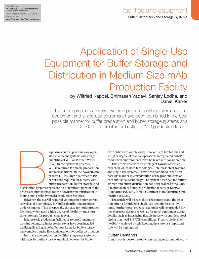
requires a number of specific buffers with different volumes. Those buffers are normally prepared in buffer preparation vessels or buffer mixing bags, then transferred for inter-mediate storage into buffer storage vessels or buffer stor-age bags and finally distributed to the point of use for the required process step. The processes for buffer preparation, buffer storage and buffer distribution run concurrently with the purification process steps and require sufficient process equipment and a proper process scheduling to make sure to have the right buffer at the right time at the right point of use in the DSP area. The volumes of the different buffers that are required for a mAb purification process and the logistics behind for preparation, storage and distribution are often underesti-mated. Table A provides data on the required buffer volumes for a typical 2,000 L mAb downstream process with a prod-uct titer of 5 g/L.
As shown in Table A, the purification of 2,000 L of cell culture broth yield-ing less than 200 L of final bulk drug substance requires a number of differ-ent buffers with a total volume of more than 25,000 L; individual volumes are between 50 L and 2,000 L. The buffer volumes required for each process step have been evaluated by modeling using mass balance calcula-tions at different product titers. In the second step, buffer usage diagrams have been prepared for each process step. Fig-ure 2 shows an example of a buffer usage diagram for the Protein A chromatogra-phy step (Chromo 1). The buffer usage diagrams helped to further optimize the concepts and designs for buffer storage and buffer
distribution such as:
• Number of the required buffers• Volumes of each buffer• Buffer storage system (stainless steel vessel or single-use
bag)• Location of the buffer storage systems (buffer preparation
room or process rooms)
Utilization of Single-Use Bags for Buffer StorageSingle-use bags for buffer storage offer a number of advan-tages compared to stainless steel systems.2 The main advan-tage is the high degree of flexibility, because the bag size can easily be changed if new processes will require this. Further advantages are that SIP and CIP are not required, and small size bags can be directly carried to the point of use without
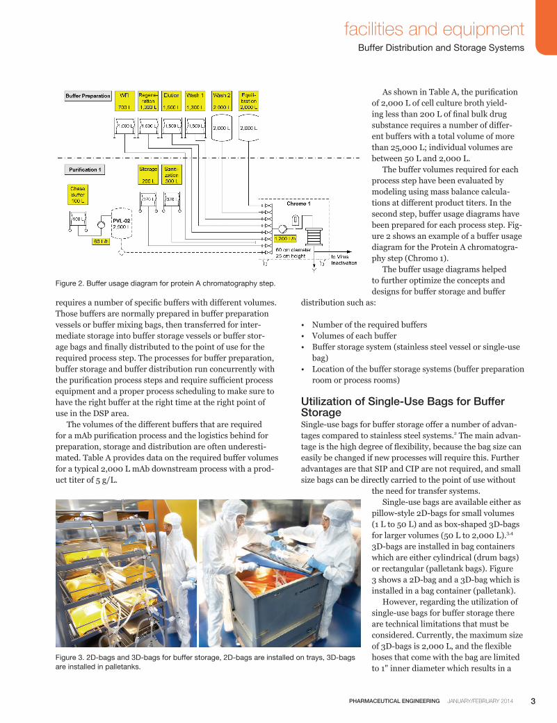
the need for transfer systems. Single-use bags are available either as pillow-style 2D-bags for small volumes (1 L to 50 L) and as box-shaped 3D-bags for larger volumes (50 L to 2,000 L).3,4 3D-bags are installed in bag containers which are either cylindrical (drum bags) or rectangular (palletank bags). Figure 3 shows a 2D-bag and a 3D-bag which is installed in a bag container (palletank). However, regarding the utilization of single-use bags for buffer storage there are technical limitations that must be considered. Currently, the maximum size of 3D-bags is 2,000 L, and the flexible hoses that come with the bag are limited to 1" inner diameter which results in a
Figure 2. Buffer usage diagram for protein A chromatography step.
Figure 3. 2D-bags and 3D-bags for buffer storage, 2D-bags are installed on trays, 3D-bags are installed in palletanks.

4 JANUARY/FEBRUARY 2014 PHARMACEUTICAL ENGINEERING
facilities and equipmentBuffer Distribution and Storage Systems
maximum flow of approximately 1.8 m3/h. Also operational requirements should not be ignored while using single-use bags for buffer storage and buffer dis-tribution, which have been considered in this project based on practical experiences from other projects.
• 2D-bags should be limited in size that they can be trans-ported in filled state without using additional trays or trolleys. A suitable maximum bag size is 20 L.
• 3D-bags in bag containers which are located in the process rooms should be limited in size that they can be moved by trolleys in filled state without using fork lifts.2 Forklifts are recommended for bag sizes ≥ 500 L.
• 3D-bags in the process rooms should utilize a small footprint as the required space in the purification rooms should be minimal for keeping flexibility in the set-up of the process equipment.
• Buffer bags which are located in the process area also should be filled in the process area via suitable buffer distribution systems in order to avoid too much traffic between the buffer preparation room and the process rooms.
• Large size buffer hold bags in the buffer preparation area should be installed into stationary bag containers (palletanks) with easy connection of the flexible hoses to headers for filling and buffer distribution.
Under consideration of the technical limitations and the operational requirements mentioned above, bag selection criteria have been set up in the beginning of the project with the following objectives:
• Large buffer volumes (> 1,500 L) that also need high flow rates are supplied from 2,000L stainless steel buffer stor-age vessels.
• For all buffers that are required in smaller volumes, single-use bags are used for buffer storage.
• 2D-bags are used only up to 20 L.• 3D-bags for movement are used only up to 200 L.• The maximum bag size in process rooms is limited to 500
L.• Buffer volumes from 500 L to 1,500 L are stored in sta-
tionary bag containers (palletanks).
Clear bag selection criteria helped to minimize the number of different bag types and to standardize on the connection methods. More detailed information is provided in Table B, which shows the type of bags related to the buffer volume, the location where the bag will be filled with buffer, the method for distribution of the buffer to the point of use, and the method for supplying the buffer to the process equip-ment.
Buffer Preparation and StorageThe initial concept for buffer preparation and buffer storage, which utilized buffer preparation vessels with 100 L, 500 L, 1,000 L and 2,000 L working volume had provisions for buffer storage up to 1,000L in bags in the process rooms and two large volume 2,000 L buffer storage vessels in the buffer preparation room. During the course of the project; however, it became clear that the designated 1,000 L pal-letanks for buffer storage in the process room would occupy too much space. Even more critical, the large volume buffer storage capacity with just two 2,000 L buffer storage vessels only was not sufficient for the buffer demands of different CMO processes. A solution to both problems was found by installing ad-ditional palletanks in the buffer preparation room. With this simple extension, the large volume buffer storage capacity was increased to 1 × 1,000 L and 3 × 1,500 L in single-use bags plus 2 × 2,000 L in stainless steel vessels. Buffer preparation takes place in a 1,000 L or a 2,000 L stainless steel vessel. Buffers are transferred from the buffer preparation vessels via sterile filters to the buffer storage vessels with filling of the buffer storage vessel from bottom. The transfer line and filter will be steamed in place (SIP) be-fore buffer filling and rinsed or cleaned in place (CIP) after buffer filling. Transfer to the buffer storage bags is also done via sterile filters using two stainless steel headers, one header assigned to the 1,000 L buffer preparation vessel, and the other header assigned to the 2,000 L buffer preparation vessel. The gamma-irradiated bags are connected via short flexible tubing with steam-to valves5 to one of the two filling headers. With the steam-to valves, which are connected at minimum distance to tri-clamps at the filling header piping, a sanitary connection between the single-use tubing and the stainless steel piping could be realized. As for the transfer lines to the buffer storage vessels, the filling lines to the buffer storage bags also will be steamed in place before buffer transfer and rinsed or cleaned in place after buffer transfer, by this providing closed sanitary systems for the filling of the buffer bags. The process flow diagram for buffer preparation and buffer storage as seen in Figure 4 shows the connection be-tween the stainless steel buffer preparation vessels and the single-use buffer storage bags via the fill header. The additional four palletanks had to fit into the infra-structure of the buffer preparation room which was domi-nated by the stainless steel buffer preparation equipment and its appropriate design principles. For seamless integra-tion of the single-use equipment, the four palletanks have been mounted on a small skid with one stainless steel piping header for filling of the buffer storage bags from the buf-fer preparation vessels, and another stainless steel piping header for buffer transfers from the buffer storage bags to the process rooms as seen in Figure 5. The palletank skid

5PHARMACEUTICAL ENGINEERING JANUARY/FEBRUARY 2014
facilities and equipmentBuffer Distribution and Storage Systems
containing four 1,000 L/1,500 L bags occupied a footprint of 5.5 m × 1.0 m only. Inserting of the single-use bags can eas-ily be done from the front. The integration of the palletank skid for the buffer storage bags, with its piping headers into the existing piping systems and automation structure could be realized in a consistent manner.
Buffer Transfer and DistributionFor transferring the buffers from the buffer storage bags over long distance to the process rooms, the gamma-irradi-ated bags also are connected via short flexible tubing with steam-to valve to a dedicated stainless steel buffer distri-bution line for each buffer storage bag. By using the same sanitary connection method – steam-to valves to tri-clamps at the piping header – as for the filling lines, the buffer distribution lines also can be steamed in place prior to buffer transfer and rinsed/cleaned in place after buffer transfer, thus providing a closed sanitary system. Both flexible hoses at the buffer storage bags for buffer filling and buffer distribution provide 1"-ID tube sizing in order to allow fast filling and high flow rates for buffer deliv-ery, which are required at certain process steps (e.g., Protein A Chromatography). Further buffer distribution from the buffer preparation room to the process rooms for DSP purification is performed via a simple transfer line system. As the buffer preparation room is in the second floor, and the process rooms Purifica-tion 1, Purification 2, and Purification 3 are at the ground floor, stainless steel transfer lines6 are used for buffer dis-tribution to the point of use or for filling bags in the process rooms.
Table B identifies which buffer volumes (> 500 L to ≤ 1,500 L) will be directly transferred from bags in the buffer preparation room to the point of use in the process rooms, and which buffer volumes (> 50 L to ≤ 500 L) will be filled into bags in the process room from the buffer preparation vessels which are located in the buffer preparation room. The buffer transfer from the buffer preparation room to the process rooms is done by gravity flow which is a well established method for stainless steel systems because it doesn’t require pumps or pressurized vessels for transfer and it provides the necessary pressure head which is re-quired for robust operation of the chromo systems at higher flow rates. The advantages of gravity flow have been adapted to buffer transfer out of bags within this project.
Figure 4. Process flow diagram for buffer preparation and buffer storage. Connecting points <A> to <H> refer to P&I-diagram in Figure 6.
Figure 5. Palletank skid for buffer storage with stainless steel piping headers for filling and distribution, located in buffer preparation room.

6 JANUARY/FEBRUARY 2014 PHARMACEUTICAL ENGINEERING
facilities and equipmentBuffer Distribution and Storage Systems
Figure 6. Simplified P&I-diagram for buffer distribution. Connecting points <A> to <H> refer to process flow diagram in Figure 4.
Figure 6 shows a simplified P&I diagram for the routing of the buffer transfer lines from the buffer preparation room via a mezzanine floor above the process rooms to the three process rooms at the ground floor. Only a few automated valves are needed for flow path selection for each of the
eight buffer transfer lines. Based on the buffer demand in the individual process rooms, all eight buffer transfer lines are routed to Purification 1 and Purification 2, but only three buffer transfer lines are required for Purification 3. While the sending side of the buffer transfer lines is
Buffer Volume Buffer Bag Type Buffer Filling Buffer Distribution Buffer Usage
> 5 L to ≤ 20 L 2 D-Bags mobile At buffer filling station in Buffer Prep. Room
Carry from Buffer Prep Room to Process Room
Connect bag to process equipment
> 20 L to ≤ 50 L 3 D-Drum Bags mobile At buffer filling station in Buffer Prep. Room
Carry from Buffer Prep Room to Process Room
Connect bag to process equipment
> 50 L to ≤ 200 L 3 D-Drum Bags mobile At buffer distribution skid in Process Room
Move to point of use within Process Room
Connect bag to process equipment
> 200 L to ≤ 500 L 3 D-Palletank Bags stationary
At buffer distribution skid in Process Room
Stationary Palletank in Process Room
Connect bag to process equipment
> 500 L to ≤ 1,500 L 3 D-Palletank Bags stationary
Via buffer filling header in Buffer Prep. Room
Buffer distribution skid in Process Room
Connect process equipment to buffer distribution skid
> 1,500 L to ≤ 2,000 L Buffer Storage Vessels stainless steel
Via buffer filling header in Buffer Prep. Room
Buffer distribution skid in Process Room
Connect process equipment to buffer distribution skid
Table B. Bag selection criteria for buffer bags.

7PHARMACEUTICAL ENGINEERING JANUARY/FEBRUARY 2014
facilities and equipmentBuffer Distribution and Storage Systems
assigned to either buffer preparation vessels, buffer stor-age vessels or buffer storage bags, the receiving side of the buffer transfer lines should allow flexible assignment for either filling of buffer storage bags in the process rooms or for supplying buffers directly to the process equipment, e.g., chromatography systems or UF/DF skids. As a general target, it should be possible to supply each buffer from the buffer preparation room to each point of use in the purifica-tion process rooms. This approach for maximum flexibility has been realized by installing three buffer distribution skids in Purification 1, Purification 2, and Purification 3 room. The buffer distribu-tion skids are the termination points of the buffer transfer lines in the process rooms with all required valves and instruments for SIP and CIP of the transfer lines (Figure 7). From the buffer distribution skids, the final connection for filling of buffer storage bags or supplying buffers to the pro-cess equipment is always done by short flexible hoses, which provides the targeted flexibility for supplying each buffer to each point of use. The sanitary interface between the stainless steel buffer distribution skid and the single use bags or plastic transfer hoses is also done via steam-to valves at minimum distance to tri-clamps at the buffer distribution skid piping. Reusable steam-to valves have been used in this project which are au-toclaved together with the transfer hose and then connected to the gamma irradiated bags by sterile tube welding (for tubes up to ¾" inner diameter), by this maintaining a closed sanitary system. After connection of the steam-to valve to the selected buffer line at the buffer distribution skid via tri-clamp, the buffer transfer line will be steamed in place in order to pro-vide a sanitary connection. For supplying buffer to the bag or process equipment, the steam-to valve must be opened manually. After transferring the buffer to the point of use, the steam-to valve will be closed again and the buffer trans-fer line will be rinsed with WFI or cleaned in place from the CIP unit. The connection of the steam-to valve at the buffer distri-bution skid is done via a standard 1½" tri-clamp port (50.4 mm flange diameter). This tri-clamp port is suitable for con-nection of a small steam-to valve for ½" ID flexible hoses or a large steam-to valve for connection of 1" ID flexible hoses. This again provides a high degree of flexibility for buffer demand changes at new processes in the CMO facility.As the entire mAb production facility is fully automated by a PLC/SCADA system, precautions must be taken for safe operation during connection and disconnection of the individual flexible hoses to the tri-clamp ports at the Buffer Distribution Skid. For that purpose, each buffer distribution skids is equipped with a small human-machine-interface (HMI) panel. The HMI panel shows the current status of all buffer transfer lines, which can be idle, SIP, transfer or CIP
mode. Furthermore, operator prompts are given to guide the operators on the necessary manual operations that must be performed. Each manual operation must be acknowledged explicitly by the operator, in order to proceed with the auto-mated functions. All those activities are part of the audit trail in order to achieve 21 CFR Part 11 compliance.
SIP/CIP Strategy for Hybrid SystemsBecause the hybrid systems for buffer storage and buffer distribution, which are described in this article consist of stainless steel systems and single-use systems, Steam in Place (SIP) and Clean in Place (CIP) will be required for the stainless steel part according to the following general strate-gies for process execution:
a. Buffer storage vessels • SIP before buffer filling • Hot water rinse after buffer delivery • CIP in regular intervals, e.g., weekly intervals
b. Buffer storage bags• No SIP required, bags come gamma irradiated• No CIP required, bags will be disposed after use
c. Transfer lines for buffer filling to vessels or bags• SIP before buffer transfer to vessel/bag
Figure 7. Buffer distribution skid in process room, with flexible hoses directly connected to chromo system and to drum bag for filling.

8 JANUARY/FEBRUARY 2014 PHARMACEUTICAL ENGINEERING
facilities and equipmentBuffer Distribution and Storage Systems
• Hot water rinse after buffer transfer• CIP in regular intervals, e.g., weekly intervals
d. Transfer lines for buffer distribution to process rooms• SIP before buffer transfer to buffer distribution skids• Hot water rinse after buffer transfer• CIP in regular intervals, e.g., weekly intervals
As it can be seen, the stainless steel parts of the hybrid systems (buffer preparation vessels) need full SIP and CIP with high CIP fluid consumptions and long CIP cycle times which are known from those kinds of systems. On the other hand, the single-use part of the hybrid systems needs SIP and rinse/CIP for the transfer lines only. By using steam-to valves as a consistent and simple interface between the pre-sterilized single-use bags and the stainless steel piping with connection to a simple tri clamp only, SIP and CIP is limited to SIP and CIP for a straight pipe only with low CIP fluid consumption and short CIP cycle time.
ConclusionThe hybrid systems, ideal for medium size mAb production plants, combining stainless steel equipment with single-use technology for buffer storage and buffer distribution, as described in this article provide the following features and benefits:
• Clear concept for the utilization of the buffer storage bags, which results in freed up process clean rooms.
• The installed buffer storage capacity in conjunction with the simple and flexible buffer distribution concept pro-vides the necessary flexibility for running different low and high titer processes in a CMO facility.
• The buffer storage and buffer distribution systems, com-bining stainless steel equipment and single-use technolo-gy could be realized as closed sanitary systems in order to be prepared for future requirements from the regulatory authorities.
• The well established gravity flow method known from stainless steel systems for buffer transfers has been real-ized also in combination with single-use buffer storage bags.
• The single-use systems have been fully integrated into the plant-wide PLC/SCADA automation system with special functionality added for guiding and tracking of manual operations.
• The single-use systems with their transfer lines use a sim-plified concept for CIP/SIP with low CIP fluid consump-tion and short CIP cycle time, by this reducing cost and process time and help to increase throughput
• The same principles as described in this article also can be applied to media preparation and storage.
Single use concepts and components are getting more and more mature and sophisticated,7 helping to overcome cur-rent limitations and enabling further optimization of the concepts and designs described in this article. Basic designs for new projects did already consider an extended usage of single-use buffer storage bags, with still maintaining the advantages of closed buffer transfer systems.
References1. Kelly B., “Industrialization of mAb Production Technol-
ogy,” mAbs, September/October 2009, pp. 443-452.
2. Nelson K.L., “Implementing Single-Use Systems in Ex-isting Facilities,” AAPS2011, Washington DC, 25 October 2011.
3. Data Sheet, “Standard Flexboy Bioprocessing Bags,” Sartorius Stedim Biotech, 2011.
4. Data Sheet, “Standard Flexel 3D Bioprocessing Bags for Palletank,” Sartorius Stedim Biotech, 2011.
5. Data Sheet, “Lynx ST Connectors,” Millipore, 2008.
6. Pais-Chanfrau, J.-M., Zorrilla, K., Chico, E., “The Impact of Disposables on Project Economics in a New Antibody Plant: A Case Study,” BioPharm International, Decem-ber 2009, pp. 26-30.
7. Peuker T., Cappia J.-M., “Single-Use Components for Flexible Biomanufacturing Processes,” Pharmaceutical Engineering, March/April 2011, Vol. 31, No. 2, pp. 17-26, www.pharmaceuticalengineering.org.
About the AuthorsWilfried Kappel is Director Integrated Solutions at Sartorius Stedim Systems GmbH, which is providing the engineering services to combine all technologies of Sar-torius toward complete process solutions. He has more than 30 years of experience
with process equipment, automation and qualification for the biotech industry and was actively involved in a number of large scale capital expenditure projects worldwide, cover-ing all phases from conceptual design, basic and detail engi-neering up to commissioning and qualification. In this role, he was also developing the Indian Sartorius organization towards consistent implementation of current international standards and technologies for the biotech industry. Kappel holds a degree in electrical engineering from University/Gesamthochschule Kassel. He is a member of ISPE and was contributing to the development of the GAMP® Guide. Kappel is regularly invited as a speaker in congresses and

9PHARMACEUTICAL ENGINEERING JANUARY/FEBRUARY 2014
facilities and equipmentBuffer Distribution and Storage Systems
workshops. He can be contacted by email: [email protected]. Sartorius Stedim Systems GmbH, Robert-Bosch-Strasse 5-7, D-34302 Guxhagen, Germany.
Bhimasen Vadavi is Head of Engineer-ing at Sartorius Stedim Biotech, Bangalore India. He is part of the Sartorius Integrated Solutions team and is responsible for all engineering services in Bangalore. He plays an active role in large scale international
projects, covering all phases from project acquisition, basic and detailed design up to execution and commissioning. Bhimasen Vadavi is an electronics engineer and holds a MSc in engineering business management from Warwick Univer-sity of UK. He can be contacted by email: [email protected] Sartorius Stedim India, #10 6th Main, 3th Phase Peenya, Bangalore, India.
Sanjay Lodha is Senior Director-Oper-ations at Kemwell Biopharma Pvt. Ltd., Bangalore, India, where he is responsible for manufacturing operations for biologics API and drug product (sterile injectables). He has more than 18 years of experience in
biopharmaceutical process development, manufacturing, op-erations management and setting-up of green-field biolog-ics manufacturing facilities. Lodha holds a Masters degree in biochemical engineering and biotechnology from the Indian Institute of Technology, Delhi, India, and has been an inventor/author on multiple patents. He can be contacted by email: [email protected] Kemwell Biopharma Pvt Ltd, Kemwell House, 11, Tumkur Road, Bangalore 560022, India.
Daniel Karrer, PhD is Managing Direc-tor of BioProject GmbH, a consulting company specialized in process technol-ogy, concepts and equipment design for industrial monoclonal antibody manufac-turing. He holds a PhD in biotechnology
from Swiss Federal Institute of Technology. Karrer has more than 30 years of experience in fermentation and purifica-tion, working for worldwide leading companies. He can be contacted by email: [email protected].