application of web services for r emote access of bearcat ... center for rob… · guided vehicles...
TRANSCRIPT

Application of Web Services for Remote Access of
Bearcat III robot using the .NET Framework
A thesis submitted to
The Division of Graduate studies and Advanced Research of the
University of Cincinnati
In partial fulfillment of requirements for the degree of
Master of Science
In the Department of Mechanical, Industrial and Nuclear
Engineering of the College of Engineering
2003
By
Sugan Narayanan
B.E. (Mechanical Engineering),
College of Engineering, Guindy,
Anna University, Chennai, 2000.
Thesis Advisor and Committee Chair: Dr. Ernest L. Hall

Abstract
Remote access to a robot with secured transfer of information across devices and
platforms is a challenging issue today. In the existing setup, to connect two machines, the
available software needs to be installed at both locations. Its application is limited only to
computers operating within the same platform. It also exposes all the functions present in
the other machine. Added to this, the data transfer protocol makes it unsecured further.
Web services on the .NET framework provided by Microsoft TM help to eliminate these
problems. To execute from a remote location authenticated users log on to the server that
controls the robot, through a web interface. In order to control the Robot for obstacle
avoidance, web services are invoked. The algorithm for obstacle avoidance is coded on a
different server using ASP. NET. It is designed for three types of obstacles-circular,
rectangular and linear. Only the required logic is exposed to the user and not the complete
algorithm. Also the parameters passed between the server controlling the robot and the
server that hosts the algorithm is through a secured protocol which is built in as a part of
the .NET framework. The result of the algorithm is returned to the user via the web
interface. In addition to this, the .NET framework also provides a facility to use the
existing program (coded using conventional programming languages) across the network.
This design was performed on Bearcat III and Bearcat Cub Robots. Thus any
authenticated user would be able to access the robot remotely and securely across the
University of Cincinnati’s network.


Acknowledgements
First and foremost I would like to thank my advisor Dr. Ernest L. Hall who has
been constantly guiding and encouraging me. Without his support this thesis would not
have been possible. His suggestions and feed back were very helpful in this thesis work. I
thank him for giving me an opportunity to work in one of the cutting edge technologies
involving the .NET framework.
I would like to thank Dr. Richard L. Shell and Dr. Ronald L. Huston for agreeing
to serve on the committee. I would also like to thank them for their positive feedback and
suggestions.
I am thankful to the Robotics team members for all the help and support they had
given me during my graduate period of study at University of Cincinnati, OH.
I extend my acknowledgements to the faculty, my colleagues and all my friends at
University of Cincinnati who have supported me both professionally and personally in all
possible ways during my graduate study. I am also grateful to all my other friends outside
University of Cincinnati who have been extending their moral support.
Last, but not the least, I am indebted to my parents who have always stood behind
me throughout my life. I dedicate this thesis work to them.

1
Table of Contents
Chapter number Page number
1. Introduction
1.1 Motivation 7
1.2 Objective 8
1.3 Organization of thesis 8
2. Bearcat Robot III-Structure and Components
2.1 Design Strategy 10
2.2 Design features and innovation 11
2.3 Structural modifications 12
2.4 Way point using global positioning system 12
2.5 Point to point using wheel encoders 12
2.6 Enhanced system diagram 13
2.7 System design and integration 14
2.7.1 Vision System 14
2.7.2 Motion Control System 15
2.8 Mechanical System 16
2.9 Power System 17
2.10 Safety System 18
2.10.1 Manual Emergency System 18
2.10.2 Remote Controlled Emergency Stop 18
2.11 Health monitoring System 19
2.12 Complete System Integration 19

2
3. Literature Survey 21
3.1 Remote access using RPC services 21
3.2 Application methodologies for multi agent oriented office
network 22
3.3 Secure remote connection using cryptography 22
3.4 Secure remote connection using IP tunneling technologies 23
3.5 Web services flow language 23
3.6 Interacting with personal robots and smart environments 24
3.7 Control of robotic arm using brain symbols over the internet 24
4. Web services 25
4.1 Introduction to Microsoft.NET 25
4.2 Introduction to web services 30
4.3 what is a web service? 34
4.4 When to use web service? 34
4.5 Operation of web services 37
4.6 Web service standards 38
4.7 XML 41
4.8 Describing a web service (WSDL) 42
4.9 Web service in action 44
4.9.1 SOAP envelope 44
4.9.2 SOAP over HTTP 46
4.10 Proxy 47
4.11 Web service discovery 48

3
5. Implementation and design of web services 49
5.1 Web server 49
5.2 Dynamic web pages 49
5.2.1 Client side dynamic web pages 50
5.2.2 Server side dynamic web pages 51
5.3 Front end 52
5.4 Back end 53
5.5 Data providers 54
5.6 Session variables 54
5.7 Data grid 55
5.8 Algorithm for obstacle detection 56
5.9 Web services 58
5.9.1 Processing directive 59
5.9.2 Name spaces 59
5.9.3 Public class 60
5.9.4 Web methods 60
5.10 Consuming web services 61
5.10.1 Functioning of proxy 62
5.10.2 Building a proxy 63
5.11 Schematic layout and step-by-step operation 64
6. Results and conclusion 66

4
7. Future research and references 67
7.1 Direction for future research 67
7.2 References 67

5
List of figures
Chapter number Page number
2 Bearcat Robot III-Structure and components 10
2.1 Sub system of Bearcat III Robot 10
2.2 Enhanced system diagram-Control logic 13
2.3 Positioning with respect to line 14
2.4 Motion control system-block diagram 16
2.5 Mechanical system 16
3.Literature survey 21
3.1 Remote access using RPC services 21
4. Web services 25
4.1 .NET Framework 25
4.2 Functioning of ASP. NET 30
4.3 Schematic diagram of web services in action 36
4.4 SOAP over HTTP 39
4.5 Schematic layout of WSDL 40
4.6 Snap shot of WSDL of a web service 43
4.7 HTTP post/GET 46
5.Implementation and design of web services 49
5.1 Client side dynamic pages 51
5.2 Server side dynamic pages 52
5.3 Circular obstacle 57
5.4 Linear obstacle 57
6
5.5 Rectangular obstacle 58
5.6 Consuming web services 63
5.7 Schematic layout of operation 64

7
Chapter 1-Introduction
1.1Motivation
Efficiency has been largely improved by incorporating robots and Automated
Guided Vehicles (AGV) in manufacturing and other industrial applications. In many
situations, human is needed to control these machines. In the existing set up, there are
very few tools that offer a remote access to the robot and its scope is also limited.
Compatibility across platforms is not achievable. Timbuktu TM, one of the tools used
currently, also necessitates the need for the software to be installed at both locations. Data
transfer is also not secured as it is only through a conventional protocol. In order to
access robot remotely with a secured connection that is platform-and-device independent,
the .NET frame work provides an effective and ideal solution by introducing the concept
of web services. The applications of web services provide a safe and secure connection
with the robot at one end and process or operation at the other end of the connection. The
framework also does not confine itself to computers and makes the whole operation inter
compatible across devices. Thus, using the .NET framework in ASP.NET, the code for
operation of a robot can be programmed on a different server, which can be accessed
using the web services protocols using a web interface to remotely access it.

8
1.2 Objective
Secure remote access with interoperability for operating BEARCAT III can be
successfully achieved using the web services provided in the .NET framework. The
complete design is made on the .NET framework. The server which operates the robot is
configured to IIS. The algorithm for obstacle detection is coded on a different server
using the .NET frame work. By using web services, a few methods are exposed so that it
can be accessed by other servers. These web services are consumed by the server on
which the BEARCAT III executes. A proxy is created on this server. The whole control
is given in the form of a series of web pages which can be accessed by any web browser.
However in order to input parameters and control the robot, authentication is required.
The user provides authentication credentials which are matched with the existing
information on the data base. After authentication, the user proceeds further to control the
robot. The security and reliability of remote access is provided by the components that
come with the web services namely, SOAP, WSDL and Proxy.
1.3 Organization of thesis
This thesis is organized into six chapters. The first chapter describes a broad
introduction and discusses the motivation and the objective involved in this thesis. The
second chapter broadly explains the features, functions and different systems of the
BEARCAT III robot. Chapter 3 outlines the literature survey made for this thesis. It
highlights the different contributions and several research work done on related topics.
Chapter 4 gives an in depth description of web services. It discusses the need for .NET
frame work and web services. A detail description of the various components used is also

9
discussed. Chapter 5 explains about the approach, design and solution of the problem.
The actual implementation is elaborately mentioned here with embedded code snippets.
Chapter 6 provides the conclusion and the inference made out of this thesis. The final
chapter, Chapter 7 highlights the various recommendations for improvement and areas of
further development.

10
Chapter 2 Bearcat Robot III-structure and components
2.1 Design Strategy
Bearcat III robot can be sub clasified into several systems. These systems can then be put
together and integerated to form the complete wholistic system. The vehicle can be
broadly decomposed into a number of major sub-systems as shown in Figure 2.1
Figure 2.1 Sub-systems of Bearcat III Robot
Operator Interface
Line Following
Sonar System
Laser Scanner
Health Monitoring
GPS Emergency Stop
Pothole Detection

11
The entire design process was based on reliability, simplicity, safety and life of the
systems. The rules of the IGVC contest were also major guiding principles in the design
of Bearcat Robot III.
2.2 Design features and innovation
Bearcat III is designed with innovation. Like Bearcat II, this also comprises of a
modular design kit. The components that are involved are readily available. It also
facilitates short assembly time. The new design innovations and features are as follows:
1. Navigation Systems: A Garmin Differential GPS unit is used for global navigation.
Data from wheel encoders are used in a second approach for local point to point
navigation. Global and local information are combined so that the most accurate data can
be used. This is an advantage since GPS does not work well inside a building because it
cannot detect the satellite signals. However, the local encoder method does not work well
outside for long distances, because of uneven terrain and error accumulation. The
combined system makes it possible to work both inside and outside. At start, the local
system is used and controls the vehicle inside or outside until the velocity reaches a point
that provides accurate GPS data.
2. Obstacle Avoidance: A laser scanner for obstacle avoidance empowers the vehicle
with the ability to detect obstacles more accurately and avoid them. Blunt roads and dead
ends can also be detected using this. A rotating sonar system is also used. A coarse search
is facilitated using the wide 25 degree beam angle of the sonar. On detection of obstacle,
the fine 1 degree resolution laser scanner is used. This provides good detection with small
false alarms.

12
2.3 Structural modifications
Structural modification was aimed to reduce the load on the robot, improve the
ergonomic aspects and to fit all the components inside the frame. The dual-monitor set,
present previously, below the monitor panel on the rear has been removed and a single
monitor in conjunction with a switch is used after the changes are effected. The complete
panel has been shifted down now. The single monitor is now on to the panel besides the
computer screen. Height, load and power overheads on the vehicle are reduced. The Iscan
tracker has been replaced with a new unit for ease of calibration. This has helped to bring
the CPU and the electronic-circuitry inside the frame.
2.4 Way point using Global positioning system
A differential GPS was added to the Bearcat III to give it precise navigational
ability. The Garmin 76 unit makes it easier to operate as it has a display. Also, the
accuracy is improved by an antenna that detects from 9-12 satellites. The objective is to
develop the ability to navigate to a given set of waypoints avoiding obstacles in the path.
Obstacles en route to the target way points are avoided using the laser sensing system. As
soon as an obstacle is detected, the obstacle avoidance routine is called to negotiate the
obstacle and the control is then transferred back to the GPS navigational routine.
2.5 Point to point using wheel encoders
Wheel encoders are used for navigation in this approach. The GPS cannot detect
signals inside buildings. Using information from the wheel encoders the vehicle can track

13
the navigated path and decide about the distance to travel and steering angle to reach a
target point. On uneven terrain, this method however may not prove to be very
successful.
2.6 Enhanced system diagram
Figure 2.2 Enhanced system diagram-Control logic
BEARCAT III CONTROL LOGIC
Pentium Processor
CPU Ethernet
ISCAN I/O
Serial I/O RS 422
Galil DMC
Serial I/O RS232
Serial I/O RS232
Remote E-stop
Serial I/O RS232
Futaba E-Stop
ISCAN tracker
Laser Scanner
Galil DMC
Garmin GPS
Rotating Sonar
Digital Voltmeter
FSR video
EPIX PCI Pothole camera
Left Camera
Right Camera
Right Motor
Left Motor
Serial RS232 Ports

14
2.7 System design and integration
2.7.1 Vision system
The Bearcat’s vision system for the autonomous challenge comprises three cameras.
Two are used for line following and one is used for pothole detection. 2CCD cameras are
used in the vision system for line following and also for an image tracking device (Iscan)
for the front end processing of the image captured by the cameras. The image of the line
is processed using Iscan tracker. The centroid of the brightest or darkest region in a
captured image is located by the tracker. The three dimensional world co-ordinates are
reduced to two dimensional image coordinates using transformations between the ground
planes to the image plane. Image co-ordinates back to world co-ordinates were
transformed for navigation purposes using a novel four point calibration system. Camera
calibration is a process to determine the relationship between a given 3-D coordinate
system, commonly known as world coordinates and the 2-D image plane co-ordinates a
camera perceives. The objective of the vision system is to make the robot follow a line
using a camera. The Bearcat III tracks only one line, either right or left, at all times. If the
track is lost from one side, then a video switch changes to the other camera through the
central controller.
Figure 2.3 Positioning with respect to line

15
The distance and the angle of the line with respect to the centroid of the robot has to
be known in order to obtain precise information about the position of the line with respect
to the robot’s centroid. When the robot is run in its auto-mode, two Iscan windows are
formed at the top and bottom of the image screen as shown in fig 2.3. The centroids of
the line segments are returned by the Iscan tracker. These are shown as points (x1, y1)
and (x2, y2) in fig. 2.3. These data-points are used to determine the angle and distance of
the line to the robot as shown in the other figure in fig. 2.3. The motion control system is
fed based on the calculated distance and angle.
2.7.2 Motion control system
As seen in fig. 2.5, the motion control system enables the vehicle to move along a
path parallel to the track and to negotiate obstacles. Differential speeds are applied to left
and right wheels to achieve steering. The velocity and orientation of the vehicle can be
controlled at any instant by manipulating the sum and difference of the speed of the right
wheels. The gear trains are powered by two motors. A step factor of 40 is used to
increase the motor torque. This is done using a worm gear train. The power to each motor
is delivered through an amplifier. It amplifies the signal received from the Galil DMC
motion controller. The data from the vision and obstacle avoidance systems work as an
input to the central controller to give commands to the motion control system to drive the
vehicle.

16
Figure 2.5 Motion Control System Block Diagram
2.8 Mechanical system
Figure 2.6-Mechanical System
Input from vision tracking system
Gear box
Central Computer
Galil DMC 3 Axis Motion Controller X Z Y
Amplifier
Encoder
Left Wheel
Amplifier
Gear box
Right Wheel Motor
Encoder
Right Wheel
I/O
Data
Left Wheel
Motor
Input from obstacle avoidance system

17
The Bearcat III is designed to be an outdoor vehicle. Its payload ability is 100
pounds. Good design practices and efficient design tools were used which resulted in an
optimal design. AutoCAD R14 and IDEAS Master series 7.0 were extensively used in the
final analysis phase for stress and load analysis. The basic structure is built with
aluminum extrusions, joining plates and T-nuts. An extruded Aluminum structure is used
for the design of the frame which can hold the components of the vehicle and permit
design adjustments.
2.9 Power system
The Bearcat’s electrical system consists of a DC battery power system that supports
an AC power system through an inverter. Three 12-Volt DC, 130 Amp hours, deep-cycle
marine batteries connected in series provide a total of 36 Volts DC, 390 Amp hours for
the main electrical power. A 36-Volt, DC input, 600-Watt inverter provides 60 Hz pure
sine wave output at 115 Volts AC. The inverter supplies AC electrical power for all AC
systems including the main computer, cameras, and auxiliary regulated DC power
supplies. An uninterruptible power source (UPS) interfaces the robot main computer with
the AC power system. Three minutes of emergency power is provided by UPS to the
main computer during AC power system interrup tions. The UPS allows the main
computer to be properly shutdown or connected to an external power source if the main
robot AC power system is offline. The DC system provides 36 volts unregulated DC
electrical power to the motors at a maximum of 10 Amps. The total power required by
the Bearcat III is approximately 735 Watts for the DC systems and 411 Watts for the AC
systems. Thus, 1146-Watts total power is required to operate the Bearcat III. A 10%

18
estimate loss was considered for the required power. This would yield 1261 Watts which
is actually required. A 10 percent loss can also be assumed for power supplied by the
batteries to yield 4212 watt hours available. Bearcat III has an endurance of 3.34 hours at
full load based on the estimated power system. Spare batteries are always important as a
back up in outdoors especially during the contest runs.
2.10 Safety system
2.10.1 Manual emergency system
A red manual push button located on the easily accessible rear surface of the vehicle
is used for manual emergency stop. The power to the motors is cut off and the self-
locking mechanism of the gearbox brings the vehicle to an instant halt on pressing the
button. The self- locking mechanism ensures that the vehicle does not move when it is not
powered, and serves as a safety measure against any undesirable motion such as rolling
when parked on a slope.
2.10.2 Remote controlled emergency stop
The mobile robot must be de-activated by a remote unit from a distance of no less
than 50 feet in compliance with the rules for the IGVC contest. The remote controlled
emergency stop consists of a Futaba transmitter, a receiver, an amplifier and a relay. One
of the main advantages of using this is that the transmitter need not be in a line of sight of
the receiver. The Futaba transmitter uses a 6V DC and transmits FM signals at 72.470

19
MHz over a range of 65 feet. The power to the motors is cut by the solenoid which is
activated by the amplified current.
2.11 Health monitoring system
A self-health monitoring system is equipped in Bearcat III. A RS 232 serial port is
used to take input from a digital multi meter, which can be accessed from C++ code to
check the total DC voltage of the batteries. The health monitoring is implemented as a
C++ class module that has methods that can monitor battery voltage and display warning
messages to the computer screen. A critical low voltage warning message can be
triggered by setting two voltage threshold trip points. The low voltage warning indicates
that the battery voltage is below the first threshold trip point and that preparations should
be made to change or charge the batteries. The critical low voltage warning indicates that
corrective actions must be taken immediately because robot power system shutdown is
eminent. At the specified threshold point, an audible alarm can be sounded by the
voltmeter class used in the code. The power system voltage display is also visible to the
operator and provides a constant indication of the robot electrical voltage.
2.12 Complete system integration
For the autonomous challenge and line following, the inputs comes from the vision
system as image coordinates of the track to be followed or from the obstacle avoidance
system as laser scanner/sonar data and pothole detection data. The central controller
processes these inputs to give commands to the motion control system which drives the
mechanical drive train. Data comes from the navigation system as GPS data or from the

20
obstacle avoidance system as laser scanner/sonar data for navigational challenge. These
data are used as inputs by the central controller to give commands to the motion control
system which drives the mechanical drive train.

21
Chapter 3-Literature survey
There have been several contributions in the field of remote access using web
services. Significant amount of research has been done on remote access of robots and
the application of web services using the .NET framework individually.
3.1 Remote access using RPC services
J.Norbeto Pires et al.1 discusses about running an industria l robot from a personal
computer using a peer-to-peer architecture. The software developed was divided into four
parts: 1. robot communication software 2.force/torque sensor access and configuration
software; 3.Connectivity to windows applications software. 4. force control application
software. An active X object was used to communicate with the robot control system and
expose its (Remote Procedure Calls) RPC services. The Robot communication software
is based on RPC. This means that the robot control system should implement procedures
that can be executed by the remote host(client). Those programs are implemented by
special programs on RPC servers. The RPC calling routines to all the basic services and
to the new added services were packed into an ActiveX object that can be easily included
into Microsoft Visual C++ or visual basic projects. These are illustrated in Figure 3.1
Figure 3.1-Remote access using RPC services1

22
3.2 Application methodologies for multi agent oriented office
network
Takeshi Chuko et al.2, in their paper on a form based approach to web services
describes the end user initiative application development methodologies for the multi
agent oriented office network systems including window work in Business to Business
(B-to-B) and Business to Consumer (B-to-C) electronic commerce. The front end of the
system is constructed using a multi agent framework. The back end is developed by
modeling techniques. The multi agent frame work is a java application framework and is
designed based on the simple concept that “one service=one form”. It provides form
based interfaces as a common XML based protocol of who, what, how for end users,
which protocol corresponds to the Universal Discovery Description Integration (UDDI)
protocol of pages.
3.3 Secure remote connection using cryptography
Tetsuya Kawase et al.3 propose a secure remote access using encryption by
providing two authentication schemes. One method is by using public key cryptography
is stored in the IC card and is locked by the pin. Another scheme is the one time pattern
authentication. Authors of these papers conclude that this scheme is feasible over the
conventional system of using a one time password protocol.

23
3.4 Secure remote access using IP tunneling technologies
Atsushi Kara4 from University of Aizu elaborates about a secure remote access
when the corporate network is protected behind a fire wall. Various IP tunneling
technologies can provide secure remote access without sacrificing ubiquitous
accessibility of the internet. However the multiple authentication process is evident in the
framework. Digital certificate technology can simplify the authentication process
required to establish multiple IP tunnels. However, IP tunneling technologies do not
scale well, and become infeasible if the number of firewalls to traverse increases.
Scalability and end to end security requirements call for deployment of authenticated fire
wall traversal methods that use minimal or no IP tunnels.
3.5 Web services flow language
Shin Nakajima5, in his paper describes verification of web service flows with
model checking techniques. As web service becomes pervasive, some “language” to
describe web service flows is needed to combine existing services flexibly. The
verification of web service flow prior to its execution in the internet is mandatory. The
paper describes the use of software model checking techniques for verification of web
service flow description (WSFL). It was concluded that the software model checking
technology is usable as a basis for the verification of WSDL descriptions.

24
3.6 Interacting with personal Robots and Smart Environments
In this paper, Juha Roning22 and Kari Kangas describe about the techniques
involved in controlling a mobile device using an architecture called Control for
Ubiquitous Embedded Systems (CUES). The CUES system uses the mobile code to
provide a virtual user interface. This code is downloaded from the system. When the
interaction is terminated, the mobile code is discarded. It uses the short range and long
range wireless technology.
3.7 Control of Robotic arm using brain symbols over the
Internet
Tiny electrodes implanted in the monkeys’ brain detected the brain symbols as
they control the robot arm. It involved encoding of brain information by spreading it
across large populations of neurons with rapid adaptability. The trajectory of brain
symbols were shown up in the cortical areas. It was inferred that brain relies of huge
populations of neurons distributed across many areas in a dynamic way to encode
behavior. The signals were transmitted across the network via the internet using a regular
TCP/IP connection from North Carolina to a lab in Massachusetts Institute of Technology
(MIT), MA. Ongoing research is being carried out for a closed loop control system by
Dr .Nicholeis and Dr. Srinivasan23.

25
Chapter 4-Web services
4.1 Introduction to Microsoft.NET
.NET frame work is the core of the .NET technology which acts a foundation to
solve many fundamental problems faced by programmers. Applications written on local
machines and written on the server are almost integrated using this framework. The
frame work avoids the overhead that come with the conventional programming
languages. Also, coding in a high-powered language to get better speed out of .NET
programs is avoided.
Figure 4.1-.NET framework13
The .NET framework:
The goal of the Microsoft .NET Framework is to make it easy to build Web
applications and Web Services13. From Fig.4.1, it can be seen that it is built on top of
operating system services is a common language runtime (CLR). CLR manages the needs
of running code written in a programming language. This runtime supplies many services

26
that help simplify code development and application deployment while also improving
application reliability. The .NET Framework also includes a set of class libraries that
developers can use from any programming language. Above all this, resides the various
application programming models that provide higher- level components and services
targeted specifically at developing Web sites and Web Services.
• MS intermediate language: The written code is compiled into a more abstract,
trimmed down form before its execution. Based on the .NET language used to
write the code, the abstracted code created from it, is defined using MSIL, the
common language of .NET
• The common language runtime (CLR): CLR is a complex and advanced system
or technology responsible for executing the MSIL code on the machine. It takes
care of all minute and specific tasks involved in talking to Windows and IIS.
• The .NET Framework Class Libraries: on top of the common language runtime
is the services framework. This framework provides classes that can be called
from any modern programming language. Some of the key class libraries in the
services framework are shown in Figure. The framework includes a base set of
class libraries that developers would expect in a standard language library, such as
collections, input/output, string, and numerical classes. Added to this, the base
class library provides classes to access operating system services such as graphics,
networking, threading, globalization, and cryptography. The services framework
also comprises of a data access class library, as well as classes that development
tools can use, such as debugging and profiling services.

27
• ADO Components : Since almost all web services are required to query or
update existing data from relational data bases, file structures etc. the .NET frame
work provides an Active X Data Objects (ADO) class library. It is designed to
provide data access services for scalable web based applications and services. It
provides high performance stream APIs for connected cursor style data access as
well as disconnected data models. The architecture is designed in a way that any
data irrespective of its type of storage can be manipulated as XML data. The
.NET Framework includes managed data providers for Microsoft SQL Server and
any data store that can be access via OLEDB. One of the major innovations of
ADO+ is the introduction of the Dataset. A Dataset is an in-memory data cache
providing a relational view of the data. Datasets do not know anything about the
source of their data—the Dataset may be created and populated programmatically
or by loading data from a data store. No matter where the data comes from, it is
manipulated using the same programming model and uses the same underlying
cache. Developers using the .NET platform will be able to use the Dataset in place
of the disconnected record set in classic ADO. Managed data providers expose a
DataSetCommand object for interfacing between data stores and Datasets. The
DataSetCommand uses ADO Connections and Commands to fill Datasets from
data stores, and resolve changes from the Dataset back to data stores.
• Win forms application model: Conceptually, on top of the services framework
reside two application models: the web application model and Windows TM
application model. Developers writing client applications for Windows TM can use
the Win Forms application model to take advantage of all the rich user interface

28
features of Windows, including existing ActiveX controls and new features of
Windows 2000, such as transparent, layered, and floating windows. Either a
traditional Windows or Web appearance can be selected. Win forms programming
is very similar to Windows-based forms packages. Win Forms also takes
advantage of the Microsoft .NET Framework runtime to reduce total cost of
ownership for Windows-based client applications. Security is also taken care here.
The framework security model can execute safely applications and components
on client machines, if they are created using the Win Forms model or used from a
Win Forms application. The Microsoft .NET Framework assembly model
simplifies application deployment and versioning. Applications can be configured
to use the versions of shared components they were built and tested with, instead
of using whatever component versions happen to be installed on the client
machine, which improves application reliability. This also eliminates
incompatible versions of user interface controls and other shared components.
• The .NET languages: They are simply programming languages that conform to
certain specific structural requirements (as defined by Common Language
Specification). These can be compiled to Microsoft Intermediate Language
(MSIL).
• ASP.NET: ASP.NET is used in .NET framework, which makes use of IIS to
manage simple pages of code, so that they can be compiled into full .NET
programs. These generate HTML which is then sent out to browsers.
When a program is executed to run on .NET framework, it must always be compiled
before using it. However, .NET compilers are designed in a way that takes only half way

29
to usual binary code that presents such problems of portability. In fact, they compile the
code into a specific format, called MS intermediate Language (MSIL). One of the
significant features of MSIL is that, it is designed to give the best of structural
optimization of pre compiled code and portability of interpreted code. Since the MSIL’s
structure does not have to be as easily human readable as original code, some
optimization can be done as part of this process. Consequently, it does not have to be
nearly so verbose, clearly structured, or neatly arranged. Since MSIL itself is not at all
machine specific, it can be executed on any machine that has CLR installed. In essence,
once some .NET code has been written and compiled, it can be copied to any machine
with the CLR installed and can be execute there. When this MSIL is executed, it is
effectively passed on to CLR, which is one of the pillars of the .NET framework. Just as
the .NET framework lies at the heart of Microsoft’s .NET vision, the common Language
Runtime (CLR) lies right at the heart of the framework. The main purpose of CLR is to
take care of executing any code that has been input into it, and to deal with all the
complex jobs that IIS and windows require doing in order to for it to function properly.
The JIT (Just-In-Time) is also used by CLR to compile to actual machine code, and make
any last minute, machine specific optimizations to the program, so that it can run as
quickly as possible on the specific machine it is loaded on.
§ Functioning of ASP.NET: ASP.NET pages are just like normal HTML pages
that have certain sections marked up. When .NET is installed, the local IIS
web server is automatically configured to look out for files with the extension
.aspx and to use the ASP.NET module which has a file called aspnet_isapi.dll

30
to handle them. The contents of the ASPX file is parsed by this module- it is
broken down into individual commands in order to establish the complete
structure of the code. After parsing, the commands are arranged within a pre
defined class definition. These may not necessarily be together or in the order
in which it was written. That class is then used to define special ASP.NET
page object. One of the main objectives of this object is to generate a stream
of HTML that can be sent back to IIS. It is then sent back to client from the
IIS.
Figure 4.2-Functioning of ASP.NET13
4.2 Introduction to web services
As the Internet, and networking in general, has matured there has been a rapid
proliferation of electronic Business-to-Business (B2B) integration. Integration implies
direct communication between computers belonging to multiple businesses over the web,
often with little or no human intervention. Though this has been only recently become a

31
possibility for many industries, with technology improving and costs falling all the time,
it is becoming more and more attractive. There are many tangible benefits of such kind of
integration, including an increase in productivity and a decrease in the lag caused by error
prone humans. Both these factors blatantly affect the economics and business in any
industry. Also, the corporate applications are increasing becoming complex which has
given rise to a greater need for distributed application architecture. Today’s applications
rarely exist on a single server with all the resources they require present locally, or even
on single platforms. Instead, both applications and resources are likely to be distributed
across many computers; of these, the computers may or may not be connected to a local
network. In many situations, the only connection between two modules of an application
will be via the Internet. Hence even individual companies or small scale industries can
benefit from the kind of electronic communication required for B2B transactions.
So, there are computers belonging to single or multiple organizations or industries
all wanting to communicate with each other across the Internet. Although there are
numerous ways to achieve this using the more fundamental protocols used for Internet
communication, it could easily cost large amounts of capital creating individually and
also spend months of development time. However a much efficient and robust solution
can be achieved for this. But there are certain constraints to this. For example, what could
be done when it is required that system needs to interact to that of different organization?
Translation between the two might not be easy. In the past there have been many efforts
to introduce distributed architecture systems aiming to solve this problem. But most have
had drawbacks which prevent deployment on even an enterprise wide scale, let alone
globally. There have been several issues involved with this. These have ranged from

32
limiting deployment to specific platforms, to security issues such as requiring ports to be
opened in corporate firewalls. The pivotal reason for all of this has been the fact that none
of the bigger vendors could ever agree on a common terms of doing things and had a
myopic approach failing to see the bigger picture at all times. However, these same
vendors are now faces with the immutable fact that they must co-exist with one another
in order to remain viable in the global market place. This has prompted for a strong
driving force for standardization. This has facilitated a demand for the industry to
develop new standards, thus giving rise to the development and growth of web services.
Such standards make it possible both to create and consume web services quickly and
economically. This applies both to own web services and those provided by other
organizations. Thus, with this back ground, other business possibilities can be considered,
and many benefits that can be obtained.
One of the significant advantages of them is the ability to increase profit by
offering an enhanced set of capabilities12. That is, with web services one could potentially
open up the business tier for external consumption, effectively generating a new channel
for sales. As an example, consider an organization that has made a major development
investment in writing code to convert in house HTML documents into PDF format files.
Web services could easily expose this code, allowing external organizations or companies
access to this functionality. However these services are considerably expensive. Along
with this, there is the advantage of simplifying access to this code for amateur users,
especially for those working with unconventional set up. Furthermore, the greater ease
with which the web service code can be accessed means that there is no need to duplicate
code in different locations, since everyone has access to one centralized location. Another

33
prominent advantage of web services is the ease with which we can adapt to changes and
updates. There are standards that make it possible for web services to describe
themselves, which would mean changes to web services are easy to propagate to web
service clients. For example, imagine a web service that provides stock values in
response to a stock market identifier. Once located, this service is easy to consume since
it provides a complete description of the data formats required both to use the service and
to represent results. Changes to the way the content is formatted are easily catered for,
and in many cases will require very little change to client code, short of changing the way
data is serialized into the web service format. This type of change to client code to a tool
that exposes data obtained from a web service to our applications is often left without
many changes. These are commonly known as a proxy. Such proxies can update
themselves in response to changes in data formats. Perhaps the strongest aspect of web
services, though, is the compatibility across platforms that enable using XML. Even if a
single industry uses the same operating systems, software, and so on, throughput, it might
not be the standard and hence all the industries may not use the same. Since the web
service standards are inter compatible across platforms, they do not make any
expectations in requirements of this nature. It would be quite easy to use a given web
service from any type of device that has internet connectivity, from mobile phones to
mainframes.

34
4.3 What is a web service?
A web service is a technology that provides an interface for some functionality to make it
accessible from other programs across the internet. This functionality might be obtaining
data from data base, performing mathematical calculation, or anything more complicated
which would involve extremely complex processes. Communication in web services
requires the use of specific set of standards and protocols. These standards and protocols
enable to create web services that can be used by anyone with internet access. This is
commonly referred as consumption of web services. It is possible to consume any
number of third party creations. These standards specify the following:
• A format for data exchange which is platform independent
• A way of describing the structure of data
• A standard method of packaging this data, which may be used for transmission
over the internet
• A way in which web services can describe themselves, the operations they can
perform, and the data structures required to clients
• A framework for programmatically locating web services via their capabilities or
description
4.4 When to use web service?
The distributed architecture can be categorized into two major categories: internal
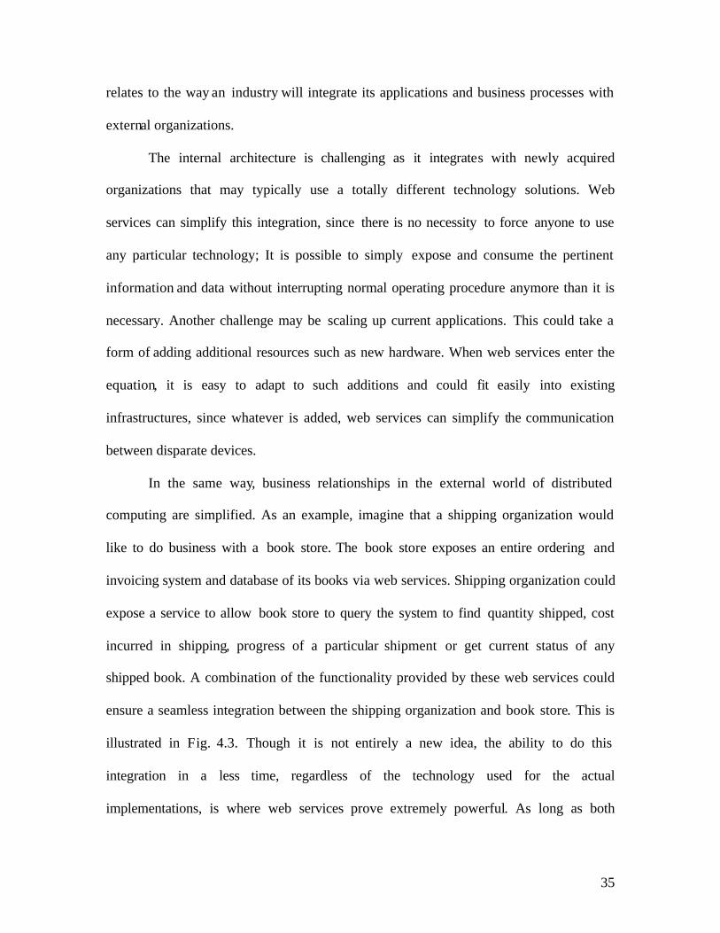
and external11. The internal architecture is related to the way an industry will deploy
applications within the company across its internal network. The external architecture
35
relates to the way an industry will integrate its applications and business processes with
external organizations.
The internal architecture is challenging as it integrates with newly acquired
organizations that may typically use a totally different technology solutions. Web
services can simplify this integration, since there is no necessity to force anyone to use
any particular technology; It is possible to simply expose and consume the pertinent
information and data without interrupting normal operating procedure anymore than it is
necessary. Another challenge may be scaling up current applications. This could take a
form of adding additional resources such as new hardware. When web services enter the
equation, it is easy to adapt to such additions and could fit easily into existing
infrastructures, since whatever is added, web services can simplify the communication
between disparate devices.
In the same way, business relationships in the external world of distributed
computing are simplified. As an example, imagine that a shipping organization would
like to do business with a book store. The book store exposes an entire ordering and
invoicing system and database of its books via web services. Shipping organization could
expose a service to allow book store to query the system to find quantity shipped, cost
incurred in shipping, progress of a particular shipment or get current status of any
shipped book. A combination of the functionality provided by these web services could
ensure a seamless integration between the shipping organization and book store. This is
illustrated in Fig. 4.3. Though it is not entirely a new idea, the ability to do this
integration in a less time, regardless of the technology used for the actual
implementations, is where web services prove extremely powerful. As long as both

36
organizations interact with the web service language, integration times are significantly
reduced.
Figure 4.3-Schematic diagram of web services in action
One of the major issues in internal world of distributed architecture is
performance. Communication via HTTP is likely to be slower than more direct forms,
even on a local network. This is further compounded by having to transform data to and
from the platform-neutral format used by web services. Although a great deal can be
achieved with web services quickly and efficiently, other options should also be
considered. In more tightly knit scenarios it is possible to get better results using
Microsoft’s DCOM, or Java equivalents depending on existing technology. Since local
communications are between well known end points there will often be no need to utilize
the web service advantage of platform independence, and sacrificing usability for
performance is a trade off. The same constraints apply to the external world of
distributing architecture, although the main concern with this is probably security. Some
of the existing competitors to web services can provide a more secure framework, even if
they limit to specific platforms, for example. Another advantage to such competitors is

37
that for the most part they are well established in the field, with many labor saving tools
available and a library of documentation to fall back on if ran into difficulties.
4.5 Operation of web services
Underlying everything is primary protocol used for Internet communication:
Hypertext Transfer Protocol (HTTP). In most cases this will be used as the transport
protocol for web service communication, although the web service specifications do not
require this. In many cases, the situation is less complicated than this- web service
communication can also be one way, with clients making requests but nor waiting for a
response. Web service initiated dialogue is also possible, which may also go one way or
both ways.
Accessing a web service is much like accessing anything else on the internet in
that it requires a URL. While browsing the web, we provide a browser application with a
URL, which sends an HTTP request to the web server associated with that URL, and
retrieves an HTTP response containing the HTML to web form. This is then submitted to
the web server, in which case the HTTP request sent to the web server hosting the web
page will contain additional information. When a web service is queried, we access
URL’s, and indeed web servers, in the same way. The web service and associated
protocol specifications simply tell what should be put in the HTTP request, and what
content can be expected to retrieve.
This use of HTTP for web services isn’t a mandatory one. However, it does make
a lot of sense. To begin with, HTTP web servers are easy to come by, making
deployment of web services trivial. HTTPS makes secure data transfer possible. A system

38
that uses HTTP as its primary transport mechanism will have no trouble switching to
HTTPS, since the non security aspects of the two protocols are identical. This is true for
web service communications, so the option of security for web services is present without
having to do any extra work at all.
4.6 Web service standards
• XML17: XML is a standard that provides encoding to data as plain text files. This has
the significant advantage that almost anything can read it, as text files are standard
across platforms. There are standards to adhere to, such as, what encoding language
to use, and how much data is used for each character, but these are surmountable on
all devices likely to be interested in web services.
• XML Schemas : XML schemas provide a mechanism of imposing rules to XML
documents. These rules can apply both to the structure of the document, and to the
data types allowed in specific sections. XML schemas are also written in XML, and
conform completely to the XML specifications. This makes XML schemas easier to
understand, and also means that they may be recognized by as many devices as XML
documents.
• SOAP: SOAP19 was originally designed as a means of manipulating objects
remotely. Now its use is more specialized, and is used almost exclusively with web
service implementation. The two technologies looked at above, XML and XML
schemas, are enough to exchange data with web services. When accessing web
services using straight HTTP, these are all however required. However it is also
possible to place XML data in what is known as a SOAP language. SOAP is another

39
technology that uses XML. Placing XML data in a SOAP message effectively means
enveloping that message with additional XML. The reason for doing this is two fold.
First it means that all communications with web services are standardized and follow
the same standard structure. Second, the SOAP protocol includes some extras that are
particularly useful with web services. SOAP messages consist of an envelope that has
header and body sections. The XML data exchanged with a web service goes in the
body, and the header is used to exchange additional, application-specific information.
This header information can be marked in such a way that a web service must act on
it, and must indicate in its response that it has. This has greater applications in more
advanced web service design. Headers can also include information concerning the
encoding of data in the body section, allowing application-specific schemes to be
used. This is another advanced feature of web services. The way two systems interact
with each other across the Internet using SOAP is shown in fig. 4.4.
Figure 4.4-SOAP over HTTP20
• WSDL: The three technologies above are all that are needed for communicating with
web services, but don’t solve the problem of knowing what to send in the first place.
To solve this, web services have an associated WSDL (Web service Description
Language) document describing all operations that a web service can perform. The
description of a web service operation consists of the data structures used, the
combinations of these data structures present in requests to and responses from the

40
service, the format of messages containing these requests and responses, and the
specific method of access required for the different operations that are supported by
the service. In order to achieve this, WSDL documents which are written in XML
contain schema information, information associating schema definitions with
message structure, and some HTTP and SOAP specific information. Given a WSDL
document it is possible to write code to access the web service it pertains to. No
additional information is required.
Figure 4.5-Schematic layout of WSDL12

41
4.7 XML
In order for web services to utilize its maximum potential, they need to use an
independent way to describe and exchange data. The solution to this is the use of XML.
XML is very powerful in representing data structures (primarily strings, data sets and
custom objects). There are two related technologies-name spaces and schemas which
allow defining structures that XML data should conform to. This effectively standardizes
the way data is represented. This makes processing of data easier as it can be easily
known about the type and location of the data. XML is responsible for storage of data
exchanged with web services and the way in which web services describe the data. It is
also very critical in formatting SOAP messages. The .NET framework contains a vast
array of classes for storing XML data, input and output of this data, validating schemas
etc. There are several name spaces used in XML. These name spaces contain specific
classes for reading and writing XML data, dealing with XML schemas, converting
objects into XML etc. There are two main methods in XML processing-Document Object
Model (DOM) and Simple API for XML (SAX).In DOM model, DOM parsers are used
to extract the data and populate these objects. It specifies how XML documents can be
viewed in terms of trees and nodes. SAX model is quite different from DOM model.
SAX parsers do not load the entire document models in memory; they step through XML
documents line by line. They give access to the content files by raising events when the
data is found. SAX parsers could be used to populate one’s own object model, and this
technique is used by many DOM parsers including the one used by the .NET framework.

42
4.8 Describing a web service (WSDL)
As communications protocols and message formats are standardized in the web
community, it becomes increasingly possible and important to be able to describe the
communications in some structured way. WSDL addresses this need by defining an XML
grammar for describing network services as collections of communication endpoints
capable of exchanging messages12. WSDL service definitions provide documentation for
distributed systems and provide the foundation in automating the details involved in
applications communication. A WSDL document defines services as collections of
network endpoints, or ports. In WSDL, the abstract definition of endpoints and messages
is separated from their core network deployment or data format bindings. This provides
the reuse of abstract definitions: messages, which are abstract descriptions of the data
being exchanged, and port types which are abstract collections of operations. The
concrete protocol and data format specifications for a particular port type constitute a
reusable binding. A port can be defined by associating a network address with a reusable
binding, and a collection of ports define a service. Hence, a WSDL document uses the
following elements in the definition of network services:
Types– a container for data type definitions using some type system (such as XSD).
Message– a typed definition of the data being communicated which is abstract in nature.
Operation– a description of an action which is abstract supported by the service.
Port Type–an abstract set of operations that are supported by one or more endpoints.
Binding– a concrete protocol and data format specification for a particular port type.
Port– a single endpoint defined as a combination of a binding and a network address.

43
Service– a collection of related endpoints. Snap shot of WSDL containing all these
network services is shown in fig. 4.6.
Figure 4.6- Snap shot of WSDL of a web service
WSDL allows specifying multiple ways of accessing web services, with the format that
will be used for each. Extensions to the WSDL language are used for whatever
techniques we want to make available, including both SOAP and HTTP GET/POST.
WSDL is an XML format for describing network services as a set of endpoints
operating on messages which may contain either document-oriented or procedure-
oriented information. The operations and messages are described abstractly, and then
bound to a concrete network protocol and message format to define an endpoint. Related
concrete endpoints are combined into abstract endpoints (services). WSDL is extensible
to allow description of endpoints and their messages regardless of what message formats
or network protocols are used to communicate, however, the most common binding

44
described is how to use WSDL in conjunction with SOAP 1.1, HTTP GET/POST, and
MIME.
4.9 Web service in action
Simple Object Protocol (SOAP) is a protocol for exchange of information in a
distributed environment19. It consists of three parts:
It comprises of an ‘envelope’ which defines the framework which describes about the
contents of the message and the way to process it.
A set of encoding rules which represent instances of application defined data type.
A convention for representing RPC and responses.
SOAP is written using XML. It can be used in combination of other protocols. It
does not define a programming model or other any other semantic specific to an
application. It provides a modular packaging model which has encoding mechanisms for
data encoding with in the module. Due to this feature, SOAP can be used in a variety of
systems from messaging to RPC.
One of the major design goals of SOAP is its extensibility and simplicity. Hence
SOAP does not have the traditional features of messaging system like distributed garbage
collection and objects by reference.
4.9.1 SOAP envelope19
The envelope is the top of the XML document representing the message. The
envelope contains a header (which is optional) and a body (which is mandatory). The
information for header and body is not defined in the specification as it is specific to the

45
consumption. As the header information is optional, it depends on the creator of SOAP to
include it. Typically SOAP headers may contain information like login information of
users, where the accessibility to users may be through an authenticated means. However
if services are accessed based using HTTP GET/POST, then these optional headers can
contain data as data could be sent through HTTP headers. SOAP body comprises of
information which is specified by semantics of web service where it is received. SOAP
message can have two types of formats. One is in document format and other is in RPC
(Remote Procedure Call) format. In the document format, the SOAP messages are
contained directly in the SOAP body. In RPC format, it is very similar to this, but it is
embedded inside an element with the same name as the operation being called. The
preference for web services is however for document style messages. This is probably
because mapping from type definition to SOAP message is less obscure than with RPC
style messages.
The following structure shows skeleton of a SOAP message
<?xml version="1.0"?> <soap:Envelope xmlns:soap="http://www.w3.org/2001/12/soap-envelope" soap:encodingStyle="http://www.w3.org/2001/12/soap-encoding"> <soap:Header> ... ... </soap:Header> <soap:Body> ... ... <soap:Fault> ... ... </soap:Fault> </soap:Body> </soap:Envelope>

46
4.9.2 SOAP over HTTP
SOAP over HTTP is achieved by packing SOAP messages as HTTP POST requests. This
is shown in fig. 4.7. The MIME content for SOAP messages is either text/xml which is
used in .NET. SOAP and multi part web service requests can be formatted as multi part
messages. This would mean that data for request can be scattered over places including
email messages. However, in reality, these are likely to be found within the message
body of HTTP request, as using an external location might not be possible. The reason
for having multipart messages is because, when data is in format of .jpeg or .bmp,
wrapping such data in SOAP may be ineffective as XML has to cope up with huge
amount of data for parsing. Hence it is efficient if the data is left at a different location
and is accessed using SOAP elements or HTTP.POST parameters.
Figure 4.7-HTTP Post/GET11

47
4.10 Proxy
A proxy11 resides on the consumer’s machine and acts as a relay between the
consumer and the web service. When a proxy is built, it uses a WSDL file to create a map
that tells the consumers what are the methods are available and how to call them. The
consumer then calls the web method that is mapped in the proxy, which in turn, makes
calls to the actual web service over the internet. The proxy handles the entire network
related work including sending of data, as well as managing the underlying WSDL.
When we reference the web service in the consumer application, it looks as if it’s
part of the consumer application itself. The application is executed as a function in proxy
code, passing any appropriate parameters to it, without being concerned that the proxy is
going to call a web service. The proxy receives the call and frames the request that will
be sent to the web service, using the specific parameters given by the consumer. This
function call is sent from the proxy to the web service. This call can be confined within
the same machine, or across a Local Area Network (LAN), or across the Internet. The
method of calling however remains the same. The web service uses the parameters
provided by the proxy to execute its web callable function and build the result in XML.
The resulting data from the web service is returned to the proxy to execute its web-
callable function and build the result in XML. The proxy parses the XML returned from
web service to retrieve the individual values generated. These values may be as simple as
integers and strings, or they may define more complex data types. The application
receives the expected values from the proxy function, completely unaware that they
resulted from a web service call.

48
4.11 Web service discovery
As well as being useful for exposing functionality for use with in own industry, or
that will be used by partner industry, web services are also a commercially viable
product. This raises the issue of how to advertise web services and make them available
to consumers. One possible way of doing that is being seriously considered is to register
web services in a central directory. Registering web services in this way mean that
potential customers can browse service entries and make use of any that they see fit. The
road to a practical implementation of this concept has been difficult, and the current set of
technologies hasn’t really taken off in the way it has predicted.
WSDL10 accurately defines web services, but this is not sufficient to allow people
to find the web service. If the web site is not known, it will not be possible to find the
WSDL that describes it. What is needed to achieve that is some central access or a
repository that people can query in order to find web services, and UDDI is used for this
purpose. Initia lly a few very large public repositories were designed, containing UDDI
information that could be used to locate web services. Instead the trend seems to have
been that individual organizations use their own UDDI repository. This can be useful
since UDDI can be programmatically used to locate and use web services, so if a web
service is not functioning or if the server is not responding for any reason, a UDDI
repository could be very useful in locating a replacement or backup service immediately.
VSDISCO is another technique where the users can locate web services on the .NET
server dynamically without knowing their address. However there may be few security
risks involved in using this technology.

49
Chapter 5-Implementation and design of web services
Remote access of Bearcat Robot III was performed using web services in the .NET
frame work. The pages were designed using ASP. NET with SQL server as the back end.
Web services were then consumed from a different server into this server. The pages
were integrated together and were hosted on the web.
5.1 Web server
A web server is a software tool which manages (hosts) web pages and makes them
available to browsers, either through a local network or through the Internet. Physically
web servers and the client machines can be on same machine or separated miles apart.
However this does not make any difference in terms of access. There are many web
servers available in the market today. Apache, IIS (Internet Information Services),
Enterprise Server by IPlanet are a few. ASP. NET runs on IIS. In this case, the Web
server is located in the Robotics Lab, located in Room 551 Baldwin Hall, University of
Cincinnati, OH. It can be accessed by any machine existing on the UC (University Of
Cincinnati, OH) network. Since IP masquerading is done, the IP address of a machine is
different outside UC’s network. Hence, the page transition address would vary.
5.2 Dynamic web pages
Dynamic web pages are those which keep changing based on time or user or other
changes on client side. Static pages are those in which, the contents always remain the
same. HTML (Hyper Text Markup Language) code is typed directly into an editor and

50
saved as a HTML file. In dynamic pages, however, contents are more dynamic and
personalized in nature. There are two ways in which dynamic pages can be created- client
side and server side.
5.2.1 Client Side Dynamic Pages
In the client side model, the web pages are created by the browser to which the
modules are attached. The HTML code is sent to the browser along with a separate file
which has a set of instructions which is referenced by the HTML page. However these
instructions can also be found embedded in the code. These are used by the browser to
generate HTML page. Hence here it is dynamically done on request. The HTML page
thus generated is sent back to browser. So, when a user types a URL (Uniform Resource
Locator), the web server looks up the URL and locates the HTML page corresponding to
it. In some cases, the web server also looks up for the instructions file associated with the
HTML. The web server sends the HTML and the instructions back to the browser across
the network. The module within the browser then processes the instructions and then
returns it as HTML within the .HTML page. There is only one page that will be returned
to the browser. The HTML is then returned to the browser, where the page is displayed.
This is shown in Fig.5.1

51
Figure 5.1-Client side dynamic pages11
5.2.2 Server side dynamic pages
Client side technologies take a long time to down load, especially with a separate file
of instructions. Also since this interpretation is done by the browser, each browser may
interpret it in a different way. Another disadvantage is, since it is a coding issue on the
client side, it is completely undesirable.
With server side coding, the HTML source is set to web server where all the processing is
done, before the page is sent back to the browser. Here, the page is logically hidden on
the server and most browsers can read it in a consistent way. This is shown in Fig.5.2
ASP. NET follows a server side model.

52
Figure 5.2-Server side dynamic web pages11
5.3 Front end
As mentioned above, ASP. NET was used as the front end. ASP. NET is a server
side coding technology used for creating dynamic web pages which can use any full
fledged programming language supported by .NET. ASP. NET is not a programming
language by itself. It is a technology. It is accessed by a programming language, which is
VB.NET in this case. So, VB.Net is used in creating the web pages, using ASP. NET to
drive it. ASP. NET is quite different from ASP. ASP (Active Server Pages) has got many
restrictions in terms of its functionality. It is restricted to using scripting languages like
VB script or Java script. ASP code is added to the pages similar to client side scripting.
This makes the code limited in its functionality and also messy. ASP. NET has a broader
array of selection of programming tools that can be used. It can also utilize the features of

53
.NET framework to the core. The pages created using ASP. NET are more dynamic,
reliable and faster to create. ASP. NET also relies on a module attached to the web
server. It uses the physical file, aspnet_isapi.dll. This dll(dynamic link library) file does
not do all the work by itself, but passes some to .NET framework.
As mentioned, the pages are created using VB.NET in ASP. NET. Since it is server
side scripting, the code is compiled on the IIS, the web server for .NET. The VB code
and the ASP code are embedded in a single page. Before the actual coding, all the
required name spaces and libraries required for the code are called in using an import
statement. The code is written in a modular approach with several sub routines, which
will be called by the objects as required. The modules start with sub followed by the
name of the module. The appropriate event handlers are also called in the module by
creating an instance. These pages are referred as web forms in .NET terminology. All
web forms have the extension of .aspx. Thus all web forms which are compiled by the
IIS, are web pages hosted by that IIS. Since it is a server side scripting, the web forms
can be seen across the browsers consistently.
5.4 Back end
Microsoft SQL server is used as the back end where the tables are created on the
data base. There are two tables, one for registered user information and other for existing
inventory. The structures of the field and data type are provided in the table design. An
authenticated access is provided to the database. A secured connection is established with
the data base through the ODBC provided by .NET framework. All the information
given when a new user signs up is captured in this data base. Whenever the user logs in,

54
the credentials are authenticated with the server and ensure further progress to the other
pages. The users are managed using the enterprise manager in SQL server.
5.5 Data providers
With the .NET frame work, there are two data providers13 : 1. OLEDB data provider
2. SQL data provider. The OLEDB provider is for connecting to any OLEDB compatible
data store like Access, Excel, Microsoft SQL server, Oracle etc. The SQL client data
provider is specifically for Microsoft SQL server. The SQL client data provider provides
much faster access to SQL server than the OLEDB equivalent. Each data provider has its
own connection object class. The OLEDB data provider has an oledbconnection
class and SQL client data provider has sqlconnection class. These classes are found
in System.data.OLEDB. and System.data.sqlclient name spaces
respectively. So depending on the data base, the appropriate name space should be
chosen.
5.6 Session variables
Session variables are useful in providing personalized information to users. For
example session variables can be used to welcome the user with his/her first name,
provide content based on his/her geographic location, personal interests etc. When the
user logs on with the credentials supplied during sign up, it is authenticated with the
information on the data base. After authentication, the session variables capture other
related information from other fields in the same record. This is stored in a variable and is

55
passed from page to page. Where ever the session variable is called, it returns the stored
field. Session variables are valid across modules and even across pages. It is one of the
most effective ways to pass data across the pages. Session variables are valid as long as
the session is valid. Session can expire either through an automatic time out or by using
session.abandon() command. Thus, when a user remains inactive for a long time,
the session variables get expired and it prevents further progress. Thus it ensures
enhanced security as well as personalized information across pages. The default time
required for a session variable to be valid can be set only on the server. Apart from data,
session variables can also pass user specific information like local time, his preferences
of content, lay out etc.
5.7 Data grid
Data grid is very helpful in displaying data from the data base in a tabular format.
However, to display the information, data grid needs to be bound with the data base. The
data grid emits the HTML needed for data bound HTML tables. To do this, first a data
reader with some data base is obtained. Once the data is in the data reader, the data grid
requires few lines of code to be bound with it. These lines of code indicate where the data
should come from, which is commonly referred as the data source. The data binding
property should also be notified here. One of the main advantages here is that the code
involved is very simple and also very efficient. Essentially, a connection is created with
the data base and the connection is opened. Then the data grid’s data source property is
set to the required data reader. Finally the binding takes place using databind method.
A significant feature in this approach is that, it isolates the code completely from the

56
content. Unlike conventional ASP, there is no mixing of HTML table and data reader
output syntax. For the given case, it is assumed that the inventory table resides in the
same data base as the user information table. Hence the binding is with the same server
and the data source is from the same data base.
5.8 Algorithm for obstacle detection
All authenticated users will be able to perform the obstacle detection test.
Assuming for three types of obstacles-circular, linear, rectangular, the algorithm was
devised. Since the intent is to demonstrate web services, all the functionality of the
existing system are not incorporated in the algorithm.
In a given 2-dimensional system, the robot is assumed to move for the pre
specified points. The user specifies the start and end co-ordinates. The position (x, y co-
ordinates) and type of obstacle is also specified.
• Circular obstacle: For a circular obstacle, the system checks if the path of the
robot will interject the circle. This can be checked by knowing the co-ordinates of
center of circle and the radius of the circle. There is an incremental loop which
progressively checks if the co-ordinates of robot along its path to the destination
will collide within the spread of circle. The position of robot is incremented every
time within the loop.

57
Figure 5.3-Circular obstacle
• Linear obstacle : For a linear obstacle, the system checks based on position and
length of the line. The incremental loop increments the co-ordinate positions of
the robot until it reaches the final destination. On its path, if it encounters any co-
ordinate of the obstacle (co-ordinates from beginning to end of obstacle), then it
prompts that an obstacle has been encountered.
Figure 5.4-Linear obstacle

58
• Rectangular obstacle : For a rectangular obstacle, it is very similar to a linear
obstacle. However here co-ordinates for all the four corners of the rectangle will
be taken into account. As the position of robot gets incremented using the
incremental loop, it progressively keeps checking for the obstacle. In this case, the
whole enclosed area between the four points is checked for and when the path is
obstructed by any of the co-ordinates inside, it prompts that the obstacle has
occurred.
Fig 5.5-Rectangular obstacle
5.9 Web services
Web services, as mentioned before, is extremely useful in remotely accessing by a
secured means. The actual algorithm for obstacle detection is on a different server.
The server on which robot is running, remotely accesses that server. By this, the code
is not exposed to the user. Only the required privileges are given and the appropriate

59
parameters are passed. Also the web services can be consumed by several users and
hence it is not restricted to a single robot. Web services are quite different from web
forms. Web services have the extension .asmx. This extension tells IIS to use
aspnet_isapi.dll and lets ISAPI filter knows that a web service is going to be
defined. Unlike the web forms, web services do not have embedded HTML in it. The
coding is similar to object oriented programming (OOP) model, where different levels
of access rights (public, private, protected), concepts of inherit ance are specified.
A web service definition contains four essential parts
• Procession directive
• Name spaces
• Public class
• Web-callable methods
5.9.1 Processing directive
The processing directive appears on top of ASP. NET source file indicating
settings or constraints that should be applied to any object generated from that file. It tells
the compiler the language it was written and the name of the class defined.
5.9.2 Namespaces
Similar to .aspx files, it is possible to import the required logic or commands from
other files existing in the libraries or name spaces. This can be seen in the code as
Imports System.Web.Services

60
It is required to import these name spaces in minimum, as it contains all the necessary
classes for web services to handle network connection issues and other OS related tasks.
5.9.3 Public Class
Public class acts as the container for the methods of the web service. The
name of this class is the name of the web service and should there fore correspond to the
class value specified in the processing directive.
Public Class circleobstacle .. End Class The object classes defined are those which are going to be exposed over the web. This
will help to make remote method calls over the Internet to the server, which will look like
method calls from same machine.
5.9.4 Web methods
Methods that are exposed over the web are web (callable) methods. A web service
will expose one or more methods. There can be methods which need not be exposed to
consumption. They do not have the web method declaration before the name of the
function. Hence,
<WebMethod()> Public Function circleobstacle(ByVal r As Integer, ByVal c1 As Integer, ByVal c2 As Integer, ByVal x1 As Integer, ByVal y1 As Integer, ByVal x2 As Integer, ByVal y2 As Integer) As String as seen on the code, are web callable methods. The parameters for web methods can be
customized. For example web methods can be customized to hold the cached results for a

61
particular period. So when the consumer is requesting a web service, the results that were
cached before will be returned.
For the given problem, three web services are designed; one for each type of obstacle. In
each web service, the web methods comprise of the algorithm which pass on the
parameters for the function when consumed.
The web services can be accessed over the internet similar to the web forms. By typing in
the address of the web service (which ends with .asmx), it fetches the web service on the
browser by taking a HTTP request. In the .asmx page, on clicking WSDL, it expands to
list the WSDL functionalities associated with that web service.
Values for the required parameters are provided and when they are invoke the web
services, a request is made to the web service to execute the web service method with the
value entered being passed. In the web service, based on the algorithm provided, for the
given values, the results are obtained on the browser. However these results are in XML
format, which can be consumed. On the results page, there are a few name spaces which
make reference to SOAP. The <types> element defines the data type that web service
expects to receive and return after completion.
Now, having created the web services, the functionality could be used in the web forms
which appear in the browser as web pages. Hence the web services need to be consumed
for this purpose.
5.10 Consuming web services
For the consumption, an interface must be created first, which will allow
customers to access the web callable methods and properties exposed by the web service.
This interface is commonly referred as proxy.

62
5.10.1 Functioning of a proxy
A proxy exists on the user’s machine and acts as the link or relay between the user
(consumer) and the web service. When a proxy is created, a WSDL file is used to map
the methods that are available and the way to call those methods. The user then calls the
web method which is mapped in the proxy. This web method in turn calls the web service
across the internet. The proxy handles all of network related activities like sending data.
It also manages the underlying WSDL. Hence when the web service is accessed by the
user, it looks as if it is a part of that application itself.
So, the application on the user’s end executes a function which resides in proxy
code. It passes the required parameters to it, without being concerned that the proxy is
going to call the web service. The proxy receives the call and makes the request to be sent
to the web service using parameters specified by the user. The function call is then sent
from the proxy to the web service. The web callable function in the web service is then
executed based on the proxy provided and generates the result in XML. The proxy parses
the XML from the web service to retrieve individual values. These generated values may
be of simple data type like strings or integers or may define any complex type. This is
then sent to the application by the proxy function. Consuming of web services is
illustrates in fig. 5.6.
In order for proper execution and consumption of the web service, the proxy must
be compiled appropriately.

63
Figure 5.6-Consuming web services12
5.10.2 Building a proxy
Building of proxy11 involves two steps: first the proxy source code needs to be
generated and then this must be compiled into a run time library. To achieve this, first the
windows variable path needs to be configured so that it includes the directory path to the
executable vbc.exe. After this, the path should be added to include wsdl.exe also.
Then the following command also needs to be executed in the DOS prompt.
>wsdl /l:vb /o:linobstacleproxy.vb http://10.85.2.251/sugan/linobstacle.asmx?WSDL /n:linobstacleService After this, the proxy file is created for the linobstacle.asmx file as
linobstacleproxy.vb
The proxy file is then compiled using vbc
>vbc /out:linobstacleproxy.dll /t:library /r:system.web.dll,system.dll,system.xml.dll,system.web.services.dll,system.data.dll linobstacleproxy.vb
This creates linobstacleproxy.dll. This file is then copied on to the /bin folder inside
thesis1 folder on the .NET platform.

64
Now the proxy class is created, the web service linobstacle.asmx can be consumed and
the web callable methods can be used appropriately. The other two web callable methods
are consumed in the same way as this into the application on the web form. On the web
form, the proxy can be referred as a name space. This can be done as
<%@Import name space= “linobstacleService”%>
5.11 Schematic layout and step-by-step operation
Figure 5.7-Schematic layout of operation
The request the user sends is given in solid arrows and the result sent back shown in
broken arrows.
1. The user with a .NET compatible device, logs on to the BEARCAT III server
using his/her credentials through the web interface.

65
2. The information provided is checked with the existing data stored in the SQL
server. The connection between them is made through the data provider (OLEDB
SQL connection). If the user is new, an option for signing up is provided. The
users’ information is stored on the SQL server.
3. On correct authentication, the user proceeds to the page where the data grid on the
same server (http://10.52.5.175) is displayed.
4. The existing BRAT code is also called from the remote location.
5. On moving further, the web services are invoked. The .NET framework interacts
with the proxy created on the BEARCAT III server (10.52.5.175). This was
created by consuming the web services on the other server (http://10.85.2.251).
6. The proxy interacts with the web callable methods on the remote server.
Parameters are sent back and forth via SOAP over HTTP.
7. The remote server (http://10.85.2.251) uses the parameters provided by the user to
the proxy and inputs them to the algorithm for obstacle avoidance.
8. After computing the results are sent back as HTTP response in XML. This is
being consumed by the proxy on the BEARCAT III server.
9. The proxy passes the results to the web forms.
10. The web forms display them to the user as a part of the application.
Thus the user finally gets the result, by using the algorithm on a remote server as a
web interface in his/her device.

66
Chapter 6-Results and conclusion
The constraints and limitations relating to Timbuktu TM were eliminated by
utilizing the full potential of the .NET framework. With Timbuktu TM, a remote access
to the desktop of the host machine was provided. The two machines were interfacing
across the subnet using the IP addresses. Also communication was via TCP/IP.
Timbuktu TM also necessitated the client and host to be on same platform. By using
web services, a secure and reliable transfer of information was achieved. The web
callable methods exposed only the required part of the algorithm to the client
machine. By using SOAP over HTTP, the data packets were secured. Inter
operatability was also achieved by using the .NET framework, which crosses the
boundaries of computers. The communicating platforms between the various devices
and servers also become insignificant by incorporating the features of .NET
framework. Also, a physical presence at the site of robot could be avoided, since
control can be made across the network.
The robot, connected to the server, was controlled by any device at a remote
location located inside the network of University of Cincinnati, OH. It successfully
utilized the services of the web methods designed for obstacle avoidance that was
coded on a different server across the network. Alternatively, the BRAT TM code used
on BEARCAT III, was also accessible via the web interface. On installing IIS to the
Bearcat Cub, a remote access to this robot via the .NET framework was also
achieved. As the code is present in a centralized location, it can be called by any
number of other robots connected to that server.

67
Chapter 7-Future research and references
7.1 Direction for future research
Web services have revolutionized the IT world by bringing together islands of
different servers together. Integration of different streams of industries over the web
is becoming easier day by day. Both J2EE18 and the .NET frame work can be used in
tandem, so that the net productivity could be improved. The existing BRAT code
written in C, can be converted to a .NET compatible language, so that it can be
encompassed into the framework. This converted code can then be completely used
across web services and web forms, there by completely utilizing the power of the
framework. Also, on the hardware side, more powerful and robust servers will be
required, as the complexity of processing and the speed of data transaction will
increase exponentially. Also the consumption of web services will cause creation of
several proxies and DLL files on the client system, which in turn must be powerful
enough to handle them. Hence, future research must be concentrated on system
integration and powerful hardware.
7.2 References
1. J.Norberto Pires and J.M.G Sa da Costa, “Running an Industrial Robot from a
typical personal computer”, IEEE International Conference, Vo l. 1, pp:267-270,
1998.
2. Marcin Metter and Dr.Robert Colomb, “WAP enabling existing HTML
applications”, User Interface Conference, pp: 49-57, 2000.

68
3. Hung- Sheng Chiu and Chyan Yang, “Beyond e-Commerce Software Quality:
Web Services Effectiveness”, Second Asia Pacific Conference on Quality
Software, pp: 397-405, 2001.
4. Takeshi Chusho and Katsuya Fujiwara, “A form-based approach for web services
by enduser- initiative application development”, Symposium on Applications and
the Internet (SAINT) workshops, pp: 196-203, 2002.
5. Tetsuya Kawase, Akira Watanabe Et al., “Proposal of secure remote access using
encryption”, Global telecommunications conference, Vol. 2, pp: 868-873, 1998.
6. Adam Bosworth, “Developing Web Services”, 17th International conference on
Data engineering, pp: 477-481, 2001.
7. Atsushi Kara, “Secure Remote Access from Office to Home”, IEEE
Communications Magazine, Vol. 39, Issue 10, pp: 68-72, 2001.
8. Jian L.Zhen, M. Anthony Lewis Et al., “Towards Universal Access to Robotics
Resources”, International conference on Intelligent Robots and Systems, Vol. 3,
pp: 1400-1407, 1996.
9. Shin Nakajima, “Verification of web service flows with model checking
techniques”, First International Symposium on Cyber Worlds, pp: 378-385, 2002.
10. Francisco Curbera, Matthew Duftler, Et al., “Unraveling web services web”,
IEEE, Internet Computing, Vol. 6, pp: 86-93, 2002.
11. Rob Birdwell, Ollie Cornes, Et al., “Beginning ASP. NET using VB.NET”, Wrox
Press Ltd., 2001.
12. Joe Bustos and Karli Watson, “Beginning .NET Web Services using Visual
Basic.NET”, Wrox Press Ltd., 2002.

69
13. http://msdn.microsoft.com/msdnmag/issues/0900/WebPlatform/default.aspx
14. http://archive.devx.com/dotnet/articles/cp0901/default.asp
15. http://www.gotdotnet.com/team/windowsforms
16. http://www.411asp.net/home/tutorial/howto/webservi
17. http://samples.gotdotnet.com/quickstart/aspplus/doc/webservicesintro.aspx
18. http://www.webservicesarchitect.com/content/articles/hanson01.asp
19. http://www.w3schools.com/soap/soap_intro.asp
20. http://www.15seconds.com/issue/010530.htm
21. Microsoft .NET developer training manual, 2001.
22. Juha Roning and Kari Kangas, “Interacting with personal robots and smart
environments”, Vol: 3837, pp: 26-39, SPIE proceedings, Boston, 1999.
23. http://web.mit.edu/newsoffice/tt/2000/dec06/monkeys.html
24. http://mars.jpl.nasa.gov/MPF/rovercom/itworks.html