application of wireless load cell to investigate rod mill
TRANSCRIPT

November 13, 2015
Application of Wireless Load Cell to Investigate Rod Mill Liner Bolt Breakage
Naseeb Adnan, Ph.D., P.Eng.Project Engineer, Process Control
XPS Consulting and Testwork Services

Other Possible Contributing Factor
Early Failure Detection
Conclusion
Outline
Bolt Breakage Issue
Possible Root Causes
Scanimetrics Wireless Load Cell Technology
Findings based on Clamp Force Data
Review Torque Process
QA/QC of the Nut/Bolt
1
1
2
3
4
5
6
7
8
9

1
2
Rod Mill Bolt Breakage
Strathcona Mill has two parallel grinding lines.
Rod Mill Specifications:• 10’ Diam X 16’ long
• Pulp density 82 to 84%• 900 hp• 4.0” rods
• Rod load 35% to 40%• 76 % of critical speed (18.2 rpm)• Produce narrow size distribution
Fig: Schematic of Grinding Circuit

1
• Bolts are used to fasten liners to the Mill shell.
• Interrupted operations when Rod Mill liner bolts failed unexpectedly while in operation
• Suffering metallurgical losses and production downtime
• Multiple bolt failures threatened liner loss
• Equipment availability
Rod Mill Bolt Breakage
3

1
Figure: Broken bolt mapping. Breakage problem more dominant at the discharge end of the mill and scattered throughout the discharge end.
Rod Mill Bolt Breakage
4

2
5
• Boltso Materialo Sizeo Torqueo Condition of bolt holes
• Liner design
• Rod Mill Speedo Trajectoryo Rod Charge and grinding media
• Operating Conditionso Grind outso Density controlo Throughput
Potential Root Causes - Contributors

2
• Grade 5, 1¼" to Grade 5, 1½"• A Rod Mill – November 1st, 2010• B Rod Mill – November 20th, 2011
6
Year Bolt Type Torque(ft-lb)
Clamping Force (lbs)
Before 2010
Grade 5, 1 ¼ " 1300 62 400
2010 Grade 5, 1 ½ " 2277 91 0802015 B7, 1 ½ " 2900 117 000
• Grade 5, 1½” to B7, 1½”
• A Rod Mill - May 2015• B Rod Mill - July 2015
Upgrades to Bolt Strength / Clamping Force

2
• Bolt breakages • Occur between the hex nut and the cup
washer• Occurs primarily on the discharge end • All bolts analyzed failed by fatigue
• Crack Propagation• Failure occurred mostly due to
unidirectional bending
• Detailed failure analysis done by XPS Material Technology GroupWilson Pascheto, M.Eng., P.Eng.Manager Materials TechnologyEmail: [email protected]. +1 705 699 3400 x3402
7
Failure Mechanism: Bending

3
• Provides wireless sensing products and solutions.
• Six load washers installed on “A” Rod Mill.
• Three washers connected by wire to one wireless mote.
• Motes take ADC measurements at the specified sample freq. and store the measurement.
• Possible to receive high speed data, up to 512 Hz.
• The Gateway periodically request new raw data from the motes and data is streamed and transferred to the server (off-site).
8
Scanimetrics Wireless Load Cell Technology

3
• Load cells can be installed with existing bolt assembly without any modification.
• Provides time series clamp force data.
• A very strong source of information as it provides data of individual load cycles, which can be correlated with process conditions.
• Compared to other alternate considered for condition monitoring, wireless technology and ability to directly measure clamp load makes it much preferable choice.
9
Scanimetrics Wireless Load Cell Technology

3
10
Scanimetrics Wireless Load Cell Technology
Source: http://www.scanimetrics.com/

3
11
Scanimetrics – Washer Installation

4
12
Findings based on Clamp Force Data
Figure: Time-series data shows clamping force of 6 bolts the month of installation, June 2015. Wide variation is observed on clamping force.

4
Fatigue Failure of Bolted Assembly
13

4
14
Findings based on Clamp Force Data
Figure: Two bolts during the installation exceeded target clamp force with one exceeding yield strength (red line). Two of the bolts show clamping force much below target with one possibly seized.

4
15
Findings based on Clamp Force Data
Figure: Individual cycles of bolt loading and unloading.

4
16
Findings based on Clamp Force Data
Figure: Frequency power spectral density of bolt 11. Tension change occurred while the mill is running is happening at a very low rate
4
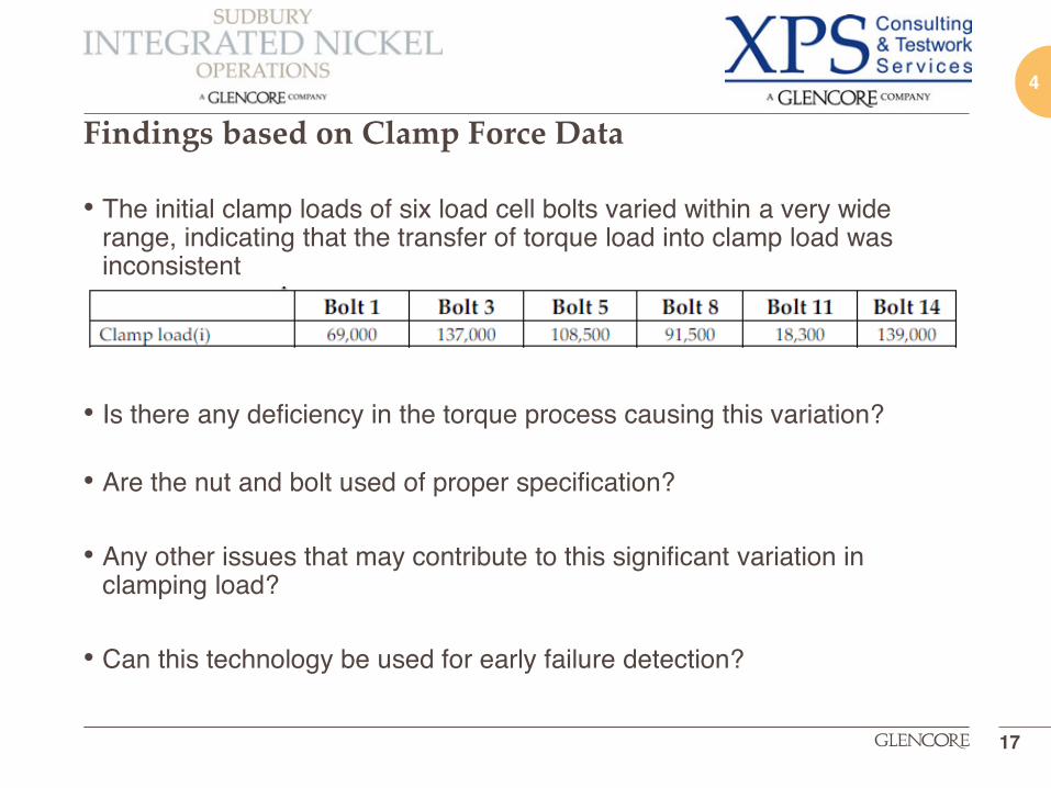
• The initial clamp loads of six load cell bolts varied within a very wide range, indicating that the transfer of torque load into clamp load was inconsistent
• Is there any deficiency in the torque process causing this variation?
• Are the nut and bolt used of proper specification?
• Any other issues that may contribute to this significant variation in clamping load?
• Can this technology be used for early failure detection?
Findings based on Clamp Force Data
17
5
• It was found that torque wrenches used had different calibration curves –potential source for variation if not carefully read, corrected with uniform settings.
• Torque wrench calibration and repeatability confirmed.
• Limitation of plant air supply identified - different torque wrench sourced which can provide same clamping force at lower air pressure.
• Bolts are retorqued after 24-hour and 7-days of initial installation.
• NDT done on every 6-week planned outage to proactively identify any crack.
Review Torque Process
18

6
• The fatigue crack area occupied more than 95% of the fracture surface, therefore the bolt strength and toughness was more than adequate for the application
• However, a mismatch of nut and bolt material were found.
• The potential consequences of having nuts which are too soft are threads seizing during torquing or clamp force relaxation during service.• Review QA/QC process of nuts/bolts
• Some of the nuts examined presented rubber residue in their threads, – may contribute to improper transfer of torque into clamp load.
Does the Nut/Bolt Satisfy Application Requirements?
19

7
• An unusually high peak was noticed beyond yield strength when bolt 5 was replaced in September.
• Cannot be explained with the range of torque wrench used.
• Some liner found to have curvature issue
• With a straight edge mismatch was found between liner curvature and shell curvature - possible to create a seesaw effect!
Other Possible Contributing Factor
20

8
• Bolts 1 and 3 (closest to the discharge end) had the highest clamp load losses since installed.
• These two bolts were from the same liner. Therefore, it would be expected that the clamp force loss of one bolt could cause the loss on the other bolt.
• Magnitude of the bolt tension stress cycle has been almost doubled for Bolt 3 at the end of the August. NDT confirmed crack in those two bolts, replaced.
Early Failure Detection
21

8
• The clamp force loss does not correlate with initial clamp force, since bolt 11 which had the lowest initial clamp force, did not relax.
• Based on the data, it appears that the clamp loss is mainly a function of the bolt position.
Early Failure Detection
22

8
• Why are discharge end bolts more likely to break than feed end?• As the bolts start to lose clamping force steadily, an increase in span is
observed.
23
Early Failure Detection

8
Early Failure Detection
24
8
Early Failure Detection
24

8
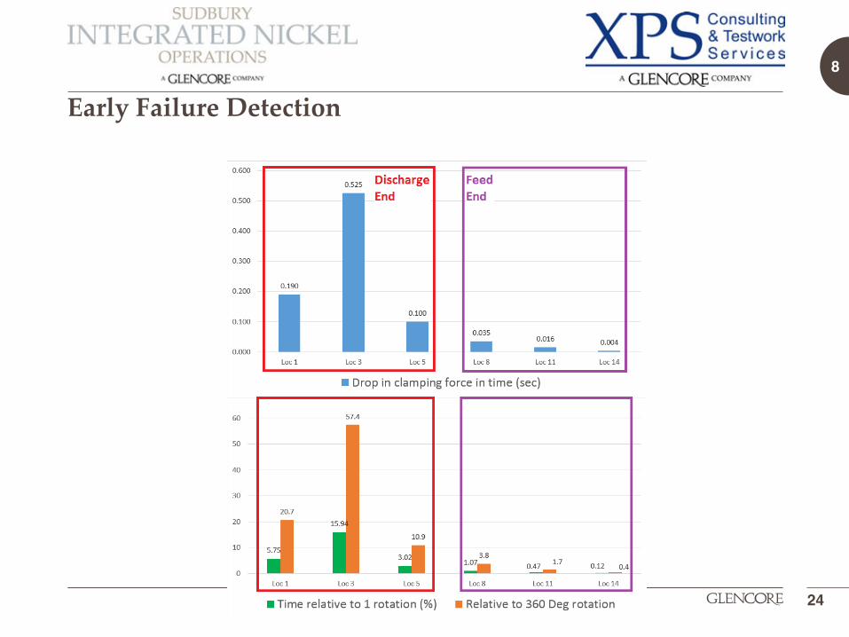
•This drop may allow more liner movement at the discharge end contributing to bending force.
• The figure shows that the fatigue origin was on the opposite side of the plastic deformation on the bolt threads.
• This is evidence that the bolt was leaning against the bolt hole while a bending moment was applied on the bolt.
Early Failure Detection
25
•Duration that intermittent drop in clamping force occurs in discharge end bolt is relatively much higher than feed end bolt.
•This is significant when compared to the time for one single Mill rotation of 3.3 seconds.
Figure: The threads were plastically deformed on one side of the bolt.

9
• Scanimetrics data helped understand the failure mode.
• Rod impacts do not cause an increase in tension, rather a reduction.
• The force causing breakage is perpendicular to the measurement, bending force:• Unidirectional crack propagation confirms bending force• Bending forces occur due to liner movement
• It is key that liner movement is minimized to address failure mechanism• Investigate locking the liners with best fastening possible and reducing forces• Investigate gap filler to prevent movement of liner
26
Summary of Learning

9
• Locking liners have following challenges:• Inconsistent torque• Variation in friction• Strong indications that “impossible” over tensioning is occurring in the torqueing
step because of seesaw action.
• There is a correlation between duration of relaxation period and forces that move the liners.
• Each bolt assembly now goes through strict in-house QA/QC process.
27
Summary of Learning

9
• The wireless load sensor helped significantly in the understanding of bolt breakage issue and developing measures to improve.
• The clamp force loss does not correlate with initial clamp force, since bolt 11 which had the lowest initial clamp force, did not relax.
• Based on the analysis, it appears that the clamp loss is mainly a function of the bolt position.
• Minimizing liner movement is key to address problem.
28
Conclusions

9
• Rob Roeterink - Mill Manager, Strathcona Mill• Julie Coffin - Lead Metallurgist, Strathcona Mill• Asim Tuzun - Business Improvement Specialist, Sudbury INO• Peter Fleming - Maintenance Specialist, Strathcona Mill• Wilson Pascheto - Manager Materials Technology, XPS Consulting & Testwork
Services• Michael Blouin - Physical Metallurgist, XPS Consulting & Testwork Services• Jeff Cayen - Operations General Foreman, Strathcona Mill• Jeff MacCullough - Maintenance General Foreman, Strathcona Mill• Suketu Patel - Asset Entitlement & BI Specialist, Sudbury INO• Kerry Connors - Mechanical Planner, Strathcona Mill• Martin Boissonneault - Mechanical Planner, Strathcona Mill• Wayne Moorhead - Scanimetrics Inc.• Terry Weng - Scanimetrics Inc.• Samantha Bell - Student, Laurentian University
29
Acknowledgement

Thank you!Questions?