application specification mag-mate* 114-2046 series 300 ... · crimp wire terminal. 114-2046 ......
TRANSCRIPT

Application Specification
© 2014 TE Connectivity family of companiesAll Rights Reserved*Trademark
TE Connectivity, TE connectivity (logo), and TE (logo) are trademarks. Other logos, product and/or company names may be trademarks of their respective owners.
1 of 12TOOLING ASSISTANCE CENTER 1-800-722-1111PRODUCT INFORMATION 1-800-522-6752
This controlled document is subject to change.For latest revision and Regional Customer Service, visit our website at www.te.com
114-2046MAG-MATE*Series 300 Terminals 05 MAR 14 Rev AA
All numerical values are in metric units [with U.S. customary units in brackets]. Dimensions are in millimeters [and inches]. Unless otherwise specified, dimensions have a tolerance of ±0.13 [±.005] and angles have a tolerance of ±2°. Figures and illustrations are for identification only and are not drawn to scale.
1. INTRODUCTION
This specification covers the requirements for application of MAG-MATE Series 300 Terminals which are designed for a housing with a terminal cavity depth approximating 7.62 mm [.300 in.]. The terminals are insulation displacement type with wire slot beams. They are designed to accept a wire size range of 33 through 17 AWG solid, round copper magnet wire or 28 through 17 AWG solid, round aluminum magnet wire. Terminals are available with narrow (1.78 mm [.070 in.] maximum) or wide (3.05 mm [.120 in.] maximum) space between beams. Some terminals are designed for one wire and some are designed for two. Those for two wires require wires of the same material and size.
There is a front and back slot for each wire, and four locking barbs on each terminal to ensure retention in your housing. Several terminal interfaces are available; Lead Wire Poke-In, Solder Tine, Wire Crimp Barrel, and FASTON* Tabs of 6.35 x 0.81, 4.75 x 0.51, and 4.75 x 0.81 mm [.250 x .032, .187 x .020, and .187 x .032 in.] sizes.
A special varnish resistant coating is available for application on terminal interfaces which are exposed to varnishing processes. This coating prevents polyester type varnishes from adhering to contact interface surfaces and causing electrical discontinuities. Compatibility with non-polyester type varnishes should be evaluated by the user.
When corresponding with TE Connectivity Personnel, use the terminology provided in this specification to facilitate your inquiries for information. Basic terms and features of this product are provided in Figure 1.
Figure 1
NOTE
i
Leaf Terminal(For Poke-In Wire) Not Available for Narrow Style Terminals Leaf
FASTONTab Terminal
Tab
Solder Tine Terminal
Tine
Housing(Customer Supplied)
WireLead-In
WireSlot
Retention Barb
Carrier Strip
Insulation Displacement Slot
Slotted BeamsAnvilWire Trim
Support
Dual-Commoned Terminal
Insulation Displacement Slot
Tri-Slot Terminal Wire Barrel
Wide StyleNarrow Style
Crimp Wire Terminal

114-2046
2 of 12Rev AA
2. REFERENCE MATERIAL
2.1. Revision Summary
• Updated document to corporate requirements
• Changed text in Paragraph 3.5.A
2.2. Customer Assistance
Reference Product Base Part Number 63235 and Product Code 1039 are representative numbers ofMAG-MATE Series 300 Terminals. Use of these numbers will identify the product line and help you to obtain product and tooling information. Such information can be obtained through a local TE Representative, by visiting our website at www.te.com, or by calling PRODUCT INFORMATION or the TOOLING ASSISTANCE CENTER at the numbers at the bottom of page 1.
2.3. Drawings
Customer Drawings for each product part number are available from the service network. The information contained in Customer Drawings takes priority if there is a conflict with this specification or with any technical documentation supplied by TE.
2.4. Specifications
Product Specification 108-2012 covers test and performance requirements.
2.5. Instructional Material
The following list includes available instruction sheets (408-series) that provide assembly procedures for product, operation, maintenance and repair of tooling, as well as setup and operation procedures of applicators; and customer manuals (409-series) that provides setup, operation, and maintenance of machines. Handbooks (410-series) are written for operator training and reference material for customers on various product lines and procedures.
Document Number Document Title
408-3295 Preparing Reel of Contacts For Application Tooling408-6654 Insertion Tool 274278-1408-8040 Heavy Duty Miniature Quick-Change Applicators408-9816 Handling of Reeled Products409-5842 AMP-O-LECTRIC* Model “G” Terminating Machine 354500-[ ]410-5483 MAG-MATE Interconnect System
3. REQUIREMENTS
3.1. Storage
A. Ultraviolet Light
Prolonged exposure to ultraviolet light may deteriorate the chemical composition used in contacts.
B. Shelf Life
The contacts should remain in the shipping containers until ready for use to prevent damage. The products should be used on a first in, first out basis to avoid storage contamination that could adversely affect signal transmissions.
C. Chemical ExposureAlkalies Ammonia Citrates Phosphates Citrates Sulfur CompoundsAmines Carbonates Nitrites Sulfur Nitrites Tartrates
Where the above environmental conditions exist, phosphor-bronze contacts are recommended instead of brass if available.
NOTE
i

114-2046
3 of 12Rev AA
3.2. Terminal Housing
Single or multiple terminal cavity housings can be designed with a concealed or exposed wire end feature and a controlled flash wire slot to help retain the wire in the housing prior to insertion of the terminal. The multiple terminal housings can be designed with or without commoned cavities.
All housings must have an open end slot on the trim side to allow protrusion of the wire. The protruding wire end and wire support should be trimmed flush with the housing by the terminal insertion machine trim blade. See Figure 2.
Figure 2
The external design of the housing will depend on your requirements. Internal cavity designs must conform to the dimensions provided in Figures 3, 4, or 5. Pre-design consultation with TE Engineering is necessary to be sure the cavity configuration will be functional and that it will be compatible with automatic insertion machines.
The following Notes apply to the housings shown in Figure 3:
(1) Housings must be glass-filled polyester material or approved equivalent.(2) The wire trim side of the housing shall have an even thickness to prevent damage to the housing when trimming excess wire.(3) Coil windings and other components must not extend above the wire slot or otherwise obstruct seating of the terminal or wire.(4) The housing must have a wire trim support if automatic machine insertion is used. It is not necessary for the housing to have a wire trim support if inserting the wire with a hand insertion tool.(5) The wire slot may have a controlled flash to provide retention and stability for a broad range of wire sizes.(6) For poke-in wire applications: depth of beam slots may be increased to conform with electrical spacing requirements, and strain relief for wire is recommended.(7) The given dimension is for a single wire application. The dimension may change for double wire application, in which case, see Customer Drawing of terminal.(8) Controlled flash may be used at wire end. See CONTROLLED FLASH detail, Figure 3.(9) Features that include draft must maintain the dimension and tolerance over the entire length of that feature.
A. Housing with Exposed Wire End
This housing design has a wire support that is even with the anvil to permit the wire end to be exposed after the wire is trimmed.
Top-Trim Applications (Ref)
Exposed Wire End Housing Concealed Wire End Housing
Machine Trim Blade
Machine Trim Blade
Typical TerminalTypical
TerminalExposed Wire End
Concealed Wire End
Scrap Wire and Support
Scrap Wire and Support
NOTE
i

114-2046
4 of 12Rev AA
Figure 3
Section B-B

114-2046
5 of 12Rev AA
B. Housing with Concealed Wire End
This housing design has a wire support above the anvil that allows the wire to be cut before the terminal is fully seated. As the terminal is seated, it pulls the wire end down and conceals it in the pocket behind the wire support. All the dimensions given for the exposed wire end cavity in Figure 3 apply, except for those that appear in Figure 4.
Figure 4
C. Commoned Multiple Cavity Housings
Multiple cavity housings can be made with exposed or concealed wire ends and wire slots with or without controlled flash as defined by the dimensions in Figures 3 and 4. They can also be made to accommodate commoned terminals by using a shorter wall between cavities. See Figure 5.
Figure 5
D. Housing for Application of Protective Gel to Aluminum Magnet Wire Terminations
For applications involving termination of aluminum magnet wire, it is often necessary to apply a protective gel to exposed bare wire at the IDC interface and wire trim areas. The housing option shown in Figure 6 includes enhanced lead-in to facilitate injection of gel down inside the terminal to coat the IDC interface areas. Also shown is a special wire trim tray option where the excess magnet wire can be trimmed off and still leave a tray for application and retention of gel at the exposed wire end. If there is no room for a wire trim tray, the concealed wire end option as shown in Figure 4 also provides a good solution. All the dimensions in Figure 3, Section A-A and B-B apply except for those that appear in Figure 6.

114-2046
6 of 12Rev AA
Figure 6
3.3. Wire Selection
Only magnet wire may be terminated in the insulation displacement beam terminals. The magnet wire size for each terminal is provided on the Customer Drawing.
Only insulated wire may be terminated in the crimp, wire poke-in, and solder type terminals. The wire size for crimp, poke-in, and solder type terminals is provided on the Customer Drawing. When stripping these wires, make sure that you do not nick, scrape, or cut the conductors. The crimp height and strip length for each wire size is provided in Figure 7.
Wire poke-in terminals are available only in the wide style. Every other termination type is available in wide and narrow style.
A. Crimp Wire
Terminals with a crimp barrel are for solid or stranded copper or aluminum wire within the range of 24 through 18 AWG.
Figure 7
B. Magnet Wire
There are terminals designed with insulation displacement slots for solid, round, film-coated copper or aluminum wire with a wire size range of 33 through 17 AWG. The magnet wire should be straight and free of any sharp bends or twists.
WIRE STRIP LENGTHTERMINAL
WIRE SIZE (AWG) STYLE MATERIAL THICKNESS CRIMP HEIGHT
3.96 [.156](5/32 in.)
22
Narrow 0.32 [.0126]
1.07 [.042]
20 1.14 [.045]
18 1.27 [.050]
24
Wide
0.41 [.0160] 1.07 [.042]
0.32 [.0126] 0.86 [.034]
220.41 [.0160] 1.14 [.045]
0.32 [.0126] 0.94 [.037]
200.41 [.0160] 1.22 [.048]
0.32 [.0126] 1.02 [.040]
.090
Wire Trim Tool
Wire Trim Tool Only Penetrates 0.004-0.008
NOTE
i

114-2046
7 of 12Rev AA
C. Poke-In Wire
Only wide terminals are designed for poke-in wire applications.
Poke-in terminals have a retaining leaf that holds solid or fused stranded copper wire within the range of 18 to 20 AWG and an insulation diameter of 2.79 mm [.110 in.] maximum. The strip length of these wires should be 4.75 ±0.38 mm [.187 ±.015 in.].
Do NOT pick up or carry assembled units by the poke-in lead wires. This can overstress or damage the poke-in interface connection. Strain relief is recommended for poke-in lead wires.
3.4. Terminating Crimp Wire (Figure 8)
The crimp wire can be crimped to the terminal before OR after the magnet wire is installed. However, it is preferable that the crimping be done BEFORE the magnet wire is attached.
A. Conductor Location
The end of the crimped wire may be flush or it may protrude up to 1.02 mm [.040 in.] from the end of the wire barrel and no insulation should be crimped in the wire barrel.
B. Wire Barrel Flash
Wire barrel flash is the formation that may appear on both sides of the wire barrel as the result of the crimping process. It shall not exceed 0.13 mm [.005 in.].
Figure 8
NOTE
i
!CAUTION
NOTE
i
Rear BellmouthFront BellmouthInsulation
End of Wire
Wire Barrel Flash Area
Wire Barrel Seam
Twist/Roll
0.25 [.010] (Max)
0.25 [.010] (Max)
Cutoff TabCutoff Tab
Burr Allowance 0.13 [.005] (Max) for Flat Stock
End View of Cutoff Tab
Burr Allowance0.25 [.010] (Max) for Unsupported Areas ofPre-milled Stock
End View ofPre-milled Stock
Burr Allowance 0.13 [.005] (Max) for Supported Areas of Pre-milled Stock

114-2046
8 of 12Rev AA
C. Wire Barrel Seam
The wire barrel seam must be closed with no evidence of loose wire strands visible in the seam.
D. Bellmouth
A bellmouth may appear at the front and rear of the crimped wire barrel. The front bellmouth shall not exceed 0.51 mm [.020 in.] and the rear bellmouth should be 0.25 to 0.76 mm [.010 to .030 in.].
E. Insulation
No insulation should be crimped in the wire barrel and should be free of nicks or cuts.
F. Cutoff Tab
Cutoff tabs are the portion of the carrier strip that remain after the terminal is cut from the carrier strip. They should not exceed 0.25 mm [.010 in.] on either side of the terminal.
G. Burrs
The burr which remains at the bottom of the cutting edge on the tabs should not exceed 0.13 mm [.005 in.] except 0.25 mm [.010 in.] max burr is permissible in areas where pre-milled stock is unsupported during cutoff.
H. Twist and Roll
There should be no twist or roll of the wire barrel, in relation to the insulation displacement beams, that would cause overstress, or impair usage.
3.5. Terminating Magnet Wire
A. Wire Placement
The magnet wires from the field assembly, coil, or bobbin must be pre-laced in the plastic cavity prior to terminal insertion. The wire must be pre-laced into the slots of the cavity so that it contacts the top of the anvil which protrudes from the middle of the cavity floor. The wire may rebound from the anvil but must remain within the narrow slots of the cavity; it must not rest in the lead-in area of the slots, or outside the cavity opening. Sufficient slack must exist between the winding and the terminal housing. This is necessary to prevent stretching the magnet wire during terminal insertion. See Figure 9.
There must be sufficient slack in the wire to allow any necessary movement of the components within your system.
Figure 9
B. Terminal Insertion Depth
The terminal shall be inserted into the housing until the wire beams are within 0.25 ±0.25 mm[.010 ±.010 in.] as specified in Figure 10.
NOTE
i
Open End Slot
Wire
Wire Trim Support

114-2046
9 of 12Rev AA
Figure 10
C. Terminated Wire Position
The wire shall be in contact with the anvil in the terminal cavity of the housing as indicated in Figure 11.
Figure 11
3.6. Poke-In Wire
After a leaf terminal is inserted into a housing, a stripped wire can be inserted by pushing it straight in until the insulation touches the leaf. See Figure 12.
Do NOT pick up or carry assembled units by the poke-in lead wires. This can overstress or damage the poke-in interface connection. Strain relief is recommended for poke-in lead wires.
Figure 12
0.38 [.015] Max
0.25 ±0.25 [.010 ±.010]
If Used, Second Wire Should Be Directly on Top of First Wire
NOTE: Contact Product Information number located at the bottom of page 1 for alternate method of measuring insertion depth from the top of the terminal cavity.
Exposed Wire Concealed Wire Exposed Wire Concealed Wire
Thin Wall Housing(For Bottom-Trim Tab Terminals and All Top-Trim Terminations)
Thick Wall Housing(For All Bottom-Trim Tab
Terminations Except Tab Terminals)
Wall Thickness (Ref)
!CAUTION
Insulation Butted Against Leaf
Terminal Leaf
Stripped Wire (Solid or Fused-Strand Only)
114-2046
10 of 12Rev AA
3.7. Solder Tine Termination
Wire can be attached to the solder tine using standard heat and reflow soldering techniques.
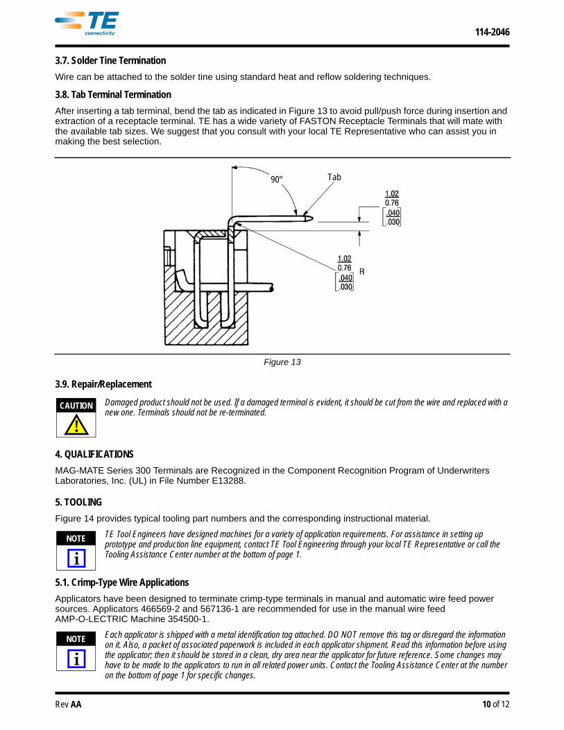
3.8. Tab Terminal Termination
After inserting a tab terminal, bend the tab as indicated in Figure 13 to avoid pull/push force during insertion and extraction of a receptacle terminal. TE has a wide variety of FASTON Receptacle Terminals that will mate with the available tab sizes. We suggest that you consult with your local TE Representative who can assist you in making the best selection.
Figure 13
3.9. Repair/Replacement
Damaged product should not be used. If a damaged terminal is evident, it should be cut from the wire and replaced with a new one. Terminals should not be re-terminated.
4. QUALIFICATIONS
MAG-MATE Series 300 Terminals are Recognized in the Component Recognition Program of Underwriters Laboratories, Inc. (UL) in File Number E13288.
5. TOOLING
Figure 14 provides typical tooling part numbers and the corresponding instructional material.
TE Tool Engineers have designed machines for a variety of application requirements. For assistance in setting up prototype and production line equipment, contact TE Tool Engineering through your local TE Representative or call the Tooling Assistance Center number at the bottom of page 1.
5.1. Crimp-Type Wire Applications
Applicators have been designed to terminate crimp-type terminals in manual and automatic wire feed power sources. Applicators 466569-2 and 567136-1 are recommended for use in the manual wire feedAMP-O-LECTRIC Machine 354500-1.
Each applicator is shipped with a metal identification tag attached. DO NOT remove this tag or disregard the information on it. Also, a packet of associated paperwork is included in each applicator shipment. Read this information before using the applicator; then it should be stored in a clean, dry area near the applicator for future reference. Some changes may have to be made to the applicators to run in all related power units. Contact the Tooling Assistance Center at the number on the bottom of page 1 for specific changes.
90° Tab
!CAUTION
NOTE
i
NOTE
i
114-2046
11 of 12Rev AA
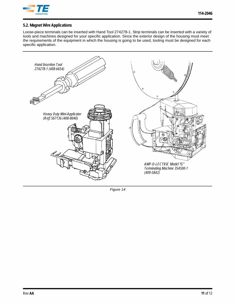
5.2. Magnet Wire Applications
Loose-piece terminals can be inserted with Hand Tool 274278-1. Strip terminals can be inserted with a variety of tools and machines designed for your specific application. Since the exterior design of the housing must meet the requirements of the equipment in which the housing is going to be used, tooling must be designed for each specific application.
Figure 14
Hand Insertion Tool 274278-1 (408-6654)
Heavy Duty Mini-Applicator (Ref) 567136 (408-8040)
AMP-O-LECTRIC Model “G” Terminating Machine 354500-1 (409-5842)

114-2046
12 of 12Rev AA
6. VISUAL AID
The illustration below shows a typical application of this product. This illustration should be used by production personnel to ensure a correctly applied product. Applications which DO NOT appear correct should be inspected using the information in the preceding pages of this specification and in the instructional material shipped with the product or tooling.
FIGURE 15. VISUAL AID
TERMINAL SHOULD BE FLUSH OR SLIGHTLY ABOVE TOP OF HOUSING
THERE SHOULD BE SUFFICIENT SLACK IN THE WIRE THAT WILL ALLOW ANY NECESSARY MOVEMENT WITHOUT STRETCHING THE WIRE
WIRE MUST BE FIRMLY HELD IN BOTH WIRE SLOTS OF THE TERMINAL WITH NO SIGNS OF DAMAGE TO THE WIRE OR THE TERMINAL
WIRE TRIM SUPPORT SHOULD BE REMOVED
WIRE SHOULD BE SEATED ON ANVIL AND CENTERED IN WIRE SLOT
FOR EXPOSED WIRE APPLICATION, WIRE END SHOULD BE CUT CLEANLY AND FLUSH WITH HOUSING. FOR CONCEALED WIRE APPLICATION, WIRE END SHOULD BE CUT CLEANLY AND PULLED INSIDE HOUSING
HOUSING MUST NOT BE SCRAPED, CRACKED, OR BROKEN, OR HAVE ANY OTHER SIGNS OF DAMAGE