applications 2007-up cadillac escalade 99-2007 · table of contents dash disassembly – cadillac...
TRANSCRIPT
METRA. THE WORLD’S BEST KITS.™
© COPYRIGHT 2004-2011 METRA ELECTRONICS CORPORATION
APPLICATIONS
1-800-221-0932 metraonline.com
INSTALLATION INSTRUCTIONS FOR PART 99-2007
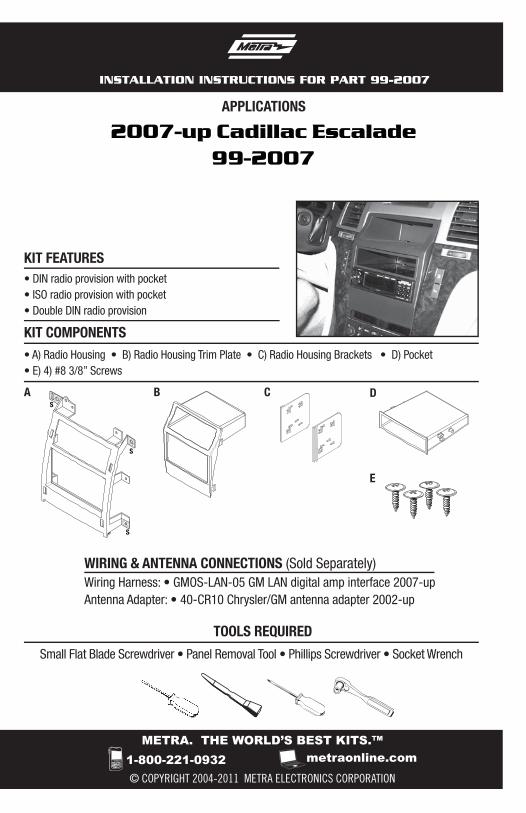
WIRING & ANTENNA CONNECTIONS (Sold Separately) Wiring Harness: • GMOS-LAN-05 GM LAN digital amp interface 2007-upAntenna Adapter: • 40-CR10 Chrysler/GM antenna adapter 2002-up
Small Flat Blade Screwdriver • Panel Removal Tool • Phillips Screwdriver • Socket Wrench
TOOLS REQUIRED
2007-up Cadillac Escalade99-2007
B
E
C DA
• A) Radio Housing • B) Radio Housing Trim Plate • C) Radio Housing Brackets • D) Pocket • E) 4) #8 3/8” Screws
KIT FEATURES
KIT COMPONENTS
S
S
S
• DIN radio provision with pocket• ISO radio provision with pocket• Double DIN radio provision

Table of Contents
Dash Disassembly
– Cadillac Escalade 2007-up 3-4
Kit Assembly
– Kit preparation 5– ISO DIN head unit provision 6-7– Double DIN head unit provision 8
KNOWLEDGE IS POWEREnhance your installation and fabrication skills by enrolling in the most recognized and respected mobile electronics school in our industry.Log onto www.installerinstitute.com or call 800-354-6782 for more information and take steps toward a better tomorrow.
Metra recommends MECP certified technicians
99-2007
CautionMetra recommends disconnecting the negative battery terminal before beginning any installation. All accessories, switches, and especially air bag indicator lights must be plugged in before reconnecting the battery or cycling the ignition.
*NOTE: Refer also to the instructions included with the aftermarket radio.

1. Unclip and remove cup holder and ashtray assembly. (Figure A)
2. Unclip and remove the trim panel above the glove box including the a/c vent. (Figure B)
3. Unclip and remove the entire panel surrounding the radio including the a/c vents. (Figure C)
Continued on next page
3
Dash Disassembly
99-2007
(Figure A)
(Figure B)
(Figure C)

4
99-2007
Dash Disassembly
4. Remove (6) 9/32” screws to extract radio from dash. (Figure D)
Continue to kit preparation
(Figure D)

5
Kit Assembly 99-2007
1. Cut and remove the shaded areas marked with an “S” only from the radio housing. (Figure A) Right side and top of radio housing. (Figure B) Left side and top of radio housing.
NOTE: DO NOT remove the tab marked with both “S” and “E”.
Continue to kit assembly.
Kit Preparation
S
S
S
S
S
S
(Figure A)
(Figure B)

6
Kit Assembly 99-2007
1. Locate the factory wiring harness in the dash. Metra recommends using the proper mating adapter from Metra or AXXESS. Re-connect the negative battery terminal and test the unit for proper operation.
2. Flip the radio housing brackets upside down then snap them to the inside edge of the radio housing. (Figure A)
3. Slide the pocket into the top of the opening aligning the holes in the radio housing brackets with the bosses on the pocket and secure using the provided (4) #8 x 3/8” screws. (Figure B)
4. Slide the ISO radio into the opening below the pocket and secure the unit to the kit using the screws supplied with the radio. (Figure C)
Continue to next page.
ISO mount radio provision with pocket
(Figure A)
(Figure B)
(Figure C)

7
Kit Assembly 99-2007
5. Snap the radio housing trim plate onto the front of the radio housing. (Figure D)
6. Reassemble dash in reverse order of disassembly.
ISO mount radio provision with pocket
(Figure D)
Kit Assembly 99-2007
6
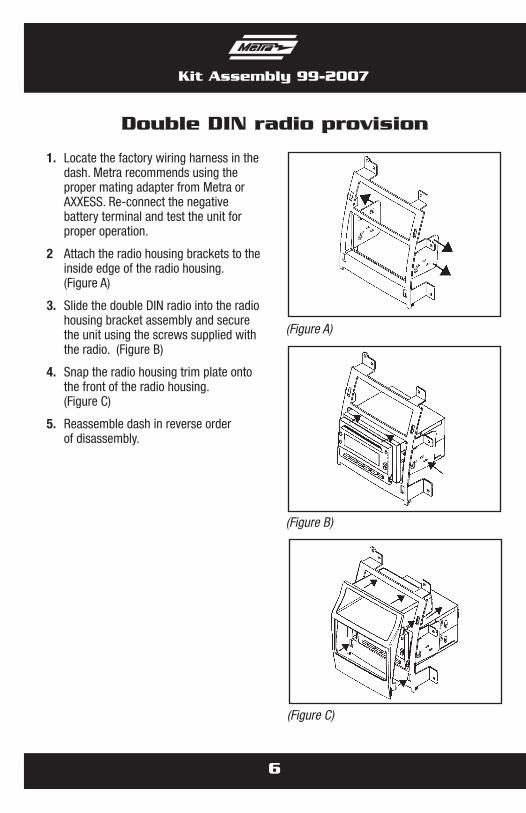
Double DIN radio provision
(Figure A)
(Figure B)
(Figure C)
1. Locate the factory wiring harness in the dash. Metra recommends using the proper mating adapter from Metra or AXXESS. Re-connect the negative battery terminal and test the unit for proper operation.
2 Attach the radio housing brackets to the inside edge of the radio housing. (Figure A)
3. Slide the double DIN radio into the radio housing bracket assembly and secure the unit using the screws supplied with the radio. (Figure B)
4. Snap the radio housing trim plate onto the front of the radio housing. (Figure C)
5. Reassemble dash in reverse order of disassembly.

Notes

Notes

Notes

METRA. THE WORLD’S BEST KITS.™
© COPYRIGHT 2004-2011 METRA ELECTRONICS CORPORATION 1-800-221-0932 metraonline.com
INSTALLATION INSTRUCTIONS FOR PART 99-2007
REV.
6/1
3/11